26SL71 29SL81 In the interests of user-safety (Required by safety regulations in some countries) the set should be restored to its original condition and only parts identical to those specified should be used. S60B526SL71// MODELS SHARP CORPORATION OUTLINE SERVICE MANUAL 26SL71 29SL81 COLOR TELEVISION Chassis No. SN-91A POWER POWER PUSH OPEN MTS STEREO This Service Manual covers the modifications from Models 26SL70 and 29SL80. For data and information not discussed here, please refer to the 26SL70/29SL80 Service Manual (S69J129SL80//).

Welcome message from author
This document is posted to help you gain knowledge. Please leave a comment to let me know what you think about it! Share it to your friends and learn new things together.
Transcript

1
26SL7129SL81
In the interests of user-safety (Required by safety regulations in some countries) the set should be restored to itsoriginal condition and only parts identical to those specified should be used.
S60B526SL71//
MODELS
SHARP CORPORATION
OUTLINE
SERVICE MANUAL
26SL7129SL81
COLOR TELEVISION
Chassis No. SN-91A
POWER POWERPUSH OPEN
MTS STEREO
This Service Manual covers the modifications from Models 26SL70 and 29SL80. For data and informationnot discussed here, please refer to the 26SL70/29SL80 Service Manual (S69J129SL80//).

2
26SL7129SL81
LIST OF CHANGED PARTSRef. No. Description Current (26SL70) New (26SL71) Note
PRINTED WIRING BOARD ASSEMBLIES
PWB-A Main Unit DUNTK9806WEV1 DUNTKA270WEV0
MAIN UNIT
IC751 I.C. VHiKA7809Pi-1 VHiKA7809AP-1 or VHiKA7809Pi-1
IC2001 I.C. RH-iX3256CEZZ RH-iX3366CEZZ
IC2101 I.C. VHiM24C01B/-1 VHiBR24C02/-1
L2040 Coil RCiLB0159CEZZ RCiLB0131CEZZ
J799 Resistor – VRD-RA2BE102J Added
RJ15 Resistor VRS-CY1JF000J – Abolished
RJ16 Resistor VRS-CY1JF000J – Abolished
R2016 Resistor – VRS-CY1JF223J Added
R2017 Resistor – VRS-CY1JF223J Added
R2023 Resistor – VRS-CY1JF223J Added
R2030 Resistor VRS-CY1JF103J – Abolished
R2033 Resistor VRS-CY1JF102J – Abolished
P704 Plug QPLGN0304CEZZ QPLGN0360CEZZ or QPLGN0304CEZZ
POWER UNIT
IC5771 I.C. VHiKA7809Pi-1 VHiKA7809AP-1 or VHiKA7809Pi-1
P5701 Plug QPLGN0404CEZZ QPLGN0460CEZZ or QPLGN0404CEZZ
SUPPLIED ACCESORRIES
Infrared R/C Unit RRMCG1339CESA RRMCG1573CESA
Operation Manual TiNS-6556GJZZ TiNS-7033GJZZ
PACKING PARTS
Packing Case SPAKC0108GJZZ SPAKC0129GJZZ
CABINET PARTS
1 Front Cabinet Ass'y CCABA0008WEH0 CCABA0008WEH3
1-4 Button, Power JBTN-0106GJSA JBTN-0106GJSB
1-6 Door GDORF0102GJSA GDORF0102GJSB
3
26SL7129SL81
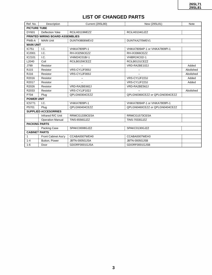
LIST OF CHANGED PARTSRef. No. Description Current (29SL80) New (29SL81) Note
PICTURE TUBE
DY601 Deflection Yoke RCiLH0119MEZZ RCiLH0104GJZZ
PRINTED WIRING BOARD ASSEMBLIES
PWB-A MAIN Unit DUNTK9806WEV2 DUNTKA270WEV1
MAIN UNIT
IC751 I.C. VHiKA7809Pi-1 VHiKA7809AP-1 or VHiKA7809Pi-1
IC2001 I.C. RH-iX3256CEZZ RH-iX3366CEZZ
IC2101 I.C. VHiM24C01B/-1 VHiBR24C02/-1
L2040 Coil RCiLB0159CEZZ RCiLB0131CEZZ
J799 Resistor – VRD-RA2BE102J Added
RJ15 Resistor VRS-CY1JF000J – Abolished
RJ16 Resistor VRS-CY1JF000J – Abolished
R2016 Resistor – VRS-CY1JF223J Added
R2017 Resistor – VRS-CY1JF223J Added
R2026 Resistor VRD-RA2BE682J VRD-RA2BE562J
R2033 Resistor VRS-CY1JF102J – Abolished
P704 Plug QPLGN0304CEZZ QPLGN0360CEZZ or QPLGN0304CEZZ
POWER UNIT
IC5771 I.C. VHiKA7809Pi-1 VHiKA7809AP-1 or VHiKA7809Pi-1
P5701 Plug QPLGN0404CEZZ QPLGN0460CEZZ or QPLGN0404CEZZ
SUPPLIED ACCESORRIES
Infrared R/C Unit RRMCG1339CESA RRMCG1573CESA
Operation Manual TiNS-6556GJZZ TiNS-7033GJZZ
PACKING PARTS
Packing Case SPAKC0008GJZZ SPAKC0130GJZZ
CABINET PARTS
1 Front Cabinet Ass'y CCABA0007WEH0 CCABA0007WEH3
1-4 Button, Power JBTN-0005GJSA JBTN-0005GJSB
1-6 Door GDORF0001GJSA GDORF0001GJSB

5
26SL7129SL81
4
121110987654321
A
B
C
D
E
F
G
H
7001GEFW
MODEL 26SL71 SCHEMATIC DIAGRAM:MAIN-1 Unit

7
26SL7129SL81
6
121110987654321
A
B
C
D
E
F
G
H
MODEL 26SL71 SCHEMATIC DIAGRAM:MAIN-2 Unit
9
26SL7129SL81
8
121110987654321
A
B
C
D
E
F
G
H
7001GEFW
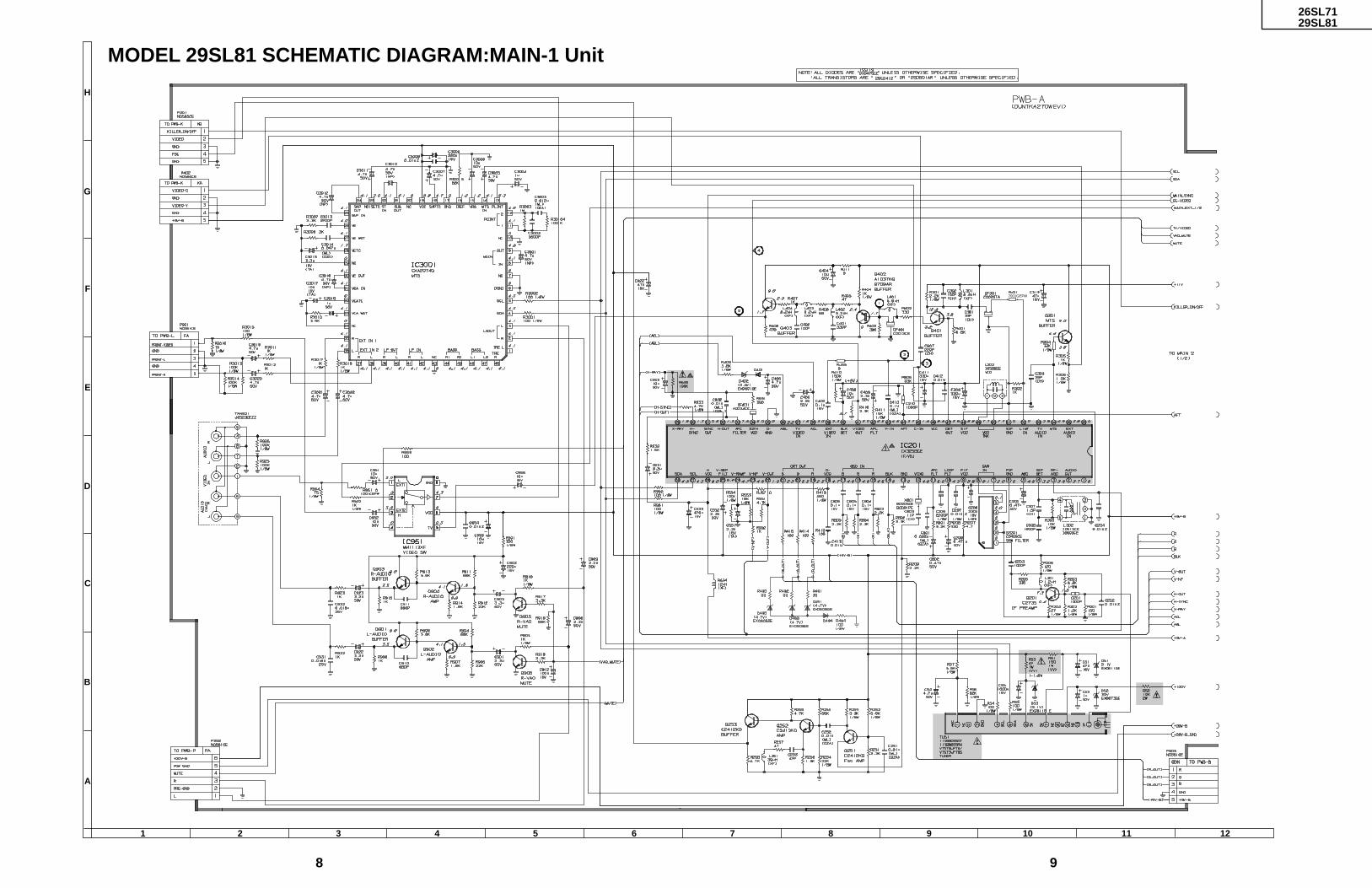
MODEL 29SL81 SCHEMATIC DIAGRAM:MAIN-1 Unit
11
26SL7129SL81
10
121110987654321
A
B
C
D
E
F
G
H
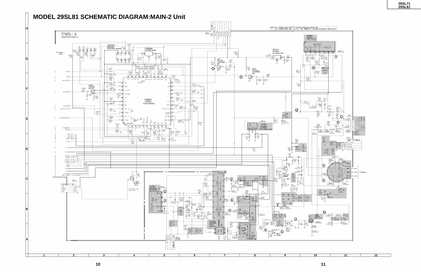
MODEL 29SL81 SCHEMATIC DIAGRAM:MAIN-2 Unit

12
26SL7129SL81
654321
A
B
C
D
E
F
G
H
SCHEMATIC DIAGRAM: POWER Unit

13
26SL7129SL81
654321
A
B
C
D
E
F
G
H
PRINTED WIRING BOARD ASSEMBLIES
PWB-A: MAIN Unit (Wiring Side)

14
26SL7129SL81
PWB-A: MAIN Unit (Component Side)
654321
A
B
C
D
E
F
G
H

15
26SL7129SL81
Ref. No. Part No. Description Code
PICTURE TUBE
PARTS LISTPARTS REPLACEMENT
Replacement parts which have these special safety characteristicsidentified in this manual; electrical components having such featuresare identified by å and shaded areas in the Replacement Parts Listsand Schematic Diagrams. The use of a substitute replacement partwhich dose no have the same safety characteristic as the factoryrecommended replacement parts shown in this service manual maycreate shock, fire or other hazards.
"HOW TO ORDER REPLACEMENT PARTS"To have your order filled promptly and correctly, please furnish thefollowing informations.
1. MODEL NUMBER 2. REF. NO.
3. PART NO. 4. DESCRIPTION
MARK : SPARE PARTS-DELIVERY SECTION
' MARK : X- RAY RELATED PARTS
Ref. No. Part No. Description Code
PWB-A : DUNTKA270WEV0 (26SL71)PWB-A : DUNTKA270WEV1 (29SL81)
MAIN UNIT
çå DY601 RCiLH0104GJZZ X Deflection Yoke BE(29SL81)
PRINTED WIRING BOARD ASSEMBLIES(NOT REPLACEMENT ITEM)
PWB-A DUNTKA270WEV0 – MAIN Unit (26SL71) —PWB-A DUNTKA270WEV1 – MAIN Unit (29SL81) —
INTEGRATED CIRCUITSå IC751 VHiKA7809AP-1 J KA7809AP AE
orVHiKA7809Pi-1
IC2001 RH-iX3366CEZZ J I.C. AUIC2101 VHiBR24C02/-1 J BR24C02 AF
COILL2040 RCiLB0131CEZZ J Oscillation Coil AE
RESISTORS[M-Ox.···Metal Oxide]
J799 VRD-RA2BE102J J 1.0k 1/8W Carbon AAR2016 VRS-CY1JF223J J 22k 1/16W M-Ox. AAR2017 VRS-CY1JF223J J 22k 1/16W M-Ox. AAR2023 VRS-CY1JF223J J 22k 1/16W M-Ox. AA
(26SL71)R2026 VRD-RA2BE562J J 5.6k 1/8W Carbon AA
(29SL81)
MISCELLANEOUS PARTSP704 QPLGN0360CEZZ J Plug, 3-pin (PC) AC
orQPLGN0304CEZZ
PWB-P : DUNTK9830WEV2POWER UNIT
INTEGRATED CIRCUITSå IC5771 VHiKA7809AP-1 M KA7809 AE
orVHiKA7809Pi-1
MISCELLANEOUS PARTSP5701 QPLGN0460CEZZ J Plug, 4-pin (M) AC
orQPLGN0404CEZZ
SUPPLIED ACCESORRIES
RRMCG1573CESA M Infrared R/C Unit AWTiNS-7033GJZZ X Operation Manual AN
PACKING PARTS(NOT REPLACEMENT ITEM)SPAKC0129GJZZ – Packing Case (26SL71) —SPAKC0130GJZZ – Packing Case (29SL81) —
CABINET PARTS
26SL711 CCABA0008WEH3 X Front Cabinet Ass'y BF1-4 JBTN-0106GJSB X Button, Power AH1-6 GDORF0102GJSB X Door AM
29SL811 CCABA0007WEH3 X Front Cabinet Ass'y BF1-4 JBTN-0005GJSB X Button, Power AH1-6 GDORF0001GJSB X Door AM

16
26SL7129SL81
SHARP CORPORATIONAV Systems GroupQuality & Reliability Control CenterYaita, Tochigi 329-2193, Japan
TQ0907-SJun. 2000 Printed in Japan
MI. KG
COPYRIGHT © 2000 BY SHARP CORPORATION
ALL RIGHTS RESERVED.
No part of this publication may be reproduced,stored in a retrieval system, or transmitted inany form or by any means, electronic, mechanical,photocopying, recording, or otherwise, withoutprior written permission of the publisher.

1
26SL40, 26SL7029SL80
In the interests of user-safety (Required by safety regulations in some countries) the set should be restored to itsoriginal condition and only parts identical to those specified should be used.
S69J129SL80//
MODELS
» ELECTRICAL SPECIFICATIONS ......................................................................................................... 1» IMPORTANT SERVICE SAFETY PRECAUTION ................................................................................. 2» LOCATION OF USER'S CONTROL ..................................................................................................... 4» INSTALLATION AND SERVICE INSTRUCTIONS ................................................................................ 5» CHASSIS LAYOUT ............................................................................................................................. 11» BLOCK DIAGRAM ............................................................................................................................. 12» SCHEMATIC DIAGRAMS................................................................................................................... 15» PRINTED WIRING BOARD ASSEMBLIES ........................................................................................ 33» REPLACEMENT PARTS LIST............................................................................................................ 37» PACKING OF THE SET ...................................................................................................................... 47
Page
POWER INPUT........................................ 110-220 V AC 50/60 HzPOWER RATING
26SL40 .............................................................................. 120 W26SL70 .............................................................................. 125 W29SL80 .............................................................................. 130 W
PICTURE SIZE26SL40, 26SL70 ................................... 2,032 cm2 (315 sq inch)29SL80 .................................................. 2,193 cm2 (340 sq inch)
CONVERGENCE ............................................................. MagneticSWEEP DEFLECTION .....................................................MagneticFOCUS ................................................Hi-Bi-Potential ElectrostaticINTERMEDIATE FREQUENCIES
Picture IF Carrier Frequency ..................................... 45.75 MHzSound IF Carrier Frequency ...................................... 41.25 MHzColor Sub-Carrier Frequency ..................................... 42.17 MHz
(Nominal)
SHARP CORPORATION
CONTENTS
ELECTRICAL SPECIFICATIONS
Specifications are subject to change withoutprior notice.
AUDIO POWEROUTPUT RATING
26SL40 ............................................................. 2.5 W + 2.5 W26SL70, 29SL80 ..................................................... 5 W + 5 W
(at 5% distortion and Dual CH Operate)SPEAKER
SIZE ............................................................... 12 × 6 cm (2 pcs.)VOICE COIL IMPEDANCE ............................... 8 ohm at 400 Hz
ANTENNA INPUT IMPEDANCEVHF/UHF .................................................... 75 ohm Unbalanced
TUNING RANGESVHF-Channels .............................................................. 2 thru 13UHF-Channels ............................................................ 14 thru 69CATV Channels ........................................................... 1 thru 125
SERVICE MANUAL
26SL40, 26SL7029SL80
COLOR TELEVISION
Chassis No. SN-91A
POWER POWERPUSH OPEN
MTS STEREO

2
26SL40, 26SL7029SL80
IMPORTANT SERVICE SAFETY PRECAUTIONService work should be performed only by qualified service technicians who are throughlyfamiliar with all safety checks and the servicing guidelines which follow:
X-RADIATION AND HIGH VOLTAGE LIMITS
1. Be sure all service personnel are aware of theprocedures and instructions covering X-radiation. Theonly potential source of X-ray in current solid stateTV receivers is the picture tube. However, the picturetube does not emit measurable X-Ray radiation, ifthe high voltage is as specified in the "High VoltageCheck" instructions.It is only when high voltage is excessive that X-radiation is capable of penetrating the shell of thepicture tube including the lead in the glass material.The important precaution is to keep the high voltagebelow the maximum level specified.
2. It is essential that servicemen have available at alltimes an accurate high voltage meter.The calibration of this meter should be checkedperiodically.
3. High voltage should always be kept at the rated value−no higher. Operation at higher voltages may causea failure of the picture tube or high voltage circuitryand;also, under certain conditions, may produceradiation in exceeding of desirable levels.
4. When the high voltage regulator is operating properlythere is no possibility of an X-radiation problem. Everytime a color chassis is serviced, the brightness shouldbe tested while monitoring the high voltage with ameter to be certain that the high voltage does notexceed the specified value and that it is regulatingcorrectly.
5. Do not use a picture tube other than that specified ormake unrecommended circuit modifications to thehigh voltage circuitry.
6. When trouble shooting and taking test measurementson a receiver with excessive high voltage, avoid beingunnecessarily close to the receiver.Do not operate the receiver longer than is necessaryto locate the cause of excessive voltage.
WARNING
1. For continued safety, no modification of any circuitshould be attempted.
2. Disconnect AC power before servicing.3. Semiconductor heat sinks are potential shock
hazards when the chassis is operating.4. The chassis in this receiver has two ground systems
which are separated by insulating material. The non-isolated (hot) ground system is for the B+ voltageregulator circuit and the horizontal output circuit. Theisolated ground system is for the low B+ DC voltagesand the secondary circuit of the high voltagetransformer.To prevent electrical shock use an isolationtransformer between the line cord and powerreceptacle, when servicing this chassis.
SERVICING OF HIGH VOLTAGE SYSTEMAND PICTURE TUBE
When servicing the high voltage system,remove the static charge by connecting a10k ohm resistor in series with an insulatedwire (such as a test probe) between the pic-ture tube ground and the anode lead. (ACline cord should be disconnected from ACoutlet.)
1. Picture tube in this receiver employs integralimplosion protection.
2. Replace with tube of the same type number forcontinued safety.
3. Do not lift picture tube by the neck.4. Handle the picture tube only when wearing
shatterproof goggles and after discharging the highvoltage anode completely.

3
26SL40, 26SL7029SL80
123456789012345678901234567890121234567890123456789012345678901212345678901234567890123456789012121234567890123456789012345678901212345678901234567890123456789012123456789012345678901234567890121212345678901234567890123456789012123456789012345678901234567890121234567890123456789012345678901212
123456789012345678901234567890121234567890123456789012345678901212345678901234567890123456789012121234567890123456789012345678901212345678901234567890123456789012123456789012345678901234567890121212345678901234567890123456789012123456789012345678901234567890121234567890123456789012345678901212
SAFETY NOTICE
Many electrical and mechanical parts in televisionreceivers have special safety-related characteristics.These characteristics are often not evident from visualinspection, nor can protection afforded by them benecessarily increased by using replacement componentsrated for higher voltage, wattage and etc.Replacement parts which have these special safetycharacteristics are identified in this manual; electricalcomponents having such features are identified by "å"and shaded areas in the Replacement Parts Lists andSchematic Diagrams.
IMPORTANT SERVICE SAFETY PRECAUTION(Continued)
1. Inspect all lead dress to make certain that leads arenot pinched or that hardware is not lodged betweenthe chassis and other metal parts in the receiver.
2. Inspect all protective devices such as non-metalliccontrol knobs, insulating materials, cabinet backs,adjustment and compartment covers or shields,isolation resistor-capacity networks, mechanicalinsulators and etc.
3. To be sure that no shock hazard exists, check forleakage current in the following manner.
• Plug the AC cord directly into a 110-220 volt AC outlet,(Do not use an isolation transformer for this test).
• Using two clip leads, connect a 1.5k ohm, 10 wattresistor paralleled by a 0.15µF capacitor in series withall exposed metal cabinet parts and a known earthground, such as electrical conduit or electrical groundconnected to earth ground.
• Use an AC voltmeter having with 5000 ohm per volt,or higher, sensitivity to measure the AC voltage dropacross the resistor.
For continued protection, replacement parts must beidentical to those used in the original circuit. The use ofsubstitute replacement parts which do not have the samesafety characteristics as the factory recommendedreplacement parts shown in this service manual, maycreate shock, fire, X-radiation or other hazards.
BEFORE RETURNING THE RECEIVER
(Fire & Shock Hazard)
Before returning the receiver to the user, performthe following safety checks.
• Connect the resistor connection to all exposed metalparts having a return to the chassis (antenna, metalcabinet, screw heads, knobs and control shafts,escutcheon and etc.) and measure the AC voltagedrop across the resistor.AII checks must be repeated with the AC ine cordplug connection reversed. (If necessary, a non-polarized adapter plug must be used only for thepurpose of completing these check.)Any current measured must not exceed 0.5 milliamp.Any measurements not within the limits outlinedabove indicate of a potential shock hazard andcorrective action must be taken before returning theinstrument to the customer.
1.5k ohm10W
0.15µFTEST PROBE
CONNECT TOKNOWN EARTHGROUND
TO EXPOSEDMETAL PARTS
ACVOLTMETER

4
26SL40, 26SL7029SL80
LOCATION OF USER'S CONTROL
POWER POWER MTS STEREOVIDEO IN 2 L-AUDIO-R– VOL + CH MENU
POWER POWER – VOL + CH MENU
TV
Infrared Transmitter Window
INPUTPress → Switch to external videoINPUT 1 mode.Press again → Switch to external videoINPUT 2 mode.Press 3 times → Switch back to theoriginal TV mode.
CHANNEL UP/DOWN( ) Selects next higher channel.( ) Selects next lower channel.• Moves the “ ” mark of the MENU
screen.
MENUPress → Accesses MAIN MENU.Press again → Exits MAIN MENU.
DISPLAYPress → Displays receiving channel for4 seconds.Press again → Removes display.• Temporarily displays receiving
channel when in Closed Captionmode.
POWERPress → On.Press again → Off.
REMOTE KEYPADAccesses any channel from keypad.
FLASHBACKReturns to previous channel.
VOLUME UP/DOWN(+) Increases sound.(–) Decreases sound.• In menu mode, changes or selects
the TV adjustments.
MUTEPress → Mutes sound.Press again → Restores sound.• CLOSED CAPTION appears when
sound is muted.
CHANNELUP/DOWN( ) Selects next higher
channel.( ) Selects next lower
channel.
SENSOR AREA FORREMOTE CONTROL
VOLUME UP/DOWN(+) Increases sound.(–) Decreases sound.
POWERPress → On.Press again → Off.
VIDEO/AUDIO TERMINALS(VIDEO/AUDIO terminals are alsoprovided on the rear.)
IN 2
MENUPress → Accesses MAINMENU.Press again → Exits MAINMENU.
Basic Remote Control Functions
Front Panel

5
26SL40, 26SL7029SL80
CIRCUIT PROTECTION
The receiver is protected by a 5.0A fuse(F5701), mounted on PWB-P, wired into oneside of the AC line input.
X-RADIATION PROTECTOR CIRCUIT TEST
After service has been performed on the horizontaldeflection system, high voltage system, B+ system,test the X-Radiation protection circuit to ascertainproper operation as follows:
1. Apply 110-220V AC using a variac transformer foraccurate input voltage.
2. Allow for warm up and adjust all customer controlsfor normal picture and sound.
3. Receive a good local channel.4. Connect a digital voltmeter to TP653 and make sure
that the voltmeter reads 11.2 ± 0.6V.5. Apply external 13.8V DC at TP653 by using an
external DC supply, TV must be shut off.6. To reset the protector, unplug the AC cord and make
a short circuit between TP651 and TP652. Now makesure that normal picture appears on the screen.
7. If the operation of the horizontal oscillator does notstop in step 5, the circuit must be repaired before theset is returned to the customer.
HIGH VOLTAGE CHECK
High voltage is not adjustable but must be checkedto verify that the receiver is operating within safeand efficient design limitations as specified checksshould be as follows:
1. Connect an accurate high voltage meter betweenground and anode of picture tube.
2. Operate receiver for at least 15 minutes at 110-220VAC line voltage, with a strong air signal or a properlytuned in test signal.
3. Enter the service mode and select the serviceadjustment "S19" and Bus data "01" (Y-mute on).
4. The voltage should be approximately, 28.7kV(26SL40/70)/29.7kV(29SL80)(at zero beam).If a correct reading cannot be obtained, check circuitryfor malfunctioning components. After the voltage test,make Y-mute off to the normal mode.
INSTALLATION AND SERVICE INSTRUCTIONSNote: (1) When performing any adjustments to resistor controls and transformers use non-metallic
screwdrivers or TV alignment tools.(2) Before performing adjustments, the TV set must be on at least 15 minutes.

6
26SL40, 26SL7029SL80
Figure A.
S01 02
CHANNELSERVICE ADJUSTMENT NUMBER
DATA NUMBER
S01 D:00
For adjustments of this model, the bus data is converted to various analog signals by the D/A convertercircuit.
Note: There are still a few analog adjustments in this series such as focus and master screen voltage.Follow the steps below whenever the service adjustment is required. See "Table-B" to determine, if serv-ice adjustments are required.
1. Service modeBefore putting unit into the service mode, check thatcustomer adjustments are in the normal mode. Usethe reset function in the video adjustment menu toensure customer controls are in their proper (reset)position.
2. Service number selectionOnce in the service mode, press the Ch-up or Ch-down button on the remote control unit or at the set.The service adjustment number will vary inincrements of one, from "S01" to "OP"(26SL40)/"M05"(26SL70, 29SL80). Select the item you wish toadjust.
3. Data number selectionPress the Vol-up or down button to adjust the datanumber.
To enter the service mode and exit serv-ice mode.
While pressing the Vol-up and Ch-up buttons at the sametime, plug the AC cord into a wall socket.Now the TV set is switched on and enters the servicemode.To exit the service mode, turn the television off bypressing the power button.
55(085)

7
26SL40, 26SL7029SL80
SERVICE NUMBER
DATAADJUSTMENT CONTENTSADJUSTMENT ITEM
RANGEINITIAL VALUE
S01 PICTURE 55 00-7FS02 TINT 46 00-7FS03 COLOR 32 00-7FS04 BRIGHTNESS 40 00-7FS05 SHARPNESS 28/24 00-3F Must be set to "28"(26SL40/70)/"24"(29SL80)S06 VERTICAL PHASE 00 00-07 Must be set to "00"S07 HORIZONTAL PHASE 12 00-1FS08 RF-AGC 23 00-3FS09 VERTICAL AMP 20 00-3FS10 PIF VCO 2C 00-7FS11 R CUT-OFF 00 00-FFS12 G CUT -OFF 00 00-FFS13 B CUT-OFF 00 00-FFS14 G GAIN 7F 00-FFS15 B GAIN 7F 00-FFS16 TRAP 00/01 00 or 01 Must be set to "00"(26SL40/70)/"01"(29SL80)S17 BALANCE 20 00-3F Must be set to "20"S18 C.C. POSITION 17 00-7FS19 MUTE 00 00,01,03 "00"=Normal, "01"=No Y, "03"=No VerticalS20 ENERGY SAVE OFFSET 20 00-3F Must be set to "19"S21 D.D.E. OFFSET 03 00-1F Must be set to "03"S22 OSD SETUP 00 00-03 Must be set to "02"S23 TUNER SETUP 00 00, 01 Must be set to "00"OP. OPTION (Set to each model) 02/36 00-FF Must be set to "02"=26SL40, "36"=26SL70, 29SL80
M01 INPUT LEVEL 0A 00-0FM02 ST VCO 20 00-3FM03 FILTER 1C 00-3FM04 WIDE BAND 20 00-3FM05 SPECTRAL 1B 00-3F
NECESSARY UNNECESSARY
ADJUSTMENTNOTESPART REPLACED
IC2001
IC2101 X
IC3001 X
CRT X
IC201 X
X Data is stored in IC2101.
The adjustment is needed to compensate for characteristicsof parts including IC201 and MTS level (M01).
Holding down both the CH-up/down buttons on the TV set inthe service mode for more than 2 seconds will automaticallywrite the above initial values into IC2101. Then perform acomplete adjustment.
Adjust items related to picture tube only.
Adjust items related to MTS only (M01~M05).
Holding down both the CH-up/down buttons on the TV set at service mode for more than 2 seconds will automaticallywrite the above initial values into IC2101.
Table - A
Table - B
Only for Models26SL70, 29SL80
8
26SL40, 26SL7029SL80
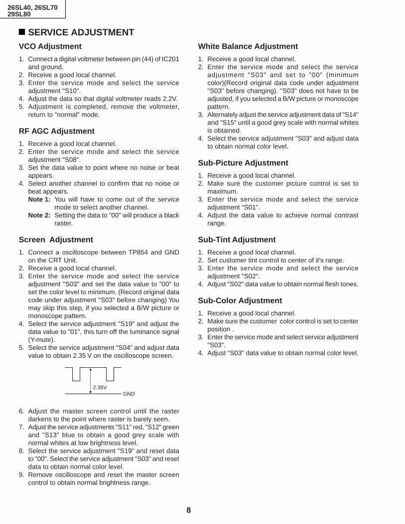
SERVICE ADJUSTMENTVCO Adjustment
1. Connect a digital voltmeter between pin (44) of IC201and ground.
2. Receive a good local channel.3. Enter the service mode and select the service
adjustment "S10".4. Adjust the data so that digital voltmeter reads 2.2V.5. Adjustment is completed, remove the voltmeter,
return to "normal" mode.
RF AGC Adjustment
1. Receive a good local channel.2. Enter the service mode and select the service
adjustment "S08".3. Set the data value to point where no noise or beat
appears.4. Select another channel to confirm that no noise or
beat appears.Note 1: You will have to come out of the service
mode to select another channel.Note 2: Setting the data to "00" will produce a black
raster.
Screen Adjustment
1. Connect a oscilloscope between TP854 and GNDon the CRT Unit.
2. Receive a good local channel.3. Enter the service mode and select the service
adjustment "S03" and set the data value to "00" toset the color level to minimum. (Record original datacode under adjustment "S03" before changing) Youmay skip this step, if you selected a B/W picture ormonoscope pattern.
4. Select the service adjustment "S19" and adjust thedata value to "01", this turn off the luminance signal(Y-mute).
5. Select the service adjustment "S04" and adjust datavalue to obtain 2.35 V on the oscilloscope screen.
6. Adjust the master screen control until the rasterdarkens to the point where raster is barely seen.
7. Adjust the service adjustments "S11" red, "S12" greenand "S13" blue to obtain a good grey scale withnormal whites at low brightness level.
8. Select the service adjustment "S19" and reset datato "00". Select the service adjustment "S03" and resetdata to obtain normal color level.
9. Remove oscilloscope and reset the master screencontrol to obtain normal brightness range.
White Balance Adjustment
1. Receive a good local channel.2. Enter the service mode and select the service
adjustment "S03" and set to "00" (minimumcolor)(Record original data code under adjustment"S03" before changing). "S03" does not have to beadjusted, if you selected a B/W picture or monoscopepattern.
3. Alternately adjust the service adjustment data of "S14"and "S15" until a good grey scale with normal whitesis obtained.
4. Select the service adjustment "S03" and adjust datato obtain normal color level.
Sub-Picture Adjustment
1. Receive a good local channel.2. Make sure the customer picture control is set to
maximum.3. Enter the service mode and select the service
adjustment "S01".4. Adjust the data value to achieve normal contrast
range.
Sub-Tint Adjustment
1. Receive a good local channel.2. Set customer tint control to center of it's range.3. Enter the service mode and select the service
adjustment "S02".4. Adjust "S02" data value to obtain normal flesh tones.
Sub-Color Adjustment
1. Receive a good local channel.2. Make sure the customer color control is set to center
position .3. Enter the service mode and select service adjustment
"S03".4. Adjust "S03" data value to obtain normal color level.
2.35VGND

9
26SL40, 26SL7029SL80
Sub-Brightness Adjustment
1. Receive a good local channel.2. Make sure the customer brightness control is set to
center position.3. Enter the service mode and select the service
adjustment "S04".4. Adjust "S04" data value to obtain normal brightness
level.
Vertical-Size Adjustment
1. Receive a good local channel.2. Enter the service mode and select the service
adjustment "S09".3. While observing the top and bottom of the screen,
adjust "S09" data value to proper vertical size.
Vertical Phase Adjustment
1. Enter the service mode and select the serviceadjustment "S06".
2. Adjust data value to "00".Note: This must be set "00" when changed data retrace
line will appear.
Horizontal Position Adjustment
1. Receive a good local channel.2. Enter the service mode and select the service
adjustment "S07".3. Adjust "S07" data value so that picture is centered.
Caption Position Adjustment (Horizontal)
1. Receive a good local channel.2. Enter the service mode and select the service
adjustment "S18".3. A black text box appears on the screen. (see Figure
B. below)4. Adjust "S18" data value so that text box is positioned
in the center of the screen.
3.58MHz Trap Adjustment
1. Receive a good local channel.2. Enter the service mode and select the service
adjustment "S16".3. This is a two position adjustment, "00" is ON, "01" is
OFF.4. Adjust data value to "00"(26SL40/70)/"01"(29SL80)
for normal viewing.
Sharpness and Audio Balance Adjust-ments
1. Receive a good local channel.2. Enter the service mode and select the service
adjustments "S05" for sharpness and "S17" forbalance.
» Sharpness Adjustment3. Adjust data value to "28"(26SL40/70)/"24"(29SL80)
(center of data range) for sharpness adjustment.» Audio Balance Adjustment4. Adjust data value to "20"(center of data range) for
audio balance adjustment.
Energy save offset Adjustment
1. Enter the service mode and select the serviceadjustment "S20".
2. Adjust data value to "19".Note: This position is used to preset the level for the
energy save function.
Other Adjustments
1. Enter the service mode.2. Adjust the following data values as listed below.
Figure B.
S21 "03" DDE OFFSET
S22 "02" OSD SETUP
S23 "00" TUNER SETUP

10
26SL40, 26SL7029SL80
MTS ADJUSTMENT(Only for Models 26SL70, 29SL80)
MTS Level Adjustment1. Feed the following monaural signal to pin (14) of
IC3001.Monaural signal : 300 Hz, 245 mVrms
2. Connect the rms voltmeter to pin (39) of IC3001.3. Enter the service mode and select the service
adjustment "M01".4. Adjust the data so that the rms voltmeter reads
490 ± 10 mVrms.
MTS VCO Adjustment1. Keep the unit in no-signal state.2. Connect the frequency counter to pin (39) of IC3001.3. Connect a capacitor (100µF, 50V) in between
positive(+) side of C3005 and ground.4. Enter the service mode and select the service
adjustment "M02"5. Adjust the data so that the frequency counter reads
62.94 ± 0.75 kHz.
Filter Adjustment1. Feed the following stereo pilot signal to pin (14) of
IC3001 .Stereo pilot signal: 9.4 kHz, 600 mVrms.
2. Enter the service mode and select the serviceadjustment "M03".
3. Adjust the data at the point where "OK" appears onthe screen. The "OK" represents the approximatecenter of the adjustable range of the data.
Separation Adjustment1. Connect the rms voltmeter to pin (39) of IC3001.2. Receive the following composite stereo signal 1.
Composite stereo signal: 30% modulation, leftchannel only, noise reduction on, 300 Hz
3. Enter the service mode and select the serviceadjustment "M04".
4. Adjust the data until the AC voltage reading of therms voltmeter is minimum.
5. Receive the following composite stereo signal 2.Stereo signal: 30% modulation, left channel only,noise reduction on, 3 kHz
6. Enter the service mode and select the serviceadjustment "M05".
7. Adjust the data until the AC voltage reading of therms voltmeter is minimum.
8. Take the above steps 1 thru 7 again for fineadjustment.

11
26SL40, 26SL7029SL80
654321
A
B
C
D
E
F
G
H
654321
A
B
C
D
E
F
G
H
CHASSIS LAYOUT
26S
L70,
29S
L80
only
(29S
L80
only
)
29S
L80
only
29S
L80
only
26SL40, 26SL70 only
26S
L70,
29S
L80
only
26S
L70,
29S
L80
only

12
26SL40, 26SL7029SL80
654321
A
B
C
D
E
F
G
H
MODEL 26SL40 BLOCK DIAGRAM

13
26SL40, 26SL7029SL80
654321
A
B
C
D
E
F
G
H
MODEL 26SL70 BLOCK DIAGRAM

14
26SL40, 26SL7029SL80
654321
A
B
C
D
E
F
G
H
MODEL 29SL80 BLOCK DIAGRAM

15
26SL40, 26SL7029SL80
654321
A
B
C
D
E
F
G
H
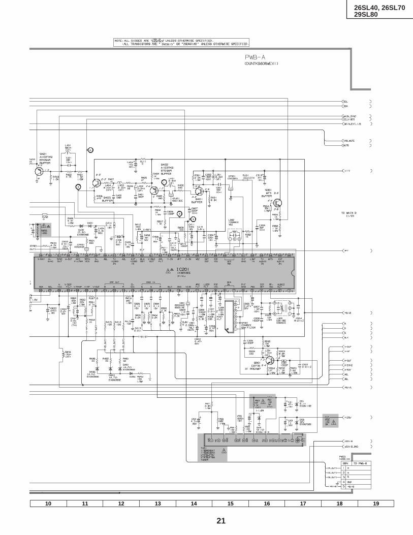
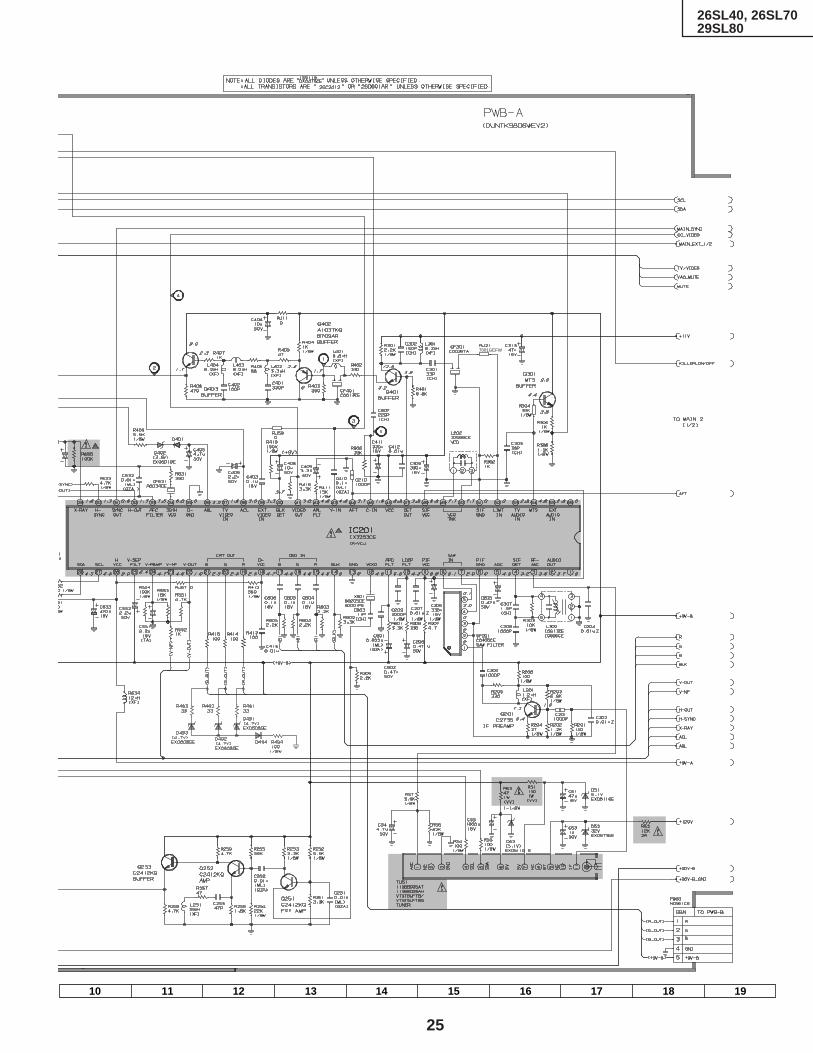
DESCRIPTION OF SCHEMATIC DIAGRAMNOTES:1. The unit of resistance "ohm" is omitted.
(K=kΩ=1000Ω, M=MΩ)2. All resistors are 1/16 watt, unless otherwise noted.3. All capacitors are µ F, unless otherwise noted.
(P=pF=µµF)4. (G) indicates ±2% tolerance may be used.5. indicates line isolated ground.6. indicates hot ground.
VOLTAGE MEASUREMENT CONDITIONS:1. All DC voltages are measured with DVM connected
between points indicated and chassis ground, linevoltage set at 110-220V AC and all controls set fornormal picture unless otherwise indicated.
2. All voltages measured with 1000µ V B & W or Colorsignal.
WAVEFORM MEASUREMENT CONDITIONS:1. Photographs taken on a standard gated color bar
signal, the tint setting adjusted for proper color. Thewave shapes at the red, green and blue cathodes ofthe picture tube depend on the tint, color level andpicture control.
2. indicates waveform check points (See chart,waveforms are measured from point indicated tochassis ground.)
å AND SHADED ( ) COMPONENTS= SAFETY RELATED PARTS.
' MARK= X-RAY RELATED PARTS.
This circuit diagram is a standard one, printed circuitsmay be subject to change for product improvementwithout prior notice.
WAVEFORMS

16
26SL40, 26SL7029SL80
87 109654321
A
B
C
D
E
F
G
H
MODEL 26SL40 SCHEMATIC DIAGRAM: MAIN-1 Unit

17
26SL40, 26SL7029SL80
1716 1918151413121110
7001GEFW
18
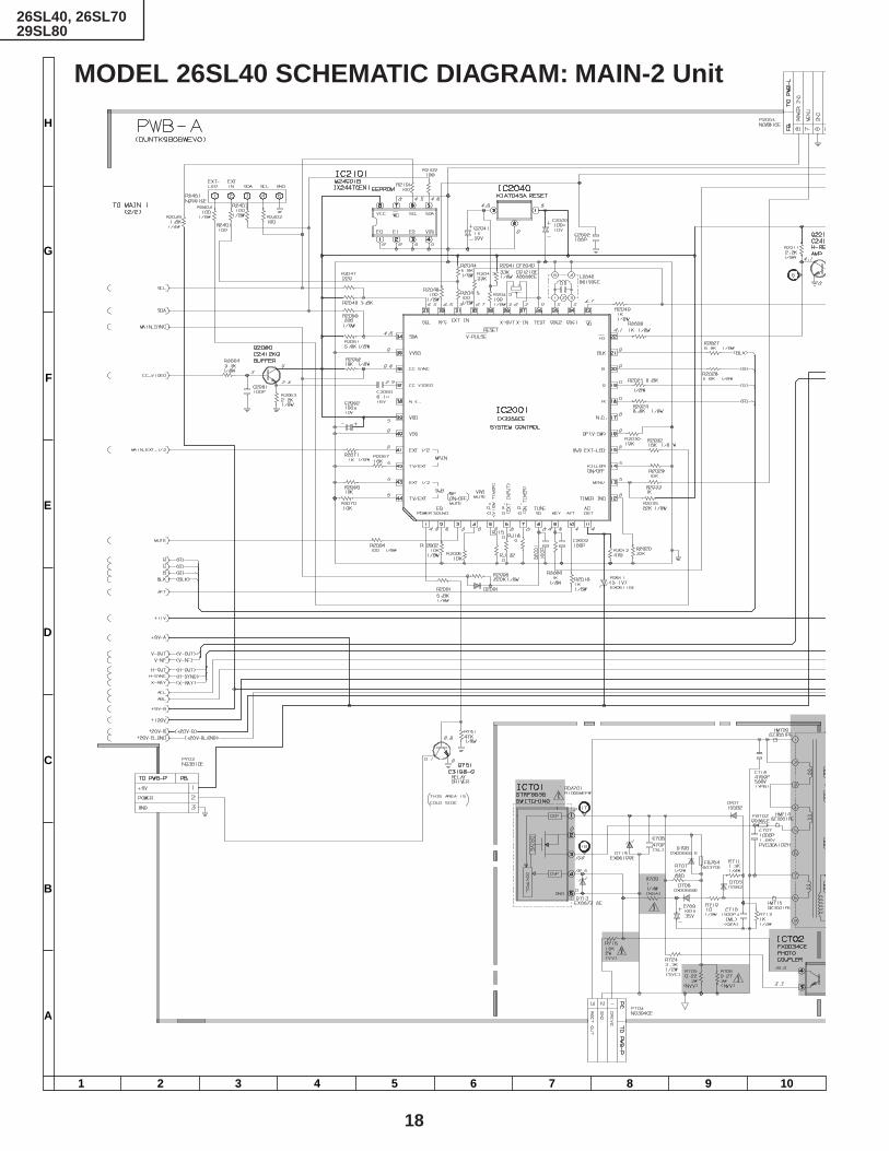
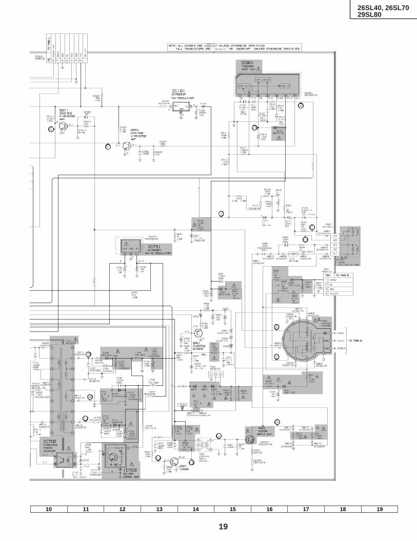
26SL40, 26SL7029SL80
87 109654321
A
B
C
D
E
F
G
H
MODEL 26SL40 SCHEMATIC DIAGRAM: MAIN-2 Unit
19
26SL40, 26SL7029SL80
1716 1918151413121110
20
26SL40, 26SL7029SL80
87 109654321
A
B
C
D
E
F
G
H
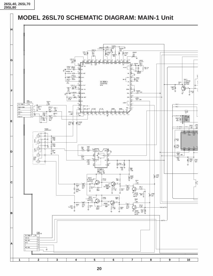
MODEL 26SL70 SCHEMATIC DIAGRAM: MAIN-1 Unit
21
26SL40, 26SL7029SL80
1716 1918151413121110
7001GEFW

22
26SL40, 26SL7029SL80
87 109654321
A
B
C
D
E
F
G
H
MODEL 26SL70 SCHEMATIC DIAGRAM: MAIN-2 Unit

23
26SL40, 26SL7029SL80
1716 1918151413121110

24
26SL40, 26SL7029SL80
87 109654321
A
B
C
D
E
F
G
H
MODEL 29SL80 SCHEMATIC DIAGRAM: MAIN-1 Unit
25
26SL40, 26SL7029SL80
1716 1918151413121110
7001GEFW

26
26SL40, 26SL7029SL80
87 109654321
A
B
C
D
E
F
G
H
MODEL 29SL80 SCHEMATIC DIAGRAM: MAIN-2 Unit

27
26SL40, 26SL7029SL80
1716 1918151413121110
28
26SL40, 26SL7029SL80
654321
A
B
C
D
E
F
G
H
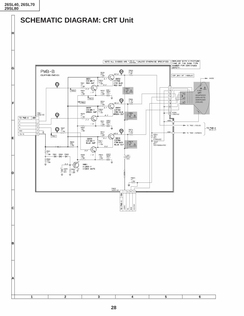
SCHEMATIC DIAGRAM: CRT Unit
A63AFW32X(26SL40/70)A68KRQ58X(29SL80)

29
26SL40, 26SL7029SL80
654321
A
B
C
D
E
F
G
H
SCHEMATIC DIAGRAM: FRONT AV Unit
MODEL 26SL40
MODELS 26SL70, 29SL80

30
26SL40, 26SL7029SL80
654321
A
B
C
D
E
F
G
H
MODEL 26SL40 SCHEMATIC DIAGRAM: POWER Unit
31
26SL40, 26SL7029SL80
654321
A
B
C
D
E
F
G
H
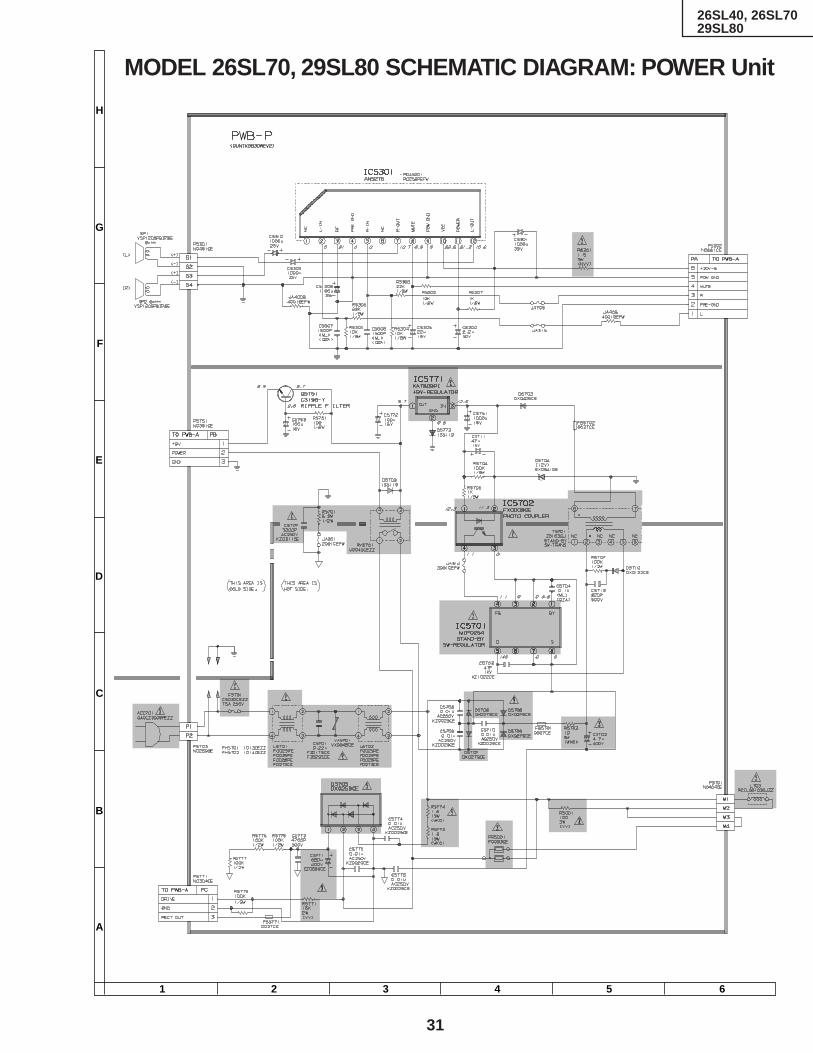
MODEL 26SL70, 29SL80 SCHEMATIC DIAGRAM: POWER Unit
32
26SL40, 26SL7029SL80
654321
A
B
C
D
E
F
G
H
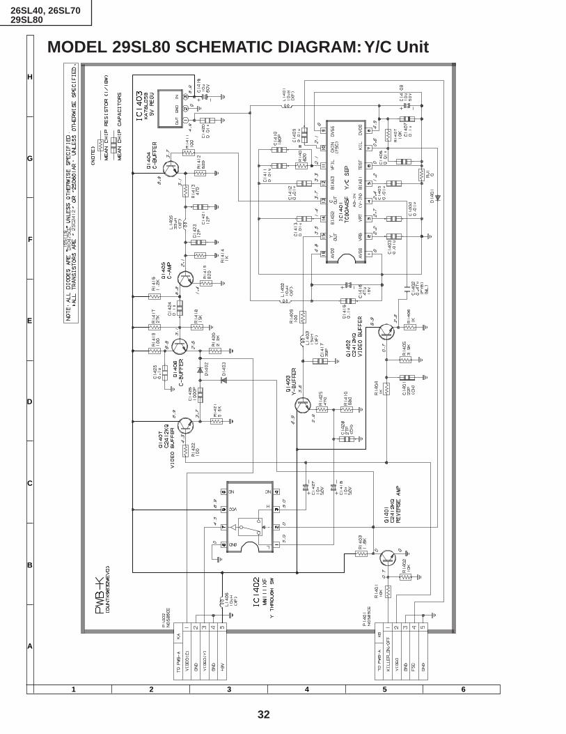
MODEL 29SL80 SCHEMATIC DIAGRAM: Y/C Unit

33
26SL40, 26SL7029SL80
654321
A
B
C
D
E
F
G
H
PRINTED WIRING BOARD ASSEMBLIES
PWB-P: POWER Unit (Wiring Side)

34
26SL40, 26SL7029SL80
654321
A
B
C
D
E
F
G
H
PWB-A: MAIN Unit (Wiring Side)

35
26SL40, 26SL7029SL80
654321
A
B
C
D
E
F
G
H
PWB-A: MAIN Unit (Chip Parts Side)
36
26SL40, 26SL7029SL80
654321
A
B
C
D
E
F
G
H
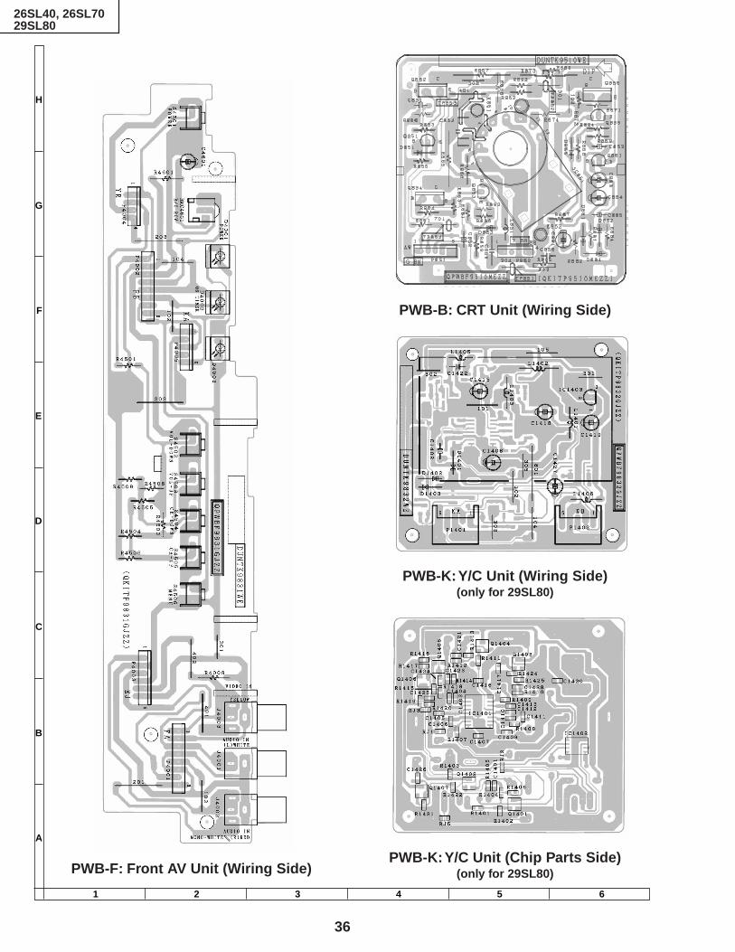
PWB-K: Y/C Unit (Chip Parts Side)(only for 29SL80)PWB-F: Front AV Unit (Wiring Side)
PWB-B: CRT Unit (Wiring Side)
PWB-K: Y/C Unit (Wiring Side)(only for 29SL80)

37
26SL40, 26SL7029SL80
Ref. No. Part No. Description Code Ref. No. Part No. Description CodePARTS LISTPARTS REPLACEMENT
Replacement parts which have these special safety characteristicsidentified in this manual; electrical components having such featuresare identified by å and shaded areas in the Replacement Parts Listsand Schematic Diagrams. The use of a substitute replacement partwhich dose no have the same safety characteristic as the factoryrecommended replacement parts shown in this service manual maycreate shock, fire or other hazards.
"HOW TO ORDER REPLACEMENT PARTS"To have your order filled promptly and correctly, please furnish thefollowing informations.
1. MODEL NUMBER 2. REF. NO.
3. PART NO. 4. DESCRIPTION
MARK : SPARE PARTS-DELIVERY SECTION
' MARK : X- RAY RELATED PARTS
Ref. No. Part No. Description Code
PICTURE TUBE
PWB-A: DUNTK9806WEV0 (26SL40)PWB-A: DUNTK9806WEV1 (26SL70)PWB-A: DUNTK9806WEV2 (29SL80)
MAIN UNIT
çå V101 VB63AFW32X/*S X Picture Tube(26SL40, 26SL70)
çå V101 VB68KRQ58X/*S X Picture Tube(29SL80)
çå DY601 RCiLH0117MEZZ X Deflection Yoke(26SL40, 26SL70)
çå DY601 RCiLH0119MEZZ X Deflection Yoke(29SL80)
å L703 RCiLG0102GJZZ X Degaussing Coil(26SL70, 26SL40)
å L703 RCiLG0101GJZZ X Degaussing Coil(29SL80)
MSPRT0002MEZZ M Spring for CRT AAQEARC2508MEZZ X Grounding Part
(26SL40, 26SL70)QEARC2702MEZZ M Grounding Part AH
(29SL80)
TUNERNOTE : THE PARTS HERE SHOWN ARE SUPPLIED AS AN
ASSEMBLY BUT NOT INDEPENDENTLY.å TU51 VTU115B8035AH M VHF Tuner AH
orVTU115B8035AT orVTUVTST6UF78/ orVTUVTST5UF78S
INTEGRATED CIRCUITSIC101 VHiKA78S05P-1 J KA78S05P AD
çå IC201 RH-iX3253CEZZ J TA1268AN AVå IC501 VHiTA8403K/-1 J TA8403K AL
(26SL40, 26SL70)å IC501 VHiTA8427K/-1 J TA8427K (29SL80) ALå IC701 VHiSTRF66561E X STRF6656å IC702 RH-FX0034CEZZ J PC817 AEå IC703 VHiSE120N//-1 J SE120N AGå IC751 VHiKA7809Pi-1 J KA7809PI AE
IC951 VHiMM1111XF1E J MM1111XF (26SL70) AEIC951 VHiMM1113XF1E J MM1113XF (29SL80) AEIC2001 RH-iX3256CEZZ J I.C. AXIC2040 VHiKiA7045A-1 M KIA7045A ACIC2101 VHiM24C01B/-1 J M24C01BN AF
orRH-iX2447CEN1
IC3001 VHiCXA2074Q-1 J CXA2074Q AY(26SL70, 29SL80)
TRANSISTORSYou can substitute "VS2SD601AR/-1" for "VS2SC2412KQ-1".Q201 VS2SC2735//1E J 2SC2735 ACQ251 VS2SC2412KQ-1 J 2SC2412 (29SL80) AAQ252 VS2SC2412KQ-1 J 2SC2412 (29SL80) AAQ253 VS2SC2412KQ-1 J 2SC2412 (29SL80) AAQ301 VS2SC2412KQ-1 J 2SC2412 (26SL70, 29SL80) AAQ401 VS2SC2412KQ-1 J 2SC2412 AAQ402 VS2SA1037KQ-1 J 2SA1037 AA
orVS2SB709AR/-1
Q403 VS2SC2412KQ-1 J 2SC2412 AAQ421 VS2SA1037KQ-1 J 2SA1037 (26SL40, 26SL70) AA
orVS2SB709AR/-1
Q451 VS2SA1037KQ-1 J 2SA1037 AA orVS2SB709AR/-1
Q601 VS2SC2482//-1 J 2SC2482 ADå Q602 VS2SD2539//1E J 2SD2589 AP
Q751 VS2SC3198-G-1 J 2SC3198 AAQ901 VS2SC2412KQ-1 J 2SC2412 (26SL70, 29SL80) AAQ902 VS2SC2412KQ-1 J 2SC2412 (26SL70, 29SL80) AAQ903 VS2SC2412KQ-1 J 2SC2412 (26SL70, 29SL80) AAQ904 VS2SC2412KQ-1 J 2SC2412 (26SL70, 29SL80) AAQ905 VS2SC2412KQ-1 J 2SC2412 (26SL70, 29SL80) AAQ906 VS2SC2412KQ-1 J 2SC2412 (26SL70, 29SL80) AAQ2060 VS2SC2412KQ-1 J 2SC2412 AAQ2201 VS2SC2412KQ-1 J 2SC2412 AAQ2211 VS2SC2412KQ-1 J 2SC2412 AA
DIODESYou can substitute "RH-DX0475CEZZ" for "VHD1SS119//-1".D51 RH-EX0611GEZZ J Zener Diode, 5.1V AAD52 RH-EX0673GEZZ J Zener Diode, 32V ABD53 RH-EX0611GEZZ J Zener Diode, 5.1V AAD103 VHD1SS119//-1 J Diode ABD401 VHD1SS119//-1 J Diode AB
PRINTED WIRING BOARD ASSEMBLIES(NOT REPLACEMENT ITEM)
PWB-A DUNTK9806WEV0 – MAIN Unit —(26SL40)
PWB-A DUNTK9806WEV1 – MAIN Unit —(26SL70)
PWB-A DUNTK9806WEV2 – MAIN Unit —(29SL80)
PWB-B DUNTK9510WEV0 – CRT Unit —PWB-F DUNTK9831WEV0 – FRONT AV Unit —
(26SL40)PWB-F DUNTK9831WEV1 – FRONT AV Unit —
(26SL70, 29SL80)PWB-K DUNTK9832WEV0 – Y/C Unit —
(29SL80)PWB-P DUNTK9830WEV0 – POWER Unit —
(26SL40)PWB-P DUNTK9830WEV2 – POWER Unit —
(26SL70, 29SL80)

38
Ref. No. Part No. Description Code Ref. No. Part No. Description Code
26SL40, 26SL7029SL80
PWB-A: DUNTK9806WEV0 (26SL40)PWB-A: DUNTK9806WEV1 (26SL70)PWB-A: DUNTK9806WEV2 (29SL80)
MAIN UNIT (Continued)D402 RH-EX0601GEZZ J Zener Diode, 3.6V (29SL80) AAD402 RH-EX0604GEZZ J Zener Diode, 3.9V AB
(26SL40, 26SL70)D454 RH-EX0611GEZZ J Zener Diode, 5.1V AAD455 VHD1SS119//-1 J Diode ABD456 VHD1SS119//-1 J Diode ABD457 RH-EX0217CEZZ J Zener Diode, 15V ABD458 RH-EX0217CEZZ J Zener Diode, 15V ABD459 VHD1SS119//-1 J Diode ABD491 RH-EX0608GEZZ J Zener Diode AAD492 RH-EX0608GEZZ J Zener Diode AAD493 RH-EX0608GEZZ J Zener Diode AAD494 VHD1SS119//-1 J Diode AB
å D501 RH-DX0131CEZZ J Diode ACå D510 RH-DX0441CEZZ J Diode AC
D621 RH-EX0631GEZZ J Zener Diode, 9.1V AAå D622 RH-DX0131CEZZ J Diode AC
çå D651 RH-DX0131CEZZ J Diode ACçå D652 RH-EX1313CEZZ J Zener Diode, 9.1V ADçå D653 VHD1SS119//-1 J Diode ABçå D654 VHD1SS119//-1 J Diode AB
D705 VHD1SS82///1A J Diode ACD706 RH-DX0066GEZZ J Diode ABD707 VHD1SS82///1A J Diode ACD708 RH-DX0066GEZZ J Diode AB
å D709 RH-DX0229CEZZ J Diode AFå D712 RH-DX0507CEZZ X Diode
D713 RH-EX0673GEZZ J Zener Diode, 30V ABD715 RH-EX0610GEZZ J Zener Diode, 4.7V AAD716 VHD1SS119//-1 J Diode ABD717 RH-EX0650GEZZ J Zener Diode, 16V AB
å D725 RH-DX0407CEZZ J Diode ADD2001 VHD1SS119//-1 J Diode AB
PACKAGED CIRCUITX801 RCRSB0205CEZZ J Crystal AF
orRCRSB0001PEZZ
FILTERS AND COILSCF301 RFiLC0029TAZZ J Ceramic Filter ADCF401 RFiLC0013CEZZ J Ceramic Filter AECF631 RFiLA0034CEZZ J Ceramic Filter ADCF2040 RFiLC0121GEZZ J Ceramic Filter ADL201 VP-XF1R2K0000 J Peaking 1.2µH ABL202 RCiLi0588CEZZ J VCO Coil AFL251 VP-XF390K0000 J Peaking 39µH (29SL80) ABL301 VP-XF8R2K0000 J Peaking 8.2µH ABL302 RCiLi0613CEZZ J IF Coil AE
orRCiLi0605CEZZ
L401 VP-XF6R8K0000 J Peaking 6.8µH ABL402 VP-XF3R3K0000 J Peaking 3.3µH ABL403 VP-XF8R2K0000 J Peaking 8.2µH ABL404 VP-XF8R2K0000 J Peaking 8.2µH ABL421 VP-XF680K0000 J Peaking 68µH AB
(26SL40, 26SL70)L672 RCiLZ0101MEZZ M Coil ALL705 RCiLP0179CEZZ J Coil ADL729 RCiLP0179CEZZ J Coil ADL2040 RCiLB0159CEZZ J Oscillation Coil AESF201 RFiLC0405CEZZ J SAW Filter AH
TRANSFORMERSå T601 RTRNZ0057PEZZ R Transformer AK
çå T602 RTRNF0037MEZZ X H-Volt Transformer or (26SL40, 26SL70)RTRNF0033MEZZ
çå T602 RTRNF0038MEZZ X H-Volt Transformer (29SL80)å T702 RTRNZ0102GJZZ X Transformer
CAPACITORS [EL.··· Electrolytic, M-Poly.··· Metalized Polypro Film]
C51 VCEA0A1CW476M J 47 16V EL. ABC53 VCEA0A1HW105M J 1.0 50V EL. ABC54 VCEA0A1HW475M J 4.7 50V EL. ABC55 VCEA0A1CW108M J 1000 16V EL. ADC103 VCEA0A1CW228M J 2200 16V EL. ADC201 VCKYPA1HB102K J 1000p 50V Ceramic AAC202 VCKYCY1HF103Z J 0.01 50V Ceramic AAC203 VCKYCY1HB102K J 1000p 50V Ceramic AAC204 VCKYCY1HF103Z J 0.01 50V Ceramic AAC205 VCEA0A1HW474M J 0.47 50V EL. ABC206 VCEA0A1CW337M J 330 16V EL. ACC207 VCKYCY1HF103Z J 0.01 50V Ceramic AAC208 VCEA0A1HW474M J 0.47 50V EL. ABC209 VCKYCY1HB222K J 2200p 50V Ceramic AAC210 VCKYCY1HB102K J 1000p 50V Ceramic AAC251 RC-QZA103TAYK J 0.01 50V Mylar AA
(29SL80)C252 RC-QZA103TAYK J 0.01 50V Mylar AA
(29SL80)C253 VCCCCY1HH470J J 47p 50V Ceramic AA
(29SL80)C301 VCCCCY1HH330J J 33p 50V Ceramic AAC302 VCCCCY1HH151J J 150p 50V Ceramic AAC303 VCCCCY1HH390J J 39p 50V Ceramic AA
(26SL70, 29SL80)C303 VCKYCY1HB472K J 4700p 50V Ceramic AA
(26SL40)C304 VCEA0A1HW225M J 2.2 50V EL. (26SL40) ABC307 VCCCCY1HH1R5C J 1.5p 50V Ceramic ADC308 VCKYCY1HB102K J 1000p 50V Ceramic AAC309 VCEA0A1CW337M J 330 16V EL. ACC313 VCEA0A1CW476M J 47 16V EL. ABC401 VCKYCY1HB331K J 330p 50V Ceramic AAC402 VCCCCY1HH101J J 100p 50V Ceramic AAC403 VCKYCY1CB104K J 0.1 16V Ceramic ABC404 VCEA0A1HW106M J 10 50V EL. ABC405 VCEA0A1HW335M J 3.3 50V EL. AB
(26SL40, 26SL70)C405 VCEA0A1HW475M J 4.7 50V EL. (29SL80) ABC406 VCEA0A1HW225M J 2.2 50V EL. ABC408 VCEA0A1HW106M J 10 50V EL. ABC409 VCEA0A1HW105M J 1.0 50V EL. AB
(26SL40, 26SL70)C409 VCEA0A1HW335M J 3.3 50V EL. (29SL80) ABC410 RC-QZA104TAYK J 0.1 50V Mylar ABC411 VCEA0A1CW337M J 330 16V EL. ACC412 VCKYCY1HB103K J 0.01 50V Ceramic AAC413 VCKYCY1HB103K J 0.01 50V Ceramic AAC414 VCKYCY1CB104K J 0.1 16V Ceramic AB
(26SL40, 26SL70)C421 VCCCCY1HH330J J 33p 50V Ceramic AA
(26SL40, 26SL70)C422 VCEA0A1CW476M J 47 16V EL. ABC451 RC-QZA104TAYK J 0.1 50V Mylar ABC452 VCEA0A1HW475M J 4.7 50V EL. ABC453 VCEA0A1CW226M J 22 16V EL. ABC501 VCKYPA2HB102K J 1000p 500V Ceramic AAC502 VCEA0A1VW108M J 1000 35V EL. ADC510 VCFYSA1JA564J J 0.56 63V Mylar AEC511 VCKYPA2HB391K J 390p 500V Ceramic AAC512 RC-QZA473TAYK J 0.047 50V Mylar ABC513 RC-QZA103TAYK J 0.01 50V Mylar AAC514 VCEA0A1VW107M J 100 35V EL. ACC515 VCEA0A1HW105M J 1.0 50V EL. AB
(26SL40, 26SL70)C515 VCEA0A1HW474M J 0.47 50V EL. (29SL80) ABC516 VCEACA1HC105K J 1.0 50V EL. AC
(26SL40, 26SL70)C516 VCSATA1VE684K J 0.68 35V Tantalum AC
(29SL80)C517 VCEA0A1VW108M J 1000 35V EL. ADC518 VCFYSA1JA473J J 0.047 63V Mylar ACC551 VCSATA1CE225K J 2.2 16V Tantalum AB

39
26SL40, 26SL7029SL80
Ref. No. Part No. Description Code Ref. No. Part No. Description Code
PWB-A: DUNTK9806WEV0 (26SL40)PWB-A: DUNTK9806WEV1 (26SL70)PWB-A: DUNTK9806WEV2 (29SL80)
MAIN UNIT (Continued)C552 VCEA0A1HW225M J 2.2 50V EL. ABC606 VCKYPA2HB561K J 560p 500V Ceramic AAC607 VCKYPA1HB472K J 4700p 50V Ceramic AA
çå C610 VCFPVC3CA722H J 7200p 1.6kV Polypro Film AFçå C611 VCFPVC3CA722H J 7200p 1.6kV Polypro Film AF
C615 VCKYPA2HB102K J 1000p 500V Ceramic AAå C623 VCEA4A2EN106M J 10 250V EL. AD
C631 VCEA0A1HW335M J 3.3 50V EL. ABC632 RC-QZA103TAYK J 0.01 50V Mylar AAC633 VCEA0A1CW477M J 470 16V EL. ACC652 VCEA0A1HW106M J 10 50V EL. ABC653 VCEA0A1HW106M J 10 50V EL. ABC680 VCFPVC2DB564J J 0.56 200V Polypro Film AF
(26SL40, 26SL70)C680 VCFPVC2DB474J J 0.47 200V Polypro Film AE
(29SL80)C682 VCKYPA2HB331K J 330p 500V Ceramic AAC707 VCFPVC3CA102H X 1000p 1.6kV Polypro FilmC708 VCCSPA1HL471J J 470p 50V Ceramic AAC709 VCEA0A1VW107M J 100 35V EL. ACC710 RC-QZA152TAYJ J 1500p 50V Mylar ABC718 VCKYPA2HB472K J 4700p 500V Ceramic ABC722 RC-QZA104TAYK J 0.1 50V Mylar AB
å C723 RC-EZ0724CEZZ J 100 160V EL. AGå C725 RC-EZ0809CEZZ J 220 160V EL. AL
C726 RC-KZ0338CEZZ J 560p 2kV EL. ADC727 RC-KZ0338CEZZ J 560p 2kV EL. ADC729 VCEA0A1CW106M J 10 16V EL. AB
å C730 RC-EZ0003PEZZ R 1000 35V EL. AFå C731 RC-EZ0385CEZZ J 1000 16V EL. AE
C732 VCKYPA2HB102K J 1000p 500V Ceramic AAC741 VCKYPA2HB102K J 1000p 500V Ceramic AAC742 VCKYPA2HB102K J 1000p 500V Ceramic AAC755 VCEA0A1CW476M J 47 16V EL. ABC801 RC-QZA223TAYK J 0.022 50V Mylar ABC802 VCEA0A1HW474M J 0.47 50V EL. ABC803 VCCCCY1HH110J J 11p 50V Ceramic AAC804 VCKYCY1CB104K J 0.1 16V Ceramic ABC805 VCKYCY1CB104K J 0.1 16V Ceramic ABC806 VCKYCY1CB104K J 0.1 16V Ceramic ABC807 VCCCCY1HH221J J 220p 50V Ceramic AAC808 VCKYCY1HB102K J 1000p 50V Ceramic AA
(26SL40, 26SL70)C901 VCEA0A1HW335M J 3.3 50V EL. AB
(26SL70, 29SL80)C902 VCEA0A1CW227M J 220 16V EL. AC
(26SL70, 29SL80)C903 VCEA0A1HW335M J 3.3 50V EL. AB
(26SL70, 29SL80)C908 VCEA0A1HW225M J 2.2 50V EL. AB
(26SL70, 29SL80)C909 VCEA0A1HW225M J 2.2 50V EL. ABC910 VCKYCY1HB681K J 680p 50V Ceramic AA
(26SL70, 29SL80)C911 VCKYCY1HB681K J 680p 50V Ceramic AA
(26SL70, 29SL80)C912 VCEA0A1CW107M J 100 16V EL. AC
(26SL70, 29SL80)C922 VCEA0A1HW335M J 3.3 50V EL. AB
(26SL70, 29SL80)C923 VCEA0A1HW335M J 3.3 50V EL. AB
(26SL70, 29SL80)C931 VCKYCY1EB183K J 0.018 25V Ceramic AA
(26SL70, 29SL80)C932 VCKYCY1EB183K J 0.018 25V Ceramic AA
(26SL70, 29SL80)C951 VCEA0A1HW106M J 10 50V EL. AB
(26SL70, 29SL80)C952 VCEA0A1HW106M J 10 50V EL. AB
(26SL70, 29SL80)
C954 VCKYCY1HF103Z J 0.01 50V Ceramic AA(26SL70, 29SL80)
C955 VCEA0A1CW106M J 10 16V EL. AB(26SL70, 29SL80)
C956 VCEA0A1CW106M J 10 16V EL. (29SL80) ABC2001 VCCCCY1HH101J J 100p 50V Ceramic AAC2002 VCCCCY1HH101J J 100p 50V Ceramic AAC2040 VCEA0A1AW107M J 100 10V EL. ABC2041 VCEA0A1HW105M J 1.0 50V EL. ABC2060 VCKYCY1CB104K J 0.1 16V Ceramic ABC2061 VCCCCY1HH101J J 100p 50V Ceramic AAC2062 VCEA0A1AW107M J 100 10V EL. ABC2201 VCKYCY1HB102K J 1000p 50V Ceramic AA
(26SL40, 26SL70)C2201 VCKYCY1HB122K J 1200p 50V Ceramic AA
(29SL80)C2202 VCCCCY1HH390J J 39p 50V Ceramic AAC2602 VCCCCY1HH101J J 100p 50V Ceramic AAC3001 VCE9GA1HW475M J 4.7 50V Elect. (N.P) AB
(26SL70, 29SL80)C3002 VCKYCY1HB562K J 5600p 50V Ceramic AA
(26SL70, 29SL80)C3003 RC-QZA123TAYK J 0.012 50V Mylar AB
(26SL70, 29SL80)C3004 VCEA0A1HW105M J 1.0 50V EL. AB
(26SL70, 29SL80)C3005 VCEA0A1HW475M J 4.7 50V EL. AB
(26SL70, 29SL80)C3006 VCEA0A1HW106M J 10 50V EL. AB
(26SL70, 29SL80)C3007 VCEA0A1HW475M J 4.7 50V EL. AB
(26SL70, 29SL80)C3008 VCKYCY1HF103Z J 0.01 50V Ceramic AA
(26SL70, 29SL80)C3009 VCEA0A1CW227M J 220 16V EL. AC
(26SL70, 29SL80)C3010 VCE9GA1HW475M J 4.7 50V Elect. (N.P) AB
(26SL70, 29SL80)C3011 VCEA0A1HW475M J 4.7 50V EL. AB
(26SL70, 29SL80)C3012 VCE9GA1HW475M J 4.7 50V Elect. (N.P) AB
(26SL70, 29SL80)C3013 VCKYCY1HB272K J 2700p 50V Ceramic AA
(26SL70, 29SL80)C3014 RC-QZA473TAYK J 0.047 50V Mylar AB
(26SL70, 29SL80)C3015 VCSATA1CE335K J 3.3 16V Tantalum AC
(26SL70, 29SL80)C3016 VCE9GA1HW475M J 4.7 50V Elect. (N.P) AB
(26SL70, 29SL80)C3017 VCSATA1CE106K J 10 16V Tantalum AD
(26SL70, 29SL80)C3018 VCEA0A1HW105M J 1.0 50V EL. AB
(26SL70, 29SL80)C3019 VCEA0A1HW475M J 4.7 50V EL. AB
(26SL70, 29SL80)C3020 VCEA0A1HW475M J 4.7 50V EL. ABC3021 VCEA0A1HW475M J 4.7 50V EL. AB
(26SL70, 29SL80)C3022 VCEA0A1HW475M J 4.7 50V EL. AB
(26SL70, 29SL80)
RESISTORS[M-Ox.··· Metal Oxide, M-Film··· Metal Film]
RJ1 VRS-CY1JF000J J 0 1/16W M-Ox. AA(29SL80)
RJ2 VRS-CY1JF000J J 0 1/16W M-Ox. AA(29SL80)
RJ3 VRS-CY1JF000J J 0 1/16W M-Ox. AA(29SL80)
RJ11 VRS-CY1JF000J J 0 1/16W M-Ox. AARJ15 VRS-CY1JF000J J 0 1/16W M-Ox. AARJ16 VRS-CY1JF000J J 0 1/16W M-Ox. AARJ18 VRS-CY1JF000J J 0 1/16W M-Ox. AA
(26SL40)

40
Ref. No. Part No. Description Code Ref. No. Part No. Description Code
26SL40, 26SL7029SL80
PWB-A: DUNTK9806WEV0 (26SL40)PWB-A: DUNTK9806WEV1 (26SL70)PWB-A: DUNTK9806WEV2 (29SL80)
MAIN UNIT (Continued)RJ26 VRS-CY1JF000J J 0 1/16W M-Ox. AARJ30 VRS-CY1JF000J J 0 1/16W M-Ox. AARJ31 VRS-CY1JF000J J 0 1/16W M-Ox. AARJ32 VRS-CY1JF000J J 0 1/16W M-Ox. AARJ33 VRS-CY1JF000J J 0 1/16W M-Ox. AARJ35 VRS-CY1JF000J J 0 1/16W M-Ox. AARJ36 VRS-CY1JF000J J 0 1/16W M-Ox. AARJ37 VRS-CY1JF000J J 0 1/16W M-Ox. AARJ38 VRS-CY1JF000J J 0 1/16W M-Ox. AA
(26SL40)RJ42 VRS-CY1JF000J J 0 1/16W M-Ox. AARJ46 VRS-CY1JF000J J 0 1/16W M-Ox. AARJ52 VRS-CY1JF000J J 0 1/16W M-Ox. AA
(26SL40, 26SL70)RJ55 VRS-CY1JF000J J 0 1/16W M-Ox. AARJ56 VRS-CY1JF000J J 0 1/16W M-Ox. AA
(29SL80)RJ59 VRS-CY1JF000J J 0 1/16W M-Ox. AA
(29SL80)RJ61 VRS-CY1JF000J J 0 1/16W M-Ox. AA
(26SL40, 26SL70)RJ66 VRS-CY1JF000J J 0 1/16W M-Ox. AA
(26SL70, 29SL80)RJ67 VRS-CY1JF000J J 0 1/16W M-Ox. AA
å R51 VRS-VV3AB151J J 150 1W M-Ox. AAå R52 VRS-VV3DB123J J 12k 2W M-Ox. AAå R53 VRS-VV3AB470J J 47 1W M-Ox. AA
R54 VRD-RA2BE101J J 100 1/8W Carbon ABR55 VRD-RA2BE101J J 100 1/8W Carbon ABR56 VRD-RA2BE823J J 82k 1/8W Carbon AAR57 VRD-RA2BE392J J 3.9k 1/8W Carbon AAR201 VRD-RA2BE151J J 150 1/8W Carbon AAR202 VRD-RA2BE122J J 1.2k 1/8W Carbon AAR203 VRD-RA2BE682J J 6.8k 1/8W Carbon AAR204 VRD-RA2BE270J J 27 1/8W Carbon AAR205 VRS-CY1JF331J J 330 1/16W M-Ox. AAR206 VRD-RA2BE121J J 120 1/8W Carbon AAR207 VRD-RA2BE4R7J J 4.7 1/8W Carbon AAR208 VRD-RA2BE331J J 330 1/8W Carbon AAR209 VRS-CY1JF222J J 2.2k 1/16W M-Ox. AA
(29SL80)R251 VRS-CY1JF332J J 3.3k 1/16W M-Ox. AA
(29SL80)R252 VRD-RA2BE562J J 5.6k 1/8W Carbon AA
(29SL80)R253 VRD-RA2BE332J J 3.3k 1/8W Carbon AA
(29SL80)R254 VRD-RA2BE223J J 22k 1/8W Carbon AA
(29SL80)R255 VRS-CY1JF563J J 56k 1/16W M-Ox. AA
(29SL80)R256 VRS-CY1JF182J J 1.8k 1/16W M-Ox. AA
(29SL80)R257 VRS-CY1JF470J J 47 1/16W M-Ox. AA
(29SL80)R258 VRS-CY1JF472J J 4.7k 1/16W M-Ox. AA
(29SL80)R259 VRS-CY1JF472J J 4.7k 1/16W M-Ox. AA
(29SL80)R301 VRD-RA2BE222J J 2.2k 1/8W Carbon AAR302 VRS-CY1JF102J J 1.0k 1/16W M-Ox. AA
(29SL80)R303 VRD-RA2BE153J J 15k 1/8W Carbon AA
(26SL40)R304 VRD-RA2BE333J J 33k 1/8W Carbon AA
(26SL70, 29SL80)R305 VRD-RA2BE102J J 1.0k 1/8W Carbon AA
(26SL70, 29SL80)R306 VRD-RA2BE152J J 1.5k 1/8W Carbon AA
(26SL70, 29SL80)
R401 VRS-CY1JF682J J 6.8k 1/16W M-Ox. AAR402 VRS-CY1JF331J J 330 1/16W M-Ox. AAR403 VRS-CY1JF391J J 390 1/16W M-Ox. AAR404 VRD-RA2BE102J J 1.0k 1/8W Carbon AAR405 VRS-CY1JF470J J 47 1/16W M-Ox. AAR406 VRS-CY1JF680J J 68 1/16W M-Ox. AAR407 VRS-CY1JF102J J 1.0k 1/16W M-Ox. AAR408 VRS-CY1JF471J J 470 1/16W M-Ox. AAR409 VRD-RA2BE562J J 5.6k 1/8W Carbon AAR410 VRD-RA2BE124J J 120k 1/8W Carbon AA
(26SL40, 26SL70)R410 VRD-RA2BE154J J 150k 1/8W Carbon AA
(29SL80)R411 VRD-RA2BE153J J 15k 1/8W Carbon AAR412 VRD-RA2BE561J J 560 1/8W Carbon AAR413 VRS-CY1JF101J J 100 1/16W M-Ox. AAR414 VRS-CY1JF101J J 100 1/16W M-Ox. AAR415 VRS-CY1JF101J J 100 1/16W M-Ox. AAR416 VRS-CY1JF332J J 3.3k 1/16W M-Ox. AA
(29SL80)R421 VRD-RA2BE152J J 1.5k 1/8W Carbon AA
(26SL40, 26SL70)R422 VRS-CY1JF472J J 4.7k 1/16W M-Ox. AA
(26SL40, 26SL70)R423 VRS-CY1JF152J J 1.5k 1/16W M-Ox. AA
(26SL40, 26SL70)R424 VRS-CY1JF102J J 1.0k 1/16W M-Ox. AA
(26SL40, 26SL70)å R451 VRS-SV2HC103J J 10k 1/2W M-Ox. AA
R452 VRD-RM2HD153J J 15k 1/2W Carbon AAR453 VRD-RA2EE683J J 68k 1/4W Carbon AAR454 VRD-RA2BE102J J 1.0k 1/8W Carbon AAR456 VRD-RA2BE682J J 6.8k 1/8W Carbon AA
(26SL40, 26SL70)R456 VRD-RA2BE183J J 18k 1/8W Carbon AA
(29SL80)R458 VRD-RA2BE152J J 1.5k 1/8W Carbon AAR491 VRS-CY1JF330J J 33 1/16W M-Ox. AAR492 VRS-CY1JF330J J 33 1/16W M-Ox. AAR493 VRS-CY1JF330J J 33 1/16W M-Ox. AAR494 VRD-RA2BE101J J 100 1/8W Carbon ABR501 VRN-VV3ABR56J J 0.56 1W M-Film AA
(26SL40, 26SL70)R501 VRN-VV3ABR27J J 0.27 1W M-Film AA
(29SL80)R510 VRD-RA2BE471J J 470 1/8W Carbon AAR511 VRD-RA2BE104G J 100k 1/8W Carbon AA
(26SL40, 26SL70)R511 VRD-RA2BE823G J 82k 1/8W Carbon AB
(29SL80)R512 VRD-RA2BE124G J 120k 1/8W Carbon AAR513 VRD-RA2BE473J J 47k 1/8W Carbon AAR514 VRD-RA2BE101J J 100 1/8W Carbon ABR519 VRD-RA2BE123G J 12k 1/8W Carbon AA
(26SL40, 26SL70)R519 VRD-RA2BE153G J 15k 1/8W Carbon AA
(29SL80)R520 VRD-RA2BE184J J 180k 1/8W Carbon AAR523 VRN-VV3AB1R0J J 1.0 1W M-Film AAR524 VRS-VV3AB391J J 390 1W M-Ox. AAR526 VRD-RA2BE332J J 3.3k 1/8W Carbon AA
(26SL40, 26SL70)R526 VRD-RA2BE472J J 4.7k 1/8W Carbon AA
(29SL80)R551 VRS-CY1JF472J J 4.7k 1/16W M-Ox. AAR552 VRS-CY1JF102J J 1.0k 1/16W M-Ox. AAR553 VRD-RA2BE223J J 22k 1/8W Carbon AA
(26SL40, 26SL70)R553 VRD-RA2BE183J J 18k 1/8W Carbon AA
(29SL80)R554 VRD-RA2BE184J J 180k 1/8W Carbon AA
(26SL40, 26SL70)R554 VRD-RA2BE104J J 100k 1/8W Carbon AA
(29SL80)å R604 VRS-VV3LB392J J 3.9k 3.0W M-Ox. AB
41
26SL40, 26SL7029SL80
Ref. No. Part No. Description Code Ref. No. Part No. Description Code
PWB-A: DUNTK9806WEV0 (26SL40)PWB-A: DUNTK9806WEV1 (26SL70)PWB-A: DUNTK9806WEV2 (29SL80)
MAIN UNIT (Continued)R605 VRD-RA2BE331J J 330 1/8W Carbon AAR606 VRD-RA2BE331J J 330 1/8W Carbon AA
å R607 VRS-VV3LB392J J 3.9k 3.0W M-Ox. ABå R609 VRS-VV3AB562J J 5.6k 1W M-Ox. AA
R610 VRD-RM2HD220J J 22 1/2W Carbon AAå R611 VRS-KA3NG3R3K J 3.3 7.0W M-Ox. ADå R621 VRN-VV3DB1R2J J 1.2 2W M-Film AA
(29SL80)å R622 VRN-VV3ABR33J J 0.33 1W M-Film AA
(26SL40, 26SL70)å R622 VRN-VV3ABR47J J 0.47 1W M-Film AA
(29SL80)å R623 VRN-VV3AB2R7J J 2.7 1W M-Film AAå R624 VRS-VV3DB332J J 3.3k 2W M-Ox. AA
R625 VRD-RA2BE102J J 1.0k 1/8W Carbon AAå R626 VRN-VV3AB3R3J J 3.3 1W M-Film AA
(26SL40, 26SL70)R627 VRD-RM2HD224J J 220k 1/2W Carbon AAR631 VRS-CY1JF391J J 390 1/16W M-Ox. AAR632 VRS-CY1JF152J J 1.5k 1/16W M-Ox. AAR633 VRD-RA2BE472J J 4.7k 1/8W Carbon AAR634 VP-XF120K0000 J Peaking 12µH AB
çå R651 VRS-SV2HC270J J 27 1/2W M-Ox. AAçå R652 VRN-RA2BK103F J 10k 1/8W M-Film AAçå R653 VRN-RA2BK822F J 8.2k 1/8W M-Film AAçå R654 VRD-RA2BE184J J 180k 1/8W Carbon AA
(26SL40, 26SL70)çå R654 VRD-RA2BE124J J 120k 1/8W Carbon AA
(29SL80)çå R655 VRS-CY1JF104J J 100k 1/16W M-Ox. AA
R690 VRS-SV2HC102J J 1.0k 1/2W M-Ox. AAå R705 VRN-VV3DBR22J J 0.22 2W M-Film ABå R706 VRN-VV3DBR27J J 0.27 2W M-Film AB
R707 VRS-SV2HC681J J 680 1/2W M-Ox. AAå R709 VRN-GA2EB1R0J J 1.0 1/4W M-Film AA
R710 VRD-RM2HD100J J 10 1/2W Carbon AAR711 VRD-RA2EE132J J 1.3k 1/4W Carbon AAR713 VRD-RA2EE102J J 1.0k 1/4W Carbon AA
å R715 VRS-VV3DB153J J 15k 2W M-Ox. AAå R723 VRN-VV3DBR39J J 0.39 2W M-Film AA
R724 VRS-SV2HC332J J 3.3k 1/2W M-Ox. AAR725 VRS-SV2HC821J J 820 1/2W M-Ox. AAR727 VRD-RA2BE271J J 270 1/8W Carbon AAR734 VRD-RM2HD124J J 120k 1/2W Carbon AA
å R737 VRN-VV3DBR56J J 0.56 2W M-Film AAR751 VRD-RA2BE473J J 47k 1/8W Carbon AAR801 VRD-RA2BE332J J 3.3k 1/8W Carbon AAR802 VRS-CY1JF332J J 3.3k 1/16W M-Ox. AAR803 VRS-CY1JF222J J 2.2k 1/16W M-Ox. AAR804 VRS-CY1JF222J J 2.2k 1/16W M-Ox. AAR805 VRS-CY1JF222J J 2.2k 1/16W M-Ox. AAR806 VRS-CY1JF333J J 33k 1/16W M-Ox. AAR807 VRS-CY1JF152J J 1.5k 1/16W M-Ox. AA
(26SL40, 26SL70)R808 VRD-RA2BE102J J 1.0k 1/8W Carbon AA
(26SL40, 26SL70)R901 VRD-RA2BE331J J 330 1/8W Carbon AA
(26SL70, 29SL80)R903 VRD-RA2BE102J J 1.0k 1/8W Carbon AA
(26SL70, 29SL80)R904 VRS-CY1JF683J J 68k 1/16W M-Ox. AA
(26SL70, 29SL80)R905 VRS-CY1JF223J J 22k 1/16W M-Ox. AA
(26SL70, 29SL80)R906 VRS-CY1JF392J J 3.9k 1/16W M-Ox. AA
(26SL70, 29SL80)R907 VRS-CY1JF182J J 1.8k 1/16W M-Ox. AA
(26SL70, 29SL80)R908 VRS-CY1JF102J J 1.0k 1/16W M-Ox. AA
(26SL70, 29SL80)
R910 VRD-RA2BE102J J 1.0k 1/8W Carbon AA(26SL70, 29SL80)
R911 VRS-CY1JF683J J 68k 1/16W M-Ox. AA(26SL70, 29SL80)
R912 VRS-CY1JF223J J 22k 1/16W M-Ox. AA(26SL70, 29SL80)
R913 VRS-CY1JF392J J 3.9k 1/16W M-Ox. AA(26SL70, 29SL80)
R914 VRS-CY1JF182J J 1.8k 1/16W M-Ox. AA(26SL70, 29SL80)
R915 VRS-CY1JF102J J 1.0k 1/16W M-Ox. AA(26SL70, 29SL80)
R916 VRS-CY1JF683J J 68k 1/16W M-Ox. AA(26SL70, 29SL80)
R917 VRS-CY1JF332J J 3.3k 1/16W M-Ox. AA(26SL70, 29SL80)
R918 VRS-CY1JF332J J 3.3k 1/16W M-Ox. AA(26SL70, 29SL80)
R922 VRS-CY1JF102J J 1.0k 1/16W M-Ox. AA(26SL70, 29SL80)
R923 VRS-CY1JF102J J 1.0k 1/16W M-Ox. AA(26SL70, 29SL80)
R924 VRD-RA2BE750J J 75 1/8W Carbon AA(26SL70)
R925 VRD-RA2BE104J J 100k 1/8W Carbon AA(26SL70, 29SL80)
R926 VRD-RA2BE104J J 100k 1/8W Carbon AA(26SL70, 29SL80)
R951 VRD-RA2BE101J J 100 1/8W Carbon AB(26SL70)
R952 VRD-RA2BE102J J 1.0k 1/8W Carbon AA(26SL70, 29SL80)
R953 VRS-CY1JF101J J 100 1/16W M-Ox. AA(29SL80)
R954 VRD-RA2BE750J J 75 1/8W Carbon AA(29SL80)
R961 VRD-RA2BE101J J 100 1/8W Carbon ABR962 VRD-RA2BE101J J 100 1/8W Carbon ABR2001 VRD-RA2BE562J J 5.6k 1/8W Carbon AAR2002 VRD-RA2BE103J J 10k 1/8W Carbon AAR2004 VRD-RA2BE101J J 100 1/8W Carbon ABR2006 VRS-CY1JF103J J 10k 1/16W M-Ox. AA
(26SL40)R2008 VRD-RA2BE224J J 220k 1/8W Carbon AAR2009 VRD-RA2BE102J J 1.0k 1/8W Carbon AAR2010 VRD-RA2BE102J J 1.0k 1/8W Carbon AAR2011 RH-EX0611GEZZ J Zener Diode AAR2012 VRS-CY1JF471J J 470 1/16W M-Ox. AAR2013 VRD-RA2BE102J J 1.0k 1/8W Carbon AA
(26SL70, 29SL80)R2020 VRS-CY1JF223J J 22k 1/16W M-Ox. AAR2023 VRS-CY1JF223J J 22k 1/16W M-Ox. AA
(29SL80)R2024 VRD-RA2BE682J J 6.8k 1/8W Carbon AAR2025 VRD-RA2BE682J J 6.8k 1/8W Carbon AAR2026 VRD-RA2BE682J J 6.8k 1/8W Carbon AAR2027 VRD-RA2BE682J J 6.8k 1/8W Carbon AAR2028 VRD-RA2BE102J J 1.0k 1/8W Carbon AAR2029 VRS-CY1JF103J J 10k 1/16W M-Ox. AA
(26SL40, 26SL70)R2030 VRS-CY1JF103J J 10k 1/16W M-Ox. AA
(26SL40, 26SL70)R2032 VRD-RA2BE103J J 10k 1/8W Carbon AAR2033 VRS-CY1JF102J J 1.0k 1/16W M-Ox. AAR2034 VRD-RA2BE102J J 1.0k 1/8W Carbon AA
(29SL80)R2035 VRD-RA2BE223J J 22k 1/8W Carbon AAR2038 VRD-RA2BE103J J 10k 1/8W Carbon AA
(29SL80)R2040 VRD-RA2BE102J J 1.0k 1/8W Carbon AAR2041 VRD-RA2BE333J J 33k 1/8W Carbon AAR2042 VRD-RA2BE101J J 100 1/8W Carbon ABR2043 VRS-CY1JF333J J 33k 1/16W M-Ox. AAR2044 VRD-RA2BE682J J 6.8k 1/8W Carbon AAR2045 VRD-RA2BE101J J 100 1/8W Carbon AB
42
Ref. No. Part No. Description Code Ref. No. Part No. Description Code
26SL40, 26SL7029SL80
R2046 VRD-RA2BE101J J 100 1/8W Carbon ABR2047 VRS-CY1JF221J J 220 1/16W M-Ox. AAR2048 VRS-CY1JF562J J 5.6k 1/16W M-Ox. AAR2049 VRD-RA2EE182J J 1.8k 1/4W Carbon AAR2060 VRD-RA2BE221J J 220 1/8W Carbon AAR2061 VRD-RA2BE562J J 5.6k 1/8W Carbon AAR2062 VRD-RA2BE183J J 18k 1/8W Carbon AAR2063 VRD-RA2BE222J J 2.2k 1/8W Carbon AAR2064 VRD-RA2BE332J J 3.3k 1/8W Carbon AAR2067 VRS-CY1JF103J J 10k 1/16W M-Ox. AA
(26SL40, 26SL70)R2068 VRS-CY1JF103J J 10k 1/16W M-Ox. AAR2069 VRS-CY1JF102J J 1.0k 1/16W M-Ox. AA
(29SL80)R2070 VRS-CY1JF103J J 10k 1/16W M-Ox. AAR2071 VRD-RA2BE102J J 1.0k 1/8W Carbon AAR2101 VRS-CY1JF101J J 100 1/16W M-Ox. AAR2102 VRS-CY1JF101J J 100 1/16W M-Ox. AAR2201 VRD-RA2BE222J J 2.2k 1/8W Carbon AAR2202 VRS-CY1JF103J J 10k 1/16W M-Ox. AAR2203 VRS-CY1JF184J J 180k 1/16W M-Ox. AAR2211 VRD-RA2BE222J J 2.2k 1/8W Carbon AAR2212 VRS-CY1JF682J J 6.8k 1/16W M-Ox. AAR2213 VRS-CY1JF333J J 33k 1/16W M-Ox. AAR2401 VRS-CY1JF101J J 100 1/16W M-Ox. AAR2402 VRS-CY1JF101J J 100 1/16W M-Ox. AAR2403 VRD-RA2BE101J J 100 1/8W Carbon ABR2404 VRD-RA2BE101J J 100 1/8W Carbon ABR2507 VRD-RA2BE823J J 82k 1/8W Carbon AAR3001 VRD-RA2BE101J J 100 1/8W Carbon
(26SL70, 29SL80) ABR3002 VRD-RA2BE101J J 100 1/8W Carbon
(26SL70, 29SL80) ABR3003 VRS-CY1JF105J J 1.0M 1/16W M-Ox. AA
(26SL70, 29SL80)R3004 VRS-CY1JF104J J 100k 1/16W M-Ox. AA
(26SL70, 29SL80)R3005 VRS-CY1JF623J J 62k 1/16W M-Ox. AA
(26SL70, 29SL80)R3007 VRS-CY1JF332J J 3.3k 1/16W M-Ox. AA
(26SL70, 29SL80)R3008 VRS-CY1JF302J J 3.0k 1/16W M-Ox. AA
(26SL70, 29SL80)R3010 VRS-CY1JF392J J 3.9k 1/16W M-Ox. AA
(26SL70, 29SL80)R3011 VRD-RA2BE102J J 1.0k 1/8W Carbon AA
(26SL70, 29SL80)R3012 VRS-CY1JF102J J 1.0k 1/16W M-Ox. AAR3013 VRD-RA2BE104J J 100k 1/8W Carbon AA
(26SL70, 29SL80)R3014 VRD-RA2BE104J J 100k 1/8W Carbon AAR3015 VRD-RA2BE101J J 100 1/8W Carbon ABR3016 VRD-RA2BE750J J 75 1/8W Carbon AAR3017 VRD-RA2BE102J J 1.0k 1/8W Carbon AA
(26SL70, 29SL80)R3018 VRD-RA2BE102J J 1.0k 1/8W Carbon AA
(26SL70, 29SL80)
MISCELLANEOUS PARTSFB601 RBLN-0047CEZZ J Ferrite Bead ABFB702 RBLN-0036CEZZ J Ferrite Bead ABFB704 RBLN-0037CEZZ J Ferrite Bead ABFB706 RBLN-0037CEZZ J Ferrite Bead ABP352 QPLGN0661CEZZ J Plug, 6-pin (FA) ADP401 QSOCN0585CEZZ J Socket, 5-pin (KB) AC
(29SL80)P402 QSOCN0585CEZZ J Socket, 5-pin (KA) AC
(29SL80)P601 QPLGN0160FJZZ J Plug, 5-pin (K) ADP621 QPLGN0461CEZZ J Plug, 4-pin (YBN) AB
P651 QPLGN0361CEZZ J Plug, 3-pin ABP702 QPLGN0361CEZZ J Plug, 3-pin (BB) ABP704 QPLGN0304CEZZ J Plug, 3-pin (PC) ABP901 QPLGN0861CEZZ J Plug, 8-pin (FA) (26SL40) ACP901 QPLGN0561CEZZ J Plug, 5-pin (FA) AB
(26SL70, 29SL80)P903 QPLGN0561CEZZ J Plug, 5-pin (GBN) ABP2003 QPLGN0861CEZZ J Plug, 8-pin (FB) ACP2401 QPLGN0561CEZZ J Plug, 5-pin ABHM501 LX-GZ3001PEZZ R Hatome ABHM601 LX-GZ3001PEZZ R Hatome ABHM602 LX-GZ3001PEZZ R Hatome ABHM603 LX-GZ3001PEZZ R Hatome ABHM604 LX-GZ3001PEZZ R Hatome ABHM605 LX-GZ3001PEZZ R Hatome ABHM606 LX-GZ3002PEZZ R Hatome ABHM607 LX-GZ3002PEZZ R Hatome ABHM608 LX-GZ3001PEZZ R Hatome ABHM609 LX-GZ3001PEZZ R Hatome ABHM610 LX-GZ3002PEZZ R Hatome ABHM611 LX-GZ3002PEZZ R Hatome ABHM612 LX-GZ3001PEZZ R Hatome ABHM613 LX-GZ3002PEZZ R Hatome ABHM614 LX-GZ3002PEZZ R Hatome ABHM615 LX-GZ3002PEZZ R Hatome ABHM616 LX-GZ3002PEZZ R Hatome ABHM617 LX-GZ3001PEZZ R Hatome ABHM618 LX-GZ3001PEZZ R Hatome ABHM714 LX-GZ3001PEZZ R Hatome ABHM715 LX-GZ3001PEZZ R Hatome ABHM716 LX-GZ3001PEZZ R Hatome ABHM717 LX-GZ3001PEZZ R Hatome ABHM718 LX-GZ3001PEZZ R Hatome ABHM719 LX-GZ3001PEZZ R Hatome ABHM720 LX-GZ3001PEZZ R Hatome ABRDA501 PRDAR0234PEFW R Heat Sink, for IC501 AHRDA604 PRDAR0233PEFW R Heat Sink, for Q602 AKRDA701 PRDAR1006MEFWX Heat Sink, for IC701RDA751 PRDAR5072CEFW J Heat Sink, for IC751 ACTAN921 QTANJ0253CEZZ X AV Terminal (26SL40)TAN921 QTANJ0523CEZZ X AV Terminal
(26SL70, 29SL80)LX-BZ3049GEFD X Screw AALX-TZ3004CEFD J Screw AA
PWB-A: DUNTK9806WEV0 (26SL40)PWB-A: DUNTK9806WEV1 (26SL70)PWB-A: DUNTK9806WEV2 (29SL80)
MAIN UNIT (Continued)

43
26SL40, 26SL7029SL80
Ref. No. Part No. Description Code Ref. No. Part No. Description Code
PWB-B: DUNTK9510WEV0CRT UNIT
TRANSISTORSQ851 VS2SC3198-Y-1 J 2SC3198(Y) AAQ852 VS2SC3789//2E J 2SC3789 AF
orVS2SC3619LB-1
Q853 VS2SC3198-Y-1 J 2SC3198(Y) AA orVS2SC3619LB-1
Q854 VS2SC3789//2E J 2SC3789 AFQ855 VS2SC3198-Y-1 J 2SC3198(Y) AAQ856 VS2SC3789//2E J 2SC3789 AF
orVS2SC3619LB-1
Q881 VS2SA1266-Y-1 J 2SA1266(Y) AA
DIODESYou can substitute "RH-DX0475CEZZ" for "VHD1SS119//-1".D881 VHD1SS119//-1 J Diode ABD882 VHD1SS119//-1 J Diode ABD884 VHD1SS119//-1 J Diode AB
COILL851 VP-MK820K0000 J Peaking 82µH AB
CAPACITORS [EL.··· Electrolytic]
C851 VCCSPA1HL391J J 390p 50V Ceramic AAC852 VCCSPA1HL331J J 330p 50V Ceramic AAC853 VCCSPA1HL391J J 390p 50V Ceramic AAC854 RC-KZ0024CEZZ J 0.001 2kV Ceramic AC
orVCKYPB3DE472Z J 0.00472kV Ceramic
C883 VCEA0A1HW106M J 10 50V EL. AB
RESISTORS[M-Ox.··· Metal Oxide]
R851 VRD-RA2BE470J J 47 1/8W Carbon AAR852 VRD-RA2BE181J J 180 1/8W Carbon AAR853 VRD-RA2BE121J J 120 1/8W Carbon AAR855 VRD-RA2BE471J J 470 1/8W Carbon AAR856 VRD-RA2BE221J J 220 1/8W Carbon AA
å R857 VRS-VV3LB123J J 12k 3.0W M-Ox. AAR858 VRD-RM2HD222J J 2.2k 1/2W Carbon AAR859 VRD-RA2BE470J J 47 1/8W Carbon AAR860 VRD-RA2BE181J J 180 1/8W Carbon AAR861 VRD-RA2BE121J J 120 1/8W Carbon AAR863 VRD-RA2BE471J J 470 1/8W Carbon AAR864 VRD-RA2BE221J J 220 1/8W Carbon AA
å R865 VRS-VV3LB123J J 12k 3.0W M-Ox. ABR866 VRD-RM2HD222J J 2.2k 1/2W Carbon AAR867 VRD-RA2BE470J J 47 1/8W Carbon AAR868 VRD-RA2BE181J J 180 1/8W Carbon AAR869 VRD-RA2BE121J J 120 1/8W Carbon AAR871 VRD-RA2BE471J J 470 1/8W Carbon AAR872 VRD-RA2BE221J J 220 1/8W Carbon AA
å R873 VRS-VV3LB123J J 12k 3.0W M-Ox. ABR874 VRD-RM2HD222J J 2.2k 1/2W Carbon AAR881 VRD-RA2BE102J J 1.0k 1/8W Carbon AAR882 VRD-RA2BE331J J 330 1/8W Carbon AAR883 VRD-RA2BE561J J 560 1/8W Carbon AAR884 VRD-RA2BE152J J 1.5k 1/8W Carbon AAR895 VRD-RA2BE470J J 47 1/8W Carbon AA
MISCELLANEOUS PARTSP851 QPLGN0541CEZZ J Plug, 5-pin (GBN) ABP852 QPLGN0441CEZZ J Plug, 4-pin (YBN) ABSC851 QSOCV0937CEZZ J CRT Socket AL
PWB-F: DUNTK9831WEV0 (26SL40)PWB-F: DUNTK9831WEV1 (26SL70, 29SL80)
FRONT AV UNITDIODE
D4001 RH-PX0383CEZZ X LED, Power Ind.
CAPACITOR[EL.··· Electrolytic]
C4601 VCEA0A1HW475M J 4.7 50V EL. AB
RESISTORSR4501 VRD-RA2BE103J J 10k 1/8W Carbon AAR4503 VRD-RA2BE273J J 27k 1/8W Carbon AAR4504 VRD-RA2BE123J J 12k 1/8W Carbon AAR4505 VRD-RA2BE563J J 56k 1/8W Carbon AAR4506 VRD-RA2BE563J J 56k 1/8W Carbon AAR4508 VRD-RA2BE153J J 15k 1/8W Carbon AAR4509 VRD-RA2BE272J J 2.7k 1/8W Carbon AAR4601 VRD-RA2EE331J J 330 1/4W Carbon AA
SWITCHESS4501 QSW-K0095CEZZ J Power ABS4502 QSW-K0095CEZZ J VOL-Down ABS4503 QSW-K0095CEZZ J VOL-Up ABS4504 QSW-K0095CEZZ J CH-Down ABS4505 QSW-K0095CEZZ J CH-Up ABS4506 QSW-K0095CEZZ J MENU AB
MISCELLANEOUS PARTSJ4001 QJAKE0185CEZZ J Audio IN (L) AE
(26SL70, 29SL80)J4002 QJAKE0192CEZZ X Audio IN (R)
(26SL70, 29SL80)J4002 QJAKE0183CEZZ X Audio IN
(26SL40)J4003 QJAKE0150CEZZ J Video IN AD
(26SL70, 29SL80)J4003 QJAKE0108CEZZ J Video IN AC
(26SL40)P4001 QPLGN0561CEZZ J Plug, 5-pin (FA) AB
(26SL70, 29SL80)P4001 QPLGN0861CEZZ J Plug, 8-pin (FA) AC
(26SL40)P4002 QPLGN0861CEZZ J Plug, 8-pin (FB) ACRMC4601 RRMCU0235CEZZ J R/C Receiver AK

44
Ref. No. Part No. Description Code Ref. No. Part No. Description Code
26SL40, 26SL7029SL80
INTEGRATED CIRCUITSIC1401 VHiTC90A45F-1 J TC90A45F AMIC1402 VHiMM1111XF1E J MM1111XFBE AEIC1403 VHiKA78L05B-1 J KIA78L05BP AE
TRANSISTORSYou can substitute "VS2SD601AR/-1" for "VS2SC2412KQ-1".Q1401 VS2SC2412KQ-1 J 2SC2412KQ AAQ1402 VS2SC2412KQ-1 J 2SC2412KQ AAQ1403 VS2SC2412KQ-1 J 2SC2412KQ AAQ1404 VS2SC2412KQ-1 J 2SC2412KQ AAQ1405 VS2SC2412KQ-1 J 2SC2412KQ AAQ1406 VS2SC2412KQ-1 J 2SC2412KQ AAQ1407 VS2SC2412KQ-1 J 2SC2412KQ AA
DIODESYou can substitute "RH-DX0475CEZZ" for "VHD1SS119//-1".D1401 VHD1SS119//-1 J Diode ABD1402 VHD1SS119//-1 J Diode ABD1403 VHD1SS119//-1 J Diode AB
COILSL1401 VP-XF100K0000 J Peaking 10µH ABL1402 VP-XF100K0000 J Peaking 10µH ABL1403 VP-XF150K0000 J Peaking 15µH ABL1405 VP-XF330K0000 J Peaking 33µH ABL1406 VP-XF100K0000 J Peaking 10µH AB
CAPACITORS[EL.··· Electrolytic]
C1401 VCCCCY1HH220J J 22p 50V Ceramic AAC1402 VCFYSA1HB474J J 0.47 50V Mylar ACC1403 VCKYCY1HB103K J 0.01 50V Ceramic AAC1404 VCKYCY1HB103K J 0.01 50V Ceramic AAC1405 VCKYCY1HB103K J 0.01 50V Ceramic AAC1406 VCKYCY1HB103K J 0.01 50V Ceramic AAC1407 VCKYCY1CB104K J 0.1 16V Ceramic ABC1408 VCEA0A1HW106M J 10 50V EL. ABC1409 VCKYCY1HB103K J 0.01 50V Ceramic AAC1410 VCCCCY1HH181J J 180p 50V Ceramic AAC1411 VCKYCY1HB103K J 0.01 50V Ceramic AAC1412 VCKYCY1HB103K J 0.01 50V Ceramic AAC1413 VCKYCY1HB103K J 0.01 50V Ceramic AAC1415 VCEA0A1CW476M J 47 16V EL ABC1416 VCKYCY1CB104K J 0.1 16V Ceramic ABC1417 VCCCCY1HH390J J 39p 50V Ceramic AAC1418 VCEA0A1HW106M J 10 50V EL. ABC1419 VCEA0A1HW106M J 10 50V EL. ABC1420 VCKYCY1HB103K J 0.01 50V Ceramic AAC1421 VCCCCY1HH120J J 12p 50V Ceramic AAC1423 VCCCCY1HH120J J 12p 50V Ceramic AAC1424 VCKYCY1CB104K J 0.1 16V Ceramic ABC1425 VCKYCY1CB104K J 0.1 16V Ceramic ABC1426 VCKYCY1HB102K J 100p 50V Ceramic AAC1427 VCEA0A1HW106M J 10 50V EL. ABC1428 VCCCCY1HH270J J 27p 50V Ceramic AA
RESISTORS[M-Ox.··· Metal Oxide]
RJ1 VRS-CY1JF000J J 0 1/16W M-Ox. AARJ2 VRS-CY1JF000J J 0 1/16W M-Ox. AARJ3 VRS-CY1JF000J J 0 1/16W M-Ox. AARJ5 VRS-CY1JF000J J 0 1/16W M-Ox. AAR1401 VRS-CY1JF103J J 10k 1/16W M-Ox. AAR1402 VRS-CY1JF103J J 10k 1/16W M-Ox. AAR1403 VRS-CY1JF182J J 1.8k 1/16W M-Ox. AAR1404 VRS-CY1JF102J J 1.0k 1/16W M-Ox. AAR1405 VRS-CY1JF392J J 3.9k 1/16W M-Ox. AAR1406 VRS-CY1JF102J J 1.0k 1/16W M-Ox. AA
R1407 VRS-CY1JF103J J 10k 1/16W M-Ox. AAR1408 VRS-CY1JF821J J 820 1/16W M-Ox. AAR1409 VRS-CY1JF101J J 10 1/16W M-Ox. AAR1410 VRS-CY1JF681J J 680 1/16W M-Ox. AAR1411 VRS-CY1JF101J J 10 1/16W M-Ox. AAR1412 VRS-CY1JF821J J 820 1/16W M-Ox. AAR1413 VRS-CY1JF471J J 470 1/16W M-Ox. AAR1414 VRS-CY1JF102J J 1.0k 1/16W M-Ox. AAR1415 VRS-CY1JF821J J 820 1/16W M-Ox. AAR1416 VRS-CY1JF122J J 1.2k 1/16W M-Ox. AAR1417 VRS-CY1JF273J J 27k 1/16W M-Ox. AAR1418 VRS-CY1JF153J J 15k 1/16W M-Ox. AAR1419 VRS-CY1JF101J J 10 1/16W M-Ox. AAR1420 VRS-CY1JF222J J 2.2k 1/16W M-Ox. AAR1421 VRS-CY1JF562J J 5.6k 1/16W M-Ox. AAR1422 VRS-CY1JF101J J 10 1/16W M-Ox. AAR1425 VRS-CY1JF471J J 470 1/16W M-Ox. AA
MISCELLANEOUS PARTSP1401 QPLGN0585CEZZ J Plug, 5-pin (KA) AAP1402 QPLGN0585CEZZ J Plug, 5-pin (KB) AB
PWB-K: DUNTK9832WEV0 (29SL80) Y/C UNIT

45
26SL40, 26SL7029SL80
Ref. No. Part No. Description Code Ref. No. Part No. Description Code
C5704 RC-QZA104TAYK J 0.1 50V Mylar ABå C5707 RC-KZ0311CEZZ J 3300p AC250V Ceramic AD
C5708 RC-KZ0029CEZZ J 0.01 AC250V Ceramic ACC5709 RC-KZ0029CEZZ J 0.01 AC250V Ceramic ACC5710 RC-KZ0029CEZZ J 0.01 AC250V Ceramic ACC5711 VCEA0A1CW476M J 47 16V EL. ABC5712 VCKYPA2HB821K J 820p 500V Ceramic AAC5751 VCEA0A1CW108M J 1000 16V EL. ADC5753 VCEA0A1CW107M J 100 16V EL. AC
å C5771 RC-EZ0689CEZZ J 680 400V EL. BAC5772 VCEA0A1CW107M J 100 16V EL. ACC5773 VCKYPA2HB472K J 4700p 500V Ceramic ABC5774 RC-KZ0029CEZZ J 0.01 AC250V Ceramic ACC5775 RC-KZ0029CEZZ J 0.01 AC250V Ceramic ACC5776 RC-KZ0029CEZZ J 0.01 AC250V Ceramic AC
RESISTORS[M-Ox.··· Metal Oxide, M-Film··· Metal Film]
å R5001 VRS-VV3LB101J J 100 3.0W M-Ox. ABå R5301 VRN-VV3LB1R5J J 1.5 3.0W M-Film AC
(26SL70, 29SL80)å R5301 VRN-VV3LB2R7J J 2.7 3.0W M-Film AB
(26SL40)R5302 VRD-RA2BE123J J 12k 1/8W Carbon AAR5303 VRD-RA2BE223J J 22k 1/8W Carbon AA
(26SL70, 29SL80)R5303 VRD-RA2BE393J J 39k 1/8W Carbon AA
(26SL40)R5304 VRD-RA2BE103J J 10k 1/8W Carbon AAR5305 VRD-RA2BE103J J 10k 1/8W Carbon AAR5306 VRD-RA2BE223J J 22k 1/8W Carbon AA
(26SL70, 29SL80)R5306 VRD-RA2BE393J J 39k 1/8W Carbon AA
(26SL40)R5307 VRD-RA2BE102J J 1.0k 1/8W Carbon AA
å R5701 RR-HZ0052CEZZ X 8.2M 1/2W Solid orVRC-UA2HG825M
R5703 VRW-KQ3HC100K X 10 5W CementR5704 VRD-RA2BE104J J 100k 1/8W Carbon AAR5706 VRD-RA2BE102J J 1.0k 1/8W Carbon AAR5707 VRD-RM2HD104J J 100k 1/2W Carbon AAR5751 VRD-RA2BE101J J 100 1/8W Carbon AB
å R5773 VRW-KQ41C1R8K J 1.8 15W Cement AGå R5774 VRW-KQ41C1R8K J 1.8 15W Cement AG
R5775 VRD-RM2HD104J J 100k 1/2W Carbon AAR5776 VRD-RM2HD104J J 100k 1/2W Carbon AAR5777 VRD-RM2HD104J J 100k 1/2W Carbon AAR5778 VRD-RM2HD104J J 100k 1/2W Carbon AA
MISCELLANEOUS PARTSå RY5701 RRLYU0045CEZZ X Relayå F5701 QFS-C5022CEZZ J Fuse, T5A (250V) AD
FB5701 RBLN-0037CEZZ J Ferrite Bead ABFB5702 RBLN-0037CEZZ J Ferrite Bead ABFB5771 RBLN-0037CEZZ J Ferrite Bead ABFH5701 QFSHD1013CEZZ J Fuse Holder ACFH5702 QFSHD1014CEZZ J Fuse Holder ACP5301 QPLGN0461CEZZ J Plug, 4-pin (S) ABP5302 QPLGN0661CEZZ J Plug, 6-pin (PA) ADP5701 QPLGN0404CEZZ J Plug, 4-pin (M) ABP5703 QPLGN0269GEZZ J Plug, 2-pin (P) ABP5751 QPLGN0361CEZZ J Plug, 3-pin (PB) ABP5771 QPLGN0304CEZZ J Plug, 3-pin (PC) ABRDA5301 PRDAR0258PEFW R Heat Sink, for IC5301 AG
LX-BZ3100CEFD J Screw AA
PWB-P: DUNTK9830WEV0 (26SL40)PWB-P: DUNTK9830WEV2 (26SL70, 29SL80)
POWER UNITINTEGRATED CIRCUITS
IC5301 VHiAN5276//-1 J AN5276 ARå IC5701 VHiMiP0254/-1 X MIP0254å IC5702 RH-FX0008GEZZ J PC123FY8 AEå IC5771 VHiKA7809Pi-1 M KA7809PI AE
TRANSISTORQ5751 VS2SC3198-Y-1 J 2SC3198(Y) AA
DIODESD5702 VHD1SS119//-1 J Diode ABD5703 RH-DX0406CEZZ J Diode ADD5704 RH-EX0641GEZZ J Zener Diode AA
å D5705 RH-DX0259CEZZ J Diode AHå D5706 RH-DX0279CEZZ J Diode ABå D5707 RH-DX0279CEZZ J Diode ABå D5708 RH-DX0279CEZZ J Diode AB
D5709 RH-DX0279CEZZ J Diode ABD5710 RH-DX0132CEZZ J Diode ACD5773 VHD1SS119//-1 J Diode AB
å VA5701 RH-VX0048CEZZ J Varistor AE
PACKAGED CIRCUITå PR5001 RMPTP0083CEZZ X Packaged Circuit
COILSå L5701 RCiLF0025PEZZ R Coil AK
orRCiLF0029PEZZ orRCiLF0028PEZZ orRCiLF0273CEZZ
å L5702 RCiLF0025PEZZ R Coil AK orRCiLF0029PEZZ orRCiLF0028PEZZ orRCiLF0273CEZZ
TRANSFORMERå T5701 RTRNZ0103GJZZ X Stand-by SW Trans.
CAPACITORS[EL.··· Electrolytic]
C5301 VCEA0A1VW108M J 1000 35V EL. ADC5302 VCEA0A1HW225M J 2.2 50V EL. AB
(26SL40)C5303 VCEA0A1HW225M J 2.2 50V EL. AB
(26SL40)C5304 VCEA0A1HW225M J 2.2 50V EL. ABC5305 VCEA0A1CW226M J 22 16V EL. ABC5306 RC-QZA152TAYK J 1500p 50V Mylar AB
(26SL70, 29SL80)C5306 RC-QZA272TAYK J 2700p 50V Mylar AB
(26SL40)C5307 RC-QZA152TAYK J 1500p 50V Mylar AB
(26SL70, 29SL80)C5307 RC-QZA272TAYK J 2700p 50V Mylar AB
(26SL40)C5308 VCEA0A1VW107M J 100 35V EL. ACC5309 VCEA0A1EW108M J 1000 25V EL. ADC5310 VCEA0A1EW108M J 1000 25V EL. AD
å C5701 RC-FZ017SCEZZ J 0.22 AC250V Plastic AD orRC-FZ029SCEZZ
å C5702 VCEA0A2GW475M J 4.7 400V EL. AEC5703 RC-KZ1022CEZZ X 47p 1kV Ceramic

46
Ref. No. Part No. Description Code Ref. No. Part No. Description Code
26SL40, 26SL7029SL80
CABINET PARTS
26SL40, 26SL701 CCABA0010WEH0 X Front Cabinet Ass’y
(26SL40)1 CCABA0008WEH0 X Front Cabinet Ass’y
(26SL70)1-1 Not Available – Front Cabinet —1-2 GCOVA0106GJSA X Cover for R/C1-3 HBDGB3141CESA X Badge, "SHARP" AG1-4 JBTN-0106GJSA X Button, Power1-5 MSPRC0005PEFWR Spring for Power Button AB1-6 GDORF0102GJSA X Door1-7 PKAi-0002PE00 X Door Latch1-8 HiNDP0102GJZZ X Indication Plate
(26SL40)1-8 HiNDP0001GJZZ X Indication Plate
(26SL70)
2 GCABB0009GJKA J Rear Cabinet (26SL40)2 GCABB0008GJKA X Rear Cabinet (26SL70)
29SL801 CCABA0007WEH0 X Front Cabinet Ass’y1-1 Not Available – Front Cabinet —1-2 GCOVA0005GJSA X Cover for R/C1-3 HBDGB3141CESA X Badge, "SHARP" AG1-4 JBTN-0005GJSA X Button, Power1-5 MSPRC0005PEFWR Spring for Power Button AB1-6 GDORF0001GJSA X Door1-7 PKAi-0002PE00 X Door Latch1-8 HiNDP0001GJZZ X Indication Plate
2 GCABB0006GJKA X Rear Cabinet
å ACC701 QACCZ3008PEZZ R AC Cord ANQCNW-0101GJZZ X Connecting Cord
(29SL80)QCNW-0102GJZZ X Connecting CordQCNW-0103GJZZ X Connecting CordQCNW-0106GJZZ X Connecting CordQCNW-0107GJZZ X Connecting CordQCNW-0108GJZZ X Connecting CordQCNW-0109GJZZ X Connecting Cord
(26SL40, 26SL70)SP1 VSP1206PB378E X Speaker 8 ohm (L)SP2 VSP1206PB378E X Speaker 8 ohm (R)
MISCELLANEOUS PARTS
RRMCG1339CESAM Infrared R/C Unit ATTCAUH3045GJZZ X Caution Card
(26SL40, 26SL70)TCAUH3046GJZZ X Caution Card
(29SL80)TiNS-6554GJZZ X Operation Manual
(26SL40)TiNS-6556GJZZ X Operation Manual
(26SL70, 29SL80)
PACKING PARTS(NOT REPLACEMENT ITEM)SPAKC0110GJZZ – Packing Case —
(26SL40)SPAKC0108GJZZ – Packing Case —
(26SL70)SPAKC0008GJZZ – Packing Case —
(29SL80)SPAKP0105GJZZ – Wrapping Paper —
(26SL40, 26SL70)SPAKP0106GJZZ – Wrapping Paper —
(29SL80)SPAKX0106GJZZ – Buffer Material —
(26SL40, 26SL70)SPAKX0005GJZZ – Buffer Material —
(29SL80)SSAKA0101GJZZ – Polyethylene Bag —
SUPPLIED ACCESORRIES
CABINET PARTS LOCATION
POWER POWERPUSH OPEN
MTS STEREO
1-1 2
1-41-5 1-2 1-6 1-7 1-8
1-3
1
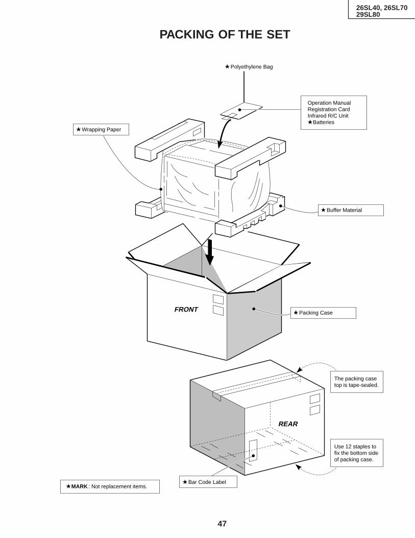
47
26SL40, 26SL7029SL80
Ref. No. Part No. Description Code Ref. No. Part No. Description CodePACKING OF THE SET
REAR
Use 12 staples tofix the bottom side of packing case.
Bar Code LabelMARK : Not replacement items.
FRONT
Buffer Material
Wrapping Paper
Polyethylene Bag
Operation ManualRegistration CardInfrared R/C Unit
Batteries
Packing Case
The packing case top is tape-sealed.

48
Ref. No. Part No. Description Code Ref. No. Part No. Description Code
26SL40, 26SL7029SL80
COPYRIGHT © 1999 BY SHARP CORPORATION
ALL RIGHTS RESERVED.
No part of this publication may be reproduced,stored in a retrieval system, or transmitted inany form or by any means, electronic, mechanical,photocopying, recording, or otherwise, withoutprior written permission of the publisher.
SHARP CORPORATIONAV Systems GroupQuality & Reliability Control CenterYaita, Tochigi 329-2193, Japan
TQ0695-SJul. 1999 Printed in Japan
SO. KG
Related Documents