BUDAPEST UNIVERSITY OF TECHNOLOGY AND ECONOMICS FACULTY OF MECHANICAL ENGINEERING DEPARTMENT OF POLYMER ENGINEERING SHAPE-CHANGING FIBRE-REINFORCED COMPOSITES ALAKVÁLTÓ SZÁLERŐSÍTÉSŰ KOMPOZITOK PHD THESIS AUTHOR: BRÚNÓ GYÖRGY VERMES MSC COMPOSITES ENGINEER SUPERVISOR: DR. TIBOR CZIGÁNY PROFESSOR - 2021 -

Welcome message from author
This document is posted to help you gain knowledge. Please leave a comment to let me know what you think about it! Share it to your friends and learn new things together.
Transcript
BUDAPEST UNIVERSITY OF TECHNOLOGY AND ECONOMICS
FACULTY OF MECHANICAL ENGINEERING
DEPARTMENT OF POLYMER ENGINEERING
SHAPE-CHANGING FIBRE-REINFORCED COMPOSITES
ALAKVÁLTÓ SZÁLERŐSÍTÉSŰ KOMPOZITOK
PHD THESIS
AUTHOR:
BRÚNÓ GYÖRGY VERMES
MSC COMPOSITES ENGINEER
SUPERVISOR:
DR. TIBOR CZIGÁNY
PROFESSOR
- 2021 -


Acknowledgements
I would first like to thank my supervisor, Prof. Tibor Czigány, for his invaluable
and always cheerful support since the day I started working with him as an
undergraduate.
For their help during my PhD studies, I am grateful to the colleagues of the
Department of Polymer Engineering, especially to its head – Dr. Tamás Bárány – and
its professors – Prof. József Karger-Kocsis†, Prof. Tibor Czvikovszky and Prof. László
M. Vas. My special gratitude goes to Prof. George (György) S. Springer and Prof.
Stephen W. Tsai from Stanford University for their outstanding hospitality and
professional guidance.
Finally, I would like to thank my family and friends for providing a balanced and
happy background.

I
TABLE OF CONTENTS
Table of symbols and abbreviations .......................................................................... III
1. Introduction ....................................................................................................... 1
2. Literature review ............................................................................................... 3
2.1. Morphing concepts ........................................................................................... 3
2.1.1. Electro-actuated shape adaptation .................................................................. 4
2.1.2. Shape adaptation actuated by heat, light, chemicals and pressure ................. 7
2.1.3. Mechanically actuated shape adaptation ...................................................... 11
2.2. Shape-changing composites .......................................................................... 13
2.2.1. Modelling of coupled composites .................................................................. 13
2.2.2. Morphing composites ................................................................................... 18
2.2.3. Warpage and bistability ................................................................................ 21
2.2.4. Exploitation of the warpage of composites .................................................... 24
2.2.5. Mitigation of the warpage of composites ...................................................... 25
2.2.6. A new direction in the design of composite laminates: double-double
layups ........................................................................................................... 27
2.3. Problem statement and the aims of the thesis ............................................ 29
3. Materials, methods and equipment .............................................................. 34
3.1. Materials ........................................................................................................... 34
3.2. Analytical and numerical analysis methods ............................................... 36
3.3. Composite manufacturing equipment ......................................................... 36
3.4. Composite testing equipment ....................................................................... 37
4. Design, investigation, results and discussion ............................................. 38
4.1. Development of the analytical layup optimizer algorithm ...................... 38
4.2. Preliminary investigations – mechanically induced shape-changing ..... 40
4.2.1. Analytical layup optimization of bend-twist composites ............................. 40
4.2.2. Numerical simulations ................................................................................. 43
4.2.3. Manufacturing and mechanical testing ....................................................... 45
4.2.4. Analytical, numerical and experimental results .......................................... 46
4.3. Thermally induced mechanical work of asymmetric laminates .............. 49
4.3.1. Determining the coefficients of thermal expansion ...................................... 49
4.3.2. Full-field search for the most significantly warping layup based on the
classical laminate theory .............................................................................. 51
4.3.3. Determination of the bifurcation point ........................................................ 54

II
4.3.4. Determination of the thermally induced mechanical work - simulations
and experiments ........................................................................................... 56
4.4. Warpage mitigation and shape-changing ................................................... 61
4.4.1. Warpage compensation by laminating on tools with curved surfaces ......... 62
4.4.2. Warpage mitigation and improved shape-changing via layup
hybridization ................................................................................................ 66
4.4.3. Layup homogenization ................................................................................. 74
4.5. The strength of double-double laminates ................................................... 82
5. Summary .......................................................................................................... 89
5.1. Summary in English ....................................................................................... 89
5.2. Summary in Hungarian ................................................................................. 91
5.3. Theses in English ............................................................................................ 94
5.4. Theses in Hungarian ...................................................................................... 99
5.5. Applicability .................................................................................................. 104
5.6. Future challenges .......................................................................................... 105
6. References ...................................................................................................... 107
7. Appendix ....................................................................................................... 120
III
TABLE OF SYMBOLS AND ABBREVIATIONS
Characters
Symbol Designation, note, value Unit
[A] extensional stiffness matrix GPa mm
[B] extensional-bending coupling stiffness matrix GPa mm2
[D] bending stiffness matrix GPa mm3
[a] extensional compliance matrix (GPa mm)-1
[b] extensional-bending coupling compliance matrix (GPa mm2)-1
[d] bending compliance matrix (GPa mm3)-1
[S] lamina compliance matrix GPa-1
[𝑄] lamina reduced stiffness matrix (material orientation) GPa
[�̅�] lamina stiffness matrix (structural orientation) GPa
E11 longitudinal Young’s modulus GPa
E22 transverse Young’s modulus GPa
G12 in-plane shear modulus GPa
ν12 longitudinal in-plane Poisson’s ratio -
ν21 transverse in-plane Poisson’s ratio -
A11 longitudinal stiffness GPa mm
A22 transverse stiffness GPa mm
A66 in-plane shear stiffness GPa mm
A12 Poisson coupling stiffness GPa mm
A16 longitudinal extension – in-plane shear coupling stiffness GPa mm
A26 transverse extension – in-plane shear coupling stiffness GPa mm
B11 longitudinal extension – longitudinal bending coupling
stiffness GPa mm2
B22 transverse extension – transverse bending coupling stiffness GPa mm2
B66 in-plane shear – twisting coupling stiffness GPa mm2
B12 longitudinal extension – transverse bending coupling
stiffness GPa mm2
B16 longitudinal extension – twisting coupling stiffness GPa mm2
B26 transverse extension – twisting coupling stiffness GPa mm2
D11 longitudinal bending stiffness GPa mm3
D22 transverse bending stiffness GPa mm3
D66 twisting stiffness GPa mm3
D12 longitudinal bending – transverse bending coupling
stiffness GPa mm3

IV
D16 longitudinal bending – twisting coupling stiffness GPa mm3
D26 transverse bending – twisting coupling stiffness GPa mm3
a11 longitudinal compliance (GPa mm)-1
a22 transverse compliance (GPa mm)-1
a66 in-plane shear compliance (GPa mm)-1
a12 Poisson coupling compliance (GPa mm)-1
a16 longitudinal extension – in-plane shear coupling compliance (GPa mm)-1
a26 transverse extension – in-plane shear coupling compliance (GPa mm)-1
b11 longitudinal extension – longitudinal bending coupling
compliance (GPa mm2)-1
b22 transverse extension – transverse bending coupling
compliance (GPa mm2)-1
b66 in-plane shear – twisting coupling compliance (GPa mm2)-1
b12 longitudinal extension – transverse bending coupling
compliance (GPa mm2)-1
b16 longitudinal extension – twisting coupling compliance (GPa mm2)-1
b26 transverse extension – twisting coupling compliance (GPa mm2)-1
b21 transverse extension – longitudinal bending coupling
compliance (GPa mm2)-1
b61 in-plane shear – longitudinal bending coupling compliance (GPa mm2)-1
b62 in-plane shear – transverse bending coupling compliance (GPa mm2)-1
d11 longitudinal bending compliance (GPa mm3)-1
d22 transverse bending compliance (GPa mm3)-1
d66 twisting compliance (GPa mm3)-1
d12 longitudinal bending – transverse bending coupling
compliance (GPa mm3)-1
d16 longitudinal bending – twisting coupling compliance (GPa mm3)-1
d26 transverse bending – twisting coupling compliance (GPa mm3)-1
S11 longitudinal compliance GPa-1
S22 transverse compliance GPa-1
S66 in-plane shear compliance GPa-1
S12 longitudinal – transverse coupling compliance GPa-1
Q11 longitudinal reduced stiffness GPa
Q22 transverse reduced stiffness GPa
Q66 in-plane shear reduced stiffness GPa
Q12 longitudinal – transverse coupling reduced stiffness GPa
T 3x3 transformation matrix (from material to structural
orientation) -
RR Reuter’s matrix -
V
�̅�11 longitudinal normal stiffness GPa
�̅�22 transverse normal stiffness GPa
�̅�66 in-plane shear stiffness GPa
�̅�12 longitudinal – transverse coupling stiffness GPa
�̅�16 longitudinal – shear coupling stiffness GPa
�̅�26 transverse – shear coupling stiffness GPa
Nxx longitudinal normal force per unit width kN/mm
Nyy transverse normal force per unit width kN/mm
Nxy in-plane shear force per unit width kN/mm
Mxx longitudinal bending moment per unit width kN
Myy transverse bending moment per unit width kN
Mxy twisting moment per unit width kN
NTxx thermal longitudinal normal force per unit width kN/mm
NTyy thermal transverse normal force per unit width kN/mm
NTxy thermal in-plane shear force per unit width kN/mm
MTxx thermal longitudinal bending moment per unit width kN
MTyy thermal transverse bending moment per unit width kN
MTxy thermal twisting moment per unit width kN
As ‘specially orthotropic’ A matrix -
Af fully populated A matrix -
Bs ‘specially orthotropic’ B matrix -
Bf fully populated B matrix -
Bl ‘leading diagonal’ B matrix -
Bt ‘transverse from diagonal’ B matrix -
Blt superposed B matrix from Bl and Bt -
Ds ‘specially orthotropic’ D matrix -
Df fully populated D matrix -
σxx longitudinal normal stress GPa
σyy transverse normal stress GPa
σzz out-of-plane (through-thickness) normal stress GPa
τxy in-plane shear stress GPa
τxz transverse shear stress in the xz plane GPa
τyz transverse shear stress in the yz plane GPa
εxx longitudinal normal strain -
εyy transverse normal strain -
εzz out-of-plane (through-thickness) normal strain -
ε0xx longitudinal normal strain of the mid-plane -
VI
ε0yy transverse normal strain of the mid-plane -
ε 0xy in-plane shear strain of the mid-plane -
γxy in-plane shear strain -
γxz transverse shear strain in the xz plane -
γyz transverse shear strain in the yz plane -
κxx longitudinal bending curvature mm-1
κyy transverse bending curvature mm-1
κxy twisting curvature mm-1
κ1princ. first principal curvature mm-1
κ2princ. second principal curvature mm-1
hk distance of the top of lamina(k) from the laminate mid-plane mm
hk-1 distance of the bottom of lamina(k) from the laminate mid-
plane mm
Tg glass transition temperature °C
Tm melting temperature °C
x max. longitudinal tensile strain (or longitudinal coordinate) - (or mm)
x’ max. longitudinal compression strain -
y max. transverse tensile strain (or transverse coordinate) - (or mm)
y’ max. transverse compression strain -
s max. shear strain -
z through-thickness coordinate mm
𝛼𝑥 longitudinal coefficient of thermal expansion °C-1
𝛼𝑦 transverse coefficient of thermal expansion °C-1
𝛼𝑥𝑦 shear coefficient of thermal expansion °C-1
R factor of safety -
Rnorm factor of safety normalized to unit thickness (1 mm) -
Rcontrol factor of safety of the controlling load -

VII
Abbreviations
Abbreviation Designation
CFRP carbon fibre–reinforced polymer
DC direct current
FEA finite element analysis
PZT lead-zirconate-titanate
EAP electroactive polymer
SMP shape memory polymer
SMA shape memory alloy
BGA Bucky gel actuator
PVC poly(vinyl-chloride)
CNT carbon nanotube
NIPA poly(N-isopropylacrylamide)
NiTi nickel-titanium (alloy)
UD unidirectional
CLT classical laminate theory
SDT shear deformation theory
FSDT first-order shear deformation theory
SSDT second-order shear deformation theory
TSDT third-order shear deformation theory
HOSDT higher-order shear deformation theory
GA genetic algorithm
FDM fused deposition modelling
DD double-double (layup)
MAV micro air vehicle
EFA elastic fluidic actuators


1
1. INTRODUCTION
The increasing trend in the research and industrial utilization of composites as
structural materials is most likely to continue in the future due to their outstanding
properties and still unexploited full potential. Composites consist of at least two
constituents with different primary functions: the matrix for binding, protection and
stress transfer and the embedded, usually fibrous reinforcement for strength and
stiffness. The most commonly used composite matrices are polymers (usually
thermoset), while the majority of the reinforcements are continuous fibres (e.g. glass
or carbon) for advanced structural performance [1]. While excellent specific
mechanical properties can be achieved in the primary loading directions, the weight
of composite parts can be significantly reduced by keeping the amount of
reinforcement low in the secondary, non-critical directions [2]. This combination of
outstanding mechanical properties and light weight is best utilized in industries where
both aspects are critical for operational efficiency (e.g. the aerospace [3, 4], automotive
[5, 6], wind-energy [7, 8], motorsport [9, 10] and sporting goods [11, 12] industries).
To exemplify the increasing importance of composites, Figure 1 illustrates the
trend of their usage in commercial aeroplanes. Twenty years ago, composites
accounted for less than 20% of the structural weight of commercial aeroplanes, which
has increased to about 50% in modern aircraft. Even if the rate of growth of the share
of composite parts slows down, the increasing number of modern aeroplanes will
require an increasing amount of composites.
Figure 1 The trend in structural composite usage in commercial aeroplanes (based on [13–15]). *The
latest official data available are for the Boeing 787 and the Airbus A350 aircraft. Unofficial
information from the commercial sector of the aerospace industry implies a plateauing of the trend
in the near future, partly due to supply chain challenges because of the Covid-19 pandemic.
Composites are mainly used for their specific mechanical properties, but their
value can be further increased by making them multifunctional. The essence of
multifunctionality is creating materials with more than one useful function. For
2
instance, a structural part can be endowed with additional self-healing [16] or
integrated health monitoring [17] features. However, there is a more fundamental type
of additional functionality that is intrinsically defined by the layup: the shape-
changing behaviour of the composite laminate. Materials respond to loads with
deformation, usually in the direction of the action (e.g. tensile, shearing, bending and
torsional deformations under corresponding loads). However, in some instances, a
non-conventional response could be more advantageous. For instance, a designed
amount of torsion of a bend–twist coupled aeroplane wing or an extension-twist
coupled turbine blade can result in a more efficient aerodynamic shape without the
need for any additional parts or motors. The principle of the morphing concept is the
same in any application—the utilization of non-conventional deformation as a
response to certain conditions during operation. Depending on the nature of the
deforming material, the possible means of actuation show a wide variety (e.g.
electricity [18], heat [19] or mechanical loads [20]); nevertheless, each approach aims
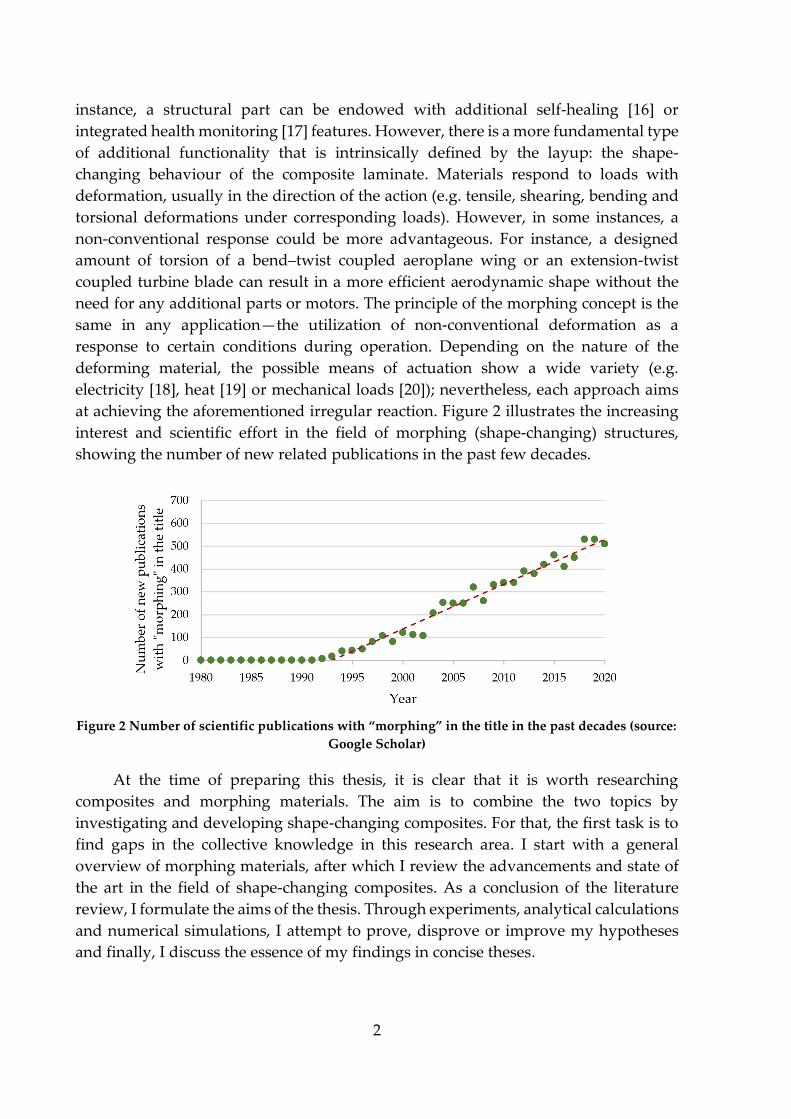
at achieving the aforementioned irregular reaction. Figure 2 illustrates the increasing
interest and scientific effort in the field of morphing (shape-changing) structures,
showing the number of new related publications in the past few decades.
Figure 2 Number of scientific publications with “morphing” in the title in the past decades (source:
Google Scholar)
At the time of preparing this thesis, it is clear that it is worth researching
composites and morphing materials. The aim is to combine the two topics by
investigating and developing shape-changing composites. For that, the first task is to
find gaps in the collective knowledge in this research area. I start with a general
overview of morphing materials, after which I review the advancements and state of
the art in the field of shape-changing composites. As a conclusion of the literature
review, I formulate the aims of the thesis. Through experiments, analytical calculations
and numerical simulations, I attempt to prove, disprove or improve my hypotheses
and finally, I discuss the essence of my findings in concise theses.
3
2. LITERATURE REVIEW
Making materials multifunctional by endowing them with additional features,
such as self-healing [21–23] or integrated health monitoring [24, 25] is one of the
greatest endeavours of today’s material science. The additional feature can also be a
special mechanical behaviour: morphing. Morphing materials can change their shape
non-conventionally, allowing us to design and manufacture structures that work more
efficiently than their conventional counterparts; therefore, their research and
development are of primary importance for the industry (e.g. the energy and
transportation industries). By definition, in this thesis, conventional deformations are
induced by loads of the same kind as the deformation itself (e.g. extension in response
to tensile loading or bending in response to bending moments). Hence, non-
conventional deformations are induced by different loads (e.g. bending in response to
tensile loading or twisting in response to bending moments) or actuated by means
other than mechanical loading (e.g. deformation to electricity, heat, pressure, etc.)
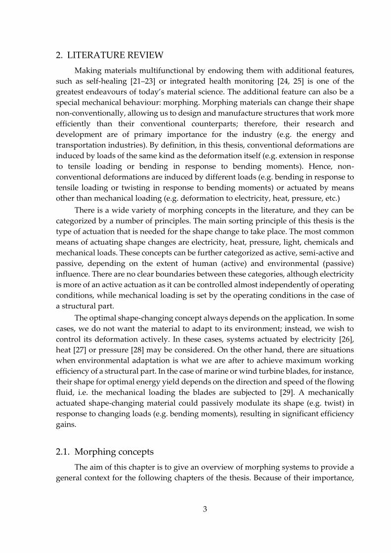
There is a wide variety of morphing concepts in the literature, and they can be
categorized by a number of principles. The main sorting principle of this thesis is the
type of actuation that is needed for the shape change to take place. The most common
means of actuating shape changes are electricity, heat, pressure, light, chemicals and
mechanical loads. These concepts can be further categorized as active, semi-active and
passive, depending on the extent of human (active) and environmental (passive)
influence. There are no clear boundaries between these categories, although electricity
is more of an active actuation as it can be controlled almost independently of operating
conditions, while mechanical loading is set by the operating conditions in the case of
a structural part.
The optimal shape-changing concept always depends on the application. In some
cases, we do not want the material to adapt to its environment; instead, we wish to
control its deformation actively. In these cases, systems actuated by electricity [26],
heat [27] or pressure [28] may be considered. On the other hand, there are situations
when environmental adaptation is what we are after to achieve maximum working
efficiency of a structural part. In the case of marine or wind turbine blades, for instance,
their shape for optimal energy yield depends on the direction and speed of the flowing
fluid, i.e. the mechanical loading the blades are subjected to [29]. A mechanically
actuated shape-changing material could passively modulate its shape (e.g. twist) in
response to changing loads (e.g. bending moments), resulting in significant efficiency
gains.
2.1. Morphing concepts
The aim of this chapter is to give an overview of morphing systems to provide a
general context for the following chapters of the thesis. Because of their importance,

4
shape-changing composite laminates are discussed separately in Chapter 2.2. in more
detail.
2.1.1. Electro-actuated shape adaptation
Electro-actuated shape adaptation is defined as the controlled deformation or
resistance to deformation of the material or structure in response to an applied electric
potential difference. Electricity can be controlled relatively easily independently of
environmental conditions and can be exploited to actuate non-conventional
deformations in various ways. It can power electromotors, piezoelectric materials and
other electrosensitive materials. Due to this diversity, there is an extensive literature
on electro-actuated systems. This section discusses some selected concepts.
Electric motors are widely used in industries like the transportation or the
aerospace industry, although seldom for morphing applications. The aerospace
industry shows the greatest interest in motor-actuated morphing concepts. In a broad
sense, conventional wing flaps are morphing structures themselves; however, there
are concepts where the triggered deformation is less evident. Garcia et al. [30], for
instance, designed a micro air vehicle (MAV) in which torque rods - placed along the
flexible membrane wings and connected to a servo motor - were responsible for control
authority by operating roll manoeuvres (Figure 3).
Figure 3 Motor actuated twist morphing of a prototype. a) undeformed wing, b) twisted wing [30]
Stanford et al. [31] investigated a similar structure with asymmetric twisting of the
wings with the addition of numerical (static structural and aerodynamic) modelling
and genetic algorithm–based optimization. With these tools, they developed a design
that showed significantly improved roll rate and lift-to-drag ratio compared to their
baseline design, highlighting the importance of computer-aided optimization, even in
the case of simple mechanism–actuated systems. Ahmed et al. [32] introduced an
aerodynamic optimization process to find the optimal anti-symmetric wing twist
distribution of an MAV to achieve improved roll performance together with a low
level of produced drag. Motors can be used to achieve deformations other than
twisting, too. Boria et al. [33] used genetic algorithm–based hardware-in-the-loop
5
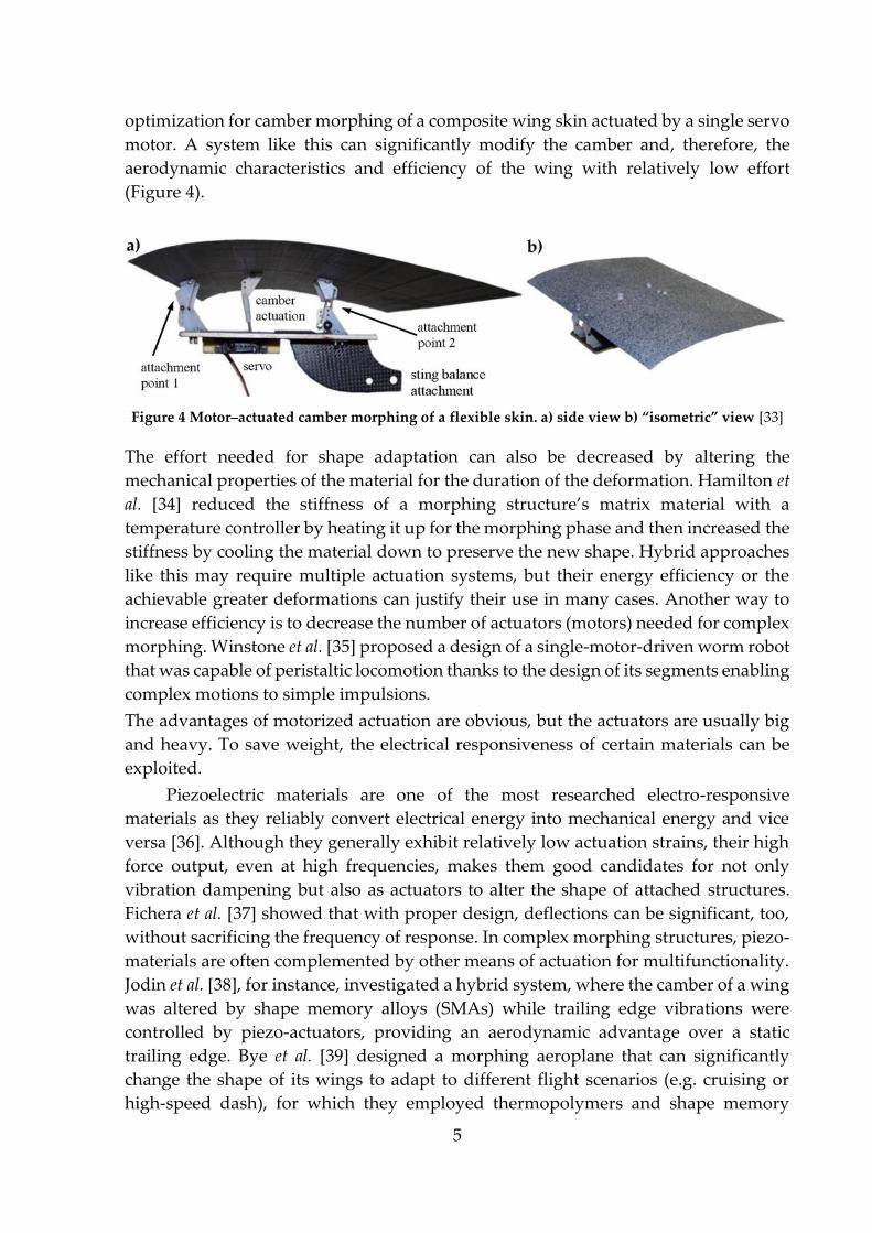
optimization for camber morphing of a composite wing skin actuated by a single servo
motor. A system like this can significantly modify the camber and, therefore, the
aerodynamic characteristics and efficiency of the wing with relatively low effort
(Figure 4).
Figure 4 Motor–actuated camber morphing of a flexible skin. a) side view b) “isometric” view [33]
The effort needed for shape adaptation can also be decreased by altering the
mechanical properties of the material for the duration of the deformation. Hamilton et
al. [34] reduced the stiffness of a morphing structure’s matrix material with a
temperature controller by heating it up for the morphing phase and then increased the
stiffness by cooling the material down to preserve the new shape. Hybrid approaches
like this may require multiple actuation systems, but their energy efficiency or the
achievable greater deformations can justify their use in many cases. Another way to
increase efficiency is to decrease the number of actuators (motors) needed for complex
morphing. Winstone et al. [35] proposed a design of a single-motor-driven worm robot
that was capable of peristaltic locomotion thanks to the design of its segments enabling
complex motions to simple impulsions.
The advantages of motorized actuation are obvious, but the actuators are usually big
and heavy. To save weight, the electrical responsiveness of certain materials can be
exploited.
Piezoelectric materials are one of the most researched electro-responsive
materials as they reliably convert electrical energy into mechanical energy and vice
versa [36]. Although they generally exhibit relatively low actuation strains, their high
force output, even at high frequencies, makes them good candidates for not only
vibration dampening but also as actuators to alter the shape of attached structures.
Fichera et al. [37] showed that with proper design, deflections can be significant, too,
without sacrificing the frequency of response. In complex morphing structures, piezo-
materials are often complemented by other means of actuation for multifunctionality.
Jodin et al. [38], for instance, investigated a hybrid system, where the camber of a wing
was altered by shape memory alloys (SMAs) while trailing edge vibrations were
controlled by piezo-actuators, providing an aerodynamic advantage over a static
trailing edge. Bye et al. [39] designed a morphing aeroplane that can significantly
change the shape of its wings to adapt to different flight scenarios (e.g. cruising or
high-speed dash), for which they employed thermopolymers and shape memory
6
polymers (SMPs) besides piezo-actuators. Nabawy et al. [40, 41] developed a
comprehensive analytical model to provide a mapping between force, displacement,
charge and voltage for piezoelectric actuators. They also validated the model with
experimental results. The significance of their work lies in making the performance of
piezoelectric actuators predictable in dynamic operations.
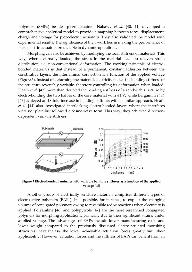
Morphing can also be achieved by modifying the local stiffness of materials. This
way, when externally loaded, the stress in the material leads to uneven strain
distribution, i.e. non-conventional deformation. The working principle of electro-
bonded materials is that instead of a permanent, constant adhesion between the
constitutive layers, the interlaminar connection is a function of the applied voltage
(Figure 5). Instead of deforming the material, electricity makes the bending stiffness of
the structure reversibly variable, therefore controlling its deformation when loaded.
Heath et al. [42] more than doubled the bending stiffness of a sandwich structure by
electro-bonding the two halves of the core material with 4 kV, while Bergamini et al.
[43] achieved an 18-fold increase in bending stiffness with a similar approach. Heath
et al. [44] also investigated interlocking electro-bonded layers where the interfaces
were not plain but followed a cosine wave form. This way, they achieved direction-
dependent variable stiffness.
Figure 5 Electro-bonded laminates with variable bending stiffness as a function of the applied
voltage [45]
Another group of electrically sensitive materials comprises different types of
electroactive polymers (EAPs). It is possible, for instance, to exploit the changing
volume of conjugated polymers owing to reversible redox reactions when electricity is
applied. Polyaniline [46] and polypyrrole [47] are the most researched conjugated
polymers for morphing applications, primarily due to their significant strains under
applied voltage. The advantages of EAPs include lower manufacturing costs and
lower weight compared to the previously discussed electro-actuated morphing
structures; nevertheless, the lower achievable actuation forces greatly limit their
applicability. However, actuation forces and the stiffness of EAPs can benefit from an

7
embedded percolating carbon nanotube (CNT) system, which reduces the limitations
of the concept [46, 48].
Not only solid-state materials can demonstrate deformation in response to
applied electricity, but gels and fluids, too. Ionic gels can usually deform (bend)
significantly in response to low actuation voltages due to counter-ion osmotic
pressure. Various types of ionic gels exist, but Bucky-gels are among the most
advanced ones as they can operate without an external ionic solution. In response to
voltage, anions and cations from the internal polymeric electrolyte film separate and
move towards the opposite electrodes. As the two different ions differ in size too, they
occupy unequal space near the outer layers leading to the bending of the material
(Figure 6) [26]. A limitation of the concept is the back-relaxation even when voltage is
maintained [49]. Electrorheological fluids can change their viscosity in response to
applied electricity by forming oriented chains of dielectric particles in an insulating
fluid. The applications of electrorheological fluids vary from stroke rehabilitation
robots in medicine [50] to active suspension systems in transportation [51].
Figure 6 Bucky gel working scheme [26]
In this chapter, I showed that electrically actuated shape-changing can be
achieved in various ways. Each approach has its advantages and limitations, and
selecting the optimal solution is always an application-specific task. In the next
chapter, I discuss morphing systems that are at least partly controlled by
environmental conditions.
2.1.2. Shape adaptation actuated by heat, light, chemicals and pressure
The simplest thermally actuated morphing materials exploit thermal expansion.
Bimetals, for instance, consist of two different metals attached. As the coefficients of
thermal expansion of the two metals differ, the two halves of the bimetal elongate at
8
different rates in response to heat, which leads to the bending of the structure. Pre-
buckled bimetals can even be used as heat engines due to their thermo-mechanical
instability (snap-through energy release) [52, 53].
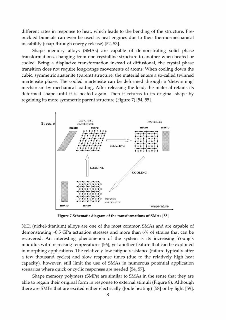
Shape memory alloys (SMAs) are capable of demonstrating solid phase
transformations, changing from one crystalline structure to another when heated or
cooled. Being a displacive transformation instead of diffusional, the crystal phase
transition does not require long-range movements of atoms. When cooling down the
cubic, symmetric austenite (parent) structure, the material enters a so-called twinned
martensite phase. The cooled martensite can be deformed through a ‘detwinning’
mechanism by mechanical loading. After releasing the load, the material retains its
deformed shape until it is heated again. Then it returns to its original shape by
regaining its more symmetric parent structure (Figure 7) [54, 55].
Figure 7 Schematic diagram of the transformations of SMAs [55]
NiTi (nickel-titanium) alloys are one of the most common SMAs and are capable of
demonstrating ~0.5 GPa actuation stresses and more than 6% of strains that can be
recovered. An interesting phenomenon of the system is its increasing Young’s
modulus with increasing temperatures [56], yet another feature that can be exploited
in morphing applications. The relatively low fatigue resistance (failure typically after
a few thousand cycles) and slow response times (due to the relatively high heat
capacity), however, still limit the use of SMAs in numerous potential application
scenarios where quick or cyclic responses are needed [54, 57].
Shape memory polymers (SMPs) are similar to SMAs in the sense that they are
able to regain their original form in response to external stimuli (Figure 8). Although
there are SMPs that are excited either electrically (Joule heating) [58] or by light [59],
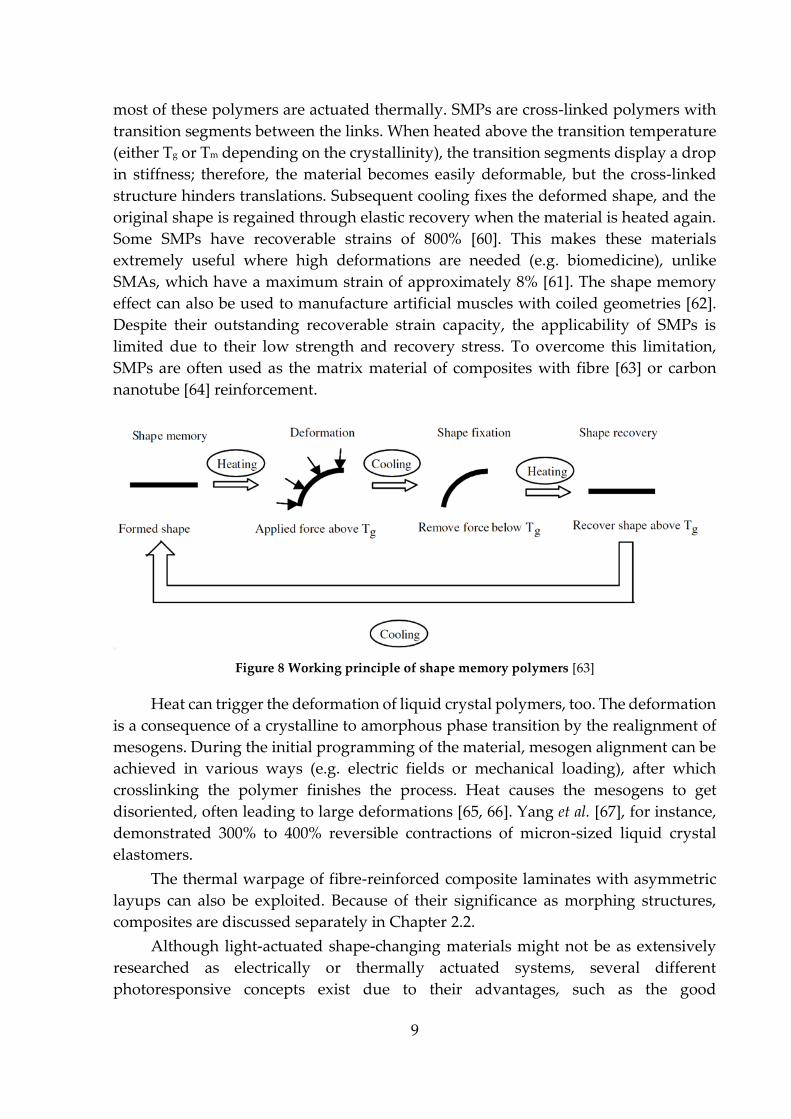
9
most of these polymers are actuated thermally. SMPs are cross-linked polymers with
transition segments between the links. When heated above the transition temperature
(either Tg or Tm depending on the crystallinity), the transition segments display a drop
in stiffness; therefore, the material becomes easily deformable, but the cross-linked
structure hinders translations. Subsequent cooling fixes the deformed shape, and the
original shape is regained through elastic recovery when the material is heated again.
Some SMPs have recoverable strains of 800% [60]. This makes these materials
extremely useful where high deformations are needed (e.g. biomedicine), unlike
SMAs, which have a maximum strain of approximately 8% [61]. The shape memory
effect can also be used to manufacture artificial muscles with coiled geometries [62].
Despite their outstanding recoverable strain capacity, the applicability of SMPs is
limited due to their low strength and recovery stress. To overcome this limitation,
SMPs are often used as the matrix material of composites with fibre [63] or carbon
nanotube [64] reinforcement.
Figure 8 Working principle of shape memory polymers [63]
Heat can trigger the deformation of liquid crystal polymers, too. The deformation
is a consequence of a crystalline to amorphous phase transition by the realignment of
mesogens. During the initial programming of the material, mesogen alignment can be
achieved in various ways (e.g. electric fields or mechanical loading), after which
crosslinking the polymer finishes the process. Heat causes the mesogens to get
disoriented, often leading to large deformations [65, 66]. Yang et al. [67], for instance,
demonstrated 300% to 400% reversible contractions of micron-sized liquid crystal
elastomers.
The thermal warpage of fibre-reinforced composite laminates with asymmetric
layups can also be exploited. Because of their significance as morphing structures,
composites are discussed separately in Chapter 2.2.
Although light-actuated shape-changing materials might not be as extensively
researched as electrically or thermally actuated systems, several different
photoresponsive concepts exist due to their advantages, such as the good
10
controllability and focusability of the actuating light. Some SMPs [59, 68] and liquid
crystal polymers [69] can be actuated by light. Most of these actuators are thin films
showing bending deformations. This is due to the primarily superficial effect of the
light that contracts the outer layer causing the film to bend. These actuators are
relatively easy and inexpensive to manufacture, but their thermal instability and often
slow response times limited their applicability for a long time [69]. Recently, however,
Zeng et al. [70] demonstrated a photoactive liquid crystal polymer with a response
frequency of almost 2000 Hz, overcoming one of the main limitations. Photoresponsive
gels exist too, but they are often actuated through photothermal effects rather than
purely by light. Wei and Yu [71] achieved a photo-actuated contraction of 70% of a
thermally sensitive hydrogel. However, that change in volume took approximately 60
minutes, showing one of the main disadvantages of the majority of these materials
once again.
Morphing behaviour can be actuated by chemicals, too. An example concept uses
water as the chemical and builds on the biomimetics of the sea cucumber dermis. It is
possible to manufacture a nanocomposite system that consists of percolating
nanofibers with hydrogen bonds between them, making the structure stiff. However,
when water is added, the structure loses the majority of its stiffness due to the
competitive bonding effect where water–fibre bonds prove to be stronger than fibre–
fibre bonds [72, 73]. This way, water can significantly influence the local stiffness and,
therefore, the shape-changing capability of the structure.
Pressure is most commonly used for actuation in the conventional piston-
cylinder setup. Depending on the pressurized medium, pressure-actuated systems are
usually categorized into two groups: pneumatic (compressible fluid) and hydraulic
(practically uncompressible fluid). Although the microscaling of these systems is a
challenge due to the required low-friction micro-seals, piston-cylinder microactuators
do exist [74]. Numerous other pressure-actuated concepts have been proposed in the
past decades. Most of them can be categorized into a group called elastic fluidic
actuators (EFAs). EFAs can be further divided into sub-categories such as membrane
[75], balloon [76] and bellow [77] types and artificial muscles [78], of which the first
two types are the most common. EFAs can extend/contract [79], bend [80], twist [81],
or even grab objects [82] when pressurized, depending on the design of the actuator.
Gorissen et al. [80], for instance, achieved large bending deflections of an elastic
cylinder with a pressurizable eccentric inner void going along its length. The simple
working principle is that the line of action of the applied force is offset from the neutral
axis of the cylinder when the internal void is pressurized, leading to bending moments
and, therefore, to the deflection of the structure.
In this chapter, I reviewed morphing concepts with the most common types of
actuation other than electricity and mechanical loading. The next chapter briefly
discusses mechanically actuated morphing systems.

11
2.1.3. Mechanically actuated shape adaptation
A typical limitation of mechanically actuated morphing systems is that the
deformations are usually difficult to control independently of the working conditions,
especially in the case of structural parts that are inevitably under mechanical loads
during their operation. On the other hand, this “passive” actuation approach can be
extremely advantageous when the operational mechanical loads are predictable, and
the optimal shapes to the various loading scenarios are known. For instance, the
optimal angle of attack of a wind turbine blade changes as a function of wind speed
[83]. A morphing blade could significantly increase energy efficiency by twisting the
right amount in response to the increasing aerodynamic (bending) load.
The mechanical behaviour of a structure is greatly dependent on its internal
architecture. Certain built-in mechanisms are capable of altering this architecture;
therefore, they can modify the mechanical characteristics of the whole structure. Ajaj
et al. [84, 85], for instance, developed and analysed a wing box with adjustable torsional
stiffness. Its resistance to torsion can be tuned by moving the span-wise front and rear
spar webs closer to or further from each other. Greater distances between the webs
lead to increased torsional stiffness. As the distance decreases, the aerodynamic loads
cause greater twists of the wing box due to the reduction of the cross-sectional area
between the webs (Figure 9).
Figure 9 Internal mechanism based variable torsional stiffness wing box – cross-sectional view. a)
maximum torsional stiffness web positions, b) minimum torsional stiffness web positions (based
on [85])
Runge et al. [86, 87] proposed a different solution to achieve torsional control of
a wing box. They introduced longitudinal spars cut into upper and lower halves
(instead of conventional single piece spars) so that the halves could slide on each other
in the longitudinal (spar-wise) direction. For controlled sliding of the spars, the
authors developed a clutch-like internal mechanism. One of the advantages of the
concept is that it exploits the external loads (e.g. lift) to achieve the desired
deformation, which makes it an energy-efficient morphing solution. The external loads
make the spar halves slide on each other due to the induced internal shear stresses,
and the clutch clamps the halves together when the desired torsion of the wing box is
achieved. With several individually controllable spar–clutch systems within a single
wing box, complex torsional morphing can be achieved.
The majority of the mechanically actuated shape-changing concepts utilize the
orthotropy of fibre-reinforced composite laminates. Shape-changing composites are

12
discussed in Chapter 2.2. in more detail, due to their outstanding industrial value and
potential as morphing systems.
In Figure 10, I summarize the main shape-changing approaches in the literature,
categorizing them based on the principle of their actuation.
Figure 10 Summary of the main morphing concepts categorized by their actuation
Coupled composite laminates have a few key advantages over the majority of the
discussed morphing concepts. Firstly, they can be actuated both mechanically and
thermally (and even electrically by Joule-heating carbon fibres). Secondly, composites
demonstrate non-conventional shape changes due to their intrinsic layup structure, so
there is no need for any additional actuator, which makes the structure simple, reliable
and light. And finally, the outstanding specific mechanical properties of composites
(e.g. strength and stiffness) allows us to use them as load-bearing primary structural
elements. The combination of these advantages makes coupled composites uniquely
13
valuable in the industry. Because of their potential, this thesis focuses on the
investigation and development of shape-changing composites.
2.2. Shape-changing composites
The individual unidirectionally reinforced (UD) plies of composites are
orthotropic, meaning that both their mechanical and thermal behaviour differ in the
three mutually perpendicular (primary) planes. However, the behaviour of UD plies
is usually approximated with transversely isotropic behaviour, where one of the
mutually perpendicular planes is an isotropy plane. Assuming identical behaviour in
the transverse and through-thickness directions of UD plies reduces the number of
required independent material constants. In a symmetric layup, the laminate is
mirrored to its mid-plane regarding the number of plies, their sequence, orientation
and material properties. When these conditions of symmetry are fulfilled, an initially
flat laminate remains flat under thermal loads and in-plane mechanical loads because
out-of-plane stresses cancel each other out. This intrinsic resistance to warpage is the
main reason why the composites industry almost exclusively uses symmetric
laminates. Symmetric layups can still allow for some coupled behaviour (e.g.
extension–shear or bend–twist coupling); however, asymmetric laminates can be more
advantageous for shape-changing applications due to their often significant in-plane–
out-of-plane couplings. It is the coupled behaviour of laminates that can be exploited
when designing shape-changing composites.
I start the following sub-chapters by discussing how the elastic behaviour of
composite laminates can be modelled, which is essential for understanding and
optimizing their shape-changing behaviour. Then, I show what the scientific
community has already achieved in the field of shape-changing composites by
presenting the essence of relevant publications. In the last sub-chapter, I introduce the
literary background of a novel layup design method that utilizes layup asymmetry,
similar to the majority of shape-changing laminates. Based on my literature review, I
highlight the main challenges in the field and formulate the aims of the thesis.
2.2.1. Modelling of coupled composites
The choice between different analytical and numerical models usually comes
down to the accuracy to solution time ratio. Analytical models tend to be quicker to
solve; however, their simplifying assumptions eventually affect their accuracy.
Numerical analyses (such as finite element analyses) are especially useful for more
complex problems (e.g. complex geometries, boundary conditions, non-linearities,
etc.). In fact, numerous problems do not have an analytical solution and can only be
solved numerically. The results still need to be validated, but reality can be
approximated with reasonable accuracy for the most part. On the other hand, a finite
element analysis usually requires significantly more computational power than an
14
analytical solution, therefore choosing the right modelling approach is always a
problem-specific task. The best solution is often a combination of the two approaches,
where analytical methods are used for the initial design steps and numerical methods
for the final design.
For laminated composites, the fundamental analytical model is the classical
laminate theory (CLT). Several extensions to the theory have been introduced to
improve the accuracy of the original model; nevertheless, CLT has proven to be a
valuable and reliable tool for initial composites design. Even finite element methods
build on CLT (or one of its extensions) by breaking down the continuum to a finite
number of elements and solving the constitutive equations for the nodal points of each
element. Furthermore, both the analytical and the numerical methods can be used to
optimize an entire layup [88, 89].
As the classical laminate theory establishes the fundamental macromechanical
constitutive equations for laminated composites, it is the model I discuss in more
detail. The analytical method does not take the micromechanics of individual laminae
into consideration; instead, it models the laminate as a set of stacked homogeneous
plies. The theory also assumes linear-elastic mechanical behaviour of the material,
which, although not accurate at large deformations, is still a reasonable approximation
at low to moderate deformations in most cases. As for the next simplification, the
assumption of perfect bonding between the plies means that the strain field is
continuous even through-thickness. However, the continuity of the stress field can be
interrupted at ply boundaries where the mechanical properties or the orientation of
the neighbouring laminae differ. Furthermore, CLT simplifies the realistic 3D stress
state of loaded structures with plane stress state, meaning that interlaminar (through-
thickness) stresses are neglected, therefore 3 of the 6 distinct terms of the symmetric
Cauchy stress tensor ‘disappear’. Another result of the plane stress state is the
fulfilment of the Kirchhoff-Love plate theory, meaning that cross-sections remain
plane and perpendicular to the laminate mid-surface even after out-of-plane
deformations of the material. Plane stress state might seem like an oversimplification,
but if the laminate is thin and long/wide enough at the same time (which is true for
most practical composite structures), it is a sensible assumption and approximates
reality well (in the linear-elastic region). Even though the aforementioned assumptions
are grounded and sensible, they still limit the accuracy of CLT results. On the other
hand, however, it is these simplifications that make CLT a quick and powerful
analytical tool that provides comprehensive constitutive relations with only a few
inputs.
To calculate the (reduced) stiffness matrix of a single – specially orthotropic – ply in
the material direction, only 4 input parameters are required: longitudinal Young’s
modulus (E11), transverse Young’s modulus (E22), in-plane shear modulus (G12) and in-
plane Poisson’s ratio (ν12). These parameters are either calculated from
micromechanical equations or measured experimentally. To take the difference
between material and structural directions into account, the stiffness matrix of each

15
ply is transformed into the structural direction. This results in a set of generally
orthotropic laminae that can be assembled to form a laminate. Knowing the thickness
of each ply and their distance from the laminate’s mid-plane, the so-called A, B and D
matrices for the whole laminate can be calculated from the stiffness matrices of the
individual plies. The 6x6 ABD matrix (Figure 11) shows the relations between loads
(forces per unit width and moments per unit width) and deformations (mid-plane
strains and curvatures). I included a more detailed but still concise derivation of CLT
in the Appendix [1, 90–92].
Figure 11 The fundamental ABD matrix equation of the classical laminate theory (based on [1])
Within the assumptions of CLT, the A, B and D matrices are symmetric to their
main diagonal, meaning that a total of 18 ‘stiffness’ terms describe the mechanical
behaviour of the laminate. The terms in the A matrix quantify the coupling relations
between in-plane strains and loads (extensional stiffness matrix), while similarly, the
terms in the D matrix quantify the coupling relations between out-of-plane strains and
loads (bending stiffness matrix). The B matrix establishes the coupling relations
between in-plane strains and out-of-plane loads and vice versa (extension-bending
coupling matrix). If all the strains and the full ABD matrix is known, it is possible to
calculate all the stress resultants, whereas if the loads are known, one needs the
inverse-ABD matrix to obtain strains and curvatures [93].
The coupling terms determine non-conventional shape-changing characteristics, and
apart from the main diagonal of the 6x6 matrix, each ABD term represents a specific
coupled behaviour. A12 is the Poisson coupling, A16 and A26 are extension–shear
couplings, D12 is the longitudinal–transverse bending coupling, D16 and D26 are bend–
twist couplings, and each term in the B matrix represents a coupling between in-plane
strains and out-of-plane stress resultants (or curvatures and in-plane stress resultants),
according to the rules of matrix multiplication [1].
16
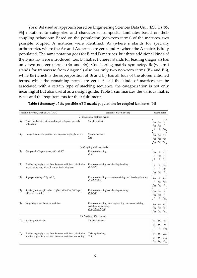
York [94] used an approach based on Engineering Sciences Data Unit (ESDU) [95,
96] notations to categorize and characterize composite laminates based on their
coupling behaviour. Based on the population (non-zero terms) of the matrices, two
possible coupled A matrices were identified: As (where s stands for specially
orthotropic), where the A16 and A26 terms are zero, and Af where the A matrix is fully
populated. The same notation goes for B and D matrices, but three additional kinds of
the B matrix were introduced, too. Bl matrix (where l stands for leading diagonal) has
only two non-zero terms (B11 and B22). Considering matrix symmetry, Bt (where t
stands for transverse from diagonal) also has only two non-zero terms (B16 and B26),
while Blt (which is the superposition of Bl and Bt) has all four of the aforementioned
terms, while the remaining terms are zero. As all the kinds of matrices can be
associated with a certain type of stacking sequence, the categorization is not only
meaningful but also useful as a design guide. Table 1 summarizes the various matrix
types and the requirements for their fulfilment.
Table 1 Summary of the possible ABD matrix populations for coupled laminates [94]

17
York [97–99] also published individual papers dedicated to extensional,
extensional-bending and bending couplings, analysing numerous stacking sequences
with ply numbers up to 21. From a practical point of view, he found—amongst
others—that bend–twist coupling has no additional benefits over simple extension–
shear couplings in certain scenarios where complex geometry can be exploited (e.g. for
wind turbine blades). York also showed that symmetry and balance are not
requirements for an uncoupled laminate and that some coupled laminates can be
hygrothermally curvature-stable, too [100, 101]. Although York’s analysis of coupled
laminates is considerably extensive, the results are only analytical and based on the
Classical Laminate Theory, which is known to be a simplified model of the actual
behaviour of laminates. To assess the accuracy of a model, the results have to be
compared to either numerical or—even better—experimental data.
Similarly to most models, the accuracy of CLT depends on the particular
problem. For simple problems (e.g. simple geometry, loading, etc.), CLT results
usually approach finite element [102] or experimental results [103] closely (i.e. error
within a few percent). Casavola et al. [104] even showed that the theory could be used
to an extent to predict the mechanical behaviour of specimens manufactured with
fused deposition modelling (FDM) because the layerwise oriented macrostructure
shows similar characteristics to composites. However, CLT was found not to be always
accurate for predicting room-temperature shapes of asymmetric laminates [105] or
analysing thick or discontinuous laminates [106]. Although the accuracy of CLT has
not been explicitly assessed for non-conventionally shape-changing composites in the
literature, the conclusions of the previous papers imply a reasonable accuracy at low
to moderate deformations of thin laminates and limited accuracy at large deformations
and relative thickness or low transverse shear modulus.
Shear deformation theories (SDTs) aim at better accuracy than CLT by modifying
one of its main assumptions. Even the simplest SDT, the first-order shear deformation
theory (FSDT), takes transverse shear into account. The accuracy of FSDT depends on
the problem and the shear correction factors [88, 107]. However, as there is no coupling
between the ABD matrix and the transverse shear matrix, one can not readily obtain
obvious benefits over CLT when predicting non-conventional shape changes [1].
Several modifications to FSDT have been introduced either to improve its accuracy
without the need for higher-order (and therefore more complex) functions or to make
it easier to solve without sacrificing fidelity. “Simple FSDTs”, for instance, are four-
variable theories capable of providing results reasonably close to the results of
conventional FSDTs in certain scenarios such as static bending or free vibration of
plates [108, 109].
To assess the transverse stress behaviour of – mainly “thick” – composite
laminates more accurately, higher-order shear deformation theories (HOSDTs) are in
use. With more or less success, these theories can handle the realistic, non-linear
through-thickness shear stress in the laminate. Although second-order shear
deformation theories (SSDTs) have been used to predict the mechanical behaviour of

18
composites, too (such as for free vibrations [110]), the majority of related papers have
been focusing on third-order theories (TSDTs) for improved accuracy. Aagaah et al.
[111], for instance, found TSDT to be significantly more accurate than FSDT and
especially CLT when predicting natural frequencies of square laminates, but again,
accuracy is greatly dependent on the nature of the problem. For hygro-thermo-
mechanical loading, Zidi et al. [112] compared CLT, FSDT, SSDT and TSDT results as
well as the results of their own refined plate theory for functionally graded materials.
Shear deformation theories gave similar predictions for the most part, while CLT was
almost always a few percent off. The advantage of their method was the decreased
amount of unknown functions (from 5 to 4) compared to the SDTs. That being said,
CLT is still easier to solve, and its error can be justified in most cases when compared
to conventional or advanced SDTs. There are further HOSDTs (e.g. trigonometric shear
deformation theories [113, 114]), but even those models have limitations. These
limitations mainly originate from the simplified modelling approach of considering
the whole laminate as “single-layer”.
So-called layerwise theories can provide results that approach experimental and
numerical results better by taking each individual ply into account separately and then
solving the compatibility and equilibrium relations at the ply boundaries (i.e.
continuous transverse stresses) [88]. Fares et al. [103] showed the superior accuracy of
layerwise theories compared to single-layer theories; however, computational weight
is a major disadvantage in most cases. Although there have been attempts to decrease
the number of unknowns of layerwise theories (e.g. by Cho and Parmertert [115]), the
computational weight usually dramatically increases with the number of plies, greatly
influencing usability [88].
Besides plate theories, composites can also be modelled using beam theories [116,
117]. In certain situations, composite beam theories can be more advantageous than
plate theories (e.g. coupling can be achieved by strategically placing the plate elements
in the cross-section). However, because of their universality, I focus on plates and
shape-changing behaviour resulting from the layup structure of those plates.
This chapter gave a brief overview of the main modelling methods while
discussing their strengths and weaknesses to help engineers decide which model (if
any) can be used to analyse the non-conventional behaviour of composites. Based on
the literature results, I use the classical laminate theory for the analytical calculations
in this thesis. Its computational lightweight and straightforward interpretability of the
coupling terms outweigh its limited accuracy during an extensive layup optimization
study of shape-changing composites. Numerical and experimental investigations
counterweigh the limited accuracy of the analytical approach.
2.2.2. Morphing composites
In this chapter, I briefly present some of the main results of the literature that
have been achieved by developing and investigating shape-changing composites.
19
Although laminates can be coupled in many ways, most publications investigate either
bend-twist or extension-twist coupled laminates. This is mainly due to the useful
applications of these shape-changing characteristics in structures, such as propeller
blades. However, it has also been shown that bend-twist behaviour can be achieved
by strategically placing extension-shear coupled laminates in structures, such as wing
boxes [118, 119].
Herath et al. [120] optimised the layup of shape-adaptive marine propellers with
a coupled genetic algorithm (GA) and smoothed finite element modelling methods
(CFRP, layer thickness 100-250 µm, 20-50 layers). The GA was used to determine the
ply orientations for the bend-twist coupling of the composite, while the deflection and
pitch of the loaded propeller were checked by finite element analysis (FEA).
Depending on the number, the thickness and the orientation increment of the plies, the
authors came up with a set of optimum layups for bend-twist performance, all
symmetric to the mid-plane to prevent warpage.
Murray et al. [121] also investigated bend-twist coupled composites with symmetric
layups. They tested cantilever plates because they found that the main applications of
bend-twist coupled composites are either wind, tidal or marine blades that are fixed at
one end. Analytical (CLT) calculations showed that plies with 30° bias lead to the most
significant twisting deformation under bending load; however, for better load-
carrying capability, they investigated a [30/0/30] layup built from UD carbon-epoxy
plies. For the numerical simulations, the 500 mm x 200 mm cantilever laminate was
modelled with 2D shell elements. An applied 25 N point bending load in the middle
of the loaded edge, which resulted in a maximum tip displacement of about 110 mm,
twisted the edge by more than 10°. The video-assisted experimental validation showed
good agreement with the numerical results. The authors also investigated the effect of
ply thickness, material properties and angle variation on the shape-changing
behaviour. Most notably, they found that a 5% difference in ply orientations (i.e. 28.5°
and 31.5° instead of 30° plies) resulted in a significant 6% change in displacements but
did not affect the twisting performance significantly. Based on one of the figures in the
paper, similar differences in ply orientation would have resulted in more significant
changes in the twisting performance, too, further away from the optimal 30°. As a
critical closing remark, the authors concluded that ply thickness, material properties
and orientations have coupled effects on the deformation of the laminates, therefore
investigating them separately only showed half of the picture.
To assess some of the real-world advantages of shape-changing laminates, Nicholls-
Lee et al. [122] simulated the hydroelastic behaviour of a bend-twist coupled tidal
turbine blade. They demonstrated a 5% improvement in the power capture (efficiency)
of the passively shape-adaptive blades compared to blades without bend-twist
coupling. Furthermore, they achieved a 12% decrease in thrust loading, which can
increase the lifespan of the component. Das and Kapuria [123] came to a similar
conclusion by numerically investigating the hydrodynamic performance of bend-twist
coupled marine propellers. Although they showed a more than 5% improvement in

20
efficiency, they also concluded that the strength of the bend-twist laminate can be a
limiting factor of the exploitation of these benefits. Motley et al. [124] demonstrated an
even more significant improvement in the efficiency of marine propellers with coupled
layups. They showed that the maximum required engine power can be reduced by
more than 36% with self-twisting propellers (schematics in Figure 12). Moreover,
Shakya et al. [125] published results of a 100% improvement of the critical flutter speed
of bend-twist coupled wind-turbine blades compared to conventional blades. They
increased the aeroelastic stability of the structure with an asymmetric composite skin
design of the blade.
Figure 12 Bend-twist coupled marine propeller for improved working efficiency [124]
Besides bend-twist laminates, extension-twist laminates can also produce
improvements in efficiency or performance. When a helicopter takes off or accelerates,
higher revolutions per minute (rpm) of the rotor is needed for increased lift and thrust.
With increasing angular velocity, the centrifugal tensile load also increases on the
blades. Therefore, the twist angle of blades made of extension-twist coupled
composites is passively increasing with the rpm, leading to advanced aerodynamics.
The passively adaptive aerodynamics allows for greater lift/thrust at the same rpm,
making the asymmetric composite blade an energy-efficient solution. Although
extension-twist laminates have obvious applicational benefits, they suffer from a
serious limitation. They are susceptible to warpage. Based on the CLT, bend-twist
coupling is driven by the d16 compliance term, which means that this shape-changing
behaviour does not require layup asymmetry. On the other hand, extension-twist
coupling is driven by the b16 compliance term, which requires layup asymmetry, as the
[b] matrix is unpopulated in the case of symmetric layups. However, it has been shown
that not all asymmetric laminates warp: there are hygrothermally stable asymmetric
laminates. There are two necessary and sufficient conditions for hygrothermal
stability. The first condition is a zero coupling matrix ([b]), which is automatically

21
satisfied by symmetric laminates but can also be satisfied by asymmetric laminates in
rare instances. Unfortunately, this also rules out any extension-twist coupling. The
second set of conditions requires the two in-plane non-mechanical stress resultants to
be equal and all other non-mechanical stress resultants to be zero. This second
condition can finally be satisfied by asymmetric extension-twist laminates with a non-
zero [b] matrix [99, 100, 126–128].
Even though the concept of hygrothermally stable extension-twist laminates has
been shown to work, the limited number of suitable layup permutations seriously
restricts the exploitation of the full potential of shape-changing composites. This
applies to other coupling characteristics, too, that are driven by the [b] matrix and
therefore require asymmetric laminates. Because of this, understanding and mitigating
the warpage of composite laminates is essential to further advance shape-changing
composites.
2.2.3. Warpage and bistability
As I showed in the previous chapter, not all asymmetric laminates warp;
however, hygrothermally stable ones are rare. Therefore, to simplify phrasing in the
following, when I mention asymmetric laminates, I refer to the vast majority of them
that warp. Broadly speaking, warpage, such as the spring-in effect of angles, can occur
in any laminate, even in symmetric ones, due to the residual stresses that develop
during manufacturing [129, 130]; however, in this thesis, I focus on the intrinsic
warpage of laminates, caused by their layup. Also, although warping is technically a
shape-changing process, the phrasing of this thesis differentiates the usually
unwanted warpage from the desired forms of shape-changing behaviour for better
clarity.
Warpage can be caused by a change in moisture concentration or temperature,
hence the expression: hygrothermal warpage. Moisture is mainly absorbed by the
matrix, but natural fibres can also absorb significant amounts of it. Because of the
orthotropy of the constitutive plies, thermal expansion and moisture expansion of the
material are orientation-dependent. When the laminate is constructed in such a way
that out-of-plane stresses—resulting from the expansions of the plies—do not cancel
each other out, the laminate warps.
The classical laminate theory can handle hygrothermal stresses similarly to
mechanical stresses. The main difference is that the hygrothermal loads are layup-
specific, and the different loading terms cannot be applied individually. The
calculation of hygrothermal loads (forces per unit width and moments per unit width)
requires the change in temperature and moisture content, the coefficients of the
thermal and moisture expansions, and the layup of the laminate (besides the standard
material properties necessary for CLT). Moisture and thermal warpage can be
investigated separately as well, assuming that either the temperature or the moisture
concentration is constant. Although the moisture absorption of composites is an
22
important and well-researched area [131–133], I focus on the thermally induced
warpage of composites in this thesis.
Asymmetric composites do not only demonstrate in-plane–out-of-plane
couplings, but they can also be bistable. This means that depending on various
parameters (e.g. the material properties, the layup and the edge length to thickness
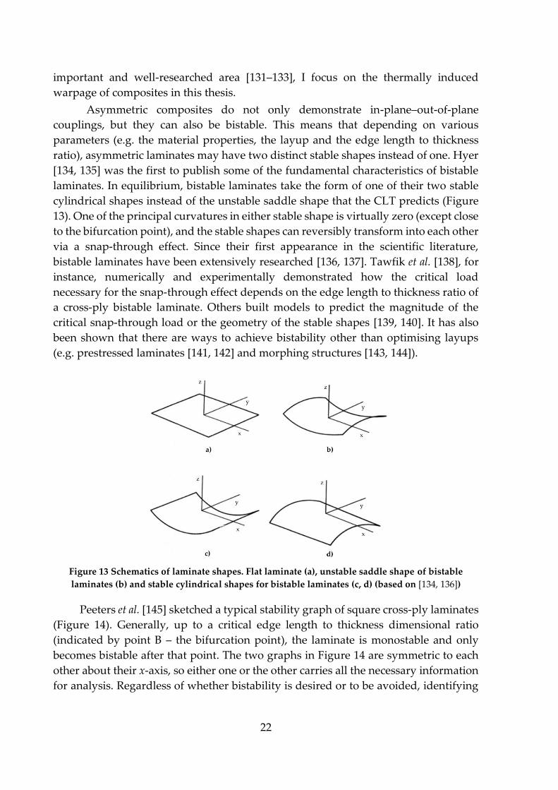
ratio), asymmetric laminates may have two distinct stable shapes instead of one. Hyer
[134, 135] was the first to publish some of the fundamental characteristics of bistable
laminates. In equilibrium, bistable laminates take the form of one of their two stable
cylindrical shapes instead of the unstable saddle shape that the CLT predicts (Figure
13). One of the principal curvatures in either stable shape is virtually zero (except close
to the bifurcation point), and the stable shapes can reversibly transform into each other
via a snap-through effect. Since their first appearance in the scientific literature,
bistable laminates have been extensively researched [136, 137]. Tawfik et al. [138], for
instance, numerically and experimentally demonstrated how the critical load
necessary for the snap-through effect depends on the edge length to thickness ratio of
a cross-ply bistable laminate. Others built models to predict the magnitude of the
critical snap-through load or the geometry of the stable shapes [139, 140]. It has also
been shown that there are ways to achieve bistability other than optimising layups
(e.g. prestressed laminates [141, 142] and morphing structures [143, 144]).
Figure 13 Schematics of laminate shapes. Flat laminate (a), unstable saddle shape of bistable
laminates (b) and stable cylindrical shapes for bistable laminates (c, d) (based on [134, 136])
Peeters et al. [145] sketched a typical stability graph of square cross-ply laminates
(Figure 14). Generally, up to a critical edge length to thickness dimensional ratio
(indicated by point B – the bifurcation point), the laminate is monostable and only
becomes bistable after that point. The two graphs in Figure 14 are symmetric to each
other about their x-axis, so either one or the other carries all the necessary information
for analysis. Regardless of whether bistability is desired or to be avoided, identifying
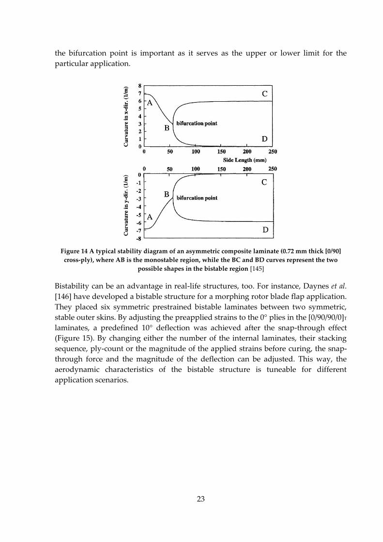
23
the bifurcation point is important as it serves as the upper or lower limit for the
particular application.
Figure 14 A typical stability diagram of an asymmetric composite laminate (0.72 mm thick [0/90]
cross-ply), where AB is the monostable region, while the BC and BD curves represent the two
possible shapes in the bistable region [145]
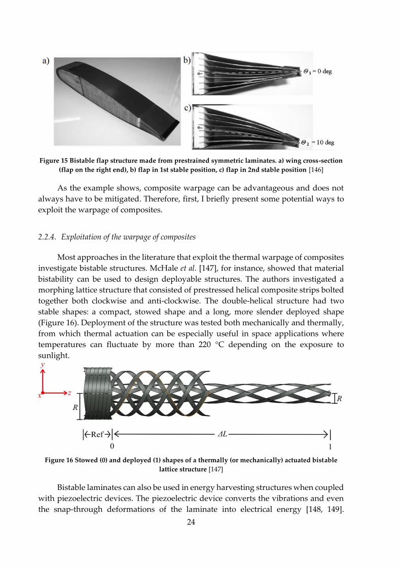
Bistability can be an advantage in real-life structures, too. For instance, Daynes et al.
[146] have developed a bistable structure for a morphing rotor blade flap application.
They placed six symmetric prestrained bistable laminates between two symmetric,
stable outer skins. By adjusting the preapplied strains to the 0° plies in the [0/90/90/0]T
laminates, a predefined 10° deflection was achieved after the snap-through effect
(Figure 15). By changing either the number of the internal laminates, their stacking
sequence, ply-count or the magnitude of the applied strains before curing, the snap-
through force and the magnitude of the deflection can be adjusted. This way, the
aerodynamic characteristics of the bistable structure is tuneable for different
application scenarios.
24
Figure 15 Bistable flap structure made from prestrained symmetric laminates. a) wing cross-section
(flap on the right end), b) flap in 1st stable position, c) flap in 2nd stable position [146]
As the example shows, composite warpage can be advantageous and does not
always have to be mitigated. Therefore, first, I briefly present some potential ways to
exploit the warpage of composites.
2.2.4. Exploitation of the warpage of composites
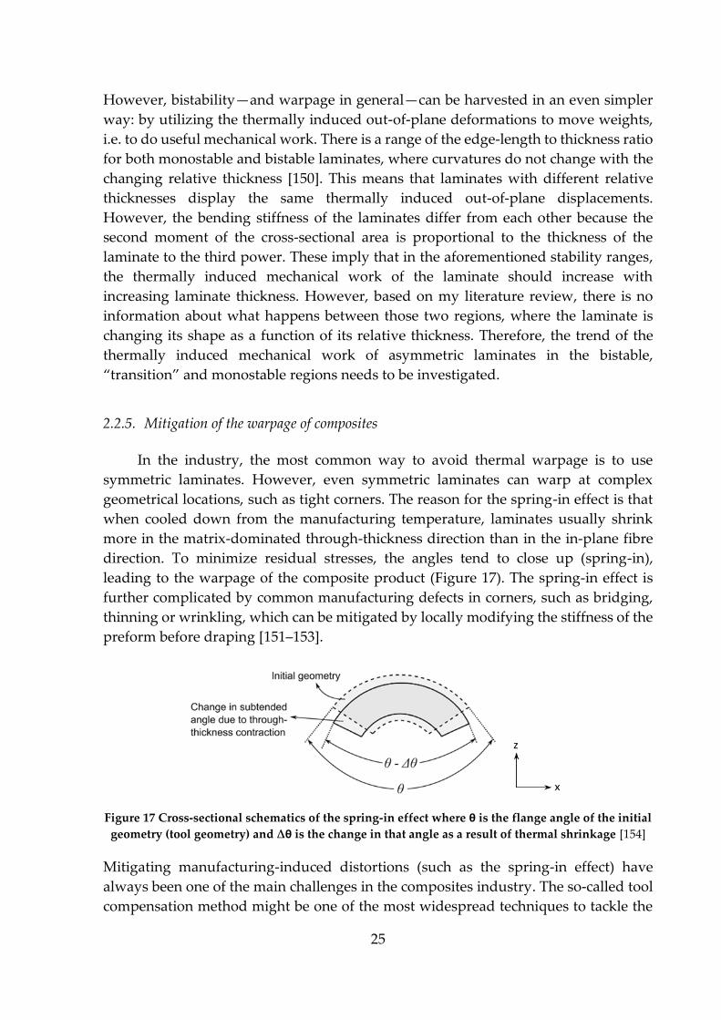
Most approaches in the literature that exploit the thermal warpage of composites
investigate bistable structures. McHale et al. [147], for instance, showed that material
bistability can be used to design deployable structures. The authors investigated a
morphing lattice structure that consisted of prestressed helical composite strips bolted
together both clockwise and anti-clockwise. The double-helical structure had two
stable shapes: a compact, stowed shape and a long, more slender deployed shape
(Figure 16). Deployment of the structure was tested both mechanically and thermally,
from which thermal actuation can be especially useful in space applications where
temperatures can fluctuate by more than 220 °C depending on the exposure to
sunlight.
Figure 16 Stowed (0) and deployed (1) shapes of a thermally (or mechanically) actuated bistable
lattice structure [147]
Bistable laminates can also be used in energy harvesting structures when coupled
with piezoelectric devices. The piezoelectric device converts the vibrations and even
the snap-through deformations of the laminate into electrical energy [148, 149].
25
However, bistability—and warpage in general—can be harvested in an even simpler
way: by utilizing the thermally induced out-of-plane deformations to move weights,
i.e. to do useful mechanical work. There is a range of the edge-length to thickness ratio
for both monostable and bistable laminates, where curvatures do not change with the
changing relative thickness [150]. This means that laminates with different relative
thicknesses display the same thermally induced out-of-plane displacements.
However, the bending stiffness of the laminates differ from each other because the
second moment of the cross-sectional area is proportional to the thickness of the
laminate to the third power. These imply that in the aforementioned stability ranges,
the thermally induced mechanical work of the laminate should increase with
increasing laminate thickness. However, based on my literature review, there is no
information about what happens between those two regions, where the laminate is
changing its shape as a function of its relative thickness. Therefore, the trend of the
thermally induced mechanical work of asymmetric laminates in the bistable,
“transition” and monostable regions needs to be investigated.
2.2.5. Mitigation of the warpage of composites
In the industry, the most common way to avoid thermal warpage is to use
symmetric laminates. However, even symmetric laminates can warp at complex
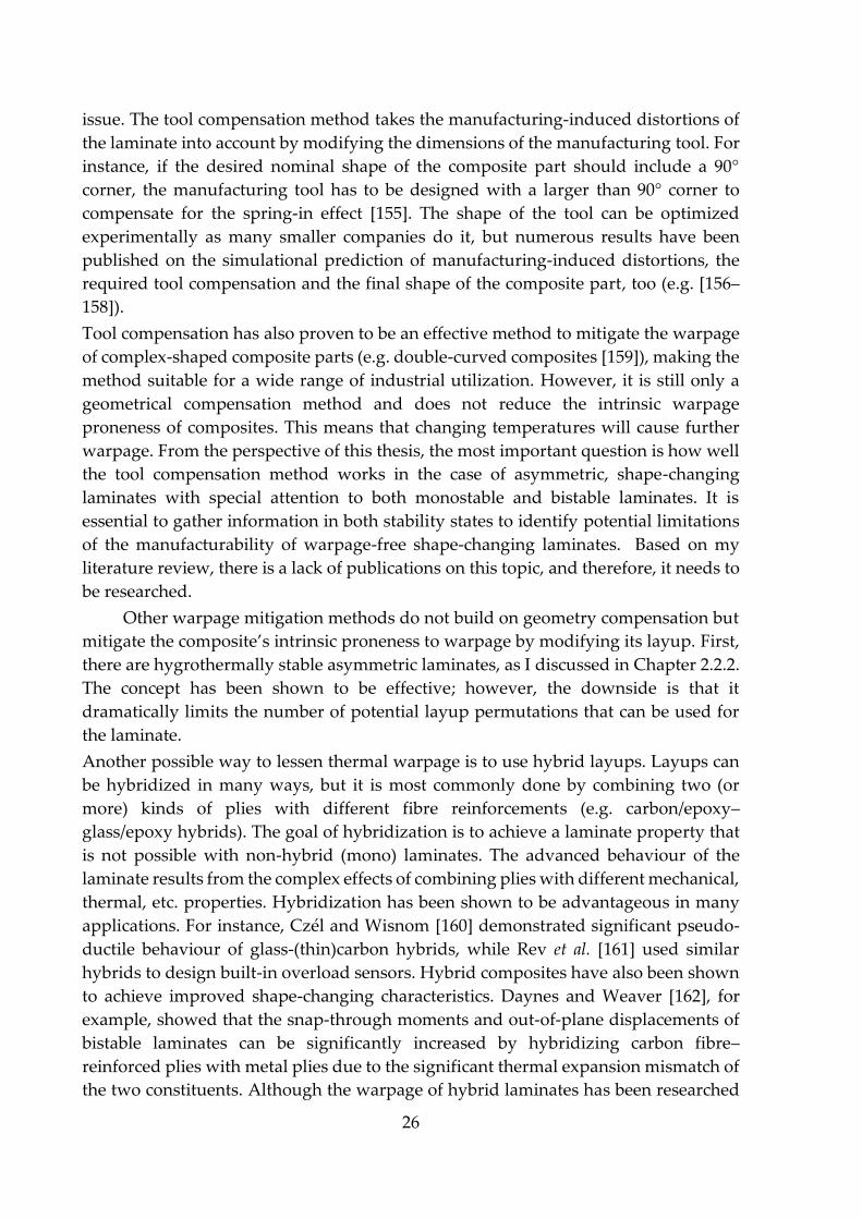
geometrical locations, such as tight corners. The reason for the spring-in effect is that
when cooled down from the manufacturing temperature, laminates usually shrink
more in the matrix-dominated through-thickness direction than in the in-plane fibre
direction. To minimize residual stresses, the angles tend to close up (spring-in),
leading to the warpage of the composite product (Figure 17). The spring-in effect is
further complicated by common manufacturing defects in corners, such as bridging,
thinning or wrinkling, which can be mitigated by locally modifying the stiffness of the
preform before draping [151–153].
Figure 17 Cross-sectional schematics of the spring-in effect where θ is the flange angle of the initial
geometry (tool geometry) and ∆θ is the change in that angle as a result of thermal shrinkage [154]
Mitigating manufacturing-induced distortions (such as the spring-in effect) have
always been one of the main challenges in the composites industry. The so-called tool
compensation method might be one of the most widespread techniques to tackle the
26
issue. The tool compensation method takes the manufacturing-induced distortions of
the laminate into account by modifying the dimensions of the manufacturing tool. For
instance, if the desired nominal shape of the composite part should include a 90°
corner, the manufacturing tool has to be designed with a larger than 90° corner to
compensate for the spring-in effect [155]. The shape of the tool can be optimized
experimentally as many smaller companies do it, but numerous results have been
published on the simulational prediction of manufacturing-induced distortions, the
required tool compensation and the final shape of the composite part, too (e.g. [156–
158]).
Tool compensation has also proven to be an effective method to mitigate the warpage
of complex-shaped composite parts (e.g. double-curved composites [159]), making the
method suitable for a wide range of industrial utilization. However, it is still only a
geometrical compensation method and does not reduce the intrinsic warpage
proneness of composites. This means that changing temperatures will cause further
warpage. From the perspective of this thesis, the most important question is how well
the tool compensation method works in the case of asymmetric, shape-changing
laminates with special attention to both monostable and bistable laminates. It is
essential to gather information in both stability states to identify potential limitations
of the manufacturability of warpage-free shape-changing laminates. Based on my
literature review, there is a lack of publications on this topic, and therefore, it needs to
be researched.
Other warpage mitigation methods do not build on geometry compensation but
mitigate the composite’s intrinsic proneness to warpage by modifying its layup. First,
there are hygrothermally stable asymmetric laminates, as I discussed in Chapter 2.2.2.
The concept has been shown to be effective; however, the downside is that it
dramatically limits the number of potential layup permutations that can be used for
the laminate.
Another possible way to lessen thermal warpage is to use hybrid layups. Layups can
be hybridized in many ways, but it is most commonly done by combining two (or
more) kinds of plies with different fibre reinforcements (e.g. carbon/epoxy–
glass/epoxy hybrids). The goal of hybridization is to achieve a laminate property that
is not possible with non-hybrid (mono) laminates. The advanced behaviour of the
laminate results from the complex effects of combining plies with different mechanical,
thermal, etc. properties. Hybridization has been shown to be advantageous in many
applications. For instance, Czél and Wisnom [160] demonstrated significant pseudo-
ductile behaviour of glass-(thin)carbon hybrids, while Rev et al. [161] used similar
hybrids to design built-in overload sensors. Hybrid composites have also been shown
to achieve improved shape-changing characteristics. Daynes and Weaver [162], for
example, showed that the snap-through moments and out-of-plane displacements of
bistable laminates can be significantly increased by hybridizing carbon fibre–
reinforced plies with metal plies due to the significant thermal expansion mismatch of
the two constituents. Although the warpage of hybrid laminates has been researched
27
(e.g. [163]), warpage mitigation does not seem to be the goal of any publication on
hybridization. This is odd because layup hybridization clearly has the potential to
significantly influence laminate warpage due to the differences in the directional
elastic and thermal properties of the constituents. Because of this, it is important to
investigate the warpage mitigating potential of layup hybridization. Moreover, as
hybridization can have a complex effect on a variety of laminate properties, warpage
and shape-changing performance should be investigated together. One of the
interesting questions is whether layup hybridization can decrease unwanted warpage
while increasing the desired shape-changing performance (e.g. extension-twist
coupling) of the laminate at the same time.
Layup homogenization is yet another way to mitigate the thermal warpage of
asymmetric laminates by modifying the layup. A layup is (partly) homogenized when
it is built up from identical sub-laminates placed on top of each other. If the sub-
laminate is asymmetric, it is prone to warpage. However, when the sub-laminate is
repeated several times through the thickness, the effect of its asymmetry diminishes.
It has been analytically shown that homogenization mitigates thermal warpage
effectively with an increasing number of sub-laminate repetitions [164]. However,
similarly to hybridization, homogenization also has a complex effect on multiple
aspects of the laminate’s behaviour. This implies that homogenization might influence
the shape-changing performance of composites, too. Therefore, I believe that besides
the experimental validation of the warpage-mitigating performance of layup
homogenization, it is important to investigate its effect on the mechanically coupled
behaviour of composites (e.g. extension-twist or bend-twist coupling).
In this chapter, I gave a brief overview of potential ways to mitigate the thermal
warpage of laminates. I discussed the tool compensation method and methods based
on hygrothermally stable, hybrid and homogenized layups. I identified some
important knowledge gaps that need further investigation to better understand not
only the advantages and limitations of warpage mitigation methods but also their
effects on the shape-changing performance of composites.
2.2.6. A new direction in the design of composite laminates: double-double layups
Asymmetric laminates can not only be used to achieve shape-changing
deformations but also to improve the stiffness and strength or even the
manufacturability and repairability of composites. Even today, the majority of the
composites industry uses the conventional layup design guidelines that have not
changed for decades. Conventional—so-called quad—laminates are symmetric to their
mid-plane to avoid thermal warpage, and they consist of plies with 0°, 90° and ±45°
fibre orientations. They also follow the 10% rule; i.e. each orientation has to account
for at least 10% of the total number of plies for safety reasons. Also, there are always
an equal number of +45° and -45° plies in the laminates. This ensures balanced
laminates where extension and shear are decoupled (A16 and A26 are zero) [165]. There

28
are at least three reasons why the industry still sticks to quad laminates. Firstly, they
are warpage-free due to layup symmetry. Secondly, manufacturing plies with non-
conventional orientations might require a significant investment in new machines.
And finally, researchers and engineers have gathered a vast amount of information
about quad laminates in the past decades, making the method a safe bet when it comes
to layup design. On the other hand, with its rules, the quad layup approach limits the
exploitation of the full potential of composites. Firstly, the guidelines dramatically
reduce the number of potential layup permutations, and therefore reduce the chance
of finding the optimum. Secondly, even with these simplifications, full optimization
can be problematic because of the large number of plies in a real composite laminate
that increases the number of possible layup permutations to an extent that even high-
performance computers cannot handle. Then come ply-drops, where the designer
decides about which plies to drop while maintaining symmetry and trying not to
sacrifice too much mechanical performance. So engineering judgement historically
plays a significant role in the design process, which should be purely based on
mechanics for the best results and repeatability. For better layup optimization and
lighter composite structures, a different approach is needed.
The novel double-double (DD) layup method promises numerous advantages
over conventional layups by deviating from some of the standard laminate design
guidelines. The double-double layup method is a Stanford University innovation (by
Prof. Stephen W. Tsai, patent pending) utilizing layup homogenization. Double-
double laminates consist of 4-ply [±φ/±ψ] sub-laminates (Figure 18). Instead of
optimizing the layup of the entire laminate in one step, the process is simplified by
optimizing the layup of only the sub-laminate and then stacking identical repetitions
of this few plies thick unit until the desired total thickness is reached. This approach
has some key advantages. Full-field optimization becomes possible because of the
significantly reduced number of layup permutations. This also enables us to consider
orientations other than the four quad orientations, which is another step towards
finding the global optimum. Furthermore, non-symmetric layups become feasible
options because layup homogenization takes care of warpage. Quad layups have
much thicker sub-laminates, which makes layup homogenization impossible in the
case of thin laminates, so they have to maintain symmetry. An additional advantage
of homogenized layups is the simplicity of tapering design as plies can be dropped in
finer increments from any part of the laminate without significantly changing the
mechanical characteristics of the laminate (unlike in the case of quads). To further aid
and simplify laminate design, Tsai also proposed an invariant-based method (based
on the Tsai’s modulus of the material) to unify the stiffness design of laminates, which
he successfully applied to the design of double-double laminates, too [164, 166–169].
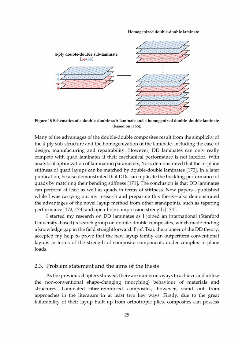
29
Figure 18 Schematics of a double-double sub-laminate and a homogenized double-double laminate
(based on [166])
Many of the advantages of the double-double composites result from the simplicity of
the 4-ply sub-structure and the homogenization of the laminate, including the ease of
design, manufacturing and repairability. However, DD laminates can only really
compete with quad laminates if their mechanical performance is not inferior. With
analytical optimization of lamination parameters, York demonstrated that the in-plane
stiffness of quad layups can be matched by double-double laminates [170]. In a later
publication, he also demonstrated that DDs can replicate the buckling performance of
quads by matching their bending stiffness [171]. The conclusion is that DD laminates
can perform at least as well as quads in terms of stiffness. New papers—published
while I was carrying out my research and preparing this thesis—also demonstrated
the advantages of the novel layup method from other standpoints, such as tapering
performance [172, 173] and open-hole compression strength [174].
I started my research on DD laminates as I joined an international (Stanford
University–based) research group on double-double composites, which made finding
a knowledge gap in the field straightforward. Prof. Tsai, the pioneer of the DD theory,
accepted my help to prove that the new layup family can outperform conventional
layups in terms of the strength of composite components under complex in-plane
loads.
2.3. Problem statement and the aims of the thesis
As the previous chapters showed, there are numerous ways to achieve and utilize
the non-conventional shape-changing (morphing) behaviour of materials and
structures. Laminated fibre-reinforced composites, however, stand out from
approaches in the literature in at least two key ways. Firstly, due to the great
tailorability of their layup built up from orthotropic plies, composites can possess
30
various intrinsic coupling characteristics between loads and deformations of different
modes (e.g. extension-shear, extension–twist, bend–twist, etc.). And secondly, the
outstanding specific mechanical properties of composites allow for using these shape-
changing laminates in load-bearing primary structures.
Morphing composites have been extensively investigated in the literature, and
there are even examples of their industrial use as extension–twist or bend–twist
coupled turbine blades, for instance. However, during my literature review, I
identified some unsolved challenges associated with the design and manufacturing of
such laminates. In this chapter, I briefly summarize the main areas that have room for
improvement and then formulate the aims of the thesis.
It has been shown that the intrinsic shape-changing and warping behaviour of
composites depend on their layups; therefore, these characteristics can be optimized
by optimizing the layup. The classical laminate theory offers a computationally
efficient way to design the elastic behaviour of laminates while providing all the
individual coupling terms that are essential for the investigation of the shape-changing
behaviour of laminates. However, the available CLT calculators are basic and cannot
be used for full-field optimizations of composite layups. There is a need for a CLT-
based algorithm that is capable of optimizing the layup of shape-changing laminates.
Such an algorithm would also be a valuable tool to better show the layup’s influence
on the morphing and warping behaviour of composites.
Many shape-changing laminates have asymmetric layups, and asymmetric
layups tend to warp. Warpage is usually unwanted, but it can also be exploited. One
way to exploit the thermally induced out-of-plane deformations is to convert the
thermal energy into mechanical work by moving weights. Predicting the thermally
induced mechanical work capability of an asymmetric laminate is a challenge in itself,
but the monostable-bistable transition further complicates the task because of the
changing shape of the laminate. The effect of the stability transition on thermally
induced work has not been investigated yet. New results in the topic might lead to
better exploitation of the thermal warpage of composites.
Mitigating the warpage of asymmetric layups seems to be one of the main
challenges in the composites industry. Solving this problem is crucial to make the
industry even consider using shape-changing laminates with asymmetric layups.
There are three promising warpage mitigation methods that can be part of the solution,
but all of them need further investigation than what has already been done in the
literature.
Tool compensation is a widely used approach in the composites industry to lessen
manufacturing-induced distortions, but it is mostly used to compensate for the
warpage of symmetric laminates arising from the complex geometry of the part.
However, most shape-changing laminates are asymmetric, so they warp intrinsically,
regardless of the complexity of the geometry. Since warpage is the main limiting factor
of the utilization of asymmetric laminates, and asymmetric laminates can be

31
monostable or bistable, the performance of the tool compensation method needs to be
assessed in both stability regions.
Hybrid layups have been used to improve a variety of laminate properties (including
some shape-changing characteristics) but have not been studied directly with the aim
of mitigating the warpage of asymmetric laminates. Due to the complex effects of
hybridization on the mechanical and thermal properties of the laminate, and the large
number of possible layup permutations, the method should have the potential to
improve certain coupled behaviour and mitigate warpage. The main question that
needs to be answered is whether hybridization can lessen warpage and improve
morphing at the same time. Such a result would clearly show the superiority of hybrids
over mono layups when it comes to industry-ready shape-changing composites.
As for the third warpage mitigation method, layup homogenization, the main
challenge is to investigate its effects on the coupling performance of composites. The
more homogenized a layup is, the more symmetrically it behaves, therefore
homogenization might cause some shape-changing characteristics to diminish
(similarly to warpage) while not affecting or even improving another coupled
behaviour that does not require layup asymmetry.
Lastly, the novel double-double layup design method, which is based on layup
homogenization, needs to be compared to the current industry standard quad layup
method. Many advantages of DD laminates have already been published
(manufacturability, aggressive tapering, etc.) but there is still a need for investigating
whether DD laminates can improve the strength of structures that have complex
loading.
The following six points concisely sum up the main aims of the thesis.
1. Develop and validate a CLT-based analytical algorithm that can be used to
carry out full-field optimization of shape-changing composites (stiffness) and
double-double composites (strength).
2. Investigate the thermally induced mechanical work of asymmetric laminates
with particular attention to the transitional range between bistability and
monostability.
3. Evaluate the performance of the tool compensation warpage mitigation
method on both bistable and monostable asymmetric laminates.
4. Investigate whether hybrid laminates can outperform mono laminates by
simultaneously reducing unwanted warpage and increasing the desired
shape-changing performance (e.g. extension-twist coupling).
5. Analyse the effect of layup homogenization on the shape-changing behaviour
of composite laminates.
6. Investigate whether the double-double layup method can improve the
strength of composite structures compared to the industry-standard quad
laminates.
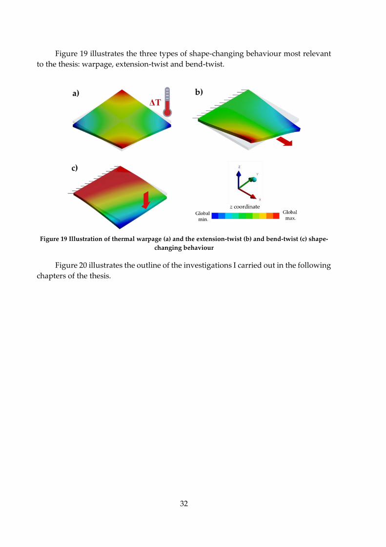
32
Figure 19 illustrates the three types of shape-changing behaviour most relevant
to the thesis: warpage, extension-twist and bend-twist.
Figure 19 Illustration of thermal warpage (a) and the extension-twist (b) and bend-twist (c) shape-
changing behaviour
Figure 20 illustrates the outline of the investigations I carried out in the following
chapters of the thesis.
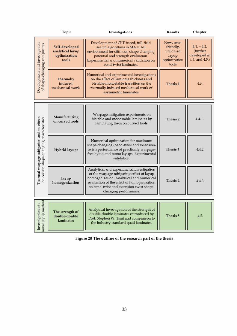
33
Figure 20 The outline of the research part of the thesis
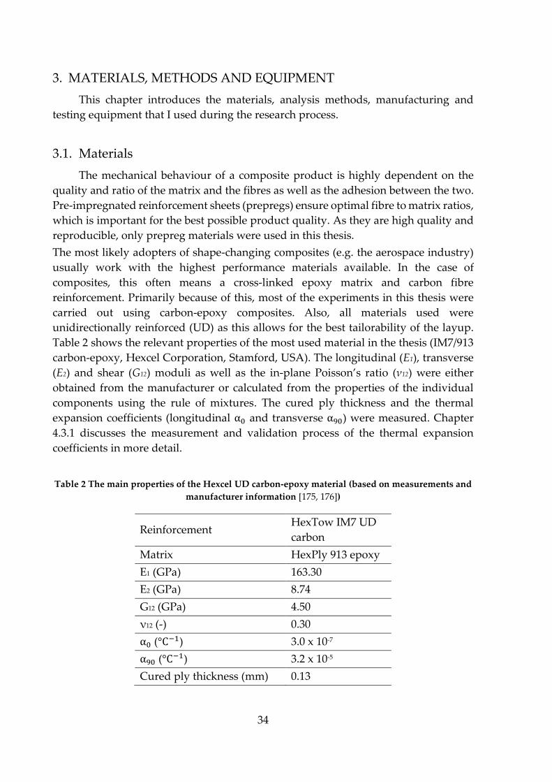
34
3. MATERIALS, METHODS AND EQUIPMENT
This chapter introduces the materials, analysis methods, manufacturing and
testing equipment that I used during the research process.
3.1. Materials
The mechanical behaviour of a composite product is highly dependent on the
quality and ratio of the matrix and the fibres as well as the adhesion between the two.
Pre-impregnated reinforcement sheets (prepregs) ensure optimal fibre to matrix ratios,
which is important for the best possible product quality. As they are high quality and
reproducible, only prepreg materials were used in this thesis.
The most likely adopters of shape-changing composites (e.g. the aerospace industry)
usually work with the highest performance materials available. In the case of
composites, this often means a cross-linked epoxy matrix and carbon fibre
reinforcement. Primarily because of this, most of the experiments in this thesis were
carried out using carbon-epoxy composites. Also, all materials used were
unidirectionally reinforced (UD) as this allows for the best tailorability of the layup.
Table 2 shows the relevant properties of the most used material in the thesis (IM7/913
carbon-epoxy, Hexcel Corporation, Stamford, USA). The longitudinal (E1), transverse
(E2) and shear (G12) moduli as well as the in-plane Poisson’s ratio (ν12) were either
obtained from the manufacturer or calculated from the properties of the individual
components using the rule of mixtures. The cured ply thickness and the thermal
expansion coefficients (longitudinal α0 and transverse α90) were measured. Chapter
4.3.1 discusses the measurement and validation process of the thermal expansion
coefficients in more detail.
Table 2 The main properties of the Hexcel UD carbon-epoxy material (based on measurements and
manufacturer information [175, 176])
Reinforcement HexTow IM7 UD
carbon
Matrix HexPly 913 epoxy
E1 (GPa) 163.30
E2 (GPa) 8.74
G12 (GPa) 4.50
ν12 (-) 0.30
α0 (°C−1) 3.0 x 10⁻⁷
α90 (°C−1) 3.2 x 10⁻⁵
Cured ply thickness (mm) 0.13
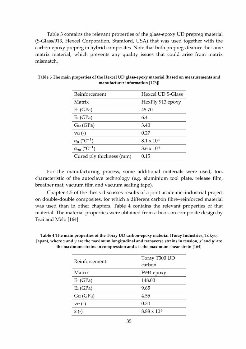
35
Table 3 contains the relevant properties of the glass-epoxy UD prepreg material
(S-Glass/913, Hexcel Corporation, Stamford, USA) that was used together with the
carbon-epoxy prepreg in hybrid composites. Note that both prepregs feature the same
matrix material, which prevents any quality issues that could arise from matrix
mismatch.
Table 3 The main properties of the Hexcel UD glass-epoxy material (based on measurements and
manufacturer information [176])
Reinforcement Hexcel UD S-Glass
Matrix HexPly 913 epoxy
E1 (GPa) 45.70
E2 (GPa) 6.41
G12 (GPa) 3.40
ν12 (-) 0.27
α0 (°C−1) 8.1 x 10⁻⁶
α90 (°C−1) 3.6 x 10⁻⁵
Cured ply thickness (mm) 0.15
For the manufacturing process, some additional materials were used, too,
characteristic of the autoclave technology (e.g. aluminium tool plate, release film,
breather mat, vacuum film and vacuum sealing tape).
Chapter 4.5 of the thesis discusses results of a joint academic–industrial project
on double-double composites, for which a different carbon fibre–reinforced material
was used than in other chapters. Table 4 contains the relevant properties of that
material. The material properties were obtained from a book on composite design by
Tsai and Melo [164].
Table 4 The main properties of the Toray UD carbon-epoxy material (Toray Industries, Tokyo,
Japan), where x and y are the maximum longitudinal and transverse strains in tension, x’ and y’ are
the maximum strains in compression and s is the maximum shear strain [164]
Reinforcement Toray T300 UD
carbon
Matrix F934 epoxy
E1 (GPa) 148.00
E2 (GPa) 9.65
G12 (GPa) 4.55
ν12 (-) 0.30
x (-) 8.88 x 10⁻³
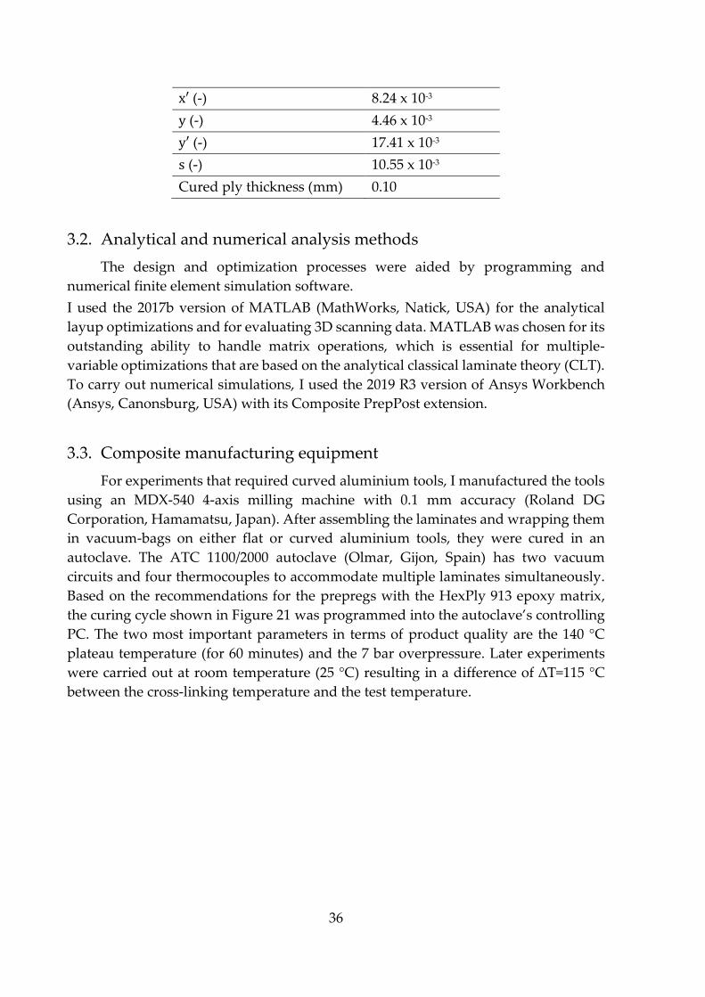
36
x′ (-) 8.24 x 10⁻³
y (-) 4.46 x 10⁻³
y′ (-) 17.41 x 10⁻³
s (-) 10.55 x 10⁻³
Cured ply thickness (mm) 0.10
3.2. Analytical and numerical analysis methods
The design and optimization processes were aided by programming and
numerical finite element simulation software.
I used the 2017b version of MATLAB (MathWorks, Natick, USA) for the analytical
layup optimizations and for evaluating 3D scanning data. MATLAB was chosen for its
outstanding ability to handle matrix operations, which is essential for multiple-
variable optimizations that are based on the analytical classical laminate theory (CLT).
To carry out numerical simulations, I used the 2019 R3 version of Ansys Workbench
(Ansys, Canonsburg, USA) with its Composite PrepPost extension.
3.3. Composite manufacturing equipment
For experiments that required curved aluminium tools, I manufactured the tools
using an MDX-540 4-axis milling machine with 0.1 mm accuracy (Roland DG
Corporation, Hamamatsu, Japan). After assembling the laminates and wrapping them
in vacuum-bags on either flat or curved aluminium tools, they were cured in an
autoclave. The ATC 1100/2000 autoclave (Olmar, Gijon, Spain) has two vacuum
circuits and four thermocouples to accommodate multiple laminates simultaneously.
Based on the recommendations for the prepregs with the HexPly 913 epoxy matrix,
the curing cycle shown in Figure 21 was programmed into the autoclave’s controlling
PC. The two most important parameters in terms of product quality are the 140 °C
plateau temperature (for 60 minutes) and the 7 bar overpressure. Later experiments
were carried out at room temperature (25 °C) resulting in a difference of ∆T=115 °C
between the cross-linking temperature and the test temperature.

37
Figure 21 The programmed autoclave curing cycle for the prepregs with the HexPly 913 epoxy
matrix
The cured laminates were cut to the exact specimen dimensions with a Diadisc
4200 precision cut-off saw with a diamond cutting disc (Mutronic Präzisionsgerätebau
GmbH & Co. KG, Rieden, Germany).
3.4. Composite testing equipment
The majority of the mechanical tests were carried out with Z005, Z050 and Z250
universal testing machines (Zwick Roell Group, Ulm, Germany). The tests where
twisting deformation under tensile load was measured were carried out with a
hydraulic Instron 8872 universal testing machine with freely rotating grips (Instron
Corporation, Norwood, USA). For accurate strain measurements, the displacements
were recorded with a Mercury Monet video system capable of digital image
correlation (DIC) measurements (Sobriety s.r.o., Kuřim, Czech Republic). The
coefficients of thermal expansion were measured with KMT-LIAS-06-1,5-350-5E strain
gauges (Kaliber Instrument and Measuring Technics Ltd., Budapest, Hungary) and a
Spider8 general data acquisition device (HBM, Darmstadt, Germany). To analyse the
warped shapes of the composite specimens, I used an ATOS 5M 3D scanner with its
ATOS Professional 2018 software (GOM GmbH, Braunschweig, Germany) and
evaluated the raw data in MATLAB.

38
4. DESIGN, INVESTIGATION, RESULTS AND DISCUSSION
This chapter’s main goal is to discuss and evaluate the analytical, numerical and
experimental results of the thesis. First, I concisely introduce a self-developed
analytical layup optimization tool and then evaluate its validity through a set of
preliminary experiments. These first two chapters (Chapter 4.1 and 4.2) provide the
basis of the following chapters. Chapter 4.3 investigates the thermally induced
mechanical work of asymmetric laminates. I formulated my first thesis based on the
results in this chapter. The following chapter comprises three sub-chapters, each
dedicated to the investigation of a thermal warpage mitigation method: the curved
tool method (Chapter 4.4.1, Thesis 2), the hybrid layup method (Chapter 4.4.2, Thesis
3) and the layup homogenization method (Chapter 4.4.3, Thesis 4). In the last chapter
(Chapter 4.5, Thesis 5), I analytically investigate the strength of a novel lamination
method - the double-double layup method - introduced by prof. Stephen W. Tsai
(Stanford University). Although this last topic is not strictly about shape-changing
laminates, it is strongly related to the layup homogenization method, and similarly to
the previous topics, it builds on layup optimization; for which I developed another
analytical algorithm.
4.1. Development of the analytical layup optimizer algorithm
Based on the findings of the literature review, layup optimization is the least
demanding on computational efforts when it is carried out analytically. Although
analytical results may have larger error than numerical simulations when compared
to real-world experimental data, their efficiency justifies their use in the case of large-
number optimizations. That being said, their accuracy needs to be checked so that they
give at least qualitatively adequate results, which is necessary for finding an optimum.
CLT calculations are the simplest way to obtain information about the elastic
behaviour of composites. These calculations can be performed by hand, but the time
needed to calculate the results for all the possible layup permutations during an
optimization process can quickly increase to a point where hand calculations are not
feasible anymore. Imagine that we wish to optimize the stacking sequence of a
laminate based on certain criteria, where we only have one kind of a UD prepreg (for
the sake of simplicity). Let us say that we can place the individual plies of the laminate
with 15° resolution in terms of their orientation. In the case of a 2-ply laminate, this
would mean (180/15)2=144 permutations. In this thesis, permutation always refers to
permutation with repetition. CLT calculations have to be performed for each of the
permutations in order to compare the results and find the optimal solution based on
our criterion or multiple criteria. This may not seem like a lot of permutations, but in
case of 3 plies, there are 1728 permutations, for 4 plies there are 20736 permutations,
and the number of permutations continues to increase rapidly. Not to mention that
these numbers can significantly increase in the case of more than one type of material
or finer orientation resolutions as seen in Figure 22. Fortunately, the outstanding

39
computational capacity of computers can be exploited by coding or scripting the
problem parametrically and running the solution in automated loops.
Figure 22 Number of permutations as a function of the number of plies (with only one type of ply-
material in the laminate)
The MATLAB script that I wrote finds the optimal stacking sequence based on
certain input parameters. For convenience, the input parameters are defined in an
Excel sheet by the user, and the script reads these data when it is run. Input parameters
include material properties (moduli, Poisson’s ratio, ply thickness), the number of plies
and materials as well as the parameter(s) to be minimized or maximized. It is possible
to select several parameters of the inverse ABD matrix at the same time and optimize
the layup based on their weighted values defined by the user. When the loading
scenario is known, these parameters give the magnitude of the desired (non-
conventional) deformation. For instance, if one wishes to maximize the twisting
deformation under pure longitudinal bending moments, d16 has to be selected as the
compliance parameter to maximize (see Equation (1) later). After this, the script runs
the CLT calculations for all the possible permutations and finds the stacking sequence
where d16 is maximal. The script plots all the results on a graph and the user can ask
the program to export all the essential data (stacking sequence with all the material
data, ABD matrices, etc.) of any chosen layup permutation into an organized text file.
Based on the data in the text files, one can validate the results numerically or by
manufacturing and testing the chosen laminate. Furthermore, it is possible to
maximize the desired compliance parameters while minimizing the unwanted ones at
the same time (with user-defined weighting factors once again, for the best results).
Later, I further developed the algorithm to handle thermal loads and perform strength
calculations, as I describe in later chapters.
40
During the development process, I extensively verified that the calculations made by
the script are correct. For validation, I compared numerous results of the algorithm to
my manual calculations and to matrix results calculated in Ansys.
4.2. Preliminary investigations – mechanically induced shape-changing
To check the validity of the shape-changing concept and the limitations of the
analytical approach, I carried out a trial optimization study and then compared the
results against numerical simulations and experimental results. I used Hexcel’s
IM7/913 carbon-epoxy material for the calculations, simulations and specimen
manufacturing.
4.2.1. Analytical layup optimization of bend-twist composites
The goal of the analytical optimization process was to maximize the twisting
curvature (κxy) under a pure longitudinal bending moment (Mxx). This non-
conventional shape-changing behaviour was chosen for its significant advantages in
real-world scenarios (e.g. turbine blades or aeroplane wings). For maximal twisting
deformation under pure bending moment, the algorithm needed to maximize the d16
parameter (see Equation (1)). Note that out-of-plane deflections are influenced by
other parameters, too, as discussed later. Also, for structures with complex boundary
conditions, the internal stress resultants are calculated from the external loads and the
boundary conditions, from which the strains and curvatures can be calculated, and
finally, the displacements. However, in the case of these CLT calculations, only the
middle two steps were required because of the model's assumptions. The number of
plies in the laminate was chosen to be 4 with an orientation resolution of 7.5°. This
gave a total of 331776 permutations that took a few hours for the computer with a 3.4
GHz central processing unit to calculate (8 cores, 32 GB random access memory and
500 MB/s solid state drive storage). Numerical solutions would have taken orders of
magnitude longer. Figure 23 illustrates the results of the CLT calculations, where each
blue marker represents the d16 compliance parameter (y-axis) of one of the layups from
all the permutations (x-axis). The optimal layup with maximal d16 was found to be a
symmetric one ([-30/90]s), where numbers in the abbreviated layup definition refer to
the orientation of the individual plies in degree (°) and “s” refers to mid-plane
symmetry. For a better comparison between analytical, numerical and experimental
results, I arbitrarily choose and investigated two other layups, too: one with a
moderate ([-45/90]s) and one with an even lower ([-60/90]s) d16 value (Table 5).
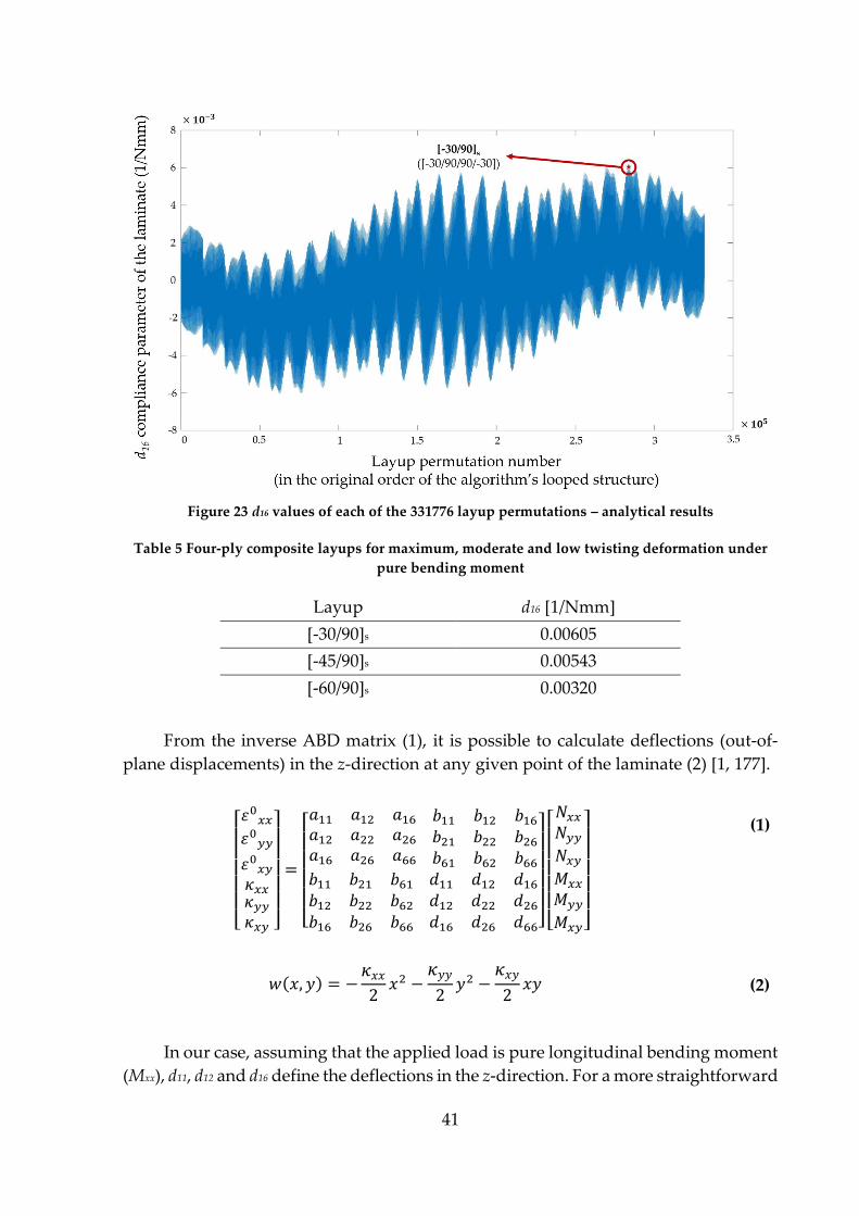
41
Figure 23 d16 values of each of the 331776 layup permutations – analytical results
Table 5 Four-ply composite layups for maximum, moderate and low twisting deformation under
pure bending moment
Layup d16 [1/Nmm]
[-30/90]s 0.00605
[-45/90]s 0.00543
[-60/90]s 0.00320
From the inverse ABD matrix (1), it is possible to calculate deflections (out-of-
plane displacements) in the z-direction at any given point of the laminate (2) [1, 177].
[ 𝜀0𝑥𝑥𝜀0𝑦𝑦
𝜀0𝑥𝑦𝜅𝑥𝑥𝜅𝑦𝑦𝜅𝑥𝑦 ]
=
[ 𝑎11 𝑎12 𝑎16𝑎12 𝑎22 𝑎26𝑎16 𝑎26 𝑎66
𝑏11 𝑏12 𝑏16𝑏21 𝑏22 𝑏26𝑏61 𝑏62 𝑏66
𝑏11 𝑏21 𝑏61𝑏12 𝑏22 𝑏62𝑏16 𝑏26 𝑏66
𝑑11 𝑑12 𝑑16𝑑12 𝑑22 𝑑26𝑑16 𝑑26 𝑑66]
[ 𝑁𝑥𝑥𝑁𝑦𝑦𝑁𝑥𝑦𝑀𝑥𝑥
𝑀𝑦𝑦
𝑀𝑥𝑦]
(1)
In our case, assuming that the applied load is pure longitudinal bending moment
(Mxx), d11, d12 and d16 define the deflections in the z-direction. For a more straightforward
𝑤(𝑥, 𝑦) = −𝜅𝑥𝑥2𝑥2 −
𝜅𝑦𝑦2𝑦2 −
𝜅𝑥𝑦2𝑥𝑦 (2)
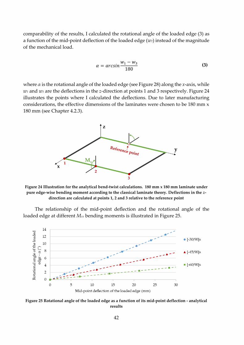
42
comparability of the results, I calculated the rotational angle of the loaded edge (3) as
a function of the mid-point deflection of the loaded edge (w2) instead of the magnitude
of the mechanical load.
where α is the rotational angle of the loaded edge (see Figure 28) along the x-axis, while
w1 and w3 are the deflections in the z-direction at points 1 and 3 respectively. Figure 24
illustrates the points where I calculated the deflections. Due to later manufacturing
considerations, the effective dimensions of the laminates were chosen to be 180 mm x
180 mm (see Chapter 4.2.3).
Figure 24 Illustration for the analytical bend-twist calculations. 180 mm x 180 mm laminate under
pure edge-wise bending moment according to the classical laminate theory. Deflections in the z-
direction are calculated at points 1, 2 and 3 relative to the reference point
The relationship of the mid-point deflection and the rotational angle of the
loaded edge at different Mxx bending moments is illustrated in Figure 25.
Figure 25 Rotational angle of the loaded edge as a function of its mid-point deflection - analytical
results
𝛼 = 𝑎𝑟𝑐𝑠𝑖𝑛𝑤1 − 𝑤3180
(3)

43
Figure 25 shows that the CLT predicts significant twisting deformations of the 4-ply
laminates under bending moments. At an arbitrarily chosen mid-point deflection (w2)
of 30 mm, the loaded edge of the 180 mm x 180 mm [-30/90]s laminate is expected to
rotate approximately 14°. The expected rotations for the other two layups are around
8° and 4°, respectively.
4.2.2. Numerical simulations
The material properties of the numerical simulations were the same as in Table
2. The dimensional ratios of the 180 mm x 180 mm, 0.52 mm thick laminates allowed
me to use shell modelling instead of solid modelling without any significant loss in
accuracy while keeping the computational weight relatively low. SHELL181 elements
were used for all simulations with large deflections enabled to recalculate the
constitutive equations at each sub-step for more accurate results. Similarly to the
analytical and the later experimental results, I evaluated the rotation of the loaded
edge as a function of its mid-point deflection. Therefore, stress and failure analysis was
not part of these analyses and tests. Also, the loading direction in the numerical and
later experimental tests pointed downwards (-z) instead of upwards (z) like in the
analytical calculations; therefore, I turned the laminates over before fixing them to
eliminate any issues arising from the change in the loading direction.
I built three different models with increasing realisticity for all three different
layups to assess how the simulation results estimate the test results. One edge of the
laminate was fixed in each setup, and for the first two setups, an out-of-plane load was
applied on the opposite side, either along the edge itself or at a round surface
(diameter: 10 mm) in the middle of the edge. The third setup was similar to the second
one (round surface loading), but I applied the force by displacing a loading rod
(diameter: 10 mm) with frictionless contact definition between the rod and the
laminate (Figure 26). As shown later, the contact model was very similar to how the
mechanical tests were carried out.

44
Figure 26 Numerical models for testing bend-twist coupled composites. a) edge loaded, b)
round surface loaded, c) contact loaded, d) deformed shape after contact loading (only for
visualization, colours represent vertical displacement)
To make sure that I obtain data that is (nearly) mesh-independent, I first ran a
mesh convergence study for the edge-loaded scenario, where the size (number) of the
elements was the variable. I chose the edge load to be 1 N in each case, and measured
the maximal displacement in the out-of-plane direction. The results converged at
around an element number of 8100 or 2 mm element edge size (Figure 27), so I used
this element size for the later simulations. I started each numerical simulation in this
thesis with a similar mesh convergence study.
The results of the simulations are illustrated and evaluated in Chapter 4.2.4 for
better comparability with the experimental and analytical results.
Figure 27 Mesh convergence study for the edge-loaded [-30/90]s laminate (1N load)
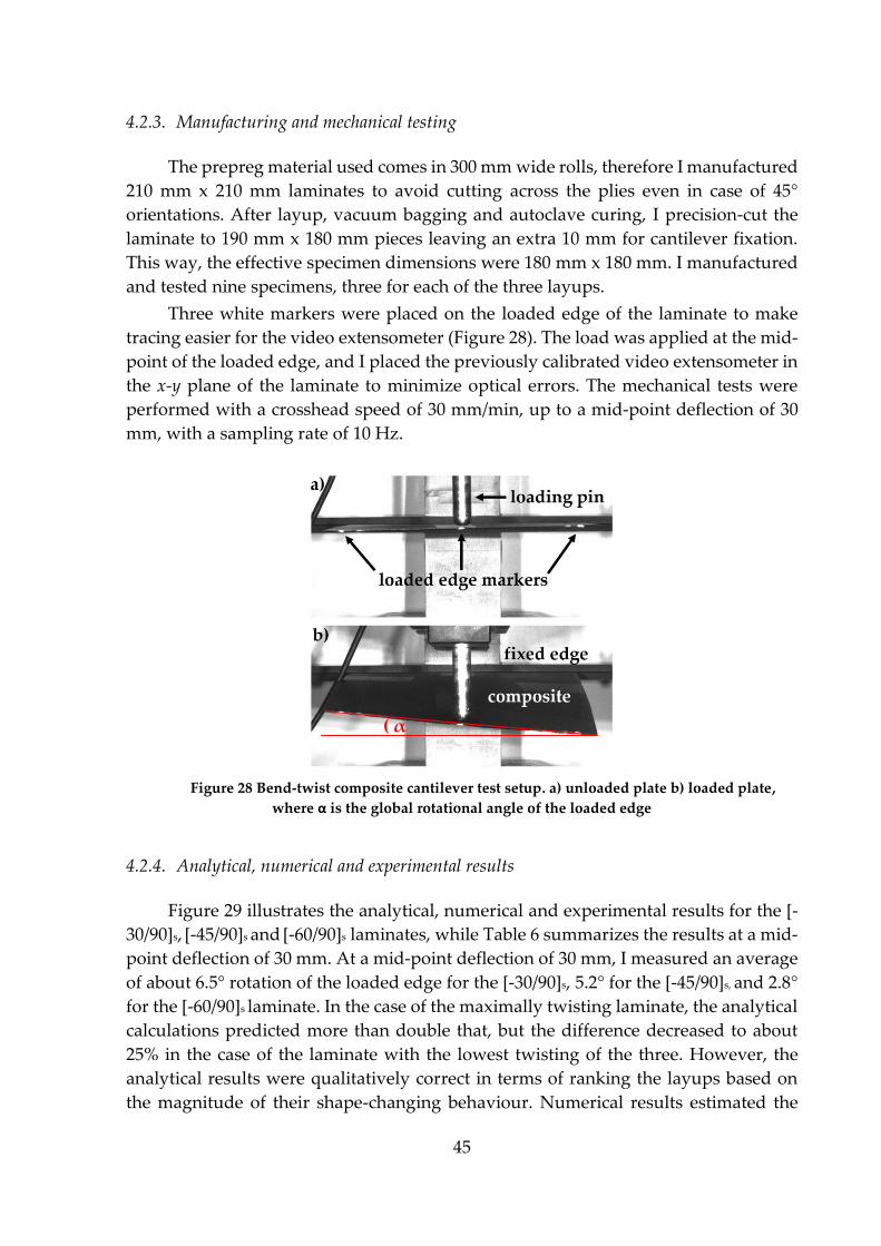
45
4.2.3. Manufacturing and mechanical testing
The prepreg material used comes in 300 mm wide rolls, therefore I manufactured
210 mm x 210 mm laminates to avoid cutting across the plies even in case of 45°
orientations. After layup, vacuum bagging and autoclave curing, I precision-cut the
laminate to 190 mm x 180 mm pieces leaving an extra 10 mm for cantilever fixation.
This way, the effective specimen dimensions were 180 mm x 180 mm. I manufactured
and tested nine specimens, three for each of the three layups.
Three white markers were placed on the loaded edge of the laminate to make
tracing easier for the video extensometer (Figure 28). The load was applied at the mid-
point of the loaded edge, and I placed the previously calibrated video extensometer in
the x-y plane of the laminate to minimize optical errors. The mechanical tests were
performed with a crosshead speed of 30 mm/min, up to a mid-point deflection of 30
mm, with a sampling rate of 10 Hz.
Figure 28 Bend-twist composite cantilever test setup. a) unloaded plate b) loaded plate,
where α is the global rotational angle of the loaded edge
4.2.4. Analytical, numerical and experimental results
Figure 29 illustrates the analytical, numerical and experimental results for the [-
30/90]s, [-45/90]s and [-60/90]s laminates, while Table 6 summarizes the results at a mid-
point deflection of 30 mm. At a mid-point deflection of 30 mm, I measured an average
of about 6.5° rotation of the loaded edge for the [-30/90]s, 5.2° for the [-45/90]s, and 2.8°
for the [-60/90]s laminate. In the case of the maximally twisting laminate, the analytical
calculations predicted more than double that, but the difference decreased to about
25% in the case of the laminate with the lowest twisting of the three. However, the
analytical results were qualitatively correct in terms of ranking the layups based on
the magnitude of their shape-changing behaviour. Numerical results estimated the
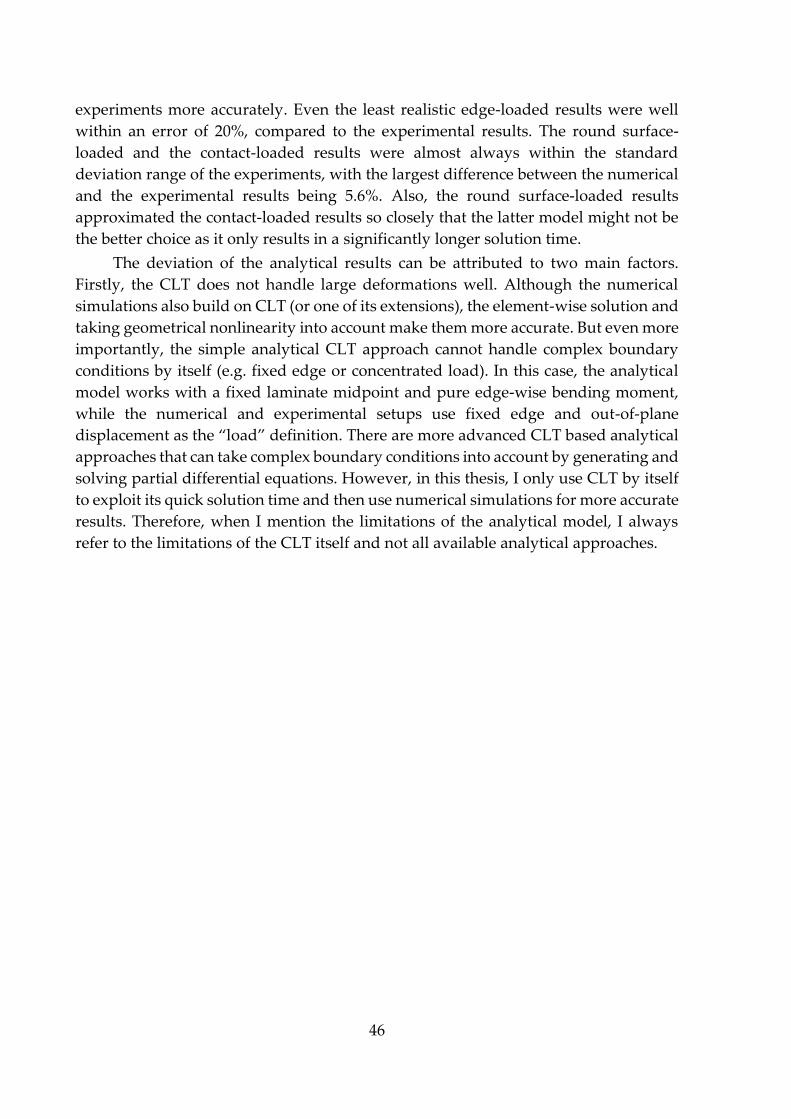
46
experiments more accurately. Even the least realistic edge-loaded results were well
within an error of 20%, compared to the experimental results. The round surface-
loaded and the contact-loaded results were almost always within the standard
deviation range of the experiments, with the largest difference between the numerical
and the experimental results being 5.6%. Also, the round surface-loaded results
approximated the contact-loaded results so closely that the latter model might not be
the better choice as it only results in a significantly longer solution time.
The deviation of the analytical results can be attributed to two main factors.
Firstly, the CLT does not handle large deformations well. Although the numerical
simulations also build on CLT (or one of its extensions), the element-wise solution and
taking geometrical nonlinearity into account make them more accurate. But even more
importantly, the simple analytical CLT approach cannot handle complex boundary
conditions by itself (e.g. fixed edge or concentrated load). In this case, the analytical
model works with a fixed laminate midpoint and pure edge-wise bending moment,
while the numerical and experimental setups use fixed edge and out-of-plane
displacement as the “load” definition. There are more advanced CLT based analytical
approaches that can take complex boundary conditions into account by generating and
solving partial differential equations. However, in this thesis, I only use CLT by itself
to exploit its quick solution time and then use numerical simulations for more accurate
results. Therefore, when I mention the limitations of the analytical model, I always
refer to the limitations of the CLT itself and not all available analytical approaches.
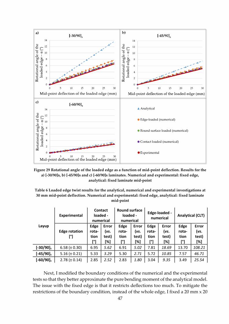
47
Figure 29 Rotational angle of the loaded edge as a function of mid-point deflection. Results for the
a) [-30/90]s, b) [-45/90]s and c) [-60/90]s laminates. Numerical and experimental: fixed edge,
analytical: fixed laminate mid-point
Table 6 Loaded edge twist results for the analytical, numerical and experimental investigations at
30 mm mid-point deflection. Numerical and experimental: fixed edge, analytical: fixed laminate
mid-point
Layup
Experimental Contact loaded -
numerical
Round surface loaded -
numerical
Edge-loaded - numerical
Analytical (CLT)
Edge rotation [°]
Edge rota-tion [°]
Error (vs.
test) [%]
Edge rota-tion [°]
Error (vs.
test) [%]
Edge rota-tion [°]
Error (vs.
test) [%]
Edge rota-tion [°]
Error (vs.
test) [%]
[-30/90]s 6.58 (± 0.30) 6.95 5.62 6.91 5.02 7.81 18.69 13.70 108.21
[-45/90]s 5.16 (± 0.21) 5.33 3.29 5.30 2.71 5.72 10.85 7.57 46.71
[-60/90]s 2.78 (± 0.14) 2.85 2.52 2.83 1.80 3.04 9.35 3.49 25.54
Next, I modified the boundary conditions of the numerical and the experimental
tests so that they better approximate the pure bending moment of the analytical model.
The issue with the fixed edge is that it restricts deflections too much. To mitigate the
restrictions of the boundary condition, instead of the whole edge, I fixed a 20 mm x 20
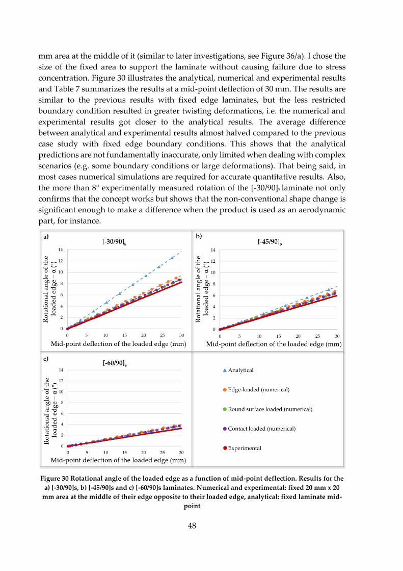
48
mm area at the middle of it (similar to later investigations, see Figure 36/a). I chose the
size of the fixed area to support the laminate without causing failure due to stress
concentration. Figure 30 illustrates the analytical, numerical and experimental results
and Table 7 summarizes the results at a mid-point deflection of 30 mm. The results are
similar to the previous results with fixed edge laminates, but the less restricted
boundary condition resulted in greater twisting deformations, i.e. the numerical and
experimental results got closer to the analytical results. The average difference
between analytical and experimental results almost halved compared to the previous
case study with fixed edge boundary conditions. This shows that the analytical
predictions are not fundamentally inaccurate, only limited when dealing with complex
scenarios (e.g. some boundary conditions or large deformations). That being said, in
most cases numerical simulations are required for accurate quantitative results. Also,
the more than 8° experimentally measured rotation of the [-30/90]s laminate not only
confirms that the concept works but shows that the non-conventional shape change is
significant enough to make a difference when the product is used as an aerodynamic
part, for instance.
Figure 30 Rotational angle of the loaded edge as a function of mid-point deflection. Results for the
a) [-30/90]s, b) [-45/90]s and c) [-60/90]s laminates. Numerical and experimental: fixed 20 mm x 20
mm area at the middle of their edge opposite to their loaded edge, analytical: fixed laminate mid-
point

49
Table 7 Loaded edge twist results for the analytical, numerical and experimental trials at a mid-
point deflection of 30 mm. Numerical and experimental: fixed 20 mm x 20 mm area at the middle of
their edge opposite to their loaded edge, analytical: fixed laminate mid-point
Layup
Experimental Contact loaded -
numerical
Round surface loaded -
numerical
Edge-loaded - numerical
Analytical (CLT)
Edge rotation [°]
Edge rota-tion [°]
Error (vs.
test) [%]
Edge rota-tion [°]
Error (vs.
test) [%]
Edge rota-tion [°]
Error (vs.
test) [%]
Edge rota-tion [°]
Error (vs.
test) [%]
[-30/90]s 8.29 (± 0.41) 8.82 6.39 8.77 5.79 9.44 13.87 13.70 65.26
[-45/90]s 5.99 (± 0.37) 6.47 8.01 6.44 7.51 6.85 14.36 7.57 26.38
[-60/90]s 3.27 (± 0.13) 3.78 15.60 3.76 14.98 4.01 22.63 3.49 6.73
The main conclusions of the preliminary investigations are the following:
The analytical layup optimization tool I developed works and is validated.
The shape-changing concept based on layup optimization works, and the
magnitude of the morphing behaviour can be significant.
Numerical simulations of shape-changing laminates estimate
experimental results well. This also implies that the input material
properties are accurate enough.
And finally, with precaution, the used analytical method is suitable for
qualitatively comparing the deformations of different laminates. At worst,
the analytical approach can find layups with significant desired shape-
changing characteristics even in complex cases. Because of this and due to
its computational readiness, the analytical approach is a sensible choice
either as the initial step of layup optimization or for finding a layup with
significant shape-changing behaviour for further numerical or
experimental investigation.
4.3. Thermally induced mechanical work of asymmetric laminates
This chapter focuses on the thermally induced deformations of composite
laminates and investigates the feasibility of utilizing composite laminates to perform
mechanical work with changing temperatures.
4.3.1. Determining the coefficients of thermal expansion
To accurately model thermal effects, I first measured the coefficients of thermal
expansion for both the carbon-reinforced (IM7/913) and the glass-reinforced (S-
Glass/913) materials. The glass-reinforced material will only be relevant in later
chapters. For the tests, I manufactured 50 mm x 50 mm 4-ply unidirectional [0]4
laminates in an autoclave. For precise measurement, I used strain gauges (KMT-LIAS-
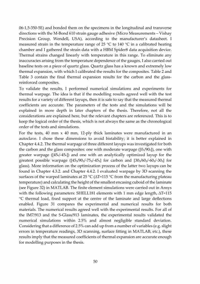
50
06-1,5-350-5E) and bonded them on the specimens in the longitudinal and transverse
directions with the M-Bond 610 strain gauge adhesive (Micro Measurements – Vishay
Precision Group, Wendell, USA), according to the manufacturer’s datasheet. I
measured strain in the temperature range of 25 °C to 140 °C in a calibrated heating
chamber and I gathered the strain data with a HBM Spider8 data acquisition device.
Thermal strains changed linearly with temperature in this range. To eliminate any
inaccuracies arising from the temperature dependence of the gauges, I also carried out
baseline tests on a piece of quartz glass. Quartz glass has a known and extremely low
thermal expansion, with which I calibrated the results for the composites. Table 2 and
Table 3 contain the final thermal expansion results for the carbon and the glass-
reinforced composites.
To validate the results, I performed numerical simulations and experiments for
thermal warpage. The idea is that if the modelling results agreed well with the test
results for a variety of different layups, then it is safe to say that the measured thermal
coefficients are accurate. The parameters of the tests and the simulations will be
explained in more depth in later chapters of the thesis. Therefore, not all the
considerations are explained here, but the relevant chapters are referenced. This is to
keep the logical order of the thesis, which is not always the same as the chronological
order of the tests and simulations.
For the tests, 40 mm x 40 mm, 12-ply thick laminates were manufactured in an
autoclave. I chose these dimensions to avoid bistability; it is better explained in
Chapter 4.4.2. The thermal warpage of three different layups was investigated for both
the carbon and the glass composites: one with moderate warpage ([06/906]), one with
greater warpage ([456/-456]) and one with an analytically optimized layup for the
greatest possible warpage ([45₃/90₃/-75₃/-45₃] for carbon and [30₃/60₃/-60₃/-30₃] for
glass). More information on the optimization process of the latter two layups can be
found in Chapter 4.3.2. and Chapter 4.4.2. I evaluated warpage by 3D scanning the
surfaces of the warped laminates at 25 °C (∆T=115 °C from the manufacturing plateau
temperature) and calculating the height of the smallest encasing cuboid of the laminate
(see Figure 32) in MATLAB. The finite element simulations were carried out in Ansys
with the following parameters: SHELL181 elements with 1 mm edge length, ∆T=115
°C thermal load, fixed support at the centre of the laminate and large deflections
enabled. Figure 31 compares the experimental and numerical results for both
materials. The numerical results agreed well with the experimental results. For all of
the IM7/913 and the S-Glass/913 laminates, the experimental results validated the
numerical simulations within 2.5% and almost negligible standard deviation.
Considering that a difference of 2.5% can add up from a number of variables (e.g. slight
errors in temperature readings, 3D scanning, surface fitting in MATLAB, etc.), these
results imply that the measured coefficients of thermal expansion are accurate enough
for modelling purposes in the thesis.
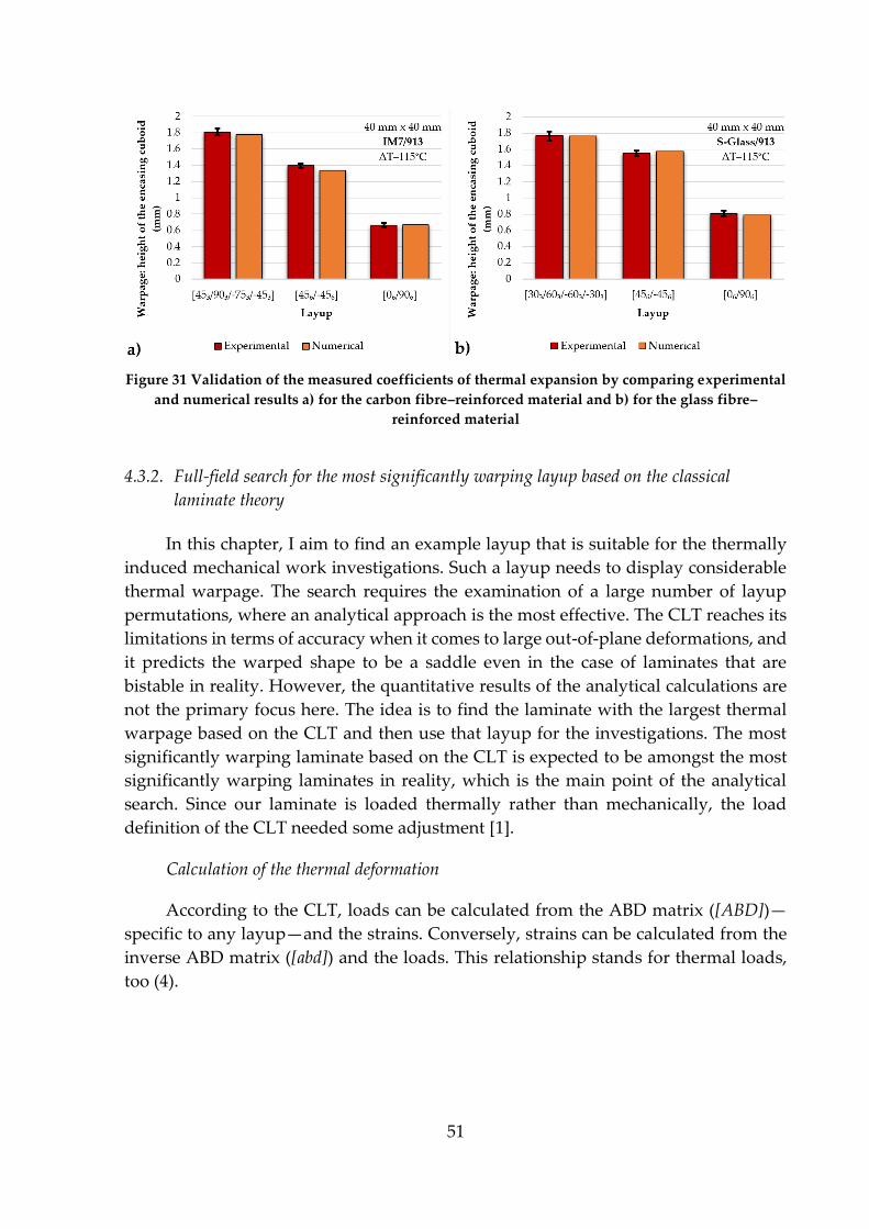
51
Figure 31 Validation of the measured coefficients of thermal expansion by comparing experimental
and numerical results a) for the carbon fibre–reinforced material and b) for the glass fibre–
reinforced material
4.3.2. Full-field search for the most significantly warping layup based on the classical
laminate theory
In this chapter, I aim to find an example layup that is suitable for the thermally
induced mechanical work investigations. Such a layup needs to display considerable
thermal warpage. The search requires the examination of a large number of layup
permutations, where an analytical approach is the most effective. The CLT reaches its
limitations in terms of accuracy when it comes to large out-of-plane deformations, and
it predicts the warped shape to be a saddle even in the case of laminates that are
bistable in reality. However, the quantitative results of the analytical calculations are
not the primary focus here. The idea is to find the laminate with the largest thermal
warpage based on the CLT and then use that layup for the investigations. The most
significantly warping laminate based on the CLT is expected to be amongst the most
significantly warping laminates in reality, which is the main point of the analytical
search. Since our laminate is loaded thermally rather than mechanically, the load
definition of the CLT needed some adjustment [1].
Calculation of the thermal deformation
According to the CLT, loads can be calculated from the ABD matrix ([ABD])—
specific to any layup—and the strains. Conversely, strains can be calculated from the
inverse ABD matrix ([abd]) and the loads. This relationship stands for thermal loads,
too (4).
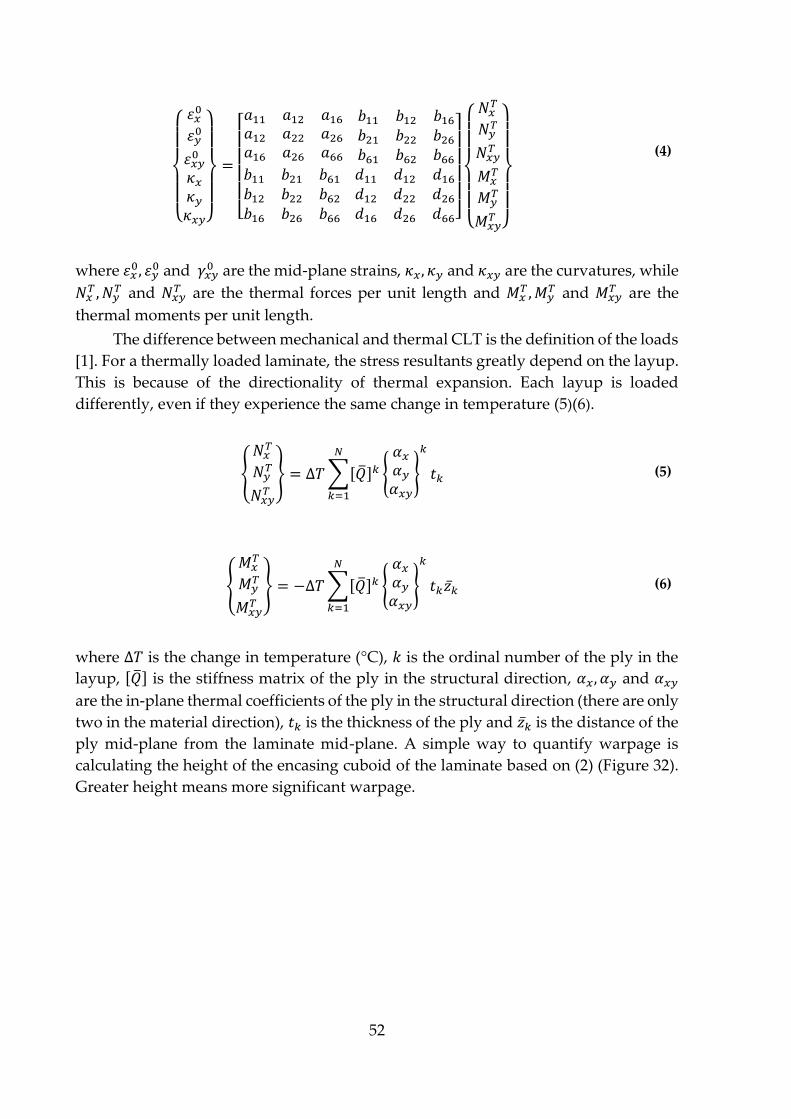
52
{
𝜀𝑥0
𝜀𝑦0
𝜀𝑥𝑦0
𝜅𝑥𝜅𝑦𝜅𝑥𝑦}
=
[ 𝑎11 𝑎12 𝑎16𝑎12 𝑎22 𝑎26𝑎16 𝑎26 𝑎66
𝑏11 𝑏12 𝑏16𝑏21 𝑏22 𝑏26𝑏61 𝑏62 𝑏66
𝑏11 𝑏21 𝑏61𝑏12 𝑏22 𝑏62𝑏16 𝑏26 𝑏66
𝑑11 𝑑12 𝑑16𝑑12 𝑑22 𝑑26𝑑16 𝑑26 𝑑66]
{
𝑁𝑥𝑇
𝑁𝑦𝑇
𝑁𝑥𝑦𝑇
𝑀𝑥𝑇
𝑀𝑦𝑇
𝑀𝑥𝑦𝑇 }
(4)
where 𝜀𝑥0, 𝜀𝑦
0 and 𝛾𝑥𝑦0 are the mid-plane strains, 𝜅𝑥, 𝜅𝑦 and 𝜅𝑥𝑦 are the curvatures, while
𝑁𝑥𝑇 , 𝑁𝑦
𝑇 and 𝑁𝑥𝑦𝑇 are the thermal forces per unit length and 𝑀𝑥
𝑇 , 𝑀𝑦𝑇 and 𝑀𝑥𝑦
𝑇 are the
thermal moments per unit length.
The difference between mechanical and thermal CLT is the definition of the loads
[1]. For a thermally loaded laminate, the stress resultants greatly depend on the layup.
This is because of the directionality of thermal expansion. Each layup is loaded
differently, even if they experience the same change in temperature (5)(6).
{
𝑁𝑥𝑇
𝑁𝑦𝑇
𝑁𝑥𝑦𝑇
} = ∆𝑇∑[�̅�]𝑘 {
𝛼𝑥𝛼𝑦𝛼𝑥𝑦
}
𝑘𝑁
𝑘=1
𝑡𝑘 (5)
{
𝑀𝑥𝑇
𝑀𝑦𝑇
𝑀𝑥𝑦𝑇
} = −∆𝑇∑[�̅�]𝑘 {
𝛼𝑥𝛼𝑦𝛼𝑥𝑦
}
𝑘𝑁
𝑘=1
𝑡𝑘𝑧�̅� (6)
where ∆𝑇 is the change in temperature (°C), 𝑘 is the ordinal number of the ply in the
layup, [�̅�] is the stiffness matrix of the ply in the structural direction, 𝛼𝑥, 𝛼𝑦 and 𝛼𝑥𝑦
are the in-plane thermal coefficients of the ply in the structural direction (there are only
two in the material direction), 𝑡𝑘 is the thickness of the ply and 𝑧�̅� is the distance of the
ply mid-plane from the laminate mid-plane. A simple way to quantify warpage is
calculating the height of the encasing cuboid of the laminate based on (2) (Figure 32).
Greater height means more significant warpage.

53
Figure 32 Height of the encasing cuboid (hencasing cuboid) of a warped laminate
Layup search with a MATLAB algorithm
For the calculations, simulations and experiments, I worked with Hexcel's
IM7/913 carbon-epoxy UD prepreg. Other than the data in Table 2, there are two
essential inputs for the calculations: the layup and the temperature change.
To allow for a full-field search, I analysed 4-ply laminates with a 15° orientation
increment (increment by which ply orientations can be rotated). With more than 20,000
possible layup permutations (permutation with repetition), this provided a good range
of mechanical behaviour to find a layup with a large out-of-plane deformation when
heated or cooled. At the same time, the computational effort needed for the
calculations was still manageable for a desktop PC with a 3.4 GHz central processing
unit (8 cores, 32 GB random access memory and 500 MB/s solid state drive storage). I
developed an algorithm in MATLAB that ran the thermal CLT calculations for every
layup permutation and found the layup with the greatest warpage. Thermal loads
were calculated from a temperature difference of ∆𝑇 = 115 °𝐶, because later I
manufactured the composites at an autoclave plateau temperature of 140 °C and
carried out the tests at room temperature (25 °C). Figure 33 illustrates the layup search
results, where each blue marker indicates the thermal warpage of one of the layups in
ascending order in terms of warpage. At the very beginning, there are symmetric
layups with no warpage at all. All the other layups are asymmetric and therefore warp
when heated or cooled. The laminate with a layup of [45/90/-75/-45] achieved the
greatest warpage. Therefore, I selected that laminate for the thermally induced
mechanical work investigations.
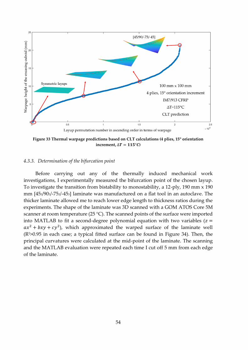
54
Figure 33 Thermal warpage predictions based on CLT calculations (4 plies, 15° orientation
increment, ∆𝑻 = 𝟏𝟏𝟓°𝑪)
4.3.3. Determination of the bifurcation point
Before carrying out any of the thermally induced mechanical work
investigations, I experimentally measured the bifurcation point of the chosen layup.
To investigate the transition from bistability to monostability, a 12-ply, 190 mm x 190
mm [453/903/-753/-453] laminate was manufactured on a flat tool in an autoclave. The
thicker laminate allowed me to reach lower edge length to thickness ratios during the
experiments. The shape of the laminate was 3D scanned with a GOM ATOS Core 5M
scanner at room temperature (25 °C). The scanned points of the surface were imported
into MATLAB to fit a second-degree polynomial equation with two variables (𝑧 =
𝑎𝑥2 + 𝑏𝑥𝑦 + 𝑐𝑦2), which approximated the warped surface of the laminate well
(R2>0.95 in each case; a typical fitted surface can be found in Figure 34). Then, the
principal curvatures were calculated at the mid-point of the laminate. The scanning
and the MATLAB evaluation were repeated each time I cut off 5 mm from each edge
of the laminate.

55
Figure 34 3D scan raw data (blue dots) and fitted second-order surface (colour surface).
Figure 35 illustrates the experimental results of the determination of the
bifurcation point. At each dimensional ratio, the relative standard deviation of the
principal curvatures was within ±3%; therefore, I visualized the average values of the
three sets of measurements for better clarity. The results show a characteristic change
of the principal curvatures as a function of the edge length to thickness ratio. Based on
results in the scientific literature, the bifurcation point can be identified just below a
length to thickness ratio of 60. In Figure 35, the transition from monostability to
bistability is indicated by a local minimum of the first principal curvature and a
significant change in the gradient of the second principal curvature. At lower
dimensional ratios, there is one stable shape of the laminate, and at higher ratios, there
are two. Even in the bistable region, I only investigated one of the stable shapes as it
provided all the necessary data for the following experiments and simulations. The
results in Figure 35 agreed well with my observations when I tested the snap-through
effect of the laminates. In the bistable region, the second principal curvature converges
to zero and the first principal curvature converges to a constant value with an
increasing dimensional ratio. With decreasing dimensional ratios, the curvatures start
to converge in the monostable region, too.
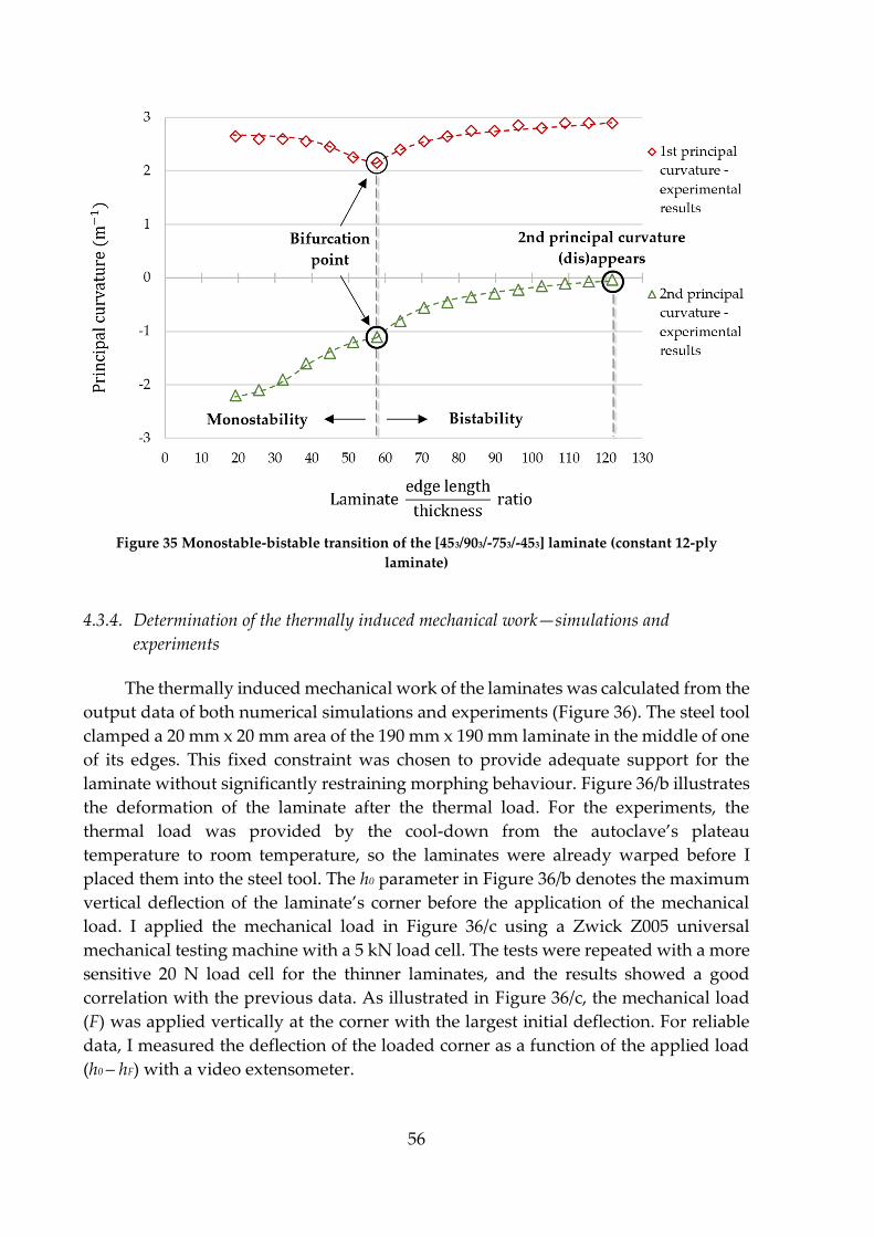
56
Figure 35 Monostable-bistable transition of the [453/903/-753/-453] laminate (constant 12-ply
laminate)
4.3.4. Determination of the thermally induced mechanical work—simulations and
experiments
The thermally induced mechanical work of the laminates was calculated from the
output data of both numerical simulations and experiments (Figure 36). The steel tool
clamped a 20 mm x 20 mm area of the 190 mm x 190 mm laminate in the middle of one
of its edges. This fixed constraint was chosen to provide adequate support for the
laminate without significantly restraining morphing behaviour. Figure 36/b illustrates
the deformation of the laminate after the thermal load. For the experiments, the
thermal load was provided by the cool-down from the autoclave’s plateau
temperature to room temperature, so the laminates were already warped before I
placed them into the steel tool. The h0 parameter in Figure 36/b denotes the maximum
vertical deflection of the laminate’s corner before the application of the mechanical
load. I applied the mechanical load in Figure 36/c using a Zwick Z005 universal
mechanical testing machine with a 5 kN load cell. The tests were repeated with a more
sensitive 20 N load cell for the thinner laminates, and the results showed a good
correlation with the previous data. As illustrated in Figure 36/c, the mechanical load
(F) was applied vertically at the corner with the largest initial deflection. For reliable
data, I measured the deflection of the loaded corner as a function of the applied load
(h0 – hF) with a video extensometer.

57
I used 1 mm SOLID185 elements during the numerical simulations to ensure
mesh convergence. A fixed support was applied at the previously mentioned 20 mm
x 20 mm area on both sides of the flat laminate. With large deflections enabled, the first
step of the simulation gave a solution for an applied ∆T=−115 °C (to replicate the cool-
down step of the manufacturing process from 140 °C to 25 °C). The second step
provided a solution for the applied vertical force at the loaded corner at constant
temperature (25 °C). Then, the mechanical work was calculated from the applied force
and the height of the loaded corner compared to the flat state of the laminate.
Figure 36 Schematics of the thermally induced mechanical work test setup (n=1, 2, …, 7 for the
experiments and n=1, 2, …, 10 for the numerical simulations), where h0 is the lift height without
mechanical load and hF is the lift height under mechanical load
Figure 37 illustrates the numerically and experimentally obtained deflections of
the loaded corner of the investigated 190 mm x 190 mm laminates as a function of the
applied mechanical load and the number of plies in the specimens. Experiments were
carried out up to 28 plies. The experimentally investigated laminates covered the
region from monostability (28-ply laminate: a length to thickness ratio of 52) to
bistability with negligible second principal curvature (4-ply laminate: a length to
thickness ratio of 365). As the transition between bistability and monostability is the
most interesting region in terms of the changes in mechanical work, I did not test
further monostable laminates thicker than 28 plies to limit prepreg expenditure. For
each laminate thickness, the relative standard deviation of the results was within ±2%;
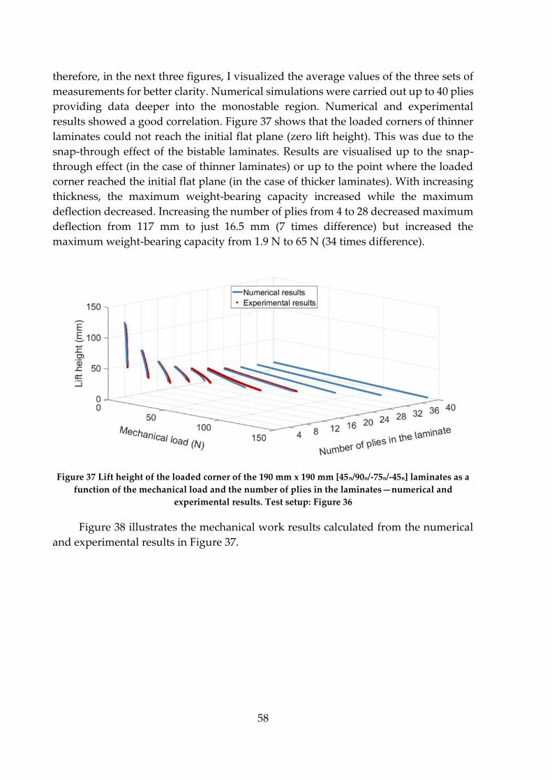
58
therefore, in the next three figures, I visualized the average values of the three sets of
measurements for better clarity. Numerical simulations were carried out up to 40 plies
providing data deeper into the monostable region. Numerical and experimental
results showed a good correlation. Figure 37 shows that the loaded corners of thinner
laminates could not reach the initial flat plane (zero lift height). This was due to the
snap-through effect of the bistable laminates. Results are visualised up to the snap-
through effect (in the case of thinner laminates) or up to the point where the loaded
corner reached the initial flat plane (in the case of thicker laminates). With increasing
thickness, the maximum weight-bearing capacity increased while the maximum
deflection decreased. Increasing the number of plies from 4 to 28 decreased maximum
deflection from 117 mm to just 16.5 mm (7 times difference) but increased the
maximum weight-bearing capacity from 1.9 N to 65 N (34 times difference).
Figure 37 Lift height of the loaded corner of the 190 mm x 190 mm [45n/90n/-75n/-45n] laminates as a
function of the mechanical load and the number of plies in the laminates—numerical and
experimental results. Test setup: Figure 36
Figure 38 illustrates the mechanical work results calculated from the numerical
and experimental results in Figure 37.

59
Figure 38 Mechanical work calculated at the loaded corner of the 190 mm x 190 mm [45n/90n/-75n/-
45n] laminates as a function of the mechanical load and the number of plies in the laminates—
numerical and experimental results. Test setup: Figure 36
The test and simulation results agreed well up to 16 plies and then slightly
separated from each other before getting closer together again at 28 plies. The
separation took place close to the bifurcation point, where the numerical simulations
slightly underestimated the measured mechanical work. Nevertheless, the numerical
and experimental results showed a similar trend in terms of thermally induced work.
Figure 39/a illustrates the change in the maximum achievable work for each
laminate as a function of their length to thickness ratio, and Figure 39/b shows the
measured and simulated principal curvatures of the 190 mm x 190 mm laminates as a
function of their length to thickness ratio. The two subfigures allow for a visual
comparison between characteristic points in the work graph and the stability
(principal curvature) graph.

60
Figure 39 Numerical and experimental results of the a) maximum thermally induced work and b)
principal curvatures of the [45n/90n/-75n/-45n] laminates as a function of their dimensional ratio
(constant 190 mm x 190 mm laminates)
In Figure 39, I evaluate the results from right to left, starting from the thin bistable
laminates and moving towards the thick monostable laminates. The most notable
result is that the maximum work goes through a local maximum and then a local
minimum. The local maximum of the maximal work can be found at around a
dimensional ratio of 125 (12-ply laminate) in Figure 39/a. Up to that point, the maximal
work increases with increasing laminate thickness, which is expected. The local
maximum is very close to the appearance of the 2nd principal curvature in Figure 39/b,
implying a causal relationship between the two. Up to that point, the 1st principal
curvature decreases, but the 2nd principal curvature is still negligible. However, after
the dimensional ratio of 125, the shape of the laminate changes qualitatively, too, with
the appearance of the 2nd principal curvature. Note that Figure 39/b provides similar
results to Figure 35, the main difference being that previously I kept laminate thickness

61
constant and later, I kept the edge length of the laminate constant. This resulted in
seemingly different graphs, but both the appearance of the 2nd principal curvature (at
a dimensional ratio of around 125) and the bifurcation point (at a dimensional ratio of
around 60) can be identified in either figure. The local minimum of the maximal work
can be found around a dimensional ratio of 70 in Figure 39/a. This is slightly off from
the bifurcation point. It was expected that after the bifurcation point (in the monostable
region), the maximal work will increase with increasing thickness, and the numerical
and experimental results confirmed this. However, this in itself does not explain why
the increase of maximal work starts even before the bifurcation point is reached. I
believe that this is due to the complex effect of the increasing 2nd principal curvature
(which was shown to reduce maximal work) and the increase of relative thickness
(which was shown to increase maximal work). The effect of increasing relative
thickness seems to outweigh the effect of the increasing 2nd principal curvature before
reaching the bifurcation point. This is the reason why the local minimum of the
maximal work does not overlap with the bifurcation point.
From a practical standpoint, this characteristic change of the maximal work can be
exploited to save weight with bistable laminates. Based on the experimental results,
the 12-ply laminates achieved about the same maximum thermally induced work as
the laminates twice the thickness, but at larger deformations and lower mechanical
loads. The results depend on various factors: e.g. material properties, stacking
sequence, laminate dimensions, boundary conditions and load application. The
numerical and experimental study in this publication serves as a proof of concept.
In this chapter (Chapter 4.3), I investigated how thermal warpage of asymmetric
composite laminates can be exploited. The next chapter (Chapter 4.4) investigates
methods that can be used to mitigate thermal warpage, and discusses their effects on
certain shape-changing characteristics of asymmetric laminates.
4.4. Warpage mitigation and shape-changing
This chapter discusses potential ways to mitigate a common manufacturing issue
of coupled composites; thermal warpage. Coupled composites often have asymmetric
layups. This asymmetry usually results in out-of-plane deformations under in-plane
mechanical loads or thermal loads. As composite manufacturing usually requires
heating and subsequent cooling, the thermal stresses can lead to laminate warpage.
This phenomenon greatly limits the design-freedom and therefore the unwanted
warpage needs to be reduced.
In this chapter, I investigate three different concepts to tackle the heat-induced
warpage of composites. I also investigate how each method affects certain shape-
changing characteristics of the laminates.
The first approach builds on the controlled dewarping of the laminate. To exploit the
benefits of the thermally induced mechanical work of composites in the industry, we
have to mitigate their manufacturing-induced warpage. It is the same thermal loads
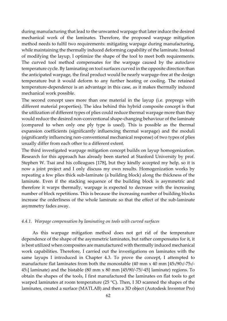
62
during manufacturing that lead to the unwanted warpage that later induce the desired
mechanical work of the laminates. Therefore, the proposed warpage mitigation
method needs to fulfil two requirements: mitigating warpage during manufacturing,
while maintaining the thermally induced deforming capability of the laminate. Instead
of modifying the layup, I optimize the shape of the tool to meet both requirements.
The curved tool method compensates for the warpage caused by the autoclave
temperature cycle. By laminating on tool surfaces curved in the opposite direction than
the anticipated warpage, the final product would be nearly warpage-free at the design
temperature but it would deform to any further heating or cooling. The retained
temperature-dependence is an advantage in this case, as it makes thermally induced
mechanical work possible.
The second concept uses more than one material in the layup (i.e. prepregs with
different material properties). The idea behind this hybrid composite concept is that
the utilization of different types of plies could reduce thermal warpage more than they
would reduce the desired non-conventional shape-changing behaviour of the laminate
(compared to when only one ply type is used). This is possible as the thermal
expansion coefficients (significantly influencing thermal warpage) and the moduli
(significantly influencing non-conventional mechanical response) of two types of plies
usually differ from each other to a different extent.
The third investigated warpage mitigation concept builds on layup homogenization.
Research for this approach has already been started at Stanford University by prof.
Stephen W. Tsai and his colleagues [178], but they kindly accepted my help, so it is
now a joint project and I only discuss my own results. Homogenization works by
repeating a few plies thick sub-laminate (a building block) along the thickness of the
laminate. Even if the stacking sequence of the building block is asymmetric and
therefore it warps thermally, warpage is expected to decrease with the increasing
number of block repetitions. This is because the increasing number of building blocks
increase the orderliness of the whole laminate so that the effect of the sub-laminate
asymmetry fades away.
4.4.1. Warpage compensation by laminating on tools with curved surfaces
As this warpage mitigation method does not get rid of the temperature
dependence of the shape of the asymmetric laminates, but rather compensates for it, it
is best utilized when composites are manufactured with thermally induced mechanical
work capabilities. Therefore, I carried out the investigations on laminates with the
same layups I introduced in Chapter 4.3. To prove the concept, I attempted to
manufacture flat laminates from both the monostable (40 mm x 40 mm [453/903/-753/-
453] laminate) and the bistable (80 mm x 80 mm [45/90/-75/-45] laminate) regions. To
obtain the shapes of the tools, I first manufactured the laminates on flat tools to get
warped laminates at room temperature (25 °C). Then, I 3D scanned the shapes of the
laminates, created a surface (MATLAB) and then a 3D object (Autodesk Inventor Pro)

63
from the data points, and finally, CNC milled (Roland MDX-540) the tools from
aluminium. Then I repeated the autoclave manufacturing process, now laminating on
the curved tools and flipping the laminates to ensure that deformations occur in the
right directions. Flipping was equivalent to laminating [-45n/-15n/0n/45n] laminates
instead of [45n/90n/-75n/-45n] laminates in the same orientation. After manufacturing, I
3D scanned the shapes of the laminates compensated by the tool and evaluated their
warpage in MATLAB.
The ratio of the principal curvatures allows us to sort the shapes into monostable
and bistable categories in the investigated range. In this chapter, the principal
curvatures always coincided with the diagonal (xy and yx direction) curvatures. Based
on Figure 35 and Figure 39/b, the ratio of the absolute values of the first (|𝜅1𝑝𝑟𝑖𝑛𝑐.
|) and
the second (|𝜅2𝑝𝑟𝑖𝑛𝑐.
|) principal curvatures at the bifurcation point is about 2 (1:0.5). Any
ratio significantly higher than this indicates a bistable shape, and a ratio significantly
lower than this indicates a monostable shape, as Figure 35 shows.
Figure 40 contains all the important data and results for the first warpage
mitigation experiment. In Figure 40, Figure 41 and Figure 42, I illustrate the results of
the laminates closest to the average of the measured specimens, which does not alter
visual evaluation significantly because of the low standard deviations shown later. The
top part of the figure illustrates the shape of the aluminium tool on which the
composite was laminated before it was cured in the autoclave. Because the 80 mm x 80
mm [45/90/-75/-45] laminate is bistable when laminated on a flat tool (dimensional
ratio of 154), the curved tool surface only had one significant principal curvature. With
the “bistable-shaped” curved tool, I achieved a slight average warpage mitigation of
11.7%, shown by the reduction of the height of the encasing cuboid from 12.0 mm (±0.2
mm) to 10.6 mm (±0.2 mm). The original curvature practically vanished, but the other
(so far hiding) principal curvature appeared, resulting in another bistable laminate.

64
Figure 40 Warpage mitigation results of the 80 mm x 80 mm 4-ply laminate with a single curvature
tool
The results suggest that both principal curvatures have to be compensated for at
the same time, even if one of them is “hiding” (practically zero) as in the case of bistable
laminates. In the next experiment, I designed and manufactured a tool based on the
tool in Figure 40, but now including the second principal curvature with the same
magnitude but opposite sign compared to the first principal curvature. This resulted
in a “monostable-shaped” tool about twice the height of the tool in Figure 40. Figure
41 illustrates the results achieved with the “monostable shaped” tool. Compared to the
original bistable laminate, I achieved a 23.3% decrease in warpage, shown by the
reduction of the height of the encasing cuboid from 12.0 mm (±0.2 mm) to 9.2 mm (±0.3
mm). The warpage mitigation achieved with the “monostable-shaped” tool was about
double what I achieved with the “bistable-shaped” tool. But the most important result
is the shape of the final laminate: the composite became monostable. This observation
was confirmed by the ratio of the principal curvatures, which was 1:0.93.

65
Figure 41 Warpage mitigation results of the 80 mm x 80 mm 4-ply laminate with a double curvature
tool
After successfully transforming the bistable laminate into a monostable one, I
investigated the effectiveness of the tool compensation method on monostable
laminates. Figure 42 illustrates the results of laminating the 12-ply [453/903/-753/-453] 40
mm x 40 mm laminate (dimensional ratio of 26) on a “monostable-shaped” tool.
Warpage was reduced by more than 90%, shown by the decrease in the height of the
encasing cuboid from 1.79 mm (±0.05 mm) to 0.16 (±0.02 mm) mm. Furthermore, the
final laminate was indistinguishable from a flat laminate; only the 3D scanner revealed
the slight residual curvatures. The final laminate satisfied the specification of the
ISO2768K standard, and therefore it can be classified as practically flat.
66
Figure 42 Warpage mitigation results of the 40 mm x 40 mm 12-ply laminate with a double
curvature tool
The results show that the tool compensation method can transform bistable
laminates into monostable laminates and that it is capable of drastically mitigating the
manufacturing-induced thermal warpage of monostable laminates. Based on these
findings, I expect that the warpage of bistable laminates can be mitigated with similar
success to that of monostable laminates. The results imply that this requires
“monostable-shaped” tools, which I will investigate numerically and experimentally
in the future.
The intrinsic shape-changing characteristics of the laminate do not change
significantly with this warpage compensation method. The reason for this is the
unchanged layup of the laminate. The modified initial geometry can influence
morphing behaviour, but this is not specific to the present warpage compensation
method and investigating initial geometry problems is beyond the scope of my thesis.
4.4.2. Warpage mitigation and improved shape-changing via layup hybridization
The hybrid layup warpage mitigation method fundamentally differs from the
curved tool method in that it changes the intrinsic shape-changing characteristics of
the laminate by modifying its layup. Composites can be hybridized in many ways: we
can bring together different kinds of matrices or reinforcements in one laminate in a
great variety (e.g. glass-carbon or carbon1-carbon2 hybrids). In this thesis, I use two
kinds of plies: both with the same epoxy matrix, but one with UD carbon reinforcement
67
(relevant properties in Table 2) and one with UD glass reinforcement (relevant
properties in Table 3). Using plies with the same type of matrix is important to avoid
compatibility issues during manufacturing.
The idea of the hybrid layup method is that the two types of plies with different
mechanical and thermal properties could interact with each other in a way that results
in a form of behaviour that is not possible with non-hybrid (mono) laminates. The goal
is to mitigate thermal warpage while maximizing a chosen desired shape-changing
characteristic of the composite (e.g. twisting under bending or tensile load). The hybrid
method is successful if, out of all the practically warpage-free laminates, it is one of the
hybrids that achieves the largest desired shape-changing deformation. I defined the
practical limit of flatness based on the ISO 2768 standard, once again. To investigate
the potential and limits of the method, I carried out a full-field layup optimization
study.
To draw reliable conclusions from the layup optimization study, I needed an
approach that provides quantitatively accurate results. Therefore, this time I carried
out the optimization numerically in Ansys instead of analytically in MATLAB. As
numerical calculations are significantly slower than analytical calculations, I increased
the orientation increment of the plies to 45° to decrease the number of layup
permutations. This way, each ply in the laminate could be placed in either of the four
“industry-standard” orientations: 0°, 45°, -45° and 90°. I investigated 40 mm x 40 mm
laminates with practically 4, but actually 12 plies as each ply had 3 times the thickness
of that in Table 2 and Table 3 (i.e. 0.39 mm thick carbon-epoxy and 0.45 mm thick glass-
epoxy plies). The reason for this was to avoid complications arising from bistability. In
Chapter 4.3.3, Figure 35 illustrates that the most significantly warping carbon-epoxy
laminate ([45₃/90₃/-75₃/-45₃]) has its bifurcation point at around a laminate edge length
to thickness ratio of 60. Later, I ran an analytical layup optimization study to find the
most significantly warping glass-epoxy layup, too, similarly to the optimization in
Figure 33. Then, I carried out a similar 3D scanning study to Figure 35 for the most
significantly warping glass-epoxy laminate ([30₃/60₃/-60₃/-30₃]) and found its
bifurcation point at around a dimensional ratio of 100. Based on the results, I chose 40
mm x 40 mm 12-ply (4x3 plies) thick laminates for further experiments, which means
a dimensional ratio of around 22 (40 mm/(4*0.45 mm)) for the glass-epoxy laminates
and around 26 (40 mm/(4*0.39 mm)) for the carbon-epoxy laminates. I chose the
dimensions and the number of plies in the laminate to be far from bistability, without
the small size of the specimens causing any issues during the 3D scanning or
mechanical experiments. The safe distance from the bifurcation point was also meant
to ensure that not only the mono laminates but all the hybrid layups stay within the
monostable region.
After building up the numerical models and running the mesh convergence
studies, I ran the simulations for all 4096 of the layup permutations (512 mono and
3584 hybrid layups). In fact, three simulations were run for each of the permutations
(one for thermal warpage, one for bend-twist and one for extension-twist shape-
68
changing), making the total number of the simulations 12288. I automated most of the
solution process of the parametric studies in Ansys, so the total time of the solution
took only slightly over a week as the computer was working on the problem almost
non-stop. For the warpage (see schematics in Figure 19/a) and bend-twist (see
schematics in Figure 19/c) simulations, I used shell elements during the simulations as
solid simulations would have taken significantly longer to solve and shell and solid
results differed less than 1% even at large deformations during my preliminary
investigations. On the other hand, some of the preliminary extension-twist (see
schematics in Figure 19/b) simulations showed larger differences between the shell
and the solid results, so there I used solid elements for more accurate results. The first
set of simulations was run for thermal warpage with the following parameters: 1 mm
uniform, square SHELL181 elements, laminate fixed at its mid-point, thermal load
∆T=115 °C (cool-down from the autoclave plateau temperature of 140 °C to room
temperature 25 °C) and large deflections enabled. The second set of simulations solved
for twisting under a bending load (displacement in z-direction) with the following
parameters: 1 mm uniform, square SHELL181 elements, laminate fixed along one of
its edges (along x) and out-of-plane displacement applied at a circular area with 2 mm
radius at the middle of its opposite edge (similarly to Figure 26/b and with automatic
meshing in the proximity of the circular area) with large deflections enabled. From the
results, I calculated the torsional angle of the loaded edge from the coordinates of its
two end-points at 5 mm of its mid-point deflection. The last set of simulations also
examined the twisting deformation of the laminate, but instead of a bending load, the
specimens were subjected to a tensile load. Twisting deformation under tension is
governed by different terms of the ABD matrix than twisting deformation under a
bending load, so I expected the results of the two studies to be significantly different.
The extension-twist simulations were carried out similarly to the bend-twist
simulations, but with 1 mm uniform, square SOLID185 elements, applied longitudinal
displacement of the loaded edge (free movement of the edge otherwise), and torsion
was calculated at 0.5% (0.2 mm) longitudinal strain. I chose the displacement of the
loaded edge instead of the applied force mainly to avoid aborted simulations due to
the order of magnitude differences in the directional stiffness of different laminates
(e.g. laminates with only longitudinal reinforcement vs. laminates with only transverse
reinforcement).
Figure 43 illustrates the results of the warpage and bend-twist performance of
the 4096 mono and hybrid layups. Based on the ISO 2768 standard, any laminate below
the dashed red line (0.4 mm encasing cuboid height) is practically warpage-free. Any
laminate above the limit of flatness is disqualified due to too large deformation, but
laminates under the limit are not differentiated based on the magnitude of their
warpage, only based on their twisting deformation under bending load. Therefore, the
best laminate is the one with the largest twisting deformation that is still under the
limit of flatness. Based on the numerical results, the optimal layup for the combined
criteria is a full carbon laminate ([45₃/90₃/90₃/45₃]), which is not only a mono laminate,
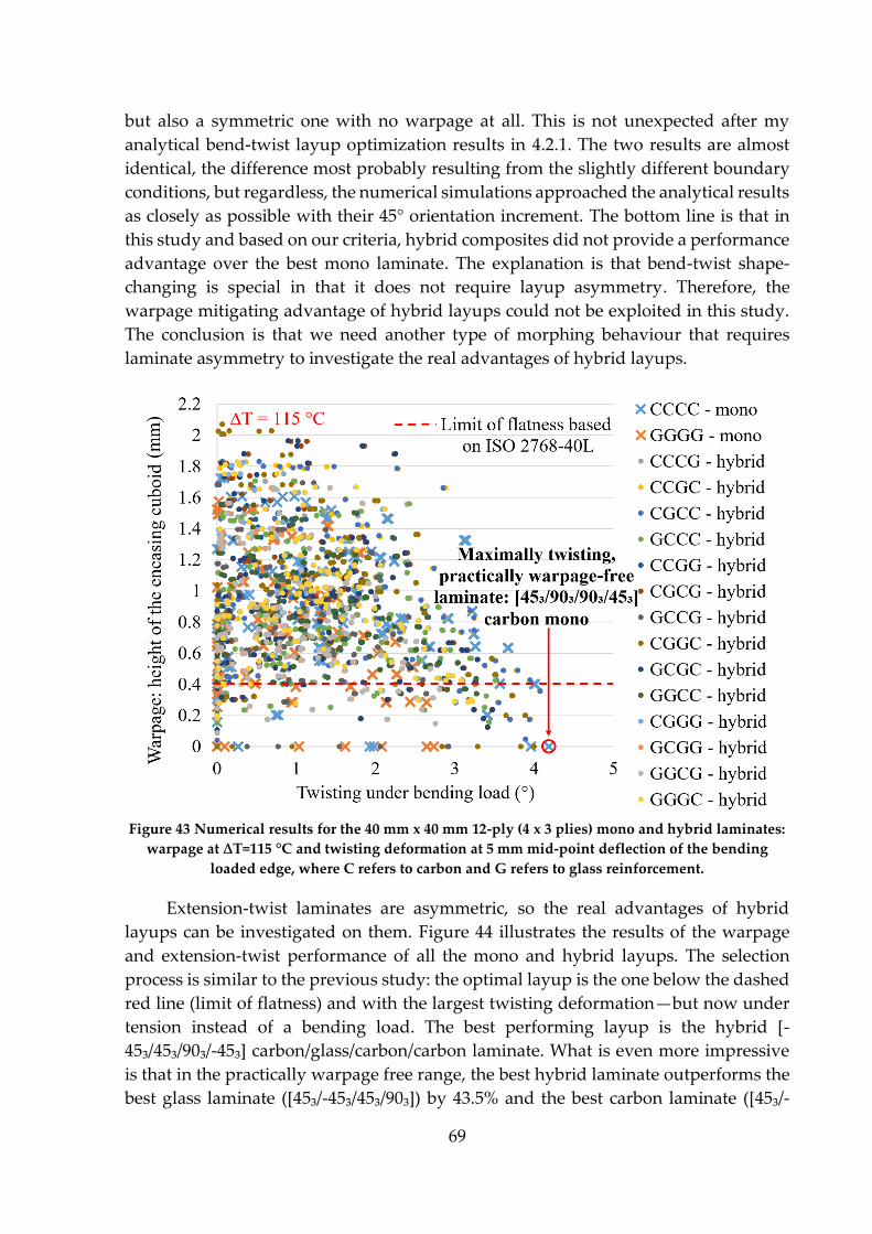
69
but also a symmetric one with no warpage at all. This is not unexpected after my
analytical bend-twist layup optimization results in 4.2.1. The two results are almost
identical, the difference most probably resulting from the slightly different boundary
conditions, but regardless, the numerical simulations approached the analytical results
as closely as possible with their 45° orientation increment. The bottom line is that in
this study and based on our criteria, hybrid composites did not provide a performance
advantage over the best mono laminate. The explanation is that bend-twist shape-
changing is special in that it does not require layup asymmetry. Therefore, the
warpage mitigating advantage of hybrid layups could not be exploited in this study.
The conclusion is that we need another type of morphing behaviour that requires
laminate asymmetry to investigate the real advantages of hybrid layups.
Figure 43 Numerical results for the 40 mm x 40 mm 12-ply (4 x 3 plies) mono and hybrid laminates:
warpage at ∆T=115 °C and twisting deformation at 5 mm mid-point deflection of the bending
loaded edge, where C refers to carbon and G refers to glass reinforcement.
Extension-twist laminates are asymmetric, so the real advantages of hybrid
layups can be investigated on them. Figure 44 illustrates the results of the warpage
and extension-twist performance of all the mono and hybrid layups. The selection
process is similar to the previous study: the optimal layup is the one below the dashed
red line (limit of flatness) and with the largest twisting deformation—but now under
tension instead of a bending load. The best performing layup is the hybrid [-
45₃/45₃/90₃/-45₃] carbon/glass/carbon/carbon laminate. What is even more impressive
is that in the practically warpage free range, the best hybrid laminate outperforms the
best glass laminate ([45₃/-45₃/45₃/90₃]) by 43.5% and the best carbon laminate ([45₃/-
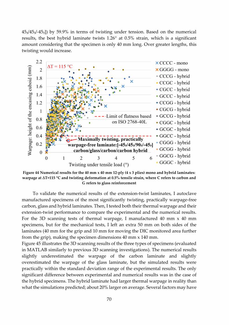
70
45₃/45₃/-45₃]) by 59.9% in terms of twisting under tension. Based on the numerical
results, the best hybrid laminate twists 1.26° at 0.5% strain, which is a significant
amount considering that the specimen is only 40 mm long. Over greater lengths, this
twisting would increase.
Figure 44 Numerical results for the 40 mm x 40 mm 12-ply (4 x 3 plies) mono and hybrid laminates:
warpage at ∆T=115 °C and twisting deformation at 0.5% tensile strain, where C refers to carbon and
G refers to glass reinforcement
To validate the numerical results of the extension-twist laminates, I autoclave
manufactured specimens of the most significantly twisting, practically warpage-free
carbon, glass and hybrid laminates. Then, I tested both their thermal warpage and their
extension-twist performance to compare the experimental and the numerical results.
For the 3D scanning tests of thermal warpage, I manufactured 40 mm x 40 mm
specimens, but for the mechanical tests, I left an extra 50 mm on both sides of the
laminates (40 mm for the grip and 10 mm for moving the DIC monitored area further
from the grip), making the specimen dimensions 40 mm x 140 mm.
Figure 45 illustrates the 3D scanning results of the three types of specimens (evaluated
in MATLAB similarly to previous 3D scanning investigations). The numerical results
slightly underestimated the warpage of the carbon laminate and slightly
overestimated the warpage of the glass laminate, but the simulated results were
practically within the standard deviation range of the experimental results. The only
significant difference between experimental and numerical results was in the case of
the hybrid specimens. The hybrid laminate had larger thermal warpage in reality than
what the simulations predicted; about 20% larger on average. Several factors may have
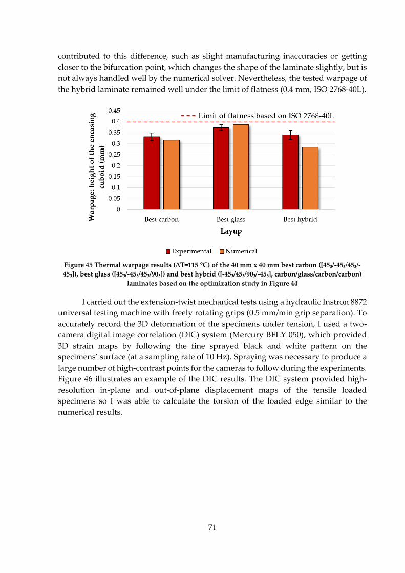
71
contributed to this difference, such as slight manufacturing inaccuracies or getting
closer to the bifurcation point, which changes the shape of the laminate slightly, but is
not always handled well by the numerical solver. Nevertheless, the tested warpage of
the hybrid laminate remained well under the limit of flatness (0.4 mm, ISO 2768-40L).
Figure 45 Thermal warpage results (∆T=115 °C) of the 40 mm x 40 mm best carbon ([45₃/-45₃/45₃/-
45₃]), best glass ([45₃/-45₃/45₃/90₃]) and best hybrid ([-45₃/45₃/90₃/-45₃], carbon/glass/carbon/carbon)
laminates based on the optimization study in Figure 44
I carried out the extension-twist mechanical tests using a hydraulic Instron 8872
universal testing machine with freely rotating grips (0.5 mm/min grip separation). To
accurately record the 3D deformation of the specimens under tension, I used a two-
camera digital image correlation (DIC) system (Mercury BFLY 050), which provided
3D strain maps by following the fine sprayed black and white pattern on the
specimens’ surface (at a sampling rate of 10 Hz). Spraying was necessary to produce a
large number of high-contrast points for the cameras to follow during the experiments.
Figure 46 illustrates an example of the DIC results. The DIC system provided high-
resolution in-plane and out-of-plane displacement maps of the tensile loaded
specimens so I was able to calculate the torsion of the loaded edge similar to the
numerical results.
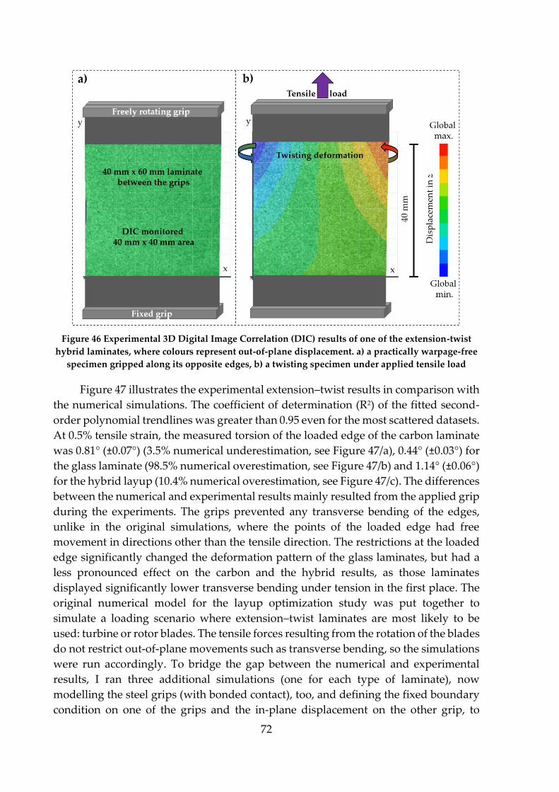
72
Figure 46 Experimental 3D Digital Image Correlation (DIC) results of one of the extension-twist
hybrid laminates, where colours represent out-of-plane displacement. a) a practically warpage-free
specimen gripped along its opposite edges, b) a twisting specimen under applied tensile load
Figure 47 illustrates the experimental extension–twist results in comparison with
the numerical simulations. The coefficient of determination (R2) of the fitted second-
order polynomial trendlines was greater than 0.95 even for the most scattered datasets.
At 0.5% tensile strain, the measured torsion of the loaded edge of the carbon laminate
was 0.81° (±0.07°) (3.5% numerical underestimation, see Figure 47/a), 0.44° (±0.03°) for
the glass laminate (98.5% numerical overestimation, see Figure 47/b) and 1.14° (±0.06°)
for the hybrid layup (10.4% numerical overestimation, see Figure 47/c). The differences
between the numerical and experimental results mainly resulted from the applied grip
during the experiments. The grips prevented any transverse bending of the edges,
unlike in the original simulations, where the points of the loaded edge had free
movement in directions other than the tensile direction. The restrictions at the loaded
edge significantly changed the deformation pattern of the glass laminates, but had a
less pronounced effect on the carbon and the hybrid results, as those laminates
displayed significantly lower transverse bending under tension in the first place. The
original numerical model for the layup optimization study was put together to
simulate a loading scenario where extension–twist laminates are most likely to be
used: turbine or rotor blades. The tensile forces resulting from the rotation of the blades
do not restrict out-of-plane movements such as transverse bending, so the simulations
were run accordingly. To bridge the gap between the numerical and experimental
results, I ran three additional simulations (one for each type of laminate), now
modelling the steel grips (with bonded contact), too, and defining the fixed boundary
condition on one of the grips and the in-plane displacement on the other grip, to
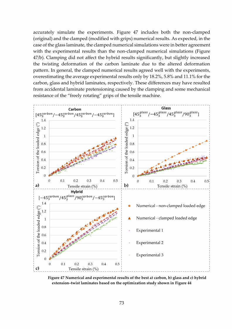
73
accurately simulate the experiments. Figure 47 includes both the non-clamped
(original) and the clamped (modified with grips) numerical results. As expected, in the
case of the glass laminate, the clamped numerical simulations were in better agreement
with the experimental results than the non-clamped numerical simulations (Figure
47/b). Clamping did not affect the hybrid results significantly, but slightly increased
the twisting deformation of the carbon laminate due to the altered deformation
pattern. In general, the clamped numerical results agreed well with the experiments,
overestimating the average experimental results only by 18.2%, 5.8% and 11.1% for the
carbon, glass and hybrid laminates, respectively. These differences may have resulted
from accidental laminate pretensioning caused by the clamping and some mechanical
resistance of the “freely rotating” grips of the tensile machine.
Figure 47 Numerical and experimental results of the best a) carbon, b) glass and c) hybrid
extension–twist laminates based on the optimization study shown in Figure 44
74
In conclusion, the best hybrid layup outperformed the best mono layup by 43.5%
based on the original (non-clamped) numerical simulations, by 32.6% based on the
modified (clamped) numerical simulations and by 40.7% based on the experimental
results in terms of extension–twist performance. The results prove that hybrid
laminates can offer significant advantages over mono laminates when it comes to the
extension–twist performance of practically warpage-free laminates. Or from another
perspective: I proved that with hybrid laminates, we can achieve a given extension–
twist performance while keeping the laminate practically warpage-free, while that
extension–twist performance is only possible with mono laminates if they demonstrate
significant thermal warpage. In this regard, layup hybridization is an effective way to
mitigate the warpage of shape-changing composites.
4.4.3. Layup homogenization
Layup homogenization is the method of repeating identical sub-laminates on top
of each other until the desired laminate thickness is reached. This can have multiple
advantages. The laminate's strength and toughness can increase due to the more
localized effects of ply group failure and better stress redistribution compared to
laminates with thicker ply groups. Also, the fewer plies the sub-laminates consist of,
the easier the layup optimization process becomes [164, 168, 178].
The advantage of homogenization I am focusing on in this thesis is its capability of
mitigating the unwanted warpage of non-symmetric layups. I show that layup
homogenization is a powerful method to mitigate warpage, and it opens new
possibilities for optimizing composite layups, ultimately leading to better optimized
and, therefore, lighter structures. Closely related to layup homogenization, Chapter
4.5 will investigate a novel layup design method with its advantages.
In this chapter, all the experiments, numerical simulations and analytical calculations
were carried out for 32-ply 150 mm x 150 mm IM7/913 CFRP laminates.
[0/90] cross-ply layup homogenization
[0/90] is the simplest cross-ply laminate, and hence the choice of layup to
demonstrate the effectiveness of layup homogenization on. Due to its asymmetry, it
warps thermally, and the 2-ply sub-laminate enables investigating the effects of layup
homogenization on 5 different levels for a total of 32 plies. The five laminates from
least homogenized to most homogenized have the following layups: [016/9016]; [08/908]2;
[04/904]4; [02/902]8 and [0/90]16. These layups have levels of homogenization of 1, 2, 4, 8
and 16, respectively, where the “level of homogenization” phrase refers to the number
of repetitions of identical sub-laminates in the laminate.
I numerically investigated the effect of homogenization on thermal warpage and
validated the results experimentally (Figure 48). The finite element simulations were
carried out similarly to the simulations in Chapter 4.4.2 (i.e. SHELL181 elements with
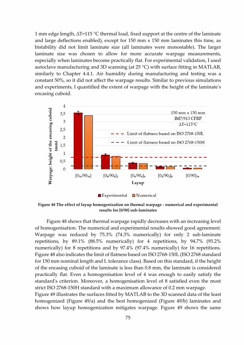
75
1 mm edge length, ∆T=115 °C thermal load, fixed support at the centre of the laminate
and large deflections enabled), except for 150 mm x 150 mm laminates this time, as
bistability did not limit laminate size (all laminates were monostable). The larger
laminate size was chosen to allow for more accurate warpage measurements,
especially when laminates become practically flat. For experimental validation, I used
autoclave manufacturing and 3D scanning (at 25 °C) with surface fitting in MATLAB,
similarly to Chapter 4.4.1. Air humidity during manufacturing and testing was a
constant 50%, so it did not affect the warpage results. Similar to previous simulations
and experiments, I quantified the extent of warpage with the height of the laminate's
encasing cuboid.
Figure 48 The effect of layup homogenization on thermal warpage - numerical and experimental
results for [0/90] sub-laminates
Figure 48 shows that thermal warpage rapidly decreases with an increasing level
of homogenisation. The numerical and experimental results showed good agreement.
Warpage was reduced by 75.3% (74.3% numerically) for only 2 sub-laminate
repetitions, by 89.1% (88.5% numerically) for 4 repetitions, by 94.7% (95.2%
numerically) for 8 repetitions and by 97.4% (97.4% numerically) for 16 repetitions.
Figure 48 also indicates the limit of flatness based on ISO 2768-150L (ISO 2768 standard
for 150 mm nominal length and L tolerance class). Based on this standard, if the height
of the encasing cuboid of the laminate is less than 0.8 mm, the laminate is considered
practically flat. Even a homogenisation level of 4 was enough to easily satisfy the
standard's criterion. Moreover, a homogenisation level of 8 satisfied even the most
strict ISO 2768-150H standard with a maximum allowance of 0.2 mm warpage.
Figure 49 illustrates the surfaces fitted by MATLAB to the 3D scanned data of the least
homogenized (Figure 49/a) and the best homogenized (Figure 49/b) laminates and
shows how layup homogenization mitigates warpage. Figure 49 shows the same
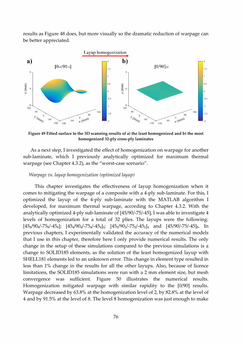
76
results as Figure 48 does, but more visually so the dramatic reduction of warpage can
be better appreciated.
Figure 49 Fitted surface to the 3D scanning results of a) the least homogenized and b) the most
homogenized 32-ply cross-ply laminates
As a next step, I investigated the effect of homogenization on warpage for another
sub-laminate, which I previously analytically optimized for maximum thermal
warpage (see Chapter 4.3.2), as the “worst-case scenario”.
Warpage vs. layup homogenization (optimized layup)
This chapter investigates the effectiveness of layup homogenization when it
comes to mitigating the warpage of a composite with a 4-ply sub-laminate. For this, I
optimized the layup of the 4-ply sub-laminate with the MATLAB algorithm I
developed, for maximum thermal warpage, according to Chapter 4.3.2. With the
analytically optimized 4-ply sub-laminate of [45/90/-75/-45], I was able to investigate 4
levels of homogenization for a total of 32 plies. The layups were the following:
[45₈/90₈/-75₈/-45₈]; [45₄/90₄/-75₄/-45₄]₂; [45₂/90₂/-75₂/-45₂]₄ and [45/90/-75/-45]₈. In
previous chapters, I experimentally validated the accuracy of the numerical models
that I use in this chapter, therefore here I only provide numerical results. The only
change in the setup of these simulations compared to the previous simulations is a
change to SOLID185 elements, as the solution of the least homogenized layup with
SHELL181 elements led to an unknown error. This change in element type resulted in
less than 1% change in the results for all the other layups. Also, because of licence
limitations, the SOLID185 simulations were run with a 2 mm element size, but mesh
convergence was sufficient. Figure 50 illustrates the numerical results.
Homogenization mitigated warpage with similar rapidity to the [0/90] results.
Warpage decreased by 63.8% at the homogenization level of 2, by 82.8% at the level of
4 and by 91.5% at the level of 8. The level 8 homogenization was just enough to make
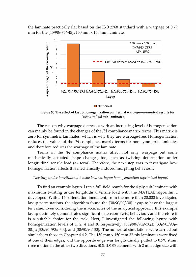
77
the laminate practically flat based on the ISO 2768 standard with a warpage of 0.79
mm for the [45/90/-75/-45]₈ 150 mm x 150 mm laminate.
Figure 50 The effect of layup homogenization on thermal warpage—numerical results for
[45/90/-75/-45] sub-laminates
The reason why warpage decreases with an increasing level of homogenization
can mainly be found in the changes of the [b] compliance matrix terms. This matrix is
zero for symmetric laminates, which is why they are warpage-free. Homogenization
reduces the values of the [b] compliance matrix terms for non-symmetric laminates
and therefore reduces the warpage of the laminate.
Terms in the [b] compliance matrix affect not only warpage but some
mechanically actuated shape changes, too, such as twisting deformation under
longitudinal tensile load (b16 term). Therefore, the next step was to investigate how
homogenization affects this mechanically induced morphing behaviour.
Twisting under longitudinal tensile load vs. layup homogenization (optimized layup)
To find an example layup, I ran a full-field search for the 4-ply sub-laminate with
maximum twisting under longitudinal tensile load with the MATLAB algorithm I
developed. With a 15° orientation increment, from the more than 20,000 investigated
layup permutations, the algorithm found the [30/90/90/-30] layup to have the largest
b16 value. Even considering the inaccuracies of the analytical approach, this example
layup definitely demonstrates significant extension–twist behaviour, and therefore it
is a suitable choice for the task. Next, I investigated the following layups with
homogenization levels of 1, 2, 4 and 8, respectively: [30₈/90₈/90₈/-30₈]; [30₄/90₄/90₄/-
30₄]₂; [30₂/90₂/90₂/-30₂]₄ and [30/90/90/-30]₈. The numerical simulations were carried out
similarly to those in Chapter 4.4.2. The 150 mm x 150 mm 32-ply laminates were fixed
at one of their edges, and the opposite edge was longitudinally pulled to 0.5% strain
(free motion in the other two directions, SOLID185 elements with 2 mm edge size with

78
checked mesh convergence and large deflections enabled). Figure 51 illustrates the
numerical results. As expected, homogenization rapidly reduced the twisting
capability of the laminate under tensile loading. By the homogenization level of 8, the
twisting of the loaded edge decreased by 89.6%, from 5.59° to just 0.58°.
Figure 51 The effect of layup homogenization on twisting deformation under longitudinal
tensile load—numerical results for [30/90/90/-30] sub-laminates
As b16 is the primary term that connects longitudinal tensile loading with twisting
deformation, it is expected that the term shows a similar declining tendency with the
increasing level of homogenization. Figure 52 illustrates the relative change in the
numerically simulated twisting and the analytically calculated b16 value of the
laminate. For better comparability, both the numerical and analytical results were
normalized by the least homogenised laminate results. The change in the numerical
and analytical results showed good correlation. The majority of the differences can be
explained by the fixed edge boundary condition of the simulations that analytical
solutions cannot consider.
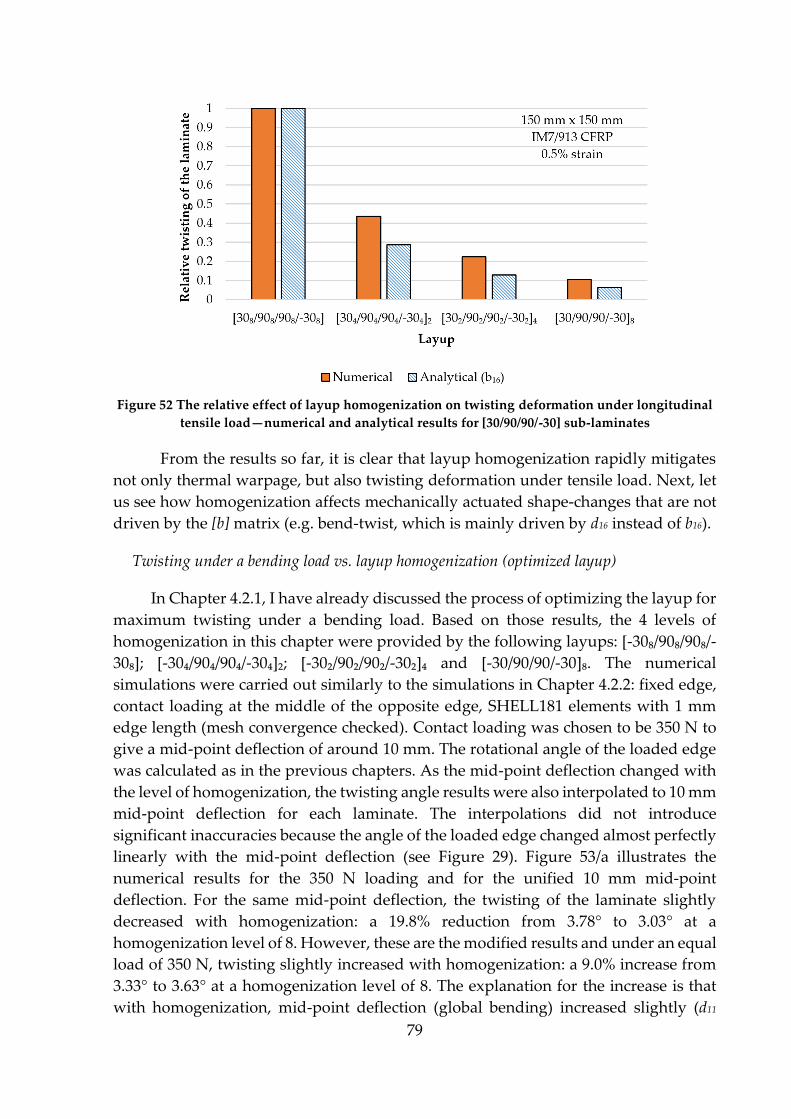
79
Figure 52 The relative effect of layup homogenization on twisting deformation under longitudinal
tensile load—numerical and analytical results for [30/90/90/-30] sub-laminates
From the results so far, it is clear that layup homogenization rapidly mitigates
not only thermal warpage, but also twisting deformation under tensile load. Next, let
us see how homogenization affects mechanically actuated shape-changes that are not
driven by the [b] matrix (e.g. bend-twist, which is mainly driven by d16 instead of b16).
Twisting under a bending load vs. layup homogenization (optimized layup)
In Chapter 4.2.1, I have already discussed the process of optimizing the layup for
maximum twisting under a bending load. Based on those results, the 4 levels of
homogenization in this chapter were provided by the following layups: [-30₈/90₈/90₈/-
30₈]; [-30₄/90₄/90₄/-30₄]₂; [-30₂/90₂/90₂/-30₂]₄ and [-30/90/90/-30]₈. The numerical
simulations were carried out similarly to the simulations in Chapter 4.2.2: fixed edge,
contact loading at the middle of the opposite edge, SHELL181 elements with 1 mm
edge length (mesh convergence checked). Contact loading was chosen to be 350 N to
give a mid-point deflection of around 10 mm. The rotational angle of the loaded edge
was calculated as in the previous chapters. As the mid-point deflection changed with
the level of homogenization, the twisting angle results were also interpolated to 10 mm
mid-point deflection for each laminate. The interpolations did not introduce
significant inaccuracies because the angle of the loaded edge changed almost perfectly
linearly with the mid-point deflection (see Figure 29). Figure 53/a illustrates the
numerical results for the 350 N loading and for the unified 10 mm mid-point
deflection. For the same mid-point deflection, the twisting of the laminate slightly
decreased with homogenization: a 19.8% reduction from 3.78° to 3.03° at a
homogenization level of 8. However, these are the modified results and under an equal
load of 350 N, twisting slightly increased with homogenization: a 9.0% increase from
3.33° to 3.63° at a homogenization level of 8. The explanation for the increase is that
with homogenization, mid-point deflection (global bending) increased slightly (d11
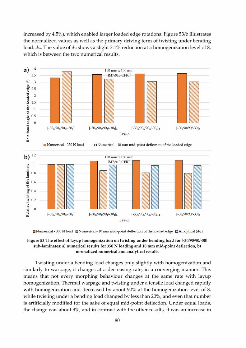
80
increased by 4.5%), which enabled larger loaded edge rotations. Figure 53/b illustrates
the normalized values as well as the primary driving term of twisting under bending
load: d16. The value of d16 shows a slight 3.1% reduction at a homogenization level of 8,
which is between the two numerical results.
Figure 53 The effect of layup homogenization on twisting under bending load for [-30/90/90/-30]
sub-laminates: a) numerical results for 350 N loading and 10 mm mid-point deflection, b)
normalized numerical and analytical results
Twisting under a bending load changes only slightly with homogenization and
similarly to warpage, it changes at a decreasing rate, in a converging manner. This
means that not every morphing behaviour changes at the same rate with layup
homogenization. Thermal warpage and twisting under a tensile load changed rapidly
with homogenization and decreased by about 90% at the homogenization level of 8,
while twisting under a bending load changed by less than 20%, and even that number
is artificially modified for the sake of equal mid-point deflection. Under equal loads,
the change was about 9%, and in contrast with the other results, it was an increase in

81
twisting, meaning that layup homogenization has the potential to increase the
morphing capability under certain circumstances (e.g. twisting under the same
bending load).
The values of the [d] matrix elements vs. layup homogenization
The values of the [b] matrix elements converge to zero with layup
homogenization as the laminate approaches a symmetric structure. However, in the
previous example, I showed that some [d] matrix elements decreased (d16) while others
increased (d11) with homogenization. It is important to identify if there is a universal
tendency regarding how the [d] matrix values change with layup homogenization.
Proving a general tendency is always trickier than disproving it, as the latter only
requires a counterexample of the hypothetical general tendency. Therefore, I started
to look at how the six [d] matrix elements change with homogenization in different
laminates, looking for opposite tendencies. I found that it is enough to compare the
previously described [-30/90/90/-30] sub-laminate to its “inverse” counterpart, the [90/-
30/-30/90] sub-laminate. Figure 54 illustrates that [d] matrix values that decrease in one
case increase in the other and vice versa. This example proves that there is no universal
tendency in how layup homogenization affects the [d] matrix values, as it depends on
the layup of the sub-laminate.
Figure 54 The effect of layup homogenization on the [d] matrix values: a) [-308/n/908/n/908/n/-308/n]n, b)
[908/n/-308/n/-308/n/908/n]n (n=1, 2, 4, 8). Increasing values marked with dotted line, decreasing values
with continuous line
The conclusion of this chapter is that layup homogenization rapidly reduces the
types of morphing that are mainly driven by the [b] matrix (e.g. thermal warpage and
twisting under a tensile load), while having a significantly smaller effect on other types
of morphing. Furthermore, homogenization can reduce or increase the value of any [d]
matrix element, depending on the layup of the sub-laminate. Composite design does
not have to be restricted to symmetric composites only. Homogenization enables the
82
selection of asymmetric (sub-)laminates as optimums without having to deal with the
disadvantages generally associated with layup asymmetry.
4.5. The strength of double-double laminates
As demonstrated in the previous chapters, layup symmetry is not the only way
to avoid or mitigate warpage, and the inclusion of asymmetric laminates significantly
increases the number of potential layups for any component. Ultimately, this can lead
to better optimized and, most importantly, lighter composite structures. Double-
double (DD) composites—with their potentially asymmetric sub-laminates
homogenized through the thickness of the laminate—can offer numerous advantages
over the industry-standard quad composites (definition in Chapter 2.2.6.). In this
chapter, I present results that show that DD laminates can outperform conventional
laminates based on strength.
Strength calculations
I developed a MATLAB-based analytical tool that finds the strongest laminates
(both DD and quad) based on a set of user-defined inputs (e.g. material properties and
complex loads). The calculations are based on the classical laminate theory (see the
equations in the Appendix), and the failure criterion is maximum strain, first ply
failure (although other failure criteria can be added, e.g. Tsai-Wu). First, the algorithm
calculates the [ABD] matrix and its inverse (compliance) matrix for each layup. From
the compliance matrix and the loads (forces per unit width, see Figure A2/a), the in-
plane strains of the laminates are calculated in the structural directions. For the failure
analysis, we need the in-plane strains of not the laminate but the individual plies and
not in the structural, but in the material directions. This can be achieved by Reuter’s
matrix aided transformation according to the first three steps of equation (A15) in the
Appendix. Then the strains of each ply are compared to the maximum (failure) strains
of the material. A safety factor (R) is calculated for each ply by dividing the maximum
(failure) strains with the actual strains [1] in each strain mode (longitudinal tension
and compression, transverse tension and compression and in-plane shear) and
selecting the lowest of the five ratios as the most critical mode of failure. The same
process is repeated for each ply. Finally, the R value of the whole laminate is chosen to
be the lowest R value of all the constituting plies. This is maximum strain, first ply
failure: when the first ply fails based on any of its maximum strain values, the whole
laminate is considered failed. Each layup permutation is then characterized by a single
R value, representing their “strength” or resistance to the applied load case. The
optimal (strongest) layup permutation is the one with the largest R value.
83
Layup families and input parameters
In this thesis, I compare the strength of 4-ply DD sub-laminates to 6-ply, 8-ply
and 10-ply quad sub-laminates—which really are 12-, 16- and 20-ply sub-laminates to
fulfil symmetry—as well as to quasi-isotropic and field quads as benchmarks. The
algorithm calculates strength for all the different double-double and quad layups. The
investigated six layup families were the following:
Quasi-isotropic 4-ply quad (QI) - 25% 0°, 50% ±45° and 25% 90° plies
Quad with 6-ply sub-laminate (6QD) – 4 layups
Quad with 8-ply sub-laminate (8QD) – 9 layups
Quad with 10-ply sub-laminate (10QD) – 16 layups
Quad with user-defined field increment (FieldQD)—the number of layups
depends on the quad field increment in (%). If quad field increment is 5%, the
laminate can consist of 10%, 15%, …, 85%, 90% 0° or 90° plies and the
remaining plies are ±45°
Double-double with 4-ply sub-laminate (DD)—the number of layups depends
on the DD orientation increment in (°). If the DD orientation increment is 5°,
±φ and ±ψ can be 0°, ±5°, …, ±85°, ±90°, independently of each other.
The different quad families represent different levels of layup customizability.
Sub-laminates with more plies allow better customization but are thicker and therefore
less suitable for thin laminates.
With the inputs, the algorithm offers an objective and quick (a few seconds) full-
field analytical layup optimization. The input variations are endless, and so are the
possible outputs, therefore in the following, I present some arbitrarily chosen case
study examples to show that double-double laminates can be superior to quad
laminates based on strength. The case studies differ only in the applied complex loads
to imitate the requirements for different composite components. The complex loads
characteristic of the two example structures (shaft and bulkhead, Figure 55) are based
on the many decades of industrial experience of Prof. Tsai and his colleagues [166].
Inputs other than the loads were kept unchanged throughout the case studies: material
– T300-F934 prepreg (see the relevant properties in Table 4), DD orientation increment
– 5°, quad field increment – 5%, failure criterion – max. strain, first ply failure.
Figure 55 Schematic illustration of the two example structures: a) shaft and b) aircraft bulkhead
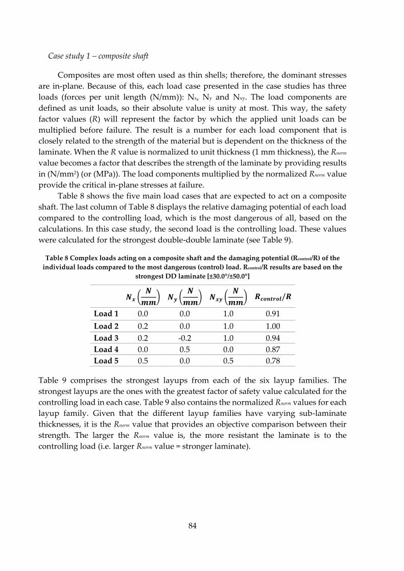
84
Case study 1 – composite shaft
Composites are most often used as thin shells; therefore, the dominant stresses
are in-plane. Because of this, each load case presented in the case studies has three
loads (forces per unit length (N/mm)): Nx, Ny and Nxy. The load components are
defined as unit loads, so their absolute value is unity at most. This way, the safety
factor values (R) will represent the factor by which the applied unit loads can be
multiplied before failure. The result is a number for each load component that is
closely related to the strength of the material but is dependent on the thickness of the
laminate. When the R value is normalized to unit thickness (1 mm thickness), the Rnorm
value becomes a factor that describes the strength of the laminate by providing results
in (N/mm2) (or (MPa)). The load components multiplied by the normalized Rnorm value
provide the critical in-plane stresses at failure.
Table 8 shows the five main load cases that are expected to act on a composite
shaft. The last column of Table 8 displays the relative damaging potential of each load
compared to the controlling load, which is the most dangerous of all, based on the
calculations. In this case study, the second load is the controlling load. These values
were calculated for the strongest double-double laminate (see Table 9).
Table 8 Complex loads acting on a composite shaft and the damaging potential (Rcontrol/R) of the
individual loads compared to the most dangerous (control) load. Rcontrol/R results are based on the
strongest DD laminate [±30.0°/±50.0°]
𝑵𝒙 (𝑵
𝒎𝒎) 𝑵𝒚 (
𝑵
𝒎𝒎) 𝑵𝒙𝒚 (
𝑵
𝒎𝒎) 𝑹𝒄𝒐𝒏𝒕𝒓𝒐𝒍/𝑹
Load 1 0.0 0.0 1.0 0.91
Load 2 0.2 0.0 1.0 1.00
Load 3 0.2 -0.2 1.0 0.94
Load 4 0.0 0.5 0.0 0.87
Load 5 0.5 0.0 0.5 0.78
Table 9 comprises the strongest layups from each of the six layup families. The
strongest layups are the ones with the greatest factor of safety value calculated for the
controlling load in each case. Table 9 also contains the normalized Rnorm values for each
layup family. Given that the different layup families have varying sub-laminate
thicknesses, it is the Rnorm value that provides an objective comparison between their
strength. The larger the Rnorm value is, the more resistant the laminate is to the
controlling load (i.e. larger Rnorm value = stronger laminate).
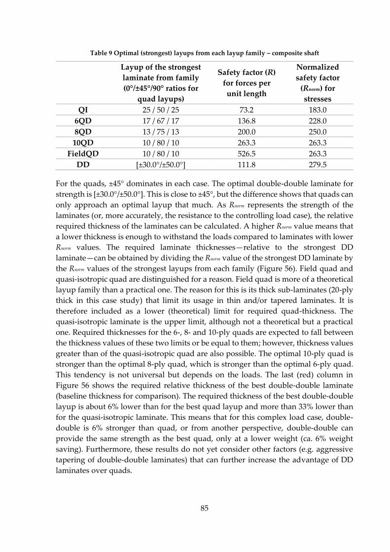
85
Table 9 Optimal (strongest) layups from each layup family – composite shaft
Layup of the strongest
laminate from family
(0°/±45°/90° ratios for
quad layups)
Safety factor (R)
for forces per
unit length
Normalized
safety factor
(Rnorm) for
stresses
QI 25 / 50 / 25 73.2 183.0
6QD 17 / 67 / 17 136.8 228.0
8QD 13 / 75 / 13 200.0 250.0
10QD 10 / 80 / 10 263.3 263.3
FieldQD 10 / 80 / 10 526.5 263.3
DD [±30.0°/±50.0°] 111.8 279.5
For the quads, ±45° dominates in each case. The optimal double-double laminate for
strength is [±30.0°/±50.0°]. This is close to ±45°, but the difference shows that quads can
only approach an optimal layup that much. As Rnorm represents the strength of the
laminates (or, more accurately, the resistance to the controlling load case), the relative
required thickness of the laminates can be calculated. A higher Rnorm value means that
a lower thickness is enough to withstand the loads compared to laminates with lower
Rnorm values. The required laminate thicknesses—relative to the strongest DD
laminate—can be obtained by dividing the Rnorm value of the strongest DD laminate by
the Rnorm values of the strongest layups from each family (Figure 56). Field quad and
quasi-isotropic quad are distinguished for a reason. Field quad is more of a theoretical
layup family than a practical one. The reason for this is its thick sub-laminates (20-ply
thick in this case study) that limit its usage in thin and/or tapered laminates. It is
therefore included as a lower (theoretical) limit for required quad-thickness. The
quasi-isotropic laminate is the upper limit, although not a theoretical but a practical
one. Required thicknesses for the 6-, 8- and 10-ply quads are expected to fall between
the thickness values of these two limits or be equal to them; however, thickness values
greater than of the quasi-isotropic quad are also possible. The optimal 10-ply quad is
stronger than the optimal 8-ply quad, which is stronger than the optimal 6-ply quad.
This tendency is not universal but depends on the loads. The last (red) column in
Figure 56 shows the required relative thickness of the best double-double laminate
(baseline thickness for comparison). The required thickness of the best double-double
layup is about 6% lower than for the best quad layup and more than 33% lower than
for the quasi-isotropic laminate. This means that for this complex load case, double-
double is 6% stronger than quad, or from another perspective, double-double can
provide the same strength as the best quad, only at a lower weight (ca. 6% weight
saving). Furthermore, these results do not yet consider other factors (e.g. aggressive
tapering of double-double laminates) that can further increase the advantage of DD
laminates over quads.
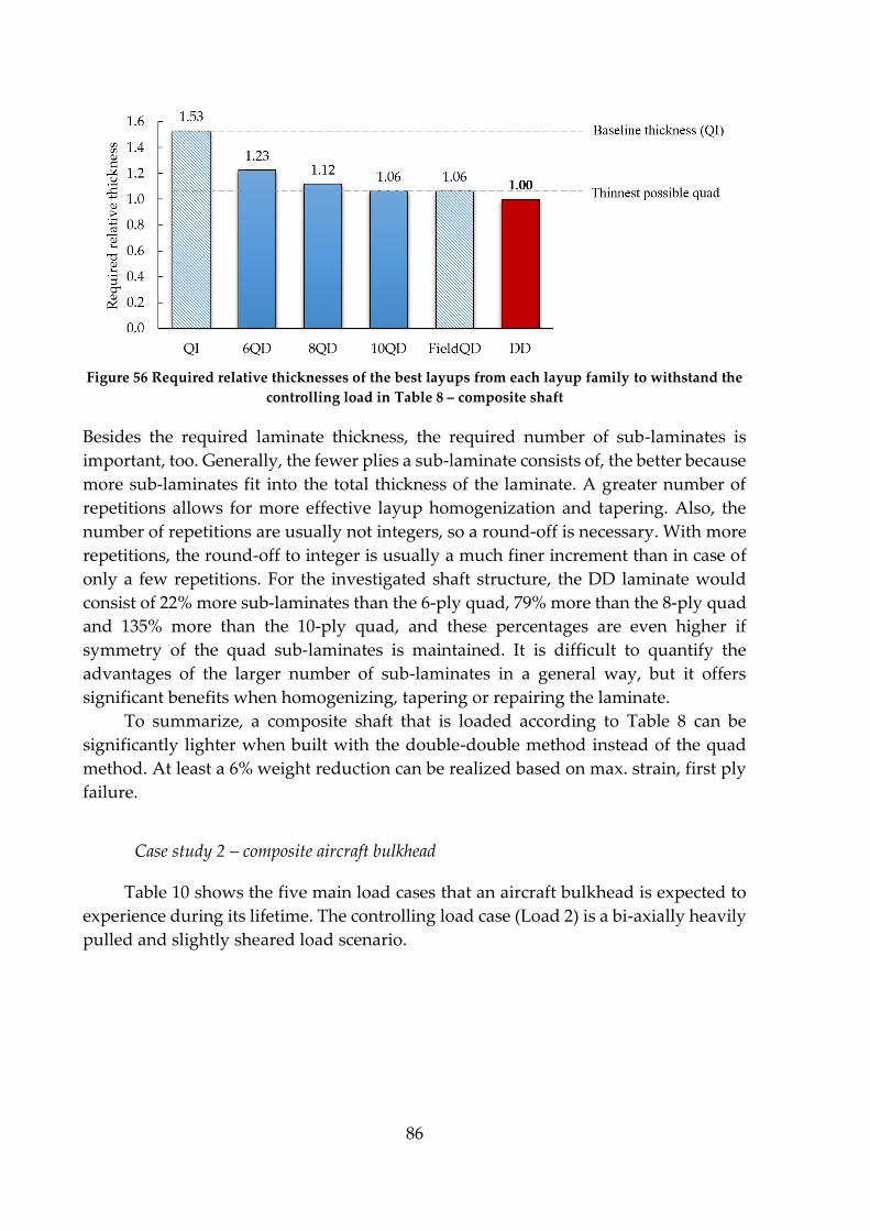
86
Figure 56 Required relative thicknesses of the best layups from each layup family to withstand the
controlling load in Table 8 – composite shaft
Besides the required laminate thickness, the required number of sub-laminates is
important, too. Generally, the fewer plies a sub-laminate consists of, the better because
more sub-laminates fit into the total thickness of the laminate. A greater number of
repetitions allows for more effective layup homogenization and tapering. Also, the
number of repetitions are usually not integers, so a round-off is necessary. With more
repetitions, the round-off to integer is usually a much finer increment than in case of
only a few repetitions. For the investigated shaft structure, the DD laminate would
consist of 22% more sub-laminates than the 6-ply quad, 79% more than the 8-ply quad
and 135% more than the 10-ply quad, and these percentages are even higher if
symmetry of the quad sub-laminates is maintained. It is difficult to quantify the
advantages of the larger number of sub-laminates in a general way, but it offers
significant benefits when homogenizing, tapering or repairing the laminate.
To summarize, a composite shaft that is loaded according to Table 8 can be
significantly lighter when built with the double-double method instead of the quad
method. At least a 6% weight reduction can be realized based on max. strain, first ply
failure.
Case study 2 – composite aircraft bulkhead
Table 10 shows the five main load cases that an aircraft bulkhead is expected to
experience during its lifetime. The controlling load case (Load 2) is a bi-axially heavily
pulled and slightly sheared load scenario.
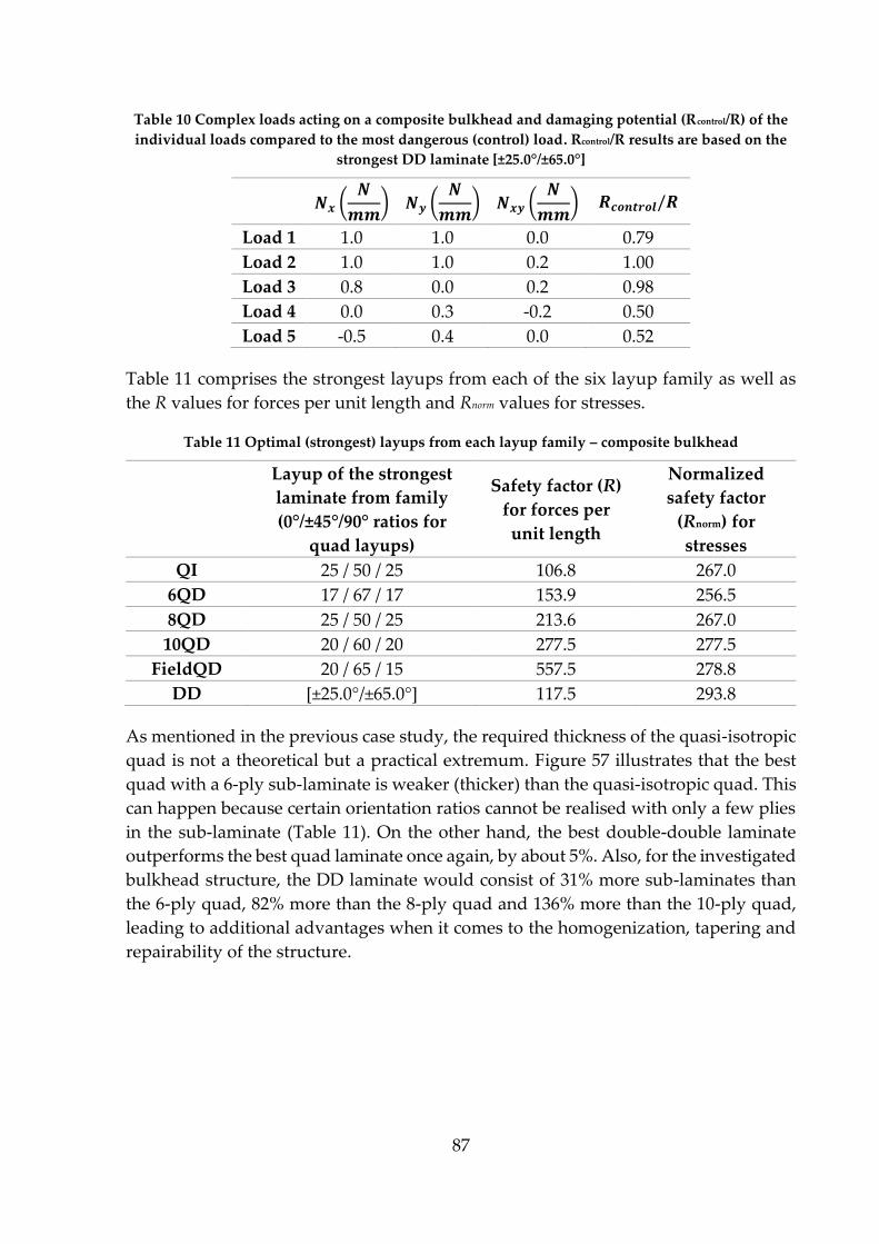
87
Table 10 Complex loads acting on a composite bulkhead and damaging potential (Rcontrol/R) of the
individual loads compared to the most dangerous (control) load. Rcontrol/R results are based on the
strongest DD laminate [±25.0°/±65.0°]
𝑵𝒙 (𝑵
𝒎𝒎) 𝑵𝒚 (
𝑵
𝒎𝒎) 𝑵𝒙𝒚 (
𝑵
𝒎𝒎) 𝑹𝒄𝒐𝒏𝒕𝒓𝒐𝒍/𝑹
Load 1 1.0 1.0 0.0 0.79
Load 2 1.0 1.0 0.2 1.00
Load 3 0.8 0.0 0.2 0.98
Load 4 0.0 0.3 -0.2 0.50
Load 5 -0.5 0.4 0.0 0.52
Table 11 comprises the strongest layups from each of the six layup family as well as
the R values for forces per unit length and Rnorm values for stresses.
Table 11 Optimal (strongest) layups from each layup family – composite bulkhead
Layup of the strongest
laminate from family
(0°/±45°/90° ratios for
quad layups)
Safety factor (R)
for forces per
unit length
Normalized
safety factor
(Rnorm) for
stresses
QI 25 / 50 / 25 106.8 267.0
6QD 17 / 67 / 17 153.9 256.5
8QD 25 / 50 / 25 213.6 267.0
10QD 20 / 60 / 20 277.5 277.5
FieldQD 20 / 65 / 15 557.5 278.8
DD [±25.0°/±65.0°] 117.5 293.8
As mentioned in the previous case study, the required thickness of the quasi-isotropic
quad is not a theoretical but a practical extremum. Figure 57 illustrates that the best
quad with a 6-ply sub-laminate is weaker (thicker) than the quasi-isotropic quad. This
can happen because certain orientation ratios cannot be realised with only a few plies
in the sub-laminate (Table 11). On the other hand, the best double-double laminate
outperforms the best quad laminate once again, by about 5%. Also, for the investigated
bulkhead structure, the DD laminate would consist of 31% more sub-laminates than
the 6-ply quad, 82% more than the 8-ply quad and 136% more than the 10-ply quad,
leading to additional advantages when it comes to the homogenization, tapering and
repairability of the structure.
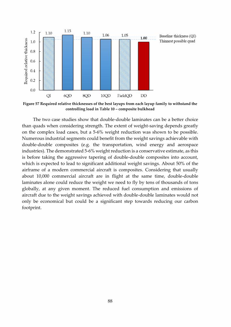
88
Figure 57 Required relative thicknesses of the best layups from each layup family to withstand the
controlling load in Table 10 – composite bulkhead
The two case studies show that double-double laminates can be a better choice
than quads when considering strength. The extent of weight-saving depends greatly
on the complex load cases, but a 5-6% weight reduction was shown to be possible.
Numerous industrial segments could benefit from the weight savings achievable with
double-double composites (e.g. the transportation, wind energy and aerospace
industries). The demonstrated 5-6% weight reduction is a conservative estimate, as this
is before taking the aggressive tapering of double-double composites into account,
which is expected to lead to significant additional weight savings. About 50% of the
airframe of a modern commercial aircraft is composites. Considering that usually
about 10,000 commercial aircraft are in flight at the same time, double-double
laminates alone could reduce the weight we need to fly by tens of thousands of tons
globally, at any given moment. The reduced fuel consumption and emissions of
aircraft due to the weight savings achieved with double-double laminates would not
only be economical but could be a significant step towards reducing our carbon
footprint.

89
5. SUMMARY
This chapter comprises the summary and the five concise theses of my PhD thesis
in English and Hungarian.
5.1. Summary in English
Certain materials and structures can demonstrate non-conventional
deformations as a result of different actuations. In my thesis, I use the terms “non-
conventional deformation” or “shape-changing” to refer to any geometric change that
is different in nature from the actuation itself (e.g. twisting deformation under bending
load or deflection under electric current). Shape-changing materials can be
advantageous in various applications (e.g. turbine blades or aeroplane wings with
improved aerodynamic performance), and thanks to their industrial value, the number
of research projects focusing on their investigation and development shows an
increasing trend year by year. I started my research by reviewing the shape-changing
concepts in the literature, categorizing them based on the nature of their actuation. I
concluded that shape-changing fibre-reinforced composites stand out from the rest of
the approaches, primarily due to their outstanding specific mechanical properties.
Therefore, I investigated these materials in my thesis. In the second part of the
literature review, I discussed the main modelling approaches of the elastic behaviour
of composites and summarized what the scientific community has achieved in the
topic of shape-changing composites so far. Finally, I identified some important and
unsolved challenges in the field and set the aims of my thesis accordingly [179].
The coupled behaviour of fibre-reinforced composites (e.g. extension–twist
coupling) results from their layup structure. Therefore, to achieve the desired shape-
changing behaviour, the layup needs to be optimized. Due to the large number of
possible layup permutations, a full-field analysis is usually only feasible using
analytical models. The analytical solution of the classical laminate theory has its limits
because of its simplifications, but it is well suited to analyze or even optimize the
coupling terms of laminates. As the basis of my thesis, I developed a classical laminate
theory-based layup optimization algorithm in MATLAB environment, with which I
was able to automatically analyze the shape-changing behaviour of hundreds of
thousands of laminates. I used the results of the algorithm (for stiffness and strength)
in several chapters [180-182].
Based on the literature review, one of the major challenges is to mitigate the
unwanted thermal warpage of shape-changing composites, as most of these laminates
have asymmetric layups, and asymmetric layups tend to warp. Furthermore,
depending on the layup and the edge-length to thickness ratio, the warped laminate
might not be monostable but bistable, which introduces further challenges.
However, before trying to mitigate thermal warpage, first, I investigated how it
can be exploited. The thermally induced out-of-plane deformations can be utilized to
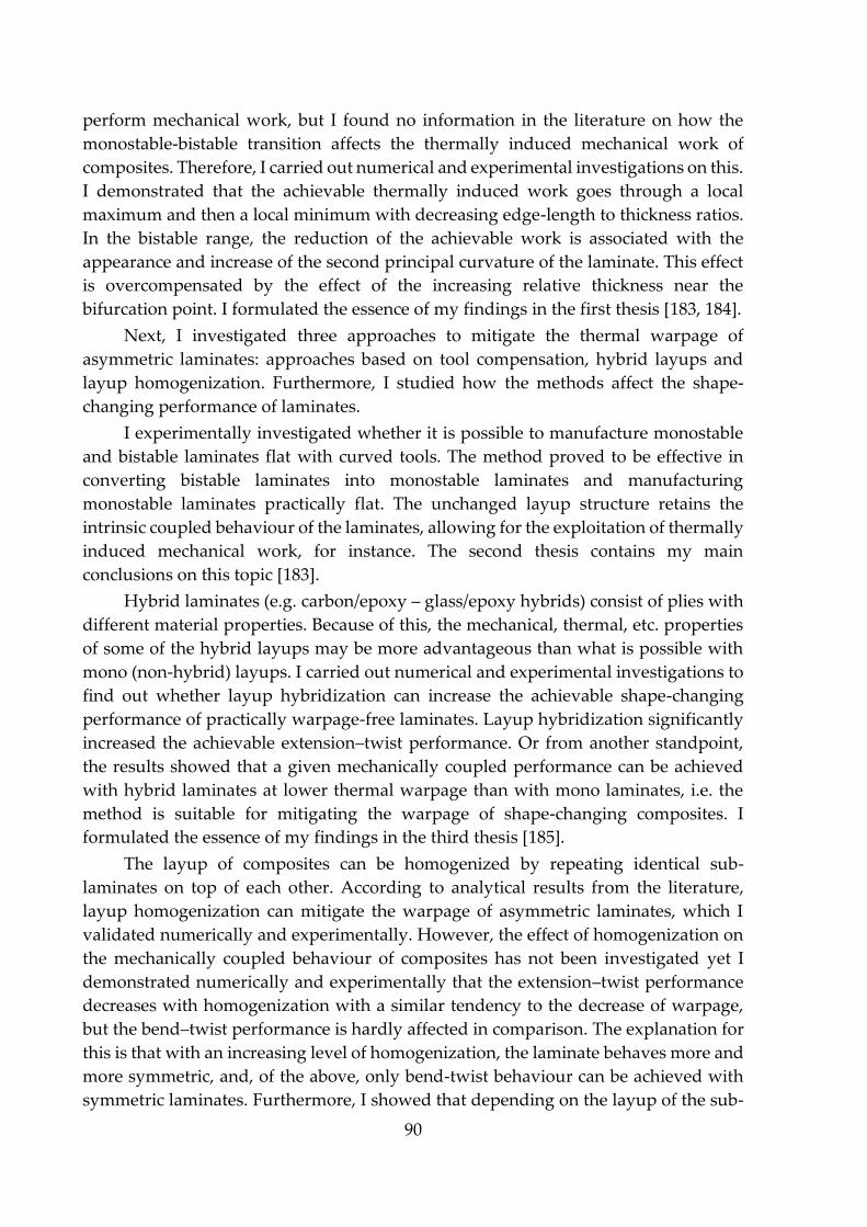
90
perform mechanical work, but I found no information in the literature on how the
monostable-bistable transition affects the thermally induced mechanical work of
composites. Therefore, I carried out numerical and experimental investigations on this.
I demonstrated that the achievable thermally induced work goes through a local
maximum and then a local minimum with decreasing edge-length to thickness ratios.
In the bistable range, the reduction of the achievable work is associated with the
appearance and increase of the second principal curvature of the laminate. This effect
is overcompensated by the effect of the increasing relative thickness near the
bifurcation point. I formulated the essence of my findings in the first thesis [183, 184].
Next, I investigated three approaches to mitigate the thermal warpage of
asymmetric laminates: approaches based on tool compensation, hybrid layups and
layup homogenization. Furthermore, I studied how the methods affect the shape-
changing performance of laminates.
I experimentally investigated whether it is possible to manufacture monostable
and bistable laminates flat with curved tools. The method proved to be effective in
converting bistable laminates into monostable laminates and manufacturing
monostable laminates practically flat. The unchanged layup structure retains the
intrinsic coupled behaviour of the laminates, allowing for the exploitation of thermally
induced mechanical work, for instance. The second thesis contains my main
conclusions on this topic [183].
Hybrid laminates (e.g. carbon/epoxy – glass/epoxy hybrids) consist of plies with
different material properties. Because of this, the mechanical, thermal, etc. properties
of some of the hybrid layups may be more advantageous than what is possible with
mono (non-hybrid) layups. I carried out numerical and experimental investigations to
find out whether layup hybridization can increase the achievable shape-changing
performance of practically warpage-free laminates. Layup hybridization significantly
increased the achievable extension–twist performance. Or from another standpoint,
the results showed that a given mechanically coupled performance can be achieved
with hybrid laminates at lower thermal warpage than with mono laminates, i.e. the
method is suitable for mitigating the warpage of shape-changing composites. I
formulated the essence of my findings in the third thesis [185].
The layup of composites can be homogenized by repeating identical sub-
laminates on top of each other. According to analytical results from the literature,
layup homogenization can mitigate the warpage of asymmetric laminates, which I
validated numerically and experimentally. However, the effect of homogenization on
the mechanically coupled behaviour of composites has not been investigated yet I
demonstrated numerically and experimentally that the extension–twist performance
decreases with homogenization with a similar tendency to the decrease of warpage,
but the bend–twist performance is hardly affected in comparison. The explanation for
this is that with an increasing level of homogenization, the laminate behaves more and
more symmetric, and, of the above, only bend-twist behaviour can be achieved with
symmetric laminates. Furthermore, I showed that depending on the layup of the sub-
91
laminate, layup homogenization can reduce or increase the value of any element of the
[d] matrix. The fourth thesis contains my main conclusions on this topic [186].
Finally, I investigated the advantages of a novel layup design method from a
strength standpoint by joining an international research group. The so-called double-
double laminates consist of 4-ply [±φ/±ψ] sub-laminates that are homogenized through
the thickness of the composite. I analytically proved that double-double laminates can
have greater strength and thus lead to lighter structures than the industry standard –
so-called quad – laminates, which consist of only 0°, 90° and ±45° plies. I formulated
the essence of my findings in the fifth thesis [186, 187].
5.2. Summary in Hungarian
Egyes anyagok és szerkezetek képesek a megszokottól eltérő deformációval
reagálni különböző hatásokra. Értekezésemben nem-konvencionális deformáció vagy
alakváltás alatt értek minden olyan geometriai változást, amely nem következik
egyértelműen az aktuáció jellegéből (például csavarodó deformáció hajlító terhelés
hatására, vagy lehajlás elektromos áram hatására). Az alakváltó anyagok előnyei
rendkívül széleskörűek lehetnek (például turbinalapátok, vagy repülőgépszárnyak
hatékonyságának növelése), és az ipari jelentőségüknek köszönhetően a fejlesztésükre
irányuló kutatások száma évről évre növekvő tendenciát mutat. Munkámat a főbb
alakváltó koncepciók irodalmának áttekintésével kezdtem, azokat aktuációjuk szerint
csoportosítva. Megállapítottam, hogy a szálerősítésű kompozit laminátumok –
elsősorban a kiváló fajlagos mechanikai tulajdonságaiknak köszönhetően –
kiemelkednek a többi megközelítés közül. Ennek megfelelően a disszertációm további
részében ezeknek az anyagoknak a vizsgálatával foglalkoztam. Az irodalmi áttekintés
második felében bemutattam a kompozitok viselkedésének modellezési lehetőségeit
lineárisan rugalmas anyagmodell felhasználásával, majd összefoglaltam, hogy milyen
eredményeket értek el eddig az alakváltó kompozitok témakörében, miközben
azonosítottam néhány fontos, megoldásra váró kihívást. Kutatómunkám céljait
ezeknek a kihívásoknak megfelelően jelöltem ki [179].
A szálerősítésű kompozitok kapcsolt viselkedése (például húzó-hajlító
kapcsolás) a rétegrendjük felépítésével magyarázható. Ahhoz tehát, hogy az alakváltó
viselkedést optimalizálni lehessen, a rétegrend optimalizálására van szükség. Egy
teljes-mezős vizsgálat esetén a lehetséges rétegrend-permutációk nagy száma miatt
általában csak az analitikus modellek jöhetnek szóba. A klasszikus lemezelmélet
számos egyszerűsítéssel él, és tisztában kell lenni a korlátaival, azonban kiválóan
alkalmas a laminátumok különböző kapcsoló paramétereinek elemzésére, vagy akár
optimalizálására. A munkám alapjaként kifejlesztettem és validáltam egy MATLAB
környezetű, klasszikus lemezelmélet alapú rétegrend optimalizáló algoritmust,
amelynek segítségével automatikusan tudtam elemezni több százezer különböző
rétegrend alakváltó viselkedését. Az algoritmus alakváltásra és szilárdságra
vonatkozó eredményeit több fejezetben is felhasználtam [180–182].
92
Az irodalmi áttekintés alapján a kutatási terület egyik legnagyobb kihívása a
kompozit lemezek hővetemedési problémáinak megoldása, ugyanis a legtöbb
alakváltó kompozit aszimmetrikus rétegrendű, az aszimmetrikus laminátumok pedig
az esetek túlnyomó többségében vetemednek. Sőt, a vetemedett kompozit a
rétegrendtől és az oldalhossz/vastagság aránytól függően nem csak monostabil,
hanem bistabil is lehet, amely további kihívásokat jelent.
A hővetemedés csökkentése előtt azonban annak egy hasznosítási lehetőségét
vizsgáltam. A hőaktuált síkból kilépő deformációkat ki lehet használni mechanikai
munkavégzésre, azonban az irodalomban nem találtam információt arra vonatkozóan,
hogy azt miként befolyásolja a laminátum bistabil-monostabil átmenete. Emiatt ezt
végeselemes módszerrel és kísérletileg is vizsgáltam. Kimutattam, hogy a laminátum
oldalhossz/vastagság arányának csökkentésével a munkavégző képesség egy lokális
maximumon majd egy lokális minimumon megy keresztül. A bistabil tartományban a
munkavégző képesség csökkenése a laminátum második főgörbületének
megjelenésével és növekedésével van összefüggésben, amelynek hatását csak a
bifurkációs pont közelében kompenzálja túl a növekvő relatív vastagság hatása. Az
erre vonatkozó eredményeimet az első tézisben fogalmaztam meg [183, 184].
Ezután három különböző megközelítést vizsgáltam az aszimmetrikus
rétegrendű laminátumok hővetemedésének csökkentésére: szerszámkompenzáción,
hibrid rétegrendeken és a rétegrend homogenizálásán alapuló módszereket.
Tanulmányoztam továbbá, hogy a módszerek milyen hatással vannak egyes alakváltó
képességek alakulására.
Irodalmi eredmények híján kísérletileg vizsgáltam, hogy ívelt szerszámlapok
segítségével lehetséges-e síkra gyártani monostabil, illetve bistabil aszimmetrikus
rétegrendű laminátumokat. A módszer alkalmasnak bizonyult a bistabil laminátumok
monostabillá alakítására, valamint a monostabil laminátumok közel síkra gyártására.
A változatlan rétegrendnek köszönhetően a kompozitok alakváltó viselkedése
megmarad, amely lehetőséget biztosít többek között a hőaktuált munkavégzés
kihasználására is. Az eredményeimet a második tézisben fogalmaztam meg [183].
A hibrid kompozitok különböző anyagú rétegei egyszerre különbözhetnek a
merevségi és a termikus tulajdonságaikban (például szénszál/epoxi – üvegszál/epoxi
hibrid). Emiatt a rétegrendek egy részében alakulhatnak olyan előnyösen ezek a
tulajdonságok, amely egy mono (nem hibrid) rétegrend esetében nem lehetséges.
Numerikusan és kísérletileg vizsgáltam, hogy közel vetemedésmentes laminátumok
esetében a rétegrend hibridizálásával növelhető-e a mono rétegrendekkel elérhető
mechanikai alakváltó képesség. A húzásra csavarodó alakváltó képességet jelentősen
növelte a hibridizálás. Az eredményeket úgy is lehet értelmezni, hogy adott mértékű
mechanikai alakváltó képesség hibrid laminátumokkal kisebb hővetemedés mellett
érhető el, mint mono laminátumokkal, vagyis a módszer alkalmas az alakváltó
kompozitok hővetemedésének csökkentésére. Az eredményeket a harmadik tézisben
fogalmaztam meg [185].
93
A rétegrend homogenizálásakor azonos felépítésű, általában aszimmetrikus al-
laminátumokat ismétlünk egymáson. A szakirodalomban elérhető analitikus
eredmények szerint ezzel csökkenthető a hővetemedés, amelyet numerikusan és
kísérletileg is validáltam. Azt viszont még nem vizsgálták, hogy a módszer miként
módosítja a mechanikailag aktuált alakváltó képességet. Numerikusan és analitikusan
is kimutattam, hogy a húzásra csavarodó képesség a homogenizálással a
vetemedéshez hasonlóan gyors ütemben csökken, míg a hajlításra csavarodás
lényegesen kisebb mértékben változik. Ennek magyarázata, hogy a homogenizálással
egyre inkább egy szimmetrikus rétegrendhez hasonlóan viselkedik a laminátum és az
előzőek közül csak a hajlításra csavarodás érhető el szimmetrikus laminátumokkal.
Megmutattam továbbá, hogy a rétegrendtől függően a homogenizálás a [d] mátrix
bármely elemét csökkentheti, illetve növelheti is. Az eredményeket a negyedik
tézisben fogalmaztam meg [186].
Végül, egy nemzetközi kutatócsoport munkájához csatlakozva, egy új rétegrend-
tervezési módszert vizsgáltam szilárdsági szempontból. Az úgynevezett double-
double laminátumok négyrétegű [±φ/±ψ] al-laminátumokból homogenizálás útján
felépülő kompozitok. Munkám során analitikus számításokkal bizonyítottam, hogy a
double-double laminátumok nagyobb szilárdsággal rendelkezhetnek, és így
könnyebb szerkezetekhez vezethetnek, mint az iparban hagyományosan alkalmazott
– úgynevezett quad – laminátumok, amelyek csupán 0°, 90° és ±45° orientációjú
rétegeket tartalmaznak. Az eredményeket az ötödik tézisben fogalmaztam meg [186,
187].

94
5.3. Theses in English
In the following, I summarize the main scientific results of my research in five
theses. In each case, I start with a general description of the results, after which I state
the thesis in a concise form. Further details regarding the investigations – on which the
theses are based – can be found in the referenced chapters of the thesis.
Composites with asymmetric layups tend to warp with changing temperatures,
which is usually an unwanted process. However, out-of-plane deformations can be
exploited to move loads, making the laminate suitable for thermally induced
mechanical work. By investigating analytically optimized [45n/90n/-75n/-45n] Hexcel
IM7/913 carbon–epoxy laminates, I showed that the bistable–monostable transition
significantly affects the achievable thermally induced mechanical work (Chapter 4.3.).
Experimental measurements of the laminate’s principal curvatures showed that
moving from the bifurcation point towards the bistable region – as the edge length to
thickness ratio of the laminate increases – the second principal curvature converges to
zero; therefore, in that region, not only the magnitude of the deformation changes but
also the shape (Chapter 4.3.3.). With finite element simulations and experiments, I
demonstrated that there is a region where the achievable thermally induced work
decreases with the increasing relative thickness of the laminate (Chapter 4.3.4.,
simulation and experimental setup: Figure 35). Based on the numerical and
experimental results, the local maximum of the achievable work is associated with the
appearance of the second principal curvature. Based on my results, I concluded that
the decreasing tendency of the achievable work from this point is due to the changing
shape of the laminate (increasing second principal curvature), which overcompensates
the effect of the increasing relative thickness. The end of the overcompensation is
indicated by the local minimum of the achievable work near the bifurcation point,
from where the increasing tendency continues.
Thesis 1
I showed that by increasing the thickness of fibre-reinforced composites with
asymmetric layups, their maximum achievable thermally induced mechanical work
goes through a local maximum and then a local minimum as they transition from
bistability to monostability. This is because the changing shape of the laminate (the
appearance and increase of the second principal curvature) overcompensates the
effect of the increasing thickness between the two local extrema [183].
95
I showed that the thermal warpage of composite laminates with asymmetric
layups can be compensated via designed dewarping by manufacturing them on
curved tools (Chapter 4.4.1.). The essence of the method is that instead of
manufacturing the laminate on a tool with the shape of the final product, the shape of
the tool is modified. This alters the initial shape of the composite, which then
approaches the desired shape due to manufacturing induced warpage, thus reducing
the apparent warpage. Since the method does not modify the layup, the shape of the
laminate remains temperature-dependent, i.e. further heating or cooling will result in
out-of-plane deformations. This is essential for the exploitation of thermally induced
mechanical work. I experimentally investigated the applicability of the warpage
compensation method for both monostable and bistable laminates; on analytically
optimized [45n/90n/-75n/-45n] Hexcel IM7/913 carbon–epoxy laminates. Based on
experimental results, I chose the edge length to thickness ratio of the laminates to
investigate the two types of behaviour in their pure forms. Therefore, within practical
limits, I investigated monostable laminates with the largest possible second principal
curvature and bistable laminates with the smallest possible second principal
curvature. The experimental results showed an average warpage reduction of 11.7%
when bistable laminates were manufactured on a “bistable shaped” (zero second
principal curvature) tool compared to manufacturing on a flat tool, but the principal
curvatures swapped places. From this, I concluded that the shape of the tool must
compensate for the zero (i.e. hiding) principal curvature, too. Therefore, I also
manufactured bistable laminates on a “monostable shaped” tool (where the
magnitudes of the two principal curvatures were comparable). I observed an average
warpage reduction of 23.3%, but more importantly, I managed to transform the
bistable laminates into monostable ones. Since tool compensation provided a
transition from the bistable region to the monostable region, the main question became
whether the method was effective enough to manufacture monostable laminates flat.
I demonstrated that the method is capable of reducing the warpage of monostable
laminates by more than 90%, with which the flatness requirement of the ISO 2768
standard (tolerance class K) can be fulfilled.
Thesis 2
I demonstrated that the thermal warpage of both bistable and monostable
asymmetric laminates can be compensated by manufacturing them on curved tools.
The method is also capable of transforming bistable laminates into monostable
ones. Since the method based on geometry compensation does not modify the
layup, the shape of the laminate remains temperature-dependent, thereby retaining
the feasibility of thermally induced mechanical work [183].
96
Through finite element simulations and experiments, I demonstrated that hybrid
layups can be superior to mono (non-hybrid) layups in terms of their shape-changing
performance. First, I numerically investigated the thermal warpage and the extension–
twist performance of Hexcel IM7/913 carbon–epoxy and Hexcel S-Glass/913 glass–
epoxy mono laminates and their hybrids. The two types of plies differ in a number of
material properties, the most important ones, in this case, being the thermal expansion
and the stiffness parameters. The idea is that hybrid layups (i.e. using more than one
type of ply in the laminate) can achieve thermal and elastic properties that are
impossible with mono layups. These complex effects can lead to mitigated unwanted
thermal warpage and increased desired shape-changing performance. The aim of the
full-field numerical optimization study was to find the layups from each laminate
family (carbon–epoxy mono, glass–epoxy mono and carbon–epoxy/glass–epoxy
hybrid) that possess the most significant shape-changing capability while remaining
practically warpage-free (according to the ISO 2768 standard, tolerance class L) after
the cooling stage of the manufacturing process. Based on these criteria and the input
parameters (Chapter 4.4.2.), the best hybrid layup outperformed the best mono layup
by more than 43%, i.e. it demonstrated that much more twisting deformation at the
same elongation. For the best hybrid and mono layups, I experimentally validated the
numerical warpage and extension–twist results. After the manufacturing process, I
verified the fulfilment of the flatness requirement and the superiority of the hybrid
laminate in terms of the shape-changing performance. In a similar numerical
optimization study, I also showed that although hybrid laminates might be superior
to mono laminates for some types of shape-changing behaviour, it is not a universal
tendency. When optimizing the layup for maximum bend–twist performance, for
instance, a mono (carbon–epoxy) laminate outperformed all hybrids, although the best
hybrid laminate was only 2.5% off from the overall best performer.
Thesis 3
For practically warpage-free laminates that meet the flatness requirement of
the ISO 2768 standard (tolerance class L), I demonstrated that hybrid layups can
achieve larger twisting deformation under tensile load than mono laminates. The
reason for this is that plies of different materials (e.g. carbon–epoxy and glass–
epoxy) differ in both thermal expansion and stiffness properties, which in a hybrid
layup can lead to mitigated thermal warpage and increased shape-changing
performance at the same time [185].
97
In my thesis, I investigated the effect of layup homogenization on the
manufacturing-induced thermal warpage and on two types of shape-changing
behaviour of 32-ply laminates (Chapter 4.4.3.). Homogenization of the layup was
achieved by repeating identical sub-laminates on top of each other. For [0𝑛/90𝑛]𝑘
Hexcel IM7/913 carbon–epoxy laminates (where k refers to the level of
homogenization), I proved numerically and experimentally that homogenization can
mitigate the extent of warpage by more than 97%. With further numerical
investigations, I showed that the [45𝑛/90𝑛/−75𝑛/−45𝑛]𝑘 laminate – which I
analytically optimized for maximal warpage – met the flatness requirement of the ISO
2768 standard (tolerance class L), from a homogenization level of eight. I carried out
the extension–twist numerical simulations on [30𝑛/90𝑛/90𝑛/−30𝑛]𝑘 (also analytically
optimized) laminates, and observed an approximately 90% reduction in the shape-
changing performance at a homogenization level of eight – similarly to warpage. The
reason for the similar tendency is that homogenization reduces laminate asymmetry,
and with that, the values of the [b] matrix elements. In contrast, I demonstrated a
significantly smaller change in the bend–twist performance of [−30𝑛/90𝑛/90𝑛/−30𝑛]𝑘
laminates with an increasing level of homogenization. However, homogenization even
increased the shape-changing performance when the laminates were subjected to the
same bending load – a 9% increase in the twisting deformation of the laminate was
demonstrated at a homogenization level of eight. Furthermore, I proved with
analytical calculations that layup homogenization can reduce or increase the value of
any element of the [d] matrix, depending on the layup of the sub-laminate.
Thesis 4
I demonstrated that layup homogenization reduces the extension–twist
performance of composites following a tendency similar to how it reduces the extent
of thermal warpage. The reason for this is that both forms of behaviour require
layup asymmetry, but the overall effect of sub-laminate asymmetry becomes less
pronounced in the composite with an increasing level of homogenization. However,
the bend–twist performance, which does not require asymmetry, can even increase
with homogenization. This can result directly from the increase of the d16 value or
indirectly from the increase of the d11 value, which can lead to increased twisting
deformation through larger deflections. Furthermore, I showed that depending on
the layup of the sub-laminate, homogenization can reduce or increase the value of
any element of the [d] matrix; therefore, a general tendency can not be identified
[186].
98
I carried out analytical strength analyses of double-double (DD) laminates by
joining the international research group of Prof. Stephen W. Tsai (Stanford University,
USA), the pioneer of the DD method. By the time I started working on the topic, a large
amount of information had already accumulated on the laminate design method
through analytical, numerical and experimental investigations. DD laminates consist
of 4-ply [±φ/±ψ] sub-laminates, which are homogenized through the thickness of the
composite, and they have several advantages over the current industry-standard quad
laminates, which consist of only 0°, 90°, 45° and -45° plies and obey the 10% rule (a
minimum of 10% of each orientation). In my thesis, I compared the two layup design
methods based on maximum strain and first-ply-failure (classical laminate theory). I
carried out the strength calculations for characteristic complex loads of two structural
components using the material properties of Toray’s T300/F934 carbon–epoxy
prepreg. In the case of quads, I investigated multiple families based on the number of
plies in the laminate (Chapter 4.5.). I demonstrated for both structural components that
a more than 5% increase in strength was achievable with DD laminates, even when
compared to the theoretical optimum of quad laminates. Furthermore, I highlighted
that DD laminates can be homogenized effectively, while quads usually require layup
symmetry due to their thicker sub-laminates, which further increases their
disadvantage in the case of tapering, for instance. According to the analytical results,
DD laminates require lower thickness than quad laminates in order to withstand
complex loads; therefore, the weight of composite components can be reduced with
the novel layup design method. In a comprehensive optimization process, aspects
other than strength have to be considered, too (e.g. stiffness, buckling stability or ply-
drops), which can further increase the advantage of double-double laminates, based
on the results of the international research group.
Thesis 5
I proved that depending on the loading, double-double laminates can achieve
greater strength than quad laminates, which can result in lighter structures. The
main reason for this is that in double-double laminates, any fibre orientation can
occur; therefore, the direction-dependent mechanical properties of the reinforcing
fibres can be exploited more effectively [186, 187].

99
5.4. Theses in Hungarian
A következőkben röviden, öt tézispontban ismertetem a kutatómunkám főbb
eredményeit. Az eredmények megfogalmazását minden esetben egy bevezető leírással
kezdem, majd tömören megfogalmazom a tézist. A tézisek alapjául szolgáló
vizsgálatok további részletei a disszertáció hivatkozott fejezeteiben találhatók.
Az aszimmetrikus rétegrendű kompozitok hőmérséklet-változás hatására
vetemednek, amely általában egy nem kívánt folyamat. Azonban a síkból kilépő
deformációt ki lehet használni terhek mozgatására, így a laminátum alkalmassá tehető
hőaktuált mechanikai munkavégzésre. Analitikusan optimalizált rétegrendű [45n/90n/-
75n/-45n] Hexcel IM7/913 szénszál-epoxi laminátumok vizsgálata során kimutattam,
hogy a hőaktuált mechanikai munkavégző képességet jelentősen befolyásolja a
bistabil-monostabil átmenet (4.3. fejezet). A laminátum főgörbületeinek kísérleti
mérésével megmutattam, hogy a bifurkációs ponttól a bistabil tartomány felé
mozdulva – a laminátum élhossz/vastagság arányának növelésével – a második
főgörbület zérushoz tart, így ebben a tartományban nem csak a deformáció mértéke
változik, hanem az alak is (4.3.3. fejezet). Végeselemes szimulációkkal és kísérleti úton
is kimutattam, hogy a hőaktuált teheremelésből számolt munkavégző képesség a
laminátum relatív vastagságának növelésével egy szakaszon csökken (4.3.4. fejezet,
szimulációs és mérési elrendezés: 35. ábra). A numerikus és a kísérleti eredmények
alapján a hőaktuált munkavégző képesség lokális maximuma a második főgörbület
megjelenésével van összefüggésben. Eredményeim alapján azt a következtetést
vontam le, hogy az ettől a ponttól csökkenő munkavégző képesség oka a laminátum
alakjának változása (növekvő második főgörbület), amelynek hatása túlkompenzálja
a relatív vastagság növekedésének hatását. A túlkompenzáció végét a bifurkációs pont
közelében a munkavégző képesség lokális minimuma jelzi, ahonnan újra növekedés
figyelhető meg.
1. Tézis
Aszimmetrikus rétegrendű szálerősítésű kompozitok vizsgálata során
kimutattam, hogy vastagságuk növelésével – miközben bistabil állapotból
monostabil állapot felé tartanak – a legnagyobb elérhető hőaktuált mechanikai
munkavégző képességük egy lokális maximumon, majd egy lokális minimumon
megy keresztül. Ennek magyarázata, hogy a két lokális szélsőérték között a
laminátum alakjának megváltozása (a második főgörbület megjelenése és
növekedése) túlkompenzálja a növekvő vastagság hatását [183].

100
Aszimmetrikus kompozit laminátumok esetében megmutattam, hogy ívelt
szerszámlapra laminálással, tervezett visszavetemedés útján hővetemedésük
kompenzálható (4.4.1. fejezet). A módszer lényege, hogy a termékkel megegyező alakú
szerszám helyett módosított alakú szerszámon történik a gyártás. Ezzel megváltozik a
kompozit kiindulási alakja és a termék a gyártási hővetemedés során a kívánt alakot
közelíti meg, így csökkentve a látszólagos vetemedést. Mivel a rétegrend nem változik,
a termék alakjának hőmérsékletfüggése megmarad, vagyis a gyártást követő további
hőközlés vagy hőelvonás hatására a laminátum síkból kilépő deformációval reagál. Ez
alapvető fontosságú a hőaktuált munkavégzés kihasználásához. A vetemedés-
kompenzációs módszer alkalmazhatóságát kísérletileg vizsgáltam mind monostabil,
mind pedig bistabil laminátumok esetében; analitikusan optimalizált rétegrendű
[45n/90n/-75n/-45n] Hexcel IM7/913 szénszál-epoxi laminátumokon. A laminátumok
élhossz/vastagság arányát kísérleti eredményeim alapján úgy választottam meg, hogy
a kétféle viselkedési forma határeseteit vizsgálhassam. Így a praktikusság határain
belül minél nagyobb második főgörbületű monostabil laminátumokat és minél kisebb
második főgörbületű bistabil laminátumokat vizsgáltam. Kísérleteim során a bistabil
laminátumokat „bistabil alakú” (zérus második főgörbületű) szerszámra laminálva
átlagosan 11.7%-os vetemedéscsökkenést értem el a sík szerszámon való gyártáshoz
képest, azonban a főgörbületek megcserélődtek a gyártás során. Ebből azt a
következtetést vontam le, hogy a szerszám alakjával a zérus – vagyis az átpattanásig
rejtőzködő – főgörbületet is kompenzálni kell. Ezért a bistabil laminátum „monostabil
alakú” (összemérhető nagyságú főgörbületekkel rendelkező) szerszámon való
gyártását is vizsgáltam. Átlagosan 23.3%-os vetemedéscsökkenést figyeltem meg,
azonban a fő eredmény, hogy monostabillá sikerült alakítani a laminátumot. Mivel a
szerszámozással átjárás biztosítható a bistabil tartományból a monostabilba, a
legfontosabb kérdés az maradt, hogy mennyire hatékony a vetemedés-kompenzációs
módszer a monostabil tartományban. Kimutattam, hogy a módszerrel több, mint 90%-
kal csökkenthető a monostabil laminátumok vetemedésének mértéke, amellyel már
elérhető az ISO 2768 szabvány K kategóriája szerinti síklapúság.
2. Tézis
Kimutattam, hogy ívelt szerszámlapon történő gyártással kompenzálható
mind a bistabil, mind pedig a monostabil aszimmetrikus rétegrendű kompozitok
hővetemedése. A módszer továbbá alkalmas bistabil laminátumok monostabillá
alakítására is. Mivel a geometria kompenzációjára épülő módszer nem módosítja a
laminátum rétegrendjét, a termék alakjának hőmérsékletfüggése megmarad, ezzel
megőrizve a hőaktuált munkavégző képességet [183].

101
Végeselemes szimulációk és kísérletek segítségével bebizonyítottam, hogy a
hibrid rétegrendek előnyt jelenthetnek a mono (nem hibrid) rétegrendekhez képest az
alakváltó képességüket tekintve. A bizonyításhoz numerikusan vizsgáltam a
hővetemedését és a húzásra csavarodó alakváltó viselkedését Hexcel IM7/913
szénszál-epoxi és Hexcel S-Glass/913 üvegszál-epoxi mono laminátumoknak, illetve
azok hibridjeinek. A kétféle anyag számos tulajdonságában különbözik egymástól,
amelyek közül ebben az esetben a termikus és a merevségi paraméterek a
legfontosabbak. Az elmélet alapja, hogy hibridizálással, vagyis egy laminátumon belül
többféle réteg alkalmazásával, olyan módon alakulhatnak a termikus és a merevségi
tulajdonságok, amelyek egy mono laminátumon belül nem lehetségesek. Ezek az
összetett hatások ahhoz vezethetnek, hogy a nem kívánt hővetemedés csökken,
miközben a kívánt alakváltó képesség növekszik. A teljes mezős numerikus vizsgálat
célja az volt, hogy megtaláljam mindhárom laminátum-családból (szénszál-epoxi
mono, üvegszál-epoxi mono és szénszál-epoxi/üvegszál-epoxi hibrid) azt a
legnagyobb alakváltó képességgel rendelkező laminátumot, amely a gyártási folyamat
hűtési ciklusa után még közel vetemedésmentes (az ISO 2768 szabvány L osztálya
szerint). A támasztott kritériumok és a bemeneti paraméterek alapján (4.4.2. fejezet) a
legjobb hibrid rétegrend több, mint 43%-kal teljesítette túl a legjobb mono rétegrendet,
vagyis ennyivel nagyobb csavarodó deformációra volt képes azonos mértékű
megnyúlásnál. A legjobb teljesítményű hibrid és mono rétegrendek vetemedési és
alakváltási teljesítményét kísérletileg is validáltam. Mérésekkel igazoltam mind a
síklapúság feltételének teljesülését a gyártást követően, mind pedig a hibrid
laminátum előnyét az alakváltó viselkedés tekintetében. Egy hasonló numerikus
kísérletsorozat során azt is kimutattam, hogy nem minden típusú alakváltó viselkedés
esetében hibrid rétegrend jelenti az optimumot. Hajlító terhelés hatására történő
csavarodás maximalizálásakor például a legjobb teljesítményt egy mono (szénszál-
epoxi) laminátum nyújtotta, bár a hibrid rétegrend teljesítménye csupán 2.5%-kal
maradt el attól.
3. Tézis
Közel vetemedésmentes, az ISO 2768 szabvány L tolerancia osztálya szerinti
síklapúságnak megfelelő laminátumok esetében kimutattam, hogy hibrid
rétegrendekkel nagyobb csavarodó deformáció érhető el húzó terhelés hatására,
mint mono rétegrendekkel. Ennek oka, hogy a különböző anyagú rétegek (pl. szén-
epoxi és üveg-epoxi) a hőtágulási és a merevségi tulajdonságaikban is különböznek
egymástól, amely egy hibrid rétegrend esetében egyszerre vezethet a vetemedés
csökkenéséhez és az alakváltó képesség növekedéséhez [185].
102
Dolgozatomban 32-rétegű laminátumokon vizsgáltam a rétegrend
homogenizálásának hatását kompozitok gyártási hővetemedésére és kétféle alakváltó
viselkedésére (4.4.3. fejezet). A rétegrend homogenizálását azonos felépítésű al-
laminátumok egymáson való ismétlésével értem el. [0𝑛/90𝑛]𝑘 rétegrendű Hexcel
IM7/913 szénszál-epoxi laminátumok esetében (ahol k a homogenizáltság fokát jelzi)
numerikus és kísérleti úton is megmutattam, hogy homogenizálással a vetemedés
mértéke több, mint 97%-kal csökkenthető. További numerikus vizsgálatokkal
megmutattam, hogy az analitikusan maximális hővetemedésre optimalizált
[45𝑛/90𝑛/−75𝑛/−45𝑛]𝑘 laminátum már nyolcas fokú homogenizáltság esetén is
megfelel az ISO 2768 szabvány L osztálya szerinti síklapúságnak. A húzásra csavarodó
végeselemes vizsgálatokat szintén analitikusan optimalizált, [30𝑛/90𝑛/90𝑛/−30𝑛]𝑘
rétegrendű laminátumokon végeztem el, amely során nyolcas fokú homogenizáltság
esetén a vetemedéshez hasonló, nagyjából 90%-os csökkenést figyeltem meg az
alakváltó képességben. A hasonló tendencia oka, hogy a homogenizálással csökken a
laminátum aszimmetriája és ezzel a [b] engedékenységi mátrix elemeinek értéke is.
[−30𝑛/90𝑛/90𝑛/−30𝑛]𝑘 rétegrendű hajlításra csavarodó laminátumok vizsgálatakor az
alakváltó képesség lényegesen kisebb változását mutattam ki a homogenizáltsági fok
függvényében, azonban azonos mértékű hajlító terhelés esetén a rétegrend
homogenizálása még növelte is az alakváltó képességet; nyolcas homogenizáltsági
foknál 9%-kal. Továbbá analitikus számításokkal bebizonyítottam, hogy a
homogenizálás a [d] mátrix bármely elemének értékét képes csökkenteni vagy növelni,
az al-laminátum rétegrendjétől függően.
4. Tézis
Kimutattam, hogy a rétegrend homogenizálásával a kompozitok húzásra
csavarodó képessége hasonlóan gyors ütemben csökken, mint hővetemedésük
mértéke. Ennek oka, hogy mindkét viselkedési forma aszimmetrikus rétegrendet
igényel, azonban a homogenizáltsági fok növekedésével az al-laminátum
aszimmetriájának hatása egyre kevésbé érvényesül a kompozitban. Az
aszimmetriát nem igénylő hajlításra csavarodó képesség ezzel szemben akár
növekedhet is, amely következhet közvetlen módon a d16 elem növekedéséből,
illetve közvetett módon a d11 elem növekedéséből is, amely nagyobb lehajlások
révén vezethet a csavarodás növekedéséhez. Megmutattam továbbá, hogy a
homogenizálás az al-laminátum rétegrendjétől függően a [d] mátrix bármely elemét
csökkentheti, illetve növelheti is, vagyis általános tendencia erre vonatkozóan nem
figyelhető meg [186].

103
A double-double (DD) laminátumok analitikus szilárdsági vizsgálatait a
módszer megalkotójának és úttörőjének - Stephen W. Tsai professzornak (Stanford
Egyetem, USA) - nemzetközi kutatócsoportjához csatlakozva végeztem el. Munkám
kezdetéig már nagy mennyiségű információ halmozódott fel a speciális rétegrend-
tervezési módszerről mind analitikus, mind pedig numerikus és kísérleti vizsgálatok
során. A DD laminátumok 4-rétegű [±φ/±ψ] al-laminátumok ismétlődéséből felépülő
kompozitok, amelyek számos előnnyel rendelkeznek a még jelenleg is ipari
sztenderdnek számító quad laminátumokkal szemben, amelyek csupán 0°, 90°, 45° és
-45°-os rétegekből épülnek fel és követik a 10%-os szabályt (minimum 10% mindegyik
orientációból). Munkám során a klasszikus lemezelmélet alapján szilárdsági
szempontból (maximális megnyúlás, első réteg tönkremenetele) optimalizáltam és
összehasonlítottam a kétféle rétegrendet. A szilárdsági számításokat Toray T300/F934
szénszál-epoxi prepreg anyagtulajdonságaival, két alkatrész jellemző komplex
terheléseire végeztem el. A quad laminátumok esetében a felépítő rétegek száma
szerint több laminátum-családot is vizsgáltam (4.5. fejezet). Kimutattam, hogy
mindkét alkatrész esetében több, mint 5%-kal nagyobb szilárdság érhető el DD
laminátumokkal, ráadásul az összehasonlításhoz a quad laminátumok olyan
optimumát vettem alapul, amely a gyakorlatban nem mindig érhető el. Rámutattam
továbbá, hogy amíg a DD laminátumok hatékonyan homogenizálhatók, a quadok a
vastagabb al-laminátumuk miatt általában szimmetriát igényelnek, amely tovább
növeli a hátrányukat például rétegelhagyások esetében. Az eredmények alapján a DD
laminátumok egy adott terhelést kisebb vastagság mellett is képesek elviselni, mint a
quadok, vagyis a kompozit termékek tömege ezzel a módszerrel csökkenthető. A
szilárdság mellett természetesen egyéb szempontokat is figyelembe kell venni egy
teljeskörű optimalizálás esetén (például merevség, kihajlási stabilitás vagy
rétegelhagyás), amelyekkel a kutatócsoport eredményei alapján tovább növekedhet a
double-double laminátumok előnye.
5. Tézis
Bebizonyítottam, hogy double-double laminátumokkal a terheléstől függően
nagyobb szilárdság érhető el, mint quad laminátumokkal, amely könnyebb
szerkezetekhez vezethet. Ennek elsődleges oka, hogy a double-double
rétegrendekben bármilyen szálorientáció előfordulhat, így hatékonyabban lehet
kihasználni az erősítőszálak irányfüggő mechanikai viselkedését [186, 187].
104
5.5. Applicability
The thesis includes results that can be applied in the industry to aid advanced
composite design and manufacturing. As some industrial examples have already
demonstrated, the mechanically actuated shape-changing behaviour of composites is
most likely to be adopted by the aerospace, motorsport and turbine-energy industries
for improved aerodynamic performance. Other results, such as the warpage mitigation
of asymmetric laminates or the novel double-double layup method, could affect the
composite industry in a more general way; by opening the door for asymmetric
laminates, ultimately leading to better optimized and lighter structures.
I showed that there is a thickness range where laminates that are capable of thermally
induced mechanical work have better performance when they are thinner (and
therefore lighter). This knowledge could help to keep the weight of such composite
parts down in the future. These types of laminates can be used as lightweight actuators
of safety switches in overheating systems, for instance.
The “curved tool” warpage mitigation method is best utilized when retaining the
temperature dependence of the laminate’s shape is essential (e.g. for thermally
actuated work) or when changing the layup is not an option (e.g. it would negatively
influence the desired shape-changing characteristics).
The hybrid layup and the layup homogenization methods are more generally
applicable than the curved tool method, as they mitigate the intrinsic tendency of the
laminate to warp by modifying its layup. Choosing between the two methods is
always an application-specific task. Hybridization might be better suited for very thin
laminates where homogenization would be insufficient, and homogenization might be
better suited for tasks where strength is the primary concern, and the weaker
constituent of a hybrid laminate could cause problems. Also, hybridization and
homogenization can significantly influence the desired shape-changing characteristics
of composites, which is yet another important consideration when choosing between
the two methods.
As for the double-double layup method, the list of applicability is almost endless. It
seems to be a true alternative to the current industry standard quad laminate method.
Double-double laminates could make anything from ships to aeroplanes, sports cars,
sports equipment or wind turbines lighter and therefore more efficient. This thesis
only investigates double-double laminates from an analytical strength standpoint that
does not support all these claims in itself. However, there is a whole international
academic-industrial project on the topic, and the investigations of Prof. Stephen W.
Tsai’s team are widespread. In the past few years, Prof. Tsai’s team (including myself)
has proven the superiority of double-double laminates analytically, numerically and
experimentally and from a variety of standpoints: strength, stiffness, buckling
stability, tapering, ease of design, manufacturing and repair, etc. As far as I can judge,
there are two scenarios when, all things considered, a double-double laminate is not
the best option: (i) for very thin laminates where homogenization is insufficient and
105
(ii) for composite parts that require special layups for special functions (e.g. certain
shape-changing characteristics).
My algorithms can be utilized in the industry too. I started my research process
by developing a layup optimization tool in MATLAB. I developed the algorithm so
that it is straightforward to use and does not require a deep knowledge of
programming or composite mechanics. Using the algorithm is as simple as entering
the necessary inputs in an Excel sheet and then running the MATLAB script. The
algorithm can handle multiple loads, multiple materials and any number of plies or
orientation increments, with the time required for the solution being the only
limitation. The algorithm provides results based on the CLT that characterizes the
behaviour of the laminates in the elastic region. Researchers and engineers can benefit
from entering multiple sets of input parameters and monitoring how the results and
the behaviour of the laminates change. There is a long string of equations between the
inputs and the outputs, therefore predicting the complex effect of a changed layup is
almost impossible without a similar tool. This makes the algorithm not only a
validated design tool for the industry but also a good learning tool.
I also developed an algorithm for the strength (and uniaxially loaded buckling
stability) comparison of double-double and quad laminates. I packaged the algorithm
into a standalone application with an easy-to-use graphical user interface. This way, I
was able to send out the tool to dozens of researchers and engineers from different
institutes (e.g. Airbus, NASA, Stanford University, University of Bristol, etc.) before
presenting my results to them at the Composites Design Workshop (Online Certified
Training by Stanford University) on multiple occasions.
5.6. Future challenges
Every solution breeds new problems. Therefore, future challenges are
unavoidable. During my research, I answered many of my original questions about
the researched topics; however, I generated at least as many new questions. Here is a
short selection of the challenges that I find important to address in the future.
- Finding a reliable way to numerically optimize the shapes of curved tools for
improved warpage mitigation of monostable and especially bistable laminates.
- Proving that bistable laminates can not only be transformed into monostable
ones with curved tools but can also be manufactured flat.
- Investigating a wide variety of hybrid laminates (e.g. different reinforcements
and different matrices) for a wide variety of characteristics other than warpage and
shape-changing (e.g. strength and pseudo-ductility).
- Continuing to gather essential information about double-double composites
(e.g. fatigue resistance and potential unique failure mechanisms). This is especially
important as quad laminates have several decades of advantage, which is the main
reason why the industry still prefers the conservative layup design method.

106
- Discovering and investigating further advantages that layup asymmetry can
provide. Some possible areas of improvement: pseudo-ductility, damage or fatigue
resistance, vibration dampening.

107
6. REFERENCES
[1] Barbero E. J.: Introduction to composite materials design. 3rd ed.Taylor &
Francis Group, Boca Raton (2018).
[2] Hull D., Clyne T. W.: An introduction to composite materials. 2nd ed.Press
Syndicate of the University of Cambridge, Cambridge (1996).
[3] Harris C. E., Starnes J. H., Shuart M. J.: Design and manufacturing of aerospace
composite structures, state-of-the-art assessment. Journal of Aircraft, 39, 545–560
(2002).
[4] Irving P. E., Soutis C.: Polymer composites in the aerospace industry. Woodhead
Publishing, Oxford (2015).
[5] Kim D. H., Choi D. H., Kim H. S.: Design optimization of a carbon fiber
reinforced composite automotive lower arm. Composites Part B: Engineering,
58, 400–407 (2014).
[6] Dirk H., Lukaszewicz J. A.: Automotive composite structures for
crashworthiness. in ‘Advanced Composite Materials for Automotive
Applications: Structural Integrity and Crashworthiness’ (editor: Elmarakbi A.).
John Wiley & Sons Ltd., Chichester, 99-127 (2013).
[7] Gunneskov O., Barlow N. D., Hancock M., Vronsky T.: Wind turbine blade.
US7198471B2, United States (2007).
[8] Chen J., Wang Q., Shen W. Z., Pang X., Li S., Guo X.: Structural optimization
study of composite wind turbine blade. Materials & Design, 46, 247–255 (2013).
[9] Evans J., Bab-Hadiashar A., Watkins S.: Racing car driveline design: Carbon
composite bonded half-shaft. International Journal of Vehicle Design, 72, 68
(2016).
[10] Bailey N.: Increasing composite versatility through motorsport developments.
Reinforced Plastics, 59, 128–130 (2015).
[11] You C.-S.: Composte laminated baseball bat. US4572508A, United States (1986).
[12] Sun T. H.: Study on composite materials used in the tennis racket. Applied
Mechanics and Materials, 540, 52–55 (2014).
[13] Brandt J.: The research requirements of the transport sectors to facilitate an
increased usage of composite materials. EADS Deutschland GmbH, München
(2004).
[14] Brinson L. C., Reifsnider K. L., Bartolotta P. A., Buczek M. B., Davis J. W.,
Johnston N. J., Sastry A. M., Sternstein S. S.: Going to extremes - Meeting the
emerging demand for durable polymer matrix composites. The National
Academies Press, Washington, D.C. (2005).
[15] http://www.1001crash.com/index-page-composite-lg-2.html (13.10.2017).
[16] Kessler M. R., Sottos N. R., White S. R.: Self-healing structural composite
materials. Composites Part A: Applied Science and Manufacturing, 34, 743–753
(2003).
108
[17] Qing X. P., Beard S. J., Kumar A., Ooi T. K., Chang F.-K.: Built-in sensor network
for structural health monitoring of composite structure. Journal of Intelligent
Material Systems and Structures, 18, 39–49 (2007).
[18] Kornbluh R. D., Pelrine R., Pei Q., Oh S., Joseph J.: Ultrahigh strain response of
field-actuated elastomeric polymers. in ‘Smart Structures and Materials 2000:
Electroactive Polymer Actuators and Devices (EAPAD). Newport Beach, USA’,
3914–3987 (2000).
[19] Hartl D. J., Lagoudas D. C.: Aerospace applications of shape memory alloys.
Proceedings of the Institution of Mechanical Engineers, Part G: Journal of
Aerospace Engineering, 221, 535–552 (2007).
[20] Thuwis G. A. A., Abdalla M. M., Gürdal Z.: Optimization of a variable-stiffness
skin for morphing high-lift devices. Smart Materials and Structures, 19, 124010
(2010).
[21] Blaiszik B. J., Kramer S. L. B., Olugebefola S. C., Moore J. S., Sottos N. R., White
S. R.: Self-healing polymers and composites. Annual Review of Materials
Research, 40, 179–211 (2010).
[22] Szebényi G., Czigány T., Vermes B., Ye X. J., Rong M. Z., Zhang M. Q.: Acoustic
emission study of the TDCB test of microcapsules filled self-healing polymer.
Polymer Testing, 54, 134–138 (2016).
[23] Vermes B., Czigány T.: Development of microcapsules. Materials Science Forum,
885, 31–35 (2017).
[24] Di Sante R.: Fibre optic sensors for structural health monitoring of aircraft
composite structures: recent advances and applications. Sensors, 15, 18666–
18713 (2015).
[25] Qing X. P., Beard S. J., Kumar A., Ooi T. K., Chang F.-K.: Built-in sensor network
for structural health monitoring of composite structure. Journal of Intelligent
Material Systems and Structures, 18, 39–49 (2007).
[26] Ghamsari A. K., Jin Y., Woldesenbet E.: Mechanical characterization of bucky gel
morphing nanocomposite for actuating/sensing applications. Smart Materials
and Structures, 21, 45007 (2012).
[27] Kim S., Hawkes E., Choy K., Joldaz M., Foleyz J., Wood R.: Micro artificial
muscle fiber using NiTi spring for soft robotics. in ‘2009 IEEE/RSJ International
Conference on Intelligent Robots and Systems. St. Louis, USA’, 2228–2234 (2009).
[28] Choi W., Akbarian M., Rubtsov V., Kim C.-J.: Microhand with internal visual
system. IEEE Transactions on Industrial Electronics, 56, 1005–1011 (2009).
[29] Motley M. R., Liu Z., Young Y. L.: Utilizing fluid–structure interactions to
improve energy efficiency of composite marine propellers in spatially varying
wake. Composite Structures, 90, 304–313 (2009).
[30] Garcia H., Abdulrahim M., Lind R.: Roll control for a micro air vehicle using
active wing morphing. in ‘AIAA Guidance, Navigation, and Control Conference
and Exhibit. Austin, USA’, AIAA-2003-5347 (2003).
109
[31] Stanford B., Abdulrahim M., Lind R., Ifju P.: Investigation of membrane
actuation for roll control of a micro air vehicle. Journal of Aircraft, 44, 741–749
(2007).
[32] Ahmed M. R., Abdelrahman M. M., ElBayoumi G. M., ElNomrossy M. M.:
Optimal wing twist distribution for roll control of MAVs. The Aeronautical
Journal, 115, 641–649 (2011).
[33] Boria F., Stanford B., Bowman S., Ifju P.: Evolutionary optimization of a
morphing wing with wind-tunnel hardware in the loop. AIAA Journal, 47, 399–
409 (2009).
[34] Hamilton B. K., Hassan A., Birchette T. S., Murrill R. R.: Composite material for
geometric morphing wing. US 7798443 B2, United States (2010).
[35] Winstone B., Pipe T., Melhuish C., Callaway M., Etoundi A. C., Dogramadzi S.:
Single motor actuated peristaltic wave generator for a soft bodied worm robot.
in ‘IEEE RAS and EMBS International Conference on Biomedical Robotics and
Biomechatronics. Singapore’, 449–456 (2016).
[36] Irschik H.: A review on static and dynamic shape control of structures by
piezoelectric actuation. Engineering Structures, 24, 5–11 (2002).
[37] Fichera S., Isnardi I., Mottershead J. E.: High-bandwidth morphing actuator for
aeroelastic model control. Aerospace, 6, 13 (2019).
[38] Jodin G., Scheller J., Duhayon E., Rouchon J. F., Braza M.: Implementation of a
hybrid electro-active actuated morphing wing in wind tunnel. Solid State
Phenomena, 260, 85–91 (2017).
[39] Bye D., McClure P.: Design of a morphing vehicle. in ‘48th
AIAA/ASME/ASCE/AHS/ASC Structures, Structural Dynamics, and Materials
Conference. Honolulu, USA’, 1–16 (2007).
[40] Nabawy M. R. A., Parslew B., Crowther W. J.: Dynamic performance of
unimorph piezoelectric bending actuators. Proceedings of the Institution of
Mechanical Engineers, Part I: Journal of Systems and Control Engineering, 229,
118–129 (2014).
[41] Nabawy M. R. A., Crowther W. J.: Dynamic electromechanical coupling of
piezoelectric bending actuators. Micromachines, 7, 12 (2016).
[42] Heath C. J. C., Bond I. P., Potter K. D.: Electrostatic adhesion for added
functionality of composite structures. Smart Materials and Structures, 25, 25016
(2016).
[43] Bergamini A., Christen R. X., Maag B., Motavalli M.: A sandwich beam with
electrostatically tunable bending stiffness. Smart Materials and Structures, 15,
678–686 (2006).
[44] Heath C. J. C., Bond I. P., Potter K. D.: Interlocking electro-bonded laminates.
Journal of Intelligent Material Systems and Structures, 28, 1524–1529 (2017).
[45] Tabata O., Konishi S., Cusin P., Ito Y., Kawai F., Hirai S., Kawamura S.: Micro
fabricated tunable bending stiffness devices. Sensors and Actuators, A: Physical,
110
89, 119–123 (2001).
[46] Kim J., Yun S.-R., Deshpande S.: Synthesis, characterization and actuation
behavior of polyaniline-coated electroactive paper actuators. Polymer
International, 56, 1530–1536 (2007).
[47] Beregoi M., Evanghelidis A., Diculescu V. C., Iovu H., Enculescu I.: Polypyrrole
actuator based on electrospun micro-ribbons. ACS Applied Materials &
Interfaces, 9, 38068–38075 (2017).
[48] Kim J., Kang Y., Ounaies Z., Bae S.-H., Yun S.: Electroactive paper materials
coated with carbon nanotubes and conducting polymers. in ‘2005 ASME
International Mechanical Engineering Congress and Exposition. Orlando, USA’,
59–63 (2005).
[49] Kruusamäe K., Sugino T., Asaka K.: Measuring blocking force to interpret ionic
mechanisms within bucky-gel actuators. in ‘Electroactive Polymer Actuators
and Devices (EAPAD). San Diego, USA’, 94300P (2015).
[50] Davidson J. R., Krebs H. I.: An electrorheological fluid actuator for rehabilitation
robotics. IEEE/ASME Transactions on Mechatronics, 23, 2156–2167 (2018).
[51] Grad P.: Against the flow - Smart fluids that can change their viscosity in real
time. Engineering & Technology, 1, 34–37 (2006).
[52] Arnaud A., Monfray S., Boughaleb J., Trioux E., Boeuf F., Cugat O., Skotnicki T.:
Modeling of the thermo-mechanical efficiency of the bimetal strip heat engines.
Journal of Physics: Conference Series, 557, 12015 (2014).
[53] Boisseau S., Despesse G., Monfray S., Puscasu O., Skotnicki T.: Semi-flexible
bimetal-based thermal energy harvesters. Smart Materials and Structures, 22,
25021 (2013).
[54] Duerig T. W., Melton K. N., Stöckel D., Wayman C. M.: Engineering aspects of
shape memory alloys. Butterworth-Heinemann Ltd, Essex (1990).
[55] Pai A.: A phenomenological model of shape memory alloys including time-
varying stress. Master of Applied Science thesis, University of Waterloo,
Waterloo (2007).
[56] Cross W. B., Kariotis A. H., Stimler F. J.: NiTiNOL characterization study.
Contractor report, Goodyear Aerospace Corporation, Akron (1969).
[57] Kuder I. K., Arrieta A. F., Raither W. E., Ermanni P.: Variable stiffness material
and structural concepts for morphing applications. Progress in Aerospace
Sciences, 63, 33–55 (2013).
[58] Lu H., Liang F., Yao Y., Gou J., Hui D.: Self-assembled multi-layered carbon
nanofiber nanopaper for significantly improving electrical actuation of shape
memory polymer nanocomposite. Composites Part B: Engineering, 59, 191–195
(2014).
[59] Lendlein A., Jiang H., Jünger O., Langer R.: Light-induced shape-memory
polymers. Nature, 434, 879–882 (2005).
111
[60] Voit W., Ware T., Dasari R. R., Smith P., Danz L., Simon D., Barlow S., Marder S.
R., Gall K.: High-strain shape-memory polymers. Advanced Functional
Materials, 20, 162–171 (2010).
[61] Humbeeck J. Van: Non-medical applications of shape memory alloys. Materials
Science and Engineering: A, 273–275, 134–148 (1999).
[62] Maksimkin A. V., Kaloshkin S. D., Zadorozhnyy M. V., Senatov F. S., Salimon A.
I., Dayyoub T.: Artificial muscles based on coiled UHMWPE fibers with shape
memory effect. Express Polymer Letters, 12, 452–461 (2018).
[63] Zhang C.-S., Ni Q.-Q.: Bending behavior of shape memory polymer based
laminates. Composite Structures, 78, 153–161 (2007).
[64] Cho J. W., Kim J. W., Jung Y. C., Goo N. S.: Electroactive shape-memory
polyurethane composites incorporating carbon nanotubes. Macromolecular
Rapid Communications, 26, 412–416 (2005).
[65] Ohm C., Brehmer M., Zentel R.: Liquid crystalline elastomers as actuators and
sensors. Advanced Materials, 22, 3366–3387 (2010).
[66] Wermter H., Finkelmann H.: Liquid crystalline elastomers as artificial muscles.
e-Polymers, 1, 1–13 (2001).
[67] Yang H., Buguin A., Taulemesse J.-M., Kaneko K., Méry S., Bergeret A., Keller
P.: Micron-sized main-chain liquid crystalline elastomer actuators with
ultralarge amplitude contractions. Journal of the American Chemical Society,
131, 15000–15004 (2009).
[68] Fang L., Chen S., Fang T., Fang J., Lu C., Xu Z.: Shape-memory polymer
composites selectively triggered by near-infrared light of two certain
wavelengths and their applications at macro-/microscale. Composites Science
and Technology, 138, 106–116 (2017).
[69] Jiang H. Y., Kelch S., Lendlein A.: Polymers move in response to light. Advanced
Materials, 18, 1471–1475 (2006).
[70] Zeng H., Wasylczyk P., Parmeggiani C., Martella D., Burresi M., Wiersma D. S.:
Light-fueled microscopic walkers. Advanced Materials, 27, 3883–3887 (2015).
[71] Wei J., Yu Y.: Photodeformable polymer gels and crosslinked liquid-crystalline
polymers. Soft Matter, 8, 8050–8059 (2012).
[72] Shanmuganathan K., Capadona J. R., Rowan S. J., Weder C.: Biomimetic
mechanically adaptive nanocomposites. Progress in Polymer Science, 35, 212–
222 (2010).
[73] Capadona J. R., Shanmuganathan K., Tyler D. J., Rowan S. J., Weder C.: Stimuli-
responsive polymer nanocomposites inspired by the sea cucumber dermis.
Science, 319, 1370–1374 (2008).
[74] Volder M. De, Ceyssens F., Reynaerts D., Puers R.: A PDMS lipseal for hydraulic
and pneumatic microactuators. Journal of Micromechanics and
Microengineering, 17, 1232–1237 (2007).
112
[75] Ok J., Lu Y., Kim C. C.: Pneumatically driven microcage for microbe
manipulation in a biological liquid environment. Journal of
Microelectromechanical Systems, 15, 1499–1505 (2006).
[76] Ikeuchi M., Ikuta K.: Development of pressure-driven micro active catheter
using membrane micro emboss following excimer laser ablation (MeME-X)
process. in ‘2009 IEEE International Conference on Robotics and Automation.
Kobe, Japan’, 4469–4472 (2009).
[77] Yang X., Tai Y.-C., Ho C.-M.: Micro bellow actuators. in ‘International Solid State
Sensors and Actuators Conference (Transducers ’97). Chicago, USA’, 45–48
(1997).
[78] De Volder M., Moers A. J. M., Reynaerts D.: Fabrication and control of miniature
McKibben actuators. Sensors and Actuators A: Physical, 166, 111–116 (2011).
[79] Kang H.-W., Lee I. H., Cho D.-W.: Development of a micro-bellows actuator
using micro-stereolithography technology. Microelectronic Engineering, 83,
1201–1204 (2006).
[80] Gorissen B., Vincentie W., Al-Bender F., Reynaerts D., De Volder M.: Modeling
and bonding-free fabrication of flexible fluidic microactuators with a bending
motion. Journal of Micromechanics and Microengineering, 23, 45012 (2013).
[81] Gorissen B., Chishiro T., Shimomura S., Reynaerts D., De Volder M., Konishi S.:
Flexible pneumatic twisting actuators and their application to tilting
micromirrors. Sensors and Actuators A: Physical, 216, 426–431 (2014).
[82] Song S., Sitti M.: Soft grippers using micro-fibrillar adhesives for transfer
printing. Advanced Materials, 26, 4901–4906 (2014).
[83] Thumthae C., Chitsomboon T.: Optimal angle of attack for untwisted blade wind
turbine. Renewable Energy, 34, 1279–1284 (2009).
[84] Ajaj R. M., Friswell M. I., Smith D. D., Allegri G., Isikveren A. T.: Roll control of
a UAV using an adaptive torsion structure. in ‘52nd
AIAA/ASME/ASCE/AHS/ASC Structures, Structural Dynamics and Materials
Conference. Denver, USA’, AIAA-2011-1834 (2011).
[85] Ajaj R. M., Friswell M. I., Dettmer W. G., Allegri G., Isikveren A. T.: Conceptual
modeling of an adaptive torsion wing structure. in ‘52nd
AIAA/ASME/ASCE/AHS/ASC Structures, Structural Dynamics and Materials
Conference. Denver, USA’, AIAA-2011-1883 (2011).
[86] Runge J.-B., Osmont D., Ohayon R.: Twist control of aerodynamic profiles by a
reactive method (experimental results). Journal of Intelligent Material Systems
and Structures, 24, 908–923 (2012).
[87] Runge J. B., Osmont D., Ohayon R.: Twist control of airfoils using a “reactive”
method. in ‘SPIE Smart Structures and Materials + Nondestructive Evaluation
and Health Monitoring. San Diego, USA’, 764305–764310 (2010).
[88] Khandan R., Noroozi S., Sewell P., Vinney J.: The development of laminated
composite plate theories: a review. Journal of Materials Science, 47, 5901–5910

113
(2012).
[89] Barbero E. J.: Finite element analysis of composite materials. CRC Press, Boca
Raton (2008).
[90] Schenk M.: StM3 CLA - Handout 1: Lamina macromechanics. University of
Bristol, Bristol (2016).
[91] Schenk M.: StM3 CLA - Handout 3: Classical lamination theory. University of
Bristol, Bristol (2016).
[92] Jones R. M.: Mechanics of composite materials. 2nd ed.Taylor & Francis,
Philadelphia (1999).
[93] Reddy J. N.: Mechanics of laminated composite plates and shells - theory and
analysis. 2nd ed.CRC Press, Boca Raton (2004).
[94] York C. B.: Unified approach to the characterization of coupled composite
laminates: benchmark configurations and special cases. Journal of Aerospace
Engineering, 4, 219–243 (2010).
[95] ESDU: Laminate stacking sequences for special orthotropy (Application to fibre
reinforced composites). Engineering Sciences Data Unit, London (1982).
[96] ESDU: Stiffnesses of laminated plates. Engineering Sciences Data Unit, London
(1994).
[97] York C. B.: On extension-shearing coupled laminates. Composite Structures, 120,
472–482 (2015).
[98] York C. B.: On bending-twisting coupled laminates. Composite Structures, 160,
887–900 (2017).
[99] York C. B.: Extension-twist coupled laminates for aero-elastic compliant blade
design. in ‘53rd AIAA/ASME/ASCE/AHS/ASC Structures, Structural Dynamics
and Materials Conference. Honolulu, USA’, AIAA-2012-1457 (2012).
[100] York C.: Unified approach to the characterization of coupled composite
laminates configurations: Hygrothermally curvature-stable configurations.
International Journal of Structural Integrity, 2, 406–436 (2012).
[101] York C. B.: Tapered hygro-thermally curvature-stable laminates with non-
standard ply orientations. Composites Part A, 44, 140–148 (2013).
[102] Koruche U. S., Patil S. F.: Application of classical lamination theory and
analytical modeling of laminates. International Research Journal of Engineering
and Technology, 2, 958–965 (2015).
[103] Sane A., Kulkarni A., Padole P. M., Uddanwadiker R. V: Analysis of composite
laminate through experimental and analytical method. International Journal on
Mechanical Engineering and Robotics, 2, 28–32 (2014).
[104] Casavola C., Cazzato A., Moramarco V., Pappalettere C.: Orthotropic
mechanical properties of fused deposition modelling parts described by classical
laminate theory. Materials and Design, 90, 453–458 (2016).
[105] Shokrieh M. M., Kamali S. M.: Theoretical and experimental studies on residual

114
stresses in laminated polymer composites. Journal of Composite Materials, 39,
2213–2225 (2015).
[106] Robbins D. H., Reddy J. N.: Modelling of thick composites using a layerwise
laminate theory. International Journal for Numerical Methods in Engineering,
36, 655–677 (1993).
[107] Aydogdu M.: A new shear deformation theory for laminated composite plates.
Composite Structures, 89, 94–101 (2009).
[108] Mantari J. L., Granados E. V: An original FSDT to study advanced composites
on elastic foundation. Thin Walled Structures, 107, 80–89 (2016).
[109] Thai H., Choi D.: A simple first-order shear deformation theory for the bending
and free vibration analysis of functionally graded plates. Composite Structures,
101, 332–340 (2013).
[110] Khdeir A. A., Reddy J. N.: Free vibrations of laminated composite plates using
second-order shear deformation theory. Computers and Structures, 71, 617–626
(1999).
[111] Aagaah M. R., Mahinfalah M., Jazar G. N.: Natural frequencies of laminated
composite plates using third order shear deformation theory. Composite
Structures, 72, 273–279 (2006).
[112] Zidi M., Tounsi A., Sid M., Houari A., Abbas E., Bedia A., Bég O. A.: Bending
analysis of FGM plates under hygro-thermo-mechanical loading using a four
variable refined plate theory. Aerospace Science and Technology, 34, 24–34
(2014).
[113] Sah S. K., Ghosh A.: Free vibration and buckling analysis of FGM plates using
inverse trigonometric shear deformation theory. Aircraft Engineering and
Aerospace Technology, 93, 298–310 (2021).
[114] Singh S. D., Sahoo R.: Static and free vibration analysis of functionally graded
CNT reinforced composite plates using trigonometric shear deformation theory.
Structures, 28, 685–696 (2020).
[115] Cho M., Parmertert R. R.: Efficient higher order composite plate theory for
general lamination configurations. AIAA Journal, 31, 1299–1306 (1993).
[116] Hodges D. H.: Nonlinear composite beam theory. American Institute of
Aeronautics and Astronautics, Virginia (2006).
[117] Kollár L. P., Pluzsik A.: Bending and torsion of composite beams (torsional-
warping shear deformation theory. Journal of Reinforced Plastics and
Composites, 31, 441-480 (2012).
[118] York C. B.: On extension-shearing coupled laminates. Composite Structures, 120,
472–482 (2015).
[119] Cui D., Li D.: Bending-twisting coupled structures based on composite laminates
with extension-shear coupling effect. Composite Structures, 209, 434–442 (2019).
[120] Herath M. T., Natarajan S., Prusty B. G., St N.: Smoothed finite element and

115
genetic algorithm based optimization for shape adaptive composite marine
propellers. Composite Structures, 109, 189–197 (2014).
[121] Murray R. E., Doman D. A., Pegg M. J.: Finite element modeling and effects of
material uncertainties in a composite laminate with bend–twist coupling.
Composite Structures, 121, 362–376 (2015).
[122] Nicholls-Lee R. F., Turnock S. R., Boyd S. W.: Application of bend-twist coupled
blades for horizontal axis tidal turbines. Renewable Energy, 50, 541–550 (2013).
[123] Das H. N., Kapuria S.: On the use of bend–twist coupling in full-scale composite
marine propellers for improving hydrodynamic performance. Journal of Fluids
and Structures, 61, 132–153 (2016).
[124] Motley M. R., Liu Z., Young Y. L.: Utilizing fluid–structure interactions to
improve energy efficiency of composite marine propellers in spatially varying
wake. Composite Structures, 90, 304–313 (2009).
[125] Shakya P., Sunny M. R., Maiti D. K.: A parametric study of flutter behavior of a
composite wind turbine blade with bend-twist coupling. Composite Structures,
207, 764–775 (2019).
[126] Haynes R. A.: New families of hygrothermally stable composite laminates with
optimal extension-twist coupling. AIAA Journal, 48, 2954–2961 (2010).
[127] Li J., Li D.: Multi-objective optimization of hygro-thermally curvature-stable
antisymmetric laminates with extension-twist coupling. Journal of Mechanical
Science and Technology, 28, 1373–1380 (2014).
[128] Cross R. J., Haynes R. A., Armanios E. A.: Families of hygrothermally stable
asymmetric laminated composites. Journal of Composite Materials, 42, 697–716
(2008).
[129] Albert C., Fernlund G.: Spring-in and warpage of angled composite laminates.
Composites Science and Technology, 62, 1895–1912 (2002).
[130] Bellini C., Sorrentino L., Polini W., Corrado A.: Spring-in analysis of CFRP thin
laminates: numerical and experimental results. Composite Structures, 173, 17–
24 (2017).
[131] Moudood A., Rahman A., Öchsner A., Islam M., Francucci G.: Flax fiber and its
composites: An overview of water and moisture absorption impact on their
performance. Journal of Reinforced Plastics and Composites, 38, 323–339 (2018).
[132] Shen C.-H., Springer G. S.: Moisture absorption and desorption of composite
materials. Journal of Composite Materials, 10, 2–20 (1976).
[133] Costa M. L., Rezende M. C., de Almeida S. F. M.: Effect of void content on the
moisture absorption in polymeric composites. Polymer-Plastics Technology and
Engineering, 45, 691–698 (2006).
[134] Hyer M. W.: Calculations of the room-temperature shapes of unsymmetric
laminates. Journal of Composite Materials, 15, 296–310 (1981).
[135] Hyer M.: The room-temperature shapes of four-layer unsymmetric cross-ply

116
laminates. Journal of Composite Materials, 16, 318–340 (1982).
[136] Emam S. A., Inman D. J.: A review on bistable composite laminates for morphing
and energy harvesting. Applied Mechanics Reviews, 67, 60803 (2015).
[137] Zhang Z., Li Y., Yu X., Li X., Wu H., Wu H., Jiang S., Chai G.: Bistable morphing
composite structures: A review. Thin-Walled Structures, 142, 74–97 (2019).
[138] Tawfik S., Xinyan Tan, Ozbay S., Armanios E.: Anticlastic stability modeling for
cross-ply composites. Journal of Composite Materials, 41, 1325–1338 (2007).
[139] Pirrera A., Avitabile D., Weaver P. M.: Bistable plates for morphing structures:
A refined analytical approach with high-order polynomials. International
Journal of Solids and Structures, 47, 3412–3425 (2010).
[140] Dano M.-L., Hyer M. W.: Snap-through of unsymmetric fiber-reinforced
composite laminates. International Journal of Solids and Structures, 39, 175–198
(2002).
[141] Chillara V. S. C., Dapino M. J.: Mechanically-prestressed bistable composite
laminates with weakly coupled equilibrium shapes. Composites Part B, 111,
251–260 (2017).
[142] Daynes S., Diaconu C. G., Potter K. D., Weaver P. M.: Bistable prestressed
symmetric laminates. Journal of Composite Materials, 44, 1119–1137 (2009).
[143] Lachenal X., Daynes S., Weaver P.: Review of morphing concepts and materials
for wind turbine blade applications. Wind Energy, 16, 283–307 (2013).
[144] Daynes S., Nall S. J., Weaver P. M., Potter K. D., Margaris P., Mellor P. H.: On a
bistable flap for an airfoil. in ‘AIAA/ASME/ASCE/AHS/ASC Structures,
Structural Dynamics and Materials Conference. Palm Springs, USA’, AIAA-
2009-2103 (2009).
[145] Peeters L. J. B., Powell P. C., Warnet L.: Thermally-induced shapes of
unsymmetric laminates. Journal of Composite Materials, 30, 603–626 (1996).
[146] Daynes S., Weaver P. M., Potter K. D.: Aeroelastic study of bistable composite
airfoils. Journal of Aircraft, 46, 6–10 (2009).
[147] McHale C., Carey S., Hadjiloizi D., Weaver P. M.: Morphing composite
cylindrical lattices: thermal effects and actuation. in ‘AIAA Scitech 2020 Forum.
Orlando, USA’, AIAA-2020-0247 (2020).
[148] Betts D. N., Kim H. A., Bowen C. R., Inman D. J.: Optimal configurations of
bistable piezo-composites for energy harvesting. Applied Physics Letters, 100,
114104 (2012).
[149] Dai F., Pan D.: Piezoelectric energy harvesting based on bi-stable composite
laminate. in ‘Energy Harvesting’ (editor: Manyala R.) IntechOpen, Rijeka, 63-82
(2018).
[150] Betts D. N., Kim H. A., Bowen C., Inman D.: Static and dynamic analysis of
bistable piezoelectric- composite plates for energy harvesting. in ‘53rd
AIAA/ASME/ASCE/AHS/ASC Structures, Structural Dynamics and Materials

117
Conference. Honolulu, USA’, AIAA-2012-1492 (2012).
[151] Ward C.: Composites manufacture: basic processes - variability. University of
Bristol, Bristol (2016).
[152] Turk M. A., Vermes B., Thompson A. J., Belnoue J. P.-H., Hallett S. R., Ivanov D.
S.: Mitigating forming defects by local modification of dry preforms. Composites
Part A: Applied Science and Manufacturing, 128, 105643 (2020).
[153] Vermes B., Thompson A., Belnoue J., Hallett S., Ivanov D.: Mitigation against
forming defects by local modification of dry preforms. in ‘18th European
Conference on Composite Materials (ECCM18). Athens, Greece’, paper ID:
188729353 (2018).
[154] Baran I., Cinar K., Ersoy N., Akkerman R., Hattel J. H.: A review on the
mechanical modeling of composite manufacturing processes. Archives of
Computational Methods in Engineering, 24, 365–395 (2017).
[155] Kappel E.: Compensating process-induced distortions of composite structures:
A short communication. Composite Structures, 192, 67–71 (2018).
[156] Svanberg J. M., Altkvist C., Nyman T.: Prediction of shape distortions for a
curved composite C-spar. Journal of Reinforced Plastics and Composites, 24,
323–339 (2005).
[157] Wucher B., Lani F., Pardoen T., Bailly C., Martiny P.: Tooling geometry
optimization for compensation of cure-induced distortions of a curved
carbon/epoxy C-spar. Composites Part A: Applied Science and Manufacturing,
56, 27–35 (2014).
[158] Fiorina M., Seman A., Castanie B., Ali K. M., Schwob C., Mezeix L.: Spring-in
prediction for carbon/epoxy aerospace composite structure. Composite
Structures, 168, 739–745 (2017).
[159] Galińska A.: Compensation of process‐induced deformations of double‐curved
carbon–epoxy composite elements. Polymer Composites, 40, 3667–3677 (2019).
[160] Czél G., Wisnom M. R.: Demonstration of pseudo-ductility in high performance
glass/epoxy composites by hybridisation with thin-ply carbon prepreg.
Composites Part A: Applied Science and Manufacturing, 52, 23–30 (2013).
[161] Rev T., Jalalvand M., Fuller J., Wisnom M. R., Czél G.: A simple and robust
approach for visual overload indication - UD thin-ply hybrid composite sensors.
Composites Part A: Applied Science and Manufacturing, 121, 376–385 (2019).
[162] Daynes S., Weaver P.: Analysis of unsymmetric CFRP–metal hybrid laminates
for use in adaptive structures. Composites Part A: Applied Science and
Manufacturing, 41, 1712–1718 (2010).
[163] Khoshrooz P., Farahani M., Farahani M. S., Khazaee R.: Experimental and
numerical investigation on the residual distortion and stress fields in un-
symmetric hybrid composite laminates induced by the manufacturing process.
Mechanics Based Design of Structures and Machines, 48, 1–17 (2020).
[164] Tsai S. W., Melo J. D. D.: Composite materials design and testing - unlocking
118
mystery with invariants. Composites Design Group, Stanford (2015).
[165] Bailie J. A., Ley R. P., Pasricha A.: A summary and review of composite laminate
design guidelines - final report. Northrop Grumman Corporation, Hampton
(1997).
[166] Tsai S. W., Sharma N., Arteiro A., Roy S., Rainsberger B.: Composite double-
double and grid/skin structures - low weight/low cost design and
manufacturing. Composites Design Group, Stanford (2019).
[167] Arteiro A., Sharma N., Melo J. D. D., Ha S. K., Miravete A., Miyano Y., Massard
T., Shah P. D., Roy S., Rainsberger R., Rother K., Cimini Jr. C., Seng J. M., Arakaki
F. K., Tay T.-E., Lee W. Il, Sihn S., Springer G. S., Roy A., Riccio A., Di Caprio F.,
Shrivastava S., Nettles A. T., Catalanotti G., Camanho P. P., Seneviratne W.,
Marques A. T., Yang H. T., Hahn H. T.: A case for Tsai’s Modulus, an invariant-
based approach to stiffness. Composite Structures, 252, 112683 (2020).
[168] Tsai S. W., Melo J. D. D., Sihn S., Arteiro A., Rainsberger R.: Composite laminates
- Theory and practice of analysis, design and automated layup. Composites
Design Group, Stanford (2017).
[169] Rother K., Tsai S. W.: Innovative design and manufacturing techniques for fiber
reinforced plastic components. in ‘Munich Symposium on Lightweight Design
2020. Munich, Germany’, 90–102 (2020).
[170] York C. B.: New insights into stiffness matching between standard and double
angle-ply laminates. in ‘11th Asian-Australian Conference on Composite
Materials. Cairns, Australia’, 1–26 (2018).
[171] York C. B.: Laminate stiffness tailoring for improved buckling performance.
Thin-Walled Structures, 161, 107482 (2021).
[172] Shrivastava S., Sharma N., Tsai S. W., Mohite P. M.: D and DD-drop layup
optimization of aircraft wing panels under multi-load case design environment.
Composite Structures, 248, 112518 (2020).
[173] Yamaguchi K., Phenisee S. E., Chen Z., Salviato M., Yang J.: Ply-drop design of
non-conventional laminated composites using Bayesian optimization.
Composites Part A: Applied Science and Manufacturing, 139, 106136 (2020).
[174] Su Y., Batra G., Colton J. S.: Composite laminate design for improved open-hole
compression strength using non-standard ply angles and customized stacking
sequences characterized by [D] matrix. Materials Today Communications, 24,
101172 (2020).
[175] HexTow IM7 carbon fiber - product data sheet. Hexcel Corporation (2020).
[176] HexPly 913 125°C curing epoxy matrix - product data sheet. Hexcel Corporation
(2020).
[177] Kollár L. P., Springer G. S.: Mechanics of composite structures. Cambridge
University Press, Cambridge (2003).
[178] Tsai S. W., Sharma N., Arteiro A., Roy S., Rainsberger R.: Composite double-
double and grid/skin structures. Composites Design Group, Stanford (2019).
119
[179] Vermes B., Czigány T.: Non-conventional deformations: Materials and
actuation. Materials, 13, 1383 (2020).
[180] Vermes B., Czigány T.: Alakváltó kompozitok tervezése és gyártása autoklávval.
Polimerek, 6, 895–899 (2020).
[181] Vermes B., Czigány T.: Kompozitok alakváltásának lehetőségei. Gép, 69, 51–54
(2018).
[182] Vermes B., Czigány T.: Layup optimization and ways to improve the
manufacturability of coupled composites. in ‘22nd International Conference on
Composite Materials (ICCM22). Melbourne, Australia’, 4667–4673 (2019).
[183] Vermes B., Czigány T.: Thermally induced mechanical work and warpage
compensation of asymmetric laminates. Composite Structures (under review)
[184] Vermes B., Czigány T.: Kompozitok hővetemedésének kihasználási lehetősége.
in ‘XXIX. Nemzetközi Gépészeti Találkozó (OGÉT 2021). Cluj-Napoca, Romania
(online)’, 144–147 (2021).
[185] Vermes B., Czigány T.: Improving the extension–twist coupling performance of
practically warpage-free laminates via layup hybridization. Composites Science
and Technology (under review)
[186] Vermes B., Tsai S. W., Massard T., Springer G. S., Czigány T.: Design of laminates
by a novel “double–double” layup. Thin-Walled Structures, 165, 107954 (2021).
[187] Vermes B., Tsai S. W., Riccio A., Di Caprio F., Roy S.: Application of the Tsai’s
modulus and double-double concepts to the definition of a new affordable
design approach for composite laminates. Composite Structures, 259, 113246
(2021).
120
7. APPENDIX
This appendix presents a concise derivation of the classical lamination theory (CLT),
where steps and equations (A1-A24) are based on [1, 90–92].
Cauchy stress tensor:
𝜎 = [
𝜎𝑥𝑥 𝜏𝑥𝑦 𝜏𝑥𝑧𝜏𝑥𝑦 𝜎𝑦𝑦 𝜏𝑦𝑧𝜏𝑥𝑧 𝜏𝑦𝑧 𝜎𝑧𝑧
] (A1)
Assuming plane stress state in the individual laminae, there are only 3 stress
components: 𝜎𝑥𝑥, 𝜎𝑦𝑦 and 𝜏𝑥𝑦.
𝜎 = [
𝜎𝑥𝑥𝜎𝑦𝑦𝜏𝑥𝑦
] (A2)
Strain tensor (engineering):
𝜀 = [
𝜀𝑥𝑥 𝛾𝑥𝑦 𝛾𝑥𝑧𝛾𝑥𝑦 𝜀𝑦𝑦 𝛾𝑦𝑧𝛾𝑥𝑧 𝛾𝑦𝑧 𝜀𝑧𝑧
] (A3)
Assuming plane strain state in the thin individual laminae, there are only 3 strain
components: 𝜀𝑥𝑥, 𝜀𝑦𝑦 and 𝛾𝑥𝑦.
𝜀 = [
𝜀𝑥𝑥𝜀𝑦𝑦𝛾𝑥𝑦
] (A4)
In the following, numbers (1,2,3) refer to the material directions of the specially
orthotropic lamina, while letters (x,y,z) refer to the structural directions.
Consider the 3 pure in-plane loading–deformation scenarios:
- Pure longitudinal tensile load:
𝜀11 =𝜎11𝐸11
𝜀22 = −𝜐12𝜀11 = −𝜐12𝜎11𝐸11
𝛾12 = 0 (A5)
- Pure transverse tensile load:

121
𝜀11 = −𝜐21𝜀22 = −𝜐21𝜎22𝐸22
𝜀22 =𝜎22𝐸22
𝛾12 = 0 (A6)
- Pure in-plane shear:
𝜀11 = 0 𝜀22 = 0 𝛾12 =1
𝐺12 (A7)
For a specially orthotropic lamina, the following (not fully populated) compliance
matrix can be composed:
[
𝜀𝑥𝑥𝜀𝑦𝑦𝛾𝑥𝑦
] = [𝑆11 𝑆12 0𝑆12 𝑆22 00 0 𝑆66
] [
𝜎𝑥𝑥𝜎𝑦𝑦𝜏𝑥𝑦
] (A8)
where
𝑆11 =1
𝐸11 𝑆22 =
1
𝐸22 𝑆12 = −
𝜐12𝐸11
= −𝜐21𝐸22
𝑆66 =1
𝐺12 (A9)
By inverting the compliance matrix, the reduced stiffness matrix (Q) of the specially
orthotropic lamina is formulated:
[
𝜎𝑥𝑥𝜎𝑦𝑦𝜏𝑥𝑦
] = [𝑄11 𝑄12 0𝑄12 𝑄22 00 0 𝑄66
] [
𝜀𝑥𝑥𝜀𝑦𝑦𝛾𝑥𝑦
] (A10)
where the stiffness terms still only depend on the 4 original input parameters (E11, E22,
G12 and ν12):
𝑄11 =𝐸11
1 − 𝜐12𝜐21 𝑄22 =
𝐸221 − 𝜐12𝜐21
(A11) 𝑄12 =
𝜐12𝐸221 − 𝜐12𝜐21
=𝜐21𝐸11
1 − 𝜐12𝜐21 𝑄66 = 𝐺12
The prime orientation axis of the specially orthotropic lamina is usually not identical
to that of the structure, therefore the matrices need to be transformed. The 3x3
transformation matrix can be written as follows (derivation in [90]):
𝑇 = [𝑐𝑜𝑠2𝜃 𝑠𝑖𝑛2𝜃 2𝑠𝑖𝑛𝜃𝑐𝑜𝑠𝜃𝑠𝑖𝑛2𝜃 𝑐𝑜𝑠2𝜃 −2𝑠𝑖𝑛𝜃𝑐𝑜𝑠𝜃
−𝑠𝑖𝑛𝜃𝑐𝑜𝑠𝜃 𝑠𝑖𝑛𝜃𝑐𝑜𝑠𝜃 𝑐𝑜𝑠2𝜃 − 𝑠𝑖𝑛2𝜃
] (A12)

122
where 𝜃 is the angle between the material and structural orientations.
For transformation compatibility, mathematical strains (𝜀) are needed, and 𝛾𝑥𝑦 = 2𝜀𝑥𝑦
(A4). To transform the engineering strain tensor, the Reuter’s matrix is introduced,
which is the aforementioned multiplication, only on a matrix level.
𝑅𝑅 = [1 0 00 1 00 0 2
] (A13)
[
𝜀𝑥𝑥𝜀𝑦𝑦𝛾𝑥𝑦
] = 𝑅𝑅 [
𝜀𝑥𝑥𝜀𝑦𝑦𝜀𝑥𝑦
] (A14)
The connection between stresses and strains in the structural direction:
[
𝜎𝑥𝑥𝜎𝑦𝑦𝜏𝑥𝑦
] = 𝑇−1𝑄𝑅𝑅𝑇𝑅𝑅−1 [
𝜀𝑥𝑥𝜀𝑦𝑦𝛾𝑥𝑦
] (A15)
where the individual steps are as follows:
1. Inverse Reuter (𝑅𝑅−1): engineering strains (xyz) mathematical strains (xyz)
2. Transformation (𝑇): structural strains (xyz) material strains (123)
3. Reuter (𝑅𝑅): mathematical strains (123) engineering strains (123)
4. Stiffness (𝑄): strains (123) stresses (123)
5. Inverse transformation (𝑇−1): material stresses (123) structural stresses (xyz)
For convenience, the 5 steps can be compacted by introducing the stiffness matrix for
the now generally orthotropic lamina (𝑄 matrix):
[
𝜎𝑥𝑥𝜎𝑦𝑦𝜏𝑥𝑦
] = 𝑄 [
𝜀𝑥𝑥𝜀𝑦𝑦𝛾𝑥𝑦
] = [
𝑄11 𝑄12 𝑄16
𝑄12 𝑄22 𝑄26
𝑄16 𝑄26 𝑄66
] [
𝜀𝑥𝑥𝜀𝑦𝑦𝛾𝑥𝑦
] (A16)
The 𝑄 matrix is ususally fully populated (unlike the 𝑄 matrix) where 𝑄16 and 𝑄26 are
the coupling terms between normal and shear components. Knowing the 𝑄 matrix and
the bias angle, we can calculate the terms of the 𝑄 matrix:
𝑄11 = 𝑄11𝑐𝑜𝑠4𝜃 + 2(𝑄12 + 2𝑄66)𝑠𝑖𝑛
2𝜃𝑐𝑜𝑠2𝜃 + 𝑄22𝑠𝑖𝑛4𝜃
(A17) 𝑄22 = 𝑄11𝑠𝑖𝑛4𝜃 + 2(𝑄12 + 2𝑄66)𝑠𝑖𝑛
2𝜃𝑐𝑜𝑠2𝜃 + 𝑄22𝑐𝑜𝑠4𝜃
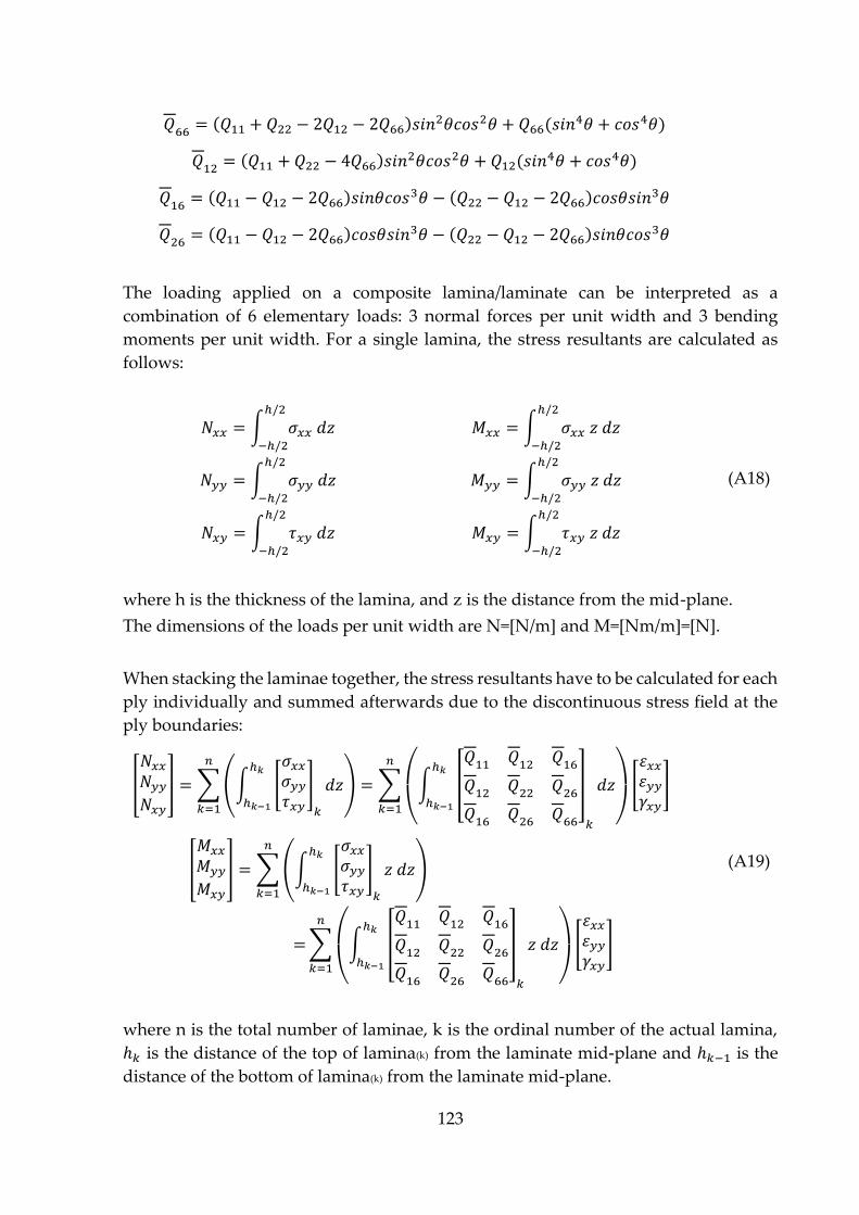
123
𝑄66 = (𝑄11 + 𝑄22 − 2𝑄12 − 2𝑄66)𝑠𝑖𝑛2𝜃𝑐𝑜𝑠2𝜃 + 𝑄66(𝑠𝑖𝑛
4𝜃 + 𝑐𝑜𝑠4𝜃)
𝑄12 = (𝑄11 + 𝑄22 − 4𝑄66)𝑠𝑖𝑛2𝜃𝑐𝑜𝑠2𝜃 + 𝑄12(𝑠𝑖𝑛
4𝜃 + 𝑐𝑜𝑠4𝜃)
𝑄16 = (𝑄11 − 𝑄12 − 2𝑄66)𝑠𝑖𝑛𝜃𝑐𝑜𝑠3𝜃 − (𝑄22 − 𝑄12 − 2𝑄66)𝑐𝑜𝑠𝜃𝑠𝑖𝑛
3𝜃
𝑄26 = (𝑄11 − 𝑄12 − 2𝑄66)𝑐𝑜𝑠𝜃𝑠𝑖𝑛3𝜃 − (𝑄22 −𝑄12 − 2𝑄66)𝑠𝑖𝑛𝜃𝑐𝑜𝑠
3𝜃
The loading applied on a composite lamina/laminate can be interpreted as a
combination of 6 elementary loads: 3 normal forces per unit width and 3 bending
moments per unit width. For a single lamina, the stress resultants are calculated as
follows:
𝑁𝑥𝑥 = ∫ 𝜎𝑥𝑥 𝑑𝑧ℎ/2
−ℎ/2
𝑀𝑥𝑥 = ∫ 𝜎𝑥𝑥 𝑧 𝑑𝑧ℎ/2
−ℎ/2
(A18) 𝑁𝑦𝑦 = ∫ 𝜎𝑦𝑦 𝑑𝑧ℎ/2
−ℎ/2
𝑀𝑦𝑦 = ∫ 𝜎𝑦𝑦 𝑧 𝑑𝑧ℎ/2
−ℎ/2
𝑁𝑥𝑦 = ∫ 𝜏𝑥𝑦 𝑑𝑧ℎ/2
−ℎ/2
𝑀𝑥𝑦 = ∫ 𝜏𝑥𝑦 𝑧 𝑑𝑧ℎ/2
−ℎ/2
where h is the thickness of the lamina, and z is the distance from the mid-plane.
The dimensions of the loads per unit width are N=[N/m] and M=[Nm/m]=[N].
When stacking the laminae together, the stress resultants have to be calculated for each
ply individually and summed afterwards due to the discontinuous stress field at the
ply boundaries:
[
𝑁𝑥𝑥𝑁𝑦𝑦𝑁𝑥𝑦
] = ∑(∫ [
𝜎𝑥𝑥𝜎𝑦𝑦𝜏𝑥𝑦
]
𝑘
𝑑𝑧ℎ𝑘
ℎ𝑘−1
)
𝑛
𝑘=1
=∑
(
∫ [
𝑄11 𝑄12 𝑄16
𝑄12 𝑄22 𝑄26
𝑄16 𝑄26 𝑄66
]
𝑘
𝑑𝑧ℎ𝑘
ℎ𝑘−1)
[
𝜀𝑥𝑥𝜀𝑦𝑦𝛾𝑥𝑦
]
𝑛
𝑘=1
(A19) [
𝑀𝑥𝑥
𝑀𝑦𝑦
𝑀𝑥𝑦
] = ∑(∫ [
𝜎𝑥𝑥𝜎𝑦𝑦𝜏𝑥𝑦
]
𝑘
𝑧 𝑑𝑧ℎ𝑘
ℎ𝑘−1
)
𝑛
𝑘=1
=∑
(
∫ [
𝑄11 𝑄12 𝑄16
𝑄12 𝑄22 𝑄26
𝑄16 𝑄26 𝑄66
]
𝑘
𝑧 𝑑𝑧ℎ𝑘
ℎ𝑘−1)
[
𝜀𝑥𝑥𝜀𝑦𝑦𝛾𝑥𝑦
]
𝑛
𝑘=1
where n is the total number of laminae, k is the ordinal number of the actual lamina,
ℎ𝑘 is the distance of the top of lamina(k) from the laminate mid-plane and ℎ𝑘−1 is the
distance of the bottom of lamina(k) from the laminate mid-plane.
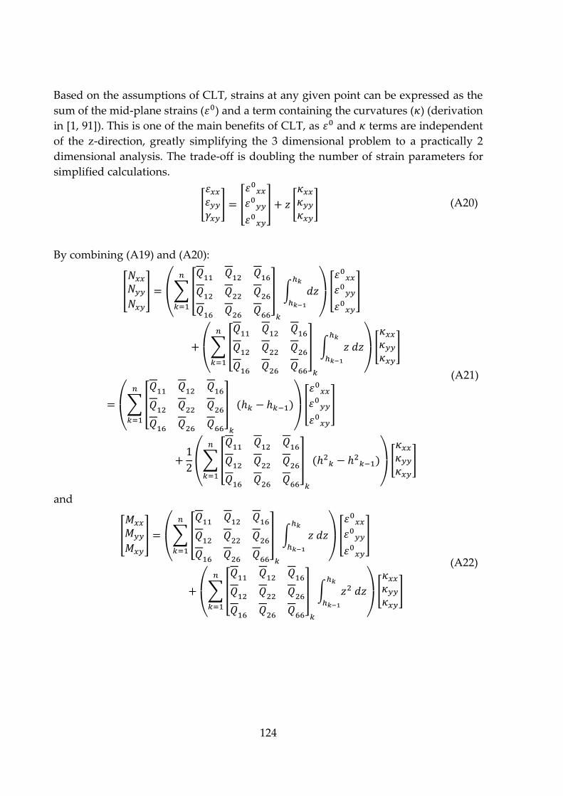
124
Based on the assumptions of CLT, strains at any given point can be expressed as the
sum of the mid-plane strains (𝜀0) and a term containing the curvatures (𝜅) (derivation
in [1, 91]). This is one of the main benefits of CLT, as 𝜀0 and 𝜅 terms are independent
of the z-direction, greatly simplifying the 3 dimensional problem to a practically 2
dimensional analysis. The trade-off is doubling the number of strain parameters for
simplified calculations.
[
𝜀𝑥𝑥𝜀𝑦𝑦𝛾𝑥𝑦
] = [
𝜀0𝑥𝑥𝜀0𝑦𝑦
𝜀0𝑥𝑦
] + 𝑧 [
𝜅𝑥𝑥𝜅𝑦𝑦𝜅𝑥𝑦
] (A20)
By combining (A19) and (A20):
[
𝑁𝑥𝑥𝑁𝑦𝑦𝑁𝑥𝑦
] =
(
∑[
𝑄11 𝑄12 𝑄16
𝑄12 𝑄22 𝑄26
𝑄16 𝑄26 𝑄66
]
𝑛
𝑘=1
𝑘
∫ 𝑑𝑧ℎ𝑘
ℎ𝑘−1)
[
𝜀0𝑥𝑥𝜀0𝑦𝑦
𝜀0𝑥𝑦
]
+
(
∑[
𝑄11 𝑄12 𝑄16
𝑄12 𝑄22 𝑄26
𝑄16 𝑄26 𝑄66
]
𝑛
𝑘=1
𝑘
∫ 𝑧 𝑑𝑧ℎ𝑘
ℎ𝑘−1)
[
𝜅𝑥𝑥𝜅𝑦𝑦𝜅𝑥𝑦
]
(A21)
=
(
∑[
𝑄11 𝑄12 𝑄16
𝑄12 𝑄22 𝑄26
𝑄16 𝑄26 𝑄66
]
𝑛
𝑘=1
𝑘
(ℎ𝑘 − ℎ𝑘−1)
)
[
𝜀0𝑥𝑥𝜀0𝑦𝑦
𝜀0𝑥𝑦
]
+1
2
(
∑[
𝑄11 𝑄12 𝑄16
𝑄12 𝑄22 𝑄26
𝑄16 𝑄26 𝑄66
]
𝑛
𝑘=1
𝑘
(ℎ2𝑘 − ℎ2𝑘−1)
)
[
𝜅𝑥𝑥𝜅𝑦𝑦𝜅𝑥𝑦
]
and
[
𝑀𝑥𝑥
𝑀𝑦𝑦
𝑀𝑥𝑦
] =
(
∑[
𝑄11 𝑄12 𝑄16
𝑄12 𝑄22 𝑄26
𝑄16 𝑄26 𝑄66
]
𝑛
𝑘=1
𝑘
∫ 𝑧 𝑑𝑧ℎ𝑘
ℎ𝑘−1)
[
𝜀0𝑥𝑥𝜀0𝑦𝑦
𝜀0𝑥𝑦
]
+
(
∑[
𝑄11 𝑄12 𝑄16
𝑄12 𝑄22 𝑄26
𝑄16 𝑄26 𝑄66
]
𝑛
𝑘=1
𝑘
∫ 𝑧2 𝑑𝑧ℎ𝑘
ℎ𝑘−1)
[
𝜅𝑥𝑥𝜅𝑦𝑦𝜅𝑥𝑦
]
(A22)
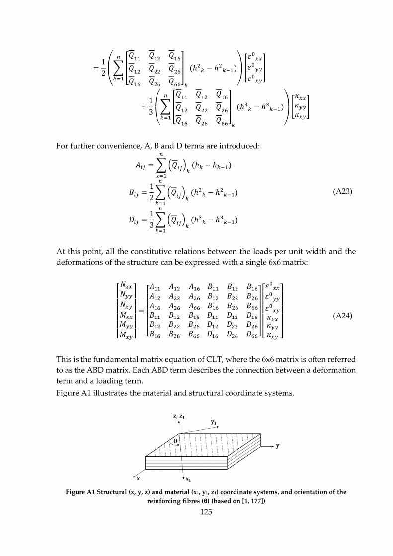
125
=1
2
(
∑[
𝑄11 𝑄12 𝑄16
𝑄12 𝑄22 𝑄26
𝑄16 𝑄26 𝑄66
]
𝑛
𝑘=1
𝑘
(ℎ2𝑘 − ℎ2𝑘−1)
)
[
𝜀0𝑥𝑥𝜀0𝑦𝑦
𝜀0𝑥𝑦
]
+1
3
(
∑[
𝑄11 𝑄12 𝑄16
𝑄12 𝑄22 𝑄26
𝑄16 𝑄26 𝑄66
]
𝑛
𝑘=1
𝑘
(ℎ3𝑘 − ℎ3𝑘−1)
)
[
𝜅𝑥𝑥𝜅𝑦𝑦𝜅𝑥𝑦
]
For further convenience, A, B and D terms are introduced:
𝐴𝑖𝑗 =∑(𝑄𝑖𝑗)𝑘(ℎ𝑘 − ℎ𝑘−1)
𝑛
𝑘=1
(A23) 𝐵𝑖𝑗 =1
2∑(𝑄𝑖𝑗)𝑘
(ℎ2𝑘 − ℎ2𝑘−1)
𝑛
𝑘=1
𝐷𝑖𝑗 =1
3∑(𝑄𝑖𝑗)𝑘
(ℎ3𝑘 − ℎ3𝑘−1)
𝑛
𝑘=1
At this point, all the constitutive relations between the loads per unit width and the
deformations of the structure can be expressed with a single 6x6 matrix:
[ 𝑁𝑥𝑥𝑁𝑦𝑦𝑁𝑥𝑦𝑀𝑥𝑥
𝑀𝑦𝑦
𝑀𝑥𝑦]
=
[ 𝐴11 𝐴12 𝐴16𝐴12 𝐴22 𝐴26𝐴16 𝐴26 𝐴66
𝐵11 𝐵12 𝐵16𝐵12 𝐵22 𝐵26𝐵16 𝐵26 𝐵66
𝐵11 𝐵12 𝐵16𝐵12 𝐵22 𝐵26𝐵16 𝐵26 𝐵66
𝐷11 𝐷12 𝐷16𝐷12 𝐷22 𝐷26𝐷16 𝐷26 𝐷66]
[ 𝜀0𝑥𝑥𝜀0𝑦𝑦
𝜀0𝑥𝑦𝜅𝑥𝑥𝜅𝑦𝑦𝜅𝑥𝑦 ]
(A24)
This is the fundamental matrix equation of CLT, where the 6x6 matrix is often referred
to as the ABD matrix. Each ABD term describes the connection between a deformation
term and a loading term.
Figure A1 illustrates the material and structural coordinate systems.
Figure A1 Structural (x, y, z) and material (x1, y1, z1) coordinate systems, and orientation of the
reinforcing fibres (θ) (based on [1, 177])

126
Figure A2 illustrates the stress resultants.
Figure A2 Illustration of the a) forces and b) moments per unit width (based on [1, 177])
Related Documents