SHAIFUL NIZAM MOHYAR UNIVERSITI MALAYSIA PERLIS SCHOOL OF MICROELECTRONIC 2007/2008

Welcome message from author
This document is posted to help you gain knowledge. Please leave a comment to let me know what you think about it! Share it to your friends and learn new things together.
Transcript

SHAIFUL NIZAM MOHYARUNIVERSITI MALAYSIA PERLIS
SCHOOL OF MICROELECTRONIC
2007/2008

Electromechanical Energy Conversion
ElectricalEnergy
MechanicalEnergy
Motor
Generator
2.0 INTRODUCTION

Pelec = vi = Teωm = Pmech
The machine’s magnetic field is the medium of (energy) conversion.

GLOSSARY Torque, T – A force that produces rotation on a axis and
also defined as a linear force multiplied by a radius. In an electric motor, this is the force from the interaction of the magnetic fields produced by the flow of current through the armature and field windings/coils.
Flux, Φ - The magnetic field which is established around an energized conductor or permanent magnet. The field is represented by flux lines creating a flux pattern between opposite poles. The density of the flux lines is a measure of the strength of the magnetic field.
Magnetic field, B - A region of space that surrounds a moving electrical charge or a magnetic pole, in which the electrical charge or magnetic pole experiences a force that is above the electrostatic ones associated with particles at rest.

The voltage in any real machine will depend on three factors: 1. The flux, Φ in the machine. 2. The speed of rotation, ω. 3. A constant representing the construction of the machine.

2.0 INTRODUCTION…contd
Flemming’s Left Hand Rule (Motor Rule)
Use: To determine the direction of a force on a current carrying conductor in a magnetic field.

2.0 INTRODUCTION…contd
The carbon rod is NOT magnetic. When no current flows, the rod is stationary When we turn on the current, the rod
experiences a force that makes it move. The direction of the force is determined by
Fleming' Left Hand Rule

2.1 CONSTRUCTION
Cutaway view of a dc motor

Stator with visible poles
2.1 CONSTRUCTION ….contnd

Rotor of a dc motor.
2.1 CONSTRUCTION ….contnd

General arrangement of a dc machine
2.2 CONSTRUCTION….contnd

The stator of the dc motor has poles, which are excited by dc current to produce magnetic fields.
In the neutral zone, in the middle between the poles, commutating poles are placed to reduce sparking of the commutator. The commutating poles are supplied by dc current.
Compensating windings are mounted on the main poles. These short-circuited windings damp rotor oscillations. .
2.1 CONSTRUCTION….contnd

The poles are mounted on an iron core that provides a closed magnetic circuit.
The motor housing supports the iron core, the brushes and the bearings.
The rotor has a ring-shaped laminated iron core with slots.
Coils with several turns are placed in the slots. The distance between the two legs of the coil is about 180 electric degrees.
2.1 CONSTRUCTION….contnd

The coils are connected in series through the commutator segments.
The ends of each coil are connected to a commutator segment.
The commutator consists of insulated copper segments mounted on an insulated tube.
Two brushes are pressed to the commutator to permit current flow.
The brushes are placed in the neutral zone, where the magnetic field is close to zero, to reduce arcing.
2.1 CONSTRUCTION….contnd

Commutator of a dc motor
2.1 CONSTRUCTION….contnd

The rotor has a ring-shaped laminated iron core with slots.
The commutator consists of insulated copper segments mounted on an insulated tube. Two brushes are pressed to the commutator to permit current flow.
The brushes are placed in the neutral zone, where the magnetic field is close to zero, to reduce arcing.
2.1 CONSTRUCTION….contnd

The commutator switches the current from one rotor coil to the adjacent coil.
The switching requires the interruption of the coil current.
The sudden interruption of an inductive current generates high voltages .
The high voltage produces flashover and arcing between the commutator segment and the brush.
2.1 CONSTRUCTION

I
I
shaftw
h
B
Next slide looks down the shaft
2.2 DC MACHINE OPERATION BASIC
THEORY

Current coming
toward you
Current leaving away from you
B
Shaft
2.2 DC MACHINE OPERATION BASIC
THEORY….contnd

Bdirection by left-hand rule
F
F T = 2hFcos = 2hIwBNcos
Thumb = current Forefinger = BRest = Force
2.2 DC MACHINE OPERATION BASIC
THEORY….contnd

B
2.2 DC MACHINE OPERATION BASIC
THEORY….contnd

B
2.2 DC MACHINE OPERATION BASIC
THEORY….contnd

B
2.2 DC MACHINE OPERATION BASIC
THEORY….contnd

B
2.2 DC MACHINE OPERATION BASIC
THEORY….contnd

B
2.2 DC MACHINE OPERATION BASIC
THEORY….contnd

B
2.2 DC MACHINE OPERATION BASIC
THEORY….contnd

B
2.2 DC MACHINE OPERATION BASIC
THEORY….contnd

B
2.2 DC MACHINE OPERATION BASIC
THEORY….contnd

B
2.2 DC MACHINE OPERATION BASIC
THEORY….contnd

In a dc motor, the stator poles are supplied by dc excitation current, which produces a dc magnetic field.
The rotor is supplied by dc
current through the brushes, commutator and coils.
The interaction of the
magnetic field and rotor current generates a force that drives the motor.
2.3 DC MACHINE OPERATION

The magnetic field lines enter into the rotor from the north pole (N) and exit toward the south pole (S).
The poles generate a magnetic field that is perpendicular to the current carrying conductors.
The interaction between the field and the current produces a Lorentz force.
The force is perpendicular to both the magnetic field and conductor.
(a) Rotor current flow from segment 1 to 2 (slot a to b)
Vdc30
NS
Bv
v
a
b
1
2
Ir_dc
(b) Rotor current flow from segment 2 to 1 (slot b to a)
30NS Vdc
a
b
B
v v
Ir_dc
2.3 DC MACHINE OPERATION

The generated force turns the rotor until the coil reaches the neutral point between the poles.
At this point, the magnetic field becomes practically zero together with the force.
However, inertia drives the motor beyond the neutral zone where the direction of the magnetic field reverses.
To avoid the reversal of the force direction, the commutator changes the current direction, which maintains the counterclockwise rotation.
(a) Rotor current flow from segment 1 to 2 (slot a to b)
Vdc30
NS
Bv
v
a
b
Ir_dc
(b) Rotor current flow from segment 2 to 1 (slot b to a)
30NS Vdc
a
b
B
v v
Ir_dc
2.3 DC MACHINE OPERATION

Before reaching the neutral zone, the current enters in segment 1 and exits from segment 2,
Therefore, current enters the coil end at slot a and exits from slot b during this stage.
After passing the neutral zone, the current enters segment 2 and exits from segment 1,
This reverses the current direction through the rotor coil, when the coil passes the neutral zone.
The result of this current reversal is the maintenance of the rotation.
(a) Rotor current flow from segment 1 to 2 (slot a to b)
Vdc30
NS
Bv
v
a
b
Ir_dc
(b) Rotor current flow from segment 2 to 1 (slot b to a)
30NS Vdc
a
b
B
v v
Ir_dc
2.3 DC MACHINE OPERATION

2.4 DC Generator Operation 2.4 DC Generator Operation

Fleming’s Right hand rule (Generator Rule) Use: To determine the direction of the induced
emf/current of a conductor moving in a magnetic field.
2.4 DC Generator Operation 2.4 DC Generator Operation

The N-S poles produce a dc magnetic field and the rotor coil turns in this field.
A turbine or other machine drives the rotor.
The conductors in the slots cut the magnetic flux lines, which induce voltage in the rotor coils.
The coil has two sides: one is placed in slot a, the other in slot b.
30NS Vdc
Bv
v
a
b
Ir_dc
(a) Rotor current flow from segment 1 to 2 (slot a to b)
30NS Vdc
a
b
1
2vv
B
Ir_dc
(b) Rotor current flow from segment 2 to 1 (slot b to a)
2.4 DC Generator Operation2.4 DC Generator Operation....contndcontnd..

In Figure (a), the conductors in slot a are cutting the field lines entering into the rotor from the north pole,
The conductors in slot b are cutting the field lines exiting from the rotor to the south pole.
The cutting of the field lines generates voltage in the conductors.
The voltages generated in the two sides of the coil are added.
30NS Vdc
Bv
v
a
b
Ir_dc
(a) Rotor current flow from segment 1 to 2 (slot a to b)
30NS Vdc
a
b
1
2vv
B
Ir_dc
(b) Rotor current flow from segment 2 to 1 (slot b to a)
2.4 DC Generator Operation2.4 DC Generator Operation....contndcontnd..

The induced voltage is connected to the generator terminals through the commutator and brushes.
In Figure (a), the induced voltage in b is positive, and in a is negative.
The positive terminal is connected to commutator segment 2 and to the conductors in slot b.
The negative terminal is connected to segment 1 and to the conductors in slot a.
30NS Vdc
Bv
v
a
b
Ir_dc
(a) Rotor current flow from segment 1 to 2 (slot a to b)
30NS Vdc
a
b
vv
B
Ir_dc
(b) Rotor current flow from segment 2 to 1 (slot b to a)
2.4 DC Generator Operation2.4 DC Generator Operation....contndcontnd..

When the coil passes the neutral zone: Conductors in slot a are
then moving toward the south pole and cut flux lines exiting from the rotor
Conductors in slot b cut the flux lines entering the in slot b.
This changes the polarity of the induced voltage in the coil.
The voltage induced in a is now positive, and in b is negative.
30NS Vdc
Bv
v
a
b
Ir_dc
(a) Rotor current flow from segment 1 to 2 (slot a to b)
30NS Vdc
a
b
vv
B
Ir_dc
(b) Rotor current flow from segment 2 to 1 (slot b to a)
2.4 DC Generator Operation2.4 DC Generator Operation....contndcontnd..

The simultaneously the commutator reverses its terminals, which assures that the output voltage (Vdc) polarity is unchanged.
In Figure (b)
the positive terminal is connected to commutator segment 1 and to the conductors in slot a.
The negative terminal is connected to segment 2 and to the conductors in slot b.
30NS Vdc
Bv
v
a
b
Ir_dc
(a) Rotor current flow from segment 1 to 2 (slot a to b)
30NS Vdc
a
b
1
2vv
B
Ir_dc
(b) Rotor current flow from segment 2 to 1 (slot b to a)
2.4 DC Generator Operation2.4 DC Generator Operation....contndcontnd..

2.5 DC Machine Type
There are generally five major types ofDC motors: The separately excited dc motor The shunt dc motor The permanent magnet dc motor The series dc motor The compounded dc motor

The magnetic field produced by the stator poles induces a voltage in the rotor (or armature) coils when the generator is rotated.
This induced voltage is represented by a voltage source.
The stator coil has resistance, which is connected in series.
The pole flux is produced by the DC excitation/field current, which is magnetically coupled to the rotor
The field circuit has resistance and a sourceThe voltage drop on the brushes represented
by a battery
2.6 DC Machine Equivalent Circuit2.6 DC Machine Equivalent Circuit

1. Permanent magnet• The poles are made of permanent
magnets. • No field winding required.• Small size.• Disadvantage is low flux density,
so low torque.
2.6 DC Machine 2.6 DC Machine EquEqu. Circuit. Circuit....contndcontnd..

2. Separately excited The field flux is derived from a separate power source
independent of the generator itself.
B
Field winding
Armature winding
2.6 DC Machine 2.6 DC Machine EquEqu. Circuit. Circuit....contndcontnd..

3. Self-excited – shunt machine
• The field flux is derives by connecting the field directly across the terminals of the generator.
B
2.6 DC Machine 2.6 DC Machine EquEqu. Circuit. Circuit....contndcontnd..

3. Self-excited - series machine
• field are connected in series with armature
B
2.6 DC Machine 2.6 DC Machine EquEqu. Circuit. Circuit....contndcontnd..

3. Self-excited – Compounded dc motor
- both a shunt and a series field
are present
2.6 DC Machine 2.6 DC Machine EquEqu. Circuit. Circuit....contndcontnd..

3. Self-excited • Cumulatively compounded
• Differentially compounded
BB
BB
2.6 DC Machine 2.6 DC Machine EquEqu. Circuit. Circuit....contndcontnd..

The armature is represented by an ideal voltage source EA and a resistor RA.
The brush voltage drop is represented by a small battery Vbrush opposing the direction of the current flow in the machine.
The field coils, which produce the magnetic flux, are represented by inductor LF and RF.
The separate resistor Radj represents an external variable resistor used to control the amount of current in the field circuit.
Equivalent Circuit of a DC Motor.
2.6 DC Machine 2.6 DC Machine EquEqu. Circuit. Circuit....contndcontnd..

The brush drop voltage is often only a very tiny fraction of the generated voltage in the motor.
Therefore, in cases where it is not critical, the brush drop voltage may be left out or approximately included in the value of RA.
Also, the internal resistance of the filed coils is sometimes lumped together with the variable resistor, and the total is called RF , Figure below.
A Simplified Equivalent Circuit eliminating the Brush Voltage Drop and Combining Radj with the Field Resistance .

F
FF R
VI AAAT RIEV
AL II
The Equivalent Circuit of Separately Excited dc Motor.From the above figure,
2.5 DC Machine 2.5 DC Machine EquEqu. Circuit. Circuit....contndcontnd..

F
FF R
VI AAAT RIEV
FAL III
Shunt DC motors
From the above figure, The Equivalent Circuit of a Shunt dc Motor

Torque Equation
T = torque of armature (N-m)kA = geometry constant
= flux/pole (Wb) IA = armature current (A)
AA IkT

Geometry Constant
p = number of field polesN = number of active conductors on armature
M = number of parallel paths in armature winding (=p for lap winding, =2 for wave winding)
)(60
),/(2
' rpmM
pNksrad
M
pNk AA
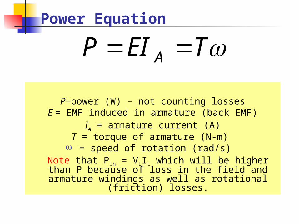
Power Equation
P=power (W) – not counting lossesE = EMF induced in armature (back EMF)
IA = armature current (A)T = torque of armature (N-m) = speed of rotation (rad/s)
Note that Pin = VLIL which will be higher than P because of loss in the field and armature
windings as well as rotational (friction) losses.
TEIP A

EMF Equation
E = EMF induced in armature (V)kA = geometry constant
= flux/pole (Wb) = speed of rotation (rad/s) n = speed of rotation of
armature (rpm)
nkkE AA '
2
60n

Terminal Voltage Equation
VT = voltage at motor terminals
E = EMF induced in armature (V)IA = armature current (A)
RA = armature resistance
AAT RIEV E VT
+
-
+
-
RA

Speed Equation
(applies to shunt connected motor only)
Note that can also be written as kfIf where kf is
/If (normally a constant ratio)
'A
AAT
k
RIVn
Ratio Equation
1
2
1
2
E
E
n
n

Speed-Torque
Torque
Speed
Series
Shunt
Cumulative Compound
Differential Compound

Example 1A 6 pole, 3.0 hp 120V DC lap-wound shunt motor has 960 conductorsin the armature. It takes 25.0 A from the supply at full load. Armature resistance is 0.75, flux/pole=10.0 mWb, field winding current is 1.20A. Find the speed and torque.
AAAIII FLA 8.232.125 VAVRIVE AAT 10275.08.23120
153
62
9606
2
MpN
K A
sradx
V
K
E
KE
A
A
/9.661010153
1023
rpmn 6382
60
kWhp
WhpP 24.2
7463
mNsrad
kWPT 5.33
/9.66
24.2

Example 2A 10hp, 115V Dc series motor takes 40A at its full load speed of 1800rpm. What is the torque at 30A?
srad
n/188
60
18002
60
2
kWhp
WhpP 46.7
74610
mNsrad
kWPT
TP
6.39/188
46.7
AFFAAA IIKKIKT
AF II 2AFA IKKT
025.0
40
6.3922
A
mN
I
TKK
A
FA
mNAIKKTnewAFAnew 2.2230025.0 22

Example 3 (a)A 220V DC shunt motor draws 10A at 1800rpm. The armatureresistance is 0.2 and field winding resistance is 440. (a) What is
thetorque?
AV
R
VI
F
TF 5.0
440
220
AAAIII FLA 5.95.010
VAVRIVE AAT 2182.05.9220
kWAVEIP A 07.25.9218
srad
n/188
60
18002
60
2
mNsrad
kWPT 0.11
/188
07.2

Example 3 (b)A 220V DC shunt motor draws 10A at 1800rpm. The armatureresistance is 0.2 and field winding resistance is 440. (b) What willbe the speed and line current at a torque of 20 N-m (if field current isconstant)?
16.1/188
218
srad
VEK
KE
A
A
AmN
K
TI
IKT
AA
AA
3.1716.1
20
AAAIII FAL 8.175.03.17
VVRIVE AAT 2172.03.17220
rpmxn
sradV
K
E
A
31079.12
60
/18716.1
217
(shunt is constant speed)
Related Documents