SGI ™ 1400 Server Family User’s Guide Document Number 007-3978-001

Welcome message from author
This document is posted to help you gain knowledge. Please leave a comment to let me know what you think about it! Share it to your friends and learn new things together.
Transcript
SGI™ 1400 Server FamilyUser’s Guide
Document Number 007-3978-001

CONTRIBUTORS
Writer Mark SchwendenIllustrated by Cheri BrownProduction by Heather Hermstad and David ClarkeEngineering contributions by James Oliver and Courtney CarrSt. Peter’s Basilica image courtesy of ENEL SpA and InfoByte SpA. Disk Thrower
image courtesy of Xavier Berenguer, Animatica.
© 1999, Silicon Graphics, Inc.— All Rights ReservedThe contents of this document may not be copied or duplicated in any form, in wholeor in part, without the prior written permission of Silicon Graphics, Inc.
LIMITED AND RESTRICTED RIGHTS LEGENDUse, duplication, or disclosure by the Government is subject to restrictions as setforth in the Rights in Data clause at FAR 52.227-14 and/or in similar or successorclauses in the FAR, or in the DOD, DOE, or NASA FAR Supplements. Unpublishedrights reserved under the Copyright Laws of the United States.Contractor/manufacturer is Silicon Graphics, Inc., 1600 Amphitheatre Pkwy.,Mountain View, CA 94043-1351.
Silicon Graphics is a registered trademark and SGI and the Silicon Graphics logo aretrademarks of Silicon Graphics, Inc. Cirrus Logic is a registered trademark of CirrusLogic Inc. Intel, Pentium, and LANDesk are registered trademarks of the IntelCorporation. Magic Packet is a trademark of Advanced Micro Devices, Inc. Microsoftand Windows are trademarks of the Microsoft Corporation. MMX and Xeon aretrademarks of the Intel Corporation. Symbios is a registered trademark of the LSILogic Corporation. All other third party brands and names mentioned in thisdocument are the property of their respective owners.
SGI™ 1400 Server Family User’s GuideDocument Number 007-3978-001
Contents
List of Figures xi
List of Tables xiii
About This Guide xv
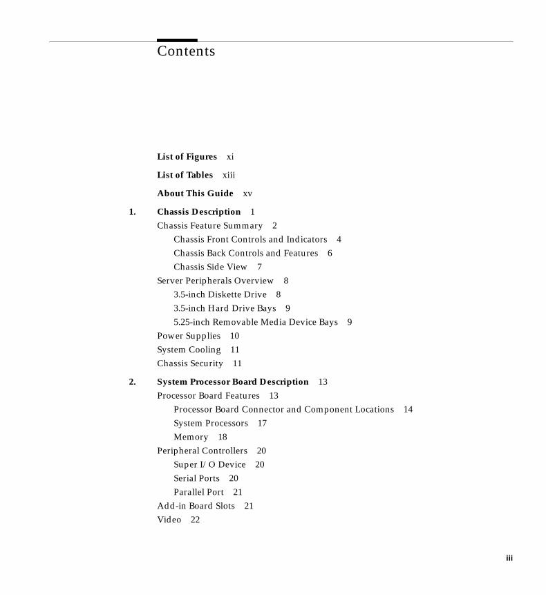
1. Chassis Description 1Chassis Feature Summary 2
Chassis Front Controls and Indicators 4Chassis Back Controls and Features 6Chassis Side View 7
Server Peripherals Overview 83.5-inch Diskette Drive 83.5-inch Hard Drive Bays 95.25-inch Removable Media Device Bays 9
Power Supplies 10System Cooling 11Chassis Security 11
2. System Processor Board Description 13Processor Board Features 13
Processor Board Connector and Component Locations 14System Processors 17Memory 18
Peripheral Controllers 20Super I/O Device 20Serial Ports 20Parallel Port 21
Add-in Board Slots 21Video 22
iii
Contents
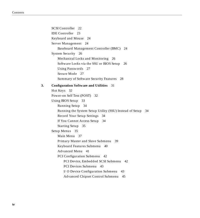
SCSI Controller 22IDE Controller 23Keyboard and Mouse 24Server Management 24
Baseboard Management Controller (BMC) 24System Security 26
Mechanical Locks and Monitoring 26Software Locks via the SSU or BIOS Setup 26Using Passwords 27Secure Mode 27Summary of Software Security Features 28
3. Configuration Software and Utilities 31Hot Keys 32Power-on Self Test (POST) 32Using BIOS Setup 33
Running Setup 34Running the System Setup Utility (SSU) Instead of Setup 34Record Your Setup Settings 34If You Cannot Access Setup 34Starting Setup 35
Setup Menus 35Main Menu 37Primary Master and Slave Submenu 39Keyboard Features Submenu 40Advanced Menu 41PCI Configuration Submenu 42
PCI Device, Embedded SCSI Submenu 42PCI Devices Submenu 43I/O Device Configuration Submenu 43Advanced Chipset Control Submenu 45
iv
Contents
Security Menu 46Server Menu 47
System Management Submenu 48Console Redirection Submenu 49
Boot Menu 49Boot Device Priority Submenu 50Hard Drive Submenu 50
Exit Menu 51Using the System Setup Utility (SSU) 52
When to Run the SSU 52What You Need to Do Before Running the SSU 53Running the SSU 54
Running the SSU Locally 54Running the SSU Remotely 54
Starting the SSU 55Customizing the SSU 57Launching a Task 58Resource Configuration Add-in (RCA) Window 58
Defining an ISA Board 59Adding and Removing ISA Boards 60Modifying Resources 60System Resource Usage 61
Multiboot Options Add-in 61Security Add-in 62
To Set the User Password 62To Change or Clear the User Password 62To Set the Administrator Password 62To Change or Clear the Administrator Password 62Security Options 63
System Event Log (SEL) Viewer Add-in 63Sensor Data Record (SDR) Manager Add-In 65Field Replaceable Unit (FRU) Manager Add-In 67Exiting the SSU 69
v
Contents
Emergency Management Port (EMP) Console 69How the EMP Console Works 70EMP Console Requirements 73Setting Up the Server for the EMP 73
System Management Submenu 74Console Redirection Submenu 74
Main EMP Console Window 75Toolbar 75Status Bar 76EMP Console Main Menu 76
Server Control Operations 77Connect to Remote Server 77Power the Server On or Off Remotely 79Reset the Server Remotely 80
Phonebook 81Management Plug-ins 82
System Event Log (SEL) Viewer 82SEL Viewer Menu Options 83Sensor Data Record (SDR) Viewer 84SDR Viewer Menu Options 84Field Replaceable Unit (FRU) Viewer 85FRU Viewer Menu Options 85
When to Run the FRUSDR Load Utility 86What You Need to Do 86
vi
Contents
How You Use the FRUSDR Load Utility 87FRUSDR Command Line Format 87Parsing the Command Line 88Displaying Usage Information 88Displaying a Given Area 89Using Specified CFG File 90Displaying the Utility Title and Version 90Configuration File 91Prompting for Product Level FRU Information 91Filtering Records From the SDR File 91Updating the SDR Nonvolatile Storage Area 91Updating FRU Nonvolatile Storage Area 91Updating DMI FRU Nonvolatile Storage Area 92Cleaning Up and Exiting the Nonvolatile Storage Area 92
Changing the BIOS Settings 92Recording the Current BIOS Settings 92Obtaining the Upgrade Utility 93Creating a Bootable Diskette 93Creating the BIOS Upgrade Diskette 94Upgrading the BIOS 94Recovering the BIOS 95Changing the BIOS Language 96
Using the Firmware Update Utility 96Running the Firmware Update Utility 96
Installing Video Drivers 97Using the Symbios SCSI Utility for NT 97
Running the SCSI Utility 97
vii
Contents
4. Solving Problems 99Resetting the System 99Initial System Startup 99
Checklist 100Running New Application Software 101
Checklist 101After the System Has Been Running Correctly 102
Checklist 102More Problem-solving Procedures 103
Preparing the System for Diagnostic Testing 103Using PCDiagnostics 103Monitoring POST 104Verifying Proper Operation of Key System Lights 104Confirming Loading of the Operating System 104
Specific Problems and Corrective Actions 105Power Light Does Not Light 105No Beep Codes 106No Characters Appear on Screen 106Characters Are Distorted or Incorrect 107System Cooling Fans Do Not Rotate Properly 107Diskette Drive Activity Light Does Not Light 108Hard Disk Drive Activity Light Does Not Light 108CD-ROM Drive Activity Light Does Not Light 109Network Problems 109PCI Installation Tips 109
Problems with Application Software 110Bootable CD-ROM Is Not Detected 110Error and Informational Messages 110
POST Codes and Countdown Codes 111POST Error Codes and Messages 116
viii
Contents
5. Installing or Replacing Drives and Power Supplies 119SCSI Hard Disk Drives 119
Mounting a SCSI Hard Disk Drive in a Carrier 119Hot-swapping a SCSI Hard Disk Drive 120
Removing or Installing a Power Supply 123Removing a Power Supply 123Installing a Power Supply 124
A. Environmental and Regulatory Specifications 125Environmental and Regulatory Specifications 125
Manufacturer’s Regulatory Declarations 126Server CMN Number 126Series Number 126Manufacturer’s Declaration of Conformity 126Upgrade Regulatory Label 127Class A Compliance 127Electromagnetic Emissions 128VCCI Notice (Japan Only) 128NOM 024 Information (Mexico Only) 128Chinese Class A Regulatory Notice 129Industry Canada Notice (Canada Only) 129CE Notice 129Korean Class A Regulatory Notice 130Shielded Cables 130Electrostatic Discharge 130
ix
Contents
B. SGI 1400 Server Rackmount Installation 131Safety Guidelines 131Server Precautions 131Equipment Rack Precautions 133Introduction 134Tools You Need 134Prepare the Slide Assemblies 135
Prepare the Server 137Attaching the Bezel Frame and Door 137Attach the Chassis Handles 137
Attach the Small Bar of the Slide Assembly to the Server 138Preparing the Equipment Rack 140
Attach the Center and Large Outer Bar Assemblies 140Attach the Bracket and Rail Assemblies to the Equipment Rack 142
Install the Server in the Rack 144
Index 147
x
List of Figures
Figure 1-1 Example Rack with Three Servers and Pedestal Server 2Figure 1-2 Front Controls and Indicators 5Figure 1-3 Back Controls and Indicators 6Figure 1-4 Chassis Side View 7Figure 2-1 Processor Board Connector and Component Locations 15Figure 2-2 Memory Module DIMM Installation Sequence 18Figure 3-1 SSU Main Window 56Figure 3-2 SEL Viewer Add-in Main Window 64Figure 3-3 SDR Manager Main Window 66Figure 3-4 FRU Manager Main Window 68Figure 3-5 EMP Console in Command State 70Figure 3-6 EMP Console in Redirect State 71Figure 3-7 Connect Dialog 77Figure 3-8 Power On/Off Dialog 79Figure 3-9 Reset Dialog 80Figure 3-10 Phonebook Dialog 81Figure 5-1 Mounting the Carrier and Heatsink Assembly to the
Hard Disk Drive 120Figure 5-2 Disengaging Drive Carrier from Chassis 121Figure 5-3 Installing a New Drive 122Figure 5-4 Removing a Power Supply 124Figure B-1 Outer Slide Assembly 136Figure B-2 Small Bar of the Slide Assembly 139Figure B-3 Center Bar and Large Outer Bar Assembly 141Figure B-4 Right-angle Bracket and Vertical Rail 143Figure B-5 Installing the Server in the Rack 145
xi

List of Tables
Table 1-1 SGI 1400 Server Physical Specifications 1Table 1-2 Chassis Features Summary 3Table 2-1 Processor Board Features 13Table 2-2 Sample DIMM Component Combinations 20Table 2-3 Server Software Security Features 28Table 3-1 Configuration Utilities 31Table 3-2 Hot Keys 32Table 3-3 Setup Menu Control Information 36Table 3-4 Restricted Menu Selection and Submenus 37Table 3-5 Main Menu Features and Descriptions 37Table 3-6 Primary IDE Master and Slave Submenu 39Table 3-7 Keyboard Features Submenu 40Table 3-8 Advanced Menu Features 41Table 3-9 PCI Device, Embedded SCSI Submenu 42Table 3-10 PCI Devices Submenu 43Table 3-11 I/O Device Configuration Submenu 43Table 3-12 Advanced Chipset Control Submenu 45Table 3-13 Security Menu 46Table 3-14 Server Menu Options 47Table 3-15 System Management Submenu 48Table 3-16 Console Redirection Submenu 49Table 3-17 Boot Menu 49Table 3-18 Boot Device Priority Submenu 50Table 3-19 Hard Drive Submenu 50Table 3-20 Exit Menu 51Table 3-21 SEL Viewer Menus 64Table 3-22 SDR Manager Menus 66
xiii
List of Tables
Table 3-23 FRU Manager Menus 68Table 3-24 EMP Console Access Modes (Server Configured for
Console Redirect) 72Table 3-25 EMP Console Access Modes (Server Not Configured for
Console Redirect) 72Table 3-26 FRUSDR Command Line Format 87Table 4-1 Port-80 Codes 111Table 4-2 POST Error Codes and Messages 116Table A-1 Environmental Specifications 125Table B-1 Server Physical Specifications 134
xiv
About This Guide
This guide provides you with information on using and administering your SGI 1400server.
Note: Qualified and trained service personnel should use the SGI 1400 Server FamilyMaintenance and Upgrades Guide to perform procedures that require opening the systemand adding, removing, or replacing internal components.
The following topics are covered in this manual:
• Chapter 1, “Chassis Description,” describes the server chassis and its keycomponents.
• Chapter 2, “System Processor Board Description,” lists the major features of theserver system’s processor board (also called the baseboard).
• Chapter 3, “Configuration Software and Utilities,” describes the Power-on Self Test(POST) and system configuration utilities.
• Chapter 4, “Solving Problems,” helps you identify and solve problems that mightoccur while you are using the server system.
• Chapter 5, “Installing or Replacing Drives and Power Supplies,” describes theserver’s drive options and removal or replacement procedures, plus information onsystem power supplies and how to replace them.
• Appendix A lists environmental and regulatory information for the server.
• Appendix B describes the procedures for mounting the server in a 19-inchequipment rack.
See the SGI 1400 Server Family Quick Start Guide for overview information on setting upyour server and getting started.
xv

Chapter 1
1. Chassis Description
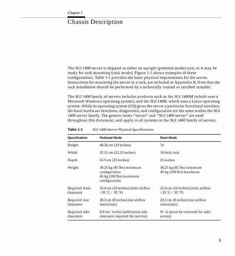
The SGI 1400 server is shipped as either an upright (pedestal mode) unit, or it may beready for rack mounting (rack mode). Figure 1-1 shows examples of theseconfigurations. Table 1-1 provides the basic physical requirements for the server.Instructions for mounting the server in a rack, are included in Appendix B. Note that therack installation should be performed by a technically trained or certified installer.
The SGI 1400 family of servers includes products such as the SGI 1400M (which uses aMicrosoft Windows operating system), and the SGI 1400L which uses a Linux operatingsystem. While its operating system (OS) gives the server a particular functional interface,the basic hardware functions, diagnostics, and configuration are the same within the SGI1400 server family. The generic terms “server” and “SGI 1400 server” are usedthroughout this document, and apply to all systems in the SGI 1400 family of servers.
Table 1-1 SGI 1400 Server Physical Specifications
Specification Pedestal Mode Rack Mode
Height 48.26 cm (19 inches) 7u
Width 31.12 cm (12.25 inches) 19-inch rack
Depth 63.5 cm (25 inches) 25 inches
Weight 38.25 kg (85 lbs) minimumconfiguration45 kg (100 lbs) maximumconfiguration
38.25 kg (85 lbs) minimum45 kg (100 lbs) maximum
Required frontclearance
25.4 cm (10 inches) (inlet airflow<35 ˚C / 95 ˚F)
25.4 cm (10 inches) (inlet airflow<35 ˚C / 95 ˚F)
Required rearclearance
20.3 cm (8 inches) (no airflowrestriction)
20.3 cm (8 inches) (no airflowrestriction)
Required sideclearance
0.0 cm/inches (additional sideclearance required for service)
N/A (must be removed for sideaccess)
1
Chapter 1: Chassis Description
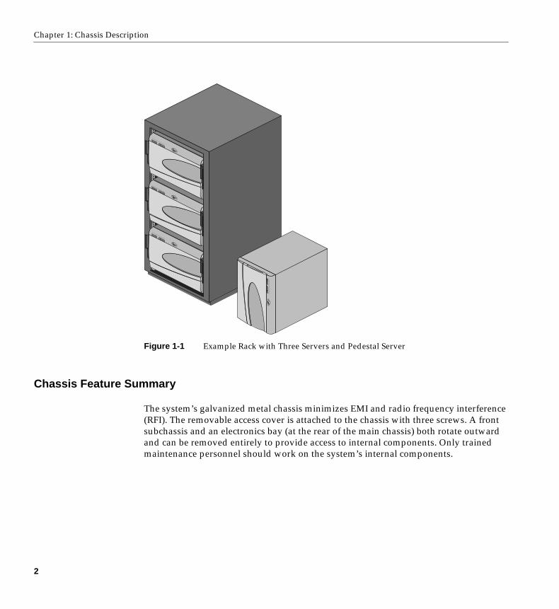
Figure 1-1 Example Rack with Three Servers and Pedestal Server
Chassis Feature Summary
The system’s galvanized metal chassis minimizes EMI and radio frequency interference(RFI). The removable access cover is attached to the chassis with three screws. A frontsubchassis and an electronics bay (at the rear of the main chassis) both rotate outwardand can be removed entirely to provide access to internal components. Only trainedmaintenance personnel should work on the system’s internal components.
2
Chassis Feature Summary
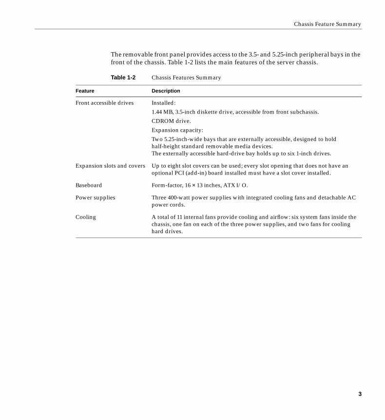
The removable front panel provides access to the 3.5- and 5.25-inch peripheral bays in thefront of the chassis. Table 1-2 lists the main features of the server chassis.
Table 1-2 Chassis Features Summary
Feature Description
Front accessible drives Installed:
1.44 MB, 3.5-inch diskette drive, accessible from front subchassis.
CDROM drive.
Expansion capacity:
Two 5.25-inch-wide bays that are externally accessible, designed to holdhalf-height standard removable media devices.The externally accessible hard-drive bay holds up to six 1-inch drives.
Expansion slots and covers Up to eight slot covers can be used; every slot opening that does not have anoptional PCI (add-in) board installed must have a slot cover installed.
Baseboard Form-factor, 16 × 13 inches, ATX I/O.
Power supplies Three 400-watt power supplies with integrated cooling fans and detachable ACpower cords.
Cooling A total of 11 internal fans provide cooling and airflow: six system fans inside thechassis, one fan on each of the three power supplies, and two fans for coolinghard drives.
3
Chapter 1: Chassis Description
Chassis Front Controls and Indicators
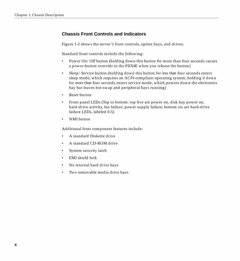
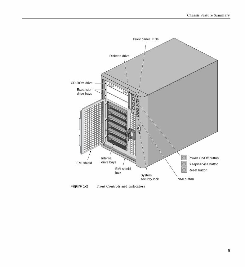
Figure 1-2 shows the server’s front controls, option bays, and drives.
Standard front controls include the following:
• Power On/Off button (holding down this button for more than four seconds causesa power-button override to the PIIX4E when you release the button)
• Sleep/Service button (holding down this button for less than four seconds enterssleep mode, which requires an ACPI-compliant operating system; holding it downfor more than four seconds enters service mode, which powers down the electronicsbay but leaves hot-swap and peripheral bays running)
• Reset button
• Front panel LEDs (Top to bottom: top five are power on, disk bay power on,hard-drive activity, fan failure, power supply failure; bottom six are hard-drivefailure LEDs, labeled 0-5)
• NMI button
Additional front component features include:
• A standard Diskette drive
• A standard CD-ROM drive
• System security latch
• EMI shield lock
• Six internal hard drive bays
• Two removable media drive bays
4
Chassis Feature Summary
Figure 1-2 Front Controls and Indicators
Power On/Off button
Sleep/service button
Reset button
NMI button
EMI shield
Systemsecurity lock
Expansiondrive bays
Internaldrive bays
EMI shieldlock
CD-ROM drive
Diskette drive
Front panel LEDs
5
Chapter 1: Chassis Description
Chassis Back Controls and Features
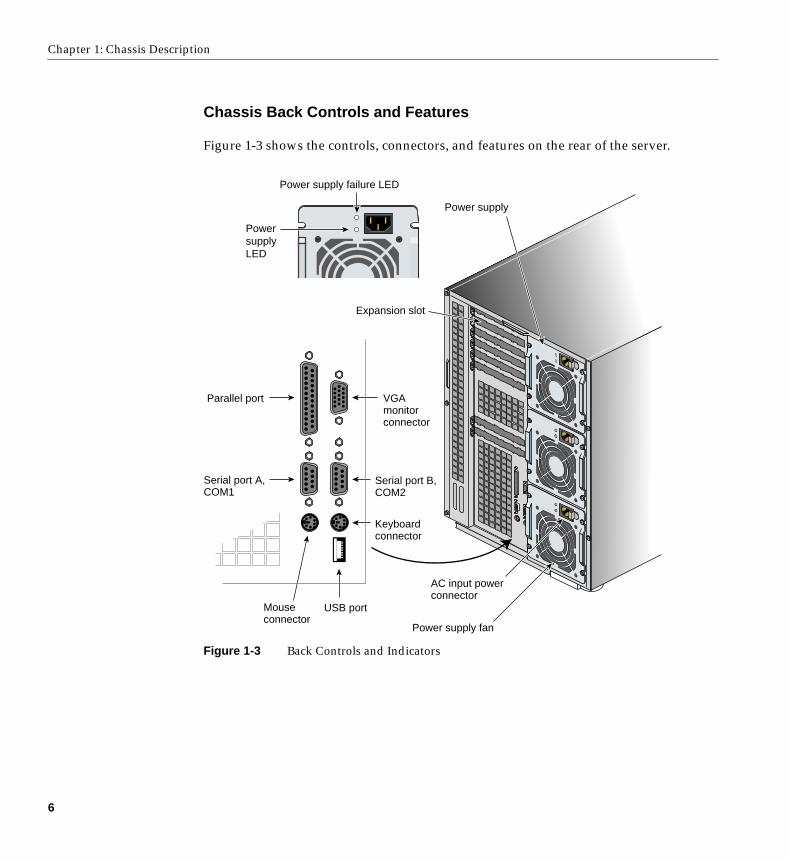
Figure 1-3 shows the controls, connectors, and features on the rear of the server.
Figure 1-3 Back Controls and Indicators
Parallel port
Expansion slot
VGAmonitorconnector
USB port
Serial port B,COM2
Power supply fan
AC input powerconnector
Power supply
Mouseconnector
Keyboardconnector
Serial port A,COM1
PowersupplyLED
Power supply failure LED
6
Chassis Feature Summary
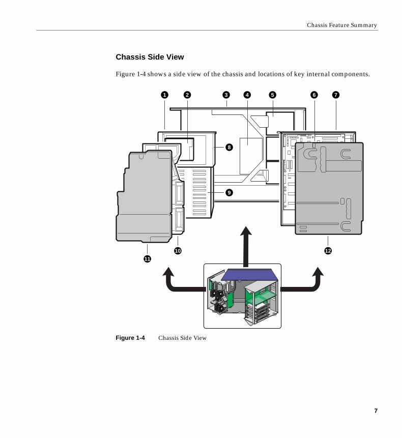
Chassis Side View
Figure 1-4 shows a side view of the chassis and locations of key internal components.
Figure 1-4 Chassis Side View
1 2 3 4 5 6 7
8
9
10 12
11
7
Chapter 1: Chassis Description
The components shown in Figure 1-4 are listed as follows:
1. The front swing-out subchassis
2. Diskette drive
3. Main chassis
4. Power backplane
5. Power supplies
6. Baseboard (processor board)
7. Lift-out electronics bay
8. SCSI hard drives bay
9. Rear foam cover
10. Foam fan housing
11. Foam fan housing cover
12. Foam rear cover
Server Peripherals Overview
The following sections describe standard and optional peripherals available with theSGI 1400 server system.
3.5-inch Diskette Drive
The 3.5-inch diskette drive in the 3.5-inch peripheral bay supports 720 KB, 1.2 MB, and1.44 MB media. The drive is externally accessible from the front of the system.
8
Server Peripherals Overview
3.5-inch Hard Drive Bays
The chassis contains one hard disk drive bay that holds 3.5-inch-wide (1” high or 1-5/8”high) LVDS SCSI drives with internal cabling. The backplane is hot-swap-capable andcan accommodate either six 3.5-inch-wide (1” high) hard drives (or three 1-5/8” highhard disks). The drives are accessed externally from the front of the system. Contact yoursales or service representative for information on obtaining additional disks or drivecarrier assemblies.
As part of the hot-swap implementation, an integral drive carrier and heatsink assemblyis required for the hard disk drives. The drives are mounted in the carrier/heatsinkassembly with four screws and the carrier snaps into the chassis. For information on howto install the carrier/heatsink assemblies, see “Mounting a SCSI Hard Disk Drive in aCarrier” in Chapter 5.
A single metal EMI shield and plastic door cover the hard drive bays. Drives canconsume up to 22 watts of power and must be specified to run at a maximum ambienttemperature of 55 °C.
The system was designed to use an optional Redundant Array of Independent Disks(RAID). A software implementation with onboard SCSI or an add-in board can be usedto set up RAID applications. Ask your sales or service representative for information oninstallation and use of RAID options.
5.25-inch Removable Media Device Bays
The chassis has three 5.25-inch half-height bays that are accessible from the front of thesystem. These bays are intended to provide space for optional removable media devices.
You can convert the 5.25-inch bays to a single full-height bay. We recommend that youdo not use these bays for hard disk drives, because they generate EMI (increasing ESDsusceptibility), and because of inadequate cooling. To maintain compliance withelectromagnetic compatibility (EMC) regulations, each 5.25-inch drive bay must beconfigured with either:
• An EMC-compliant 5.25-inch peripheral device, or
• A metal cover plate, available from your sales or service representative
9
Chapter 1: Chassis Description
Note: Integration of the 5.25-inch peripheral bay can affect EMC compliance and is aregulated activity.
Caution: To avoid damage to a 5.25-inch peripheral device, ensure the EMI gasketingprovided in the lower bay does not bridge or short any open circuits of the exposedperipheral device. If the 5.25-inch device has open circuits, install it in one of the twoupper bays.
Power Supplies
The chassis comes configured with three 400-watt power supplies, each designed tominimize EMI and RFI. Each supply auto-senses within the following voltage ranges andis rated as follows:
• 100-120 V∼ at 50/60 Hertz (Hz); 7.6 A maximum
• 200-240 V∼ at 50/60 Hz; 3.8 A maximum
The DC output voltages of each power supply are:
• +3.3V at 36 A max
• +5V at 24 A max (total combined output of +3.3 V and +5.5 V not to exceed 195 W)
• +12V at 18.0 A with 19.0 A <10ms peak
• +24V at 50mA
• -12V at 0.5 A
• +5V standby 1.5 A
Power is sourced through the power cable to the 20-pin main connectors on thebaseboard. Remote sensing signals are provided through the cable to the 14-pin auxiliaryconnector on the baseboard.
10
System Cooling
System Cooling
The SGI 1400 server system includes the maximum (6) fan configuration for internalcooling and airflow. There is also one fan for each of the three power supplies, and twofans specifically for cooling the hard drives.
Note: The access cover must be installed on the system for proper cooling.
Chassis Security
For information on security features on the SGI 1400 server, see “System Security” inChapter 2.
11

Chapter 2
2. System Processor Board Description
Processor Board Features
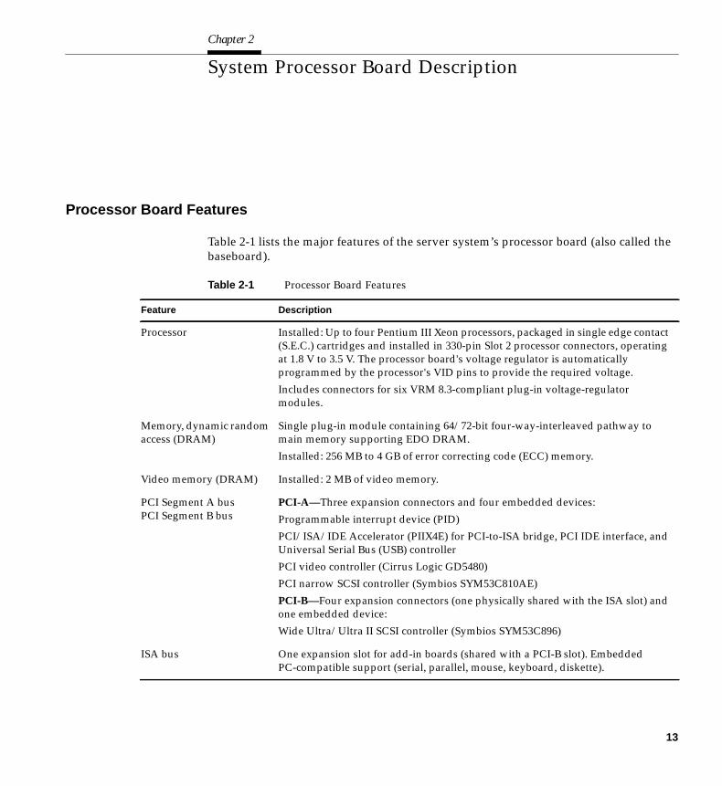
Table 2-1 lists the major features of the server system’s processor board (also called thebaseboard).
Table 2-1 Processor Board Features
Feature Description
Processor Installed: Up to four Pentium III Xeon processors, packaged in single edge contact(S.E.C.) cartridges and installed in 330-pin Slot 2 processor connectors, operatingat 1.8 V to 3.5 V. The processor board's voltage regulator is automaticallyprogrammed by the processor's VID pins to provide the required voltage.
Includes connectors for six VRM 8.3-compliant plug-in voltage-regulatormodules.
Memory, dynamic randomaccess (DRAM)
Single plug-in module containing 64/72-bit four-way-interleaved pathway tomain memory supporting EDO DRAM.
Installed: 256 MB to 4 GB of error correcting code (ECC) memory.
Video memory (DRAM) Installed: 2 MB of video memory.
PCI Segment A busPCI Segment B bus
PCI-A—Three expansion connectors and four embedded devices:
Programmable interrupt device (PID)
PCI/ISA/IDE Accelerator (PIIX4E) for PCI-to-ISA bridge, PCI IDE interface, andUniversal Serial Bus (USB) controller
PCI video controller (Cirrus Logic GD5480)
PCI narrow SCSI controller (Symbios SYM53C810AE)
PCI-B—Four expansion connectors (one physically shared with the ISA slot) andone embedded device:
Wide Ultra/Ultra II SCSI controller (Symbios SYM53C896)
ISA bus One expansion slot for add-in boards (shared with a PCI-B slot). EmbeddedPC-compatible support (serial, parallel, mouse, keyboard, diskette).
13
Chapter 2: System Processor Board Description
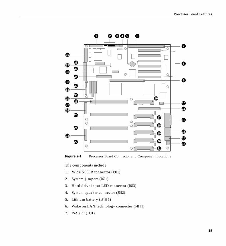
Processor Board Connector and Component Locations
Figure 2-2 shows the locations of the main components on the system processor board.
Server Management Thermal/voltage monitoring and error handling.
Front panel controls and indicators (LEDs).
Graphics Integrated onboard Cirrus Logic GD5480 super video graphics array (SVGA)controller.
SCSI Two embedded SCSI controllers:Symbios SYM53C810AE—narrow SCSI controller on PCI-A bus providingsupport for the legacy 8-bit SCSI devices in the 5.25-inch drive bays.
Symbios SYM53C896—dual-channel wide LVD/SE (Ultra2/Ultra) SCSIcontroller on PCI-B bus driving one SCSI backplane in the system and providingsupport for external expansion.
System I/O PS/2-compatible keyboard and mouse ports, 6-pin DIN.Advanced parallel port, supporting Enhanced Parallel Port (EPP) levels 1.7 and1.9, ECP, compatible 25-pin.VGA video port,15-pin.Two serial ports, 9-pin (serial port A is the top connector).
Form Factor Form-factor, 13 × 16 inches, ATX I/O.
Table 2-1 (continued) Processor Board Features
14
Processor Board Features
Figure 2-1 Processor Board Connector and Component Locations
The components include:
1. Wide SCSI B connector (J9J1)
2. System jumpers (J6J1)
3. Hard drive input LED connector (J6J3)
4. System speaker connector (J6J2)
5. Lithium battery (B4H1)
6. Wake on LAN technology connector (J4H1)
7. ISA slot (J1J1)
1 2 3 4 5 6
39
37
35
33
31
29
27
26
2314
15
21
20
19
18
17
16
13
12
11
10
9
8
7
36
38
34
32
30
28
25
24
22
15
Chapter 2: System Processor Board Description
8. PCI slots B4 (closest to ISA), B3, B2, B1, A3, and A2 (farthest from ISA)
9. Memory module connector (J3G1)
10. ICMB connector (J1E1)
11. PCI slot A1 (J2D1)
12. Video and parallel port connectors (J1C1)
13. Serial port connector (J1B2)
14. Keyboard and mouse connectors (J1B1)
15. USB external connector (J1A1)
16. VRM connector for processor 4 (J4E1)
17. VRM connector for processors 4 and 3 (J4C2)
18. VRM connector for processor 3 (J4C1)
19. VRM connector for processor 2 (J4B1)
20. VRM connector for processors 2 and 1 (J4A2)
21. VRM connector for processor 1 (J4A1)
22. Processor 1 Slot 2 connector (J9A1)
23. Main power connector, primary (J9B1)
24. Processor 2 Slot 2 connector (J9B2)
25. Processor 3 Slot 2 connector (J9D1)
26. Main power connector, secondary (J9D2)
27. Front panel connector (J8E1)
28. Processor 4 Slot 2 connector (J9E1)
29. IDE connector (J9E2)
30. Diskette drive connector (J9E3)
31. Auxiliary power connector (J9E4)
32. USB internal header (JC9F14)
33. SMBus connector (J9F2)
34. F16 expansion connector (J7G1)
16
Processor Board Features
35. ITP connector (J6G1)
36. Narrow SCSI connector (J9H1)
37. External IPMB connector (J7H1)
38. SMM connector (J8H1)
39. Wide SCSI A connector (J9H2)
System Processors
Each Pentium III Xeon processor is packaged in a single edge contact (S.E.C.) cartridge.The cartridge includes the processor core with an integrated 16 KB primary (L1) cache;the secondary (L2) cache; a thermal plate; and a back cover.
The processor implements the MMX technology and it has a numeric coprocessor thatsignificantly increases the speed of floating-point operations and complies withANSI/IEEE standard 754-1985.
Each S.E.C. cartridge connects to the processor board through a 330-pin Slot 2 edgeconnector. The cartridge is secured by a retention module attached to the processorboard. Depending on configuration, your system has one to four processors.
The processor external interface is MP-ready and operates at 100 MHz. The processorcontains a local APIC unit for interrupt handling in multiprocessor (MP) anduniprocessor (UP) environments.
The L2 cache is located on the substrate of the S.E.C. cartridge. The cache:
• Includes burst pipelined synchronous static RAM (BSRAM)
• Is offered in 512 KB, 1 MB, and 2 MB configurations
• Has error checking and correction (ECC)
• Operates at the full core clock rate
17
Chapter 2: System Processor Board Description
Memory
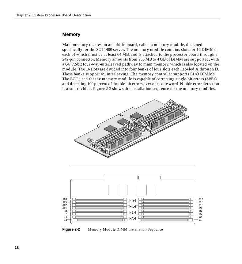
Main memory resides on an add-in board, called a memory module, designedspecifically for the SGI 1400 server. The memory module contains slots for 16 DIMMs,each of which must be at least 64 MB, and is attached to the processor board through a242-pin connector. Memory amounts from 256 MB to 4 GB of DIMM are supported, witha 64/72-bit four-way-interleaved pathway to main memory, which is also located on themodule. The 16 slots are divided into four banks of four slots each, labeled A through D.These banks support 4:1 interleaving. The memory controller supports EDO DRAMs.The ECC used for the memory module is capable of correcting single-bit errors (SBEs)and detecting 100 percent of double-bit errors over one code word. Nibble error detectionis also provided. Figure 2-2 shows the installation sequence for the memory modules.
Figure 2-2 Memory Module DIMM Installation Sequence
J16J15J12J11
J8J7
J3J4
J14J13J10J9J6J5
J1J2
D
C
B
A
18
Processor Board Features
The first four module group installs in memory bank A, the second in bank B, the thirdin bank C and the last in Bank D.
System memory begins at address 0 and is continuous (flat addressing) up to themaximum amount of DRAM installed (exception: system memory is noncontiguous inthe ranges defined as memory holes using configuration registers). The system supportsboth base (conventional) and extended memory.
• Base memory is located at addresses 00000h to 9FFFFh (the first 1 MB).
• Extended memory begins at address 0100000h (1 MB) and extends to FFFFFFFFh (4GB), which is the limit of supported addressable memory. The top of physicalmemory is a maximum of 4 GB (to FFFFFFFFh).
Note: Addressable memory can be extended to 64 GB under certain configurations, butthis server is configured to support 4 GB.
Some operating systems and application programs use base memory while others useboth conventional and extended memory. Examples:
• Base memory: Windows NT and LINUX
• Conventional and extended memory: Windows NT and LINUX
MS-DOS does not use extended memory; however, some MS-DOS utility programs likeRAM disks, disk caches, print spoolers, and windowing environments use extendedmemory for better performance.
BIOS automatically detects, sizes, and initializes the memory array, depending on thetype, size, and speed of the installed DIMMs, and reports memory size and allocation tothe system via configuration registers.
In a 4 GB configuration, a small part of memory (typically 32 MB) is not remapped above4 GB. If your operating system does not support more than 4 GB of physical memory, thissmall part of the memory is effectively lost.
19
Chapter 2: System Processor Board Description
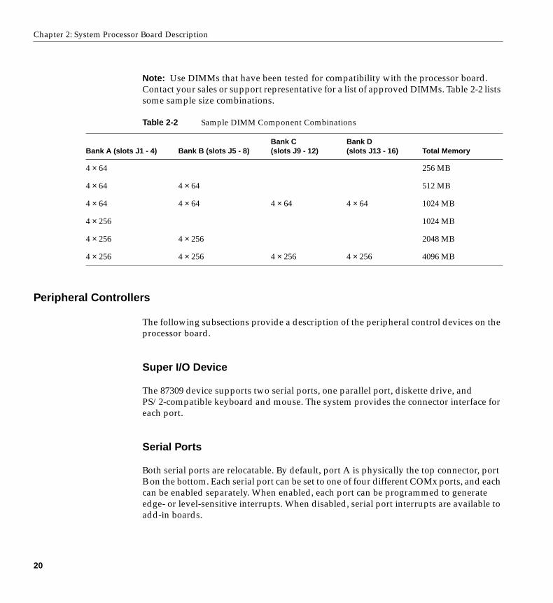
Note: Use DIMMs that have been tested for compatibility with the processor board.Contact your sales or support representative for a list of approved DIMMs. Table 2-2 listssome sample size combinations.
Peripheral Controllers
The following subsections provide a description of the peripheral control devices on theprocessor board.
Super I/O Device
The 87309 device supports two serial ports, one parallel port, diskette drive, andPS/2-compatible keyboard and mouse. The system provides the connector interface foreach port.
Serial Ports
Both serial ports are relocatable. By default, port A is physically the top connector, portB on the bottom. Each serial port can be set to one of four different COMx ports, and eachcan be enabled separately. When enabled, each port can be programmed to generateedge- or level-sensitive interrupts. When disabled, serial port interrupts are available toadd-in boards.
Table 2-2 Sample DIMM Component Combinations
Bank A (slots J1 - 4) Bank B (slots J5 - 8)Bank C(slots J9 - 12)
Bank D(slots J13 - 16) Total Memory
4 × 64 256 MB
4 × 64 4 × 64 512 MB
4 × 64 4 × 64 4 × 64 4 × 64 1024 MB
4 × 256 1024 MB
4 × 256 4 × 256 2048 MB
4 × 256 4 × 256 4 × 256 4 × 256 4096 MB
20
Add-in Board Slots
Parallel Port
The 25/15-pin connector stacks the parallel port over the VGA. The 87309 provides oneIEEE 1284-compatible 25-pin bidirectional EPP (supporting levels 1.7 and 1.9). BIOSprogramming of the 87309 registers enables the parallel port and determines the portaddress and interrupt. When disabled, the interrupt is available to add-in boards.
Add-in Board Slots
The processor board (also called a baseboard) has one ISA slot that is full-length if thewide SCSI-B slot is not used (and half-length if the wide SCSI-B slot is used); the ISA slotsupports slave-only boards and is shared with PCI-B slot 4. The ISA has three embeddeddevices: the Super I/O device, Baseboard Management Controller (BMC), and flashmemory for system BIOS. ISA features include:
• Bus speed up to 8.33 MHz
• 16-bit memory addressing
• Type A transfers at 5.33 MB/sec
• Type B transfers at 8 MB/sec
• 8- or 16-bit data transfers
• Plug and Play ready
The processor board has two 32-bit PCI bus segments: PCI-A and PCI-B. These provideseven slots for PCI add-in boards: three on PCI-A and four on PCI-B. PCI-B4 is sharedwith the ISA slot. PCI-A1 supports half-length boards only. The other slots supportfull-length boards. PCI features:
• 33 MHz bus speed
• 32-bit memory addressing
• 5 V signaling environment
• Burst transfers of up to 133 MB/sec
• 8-, 16-, or 32-bit data transfers
• Plug and Play ready
• Parity enabled
21
Chapter 2: System Processor Board Description
Video
The onboard, integrated Cirrus Logic CL-GD5480 64-bit VGA ASIC contains an SVGAcontroller that is fully compatible with these video standards: CGA, EGA, HerculesGraphics, MDA, and VGA. The standard system configuration comes with 2 MB of 10 nsonboard video memory. The video controller supports pixel resolutions of up to1600 x 1200 and up to 16.7 M colors.
The SVGA controller supports analog VGA monitors (single and multiple frequency,interlaced and noninterlaced) with a maximum vertical retrace noninterlaced frequencyof 100 Hz.
You cannot add video memory to this system. Depending on the environment, thecontroller displays up to 16.7 M colors in some video resolutions. It also provideshardware-accelerated bit block transfers (BITBLT) of data.
SCSI Controller
The processor board includes two SCSI controllers. A narrow SCSI controller(SYM53C810AE) is on the PCI-A bus, and a dual-channel wide LVD/SE (Ultra2/Ultra)SCSI controller (SYM53C896) is on the PCI-B bus. The narrow provides support for thelegacy 8-bit SCSI devices in the 5.25-inch drive bays. The wide drives one SCSI backplaneand provides support for external expansion.
Internally, each wide channel is identical, capable of operations using either 8- or 16-bitSCSI providing 10 MB/sec (Fast-10) or 20 MB/sec (Fast-20) throughput, or 20 MB/sec(Ultra), 40 MB/sec (Ultra-wide) or 80 MB/sec (40 Mhz) (Ultra-2).
The SYM53C810AE (narrow) contains a high-performance SCSI core capable of Fast 8-bitSCSI transfers in single-ended mode. It provides programmable active negation, PCIzero wait-state bursts of faster than 110 MB/sec at 33 MHz, and SCSI transfer rates from5 to 10 MB/sec. The narrow SCSI comes in a 100-pin rectangular plastic quad flat pack(PQFP) and provides an “AND tree” structure for testing component connectivity.
The Sym53C896 (wide) contains a high-performance SCSI bus interface. It supports SEmode with 8-bit (10 or 20 MB/sec) or 16-bit (20 or 40 MB/sec) transfers and LVD modewith 8-bit (40 MB/sec) or 16-bit (80 MB/sec) transfers in a 329-pin ball grid array (BGA)package.
22
IDE Controller
Each controller has its own set of PCI configuration registers and SCSI I/O registers. Asa PCI 2.1 bus master, the SYM53C896 supports burst data transfers on PCI up to themaximum rate of 132 MB per second using on-chip buffers.
In the internal bay, the system supports up to six one-inch SCSI hard disk drives, plus, inthe 5.25-inch removable media bays, three SCSI or IDE devices (the controller itselfsupports more devices, but the 5.25-inch bay can contain a maximum of three devices).A wide SCSI cable provides two connectors for Ultra SCSI devices (one of theseconnectors is for the internal SCSI backplane). However, SCSI devices do not need tooperate at the ultra transfer rate. All drives on the bus must be Ultra-2 (LVD) to run at80 MB/sec (40 MHz). The 5, 10, and 20 MHz operations can coexist on the bus and eachdevice will interact at its appropriate speed.
No logic, termination, or resistor loads are required to connect devices to the SCSIcontroller other than termination in the device at the end of the cable. The SCSI bus isterminated on the processor board with active terminators that can be disabled.
IDE Controller
IDE is a 16-bit interface for intelligent disk drives with AT disk controller electronicsonboard. The PCI/ISA/IDE Accelerator, called PIIX4E, is a multifunction device on theprocessor board that acts as a PCI-based Fast IDE controller. The device controls:
• PIO and IDE DMA/bus master operations
• Mode 4 timings
• Transfer rates up to 22 MB/sec
• Buffering for PCI/IDE burst transfers
• Master/slave IDE mode
• Up to two drives for one IDE channel
Note: 18-inch maximum length of IDE cable on each channel: you can connect an IDEsignal cable, up to a maximum of 18 inches, to the IDE connector on the processor board.The cable can support two devices, one at the end of the cable and one six inches fromthe end.
23
Chapter 2: System Processor Board Description
Keyboard and Mouse
The PS/2-compatible keyboard and mouse connectors are mounted in a single-stackedhousing with the mouse connector over the keyboard. External to the system, theyappear as two connectors.
You can plug in the keyboard and mouse to either connector before powering up thesystem. BIOS detects these and configures the keyboard controller accordingly.
The keyboard controller is functionally compatible with the 8042A microcontroller. Thesystem can be locked automatically if no keyboard or mouse activity occurs for apredefined length of time, if specified through the system setup utility (SSU). Once theinactivity (lockout) timer has expired, the keyboard and mouse do not respond until thepreviously stored password is entered.
Server Management
Server Management features are implemented using one microcontroller on theprocessor board known as the Baseboard Management Controller (BMC).
Baseboard Management Controller (BMC)
The BMC and associated circuitry are powered from 5V_Standby, which means thisdevice remains active even when system power is switched off.
The primary function of the BMC is to autonomously monitor system platformmanagement events and log their occurrence in the nonvolatile System Event Log (SEL).These events include overtemperature and overvoltage conditions, fan failure, or chassisintrusion. While monitoring, the BMC maintains the nonvolatile sensor data recordrepository (SDRR), from which run-time information can be retrieved. The BMCprovides an ISA host interface to SDRR information, so software running on the servercan poll and retrieve the current status of the platform. A shared register interface isdefined for this purpose.
24
Server Management
SEL contents can be retrieved after system failure for analysis by field service personnelusing system management tools like Intel LANDesk Server Manager. Because the BMCis powered by 5V_Standby, SEL (and SDRR) information is also available by way of theinterperipheral management bus (IPMB). An emergency management board like theIntel LANDesk Server Monitor Module board can obtain the SEL and make it remotelyaccessible using a LAN or telephone line connection. During monitoring, the BMCperforms the following functions:
• Processor board temperature and voltage monitoring
• Processor presence monitoring and FRB control
• Processor board fan failure detection and indicator control
• SEL interface management
• Sensor Data Record Repository (SDRR) interface management
• SDR/SEL timestamp clock
• Processor board Field Replaceable Unit (FRU) information interface
• System management watchdog timer
• Periodic SMI timer
• Front panel NMI handling
• Event receiver
• ISA host and IPMB interface management
• Secure mode control, front panel lock/unlock initiation, and video blank anddiskette write protect monitoring and control
• Sensor event initialization agent
• Wake on LAN via Magic Packet support
• ACPI Support
• Emergency Management Port (EMP) support
25
Chapter 2: System Processor Board Description
System Security
To help prevent unauthorized entry or use of the system, the system includes athree-position key lock/switch to permit selected access to drive bays (position iscommunicated to BMC). The system also includes server management software thatmonitors the chassis intrusion switch.
Mechanical Locks and Monitoring
The system includes a chassis intrusion switch. When the access cover is opened, theswitch transmits an alarm signal to the processor board, where server managementsoftware processes the signal. The system can be programmed to respond to an intrusionby powering down or by locking the keyboard, for example.
Software Locks via the SSU or BIOS Setup
The SSU provides a number of security features to prevent unauthorized or accidentalaccess to the system. Once the security measures are enabled, access to the system isallowed only after the user enters the correct password(s). For example, the SSU allowsyou to:
• Enable the keyboard lockout timer so the server requires a password to reactivatethe keyboard and mouse after a specified time-out period of 1 to 120 minutes
• Set and enable administrator and user passwords
• Set secure mode to prevent keyboard or mouse input and to prevent use of the frontpanel reset and power switches
• Activate a hot-key combination to enter secure mode quickly
• Disable writing to the diskette drive when secure mode is set
26
System Security
Using Passwords
If you set and enable a user password but not an administrator password, enter the userpassword to boot the system and run the SSU.
If you set and enable both a user and an administrator password:
• Enter either one to boot the server and enable the keyboard and mouse
• Enter the administrator password to access the SSU or BIOS Setup to change thesystem configuration
Secure Mode
Configure and enable the secure boot mode by using the SSU. When secure mode is ineffect, you:
• Can boot the system and the OS will run, but you must enter the user password touse the keyboard or mouse
• Cannot turn off system power or reset the system from the front panel switches
Secure mode has no effect on functions enabled via the Server Manager Module or powercontrol via the real-time clock (RTC).
Taking the system out of secure mode does not change the state of system power. That is,if you press and release the power switch while secure mode is in effect, the system willnot power off when secure mode is later removed. However, if the front panel powerswitch remains depressed when secure mode is removed, the system will power off.
27
Chapter 2: System Processor Board Description
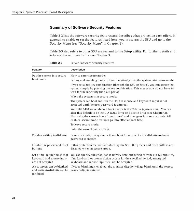
Summary of Software Security Features
Table 2-3 lists the software security features and describes what protection each offers. Ingeneral, to enable or set the features listed here, you must run the SSU and go to theSecurity Menu (see “Security Menu” in Chapter 3).
Table 2-3 also refers to other SSU menus and to the Setup utility. For further details andinformation on these topics see Chapter 3.
Table 2-3 Server Software Security Features
Feature Description
Put the system into secureboot mode
How to enter secure mode:
Setting and enabling passwords automatically puts the system into secure mode.
If you set a hot-key combination (through the SSU or Setup), you can secure thesystem simply by pressing the key combination. This means you do not have towait for the inactivity time-out period.
When the system is in secure mode:
The system can boot and run the OS, but mouse and keyboard input is notaccepted until the user password is entered.
Your SGI 1400 server default boot device is the C drive (system disk). You canalter this default to be the CD-ROM drive or diskette drive (see Chapter 3).Normally, the system boots from drive C and then goes into secure mode. Allenabled secure mode features go into effect at boot time.
To leave secure mode:
Enter the correct password(s).
Disable writing to diskette In secure mode, the system will not boot from or write to a diskette unless apassword is entered.
Disable the power and resetbuttons
If this protection feature is enabled by the SSU, the power and reset buttons aredisabled when in secure mode.
Set a time-out period so thatkeyboard and mouse inputare not accepted
Also, screen can be blankedand writes to diskette can beinhibited
You can specify and enable an inactivity time-out period of from 1 to 120 minutes.If no keyboard or mouse action occurs for the specified period, attemptedkeyboard and mouse input will not be accepted.
If video blanking is enabled, the monitor display will go blank until the correctpassword(s) is entered.
28
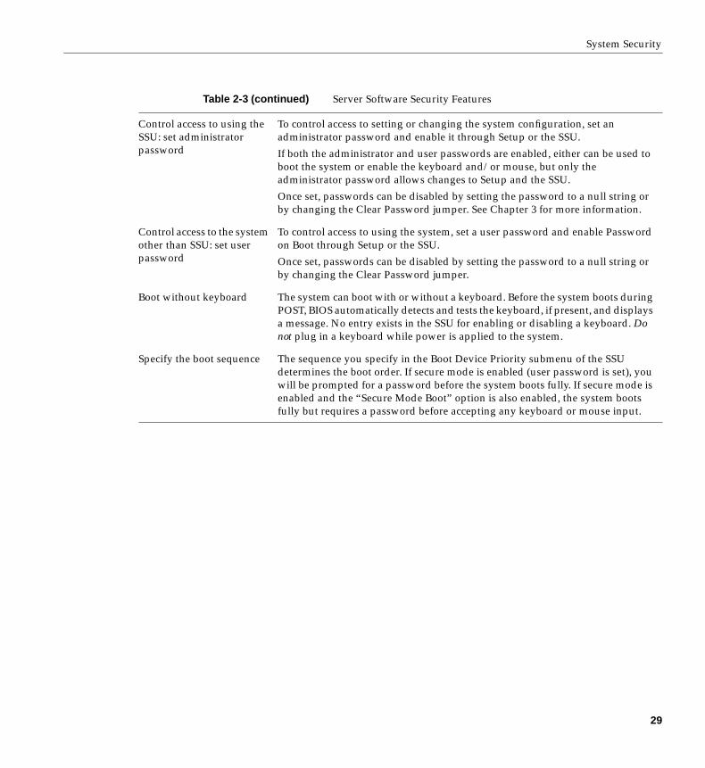
System Security
Control access to using theSSU: set administratorpassword
To control access to setting or changing the system configuration, set anadministrator password and enable it through Setup or the SSU.
If both the administrator and user passwords are enabled, either can be used toboot the system or enable the keyboard and/or mouse, but only theadministrator password allows changes to Setup and the SSU.
Once set, passwords can be disabled by setting the password to a null string orby changing the Clear Password jumper. See Chapter 3 for more information.
Control access to the systemother than SSU: set userpassword
To control access to using the system, set a user password and enable Passwordon Boot through Setup or the SSU.
Once set, passwords can be disabled by setting the password to a null string orby changing the Clear Password jumper.
Boot without keyboard The system can boot with or without a keyboard. Before the system boots duringPOST, BIOS automatically detects and tests the keyboard, if present, and displaysa message. No entry exists in the SSU for enabling or disabling a keyboard. Donot plug in a keyboard while power is applied to the system.
Specify the boot sequence The sequence you specify in the Boot Device Priority submenu of the SSUdetermines the boot order. If secure mode is enabled (user password is set), youwill be prompted for a password before the system boots fully. If secure mode isenabled and the “Secure Mode Boot” option is also enabled, the system bootsfully but requires a password before accepting any keyboard or mouse input.
Table 2-3 (continued) Server Software Security Features
29

Chapter 3
3. Configuration Software and Utilities
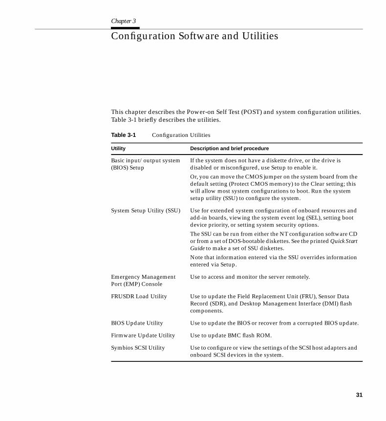
This chapter describes the Power-on Self Test (POST) and system configuration utilities.Table 3-1 briefly describes the utilities.
Table 3-1 Configuration Utilities
Utility Description and brief procedure
Basic input/output system(BIOS) Setup
If the system does not have a diskette drive, or the drive isdisabled or misconfigured, use Setup to enable it.
Or, you can move the CMOS jumper on the system board from thedefault setting (Protect CMOS memory) to the Clear setting; thiswill allow most system configurations to boot. Run the systemsetup utility (SSU) to configure the system.
System Setup Utility (SSU) Use for extended system configuration of onboard resources andadd-in boards, viewing the system event log (SEL), setting bootdevice priority, or setting system security options.
The SSU can be run from either the NT configuration software CDor from a set of DOS-bootable diskettes. See the printed Quick StartGuide to make a set of SSU diskettes.
Note that information entered via the SSU overrides informationentered via Setup.
Emergency ManagementPort (EMP) Console
Use to access and monitor the server remotely.
FRUSDR Load Utility Use to update the Field Replacement Unit (FRU), Sensor DataRecord (SDR), and Desktop Management Interface (DMI) flashcomponents.
BIOS Update Utility Use to update the BIOS or recover from a corrupted BIOS update.
Firmware Update Utility Use to update BMC flash ROM.
Symbios SCSI Utility Use to configure or view the settings of the SCSI host adapters andonboard SCSI devices in the system.
31
Chapter 3: Configuration Software and Utilities
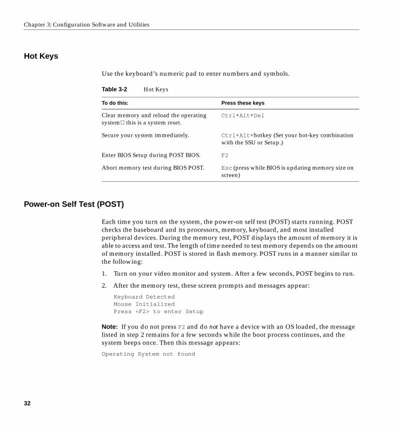
Hot Keys
Use the keyboard’s numeric pad to enter numbers and symbols.
Power-on Self Test (POST)
Each time you turn on the system, the power-on self test (POST) starts running. POSTchecks the baseboard and its processors, memory, keyboard, and most installedperipheral devices. During the memory test, POST displays the amount of memory it isable to access and test. The length of time needed to test memory depends on the amountof memory installed. POST is stored in flash memory. POST runs in a manner similar tothe following:
1. Turn on your video monitor and system. After a few seconds, POST begins to run.
2. After the memory test, these screen prompts and messages appear:
Keyboard DetectedMouse InitializedPress <F2> to enter Setup
Note: If you do not press F2 and do not have a device with an OS loaded, the messagelisted in step 2 remains for a few seconds while the boot process continues, and thesystem beeps once. Then this message appears:
Operating System not found
Table 3-2 Hot Keys
To do this: Press these keys
Clear memory and reload the operatingsystemthis is a system reset.
Ctrl +Alt +Del
Secure your system immediately. Ctrl +Alt +hotkey (Set your hot-key combinationwith the SSU or Setup.)
Enter BIOS Setup during POST BIOS. F2
Abort memory test during BIOS POST. Esc (press while BIOS is updating memory size onscreen)
32
Using BIOS Setup
3. If you do not press F2, the boot process continues and various messages appear. Themessage content may differ based on your system configuration and operatingsystem. User’s with NT systems may see a message similar to the following:
Press <Ctrl><C> to enter SCSI Utility
Note: The next two steps are applicable to NT users.
4. Press Ctrl +C if SCSI devices are installed. When the utility opens, follow thedisplayed instructions to configure the onboard SCSI host adapter settings and torun the SCSI utilities. If you do not enter the SCSI utility, the boot process continues.
5. Press Esc during POST to access a boot menu when POST finishes. From this menu,you can choose the boot device or enter BIOS Setup.
After POST completes, the system beeps once.
What appears on the screen after this depends on if you have an OS loaded and if so,which one.
If the system halts before POST completes running, it emits a beep code indicating acritical system error that requires immediate attention. If POST can display a message onthe video display screen, the speaker beeps twice as the message appears.
Note the screen display and write down the beep code you hear; this information isuseful for your service representative.
Using BIOS Setup
This section describes the BIOS Setup options. Use Setup to change the systemconfiguration defaults. You can run Setup with or without an OS being present. Setupstores most of the configuration values in battery-backed CMOS; the rest of the valuesare stored in flash memory. The values take effect when you boot the system. POST usesthese values to configure the hardware; if the values and the actual hardware do notagree, POST generates an error message. You must then run Setup to specify the correctconfiguration.
33
Chapter 3: Configuration Software and Utilities
Running Setup
You can run Setup to modify any standard PC baseboard feature such as:
• Select diskette drive
• Select parallel port
• Select serial port
• Set time/date (to be stored in RTC)
• Configure IDE hard drive
• Specify boot device sequence
• Enable SCSI BIOS
Running the System Setup Utility (SSU) Instead of Setup
You must run the SSU instead of Setup to do the following:
• Enter or change information about a board
• Alter system resources (for example, interrupts, memory addresses, I/Oassignments) to user-selected choices instead of choices selected by the BIOSresource manager
Record Your Setup Settings
If the default values ever need to be restored (after a CMOS clear, for example), you mustrun Setup again. Referring to the worksheets could make your task easier.
If You Cannot Access Setup
If the diskette drive is misconfigured so that you cannot access it to run a utility from adiskette, you might need to clear CMOS memory. You must open the system, change ajumper setting, use Setup to check and set diskette drive options, and change the jumperback. This procedure should be done by a trained service person, see the SGI 1400 ServerFamily Maintenance and Upgrades Guide.
34
Setup Menus
Starting Setup
You can enter and start Setup under several conditions:
• When you turn on the system, after POST completes the memory test
• When you reboot the system by pressing Ctrl +Alt +Del while at the DOS operatingsystem prompt
• When you have moved the CMOS jumper on the baseboard to the “Clear CMOS”position (enabled); see the SGI 1400 Server Family Maintenance and Upgrades Guide.
In the three conditions listed above, after rebooting, you will see this prompt:Press <F2> to enter SETUP
In a fourth condition, when CMOS/NVRAM has been corrupted, you will see otherprompts but not the F2 prompt:
Warning: cmos checksum invalidWarning: cmos time and date not set
In this condition, the BIOS will load default values for CMOS and attempt to boot.
Setup Menus
Setup has six major menus and several submenus:
1. Main Menu
• Primary IDE Master and Slave
• Keyboard Features
2. Advanced Menu
• PCI Configuration
• PCI Device, Embedded SCSI
• PCI Devices
• I/O Device Configuration
• Advanced Chipset Control
3. Security Menu
35
Chapter 3: Configuration Software and Utilities
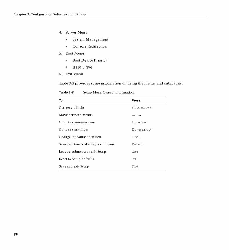
4. Server Menu
• System Management
• Console Redirection
5. Boot Menu
• Boot Device Priority
• Hard Drive
6. Exit Menu
Table 3-3 provides some information on using the menus and submenus.
Table 3-3 Setup Menu Control Information
To: Press:
Get general help F1 or Alt +H
Move between menus ← →
Go to the previous item Up arrow
Go to the next Item Down arrow
Change the value of an item + or -
Select an item or display a submenu Enter
Leave a submenu or exit Setup Esc
Reset to Setup defaults F9
Save and exit Setup F10
36
Setup Menus
The following sections list the features that display onscreen after you press F2 and enterSetup. Not all of the option choices are described:
• a few are not user-selectable and are displayed for information only
• many of the choices are relatively self-explanatory.
Main Menu
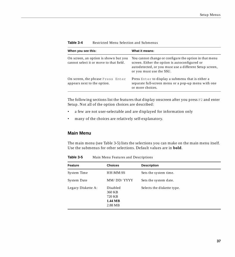
The main menu (see Table 3-5) lists the selections you can make on the main menu itself.Use the submenus for other selections. Default values are in bold.
Table 3-4 Restricted Menu Selection and Submenus
When you see this: What it means:
On screen, an option is shown but youcannot select it or move to that field.
You cannot change or configure the option in that menuscreen. Either the option is autoconfigured orautodetected, or you must use a different Setup screen,or you must use the SSU.
On screen, the phrase Press Enterappears next to the option.
Press Enter to display a submenu that is either aseparate full-screen menu or a pop-up menu with oneor more choices.
Table 3-5 Main Menu Features and Descriptions
Feature Choices Description
System Time HH:MM:SS Sets the system time.
System Date MM/DD/YYYY Sets the system date.
Legacy Diskette A: Disabled360 KB720 KB1.44 MB2.88 MB
Selects the diskette type.
37
Chapter 3: Configuration Software and Utilities
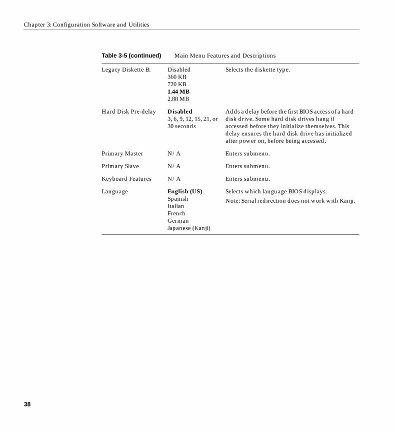
Legacy Diskette B: Disabled360 KB720 KB1.44 MB2.88 MB
Selects the diskette type.
Hard Disk Pre-delay Disabled3, 6, 9, 12, 15, 21, or30 seconds
Adds a delay before the first BIOS access of a harddisk drive. Some hard disk drives hang ifaccessed before they initialize themselves. Thisdelay ensures the hard disk drive has initializedafter power on, before being accessed.
Primary Master N/A Enters submenu.
Primary Slave N/A Enters submenu.
Keyboard Features N/A Enters submenu.
Language English (US)SpanishItalianFrenchGermanJapanese (Kanji)
Selects which language BIOS displays.
Note: Serial redirection does not work with Kanji.
Table 3-5 (continued) Main Menu Features and Descriptions
38
Setup Menus
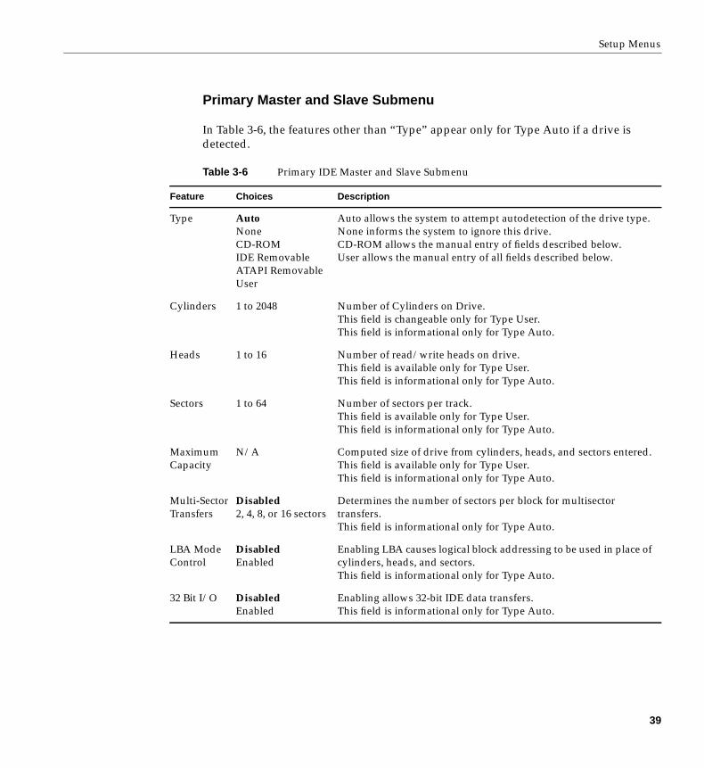
Primary Master and Slave Submenu
In Table 3-6, the features other than “Type” appear only for Type Auto if a drive isdetected.
Table 3-6 Primary IDE Master and Slave Submenu
Feature Choices Description
Type AutoNoneCD-ROMIDE RemovableATAPI RemovableUser
Auto allows the system to attempt autodetection of the drive type.None informs the system to ignore this drive.CD-ROM allows the manual entry of fields described below.User allows the manual entry of all fields described below.
Cylinders 1 to 2048 Number of Cylinders on Drive.This field is changeable only for Type User.This field is informational only for Type Auto.
Heads 1 to 16 Number of read/write heads on drive.This field is available only for Type User.This field is informational only for Type Auto.
Sectors 1 to 64 Number of sectors per track.This field is available only for Type User.This field is informational only for Type Auto.
MaximumCapacity
N/A Computed size of drive from cylinders, heads, and sectors entered.This field is available only for Type User.This field is informational only for Type Auto.
Multi-SectorTransfers
Disabled2, 4, 8, or 16 sectors
Determines the number of sectors per block for multisectortransfers.This field is informational only for Type Auto.
LBA ModeControl
DisabledEnabled
Enabling LBA causes logical block addressing to be used in place ofcylinders, heads, and sectors.This field is informational only for Type Auto.
32 Bit I/O DisabledEnabled
Enabling allows 32-bit IDE data transfers.This field is informational only for Type Auto.
39

Chapter 3: Configuration Software and Utilities
Keyboard Features Submenu
Table 3-7 summarizes the features of the keyboard submenu.
TransferMode
StandardFast PIO 1Fast PIO 2Fast PIO 3Fast PIO 4
Selects the method for moving data to and from the drive.This field is informational only for Type Auto.
Ultra DMA DisabledEnabled
For use with Ultra DMA drives.This field is information only for Type Auto.
Table 3-7 Keyboard Features Submenu
Feature Choices Description
Num Lock AutoOnOff
Selects power-on state for Num Lock.
Key Click DisabledEnabled
Enables or disables key click.
Keyboardauto-repeat rate
30, 26.7, 21.8, 18.5, 13.3, 10,6, or 2 per second
Selects key repeat rate.
Keyboardauto-repeat delay
1/4 sec1/2 sec3/4 sec1 sec
Selects delay before key repeat.
Table 3-6 (continued) Primary IDE Master and Slave Submenu
40
Setup Menus
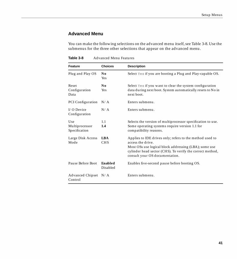
Advanced Menu
You can make the following selections on the advanced menu itself, see Table 3-8. Use thesubmenus for the three other selections that appear on the advanced menu.
Table 3-8 Advanced Menu Features
Feature Choices Description
Plug and Play OS NoYes
Select Yes if you are booting a Plug and Play-capable OS.
ResetConfigurationData
NoYes
Select Yes if you want to clear the system configurationdata during next boot. System automatically resets to No innext boot.
PCI Configuration N/A Enters submenu.
I/O DeviceConfiguration
N/A Enters submenu.
UseMultiprocessorSpecification
1.11.4
Selects the version of multiprocessor specification to use.Some operating systems require version 1.1 forcompatibility reasons.
Large Disk AccessMode
LBACHS
Applies to IDE drives only; refers to the method used toaccess the drive.Most OSs use logical block addressing (LBA); some usecylinder head sector (CHS). To verify the correct method,consult your OS documentation.
Pause Before Boot EnabledDisabled
Enables five-second pause before booting OS.
Advanced ChipsetControl
N/A Enters submenu.
41
Chapter 3: Configuration Software and Utilities
PCI Configuration Submenu
The PCI Configuration Menu contains selections that access other submenus.
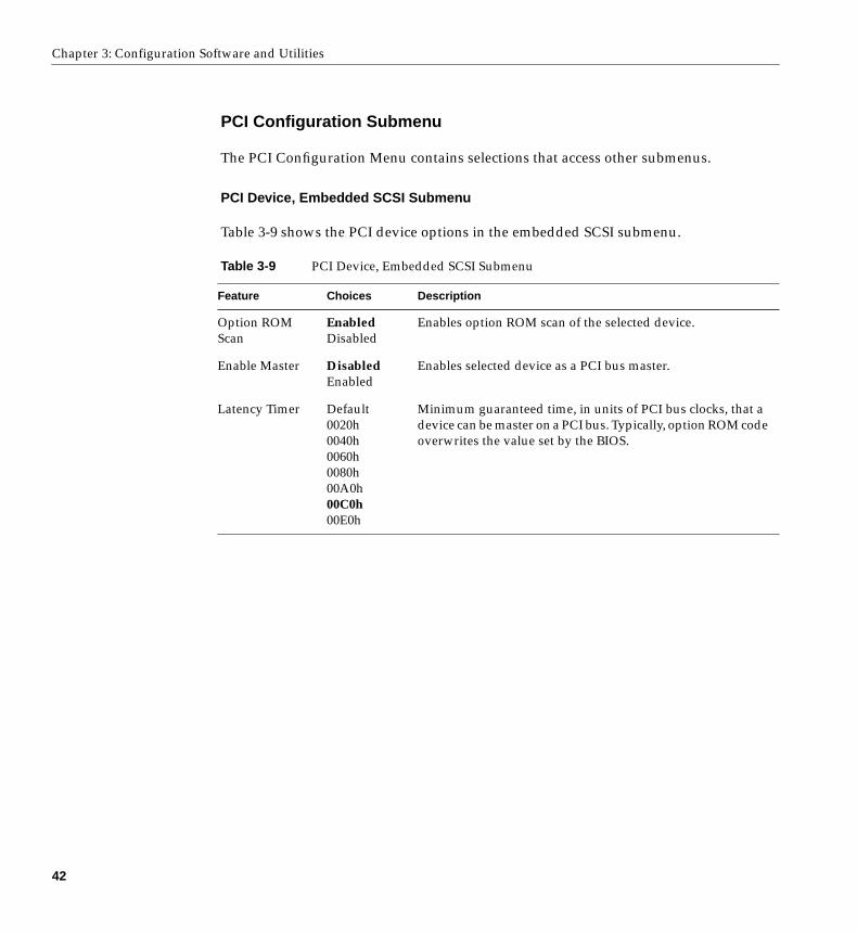
PCI Device, Embedded SCSI Submenu
Table 3-9 shows the PCI device options in the embedded SCSI submenu.
Table 3-9 PCI Device, Embedded SCSI Submenu
Feature Choices Description
Option ROMScan
EnabledDisabled
Enables option ROM scan of the selected device.
Enable Master DisabledEnabled
Enables selected device as a PCI bus master.
Latency Timer Default0020h0040h0060h0080h00A0h00C0h00E0h
Minimum guaranteed time, in units of PCI bus clocks, that adevice can be master on a PCI bus. Typically, option ROM codeoverwrites the value set by the BIOS.
42
Setup Menus
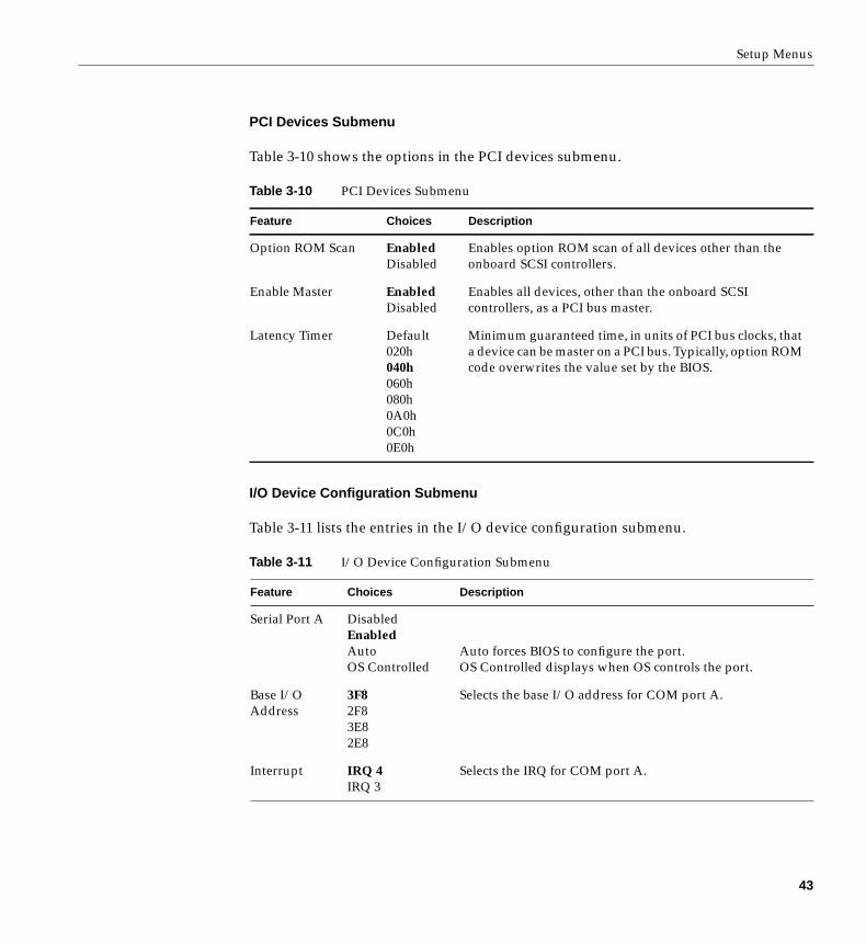
PCI Devices Submenu
Table 3-10 shows the options in the PCI devices submenu.
I/O Device Configuration Submenu
Table 3-11 lists the entries in the I/O device configuration submenu.
Table 3-10 PCI Devices Submenu
Feature Choices Description
Option ROM Scan EnabledDisabled
Enables option ROM scan of all devices other than theonboard SCSI controllers.
Enable Master EnabledDisabled
Enables all devices, other than the onboard SCSIcontrollers, as a PCI bus master.
Latency Timer Default020h040h060h080h0A0h0C0h0E0h
Minimum guaranteed time, in units of PCI bus clocks, thata device can be master on a PCI bus. Typically, option ROMcode overwrites the value set by the BIOS.
Table 3-11 I/O Device Configuration Submenu
Feature Choices Description
Serial Port A DisabledEnabledAutoOS Controlled
Auto forces BIOS to configure the port.OS Controlled displays when OS controls the port.
Base I/OAddress
3F82F83E82E8
Selects the base I/O address for COM port A.
Interrupt IRQ 4IRQ 3
Selects the IRQ for COM port A.
43
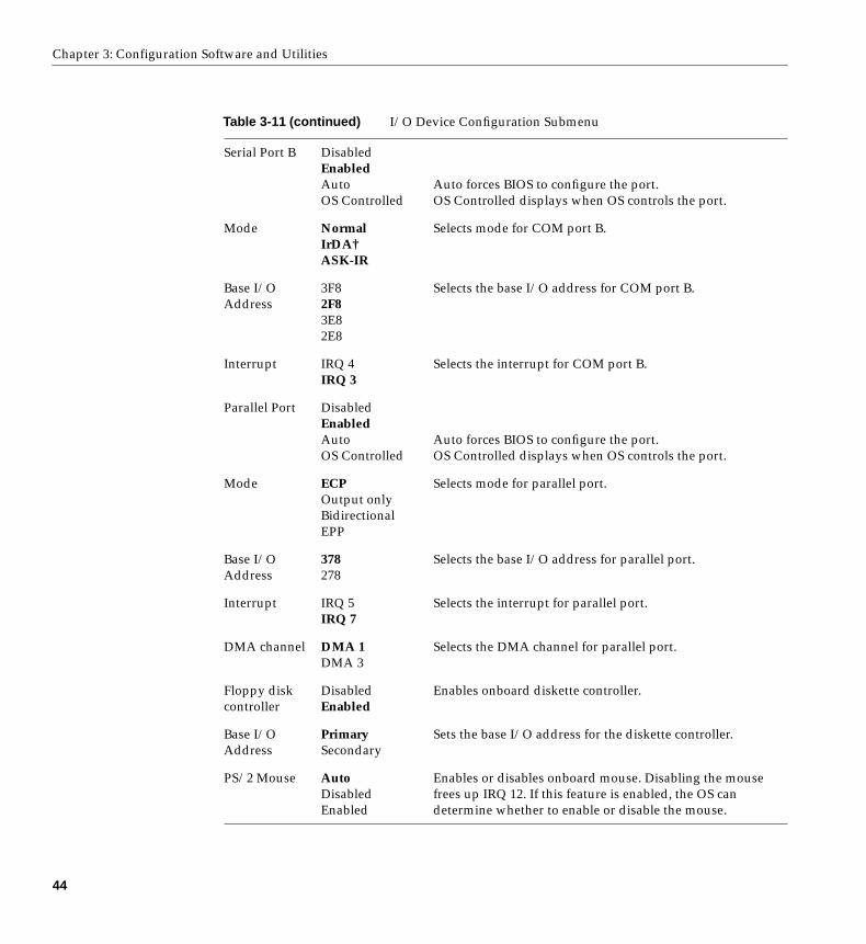
Chapter 3: Configuration Software and Utilities
Serial Port B DisabledEnabledAutoOS Controlled
Auto forces BIOS to configure the port.OS Controlled displays when OS controls the port.
Mode NormalIrDA†ASK-IR
Selects mode for COM port B.
Base I/OAddress
3F82F83E82E8
Selects the base I/O address for COM port B.
Interrupt IRQ 4IRQ 3
Selects the interrupt for COM port B.
Parallel Port DisabledEnabledAutoOS Controlled
Auto forces BIOS to configure the port.OS Controlled displays when OS controls the port.
Mode ECPOutput onlyBidirectionalEPP
Selects mode for parallel port.
Base I/OAddress
378278
Selects the base I/O address for parallel port.
Interrupt IRQ 5IRQ 7
Selects the interrupt for parallel port.
DMA channel DMA 1DMA 3
Selects the DMA channel for parallel port.
Floppy diskcontroller
DisabledEnabled
Enables onboard diskette controller.
Base I/OAddress
PrimarySecondary
Sets the base I/O address for the diskette controller.
PS/2 Mouse AutoDisabledEnabled
Enables or disables onboard mouse. Disabling the mousefrees up IRQ 12. If this feature is enabled, the OS candetermine whether to enable or disable the mouse.
Table 3-11 (continued) I/O Device Configuration Submenu
44
Setup Menus
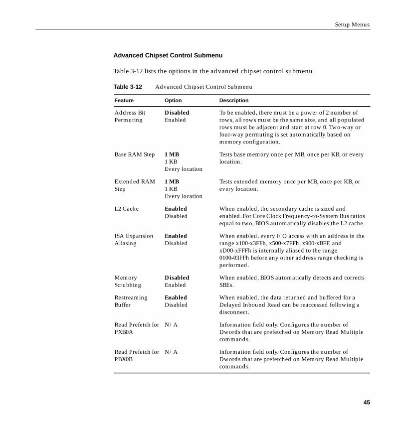
Advanced Chipset Control Submenu
Table 3-12 lists the options in the advanced chipset control submenu.
Table 3-12 Advanced Chipset Control Submenu
Feature Option Description
Address BitPermuting
DisabledEnabled
To be enabled, there must be a power of 2 number ofrows, all rows must be the same size, and all populatedrows must be adjacent and start at row 0. Two-way orfour-way permuting is set automatically based onmemory configuration.
Base RAM Step 1 MB1 KBEvery location
Tests base memory once per MB, once per KB, or everylocation.
Extended RAMStep
1 MB1 KBEvery location
Tests extended memory once per MB, once per KB, orevery location.
L2 Cache EnabledDisabled
When enabled, the secondary cache is sized andenabled. For Core Clock Frequency-to-System Bus ratiosequal to two, BIOS automatically disables the L2 cache.
ISA ExpansionAliasing
EnabledDisabled
When enabled, every I/O access with an address in therange x100-x3FFh, x500-x7FFh, x900-xBFF, andxD00-xFFFh is internally aliased to the range0100-03FFh before any other address range checking isperformed.
MemoryScrubbing
DisabledEnabled
When enabled, BIOS automatically detects and correctsSBEs.
RestreamingBuffer
EnabledDisabled
When enabled, the data returned and buffered for aDelayed Inbound Read can be reaccessed following adisconnect.
Read Prefetch forPXB0A
N/A Information field only. Configures the number ofDwords that are prefetched on Memory Read Multiplecommands.
Read Prefetch forPBX0B
N/A Information field only. Configures the number ofDwords that are prefetched on Memory Read Multiplecommands.
45
Chapter 3: Configuration Software and Utilities
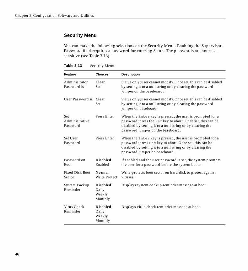
Security Menu
You can make the following selections on the Security Menu. Enabling the SupervisorPassword field requires a password for entering Setup. The passwords are not casesensitive (see Table 3-13).
Table 3-13 Security Menu
Feature Choices Description
AdministratorPassword is
ClearSet
Status only; user cannot modify. Once set, this can be disabledby setting it to a null string or by clearing the passwordjumper on the baseboard.
User Password is ClearSet
Status only; user cannot modify. Once set, this can be disabledby setting it to a null string or by clearing the passwordjumper on baseboard.
SetAdministrativePassword
Press Enter When the Enter key is pressed, the user is prompted for apassword; press the Esc key to abort. Once set, this can bedisabled by setting it to a null string or by clearing thepassword jumper on the baseboard.
Set UserPassword
Press Enter When the Enter key is pressed, the user is prompted for apassword; press Esc key to abort. Once set, this can bedisabled by setting it to a null string or by clearing thepassword jumper on baseboard.
Password onBoot
DisabledEnabled
If enabled and the user password is set, the system promptsthe user for a password before the system boots.
Fixed Disk BootSector
NormalWrite Protect
Write-protects boot sector on hard disk to protect againstviruses.
System BackupReminder
DisabledDailyWeeklyMonthly
Displays system-backup reminder message at boot.
Virus CheckReminder
DisabledDailyWeeklyMonthly
Displays virus-check reminder message at boot.
46
Setup Menus
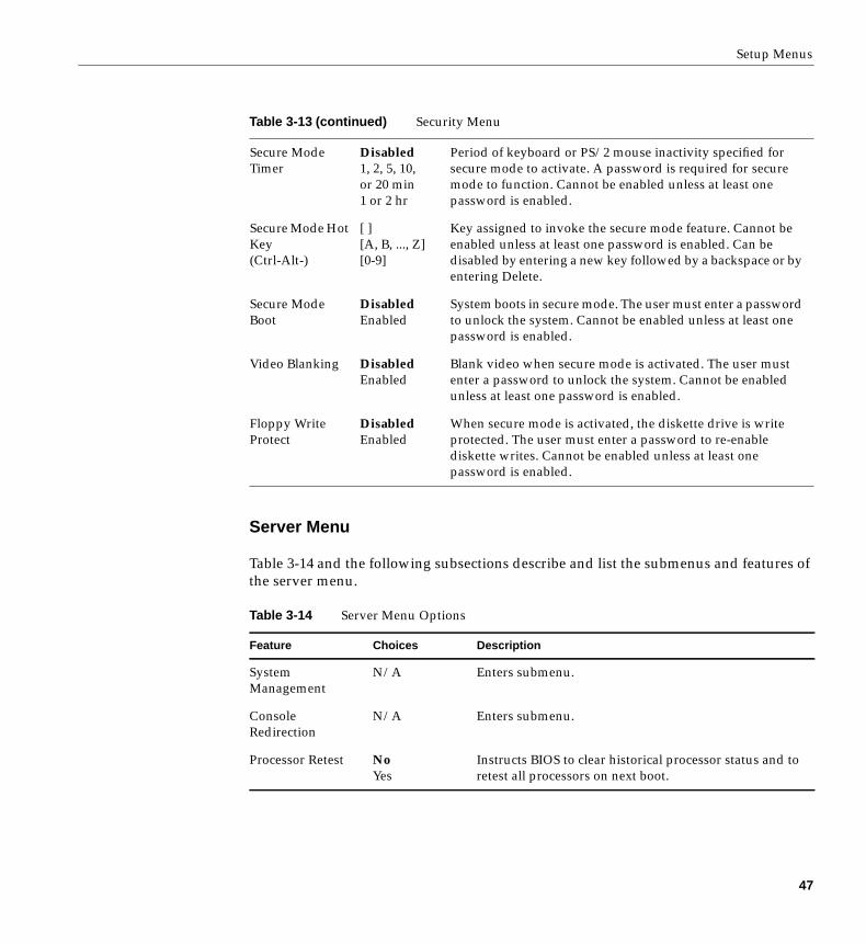
Server Menu
Table 3-14 and the following subsections describe and list the submenus and features ofthe server menu.
Secure ModeTimer
Disabled1, 2, 5, 10,or 20 min1 or 2 hr
Period of keyboard or PS/2 mouse inactivity specified forsecure mode to activate. A password is required for securemode to function. Cannot be enabled unless at least onepassword is enabled.
Secure Mode HotKey(Ctrl-Alt-)
[ ][A, B, ..., Z][0-9]
Key assigned to invoke the secure mode feature. Cannot beenabled unless at least one password is enabled. Can bedisabled by entering a new key followed by a backspace or byentering Delete.
Secure ModeBoot
DisabledEnabled
System boots in secure mode. The user must enter a passwordto unlock the system. Cannot be enabled unless at least onepassword is enabled.
Video Blanking DisabledEnabled
Blank video when secure mode is activated. The user mustenter a password to unlock the system. Cannot be enabledunless at least one password is enabled.
Floppy WriteProtect
DisabledEnabled
When secure mode is activated, the diskette drive is writeprotected. The user must enter a password to re-enablediskette writes. Cannot be enabled unless at least onepassword is enabled.
Table 3-14 Server Menu Options
Feature Choices Description
SystemManagement
N/A Enters submenu.
ConsoleRedirection
N/A Enters submenu.
Processor Retest NoYes
Instructs BIOS to clear historical processor status and toretest all processors on next boot.
Table 3-13 (continued) Security Menu
47
Chapter 3: Configuration Software and Utilities
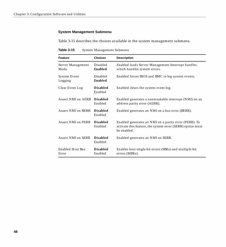
System Management Submenu
Table 3-15 describes the choices available in the system management submenu.
Table 3-15 System Management Submenu
Feature Choices Description
Server ManagementMode
DisabledEnabled
Enabled loads Server Management Interrupt handler,which handles system errors.
System EventLogging
DisabledEnabled
Enabled forces BIOS and BMC to log system events.
Clear Event Log DisabledEnabled
Enabled clears the system event log.
Assert NMI on AERR DisabledEnabled
Enabled generates a nonmaskable interrupt (NMI) on anaddress parity error (AERR).
Assert NMI on BERR DisabledEnabled
Enabled generates an NMI on a bus error (BERR).
Assert NMI on PERR DisabledEnabled
Enabled generates an NMI on a parity error (PERR). Toactivate this feature, the system error (SERR) option mustbe enabled.
Assert NMI on SERR DisabledEnabled
Enabled generates an NMI on SERR.
Enabled Host BusError
DisabledEnabled
Enables host single-bit errors (SBEs) and multiple-biterrors (MBEs).
48
Setup Menus
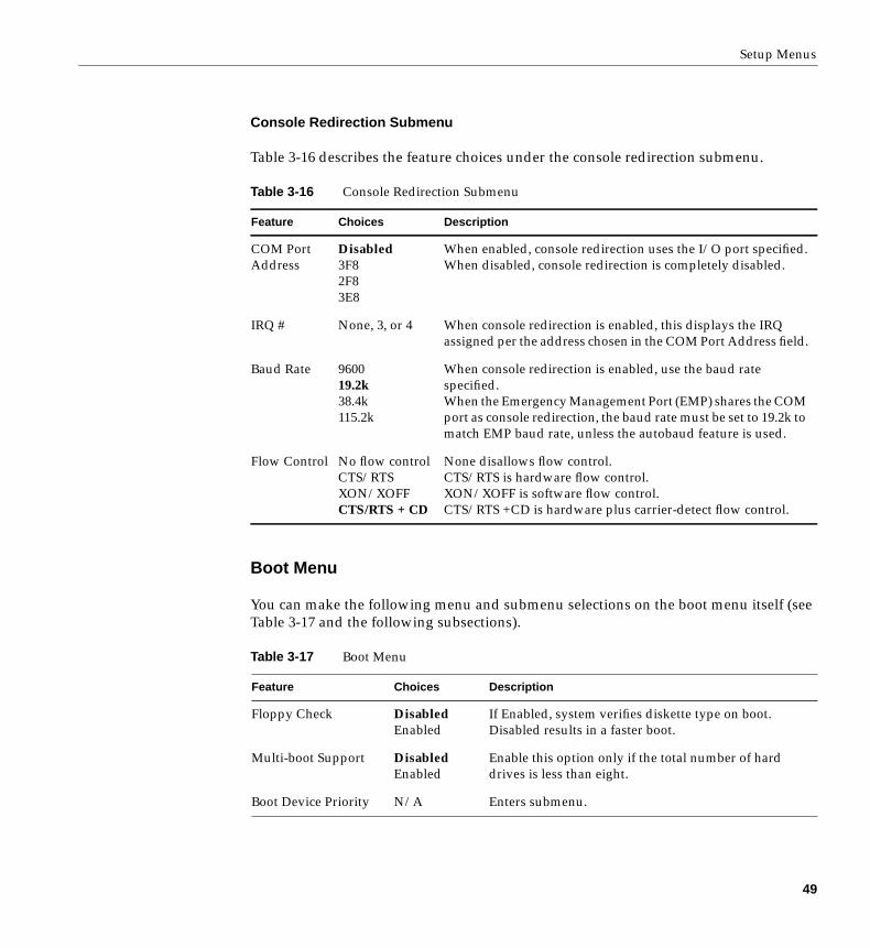
Console Redirection Submenu
Table 3-16 describes the feature choices under the console redirection submenu.
Boot Menu
You can make the following menu and submenu selections on the boot menu itself (seeTable 3-17 and the following subsections).
Table 3-16 Console Redirection Submenu
Feature Choices Description
COM PortAddress
Disabled3F82F83E8
When enabled, console redirection uses the I/O port specified.When disabled, console redirection is completely disabled.
IRQ # None, 3, or 4 When console redirection is enabled, this displays the IRQassigned per the address chosen in the COM Port Address field.
Baud Rate 960019.2k38.4k115.2k
When console redirection is enabled, use the baud ratespecified.When the Emergency Management Port (EMP) shares the COMport as console redirection, the baud rate must be set to 19.2k tomatch EMP baud rate, unless the autobaud feature is used.
Flow Control No flow controlCTS/RTSXON/XOFFCTS/RTS + CD
None disallows flow control.CTS/RTS is hardware flow control.XON/XOFF is software flow control.CTS/RTS +CD is hardware plus carrier-detect flow control.
Table 3-17 Boot Menu
Feature Choices Description
Floppy Check DisabledEnabled
If Enabled, system verifies diskette type on boot.Disabled results in a faster boot.
Multi-boot Support DisabledEnabled
Enable this option only if the total number of harddrives is less than eight.
Boot Device Priority N/A Enters submenu.
49
Chapter 3: Configuration Software and Utilities
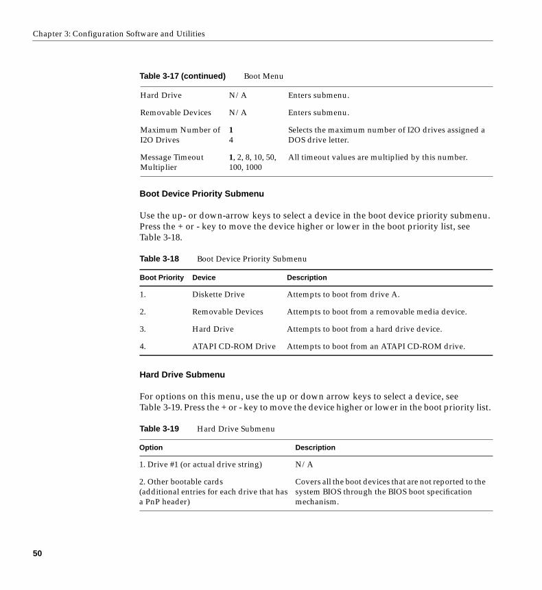
Boot Device Priority Submenu
Use the up- or down-arrow keys to select a device in the boot device priority submenu.Press the + or - key to move the device higher or lower in the boot priority list, seeTable 3-18.
Hard Drive Submenu
For options on this menu, use the up or down arrow keys to select a device, seeTable 3-19. Press the + or - key to move the device higher or lower in the boot priority list.
Hard Drive N/A Enters submenu.
Removable Devices N/A Enters submenu.
Maximum Number ofI2O Drives
14
Selects the maximum number of I2O drives assigned aDOS drive letter.
Message TimeoutMultiplier
1, 2, 8, 10, 50,100, 1000
All timeout values are multiplied by this number.
Table 3-18 Boot Device Priority Submenu
Boot Priority Device Description
1. Diskette Drive Attempts to boot from drive A.
2. Removable Devices Attempts to boot from a removable media device.
3. Hard Drive Attempts to boot from a hard drive device.
4. ATAPI CD-ROM Drive Attempts to boot from an ATAPI CD-ROM drive.
Table 3-19 Hard Drive Submenu
Option Description
1. Drive #1 (or actual drive string) N/A
2. Other bootable cards(additional entries for each drive that hasa PnP header)
Covers all the boot devices that are not reported to thesystem BIOS through the BIOS boot specificationmechanism.
Table 3-17 (continued) Boot Menu
50
Setup Menus
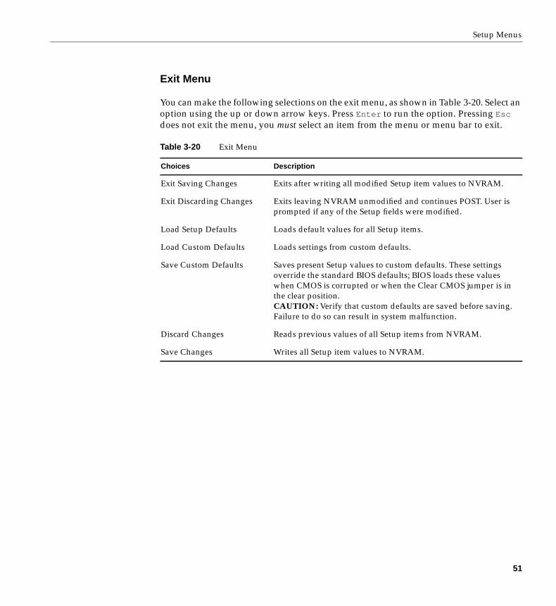
Exit Menu
You can make the following selections on the exit menu, as shown in Table 3-20. Select anoption using the up or down arrow keys. Press Enter to run the option. Pressing Esc
does not exit the menu, you must select an item from the menu or menu bar to exit.
Table 3-20 Exit Menu
Choices Description
Exit Saving Changes Exits after writing all modified Setup item values to NVRAM.
Exit Discarding Changes Exits leaving NVRAM unmodified and continues POST. User isprompted if any of the Setup fields were modified.
Load Setup Defaults Loads default values for all Setup items.
Load Custom Defaults Loads settings from custom defaults.
Save Custom Defaults Saves present Setup values to custom defaults. These settingsoverride the standard BIOS defaults; BIOS loads these valueswhen CMOS is corrupted or when the Clear CMOS jumper is inthe clear position.CAUTION: Verify that custom defaults are saved before saving.Failure to do so can result in system malfunction.
Discard Changes Reads previous values of all Setup items from NVRAM.
Save Changes Writes all Setup item values to NVRAM.
51
Chapter 3: Configuration Software and Utilities
Using the System Setup Utility (SSU)
The SSU is on the configuration software CD shipped with the server. The SSU providesa graphical user interface (GUI) over an extensible framework for server configuration.The SSU framework supports the following functions and capabilities:
• Assigns resources to baseboard devices and add-in boards before loading the OS
• Lets you specify boot device order and system security options
• Permits viewing and clearing of the system event log (SEL)
• Permits viewing of the system FRU and SDRs
• Allows troubleshooting of the server when the OS is not operational
• Provides a system-level view of the server’s I/O devices
When to Run the SSU
The SSU is a DOS-based utility that supports extended system configuration operationsfor onboard resources and add-in boards. Use the SSU when you need to:
• Add and remove boards affecting the assignment of resources (ports, memory,IRQs, DMA)
• Modify the server’s boot device order or security settings
• Change the server configuration settings
• Save the server configuration
• View or clear the SEL
• View FRU information
• View the SDR table
If you install or remove an ISA add-in board, you must run the SSU to reconfigure theserver. Running the SSU is optional for PCI and Plug and Play ISA add-in boards.
The SSU is PCI-aware and complies with the ISA Plug and Play specifications; it workswith any compliant configuration (.CFG) files supplied by the peripheral devicemanufacturer.
52
Using the System Setup Utility (SSU)
The baseboard comes with a .CFG file describing the characteristics of the board and thesystem resources it requires. The configuration registers on PCI and ISA Plug and Playadd-in boards contain the same type of information in a .CFG file. Some ISA boards alsocome with a .CFG file.
The SSU uses the information provided by .CFG files, configuration registers, flashmemory, and the information that you enter, to specify a system configuration. The SSUthen writes the configuration information to flash memory.
The SSU stores configuration values in flash memory. These values take effect when youboot the server. POST checks the values against the actual hardware configuration; if thevalues do not agree, POST generates an error message. You must then run the SSU tospecify the correct configuration before the server boots.
The SSU always includes a checksum with the configuration data so the BIOS can detectany potential data corruption before the actual hardware configuration takes place.
What You Need to Do Before Running the SSU
You can run the SSU directly from the configuration software CD after you have installeda CD-ROM drive, or from a set of DOS diskettes.
If you choose to run the SSU from DOS diskettes, you must copy the SSU from the CD tothe diskettes and follow the instructions in the included README.TXT file to prepare thediskettes.
If your diskette drive is disabled or improperly configured, you must use theflash-resident Setup utility to enable it so you can use the SSU. If necessary, you candisable the drive after exiting the SSU. Information entered using the SSU overrides anyentered using Setup.
53
Chapter 3: Configuration Software and Utilities
Running the SSU
You can run the SSU either locally or remotely. The following subsections describe theseoptions.
Running the SSU Locally
Running the ssu.bat file provided on the SSU media starts the SSU. If the server bootsdirectly from the SSU media, the ssu.bat file runs automatically. If the server boots fromdifferent media, the SSU can be started manually or by another application. When theutility starts in the local execution mode (the default mode), the SSU accepts input fromthe keyboard and/or mouse. The SSU presents a VGA-based GUI on the primarymonitor.
The SSU runs from writable, nonwritable, removable, and nonremovable media. If theSSU is run from nonwritable media, user preference settings (like screen colors) cannotbe saved.
The SSU supports the ROM-DOS V6.22 OS. It can run on other ROM-DOS compatibleOSs, but they are not supported. The SSU will not operate from a “DOS window”running under another OS.
Running the SSU Remotely
To run the SSU remotely, you must invoke the SSU.BAT file with the /t switch andredirect the text-mode output via BIOS console redirect.
54
Using the System Setup Utility (SSU)
Starting the SSU
The SSU is a collection of task-oriented modules plugged into a common frameworkcalled the Application Framework (AF). The AF provides a launching point forindividual tasks and a location for setting customization information.
1. Turn on your video monitor and your system.
2. Start the SSU through one of two ways:
Directly from the Server Configuration Software CD:
■ Insert the configuration software CD into your server’s CD-ROM drive.
■ Press the reset button or Ctrl +Alt +Del to reboot. When prompted to do so,press F2 to enter BIOS Setup.
■ From the Boot Menu, select the Boot Device Priority option and press Enter .
■ Select CD-ROM as your primary boot device by using the + key to move it tothe top of the list.
■ Press Esc to exit the Boot Menu and F10 to save your choice.
■ The server will boot from the CD-ROM and display a menu of options. Followthe instructions in the menu to start the SSU.
After creating a set of SSU diskettes from the CD:
■ Insert the first SSU diskette in drive A.
■ Press the reset button or Ctrl +Alt +Del and press F2 to enter the BIOS Setupand reconfigure your system to reboot the server from the diskette.
■ Use the same steps as listed above for the CD drive but select the diskette drive.
3. When the SSU title appears on the screen, select Utilities and press Enter .
4. Select Run System Setup Utility then press Enter .
55
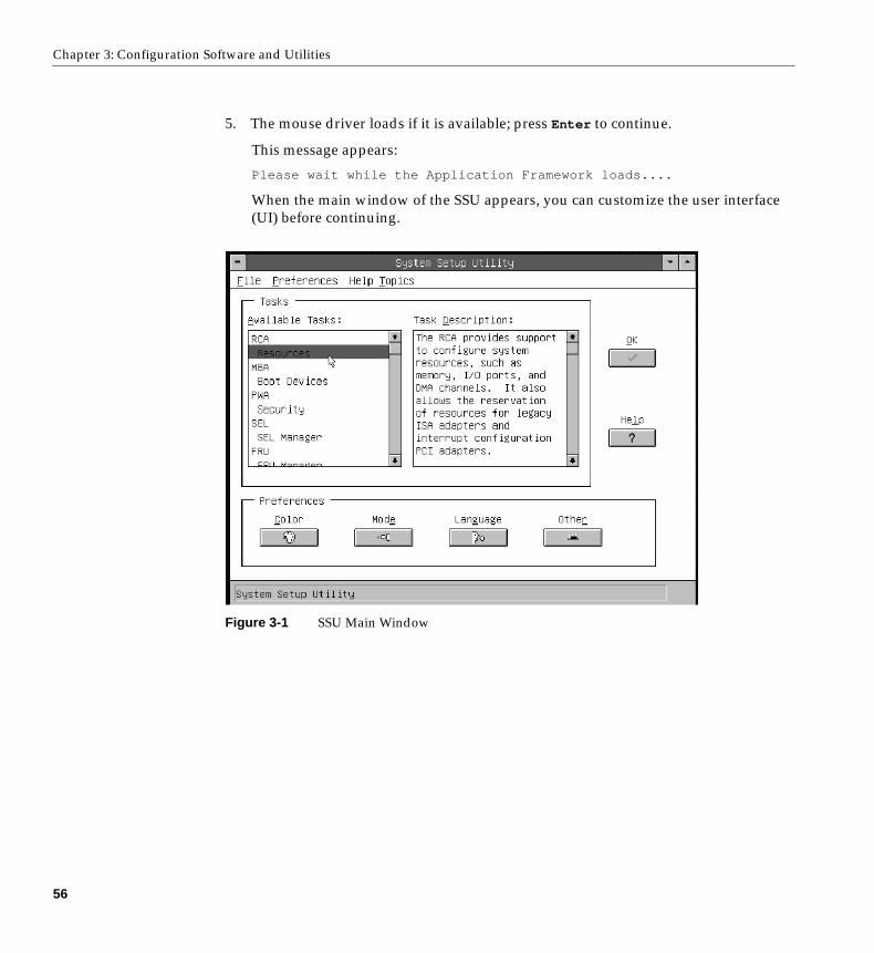
Chapter 3: Configuration Software and Utilities
5. The mouse driver loads if it is available; press Enter to continue.
This message appears:
Please wait while the Application Framework loads....
When the main window of the SSU appears, you can customize the user interface(UI) before continuing.
Figure 3-1 SSU Main Window
56
Using the System Setup Utility (SSU)
Customizing the SSU
You can customize the UI according to your preferences. The AF sets these preferencesand saves them in the AF.INI file so that they take effect the next time you start the SSU.Use these four user-customizable settings:
1. Color—lets you change the default colors associated with different items on thescreen to predefined color combinations. The changes are instantaneous.
2. Mode—lets you set the desired expertise level.
• Novice
• Intermediate
• Expert
The expertise level determines which tasks are visible in the Available Tasks sectionand what actions each task performs. For a new mode setting to take effect, youmust exit the SSU and restart it. In the current implementation, there is nodistinction between these three different modes.
3. Language—lets you change the text displayed in the SSU to the appropriatelanguage. For a new language setting to take effect, you must exit the SSU andrestart it.
4. Other—lets you change other miscellaneous options in the SSU. The changes areimmediate.
To change the interface default values, do one of the following:
• Use the mouse to click on the proper button in the Preferences section of theSSU Main window.
• Use the Tab and arrow keys to highlight the desired button, and press thespacebar or Enter .
• Access the menu bar with the mouse or hot keys (Alt + underlined letter).
Note: If you run the SSU from non-writable media (like a CD-ROM), these preferenceswill be lost when you exit the SSU.
57
Chapter 3: Configuration Software and Utilities
Launching a Task
It is possible to have many tasks open at the same time, although some tasks mightrequire complete control to avoid possible conflicts. The tasks achieve complete controlby commanding the center of operation until you close the task window.
To launch a task, do one of the following:
• In the SSU Main window, double-click on the task name under Available Tasks todisplay the main window for that task.
• Highlight the task name, and click OK.
• Use the Tab and arrow keys to highlight the desired button, and press the spacebaror Enter .
Resource Configuration Add-in (RCA) Window
The RCA provides three major functions:
• Creates representations of devices that cannot be discovered by the system (ISAboards)
• Modifies the contents of the system by adding and removing devices
• Modifies the resources used by devices
58
Using the System Setup Utility (SSU)
You can use the RCA window to define or add an ISA board by clicking on theappropriate button. To remove an ISA board, highlight the board in the Devices sectionof the screen before clicking on the button. You can add only as many ISA boards as thereare ISA slots available.
1. From the SSU main window, launch the RCA by selecting the Resources task underthe RCA heading in the task box.
2. When the RCA window appears, it displays messages similar to the following:
Baseboard: System BoardPCI Card: Bus 00 dev 00 -– Host Processor BridgePCI Card: Bus 00 dev 0D –- Multifunction ControllerPCI Card: Bus 00 dev 0F –- Ethernet ControllerPCI Card: Bus 00 dev 12 –- Multifunction ControllerPCI Card: Bus 00 dev 14 –- VGA Controller
3. To configure a device, click on it or select its name in the Devices section of the RCAwindow and press the spacebar or Enter .
4. You can close the RCA window and return to the AF by clicking on the Closebutton. Any changes made will be kept in memory for use by the RCA when it isrerun.
5. Save all changes by clicking Save. Saving writes your current configuration tononvolatile storage where it will be available to the system after every reboot.
6. Closing the window by clicking on the system menu (the dash in the upper-leftcorner) discards all changes.
Defining an ISA Board
An ISA board usually comes with a vendor-created .CFG file that specifies the resourcesthe card requires to function properly. If the .CFG file is unavailable, you must manuallycreate it or define the board through the SSU. Defining an ISA board consists ofspecifying the name of the board and the resources it consumes. This allows the RCA toconsider the ISA board resource requirements when the RCA tries to resolve conflicts.BIOS also uses this information to configure hardware when the system is booted.
1. To add or remove ISA board resources, click on the appropriate resource buttons,select the desired value, and click Add or Remove.
2. After you complete the necessary information, click Save.
59
Chapter 3: Configuration Software and Utilities
3. To edit a board, click Load to retrieve the board information. After making changes,click Save.
4. To create a board, click New.
5. To remove a current definition of a board, click Delete.
Adding and Removing ISA Boards
Adding and removing boards through the RCA provides a way for the RCA to run itsconflict detection algorithms on the resources requested by the boards. This alerts you toany possible problems with that particular board in the current configuration.
To add an ISA board:
1. Click Add ISA Board in the RCA window.
2. Specify the directory for the .CFG file.
3. Select the file and click OK.
To remove an ISA board:
1. Select a valid ISA board in the Devices section of the RCA window.
2. Click on Remove ISA Board.
Modifying Resources
Modifying the resources of a device may be necessary to accommodate certain operatingsystem applications, and drivers. It may also be necessary to modify resources to resolvea conflict.
To modify the resources associated with a device:
1. Highlight the device in the Devices section of the RCA window.
2. Press the spacebar or Enter , or double-click on the entry.
This displays the functions of the selected device along with possible choices andthe resources associated with those choices.
60
Using the System Setup Utility (SSU)
To make a modification:
1. Highlight the function in the Configuration window.
2. Press the spacebar or Enter , or double-click on the entry (this updates the choiceand resource lists).
3. Press the Tab key to get to the choice list, and press Enter .
4. Use the arrow keys to select a proper choice, and press Enter again.
5. If the choice allows multiple possible values for a particular resource, use the hotkey to select a resource and press the spacebar or double-click on the resource.
6. Select the desired resource, and click OK.
System Resource Usage
Click on Resource Use in the Configuration window to display the System ResourceUsage window, which shows the resources each device consumes. This information isuseful if a conflict occurs. Devices can be organized according to the resources you wantto examine using the options in the Resource section of the screen. The resourceinformation can also be written to a plain text file through this window.
Multiboot Options Add-in
In this window, you can change the boot priority of a device.
1. Select a device.
2. Press + to move the device up in the list (higher priority). Press - to move it down.
61
Chapter 3: Configuration Software and Utilities
Security Add-in
In this window, you can set the User and Administrator passwords and security options.
To Set the User Password
1. Click on User Password.
2. Enter the password in the first field.
3. Confirm the password by entering it again in the second field.
To Change or Clear the User Password
1. Click on User Password.
2. Enter the old password in the first field.
3. Enter the new password in the second field (or leave it blank to clear).
4. Confirm the password by entering it again in the second field (leave blank to clear).
To Set the Administrator Password
1. Click on Administrator Password.
2. Enter the password in the first field.
3. Confirm the password by entering it again in the second field.
To Change or Clear the Administrator Password
1. Click on Administrator Password.
2. Enter the old password in the first field.
3. Enter the new password in the second field (or leave it blank to clear).
4. Confirm the password by entering it again in the second field (leave blank to clear).
62
Using the System Setup Utility (SSU)
Security Options
In the security options window, you can set the other security options:
• Hot Key—sets a key sequence that puts the server into secure mode when the key ispressed.
• Lock-Out Timer—sets an interval that puts the server into secure mode when noactivity occurs during the interval.
• Secure Boot Mode—forces the server to boot directly into secure mode.
• Video Blanking—turns off the video when the server is in secure mode.
• Floppy Write—controls access to the diskette drive when the server is in securemode.
• Reset/Power Switch Locking—controls the power and reset buttons when theserver is in secure mode.
System Event Log (SEL) Viewer Add-in
Clicking on the SEL add-in task brings up the SEL viewer add-in, which allows users to:
• Examine SEL records via the BMC in hex or verbose mode
• Examine SEL records by sensor or event type in hex or verbose mode
• Examine SEL records from a previously stored binary file in hex or verbose mode
• Save SEL records to a file in either text or binary form
• Clear SEL entries from the non-volatile storage area
The SEL viewer’s main window provides access to features of the add-in. Each optionincluded on the main menu supports an accelerator key. Accelerator keys are indicatedby an underlined letter in the text listing the option. The main window includes supportto display the following information for each SEL entry: record identifier, event type,time stamp information, generator identifier, emv revision, sensor type, sensor number,and event description.
63
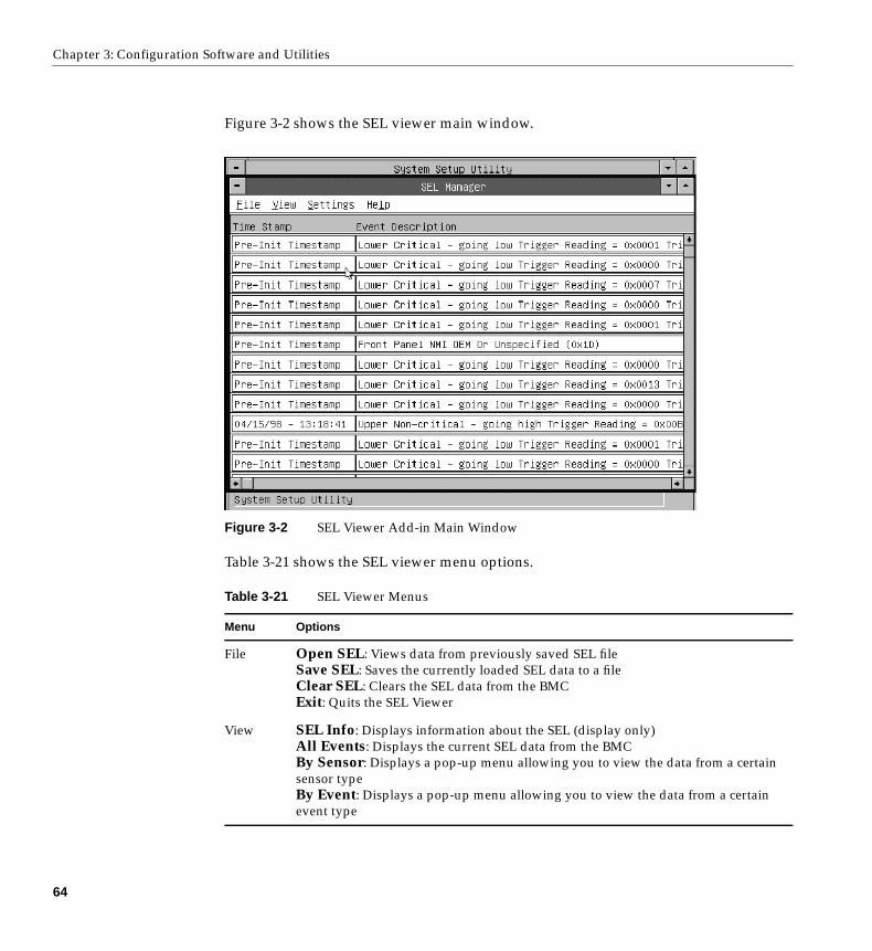
Chapter 3: Configuration Software and Utilities
Figure 3-2 shows the SEL viewer main window.
Figure 3-2 SEL Viewer Add-in Main Window
Table 3-21 shows the SEL viewer menu options.
Table 3-21 SEL Viewer Menus
Menu Options
File Open SEL: Views data from previously saved SEL fileSave SEL: Saves the currently loaded SEL data to a fileClear SEL: Clears the SEL data from the BMCExit: Quits the SEL Viewer
View SEL Info: Displays information about the SEL (display only)All Events: Displays the current SEL data from the BMCBy Sensor: Displays a pop-up menu allowing you to view the data from a certainsensor typeBy Event: Displays a pop-up menu allowing you to view the data from a certainevent type
64
Using the System Setup Utility (SSU)
Sensor Data Record (SDR) Manager Add-In
In this window, you can:
• Examine all SDR records through the BMC (in either Hex or Verbose mode)
• Examine SDR records by Record type (in either Hex or Verbose mode)
• Examine SDR records from a previously stored binary file (in either Hex or Verbosemode)
• Save the SDR records to a file (in either text or binary form)
The SDR Manager can display SDR records in either raw form (hexadecimal) or in aninterpreted, easy-to-understand textual form (verbose).
The SDR Manager’s main window provides access to features of the add-in throughmenus. Each option included on the main menu supports an accelerator key. Acceleratorkeys are indicated by an underlined letter in the text listing the option.
Settings Display Hex/Verbose: Toggles between Hex/interpreted mode of displaying theSEL recordsOutput Text/Binary: Determines whether SEL data will be saved to the file (andunder File - Save) in binary format or verbose format
Help About: Displays the SEL Viewer version information
Table 3-21 (continued) SEL Viewer Menus
65
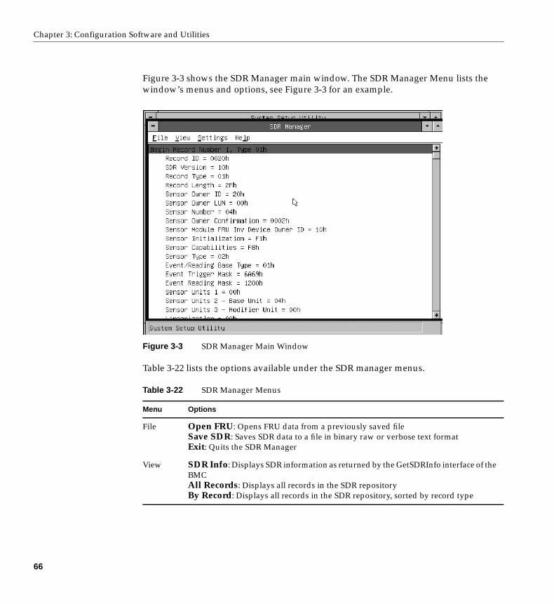
Chapter 3: Configuration Software and Utilities
Figure 3-3 shows the SDR Manager main window. The SDR Manager Menu lists thewindow’s menus and options, see Figure 3-3 for an example.
Figure 3-3 SDR Manager Main Window
Table 3-22 lists the options available under the SDR manager menus.
Table 3-22 SDR Manager Menus
Menu Options
File Open FRU: Opens FRU data from a previously saved fileSave SDR: Saves SDR data to a file in binary raw or verbose text formatExit: Quits the SDR Manager
View SDR Info: Displays SDR information as returned by the GetSDRInfo interface of theBMCAll Records: Displays all records in the SDR repositoryBy Record: Displays all records in the SDR repository, sorted by record type
66
Using the System Setup Utility (SSU)
Field Replaceable Unit (FRU) Manager Add-In
In this window you can:
• Examine all FRU Inventory areas on the server (in either Hex or Verbose mode)
• Examine individual FRU Inventory areas (in either Hex or Verbose mode)
• Examine FRU Inventory areas from a previously stored binary file (in either Hex orVerbose mode)
• Save the FRU Inventory areas to a file (in either text or binary form)
The FRU Manager can display the FRU Inventory areas in either raw form (hexadecimal)or in an interpreted, easy-to-understand textual form (verbose). The FRU manager’smain window provides access to features of the add-in through menus. Each optionincluded on the main menu supports an accelerator key. Accelerator keys are indicatedby an underlined letter in the text listing the option.
Settings Display HEX: Displays SDR records in Hex formatDisplay Verbose: Displays SDR records in verbose formatOutput Text: Saves SDR data in verbose formatOutput Binary: Saves SDR data in binary format
Help About: Displays SDR Manager version information
Table 3-22 (continued) SDR Manager Menus
67
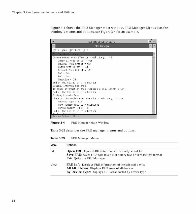
Chapter 3: Configuration Software and Utilities
Figure 3-4 shows the FRU Manager main window. FRU Manager Menus lists thewindow’s menus and options, see Figure 3-4 for an example.
Figure 3-4 FRU Manager Main Window
Table 3-23 describes the FRU manager menus and options.
Table 3-23 FRU Manager Menus
Menu Options
File Open FRU: Opens FRU data from a previously saved fileSave FRU: Saves FRU data to a file in binary raw or verbose text formatExit: Quits the FRU Manager
View FRU Info: Displays FRU information of the selected deviceAll FRU Areas: Displays FRU areas of all devicesBy Device Type: Displays FRU areas sorted by device type
68
Emergency Management Port (EMP) Console
Exiting the SSU
Exiting the SSU causes all windows to close.
1. Exit the SSU by opening the menu bar item File in the SSU Main window.
2. Click on Exit
or
Highlight Exit, and press Enter .
Emergency Management Port (EMP) Console
The EMP console provides an interface, called the console manager, to the EMP. Thisinterface allows remote server management by way of a modem or direct connection.The EMP console is used only with a Windows operating system.
The following server control operations are available with the console manager:
• Connecting to remote servers
• Powering the server on or off
• Resetting the server
• Switching the server console between EMP active and BIOS re-direct modes
The console manager uses three management plug-ins to monitor the server: the SEL,SDR, and FRU viewers.
The console manager also has a support plug-in phonebook, which you can use to createand maintain a list of servers and their phone numbers. You can launch the Connectdialog directly from the Phonebook dialog to connect to a selected server.
Settings Display HEX: Displays FRU areas in Hex formatDisplay Verbose: Displays FRU areas in verbose formatOutput Text: Saves FRU data in verbose formatOutput Binary: Saves FRU data in binary format
Help About: Displays FRU Manager version information
Table 3-23 (continued) FRU Manager Menus
69
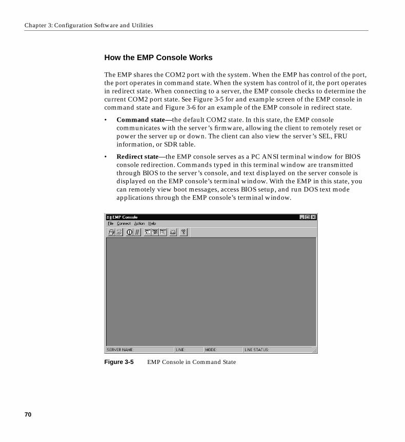
Chapter 3: Configuration Software and Utilities
How the EMP Console Works
The EMP shares the COM2 port with the system. When the EMP has control of the port,the port operates in command state. When the system has control of it, the port operatesin redirect state. When connecting to a server, the EMP console checks to determine thecurrent COM2 port state. See Figure 3-5 for and example screen of the EMP console incommand state and Figure 3-6 for an example of the EMP console in redirect state.
• Command state—the default COM2 state. In this state, the EMP consolecommunicates with the server’s firmware, allowing the client to remotely reset orpower the server up or down. The client can also view the server’s SEL, FRUinformation, or SDR table.
• Redirect state—the EMP console serves as a PC ANSI terminal window for BIOSconsole redirection. Commands typed in this terminal window are transmittedthrough BIOS to the server’s console, and text displayed on the server console isdisplayed on the EMP console’s terminal window. With the EMP in this state, youcan remotely view boot messages, access BIOS setup, and run DOS text modeapplications through the EMP console’s terminal window.
Figure 3-5 EMP Console in Command State
70
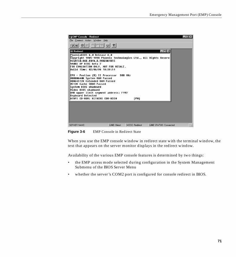
Emergency Management Port (EMP) Console
Figure 3-6 EMP Console in Redirect State
When you use the EMP console window in redirect state with the terminal window, thetext that appears on the server monitor displays in the redirect window.
Availability of the various EMP console features is determined by two things:
• the EMP access mode selected during configuration in the System ManagementSubmenu of the BIOS Server Menu
• whether the server’s COM2 port is configured for console redirect in BIOS.
71
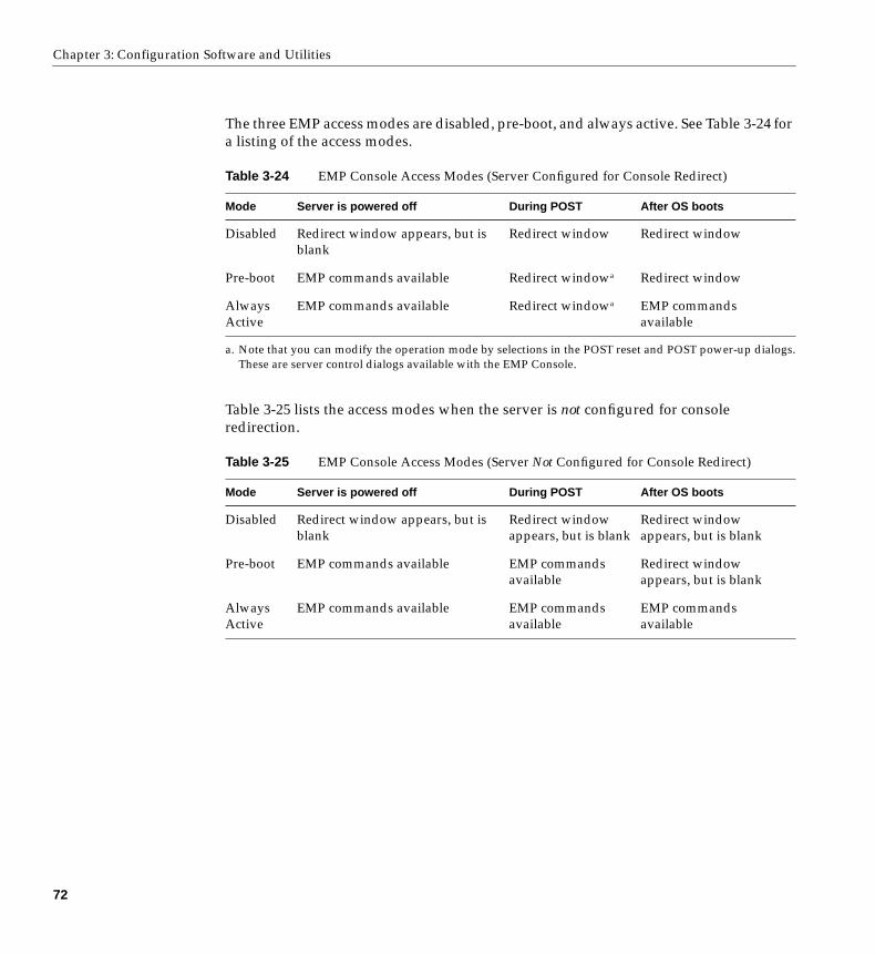
Chapter 3: Configuration Software and Utilities
The three EMP access modes are disabled, pre-boot, and always active. See Table 3-24 fora listing of the access modes.
Table 3-25 lists the access modes when the server is not configured for consoleredirection.
Table 3-24 EMP Console Access Modes (Server Configured for Console Redirect)
Mode Server is powered off During POST After OS boots
Disabled Redirect window appears, but isblank
Redirect window Redirect window
Pre-boot EMP commands available Redirect windowa
a. Note that you can modify the operation mode by selections in the POST reset and POST power-up dialogs.These are server control dialogs available with the EMP Console.
Redirect window
AlwaysActive
EMP commands available Redirect windowa EMP commandsavailable
Table 3-25 EMP Console Access Modes (Server Not Configured for Console Redirect)
Mode Server is powered off During POST After OS boots
Disabled Redirect window appears, but isblank
Redirect windowappears, but is blank
Redirect windowappears, but is blank
Pre-boot EMP commands available EMP commandsavailable
Redirect windowappears, but is blank
AlwaysActive
EMP commands available EMP commandsavailable
EMP commandsavailable
72
Emergency Management Port (EMP) Console
EMP Console Requirements
This section outlines the requirements and configurations necessary for using the EMPconsole.
Operating System:
• Windows NT
– Windows NT 4.0 or later
– 24 MB of RAM, 32 MB recommended
– 20 MB disk space
Client Configuration: The EMP console will support all COM ports on the client system,along with any Windows NT compatible modem.
Server Configuration: The EMP console requires that the server’s COM2 port beconnected to an external modem or directly connected to a serial cable.
Direct Connect Configuration: A null modem serial cable is needed. Connect one end ofthe cable into the COM2 port of the server and the other into a port on the client machine.
Modem Configuration: On the client, the EMP console uses the Windows applicationprogram interface (API) to determine if a modem is connected and available. The EMPConsole does not configure the modem; it should be preconfigured through Windows.
For modem support, the server must use a Hayes-compatible 14400 bps modem. Themodem must be on the NT hardware compatibility list provided by Microsoft. The servermodem must be set in autoanswer mode for the EMP console to be able to connect to it.
Setting Up the Server for the EMP
To use the EMP, you must configure BIOS with specific settings. Enter these settings intwo submenus of the BIOS Server Menu: the System Management Submenu and theConsole Redirect Submenu. The section above on BIOS settings shows all availableoptions. The sections below focus on the settings that must be configured to use the EMP.
73
Chapter 3: Configuration Software and Utilities
System Management Submenu
All EMP-related settings occur from the System Management Submenu of the serverMain Menu. Change only the items below; all other default settings should remain thesame.
EMP Password: Any time you attempt to initiate a connection, a prompt for the userpassword appears. If you never set up the EMP password, anyone can access the EMPby clicking OK through the password prompt.
In the EMP password area of the System Management Submenu, type in a password ofup to eight alphanumeric characters. If the system beeps, the password was not accepted;you must enter a different password.
EMP Access Modes: Choose either disabled, pre-boot, or always active, depending onthe type of EMP access needed. Table 3-24 and Table 3-25 list what is available with agiven setting.
EMP Restricted Mode Access: Set restricted mode to either enabled or disabled. Inenabled mode, the EMP console’s server control options, Power On/Off and Reset, areNOT available. In disabled mode, these options ARE available.
EMP Direct Connect/Modem Mode: Select Direct Connect if a null modem serial cabledirectly connects the server’s COM2 port to the EMP console client machine. If they areconnected via a modem, select Modem Mode.
Console Redirection Submenu
To use the EMP, you must set the following options exactly as noted.
COM Port Address: Select 2F8. This is the COM2 port that the EMP must use. TheIRQ# setting is automatically assigned with the correct number based on the COM portaddress choice.
Baud Rate: Select 19.2k.
Console Type: Choose PC ANSI.
Flow Control: Choose CTS/RTS + CD.
74
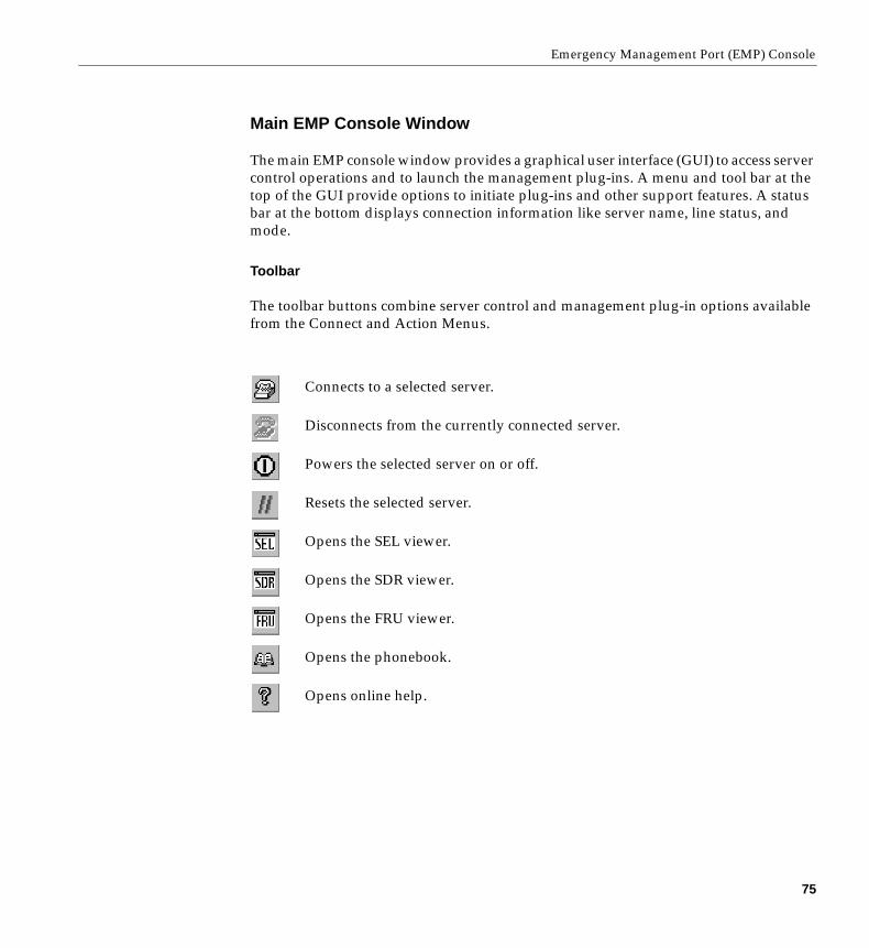
Emergency Management Port (EMP) Console
Main EMP Console Window
The main EMP console window provides a graphical user interface (GUI) to access servercontrol operations and to launch the management plug-ins. A menu and tool bar at thetop of the GUI provide options to initiate plug-ins and other support features. A statusbar at the bottom displays connection information like server name, line status, andmode.
Toolbar
The toolbar buttons combine server control and management plug-in options availablefrom the Connect and Action Menus.
Connects to a selected server.
Disconnects from the currently connected server.
Powers the selected server on or off.
Resets the selected server.
Opens the SEL viewer.
Opens the SDR viewer.
Opens the FRU viewer.
Opens the phonebook.
Opens online help.
75
Chapter 3: Configuration Software and Utilities
Status Bar
The status bar displays at the bottom of the current window. It contains the followingstatus information:
• Server Name: The name of the connected server.
• Line: The type of line connection (direct or modem).
• Mode: Either redirect or EMP, depending on whether the EMP has control of theCOM2 port.
• Line Status: Gives status information on the server connection. For example, if aserver is connected, the status bar says Connected. Otherwise, the line is blank.
EMP Console Main Menu
• File
– Exit: Exits the EMP console.
• Connect
– Disconnect: Disconnects the server connection.
– [Re]Connect: Raises the connect dialog.
– (A list of the five most recent connections): Initiates connection to selectedserver.
• Action
– Power On/Off: Powers the server on or off with POST power-up options.
– Reset: Resets the server with POST reset options.
– SEL Viewer: Opens the SEL viewer.
– SDR Viewer: Opens the SDR viewer.
– FRU Viewer: Opens the FRU viewer.
– Phonebook: Opens the phonebook dialog.
• Help: Provides version information and help topics for the EMP console.
76
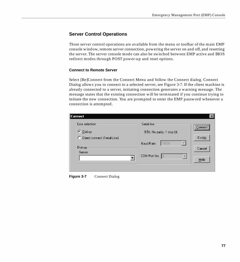
Emergency Management Port (EMP) Console
Server Control Operations
Three server control operations are available from the menu or toolbar of the main EMPconsole window, remote server connection, powering the server on and off, and resettingthe server. The server console mode can also be switched between EMP active and BIOSredirect modes through POST power-up and reset options.
Connect to Remote Server
Select [Re]Connect from the Connect Menu and follow the Connect dialog. ConnectDialog allows you to connect to a selected server, see Figure 3-7. If the client machine isalready connected to a server, initiating connection generates a warning message. Themessage states that the existing connection will be terminated if you continue trying toinitiate the new connection. You are prompted to enter the EMP password whenever aconnection is attempted.
Figure 3-7 Connect Dialog
77
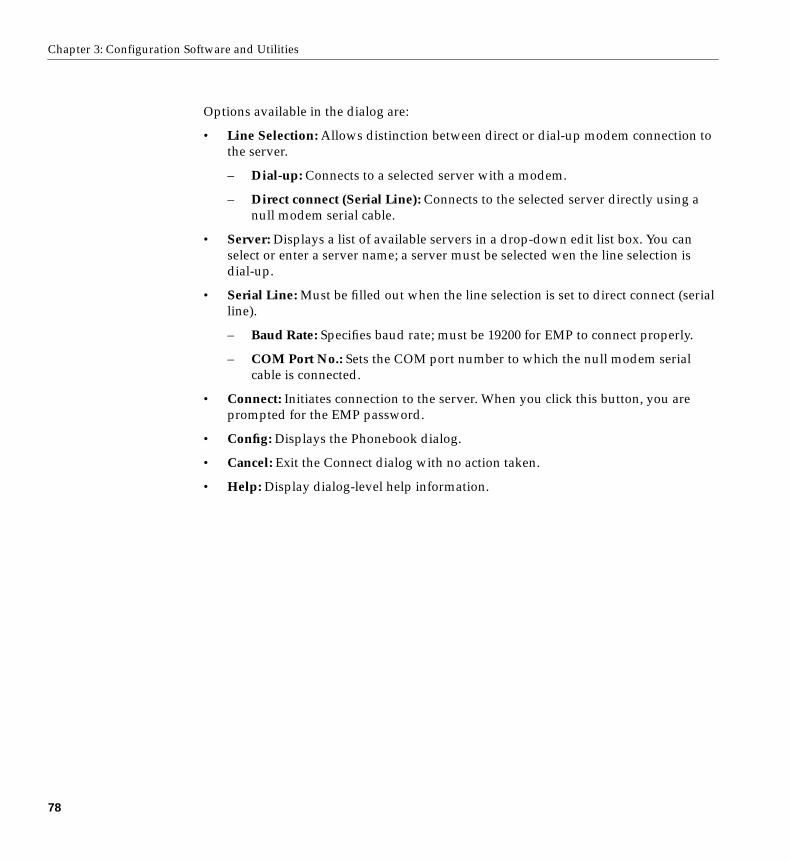
Chapter 3: Configuration Software and Utilities
Options available in the dialog are:
• Line Selection: Allows distinction between direct or dial-up modem connection tothe server.
– Dial-up: Connects to a selected server with a modem.
– Direct connect (Serial Line): Connects to the selected server directly using anull modem serial cable.
• Server: Displays a list of available servers in a drop-down edit list box. You canselect or enter a server name; a server must be selected wen the line selection isdial-up.
• Serial Line: Must be filled out when the line selection is set to direct connect (serialline).
– Baud Rate: Specifies baud rate; must be 19200 for EMP to connect properly.
– COM Port No.: Sets the COM port number to which the null modem serialcable is connected.
• Connect: Initiates connection to the server. When you click this button, you areprompted for the EMP password.
• Config: Displays the Phonebook dialog.
• Cancel: Exit the Connect dialog with no action taken.
• Help: Display dialog-level help information.
78
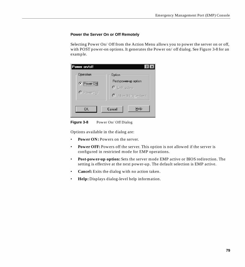
Emergency Management Port (EMP) Console
Power the Server On or Off Remotely
Selecting Power On/Off from the Action Menu allows you to power the server on or off,with POST power-on options. It generates the Power on/off dialog. See Figure 3-8 for anexample.
Figure 3-8 Power On/Off Dialog
Options available in the dialog are:
• Power ON: Powers on the server.
• Power OFF: Powers off the server. This option is not allowed if the server isconfigured in restricted mode for EMP operations.
• Post-power-up option: Sets the server mode EMP active or BIOS redirection. Thesetting is effective at the next power-up. The default selection is EMP active.
• Cancel: Exits the dialog with no action taken.
• Help: Displays dialog-level help information.
79
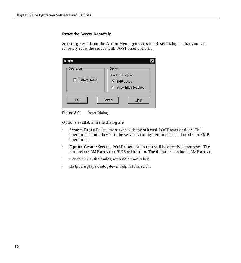
Chapter 3: Configuration Software and Utilities
Reset the Server Remotely
Selecting Reset from the Action Menu generates the Reset dialog so that you canremotely reset the server with POST reset options.
Figure 3-9 Reset Dialog
Options available in the dialog are:
• System Reset: Resets the server with the selected POST reset options. Thisoperation is not allowed if the server is configured in restricted mode for EMPoperations.
• Option Group: Sets the POST reset option that will be effective after reset. Theoptions are EMP active or BIOS redirection. The default selection is EMP active.
• Cancel: Exits the dialog with no action taken.
• Help: Displays dialog-level help information.
80
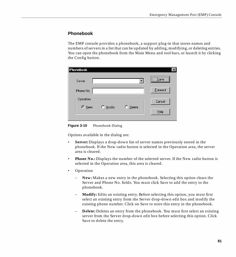
Emergency Management Port (EMP) Console
Phonebook
The EMP console provides a phonebook, a support plug-in that stores names andnumbers of servers in a list that can be updated by adding, modifying, or deleting entries.You can open the phonebook from the Main Menu and tool bars, or launch it by clickingthe Config button.
Figure 3-10 Phonebook Dialog
Options available in the dialog are:
• Server: Displays a drop-down list of server names previously stored in thephonebook. If the New radio button is selected in the Operation area, the serverarea is cleared.
• Phone No.: Displays the number of the selected server. If the New radio button isselected in the Operation area, this area is cleared.
• Operation
– New: Makes a new entry in the phonebook. Selecting this option clears theServer and Phone No. fields. You must click Save to add the entry to thephonebook.
– Modify: Edits an existing entry. Before selecting this option, you must firstselect an existing entry from the Server drop-down edit box and modify theexisting phone number. Click on Save to store this entry in the phonebook.
– Delete: Deletes an entry from the phonebook. You must first select an existingserver from the Server drop-down edit box before selecting this option. ClickSave to delete the entry.
81
Chapter 3: Configuration Software and Utilities
• Save: Saves a new or modified phonebook entry or deletes an entry if you havealready selected the Delete radio button.
• Connect: Raises the Connect dialog with the server from the phonebook’s Serverdrop-down edit box already populating the Connect dialog’s Server drop-downedit box.
• Cancel: Exits the dialog with no action taken.
• Help: Displays dialog-level help information.
Management Plug-ins
The following subsections list information on the SEL viewer and its options.
System Event Log (SEL) Viewer
The SEL viewer can display records in either hexadecimal or text (verbose) form. Theseoptions are available through the SEL viewer:
• View the SEL from a file
• Save the SEL to a file
• View SEL summary information
• View all SEL entries
• View SEL info by event type
• View SEL info by sensor type
• Set SEL display mode to either Hex or verbose mode
• Set the SEL output file format to either text or binary format
• Close the SEL viewer
• Exit the EMP console
82
Emergency Management Port (EMP) Console
SEL Viewer Menu Options
The following menu options are available on the SEL viewer menu bar:
• File
– Open: Allows you to view SEL data from a previously saved file if it was storedin binary format. Selecting the Open Menu item lets you specify a filenameunder which the data are found. The default filename is SELLOG.DAT. If thefile cannot be opened, the program displays an error message.
– Close: Closes the SEL viewer.
– Save As: Dumps the SEL data to a file in either binary raw or verbose textformat. The binary file can be retrieved later. Selecting this option lets youspecify a filename to which the data can be saved. The default filename isSELLOG.DAT. If no data exist, an error message displays.
– Exit: Exits the EMP console.
– SEL Information: Displays SEL summary information.
– All Events: Displays all events in the SEL.
– By Sensor Type: Displays all events in the SEL generated by a specific sensortype, such as voltage, temperature, etc.
– By Event: Displays all events in the SEL of a particular type, for example, bymemory or threshold. A pop-up menu lets you select the event type to display.This menu displays all event types that can be generated by the particularhardware.
• Settings: Lets you change several operating parameters for the SEL viewer. Thismenu displays the following suboptions:
– Display HEX/Verbose: Toggles between HEX mode and interpreted mode ofdisplaying SEL records.
– Output Text/Binary: Specifies whether SEL data will be saved to the file inbinary format or verbose format.
• Window: Gives options for displaying currently open windows.
• Help: Provides version information for the SEL viewer and provides help topics onthe EMP console.
83
Chapter 3: Configuration Software and Utilities
Sensor Data Record (SDR) Viewer
The SDR viewer lets you view the records retrieved from the SDR repository. Optionsavailable through the SDR viewer are:
• View all SDR records
• View SDR entries by SDR type
• View SDR summary information
• Set SDR display mode to either Hex or verbose mode
• Close the SDR viewer
• Exit the EMP console
SDR Viewer Menu Options
The SDR viewer menu bar contains the following:
• File
– Close: Closes the SDR viewer.
– Exit: Exits the EMP console.
• View
– Display all Records: Displays all records from the SDR repository.
– SDR Type: Displays the records of a particular SDR type. You select an SDRtype from a pop-up menu that displays all the SDR types available for the givenhardware.
– SDR Info: Displays the SDR summary information.
• Settings: Lets you change operating parameters for the SDR viewer. This menudisplays the following suboption:
– Display HEX/Verbose: Toggles between HEX mode and interpreted mode ofdisplaying SDR records.
• Window: Gives options for displaying currently open windows.
• Help: Provides version information for the SDR viewer and provides help topics onthe EMP console.
84
Emergency Management Port (EMP) Console
Field Replaceable Unit (FRU) Viewer
The FRU viewer lets you view data from the server’s baseboard FRU information area.Options available with the FRU viewer are:
• View all FRU records
• View FRU summary information
• Set FRU display mode to either Hex or verbose mode
• Close the FRU viewer
• Exit the EMP console
FRU Viewer Menu Options
The following menu options are on the FRU viewer menu bar:
• File
– Close: Closes the FRU viewer.
– Exit: Exits the EMP console.
• View
– Display all Records: Displays all FRU data, which consist of chassis, board, andproduct information.
– FRU Info: Displays the FRU summary information.
• Settings: Lets you change operating parameters for the FRU viewer. This menudisplays the following suboption:
– Display HEX/Verbose: Toggles between HEX mode and interpreted mode ofdisplaying FRU records.
• Window: Gives options for displaying currently open windows.
• Help: Provides version information for the FRU viewer and provides help topics onthe EMP console.
85
Chapter 3: Configuration Software and Utilities
FRU and SDR Load Utility
The Field Replacement Unit (FRU) and Sensor Data Record (SDR) load utility is aDOS-based program used to update the server management subsystem’s product levelFRU, SDR, and the Desktop Management Interface (DMI) nonvolatile storagecomponents (EEPROMs). The utility:
• Discovers the product configuration based on instructions in a master configurationfile
• Displays the FRU information
• Updates the EEPROM associated with the Baseboard Management Controller(BMC) that holds the SDR and FRU area
• Updates the DMI FRU area located in the BIOS nonvolatile storage device
• Generically handles FRU devices that might not be associated with the BMC
When to Run the FRUSDR Load Utility
You should run the FRUSDR load utility each time you upgrade or replace the hardwarein your server, excluding add-in boards, hard drives, and RAM. For example, if youreplace an array of fans, you need to run the utility. It programs the sensors that need tobe monitored for server management.
Because the utility must be reloaded to properly initialize the sensors after programming,turn the server off and remove the AC power cords from the server. Wait approximately30 seconds, then reconnect the power cords and turn on the server.
What You Need to Do
You can run the utility directly from the configuration software CD or from diskettes youcreate from the CD.
If you choose to run the FRUSDR Load Utility from a diskette, you must copy the utilityfrom the CD and follow the instructions in the included README.TXT file.
If your diskette drive is disabled, or improperly configured, you must use BIOS Setup toenable it. If necessary, you can disable the drive after you are done with the FRUSDRutility.
86

Emergency Management Port (EMP) Console
How You Use the FRUSDR Load Utility
The utility:
• Is compatible with ROM-DOS Ver. 6.22, MS-DOS Ver. 6.22, and later versions
• Accepts CFG, SDR, and FRU load files (the executable file for the utility isfrusdr.exe )
• Requires the following supporting files
– one or more .fru files describing the system’s field replaceable units
– a .cfg file describing the system configuration
– an .sdr file describing the sensors in the system
FRUSDR Command Line Format
The basic command line format is
frusdr [-?] [-h] [-d {dmi, fru, sdr}] [-cfg filename.cfg] [-fru filename.fru]
Table 3-26 lists the FRUSDR commands and describes them.
Table 3-26 FRUSDR Command Line Format
Command Description
frusdr Is the name of the utility
-? or -h Displays usage information
-d {dmi, fru, sdr} Displays requested area only
-cfg filename.cfg Uses custom CFG file
-p Pause between blocks of data
-v Verbose, display any additional details
87
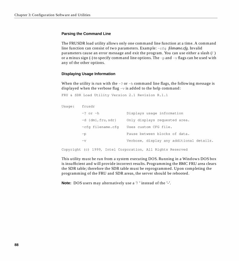
Chapter 3: Configuration Software and Utilities
Parsing the Command Line
The FRUSDR load utility allows only one command line function at a time. A commandline function can consist of two parameters. Example: -cfg filename.cfg. Invalidparameters cause an error message and exit the program. You can use either a slash (/)or a minus sign (-) to specify command line options. The -p and -v flags can be used withany of the other options.
Displaying Usage Information
When the utility is run with the -? or -h command line flags, the following message isdisplayed when the verbose flag -v is added to the help command:
FRU & SDR Load Utility Version 2.1 Revision R.1.1
Copyright (c) 1999, Intel Corporation, All Rights Reserved
This utility must be run from a system executing DOS. Running in a Windows DOS boxis insufficient and will provide incorrect results. Programming the BMC FRU area clearsthe SDR table; therefore the SDR table must be reprogrammed. Upon completing theprogramming of the FRU and SDR areas, the server should be rebooted.
Note: DOS users may alternatively use a ’/’ instead of the ’-’.
Usage: frusdr
-? or -h Displays usage information
-d {dmi,fru,sdr} Only displays requested area.
-cfg filename.cfg Uses custom CFG file.
-p Pause between blocks of data.
-v Verbose, display any additional details.
88
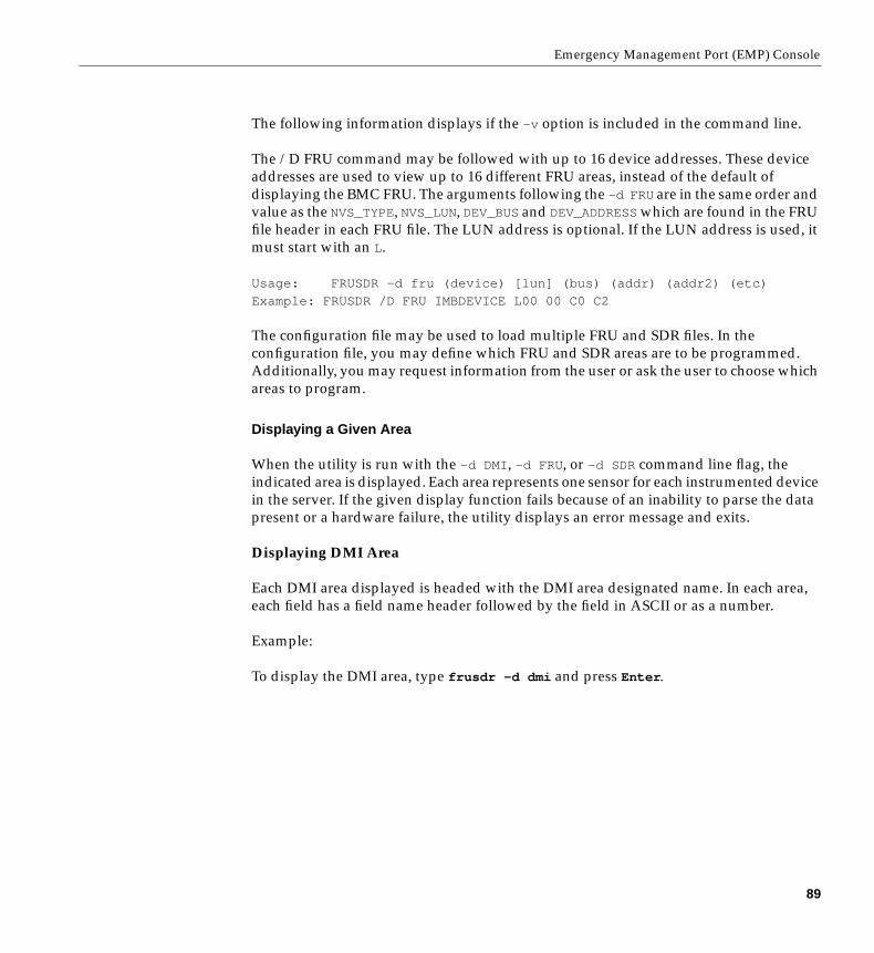
Emergency Management Port (EMP) Console
The following information displays if the -v option is included in the command line.
The /D FRU command may be followed with up to 16 device addresses. These deviceaddresses are used to view up to 16 different FRU areas, instead of the default ofdisplaying the BMC FRU. The arguments following the -d FRU are in the same order andvalue as the NVS_TYPE, NVS_LUN, DEV_BUSand DEV_ADDRESSwhich are found in the FRUfile header in each FRU file. The LUN address is optional. If the LUN address is used, itmust start with an L.
Usage: FRUSDR -d fru (device) [lun] (bus) (addr) (addr2) (etc)
Example: FRUSDR /D FRU IMBDEVICE L00 00 C0 C2
The configuration file may be used to load multiple FRU and SDR files. In theconfiguration file, you may define which FRU and SDR areas are to be programmed.Additionally, you may request information from the user or ask the user to choose whichareas to program.
Displaying a Given Area
When the utility is run with the -d DMI , -d FRU , or -d SDR command line flag, theindicated area is displayed. Each area represents one sensor for each instrumented devicein the server. If the given display function fails because of an inability to parse the datapresent or a hardware failure, the utility displays an error message and exits.
Displaying DMI Area
Each DMI area displayed is headed with the DMI area designated name. In each area,each field has a field name header followed by the field in ASCII or as a number.
Example:
To display the DMI area, type frusdr -d dmi and press Enter .
89
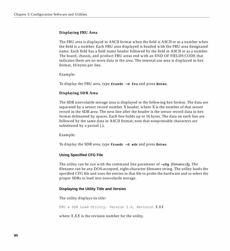
Chapter 3: Configuration Software and Utilities
Displaying FRU Area
The FRU area is displayed in ASCII format when the field is ASCII or as a number whenthe field is a number. Each FRU area displayed is headed with the FRU area designatedname. Each field has a field name header followed by the field in ASCII or as a number.The board, chassis, and product FRU areas end with an END OF FIELDS CODE thatindicates there are no more data in the area. The internal use area is displayed in hexformat, 16 bytes per line.
Example:
To display the FRU area, type frusdr -d fru and press Enter .
Displaying SDR Area
The SDR nonvolatile storage area is displayed in the following hex format. The data areseparated by a sensor record number X header, where X is the number of that sensorrecord in the SDR area. The next line after the header is the sensor record data in hexformat delineated by spaces. Each line holds up to 16 bytes. The data on each line arefollowed by the same data in ASCII format; note that nonprintable characters aresubstituted by a period (.).
Example:
To display the SDR area, type frusdr -d sdr and press Enter .
Using Specified CFG File
The utility can be run with the command line parameter of -cfg filename.cfg. Thefilename can be any DOS-accepted, eight-character filename string. The utility loads thespecified CFG file and uses the entries in that file to probe the hardware and to select theproper SDRs to load into nonvolatile storage.
Displaying the Utility Title and Version
The utility displays its title:
FRU & SDR Load Utility, Version 2.0, Revision X.XX
where X.XX is the revision number for the utility.
90

Emergency Management Port (EMP) Console
Configuration File
The configuration file is in ASCII text. The utility executes commands formed by thestrings present in the configuration file. These commands cause the utility to run tasksneeded to load the proper SDRs into the nonvolatile storage of the BMC and possiblygeneric FRU devices. Some of the commands may be interactive and require you to makea choice.
Prompting for Product Level FRU Information
Through the use of a configuration file, the utility might prompt you for FRUinformation.
Filtering Records From the SDR File
The MASTER.SDRfile has all the possible SDRs for the system. These records might needto be filtered based on the current product configuration. The configuration file directsthe filtering of the SDRs.
Updating the SDR Nonvolatile Storage Area
After the utility validates the header area of the supplied SDR file, it updates the SDRrepository area. Before programming, the utility clears the SDR repository area. Theutility filters all tagged SDRs depending on the product configuration set in theconfiguration file. Nontagged SDRs are automatically programmed. The utility alsocopies all written SDRs to the SDR.TMP file, as it contains an image of what was loaded.The TMP file is also useful for debugging the server.
Updating FRU Nonvolatile Storage Area
After the configuration is determined, the utility updates the FRU nonvolatile storagearea. First it verifies the common header area and checksum from the specified FRU file.The internal use area is read out of the specified .FRU file and is programmed into thenonvolatile storage. The chassis area is read out of the specified .FRU file. Finally, it readsthe product area out of the specified FRU file, then the area is programmed into the FRUnonvolatile storage. All areas are also written to the FRU.TMP file.
91
Chapter 3: Configuration Software and Utilities
Updating DMI FRU Nonvolatile Storage Area
After programming the BMC FRU area, the utility programs the chassis, board, andproduct FRU information to the DMI fields. The update happens only if the DMI flagfollows each FRUAREA command in the configuration file.
Cleaning Up and Exiting the Nonvolatile Storage Area
If an update was successfully performed, the utility displays a single message and thenexits.
If the utility fails, it immediately exits with an error message and an exit code.
Changing the BIOS Settings
Before you change or upgrade the BIOS, prepare the system by recording the currentBIOS settings, obtaining the upgrade utility, and making a copy of the current BIOS. Readthe following subsections for information on these procedures.
Recording the Current BIOS Settings
1. Boot the computer and press F2 when you see the message:
Press F2 Key if you want to run SETUP
2. Write down the current settings in the BIOS Setup program.
Note: Do not skip step 2. You will need these settings to configure your computer at theend of the procedure.
92
Changing the BIOS Settings
Obtaining the Upgrade Utility
You can upgrade to a new version of the BIOS using the new BIOS files and the BIOSupgrade utility, iFLASH.EXE. You can obtain the BIOS upgrade file and the iFLASH.EXEutility through your support provider or from the Intel World Wide Web site:
http://www.intel.com
Note: Please review the instructions distributed with the upgrade utility beforeattempting a BIOS upgrade.
This upgrade utility lets you:
• Upgrade the BIOS in flash memory.
• Update the language section of the BIOS.
The following steps explain how to upgrade the BIOS.
Creating a Bootable Diskette
1. Use a DOS or Windows 95 system to create the diskette.
2. Insert a diskette in drive A.
3. At the C:\ prompt, for an unformatted diskette, type:
format a:/s
or, for a formatted diskette, type:
sys a:
4. Press Enter .
93
Chapter 3: Configuration Software and Utilities
Creating the BIOS Upgrade Diskette
The BIOS upgrade file is a compressed self-extracting archive that contains the files youneed to upgrade the BIOS.
1. Copy the BIOS upgrade file to a temporary directory on your hard disk.
2. From the C:\ prompt, change to the temporary directory.
3. To extract the file, type the name of the BIOS upgrade file, for example:
10006BI1.EXE
4. Press Enter . The extracted file contains the following files:
LICENSE.TXTREADME.TXTBIOS.EXE
5. Read the LICENSE.TXT file, which contains the software license agreement, and theREADME.TXT file, which contains the instructions for the BIOS upgrade.
6. Insert the bootable diskette into drive A.
7. To extract the BIOS.EXE file to the diskette, change to the temporary directory thatholds the BIOS.EXE file and type:
BIOS A:
8. Press Enter .
9. The diskette now holds the BIOS upgrade and recovery files.
Upgrading the BIOS
1. Boot the computer with the diskette in drive A. The BIOS upgrade utility screenappears.
2. Select Update Flash Memory From a File.
3. Select Update System BIOS. Press Enter .
4. Use the arrow keys to select the correct .bio file then press Enter .
5. When the utility asks for confirmation that you want to flash the new BIOS intomemory, select Continue with Programming. Press Enter .
6. When the utility displays the message upgrade is complete, remove the diskette andpress Enter .
94
Changing the BIOS Settings
7. As the computer boots, check the BIOS identifier (version number) to make sure theupgrade was successful.
8. To enter the Setup program, press F2 when you see the message:
Press F2 Key if you want to run SETUP
9. For proper operation, load the Setup program defaults. To load the defaults, pressF9.
10. To accept the defaults, press Enter .
11. Set the options in the Setup program to the settings you wrote down before theBIOS upgrade.
12. To save the settings, press F10.
13. To accept the settings, press Enter .
14. Turn off the computer and reboot.
Recovering the BIOS
It is unlikely that anything will interrupt the BIOS upgrade; however, if an interruptionoccurs, the BIOS could be damaged. In that case, you must recover the BIOS.
Note: Because of the small amount of code available in the noneraseable boot block area,there is no video support. You will not see anything on the screen during the procedure.Monitor the procedure by listening to the speaker and looking at the diskette drive LED.
The procedure for recovering the BIOS is covered in the SGI 1400 Server FamilyMaintenance and Upgrades Guide. After doing the procedure, leave the upgrade disk indrive A and turn on the server, then continue with the BIOS upgrade.
95
Chapter 3: Configuration Software and Utilities
Changing the BIOS Language
You can use the BIOS upgrade utility to change the language BIOS displays. Use abootable diskette containing the proper flash utility and language files.
1. Boot the computer with the bootable diskette in drive A. The BIOS upgrade utilityscreen appears.
2. Select Update Flash Memory From a File.
3. Select Update Language Set. Press Enter .
4. Select drive A and use the arrow keys to select the correct .lng file. Press Enter .
5. When the utility asks for confirmation that you want to flash the new language intomemory, select Continue with Programming. Press Enter .
6. When the utility displays the message upgrade is complete, remove the diskette.Press Enter .
7. The computer will reboot and the changes will take effect.
Using the Firmware Update Utility
The Firmware Update Utility is a DOS-based program used to update the BMC’sfirmware code. You need to run the utility only if new firmware code is necessary.
Running the Firmware Update Utility
1. Create a DOS-bootable diskette. The version of DOS must be 6.0 or higher.
2. Place the firmware update utility (FWUPDATE.EXE) and the *.hex file on the diskette.Make a note of the *.hex filename, because you will need it later.
3. Insert the diskette into the drive and boot to it.
4. At the DOS prompt, run the executable file (FWUPDATE.EXE).
5. The utility will display a menu screen. Select Upload Flash.
6. The utility will ask for a filename. Enter the name of the *.hex file.
7. The program will load the file and then ask if it should upload boot block. Press N tocontinue.
8. The program will next ask if it should upload operational code. Press Y to continue.
96
Installing Video Drivers
9. Once the operational code has been updated and verified, press any key to continue.Then press Esc to exit the program.
10. Shut the system down and remove any diskettes in the system.
11. Disconnect all AC power cords from the system and wait 60 seconds.
12. Reconnect the AC power cords and power up the system.
Installing Video Drivers
After configuring the system, you need to install video drivers to take full advantage ofthe features of the onboard CL-GD5480 super VGA video controller.
• The NT configuration software CD includes video drivers for use with DOS andWindows NT. Check the README.TXT file on the CD for information on installingthese drivers.
• For other operating systems, see your OS instructions for installing device drivers.
Using the Symbios SCSI Utility for NT
The Symbios SCSI utility detects the SCSI host adapters on the system board. Use theutility to:
• Change default values
• Check and/or change SCSI device settings that may conflict with those of otherdevices in the server
Running the SCSI Utility
When this message appears on the video monitor:
Press Ctrl-C to run SCSI Utility...
Press Ctrl +C to run the utility. When it appears, choose the host adapter that you wantto configure.
97

Chapter 4
4. Solving Problems
This chapter helps you identify and solve problems that might occur while you are usingthe system.
Resetting the System
Initial System Startup
Problems that occur at initial system startup are usually caused by incorrect installationor configuration. Hardware failure is a less frequent cause. Use the following checklist tohelp determine the source of a failure.
To do this: Press:
Soft boot reset, which clears system memory and reloads theoperating system.
Ctrl +Alt +Del
Clear system memory, restart POST, and reload the operatingsystem.
Reset button
Cold boot reset, which clears system memory, restarts POST,reloads the operating system, and halts power to allperipherals.
Power off/on
99
Chapter 4: Solving Problems
Checklist
❑ Are all cables correctly connected and secured?
❑ Are the processors fully seated in their slots on the baseboard?
❑ Are all add-in ISA and PCI boards fully seated in their slots on the baseboard?
❑ Are all switch and jumper settings on the baseboard correct?
❑ Are all jumper and switch settings on add-in boards and peripheral devices correct?To check these settings, refer to the manufacturer’s documentation that comes withthem. If applicable, ensure that there are no conflicts—for example, two add-inboards sharing the same interrupt.
❑ Are all DIMMs installed correctly?
❑ Are all peripheral devices installed correctly?
❑ If the system has a hard disk drive, is it properly formatted or configured?
❑ Are all device drivers properly installed?
❑ Are the configuration settings made with the SSU correct?
❑ Is the operating system properly loaded? Refer to the operating systemdocumentation.
❑ Did you press the system power on/off switch on the front panel to turn the serveron (power-on light should be lit)?
❑ Are the system power cords properly connected to the system and plugged into aNEMA 5-15R outlet for 100-120 V∼ or a NEMA 6-15R outlet for 200-240 V∼?
❑ Is AC power available at the wall outlet?
❑ If these items are correct but the problem recurs, see “More Problem-solvingProcedures” on page 103.
100
Running New Application Software
Running New Application Software
Problems that occur when you run new application software are usually related to thesoftware. Faulty equipment is much less likely, especially if other software runs correctly.
Checklist
❑ Does the system meet the minimum hardware requirements for the software? See thesoftware documentation.
❑ Is the software an authorized copy? If not, get one; unauthorized copies often do notwork.
❑ If you are running the software from a diskette, is it a good copy?
❑ If you are running the software from a CD-ROM disk, is the disk scratched or dirty?
❑ If you are running the software from a hard disk drive, is the software correctlyinstalled? Were all necessary procedures followed and files installed?
❑ Are the correct device drivers installed?
❑ Is the software correctly configured for the system?
❑ Are you using the software correctly?
❑ If the problems persist, contact the software vendor’s customer servicerepresentative.
101
Chapter 4: Solving Problems
After the System Has Been Running Correctly
Problems that occur after the system hardware and software have been running correctlyoften indicate equipment failure. Many situations that are easy to correct, however, canalso cause such problems; sometimes the problem stems from changes made to thesystem, such as hardware or software that has been added or removed.
Checklist
❑ If you are running the software from a diskette, try a new copy of the software.
❑ If you are running the software from a CD-ROM disk, try a different disk to see if theproblem occurs on all disks.
❑ If you are running the software from a hard disk drive, try running it from a diskette.If the software runs correctly, there may be a problem with the copy on the hard diskdrive. Reinstall the software on the hard disk, and try running it again. Make sure allnecessary files are installed.
❑ If the problems are intermittent, there may be a loose cable, dirt in the keyboard (ifkeyboard input is incorrect), a marginal power supply, or other random componentfailures.
❑ If you suspect that a transient voltage spike, power outage, or brownout might haveoccurred, reload the software and try running it again. (Symptoms of voltage spikesinclude a flickering video display, unexpected system reboots, and the system notresponding to user commands.)
Note: Random errors in data files: if you are getting random errors in your data files,they may be getting corrupted by voltage spikes on your power line. If you areexperiencing any of the above symptoms that might indicate voltage spikes on the powerline, you may want to install a surge suppressor between the power outlet and the systempower cords.
102
More Problem-solving Procedures
More Problem-solving Procedures
The following subsections provide a more detailed approach to identifying a problemand locating its source.
Preparing the System for Diagnostic Testing
Caution: Turn off devices before disconnecting cables: before disconnecting anyperipheral cables from the system, turn off the system and any external peripheraldevices. Failure to do so can cause permanent damage to the system and/or theperipheral devices.
1. Turn off the system and all external peripheral devices. Disconnect all of them fromthe system, except the keyboard and video monitor.
2. Make sure the system power cords are plugged into a properly grounded AC outlet.
3. Make sure your video display monitor and keyboard are correctly connected to thesystem. Turn on the video monitor. Set its brightness and contrast controls to at leasttwo-thirds of their maximum ranges (see the documentation supplied with yourvideo display monitor).
4. If the operating system normally loads from the hard disk drive, make sure there isno diskette in drive A. Otherwise, place a diskette containing the operating systemfiles in drive A.
5. Turn on the system. If the power LED does not light, see “Power Light Does NotLight” on page 105.
Using PCDiagnostics
A diagnostics package for the system is contained on the configuration software CD thatcomes with the system. For documentation about the test modules, see the Diagnostichelp disks that end with the extension .HLP. They are ASCII files that you can print toform a manual of all tests in this product.
• The program called Testview uses a simple DOS-based menu system.
• The program called T.EXE is a noninteractive test executable used to run testprogram modules from DOS batch files.
• The README.TXT file for diagnostics tells how to install the program.
103
Chapter 4: Solving Problems
Caution: Read help information for a test before running it: the diagnostic packagecontains many optional tests that should be used only by a user with advanced technicalknowledge. Inadvertent actions could be damaging, such as running a hard drive writetest on a hard disk. All tests that require external hardware, user interaction, or aredestructive, are disabled in the default configurations. Before using such a test, makesure you read and understand the help information for that test.
Monitoring POST
For detailed information on POST see the section “Power-on Self Test (POST)” inChapter 3.
Verifying Proper Operation of Key System Lights
As POST determines the system configuration, it tests for the presence of each massstorage device installed in the system. As each device is checked, its activity light shouldturn on briefly. Check for the following:
• Does the diskette drive activity light turn on briefly? If not, see “Diskette DriveActivity Light Does Not Light” on page 108.
• If a second diskette drive is installed, does its activity light turn on briefly? If not,see “Diskette Drive Activity Light Does Not Light” on page 108.
• If there is a hard disk drive or SCSI devices installed in the system, does the harddisk drive activity light on the control panel turn on briefly? If not, see “Hard DiskDrive Activity Light Does Not Light” on page 108.
Confirming Loading of the Operating System
Once the system boots up, the operating system prompt appears on the screen. Theprompt varies according to the operating system. If the operating system prompt doesnot appear, see “Initial System Startup” on page 99.
104
Specific Problems and Corrective Actions
Specific Problems and Corrective Actions
This section provides possible solutions for these specific problems:
• Power light does not light.
• No beep or incorrect beep pattern.
• No characters appear on screen.
• Characters on the screen appear distorted or incorrect.
• System cooling fans do not rotate.
• Diskette drive activity light does not light.
• Hard disk drive activity light does not light.
• CD-ROM drive activity light does not light.
• Problems with application software.
• The startup prompt Press F2 key if you want to run Setup does not appearon the screen.
• The bootable CD-ROM is not detected.
Try the solutions in the order given. If you cannot correct the problem, contact yourservice representative for assistance.
Power Light Does Not Light
Check the following:
❑ Are all the power supplies plugged in? Is the power turned on to the power strip oroutlet? Do you have a blown fuse or breaker?
❑ Is the system operating normally? If so, the power LED is probably defective or thecable from the front panel to the baseboard is loose.
❑ Are there other problems with the system? If so, check the items listed under“System Cooling Fans Do Not Rotate Properly.”
If all items are correct and problems persist, contact your service representative orauthorized dealer for assistance.
105
Chapter 4: Solving Problems
No Beep Codes
If the system operates normally, but there was no beep, the speaker may be defective. Ifthe speaker is enabled, but the speaker does not function, contact your servicerepresentative or authorized dealer for assistance.
Record the beep code emitted by POST, and see “Error and Informational Messages” onpage 110.
No Characters Appear on Screen
If there are no characters on the screen check the following:
❑ Is the keyboard working? Check to see that the Num Lock light is functioning.
❑ Is the video monitor plugged in and turned on? Many modern video monitors shutdown when inactive and may require a moment to warm up when activated.
❑ Are the brightness and contrast controls on the video monitor properly adjusted?
❑ Are the video monitor switch settings correct?
❑ Is the video monitor signal cable properly installed?
❑ Is the onboard video controller enabled?
If you are using an add-in video controller board, do the following:
1. Verify that the video controller board is fully seated in the baseboard connector (andverify that the video monitor is plugged in to the ACTIVE video controller).
2. Reboot the system for changes to take effect.
3. If there are still no characters on the screen after you reboot the system and POSTemits a beep code, write down the beep code you hear. This information is usefulfor your service representative.
4. If you do not receive a beep code and characters do not appear, the video displaymonitor or video controller may have failed. You can verify this by trying themonitor on another system or trying a different monitor on this system. Contactyour service representative or authorized dealer for assistance.
106
Specific Problems and Corrective Actions
Characters Are Distorted or Incorrect
Check the following:
❑ Are the brightness and contrast controls properly adjusted on the video monitor? Seethe manufacturer’s documentation.
❑ Are the video monitor signal and power cables properly installed?
❑ Is the correct monitor/video board installed for your operating system?
If the problem persists, the video monitor may be faulty or it may be the incorrect type.Contact your service representative for assistance.
System Cooling Fans Do Not Rotate Properly
If the system cooling fans are not operating properly, system components could bedamaged. Check the following:
❑ Is AC power available at the wall outlet?
❑ Are the system power cords properly connected to the system and the wall outlet?
❑ Did you press the power on/off push-button switch?
❑ Is the power-on light lit?
❑ Have any of the fan motors stopped (use the server management subsystem to checkthe fan status)?
❑ Are the fan power connectors properly connected to the baseboard?
❑ Is the cable from the front panel board connected to the baseboard?
❑ Are the power supply cables properly connected to the baseboard?
❑ Are there any shorted wires caused by pinched cables or power connector plugsforced into power connector sockets the wrong way?
If the switches and connections are correct and AC power is available at the wall outlet,contact your service representative for assistance.
107
Chapter 4: Solving Problems
Diskette Drive Activity Light Does Not Light
Check the following:
❑ Are the diskette drive power and signal cables properly installed?
❑ Are all relevant switches and jumpers on the diskette drive set correctly?
❑ Is the diskette drive properly configured?
❑ Is the diskette drive activity light always on? If so, the signal cable may be pluggedin incorrectly.
If you are using the onboard diskette controller, use the SSU to make sure that OnboardFloppy is set to Enabled. If you are using an add-in diskette controller, make sure thatOnboard Floppy is set to Disabled. To run the SSU, see “When to Run the SSU” inChapter 3.
If the problem persists, there may be a problem with the diskette drive, baseboard, ordrive signal cable. Contact your service representative for assistance.
Hard Disk Drive Activity Light Does Not Light
If you have installed one or more hard disk drives in your system, check the following:
❑ Are the power and signal cables to the drive properly installed?
❑ Are all relevant switches and jumpers on the hard drive and adapter board setcorrectly?
❑ Is the onboard IDE controller enabled? (IDE hard drives only)
❑ Is the hard disk drive properly configured?
Note: Front panel hard disk LED indicates IDE and SCSI devices: the hard disk driveactivity light on the front panel lights when either an IDE hard disk drive, or a SCSIdevice controlled by the onboard SCSI host controller, is in use. This LED does notdisplay CD-ROM activity.
108
Specific Problems and Corrective Actions
CD-ROM Drive Activity Light Does Not Light
Check the following:
❑ Are the power and signal cables to the CD-ROM drive properly installed?
❑ Are all relevant switches and jumpers on the drive set correctly?
❑ Is the drive properly configured?
❑ Is the onboard IDE controller enabled?
Note: Front panel hard disk LED indicates IDE and SCSI devices: the hard disk driveactivity light on the front panel lights when either an IDE hard disk drive, or a SCSIdevice controlled by the onboard SCSI host controller, is in use. This LED does notdisplay CD-ROM activity.
Network Problems
If you have network problems, consult the documentation that came with the networkboard you purchased for this server.
PCI Installation Tips
Some common PCI tips are listed here.
• Reserve interrupts (IRQs) and/or memory addresses specifically for ISA adapters.This prevents PCI boards from trying to use the same settings ISA boards are using.Use the SSU to keep track of ISA adapter resources.
• Certain drivers may require interrupts that are not shared with other PCI drivers.The SSU can be used to adjust the interrupt numbers for PCI devices. For certaindrivers, it may be necessary to alter settings so that interrupts are not shared.
• Check PCI interrupt interdependencies among slots and onboard devices.
109
Chapter 4: Solving Problems
Problems with Application Software
If you have problems with application software, do the following:
• Verify that the software is properly configured for the system. See the softwareinstallation and operation documentation for instructions on setting up and usingthe software.
• Try a different copy of the software to see if the problem is with the copy you areusing.
• Make sure all cables are installed correctly.
• Verify that the baseboard jumpers are set correctly.
• If other software runs correctly on the system, contact your vendor about the failingsoftware.
If the problem persists, contact the software vendor’s customer service representative forassistance.
Bootable CD-ROM Is Not Detected
Check the following:
❑ Is the BIOS set to allow the CD-ROM to be the first bootable device?
Error and Informational Messages
When you turn on the system, POST displays messages that provide information aboutthe system. If a failure occurs, POST emits beep codes that indicate errors in hardware,software, or firmware. If POST can display a message on the video display screen, itcauses the speaker to beep twice as the message appears.
110
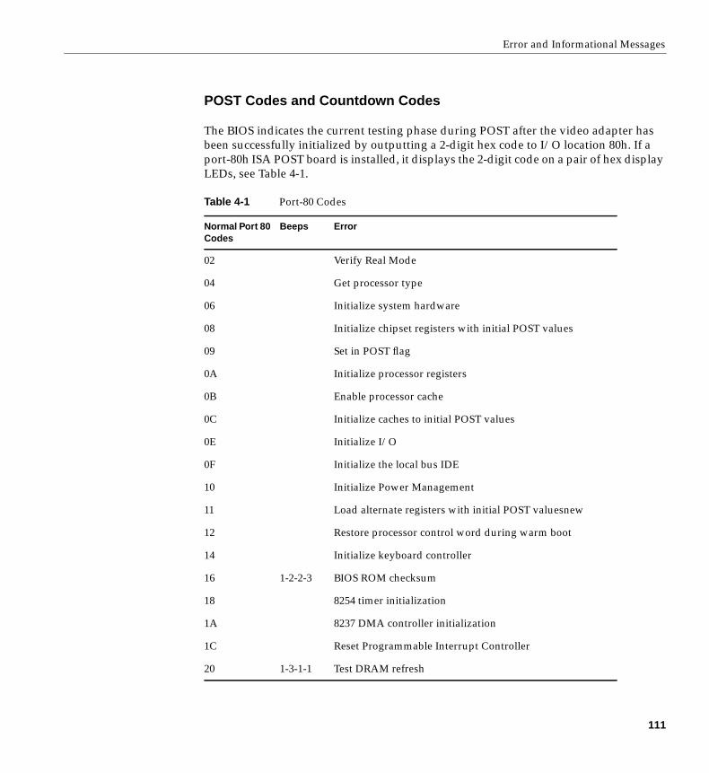
Error and Informational Messages
POST Codes and Countdown Codes
The BIOS indicates the current testing phase during POST after the video adapter hasbeen successfully initialized by outputting a 2-digit hex code to I/O location 80h. If aport-80h ISA POST board is installed, it displays the 2-digit code on a pair of hex displayLEDs, see Table 4-1.
Table 4-1 Port-80 Codes
Normal Port 80Codes
Beeps Error
02 Verify Real Mode
04 Get processor type
06 Initialize system hardware
08 Initialize chipset registers with initial POST values
09 Set in POST flag
0A Initialize processor registers
0B Enable processor cache
0C Initialize caches to initial POST values
0E Initialize I/O
0F Initialize the local bus IDE
10 Initialize Power Management
11 Load alternate registers with initial POST valuesnew
12 Restore processor control word during warm boot
14 Initialize keyboard controller
16 1-2-2-3 BIOS ROM checksum
18 8254 timer initialization
1A 8237 DMA controller initialization
1C Reset Programmable Interrupt Controller
20 1-3-1-1 Test DRAM refresh
111
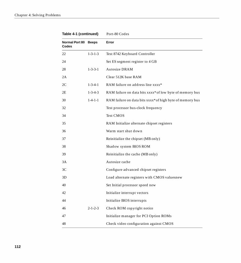
Chapter 4: Solving Problems
22 1-3-1-3 Test 8742 Keyboard Controller
24 Set ES segment register to 4 GB
28 1-3-3-1 Autosize DRAM
2A Clear 512K base RAM
2C 1-3-4-1 RAM failure on address line xxxx*
2E 1-3-4-3 RAM failure on data bits xxxx* of low byte of memory bus
30 1-4-1-1 RAM failure on data bits xxxx* of high byte of memory bus
32 Test processor bus-clock frequency
34 Test CMOS
35 RAM Initialize alternate chipset registers
36 Warm start shut down
37 Reinitialize the chipset (MB only)
38 Shadow system BIOS ROM
39 Reinitialize the cache (MB only)
3A Autosize cache
3C Configure advanced chipset registers
3D Load alternate registers with CMOS valuesnew
40 Set Initial processor speed new
42 Initialize interrupt vectors
44 Initialize BIOS interrupts
46 2-1-2-3 Check ROM copyright notice
47 Initialize manager for PCI Option ROMs
48 Check video configuration against CMOS
Table 4-1 (continued) Port-80 Codes
Normal Port 80Codes
Beeps Error
112
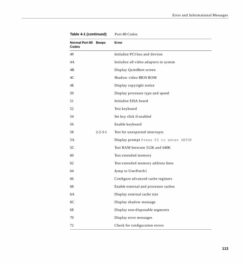
Error and Informational Messages
49 Initialize PCI bus and devices
4A Initialize all video adapters in system
4B Display QuietBoot screen
4C Shadow video BIOS ROM
4E Display copyright notice
50 Display processor type and speed
51 Initialize EISA board
52 Test keyboard
54 Set key click if enabled
56 Enable keyboard
58 2-2-3-1 Test for unexpected interrupts
5A Display prompt Press F2 to enter SETUP
5C Test RAM between 512K and 640K
60 Test extended memory
62 Test extended memory address lines
64 Jump to UserPatch1
66 Configure advanced cache registers
68 Enable external and processor caches
6A Display external cache size
6C Display shadow message
6E Display non-disposable segments
70 Display error messages
72 Check for configuration errors
Table 4-1 (continued) Port-80 Codes
Normal Port 80Codes
Beeps Error
113
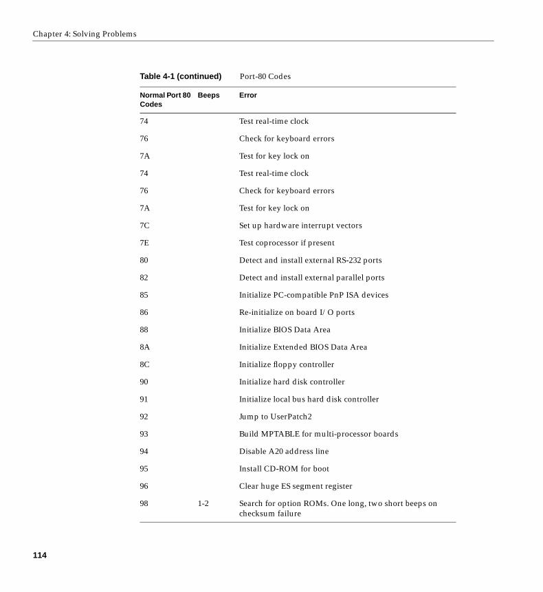
Chapter 4: Solving Problems
74 Test real-time clock
76 Check for keyboard errors
7A Test for key lock on
74 Test real-time clock
76 Check for keyboard errors
7A Test for key lock on
7C Set up hardware interrupt vectors
7E Test coprocessor if present
80 Detect and install external RS-232 ports
82 Detect and install external parallel ports
85 Initialize PC-compatible PnP ISA devices
86 Re-initialize on board I/O ports
88 Initialize BIOS Data Area
8A Initialize Extended BIOS Data Area
8C Initialize floppy controller
90 Initialize hard disk controller
91 Initialize local bus hard disk controller
92 Jump to UserPatch2
93 Build MPTABLE for multi-processor boards
94 Disable A20 address line
95 Install CD-ROM for boot
96 Clear huge ES segment register
98 1-2 Search for option ROMs. One long, two short beeps onchecksum failure
Table 4-1 (continued) Port-80 Codes
Normal Port 80Codes
Beeps Error
114
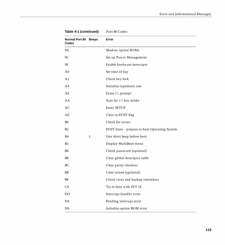
Error and Informational Messages
9A Shadow option ROMs
9C Set up Power Management
9E Enable hardware interrupts
A0 Set time of day
A2 Check key lock
A4 Initialize typematic rate
A8 Erase F2 prompt
AA Scan for F2 key stroke
AC Enter SETUP
AE Clear in-POST flag
B0 Check for errors
B2 POST done – prepare to boot Operating System
B4 1 One short beep before boot
B5 Display MultiBoot menu
B6 Check password (optional)
B8 Clear global descriptor table
BC Clear parity checkers
BE Clear screen (optional)
BF Check virus and backup reminders
C0 Try to boot with INT 19
DO Interrupt handler error
D4 Pending interrupt error
D6 Initialize option ROM error
Table 4-1 (continued) Port-80 Codes
Normal Port 80Codes
Beeps Error
115
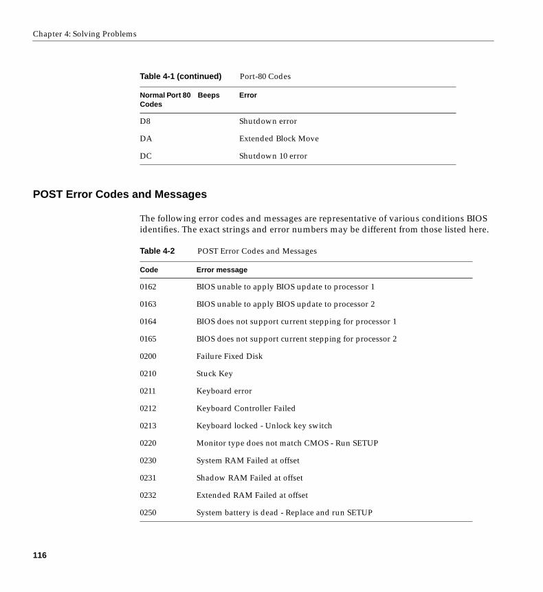
Chapter 4: Solving Problems
POST Error Codes and Messages
The following error codes and messages are representative of various conditions BIOSidentifies. The exact strings and error numbers may be different from those listed here.
D8 Shutdown error
DA Extended Block Move
DC Shutdown 10 error
Table 4-2 POST Error Codes and Messages
Code Error message
0162 BIOS unable to apply BIOS update to processor 1
0163 BIOS unable to apply BIOS update to processor 2
0164 BIOS does not support current stepping for processor 1
0165 BIOS does not support current stepping for processor 2
0200 Failure Fixed Disk
0210 Stuck Key
0211 Keyboard error
0212 Keyboard Controller Failed
0213 Keyboard locked - Unlock key switch
0220 Monitor type does not match CMOS - Run SETUP
0230 System RAM Failed at offset
0231 Shadow RAM Failed at offset
0232 Extended RAM Failed at offset
0250 System battery is dead - Replace and run SETUP
Table 4-1 (continued) Port-80 Codes
Normal Port 80Codes
Beeps Error
116

POST Error Codes and Messages
0251 System CMOS checksum bad - Default configuration used
0260 System timer error
0270 Real-time clock error
0297 ECC Memory error in base (extended) memory test in Bank xx
02B2 Incorrect Drive A type - run SETUP
02B3 Incorrect Drive B type - run SETUP
02D0 System cache error - Cache disabled
02F5 DMA Test Failed
02F6 Software NMI Failed
0401 Invalid System Configuration Data - run configuration utility
None System Configuration Data Read Error
0403 Resource Conflict
0404 Resource Conflict
0405 Expansion ROM not initialized
0406 Warning: IRQ not configured
0504 Resource Conflict
0505 Expansion ROM not initialized
0506 Warning: IRQ not configured
0601 Device configuration changed
0602 Configuration error - device disabled
8100 Processor 1 failed BIST
8101 Processor 2 failed BIST
8104 Processor 1 Internal Error (IERR) failure
8105 Processor 2 Internal Error (IERR) failure
Table 4-2 (continued) POST Error Codes and Messages
Code Error message
117
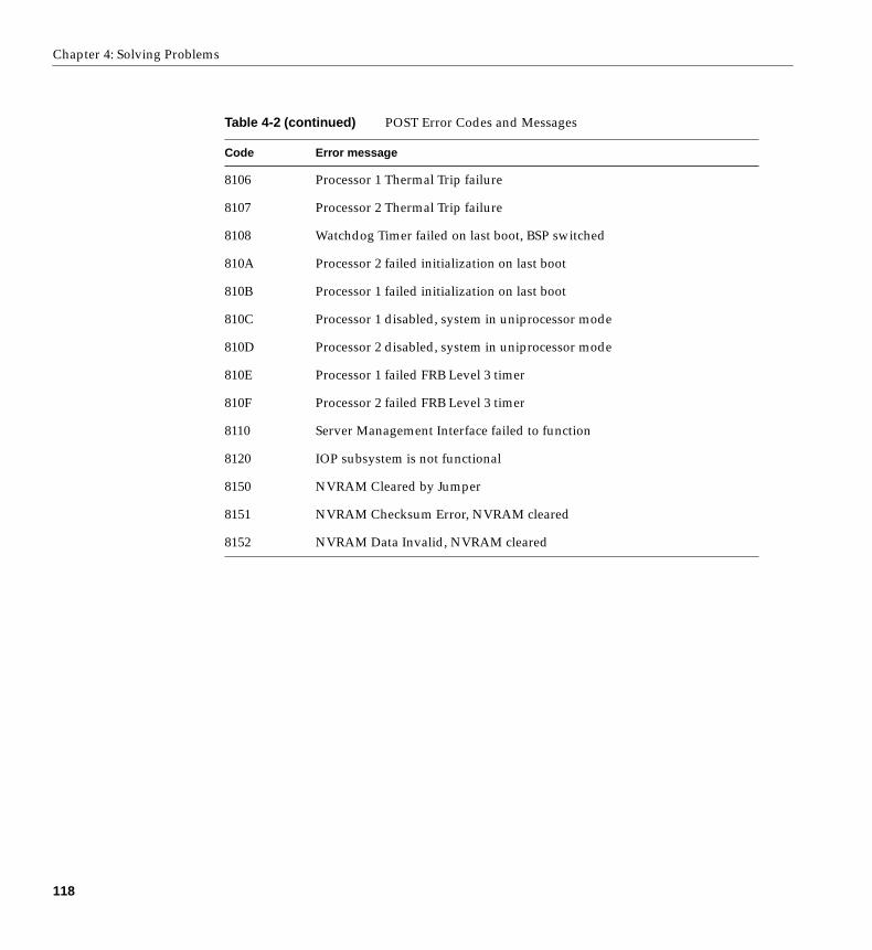
Chapter 4: Solving Problems
8106 Processor 1 Thermal Trip failure
8107 Processor 2 Thermal Trip failure
8108 Watchdog Timer failed on last boot, BSP switched
810A Processor 2 failed initialization on last boot
810B Processor 1 failed initialization on last boot
810C Processor 1 disabled, system in uniprocessor mode
810D Processor 2 disabled, system in uniprocessor mode
810E Processor 1 failed FRB Level 3 timer
810F Processor 2 failed FRB Level 3 timer
8110 Server Management Interface failed to function
8120 IOP subsystem is not functional
8150 NVRAM Cleared by Jumper
8151 NVRAM Checksum Error, NVRAM cleared
8152 NVRAM Data Invalid, NVRAM cleared
Table 4-2 (continued) POST Error Codes and Messages
Code Error message
118

Chapter 5
5. Installing or Replacing Drives and Power Supplies
SCSI Hard Disk Drives
The system supports a variety of low-voltage differential (LVD) and single-ended SCSIdevices. As shipped from the factory, the system might contain only a single hard diskdrive (sometimes called the “system disk”). Contact your sales or service representativefor a list of optional approved SCSI devices.
Caution: Electrostatic discharge (ESD): ESD can damage disk drives, add-in boards,and other components. The server can withstand normal levels of environmental ESDwhile you are hot-swapping SCSI hard disk drives. However, we recommend doing allprocedures in this manual only at an ESD-protected workstation. If one is not available,you can provide some ESD protection by wearing an antistatic wrist strap attached tochassis ground of the server—any unpainted metal surface—when handlingcomponents.
Mounting a SCSI Hard Disk Drive in a Carrier
The SGI 1400 servers use an integrated drive sled and heatsink assembly for installinghard disks into the server. If you plan to use SCSI drives whose power exceeds 15 watts,you must have heatsinks on those drives.
1. Remove the 3.5-inch hard drive from its wrapper and place it on an antistaticsurface.
2. Record the drive model and serial number in your equipment log.
119
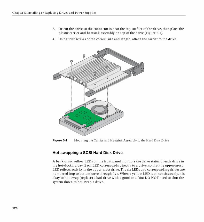
Chapter 5: Installing or Replacing Drives and Power Supplies
3. Orient the drive so the connector is near the top surface of the drive, then place theplastic carrier and heatsink assembly on top of the drive (Figure 5-1).
4. Using four screws of the correct size and length, attach the carrier to the drive.
Figure 5-1 Mounting the Carrier and Heatsink Assembly to the Hard Disk Drive
Hot-swapping a SCSI Hard Disk Drive
A bank of six yellow LEDs on the front panel monitors the drive status of each drive inthe hot-docking bay. Each LED corresponds directly to a drive, so that the upper-mostLED reflects activity in the upper-most drive. The six LEDs and corresponding drives arenumbered (top to bottom) zero through five. When a yellow LED is on continuously, it isokay to hot-swap (replace) a bad drive with a good one. You DO NOT need to shut thesystem down to hot-swap a drive.
120
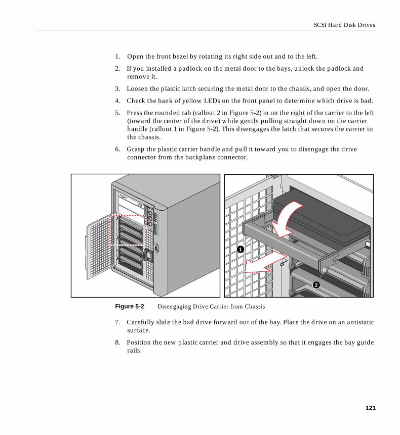
SCSI Hard Disk Drives
1. Open the front bezel by rotating its right side out and to the left.
2. If you installed a padlock on the metal door to the bays, unlock the padlock andremove it.
3. Loosen the plastic latch securing the metal door to the chassis, and open the door.
4. Check the bank of yellow LEDs on the front panel to determine which drive is bad.
5. Press the rounded tab (callout 2 in Figure 5-2) in on the right of the carrier to the left(toward the center of the drive) while gently pulling straight down on the carrierhandle (callout 1 in Figure 5-2). This disengages the latch that secures the carrier tothe chassis.
6. Grasp the plastic carrier handle and pull it toward you to disengage the driveconnector from the backplane connector.
Figure 5-2 Disengaging Drive Carrier from Chassis
7. Carefully slide the bad drive forward out of the bay. Place the drive on an antistaticsurface.
8. Position the new plastic carrier and drive assembly so that it engages the bay guiderails.
1
2
121
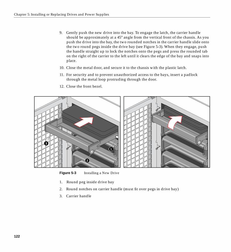
Chapter 5: Installing or Replacing Drives and Power Supplies
9. Gently push the new drive into the bay. To engage the latch, the carrier handleshould be approximately at a 45° angle from the vertical front of the chassis. As youpush the drive into the bay, the two rounded notches in the carrier handle slide ontothe two round pegs inside the drive bay (see Figure 5-3). When they engage, pushthe handle straight up to lock the notches onto the pegs and press the rounded tabon the right of the carrier to the left until it clears the edge of the bay and snaps intoplace.
10. Close the metal door, and secure it to the chassis with the plastic latch.
11. For security and to prevent unauthorized access to the bays, insert a padlockthrough the metal loop protruding through the door.
12. Close the front bezel.
Figure 5-3 Installing a New Drive
1. Round peg inside drive bay
2. Round notches on carrier handle (must fit over pegs in drive bay)
3. Carrier handle
3
1
2
122

Removing or Installing a Power Supply
Removing or Installing a Power Supply
The SGI 1400 server comes standard with three power supplies. All three should beplugged in to provide your system with high availability. If one power supply fails, theserver will continue to run uninterrupted. The SGI 1400 server also comes with a powershare board (PSB). The PSB supports one to three supplies. Never replace the powershare board with a power distribution board (which is intended to work in systems usingone power supply only). Power share boards should only be replaced by trainedinstallers. Information on replacing PSBs is included in the SGI 1400 Server FamilyMaintenance and Upgrades Guide.
Caution: Hazardous voltage, current, and energy levels are present inside the powersupply. There are no user-serviceable parts inside it; servicing should be done bytechnically qualified personnel only.
Removing a Power Supply
1. Disconnect the AC power cable from the system.
2. Remove the four screws holding the power supply to the back of the chassis.
3. Using the flared, vertical edges as handles, slide the supply straight back from itsbay (Figure 5-4 shows an example).
Caution: You might feel initial resistance in sliding the power supply from its bay. Donot tilt or twist the supply; this can damage components. Resistance is caused by thesupply disengaging from its 40-pin connector. Use even, steady force to remove thesupply.
123
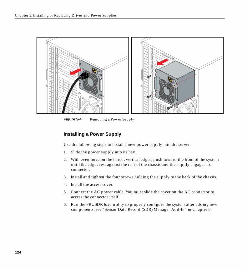
Chapter 5: Installing or Replacing Drives and Power Supplies
Figure 5-4 Removing a Power Supply
Installing a Power Supply
Use the following steps to install a new power supply into the server.
1. Slide the power supply into its bay.
2. With even force on the flared, vertical edges, push toward the front of the systemuntil the edges rest against the rear of the chassis and the supply engages itsconnector.
3. Install and tighten the four screws holding the supply to the back of the chassis.
4. Install the access cover.
5. Connect the AC power cable. You must slide the cover on the AC connector toaccess the connector itself.
6. Run the FRUSDR load utility to properly configure the system after adding newcomponents, see “Sensor Data Record (SDR) Manager Add-In” in Chapter 3.
124

Appendix A
A. Environmental and Regulatory Specifications
Environmental and Regulatory Specifications
The following sections and tables present information that may be important to theoperation of your SGI 1400 server. Table A-1 provides environmental specifications.
Table A-1 Environmental Specifications
Temperature
NonoperatingOperating
–40 ˚C to 70 ˚C (–55 ˚F to 150 ˚F)10 ˚C to 35 ˚C (41 ˚F to 95 ˚F); derated 0.5 ˚C for every 1000 ft (305 m)Altitude to 10,000 ft max; maximum rate of change = 10 ˚C per hour
Humidity
NonoperatingOperating wet bulb
95% relative humidity (noncondensing) at 30 ˚C (86 ˚F)Not to exceed 33 ˚C (91.4 ˚F) (with diskette drive or hard disk drive)
Shock
OperatingPackaged
2.0 g, 11 msec, 1/2 sineOperational after 30-inch (76.2 cm) free fall (cosmetic damage mightoccur)
Acoustic noise < 55 dBA with three power supplies at 28 ˚C +/- 2 ˚C
Electrostaticdischarge (ESD)
Tested to 20 kilovolts (kV) per Intel environmental test specifications; nocomponent damage
AC Input Power
100-120 V∼200-240 V∼
100-120 V∼, 7.6 A, 50/60 Hz200-240 V∼, 3.8 A, 50/60 Hz
125
Appendix A: Environmental and Regulatory Specifications
Manufacturer’s Regulatory Declarations
The SGI 1400 server products conform to several national and internationalspecifications and European Directives listed on the “Manufacturer’s Declaration ofConformity.” The CE insignia displayed on each device is an indication of conformity tothe European requirements.
Caution: Each SGI 1400 server system has several governmental and third-partyapprovals, licenses, and permits. Do not modify this product in any way that is notexpressly approved by Silicon Graphics. If you do, you may lose these approvals andyour governmental agency authority to operate this device.
Server CMN Number
The CMN (model) number, for the SGI 1400 server is A021. This model number is alsoshown on the system label on the back of the unit.
Series Number
The series number is on the serial number label on the back of the SGI 1400 server.
You need to know the series number and CMN number for downloading theManufacturer’s Declaration of Conformity from the World Wide Web.
Manufacturer’s Declaration of Conformity
A “Manufacturer’s Declaration of Conformity” is available on the World Wide Web.Look on your system (regulatory) label on the rear of the system to determine your CMN(model) number, and on the serial number label to determine your series number. Youneed both to identify your Declaration of Conformity. To locate the information on theWorld Wide Web, enter the following in your Web browser location window:
http://www.sgi.com/compliance
126
Environmental and Regulatory Specifications
Upgrade Regulatory Label
If you received a regulatory label with an upgrade, place it on the back of the system nearthe Manufacturer’s Declaration of Conformity label.
Class A Compliance
This equipment complies with Part 15 of the FCC Rules. Operation is subject to thefollowing two conditions: (1) This device may not cause harmful interference, and (2) thisdevice must accept any interference received, including interference that may causeundesired operation.
Note: This equipment has been tested and found to comply with the limits for a Class Adigital device, pursuant to Part 15 of the FCC Rules. These limits are designed to providereasonable protection against harmful interference when the equipment is operated in acommercial environment. This equipment generates, uses, and can radiate radiofrequency energy and, if not installed and used in accordance with the instructionmanual, may cause harmful interference to radio communications. Operation of thisequipment in a residential area is likely to cause harmful interference in which case theuser will be required to correct the interference at his own expense.
If this equipment does cause harmful interference to radio or television reception, whichcan be determined by turning the equipment off and on, the user is encouraged to try tocorrect the interference by one or more of the following measures:
• Reorient or relocate the receiving antenna.
• Increase the separation between the equipment and receiver.
• Connect the equipment into an outlet on a circuit different from that to which thereceiver is connected.
• Consult the dealer or an experienced radio/TV technician for help.
Caution: The user is cautioned that changes or modifications to the equipment notexpressly approved by the party responsible for compliance could void the user’sauthority to operate the equipment.
127
Appendix A: Environmental and Regulatory Specifications
Electromagnetic Emissions
This device complies with the Class A limits of Part 15 of the FCC Rules. Operation issubject to the following two conditions:
• This device may not cause harmful interference.
• This device must accept any interference received, including interference that maycause undesired operation.
Also, this device complies with Class A electromagnetic emissions limits of C.I.S.P.R.Publication 22, Limits and Methods of Measurement of Radio InterferenceCharacteristics of Information Technology Equipment.
VCCI Notice (Japan Only)
NOM 024 Information (Mexico Only)
La información siguiente se proporciona en el dispositivo o en dispositivos descritos eneste documento, en cumplimiento con los requisitos de la Norma Ofical Mexicana (NOM024):
Exportador: Silicon Graphics, Inc.
Importador: Silicon Graphics, Inc.
Embarcar a: Av. Vasco de QuirogaNo. 3000Col. Santa FeC.P. 01210México, D.F. México
128

Environmental and Regulatory Specifications
Tensión alimentación:100/240 ~ VAC
Frecuencia: 50/60 Hz: Consumo de corriente: 7.6 A
Chinese Class A Regulatory Notice
Industry Canada Notice (Canada Only)
This Class A digital apparatus meets all requirements of the CanadianInterference-Causing Equipment Regulations.
Cet appareil numérique német pas de perturbations radioélectriques dépassant lesnormes applicables aux appareils numériques de Classe A préscrites dans le Règlementsur les interferences radioélectriques établi par le Ministère des Communications duCanada.
CE Notice
Marking by the “CE” symbol indicates compliance of the device to directives of theEuropean Community. A “Declaration of Conformity” in accordance with the standardshas been made and is available from Silicon Graphics upon request.
R
NRTL/C
geprufteSicherheitN47337
LISTEDITEE139761
TYPE: CABSIT
®
129
Appendix A: Environmental and Regulatory Specifications
Korean Class A Regulatory Notice
Shielded Cables
The SGI 1400 server system is FCC-compliant under test conditions that include the useof shielded cables between the server and its peripherals. Your server and anyperipherals you purchase from Silicon Graphics have shielded cables. Shielded cablesreduce the possibility of interference with radio, television, and other devices. If you useany cables that are not from Silicon Graphics, make sure they are shielded. Telephonecables do not need to be shielded.
Optional monitor cables supplied with your server system use additional filteringmolded into the cable jacket to reduce radio frequency interference. Always use the cablesupplied with your system. If your monitor cable becomes damaged, a replacement cableshould be obtained from Silicon Graphics.
Electrostatic Discharge
Silicon Graphics designs and tests its products to be immune to the effects of electrostaticdischarge (ESD). ESD is a source of electromagnetic interference and can cause problemsranging from data errors and lockups to permanent component damage.
It is important that while you are operating the server system you keep all the covers anddoors, including the plastics, in place. The shielded cables that came with the server andits peripherals should be installed correctly, with all thumbscrews fastened securely.
An ESD wrist strap may be included with some products, such as memory or PCIupgrades. The wrist strap is used when installing these upgrades to prevent the flow ofstatic electricity, and it should protect your system from ESD damage.
130
Appendix B
B. SGI 1400 Server Rackmount Installation
Safety Guidelines
Before you remove a server cover, observe these safety guidelines:
• Only technically qualified personnel should mount the server in a rack.
• Turn off all peripheral devices connected to the server.
• Turn off the server using the push-button on/off power switch on the front panel ofthe server, and unplug the AC power cord from each power supply or wall outlet.
• Label and disconnect all peripheral cables attached to the I/O panel on the back ofthe server.
Server Precautions
Warning: SERVER POWER ON/OFF: The push-button on/off power switch on the frontpanel of the server does not turn off the AC power. To remove AC power from theserver, you must unplug each AC power cord from each power supply or wall outlet.
HAZARDOUS CONDITIONS—POWER SUPPLY AND POWER SHARE BACKPLANE: Hazardousvoltage, current, and energy levels are present inside the power supply and the powershare backplane enclosures. There are no user-serviceable parts inside them; servicingshould only be done by technically qualified personnel.
HAZARDOUS CONDITIONS—DEVICES AND CABLES: Hazardous electrical conditions maybe present on power, telephone, and communication cables. Turn off the server anddisconnect telecommunications systems, networks, modems, and each power cordattached to the server before opening it. Otherwise, personal injury or equipmentdamage can result.
131
Appendix B: SGI 1400 Server Rackmount Installation
SHOCK AND VIBRATION CONDITIONS: The server’s mounting rails do not providedampening and insulation from excess mechanical vibration and shock. If you areinstalling the server in a location that is subject to shock and vibration in excess of thevalues these units are rated to, you must obtain an appropriate mounting system.
Note: Although the hardware supplied with the server enables you to mount thesesystems in most all 19-inch equipment racks, installation in such racks may requiresubmittal to an approved safety agency for evaluation, certification, and licensing for thenew rack-system combination. Check with your local building inspector forrequirements applicable to your location.
Warning: AVOID INJURY: To avoid personal injury when unpacking the server, usetwo people and/ or a mechanical assist unit to lift it off the shipping pallet. Theminimum server configuration weighs 38 kg (85 lbs); the maximum weighs 45 kg (100lbs). Use only a hand-truck or other mechanical assist unit to move the server from onelocation to another.
Caution: ELECTROSTATIC DISCHARGE (ESD) AND ESD PROTECTION: ESD can damagedisk drives, add-in boards, and other components. This server can withstand normallevels of environmental ESD while hot-swapping SCSI hard disk drives. However, werecommend doing all procedures in this manual only at an ESD-protected workstation.If one is not available, you can provide some ESD protection by wearing an antistaticwrist strap attached to chassis ground of the server—any unpainted metal surface—when handling components.
SERVER COOLING AND AIRFLOW: Operating the server with the covers removed candamage the server components. For proper cooling and airflow, always replace thecovers before turning on the server.
132
Equipment Rack Precautions
Equipment Rack Precautions
Warning: ANCHOR THE EQUIPMENT RACK: The equipment rack must be anchored toan unmovable support to prevent it from falling over when one or more servers areextended in front of it on slide assemblies. The anchors must be able to withstand aforce of up to 113 kg (250 lbs). You must also consider the weight of any other deviceinstalled in the rack.
MAIN AC POWER DISCONNECT: You are responsible for installing an AC powerdisconnect for the entire rack unit. This main disconnect must be readily accessible,and it must be labeled as controlling power to the entire unit, not just to the server(s).
GROUNDING THE RACK INSTALLATION: To avoid the potential for an electrical shockhazard, you must include a third wire safety grounding conductor with the rackinstallation. If server power cords are plugged into AC outlets that are part of the rack,then you must provide proper grounding for the rack itself. If server power cords areplugged into wall AC outlets, the safety grounding conductor in each power cordprovides proper grounding only for the server. You must provide additional, propergrounding for the rack and other devices installed in it.
Warning: Overcurrent protection: The server is designed for an AC line voltagesource with up to 20 amperes of overcurrent protection. If the power system for theequipment rack is installed on a branch circuit with more than 20 amperes ofprotection, you must provide supplemental protection for the server. If more than oneserver is installed in the rack, the power source for each server must be from a separatebranch circuit. The overall current rating of a server configured with three powersupplies is under 12 amperes.
Caution: Temperature: The operating temperature of the server, when installed in anequipment rack, must not go below 5 ˚C (41 ˚F) or rise above 35 ˚C (95 ˚F). Extremefluctuations in temperature can cause a variety of problems in your server.
Ventilation: The equipment rack must provide sufficient airflow through the front of theserver to maintain proper cooling. It must also include ventilation sufficient to exhaust amaximum of 4,100 Btu’s per hour for the server. The rack selected and the ventilationprovided must be suitable to the environment in which the server will be used.
133
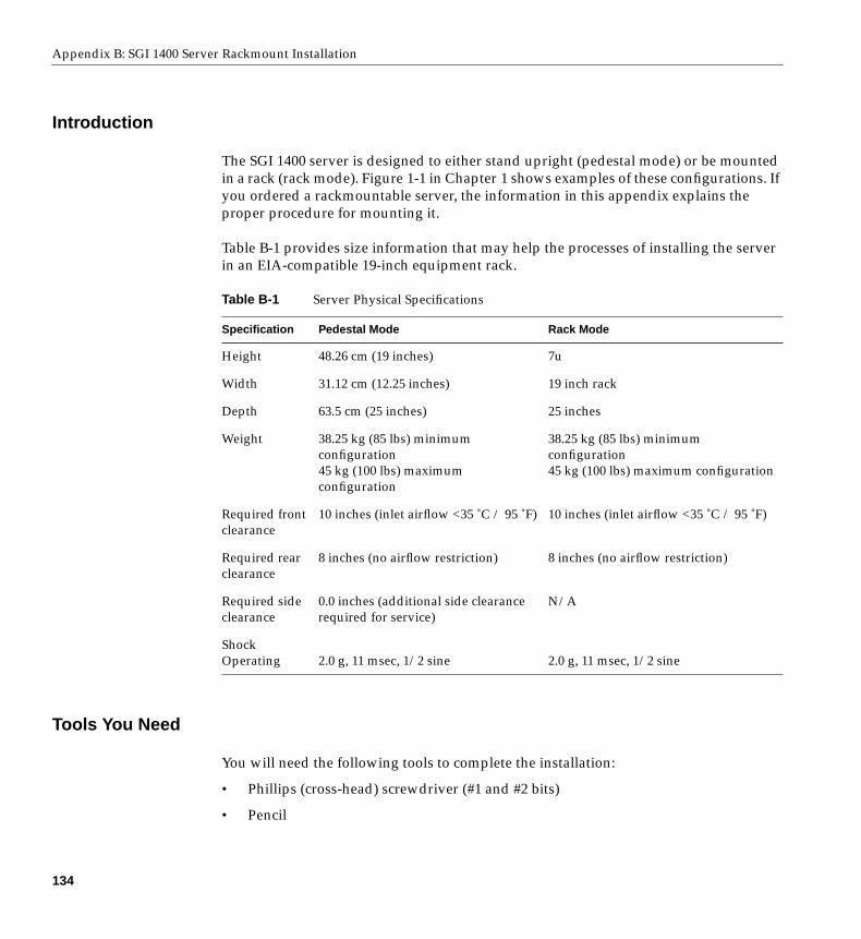
Appendix B: SGI 1400 Server Rackmount Installation
Introduction
The SGI 1400 server is designed to either stand upright (pedestal mode) or be mountedin a rack (rack mode). Figure 1-1 in Chapter 1 shows examples of these configurations. Ifyou ordered a rackmountable server, the information in this appendix explains theproper procedure for mounting it.
Table B-1 provides size information that may help the processes of installing the serverin an EIA-compatible 19-inch equipment rack.
Tools You Need
You will need the following tools to complete the installation:
• Phillips (cross-head) screwdriver (#1 and #2 bits)
• Pencil
Table B-1 Server Physical Specifications
Specification Pedestal Mode Rack Mode
Height 48.26 cm (19 inches) 7u
Width 31.12 cm (12.25 inches) 19 inch rack
Depth 63.5 cm (25 inches) 25 inches
Weight 38.25 kg (85 lbs) minimumconfiguration45 kg (100 lbs) maximumconfiguration
38.25 kg (85 lbs) minimumconfiguration45 kg (100 lbs) maximum configuration
Required frontclearance
10 inches (inlet airflow <35 ˚C / 95 ˚F) 10 inches (inlet airflow <35 ˚C / 95 ˚F)
Required rearclearance
8 inches (no airflow restriction) 8 inches (no airflow restriction)
Required sideclearance
0.0 inches (additional side clearancerequired for service)
N/A
ShockOperating 2.0 g, 11 msec, 1/2 sine 2.0 g, 11 msec, 1/2 sine
134
Prepare the Slide Assemblies
Prepare the Slide Assemblies
Use Figure B-1 and the following steps to prepare the rackmounting slide assemblies.
1. Remove the slide assemblies from the kit.
2. Orient a slide assembly so that the smallest outer bar is facing down.
3. Fully extend the telescoping slide assembly until the center bar hits the safety latchon the small outer bar (all three overlapping bars will be visible).
4. Grasp the small outer bar with your hand so that your thumb is on the safety latchof the small outer bar.
5. Press and hold the safety latch down, and at the same time, grasp the large outer barwith your free hand.
6. Pull the small bar out of the center bar; this takes a little force to separate them. Setthe small bar aside to attach to the chassis in a later step.
7. Orient the center bar and large outer bar assembly so that the center bar is facing up.
8. Grasp the center bar with one hand and the large outer bar with your other hand sothat your thumb is on the safety latch of the center bar.
9. Press the safety latch, and slide the bars together. Set the center bar and large outerbar assembly aside to attach to the equipment rack in a later step.
10. Prepare the other slide assembly by repeating steps 2–9 above.
135
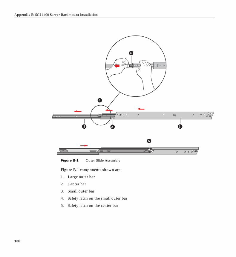
Appendix B: SGI 1400 Server Rackmount Installation
Figure B-1 Outer Slide Assembly
Figure B-1 components shown are:
1. Large outer bar
2. Center bar
3. Small outer bar
4. Safety latch on the small outer bar
5. Safety latch on the center bar
123
4
4
5
136

Prepare the Slide Assemblies
Prepare the Server
Before you can install the server in the 19-inch equipment rack, you must install a bezel,handles, and the small bars of the slide assemblies onto the sides of the server.
Attaching the Bezel Frame and Door
To be installed in a rack, the server needs a bezel frame with rectangular cutouts wherethe chassis handles fit.
1. Attach the bezel frame by inserting the tabs at the corner of the frame into theircorresponding rectangular slots on the chassis.
2. Attach the bezel door: with the door all the way open (down, as the server lay as itwould when inserted in a rack), align the tabs on the door with their correspondinghinge loops on the chassis; slide the door to the right to engage the tabs in the loops.
Attach the Chassis Handles
Before you can attach the chassis handles, the server must be on its side, in the horizontalposition in which you will slide it into the rack. If the server is not already in the properposition, you must move it. See step one, below.
Caution: The server is heavy (up to 45 kg [100 lbs]), be sure to read all the warnings atthe beginning of this appendix. Always use at least two people to mount the server in arack.
1. If the server is not already in the proper position, then face the front of the serverand, with the help of a mechanical assist unit, carefully tip it onto its side. The longfront edges (19 inches) should now be horizontal; the short front edges (12.25inches) should now be vertical, with the front-panel LEDs at the top left and thehard drive bays at the bottom right of the front panel.
The bezel frame has rectangular cutouts on its edges where the chassis handles fit;you should be able to see two threaded holes in that cut-out space where thehandles attach to the chassis.
2. Orient each handle so the two screw holes on the long edge of each handle alignwith the threaded holes in the chassis. Because the bezel frame’s cutouts act asguides, the handles can be installed in only one way.
3. Use four screws from the kit to attach the handles to the chassis.
137
Appendix B: SGI 1400 Server Rackmount Installation
Attach the Small Bar of the Slide Assembly to the Server
Use Figure B-2 and the following steps to properly attach the small bar of the slideassembly to the server chassis.
1. Remove four screws from the kit.
2. While facing the side of the server, orient the small bar so that the flat side faces thetop and the right-angle end faces the front of the server.
3. Align the first hole in the right-angle end of the bar with the first threaded hole inthe side of the chassis.
4. Insert a screw through the hole in the bar and into the chassis wall. Then looselytighten the screw.
5. Align the rest of the holes in the bar with the remaining three threaded holes alongthe side of the chassis.
6. Insert three more screws through the bar and into the threaded holes in the chassiswall. Then tighten all four screws firmly (6.0 inch-pounds).
7. To install the remaining small bar on the other side of the chassis, repeat steps 1–6.
138
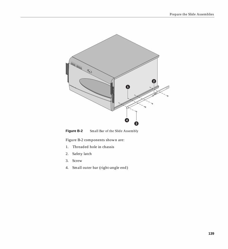
Prepare the Slide Assemblies
Figure B-2 Small Bar of the Slide Assembly
Figure B-2 components shown are:
1. Threaded hole in chassis
2. Safety latch
3. Screw
4. Small outer bar (right-angle end)
1
34
2
139
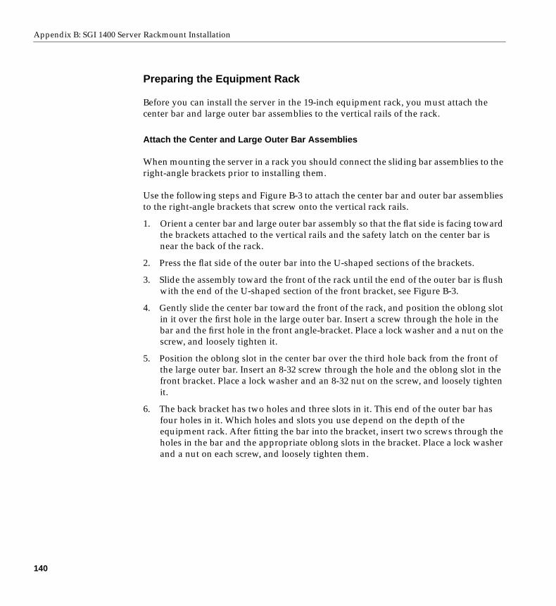
Appendix B: SGI 1400 Server Rackmount Installation
Preparing the Equipment Rack
Before you can install the server in the 19-inch equipment rack, you must attach thecenter bar and large outer bar assemblies to the vertical rails of the rack.
Attach the Center and Large Outer Bar Assemblies
When mounting the server in a rack you should connect the sliding bar assemblies to theright-angle brackets prior to installing them.
Use the following steps and Figure B-3 to attach the center bar and outer bar assembliesto the right-angle brackets that screw onto the vertical rack rails.
1. Orient a center bar and large outer bar assembly so that the flat side is facing towardthe brackets attached to the vertical rails and the safety latch on the center bar isnear the back of the rack.
2. Press the flat side of the outer bar into the U-shaped sections of the brackets.
3. Slide the assembly toward the front of the rack until the end of the outer bar is flushwith the end of the U-shaped section of the front bracket, see Figure B-3.
4. Gently slide the center bar toward the front of the rack, and position the oblong slotin it over the first hole in the large outer bar. Insert a screw through the hole in thebar and the first hole in the front angle-bracket. Place a lock washer and a nut on thescrew, and loosely tighten it.
5. Position the oblong slot in the center bar over the third hole back from the front ofthe large outer bar. Insert an 8-32 screw through the hole and the oblong slot in thefront bracket. Place a lock washer and an 8-32 nut on the screw, and loosely tightenit.
6. The back bracket has two holes and three slots in it. This end of the outer bar hasfour holes in it. Which holes and slots you use depend on the depth of theequipment rack. After fitting the bar into the bracket, insert two screws through theholes in the bar and the appropriate oblong slots in the bracket. Place a lock washerand a nut on each screw, and loosely tighten them.
140
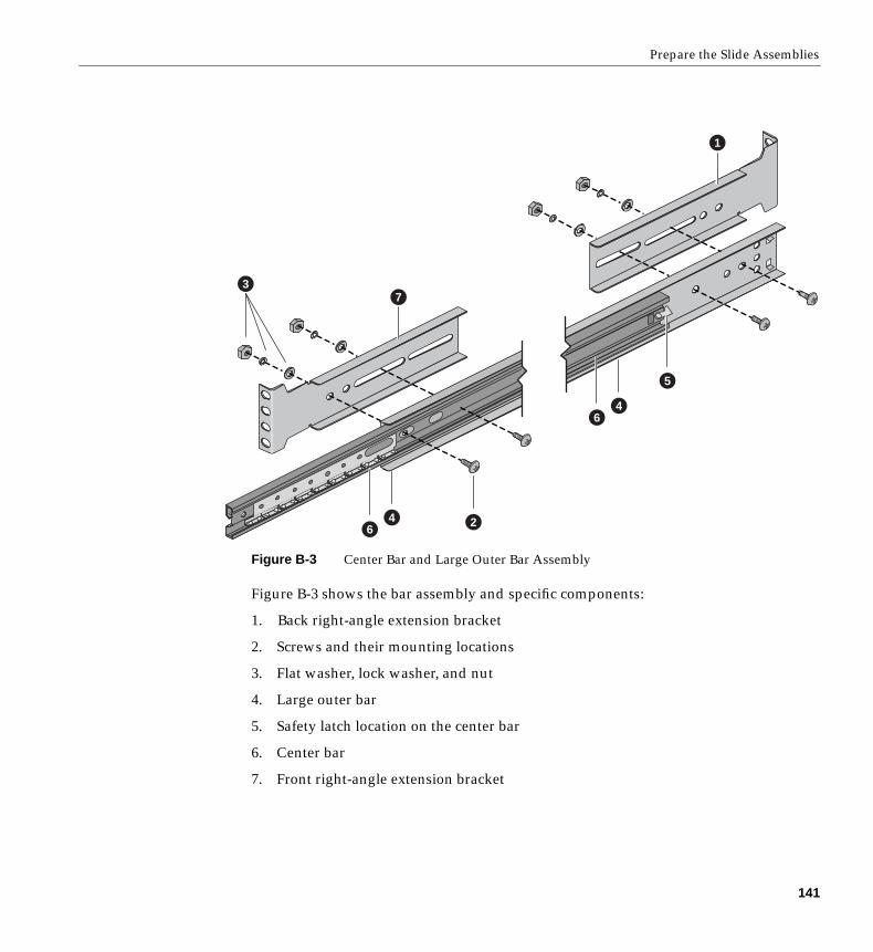
Prepare the Slide Assemblies
Figure B-3 Center Bar and Large Outer Bar Assembly
Figure B-3 shows the bar assembly and specific components:
1. Back right-angle extension bracket
2. Screws and their mounting locations
3. Flat washer, lock washer, and nut
4. Large outer bar
5. Safety latch location on the center bar
6. Center bar
7. Front right-angle extension bracket
1
2
3
4
5
6
46
7
141
Appendix B: SGI 1400 Server Rackmount Installation
Attach the Bracket and Rail Assemblies to the Equipment Rack
Note: Mounting holes in the vertical rails of equipment racks are commonly spaced in a5/8 x 5/8 x 1/2-inch sequence. Perform the following steps carefully; brackets must bemounted with precision to allow room for the next server you install in a rack. You maywant to mark the appropriate top and bottom holes with a pen or pencil.
1. Remove two screws, and a bar nut from the kit.
2. Select one of the right-angle bracket and rail assemblies that you put together usingthe information in “Attach the Center and Large Outer Bar Assemblies” onpage 140.
3. While facing the front or back of the rack, orient the right-angle extension bracketand rail assembly so that the short side with the four mounting holes is facingtoward the outside edge of the vertical rail.
4. Position the bracket behind the mounting holes in the vertical rail, see Figure B-4 foran example.
5. With a pencil, mark the top and bottom hole locations of the bracket on both sides ofthe vertical rail; no hole numbers are printed on the rail.
6. Insert a screw through the marked top hole in the rail and through the top hole inthe bracket. Place a bar nut on the screw and loosely tighten it. Repeat for themarked bottom hole.
7. Go to the rear of the system and make sure the bracket and slide-rail assembly is inhorizontal alignment with the front. Repeat the connection procedure from step 6.
8. Install the other right-angle extension brackets and slide rail assembly on the otherside by repeating steps 1–7.
9. Ensure that the brackets and bars are positioned correctly in the rack. Then tightenall bracket and rail screws firmly (6.0 inch-pounds).
142
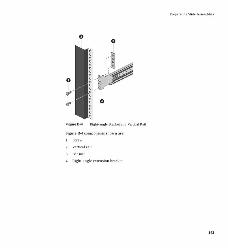
Prepare the Slide Assemblies
Figure B-4 Right-angle Bracket and Vertical Rail
Figure B-4 components shown are:
1. Screw
2. Vertical rail
3. Bar nut
4. Right-angle extension bracket
1
23
4
143
Appendix B: SGI 1400 Server Rackmount Installation
Install the Server in the Rack
Warning: ANCHOR THE EQUIPMENT RACK: The equipment rack must be anchored toan unmovable support to prevent it from falling over when one or more servers areextended in front of it on slide assemblies. The anchors must be able to withstand aforce of up to 113 kg (250 lbs). You must also consider the weight of any other deviceinstalled in the rack.
Use the following steps to install the server in the rack:
1. Pull the telescoping center bars out of the large outer bars until they are fullyextended and locked in place.
2. Use a mechanical assist unit to carefully pick up the server; gently slide the smallbars attached to each side of the server into the extended center bars.
3. When the server stops, press in on the safety latches on the small bars and gentlyslide the server into the rack.
4. Connect all external cables and the power cord(s) to the server.
144
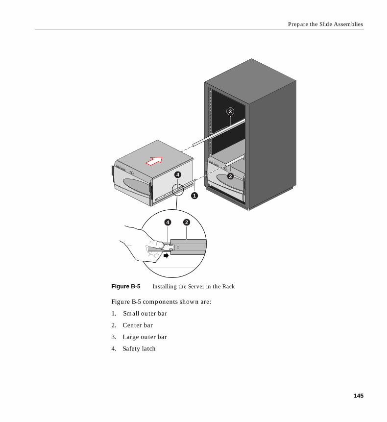
Prepare the Slide Assemblies
Figure B-5 Installing the Server in the Rack
Figure B-5 components shown are:
1. Small outer bar
2. Center bar
3. Large outer bar
4. Safety latch
1
2
3
4 2
4
145


Index
A
add-in, 3add-in board
ISA, 52ISA slot, 21PCI, 52PCI bus slots, 21
addressbase memory, 19extended memory, 19
administrative, 29administrative password, 26Advanced Chipset Control Submenu, configuring in
Setup, 45Advanced Menu, configuring in Setup, 41audible beep error codes, 33
B
baseboardcomponent locations, figure, 14form factor, 3, 14
base memory, 19beep codes, 33BIOS
changing the language, 96recovering, 95update utility, 31upgrading, 92
boot, 29bootable media
required by POST, 32booting cold, 99Boot menu, configuring, Setup, 49boot sequence
setting in Setup, 29bus termination requirements, SCSI devices, 23
C
cablesIDE bus length limit, 23
cautionESD protection, 119
CFG files, 53CMOS
clear to reconfigure diskette drive, 34configuration
limiting, 29configuring system
Setup, 31SSU, 31
controllerkeyboard/mouse, 24video, 14, 22
coolingfans, 3
coverempty board slots must be covered, 3
147
Index
D
DC outputs, 10diagnostics
preparing system for testing, 103using PCDiagnostics, 103
disk array, 9diskette
enabling/disabling floppy writes, 28no booting in secure mode without password, 28reconfiguring if cannot enter Setup, 34running SSU from, 31, 32
drivediskette, 3expansion, 3hard, 3internal, 9maximum, 9
E
Emergency Management PortConsole, 31, 69FRU viewer, 85main console window, 75phonebook, 81requirements, 73SDR viewer, 84SEL viewer, 82server control operations, 77
EMP, 69error
codes and messages, 116messages, 33, 110
ESD, 119, 125hot-swapping SCSI hard disk drives, 119
Exit menu, configuring, Setup, 51expanded video memory, 22
extended memory, 19external drive bays, 9
F
feature summaryboard, 13chassis side view, 7front controls and indicators, 4
Firmware Update Utility, 96Firmware update utility, 31front drive bay for removable media devices, 9FRUSDR Load Utility, 86FRUSDR load utility, 31
when to run, 86
H
hard disk drivehot-swapping, 120plastic carrier, 119SCSI, 119
Hard Drive submenuconfiguring, Setup, 50
I
IDEbus length limit, 23primary, master and slave, configuring, Setup, 39
input voltage, 10internal, 9intrusion detection, 26
148
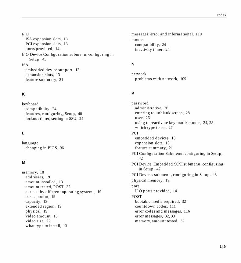
Index
I/OISA expansion slots, 13PCI expansion slots, 13ports provided, 14
I/O Device Configuration submenu, configuring inSetup, 43
ISAembedded device support, 13expansion slots, 13feature summary, 21
K
keyboardcompatibility, 24features, configuring, Setup, 40lockout timer, setting in SSU, 24
L
languagechanging in BIOS, 96
M
memory, 18addresses, 19amount installed, 13amount tested, POST, 32as used by different operating systems, 19base amount, 19capacity, 13extended region, 19physical, 19video amount, 13video size, 22what type to install, 13
messages, error and informational, 110mouse
compatibility, 24inactivity timer, 24
N
networkproblems with network, 109
P
passwordadministrative, 26entering to unblank screen, 28user, 26using to reactivate keyboard/mouse, 24, 28which type to set, 27
PCIembedded devices, 13expansion slots, 13feature summary, 21
PCI Configuration Submenu, configuring in Setup,42
PCI Device, Embedded SCSI submenu, configuringin Setup, 42
PCI Devices submenu, configuring in Setup, 43physical memory, 19port
I/O ports provided, 14POST
bootable media required, 32countdown codes, 111error codes and messages, 116error messages, 32, 33memory, amount tested, 32
149

Index
power on/offlocking on/off switch, Setup, 28
power supply400 watt, 3AC input, 125DC outputs, 10hazardous conditions, 123input voltage ranges, 10maximum watts, drives, 9
problemsafter running new application software, 101after system has been running correctly, 102application software, 110beep codes, 106bootable CD-ROM not detected, 110CD-ROM drive activity light, 109confirm OS loading, 104diskette drive light, 108hard drive light, 108initial system startup, 99network, 109no characters on screen, 106PCI installation tips, 109power light, 105preparing system for diagnostic testing, 103random error in data files, 102screen characters incorrect, 107system cooling fans do not rotate, 107system lights, 104using PCDiagnostics, 103
R
RAID, 9removable media bays
limiting use of hard drives, 9number of drives, 9
reset system, 32, 99
S
Safetycautions, 119
SCI files, 53SCSI
bus termination requirements, 23hard disk drive, 119
hot-swapping, 120plastic carrier, 119
LVD devices, 119singled-ended devices, 119Symbios SCSI utility, 97type of devices supported, 23
secure mode, 27affects boot sequence, 29enter by setting passwords, 28locking reset and power on/off switches, 28no booting from diskette without password, 28using hot keys to enter, 32
security, 26, 28alarm switches, 26boot sequence, 29enabling/disabling floppy writes, 28locking mouse, keyboard with timer, 24, 28locking reset and power on/off switches, Setup, 28password, 29secure mode, 28secure mode, setting in SSU, 27software lock, SSU, 26unattended, 29using hot key combination, 32video blanking, 28
Security menuconfiguring, Setup, 46
server managementfeatures, 24intrusion detection, 26
Server menu, configuring in Setup, 47
150
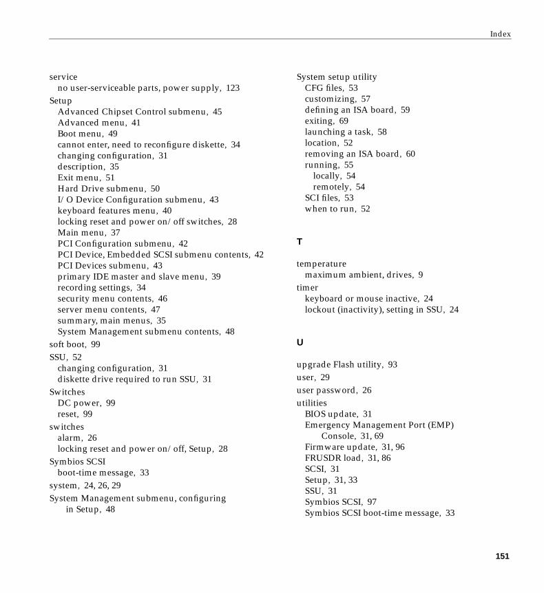
Index
serviceno user-serviceable parts, power supply, 123
SetupAdvanced Chipset Control submenu, 45Advanced menu, 41Boot menu, 49cannot enter, need to reconfigure diskette, 34changing configuration, 31description, 35Exit menu, 51Hard Drive submenu, 50I/O Device Configuration submenu, 43keyboard features menu, 40locking reset and power on/off switches, 28Main menu, 37PCI Configuration submenu, 42PCI Device, Embedded SCSI submenu contents, 42PCI Devices submenu, 43primary IDE master and slave menu, 39recording settings, 34security menu contents, 46server menu contents, 47summary, main menus, 35System Management submenu contents, 48
soft boot, 99SSU, 52
changing configuration, 31diskette drive required to run SSU, 31
SwitchesDC power, 99reset, 99
switchesalarm, 26locking reset and power on/off, Setup, 28
Symbios SCSIboot-time message, 33
system, 24, 26, 29System Management submenu, configuring
in Setup, 48
System setup utilityCFG files, 53customizing, 57defining an ISA board, 59exiting, 69launching a task, 58location, 52removing an ISA board, 60running, 55
locally, 54remotely, 54
SCI files, 53when to run, 52
T
temperaturemaximum ambient, drives, 9
timerkeyboard or mouse inactive, 24lockout (inactivity), setting in SSU, 24
U
upgrade Flash utility, 93user, 29user password, 26utilities
BIOS update, 31Emergency Management Port (EMP)
Console, 31, 69Firmware update, 31, 96FRUSDR load, 31, 86SCSI, 31Setup, 31, 33SSU, 31Symbios SCSI, 97Symbios SCSI boot-time message, 33
151

Index
V
videoblanking for security, 28controller, 22expansion, 22graphics controller, 14memory, 13resolutions supported, 22
video memory, 22
W
Warningno user-serviceable parts, power supply, 123
write to diskette, disabling, 28
152
Related Documents