SG 2 Table of Contents IN16-0501 Besserman 4-12-16 2 NB13-1701 Failed Ballot 2-1-16.pdf 3 NB13-1701 LB Comments 3-2-16 7 NB16-0901 Vallance 2-3-16 9 NB16-1001 AIA Comments 2-19-16 11 NB16-1601 NPGA Letter 4-15-16 16

Welcome message from author
This document is posted to help you gain knowledge. Please leave a comment to let me know what you think about it! Share it to your friends and learn new things together.
Transcript
SG 2 Table of ContentsIN16-0501 Besserman 4-12-16 2NB13-1701 Failed Ballot 2-1-16.pdf 3NB13-1701 LB Comments 3-2-16 7NB16-0901 Vallance 2-3-16 9NB16-1001 AIA Comments 2-19-16 11NB16-1601 NPGA Letter 4-15-16 16
ASME Tank Sales • LPG/NH3 Plant Design & Construction • ASME & DOT Certified • Transportation Services • Pre-cast Tank Piers
971 N. Jefferson Street, Kearney, MO 64060 • 816.903.1806 • Toll Free 888.739.8764 • www.lpgventures.com
1) Inquiry:
Can pressure vessels that were previously used in anhydrous ammonia service be converted to LPG service?
2) Reply: Yes. With proper testing and evaluation they can be converted to LPG service.
3) Background Information: We are seeking a formal interpretation of what appears to be conflicting standards as it relates to Change of Service of vessels larger than 3000 gallons that had been previously used in Anhydrous Ammonia service to LPG service. The conflict is as follows; Part 2, Supplement 7: S7.8.6- "Containers that have been previously used in anhydrous ammonia service shall not be converted to LPG service". Part 2, Supplement 9: Table S9.4- Examples of change of service conditions; Factors to consider when changing vessel from Ammonia to LP Gas. NFPA 58 5.2.1.5- ASME containers of 3000 gallons WC or less shall not be converted to LPG service. The one sentence in S7.8.6 appears to conflict with Table S9.4 Change of Service factors to consider and definitely conflicts with the governing installation code, NFPA 58. We are specifically seeking clarification as to whether or not a vessel larger than 3,000 gallons water capacity can be changed from Anhydrous Ammonia service to LPG Service.
Sincerely, Chris Heichel Quality Control Manager LPG Ventures, Inc. 816-903-1806 [email protected]
Attachment Page 2
Attachment Page 2
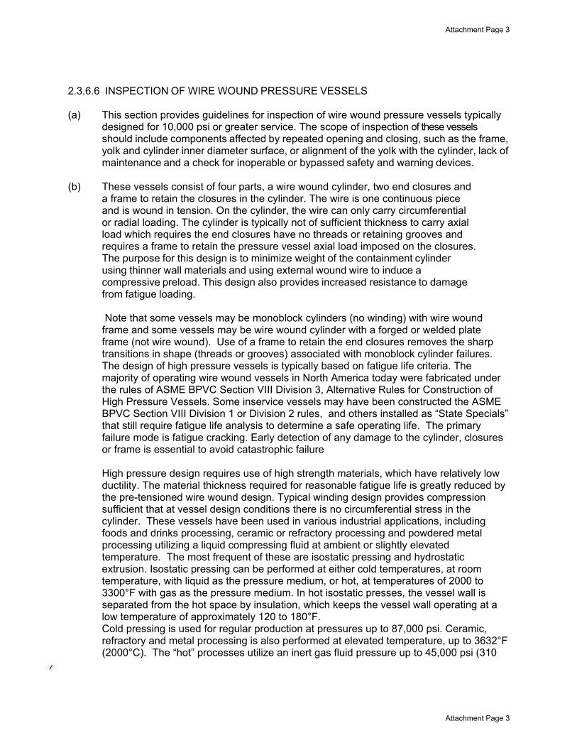
2.3.6.6 INSPECTION OF WIRE WOUND PRESSURE VESSELS (a) This section provides guidelines for inspection of wire wound pressure vessels typically
designed for 10,000 psi or greater service. The scope of inspection of these vessels should include components affected by repeated opening and closing, such as the frame, yolk and cylinder inner diameter surface, or alignment of the yolk with the cylinder, lack of maintenance and a check for inoperable or bypassed safety and warning devices.
(b) These vessels consist of four parts, a wire wound cylinder, two end closures and a frame to retain the closures in the cylinder. The wire is one continuous piece and is wound in tension. On the cylinder, the wire can only carry circumferential or radial loading. The cylinder is typically not of sufficient thickness to carry axial load which requires the end closures have no threads or retaining grooves and requires a frame to retain the pressure vessel axial load imposed on the closures. The purpose for this design is to minimize weight of the containment cylinder using thinner wall materials and using external wound wire to induce a compressive preload. This design also provides increased resistance to damage from fatigue loading. Note that some vessels may be monoblock cylinders (no winding) with wire wound frame and some vessels may be wire wound cylinder with a forged or welded plate frame (not wire wound). Use of a frame to retain the end closures removes the sharp transitions in shape (threads or grooves) associated with monoblock cylinder failures. The design of high pressure vessels is typically based on fatigue life criteria. The majority of operating wire wound vessels in North America today were fabricated under the rules of ASME BPVC Section VIII Division 3, Alternative Rules for Construction of High Pressure Vessels. Some inservice vessels may have been constructed the ASME BPVC Section VIII Division 1 or Division 2 rules, and others installed as “State Specials” that still require fatigue life analysis to determine a safe operating life. The primary failure mode is fatigue cracking. Early detection of any damage to the cylinder, closures or frame is essential to avoid catastrophic failure
High pressure design requires use of high strength materials, which have relatively low ductility. The material thickness required for reasonable fatigue life is greatly reduced by the pre-tensioned wire wound design. Typical winding design provides compression sufficient that at vessel design conditions there is no circumferential stress in the cylinder. These vessels have been used in various industrial applications, including foods and drinks processing, ceramic or refractory processing and powdered metal processing utilizing a liquid compressing fluid at ambient or slightly elevated temperature. The most frequent of these are isostatic pressing and hydrostatic extrusion. Isostatic pressing can be performed at either cold temperatures, at room temperature, with liquid as the pressure medium, or hot, at temperatures of 2000 to 3300°F with gas as the pressure medium. In hot isostatic presses, the vessel wall is separated from the hot space by insulation, which keeps the vessel wall operating at a low temperature of approximately 120 to 180°F. Cold pressing is used for regular production at pressures up to 87,000 psi. Ceramic, refractory and metal processing is also performed at elevated temperature, up to 3632°F (2000°C). The “hot” processes utilize an inert gas fluid pressure up to 45,000 psi (310
Attachment Page 3
Attachment Page 3
GM2
Text Box
Isostatic pressing can be performed at temperatures at or less than ambient with liquid as the pressure medium. When temperatures are between 2000F and 3300F, gas is used as the pressure medium.
GM2
Line
GM2
Line
GM2
Line
GM2
Line
MPa). Continuous cooling is necessary for the hot process and may contribute to corrosion damage of the cylinder of closures. Hydrostatic extrusion is generally performed either cold, at room temperature, or warm, at temperatures up to 1110°F, in both cases with liquid as the pressure medium. Hydrostatic extrusion is used for regular production at pressures up to 200,000 psi. Both cold and hot processes are commonly found in research facilities and in universities.
(c) Record keeping (1) Since these vessels have a finite fatigue life, it is essential a record be maintained of each operating cycle, recording both temperature and pressure. Deviation beyond design limits is cause for suspending operation and reevaluation of remaining fatigue life. Vessels having no operating record should be inspected and a fracture mechanics evaluation with a fatigue analysis test be performed to establish remaining life before resuming operation. (2) Operating data should be recorded and include the following whenever the vessel is operating:
a. Number of cycles b. Maximum pressure c. Maximum temperature
(d) Any unusual conditions (d) Any damage to the cylinder or closures can lead to premature failure. Frequent visual inspection should be made of internal and external surfaces of the cylinder, frame and closures. A thorough examination should be completed if any visually apparent damage is identified or if any excursion beyond design temperature or pressure occurs. In addition, surfaces of the cylinder and closures should be examined by dye penetrant or magnetic particle method at intervals based on vessel remaining life. Closures may require ultrasonic examination of passageways. Following is an example of what the results of such a study might reveal as allowable cycles for a particular wire wound vessel:
Columns > 106 Cycles “Columns” are beams on either side of frame, between the yokes.
Yokes > 106 Cycles “Yokes” are the circular ends of the frame. Wires of frames > 106Cycles “Wires” place frame in compression
Cylinder 100 X 103 cycles
Wires of Cylinder 60 X 103 cycles “Wires” place cylinder in compression.
Closures 30 X 103 cycles All connections to the vessel are through the closures. These passageways create stress raisers, as do grooves for sealing system.
The vessel design life in this example is thus limited by the closure. The calculated design life is 30,000 cycles at design pressure and temperature.
Attachment Page 4
Attachment Page 4
GM2
Text Box
Hydrostatic extrusion is generally performed at temperatures at or less than ambient to 1100F, with liquid as the pressure medium.
GM2
Line
GM2
Line
GM2
Line
GM2
Line
GM2
Text Box
d. any unusual conditions e. Duration of the cycle f. Date & time of cycle start
GM2
Text Box
add:
GM2
Line
An acceptable factor of safety for vessel fatigue inspection interval varies between 0.25 and 0.5 of the remaining design life. The inspection interval for the above example is therefore 10,000 to 20,000 cycles, but should not exceed five years. In addition to scope of frequent inspection, the fatigue inspection should include measurement of the cylinder inside diameter and frame inside length to detect reduced tension in the wire windings. Note that monoblock cylinders and plate frames require additional inspection due to differing construction. If a crack or flaw is detected during any inspection, an immediate evaluation, repair and study of impact on remaining fatigue life should be completed by a National Board authorized repair agency. Using the results of this study, and application of safety factor 0.25 (due to known damage), the number of cycles of operation to the next fatigue inspection is established. As part of the frequent inspection, the following items should be reviewed:
(1) Verify no change in the process, such as the processing fluid, that might adversely
impact vessel integrity. (2) Review the vessel manufacturer’s inspection recommendations for vessel, closures
and frame. If manufacturer’s recommendations are not available, obtain recommendations from a recognized wire wound vessel service provider.
(3) Verify any repair to pressure retaining items has been completed by National
Board authorized service provider having wire wound vessel expertise. (4) Verify overpressure protection with appropriate set pressure and capacity is
provided. Rupture discs are commonly used for pressures exceeding 14,500 psi (100 MPa) to avoid valve seat leakage. Overpressure protection devices are frequently replaced to avoid premature operation.
(e) Additional Inspection Criteria
(1) If there are no manufacturer’s recommendations available for the vessel, the following are additional recommended inspections that should be conducted to ensure vessel integrity and safety a. Conduct annual visual and dimensional vessel inspections with liquid
penetrant examination of maximum stressed areas to ensure that the surfaces are free of defects. Conduct ultrasonic examination of the vessel after every 25% of the design cycle life or every five years, whichever comes first, to detect subsurface cracks. Special attention Should be given to the roots of threads and closures using threaded head retention construction. Other geometric discontinuities that are inherent in the design or irregularities resulting from localized corrosion, erosion, or mechanical damage should be carefully examined. This is particularly important for units of monoblock construction.
Attachment Page 5
Attachment Page 5
GM2
Line
GM2
Text Box
7,500 to 15,000
b. The closure mechanism of the vessel end-closure is opened and closed frequently during operation. It should be closely inspected for freedom of movement and proper contact with its locking elements. Wire wound vessels must have yoke-type closures so the yoke frame will need to be closely inspected on a regular basis
c. Should pitting, cracks, corrosion, or other defects are found during scheduled
inspection; verify that an evaluation using fracture mechanics techniques is performed. This is to determine MAWP, cyclic life and extent of NDE frequency based on crack growth rate.
(2) Gages, Safety Devices, and Controls
a. Verify that the vessel is provided control and monitoring of the pressure, temperature, electrical system, fluid flow, liquid levels, and all variables that are essential for the safe operation of the system. If the vessel is automatically controlled, manual override should be available. Also, safety interlocks should be provided on the vessel closure to prevent vessel pressurization if the vessel closure is not complete and locked.
b. Verify that all safety device isolation valves are locked open if used.
c. Verify appropriate pressure relief device is installed with relief setpoint at low a
pressure as possible, consistent with the normal operating pressure but in no case higher than the design operating pressure of the vessel. Rupture discs are normally considered more suitable for these types of applications since pressure relief devices operating at pressures above 14500 psi may tend to leak by their seat.
d. Verify that pressure and temperature of the vessel coolant and vessel wall is
controlled and monitored. Interlock devices associated with these monitoring devices that will deenergize or depressurize the vessel are strongly recommended due to the potential significant damage that can be caused by release of energy in the event of overpressurization due to excess pressure or temperature in the vessel.
e. Verify audible and visual alarms are installed to indicate unsafe conditions.
Attachment Page 6
Attachment Page 6
GM2
Text Box
If pitting, cracks, corrosion or other defects are found during an inspection, an evaluation using fracture mechanics techniques shall be performed.
GM2
Line
GM2
Line
GM2
Line
GM2
Line
GM2
Text Box
the lowest pressure possible,
GM2
Line
GM2
Line
GM2
Line
GM2
Text Box
spring loaded
GM2
Line
GM2
Text Box
and operable
GM2
Line
GM2
Text Box
Comment: Metric SI conversion factors to be used throughout this document. (Administrative)
Attachment Page 7
Attachment Page 7
Attachment Page 8
Attachment Page 8
Action Item Request Form
NB16‐0901
Existing Text:
b) Statement of Need
Provide a brief explanation of the need for the revision or addition.
c) Background Information
Provide background information to support the revision or addition, including any data or changes in
technology that form the basis for the request that will allow the Committee to adequately evaluate the
proposed revision or addition. Sketches, tables, figures, and graphs should be submitted as appropriate.
When applicable, identify any pertinent paragraph in the Code that would be affected by the revision or
addition and identify paragraphs in the Code that reference the paragraphs that are to be revised or
added.
2015 NBIC Part 2
PART 2, SECTION 3 INSPECTION — CORROSION AND FAILURE MECHANISMS 3.1 SCOPE This section describes damage mechanisms applicable to pressure-retaining items. Further information concerning metallurgical properties of steels and nonferrous alloys are described in ASME Section II, Part D, of the Boiler and Pressure Vessel Code, Non Mandatory Appendix A, titled Metallurgical Phenomena.
The title of 2015 ASME Code Section II, Part D Non Mandatory Appendix A is now,
ISSUES ASSOCIATED WITH MATERIALS USED IN ASME CODE CONSTRUCTION
Attachment Page 9
Attachment Page 9
Affected paragraph 2015 NBIC Part 2
PART 2, SECTION 3 INSPECTION — CORROSION AND FAILURE MECHANISMS 3.1 SCOPE
Attachment Page 10
Attachment Page 10
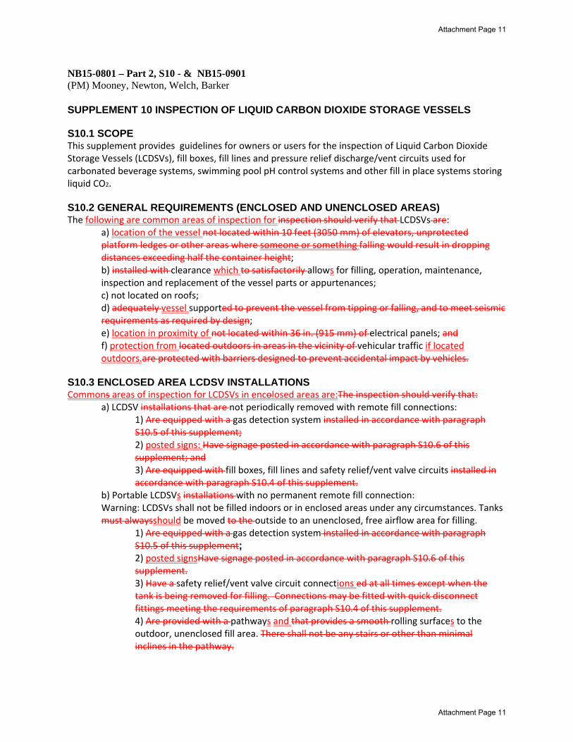
NB15-0801 – Part 2, S10 - & NB15-0901 (PM) Mooney, Newton, Welch, Barker SUPPLEMENT 10 INSPECTION OF LIQUID CARBON DIOXIDE STORAGE VESSELS S10.1 SCOPE This supplement provides guidelines for owners or users for the inspection of Liquid Carbon Dioxide Storage Vessels (LCDSVs), fill boxes, fill lines and pressure relief discharge/vent circuits used for carbonated beverage systems, swimming pool pH control systems and other fill in place systems storing liquid CO2. S10.2 GENERAL REQUIREMENTS (ENCLOSED AND UNENCLOSED AREAS) The following are common areas of inspection for inspection should verify that LCDSVs are:
a) location of the vessel not located within 10 feet (3050 mm) of elevators, unprotected platform ledges or other areas where someone or something falling would result in dropping distances exceeding half the container height; b) installed with clearance which to satisfactorily allows for filling, operation, maintenance, inspection and replacement of the vessel parts or appurtenances; c) not located on roofs; d) adequately vessel supported to prevent the vessel from tipping or falling, and to meet seismic requirements as required by design; e) location in proximity of not located within 36 in. (915 mm) of electrical panels; and f) protection from located outdoors in areas in the vicinity of vehicular traffic if located outdoors.are protected with barriers designed to prevent accidental impact by vehicles.
S10.3 ENCLOSED AREA LCDSV INSTALLATIONS Commons areas of inspection for LCDSVs in encolosed areas are:The inspection should verify that:
a) LCDSV installations that are not periodically removed with remote fill connections: 1) Are equipped with a gas detection system installed in accordance with paragraph S10.5 of this supplement; 2) posted signs: Have signage posted in accordance with paragraph S10.6 of this supplement; and 3) Are equipped with fill boxes, fill lines and safety relief/vent valve circuits installed in accordance with paragraph S10.4 of this supplement.
b) Portable LCDSVs installations with no permanent remote fill connection: Warning: LCDSVs shall not be filled indoors or in enclosed areas under any circumstances. Tanks must alwaysshould be moved to the outside to an unenclosed, free airflow area for filling.
1) Are equipped with a gas detection system installed in accordance with paragraph S10.5 of this supplement; 2) posted signsHave signage posted in accordance with paragraph S10.6 of this supplement. 3) Have a safety relief/vent valve circuit connections ed at all times except when the tank is being removed for filling. Connections may be fitted with quick disconnect fittings meeting the requirements of paragraph S10.4 of this supplement. 4) Are provided with a pathways and that provides a smooth rolling surfaces to the outdoor, unenclosed fill area. There shall not be any stairs or other than minimal inclines in the pathway.
Attachment Page 11
Attachment Page 11
S10.4 FILL BOX LOCATION /SAFETY RELIEF/VENT VALVE CIRCUIT TERMINATION Common areas of inspection for fill boxes, safety relief or vent valve circuit terminations are locations for :
a) access and means of personnel egress. b) Aaccessibility for servicing and delivery of product The inspection should verify that fill boxes and/or vent valve terminations are installed above grade, outdoors in an unenclosed, free airflow area, and that the fill connection is located so not to impede means of egress or the operation of sidewalk cellar entrance doors, including during the delivery process and that they are:
a) At least three (3) feet (915 mm) from any door or operable windows;* b) At least three (3) feet (915 mm) above grade;* c) Not located within ten (10) feet (3050 mm) from side to side at the same level or below, from any air intakes;* d) Not located within ten (10) feet (3050 mm) from stair wells that go below grade.* * Note: Many systems installed prior to 1/1/2014 do not meet the above requirements and the local Jurisdiction should be consulted for guidance.
S10.5 GAS DETECTION SYSTEMS Rooms or areas where carbon dioxide storage vessel(s) are located indoors or in enclosed or below grade outdoor locations should have shall be provided with a gas detection and alarm system for general area monitoring that is capable of detecting and notifying building occupants of a CO2 gas release. LCSVDs are typically installed with Aalarms will be designed to activate a low level pre‐alarm at 1.5% concentration of CO2 and a full high alarm meeting at 3% concentration of CO2 which is the NIOSH & ACGIH 15 minute Short Term Exposure Limit for CO2. These systems are not designed for employee personal exposure monitoring. Common areas of inspection are: a) Gas detection systems shall be installation and testing ed and tested in accordance with manufactures installation instructions; and the following requirements:
b) a) The inspection should verify that the operation and testing of the gas detection system and audible alarm is operational and tested in accordance with manufacturer’s guidelines. b) placement of The inspection should verify that audible alarms are placed at the entrance(s) to the room or area where the carbon dioxide storage vessel and/ or fill box is located to notify anyone who might try to enter the area of a potential problem.
S10.6 SIGNAGE Common areas of inspection are: a) sign inspection location and content of warning signs; and b) signs with instructional informationThe inspection should verify that warning signs are posted at the entrance to the building, room, enclosure, or enclosed area where the container is located. The warning sign shall be at least 8 in (200mm) wide and 6 in. (150mm) high. The wording shall be concise and easy to read and the upper portion of the sign must be orange as shown in figure NBIC Part 2, Figure S10.6. The size of the lettering must be as large as possible for the intended viewing distance and in accordance with jurisdictional requirements. When no jurisdictional requirements exist, the minimum letter height shall be in accordance with NEMA American National Standard for Environmental and Facility Safety Signs (ANSI Z535.2). The warning signs shall be as shown in figure S10.6. Figure S10.6
Attachment Page 12
Attachment Page 12

Additional instructional signage shall be posted outside of the area where the container is located and such signage shall contain at minimum the following information:
a) Carbon dioxide monitors for general area monitoring (not employee personal exposure monitoring) are provided in this area. These monitors are set to alarm at 5,000 ppm(1.5% concentration) for the low level alarm and at 30,000 ppm (3% concentration) for high level alarm. b) Low Level Alarm (5,000 ppm) – Provide appropriate cross ventilation to the area. Personnel may enter area for short periods of time (not to exceed 15 minutes at a time) in order to identify and repair potential leaks. c) High Level Alarm (30,000 ppm) – Personnel should evacuate the area and nobody should enter the affected area without proper self‐contained breathing apparatus until the area is adequately ventilated and the concentration of CO2 is reduced below the high alarm limit.
S10.7 VALVES, PIPING, TUBING AND FITTINGS Common areas of inspection are: a) Materials – The inspection should verify that the materials selected for valves, piping, tubing, hoses and fittings used in the LCDSV system for meet following requirements: 1) Components shall be rated for the operational applicable temperatures and pressures encountered, in the applicable circuit of the system.
2) All valves and fittings used on the LCDSV shall be rated for the maximum allowable working pressure(MAWP) stamped on the tank. 3) All piping, hoses and tubing used in the LCDSV system shall be rated for the working pressure of the applicable circuit in the system and have a burst pressure rating of at least four times the MAWP of the piping, hose or tubing.
c) b) Relief Valves – The inspection should verify that each LCDSV shall have at least one ASME/NB
stamped & certified relief valve with a pressure setting at or below the MAWP of the tank should be installed. The relief valve shouldall be suitable for the temperatures and flows experienced during relief valve operation. The minimum relief valve capacity shouldall be designated by the manufacturer. Additional relief valves that do not require ASME stamps may be added per Compressed Gas Association pamphlet, CGA S‐1.3 Pressure Relief Device Standards Part 3, Stationary Storage Containers for Compressed Gases, recommendations.
a) Sizing of Ddischarge lines from the relief valves shall be sized in accordance with NBIC Part 2, Tables S10‐a and S10‐b. Note: Due to the design of the LCDSV, the discharge line may be smaller in diameter than the relief valve outlet size.
Caution: Company’s and or individuals filling or refilling LCDSV’s shall be responsible for utilizing fill equipment that is acceptable to the manufacturer to prevent over pressurization of the vessel. cd‐) Isolation Valves – The inspection should verify that each LCDSVs shall have an isolation valves installed on the fill line and tank discharge, or gas supply line in accordance with the following requirements: 1) Isolation valves shall be located on the tank or at an accessible point as near to the storage tank a possible. They are 2) All valves shall be designed or marked to indicate clearly whether they are open or closed and . 3) All valves shall be capable of being locked or tagged in the closed position for servicing.
4) Gas supply and liquid CO2 fill valves should shall be clearly marked for easy identification.
Attachment Page 13
Attachment Page 13
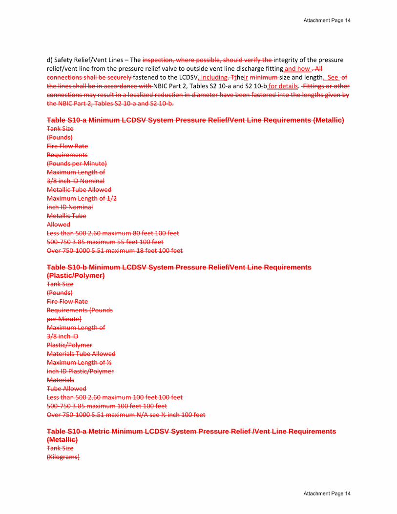
d) Safety Relief/Vent Lines – The inspection, where possible, should verify the integrity of the pressure relief/vent line from the pressure relief valve to outside vent line discharge fitting and how . All connections shall be securely fastened to the LCDSV, including. Ttheir minimum size and length. See of the lines shall be in accordance with NBIC Part 2, Tables S2 10‐a and S2 10‐b for details. Fittings or other connections may result in a localized reduction in diameter have been factored into the lengths given by the NBIC Part 2, Tables S2 10‐a and S2 10‐b. Table S10-a Minimum LCDSV System Pressure Relief/Vent Line Requirements (Metallic) Tank Size (Pounds) Fire Flow Rate Requirements (Pounds per Minute) Maximum Length of 3/8 inch ID Nominal Metallic Tube Allowed Maximum Length of 1/2 inch ID Nominal Metallic Tube Allowed Less than 500 2.60 maximum 80 feet 100 feet 500‐750 3.85 maximum 55 feet 100 feet Over 750‐1000 5.51 maximum 18 feet 100 feet Table S10-b Minimum LCDSV System Pressure Relief/Vent Line Requirements (Plastic/Polymer) Tank Size (Pounds) Fire Flow Rate Requirements (Pounds per Minute) Maximum Length of 3/8 inch ID Plastic/Polymer Materials Tube Allowed Maximum Length of ½ inch ID Plastic/Polymer Materials Tube Allowed Less than 500 2.60 maximum 100 feet 100 feet 500‐750 3.85 maximum 100 feet 100 feet Over 750‐1000 5.51 maximum N/A see ½ inch 100 feet Table S10-a Metric Minimum LCDSV System Pressure Relief /Vent Line Requirements (Metallic) Tank Size (Kilograms)
Attachment Page 14
Attachment Page 14
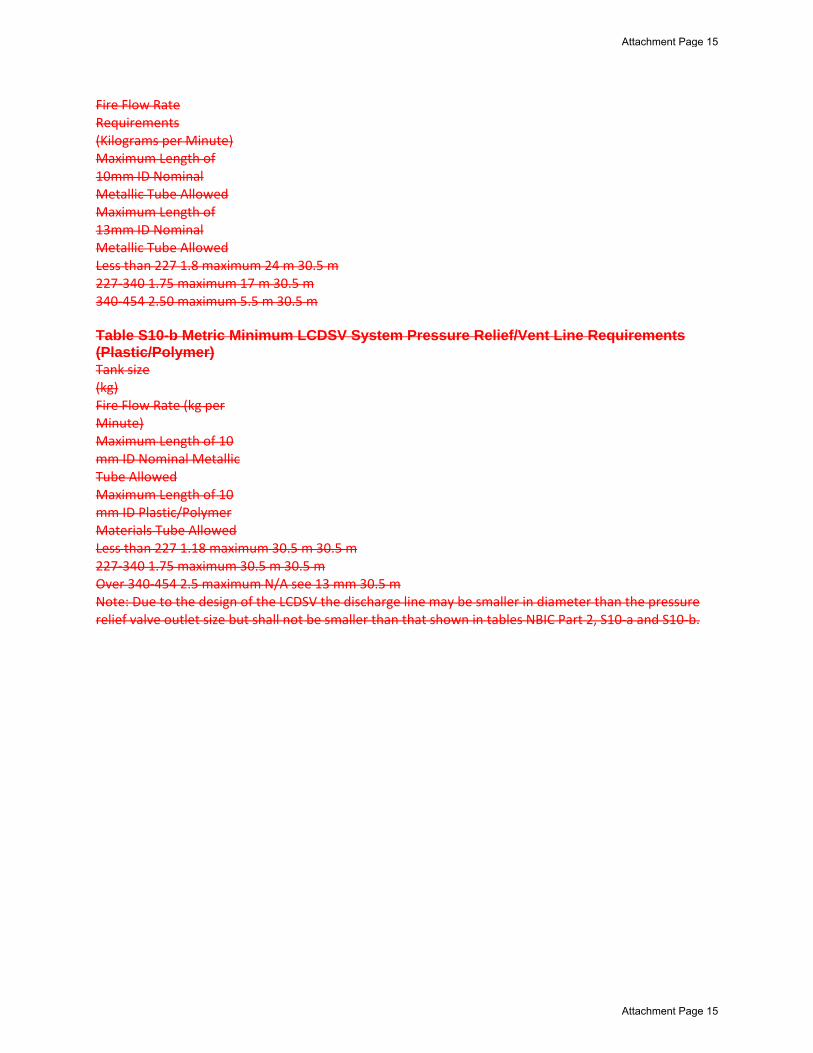
Fire Flow Rate Requirements (Kilograms per Minute) Maximum Length of 10mm ID Nominal Metallic Tube Allowed Maximum Length of 13mm ID Nominal Metallic Tube Allowed Less than 227 1.8 maximum 24 m 30.5 m 227‐340 1.75 maximum 17 m 30.5 m 340‐454 2.50 maximum 5.5 m 30.5 m Table S10-b Metric Minimum LCDSV System Pressure Relief/Vent Line Requirements (Plastic/Polymer) Tank size (kg) Fire Flow Rate (kg per Minute) Maximum Length of 10 mm ID Nominal Metallic Tube Allowed Maximum Length of 10 mm ID Plastic/Polymer Materials Tube Allowed Less than 227 1.18 maximum 30.5 m 30.5 m 227‐340 1.75 maximum 30.5 m 30.5 m Over 340‐454 2.5 maximum N/A see 13 mm 30.5 m Note: Due to the design of the LCDSV the discharge line may be smaller in diameter than the pressure relief valve outlet size but shall not be smaller than that shown in tables NBIC Part 2, S10‐a and S10‐b.
Attachment Page 15
Attachment Page 15
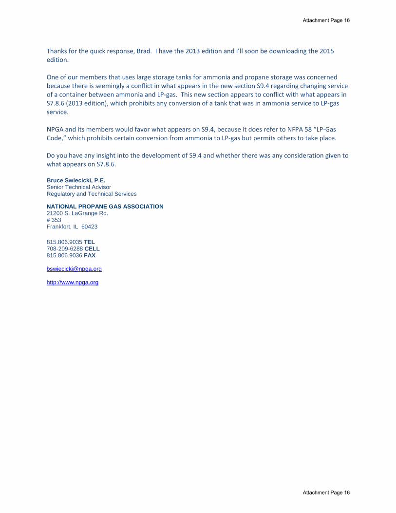
Thanks for the quick response, Brad. I have the 2013 edition and I’ll soon be downloading the 2015 edition. One of our members that uses large storage tanks for ammonia and propane storage was concerned because there is seemingly a conflict in what appears in the new section S9.4 regarding changing service of a container between ammonia and LP‐gas. This new section appears to conflict with what appears in S7.8.6 (2013 edition), which prohibits any conversion of a tank that was in ammonia service to LP‐gas service. NPGA and its members would favor what appears on S9.4, because it does refer to NFPA 58 “LP‐Gas Code,” which prohibits certain conversion from ammonia to LP‐gas but permits others to take place. Do you have any insight into the development of S9.4 and whether there was any consideration given to what appears on S7.8.6. Bruce Swiecicki, P.E. Senior Technical Advisor Regulatory and Technical Services NATIONAL PROPANE GAS ASSOCIATION 21200 S. LaGrange Rd. # 353 Frankfort, IL 60423 815.806.9035 TEL 708-209-6288 CELL 815.806.9036 FAX [email protected] http://www.npga.org
Attachment Page 16
Attachment Page 16
Related Documents
![23 - Berkeley City · Web view... (NH3)4Cl2]Cl ( [Co(NH3)4Cl2]+ + Cl-; (# of ions = 2) [Co(NH3)5Cl]Cl2 ... (III) chloride, [Co(NH3)5(NO2)]Cl2, and ... Copper Ceruloplasmin Hemoglobin](https://static.cupdf.com/doc/110x72/5a9e9e6e7f8b9a0d158b9d45/doc23-berkeley-city-view-nh34cl2cl-conh34cl2-cl-of-ions.jpg)