low voltage SFM-SERIES-DC-DAT REV. C APRIL 2022 2203008 Data Sheet Page 1 of 10 Hydraulic-Magnetic Circuit Breakers 100% rated, unaffected by ambient temperature SFM - Series Miniature Circuit Breakers - DC 1 pole Surface mount 2 pole Surface mount • DC circuit breaker • Hydraulic-magnetic technology • 100 % rating capability; independent of ambient temperature • One and two pole (3 & 4 pole applies only if accessories are required) • 125 Vdc (250 Vdc 2 pole in series) • Ratings 1 A to 100 A (No third party approvals) • Available in various current ratings and time delays • Precision tripping characteristics • Can be switched on immediately after tripping • Optional auxiliary switch • Optional shunt trip (No approvals) Features Auxiliary Switch: Features • Single pole double throw 15 A @ 250 Vac Optional Accessories • Handle lock - 4474005 • Safety blank (1 Pole) - SFM1BLANK • Safety blank (2 Pole) - SFM2BLANK • Escutcheon blank - SFEB000

Welcome message from author
This document is posted to help you gain knowledge. Please leave a comment to let me know what you think about it! Share it to your friends and learn new things together.
Transcript
low voltage
SFM-SERIES-DC-DATREV. C
APRIL 20222203008
Data SheetPage 1 of 10
Hydraulic-Magnetic Circuit Breakers 100% rated, unaffected by ambient temperature
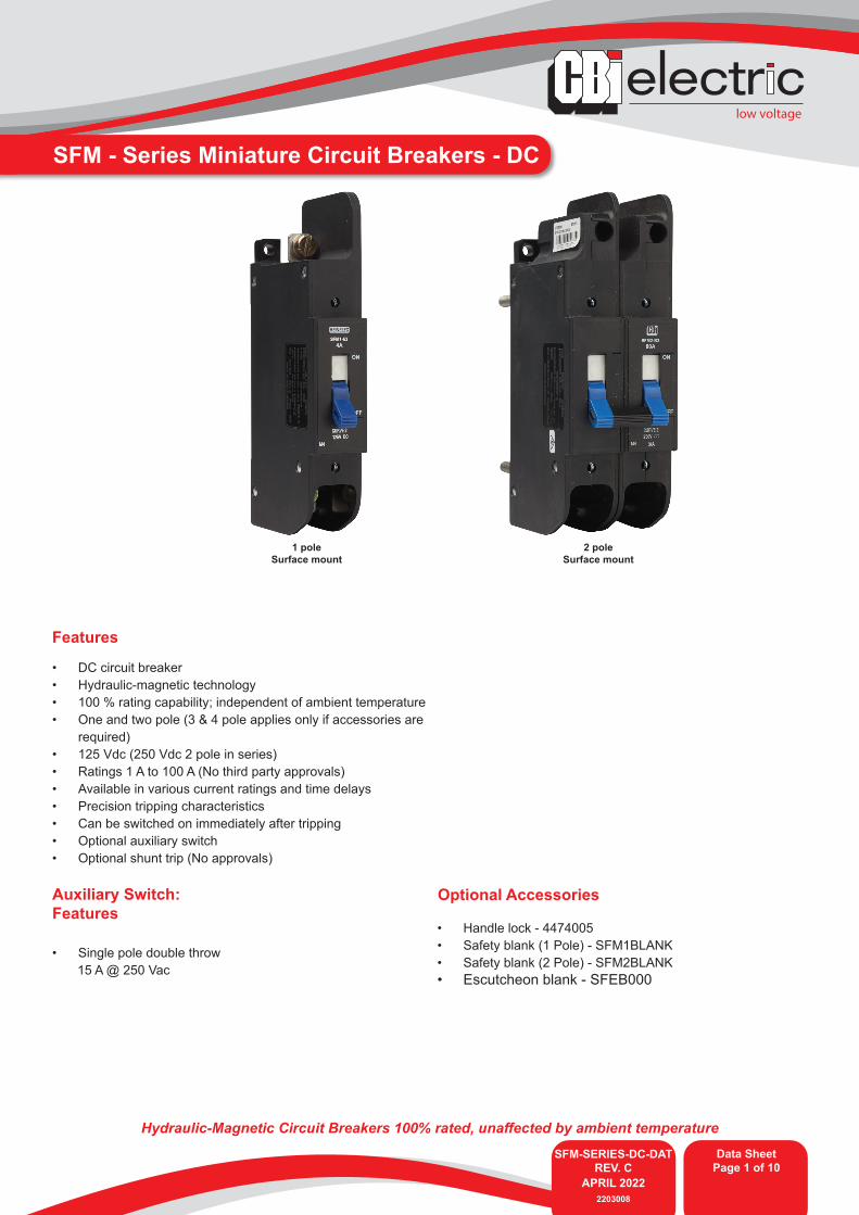
SFM - Series Miniature Circuit Breakers - DC
1 poleSurface mount
2 poleSurface mount
• DC circuit breaker• Hydraulic-magnetic technology • 100 % rating capability; independent of ambient temperature• One and two pole (3 & 4 pole applies only if accessories are
required)• 125 Vdc (250 Vdc 2 pole in series)• Ratings 1 A to 100 A (No third party approvals)• Available in various current ratings and time delays• Precision tripping characteristics • Can be switched on immediately after tripping • Optional auxiliary switch• Optional shunt trip (No approvals)
Features
Auxiliary Switch:Features
• Single pole double throw 15 A @ 250 Vac
Optional Accessories
• Handle lock - 4474005• Safety blank (1 Pole) - SFM1BLANK • Safety blank (2 Pole) - SFM2BLANK• Escutcheon blank - SFEB000

SFM-SERIES-DC-DATREV. C
APRIL 20222203008
Data SheetPage 2 of 10
low voltage
SFM - Series Miniature Circuit Breakers - DC
Product Type SFM(26)Ambient Operating Temperature -40 °C to +85 °CMounting Options Clip tray, Front & Surface mounting Time Delay Curves 1, 2, 3Weight 200 g per pole, 260 g with auxiliary (unpacked)
Altitude Certification tests done at altitude ≈ 2000 metres. Will operate at higher altitudes.
Shock 50 g with pulse duration of 11 millisecondsVibration 5 g from 35 Hz to 200 Hz
Flammability I3 - Ignition does not persist at 850 °C after glow wire is withdrawn with an oxygen index of ≥ 28
Toxicity F1 - Smoke index of ≤ 20 which determines the fume class
Pollution Degree PD2 - Normally only non-conductive pollution occurs. Temporary conductivity caused by condensation is to be expected.
Technical Data
Circuit Breaker Wire Size (IEC) Torque (IEC)
Main terminals Box Type 1 mm² - 35 mm² 4 NmLug & Rear Studs Type 1 mm² - 50 mm²

low voltage
SFM-SERIES-DC-DATREV. C
APRIL 20222203008
Data SheetPage 3 of 10
SFM - Series Miniature Circuit Breakers - DC
Continues on page 4
Group 1 2 3 4 5 6 7 8 9 10 11 12 13 14 15 16 17 18 19
Requirement SFM FourPole
Two PoleFirst Set
Box Type Main
Termi-nal
OverloadSeries
Trip
One Pole Sec-ondSet
Box TypeMain
Termi-nal
OverloadSeries
TripWITH Aux
swich
One Pole Third Set
Box Type Main
Termi-nal
Shunt Trip
(ST1), flexible leads
N/A N/A N/A CurrentRating
Time Delay
ShuntTrip
VoltageVac
AC/DCNo
Approv-als
Long Code SFM 4 2 H 3 / H 1 / H 10 - - - 60 A 2 48-125 DC Z
Example Code: SFM4-2H3/H1/H10-60A-2-48-125Vdc - DC-Z
Long Code
Ordering InformationGroup 1: Frame Type
Code Description CommentsSFM SFM
Group 2: Total Number of Poles
Code Description Comments1 Single pole2 Double pole3 Triple pole4 Four pole
Group 3: Number of Poles
Code Description Comments- Not applicable All poles are the same2 Two poles 3 Three poles 3 & 4 pole applies only if accessories are required. i.e Shunt trip, Auxilairy switch
pole, etc.4 Four poles Group 4: Termination
Code Description CommentsB Rear studs ‘‘DC’’E Screw terminal ‘‘DC’’H Box terminal ‘‘DC’’
Group 5: Pole Construction
Code Description Comments0 Switch Disconnector with auxiliary switch fitted1 Series trip overload with auxiliary switch fitted 3 Overload series trip6 Shunt trip four terminals. (INTERNAL SHUNT)
10 Shunt trip (ST1), flexible leads. (EXTERNAL SHUNT)11 Shunt trip (ST1). with auxiliary switched fitted. (EXTERNAL SHUNT)13 Switch Disconnector with auxiliary switch fitted
14 Shunt trip in series with a cut-off main contacts (ST1CO). With flexible leads. Occu-pies additional pole. (SERIES SHUNT)
15 Auxiliary switch with flexible leads (internal fitted). Occupies additional poleGroup 6: Number of Poles
Code Description Comments- Not Applicable / One pole
/2 Two poles /3 Three poles /4 Four poles
Group 7: Terminal Type
Code Description CommentsB Rear studs ‘‘DC’’E Screw terminal ‘‘DC’’H Box terminal ‘‘DC’’
Group 8: Pole Construction
Code Description Comments0 Switch Disconnector with auxiliary switch fitted1 Series trip overload with auxiliary switch fitted 3 Overload series trip6 Shunt trip four terminals. (INTERNAL SHUNT)
10 Shunt trips (ST1), flexible leads. (EXTERNAL SHUNT)11 Shunt trip (ST1), with auxiliary switch fitted. (EXTERNAL SHUNT)13 Switch Disconnector with auxiliary switch fitted
14 Shunt trip in series with a cutt-off main contacts (ST1CO). With flexible leads. Occupies additional pole. (SERIES SHUNT)
15 Auxiliary switch with flexible leads (internal fitted), Occupies additional pole
Firs
t Set
(s)
Sec
ond
Set (
s)

SFM-SERIES-DC-DATREV. C
APRIL 20222203008
Data SheetPage 4 of 10
low voltage
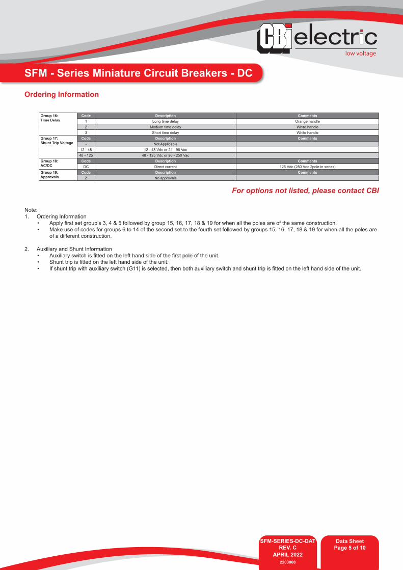
SFM - Series Miniature Circuit Breakers - DCOrdering Information
Group 13: Terminal Type
Code Description CommentsB Rear studs ‘‘DC’’E Screw terminal ‘‘DC’’H Box terminal ‘‘DC’’
Group 14: Pole Construction
Code Description Comments0 Switch Disconnector with auxiliary switch fitted 1 Series trip overload with auxiliary switch fitted 3 Overload series trip 6 Shunt trip four terminals. (INTERNAL SHUNT)
10 Shunt trips (ST1), flexible leads. (EXTERNAL SHUNT)11 Shunt trip (ST1), with auxiliary switch fitted. (EXTERNAL SHUNT)13 Switch Disconnector with auxiliary switch fitted
14 Shunt trip in series with a cut-off main contacts (ST1CO). With flexible leads. Occupies additional pole. (SERIES SHUNT)
15 Auxiliary switch with flexible leads (internal fitted). Occupies additional poleGroup 15: Current Rating
Code Description Comments1, 2, 4, 6, 10, 15,16, 20, 25, 30, 32, 40, 50, 63, 70, 80, 100 A Ratings certification dependant
Group 10: Terminal Type
Code Description CommentsB Rear studs ‘‘DC’’E Screw terminal ‘‘DC’’H Box terminal ‘‘DC’’
Group 11: Pole Construction
Code Description Comments0 Switch Disconnector with auxiliary switch fitted 1 Series trip overload with auxiliary switch fitted3 Overload series trip6 Shunt trip four terminals. (INTERNAL SHUNT)
10 Shunt trip (ST1), flexible leads. (EXTERNAL SHUNT)11 Shunt trip (ST1), with auxiliary switch fitted. (EXTERNAL SHUNT)13 Switch Disconnector with auxiliary switch fitted
14 Shunt trip in series with a cut-off main contacts (ST1CO). With flexible leads. Occu-pies additional pole. (SERIES SHUNT)
15 Auxiliary switch with flexible leads (INTERNAL FITTED). Occupies additional poleGroup 12: Number of Poles
Code Description Comments- Not Applicable /2 Two pole/3 Three poles /4 Four poles
Group 9: Number of Poles
Code Description Comments- Not Applicable /2 Two pole/3 Three poles /4 Four poles
Third
Set
(s)
Four
th S
et (s
)
low voltage
SFM-SERIES-DC-DATREV. C
APRIL 20222203008
Data SheetPage 5 of 10
SFM - Series Miniature Circuit Breakers - DC
For options not listed, please contact CBI
Group 16: Time Delay
Code Description Comments1 Long time delay Orange handle 2 Medium time delay White handle 3 Short time delay White handle
Group 17: Shunt Trip Voltage
Code Description Comments- Not Applicable
12 - 48 12 - 48 Vdc or 24 - 96 Vac48 - 125 48 - 125 Vdc or 96 - 250 Vac
Group 18: AC/DC
Code Description CommentsDC Direct current 125 Vdc (250 Vdc 2pole in series)
Group 19: Approvals
Code Description CommentsZ No approvals
Note:1. Ordering Information
• Apply first set group’s 3, 4 & 5 followed by group 15, 16, 17, 18 & 19 for when all the poles are of the same construction.• Make use of codes for groups 6 to 14 of the second set to the fourth set followed by groups 15, 16, 17, 18 & 19 for when all the poles are
of a different construction.
2. Auxiliary and Shunt Information• Auxiliary switch is fitted on the left hand side of the first pole of the unit.• Shunt trip is fitted on the left hand side of the unit.• If shunt trip with auxiliary switch (G11) is selected, then both auxiliary switch and shunt trip is fitted on the left hand side of the unit.
Ordering Information
SFM-SERIES-DC-DATREV. C
APRIL 20222203008
Data SheetPage 6 of 10
low voltage
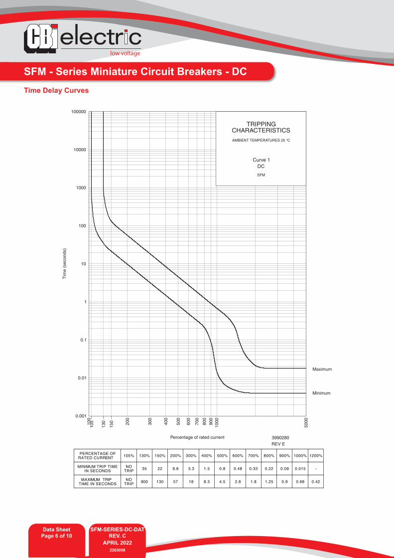
SFM - Series Miniature Circuit Breakers - DCTime Delay Curves
Percentage of rated current
Tim
e(s
econ
ds)
Maximum
Minimum
3990280REV E
105
130
15010
0
200
300
400
500
600
700
800
900
1000
5000
0.001
0.01
0.1
1
10
100
1000
10000
100000
TRIPPINGCHARACTERISTICSAMBIENT TEMPERATURES 25 °C
Curve 1DC
SFM
low voltage
SFM-SERIES-DC-DATREV. C
APRIL 20222203008
Data SheetPage 7 of 10
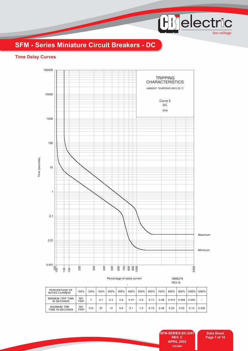
SFM - Series Miniature Circuit Breakers - DCTime Delay Curves
Percentage of rated current
Tim
e(s
econ
ds)
Maximum
Minimum
3990279REV B
105
130
15010
0
200
300
400
500
600
700
800
900
1000
5000
0.001
0.01
0.1
1
10
100
1000
10000
100000
TRIPPINGCHARACTERISTICSAMBIENT TEMPERATURES 30 °C
Curve 2DC
SFM
SFM-SERIES-DC-DATREV. C
APRIL 20222203008
Data SheetPage 8 of 10
low voltage
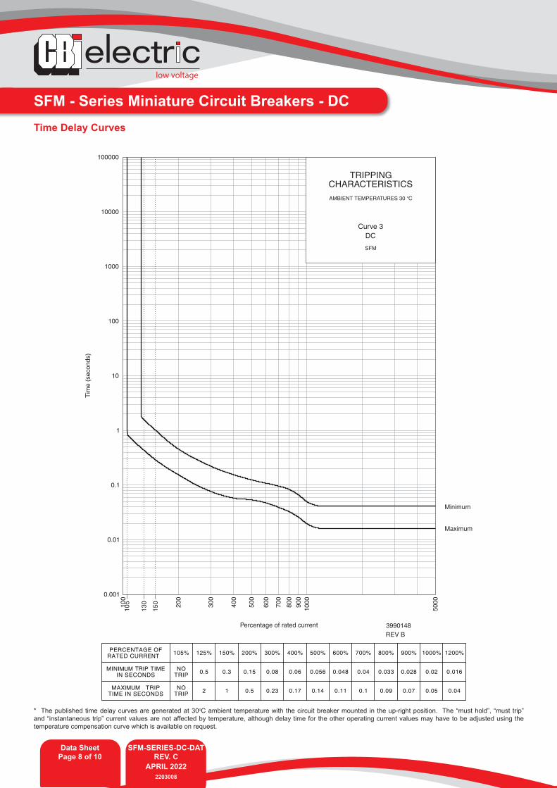
SFM - Series Miniature Circuit Breakers - DCTime Delay Curves
Percentage of rated current
Tim
e(s
econ
ds)
Maximum
Minimum
3990148REV B
105
130
15010
0
200
300
400
500
600
700
800
900
1000
5000
0.001
0.01
0.1
1
10
100
1000
10000
100000
TRIPPINGCHARACTERISTICSAMBIENT TEMPERATURES 30 °C
Curve 3DC
SFM
* The published time delay curves are generated at 30oC ambient temperature with the circuit breaker mounted in the up-right position. The “must hold”, “must trip” and “instantaneous trip” current values are not affected by temperature, although delay time for the other operating current values may have to be adjusted using the temperature compensation curve which is available on request.
low voltage
SFM-SERIES-DC-DATREV. C
APRIL 20222203008
Data SheetPage 9 of 10
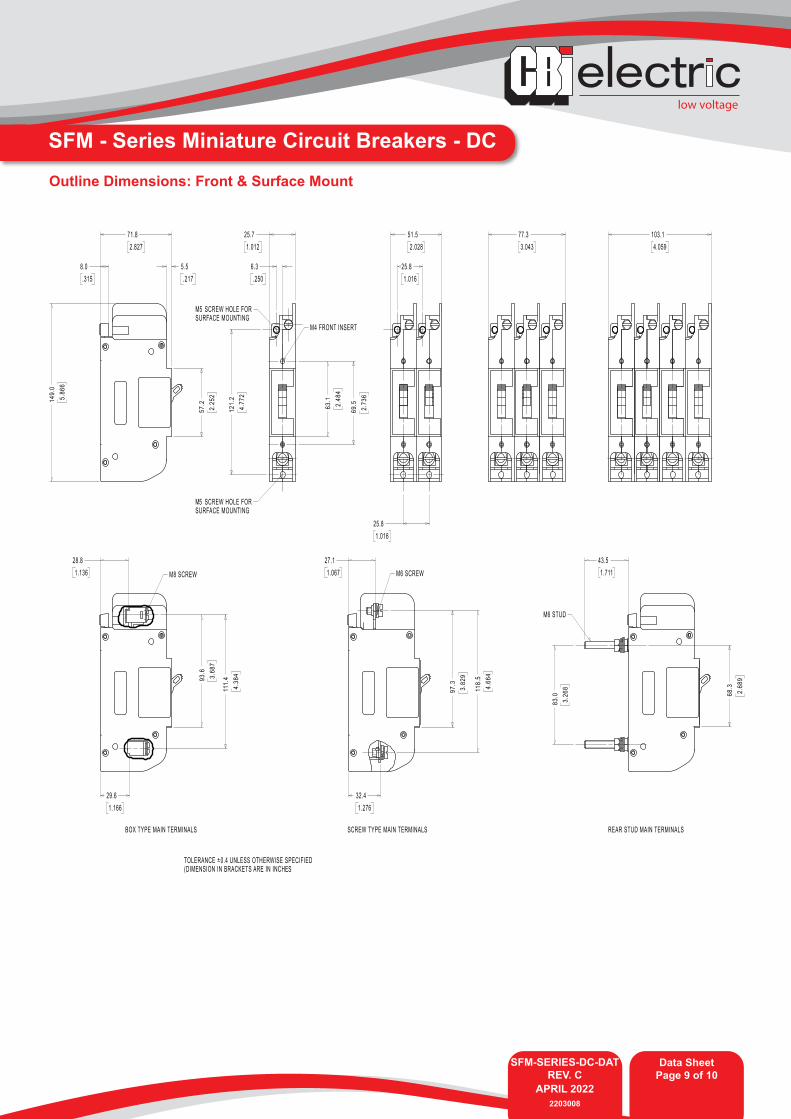
SFM - Series Miniature Circuit Breakers - DC
Outline Dimensions: Front & Surface Mount
A member of the GroupSFM-SERIES-DC-DATREV. C
APRIL 20222203008
Data SheetPage 10 of 10
low voltage
Please review our Customer Terms and Conditions on www.cbi-lowvoltage.co.zaAll rights reserved. Unless otherwise indicated, all materials on these pages are copyrighted by CBI (Pty) Ltd. No part of these pages, either text or image may be used for any purpose other than personal use. Therefore, reproduction, modification, storage in a retrieval system or retransmission, in any form or by any means, electronic, mechanical or otherwise, for reasons other than personal use, is strictly prohibited without prior written permission. CBI (Pty) Ltd reserves the right to alter any details of this document without notice and while every effort is made to ensure the accuracy of the content, no warranty is given as to the accuracy of this document and no responsibility will be accepted for error or misinterpretation and any resulting loss.
© CBI (Pty) Ltd. All Rights Reserved.
AUSTRALIACBI-electric: Australia27 Wedgewood Rd, Hallam Victoria 3803 AustraliaTel: +61 3 8752 9300Fax: +61 3 9796 5407Email: [email protected]: www.cbi-electric.com.au
SOUTH AFRICACBI-electric: low voltageTripswitch Drive ElandsfonteinGauteng South AfricaTel: +27 11 928 2000Fax: + 27 11 392 2354Email: [email protected]@cbi-electric.comWebsite: www.cbi-lowvoltage.co.za
USACBI-electric: North America35 E. Uwchlan Ave Suite 328Exton PA 19341 USATel: +1 610 524 9949Fax: +1 610 524 9945E-mail: [email protected]: www.cbibreakers.com
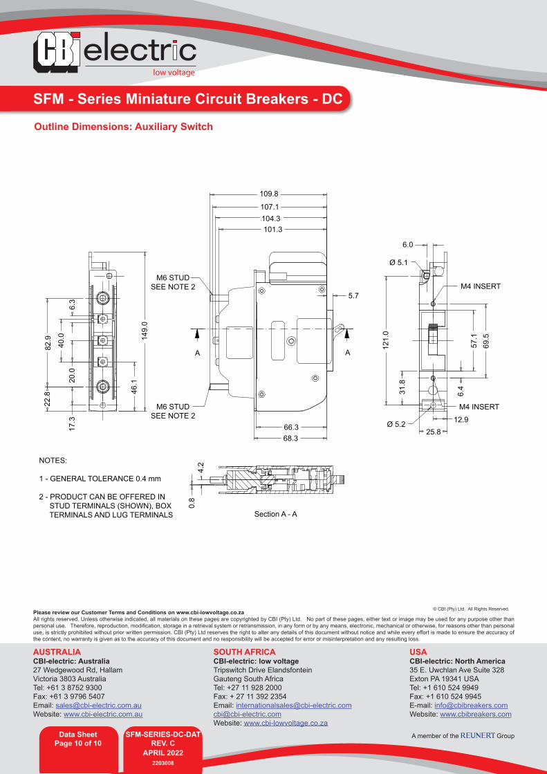
SFM - Series Miniature Circuit Breakers - DCOutline Dimensions: Auxiliary Switch
109.8
107.1104.3101.3
5.7
AA
66.368.3
Section A - A
25.8
Ø 5.1
Ø 5.2 12.9
M4 INSERT
M4 INSERT
6.0
M6 STUDSEE NOTE 2
M6 STUDSEE NOTE 2
NOTES:
1 - GENERAL TOLERANCE 0.4 mm
2 - PRODUCT CAN BE OFFERED IN STUD TERMINALS (SHOWN), BOX TERMINALS AND LUG TERMINALS
121.
0
57.1
69.514
9.0
46.1
17.3
20.0
6.3
40.0
82.9
22.8 31
.8
6.4
4.2
0.8
Related Documents