Engine Model: SFGLD360/480 Gas Generator Set Models: 750/1000REZK See Inside Front Cover for Service Assistance Information TP-6991 8/18b Engine Operation & Maintenance

Welcome message from author
This document is posted to help you gain knowledge. Please leave a comment to let me know what you think about it! Share it to your friends and learn new things together.
Transcript

Engine Model:
SFGLD360/480 Gas
Generator Set Models:
750/1000REZK
See Inside Front Cover for Service Assistance Information
TP-6991 8/18b
Engine Operation &Maintenance

WARNING: This product can expose youto chemicals, including carbon monoxideand benzene, which are known to the Stateof California to cause cancer and birthdefects or other reproductive harm.For more information go towww.P65warnings.ca.gov
Service Assistance
For professional advice on generator set powerrequirementsandconscientiousservice, pleasecontactyour nearest Kohler distributor or dealer.
D Visit the Kohler Co. website at KOHLERPower.com.
D Lookat the labels and stickers on yourKohler productor review the appropriate literature or documentsincluded with the product.
D Call toll free in the US and Canada 1-800-544-2444.
D Outside theUSandCanada, call the nearest regionaloffice.
Headquarters Europe, Middle East, Africa(EMEA)Kohler EMEA HeadquartersNetherlands B.V.Kristallaan 14761 ZC ZevenbergenThe NetherlandsPhone: (31) 168 331630Fax: (31) 168 331631
Asia PacificPower Systems Asia Pacific Regional OfficeSingapore, Republic of SingaporePhone: (65) 6264-6422Fax: (65) 6264-6455
ChinaNorth China Regional Office, BeijingPhone: (86) 10 6518 7950
(86) 10 6518 7951(86) 10 6518 7952
Fax: (86) 10 6518 7955
East China Regional Office, ShanghaiPhone: (86) 21 6288 0500Fax: (86) 21 6288 0550
India, Bangladesh, Sri LankaIndia Regional OfficeBangalore, IndiaPhone: (91) 80 3366208
(91) 80 3366231Fax: (91) 80 3315972
Japan, KoreaNorth Asia Regional OfficeTokyo, JapanPhone: (813) 3440-4515Fax: (813) 3440-2727


5552656v1
Gua
sco
r P
owe
r, S
.A.U
., S
oci
eda
d In
scrit
a e
n el
Re
gist
ro M
erca
ntil
de
Gu
ipú
zcoa
, T
omo
1195
, Fol
io 1
78
, Sec
ción
8,
Hoj
a S
S-3
957
- C
.I.F
. A
-48
042
709
Dear Customers,
Please be advised that EPA regulation 40 CFR part 60 subpart JJJJ places certain requirements on
owners and operators of new stationary spark ignition internal combustion engines. You have
purchased a EPA pre‐certified Guascor gas engine per 40 CFR part 60 subpart JJJJ and, therefore,
should adhere to the compliance requirements for pre‐certified engines Your engine has been
certified for stationary emergency use only. As such, there is no time limit for use of this
emergency stationary ICE engine in emergency situations ‐ as determined by an authorized entity.
However, the EPA does strictly regulate how much, and when this unit can be operated for non‐
emergency situations. Please consult the regulations for specifics.
This pre‐certification does not exempt you from State or local air authority regulations. In fact,
many State and local air authorities have adopted regulations more stringent than the EPA and will
require on‐site testing to their specific test protocols regardless of this pre‐certification. We
advise you to consult all applicable regulations in determining your compliance obligations and to
check with your local authority to make sure your installation is in compliance with local laws and
regulations.
Guascor engines will satisfy the aforementioned EPA regulations only if the engine configuration is
not changed, the engine is commissioned by a factory technician, approved Dealer or Service
Company technician, the engine maintenance schedule is followed, and the supply gas to the
engines meets the following fuel specification IC‐G‐D‐30‐021. The Dresser‐Rand business, part of
Siemens Power and Gas Division, disclaims liability for all operational factors outside of its control,
which may affect your engines emissions output.
Please contact Dresser‐Rand if you have any questions about your engine’s emissions
performance.

2.002211.810_A
10-2016 GENERAL INDEX
OPERATION & MAINTENANCE MANUAL SFGLD “V” KOHLER CO – PRIME / STAND BY
1/3
CHAPTER 1 – SAFETY FEATURES AND PRECAUTIONS
IC-G-D-60-002e_B Safety precautions for KOHLER gas engines 1.1 IC-G-D-60-003e_D Review of compliance with european machinery safety regulations and "CE" mark requirements 1.9 IC-G-D-00-042e_E Sound pressure level in GAS engines 1.17 IC-G-D-00-043e_F Sound pressure level in the exhaust zone of the GAS engines 1.21 IO-C-M-00-004e_A Guide to environment-friendly waste management during product maintenance and at end of life 1.25
CHAPTER 2 – ENGINE TECHNICAL DESCRIPTION
2.1 General
IC-G-D-00-039e_F Gas engines identification plates and characteristics 2.1.1 IC-G-D-00-253e Emissions plate of Epa certified engines 2.1.9
IC-G-D-00-040e_F Gas engines general description of construction 2.1.11 IC-G-D-00-036e_G Table of technical characteristics in-line FGLD/SFGLD/SFGM/HGM engines 2.1.15 IC-G-D-00-151e Description of the components in one circuit “V” gas engines 2.1.17
IM-G-C-00-002e_F Gaps and wear limits for “V” Gas and Ethanol engines 2.1.25 IM-G-C-00-001e_F Tightening torques for Gas and Ethanol engines 2.1.33 IM-C-C-00-002e_B Tightening torques for commercial bolts & nuts 2.1.37
IC-C-D-00-025e Units conversión 2.1.41
2.2 Cooling System
IT-G-A-20-025e One circuit cooling system for gas V - engines 2.2.1 IT-G-A-20-007e_I Gas engines – pressure losses and flowrates 2.2.9
2.3 Lubrication System
IC-C-D-25-005e_C Description of lubrication system for “V” engines 2.3.1
IT-C-A-25-002e_F Automatic engine oil level controller 2.3.7 IT-C-A-25-045e_B Lube oil level indicator UL 2.3.11 IT-C-A-25-030e_G Kohler engines submerged oil preheating system 2.3.15 IC-C-D-25-006e_B Description of a crankcase Gas recirculation system 2.3.19
2.4 Fuel System
IC-G-D-50-003e EGS 02. Description 2.4.1
IT-G-E-30-001e_B Venturi type carburation - description 2.4.5 IC-G-D-30-040e_A Specification of Gas supply to tecjet 52 2.4.11
O&M_2.002211.810_A_10_2016
Kohler

2.002211.810_A
10-2016 GENERAL INDEX
OPERATION & MAINTENANCE MANUAL SFGLD “V” KOHLER CO – PRIME / STAND BY
2/3
2.5 Ignition
IC-G-D-33-002e_A Description of the GIS ignition system 2.5.1
2.6 Intake
IC-C-D-35-002e_C GAS engines intake system 2.6.1 IC-C-D-35-001e_D Air filters 2.6.5
2.7 Exhaust
IC-C-D-40-003e_A Oxidative catalytic converters 2.7.1
IC-G-D-40-002e_B Exhaust system and ventilation of the oil sump 2.7.7
2.8 Starter
IT-C-A-55-001e_J Electric starting 2.8.1
2.9 Safety and Control
IO-G-M-60-002e_K FG/FGLD/SFGLD/SFGM/SFGRD engines instrumentation 2.9.1
CHAPTER 3 – HANDLING AND STORAGE INSTRUCTIONS
IM-G-C-00-004e_A Lifting system for SFGLD/SFGM V engine 3.1.1 IO-C-M-00-001e_A Deferred start-up engine inspection and protection 3.1.7
CHAPTER 4 – OPERATING INSTRUCTIONS
IT-G-A-00-011e_C Minimum room temperature for operating Gas engines 4.1.1
IO-C-M-15-002e_A Kohler Engine barring gear operating instructions 4.1.3 IO-C-M-20-001e_D Cooling water quality and treatment 4.1.5 IC-G-D-25-003e_B motoroil 3040 plus lube oil for natural gas-fuelled and ethanol engines 4.1.11
IC-G-D-30-001e_D Fuel specifications for Gas engines. General 4.1.13 IC-G-D-30-021e_B Fuel specifications – Us natural gas 4.1.19
IO-G-M-33-010e Installation and operation manual - Gis ignition unit display 4.1.25
IO-G-T-00-003e Starting and stopping of emergency gas engines 4.1.39 IO-G-M-40-001e_D Gas engine and ethanol carburation 4.1.43 IC-C-D-40-001e_C Emission units conversion 4.1.45
IO-C-M-25-006e_G Oil level indicators 4.1.49
IO-C-M-25-005e_D Automatic oil level controller 4.1.51
IT-G-A-00-008e_A Emissions - related installation instructions 4.1.53
O&M_2.002211.810_A_10_2016
Kohler
Kohler

2.002211.810_A
10-2016 GENERAL INDEX
OPERATION & MAINTENANCE MANUAL SFGLD “V” KOHLER CO – PRIME / STAND BY
3/3
CHAPTER 5 – MAINTENANCE INSTRUCTIONS
5.1 Maintenance Procedures
IO-G-M-00-060e_B General maintenance of gas engine 5.1.1
IO-G-M-00-061e_C Maintenance of natural gas engine SFGLD 1800 rpm prime 5.1.5
IO-G-M-00-019e_G Maintenance of natural gas engine SFGLD stand-by 5.1.13
5.2 Description of Maintenance Operations Type E
IO-G-M-25-001e_G Gas-fueled engine oil servicing instructions 5.2.1
IO-C-M-25-001e_A Oil sampling procedure 5.2.5 IO-C-M-25-004e_A engine oil change instructions 5.2.7
IO-C-M-25-003e_A 180/240/360/480/560 engines centrifugal oil filter maintenance instructions 5.2.11
IO-C-M-25-011e Maintenance of the crankcase gas recirculation system 5.2.13
IO-C-M-25-012e_A Cleaning the oil separator filter of the crankcase gas breather 5.2.17 IO-C-M-00-006e_A engine cylinder compression test 5.2.19 IO-G-M-33-001e_C Conventional spark plug changing and maintenance instructions 5.2.23
IO-G-M-33-002e_F Conventional spark plug replacement criteria in Gas engines 5.2.27 IM-G-C-33-001e_D Conventional spark plug installation instructions 5.2.31
IO-G-M-33-003e_B Check of ignition coils and spark plug wires 5.2.33 IO-G-M-33-007e_L Maintenance of spark plugs. Overview 5.2.35 IO-G-M-33-009e_A Checking the ignition timing 5.2.37 IT-G-E-10-001e_G Adjustment of Gas and Ethanol engine valves 5.2.41 IO-C-M-35-001e_E Air filters. Maintenance 5.2.45 IO-C-M-15-001e_B Damper condition monitoring 5.2.51 IO-C-M-20-002e_G Maintenance of the cooling system 5.2.55
IO-C-M-45-001e_B Maintenance of turbocharger 5.2.61
IO-G-T-35-001e_A Intake safety valve operating and maintenance procedure 5.2.65
IO-C-M-20-010e_A Maintenance of intercoolers 5.2.67 IO-C-M-60-004e Maintenance of pick-ups 5.2.71 IO-C-M-55-001e Maintenance of batteries 5.2.73
CHAPTER 6 – TROUBLESHOOTING
IO-G-T-00-001e_B Gas engines troubleshooting 6.1.1
O&M_2.002211.810_A_10_2016
Kohler
Kohler
Kohler

2.002211.810_A
10-2016
INDEX Chapter 1 SAFETY FEATURES AND PRECAUTIONS
OPERATION & MAINTENANCE MANUAL SFGLD “V” KOHLER CO – PRIME / STAND BY
1/1
CHAPTER 1 – SAFETY FEATURES AND PRECAUTIONS
IC-G-D-60-002e_B Safety precautions for KOHLER gas engines 1.1 IC-G-D-60-003e_D Review of compliance with european machinery safety regulations and "CE" mark requirements 1.9 IC-G-D-00-042e_E Sound pressure level in GAS engines 1.17 IC-G-D-00-043e_F Sound pressure level in the exhaust zone of the GAS engines 1.21 IO-C-M-00-004e_A Guide to environment-friendly waste management during product maintenance and at end of life 1.25
O&M_2.002211.810_A_10_2016

PRODUCT INFORMATION INDEX DATE
Dep. 1 IC-G-D-60-002e B July 2015
SAFETY PRECAUTIONS FOR KOHLER GAS ENGINES
1/8
1. INTRODUCTION
All Kohler engines have been designed in accordance with European Machinery Safety Regulations, European Directive 2006/42/EC and the harmonised standards UNE-EN ISO 12100-1 and UNE-EN ISO 12100-2. Accordingly, we supply them with the EC Declaration of Conformity and «CE» mark.
The intention has been to supply an intrinsically-safe engine, although the nature of this machine does not rule out the possibility of potential risks, for which it is necessary to adopt certain safety precautions.
The aim of this document is to inform the users of Kohler equipment on the safety precautions which are required for handling and operating it adequately.
Engine installations and specially fuel-powered engines must be adapted in all cases to the local regulations.
2. PRELIMINARY OBSERVATIONS
We recommend you to read these safety precaution instructions on receiving your Kohler engine. They are part of the engine operation and maintenance manual we supply with each engine.
Therefore, we recommend that the manual be kept in perfect condition and readily available to the operator and those responsible for engine maintenance.
Our Network of Repair Shops is at your disposal to carry out revisions and repairs under the best conditions and in accordance with the standards established by Kohler.
The use of original spare parts ensures high performance over long periods of operation. These parts have been manufactured with the same strict quality controls, which were used for the manufacture of the original equipment.
3. BODILY PROTECTION
�������
Wear approved bodily, sight, hearing and respiratory protection. Never wear loose clothing, jewellery or long hair around the engine.
4. EXHAUST GASES
�������
IC engine exhaust products are toxic and may cause injury or death if inhaled. All engine installations must have an exhaust discharge pipe so that the exhaust gases are delivered into the outside air. A closed building or shelter must be adequately vented to provide a steady supply of fresh air.
1.1
O&M_2.002211.810_A_10_2016

PRODUCT INFORMATION
INDEX
DATE
Dep. 1 IC-G-D-60-002e B July 2015
SAFETY PRECAUTIONS FOR KOHLER GAS ENGINES
2/8
5. ENGINE FUELS
�������
If a gas engine has been cranked excessively without starting, shut off the gas fuel supply and continue cranking the engine to purge the cylinders and exhaust system of accumulated, unburned gas. If you fail to do this, a spark plug could ignite and cause an explosion. Engine fuels may ignite or explode. These must be delivered to the engine with proper piping, free from leaks and designed to resist breakage from vibration. 6. POSITIVE FUEL SHUT-OFF
�������
Some means of positive fuel shut-off should be provided for emergency use. Pressurised fuels such as natural gas, landfill or digester gas should have another positive shut off valve (manual, automatic or valve train), other than those in the carburettor or gas pressure regulation equipment. It is the final responsibility of the user to ensure that the installation is free from fuel or exhaust leakage and such installation meets all applicable codes. 7. SAFETY GUARDS
�������
IC engines must be provided with guards to protect persons or structures from rotating or heated parts. It is the responsibility of the engine owner to fit such protection. 8. CRANKCASE GASES
�����
All the engines incorporate a crankcase gases vent to relieve pressure that builds up inside as a portion of the combustion gases flow in through the piston rings (blow by). Make sure the vent pipe is correctly fitted, allowing free passage of the gases.
1.2
O&M_2.002211.810_A_10_2016

PRODUCT INFORMATION
INDEX
DATE
Dep. 1 IC-G-D-60-002e B July 2015
SAFETY PRECAUTIONS FOR KOHLER GAS ENGINES
3/8
9. COOLING SYSTEM PRESSURE CAPS AND CONNECTIONS
�������
Do not remove the pressure caps while the engine is operating or while coolant is hot. The cooling system is under pressure and severe burns could result from the hot coolant spewing out when the cap is removed. Wait until the engine and coolants have cooled down before removing caps from the intercooler, thermostat box, radiator or surge tank. Always replace the weak hoses, lines and fittings. 10. IGNITION SYSTEM
�������
Ignition systems can cause electric shocks. Avoid contacting ignition units and wiring. A spark plug will fire if the storage capacitor in the electronic ignition module is connected. This may even happen when the cable is disconnected. When this cable is connected the capacitor will discharge and fire the spark plug which will ignite any gas which has accumulated in that cylinder. The crankshaft and driven equipment may rotate, possibly causing personal injury or damage to equipment. Gas which has accumulated In the exhaust system may also be ignited. Before reconnecting the cabling of the electronic ignition module, shut off the supply of current. Protect spark plugs, wires and coils from the rain and snow. 11. GENERATOR SETS
����
The voltage produced by generator sets is dangerous for anyone who touches a part of the electrical system while this is working. Severe, possibly fatal shock may result from contact. Make sure the generator set is grounded before operation. Be extremely careful when the unit or surrounding area in damp or wet. When servicing any part of the electrical system or making any connections, make sure that the main power switch is off. Clean or service generator only when engine is shut down. In case of an accident from electrical shock, shut down the generator set at once. If it cannot be shut down, free the victim from the live conductor. Avoid direct contact with the victim. Use a dry board, dry rope or any non-conducting implement to free the victim. If the victim is unconscious, apply artificial respiration and get medical help. Do not operate the generator set with the ammeter circuit open. Voltage, dangerous to both equipment and personnel, can be generated in an open secondary circuit of a current transformer. If the generator set is stopped by operation of safety devices, do not attempt or operate until the cause has been eliminated. When the generator set is shut down after operation, disconnect all line switches to all external power load and parallel circuits.
1.3
O&M_2.002211.810_A_10_2016

PRODUCT INFORMATION INDEX DATE
Dep. 1 IC-G-D-60-002e B July 2015
SAFETY PRECAUTIONS FOR KOHLER GAS ENGINES
4/8
12. TIDINESS AND CLEANLINESS
�����
Tidiness and cleanliness are essential to endure a safe workplace. A tidy workspace with clean catwalks and well-ordered equipment and tools, allows one to do the job better and is an important factor in accident prevention.
13. ENGINE AND EQUIPMENT; REPAIR AND SERVICE
�������
Always stop the engine before cleaning, servicing or repairing the engine or driven equipment. Place all controls in the off position to prevent accidental restarting. If possible, lock all controls in the off position and take the key. Put a sign on the instrument panel warning that the engine is being serviced. Before restarting, make sure that all tools and other material are removed from the engine and equipment.
Proper service and repair is important to the safe, reliable operation of the engine and related equipment. The procedures recommended by Kohler in this manual are effective methods for performing service and repair operations. Some of these procedures require the use of specially-designed tools. Special tools should be used when and as recommended. Anyone who uses a service, repair or installation procedure not recommended by Kohler must first satisfy themselves thoroughly that their safety will not be jeopardised by the service methods they selected.
14. ENGINE FAN BLADES
- Do not operate the engine with the fan bent, broken, modified or damaged in any way.
�������
- Do not operate the engine if the fan contacts or strikes any engine accessory or the radiator shroud or core.
- Do not try to rebalance the fan. Contact the supplier if rebalancing is required.
- Ensure that all bolts attaching the fan are securely installed to a torque specified by the engine, vehicle or boat manufacturer.
- Install the fan so that it is directed correctly towards the radiator.
- Perform all required maintenance on the drive system, as described in this manual.
- Do not modify or substitute any parts of the engine without the approval of the Service Department of Kohler. Take special care not to make modifications which will increase the operating speed of the fan.
1.4
O&M_2.002211.810_A_10_2016

PRODUCT INFORMATION INDEX DATE
Dep. 1 IC-G-D-60-002e B July 2015
SAFETY PRECAUTIONS FOR KOHLER GAS ENGINES
5/8
- Install the fan only if the engine has been approved for fan installation. Likewise, install a drive system defined by Kohler.
- If the fan or drive contains any plastic or rubber component, have the fan and drive inspected by a qualified mechanic after operation or exposure to excessively high temperatures (air temperature of over 120ºC).
- Replace the fan if indications of excessive corrosion or erosion appear in the fan.
- For reversible or adjustable pitch fans, make sure the blades are correctly locked in the proper position prior to operation. Also, inspect the fan prior to operation to ensure that ice and dirt have not accumulated on the fan to cause potential imbalance of the fan.
- Be sure that all fans, fan drives and belts are properly shielded.
15. TURBOCHARGERS
�������
Turbochargers are designed specifically for each application. Turbochargers operate at high temperatures, therefore all inflammable material must be kept away from them. Engines must be shut down and at room temperature before working on turbochargers or burns will result.
16. ENGINE STORAGE CHEMICALS
����
Protective oils contain a petroleum distillation, which is harmful or fatal if swallowed. Avoid contact with skin, eyes and clothes. Vapour is harmful and causes irritation of eyes, nose, throat and skin. Use only with adequate ventilation. Avoid breathing of vapour. Do not take internally. Keep container closed and away from heat. Always read and observe the <<CAUTION>> labels on the containers. Do not destroy the labels on the containers.
In general, protective compounds should not be heated over 90ºC. To heat at this temperature, the containers must be placed in a vessel with hot water. The cover must be removed and a hole must be made in the container to reduce the danger of explosion. Heating or direct heat is an unnecessary fire risk.
17. FIRE PROTECTION
�����
Locate fire extinguishers so that they are easily accessible if a fire start. Carefully maintain records of extinguisher inspection and recharging to ensure the fire extinguishing capabilities when required. Consult your fire extinguisher supplier or insurance engineering for recommendations required for the engine installation. It is also recommended to have well-identified fire emergency escape routes in all engine installations, in accordance with regulations.
1.5
O&M_2.002211.810_A_10_2016

PRODUCT INFORMATION
INDEX
DATE
Dep. 1 IC-G-D-60-002e B July 2015
SAFETY PRECAUTIONS FOR KOHLER GAS ENGINES
6/8
18. CLEANING SOLVENT
�������
Use approved cleaning solvents in a well ventilated area. Do not breathe fumes as some vapours can be fatal. Keep away from open flames or sparks. Do not use gasoline or paint thinners or other highly volatile fluids for cleaning. Always read and observe the <<CAUTION>> labels of containers. Do not destroy the labels on the containers. Cleaning solvents can cause various kinds of skin irritations. 19. WELDING EQUIPMENT
�������
Welding gas cylinders can explode if damaged. Cylinders must be stored in accordance with manufacturer’s specifications and applicable safety requirements. When using acetylene, check valves should be installed between the regulators and hoses to prevent flashback into the regulators and supply tanks. Flashback could cause the regulators and supply tanks to explode. Oily and greasy materials must be kept away from oxygen valves, hoses, etc. Oxygen, if combined with such materials, will cause and explosive reaction. Always wear protective eyes shields when welding, cutting or watching welding operations. Protective clothing must be worn. Do not weld or cut near combustible materials. 20. GROUNDING PRECAUTIONS WHEN WELDING
�������
When using an electrical welder on an engine, clip the ground lead as close to the welding site as possible. Putting the ground lead too far from the welding site may result in arching across the main bearings and fusing these to the crankshaft. 21. ELECTRICAL TOOLS
�������
Make sure that electrical tools are properly grounded. Wear proper eye protection. Do not work in wet or damp conditions. Be sure that the tool is in good condition and safety guards are in position. An electric trouble light must also be grounded. Do not carry electric power tools by the cord. Do not yank the cord when removing from an outlet. Instead, grasp the plug to remove it from an outlet.
1.6
O&M_2.002211.810_A_10_2016

PRODUCT INFORMATION
INDEX
DATE
Dep. 1 IC-G-D-60-002e B July 2015
SAFETY PRECAUTIONS FOR KOHLER GAS ENGINES
7/8
22. BATTERIES
�������
Always disconnect the battery ground connection from batteries before performing any work on the engine or equipment. This will prevent sparks or burns when accidentally shorting an electrical connection. Never expose batteries to open flame or electric spark. The chemical action of the battery produces hydrogenous gas which is inflammable and explosive. Do not allow the battery fluid to contact skin, eyes, clothes or painted surfaces. The electrolyte is a sulphuric acid solution, which could cause serious burns or damage equipment. Wear eye protection when working with batteries. 23. PRECAUTIONS WHEN USING BOOSTER BATTERIES AND CABLES Do not attempt to jump start an engine having a frozen battery. The battery may rupture or explode. Before starting, examine all fill vents on the battery. If ice can be seen, or if the electrolyte fluid cannot be seen, do not attempt to start with jump cables. Batteries, charged and discharged, should be treated carefully when using jumper cables. The following procedures assist in reducing sparks and explosion hazards always present in both batteries when connecting charged batteries to discharges batteries:
- Turn off all electrical loads. Remove vent caps and lay damp cloth over open vent well of each battery. The charged booster battery or batteries must have the same voltage capacity as the discharged battery or batteries.
- The positive post is identified by a <<+>>, pos. and red colour and is larger in diameter than the negative
post. - The negative post is identified by a <<->> neg, and natural lead colour (grey).
24. COMPRESSED AIR Compressed air or gases should never be used to clean clothing or your body. Compressed air can pierce the skin and cause severe and very painful injury. Never use your hand to check air, gas, or liquid flow rates, or check for leaks. Do not engage in <<horseplay>> with air, gas or liquid hoses. Observe all applicable regulations as related to compressed gases. 25. INTOXICANTS AND NARCOTICS
�������
Anybody under the influence of intoxicants and/or narcotics is hazard to themselves and other employees.
1.7
O&M_2.002211.810_A_10_2016

PRODUCT INFORMATION
INDEX
DATE
Dep. 1 IC-G-D-60-002e B July 2015
SAFETY PRECAUTIONS FOR KOHLER GAS ENGINES
8/8
26. SAFETY PRACTICES FOR HANDLING ACIDS Cleaning with acid for certain castings and pieces of equipment is frequent. In handling them, follow these recommendations:
- Avoid contact with skin, clothing and eyes. - Descaling operations should be performed away from all fire, spark or other ignition sources. - Keep acid off of concrete floors because it attacks the lime in the concrete. If solution does get on concrete
surfaces, apply an alkaline solution to neutralise. - Acids can react with metals to form various gases. Generally, acid solutions on lime scale and rust result in
the formation of harmless carbon dioxide. However, when acids contact aluminium, zinc, cadmium, tin, sulphur, arsenic or cyanide, poisonous and explosive gases may be generated. When descaling is done in closed equipment, install proper ventilation to carry the gases away.
- Always store containers closed, placing these in their normal position. - Be sure that there are no leaks in the vessel being descaled, which will permit solution to leak into opposite
side of equipment. Good practice is to fill the opposite side of the equipment being descaled with water to level higher than the acid solution.
- Use an acid-proof pump, or an inexpensive, throw-away pump. - Do not agitate acid solutions with compressed air. - Applications of acid should be followed by thorough rising, then neutralising with an alkaline solution to
remove all acidic residue, to prevent further action. - Store acid solutions in either an acid-proof wooden or synthetic rubber lined steel container. - Check steel equipment to be treated with acid solution for copper or brass fittings or fusible metal plugs. If
possible, dissimilar metals should be removed prior to descaling to prevent electrolytic action which might interfere with the inhibiting action of acid solution. Do not use acid to descale equipment constructed of aluminium.
27. ENGINE LIFTING AND HANDLING
- The use of cloth slings is recommended to avoid damaging the equipment with rough movements.
- Assure that the slings do not come into contact with sensitive parts of the equipment.
- Correctly inspect all anchor points so that there is no defective welding, loose screws, etc. that might jeopardize the lifting of the equipment.
- Verify that all pertinent structures have been inspected, are in good condition, and can support at least the weight of the equipment plus 10%. If you are not sure, weigh the equipment prior to lifting it.
- Prior to lifting it, be sure to balance the equipment to the maximum, using slings of different lengths if necessary.
- Keep all personnel away when the unit is in the air.
- Do not lift the equipment further than necessary.
1.8
O&M_2.002211.810_A_10_2016

PRODUCT INFORMATION INDEX DATE
Dep. 2 IC-G-D-60-003e D May 2016
REVIEW OF COMPLIANCE WITH EUROPEAN MACHINERY SAFETY REGULATIONS AND "CE" MARK
1/7
1. INTRODUCTION
This document describes all the design and operative features of our engines and their applications (generating sets or others) as well as the technical solutions that we have implemented to comply with the current machinery safety regulations. These include Royal Decree 1435/1992 and subsequent amendments, European Directive 2006/42/CE and the harmonised standards UNE-EN ISO 12100-1 and UNE-EN ISO 12100-2. Compliance with these is mandatory to be able to issue the Declaration of Conformity with the European Regulations and to use the "CE" mark.
2. ENGINE DESIGN
The check for compliance with the European Regulations on Machine Safety described in this document applies to Kohler gas and ethanol engines.
Those engines are mostly developments of their diesel counterparts whose design has passed technical audits by renowned certification agencies - Lloyd’s Register, Bureau Veritas, Germanischer Lloyd’s, Rina, Det Norske Veritas, Hellenic Register of Shipping, and others - for approval in marine applications and has been awarded the ‘type approval' certificate that guarantees the suitability of the basic engineering design.
In designing and manufacturing the engines, Kohler follows risk suppression or reduction criteria, implementing adequate solutions and adopting the necessary protective measures when it is not possible to eliminate these risks. In this event, Kohler informs users of any residual hazards due to the incomplete effectiveness of the protective measures, advising them that they must have specific training and use personal protective equipment where necessary.
Similarly, in designing and manufacturing the machine as well as in writing the product information, Kohler bears in mind not only the normal use, but also any reasonably expectable use of the machine.
3. ENGINE ROOM
The engine room or the area surrounding the engine or generating set cannot be rated as a danger zone under current regulations since the running of the engine will under no circumstances give rise to the release of solids, liquids or heat in it that could affect the operators' safety.
Despite this, given that the engine’s operation, service or control while running does not require anybody very close to it, we recommend that operators should stay at a suitable safety distance to prevent the effects of any fault or unforeseeable failure, should one occur.
Adjustment and fine-tuning operations (valve timing, oil and water level control, etc) are to be undertaken with the engine stopped. Only qualified and trained personnel must carry out carburetion adjustments with the engine running according to the set procedures, without putting any of the operators in danger.
4. RISK ANALYSIS
In designing the engines, we adopted technical options or solutions that avoid intrinsic and specific engine operation hazards.
Nevertheless, due to the very concept of the machine and its operation, there still exist various unavoidable, though limited hazards, representing a risk for the operator.
1.9
O&M_2.002211.810_A_10_2016

PRODUCT INFORMATION INDEX DATE
Dep. 2 IC-G-D-60-003e D May 2016
REVIEW OF COMPLIANCE WITH EUROPEAN MACHINERY SAFETY REGULATIONS AND "CE" MARK
2/7
This section reviews the design solutions implemented to overcome any machine-specific risks and the preventive measures against unavoidable risks.
Kohler will not be liable for any injury or damage arising from any use of the engine other than that described in the instruction manual. Operating the engine beyond its nominal conditions (e.g. in terms of power, ignition advance, mixture strength - carburetion, etc) can have serious consequences for the user or even put the user's life at risk and cause extensive material damage.
4.1. MATERIALS AND PRODUCTS
The materials and products used for the construction and operation of the machine do not involve any health or safety hazard as long as operators follow the user instructions and current regulations.
4.2. EQUIPMENT DRIVES
The drive systems are safe and reliable, with clearly identified and visible controls, including adequate alarms as well as normal and emergency stop devices.
4.3. MECHANICAL HAZARDS
The equipment supplied has been designed and built to offer sufficient stability under the planned operating conditions. Its components are designed for appropriate resistance in operation. Product information sheets specify the necessary inspection and maintenance programmes for safety’s sake.
We design and manufacture the moving parts of the engine to avoid any risk. Therefore they incorporate guards or protective systems impeding physical contact that would cause injuries or accidents. Drive components (pulleys, belts, gears, etc) have covers that can be fixed or are movable depending on the frequency of servicing tasks. All protective devices are made solidly and resistant.
4.4. ELECTRICAL HAZARDS
The engines’ design, construction and equipment prevent or ensure possible prevention of all electrical hazards. Refer to the “Electrical installation” section. The engines also have static elimination systems.
4.5. FIRE, EXPLOSION AND HIGH TEMPERATURE HAZARDS
We have taken precautionary measures to avoid injuries caused by hot parts or materials through physical contact or remotely. We also addressed the risk of flying hot matters and avoided fire and overheating hazards originating in the engine.
Various types of fluids of varying properties circulate through the engine at varying temperatures.
4.5.1. COOLING WATER
By design, all the connections in the water circuit are fitted with mechanical seals and/or bushed systems with ethylene propylene O-rings, suitable for the high temperature of the engine coolant in the main system (120 ºC) and in the auxiliary circuit (90 ºC). Therefore no rubber couplings are used.
4.5.2. LUBRICATING OIL
The oil circuit has been designed fully integrated into the engine so that the only outgoing pipes are those to and from the oil cooler. Sealing of all the tubes is through mechanical seals or bushed systems with Viton O-rings, avoiding the use of rubber couplings by all means.
1.10
O&M_2.002211.810_A_10_2016

PRODUCT INFORMATION
INDEX
DATE
Dep. 2 IC-G-D-60-003e D May 2016
REVIEW OF COMPLIANCE WITH EUROPEAN MACHINERY SAFETY REGULATIONS AND "CE" MARK
3/7
4.5.3. FORCED INDUCTION In the supercharging circuit (downstream of the turbocharger), the components are sealed is mechanically with Viton O-rings. Rubber sleeves and other materials have been totally discarded. 4.5.4. MANIFOLDS AND EXHAUST PIPE To limit leak risks, the engine exhaust manifolds are mechanically sealed with special metal-reinforced joints. For the purposes of protecting the operators from accidental contact, we have designed a cooled exhaust manifold with the engine cooling water circulating outside and around it so that the temperature on the exhaust manifold surface, otherwise 400 to 500 ºC, falls to the coolant temperature levels of 80 to 90 ºC. As for the turbocharger, the turbine casing (exhaust side) is also very hot and cannot be cooled but is protected with a heat-insulating blanket (or jacket) limiting the surface temperature to less than 90 ºC. This solution also applies where the engine application requires the use of hot (uncooled) exhaust manifolds. A similar type of protection covers that part of the exhaust elbow or pipe extending to the connecting flange on the hose for connection to the external exhaust pipe. The installation project must protect this exhaust pipe. When supplying the installation, we check for any contact with this piping and, where appropriate or for exhaust heat recovery if desired, we protect the pipe with a stainless steel lined heat-insulating blanket. 4.6. VIBRATION Engine vibrations do not affect operator safety, although they could be transmitted through the engine mounting to other machines or to the building, causing a nuisance for people in the neighbourhood. Engines for applications where structure-borne vibrations are likely to occur will be isolated from their support by elastic vibration absorbers. We also use flexible elements to connect all the utilities (water, fuel, oil, etc) to the outside of the engine. 4.7. NOISE Noise generation is inherent to the engine and is generally inevitable although design approval is conditioned to a sustainable sound level when adequate and necessary means of protection are used. Ear protection is necessary for all the people present in the engine room when the engines are running. Therefore, at the entrance to the engine room, there must be a clear and visible warning of the obligation for the operators to wear ear protection. No type of ear protection is specified, as the certified personal protective equipment usually available on the market is considered suitable. As regards noise outside the engine room (environmental noise pollution), it is necessary to install - and we do install in all cases - adequate exhaust silencers to meet the local or environmental rules and regulations in force where the engines operate. 4.8. ELECTRICAL INSTALLATION The engine’s electrical installation consists of one terminal box for the connection of 24 V DC and 220 V, 400 V, 480 V, etc, devices, including sensors, contacts, etc. This terminal box and the wiring for these devices comply with the low voltage wiring regulations and Directive 73/23/EEC as amended by Directive 93/68/EEC. There is a switch on the front of this box for immediately stopping the engine in an emergency.
1.11
O&M_2.002211.810_A_10_2016

PRODUCT INFORMATION
INDEX
DATE
Dep. 2 IC-G-D-60-003e D May 2016
REVIEW OF COMPLIANCE WITH EUROPEAN MACHINERY SAFETY REGULATIONS AND "CE" MARK
4/7
4.9. FUEL SYSTEM
GAS The gas system design always conforms to the applicable regulations (UNE 60.620) and comprises the following elements: ERM. Gauge and meter panel built to the applicable standard for this type of engine to ensure a gas supply under the set pressure conditions. VALVE TRAIN. Set of elements comprising a hand-operated shut-off valve, gas filters, a pressure control gauge, a double normally-closed solenoid valve to stop the gas flow to the engine and a venting line for leaks control or electronic leak control, all consistent with the standard specifications. CONNECTIONS TO THE ENGINE, by DIN flanges and homologated hoses in all cases. ENGINE-MOUNTED PRE-CARBURATION PIPING designed with a minimum of development and connections. In any case, the pipes are made to the installer's standards and checked for leaks during the engine tests. POST-CARBURATION AIR/GAS MIXTURE PIPING. The whole circuit has been mechanically sealed with Viton O-rings (all rubber or silicone couplings have been suppressed).
ETHANOL
The ethanol fuel system includes: ERM. Gauge and meter panel built to the applicable standard for this type of engine to ensure an ethanol supply under the set pressure conditions. VALVES Set of elements comprising a hand-operated shut-off valve, ethanol filters, a control pressure gauge and a double normally-closed solenoid valve to stop the ethanol flow to the engine, all in accordance with the specifications as required by regulation. CONNECTIONS TO THE ENGINE in all cases by DIN flanges, NPT couplings and authorised hoses. ENGINE-MOUNTED PIPING designed with a minimum of development and connections. In any case, the pipes are made in accordance with standards and checked for leaks during the engine test phase. To ensure sealing and avoid any incident, the solution adopted includes double layer hoses using a stainless braid without any type of elastomer that deteriorates on contact with ethanol. Both fuel systems (gas and ethanol) come equipped with the following additional safeguards: "BACKFIRING" or "DETONATION" PROTECTION. In a gas engine, backfiring may happen when burning of the fuel mixture takes place in the intake manifold because damaged valves do not seal the combustion chamber hermetically. Detonation occurs if the mixture strength varies out of control or when the mixture self-ignites in contact with hot surfaces. Two forms of protection or safeguards have been adopted as a direct protection against these phenomena. The mechanical resistance of the equipment (as regards intake manifold joints, ribs, etc) has been increased with respect to the normal design specification (diesel type) and two pressure-relief valves have been installed in the intake manifold to permit a pressure leak while preventing any overload of the manifolds. Indirect protection is provided by the engine's own control and regulating systems which have been designed to protect the engine against erratic or abnormal operation.
1.12
O&M_2.002211.810_A_10_2016

PRODUCT INFORMATION INDEX DATE
Dep. 2 IC-G-D-60-003e D May 2016
REVIEW OF COMPLIANCE WITH EUROPEAN MACHINERY SAFETY REGULATIONS AND "CE" MARK
5/7
4.10. BLOW-BY GASES
Because it is impossible to have the combustion chamber completely sealed, combustion gases always accumulate in the crankcase and can give rise to oil splashing outside due to overpressure in the crankcase. To prevent this occurrence, all the engines come complete with an explosion relief valve to expel those gases, which are fed back after filtering into the engine intake system on environmental protection grounds.
4.11. EXHAUST FUMES
The emission of exhaust fumes is intrinsic to the engine’s function and is thus inevitable. There are clear and specific instructions for installing exhaust gas piping to eliminate the risk of contaminating the engine room.
Those instructions specify the requisites for the exhaust piping layout, how to calculate the pipe diameters, standards for the placement of expansion joints, etc.
4.12. MAINTENANCE
Maintenance tasks must be undertaken with the machine idle. The maintenance, adjustment, lubrication and upkeep points lie outside dangerous areas. Staff can work safely and at ease and the reasons for their intervention are limited.
4.13. INFORMATION
Product information necessary for using the equipment is clear, concise and easy to understand. The machines include alarm systems that report any malfunction of the machine and warn exposed persons of possible risks. There are signalling devices (dial gauges, control panels, etc) on the equipment as well as warning signs informing of potential non-evident persistent hazards through icons that everybody understands.
All engines are delivered with a minimum of safety devices and operational controls and although their primary function may not be to protect operators, they do protect them indirectly by preventing malfunctions or inadequate operation.
The following information is legibly and indelibly available on each machine: nameplate (manufacturer's name and address, model, serial number, year of manufacture, power, fuel gas quality and pressure requirements), and specific “CE” mark tag. The product information also contains all the necessary instructions for the safe operation of the machine.
On the non-moving parts of the engine there are strong lugs for the safe handling of the engine with conventional lifting equipment. The product information also clearly states the engine’s weights needed for tis suitable transport.
4.14. INSTALLATION, OPERATION AND MAINTENANCE INSTRUCTION MANUALS
Each machine has its instruction manual containing a reminder of the data required for the marking, except the serial number, as well as the instructions for easy maintenance, conditions of intended use, instructions for safe commissioning, operation, handling (including information about the machine’s weight), installation, assembly, disassembly, adjustment, maintenance (preventive and corrective), and counter-indications.
Kohler has prepared an instruction manual in Spanish, English, French, German and Italian. This manual must be kept close to the machine, when put into service. The mechanic's handbook, intended for specialist staff who source from the manufacturer, is available in English or Spanish. According to the standing regulations, to use the “CE” mark, it is compulsory to have the engine instruction manuals available in the official language of the member state in which the engine operates. Fulfilment of these regulations will be achieved by translating the current Installation, Operation and Maintenance Instruction Manuals in pace with the sales of our engines to the various countries in the European Union.
1.13
O&M_2.002211.810_A_10_2016

PRODUCT INFORMATION INDEX DATE
Dep. 2 IC-G-D-60-003e D May 2016
REVIEW OF COMPLIANCE WITH EUROPEAN MACHINERY SAFETY REGULATIONS AND "CE" MARK
6/7
The instruction manuals include all necessary drawings and diagrams to install, operate, maintain and inspect the machine and check it for correct operation, and make any repair, if needed, in addition to other relevant recommendations, especially in relation to safety issues. Kohler has prepared the following manuals in compliance with the Machinery Safety Directive:
- Installation Manual (installation and start-up).
- Operation and Maintenance Manual (maintenance, inspection, safety and correct operation testing).
- Spare Parts Manual (list of spare parts for the equipment).
- Mechanic's Manual (specialist inspection and repair of the equipment).
Catalogues and other documents used to present the machine are consistent with the instruction manuals as regards safety. The Installation Manual provides assembly and installation recommendations to reduce noise and vibration (dampers, foundations, etc). Data on the machine’s airborne noise appear in the Instruction Manuals.
Engines are installed according to a specific installation manual for each application. This manual includes:
- General engine dimensions drawing.
- Engine peripherals drawing (includes information for installing all the necessary peripherals for engineoperation - water, oil, fuel, exhaust, etc).
- Specific installation instructions for each peripheral.
- Specific instructions for engine complements or optional and additional devices (not mandatory).
The operation and maintenance manuals for each engine are written so the operator has readily available information for:
- The identification of the machine and its components.
- Instructions for proper adjustment and start-up.
- Operational instructions.
- Maintenance instructions (frequency of maintenance operations). These are of major importance as adirect safety element to insure proper engine condition and operation.
5. SAFEGUARDING AGAINST MALFUNCTION
The monitoring and safety systems, that verify the engine operating condition through the measurement of its major parameters, activate PREVENTIVE warning signals when current values exceed the predetermined setpoints or immediately STOP THE ENGINE if the alarm threshold is reached.
In any event, in prevision of any potential monitoring system failure, all gas engines are fitted with a communication and junction box connected to the electric control panels. This box, placed ON THE ENGINE, includes an EMERGENCY STOP SWITCH for the deliberate and immediate stoppage of the engine.
In all cases there is also an engine-mounted EMERGENCY STOP LEVER which, once operated MANUALLY and deliberately, blocks the air/gas supply to the engine immediately, causing the engine to stop at once.
1.14
O&M_2.002211.810_A_10_2016

PRODUCT INFORMATION
INDEX
DATE
Dep. 2 IC-G-D-60-003e D May 2016
REVIEW OF COMPLIANCE WITH EUROPEAN MACHINERY SAFETY REGULATIONS AND "CE" MARK
7/7
6. SAFETY PRECAUTIONS In all instances, together with the engine operation and maintenance documentation, we deliver Product Information IC-G-D-60-002e “Kohler gas engine safety precautions” which describes preventive measures for handling our engines and their environment. 7. CONCLUSION The above review allows us to conclude that Kohler engines have been designed in full awareness of and in compliance with the machinery safety regulations requirements, as specified in Directive 2006/42/EC and the harmonised standards UNE-EN ISO 12100-1 and UNE-EN ISO 12100-2. Consequently, it is right to issue the relevant Declaration of Conformity and to use the "CE" mark that guarantees it. Related product information:
- IC-G-D-00-040e: "General gas engines construction description.”
- IC-L-D-00-001e: "General ethanol engines construction description."
- IC-G-D-60-002e: "Safety precautions for engines."
All certificates that support the statements and conclusions in this report have been documented and submitted to external auditing.
1.15
O&M_2.002211.810_A_10_2016

PRODUCT INFORMATION
INDEX
DATE Dep. 2
IC-G-D-00-042e E March 2015
SOUND PRESSURE LEVEL IN GAS ENGINES
1/3
1. INTRODUCTION The purpose of this information is to define the noise emission levels in Kohler gas engines. 2. ACOUSTIC DEFINITIONS Decibel Logarithmic unit that relates an energy magnitude with another, similar, magnitude accepted as a reference. Sound power Energy that a sound source emits to the surrounding medium by time unit. Sound pressure Atmospheric pressure variations at one point, produced by the propagation of a sound wave. 3. NOISE EMISSION AT 1200 RPM The following table shows the sound pressure distribution in octave frequency bands and the total sound level with the engine running continuously at 1200 rpm and at 100% power.
ENGINES F/SFGLD 180 240 360 480 560
LpA
IN F
RE
QU
EN
CY
B
AN
DS
(H
z)
125
250
500
1000
2000
4000
--
70
82
84
81
76
59
73
79
85
83
77
--
69
76
82
83
79
66
70
76
81
80
73
71
79
81
83
84
79
LpA, dB(A) 88 88 87 85 89
HGM ENGINES 560
LpA
IN F
RE
QU
EN
CY
B
AN
DS
(H
z)
125
250
500
1000
2000
4000
71
77
79
81
88
83
LpA, dB(A) 90
1.17
O&M_2.002211.810_A_10_2016

PRODUCT INFORMATION
INDEX
DATE Dep. 2
IC-G-D-00-042e E March 2015
SOUND PRESSURE LEVEL IN GAS ENGINES
2/3
Notes
- Sound power levels obtained as per the ISO 9614-2 standard.
- Sound pressure levels measured at 1 m from the engine, calculated as per the UNE-EN ISO-11203:1996 standard.
- The uncertainty of the results is for class 3 determinations with a maximum standard deviation of = 4 dB(A).
4. NOISE EMISSION AT 1500 RPM The following table shows the sound pressure distribution in octave frequency bands and the total sound level with the engine running continuously at 1500 rpm and at 100% power.
F/SFGLD/SFGM ENGINES
180 240 360 480 560
LpA
IN F
RE
QU
EN
CY
B
AN
DS
(H
z)
125
250
500
1000
2000
4000
--
73
83
87
84
79
72
82
87
90
89
86
70
81
86
88
86
80
73
83
88
90
89
82
76
92
89
89
89
85
LpA, dB(A) 90 95 92 95 97
HGM ENGINES 240 420 560
LpA
IN F
RE
QU
EN
CY
B
AN
DS
(H
z)
125
250
500
1000
2000
4000
73
83
85
88
92
89
71
81
84
87
90
89
73
83
85
88
92
89
LpA, dB(A) 96 94 96
Notes
- Sound power levels obtained as per the ISO 9614-2 standard.
- Sound pressure levels measured at 1 m from the engine, calculated as per the UNE-EN ISO-11203:1996 standard.
- The uncertainty of the results is for class 3 determinations with a maximum standard deviation of = 4 dB(A).
1.18
O&M_2.002211.810_A_10_2016

PRODUCT INFORMATION
INDEX
DATE Dep. 2
IC-G-D-00-042e E March 2015
SOUND PRESSURE LEVEL IN GAS ENGINES
3/3
5. NOISE EMISSION AT 1800 RPM The following table shows the sound pressure distribution in octave frequency bands and the total sound level with the engine running continuously at 1800 rpm and at 100% power.
F/SFGLD/SFGM ENGINES
180 240 360 480 560
LpA
IN F
RE
QU
EN
CY
B
AN
DS
(H
z)
125
250
500
1000
2000
4000
--
76
88
91
87
83
70
86
84
89
87
83
--
74
90
85
87
82
70
84
84
88
89
83
73
87
85
87
91
86
LpA, dB(A) 94 94 93 93 95
HGM ENGINES 240 420 560
LpA
IN F
RE
QU
EN
CY
B
AN
DS
(H
z)
125
250
500
1000
2000
4000
67
77
80
88
91
87
--
74
88
83
90
87
70
84
82
86
92
88
LpA, dB(A) 94 94 95
Notes
- Sound power levels obtained as per the ISO 9614-2 standard.
- Sound pressure levels measured at 1 m from the engine, calculated as per the UNE-EN ISO-11203:1996 standard.
- The uncertainty of the results is for class 3 determinations with a maximum standard deviation of = 4 dB(A).
1.19
O&M_2.002211.810_A_10_2016

PRODUCT INFORMATION
INDEX
DATE
Dep. 2 IC-G-D-00-043e F July 2016
SOUND PRESSURE LEVEL IN THE GAS ENGINES EXHAUST AREA
1/3
1. INTRODUCTION The purpose of this information is to define the noise emission levels in the Kohler gas engine exhausts. 2. ACOUSTIC DEFINITIONS Decibel
Logarithmic unit that relates an energy magnitude with another, similar, magnitude accepted as a reference. Sound power
Energy that a sound source emits to the surrounding medium by time unit. Sound pressure
Atmospheric pressure variations at one point, produced by the propagation of a sound wave. 3. NOISE EMISSION AT 1200 RPM The following table shows the sound pressure distribution in octave frequency bands and the total sound level with the engine running continuously at 1200 rpm and at 100% power.
F/SFGLD ENGINES 180 240 360 480 560
LpA
IN F
RE
QU
EN
CY
B
AN
DS
(H
z)
63
125
250
500
1000
2000
4000
94
106
106
112
108
109
109
96
109
113
115
111
113
112
96
109
113
115
112
113
114
94
111
112
119
116
117
116
98
109
112
117
113
113
114
LpA, dB(A) 117 120 121 124 121
HGM ENGINES 560
LpA
IN F
RE
QU
EN
CY
B
AN
DS
(H
z)
63
125
250
500
1000
2000
4000
99
109
115
116
114
114
116
LpA, dB(A) 122
1.21
O&M_2.002211.810_A_10_2016

PRODUCT INFORMATION
INDEX
DATE
Dep. 2 IC-G-D-00-043e F July 2016
SOUND PRESSURE LEVEL IN THE GAS ENGINES EXHAUST AREA
2/3
Notes
- Sound power levels obtained as per the ISO 9614-2 standard.
- Sound pressure levels measured at 1 m from the engine, calculated as per the UNE-EN ISO-11203:1996 standard.
- The uncertainty of the results is for class 3 determinations with a maximum standard deviation of =
4 dB(A).
4. NOISE EMISSION AT 1500 RPM The following table shows the sound pressure distribution in octave frequency bands and the total sound level with the engine running continuously at 1500 rpm and at 100% power.
F/SFGLD/SFGM ENGINES 180 240 360 480 560
LpA
IN F
RE
QU
EN
CY
B
AN
DS
(H
z)
63
125
250
500
1000
2000
4000
97
118
124
113
112
110
106
99
121
127
116
115
114
109
100
121
126
119
117
115
110
98
124
125
124
121
119
111
102
121
125
122
118
115
109
LpA, dB(A) 126 128 129 130 129
HGM ENGINES 240 420 560
LpA
IN F
RE
QU
EN
CY
B
AN
DS
(H
z)
63
125
250
500
1000
2000
4000
100
121
129
116
116
115
112
105
119
129
116
115
113
111
102
122
128
122
119
117
112
LpA, dB(A) 130 130 130
Notes
- Sound power levels obtained as per the ISO 9614-2 standard.
- Sound pressure levels measured at 1 m from the engine, calculated as per the UNE-EN ISO-11203:1996 standard.
- The uncertainty of the results is for class 3 determinations with a maximum standard deviation of =
4 dB(A).
1.22
O&M_2.002211.810_A_10_2016

PRODUCT INFORMATION
INDEX
DATE
Dep. 2 IC-G-D-00-043e F July 2016
SOUND PRESSURE LEVEL IN THE GAS ENGINES EXHAUST AREA
3/3
5. NOISE EMISSION AT 1800 RPM The following table shows the sound pressure distribution in octave frequency bands and the total sound level with the engine running continuously at 1800 rpm and at 100% power.
F/SFGLD/SFGM ENGINE 180 240 360 480 560
LpA
IN F
RE
QU
EN
CY
B
AN
DS
(H
z)
63
125
250
500
1000
2000
4000
99
128
128
120
115
112
105
101
131
131
123
118
116
108
102
131
131
126
119
116
110
99
127
134
130
123
119
112
102
125
134
128
120
115
110
LpA, dB(A) 132 135 135 136 135
HGM ENGINES 240 420 560
LpA
IN F
RE
QU
EN
CY
B
AN
DS
(H
z)
63
125
250
500
1000
2000
4000
102
131
133
122
119
117
110
106
129
133
123
117
114
111
103
125
136
127
121
117
113
LpA, dB(A) 136 135 137
Notes
- Sound power levels obtained as per the ISO 9614-2 standard.
- Sound pressure levels measured at 1 m from the engine, calculated as per the UNE-EN ISO-11203:1996 standard.
- The uncertainty of the results is for class 3 determinations with a maximum standard deviation of =
4 dB(A).
1.23
O&M_2.002211.810_A_10_2016

PRODUCT INFORMATION INDEX DATE
Dep.2 IO-C-M-00-004e A February 2012
GUIDE TO ENVIRONMENT-FRIENDLY WASTE MANAGEMENT DURING PRODUCT MAINTENANCE AND AT END OF LIFE
1/5
1. INTRODUCTIONWaste generated during the maintenance of Kohler equipment, or at the end of their useful life, demands environmentally correct management. This guide establishes adequate environment-friendly waste management procedures that aim at keeping the environmental impact as low as possible and at boosting waste recycling and valorisation processes.
It is thus essential to disassemble, handle and manage the parts, components and waste removed from Kohler machines according to the waste management procedures that legislation prevailing at the equipment’s operating site might provide from time to time.
Most components of the machines are ferrous and non-ferrous materials (scrap) that are usable as raw materials in the iron and steel industry. All other non-reusable waste products will be disposed of to landfill sites. When performing the a.m. disassembling, removal and handling operations, it is necessary to bear in mind the impact they may have on the environment, including but not limited to contamination resulting from inadequate arrangement of stored supplies or from ground pollution at the place where said operations are carried on.
The environmental impact that improper handling of waste products may cause further originates in machines containing hazardous substances that must be considered throughout the operations said machines undergo.
2. DECONTAMINATION AND DISASSEMBLY
���������
Maintenance staff shall decontaminate the machine, stripping it of all the parts that contain hazardous substances and are classified as hazardous waste (see further below). Only if it is planned to reuse the complete engine block is it admissible to keep it lubricated, omitting to extract oil.
The area assigned to decontamination operations shall comprise pollution prevention systems against accidental spillage while handling the machines (sealed collection boxes) and (whenever possible) grease separation and settling systems. Likewise, provisions shall be made to store decontamination process waste under cover and separately in adequate containers, such as containers for batteries or sealed tanks for each type of liquid waste (fuels, oils, coolants, etc.). Those tanks must have individual retention basins per type of waste, or similar systems to ensure possible overflow containment.
All collected dangerous waste shall be forwarded, separately and subject to prior acceptance, to authorised hazardous waste managers.
Decontaminated machines, which thus rank as NON-HAZARDOUS WASTE, shall undergo the following process: disassembly and sorting of components and special waste products capable of reuse or recycling. This type of waste includes metallic components that contain copper, aluminium and magnesium, electric parts and plastic items.
It will thus be necessary to do the following: remove the battery as soon as possible, extract fuel and all other fluids, materials and components classified as hazardous waste, discharging them into their respective, properly tagged containers. Draining all the fluids must be carried on in the appropriate manner to minimise hazardous waste generation at subsequent pressing and fragmentation processes and to make recycling easier. The fluid removal means (funnels, drums, pumps, etc.) shall be assigned to one single duty exclusively and be duly identified and tagged to prevent using them for other duties. For instance, gas oil extracting means shall differ from lube oil draining equipment.
1.25
O&M_2.002211.810_A_10_2016

PRODUCT INFORMATION
INDEX
DATE
Dep.2 IO-C-M-00-004e A February 2012
GUIDE TO ENVIRONMENT-FRIENDLY WASTE MANAGEMENT DURING PRODUCT MAINTENANCE AND AT END OF LIFE
2/5
3. STAFF TRAINING Operators in charge of decontamination and disassembly shall receive adequate information and training to ensure they qualify to do the jobs involved. Besides maintenance of the equipment to prevent contamination in the event of accidental spillage or leakage, training shall cover safety procedures in relation to: (i) the storage and labelling of hazardous chemicals (pollutant, inflammable, toxic, harmful, etc.); (ii) pouring inflammable liquids into other containers; (iii) manual handling of loads (carrying and lifting); (iv) correct use of personal protective equipment; and (v) correct use of extinguishers and fire-fighting systems. 4. DECONTAMINATION, WASTE PROCESSING AND MANAGEMENT METHODS Another important issue refers to the choice of the waste products’ final destination. As is the case for any other type of waste, this selection shall comply with the established hierarchical process structure: 1. Reduce, whenever possible, the amount of waste through good operating practices. That will avoid spillage,
leakage, etc., which in turn will result in less soaked cloths, contaminated absorbent products, etc. 2. Recycle. Where reuse is not feasible, it will be necessary to look for processing methods enabling to re-
incorporate the waste products into the production chain (scrap, retreading of tyres, etc.). 3. Valorise. If no other use is possible, energetic valorisation may be an option. 4. Dump. The portion of waste for dumping shall always be the lowest possible. 4.1. HAZARDOUS WASTE
����
Fuels, motor oils, coolants and antifreeze products, batteries, oil filters and fuel filters are items classified as hazardous waste, which can be present in the machines at the end of their useful life and must be removed during the decontamination phase. There are various methods available to remove and extract fluids from the machines: gravity draining, pumping out, etc. The simplest method consists in suction pumping any waste fluid. To do so, open the fluid containing tank or cavity and install the fluid recovery unit in the adequate position. You must obligatorily use one such unit per type of fluid. Make sure it is properly identified and tagged to prevent cross contamination of the different fluids to be drained. It is advisable for you to use a unit fitted with a large funnel and telescopic pipe or another similar vertically adjustable system.
Pumping with a pneumatic pump will be the method for discharging waste fluid from the recovery unit tank to the storage vessel or container pending collection by the authorised waste manager. As an alternative to the a.m. mobile recovery unit, it is possible to use a funnel, connecting it to a drum through a hose. 4.1.1. RECOMMENDED HANDLING METHODS Lead-Acid Battery. Selective disposal of batteries implies eliminating such contaminants as sulphuric acid and lead from the fragmentation waste products and recovering such materials as metals and plastic. Batteries are classified as corrosive. Decontamination: Remove the battery from its housing; cut the connection wires if the terminals are rusty and hard to detach. Check for leaks. Always make sure you have a battery acid neutraliser (e.g. sodium bicarbonate) within reach and ready for use in case of spill. Fuels: They include petrols, gas oil and ethanol that are classified as inflammable and harmful. Decontamination: Empty the fuel tank. Pour waste fuel or non-reusable fuel into adequate and properly tagged tanks or vessels. Store them separately and forward them separately to the authorised waste manager.
1.26
O&M_2.002211.810_A_10_2016

PRODUCT INFORMATION INDEX DATE
Dep.2 IO-C-M-00-004e A February 2012
GUIDE TO ENVIRONMENT-FRIENDLY WASTE MANAGEMENT DURING PRODUCT MAINTENANCE AND AT END OF LIFE
3/5
Used motor oils: These fluids pollute soils; they are leaching-toxic to surface and underground waters. Therefore, correct management is essential to avoid transferring contamination to the receiving environments. Motor oils are classified as toxic and hazardous in addition to inflammable. Toxic additives are present in their composition and they can be spoiled and contaminated by combustion by-products or materials they have been in contact with. Decontamination: Open and remove the filling plugs and crankcase drain caps allowing oil to flow by gravity or pumping. Instead of an Oil Recovery unit, you may use a funnel connected to a container through a hose, complete with an antidrip tray.
Whenever possible, before removing motor oil, it is best to operate the engine for a certain time; this will improve draining, especially in case of low ambient temperature.
Antifreeze. Coolants for the engine cooling system consist of a water and antifreeze mixture. Antifreeze products generally are glycols or similar polyalcohols (ethylene glycol or propylene glycol). They are classified as toxic products. Decontamination: Visually inspect antifreeze to determine whether it is reusable or it is waste fluid. Install the available collecting system appropriately. Release or cut the sleeves to enable complete draining of the engine cooling circuit. This will be easier if you open the filling plug and drain caps. Waste antifreeze is recyclable for marketing again, either through an authorised waste manager or at the operating site itself, using the distillation, filtration, ultrafiltration or ion exchange techniques.
Used oil filter. Decontamination: The most efficient method for removing oil from the filter consists in taking off and emptying the filter, allowing oil to drain on the funnel of the collecting system or on a drip pan, before squeezing the filter to facilitate draining. An alternative procedure consists in carefully drilling the filter cap with an adequate (spark resistant) tool and setting it (with the hole downwards) on a collecting vessel or drip pan for 24 hours at least. Store the filter in an ad hoc container until you can forward it to the authorised waste manager.
Fuel filter. Decontamination: The most efficient method for removing fuel from the filter consists in taking off and emptying the filter, allowing fuel to drain on the funnel of the collecting system or on a drip pan, before squeezing the filter to drain fuel completely. An alternative procedure consists in removing the filter, carefully drilling the filter cap with an adequate (spark resistant) tool and setting it upside down, with the hole downwards, on a collecting vessel (drip pan, funnel, etc.) for 24 hours at least. Store the filter in an ad hoc container until you can forward it to the authorised waste manager.
Asbestos. Asbestos is classified as a toxic and hazardous (carcinogenic) substance. Presently, there is a ban put on its marketing and use. Kohler machines are free from asbestos.
Decontamination process waste and handling waste. Management of hazardous waste resulting from the decontamination process shall conform to the following. Absorbent products: Keep the absorbent products used to collect spills and leaks in adequate containers until you can forward them to the relevant waste manager. Empties: Non-reclaimable empty drums that contained hazardous substances shall be forwarded to the authorised manager. Contaminated rags: put them in an ad hoc container and forward them to the authorised waste manager.
4.2. NON-HAZARDOUS WASTE Remove all reusable parts and components from the machine, as well as any items that can be disassembled and recycled through scrap reclamation.
1.27
O&M_2.002211.810_A_10_2016

PRODUCT INFORMATION
INDEX
DATE
Dep.2 IO-C-M-00-004e A February 2012
GUIDE TO ENVIRONMENT-FRIENDLY WASTE MANAGEMENT DURING PRODUCT MAINTENANCE AND AT END OF LIFE
4/5
5. WASTE MANAGEMENT Effective management of the Hazardous Waste Products deriving from machine maintenance and end of life starts with appropriate packaging, labelling and storage at the operating site. The producers of hazardous waste are under an obligation to refrain from pouring waste liquids into sewer systems, septic tanks, etc., as well as to use different methods and systems for collecting and processing each type of waste in order to avoid cross contamination, and to avoid mixing different classes of waste. Packaging of Hazardous Waste. The containers and their seals shall be so designed and developed as to prevent leakage whatsoever. They shall be made of materials resistant to the type of waste they are to hold. Those constructional materials shall not be prone to hazardous combinations with the waste products. Labelling of Hazardous Waste. Containers or packagings shall bear a firmly secured, clear, readable and indelible label stating the waste identification code, nature of waste intrinsic hazards, name and address and phone number of the owners of the waste products, date packed.
WASTE OIL Waste identification code: Q7//R1//L8//C51//H5/6//A241//B0019 CER: 13 02 05
Details of the owners of waste
Name: Address: Telephone nr.:
Date packed:
Hazardous Waste Waste Identification Code CER Pictogram Used oil Q7 //R_//L8//C51//H5/6//A935/B0019 130205 Toxic – T
Antifreeze Q7 //D-R_//L20//C51//H6//A935/B9711 160114 Toxic – T
Lead-acid batteries Q6 //R_//S37//C18/23//H8//A935/B0019 160601 Corrosive – C
Gas oil Q7 //R_//L9//C51//H38//A935/B9711 130701 Flammable - F Harmful – Xn
Ethanol Q8 //R13 //L9//C51//H3A//A870/B0019 130703 Flammable - F
Toxic – T
Oil filters Q6 //R_//S35//C51//H5//A935/B9711 160107 Harmful – Xn
Contaminated cloths and absorbent products Q5 //D_//S40//C51//H5//A935/B9711 150202 Harmful –Xn
Fuel filters Q6 //D_//S35//C51//H5//A935/B9711 160121 Harmful –Xn
Contaminated metal containers Q5 //R_//S36//C41//H5//A935/B9711 150110 Harmful –Xn
Contaminated plastic containers Q5 //D-R_//S36//C41/51//H5//A935/B9711 150110 Harmful –Xn
T
POISON
1.28
O&M_2.002211.810_A_10_2016

PRODUCT INFORMATION
INDEX
DATE
Dep.2 IO-C-M-00-004e A February 2012
GUIDE TO ENVIRONMENT-FRIENDLY WASTE MANAGEMENT DURING PRODUCT MAINTENANCE AND AT END OF LIFE
5/5
Hazardous Waste Register. Every company that produces hazardous waste shall keep a Register in such conditions as the prevailing legislation provides. Storage of Hazardous Waste. Waste liquids shall be stored in individual and separate tanks or containers, by type of waste. Those containers, properly closed and tagged, shall be stored in a sheltered area, on an impermeable surface. Applicable legislation defines the storage conditions. Transport and disposal. Before forwarding hazardous waste products resulting from the decontamination process to the authorised waste manager, it is necessary to verify that the selected carriers can take charge of waste transport to the manager’s premises, being duly authorised to do so and that the waste manager has the necessary permits to process the specific waste products to be disposed of.
1.29
O&M_2.002211.810_A_10_2016

2.002211.810_A
10-2016
INDEX Chapter 2 ENGINE TECHNICAL DESCRIPTION
OPERATION & MAINTENANCE MANUAL SFGLD “V” KOHLER CO – PRIME / STAND BY
1/2
CHAPTER 2 – ENGINE TECHNICAL DESCRIPTION
2.1 General
IC-G-D-00-039e_F Gas engines identification plates and characteristics 2.1.1 IC-G-D-00-253e Emissions plate of Epa certified engines 2.1.9
IC-G-D-00-040e_F Gas engines general description of construction 2.1.11 IC-G-D-00-036e_G Table of technical characteristics in-line FGLD/SFGLD/SFGM/HGM engines 2.1.15 IC-G-D-00-151e Description of the components in one circuit “V” gas engines 2.1.17
IM-G-C-00-002e_F Gaps and wear limits for “V” Gas and Ethanol engines 2.1.25 IM-G-C-00-001e_F Tightening torques for Gas and Ethanol engines 2.1.33 IM-C-C-00-002e_B Tightening torques for commercial bolts & nuts 2.1.37
IC-C-D-00-025e Units conversión 2.1.41
2.2 Cooling System
IT-G-A-20-025e One circuit cooling system for gas V - engines 2.2.1 IT-G-A-20-007e_I Gas engines – pressure losses and flowrates 2.2.9
2.3 Lubrication System
IC-C-D-25-005e_C Description of lubrication system for “V” engines 2.3.1
IT-C-A-25-002e_F Automatic engine oil level controller 2.3.7 IT-C-A-25-045e_B Lube oil level indicator UL 2.3.11 IT-C-A-25-030e_G Kohler engines submerged oil preheating system 2.3.15 IC-C-D-25-006e_B Description of a crankcase Gas recirculation system 2.3.19
2.4 Fuel System
IC-G-D-50-003e EGS 02. Description 2.4.1
IT-G-E-30-001e_B Venturi type carburation - description 2.4.5 IC-G-D-30-040e_A Specification of Gas supply to tecjet 52 2.4.11
2.5 Ignition
IC-G-D-33-002e_A Description of the GIS ignition system 2.5.1
2.6 Intake
IC-C-D-35-002e_C GAS engines intake system 2.6.1 IC-C-D-35-001e_D Air filters 2.6.5
O&M_2.002211.810_A_10_2016
Kohler

2.002211.810_A
10-2016
INDEX Chapter 2 ENGINE TECHNICAL DESCRIPTION
OPERATION & MAINTENANCE MANUAL SFGLD “V” KOHLER CO – PRIME / STAND BY
2/2
2.7 Exhaust
IC-C-D-40-003e_A Oxidative catalytic converters 2.7.1
IC-G-D-40-002e_B Exhaust system and ventilation of the oil sump 2.7.7
2.8 Starter
IT-C-A-55-001e_J Electric starting 2.8.1
2.9 Safety and Control
IO-G-M-60-002e_K FG/FGLD/SFGLD/SFGM/SFGRD engines instrumentation 2.9.1
O&M_2.002211.810_A_10_2016

PRODUCT INFORMATION
INDEX
DATE
Dep.1 IC-G-D-00-039e F January 2015
GAS ENGINES IDENTIFICATION PLATES AND CHARACTERISTICS
1/8
1. ENGINE IDENTIFICATION PLATE The identification plate provides engine reference information which includes:
- Engine Model.
- The power and rating of the engine.
- Serial number and manufacturing date. On the 180/240 in-line engines it is located on the right-hand side of the crankcase (See Fig. 2); on the 360/480 and SFGLD/SFGM 560 V engines, the plate is on the front right-hand side of the crankcase (See Fig. 3), and on the HGM 420/560 on the bottom right front panel of the water distribution box (See Fig. 4).
When asking Kohler A Siemens Businessfor information and spare parts, please state the engine model and serial number.
Fig. 1 – KOHLER Gas Engine Identification Plate
����
2.1.1
O&M_2.002211.810_A_10_2016

PRODUCT INFORMATION
INDEX
DATE
Dep.1 IC-G-D-00-039e F January 2015
GAS ENGINES IDENTIFICATION PLATES AND CHARACTERISTICS
2/8
Fig. 2 – Identification Plate Location on 180/240 Series Engines
2.1.2
O&M_2.002211.810_A_10_2016

PRODUCT INFORMATION
INDEX
DATE
Dep.1 IC-G-D-00-039e F January 2015
GAS ENGINES IDENTIFICATION PLATES AND CHARACTERISTICS
3/8
Fig. 3 – Identification Plate Location on 360/480/560 Series Engines
2.1.3
O&M_2.002211.810_A_10_2016

PRODUCT INFORMATION
INDEX
DATE
Dep.1 IC-G-D-00-039e F January 2015
GAS ENGINES IDENTIFICATION PLATES AND CHARACTERISTICS
4/8
Fig. 4 – Identification Plate Location on “HGM 420/560” Engines
2.1.4
O&M_2.002211.810_A_10_2016

PRODUCT INFORMATION
INDEX
DATE
Dep.1 IC-G-D-00-039e F January 2015
GAS ENGINES IDENTIFICATION PLATES AND CHARACTERISTICS
5/8
2. CHARACTERISTICS PLATE
The characteristics plate provides engine operating data including: Firing order, ignition timing, valve adjustment, auxiliary circuit temperature, type of gas to be used, and compression ratio.
Fig. 5 - Characteristics Plate “180 Series” Engines
Fig. 6 - Characteristics Plate “240 Series” Engines
2.1.5
O&M_2.002211.810_A_10_2016

PRODUCT INFORMATION
INDEX
DATE
Dep.1 IC-G-D-00-039e F January 2015
GAS ENGINES IDENTIFICATION PLATES AND CHARACTERISTICS
6/8
Fig. 7 - Characteristics Plate “360/420 Series” Engines
Fig. 8 - Characteristics Plate “480/560 Series” Engines
2.1.6
O&M_2.002211.810_A_10_2016

PRODUCT INFORMATION
INDEX
DATE
Dep.1 IC-G-D-00-039e F January 2015
GAS ENGINES IDENTIFICATION PLATES AND CHARACTERISTICS
7/8
Fig. 9 – Characteristics Plate Location on “180/240 Series” Engines
2.1.7
O&M_2.002211.810_A_10_2016

PRODUCT INFORMATION
INDEX
DATE
Dep.1 IC-G-D-00-039e F January 2015
GAS ENGINES IDENTIFICATION PLATES AND CHARACTERISTICS
8/8
Fig. 10 – Characteristics Plate Location on “360/420/480/560 Series” Engines
2.1.8
O&M_2.002211.810_A_10_2016

PRODUCT INFORMATION
INDEX
DATE
Dep. 2 IC-G-D-00-253e April 2016
EMISSIONS PLATE OF EPA CERTIFIED ENGINES
1/2
1. ENGINE IDENTIFICATION PLATE The emissions plate of the engines with EPA certification under 40 CFR part 60 subpart JJJJ includes the following information:
- ENGINE FAMILY: EPA certification code corresponding to the engine model
- ENGINE DISPLACEMENT: in litres
- MAX.RATED KW: maximum engine power (the nominal engine power except for Prime applications where a 10% of overload is allowed, see conditions in IC-C-D-00-002e or in the engine thermal balance)
- EMISSION CONTROL SYSTEM: related to the engine configuration:
o ECM Electronic Control Module for the electronic control of the carburation
o MIX for the mixture of air and fuel by a carburetor
o TC with turbocharger
o CAC with Chargecooler.
- THIS ENGINE IS CERTIFIED TO OPERATING ON: indicates the fuel which the certification is valid for
o NG (gas natural)
- THE USEFUL LIFE: running hours/years (which occurs firts) of the engine emissions certifications warranty.
- THIS ENGINE IS CERTIFIED TO: certified emissions values of pollutants.
- EPA certification year and manufacture year.
On the 180/240 in-line engines it is located on the right-hand side of the crankcase; on the 360/480 and SFGLD/SFGM 560 V engines, the plate is on the front right-hand side of the crankcase, and on the HGM 420/560 on the bottom right front panel of the water distribution box.
Fig. 1 - EPA emissions Plate
2.1.9
O&M_2.002211.810_A_10_2016

PRODUCT INFORMATION
INDEX
DATE
Dep. 2 IC-G-D-00-253e April 2016
EMISSIONS PLATE OF EPA CERTIFIED ENGINES
2/2
The next table shows the different engine codes (ENGINE FAMILY) the certified engines have been categorized
xGSRB18.0180 SFGLD180 continuous
xGSRB24.0240 SFGLD240 continuous, Prime
xGSRB36.0360 SFGLD360 continuous, Prime
xGSRB48.0480 SFGLD480 continuous, Prime
xGSRB56.0560 SFGLD560 continuous
xGSRB24.240E SFGLD240 Stand-by
xGSRB36.360E SFGLD360 Stand-by
xGSRB48.480E SFGLD480 Stand-by
Table 1 - Engines Family codes
The first letter “x” of the code is related to the year of the certification (f.e. for 2016, the letter is a “G”).
2.1.10
O&M_2.002211.810_A_10_2016

PRODUCT INFORMATION
INDEX
DATE
Dep. 2 IC-G-D-00-040e F May 2016
GAS ENGINES GENERAL DESCRIPTION OF CONSTRUCTION
1/4
1. BASIC SPECIFICATIONS OF GAS ENGINES The technical characteristics of the engines are shown in:
- IC-G-D-00-034 FG engines
- IC-G-D-00-035 FGLD, SFGLD, SFGM in line engines
- IC-G-D-00-036 FGLD, SFGLD, SFGM V engines
- IC-G-D-00-131 SFGRD in line engines
- IC-G-D-00-132 SFGRD V engines
- IC-G-D-00-149 HGM engines These are four-stroke engines with spark ignition (Otto Cycle). The SFGM and HGM series feature Miller cycle. They belong to different categories, as follows:
- FG engines, naturally aspirated with stoichiometric combustion (lambda=1).
- SFGRD engines supercharged by turbocharger and aftercooler with rich burn technology (Lambda<1) and low-pressure air/gas mixture.
- FGLD/SFGLD/SFGM engines supercharged by turbocharger and aftercooler with lean burn technology (Lambda=1.3 / 1.6) and low-pressure air/gas mixture.
- HGM engines supercharged by high-compression ratio turbocharger and intercooler, with lean burn technology (Lambda=1.4 / 1.7) and low-pressure air/gas mixture.
Kohler engines can operate on gases with different calorific capacities (LHV), see Product Information IC-G-D-30-001e. 2. GENERAL DESCRIPTION OF THE CONSTRUCTION OF THE ENGINE 2.1. CRANKCASE The crankcase is manufactured from grey cast iron with a stabilising heat treatment to eliminate residual stresses. It has a high mechanical sturdiness as befits its original design oriented towards diesel applications. The crankcase is constructed with different side openings, which allows a high degree of accessibility to internal engine components such as connecting rods, camshafts, etc., to facilitate engine maintenance. 2.2. SLEEVES Sleeves are from centrifuged grey cast iron and are installed on the engine block, due to which they are interchangeable, allowing easy maintenance. 2.3. CRANKSHAFT The crankshaft is made from die-pressed alloy steel, which is given a general heat treatment (quenching and tempering).
2.1.11
O&M_2.002211.810_A_10_2016

PRODUCT INFORMATION
INDEX
DATE
Dep. 2 IC-G-D-00-040e F May 2016
GAS ENGINES GENERAL DESCRIPTION OF CONSTRUCTION
2/4
It is of the suspended block type for which reason it is secured with nodular cast iron caps and alloy steel studs, making the engine assembly very sturdy. The crankshaft bearings, crankpins and radii (bends) are induction-tempered to ensure surface hardness and better performance and longer life for the crankshaft. The crankshaft is dynamically balanced by built-in counterweights and its ends are supported by an inertia flywheel to ensure regular operation and a torsion vibration damper. 2.4. BEARINGS The semi-bearings used in the connecting rod head and crankshaft are manufactured from steel and the roller track is made from aluminium tin alloy. 2.5. CYLINDER HEADS The cylinder heads are made from grey cast iron and are individual for each cylinder, allowing high engine maintenance. Apart from housing the intake and exhaust piping, they have two water chambers that are part of the engine cooling system. Each cylinder head comes complete with a four-valve system per cylinder (2 intake and 2 exhaust) which are formed by valve seats, valves and valve guides, as well as springs, valve plates and half-cones. All the components fitted into the cylinder heads allow easy replacement and maintenance. The cylinder head also houses the spark plug sleeve that accommodates an easy-to-fit/remove firing spark plug. 2.6. CONNECTING RODS The connecting rods are die-pressed in alloy steel and are then quenched and tempered to improve their mechanical characteristics. They are cut obliquely and with a saw-tooth joint which guarantees an adequate joint after assembly of crank head and cap. 2.7. PISTONS The pistons are made from aluminium alloy. The volume for the combustion is formed by the volume between the piston TDC and the cylinder head. The pistons include a chamber shaped on piston top The piston is jet cooled with refrigeration oil from a specific regulated pressure gallery either at the base of the piston or through a gallery inside the piston itself. 2.8. PISTON RINGS A piston ring set consists of three rings:
- Compression ring, i.e. a chrome-plated rectangular ring on a piston ring carrier for engines with 152mm cylinder dia. and a ceramic trapezoidal ring for engines with 160mm dia. pistons
- Scraper ring, and
- Oil control ring
2.1.12
O&M_2.002211.810_A_10_2016

PRODUCT INFORMATION
INDEX
DATE
Dep. 2 IC-G-D-00-040e F May 2016
GAS ENGINES GENERAL DESCRIPTION OF CONSTRUCTION
3/4
2.9. CAMSHAFT The camshafts (one for in-line and two in V-engines) are made from alloy steel and induction tempered or case hardened (HGM and SFGM). The cams have been calculated to optimise the operation of all the engine distribution; camshaft drive is through gear arrangement. The cam followers are of the roller type, mounted on a rocker arm. 2.10. DISTRIBUTION Timing gears, i.e. the drive system of such components as camshafts, regulators, oil pump and water, consist of spur gears on in-line engines and helical gears on V-engines. 2.11. LUBRICATION The oil pump is a gear pump type, driven by means of gears from the crankshaft. The lubrication system also consists of interchangeable filters, thermostatic oil temperature regulation (V-engines), oil refrigeration, regulation of the lubrication oil pressure, in addition to safety systems like centrifugal filters according to the application concerned. 2.12. REFRIGERATION There is two types of refrigeration:
- The engine is cooled by a double water circuit. A main circuit which cools the motor crankcase, cylinder heads and exhaust manifold (except in the case of dry exhaust manifold) as well as the air-fuel mixture on engines with double-stage intercooler, and an auxiliary circuit for cooling the oil and the air-fuel mixture. There are some configurations in which the oil cooler is cooled by the main circuit in parallel with the other parts of the engine.
- The engine is cooled by just one water circuit. In line engines the oilcooler and the mixture cooler are in series, and both in parallel to the block, cylinder-heads and exhaust manifold. In v engines oilcooler and mixture cooler are in parallel and both are in parallel to the block, cylinder-heads and exhaust manifold. the mixture cooler is one stage intercooler.
Cooling circuits can include pumps that can be driven by gears from the crankshaft. 2.13. CARBURETION The gas system consists of an air/fuel ratio adjustment system (mechanical, screw-type on FG/FGLD/SFGLD/SFGM-series engines and electronic on SFGRD/SFGLD/SFGM and HGM series engines and a Venturi type carburettor. Following the specifications and general standards, a valve train is always installed before the engine to guarantee the safety of the gas installation.
2.1.13
O&M_2.002211.810_A_10_2016

PRODUCT INFORMATION
INDEX
DATE
Dep. 2 IC-G-D-00-040e F May 2016
GAS ENGINES GENERAL DESCRIPTION OF CONSTRUCTION
4/4
2.14. INTAKE All the engines are supplied with an air filter system. Once the mixture has been made, it flows through the intake manifold immediately on a naturally aspirated engine, or after passing through the compressor and intercooler on a supercharged engine. The intake manifolds are made from aluminium in In-line engines, from nodular casting in V engines and are provided with a safety, explosion and pressure relief valve system. 2.15. MISCELLANEOUS The engine incorporates a crankcase gas vent for relieving pressure due to blow-by gases. In order to ensure performance consistent with their different applications, our engines include auxiliary pre-lubrication systems, oil draining, oil level control, etc.
2.1.14
O&M_2.002211.810_A_10_2016

PRODUCT INFORMATION
INDEX
DATE Dep. 2
IC-G-D-00-036e G March 2015
TABLE OF TECHNICAL CHARACTERISTICS FGLD/SFGLD/SFGM "V" GAS ENGINES
1/2
ITEM UNITS FGLD/SFGLD/SFGM
360 FGLD/SFGLD/SFGM
480 SFGLD 560 SFGM 560
No. of cylinders 12 16
Cycle 4 strokes per cycle
Cylinder Bore x Stroke
mm / (in) 152 x 165 / (5.98 x 6.50) 160 x 175 / (6.30 x 6.90)
Total cubic capacity
L / (In3) 35.93 / (2193) 47.90 / (2923) 56.30 / (3436)
Compression ratio 11:1 / 11.6:1 – 9.2.1(A)(B) / 8:1(C) 12:1-9.2.1(A)(B)/ 8:1(C) 12:1
Firing order 1-8-5-10-3-7-6-11-2-
9-4-12 1-12-4-10-2-14-6-16-8-13-5-15-7-11-3-9
Rotation direction viewed from
Anticlockwise
Flywheel housing / Flywheel
SAE 00 / 18"
Valve set Intake: mm / (in) Exhaust:mm /(in)
0.3 / (0.012) 0.8 / (0.031)
Engine weight Kg / (lb) 4115-4200 / (9072-9259)
5360-5450 / (11816-12015)
5800 / (12787)
General dimensions
W mm / (in) 1664 / (65.51) 1664 / (65.51) 1669 / (65.71)
L mm / (in) 2796 / (110.08) 3033 / (119.41) 3033 / (119.41)
H mm / (in) 2258 / (88.90) 2278 / (89.69) 2270 / (89.37)
COOLING SYSTEM
Types Water-water / Water-air
Main circuit capacity
L / (gal) 180 / (47.6) 200 / (52.8)
Auxiliary circuit capacity
L / (gal) 40 / ( 10.6) 50 / (13.2) 60 / (15.8)
Standard jacket water temperature
ºC / (°F) min-std 75-90 / (167-194) // 105-120(D) / (221-248) 75-90 / (167-194)
High jacket water temperature
ºC / (°F) max 96 / (205) // 125(D) / (257) 96 / (205)
Auxiliary water temperature
ºC / °F /55 /(131)
/80(D) /(176) /32 /(90) /55 /(131)
LUBRICATION SYSTEM
Type of oil
Natural gas KOHLER MOTOROIL 3040 Plus See IC-G-D-25-003
Biogas / Syngas MOTOROIL 2040 See IC-G-D-25-002
Propane(B) MOTOROIL 99.27.046 See IC-G-D-25-004
----------------------
Normal oil pressure
Bar / (psi) 4 – 6 / (58-87)
Oil temperature (min/max.)
ºC / °F 80 – 95 / (176-203) // 80-100 / (176-212) (E)
Oil capacity (max.) L / (gal) 174 / (46.0) 233 / (61.5) 272 / (71.9)
2.1.15
O&M_2.002211.810_A_10_2016
KOHLER
KOHLER

PRODUCT INFORMATION
INDEX
DATE Dep. 2
IC-G-D-00-036e G March 2015
TABLE OF TECHNICAL CHARACTERISTICS FGLD/SFGLD/SFGM "V" GAS ENGINES
2/2
Approximate oil consumption
gr/kWh / (gr/hphr)
0.35 / (0.26) 0.20 / (0.15) 0.10 / (0.07)
COMBUSTION SYSTEM
Type of combustion
Lean burn (Lambda = 1.3 / 1.7)
Regulation
FGLD: Fuel ratio regulation by adjusting screw (manual-mechanical carburetion)
SFGLD/SFGM: Electronic ratio regulation and also manual regulation by adjusting screw
Fuel gases Natural gas / Digester / Landfill /
Well gases(A)(C) / Syngas(A) / Propane(B) Natural gas /
Digester / Landfill
Gas regulation valve
Dungs (zero pressure) in mechanical carburetion
(A) SFGLD Syngas and low methane number (45<NM<65) engines (B) SFGM propane engines (C) SFGLD engines with mechanical drive applications and low methane number gases (35<NM) (D) Natural Gas Only (E) SFGLD emergency engines
2.1.16
O&M_2.002211.810_A_10_2016

PRODUCT INFORMATION
INDEX
DATE
Dep. 8 IC-G-D-00-151e February 2015
DESCRIPTION OF THE COMPONENTS IN ONE CIRCUIT “V” GAS ENGINES
1/7
Fig. 1 – Right side view
2.1.17
O&M_2.002211.810_A_10_2016

PRODUCT INFORMATION
INDEX
DATE
Dep. 8 IC-G-D-00-151e February 2015
DESCRIPTION OF THE COMPONENTS IN ONE CIRCUIT “V” GAS ENGINES
2/7
Fig. 2 – Left side view
2.1.18
O&M_2.002211.810_A_10_2016

PRODUCT INFORMATION
INDEX
DATE
Dep. 8 IC-G-D-00-151e February 2015
DESCRIPTION OF THE COMPONENTS IN ONE CIRCUIT “V” GAS ENGINES
3/7
Fig. 3 – Top view
2.1.19
O&M_2.002211.810_A_10_2016

PRODUCT INFORMATION
INDEX
DATE
Dep. 8 IC-G-D-00-151e February 2015
DESCRIPTION OF THE COMPONENTS IN ONE CIRCUIT “V” GAS ENGINES
4/7
Fig. 4 – Front view
2.1.20
O&M_2.002211.810_A_10_2016

PRODUCT INFORMATION
INDEX
DATE
Dep. 8 IC-G-D-00-151e February 2015
DESCRIPTION OF THE COMPONENTS IN ONE CIRCUIT “V” GAS ENGINES
5/7
Fig. 5 – Rear view
2.1.21
O&M_2.002211.810_A_10_2016

PRODUCT INFORMATION
INDEX
DATE
Dep. 8 IC-G-D-00-151e February 2015
DESCRIPTION OF THE COMPONENTS IN ONE CIRCUIT “V” GAS ENGINES
6/7
1 Crankcase
2 Connecting rod inspection door
3 Rocker arm inspection doors
4 Oil pan
5 Flywheel housing
6 Front gear cover
7 Cylinder head
8 Rocker arm cover
9 Filter Crankase gas recirculation
10 Flywheel
11 Vibration damper
12 Water circuit drainage
13 Starter
14 Jacket water thermostatic valve
15 Engine supports
16 Jacket water inlet
17 Jacket water outlet
18 Lifting eye
19 Exhaust gas outlet elbow
20 Oil cooler
21 Oil filters
22 Dipstick
23 Oil regulation and thermostat
24 Oil distributor
25 Oil centrifugal filter
26 Oil drain plug
27 Fuel gas inlet
28 Fuel gas regulator (tecjet)
29 Carburetor
30 Electronic ignition module
31 Ignition coil
32 Intake manifold
33 Throttle valve body
34 Throttle valve elbow
35 Throttle valve and intake manifold elbow union
36 Right intake manifold elbow
37 Left intake manifold elbow
38 Air filter
39 Exhaust manifolds
40 Intercooler
2.1.22
O&M_2.002211.810_A_10_2016

PRODUCT INFORMATION
INDEX
DATE
Dep. 8 IC-G-D-00-151e February 2015
DESCRIPTION OF THE COMPONENTS IN ONE CIRCUIT “V” GAS ENGINES
7/7
41 Turbocharger
42 Air cooler drain
43 Water circuit drain
44 Lubrication pump
45 Wiring Box 220V
46 Wiring Box 24V
47 Oil filling plug
48 Battery charge
49 Water preheating
2.1.23
O&M_2.002211.810_A_10_2016

PRODUCT INFORMATION
INDEX
DATE Dep. 2
IM-G-C-00-002e F January 2015
GAPS AND WEAR LIMITS FOR “V” GAS AND ETHANOL ENGINES
1/7
ITEM REFERENCE GAPS & LIMITS (mm)
FGLD/SFGLD/SFGM/SFE Normal Limit
360 480
DISTRIBUTION
Camshaft bushing Ø Central / Front / Rear
Central / Front / Rear 92+0+0,057 / 92 +0 +0,057 /
92 +0,110 +0,020
Longitudinal gap on camshaft (locked pinion) 0.15 to 0.20 0.3
OIL CIRCUIT
Axial clearance of internal pump gears 0.100 to 0.237
Radial clearance of internal pump gears 0.075 to 0.155
Gap between gear tooth faces 0.3 to 0.5
Diametral clearance of drive shaft in pump cover and sleeve 0.075 to 0.130
Oil pump safety valve rating 8 bar
Lube oil pressure control valve rating 4.5 bar
Piston coolant pressure control valve rating 3 bar
Relief valve rating because of filter obstruction 6 bar
VALVE LIFTER
Lifter guide housing inside Ø 14.050 to 14.077
Clearance between housing and lifter 0.006 to 0.044
Lifter guide Ø 14.033 to 14.044
Clearance between lifter and rocker arm (intake) 0.3
Clearance between lifter and rocker arm (exhaust) 0.8
CYLINDER
Liner inside Ø (top) 152.000 to 152.025 152.4
Maximum out-of-roundness 0.025 0.2
Upper Ø of bore (liner housing 175.50 to 175.54
Lower Ø of bore (liner housing) 172.00 to 172.04
Protrusion of liner over cylinder block 0.04 to 0.10
CONNECTING ROD
Width of connecting rod big end (Pistón LCR)
52.82 to 52.78
Clearance between piston pin and connecting rod bearing insert (Pistón LCR)
0.035 to 0.086 (0.050 a 0.102)
Diametral crankpin-to-bearing clearance 0.077 to 0.144
PISTON-RINGS
Height of piston groove 1 (compression ring) 3.56 to 3.54 3.7
Height of piston groove 2 (scraper ring) 3.56 to 3.54 3.7
Height of piston groove 3 (oil control ring) 4.04 to 4.02 4.15
Height of compression ring 1 3.475 to 3.490 3.4
Height of scraper ring 2 3.478 to 3.490 3.4
Height of oil control ring 3 3.978 to 3.990 3.9
Protrusion of the piston over the liner (dwell) -1.0 to -1.8
2.1.25
O&M_2.002211.810_A_10_2016

PRODUCT INFORMATION
INDEX
DATE Dep. 2
IM-G-C-00-002e F January 2015
GAPS AND WEAR LIMITS FOR “V” GAS AND ETHANOL ENGINES
2/7
ITEM
REFERENCE GAPS & LIMITS (mm.)
FGLD/SFGLD/SFGM/SFE Normal Limit
360 480
Clearance of ring 1 in groove 1 0.05 to 0.085 0.15
Clearance of ring 2 in groove 2 0.05 to 0.082 0.15
Clearance of ring 3 in groove 3 0.03 to 0.062 0.15
End-to-end clearance of compression ring (1) 0.50 to 0.75 1.7
End-to-end clearance of scraper ring (2) 0.60 to 0.85 1.7
End-to-end clearance of oil control ring (3) 0.50 to 0.80 1.7
CRANKSHAFT
Crankpin Ø
114.991 to 115.013 114.9
Crankpin Ø 1st repair size 114.491 to 114.513 114.4
Crankpin Ø 2nd repair size 113.991 to 114.013 113.9
Crankshaft journal Ø 159.96 to 160.00 159.8 4
Crankshaft journal Ø 1st crankshaft repair size 159.46 to 159.50 159.3 4
Crankshaft journal Ø 2nd crankshaft repair size 158.96 to 159.00 158.8 4
Diametral gap between journal and bearing 0.120 to 0.204
Axial thrust disk thickness 5.05 to 5.11 4.85
End play of crankshaft 0.34 to 0.586 0.8
VALVE
Head angle, intake / exhaust valves 141º 0º15’
Milling angle, intake / exhaust valve seats 140º 0º15’
Free length of external spring 67.1 65
Free length of internal spring 56.6 55
Clearance of valve stem in removable guide – (LF) 0,055 a 0,08 0.15
Clearance of valve stem in removable guide 0,055 a 0,08 0.15
Depression of valve with regard to cylinder head plane 1.15 to 1.50 1.75
ROCKER ARM
Rocker arm shaft 31.975 to 31.991 31.9
Clearance of rocker arm shaft in removable bushing 0.018 to 0.059 0.10
2.1.26
O&M_2.002211.810_A_10_2016

PRODUCT INFORMATION
INDEX
DATE Dep. 2
IM-G-C-00-002e F January 2015
GAPS AND WEAR LIMITS FOR “V” GAS AND ETHANOL ENGINES
3/7
ITEM REFERENCE GAPS & LIMITS (mm)
SFGLD/SFGM 560 Normal Limit
DISTRIBUTION
Camshaft bushing Ø Central / Front / Rear
Central / Front / Rear 92+0+0.057 /92 +0 +0.057 / 92
+0.110 +0.020
Longitudinal gap on camshaft (locked pinion) 0.15 to 0.20 0.3
OIL CIRCUIT
Axial clearance of internal pump gears 0.100 to 0.237
Radial clearance of internal pump gears 0.075 to 0.155
Gap between gear tooth faces 0.3 to 0.5
Diametral clearance of drive shaft in pump cover and sleeve 0.075 to 0.130
Oil pump safety valve rating 8 bar
Lube oil pressure control valve rating 4.5 bar
Piston coolant pressure control valve rating 3 bar
Relief valve rating because of filter obstruction 6 bar
VALVE LIFTER
Lifter guide housing inside Ø 14.050 to 14.077
Clearance between housing and lifter 0.006 to 0.044
Lifter guide Ø 14.033 to 14.044
Clearance between lifter and rocker arm (intake) 0.3
Clearance between lifter and rocker arm (exhaust) 0.8 (SFGLD) / 0.5 (SFGM)
CYLINDER
Liner inside Ø (top) 160.000 to 160.025 160.4
Maximum out-of-roundness 0.025 0.2
Upper Ø of bore (liner housing 181.50 to 181.54
Lower Ø of bore (liner housing) 180.00 to 180.04
Protrusion of liner over cylinder block 0.08 to 0.14
CONNECTING ROD
Width of connecting rod big end 52.82 to 52.78
Clearance between piston pin and connecting rod bearing insert 0.050 to 0.102
Diametral crankpin-to-bearing clearance 0.077 to 0.144
PISTON-RINGS
Height of piston groove 1 (compression ring)
Height of piston groove 2 (scraper ring) 3.56 to 3.54 3.7
Height of piston groove 3 (oil control ring) 4.04 to 4.02 4.15
Height of compression ring 1
Height of scraper ring 2 3.475 to 3.490 3.4
Height of oil control ring 3 3.975 to 3.990 3.9
Protrusion of the piston over the liner (dwell) -1.0 to -1.8
2.1.27
O&M_2.002211.810_A_10_2016

PRODUCT INFORMATION
INDEX
DATE Dep. 2
IM-G-C-00-002e F January 2015
GAPS AND WEAR LIMITS FOR “V” GAS AND ETHANOL ENGINES
4/7
ITEM REFERENCE GAPS & LIMITS (mm.)
SFGLD/SFGM 560 Normal Limit
Clearance of ring 1 in groove 1 -
Clearance of ring 2 in groove 2 0.05 to 0.085 0.15
Clearance of ring 3 in groove 3 0.03 to 0.065 0.15
End-to-end clearance of compression ring (1) 0.40 to 0.65 1.6
End-to-end clearance of scraper ring (2) 0.80 to 1.05 1.9
End-to-end clearance of oil control ring (3) 0.50 to 0.80 1.7
CRANKSHAFT
Crankpin Ø
114.991 to 115.013 114.9
Crankpin Ø 1st repair size 114.491 to 114.513 114.4
Crankpin Ø 2nd repair size 113.991 to 114.013 113.9
Crankshaft journal Ø 159.975 to 160.000 159.8 4
Crankshaft journal Ø 1st crankshaft repair size 159.475 to 159.500 159.3 4
Crankshaft journal Ø 2nd crankshaft repair size 158.975 to 159.000 158.8 4
Diametral gap between journal and bearing 0.120 to 0.204
Axial thrust disk thickness 5.05 to 5.11 4.85
End play of crankshaft 0.34 to 0.586 0.8
VALVE
Head angle, intake / exhaust valves 141º 0º15’
Milling angle, intake / exhaust valve seats 140º 0º15’
Free length of external spring 67.1 65
Free length of internal spring 56.6 55
Clearance of valve stem in removable guide – (LF) 0,055 a 0,08 0.15
Clearance of valve stem in removable guide 0,055 a 0,08 0.15
Depression of valve with regard to cylinder head plane 1.15 to 1.50 1.75
ROCKER ARM
Rocker arm shaft 31.975 to 31.991 31.9
Clearance of rocker arm shaft in removable bushing 0.018 to 0.059 0.10
2.1.28
O&M_2.002211.810_A_10_2016

PRODUCT INFORMATION
INDEX
DATE Dep. 2
IM-G-C-00-002e F January 2015
GAPS AND WEAR LIMITS FOR “V” GAS AND ETHANOL ENGINES
5/7
ITEM REFERENCE GAPS & LIMITS (mm)
HGM 420 / 560 Normal Limit
DISTRIBUTION
Camshaft bushing Ø Central / Front / Rear
Central / Front / Rear 92+0+0.057 /92 +0 +0.057 / 92
+0.110 +0.020
Longitudinal gap on camshaft (locked pinion) 0.15 to 0.20 0.3
OIL CIRCUIT
Axial clearance of internal pump gears 0.100 to 0.237
Radial clearance of internal pump gears 0.075 to 0.155
Gap between gear tooth faces 0.3 to 0.5
Diametral clearance of drive shaft in pump cover and sleeve 0.075 to 0.130
Oil pump safety valve rating 8 bar
Lube oil pressure control valve rating 4.5 bar
Piston coolant pressure control valve rating 3 bar
Relief valve rating because of filter obstruction 6 bar
VALVE LIFTER
Lifter guide housing inside Ø 14.050 to 14.077
Clearance between housing and lifter 0.006 to 0.044
Lifter guide Ø 14.033 to 14.044
Clearance between lifter and rocker arm (intake) 0.3
Clearance between lifter and rocker arm (exhaust) 0.5
CYLINDER
Liner inside Ø (top) 160.000 to 160.025 160.4
Maximum out-of-roundness 0.025 0.2
Upper Ø of bore (liner housing) 181.50 to 181.54
Lower Ø of bore (liner housing) 180.00 to 180.04
Protrusion of liner over cylinder block 0.08 to 0.14
CONNECTING ROD
Width of connecting rod big end 52.82 to 52.78
Clearance between piston pin and connecting rod bearing insert 0.050 to 0.102
Diametral crankpin-to-bearing clearance 0.077 to 0.144
PISTON-RINGS
Height of piston groove 1 (compression ring)
Height of piston groove 2 (scraper ring) 3.57 to 3.55 3.7
Height of piston groove 3 (oil control ring) 4.05 to 4.02 4.15
Height of compression ring 1
Height of scraper ring 2 3.475 to 3.490 3.4
Height of oil control ring 3 3.975 to 3.990 3.9
Protrusion of the piston over the liner (dwell) -1.0 to -1.8
2.1.29
O&M_2.002211.810_A_10_2016

PRODUCT INFORMATION
INDEX
DATE Dep. 2
IM-G-C-00-002e F January 2015
GAPS AND WEAR LIMITS FOR “V” GAS AND ETHANOL ENGINES
6/7
ITEM REFERENCE GAPS & LIMITS (mm)
HGM 420 / 560 Normal Limit
Clearance of ring 1 in groove 1 -
Clearance of ring 2 in groove 2 0.060 to 0.095 0.15
Clearance of ring 3 in groove 3 0.030 to 0.075 0.15
End-to-end clearance of compression ring (1) 0.400 to 0.650 1.6
End-to-end clearance of scraper ring (2) 0.800 to 1.050 1.9
End-to-end clearance of oil control ring (3) 0.500 to 0.800 1.7
CRANKSHAFT
Crankpin Ø
114.991 to 115.013 114.9
Crankpin Ø 1st repair size 114.491 to 114.513 114.4
Crankpin Ø 2nd repair size 113.991 to 114.013 113.9
Crankshaft journal Ø 159.975 to 160.000 159.8 4
Crankshaft journal Ø 1st crankshaft repair size 159.475 to 159.500 159.3 4
Crankshaft journal Ø 2nd crankshaft repair size 158.975 to 159.000 158.8 4
Diametral gap between journal and bearing 0.120 to 0.204
Axial thrust disk thickness 5.05 to 5.11 4.85
End play of crankshaft 0.280 to 0.586 0.8
VALVE
Head angle, intake / exhaust valves 141º 0º15’
Milling angle, intake / exhaust valve seats 121º 0º15’
Free length of external spring 140º 0º15’
Free length of internal spring 120º 0º15’
Clearance of valve stem in removable guide (Exhaust) 69 1.69 67
Clearance of valve stem in removable guide (Intake) 69 1.33 67.5
Head angle, intake / exhaust valves 0.055 to 0.080 0.15
Milling angle, intake / exhaust valve seats 0.070 to 0.095 0.15
Depression of valve with regard to cylinder head plane 1.14 to 1.22 1.75
ROCKER ARM
Rocker arm shaft 31.975 to 31.991 31.9
Clearance of rocker arm shaft in removable bushing 0.018 to 0.050 0.10
2.1.30
O&M_2.002211.810_A_10_2016

PRODUCT INFORMATION
INDEX
DATE Dep. 2
IM-G-C-00-002e F January 2015
GAPS AND WEAR LIMITS FOR “V” GAS AND ETHANOL ENGINES
7/7
Other considerations for taking into account with all the engines: The connecting rods and their bearing caps are marked with matching identification numbers in addition to the relevant cylinder number for assembly purposes. It is necessary to replace the connecting rod bolts either after their third retightening or according to the relevant maintenance instructions. The counterweight bolts must be changed at each regrinding of the crankshaft. The lips of the front and rear seals must be oriented towards the inside of the engine and impregnated with motor oil on assembly. The damper is a precision device, the internal parts of which are adjusted to very close tolerances. Any wear of its external housing can reduce its performance and cause serious damage to the engine crankshaft. It should be changed, following the relevant instructions for that purpose. Main bearing caps are marked with figures in ascending order from the flywheel side. These figures are reproduced on the lower face of the cylinder block.
2.1.31
O&M_2.002211.810_A_10_2016

PRODUCT INFORMATION
INDEX
DATE Dep. 1
IM-G-C-00-001e F January 2015
TIGHTENING TORQUES FOR GAS AND ETHANOL ENGINES
1/3
In line 180/240
ITEM REFERENCE TIGHTENING TORQUE
Kgm. Nm.
ENGINE BLOCK
Bearing capscrew (See IM-C-C-10-001e) 82* 804*
Bearing cap cross bolt (See IM-C-C-10-001e) 13* 128*
Cylinder head stud to crankcase (with Loctite 511) 5 49
MOVING PARTS
Counterweight to crankshaft capscrew 28.5* 280*
Connecting rod capscrew (See IM-C-C-15-002e) 50* 491*
Flywheel mounting capscrew (with Loctite 243) 36 353
Screws crankshaft companion flange front (with Loctite 243) 16 157
Vibration damper capscrew 14 137
CYLINDER HEAD
Cylinder head nut (See IM-C-C-10-002e) 48* 471*
Spark plug sleeve 23 226
Rocker arm adjusting screw 10 98
Valve lifter adjusting screw 4.5 44
SPARK PLUG (See IO-G-M-33-001, IO-G-M-33-004, IO-G-M-33-007)
DISTRIBUTION
Oil pump gear fixing nut (with Loctite 243) 30 294
OTHERS
Nut for water pump impeller, main circuit (with Loctite 243) 10 98
Water pump gear drive and bearing capscrew, main circuit (with Loctite 243)
Engine to skid / subbase capscrew (M.20) -- 33 324
Exhaust manifold to cylinder head capscrew
Wet / Dry
6 / 4,5 59 / 44
8.3 / 4,5 81 / 44
Turbocharger to manifold nut 4,5 / 4,5 44 / 44
���� * Oil lubricated (with plenty of motor oil)
General directive for tightening torques based on screw quality and diameter. These values should be used unless expressly specified otherwise. See IM-C-C-00-002e.
2.1.33
O&M_2.002211.810_A_10_2016
16 157
10 98
10 98

PRODUCT INFORMATION
INDEX
DATE Dep. 1
IM-G-C-00-001e F January 2015
TIGHTENING TORQUES FOR GAS AND ETHANOL ENGINES
2/3
FGLD/SFGLD/SFGM 360/480/560
ITEM REFERENCE TIGHTENING TORQUE
Kgm. Nm.
ENGINE BLOCK
Bearing cap fixing stud 10* 98*
Bearing cap nut (See IM-C-C-10-001e) 102* 1001*
Bearing cap cross bolt (See IM-C-C-10-001e) 28* 275*
Cylinder head stud to crankcase (with Loctite 511) 5 49
Cyl. head stud SFGLD 560 (with Loctite 511) 5 49
MOVING PARTS
Counterweight to crankshaft capscrew 28,5* 280*
Vibration damper capscrew 14 137
Connecting rod capscrew (See IM-C-C-15-002e) 50* 491*
Crankshaft rear output flange capscrew (flywheel) 43* 421*
Flywheel capscrew 31* 304*
CYLINDER HEAD
Cylinder head nut (See IM-C-C-10-002e) 48* 471*
Cyl. head nut SFGLD/SFGM 560 (See IM-C-C-10-002e) 45* 441*
Spark plug sleeve / SFGM560 23 226
Rocker arm adjusting screw 10 98
Valve lifter adjusting nut 4,5 44
SPARK PLUG (See IO-G-M-33-001, IO-G-M-33-004, IO-G-M-33-007)
DISTRIBUTION
Oil pump gear fixing nut (with Loctite 243) 35 343
OTHERS
Nut for water pump impeller, main & auxiliary circuits (with Loctite 243) 10 98
Water pump gear drive and bearing capscrew, main & auxiliary circuits (with Loctite 243) 18 177
Engine to skid / subbase capscrew (M.20) -- 33 324
Exhaust manifold to cylinder head capscrew
Wet / Dry
6,5 / 4,5 64 / 44
8,3 / 4,5 81 / 44
Turbocharger to manifold capscrew 4,5 / 4,5 44 / 44
���� * Oil lubricated (with plenty of motor oil)
General directive for tightening torques based on screw quality and diameter. These values should be used unless expressly specified otherwise. See IM-C-C-00-002e.
2.1.34
O&M_2.002211.810_A_10_2016
10 98
18 177

PRODUCT INFORMATION
INDEX
DATE Dep. 1
IM-G-C-00-001e F January 2015
TIGHTENING TORQUES FOR GAS AND ETHANOL ENGINES
3/3
HGM 420 / 560
ITEM REFERENCE TIGHTENING TORQUE
Kgm. Nm.
ENGINE BLOCK
Bearing cap fixing stud 10* 98*
Bearing cap nut (See IM-C-C-10-001e) 102* 1001*
Bearing cap cross bolt (See IM-C-C-10-001e) 28* 275*
Cylinder head stud to crankcase (with Loctite 511) 5 49
MOVING PARTS
Counterweight to crankshaft capscrew 28,5* 280*
Vibration damper capscrew 14 137
Connecting rod capscrew (See IM-C-C-15-002e) 50* 491*
Crankshaft rear output flange capscrew (flywheel) 43* 421*
Flywheel capscrew 31* 304*
CYLINDER HEAD
Cylinder head nut 48* 441*
Spark plug sleeve 23 226
Rocker arm adjusting screw 10 98
Valve lifter adjusting screw 4,5 44
SPARK PLUG (See IO-G-M-33-001, IO-G-M-33-004, IO-G-M-33-007)
DISTRIBUTION
Oil pump gear fixing nut (with Loctite 243) 35 343
OTHERS
Nut for water pump impeller, main & auxiliary circuits (with Loctite 243) 10 98
Water pump gear drive and bearing capscrew, main & auxiliary circuits (with Loctite 243) 18 177
Engine to skid / subbase capscrew (M.20) -- 33 324
Exhaust manifold to cylinder head capscrew 4,5 44
Turbocharger to manifold nut 4,5 44
���� * Oil lubricated (with plenty of motor oil)
General directive for tightening torques based on screw quality and diameter. These values should be used unless expressly specified otherwise. See IM-C-C-00-002e.
2.1.35
O&M_2.002211.810_A_10_2016
10 98
18 177

PRODUCT INFORMATION
INDEX
DATE
Dep.2 IM-C-C-00-002e B February 2012
TIGHTENING TORQUES FOR COMMERCIAL BOLTS & NUTS
1/3
1. STANDARD TIGHTENING TORQUE SPECIFICATION Tabulated below are the tightening torques for commercial bolts and nuts according to their metric threads and grades.
THREAD GRADE
8.8 10.9 12.9 N.m Ft.lb N.m Ft.lb N.m Ft.lb
M.5 6 4.4 9 6,6 11 8.1
M.6 11 8 15 11 18 13.3
M.8 25 18 34 25 43 32
M.10 47 35 65 48 83 61
M.12 78 58 113 83 140 103
M.14 120 86 175 129 210 155
M.16 180 133 260 192 310 229
M.18 250 184 360 266 430 317
M.20 330 243 470 347 560 413
M.22 430 317 600 443 720 531
M.24 560 413 790 583 950 701
M.27 710 524 1060 782 1180 870
M.33 1110 819 1540 1136 1730 1276
Table 1 – Tightening torques for the fasteners’ different threads and grades Screw tightening torques outside this standard specification are listed in documents IM-F-C-00-002e and IM-F-C-00-004e for diesel and dual-fuel engines and IM-G-C-00-001e for gas and ethanol engines. 2. CALCULATING THE SCREW PRE-STRESSING FORCE ACCORDING TO THE APPLIED TIGHTENING TORQUE The screw tightening torque is useful for two purposes: - To overcome friction between contact areas, whether between screw and nut threads or between screw head
and bearing surface. - To apply a pre-stressing force to the fastener. The amount of tightening torque usable for applying the pre-stressing force varies depending on the coefficient of friction to overcome. Therefore, even though the same tightening torque is applied to two identical screws, the pre-stressing force can vary if the coefficient of friction is different in both instances. The lower the coefficient, the lower the effort needed to overcome friction and consequently, the pre-stressing force will be greater. Torques table 1 has been calculated with a coefficient of friction standard for steel μ=0.14. For other coatings, look at Table 2.
2.1.37
O&M_2.002211.810_A_10_2016

PRODUCT INFORMATION INDEX DATE
Dep.2 IM-C-C-00-002e B February 2012
TIGHTENING TORQUES FOR COMMERCIAL BOLTS & NUTS
2/3
Coating Coefficient of friction
Normal LubricatedSteel with cadmium 0.07 0.07
Cadmium with zinc 0.1 0.08
Cadmium with cadmium 0.1 0.07
Steel with phosphate 0.11 0.1
Phosphate with cadmium 0.11 0.08
Phosphate with zinc 0.11 0.11
Phosphate with phosphate 0.12 0.1
Steel with zinc 0.14 0.07
Table 2 – Coefficient of friction for different coatings
In any case, the normal coefficient of friction used is 0.14 for clean and non-lubricated steel-to-steel assembly. If the screw and the mating threads are of steel, clean and lubricated, this coefficient is 0.1.
From a known coefficient of friction, it is possible to calculate the pre-stressing force using this formula.
To determine whether a screw will resist a pre-stressing force (as calculated from a known tightening torque and coefficient of friction), it is necessary to know the mechanical properties of that screw. The following table shows those properties.
GRADE 8.8 10.9 12.9
Tensile strength (N/mm2) Min. 784 980 1176
Max. 980 1176 1372
Yield strength (N/mm2) 627 882 1058
Extension to the breakage (%) min 12 9 8
Resilience (N.m/cm2) 59 39 29,4
Hardness HRC Min. 18 27 34
Max. 31 38 44
Table 3 – Mechanical properties of screws used (acc. to DIN 267)
MP
p
dn
S
df
v torque with theobtainedforce stressing-Pre
pitch Screw
diameter nominal Screw
diameter Washer´s
threadpart´s and screwin friction of Coeficient
part and screwbetween friction of Coeficient
:offriction of coeficient average The
diameterside
2
1
]16.0)58.04
([ pdfdnS
PM v
2.1.38
O&M_2.002211.810_A_10_2016

PRODUCT INFORMATION
INDEX
DATE
Dep.2 IM-C-C-00-002e B February 2012
TIGHTENING TORQUES FOR COMMERCIAL BOLTS & NUTS
3/3
3. AUXILIARY SCREW DRIVING PRODUCTS All screwed joints must have all their parts perfectly clean and assembled applying oil to the threads. For special applications, different products are usable for assembly. The following situations occur. - Screws that never need to be removed, which can come loose due to vibration or for other reasons. In those
cases, high strength threadlocker (Loctite 270) will be used. - Screws that will be removed only on rare occasions, which can come loose due to vibration or for other
reasons. In those cases, medium strength threadlocker (Loctite 243) will be used. - Screws that never need to be removed, which fix low-pressure oil or water pipes, where gaps between threads
are small. Medium strength thread sealant (Loctite 542) will be used. - Screws that will have to be removed, which fix low-pressure oil or water pipes, where gaps between threads
are small. They require low-strength thread sealant (Loctite 511). - Screws that never need to be removed, which fix high-pressure oil or water pipes, where gaps between
threads are important. They require high-strength threadlocker (Loctite 270 with Activator N [7649]). - Awkward bolts and nuts, where high tightening torque accuracy and a known steady coefficient of friction are
necessary, which will have to be removed, even after working in bad conditions. They require the application of solid lubricants for bolted metal joints (Molykote 1000).
2.1.39
O&M_2.002211.810_A_10_2016

PRODUCT INFORMATION
INDEX
DATE
Dep. 2 IC-C-D-00-025e December 2013
UNITS CONVERSION
1/2
Length
1 inch (in) 25.4 mm 2.54 cm
0.0254 m 1 mm
0.039370 in 0.0032808 ft 0.0010936 yd
12 in 1 foot (ft)
304.8 mm 30.48 cm 0.3048 m
10 mm 1 cm
0.39370 in 0.032808 ft 0.010936 yd
3 ft 1 yard (yd)
914.4 mm 91.44 cm 0.9144 m
100 cm 1 m
39.370 in 3.2808 ft 1.0936 yd
Area
1 sq.in 645.16 mm2 6.4516 cm2
1 cm2 0.155 sq. In
0.0010764 sq ft
1 sq.ft 929.03 cm2
0.092903 m2 10000 cm2
1 m2 1550 sq. In 10.764 sq ft
Volume
1 cubic.in 16.387 cm3 (c.c)
0.016387 dm3 (liters) 1 cm3 (c.c)
0.061024 cu.in 0.000035315 cu.ft 0.00026417 gal
1 cubic ft 28.317 dm3 (liters)
0.028317 m3 1000 cm3 (c.c) 1 dm3 (liters)
61.024 cu.in 0.035315 cu.ft 0.26417 gal
1 US gallon 3.7854 dm3 (liters)
0.0037854 m3 1000 dm3 (liters)
1 m3
61024 cu.in 35.315 cu.ft 264.17 gal
Mass
1 pound (lb) 453.59 g
0.45359 kg 1 kg 2.2046 lb
Torque
1 ft lb 1.3558 N m 1 N m 0.73756 ft lb
Power
1 hp 0.7457 kW 1 W 0.0013410 HP 3,4121 Btu/hr
0.056838 Btu/min
1000 Btu/hr 0.293 kW 1000 W
1 kW
1.3410 HP 3412.1 Btu/hr
56.838 Btu/min
1 Btu/min 0.01759 kW 1000 kW
1 MW
1341.0 HP 3412100 Btu/hr 56868 Btu/min
2.1.41
O&M_2.002211.810_A_10_2016

PRODUCT INFORMATION
INDEX
DATE
Dep. 2 IC-C-D-00-025e December 2013
UNITS CONVERSION
2/2
Energy
1 Btu 1.0551 kJ
0.00029307 kWh 1 kJ
(0.00027778 KWh)0.94782 Btu
Temperature ºF = ºC x 1,8 + 32 K = ºC + 273,15
Presure
psi In HG in H2O kPa bar kg/cm2 mmH2O
1 2.0360 27.68 6.8948 0.068948 0.070307 703.07
0.49115 1 13.595 3.3864 0.033864 0.034532 345.32
0.036127 0.073556 1 0.24909 0.0024909 0.00254 25.400
0.14504 0.2953 4.0146 1 0.01 0.010197 101.97
14.504 29.53 401.46 100 1 1.0197 10197
14.223 28.959 393.70 98.067 0.98067 1 10000
0.0014223 0.0028959 0.039370 0.0098066 0.000098066 0.0001000 1
2.1.42
O&M_2.002211.810_A_10_2016

1 INTRO
KOHLER operation.
In order to transfer and
In the case are cooled b
2 COOLI
Below we hcomponents
1. Main
2. Main
3. Engin
4. Air or
5. Main
6. Cooli
7. Main
8. Venti
9. Venti
10. Venti
11. Auxil
12. Wate
ODUCTION
engines req
cool the engd the non-ap
of gas enginby the same
ING CIRCU
have an exas: (Fig. 2)
circuit water
circuit oil co
ne block. Lin
r air/fuel mixt
circuit temp
ing system e
circuit expa
ing piping at
ing piping at
ing piping at
iary water pr
er preheating
P
IT
O
N
quire a cooli
gine, water ipearance of
nes with singcircuit.
UIT DIAGR
ample of a
r impeller pu
ooler
ings and cyl
ture cooler
erature regu
external to the
nsion tank
the highest
the main cir
the highest
reheating pu
g resistor
PRODUCT INFOR
T-G-A-20-
ONE CIRC
ing system a
s used as thproblems re
gle cooling ci
RAM
cooling syst
Figure 1 V e
mp
inder heads
lator
e engine of t
point of the e
cuit pump in
point of cool
mp
RMATION
-025e
CUIT COOL
able to dissi
he coolant flelated to the l
rcuit, all eng
tem of a V
engine, one c
the main circ
engine of the
let
ing system e
INDEX
LING SYST
pate the the
uid, after below quality o
gine compone
engine with
cooling circui
cuit
e main circuit
external to th
Sept
TEM FOR
ermal energy
eing treated f the same
ents, includin
one cooling
t
t and engine
e engine of t
DATE
tember 2014
GAS V-EN
y they gener
to ensure op
ng the air/mi
g circuit, sho
e water vent
the main circ
Dep.4
NGINES
1/8
rate when in
ptimum heat
xture cooler,
owing all its
cuit
. 2
8
n
t
,
s
2.2.1
O&M_2.002211.810_A_10_2016

2.1 ENGINE
2.1.1 JACK
The main pthe front ofcooling eve From the frothat either dexternal cooclose the re
1 Jacket
2 Water p
3 Water s4 Water i
5 Cooled
E-MOUNTED
KET WATER
ump draws cf the enginery cylinder h
ont end of thdirects wateoling system
espective pip
water pump
pump inlet
supply line tonlet to engin
exhaust ma
P
IT
O
D COOLING
R CIRCUIT
cold water fr (into the Vead, cylinde
e cooled exher to the pumm, depending
eplines acco
Figure 2
o engine ne
anifold
PRODUCT INFOR
T-G-A-20-
ONE CIRC
CIRCUIT
rom the exteVee of the bl
r sleeve and
haust manifomp inlet for r
on the degrording to the
2 Jacket Wat
RMATION
-025e
CUIT COOL
ernal cooling lock) where cooled exha
olds, water florecirculation ree of dilatatiwater tempe
ter cooling sy
6 Cylin
7 Ther
8 Jack
9 Wate
INDEX
LING SYST
equipment awater flows
aust manifold
ows through inside the e
ion of the seerature.
ystem. FRON
nder heads
rmostatic val
ket water circ
er outlet to e
Sept
TEM FOR
and dischargs through thed.
two elbows tengine blockven thermos
NT VIEW
ve
cuit by-pass p
xternal cooli
DATE
tember 2014
GAS V-EN
ges it throughe block's int
to the thermk or diverts wstatic valves
pipe
ng system
Dep.4
NGINES
2/8
h a pipe intoternal ducts,
ostatic valvewater to thethat open or
. 2
8
o ,
e e r
2.2.2
O&M_2.002211.810_A_10_2016

2.1.2 OILC
COOLER AND
P
IT
O
Figure 3– J
D INTERCO
Fi
PRODUCT INFOR
T-G-A-20-
ONE CIRC
Jacket Water
OLER CIRC
gure 4 Tubu
RMATION
-025e
CUIT COOL
r cooling syst
CUIT
lar oilcooler
INDEX
LING SYST
tem. (LEFT S
and intercoo
Sept
TEM FOR
SIDE VIEW)
oler
DATE
tember 2014
GAS V-EN
Dep.4
NGINES
3/8
. 2
82.2.3
O&M_2.002211.810_A_10_2016

234
1 Oilcooler
2 Oilcooler
3 Oilcooler
4 Intercool
r inlet pipe
r
r outlet pipe
er inlet pipe
P
IT
O
F
PRODUCT INFOR
T-G-A-20-
ONE CIRC
igure 5 Plate
RMATION
-025e
CUIT COOL
es Oilcooler a
5 In
6 In
7 T
INDEX
LING SYST
and intercoo
ntercooler
ntercooler ou
Thermostatic
Sept
TEM FOR
ler
utlet pipe
valve
DATE
tember 2014
GAS V-EN
Dep.4
NGINES
4/8
. 2
82.2.4
O&M_2.002211.810_A_10_2016

PRODUCT INFORMATION
INDEX
DATE
Dep. 2 IT-G-A-20-025e September 2014
ONE CIRCUIT COOLING SYSTEM FOR GAS V-ENGINES
5/8
3 COOLING SYSTEM COMPONENTS
3.1 IMPELLER PUMP
Responsible for passing the right amount and pressure of cooling water past all elements of the engine. This is a timing gear-driven centrifugal pump located on the front left side of the engine.
Figure 6 Jacket water pump
1 Driven gear
2 Bearing
3 Seals
4 Impeller
3.2 OIL COOLER
Lubrication and cooling oil cooling system.
3.3 ENGINE BLOCK
Distributes water to the engine block to cool the liners and then the cylinder heads.
3.4 AIR OR AIR/FUEL INLET COOLER
This is the component of turbocharged engines that cools the air or air/fuel inlet mixture, which is heated by compression in the turbocharger, before it enters the combustion chamber.
2.2.5
O&M_2.002211.810_A_10_2016

PRODUCT INFORMATION
INDEX
DATE
Dep. 2 IT-G-A-20-025e September 2014
ONE CIRCUIT COOLING SYSTEM FOR GAS V-ENGINES
6/8
3.5 WATER PREHEATING SYSTEM
This is an auxiliary system that allows the engine cooling water to be at the optimum temperature when the engine starts from cold. This system consists of a heating element that heats up the water and, occasionally, an auxiliary water pump that distributes the water throughout the engine. See IT-C-A-20-009.
3.6 WATER TEMPERATURE REGULATOR
The temperature of the water in the circuit needs to be controlled in order to stay at the right temperature. This can be done by means of thermostatic valves that are installed in a thermostat box or by electronic regulation using 3-way valves.
Temperature regulation using thermostatic valves is generally used for cases where precise temperature control is needed, as they control ranges from 8 to 10ºC. Electronic regulation is used for cases where precise temperature control is needed, in heat recovery applications for example.
3.6.1 CAJA DE TERMOSTATOS CIRCUITO PRINCIPAL
The thermostat housing is located at the front of the engine and contains seven thermostatic valves whose function is to maintain the water temperature in the engine within a range (80-90 ° C).
If the temperature is lower than the desired most of the water is directed back to the suction of the main pump to re-enter the engine.
However a small amount of cooling water always circulates through the external thermostat housing cooling element. This slight flow of water that is allowed to pass is used to trap air, avoiding the formation of air pockets in the coolant circuit.
When the cooling water temperature exceeds the starting temperature of opening of the thermostat, water flowing through the thermostatic valves and out to the external cooling system..
Figure 7– Thermostate housing.
2.2.6
O&M_2.002211.810_A_10_2016

3.7 VENT
An element
3.8 EXPAN
Due to the i
The expans
A pipe must
All venting p
The expansbelow a minsteam or air
The expans
Pressurizedcooling circengine temp
3.9 VENTIN
This is a sys
At least thewater level
Fro Fro Fro
3.10 EXTE
This part of
These syste
1 The
2 The
3 Purg
that purges
SION TANK
ncreased vo
sion tank has
t run from the
pipes on the
sion tank munimum level r to leave at
sion tank mus
d expansion cuit cannot bperature exc
NG PIPES
stem of pipe
e following vin the tank:
m the circuitm the highesm the highes
ERNAL COO
the cooling c
ems may be
P
IT
O
mostates ho
mostatic Val
ge
any possible
K
olume of heat
s to be install
e expansion
circuit must
ust be fitted and a safetypositive over
st have a ca
tanks must bbe reached
ceeds 100ºC.
s that avoid
venting pipes
t water pumpst point of thest point of the
OLING SYST
circuit is resp
of different t
PRODUCT INFOR
T-G-A-20-
ONE CIRC
ucing
ves
e air pockets
ted water, a
led at the hig
tank to the c
lead to the e
with a low wy valve that arpressure.
pacity of at le
be used in thwith cooling
.
air from colle
s should be
p inlet to the ee cooling circe external co
TEM
ponsible for c
ypes, depen
RMATION
-025e
CUIT COOL
s from the cir
tank has to b
ghest point o
circuit water
expansion ta
water level sallows air to
east 15% of
hose cases wg systems u
ecting in the
installed, le
expansion tacuit in the enooling circuit
cooling the h
nding on the
INDEX
LING SYST
rcuit while the
be installed t
of the cooling
pump inlet.
nk below wa
sensor that denter the cir
the total volu
where the musing unpres
cooling syste
eading to the
ank ngine to the eto the expan
heat produce
requirements
Sept
TEM FOR
e cooling circ
to control sai
circuit.
ater level.
does not allorcuit at nega
ume of water
minimum presssurised exp
em.
e expansion
expansion tansion tank
ed by the eng
s and applica
DATE
tember 2014
GAS V-EN
cuit is being
id increases
ow the waterative pressure
r in the cooli
ssure requirepansion tank
tank, alway
ank
gine.
ation in ques
Dep.4
NGINES
7/8
filled.
in volume.
r level to falle and water,
ng circuit.
ement of theks or where
ys below the
stion.
. 2
8
l ,
e e
e
2.2.7
O&M_2.002211.810_A_10_2016

PRODUCT INFORMATION
INDEX
DATE
Dep. 2 IT-G-A-20-025e September 2014
ONE CIRCUIT COOLING SYSTEM FOR GAS V-ENGINES
8/8
4 REQUIREMENTS OF THE ENGINE COOLING SYSTEM
The cooling system must be able to dissipate all the heat generated by the engine and keep the same at the correct in all possible operating conditions.
The heat generated and the cooling temperature are reflected in the thermal balances of each engine.
The heat generated by the engine and shown on the thermal balance sheet is a value determined under specific operating parameters and standard conditions, meaning that in real conditions the heat generated by the engine may vary, depending on its operating conditions and on environmental conditions. The cooling circuit should be sized taking into account these variations, as well as taking into account the fact that the cooling system may well get dirty. KOHLER recommends having a reserve capacity of 15%.
The cooling liquid must satisfy the requirements listed in product information IO-C-M-20-001. The cooling circuit must be designed to take into account the fact that using antifreeze in the coolant reduces heat transfer by 3% for each 10% of antifreeze added to the coolant.
The cooling circuit pressure must always be positive throughout the circuit and comply with all minimum requirements laid down for each engine in product information sheets IO-G-M-60-002, IO-G-M-60-006, IO-F-M-60-002 and IO-D-M-60-001.
The cooling circuit must have a certain flow rate, defined in product information sheets IT-G-A-20-007 and IT-F-A-20-005.
2.2.8
O&M_2.002211.810_A_10_2016

PRODUCT INFORMATION
INDEX
DATE
Dep. 2 IT-G-A-20-007e I May 2015
GAS ENGINES – PRESSURE LOSSES AND FLOWRATES
1/7
1. INTRODUCTION When calculating pressure losses in the cooling circuits of gas engines. Product Information Datasheets IT-C-A-20-001e and IT-C-A-20-002e apply. The former explains how to calculate pressure losses based on the components layout. while the latter summarises the pressure losses for each separate component. To define flowrates in addition to the parameters that guarantee correct performance of the engine against seizing or knocking. we take it into account that the flowing-through velocity in the heat exchanger pipes should not be less than 1m/s nor greater than 3m/s. Maximum flowrate in the main circuit depends on the external cooling system. while the maximum flowrate in the auxiliary circuit is determined by the passage cross section in the air and oil coolers and should not exceed 30m3/h. According to the temperature of the primary and/or secondary cooling circuit(s). the minimum flowrates will vary. The circuit's pressure loss (Delta P) and restriction (K) are valid for a basic engine configuration with mechanical pumps as defined in section 5 of this document. Any change to the components of said configuration will entail recalculating both aforementioned parameters. For instance. if the engine incorporates electric pumps. the thermostat box is different from that specified for engines with mechanical pumps; therefore. you need to recalculate both the restriction and the pressure loss. Considerations to take into account in other engine applications or engine configurations
The minimum flowrates specified for both cooling circuits apply to "continuous" duty equipment. For "standby" units. the minimum flowrate shall be determined. increasing it in the same proportion as power does in relation to the tabulated flowrates.
Minimum flowrates are the same for engines with dry exhaust manifolds and with (wet) cooled exhaust
manifold.
For variable speed engines the Minimum flows are the same that for constant speed engines
�������
�����
2.2.9
O&M_2.002211.810_A_10_2016

PRODUCT INFORMATION
INDEX
DATE
Dep. 2 IT-G-A-20-007e I May 2015
GAS ENGINES – PRESSURE LOSSES AND FLOWRATES
2/7
2. MINIMUM FLOWRATES FOR FGLD ENGINES 2.1 MAIN COOLING CIRCUIT
Engine Speed Minimum flowrate Delta P
K [rpm] [m3/h] [bar]
FGLD180 FG180
1500 25 0.28 4.5·10-4
1800 30 0.41
FGLD240 FG240
1500 30 0.30 3.3·10-4
1800 35 0.40
FGLD360 1500 50 0.25
1.0·10-4 1800 60 0.36
FGLD480 1500 60 0.40
1.1·10-4 1800 70 0.54
2.2 AUXILIARY COOLING CIRCUIT
Engine Speed Temperature Minimum Flowrate Delta P
K [rpm] [ºC] [m3/h] [bar]
FGLD180 1500
55(Biogas) 15
0.42 1.86·10-3
55 0.45 2.01·10-3
80 0.46 2.04·10-3
1800 55
20 0.81 2.01·10-3
80 0.82 2.04·10-3
FGLD240
1500
55(Biogas)
20
0.74 1.86·10-3
55 (90 Main C.) 0.80 2.01·10-3
55 (120 Main C.) 0.82 2.04·10-3
80 0.7 1.76·10-3
1800
55(Biogas)
25
1.16 1.86·10-3
55 1.26 2.01·10-3
80 1.10 1.76·10-3
FGLD360 1500
55 (90 Main C.)
20
0.45 1.13·10-3
55 (120 Main C.) 0.45 1.13·10-3
80 (90 Main C.) 0.45 1.13·10-3
80 (120 Main C.) 0.46 1.16·10-3
1800 55
25 0.68 1.09·10-3
80 0.71 1.13·10-3
FGLD480 1500
55 (90 Main C.)
20
0.45 1.13·10-3
55 (120 Main C.) 0.46 1.16·10-3
80 0.47 1.18·10-3
1800 55
25 0.71 1.13·10-3
80 0.74 1.18·10-3
2.2.10
O&M_2.002211.810_A_10_2016

PRODUCT INFORMATION
INDEX
DATE
Dep. 2 IT-G-A-20-007e I May 2015
GAS ENGINES – PRESSURE LOSSES AND FLOWRATES
3/7
3. MINIMUM FLOWRATES FOR SFGLD / SFGRD / SFGM ENGINES 3.1 MAIN COOLING CIRCUIT – TWO CIRCUITS
Engine Speed Minimum flowrate Delta P
K [rpm] [m3/h] [bar]
SFGLD/SFGRD/SFGM180 1200 20 0.18
4.5·10-4 1500 25 0.28
1800 30 0.41
SFGLD/SFGRD/SFGM 240 1200 25 0.21
3.3·10-4 1500 30 0.30
1800 40 0.53
SFGLD/SFGRD/SFGM 360 1200 40 0.16
1.0·10-4 1500 50 0.25
1800 60 0.36
SFGLD/SFGRD/SFGM 480 1200 50 0.28
1.1·10-4
1500 60 0.40
1800 80 0.70
SFGLD/SFGRD SFGM /560 1200 60 0.40
1500 70 0.54
1800 75 0.62
3.2 MAIN COOLING CIRCUIT – ONE CIRCUIT
Engine Speed Minimum flowrate Delta P
K [rpm] [m3/h] [bar]
SFGLD 180 1800 40 0,43 2,7·10-4
SFGLD 240 1800 50 0,30 1,2·10-4
SFGLD 360 1800 60 0,14 3,9·10-5
SFGLD 480 1800 80 0,25 3,9·10-5
SFGLD 560 1800 88 0,30 3,9·10-5
2.2.11
O&M_2.002211.810_A_10_2016

PRODUCT INFORMATION
INDEX
DATE
Dep. 2 IT-G-A-20-007e I May 2015
GAS ENGINES – PRESSURE LOSSES AND FLOWRATES
4/7
3.3 AUXILIARY COOLING CIRCUIT. SINGLE-STAGE AIRCOOLER
Engine Speed Temperature Minimum
Flowrate Delta P K
[rpm] [ºC] [m3/h] [bar]
SFGLD/SFGRD/SFGM1801200/1500
55 15
0.42 1.86·10-3
80 0.43 1.89·10-3
1800 55
20 0.74 1.86·10-3
80 0.76 1.89·10-3
SFGLD/SFGRD/SFGM240
1200 55 15 0.43 1.89·10-3
1500 40 – 55
20 0.76 1.89·10-3
80 0.64 1.61·10-3
1800 55
25 1.18 1.89·10-3
80 1.01 1.61·10-3
SFGLD360
1200 55 15 0.25 1.09·10-3
1500
40 – 55 (90 Main C)
20
0.44 1.09·10-3 55 (120 Main C)
0.45 1.13·10-3 80 (90 Main C)
80 (120 Main C) 0.46 1.16·10-3
1800
55 (90 Main C)
25
0.68 1.09·10-3 80 (90 Main C) 0.71
1.13·10-3 80 (90 Main C) 0.71
80 (120 Main C) 0.73 1.16·10-3
SFGLD480
1200 55 15 0.25 1.13·10-3
1500 40 – 55 (90 Main C)
20 0.45 1.13·10-3
55 (120 Main C) 0.46 1.16·10-3 80 0.47 1.18·10-3
1800 55
25 0.71 1.13·10-3
80 0.74 1.18·10-3
SFGLD560 1200 55 15 0.25
1.13·10-3 1500 32 – 55 25 0.71
2.2.12
O&M_2.002211.810_A_10_2016

PRODUCT INFORMATION
INDEX
DATE
Dep. 2 IT-G-A-20-007e I May 2015
GAS ENGINES – PRESSURE LOSSES AND FLOWRATES
5/7
3.4 AUXILIARY COOLING CIRCUIT. DOUBLE-STAGE AIRCOOLER
Engine Speed Temperature Minimum Flowrate Delta P K
[rpm] [ºC] [m3/h] [bar]
SFGLD/SFGRD/SFGM 360 1200 55 15 0.47
2.06·10-3 1500 40 – 55 23 1.09
1800 55 25 1.29
SFGLD/SFGRD/SFGM 480 1200 55 18 0.67
2.06·10-3
1500 40 – 55 23 1.09
1800 55 25 1.29
SFGLD/SFGRD/SFGM 560 1200 55 17 0.6
1500 40 – 55 21 0.9
1800 55 25 1.28
4. MINIMUM FLOWRATES FOR HGM ENGINES 4.1 MAIN COOLING CIRCUIT
Engine Speed Minimum Flowrate Delta P K
[rpm] [m3/h] [bar]
HGM240 1500 36 0,71
5,48·10-4 1800 45 1.11
HGM420 1500 55 1.27
4.23· 10-4 1800 60 1.52
HGM560 1200 55 0.53
1.78·10-4 1500 70 0.87
1800 80 1.13
4.2 AUXILIARY COOLING CIRCUIT. 4.2.1 DOUBLE STAGE INTERCOOLER
Engine Speed Temperature Minimum Flowrate Delta P K
[rpm] [ºC] [m3/h] [bar]
HGM420 1500
40-55
21 0.83
1.90·10-3
1800 25 1.18
HGM560 1200 12 0.27
1500 21 0.83
1800 25 1.18
2.2.13
O&M_2.002211.810_A_10_2016

PRODUCT INFORMATION
INDEX
DATE
Dep. 2 IT-G-A-20-007e I May 2015
GAS ENGINES – PRESSURE LOSSES AND FLOWRATES
6/7
4.2.2 SINGLE STAGE INTERCOOLER
Engine Speed Temperature Minimum Flowrate Delta P
K [rpm] [ºC] [m3/h] [bar]
HGM240 1500
55 20 0,46
1,16·10-3 1800 22 0.56
5. BASIC CONFIGURATIONS The following are the basic configurations used to determine the pressure losses in the main and auxiliary cooling circuits of the above-listed engines. 5.1 MAIN COOLING CIRCUIT Engine Cyl. Block Thermostat Box SFGLD/SFGRD/SFGM/FGLD/FG180 YES YES (3 Thermostats)
SFGLD/SFGRD/SFGM/FGLD/FG240 YES YES (3 Thermostats)
SFGLD/SFGRD/SFGM/FGLD360 YES YES (7 Thermostats)
SFGLD/SFGRD/SFGM/FGLD480 YES YES (7 Thermostats)
SFGLD/SFGRD/SFGM560 YES YES (7 Thermostats)
5.2 AUXILIARY COOLING CIRCUIT. SINGLE-STAGE AIRCOOLER Engine Oil cooler Aircooler Thermostat Box FGLD180 YES YES YES (1 Thermostat)
FGLD180 (Landfill/Digester) YES YES YES (1 Thermostat)
FGLD240 YES YES YES (1 Thermostat)
FGLD240 (Landfill/Digester) YES YES YES (1 Thermostat)
FGLD360 YES YES YES (2 Thermostats)
FGLD480 YES YES YES (2 Thermostats)
Engine Oil cooler Aircooler Thermostat Box
SFGLD/SFGRD/SFGM180 YES YES YES (1 Thermostat)
SFGLD/SFGRD/SFGM240 YES YES YES (1 Thermostat)
SFGLD360 YES YES YES (2 Thermostats)
SFGLD480 YES YES YES (2 Thermostats)
SFGLD560 YES YES YES (2 Thermostats)
5.3 AUXILIARY COOLING CIRCUIT. DOUBLE-STAGE AIRCOOLER Engine Oil cooler Aircooler Thermostat Box SFGLD/SFGRD/SFGM360 YES YES YES (2 Thermostats)
SFGLD/SFGRD/SFGM480 YES YES YES (2 Thermostats)
SFGLD/SFGRD/SFGM560 YES YES YES (2 Thermostats)
2.2.14
O&M_2.002211.810_A_10_2016

PRODUCT INFORMATION
INDEX
DATE
Dep. 2 IT-G-A-20-007e I May 2015
GAS ENGINES – PRESSURE LOSSES AND FLOWRATES
7/7
5.4 COOLING CIRCUIT HGM 5.4.1. Main Cooling Circuit
Motor Cyl. Block Oil cooler Distribution box 19.20.C60 Thermostat Box
HGM240 YES YES NO YES (4 Thermostats)
HGM420 YES NO YES YES (6 Thermostats-Dist. box) HGM560 YES NO YES YES (6 Thermostats-Dist. box)
5.4.2. Auxiliary Cooling Circuit. Motor Oil cooler Air cooler Distribution Box Thermostat Box HGM240 NO YES NO YES (2 Thermostats)
HGM420 YES YES YES YES (4 Thermostats- Dist. box) HGM560 YES YES YES YES (4 Thermostats- Dist. box)
2.2.15
O&M_2.002211.810_A_10_2016

PRODUCT INFORMATION
INDEX
DATE
Dep. 2 IC-C-D-25-005e C February 2012
DESCRIPTION OF LUBRICATION SYSTEM FOR “V” ENGINES
1/6
1. INTRODUCTION The purpose of the engine lubrication system is to: - Provide pressurised oil for hydrodynamic lubrication, minimizing friction between parts moving in relation to
each other (crankshaft, connecting rods, etc.). - Regulate the oil pressure so as to ensure correct lubrication. - Filter oil adequately in order to maintain its lubricating properties. - Cool the engine. - Protect the engine parts, like the filters, seals, etc., against oil overpressure by means of relief valves. 2. DESCRIPTION The lubricating system comprises the following elements:
- Wet oil sump, suction tube and oil level indicator. - Geared oil pump with overpressure safety valve. - Lube oil pressure regulating valve. - Oil temperature thermostatic regulation. - Oil cooler. - Clogged filter valve. - Safety oil pressure switch. - Oil filters. - Jet pressure regulation valve. - Centrifugal filter (diesel, biogas, low methane number gases and propane engines). - Blow-by gas exhaust system: crankcase breathers. 2.1. OIL SUMP An oil sump or oil tank encloses the bottom of the crankcase. The amount of oil it contains depends on the engine model. A threaded drain plug is fitted to the lowest point in the sump. Located in the crankcase is the oil suction tube which is fitted with a grille, preventing the suction of foreign material into the oil circuit. The dipstick, which allows visual control of the oil level, is also located in the sump. 2.2. OIL PUMP This is a gear type positive displacement pump driven through the timing gears, which ensures the pump operates when the engine is running. It is the oil pump function to supply oil to the other components of the engine. The pump consists of: a pump body, cover or suction hood, two gears (a driving gear and an idler gear), and an overpressure safety valve.
Overpressure safety valve
2.3.1
O&M_2.002211.810_A_10_2016

PRODUCT INFORMATION
INDEX
DATE
Dep. 2 IC-C-D-25-005e C February 2012
DESCRIPTION OF LUBRICATION SYSTEM FOR “V” ENGINES
2/6
2.3. OVERPRESSURE SAFETY VALVE The overpressure safety valve or relief valve lies at the outlet of the oil pump. Its function is to control pressure and discharge oil directly to the sump if the impulse pressure exceeds the rated pressure (8 bar / 116 psi), thus protecting engine components from failure. The valve is fixed to a bracket attached to the ribs of the oil sump. (See Fig. 1). 2.4. LUBRICATING OIL PRESSURE REGULATING VALVE Its function is to regulate the lubricating oil pressure of the engine. It is located at the inlet to the oil filters and is rated at 4.5 bar (65 psi). Its function is to discharge the surplus oil when the rated pressure is exceeded, ensuring that the oil pressure is constant under all the engine operating or load conditions.
2.5. THERMOSTATTED OIL VALVE Its function is to control the minimum oil temperature. It is located at the inlet to the oil cooler. It operates in such a way that when the oil temperature drops below a preset value (75ºC), it prevents oil from going through the cooler, allowing oil to heat up quickly. Once the minimum oil temperature has been reached, all the oil will flow through the cooler.
2.6. OIL COOLER These engines have an external oil cooler, which in its standard version, is the pipes type, housed in a casing. The design of the oil cooler can be adapted to the application requirements.
2.7. CLOGGED FILTER VALVE Situated upstream of the filters, this valve would divert oil to the sump in order to avoid damage to filter cartidges, should pressure exceed the set limit of 6 bar due to the clogging of the filters.
2.8. SAFETY OIL PRESSURE SWITCH All V-engines have a low oil pressure switch in the main lubrication gallery. If the lubrication pressure is insufficient, the alarm will go off as a warning about the need for service or activate the engine shutdown. When oil flows back into the sump due to the clogging of the filters, it is normal that pressure drops after the filters and this pressure switch activates the alarm. It is possible to have a high oil pressure switch. This will be placed at the inlet to the oil filters. It will operate, activating an alarm, when the oil pressure rises due to the clogging of the filters or if the oil flow is blocked.
2.9. OIL FILTERS The filters are of the interchangeable and full flow cartridge type, oil being entirely cleaned in a set of three parallel filters. They have no bypass or non-return valve. Filtering efficiency is 99% at 30m and >50% at 15m. 2.10. JET PRESSURE REGULATION VALVE On a V-engine, this valve lies at the end of the main lubrication gallery (side opposite the oil inlet to the engine block). It is rated at 3 bar (43.5 psi) and its function is to allow oil to pass to the jet gallery and to the piston coolant jets themselves when the rated pressure is reached.
2.3.2
O&M_2.002211.810_A_10_2016

PRODUCT INFORMATION
INDEX
DATE
Dep. 2 IC-C-D-25-005e C February 2012
DESCRIPTION OF LUBRICATION SYSTEM FOR “V” ENGINES
3/6
2.11. CENTRIFUGAL FILTER Combustion in diesel engines produces a large amount of soot or very fine-grained pulverised carbon particles that are absolutely not retained in the oil filter. In the case of gas engines, the problem is the presence of oil-borne contaminants in fuel gas (mainly biogas) rather than the production of soot. Centrifugal filters are not so common as the oil filters; their underlying principle is the heavier weight of solids compared to oil. A centrifugal filter comprises a rotating circular body on the wall of which the solid particles settle, while purified oil flows through a central duct to the oil sump.
2.12. BLOW-BY GAS EXHAUST SYSTEM KOHLER engines can come with a passive or an active blow-by gas exhaust system. 2.12.1. Open or passive system (for diesel, gas and ethanol engines)
The commonest standard blow-by gas exhaust system is the open system with an oil separator followed by an exhaust pipe to the outside. These are the components of such an open gas exhaust system: - The crankcase, which finally collects the gases that escape from the combustion chamber through the
interstice between the piston rings and the cylinder liner.
- The blow-by gas breather. It is made of one wire-mesh separator which separates the gas-borne thick liquid drops and feeds them back to the crankcase by gravity.
- An exhaust pipe. 2.12.2. Active o blow-by gas recirculating system (only for gas engines)
The blow-by gas recirculating system aims at introducing the crankcase gases, in a clean and effective manner, into the intake air stream. In the blow-by gas recirculating system, there is a filter that cleans the gases before they flow into the engine.
2.3.3
O&M_2.002211.810_A_10_2016

PRODUCT INFORMATION
INDEX
DATE
Dep. 2 IC-C-D-25-005e C February 2012
DESCRIPTION OF LUBRICATION SYSTEM FOR “V” ENGINES
4/6
1 Oil pump
2 Safety valve
3 Regulation valve
4 Thermostat valve
5 Oil cooler
6 Clogged filter valve
7 Oil filters
8 Jet pressure valve
9 Oil sump
3. OPERATION - Oil is drawn from the sump through the grille in the suction tube by means of the oil pump. - The pump supplies a specific flow of oil at a certain pressure. If the pressure exceeds 8 bar (116 psi), oil is
drained in the safety valve directly to the crankcase. - Oil flows from the pump to the thermostat valve unit, reaching first the lubricating oil pressure regulating valve.
This adjusts the oil flow to maintain a pressure of 4.5 to 5 bar in the gallery under normal working conditions. - If the oil is cold (less than 75ºC), it flows through the thermostat valve, avoiding the cooler. Under normal
operating conditions (hot oil), it flows through the cooler. - Afterwards oil arrives at the filter access gallery where the clogged filter valve is to be found. If, for this reason
(filter clogging), the pressure exceeds 6 bar, oil will be diverted to the oil sump. - Once filtered, a small amount of oil flows to a distributor that lubricates the auxiliary water pump as well as:
the right injection pump , on diesel engines; the turbocharger on HGM gas engines.
- The other portion of oil flows to the main lubrication gallery and is distributed in parallel towards:
The right camshaft, cylinder heads, rocker arms and injection pump drive.
Oil flows inside the camshaft, from end to end, along the longitudinal direction of the engine block. Also, oil is distributed through individual passages to the bearings and the auxiliary rocker arm shaft. Holes in the rocker arm shaft bushing allow oil to lubricate the camshaft rollers. Part of the oil that flows through the camshaft flows into an external channel which is machined on the engine block and cylinder head and conveys oil to the main rocker arm shaft. From this point, oil passes
3
19 5 2
4
R
7
8
2.3.4
O&M_2.002211.810_A_10_2016

PRODUCT INFORMATION
INDEX
DATE
Dep. 2 IC-C-D-25-005e C February 2012
DESCRIPTION OF LUBRICATION SYSTEM FOR “V” ENGINES
5/6
through the shaft orifices to the oiling holes of the intake and exhaust valve rockers and to the valve stems. The rest of the cylinder head is spray-lubricated. Finally, on diesel engines, oil will lubricate the injection pump drive.
Then, oil lubricates the timing gears. Next, oil reaches a distributor that guides the oil stream to the turbocharger (except for the HGM engine) and to the regulator. Now, ahead of the oil distributing point to the crankshaft, oil reaches another distributor that directs oil partly to lubricate the left injection pump (on diesel engines) and the water pump drive and partly to proceed to the centrifugal filter, if any. Afterwards, oil passes through a hole to the crankshaft, bearing caps, big and small ends of the connecting rods.
On reaching the crankshaft, oil flows through internal channels which lead it to the bearing caps and big-end bearings. Oil circulates through ducts inside the connecting rod to reach the upper part of the conrod, i.e. the small end bushings and the pin, which are coated with a lubricating film. The cylinder walls and the piston pins are lubricated by the amount of oil that leaks out from the ends of the bearings and is splashed by the rotating action of the crankshaft. Excess oil is removed from the cylinder by the scraper ring and fed back into the crankcase.
Thereafter, oil reaches the lubricating point of the camshaft on the left-hand side of the engine. It lubricates the camshaft, rocker arms and cylinder heads on the left bank as well as the drive of the left injection pump. At the end of the main lubrication gallery, side opposite inlet, oil arrives at the jet pressure valve that directs oil to the left and to the right of the engine, through the jet gallery that leads it to the piston coolant jets. Finally, oil returns to the oil sump
2.3.5
O&M_2.002211.810_A_10_2016

PRODUCT INFORMATION
INDEX
DATE
Dep. 2 IC-C-D-25-005e C February 2012
DESCRIPTION OF LUBRICATION SYSTEM FOR “V” ENGINES
6/6
�������
��� ������������������
�������
���� �!�"�#$�� %��� �!�
����� %��� �!�
�� %���
�"�&���'$�("��)�*
+��,)��
-�� ����������.��
��� ������������
()"���
(��������� ������/�
�"+),*0"�0)�1�2�/��
,-)����,",0"�0),3�1�456��
*)�
&�
&� �)�$�)($�0"�0)�1�785�/��
9�����/����
��.����������.��
���(()9+��,)��0"�0)
�1�:�/��
�������)�
;),��)�$0"�0)�1�<�/��
;��� ���� ���
,��/� ����������=�
�����!�����!�����
��� ������������������
>���������������
9�����/����
9�����/����
,����������
���%� �!� ������
��� ������������������
���� �!�"�#$�� %��� �!�
����� %��� �!�
�� %���
&�
*)�
*)�&�
*)�
,��/� �������<�
�������
(1) F/SF diesel engines
(2) FGLD/SFGLD gas and SFE ethanol engines
(3) HGM engine
2.3.6
O&M_2.002211.810_A_10_2016

PRODUCT INFORMATION
INDEX
DATE
Dep. 2 IT-C-A-25-002e F March 2015
AUTOMATIC ENGINE OIL LEVEL CONTROLLER
1/4
1. INTRODUCTION If engine-driven equipment is intended for 24-hour operation or similar, it is recommended that the engine should be fitted with an oil level controller.
Fig. 1 – General layout on 180/240 series engines
Fig. 2 – General layout on 180/240 series generating sets
2.3.7
O&M_2.002211.810_A_10_2016

PRODUCT INFORMATION
INDEX
DATE
Dep. 2 IT-C-A-25-002e F March 2015
AUTOMATIC ENGINE OIL LEVEL CONTROLLER
2/4
Fig. 3 – General layout on 360/480/560 series engines/generating sets
1 Automatic oil level controller
2 Oil tank
3 Filling hose
4 Oil sump to level controller hose
5 Venting hose
6 Lube oil level indicator (Refer to IT-C-A-25-009e or IT-G-A-25-009e)
Fig. 4 – Automatic Oil Level Controller
6
MT-90Digital Tachometer
bar
3
1
2
0
45
6
7
60
40
80 100
120°C
110
34 15 2
2.3.8
O&M_2.002211.810_A_10_2016

PRODUCT INFORMATION
INDEX
DATE
Dep. 2 IT-C-A-25-002e F March 2015
AUTOMATIC ENGINE OIL LEVEL CONTROLLER
3/4
2. DESCRIPTION AND ASSEMBLY The oil level controller is a mechanical actuator placed on the oil sump at the bottom of the engine. It is equipped with a floater inside a small reservoir which opens or closes the oil flow into the engine crankcase.
When assembling the level controller in the sump, the latter is equipped with a universal bracket with two screws whose task is not only to secure the unit to the engine but to adjust the height thereof such that with the engine running and oil hot, the indicator level should be aligned with the oil level in the engine crankcase.
Therefore, the height from the adjusting nut to the oil sump base will vary according to the engine model. Variations with respect to its height or position on the engine can cause the oil sump to overfill. It is also important to tighten the fasteners correctly to prevent engine vibrations from altering the position of the oil controller (see enclosed table).
1 Oil supply hose
2 Venting hose
3 Oil controller hose to oil sump
4 Height adjustment screw
As the automatic filling equipment is connected by a hose to the oil sump, the oil level displayed always matches the actual reading, whether in applications where ventilation airs to the atmosphere or for applications with crankcase gas recirculation to intake. This crankcase ventilation hose (2) must be 12mm in diameter and the connection must be located above the oil level. Improper installation of crankcase ventilation can cause overflow. The discharge hose to the crankcase (3) should be approximately 25mm in diameter and should be free from buckling. The charging hose (1) should have a downward pitch with no sags and be 12mm in diameter. If fed from a booster tank, the height thereof must NOT exceed 4.6 m. If this height is exceeded, the oil sump may overfill due to excess inlet pressure.
ENGINE HEIGHT (MM)
F/SF 180/240 122
SFE/FG/FGLD/SFGLD/SFGM/SFGRD 180/240 92
HGM240 122
F/SF 360/480 92
SFE/FGLD/SFGLD/SFGM/SFGRD 360 55
SFE/FGLD/SFGLD/SFGM/SFGRD 480 92
SFGLD/SFGM/SFGRD 560 47
HGM420/560 92
2.3.9
O&M_2.002211.810_A_10_2016

PRODUCT INFORMATION
INDEX
DATE
Dep. 2 IT-C-A-25-002e F March 2015
AUTOMATIC ENGINE OIL LEVEL CONTROLLER
4/4
When the engine is running, the oil level in the display must be within the normal operating range.
When the engine is stopped due to oil backflow in the circuit, the oil level will exceed this range and overflow will occur, but once the engine has been started, it will return to its regular position.
2.3.10
O&M_2.002211.810_A_10_2016

PRODUCT INFORMATION
INDEX
DATE
Dep. 2 IT-C-A-25-045e B September 2015
LUBE OIL LEVEL INDICATOR UL
1/4
1. INTRODUCTION The UL oil level indicator is a box with high and low limit adjustable switches. It provides protection against the high and low level of lubricant caused by overfilling of water inside the sump.
Fig. 1 – General Layout
1 Lube oil level sesors box
2 High level indicator sensor
3 Low level indicator sensor
4 Two-way valve
5 Lube oil pan
6 Connecting rods inspection cover
Table 1 – Components Specification.
2.3.11
O&M_2.002211.810_A_10_2016

PRODUCT INFORMATION
INDEX
DATE
Dep. 2 IT-C-A-25-045e B September 2015
LUBE OIL LEVEL INDICATOR UL
2/4
2. DESCRIPTION AND ASSEMBLY
The function of this device is to trigger a warning alarm when the level reaches the defined low or high limit. Therefore, the high and low oil limits will vary according to the oil capacity of the sump for each model of engine, as shown hereafter. There two different positions of the sensors depending on engine type.
Fig. 2 – In line engines Layout
2.3.12
O&M_2.002211.810_A_10_2016

PRODUCT INFORMATION
INDEX
DATE
Dep. 2 IT-C-A-25-045e B September 2015
LUBE OIL LEVEL INDICATOR UL
3/4
Fig. 3 – V engines Layout The inside diameter of the outlet pipe to the sump must be at least 12 mm. The venting pipe to the sump must be 6 mm in outside diameter, connected to a point above the lubricant level and free of restriction due to bends or obstacles of any kind. With the engine running, the oil level in the box must lie between the two defined limits. This way, in the event of oil overfilling due to a failure of the automatic supply system, fuel or water ingress or oil leaks, the device outputs the high-level or low-level alarm signal, as appropriate. With the engine at rest, the oil level may rise up to the high limit, occasionally indicating a situation of excess oil. This results from backflow, i.e. oil flows back from the lubricating circuit to the sump, when the engine has stopped.
3. CONNECTION
Fig. 4 – Electric Diagram.
2.3.13
O&M_2.002211.810_A_10_2016

PRODUCT INFORMATION
INDEX
DATE
Dep. 2 IT-C-A-25-045e B September 2015
LUBE OIL LEVEL INDICATOR UL
4/4
Fig. 5 – Low level sensor signal
Fig. 6 – High level sensor signal
2.3.14
O&M_2.002211.810_A_10_2016

PRODUCT INFORMATION
INDEX
DATE Dep. 2
IT-C-A-25-030e G January 2015
KOHLER POWER ENGINES SUBMERGED OIL PREHEATING SYSTEM
1/3
1. INTRODUCTION The aim of preheating oil is to raise the oil temperature before starting the engine up to the appropriate minimum value (about 40ºC) that ensures adequate oil viscosity for loading the engine. 2. DESCRIPTION For this purpose, we use a direct preheating system in which the heating resistance is in straight contact with the fluid, i.e. oil, to warm up. Direct heating offers the advantage that heaters’ efficiency is near 100% because oil directly absorbs all the generated heat. This contributes to faster warming up and suppression of thermal delay. There is no intermediate medium giving rise to heat losses during heat transfer. The oil preheating system is a monobloc unit that consists of a resistance, a thermostat and a protective cap. According to the engine model and the crankcase capacity, there will be one, two or four resistances. See table 1. For heating oil, we specify a 1500W resistance with a specific charge of up to 3.9W/cm². Fitting into the tank is with a 1-1/4” gas stamped brass cap nut and a copper gasket to prevent oil leaking through the thread. The tube is made of AISI 316L stainless steel, 8mm in diameter.
Fig. 1 - Heating resistance
3. ASSEMBLY These monobloc units lie inside the crankcase (oil sump), in the lower front area. See Fig. 2, 3 and 4. The resistance is connected to the mains through a plug-in thermostat with the power wires secured to the special-purpose clamping screws. The resistance must always lie horizontally and submerged in oil. Otherwise, it could break and fail to operate correctly. These so-called monobloc preheating systems have built-in thermostatic controls with temperature adjustments from 30 to 90ºC. The thermostat must be set at 40ºC. When the preheating system switches on, the resistances start warming up the crankcase and the oil temperature rises progressively. As the oil temperature reaches 40ºC, the thermostat switches off.
2.3.15
O&M_2.002211.810_A_10_2016

PRODUCT INFORMATION
INDEX
DATE Dep. 2
IT-C-A-25-030e G January 2015
KOHLER POWER ENGINES SUBMERGED OIL PREHEATING SYSTEM
2/3
ENGINE TYPE REFERENCE VOLTAGE POWER No. of Units
180/240
230 V/50 Hz 1500 W.
1
360/480 2
SFGLD/SFGM/SFGRD 560 2
HGM 420/560 4
180/240
400 V/50Hz 1500 W.
1
360/480 2
SFGLD/SFGM/SFGRD 560 2
HGM 420/560 4
180/240
480 V/60Hz 1500 W.
1
360/48 2
SFGLD/SFGM/SFGRD 560 2
HGM 420/560 4
Table 1 – Oil Preheating System per Type of Engine
Fig. 2 – General Layout - F/SF/FG/FGLD/SFGLD/SFGM/SFGRD/SFE 180/240 Engines
Fig. 3 – General Layout - HGM 240 Engines
Fig. 4 - General Layout - F/SF/FGLD/SFGLD/SFGM/SFGRD/SFE360/480 – SFGLD/SFGM/SFGRD560 Engines
2.3.16
O&M_2.002211.810_A_10_2016
2

PRODUCT INFORMATION
INDEX
DATE Dep. 2
IT-C-A-25-030e G January 2015
KOHLER POWER ENGINES SUBMERGED OIL PREHEATING SYSTEM
3/3
Fig. 5 - General Layout – HGM420/560 Engines 4. PERFORMANCE Warming expected from the proposed preheating system is 40ºC over 2 hours. 5. OPERATION Switching on/off of the preheating resistances is through a control integrated into the engine control panels, which assures thermal/magnetic protection of each resistance. The resistance incorporates an on/off thermostat.
2.3.17
O&M_2.002211.810_A_10_2016

PRODUCT INFORMATION
INDEX
DATE Dep. 2
IC-C-D-25-006e B January 2015
DESCRIPTION OF A CRANKCASE GAS RECIRCULATION SYSTEM
1/5
1. INTRODUCTION The crankcase gas recirculation system of the engine, also called the active system, is intended to feed the flow of engine blow-by gases back into the intake air current in a clean and efficient manner and so: - to eliminate one source of emissions, by burning these gases inside the engine, and thus to get one single
exhaust in accordance with the prevailing legislation in different countries; - to clean the blow-by gas flow so that it is harmless when reintroduced into the engine; - to regulate the blow-by gas flow so as to set optimum working conditions, fulfilling both internal criteria of
optimum cleanness and engine operation requirements. Blow-by gases refer to the portion of combustion gases which passes through the combustion chamber sealing rings into the crankcase, generating a higher pressure than the atmospheric one, and which must be released to the outside of the machine room in order to avoid: - plugging of the inlet filters;
- explosion and fire hazards;
- a polluted atmosphere harmful to the machine operators.
2. CONFIGURATION A crankcase gas recirculation system (CGR) comprises the following parts: - A crankcase (1) which collects the gases that escape from the combustion chamber through the interstice
between the piston rings and the cylinder liner. - The blow-by gas breather (2) with drain It is made of one or various wire-mesh separators which separate the
gas-borne thick liquid drops and feed them back to the crankcase by gravity. - Piping between separators and recirculation filter (6). - Blow-by gas separator filter (3). All the liberated configurations have only one filter, except for terrestrial diesel
V-engines with air filters which have two gas separator filters and the HGM420/560, with the HGM filters having the greatest filtering efficiency.
- An oil return pipe from the recirculation filter (5). - Crankcase pressure control valve (4). - Blow-by gas feed pipe to air intake (between air filter and carburettor) (6).
It is mandatory to follow the installation and assembly instructions defined in product information documents IT-C-A-25-024e and IM-C-C-25-002e in order to ensure correct operation of each component as specified or otherwise to be able to take the necessary corrective steps.
2.3.19
O&M_2.002211.810_A_10_2016

PRODUCT INFORMATION
INDEX
DATE Dep. 2
IC-C-D-25-006e B January 2015
DESCRIPTION OF A CRANKCASE GAS RECIRCULATION SYSTEM
2/5
Fig.1: CGR on gas in-line engine FGLD/SFGLD. Fig 2: CGR on gas V-engine FGLD/SFGLD.
Fig 3: CGR on HGM240 engine Fig 4: CGR on HGM 420/560 engine 2.1. Crankcase The crankcase or oil sump is an important component of the engine, which little attention is often paid to. In addition to collecting, storing and recirculating oil that has lubricated and cooled the engine, the crankcase also accumulates the gases leaking from the engine's combustion chambers through small interstices between the rings and liners of each cylinder. The amount of gas entering the crankcase will depend on the wear condition of the a.m. parts. Due to crankshaft rotation and oil removal from different places in the engine, an undetermined quantity of oil drops are carried by the blow-by gas flow. The crankcase gas pressure indicates the status of balance between the amount of blow-by gases removed from the crankcase through the exhaust system and the quantity generated during the engine operation. By analysing the crankcase pressure over time, it is possible to anticipate any failure that would offset the said balance in one direction or another, notably wear of piston rings, filter clogging, blocked pipes, etc.
5
4
3
1
6
2
706 04 0
0
° C
5032
1 60
° F1 401 2090
70
5 0
9 0
°C
120
11 010 0
7
1 2050
32
°C
7 0
160
°F
6 0
1 4012 0
400
90
0321
B ARS
654
507 0
9 0
°C1 10
1 00
652
1
6 34
2.3.20
O&M_2.002211.810_A_10_2016

PRODUCT INFORMATION
INDEX
DATE Dep. 2
IC-C-D-25-006e B January 2015
DESCRIPTION OF A CRANKCASE GAS RECIRCULATION SYSTEM
3/5
2.2 Oil level controller. This is an oil level valve with a float that allows oil to pass into the crankcase and fill it when the level is too low, allowing the level to rise until it reaches the correct level before it cuts off the oil supply. When there is gas recirculation from the crankcase to the intake, given that the pressure in the crankcase does not have to coincide exactly with atmospheric pressure, it is essential to have an effective oil level control device, and this is achieved with the automatic level control. This level control is connected to engine crankcase pressure and not to atmospheric pressure, meaning that we obtain a real measurement of the true level of oil in the crankcase. When the crankcase pressure does not coincide with the atmospheric pressure, the dipstick will give a false reading, as when crankcase pressure is negative it will indicate low oil levels and high levels when it is negative. The dipstick is a valid means of measuring the oil level when crankcase gases exit to the atmosphere, but not with recirculation. 2.3. Crankcase Gas Breather The blow-by gases exit the engine through the "crankcase breather" made of one cylindrical separator filled with wire-mesh. The function of the breather is to separate gas-borne oil. This oil is collected it in the lower portion and oil is fed back to the crankcase by gravity. The breather always lies above the oil level of the engine. It is part of the engine, whether integrated into a blow-by recirculation system or an open venting system. The location of the system in the engine depends on the type of breather and will be such as to prevent or minimise the entrainment of oil by the blow-by gases.
2.3.21
O&M_2.002211.810_A_10_2016

PRODUCT INFORMATION
INDEX
DATE Dep. 2
IC-C-D-25-006e B January 2015
DESCRIPTION OF A CRANKCASE GAS RECIRCULATION SYSTEM
4/5
2.4. Blow-by gas recirculation filter This is the real conditioner of the blow-by gases before entry into the air intake system. Externally, it looks like an upright black cylinder fitted with a blow-by gas inlet pipe, one gas exhaust pipe and a drain for filtered products at the bottom. Its function is to completely eliminate gas-borne oil and condensates. For this purpose, it includes a high-performance synthetic fibre filtering cartridge. There are two filter models depending on the engine model, with the HGM filter having the greatest filtering efficiency given the demands for cleaning the turbochargers. At the top, it has a red light indicator warning that the filter is plugged and must be changed. In any case, the cartridge shall be changed at the intervals specified in the maintenance guidelines. Refer to IO-C-M-25-011e. At the bottom of the system, there is a non-return valve which prevents blow-by gas from flowing in a direction opposite draining. The device has marks on the top showing the gas flow direction, by pointing to the in and out ports of the filter. 2.5. Crankcase pressure control valve This valve checks the balance between the amount of blow-by gas sucked out of the crankcase into the air intake system and the total quantity of blow-by gas produced in the engine. For correct operation of the valve, it is necessary to measure the pressure in the crankcase with the engine running at nominal power and to set the valve to the specified rating. When done, the valve need not be readjusted until the cartridge is changed, since the crankcase pressure variations provide important information on the system performance and the internal wear of the engine. Tampering with the valve would result in a loss of data and "deceiving" the system. When changing the filter cartridge, check the valve. If found dirty or full of condensates, flush it with a water jet.
FILTRO RECIRCULACION GASES CARTER
Piloto saturación
Cierres para cambio de cartucho
Drenaje filtro
2.3.22
O&M_2.002211.810_A_10_2016

PRODUCT INFORMATION
INDEX
DATE Dep. 2
IC-C-D-25-006e B January 2015
DESCRIPTION OF A CRANKCASE GAS RECIRCULATION SYSTEM
5/5
2.6. Oil feedback to crankcase Oil separated by the recirculation filter shall be fed back through a hose to the crankcase and always above the crankcase oil level. 2.7. Blow-by gas feed pipe to the air intake Connected downstream of the crankcase pressure control valve, this pipe transports the filtered gas to the engine air intake. On gas engines, the blow-by gas feed pipe is connected between the air filters and the compressor (Fig. 1, 2, 3 and 4) 2.8 Crankcase pressure Monitoring the crankcase pressure will enable you to detect and follow-up the evolution of possible failures due to a malfunction of the recirculation system or the engine. The crankcase pressure can be measured at the connecting rod cover or oil sump filling plug or crankcase breather cover, using a water gauge.
2.3.23
O&M_2.002211.810_A_10_2016

PRODUCT INFORMATION
INDEX
DATE
Dep.2 IC-G-D-50-003e January 2010
EGS 02. DESCRIPTION
1/4
1. DESCRIPTION EGS 02 is the new control system for gas engines and it is suitable for the entire range of Kohler gas engines.
These are the major features of the controller:
- Speed control (variable duty and island applications)
- Load control (parallel/mains applications)
- Control of carburetion at different loads
- Control of carburetion for variations of gas quality
- Engine protections
- Communications-based system management. A complete EGS control system comprises the following items:
- EGS 02.
- TECJET
- AIR/FUEL MIX THROTTLE VALVE
- PICK-UP
- MAT
- MAP
2.4.1
O&M_2.002211.810_A_10_2016

PRODUCT INFORMATION
INDEX
DATE
Dep.2 IC-G-D-50-003e January 2010
EGS 02. DESCRIPTION
2/4
2. FUNCTIONALITIES 2.1 SPEED CONTROL EGS02 can ensure the engine runs at constant speed regardless of its load. Speed can be pre-programmed in the controller memory or changed externally by means of an analogue signal or through communications. 2.2 LOAD CONTROL Where EGS02 does not control speed, e.g. when the engine is synchronised with the grid, it can control power according to the required output, by means of an analogue signal or through communications. 2.3 CONTROL OF CARBURATION AT DIFFERENT LOADS EGS02 can control the required air/gas ratio from tables that depend on power and speed. For this purpose, EGS measures the gas flow as provided by the Tecjet and the mixture volume. This enables controlling emissions according to load. 2.4 CONTROL OF CARBURATION FOR VARIATIONS OF GAS QUALITY EGS02 will control carburetion, and subsequently emissions, when gas quality variations do not exceed ±10%. Where gas quality is expected to change by more than 10%, it is possible to feed EGS02 with the gas CH4 percentage to enable EGS to make the appropriate corrections. 2.5 COMMUNICATONS-BASED SYSTEM MANAGEMENT For easier monitoring and control, EGS02 features CanOpen communications that allow operators to read the controller's data and to enter all kinds of settings. For further information about CanOpen communications, please refer to: IT-G-A-50-010e “Description of EGS02 CanOpen Communications”. 2.6 ENGINE PROTECTIONS EGS02 provides a number of alarms to protect the engine against mechanical failures: - Overspeed detection. It is possible to program the maximum speed limit that the engine may not exceed. - Sensor faults: the controller can detect failing sensors in order to prevent damage to the engine. - Misfire detection Detecting engine running instability can help detect misfire events. The following are possible
causes of engine speed inconsistency that can cause misfire events: Failure of ignition parts (module, coil, high voltage wire, spark plug)
Carburetion faults
Mechanical breakdowns
2.4.2
O&M_2.002211.810_A_10_2016

PRODUCT INFORMATION
INDEX
DATE
Dep.2 IC-G-D-50-003e January 2010
EGS 02. DESCRIPTION
3/4
3. EGS02 COMPLEMENTARY EQUIPMENT The EGS02 control system would keep to the following diagram:
3.1 PICK-UP This sensor detects the teeth of the engine flywheel. From the teeth detection data, EGS02 can calculate the engine rotational speed. 3.2 MAT This NTC type temperature sensor reads the temperature of the air/fuel gas mixture fed into the engine. The data is necessary for carburetion control. 3.3 MAP This pressure sensor reads the pressure of the air/fuel gas mixture in the inlet manifold. The data is necessary for carburetion control.
Air filter
Carburetor
Throttle valve
2.4.3
O&M_2.002211.810_A_10_2016

PRODUCT INFORMATION
INDEX
DATE
Dep.2 IC-G-D-50-003e January 2010
EGS 02. DESCRIPTION
4/4
3.4 THROTTLE VALVE By controlling the throttle valve, the EGS controller adjusts the amount of mixture fed into the engine. Controlling the throttle valve is the way the EGS can control the engine power or speed. 3.5 TECJET This is a valve controlling the amount of gas supplied to the engine. It incorporates both pressure and temperature sensors before and after the valve chest. Hence the controller receives accurate information on the gas volume entering the engine.
2.4.4
O&M_2.002211.810_A_10_2016

PRODUCT INFORMATION
INDEX
DATE
Dep. 2 IT-G-E-30-001e B September 2015
VENTURI TYPE CARBURATION - DESCRIPTION
1/5
1. INTRODUCTION A venturi-type carburation system comprises generically the following items:
- Zero Pressure Regulator (ZPR)
- Main Adjustment Screw (MAS)
- Carburettor (Mixer)
CARBURATION SYSTEM
Figure 1 Carburation system scheme
In the case of electronic regulation, for the NOX sensor control or Lambda sensor control regulation, the main adjuxsting screw is changed by an electronic gas control valve. In the case of electronic regulation, for the lambda close loop control regulation, the zero pressure regulator and the main adjusting screw are changed by a gas inyecction valve. 2. ZERO PRESSURE REGULATOR (ZPR) It is the pressure regulator's function to reduce the gas supply pressure to the carburettor inlet pressure. This type of regulator is called "zero pressure regulator", because the regulator outlet pressure is zero or almost zero. For the Zero Pressure Regulator setting, see document IT-G-A-30-001e
2.4.5
O&M_2.002211.810_A_10_2016

PRODUCT INFORMATION INDEX DATE
Dep. 2 IT-G-E-30-001e B September 2015
VENTURI TYPE CARBURATION - DESCRIPTION
2/5
Figure 2 Zero pressure regulator
The ZPR shall be mounted as near the adjustment screw or the gas control valve as possible, respecting the minimum distance specified by the regulator manufacturer, and in such a way as to avoid the engine vibrations Kohler uses two models of pressure regulators:
- FRN: This regulator must always be placed with the outlet pressure adjusting spring facing downwards. Itneeds an inlet air pressure compensation line downstream of the filters.
- FRNG: This type of regulators can be installed with the outlet pressure adjusting spring facing up or facingdownwards. They require no inlet air pressure compensation line downstream of the filters; fitting acompensation line could lead to problems with the engine operation. Since there is no compensation line, theyrequire more frequent monitoring of the exhaust emissions to avoid air-fuel ratio misadjustments due toclogged air filters.
For this type of regulators (supplied by Kohler), the inlet gas pressure must not exceed 50 mbar.
3. GAS FLOW CONTROL
3.1 MAIN ADJUSTMENT SCREW (MAS)
The main adjustment screw for the mixture ratio lies between regulator and carburettor. It checks the flow of fuel to the carburettor.
For the MAS setting procedure, see IT-G-A-30-001e
Gas outletGas inlet
Outlet pressure adjustment
2.4.6
O&M_2.002211.810_A_10_2016

PRODUCT INFORMATION
INDEX
DATE
Dep. 2 IT-G-E-30-001e B September 2015
VENTURI TYPE CARBURATION - DESCRIPTION
3/5
Figure 3 Main Adjusting Screw 3.2 GAS CONTROL VALVE The gas control valve is a throttle valve, powered by an electric actuator and electronically controlled. It requires a zero pressure regulator before.
Figure 4 Gas Control Valve
3.3 GAS CONTROL INJECTOR The gas control injector is a throttle valve, powered by an electric actuator and electronically controlled. Temperature and pressure sensors are used internally for the gas flow control. It works with positive inlet pressure, so it is not necessary a zero pressure regulator installation.
2.4.7
O&M_2.002211.810_A_10_2016

PRODUCT INFORMATION
INDEX
DATE
Dep. 2 IT-G-E-30-001e B September 2015
VENTURI TYPE CARBURATION - DESCRIPTION
4/5
Figure 5 Gas Control Injector
4. CARBURETTOR A venturi-type carburettor consists of a barrel in a housing, which allows it to be mounted on the air intake manifold.
Complete carburettor Barrel
Figure 6 Carburettor and barrel
The operating principle is the Venturi effect. As air flows through the barrel, a vacuum proportional to the air velocity develops in the throat of the venturi, causing gas to be drawn into the carburettor, thus giving rise to an air-gas mixture in the venturi.
2.4.8
O&M_2.002211.810_A_10_2016

PRODUCT INFORMATION
INDEX
DATE
Dep. 2 IT-G-E-30-001e B September 2015
VENTURI TYPE CARBURATION - DESCRIPTION
5/5
With a venturi type carburettor, the gas pressure need not be greater than the atmospheric pressure. Accordingly, the system includes a zero pressure regulator upstream of the carburettor. Since air and gas pressures are identical, a constant air-gas ratio is obtained throughout the operating range of the engine. Using this type of carburation permits easy adjustment of the proper air-fuel mixture to ensure optimum operation of the engine under conditions of maximum efficiency or minimum exhaust emissions.
Figure 7 Air-Gas mixteure by venturi effect
For a manual carburation setting procedure using a mechanical carburation (Main Adjusting Screw), refer to document IT-G-A-30-001e. 5. ELECTRONIC CONTROL An electronically controlled valve uses a valve as shown in 3.2 and 3.3 paragraphs. See the product information for carburation electronic control: - IC-G-D-50-003 for EGS 02 system
- IC-G-D-50-004 for GCS system
- IC-G-D-50-005 for E3. DESCRIPCIÓN system
GAS
AIR
2.4.9
O&M_2.002211.810_A_10_2016

PRODUCT INFORMATION INDEX DATE
Dep. 2 IC-G-D-30-040e A September 2016
SPECIFICATION OF GAS SUPPLY TO TECJET 52
1/3
1. INTRODUCTION
This Product Information document applies to all the gas engines fitted with a Tecjet 52 valve.
2. GAS PRESSURE RANGE
Correct operation of the Tecjet 52 control valve is directly related to the input gas pressure and the pressuredrop in the valve during normal running of the engine.
The input pressure to Tecjet 52 must be in the range from 50 to 275 mbar (as shown on the graph-Fig. 1).
For input gas pressure to Tecjet52 less than 50 mbar, consult Kohler. Accuracy may be adversely affected
With the engine running, pressure drop in the Tecjet valve (delta-p) must be in the range 70-345 mbar. Operation below this range is possible at start-up and idling, but on load, accuracy will be affected negatively. At pressures greater than 275 mbar, accuracy decreases as well and the error tolerance increases by about 10% in relation to the normal margin.
The graph below shows the minimum pressure requirements as measured at the inlet to the Tecjet 52 valve related to engine power and gas quality under normal conditions.
0
50
100
150
200
250
300
0 100 200 300 400 500 600 700 800 900 1000 1100 1200 1300 1400 1500 1600 1700 1800 1900 2000 2100 2200
TJ5
2 In
let
Pre
ssu
re (
mb
ar)
Engine Power (KW)
MINIMUM PRESSURE TJ52 vs MAXIMUM POWER (Gas Temperature 25ºC / 40ºC)
1- Natural Gas (37,5 MJ/Nm3)2- Mine Gas (27,5 MJ/Nm3)3- Sewage Gas (22 MJ/Nm3)4- Landfill Gas (18 MJ/Nm3)5- Landfill Gas (14MJ/Nm3)6- Syngas (10,1 MJ/Nm3)
Minimum Pressure 50 mbar
2
3456
1
Maximum Pressure 275 mbar
40ºC 40ºC
40ºC
40ºC
40ºC
25ºC25ºC
25ºC
25ºC
25ºC
25ºC
40ºC
Fig. 1 - Minimum pressure at Tecjet52 vs Maximum Power
2.4.11
O&M_2.002211.810_A_10_2016

PRODUCT INFORMATION INDEX DATE
Dep. 2 IC-G-D-30-040e A September 2016
SPECIFICATION OF GAS SUPPLY TO TECJET 52
2/3
Where gas temperatures exceed the value used in the graph, the minimum pressure required for a given power will increase. Consult Kohler.
Using a Tecjet 52 valve with a gas of very high volumetric Low Heat Value (LHV) may affect accuracy negatively, depending on the engine power and the gas pressure at the Tecjet. If the supply pressure is high for a gas of very high LHV, small variations in the valve opening or supply pressure may lead to great variations in the carburetion of the engine. For this reason, we specify a maximum supply pressure to the Tecjet for Natural Gas and propane.
The graph below shows the maximum pressure requirements as measured at the inlet to the Tecjet 52 valve related to engine power and gas quality under normal conditions.
0
50
100
150
200
250
300
0 100 200 300 400 500 600 700 800 900 1000
TJ5
2 In
let
Pre
ssu
re (
mb
ar)
Engine Power (KW)
MAXIMUM PRESSURE TJ52 vs MINIMUM POWER (Gas Temperature 25ºC / 40ºC)
1- Propano >95 (102,7 MJ/Nm3)2- Gas Natural (37,5 MJ/Nm3)3- Gas Mina (27,5 MJ/Nm3)
Minimum Pressure 50 mbar
23 1
Maximum Pressure 275 mbar
40ºC40ºC
25ºC25ºC25ºC
40ºC
Fig. 2 - Maximum pressure at Tecjet52 vs Maximum Power
2.4.12
O&M_2.002211.810_A_10_2016

PRODUCT INFORMATION INDEX DATE
Dep. 2 IC-G-D-30-040e A September 2016
SPECIFICATION OF GAS SUPPLY TO TECJET 52
3/3
Tabulated below are the characteristics of the reference types of gas used in the graph:
Density (kg/mn3) LHV (kJ/kg)
Propane 2,02 46050
Natural Gas 0,80 47200
Mine gas 0,88 31500
Digester Gas 1,17 18800
Landfill Gas A 1,33 13500
Landfill Gas B 1,38 10200
Syngas 0,89 11400
For optimum performance of the carburetion control, a gas pressure regulator must be installed upstream of the Tecjet 52 valve. We recommend that the volume between both devices be minimized by placing a regulator close to the engine and with a straight fitting of a minimum length equal to 5 times the diameter of the pipe linking the pressure regulator to the Tecjet52. Under stable operation, the input pressure to the Tecjet 52 valve should not fluctuate in more than +/- 2 mbar.
With the engine running at full power, the position of the Tecjet52 valve must lie anywhere between 20 and 85% of its total travel. In the event it is near any of the said limits, then, if the equipment allows and the input pressure and pressure drop requirements are fulfilled, it will be necessary to adjust the pressure regulator so as to work with the valve in the recommended position.
3. WORKING TEMPERATURES
Room temperatures for Tecjet52 operation: - 20 ºC to + 85 ºC
Tecjet52 gas temperature range: - 20 ºC to + 65 ºC
Kohler recommended gas temperature in operation:+10 ºC to + 40 ºC
4. GAS FILTER
To prevent damage, a 1μm or thinner mesh filter must be installed at the Tecjet gas intake.
With regard to the contaminants contents, gases must also meet the specifications set out in Product Information IC-G-D-30-001e, IC-G-D-30-002e, IC-G-D-30-003e, IC-G-D-30-004e, IC-G-D-30-013e, IC-G-D-30-018e and IC-G-D-30-038e.
2.4.13
O&M_2.002211.810_A_10_2016

PRODUCT INFORMATION INDEX DATE
Dep. 2 IC-G-D-33-002e A July 2013
DESCRIPTION OF THE GIS IGNITION SYSTEM
1/7
1. DESCRIPTION
The ignition system manages and controls the ignition of the mixture in the combustion chamber. Firing must be accurately coordinated with the rotation of the engine and the movement of the valves of each cylinder.
Two GIS ignition unit models are used by Kohler:
- GIS ignition unit- GIS CSA ignition unit
Both units have the same performance in operation. The only difference of the two units lies in the housing; 76.64.607 up to 60ºC and 76.64.605 up to 70ºC.
The GIS ignition system is made up of the following components:
1. GIS ignition module2. Display module3. Hall effect pickup and wiring4. Two magnetic pickups and wiring.5. Reset pin6. Reference magnet7. Primary wiring8. Coils9. Secondary wiring
Fig. 1 – GIS ignition unit
2.5.1
O&M_2.002211.810_A_10_2016

PRODUCT INFORMATION
INDEX
DATE
Dep. 2 IC-G-D-33-002e A July 2013
DESCRIPTION OF THE GIS IGNITION SYSTEM
2/7
Fig. 2 – GIS coil
Fig. 3 – GIS high voltage lead
Most items on the list are compatible with the CPU 95 electronic ignition system used up to now with SFGLD and HGM engines. The only incompatible items are the coil, the high voltage lead and the ignition rails. The electrical characteristics of the coil are different to those of the coil used with the CPU 95 electronic ignition system, while the high voltage lead is different in the threaded connection with the coil. In fact, the basic ignition diagram is the same as that used with the CPU 95 electronic ignition system.
Fig. 4 - Basic layout of the in-line engine ignition system
2.5.2
O&M_2.002211.810_A_10_2016

PRODUCT INFORMATION
INDEX
DATE
Dep. 2 IC-G-D-33-002e A July 2013
DESCRIPTION OF THE GIS IGNITION SYSTEM
3/7
Fig. 5 - Basic layout of the V-engine ignition system
1 GIS ignition module. 2 Display module 3 Primary wiring 4 GIS ignition coils 5 Secondary wiring 6 Spark plugs 7 Hall effect pickup and wiring 8 Magnetic pickups and wiring 9 Reset pin 10 Reference magnet
A 24Vcc power supply. C Hall effect pickup. Unlike the CPU 95 system, the reference magnet of the camshaft does not have to be
lined up with the reset pin during the compression stage of cylinder Nº1 (with 6 and 8 in-line engines), Nº12 (12V engines) and Nº8 (16V engines).
D CAN communications cable for transmission of data from the module to the display E Communication with external equipment (CAN or RS-485), digital and analogue inputs and outputs for
connection to control equipment (PLC) F Pickup wiring for measuring engine revolutions G Reset pickup wiring The ignition system is configured at the factory. Field use of the ignition system may lead to improper engine operation and could cause serious engine damage and/or personal injury to operators and other personnel nearby. Check with Kohler Engineering Department for any queries concerning the ignition module. Do not manipulate the module without prior authorisation.
2.5.3
O&M_2.002211.810_A_10_2016

PRODUCT INFORMATION INDEX DATE
Dep. 2 IC-G-D-33-002e A July 2013
DESCRIPTION OF THE GIS IGNITION SYSTEM
4/7
1.1. GIS IGNITION MODULE
1.1.1. General features
The main features of the GIS ignition module are as follows:
- Microprocessor-based digital system with highly precise distribution of engine ignition, based oncrankshaft and camshaft position reference signals.
- Optional programming adjustment to adapt to different engine configurations.- Optional manual timing adjustment can be configured according to engine speed, analogue signals,
potentiometer, digital inputs and/or communications.- Option to adjust timing per cylinder.- Option to adjust ignition energy and even configure different energy levels for start-up and normal engine
operation.- High capacity for diagnosis in the primary and secondary ignition system circuits.- Modbus RTU and CAN 2.0b (CANopen) communications.- Ability to generate a series of pulses that control other equipment, such as the Detcon, injection system,
etc.- USB connection compatible with USB 1.1 and USB 2.0 for connection to PC.- CE Marking.- Certification CSA Class I, Division 2, Group C, D; T4.
All the system options are selected by Kohler on the basis of the requirements and characteristics of each application. All the data required, such as distribution of ignition, configuration of the energy parameters, ignition sequence, number of flywheel teeth, etc. are programmed at the factory.
����
Refer to IT-G-A-33-011 for programming the GIS ignition module. Refer to IO-G-M-33-010 for information on the display module. Refer to IM-G-C-33-006 for installation of the ignition module.
1.1.2. Functions and operation
Configuration of pickup signals
Unlike the CPU 95 module, the GIS ignition system can operate with different pickup signal configurations, making it a more flexible system. With Kohler engines, it can operate with two different configurations:
- 2 PU configuration: The ignition module operates according to the signals received from the magnetictooth pickup and the camshaft Hall effect pickup.
- 3 PU configuration: The ignition module operates according to the signals received from two magneticpickups fitted to the crankshaft (teeth and reset) and the camshaft Hall effect pickup.
Analogue/Digital Inputs
The ignition module has an analogue input which, once configured, allows the advance ignition to be adjusted. The analogue signal can be intensity (4-20 mA) or voltage (0-10 V). With Kohler engines, this analogue input is connected to the Detcon and configured so that the ignition unit reduces the advance as the mA of the signal increase.
2.5.4
O&M_2.002211.810_A_10_2016

PRODUCT INFORMATION
INDEX
DATE
Dep. 2 IC-G-D-33-002e A July 2013
DESCRIPTION OF THE GIS IGNITION SYSTEM
5/7
The module also has three digital inputs to carry out the following functions:
- Start/Stop. This signal allows the ignition to be enabled/disabled. If a high level signal is sent (2.8 – 32 V) the ignition is activated, while if a low level signal is sent (0- 0.8 V) the ignition is deactivated. The signal has a maximum input current of 20 mA.
- Reserved/GPI: The General Purpose Input (GPI) can be configured by software and used for several functions. With Kohler engines, this input allows us to reset the CAN communications module with the engine in operation (1 second pulse at high level) or completely reset the ignition unit when the engine is stopped (5 second pulse at high level).
- Schedule A/B: This digital input allows us to select from two previously configured ignition schedules. The unit allows us to programme two ignition schedules (Schedule A and B) and this digital signal allows us to select one of the other (low level (0 - 0.8 V) for schedule A and high level (2.83 - 2 V) for schedule B). The signal has a maximum input current of 20 mA. With Kohler engines, this input is not connected, meaning that the unit allows operates with ignition schedule A.
Analogue/Digital Outputs The GIS ignition unit has two digital outputs that provide information on the status of the unit. They are potential free contacts with a common return that is not referenced (maximum 32 VDC, 100 mA):
- The Go/NoGo contact closes when the unit is sending ignition signals to the coils. This output can be used to activate the security loop when there is an emergency engine shut-down.
- The GPO (General Purpose Output) contact is totally configurable by software. We can configure both those situations when we want it to be activated and the output logic itself. With Kohler engines, the output is normally configured as closed, to be activated (open) only when the unit shows a serious error that results in ignition shutdown.
The ignition module can generate a pulse sequence signal that allows it to control another piece of equipment, such as the Detcon. This signal is known as the ASO (Auxiliary Signal Output) and can be connected with two wires to the equipment in question. It is a TTL level (5V) with a maximum intensity of +- 10 mA. With Kohler engines, this signal is used to control the Detcon, meaning that the ignition unit must be connected to the Detcon with a 2-wire screened cable.
Visualisation LEDs
There are 6 LEDs on the front of the ignition module that provide information on the status of the unit:
- The “Status” LED indicates the status of the unit. The LED is always flashing and its colour changes according to the status of the unit. If the unit has an error, the LED is red, if there is a warning, the LED is orange and the LED is green if there is no error or warning. When the LED flashes quickly, the unit has a hardware problem (“critical error”).
- The “Firing” LED always activates when the unit is sending. The light is green. - The pickup LEDs activate whenever the module receives a signal from a pickup. All the lights are green.
With Kohler engines, they are as follows: o Pick up 1: Hall effect camshaft pickup o Pick up 2: magnetic reset pickup o Pick up 3: crankshaft tooth pickup
- The GPO LED activates when the GPO contact is closed. With Kohler engines, due to the fact that this output is normally configured with closed logic, the LED should always be lit unless the unit is in error status.
2.5.5
O&M_2.002211.810_A_10_2016

PRODUCT INFORMATION INDEX DATE
Dep. 2 IC-G-D-33-002e A July 2013
DESCRIPTION OF THE GIS IGNITION SYSTEM
6/7
����
If the module has been configured so that one of the three pickup signals is not used, the LED corresponding to this signal will never be lit.
Communications
The ignition module has two options for communicating with other equipment. Both communications protocols have the same possibilities as regards control and reading capacity:
- 2 CANbus 2.0 communications ports: the unit can communicate with the other equipment by means oftwo different CAN protocols: CANopen and J1939. We can use the configuration menu to choose oneprotocol or the other. The CAN connection allows a maximum cable length of 250 metres.
- 1 RS-485 port for connecting to a PC or Modbus communication with other equipment. The RS-485connection allows a maximum length of 100 metres.
����
With GCS-E panels, communication with the other equipment is carried out through the CAN port using the CANopen protocol.
����
The ignition module can be connected to the PC in two ways: via the USB or RS-485 ports. To activate said port, please contact Kohler.
PC Connection
The ignition module can be connected to the PC in two ways: via the USB or RS-485 ports. However, the firmware to connect the unit via the USB port does not let us connect it via the RS-485 port and vice versa. This means that the firmware version of the unit has to be changed to change the port used to connect to the PC.
����
With Kohler engines, the units are pre-programmed for connecting to the PC via the USB port. The maximum USB cable length allowed is 5 metres.
Potentiometers and reset button
The unit has two potentiometers to adjust the advance: one for ignition schedule A and the other for ignition schedule B. With Kohler engines, the option of adjusting the advance using these potentiometers is disabled (only A).
The reset button completely resets the unit. With Kohler engines, this reset is carried out via communications, either from the GCS-E panel display or from the GIS unit display.
2.5.6
O&M_2.002211.810_A_10_2016

PRODUCT INFORMATION
INDEX
DATE
Dep. 2 IC-G-D-33-002e A July 2013
DESCRIPTION OF THE GIS IGNITION SYSTEM
7/7
�����
The reset button (in the GIS hardware) should not under any circumstances be pressed when the engine is in operation. Pressing the reset button cuts of ignition, which could lead to detonations in the exhaust and/or inlet manifolds. Said detonations could both cause damage to the engine and serious injury to anyone standing near the engine. 1.1.3. Technical specifications The following table shows the main technical specifications of the GIS ignition module. Certain data is common to both stock references ( and ), while other details are not:
Power Supply Voltage 24 VDC (nominal)
Consumption < 7A (depending on the application and power supply voltage)
Number of outlets to cylinders 16
Digital inputs 3
Digital outputs 2 (NC and configurable)
Analogue inputs 1 Configurable: 4‐20 mA / 0‐10 V
Magnetic pick up 2
Hall effect pick up 1
Communications port 1 x USB 1.1; 2 x CAN 2.0b; 1 x RS‐485
Display Optional
GIS Unit
Operating Temperature ‐40ºC to 60ºC
Dimensions 304 x 240 x 95.5 mm
Weight 5.2 kg
GIS CSA Unit
Operating Temperature ‐40ºC to 70ºC
Dimensions 304 x 240 x 115.5 mm
Weight 6.7 kg
Fig. 6 – Overview of the ignition system for V-engines with 16 cylinders
2. FITTING THE IGNITION MODULE Depending on the engine type and the application, the ignition module can be installed in three different positions:
- Installed on a bracket on the engine with shock-absorbing systems to minimise the negative effect of vibrations.
- Installed on the nerve of the profile of the engine frame. Shock-absorbing systems are also used in this case to minimise the negative effect of vibrations.
- Installed in the GCS-E panel with those engines fitted with said panel. For further detail on the installation of the ignition module, refer to IM-G-C-33-006, GIS ignition module installation manual.
2.5.7
O&M_2.002211.810_A_10_2016

PRODUCT INFORMATION
INDEX
DATE
Dep. 2 IC-C-D-35-002e C May 2016
GAS ENGINES INTAKE SYSTEM
1/4
1. AIM The aim of this product information sheet is to describe the elements installed in series to make up the gas engine intake system. 2. INTRODUCTION The air intake system comprises the following elements mounted on the engine:
- Air filter.
- Carburettor.
- Turbocharger (only in supercharged engines).
- Air Cooler (only in supercharged engines).
- Throttle Valve.
- Intake Manifold. 3. AIR FILTER It is the air filter's function to remove impurities from the air needed for combustion. The most appropriate type of filter for the operational environment must be defined. The air filtration system must guarantee 99.7% efficiency. The maximum intake restriction is 38 mbar when the engine is operating at its rated power. There are two types of filters in use: two-stage cyclone filters and high-rate single-stage filter.
Fig. 1 - Air Filter (two stages)
Filter
Prefilter
2.6.1
O&M_2.002211.810_A_10_2016

PRODUCT INFORMATION
INDEX
DATE
Dep. 2 IC-C-D-35-002e C May 2016
GAS ENGINES INTAKE SYSTEM
2/4
Fig. 2 - High-rate single-stage filter 4. TURBOCHARGER The turbocharger is installed in order to boost the air pressure fed into the intake manifold so that there is a dense air/fuel mixture in the combustion chamber. As they are “low gas pressure” engines, the air-fuel mixture is created at atmospheric pressure (carburettor next to the air filter) and later the air-fuel mixture is compressed. From the turbocharger outlet, the mixture passes through the air cooler to the elbow in the Throttle valve and from there it is diverted towards the intake manifold. In-line Engines
- They include one (1) turbocharger on their top right-hand side. V Engines
- They have two (2) turbochargers: one on each cylinder bank. HGM engines however have one single turbocharger.
- They include two (2) intake manifolds
COVER
CLAMP
FILTERING ELEMENT
CASING
FOULING INDICATOR
2.6.2
O&M_2.002211.810_A_10_2016

PRODUCT INFORMATION
INDEX
DATE
Dep. 2 IC-C-D-35-002e C May 2016
GAS ENGINES INTAKE SYSTEM
3/4
1 Air Filter
2 Air Compressor
3 Air Cooler
4 Valves
5 Piston
6 Combustion Chamber
7 Exhaust Turbine
8 Non Compressed Air
9 Hot Compressed Air
10 Intercooler Water Inlet
11 Intercooler Water Outlet
12 Cold Compressed Air
Fig. 3 - General Drawing - Intake System The electronic management of the units with a control of the power generated (in kW) regulates and limits the supercharging of the engine, normally being sufficient as a safety limiter. 5. AIR COOLER The air cooler is integrated into the engine and consist of a tube nest and blades, housed in a reinforced cast-iron body as a pressurised air-fuel mixture circulates between the tubes. The air cooler is cooled by means of water from the auxiliary circuit (at 55ºC or 80ºC depending on the engine model), which circulates inside the tubes. Two-stage coolers have main circuit water flowing at 82ºC through their first stage. Water reduces the temperature of the air-fuel mixture once compressed by the turbo. On reducing the temperature of the air-fuel mixture the density of the air load in the engine increases, allowing a larger amount of air-fuel mixture to enter the cylinder. This leads to greater combustion efficiency and indirectly, more power per cylinder. 6. THROTTLE VALVE The load regulation valve (Throttle valve) lies downstream of the air cooler outlet. By regulating the amount of A/F mixture delivered to the cylinders, it regulates the power output or the speed according as the engine is in grid or island mode. This valve is driven directly by the load/speed regulator. In “V” engines, a branch at the outlet of the Throttle valve diverts the flow of mixture toward the two intake manifolds
1 9
8
3
2
5
6
4
7
2.6.3
O&M_2.002211.810_A_10_2016

PRODUCT INFORMATION
INDEX
DATE
Dep. 2 IC-C-D-35-002e C May 2016
GAS ENGINES INTAKE SYSTEM
4/4
7. INTAKE MANIFOLD The design of the intake manifold includes special internal ribs that cause the flow to go in the right direction. In-Line Engines:
- The intake manifold lies on the left-hand side of the engine and distributes the mixture to the cylinders. V Engines:
- There are two intake manifolds: one on each side of the engine, distributing the mixture independently to the cylinders on its bank.
2.6.4
O&M_2.002211.810_A_10_2016

PRODUCT INFORMATION
INDEX
DATE
Dep. 2 IC-C-D-35-001e D September 2016
AIR FILTERS
1/4
1. AIR FILTERS. CHARACTERISTICS It is the function of an air filter to ensure that air supplied to the engine has optimum cleanness characteristics. Kohler engines can include either of two types of filters: double-stage cyclonic filters and GHF high-flow single-stage filtration filters. The cyclonic air filters used on Kohler engines comprise two filtering elements or cartridges: one so-called main cartridge outside and the other so-called safety element inside. High-flow filters are single-stage filtration systems. Air filtering is achieved to global efficiency rates of 99.7%. Pressure losses due to filtering are less than 20mbar with a clean filter and the engine running at rated power and full speed. Filter plugging occurs when pressure losses exceed 38mbar. The air filters fitted to Kohler engines can be used in dust-laden atmospheres of up to 15 mg/mn
3. In case of greater dust concentration, it will be necessary to install mechanical air prefilters (refer to document IC-G-D-35-001e). In double-stage filters, this is how filtering occurs:
- Air enters the filter tangentially to the cylindrical casing of the filter.
- Passes through the first filtering element (main element).
- Flows through the second, safety filtering element.
- And finally goes out axially with respect to the filter casing.
Fig. 1 - General view of double-stage air filters
The airflow restriction created by the air filters increases as the filters get fouled. As already mentioned, the maximum permissible airflow restriction is 38mbar for filters on engines running at their power rating. On reaching this value, the filtering elements are said to be clogged and must be immediately cleaned or changed. For monitoring their fouling level, the Kohler filters include a mechanical air flow restriction detector Ref. 76.50.134 with a red-coloured indicator showing up completely when the maximum permissible pressure drop has been reached. Alternatively, an electric detector Ref. 76.50.321 can be installed, indicating the fouling condition of the filters by means of a light signal or by transmitting an electric signal to the PLC.
Main
Safety
Fouled filter
2.6.5
O&M_2.002211.810_A_10_2016

PRODUCT INFORMATION
INDEX
DATE
Dep. 2 IC-C-D-35-001e D September 2016
AIR FILTERS
2/4
The figures below show exploded views of double-stage air filters, identifying their major components.
Fig. 2 - Exploded view of a tangentially sealed air filter
Fig. 3 - Exploded view of a radially sealed air filter
Fouling detector
Air filter casing
Safety filtering element
Main filtering element
Intake cap
Clamp
Safety cartridge
S.C. washer
Main cartridge
Front sealing ring
Locknut
Fouling detector
Filter casing
Integrated axial sealing gaskets
M.C. washer
2.6.6
O&M_2.002211.810_A_10_2016

PRODUCT INFORMATION
INDEX
DATE
Dep. 2 IC-C-D-35-001e D September 2016
AIR FILTERS
3/4
In GHF High-Flow filter, filtering occurs as follows:
- Air enters the filter directly through either one or two of the side intake ports, depending on whether the filter has 1 or 2 filtering cartridges
- Passes through the filtering cartridge,
- And finally flows out to the engine through one port with HGM engines and through two ports on the other engines.
Fig. 4 - General drawing of Kohler High Flow two-cartridge filter
To monitor their fouling level, the GHF filters have a mechanical airflow restriction detector Ref. 76.50.319 with a red-coloured indicator showing up completely when the maximum permissible pressure drop (38 mbar) has been reached at the filter outlet. In this event, depending on the case, either one or two cartridges need to be changed. The fouling detector can alternatively be an electric device Ref. 76.50.266 indicating the fouling condition of the filters by means of a light signal or by transmitting an electric signal to the PLC. The next figures show exploded views of the GHF air filter.
Fig. 5 - Exploded view of Kohler High Flow two-cartridge air filters
COVER
CLAMP
FILTERING ELEMENT
CASING
FOULING INDICATOR
2.6.7
O&M_2.002211.810_A_10_2016

PRODUCT INFORMATION
INDEX
DATE
Dep. 2 IC-C-D-35-001e D September 2016
AIR FILTERS
4/4
Fig. 6 - Exploded view of Kohler High Flow one-cartridge air filter
FILTERING ELEMENT
CASING
CLAMP
COVER
2.6.8
O&M_2.002211.810_A_10_2016

PRODUCT INFORMATION
INDEX
DATE
Dep. 2 IC-C-D-40-003e A May 2012
OXIDATIVE CATALYTIC CONVERTERS
1/6
1. OXIDATIVE CATALYTIC CONVERTERS Catalytic substrates consist of high-temperature resistant steel foils of alternating layers of corrugated and flat strips 100, 200, 300 or 400 cpsi (cells per square inch). The catalytic materials coated onto the surfaces of the channels consist of a refractory inorganic oxide, various substances which act as chemical promoters and stabilisers, and a combination of precious metals that can include platinum, palladium and rhodium. The substrates provide high resistance to thermal and mechanical shocks, while at the same time offering customers an economical alternative to ceramic and metal substrates currently on the market. 2. OPERATING THE CATALYTIC CONVERTER The oxidative catalytic converter is effective in controlling carbon monoxide (CO), non-methane hydrocarbons (NMHC), volatile organic compounds (VOC), formaldehyde (CH2O) and hazardous air pollutants (HAPs) produced by gas engines. The oxidation catalytic converter is also effective for the catalytic combustion of VOC emissions from a variety of exhaust gas streams. The temperature of the exhaust gases within the catalytic converter is a very important factor with regard to obtaining a high degree of conversion efficiency. In general, the higher the temperature, the greater the efficiency obtained by the catalytic system, depending on the pollutant being treated. The appropriate permissible temperature range should be greater than 400°C and less than 600°C. These oxidation reactions are exothermic (they produce heat), meaning that the catalyser outlet temperature is higher than the inlet temperature. The T value throughout the catalytic converter depends on several factors, such as the amount of contaminant or the degree of efficiency of the catalytic converter, but the temperature rise is normally below 40ºC. An oxidative catalytic converter requires a certain amount of oxygen in order to be able to operate correctly, which is why they are not normally used in stoichiometric combustion engines. Due to the high oxygen requirements in the exhaust, it is not viable to carry out NOx reduction reactions in this type of catalytic converter, meaning that the presence of these pollutants in the exhaust flows remains practically the same. The amount of NOx in the exhausts must be adjusted to comply with legal requirements concerning emissions by controlling the parameters of the lean mix engine itself or by incorporating other processing systems. OXIDATION REACTIONS THAT OCCUR IN THE OXIDATION CATALYTIC CONVERTER
CARBON MONOXIDE CO + ½ O2 → CO2 (1)
HYDROCARBONS CmHn + (m + n/4) O2 → m CO2 + n/2 H2O (2)
ALDEHYDES, KETONES, ETC. CmHnO + (m + n/4 - 0.5) O2 → m CO2 + n/2 H2O (3)
HYDROGEN H2 + ½ O2 → H2O (4)
Table 1. Contaminants that are reduced in a oxidative catalytic converter by utilising oxidation reactions.
2.7.1
O&M_2.002211.810_A_10_2016

PRODUCT INFORMATION
INDEX
DATE
Dep. 2 IC-C-D-40-003e A May 2012
OXIDATIVE CATALYTIC CONVERTERS
2/6
The conversion efficiency of this type of oxidative catalytic converter is shown in the following table:
NOx CO NMHC VOC CH2O HAPs
Null 70-95% 40-90% 60-99% 60-99% 60-99%
NMHC: Hydrocarbons (no methane)VOC: Volatile Organic Compounds. CH2O: Formaldehydes. HAPs: Polycyclic aromatic hydrocarbons.
Table 2. Reduction efficiencies of each contaminant in an oxidative catalytic converter.
Oxidative catalytic converter A,B: Lid C: Gaskets D: retaining system E: Catalyst element
Fig. 1 Parts of an oxidative catalytic converter. 2. ENGINE OPERATION The way in which an engine with an oxidative catalytic converter is operated may cause it not to work properly or even damage or disable it The following requirements should thus be taken into account when operating the engine-catalytic converter unit. - The engine must be operated and maintained in accordance with the manufacturer’s specifications.
- Maximum inlet temperature to the catalytic converter 600°C.
- Special lubricating oil with less than 0.6% weight of sulphated ash as an additive of the same must be used. Zinc content must be less than 900ppm and phosphorus content less than 400 ppm.
- Substances deposited on the inner surface of the catalytic converter must not lead to an excessive increase in the initial load of the catalytic converter, as it would be covering the reaction points and leading to a progressive reduction in system efficiency. The engine must operate with specific oil consumption in accordance with IO-G-M-25-001 and IO-F-M-25-001.
- The engine can operate with or without recirculation of crankcase gases, in accordance with the systems and specifications defined by the manufacturer.
- Fuel quality should meet the ASTM D975, ASTM D6751 standards and also have a sulphur content of <500 ppm, chlorine compounds of <10ppm and without the presence of silicon compounds.
Gas inlet
Gas outlet
Emissions sampling points.
2.7.2
O&M_2.002211.810_A_10_2016

PRODUCT INFORMATION
INDEX
DATE
Dep. 2 IC-C-D-40-003e A May 2012
OXIDATIVE CATALYTIC CONVERTERS
3/6
- The quality of the natural gas must be as specified in documents IP-GD-30 IC-001 and IC-GD-IP 30-002 on natural gas fuel. There must be no leaks from the exhaust system.
- There must be a minimum of 4% by volume of oxygen in the exhaust gas at the oxidative catalytic converter inlet.
- The pressure drop in the catalytic converter should be no more than 0.5 kPa above the initial pressure drop in the catalytic converter. If this occurs ash deposits are being produced on the surface of the catalytic converter and it must be cleaned.
3. OPERATING THE CATALYTIC CONVERTER The oxidative catalytic converter is designed to convert the main unburnt fractions of the engine exhaust gases: carbon monoxide (CO), hydrocarbons (CxHy) and partially oxidised hydrocarbons (CxHyO) to the typical products of perfect combustion: carbon dioxide (CO2) and water (H2O). These oxidation reactions are exothermic (they produce heat), meaning that the catalyser outlet temperature is higher than the inlet temperature. The T value throughout the catalytic converter depends on several factors, such as the amount of contaminant available or the degree of efficiency of the catalytic converter, but the temperature rise is normally below 40ºC. The temperature of the exhaust gases within the catalytic converter is a very important factor with regard to obtaining a high degree of conversion efficiency. In general, the higher the temperature, the greater the efficiency obtained by the catalytic system, depending on the pollutant being treated. Below you can see the typical recommended values and limits for temperature and pollutants in the exhaust gas to optimise the efficiency of oxidative catalytic converters.
Fuel type Pollutant type Minimum temperature Exhaust composition limit
Any fuel CO 400ºC -
Natural Gas NMHCs, including
formaldehyde (no methane)
450ºC Ethane < 40% weight NMHCs Ethane + propane < 50% weight NMHCs
Natural Gas NMNEHCs
(no methane, no ethane)
425ºC Propane < 10% weight NMNEHCs
Natural Gas VOCs 425ºC -
Natural Gas CH2O (formaldehyde) 425ºC -
LPG (Liquid Petroleum Gas)
THCs (totals) 450ºC Propane < 30% weight THCs
Diesel THCs 400ºC
NMHCs: Hydrocarbons (no methane) NMNEHCs: Hydrocarbons (no methane, no ethane) VOCs: Volatile Organic Compounds. THCs: Total hydrocarbons. CH2O: Formaldehyde.
Table 2. Optimal working temperatures of the catalytic converter
2.7.3
O&M_2.002211.810_A_10_2016

PRODUCT INFORMATION
INDEX
DATE
Dep. 2 IC-C-D-40-003e A May 2012
OXIDATIVE CATALYTIC CONVERTERS
4/6
The following diagram shows the overall trend as regards the degree of conversion of the catalytic converter for the different contaminants according to the exhaust gas temperature at the catalytic converter inlet.
Fig.2 Reduction efficiencies according to contaminant, based on the temperature inside the catalytic converter These curves show general tendencies for oxidative catalytic converters. However, noble or transition metals that make up the active stage, as well as the coating material and the preparation method determine conversion results at different temperatures. Catalytic converters manufacturers do not usually supply the consumer with this information, but show the conversion vs temperature curves for a specific catalyst. Another important factor is the influence of the spatial speed of exhaust gases in the catalytic converters. The higher the speed, the lower the conversion is
2.7.4
O&M_2.002211.810_A_10_2016

PRODUCT INFORMATION
INDEX
DATE
Dep. 2 IC-C-D-40-003e A May 2012
OXIDATIVE CATALYTIC CONVERTERS
5/6
4. TECHNICAL LIMITATIONS OF THE LUBRICATING OIL The lubricating oil used by an engine with an oxidative catalytic converter in the exhaust must have certain special specifications with regard to maximum additive content and maximum engine consumption. This is because both high specific consumption of motor oil and excessive additive levels therein can lead to the excessive generation of components that are damaging to the catalytic converter, or poisons that reduce its performance and useful life. As well as these values, the lubricating oil must comply with specifications relating to engines that do not have oxidative catalytic converters fitted to their exhausts. POISON MAXIMUM AMOUNT
Zinc 900 ppm
Phosphorous 400 ppm
Sulphated Ash 0.6% weight
Specific consumption In accordance with KOHLER specification IO-G-M-25-001
Table 3. Limit of harmful compounds entering the catalytic converter in the engine lubricating oil.
5. TECHNICAL LIMITATIONS OF COMBUSTION GAS AND EXHAUST GAS As with the lubricating oil, certain catalytic converter poisons can mix with the exhaust gas flow as a result of the combustion of the fuel used. The maximum quantity of poison catalytic converters can tolerate, like their performance, depend on the suppliers. By way of example, the following table shows the limits for these types of harmful components for the approved catalytic converter. POISON LOCATION MAXIMUM AMOUNT
Chlorine compounds Combustion gas According to fuel IP IP IC-G-D-30-002
Sulphur Combustion gas According to fuel IP IP IC-G-D-30-002
Silicon compounds Combustion gas Null for both types of fuel.
Calcium Sulphur Phosphorous Zinc Iron Sulphur+Calcium+Phosphorous+Zinc+Iron
Catalytic substrate
< 1 % < 1 % < 1 % < 0.5 % <1 % < 2 % (collectively).
Heavy metals: Pb, Hg, Ar, Sb, Zn, Cu, Sn, Fe, Ba, Ni, Cr, P y S Exhaust gas 200 ppm weight (collectively)
Ash deposit Catalytic substrate < 1g/litre of substrate
Table 4. Limit of harmful compounds entering the catalytic converter present in the engine's exhaust gases.
2.7.5
O&M_2.002211.810_A_10_2016

PRODUCT INFORMATION
INDEX
DATE
Dep. 2 IC-C-D-40-003e A May 2012
OXIDATIVE CATALYTIC CONVERTERS
6/6
6. LOSS OF ACTIVITY IN THE CATALYTIC CONVERTER The activity of a catalytic converter drops progressively over time, although a series of mechanisms can cause said activity to be lost before the end of its useful life, significantly reducing exhaust pollutant reduction efficiency as shown on the following table:
Mechanism Description
CHEMICAL POISONING
Poisons are those elements or compounds which are present in engine exhaust gases and combine chemically with the materials of the catalytic converter, causing them to lose activity. In most cases when poisoning occurs the damage is irreversible.
CATALYTIC INHIBITION
Inhibitors are those elements that, when present in engine exhaust gases, can make the catalytic converter lose efficiency in certain operating conditions. However, the catalytic converter recovers its normal performance when the inhibitor is not present in the exhaust gases or when operating conditions change. One example of this is sulphur, which does not allow the catalytic converter to operate correctly at low temperatures, and acts as a poison. When the system starts operating at high temperatures it is eliminated and normal efficiency levels are regained.
DIRTYING OR MASKING
The loss of activity by a catalytic converter through dirtying or masking happens when an inert residue or ash from the exhaust gases is deposited on the catalytic surface, blocking it and preventing it from working correctly. In many cases, the residue can be eliminated from the catalytic surface using cleaning methods that allow it to regain normal catalytic converter activity levels.
THERMAL DEACTIVATION
Thermal deactivation of the catalytic converter happens when the creep temperature of the materials that make it up is exceeded. This type of problem can happen as a result of a sudden increase in the pollutants to be eliminated which, when they are converted through exothermic reactions, cause the thermal limits of the materials of the catalytic converter to be exceeded, causing irreversible damage to its structure.
MECHANICAL EROSION AND DEACTIVATION
The erosion of the materials making up the catalytic converter substrate is due to natural causes (time) or to wear caused by an excessive presence of solid materials in the exhaust gas. Mechanical deactivation means that the internal channels of the catalytic converter become blocked or their walls collapse due to mechanical problems (excessive vibration, blows, excessive erosion, etc.). This type of damage to the catalytic converter is irreversible.
Table 5. Causes of loss of activity in the catalytic converter.
2.7.6
O&M_2.002211.810_A_10_2016

PRODUCT INFORMATION
INDEX
DATE
Dep. 2 IC-G-D-40-002e B October 2010
EXHAUST SYSTEM AND VENTILATION OF THE OIL SUMP
1/4
1. AIM This product information sheet describes the exhaust system and crankcase gas breather of GAS engines. 2. EXHAUST SYSTEM The exhaust system consists of the following components: - Exhaust Manifold.
1 in “L” engines.
2 in “V” engines. - Turbocharger Turbine (only in supercharged engines)
1 in “L” and HGM engines.
2 in “V” engines. - Exhaust Pipe (supplied by customer ) - Crankcase gas exhaust system
3. EXHAUST MANIFOLD Each exhaust manifold comprises various segments joined together. The exhaust manifolds connect to the cylinder heads to receive the exhaust gases. - “L” engines: The exhaust manifold lies on the right hand side of the engine. - “V” engines: The exhaust manifolds are on the inside of the engines and fixed to their respective line of
cylinder heads. A. Water-cooled Exhaust Manifold Cooled by water from the engine’s cooling system, these exhaust manifolds connect to the cylinder heads to receive coolant. B. Dry Manifold
It is made up of various separate sections joined together with high-temperature expansion joints. The manifold is covered with thermal insulation material.
2.7.7
O&M_2.002211.810_A_10_2016

PRODUCT INFORMATION
INDEX
DATE
Dep. 2 IC-G-D-40-002e B October 2010
EXHAUST SYSTEM AND VENTILATION OF THE OIL SUMP
2/4
Fig. 1 Example of dry exhaust manifold on a V-engine
4. TURBOCHARGER (Only in supercharged engines) A turbocharger is a centrifuge air compressor driven by a turbine that utilises the energy of the exhaust gases. It is an element of the air/fuel mixture system. The turbocharger delivers high-pressure air to the engine; accordingly, the amount of air the piston can take is greater. This increase in the amount of air delivered allows the engine to increase its level of combustion efficiency and power output.
Fig. 2 Turbocharger Section
In “L” engines, the turbocharger is mounted on the right side of the engine. In “V” engines, the turbochargers are mounted on the right and left of the engine, over the exhaust manifolds. In HGM engines, the turbocharger lies in the front end, in V engines above the top cover of the air cooler.
2.7.8
O&M_2.002211.810_A_10_2016

PRODUCT INFORMATION
INDEX
DATE
Dep. 2 IC-G-D-40-002e B October 2010
EXHAUST SYSTEM AND VENTILATION OF THE OIL SUMP
3/4
5. EXHAUST GASES OUTLET LINE The exhaust gases produced by combustion leave the cylinders through the exhaust valves in the cylinder heads. They are expelled to the exhaust manifold during the up stroke of the pistons. In naturally aspirated engines, the exhaust gases go out of the engine through the exhaust directly. Customer has to fit the gas outlet line to this exhaust. In supercharged engines, the exhaust gases flow from the exhaust manifold into the turbocompressor(s) that make(s) use of the energy of the exhaust gases to compress the intake air. Finally, the gases go out into the atmosphere through the gas outlet line provided with flexible joints that absorb expansion caused by the high temperatures involved. The exhaust pipe will also be fitted with an exhaust gas silencer to reduce the noise produced in all internal combustion engines and, where appropriate, with a catalytic converter to reduce polluting emissions. 6. CRANKCASE GAS BREATHER Crankcase ventilation aims to eliminate the combustion gases that enter the crankcase through the clearance between piston rings and piston liners. Those gases sweep oil along, which must be separated. Ventilation takes place through a tap in the front or rear cover of the engine block. There, an elbow directs the gases to a gridiron separator. A. Open System In an open crankcase ventilation system, gas-borne oil is separated in a separator (and drawn off oil returns to the oil sump), while clean gases are expelled to the outside through a duct or pipeline. Refer to Product Information Sheets IC-C-D-25-007e and IT-C-A-25-016e. B. Closed System or Gas Recirculation System In a closed system, the blow-by gases flow first through a separator and then through a specific filter that also directs drawn off oil to the oil sump. Clean gases are fed back into the intake system, at a point located between the intake filter and the carburettor. See specific Product Information Sheet IC-C-D-25-006e.
2.7.9
O&M_2.002211.810_A_10_2016

PRODUCT INFORMATION
INDEX
DATE
Dep. 2 IC-G-D-40-002e B October 2010
EXHAUST SYSTEM AND VENTILATION OF THE OIL SUMP
4/4
Fig. 3 Arrangement of Crankcase Gas Breather
2.7.10
O&M_2.002211.810_A_10_2016

PRODUCT INFORMATION
INDEX
DATE
Dep. 2 IT-C-A-55-001e J June 2016
ELECTRIC STARTER
1/3
1. ELECTRIC STARTER 1.1. DESCRIPTION OF THE ELECTRIC STARTER SYSTEM The electric starters used to start all Kohler engines are standard commercially-available products, with a toothed pinion that moves linearly to engage with the flywheel gear. The electric starter pinion is operated with a start button. This pinion disengages as soon as the start button is released or when a tachometer relay detects a particular gear mesh frequency and disables the electric starter. 1.2. INSTALLATION The wiring diagram below shows the installation with starter motor.
Fig. 1.1 - Overview of electric start with one starter motor
TERMINAL BOX (ENGINE)
2.8.1
O&M_2.002211.810_A_10_2016

PRODUCT INFORMATION INDEX DATE
Dep. 2 IT-C-A-55-001e J June 2016
ELECTRIC STARTER
2/3
The wiring diagram below shows the installation with two starter motors.
Fig. 1.2 - Overview of electric start with two starter motors
1 Battery (12 V DC)
2 Master switch
3 Starter motor
4 Auxiliary start-up relay
A Earth insulation
B Earth connection
Table 1 - Electrical schematic components
The auxiliary start-up relay (4) should be fitted as close as possible to the engine, either in the terminal box or on the starter motor itself.
The system has a series of batteries to power the electric starter. The standard batteries used by Kohler to start its engines are LEAD BATTERIES. The battery capacities are the minimum needed for the maximum current during start-up.
If the batteries are to provide other services apart from engine start-up, the installer should size their capacity to satisfy the services to be provided. A voltage of 24 V DC has been adopted for the starter motor. The batteries are 12 V and two are installed in series.
2.8.2
O&M_2.002211.810_A_10_2016

PRODUCT INFORMATION
INDEX
DATE
Dep. 2 IT-C-A-55-001e J June 2016
ELECTRIC STARTER
3/3
Engine Voltage (V) Capacity 20 h (Ah) No of batteries in series
H series
12
90 2
E series 180 2
FG/SFGLD/SFGM/SFGRD/HGM 220 2
V engines, remote areas 220 4
Table 2 - Battery properties for engine series The cross section of the power leads should be chosen according to the capacity of the battery chosen and the maximum length of the lead. The minimum cross section of the lead used should be at least 95 mm2 It is very important for the batteries to be installed as close to the starter motor as possible. 1.3. OPERATION The system works as follows:
- Connect the batteries to the start-up system using the Main switch.
- Connect the Switch contact in the start-up panel.
- Start by pressing the Start button. After pressing the start button, start-up consists of three stages:
- Movement of the pinion and slow rotation so that it can engage with the flywheel gear.
- Rotation of the starter motor at maximum torque to start the engine.
- Disengagement of the starter pinion from the flywheel gear after the engine has started.
1.4. START-UP This start-up sequence must be programmed in the engine PLC as follows.
- Maximum start-up time 20 seconds (1st, 2nd and 3rd attempts) and 30 seconds (4th and 5th attempts).
- Minimum pause between start-up attempts 30 seconds between the first three start-up attempts and 120 seconds between the 4th and 5th start-up attempts.
- After five start-up attempts, the sequence begins again; the time out between sequences is 120 seconds. The start-up time is a set maximum. Start-up times of less than 20 seconds can be entered as parameters for the first three start-up attempts and less than 30 seconds for the last two attempts. The same is true for the pause, which can be increased between start-up attempts. The engine speed at which it can be considered running and at which the starter must be released from the crown gear is 400 rpm.
2.8.3
O&M_2.002211.810_A_10_2016

PRODUCT INFORMATION
INDEX
DATE
Dep. 3 IO-G-M-60-002e K May 2016
FG/FGLD/SFGLD/SFGM/SFGRD ENGINES INSTRUMENTATION
1/5
1. INTRODUCTION This document compiles the different variables that can be recorded on a FG/FGLD/SFGLD/SFGM/SFGRD engine with a view to setting up an operating safety chain. We classify the safety features in order of importance within two groups as follows:
- Minimum or obligatory safety measures
- Additional signals
Of a general nature, this document does not apply to special cases in which the values shown in the next tables may vary due to production requirements, prevailing regulations, characteristics of the plant, or fuel quality, etc. 2. MINIMUM OR OBLIGATORY SAFETY MEASURES 2.1. FAILURE OF THE MEASUREMENT SIGNALS Failure of the measurement signals of any of the sensors used should be treated as non-compliance with the minimum or obligatory safety measures of the engine. With a failure of this kind, you should initiate a gradient shutdown of the engine. With the 4-20mA analogue signals, the control equipment must be able to detect cable breakage and/or interpret a reading outside the 4-20mA range as a failure of the measurement signal. Gradient shutdown of the engine due to analogue signal failure can be timed as long as the fault is maintained for over 10 seconds. With potential-free contacts, as all of them are NC (Normally Closed) type in operation without alarm, a broken cable or failure in the signal should initiate a gradient shutdown of the engine. 2.2. TABLE OF MINIMUM ENGINE SAFETY MEASURES. Table 1 shows all the obligatory safety measures that must be configured in the engine control equipment.
�������
If the configurations shown in the table are not complied with and said non-compliance leads to a fault in the engine, the client shall be held responsible for all damage caused.
2.9.1
O&M_2.002211.810_A_10_2016

PRODUCT INFORMATION
INDEX
DATE
Dep. 3 IO-G-M-60-002e K May 2016
FG/FGLD/SFGLD/SFGM/SFGRD ENGINES INSTRUMENTATION
2/5
Table 1. Configuration of minimum engine protections.
Measure Location Signal type Protection value Action Active
Oil temperature Dual cooling circuit engines
Crankcase 4-20 mA (0-150ºC) (32-302ºF)
> 105ºC (221ºF) Gradient shutdown Always
> 100ºC (212ºF) Alarm or warning Always
Oil temperature Single cooling circuit engine
> 107ºC (224,6ºF) Gradient shutdown Always
> 104ºC (219,2ºF) Alarm or warning Always
Oil level Crankcase NC potential-free contact with the correct oil level
High Alarm or warning Always
Low Emergency shutdown Always
Oil pressure Gallery
4-20mA (0-10 bar) (0-145 psi)
< 3,9 bar (56,6 psi) Alarm or warning In operation + 20 s
< 3,6 bar (52,2 psi) Emergency shutdown In operation + 20 s
Before filters (only V
engines)
NC potential-free contact > 6 bar (87 psi) Alarm or warning In operation + 20 s
Oil pressure Explosive areas engines Does not apply
Water temperature Engines 90/80,90/55 and 90/40
(194/176ºF 194/131ºF y 194/104ºF) Main Circuit
Outlet 4-20 mA (0-150ºC) (32-302ºF)
> 92ºC (197,6ºF) Alarm or warning Always
> 96ºC (204,8ºF) Emergency shutdown Always
Water temperature Engines 120/80, 120/55 and 120/40 (248/176ºF 248/131ºF y 248/104ºF)
> 122ºC (251,6ºF) Alarm or warning Always
> 126ºC (258,8ºF) Emergency shutdown Always
Water temperature Auxiliary Circuit Inlet - Display Always
Water pressure Engines 120/80, 120/55 and 120/40 (248/176ºF 248/131ºF y 248/104ºF)
Main Circuit Outlet
NC potential-free contact in operation without alarm
< 2,6 bar (37,7 psi) Gradient shutdown Under load Water pressure Engines 120/80, 120/55 and 120/40 (248/176ºF 248/131ºF y 248/104ºF)
Explosive areas engines
4-20mA (0-10 bar) (0-145 psi)
Water pressure
Discharge Main Circuit
pump NC potential-free contact in operation without alarm
< 0.5 bar (7,3 psi) Alarm or warning Under load
Discharge Auxiliary
Circuit pump
Water pressure Explosive areas engines
Discharge Main Circuit
pump 4-20mA (0-10 bar) (0-145 psi) Discharge
Auxiliary Circuit pump
Air Temperature Engine inlet 4-20 mA (0-150ºC) (32-302ºF) -
Power correction. (See IC-G-B-00-001e)
Always
2.9.2
O&M_2.002211.810_A_10_2016

PRODUCT INFORMATION
INDEX
DATE
Dep. 3 IO-G-M-60-002e K May 2016
FG/FGLD/SFGLD/SFGM/SFGRD ENGINES INSTRUMENTATION
3/5
Measure Location Signal type Protection value Action Active
Mixture Temperature Engines 90/55 and 120/55 (194/131ºF y 248/131ºF)
Intake manifold
4-20 mA (0-150ºC) (32-302ºF)
> 63ºC (145,4ºF) Alarm or warning Always
> 65ºC (149ºF) Emergency shutdown Always
Mixture Temperature Engines 90/80 and 120/80 (194/176ºF y 248/176ºF)
> 85ºC (185ºF) Alarm or warning Always
> 87ºC (188.6ºF) Emergency shutdown Always
Mixture Temperature Engines 90/40 and 120/40 (194/104ºF y 248/104ºF)
> 52ºC (125,6ºF) Alarm or warning Always
> 65ºC (149ºF) Emergency shutdown Always
Mixture Temperature Single cooling circuit engines
> 105 ºC (221ºF) Alarm or warning Always
> 107 ºC (224,6ºF) Emergency shutdown Always
Mixture pressure Explosive areas engines
Intake manifold
4-20mA (0-4 bar abs) (0-58 psi)
Mechanical regulation - Display Always Control unit parameter
Electronic regulation
Crankcase gas pressure Engines 120/80, 120/55 and 120/40 (248/176ºF 248/131ºF y 248/104ºF)
Gallery NC potential-free contact > 3mbar (0,044 psi)
Alarm or warning In operation. Timed 5 sec.
Emergency shutdown Refer to (*) Timed 5 sec.
Exhaust temperature After turbo 4-20 mA (0-800ºC) (32-1472ºF)
> T + 50ºC (122ºF) Alarm or warning
(T = temperature balance)
Always
Difference between lines > 30ºC
V Engines Alarm or warning Under stable
load
Exhaust temperature (SFGRD) After catalyst > 700ºC (1292ºF) Emergency shutdown Always
Overspeed Engines 1200 rpm
Engine control
equipment
Signal type according to control equipment used for
said protection
> 1500 rpm (25%)
Emergency shutdown Always
Overspeed Engines 1500 rpm
> 1875 rpm (25%)
Emergency shutdown Always
Overspeed Engines 1800 rpm
> 2160 rpm (20%)
Emergency shutdown Always
Emergency stop button On Engine NC potential-free contact - Emergency shutdown Always
(*) Activates when the engine has been running for several minutes. This time depends on the oil temperature:
<60ºC (140ºF) Cannot be activated for oil temperatures of less than 60ºC (140ºF)
Activates and engine shutdown 20 minutes after temperature has been > 60ºC (140ºF)
Activates and engine shutdown 15 minutes after temperature has been > 70ºC (158ºF)
Activates and engine shutdown 10 minutes after temperature has been > 80ºC (176ºF)
Activates and engine shutdown 5 minutes after temperature has been > 90ºC (194ºF)
2.9.3
O&M_2.002211.810_A_10_2016

PRODUCT INFORMATION
INDEX
DATE
Dep. 3 IO-G-M-60-002e K May 2016
FG/FGLD/SFGLD/SFGM/SFGRD ENGINES INSTRUMENTATION
4/5
3. ADDITIONAL INSTRUMENTATION The following signals and/or protections can be included with the engine on express request of the client. . Table 2. Configuration of additional engine signals and/or protections
Measure Location Signal type Protection value Action Active
Exhaust manifold temperature (SFGM560)
Exhaust outlet of
each cylinder
Type K thermocouple - Informative Always
Crankcase gas pressure Engines 90/80,90/55 and 90/40
(194/176ºF 194/131ºF y 194/104ºF) Gallery
NC potential-free contact
>3mbar (0,044 psi)
Alarm or warning In operation. Timed 5 sec.
Crankcase gas pressure Engines 90/80,90/55 and 90/40
(194/176ºF 194/131ºF y 194/104ºF) Explosive areas engines
4-20mA (-50 - 50 mbar) (-0.73 – 0,73 psi) Emergency
shutdown Refer to (*)
Timed 5 sec.
Air filter blockages Air filter Visual > 38 mbar
(0,055 psi) Alarm or warning Always
NC potential-free contact
Air filter blockages Explosive areas engines Air filter
4-20mA (-50 - 50 mbar) (-0.73 – 0,73 psi)
> 38 mbar (0,055 psi)
Alarm or warning Always
Catalyst blockage SFGRD engines Catalyst inlet
4-20mA (-50 - 50 mbar) (-0.73 – 0,73 psi)
< 45 mbar (0,065 psi)
Alarm or warning Always
Water pressure Engines 90/80, 90/55 and 90/40
(194/176ºF 194/131ºF y 194/104ºF)
Discharge Auxiliary
Circuit pump
4-20mA (0-10 bar) (0-145 psi)
< 1 bar (14,5 psi)
Alarm or warning In operation + 10 s
< 0,5 bar (7,3 psi)
Gradient shutdown In operation + 10 s
Water pressure Engines 120/80.120/55 and 120/40 (248/176ºF 248/131ºF y 248/104ºF)
< 2 bar (29 psi)
Alarm or warning In operation
+ 10 s and water temp. > 100ºC (212ºF)
< 1,5 bar (21,8 psi)
Gradient shutdown In operation
+ 10 s and water temp. > 100ºC (212ºF)
(*) Activates when the engine has been running for several minutes. This time depends on the oil temperature:
<60ºC (140ºF) Cannot be activated for oil temperatures of less than 60ºC (140ºF)
Activates and engine shutdown 20 minutes after temperature has been > 60ºC (140ºF)
Activates and engine shutdown 15 minutes after temperature has been > 70ºC (158ºF)
Activates and engine shutdown 10 minutes after temperature has been > 80ºC (176ºF)
Activates and engine shutdown 5 minutes after temperature has been > 90ºC (194ºF)
2.9.4
O&M_2.002211.810_A_10_2016
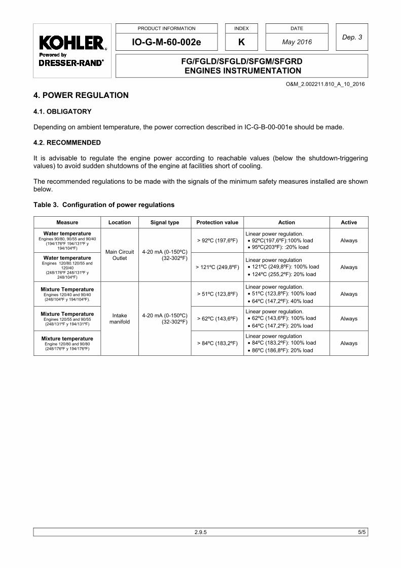
PRODUCT INFORMATION
INDEX
DATE
Dep. 3 IO-G-M-60-002e K May 2016
FG/FGLD/SFGLD/SFGM/SFGRD ENGINES INSTRUMENTATION
5/5
4. POWER REGULATION 4.1. OBLIGATORY Depending on ambient temperature, the power correction described in IC-G-B-00-001e should be made. 4.2. RECOMMENDED It is advisable to regulate the engine power according to reachable values (below the shutdown-triggering values) to avoid sudden shutdowns of the engine at facilities short of cooling. The recommended regulations to be made with the signals of the minimum safety measures installed are shown below. Table 3. Configuration of power regulations
Measure Location Signal type Protection value Action Active
Water temperature Engines 90/80, 90/55 and 90/40
(194/176ºF 194/131ºF y 194/104ºF)
Main Circuit Outlet
4-20 mA (0-150ºC) (32-302ºF)
> 92ºC (197,6ºF) Linear power regulation. 92ºC(197,6ºF):100% load 95ºC(203ºF): :20% load
Always
Water temperature Engines 120/80.120/55 and
120/40 (248/176ºF 248/131ºF y
248/104ºF)
> 121ºC (249,8ºF) Linear power regulation 121ºC (249,8ºF): 100% load
124ºC (255,2ºF): 20% load Always
Mixture Temperature Engines 120/40 and 90/40 (248/104ºF y 194/104ºF).
Intake manifold
4-20 mA (0-150ºC) (32-302ºF)
> 51ºC (123,8ºF) Linear power regulation. 51ºC (123,8ºF): 100% load
64ºC (147,2ºF): 40% load Always
Mixture Temperature Engines 120/55 and 90/55 (248/131ºF y 194/131ºF)
> 62ºC (143,6ºF) Linear power regulation. 62ºC (143,6ºF): 100% load
64ºC (147,2ºF): 20% load Always
Mixture temperature Engine 120/80 and 90/80 (248/176ºF y 194/176ºF)
> 84ºC (183,2ºF) Linear power regulation 84ºC (183,2ºF): 100% load
86ºC (186,8ºF): 20% load Always
2.9.5
O&M_2.002211.810_A_10_2016

2.002211.810_A
10-2016
INDEX Chapter 3 HANDLING AND STORAGE
INSTRUCTIONS OPERATION & MAINTENANCE MANUAL SFGLD “V”
KOHLER CO – PRIME / STAND BY
1/1
CHAPTER 3 – HANDLING AND STORAGE INSTRUCTIONS
IM-G-C-00-004e_A Lifting system for SFGLD/SFGM V engine 3.1.1 IO-C-M-00-001e_A Deferred start-up engine inspection and protection 3.1.7
O&M_2.002211.810_A_10_2016

PRODUCT INFORMATION
INDEX
DATE
Dep. 8 IM-G-C-00-004e A March 2016
LIFTING SYSTEM FOR SFGLD/SFGM V ENGINE
1/5
1 GENERAL REGULATION
- Always be careful when the lifting the engine or its components.
- Keep all the personnel away and do not walk under or around the engine when is lifted.
- Inspect all anchoring points to make sure that there are no faulty welds, loose bolts, etc., which could make the lifting of the engines dangerous.
- Be sure that the apparatus used for the lifting has been inspected, that it is in good condition and that it can bear the weight of the engine plus 10%. If you are not sure, weight the engine before raising it.
- The use of cloth slings is recommended in order to prevent damage to the engine with sharp movements. - Ensure that the slings do not make contact with sensitive parts of the engine. - Before raising the engine, make sure that it is a balanced as possible. If necessary, use slings of different
lengths. - Do not raise the engine higher than necessary. - This IP is for SFLD/SFGM V engines except of SFGLD360for continuous operation application. For this
engine consult it in IT-G-A-70-001e.
MODEL WEIGHT (KG) WEIGHT (LB)
360 4200 9300
480 5500 12000
SFGLD/SFGM560 5800 12800
�������
�����
3.1.1
O&M_2.002211.810_A_10_2016

2
2
2
F
R
3
3
Pb
R
T
1
2
3
2 PREPAR
2.1 Use 10 to
2.2 Fit slings
Front of engin
Rear of engin
3 FRONT
3.1 Secure th
Protect from fby using padd
RESOURCES:
The end of th
. End of slin
2. Shackle
3. Hook
RATION
on crane and
in place.
ne 1,970 mm
ne 2.300 mm
OF ENGIN
he end of the
friction ding
: EQUIPMENT
he front sling
g
PRO
IM-
beams with
m in total
m in total
NE
e front sling to
T & PROCES
comprises:
ODUCT INFORMA
-G-C-00-0
LIFTING
1,400 mm s
o the eyebolt
SES
ATION
004e
G SYSTEM
separation be
t
INDEX
A
FOR SFG
etween cente
Mar
GLD/SFGM
ers.
1
2
3
DATE
rch 2016
M V ENGIN
Dep. 8
NE
2//5 3.1.2
O&M_2.002211.810_A_10_2016

3
4
4
R
4
3.2 Do the sa
4 REAR O
4.1 Insert the
RESOURCES: E
4.2 Insert the
ame with the
OF ENGINE
e hook, (open
EQUIPMENT &
e two rear slin
PRO
IM-
other eyebo
E
n) in the two
PROCESSES
ngs between
ODUCT INFORMA
-G-C-00-0
LIFTING
olt
eyebolts
the gas reci
ATION
004e
G SYSTEM
irculation pip
INDEX
A
FOR SFG
pes,
Mar
GLD/SFGM
DATE
rch 2016
M V ENGIN
Dep. 8
NE
3//5
3.1.3
O&M_2.002211.810_A_10_2016

4
4
4
4
4.3 So each s
4.4 Attach the
4.5
4.6 Connect bwhen tens
��
sling is direct
e end of the
both ends ofsion is create
�� ��
PRO
IM-
ted toward e
sling to the p
Exercise ca
f the slings wed on lifting.
ODUCT INFORMA
-G-C-00-0
LIFTING
each side of t
preassemble
aution with th
with a shackle
ATION
004e
G SYSTEM
the engine.
ed fork and h
he recirculati
e as per the
INDEX
A
FOR SFG
ook.
on hoses
image on the
Mar
GLD/SFGM
e right, so bo
DATE
rch 2016
M V ENGIN
oth slings are
Dep. 8
NE
4/
e joined
/5
3.1.4
O&M_2.002211.810_A_10_2016

R
4
RESOURCES: E
4.7 Operate t
EQUIPMENT &
the crane tak
PRO
IM-
PROCESSES
king care not
ODUCT INFORMA
-G-C-00-0
LIFTING
t to cause an
ATION
004e
G SYSTEM
ny friction or r
INDEX
A
FOR SFG
rubbing agai
Mar
GLD/SFGM
nst the engin
DATE
rch 2016
M V ENGIN
ne compone
Dep. 8
NE
5/
nts.
/5 3.1.5
O&M_2.002211.810_A_10_2016

PRODUCT INFORMATION INDEX DATE
Dep.1 IO-C-M-00-001e A December 2007
DEFERRED START-UP ENGINE INSPECTION AND PROTECTION
1/6
1. INTRODUCTIONThe deferred start-up status aims to keep Kohler Basic Warranty valid for any new engine that is going to be stored for more than 6 months from factory dispatch before its initial start-up.
Kohler will grant the deferred start-up status to an engine if all of Kohler requirements as specified in this Product Information Sheet are met.
2. DEFERRED START-UP STATUS APPLICATION REQUIREMENTS
When planning to store a new engine for more than 6 months, the owner shall apply to Kohler for the deferred start-up status. In this event, Kohler authorised staff shall inspect and protect the engine fulfilling all the herein defined obligations.
An engine subject to deferred start-up shall be put into operation within the next 12 months from the date of being recognised the deferred start-up status.
Kohler will accept a maximum of two requests for deferred start-up status, the second application having to be filed no more than 12 months after the first inspection and protection of the engine provided however that the first request had been made.
As a result of said deferred start-up status, the initial start-up of an engine may occur up to 30 months after the date of dispatch from factory, with Kohler Basic Warranty remaining valid. The total storage and warranty period shall by no means exceed 42 months from the date the equipment is at the customer's disposal.
If an engine is tested after dispatch from factory and is not started at the operating site within one month from said testing, then it will be necessary to protect it and to apply for deferred start-up status in order to withhold its warranty; it will be further requisite to renew said protection once a year.
Engines stored at the mercy of the elements or in humid or corrosive atmospheres may need protections and inspections more often than specified herein. In those events, consult Kohler Siemens Business.
Since the deferred start-up status is no extension of the standard Basic Warranty, there is no cost charged for it, except for the costs of the inspection made and protective lube oil used by the Authorised Technical Service Workshop.
The Basic Warranty will become effective from the engine start-up date, provided that the duly filled start-up report is submitted within thirty days from said start-up, the requests for deferred start-up status had been filed and the protections implemented. If the owner did not apply for the deferred start-up status, the warranty period will not be extended as stated in this section.
3.
RELATED DOCUMENTS
GLPI_09 Kohler Limited Warranty for Industrial Products GLPM_09 Kohler Limited Warranty for Marine Products
3.1.7
O&M_2.002211.810_A_10_2016
PRODUCT INFORMATION
INDEX
DATE
Dep.1 IO-C-M-00-001e A December 2007
DEFERRED START-UP ENGINE INSPECTION AND PROTECTION
2/6
4. CONDITION OF ENGINES SUBJECT TO DEFERRED START-UP
At the time Customer applies for the deferred start-up status, the engine can be in any of these conditions: stored in its original packaging; unpacked and stored under conditions differing from the original ones, or mounted on the Customer's equipment.
If packed in its original packaging, the engine shall be inspected and protected by the Workshop according to the instructions contained in this Product Information Sheet.
When the engine is unpacked and stored in conditions differing from the original ones, the Workshop shall inspect the engine in order to assess its storage conditions and shall pack the engine again in original packaging in order to ensure a good state of preservation. Such inspection, protection and packaging of the engine shall conform to these specifications.
In the event of the engine being mounted on the Customer’s equipment, but not put into operation, the Workshop shall inspect, protect and pack the engine as specified herein.
�������
If the engine exhaust is piped to the outside, the Workshop shall check to ensure these connections are perfectly sealed, impeding rainwater from getting inside the engine and causing serious damage to it.
In the event of the engine having been started up and its commissioning being incomplete and not expected to be completed at once (within one to six or more months), the Workshop shall recommend that Customer should start the engine periodically (weekly) and operate it at least for one hour, idling or on low load. In addition to the items described in this Product Information Sheet, the following points shall be checked during the engine inspection: Draining of cooling circuits
Oil and coolant levels and pressures
Air filters
Starter motor
Unusual noise during operation
Draining of condensates or water ingress from exhaust system
Repair of fuel, coolant or lube oil leaks, if any.
Finally, the Workshop shall protect the engine according to the specifications contained in this document. 5. DEFERRED START-UP ENGINE INSPECTION
The Authorised Technical Service Workshop shall inspect the equipment in accordance with the following guidelines, recording findings and results on form G-19-31 “Deferred Start-up Engine Inspection”.
Engine inspection comprises the following steps:
Check packaging and protection of the engine as per document IM-C-C-00-001e and record whether the engine has been installed and whether it has been started but not completely commissioned.
Turn the engine by hand to check that it rotates freely and has not seized up.
Inspect the unpainted machined surfaces for rust. Also, check to see if all inlets and outlets of the engine (such as pump elbows, exhaust fume ducts, etc.) are adequately sealed and whether there is any part of the engine missing. If you observed any defect or fault, report on the condition of the equipment.
Remove all the rocker arms covers. Check pushrods, rocker arms, adjusting screws, valve springs for rust, corrosion or contamination. If you observed any defect or fault, report on the condition of the equipment.
3.1.8
O&M_2.002211.810_A_10_2016

PRODUCT INFORMATION
INDEX
DATE
Dep.1 IO-C-M-00-001e A December 2007
DEFERRED START-UP ENGINE INSPECTION AND PROTECTION
3/6
Boroscope the combustion chambers of all the engine cylinders to see if there is water or moisture inside. Also, check the cylinder liners or walls, cylinder head firing deck and valves for rust. If you observed any defect or fault, report on the condition of the equipment.
Remove the covers from the exhaust manifold (water-cooled exhaust manifold) and from the intake manifold. Check to see if there is moisture or corrosion inside. If you observed any defect or fault, report on the condition of the equipment.
Remove the camshaft covers. Inspect camshafts and auxiliary rocker arms for moisture or rust. If you observed any defect or fault, report on the condition of the equipment.
Remove the crankshaft covers. Inspect crankshaft, connecting rods, main bearing caps and crankcase for moisture or rust. If you observed any defect or fault, report on the condition of the equipment.
Remove the inspection covers from the gear covers (front and rear). Check the timing gears for moisture or rust. If you observed any defect or fault, report on the condition of the equipment.
Check turbochargers to see if their shafts rotate freely, if there is any blade damaged and if the axial bearings are correctly lubricated. If you observed any defect or fault, report on the condition of the equipment.
Check the water pumps of the engine to determine whether they rotate freely and their belts (in the case of belt-driven pumps) are in good condition. If you observed any defect or fault, report on the condition of the equipment.
Check the injectors (jets) of the engine to make sure they inject fuel correctly. If you observed any defect or fault, report on the condition of the equipment.
Inspect wiring and electric and electronic devices (e.g. pickups, connectors, coils, HV leads, actuators, etc.) to see if they are rusty, if they are adequately protected, if leads are coiled and packed in plastic bags. If you observed any defect or fault, report on the condition of the equipment.
Record all findings and results on form G-19-31 “Deferred Start-up Engine Inspection” included at the end of this document. 6. DEFERRED START-UP ENGINE PROTECTION
The Authorised Technical Service Workshop, after checking the equipment, shall protect or preserve it in accordance with the following guidelines.
�������
For engine protection, use only KOHLER MOTOROIL PROTECTOR.
����
The recommended protector contains oil distillates. Read the Material Safety Datasheet before use.
Spray KOHLER MOTOROIL PROTECTOR inside all of the rocker arms covers while turning the engine manually. Apply said protector to push rods, rocker arms, adjusting screws and valve springs.
Spray KOHLER MOTOROIL PROTECTOR inside the combustion chambers through the jet or spark plug housings while turning the engine manually. Spray when the piston is at TDC.
3.1.9
O&M_2.002211.810_A_10_2016

PRODUCT INFORMATION
INDEX
DATE
Dep.1 IO-C-M-00-001e A December 2007
DEFERRED START-UP ENGINE INSPECTION AND PROTECTION
4/6
�������
Before starting up engines that have been protected this way (especially gas engines), it will be necessary to inspect the combustion chambers and drain waste protective oil.
Dry the inside of the exhaust manifold and the camshaft housing, if found humid during inspection. Spray KOHLER MOTOROIL PROTECTOR on the camshaft and, only in case of humidity, into the exhaust manifold.
Spray a thin coat of TECTYL 506 or similar rust-preventive oil on the unpainted machined surfaces that will remain exposed, out of the engine (such as, for instance, the flywheel, etc.).
Hermetically seal all the flanged elbows or inlet and outlet ports of the intake, exhaust, cooling and lubricating systems with plastic, rubber or similar plugs or films.
Apply KOHLER MOTOROIL PROTECTOR with a brush to the control linkage and ball joints.
Fit the electric and electronic components with connectors, protectors and caps, if missing. Put all leads and cables in plastic bags. Also, apply TECTYL 506 or any similar substance to any components showing signs of rust damage.
7. PACKING OF DEFERRED START-UP ENGINES
These instructions apply to engines with damaged packaging or unpacked. Packing deferred start-up engines implies the steps that follow.
Spread bags of desiccant evenly over the surface to be packed. The number of bags will be proportional to the volume of the package.
Cover the engine with heat-shrinkable plastic film and heat-seal it. Protect all sharp edges to prevent damage to the plastic film. The wrapping must cover the machine entirely and be sealed at the bottom.
The wrapping must enable lifting the engine without breaking; for this purpose, make holes in the wrapping as follows. In the event of 6 or 12-cylinder engines, make two holes on both sides and one hole at each end; in the event of 8 or 16-cylinder engines, make three holes on both sides and one hole at each end. Additionally, the wrapping must have a window to gain access to the engine nameplate.
Write the date inspected, protected and packed on the engine's packaging sticker.
8. APPLICABLE FORMS
Form G-19-31 – Deferred Start-up Engine Inspection
3.1.10
O&M_2.002211.810_A_10_2016

PRODUCT INFORMATION
INDEX
DATE
Dep.1 IO-C-M-00-001e A December 2007
DEFERRED START-UP ENGINE INSPECTION AND PROTECTION
5/6
3.1.11
O&M_2.002211.810_A_10_2016

PRODUCT INFORMATION
INDEX
DATE
Dep.1 IO-C-M-00-001e A December 2007
DEFERRED START-UP ENGINE INSPECTION AND PROTECTION
6/6
3.1.12
O&M_2.002211.810_A_10_2016

2.002211.810_A
10-2016
INDEX Chapter 4 OPERATING INSTRUCTIONS
OPERATION & MAINTENANCE MANUAL SFGLD “V” KOHLER CO – PRIME / STAND BY
1/1
CHAPTER 4 – OPERATING INSTRUCTIONS
IT-G-A-00-011e_C Minimum room temperature for operating Gas engines 4.1.1
IO-C-M-15-002e_A Engine barring gear operating instructions 4.1.3 IO-C-M-20-001e_D Cooling water quality and treatment 4.1.5 IC-G-D-25-003e_B motoroil 3040 plus lube oil for natural gas-fuelled and ethanol engines 4.1.11
IC-G-D-30-001e_D Fuel specifications for Gas engines. General 4.1.13 IC-G-D-30-021e_B Fuel specifications – Us natural gas 4.1.19
IO-G-M-33-010e Installation and operation manual - Gis ignition unit display 4.1.25
IO-G-T-00-003e Starting and stopping of emergency gas engines 4.1.39 IO-G-M-40-001e_D Gas engine and ethanol carburation 4.1.43 IC-C-D-40-001e_C Emission units conversion 4.1.45
IO-C-M-25-006e_G Oil level indicators 4.1.49
IO-C-M-25-005e_D Automatic oil level controller 4.1.51
IT-G-A-00-008e_A Emissions - related installation instructions 4.1.53
O&M_2.002211.810_A_10_2016
Kohler
Kohler

PRODUCT INFORMATION INDEX DATE
Dep. 2 IT-G-A-00-011e C June 2016
MINIMUM ROOM TEMPERATURE FOR OPERATING GAS ENGINES
1/2
1. INTRODUCTION
This product information document is applicable to all gas engines installed in covered facilities and not outdoors. This document is designed to limit the minimum engine air inlet temperature, whether it is installed in a room or a container, to avoid condensation inside the same.
This document is aimed at all gas, natural gas, syngas, landfill, digester, propane and low methane number gas engines.
This document is designed to identify the minimum air inlet temperature at its installation site in order to prevent the appearance of any condensates in the same when site conditions mean that the engine will have to operate at low temperatures.
2. TEMPERATURE LIMIT IN THE ROOM OR CONTAINER ON START-UP
The gas engines air inlet temperature, should be no lower than 0ºC at start-up and the engines with injected pre-chamber 10ºC. If lower temperatures are expected, the room, container or inlet air should be pre-heated to achieve the minimum temperature indicated.
You should take into account the “Criteria for application of pre-lubrication, post-lubrication and oil and water pre-heating” described in document IC-C-D-00-008e.
For lower room temperatures, check with Kohler.
This limitation does not apply to the engine with single cooling circuit, like the emergency engines.
RECOMENDATION
In these engines with single cooling circuit, it is recommended not to start up the external cooling system of the facility until the engine water temperature is higher than 50ºC, in order to avoid the engine water temperature to drop below than 35 ºC (obtained temperature due to the preheating system of the engine).
3. TEMPERATURE LIMIT IN THE ROOM OR CONTAINER ON OPERATION
The engine air inlet temperature -air filter- should be maintained over 0ºC for the engines FGLD/SFGLD/SFGM when the engine runs over 30 % of nominal load to avoid surge problems or turbocompressor pumping. Below of 30% the load the engine can run without problems with air inlet temperature below 0ºC.
In the applications where the air inlet temperature could be below 0ºC, is suggested not to run the engine at higher load than 30% until the room temperature has been accommodated with the heat of the engine itself during the operation at low load.
4.1.1
O&M_2.002211.810_A_10_2016

PRODUCT INFORMATION INDEX DATE
Dep. 2 IT-G-A-00-011e C June 2016
MINIMUM ROOM TEMPERATURE FOR OPERATING GAS ENGINES
2/2
If it is required to run the engine above of 30% of load with air inlet temperatures to the engine below 0ºC, it will be necessary to consult it with Kohler. In order to change the supply scope of these engines (out of standard).
If the fuel gas has a high concentration of moisture or heavy hydrocarbons (like usually have biogases, syngases or well gas), the minimum temperature of the gas could be limited to avoid condensates in the carburetor due to the contact of the gas with the cold air. In this cases it is required a dew point calculation of the gas taking in account the temperature of the air and the mixture in the carburetor.
4.1.2
O&M_2.002211.810_A_10_2016

PRODUCT INFORMATION
INDEX
DATE
Dep. 2 IO-C-M-15-002e A March 2008
KOHLER ENGINE BARRING GEAR OPERATING INSTRUCTIONS
1/1
1. USE OF THE BARRING GEAR The barring gear is located on the flywheel housing on the left side of the engine. It serves to turn the crankshaft during maintenance operations (valve setting, bore scoping, etc.). To use the barring gear:
1. Remove the barring gear cover.
2. Place the drive socket over the hex nut.
3. Push the barring gear shaft, until the pinion engages the ring gear.
4. Rotate the socket to turn the flywheel.
5. Upon completion of the maintenance operations, replace the barring gear cover.
NEVER TRY TO START THE ENGINE WITH THE SOCKET CONNECTED TO THE BARRING GEAR. THE BARRING GEAR COULD SPIN, CAUSING THE SOCKET WRENCH TO BE THROWN, CAUSING SEVERE INJURY OR DEATH!
1 Complete barring gear 6 Pinion
2 Hexagonal nut (size 22) 7 Flywheel
3 Barring gear shaft 8 Ring gear
4 Spring (inspect periodically to insure that it is not broken) 9 Flywheel housing
5 Barring gear cover
Fig. 1 – Location on in-line engines Fig. 2 – Location on Vee engines
6
4
3
2
4
9
5
1
7
8
4
7
8
9
2
4
3
6
1
5
�������
4.1.3
O&M_2.002211.810_A_10_2016

PRODUCT INFORMATION
INDEX
DATE
Dep. 2 IO-C-M-20-001e D February 2016
COOLING WATER QUALITY AND TREATMENT
1/6
1. GENERAL INFORMATION When installing the engine, one point to bear in mind is the quality of the cooling water that will be used, in order to prevent heat transfer problems. Any water treatment programme mainly aims at protecting the cooling system from corrosion, deposit or scale which might impair the continuous flow of the coolant. The most common problems with an engine cooling system are as a result of corrosion, cavitation, microbiological growth, deposits and scale. Corrosion This is a metal degrading process arising from oxygen-triggered chemical or electrochemical reactions. As for cooling systems, the reactive medium is water that attacks the metallic materials of piping and heat exchangers. Corrosion is dependent upon the effect of temperature, high salinity (especially of chlorides), high water speed, alkalinity or acidity, dissolved solids, dissolved gas traces, microbial growth and pollution by manufacturing process waste. The major negative effect of corrosion is a decrease in the engine components’ fatigue strength. The following are the most frequently occurring types of corrosion: Electrochemical: Bonding of metals of varying electrochemical properties. Chemical: pH and salinity Physical: Abrasion and cavitation Differential aeration: Low deposits Bacterial: Sulphate-reducing bacteria, ferrobacteria, nitrifying bacteria, denitrifying bacteria. Cavitation Cavitation is the creation of bubbles within a liquid when it passes through a high pressure area at high speed and increases when the pressure is low in the cooling system and/or when there are leaks. In addition, as the vibration increases, so the number of bubbles in the coolant also increases. These bubbles cause erosive corrosion of the cylinder wall and frequently lead to pitting of cylinder walls. To solve cavitation problems, purge the cooling circuit thoroughly and, for applications requiring high temperature, keep the circuit under pressure. Also add coolant additives that will cover the metal surfaces and limit cavitation-induced erosion and pinholes. Scale This is the crystallisation and deposition in their solid form of different combined ions present in water, due to oversaturation of the solution at a given temperature. It usually appears as compact, hard and adhering deposits of predominantly inorganic matters, but may occasionally take soft, non-adhesive forms and be a mixture of organic and inorganic components. The major compositions of scale include, but are not limited to: calcium carbonate, calcium sulphate, calcium phosphate, magnesian salts, silica, and iron and manganese compounds. Scale forming depends on multiple factors such as temperature, salt concentration, pH and alkalinity, dissolved solids content, fluid-dynamic and thermostatic conditions of the system, etc.
4.1.5
O&M_2.002211.810_A_10_2016

PRODUCT INFORMATION
INDEX
DATE
Dep. 2 IO-C-M-20-001e D February 2016
COOLING WATER QUALITY AND TREATMENT
2/6
One of the most typical reactions is: Ca (HCO3)2 + heat CO2 + H2O + Ca CO3� Calcium bicarbonate Carbon dioxide Calcium carbonate highly soluble (760 mg/l. approx.) (hardly soluble 30 mg/l. approx.) The presence of scale has a significant impact on the performance and operation of the equipment, since some of its effects are:
- Reduction in heat transfer - Non-scheduled outages - Maintenance costs - Deterioration and overheating of exchangers - Decrease in the quantity of circulating water
Microbiological growth This basically originates in algae, fungi, bacteria and other micro-organisms to a lower extent, all of which avail themselves of light, heat, sludge and contamination by the manufacturing process or otherwise, nutrients and pH to keep growing. Special consideration is to be given to autotrophic bacteria (ferrobacteria and sulphate-reducing bacteria) which can give rise to localised corrosion. A product of this activity is sludge that builds up in the system, reducing its efficiency in addition to limiting the water passage and decreasing the flow rate, which in turn results in an increase in temperature. Both observing the colour, feel and smell of sludge and analysing it will provide information about its origin. 2. COOLING WATER QUALITY
In general, an engine coolant consists of water, additives and antifreeze.
There are several basic parameters that ensure optimum coolant quality and, thus, a trouble-free operation of the equipment.
This is why, it is strongly advisable to have cooling water analysed at the planning stage or before commissioning, so that should results fail to match the values in Table 1, the user can contact a water treatment specialist in order to take the necessary actions to ensure compliance with those specifications.
According to information provided by the equipment and the available water analysis results, it is essential to determine the optimum concentration and any appropriate external and internal treatment which will maintain the above issues under control and ensure the lowest possible water consumption.
These are the most common chemical treatments:
- Sludge dispersants or conditioners.
- Scale inhibitors.
- Corrosion inhibitors.
- Algicides
- Microbicides/biocides
- Biodispersants
In the market, there exist combined products suitable for treating different problems simultaneously.
4.1.6
O&M_2.002211.810_A_10_2016

PRODUCT INFORMATION
INDEX
DATE
Dep. 2 IO-C-M-20-001e D February 2016
COOLING WATER QUALITY AND TREATMENT
3/6
Minimum coolant requirements.
PARAMETERS VALUE UNITS
Aspect and odour Transparent, neutral odour, free from sediments
pH value 25ºC 7-9
Total hardness 35-170 / 2-9.5 ppm CO3Ca / ºd
Sulphates SO4 -2 Max 100 ppm or mg/l
Chlorides Cl- Max 40 ppm or mg/l
Nitrates Max 10 ppm or mg/l
Total dissolved solids (TDS) Max 300 ppm or mg/l
Conductivity @ 25ºC Max 400 S/cm
Total alkalinity Max 150 ppm CO3Ca
Iron Fe Max 0.5 ppm or mg/l
Aspect and Odour: Water-borne chemical compounds like phenols, several hydrocarbons, chlorine, organic matters in any state of decomposition or the products of outgassing algae and fungi can give water a very strong odour and taste, even if said compounds exist only in very small concentrations. Salts or minerals give water a salty or metallic taste, but not always an odour.
Particles such as clay and silt, a.o., although not dissolved, are transported by water in either of two ways: as a colloidal solution or in a dissolved condition that only persists while these particles are carried away by the flow of water. Colloids will settle only if undergoing coagulation or flocculation (clumping of particles).
Ph: The pH value expresses the acidity or alkalinity of an aqueous system. To be precise, it is the measurement of the hydrogen ion "activity" in a given sample; in practical terms, it is a measure of the hydrogen ion concentration in a sample Since the pH scale is logarithmic and inverse, any increase in pH by one unit corresponds to a tenfold decrease in the hydrogen ion molar concentration. The lower end of the scale (pH = 0) defines the acidity equivalent to a solution of 1.0 M HCl whereas the upper end of the scale (pH = 14) represents the alkalinity equivalent to a solution of NaOH 1.0 M.
Total hardness: The sum of temporary and permanent hardness. This is the sum of water dissolved metallic ions. It is always stated in mg /l CO3Ca Temporary hardness: caused by acid calcium or magnesium carbonate. These bicarbonates precipitate, as water warms up, to form insoluble carbonates. Permanent hardness: due to the contents of sulphates, nitrates and calcium, magnesium, sodium and iron chlorides. These salts do not precipitate as solutions.
Sulphates: Salts that dissociate in an aqueous solution and form ions which combine with calcium and magnesium. These compounds combine with hydrogen to form acids which turn water corrosive.
Chlorides: The amount of chloride ions present in the system enhances the conductivity of water and affects the protective film on the metallic surface, creating a favourable atmosphere for corrosion.
Nitrates: Salts that, in an aqueous solution, combine with hydrogen to form aggressive corrosive acids that may damage the cooling system.
Total alkalinity: Water alkalinity may be defined either as the water capacity to neutralise acids, react with hydrogen ions, or accept protons or as a measure of the water total contents of alkaline substances (OH-). Determining total alkalinity and different forms of alkalinity is important in chemical coagulation, softening and corrosion control processes.
4.1.7
O&M_2.002211.810_A_10_2016
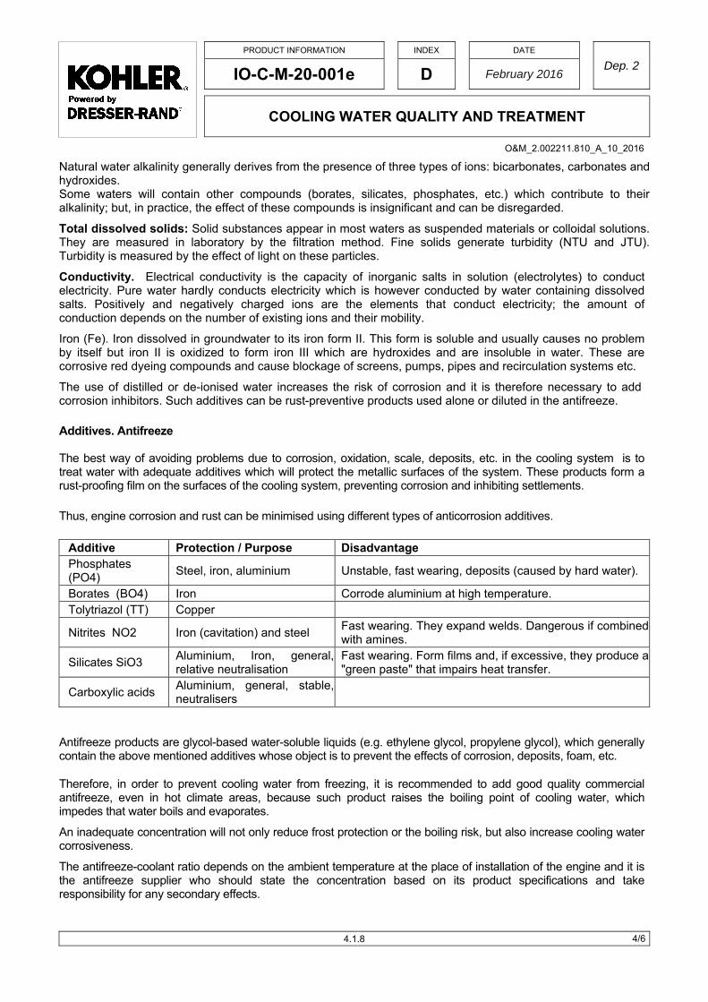
PRODUCT INFORMATION
INDEX
DATE
Dep. 2 IO-C-M-20-001e D February 2016
COOLING WATER QUALITY AND TREATMENT
4/6
Natural water alkalinity generally derives from the presence of three types of ions: bicarbonates, carbonates and hydroxides. Some waters will contain other compounds (borates, silicates, phosphates, etc.) which contribute to their alkalinity; but, in practice, the effect of these compounds is insignificant and can be disregarded.
Total dissolved solids: Solid substances appear in most waters as suspended materials or colloidal solutions. They are measured in laboratory by the filtration method. Fine solids generate turbidity (NTU and JTU). Turbidity is measured by the effect of light on these particles.
Conductivity. Electrical conductivity is the capacity of inorganic salts in solution (electrolytes) to conduct electricity. Pure water hardly conducts electricity which is however conducted by water containing dissolved salts. Positively and negatively charged ions are the elements that conduct electricity; the amount of conduction depends on the number of existing ions and their mobility.
Iron (Fe). Iron dissolved in groundwater to its iron form II. This form is soluble and usually causes no problem by itself but iron II is oxidized to form iron III which are hydroxides and are insoluble in water. These are corrosive red dyeing compounds and cause blockage of screens, pumps, pipes and recirculation systems etc.
The use of distilled or de-ionised water increases the risk of corrosion and it is therefore necessary to add corrosion inhibitors. Such additives can be rust-preventive products used alone or diluted in the antifreeze.
Additives. Antifreeze The best way of avoiding problems due to corrosion, oxidation, scale, deposits, etc. in the cooling system is to treat water with adequate additives which will protect the metallic surfaces of the system. These products form a rust-proofing film on the surfaces of the cooling system, preventing corrosion and inhibiting settlements.
Thus, engine corrosion and rust can be minimised using different types of anticorrosion additives.
Additive Protection / Purpose Disadvantage Phosphates (PO4)
Steel, iron, aluminium Unstable, fast wearing, deposits (caused by hard water).
Borates (BO4) Iron Corrode aluminium at high temperature. Tolytriazol (TT) Copper
Nitrites NO2 Iron (cavitation) and steel Fast wearing. They expand welds. Dangerous if combined with amines.
Silicates SiO3 Aluminium, Iron, general, relative neutralisation
Fast wearing. Form films and, if excessive, they produce a "green paste" that impairs heat transfer.
Carboxylic acids Aluminium, general, stable, neutralisers
Antifreeze products are glycol-based water-soluble liquids (e.g. ethylene glycol, propylene glycol), which generally contain the above mentioned additives whose object is to prevent the effects of corrosion, deposits, foam, etc.
Therefore, in order to prevent cooling water from freezing, it is recommended to add good quality commercial antifreeze, even in hot climate areas, because such product raises the boiling point of cooling water, which impedes that water boils and evaporates.
An inadequate concentration will not only reduce frost protection or the boiling risk, but also increase cooling water corrosiveness.
The antifreeze-coolant ratio depends on the ambient temperature at the place of installation of the engine and it is the antifreeze supplier who should state the concentration based on its product specifications and take responsibility for any secondary effects.
4.1.8
O&M_2.002211.810_A_10_2016

PRODUCT INFORMATION INDEX DATE
Dep. 2 IO-C-M-20-001e D February 2016
COOLING WATER QUALITY AND TREATMENT
5/6
The figure below can be used to check the recommended glycol ratio according to the ambient temperature.
As a rule, where the objective is to increase the boiling temperature of water without it evaporating, Kohlerrecommends adding around 10% of glycol to the water, not only where there is risk of freezing. The antifreeze will not only prevent the possibility of the water boiling but it will also protect against possible corrosion thanks to its anticorrosive additives which antifreeze normally contains.
In the case of ambient temperatures being very low and there is a risk of freezing, the maximum permitted amount of glycol, and for use only in engines, is 50%. The use of incorrect quantities of antifreeze in the cooling circuit can lead to a reduction in heat transfer from the cooling fluid and can affect the performance of the engine.
Here we can find ourselves faced with:
• Increased internal temperature of head and shroud
• Increased intake temperature.
• Increased exhaust temperature
Therefore, and in order to maintain the best possible performance, if the content of glycol is more than 30% then a change should be made at the end of the cold season to use coolant with % glycol in accordance with the indications of the following chart; in any case a minimum of about 10% antifreeze is recommended.
Glycol Concentration, % weight
4.1.9
O&M_2.002211.810_A_10_2016

PRODUCT INFORMATION
INDEX
DATE
Dep. 2 IO-C-M-20-001e D February 2016
COOLING WATER QUALITY AND TREATMENT
6/6
3. COOLANT TREATMENT
Maintaining cooling water in good condition will avoid the aforementioned trouble with and failure of the cooling system, as well as helping us to detect possible engine malfunction.
For instance, a decrease of the pH value together with an increase in the sulphate contents may be symptomatic of water pollution by exhaust gases. On the other hand, a rise in chloride contents may be due to contamination by seawater, and in this event, it would be advisable to inspect the engine and look for the source of the leak.
In closed circuits, where fluid refilling is infrequent, a complete corrective treatment can be applied initially, while cooling water properties can be checked subsequently on refilling large amounts of water, but at least once a year.
It is advisable to clean the engine cooling circuit as described below:
Prepare a concentrated detergent solution (for cooling circuits) in warm fresh water (40-50°C) and shake until the detergent is completely dissolved and there is no sediment. The maximum concentration should be 2%. Insert said solution into the engine cooling circuit and start the engine up until it is hot. The engine must be operating at full load for approximately two hours. Once this time has elapsed, stop the engine. Then clean the cleaning fluid using fresh water. Once rinsed and clean, immediately fill the water circuit with treated antifreeze.
In open systems that operate on large volumes of water, water treatment is very expensive. Input treatments are usual practice or, if the installation allows, chemical cleaning will be undertaken periodically. For this type of system, water tests must be made at least once a month, both at the cooling tower and in the water circuit to the engine.
Companies specialising in water analysis and treatment have test kits available so users can check the cooling system periodically.
If the results of periodic checks fail to match the values shown in Table 1, the customer must contact the water treatment specialist, who has to participate actively in preparing and in defining the protection method most suitable for the installation concerned.
Antifreeze decomposes into corrosive acids due to the cooling system's temperature cycles; contamination can build up in the system and the corrosion inhibitors will eventually get exhausted. It is therefore recommended that the antifreeze concentration in the system should be checked with a refractometer or hydrometer when testing the water quality. This will aid to ensure that the glycol concentration remains within adequate limits. By measuring the coolant density as shown below, you can determine whether the antifreeze concentration is correct:
Glycol Concentration % weight Coolant density @ 20ºC Freezing point of coolant
10% 1.02 g/l -3.4 ºC
20% 1.03 g/l -7.9 ºC
30% 1.04 g/l -13.7 ºC
40% 1.06 g/l -23.5 ºC
50% 1.07 g/l -36.8 ºC
4.1.10
O&M_2.002211.810_A_10_2016

PRODUCT INFORMATION INDEX DATE
Dep. 2 IC-G-D-25-003e B October 2012
KOHLER MOTOROIL 3040 PLUS LUBE OIL FOR NATURAL GAS-FUELLED AND ETHANOL ENGINES
1/2
1. INTRODUCTION
There are currently no standard procedures for classifying lube oils to be used in gas-fuelled and ethanol-fuelled engines. It is therefore necessary to perform exhaustive field tests in order to approve a suitable lubricant. Along with the ash content, there are several other parameters to bear in mind. These include phosphorus content, resistance to oxidation and nitration (often produced by the high working temperatures), neutralising capacity and corrosion inhibition (particularly in the presence of aggressive gases).
2. DESCRIPTION
KOHLER MOTOROIL 3040 PLUS is a lubricant designed by Kohler division in collaboration with the most prestigious lubricant manufacturers. It has been specially formulated for use in Kohler engines that operate on gas or ethanol. See documents IP IC-G-D-30-002e, IC-G-D-30-013e, IC-L-D-30-001e.
KOHLER MOTOROIL 3040 PLUS is a high-performance oil with a medium ash content. It is formulated with prime quality paraffin bases that provide it with exceptional oxidation and nitration stability, great thermal resistance, and a very low tendency to carbon deposit and residue build-up. Maintaining excellent performance after a long period of operation is thus ensured. Additionally, this oil has a low foam-forming tendency, good emulsibility and corrosion protection for cylinders and bearings, while considerably reducing wear on piston rings, liners and valve seats. All this means the oil has a long service life and filters withstand extended maintenance intervals.
Given its advanced formulation, KOHLER MOTOROIL 3040 PLUS is specially suitable for modern four-stroke engines with low oil consumption. It has been specially developed to ensure extended intervals between oil changes in engines whose usability is limited by the oil lifespan.
Its detergency and dispersancy system controls the build-up of carbon deposits and sludge, which results in cleaner engines, longer lasting oils and lower filter costs.
This oil has also been designed to provide exceptional protection against piston abrasion and wear of cylinder liners and piston rings.
3. APPLICATIONS
KOHLER MOTOROIL 3040 PLUS has been specially designed and is recommended for providing the highest performance in Kohler engines that operate on natural gas and ethanol. It can however be used in all kinds of naturally-aspirated or supercharged four-stroke engines, whether high or medium rated, that require a lubricant having a medium ash content. It is designed to ensure optimum engine life and lower maintenance costs. Its scope of application encompasses stoichiometric combustion and lean-burn engines as well, ensuring low oil consumption in both cases.
Given its low zinc and phosphorus content, this lube oil can be used in engines fitted with a catalytic converter, which require lube oil having a medium ash content.
Its advanced technology means any wear on the valve train components can be monitored as well as reducing the risk of abrasion, scoring and accelerated wear of pistons and piston rings. The end result means lower engine operating and maintenance costs.
4.1.11
O&M_2.002211.810_A_10_2016

PRODUCT INFORMATION
INDEX
DATE
Dep. 2 IC-G-D-25-003e B October 2012
KOHLER MOTOROIL 3040 PLUS LUBE OIL FOR NATURAL GAS-FUELLED AND ETHANOL ENGINES
2/2
4. ADVANTAGES AND BENEFITS
- Excellent resistance in the presence of oxidation and nitration. - Very high protection of cylinder head valve seats and guides. - Excellent protection against piston scoring and liner surface wear. - Excellent engine cleanliness. - Minimum deposit build-up. - High foam-forming and corrosion resistance. - Excellent performance of the alkaline reserve. - Longer oil and filter life. - Lower maintenance costs.
5. HEALTH AND SAFETY No special precautions are required for its use, except good personal hygiene and avoiding contact with the skin for extended periods of time. There is a Safety Data Sheet available on request.
TYPICAL CHARACTERISTICS
PROPER KOHLER MOTOROIL 3040 PLUS Viscosity, SAE grade 40
Flashpoint, Open Cup method, oC D-92 240
Freezing point, oC D-97 -21
Density @ 15o C, g/cc D-4052 0.895
Viscosity, cSt @ 100 oC D-445 13.6
Viscosity, cSt @ 40 oC D-445 124.3
TBN, mg KOH/gr D-2896 9.0
The values of typical properties shown in the table are mean values given for information purposes only. They do not constitute any guarantee These values are subject to change without prior notice. ________________________________________________________________________________________________________________
4.1.12
O&M_2.002211.810_A_10_2016
ASTM

PRODUCT INFORMATION INDEX DATE
Dep. 2 IC-G-D-30-001e D March 2014
FUEL SPECIFICATIONS FOR GAS ENGINES. GENERAL
1/5
1. AIM
This product datasheet defines the conditions a gas must comply with in order for it to be used as a fuel in Kohler gas engines. Every parameter or component out of this specification should be consulted to and authorized by Kohler, else Kohler won't take any malfunctioning responsibilities.
2. GASES USED AS ENGINE FUELS
The gaseous fuels used in internal combustion engines are available in a large variety of compositions and conditions of supply, which will affect the configuration, design, life expectancy and performance of the engine to a greater or lesser extent,. The gaseous fuels used in Kohler engines may range from "dry" natural gas to different kinds of synthesis gases resulting from thermochemical processes or the anaerobic digestion of organic matters.
In all cases, the gas is a mixture of major constituents, some combustible and others inert, and a number of minor or low-concentration components which may however play an important role for the correct operation of the engine, since they could be very harmful in quantities exceeding the manufacturer-specified limits.
As a consequence, it is necessary to assess the fitness of a given type of gas for its use in internal combustion engines. Where appropriate, the gas must be cleaned or filtered, to make it match the specifications required for its use in IC engines, by limiting its contents of corrosive and abrasive components, in order to guarantee a reasonable service life of the engine.
Depending on the type of constituents to be completely or partly eliminated from the gas so as to adjust their concentration to the specifications, one of several filtering techniques may be used. Kohler does not wish to make any recommendation with respect to any of them, provided that the limit values specified in this document are complied with. However, Kohler has experience in this field and may be consulted for advice by the customer, on the understanding that Kohler will not assume any responsibility for the effectiveness or performance of the recommended equipment or systems. Any such responsibility being directly incumbent upon the system's supplier.
2.1. BASIC PARAMETERS OF GASEOUS FUELS
There are several basic parameters to bear in mind when specifying or selecting a gas-fueled engine. Those parameters, which are listed below, can be calculated with reference to the chemical analysis of the fuel mixture:
- LHV (Lower Heat Value): This indicates the amount of energy available per unit volume or mass of gas. Its SIunits are kJ/mn
3 or kJ/kg.
- Methane number: Is an indicator of a gas mixture's pro-knock tendency. The higher the methane number, thesmaller the pro-knock tendency. This is a dimensionless number.
- Density: This is the mass per unit volume of combustible gas. It depends on pressure and temperature. So,for its measurement, standardized values of pressure and temperature are normally used, namely 101325 Pa(1 atm) and 0ºC. The SI unit of density is kg/mn
3.
- Stoichiometric A/F ratio: Indicates the minimum amount of air necessary for a complete combustion of thefuel gas mixture. It is a dimensionless number representing the ratio of air volumes or masses per unit of fuelgas.
4.1.13
O&M_2.002211.810_A_10_2016

PRODUCT INFORMATION INDEX DATE
Dep. 2 IC-G-D-30-001e D March 2014
FUEL SPECIFICATIONS FOR GAS ENGINES. GENERAL
2/5
3. ANALYSIS OF FUEL GAS
For the characterization of the gas to be used as a fuel, it will be necessary to carry out a chemical analysis of the same. Such an analysis will be made first in order to select the type of engine required and to check the gas conformity with the specifications for its use as an engine fuel. Additionally, gas analysis shall be conducted whenever harmful constituents are suspected to be present in the gas as well as from time to time as part of the installation monitoring.
3.1. SAMPLING FREQUENCY
For all the specified types of gas, the sampling frequency will be determined as follows:
Project Phase: At least one complete analysis shall be made for each application.
Start-up Phase: During the first year, analysis shall be made at least every six months for natural gas, every three months for landfill and digester gas, and every month for gases resulting from thermochemical processes.
Operation Phase: Once the gas properties have been found stable (one year without relevant variations), the following minimum analysis program can be established: once a year for natural gas, once every six months for landfill and digester gas, once every three months for gas from thermochemical processes. The intervals of the above analysis program may be increased, provided the stability of the supplied fuel gas has been demonstrated.
3.2. ANALYSIS LABORATORIES.
Kohler can advice the customer on the availability of laboratories where to make the required gas composition analysis.
In any case, Kohler reserves the right to carry out its own analysis on fuel gas fed to the engine.
4. CONTAMINANTS AND FACTORS AFFECTING THE ENGINE OPERATION
The fuel gas contaminants and factors affecting the engine operation fall within these categories:
- Important variations in the fuel gas composition and conditions of supply. In case there are variations inthe composition, pressure, temperature and humidity of the fuel gas affecting its basic specificationparameters (see point 2.1), their effect can be the engine breakdown or operation in conditions beyond thoseadvisable. By important variations, we mean also those which are within the fuel specifications but differ by±5% from the design value given to the manufacturer or the engine start-up conditions. At times, a smalladjustment will suffice to adapt the engine to the new conditions; but any change whatsoever in the suppliedgas conditions over the aforesaid limit must be reported to the engine manufacturer or maintenance staff whowill come to tune the engine as necessary.
- Contaminants that cause abrasive wear to the engine components. These include all the substancescontained in the gas, which circulate at high speed inside the engine, either upstream or downstream of thecombustion chamber, and may therefore cause abrasive wear to different parts of the engine, leading toengine failure or to a reduction of its life expectancy. Belonging to this category are such compounds assiloxanes, gas combustion salts, metal particles, oils, tar, etc.
- Contaminants that corrode the engine components. This category refers to those substances which, dueto their chemical nature, are capable of attacking both the metallic parts and the fluids of an engine, and thusleading to engine failure or to a reduction of its life expectancy. Within this group are acids compounds,
4.1.14
O&M_2.002211.810_A_10_2016

PRODUCT INFORMATION INDEX DATE
Dep. 2 IC-G-D-30-001e D March 2014
FUEL SPECIFICATIONS FOR GAS ENGINES. GENERAL
3/5
ammonia, and even condensation water that sometimes contributes to increasing the harmful effects of the contaminants, etc.
Although not explicitly referred to in this document, any gas constituent which has any of the described effects on the engine components, should be considered as included in the list of harmful contaminants and it will be the customer's responsibility to follow the engine manufacturer's recommendations specific to each case of application.
5. KOHLER SPECIFICATIONS FOR FUEL GASES
5.1. LOWER HEAT VALUE
Lower heat values of fuel gases may be within the following ranges:
NATURAL GAS: 30 / 43 MJ/mn3 equal to 7165 / 10270 kcal/mn
3 (See IC-G-D-30-002)
DIGESTER GAS: 23 / 30 MJ/mn 3 equal to 5490 / 7165 kcal/mn
3 (See IC-G-D-30-003)
LANDFILL GAS: 17 / 23 MJ/mn 3 equal to 4060 / 5490 kcal/mn
3 (See IC-G-D-30-003)
LEAN LANDFILL GAS: 14 / 17 MJ/mn 3 equal to 3350 / 4060 kcal/mn
3 (See IC-G-D-30-003)
RICH SYNGAS: 7.0 / 14 MJ/mn 3 equal to 1670 / 3350 kcal/mn
3 (See IC-G-D-30-004)
LEAN SYNGAS: 4.6 / 7.0 MJ/mn 3 equal to 1100 / 1670 kcal/mn
3 (See IC-G-D-30-004)
LOW METHAN NUMBER GAS: 40 / 47 MJ/mn 3 equal to 9560 / 11230 kcal/mn
3 (See IC-G-D-30-013)
VERY LOW METHAN NUMBER GAS: 40 / 93 MJ/mn 3 equal to 9600 / 22250 kcal/mn
3 (See IC-G-D-30-038) PROPANE: 93 / 100 MJ/mn
3 equal to 22200 / 23900 kcal/mn 3 (See IC-G-D-30-018)
5.2. CONTAMINANTS OF FUEL GAS
Listed below are the contaminants that are normally found in gases used as fuel in Kohler engines. Contaminants other than those listed are not allowed in the fuel gas.
The permissible amounts of those contaminants in each type of fuel are stated in the relevant Product Information sheets. Refer to IC-G-D-30-002e for natural gas, to IC-G-D-30-003e for digester and landfill gas, to IC-G-D-30-004e for gases from thermochemical processes, IC-G-D-30-013 for low methane number gases and to IC-G-D-30-018 for propane.
5.2.1. SULFUR COMPOUNDS LIKE H2S.
Among the sulfur compounds present in fuel gases, hydrogen sulfide (H2S) is the most common one. Hydrogen sulfide is a corrosive compound that is normally contained in gases resulting from the decomposition of organic matter. There are limitations to its concentration in fuel gases because:
- H2S attacks the metal parts of the engine - above all those containing copper - reducing their service life andperformance.
- H2S leads to premature degradation of lubricating oil. Indeed, an acidic constituent, H2S will attack the oiladditives, reducing the life of oil, if its concentration is out of the specifications.
- H2S generates sulfur oxide releases at the exhaust. Emissions of sulfur oxides are limited by law and alsoattack the exhaust gas piping, silencers, turbochargers, valves, etc.
4.1.15
O&M_2.002211.810_A_10_2016

PRODUCT INFORMATION
INDEX
DATE
Dep. 2 IC-G-D-30-001e D March 2014
FUEL SPECIFICATIONS FOR GAS ENGINES. GENERAL
4/5
5.2.2. HALOGENATED COMPOUNDS ( F, CL, BR, I ) SUCH AS CL –
Halogenated compounds may be very harmful to the engine, if they are present in the form of acidic elements in the fuel gas or in the combustion products. They normally develop in landfill gases, and to a lesser extent, in digester gases and in gases from thermochemical processes. Due to their chemical nature, the acids of this type of constituents are extremely corrosive, they attack almost all the metallic parts of the engine and destroy the additives of lubricating oil, thus reducing its life. 5.2.3. SILICON COMPOUNDS
Silicon compounds appear in fuel gases in either of two type groups: a) inorganic silicon compounds, having their origin in mineral material introduced in the gas flow, such as
silicates and silica, and which can be classified in the group of gas-borne solid particles; or b) organic silicon compounds, which include siloxanes as the most frequent ones, are hard to detect because
they require special analysis techniques, generally have their origin in the degradation of the many silicon-based products used in the industry for manufacturing general-purpose products, paints, cosmetics, cleaning products, etc.
Those compounds are present in the form of gas or vapor in the fuel flow and, generally, are harmless to the engine until their combustion. Combustion transforms the silicon they contain into silicon dioxide, silicates and other crystalline compounds that precipitate, forming abrasive particles inside the engine and jamming valves, pistons and other parts essential to the operation of the engine. Moreover, a portion of the silicon content migrates from the combustion chamber to the lubricating oil, reducing the oil properties, which in turn affects engine parts that are not in direct contact with the combustion chamber.
5.2.4. AMMONIA (NH3)
Ammonia is a chemical compound that can either attack different elements of an engine alone or combine with other more acidic constituents to form ammonia salts that will abrade the engine components. Also, the NOx emissions of the engine may increase, as ammonia compounds pass through the combustion chamber, where ammonia transforms itself into nitrogen oxides.
5.2.5. RESIDUAL OILS AND TAR
Oils and tar are usually carried along by the fuel gas. They are in the liquid phase or they condense when the gas temperature decreases. Their presence is attributable to lubricant leaks in the gas compression equipment. However, they are also present in large quantities in gases from thermochemical processes. Their effects on the engine include plugging of filters and regulators, as well as a lower performance of the turbochargers and dirtying of air coolers, etc.
5.2.6. SOLID PARTICLES
Solid particles act as abrasives on the engine components and they also give rise to failure when they accumulate and block certain items of equipment impeding them to operate correctly. Solid particles are the major source of inorganic silicon entering the engine with the fuel gas.
4.1.16
O&M_2.002211.810_A_10_2016

PRODUCT INFORMATION INDEX DATE
Dep. 2 IC-G-D-30-001e D March 2014
FUEL SPECIFICATIONS FOR GAS ENGINES. GENERAL
5/5
5.3. ENGINES WITH A CATALYTIC CONVERTER
The Kohler engines with a catalytic converter to reduce emissions deserve a special treatment within this document. Catalytic converters require the fulfillment of several special requisites in terms of fuel gas contaminants and lubricating oils used in the engine. This is why the fuel gas specifications must be checked by Kohler in accordance with the type and brand of catalytic converter whenever one is installed on the engine. (See IC-G-D-45-001)
Catalytic converters may be reliably used only on natural gas-fueled engines. All other types of gas do not meet the specifications required by the catalytic converter manufacturers.
6. ENGINE LUBE OIL ANALYSIS AS AN INDICATOR OF THE FUEL GASCHARACTERISTICS.
On certain occasions, lubricating oil analysis may serve as a relative measure of the quantities of contaminants that may show up in a fuel gas fed to the engine.
Lubricating oil is one of the engine consumables that permit to rapidly notice a deterioration of their properties due to the increase in the amounts of contaminants in the fuel gas.
In those installations where there are no continuous sampling of gas contaminants and where it is thus possible to have periods of time in which the limits specified in this document could be surpassed, we recommend, for a reliable operation of the engine, that the lubricating oil of the engine should be analyzed frequently according to the criteria set forth in Product Information Sheet IO-G-M-25-001e. Those analysis would allow to predict the type of contaminants entering the engine or which components of the engine are getting deteriorated, before any breakdown occurs.
Depending on the oil analysis results, it might be decided to make a specific analysis of the fuel gas contaminants which might be affecting the engine, so as to be able to take any appropriate actions rapidly and effectively.
4.1.17
O&M_2.002211.810_A_10_2016

PRODUCT INFORMATION
INDEX
DATE
Dep. 8 IC-G-D-30-021e B May 2014
FUEL SPECIFICATIONS – US NATURAL GAS
1/5
1. ANALYSIS OF FUEL GAS For the characterization of the gas to be used as a fuel, it will be necessary to carry out a chemical analysis of the same. Such an analysis will be made first in order to select the type of engine required and to check the gas conformity with the specifications for its use as an engine fuel. Additionally, gas analysis shall be conducted whenever harmful constituents are suspected to be present in the gas as well as from time to time as part of the installation monitoring. Below are the basic parameters of the fuel gas which need be checked, according to the gas origin. 1.1. NATURAL GAS Natural gas consists in a mixture of light hydrocarbons and inert constituents. It is of mineral origin. Its composition will be determined by analyzing at least the following parameters:
1. Description of the place where the analysis is conducted (within an installation or at a location)
2. Date/time of sampling
3. Date/time of analysis
4. Analysis procedures employed
5. Gas temperature and pressure
6. CH4 concentration (Vol %)
7. C2H6 concentration (Vol %)
8. C3H8 concentration (Vol %)
9. C4H10 concentration (Vol %)
10. C5H12 concentration (Vol %)
11. +C6 concentration (Vol %)
12. CO2 concentration (Vol %)
13. N2 concentration (Vol %)
14. O2 concentration (Vol %)
15. CO concentration (Vol %)
16. H2 concentration (Vol %)
17. H2S concentration (ppm or mg/mn3)
18. Gas relative humidity (%)
As a general rule, the above elements are the usual constituents of natural gas and their measurement is by gas chromatography. However, where there are doubts about the total gas composition, it will be necessary to check additionally for the presence of the following compounds:
19. Halides concentration (ppm or mg/mn3)
20. Siloxanes concentration (mg/mn3): at least TMOH, TMS, L2, L3, L4, D3, D4, D5
21. NH3 concentration (ppm or mg/mn3)
22. BTEX concentration (ppm or mg/mn3)
23. Oils and tar concentration (mg/mn3)
24. Solid particles concentration (mg/mn3)
4.1.19
O&M_2.002211.810_A_10_2016

PRODUCT INFORMATION INDEX DATE
Dep. 8 IC-G-D-30-021e B May 2014
FUEL SPECIFICATIONS – US NATURAL GAS
2/5
2. KOHLER SPECIFICATIONS FOR FUEL GASES
2.1. LOWER HEAT VALUE
Lower heat values of natural gas may be within the following range:
37.5 / 42 MJ/mn3 equal to 950 / 1050 Btu/SFC natural gas
As for engines with a mechanical carburetion system, the maximum permissible variation in the gas LHV is ±5% with regard to the carburetion point. Greater variations would mean that carburetion must be readjusted. Engines with an electronic carburetion system must be used where LHV variations can be as high as ±10%; above this limit, the gas composition has to be continually monitored with an analyzer.
LHV variation in excess of 1%/min. absolute value shall not be allowed over time.
2.2. METHANE NUMBER
The minimum value for the methane number (AVL) of natural gas is fixed at 75. For lower values, contact Kohler .
2.3. SUPPLIED GAS CONDITIONS
In this respect, the following applies:
2.3.1. SUPPLIED GAS PRESSURE AND TEMPERATURE
Since the acceptable gas pressure and temperature at the inlet to the engine depend on the carburetion system the engine is equipped with, refer to the following Product Information documents for the applicable ranges:
- IC-G-D-30-007e: Engines with a TECJET 50+ type electronic carburetion system
- IC-G-D-30-040e: Engines with a TECJET 52 type electronic carburetion system
- IC-G-D-30-008e: Engines with a mechanical carburetion system
- IC-G-D-30-015e: Engines with a ELEKTRA 50 type electronic carburetion system
- IT-G-A-00-011e : Minimum room temperature for operating gas engines
2.3.2. GAS HUMIDITY
The gas relative humidity at the inlet to the gas ramp shall always be less than 80% and by no means shall water be allowed to condense over the engine components. Therefore, we recommend that gas is fed to the engine at a temperature exceeding the water dew point by at least 15ºC. Natural gas does not usually imply serious humidity problems.
2.3.3. OXYGEN IN GAS
For engines with a mechanical carburetion system, the maximum permissible quantity of oxygen (O2) in the gas is 2% vol. For higher values or fluctuations greater than ±1% in relation to the carburetion point, it will be necessary to use engines with an electronic carburetion system and continuous monitoring of the gas composition by an analyzer.
2.3.4. HYDROGEN IN GAS
The maximum permissible hydrogen (H2) content in a fuel gas is 12% vol. H2.
4.1.20
O&M_2.002211.810_A_10_2016

PRODUCT INFORMATION INDEX DATE
Dep. 8 IC-G-D-30-021e B May 2014
FUEL SPECIFICATIONS – US NATURAL GAS
3/5
2.3.5. HIGHER HYDROCARBONS IN GAS
The maximum permissible quantity of C4+ hydrocarbons (butane and higher) shall not exceed 2% of the total gas mixture volume. For greater percentages, contact Kohler .
Therefore, we recommend that gas is fed to the engine at a temperature exceeding the gas dew point by at least 15ºC.
2.4. CONTAMINANTS OF FUEL GAS
Listed below are the maximum permissible values of the contaminants that are normally found in natural gas used as fuel in Kohler engines. The stated limits may not be exceeded; neither are contaminants - other than those listed below - allowed in the fuel gas.
2.4.1. SULFUR COMPOUNDS STATED AS H2S.
For Kohler engines, the maximum permissible limit of H2S equivalent* is set at:
300 ppm ---- 455 mg /mn3 ENGINES WITHOUT CATALYTIC CONVERTER
100 ppm------- 150 mg /mn3 ENGINES WITH A CATALYTIC CONVERTER
*: In order to calculate the H2S equivalent in other sulfur compounds, the mass of S present in the sulfur compound may be taken as a basis for the mass of H2S, considering organic and inorganic compounds.
2.4.2. HALOGENATED COMPOUNDS ( F, Cl, Br, I ) STATED AS Cl-
HF and HCl are the most harmful acids; therefore, their concentration is specified in mg of Cl – equivalent /mn
3
and the remaining constituents are considered as if they were chlorine, using the following equations:
Fluor = 2 Chlorine Bromine = 0.5 Chlorine Iodine = 0.25 Chlorine
Accordingly, for Kohler engines, the maximum permissible level of halides, expressed as chloride equivalent, is set at:
80 ppm ---- 100 mg Cl - equivalent* / mn
3 ENGINES WITHOUT CATALYTIC CONVERTER
6.5 ppm ----8 mg Cl - equivalent* / mn
3 ENGINES WITH A CATALYTIC CONVERTER
*: Organic and inorganic halides must be taken into consideration.
2.4.3. SILICON COMPOUNDS
Kohler has set the maximum permissible content of silicon in a fuel gas at:
7 mg / mn3 * ENGINES WITHOUT CATALYTIC CONVERTER
NIL ENGINES WITH A CATALYTIC CONVERTER
In calculating the proportion of silicon in siloxanes, it is reasonable to take an average of 37% of silicon per total siloxanes.
*: Given the difficulties in analyzing and quantifying the silicon compounds in a fuel gas (Contact Kohler for information on reference laboratories), it is generally agreed that the silicon content in the oil of the engine should not exceed 75 ppm during the contracted maintenance period of the engine concerned. Accordingly, this value may also be deemed to be the maximum relative limit of silicon in the fuel.
4.1.21
O&M_2.002211.810_A_10_2016

PRODUCT INFORMATION INDEX DATE
Dep. 8 IC-G-D-30-021e B May 2014
FUEL SPECIFICATIONS – US NATURAL GAS
4/5
2.4.4. AMMONIA (NH3)
For Kohler engines, the maximum permissible content of ammonia in the fuel gas is set at:
− 60 ppm ---- 45 mg / mn3
2.4.5. RESIDUAL OILS AND TAR
Condensation is not allowed.
Consult Kohler about analysis methods.
2.4.6. SOLID PARTICLES
Kohler has established the following limits in connection with the presence of solid particles in fuel gas:
Maximum permissible particle size: 5 microns (µm)
Maximum concentration of particles 1 to 5µm in size:
10 mg / mn3
4.1.22
O&M_2.002211.810_A_10_2016

PRODUCT INFORMATION
INDEX
DATE
Dep. 8 IC-G-D-30-021e B May 2014
FUEL SPECIFICATIONS – US NATURAL GAS
5/5
3. SUMMARY TABLE
Symbol Parameter Limit value Engine/application Comments LHV Lower heat value 37.5 – 42 MJ/mn
3 All Natural gas engines Natural gas
LHV LHV variation
<±5% Mechanical carburetion Readjust carburetion
<±10% Electronic carburetion
>±10% Electronic carburetion Continuous gas analyzer
Continuous gas analyzer required
LHV LHV gradient <1%PCI/min All Natural gas engines
MN Methane number >75 All Natural gas engines
P & T Supplied gas pressure and temperature
IC-G-D-30-007e Electronic carburetion TECJET 50+
IC-G-D-30-040e Electronic carburetion TECJET 52
IC-G-D-30-008e Mechanical carburetion Zero pressure regulator and screw
IC-G-D-30-015e Electronic carburetion ELEKTRA 50
IT-G-A-00-011e All Natural gas engines Minimum room temperature
Gas humidity <80% All Natural gas engines No condensation
WetDewT Wet gas dew point >15º less than Tgas All Natural gas engines Recommended
O2 Oxygen in gas <2% vol.
Mechanical carburetion Readjust carburetion <±1% carb. point
O2 Oxygen in gas >2% vol.
Electronic carburetion Continuous methane meter for automatic setting of carburetion >±1% carb. point
H2 Hydrogen in gas <12% vol. All Natural gas engines
C4+ Higher hydrocarbons <2% vol. All Natural gas engines
DryDewT Dry gas dew point >15º less than Tamb All Natural gas engines @ max. supplied gas P. Recommended
H2S hydrogen sulfide equivalent <300 ppm W/o catalytic converter
Total sulfur: H2S equivalent <100 ppm W/ catalytic converter
Cl - Chlorine equivalent <80 ppm W/o catalytic converter
F, Cl, Br, I organic and inorganic <6.5 ppm W/ catalytic converter
Si Silicon and siloxanes <7 mg/mn
3 W/o catalytic converter Analyze: TMOH,TMS,L2,L3,L4,D3,D4,D5 Besides, <75ppm of Si in engine oil Nil W/ catalytic converter
NH3 Ammonia <60 ppm All Natural gas engines
Tar Oils and tar Condensations not allowed
All Natural gas engines Condensable oil vapors
Dust Solid particles <5 m All Natural gas engines
Larger size not allowed. <10 mg/mn
3 (1-5m) All Natural gas engines
Summary table of natural gas fuel specifications for Kohler engines
4.1.23
O&M_2.002211.810_A_10_2016

PRODUCT INFORMATION
INDEX
DATE Dep. 2
IO-G-M-33-010e June 2013
INSTALLATION AND OPERATION MANUAL - GIS IGNITION UNIT DISPLAY
1/14
1. INTRODUCTION Once the display has been properly connected in accordance with the guidelines set out in IM-G-C-33-004, it is then ready for use. This document lists the steps required to configure the display and also sets out the different features provided: data visualization, parameter settings. 2. DISPLAY CONFIGURATION
Configuration is divided into two steps:
- In order to connect the ignition unit to the display, first you have to configure the unit. - Screen configuration
For both steps, you have to access the Device Menu display
2.1. DEVICE CONFIGURATION To configure the devices you wish to view, you have to access the Device Setup menu within the Device Menu view via the display. The steps for including data related to the GIS ignition unit on the display are outlined below:
1. Clicking the Add New button displays the following window shown in Figure 2
Fig. 1 – Screenshot of Device Menu
4.1.25
O&M_2.002211.810_A_10_2016

PRODUCT INFORMATION
INDEX
DATE Dep. 2
IO-G-M-33-010e June 2013
INSTALLATION AND OPERATION MANUAL - GIS IGNITION UNIT DISPLAY
2/14
Fig. 2 – Selecting a new device
2. Then, select the device you want to connect. In this case, choose the MIC4 option.
3. The node number must be entered. All KOHLER GIS units have Node ID 30 set as default. After completing these steps, press the Save button to save the settings on the display.
Once this has been done, the new device will be shown in the Device Menu (see the MIC4 icon in Figure 3)
Fig. 3 - Device Menu view, once the device has been configured
4.1.26
O&M_2.002211.810_A_10_2016

PRODUCT INFORMATION
INDEX
DATE Dep. 2
IO-G-M-33-010e June 2013
INSTALLATION AND OPERATION MANUAL - GIS IGNITION UNIT DISPLAY
3/14
2.2. SCREEN CONFIGURATION By clicking the Display button in the Device Menu view, you access the next screen where you can configure the various display options.
Fig. 4 – Display settings
Select language: Press the Select button to set German, English or French as system language. Adjusting the date and time: Click the Set button and change the date and time. Screen calibration: If the touch screen is not responding properly to touch, click the Display Calibration
button. Then, tip the midpoint of the Xs displayed on the screen. This will automatically calibrate the screen.
2.3. ACCESS CONTROL CONFIGURATION The display on the GIS ignition unit can be configured to assign different levels of access to different user types. To access the access control configuration menu, simply click the button that appears on the left of the display:
4.1.27
O&M_2.002211.810_A_10_2016

PRODUCT INFORMATION
INDEX
DATE Dep. 2
IO-G-M-33-010e June 2013
INSTALLATION AND OPERATION MANUAL - GIS IGNITION UNIT DISPLAY
4/14
By clicking this button, you can access the following menu:
Fig. 5 - Access control
In the dropdown menu at the top left, select the access level you want to configure. Once you select the access level, several options are at your disposal:
- Login/Logout: Login/Logout to a specific operating level with the access level selected - Change Pin: Change PIN access code. This can only be accessed at Master access level. - Enable/Disable Control: Enable/disable access control. This can only be accessed at Master access
level.
����
As a default setting, all Pins for all users are set to 0000. The following table describes the different user levels and rights available for each level:
4.1.28
O&M_2.002211.810_A_10_2016

PRODUCT INFORMATION
INDEX
DATE Dep. 2
IO-G-M-33-010e June 2013
INSTALLATION AND OPERATION MANUAL - GIS IGNITION UNIT DISPLAY
5/14
ACCESS PERMISSION Read only Read access to all data provided Operator Perimosos Read only
Display configuration Recording of device data GIS ignition
Reset errors Reset warnings Reset misfires
Service Operator rights
Configure Node ID Configure device GIS ignition
Energy adjustments Ignition timing adjustments Self Test Operating hours adjustment Spark plug operating hours adjustment
Master Service rights
Enabling/Disabling access control Reset all PINs Firmware update
3. USE OF GIS UNIT DISPLAY The following briefly describes each of the sessions related to the GIS ignition unit. Once the devices have been configured, you can access the Main Menu for each one. To do this, select the icon for the device you wish to view in the Device Menu view. The following screenshot shows the Main Menu of the GIS ignition unit.
Fig. 6 – Main menu on GIS ignition unit
4.1.29
O&M_2.002211.810_A_10_2016

PRODUCT INFORMATION
INDEX
DATE Dep. 2
IO-G-M-33-010e June 2013
INSTALLATION AND OPERATION MANUAL - GIS IGNITION UNIT DISPLAY
6/14
3.1. READING PARAMETERS The following briefly explains each of the screen views where data is displayed on the ignition unit: 3.1.1. Overview This view shows global operating parameters
Fig. 7 – Menu Overview
- Pick up: the green status display indicates that pickup signals are being recorded (engine running). If no signal is detected, the LED remains grey.
- Ignition Output: we get different information on the ignition outputs depending on the colour:Grey: the firing is not active
o Green: There are no misfires. Everything is working correctly. o Yellow: There were previously misfires, but currently there are no more misfires. o Red: There are misfires.
Further details on the information this led provides can be found in the Ignition view. - Ignition Enabled: This LED indicates whether the ignition unit has received a spark enabled command or
not. o Grey: the firing is not activated o Green. The firing is activated
- System: this LED displays the system status. Equivalent to Status LED on the front of the ignition unit: o Grey: the display is not communicating with the ignition unit (the ignition unit is not powered on,
the unit-screen communication is not working...) o Green: the ignition unit is recording no errors. o Yellow. The ignition unit is giving warnings/alerts (which do not lead to stopping the unit) o Red: There are errors, which lead to shut down.
- Speed: the pointer shows the engine speed. - Ignition Time: shows the global timing of the engine.
3.1.2. Timing
This view provides information on how to calculate the ignition timing the engine operates on.
4.1.30
O&M_2.002211.810_A_10_2016

PRODUCT INFORMATION
INDEX
DATE Dep. 2
IO-G-M-33-010e June 2013
INSTALLATION AND OPERATION MANUAL - GIS IGNITION UNIT DISPLAY
7/14
Fig. 8 – Ignition timing display menu
The following parameters are related to the global timing of the engine:
- Base Timing: Shows the base ignition timing programmed in the unit. The value for this parameter is set to 21° in all KOHLER engines. This base timing is corrected in "Timing correction" depending on the engine balance
- Potentiometer Timing: Displays the correction applied by the potentiometers in the unit. The value for this parameter is always set to 0 in KOHLER engines as potentiometers are not used.
- Analogue Current Input Timing: Displays the correction applied by 4-20 mA signal from the Detcon. - Analogue Voltage Input Timing: Displays the correction applied by an analogue voltage signal. The value
for this parameter is always set to 0 in KOHLER engines as no analogue voltage signal is used to adjust the advance.
- Speed Curve Correction: Displays the correction applied based on the engine speed. - Timing Correction: Displays the external correction the unit receives via communications (CAN, Modbus).
This timing correction can come from several devices: o From the display itself o From the PLC that controls the engine o From the ECU
NOTE Depending on the engine balance, the required timing advance is entered via the display. Therefore, the timing correction value is always different to 0. (It is only set to 0 for disengaged engines with an advance of 21).
- Global Timing: Displays the currently set global timing which all cylinders are running on. This value is the result of the sum of all the above parameters.
The following parameters relate to the individual timings for each cylinder. There may be cylinders that are not working with the global timing because some kind of cylinder-specific individual correction is being applied: - Minimum Relative Firing Angle: This is the lowest of the individual timings (the most retarded) of all
engine cylinders. - Maximum Relative Firing Angle: This is the largest of the individual timings (the most advanced) of all
engine cylinders. - Average Relative Firing Angle: Displays the average value of the different cylinder-specific advances in
the engine. This value does not have to coincide with the Global Timing.
4.1.31
O&M_2.002211.810_A_10_2016

PRODUCT INFORMATION
INDEX
DATE Dep. 2
IO-G-M-33-010e June 2013
INSTALLATION AND OPERATION MANUAL - GIS IGNITION UNIT DISPLAY
8/14
3.1.3. Ignition This view provides information related to the firing in each cylinder
Fig. 9 – Screenshot of secondary voltage
- Secondary Voltage: it is an estimate value of the voltage required to generate the spark in the spark plug gap.
- Misfire Indicator: This LED gives information on where the misfires have occurred in the different cylinders:
o Grey: There are no misfires. o Yellow: has previously been misfiring but currently there are none. o Red: There are misfires.
3.1.4. Energy This view displays cylinder-specific spark characteristics. The value of two parameters is shown for each cylinder:
- Spark Duration: spark duration in microseconds - Energy Output: firing energy applied to each cylinder to generate the spark
4.1.32
O&M_2.002211.810_A_10_2016

PRODUCT INFORMATION
INDEX
DATE Dep. 2
IO-G-M-33-010e June 2013
INSTALLATION AND OPERATION MANUAL - GIS IGNITION UNIT DISPLAY
9/14
Fig. 10 – Screenshot of energy parameters
3.1.5. Firing Angle This view displays the individual timings per cylinder
Fig. 11 – Screenshot of ignition timing per cylinder
3.1.6. Message Log This view displays a record of al alarms, warnings and errors. In addition, lines are also included reporting on how the on system status and operation.
4.1.33
O&M_2.002211.810_A_10_2016

PRODUCT INFORMATION
INDEX
DATE Dep. 2
IO-G-M-33-010e June 2013
INSTALLATION AND OPERATION MANUAL - GIS IGNITION UNIT DISPLAY
10/14
Fig. 12 – Screenshot of list of errors and warnings
Clicking the button, you can access the actions menu where you can perform the following functions:
- Confirm Alarms - Confirm Runtime Errors - Activate and deactivate automatic scrolling
A list of errors and warnings are outlined below.
ERROR CODE DESCRIPTION
Trigger number Number of teeth does not coincide with the set number
Trigger missing Number of teeth counted is smaller than expected number
Cycle signal missing Cam signal was not detected in time. More events were counted than expected per cycle.
Trigger period Event period between two teeth was outside the expected range.
Reset number Number of reset signals per cycle is outside expected range
Pre-processor pickup Pre-processor pickup is causing an error Overspeed Overspeed
Output board missing Output board could not be detected
Output or HV error Error occurred in output board Possible problems with primary high voltage generator (185 V)
Misfire rate Misfire rate exceeded
Low-power Voltage too low
General General warning
Temperature The maximum permissible device temperature was exceededReset by watchdog The device was restarted by the watchdog
4.1.34
O&M_2.002211.810_A_10_2016

PRODUCT INFORMATION
INDEX
DATE Dep. 2
IO-G-M-33-010e June 2013
INSTALLATION AND OPERATION MANUAL - GIS IGNITION UNIT DISPLAY
11/14
WARNING DESCRIPTION
Trigger number Number of teeth does not coincide with the set number
Trigger missing Number of teeth counted is smaller than expected number
Cycle signal missing Cam signal was not detected in time. More events were counted than expected per cycle.
Trigger period Event period between two teeth was outside the expected range.
Wrong trigger Tooth event recognised as fault Wrong reset Reset event recognised as fault
Reset number Number of reset signals per cycle is outside expected range
Pre-processor pickup trigger number
Number of events detected in the pre-processor pickup is outside the expected range
Pre-processor trigger missing Event period of pre-processor pickup is outside the expected range
Pre-processor pickup Index missing
The pre-processor pickup has not been able to detect the reset/cam signal
Pre-processor pickup Pre-processor pickup causes warning
Misfire rate Limit of misfire events exceeded
Overspeed Overspeed
Low-power Voltage too low
General General warning
Configuration data CRC error The configuration could not be read due to a CRC error
����
There are a number of errors and warnings that match the description. The difference is that when such failures occur below a rotation speed threshold, it is considered a warning and the unit continues firing. When failure occurs above this threshold, it is considered an error and the unit cuts out the ignition. This rotation speed threshold depends on the rated operating conditions the unit is configured to. 3.1.7. Information This view displays an overview of the ignition unit
4.1.35
O&M_2.002211.810_A_10_2016

PRODUCT INFORMATION
INDEX
DATE Dep. 2
IO-G-M-33-010e June 2013
INSTALLATION AND OPERATION MANUAL - GIS IGNITION UNIT DISPLAY
12/14
Fig. 13 – Screenshot of device information
3.1.8. Diagnostics This view includes further information on unit operation: board temperature, voltage.
Fig. 16 – Screenshot of the unit's operating parameters
3.2. ADJUSTING PARAMETERS Adjusting and writing parameters is carried out in the "Adjustments" session in the Main Menu.
4.1.36
O&M_2.002211.810_A_10_2016

PRODUCT INFORMATION
INDEX
DATE Dep. 2
IO-G-M-33-010e June 2013
INSTALLATION AND OPERATION MANUAL - GIS IGNITION UNIT DISPLAY
13/14
3.2.1. Adjusting the ignition timing You can adjust the ignition timing on the next screen. Adjustments can be made in increments of +- 0,1 º o +- 0,5 º.
Fig. 14 – Adjusting the ignition timing 3.2.2. Adjusting energy parameters Both the spark duration and the level of intensity can be changed on the next screen.
Fig. 15 – Adjusting energy parameters
4.1.37
O&M_2.002211.810_A_10_2016

PRODUCT INFORMATION
INDEX
DATE Dep. 2
IO-G-M-33-010e June 2013
INSTALLATION AND OPERATION MANUAL - GIS IGNITION UNIT DISPLAY
14/14
�����
KOHLER recommends that you do not change the energy parameters previously configured in the ignition unit Changing these can cause an engine malfunction. 3.2.3. Operational hours The spark plug burn time duration and operating hours of the unit can be adjusted on the next screen.
Fig. 16 – Adjusting operating hours counter
4.1.38
O&M_2.002211.810_A_10_2016

PRODUCT INFORMATION
INDEX
DATE Dep. 2
IO-G-T-00-003e September 2014
STARTING AND STOPPING OF EMERGENCY GAS ENGINES
1/4
1 AIM
The aim of this product information sheet is to define an SFGLD emergency gas engine starting and stopping procedure.
2 PREPARATIONS FOR STARTING UP FOR THE FIRST TIME
Before starting up for the first time, the following operations shall be carried out:
2.1 PRE-START INSPECTION
General checks:
- Ensure that there are no power transmitting devices connected (clutches, brakes, etc.).
- Also inspect drive belts. Examine for good condition and correct tension. If a cooling fan is used, be sure it is free to turn, the journal bearings are properly lubricated and the belt tension is correct.
- Make certain that all guards and shields are secure on engine and equipment. Remove all loose tools, rags, fittings or other equipment, which may be picked up by external moving parts of the engine.
- Use a starter bar to turn over the engine several revolutions to be sure that nothing will interfere with the turning of moving parts. Do not forget to remove the bar when this has been checked.
- Ensure that there are no oil, fuel or coolant leaks on all joined surfaces.
Refrigeration (engine coolant circuit):
- Check the coolant level and concentration. Add additional quantity if necessary. If the amount of coolant to be added is large, open the drainage valves to allow the removal of air bubbles. It is advisable to check the entire coolant circuit in order to find out the cause of any significant leaks of coolant.
- Check the entire water circuit checking that all the control valves are open and all the drainage valves are closed.
Lubrication (oil circuit):
- Check the lubricant oil levels daily; adding more oil is required to maintain the level above the minimum indicated with the dipstick, unless an automatic oil level regulator has been installed. It is advisable to check the oil level regulator periodically to make sure it works properly.
- Start the prelube system (if any) until the indicator shows a positive oil pressure.
The engines are supplied without oil. It is necessary to disassemble the drainage plugs to allow a small amount of oil and condensate to drip, accumulating in the bottom of the sump during the storage. Tighten the plugs firmly after this operation. Fill with oil in accordance with the instructions given in the chapter on maintenance.
����
4.1.39
O&M_2.002211.810_A_10_2016

PRODUCT INFORMATION
INDEX
DATE Dep. 2
IO-G-T-00-003e September 2014
STARTING AND STOPPING OF EMERGENCY GAS ENGINES
2/4
Fuel:
- Make sure that the fuel is supplied at the right pressure. If the motor is equipped with fuel cut-off valve, ensure that it is active.
Air filter:
- Check the status of the clogged air filter indicator. If the indicator is red, press the button at the top of the indicator to reset it. If the indicator turns red again when the engine reaches full load, change the main filter and the safety filter.
Batteries:
- Check connections and batteries voltage.
2.2 OPERATION
Compliance with these regulations will have a decisive influence on the life of the engine:
- Avoid sudden load increases when the engine is cold.
- Avoid prolonged operations when the engine is running with no load or a very light load.
3 PRECAUTIONS TO BE TAKEN AT EACH START-UP
The procedure for starting up an engine is described below:
3.1 Before engine start-up
1. Before starting up, locate the manual stop lever, in order to operate this if necessary.
2. Activate engine pre-lubrication to distribute the oil to all parts of the engine, IT-C-A-25-040. When necessary, activate oil and coolant pre-heating as well. See IC-C-D-00-008.
3. Carry out the pre-start-up check: purge circuits, check levels and pressures.
3.2. Engine start-up
1. Initiate the start-up sequence.
2. Monitor the oil pressure gauge when the engine has started.
If, within a period of 10 seconds, no oil pressure has been indicated, stop the engine immediately. Never keep the engine in operation without an oil pressure indication.
The oil pressure may reach 7 bar (100 psi) with cold oil at start-up
������
����
4.1.40
O&M_2.002211.810_A_10_2016

PRODUCT INFORMATION
INDEX
DATE Dep. 2
IO-G-T-00-003e September 2014
STARTING AND STOPPING OF EMERGENCY GAS ENGINES
3/4
3. The generator switch can be closed once the rated speed is ready. Normally, the idle speed can be get . in 20 or 30 seconds after pressing the start button. This time depends on the batteries conditions and ambient temperature mainly.
In case of generated connected to the grid, the synchronize process must be carried out to close the switch. The synchronization time will dependo n the stability of the grid parameters.
4. Load applications must be according to the product information:
- IC-G-B-00-002 for engines at 1500 rpm
- IC-G-B-00-003 for engines at1800 rpm
Minimum time between loads application of 5 seconds.
Do not operate a turbocharged engine for prolonged periods (fifteen minutes or above) at light load or idle. Under this condition the turbocharger may be damaged by the accumulation of carbon, which does not have a chance to burn off completely. 5. Operating inspection: There are series of important aspects, which must be checked while the engine is
in operation: - Examine the water, fuel and oil conduits in case of leaks, mechanical damage or corrosion.
- Inspect the level and status of coolant. The presence of rust, foam or oil in the coolant indicates the need to overhaul the circuit.
- Observe and note down the operating parameters. Variations with regard to the normal values may indicate that anomalies are occurring.
- Listen to the sound of the engine. Some problems such an occasional false explosions, failures of the turbocharger bearings or problems with the water pumps, may be detected at the outset by unusual sounds from the engine.
3.3. Engine Shut-down
1. Reduce the load gradually.
2. Open the generator switch once the load is off.
3. Before stopping an engine after having been operating in severe loading conditions, you should make spinning without charge or idle for 5 to 10 minutes to stabilize at moderate levels the temperatures of the various components of the turbocharger, valves and other engine parts
Before doing anything to the engine, let it cool for at least ten minutes after shut-down.
4. Check the fuel supply has been cut off at the engine.
������
������
4.1.41
O&M_2.002211.810_A_10_2016

PRODUCT INFORMATION
INDEX
DATE Dep. 2
IO-G-T-00-003e September 2014
STARTING AND STOPPING OF EMERGENCY GAS ENGINES
4/4
5. Post-lubricate the engine during five minutes after shut-down (when fitted with a pre-lube/post-lubrication system),
The exhaust pipe must be blocked off when the engine is shut down for long periods of time, to prevent rainwater or condensation from getting into the engine should be exposed to these elements.
4 NORMAL START AND STOP PROCEDURE
During normal operation, the start-up procedure shall be as follows:
1. Start the engine with both the ignition system and the fuel supply off, in order to eliminate any residual fuel from the intake and exhaust lines.
2. First turn the ignition system on and next the fuel supply.
During normal operation, the shut-down procedure shall be as follows:
1. Turn the fuel supply to the engine off.
2. Allow the engine to turn over several times and then disconnect the ignition system. Any residual fuel will get out of the system or will burn in the cylinders before the ignition system is off.
5 EMERGENCY START AND SHUT-DOWN
In case of an emergency, shut down the engine by turning the fuel supply and ignition system off at the same time. Failure to comply with this rule may lead to irreparable damage, injury or death.
Before restarting the engine after an emergency shutdown, wait for 10 minutes until the engine temperatures have stabilised. Do not restart the engine, unless the causes of the shutdown have been completely identified and the problems solved. Failing to do this may lead to irreparable damage, injury or death. Once the problems have been identified and solved, you can restart the engine according to the normal start-up procedure described in point 4.
������
4.1.42
O&M_2.002211.810_A_10_2016

PRODUCT INFORMATION
INDEX
DATE
Dep.2 IO-G-M-40-001e D July 2015
GAS ENGINES AND ETHANOL ENGINES CARBURATION
1/2
1. INTRODUCTION Tuning of an engine in order to ensure its correct operation means that different elements or parameters of the same, namely ignition timing and the air/fuel ratio, are adjusted. Depending on the application of the engine and on the specifications or regulations to be complied with, tuning will be the most appropriate to meet these requirements, e.g. maximum thermal efficiency, lowest emissions, etc. As for compliance with the regulations on permissible emission levels, it is essential to determine the proper air/fuel ratio and to this effect, the Kohler engines include adequate tuning capabilities. 2. SPECIFICATIONS The thermal balance-sheets of Kohler for gas engines and ethanol engines (lean burn in both cases) specify the NOx emission level that can be achieved for each engine, based on the preset ignition timing and the different cooling water temperature settings. The engine carburation is adjusted so that the specified NOx level is complied with in each case. Normally, the NOx value is related to 5% Oxygen (provided the applicable legislation does not specify another reference oxygen level for correction).
���������
Never carburet an engine, taking the percentage value of oxygen in the exhaust as a reference, but the NOx referred to above. In rich burn engines, the target is to maximize the emissions’ reduction; therefore, a 3 Way catalyst is used. In these cases the carburetion must be done in order to get the conjunction of the minimum possible NOx and CO emissions.
����
To calculate the emissions, refer to doc. IC-C-D-40-001e “Emission Units Conversion”. 3. REMARKS 1- Compliance with this specification is conditional upon correct tuning and adequate maintenance of the engine, in particular with regard to ignition timing and spark plugs. 2- On gas engines with mechanical controller, engine carburation faults may occur mainly due to any of the following circumstances: - Change in the gas supply conditions (pressure, temperature, humidity and composition of gas). - Change in room temperature or in the temperature of the intake manifold. - Plugging of air filters.
4.1.43
O&M_2.002211.810_A_10_2016

PRODUCT INFORMATION
INDEX
DATE
Dep.2 IO-G-M-40-001e D July 2015
GAS ENGINES AND ETHANOL ENGINES CARBURATION
2/2
As a result, it is necessary to increase exhaust emission controls with a view to making any correction of the air/fuel ratio that may be required to prevent the engine from running at risk. 3- Unusual emission values can denote any of different problems with the engine, according to the component of the exhaust gases which is out of standard and the engine behaviour. For instance: - High oxygen level: denotes ignition problems (old spark plugs, broken or defective spark plug, faulty
connection of a wire, failure of the ignition unit...). It is associated with a high level of Total Hydrocarbons (THC), if measured. Also, the exhaust temperatures will be lower on the affected cylinder bank and possible unbalance will be observed between the two banks of Vee engines.
- The engine will not reach its rated power, although the emission levels show a good mixture: This can be
caused by air filter plugging or by problems with the throttle valve. - The engine will not reach its rated power and the emission levels denote a very poor mixture: This is due to
engine carburation faults or problems with the fuel system (low fuel pressure, dirty fuel filter, valves not opening correctly, ...). Also, the exhaust temperatures will be lightly lower and the throttle valve will be fully open.
4.1.44
O&M_2.002211.810_A_10_2016

PRODUCT INFORMATION
INDEX
DATE
Dep.2 IC-C-D-40-001e C November 2015
EMISSION UNITS CONVERSION
1/3
1. EMISSION UNITS CONVERSION For further information on emission computation and units conversion, refer to ISO 8178-1 (2006). Exhaust emissions are usually stated in any of the following units:
Parts per million - ppm (1)
Milligrams per cubic meter (normal) - mg/mn3 (2)
Grams per kilowatt-hour - g/kWh Generally analyzers measure volume, in ppm or %, in wet basis (considering the water of the exhaust gases) or in dry basis (water not considered). Some analyzers can give results in other units after making internal calculations. In case of mg/m3 units, the pressure and temperature conditions as reference must be taken into account. This can suppose differences between the values from different equipments. To compare different equipments measurement in this unit, they have to reference to the same pressure and temperature conditions. Legislations use to indicate the reference conditions to be taken. In general normal conditions, 0ºC and 1013 mbar (100 KPa) are the usual reference. Below are bases of unit conversion for a number of components: 1.1. Converting ppm to mg/mn
3 (2) Multiply the ppm value by the density of the gas to be measured under normal conditions (2), which is, in kg/mn
3:
Nitrogen Oxides, NOx such as NO2 2.053
Sulfur Dioxide, SO2 2.85
Carbon monoxide, CO 1.250
Total Hydrocarbon, THC (C/H RATIO 1.85) 0.619 (0.716 in case of natural gas)
Methane, CH4 0.716
Formaldehyde, CH2O 1.34 NMHC (Non Methane HydroCarbons) are calculated by subtracting CH4 (methane) from THC (Total HydroCarbons). When measuring ppm or mg/Nm3, the usual practice is to take a reference exhaust oxygen value; in this event, the result must be multiplied by:
20.95 - O2 ref (%) -----------------------------
20.95 - O2 measured (%)
Generally, the most frequent O2 ref (%) values are 3, 5, 7, 12 and 15, and they are specified by the applicable legislation. (1) Parts per milion by volume, sometimes noted ppmv, 1 ppm = 0.0001%
(2) (Normal conditions: Temperature 273 K and Pressure 1013 mbar)
4.1.45
O&M_2.002211.810_A_10_2016

PRODUCT INFORMATION
INDEX
DATE
Dep.2 IC-C-D-40-001e C November 2015
EMISSION UNITS CONVERSION
2/3
1.2. Converting ppm to g/kWh The formula reproduced below is approximate; the exact computation method is defined in ISO 8178-1. qm gas (g/h) = Emis (ppm)w x factorgas x Flow rate of wet exhaust gas (kg/h) / 1000 Emis (g/kWh) = qm gas (g/h) / Power (kW) where: - factor gas is the relative density-to-air ratio (or molecular weight ratio):
Diesel Natural Gas Propane Ethanol
Nitrogen Oxides, NOx 1.586 1.621 1.603 1,609
Sulfur Dioxide, SO2 2.21
Carbon Monoxide, CO 0.966 0.987 0.976 0.98
THC (C/H ratio 1.85) 0.479 0.565 0.512 0.805
Methane, CH4 0.553 0.565 0.559 0.561
Formaldehyde, CH2O 1.035 1.058 1.046 1.050
- the exhaust gas flowrate appears on the thermal balance sheets; it is a wet basis concentration value. The
emission value in ppm used in the formulae must be a wet basis value (usually NOx, SO2 and CO are measured in dry basis) and the calculation of NOx requires correction to account for the ambient humidity, defined in ISO 8178-1 (2006).
For Kohler gas engines, the Qexh / Power factor normally lies between 5 - 6.
- To change from a dry basis concentration “Emis (ppm)d“ to a wet basis concentration “Emis (ppm)w“ use the
following equation:
Emis (ppm)w = Emis (ppm)d x factorW/D
where factorW/D is in the order of: Diesel engines: 0.92 ( 0.03) Lean gas engines: 0.88 ( 0.03) Rich gas engines: 0.81 ( 0.01) Methanol engines: 0.84 ( 0.03) (3)
The factorW/D in the above equation can be calculated accurately, by applying the definition in ISO 8178-1 (2006).
When using g/bHPh units, the equivalence is 1 bHP = 0.7457 kW. In the case of ISO 8178-4 cycle performance, see paragraph 1.3 (3) Hydrated Ethanol, 5% of water
4.1.46
O&M_2.002211.810_A_10_2016

PRODUCT INFORMATION
INDEX
DATE
Dep.2 IC-C-D-40-001e C November 2015
EMISSION UNITS CONVERSION
3/3
1.3. ISO Cycles On many occasions (e.g. Marine engines), emissions are calculated by taking measurements under various operating conditions of the engine and applying weighting factors for each checkpoint. Legislations specify which cycle must be applied to calculate the emissions. These are the most common cycles: - C1 Cycle Speed Rated Speed Intermediate Speed Idling
Torque (%) 100 75 50 10 100 75 50 0
Weighting Factor 0.15 0.15 0.15 0.1 0.1 0.1 0.1 0.15 - D1 Cycle Speed Rated Speed
Torque (%) 100 75 50
Weighting Factor 0.3 0.5 0.2 - D2 Cycle Speed Rated Speed
Torque (%) 100 75 50 25 10
Weighting Factor 0.05 0.25 0.3 0.3 0.1 - E2 Cycle Speed Rated Speed
Torque (%) 100 75 50 25
Weighting Factor 0.2 0.5 0.15 0.15 - E3 Cycle Speed (%) 100 91 80 63
Torque (%) 100 75 50 25
Weighting Factor 0.2 0.5 0.15 0.15 - E5 Cycle Speed (%) 100 91 80 63 Idling
Torque (%) 100 75 50 25 0
Weighting Factor 0.08 0.13 0.17 0.32 0.3 Formula for the specific emissions calculation:
Emissions = ∑
∑
Where qm gas i is the pollutant flow (g/h) as 1.2 paragraph formula, Pi is the power and Wi is the weighting factor
4.1.47
O&M_2.002211.810_A_10_2016

PRODUCT INFORMATION
INDEX
DATE Dep. 2
IO-C-M-25-006e G March 2015
OIL LEVEL INDICATORS
1/2
1. DESCRIPTION A level indicator is a device that combines an oil level display with high and low alarms. It provides protection against any high oil level due to possible water or fuel ingress as well as against a low level arising from high oil consumption or leakage. An oil level indicator with dial means the condition of the lubricant as well as the level can be checked without having to stop the equipment. When the float hits the high or low limit switch, it activates the alarm on the equipment.
Fig.1 – Oil level indicator
1 Oil level indicator 2 High level indicator 3 High level adjuster 4 Low level indicator 5 Low level adjuster 6 Float 7 2-way valve 8 Oil sump 9 Connecting rods inspection cover
In place of this oil level indicator with high and low alarms, and if UL certification is required, the engines may be equipped with another alarm system but without an oil level indicator. Refer to IT-G-A-25-009e.
B
A
4
1
MAX.
MIN.
8
6
2 3 5 9
7
4.1.49
O&M_2.002211.810_A_10_2016

PRODUCT INFORMATION
INDEX
DATE Dep. 2
IO-C-M-25-006e G March 2015
OIL LEVEL INDICATORS
2/2
Fig.2 – UL Oil level indicator With the engine at rest, the oil level in the indicator may rise up to the high limit, occasionally indicating a situation of excess oil. This results from backflow, i.e. oil flows back from the lubricating circuit to the sump, when the engine has stopped. 2. MAINTENANCE There have been cases reported when, due to a lack of cleaning, the oil level indicator showed a normal level, whereas the amount of oil in the equipment was above or below the permissible limits due to obstruction in the pipe that connects the oil level indicator to the oil sump in the engine. Cleaning the oil level indicator is a simple process that requires little time and must be included in the engine maintenance programme. It is advisable to clean the equipment when the oil is being changed, and do so at least once a year. Cleaning involves removing the pipes, both the sump-venting pipe and the connection pipe to the oil sump, and checking to ensure they are not blocked.
1 High level alarm indicator 2 Low level alarm indicator 3 Oil controller hose to oil sump 4 Venting hose 5 2-way valve
4.1.50
O&M_2.002211.810_A_10_2016

PRODUCT INFORMATION
INDEX
DATE Dep. 2
IO-C-M-25-005e D March 2015
AUTOMATIC OIL LEVEL CONTROLLER
1/2
1. DESCRIPTION In engine-driven facilities that operate 24 hours a day or similar, it is advisable to mount an oil level controller. Diesel engines for industrial applications usually incorporate such a device, while engines for marine applications are not normally equipped with one. The oil level controller is a mechanical actuator fitted on the oil sump in the lower part of the engine. It is equipped with a floater inside a small reservoir which opens or closes the oil flow into the engine crankcase based on the oil level in the oil sump at that time. KOHLER engines do not use this latter function of the actuator, since they incorporate another system that monitors the high and low oil levels in the crankcase (Refer to IO-C-M-25-006e, IT-C-A-25-002e or IT-G-A-25-009e) For CSA-certified engines, the filling unit is equipped with sensors, a maximum and a minimum sensor, in order to send alarm signals and/or stop signals to a control panel. (Refer to IT-G-A-25-008e) Automatic oil level controller
Automatic oil level controller
Automatic CSA oil level controller
CONNECTION TO CRANKCASE
OIL SUPPLY
OIL TO SUMP
CONNECTION TO CRANKCASE OIL SUPPLY
OIL TO SUMP
4.1.51
O&M_2.002211.810_A_10_2016

PRODUCT INFORMATION
INDEX
DATE Dep. 2
IO-C-M-25-005e D March 2015
AUTOMATIC OIL LEVEL CONTROLLER
2/2
When the engine is running, the oil level in the display must be within the normal operating range. With the engine at rest, the oil level will go beyond this range due to oil flow back from the oil circuit, causing overfills. However, after restarting the engine, the oil level will lie again in the normal range. 2. MAINTENANCE Cleaning the controller indicator and checking correct operation thereof is a very simple process. It is advisable to clean the equipment when changing the oil, doing so at least once a year. Cleaning involves removing both the venting hose and the connection hose to the oil sump, and checking that they are not blocked.
4.1.52
O&M_2.002211.810_A_10_2016

PRODUCT INFORMATION
INDEX
DATE
Dep. 2 IT-G-A-00-008e A February 2010
EMISSIONS - RELATED INSTALLATION INSTRUCTIONS
1/5
1. INTRODUCTION
According to the United States Environmental Protection Agency (EPA) Ref. code of Federal Regulations 1048.130, these instructions are intended to give the installer of the engine all of the information that is necessary to properly install the engine. SFGLD series engines are stationary engines that fulfill the requirements described in 40 CFR 60 subpart JJJJ. The SFGLD series engines are constant speed only engines, and no variable speed applications are allowed. The maximum mechanical power is the value defined in the corresponding Heat Balance sheet as nominal power (100% Load) and no overloads are allowed. The mechanical power is given without mechanical water pumps. If the mechanical pumps are installed in the engine the corresponding power required by pumps must be subtracted from the nominal value.
- V engines. Water pumps power: 7 kW.
- Line engines Water pumps power: 4 kW. In order to obtain the best engine performance and maintain the engine emissions levels the maintenance schedule for each application and engine configuration must be followed.
Failing to follow these instructions when installing a certified engine in a piece of non road equipment violates federal law (40 CFR 1068.105(b)), subject to fines or other penalties as described in the Clean Air Act.
If you install the engine in a way that makes the engine's emission control information label hard to read during normal engine maintenance, you must place a duplicate label on the equipment, as described in 40 CFR 1068.105. 2. INSTRUCTIONS FOR INSTALLATION OF THE EXHAUST PIPE The maximum backpressure allowed is defined in the Heat Balance sheet and to exceed this value is not allowed. The exhaust pipeline shall be made up of as few bends as possible and no unnecessary pipe lengths, in order to reduce pressure losses to a minimum. Below are some aspects to be borne in mind when designing the installation:
- Insert the appropriate number of expansion joints into the exhaust pipeline, as will enable free expansion and contraction of the pipes under temperature changes.
- The rigid fixing of the exhaust pipes to the engine room structure usually is a source of noise and vibrations. Additionally, it may be the cause for exhaust pipeline breakage.
4.1.53
O&M_2.002211.810_A_10_2016

PRODUCT INFORMATION
INDEX
DATE
Dep. 2 IT-G-A-00-008e A February 2010
EMISSIONS - RELATED INSTALLATION INSTRUCTIONS
2/5
- The exhaust pipeline shall be secured by means of collars through which it can slide and properly distributed fixed anchorage points.
- The exhaust pipeline and silencer shall be protected and heat-insulated to avoid big heat radiations into the engine room and the subsequent reduction in the engine performance.
- The exhaust pipeline must be laid for each engine individually. Never put together the gas outlets of various engines in a single collector.
- For completion of the exhaust pipeline, there must be a condensate trap installed at the lower end of the last vertical run of exhaust pipe as well as one draining valve (see Figure 1).
A Inner Diameter D 10 mm (0.39 inch)
B Exhaust Flexible Diameter E 30º (86ºF)
C 20 mm (0.78 inch) n A
Fig. 1 – “V” Engine Installation of Exhaust Pipeline
ALTERNATIVES TO PREVENT WATER INFILTRATIONS
SILENCER
FLEXIBLE
SLIDING FIXINGPOINT
FLEXIBLE
FLEXIBLE
DIAMETER AS PER TABLE 1
CONDENSATETRAP
DRAINING VALVE
4.1.54
O&M_2.002211.810_A_10_2016

PRODUCT INFORMATION INDEX DATE
Dep. 2 IT-G-A-00-008e A February 2010
EMISSIONS - RELATED INSTALLATION INSTRUCTIONS
3/5
Although there is no problem for installing expansion joints or flexible exhaust pipes, the following should be taken into consideration:
- The expansion joints are basically designed to make good any longitudinal extension of the exhaust pipes.- To prevent exhaust pipes from moving crosswise, the pipes should be guided and attached to the engine
room structure in such a way that their longitudinal movement only is permitted to avoid damage to theexpansion joints.
- The expansion joints have one single assembly position in accordance with the direction of the exhaust gas.- The number of joints to be installed is determined by the length and layout of the exhaust pipeline.
Figures 2 and 3 show the admissible axial shift and cross travel as well as the direction of exhaust gas escape for standard Kohler flexible pipes.
The dimensions of the engine exhaust connections for V engines are given in IT-G-A-40-002e. In line engines don’t require special connections.
3. INSTRUCTIONS FOR INSTALLATION OF THE FUEL PIPE
In order to control emissions efficiently the elements and dimensions of the pipes and components must be in such way to comply the gas specifications for the fuel supply described in IC-G-D-30-007e (TECJET 50+ gas injector) or IC-G-D-30-012e (TECJET 110 gas injector).
The gas ramp must include, at least, the following elements in the same order: manual shutoff valve, filter, pressure regulator (if required) and valve train.
The fuel gas must comply with the specifications described in IC-G-D-30-002e (Gas Natural) or IC-G-D-30-003e (Biogas) or IC-G-D-00-04e (syngas). Other gas qualities or failures in the specifications meeting can affect emissions levels, being out of the emissions levels according to the 40 CFR 60 subpart JJJJ standards. Kohler is not responsible for the emission level compliance in these situations
Check leakages before engine first start.
“A” Max. (mm) “B” Max. (mm)
DIRECTION OF EXHAUS GAS
INNERLINING
Fig. 3 – Axial Shift (Compression) Fig. 4 – Cross Travel
4.1.55
O&M_2.002211.810_A_10_2016

PRODUCT INFORMATION
INDEX
DATE
Dep. 2 IT-G-A-00-008e A February 2010
EMISSIONS - RELATED INSTALLATION INSTRUCTIONS
4/5
4. ENGINE-ROOM VENTILATION The correct ventilation of the engine room allows the correct engine performance; especially in the case the engine takes the air from the room. In designing a ventilation system, the same importance should be given to the necessary volume of air as to the flow direction. The ventilation system must be able to provide sufficient combustion air and to remove radiation heat from the rest of the facility. For an estimated thermal difference of 5ºC (9ºF) between inlet and outlet air temperatures, the air inflow must be in the region of 70 m3/h per 1kW installed power. See the following table for air flow rates.
ENGINE TYPE EXHAUST MANIFOLD
AIR FLOW RATE
AIR INTAKE ENGINE ENGINE ROOM VENTILATION
TOTAL
ft3/hHP m3/hkW ft3/hHP m3/hkW ft3/hHP m3/hkW
TURBOCHARGED
WATER-COOLED
EXTERNAL FILTER 0 0 1580 60 1580 60
INTERNAL FILTER 263 10 1580 60 1843 70
DRY EXTERNAL FILTER 0 0 1580 60 1580 60
INTERNAL FILTER 263 10 1580 60 1843 70
Generally, the air flow direction in an engine room will match the following pattern:
- The entry of air in the engine room should be from the area furthest away from any sources of heat.
- The fresh air should be able to flow freely from the point of entry to the sources of heat, in its circulation towards the point of exit.
- The expulsion of hot air should be at a point directly above the most important sources of heat, avoiding the intake of the exhaust gas.
- Where the temperature of the engine room or, in particular, of the crankcase gases return lines to the intake manifold is too low, the said lines must be heat-insulated so as to prevent condensation in the said piping section.
In all cases, the hot air should be forced out of the engine room by means of an outlet duct, without allowing it to mix with the fresh ventilation air. 5.2 INSTALLATION OF AIR FILTERS
- The filters should be installed in every case in the most optimum place according to the layout of the engine room.
- A sufficient quantity of combustion air should be guaranteed.
- In case of an external air inlet, avoid any risk of water entering into the filter.
- The minimum cross section area (S) of air flow through the filter protector derives from the following equation:
S = S1 x 2 (where S1 = developed area of the filter)
- The air duct between the filter and the engine should be made of metal with a circular or rectangular section.
- The maximum admissible pressure drop after filter, measured in the air intake duct, should not be bigger than 381 mm.w.c. relative to external atmosphere. It is recommended to keep approximately 81 mm.w.c. in reserve, that is to say that with clean filter the maximum pressure drop shouldn’t exceed 300 mm.w.c.
4.1.56
O&M_2.002211.810_A_10_2016

PRODUCT INFORMATION INDEX DATE
Dep. 2 IT-G-A-00-008e A February 2010
EMISSIONS - RELATED INSTALLATION INSTRUCTIONS
5/5
- The fitting of the air intake duct should be studied by the installer and should eliminate all the abnormalforces due to the sheer weight of the air intake duct and all the vibrations which could be produced, as boththese factors could result in problems for the correct functioning of the engine.
- The air intake duct connection to engine should be made by means of a flexible rubber hose.
- Fit a drain cock at the lowest point of the air intake duct. This point is generally as near as possible to theturbochargers. It is important and necessary that, if the air intake duct were over hot parts it would be wellisolated. (See fig.4)
Fig 4
- In any case, the air temperature for combustion should not exceed in general 25°C (77ºF) at the filter entrypoint, otherwise it will be necessary to reduce the engine power.
6. ENGINE INSTRUMENTATION
The instrumentation is defined in IO-G-M-60-002e. In this Product Information sheet you can find the engine running parameters that must be monitored, the limit values for this parameters and the alarm logic operation.
7. IN USE TESTING
The U.S. EPA certification regulations for LSI engines require the engine manufacturer (Dresser-Rand A Siemens Business) to notify the equipment manufacturer that sampling of exhaust emissions must be possible after engines are installed in equipment and placed in service. If this cannot be done by simply adding a 20-centimeter extension to the exhaust pipe, you, as the equipment manufacturer, must demonstrate to Dresser-Rand A Siemens Business how to sample exhaust emissions in a way that prevents diluting the exhaust sample with ambient air.
8. ADJUST FUEL AIR RATIO
The carburetion control systems are designed to maintain the emissions level during all typical operating conditions. Under extreme or unusual operating conditions (gas quality, gas pollutant, dusty ambient, extreme season temperatures) carburetion settings need to be confirmed and potentially adjusted. To “check / adjust fuel air ratio” the exhaust emissions and actual A/F ratios are confirmed. If adjustments are necessary, they are performed using Kohler proprietary software interface and only performed by Kohler authorized service technicians.
TURBOCHARGER
INLET
AIR
AIR FILTER
DRAIN COCK
1
2
34
bar0
805
6
7 40
60
100
110
120° C
MT -90Dig ita l Tac ho me ter
HOT AIR
OUTLET
4.1.57
O&M_2.002211.810_A_10_2016

2.002211.810_A
10-2016
INDEX Chapter 5 MAINTENANCE INSTRUCTIONS
OPERATION & MAINTENANCE MANUAL SFGLD “V” KOHLER CO – PRIME / STAND BY
1/1
CHAPTER 5 – MAINTENANCE INSTRUCTIONS
5.1 Maintenance Procedures
IO-G-M-00-060e_B General maintenance of gas engine 5.1.1
IO-G-M-00-061e_C Maintenance of natural gas engine SFGLD 1800 rpm prime 5.1.5
IO-G-M-00-019e_G Maintenance of natural gas engine SFGLD stand-by 5.1.13
5.2 Description of Maintenance Operations Type E
IO-G-M-25-001e_G Gas-fueled engine oil servicing instructions 5.2.1
IO-C-M-25-001e_A Oil sampling procedure 5.2.5 IO-C-M-25-004e_A engine oil change instructions 5.2.7
IO-C-M-25-003e_A 180/240/360/480/560 engines centrifugal oil filter maintenance instructions 5.2.11
IO-C-M-25-011e Maintenance of the crankcase gas recirculation system 5.2.13
IO-C-M-25-012e_A Cleaning the oil separator filter of the crankcase gas breather 5.2.17 IO-C-M-00-006e_A engine cylinder compression test 5.2.19 IO-G-M-33-001e_C Conventional spark plug changing and maintenance instructions 5.2.23
IO-G-M-33-002e_F Conventional spark plug replacement criteria in Gas engines 5.2.27 IM-G-C-33-001e_D Conventional spark plug installation instructions 5.2.31
IO-G-M-33-003e_B Check of ignition coils and spark plug wires 5.2.33 IO-G-M-33-007e_L Maintenance of spark plugs. Overview 5.2.35 IO-G-M-33-009e_A Checking the ignition timing 5.2.37 IT-G-E-10-001e_G Adjustment of Gas and Ethanol engine valves 5.2.41 IO-C-M-35-001e_E Air filters. Maintenance 5.2.45 IO-C-M-15-001e_B Damper condition monitoring 5.2.51 IO-C-M-20-002e_G Maintenance of the cooling system 5.2.55
IO-C-M-45-001e_B Maintenance of turbocharger 5.2.61
IO-G-T-35-001e_A Intake safety valve operating and maintenance procedure 5.2.65
IO-C-M-20-010e_A Maintenance of intercoolers 5.2.67 IO-C-M-60-004e Maintenance of pick-ups 5.2.71 IO-C-M-55-001e Maintenance of batteries 5.2.73
O&M_2.002211.810_A_10_2016
Kohler
Kohler
Kohler

PRODUCT INFORMATION
INDEX
DATE
Dep. 2 IO-G-M-00-060e B February 2016
GENERAL MAINTENANCE OF GAS ENGINES
1/3
MAINTENANCE INTERVALS 1. The satisfactory performance of engines depends on many factors, the most significant being:
- Mode of operation - Humidity, barometric pressure and air temperature - Number of hours operating at full load - Number of hours operating at full speed - Engine parameters: ignition timing, cooling temperatures, water flows,… - Fuel and lubrication oil quality - Proper loading of engine after start sequence - Oil and filters changes intervals - Use of Kohler products and original spare parts - Care taken to ensure that engines are adjusted to factory settings in inspections and maintenance
operations
Because of these as well as other similar factors not mentioned, it is difficult to set a precise number of hours of operation for each engine, before normal servicing becomes necessary.
The maintenance intervals listed in this section do not in any way imply an obligation on behalf of Kohler, and are given only as a guide to users for maintenance scheduling. Users must take into account operating conditions and demands to determine the maintenance operations that should be carried out more frequently than stated on the schedule. In all cases, the number of hours specified are reasonable limits, which should not be exceeded in order to ensure that the engine works correctly. If the engine maintenance schedule is not adhered to then the warranty of the same may be cancelled. This document should be studied carefully before the engine is started up for the first time.
These circumstances can modify the intervals of maintenance operations:
- Excessive exhaust back-pressure - Insufficient air supply to intake. Air quality - High crankcase pressure - Low oil pressure - Over heating of the jacket water system (boiling) - Changes in fuel quality - High air temperature - Sudden stops and alarms - Incorrect realization of maintenance operations - Deficient installation or ventilation - Incorrect air/fuel ratio - Use of non-approved oil
5.1.1
O&M_2.002211.810_A_10_2016

PRODUCT INFORMATION
INDEX
DATE
Dep. 2 IO-G-M-00-060e B February 2016
GENERAL MAINTENANCE OF GAS ENGINES
2/3
DAILY MAINTENANCE 2.
CONTROL OF COOLANT LEVEL 2.1. The coolant level must be checked daily. It is necessary to ensure that there aren’t air or steam bubbles in the system. In that case the system must be purged by hand or automatic vent valves must be installed in the top of the circuit.
The quality of the cooling water must comply with IO-C-M-20-001, which specifies not only the water quality but recommends the percentage of glycol to be used.
NEVER USE DIRTY, HARD OR SALT WATER. COOLANT NOT ONLY PRESERVES ENGINE AGAINST FREEZING, BUT ALSO PRESERVES ENGINE AGAINST CORROSION AND OXIDATION. SEE IO-C-M-20-001.
CONTROL OF OIL LEVEL 2.2. Check the engine oil level every day under identical conditions. This is to be done with the engine idling, after running for several minutes. The oil level should never be below the lower indicator mark, nor above the high limit on the dipstick. Note: If the engine has crankcase gases recirculation system, the oil level on the dipstick could be erroneous because the pressure in the crankcase is not at atmospheric pressure. Therefore, the oil level must be checked when crankcase pressure is at atmospheric pressure or the reading must be done in the devices not influenced by these pressure differences: lubrication oil level indicator or oil level regulator (with the filling valve closed).
DAILY RECORDING OF THE ENGINE DATA 2.3. It is necessary to record pressures, temperatures, levels, energy outputs... in order to be able to detect possible engine operation failures by analysing the evolution of the aforementioned parameter values. Note: Daily records may help you to solve performance problems before they arise, because of that, it is recommendable to record a high number of parameters of engine performance.
CLEANING OF THE ENGINE 2.4. Several reasons make it desirable to keep the exterior of the engine clean. Dirt from the outside can be drawn into the intake filters. Further, exterior dirt can get into the engine during normal maintenance in cylinder heads, crankcase… A number of products for cleaning the engine exterior can be used, such as pressurized steam or degreasing agents. It is necessary to be extremely careful with the electrical components of the engine.
CLEAN AND KEEP WATCH OVER ELECTRICAL CONNECTORS 2.5. Clean the electrical connectors if necessary, but before be sure that there is no tension on them.
5.1.2
O&M_2.002211.810_A_10_2016

PRODUCT INFORMATION
INDEX
DATE
Dep. 2 IO-G-M-00-060e B February 2016
GENERAL MAINTENANCE OF GAS ENGINES
3/3
NEVER BRING A FLAME OR MAKE SPARKS NEAR THE BATTERIES. FLAMMABLE STEAM CAN BE PRODUCED.
LUBRICATION OIL LEAKS 2.6. Inspect plant lubrication piping for oil leaks. Tighten hardware or change seals and gaskets if necessary. In addition, make sure the dipstick and filling plug on the inspection cover are tight.
COOLANT LEAKS 2.7. Inspect plant water piping for water leaks. Tighten hardware or change seals and gaskets if necessary. Verify that the drain holes on the water pumps are unobstructed, as their plugging could lead to serious damage.
GAS LEAKS 2.8. Inspect gas piping for leaks using a gas detector or water with soap. Tighten hardware or change gaskets if necessary.
NEVER USE A FLAME TO DETECT GAS LEAKS BECAUSE THIS CAN PRODUCE AN EXPLOSION AND PERSONS CAN BE HURT.
SPEED CONTROL LINKAGE (NOT NECESSARY FOR ELECTRONIC CONTROL ENGINES) 2.9. It is necessary to check the ball joints of the speed control linkage for clearances (greased and readjusted where appropriate).
CHECK FOR SENSORS 2.10. Temperature and pressure measures must be checked in order to detect deviations or broken sensors on engine. It is also necessary to inspect pressure and temperature sensors of the control system.
INTAKE AND EXHAUST LEAKS 2.11. Check that there are no leaks in the intake and exhaust circuits.
5.1.3
O&M_2.002211.810_A_10_2016

PRODUCT INFORMATION
INDEX
DATE Dep. 2 IO-G-M-00-061e C January 2016
MAINTENANCE OF NATURAL GAS ENGINE SFGLD 1800 RPM PRIME
1/7
1. MAINTENANCE PROGRAM The information in this maintenan ce program is complemented with product information document IO-G-M-00-060e, General Maintenance Guidelines for Ga s Engines. This maintenance program have been defined for Prime application, as indicated in the product information IC-C-D-00-002. KOHLER has developed this maintenance program to ensure optimum performance of your engine. Given that strict adherence to thi s program will benefit you, it is es sential that you follo w the in structions detailed in this manual. Failure to do so may not only jeopardize KOHLER’s warranty, but also restrict you from obtaining the best performance for equipment. The maintenance intervals listed in this section do not in any way imply an obligation on behalf of KOHLER, and are given only as a guide to use rs for mai ntenance scheduling. Users will take into account op erating conditions and demands to determine the maintenance operations that should be carried out more frequently than stated on the schedule. In all cases, the number of hours specified are reasonable limits, which should not be exceeded in order to ensure that the engine works correctly. If the engine maintenance schedule is not adhered to then the warranty of the same may be cancelled. This document and product information document IO-G-M-00-060e should be studied carefully before the engine is started up for the first time.
����
Any Check-Inspection may require a corrective operation if the element in question requires one.
�������
The maintenance jobs described below (identified with as an “E” type task) must be regarded as “additive” to each other. Accordingly, the performance of every “Ei” job implies that all previous “Ei-1”, every time as the frequency indicates it. This will require the availability of such materials and labour as may be necessary at each stage.
5.1.5
O&M_2.002211.810_A_10_2016

PRODUCT INFORMATION
INDEX
DATE Dep. 2 IO-G-M-00-061e C January 2016
MAINTENANCE OF NATURAL GAS ENGINE SFGLD 1800 RPM PRIME
2/7
1.1. Basic maintenance operations:
NEW ENGINE OR MAJOR SERVICE WORK START-UP MAINTENANCE
Jobs to be done during the initial start-up of a new engine or during the break-in phases following major overhauls (change of cylinder liners, pistons, piston rings, cylinder heads,...). They must be carried out by KOHLER authorized Repair Shop.
Job Interval Job Description
NA 0 h (Operation before starting up the engine)
- General inspection and set-up of the engine
N1 100 h
(Operations after starting up or break-in phase)
- Change oil KOHLER MOTOROIL (oil sump and cooler)
- Change oil filters
- Analyze waste oil
- Clean the oil centrifuge filter and change the paper filter
- Inspection of the gas ramp filter
- Adjustment of rocker arms and valve lifters. Measure valve height
- Check air/fuel ratio
- Adjust air/fuel ratio to full load, if necessary
- Measure the exhaust back-pressure
- Check damper temperature
- Inspect for leaks in all coolant, oil, gas and exhaust gases system
- Check the cleaning of carburetion system and admission (compressor, intercooler and inlet manifold)
- Inspection and retightening of flanges and clamps, battery terminals, connectors, flexible couplings, air filter supports, exhaust piping, oil pipes, etc.
5.1.6
O&M_2.002211.810_A_10_2016

PRODUCT INFORMATION
INDEX
DATE Dep. 2 IO-G-M-00-061e C January 2016
MAINTENANCE OF NATURAL GAS ENGINE SFGLD 1800 RPM PRIME
3/7
ROUTINE MAINTENANCE (Type "E") Minor Jobs
Job Interval Job Description
EO Daily
(Operations to be performed with the engine stopped)
- Vent the coolant circuit. Check automatic vent valves
- Drain condensates out of the exhaust Y-pipe
- Check oil pressure and temperature during the pre-lubrication phase
- With the dipstick, check for a possible increase of the oil level in the oil pan due to coolant leaks
- Verify oil heating with the pre-heater, if necessary
- Check the oil level of the pneumatic starter lubricator, if necessary
- Clean the engine and its surrounding
(Operations to be carried out with the engine idling)
- Check oil level
(Operations to be carried out with the engine stabilized)
- Check coolant level / pressure. Vent circuits
- Check oil pressure
- Inspect the air filter plugging level (reset the pilot first)
- Check oil, coolant and exhaust gases temperature
- Check the filter cleaning state pilot of the crankcase gases recirculation system. Control the crankcase pressure (*A*)
- Record engine parameters on a regular basis
- Revision of the operational stability and unusual noise
- Inspect for leaks in fuel, coolant, oil and exhaust gases
5.1.7
O&M_2.002211.810_A_10_2016

PRODUCT INFORMATION
INDEX
DATE Dep. 2 IO-G-M-00-061e C January 2016
MAINTENANCE OF NATURAL GAS ENGINE SFGLD 1800 RPM PRIME
4/7
Job Interval Job Description
E1 1.200 h
- Analyse waste oil
- Change oil filters
- Change oil KOHLER MOTOROIL (oil sump and cooler)
- Clean the oil centrifuge filter, film-thickness measurement and change the paper filter
- Clean the metallic sponge of the oil purifier
- Measure crankcase pressure
- Check air/fuel ratio
- Adjust air/fuel ratio to full load (*), if necessary
- Inspect the air filters
- Adjustment of rocker arms and valve lifters. Measure valve height
- Check safety devices and connections: temperature and pressure switches and probes
- Check battery acid level
- Check battery and starter connections
- Inspection of high voltage wires of the ignition system
- Change the filter of crankcase gases recirculation system and clean this circuit (*A*)
E3 4,800 h
or once a year
- Verify the ignition timing
- Check damper temperature
- Change air filters
- Check gaskets in the rocker arm covers
- Disassemble, clean and adjust all the speed and ignition pick-ups
- Measure the exhaust back-pressure
- Change coolant
- Verify the tightening torque of knocking sensors on stud head (20 Nm)
- Check the axial clearance, radial clearance and condition of the turbocharger vanes
����
- The spark plugs change must be made attending the IO-G-M-33-007 product information*. *It’s recommend to carry out a borescope inspection and do a compression test when changing spark plugs
- Ask Kohler to use another oil that it is not KOHLER MOTOROIL.
5.1.8
O&M_2.002211.810_A_10_2016

PRODUCT INFORMATION
INDEX
DATE Dep. 2 IO-G-M-00-061e C January 2016
MAINTENANCE OF NATURAL GAS ENGINE SFGLD 1800 RPM PRIME
5/7
Periodic interventions (Type "R") major interventions
Job Interval Job Description
R1 11,200 h
- Recondition cylinder heads.
- Clean pistons, cylinder liners and cylinder head seating on block
- Check valves driving system: valve lifters, rocker arms, push-rods, roller rocker arms and cams
- Measure cylinder liners wear
- Clean oil sump
- Check and clean the cooling system. Clean pipe bundles and change gaskets on heat exchanger and coolers
- Change oil thermostat (only V engine)
- Test thermostats of coolant circuit.
- Clean filters of coolant circuit. Change filter cartridge
- Retighten connections in knocking detection system unit.
- Check-up of electric or pneumatic starting motor.
- Check-up of battery charging alternator
- Change hoses and clamps.
- Check safety valves in intake manifold
- Check and clean the intake circuit, from the air filters outlet to the intercooler (*A*)
- Test control and safety devices: temperature and pressure switches and probes
- Change high voltage wires of the ignition system
- Recondition turbochargers
5.1.9
O&M_2.002211.810_A_10_2016

PRODUCT INFORMATION
INDEX
DATE Dep. 2 IO-G-M-00-061e C January 2016
MAINTENANCE OF NATURAL GAS ENGINE SFGLD 1800 RPM PRIME
6/7
Job Interval Job Description
R2 22,400 h
- Change complete pistons (Piston, piston rings, pin, circlips)
- Change cylinder head springs
- Change cylinder liners
- Change flexible coupling condition engine-alternator
- Inspection of elastic suspensions and alignments
- Check axial and Radial allowance of Crankshaft
- Check connecting rods
- Change conrod bearings
- Change the connecting rod bolts (maximum of 3 retightenings). Mark number of retightenings on the bolt
- Change thermostats of coolant circuit
- Recondition water pumps of main coolant circuit
R3 44,800 h
- Engine Overhaul, including its major components and systems:
Inspection of Cylinder block, change main crankshaft bearing shells, camshaft thrust drive discs and bushings
Inspection of Crankshaft
- Inspect camshafts
- Inspect timing gears and change ball-bearings
- Recondition oil pump: check gears and change bushings
- Change crankshaft counterweights fixing screws and washers
- Change damper
- Overall inspection and cleaning of coolant, oil, fuel, intake air, exhaust gas, automation systems, wiring.
- Change turbochargers
- Change connecting rods
- Change coils
- Change engine gaskets
5.1.10
O&M_2.002211.810_A_10_2016

PRODUCT INFORMATION
INDEX
DATE Dep. 2 IO-G-M-00-061e C January 2016
MAINTENANCE OF NATURAL GAS ENGINE SFGLD 1800 RPM PRIME
7/7
This maintenance program is specified for dry natural gas. The natural gas specifications are detailed in the last version of P roduct Information Sheet IC-G-D-30-002e: “Fuel specifications – natural gas”. Minimum methane number is specified in the Power Rating of the engine for this application. If methane number is less than the specified, consult with KOHLER.
(*) For installations where the gas composition is variable, it’s recommended to reduce the periods between carburetion adjustments
(*A*) Make this maintenance job only if the engine has crankcase gases recirculation system
2. ENGINE LONG TERM STORAGE When a customer has specified in advance that the engine is going to be stored, the instructions contained in Product Information Sheets IM-C-C-00-001e (storage for less tha n 6 months) and IO-C-M-00-001e (storage for more than 6 months) apply. In that case, the engine is supplied perfectly packed and sealed against external agents. It is however very important that the temperature in the warehouse used for storing the engine should remain at all times above the outside temperature to prevent condensation.
5.1.11
O&M_2.002211.810_A_10_2016

PRODUCT INFORMATION
INDEX
DATE Dep. 2 IO-G-M-00-019e G January 2016
MAINTENANCE OF NATURAL GAS ENGINE SFGLD STAND-BY
1/6
1. MAINTENANCE PROGRAM The information in this maintenan ce program is complemented with product information document IO-G-M-00-060e, General Maintenance Guidelines for Gas Engines. KOHLER has developed this maintenance program to ensure optimum performance of your engine. Given that strict adherence to thi s program will benefit you, it is es sential that you follo w the in structions detailed in this manual. Failure to do so may not only jeopardize KOHLER’s warranty, but also restrict you from obtaining the best performance for equipment. The maintenance intervals listed in this section do not in any way imply an obligation on behalf of KOHLER, and are given only as a guide to use rs for mai ntenance scheduling. Users will take into account op erating conditions and demands to determine the maintenance operations that should be carried out more frequently than stated on the schedule. In all cases, the number of hours specified are reasonable limits, which should not be exceeded in order to ensure that the engine works correctly. If the engine maintenance schedule is not adhered to then the warranty of the same may be cancelled. This document and product information document IO-G-M-00-060e should be studied carefully before the engine is started up for the first time.
����
Any Check-Inspection may require a corrective operation if the element in question requires one.
�������
The maintenance jobs described below (identified with as an “E” type task) must be regarded as “additive” to each other. Accordingly, the performance of every “Ei” job implies that all previous “Ei-1”, every time as the frequency indicates it. This will require the availability of such materials and labour as may be necessary at each stage.
5.1.13
O&M_2.002211.810_A_10_2016

PRODUCT INFORMATION
INDEX
DATE Dep. 2 IO-G-M-00-019e G January 2016
MAINTENANCE OF NATURAL GAS ENGINE SFGLD STAND-BY
2/6
1.1. Basic maintenance operations:
NEW ENGINE OR MAJOR SERVICE WORK START-UP MAINTENANCE
Jobs to be done during the initial start-up of a new engine or during the break-in phases following major overhauls (change of cylinder liners, pistons, piston rings, cylinder heads,...). They must be carried out by KOHLER authorized Repair Shop.
Job Interval Job Description
NA 0 h (Operation before starting up the engine)
- General inspection and set-up of the engine
1.2 Daily maintenance:
ROUTINE MAINTENANCE (Type "E") Minor Jobs
Job Interval Job Description
ED 24 h
- Check oil pressure and temperature during the pre-lubrication phase
- Verify oil heating with the pre-heater
- Check battery acid level
- Verify water heating with the pre-heater
1.2.1 Continuous Pre-lubrication In order to ensure perfect lubrication of all circuits of the engine, it is necessary to operate the pre-lube pump in the correct conditions, see IT-C-A-25-040. 1.2.2 Continuous Pre-heating In order to guarantee a suitable oil viscosity before the start up of the engine preheating must be used according to instruction IC-C-D-00-008. The use of water preheating improves the engine start conditions, see IC-C-D-00-008. 1.2.3 Battery Charger The correct function of the battery charger must be checked every day.
5.1.14
O&M_2.002211.810_A_10_2016

PRODUCT INFORMATION
INDEX
DATE Dep. 2 IO-G-M-00-019e G January 2016
MAINTENANCE OF NATURAL GAS ENGINE SFGLD STAND-BY
3/6
1.3 Monthly maintenance
Job Interval Job Description
EM Monthly
(Operations to be performed with the engine stopped)
- Vent the coolant circuit. Check automatic vent valves.
- Drain condensates out of the exhaust Y-pipe
- With the dipstick, check for a possible increase of the oil level in the oil pan due to coolant leaks
- Check the oil level of the pneumatic starter lubricator, if necessary
- Check battery acid level
- Clean the engine and its surrounding
(Operations to be carried out with the engine stabilized)
- Check coolant level / pressure. Vent circuits.
- Check oil level / pressure
- Inspect the air filter plugging level
- Check oil and coolant temperature
- Check exhaust gases temperature
- Record engine parameters on a regular basis
- Revision of the operational stability and unusual noise
- Inspect for leaks in fuel, coolant, oil and exhaust gases
1.3.1 Engine Start-up Every month, the engine must be started and correct performance of the following items should be checked: - Start-up process and increase in speed.
- Loading of the engine.
- Switch: making and breaking.
The start-up test must be made with a load equal to at least 40% of the engine's rated power. The engine shall run during a minimum of one hour. These recommendations figure in the ISO 8528-12 standard on standby sets for security duty.
5.1.15
O&M_2.002211.810_A_10_2016

PRODUCT INFORMATION
INDEX
DATE Dep. 2 IO-G-M-00-019e G January 2016
MAINTENANCE OF NATURAL GAS ENGINE SFGLD STAND-BY
4/6
Job Interval Job Description
E0 250 h
or 6 months
- Analyse waste oil
- Check and refill additive level in coolant
E1 500 h
or once a year
- Change oil KOHLER MOTOROIL (oil sump and cooler)
- Change oil filters
- Clean the oil centrifuge filter, film-thickness measurement and change the paper filter
- Clean the metallic sponge of the oil purifier
- Measure crankcase pressure
- Check air/fuel ratio
- Adjust air/fuel ratio to full load (*), if necessary
- Inspect the air filters
- Adjustment of rocker arms and valve lifters. Measure valve height
- Verify the ignition timing
- Check battery and starter connections
- Inspection of high voltage wires of the ignition system
- Change the filter of crankcase gases recirculation system and clean this circuit (*A*)
E2 1,500 h
or 3 years
- Check gas filters
- Change hoses and clamps.
- Test thermostats of coolant circuit.
- Test control and safety devices: temperature and pressure switches and probes
- Check damper temperature
- Change air filters
- Check gaskets in the rocker arm covers
- Disassemble, clean and adjust all the speed and ignition pick-ups
- Measure the exhaust back-pressure
- Change coolant
- Verify the tightening torque of knocking sensors on stud head (20 Nm)
- Check axial and Radial allowance of turbochargers
����
- The spark plugs change must be made attending the IO-G-M-33-007 product information. *It is recommended cylinder endoscope revision and compression test when the spark-plug change
- Ask Kohler to use another oil that it is not KOHLER MOTOROIL.
5.1.16
O&M_2.002211.810_A_10_2016

PRODUCT INFORMATION
INDEX
DATE Dep. 2 IO-G-M-00-019e G January 2016
MAINTENANCE OF NATURAL GAS ENGINE SFGLD STAND-BY
5/6
Periodic interventions (Type "R") major interventions
Job Interval Job Description
R1 6,000 h
or 12 years
- Recondition cylinder heads.
- Clean pistons, cylinder liners and cylinder head seating on block
- Check valves driving system: valve lifters, rocker arms, push-rods, roller rocker arms and cams
- Measure cylinder liners wear
- Clean oil sump
- Check and clean the cooling system. Clean pipe bundles and change gaskets on heat exchanger and coolers
- Change thermostats of oil(only V engine)
- Change thermostats of coolant circuit
- Clean filters of coolant circuit. Change filter cartridge
- Retighten connections in knocking detection system unit.
- Check-up of electric or pneumatic starting motor.
- Check-up of battery charging alternator
- Check safety valves in intake manifold
- Change high voltage wires of the ignition system
- Recondition turbochargers
- Check and clean the intake circuit, from the air filters outlet to the intercooler (*A*)
- Change flexible coupling condition engine-alternator
- Inspection of elastic suspensions and alignments
- Recondition water pumps of main coolant circuit
- Change damper
5.1.17
O&M_2.002211.810_A_10_2016

PRODUCT INFORMATION
INDEX
DATE Dep. 2 IO-G-M-00-019e G January 2016
MAINTENANCE OF NATURAL GAS ENGINE SFGLD STAND-BY
6/6
This maintenance program is specified for dry natural gas. The natural gas specifications are detailed in the last version of P roduct Information Sheet IC-G-D-30-002e: “Fuel specifications – natural gas”. Minimum methane number is specified in the Power Rating of the engine for this application. If methane number is less than the specified, consult with KOHLER.
(*) For installations where the gas composition is variable, it’s recommended to reduce the periods between carburetion adjustments
(*A*) Make this maintenance job only if the engine has crankcase gases recirculation system
2. ENGINE LONG TERM STORAGE When a customer has specified in advance that the engine is going to be stored, the instructions contained in Product Information Sheets IM-C-C-00-001e (storage for less tha n 6 months) and IO-C-M-00-001e (storage for more than 6 months) apply. In that case, the engine is supplied perfectly packed and sealed against external agents. It is however very important that the temperature in the warehouse used for storing the engine should remain at all times above the outside temperature to prevent condensation.
5.1.18
O&M_2.002211.810_A_10_2016

PRODUCT INFORMATION INDEX DATE
Dep.2 IO-G-M-25-001e G January 2015
GAS-FUELED ENGINE OIL SERVICING INSTRUCTIONS
1/4
1. DESCRIPTION
This Product Information document clearly explains an oil monitoring procedure in order to determine oil change intervals for gas-fueled engines whose specifications are defined in Product Information IC-G-D-25-003e and IC-G-D-25-002e.
2. OIL CONSUMPTION
A small amount of lube oil is consumed in the combustion process. In general, oil consumption decreases with the operation of the engine or any rise in temperature. After the first 600 hours of operation, the oil demand should be considered constant. From then on, it is advisable to check the oil consumption, which should be as follow:
Engine Standard consumption g/kwh Maximum consumption g/kwh
FGLD/SFGLD/SFGM/HGM 180/240/360/480 0.35 < 0.5
SFGLD 560 0.20 <0.3
SFGM/HGM 420/560 0.15 <0.2
In order to calculate an engine's oil consumption, the following formula applies:
3. OIL ANALYSIS
As a reference, Kohler recommends that oil analysis should be conducted as specified in the maintenance instructions in respect of lubricant for use in gas engines.
Product Information sheet IO-C-M-25-001e describes the oil sampling procedure for its subsequent analysis, while document IO-C-M-25-004e deals with the oil change procedure.
����
Changing oil from an engine does not only consist in draining the crankcase and cooler, but it also implies changing the oil filters.
Oil change intervals should not exceed the recommendations (due to the deterioration of the additives), unless there is a careful oil analysis program established. Even in this latter event, however, remember that rather than predicting the exact moment additives will fail, laboratory analyses normally aim at detecting engine malfunctions. It is therefore important to inspect the engine before deciding on any modification of the oil change intervals.
Besides on oil consumption, the useful life of oil is highly dependent upon the thermal and mechanical stress oil is subjected to, the volume of circulating oil, the engine wear and tear, and most importantly the fuel gas composition and quality, since the oil change intervals will vary as a function of the quality of the biogas or biomass gas used as fuel.
With those analyses, wear and tear of the engine can be efficiently monitored and actions taken in order to ensure good performance at a minimum cost, before serious and costly failures occur.
Specific consumption (g/kWh) = [ 897 x Consumption (liters) ] / [ Power (kW) x Hours of operation ]
5.2.1
O&M_2.002211.810_A_10_2016

PRODUCT INFORMATION
INDEX
DATE
Dep.2 IO-G-M-25-001e G January 2015
GAS-FUELED ENGINE OIL SERVICING INSTRUCTIONS
2/4
When requesting an oil analysis, always state the type of oil used as well as the time (number of hours) the oil charge has been in service, and the engine specific oil consumption. We recommend the following properties are checked: - Viscosity - Insoluble substances
- TBN / TAN - Metals
- Oxidation / Nitration - Chlorine
- Water content - Observations 4. INTERPRETATION OF RESULTS Oil degrades throughout its useful life due to oxidation, loss of effectiveness of the additives, and pollution by combustion products, fuel, water or solids. This can be checked by reviewing the evolution of the periodical test results. Those analyses serve to check the oil contamination levels and to detect potential ill performance of oil. The most significant test results may be interpreted in the following manner: - Viscosity Oil viscosity is a very important feature, since it gives an idea of the working conditions of the oil that coats the bearings with a lubricating film ensuring the lowest friction and leakage. An increase in oil viscosity is generally attributable to the presence of oxidation products, dirt, insoluble substances or wear elements. Generally, the established oil change frequency prevents reaching the point where oil can no longer accept any increase in contaminants. - TBN It is the function of the alkaline additives contained in oil to neutralize the acidic products that develop during combustion (mainly strong sulfuric and nitric acids) as well as weak organic acids resulting from oil oxidation through aging. TBN is a measure of the oil capacity to neutralize strong acids produced by the fuel combustion. It does not measure the oil alkalinity, but the alkaline reserve of oil or its acid-neutralizing capacity. A sharp fall of the TBN may occur due to a low consumption of oil, the use of a fuel rich in sulfur or a small volume of the oil pan. Oil with a low TBN does not have enough capacity to neutralize the acids which corrode the engine parts. - TAN
By measuring the oil acidity, it is possible to prejudge and determine the quantity of products of an acidic nature contained in the oil. Such acidic products may originate both in the natural oxidation of oil and in its contamination by sulfur compounds or halogen acids formed during combustion. - Chlorine
Halogenated compounds, if present in the form of acidic components, may prove very harmful to the engine. Given their chemical nature, acids of this type of elements are very aggressive, attack almost all the metallic components of an engine and shorten the working life of lube oil by destroying its reserve of additives.
5.2.2
O&M_2.002211.810_A_10_2016
PRODUCT INFORMATION
INDEX
DATE
Dep.2 IO-G-M-25-001e G January 2015
GAS-FUELED ENGINE OIL SERVICING INSTRUCTIONS
3/4
- Oxidation / Nitration
Oxidation is a chemical reaction of oil with oxygen. Oil oxidation can be fought by adding inhibitors, however, it will always develop when oil is mixed with air and it will accelerate under the effect of the combustion gas temperature, contaminants and oxidizing agents. As oxidation grows, the oil loses its lubricating properties and thickens, organic acids build up, forming deposits and gum. Nitration occurs in all engines, but reaches high levels in natural gas engines. Nitrogen compounds, formed during the combustion, make oil thicken and lose its lubricating properties. - Water Content The presence of water in oil means there is contamination either through the cooling circuit or due to combustion steam condensation. Any small amount of water - in particular from the cooling system - which has been treated with chemical inhibitors will have a harmful effect on oil. It will bring about a reduction of the oil lubricating capacities and the build up of sludge; also it may induce corrosion. If Na or B is found in a metals analysis, this means water an/or anti-freeze is present. This will be the case, if water has leaked out of the cooling system. Both sodium silicate and potassium metaborate are typical inhibitors and responsible for introducing Si, K or N and B into oil. Another way of detecting the presence of coolant consists in determining the glycol level in oil. - Insoluble Substances A check for insoluble substances will indicate if there are carbonaceous matter, powders, wear-induced particles and oxidation products present in oil. The presence of solids in oil affects the oil detergency and dispersancy, giving rise to a fast-growing tendency of deposit formation in several engine components. Generally, the quantity of insoluble substances is greater when wear intensifies. A high content of solids leads to an increase in oil viscosity, wear of bearings and moving parts, and clogging of filters. - Content of Metallic Particles The test includes a measurement of oil-borne metal particles, like: - Fe: Iron - Pb: Lead
- Cr: Chromium - Na: Sodium
- Al: Aluminium - Sn: Tin
- Cu: Copper - Si: Silicon
Other elements may be added to the above list. It is essential to compare the test results with previous ones before drawing final conclusions on their meaning. Metal concentrations in oil are initially low and increase with the operating time of the engine. A sudden rise would mean abnormal wear and operating conditions. Consequently, it is important to take into account not only the metals content but also the engine operating conditions and the mechanical interventions carried out on the engine.
5.2.3
O&M_2.002211.810_A_10_2016

PRODUCT INFORMATION
INDEX
DATE
Dep.2 IO-G-M-25-001e G January 2015
GAS-FUELED ENGINE OIL SERVICING INSTRUCTIONS
4/4
An increase in the content of any metal indicates wear or damage of an engine component. The metal present in oil can identify the engine part concerned. For example: - An increase in the content of lead and copper should lead to an inspection of the bearings, bushings...
- An increase in the iron content should bring about an inspection both of the cylinder liners and of the timing gears.
- A higher content of aluminium may be caused by an incipient peeling of the piston material.
- The presence of silicon is, generally, due to poor filtering of inlet air; however, in biogas applications, this element originates in the gas fuel itself.
For all those reasons, in determining the oil service life, it will be necessary to implement an analysis program that provides information on the oil performance tendency or specific details on its evolution. Initially and until the oil change frequency has been fixed, it is advisable to take oil samples for subsequent analysis by a specialist laboratory every 100h. Depending on the test results, sampling intervals may then change. Based on our knowledge and experience, for natural gas fuelled engines, we would recommend sampling oil at least at the oil's half-life and at oil change. The high limits of acceptability of an oil for natural gas, biogas or biomass gas engines have been established from a database obtained through the use of the lubricant in real operating conditions and tests of waste oil. These are the properties to be analyzed and their high limits of acceptability:
Property Oil from natural gas engines Oil from landfill or digester gas engines Viscosity + - 25% + - 25%
TBN -50% fresh oil -50% fresh oil
TAN +2 mgKOH/g fresh oil +2 mgKOH/g fresh oil
pH 4,5 4,5
Oxidation 20 Abs/cm 20 Abs/cm
Nitration 20 Abs/cm 20 Abs/cm
Water content Max. 0.5% Max. 0.5%
Insoluble substances Max. 1.0% Max. 1.0%
Metals
Fe<100 ppm Cu<40 ppm Cr<25 ppm Sn< 25ppm Al<20ppm Pb<40ppm Na<40ppm
Fe<100 ppm Cu<40 ppm Cr<25 ppm Sn< 25ppm Al<20ppm Pb<40ppm Na<40ppm
Silicon Si< 30 ppm Si<75, provided it comes from the gas *.
Chlorine < 800 ppm
* Reaching this limit before the time interval specified in the oil servicing Instruction Sheet will probably be due to a poor quality of the gas. The frequency of analysis and the test results determine the oil changing requirements in each individual case. When altering the oil change intervals, bear in mind not only the test results, but also the engine condition and operating temperature. If oil and water temperatures are kept within the manufacturer-specified range, in particular during lengthy periods of operation at low load, the probability of corrosive vapor condensation will be minimized. This, in turn, will reduce the TBN depletion rate and consequently increase the time oil can be used.
5.2.4
O&M_2.002211.810_A_10_2016

PRODUCT INFORMATION
INDEX
DATE
Dep.2 IO-C-M-25-001e A February. 2012
OIL SAMPLING PROCEDURE
1/1
1. OBJECT
This Product Information sheet clearly specifies a procedure for collecting oil samples from all Kohler engines, for their subsequent analyses. 2. SAMPLING ROCEDURE - The oil sample for analysis must be representative of the entire operating load. Therefore, always do the
sampling when oil is circulating in the engine, since this ensures product homogenization.
- When collecting oil, take great care to avoid external contamination. In particular, check that the sample containers are perfectly clean and dry.
- You may sample oil during an oil change, but bear in mind that you should not take samples at the beginning or end of the oil sump draining process.
- To take samples for analysing the oil condition when there is a sampling valve (unit ref. 31.25.920) available, remove the cap from the sampling valve.
- Where there is no such sampling valve available, we recommend sampling on a pressure oil line or, failing this, direct from the oil sump.
- NEVER take samples from the first jet of oil coming out when you open the sampling valve; always drain about 400ml of oil to eliminate any contaminating residues present in the circuit. When done, reset the valve cap.
- Finally, stick a label on the sample, stating all the relevant data: date, engine, type of oil, operating time of engine, operating time of oil, engine oil consumption.
In-line engines V-engines
5.2.5
O&M_2.002211.810_A_10_2016

PRODUCT INFORMATION
INDEX
DATE
Dep.2 IO-C-M-25-004e A May 2008
KOHLER ENGINE OIL CHANGE INSTRUCTIONS
1/3
1. INTRODUCTION The useful life of a lube oil charge depends on many and varied factors. Determinants are the oil working time, engine oil consumption, type and grade of fuel, volume of circulating oil, lubricant quality, engine condition, oil temperature, etc. Oil change frequencies should not exceed the recommendations (due to the degradation of the additives) unless a careful oil analysis programme is previously implemented. But, even in this event, remember that lab analysis are normally intended to detect troubles with the engine, rather than predicting the exact time additives will fail. It is therefore important to inspect the engine before making a decision of modifying the oil change intervals.
Accordingly, when determining the oil life, it is necessary to make a series of analysis in order to obtain information on the oil performance tendency or specific details on its evolution.
Changing the oil charge must be made either in accordance with the maintenance instructions for each type of engine and application or when the values of the tested parameters have reached their maximum permissible limits as specified in the oil maintenance instructions in respect of each application, or else when the operating conditions require that oil be changed before the limit values are reached.
Check the sump oil level daily to detect possible contamination by water or fuel and to make yourself an idea of the oil condition.
If this visual inspection reveals that oil on the dipstick has lost consistency, flows quickly, is muddy, milky or thick, then oil must be changed.
Changing the oil of an engine is not limited to draining oil from the sump and cooler, but also implies changing the oil filters. 2. OIL CHANGE PROCEDURE The oil change procedure is identical for all types of engines and must always be performed after stopping the engine, with the oil still hot, since in this state, oil drains better and faster. Procedure: 1. Drain the sump. To do so, open the oil sump drain plug or use a draining pump.
If the engine incorporates a the pre-lubricating pump, you can use it as a draining pump.
TOMA DE VACIADO
BOMBA DE VACIADO
TOMA DE VACIADO
BOMBA DE VACIADO
Line Engine V Engine
DRAINING PUMP
DRAINING PUMP
DRAIN TAP
DRAIN TAP
5.2.7
O&M_2.002211.810_A_10_2016

PRODUCT INFORMATION INDEX DATE
Dep.2 IO-C-M-25-004e A May 2008
KOHLER ENGINE OIL CHANGE INSTRUCTIONS
2/3
It is essential that the amount of oil which remains in the sump be as small as possible, since the useful life of the next oil charge may be shortened due to the presence and quality of this oil quantity.
�������
Contact with hot oil may cause severe burns.
2. Open the drain plug of the oil cooler and remove the waste oil. Make sure the cooler body is drained.
3. Clean the oil sump through the inspection cover provided for this purpose on one side of the sump.
�������
Do not use any cleaning product likely to leave residues.
4. Set and tighten the drain plugs thoroughly.
5. Now, through the filling plug pour new oil, according to Kohler specifications, untilthe oil level is two centimetres above the maximum limit on the dipstick.
6. Perform a pre-lubrication cycle, idle the engine and check that the oil level is between the maximum and minimum marks on the dipstick.
7. Inspect for possible oil leakage in the engine.
8. Check the oil level every day. With the engine at rest and cold oil, the level must reach the maximum mark on the dipstick. When the engine is idling, the level must be within the max. and min. marks on the dipstick. If necessary, add oil as per Kohler specification for each application.
On engines with an automatic oil level controller, oil makeup is continuous.
�����
Dispose of waste oil in a controlled manner in compliance with the prevailing legislation on waste oil collection and management.
We do not recommend adding extra additives because the oils used in Kohler engines have been formulated and produced with state-of-the-art technology so that nothing need be added to the original formulation. Besides, the use of additives other than those contained in a given oil is likely to modify its balance, resulting in an unfavourable performance of oil.
If you cannot use any of the recommended types of oil for the application concerned, you should consult
Kohler before choosing another type of oil.
5.2.8
O&M_2.002211.810_A_10_2016

PRODUCT INFORMATION
INDEX
DATE
Dep.2 IO-C-M-25-004e A May 2008
KOHLER ENGINE OIL CHANGE INSTRUCTIONS
3/3
3. CHANGING OF THE OIL FILTER CARTRIDGE The oil filter cartridges must be replaced each time you change oil in the engine or when the filters are clogged, a condition that generates such a low oil pressure in the gallery that the oil pressure alarm is near the setting value. To dismount the filter:
1. unscrew the filter body with your hand or with the special-purpose spanner; 2. make sure the old gasket comes out with the filter cartridge..
Mounting the filter:
1. Oil the gasket. 2. Screw on the filter and tighten it slightly. Once the filter is in contact with the sealing gasket, give it 3/4 of a
turn. 3. Start the engine and check the filter tightness. 4. Tighten further where applicable.
Fig. 1 - Oil filter
SOPORTE DE FILTROSRACOR DE ACOPLAMIENTO
CUERPO DE FILTROFILTER BODY
FILTER SUPPORTFILTER COUPLING ADAPTER
5.2.9
O&M_2.002211.810_A_10_2016

PRODUCT INFORMATION
INDEX
DATE
Dep. 2 IO-C-M-25-003e A June 2013
KOHLER 180/240/360/480/560 ENGINES CENTRIFUGAL OIL FILTER MAINTENANCE INSTRUCTIONS
1/1
1. CLEANING OF FILTER After stopping the engine completely or isolating the filter from the lubrication system by means of a valve: 1.1. Release and remove the clamp (1). 1.2. Remove the cover and check the top bearing for damage or wear. Inspect the O-ring (2) and replace it if necessary. 1.3. Lift the rotor unit and allow oil to flow through the nozzles, before separating the rotor from the filter body. Secure the filter body and undo the rotor nut (3). Separate the cover from the rotor body and dismantle the central support tube (4-5). 1.4. If there is a sheet of paper at the bottom of the rotor, remove it, since it contains accumulated impurities. If there is no sheet of paper, remove sludge from the rotor inside with a wooden spatula or an adequate wooden object and clean the interior of the rotor with a cloth. Put a new filtering paper (7). 1.5. Clean the nozzle with a bronze wire to verify that oil can circulate freely. Make sure that the inside of the shaft is unobstructed by impurities. Check the shaft bearings for damage and excessive wear. Inspect the O-ring (6) for good condition and replace it if necessary. 1.6. Clean and wash the central support tube and make sure the filter holes are unobstructed. 1.7. Re-assemble the whole rotor and torque the nut (3) to 9.5 to 10.8 Nm (1 to 1.10 kgm). 1.8. Check the bottom bearings fitted in the filter body for damage or wear. 1.9. Remove the cap of the shutoff valve (8) and take out the unit. Check the spring and valve for damage and freedom of motion. Inspect the seal (9) and replace it if found damaged. 1.10. Re-assemble the shutoff valve unit. 1.11. Re-assemble the whole filter and check for free rotation of the rotor unit. Then, put the filter cover and secure it with the clamp. 1.12. With the filter in service, check for possible leaks at seals and fittings.
Fig. 1 - Centrifugal filter
Fig. 2 - Exploded
5.2.11
O&M_2.002211.810_A_10_2016

PRODUCT INFORMATION
INDEX
DATE
Dep. 2 IO-C-M-25-011e May 2006
MAINTENANCE OF THE CRANKCASE GAS RECIRCULATION SYSTEM
1/3
1. MAINTENANCE OF THE RECIRCULATION SYSTEM Maintaining the crankcase gas recirculation system basically consists in changing the filtering cartridge, inspecting the installation and performing the start-up procedure after changing the cartridge. The filtering cartridges must be changed when the hours of operation specified in the maintenance guidelines have been reached or when the filter is clogged (the red indicator at the top of the filter being completely extended), whichever first occurs.
����
Make sure you use spare filtering cartridges of model reference: . Check to see that, with the cartridge, you receive one O-ring for the top of the filter cartridge and another for the upper part of the body. 1.1. Changing the filtering cartridge
- Release the 4 filtering cartridge locks (1).
- Pull the lower body (3) slightly downwards and the upper body (2) upwards to separate them. Take care of possible oil splashing.
- Remove the waste filtering cartridge (4) pulling downwards smoothly; again oil splashing may occur.
- Remove the O-ring (5) from the top of the external body of the filter and set a new one.
- Set another O-ring (5) into the upper body and the new filtering cartridge in the same position as the used one was.
- Slightly push the new cartridge upwards for a perfect fit into its housing.
- Replace the external body of the filter, taking care that the locks match.
- Tighten the locks, fastening all the parts together.
5.2.13
O&M_2.002211.810_A_10_2016

PRODUCT INFORMATION
INDEX
DATE
Dep. 2 IO-C-M-25-011e May 2006
MAINTENANCE OF THE CRANKCASE GAS RECIRCULATION SYSTEM
2/3
1.2. Inspecting the installation
- Detach the hose clamps and wash any oil condensate and water out of the hose.
- Clean the pressure control valve.
1.3. Performing the start-up procedure
- Carry out the operations of a normal start-up (see IT-C-A-25-024e). If the red indicator is fully extended, push it down with your finger, before starting the engine.
- Record the crankcase pressure with the engine on load and the time (number of hours of operation) for the next filter change. Set the control valve at an initial crankcase pressure of minus 4mbar. This valve shall not be readjusted until the filtering cartridge is changed again; therefore, we recommend removing its operating lever.
1 Crankcase 4 Pressure control valve
2 Blow-by gas breather 5 Oil return line
3 Gas recirculation filter 6 Connecting hoses
The graph below shows the crankcase pressure variation in relation to the hours of operation of the filtering cartridge.
9 0
0
5 03 2
7050
2
°C
90
7 0
160
°F
60
14 0120
40
90°C
12011 0
100
0
5032
10
°C
7 0
160
°F
60
1 40120
40
7050
37
BARS
654
90°C
12011 0
100
R
62
1
MUST BE INSTALLED PER FORM CPU-95 II
ALTRONIC,INC YOUNGSTOWN,OHIO
CLASS I, GROUP D, DIV.2T4
LORS QUE LES.COUVE RCLE BIE N FERMEAVERTISSE ME NT:GARDER LEWHILE CIRCUITS ARE LI VE.WARNING:KEEP COVE R TIGHT
INST ALLECONFORMEMANT CPU-95 II
CERTIFIED
R
U.S. PATENT NO.5.623.209
IGNITION SYSTEMALTRONIC CPU-95
PART NO.
R
S/N
4
3
5
6
+3 mbar
0 mbar
-4 mbar
PRESION RELATIVA
HORAS DE FUNCIONAMIENTO
PRESION DE CARTER
RELATIVE PRESSURE
HOURS OF OPERATION
CRANKCASE PRESSURE
5.2.14
O&M_2.002211.810_A_10_2016

PRODUCT INFORMATION
INDEX
DATE
Dep. 2 IO-C-M-25-011e May 2006
MAINTENANCE OF THE CRANKCASE GAS RECIRCULATION SYSTEM
3/3
2. TROUBLESHOOTING At times, the filter clogging indicator will rise when starting the engine after a certain period shut down. This occurs because the cooling of oil in the outside of the filter leads to an increase in head losses. Once warm, oil drips and the system operates correctly again.
To check that the filter works alright, remove the cap from the indicator and push the indicator downwards with your finger, when the engine has warmed up. If the indicator does not rise again, the filter is in good condition. If after pushing the indicator down, it rises again, change the filtering cartridge even if the specified hours of operation for maintenance have not been reached.
When the engine is fitted with a crankcase gas recirculation system, it is advisable to measure the crankcase pressure periodically (every 200 hours). This pressure, being indicative of the balance between the amount of engine-generated blow-by gas and the exhausted quantity, may denote the occurrence of a failure.
The following table shows the relation between the crankcase pressure and the engine components, suggesting corrective actions.
Crankcase pressure CAUSE ACTIONS
from –4 to +3 mbar System ok. Pressure varies from -4 to +3 mbar in time
None
Greater than +3 mbar
Filter clogged. Possible high blow-by (rings and liners)
Check clogging indicator. Change filtering cartridge. Check to see if the valve has been closed by mistake. Inspect the pipeline of the system to detect any plug or undesired throttling of the gas flow. Measure the crankcase pressure level, after disconnecting the recirculation system, i.e. at atmospheric pressure (by opening the oil filling plug). See IT-C-A-25-016.
Less than –4 mbar Pressure control valve wide open. High exhaust of blow-by gases.
Check the valve condition. Check the air filters for good condition.
Many fluctuations Condensate build-up in the system.
Make sure the entire run of pipes of the system is free from spots where condensates could gather. Verify if the hoses of the system are subject to excessive ventilation, leading to large amounts of condensate developing in the hoses. If yes, lag the cold spots.
5.2.15
O&M_2.002211.810_A_10_2016

PRODUCT INFORMATION
INDEX
DATE
Dep. 2 IO-C-M-25-012e A June 2014
CLEANING THE OIL SEPARATOR FILTER OF THE CRANKCASE GAS BREATHER
1/2
1. DISASSEMBLY Follow the instructions referring to Figure 1 that shows the different parts of the crankcase gas breather. 1. Remove the bolts and nuts nº10 & 4, taking care that the O-ring nº8 does not fall out. 2. Separate the hose from the upper body. 3. Undo nut nº6 and remove washer nº7. Next, detach the lower body nº1 from the upper body nº5, taking care
that the O-ring nº2 does not fall out.
2. CLEANING AND INSPECTION 1. Remove wire mesh nº3 from its housing and clean it with a solution of water, detergent and rust-preventer,
eliminating all accumulated dirt and residues. If the wire mesh is badly damaged, change it. 2. Clean bodies nº 1 & 5 and check to see if the O-rings nº2 & 8 are in perfect condition, flexible and free from
cracks. Otherwise, fit new O-rings.
3. ASSEMBLY 1. Set O-ring nº2 in its seat on lower body nº1. Next, set wire mesh nº3 surrounding the stud that lies inside the
lower body nº1. 2. Fit the upper body nº5 onto the lower body nº1, fixing them with washer nº7 and nut nº6. Take care that the
O-ring does not come off its seat. 3. Connect the outlet of upper body nº5 to discharge pipe nº9, fitting O-ring nº8 in-between and fastening them
with bolts nº4 and nuts nº 10. 4. CHECK FOR LEAKS 1. After starting the system, check there are no leaks; if there are, repair them.
Fig. 1 – Crankcase Gas Breather
7
6
1
2
5
3
8
4 10
9
5.2.17
O&M_2.002211.810_A_10_2016

PRODUCT INFORMATION
INDEX
DATE
Dep. 2 IO-C-M-25-012e A June 2014
CLEANING THE OIL SEPARATOR FILTER OF THE CRANKCASE GAS BREATHER
2/2
5. ALTERNATIVE FOR FV GAS ENGINES
In cases where the upper body nº5 cannot be removed, due to interference with the air filter bracket (gas FV engines), remove the full gas vent and follow the instructions in point 1 to open it and then clean the metal mesh following the instructions in point 2.
Photo. 1 – Crankcase Gas Breather
Once the outside of the engine has been cleaned, mount the gas breather assembly as per instructions in point 3 before mounting the entire assembly on the engine.
Loosen the nuts on the cap and remove the complete assembly to open it
5.2.18
O&M_2.002211.810_A_10_2016

PRODUCT INFORMATION INDEX DATE
Dep.2 IO-C-M-00-006e A February 2012
KOHLER ENGINE CYLINDER COMPRESSION TEST
1/3
1. AIM
For a correct measurement, you will need both the special tool that fits into the injector or spark plug hole and a pressure gauge, which is a commercial product (Moto Meter, Facom, etc.), adapting to the said tool.
Whenever you measure the compression pressure of one cylinder, always check all the remaining cylinders as well. If the fault diagnostic indicates that only one cylinder should be compression-tested, then you can perform the test, by removing the spark plug from the cylinder and operating the starter motor without turning on ignition.
2. TEST PROCEDURE
Before starting the test, make sure the engine is warm and
- Diesel and Dual Fuel Engines: all the injection pipes are loose and all the rocker covers removed, thuspreventing the engine from starting while measuring the pressure. Moreover, cut off the fuel supply.
- Gas and Ethanol Engines: disconnect all of spark plug wires, so that the engine will not start while checkingthe compression pressure. For safety’s sake, close the gas supply valve and disable the ignition system. Also,remove all the spark plugs, so the engine can rotate easily.
Next, do the following:
- Diesel and Dual Fuel Engines: Insert the tool (Kohler ref.: 19.75.065) with acopper washer in the place of the jet, to ensure adequate cylinder sealing.
Special tool - Ref.: 16.75.065
Compression pressure gauge Compression pressure recording card
5.2.19
O&M_2.002211.810_A_10_2016

PRODUCT INFORMATION INDEX DATE
Dep.2 IO-C-M-00-006e A February 2012
KOHLER ENGINE CYLINDER COMPRESSION TEST
2/3
) with a copper Gas and Ethanol Engines: Insert the tool washer in the place of the spark plug, to ensure adequate cylinder sealing (Fig. 1).
Fig.1 - Special tool
Mount the compression pressure gauge on the tool in the cylinder.
- Rotate the engine with the starter, until the line marking on the pressure-recording card stops (normally thistakes 4 to 6 seconds). If unsure, repeat this step. We recommend writing down the number of the cylindertested.
- Press the discharge valve of the pressure gauge until the pointer indicates zero.
- Test the remaining cylinders similarly, in correlative order.
���������
The table below shows compression test values for Kohler engines: These values are for guidance only, since compression checks differ if performed on a hot or cold engine; therefore what really matters is the reading variation among all the cylinders. So, if the compression pressure difference of one cylinder is 2-3 kg/cm2 lower than for the rest of cylinders, then this cylinder needs servicing.
GAS ENGINES
LCR 12-15 kg/cm2
FGLD 14-18 kg/cm2
SFGLD
SFGM 21-24 kg/cm2
HGM
ETHANOL SFE 14-18 kg/cm2
DIESEL DUALFUEL ENGINES
TA Y TAB 19-23 kg/cm2
F180
RG ¼” – 19 threads
5.2.20
O&M_2.002211.810_A_10_2016

PRODUCT INFORMATION
INDEX
DATE
Dep.2 IO-C-M-00-006e A February 2012
KOHLER ENGINE CYLINDER COMPRESSION TEST
3/3
Pay special attention to the starter motor, to prevent overheating after a number of operations. Also, ensure that the rotational speed is similar, during the test. 3. CONDITIONS CAUSING LOW ENGINE COMPRESSION The following conditions principally can cause low engine compression: - Scratched liner; which also implies high oil consumption
- Damaged rings
- Insufficient valve-to-seat sealing due to:
- dirt between valve head and seat;
- abnormal wear of the seat caused by worn / stuck valve guide / rod;
- deposits resulting from combustion problems.
5.2.21
O&M_2.002211.810_A_10_2016

PRODUCT INFORMATION INDEX DATE
Dep.2 IO-G-M-33-001e C June 2013
CONVENTIONAL SPARK PLUG CHANGING AND MAINTENANCE INSTRUCTIONS
1/3
1. INTRODUCTION
Changing spark plugs correctly is extremely important, because otherwise ignition failure would take place, affecting the performance of the engine or influencing the engine overhaul routine.
This document thus describes the basic procedure for changing spark plugs in conformity with Kohler Siemens Business recommendations.
2. PRELIMINARY CHECKS
Before installing a new set of spark plugs in an engine, check the following points:
- The spark plugs you are going to install are those specified by Kohler forthe application concerned.
- You have the appropriate tools, i.e. socket wrench, torque wrench.
- Handling of the parts was correct, no hitting or fall having occurred, which would have damaged the new elements.
- Each plug has been visually checked and found free from imperfections and mill defects which could impair its proper operation. You can measure and adjust only some of the Kohler -referenced spark plugs. In particular, the spark gap will be measured against the values tabulated below, using thickness gauges (in the event of one-electrode spark plugs) and a special gap setting tool ref. (in the event of four-electrode spark plugs).
���������
It may happen that the actual spark gap differs from the specified value even on new spark plugs. In this event, adjust the gap with the special tool by separating or approaching the electrodes. Refer to Kohler for spark gap for each spark plug.
3. CHANGING THE SPARK PLUGS
Having completed the above preliminary checks, change the spark plugs of the engine according to the following steps:
1. Stop the engine, then disconnect all the wires of the secondary, taking care to soil the Teflon section of thesame as little as possible and clean this section with an absorbent degreasing paper if stained with oil or anyother substance. Check for electric continuity of any wire suspected of being damaged. If any of the wires is sodamaged or soiled that it would not operate correctly, change it for a new one.
5.2.23
O&M_2.002211.810_A_10_2016

PRODUCT INFORMATION
INDEX
DATE
Dep.2 IO-G-M-33-001e C June 2013
CONVENTIONAL SPARK PLUG CHANGING AND MAINTENANCE INSTRUCTIONS
2/3
�����
Under certain circumstances, the failure of a spark plug to operate properly may be due to problems with the wire: either dirt on the wire deviates the spark to earth or the wire contacts are cracked or sulphated, impeding the electric potential to reach the spark plug. 2. Remove the used spark plugs from the engine with a socket wrench.
3. Insert the new spark plugs (dry, without MOLIKOTE) into their housings in the engine, avoiding as far as
possible to touch the ceramic portion of the same and remove any residual dirt from the surface of this portion, using an absorbent paper. You can start screwing on the spark plugs manually, making sure the washer is correctly placed in its seat. Finally, use the torque wrench to fasten the spark plug to the appropriate nominal tightening torque, i.e. 4.8kgm.
4. Reconnect the wires of the secondary to the spark plugs, using light pressure to click them in place. Now, you can restart the engine.
5. To prevent the formation of corrosion or sulphation, apply silicone grease onto the connectors and terminals, which prevents moisture from getting in. Such types of grease include: Dow Corning DC-4, G.E. G-623 or GC Electronics Z5. Also apply a small amount of grease onto the wire connector and coil.
0.3 mm.
0.3 mm.
Fig.1 - Disposición de Bujía de un electrodo. Fig.2 - Disposición de Bujía de 4 electrodos.
5.2.24
O&M_2.002211.810_A_10_2016

PRODUCT INFORMATION
INDEX
DATE
Dep.2 IO-G-M-33-001e C June 2013
CONVENTIONAL SPARK PLUG CHANGING AND MAINTENANCE INSTRUCTIONS
3/3
5. VISUAL INSPECTION OF THE SPARK PLUG CONDITION
ID CONDITION POSSIBLE CAUSE
1
Small deposits of white ashes on the electrodes
NORMAL
2 Electrodes or casing fused PREMATURE DETONATION OR IGNITION
(Possible faulty carburetion, ignition timing or poor quality of the gas used)
3
Orange-colour residues on spark plug end
ANTIFREEZE RESIDUES (Possible entry of cooling water into the chamber)
4
Granular red deposits on insulator or spark plug end
IRON OXIDE DEPOSITS
5
White-yellowish deposits on the electrodes
SILICON DIOXIDE DEPOSITS (Possible content of silicon in the fuel gas or intake air)
6 Rough white deposits on spark plug end DEPOSITS OF CALCIUM OR BARIUM
(These elements normally proceed from oil, but calcium also exists in water)
7
Hard whitish deposits on the spark plug
DEPOSITS OF BURNT OIL (Possible wear or scratching of cyl. liner and/or piston rings.
Generally associated with high blow-by)
8
Black specks on the spark plug end
CINDER DEPOSITS (Probably due to incomplete combustion or problems with oil
in the chamber)
In many occasions, the forming of those deposits on the spark plugs is associated with the contamination of a given motor oil component. It is therefore recommended that oil analysis should be made in order to determine the oil components out of tolerance.
ID Representative oil component ID Representative oil component 1 Normal oil 5 Silicon
2 Aluminium 6 Water
3 Water, glycol 7 Total solids, iron
4 Iron 8 Total solids, iron
When detecting any of the above mentioned conditions, eliminate the root cause before installing a new spark plug.
5.2.25
O&M_2.002211.810_A_10_2016

PRODUCT INFORMATION
INDEX
DATE
Dep. 2 IO-G-M-33-002e F May 2016
CONVENTIONAL SPARK PLUG REPLACEMENT CRITERIA IN GAS ENGINES
1/3
1. INTRODUCTION This document describes the various methods for detecting spark plug failure to set usable criteria for determining when the spark plugs in the engine should be replaced.
2. SCOPE OF APPLICATION Fuel: Gas
Spark plugs: Spark plugs without prechamber (4 electrodes, J-type, circular electrode, etc).
See IO-G-M-33-007e: Spark plug maintenance. Overview.
Coils:
High voltage ignition leads:
Extenders:
Any change to the spark plug, wire or coil may involve a change to the values used in this document. Either criterion can be used depending on the engine’s ignition system. 3. USE OF THE CPU 95 IGNITION UNIT DIAGNOSIS CAPABILITY There are values in the CPU 95 for the voltage needed to produce a spark in each of the engine’s spark plugs with a dimensionless number called the “spark plug reference voltage.” Its usefulness lies in how it changes according to spark plug wear. The reference values in the CPU95 increase as the electrodes wear. High values mean greater electrode wear. These values can be used as a reference to determine when the spark plugs fail. The "spark plug reference voltage" value has an initial value which basically depends on the coil used, but may also vary according to the types of wires and spark plugs. This value is typically about 100 when the spark plug is new and increases as the spark plug wears (its gap growing wider). This “spark plug reference voltage” increases slowly to values of nearly 130 – 135, above which the spark loses consistency, causing misfiring in the engine. There is a maximum CAVG (average cylinder value) value above which the CPU 95 issues a HI SPARK VOLT warning to replace the spark plugs. There are other limits in the CPU-95 for detecting problems in a specific cylinder:
- Minimum CAVG (average cylinder value) limit: most probably due to a short circuit in the spark plug (centre electrode and ground joined). In this case, readjust the gap.
- Difference between the EAVG (average engine value) and CAVG (average cylinder value) readings. If the
difference is much less than the EAVG value, this may be due to a short circuit in the spark plug in that cylinder. If the difference is greater, this may be the result of too large a gap or a fault in the spark plug lead. In the event of a fault in the spark plug, readjust the gap or change the spark plug. If the fault is in the spark plug lead, replace the lead.
5.2.27
O&M_2.002211.810_A_10_2016

PRODUCT INFORMATION
INDEX
DATE
Dep. 2 IO-G-M-33-002e F May 2016
CONVENTIONAL SPARK PLUG REPLACEMENT CRITERIA IN GAS ENGINES
2/3
The values set in the CPU-95 unit program for the engines to which this document applies are: Energy level: E3
Minimum CAVG value: 90
Maximum CAVG value of the high voltage level in the secondary circuit: 130 (alarm on display: HI SPARK VOLT).
Limit CAVG value setting for detecting an ignition failure in the secondary circuit: 135 (alarm on display: NO SEC. SPARK).
Maximum CAVG-EAVG difference: 15
Maximum EAVG-CAVG difference: 15 The remaining values that refer to changes in energy levels are not necessary, since the system does not use them.
4. USE OF THE GIS IGNITION UNIT DIAGNOSIS CAPABILITY The GIS ignition unit has secondary voltage values (kV) which are used to determine if the spark plugs are reaching the end of their service life. The secondary voltage value increases as the spark plug gap increases and greater electric arc to generate the ignition spark is required. The limit values may vary in different engines.
Fig. 1 - Secondary voltage values on the GIS ignition unit screen
5.2.28
O&M_2.002211.810_A_10_2016

PRODUCT INFORMATION
INDEX
DATE
Dep. 2 IO-G-M-33-002e F May 2016
CONVENTIONAL SPARK PLUG REPLACEMENT CRITERIA IN GAS ENGINES
3/3
5. USE OF THE GCS UNIT DIAGNOSIS CAPABILITY The GCS unit displays estimated secondary voltage values (kV) for determining if the spark plugs are reaching the end of their service life. The secondary voltage value increases as the spark plug gap increases and a greater electrical arc is needed to generate the ignition spark. The limit values may vary in different engines. If the values are near to 30 – 35 kV, this means that the spark plugs must soon be changed. If the engine is misfiring and the estimated secondary voltage value in a cylinder is very high or very low, this may mean an ignition failure (in some cases a spark plug failure).
Fig. 2 - Secondary voltage values on the GCS unit screen. 6. USE OF EXHAUST TEMPERATURES PER CYLINDER After a stoppage due to engine misfire, measuring the exhaust temperature of each cylinder can reveal which one is failing. A much lower temperature than the rest of the cylinders and a much lower temperature for the cylinder than when in normal operation means a combustion failure. In some cases the failure is due to an ignition failure and, more specifically, to the spark plug. This method is recommended for engines with exhaust thermocouples on each cylinder. On engines without these, the exhaust temperature for each cylinder can be measured with a potable laser thermometer.
5.2.29
O&M_2.002211.810_A_10_2016

PRODUCT INFORMATION INDEX DATE
Dep.2 IM-G-C-33-001e D June 2013
CONVENTIONAL SPARK PLUG INSTALLATION INSTRUCTIONS
1/1
1. FITTING THE SPARK PLUGS
This document describes the basic procedure for fitting spark plugs and connectors in conformity with the criteria established by Kohler .
1. To prevent the formation of corrosion or sulphation, apply silicone grease onto the connectors and terminals, which prevents moisture from getting in. Such types of grease include: Dow Corning DC-4, G.E. G-623 or GC Electronics Z5. Also apply a small amount of grease onto the wire connector and coil.
2. You can measure and adjust the spark plug gap of some of the Kohler -referenced spark plugs. Check the spark gap for each spark plug reference.
- Measure the spark plug gap using thickness gauges.
Fig.1: Example: 0.3mm gap 1-electrode spark plug Fig.2: Example: 4-electrode spark plug.
2. In the case of four-electrode spark plugs, a special spark gap setting tool as shown in figure 3 ref. 19.75.016 isused.
Fig. 3
3. The tightening torque should be 4.8 Kgm.
0,3 mm.
0,3 mm.
5.2.31
O&M_2.002211.810_A_10_2016

PRODUCT INFORMATION
INDEX
DATE
Dep. 2 IO-G-M-33-003e B May 2016
CHECK OF IGNITION COILS AND SPARK PLUG WIRES
1/2
1. INTRODUCTION This Product Information Sheet aims to establish a procedure for checking Kohler gas engine ignition components, namely the ignition coils and spark plug wires. The coils and spark plug wires are the following:: Coils:
Spark plug wires: A quick coupling system is very easy to fit, but is subject to oxidation/sulfation in the contact area between coil and high-voltage wire. A screwed coupling system is not so easy to fit as a quick coupling, but it ensures improved ignition due to a stronger electrical connection.
2. COILS The ignition coil is an electric transformer that transforms a low voltage into a high voltage impulse. The coil is a component of the engine that barely needs any maintenance. In case of failure, it is necessary to change the coil for a new one, since it is beyond repair. Checking consists in measuring the resistance of the primary and secondary windings with a multitester before fitting the coils into the engine. For references and , resistance must be in the range of 0.3 to 0.9 for the primary and between 4 and 8 k for the secondary winding. With reference , the value of the primary winding must be in the range of 0.45-0.65 and the secondary winding must lie between 9 and 11 kThe photos show how to measure resistance properly, indicating its value as an example. We do not recommend making this test on coils already fitted in the engine. When checking the coils, sulphated compounds may develop and must be removed.
Fig. 1 - Measuring the resistance of the primary winding of an ignition coil ref. 76.64.302
5.2.33
O&M_2.002211.810_A_10_2016

PRODUCT INFORMATION
INDEX
DATE
Dep. 2 IO-G-M-33-003e B May 2016
CHECK OF IGNITION COILS AND SPARK PLUG WIRES
2/2
Fig. 2 - Measuring the resistance of the secondary winding of an ignition coil ref.
3. SPARK PLUG WIRES The high voltage or spark plug wire conveys the high-voltage impulse produced by the coil to the spark plug. The spark plug generates the spark between its electrodes. For proper operation, the contacts between the high-voltage wire from the coil and the high-voltage wire to the spark plug must be perfect. During the inspection according to the maintenance guidelines, check the following before fitting new wires into the engine:
- The condition of the connection between the high voltage wire and the coil, removing sulphated compounds if any.
- The tightening torque of the coil fixing screws in the event of a screwed coupling.
- The resistance of the high voltage wire is 5k; therefore, it must be in the range of 4 to 6k. Otherwise, change the wire for a new one.
Fig. 3 - Measuring the resistance of a spark plug wire ref.
5.2.34
O&M_2.002211.810_A_10_2016

PRODUCT INFORMATION
INDEX
DATE
Dep. 2 IO-G-M-33-007e L February 2016
MAINTENANCE OF SPARK PLUGS. OVERVIEW
1/2
1. INTRODUCTION This document establishes the maintenance intervals for the spark plugs fitted into the different KOHLER engines. It is worth reminding that spark plug performance, like the behaviour of other components, depends on a number of factors, including without limitation:
- Engine duty - Full load running time - Full rate running time - Fuel quality
Accordingly, it is hard to specify a rigorous number of hours a spark plug can be in service before needing replacement. Average intervals stated below shall by no means commit KOHLER to any liability. They are provided only as a guide to the servicing needs. According to the operating conditions, requirements, and fuel properties, user has to define whether replacing the spark plugs is necessary before or after the working times suggested in this document. 2. OPERATIONS SIMULTANEOUS WITH SPARK PLUG REPLACEMENT Changing spark plugs will take place at the same time as other operations, namely: - Boroscoping of cylinders to check for absence of polish, scratch, unusual coloration or deposits on the
components of the combustion chamber (liner, cylinder head, valves, pistons and piston rings). - Check of cylinder compression. - Inspection of high voltage wires of the ignition system and replacement if necessary. See IO-G-M-33-003.
- Verification and cleaning of the spark plug extender (for engines with the coil on the rocker arm cover -
ignition system defined for explosive environments).
5.2.35
O&M_2.002211.810_A_10_2016

PRODUCT INFORMATION
INDEX
DATE
Dep. 2 IO-G-M-33-007e L February 2016
MAINTENANCE OF SPARK PLUGS. OVERVIEW
2/2
3. GUIDELINES ON SPARK PLUG REPLACEMENT
1200rpm 1500rpm 1800rpm
REF HOURSREFERENCE DOCUMENT
HOURSREFERENCE DOCUMENT
HOURS REFERENCE DOCUMENT
FG/ FGLD natural gas 1250
IO-G-M-00-073 1000
IO-G-M-00-074 5000 4000
FG/ FGLD biogas (*) 1250
IO-G-M-00-073 1000
IO-G-M-00-074 5000 4000
SFGLD natural gas 4500 IO-G-M-00-067 3750 IO-G-M-00-065 3000 IO-G-M-00-066
SFGLD natural gas ISLAND 7500 IO-G-M-00-057 6000 IO-G-M-00-038 4500 IO-G-M-00-058
SFGLD natural gas PRIME 1000 IO-G-M-00-061
SFGLD natural gas STAND-BY 1000 IO-G-M-00-019
SFGLD biogas (*) 1250
IO-G-M-00-067 1000
IO-G-M-00-065 1000
IO-G-M-00-066 4500 3750 3000
SFGLD natural gas LCR 9,3:1 2500
IO-G-M-00-034 2000
IO-G-M-00-024 1600
IO-G-M-00-035 5000 4000 3200
SFGLD natural gas LCR 9,3:1 ISLAND
2500
IO-G-M-00-079 2000
IO-G-M-00-078 7500 6000
SFGLD natural gas LCR 8:1 2000 IO-G-M-00-024 1600 IO-G-M-00-035
SFGLD natural gas LCR 8:1 ISLAND 2500 IO-G-M-00-079 2000 IO-G-M-00-078
SFGLD syngas (**) 800
IO-G-M-00-042 700
IO-G-M-00-003 600
IO-G-M-00-043 4000 3500 3000
SFGRD natural gas 1000 IO-G-M-00-062
SFGRD natural gas PRIME 1200 IO-G-M-00-063
SFGRD natural gas STAND-BY 1000 IO-G-M-00-064
HGM natural gas 3500 IO-G-M-00-072 3500 IO-G-M-00-070 3500 IO-G-M-00-071
HGM biogas 3500 IO-G-M-00-072 3500 IO-G-M-00-070 3500 IO-G-M-00-071
SFGM natural gas 3000 IO-G-M-00-068 3000 IO-G-M-00-069
SFGM natural gas ISLAND 4800 IO-G-M-00-051 4800 IO-G-M-00-059
SFGM biogas 3000 IO-G-M-00-068 3000 IO-G-M-00-069
SFGM propane 3000 IO-G-M-00-040 3000 IO-G-M-00-041
SFE ethanol 4800 IO-L-M-00-001
NOTE: In most cases, the times specified in this document have been defined to coincide with maintenance activities E. In the cases of engines operating at variable speed, it must be apply the value of the highest speed. (*) If the variation of biogas (LHV) is higher than 10%, it is recommended use the spark plug reference
(**) If the gas is very dirty, it is recommended use the spark plug reference
5.2.36
O&M_2.002211.810_A_10_2016

PRODUCT INFORMATION
INDEX
DATE
Dep. 2 IO-G-M-33-009e A April 2013
CHECKING THE IGNITION TIMING
1/3
1. DESCRIPTION This document describes how to check the engine ignition timing. The timing gun can be connected with the engine running or stopped. 2. CHECKING THE IGNITION TIMING The cylinders of Line engines and those from 1 to 8 for 16V (or 1 to 6 for 12V) are on the opposite side of the engine to the timing measurement port. In such cases, the strobe timing gun cables are laid over the engine. In order to avoid any risk due to moving parts, the strobe gun cables should not be passed from one side to the other with the engine running. The following explains how to connect the strobe gun with the engine stopped or running. 2.1. Engine stopped For Line and V-Engines
1. Connect the gun earth to the ignition rail, engine block or coil earth. 2. Connect the clamp to the secondary of the cylinder where the timing is to be measured. The clamp must
be connected in the right way (See photo)
Image 1 – Strobe gun earth and measurement clamps.
5.2.37
O&M_2.002211.810_A_10_2016

PRODUCT INFORMATION
INDEX
DATE
Dep. 2 IO-G-M-33-009e A April 2013
CHECKING THE IGNITION TIMING
2/3
3. Connect earth to the negative terminal of the battery
Image 2 – Earth clamp on battery negative terminal
4. Start engine and go to the operating point chosen to measure the ignition timing.
5. Connect to the + terminal of the battery to make the strobe gun work.
Image 3 – Red clamp on positive terminal of the battery
6. It is normal to connect and disconnect so as not to drain the batteries.
7. Check with the timing gun in the flywheel window.
Image 4 – Measuring the timing
5.2.38
O&M_2.002211.810_A_10_2016

PRODUCT INFORMATION
INDEX
DATE
Dep. 2 IO-G-M-33-009e A April 2013
CHECKING THE IGNITION TIMING
3/3
8. Disconnect everything when the engine has stopped. Once the engine has stopped the coils are not active. In addition, the coils discharge very quickly so there is no risk of them being live as long as they are well earthed.
2.2. Engine running
1. Only for measuring the timing with V-Engines in cylinders 9 to 16 (16V) or 7 to 12 (12V). These cylinders are on the same side as the measurement port. This means that you do not have to pass the strobe gun cables from one side to another. Connect the gun earth to the ignition rail, engine block or coil earth.
2. Stand on an insulated stool, wearing a high voltage glove and helmet with electrical protection screen, connect the clamp to the secondary of the cylinder where the timing is to be measured.
Image 5 – Connecting the clamp wearing high voltage gloves
3. Connect the earth to the battery
4. Connect to the + terminal of the battery. It is normal to connect and disconnect so as not to drain the batteries.
To disconnect everything: 1. Disconnect from the + terminal of the battery.
2. Using the insulated stool , wearing a high voltage glove and helmet with electrical protection, disconnect
the clamp from the secondary of the cylinder.
3. Disconnect the timing gun earth.
4. Disconnect the battery earth.
5.2.39
O&M_2.002211.810_A_10_2016

PRODUCT INFORMATION
INDEX
DATE
Dep. 2 IT-G-E-10-001e G August 2016
ADJUSTMENT OF GAS AND ETHANOL ENGINE VALVES. VALVE CLEARANCE
1/4
1. ADJUSTING THE VALVES This operation aims to set the clearance between the valve lifter and the overhead-valve rocker. With the engine cold and the cylinder being adjusted at TDC (Top Dead Center) in the compression stroke, the clearance between the rocker arms and the valve lifters must be:
ENGINE 180/240/360/480 - HGM 240 SFGLD/SFGM/SFGRD 560
HGM420 / HGM 560
Intake 0.3 mm / 0.012 in. 0.3 mm / 0.012 in.
Exhaust 0.8 mm / 0.031 in. 0.5 mm / 0.02 in.
Adjustment procedure sequence:
1. Use the barring device to rotate the engine until cylinder #1 in the firing order is at Top Dead Center (TDC) of the compression stroke. Watch the flywheel marks through the hole in the flywheel housing (see page 3 for location marks on the flywheel).
NOTE: Rotate until cylinder #1 is in the position corresponding to maximum compression, provided that the rocker arms do NOT act on the lifters (cylinder is not in valve crossover position). Otherwise, rotate the crankshaft one complete revolution and set the cylinder in the compression stroke.
2. At the cylinder #1 rocker arm, loosen the ball joint nut (2) and the rocker arm ball joint (3) until the rocker
arm (1) moves freely (see figure 1 on page 2). 3. Loosen the valve lifter lock nut (6) and adjusting screw on the valve lifter (7) (see figure 1 on page 2). 4. Check for proper contact between the valve lifter and the valve stems. The valve lifter should contact both
valves at the same time. 5. While applying pressure on the fixed side of the lifter, carefully rotate the adjusting screw clockwise until it
contacts the valve stem. Tighten the valve lifter lock nut (6) while keeping the adjusting screw from turning. Be sure the valve lifter is contacting both valves evenly.
6. Inset the proper size feeler gauge between the valve lifter (5) and the rocker arm (1) (see table above).
The valve lifter should contact both valves at the same time. 7. Tighten the ball joint (3) of rocker arm (1) until it contacts the push rod socket (4) and produces a slight
drag on the feeler gauge when it is slid back and forth between the valve lifter and rocker arm. 8. Hold the push rod socket (4) with a screwdriver and tighten the ball joint nut (2). 9. Repeat the same procedure for the other set of valves. 10. Repeat the same procedure for all other cylinders by rotating the engine to bring the next cylinder to the
TDC, in the compression stroke.
5.2.41
O&M_2.002211.810_A_10_2016

PRODUCT INFORMATION
INDEX
DATE
Dep. 2 IT-G-E-10-001e G August 2016
ADJUSTMENT OF GAS AND ETHANOL ENGINE VALVES. VALVE CLEARANCE
2/4
8
8
6 7
4
35 1 2
Fig. 1 - Valve Adjustment
1 Rocker arm
2 Ball joint nut
3 Rocker arm ball joint
4 Rocker arm pushrod
5 Valve lifter
6 Valve lifter lock nut
7 Adjusting screw
8 Valves
5.2.42
O&M_2.002211.810_A_10_2016

PRODUCT INFORMATION
INDEX
DATE
Dep. 2 IT-G-E-10-001e G August 2016
ADJUSTMENT OF GAS AND ETHANOL ENGINE VALVES. VALVE CLEARANCE
3/4
Pairing of Cylinders at Top Dead Center
180 1 5 3 6 2 4 - - - - - - - - - -
6 2 4 1 5 3 - - - - - - - - - -
240 1 4 2 6 8 5 7 3 - - - - - - - -
8 5 7 3 1 4 2 6 - - - - - - - -
360 1 8 5 10 3 7 6 11 2 9 4 12 - - - -
6 11 2 9 4 12 1 8 5 10 3 7 - - - -
480/560 1 12 4 10 2 14 6 16 8 13 5 15 7 11 3 9
8 13 5 15 7 11 3 9 1 12 4 10 2 14 6 16
In all cases, when both valves of one cylinder are depressed (open, crossing stroke), the valves of the paired cylinder are released (closed, on compression stroke) and can be adjusted.
120°
120°
PMS
PMS
10-9
3-460°
7-12
(PMS)
60°
60°
IGN
3-4
IGN
1-6 1-8 12-13
60°60°5-2
60°60°
8-11
60°
14-11 2-7
30°
6-3
16-9
(PMS)
30°
60°30°
10-15
4-530°
60°
90°
90°
1-8
90°120°
5-2
90°
IGN PMS
2-7
6-3
1-6 IGN PMS
4-5
FLYWHEEL ROTATION FLYWHEEL ROTATION
FLYWHEEL ROTATION FLYWHEEL ROTATION
Marks on flywheel 180
Marks on flywheel 240
Marks on flywheel 360/420
Marks on flywheel 480/560
5.2.43
O&M_2.002211.810_A_10_2016

PRODUCT INFORMATION
INDEX
DATE
Dep. 2 IT-G-E-10-001e G August 2016
ADJUSTMENT OF GAS AND ETHANOL ENGINE VALVES. VALVE CLEARANCE
4/4
2. VALVE CLEARANCE The valve clearance control allows assessment of wear on the contact points between valve and seat. The operation is explained below. Valve clearance: use the caliper to measure the distance between the upper disk face and the mechanized upper face of the cylinder head. Evaluation: the reference value is the initial measurement after 100 hours of operation of the cylinder head. If this value increases over time by more than 1 mm, the wear should be carefully monitored. If this value increases by more than 1.5 mm, it indicates excessive wear and the valve and seat should be replaced.
Measurement of valve clearance
The guiding reference values of initial valve clearance are:
Engine / cylinder head type
Initial reference valve clearance (+0.3/-0.2) (mm)
Diesel F/SF Intake Exhaust
52.90 51.90
Gas FG/SFG/HGM240 52.1
Gas HGM420/HGM560 43.6
Valve clearance Maximum: Initial value + 1.5 mm
5.2.44
O&M_2.002211.810_A_10_2016

PRODUCT INFORMATION
INDEX
DATE
Dep. 2 IO-C-M-35-001e E September 2016
AIR FILTERS. MAINTENANCE
1/6
1. MAINTENANCE OF AIR FILTERS For higher efficiency, it is essential that air filters be always in perfect conditions. Therefore, it is necessary to clean or change the filtering cartridges when the appropriate maintenance schedule so specifies or when static pressure loss at filter outlet exceeds 38mbar. 2. DOUBLE-STAGE AIR FILTER MAINTENANCE OPERATIONS Servicing double-stage air filters imply the following commonest operations.
- Inspection, cleaning and (where appropriate) substitution of the core components of the air filters. Generally, the main filter cartridge can be cleaned three times before its replacement. By contrast, NEVER clean the safety component, but replace it, as a rule, at the same time as the main cartridge.
- Replacement of the core components of air filters. This operation shall be performed in accordance
with the specified maintenance programme or if found damaged or when cartridge cleaning has reached the a.m. limit.
- Substitution of safety components of air filters. This operation shall be performed according to the
specified maintenance programme or in case of cartridge damage or fouling. NEVER clean the safety cartridge, always change it when fouled or specified in the maintenance schedule.
2.1. INSPECTION OF THE MAIN FILTER CARTRIDGE The parameter that determines the fouling level of an air filter is the airflow restriction at the air filter outlet. On Kohler engines, the maximum permissible air flow restriction or pressure loss is 38 mbar and it is measured with the engine running at rated power and load. For monitoring their fouling level, the Kohler engines' double-stage filters include either a mechanical air flow restriction detector or an electric detector. The mechanical detector has a red-coloured indicator showing up completely when the maximum permissible pressure drop has been reached. The electric detector consists of a normally open contact that closes when the airflow restriction reaches the a.m. specification and indicates the fouling condition of the filters by means of a light signal or by transmitting an electric signal to the PLC. The system shall be serviced, when the membrane indicator is completely red or the fouling alarm is given. After servicing a filter with a mechanical fouling indicator, it is necessary to push the "Reset" button on the indicator to relocate the membrane at its initial position. Other signs can help detect the plugging of the air filters. A gas engine may be unable to reach its rated power, or will see its efficiency decrease or even can present carburetion problems (fuel-air mixture becoming richer), if the air filter does not work properly. A diesel engine with failing air filters will have greater specific fuel consumption and darker exhaust gases. Always perform filter maintenance with the engine at rest. For tangentially sealed filters, inspecting the main filtering cartridge will imply the following sequence of operations: 1. Back off the air filter locknut and remove the front sealing ring. Also, remove the washer from the main
cartridge.
2. Extract the main filter cartridge from engine's filter, avoiding impacts of the cartridge against the casing.
5.2.45
O&M_2.002211.810_A_10_2016

PRODUCT INFORMATION
INDEX
DATE
Dep. 2 IO-C-M-35-001e E September 2016
AIR FILTERS. MAINTENANCE
2/6
3. Inspect the inside of the filter casing and clean it with a moistened rag. Also check the exhaust valve at the bottom of the filter and eliminate possible dirt build-ups or condensates
4. Verify the condition and appearance of the main filter cartridge: the filtering paper should be free from
excessive dirt or breakage. Check the paper folds for homogeneous distribution and absence of deformation.
Clean the filter cartridge in case of high dust concentration or if specified by the maintenance programme (see point 2.2).
Fig. 1 - Exploded view of a tangentially sealed air filter For radially sealed filters, inspecting the main filtering cartridge will imply the following sequence of operations:
1. Release the metal latches and remove the cover. 2. Extract the main filter cartridge from the filter, avoiding impacts of the cartridge against the casing. 3. Inspect the inside of the filter casing and clean it with a moistened rag. Also check the exhaust valve at the
bottom of the filter and eliminate possible dirt build-ups or condensates.
Intake cap
Fouling detector
Clamp
Safety cartridge
Filter casing
S.C. washer
Main cartridge
Integrated axial sealing gaskets
Front sealing ring
Locknut
M.C. washer
5.2.46
O&M_2.002211.810_A_10_2016

PRODUCT INFORMATION
INDEX
DATE
Dep. 2 IO-C-M-35-001e E September 2016
AIR FILTERS. MAINTENANCE
3/6
4. Verify the condition and appearance of the main filter cartridge: the filtering paper should be free from excessive dirt or breakage. Check the paper folds for homogeneous distribution and absence of deformation.
Clean the filter cartridge in case of high dust concentration or if specified by the maintenance programme (see point 2.2).
Fig. 2 - Exploded view of a radially sealed air filter
Both tangentially and radially sealed filters shall undergo other checks of their main cartridge, as follows: 1. Check the elasticity of the sealing gaskets, mounted on the cartridge, by pressing with your finger and
watching the gaskets recover their original form. Wipe the gaskets clean with a moistened cloth.
2. After checking the condition of the cartridge and cleaning or changing the filter if necessary or specified by the maintenance programme, reassemble the filter, proceeding in reverse order of its disassembly.
3. Reset the mechanical fouling detector and check the general performance of the engine when restarted. For gas engines, also check for correct carburetion, since the mixture could be leaner.
2.2. CLEANING THE MAIN FILTER CARTRIDGE Before cleaning the main cartridge of air filters, the inspection process described in the previous section should have been carried out.
Only the main cartridge may be cleaned (up to three times according to the maintenance schedule). The safety cartridge has to be changed as and when specified in the maintenance programme; it may not be cleaned using the procedures described below because they would damage the safety cartridge. There are two methods for cleaning the main filter cartridge: Blow-through and Washing.
Fouling detector
Air filter casing
Safety filtering element
Main filtering element
5.2.47
O&M_2.002211.810_A_10_2016

PRODUCT INFORMATION
INDEX
DATE
Dep. 2 IO-C-M-35-001e E September 2016
AIR FILTERS. MAINTENANCE
4/6
2.2.1. BLOW-THROUGH NEVER clean the filter cartridge mounted in the filter or on the engine or in the engine room. Moreover, it is advisable to carry out this operation at a safe distance from any object susceptible to be damaged by blown out dust. Wear respiratory mask, eye and hand protection. Maximum recommended compressed air pressure to avoid damage to the cartridge: 6 kg/cm 2
Blow through in the direction opposite the cartridge's use, from inside out and from top to bottom, turning the cartridge. Keep the gun nozzle at least 5cm away from the internal perforated plate. 2.2.2. WASHING Washing is recommendable only if the filter cartridge has been fouled by contaminants mixing with dust to form dirt that compressed air will be unable to remove. This method should not be used more than twice before replacing the cartridge. 1. Detach the major portion of dirt with compressed air or a water jet.
2. Soak the cartridge in water with a solvent for not less than 15 minutes.
3. Rinse with a water jet until clear water comes out. Maximum recommended pressure: 2.5 kg/cm2.
4. Let the cartridge dry
Do not use compressed air for drying. Do not re-assemble the filter until the cartridge is completely dry and has been checked again.
2.3 SUBSTITUTION OF FILTER CARTRIDGES Changing the cartridges of air filters must take place, with the engine at rest, in a ventilated room, following these instructions: 1. For tangentially sealed filters, back off the air filter locknut and remove the front sealing ring. Also, remove
the washer from the main cartridge. For radially sealed filters, release the metal latches and remove the cover.
2. Extract the main filter cartridge from the engine's filter, avoiding impacts of the cartridge against the casing.
3. For tangentially sealed filters, remove the washer from the safety cartridge, if this has to be changed, and take out the safety cartridge.
4. Inspect the inside of the filter casing and clean it with a moistened rag. Also, check the exhaust valve at the bottom of the filter and eliminate possible dirt build-ups or condensates.
5. Check the elasticity of the sealing gaskets, mounted on the cartridges, by pressing with your finger and watching the gaskets recover their original form. Wipe the gaskets clean with a moistened cloth
6. Change old cartridges by new ones, making sure their references coincide.
7. Reassemble the filter, proceeding in reverse order of its disassembly. For tangentially sealed filters, verify that the axial sealing gaskets lean correctly against the filter casing. Take special care when fitting the front sealing ring, to ensure total tightness. For radially sealed filters, insert the main and safety cartridges into the casing, as you would put a cork into a bottle; the two cartridges will centre and align themselves automatically.
8. Make sure that all fittings and ducts close hermetically.
5.2.48
O&M_2.002211.810_A_10_2016

PRODUCT INFORMATION
INDEX
DATE
Dep. 2 IO-C-M-35-001e E September 2016
AIR FILTERS. MAINTENANCE
5/6
9. Reset the mechanical fouling detector and check the general performance of the engine when restarted. For gas engines, also check for correct carburetion.
3. MAINTENANCE OF GHF AIR FILTERS The parameter that determines the fouling level of an air filter is the air flow restriction at the air filter outlet. On Kohler engines, the maximum permissible airflow restriction or pressure loss is 38 mbar and it is measured with the engine running at rated power and load. The GHF air filter on Kohler engines includes either a mechanical airflow restriction detector or an electric detector. The mechanical detector has a red-coloured indicator showing up completely when the maximum permissible pressure drop has been reached. The electric detector indicates the fouling condition of the filters by means of a light signal or by transmitting an electric signal to the PLC. Always service the GHF filter, i.e. replace the two filtering cartridges, with the engine at rest. 3.1 CHANGING THE GHF FILTERING CARTRIDGES Changing the cartridges of a GHF filter must take place with the engine at rest, in a ventilated room, following these instructions: 1. Undo the clamp form one side of the filter. 2. Remove the cover. 3. Disassemble the fouled cartridge. 4. Install a new filtering cartridge. Do this operation as fast as you can to prevent dust and/or particles from
entering the engine. 5. Fit the cover correctly, observing the direction specified on it. 6. Secure the clamp. 7. Repeat the same operation for the second cartridge of the filter, depending on whether the filter has 1 or 2
cartridges. 8. Reset the mechanical fouling detector and check the general performance of the engine when restarted. For
gas engines, also check for correct carburetion, since the mixture could be leaner.
NEVER clean a filtering cartridge
5.2.49
O&M_2.002211.810_A_10_2016

PRODUCT INFORMATION
INDEX
DATE
Dep. 2 IO-C-M-35-001e E September 2016
AIR FILTERS. MAINTENANCE
6/6
Fig. 3 - Exploded view of Kohler High Flow two-cartridge air filter
Fig. 4 - Exploded view of Kohler High Flow one-cartridge air filter
COVER CLAMP
CASING
FOULING DETECTOR
FILTERING CARTRIDGE
COVER
FILTERING ELEMENT
CLAMP CASING
5.2.50
O&M_2.002211.810_A_10_2016

PRODUCT INFORMATION
INDEX
DATE
Dep.2 IO-C-M-15-001e B September 2013
DAMPER CONDITION MONITORING
1/4
1. INTRODUCTION It is the damper's function to minimize the impact of the torsional vibrations developing in the crankshaft. These vibrations originate in the successive explosions that take place in the combustion chambers and are transmitted to the crankshaft through the pistons and connecting rods. Damping is achieved as a viscous fluid (silicone) contained in a housing or idle flywheel spreads between the internal plates secured to the end of the crankshaft. As silicone oil deteriorates in time, servicing becomes necessary. There are two methods for monitoring the condition of a damper: - controlling its temperature - analyzing the silicone oil.
Whatever the method used, the control frequency shall be established in accordance with the specifications contained in the Engine Maintenance Guidelines. 2. DAMPER TEMPERATURE CONTROL Dampers have been fitted with a self-adhesive temperature indicator (ref.16.15.369) for controlling their operating temperature.
Self-adhesive temperature indicator
This indicator enables an approximate control of the maximum permissible temperature on the damper surface. It is to be noted, however, that this indicator only records discrete jumps of temperature. The self-adhesive indicator has ten graduations between the two temperature limits that, in our case, are fixed at 71°C and 110°C. When the temperature reaches or exceeds a reference value, the colour of the corresponding section or graduation changes and turns black. Temperature should be measured at least after one hour of operation at full power. Ideally, the equilibrium operating temperature of the damper should not exceed 100°C. Above this temperature, silicone loses its dampening properties and, consequently, the damper stops to operate correctly, which may give rise to an increase in torsional vibrations, finally leading to severe failures of moving components, including the breaking of crankshaft, gears, couplings, etc.
Damper Temperature Condition T = Room Temperature Damper inoperative. Silicone in bad condition: solid.
40ºC < T < 100ºC Ok.
T > 100ºC Overheating. Possible failure of the engine. It is important that the indicator does not come into contact with such elements as oil, grease, water, etc. Also, it may happen that the indicator looses its thermal properties and the reagent turns grey after a certain time of operation. This is why, for permanent temperature monitoring, the indicators should be changed from time to time. An alternative of this monitoring system consists in measuring the temperature with an infrared thermometer that permits measurements of the existing or instantaneous temperature.
5.2.51
O&M_2.002211.810_A_10_2016

PRODUCT INFORMATION INDEX DATE
Dep.2 IO-C-M-15-001e B September 2013
DAMPER CONDITION MONITORING
2/4
3. SILICONE SAMPLING METHOD
An analysis of the damper silicone is essential to determine whether its properties are optimum or not.
The filling plugs will be found, diametrically opposed, on the damper cover. If there is a reasonably easy access to one of those plugs, sampling can be done with the damper installed on the engine. Otherwise, put the damper in a normal vertical position during the sampling process. As for engines with double damper, both dampers must be checked.
����
For HGM series it is not necessary to take a periodical silicone sample for analysis. The damper must only be changed when the schedule program sets it.
It is recommended to place the damper so that both filling plugs are roughly in a horizontal position and to leave it in that position for at least one hour before starting to take samples. Depending on the damper model, any of various thread sizes are used for the filling holes and, consequently, the threads vary at either end of the sample container.
The silicone fluid sampling procedure is described below:
Assuming you know the thread size of the damper plug hole, prepare a sample container and remove its screw-on cap from the end to be introduced into the damper.
Remove the filling plug from the damper cover, while holding the container ready to be inserted immediately.
Screw the container totally into the hole of the filling plug.
Remove the second screw-on cap from the container.
5.2.52
O&M_2.002211.810_A_10_2016

PRODUCT INFORMATION
INDEX
DATE
Dep.2 IO-C-M-15-001e B September 2013
DAMPER CONDITION MONITORING
3/4
Allow silicone fluid to reach the open end of the sample container. This may take a few seconds or hours depending on the fluid conditions and other factors: the higher the temperature, the shorter the time required.
As soon as the fluid flows out through the open end of the container, replace the screw-on cap. Warning! In order to perform the analysis of a silicone sample, at least 3/4 of the container must be filled up.
Having a filling plug ready for its relocation on the damper cover, unscrew the sample container.
Immediately replace the filling plug and torque to 2.5kg (18lb/ft), and seal it with a punch mark. It is advisable to insert a new O-ring (included in the kit) and to tighten the plug until matching the previously existing marks.
Screw the cap on to the end of the container and check that both caps are fully screwed on, but not forced. (Do not use any wrench.)
�������
Cleanness of sample container, filling plugs and areas around the filling hole is essential. It is very important to limit fluid spillage as much as possible during this process. Excess loss would alter the characteristics of the damper as well as reduce the possibilities of taking more samples in future. If fluid spillage is null, at least 10 samples can be taken, when using 'Standard' 1cc containers.
5.2.53
O&M_2.002211.810_A_10_2016

PRODUCT INFORMATION INDEX DATE
Dep.2 IO-C-M-15-001e B September 2013
DAMPER CONDITION MONITORING
4/4
3.1. On-site analysis of the silicone sample
A rapid analysis of the silicone condition can be made by observing the color of the sample. The meaning of possible colors is defined below.
Normal Condition: The original fluid is completely clean and free from impurities.
Intermediate Condition: The sample has a lightly darkened color and may contained particles.
Critical Condition: The sample has a dark brown or black color and has been contaminated by metallic particles.
3.2. Silicone sample analysis performed by the manufacturer
If there is any doubt about the silicone condition, it is recommended to perform a more exhaustive analysis. In this case it must send a sample to Kohler in order to perform that analysis.
5.2.54
O&M_2.002211.810_A_10_2016

PRODUCT INFORMATION
INDEX
DATE
Dep. 2 IO-C-M-20-002e G June 2016
COOLING SYSTEM MAINTENANCE
1/5
1. PROCEDURE FOR FILLING AND DRAINING THE COOLING CIRCUIT WITH ANTIFREEZE This section describes the method of filling the cooling circuits in Kohler engines, and is suitable for engines and containerized units.
Prior to filling, the bleed valves on the water circuits have to be opened. On the engine side, the purge in the main circuit is located in the thermostat housing or on the inlet pipe to the latter. If there is no thermostat housing, look for it at the highest point of the circuit. In general, for the auxiliary circuit, it is fitted to the highest part of the dry-cooler or at a high point on the pipe.
Fig. 1 - Air bleed valve in thermostat housing For the HGM 420/560 it should be purged both in the thermostat housing and at the highest point of the main circuit, which is in the cylinder head water outlet manifold.
Fig. 2 - Air bleed valve in thermostat housing and cylinder head water outlet manifold, HGM 420/560
5.2.55
O&M_2.002211.810_A_10_2016

PRODUCT INFORMATION
INDEX
DATE
Dep. 2 IO-C-M-20-002e G June 2016
COOLING SYSTEM MAINTENANCE
2/5
The main and secondary circuits on dry-coolers, radiators or heat exchangers, are usually equipped with automatic air bleed valves. Some come with a shut-off valve for overriding, but you must ensure they are open during operation. To fill quickly, leave the shut-off valve open and remove the automatic bleed valves until only liquid begins to flow out with no air, at which point you have to close the valve, without forgetting to refit the automatic bleed valves and open said shut-off valve.
Fig. 3 - Automatic air bleed valve
It is, in turn, both important and necessary that automatic bleed valves are installed at the highest, intermediate points on the circuit, where there is a probability that air pockets (loops in the circuit) may occur. This way, purging air pockets located at different points throughout the installation is ensured.
Ç
Fig. 4 - Diagram and fitting of automatic air bleed valves at high, intermediate points on the circuit
5.2.56
O&M_2.002211.810_A_10_2016

PRODUCT INFORMATION
INDEX
DATE
Dep. 2 IO-C-M-20-002e G June 2016
COOLING SYSTEM MAINTENANCE
3/5
There are two ways to fill the circuit: 1. Fill with water previously mixed with antifreeze. This is the best system to use for filling the cooling
circuits. Water with antifreeze in the right proportion is premixed in a tank (refer to IP IO-CM-20-001), so what we feed into the engine is a homogeneous mixture of water and glycol. Filling is done using an electric pump or by gravity until the right pressure is achieved.
2. Fill with water and subsequently add antifreeze. This method is not recommended because the mixture will not be homogeneous until the water pumps are started, which if after adding antifreeze we do not operate the pumps at specific points in the circuit, we only have water that can freeze after a certain period of time. Therefore, when filling it is important to make sure that after starting the engine, we reach a sufficient load to open the thermostats and recirculate water and antifreeze around the circuit, such that after stopping the circuit, it is full and there is no risk of freezing.
In both cases ensure that the ratio of water to antifreeze is correct (refer to IP IO-C-M-20-001). A hydrometer is used to determine the concentration of glycol in the water, which will give the density of the water/antifreeze mixture. The supplier of the antifreeze is required to provide the table that correlates density and concentration. A refractometer can also be used to get an immediate reading for the concentration value. IP IO-C-M-20-001 displays a graph indicating, based on the concentration and, if the antifreeze is ethylene glycol or propylene glycol, the temperature at which the mixture freezes, in addition to the recommendations on the additive to be used. The air bleed valves must be opened until no further air bleeds out. For closed, pressurized circuits, the circuit is filled to a pressure slightly above 1 bar.
Fig. 5 - Typical hose/circuit connection for filling and draining the cooling system During the first engine start-up and when the water is a little hot again, open the purge valves to ensure only water flows out. If air comes out, leave them open until the air is completely released. If the pressure in the circuit has lowered a lot, it has to be filled up sufficiently.
It is very important to ensure that there is no air in the circuit, since this greatly reduces the cooling capacity, causing explosions in the cylinders, cavitation in the water pumps and a considerable decrease in the flow of water that is circulating through the engine circuits.
5.2.57
O&M_2.002211.810_A_10_2016

PRODUCT INFORMATION
INDEX
DATE
Dep. 2 IO-C-M-20-002e G June 2016
COOLING SYSTEM MAINTENANCE
4/5
This is particularly true for engines that operate with water in the main circuit 120ºC when this temperature is reached, it is necessary to re-purge the circuit as the capacity to dissolve air in water decreases significantly with temperature, such that on filling the circuit with cold water, we may not have air and have significant air pockets in the entire circuit at the operating temperature. The same occurs in engines where the secondary circuit water is at 80°C.
To drain the cooling circuits, water intakes for filling and emptying should be at the lowest point of the circuit. If not, release a flange in the lower area to completely empty the circuit by placing a container underneath to collect the water with antifreeze. Emptying can be done by gravity or by using an electric pump. The hose is connected to the water intake and after starting up the pump, once the pressure permits, open all the purges in the circuit that are being emptied, so the water allows the air to flow through after it has been discharged. If the circuit is equipped with another water intake on the side of the dry-coolers, radiators or heat exchangers, we connect the hose or pump to that intake after draining the water from the engine and check whether water still comes out. Then, close all the bleed valves.
Since antifreeze is a pollutant, it must be collected in a suitable container for subsequent treatment or reuse.
To fully drain the dry-coolers, radiators or heat exchangers (as may occur in the case of containerized units), they have to be separated from the rest of the circuit by disconnecting the associated piping. A number of covers that have been designed for draining are fitted to the pipes: the one at the highest pipe have an outlet for compressed air and located on the lowest pipe to connect a hose that after injecting compressed air discharges all water with antifreeze into a suitable container.
Before draining, wait for the water contained in the circuits to cool, as the temperatures reached in the engine after it has been operating are dangerous if they come into contact with the body.
2. COOLING SYSTEM MONITORING AND CLEANING
The cooling system has to be regularly monitored, paying particular attention to any leaks that may occur in the hoses, clamping flanges, seals, etc.
To prevent any overheating of the engine, the cooling system must be kept clean. All conduits in the engine and in the heat exchanger (if any) must be free from deposits and impurities contained in the cooling water (refer to IP IO-C-M-20-001e).
A chemical is used to clean the circuit (usually dilute hydrochloric acid), recirculating it by using an auxiliary pump to eliminate all possible scaling in pipes and component ducts in the system.
5.2.58
O&M_2.002211.810_A_10_2016

PRODUCT INFORMATION
INDEX
DATE
Dep. 2 IO-C-M-20-002e G June 2016
COOLING SYSTEM MAINTENANCE
5/5
Particular attention should be paid to the specifications of this product and the supplier's recommendations as excessive recirculation may damage some components. In addition, before refilling the circuit, it must be cleaned with water to remove all traces of hydrochloric acid in the installation. This cleaning product should be used with the appropriate security measures to avoid contact with any part of the body because it can be very dangerous.
If you notice a decrease in the thermal efficiency of the intercooler or when the operating hours set out in the guidelines for maintenance are reached, it can be disassembled for cleaning. The tubes are thoroughly cleaned using a nylon brush that has been dampened. They are then rinsed with plenty of water until no further deposit exits. The water seals have to be changed before assembling the intercooler. Cleaning can be done using high pressure water and using equipment designed for it, like the rest of the cooling system, by recirculating a suitable cleaning. We can do the same with the oil cooler.
The water thermostat is another component that has to be checked, which is built in to the corresponding casting housings. To verify proper operation, they are periodically placed into a bowl of water, heating it and controlling the temperature from the start and end of opening. The opening start temperature is marked on the base of the capsule in which the wax is enclosed which enables the thermostat to operate, while the opening end temperature is 13ºC greater than the previous temperature. If the data obtained deviates significantly from the specified values, the thermostat needs to be changed.
5.2.59
O&M_2.002211.810_A_10_2016

PRODUCT INFORMATION INDEX DATE
Dep.2 IO-C-M-45-001e B June 2008
MAINTENANCE OF TURBOCHARGER
1/4
1. INTRODUCTION
This Product Information Sheet aims to provide guidance on how to maintain the turbocharger of Kohler engines.
2. INSPECTION OF THE TURBOCHARGER
The inspection and possible repair of turbochargers must be carried out by one of Kohler official or authorised Repair Shops.
A turbocharger is a critical component to ensure correct operation of the engine. If the turbocharger does not work correctly, the engine will not perform as initially specified. Therefore, the turbocharger must undergo a simple inspection consisting of four checks (that do not require removing the turbocharger), namely:
- Check for axial play: Apply force axially on the shaft and check that there is no axial clearance.
- Check for radial play: Apply force radially on the shaft and check that there is no radial clearance.
- Rotation: Push one of the wheels inwards, while turning it with your hand at the same time in order todetect friction or seizure. Repeat this process on the opposite side. The wheels must rotate freely, withouttouching the casing, turbo plate or turbine insert.
- Blade condition: Visually inspect the blades of compressor and turbine, with a lamp, to see if they arevery dirty or contain foreign materials. Check the wheels, casings and turbine inserts for scratches. Verifyif there are blade edges bent, cracked or indented. Check clearance between blade and casing.
Step 1: Axial Clearance Step 2: Radial Clearance
Step 3: Rotation Step 4: Visual Inspection
Compressor Turbine Compressor Turbine
Compressor Turbine Compressor Turbine
5.2.61
O&M_2.002211.810_A_10_2016

PRODUCT INFORMATION INDEX DATE
Dep.2 IO-C-M-45-001e B June 2008
MAINTENANCE OF TURBOCHARGER
2/4
���������
If you find any fault during this inspection, you will have to check the turbocompressor completely in order to solve the problem. In this event, ask Kohler for the instruction manual specific to the turbocompressor that needs overhauling or have the turbocompressor checked by one of Kohler official or authorised Repair Shop.
After assembling the turbocompressor, do the following:
- Check the turbo assembly and connections for security problems and air or lubricant leaks.
- Check the manifold connections to the turbine as well as the exhaust manifold gasket.
- Remove the oil drainage tube from the turbo. Look if there is oil inside and check the oil circuit for properoperation (if your engine comes with a pre-lubrication system, you can use it). Once you have finished theinspection, refit the drainage tube.
- Lubricate the new turbos before starting them. To do so, add oil into the oil inlet and turn the turbo byhand a few revolutions.
- Verify that lube oil is clean and that the oil strainers are in good working conditions.
After starting the engine, do the following:
- Refrain from increasing the load excessively, while the coolant temperature in the fresh water circuit remains below 37ºC.
- Test the engine under full loaded conditions.
- Inspect all air, oil and exhaust gas pipes for leaks.
- Check the turbochargers for unusual noise or vibration when the engine runs at rated load and output. If noting any excessive noise or vibration, stop the engine immediately and contact your local Kohler Technical Assistance Service.
- Keep the engine idling for 3 or 4 minutes before shutting it off.
5.2.62
O&M_2.002211.810_A_10_2016

PRODUCT INFORMATION
INDEX
DATE
Dep.2 IO-C-M-45-001e B June 2008
MAINTENANCE OF TURBOCHARGER
3/4
3. CLEANING THE TURBOCHARGER Dust particles entering the intake air pipe may cause damage to the compressor of the supercharging system. Bearing in mind that even the most efficient air filter allows a small amount of dirt to pass through, dirt will adhere to the compressor blades if there is oil or similar substances on them. This will unbalance the blades and reduce the efficiency of the turbo. Therefore, it is advisable to set up a compressor cleaning plan based on the operating conditions and to remove periodically any dirt particles adhering to the blade surface. To eliminate dirt, avoid inadequate methods like scraping with a screwdriver, sandpaper, emery cloth or steel wool. To clean the turbocharger effectively, proceed as follows:
- Disassemble the turbocharger following the instructions in its maintenance manual. The parts to be cleaned are: the compressor housing, the turbine casing, the shaft with compressor wheel, turbine runner, central bearing body, and the turbine plate.
- Dip the components in a container with a solvent (e.g. trichloroethylene) until they are free from grease or
oil residues. Neutral household soap can be used instead of solvent, provided it has no chemical effect on the components.
- Dry the components thoroughly with compressed air. There should be no traces of solvent on the parts.
- Remove any dirt or scale left with a non-metallic brush or plastic scraper. Next, dip the components again
into the solvent.
- After cleaning the components, apply clean motor oil to the friction areas: shaft and bearing body.
���������
Handle the turbocharger components with great care while cleaning and drying them to avoid any damage. 4. TURBOCHARGER FAILURE ANALYSIS Due to high pressure and high temperature working conditions, the turbocharger wheels are made very sensitive to abrasive and other specific operating environments. Some of the most frequent causes of turbocharger failure include: Presence of foreign material in the intake system, causing damage to the compressor blade profile. Foreign materials can be of such nature as: - Weld slag that failed to be removed from the pipes. - Particles that detach from air filters. - Nuts, bolts, washers, etc. - Compressor wheel fixing nut loose and moving along the threaded shaft.
- …
5.2.63
O&M_2.002211.810_A_10_2016

PRODUCT INFORMATION
INDEX
DATE
Dep.2 IO-C-M-45-001e B June 2008
MAINTENANCE OF TURBOCHARGER
4/4
Presence of foreign material in the exhaust system, resulting in breakage, deformation or knocking of the turbine impeller blades. Such material can be:
- loose items in the exhaust manifold, namely nuts, bolts, washers and parts that were not removed when the turbo was last overhauled,
- fragments of broken parts of the engine (valves, valve guides, seats, piston rings…).
Inadequate part clearance leading to collision of the compressor wheel or turbine wheel with their respective casing. Incorrect play may result from damaged axial bearings that permit shaft movements beyond normal limits. Damage to the bearings can originate in:
- contaminated lubricant - a lack of lubrication - improper balance of a rotating unit - high negative pressure at compressor inlet due to air filter clogging - high back-pressure at exhaust gases oultet.
Abrasion or erosion develop under the action of sands that bite and thin the leading edges of the blades. Sands and other particles impacting on the blade surface at high speed also produce severe erosion. The presence of such materials may be due to defective air filtration.
5.2.64
O&M_2.002211.810_A_10_2016

PRODUCT INFORMATION
INDEX
DATE
Dep. 2 IO-G-T-35-001e A October 2010
INTAKE SAFETY VALVE OPERATING AND MAINTENANCE PROCEDURE
1/2
1. INTRODUCTION This Product Information document establishes the intake safety valve operating and maintenance procedure. 2. OPERATION AND MAINTENANCE 2.1. OPERATION Safety valves protect people as well as engines in case of explosions in the intake system of gas engines.
They include adequately calibrated inner springs to ensure the valve opens in case of overpressure building up in the intake manifold and releases the air-fuel gas mixture until the rated pressure is restored in the intake system.
Also, wrapping the valve externally, there are a few plates whose sole object is to extinguish the fire as it catches.
Finally, an O-ring gasket seals the whole unit during the normal operation of the engine
2.2. INSPECTION GUIDE 1. Intake safety valves shall be visually inspected, on a regular basis, during their service life on the engine.
�������
2. Due to residual heat, do not touch these valves after an explosion, since otherwise you would expose yourself to severe injury.
�������
3. After an explosion, the flame-killing plates must be visually inspected and the valve replaced if said plates show gaps or any other damage whatsoever.
4. Do not work on the engine when the same is running. 5. Reasons for rejecting a valve during its visual inspection:
- Gaps or incorrect interspace between the flame-killing plates.
- Damage or wear of the plates.
- Gas leaking through the valve due to improper seating of the valve disc as a result of a damaged O-ring.
- Loose plates, rotating freely, without strain.
5.2.65
O&M_2.002211.810_A_10_2016

PRODUCT INFORMATION
INDEX
DATE
Dep. 2 IO-G-T-35-001e A October 2010
INTAKE SAFETY VALVE OPERATING AND MAINTENANCE PROCEDURE
2/2
Fig. 1 – Pictures showing reasons for rejecting valves
2.3. MAINTENANCE INSTRUCTIONS
1. In the event the flame-killing plates are covered with dust, they must be cleaned with non-corrosive, non-flammable products.
2. The O-ring may deteriorate due to ageing and chemical attacks, leading to gas escape. On detecting gas leaks, change the valve.
3. For changing the safety valve, refer to the appropriate Maintenance document.
��
NEVER OPEN THE VALVE TO BE INSPECTED; IT COULD GET DAMAGED AND MALFUNCTION.
ABNORMAL INTERSPACE
DAMAGED EDGES
ABNORMAL INTERSPACE
DAMAGED EDGES
5.2.66
O&M_2.002211.810_A_10_2016

PRODUCT INFORMATION INDEX DATE
Dep.2 IO-C-M-20-010e A January 2014
MAINTENANCE OF INTERCOOLERS
1/3
1. INTRODUCTION
This document describes the correct maintenance procedure for Kohler intercoolers.
2. CLEANING THE INTERCOOLER
Kohler has designed and manufactured its intercoolers with a view to minimising the necessary maintenance operations.
Therefore, no special maintenance process other than cleaning is necessary for operating the intercooler. Cleaning specifically implies:
- cleaning the set of plates
- cleaning the water pipes
- plugging the water pipes
Different intercooler models
2.1. Cleaning the set of plates
Excessive dirt build-up on the plate surface reduces the performance of the intercooler considerably. Dirt on the plates also leads to a pressure drop in the air stream that flows through the cooling core.
To clean the intercooler, it is necessary to remove the cooling core from the air pipework (see section 3). Next, clean the plates with a jet of warm water.
��������
When performing this operation, take care not to damage the plates. Direct the water jet parallel to the plates.
5.2.67
O&M_2.002211.810_A_10_2016

PRODUCT INFORMATION
INDEX
DATE
Dep.2 IO-C-M-20-010e A January 2014
MAINTENANCE OF INTERCOOLERS
2/3
Then, dry the plates with compressed air. If any plate gets damaged during this process, you can repair it with long-nose pliers or a special-purpose tool. If the dirt is not removed by the above procedure, use a solvent, as outlined below, to get a deeper clean.
Firstly, insert the bundle of plates into a tank where they are completely covered. Add a benzene (minimum 75%), hydrocarbon (minimum 10%) and alcohol (minimum 2.5%) based solvent, leaving it to stand for 24 hours. After this time, visually inspect the plates for cleanliness obtained.
If the previous step does not thoroughly clean the plates, a closed cycle recirculating a cleaning solution is applied, wherein the flow of solvent through the bundle of plates is strengthened by means of a transfer pump. The pump should impel 6m3/h at a pressure of 1 bar.
As a final step, compressed air is used to dry the plates. Finally, reassemble the cooling core as explained in section 4. 2.2. Cleaning the water pipes For chemical cleaning of the water pipes inside, it is not necessary to remove the intercooler from the engine or the cover from the water system. If cleaning is by mechanical means, it will be necessary to remove the water system covers in order to reach the pipes. Chemical cleaning is suitable when the parts are not excessively dirty. To clean the pipes, circulate a mixture of water and special cleaner in the system for at least one hour. Next, check the pipes cleanliness through the water inlet/outlet. Finally, flush the system with clean water. In the event of a mechanical cleaning process (after removing the covers), clean the inside of the pipes with a special brush and then flush the system with water to remove dirt. Finally, reassemble the cooling core as explained in section 4. 2.3. Plugging the water pipes If any pipe leaks or is broken, both ends can be plugged with special covers to repair the leak.
��
When the number of plugged pipes exceeds 5% of the total, it is necessary to replace the entire intercooler.
5.2.68
O&M_2.002211.810_A_10_2016

PRODUCT INFORMATION
INDEX
DATE
Dep.2 IO-C-M-20-010e A January 2014
MAINTENANCE OF INTERCOOLERS
3/3
3. REMOVING THE INTERCOOLER Here is the procedure for removing the intercooler: - Stop the engine; allow water to circulate for several minutes until it cools down. - Close the coolant supply (where appropriate) and remove the drain plugs and bleeders to empty the cooling
circuit. - Release the connectors of the inlet and outlet coolant pipes, taking care not to damage the pipes and seals In
the contact areas. Unscrew the air circuit adaptors and remove the intercooler.
- After removing the intercooler, remove the side covers from the intercooler, taking care not to damage the surface of the gaskets. 4. FITTING THE INTERCOOLER Here is the procedure for fitting the intercooler: - Check and clean the seals contact areas. Change old seals with new ones. - Set the sealing gaskets in the side covers of the intercooler. - Fit the side covers and tighten the fixing screws alternately diagonally (top left, bottom right...) to avoid stress
in the covers. The following tightening torques apply:
Screw M6 M8
Tightening torque (Nm) 8,6 21
- Set the intercooler between the two air circuit adaptors and fix it. - Fit the connectors of the in and out coolant pipes. - Close the circuit-draining plug and open the coolant supply, with the circuit bleeder still open. After filling the
circuit, close the coolant supply and circuit bleeder.
5.2.69
O&M_2.002211.810_A_10_2016

PRODUCT INFORMATION
INDEX
DATE
Dep. 2 IO-C-M-60-004e June 2007
MAINTENANCE OF PICK-UPS
1/1
1. INTRODUCTION This document describes the procedure for correct maintenance of speed pick-ups on Kohler engines. 2. MAINTENANCE OF PICK-UPS The magnetic pick-ups serve as instant input of the engine speed or cycle (expansion or compression) to the engine control, carburetion, injection and other systems. Pick-up maintenance is a simple process that shall take place according to the engine maintenance schedule. Concretely, the maintenance operations consist in: - Removing the pick-up: disconnect the cable from the top and unscrew the pick-up from its housing. - Cleaning the pick-up: wipe the pick-up head with a damp cloth to remove sticking dirt. Do not use any solvent
or other aggressive products that would damage this device.
Also, clean any waste oil, dust, etc. off the two connectors (cable and pick-up) with an electrical circuit cleaner.
���������
If you observe any impact, wear or other defect on the pick-up, change it for a new one. - Adjusting the pick-up: the gap between the pick-up sensor and the moving component must be from 0.5 to 0.8
mm. To adjust the pick-up, screw it in to a stop and then back it half a turn. Next, secure the pick-up with the locknut and plug the signal cable.
Other pick-ups are available, which permit a greater clearance between pick-up and moving part (0.25 and 1mm). However, we recommend you adjust the gap to the abovementioned values.
0,5-0,8 mm
5.2.71
O&M_2.002211.810_A_10_2016

PRODUCT INFORMATION
INDEX
DATE Dep. 2
IO-C-M-55-001e February 2007
MAINTENANCE OF BATTERIES
1/2
1. INTRODUCTION This document specifies instructions and recommendations for correct inspection and maintenance of batteries in service on KOHLER machines. 2. MAINTENANCE 2.1. ROUTINE INSPECTION It is necessary to carry out the inspection and servicing tasks described below within the time intervals specified in the application-specific maintenance programme. Those tasks are:
- Adjusting terminal caps and vents. - Removing dirt from the top of the battery with hot water and drying thoroughly. - Checking voltage across the battery terminals with a voltmeter or similar tester. The measured voltage must
be equal to or greater than 12.5V (6.25V for 6V batteries). Otherwise, the battery needs recharging (section 2.2).
NEVER PUT A FLAME OR MAKE SPARKS NEAR A BATTERY. FLAMMABLE VAPOURS COULD BE ISSUING. 2.2. CHARGING THE BATTERY
- Do not charge a battery if the room temperature is below 3ºC. The electrolyte may have frozen. - It is best to remove the battery from the engine or set for its charging (see section 2.4). - Always make sure the charger is off. - Connect the battery, taking account of the terminals' polarity. - Switch the charger on. - Stop charging the battery if a lot of gas comes out or if the battery temperature rises above 50ºC. - Observe the charging time specified for the type of charger used. - After charging the battery, switch the charger off and wait for 20 minutes, until flammable gas has dispersed.
When disconnecting the terminals, sparks may fly out. - Check the acid levels (section 2.3) and refill as appropriate. - Fit the battery on the engine. Connect the terminals and vents.
5.2.73
O&M_2.002211.810_A_10_2016

PRODUCT INFORMATION
INDEX
DATE Dep. 2
IO-C-M-55-001e February 2007
MAINTENANCE OF BATTERIES
2/2
2.3. ADJUSTING THE ACID LEVELS
- If the battery does not operate once recharged, check and complete the acid level. If the battery remains flat, then you have to change it.
- Never fill electrolyte up to the maximum level of a battery that you are going to charge, since the level will
rise during the charging process. However, if the acid level is under the separators, add distilled or deionised water until it covers the separators.
- Set electrolyte to the maximum level, once you have charged the battery. - Do not overfill a battery: acid would flow through the vents during the charging process. - Always use distilled or deionised water to refill the batteries. The use of acid liquid is restricted to the initial
filling of the battery. - After putting the battery in service again, recheck the acid level and adjust to the maximum level identified on
the battery with a line or mark. 2.4. CHANGING THE BATTERY
- Detach the clips from the terminals, starting with the negative one. - Do not short-circuit the loose connections. - Remove the waste battery. - In the event of 24V battery systems, both 12V batteries need a change. If you change only one of them, the
service life of the new battery could be shorter. - Check that clips and seat are free from corrosion and dirt. If necessary, clean with hot water. - Remove the caps from the new battery terminals and put them on the old battery to prevent short-circuits. - Set the new battery and do routine inspection (section 2.1.). - Adjust and tighten the connection clips, starting with the positive one. DO NOT TIGHTEN TOO MUCH.
These recommendations are of a general nature and users must follow the battery manufacturer's instructions. KOHLER shall accept no liability for troubles originating in the batteries.
5.2.74
O&M_2.002211.810_A_10_2016

2.002211.810_A
10-2016
INDEX Chapter 6 TROUBLESHOOTING
OPERATION & MAINTENANCE MANUAL SFGLD “V” KOHLER CO – PRIME / STAND BY
1/1
CHAPTER 6 – TROUBLESHOOTING
IO-G-T-00-001e_B Gas engines troubleshooting 6.1.1
O&M_2.002211.810_A_10_2016

PRODUCT INFORMATION
INDEX
DATE
Dep. 2 IO-G-T-00-001e B February 2016
GAS ENGINES TROUBLESHOOTING
1/10
1. INTRODUCTION These instructions are intended as a guide to quick troubleshooting in Kohler gas engines. The layout SYMPTOM / PROBABLE CAUSE / REMEDY leads to the solution of many minor engine problems. At all times, an after-sales technical service is at our customers' disposal for any help to diagnose failures. 2. TROUBLESHOOTING GUIDE
SYMPTOM PROBABLE CAUSE REMEDY
Crankshaft will not rotate, using manual barring device.
Engine-driven machine in gear Disengage the driven machine
Coolant inside cylinder:
1. Damaged head gasket
2. Damaged exhaust manifold gasket
3. Cracked head
4. Cracked liner
5. Cracked crankcase
NOTE: Remove spark plugs to vent cylinders of accumulated coolant.
1. Change head gasket
2. Change manifold gasket
3. Change head
4. Change liner
5. Repair crack or change crankcase
Seized piston Change piston, rings and sleeve, as appropriate.
Bearing stuck to crankshaft Change bearings, check crankshaft.
Engine does not turn when pressing the start button
1. Worn or faulty starter batteries(1)
2. Air valve closed or low air pressure (2)
3. Defective starter motor
4. Drive pinion blocked
5. Emergency stop on
6. Alarm activated
1. Check batteries and change, if necessary
2. Open air valve or wait until there is enough air pressure
3. Change starter motor
4. Unblock the pinion
5. Release emergency stop (3)
6. Check system alarms and reset after solving the failure
(1) Electric starter (2) Pneumatic starter (3) First check that there is no risk for people or equipment and then solve the fault, if any.
�������
Before operating the starter motor or the barring device, make sure the starter air valve is closed or the starter batteries off in order to avoid personal injuries in case of unintentional start.
6.1.1
O&M_2.002211.810_A_10_2016

PRODUCT INFORMATION
INDEX
DATE
Dep. 2 IO-G-T-00-001e B February 2016
GAS ENGINES TROUBLESHOOTING
2/10
SYMPTOM PROBABLE CAUSE REMEDY
The engine rotates, but does not start
Ignition fails
1. Pickup broken, faulty, dirty or in wrong position
2. Incorrect pick-up wiring, loose or broken wire
3. Reset pickup and hall-effect pickup are not synchronised (1).
4. Pick-up wrong positioned
5. Defective ignition module
6. Faulty spark plugs
7. Failure of high-voltage wires or coil
8. Incorrect programmed angle of reset pin (1)
1. Check, clean or change pickup as appropriate
2. Check and change wiring as appropriate
3. Synchronise with an oscilloscope
4. Change ignition module
5. Adjust the position of pick-up
6. Change or regap spark plugs
7. Check coils and high-voltage wires (IO-G-M-33-003e)
8. Measure and correct angle
Fuel system fails
1. Manual gas valve closed
2. Insufficient gas supply pressure
3. Emergency solenoid valve closed
4. Pressure controller off, incorrectly set or defective
5. Carburetion failure
6. Fouled gas filter
7. Mechanical carburetion screw closed (2)
8. Zero pressure regulator broken or set incorrectly (2) (4)
9. Electronic gas valve closed (3) (4)
1. Open gas valve
2. Check line or contact supplier
3. Check power supply and opening
4. Reset, adjust or change controller
5. Readjust carburettor mixture valve.
6. Clean or change filter
7. Open screw and carburet again
8. Change or set regulator correctly
9. Check shaft movement and supply
Insufficient compression
1. Broken or worn piston rings
2. Scratched sleeves
3. Overhead valves do not close correctly
4. Defective cylinder head gasket
1. Change piston rings
2. Change sleeves
3. Repair or change cylinder head 4. Change cylinder head gasket
Dirty air filters Change air filters
Throttle valve does not open
1. Power supply failure
2. Mechanical failure
3. Problems with the control system
4. Programming error (3)
1. Check power supply, batteries and battery-charger
2. Check bearings and shaft bend
3. Check control system and change parts where appropriate
4. Check program.
Alarm on Reset alarms
(1) Engines with CPU95, GIS and GCS-e ignition system (2) Engines with mechanical carburetion (3) Engines with electronic carburetion (4) Engines with NOx sensor or lambda sensor carburetion
6.1.2
O&M_2.002211.810_A_10_2016

PRODUCT INFORMATION
INDEX
DATE
Dep. 2 IO-G-T-00-001e B February 2016
GAS ENGINES TROUBLESHOOTING
3/10
SYMPTOM PROBABLE CAUSE REMEDY
Emergency stop
Engine alarm:
1. Oil pressure
2. Water temperature
3. Control program alarm
4. Overspeed
5. Knock detection system
6. Mixture temp. in intake manifold
7. Running instability
8. Exhaust temperature (1)
9. Emergency stop button depressed
Note: Check sensors to see if problem is due to measurement failure
1. Check lubricating system and reset
2. Check coolant system and reset
3. Check control system and reset
4. Check equipment and reset
5. Check cylinders
6. Check coolant system and reset
7. Check carburetion, spark plugs, high-voltage wires, coils, control system, fuel system, piston compression, valves adjusting
8. Check control system, lambda sensor and carburetion
9. Check equipment and release
Faulty ignition system
1. Spark plug failure
2. Ignition module failure
3. High-voltage wires or coils failure
4. Power supply failure
5. Pickup fault
1. Change or regap spark plugs
2. Change ignition module
3. Check wires and coils
4. Check wiring, batteries or charger
5. Change faulty pickups
Excessive load swing (2) Reset and restart.
Seized piston Change piston, rings and liner, as appropriate
Bearing rotation Change bearings and check crankshaft
(1) Rich burn engines (2) Island-mode generation or compressor applications
6.1.3
O&M_2.002211.810_A_10_2016

PRODUCT INFORMATION
INDEX
DATE
Dep. 2 IO-G-T-00-001e B February 2016
GAS ENGINES TROUBLESHOOTING
4/10
SYMPTOM PROBABLE CAUSE REMEDY
Engine does not reach rated speed
Overload due to wrong reading of power signal Calibrate power signal
Fuel system fails
1. Low gas pressure
2. Misadjusted pressure regulator
3. Poor carburetion
4. Clogged gas filter
1. Check supply line or contact supplier
2. Readjust or change spring
3. Readjust carburettor mixture valve
Check MAP and MAT signals (1)
Check NOx sensor or lambda sensor(2)
4. Clean or change filter
Fuel leaks Repair leaks
Inadequate speed setting Adjust rated speed setting
Clogged air filter Change air filter
Engine stops
Fuel system fails:
1. Low gas pressure
2. Misadjusted pressure regulator
3. Poor carburetion
4. Clogged gas filter
5. Regulator off
6. Shut-off electric valve closed
7. Fuel leaks
1. Check supply line or contact supplier
2. Readjust or change spring
3. Readjust carburettor mixture valve
Check MAP and MAT signals (1)
Check NOx sensor or lambda sensor(2)
4. Clean or change filter
5. Reset regulator
6. Check valve power supply
7. Repair leaks
No spark produced
1. Ignition module failure
2. Lead or connector loose
3. Pickup damaged or dirty, inadequate spacing, wire detached or hall effect pickup not synchronised
4. Power supply failure
1. Change module
2. Check connectors and wires
3. Check and replace pickups if necessary. Check synchronisation of reset and hall effect pickups with an oscilloscope
4. Check voltage, batteries and chargers.
Stop caused by GKCS (knocking) Boroscope engine
See knocking paragraph in next sheet
PLC alarm Identify alarm and assess its importance before resetting
Control system alarm Check equipment and reset alarm
Overspeed Check equipment and reset alarm
Running instability Carry out a general check of engine to determine the cause of instability.
Line dropping or micro-cut Reset power supply
6.1.4
O&M_2.002211.810_A_10_2016

PRODUCT INFORMATION
INDEX
DATE
Dep. 2 IO-G-T-00-001e B February 2016
GAS ENGINES TROUBLESHOOTING
5/10
SYMPTOM PROBABLE CAUSE REMEDY
Output power decreases or cannot reach preset value
Fuel system fails
1. Low gas pressure
2. Misadjusted pressure regulator
3. Clogged gas filter
1. Check supply line or contact supplier
2. Readjust or change spring
3. Clean or change filter
Clogged air filter Replace filters
Dirty air cooler Clean air cooler
Leaks in intake or exhaust system Check and repair leaks
Turbocharger malfunction
1. Low oil pressure
2. Dirty blades
3. Excessive backpressure
4. Turbo seized up
5. Damaged blades
1. Check pipes
2. Clean or replace turbocharger
3. Check exhaust
4. Change turbocharger
5. Change turbocharger
Ignition failure Check spark plugs, high-voltage wire and coils
Insufficient compression
1. Piston rings broken or worn
2. Scratched liners
3. Overhead valves do not close
4. Defective cylinder head gasket
1. Change piston rings
2. Change liners
3. Rework cylinder head or change
4. Change cylinder head gasket
Problem with throttle
1. Speed PID misadjusted
2. Low voltage
3. Problem in program
Check throttle with engine stop
1. Adjust speed PID
2. Check batteries or chargers
3. Check program
Carburetion problem
1. Carburetion dailure
2. Failure in MAP sensor(1)
3. Failure in MAT sensor(1)
4. Failure in NOx sensor or lambda sensor(2)
1. Readjust carburettor
2. Change sensor/check wiring. Check gas leaks in conections
3. Change sensor/check wiring.
4. Change sensor/check wiring
Engine does not accept sudden changes in power
Too lean air-fuel mixture Readjust carburettor mixture valve.
With hydraulic controller, speed PID misadjusted
Adjust PID potentiometers correctly on controller board.
With electronic controller, speed PID misadjusted
Adjust speed PID. You need to have advanced knowledge of programme
Ignition system failure Check wires, coils, spark plugs and connectors
(1) Engines with electronic carburetion (2) Engines with NOx sensor or lambda sensor carburetion
6.1.5
O&M_2.002211.810_A_10_2016

PRODUCT INFORMATION
INDEX
DATE
Dep. 2 IO-G-T-00-001e B February 2016
GAS ENGINES TROUBLESHOOTING
6/10
SYMPTOM PROBABLE CAUSE REMEDY
Engine shows signs of ignition failures
Too lean air-fuel mixture Readjust carburettor mixture valve.Check NOx sensor or lambda sensor signal(1)
Spark plug failure Check, regap or change spark plus as appropriate
Coil or high-voltage wire failure Change wires or coils that are out of specifications
Ignition module failure Change module
Knocking
Whenever knocking occurs, endoscopic examination is necessary to determine the extent of the fault and to be able to change any affected parts.
If the engine incorporates a Detonation Detection System, check the sensors to see if they fail to detect knocking on time.
High temperature of intake air Clean air cooler, check thermostats and auxiliary circuit pump
Oil jet broken or bent Change jet. Inspect piston dome for signs of overheating and, if any, change piston
Intake or exhaust valve drop Change cylinder head and, where appropriate, sleeve, piston...
Excessively advanced ignition Check ignition timing
High water temperature in main circuit
1. Not enough coolant
2. Air in the main circuit
3. Water leak
4. Dirty radiator or heat exchanger
5. Fan failed
6. Damaged pump
7. Damaged cylinder head gaskets
1. Add coolant into the circuit
2. Vent the circuit
3. Repair leak
4. Clean radiator or heat exchanger
5. Change fan
6. Repair or change pump
7. Change cylinder head gasket
Overload due to wrong reading of power signal Calibrate power signal
Too rich air-fuel mixture
Readjust carburettor mixture valve.
Check MAP and MAT sensors signal(2)
Check NOx sensor or lambda sensor signal(1)
Broken or damaged spark plug Change spark plug
Overhead valves do not close correctly Change or rework cylinder head
Foreign bodies in the combustion chamber Remove foreign bodies
Carburetion control failure Check control program
Failure of gas flow regulating valve Change gas flow regulating valve
Sudden change in gas quality
Check against chromatogram if available. Readjust carburettor mixture valve(3)
Check programming if electronic system installed (2)
Seizure Change any parts concerned.
(1) Engines with NOx sensor or lambda sensor carburetion (2) Engines with electronic carburetion (3) Engines with Mechanical carburetion
6.1.6
O&M_2.002211.810_A_10_2016

PRODUCT INFORMATION
INDEX
DATE
Dep. 2 IO-G-T-00-001e B February 2016
GAS ENGINES TROUBLESHOOTING
7/10
SYMPTOM PROBABLE CAUSE REMEDY
Low oil pressure
Low oil level Fill oil sump up to the specified level
Inaccurate pressure gauge Recalibrate or change, as appropriate, the pressure gauge
Clogged oil filters Change filters
Oil pressure regulating valve damaged Change spring or piston, as the case may be
Overpressure valve open Change overpressure valve
Damaged or faulty oil pump Change oil pump
Oil leak Locate and repair leak
High oil pressure
Regulating valve in bad condition Change regulating valve
Low oil temperature Check thermostat
Inadequate oil viscosity Use oil to specification
Inaccurate pressure gauge Recalibrate or change the pressure gauge
Safety valve stuck Change safety valve
High oil temperature
Damaged thermostat Change thermostat
Overload Check power signal
Insufficient cooling Clean cooler
Low oil pressure Check regulating valve
Low oil level Refill oil sump
Rotation of crankshaft bearings Change crankshaft bearings
Low oil temperature Thermostat stuck open Change thermostat
Low temperature of oil cooler coolant Check thermostats on water circuit
Excessive oil consumption
Oil leaks
1. Cylinder head gasket
2. Oil cooler
3. Any point of the oil system outside the engine
4. Crankshaft seal
1. Change cylinder head gasket
2. Change oil cooler seals and check tube
3. Repair external leaks
4. Change crankshaft seal
Inadequate oil viscosity Use oil of adequate viscosity
Damaged piston rings or scratched liner Change piston rings. Grind or change the liner according to depth of scratches
Oil contaminated with coolant.
If oil is contaminated, you must solve the problem and then change oil.
Scratched liner Change liner
Cracked crankcase Change crankcase
Cracked cylinder head Change cylinder head
Broken cooler Repair or change cooler
Damaged cylinder head gasket Change cylinder head gasket
6.1.7
O&M_2.002211.810_A_10_2016

PRODUCT INFORMATION
INDEX
DATE
Dep. 2 IO-G-T-00-001e B February 2016
GAS ENGINES TROUBLESHOOTING
8/10
SYMPTOM PROBABLE CAUSE REMEDY
Low gas pressure
Broken or misadjusted regulator Readjust or change regulator
Insufficient gas supply pressure Contact gas supplier
Fuel leaks Inspect fuel system and repair
Undersized pipelines Check circuit and make sure pipe diameter is adequate for the gas quality
Clogged gas filter Clean or change filtering element
High gas pressure Broken or misadjusted regulator Readjust or change regulator
Low water pressure
Damaged or inaccurate pressure gauge Change or recalibrate
Low coolant level Refill with coolant
Blocked radiator or heat exchanger Clean radiator or heat exchanger
Coolant leak Locate and repair leaking item
Damaged cylinder head gasket Change gasket
Damaged or defective pump Repair or change pump
Cavitation Drain the circuit
High water pressure
Damaged cylinder head gasket Change gasket
Flow restriction in water system Check system and change items restricting flow
High water temperature Clean heat exchanger or radiator; check fan, thermostats...
Low water temperature Thermostats stuck open Change thermostats
Broken or inaccurate thermometer Recalibrate or change thermometer
High water temperature
Broken or inaccurate thermometer Recalibrate or change thermometer
Low coolant level Refill with coolant
Thermostats stuck closed Change thermostats
Air bubbles in circuit Vent the circuit
Overload Check power signal
Damaged or defective water pump Repair or change water pump
Water frozen in radiator Defrost radiator
Damaged cylinder head gasket Change cylinder head gasket
Late ignition Re-time
Cracked cylinder head Change cylinder head
Cracked liner Change liner
Low water flow Check system and change items restricting flow
6.1.8
O&M_2.002211.810_A_10_2016

PRODUCT INFORMATION
INDEX
DATE
Dep. 2 IO-G-T-00-001e B February 2016
GAS ENGINES TROUBLESHOOTING
9/10
SYMPTOM PROBABLE CAUSE REMEDY
High exhaust gas emissions
Excessively advanced ignition Check with a stroboscopic lamp and re-time as necessary
Carburetion maladjustment
Readjust carburettor mixture valve.(1)
Check MAP and MAT sensors signal(2)
Check NOx sensor or lambda sensor signal(3)
Ignition failures Check spark plugs, high-voltage wires and ignition coils
Change in gas quality Readjust carburettor mixture valve.(1)
Dirty air filters Change air filters
Excessive vibrations
Incorrect alignment of engine Re-align
Fasteners loose Retighten fasteners
Defective damper Change damper
Wrong crankshaft counterbalance Re-balance
Loose flywheel Retighten flywheel fasteners
Unusual noise
Knocking Stop engine and check cylinders
Overload Check power signal
Excessive valve clearance Re-adjust valve clearance
Sticking valves Repair valves
Piston hits jet Change jet
Pin failure Change pin
Excessive crankshaft end play Replace main bearing thrust rings.
Gears in bad condition Change defective gears
Leak in intake or exhaust Locate and repair leaks
Excessive fuel consumption
Leak in gas system Locate and repair leaks
Incorrect ignition advance Adjust timing with a stroboscopic lamp
Combustion failure in a cylinder Check coils, wires and ignition spark plugs
Incorrect air-fuel mixture
Readjust carburettor mixture valve(1)
Check MAP and MAT sensors signal(2)
Check NOx sensor or lambda sensor signal(1)
Overload Recalibrate power signal
(1) Engines with mechanical carburetion (2) Engines with electronic carburetion (3) Engines with NOx sensor or lambda sensor carburetion
6.1.9
O&M_2.002211.810_A_10_2016

PRODUCT INFORMATION
INDEX
DATE
Dep. 2 IO-G-T-00-001e B February 2016
GAS ENGINES TROUBLESHOOTING
10/10
SYMPTOM PROBABLE CAUSE REMEDY
Engine oscillates
Engines with electronic carburetion and electrical throttle:
1. Spees PID Misadjusted
2. Low voltage in throttle actuator
3. Tool lean mixture
4. Program prolem
5. NOx sensor or lambda sensor failure
1. Adjust speed PID
2. Change batteries or charger
3. Adjust A/F ratio, opening the screw
4. Check program
5. Check sensor and wire
Engines with electronic carburetion and electric throttle: Speed PID misadjusted
1. Low voltage at throttle
2. Too lean mixture
3. Problem with program
You need to have good knowledge of the control system in order to solve program-related issues
1. Adjust speed PID
2. Change batteries or charger
3. Readjust carburettor mixture valve
4. Check program
Clogged air filters Change filters
Ignition fails
1. High voltage wires
2. Coils
3. Damaged spark plugs or inadequate gap
4. Defective ignition module
1. Change faulty wires
2. Change defective coils
3. Regap or change spark plugs Change ignition module
Low or fluctuating gas pressure Change regulator and, if problem is due to gas supply, contact your supplier
Dirty air cooler Clean cooler
Turbochargers in bad condition Change turbochargers
6.1.10
O&M_2.002211.810_A_10_2016

E 2015, 2016, 2018 by Kohler Co. All rights reserved.
TP-6991 8/18b (2.002211.810)KOHLER CO., Kohler, Wisconsin 53044Phone 920-457-4441, Fax 920-459-1646For the nearest sales/service outlet in theUS and Canada, phone 1-800-544-2444KOHLERPower.com
Related Documents