BALL VALVE ASSEMBLY AND MAINTENANCE PROCEDURE REF. DOC.MMM500E Rev. 13 – July 2016 SFF & SFR SERIES SFF / SFR SFF EN/ANSI/ASME/API/BS/NF EN/DIN/BS/NF

Welcome message from author
This document is posted to help you gain knowledge. Please leave a comment to let me know what you think about it! Share it to your friends and learn new things together.
Transcript
BALL VALVE ASSEMBLY AND MAINTENANCE PROCEDURE REF. DOC.MMM500E Rev. 13 – July 2016
Page 1 of 230
SFF & SFR SERIES
SFF / SFR SFFEN/ANSI/ASME/API/BS/NF EN/DIN/BS/NF

BALL VALVE ASSEMBLY AND MAINTENANCE PROCEDURE REF. DOC.MMM500E Rev. 13 – July 2016
Page 2 of 230
REVIEW CONTROL
PROCEDURE REF.: DOC.MMM500E
REV. DATE CARRIED OUT BY APPROVED BY DESCRIPTION 0 12/03/2001 C. Gallardo J. Tejedor General adaptation to EC Directive 1 12/07/2001 JM. Camps J. Tejedor Orthographic correction 2 25/10/2001 C. Gallardo J. Tejedor Temp. Design. ANSI Class
3 16/05/2002 C. Gallardo J. Tejedor Add note page 8 / Add important note page 10 Change of material values chart “ Din Thread Assembly “, page 15.
4 08/05/2003 C. Gallardo J. Tejedor Add note (*) page 8 5 12/12/2003 C. Gallardo J. Tejedor Incorporation of the ATEX Declaration page 5. 6 16/02/2005 J. Rubio J. Tejedor Update of improvements (add position 72 &39) 7 14/06/2006 J. Rubio J. Tejedor Changes in Design Conditions, page 9
8 & 9 02/04/2008 J. Rubio J. Tejedor Updates in EN standards, page 5-7 Add section “Environmental Considerations“, page 8
10 05/05/2011 D. Grau J. Tejedor Update of Standards, working temperatures and drawings.
11 27/03/2014 D. Grau J. Tejedor Update of Standards. 12 11/12/2014 E.Hidalgo J.Tejedor Add Class 900 & 1500 13 21/07/2016 A.Velasco J.Tejedor Update of Directives

BALL VALVE ASSEMBLY AND MAINTENANCE PROCEDURE REF. DOC.MMM500E Rev. 13 – July 2016
Page 3 of 230
CONTENTS
1.- APPLICABLE RANGE ......................................................................................... Page 4 2.- GENERAL INFORMATION .................................................................................. Pages 5-11
STATEMENT DESCRIPTION OF APPLICABLE EQUIPMENTS TECHNICAL STANDARDS SCOPE OF USE ENVIRONMENTAL CONSIDERATIONS DESIGN CONDITIONS
3.- INSPECTION AT RECEPTION AND STORAGE ................................................. Page 11 4.- INSTALLATION .................................................................................................... Pages 11-12 5.- PREVENTIVE MAINTENANCE ............................................................................ Page 12-13 6.- MAINTENANCE OPERATIONS ........................................................................... Page 13
PRECAUTIONS
7.- REASONS FOR PARTS REPAIR AND REPLACEMENT ................................... Pages 13-17
LEAKAGE THROUGH THE PACKING LEAKAGE THROUGH BODY SEAL LEAKAGE THROUGH THE PACKING IN VALVES WITH DOUBLE PACKING CHANGE OF THE PACKING CHANGE OF THE SEATS, PACKING AND SEALS CHANGE OF THE PACKING, SEATS AND SEALS IN VALVES WITH DOUBLE PACKING
8.- MAXIMUM GLAND NUT TIGHTENING TORQUE ............................................... Page 17
9.- NUTS AND BOLTS TIGHTENING TORQUE ....................................................... Page 18
10.- SOFT SEATED VALVE EXPLOSION VIEW ........................................................Page 19
11.- METAL SEATED VALVE EXPLOSION VIEW ..................................................... Page 20
12.- DOUBLE PACKING VALVE EXPLOSION VIEW ................................................ Page 21 13.- AUTOMATED VALVE EXPLOSION VIEW .......................................................... Page 22

BALL VALVE ASSEMBLY AND MAINTENANCE PROCEDURE REF. DOC.MMM500E Rev. 13 – July 2016
Page 4 of 230
1.- APPLICABLE RANGE
ANSI/ASME/API/BS/NF RANGE
SFF SERIES SFR SERIES
SOFT SEATS METAL SEATS SOFT SEATS METAL SEATS
FIGURES
515
530
560
FIGURES
3515
3530
3560
FIGURES
660
FIGURES
3660
EN/DIN/BS/NF RANGE
SFF SERIES
SOFT SEATS METAL SEATS
FIGURES
516
540
316
340
363
FIGURES
3516
3540
3316
3340
3363
399 3399
590
550
690
650
BALL VALVE ASSEMBLY AND MAINTENANCE PROCEDURE REF. DOC.MMM500E Rev. 13 – July 2016
Page 5 of 230
2.- GENERAL INFORMATION 2.1 STATEMENT
JC SFF and SFR Series Ball Valves have been designed and manufactured for the use, circulation and control of fluids in those industrial processes in which conditions are suitable for the performance levels of the valves, according to the applicable standards. Steel & Stainless Steel Valves DN greater than 25 JC Fábrica de Válvulas, S.A states that JC valves covered by this certificate have been designed and manufactured according to the following European Directive requirements:
- European Pressure Equipment Directive 2014/68/EU: Evaluation Procedure of Conformity Mod H Cat III, certified by Bureau Veritas nº CE-0056-PED-H1-JCV-001-14-ESP. Marking CE0056 Mod H1.
- Directive 2014/34/EU ATEX, classification Group II, Cat 2 for use in explosive atmospheres, areas 1,2 & 21,22. Evaluation of conformity according to Appendix VIII. Marking CE Ex II2GDc.
Applied harmonized and non-harmonized technical Standards:
- EN 10213, EN 10204, EN 12266-1, EN 15848-1 & (2)*, EN ISO 17292, EN 1983, EN 19:2002, others see JC’s Catalogue and Assembly & Maintenance Procedures.
- EN 13463-1, EN 1127-1. The electrical and mechanical extras are not covered by this statement and will have to carry their own in order to be assembled with JC valves. Steel & Stainless Steel Valves DN lower than 32 JC Fábrica de Válvulas, S.A states that JC valves covered by this certificate have been designed and manufactured according to the following European Directive requirements:
- European Pressure Equipment Directive 2014/68/EU: classified according article 3, part 3, cat SEP, must not carry the CE label.
- Directive 2014/34/EU ATEX, classification Group II, Cat 2 for use in explosive atmospheres, areas 1,2 & 21,22. Evaluation of conformity according to Appendix VIII. Marking CE Ex II2GDc.
Applied harmonized and non-harmonized technical Standards:
- EN 10213, EN 10204, EN 12266-1, EN 15848-1 & (2)*, EN ISO 17292, EN 1983, EN 19, others see JC’s Catalogue and Assembly & Maintenance Procedures.
- EN 13463-1, EN 1127-1. The electrical and mechanical extras are not covered by this statement and will have to carry their own in order to be assembled with JC valves. The suitability of the materials and the design of the type of valve in terms of their working conditions is the responsibility of the end user of the valve. * on request

BALL VALVE ASSEMBLY AND MAINTENANCE PROCEDURE REF. DOC.MMM500E Rev. 13 – July 2016
Page 6 of 230
SFF & SFR SERIES FOR EN/ANSI/ASME/API/BS/NF DESIGN
DESCRIPTION OF THE APPLICABLE VALVES
Module H1 (ISO EN 9001)
Series
Body
Ball
Bore
Class/ISO PN
JC Fig.
DN
FLANGES
SFF
Two pieces
Floating
Full
150 / ISO PN 20
515 3515
1/2”- 8” ½” – 6” (**)
RF Stock Finish
SFF 300 /
ISO PN 50 530
3530 ½”- 6” ½” – 1”
SFF 600 /
ISO PN 100 560
3560 2” - 4” ½” – 1”
SFF 900 /
ISO PN 150 590 ½” –2”
SFF 1500 /
ISO PN 250 550 ½” –2”
SFR
Reduced
600 / ISO PN 100
660 3660
2” - 4” ½” – 1”
SFR 900 /
ISO PN 150 690 ½” –2”
SFR 1500 /
ISO PN 250 650 ½” –2”
(**) From DN 80 (3”) up to DN 150 (6”) pressure limited to 16 bar eff. (limited also depending upon temperature)
Applicable Technical Standards:
EN 19: Marking of general purpose industrial valves. EN 558: Face-to-face and centre-to-face dimensions of metal valves for use in flanged pipe systems
Part 2: Class-designated valves. EN 1503-2: Valves - Materials for bodies, bonnets and covers - Part 2: Steels other than those
specified in European Standards.
Fire Safe certification: BS 6755 Part 2 / API 607 / API 6FA / ISO 10497 Valves design: API 6D / ASME B 16.34 / EN 1983 / EN ISO 17292 Body design: ASME VIII Div 1 Shell thickness: ASME B 16.34 / BS ISO 17292 Flanges: ASME B 16.5 Face-to-face dimensions: ASME B 16.10 / API 6D Shell finishing quality: MSS SP 55 Wetted parts materials & bolting: NACE MR 01.75 Marking: EN 19 / API 6D / EN ISO 17292 Pressure testing: API 598 / ISO 5208 / EN 12266 Actuator mounting flange: ISO - EN 5211 Fugitive emissions: EN 15848-1 & (2)*
* on request

BALL VALVE ASSEMBLY AND MAINTENANCE PROCEDURE REF. DOC.MMM500E Rev. 13 – July 2016
Page 7 of 230
SFF SERIES FOR EN/DIN/BS/NF DESIGN
DESCRIPTION OF THE APPLICABLE VALVES Module H1 (ISO EN 9001)
Series
Body
Ball
Bore
ISO PN
JC Fig.
DN
FLANGES
SFF
Short (F18) Split body
Floating
Full
16 516 3516
65 - 200 65 - 150
RF Form C
40 540 3540
15 - 150 15 - 25
Long (F1) Split body
16 316 3316
65 - 200 65 - 150
40 340 3340
15 - 150 15 - 25
63 363 3363
15 - 100 15 - 25
100 399 3399
15 - 50 15 - 25
Applicable Technical Standards EN 19: Marking of general-purpose industrial valves. EN 558: Face-to-face and centre-to-face dimensions of metal valves for use in flanged pipe systems. Part 1: PN-designated valves EN 1503-1: Valves - Materials for bodies, bonnets and covers - Part 1: Steels specified in European Standards. Fire Safe certification: BS 6755 Part 2 / ISO 10497 Valves design: EN 1983 / EN ISO 17292 Body design: DIN 3840 Shell thickness: BS ISO 17292 Flanges: EN 1902-1 Face to face dimensions: EN 558 Shell finishing quality: MSS SP 55 Marking: EN 19 / ISO EN 17292 Pressure testing: ISO 5208 / EN 12266 Actuator mounting flange: DIN 3337 / ISO - EN 5211 Fugitive emissions: EN 15848-1 & (2)*
* on request

BALL VALVE ASSEMBLY AND MAINTENANCE PROCEDURE REF. DOC.MMM500E Rev. 13 – July 2016
Page 8 of 230
SCOPE OF INSTALLATION ACCORDING TO THE TYPE OF FLUID (DANGEROUS FOR THE ENVIRONMENT OR HUMAN HEALTH) GROUP 1 CLASSIFICATION .- The incorporation of additional safety elements “Double packing” is recommended for the range of products included in Group 1.
.- The use of valves without additional safety devices in Group 1 will be the responsibility of the user or the purchaser, as well as the advisability of installing leakage detection systems. GROUP 2 CLASSIFICATION .- Carbon Steel valves will not be used in corrosive fluids lines Warning is given that when the use of fluids that could cause damages to human's health, environment or property is expected, then the necessary safety elements to prevent risks must also be used! ENVIRONMENTAL CONSIDERATIONS: According to the premises marked by the ISO 14000 Regulations and the environmental policy of JC Fábrica de Válvulas. The recyclability of the components that form part of JC valves is the following: Recyclable components: Metal parts, PTFE (hard), plastic plug (low-density polyethylene). Non-recyclable components: PTFE mixed with other compounds (Glass-fiber, graphite, etc…), nylon, graphite and graphite mixed with metal.
BALL VALVE ASSEMBLY AND MAINTENANCE PROCEDURE REF. DOC.MMM500E Rev. 13 – July 2016
Page 9 of 230
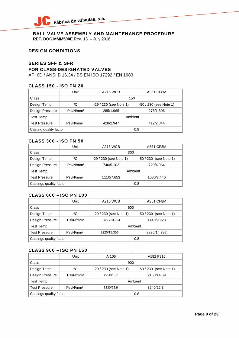
DESIGN CONDITIONS SERIES SFF & SFR FOR CLASS-DESIGNATED VALVES API 6D / ANSI B 16.34 / BS EN ISO 17292 / EN 1983 CLASS 150 - ISO PN 20
Unit A216 WCB A351 CF8M
Class 150
Design Temp. ºC -29 / 230 (see Note 1) -50 / 230 (see Note 1)
Design Pressure Psi/N/mm² 285/1.965 275/1.896
Test Temp. Ambient
Test Pressure Psi/N/mm² 428/2.947 412/2.844
Casting quality factor 0.8
CLASS 300 - ISO PN 50 Unit A216 WCB A351 CF8M
Class 300
Design Temp. ºC -29 / 230 (see Note 1) -50 / 230 (see Note 1)
Design Pressure Psi/N/mm² 740/5.102 720/4.964
Test Temp. Ambient
Test Pressure Psi/N/mm² 1110/7.653 1080/7.446
Castings quality factor 0.8
CLASS 600 – ISO PN 100
Unit A216 WCB A351 CF8M
Class 600
Design Temp. ºC -29 / 230 (see Note 1) -50 / 230 (see Note 1)
Design Pressure Psi/N/mm² 1480/10.204 1440/9.928
Test Temp. Ambient
Test Pressure Psi/N/mm² 2220/15.306 2880/14.892
Castings quality factor 0.8
CLASS 900 – ISO PN 150
Unit A 105 A182 F316
Class 900
Design Temp. ºC -29 / 230 (see Note 1) -50 / 230 (see Note 1)
Design Pressure Psi/N/mm² 2220/15.3 2160/14.89
Test Temp. Ambient
Test Pressure Psi/N/mm² 3330/22.9 3240/22.3
Castings quality factor 0.8
BALL VALVE ASSEMBLY AND MAINTENANCE PROCEDURE REF. DOC.MMM500E Rev. 13 – July 2016
Page 10 of 230
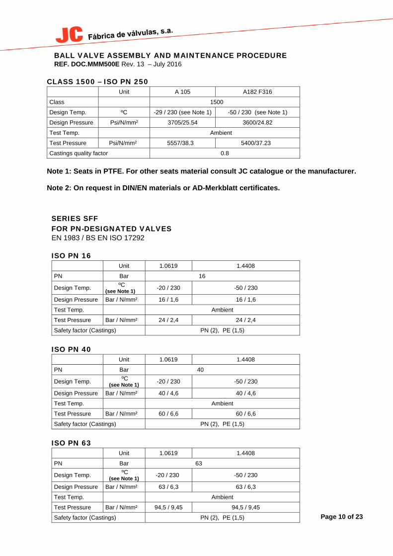
CLASS 1500 – ISO PN 250 Unit A 105 A182 F316
Class 1500
Design Temp. ºC -29 / 230 (see Note 1) -50 / 230 (see Note 1)
Design Pressure Psi/N/mm² 3705/25.54 3600/24.82
Test Temp. Ambient
Test Pressure Psi/N/mm² 5557/38.3 5400/37.23
Castings quality factor 0.8
Note 1: Seats in PTFE. For other seats material consult JC catalogue or the manufacturer. Note 2: On request in DIN/EN materials or AD-Merkblatt certificates.
SERIES SFF FOR PN-DESIGNATED VALVES EN 1983 / BS EN ISO 17292 ISO PN 16
Unit 1.0619 1.4408
PN Bar 16
Design Temp. ºC (see Note 1)
-20 / 230 -50 / 230
Design Pressure Bar / N/mm² 16 / 1,6 16 / 1,6
Test Temp. Ambient
Test Pressure Bar / N/mm² 24 / 2,4 24 / 2,4
Safety factor (Castings) PN (2), PE (1,5)
ISO PN 40
Unit 1.0619 1.4408
PN Bar 40
Design Temp. ºC (see Note 1)
-20 / 230 -50 / 230
Design Pressure Bar / N/mm² 40 / 4,6 40 / 4,6
Test Temp. Ambient
Test Pressure Bar / N/mm² 60 / 6,6 60 / 6,6
Safety factor (Castings) PN (2), PE (1,5)
ISO PN 63 Unit 1.0619 1.4408
PN Bar 63
Design Temp. ºC (see Note 1)
-20 / 230 -50 / 230
Design Pressure Bar / N/mm² 63 / 6,3 63 / 6,3
Test Temp. Ambient
Test Pressure Bar / N/mm² 94,5 / 9,45 94,5 / 9,45
Safety factor (Castings) PN (2), PE (1,5)

BALL VALVE ASSEMBLY AND MAINTENANCE PROCEDURE REF. DOC.MMM500E Rev. 13 – July 2016
Page 11 of 230
ISO PN 100
(See note 2) Unit A105 Tp.316
PN Bar 100
Design Temp. ºC (see Note 1)
-20 / 230 -50 / 230
Design Pressure Bar / N/mm² 100/10 100/10
Test Temp. Ambient
Test Pressure Bar / N/mm² 150/15 150/15
Safety factor (Castings) PN (2), PE (1,5)
3.- INSPECTION ON RECEPTION AND STORAGE 3.1 All valves will be examined on reception, to ensure that they have not suffered any damages during
transport, and the supplier will immediately be informed of any damages observed.
3.2 Valves are supplied in open position as a measure of protection and to ensure that no foreign body can damage the ball, except fail to close actuated valves (Actuator normally in closed position).
3.3 WARNING! Valves will be stored under cover and protected from inclement weather conditions and foreign bodies.
3.4 Valves will not be unpacked until they are to be definitively installed, except for inspection. After
inspection they will be packed again.
4.- INSTALLATION 4.1 The handling and transport of the valves must be carried out with extreme precaution and using the
necessary and adequate means on the basis of their size and weight, in order to avoid any risks to the persons that handle them.
4.2 WARNING! Never use the wrench to hold the valve during handling, assembly or transport. Check the condition of the valve, firstly to detect any possible damage caused during their transport and/or handling. Likewise inspect the inside of the valve, as well as the interior of the pipe that connects up to the valve. It is of utmost importance that there are no foreign bodies that could damage the valve seats, insofar as these parts are fundamental to the correct operation of the valve.

BALL VALVE ASSEMBLY AND MAINTENANCE PROCEDURE REF. DOC.MMM500E Rev. 13 – July 2016
Page 12 of 230
WARNING! When it is known or assumed that the valve is to be installed at a collection point of waste, such as welding slag, rust or scale, protective filters or screens must be placed, temporarily or definitively (depending on the installation), upstream of the connection with the valve. The valve must be installed in such a way that it is accessible for the necessary periodic inspection and maintenance required guaranteeing the performance levels for which it has been designed.
JC Standard SFF Series construction, up to – 20 ºC have been designed without fluid direction preference –“They are Bi-directional” When the construction of the valve, even being of the same SFF Series, have been designed to work at temperatures below - 20ºC and down to - 46ºC (LOW TEMPERATURE), then they will be “Unidirectional” and will carry an arrow indicating the flow direction. The valve can be installed with the stem in any position, although it is recommended that this is done in vertical position, with the stem upwards. WARNING! Valves must not support stress from the piping. The installation must be carried out ensuring correct alignment and parallelism to ensure that it is not subject to any unexpected stress. Make sure when installing the valve that the flange seal that connects to the valve is correctly fitted, checking its correct assembly and compatibility with the fluid circulating in the pipeline. IMPORTANT! After installation run a final check on the valve, opening and closing it to make sure that it is perfectly working. WARNING! Make sure that the fluid used in cleaning operations and the way in which the cleaning is done are compatible with the installed valve. Having ended the final cleaning operations prior to setting-up the valve, if filters have been installed they can be removed or, on the other hand if the user considers that there may be rust or scale formations, then, they must be left permanently in place.
IMPORTANT! When ball valves are destined to end line, you should reduce the hydrostatic proof pressure of the line to 1,1 Rating pressure.
5.- PREVENTIVE MAINTENANCE 5.1 Preventive maintenance operations essentially consist of periodic inspections to ensure that the valve
is working correctly.
5.2 Valves must be opened and closed at least once every 6 months and, depending on the fluid or application of the valve and its responsibility, opening and closing check plans will have to be established for shorter periods.

BALL VALVE ASSEMBLY AND MAINTENANCE PROCEDURE REF. DOC.MMM500E Rev. 13 – July 2016
Page 13 of 230
5.3 The user will be responsible for establishing opening and closing plans that are adequate for the working conditions and fluids used!
5.4 WARNING! Never leave the valves open or closed for a long period of time.
5.5 A very high torque increase could be due to the inclusion of foreign bodies in the seats. It is important not to force the valve! Proceed with an inspection of the seats in order to avoid damaging the ball.
5.6 It is recommended to replace the seals and seats whenever an in-depth revision of the installation is made.
6.- MAINTENANCE OPERATIONS PRECAUTIONS BEFORE DISASSEMBLY! Make sure that the line has been closed and depressurised.
Open and close the valve several times in order to release the pressure and drain the valve cavity.
WARNING! Wear protective clothing adequate to the circulating fluid. (Comply with the safety guidelines established by the company!) Remove the valve from the line in closed position and clean off any remaining fluid.
The replacement of parts must be done using original JC spare parts!
The manufacturer will not be responsible for the malfunctioning of the valve if original JC parts are not used!
7.- REASONS FOR PARTS REPAIR AND REPLACEMENT 7.1.- LEAKAGE THROUGH THE PACKING
7.1.1 If leakage is detected through the packing, open-out the bit on the locking washer (46) and tighten the gland nut (7) by an eighth of a turn. Repeat this operation if leakage continues, then return the bit to its original position. If there is still leakage replace the packing (11).
7.2.- LEAKAGE THROUGH THE BODY SEAL
7.2.1 If leakage is detected in the body seal (13) then the seal must be changed. Follow the instructions in point 7.5.

BALL VALVE ASSEMBLY AND MAINTENANCE PROCEDURE REF. DOC.MMM500E Rev. 13 – July 2016
Page 14 of 230
7.3.- LEAKAGE THROUGH THE PACKING IN VALVES WITH DOUBLE PACKING
7.3.1 If a leakage is detected in the stem packing lantern ring, as an emergency measure follow the instructions given in point 7.1.1. In continuation replace packing rings and the stem O’rings, following the procedure indicated in point 7.6 "Change of the packing in valves with double packing"
7.4.- CHANGE OF THE PACKING
We recommend that whenever it is necessary to change the packing, the seats should also be replaced, along with the body seal and stem thrust washers. However, if due to process needs, it is not possible to disassembly the valve, then the following sequence should be carried out:
DISASSEMBLY
7.4.1 Make sure that the installation is not under pressure.
7.4.2 Remove the handle or actuator, (6) and open-out the rib of the locking washer (46), in order to remove the gland nut (7), remove the locking washer (46), the disk springs (8) and the spacer (41), should there be one.
7.4.3 Remove the stop (9) ,marking its top side for re-assembly, the glass filled PTFE thrust washer
(18) and the gland ring(10). Remove the packing (11) without damaging the stem and body surfaces.
ASSEMBLY
7.4.4 Fit a new packing (11).
7.4.5 Replace the gland ring (10), a new glass filled PTFE thrust washer (18) the stop (9) with the
marked side facing up, the spacer (41) should there be one, the disk springs (8), the locking washer (46) and tighten the gland nut (7) to the torque specified in point 8.
7.4.6 Before refitting the handle, or actuator, check the valve under pressure to verify the seal of the
packing. If leakage is detected see point 7.1.1. Finish off by bending back the rib of the locking washer (46)
7.4.7 Refit the handle or actuator (6).
7.5.- CHANGE OF PACKING AND SEALS DISASSEMBLY
7.5.1 Make sure that the installation is not under pressure.
7.5.2 Remove the valve from the line. If the circulating fluid is noxious or inflammable precautions must be taken to avoid accidents.
7.5.3 Remove the studs (15) or hex-nuts (28) that attach the tailpiece to the body, bearing in mind
that there may be fluid trapped in the body cavity. Remove the tailpiece (2) from the body (1).

BALL VALVE ASSEMBLY AND MAINTENANCE PROCEDURE REF. DOC.MMM500E Rev. 13 – July 2016
Page 15 of 230
7.5.4 Remove the seat (5) from the tailpiece and the body-tailpiece union seal (13). In the case of
metal seat valves also remove the O’ring (33), the graphite seal (54), the ring (29) and the spring-washer (32).
7.5.5 Turn the ball (3) to the closed position and remove it from the body. Clean the external
surfaces of the bore and the slot, making sure that the hole relief at the bottom is not sealed. Check the external surface of the ball, particularly the area in contact with the seats and the radius of transition between the external surface and the bore. If the ball’s surface or slot are damaged replace the ball.
7.5.6 Remove the seat (5) from the body. In the case of valves with metal seats also remove the
O’ring (33), the graphite seal (54), the ring (29) and the spring washer (32).
7.5.7 Remove the stem (4), for this operation follow points 7.4.2 and 7.4.3, and then extract the stem from inside the body. Remove the glass fibre charged PTFE stem friction washer (12). The stem will incorporate one or two (see figures) O’rings (72) which must also be replaced.
7.5.8 Clean the internal surfaces of the body and body connector, specially the area of the seats,
the body seal, friction washer and packing.
7.5.9 Clean and check the stem. Check that the antistatic device is working by pushing the balls inwards in their housing and making sure they return to their original position. If any of these balls is seized, or the stem surface is damaged, replace it with a new stem.
ASSEMBLY
Ensure that all spare parts are JC original, of the same material and with the same dimensions as the parts to be replaced. For valves manufactured before 1983, the spares may be different from those of current models. In case of whatsoever doubt consult your regular supplier.
7.5.10 Fit the stem friction washer (12) onto the stem (4). The spare parts set includes two friction
washers. For some of the nominal diameters they are the same; should they be different this washer (12) is the thicker one. Fit the O’ring (72) (two depending on the figure) into the stem slot.
7.5.11 Insert the stem (4) into its housing through the interior of the body.
7.5.12 Assemble the packing and the other parts according to points 7.4.4, 7.4.5 and 7.4.6
7.5.13 Fit a new seat (5) to the body.
7.5.14 Turn the stem to the closed position so that it can be inserted in the slot of the ball. Fit the ball
(3) in place in the closed position, making sure that there is no play between the slot and the stem. In valves with metal seats lightly grease the surface of the ball before fitting it into place, if the valve is part of an oxygen circulation line consult the manufacturer.
7.5.15 Insert the other seat (5) into the tailpiece and the seal (13) into the body pocket. For valves
with metal seats also assemble parts (33), (54), (29) and (32). 7.5.16 Attach the tailpiece (2) to the body. In some of the nominal diameters the tailpiece must be
fitted in a specific position, due to the fact that the number of body-tailpiece union studs is not equal or a multiple of the number of flange studs. Make sure that the holes of both flanges are in the same position in relation to the valve’s axis of symmetry.
BALL VALVE ASSEMBLY AND MAINTENANCE PROCEDURE REF. DOC.MMM500E Rev. 13 – July 2016
Page 16 of 230
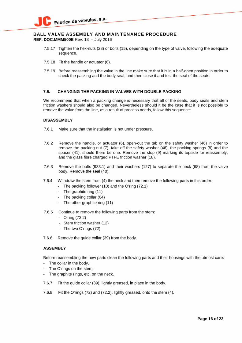
7.5.17 Tighten the hex-nuts (28) or bolts (15), depending on the type of valve, following the adequate
sequence.
7.5.18 Fit the handle or actuator (6).
7.5.19 Before reassembling the valve in the line make sure that it is in a half-open position in order to check the packing and the body seal, and then close it and test the seal of the seats.
7.6.- CHANGING THE PACKING IN VALVES WITH DOUBLE PACKING
We recommend that when a packing change is necessary that all of the seats, body seals and stem friction washers should also be changed. Nevertheless should it be the case that it is not possible to remove the valve from the line, as a result of process needs, follow this sequence:
DISASSEMBLY
7.6.1 Make sure that the installation is not under pressure. 7.6.2 Remove the handle, or actuator (6), open-out the tab on the safety washer (46) in order to
remove the packing nut (7), take off the safety washer (46), the packing springs (8) and the spacer (41), should there be one. Remove the stop (9) marking its topside for reassembly, and the glass fibre charged PTFE friction washer (18).
7.6.3 Remove the bolts (933.1) and their washers (127) to separate the neck (68) from the valve
body. Remove the seal (40). 7.6.4 Withdraw the stem from (4) the neck and then remove the following parts in this order:
- The packing follower (10) and the O’ring (72.1) - The graphite ring (11) - The packing collar (64) - The other graphite ring (11)
7.6.5 Continue to remove the following parts from the stem:
- O’ring (72.2) - Stem friction washer (12) - The two O’rings (72)
7.6.6 Remove the guide collar (39) from the body. ASSEMBLY
Before reassembling the new parts clean the following parts and their housings with the utmost care:
- The collar in the body. - The O’rings on the stem. - The graphite rings, etc. on the neck.
7.6.7 Fit the guide collar (39), lightly greased, in place in the body.
7.6.8 Fit the O’rings (72) and (72.2), lightly greased, onto the stem (4).

BALL VALVE ASSEMBLY AND MAINTENANCE PROCEDURE REF. DOC.MMM500E Rev. 13 – July 2016
Page 17 of 230
7.6.9 Place the stem friction washer (12) onto the stem and insert it into the neck (68).
7.6.10 Fit the seal (40) into position in the body.
7.6.11 Attach the neck and stem assembly to the body (1), fit the safety washers (127) to the bolts
and make them up.
7.6.12 Assemble the parts in the following order, in the packing housing in the neck: - Fully insert a graphite ring (11). - Insert the lantern ring (64) and a second graphite ring (11). - Fit the collar (10) with its O’ring (72.1). - Locate the sliding seal (18), the stop (9), the supplementary ring (41), the packing springs
(8), the safety washer (46), the packing nut (7) and tighten to the torque indicated in point 11.
7.6.13 Before fitting the handle, or actuator, pressure test the valve to ensure that the packing seals.
If a leak is detected follow the steps indicated in point 7.1.1.
7.6.14 Attach the handle, or actuator, (6).
8.- MAXIMUM GLAND NUT TIGHTNESS TORQUE IN mKp.
NOMINAL DIAMETER (1) PTFE PACKING GRAPHITE PACKING
15 2 2.2 20 2 2.2 25 2 2.2 32 2.5 2.5 40 4 4 50 4 4 65 6.5 7 80 7.5 8 100 8 8 125 8.5 9 150 9 9 200 21 23 (1) Understood as the bore diameter for reduced bore valves.

BALL VALVE ASSEMBLY AND MAINTENANCE PROCEDURE REF. DOC.MMM500E Rev. 13 – July 2016
Page 18 of 230
9.- TIGHTNESS TORQUE CHARTS FOR BODY/TAILPIECE UNION STUDS AND HEX-NUTS.
VALUES IN MKG.
DIN THREAD ASSEMBLY (*) ANSI ASSEMBLY UNC THREAD (**)
Elastic limit 0.2% Elastic limit 0.2% (Kg/mm²) 64 45 (Kg/mm²) 21 55 72.4 55 Material 8.8 A4.70 Material B8/B8M L7M B7 B7M Stud Ø Stud Ø
M.6 1.2 0.9 3/8” 1.57 4 5.44 4
M.8 3 2.1 7/16” 2 5.5 7.4 5.5
M.10 5.9 4.2 1/2” 2.6 7 9.5 7
M.12 10.4 7.3 9/16” 4.2 11 15 11
M.14 16.5 11.6 5/8” 6.3 16.5 22.5 16.5
M.16 25.7 18.1 3/4” 10 27 37 27
M.20 50.2 35.3 7/8” 16.8 44 59 43
1” 25 65 87 72
1.1/8” 35 93 125 93
1.1/4” 48 128 171 128
1.3/8” 70 167 223 167
1.1/2” 95 247 330 247 (*) LUBRICATION WITH SAE 10 AND A LOAD NO HIGHER THAN 80% OF THE ELASTIC LIMIT IS ASSUMED. (**) A FRICTION COEFFICIENT OF 0.12 AND 75% OF THE ELASTIC LIMIT IS ASSUMED

BALL VALVE ASSEMBLY AND MAINTENANCE PROCEDURE REF. DOC.MMM500E Rev. 13 – July 2016
Page 19 of 230
10.- SOFT SEAT VALVE
STEM BUSHING & “O” RING ONLY DN-5” AND LARGER
HANDLE FOR DN-4” & 6”

BALL VALVE ASSEMBLY AND MAINTENANCE PROCEDURE REF. DOC.MMM500E Rev. 13 – July 2016
Page 20 of 230
11.- METAL SEAT VALVE
HA
ND
LE
FO
R D
N-4
” &
6”

BALL VALVE ASSEMBLY AND MAINTENANCE PROCEDURE REF. DOC.MMM500E Rev. 13 – July 2016
Page 21 of 230
12.- VALVE WITH DOUBLE PACKING
HANDLE FOR DN-4” & 6”

BALL VALVE ASSEMBLY AND MAINTENANCE PROCEDURE REF. DOC.MMM500E Rev. 13 – July 2016
Page 22 of 230
13.- AUTOMATED VALVE
ACTUATOR COUPLING DETAIL

BALL VALVE ASSEMBLY AND MAINTENANCE PROCEDURE REF. DOC.MMM500E Rev. 13 – July 2016
Page 23 of 230
VEREENIGINGTel: 011 397 2833Fax: 011 397 4700
DURBANTel: 031 579 2593Fax: 031 579 2562
E-mail: [email protected]: [email protected]
Related Documents