Bentley SewerCAD V8i User’s Guide 1-1 1 Chapter Welcome to Bentley SewerCAD V8i Help “Getting S tarted” on page 1-1 Learn about Bentley SewerCAD V8i, how to install and uninstall the product, and how to contact Bentley Systems. “Load ing” on pa ge 7-297 Learn how to use Bentley SewerCAD V8 i data loading features to extend your model. “Introducing the Workspac e” on page 2-9 Learn about the Bentley SewerCAD V8i workspace, including menus, toolbars and dockable managers. “Calculating Y our Model” on page 8-369 Learn how to create and manage "what-if" scenarios. “Quick S tart Lesso ns” on page 3-51 Perform these tutorials to learn the basics of using Bentley SewerCAD V8i. “Using Scenarios and Alternatives ” on page 9-397 Learn how to define calculation options, calculate your model, and review your results. “Sta rting a Project” on page 4-109 Learn how to set up a new project, manage existing project and set project and other global options. “Presenting Y our Results” on page 10-453 Learn how to present results in graphs, profile s and reports. “Using Modelbuilder” on page 5-135 Learn how to use ModelBuilder in ArcGIS mode or the Stand-Alone Editor. “Working in AutoCAD Mode” on page 12-607 Learn how to use Bentley SewerCAD V8 i in AutoCAD mode. “Creating Y our Model” on page 6-169 Learn how to use Bentley SewerCAD V8i layout and editing tools to build your model. “Theory” on page 13-619 Learn about the theory behind Bentley SewerCAD V8 i. DAA038110-1/0001

Welcome message from author
This document is posted to help you gain knowledge. Please leave a comment to let me know what you think about it! Share it to your friends and learn new things together.
Transcript
8/20/2019 SewerCAD V8i Users Guide de 1-50
http://slidepdf.com/reader/full/sewercad-v8i-users-guide-de-1-50 1/50
Bentley SewerCAD V8 i User’s Guide 1-1
1Chapter
Welcome to Bentley
SewerCAD V8 i Help
“Getting Started” on page 1-1Learn about Bentley SewerCAD V8 i , how to install and uninstall the
product, and how to contact Bentley Systems.
“Loading” on page 7-297Learn how to use Bentley SewerCAD V8 i data loading features to
extend your model.
“Introducing the Workspace” on page 2-9Learn about the Bentley SewerCAD V8 i workspace, including menus,
toolbars and dockable managers.
“Calculating Your Model” on page 8-369Learn how to create and manage "what-if" scenarios.
“Quick Start Lessons” on page 3-51Perform these tutorials to learn the basics of using Bentley SewerCAD
V8 i .
“Using Scenarios and Alternatives” on page 9-397Learn how to define calculation options, calculate your model, and
review your results.
“Starting a Project” on page 4-109Learn how to set up a new project, manage existing project and set
project and other global options.
“Presenting Your Results” on page 10-453Learn how to present results in graphs, profile s and reports.
“Using Modelbuilder” on page 5-135Learn how to use ModelBuilder in ArcGIS mode or the Stand-Alone
Editor.
“Working in AutoCAD Mode” on page 12-607Learn how to use Bentley SewerCAD V8 i in AutoCAD mode.
“Creating Your Model” on page 6-169Learn how to use Bentley SewerCAD V8 i layout and editing tools to
build your model.
“Theory” on page 13-619Learn about the theory behind Bentley SewerCAD V8 i .
DAA038110-1/0001

8/20/2019 SewerCAD V8i Users Guide de 1-50
http://slidepdf.com/reader/full/sewercad-v8i-users-guide-de-1-50 2/50
1-2 Bentley SewerCAD V8 i User’s Guide
8/20/2019 SewerCAD V8i Users Guide de 1-50
http://slidepdf.com/reader/full/sewercad-v8i-users-guide-de-1-50 3/50
Bentley SewerCAD V8 XM Edition User’s Guide Contents-i
Chapter 1: Welcome to Bentley SewerCAD V8 i Help1
Chapter 1: Getting Started1What is Bentley SewerCAD V8 i ?1-1
Installation, Upgrades, and Updates1-2Municipal License Administrator Auto-Configuration1-2Software Updates via the Web and Bentley SELECT1-3Troubleshooting1-3
UPDATING YOUR S ENTINEL LM LICENSES IF YOU MOVE YOUR LI-CENSE S ERVER 1-4UPDATING YOUR BENTLEY SELECT S ERVER LICENSES IF YOU MOVE YOUR LICENSE S ERVER 1-4
Checking Your Current Registration Status1-4
Documentation1-4
Quick Start Lessons1-5
Contacting Us1-6Sales1-6Technical Support1-6
S UPPORT HOURS 1-7 Addresses1-7Your Suggestions Count1-8
Chapter 2: Introducing the Workspace9
The Workspace2-9Stand-Alone Editor2-9Microstation Mode2-10
AutoCAD Mode2-11
Menus2-11File Menu2-11Edit Menu2-15
Analysis Menu2-17Components Menu2-18View Menu2-19Tools Menu2-22Report Menu2-24Help Menu2-24
Toolbars2-25Layout Toolbar2-27Standard Toolbar2-28Edit Toolbar2-30
8/20/2019 SewerCAD V8i Users Guide de 1-50
http://slidepdf.com/reader/full/sewercad-v8i-users-guide-de-1-50 4/50
Contents-ii Bentley SewerCAD V8 XM Edition User’s Guide
View Toolbar2-30Scenarios Toolbar2-32
Analysis Toolbar2-32Compute Toolbar2-33Tools Toolbar2-33Help Toolbar2-34Zoom Toolbar2-34
Customizing the Toolbars2-36 Adding and Removing Toolbar Buttons2-36Controlling Toolbars2-36
Dynamic Manager Display2-37Opening Managers2-38Customizing Managers2-40
Using Customizations2-42Customization Manager2-42
CUSTOMIZATION E DITOR D IALOG BOX2-44
Using Named Views2-44Copying and Pasting Data To and From Tables2-46
Chapter 3: Quick Start Lessons51Lesson 1 - Creating a Schematic Network3-51
Part 1 - Creating a New Schematic Project File3-52Part 2 - Entering Data3-56
ENTERING D ATA THROUGH THE P ROPERTIES E DITOR 3-57ENTERING D ATA THROUGH F LEXT ABLES 3-59ENTERING INFILTRATION D ATA FOR G RAVITY P IPES 3-61
S TEADY S TATE LOADING 3-61EXTREME F LOW F ACTORS 3-66Part 3- Calculating the Model3-69
Lesson 2 - Automatic Design3-71Part 1: Specifying Design Constraints3-71Part 2: Design3-75
Lesson 3 - Scenario Management3-76Part 1 - Opening the Project File3-76Part 2 - Creating Alternatives3-76Part 3 - Editing Base Scenarios3-81Part 4 - Creating Child Scenarios3-82
Part 5 - Calculate and Compare3-84Lesson 4 - Presentation of Results3-86
Part 1 - Reports3-86Part 2 - FlexTables3-89Part 3 - Element Annotation3-93
8/20/2019 SewerCAD V8i Users Guide de 1-50
http://slidepdf.com/reader/full/sewercad-v8i-users-guide-de-1-50 5/50
Bentley SewerCAD V8 XM Edition User’s Guide Contents-iii
Part 4 - Create a Profile3-95Part 5 - Color Coding3-97
Lesson 5 - Running an Extended Period Simulation3-98Part 1 - Entering and Applying Loading Patterns3-99Part 2 - Entering Hydrographs3-101Part 3 - Running the Extended Period Simulation3-103Part 4 - Time Based Graphs and Tables3-103Part 5 - Animations3-105
Chapter 4: Starting a Project109Welcome Dialog Box4-109
Projects4-110
Setting Project Properties4-110
Setting Options4-111Options Dialog Box - Global Tab4-111Options Dialog Box - Project Tab4-114Options Dialog Box - Drawing Tab4-116Options Dialog Box - Units Tab4-117Options Dialog Box - Labeling Tab4-120Options Dialog Box - ProjectWise Tab4-121
Considerations for ProjectWise Users4-123General Guidelines for using ProjectWise 4-123Performing ProjectWise Operations4-124
Importing Data From Other Models4-127Importing Data from a SewerCAD V8 Database4-128Importing a Submodel4-128Importing from LandXML4-129Importing StormCAD V84-130Importing from SewerGEMS V84-131
Exporting Data4-132Exporting a .DXF File4-132Exporting a Submodel4-132Exporting to LandXML4-1334-133
Chapter 5: Using Modelbuilder135Preparing to Use ModelBuilder5-135ModelBuilder Connections Manager5-138
ModelBuilder Wizard5-141Step 1—Specify Data Source5-141Step 2—Specify Spatial Options5-142

8/20/2019 SewerCAD V8i Users Guide de 1-50
http://slidepdf.com/reader/full/sewercad-v8i-users-guide-de-1-50 6/50
Contents-iv Bentley SewerCAD V8 XM Edition User’s Guide
Step 3—Specify Field Mappings for each Table/Feature Class5-144Step 4—Build Operation Confirmation5-146
Reviewing Your Results5-146
Multi-select Data Source Types5-147
ModelBuilder Warnings and Error Messages5-147Warnings5-147Error Messages5-148
Specifying Network Connectivity in ModelBuilder5-149Sample Spreadsheet Data Source5-151
Handling Collection and Curve Data in Modelbuilder5-152Importing Pump Definitions Using ModelBuilder5-153Using ModelBuilder to Import Pump Curves5-158Using ModelBuilder to Import Patterns5-162
Chapter 6: Creating Your Model169Elements and Element Attributes6-169
Link Elements6-170ENTERING ADDITIONAL D ATA TO LINK E LEMENTS 6-170
Adding a Minor Loss Collection to a Pressure Pipe6-171Diversion Rating Curve Dialog Box6-172Defining the Geometry of a Link Element6-172Irregular Channel Editor Dialog Box6-173Defining the Cross-Sectional Shape of a Link Element6-174
S ECTIONS R ESULTS D IALOG BOX6-175Manholes6-175
FLOW (D OWNSTREAM C ONDUIT )6-176FLOW HEADLOSS C URVES D IALOG BOX6-176DROP M ANHOLES 6-178
Transitions6-178Wet Wells6-179
P ERCENT F ULL6-179INFLOW (WET ) C OLLECTION D IALOG BOX6-180
Outfalls6-180 ADDING E LEVATION VS . F LOW D ATA TO AN O UTFALL 6-181
Pressure Junctions6-182Pumps6-182
P UMP DEFINITIONS D IALOG BOX6-183S UBMERSIBLE P UMPS 6-189
Variable Speed Pump Batteries6-190 Air Valves6-191Other Tools6-192
Adding Elements to Your Model6-193
8/20/2019 SewerCAD V8i Users Guide de 1-50
http://slidepdf.com/reader/full/sewercad-v8i-users-guide-de-1-50 7/50
8/20/2019 SewerCAD V8i Users Guide de 1-50
http://slidepdf.com/reader/full/sewercad-v8i-users-guide-de-1-50 8/50
Contents-vi Bentley SewerCAD V8 XM Edition User’s Guide
Converting Legacy Engineering Library Files6-245Conduit Catalog Dialog Box6-247
Adding Hyperlinks to Elements6-251Hyperlinks Dialog Box6-251
Using Queries6-254
Queries Manager6-255QUERY P ARAMETERS D IALOG BOX6-256Creating Queries6-257
USING THE LIKE O PERATOR 6-261
Controls6-262Controls Tab6-264Conditions Tab6-269
Actions Tab6-275Control Sets Tab6-279
LOGICAL C ONTROL S ETS D IALOG BOX6-280
User Data Extensions6-280
User Data Extensions Dialog Box6-283User Data Extensions Import Dialog Box6-287Sharing User Data Extensions Among Element Types6-287Shared Field Specification Dialog Box6-288Enumeration Editor Dialog Box6-289
Batch Pipe Split Dialog Box6-290
External Tools6-291External Tools Workflow6-292
TRex Wizard6-293
Chapter 7: Loading297Loading7-297
Methods for Entering Loads7-298
Types of Loads7-299 Adding Fixed Loads7-301Hydrograph vs. Pattern Loads7-301
Adding User Defined Hydrographs7-302Pattern Loads7-303
WORKING WITH P ATTERNS 7-303Pattern Manager7-305
DEFINING P ATTERN S ETUPS 7-307Unit Sanitary Loading7-309
TYPES OF UNIT S ANITARY (D RY WEATHER ) LOADS 7-310 ADDING UNIT S ANITARY (D RY W EATHER ) LOADS 7-311
Composite Hydrographs7-318Composite Hydrograph Window7-318
8/20/2019 SewerCAD V8i Users Guide de 1-50
http://slidepdf.com/reader/full/sewercad-v8i-users-guide-de-1-50 9/50
Bentley SewerCAD V8 XM Edition User’s Guide Contents-vii
Composite Hydrograph Data Table Window7-318
Inflows7-319Defining Inflow Collections7-322Inflow Control Center7-325
APPLY S ANITARY INFLOW TYPE TO S ELECTION D IALOG7-329Sanitary Load Control Center7-329
APPLY S ANITARY LOAD TO S ELECTION D IALOG7-332
Sanitary (Dry Weather) Flow Collections7-332
Using LoadBuilder to Assign Loading Data7-335 Allocation7-336Billing Meter Aggregation7-338Distribution7-339Projection7-341
Using LoadBuilder to Assign Loading Data7-342LoadBuilder Manager7-342LoadBuilder Wizard7-343
LoadBuilder Run Summary7-354Generating Thiessen Polygons7-354
Thiessen Polygon Creator Dialog Box7-357Creating Boundary Polygon Feature Classes7-359
Pipeline Infiltration7-360Hydrograph Curve Dialog Box7-360
Extreme Flows7-361Extreme Flows Dialog7-361Extreme Flow Setups Dialog7-366
Chapter 8: Calculating Your Model369Steady State/Extended Period Simulation8-369
Steady State Simulation8-369Extended Period Simulation8-369
EPS R ESULTS BROWSER 8-370
Calculation Options Manager8-373
Creating Calculation Options8-374Calculation Option Attributes8-376
FLOW P ROFILE METHOD 8-382Controlling Results Output8-382
REPORTING
TIME
STEPS
DIALOG
BOX
8-383Check Data/ Validate8-383
Detailed Calculation Summary Dialog Box8-384Executive Summary Tab8-384Calculation Options Tab8-385
8/20/2019 SewerCAD V8i Users Guide de 1-50
http://slidepdf.com/reader/full/sewercad-v8i-users-guide-de-1-50 10/50
Contents-viii Bentley SewerCAD V8 XM Edition User’s Guide
Pressure Summary Tab8-391Pipe Report Tab8-392Node Report Tab8-392
User Notifications8-393User Notifications Manager8-393
USER NOTIFICATION DETAILS D IALOG BOX8-395
8-395
Chapter 9: Using Scenarios and Alternatives397Understanding Scenarios and Alternatives9-397
Advantages of Automated Scenario Management9-398 A History of What-If Analyses9-398
BEFORE H AESTAD METHODS - D ISTRIBUTED S CENARIOS 9-398WITH H AESTAD METHODS : S ELF -C ONTAINED S CENARIOS 9-400
The Scenario Cycle9-400Scenario Attributes and Alternatives9-402
A Familiar Parallel9-402Inheritance9-403
OVERRIDING INHERITANCE 9-404DYNAMIC INHERITANCE 9-404
Local and Inherited Values9-405Minimizing Effort through Attribute Inheritance9-405Minimizing Effort through Scenario Inheritance9-406
Scenario Example - Simple Water Distribution System9-407Building the Model (Average Day Conditions)9-408
Analyzing Different Demands (Maximum Day Conditions)9-408 Another Set of Demands (Peak Hour Conditions)9-409
Correcting an Error9-409 Analyzing Improvement Suggestions9-410Finalizing the Project9-411Summary9-411
Scenarios9-412Base and Child Scenarios9-413Creating Scenarios9-413Editing Scenarios9-413Running Multiple Scenarios at Once (Batch Runs)9-414Scenario Manager9-415
Alternatives9-417
Types of Alternatives9-417Base and Child Alternatives9-418Creating Alternatives9-418Editing Alternatives9-419
Alternative Manager9-419 Alternative Editor Dialog Box9-420
8/20/2019 SewerCAD V8i Users Guide de 1-50
http://slidepdf.com/reader/full/sewercad-v8i-users-guide-de-1-50 11/50
8/20/2019 SewerCAD V8i Users Guide de 1-50
http://slidepdf.com/reader/full/sewercad-v8i-users-guide-de-1-50 12/50
Contents-x Bentley SewerCAD V8 XM Edition User’s Guide
Shapefile Properties Dialog Box10-460DXF Properties Dialog Box10-461
Annotating Your Model10-462Element Symbology Manager10-463Using Folders in the Element Symbology Manager10-465
Adding Annotations10-466Deleting Annotations10-467Editing Annotations10-467Renaming Annotations10-467
Annotation Properties Dialog Box10-468FREE F ORM ANNOTATION D IALOG BOX10-469
Zoom Dependent Visibility10-470
Color Coding Your Model10-470 Adding Color-Coding10-471Deleting Color-Coding10-471Editing Color-Coding10-472Renaming Color-Coding10-472Color-Coding Properties Dialog Box10-472
Using Profiles10-474Profiles Manager10-475Viewing Profiles10-476Creating a New Profile10-477Editing Profiles10-478Deleting Profiles10-478Renaming Profiles10-478Profile Setup Dialog Box10-479Profile Viewer Dialog Box10-480
AXIS O PTIONS D IALOG BOX10-483
Engineering Profile Viewer Dialog Box10-483ENGINEERING P ROFILE O PTIONS 10-485GROUND P ROFILE O PTIONS 10-487
ANNOTATION P ROPERTIES D IALOG BOX10-487LINK ANNOTATION P ROPERTIES D IALOG BOX10-487TEXT P ROPERTIES 10-488
Viewing and Editing Data in FlexTables10-488FlexTables Manager10-489Working with FlexTable Folders10-491FlexTable Dialog Box10-492
S TATISTICS D IALOG BOX10-494Opening FlexTables10-494Creating a New FlexTable10-495Deleting FlexTables10-495Naming and Renaming FlexTables10-495Editing FlexTables10-496Sorting and Filtering FlexTable Data10-498
8/20/2019 SewerCAD V8i Users Guide de 1-50
http://slidepdf.com/reader/full/sewercad-v8i-users-guide-de-1-50 13/50
Bentley SewerCAD V8 XM Edition User’s Guide Contents-xi
CUSTOM S ORT D IALOG BOX10-501Customizing Your FlexTable10-501FlexTable Setup Dialog Box10-502Element Relabeling Dialog Box10-504Copying, Exporting, and Printing FlexTable Data10-505Using Predefined Tables10-507
Reporting10-507Using Standard Reports10-507
CREATING A P ROJECT INVENTORY R EPORT 10-507CREATING A S CENARIO S UMMARY R EPORT 10-508CREATING A C ONDUIT AND P RESSURE P IPE INVENTORY 10-508
Reporting on Element Data10-508Report Options10-508
Graphing10-509Graph Manager10-510Creating a Graph10-511Printing a Graph10-512Working with Graph Data: Viewing and Copying10-512Graph Dialog Box10-512
GRAPH S ERIES O PTIONS D IALOG BOX10-517F ILTER D IALOG BOX10-517OBSERVED D ATA D IALOG BOX10-517
Sample Observed Data Source10-519
Chart Options Dialog Box10-520Chart Options Dialog Box - Chart Tab10-521
S ERIES T AB10-522P ANEL T AB10-522
AXES T AB10-525
GENERAL T AB10-532TITLES T AB10-533W ALLS T AB10-538P AGING T AB10-539LEGEND T AB10-5403D T AB10-546
Chart Options Dialog Box - Series Tab10-547FORMAT T AB10-547P OINT T AB10-548GENERAL T AB10-549D ATA S OURCE T AB10-550M ARKS T AB10-551
Chart Options Dialog Box - Tools Tab10-555Chart Options Dialog Box - Export Tab10-556Chart Options Dialog Box - Print Tab10-558Border Editor Dialog Box10-559Gradient Editor Dialog Box10-560Color Editor Dialog Box10-561
8/20/2019 SewerCAD V8i Users Guide de 1-50
http://slidepdf.com/reader/full/sewercad-v8i-users-guide-de-1-50 14/50
Contents-xii Bentley SewerCAD V8 XM Edition User’s Guide
Color Dialog Box10-561Hatch Brush Editor Dialog Box10-562
H ATCH BRUSH E DITOR D IALOG BOX - S OLID T AB10-562H ATCH BRUSH E DITOR D IALOG BOX - H ATCH T AB10-563H ATCH BRUSH E DITOR D IALOG BOX - G RADIENT T AB10-563H ATCH BRUSH E DITOR D IALOG BOX - IMAGE T AB10-564
Pointer Dialog Box10-565Change Series Title Dialog Box10-566Chart Tools Gallery Dialog Box10-566
CHART TOOLS G ALLERY D IALOG BOX - S ERIES T AB10-566CHART TOOLS G ALLERY D IALOG BOX - AXIS T AB10-570CHART TOOLS G ALLERY D IALOG BOX - O THER T AB10-573
TeeChart Gallery Dialog Box10-578S ERIES 10-578FUNCTIONS 10-578
Customizing a Graph10-578
Print Preview Window10-587
Contours10-588Contour Definition10-590Contour Plot10-591Contour Browser Dialog Box10-592Enhanced Pressure Contours10-592
Using Named Views10-592Using Aerial View10-593
Time Series Field Data10-594S ELECT ASSOCIATED MODELING ATTRIBUTE D IALOG BOX10-596
Chapter 11: Features of the MicroStation Version597MicroStation Environment11-598
MicroStation Mode Graphical Layout11-598
MicroStation Project Files11-599
Bentley SewerCAD V8 i Element Properties11-599Element Properties11-600Levels11-600
ELEMENT LEVELS D IALOG 11-601Text Styles11-601
Working with Elements11-601Edit Elements11-601Deleting Elements11-602Modifying Elements11-602
CHANGE P IPE W IDTHS 11-602

8/20/2019 SewerCAD V8i Users Guide de 1-50
http://slidepdf.com/reader/full/sewercad-v8i-users-guide-de-1-50 15/50
Bentley SewerCAD V8 XM Edition User’s Guide Contents-xiii
EDIT E LEMENTS 11-602Working with Elements Using MicroStation Commands11-602
BENTLEY S EWER CAD V8 I C USTOM MICRO STATION E NTITIES 11-603MICRO STATION C OMMANDS 11-603MOVING E LEMENTS 11-603MOVING E LEMENT L ABELS 11-604
Snap Menu11-604
Undo/Redo11-604
Special Considerations11-605Import Bentley SewerCAD V8 i 11-605
Annotation Display11-605Use SewerCAD V8 i Z Order Command11-605
Chapter 12: Working in AutoCAD Mode607The AutoCAD Workspace12-608
AutoCAD Integration with SewerCAD V8 i 12-608 AutoCAD Mode Graphical Layout12-609Menus12-609Toolbars12-609Drawing Setup12-610Symbol Visibility12-610Layout Options Dialog12-610
AutoCAD Project Files12-611
AutoCAD Project Files12-611Drawing Synchronization12-612
Working with Elements Using AutoCAD Commands12-613SewerCAD V8 i Custom AutoCAD Entities12-613SewerCAD V8 i Custom AutoCAD Entities12-614
AutoCAD Commands12-614Explode Elements12-614Moving Elements12-615Moving Element Labels12-615Snap Menu12-615
Undo/Redo12-615
Special Considerations12-616Importing SewerCAD V8 i Data12-617
Importing SewerCAD V8 i Data12-617Working with Proxies12-617

8/20/2019 SewerCAD V8i Users Guide de 1-50
http://slidepdf.com/reader/full/sewercad-v8i-users-guide-de-1-50 16/50
Contents-xiv Bentley SewerCAD V8 XM Edition User’s Guide
Chapter 13: Theory619Loading13-620
Common Load Types13-620HYDROGRAPHS 13-620P ATTERN LOADS 13-621
HYDROGRAPHS VS . P ATTERN LOADS 13-621Sanitary (Dry Weather) Loading13-621
UNIT S ANITARY (D RY W EATHER ) LOADS 13-622EXTREME F LOW F ACTOR 13-622COMMON V ARIABLE P EAKING F ACTORS 13-623
Wet Weather Loading13-624INFILTRATION 13-624INFLOW 13-625
Known Flow13-625
Gravity Pipe Hydraulics13-626The Energy Principle13-626
THE E NERGY E QUATION 13-627Hydraulic and Energy Grades13-628
HYDRAULIC G RADE 13-629ENERGY G RADE 13-629
Friction Loss Methods13-629CHEZY ’S E QUATION 13-629COLEBROOK -WHITE E QUATION 13-630H AZEN -W ILLIAMS E QUATION 13-631D ARCY -WEISBACH E QUATION 13-631
Swamee and Jain Equation13-633M ANNING ’S E QUATION 13-633
Flow Regime13-634
P RESSURE F LOW 13-635UNIFORM F LOW AND NORMAL DEPTH 13-635CRITICAL F LOW, C RITICAL DEPTH , AND C RITICAL S LOPE 13-635S UBCRITICAL F LOW 13-636S UPERCRITICAL F LOW 13-636
Gradually Varied Flow Analysis13-636S LOPE C LASSIFICATION 13-636ZONE C LASSIFICATION 13-638P ROFILE C LASSIFICATION 13-639
Energy Balance13-640S TANDARD S TEP METHOD 13-641DIRECT S TEP METHOD 13-641
Mixed Flow Profiles13-641S EALING (S URCHARGING ) C ONDITIONS 13-642R APIDLY V ARIED F LOW13-642
Backwater Analysis13-642FREE O UTFALL 13-643S TRUCTURE F LOODING 13-643
8/20/2019 SewerCAD V8i Users Guide de 1-50
http://slidepdf.com/reader/full/sewercad-v8i-users-guide-de-1-50 17/50
Bentley SewerCAD V8 XM Edition User’s Guide Contents-xv
Frontwater Analysis13-643Pipe Average Velocity13-644
UNIFORM F LOW VELOCITY 13-644FULL F LOW VELOCITY 13-644S IMPLE AVERAGE VELOCITY 13-644WEIGHTED AVERAGE VELOCITY 13-645P IPE AVERAGE VELOCITY AND TRAVEL TIME13-645
Capacity Analysis (Approximate Profiles)13-645FULL C APACITY P ROFILES 13-646EXCESS C APACITY P ROFILES 13-646COMPOSITE E XCESS C APACITY P ROFILES 13-648
Junction Headlosses and Minor Losses13-648Manhole Head Loss Equations (AASHTO/HEC-2 Overview)13-649Junction Headlosses13-649
STRUCTURE HEADLOSS 13-649SPECIAL ASSUMPTIONS 13-652
Pressure Flow, Free Surface Flow, and Transitional Flow13-652
Initial Headloss Coefficient13-652Correction for Pipe Diameter13-653Correction for Flow Depth13-653Correction for Relative Flow13-654Correction for Plunging Flow13-654Correction for Benching13-655Headloss - AASHTO Method13-656
AASHTO Contraction Loss13-657 AASHTO Bend Loss13-657 AASHTO Bend Loss Original Equation13-658 AASHTO Expansion Loss13-659 AASHTO Correction For Non-Piped Flow13-660 AASHTO Correction for Shaping13-660
Minor Losses13-660F ITTING LOSS C OEFFICIENTS 13-661
Pump Theory13-662Variable Speed Pumps13-663Constant Horsepower Pumps13-666Conservation of Mass and Energy13-667
CONSERVATION OF M ASS 13-667CONSERVATION OF E NERGY 13-668
The Gradient Algorithm13-668Derivation of the Gradient Algorithm13-669The Linear System Equation Solver13-671
Extended Period Simulations13-673Extended Period Simulations Overview13-673Routing Overview13-673Convex Routing13-674Weighted Translation Routing13-675
8/20/2019 SewerCAD V8i Users Guide de 1-50
http://slidepdf.com/reader/full/sewercad-v8i-users-guide-de-1-50 18/50
Contents-xvi Bentley SewerCAD V8 XM Edition User’s Guide
Hydrologic and Hydraulic Time Steps13-676
Transitioning Between Gravity and Pressure Networks13-676Identifying Gravity Pipes and Force Mains13-676Direction of Flow in Gravity and Pressure Systems13-677Transitioning From Gravity Pipes to Force Mains13-677Transitioning From Force Mains to Gravity Elements13-678Subnetworks13-682
Constraint Based Automatic Design13-683Gravity Pipes and Structures Design13-683Part Full Design13-683
Allow Multiple Sections13-684Limit Section Size13-685Pipe Matching13-685Offset Matching13-686Drop Structures13-686Structure invert Elevations13-686Design Priorities13-686
Automatic Design with Hydrograph and Pattern Loads13-689Constraint Based Warning Messages13-690
Open and Closed Channel Weighting Methods13-690Note to HEC-2, WSP-2, and WSPRO Users13-693
Special Considerations13-693Energy Discontinuity13-693Structure Energy Grade13-694Design Considerations13-694Reporting Flow Attributes13-694
Manning’s n Coefficients13-695
Headloss Coefficients for Junctions13-698Roughness Values—Manning’s Equation13-699Roughness Values—Darcy-Weisbach Equation (Colebrook-White)13-700
Appendix 14: References703
Chapter 15: About Bentley Systems705Software15-705
CivilStorm15-706SewerGEMS15-707SewerGEMS15-707WaterGEMS15-708WaterCAD15-708StormCAD15-709

8/20/2019 SewerCAD V8i Users Guide de 1-50
http://slidepdf.com/reader/full/sewercad-v8i-users-guide-de-1-50 19/50

8/20/2019 SewerCAD V8i Users Guide de 1-50
http://slidepdf.com/reader/full/sewercad-v8i-users-guide-de-1-50 20/50
Contents-xviii Bentley SewerCAD V8 XM Edition User’s Guide
8/20/2019 SewerCAD V8i Users Guide de 1-50
http://slidepdf.com/reader/full/sewercad-v8i-users-guide-de-1-50 21/50
Bentley SewerCAD V8 i User’s Guide 1-1
1Chapter
Getting Started
Thank you for purchasing Bentley SewerCAD V8 i . At Bentley Systems, we prideourselves in providing the very best engineering software available. Our goal is tomake software that is easy to install and use, yet so powerful and intuitive that it antic-ipates your needs without getting in your way.
When you first use Bentley SewerCAD V8 i , use the intuitive interface and interactive
dialog boxes to guide you. If you need more information, use the online help by pressing the F1 key or selecting Bentley SewerCAD V8 i Help from the Help menu.A help topic describing the area of the program in which you are working appears.
•
• “Documentation” on page 1-4
• “Quick Start Lessons” on page 1-5
• “Contacting Us” on page 1-6
What is Bentley SewerCAD V8 i ?SewerCAD V8 i is an extremely powerful program for the design and analysis ofgravity flow and pressure flow through pipe networks and pumping stations. The
program can be run in Microstation and AutoCAD mode, giving you all the power ofMicrostation and AutoCAD’s capabilities, or in Stand-Alone mode utilizing our owngraphical interface.
SewerCAD V8 i allows you to construct a graphical representation of a pipe networkcontaining information such as pipe data, pump data, loading, and infiltration. Youhave a choice of conveyance elements including circular pipes, arches, boxes andmore.
8/20/2019 SewerCAD V8i Users Guide de 1-50
http://slidepdf.com/reader/full/sewercad-v8i-users-guide-de-1-50 22/50
Installation, Upgrades, and Updates
1-2 Bentley SewerCAD V8 i User’s Guide
The gravity network is calculated using the built-in numerical model, which utilizes both the direct step and standard step gradually varied flow methods. Flow calcula-tions are valid for both surcharged and varied flow situations, including hydraulic
jumps, backwater, and drawdown curves. You also have the flexibility to mix gravityand pressure components freely, building your systems in parallel or in series as theyexist in the field. Pressure elements can be controlled based on system hydraulics,
turning pumps on and off due to changes in flows and pressures.
SewerCAD V8 i ’s flexible reporting feature allows you to customize and print themodel results in both a report format and as a graphical plot.
Installation, Upgrades, and Updates
For instructions on installing, registering, activating, and updating the software pleaserefer to the Readme.pdf in the Program Files/Bentley/SewerCAD8 directory.
Municipal License Administrator Auto-Configuration
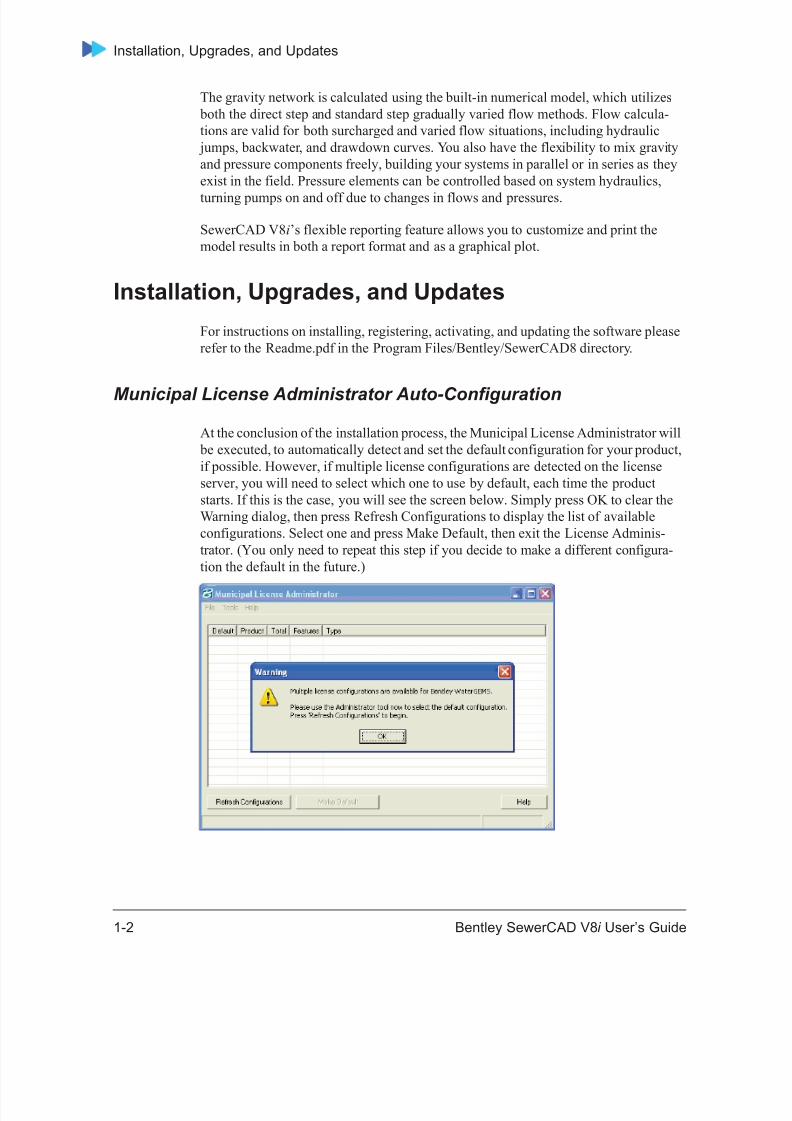
At the conclusion of the installation process, the Municipal License Administrator will be executed, to automatically detect and set the default configuration for your product,if possible. However, if multiple license configurations are detected on the licenseserver, you will need to select which one to use by default, each time the productstarts. If this is the case, you will see the screen below. Simply press OK to clear theWarning dialog, then press Refresh Configurations to display the list of availableconfigurations. Select one and press Make Default, then exit the License Adminis-trator. (You only need to repeat this step if you decide to make a different configura-tion the default in the future.)
8/20/2019 SewerCAD V8i Users Guide de 1-50
http://slidepdf.com/reader/full/sewercad-v8i-users-guide-de-1-50 23/50
Getting Started
Bentley SewerCAD V8 i User’s Guide 1-3
Software Updates via the Web and Bentley SELECT
Note: Your PC must be connected to the Internet to use the Check forUpdates button.
Bentley SELECT is the comprehensive delivery and support subscription programthat features product updates and upgrades via Web downloads, around-the-clocktechnical support, exclusive licensing options, discounts on training and consultingservices, as well as technical information and support channels. It’s easy to stay up-to-date with the latest advances in our software. Software updates can be downloadedfrom our Web site, and your version of Bentley SewerCAD V8 i can then be upgradedto the current version quickly and easily. Just click the Check for Updates button onthe toolbar to launch your preferred Web browser and open our Web site. The Web siteautomatically checks to see if your installed version is the latest available, and if not, it
provides you with the opportunity to download the correct upgrade to bring it up-to-date. You can also access our Knowledgebase for answers to your Frequently AskedQuestions (FAQs).
For more information, see “Technical Support” on page 1-6 .
Troubleshooting
Because of the multitasking capabilities of Windows, you may have applicationsrunning in the background that make it difficult for software setup and installations todetermine the configuration of your current system. If you have difficulties during theinstallation or uninstallation process, please try these steps before contacting our tech-nical support staff:
1. Shut down and restart your computer.2. Verify that there are no other programs running. You can see applications
currently in use by pressing Ctrl+Shift+Esc in Windows 2000 and Windows XP.Exit any applications that are running.
3. Disable any antivirus software that you are running.
Caution: After you install Bentley SewerCAD V8 i , make certain thatyou restart any antivirus software you have disabled. Failureto restart your antivirus software leaves you exposed topotentially destructive computer viruses.
4. Try running the installation or uninstallation again (without running any other program first).
If these three steps fail to successfully install or uninstall the product, contact ourTechnical Support staff. For more information, see “Contacting Us” on page 1-6 .
8/20/2019 SewerCAD V8i Users Guide de 1-50
http://slidepdf.com/reader/full/sewercad-v8i-users-guide-de-1-50 24/50
Documentation
1-4 Bentley SewerCAD V8 i User’s Guide
Updating Your SentinelLM Licenses if You Move Your LicenseServer
If you move your SentinelLM license manager to a different server, following thesesteps to update the licenses:
1. Install the license file on the new server.2. Replace the server name in the license.ini file on all client workstations with the
new server name (on the line containing “Server=”). Don’t forget to save the fileon each workstation. The license.ini file is usually located in the Haestad Method
product directory.
Updating Your Bentley SELECT Server Licenses if you Move YourLicense Server
If you move your Bentley SELECT Server license manager to a different server,following these steps to update the licenses:
1. Obtain a new license file (license string) from Bentley Systems, then update thelicense.lic file on the new server with the new license string.
2. Replace the server name in the license.lic file on all client workstations with thenew server name. Don’t forget to save the file on each workstation. The license.licfile is usually located in the Haestad Method product directory.
Checking Your Current Registration Status
After you have registered the software, you can check your current registration status by opening the About... box from within the software itself.
To view your registration information
1. Select Help > About Bentley SewerCAD V8 i Edition.
2. The version and build number for Bentley SewerCAD V8 i Edition display in thelower-left corner of the About Bentley Bentley SewerCAD V8 i dialog box.
The current registration status is also displayed, including: user name andcompany, serial number, license type and check-in status, feature level, expirationdate, and SELECT Server information.
DocumentationBentley SewerCAD V8 i documentation is available in two parts:
8/20/2019 SewerCAD V8i Users Guide de 1-50
http://slidepdf.com/reader/full/sewercad-v8i-users-guide-de-1-50 25/50
8/20/2019 SewerCAD V8i Users Guide de 1-50
http://slidepdf.com/reader/full/sewercad-v8i-users-guide-de-1-50 26/50
Contacting Us
1-6 Bentley SewerCAD V8 i User’s Guide
Contacting Us
Contact Bentley Systems if you want product information, to upgrade your software,or need technical support.
Sales
Bentley Systems, Inc.’ professional staff is ready to answer your questions. Pleasecontact your sales representative for any questions regarding Bentley Systems, Inc.’latest products and prices.
Toll-free U.S. Phone: 800-727-6555
Worldwide Phone: +1-203-755-1666
Fax: +1-203-597-1488
Email: [email protected]
Technical Support
We hope that everything runs smoothly and you never have a need for our technicalsupport staff. However, if you do need support, our highly-skilled staff offers theirservices seven days a week, and may be contacted by phone, fax, email, and theInternet. For information on the various levels of support that we offer, contact oursales team today and request information on our ClientCare program, or visit our Website.
When calling for support, in order to assist our technicians in troubleshooting your problem, please be in front of your computer and have the following informationavailable:
• Your computer’s operating system (Windows 2000 or Windows XP).
• Name and build number of the Bentley Systems, Inc. software you are callingabout. The build number can be determined by clicking Help > About BentleySewerCAD V8 i . The build number is the number in brackets located in the lower-left corner of the dialog box that opens.
• A note of exactly what you were doing when you encountered the problem.
• Any error messages or other information displayed on your screen.
8/20/2019 SewerCAD V8i Users Guide de 1-50
http://slidepdf.com/reader/full/sewercad-v8i-users-guide-de-1-50 27/50
Getting Started
Bentley SewerCAD V8 i User’s Guide 1-7
When emailing or faxing for support, please provide the following details, in additionto the above, to enable us to provide a more timely and accurate response:
• Company name, address, and phone number
• A detailed explanation of your concerns
• If you are emailing us, the Haestad Bentley SewerCAD V8 i .log files located in the product directory (e.g., C:\Documents and Settings\All Users\ApplicationData\Haestad\Bentley SewerCAD V8 i \1)
Support Hours
:Technical Support is available 24 hours a day, seven days a week.
You can contact our technical support team at:
Phone: +1-203-755-1666
Fax: +1-203-597-1488
Email: [email protected]
Addresses
Use this address information to contact us:
Internet: http://www.haestad.com
Email: [email protected]
Toll-free U.S. Phone: 800-727-6555
Worldwide Phone: +1-203-755-1666
Fax: +1-203-597-1488
Mail: Bentley Systems, Inc., Incorporated
Haestad Methods Solutions Center
Suite 200W
37 Brookside Road
Watertown, CT 06795

8/20/2019 SewerCAD V8i Users Guide de 1-50
http://slidepdf.com/reader/full/sewercad-v8i-users-guide-de-1-50 28/50
Contacting Us
1-8 Bentley SewerCAD V8 i User’s Guide
Your Suggestions Count
Bentley Systems, Inc. strives to continually provide you with sophisticated softwareand documentation. We are very interested in hearing your suggestions for improvingthe Bentley SewerCAD V8 i software, online help, and printed manual. Your feedbackguides us in developing products that make your work easier.
Please let us hear from you!
8/20/2019 SewerCAD V8i Users Guide de 1-50
http://slidepdf.com/reader/full/sewercad-v8i-users-guide-de-1-50 29/50
Bentley SewerCAD V8 i User’s Guide 2-9
2Chapter
Introducing the
WorkspaceClick one of the following links to learn more about the Bentley SewerCAD V8 i workspace.
• “The Workspace” on page 2-9
• “Menus” on page 2-11
• “Toolbars” on page 2-25• “Customizing the Toolbars” on page 2-36
• “Dynamic Manager Display” on page 2-37
The Workspace
You use Bentley SewerCAD V8 i in one of these modes:
• “Stand-Alone Editor” on page 2-9
• “Microstation Mode” on page 2-10• “AutoCAD Mode” on page 2-11
Stand-Alone Editor
The Stand-Alone Editor is the workspace that contains the various managers, toolbars,and menus, along with the drawing pane, that make up the Bentley SewerCAD V8 i interface. The Bentley SewerCAD V8 i interface uses dockable windows and toolbars,so the position of the various interface elements can be manually adjusted to suit your
preference.
8/20/2019 SewerCAD V8i Users Guide de 1-50
http://slidepdf.com/reader/full/sewercad-v8i-users-guide-de-1-50 30/50
The Workspace
2-10 Bentley SewerCAD V8 i User’s Guide
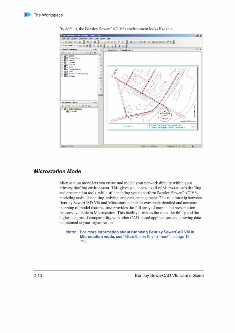
By default, the Bentley SewerCAD V8 i environment looks like this:
Microstation Mode
Microstation mode lets you create and model your network directly within your primary drafting environment. This gives you access to all of Microstation‘s draftingand presentation tools, while still enabling you to perform Bentley SewerCAD V8 i modeling tasks like editing, solving, and data management. This relationship betweenBentley SewerCAD V8 i and Microstation enables extremely detailed and accuratemapping of model features, and provides the full array of output and presentationfeatures available in Microstation. This facility provides the most flexibility and thehighest degree of compatibility with other CAD-based applications and drawing datamaintained at your organization.
Note: For more information about runnning Bentley SewerCAD V8 i inMicrostation mode, see “MicroStation Environment” on page 12-702 .
8/20/2019 SewerCAD V8i Users Guide de 1-50
http://slidepdf.com/reader/full/sewercad-v8i-users-guide-de-1-50 31/50
Introducing the Workspace
Bentley SewerCAD V8 i User’s Guide 2-11
AutoCAD Mode
AutoCAD mode lets you create and model your network directly within your primarydrafting environment. This gives you access to all of AutoCAD’s drafting and presen-tation tools, while still enabling you to perform Bentley SewerCAD V8 i modelingtasks like editing, solving, and data management. This relationship between BentleySewerCAD V8 i and AutoCAD enables extremely detailed and accurate mapping ofmodel features, and provides the full array of output and presentation features avail-able in AutoCAD. This facility provides the most flexibility and the highest degree ofcompatibility with other CAD-based applications and drawing data maintained at yourorganization.
Note: For more information about runnning Bentley SewerCAD V8 i inAutoCAD mode, see “Working in AutoCAD Mode” on page 13-711 .
Menus
Menus are located at the top of Bentley SewerCAD V8 i stand-alone editor windowand provide access to program commands, which are broken down by type of func-tionality.
The following menus are available:
• “File Menu” on page 2-11
• “Edit Menu” on page 2-15
• “Analysis Menu” on page 2-17
• “View Menu” on page 2-19
• “Tools Menu” on page 2-22
• “Report Menu” on page 2-24
• “Help Menu” on page 2-24
File Menu
The File menu contains the following commands:
New Creates a new project. When you select thiscommand, a new untitled project is created.
Open Opens an existing project. When you select thiscommand, the Open dialog box appears, allowingyou to browse to the project to be opened.
8/20/2019 SewerCAD V8i Users Guide de 1-50
http://slidepdf.com/reader/full/sewercad-v8i-users-guide-de-1-50 32/50
Menus
2-12 Bentley SewerCAD V8 i User’s Guide
Close Closes the current project without exiting the program.
Close All Closes all currently open projects.
Save Saves the current project.
Save As Saves the current project under a new project nameand/or to a different directory location.
Save All Saves all currently open projects.
8/20/2019 SewerCAD V8i Users Guide de 1-50
http://slidepdf.com/reader/full/sewercad-v8i-users-guide-de-1-50 33/50
Introducing the Workspace
Bentley SewerCAD V8 i User’s Guide 2-13
ProjectWise Opens a submenu containing the followingcommands:
• Open —Open an existing SewerCAD V8 i project from ProjectWise. You are prompted tolog into a ProjectWise datasource if you are not
already logged in.
Note: Only projects that wereoriginally saved intoProjectWise from the SewerCADV8i application can be opened
• Save As —Saves the current project to aProjectWise datasource. You are prompted tolog into a ProjectWise datasource if you are notalready logged in.
• Change Datasource —Lets you connect to a
different ProjectWise datasource for futureOpen and Save As operations.
• Import —Lets you import the following file typesinto the ProjectWise project:
• SewerCAD V8 Database —Lets you importa Bentley SewerCAD V8 i project databasefile.
• Submodel —Lets you import a SewerCADsubmodel file.
• LandXML —Lets you import a LandXMLfile.
• StormCAD V8 —Lets you import aStormCAD V8 file.
• SewerGEMS V8 —Lets you import aSewerGEMS V8 file.
Note: For more information aboutusing SewerCAD V8 i withProjectWise, see “Considerationsfor ProjectWise Users” on page 4-158
8/20/2019 SewerCAD V8i Users Guide de 1-50
http://slidepdf.com/reader/full/sewercad-v8i-users-guide-de-1-50 34/50
Menus
2-14 Bentley SewerCAD V8 i User’s Guide
Import Opens a submenu containing the followingcommands:
• Bentley SewerCAD V8 i Database —Lets youimport a Bentley SewerCAD V8 i project data-base file.
• Submodel —Lets you import a SewerCADsubmodel file.
• LandXML —Lets you import a LandXMLfile.
• StormCAD V8 —Lets you import aStormCAD V8 file.
• SewerGEMS V8 —Lets you import aSewerGEMS V8 file.
Export Opens a submenu containing the followingcommands:
• DXF—Lets you export the current networklayout as a DXF drawing.
• Submodel —Exports the currently selectedarea of the network as a SewerCAD submodelfile.
• LandXML —Exports the current project as aLandXML file.
Page Setup Defines the print settings that will be used when thecurrent view is printed.
Print Preview Opens the Print Preview window, displaying thecurrent view exactly as it will be printed. You canselect whether you want the print preview to be Fitto Page or Scaled:
• Fit to Page —The view will be zoomed in or outso that the current view fits to a single page ofthe default page size.
• Scaled —The view will be scaled so that itmatches the user-defined drawing scale (this isdefined on the Drawing Tab of the Optionsdialog: Tools > Options).
8/20/2019 SewerCAD V8i Users Guide de 1-50
http://slidepdf.com/reader/full/sewercad-v8i-users-guide-de-1-50 35/50
Introducing the Workspace
Bentley SewerCAD V8 i User’s Guide 2-15
Edit Menu
The Edit menu contains the following commands:
Print Prints the current view. You can select whether youwant the print preview to be Fit to Page or Scaled:
• Fit to Page —The view will be zoomed in or outso that the current view fits to a single page ofthe default page size.
• Scaled —The view will be scaled so that itmatches the user-defined drawing scale (this isdefined on the Drawing Tab of the Optionsdialog: Tools > Options).
Project Properties Opens the Project Properties dialog box, allowingyou to specify project-level settings.
Recent Files When the Recent Files Visible option is selected inthe Options dialog box, the most recently openedfiles will appear in the File menu. See “OptionsDialog Box - Global Tab” on page 4-147 for moreinformation.
Exit Closes the program.
Undo Cancels the last data input action on the currentlyactive dialog box. Clicking Undo again cancelsthe second-to-last data input action, and so on.
Redo Cancels the last undo command.
Delete Deletes the currently highlighted element.

8/20/2019 SewerCAD V8i Users Guide de 1-50
http://slidepdf.com/reader/full/sewercad-v8i-users-guide-de-1-50 36/50
Menus
2-16 Bentley SewerCAD V8 i User’s Guide
Select By Polygon Lets you select elements in your model bydrawing a polygon in the drawing pane. Click inthe drawing pane to draw each side of the
polygon. After the polygon has been drawn, right-click to select from the following options:
• As Selected - All elements contained withinthe polygon will be selected. Elements thatwere selected before the Select By Polygonopperation will be de-selected.
• Add to Selection - All elements containedwithin the polygon will be selected in additionto any elements that were selected before theSelect By Polygon operation were performed.
• Invert Selection - All elements containedwithin the polygon that were selected beforethe operation will be de-selected; all elementscontained within the polygon that were not
selected before the operation will be selected• Remove From Selection - All elements
contained within the polygon that wereselected before the operation will be de-selected.
Select All Selects all of the elements in the network.
Invert Selection Selects all currently unselected elements anddeselects all currently selected ones.
Select by Element Opens a submenu listing all available element
types. Select one of the element types from thesubmenu to select all elements of that type in themodel.
Select by Attribute Opens a menu listing all available attribute types.Select one of the attribute types from the menuand the Query Builder dialog box opens.
Clear Selection Deselects the currently selected element(s).
Clear Highlight Removes Network Navigator highlighting for allelements.
Find Element Lets you find a specific element by entering theelement’s label.
8/20/2019 SewerCAD V8i Users Guide de 1-50
http://slidepdf.com/reader/full/sewercad-v8i-users-guide-de-1-50 37/50
Introducing the Workspace
Bentley SewerCAD V8 i User’s Guide 2-17
Analysis Menu
The Analysis menu contains the following commands:
Scenarios Opens the Scenario Manager, which lets you
create, view, and manage project scenarios.
Alternatives Opens the Alternative Manager, which lets youcreate, view, and manage alternatives.
Calculation Options Opens the Calculation Options Manager, whichlets you create, view, and manage calculationsettings for the project.
Totalizing FlowMeters
Opens the Totalizing Flow Meters manager whereyou can create new meters.
System Head Curves Opens the System Head Curves manager.
EPS Results Browser Opens the EPS Results Browser dialog box, whichlets you manipulate the currently displayed timestep and to animate the drawing pane.
Calculation Summary Opens the calculation summary report, whichreports the details of the calculations performedon your model .
User Notifications Opens the User Notifications Manager, allowingyou to view warnings and errors uncovered by thevalidation process.
Validate Runs a diagnostic check on the network data toalert you to possible problems that may beencountered during calculation. This is the manualvalidation command, and it checks for input dataerrors. It differs in this respect from the automaticvalidation that SewerCAD V8 i runs when thecompute command is initiated, which checks fornetwork connectivity errors as well as many otherthings beyond what the manual validation checks.Pressing CTRL+F7 also selects this command.
8/20/2019 SewerCAD V8i Users Guide de 1-50
http://slidepdf.com/reader/full/sewercad-v8i-users-guide-de-1-50 38/50
Menus
2-18 Bentley SewerCAD V8 i User’s Guide
Components Menu
The Components menu contains the following commands:
Compute Calculates the network. Before calculating, anautomatic validation routine is triggered, whichchecks the model for network connectivity errorsand performs other validation. For moreinformation, see “Calculating Your Model” on
page 8-433 . Pressing F9 also selects thiscommand.
Default DesignConstraints
Opens the Default Design Constraints dialog,whiach allows you to specify constraints for pipes,nodes, and inlets to be used during an automaticdesign and while checking constraints for ananalysis calculation.
Controls Opens the Controls manager where you can setcontrols, conditions, actions, and logical controlsets.
Conduit Catalog Opens the Conduit Catalog dialog box, which letsyou create, edit, and view catalog conduits.Catalog conduits are an efficient way to reusecommon physical conduit definitions.
Flow Headloss Curves Opens the Flow-Headloss Curves dialog.
Minor LossCoefficients
Opens the Minor Loss Coefficients Managerdialog.
Unit Sanitary (DryWeather) Loads
Opens the Unit Sanitary (Dry Weather) Loadsdialog box, which lets you create, edit, and deleteunit sanitary loads. For more information, see“Adding Unit Sanitary (Dry Weather) Loads” on
page 7-372 .
Patterns Opens the Pattern Manager where you can createand edit diurnal loading patterns for use withextended period simulations. For moreinformation, see “Defining Patterns” on page 7-364 .
8/20/2019 SewerCAD V8i Users Guide de 1-50
http://slidepdf.com/reader/full/sewercad-v8i-users-guide-de-1-50 39/50
Introducing the Workspace
Bentley SewerCAD V8 i User’s Guide 2-19
View Menu
The View menu contains the following commands:
Pattern Setups Opens the Pattern Setup Manager where you canassociate diurnal patterns with the appropriate unitsanitary loads for a given scenario. For moreinformation, see “Defining Pattern Setups” on
page 7-367 .
Extreme Flows Opens the Extreme Flows dialog.
Extreme Flow Setups Opens the Extreme Flow Setups dialog.
Pump Definitions Opens the Pump Definitions dialog box, whichlets you view, edit, and create pump curvedefinitions. For more information, see “PumpCurve Definitions Dialog Box” on page 6-235 .
Time Series FieldData
Opens the Time Series Field Data dialog.
Engineering Libraries Opens the Engineering Libraries Manager.
Element Symbology Opens the Element Symbology Manager, whichlets you create, view, and manage annotation andcolor-coding in your project.
Background Layers Opens the Background Layers Manager, whichlets you create, view, and manage the backgroundlayers associated with the project.
Network Navigator Opens the Network Navigator.
Selection Sets Opens the Selection Sets Manager, which lets youcreate, view, and manage selection sets associatedwith the project.
Queries Opens the Query Manager, which lets you create
SQL expressions for use with selection sets andFlexTables. For more information, see ADDLINK
8/20/2019 SewerCAD V8i Users Guide de 1-50
http://slidepdf.com/reader/full/sewercad-v8i-users-guide-de-1-50 40/50
Menus
2-20 Bentley SewerCAD V8 i User’s Guide
Prototypes Opens the Prototypes Manager, which lets youenter default values for elements in your model.Prototypes can reduce data entry requirementsdramatically if a group of network elements sharecommon data. For more information, see ADD
LINK
FlexTables Opens the FlexTables Manager, which lets youcreate, view, and manage the tabular reports forthe project.
Graphs Opens the Graph Manager, which lets you create,view, and manage graphs for the project.
Profiles Opens the Profile Manager, which lets you create,view, and manage the profiles for the project.
Contours Opens the Contours manager where you can createand edit contour definitions.
Named Views Opens the Named Views manager where you cancreate, edit, and use Named Views.
Aerial View Opens the Aerial View navigation window.
Properties Turns the Properties Editor display on or off.
Customizations Opens the Customization Manager dialog.
Auto-Refresh Turns automatic updates to the main window viewon or off whenever changes are made to theBentley SewerCAD V8 i datastore. When selected,a check mark appears next to this menu command,indicating that automatic updates are turned on.
Refresh Drawing Updates the main window view according to thelatest information contained in the BentleySewerCAD V8 i datastore.
8/20/2019 SewerCAD V8i Users Guide de 1-50
http://slidepdf.com/reader/full/sewercad-v8i-users-guide-de-1-50 41/50
Introducing the Workspace
Bentley SewerCAD V8 i User’s Guide 2-21
Zoom Opens a submenu containing the followingcommands:
• Zoom Extents —Sets the view so that theentire network is visible in the drawing pane.
• Zoom Window —Activates the manual zoomtool, which lets you specify a portion of thedrawing to enlarge.
• Zoom In —Enlarges the size of the model inthe drawing pane.
• Zoom Out —Reduces the size of the model inthe drawing pane.
• Zoom Realtime —Enables the realtime zoomtool, which lets you zoom in and out bymoving the mouse while holding down the leftmouse button.
• Zoom Center —Opens the Zoom Centerdialog box, which lets you enter drawing coor-dinates that will be centered in the drawingpane.
• Zoom to Selection —Zooms to the element(s)that are currently selected in the drawingpane.
• Zoom Previous —Resets the zoom level tothe last setting.
• Zoom Next —Resets the zoom level to thesetting that was active before a ZoomPrevious command was executed.
Pan Activates the Pan tool, which lets you move themodel within the drawing pane. When you selectthis command, the cursor changes to a hand,indicating that you can click and hold the leftmouse button and move the mouse to move thedrawing.
Toolbars Opens a submenu that lists each of the availabletoolbars. Select one of the toolbars in the submenuto turn that toolbar on or off. For moreinformation, see “Toolbars” on page 2-25 .
Reset Workspace Resets the Bentley SewerCAD V8 i workspace sothat the dockable managers appear in their defaultfactory-set positions.
8/20/2019 SewerCAD V8i Users Guide de 1-50
http://slidepdf.com/reader/full/sewercad-v8i-users-guide-de-1-50 42/50
Menus
2-22 Bentley SewerCAD V8 i User’s Guide
Tools Menu
The Tools menu contains the following commands:
Active Topology
Selection
Opens a Select dialog to select elements in the
drawing to make them Inactive or Active.
ModelBuilder Opens the ModelBuilder Connections Manager, whichlets you create, edit, and manage ModelBuilderconnections to be used in the model-building/model-synchronizing process. For more information, see“ModelBuilder Connections Manager” on page 5-175 .
TRex Opens the TRex node elevation assignment tool.
LoadBuilder Opens the LoadBuilder manager where you can assigndemands to model nodes using data from outside
sources.
Thiessen Polygon Opens the Wizard used to create Thiessen polygonsfor use with LoadBuilder.
Inflow Control Center Opens the Inflow Control Center, allowing you tocreate, edit, and delete sanitary inflow definitions.
Element PropertyInferencing
Opes the Element Property Inferencing dialog.
Hyperlinks Lets you associate external files, such as pictures or
movie files, with elements. For more information, see“Adding Hyperlinks to Elements” on page 6-326 .
User Data Extensions User Data Extensions —Opens the User DataExtension dialog box, which lets you add and definecustom data fields. For example, you can add newfields such as the pipe installation date. For moreinformation, see “User Data Extensions” on page 6-337 .
Sanitary Load ControlCenter
Opens the Sanitary Load Control Center, allowing youto create, edit, and delete sanitary load definitions.
8/20/2019 SewerCAD V8i Users Guide de 1-50
http://slidepdf.com/reader/full/sewercad-v8i-users-guide-de-1-50 43/50
Introducing the Workspace
Bentley SewerCAD V8 i User’s Guide 2-23
Database Utilities Opens a submenu containing the followingcommands:
• Compact Database —When you delete data froma Bentley SewerCAD V8 i project, such aselements or alternatives, the database store that
Bentley SewerCAD V8 i uses can become frag-mented, causing unnecessarily large data files,which impact performance substantially.Compacting the database eliminates the emptydata records, thereby defragmenting the datastoreand improving the performance of the file.
Note: Every tenth time a file is saved,Bentley SewerCAD V8 i willautomatically prompt you tocompact the database. If you opena file without saving it, the countdoes not go up. If you open andsave a file multiple times in thesame session, the count only goesup on the first save. If you open,save, and close the file, the countgoes up. Click Yes to compact thedatabase, or no to close the promptdialog box without compacting.Since compacting the database cantake time, especially for largermodels, you may want to postponethe compact procedure until a latertime. You can modify how BentleySewerCAD V8 i compacts thedatabase in the Options dialog box.
• Synchronize Drawing —Synchronizes the currentmodel drawing with the project database.
• Update Database cache —Updates the currentmodel to reflect any changes made in the database.
• Update Results from Project Directory —Thiscommand copies the model result files (if any) from theproject directory (the directory where the project .mdbfile is saved) to the custom result file directory. Thecustom result directory is specified inTools>Options>Project tab. This allows you to make acopy of the results that may exist in the model's savedirectory and replace the current results being workedon with them.
• Copy Results to Project Directory —Thiscommand copies the result files that are currently beingused by the model to the project directory (where theproject .mdb is stored).
• Batch Update Conduit Descriptions —Updatesthe Conduit Description field to reflect any changesmade to the underlying attributes.

8/20/2019 SewerCAD V8i Users Guide de 1-50
http://slidepdf.com/reader/full/sewercad-v8i-users-guide-de-1-50 44/50
Menus
2-24 Bentley SewerCAD V8 i User’s Guide
Report Menu
The Report menu contains the following commands:
Help Menu
The Help menu contains the following commands:
Layout Opens a submenu that lists each of the availableelement types. Select one of the element types in thesubmenu to place that element in your model.
External Tools Run an existing external tool or create a new one by
opening up the External Tools manager.Options Opens the Options dialog box, which lets you change
global settings such as display pane settings, drawingscale, units, display precision and format used, andelement labeling.
Element Tables Opens a submenu that lets you display FlexTablesfor any link or node element. These predefinedFlexTables contain most of the input data andresults for each instance of the selected element inthe model.
Element Details Allows you to select one or more elements fromthe drawing view. A report is generated containingthe details of the selected element(s).
Scenario Summary Opens the Scenario Summary Report.
Project Inventory Opens the Project Inventory Report, whichcontains the number of each of the variouselement types that are in the network.
Conduit and PressurePipe Inventory
Opens the Conduit and Pressure Pipe Inventoryreport.
Report Options Opens the Report Options box where you can setHeaders and Footers for the predefined reports.
8/20/2019 SewerCAD V8i Users Guide de 1-50
http://slidepdf.com/reader/full/sewercad-v8i-users-guide-de-1-50 45/50
Introducing the Workspace
Bentley SewerCAD V8 i User’s Guide 2-25
Toolbars
Toolbars provide access to frequently used menu commands and are organized by thetype of functionality offered. Many of the toolbars have additional buttons availablethat are not displayed by default. You can display these additional buttons byfollowing the procedure in “Adding and Removing Toolbar Buttons” on page 2-36 .
The following toolbars are available:
• “Layout Toolbar” on page 2-27• “Standard Toolbar” on page 2-28
• “Edit Toolbar” on page 2-30
• “View Toolbar” on page 2-30
Bentley SewerCAD V8 i Help
Opens the online help Table of Contents.
Quick Start Lessons Opens the online help to the Quick Start LessonsOverview topic.
Welcome Dialog Opens the Welcome dialog box.
Check for Updates Opens your Web browser to the our Web site,allowing you to check for Bentley SewerCAD V8 i updates.
Bentley InstituteTraining
Opens your browser to the Bentley InstituteTraining web site.
Bentley ProfessionalServices
Opens your browser to the Bentley ProfessionalServices web site.
Online Support Opens your browser to SELECTservices area ofthe Bentley web site.
Discussion Groups Opens your browser to Bentley’s HaestadDiscussion Groups.
Bentley.com Opens the home page on the Bentley web site.
About BentleySewerCAD V8 i
Opens the About Bentley SewerCAD V8 i dialog box, which displays copyright information aboutthe product, registration information, and thecurrent version number of this release.

8/20/2019 SewerCAD V8i Users Guide de 1-50
http://slidepdf.com/reader/full/sewercad-v8i-users-guide-de-1-50 46/50
8/20/2019 SewerCAD V8i Users Guide de 1-50
http://slidepdf.com/reader/full/sewercad-v8i-users-guide-de-1-50 47/50
Introducing the Workspace
Bentley SewerCAD V8 i User’s Guide 2-27
Layout Toolbar
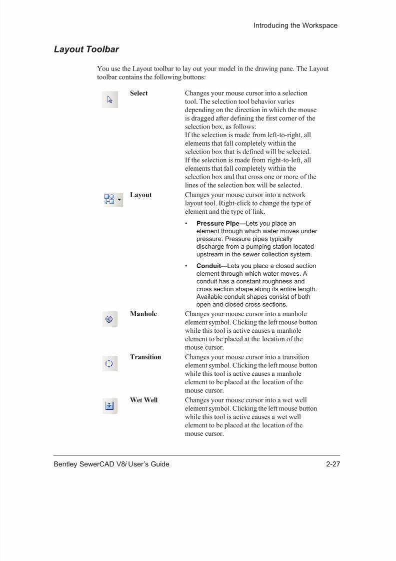
You use the Layout toolbar to lay out your model in the drawing pane. The Layouttoolbar contains the following buttons:
Select Changes your mouse cursor into a selectiontool. The selection tool behavior variesdepending on the direction in which the mouseis dragged after defining the first corner of theselection box, as follows:If the selection is made from left-to-right, allelements that fall completely within theselection box that is defined will be selected.If the selection is made from right-to-left, allelements that fall completely within theselection box and that cross one or more of thelines of the selection box will be selected.
Layout Changes your mouse cursor into a networklayout tool. Right-click to change the type ofelement and the type of link.
• Pressure Pipe— Lets you place anelement through which water moves underpressure. Pressure pipes typicallydischarge from a pumping station locatedupstream in the sewer collection system.
• Conduit —Lets you place a closed sectionelement through which water moves. Aconduit has a constant roughness andcross section shape along its entire length.
Available conduit shapes consist of bothopen and closed cross sections.
Manhole Changes your mouse cursor into a manholeelement symbol. Clicking the left mouse buttonwhile this tool is active causes a manholeelement to be placed at the location of themouse cursor.
Transition Changes your mouse cursor into a transitionelement symbol. Clicking the left mouse buttonwhile this tool is active causes a manholeelement to be placed at the location of the
mouse cursor.Wet Well Changes your mouse cursor into a wet well
element symbol. Clicking the left mouse buttonwhile this tool is active causes a wet wellelement to be placed at the location of themouse cursor.
8/20/2019 SewerCAD V8i Users Guide de 1-50
http://slidepdf.com/reader/full/sewercad-v8i-users-guide-de-1-50 48/50
Toolbars
2-28 Bentley SewerCAD V8 i User’s Guide
Standard Toolbar
The Standard toolbar contains the following buttons:
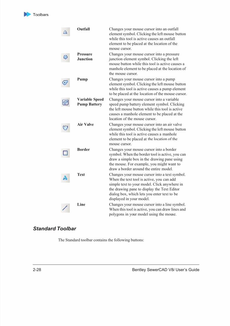
Outfall Changes your mouse cursor into an outfallelement symbol. Clicking the left mouse buttonwhile this tool is active causes an outfallelement to be placed at the location of themouse cursor.
PressureJunction
Changes your mouse cursor into a pressure junction element symbol. Clicking the leftmouse button while this tool is active causes amanhole element to be placed at the location ofthe mouse cursor.
Pump Changes your mouse cursor into a pumpelement symbol. Clicking the left mouse buttonwhile this tool is active causes a pump elementto be placed at the location of the mouse cursor.
Variable SpeedPump Battery
Changes your mouse cursor into a variablespeed pump battery element symbol. Clickingthe left mouse button while this tool is active
causes a manhole element to be placed at thelocation of the mouse cursor.
Air Valve Changes your mouse cursor into an air valveelement symbol. Clicking the left mouse buttonwhile this tool is active causes a manholeelement to be placed at the location of themouse cursor.
Border Changes your mouse cursor into a bordersymbol. When the border tool is active, you candraw a simple box in the drawing pane usingthe mouse. For example, you might want todraw a border around the entire model.
Text Changes your mouse cursor into a text symbol.When the text tool is active, you can addsimple text to your model. Click anywhere inthe drawing pane to display the Text Editordialog box, which lets you enter text to bedisplayed in your model.
Line Changes your mouse cursor into a line symbol.When this tool is active, you can draw lines and
polygons in your model using the mouse.

8/20/2019 SewerCAD V8i Users Guide de 1-50
http://slidepdf.com/reader/full/sewercad-v8i-users-guide-de-1-50 49/50
Introducing the Workspace
Bentley SewerCAD V8 i User’s Guide 2-29
New Creates a new Bentley SewerCAD V8 i project.When you select this command, the Select File toCreate dialog box appears, allowing you todefine a name and directory location for the new
project.
Open Opens an existing Bentley SewerCAD V8 i project. When this command is initialized, theSelect Bentley SewerCAD V8 i Project to Open dialog box appears, allowing you to browse to the
project to be opened.
Save Saves the current project.
Print Preview Opens the Print Preview window, displaying thecurrent view exactly as it will be printed.
Print Prints the current view of the network asdisplayed in the drawing pane.
8/20/2019 SewerCAD V8i Users Guide de 1-50
http://slidepdf.com/reader/full/sewercad-v8i-users-guide-de-1-50 50/50
Toolbars
Edit Toolbar
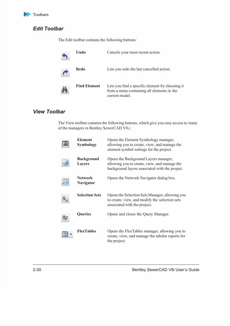
The Edit toolbar contains the following buttons:
View Toolbar The View toolbar contains the following buttons, which give you easy access to manyof the managers in Bentley SewerCAD V8 i .:
Undo Cancels your most recent action.
Redo Lets you redo the last cancelled action.
Find Element Lets you find a specific element by choosing itfrom a menu containing all elements in thecurrent model.
ElementSymbology
Opens the Element Symbology manager,allowing you to create, view, and manage theelement symbol settings for the project.
BackgroundLayers
Opens the Background Layers manager,allowing you to create, view, and manage the
background layers associated with the project.
NetworkNavigator
Opens the Network Navigator dialog box.
Selection Sets Opens the Selection Sets Manager, allowing youto create, view, and modify the selection setsassociated with the project.
Queries Opens and closes the Query Manager.
FlexTables Opens the FlexTables manager, allowing you tocreate, view, and manage the tabular reports forthe project.
Related Documents