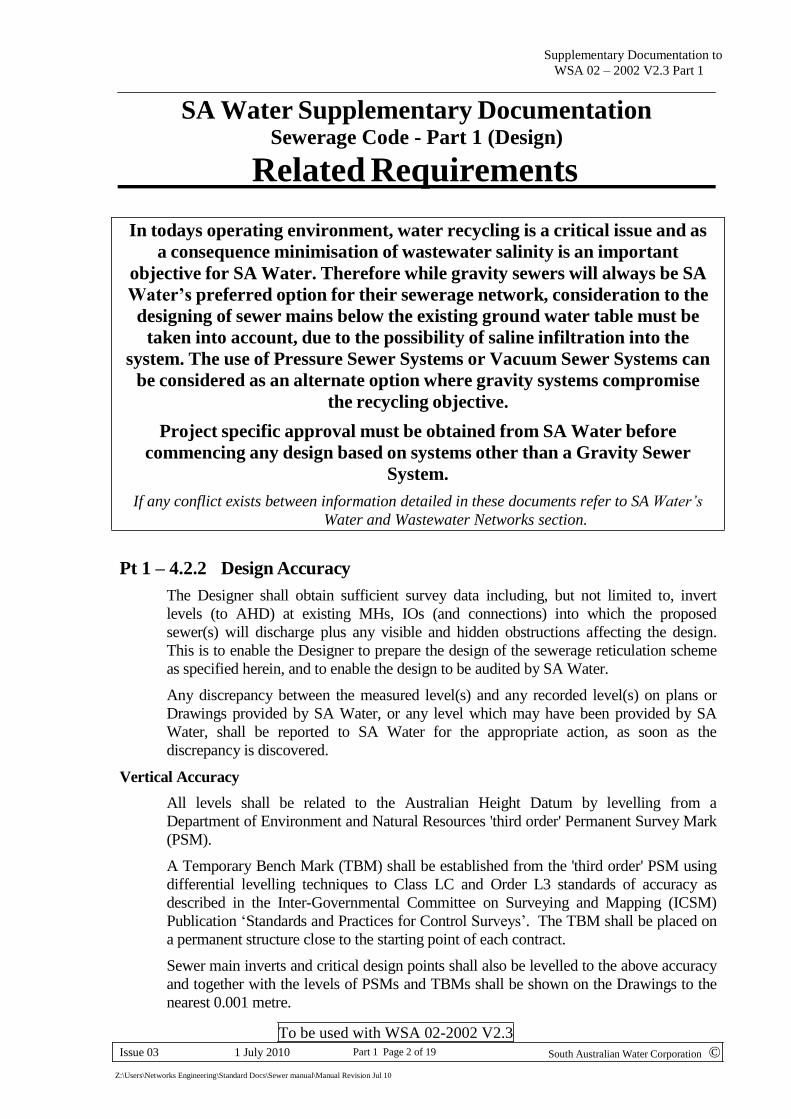
SEWERAGE CODE OF AUSTRALIA AGENCY REQUIREMENTS PART 1 - DESIGN Clause Description Requirement Supporting Document 4.2.2 Design Accuracy Design levels and distances to be in accordance with SA Water requirements:- Pt1 – 4.2.2 (Pg 2) 4.2.3 Sewer Locations All mains laid in SA are to meet the requirements of SERVICES IN STREETS. A code for the Design of Infrastructure Services in New and Existing Streets 4.2.5 Easements To be in accordance with details shown:- Pt1 – 4.2.5 (Pg 3) 4.3.7 Horizontal Curves Method to be as detailed in Pt3–17.2 Table 17.1 plus Pt1 – 4.3.7 (Pg 6) 4.4 Obstructions and Clearances To be in accordance with details shown:- Pt1 – 4.4 (Pg 7) 4.4.5 Table 4.4 Maximum EP for Reticulation Sewers See revised Table Pt1 – 4.4.5 (Pg 8) Table 4.6 Table 4.7 Minimum Grades & Min Grades for Prop Connects See revised Tables Pt1 – Table 4.6 & Table 4.7 (Pg 8) 4.6.4 Lot Servicing Requirements To be in accordance with details shown:- Pt1 – 4.6.4 (Pg 9) 4.6.5.4 Depth of Connection Point All Connection points to have riser to surface regardless of depth. See also SCM Drgs Sect K Pt1 – 4.6.5.4 (Pg 10) 4.6.7 Vertical Curves Method to be as detailed in Pt3–17.2 Table 17.1 plus Pt1– 4.6.7(Pg 11) 4.6.8 Compound Bends Compound bends are not to be used without specific approval from SA Water 5.3 Property Connections SA Water use the IO interface system 5.7 “Y” Connections To be used wherever possible, provided crossfall of the allotments at the front boundary < 0.6 m 5.8 Length of Connection Maximum length to be 30 m. Where > 20 m an additional standard IP is required at the mid-point 6.6.8 Ladders and Step irons Not required in SA Water infrastructure 6.6.9 Covers Gas &watertight covers are not required unless specifically directed by SA Water 6.7 Maintenance Shafts To be in accordance with SA Water requirements Pt1 – 6.7 (Pg 11) 7.2 Water Seals See SCM Drg H1. Other WSSA systems require approval 7.5 Vents See SCM Drg J1-J3. Other WSSA methods require approval 8.10 Bulkheads /Trenchstops Required on steep slopes in agreement with SA Water where sewer passes through water body (ie underground stream) or where directed by SA Water. Section 9 Design Drawings Attached SA Water specific requirements apply Pt1 – Section 9 (Pg 12) Appendices A, B & D Flow Estimation SA Water to be contacted before using these systems Additional Design Requirements Battleaxe allotments SA water have minimum access requirements for mains servicing narrow entry (Battleaxe, Hammerhead, Flagpole etc) allotments Pt1 - AR1 (Pg 18) Other Design Requirements (see WSCM Specifications) Pumping Stations Until the release of the WSAA Pumping Station Code use the existing criteria DS11(a)-Section 4 Rising Mains Until the release of the WSAA Pumping Station Code use the existing criteria DS11(a)-Section 5 To be used with WSA 02-2002 V2.3 Issue 03 1 July 2010 Part 1 Page 1 of 18 South Australian Water Corporation © Z:\Users\Networks Engineering\Standard Docs\Sewer manual\Manual Revision Jul 10

Welcome message from author
This document is posted to help you gain knowledge. Please leave a comment to let me know what you think about it! Share it to your friends and learn new things together.
Transcript
SEWERAGE CODE OF AUSTRALIA
AGENCY REQUIREMENTS
PART 1 - DESIGN
Clause
Description
Requirement Supporting
Document 4.2.2 Design Accuracy Design levels and distances to be in accordance with
SA Water requirements:-
Pt1 – 4.2.2 (Pg 2)
4.2.3 Sewer Locations All mains laid in SA are to meet the requirements of
SERVICES IN STREETS. A code for the Design of
Infrastructure Services in New and Existing Streets
4.2.5 Easements To be in accordance with details shown:- Pt1 – 4.2.5 (Pg 3)
4.3.7 Horizontal Curves Method to be as detailed in Pt3–17.2 Table 17.1 plus Pt1 – 4.3.7 (Pg 6)
4.4 Obstructions and Clearances To be in accordance with details shown:- Pt1 – 4.4 (Pg 7)
4.4.5
Table 4.4
Maximum EP for
Reticulation Sewers
See revised Table Pt1 – 4.4.5 (Pg 8)
Table 4.6
Table 4.7 Minimum Grades & Min
Grades for Prop Connects
See revised Tables Pt1 – Table 4.6 &
Table 4.7 (Pg 8)
4.6.4 Lot Servicing Requirements To be in accordance with details shown:- Pt1 – 4.6.4 (Pg 9)
4.6.5.4 Depth of Connection Point All Connection points to have riser to surface
regardless of depth. See also SCM Drgs Sect K
Pt1 – 4.6.5.4
(Pg 10)
4.6.7 Vertical Curves Method to be as detailed in Pt3–17.2 Table 17.1 plus Pt1– 4.6.7(Pg 11)
4.6.8 Compound Bends Compound bends are not to be used without specific
approval from SA Water
5.3 Property Connections SA Water use the IO interface system 5.7 “Y” Connections To be used wherever possible, provided crossfall of
the allotments at the front boundary < 0.6 m
5.8 Length of Connection Maximum length to be 30 m. Where > 20 m an
additional standard IP is required at the mid-point
6.6.8 Ladders and Step irons Not required in SA Water infrastructure 6.6.9 Covers Gas &watertight covers are not required unless
specifically directed by SA Water
6.7 Maintenance Shafts To be in accordance with SA Water requirements Pt1 – 6.7 (Pg 11)
7.2 Water Seals See SCM Drg H1. Other WSSA systems require
approval
7.5 Vents See SCM Drg J1-J3. Other WSSA methods require
approval
8.10 Bulkheads /Trenchstops Required on steep slopes in agreement with SA
Water where sewer passes through water body (ie
underground stream) or where directed by SA Water.
Section 9 Design Drawings Attached SA Water specific requirements apply Pt1 – Section 9
(Pg 12)
Appendices
A, B & D
Flow Estimation SA Water to be contacted before using these systems
Additional Design Requirements
Battleaxe allotments SA water have minimum access requirements for mains servicing
narrow entry (Battleaxe, Hammerhead, Flagpole etc) allotments
Pt1 - AR1 (Pg 18)
Other Design Requirements (see WSCM Specifications)
Pumping Stations Until the release of the WSAA Pumping Station Code use the existing
criteria
DS11(a)-Section 4
Rising Mains Until the release of the WSAA Pumping Station Code use the existing
criteria
DS11(a)-Section 5
To be used with WSA 02-2002 V2.3
Issue 03 1 July 2010 Part 1 Page 1 of 18 South Australian Water Corporation ©
Z:\Users\Networks Engineering\Standard Docs\Sewer manual\Manual Revision Jul 10
Supplementary Documentation to
WSA 02 – 2002 V2.3 Part 1
To be used with WSA 02-2002 V2.3
South Australian Water Corporation © Issue 03 1 July 2010 Part 1 Page 2 of 19
Z:\Users\Networks Engineering\Standard Docs\Sewer manual\Manual Revision Jul 10
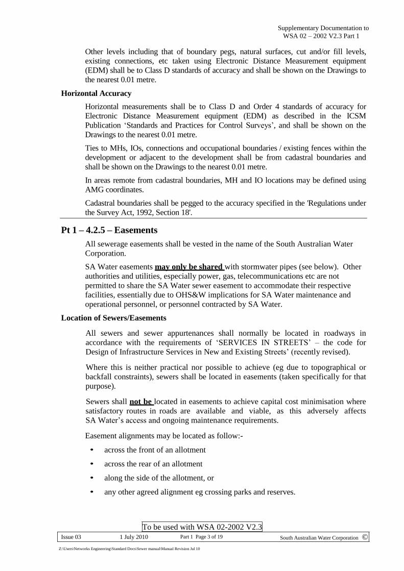
SA Water Supplementary Documentation Sewerage Code - Part 1 (Design)
Related Requirements
In todays operating environment, water recycling is a critical issue and as
a consequence minimisation of wastewater salinity is an important
objective for SA Water. Therefore while gravity sewers will always be SA
Water’s preferred option for their sewerage network, consideration to the
designing of sewer mains below the existing ground water table must be
taken into account, due to the possibility of saline infiltration into the
system. The use of Pressure Sewer Systems or Vacuum Sewer Systems can
be considered as an alternate option where gravity systems compromise
the recycling objective.
Project specific approval must be obtained from SA Water before
commencing any design based on systems other than a Gravity Sewer
System.
If any conflict exists between information detailed in these documents refer to SA Water’s
Water and Wastewater Networks section.
Pt 1 – 4.2.2 Design Accuracy
The Designer shall obtain sufficient survey data including, but not limited to, invert
levels (to AHD) at existing MHs, IOs (and connections) into which the proposed
sewer(s) will discharge plus any visible and hidden obstructions affecting the design.
This is to enable the Designer to prepare the design of the sewerage reticulation scheme
as specified herein, and to enable the design to be audited by SA Water.
Any discrepancy between the measured level(s) and any recorded level(s) on plans or
Drawings provided by SA Water, or any level which may have been provided by SA
Water, shall be reported to SA Water for the appropriate action, as soon as the
discrepancy is discovered.
Vertical Accuracy
All levels shall be related to the Australian Height Datum by levelling from a
Department of Environment and Natural Resources 'third order' Permanent Survey Mark
(PSM).
A Temporary Bench Mark (TBM) shall be established from the 'third order' PSM using
differential levelling techniques to Class LC and Order L3 standards of accuracy as
described in the Inter-Governmental Committee on Surveying and Mapping (ICSM)
Publication ‘Standards and Practices for Control Surveys’. The TBM shall be placed on
a permanent structure close to the starting point of each contract.
Sewer main inverts and critical design points shall also be levelled to the above accuracy
and together with the levels of PSMs and TBMs shall be shown on the Drawings to the
nearest 0.001 metre.
Supplementary Documentation to
WSA 02 – 2002 V2.3 Part 1
To be used with WSA 02-2002 V2.3
South Australian Water Corporation © Issue 03 1 July 2010 Part 1 Page 3 of 19
Z:\Users\Networks Engineering\Standard Docs\Sewer manual\Manual Revision Jul 10
Other levels including that of boundary pegs, natural surfaces, cut and/or fill levels,
existing connections, etc taken using Electronic Distance Measurement equipment
(EDM) shall be to Class D standards of accuracy and shall be shown on the Drawings to
the nearest 0.01 metre.
Horizontal Accuracy
Horizontal measurements shall be to Class D and Order 4 standards of accuracy for
Electronic Distance Measurement equipment (EDM) as described in the ICSM
Publication ‘Standards and Practices for Control Surveys’, and shall be shown on the
Drawings to the nearest 0.01 metre.
Ties to MHs, IOs, connections and occupational boundaries / existing fences within the
development or adjacent to the development shall be from cadastral boundaries and
shall be shown on the Drawings to the nearest 0.01 metre.
In areas remote from cadastral boundaries, MH and IO locations may be defined using
AMG coordinates.
Cadastral boundaries shall be pegged to the accuracy specified in the 'Regulations under
the Survey Act, 1992, Section 18'.
Pt 1 – 4.2.5 – Easements
All sewerage easements shall be vested in the name of the South Australian Water
Corporation.
SA Water easements may only be shared with stormwater pipes (see below). Other
authorities and utilities, especially power, gas, telecommunications etc are not
permitted to share the SA Water sewer easement to accommodate their respective
facilities, essentially due to OHS&W implications for SA Water maintenance and
operational personnel, or personnel contracted by SA Water.
Location of Sewers/Easements
All sewers and sewer appurtenances shall normally be located in roadways in
accordance with the requirements of ‘SERVICES IN STREETS’ – the code for
Design of Infrastructure Services in New and Existing Streets’ (recently revised).
Where this is neither practical nor possible to achieve (eg due to topographical or
backfall constraints), sewers shall be located in easements (taken specifically for that
purpose).
Sewers shall not be located in easements to achieve capital cost minimisation where
satisfactory routes in roads are available and viable, as this adversely affects
SA Water’s access and ongoing maintenance requirements.
Easement alignments may be located as follow:-
• across the front of an allotment
• across the rear of an allotment
• along the side of the allotment, or
• any other agreed alignment eg crossing parks and reserves.

Supplementary Documentation to
WSA 02 – 2002 V2.3 Part 1
To be used with WSA 02-2002 V2.3
South Australian Water Corporation © Issue 03 1 July 2010 Part 1 Page 4 of 19
Z:\Users\Networks Engineering\Standard Docs\Sewer manual\Manual Revision Jul 10
Sewer easements shall generally be located in the allotment served by that sewer, or
if the property adjoins a park/reserve, the sewer may be located in the park/reserve,
providing:-
• suitable vehicle access to the sewer can be demonstrated to SA Water
• the sewer pipeline is well clear of existing or proposed locations of trees and
shrubs, in accordance with the minimum clearances specified in the
Supplementary Documentation WSA 02 Part 1 - 2.6.5
The minimum horizontal clearance between the outside face of the sewer and an
existing or proposed building or structure shall be as detailed in the Supplementary
Documentation to WSA 02 Part 1 – 4.4
Minimum Cover in Easements
The minimum cover to mains in any easement will be 600 mm unless specifically
authorised by SA water.
Amdt Jun09
Supplementary Documentation to
WSA 02 – 2002 V2.3 Part 1
To be used with WSA 02-2002 V2.3
South Australian Water Corporation © Issue 03 1 July 2010 Part 1 Page 5 of 19
Z:\Users\Networks Engineering\Standard Docs\Sewer manual\Manual Revision Jul 10
DEPTH
TO
INVERT
m
PIPE SIZE
EASEMENT
WIDTH
m
LOCATION
Spacing to Edge of
Easement
D1 (see Fig 1)
Clearance
Between Pipes
≤ 1
DN150 & DN225 3.0 1.0 m
1.2m minimum DN300 5.0 1.5 m
1 to 3.3
DN150 & DN225 4.0 1.5 m
DN300 5.0 1.5 m
> 3.3
DN150 & DN225 5.0 2.0 m
1.5m minimum
DN300 6.0 2.0 m
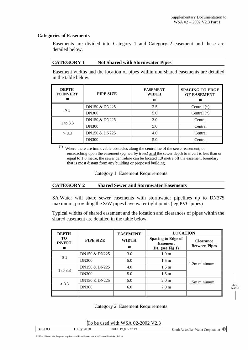
Categories of Easements
Easements are divided into Category 1 and Category 2 easement and these are
detailed below.
CATEGORY 1 Not Shared with Stormwater Pipes
Easement widths and the location of pipes within non shared easements are detailed
in the table below.
DEPTH
TO INVERT
m
PIPE SIZE
EASEMENT
WIDTH
m
SPACING TO EDGE
OF EASEMENT
m
≤ 1
DN150 & DN225 2.5 Central (*)
DN300 5.0 Central (*)
1 to 3.3
DN150 & DN225 3.0 Central
DN300 5.0 Central
> 3.3 DN150 & DN225 4.0 Central
DN300 5.0 Central
(*) Where there are immovable obstacles along the centreline of the sewer easement, or
encroaching upon the easement (eg nearby trees) and the sewer depth to invert is less than or
equal to 1.0 metre, the sewer centreline can be located 1.0 metre off the easement boundary
that is most distant from any building or proposed building.
Category 1 Easement Requirements
CATEGORY 2 Shared Sewer and Stormwater Easements
SA Water will share sewer easements with stormwater pipelines up to DN375
maximum, providing the S/W pipes have water tight joints ( eg PVC pipes)
Typical widths of shared easement and the location and clearances of pipes within the
shared easement are detailed in the table below.
Amdt
Mar 10
Category 2 Easement Requirements
Supplementary Documentation to
WSA 02 – 2002 V2.3 Part 1
To be used with WSA 02-2002 V2.3
South Australian Water Corporation © Issue 03 1 July 2010 Part 1 Page 6 of 19
Z:\Users\Networks Engineering\Standard Docs\Sewer manual\Manual Revision Jul 10
All
otm
ent
Bou
nd
ary
or
Ed
ge
of
Eas
emen
t
Dep
th o
f S
ewer
(As
req
uir
ed)
Ed
ge
of
Eas
emen
t
Shared Easement Width (See Table 4)
D1 (see Table 4)
300 min
1 200 min
SEWER
DN150, 225 or 300
S/W (PVC)
DN375 max
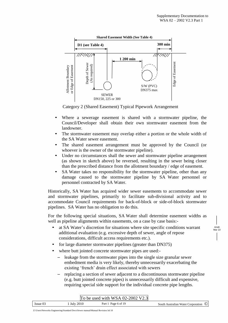
Category 2 (Shared Easement) Typical Pipework Arrangement
• Where a sewerage easement is shared with a stormwater pipeline, the
Council/Developer shall obtain their own stormwater easement from the
landowner.
• The stormwater easement may overlap either a portion or the whole width of
the SA Water sewer easement.
• The shared easement arrangement must be approved by the Council (or
whoever is the owner of the stormwater pipeline).
• Under no circumstances shall the sewer and stormwater pipeline arrangement
(as shown in sketch above) be reversed, resulting in the sewer being closer
than the prescribed distance from the allotment boundary / edge of easement.
• SA Water takes no responsibility for the stormwater pipeline, other than any
damage caused to the stormwater pipeline by SA Water personnel or
personnel contracted by SA Water.
Historically, SA Water has acquired wider sewer easements to accommodate sewer
and stormwater pipelines, primarily to facilitate sub-divisional activity and to
accommodate Council requirements for back-of-block or side-of-block stormwater
pipelines. SA Water has no obligation to do this.
For the following special situations, SA Water shall determine easement widths as
well as pipeline alignments within easements, on a case by case basis:-
• at SA Water’s discretion for situations where site specific conditions warrant
additional evaluation (e.g. excessive depth of sewer, angle of repose
considerations, difficult access requirements etc.).
• for large diameter stormwater pipelines (greater than DN375)
• where butt jointed concrete stormwater pipes are used:-
– leakage from the stormwater pipes into the single size granular sewer
embedment media is very likely, thereby unnecessarily exacerbating the
existing ‘french’ drain effect associated with sewers
– replacing a section of sewer adjacent to a discontinuous stormwater pipeline
(e.g. butt jointed concrete pipes) is unnecessarily difficult and expensive,
requiring special side support for the individual concrete pipe lengths.
Amdt Mar 10
Supplementary Documentation to
WSA 02 – 2002 V2.3 Part 1
To be used with WSA 02-2002 V2.3
South Australian Water Corporation © Issue 03 1 July 2010 Part 1 Page 7 of 19
Z:\Users\Networks Engineering\Standard Docs\Sewer manual\Manual Revision Jul 10
Easements obtained under Developer Contracts
The Developer shall be responsible for all costs associated with the acquisition of
sewer easements that are required within the development.
Easements within the development shall be established on the basis of the Final Plan
of the Development. The final plan shall be prepared and lodged with the
Development Assessment Commission by the Licensed Surveyor engaged by the
Developer.
Where easements external to the development are required, the Developer may
acquire the easements independently or may request that SA Water acquire the
easements at the developers cost.
Pt 1 – 4.3.7 – Horizontal Curves
Rubber ring joints are not permissible for PVC (<DN300) or PE sewer pipe and
therefore the cumulative joint deflection method is not permissible for these pipes
The following allowable Minimum Curve Lengths are applicable for manual cold
bending of PVC sewer pipes
Horizontal Curves Minimum Curve Length
Deflection Angle 150 mm Diameter 225 mm Diameter
Up to 10° 6 metres 12 metres
10° to 22° 12 metres 24 metres
IOs shall be provided at the tangent points at the beginning and end of each horizontal
curve except in the case where a curve commences or ends adjacent to a MH. In this
situation, the IO nearest the MH is not required.
Manufactured (Variable) Bends
Short radius bends– (635 mm nominal radius) up to 45° can be used immediately
upstream of straight through maintenance shafts and maintenance shaft junctions.
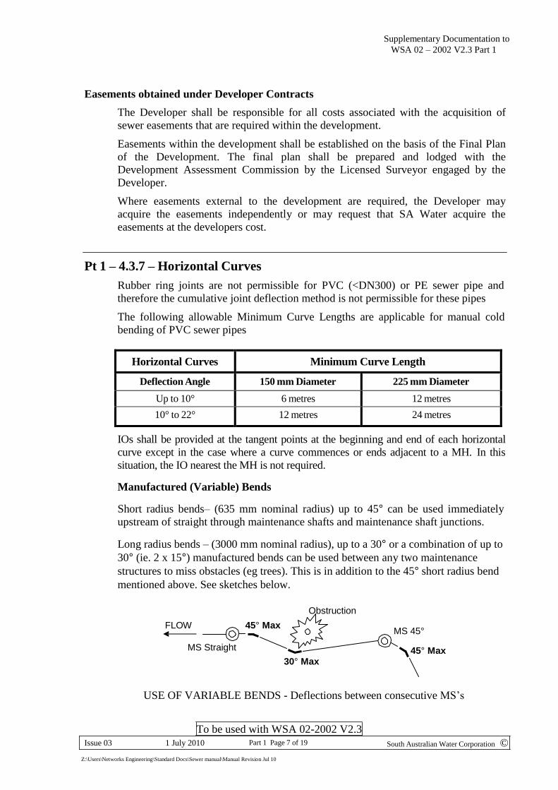
Long radius bends – (3000 mm nominal radius), up to a 30° or a combination of up to
30° (ie. 2 x 15°) manufactured bends can be used between any two maintenance
structures to miss obstacles (eg trees). This is in addition to the 45° short radius bend
mentioned above. See sketches below.
FLOW 45° Max
MS Straight
Obstruction 30° Max
MS 45°
45° Max
USE OF VARIABLE BENDS - Deflections between consecutive MS’s
Supplementary Documentation to
WSA 02 – 2002 V2.3 Part 1
To be used with WSA 02-2002 V2.3
South Australian Water Corporation © Issue 03 1 July 2010 Part 1 Page 8 of 19
Z:\Users\Networks Engineering\Standard Docs\Sewer manual\Manual Revision Jul 10
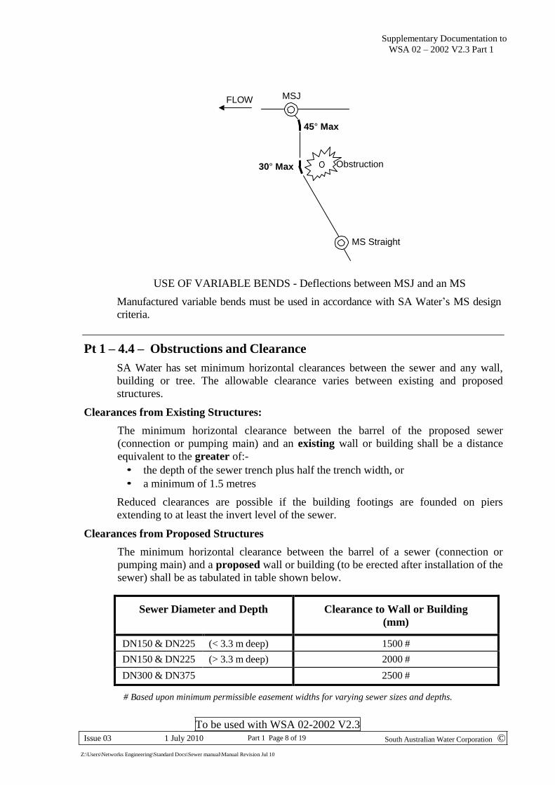
FLOW MSJ
45° Max
30° Max Obstruction
MS Straight
USE OF VARIABLE BENDS - Deflections between MSJ and an MS
Manufactured variable bends must be used in accordance with SA Water’s MS design
criteria.
Pt 1 – 4.4 – Obstructions and Clearance
SA Water has set minimum horizontal clearances between the sewer and any wall,
building or tree. The allowable clearance varies between existing and proposed
structures.
Clearances from Existing Structures:
The minimum horizontal clearance between the barrel of the proposed sewer
(connection or pumping main) and an existing wall or building shall be a distance
equivalent to the greater of:-
• the depth of the sewer trench plus half the trench width, or
• a minimum of 1.5 metres
Reduced clearances are possible if the building footings are founded on piers
extending to at least the invert level of the sewer.
Clearances from Proposed Structures
The minimum horizontal clearance between the barrel of a sewer (connection or
pumping main) and a proposed wall or building (to be erected after installation of the
sewer) shall be as tabulated in table shown below.
Sewer Diameter and Depth
Clearance to Wall or Building
(mm)
DN150 & DN225 (< 3.3 m deep) 1500 #
DN150 & DN225 (> 3.3 m deep) 2000 #
DN300 & DN375 2500 #
# Based upon minimum permissible easement widths for varying sewer sizes and depths.
Supplementary Documentation to
WSA 02 – 2002 V2.3 Part 1
To be used with WSA 02-2002 V2.3
South Australian Water Corporation © Issue 03 1 July 2010 Part 1 Page 9 of 19
Z:\Users\Networks Engineering\Standard Docs\Sewer manual\Manual Revision Jul 10
Pipe Size DN
Maximum Allowable EP
Equivalent No. Properties
150
1000
400
225
2500
1000
300
4500
1800
Clearances from Trees
Clearances between sewers and trees shall be the greater of the following two
conditions:-
• minimum 1.5 metres lateral clearance between the face of the sewer and the
trunk of a mature small tree, or
• Larger clearances (covering many tree types) as determined by the SA Water
“Tree Planting Guide”.
Note:- Where it is impossible to attain the necessary lateral clearances from trees, it may be
practical to tunnel beneath (or alongside) the tree/s, provided the tree type and root growth
will permit such action and provided the tunnelling will not affect or endanger the health OR
stability of the tree/s. This action, on a case by case basis, must be supported by a written
opinion to SA Water from a specialist tree consultant who is qualified and accredited to
provide such professional judgements (eg horticulturist and/or arboriculturist).
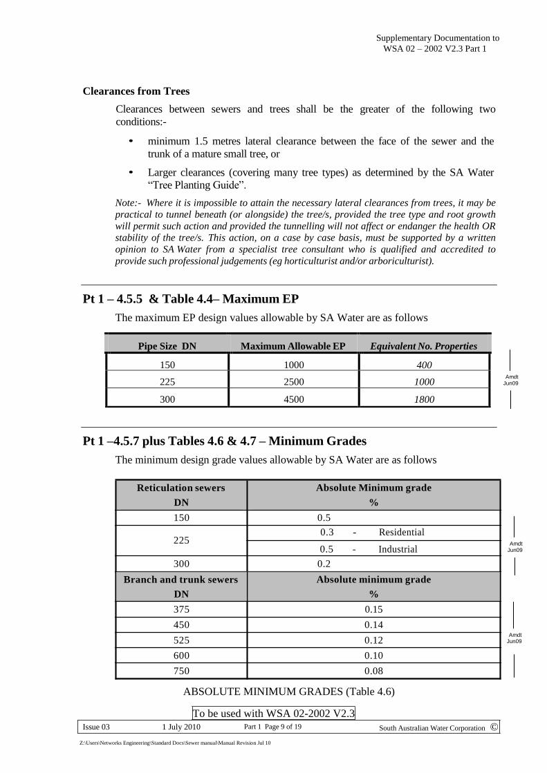
Pt 1 – 4.5.5 & Table 4.4– Maximum EP
The maximum EP design values allowable by SA Water are as follows
Amdt Jun09
Pt 1 –4.5.7 plus Tables 4.6 & 4.7 – Minimum Grades
The minimum design grade values allowable by SA Water are as follows
Reticulation sewers
DN
Absolute Minimum grade
%
150 0.5
0.3 - Residential 225
0.5 - Industrial
300 0.2
Amdt Jun09
Branch and trunk sewers
DN
Absolute minimum grade
%
375 0.15
450 0.14
525 0.12
600 0.10
750 0.08
ABSOLUTE MINIMUM GRADES (Table 4.6)
Amdt Jun09
Supplementary Documentation to
WSA 02 – 2002 V2.3 Part 1
To be used with WSA 02-2002 V2.3
South Australian Water Corporation © Issue 03 1 July 2010 Part 1 Page 10 of 19
Z:\Users\Networks Engineering\Standard Docs\Sewer manual\Manual Revision Jul 10
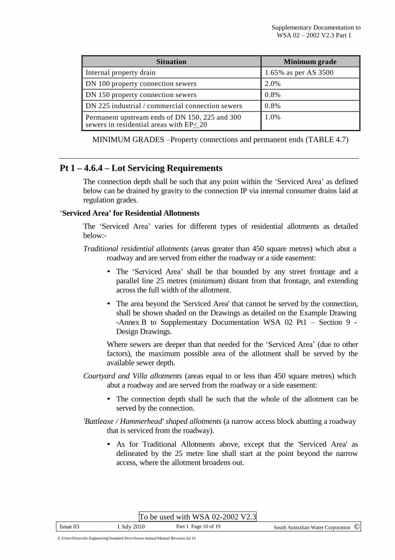
Situation Minimum grade
Internal property drain 1.65% as per AS 3500
DN 100 property connection sewers 2.0%
DN 150 property connection sewers 0.8%
DN 225 industrial / commercial connection sewers 0.8%
Permanent upstream ends of DN 150, 225 and 300 sewers in residential areas with EP< 20
1.0%
MINIMUM GRADES –Property connections and permanent ends (TABLE 4.7)
Pt 1 – 4.6.4 – Lot Servicing Requirements
The connection depth shall be such that any point within the ‘Serviced Area’ as defined
below can be drained by gravity to the connection IP via internal consumer drains laid at
regulation grades.
‘Serviced Area’ for Residential Allotments
The ‘Serviced Area’ varies for different types of residential allotments as detailed
below:-
Traditional residential allotments (areas greater than 450 square metres) which abut a
roadway and are served from either the roadway or a side easement:
• The ‘Serviced Area’ shall be that bounded by any street frontage and a
parallel line 25 metres (minimum) distant from that frontage, and extending
across the full width of the allotment.
• The area beyond the 'Serviced Area' that cannot be served by the connection,
shall be shown shaded on the Drawings as detailed on the Example Drawing
-Annex B to Supplementary Documentation WSA 02 Pt1 – Section 9 -
Design Drawings.
Where sewers are deeper than that needed for the ‘Serviced Area’ (due to other
factors), the maximum possible area of the allotment shall be served by the
available sewer depth.
Courtyard and Villa allotments (areas equal to or less than 450 square metres) which
abut a roadway and are served from the roadway or a side easement:
• The connection depth shall be such that the whole of the allotment can be
served by the connection.
'Battleaxe / Hammerhead' shaped allotments (a narrow access block abutting a roadway
that is serviced from the roadway).
• As for Traditional Allotments above, except that the 'Serviced Area' as
delineated by the 25 metre line shall start at the point beyond the narrow
access, where the allotment broadens out.
Supplementary Documentation to
WSA 02 – 2002 V2.3 Part 1
To be used with WSA 02-2002 V2.3
South Australian Water Corporation © Issue 03 1 July 2010 Part 1 Page 11 of 19
Z:\Users\Networks Engineering\Standard Docs\Sewer manual\Manual Revision Jul 10
Allotments abutting a roadway but served from a rear easement:
• For allotments served from a sewer in a rear easement (generally due to a
significant backfall from the street frontage), the depth of the connection shall
be such that the whole of the allotment, or that area as defined by the local
council’s building envelope (eg set backs etc), shall be served by the
connection.
‘Serviced Area’ for Industrial and Commercial Allotments
For industrial/commercial allotments, the ‘Serviced Area’ shall be a minimum of
5500 square metres, abutting the street frontage for that allotment.
Depending upon the size of the allotment, the ‘Serviced Area’ can comprise either the
entire allotment, or that portion of the allotment abutting the street, but can not
comprise only a rear or intermediate portion of the allotment (regardless of whether
only that portion of the allotment abuts the sewer).
The depth of the connection shall be calculated on the ‘worst’ case scenario of using
a 100 mm diameter consumer drain laid around the perimeter of the ‘Serviced Area’,
at the minimum regulation grade for 100 mm consumer drains, with an allowance of
at least 300 mm for pipe cover at the upgrade end of the drain when not subject to
vehicular traffic, or 500 mm cover where subject to vehicular traffic.
Where a connection laid at maximum depth can not service the minimum ‘Serviced
Area’ of 5500 square metres, the balance of the 5500 square metres shall be serviced
by either:-
(a) filling that portion of the site, or
(b) providing a second connection from another sewer.
Where there is a requirement to service an area greater than the minimum 5500
square metres, the additional area can be serviced by either (a) or (b) above, or by
‘private’ pumping into the connection.
In all cases, the area that cannot be served by gravity shall be shown shaded on the
Drawings
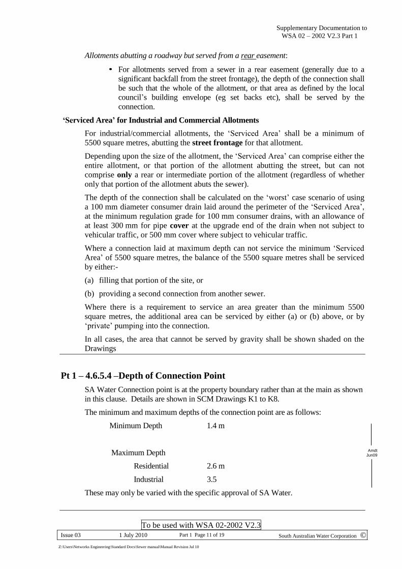
Pt 1 – 4.6.5.4 –Depth of Connection Point
SA Water Connection point is at the property boundary rather than at the main as shown
in this clause. Details are shown in SCM Drawings K1 to K8.
The minimum and maximum depths of the connection point are as follows:
Minimum Depth 1.4 m
Maximum Depth
Residential 2.6 m
Industrial 3.5
These may only be varied with the specific approval of SA Water.
Amdt Jun09
Supplementary Documentation to
WSA 02 – 2002 V2.3 Part 1
To be used with WSA 02-2002 V2.3
South Australian Water Corporation © Issue 03 1 July 2010 Part 1 Page 12 of 19
Z:\Users\Networks Engineering\Standard Docs\Sewer manual\Manual Revision Jul 10
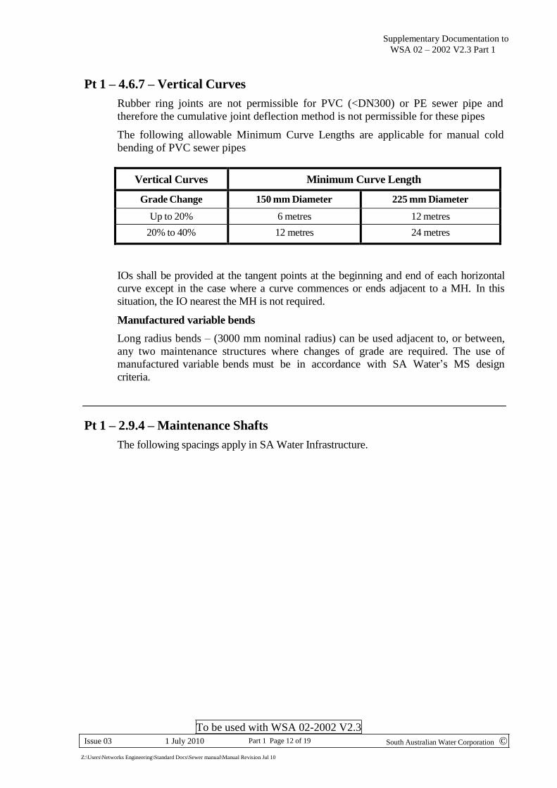
Pt 1 – 4.6.7 – Vertical Curves
Rubber ring joints are not permissible for PVC (<DN300) or PE sewer pipe and
therefore the cumulative joint deflection method is not permissible for these pipes
The following allowable Minimum Curve Lengths are applicable for manual cold
bending of PVC sewer pipes
Vertical Curves Minimum Curve Length
Grade Change 150 mm Diameter 225 mm Diameter
Up to 20% 6 metres 12 metres
20% to 40% 12 metres 24 metres
IOs shall be provided at the tangent points at the beginning and end of each horizontal
curve except in the case where a curve commences or ends adjacent to a MH. In this
situation, the IO nearest the MH is not required.
Manufactured variable bends
Long radius bends – (3000 mm nominal radius) can be used adjacent to, or between,
any two maintenance structures where changes of grade are required. The use of
manufactured variable bends must be in accordance with SA Water’s MS design
criteria.
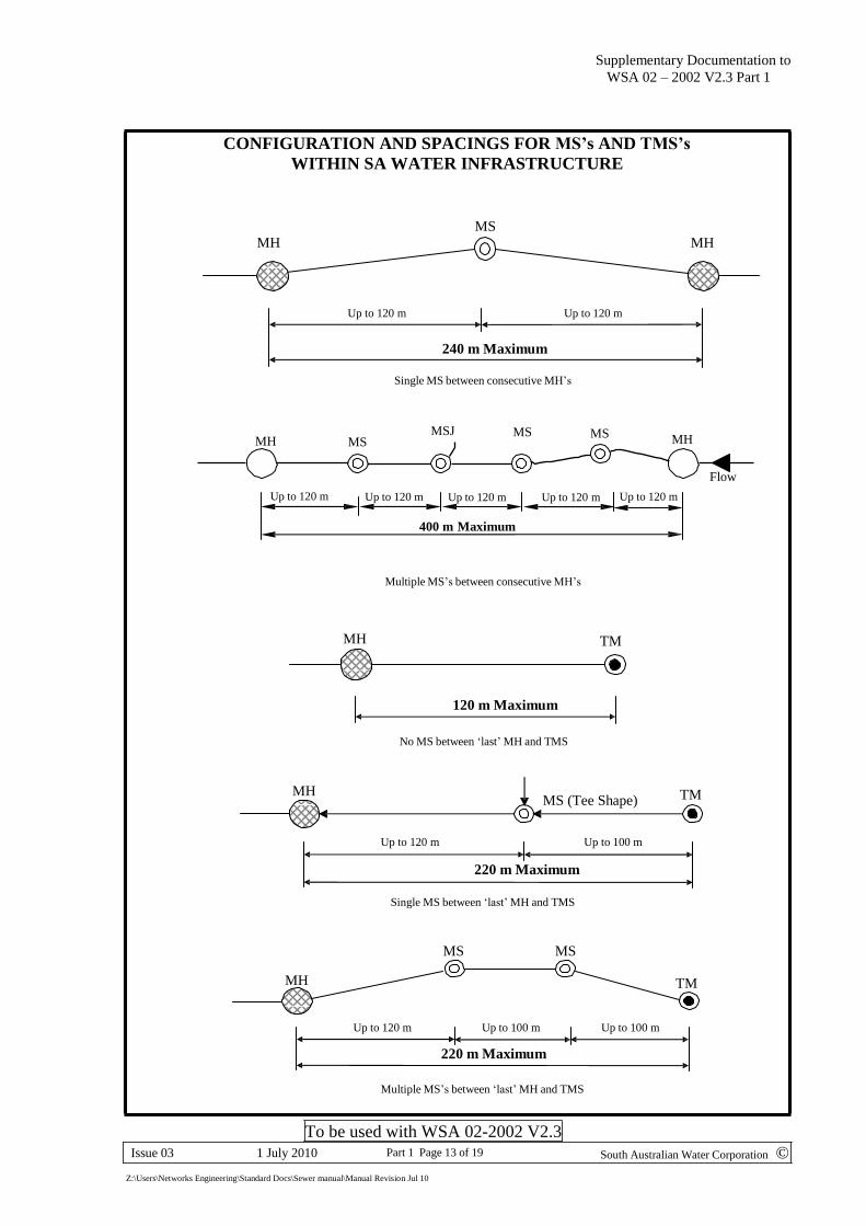
Pt 1 – 2.9.4 – Maintenance Shafts
The following spacings apply in SA Water Infrastructure.
Supplementary Documentation to
WSA 02 – 2002 V2.3 Part 1
To be used with WSA 02-2002 V2.3
South Australian Water Corporation © Issue 03 1 July 2010 Part 1 Page 13 of 19
Z:\Users\Networks Engineering\Standard Docs\Sewer manual\Manual Revision Jul 10
CONFIGURATION AND SPACINGS FOR MS’s AND TMS’s
WITHIN SA WATER INFRASTRUCTURE
MS MH MH
Up to 120 m Up to 120 m
240 m Maximum
Single MS between consecutive MH’s
MH MS MSJ MS MS MH
Up to 120 m
Up to 120 m
Up to 120 m
Up to 120 m
Up to 120 m
Flow
400 m Maximum
Multiple MS’s between consecutive MH’s
MH TM
120 m Maximum
No MS between ‘last’ MH and TMS
MH MS (Tee Shape) TM
Up to 120 m Up to 100 m
220 m Maximum
Single MS between ‘last’ MH and TMS
MS MS
MH TM
Up to 120 m Up to 100 m
220 m Maximum
Up to 100 m
Multiple MS’s between ‘last’ MH and TMS

Supplementary Documentation to
WSA 02 – 2002 V2.3 Part 1
To be used with WSA 02-2002 V2.3
South Australian Water Corporation © Issue 03 1 July 2010 Part 1 Page 14 of 19
Z:\Users\Networks Engineering\Standard Docs\Sewer manual\Manual Revision Jul 10
Pt 1 - Section 5 Design Drawings
Design Drawings are to be prepared in accordance with the following criteria:-
• All Drawing sheets shall be A1 size.
• All Drawings shall have title blocks, alteration blocks, margins etc. in accordance
with the South Australian Water Corporation’s Standard Drawing format. (refer to
Annex B for Example Drawing).
• Special symbols, standard abbreviations and special text sizes for Drawings shall be
as shown as attached. (refer to Part 1 Annex A Pages B1-B3)
• Drawings for pumping stations and pumping mains shall form part of the overall set
of Drawings for that sewerage scheme, and will be numbered accordingly as part of
that set.
• Dimensions and distances shall be shown in metres and shall be to two decimal
places and placed as shown in the Example Drawing (refer to Part 1 Annex B).
Composition of Drawings (A Supplementary Drawings Check List is also available)
The Drawings shall:
• Clearly define and detail the full extent of the Works being designed under the
Contract.
• Show all interacting services and facilities (including common services, water and
stormwater drains) on the plan and longitudinal section views of the Drawings where
they cross sewers, connections, pumping mains or appurtenances being designed, or
where those services are in close proximity to and/or running parallel to the sewers,
connections or pumping mains being designed.
• Provide sufficient information to enable the accurate setting out of the Works by the
Constructor including (but not limited to) ties from boundary pegs to MHs, to IOs, to
sewer lines, and to pumping lines.
• Where narrow roads are involved (particularly narrow curvilinear roads), the kerb
alignments shall also be shown in addition to the other relevant services and features.
Cover/Front Sheet
The Front Sheet shall comprise:-
• Plan View of the Sewerage Scheme
– Correlating the Works to existing infrastructure and existing roads.
– Drawn to a scale of 1:500 or 1:1000 depending on the allotment size and
ensuring that after construction of the scheme, the ‘as-constructed’
information can be readily and clearly recorded to a standard suitable for
microfilming.
As a guide, where allotments in the development have frontages less than 15
metres wide, then the Drawing shall be at a scale of 1:500.
Refer to the Example Drawing in Annex B
Supplementary Documentation to
WSA 02 – 2002 V2.3 Part 1
To be used with WSA 02-2002 V2.3
South Australian Water Corporation © Issue 03 1 July 2010 Part 1 Page 15 of 19
Z:\Users\Networks Engineering\Standard Docs\Sewer manual\Manual Revision Jul 10
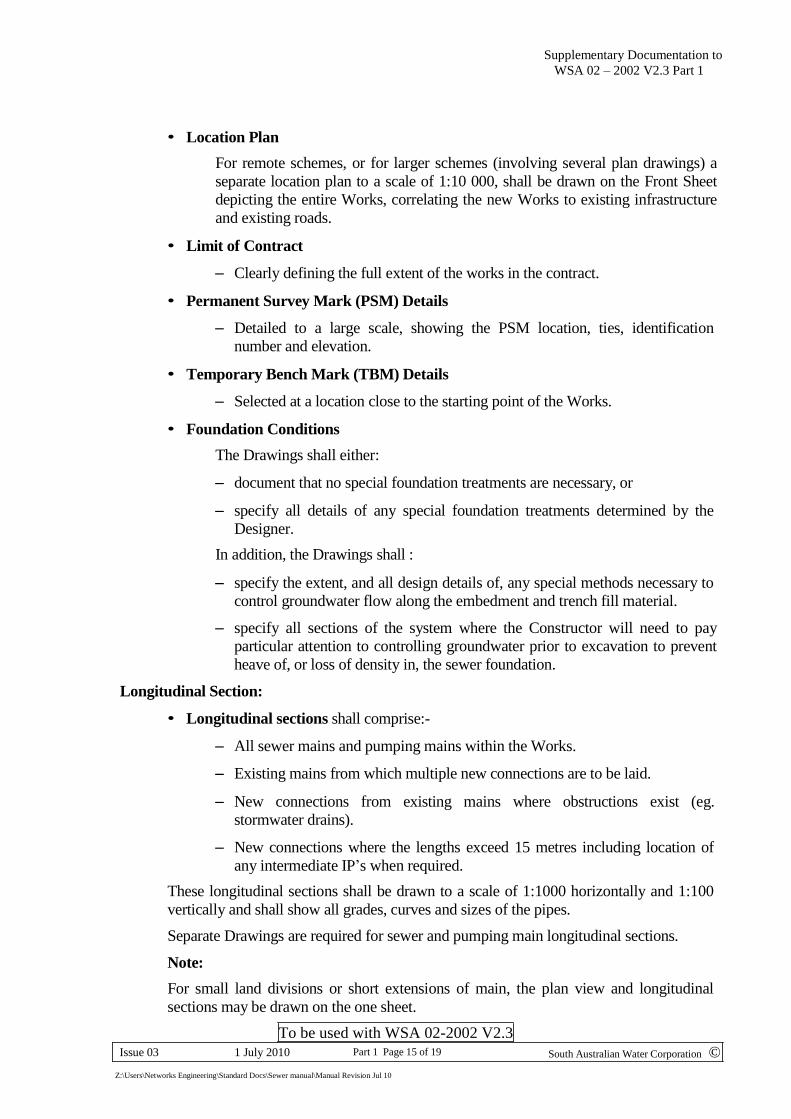
• Location Plan
For remote schemes, or for larger schemes (involving several plan drawings) a
separate location plan to a scale of 1:10 000, shall be drawn on the Front Sheet
depicting the entire Works, correlating the new Works to existing infrastructure
and existing roads.
• Limit of Contract
– Clearly defining the full extent of the works in the contract.
• Permanent Survey Mark (PSM) Details
– Detailed to a large scale, showing the PSM location, ties, identification
number and elevation.
• Temporary Bench Mark (TBM) Details
– Selected at a location close to the starting point of the Works.
• Foundation Conditions
The Drawings shall either:
– document that no special foundation treatments are necessary, or
– specify all details of any special foundation treatments determined by the
Designer.
In addition, the Drawings shall :
– specify the extent, and all design details of, any special methods necessary to
control groundwater flow along the embedment and trench fill material.
– specify all sections of the system where the Constructor will need to pay
particular attention to controlling groundwater prior to excavation to prevent
heave of, or loss of density in, the sewer foundation.
Longitudinal Section:
• Longitudinal sections shall comprise:-
– All sewer mains and pumping mains within the Works.
– Existing mains from which multiple new connections are to be laid.
– New connections from existing mains where obstructions exist (eg.
stormwater drains).
– New connections where the lengths exceed 15 metres including location of
any intermediate IP’s when required.
These longitudinal sections shall be drawn to a scale of 1:1000 horizontally and 1:100
vertically and shall show all grades, curves and sizes of the pipes.
Separate Drawings are required for sewer and pumping main longitudinal sections.
Note:
For small land divisions or short extensions of main, the plan view and longitudinal
sections may be drawn on the one sheet.

Supplementary Documentation to
WSA 02 – 2002 V2.3 Part 1
To be used with WSA 02-2002 V2.3
South Australian Water Corporation © Issue 03 1 July 2010 Part 1 Page 16 of 19
Z:\Users\Networks Engineering\Standard Docs\Sewer manual\Manual Revision Jul 10
Pumping Stations, Access Roads and Pumping Mains
Where pumping stations are required, a detailed Site Layout Plan of the pumping station
shall be prepared to a scale of 1:100, and shall incorporate a Location Plan correlating
the works to existing infrastructure and existing roads.
The station Site Layout Drawing shall show all station property boundaries and the
general arrangement of the sump, control Maintenance Hole (MH), valve chamber,
switchboard cubicle, venting arrangements, power supply, telemetry, sewers, pumping
main, water service, vehicular entranceways, fencing and all relevant levels (eg site
levels and levels at the tops of the sump, valve chamber, control MH and top of
switchboard cubicle base slab). AMG coordinates of the sump and the control MH are
also required.
In circumstances where the station does not abut a public roadway, a detailed Plan view,
Longitudinal Section view and Cross Sections of the access road and vehicle turn-
around areas shall be prepared to a scale of 1:200 horizontally and 1:20 vertically, and
shall include all site levels, site gradients, transition gradients, all earthworks including
the extent of cut and/or fill (ie top and bottom extremities of the cut and/or fill batters),
batter gradients, all surface and cut-off drains, embankments to deflect surface waters
and shall also detail compaction requirements.
Refer also to Sewer Construction Drawings - Section M for further details regarding
pumping stations.
The design of the collection sewers shall commence at the downstream end of the 'Inlet
Sewer' (ie distance 00), commencing at the inside face of the pumping station sump.
For pumping mains, the detailed Plan and Longitudinal Section Drawings shall show all
distances, invert levels, all vertical and horizontal curves (if applicable), all road and
ground levels, as well as the relationship of the pumping main with relevant existing and
proposed underground services, and all structures.
The Drawings for a pumping main shall commence at the outlet side of the valve
chamber (ie Distance 00 at the outside face of the chamber) and shall terminate in a MH
(called the Discharge MH).
The pumping main Drawings shall show all horizontal and vertical bend locations,
horizontal and vertical curves, and/or joint deflections where used, at their respective
distances, and shall also quote the actual value of the bend/s (eg 45 degrees) and/or
joint deflection (eg 1 degree).
Air-relief valves, pump-out branches etc shall also be shown on the Drawings.
The standard note regarding ‘Effluent Disposal’ to be added to the ‘Limit of Contract’
on the front sheet of the Drawings for Developer funded schemes involving pumping
stations.
Vertical and Horizontal Curves
For vertical curves, the distance and invert levels shall be calculated at the tangent
points of the curve and shall be shown on the longitudinal section view of the Drawings.
Where the curve length is greater than 6 metres, the distance and invert level at the
centre of the vertical curve, (ie opposite the curve intersection point) shall also be
calculated and shown on the Drawings.
Supplementary Documentation to
WSA 02 – 2002 V2.3 Part 1
To be used with WSA 02-2002 V2.3
South Australian Water Corporation © Issue 03 1 July 2010 Part 1 Page 17 of 19
Z:\Users\Networks Engineering\Standard Docs\Sewer manual\Manual Revision Jul 10
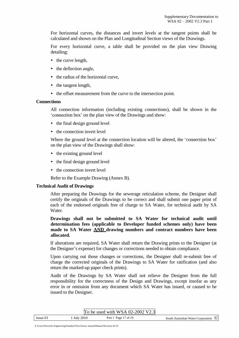
For horizontal curves, the distances and invert levels at the tangent points shall be
calculated and shown on the Plan and Longitudinal Section views of the Drawings.
For every horizontal curve, a table shall be provided on the plan view Drawing
detailing:
• the curve length,
• the deflection angle,
• the radius of the horizontal curve,
• the tangent length,
• the offset measurement from the curve to the intersection point.
Connections
All connection information (including existing connections), shall be shown in the
‘connection box’ on the plan view of the Drawings and show:
• the final design ground level
• the connection invert level
Where the ground level at the connection location will be altered, the ‘connection box’
on the plan view of the Drawings shall show:
• the existing ground level
• the final design ground level
• the connection invert level
Refer to the Example Drawing (Annex B).
Technical Audit of Drawings
After preparing the Drawings for the sewerage reticulation scheme, the Designer shall
certify the originals of the Drawings to be correct and shall submit one paper print of
each of the endorsed originals free of charge to SA Water, for technical audit by SA
Water.
Drawings shall not be submitted to SA Water for technical audit until
determination fees (applicable to Developer funded schemes only) have been
made to SA Water AND drawing numbers and contract numbers have been
allocated.
If alterations are required, SA Water shall return the Drawing prints to the Designer (at
the Designer’s expense) for changes or corrections needed to obtain compliance.
Upon carrying out those changes or corrections, the Designer shall re-submit free of
charge the corrected originals of the Drawings to SA Water for ratification (and also
return the marked-up paper check prints).
Audit of the Drawings by SA Water shall not relieve the Designer from the full
responsibility for the correctness of the Design and Drawings, except insofar as any
error in or omission from any document which SA Water has issued, or caused to be
issued to the Designer.
Supplementary Documentation to
WSA 02 – 2002 V2.3 Part 1
To be used with WSA 02-2002 V2.3
South Australian Water Corporation © Issue 03 1 July 2010 Part 1 Page 18 of 19
Z:\Users\Networks Engineering\Standard Docs\Sewer manual\Manual Revision Jul 10
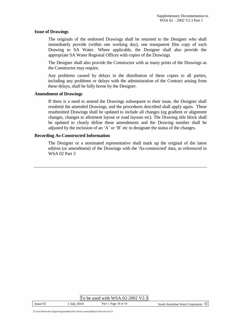
Issue of Drawings
The originals of the endorsed Drawings shall be returned to the Designer who shall
immediately provide (within one working day), one transparent film copy of each
Drawing to SA Water. Where applicable, the Designer shall also provide the
appropriate SA Water Regional Offices with copies of the Drawings.
The Designer shall also provide the Constructor with as many prints of the Drawings as
the Constructor may require.
Any problems caused by delays in the distribution of these copies to all parties,
including any problems or delays with the administration of the Contract arising from
these delays, shall be fully borne by the Designer.
Amendment of Drawings
If there is a need to amend the Drawings subsequent to their issue, the Designer shall
resubmit the amended Drawings, and the procedures described shall apply again. These
resubmitted Drawings shall be updated to include all changes (eg gradient or alignment
changes, changes to allotment layout or road layouts etc). The Drawing title block shall
be updated to clearly define these amendments and the Drawing number shall be
adjusted by the inclusion of an ‘A’ or ‘B’ etc to designate the status of the changes.
Recording As-Constructed Information
The Designer or a nominated representative shall mark up the original of the latest
edition (or amendment) of the Drawings with the 'As-constructed' data, as referenced in
WSA 02 Part 3

To be used with WSA 02-2002 V2.3
South Australian Water Corporation © Issue 03 1 July 2010 Part 1 Page 19 of 19
Z:\Users\Networks Engineering\Standard Docs\Sewer manual\Manual Revision Jul 10
Supplementary Documentation to
WSA 02 Part 1
SA Water Supplementary Documentation Sewer Code - Part 1 - Design
Additional Requirements
Part 1 – AR1 Battleaxe / Hammerhead Allotments
This additional requirement applies to allotments that are located behind other
allotments with a street frontage and require a narrow access corridor for the provision
of water and /or sewerage services. These allotments are described in a variety of ways
with the most common being “Battleaxe”, “Hammerhead” and “Flagpole”.
SA Water has established minimum width requirements for these narrow corridors to
protect the main(s) from building loads and for maintenance access. The minimum
widths are as follows:
DEPTH
TO INVERT
m
PIPE SIZE
CORRIDOR
WIDTH
m
SPACING TO
EDGE OF
CORRIDOR
m
SEWER MAIN ONLY
≤ 1
DN150 & DN225 2.5 Central (*)
DN300 5.0 Central (*)
1 to 3.3
DN150 & DN225 3.0 Central
DN300 5.0 Central
SEWER AND WATER MAIN
≤ 1
DN150 & DN225 3.0 1.0
DN300 5.0 1.5
1 to 3.3
DN150 & DN225 3.5 1.5
DN300 5.0 1.5
(*) Where there are immovable obstacles along the centreline of the corridor (eg
nearby trees) and the sewer depth to invert is less than or equal to 1.0 metre, the
sewer centreline can be located 1.0 metre off the corridor boundary that is most
distant from any building or proposed building.
Where both water and sewer mains are included in the corridor the minimum horizontal
clearance between pipes shall be 600 mm.
The minimum horizontal clearance between the outside face of the sewer and an
existing or proposed building or structure shall be as detailed in the Supplementary
Documentation to WSA 02 Part 1 – 4.4
The property developer shall be responsible for all costs associated with the
acquisition / provision of any access corridor(s) that are required for the development.
To be used with WSA 02-2002 V2.3
South Australian Water Corporation © Issue 03 1 July 2010 Part 1 Page 20 of 19
Z:\Users\Networks Engineering\Standard Docs\Sewer manual\Manual Revision Jul 10
Supplementary Documentation to
WSA 02 Part 1
Sewer Connection
DN
Maximum Number
of Dwellings
DN 100
8
DN 150
Unlimited
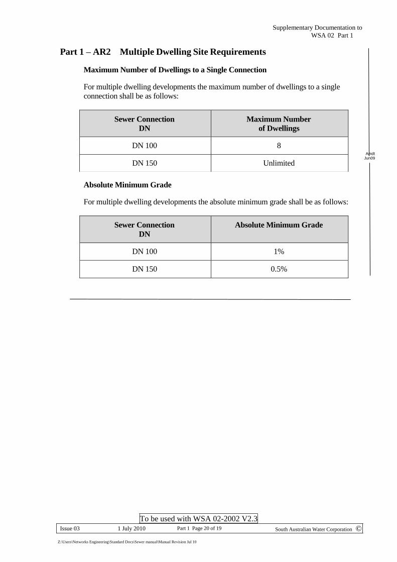
Part 1 – AR2 Multiple Dwelling Site Requirements
Maximum Number of Dwellings to a Single Connection
For multiple dwelling developments the maximum number of dwellings to a single
connection shall be as follows:
Amdt Jun09
Absolute Minimum Grade
For multiple dwelling developments the absolute minimum grade shall be as follows:
Sewer Connection
DN
Absolute Minimum Grade
DN 100
1%
DN 150
0.5%
Supplementary Documentation to WSA 02 Part 1
ANNEX A
To be used with WSA 02-2002 V2.3
South Australian Water Corporation © Issue 03 1 July 2010 Part 1 Annex A Page A1 of 3
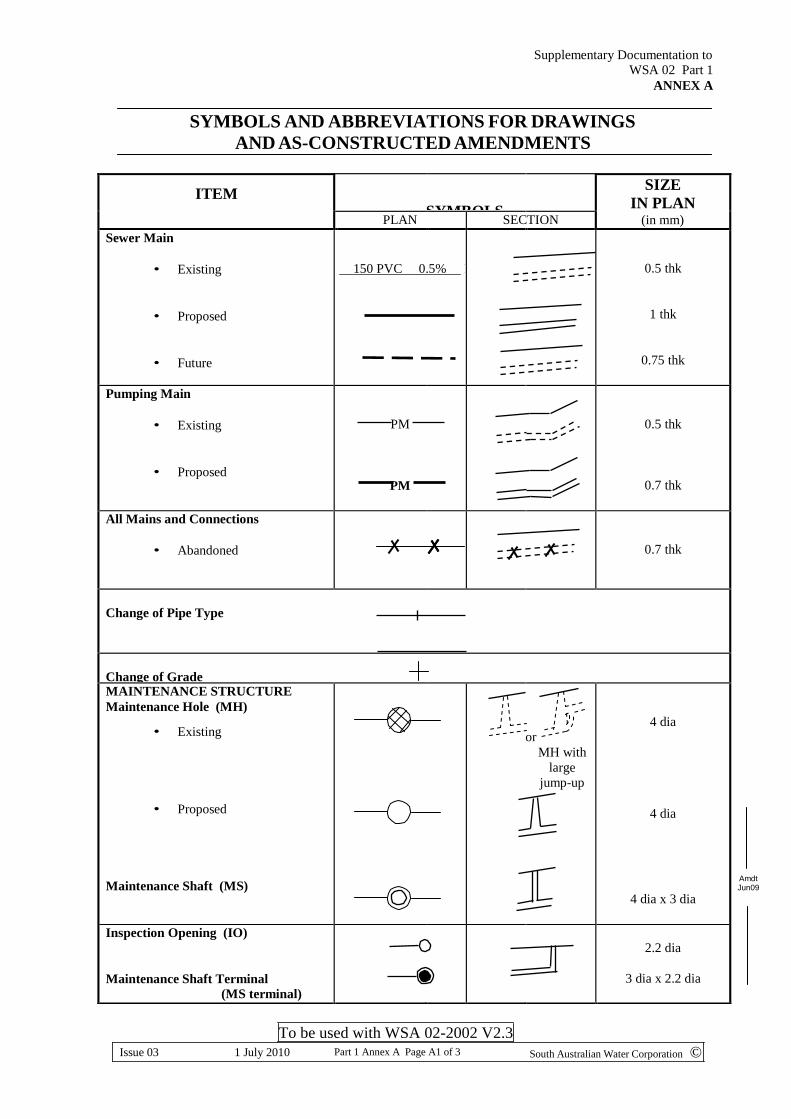
ITEM
SYMBOLS
SIZE
IN PLAN PLAN SECTION (in mm)
Sewer Main
• Existing
• Proposed
• Future
150 PVC 0.5% FB369p7
0.5 thk
1 thk
0.75 thk
Pumping Main
• Existing
• Proposed
PM
PM
0.5 thk
0.7 thk
All Mains and Connections
• Abandoned
0.7 thk
Change of Pipe Type
Change of Grade MAINTENANCE STRUCTURE
Maintenance Hole (MH)
• Existing
• Proposed
Maintenance Shaft (MS)
or
MH with
large
jump-up
4 dia
4 dia
4 dia x 3 dia
Inspection Opening (IO) Maintenance Shaft Terminal
(MS terminal)
2.2 dia
3 dia x 2.2 dia
Jun09
SYMBOLS AND ABBREVIATIONS FOR DRAWINGS
AND AS-CONSTRUCTED AMENDMENTS
Amdt
Supplementary Documentation to WSA 02 Part 1
ANNEX A
To be used with WSA 02-2002 V2.3
South Australian Water Corporation © Issue 03 1 July 2010 Part 1 Annex A Page A2 of 3
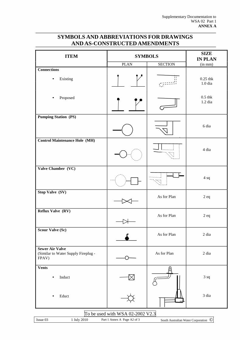
SYMBOLS AND ABBREVIATIONS FOR DRAWINGS
AND AS-CONSTRUCTED AMENDMENTS
ITEM
SYMBOLS SIZE
IN PLAN (in mm) PLAN SECTION
Connections
0.25 thk
• Existing
1.0 dia
• Proposed
0.5 thk
1.2 dia
Pumping Station (PS)
6 dia
Control Maintenance Hole (MH)
4 dia
Valve Chamber (VC)
4 sq
Stop Valve (SV) As for Plan
2 eq
Reflux Valve (RV) As for Plan
2 eq
Scour Valve (Sc) As for Plan
2 dia
Sewer Air Valve
(Similar to Water Supply Fireplug - FPAV)
As for Plan
2 dia
Vents
• Induct
• Educt
3 sq
3 dia

Supplementary Documentation to WSA 02 Part 1
ANNEX A
To be used with WSA 02-2002 V2.3
South Australian Water Corporation © Issue 03 1 July 2010 Part 1 Annex A Page A3 of 3
ABBREVIATIONS
PIPE MATERIALS
PVC Poly Vinyl Chloride
PE Polyethylene
May be used where special, project based, approval has been given by SA Water
PP Polypropylene eg SewerMAX
RCRJ Reinforced Concrete Rubber Ring Jointed
DICL Ductile Iron Cement Lined
MSCL Mild Steel Cement Lined
GRP Glass Reinforced Plastic
ABS Acryonitrile Butadiene Styrene
VC Vitreous Clay
Supplementary Documentation to WSA 02 Part 1
ANNEX B
To be used with WSA 02-2002 V2.3
South Australian Water Corporation © Issue 03 1 July 2010 Part 1 Annex B Page B1
Insert Typical Drawing Here
Supplementary Documentation to WSA 02 Part 1
ANNEX C
To be used with WSA 02-2002 V2.3
South Australian Water Corporation © Issue 03 1 July 2010 Part 1 Annex C Page C1
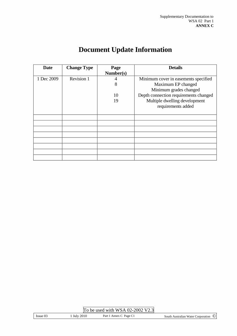
Document Update Information
Date Change Type Page
Number(s)
Details
1 Dec 2009 Revision 1 4 8
10
19
Minimum cover in easements specified
Maximum EP changed
Minimum grades changed Depth connection requirements changed
Multiple dwelling development
requirements added
Related Documents