Severe Duty (SD) Control Valves

Welcome message from author
This document is posted to help you gain knowledge. Please leave a comment to let me know what you think about it! Share it to your friends and learn new things together.
Transcript
Severe Duty (SD) Control Valves

Copes-Vulcan has been providing control
valves and desuperheaters for the power,
process and nuclear industries since 1903.
SPX provides a wide range of valves for
the control of pressure, temperature and
flow-induced noise in all types of power
plants. Products include severe service and
general service control valves, variable orifice
desuperheaters, Raven™, trim and steam-
conditioning valves and nuclear control valves,
as well as custom designed specialty valves.
Copes-Vulcan is recognized worldwide as a
leader in valves for severe and critical service
applications. Our strength lies in our ability
to provide innovative valve solutions for our
customers’ application needs.
Finding innovative ways to help the world
meet its ever growing demand for power
is a key focus for SPX. SPX provides
creative solutions the serve global energy
markets in a myriad of ways. Our ideas are
helping build more efficient power plants
and renovate older existing facilities. SPX
supplies a wide range of components - from
air preheaters to filter systems for nuclear,
coal-fired, combined cycle, solar, thermal
and geothermal power plants.
With operations in over 35 countries, SPX
has the global experience and regional
presence, products and powerful ideas it
takes to help our customers compete more
effectively, and more efficiently deliver
power to almost any part of the world.
SD Severe Duty Control Valves
The SD-Severe Duty valve is SPX’s premium severe duty and critical service control
valve design. The SD-Severe Duty line is the next generation of control valves
designed specifically for severe duty applications. It is the preferred style of valve for
applications such as pump recirculation, feedwater control and feedwater start-up,
flashing or cavitating service, critical pressure drop gas and steam service, and any
potentially noisy or vibration-prone service. It is also widely used for nuclear “N”
stamp and seismic applications.
The SD-Severe Duty line incorporates a number of improvements such as:
• Quick disconnect between valve stem and actuator yoke on most models that
greatly simplifies service and inspection.
• An extensive array of standard trims is available including many previously
offered only as custom designs.
• Shorter lead times/quicker delivery of both entire valve assemblies and
replacement parts.
Improvements such as these, coupled with SPX’s innovative yet sound engineering
practices, and a reputation for building the best control valves possible, assures
that the SD-Severe Duty line is destined to become the new industry standard for
severe duty and critical service applications.
For applications requiring pressure classes of 600 and below refer to Copes-
Vulcan’s GS Series valves.
D e scr i ption an D pr i nci ple of ope ration
SD-Severe Duty control valve assemblies feature a straight through globe and
angle style body design with single web internal construction. The valve body is
designed with high structural integrity, large interior flow passageways and a large
capacity bowl to accommodate an extensive variety of trim designs while allowing
maximum recovery within the valve. The massive amount of body and bonnet
material utilized and the thick cross sectional areas allow the SD valve to withstand
the most severe operational conditions.
The valve is available in sizes .75–20” (20–500mm) and ASME pressure classes
150 through 4500 standard. Larger sizes are available as required. Typically of cast
construction, all standard castable materials are available. When necessary, due
to customer preference or technical requirements, forgings are utilized for both
body and bonnet. Depending upon size and pressure class, ends are available as
threaded, flanged or welded.
The most important sub-assembly of a control valve is the trim. It must control the
fluid process, often under extremely high pressure drop conditions, without undue
damage due to flashing, cavitation, wire drawing, noise vibration or instability.
3
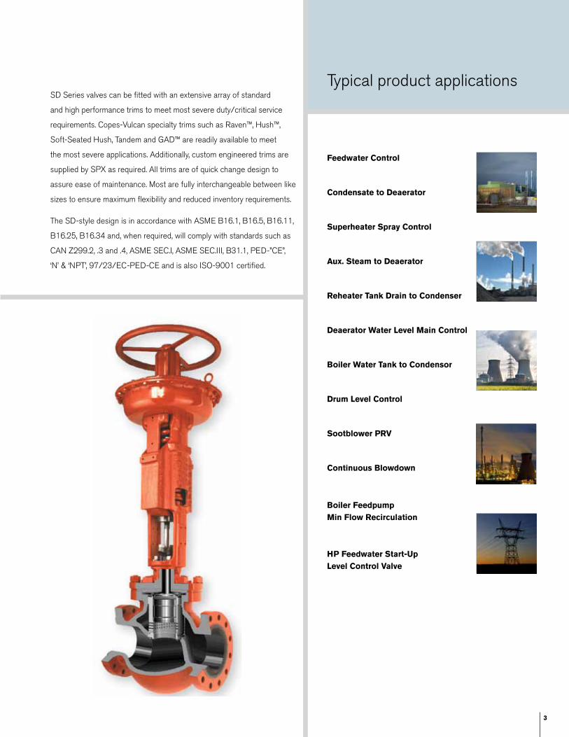
Typical product applications
feedwater control
condensate to Deaerator
superheater spray control
aux. steam to Deaerator
reheater tank Drain to condenser
Deaerator Water level Main control
Boiler Water tank to condensor
Drum level control
sootblower prV
continuous Blowdown
Boiler feedpump Min flow recirculation
Hp feedwater start-Up level control Valve
SD Series valves can be fitted with an extensive array of standard
and high performance trims to meet most severe duty/critical service
requirements. Copes-Vulcan specialty trims such as Raven™, Hush™,
Soft-Seated Hush, Tandem and GAD™ are readily available to meet
the most severe applications. Additionally, custom engineered trims are
supplied by SPX as required. All trims are of quick change design to
assure ease of maintenance. Most are fully interchangeable between like
sizes to ensure maximum flexibility and reduced inventory requirements.
The SD-style design is in accordance with ASME B16.1, B16.5, B16.11,
B16.25, B16.34 and, when required, will comply with standards such as
CAN Z299.2, .3 and .4, ASME SEC.I, ASME SEC.III, B31.1, PED-”CE”,
‘N’ & ‘NPT’, 97/23/EC-PED-CE and is also ISO-9001 certified.
4
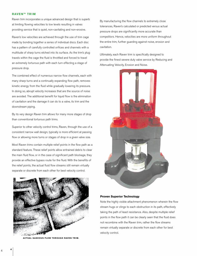
actUal gas eoUs floW tH roUg H raVe n tr i M.
raVe n™ tr i M
Raven trim incorporates a unique advanced design that is superb
at limiting flowing velocities to low levels resulting in valves
providing service that is quiet, non-cavitating and non-erosive.
Raven’s low velocities are achieved through the use of trim cage
made by bonding together a series of individual discs. Each disc
has a pattern of carefully controlled orifices and channels with a
multitude of sharp turns etched into its surface. As the trim’s plug
travels within the cage the fluid is throttled and forced to travel
an extremely torturous path with each turn effecting a stage of
pressure drop.
The combined effect of numerous narrow flow channels, each with
many sharp turns and a continually expanding flow path, removes
kinetic energy from the fluid while gradually lowering its pressure.
In doing so, abrupt velocity increases that are the source of noise
are avoided. The additional benefit for liquid flow is the elimination
of cavitation and the damage it can do to a valve, its trim and the
downstream piping.
By its very design Raven trim allows for many more stages of drop
than conventional torturous path trims.
Superior to other velocity control trims, Raven, through the use of a
consistent narrow wall design, typically is more efficient at passing
flow or allowing more turns or stages of drop in a given valve size.
Most Raven trims contain multiple relief points in the flow path as a
standard feature. These relief points allow entrained debris to clear
the main fluid flow, or in the case of significant path blockage, they
provide an effective bypass route for the fluid. With the benefits of
the relief points, the actual fluid flow streams still remain virtually
separate or discrete from each other for best velocity control.
By manufacturing the flow channels to extremely close
tolerances, Raven’s calculated or predicted versus actual
pressure drops are significantly more accurate than
competitors. Hence, velocities are more uniform throughout
the entire trim, further guarding against noise, erosion and
cavitation.
Ultimately, each Raven trim is specifically designed to
provide the finest severe duty valve service by Reducing and
Attenuating Velocity, Erosion and Noise.
proven superior technology
Note the highly visible attachment phenomenon wherein the flow
stream hugs or clings to each obstruction in its path, effectively
taking the path of least resistance. Also, despite multiple relief
points in the flow path it can be clearly seen that the fluid does
not recombine with the Raven trim, rather the flow streams
remain virtually separate or discrete from each other for best
velocity control.
4
5
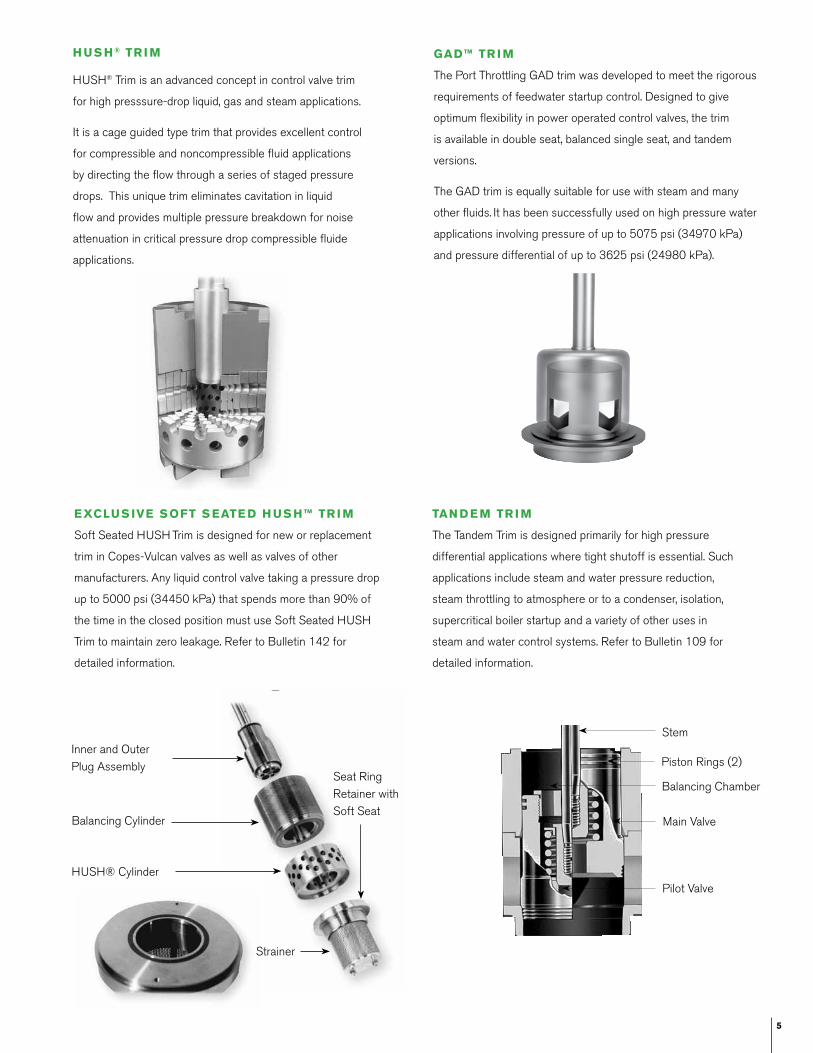
tan D e M tr i M
The Tandem Trim is designed primarily for high pressure
differential applications where tight shutoff is essential. Such
applications include steam and water pressure reduction,
steam throttling to atmosphere or to a condenser, isolation,
supercritical boiler startup and a variety of other uses in
steam and water control systems. Refer to Bulletin 109 for
detailed information.
gaD™ tr i M
The Port Throttling GAD trim was developed to meet the rigorous
requirements of feedwater startup control. Designed to give
optimum flexibility in power operated control valves, the trim
is available in double seat, balanced single seat, and tandem
versions.
The GAD trim is equally suitable for use with steam and many
other fluids. It has been successfully used on high pressure water
applications involving pressure of up to 5075 psi (34970 kPa)
and pressure differential of up to 3625 psi (24980 kPa).
Stem
Piston Rings (2)
Balancing Chamber
Main Valve
Pilot Valve
Inner and Outer Plug Assembly
Balancing Cylinder
Seat Ring Retainer with Soft Seat
HUSH® Cylinder
Strainer
exclUs iVe soft s eate D H Us H™ tr i M
Soft Seated HUSH Trim is designed for new or replacement
trim in Copes-Vulcan valves as well as valves of other
manufacturers. Any liquid control valve taking a pressure drop
up to 5000 psi (34450 kPa) that spends more than 90% of
the time in the closed position must use Soft Seated HUSH
Trim to maintain zero leakage. Refer to Bulletin 142 for
detailed information.
HUSH® Trim is an advanced concept in control valve trim
for high presssure-drop liquid, gas and steam applications.
It is a cage guided type trim that provides excellent control
for compressible and noncompressible fluid applications
by directing the flow through a series of staged pressure
drops. This unique trim eliminates cavitation in liquid
flow and provides multiple pressure breakdown for noise
attenuation in critical pressure drop compressible fluide
applications.
H Us H® tr i M
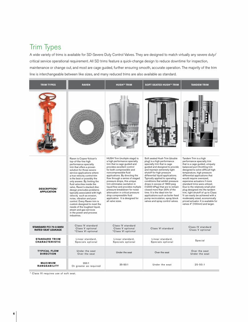
Trim TypesA wide variety of trims is available for SD-Severe Duty Control Valves. They are designed to match virtually any severe duty/
critical service operational requirement. All SD trims feature a quick-change design to reduce downtime for inspection,
maintenance or change out, and most are cage guided, further ensuring smooth, accurate operation. The majority of the trim
line is interchangeable between like sizes, and many reduced trims are also available as standard.
6
* Class V I requ i res use o f sof t seat .
Unbalanced single seat plug throttling
Unbalanced single seat port throttling
Balanced single seat port throttling
Balanced single seat port throttling
(Hi-temp)triM tYpes raVen HUsH™ triM soft seateD HUsH™ triM tanDeM triM
Description/ application
Raven is Copes-Vulcan’s top-of-the-line high performance specialty trim that offers a proven solution for those severe service applications where a true velocity control trim is the best or possibly the only answer. By limiting the fluid velocities inside the valve, Raven’s stacked disc design precludes problems typically associated with high velocity such as erosion, noise, vibration and poor control. Every Raven trim is custom designed to meet the needs of the toughest liquid, steam and gas services in the power and process industries.
HUSH Trim (multiple stage) is a high performance specialty trim that is cage guided and provides excellent control for both compressible and noncompressible fluid applications. By directing the flow through a series of staged pressure drops, this unique trim eliminates cavitation in liquid flow and provides multiple pressure breakdown for noise attenuation in critical pressure drop compressible fluid application. It is designed for all valve sizes.
Soft seated Hush Trim (double plug) is a high performance specialty trim that is cage guided and designed to provide and maintain extremely tight shutoff for high pressure differential liquid applications. Typically applied to operating conditions that exhibit pressure drops in excess of 1800 psig (12400 kPag) that are to remain closed more than 25% of the time. It is the ideal trim for applications such as boiler feed pump recirculation, spray block valves and spray control valves.
Tandem Trim is a high performance specialty trim that is a cage guided, uniquely balanced port throttling trim designed to solve difficult high temperature, high pressure differential applications that would require oversized, expensive actuators if more standard trims were utilized. Due to the relatively small pilot plug designed into the tandem trim, tight shutoff of up to Class V can easily be achieved with a moderately sized, economically priced actuator. It is available for valves 4” (100mm) and larger.
stanDarD fci 70-2/ansi rateD seat leaKage
Class lV s t andardClass V opt iona l
*Class V I opt iona l
Class lV s t andardClass V opt iona l
*Class V I opt iona l Class V I s t andard Class IV s t andard
Class V opt iona l
stan Dar D tr i i M cHaracte r i stic
L inear s t andard , Spec ia ls opt iona l
L inear s t andard , Spec ia ls opt iona l
L inear s t andard , Spec ia ls opt iona l Spec ia l
tYpical floW D i r ection
Under the seatOver the seat Under the seat Over the seat Over the seat
Under the seat
Maxi M U Mrang eaB i litY
200:1Or greater as requ i red 35-50:1 Under the seat 25-50:1

7
The trims shown in this bulletin represent the more common selections available. Additional standard, special and custom
engineered trims can be supplied as required.
Standard stocked trim materials are 300 series and 400 series stainless steel. Other materials are available on special order.
* Class VI requires use of soft seat.
Unbalanced single seat plug throttling
Unbalanced single seat port throttling
Balanced single seat port throttling
Balanced single seat port throttling
(Hi-temp)
gaD triM UnBalanceD single seat
plUg tHrottlingUnBalanceD single seat
port tHrottlingBalanceD single seat
port tHrottling
BalanceD single seat port tHrottling
(Hi-teMp)
GAD Trim is a high performance specialty trim that is cage guided and engineered to meet the rigorous requirements of feedwater control and feedwater startup control. Designed to give optimum flexibility in automated control valves, this trim is available in double seat, balanced single seat, tandem plug and one-stage Hush versions. GAD Trim is equally suitable for use with steam and many other fluids. It has been successfully used on high pressure water applications involving pressure of 5075 psi (34970 kPa) and pressure differential of up to 3625 psi (24980 kPa). It is available for valves 2” (50mm) and larger.
This trim style is a general purpose cage guided trim for on/off or modulating control. It is designed for low to moderate pressure drop applications. The solid plug has a contour on its lower end that provides varying flow area with lift, thus regulating the flow. It can be used with a wide variety of non-abrasive/non-adhesive compressible and noncompressible fluids. Standard trim for valve sizes 1.5” (40mm) and smaller.
This trim style is a general service cage guided trim for on/ off or modulating control where moderate flow rates exist along with low differential pressures. The unbalanced single seat plug modulates flow by uncovering ports in the cage. The cage porting produces the pressure drop or flow control. This trim can be used in most non-abrasive/non-adhesive compressible and noncompressible fluids.
This trim style is a general purpose cage guided trim for on/off or modulating control suitable for use in most non-abrasive/non-adhesive compressible and noncompressible fluid services. The balanced plug design reduces actuator force requirements thus permitting the use of smaller, less expensive actuators while maintaining tight shutoff capability. It is designed for valves 2” (50mm) and larger and is a standard offering when the service temperature does not exceed the 400°–500°F (204°– 260°C) range, relative to pressure.
This general purpose cage guided trim is virtually identical in all respects to the balanced single seat port throttling trim except that piston rings are used in lieu of the elastomeric seal on the trim’s plug. While the piston rings do limit the leakage rate to ANSI Class III, this trim is a viable option when a balanced plug is desirable and when temperatures of the fluid exceed 500°F (260°C). It is for valve sizes 2” (50mm) and larger.
Class I I I– IVDepending upondes ign se lected
Class IV standard Class V optional
Class IV standard Class V optional
Class IV standard Class V optional
*Class VI optionalCClass IV standard
Modi f ied parabo l ic ,l inear, equa l percentage.A l l ava i lab le as s t andard
Modi f ied parabol ic ,l inear, equal percentage.
Modified parabolic, linear, equal percentage
Modified parabolic, linear, equal percentage
Modified parabolic, linear, equal percentage
Over the seat Under the seat Under the seat Over the seat Over the seat
50:1 50:1 35-50:1 35-50:1 35-50:1
8
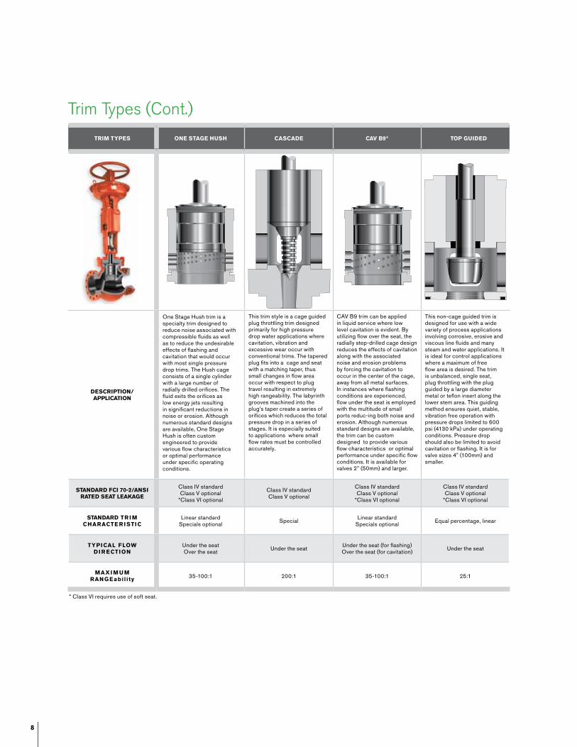
Trim Types (Cont.)
* Class VI requires use of soft seat.
triM tYpes one stage HUsH cascaDe caV B9® top gUiDeD
Description/ application
One Stage Hush trim is a specialty trim designed to reduce noise associated with compressible fluids as well as to reduce the undesirable effects of flashing and cavitation that would occur with most single pressure drop trims. The Hush cage consists of a single cylinder with a large number of radially drilled orifices. The fluid exits the orifices as low energy jets resulting in significant reductions in noise or erosion. Although numerous standard designs are available, One Stage Hush is often custom engineered to provide various flow characteristics or optimal performance under specific operating conditions.
This trim style is a cage guided plug throttling trim designed primarily for high pressure drop water applications where cavitation, vibration and excessive wear occur with conventional trims. The tapered plug fits into a cage and seat with a matching taper, thus small changes in flow area occur with respect to plug travel resulting in extremely high rangeability. The labyrinth grooves machined into the plug’s taper create a series of orifices which reduces the total pressure drop in a series of stages. It is especially suited to applications where small flow rates must be controlled accurately.
CAV B9 trim can be applied in liquid service where low level cavitation is evident. By utilizing flow over the seat, the radially step-drilled cage design reduces the effects of cavitation along with the associated noise and erosion problems by forcing the cavitation to occur in the center of the cage, away from all metal surfaces. In instances where flashing conditions are experienced, flow under the seat is employed with the multitude of small ports reduc-ing both noise and erosion. Although numerous standard designs are available, the trim can be custom designed to provide various flow characteristics or optimal performance under specific flow conditions. It is available for valves 2” (50mm) and larger.
This non-cage guided trim is designed for use with a wide variety of process applications involving corrosive, erosive and viscous line fluids and many steam and water applications. It is ideal for control applications where a maximum of free flow area is desired. The trim is unbalanced, single seat, plug throttling with the plug guided by a large diameter metal or teflon insert along the lower stem area. This guiding method ensures quiet, stable, vibration free operation with pressure drops limited to 600 psi (4130 kPa) under operating conditions. Pressure drop should also be limited to avoid cavitation or flashing. It is for valve sizes 4” (100mm) and smaller.
stanDarD fci 70-2/ansi rateD seat leaKage
Class IV standard Class V optional
*Class VI optional
Class IV standard Class V optional
Class IV standard Class V optional
*Class VI optional
Class IV standard Class V optional
*Class VI optional
stanDarD tr i M cHaracte r i stic
Linear standard Specials optional Special Linear standard
Specials optional Equal percentage, linear
tYpical floW D i r ection
Under the seat Over the seat Under the seat Under the seat (for flashing)
Over the seat (for cavitation) Under the seat
Maxi M U M rang eabil i ty 35-100:1 200:1 35-100:1 25:1
9
ValVe clos e DValVe ope n ValVe ope nValVe clos e D
Optional Manual
Handwheel
D
H
I
F
G
EactUator
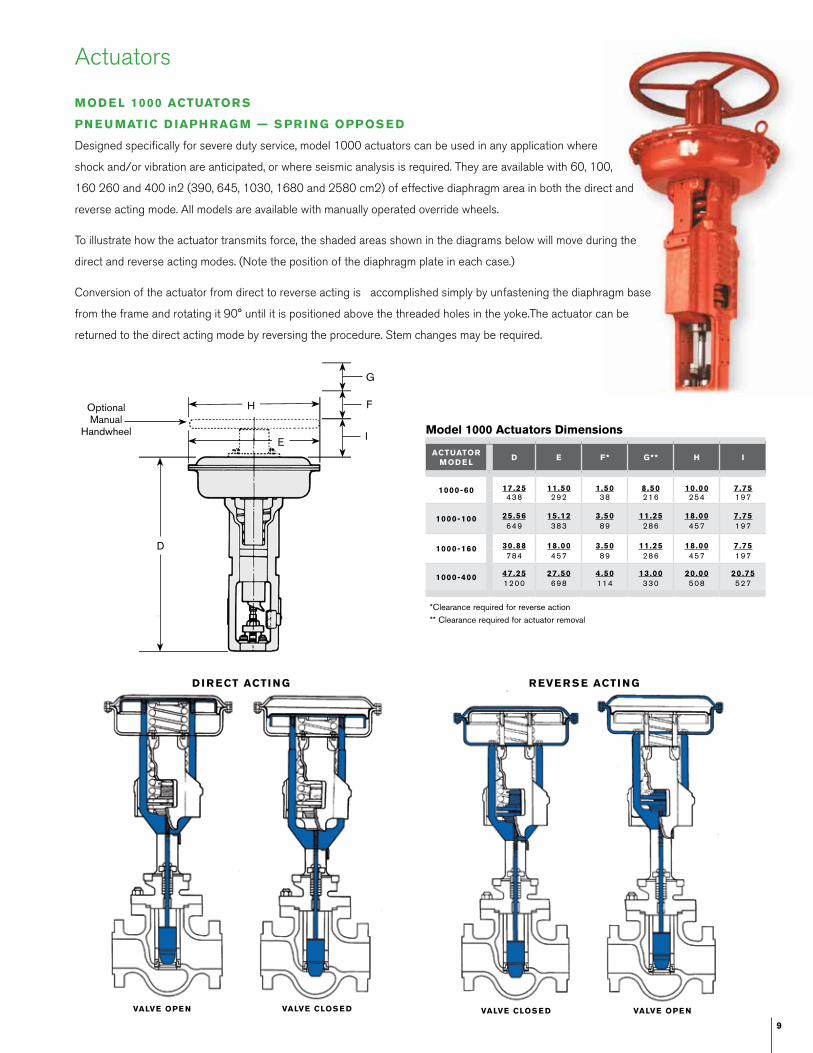
MoD e lD e f* g** H i
1000-60 17.25 11.50 1.50 8.50 10.00 7.75438 292 38 216 254 197
1000-100 25.56 15.12 3.50 11.25 18.00 7.75649 383 89 286 457 197
1000-160 30.88 18.00 3.50 11.25 18.00 7.75784 457 89 286 457 197
1000-400 47.25 27.50 4.50 13.00 20.00 20.751200 698 114 330 508 527
*Clearance required for reverse action
** Clearance required for actuator removal
Actuators
MoD e l 1000 actUator s
pn e U Matic D iapH rag M — s pr i ng oppos e D
Designed specifically for severe duty service, model 1000 actuators can be used in any application where
shock and/or vibration are anticipated, or where seismic analysis is required. They are available with 60, 100,
160 260 and 400 in2 (390, 645, 1030, 1680 and 2580 cm2) of effective diaphragm area in both the direct and
reverse acting mode. All models are available with manually operated override wheels.
To illustrate how the actuator transmits force, the shaded areas shown in the diagrams below will move during the
direct and reverse acting modes. (Note the position of the diaphragm plate in each case.)
Conversion of the actuator from direct to reverse acting is accomplished simply by unfastening the diaphragm base
from the frame and rotating it 90° until it is positioned above the threaded holes in the yoke.The actuator can be
returned to the direct acting mode by reversing the procedure. Stem changes may be required.
D i r ect acti ng r eVe r s e acti ng
Model 1000 actuators Dimensions
10
Actuators
s e r i e s 700 actUator (s HoWn WitH optional top-MoU nte D Han DWH e e l)
reverse acting (spring-to-close) Direct acting (spring-to-open)
actUatorsiZe
60 100 160 160l
l21.09536
28.06713
32.38822
40.811037
M11.50292
15.12384
18.00457
18.00 457
n*6.50165
6.50165
6.25159
6.38162
o6.72171
11.38289
11.56294
17.19437
p 10.00254
18.00457
18.00457
18.00457
actUatorsiZe
60 100 160 160l
l20.50521
28.12714
32.31821
39.751010
M11.50292
15.12384
18.00457
18.00 457
n*7.56192
9.38238
9.31236
11.81300
o5.81148
9.44240
9.50241
15.19386
p 10.00254
18.00457
18.00457
18.00457
tH e s D-700 ValVe ass e M B lY
The SD-700 valve assembly is comprised of an SD valve body, bonnet and trim with the 700 series actuator. In those instances where an SD
valve (i.e. body, bonnet, trim, etc.) is necessary, but the use of the heavy duty, 1000 style actuator is not needed, the more economical 700
style operator can be utilized.
Series 700 actuators are pneumatic diaphragm operators that have spring return in both direct and reverse acting styles, offering fail-open
and fail-closed modes respectively. The pressed steel diaphragm case construction along with the nylon reinforced Buna N rubber diaphragm
permits a maximum allowable air supply pressure of 80 psig (550 kPag). This pre-formed diaphragm provides a constant effective area
throughout the full extent of travel. With effective diaphragm areas ranging from 60–160 in2 (385–1030 cm2), Series 700 actuators can
provide the necessary stem force to meet many operating requirements.
MoD e l 200 pi ston actUator s
When necessitated by travel or thrust requirements, model 200 pneumatic actuators are supplied. Contact Copes-Vulcan for details.
s e r i e s 300 Motor ope rate D
Motor operated actuators are available to meet specified operations. Contact Copes-Vulcan for details.
s i D e MoU nte D Han DWH e e l
Side mounted handwheels are available for the Series 700 actuator. Contact Copes-Vulcan for details and dimensions.
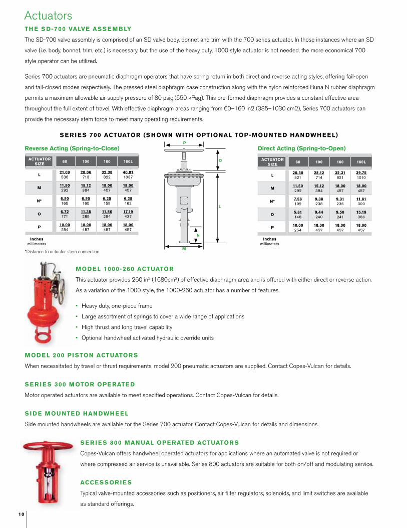
s e r i e s 800 Man Ual ope rate D actUator s
Copes-Vulcan offers handwheel operated actuators for applications where an automated valve is not required or
where compressed air service is unavailable. Series 800 actuators are suitable for both on/off and modulating service.
acce ssor i e s
Typical valve-mounted accessories such as positioners, air filter regulators, solenoids, and limit switches are available
as standard offerings.
MoD e l 1000-260 actUator
This actuator provides 260 in2 (1680cm2) of effective diaphragm area and is offered with either direct or reverse action.
As a variation of the 1000 style, the 1000-260 actuator has a number of features.
• Heavy duty, one-piece frame
• Large assortment of springs to cover a wide range of applications
• High thrust and long travel capability
• Optional handwheel activated hydraulic override units
*Distance to actuator stem connection
p
o
l
M
ninches
millimetersinches
millimeters

11
DimensionssD Valve Body/Bonnet assembly
flang e D e n D s
inchesmillimeters
B
a
c**Radius of flange may exceed C.
flang e D e n D s
B
A
C
Note: The SD-style bonnet is easily adaptable to all sizes and types of pneumatic, electric and hydraulic actuators.
ValVe siZe
class 150 class 300 class 400 class 600 class 900 class 1500 class 2500
a B c a B c a B c a B c a B c a B c a B c
.75” 7.75 7.00 2.56 7.75 7.00 2.56 7.75 7.00 2.56 7.75 7.00 2.56 7.75 10.00 2.50 7.75 10.00 2.50 8.50 10.00 2.5020mm 197 178 65 197 178 65 197 178 65 197 178 65 197 254 64 197 254 64 216 254 64
1” 7.75 7.00 2.56 7.75 7.00 2.56 7.75 7.00 2.56 7.75 7.00 2.56 7.75 10.00 2.75 7.75 10.00 2.75 8.50 10.00 2.7525mm 197 178 65 197 178 65 197 178 65 197 178 65 197 254 70 197 254 70 216 254 70
1.5” 9.25 7.25 2.88 9.25 7.25 2.88 9.25 7.25 2.88 9.25 7.25 2.88 9.25 10.15 3.00 9.25 10.15 3.00 10.25 10.15 3.2540mm 235 184 73 235 184 73 235 184 73 235 184 73 235 258 76 235 258 76 260 258 83
2” 10.50 7.34 3.50 10.50 7.34 3.50 10.50 7.34 3.56 10.50 7.34 3.56 11.50 10.15 3.75 11.50 10.15 3.75 12.50 10.15 3.8850mm 267 186 89 267 186 89 267 186 90 267 186 89 292 258 95 292 258 95 318 258 99
2.5” 11.50 9.31 4.06 11.50 9.31 4.06 11.50 9.31 4.19 11.50 9.31 4.19 11.50 12.15 4.44 11.50 12.15 4.44 12.50 12.15 4.6260mm 292 236 103 292 236 103 292 236 106 292 236 103 292 309 113 292 309 113 318 309 117
3” 12.50 9.72 4.44 12.50 9.72 4.44 12.50 9.72 4.50 12.50 9.72 4.50 12.50 12.47 4.56 12.50 12.47 4.81 15.00 12.47 5.5675mm 318 247 113 318 247 113 318 247 114 318 247 113 318 317 116 318 317 122 381 317 141
4” 14.50 9.91 5.38 14.50 9.91 5.38 14.50 9.91 5.56 14.50 9.91 5.56 14.50 13.56 6.12 14.50 13.56 6.12 16.00 13.56 6.50100mm 368 252 137 368 252 137 368 252 141 368 252 137 368 344 155 368 344 155 406 344 165
6” 20.00 12.16 7.69 20.00 12.16 7.69 20.00 12.16 7.88 20.00 12.16 7.88 20.00 14.81 8.12 22.00 14.81 8.94 24.00 14.81 9.44150mm 508 309 195 508 309 195 508 309 200 508 309 195 508 376 206 559 376 227 610 376 240
8” 24.00 13.31 10.25 24.00 13.31 10.25 24.00 13.31 10.56 24.00 13.31 10.56 24.00 16.06 10.82 27.00 16.06 11.25 30.00 16.06 11.94200mm 610 338 260 610 338 260 610 338 260 610 338 260 610 408 275 686 408 286 762 408 303
10” 30.00 19.00 13.00 30.00 19.00 13.00 30.00 19.00 13.00 30.00 19.00 13.00 30.00 22.06 13.00 34.00 22.06 14.00 40.00 22.06 14.88250mm 762 482 330 762 482 330 762 482 330 762 482 335 762 560 342 864 560 356 1016 560 378
12” 36.00 23.06 15.00 36.00 23.06 15.00 36.00 23.06 15.19 36.00 23.06 15.19 36.00 26.06 15.56 38.00 26.06 15.31 44.00 26.06 16.38300mm 914 586 381 914 586 381 914 586 386 914 586 386 914 662 395 965 662 389 1118 662 416
inchesmillimeters
ValVe siZe
class 150 class 300 class 400 class 600 class 900 class 1500 class 2500
a B c a B c a B c a B c a B c a B c a B c
.75”20mm
7.25184
7.00178
2.5665
7.62194
7.00178
2.5665
8.12206
7.00178
2.5665
8.12206
7.00178
2.5665
11.12282
10.00254
2.5064
11.12282
10.00254
2.5064
12.12308
10.00254
2.5064
1”25mm
7.25184
7.00182
2.5665
7.75197
7.00178
2.5665
8.25210
7.00178
2.5665
8.25210
7.00178
2.5665
11.50292
10.00254
2.7570
11.50292
10.00254
2.7570
12.50318
10.00254
2.7570
1.5”40mm
8.75222
7.55184
2.8873
9.25235
7.25184
2.8873
9.88251
7.25184
2.8873
9.88251
7.15182
2.8873
13.12333
10.15258
3.0076
13.12333
10.15258
3.0076
14.12359
10.15258
3.2583
2”50mm
10.00254
7.34186
3.5089
10.50267
7.34186
3.5089
11.25286
7.34186
3.5089
11.25286
7.34186
3.5089
14.75375
10.15258
3.7595
14.75375
10.15258
3.7595
15.75400
10.15258
3.8899
2.5”60mm
10.88276
9.31236
4.06103
11.50292
9.31236
4.06103
12.25311
9.31236
4.19106
12.25311
9.31236
4.19106
16.12409
12.15309
4.44113
16.12409
12.15309
4.44113
17.38441
12.15309
4.62117
3”75mm
11.75298
9.72247
4.44113
12.50318
9.72247
4.44113
13.25337
9.72247
4.50114
13.25337
9.72247
4.50114
17.38441
12.47317
4.56116
18.12460
12.47317
4.81122
19.62498
12.47317
5.56141
4”100mm
13.88353
9.91252
5.38137
14.50368
9.91252
5.38137
15.25387
9.91252
5.56141
15.50394
9.91252
5.56141
20.62524
13.56344
6.12155
21.38543
13.56344
6.12155
23.12587
13.56344
6.50165
6”150mm
17.75451
12.16309
7.69195
18.62473
12.16309
7.69195
19.50495
12.16309
7.88200
20.00508
12.16309
7.88200
23.62600
14.81376
8.12206
27.25692
14.81376
8.94227
32.25819
14.81376
9.44240
8”200mm
21.38543
13.31338
10.25260
22.38568
13.31338
10.25260
23.38594
13.31338
10.56268
24.00610
13.31338
10.56268
30.75781
16.06408
10.82275
33.00838
16.06408
11.25286
40.501029
16.06408
11.94303
10”250mm
29.38746
19.00482
13.00330
30.75781
19.00482
13.00330
31.75806
19.00482
13.00330
32.50826
19.00482
13.00330
34.00864
22.06560
13.00342
42.001067
22.06560
14.00356
54.001372
22.06560
14.88378
12”300mm
35.25895
23.06586
15.00381
36.75933
23.06586
15.00381
37.75959
23.06586
15.19386
38.50978
23.06586
15.10386
40.001016
26.06662
15.56395
48.001219
26.06662
15.31389
62.001575
26.06662
16.38416
We lD e n D s an D tH r eaD e D e n D s (for 2” (50M M) an D s Malle r)
We lD e n D s an D tH r eaD e D e n D s
Global locations
Based in Charlotte, North Carolina, SPX Corporation (NYSE: SPW) is a global Fortune 500 multi-industry manufacturing leader. For more information, please visit www.spx.com
s px floW tecH nologY
5620 West Rd.
McKean, PA 16426
P: (814)476-5800
F: (814)476-5854
s px floW tecH nologY
25 International Business Park
#03-03/12 German Centre
Singapore 609916
+65 6264 4366
s px floW tecH nologY
5620 West Road
McKean, PA 16426
United States of America
+1 814 476 5800
s px floW tecH nologY
Road Two, Industrial Estate
Winsford, Cheshire CW7 3QL
England
+44 1606 552041
SPX reserves the right to incorporate our latest design and material changes without notice or obligation.
Design features, materials of construction and dimensional data, as described in this bulletin, are provided for your information only and should not be relied upon unless confirmed in
writing. Please contact your local sales representative for product availability in your region. For more information visit www.spx.com.
The green “>” is a trademark of SPX Corporation, Inc.
ISSUED 05/2012 CV-1149
COPYRIGHT © 2012 SPX Corporation
Severe Duty (SD) Control Valves
s px floW tecH nologY
6F Treasury Building
1568 Hua Shan Road
Shanghai 200052
PR China
+86 21 2208 5888
Related Documents