SESSION III

Welcome message from author
This document is posted to help you gain knowledge. Please leave a comment to let me know what you think about it! Share it to your friends and learn new things together.
Transcript

SESSION III

APOLLO 15 MAIN-PARACHUTE FAILURE
By Donald D. Arabian and Joseph E. Mechelay*
ABSTRACT
In the investigation of the failure of one of the three main parachutes of the Apollo 15 spacecraft, which collapsed at approximately 1825 meters after operating properly from deployment at 3050 meters, three conditions considered to be possible causes of the failure were produced. The suspect conditions were the proximity of the forward heat shield that passed the spacecraft at approximately 1825 meters, the dumping of the reaction control system hypergolic propellants at approximately 1825 meters, and the failing of a riser link found on a recovered parachute. (The failed parachute was not recovered. ) The remaining two parachutes functioned as planned and averted a catastrophic failure. In this paper, the highlights of the investigation and the conclusions concerning the cause of the failure are discussed.
INTRODUCTION
One of the three main parachutes of the Apollo 15 spacecraft collapsed at approximately 1825 meters altitude after operating properly from deployment at 3050 meters. Immediately after the successful recovery of the Apollo 15 crewmen, an investigation was conducted to assess the data, tp perform tests and analyses as required to identify possible causes of the problem, and to define the corrective action necessary to preclude the occurrence of the incident on future flights. In this paper, the highlights of the investigation are summarized. The paper also shows how wrong conclusions concerning the cause of a problem can easily be reached if all of the available information is not weighed carefully during the course of the investigation.
DESCRIPTION OF EVENTS
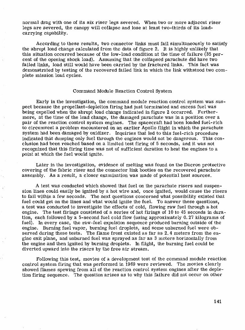
The three main parachutes of the Apollo 15 spacecraft deployed and inflated properly at approximately 3050 meters altitude. Films show that all three parachutes disreefed and opened fully in the proper sequence. The spacecraft and its parachutes were obscured by clouds at approximately 2135 meters altitude. On emerging from the clouds at approximately 1825 meters altitude, one of the three main parachutes was deflated,
*NASA Manned Spacecraft Center, Houston, Tex.
137
as shown in figure 1. The spacecraft and parachute system descended in this configuration to water landing. The three parachutes were disconnected and one of the good main parachutes was recovered.
The failure occurred abruptly. At about the altitude and time of the failure, the forward heat shield was in proximity to the spacecraft, and the reaction control system propellant-depletion firing was almost completed. An inspection of the recovered parachute showed that one of the six riser links had a broken stud and three others had cracks. Therefore, the investigation of the failure was focused on the reaction control system propellant-depletion firing, the forward heat shield, and the failed links.
DATA GATHERING AND ANALYSIS
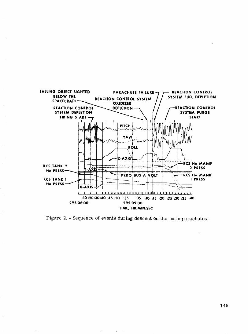
The initial efforts of the investigation team were concentrated on accumulating and assessing the spacecraft data, evaluating the photographic and television coverage, and inspecting the recovered parachute and the forward heat shield. The spacecraft · data and the associated events are shown in figure 2. The time of the anomaly was determined from the X, Y, and Z accelerometer data and the associated rapid rate changes. The data show that the command module reaction control system depletion firing was completed approximately 3. 5 seconds before the anomaly, as determined from an abrupt rise in the reaction control system manifold pressure. This change occurs when the pressure regulators abruptly close, as a result of the reaction control system tank bladders being collapsed. The completion time of the fuel (monomethyl hydrazine) dump that follows the depletion firing was determined by calculating the amount of fuel remaining at the end of the depletion firing (approximately 2. 72 kilograms, using the known flow rate of the fuel through the engines). The 4. 7-second duration of the fuel dump overlaps the time of the anomaly occurrence. The start of the reaction control system purge occurred 8. 3 seconds after the anomaly, as determined from the spike in the pyrotechnic bus voltage and the immediate decreases in the reaction control system pressures.
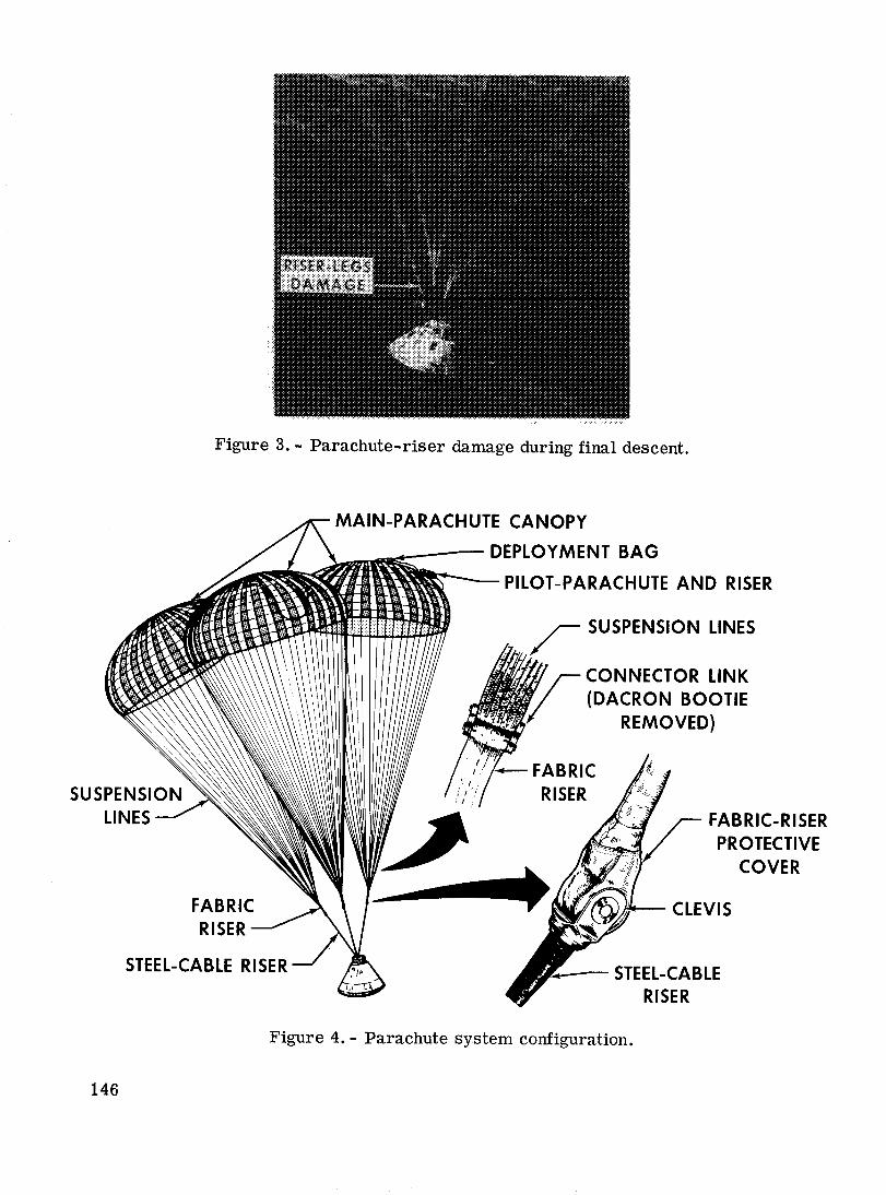
The two most significant items of photographic data obtained were the television tape, which indicated that the forward heat shield was in the vicinity of the spacecraft at the time of the anomaly, and the photographs shown in figures 1 and 3, which show the spacecraft parachute system damage when the spacecraft was relatively close to landing. The photographs show that
1. Three of the risers are taking the load.
2. There is no evidence of flailing suspension lines.
3. Two of the damaged riser lines appear to be full length.
4. Approximately two-thirds of the suspension system appears to be missing.
5. No significant canopy damage is visible.
The inspection of the forward heat shield revealed no damage that could be attributed to contact with the parachute system or the spacecraft. The initial inspection of
138
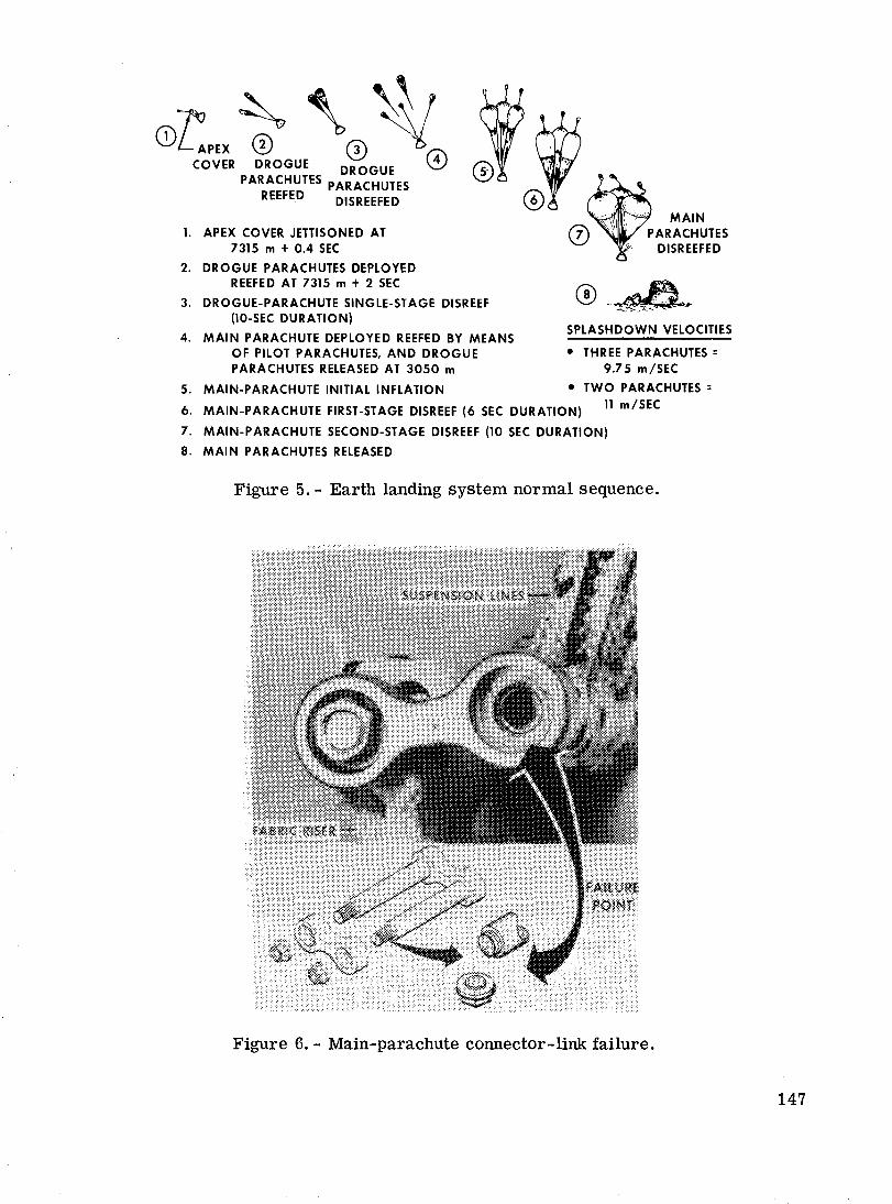
the recovered parachute showed only that it was not the one that had collapsed. Approximately 1 week after the first inspection, a second inspection was conducted, and a broken riser/suspension-line connector link was found after the Dacr.on bootie that protected it had been removed. Two to 3 weeks later, a closer examination of the Dacron riser protective cover (fig. 4) and the Dacron connector-link booties showed evidence of heat.
FAILURE ASSESSMENT
The investigation was directed toward the three· most likely causes of the parachute failure.
1. The forward heat shield was suspected of causing the damage because of its close proximity to the spacecraft during the time period in which the failure occurred.
2. The broken riser/suspension-line connector link that was found on therecovered parachute indicated the possibility of broken links in the failed parachute.
3. The command module reaction control system propellant-depletion firing had just been completed and fuel expulsion was in progress at the time of the failure, indicating the possibility of damage from the propellants.
The analyses and tests performed to investigate each possibility are presented.
Forward Heat Shield
Trajectory analysis.- .The landing sequence was initiated at a nominal altitude of 7315 meters with jettisoning of the forward heat shield (fig. 5), which is used to protect the parachute system. Immediately after separation of the heat shield from the command module, a 2. 19-meter-diameter parachute was mortar deployed from the forward heat shield, an action that augments separation of the heat shield from the command module. Following a drogue- and pilot-parachute deployment sequence, the main parachutes are deployed and decelerate the command module to its final descent velocity of approximately 9 m/sec. The descent rate of the 172-kilogram forward heat shield is approximately 31m/sec.
A trajectory analysis was performed to determine if the forward heat shield could have contacted the main parachutes. The analysis shows that the spacecraft and the · forward heat shield were at the same altitude at 1735 meters, with a miss distance of approximately 46 meters. This conclusion correlates with observations of the recovery personnel. Further, the analysis indicates that, at landing, the spacecraft and the forward heat shield were approximately 200 meters apart. This figure is in agreement with the estimated separation distance of 275 meters on the water, as observed by the recovery personnel. Based on wind-profile trajectory simulations (assumed deviations of plus or minus 1. 0 m/sec), the forward heat shield could have contacted the spacecraft parachute system at an altitude near 1825 meters.
139
Photographic analysis.- A close examination of the television record of spacecraft descent on the main parachutes shows the forward heat shield below the spacecraft in a frame recorded approximately 2 seconds before the anomaly occurred. By correlation with a later frame that shows both the parachute and forward heat shield, by direct measurement of the separation distance between the two objects, and by measurement of the known parachute dimensions, the vertical separation distances between the forward heat shield and the spacecraft were determined.
By an extrapolation of the forward heat shield trajectory and a comparison of the trajectory with the spacecraft trajectory, the forward heat shield would have intercepted the spacecraft 10. 5 seconds before the spacecraft data indicate that the parachute failure occurred. Therefore, the photographic analysis conclusively proved that the forward heat shield could not have caused the failure.
In addition, tests were performed that were designed to assess the damage to the parachute system and the command module from forward heat shield impact. These tests show the damage to be acceptable; therefore, the decision was made to retain the current forward heat shield/parachute system.
Riser/Suspension-Line Connector Links
The discovery of the failed link on the recovered parachute (fig. 6) resulted in an extension of the investigation in order to identify the process that caused the connector link to fail and to determine if such a failure could have occurred and resulted in the parachute failure observed during the Apollo 15 landing. Microscopic inspection of the broken stud (fig. 7) indicated that stress corrosion or hydrogen embrittlement may have caused the link failure, or that it may have been caused by some other indeterminate means. The material used in the studs (4130 steel alloy) is susceptible to cracking when it is highly stressed and immersed in salt water. This process can cause stress corrosion. Hydrogen embrittlement can occur in the plating operation during the manufacturing process. The plating produces hydrogen that causes the embrittlement if the subsequent heat treating is improper.
Tests were performed on the connector links in an attempt to determine if either stress corrosion or hydrogen embrittlement was the process that caused the link failure. These tests included sustained-load tests to determine if hydrogen embrittlement was present; stress-corrosion tests to determine if salt-water corrosion could have induced the failure; over-torque tests of the studs to determine if tolerance buildup of stresses could have caused the problem; and hypergolic propellant exposure to determine if propellant exposure could have caused the observed flaws. The results of the tests and the metallurgical examinations performed were inconclusive in isolating the failure mechanism.
It was not known whether a single failed link could cause the parachute to collapse. To answer this question, ground parachute tow tests were conducted by failing one, two, ahd three links of an inflated parachute. Iriflation was obtained by towing a parachute into the wind. When the canopy was fully inflated and stable, selected risers were severed. These tests showed that the parachute will remain fully inflated and provide
140
normal drag with one of its six riser legs severed. When two or more adjacent riser legs are severed, the canopy will collapse and lose at least two-thirds of its loadcarrying capability.
According to these results, two connector links must fail simultaneously to satisfy the abrupt load change calculated from the data of figure 2. It is highly unlikely that this situation occurred because of the low-load condition at the time of failure (35 percent of the opening shock load). Assuming that the collapsed parachute did have two failed links, load still would have been carried by the fractured links. This fact was demonstrated by testing of the recovered failed link in which the link withstood two complete mission load cycles.
Command Module Reaction Control System
Early in the investigation, the command module reaction control system was suspect because the propellant-depletion firing had just terminated and excess fuel was being expelled when the abrupt load change indicated in figure 2 occurred. Furthermore, at the time of the load change, the damaged parachute was in a position over a pair of the reaction control system engines. The spacecraft had been loaded fuel-rich to circumvent a problem encountered on an earlier Apollo flight in which the parachute system had been damaged by oxidizer. fuquiries that led to this fuel-rich procedure indicated that dumping only fuel through the engines would not be dangerous. This conclusion had been reached based on a limited test firing of 5 seconds, and it was not recognized that this firing time was not of sufficient duration to heat the engines to a point at which the fuel would ignite.
Later in the investigation, evidence of melting was found on the Dacron protective covering of the fabric riser and the connector link booties on the recovered parachute assembly. As a result, a closer examination was made of potential heat sources.
A test was conducted which showed that fuel on the parachute risers and suspension lines could easily be ignited by a hot wire and, once ignited, would cause the risers to fail within a few seconds. The next questions concerned what possibility existed that fuel could get on the lines and what would ignite the fuel. To answer these questions, a test was conducted to investigate the effects of cold, flowing raw fuel through a. hot engine. The test firings consisted of a series of hot firings of 10 to 45 seconds in duration, each followed by a 5-second fuel cold flow (using approximately 0. 27 kilograms of fuel). In every case, the raw-fuel expulsion sequence produced burning outside of the engine. Burning fuel vapor, burning fuel droplets, and some unburned fuel were observed during these tests. The flame front existed as far as 2. 4 meters from the engine exit plane, and unburned fuel was sprayed as far as 3 meters horizontally from the engine and then ignited by burning droplets. fu flight, the burning fuel could be diverted upward into the risers by the free air stream.
Following this test, movies of a development test of the command module reaction control system firing that was performed in 1969 were reviewed. The movies clearly showed flames spewing from all of the reaction control system engines after the depletion firing sequence. The question arises as to why this failure did not occur on other
141
Apollo flights in which the fuel-rich propellant loading was used. After the parachutelocation characteristics during the previous missions had been researched, it was determined that the parachute location is arbitrary and that, unfortunately, during the Apollo 15 descent, the failed parachute was oriented over the engines for several seconds during the fuel-expulsion sequence.
When the burning-fuel test results are combined with the available data (for example, the abrupt load change, the location of the parachute at the time of the failure, the damage to the parachute system as determined from the photographic coverage, and the timing of the fuel expulsion) and weighed against the forward heat shield and the broken stud as possible causes, all of the evidence indicates that the burning reaction control system fuel was the cause of the failure.
Conclusions of Failure Assessment
The results of the analyses and tests lead to the following conclusions.
Burning of raw fuel (monomethyl hydrazine) that is being expelled during the later portion of the reaction control system depletion firing can exceed the temperature limits of parachute riser and suspension lines located over the thruster engines and can cause extensive damage to a parachute.
The failure of a single connector link has little effect on the load-carrying capability of a parachute and was not the cause of the parachute collapse.
The forward heat shield did not cause the damage to the parachute.
CORRECTIVE ACTIONS
Corrective actions for the reaction control system include landing with the propellants on board for a normal landing and biasing the propellant load to provide a slight excess of oxidizer. Thus, for the low-altitude abort land landing, burning the propellants when the parachutes are deployed will subject the parachutes to some acceptable oxidizer damage but will eliminate the dangerous burning-fuel conditions. The suspension-line connector-link material has been changed to Inconel 718 to eliminate the requirement for plating, and the link-stud threads are rolled rather than machined to improve the metallurgical properties of the material.
CONCLUDING REMARKS
Two major points can be emphasized as a result of the investigation of the Apollo 15 parachute problem. The first point is that existing information should be thoroughly analyzed before an integrated operational system is established. The Apollo 15 parachute problem could have been prevented if the implications of existing reaction control system ground-test data had been completely understood. The solution
142
to the earlier problem in which the spacecraft was loaded fuel-rich to prevent the parachutes from being damaged by oxidizer was acceptable insofar as the reaction control system and the oxidizer problem were concerned. However, the solution created different conditions that resulted in an unacceptable environment for the parachute landing system.
The second point is that, in cases in which the data are limited, more than one set of conditions may satisfy the questions raised. The probability of reaching a wrong conclusion is increased when data are limited. In the case of the parachute anomaly, three likely causes of the failure existed. If certain bits of telemetry, visual, timing, and photographic data had not been available, the wrong conclusion could have been reached. It is important to weigh all available information carefully during the course of the analysis.
Aside from the investigative effort, the importance of basic design considerations cannot be overemphasized. The interfacing effects of operational systems should be thoroughly analyzed and understood early in the program. Test programs should be developed to verify the integrity of the integrated systems. In short, it is more profitable to apply engineering man-hours to the development of operable and compatible systems than to the resolution of systems problems.
143
Figure 1. - Spacecraft descending with one main parachute failed.
144
FALLING OBJECT SIGHTED BELOW THE SPACECRAFT
PARACHUTE FAILUR7 REACTION CONTROL SYSTEM
OXIDIZER REACTION CONTROL DEPLETION ~ SYSTEM DEPLETION :
FIRING START--, ! I f I I ! II
RCS TANK 2 He PRESS
RCS TANK 1 He PRESS
I
I I
REACTION CONTROL SYSTEM FUEL DEPLETION
[
REACTION CONTROL SYSTEM PURGE
START I
:10 :20:30:40 :45 :50 :55 :05 :10 :15 :20 :25 :30 :35 :40 295:08:00 295:09:00
TIME, HR:MIN:SEC
Figure 2.- Sequence of events during descent on the main parachutes.
145
146
Figure 3.- Parachute-riser damage during final descent.
STEEL-CABLE RISER
r SUSPENSION LINES
CONNECTOR LINK (DACRON BOOTIE
REMOVED)
FABRIC RISER
FABRIC-RISER PROTECTIVE
COVER
-~- STEEL-CABLE RISER
Figure 4.- Parachute system configuration.
Z~ ~' ~~ CD APEX 0 0 'i . COVER DROGUE DROGUE 0
PARACHUTES PARACHUTES REEFED DIS REEFED
1. APEX COVER JETTISONED AT 7315 m + 0.4 SEC
2. DROGUE PARACHUTES DEPLOYED REEFED AT 7315 m + 2 SEC
3. DROGUE-PARACHUTE SINGLE-STAGE DISREEF (10-SEC DURATION)
4. MAIN PARACHUTE DEPLOYED REEFED BY MEANS OF PILOT PARACHUTES, AND DROGUE PARACHUTES RELEASED AT 3050 m
5. MAIN-PARACHUTE INITIAL INFLATION
SPLASHDOWN VELOCITIES
• THREE PARACHUTES = 9.75 m/SEC
• TWO PARACHUTES = 6. MAIN-PARACHUTE FIRST-STAGE DISREEF (6 SEC DURATION) 11 m/SEC
7. MAIN-PARACHUTE SECOND-STAGE DISREEF (10 SEC DURATION)
8. MAIN PARACHUTES RELEASED
Figure 5. - Earth landing system normal sequence.
Figure 6.- Main-parachute connector-link failure.
147
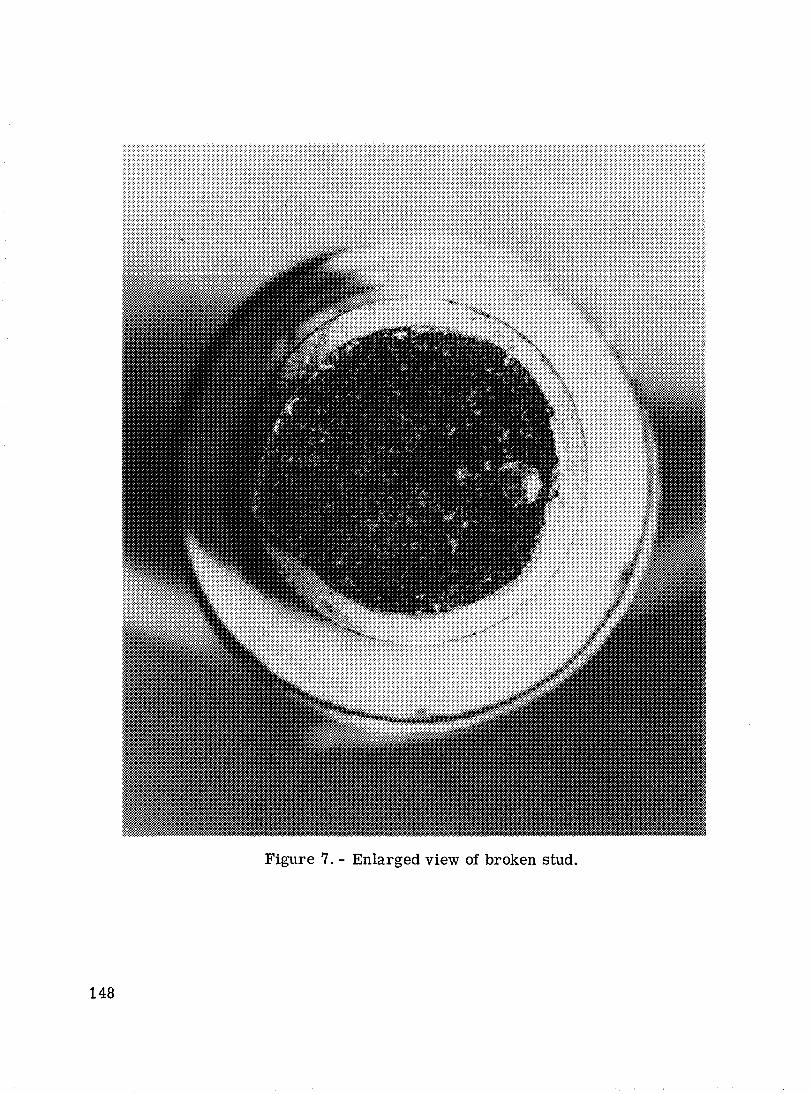
Figure 7. - Enlarged view of broken stud.
148
Related Documents