FORMWORK Forms or moulds or shutters are the receptacles in which concrete is placed, so that it will have desired shape or outline when hardened. Once concrete develops the adequate strength to support its own weight they can be taken out

Session 3 Formwork
Dec 05, 2015
Formwork and faslework
Welcome message from author
This document is posted to help you gain knowledge. Please leave a comment to let me know what you think about it! Share it to your friends and learn new things together.
Transcript

FORMWORK
Forms or moulds or shutters are the receptacles in
which concrete is placed, so that it will have desired
shape or outline when hardened. Once concrete
develops the adequate strength to support its own
weight they can be taken out

Requirements of a good formwork
The essential requirements of formwork or shuttering are• It should be strong enough to take the dead and live
loads during construction.• The joints in the formwork should be rigid so that the
bulging, twisting, or sagging due to dead and live load is as small as possible. Excessive deformation may disfigure the surface of concrete.
• The construction lines in the formwork should be true and the surface plane so that the cost finishing the surface of concrete on removing the shuttering is the least.
• The formwork should be easily removable without damage to itself so that it could be used repeatedly.

Requirements of form work
• A good form work should satisfy following requirements:• Material of formwork should be cheap & can be reused
many time.• It should be water proof & should not absorb water from
concrete. • Shrinkage & swelling should be minimum.• It should be strong enough to take all loads coming on it
(dead load of concrete, live load of labour during pouring, compaction & curing.
• It should be stiff enough so that deflection is minimum.• It should be light as far as possible• Surface of form work should be smooth for easy stripping• All joints of form work should be stiff so that lateral
deformation under load is minimum. • Joints should be leak proof.
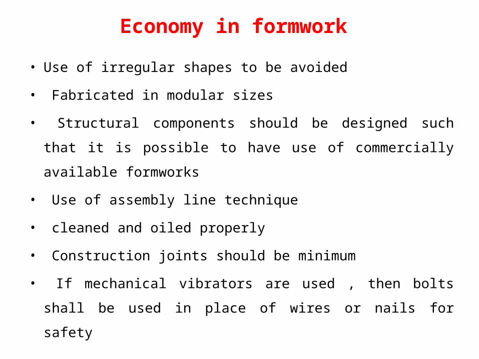
Economy in formwork
• Use of irregular shapes to be avoided
• Fabricated in modular sizes
• Structural components should be designed such that it is
possible to have use of commercially available formworks
• Use of assembly line technique
• cleaned and oiled properly
• Construction joints should be minimum
• If mechanical vibrators are used , then bolts shall be used in
place of wires or nails for safety
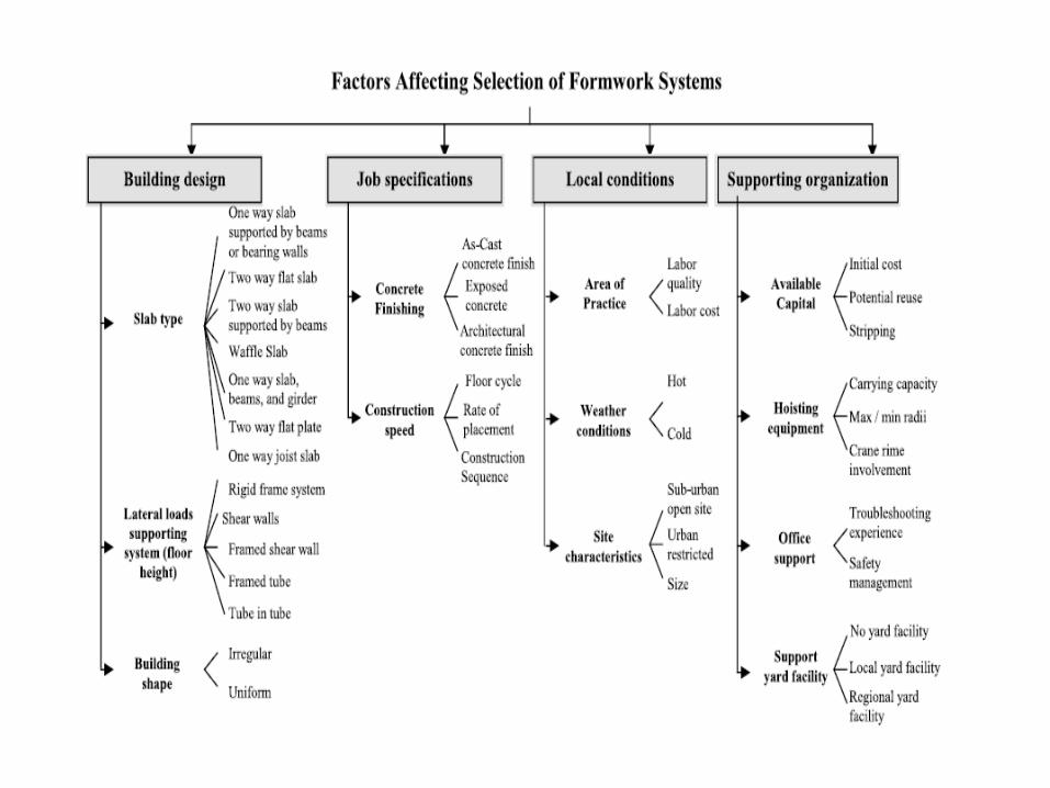

Classification of FormworkThe different categories in which formwork
can be classified are:• According to size.• According to location of use.• According to materials of construction.• According to nature of operation.• According to brand name of the product.

Classification according to the size of formwork• In practice, there are only two sizes for formwork;
small-sized and large-sized. Any size which is designed for operation by workers manually is small-sized.
• Very often, the erection process is preferably handled by a single worker, with site work best done independently to avoid possible waiting times.
• Due to reasons of size and weight, the materials and construction of small-sized formwork are thus limited.
• At present, the most common systems are made of timber and aluminum, and are usually in the form of small panels. There is seldom medium-sized formwork.

Classification according to the location of use
• There are not many effective formwork systems for stairs and staircases.
• The complicated three-dimensional nature of an element involving suspended panels and riser boards, as well as the need to cope with very different spatial and dimensional variances as required by individual design situations, cannot be achieved by a universally adaptable formwork system

Classification according to materials of construction
• Materials used for formwork are traditionally quite limited due to finding the difficult balance between cost and performance.
• Timber in general is still the most popular formwork material for its relative low initial cost and adaptability
• Steel, in the form of either hot-rolled or cold-formed sections and in combination with other sheeting materials, is another popular choice for formwork materials.
• Aluminum formwork systems have been used in some cases but the performance is still being questioned by many users, especially in concern to cost and labor control
Classification according to nature of operation
• Formwork can be operated manually or by other power-lifted methods.
• Some systems are equipped with a certain degree of mobility to ease the erection and striking processes, or to allow horizontal moment using rollers, rails or tracks
Wooden form work
Most common form work Disadvantage • Possibility of warping, swelling, shrinkage.• Water impermeable coating on wood form
work is applied to reduce warping, swelling, shrinking
• With impermeable coating shuttering can be removed easily.

Steel form workSteel shuttering is used for major work.• Advantages:a) It can be put to use for high number of times.b) It provides ease of strippingc) It gives smooth & even concrete surfaced) It posses high rigiditye) It is not liable to shrinkage or distortion f) It is costly
Steel form work• This consist of panels fabricated out of thin steel
plates stiffened along the edges by small steel angles.
• The panel units can be held together through the use of suitable clamps or bolts and nuts.
• The panels can be fabricated in large number in any desired modular shape or size.
• Steel forms are largely used in large projects or in situation where large number reuses of the shuttering is possible.
• This type of shuttering is considered most suitable for circular or curved structures.

• For heavy concrete work• With reasonable care will last indefinitely• High initial cost and high handling cost
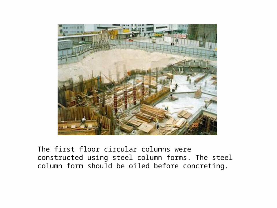
The first floor circular columns were constructed using steel column forms. The steel column form should be oiled before concreting.

After concreting to the first floor columns, the steel column forms were dismantled easily.

Compared with timber formwork
• Steel forms are stronger, durable and have longer life than timber formwork and their reuses are more in number.
• Steel forms can be installed and dismantled with greater ease and speed.
• The quality of exposed concrete surface by using steel forms is good and such surfaces need no further treatment.
• Steel formwork does not absorb moisture from concrete.
• Steel formwork does not shrink or warp.

STEEL FORMWORK AND ACCESSORIES
• Steel formwork systems for every size and shape of ground plan, in practical dimension & equipped with different features to make shuttering more efficient.

Flatform Panels Form Work
Column Formwork
Application of Push-pull Prop. & Soldier System


Flat Form
Flat Form is used for forming planes such as those of Square columns, walls, slab floors, etc. By combining units of various sizes, flat form can be made to serve a wide variety of purposes.

Corner Angle Outside Corner Form
Inside Corner Form "L" - type pin & U-clip
Steel Form for CornersForm can be assembled easily and tightly by using the Corner Angle, Outside Corner Form & Inside Corner Form.We can tailor-made various sizes of corner to suit customer specific requirements & application.
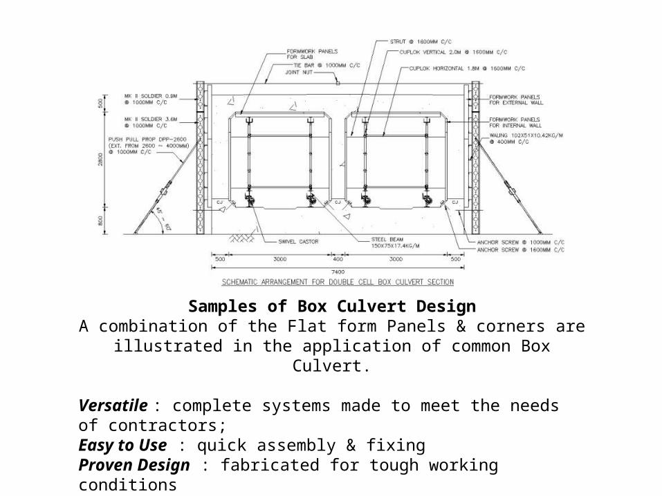
Samples of Box Culvert DesignA combination of the Flat form Panels & corners are illustrated in the
application of common Box Culvert.
Versatile : complete systems made to meet the needs of contractors; Easy to Use : quick assembly & fixing Proven Design : fabricated for tough working conditions
Indian Standard of Form work(IS :456-1964)
(1) General :The form work :• shall conform to the shape, lines & dimensions
as shown on the plans.• Shall be rigid during placing & compacting of
concrete.• Water tight to prevent loss of water from
concrete.(2) Cleaning & treatment of forms• All rubbish, chippings, saw dust shall be
removed from the interior of form work before placing of concrete. Shall be wetted
Indian Standard of Form work(IS :456-1964)
• STRIPPING TIME• Form work should not removed until good strength has
come.• Type of form work Time• Vertical wall, columns 16-24 hrs• Soffit of slab (Prop should be refixed immediately) 3
days• Soffit of beam (Prop should be refixed immediately) 7
days• Props to slab Span < 4.5 m 7 days• Props to slab Span > 4.5 m 14 days• Props of beam (Span < 6 m) 14 days• Props of beam (Span > 6 m) 21 days

Time of Removal of formwork
Sr. No
Structural Member
OPC (Ordinary Portland
Cement)
Rapid Hardening
Cement
1 Beam sides, walls & Columns 2-3 Days 2 Days
2 Slab (Vertical Supports remains intact) 4 Days 3 Days
3 Slab (Complete Formwork removal) 10 Days 5 Days
4 Beams (Removal of Sheeting, Props remains intact)
8 Days 5 Days
5 Beams & Arches (Complete formwork removal) (up to 6 m span)
14 Days 5-8 Days
6 Beams & Arches (Complete formwork removal) (more than 6 m span)
21 Days 8-10 Days
(4) Procedure when removing form work All form work shall be removed without shock or vibration as it will damage the concrete. Before the soffit (bottom surface ) & struts (pole) are removed, the concrete shall be exposed, to check that the concrete has sufficiently hardened. Proper precautions shall be taken to allow for decrease in the rate of hardening in cold water.
(5) Camber It is desirable to give form an upward camber (slope) to ensure that beams do not sag when they have taken up their deflection. This should be done only when allowed in the design calculation of the beam.
Indian Standard of Form work (IS :456-1964)

Indian Standard of Form work (IS :456-1964)
(6) Tolerances Form work shall be so constructed that the internal dimensions are within the permissible tolerance specified by the designed
LOADS ON FORM WORK
• The form work has to take following loads: • a)Live load due to labour • b)Weight of wet concrete • c)Hydrostatic pressure of the fluid concrete acting
against the vertical or inclined faces of form • d)Impact due to pouring of concrete.
• Live loads of labour & equipment including impact may be taken as 370 Kg/m2.
LOADS ON FORM WORK
• HYDROSTATIC PRESSURE: • Hydro static pressure due to fluid of concrete
depends on : • a)Quantity of water in concrete • b)Size of aggregate • c)Rate of pouring • d)Temperature

HYDROSTATIC PRESSURE
• Hydrostatic pressure is maximum during pouring and decreases when concrete becomes hard.
• Setting time may be taken as ¾ to 1 hour. • Only height of concrete poured in ¾ to 1 hour is
taken into account for calculation of hydrostatic pressure on form work.
• For 1.5 m height of concrete, equivalent weight of concrete may be taken as 2300 kg/m3.

HYDROSTATIC PRESSURE
• For higher height, the equivalent weight of concrete is reduced. When height of concrete in one pour is 6 m, the equivalent fluid weight may be 1200 kg/m3.
• For intermediate heights between 1.5 to 6 m poured within the setting time of ¾ hour linear interpolation of unit weight between 1200 to 2300 kg/m3 may be taken

SHUTTERING FOR BEAM & SLAB FLOOR
• The slab is continuous over number of beams. • The slab is supported on 2.5 cm thick sheathing laid
parallel to main beam. • The sheathing is supported on wooden battens which are
laid between the beams, at suitable spacing. • In order to reduce deflection, the battens may be
propped at middle of the span through joists. • The side forms of the beam consists 3 mm thick
sheathing. • The bottom sheathing of the beam form may be 5 to 7
cm thick

SHUTTERING FOR BEAM & SLAB FLOOR
• The end of the battens are supported on ledger which is fixed to cleats throughout the length.
• Cleats 10 cm x 2 cm x 3 cm are fixed to the forms at the same spacing as that of battens, so that battens may be fixed to them.
• The beam forms is supported on a head tree. • The shore or post is connected to head tree through
cleats. • At the bottom of shore, two wedges of hard wood are
provided over a sole piece


MERITS OF ALUMINIUM FORMWORK
• In contrast to most of the modern construction systems, which are machine and equipment oriented, the formwork does not depend upon heavy lifting equipment and can be handled by unskilled labors.
• Fast construction is assured and is particularly suitable for large magnitude construction of respective nature at one project site.
• Construction carried out by this system has exceptionally good quality with accurate dimensions for all openings to receive windows and doors, right angles at meeting points of wall to wall, wall to floor, wall to ceiling, etc, concrete surface finishes are good to receive painting directly without plaster.
MERITS OF ALUMINIUM FORMWORK
• System components are durable and can be used several times without sacrificing the quality or correctness of dimensions and surface.
• Monolithic construction of load bearing walls and slabs in concrete produces structurally superior quality with very few constructions joined compared to the conventional column and beam slabs construction combined with filter brick work or block work subsequently covered by plaster.
• In view of the four – day cycle of casting the floor together with all slabs as against 14 to 20 – day cycle in the conventional method, completed RCC structure is available for subsequent finish trades much faster, resulting in a saving of 10 to 15 days per floor in the overall completion period.
• .

MERITS OF ALUMINIUM FORMWORK
• As all the walls are cast monolithic and simultaneously with floor slabs requiring no further plasters finish. Therefore the time required in the conventional method for construction of walls and plastering is saved.
• As fully completed structural frame is made available in one stretch for subsequent – finishing items, uninterrupted progress can be planned ensuring, continuity in each trade, thereby providing as cope for employing increased labor force on finishing item.
• As the system establishes a kind of “Assembly line production” phase – wise completion in desired groups of buildings can be planned to achieve early utilization of the buildings

ULMA FORMWORK SYSTEM• PRODUCT DESCRIPTION• The ULMA CC-4 formwork system is mainly for
large surface areas with a good finishing surface, where geometry and distance between columns is regular, providing high quality finishing, directed to the requirements of building construction.
• Its elements are built in aluminium, so the system is lightweight.
• It is characterized by its safe and fast assembly and dismantling, as its main parts are made of aluminium.

ULMA FORMWORK SYSTEM

Drop heads CC: It is equipped with a drop system which assists the stripping, letting the panels, beams & Transversals descend to be easily retrieved. Along with the prop, it is the only remaining part of the system


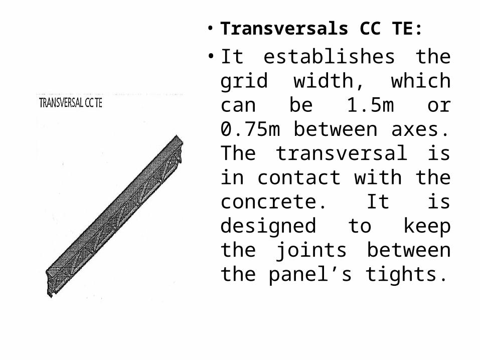
• Transversals CC TE:
• It establishes the grid width, which can be 1.5m or 0.75m between axes. The transversal is in contact with the concrete. It is designed to keep the joints between the panel’s tights.

• .Standard boards:• The formwork face is
plywood or composite board which fits in the frame. The openings in the frame facilitate its manual handling
ADVANTAGES OF ULMA CC-4 OVER CONVENTIONAL FORMWORK
• Most system elements are manufactured in aluminium, and some elements are plastic, thus this is a very lightweight formwork.•This formwork stripping system is designed to facilitate the recovery of material without permitting any of it to fall to the ground-achieved by “drop head” system. This helps to increased worker safety and reduces material deterioration.•Great versatility which enables to change beam direction; one beam can be installed at a 90º angle to its adjacent beam.•Easy to adjust height and to level the formwork because of few props used in setup.•High efficiency of assembly and disassembly
GROCON FORMWORK SYSTEM• Grocon climbing systems form vertical elements
such as columns and walls, providing employees with a safe work environment. The formwork, working platforms, trailing screen assemblies and rams are attached to overhead truss assemblies, so with each lift the whole system rises simultaneously.
• It can be raised in only one hour with one fully-trained operator having control over the process. Jacking points that raise the system are located below the truss assemblies to give clear access to all working platforms
• The top-working platform is left clear for storing crane-handled equipment and provides clear access for workers. Vertical formwork elements are suspended from members located in the top chord assemblies of the truss system allowing vertical, lateral and horizontal adjustment. High-level construction accuracy is therefore possible within the system
• In all stages of the jump from operating cycle the workers are fully enclosures their complete safety & that of all other workers & members of the public. At no time can the workers fall or lose their to cause accidents and hence offers full safety

• The Grocon jump from operates as one system. This eliminates the possibility of creating opening in the system when one section is raised before another section.


ADVANTAGES OF GROCON OVER CONVENTIONAL FORMWORK
• Standard plywood used on the lubeca system can be used up to 77 pours. By treating two stories as one the need to replace wall from plywood is reduced.
• Down time costs are minimised or eliminated.• The system is as effective as a steel formwork
alternative without the associated weight & cost penalties.
• Less pours means a saving on re-enforcement laps bars & concrete with a consequence increase in efficiency & productivity.
• Forming two floors at a time halves the number of plumbing & surveying operations during construction of the core.
ADVANTAGES OF GROCON OVER CONVENTIONAL FORMWORK
• The system does not rely on the most recent concrete pour, with jacking beams supported by concrete that is one cycle old.
• The top deck is free of jacking masts & other mechanical obstacles, which protects all operational equipment from concrete spills & the possibility of crane damage.
• Long stroke, heavy duty hydraulic rams allow over 4 meters of travel & deep single pours, which is particularly useful for areas such as computer floors.
• Hydraulic safety features include non-return valves, a complete backup system & locking devices on each arm ram.
Related Documents