1 INTRODUCTION IS-Shanghai 2008 became a major opportunity to share recent experience related to underground construction in soft ground. In Session 3, devoted to case histories, many projects reflecting advances in geotechnical engineering related to challenging urban conditions were discussed. Eight countries contributed a total of twenty papers to this session: eleven from China, one from Japan, two from Korea, one from Singapore, one from Taiwan, one from Italy, two from France and one from Germany. In the following sections, the twenty papers are classified and summarized. The purpose of this classification is to guide the interested reader to specific information that might be useful for his/her research. Papers are grouped as follows: i) seven papers dealing with open pit excavations; ii) four papers dealing with NATM and drill&blast tunnels; iii) five papers dealing with TBMs and shield tunnels; and iv) four papers dealing with monitoring systems and the evaluation of the impact of under- ground projects on surroundings. Almost all kind of difficult ground conditions due to existing infrastructure and space constraints were described. For instance, papers dealing with TBM tunnelling describe crossing beneath a shield tunnel and a railway line, across the foundations of a highway bridge and above existing tunnels of an operating metro line. Open pit excavation projects are not simpler, showing the challenges that urban construction poses to geoengineering. Two facts became evident during the revision process, as follows: i) ground conditions are described in widely different ways and with highly varying degree of completeness; and ii) ground and structure behavior are characterized by some “repre- sentative” numbers selected with ample liberty. While the reported data is very valuable, some effort must be done to fully exploit it’s usability. It is remarkable that seven out of twenty papers deal with either recent or on-going underground projects in Shanghai, thus reflecting the impresive rate of infrastructure development of the city. A large amount of information is provided with respect to Shanghai soils, including laboratory and field tests and extensive reporting of ground behavior during construction. It is desirable that this valuable information be further analyzed by researchers to produce a consistent and complete set of material parameters for Shanghai soils, as the raw data provided by the papers does not allow for a complete understanding of soil conditions and soil behavior. In each section, the list of papers is listed in a table and a brief description is presented for each paper. The description merely states the type of project, geology conditions where known and the description of a few selected contributions. These contributions can be of any type, from an overall description of construction processes to a quanti- tative measure of ground behavior or detailed monitoring data. The writer recommends the reading of all papers, as the valuable information contained there is only superficially grasped by the short descriptions that follow in this report. Session 3: Case Histories. General Report. A. Sfriso Dept. of Estabilidad, University of Buenos Aires, Argentina. ABSTRACT: Twenty papers accepted for publication under IS-Shanghai 2008 Session 3 on Case Histories are classified and summarized. Papers deal with open pit excavations, ground improvement, tunnels, monitoring systems and impact on surroundings, most of them related to projects performed in challenging urban environments. It has been found that different authors follow different approaches when reporting case histories, mainly with respect to the quantitative description of ground conditions and behavior. While this can be attributed to different scientific and professional schools, it is judged that a higher degree of consistency and completeness of the basic information is required for a better usability of the informed data. To contribute to this goal, a short guideline on reporting case histories is proposed.

Welcome message from author
This document is posted to help you gain knowledge. Please leave a comment to let me know what you think about it! Share it to your friends and learn new things together.
Transcript

1 INTRODUCTION
IS-Shanghai 2008 became a major opportunity to share recent experience related to underground construction in soft ground. In Session 3, devoted to case histories, many projects reflecting advances in geotechnical engineering related to challenging urban conditions were discussed.
Eight countries contributed a total of twenty papers to this session: eleven from China, one from Japan, two from Korea, one from Singapore, one from Taiwan, one from Italy, two from France and one from Germany.
In the following sections, the twenty papers are classified and summarized. The purpose of this classification is to guide the interested reader to specific information that might be useful for his/her research. Papers are grouped as follows: i) seven papers dealing with open pit excavations; ii) four papers dealing with NATM and drill&blast tunnels; iii) five papers dealing with TBMs and shield tunnels; and iv) four papers dealing with monitoring systems and the evaluation of the impact of under-ground projects on surroundings.
Almost all kind of difficult ground conditions due to existing infrastructure and space constraints were described. For instance, papers dealing with TBM tunnelling describe crossing beneath a shield tunnel and a railway line, across the foundations of a highway bridge and above existing tunnels of an operating metro line. Open pit excavation projects are not simpler, showing the challenges that urban construction poses to geoengineering.
Two facts became evident during the revision process, as follows: i) ground conditions are described in widely different ways and with highly varying degree of completeness; and ii) ground and structure behavior are characterized by some “repre-sentative” numbers selected with ample liberty. While the reported data is very valuable, some effort must be done to fully exploit it’s usability.
It is remarkable that seven out of twenty papers deal with either recent or on-going underground projects in Shanghai, thus reflecting the impresive rate of infrastructure development of the city. A large amount of information is provided with respect to Shanghai soils, including laboratory and field tests and extensive reporting of ground behavior during construction. It is desirable that this valuable information be further analyzed by researchers to produce a consistent and complete set of material parameters for Shanghai soils, as the raw data provided by the papers does not allow for a complete understanding of soil conditions and soil behavior.
In each section, the list of papers is listed in a table and a brief description is presented for each paper. The description merely states the type of project, geology conditions where known and the description of a few selected contributions. These contributions can be of any type, from an overall description of construction processes to a quanti-tative measure of ground behavior or detailed monitoring data. The writer recommends the reading of all papers, as the valuable information contained there is only superficially grasped by the short descriptions that follow in this report.
Session 3: Case Histories. General Report.
A. Sfriso Dept. of Estabilidad, University of Buenos Aires, Argentina.
ABSTRACT: Twenty papers accepted for publication under IS-Shanghai 2008 Session 3 on Case Histories are classified and summarized. Papers deal with open pit excavations, ground improvement, tunnels, monitoring systems and impact on surroundings, most of them related to projects performed in challenging urban environments. It has been found that different authors follow different approaches when reporting case histories, mainly with respect to the quantitative description of ground conditions and behavior. While this can be attributed to different scientific and professional schools, it is judged that a higher degree of consistency and completeness of the basic information is required for a better usability of the informed data. To contribute to this goal, a short guideline on reporting case histories is proposed.
2 OPEN PIT EXCAVATIONS
The list of papers dealing with open pit excavations is given in Table 1.
Table 1. Papers on open pit excavations ___________________________________________________ Author Project ___________________________________________________ Hsiung&Chuay Three excav. 20m deep in Kaohsiung, Taiwan Konda et al Eleven braced excavations at Osaka, Japan Liu, D. et al 18m deep propped excavation in Shanghai Liu, G. et al 21m deep propped excavation in Shanghai Liu, T. et al 40m deep propped excavation in Shanghai Mei et al 6m deep propped excavation in Shanghai Osborne et al JMM ground treatment in Singapore ___________________________________________________
2.1 Hsiung and Chuay. Observed behaviour of deep excavations in sand.
The behavior of three excavations in Kaohsiung, Taiwan, is described. The excavations are approx. 20m deep, supported by propped diaphragm walls 1.0m thick and 36m long, and excavated in medium dense silty sand with clay layers (NSPT: 5-30). The water table is reported at 3m to 6m below ground surface.
The maximum lateral wall displacement δh max and surface settlement δv max are reported. Values are normalized by the effective height of the excavation He for comparison among the three projects. It is observed that δh max/He falls in the range 0.03% to 0.3% and that δv max is about one half of δh max. The effect of the construction sequence and remedial effects to reduce surface settlements are discussed.
2.2 Konda et al. Measurement of ground deformations behind braced excavations.
The paper reports surface and wall deformations of braced support systems used at eleven sites of the Osaka Subway L8 project in Japan. While details of the support systems are not informed, the geotech-nical conditions are reported to vary widely among the sites analyzed, from gravels to soft clays. Wall deformation and surface settlements are described by area indices as shown in Fig. 1. It is concluded that the ground settlement area As is about 20%-30% of the wall deflection area Aδ for excavations approx. 21m deep, but can be much higher if consolidation settlements occur.
No.1No.2
AδAδ 1
Aδ 2
As
Smax
δ max
earth retaining wall
Zm
B : excavation width
Ze
Lmground surface
excavation bottom
Figure 1. Symbol definition (Konda et al 2008).
2.3 Liu, D. et al. Research on the effect of buried channels to the differential settlement of building.
The paper deals with the impact of a deep excavation on adyacent structures in Shanghai, China. The excavation is 18m deep, supported by a diaphragm wall 0.8m thick and 26m long with steel supports, excavated in Shanghai soft clays. Ground conditions are described as shown in Table 2. The water table is assumed to be 1m below ground level.
Table 2. Description of the soils (Liu, D. et al 2008). ___________________________________________________ name bottom ω γ e shear pars level [m] % kN/m
3 - c[kPa] φ[°] ___________________________________________________
fill 2.93 - - - - - clay 0.33 34.6 18.2 0.99 21 17.5 silty clay -3.87 43.0 17.3 1.21 13 17.0 silty clay -11.87 49.1 16.8 1.39 14 11.0 clay -14.87 38.9 17.6 1.12 16 14.0 silty clay -21.37 34.9 17.9 1.02 15 18.5 sandy silt -35.87 32.2 18.0 0.94 4 29.0 silty sand 26.3 18.8 0.77 1 32.0 ___________________________________________________
The maximum lateral wall displacement δh max is reported to be 60mm, or 0.33% of the excavation height. Extensive analysis of the settlement behavior of an adyacent building is reported in the paper, with emphasis on the non-uniform settlement rate during the excavation stage. While the complexity of the geological conditions is assessed, no data on the compression and permeability parameters of the soft clay layers is given and the consolidation process is not discussed, despite the fact that the reported settlement of the building was up to 125mm.
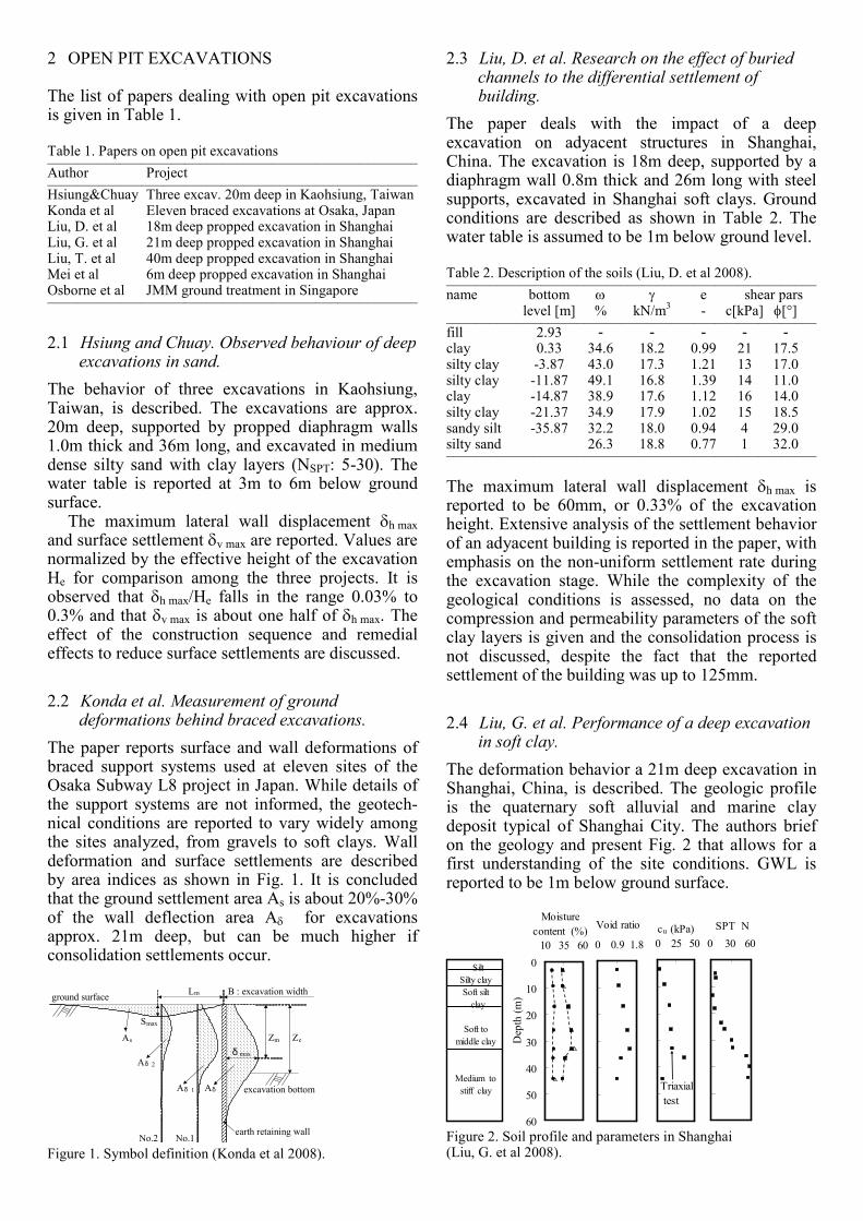
2.4 Liu, G. et al. Performance of a deep excavation in soft clay.
The deformation behavior a 21m deep excavation in Shanghai, China, is described. The geologic profile is the quaternary soft alluvial and marine clay deposit typical of Shanghai City. The authors brief on the geology and present Fig. 2 that allows for a first understanding of the site conditions. GWL is reported to be 1m below ground surface.
SiltSilty clay
Soft silt
clay
Soft to
middle clay
Medium to
stiff clay
0 0.9 1.8
Void ratio
0 25 50
cu (kPa)
0 30 60
SPT N
Triaxial
test
0
10
20
30
40
50
60
10 35 60
Moisture
content (%)
Dep
th (m
)
Figure 2. Soil profile and parameters in Shanghai (Liu, G. et al 2008).

The support system is a 0.8m x 40m propped diaphragm wall with base compensation grouting and prestressed struts. The maximum lateral wall displacement δh max is reported to be 55mm, or 0.32% of the excavation height. This result is compared with other measured values in Shanghai and other sites having rather similar soil conditions.
The effect of the stiffness of multi-propped support systems is analysed and the three dimen-sional behavior of the excavation is assessed. It is concluded that a corner effect exists that reduces the lateral wall displacement corner-to-center ratio δh max (corner) / δh max (center) to about 0.39-0.74.
2.5 Liu, T. et al. The construction and field monitoring of a deep excavation in soft soils.
The paper describes the construction procedure of a very large and deep excavation performed in Shanghai clays. The excavation was 263m long, 23m wide and 38m-41m deep, supported by a 1.2m thick and 65m long multi-propped diaphragm wall.
The deep diaphragm wall construction procedure is described in detail, including the so called “two-drill-one grab” construction method shown in Fig. 3 and the employment of a counterweight to better clean the last panel’s lateral surface before pouring the next panel, as shown in Fig. 4.
finished wall
advanced wall
oriented holes
subsequence wall
Figure 3. The “two-drill-one grab” method for the construction of the diaphragm wall (Lui, T. et al 2008).
crane
finished wall
counterweight
Figure 4. Procedure used to clean the lateral surface of the last panel (Lui, T. et al 2008).
Jet grouting was extensively employed to improve soil conditions in the passive zone. Reported inclinomenter data shows wall behavior along the construction stages. The max lateral wall deflection was δh max= 50mm, or 0.12% of the total height of the excavation. Surface settlements are reported but not associated by the authors to a consolidation process. Moreover, neither a set of compression parameters nor an analysis of compression behavior of Shanghai clays is reported.
2.6 Mei et al. Excavation entirely on subway tunnels in the central area of the People’s Square.
The design and construction of a shallow excavation 6m deep in Shanghai, China, is described. The particular challenge of this project was that the bottom of the excavation was placed 3m above existing tunnels. A support system consisting in a soil-cement pile wall 3.2m thick with directional jet grouting was designed and passive tension piles were provided to control uplift.
2.7 Osborne et al. The benefits of hybrid ground treatment in significantly reducing wall movement: a Singapore case history.
The paper reports the first major use in Singapore of a hybrid ground improvement procedure called Jet Mechanical Mixing (JMM). JMM is a large diameter deep mixing method that forms a central core of mixed soil combined with a jet-grouted outer annulus. A schematic diagram of the drilling tool is shown in Fig. 5.
Figure 5. Schematic diagram of the drilling tool showing the mixing arm of the JMM machine (Osborne et al 2008).
The system was employed in the Nicoll Highway Station Project. The excavation was 27m deep, supported by a 1.5m thick and 51m long diaphragm wall. The JMM was used to make a base plug of improved soil 7m thick below the excavation. Ground conditions include fill, fluvial sand, fluvial clay and normally consolidated marine clay. The authors concluded that the ground improvement technique employed reduced the lateral wall displa-cements δh max by a factor of three.
2.8 Comparison between wall deformation data.
Table 3 lists the lateral wall displacement δh max as a fraction of the excavation height He for the different projects and construction procedures described. No correlation can be observed between He and δh max, confirming the well-known fact that wall deflection heavily depends on the particular construction procedure, to the extent that it might be concluded

that diaphragm walls and construction procedures are designed to accomplish lateral wall deflections that balance the performance requirements of engineers and clients.
Table 3. Comparison of wall deformation data _____________________________________ Author Soil He δh max/He m % _____________________________________ Hsiung&Chuay sand 20 0.03-0.30 Konda et al varies 21 0.10-0.24 Liu, D. et al clay 18 0.33 Liu, G. et al clay 20 0.32 Liu, T. et al clay 40 0.12 Osborne et al clay 27 0.09 _____________________________________
3 NATM / DRILL&BLAST TUNNELS
The list of papers dealing with NATM and drill&blast tunnels is given in Table 4.
Table 4. Papers on drill&blast and NATM tunnels ___________________________________________________ Author Description ___________________________________________________ Eclaircy-Caudron et al Drill&blast tunnel in Bois de Peu, Fr. Guiloux et al Drill&blast tunnel in Morocco Quick et al NATM tunnel in Mainz, Germany Yoo et al Subsidence due to water drawdown ___________________________________________________
3.1 Eclaircy-Caudron. Displacements and stresses induced by a et al tunnel excavation: case of Bois de Peu (France).
The paper describes the ground response during the construction of the two twin drill&blast tunnels in Bois de Peu, France. The tunnels have a cross section area of 130m
2, a length of 520m, and were
excavated through clays and soft rocks under 8m to 140m of overburen. The support system was formed by shotcrete, steel ribs and radial bolts. Unfavour-able ground conditions in the clay soils demanded the use of a structural invert, forepoling and face bolting.
An interactive design and construction procedure was employed, where monitoring data was used in an adaptive design process. The paper reports the construction sequence, the use of monitoring information to adjust design, and extensive data on face displacements measured at four instrumented sections. It is shown that extrusion extended one diameter ahead of the tunnel face and that high face extrusion proved to be a good indicator of poor ground performance and risk of face failure.
3.2 Guiloux et al. Case history on a railway tunnel in soft rock (Morocco).
The construction process of the Ras R'Mel tunnel in Morocco is described. The tunnel is 2.6km long and has a cross section of 60m
2. It was excavated
through weak flysch under 50m to 150m overburden by drill&blast method. The support system consists in 23cm of shotcrete and steel ribs. A particular feature of the construction procedure is the use of a formwork to reduce shotcrete loss, as shown in Fig. 6. Stress-to-UCS ratios up to 3.5 and convergences up to 300mm were reported, values higher than usual for drill&blast tunnels in rock.
Figure 6. Construction of Ras R'Mel tunnel (Guiloux et al 2008).
3.3 Quick et al. Challenging urban tunnelling projects in soft soil conditions.
The design and construction of the New Mainz Tunnel in Germany is presented. New Mainz Tunnel runs parallel to Old Mainz Tunnel, built in 1884, with a clearance of 4m to 50 meters. The tunnel is 1250m long, with a cross section of 140m
2 and runs
below buildings with 10m to 23m overburden. Soils are marly clays, silts and sand, and the support system is a complex combination of bolting, umbrellas, face bolting and reinforced shotcrete. Ground improvement techniques employed at some sections to reduce surface settlements are described. It is reported that a reduction of settlements from 11cm to 1.5cm-2.5cm was achieved by ground improvement.
It is very interesting to note the differences and similitudes in construction procedures used in two similar tunnels separated in time by one century, as shown in Fig. 7.
bench
core
side- wall
side- wall
filling GW
bolting
Figure 7. Construction procedure for Old and New Mainz Tunnels (Quick et al 2008).
3.4 Yoo et al. Characteristics of tunneling-induced ground settlement in groundwater drawdown environment.
The paper studies the effect on surface settlements of groundwater drawdown due to tunnel cons-truction. The case analyzed consists in a 70m
2 tunnel
excavated through weathered granite with 20m to 30m overburden formed by fill, alluvium and weathered rock. The support system consisted in pre-grouting, pipe umbrellas, rock bolts and shotcrete.
Water drawdown produced surface settlements that started approximately six diameters ahead of tunnel face and that stabilized six diameters behind it. The problem was analyzed by a parametric study using a 2D finite element model with Mohr-Coulomb constitutive model. It was concluded that surface settlements due to tunnel construction have different patterns when ground-water drawdown is present, when compared to the normal case.
It must be noted that surface settlements due to groundwater drawdown are a well-known problem of geotechnical engineering that is accounted for by consolidation theory and that is simulated with constitutive equations that account for inelastic compression. The Mohr-Coulomb constitutive model reported to be used in the model, however, neither simulates inelastic compression nor includes compression parameters.
4 SHIELD TUNNELS AND TBMS
The list of papers dealing with shield tunnels and TBMs is given in Table 5. Table 5. Papers on shield tunnels and TBMs ___________________________________________________ Author Description ___________________________________________________ Antiga&Chiorboli EPB tunnels in Milano, Italy Gong&Zhou Tunnel beneath railway line in Shanghai Wang et al Crossing below existing tunnel in Shanghai Wong et al Crossing above existing tunnel in HKSAR Xu et al Crossing bridge foundations, Shanghai ___________________________________________________
4.1 Antiga and Chiorboli. Tunnel face stability and settlement control using earth pressure balance shield in cohe sionless soil.
The paper analyzes and compares two case histories of EPB tunnels driven in Milano, Italy. Both tunnels were excavated through 50m to 60m of medium-dense to dense alluvial sands and gravels.
The authors provide a comprehensive summary of factors affecting subsidence of shield tunnels in sands. They conclude that a high advance rate produces less volume loss and reduces subsidence and show that EPB face pressure is poorly correlated to surface settlements but depends on technological aspects of backfilling operations.
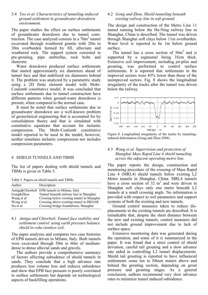
4.2 Gong and Zhou. Shield tunneling beneath existing railway line in soft ground.
The design and construction of the Metro Line 11 tunnel running below the Hu-Ning railway line in Shanghai, China is described. The tunnel was driven through Shanghai soft clays below 11m overburden. Water level is reported to be 1m below ground surface.
The tunnel has a cross section of 30m2 and is
supported by a segmental lining 35cm thick. Extensive soil improvement, including jet-piles and grouting, was performed to control surface settlements. It is reported that settlements in the improved sectors were 85% lower than those of the unimproved sectors. Fig. 8 shows the longitudinal irregularity of the tracks after the tunnel was driven below the railway.
Figure 8. Longitudinal irregularity of the tracks by tunneling-induced deformation (Gong and Zhou 2008).
4.3 Wang et al. Supervision and protection of Shanghai Mass Rapid Line 4 shield tunneling across the adjacent operating metro line.
The paper reports the design, construction and monitoring procedure of the crossing of Mass Rapid Line 4 (MRL4) shield tunnels below existing L2 Metro tunnels in Shanghai, China. MRL4 tunnels have a cross section of 32 m
2 and were driven in
Shanghai soft clays only one meter beneath L2 tunnels at a small crossing angle. No information is provided with respect to soil parameters and support systems of both the existing and new tunnels.
Ground control measures taken to reduce dis-placements in the existing tunnels are described. It is remarkable that, despite the short distance between the new and existing tunnels, control measures did not include ground improvement due to lack of surface space.
Extensive monitoring data was generated during the operation, and some of it is summarized in the paper. It was found that a strict control of shield deviation, careful tail grouting and a slow advance rate aided in controlling L2 tunnel displacements. Shield tail grouting is reported to have influenced settlements some ten to fifteen meters above and behind the grouting section, depending on grout pressure and grouting stages. As a general conclusion, authors recommend very slow advance rates to minimize tunnel induced subsidence.
4.4 Wong et al. Kowloon Southern Link – TBM crossing over MTR Tsuen Wan Line tunnels in HKSAR.
The paper describes the construction of Mass Transit Railway (MTR) Crossing. MTR Crossing is the point where the new Kowloon S. Link twin tunnels cross (2m above) the existing MTR tunnels in Hong Kong. Kowloon S. Link tunnels have a cross section of 51m
2 and were driven through decomposed and
sound granite under 6.8m overburden by a shield-slurry TBM with an horizontal clearance of 900 mm. Water table is reported to be 2.5m below ground level.
No restrictions to service of MTR tunnels were allowed, and therefore a series of ground improve-ment and ground control measures had to be undertaken. These measures included extensive jet-grouting of the whole area and the installation of a physical barrier made by an umbrella of horizontal pipe piles placed below the new tunnel as shown in Fig. 9. While a sophisticated monitoring system is reported to have been installed, there is no information of ground or tunnel behavior during the construction of MTR Crossing.
Figure 9. Horizontal umbrella placed between the new and existing tunnels (Wong et al 2008).
4.5 Xu et al. Application of pile underpinning technology on shield machine crossing through pile foun dations of road bridge.
The paper deals with the design problem of a 39m2
EPB tunnel hiting 14 piles of a bridge foundation. The tunnel belongs to Metro Line 10 in Shanghai, China. Soil conditions are described as fill, organic soil, clayley silts and clays. Two underpinning schemes are proposed in the paper: i) the bridge’s foundations be reinforced before eliminating the existing piles; and ii) the existing piles be replaced after foundation reinforcement. It is unclear whether the project is completed or not.
5 MONITORING AND IMPACT TO SURROUNDINGS
The list of papers dealing with monitoring systems and impact to surroundings is given in Table 6.
Table 6. Papers on monitoring systems and impact to sourroundings ___________________________________________________ Author Description ___________________________________________________ Kim et al Hydrogeological model for Inje Tunnel, Korea Liu&Wang Description of deformation monitoring systems Qiu et al Monitoring system applied at Beijing Subway L1 Zhao et al Math. model of settlement induced lining stress ___________________________________________________
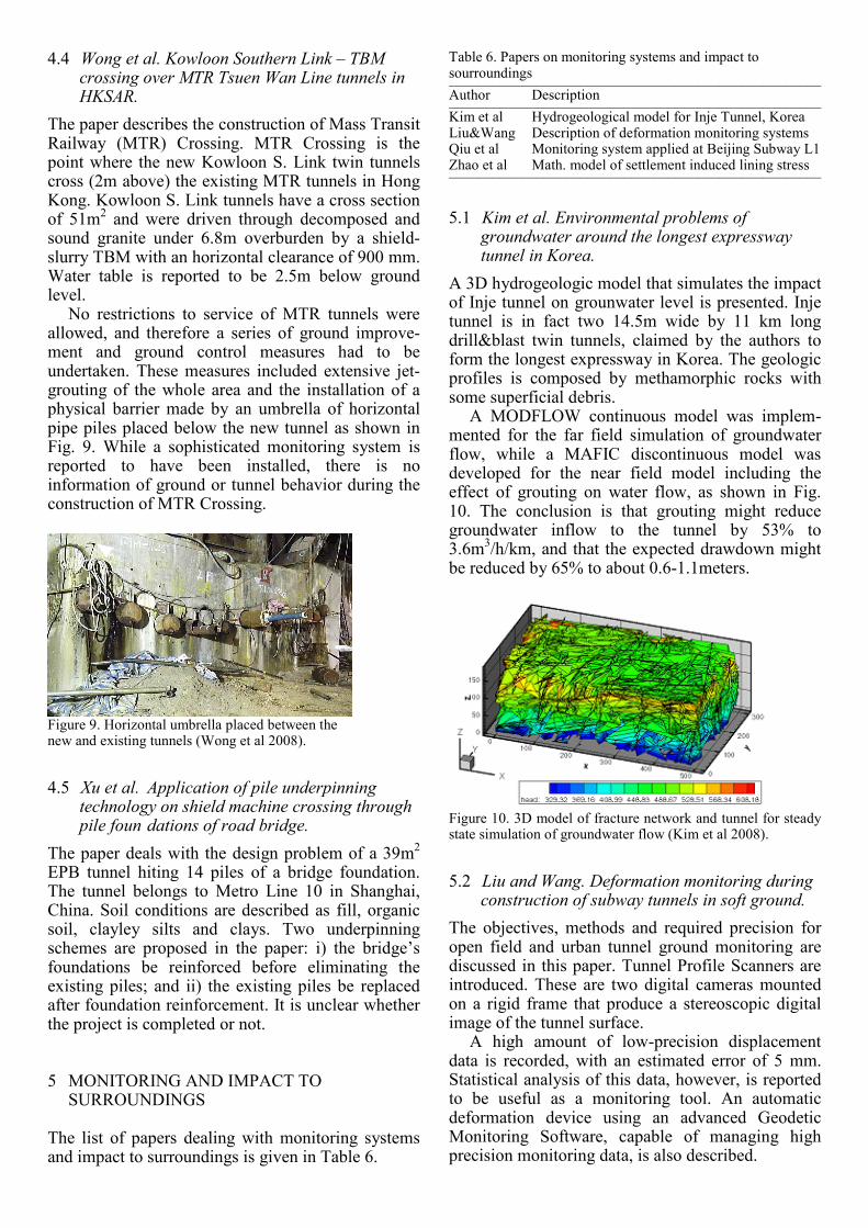
5.1 Kim et al. Environmental problems of groundwater around the longest expressway tunnel in Korea.
A 3D hydrogeologic model that simulates the impact of Inje tunnel on grounwater level is presented. Inje tunnel is in fact two 14.5m wide by 11 km long drill&blast twin tunnels, claimed by the authors to form the longest expressway in Korea. The geologic profiles is composed by methamorphic rocks with some superficial debris.
A MODFLOW continuous model was implem-mented for the far field simulation of groundwater flow, while a MAFIC discontinuous model was developed for the near field model including the effect of grouting on water flow, as shown in Fig. 10. The conclusion is that grouting might reduce groundwater inflow to the tunnel by 53% to 3.6m
3/h/km, and that the expected drawdown might
be reduced by 65% to about 0.6-1.1meters.
Figure 10. 3D model of fracture network and tunnel for steady state simulation of groundwater flow (Kim et al 2008).
5.2 Liu and Wang. Deformation monitoring during construction of subway tunnels in soft ground.
The objectives, methods and required precision for open field and urban tunnel ground monitoring are discussed in this paper. Tunnel Profile Scanners are introduced. These are two digital cameras mounted on a rigid frame that produce a stereoscopic digital image of the tunnel surface.
A high amount of low-precision displacement data is recorded, with an estimated error of 5 mm. Statistical analysis of this data, however, is reported to be useful as a monitoring tool. An automatic deformation device using an advanced Geodetic Monitoring Software, capable of managing high precision monitoring data, is also described.
5.3 Qiu et al. 3D deformation monitoring of subway tunnel.
The paper describes the application of LIDAR technology to Beijing Subway L1 tunnel. LIDAR technology allows for a rate of 3D data acquisition of 100.000 points/sec by 3D laser scanning. With this technology, expensive reflecting prisms do not need to be used and can be replaced by reflection sheets placed on the tunnel walls. NURBS (non uniform rational B splines) technology is used to interpolate the obtained data, and a mathematical model is developed for the analysis of the inform-ation. An example is given where a differential settlement of 0.29mm could be measured using this technology.
5.4 Zhao et al. Effect of long-term settlement on longitudinal mechanical performance of tunnel in soft soil.
The paper presents a structural model for the induced longitudinal stress developed in a segmental tunnel due to nonuniform settlements and apply the theory to a case history.
As reported by the authors, an unspecified highway shield tunnel 30yr old, settled/heaved up to 30mm in the last 10 years. The mathematical model was used to evaluate the structural performance of the tunnel based on longitudinal curvature radius R. It is concluded that R <27300m may induce leakage; stresses induced by R<18800m may fail segments; bolt yielding should be expected for R<15000m; and that tensile failure would probably occur for R<302m.
6 SUMMARY OF CASE HISTORIES RELATED TO PROJECTS IN SHANGHAI
Seven out of the twenty case histories presented at Session 3 are related to challenging underground projects in Shanghai, China. This is an unique opportunity to advance in technology and to calibrate design procedures for soft soils with valuable experimental evidence.
However, it must be noted that no complete and consistent description of Shanghai soils has been found among all papers. There is almost no information on basic index parameters like liquid limit, compression or recompression indexes and apparent OCR due to ageing.
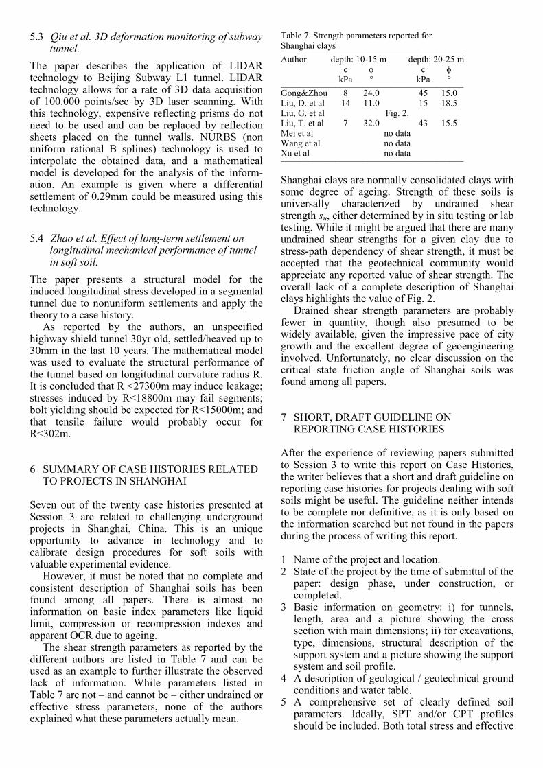
The shear strength parameters as reported by the different authors are listed in Table 7 and can be used as an example to further illustrate the observed lack of information. While parameters listed in Table 7 are not – and cannot be – either undrained or effective stress parameters, none of the authors explained what these parameters actually mean.
Table 7. Strength parameters reported for Shanghai clays ________________________________________ Author depth: 10-15 m depth: 20-25 m c φ c φ kPa ° kPa ° ________________________________________ Gong&Zhou 8 24.0 45 15.0 Liu, D. et al 14 11.0 15 18.5 Liu, G. et al Fig. 2. Liu, T. et al 7 32.0 43 15.5 Mei et al no data Wang et al no data Xu et al no data ________________________________________
Shanghai clays are normally consolidated clays with some degree of ageing. Strength of these soils is universally characterized by undrained shear strength su, either determined by in situ testing or lab testing. While it might be argued that there are many undrained shear strengths for a given clay due to stress-path dependency of shear strength, it must be accepted that the geotechnical community would appreciate any reported value of shear strength. The overall lack of a complete description of Shanghai clays highlights the value of Fig. 2.
Drained shear strength parameters are probably fewer in quantity, though also presumed to be widely available, given the impressive pace of city growth and the excellent degree of geoengineering involved. Unfortunately, no clear discussion on the critical state friction angle of Shanghai soils was found among all papers.
7 SHORT, DRAFT GUIDELINE ON REPORTING CASE HISTORIES
After the experience of reviewing papers submitted to Session 3 to write this report on Case Histories, the writer believes that a short and draft guideline on reporting case histories for projects dealing with soft soils might be useful. The guideline neither intends to be complete nor definitive, as it is only based on the information searched but not found in the papers during the process of writing this report.
1 Name of the project and location. 2 State of the project by the time of submittal of the
paper: design phase, under construction, or completed.
3 Basic information on geometry: i) for tunnels, length, area and a picture showing the cross section with main dimensions; ii) for excavations, type, dimensions, structural description of the support system and a picture showing the support system and soil profile.
4 A description of geological / geotechnical ground conditions and water table.
5 A comprehensive set of clearly defined soil parameters. Ideally, SPT and/or CPT profiles should be included. Both total stress and effective

stress shear parameters should be indicated, either as measured or estimated values. If other strength parameters are also reported, their meaning should be fully explained. For problems involving large subsidence or other compression-driven phenomena, compression parameters and material permeability should also be indicated.
6 A brief description of the construction process. 7 Description of ground behavior and unexpected
changes in ground conditions during construction activities.
8 Monitoring information when available, or a statement otherwise. Some amount of basic raw data should be included to better understand and use some derived parameters like Aδ, see Fig. 1. Fig 8 is a good example of information relevant to the subject being discussed.
9 For unusal equipments or construction proce-dures, some figures / pictures that better explain the idea, see Figs. 3 to 7 and 9.
10 For non conventional calculations and models, an illustrative picture, see Fig. 10.
In all cases, the source and degree of confidence of the provided information should be assessed.
A good example of reporting a case history can be found in a paper by Shao and Macari (Shao and Macari 2008), selected because it deals with a deep excavation in Shanghai clays. Twenty three key parameters identify each of the six main layers that form Shanghai soils profile, including water content and void ratio, classification data, shear and compression parameters, permeability and SPT values. (Shao and Macari 2008).
8 CONCLUSIONS
Session 3 of IS-Shanghai 2008 became an excellent opportunity to share experience related to under-ground construction in soft ground in challenging urban conditions.
Twenty papers from eight countries, dealing with open pit excavations, NATM and drill&blast tunnels, TBMs and shield tunnels, and monitoring systems were classified and summarized in this report. While the reported data is very valuable, some effort must be done to fully exploit it’s usability because no consistent procedure was followed by the authors to report ground conditions and ground behavior during construction activities.
A large amount of information was provided with respect to Shanghai soils, including laboratory, field tests and ground behavior during construction. Lack of definition of the reported parameters is judged to maje the interpretation of the reported information not easy. To allow for a better consistency and completeness of reported data, a short draft guideline on reporting case histories is proposed.
9 ACKNOWLEDGEMENTS
The writer wishes to acknowedge the authors of the summarized papers for sharing valuable information with the geo-community and the organizing comittee for inviting him to deliver this general report.
REFERENCES
Antiga, A. and Chiorboli, M. 2008. Tunnel face stability and settlement control using earth pressure balance shield in cohesionless soil. IS-039.
Eclaircy-Caudron, S., Dias, D. and Kastner, R. 2008. Displacements and stresses induced by a tunnel excavation: case of Bois de Peu (France). IS-107.
Gong, Q. and Zhou, S. 2008. Shield tunneling beneath existing railway line in soft ground. IS-013.
Guiloux, A., Le Bissonnais, H., Marlinge, J., Thiebault, H., Ryckaert, J., Viel, G., Lanquette, F., Erridaoui, A. and Hu, M. 2008. Case history on a railway tunnel in soft rock (Morocco). IS-367.
Hsiung, B. and Chuay, H. 2008. Observed behaviour of deep excavations in sand. IS-005.
Kim, S., Yang, H. and Yoon, S. 2008. Environmental problems of groundwater around the longest expressway tunnel in Korea. IS-087.
Konda, T., Ota, H., Yanagawa, T. and Hashimoto, A. 2008. Measurements of ground deformations behind braced excavations. IS-337.
Liu, D., Wang, R. and Liu, G. 2008. Research on the effect of buried channels to the differential settlement of building. IS-118.
Liu, G., Jiang, J. Ng, C. 2008. Performance of a deep excavation in soft clay. IS-082.
Liu, S. and Wang, Z. 2008. Deformation monitoring during construction of subway tunnels in soft ground. IS-120.
Liu, T., Liu, G. and Ng, C. 2008. The construction and field monitoring of a deep excavation in soft soils. IS-029.
Mei, Y., Jiang, X., Zhu, Y. and Qiao, H. 2008. Excavation entirely on subway tunnels in the central area of the People’s Square. IS-140.
Osborne, N., Ng, C. and Cheah, C. The benefits of hybrid ground treatment in significantly reducing wall movement: a Singapore case history. IS-378.
Qiu, D., Zhou, K., Ding, Y., Liang, Q. and Yang, S. 2008. 3D deformation monitoring of subway tunnel. IS-151.
Quick, H., Michael, J., Meissner, S. and Arslan, U. 2008. Challenging urban tunnelling projects in soft soil conditions. IS-358.
Shao, Y. and Macari, E. 2008. Information feedback analysis in deep excavations. ASCE Int. Jou. Geom. Vol. 8, 1, 91-103.
Wang, R. and Cai, Y. and Liu, J. 2008. Supervision and protection of Shanghai Mass Rapid Line 4 shield tunneling across the adjacent operating metro line. IS-033.
Wong, K. Ng, N., Leung, L. and Chan, Y. 2008. Kowloon Southern Link – TBM crossing over MTR Tsuen Wan Line tunnels in HKSAR. IS-370.
Xu, Q., Ma, X. and Ma, Z. 2008. Application of pile underpinning technology on shield machine crossing through pile foundations of road bridge. IS-326.
Yoo, C., Kim, S. and Lee, Y. 2008. Characteristics of tunneling-induced ground settlement in groundwater drawdown environment. IS-329.
Zhao, H., Liu, X., Yuan, Y. and Chi, Y. 2008. Effect of long-term settlement on longitudinal mechanical performance of tunnel in soft soil. IS-199.
Related Documents