isel Germany AG, D-36124 Eichenzell, Bürgermeister-Ebert-Str. 40 (06659)981-0 (06659)981-776 Servo – Power Unit iPU-DC iPU-EC Operating Instruction

Welcome message from author
This document is posted to help you gain knowledge. Please leave a comment to let me know what you think about it! Share it to your friends and learn new things together.
Transcript

isel Germany AG, D-36124 Eichenzell, Bürgermeister-Ebert-Str. 40 (06659)981-0 (06659)981-776
Servo – Power Unit
iPU-DC iPU-EC
Operating Instruction

iPU-DC / iPU-EC Operating Instruction
About this operating instruction Used shortcuts MRL machine directive 2006/42/EC ERL EMC directive 2004/108/EC NRL low voltage directive 2006/95/EC Used symbols You will find different symbols in this manual that signalizes important information/ facts and danger.
Warning! This symbol indicates dangers that cause damages for person’s health, physical injury or death.
Warning! Dangerous voltage! Warning of danger from electricity. Ignoring can lead to serious injury or death.
Attention! This Symbol indicates important notes. Ignoring this symbol leads to damages and malfunctions of the machinery
Information: This symbol indicates important information and notes.
Observe the safety instructions
Before you take the servo power unit iPU-DC/iPU-EC in operation, working with the controller or make additions or changes to the wiring of the, make sure to read carefully the safety instructions in this manual. (Chapter 1.2)

iPU-DC / iPU-EC Operating Instruction
All information, technical data and dimensions contained in this booklet correspond to the technical state at the moment of publication. However, possible misprints or mistakes cannot be ruled out. We will appreciate all suggestions for improvement and error notes. We would like to point out that all used software and hardware names of the respective companies generally are subject to protection by brand, trademark and patent law. All rights reserved. It is prohibited to process, duplicate or reproduce this booklet partially or on the whole in any form (print, copy, or other procedure) without written
permission of isel Germany AG. This booklet has been translated from the original German version into English language. It does not lay claim to completeness nor flawlessness. In case of doubt the German original has validity.
isel controllers are concurrent with CE norms and marked accordingly. Commissioning of all other parts or components, for which CE safety regulations apply, is prohibited until all respective requests are met.
isel Germany AG as the manufacturer cannot take over guarantee if you change the controller in any way.
The EMC test is valid only for the controller’s original configuration ex works, i.e. the delivery state.
Manufacturer: isel Germany AG Bürgermeister-Ebert-Straße 40 D-36124 Eichenzell Tel.: (06659) 981-0 Fax: (06659) 981-776 Email: [email protected] http://www.isel.com Item-No.: 354000 xxxx
(Translation of operation instruction in German language) Revisions Date of
change Reason for change Changed by
a 06/01/2015 Serial number RL
07/2014 First print
Technical changes reserved.
Latest operating instructions and manuals for download, visit: www.isel-data.de/manuals
iPU-DC / iPU-EC Operating Instruction
Table of contents
1 Introduction .......................................................................................................... 5
1.1 Intended use .................................................................................................... 5
1.2 Safety instructions............................................................................................ 6
2 Types ..................................................................................................................... 8
3 Technical data ...................................................................................................... 9
4 Hardware description ......................................................................................... 10
4.1 Controller front side iPU-DC / iPU-EC .............................................................10
4.2 Controller back side iPU-DC / iPU-EC ............................................................12
4.4 Assembly iPU-DC / iPU-EC ............................................................................19
5 Initial operation ................................................................................................... 20
6 Software .............................................................................................................. 22
6.1 Installing setup software .................................................................................22
6.2 ProNC / Remote installation and first steps ....................................................24
8 EC - Declaration of Conformity ......................................................................... 27
9 Bibiography ........................................................................................................ 28
10 Index .................................................................................................................... 28

iPU-DC / iPU-EC Operating Instruction
page - 5
1 Introduction The iPU power units are powerful drive controllers for up to four linear or circular axes with brush or brushless motors. The compact controller The table or the 19” HE housing integrates all necessary controller components, which are needed to solve a wide range of automation tasks. As its interface for NC control, the iPU power unit has a CANopen interface at the back of the housing, which works according to the DS301 bus protocol and DS402. By using the optional CAN PCI board iCC 10 or a iPC series control computer, the controller can control interpolation (linear, circular, helical) of all four axes as well as track processing. The final output stages (iMD10 or iMD20) also have automatic jerk limitations and rest state monitoring. The control elements integrated in the front of the housing, such as EMERGENCY SHUTDOWN, START or STOP enable convenient operation. 1.1 Intended use
Die control unit iPU-DC/iPU-EC integrates motor power amplifiers, I/O module and security circuit module. The power units have to be used in connection with an isel CANopen PCI-card (iCC10, iCC20) that works as CAN master in the control computer. The card communicates with the power amplifiers for the axes and other CAN peripheral devices such as I/O-module. The CNC Motion control allows the interpolation of up to 4 axes (linear, circular and helix), on-line and look ahead continuous path (CP) machining as well as the control of up to 4 handling axes. The CAN-servo units series iPU-DC are able to drive up to 4 brushed DC-servo-motors. The used power amplifiers type iMD10 have a jerk limit and standstill monitoring (till safety category 3). Control units series iPU-EC are able to drive up to46 brushless DC-servo-motors. The used power amplifiers type iMD20 have a jerk limit and standstill monitoring (till safety category 3).
All axis of the controller have to be used only with the compatible motor type. Please read this operation instruction manual carefully before first use of the controller therewith you can: • Work safely, fast and effective • Keep away danger from persons • Use all the power and features of the controller.
iPU-DC / iPU-EC Operating Instruction
page - 6
1.2 Safety instructions
The CNC-controllers iPU-DC and iPU-EC are designed in conformability to current technical and recognized rules.
The device may only be used if it is in correct condition. Any faults
have to be eliminated immediately. Neither children nor non-authorized persons are allowed to put the device into operation.
The device may only be used for the intended purpose: control of 2
up to 6 linear or rotational axes with brushed DC Servo (iPU-DC) or brushless DC servo motors (iPU-EC), both motor types with integrated incremental measurement system (encoder).
All work with the controllers iPU-DC and iPU-EC, especially initial
operation, installation as well as external wiring must be executed by authorized personal regarding electrical industry rules and accident prevention regulations.
Assembly and use of operating material has to be according to
Machine directive 2006/42/EC/EC and Low voltage directive 2006/95/EC. In case of in proper use even the observation of the respective rules and standards does not protect against physical damages and damage to property.
Do not expose the device to high humidity or high vibrations.
Please take care of the instruction manual. Be sure that all users
know the instructions.
Ignoring the instruction manual can lead to damage, heavy physical damage or to death.

iPU-DC / iPU-EC Operating Instruction
page - 7
Warning! High earth leakage current (ground discharge current, protection conductor current). Before connecting to the AC supply network, it is necessarily required an additional protective grounding. Before connecting the CNC controller to the AC supply network, an additional protective grounding (cross section: 2.5 mm2 or 4 mm2, see below) has to be connected! Before the electrical start-op of the controllers a protective grounding of 2.5 mm2 (protected installation) or a protective conductor of 4 mm2 (unprotected installation) has to be connected durably to the marked clamping point
at the back of the housing where the cross section of the protective grounding shall not be less than 10 mm2 copper or 16 mm2 aluminum has (e.g. electrical distribution of the building). Please instruct an electrician with these implementation. When using the Residual Current circuit Device (RCD) for line fuses/fault current delimitation: Do not use an RCD with AC characteristics. Using a frequency inverter and choppered power stages in the power units may cause superimposed AC fault units with pulsating direct current and direct current apart from AC fault currents. Please consult your electrician.
The term leakage is understood here as grounding discharge current. This is defined in the standard EN 60204-1:2006 section 8.2.8, note 1
If the CNC machine (ideal) is set up isolated from the reference potential, the grounding discharge current is equal to the protective grounding stream.

iPU-DC / iPU-EC Operating Instruction
page - 8
2 Types
type servo motor amplifiers max. axis
iPU-DC BDC-servo motors (brushed) iMD10 4
iPU-EC BLDC-servo motors (brushless) iMD20 4
Scope of delivery iPU-DC (part.-no. 353000 X101X2)
Power unit iPU-DC as table housing or 19“ 4 HE housing with the following electronic components:
o max 4 integrated power amplifiers iMD10 for brushed DC servo motors /1/
o CAN IO 8-12 / 4-1 module o Safety circuit module iSM5 o power unit 24V-60W, 48V-1000W
main lead (protection contact plug, IEC-60320 power connector)
CAN bus connection cable, RJ45 plugplug
connector package
control software Remote from Version 1.46.2.1 (optional: ProNC)
operating instruction in printed form
Scope of delivery iPU-EC (Art.-Nr. 353000 X102X2)
Power unit iPU-DC as table housing or 19“ 4 HE housing with the following electronic components:
o max 4 integrated power amplifiers iMD20 for brushed DC servo motors /1/
o CAN IO 8-12 / 4-1 module o Safety circuit module iSM5 o power unit 24V-60W, 48V-1000W
main lead (protection contact plug, IEC-60320 power connector)
CAN bus connection cable, RJ45 plugplug
connector package
control software Remote from Version 1.46.2.1 (optional: ProNC)
operating instruction in printed form
1 case 1 … 19“ 4HE housing, 2 … table housing
2 Number of axis: 2 …4

iPU-DC / iPU-EC Operating Instruction
page - 9
3 Technical data
controller iPU-DC iPU-EC
servo-motor type BDC servo motors (DC brushed) BLDC servo motors (DC brushless)
maximum number of axis 4 4
power supply input 100 - 230 VAC, 50 … 60 Hz 100 - 230 VAC, 50 … 60 Hz
Fuses 2 x 6.3A (inert)
power supply output 1000 W 1000 W
motor power amplifier iMD10 iMD20
intermediate circuit power supply
48 VDC 48 VDC
rated current 12 A 12 A
peak current 25 A 25 A
safety characteristic: EN ISO 13849-1:2006 category 3, PL d
additional safety functions integration in higher ranked security circuit , safety door control, working spindle control
I/O module
4 x digital inputs (24VDC/8mA) 8 x digital outputs (4 x electronic Imax<350mA, 4 x relay Imax <5A)
1 x 115-230V relay output (max. 6 A) 1 x analog output (8 Bit, 0 …10 V)
control elements function buttons, switches, emergency stop
control software Remote (optional: ProNC, isyCAD/CAM)
dimensions L x W x H 625 x 225 x 375 625 x 225 x 375

iPU-DC / iPU-EC Operating Instruction
page - 10
4 Hardware description 4.1 Controller front side iPU-DC / iPU-EC
1 - operation mode switch (key switch) Use this switch to choose between automatic- and setup-mode.
In automatic-mode you can only open the cover or safety door of the machine if no axis is in motion and the mounted working spindle is switched off (means that spindle does not turn). In the setup-mode you can only open the cover or safety door of the machine if the mounted working spindle is switched off (means that spindle does not turn). You can just move the axes at opened cover or safety door if you press the ACK button. Ensure that in setup-mode (key switch on TEST) only authorized personal operates on the machine.
2 - cover-button
Use this button to open the machines cover or safety door. This is possible only if the conditions from point “3 – operation mode switch“ are complied. An enable for opening of the cover or safety door is signalized by a white lighted cover button.
3 - start-button
If you press the start button an opened user program in the operator software ProNC (ISO-, PAL- or NCP-file) resp. user program in control software Remote (ISO-, NCP- or CNC-file) will be started.
If there is no user program opened a dialog window is shown where you can select an user program.
4 - fault-lamp
The fault lamp indicates an error within the safety circuit.

iPU-DC / iPU-EC Operating Instruction
page - 11
5 - ACK (ACKnowledge-button)
Press this button to move the axes when the machine is in setup-mode and the cover or safety door is open.
6 - stop-button
With the stop button you can stop a running user program / axis motion. By pressing the start button you can continue the execution of the user program. 7 - power-button
Use this button to switch on motor power supply voltage for the motor power amplifiers. Conditions for switch on: - Main power switch on the controller back side is switched on - Emergency stop button is pulled out
If power supply voltage is successfully switched on the power button is lighted green. 8 - emergency-stop-switch
Turns off the power supply for the motor power amplifiers and the working spindle in case of any danger. This means dangers for the users health or machine safety.
9 - Main switch (if mounted) Switch on net power supply voltage for the controller. The switch is lighted green if device is powered.
If you push the emergency stop switch any axes motion will be slow down controlled and the motor power supply will be time lag switched off (stop category 1). The main power supply voltage of 115/230VAC lies still on the device, only the motor power supply voltage for the amplifiers is switched off.

iPU-DC / iPU-EC Operating Instruction
page - 12
4.2 Controller back side iPU-DC / iPU-EC
Connectors for motor-, encoder- and signal leads
iPU-DC - motor, encoder and signal leads
motor connector (X, Y, Z, A, B, C), 8+1-pin M23 socket
pin signal lead no. description
1 1 1 motor phase 1*
2 2 2 motor phase 2*
3 1 3 motor phase 1*
4 2 4 motor phase 2*
5 brake brown motor brake
6 brake_GND white motor brake GND
7 ---
8 ---
9 PE yellow / green protected earth
* every motor phase is connected via two leads
encoder / signal connector, 15-pin Sub-D socket
pin signal lead color description
1 n.c
2 VCC_Encoder red digital +5V DC
3 /ENC_Z orange / black encoder line /Z
4 /ENC_B brown / black encoder line /B
5 /ENC_A grey / black encoder line /A
6 VCC_Logik logic +24V DC
7 LIMIT_SW1 limit switch 1
8 GND_24V Logik GND
9 n.c white
10 D_GND black digital GND
11 ENC_Z orange encoder line Z
12 ENC_B brown encoder line B
13 ENC_A grey encoder line A
14 REF_SW reference switch
15 LIMIT_SW2 limit switch 2

iPU-DC / iPU-EC Operating Instruction
page - 13
iPU-EC - motor, encoder and signal leads
motor connector (X, Y, Z, A, B, C), 8+1-pin M23 socket
pin signal lead no. description
1 U black 1 motor phase U
2 V black 2 motor phase V
3 W black 3 motor phase W
4 ---
5 brake brown motor brake
6 brake_GND white motor brake GND
7 ---
8 ---
9 PE yellow / green protected earth
encoder / signal connector, 15-pin Sub-D socket
pin signal lead no. description
1 HALL_A _IN yellow Hall Signal A
2 VCC_Encoder red Digital +5V DC
3 /ENC_Z orange / black Encoderspur /Z
4 /ENC_B brown / black Encoderspur /B
5 /ENC_A grey / black Encoderspur /A
6 VCC_Logik Logik +24V DC
7 LIMIT_SW1 Endlagenschalter 1
8 GND_24V Logik GND
9 HALL_B_IN white Hall Signal B
10 D_GND black Digital GND
11 ENC_Z orange Encoderspur Z
12 ENC_B brown Encoderspur B
13 ENC_A grey Encoderspur A
14 HALL_C_IN green Hall Signal C
15 LIMIT_SW2 Endlagenschalter 2

iPU-DC / iPU-EC Operating Instruction
page - 14
hand control unit - 25-pin Sub-D (optional version)
This connector is only available on controller without integrated function keys in the case front. It is possible to connect function keys (switches, buttons) from:
- an external hand control unit
- an isel CNC control panel with the corresponding connectors on the security circuit module inside the controller case.
pin signal description
1 E-STOP_1 Emergency stop channel 1, 1.1
2 E-STOP_1 Emergency stop channel 1, 1.2
3 E-STOP_2 Emergency stop channel 2, 2.1
4 E-STOP_2 Emergency stop channel 2, 2.2
5 24V +24 V DC
6 POWER BTN Input power button
7 POWER LAMP Output power button lamp
8 24V +24VDC
9 KEY SWITCH Test Input key switch test mode
10 KEY SWITCH Auto Input key switch automatic mode
11 24V +24VDC
12 ACK_1 Input acknowledge button channel1
13 24V +24VDC
14 ACK_2 Input acknowledge button channel 2
15 COVER SWITCH Input cover button
16 COVER SWITCH Input cover button
17 GND
18
19
20 FAULT LAMP output FAULT lamp
21 START BTN Input START button (make contact)
22 STOP BTN Input STOP button (break contact)
23 START LAMP Output START lamp
24 STOP LAMP Output STOP lamp
25 n.v.
The maximum length of the connection cable for the hand control unit / CNC control panel should not exceed 5m.

iPU-DC / iPU-EC Operating Instruction
page - 15
External additional control console connector - 15-pin Sub-D (optional)
This connector is used if an additional isel control console is used.
pin signal description
1 EM_STOP_1 Emergency stop channel 1, connector 1.1
2 EM_STOP_1 Emergency stop channel 1, connector 1.2
3 EM_STOP_2 Emergency stop channel 2, connector 2.1
4 EM_STOP_2 Emergency stop channel 2, connector 2.1
5 GND GND control console
6 LAMP ACK Output ACK lamp
7 ACK_1 Acknowledge channel 1, connector 1.1
8 ACK_1 Acknowledge channel 1, connector 1.2
9 ACK_2 Acknowledge channel 2, connector 2.1
10 ACK_2 Acknowledge channel 2, connector 2.2
11 COVER_1 Connector for cover button, connector 1.1
12 COVER_1 Connector for cover button, connector 1.2
13 COVER_2 Connector for cover button, connector 2.1 (option)
14 COVER_2 Connector for cover button, connector 2.1 (option)
15 n.v.
The maximum length of the connection cable for the hand control unit / CNC control panel should not exceed 5m.
External Spindle – SubD-9-pin
Use this connetor to get the signals for driving an external frequency converter for an main spindle drive.
pin signal description
1 VCC +24V DC
2 SPINDLE_FAULT Input frequency converter fault (LOW activ)
3 - n.u.
4 - n.u.
5 ANALOG_OUT analog out 0 …10V (8 bit resolution)
6 ANALOG_GND analog GND
7 - n.u.
8 SPINDLE_START uutput spindle start
9 GND GND (digital)

iPU-DC / iPU-EC Operating Instruction
page - 16
Digital input port - 8-pin, bottom to top E1.1 – E1.4
The mounted I/O board has two digital input ports each with 8 digital inputs. The first input port (E1.1 – E1.8) is partly internal used for signalization. The digital inputs E1.1 – E1.4 can free configured by the user. Properties - opt coupled inputs - input current ca. 8mA
Wiring
pin input description
1 In 1 input E1.1
2 VCC +24VDC
3 In 2 input E1.2
4 VCC +24VDC
5 In 3 input E1.3
6 VCC +24VDC
7 In 4 input E1.4
8 VCC +24VDC
Please note the default connection of the second input –port (I1.5 – I1.8) in the control software Remote / ProNC under the menu entry „Signalization“. These inputs are directly wired with the modules inside the controller. You cannot longer use these inputs in the user program!
Digital electronic outputs - 8-pin, bottom to top A1.1 – A1.4
The mounted I/O board has two digital output ports each with 8 digital switches. The first output port (A1.1 – A1.8) is partly internal used for signalization. The outputs A1.1 – A1.4 can used to switch different actors. Properties - 8 x electronic outputs
- Imax < 350mA, 24VDC - Thermic protection
- short circuit proof
Wiring
pin output description
1 Out1 Output A1.1
2 GND GND
3 Out2 output A1.2
4 GND GND
5 Out3 Output A1.3
6 GND GND
7 Out4 Output A1.4
8 GND GND

iPU-DC / iPU-EC Operating Instruction
page - 17
Please note the default connection of the first output –port (A1.1 – A1.8) in the control software Remote / ProNC under the menu entry „Signalization“. These outputs are directly wired with the modules inside the controller. You cannot longer use these outputs in the user program! By using intuctance, an free-wheeling diode is necessarily.
Digital relay outputs - 8-pin, bottom to top A2.1 – A2.4
The mounted I/O board has a second digital output port with four other relay outputs. The second output port (A2.1 – A2.8) is partly internal used. The outputs A2.1 – A2.4 can freely used to switch different actors. Properties - 4 x digital rely outputs
- Imax < 5 A, 24VDC - Thermic protection
- short circuit proof
Wiring
pin output description
1 Out1 Output A2.1
2 GND GND
3 Out2 output A2.2
4 GND GND
5 Out3 Output A2.3
6 GND GND
7 Out4 Output A2.4
8 GND GND
Remote- security circuit interface, 8-pin, bottom to top
Use this connector to include the controller into a higher ranked security circuit system. Furthermore, this interface provides the functions of the front control buttons (START, STOP) as a function of an external remote control panel or other device via I / O functions.
pin signal description
1 E_STOP_1_1 external emergency STOP, channel 1, connector 1.1
2 E_STOP_1_2 external emergency STOP, channel 1, connector 1.2
3 E_STOP_2_1 external emergency STOP, channel 2, connector 2.1
4 E_STOP_2_2 external emergency STOP, channel 2, connector 2.2
5 EXT_START external START button (option to E1.7 on CAN IO)
6 EXT_STOP external STOP button (option to E1.8 on CAN IO)
7 VCC +24V for switches
8 VCC +24V for switches

iPU-DC / iPU-EC Operating Instruction
page - 18
AC-Input – net input module 115 -230 VAC, 50 …60 Hz
The net input module consists of net input socket, net filter, fuse holder and net main switch. Connect the controller via delivered net cable to a free receptacle. After that you can switch on the controller with the net main switch.
Spindle -115V/ 230V connector
Use this output connector to directly tap a working spindle without speed control. Use the delivered mating connector. Maximum load of the relay output is 115/230 V AC / 6A. The spindle start signal is switched by the integrated CAN-I/O-module and will be analyzed by the security-circuit-module (iSM5). If all safety related conditions are complied the 115/230 V AC voltage is switched on the connector.
Please note the pin assignment for the spindle start signal in the table for the CAN-I/O-module in chapter 4.2.4.2
The net input module consists of net input socket, net filter, fuse holder und net main switch. Connect the controller via delivered net cable to a free receptacle. After that you can switch on the controller with the net main switch.
Cover - Sub-D9-pin connector
This connector is used to integrate a solenoid interlock to the security circuit of the controller.
On isel machines the solenoid interlock is realized by a switch of type: SCHMERSAL EX-AZM 170-02ZK-24V (part-no. 577047 0800) Only this type interlocks or interlocks with the same functionality have to be used.
pin description
1 + coil break contact
2 switch 1.1 (bridge to pin 3 if no safety door is used)
3 switch 1.2 (bridge to pin 2 if no safety door is used
4 switch 2.1 (bridge to pin 5 if no safety door is used
5 switch 2 .2 (bridge to pin 4 if no safety door is used
6 - coil break contact
7 - 9 n.u.
If no cover or safety door is used the pins 2, 3 and 4, 5 must be bridged. Therefore use the enclosed Sub-D 9-pin plug.
If the contacts of the interlock is interrupted (e.g. forcible opening of the hood or remove the jumper, Sub-D) will immediately trigger an emergency stop and turned off the spindle.

iPU-DC / iPU-EC Operating Instruction
page - 19
4.4 Assembly iPU-DC / iPU-EC
iSM 5 security circuit module
function keys module for control elements
(buttons, switches) on the front side of the controller
power amplifier iMD10 on iPU-DC
for brushed DC servo-motors
iMD20 on iPU-EC for brushless DC
servo-motors
power supply unit 100-230VAC,
24V DC 60W for logic
power supply unit 100- 230VAC, 48V DC 1000W
für Endstufen
CAN I/O-8/12-4/1 I/O module
Chopper module with brake resistor
E/A Modul

iPU-DC / iPU-EC Operating Instruction
page - 20
5 Initial operation Voraussetzungen für den Betrieb des Controllers The power units iPU DC / iPU -EC have intelligent CAN modules such as poweramplifiers for controlling motors . To communicate with the modules you need a CAN master controller iCC10 (Item No. 320310 ) or iCC20 (Item No. 320310 ) as a PCI card . Insert the PCI card iCC10 / iCC20 into a free PCI slot in your PC. The drivers for the CAN PCI card is located on the volume containing the installation files from ProNC / Remote in directory:
{root:}\Control\CAN\CAN_PCI_Driver_1_Channel
In its subdirectories contains drivers for various Windows operating systems. When the computer starts you will be prompted to select the driver to install . Alternatively, you can install the driver via the device manager of the operating system. Preparation
Before power up of the controller please check the scope of delivery. Following parts should be included:
- net cable - operating instruction - CAN bus communication cable RJ45 plug RJ45 plug
Make all necessary connections:
- connect net cable - connect motor- and encoder-lines (motors) with the connectors on the back
side of the controller - connect communication cable between CAN PCI card and controller iPU-
DC/iPU-EC - check all other connection cables

iPU-DC / iPU-EC Operating Instruction
page - 21
Initial operation - switch on controller main switches on front side and back side the main switch on the front side should be lighted green
- install control software (if not preinstalled)
ProNC (1) or Remote
- install setup software (if not preinstalled) DCSetup (2) ACSetup (1)
- check if Emergency stop switch is pulled
- push Power button on the controller front side – motor power amplifier voltage
should be switched on
- parameterize power amplifiers with ACSetup.exe / DCSetup.exe - setup axes kinematic of your machine/system with CANSet.exe
- Control/operate the connected axes with the control- and programming
software ProNC or Remote

iPU-DC / iPU-EC Operating Instruction
page - 22
6 Software
6.1 Installing setup software Setup / initial operation of the integrated power amplifiers inside the controller’s iMC-B, iMC-V and iMC-VP takes place by the following setup software DCSetup.exe (4) for:
- BDC-servo-motors (brushed-DC-servos) with motor power amplifiers iMD10
or
ACSetup.exe (2) for:
- BLDC-servo-motors (brushless-DC-servos) with motor power amplifiers iMD20
Do the following steps to install setup software additional: 1. Connect ProNC/Remote install medium (delivered CD or USB stick) with the
control computer.
2. Following Auto-start-window will be shown (when installing from CD):
If Auto-Start-window is not shown start the Windows Explorer and open the root directory of the CD/DVD- or USB-drive. Double click on the file “Autorun.exe“.

iPU-DC / iPU-EC Operating Instruction
page - 23
3. Click on the entry “Installation of control software“. The following window will be shown:
Choose now the setup software depending on your motor type and click on the entry to start the installation. (in this example “Installation of ACSetup“) Follow the instructions of the setup assistant. After finishing the installation click on button “Exit“ to close the Auto-Start-menu. Start DCSetup.exe / ACSetup.exe via the desktop shortcut or via the start menu entry: Start Programs ACSetup ACSetup / DCSetup
Information on parameterization of motor power amplifiers iMD10 you will find in the manual /1/ DC-Servo positioning module with CANopen interface UVE8112 / iMD10. Therefore open the file “dcsetup_eng.pdf “ via shortcut in the start menu. Information on parameterization of motor power amplifiers iMD20 you will find in the manual /2/ AC-Servo positioning module with CANopen interface iMD20 / iMD40. Therefore open the file “acsetup_eng.pdf “ via shortcut in the start menu.

iPU-DC / iPU-EC Operating Instruction
page - 24
6.2 ProNC / Remote installation and first steps Operation of the controller iMC-B / iMC-V takes place either with the control software Remote or with the control / programming software ProNC. If there is no operation software installed ex factory do the following steps to install the software later: 1. Connect ProNC / Remote install medium (delivered CD or USB stick) with the
control computer.
2. Following Auto-start-window will be shown (when installing from CD):
If Auto-Start-window is not shown start the Windows Explorer and open the root directory of the CD/DVD- or USB-drive. Double click on the file “Autorun.exe“.
iPU-DC / iPU-EC Operating Instruction
page - 25
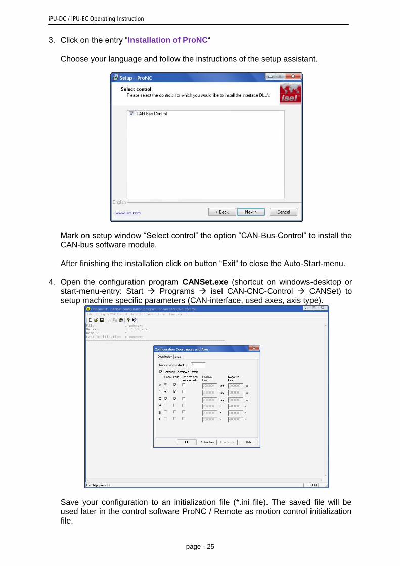
3. Click on the entry “Installation of ProNC“ Choose your language and follow the instructions of the setup assistant.
Mark on setup window “Select control“ the option “CAN-Bus-Control“ to install the CAN-bus software module. After finishing the installation click on button “Exit“ to close the Auto-Start-menu.
4. Open the configuration program CANSet.exe (shortcut on windows-desktop or start-menu-entry: Start Programs isel CAN-CNC-Control CANSet) to setup machine specific parameters (CAN-interface, used axes, axis type).
Save your configuration to an initialization file (*.ini file). The saved file will be used later in the control software ProNC / Remote as motion control initialization file.
iPU-DC / iPU-EC Operating Instruction
page - 26
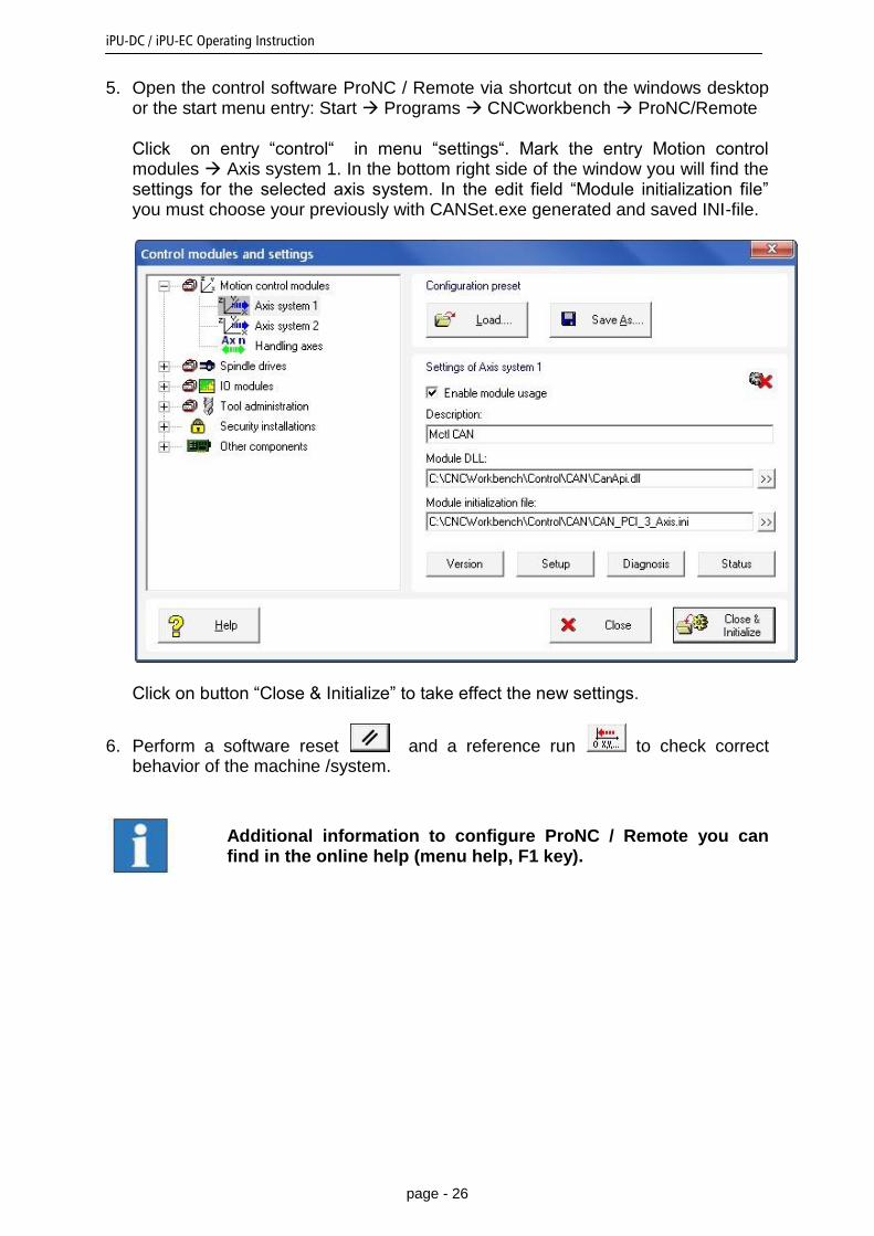
5. Open the control software ProNC / Remote via shortcut on the windows desktop or the start menu entry: Start Programs CNCworkbench ProNC/Remote Click on entry “control“ in menu “settings“. Mark the entry Motion control modules Axis system 1. In the bottom right side of the window you will find the settings for the selected axis system. In the edit field “Module initialization file” you must choose your previously with CANSet.exe generated and saved INI-file.
Click on button “Close & Initialize” to take effect the new settings.
6. Perform a software reset and a reference run to check correct behavior of the machine /system.
Additional information to configure ProNC / Remote you can find in the online help (menu help, F1 key).
iPU-DC / iPU-EC Operating Instruction
page - 27
8 EC - Declaration of Conformity Der Hersteller The manufacturer
isel Germany AG Bürgermeister-Ebert-Str. 40 D-36124 Eichenzell
erklärt hiermit, dass folgendes Produkt hereby declares that the following product
Geräteart: isel Leistungseinheit Device: isel power unit
Typ: iPU-DC / iPU-EC Type:
Art.-Nr.: iPU-DC: 354000 10X0
Product - No.: iPU-EC: 354000 20X0 Serien-Nr.: Serial-no.: _______________
mit den Vorschriften folgender Europäischer Richtlinien übereinstimmt: complies with the requirements of the European Directives:
EG-Richtlinie 2004/108/EG EC-Directive 2004/108/EC
EMV Richtlinie EMC directive
EG-Richtlinie 2006/95/EG EC-Directive 2006/95/EC
Niederspannungsrichtlinie low voltage directive
Folgende harmonisierte Normen wurden angewandt: Following harmonized standards have been applied:
EN 61000-6-2:2005 EMV - Fachgrundnorm - Störfestigkeit für Industriebereich
EMC - Generic standards - Immunity for industrial environments EN 61000-4-2:2008 EMV - Prüf- und Messverfahren - Prüfung der Störfestigkeit gegen Entladung
statischer Elektrizität (ESD)
EMC - Testing and measurement techniques; Electrostatic discharge immunity test
EN 61000-4-4:2012 EMV - Prüf- und Messverfahren - Prüfung der Störfestigkeit gegen schnelle transiente elektrische Störgrößen (Burst)
EMC - Testing and measurement techniques - Electrical fast transient/burst immunity test
EN 61000-4-5:2007 EMV - Prüf- und Messverfahren - Prüfung der Störfestigkeit gegen energiereiche Impulse (Surge)
EMC - Testing and measurement techniques - Surge immunity test
EN 61000-4-11:2005 EMV - Prüf- und Messverfahren - Prüfung der Störfestigkeit gegen Spannungs-einbrüche / Spannungsunterbrechungen
EMC - Testing and measurement techniques - Voltage dips, short interruptions and voltage variations immunity tests
EN 61000-6-3:2011 EMV - Fachgrundnorm - Störaussendung Wohn- und Geschäftsbereich, Kleinbetriebe EMC - emission standard for residential, commercial and light-industrial environments
DIN EN 55011:2011 Industrielle, wissenschaftliche und medizinische Hochfrequenzgeräte (ISM-Geräte) - Funkstörungen - Grenzwerte und Messverfahren
Industrial scientific and medical (ISM) radio-frequency equipment - Electromagnetic disturbance characteristics - Limits and methods of measurement
EN 60204-1:2006
Sicherheit von Maschinen – Elektrische Ausrüstung von Maschinen – Teil 1: Allgemeine Anforderungen
Safety of machinery – Electrical equipment of machines – Part 1: General requirements
Dermbach, 16.07.2014
Werner Kister, Vorstand / managing board

iPU-DC / iPU-EC Operating Instruction
page - 28
9 Bibiography /1/ isel Germany AG. Positioning module with CANOpen interface UVE8112 / iMD10. 03/2008. /2/ isel Germany AG. Positioning module with CANOpen interface iMD20 / iMD40. 03/2009. /3/ isel Germany AG. ProNC operating instruction 2003. Operating instructions and manuals for download you can find here:
www.isel-data.de/manuals
10 Index
A
ACK 11 ACSetup.exe 22
B
BLDC-Servomotoren 8 brushed 5
C
CANSet.exe 21 control console 15 Cover 18 Cover button 10
D
DCSetup.exe 22
E
Encoder 12, 13
H
harmonisierte Normen 27
I
iMD20 9 Installation software 22 intended use 6
L
Low voltage directive 6
O
Operation mode switch 10
P
ProNC 21
R
Remote 21
S
Software 22
Related Documents