E 5.94035.09a Operating Instructions Servo-Power-Unit BUS 621, 622, 623, 624

Welcome message from author
This document is posted to help you gain knowledge. Please leave a comment to let me know what you think about it! Share it to your friends and learn new things together.
Transcript

E 5.94035.09a
Operating Instructions
Servo-Power-Unit BUS 621, 622, 623, 624

Title Operating Instructions
Product Servo-Power-Unit BUS 621, 622, 623, 624
Version 5.94035.09a
Issue date 10.09.09
Part no. 228950
Copyright These operating instructions may be copied by the owner in any quantity but only for internal use. For other purposes these operating instructions and extracts thereof must not be copied or reproduced. Use and disclosure of information contained in these oper-ating instructions are not permitted. Designations and company marks contained in these op-erating instructions may be brand names, the use of which by third parties for their own purposes may violate the rights of the holders.
Obligatory These operating instructions are part of the equipment/ma-chine. These operating instructions must be available to the operator at all times and must be in a legible condition. If the equipment/machine is sold or moved to a different lo-cation these operating instructions must be passed on by the owner together with the equipment/machine. After any sale of the equipment/machine this original and all copies must be handed over to the buyer. After disposal or any other end of use this original and all copies must be destroyed.
When the present operating instructions are handed over, corresponding sets of operating instructions of a previous version are automatically invalidated. Please notice that specifications/data/information are current values ac-cording to the printing date. These statements are not legally binding according to the measurement, computa-tion and calculations. Baumüller Nürnberg GmbH reserves the right, in develop-ing its products further, to change the technical specifica-tions and the handling of the products concerned without prior notice.
No liability can be accepted concerning the correctness of the operating instructions unless otherwise specified in the General Conditions of Sale and Delivery.
Manufacturer Baumüller Nürnberg GmbH Ostendstr. 80 - 90 D-90482 Nürnberg Germany Tel. +49 9 11 54 32 - 0 Fax: +49 9 11 54 32 - 1 30 www.baumueller.de

Inhaltsverzeichnis
1 Introduction . . . . . . . . . . . . . . . . . . . . . . . . . . . . . . . . . . . . . . . . . . . . . . . . . . . . . . . . . . . . . . 5
1.1 Overview of the equipment series Servo-Power-Unit BUS 621, 622, 623, 624 . . . . . . 51.2 First Steps . . . . . . . . . . . . . . . . . . . . . . . . . . . . . . . . . . . . . . . . . . . . . . . . . . . . . . . . . . . 61.3 Terms used . . . . . . . . . . . . . . . . . . . . . . . . . . . . . . . . . . . . . . . . . . . . . . . . . . . . . . . . . . 6
2 Fundamental safety instructions . . . . . . . . . . . . . . . . . . . . . . . . . . . . . . . . . . . . . . . . . . . . . 7
2.1 General notes . . . . . . . . . . . . . . . . . . . . . . . . . . . . . . . . . . . . . . . . . . . . . . . . . . . . . . . . 72.2 Hazard information and commands. . . . . . . . . . . . . . . . . . . . . . . . . . . . . . . . . . . . . . . . 82.2.1 Safety note structure . . . . . . . . . . . . . . . . . . . . . . . . . . . . . . . . . . . . . . . . . . . . . . . . . . 92.2.2 Form of the hazard sign (triangular or round) . . . . . . . . . . . . . . . . . . . . . . . . . . . . . . . 92.3 Information sign . . . . . . . . . . . . . . . . . . . . . . . . . . . . . . . . . . . . . . . . . . . . . . . . . . . . . . 162.4 Legal instructions. . . . . . . . . . . . . . . . . . . . . . . . . . . . . . . . . . . . . . . . . . . . . . . . . . . . . 162.5 Appropriate use . . . . . . . . . . . . . . . . . . . . . . . . . . . . . . . . . . . . . . . . . . . . . . . . . . . . . . 172.6 Inappropriate use. . . . . . . . . . . . . . . . . . . . . . . . . . . . . . . . . . . . . . . . . . . . . . . . . . . . . 182.7 Protective devices . . . . . . . . . . . . . . . . . . . . . . . . . . . . . . . . . . . . . . . . . . . . . . . . . . . . 192.8 Personnel training . . . . . . . . . . . . . . . . . . . . . . . . . . . . . . . . . . . . . . . . . . . . . . . . . . . . 192.9 Safety measures in standard operation . . . . . . . . . . . . . . . . . . . . . . . . . . . . . . . . . . . . 192.10 Hazards due to residual energy. . . . . . . . . . . . . . . . . . . . . . . . . . . . . . . . . . . . . . . . . . 202.11 Disposal of the device . . . . . . . . . . . . . . . . . . . . . . . . . . . . . . . . . . . . . . . . . . . . . . . . . 202.12 Fire fighting . . . . . . . . . . . . . . . . . . . . . . . . . . . . . . . . . . . . . . . . . . . . . . . . . . . . . . . . . 202.13 Responsibility and liability . . . . . . . . . . . . . . . . . . . . . . . . . . . . . . . . . . . . . . . . . . . . . . 212.13.1 Observing hazard information and safety instructions . . . . . . . . . . . . . . . . . . . . . . . 212.13.2 Hazards when handling this device. . . . . . . . . . . . . . . . . . . . . . . . . . . . . . . . . . . . . . 212.13.3 Warranty and liability . . . . . . . . . . . . . . . . . . . . . . . . . . . . . . . . . . . . . . . . . . . . . . . . . 21
3 Packaging and transportation . . . . . . . . . . . . . . . . . . . . . . . . . . . . . . . . . . . . . . . . . . . . . . 23
3.1 Observe during transportation . . . . . . . . . . . . . . . . . . . . . . . . . . . . . . . . . . . . . . . . . . . 233.2 Unpacking . . . . . . . . . . . . . . . . . . . . . . . . . . . . . . . . . . . . . . . . . . . . . . . . . . . . . . . . . . 233.3 Disposing of the packaging . . . . . . . . . . . . . . . . . . . . . . . . . . . . . . . . . . . . . . . . . . . . . 24
4 Description of the units . . . . . . . . . . . . . . . . . . . . . . . . . . . . . . . . . . . . . . . . . . . . . . . . . . . . 25
4.1 Function description. . . . . . . . . . . . . . . . . . . . . . . . . . . . . . . . . . . . . . . . . . . . . . . . . . . 264.2 Block circuit diagram . . . . . . . . . . . . . . . . . . . . . . . . . . . . . . . . . . . . . . . . . . . . . . . . . . 274.3 Interconnecting devices . . . . . . . . . . . . . . . . . . . . . . . . . . . . . . . . . . . . . . . . . . . . . . . . 274.4 Variants - Basic version / version with Safe Torque Off (STO) . . . . . . . . . . . . . . . . . . 284.5 Overview with hazardous areas. . . . . . . . . . . . . . . . . . . . . . . . . . . . . . . . . . . . . . . . . . 284.6 Marking the device - Type code. . . . . . . . . . . . . . . . . . . . . . . . . . . . . . . . . . . . . . . . . . 29
5 Assembly . . . . . . . . . . . . . . . . . . . . . . . . . . . . . . . . . . . . . . . . . . . . . . . . . . . . . . . . . . . . . . . 31
5.1 General safety instructions . . . . . . . . . . . . . . . . . . . . . . . . . . . . . . . . . . . . . . . . . . . . . 315.2 Requirements to the executing personnel . . . . . . . . . . . . . . . . . . . . . . . . . . . . . . . . . . 325.3 Prepare mounting . . . . . . . . . . . . . . . . . . . . . . . . . . . . . . . . . . . . . . . . . . . . . . . . . . . . 325.4 Drilling templates/installation space. . . . . . . . . . . . . . . . . . . . . . . . . . . . . . . . . . . . . . . 335.5 Assembly instructions . . . . . . . . . . . . . . . . . . . . . . . . . . . . . . . . . . . . . . . . . . . . . . . . . 345.6 Attachment. . . . . . . . . . . . . . . . . . . . . . . . . . . . . . . . . . . . . . . . . . . . . . . . . . . . . . . . . . 36
6 Installation . . . . . . . . . . . . . . . . . . . . . . . . . . . . . . . . . . . . . . . . . . . . . . . . . . . . . . . . . . . . . . 37
6.1 General safety instructions . . . . . . . . . . . . . . . . . . . . . . . . . . . . . . . . . . . . . . . . . . . . . 376.2 Requirements to the executing personnel . . . . . . . . . . . . . . . . . . . . . . . . . . . . . . . . . . 386.3 Voltage check . . . . . . . . . . . . . . . . . . . . . . . . . . . . . . . . . . . . . . . . . . . . . . . . . . . . . . . 386.4 Requirements to the connecting cables. . . . . . . . . . . . . . . . . . . . . . . . . . . . . . . . . . . . 396.5 Requirements on the laying (EMC notes device) . . . . . . . . . . . . . . . . . . . . . . . . . . . . 396.6 Requirements for the temperature sensor of the motor. . . . . . . . . . . . . . . . . . . . . . . . 406.7 Sequence of the installation. . . . . . . . . . . . . . . . . . . . . . . . . . . . . . . . . . . . . . . . . . . . . 41
Operating Instructions Servo-Power-Unit BUS 621, 622, 623, 624
Document No.: 5.94035.09a
3of 96
4of 96
Inhaltsverzeichnis
6.8 Connection diagram . . . . . . . . . . . . . . . . . . . . . . . . . . . . . . . . . . . . . . . . . . . . . . . . . . . 426.8.1 Connection instructions . . . . . . . . . . . . . . . . . . . . . . . . . . . . . . . . . . . . . . . . . . . . . . . 436.9 Pin assignment. . . . . . . . . . . . . . . . . . . . . . . . . . . . . . . . . . . . . . . . . . . . . . . . . . . . . . . 446.9.1 Power connections . . . . . . . . . . . . . . . . . . . . . . . . . . . . . . . . . . . . . . . . . . . . . . . . . . 446.9.2 Control connectors. . . . . . . . . . . . . . . . . . . . . . . . . . . . . . . . . . . . . . . . . . . . . . . . . . . 456.10 Accessories . . . . . . . . . . . . . . . . . . . . . . . . . . . . . . . . . . . . . . . . . . . . . . . . . . . . . . . . . 46
7 Operation. . . . . . . . . . . . . . . . . . . . . . . . . . . . . . . . . . . . . . . . . . . . . . . . . . . . . . . . . . . . . . . . 47
7.1 Safety instructions . . . . . . . . . . . . . . . . . . . . . . . . . . . . . . . . . . . . . . . . . . . . . . . . . . . . 477.2 Requirements to the executing personnel . . . . . . . . . . . . . . . . . . . . . . . . . . . . . . . . . . 487.3 Function diagram . . . . . . . . . . . . . . . . . . . . . . . . . . . . . . . . . . . . . . . . . . . . . . . . . . . . . 497.4 Operation . . . . . . . . . . . . . . . . . . . . . . . . . . . . . . . . . . . . . . . . . . . . . . . . . . . . . . . . . . . 507.5 Messages and warnings. . . . . . . . . . . . . . . . . . . . . . . . . . . . . . . . . . . . . . . . . . . . . . . . 507.6 Maintenance. . . . . . . . . . . . . . . . . . . . . . . . . . . . . . . . . . . . . . . . . . . . . . . . . . . . . . . . . 53
8 Maintenance . . . . . . . . . . . . . . . . . . . . . . . . . . . . . . . . . . . . . . . . . . . . . . . . . . . . . . . . . . . . . 55
8.1 Safety instructions . . . . . . . . . . . . . . . . . . . . . . . . . . . . . . . . . . . . . . . . . . . . . . . . . . . . 558.2 Environmental conditions . . . . . . . . . . . . . . . . . . . . . . . . . . . . . . . . . . . . . . . . . . . . . . . 558.3 Inspection intervals - maintenance notes . . . . . . . . . . . . . . . . . . . . . . . . . . . . . . . . . . . 568.4 Repair . . . . . . . . . . . . . . . . . . . . . . . . . . . . . . . . . . . . . . . . . . . . . . . . . . . . . . . . . . . . . . 57
9 Decommissioning, storage. . . . . . . . . . . . . . . . . . . . . . . . . . . . . . . . . . . . . . . . . . . . . . . . . 59
9.1 Safety regulations. . . . . . . . . . . . . . . . . . . . . . . . . . . . . . . . . . . . . . . . . . . . . . . . . . . . . 599.2 Requirements to the executing personnel . . . . . . . . . . . . . . . . . . . . . . . . . . . . . . . . . . 609.3 Decommissioning . . . . . . . . . . . . . . . . . . . . . . . . . . . . . . . . . . . . . . . . . . . . . . . . . . . . . 609.4 Demounting . . . . . . . . . . . . . . . . . . . . . . . . . . . . . . . . . . . . . . . . . . . . . . . . . . . . . . . . . 609.5 Storage conditions . . . . . . . . . . . . . . . . . . . . . . . . . . . . . . . . . . . . . . . . . . . . . . . . . . . . 619.6 Recommissioning . . . . . . . . . . . . . . . . . . . . . . . . . . . . . . . . . . . . . . . . . . . . . . . . . . . . . 61
10 Disposal. . . . . . . . . . . . . . . . . . . . . . . . . . . . . . . . . . . . . . . . . . . . . . . . . . . . . . . . . . . . . . . . . 63
10.1 Safety instructions . . . . . . . . . . . . . . . . . . . . . . . . . . . . . . . . . . . . . . . . . . . . . . . . . . . . 6310.2 Requirements to the executing personnel . . . . . . . . . . . . . . . . . . . . . . . . . . . . . . . . . . 6510.3 Disposal instructions . . . . . . . . . . . . . . . . . . . . . . . . . . . . . . . . . . . . . . . . . . . . . . . . . . 6510.3.1 Assemblies . . . . . . . . . . . . . . . . . . . . . . . . . . . . . . . . . . . . . . . . . . . . . . . . . . . . . . . . 6510.4 Recycling plants/offices . . . . . . . . . . . . . . . . . . . . . . . . . . . . . . . . . . . . . . . . . . . . . . . . 66
Abbildungsverzeichnis . . . . . . . . . . . . . . . . . . . . . . . . . . . . . . . . . . . . . . . . . . . . . . . . . . . . . . . 91
Index . . . . . . . . . . . . . . . . . . . . . . . . . . . . . . . . . . . . . . . . . . . . . . . . . . . . . . . . . . . . . . . . . . . . . . 93
Revision summary . . . . . . . . . . . . . . . . . . . . . . . . . . . . . . . . . . . . . . . . . . . . . . . . . . . . . . . . . . . 95
Operating Instructions Servo-Power-Unit BUS 621, 622, 623, 624
Document No.: 5.94035.09a Baumüller Nürnberg GmbH
1
1INTRODUCTIONThese operating instructions are an important part of your BUS 621, 622, 623, 624 unit; you should therefore read this documentation completely, not least in the interest of your own safety.
The first steps to be completed after receiving the unit will be described in this chapter. It defines terms used throughout this document. You will be informed of the obligations that must be considered when using this product.
1.1 Overview of the equipment series Servo-Power-Unit BUS 621, 622, 623, 624
The available power modules BUS 621, 622, 623, 624 are power amplifier for controlling three-phase drives.
The BUS 621, 622, 623, 624 power modules are combined with the rack-mounted controllers of Baumüller Nürnberg GmbH. As a result, the drives can be adapted to a wide variety of requirements.
Depending on the type of application, the units are available as simple frequency convert-er up to high-dynamic and high-precise vector controllers.
With the digital drive controllers of the BUS 62X series, both asynchronous and synchro-nous motors with different encoder systems can be driven by the same unit.
The BUS 62X power modules have been constructed using IGBT technology. Their compact construction with 8 kHz clock frequency and its self-protective characteristics are special features of these moduels.
As all Baumüller controllers are equipped to be rack-mounted, separate descriptions are available with the respective characteristics and technical data.
5of 96
Operating Instructions Servo-Power-Unit BUS 621, 622, 623, 624
Document No.: 5.94035.09a

First Steps1.2
Figure 1: Overview of the configuration of the unit
1.2 First Steps
h Check the delivery, see ZPackaging and transportation– starting at page 23.
h Provide suitable staff for the assembly, installation and commissioning.
h Pass these operating instructions on to the staff for the assembly, installation and commissioning. Verify that especially the safety instructions specified here can be understood and followed.
1.3 Terms used
The term "unit" is also used in this documentation for the Baumüller product "Servo-Power-Unit“. A list of the abbreviations used may be found in ZAppendix A - Abbreviations– starting at page 67.
WARNING (WARNING)
The following can occur, if you do not observe these warnings:
m serious bodily injuries m death
Anyone working on or with the devices BUS 62x must have these instructions available in their work and follow the instructions and information contained herein - especially the safety instructions.
Operating Instructions Servo-Power-Unit BUS 621, 622, 623, 624
Document No.: 5.94035.09a Baumüller Nürnberg GmbH
6of 96
2
2FUNDAMENTAL SAFETYINSTRUCTIONS
2.1 General notes
Every Baumüller appliance was constructed and produced under strict safety guidelines. Nevertheless working with the appliance can still be dangerous for you.
In this chapter we describe the hazards, that can arise when working with the Baumüller-device. Hazards we point up with symbols (icons). All symbols that are used in this man-ual are listed and explained.
How you can protect yourself against the single hazards in the concrete case, we will not explain in this chapter. In this chapter only general protective measures are specified. Concrete protective measures we will always give directly in the subsequent chapters af-ter the note to the hazard.
WARNING
The following can occur, if you disregard this hazard information:
m serious personal injury m death
The safety note is showing you the hazards which can lead to injury or even to death.
Always follow the safety notes given in this manual.
7of 96
Operating Instructions Servo-Power-Unit BUS 621, 622, 623, 624
Document No.: 5.94035.09a
Hazard information and commands2.2
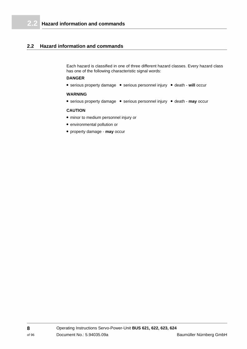
2.2 Hazard information and commands
Each hazard is classified in one of three different hazard classes. Every hazard class has one of the following characteristic signal words:
DANGER
m serious property damage m serious personnel injury m death - will occur
WARNING
m serious property damage m serious personnel injury m death - may occur
CAUTION
m minor to medium personnel injury or
m environmental pollution or
m property damage - may occur
Operating Instructions Servo-Power-Unit BUS 621, 622, 623, 624
Document No.: 5.94035.09a Baumüller Nürnberg GmbH
8of 96
Fundamental safety instructions 2
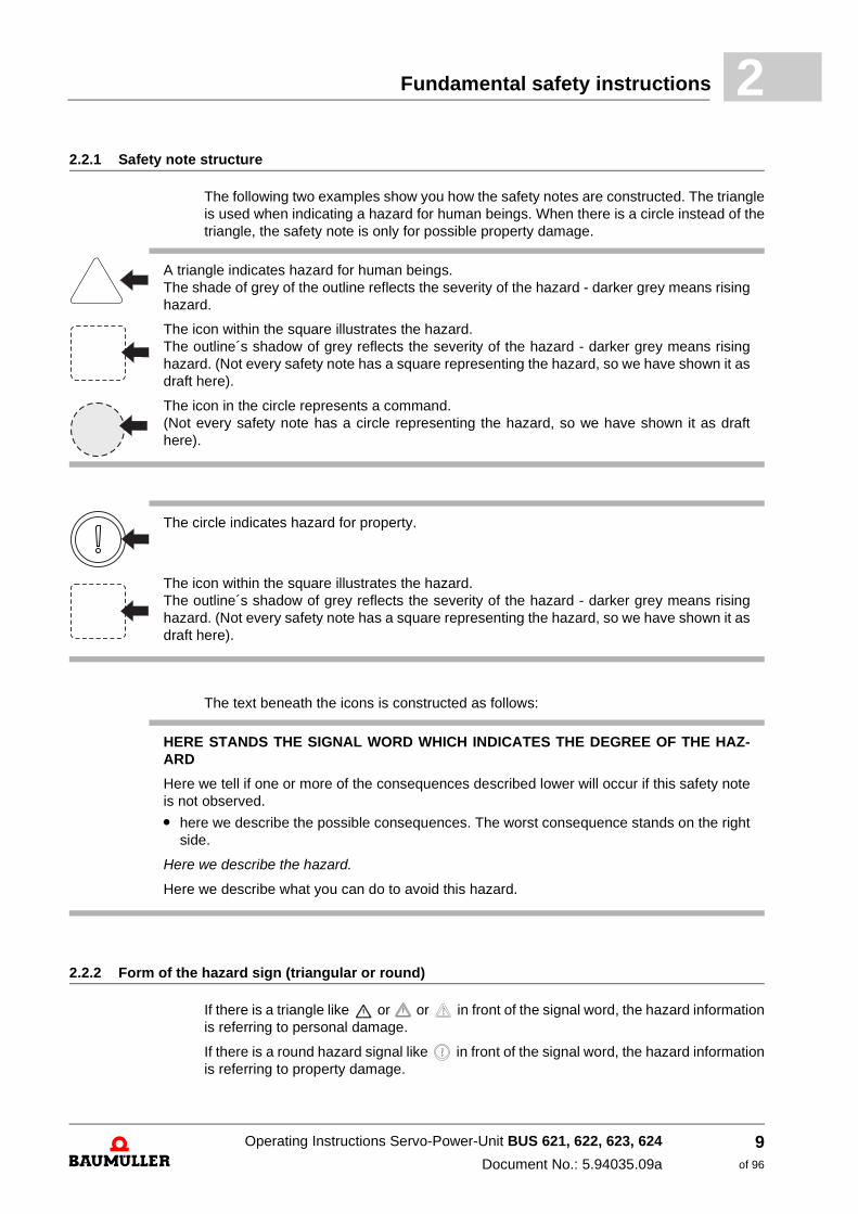
2.2.1 Safety note structureThe following two examples show you how the safety notes are constructed. The triangle is used when indicating a hazard for human beings. When there is a circle instead of the triangle, the safety note is only for possible property damage.
The text beneath the icons is constructed as follows:
2.2.2 Form of the hazard sign (triangular or round)
If there is a triangle like or or in front of the signal word, the hazard information is referring to personal damage.
If there is a round hazard signal like in front of the signal word, the hazard information is referring to property damage.
A triangle indicates hazard for human beings. The shade of grey of the outline reflects the severity of the hazard - darker grey means rising hazard.
The icon within the square illustrates the hazard. The outline´s shadow of grey reflects the severity of the hazard - darker grey means rising hazard. (Not every safety note has a square representing the hazard, so we have shown it as draft here).
The icon in the circle represents a command. (Not every safety note has a circle representing the hazard, so we have shown it as draft here).
The circle indicates hazard for property.
The icon within the square illustrates the hazard. The outline´s shadow of grey reflects the severity of the hazard - darker grey means rising hazard. (Not every safety note has a square representing the hazard, so we have shown it as draft here).
HERE STANDS THE SIGNAL WORD WHICH INDICATES THE DEGREE OF THE HAZ-ARD
Here we tell if one or more of the consequences described lower will occur if this safety note is not observed.
m here we describe the possible consequences. The worst consequence stands on the right side.
Here we describe the hazard.
Here we describe what you can do to avoid this hazard.
Operating Instructions Servo-Power-Unit BUS 621, 622, 623, 624
Document No.: 5.94035.09a
9of 96
Hazard information and commands2.2
2.2.2.1 Hazard information on personal injury
To distinguish each class of hazard information, we use a characteristic outline for both the triangular hazard signs and the square-form icons
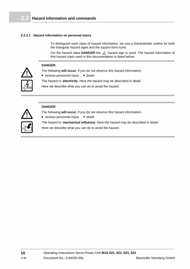
For the hazard class DANGER the hazard sign is used. The hazard information of this hazard class used in this documentation is listed below:
DANGER
The following will occur, if you do not observe this hazard information:
m serious personnel injury m death
The hazard is: electricity. Here the hazard may be described in detail.
Here we describe what you can do to avoid the hazard.
DANGER
The following will occur, if you do not observe this hazard information:
m serious personnel injury m death
The hazard is: mechanical influence. Here the hazard may be described in detail.
Here we describe what you can do to avoid the hazard.
Operating Instructions Servo-Power-Unit BUS 621, 622, 623, 624
Document No.: 5.94035.09a Baumüller Nürnberg GmbH
10of 96
Fundamental safety instructions 2
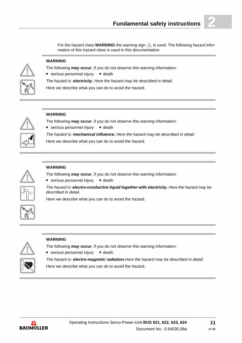
For the hazard class WARNING the warning sign is used. The following hazard infor-mation of this hazard class is used in this documentation.WARNING
The following may occur, if you do not observe this warning information:
m serious personnel injury m death
The hazard is: electricity. Here the hazard may be described in detail.
Here we describe what you can do to avoid the hazard.
WARNING
The following may occur, if you do not observe this warning information:
m serious personnel injury m death
The hazard is: mechanical influence. Here the hazard may be described in detail.
Here we describe what you can do to avoid the hazard.
WARNING
The following may occur, if you do not observe this warning information:
m serious personnel injury m death
The hazard is: electro-conductive liquid together with electricity. Here the hazard may be described in detail.
Here we describe what you can do to avoid the hazard.
WARNING
The following may occur, if you do not observe this warning information:
m serious personnel injury m death
The hazard is: electro-magnetic radiation.Here the hazard may be described in detail.
Here we describe what you can do to avoid the hazard.
Operating Instructions Servo-Power-Unit BUS 621, 622, 623, 624
Document No.: 5.94035.09a
11of 96
Hazard information and commands2.2
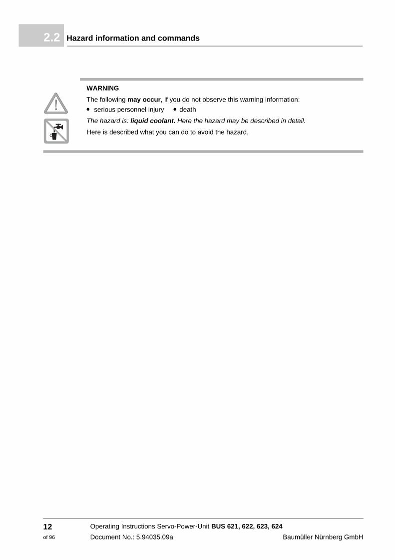
WARNING
The following may occur, if you do not observe this warning information:
m serious personnel injury m death
The hazard is: liquid coolant. Here the hazard may be described in detail.
Here is described what you can do to avoid the hazard.
Operating Instructions Servo-Power-Unit BUS 621, 622, 623, 624
Document No.: 5.94035.09a Baumüller Nürnberg GmbH
12of 96
Fundamental safety instructions 2
For the hazard class CAUTION the caution sign is used when there is hazard for per-sons or of environmental pollution. The following hazard information of this hazard class is used in this documentation.CAUTION
The following may occur, if you do not observe this caution information:
m minor to medium personal injury.
The hazard is: hot surface. Here the hazard may be described in detail.
Here we describe what you can do to avoid the hazard.
CAUTION
The following may occur, if you do not observe this caution information:
m minor to medium personal injury.
The hazard is: sharp edges. Here the hazard may be described in detail.
Here we describe what you can do to avoid the hazard.
CAUTION
The following may occur, if you do not observe this caution information:
m minor to medium personal injury.
The hazard is: rotating parts. Here the hazard may be described in detail.
Here we describe what you can do to avoid the hazard.
CAUTION
The following may occur, if you do not observe this caution information:
m minor to medium personal injury.
The hazard is: injury of the eye caused by ricochetting particles. Here the hazard may be described in detail.
Here we describe what you can do to avoid the hazard.
Operating Instructions Servo-Power-Unit BUS 621, 622, 623, 624
Document No.: 5.94035.09a
13of 96
Hazard information and commands2.2
CAUTION
The following may occur, if you do not observe this caution information:
m minor to medium personal injury.
The hazard is: noise. Here the hazard may be described in detail.
Here we describe what you can do to avoid the hazard.
CAUTION
The following may occur, if you do not observe this caution information:
m minor to medium personal injury.
The hazard is: hazard of sliding caused by liquid. Here the hazard may be described in de-tail.
Here we describe what you can do to avoid the hazard.
CAUTION
The following may occur, if you do not observe this hazard information:
m environmental pollution.
The hazard is: inadequate disposal. Here the hazard may be described in detail.
Here we describe what you can do to avoid the hazard.
Operating Instructions Servo-Power-Unit BUS 621, 622, 623, 624
Document No.: 5.94035.09a Baumüller Nürnberg GmbH
14of 96

Fundamental safety instructions 2
2.2.2.2 Hazard information on property damageIf there is a round caution sign in front of the signal word, the safety information refers to property damage.
2.2.2.3 Command signs used
CAUTION
The following may occur, if you do not observe this caution information:
m property damage
The hazard is: electro-static discharge.Here the hazard may be described in detail.
Here we describe what you can do to avoid the hazard.
CAUTION
The following may occur, if you do not observe this caution information:
m property damage
The hazard is: damage of the coolant hose. Here the hazard may be described in detail.
Here we describe what you can do to avoid the hazard.
wear safety gloves
wear safety shoes
wear eye protection
wear ear protection
Use this fire extinguishing agent:
„fire extinguishing agent“
Operating Instructions Servo-Power-Unit BUS 621, 622, 623, 624
Document No.: 5.94035.09a
15of 96
Information sign2.3
2.3 Information sign
2.4 Legal instructions
This documentation is addressed to technical qualified personnel, who is specifically skilled and who is thoroughly familiar with all warnings and maintenance procedures.
The devices are made according to the state-of-the-art technology and they are fail-safe. It can be put into operation and function without problems if you ensure that the informa-tion in the manual is complied with.
The user is responsible for the execution of service and commissioning according to the safety instructions of the prevailing standards and other relevant national and local in-structions concerning conductor dimensioning and protection, grounding, disconnector, overcurrent protection and so on.
For damages, which result from the mounting or from the connection, the one is liable, who has carried out the mounting or the installation.
NOTE
This note is a very important information.
Operating Instructions Servo-Power-Unit BUS 621, 622, 623, 624
Document No.: 5.94035.09a Baumüller Nürnberg GmbH
16of 96
Fundamental safety instructions 2
2.5 Appropriate useAlways use the device according to the terms. Stated below we have carried a few impor-tant notes together. The notes stated below shall give you a feeling for the according to the terms usage of the device. We do not raise any claim for the completion of the notes stated below - follow all instructions given in this operating instruction.
m project the application in such a way, that you always operate the device within its specification.
m use this device only as converter for three-phase drives.
m make sure, that only qualified personnel work with/at this device.
m install this device only on an adequate carrying wall.
m install this device in the way as it is described in the documentation.
m make sure, that the mains/power supply unit always applies to the predetermined specifications.
m only operate the device, if it is technical faultlessly.
m operate this device only in combination with released components of the company Baumüller Nürnberg GmbH.
m always operate the device in an area as it is instructed in the "Technical data“.
m Operate the device in environments of second mode (industrial environment). The de-vice was developed in such a way, that it meets the requirements of the category C3 according to IEC 61800-3:2005. The device is not provided for the connection to the public network. The operation of the device in an environment of the first mode of cat-egory C2/C1 (living-, business and industry area without intermediate transformer di-rectly at a public secondary distribution system), in order to reduce the RFI-emission (cable-guided and blasted) special measures must be provided for and must be proved by the control cabinet manufacturer, because EMC-interferences can occur, if no ad-ditional measures have been taken. If a device, which was described here, reaches the category C2/C1, even with additional measures, can not be ensured.
m always operate the device in serialized condition. Due to safety reasons you must not rebuild the device.
m consider all instructions referring to this, if you intend to store the device.
You are using the device according to the terms, as soon as you regard all notes and in-formation in this operating manual.
Operating Instructions Servo-Power-Unit BUS 621, 622, 623, 624
Document No.: 5.94035.09a
17of 96

Inappropriate use2.6
2.6 Inappropriate use
In the following we are listing some examples of inappropriate use. The notes mentioned below shall give you a feeling, what a faulty use of the device is. However, we cannot list all possible cases of inappropriate use here. All uses, in which the instructions of this manual are disregarded are inappropriate and therewith forbidden, especially in the fol-lowing cases:
m You disregarded the notes in this manual.
m The device has not been specifically applied as a converter in order to control a motor.
n The device has been
m mounted incorrectly,
m connected incorrectly,
m commissioned incorrectly,
m operated incorrectly,
m mounted, connected, commissioned, operated and/or maintained by not qualified or inadequately qualified personnel,
m inappropriately maintained or not maintained (also consider the descriptions of the components),
m overloaded
n operated
m with defective safety devices,
m with incorrectly mounted safety devices or without safety devices,
m with incorrectly working safety- and protection devices,
m outside the specified environmental conditions.
m You have modified the device.
m You have insufficiently monitored the parts, which are subject to a wearing.
m You have improperly carried out a repair.
m You have combined the device with improper products, which are not enabled for de-vices described in this manual.
m You have combined the device with faulty and/or faulty documented products of other manufacturers.
m The device has been operated in an explosive environment.
Operating Instructions Servo-Power-Unit BUS 621, 622, 623, 624
Document No.: 5.94035.09a Baumüller Nürnberg GmbH
18of 96

Fundamental safety instructions 2
2.7 Protective devicesThe devices Servo-Power-Unit BUS 621, 622, 623, 624 fulfill the IP20-degree of protec-tion.
2.8 Personnel training
Qualified personnel (skilled person) are defined as follows:
Qualified personnel
Authorized electronic engineers and skilled persons of the customer or third persons, who have learned the installation and commissioning of Baumüller drive systems and who are authorized, to put circuits and devices into operation according to the standards of the safety technology, to ground and to label.
Qualified personnel has a training or an instruction due to the local valid standards of the safety technique in maintenance and usage of an adequate safety equipment.
Requirements to the operating per-sonnel
The operating of the drive system must only be executed by persons, who have had a training, who have been instructed and who have been authorized for this.
Troubleshooting, preventive maintenance, cleaning, maintenance and replacing parts are only to be executed by trained personnel or by personnel, who has been introduced in this. These persons must be familiar with the manual and act in accordance with this.
Commissioning and instruction must only be carried out by qualified personnel.
2.9 Safety measures in standard operation
h At the mounting location of the device the applicable safety regulations for the installa-tion have to be considered, in which this device has been installed.
h Provide the device with additional monitoring- and safety devices, in case safety pre-cautions determine this.
WARNING
The following can occur, if you disregard this hazard information:
m serious personal injury m death
The hazard is: electricity The device cabinet complies with IP 00.
Operate the device in a control cabinet, which provides a protection against a direct touching of the devices and fulfills at least the demands of the EN 50178 chapter 5.2.4
WARNING
The following can occur, if you disregard this hazard information:
m serious personal injury m death
Devices of Baumüller Nürnberg GmbH may only be mounted, installed, operated and maintained by qualified personnel.
Operating Instructions Servo-Power-Unit BUS 621, 622, 623, 624
Document No.: 5.94035.09a
19of 96
Hazards due to residual energy2.10
2.10 Hazards due to residual energy
Electrical residual energy
After separation of the device of the mains current-led parts, as e.g. power connections may not be touched until the capacitors in the device have been discharged (see „dis-charge time“ in ZTechnical data– from page 69. Also pay regard to the instructions on the device. If you have additional capacitors connected to the capacitors at the DC link, the decharging also can last much longer. In this case you must determine the necessary waiting time on yourself or measure if the device is off-circuit.
Mechanical residual energy
The mechanical residual energy is dependent upon the application. Driven parts also ro-tate/move after disconnection of the mains supply for a certain time. Please, provide ad-equate safety arrangements.
2.11 Disposal of the device
The accurate disposal of the device is described in ZDisposal– from page 63.
2.12 Fire fighting
WARNING
The following can occur, if you disregard this hazard information:
m serious personal injury m death
The hazard is: Electricity when using a conductive fire fighting device.
Use the following fire fighting devices:
ABC-Pulver / CO2
Operating Instructions Servo-Power-Unit BUS 621, 622, 623, 624
Document No.: 5.94035.09a Baumüller Nürnberg GmbH
20of 96

Fundamental safety instructions 2
2.13 Responsibility and liabilityTo be able to work as safe as possible with this device, you must know and follow the hazard notes as well as the safety instructions.
2.13.1 Observing hazard information and safety instructions
In this manual we use visually unified safety instructions, which are intended to prevent from personal injury or damage to property.
2.13.2 Hazards when handling this device
The device „Servo-Power-Unit“ was developed and manufactured according to the state-of-the-art technology and in compliance with the valid regulations and standards. It is still possible that hazards can arise during use. An overview of possible hazards is to be found in chapter ZFundamental safety instructions– from page 7. We advise against the acute hazard at the accordant positions in this manual.
2.13.3 Warranty and liability
All information in this manual is non-binding customer information; it is subject to ongoing further development and is updated on a continuous basis by the revision service of Baumüller Nürnberg GmbH.
Warranty- and liability claims against Baumüller Nürnberg GmbH are excluded if in par-ticular one or more of the causes listed in ZInappropriate use– from page 18 has/have caused the damage.
WARNING
The following can occur, if you disregard this hazard information:
m serious personal injury m death
All persons, who work with this device, must know and regard the safety notes and the safety instructions in this manual.
Apart from this, any and all persons who work on this device must additionally know and re-gard to all regulations and instructions, that are valid at the location.
Operating Instructions Servo-Power-Unit BUS 621, 622, 623, 624
Document No.: 5.94035.09a
21of 96

Responsibility and liability2.13
Operating Instructions Servo-Power-Unit BUS 621, 622, 623, 624
Document No.: 5.94035.09a Baumüller Nürnberg GmbH
22of 96
3
3PACKAGING AND TRANSPORTATIONIn this chapter we describe, which conditions have to be adhered to at transportation, how you check the device after receipt and what you should have to consider, if you dispose the packing.
We package every Baumüller unit before shipping such that it is highly unlikely that it will be damaged in transit.
3.1 Observe during transportation
The unit was packaged at the manufacturer's plant for initial transportation. If you have to transport the unit at a later date, please note the following points.
Ensure that the following conditions always apply during transportation:
m 2 K 3 (Climatic category) 1)
m - 30 °C bis + 70 °C (Temperature range)
m Fallhöhe (verpackt) max. 25 cm (Vibration, shock, repetitive shock)1) DIN EN IEC 60721-3-3
3.2 Unpacking
After receiving the unit while it is still packaged:
h Avoid strong transportation vibrations and severe hits, e.g. when setting down.
h Check whether there is any visible damage!
If there is:
h Complain to the delivery company. Have your complaint confirmed in writing and con-tact immediately your nearest Baumüller Nürnberg GmbH subsidiary.
23of 96
Operating Instructions Servo-Power-Unit BUS 621, 622, 623, 624 Document No.: 5.94035.09a

Disposing of the packaging3.3
If no damage is visible:
h Open the unit's packaging.
h Check the scope of supply against the delivery note.
The scope of supply is:
m Servo-Power-Unit BUS 621, 622, 623, 624
m these Operating Instructions including the declaration of conformity/manufacturer dec-laration
h complain to your local Baumüller subsidiary if you find damage or if the delivery is not complete.
3.3 Disposing of the packaging
The packaging consists of cardboard and plastic.
h Observe local disposal regulations if you intend to dispose of the packaging.
WARNING
The following can occur, if you disregard this hazard information:
m serious personal injury m death
The hazard is: electricity
Do not operate the device, if you have recognized a transportation damage or if you assume this. In this case immediately contact Baumüller Nürnberg GmbH
Operating Instructions Servo-Power-Unit BUS 621, 622, 623, 624
Document No.: 5.94035.09a Baumüller Nürnberg GmbH
24of 96
4
4DESCRIPTION OF THE UNITSThe basic structure of the power modules BUS 621, 622, 623, 624 will be described and the model key affixed on the units will be explained in this chapter.
NOTE
The power module BUS 621, 622, 623, 624 series are intended for the use in the "second environment" (industrial environment) according to EN61800-3. Electromagnetic interferences may occur when connecting to the public network. See also ZAppropriate use– starting at page 17.
NOTE
"In accordance with EN 50178, the components by Baumüller Nürnberg GmbH are built in devices. Built in devices are defined in EN 50178, para. 5.2.6 as "Assemblies and devices designated for the installation into a larger device or housing, which offers the required protection […]. They are intended for the installation in standard control cabinets.
There are a number of reasons that result in the components and devices having to be operated in standard control cabinets. In particular, the installation in control cabinets guarantees
m that the required contact protection can be implemented by the user,
m that the thermal ambient conditions specified in technical data of the components and devices (temperatures, relative humidity, cleanliness of the cooling media, ...) can be secured,
m that the mechanical ambient conditions specified in technical data of the components and devices (vibrations, ...) can be secured,
m that the instructions for the EMC projection and the EMC design (shielding concept, installation principles, ducts, ...) listed in the technical data of the components and devices can be implemented.
25of 96
Operating Instructions Servo-Power-Unit BUS 621, 622, 623, 624
Document No.: 5.94035.09a

Function description4.1
4.1 Function description
The devices are servo inverters by Baumüller Nürnberg GmbH. The devices consist of a power module with an integrated slot for the controller.
Power unit
The power unit has been constructed as a 3-phase bridge using IGBT technology, and converts control signals from the controller cassette into voltage pulses to supply Baumüller 3-phase motors (asynchronous and synchronous).
Monitoring
The power unit is self-protecting and has monitoring functions for the DC link voltage, earth connection current and motor current.
Safety relay (as an option)
Some applications demand that it must be possible to stop a drive electronically without the need for contactors in the motor cables and without switching of the DC link voltage to achieve an immediate production restart.
The actuator in this function is switched torqueless.
The function is structured as a dual channel for fulfilling safety requirements according to DIN EN ISO 13849- 1, EN 62061 and EN 61800-5-2 and therefore has two separate cutoff methods, which are used to cut off the commutation in the power part.
The first cutoff method is realized by a force operated relay, a safety relay, the force operated contacts of which interrupt the auxiliary voltage supply of the actuators and therefore prevent the power transistors from starting.
The second cutoff method, the pulse enable / pulse lock is performed via the controller (V-controller or M-drive) and also blocks the new pulses for the power transistors. Detailed information can be found in ZAppendix C - Safety Technology– starting at page 77.
NOTE
A proper operation of the performance modules BUS 621, 622, 623, 624 can only be guaranteed on Baumüller frequency changers or network frequency changers.
Operating Instructions Servo-Power-Unit BUS 621, 622, 623, 624
Document No.: 5.94035.09a Baumüller Nürnberg GmbH
26of 96

Description of the units 4
4.2 Block circuit diagramFigure 2: Block circuit diagram
4.3 Interconnecting devices
The device Servo-Power-Unit BUS 621, 622, 623, 624 can be combined with other Baumüller devices.
Operating Instructions Servo-Power-Unit BUS 621, 622, 623, 624
Document No.: 5.94035.09a
27of 96

Variants - Basic version / version with Safe Torque Off (STO)4.4
4.4 Variants - Basic version / version with Safe Torque Off (STO)
In addition to the basic version of the units, there are also equipment versions, which combined with especially executed controllers, meet the requirements for safety function STO (Safe Torque Off) according to DIN EN ISO 13849-1, EN 62061 and EN61800-5-2.
These power modules carry the type description BUS62x-xx/xx-xx-M-xxx-001
The following controllers approved for this function are available:
M-drive with type description: BUS6-MC-xx-xxxx-xxxx-SIxx-...
or
V-controller with type description: BUS6-S1-VC-...
4.5 Overview with hazardous areas
The following overview shows the hazardous areas existing in the respective device. Use this overview to provide an overview of the existing hazardous areas, if you are working into the handling of this device.
Figure 3: Hazardous areas
Operating Instructions Servo-Power-Unit BUS 621, 622, 623, 624
Document No.: 5.94035.09a Baumüller Nürnberg GmbH
28of 96
Description of the units 4
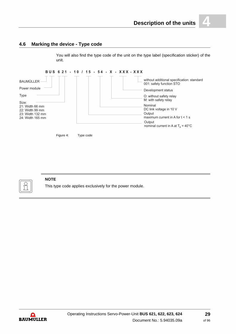
4.6 Marking the device - Type codeYou will also find the type code of the unit on the type label (specification sticker) of the unit.
Figure 4: Type code
Power module
Type
Size:21: Width 66 mm22: Width 99 mm23: Width 132 mm24: Width 165 mm
Development status
without additional specification: standard001: safety function STO
O: without safety relay
NominalDC link voltage in 10 VOutputmaximum current in A for t < 1 s
Outputnominal current in A at T = 40°C
K
M: with safety relay
B U S 6 2 1 - 1 0 / 1 5 - 5 4 - X - X X X - X X X
BAUMÜLLER
NOTE
This type code applies exclusively for the power module.
Operating Instructions Servo-Power-Unit BUS 621, 622, 623, 624
Document No.: 5.94035.09a
29of 96

Marking the device - Type code4.6
Operating Instructions Servo-Power-Unit BUS 621, 622, 623, 624
Document No.: 5.94035.09a Baumüller Nürnberg GmbH
30of 96

5
5ASSEMBLYIn this chapter we describe the mechanical mounting of the device into a control cabinet.
Mounting consists of the following steps:
1 Prepare mounting (drill holes/cut-out segments)
2 Install device
5.1 General safety instructions
h Please regard to the information in chapter ZFundamental safety instructions– starting at page 7.
h Pay attention to all areas at the device, which could be dangerous for you while mount-ing.
WARNING
The following may occur, if you do not observe this warning information:
m serious personal injury m death
At execution of any mounting workings it must be assured that no strange substances (e.g. drilling chips, copper wire etc.) get into the device. If possible the drillings should be done be-fore mounting the device and the assembling of the cables should be done outside the control cabinet. If this is not possible, the device must be covered accordingly.
CAUTION
The following may occur, if you do not observe this caution information:
m property damage.
The danger is: electrostatic discharge. Connections of the device sometimes are danger-ous to ESD.
Regard the corresponding notes.
31of 96
Operating Instructions Servo-Power-Unit BUS 621, 622, 623, 624
Document No.: 5.94035.09a
Requirements to the executing personnel5.2
5.2 Requirements to the executing personnel
Qualified personnel are persons, who have been instructed by the responsible person, based on their training, experience, the instructions they were given as well as their knowledge about relevant standards and instructions, knowledge of the accident preven-tion instructions and of the company, to execute the necessary operations and thereby are able to recognize and avoid the dangers which could happen. The required qualifica-tions for the work with this unit are for example:
m Training or instruction due to the standards of the safety engineering in maintenance and use of appropriate safety equipment.
5.3 Prepare mounting
You can prepare the mounting with the configuring manual for your installation. With the project manual and the drilling templates (see ZDrilling templates/installation space– starting at page 33) you can determine the dimensions for the cut-outs and for the fasten-ing drills.
h Execute the drilling and if necessary the cut-outs.
CAUTION
The following may occur, if you do not observe this caution information:
m minor to medium personal injury.
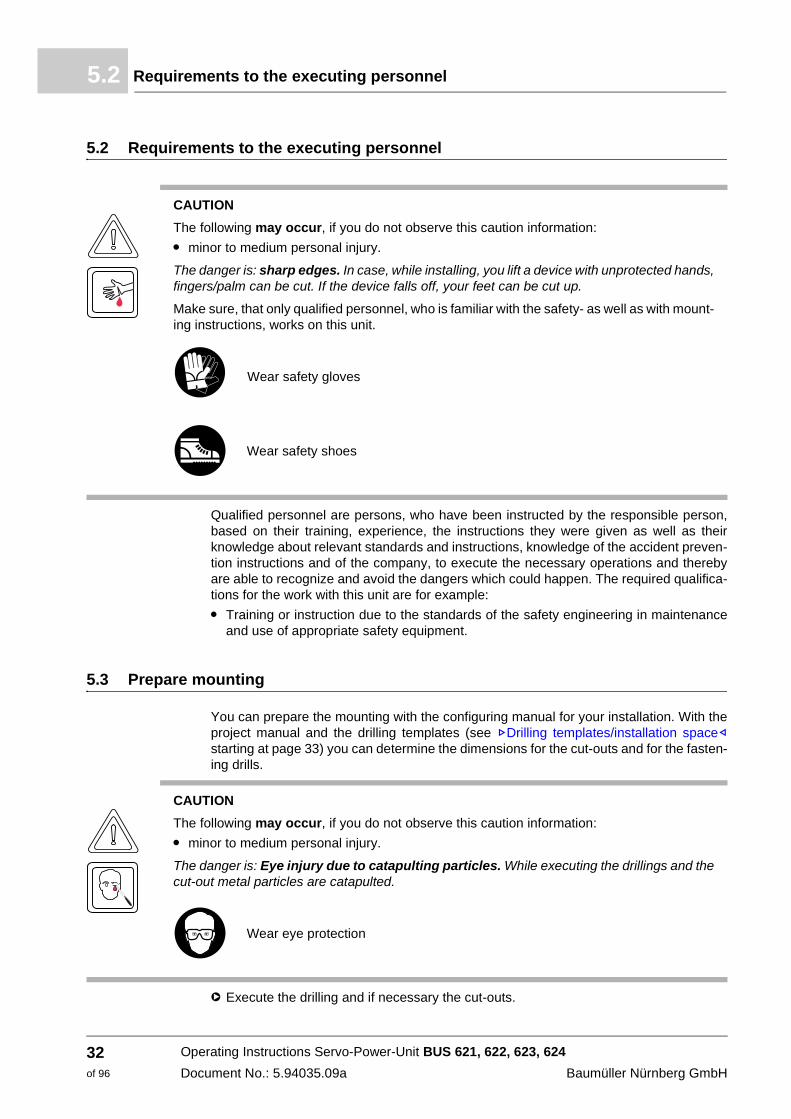
The danger is: sharp edges. In case, while installing, you lift a device with unprotected hands, fingers/palm can be cut. If the device falls off, your feet can be cut up.
Make sure, that only qualified personnel, who is familiar with the safety- as well as with mount-ing instructions, works on this unit.
Wear safety gloves
Wear safety shoes
CAUTION
The following may occur, if you do not observe this caution information:
m minor to medium personal injury.
The danger is: Eye injury due to catapulting particles. While executing the drillings and the cut-out metal particles are catapulted.
Wear eye protection
Operating Instructions Servo-Power-Unit BUS 621, 622, 623, 624
Document No.: 5.94035.09a Baumüller Nürnberg GmbH
32of 96
Assembly 5
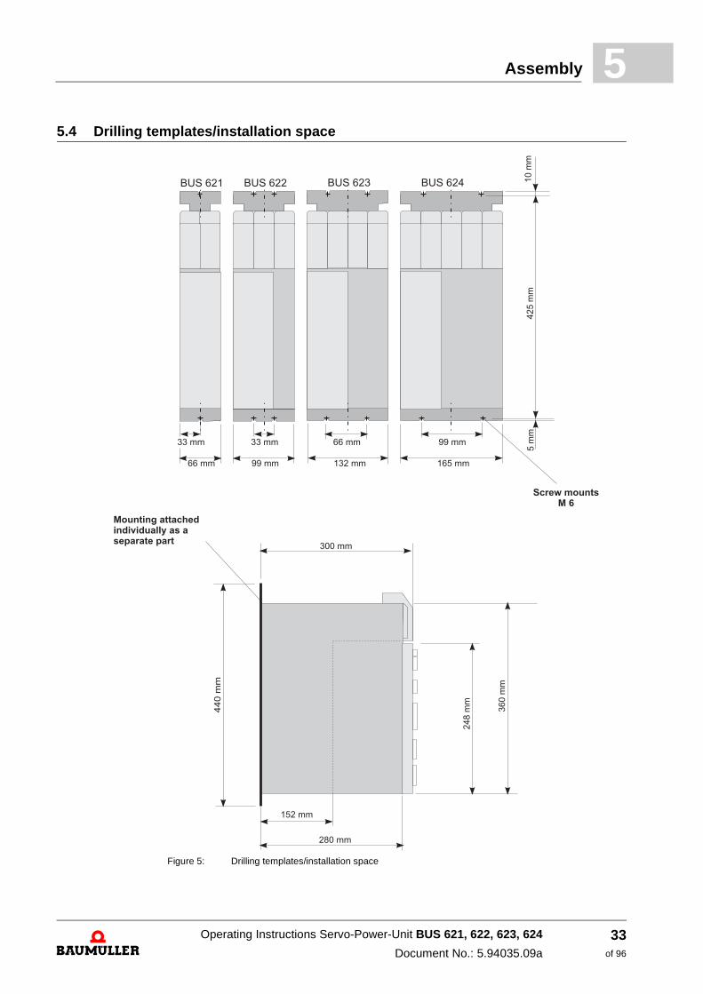
5.4 Drilling templates/installation spaceFigure 5: Drilling templates/installation space
Operating Instructions Servo-Power-Unit BUS 621, 622, 623, 624
Document No.: 5.94035.09a
33of 96
Assembly instructions5.5
5.5 Assembly instructions
Perform the assembly as follows:
1 If necessary, provide a suitable transporting/lifting device
2 Provide suitable fasteners
3 Assemble the device.
m The units must be installed in the switch cabinet vertically. The power module BUS 62x must be arranged near to the feed / feed back unit BUC 624, 625 or the basic feed unit BUG 622, 623 and the DC Link must be connected by the connection bars supplied with the unit. When delivered, the connection bars are fastened to the front bars of the units BUS 62x.
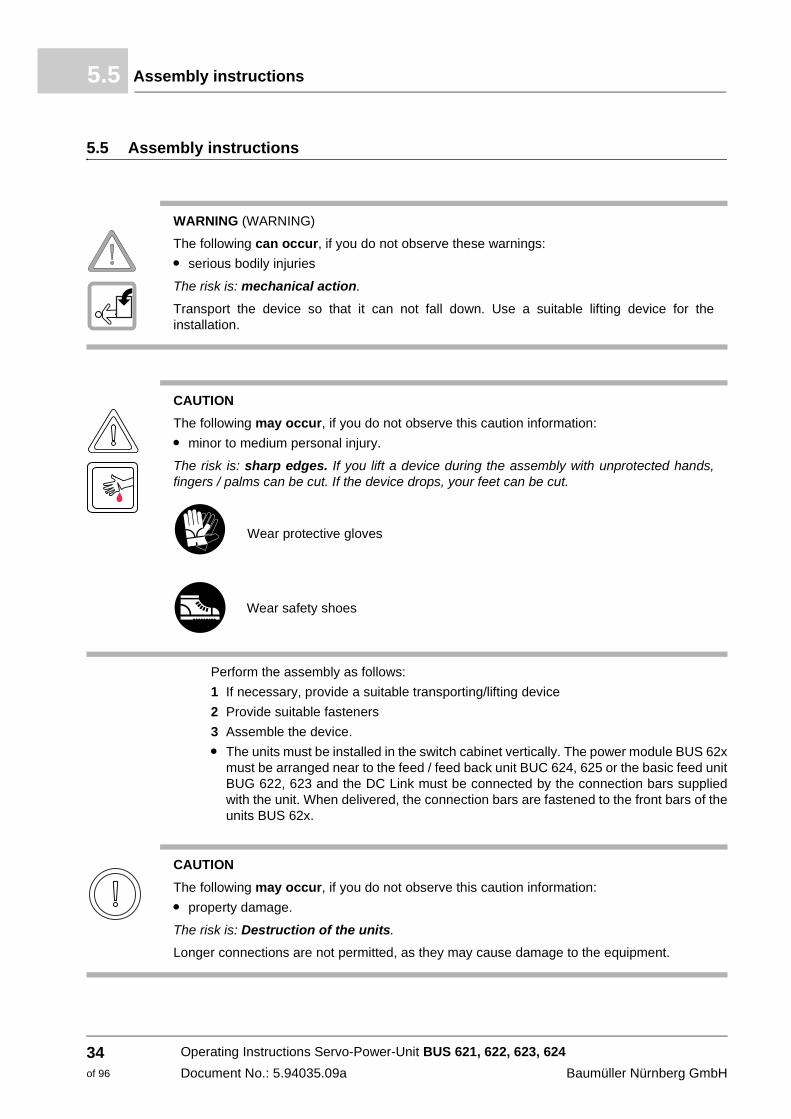
WARNING (WARNING)
The following can occur, if you do not observe these warnings:
m serious bodily injuries
The risk is: mechanical action.
Transport the device so that it can not fall down. Use a suitable lifting device for the installation.
CAUTION
The following may occur, if you do not observe this caution information:
m minor to medium personal injury.
The risk is: sharp edges. If you lift a device during the assembly with unprotected hands, fingers / palms can be cut. If the device drops, your feet can be cut.
Wear protective gloves
Wear safety shoes
CAUTION
The following may occur, if you do not observe this caution information:
m property damage.
The risk is: Destruction of the units.
Longer connections are not permitted, as they may cause damage to the equipment.
Operating Instructions Servo-Power-Unit BUS 621, 622, 623, 624
Document No.: 5.94035.09a Baumüller Nürnberg GmbH
34of 96
Assembly 5
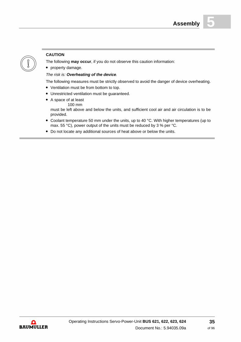
CAUTION
The following may occur, if you do not observe this caution information:
m property damage.
The risk is: Overheating of the device.
The following measures must be strictly observed to avoid the danger of device overheating.
m Ventilation must be from bottom to top.
m Unrestricted ventilation must be guaranteed.
m A space of at least 100 mm
must be left above and below the units, and sufficient cool air and air circulation is to be provided.
m Coolant temperature 50 mm under the units, up to 40 °C. With higher temperatures (up to max. 55 °C), power output of the units must be reduced by 3 % per °C.
m Do not locate any additional sources of heat above or below the units.
Operating Instructions Servo-Power-Unit BUS 621, 622, 623, 624
Document No.: 5.94035.09a
35of 96
Attachment5.6
5.6 Attachment
1. Attach the mounting backplate to the control cabinet (for sizes, see ZFigure 5– on page 33). The backplate can be used as a mounting and drilling template. The backplates of neighbouring units must be directly next to one another.
2. Push back the retaining plate spring and hang the unit in place. The unit is then held fast between the mounting backplate and the back wall.
3. To dismount the unit, press the retaining plate spring and lift out upwards.
Operating Instructions Servo-Power-Unit BUS 621, 622, 623, 624
Document No.: 5.94035.09a Baumüller Nürnberg GmbH
36of 96
6
6INSTALLATIONIn this chapter we describe the electric installation of the device. The mechanical installation is described in ZAssembly– starting at page 31.
Before installing assure, that the technical preconditions are fulfilled:
1 Check the requirements to the electrical cables and provide the according cables.
2 Check the characteristics of the connections and configure the connections accordingly.
6.1 General safety instructions
h Pay attention to the information in the chapters ZFundamental safety instructions– starting at page 7.
h Pay attention to all areas at the device, which could be dangerous for you during the electrical installation.
37of 96
Operating Instructions Servo-Power-Unit BUS 621, 622, 623, 624
Document No.: 5.94035.09a
Requirements to the executing personnel6.2
6.2 Requirements to the executing personnel
At each case qualified personnel are persons, who are authorized by the responsible persons, to execute necessary actions and who recognize the possible dangers and who are able to avoid these dangers. They have had the training, the experience, they were given instructions as well as knowledge about the relevant standards and instructions, they have knowledge of the accident prevention regulations and of the operating environments. The required qualifications for the work with this unit are for example:
m Education or instruction or to have the authorization to put into operation, ground and label circuits and devices according to the standards of safety engineering.
m Training or instruction due to the standards of the safety engineering in maintenance and use of appropriate safety equipment.
6.3 Voltage check
At routine test of these units a voltage check is executed acc. to EN50178/VDE0160, paragraph 9.4.5 by Baumüller Nürnberg GmbH.
WARNING
The following may occur, if you do not observe this warning information:
m serious personal injury m death
The danger is: electricity.When operating with this electrical unit, inevitably certain parts of this unit are under dangerous voltage.
Make sure, that only qualified personnel, who are familiar with the safety- as well as with mounting-, operating- and maintenance instructions, work on this unit.
WARNING
The following may occur, if you do not observe this warning information:
m serious personal injury m death
The danger is: electricity.
Subsequent checks of unit with high voltages must be made only by Baumüller Nürnberg GmbH.
Operating Instructions Servo-Power-Unit BUS 621, 622, 623, 624
Document No.: 5.94035.09a Baumüller Nürnberg GmbH
38of 96
Installation 6
6.4 Requirements to the connecting cablesh You must consider IEC/EN 60204-1, chapter 13 at selection of connection cables.
h The protective conductor cross section of the cable must be executed accordant to IEC/EN 60204-1, section 5.2, tab. 1.
h The permanent connection of the protective conductor is imperatively regulated for the operation of the device.
h Use a copper cable for at least 60°C (drives < 3 x 100 A) or 75°C (drives ≥ 3 x 100 A) incase you consider UL 508 C.
For further information (e.g. maximum allowed length) see ##Anh B8.
6.5 Requirements on the laying (EMC notes device)
m Use Baumüller motor cables and Baumüller components.
m Use a suitable mains filter of Baumüller Nürnberg GmbH
m Mount all components to one single mounting board with well electroconductive sur-face (e. g. galvanized steel plate).
m Establish the ground connection converter/ground plane as short as possible (< 30 cm) with fine-wired cables and a great cross section (> 10 mm2).
m Assure, that the motor cables always consist of one piece. Do not interrupt the motor cables e. g. by connectors, conductors, fuses a.s.o.
m Run the cables directly on the surface of the grounded mounting board. (smallest possible effective aerial height).
m Keep a minimum clearance of 30 cm between signal/control and 24V-wires towards electric power cables at parallel laying.
m Cross cables with different EMC categories (signal cables - supply cables or motor ca-bles) only in a 90° angle.
m Contact the external cable screens when passing through walls, which separate differ-ent EMC ranges.
m Connect the cable shields of the Servo-Power-Unit-devices plane on both ends and highly conductive with ground.
NOTE
The emission of radio interferences is to a high level dependent on the wiring, the volume ex-pansion and the arrangement of the components in the installation. That is why the assurance of the electromagnetic compatibility according to the statutory provisions only is possible on the completed installation and therefore is in the responsibility range of the manufacturer of the installation or of the operating authority (EMVG § 6, sec. 9).
NOTE
In this Operating Instructions the most important information for an EMC-compatible installa-tion is available. Further notes, which necessarily have to be considered in order to mount a CE-conform installation are to be found in the manual ’filters for mains applications’.
Operating Instructions Servo-Power-Unit BUS 621, 622, 623, 624
Document No.: 5.94035.09a
39of 96

Requirements for the temperature sensor of the motor6.6
m It is recommended to use protection elements against overvoltage in each 24 V control cabinet sub-distribution (e.g. Phoenix Contact part no. 2839318 type: PT2-PE/S-24AC-ST) when using a peripheral 24 V supply (that means the 24 V power supply is not within the device’s control cabinet).
6.6 Requirements for the temperature sensor of the motor
In order to protect the motor against excessive overheating, a Servo-Power-Unit motor temperature sensor can be connected. When exceeding an adjustable temperature limit, the inverter switches off the motor. Requirements for the temperature sensor can be found in ##Anh B11.1ZTemperature sensors of the motor– starting at page 76.
NOTE
The capacitive coupling of the signals is reduced by factor 5 if a clearance of at least 30 cm is maintained compared with a cable laying directly side by side.
Baumüller has already considered on EMC view that the recommended clearance of 30 cm is not maintained on the supply and the Baumüller devices, therefore this is uncritical and per-mitted.
NOTE
The motor temperature sensor is designed so that a safe electrical isolation is guaranteed. The motor temperature sensors installed in Baumüller motors meet these requirements. When connecting third-party motors, the operator must verify that the motor temperature sensor installed in the motor from another manufacturer meets the function Safe electrical separation.
Operating Instructions Servo-Power-Unit BUS 621, 622, 623, 624
Document No.: 5.94035.09a Baumüller Nürnberg GmbH
40of 96
Installation 6
6.7 Sequence of the installationThe installation consists of the following steps:
1 Route all cables EMC-compliant.
2 Connect the lines (see ZConnection diagram– starting at page 42) (Also observe the approved torques).
m Connect the motor via terminals 1U2, 1V2, 1W2, PE. Note the correct phase connection (rotation). (Observe the approved torques).
m Connect the ground wire to terminal PE (a fixed protective earth connection is mandatory).
m Connect the 24 V supply via connectors X100-1/2, X100-5/6. (when including UL508C: limit the current to 4 A).
m Connect the transmitter (see operating instructions of the controller).
m Connect the temperature sensor of the motor.
m Connect the safety relay. (Also refer to ##ZAppendix B - Technical data– starting on page 69 for connection data of the safety relay).
WARNING
The following may occur, if you do not observe this warning information:
m serious personal injury m death
The risk is: Electricity Live parts are life-threatening.
Verify that the parts to be assembled (power lines) and the assembly area are deenergized throughout the entire assembly of the device .
NOTE
Plugging and pulling the encoder cable under voltage is not allowed.
Operating Instructions Servo-Power-Unit BUS 621, 622, 623, 624
Document No.: 5.94035.09a
41of 96
Connection diagram6.8
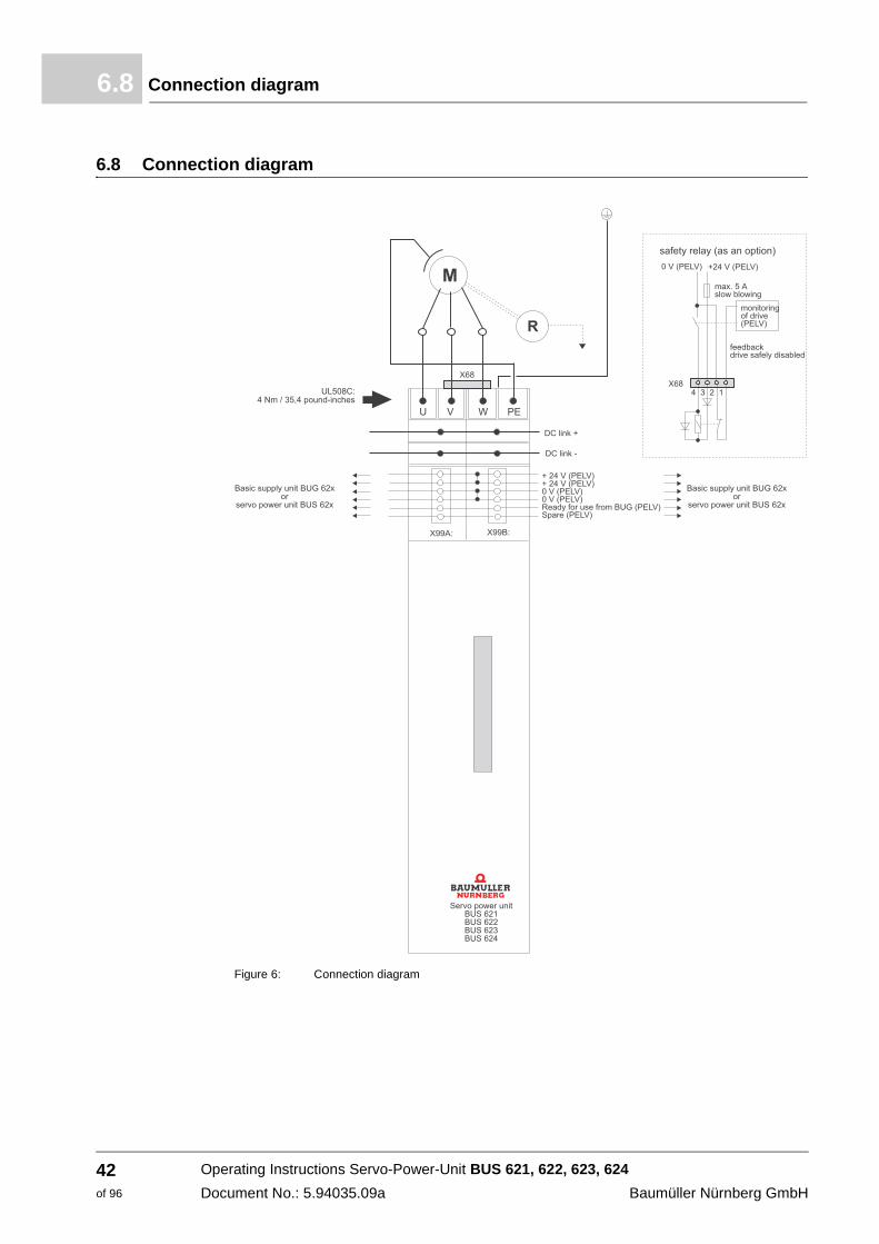
6.8 Connection diagram
Figure 6: Connection diagram
Operating Instructions Servo-Power-Unit BUS 621, 622, 623, 624
Document No.: 5.94035.09a Baumüller Nürnberg GmbH
42of 96
Installation 6
6.8.1 Connection instructionsGround leakage circuit breaker
Relatively high leakage to ground occurs in the converter and the motor, i.e. the drive may be incompatible with residual current protective devices.
Reference should be made to EN 50178 / VDE0160 / 4.98 sect. 5.2.11before configuration.
U, V, W
PE
Motor connections. See EMC instructions for routing the lines.
Control cabinet ground, cross sections according to EN 60204-1:1997
When including UL508C: Only 60°C / 75°C copper lines may be connected (UL508C, nominal tightening torque of the connecting screws: 4 Nm or 35.4 psi.
ZK+, ZK- DC link connection to the feed-in unit and to additional power modules.
When including UL508C: Nominal tightening torque of the connecting screws: 4 Nm or 35.4 psi.
WARNING
The following may occur, if you do not observe this warning information:
m serious personal injury m death
The risk is: Electricity. Live parts are life-threatening.
The DC Link carries electrical potential: it is imperative that the provided cover is used.
Power supply 24 V 24 V voltage supply with secure isolation (SELV) according to EN 50178 for supplying the electronic parts
Current input without controller
m BUS 621 0,9 A
m BUS 622 0,9 A maximum current
m BUS 623 1,1 A at 24 V - 10 %
m BUS 624 1,6 A
NOTE
The power supply has capacitors at its input (250 µF); which means, on switching the 24 V supply, charging current is present!
At continuous operation below 24 V the cooling power of the internal ventilator is reduced. Power reducing of the power module on inquiry.
Operating Instructions Servo-Power-Unit BUS 621, 622, 623, 624
Document No.: 5.94035.09a
43of 96
Pin assignment6.9
6.9 Pin assignment
6.9.1 Power connections
m U, V, W, PE U, V, W: Motor connections, M 6 terminals PE: Control cabinet ground, M 4 terminal If UL508C has to be observed: Use 60°C / 75° C copper conductors only (UL508C, Nov 27, 1996, Tab. 39.2). Nominal tightening torque of the terminal screws: 4 Nm resp. 35,4 pound-inches.
m ZK+, ZK- Connection of the power unit to the DC Link of the basic feed unit BUG 62x resp. to other BUS 62x basic feed units must be done by the connection bars supplied with the unit. When delivered, the connection bars are fastened to the front bars of the units BUS 62x M 6 terminals
If UL508C has to be observed: Nominal tightening torque of the terminal screws: 4 Nm resp. 35,4 pound-inches.
CAUTION
The following may occur, if you do not observe this caution information:
m property damage.
The risk is: Destruction of the units.
Longer connections than those with the included rails are not allowed, otherwise there is risk of destroying the equipment!
Operating Instructions Servo-Power-Unit BUS 621, 622, 623, 624
Document No.: 5.94035.09a Baumüller Nürnberg GmbH
44of 96

Installation 6
6.9.2 Control connectorsConnection strip X99A/X99B
All connectors are connected to each other (i.e. connector 1 of X99A is connected to con-nector 1 of X99B ...). Because of this they can be used as BUS-connection from one Baumüller unit to the other.
The signals can be executed as a bus connection, due to the connection of X99A with X99B of the next unit in the line.
Recommended connection lead length - 44 mm.
X 99 A
X 99 B
Connector no. Assignment
1, 2 + 24 V (PELV) Connector for power supply to the units,
both connectors internally bypassed, 2nd connector with power supply current > 10 A
3, 4 Ground 24 V (PELV) Connector for power supply to the units,
both connectors internally bypassed,2nd connector with power supply current > 10 A
5 Ready for use, internalReady for use message from the supply
converter to all units attached to the DC link.
6 Reserved (PELV)
NOTE
A maximum current greater than 10 A per single connector may cause damage to the equipment.
If higher currents are needed do build a multiple feeder system.
If UL508C has to be observed: Limit the current to 4 A.
Operating Instructions Servo-Power-Unit BUS 621, 622, 623, 624
Document No.: 5.94035.09a
45of 96

Accessories6.10
m Connection strip X68 safety relay (as an option)
m X60 plug 64-pin X60 connects the controller cassette internal with the motor side converter. See description controller for external connections of controller cassette.
6.10 Accessories
m EMC package
n on requirement available: EMC filter shielded cables shield clamps
Connector no. Description
1 feedback contact 1 (SELV)
2 feedback contact 2 (SELV)
3 +24 V (SELV)
4 ground connection 24 V (SELV)
Operating Instructions Servo-Power-Unit BUS 621, 622, 623, 624
Document No.: 5.94035.09a Baumüller Nürnberg GmbH
46of 96

7
7OPERATIONIn this chapter we describe, how the device works during operation and how you handle the device during operation.
7.1 Safety instructions
h Refer to the safety instructions from the chapter ZFundamental safety instructions– starting on page 7.
CAUTION
The following may occur, if you do not observe this caution information:
m property damage.
The danger is: Environmental conditions, that do not refer to the demands.
Assure, that the environmental conditions are referred to during operation (see ##Anh B4ZRequired ambient conditions– starting on page 72).
WARNING
The following may occur, if you do not observe this warning information:
m serious personal injury m death
The danger is: electricity. The control cabinet, in which the device is built in, shall protect against contacts with parts, which are under voltage.
Assure, that during operation all doors of the control cabinet are closed.
Assure, that during operation all safety devices work.
47of 96
Operating Instructions Servo-Power-Unit BUS 621, 622, 623, 624
Document No.: 5.94035.09a

Requirements to the executing personnel7.2
7.2 Requirements to the executing personnel
At each case qualified personnel are persons, who are authorized by the responsible per-sons, to execute necessary actions and who recognize the possible dangers and who are able to avoid these dangers. They have had the training, the experience, they were given instructions as well as knowledge about the relevant standards and instructions, they have knowledge of the accident prevention regulations and of the operating environ-ments. The required qualifications for the work with this unit are for example:
m Education or instruction or to have the authorization to put into operation, ground and label circuits and devices according to the standards of safety engineering.
m Training or instruction due to the standards of the safety engineering in maintenance and use of appropriate safety equipment.
WARNING
The following may occur, if you do not observe this warning information:
m serious personal injury m death
The danger is: electricity.When operating with this electrical unit, inevitably certain parts of this unit are under dangerous voltage.
Assure, that only qualified personnel work on this unit.
Operating Instructions Servo-Power-Unit BUS 621, 622, 623, 624
Document No.: 5.94035.09a Baumüller Nürnberg GmbH
48of 96

Operation 7
7.3 Function diagramAbbildung 7: Function diagram
Operating Instructions Servo-Power-Unit BUS 621, 622, 623, 624
Document No.: 5.94035.09a
49of 96
Operation7.4
7.4 Operation
All messages given by a BUS 62x power module monitoring device are saved there.
Error saving can be reset via a signal from the controller (see controller description).
The feed unit reset signal does only affect the feed unit itself and does not cancel error saving in the BUS 62x power module.
Setting the BUS 62x power module is not necessary.
7.5 Messages and warnings
To use the monitoring the +24 V power supply (X99A or X99B) must be available.
Following features are monitored:– Overcurrent in the motor cables– Earth-fault current– DC Link voltage– Power transistors switching status– state of safety relay
Overcurrent message
Motor current in the motor phases is monitored, and on exceeding phase current by 30 % of the permitted peak current, an overcurrent message is generated. This error message is saved and a pulse inhibit is made.
The overcurrent message can be reset by a controller reset. For display and message resetting, see controller description.
Earth-fault monitoring
The earth fault current of the power unit, and thus the motor current, is monitored for earth faults. An earth fault message is generated if the fault current exceeds 10 % of the power unit's peak current.
Earth-fault monitoring can be reset by a controller reset. For display and message resetting, see controller description.
DC Link monitoring
The amount of the DC Link voltage is monitored in the power unit. If it reaches 800 V an error message is generated.
NOTE
The overcurrent message should be seen as protection, and limitation of the permitted peak of the motor phase currents is determined by the controller.
Operating Instructions Servo-Power-Unit BUS 621, 622, 623, 624
Document No.: 5.94035.09a Baumüller Nürnberg GmbH
50of 96

Operation 7
DC Link monitoring can be reset by a controller reset. For display and message resetting, see controller description.Power transistors switching status monitoring
During the power transistor switch-on command, the collector-emitter saturation voltage is monitored. If a too-high saturation voltage is detected in a conductive state, overcurrent of the power transistors is the reason, e.g. by a short-circuit of the motor terminals, and a controlled shut-down procedure follows, which shuts down the transistor and generates an error message.
This monitoring feature can be reset by a controller reset. For display and message resetting, see controller description.
Auxiliary voltage supply monitoring
The power unit auxiliary voltage supply is monitored and generates an error message on appearance of a fault.
This monitoring feature can be reset by a controller reset. For display and message resetting, see controller description.
Supply monitoring
Basic unit monitoring has no direct influence on the power unit.
The ready for use message of the basic unit, connector X99A and X99B connection 5 and the reserve circuit connection 6 is transferred, free of potential, to the controller cassette, where it is processed (see controller description).
Head sink temperature monitoring
The power unit has no temperature monitoring feature of its own, as the head sink temperature is not greatly time-critical.
The head sink has a linear temperature sensor which passes measurements on to the controller. Temperature monitoring is thus taken over by the controller (see controller description).
NOTE
The DC Link voltage can rise until it is shut off if the drive brakes and no, or too little, ballast switching is available in the DC Link.
NOTE
To guarantee recovery of the transistor after switching off due to overcurrent, the error message can only be reset after at least 5 seconds (typically, 10 seconds).
Operating Instructions Servo-Power-Unit BUS 621, 622, 623, 624
Document No.: 5.94035.09a
51of 96
Messages and warnings7.5
Ready for use
All error messages produced by the BUS 62x power module monitoring are saved there. As soon as there are no more errors present or saved, the power module is ready for use and reports this via the controller connection plug (X60).
If there is an error, a pulse inhibit takes place.
Reset
Error saving is reset via a signal from the controller (see controller description).
safety relay (as an option)
For an immediate production restart, it is necessary to stop a drive electronically and to ensure, that the DC link voltage does not have to be switched off. Furthermore many users want no contactors in the motor cables.
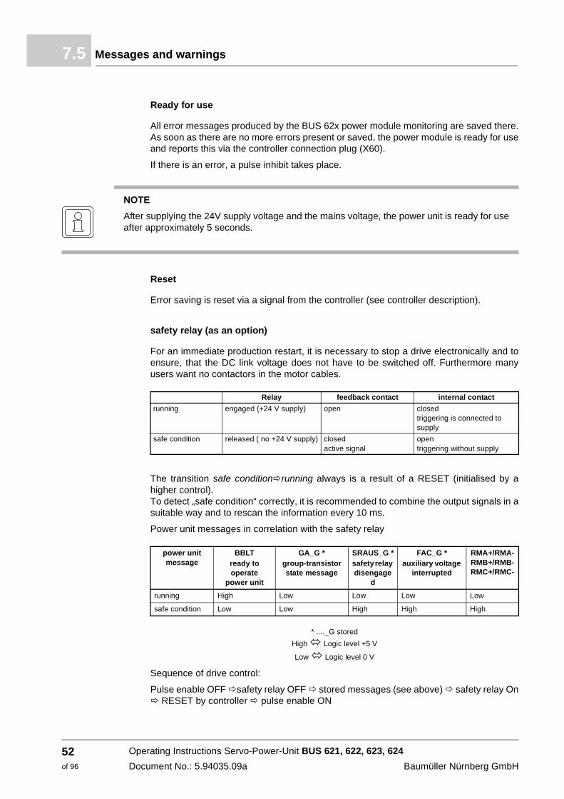
The transition safe condition running always is a result of a RESET (initialised by a higher control). To detect „safe condition“ correctly, it is recommended to combine the output signals in a suitable way and to rescan the information every 10 ms.
Power unit messages in correlation with the safety relay
* ...._G stored
High Logic level +5 V
Low Logic level 0 V
Sequence of drive control:
Pulse enable OFF safety relay OFF stored messages (see above) safety relay On RESET by controller pulse enable ON
NOTE
After supplying the 24V supply voltage and the mains voltage, the power unit is ready for use after approximately 5 seconds.
Relay feedback contact internal contact
running engaged (+24 V supply) open closed triggering is connected to supply
safe condition released ( no +24 V supply) closed active signal
open triggering without supply
power unit message
BBLTready to operate
power unit
GA_G *group-transistorstate message
SRAUS_G *safety relay disengage
d
FAC_G *auxiliary voltage
interrupted
RMA+/RMA-RMB+/RMB-RMC+/RMC-
running High Low Low Low Low
safe condition Low Low High High High
Operating Instructions Servo-Power-Unit BUS 621, 622, 623, 624
Document No.: 5.94035.09a Baumüller Nürnberg GmbH
52of 96
Operation 7
7.6 MaintenanceMaintenance is primarily the monitoring of the ambient conditions. When appropriately planning your facility, you can monitor the ambient conditions during the ongoing operation and do not have to interrupt the operation for maintenance.
You can find more information at ZMaintenance– starting on page 55.
Operating Instructions Servo-Power-Unit BUS 621, 622, 623, 624
Document No.: 5.94035.09a
53of 96
Maintenance7.6
Operating Instructions Servo-Power-Unit BUS 621, 622, 623, 624
Document No.: 5.94035.09a Baumüller Nürnberg GmbH
54of 96
8
8MAINTENANCEIn this chapter we describe, how you can safely maintain your device.
8.1 Safety instructions
h Refer to ZFundamental safety instructions– starting on page 7.
h Refer to the danger areas of the devices.
8.2 Environmental conditions
If the prescribed environmental conditions are complied with, the device is maintenance-free. The prescribed environmental conditions are to be found in chapter ZAppendix B - Technical data– from page 69. The most important prescribed environmental conditions are:
m dustless ambient air
m Temperature: min. 5 °C bis max. 55 °C (pay attention to the over 40 °C derating!)
m Relative air humidity: 5% to 85%, no condensation
NOTE
Condensation is possible, if a device is straightly built in and started after it is fetched from the storage.
55of 96
Operating Instructions Servo-Power-Unit BUS 621, 622, 623, 624
Document No.: 5.94035.09a
Inspection intervals - maintenance notes8.3
8.3 Inspection intervals - maintenance notes
Baumüller Nürnberg GmbH recommends a steady checking of the environmental condi-tions. Thus you will receive the possibility, to react immediately, in case the actual condi-tions deviate from the prescribed conditions.
h Check at least once a day the equipment at the control cabinet, which ensure the re-quired environmental air (e.g. air filters).
h Maintain the air filters according to the indications of the manufacturer.
In the case of polluted environmental air, the required cooling air rate can not be reached anymore, if dirt deposits narrow/block up the ventilation slots. If the devices are dirty, con-tact Baumüller Nürnberg GmbH, in order to initiate a servicing or send the device to the company for inspection.
WARNING
The following may occur, if you do not observe this warning information:
m serious personal injury m death
The danger is: electricity. The unit carries dangerous voltages and currents, as well as re-sidual charges in the DC link.
Assure, that when working in the control cabinet, that all devices in the control cabinet are off-circuit and are safe against re-starting.
Await the discharging of the DC link, before maintenance work is carried out. The capacitors, which are used in the device of the DC link are 10 min. after interruption of the supply voltage discharge so far, that the connections can be demounted without danger. If you have addi-tional capacitors connected to the DC link, the discharging of the DC link also can last much longer. In this case you must determine the necessary delay time yourself and you must de-termine the deenergization at all terminals of the device (also see ZHazards due to residual energy– starting on page 20).
WARNING
The following may occur, if you do not observe this warning information:
m serious personal injury m death
The danger is: electricity. The device can be damaged by incorrect maintenance in such a way, that a safe operating isn’t possible anymore.
Do not maintain the device yourself.
Never remove dirt deposits especially in the inside of the device with sharp objects like screw-drivers or by the usage of e. g. compressed air, steam jet appliances/high pressure cleaners.
Operating Instructions Servo-Power-Unit BUS 621, 622, 623, 624
Document No.: 5.94035.09a Baumüller Nürnberg GmbH
56of 96

Maintenance 8
8.4 RepairWARNING
The following may occur, if you do not observe this warning information:
m serious personal injury m death
The danger is: electricity. After a faulty repair the device doesn’t fulfill the safety instructions anymore.
Have the devices be commissioned only by Baumüller Nürnberg GmbH or the authorized service points.
Operating Instructions Servo-Power-Unit BUS 621, 622, 623, 624
Document No.: 5.94035.09a
57of 96

Repair8.4
Operating Instructions Servo-Power-Unit BUS 621, 622, 623, 624
Document No.: 5.94035.09a Baumüller Nürnberg GmbH
58of 96

9
9DECOMMISSIONING, STORAGEThis chapter describes how to remove the unit from service and store the unit.
9.1 Safety regulations
h Observe ZFundamental safety instructions– starting on page 7 and the information in ZPackaging and transportation– starting on page 23.
Only skilled and trained personnel may decommission the unit.
DANGER
The following will occur, if you do not observe this danger information:
m serious personal injury m death
The risk is: Electricity and stored electrical charge. Electrical connections that are not currentless carry dangerous voltage. The modules contained in the unit (i. e. condensers) can also contain dangerous charges after disconnecting!
Verify that all electrical connections are de-energized and are secured against restarting.
Prior to working on electrical connections with suitable measuring devices, check that the connections are not live.
Only remove the connections, if you are convinced that they are not live.
The condensers used in the device must discharge automatically 10 min. after switching off the supply voltage so that you can remove the connections without risks. Various discharge times result, regardless of the size of the unit. These may be found from ZTechnical data– starting on page 69. If you connected additional capacitors to the DC link, the DC link discharge can also last much longer. In this case, you must determine the necessary waiting period (see also ZHazards due to residual energy– starting on page 20).
59of 96
Operating Instructions Servo-Power-Unit BUS 621, 622, 623, 624
Document No.: 5.94035.09a
Requirements to the executing personnel9.2
9.2 Requirements to the executing personnel
The personnel, who is appointed to setting out of operation, must have the required knowledge and instructions, which is necessary for an execution according to the rules. Select the personnel in such a way, that the safety instructions, which are mounted to the device and its parts as well as to the connections, are understood and applied to.
9.3 Decommissioning
Execute the setting out of operation as follows:
1 put the device off-circuit and assure the device against unintentional restart.
2 check the isolation from supply of all connections (earliest 10 minutes after switching off).
3 demount the connections and protect the connections according to the safety instruc-tions.
4 document the shut down setting.
9.4 Demounting
The demounting assumes a completed, documented setting out of operation.
1 secure the device against falling off/out.
2 loosen all mechanical connections.
3 lift the device out of the control cabinet.
4 store the device in a suitable packing.
5 at transportation pay attention to, that the device is not damaged by wrong storage or severe shocks, also see ZObserve during transportation– starting on page 23.
In case you want to dispose the device, additional data is available in chapter ##ZDisposal– starting on page 63.
CAUTION
The following may occur, if you do not observe this caution information:
m minor to medium personal injury.
In case, while installing, you lift a device with unprotected hands, fingers/palm can be cut. If the device falls off, your feet can be cut up.
Wear safety gloves
Wear safety shoes
Operating Instructions Servo-Power-Unit BUS 621, 622, 623, 624
Document No.: 5.94035.09a Baumüller Nürnberg GmbH
60of 96

Decommissioning, storage 9
9.5 Storage conditionsThe device is maintenance-free. If you keep to the environmental conditions during the entire period of storage, you can assume, that the device will not be damaged. In case the environmental conditions during storage are not kept, you should assume that the device is damaged after storage.
9.6 Recommissioning
Execute commissioning as with a new device, see ZAssembly– starting on page 31, ZInstallation– starting on page 37..
CAUTION
The following may occur, if you do not observe this caution information:
m property damage.
The danger is: incorrect environmental conditions. Incorrect storage can damage/destroy the device.
Assure, that the environmental conditions are kept during the entire period of storage:
m Climatic category 1K4
m Temperature range -25 °C to +55 °C
The danger is: recommissioning without forming of the capacitors. From six months stor-age period on, the capacitors are destroyed during commissioning, if they are not formed be-forehand.
m Reform the DC link capacitors by supplying the device ready-to-operate for at least one hour with supply voltage, but do not transmit a pulse enable during this time.
m Consider, that it is imperative, to connect the accordingly prescribed line commutating re-actor for this forming procedure.Devices, where no line commutating reactor is necessary can directly be supplied with mains voltage.
The danger is: recommissioning without forming of the capacitors. From six months stor-age period on, the capacitors can be destroyed during commissioning, if they are not formed beforehand.
m Form the DC link capacitors by supplying the device ready-to-operate for at least one hour with supply voltage, but do not transmit a pulse enable during this time.
m Consider, that it is imperative, to connect the accordingly prescribed line commutating re-actor for this forming procedure. Devices, where no line commutating reactor is necessary can directly be supplied with mains voltage.
Operating Instructions Servo-Power-Unit BUS 621, 622, 623, 624
Document No.: 5.94035.09a
61of 96

Recommissioning9.6
Operating Instructions Servo-Power-Unit BUS 621, 622, 623, 624
Document No.: 5.94035.09a Baumüller Nürnberg GmbH
62of 96

10
10DISPOSALIn this chapter we describe the correct and safe disposal of the devices of the series Servo-Power-Unit. During the disposal you will mainly get metal parts (iron- and non-iron metal), electronic scrap and plastics.
10.1 Safety instructions
h Refer to ZFundamental safety instructions– ab Seite 7.
NOTE
Baumüller products do not belong to the scope of the EU guideline for the disposal of electrical and electronics devices (WEEE, 2002/96/EG). Therefore, no costs are to be carried by Baumüller for the canceling and disposal of old devices.
DANGER
The following will occur, if you do not observe this danger information:
m serious personal injury m death
The danger is: electricity. The containing components in the device (e. g. capacitors) can contain dangerous charges! The capacitors used in the device are after 10 min. automatically so far discharged, that they can be demounted without danger.
If you have additional capacitors connected to the DC link, the discharging of the DC link also can last much longer. In this case you must determine the necessary delay time self (also see ZHazards due to residual energy– ab Seite 20).
Demount the capacitors only then, if you have verified yourself of the isolation from supply.
63of 96
Operating Instructions Servo-Power-Unit BUS 621, 622, 623, 624
Document No.: 5.94035.09a

Safety instructions10.1
CAUTION
The following may occur, if you do not observe this caution information:
m minor to medium personal injury.
The danger is: sharp edges. The components of the device, sheet metal components, heat sinks and so on can have sharp edges!
In case you lift a device during demounting with non-protected hands, your fingers/palms can be cut. If the device falls off, your feet can be cut up.
Wear safety gloves
Wear safety shoes
WARNING
The following may occur, if you do not observe this warning information:
m serious personal injury m death
The risk is: mechanical action. A unit of size 446X weighs 70,0 kg and can inure you severely or kill you, if it drops.
Verify that the unit cannot drop through suitable measures, such as braces, cranes, aids.
CAUTION
The following may occur, if you do not observe this danger information:
m environmental pollution.
The danger is: incorrect disposal.
You may only dispose under consideration of the safety instructions. If necessary, also refer to the local regulations. In case you cannot execute a secure disposal, contact a certified disposal business.
Dangerous materials may result or may be set free from a fire.
Do not expose electronic components to high temperatures.
The inner insulation e. g. various power semiconductors hold beryllium oxide. When opened, the beryllium dust is dangerous to your health.
Do not open the electronical components.
Operating Instructions Servo-Power-Unit BUS 621, 622, 623, 624
Document No.: 5.94035.09a Baumüller Nürnberg GmbH
64of 96
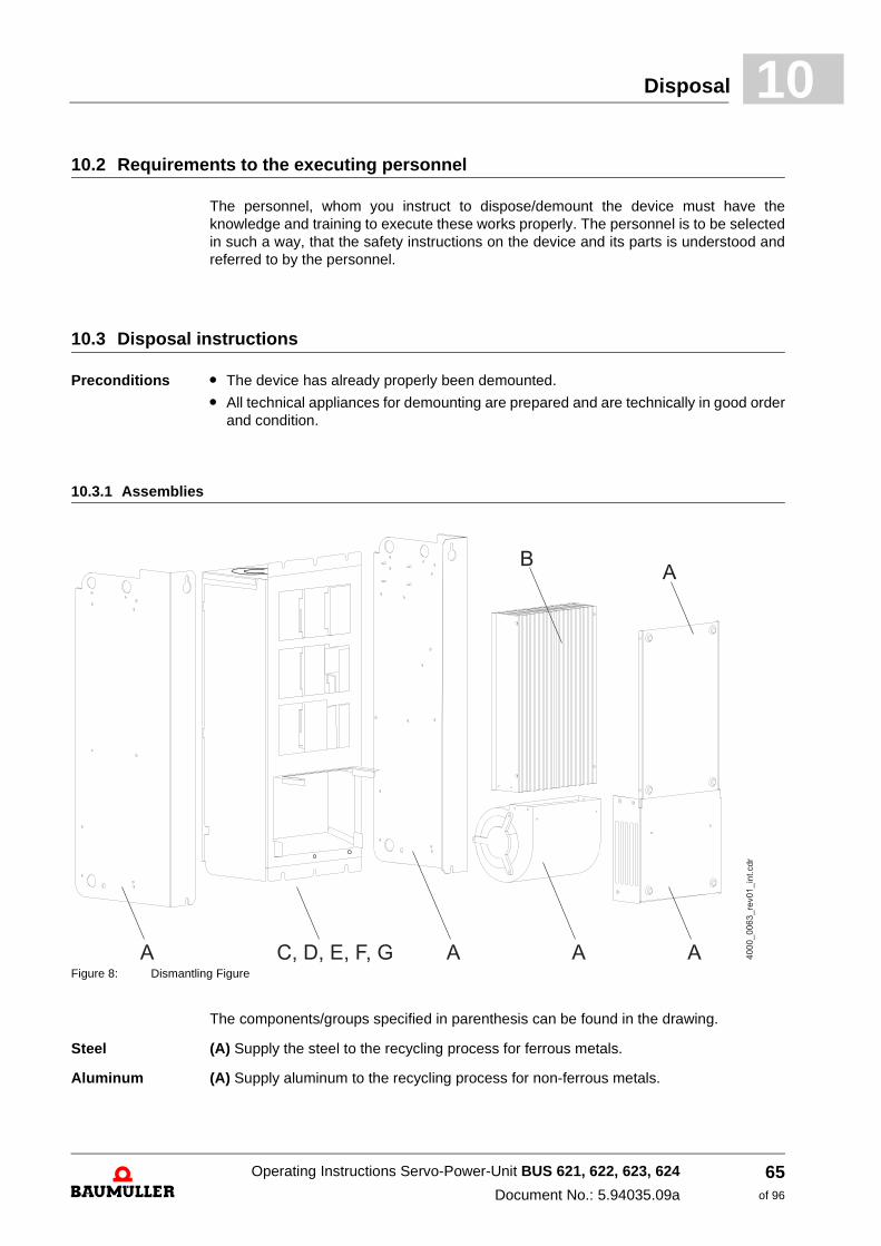
Disposal 10
10.2 Requirements to the executing personnelThe personnel, whom you instruct to dispose/demount the device must have the knowledge and training to execute these works properly. The personnel is to be selected in such a way, that the safety instructions on the device and its parts is understood and referred to by the personnel.
10.3 Disposal instructions
Preconditions m The device has already properly been demounted.
m All technical appliances for demounting are prepared and are technically in good order and condition.
10.3.1 Assemblies
Figure 8: Dismantling Figure
The components/groups specified in parenthesis can be found in the drawing.
Steel (A) Supply the steel to the recycling process for ferrous metals.
Aluminum (A) Supply aluminum to the recycling process for non-ferrous metals.
Operating Instructions Servo-Power-Unit BUS 621, 622, 623, 624
Document No.: 5.94035.09a
65of 96

Recycling plants/offices10.4
Aluminum/copper compound
(A) Supply aluminum/copper compound to the recycling process for non-ferrous metals.
Plastics (D) Supply the plastic parts of the housing as well as the covers and other small items made of plastic to the recycling process for plastics.
Capacitors Capacitors are to be recycled as special waste. Thereby refer to the relevant instructions.
Semiconductor modules
Semiconductor modules are to be recycled as special waste. Thereby refer to the relevant instructions.
Electronic scrap The electronic scrap from PCBs, which no further can be demounted, must be recycled as special waste. Thereby refer to the relevant instructions.
10.4 Recycling plants/offices
Assure, that the disposal is carried out according to your company’s regulations and the regulations of the disposal companies and official administrations. In case of doubt, contact the local business administration, which is responsible for your company or the environmental office.
CAUTION
The following may occur, if you do not observe this danger information:
m environmental pollution.
The danger is: incorrect disposal.
Capacitors, semiconductor modules and electronic scrap is to be recycled as special waste.
Operating Instructions Servo-Power-Unit BUS 621, 622, 623, 624
Document No.: 5.94035.09a Baumüller Nürnberg GmbH
66of 96
A
APPENDIX A - ABBREVIATIONSAC Alternating current
AM Asynchronous motor
BBint Operational readiness (internal)
BUC Baumüller rectifier / regenerative feedback unit
BUG Baumüller basic inverter-rectifier unit
BUM Baumüller single power unit
BUS Baumüller power module
DC Direct current
DIN German Institute for Standardization e.V.(Deutsches Institut für Normung e.V.)
EMV Electromagnetic compatibility
EN European standard
FI Fault current
HS Main contactor
NN Height above zero
PELV Low voltage with safe isolation, grounded
SELV Low voltage with safe isolation
SL PE
SM Synchronous motor
VBG Administrative Professional Association
VDE Association of German Electrical Engineers
ZK Link
67of 96
Operating Instructions Servo-Power-Unit BUS 621, 622, 623, 624
Document No.: 5.94035.09a

A
Operating Instructions Servo-Power-Unit BUS 621, 622, 623, 624
Document No.: 5.94035.09a Baumüller Nürnberg GmbH
68of 96

B
APPENDIX B - TECHNICAL DATAIn this chapter you will find detailed technical data on all sizes of the device series Servo-Power-Unit BUS 621, 622, 623, 624 .
B.1 Requirements for the energy supply
See the operating instructions for basic unit BUG / BUC.
1) The control voltage must correspond with PELV (EN61800-5-1, Chapter 3.2.14) and SELV (EN61800-5-1, Chapter 3.2.28). The fan performance is reduced at a control voltage of < 24 V. It may therefore be necessary to reduce the output currents as well. If you include UL508C: limit the current to 4 A (UL-listed) and to a max. voltage of 30 VDC.
2) according to EN61131-2: 1994, Table 7.
Control voltage 1) (UDC) + 24 V -15% / +20% 2)
69of 96
Operating Instructions Servo-Power-Unit BUS 621, 622, 623, 624
Document No.: 5.94035.09a

B.2
B.2 Connection between the rated and peak currents
m Calculating the effective thermal current from a design cycle
Abbildung 9: Calculation of the thermal effective current
m Connection between the peak and rated current for the interpretation of a movement cycle
Abbildung 10: Connection between the peak and rated current
i(t)
I1
I2
I3
T
t
t1 t2 t3
I1
I2
I3
t1 t2 t3
Ieff In2 tn
T----⋅
n 1=
k
∑ I12 t1
T---- I2
2 t2T---- I3
2 t3T----⋅+⋅+⋅= =
i(t)
IPeak
T
ttPeak
IPeak
T + tPeak
tPeak
T------------
Inenn
IPeak------------⎝ ⎠⎛ ⎞
2=
Operating Instructions Servo-Power-Unit BUS 621, 622, 623, 624
Document No.: 5.94035.09a Baumüller Nürnberg GmbH
70of 96
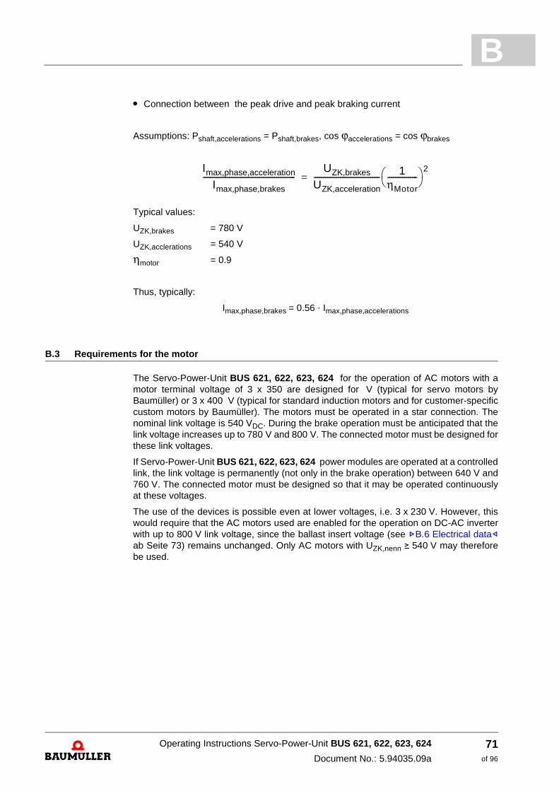
B
m Connection between the peak drive and peak braking currentAssumptions: Pshaft,accelerations = Pshaft,brakes, cos ϕaccelerations = cos ϕbrakes
Typical values:
UZK,brakes = 780 V
UZK,acclerations = 540 V
ηmotor = 0.9
Thus, typically:
Imax,phase,brakes = 0.56 ⋅ Imax,phase,accelerations
B.3 Requirements for the motor
The Servo-Power-Unit BUS 621, 622, 623, 624 for the operation of AC motors with a motor terminal voltage of 3 x 350 are designed for V (typical for servo motors by Baumüller) or 3 x 400 V (typical for standard induction motors and for customer-specific custom motors by Baumüller). The motors must be operated in a star connection. The nominal link voltage is 540 VDC. During the brake operation must be anticipated that the link voltage increases up to 780 V and 800 V. The connected motor must be designed for these link voltages.
If Servo-Power-Unit BUS 621, 622, 623, 624 power modules are operated at a controlled link, the link voltage is permanently (not only in the brake operation) between 640 V and 760 V. The connected motor must be designed so that it may be operated continuously at these voltages.
The use of the devices is possible even at lower voltages, i.e. 3 x 230 V. However, this would require that the AC motors used are enabled for the operation on DC-AC inverter with up to 800 V link voltage, since the ballast insert voltage (see ZB.6 Electrical data– ab Seite 73) remains unchanged. Only AC motors with UZK,nenn v 540 V may therefore be used.
Imax,phase,acceleration
Imax,phase,brakes-------------------------------------------------
UZK,brakes
UZK,acceleration----------------------------------- 1
ηMotor----------------⎝ ⎠⎛ ⎞ 2
=
Operating Instructions Servo-Power-Unit BUS 621, 622, 623, 624
Document No.: 5.94035.09a
71of 96
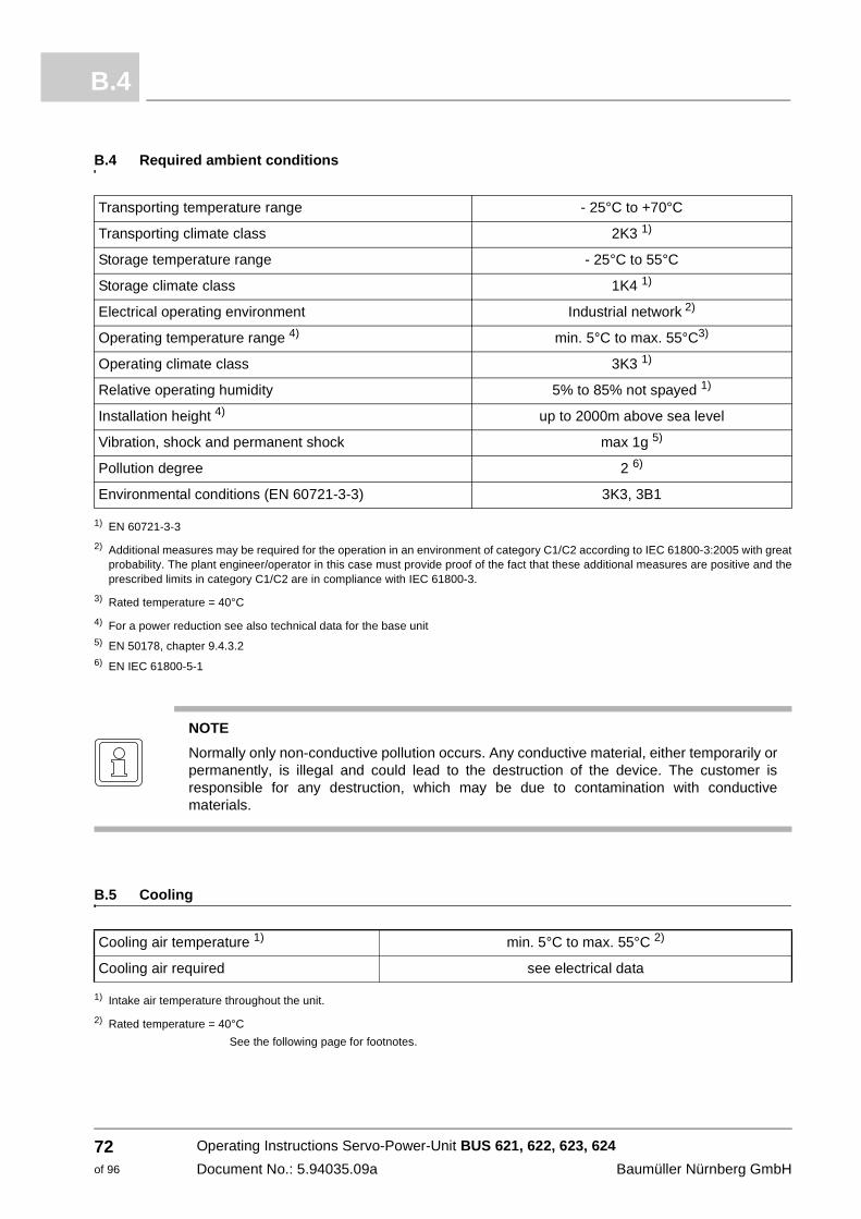
B.4
B.4 Required ambient conditions
1) EN 60721-3-3
2) Additional measures may be required for the operation in an environment of category C1/C2 according to IEC 61800-3:2005 with great probability. The plant engineer/operator in this case must provide proof of the fact that these additional measures are positive and the prescribed limits in category C1/C2 are in compliance with IEC 61800-3.
3) Rated temperature = 40°C
4) For a power reduction see also technical data for the base unit5) EN 50178, chapter 9.4.3.26) EN IEC 61800-5-1
B.5 Cooling
1) Intake air temperature throughout the unit.
2) Rated temperature = 40°C
See the following page for footnotes.
Transporting temperature range - 25°C to +70°C
Transporting climate class 2K3 1)
Storage temperature range - 25°C to 55°C
Storage climate class 1K4 1)
Electrical operating environment Industrial network 2)
Operating temperature range 4) min. 5°C to max. 55°C3)
Operating climate class 3K3 1)
Relative operating humidity 5% to 85% not spayed 1)
Installation height 4) up to 2000m above sea level
Vibration, shock and permanent shock max 1g 5)
Pollution degree 2 6)
Environmental conditions (EN 60721-3-3) 3K3, 3B1
NOTE
Normally only non-conductive pollution occurs. Any conductive material, either temporarily or permanently, is illegal and could lead to the destruction of the device. The customer is responsible for any destruction, which may be due to contamination with conductive materials.
Cooling air temperature 1) min. 5°C to max. 55°C 2)
Cooling air required see electrical data
Operating Instructions Servo-Power-Unit BUS 621, 622, 623, 624
Document No.: 5.94035.09a Baumüller Nürnberg GmbH
72of 96

B
B.6 Electrical data* not supplied, must be ordered separately
1 According to EN 61131-2 (Table 5). With a supply voltage < 24 V the fan power is reduced. Therefore, it may be necessary to reduce the output current additonally.
2 depends on the connected DC Link capacity.
Power unit BUS 621 BUS 622 BUS 623 BUS 624
Control * Slot for BUS 6 controller cassette
DC link voltage nominal value maximum (< 2 min)
0 ... 685 VDC540 VDC760 VDC
Low voltage supply for controller and 1) moitoring functions
+ 24 VDC - 10% + 20%
Power input without controller 22 W 22 W 27 W 39 W
Capacitor DC Link 50 µF 110 µF 235 µF 500 µF
Switch on: Ready for use after 2) ≤ 10 s
Output voltage 3) 3 x 0 VAC ... connection voltage BUG - 30 V resp.
3 x 0,74 • DC link voltage
Output frequency 0 Hz ... 300 Hz
Output power 4) 1,4 kVA 3,5 kVA 7 kVA 10,5 kVA 14 kVA 26 kVA 31 kVA
Typ. motor power 4) 0,8 kW 2 kW 4 kW 6 kW 8 kW 15 kW 20 kW
Typ. motor max. power 5) 1,2 kW 3 kW 6 kW 9 kW 12 kW 23 kW 30 kW
Output nominal current (Ieff) 4) 6) 2 A 5 A 10 A 15 A 20 A 38 A 45 A
Output max. current (Ieff) 6) 7) 3 A 7,5 A 15 A 22 A 30 A 55 A 67 A
permitted transistor clock frequency 3 ... 8 kHz
Power loss during rated operation 4)
without low voltage supply30 W 75 W 150 W 170 W 230 W 450 W 550 W
safety relay (as an option) coil side nominal voltage
operating voltage coil resistance
contact side max. switching voltage max. switching current max. switching capacity
24 V (SELV)18,4 V to 50,4 V at Tu = 20 °C
1300 Ω ±10 %25 VAC resp. 60 VDC (SELV)
5 A (max. permanent current 6 A)1500 VAAC / 30 WDC
type of protection IP 20
Operational environment range TB 0 ... 40 °C (with power reduction 55 °C)
Reduction for nominal output current (45 ... 55 °C)
0 % / °C 3 % / °C
Installation hight 8) 1000 m above sea level
Relative humidity 15 % ... 85 % no condensation
Storage temperature range - 30 °C ... + 70 °C
Short circuit proof partly short circuit proof
Dimensions Width 66 mm 99 mm 132 mm 165 mm
Height 360 mm
Depth 280 mm
Weight without controller 5 kg 7,5 kg 10 kg 12,5 kg
Operating Instructions Servo-Power-Unit BUS 621, 622, 623, 624
Document No.: 5.94035.09a
73of 96
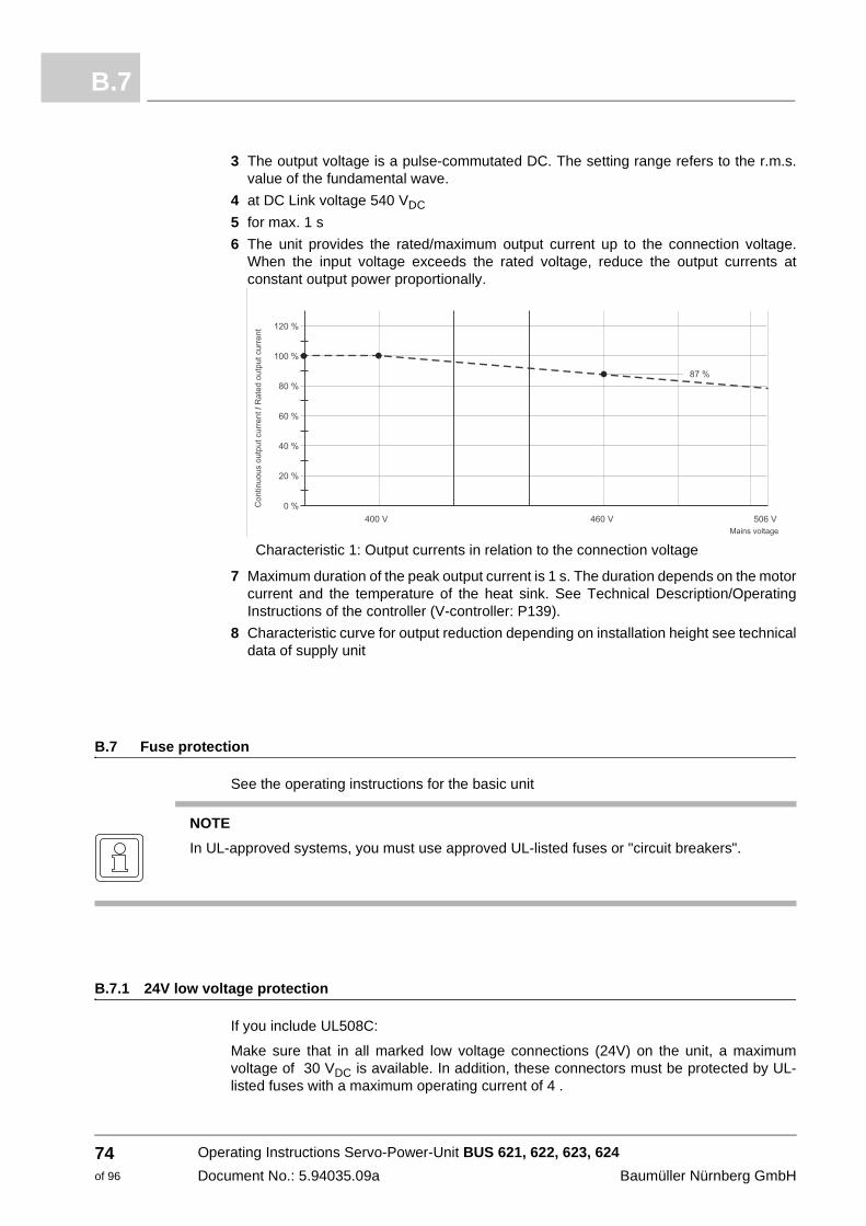
B.7
3 The output voltage is a pulse-commutated DC. The setting range refers to the r.m.s. value of the fundamental wave.
4 at DC Link voltage 540 VDC
5 for max. 1 s
6 The unit provides the rated/maximum output current up to the connection voltage. When the input voltage exceeds the rated voltage, reduce the output currents at constant output power proportionally.
Characteristic 1: Output currents in relation to the connection voltage
7 Maximum duration of the peak output current is 1 s. The duration depends on the motor current and the temperature of the heat sink. See Technical Description/Operating Instructions of the controller (V-controller: P139).
8 Characteristic curve for output reduction depending on installation height see technical data of supply unit
B.7 Fuse protection
See the operating instructions for the basic unit
B.7.1 24V low voltage protection
If you include UL508C:
Make sure that in all marked low voltage connections (24V) on the unit, a maximum voltage of 30 VDC is available. In addition, these connectors must be protected by UL-listed fuses with a maximum operating current of 4 .
NOTE
In UL-approved systems, you must use approved UL-listed fuses or "circuit breakers".
Operating Instructions Servo-Power-Unit BUS 621, 622, 623, 624
Document No.: 5.94035.09a Baumüller Nürnberg GmbH
74of 96
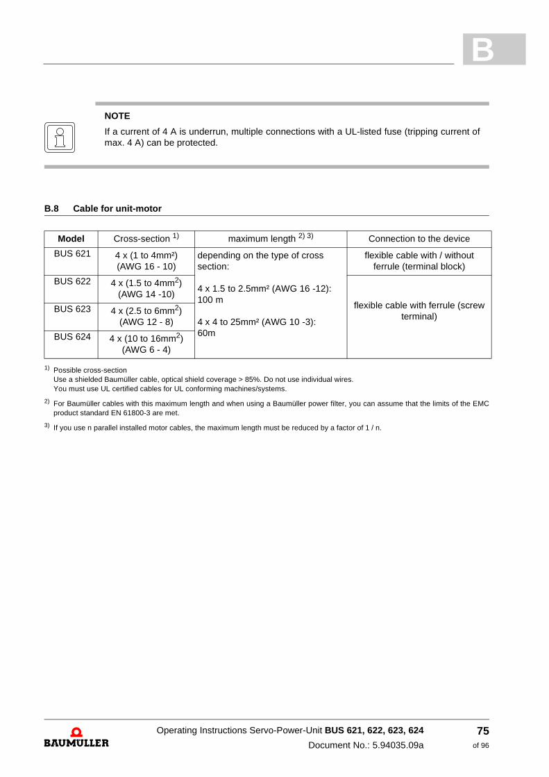
B
B.8 Cable for unit-motor
1) Possible cross-section Use a shielded Baumüller cable, optical shield coverage > 85%. Do not use individual wires. You must use UL certified cables for UL conforming machines/systems.
2) For Baumüller cables with this maximum length and when using a Baumüller power filter, you can assume that the limits of the EMC product standard EN 61800-3 are met.
3) If you use n parallel installed motor cables, the maximum length must be reduced by a factor of 1 / n.
NOTE
If a current of 4 A is underrun, multiple connections with a UL-listed fuse (tripping current of max. 4 A) can be protected.
Model Cross-section 1) maximum length 2) 3) Connection to the device
BUS 621 4 x (1 to 4mm²)(AWG 16 - 10)
depending on the type of cross section:
4 x 1.5 to 2.5mm² (AWG 16 -12): 100 m
4 x 4 to 25mm² (AWG 10 -3): 60m
flexible cable with / without ferrule (terminal block)
BUS 622 4 x (1.5 to 4mm2)
(AWG 14 -10)flexible cable with ferrule (screw
terminal) BUS 623 4 x (2.5 to 6mm2)
(AWG 12 - 8)
BUS 624 4 x (10 to 16mm2)
(AWG 6 - 4)
Operating Instructions Servo-Power-Unit BUS 621, 622, 623, 624
Document No.: 5.94035.09a
75of 96
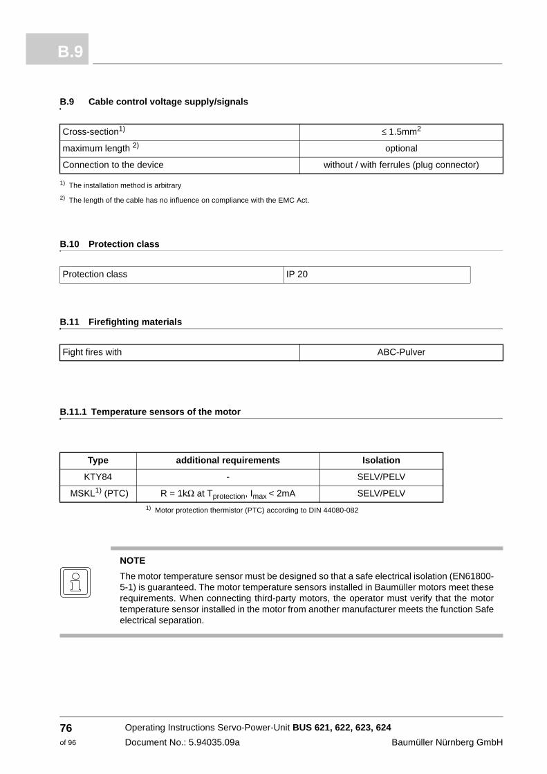
B.9
B.9 Cable control voltage supply/signals
1) The installation method is arbitrary
2) The length of the cable has no influence on compliance with the EMC Act.
B.10 Protection class
B.11 Firefighting materials
B.11.1 Temperature sensors of the motor
1) Motor protection thermistor (PTC) according to DIN 44080-082
Cross-section1) ≤ 1.5mm2
maximum length 2) optional
Connection to the device without / with ferrules (plug connector)
Protection class IP 20
Fight fires with ABC-Pulver
Type additional requirements Isolation
KTY84 - SELV/PELV
MSKL1) (PTC) R = 1kΩ at Tprotection, Imax < 2mA SELV/PELV
NOTE
The motor temperature sensor must be designed so that a safe electrical isolation (EN61800-5-1) is guaranteed. The motor temperature sensors installed in Baumüller motors meet these requirements. When connecting third-party motors, the operator must verify that the motor temperature sensor installed in the motor from another manufacturer meets the function Safe electrical separation.
Operating Instructions Servo-Power-Unit BUS 621, 622, 623, 624
Document No.: 5.94035.09a Baumüller Nürnberg GmbH
76of 96
C
APPENDIX C - SAFETY TECHNOLOGYC.1 Measures to prevent an unexpected start
In order to rule out any risks to persons, e.g. operator, service and maintenance technicians, the machine must be maintained in a safe condition (safe stop) when accessing the hazardous area. The reliable prevention of an unexpected start is therefore required (including Machinery Directive 2006/42/EC, Appendix I, 1.2.4, EN ISO 12100-1). An unexpected start means any attempt that can create a risk for people by its unexpected occurrence (EN 292-1). The unexpected acceleration of the machine, as well as the transition from a safe stop to an unsafe movement must also be considered in addition to the transition from the rest to the operating condition of the machine. This is necessary as the unexpected ramp-up is usually due to an interruption of the control circuit of the machine. In this case, the actuator based on the control attempts to achieve the highest speed at the maximum acceleration. The machine operator therefore no longer has the chance to remove himself or his hand from the hazardous area at an unexpected start. The actuator must therefore be stopped at open, electrically interlocked safety equipment and be securely maintained in its rest position. The motor may not be able to generate any torque and therefore no dangerous movement.
Preventing an unexpected start can be achieved by electrically isolating safety equipment, such as contactors.
This form of shutting down, however, no longer corresponds with the current state of the art, since the contact-switching operation in the power circuit of the drive may result in unnecessary wear in the switching element and to relatively long response times on the machine.
The integration of the protection function is more efficient for preventing an unexpected start directly into the inverter. Here, the drive itself is not isolated from the power supply, however, the commutation safety prevents the power semiconductors in the inverter.
In power modules BUS 621, 622, 623 624, this occurs by the safety relay, which switches off the power supply for the IGBT control (cutoff method 1).
A second cutoff method is realized by the two usable Baumüller controllers M-Drive and V-controller via the pulse enable channel: Here, the pulses for the IGBT activation are also blocked.
77of 96
Operating Instructions Servo-Power-Unit BUS 621, 622, 623, 624
Document No.: 5.94035.09a

C.1
NOTE
In the unlikely event of total failure of an internal driver (IGBT) or an actuator element, it can trigger a temporary excitement of the drive (also in the STO state).
If the link to a winding of the motor is "shorted", a magnetic field can develop in the motor. If this concerns an induction motor, the resulting DC field cannot effect a jolt of the rotor.
The rotor in a permanently energized synchronous motor will rotate into a no-load position. The angular movement covered in this case depends on the rotor position and the number of pole pairs of the motor. It amounts to a maximum of 180°/number of pole pairs.
The potential jolting movement must be considered when planning a machine with a synchronous motor.
NOTE
The function is limited to the prevention of unexpected start. Switching the safety relay while the rotor of the motor rotates causes uncontrolled "coasting" of the machine, slowing down by using the power converter is no longer possible.
WARNING
The following may occur, if you do not observe this warning information:
m serious personal injury m death
The risk is: Electricity Line voltage may be present on the motor, as well as the unit at an activated STO/safe stop function.
If necessary, switch off the power as to a unit without a safety relay - the safety relay does not switch off the power to the device and the motor!
NOTE
Activating the STO / Safe Stop does not result in an isolation from the power supply. Supply voltage can therefore be present at both the power converter as well as the motor. Other means must therefore be used to secure the protection from electrical hazards (i.e. main switch) for maintenance, service and repair work on electrical components of the propulsion system.
Operating Instructions Servo-Power-Unit BUS 621, 622, 623, 624
Document No.: 5.94035.09a Baumüller Nürnberg GmbH
78of 96

C
C.2 Safe Torque Off (STO)Refer to the SAH (Safety Application Handbook) for additional information.
C.2.1 Safety classifications and safety instructions
according to DIN EN ISO 13849-1 and EN 62061
The power modules BUS 621, 622, 623, 624 in device models "-001", in conjunction with the two Baumüller controllers
- M-Drive of version "BUS6-MC-xx-xxxx-xxxx-SIxx-..."
or
- V-controller of version "BUS6-S1-VC-..."
have the safety function STO (Safe Torque Off).
The actuator in function STO is switched torqueless.
If no load acts on the drive shaft, the drive will stop after coming to a rest (coasting). No active threat therefore comes from the drive, provided that the STO function is selected. A start of the drive without the withdrawal of the STO function is not possible.
The STO-function meets the following safety classifications and standards:
m PL-d according to DIN EN ISO 13849-1 with the following parameters:
n Structure: cat 3
n MTTFd: high
n DC: low
m SIL 2 according to EN 62061 and 61508 with PFHDssD = 3 x 10⁻¹⁰
Additional instructions for the STO function: EN 61800 part 5.2
Operating Instructions Servo-Power-Unit BUS 621, 622, 623, 624
Document No.: 5.94035.09a
79of 96

C.2
NOTE
The above safety levels apply only if the safety instructions listed below will be considered and respected.
m The classification of the safety category applies only to the STO function.
m The following switching measures must be met to achieve the safety function:
n Two-channel connection of the cutoff
n Control of the force-operated opener
n Using an external circuit or a switching device that is suitable for the two-channel circuit with the necessary control (i.e., safety relay or safety controller)
m The perfect function of the relay must be checked at least once a year. The relay must hereby be unplugged, and the NC contact must be monitored for the closing function.
m Prior to switching on the drive for the first time (via a safety device), the state of the NC contact must be monitored for its closing function.
m Abruptly stopping the drive or an out-of-round operation can be triggered by an error in the safety chain. The drive must be switched off when this error occurs.
m Function STO separates the drive only from its torque and not the voltage. For safe separation of the supply, another action (i.e. the use of a main switch) must be used.
m In the unlikely event of total failure of an internal driver (IGBT) or an actuator element, it can trigger a temporary excitement of the drive (also in the STO state). The angular movement covered in this case depends on the rotor position and the number of pole pairs of the motor. It amounts to a maximum of 180°/number of pole pairs.
Operating Instructions Servo-Power-Unit BUS 621, 622, 623, 624
Document No.: 5.94035.09a Baumüller Nürnberg GmbH
80of 96

C
C.2.2 Function principle STOApplications that require a risk reduction according to category 3, performance level d or SIL2 according to chapter ZC.2.1 Safety classifications and safety instructions– starting at page 79 must have two independent cutoff paths, which are used to shut down the commutation in the power section of the inverter.
The power modules of series BUS 621, 622, 623, 624 have these two cutoff paths in connection with the Baumüller controllers M-drive or V-control.
The connection diagrams in this chapter and the instructions for the safety levels at Zpage 80– must be considered for the two-channel cutoff.
Cutoff path 1: Safety relay of the power modules BUS621, 622, 623, 624
The function of the safety relay is executed in fail-safe-technic, also named closed-circuit principle. The safety function “safe stop” is active, as long as no voltage is applied to the input connectors (X68: 3,4). Consequently the functioning of the safety function is guaranteed if power failure takes place. In order to deactivate “safe stop” a voltage of 24 V has to be applied to the connectors, which are intended for this use (X68: 3,4).
For the external error monitoring of the safety relay´, the instantaneous control state can be interrogated at its positively driven status signal contact (X68: 1,2). In case there is no voltage applied to the safety relay (X68: 3,4), that means during the “safe stop”, then the status signal contact is closed (NC contact). Also a parting of a cable can thusly be recognized as an error.
If the voltage at the input connectors of the relay (X68: 3,4) is switched off, then the converter generates one or two error messages (F0204 and/or F0206), which it displays on the V-controller. The drive can only be taken in operation again, if these messages are deleted after a reset of the safety relay with a reset signal from the controller (for example by X26, pin programmable or over the interface to a bus system).
Cutoff path 2: Pulse enable of the two usable controller types M-drive and V-controller.
The safety function pulse enable is active, as long as no voltage is present at the input connectors. In this case, the pulses for the IGBT activation are blocked.
In order to deactivate the second shutdown path, a voltage of 24 V must be applied to the available connectors.
Input connectors of the controllers:
M-drive: BUS6-MC-xx-xxxx-xxxx-SIxx-... : X26: IF+, IF-
V- controller: BUS6-S1-VC-...: X26:14, 20
Operating Instructions Servo-Power-Unit BUS 621, 622, 623, 624
Document No.: 5.94035.09a
81of 96

C.2
The closing- and opening sequence of the release signals as well as of the safety relay must be considered in order to assure a faultless operation of the drive.
Figure 11: Sequence diagram of the safety relay
Before the commissioning of the machine, in which the converter with the safety relay is built in, the safety function “protection against unexpected starting” must be checked. For that purpose a safety device must be executed (for example door contact). The motor must now be zero-torque.
Operating Instructions Servo-Power-Unit BUS 621, 622, 623, 624
Document No.: 5.94035.09a Baumüller Nürnberg GmbH
82of 96

C
The two cutoff paths are shown in the following figures for the two usable controller types M-drive and V-control.Figure 12: Cutoff paths for power modules BUS 621, 622, 623, 624 with controller M-drive
Figure 13: Cutoff paths for power module BUS621, 622, 623, 624 with V-controller
The first cutoff path on connector 68 of the power modules (safety relay) is realized by a positively driven relay, which interrupts the driver supply for the activation of the motor. Only when the relay is energized can the drive be set in motion (control inputs X68:3 and X68:4). The condition of the relay contact can be queried via the force operated opener (signal outputs X68: 1 and X68:2).
The second cutoff path (pulse enable), which is guided via the respective controller, is used for a quick disconnect and leads over a semiconductor chain. Only when the inputs are supplied with voltage will the driver generate the necessary signals for the motor rotation.
These are the following signal inputs: M-drive: connector X26: IF+ and IF- V- controller: connector X26: 14 and 20
Operating Instructions Servo-Power-Unit BUS 621, 622, 623, 624
Document No.: 5.94035.09a
83of 96
C.3
C.3 Safe stop
C.3.1 Safety categories according to DIN EN 954-1
Depending on the potential risks (these will be assessed, inter alia in terms of possible injury severity, frequency of the duration of stay in the hazardous area and possibilities of risk prevention), safety components of machines must comply with certain safety criteria. The requirements for safety-related parts are classified in standard EN 954-1 in five categories.
In category B, basic requirements are required in 1 additional safety-tested components and principles. In category 2, an error between test intervals can result in the loss of the safety function.
Category 3 corresponds to the level of "single fault tolerance with partial error detection. The safety-relevant component must be designed so that a single fault does not result in the loss of the safety function, whereby not all possible errors are detected independently by the system. An accumulation of undetected errors can therefore result in the loss of the safety function.
Category 4 corresponds with the level of "self-monitoring". The component detects possible errors independently and reports the loss of the safety function in time. The safety function is always maintained even at the occurrence of up to three independent errors.
C.3.2 The safety relay
The function of the safety relay is performed in fail-safe technology, also called closed-circuit principle. The safety function "safe stop" is active, as long as no voltage is present at the input connectors (X68: 3,4). The function of the safety function is therefore guaranteed, even at a power failure. In order to deactivate the function "safe stop", a voltage of 24V must be applied to the appropriate connectors (X68: 3,4).
For external monitoring of the safety relay, the current switching condition can be queried on its force operated response contacts X68:3,4). If no voltage is present on the safety relay (X68: 3,4) therefore during the "safe stop", the response contacts are closed (opener). Even a broken cable can therefore be detected as an error.
If the voltage is switched off at the input connectors of the relay (X68: 3.4), then the inverter generates one or two error messages (F0204 and / or F0206), which it displays on the V-controller. The drive can only be put into operation again, if these messages are deleted after switching on the safety relays with a reset signal from the controller (i.e. X26, programmable pin or via the interface to a bus system).
Applications that require a risk reduction according to category 3 performance level d or SIL2 must have a second, independent disconnecting path. The safety relay is simply a disconnecting path. The connection diagram and the requirements and instructions in accordance with ZC.2.1 Safety classifications and safety instructions– starting at page 79 must be considered for a two-channel cutoff.
Operating Instructions Servo-Power-Unit BUS 621, 622, 623, 624
Document No.: 5.94035.09a Baumüller Nürnberg GmbH
84of 96
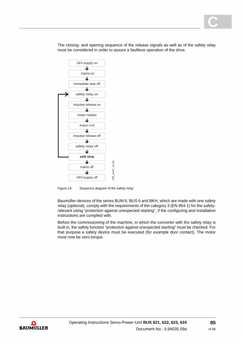
C
The closing- and opening sequence of the release signals as well as of the safety relay must be considered in order to assure a faultless operation of the drive.Figure 14: Sequence diagram of the safety relay
Baumüller-devices of the series BUM 6, BUS 6 and BKH, which are made with one safety relay (optional), comply with the requirements of the category 3 (EN 954-1) for the safety-relevant using “protection against unexpected starting”, if the configuring and installation instructions are complied with.
Before the commissioning of the machine, in which the converter with the safety relay is built in, the safety function “protection against unexpected starting” must be checked. For that purpose a safety device must be executed (for example door contact). The motor must now be zero-torque.
Operating Instructions Servo-Power-Unit BUS 621, 622, 623, 624
Document No.: 5.94035.09a
85of 96

C.3
C.3.3 Application example for a machine of category 3 of EN 954-1
The following diagram shows an example of the application and wiring of a machine tool, in which the safe removal of workpieces with an open protective cover is possible according to Category 3 (EN 954-1).
Figure 15: Example for an application for safe stop according to category 3 (EN 954-1)
The switching-off of the electrical drive motor takes place dual-ported.
m S2 (NC contact) and S3 (NO contact) have hardware effects on the pulse release input of the converter (X26: 14). Only if S2 and S3 display a closed cover (and therewith a safe condition) voltage is being applied to the impulse release input of the converter.
m S1 (NC contact) has hardware effects on the safety relay of the converter. Only if S1 displays a closed cover (and therewith a safe condition) voltage is applied to the safety relay input (X68: 3) and therewith allows a torque generation at the shaft of the motor. The NO contact of S1 is connected with the monitoring circuit.
m The monitoring circuit, a fail-safe monitoring control of the category 3 (EN 954-1), checks on its own the directly connected switching contacts of the position switch S1 (NO contact), S2 (NO contact) and S3 (NC contact). If the barrier is not completely closed or a theoretical impossible condition of the position switch contacts is present (for example S1 and S2 show a different switching condition or S2 and S3 show the same switching condition), then the control circuit will not get a release signal from the monitoring circuit. A missing release signal of the monitoring device leads to a direct
Operating Instructions Servo-Power-Unit BUS 621, 622, 623, 624
Document No.: 5.94035.09a Baumüller Nürnberg GmbH
86of 96
C
switching off of the converter by means of the control circuit. If the monitoring circuit has recognized an error (for example different switch condition of S1 and S2), this is displayed to the operator and a commissioning of the drive is not possible until the error has been repaired.m The status signal contact of the safety relay (X68: 1,2; NC contact) can additionally be evaluated by the monitoring circuit (not obligatory).
m The position switches, which are used, must unavoidable have actuated and mechanical connected contacts as well as a dual-port connection (NC contact/ NO contact). The mechanical operating at the safety device must take place unavoidable, that means tamper-resistant.
The connection cables between the safety relay input (X68: 3,4) and the control as well as between the impulse release input at the converter (X3:5) and the controller must not be installed outside the control cabinet in a common cable channel.
Operating Instructions Servo-Power-Unit BUS 621, 622, 623, 624
Document No.: 5.94035.09a
87of 96
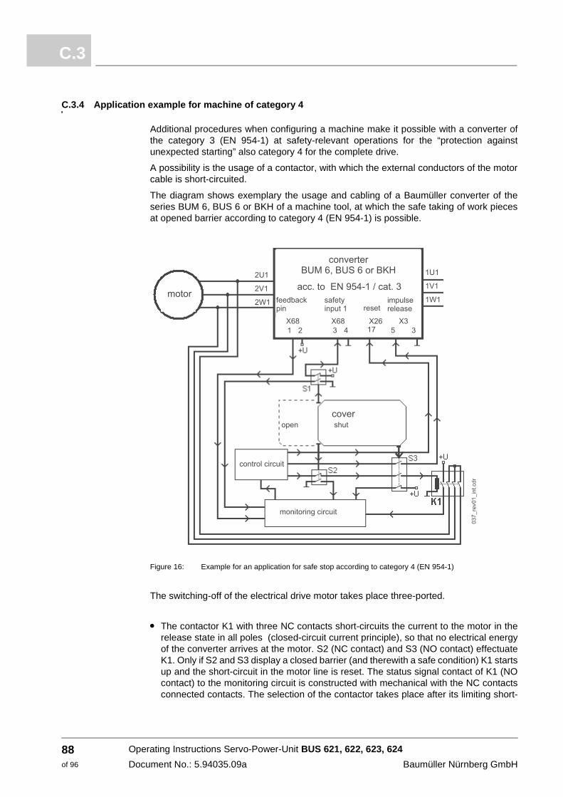
C.3
C.3.4 Application example for machine of category 4
Additional procedures when configuring a machine make it possible with a converter of the category 3 (EN 954-1) at safety-relevant operations for the “protection against unexpected starting” also category 4 for the complete drive.
A possibility is the usage of a contactor, with which the external conductors of the motor cable is short-circuited.
The diagram shows exemplary the usage and cabling of a Baumüller converter of the series BUM 6, BUS 6 or BKH of a machine tool, at which the safe taking of work pieces at opened barrier according to category 4 (EN 954-1) is possible.
Figure 16: Example for an application for safe stop according to category 4 (EN 954-1)
The switching-off of the electrical drive motor takes place three-ported.
m The contactor K1 with three NC contacts short-circuits the current to the motor in the release state in all poles (closed-circuit current principle), so that no electrical energy of the converter arrives at the motor. S2 (NC contact) and S3 (NO contact) effectuate K1. Only if S2 and S3 display a closed barrier (and therewith a safe condition) K1 starts up and the short-circuit in the motor line is reset. The status signal contact of K1 (NO contact) to the monitoring circuit is constructed with mechanical with the NC contacts connected contacts. The selection of the contactor takes place after its limiting short-
Operating Instructions Servo-Power-Unit BUS 621, 622, 623, 624
Document No.: 5.94035.09a Baumüller Nürnberg GmbH
88of 96
C
time current load capability (10 ms). This must be bigger than the nominal current of the used semiconductor fuses at the mains input of the converter.m S1 (NC contact) has hardware effects on the safety relay of the converter. Only then if S1 displays a closed barrier (and therewith a safe condition) voltage is applied to the safety relay input (X68: 3) and therewith makes a torque generation at the shaft of the motor. The NO contact of S1 is connected with the monitoring circuit.
m S3 (NO contact) has hardware effects on the impulse release input of the converter (X26: 14). Only if S3 displays a closed barrier (and therewith a safe condition) voltage is applied to the impulse release input of the converter.
m The monitoring circuit, a fail-safe monitoring control of the category 4 (EN 954-1), checks on its own the directly connected switch contacts of the position switches S1 (NO contact), S2 (NO contact), S3 (NC contact) and the status signal contact of the safety relay (X68: 1,2; NC contact) as well as the contactor K1 (NO contact). If the barrier is not completely closed or a theoretic impossible condition of the position switch contacts is present (for example S1 and S2 show a different switch condition or S2 and S3 show the same switch condition or the status signal contact of the safety relay is opened/closed, although the status signal contact of S1 is closed/opened), the control circuit receives no release signal of the monitoring signal. A missing release signal of the monitoring device leads to a direct switching off of the converter by means of the control circuit. If the monitoring circuit has recognized an error (for example different switch condition of S1 and S2), this if displayed to the operator and the commissiong of the drive is not possible until the error has been repaired.
m The position switches, which are used, must unavoidable have actuated and mechanical connected contacts as well as a dual-port connection (NC contact/ NO contact). The mechanical operating at the safety device must take place unavoidable, that means tamper-resistant.
The connection cables between the contactor K1 and the control circuit as well as between the safety relay input at the converter (X68: 3,4) and the control circuit must not be installed outside the switching cabinet in a common cable channel.
NOTE
All information given in the Operation Manual of the converter, especially the chapters safety instruction, installation and commissioning, must absolutely be observed.
For the use and the installation of the safety devices the legal and official requirements of the government safety organizations and of the EU-Directives for safety requirements at installations and machines (for example EN 60204-1, security of machines, electric equipment and EN 292-2 security of machines general configuration directives) are valid.
Operating Instructions Servo-Power-Unit BUS 621, 622, 623, 624
Document No.: 5.94035.09a
89of 96

C.3
Operating Instructions Servo-Power-Unit BUS 621, 622, 623, 624
Document No.: 5.94035.09a Baumüller Nürnberg GmbH
90of 96
Abbildungsverzeichnis
Abbildungsverzeichnis
Overview of the configuration of the unit...................................................................................... 6Block circuit diagram.................................................................................................................. 27Hazardous areas ....................................................................................................................... 28Type code .................................................................................................................................. 29Drilling templates/installation space ........................................................................................... 33Connection diagram................................................................................................................... 42Function diagram ....................................................................................................................... 49Dismantling Figure ..................................................................................................................... 65Calculation of the thermal effective current................................................................................ 70Connection between the peak and rated current ...................................................................... 70Sequence diagram of the safety relay........................................................................................ 82Cutoff paths for power modules BUS 621, 622, 623, 624 with controller M-drive...................... 83Cutoff paths for power module BUS621, 622, 623, 624 with V-controller.................................. 83Sequence diagram of the safety relay........................................................................................ 85Example for an application for safe stop according to category 3 (EN 954-1) ........................... 86Example for an application for safe stop according to category 4 (EN 954-1) ........................... 88
Operating Instructions Servo-Power-Unit BUS 621, 622, 623, 624 Document No.: 5.94035.09a
91of 72

Operating Instructions Servo-Power-Unit BUS 621, 622, 623, 624
Document No.: 5.94035.09a Baumüller Nürnberg GmbH
92of 72
Index
AAmbient requirements 72Ambient temperature 72Assemblies 65Assembly 31Assembly instructions 34Attachment 36
Bb maXX® 4400 69Baumüller 7, 23
CCable
EMC instructions 39Cable control voltage supply 76Cable screens 39Cables
laying 39Capacitors 59Class of protection 19Components/groups 65Connecting cable 39Connection diagram 42Connection instructions 43Connection strip X99A/X99B 45Control cabinet 47, 56Coolant temperature range 73
DDanger areas 55DC link 56DC link capacitor 73DC link voltage 73Decommissioning 59, 60Demounting 60Description of the units 25Designation 29Discharge 56Dismantling Figure 65Disposal 63Disposal instructions 65
EElectrical data 73EMC instructions 39EMC package 46EMC-compatible installation 39Energy supply 69Environmental conditions 47, 55
FFire fighting 20First Steps 6
Fuse protection 74
HHazard information 21Hazardous areas 28Hazards 7, 21
IIEC 60204-1 39Inappropriate use 18Inspection intervals 56Installation 37
preconditions 37Installation height 72Installation space 31, 33Interconnecting devices 27
LLaying 39Legal instructions 16Low voltage supply 69, 73
MMaintenance 53Maintenance notes 56Max. current 73Messages 50Modification 18Motor max. power 73
NNominal current 73
OOperation 47Output voltage 73Overview 28Overview of the equipment series 5
PPersonnel 19
qualified 19Power part 26Power reduction 73Prepare mounting 32Protective measures 7
QQualified personnel 19, 32, 48
RRecommissioning 61Recycling process 65Relative air humidity 55
Operating Instructions Servo-Power-Unit BUS 621, 622, 623, 624
Document No.: 5.94035.09a
93of 72
94of 72
Stichwortverzeichnis
Requirements for the motor 71Residual energy 20Responsibility and liability 21
SSafe stop 77Safety categories 84Safety Instructions 5Safety instructions 21Safety notes 7Safety relay 41, 81, 84Sequence of the installation 41Servo inverter 26Skilled person 19Storage 59Storage conditions 61Structure of the units 25
TTechnical data 69Temperature 55Terminals 41Terms
Definition 6Type code 29Typical motor power 73
UUL 508 C 39UL508C 41, 69, 74Unexpected ramp-up 77
WWEEE, 2002/96/EG 63
XX60 46X68 46
ZZero potential 59ZK+, ZK- 44
Operating Instructions Servo-Power-Unit BUS 6
Document No.: 5.94035.09a
21, 622, 623, 624
Baumüller Nürnberg GmbH
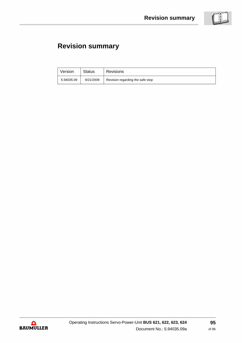
Revision summary
Revision summary
Version Status Revisions
5.94035.09 9/21/2009 Revision regarding the safe stop
Operating Instructions Servo-Power-Unit BUS 621, 622, 623, 624
Document No.: 5.94035.09a
95of 96

Notes:
Operating Instructions Servo-Power-Unit BUS 621, 622, 623, 624
Document No.: 5.94035.09a Baumüller Nürnberg GmbH
96of 96


Baumüller Nürnberg GmbH Ostendstraße 80-90 90482 Nürnberg T: +49(0)911-5432-0 F: +49(0)911-5432-130 www.baumueller.de
All information given in this manual is customer information, subject to change without notice. We reserve the right to futher develop and actualize our products continuously using our permanent revision service. Please notice, that specifications/data/information are current values according to the printing date.These statements are not legally binding according to the measurement, computation and calculations. Before you make any information given in this manual to the basis of your own calculations and/or applications, please make sure that you have the latest edition of the information in hand.No liability can be accepted concerning the correctness of the information.
Related Documents