07-02-09-01-E-V0504.doc Servo drive 637+ Product Manual

Welcome message from author
This document is posted to help you gain knowledge. Please leave a comment to let me know what you think about it! Share it to your friends and learn new things together.
Transcript
07-02-09-01-E-V0504.doc
Servo drive
637+
ProductManual
________________________________________________________________________________________________________________________________________________________________________________________________________________________
2 Product Manual Type: 637+ 07-02-09-01-E-V0504.doc
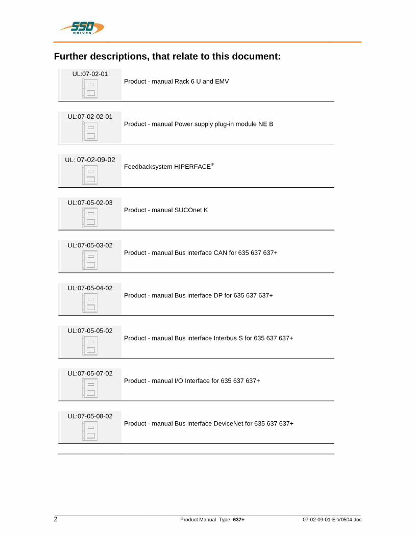
Further descriptions, that relate to this document:UL:07-02-01
Product - manual Rack 6 U and EMV
UL:07-02-02-01 Product - manual Power supply plug-in module NE B
UL: 07-02-09-02 Feedbacksystem HIPERFACE®
UL:07-05-02-03Product - manual SUCOnet K
UL:07-05-03-02 Product - manual Bus interface CAN for 635 637 637+
UL:07-05-04-02 Product - manual Bus interface DP for 635 637 637+
UL:07-05-05-02 Product - manual Bus interface Interbus S for 635 637 637+
UL:07-05-07-02 Product - manual I/O Interface for 635 637 637+
UL:07-05-08-02 Product - manual Bus interface DeviceNet for 635 637 637+
ۤ!?{

________________________________________________________________________________________________________________________________________________________________________________________________________________________
07-02-09-01-E-V0504.doc Product Manual Type: 637+ 3
Further descriptions, that relate to this document.
UL:07-09-04-02 Product - manual Supression aids EH
UL:10-06-03Product - manual Serial transfer protocol 635 637 637+ EASY-serial
UL: CDEASYRIDER Windows - Software
UL:10-06-05 Product - manual Software BIAS®
UL: 12-01Product - manual Accessories - Plugs
UL:12-02 Product - manual Accessories - Cable
UL:12-03 Product - manual Accessories - Brake resistances
SSD Drives GmbH.All rights reserved. No portion of this description may be produced or processed in any form without the consent of the company.
Changes are subject to change without notice.
SSD Drives has registered in part trademark protection and legal protection of designs. The handing over of the descriptions may not be construed as the transfer of any rights.
Made in Germany, 2004
¢§.§y*
6
________________________________________________________________________________________________________________________________________________________________________________________________________________________
4 Product Manual Type: 637+ 07-02-09-01-E-V0504.doc
CONTENTS page
The most important thing first ..........................................................................7
Safety precautions ............................................................................................. 8
1 General ....................................................................................................101.1 System description .......................................................................................................................101.1.1 Digital communication...................................................................................................................111.1.2 Operation configurations...............................................................................................................111.1.3 Compatibility to 637 servodrives..................................................................................................121.2 Key to the models .........................................................................................................................131.2.1 Example ........................................................................................................................................131.3 Range data ...................................................................................................................................141.3.1 Insulation concept.........................................................................................................................141.3.2 General data ................................................................................................................................. 141.3.3 Compact units 637+/K D6R ..........................................................................................................151.3.4 Plug-in modules 637+/D6R...........................................................................................................161.3.5 Single- and three-phase supply....................................................................................................171.3.6 Output power ................................................................................................................................181.4 Dimensions and layout ................................................................................................................. 191.4.1 Dimensions for compact device and plug-in module....................................................................191.4.2 EMC-Clip (optional) .....................................................................................................................201.4.3 Layout ........................................................................................................................................... 21
2 Connector assignment and functions..................................................222.1 General view of connections of the compact device 637+/ K D6R 02 - 10 ..................................222.1.2 General view of connections of the compact device 637+/K D6R 16...30 ...................................232.2 Connector pin assignments and contact functions.......................................................................242.2.1 Power connections for plug-in module 637+/D6R........................................................................242.3.1 Signal connections........................................................................................................................252.3.2 Control signal plug X10 SUB D25 socket.....................................................................................252.4 Feedback-Sensor-Connection X30 ..............................................................................................282.4.1 Function-Module X300................................................................................................................. 282.4.2 Resolver connection X30 SUB D 09 socket .................................................................................292.5 Multi-function X40 .........................................................................................................................302.5.1 Incremental output ........................................................................................................................312.5.2 Incremental input ..........................................................................................................................322.5.3 Stepper motor input ......................................................................................................................332.5.4 Stepper motor input ......................................................................................................................342.5.5 SSI-Encoder Interface 2.6 Digital interfaces ...........................................................................................................................362.6.1 Service interface COM1 (RS232) .................................................................................................362.6.2 Fieldbus interface COM2..............................................................................................................37
3 Operating modes .................................................................................... 433.1 Operating modes and pin functions..............................................................................................443.2 Configurable pin-functions (depending on the operating mode) ..................................................453.3 Function diagrams from inputs and outputs 4 ..............................................................................46

________________________________________________________________________________________________________________________________________________________________________________________________________________________
07-02-09-01-E-V0504.doc Product Manual Type: 637+ 5
CONTENTS page
4 Mechanical installation ..........................................................................47 4.1 Mounting ....................................................................................................................................... 474.2 Control cabinet - mounting............................................................................................................ 474.3 Cooling..........................................................................................................................................47
5 Electrical installation.............................................................................. 485.1 Safety............................................................................................................................................485.2 The danger of electric shocks.......................................................................................................485.3 Danger areas ................................................................................................................................485.4 Grounding, safety grounding ........................................................................................................485.4.1 Ground connections......................................................................................................................485.5 Short-circuit capability and discharge currents.............................................................................485.6 Fuses, contactors, filters...............................................................................................................495.7 Correction of supply current .........................................................................................................505.8 Brake resistor................................................................................................................................515.8.1 Selection of the brake resistor ......................................................................................................515.8.2 Configuration of the brake resistor ...............................................................................................525.8.3 Additional informations .................................................................................................................53
6 Wiring instructions................................................................................. 546.1 General Information ......................................................................................................................546.2 Control cabling..............................................................................................................................546.3 Power cabling ...............................................................................................................................546.4 Installation of the rack...................................................................................................................546.5 Analog setpoint .............................................................................................................................546.6 Safety rules ................................................................................................................................... 546.7 Electromagnetic compatibility (EMC)............................................................................................546.7.1 Hints for mounting.........................................................................................................................556.7.2 Example for mounting...................................................................................................................566.7.3 Achieveable specifications and conditions ...................................................................................577.1 Jumper ..........................................................................................................................................58 All jumpers are set to a standard position in production !.............................................................587.2 Digital communication................................................................................................................... 58
8 Commissioning.......................................................................................598.1 Preparation ...................................................................................................................................598.2 Commissioning in steps................................................................................................................ 60
9 Diagnosis and trouble shooting............................................................639.1 7-segment display.........................................................................................................................639.2 Reset of a regulator trouble .......................................................................................................... 659.3 Trouble shooting ...........................................................................................................................66

________________________________________________________________________________________________________________________________________________________________________________________________________________________
6 Product Manual Type: 637+ 07-02-09-01-E-V0504.doc
CONTENTS page
10 Block circuit diagram ............................................................................. 67
11 General technical data ........................................................................... 6811.1 Power circuit ................................................................................................................................. 6811.2 Control circuit ................................................................................................................................6811.3 Signal inputs and outputs, connection X10 ..................................................................................6811.4 Digital control ................................................................................................................................6911.5 Digital communication...................................................................................................................6911.6 Resolverauswertung / Transmitterprinzip.....................................................................................6911.7 Controllersystem...........................................................................................................................7011.8 Analog-Outps................................................................................................................................7011.9 Thermal data.................................................................................................................................7011.10 Mechanical data............................................................................................................................70
12 Disposal...................................................................................................71
13 Software...................................................................................................7213.1 EASYRIDER Windows - Software .............................................................................................. 7213.2 Eurotherm programming language BIAS......................................................................................7313.3 BIAS-commands...........................................................................................................................7513.4 Extended BIAS-commands...........................................................................................................76
14 Certificates ..............................................................................................77
15 Index ........................................................................................................ 84
16 Notes........................................................................................................ 85
17 Modification Record ...............................................................................86

________________________________________________________________________________________________________________________________________________________________________________________________________________________
07-02-09-01-E-V0504.doc Product Manual Type: 637+ 7
The most important thing first
Thanks for your confidence choosing our product. These operating instructions present themselves as an overview of the technical data and features. Please read the operating instructions before operating the product. If you have any questions, please contact your nearest SSD Drives representative. Improper application of the product in combination with dangerous voltage can lead to injuries. In addition, damage can also occur to motors or other products. Therefore please observe our safety precautions strictly.
Safety precautions We assume that, as an expert, you are familiar with the relevant safety regulations, especially in accordance with VDE 0100, VDE 0113,VDE 0160, EN 50178, the accident prevention regulations of the employers liability insurance company and the DIN regulations and that you are able to use and apply them. As well, relevant European Directives must be observed. Depending on the kind of application, additional regulations e.g. UL, DIN are subject to be observed. If our products are operated in connection with components from other manufacturers, their operating instructions are also subject to be observed strictly.

________________________________________________________________________________________________________________________________________________________________________________________________________________________
8 Product Manual Type: 637+ 07-02-09-01-E-V0504.doc
Safety precautions
Attention !
The digital servo drives are in the sense of EN 50178/VDE 0160 power electronic equipments for regulating the flow of energy in electrical power installations. They are exclusively for supplying Eurotherm (or Eurotherm approved) servomotors. Handling, installation, operation, and maintenance are only permitted under the conditions of and in keeping with the effective and/or legal regulations, regulation publications and this technical document.
The operator must make sure that these regulations are strictly followed.
Concept of the galvanic separation and insulation:
Galvanically separation and insulation correspond to EN 50178/VDE 0160, amplified insulation.
In addition all digital signal inputs and outputs are galvanically separated either as a relay or via opto coupler. In this way an increased interference security and the limitation of damages in case of external incorrect connections is given.
The voltage level must not exceed the low safety voltage 60V DC or 25V AC, respectively in accordance with EN 50178/VDE 0160.
The operator must make sure that these regulations are strictly followed.
Danger ! High contact voltage ! Danger of getting shocked ! Danger to your life !
Caution!Opening the servo drive by the operator is prohibited due to reasons of safety and guarantee. The requirement for problem-free operation of the servo drive is the expert configuring !
ۤ!?
A
A

________________________________________________________________________________________________________________________________________________________________________________________________________________________
07-02-09-01-E-V0504.doc Product Manual Type: 637+ 9
Safety precautionsPlease observe !Especially to be complied with:The class of protecton which is permitted: protective grounding; operation is only permitted when the protective conductor is connected according to regulations. The operation of servo drives is not allowed under the sole use of a residual current operated protective device as protection against indirect touching. The servo drive may only be used in the rack or in its compact enclousure. Furthermore the regulator is designed solely for control cabinet operation. Work on or with the servo drive may only be carried out with insulated tools. Installation work may only be done in a deenergized state. When working on the drive, do not only block the Aktiv-input but separate the complete drive from the mains. CAUTION - risk of electrical shock, wait 3 minutes after switching off, for discharging the capacitors.Screws sealed with varnish fulfill an important protection function and may not be moved or removed. It is prohibited to penetrate the inside of the unit with objects of any kind. Protect the unit from falling parts (pieces of wire, fley, metal parts, etc.) during installation or other work in the control cabinet. Metal parts can lead to a short in the servo drive. Before putting into operation, remove additional covers so that the unit does not overheat. With measurements at the servo drive it is absolutely necessary to observe the potential separation!
Stop !
Eurotherm Drives Limited is not liable for damages whith occur by not following the instructions or the applicable regulations !!
DRIVES

________________________________________________________________________________________________________________________________________________________________________________________________________________________
10 Product Manual Type: 637+ 07-02-09-01-E-V0504.doc
1 General 1.1 System description The digital servo drive serves the 4 th generation to regulate the current, speed and position of AC servo motors,(standard: with resolver)
All servo controls and functions are realized digitally.
System variants
Rack-version: 637+/D6R.... Compact-version: 637+/K D6R....
Us 24V DC
ACDC
NEB...
optional
DC-BUSUcc
R
24V DC
M
637+/D6R
M
637+/D6R
Supply voltage:1*or 3*230VAC/50..60Hz
3* 400... 460VAC/50..60Hz
637+/K D6RAC
DC
Us 24VDC
R
Supply voltage:1*or 3*230VAC/50..60Hz3*400...460VAC/50..60Hz
M
Explanations to rack and power supply modules are documented in separate description.
If required, the returned braking energy can be drawn off into additional external ballast resistors.
The AC-supply voltage is fed directly or via transformer to the associated power supply module.
The devices are designed to be operated on networks which are grounded on centre point (TN networks) !
Fan
Power supplyplug-in moduleNE B
Rack, R6or
R6 EMVXNI654321
Servodrives
Fan
Servo-drive
Power supply unit
‘I_!l‘ml =1.“_____.9
_.I!E]
U_lEl‘m_lV!

________________________________________________________________________________________________________________________________________________________________________________________________________________________
07-02-09-01-E-V0504.doc Product Manual Type: 637+ 11
System description 1.1.1 Digital communication Diagnose / SetupGeneral: by 7-segment display Comfortable: via PC by EASYRIDER® Windows - Software (serial interface RS232)
Communication
The serial-communication-protocol is free documented. (Explanation see seperate documentation) Every user has unrestricted acces to all functions and parameters.
1.1.2 Operation configurations There are opportunities ranging from simple current and speed control to programmable position control processes (PLC), supported by the 1500 BIAS- command blocks. "BIAS" User shell for intelligent drive controls
see: chapter 3 Operating modes
chapter 13.2 BIAS - commands chapter 13.3 Extended BIAS – commands
EASYRIDER
custom-made software
PLC Software
PLC, binary selectionl,+/- 10V X10
RS232,
RS422,RS485,CAN-Bus,
Profibus DP,
current-loop
speed-loop
position-loop
instructions programmingdiagnostics setup
SPS
SUCOnet K,
Interbus S
COM1
COM2RS232,
DeviceNet
637+0<>k @:é‘@/‘
ۤ!?
‘Q_F
<>
El <11
€éP@/‘
‘@:é"@/‘
4
fj géb/‘ i
@ aw ,@

________________________________________________________________________________________________________________________________________________________________________________________________________________________
12 Product Manual Type: 637+ 07-02-09-01-E-V0504.doc
System description 1.1.3 Compatibility to 637 servodrives
(Not required for new projects)The 637+ series servo controllers are essentially pin- and functionally compatible with the servo controllers 637. However at replacement of a 637 for a 637+ controller, the existing application must be checked and carefully tested under compliance with the corresponding safety precautions. The following points should be checked in any case and eventually be adjusted before function test: 1. Motor direction parameter and limit switch setting (please see Release note 637+ V6.12) 2. Position setpoints and comparison values have to be quadrupled, resp. Octal (low encoder resolution at 637) 3. Coupling factors in synchronous applications have to be quadrupled, resp. octal (low encoder resolution at 637) 4. Execution of BIAS- and PLC programs is 2.25 times quicker than at 637. This can cause Timing problems at unfavourable programming (e.g. Wait times with NOPs)
Function 637 637+ PC-Operating-Software EASYRIDER DOS-Version or
Windows-Version EASYRIDER Windows -Version
PC-Connection-Cable see: chapter 2.6.2.3
SUBD-9 to LEMO-Connector (COM1)
SUBD-9 to 4-pol Module-Connector (COM1)
Powerpart, Powerdata and Powerconnectors
Unchanged
Control-Singals, Connector X10 see: chapter 2.3.2
unchanged pinning and function
Analog Setpoint X10.5/18, Resolution
12 bit 14 bit
Resolversignals, Connector X30 see: chapter 2.4.2
pin – compatible 12/14 bit resolution
extended functionality 16 bit
Feedback – Interface - Module X300 see: chapter 2.4.1
- New, extended flexibility (HIPERFACE etc)
Multifunction, Connector X40 see: chapter 2.5
compatible extended functionality
Interface, Connector COM2 see: chapter 2.6.2 – 2.6.2.9
unchanged
Optionsmodule see: chapter 2.6.2 – 2.6.2.10
unchanged
Operating Modes, BIAS – Functions see: chapter 3 and 13.2
command set compatible position value 12/14 bit
1revolution
future extensions possible position value 16 bit 1 revolution
PROG-Key not available Analog-Output-TestsginalsMP1/MP2: > connector X 10
X 10.6 / X 10.17
> Front-Testconnectors yes no Tecnical Data Analog Out MP1 / X10.17 MP2 / X10.6
7 bit , Rout = 10 kOhm 7 bit , Rout = 10 kOhm
8 bit , Rout = 1,8 kOhm 10 bit , Rout = 1,8 kOhm
Control-Loops see: chapter 11.4
Performance increased: Cycle times are double speed now
Control-Loop Parameters Generally compatible, possibly optimisation required
Jumper see: chapter 7.1
JP2.2, JP2.3, JP2.7, JP2.8
ۤ!?{
® } ®
z I z

________________________________________________________________________________________________________________________________________________________________________________________________________________________
07-02-09-01-E-V0504.doc Product Manual Type: 637+ 13
1.2 Key to the models Standard optional
Marking a b c d e f g h Model: XXX/ X D6R XX .S4 -X -X -XXX -XXx
Marking DescriptionXXX/ = 637+ Eurotherm-design (blue)
a K = 1 axis compact digital servo drive system = (is not used with model plug-in device)
b D6R = Digital 6U Regulator c Rated current:
02 = 2 amperes 04 = 4 amperes 06 = 6 amperes 10 = 10 amperes 16 = 16 amperes 22 = 22 amperes 30 = 30 amperes
d .S4 = Digital drive 4 th generation e Intermediate circuit rated voltage:
-3 = 325V (230V AC) 16..30A only as racksystem -7 = 650V (460V AC)
f -E = with EMC-Clip unit -0 = without EMC-Clip unit additional optionmodules on the drive for communication via COM2-232 = RS 232 interface -422 = RS 422 interface -485 = RS 485 interface -CAN = CAN - bus -DEV = CAN - bus / DeviceNet -SUC = SUCOnet K -PDP = Profibus DP -IBS = Interbus S (Attention: changed front plate) –EA5 = I/O - interface (5E, 2A) COM2
g
–EAE = I/O - Interface (14E, 10A) X200 (Attention: changed front plate) –XXE = Combination of communication interface and I/O interface EAE (the first two places of com.-interface + E for I/O-interface EAE)
h X300 – Functionsmodules = no information = standard X30 Resolver (-RD2) -HF2 = HIPERFACE – Module 2. Version
1.2.1 Example Typical example of an order of a 1-axis- compact device in Eurotherm-design Model: 637+/K D6R 02.S4-7-CAN
637+/ = Eurotherm-design (blue) K = 1 axis compact device
D6R = Digital 6U Regulator 02 = 2 amperes Regulator rated current .S4 = Digital drive 4 th generation-7 = 650V UCCN -CAN = CAN-Bus – Optionsmodule insertion
€€!?
ll I Ill!’
l

________________________________________________________________________________________________________________________________________________________________________________________________________________________
14 Product Manual Type: 637+ 07-02-09-01-E-V0504.doc
1.3 Range data 1.3.1 Insulation concept
COM1
COM2
Remote IN
X10 analog
X10 digital
X40
X30
dep. Optionsmodule
M1, M2, M3 DC-bus
brak - cirquit
L1, L2, L3
Us DC 24 V power supply
DC 24 V
PE
L1
N AC
power - terminals
double insulation VDE 0160
Insulation of control voltage supply
Required for safe separation (PELV): double insulation Take Care ! The insulation of control (Com1..X40) depends on the insulation of control voltage supply
Additional insulation via opto-coupler or relay (without Safety-Functions)
customer part
1)
1) see additional hints, chapter 2.4.2
GND
1.3.2 General data Enclosure Rating (for mounting in cubicle)
IP20
operating temperature range EN 50178 / VDE 0160, class 3K3 storage temperature range -25°...+55° C air pressure 86 kPa - 106 kPa Humidity 5 % - 85% 40°C Opertating Temp 0...40°C reduced operation derating of the output current
1) >40°...< 50°C 2% /°C
Altitude h h 1000m reduced operation Derating of the output current
1) h > 1000... 4000m 1% / 100m
Safety Overvoltage-category of power circuit EN 50178 / VDE 0160, UL, cUL III, Pollution degree for mounting in cubicle VDE / UL: 2 Vibration test in accordance with DIN IEC 68-2-6, test FC Condition for testing Frequency range Amplitude Acceleration Test time per axis Frequency sweep speed
10...57Hz 57...150Hz 0,075 mm
1g 10 sweep cycle 1 Oktave/min
1) Use only fan-cooled devices. For reduced operating conditions, no UL-Approbation are available.
ۤ!?
%c
I@III
L 1

________________________________________________________________________________________________________________________________________________________________________________________________________________________
07-02-09-01-E-V0504.doc Product Manual Type: 637+ 15
Range data1.3.3 Compact units 637+/K D6R
Compact units 637+ / K D6R 02.S4
K D6R 04.S4
K D6R 06.S4
K D6R 10.S4
K D6R 16 .S4
K D6R 22.S4
K D6R 30.S4
-3 -7 -3 -7 -3 -7 -3 -7 -7 -7 -7
Input supply voltage min. [V] 14 50..60 Hz Un [V] 230 460 230 460 230 460 230 460 460 460 460
max. tolarance + 10% phases 1;3 3 1;3 3 1;3 3 supply-preparation Fuses, contactors, filters see chapter 5.6 power-on current limit
model NTC 4 Ohm NTC 2 Ohm
control voltage 1) Us [V] 21,5....24....29, attention: insulation-concept chapter 1.3.1 control current incl. Fan
Is DC
[A] Continuous: max. 1,2A Power-On-Peak: nom. 3A; max.. 6A / 0,8 mS, 2,5A / 25 mS
Continuous: max 1,5A Power-On-Peak: nom. 3A; max. 6A / 0,8 mS, 3A / 25 mS
Outputsine-wave volt. At Un Unr [Veff] 220 447 220 447 220 447 220 447 447 447 447 3)
derating of Unr depending on load and single or 3-phase supply. (see chapter 1.3.5) rated current RMS Inr [A] 2 4 6 10 16 22 30 3)
max. current RMS time for Imax 4)
Imaxr min.
[A] Sec
4 5
8 5
12 5
20 5
32 5
44 5
60 5
min. motor inductance (terminal / terminal)
Lph/ph [mH] 6,0 12,0 3,0 6,0 2,0 4,0 1,2 2,4 2,0 1,1 0,8
Brake circuitSetpoint DC Ub [V] 375 730 375 730 375 730 375 730 730 730 730 max. power Pbmax [kW] 4,5 8,7 4,5 8,7 6,7 13,0 11,2 21,7 29,0 34,8 34,8 continuous power Pbnenn [W] 560 internal resistor Rbint
Pd Pmax
[ ] [W] [kW]
100 30 1,4
300 30 1,7
100 30 1,4
300 30 1,7
100 30 1,4
300 30 1,7
100 30 1,4
300 30 1,7
------
min. external resistor 2) Rbextmin
[ ] 47 82 47 82 27 47 15 27 20 15 15
General power loss fan, electronic
PE loos [W] 29 29 29 29 29 29 29 29 36 36 36
2 Piece L 024 / (16TE x 25) fan models24V DC
[V] 2 Piece L 024 / (12TE * 25) 1 Piece L 024 / (12TE * 15) 1 2 Piece L 024 /
(16TE x 20) power stage per A [W/A] 9 12 9 12 9 12 9 12 12 12 12 weight [kg] 5,0 8,8 further data see: chapter 11
1) suggested: transformer-based supply 2) use only Eurotherm-released types 3) max. continuous performance derated to 80%, see chapter 1.3.6 4) References chapter 1.3.6
ۤ!?
________________________________________________________________________________________________________________________________________________________________________________________________________________________
16 Product Manual Type: 637+ 07-02-09-01-E-V0504.doc
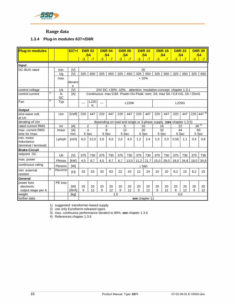
Range data1.3.4 Plug-in modules 637+/D6R
Plug-in modules 637+/ D6R 02 .S4
D6R 04 .S4
D6R 06 .S4
D6R 10 .S4
D6R 16 .S4
D6R 22 .S4
D6R 30 .S4
-3 -7 -3 -7 -3 -7 -3 -7 -3 -7 -3 -7 -3 -7 Input DC-BUS rated min. [V] 20 Ug [V] 325 650 325 650 325 650 325 650 325 650 325 650 325 650 max.
olerance
+ 10%
control voltage Us [V] 24V DC +20% -10%, attention: insulation-concept chapter 1.3.1 control current 1) Is
DC [A] Continuous: max 0,8A Power-On-Peak: nom. 2A; max 5A / 0,8 mS, 2A / 25mS
Fan 2) Typ --- L220K
--- L220K L220G
Outputsine-wave volt. at Un
Unr [Veff] 220 447 220 447 220 447 220 447 220 447 220 447 220 447 3)
derating of Unr depending on load and single or 3-phase supply (see chapter 1.3.5) rated current RMS Inr [A] 2 4 6 10 16 22 30 3)
max. current RMS time for Imax
Imaxr [A] min.
4 5 Sec
8 5 Sec
12 5 Sec
20 5 Sec
32 5 Sec
44 5 Sec
60 5 Sec
min. motor inductance (terminal / terminal)
Lph/ph [mH] 6,0 12,0 3,0 6,0 2,0 4,0 1,2 2,4 1,0 2,0 0,55 1,1 0,4 0,8
Brake-Circuitsetpoint DC Ub [V] 375 730 375 730 375 730 375 730 375 730 375 730 375 730max. power Pbmax [kW] 4,5 8,7 4,5 8,7 6,7 13,0 11,2 21,7 15,0 29,0 18,0 34,8 18,0 34,8continuous rating Pbnenn [W] 560 min. external resistor
2) Rbextmin [ ] 33 63 33 63 22 43 12 24 10 20 8,2 15 8,2 15
Generalpower loss electronic output stage per A
PE loss [W]
[W/A] 20 9
20 12
20 9
20 12
20 9
20 12
20 9
20 12
20 9
20 12
20 9
20 12
20 9
20 12
weight [kg] 1,5 4,0 further data see chapter 11
1) suggested: transformer-based supply 2) use only Eurotherm-released types 3) max. continuous performance derated to 80%, see chapter 1.3.6 4) References chapter 1.3.6
ۤ!?
S

________________________________________________________________________________________________________________________________________________________________________________________________________________________
07-02-09-01-E-V0504.doc Product Manual Type: 637+ 17
Range data1.3.5 Single- and three-phase supplyDue to the line-ripple of DC-Bus, the rate of usable output voltage is derated like follows. This deration effects the max. reachable speed of the applied motor.
Three-phase-supply: the unloaded output voltage will be derated to approx. 90%, maximum 85 %
Single-phase: supply: 50 – 60Hz only drive 637+ / ..02 up to 06 see following diagram:
Hints for setup:To avoid unexpected tripping of undervoltage threshold (EASYRIDER Windows - Software), this value should be set to default.
Required motor-terminal-voltage forspecified speed.
Approximation: (up to 3000RPM)
Ukl = 1,2 * (EMF * n / 1000) + I * (Rph + RL) [V]
Ukl required motorvoltage [V RMS] EMF Back-EMF of motor [V RMS] / 1000 RPM Rph resistance of motor (between terminals) [ ] RL line resistance of motor cable [ ] I motor-current [A RMS]
Output current [Aeff]
Derating of servo drive output voltage in case of single-phase supply
2 4 6 8
10
20 40 60 80 100 0
0
12
[%]
Output voltage in % of unloaded condition
DEswS
P
|ll__'ll
____
llkll
_
l|l__'||
_
l|l__'||
_
LIILIlllrll.
__
|_|||_|||_|||_|||‘____
__
_
|_l||_|l|_|l|____
__
|_l||_|l|_l|l_'l|_____
‘

________________________________________________________________________________________________________________________________________________________________________________________________________________________
18 Product Manual Type: 637+ 07-02-09-01-E-V0504.doc
Range data1.3.6 Output powerIn case of continuous operation in the range of full-load the limits like shown in the diagram have to be respected. Typical servo applications are not effected by this restriction. (S3-operation: Start/Stop)
0,20,40,60,81,0
20 40 60 80 1000
0
1,2
[%]
1,41,61,82,0 5 sec
18 sec
36 sec
Imaxr / Inr11,25 sec
Duration of pulseuntil supervising reaction
Cont. operation
Derating ONLY forxD6R30.S4-x
Output voltage [%]
VHD
D“
\
/\
\
I\
\

________________________________________________________________________________________________________________________________________________________________________________________________________________________
07-02-09-01-E-V0504.doc Product Manual Type: 637+ 19
1.4 Dimensions and layout 1.4.1 Dimensions for compact device and plug-in module
637+/K D6R 02...10 width 637+/K D6R 16...30 width
A 65,0 mm 14 HP 104,6 mm 20 HP B 60,0 mm 100,0 mm C 30,0 mm 71,0 mm 1 HP 5,08mm D 14,5 mm 14,5 mm a 40,2 mm 8 HP 80,4 mm 16 HP
Important:Make sure you need an additional space of approx. 70 mm on the front side for the signal mating plugs !
ABCD D
400
386262
a
280
233 304
243
220
plug-in module
space for fan
18
Ø 5,2
Ø 10
Ø 5,2
5,2
9
detail
detail
E
E 1,6
front sideQ*
fig?______if!”l
F
LILEEEE
T‘
|_\
LX__
I|
________________________________________________________________________________________________________________________________________________________________________________________________________________________
20 Product Manual Type: 637+ 07-02-09-01-E-V0504.doc
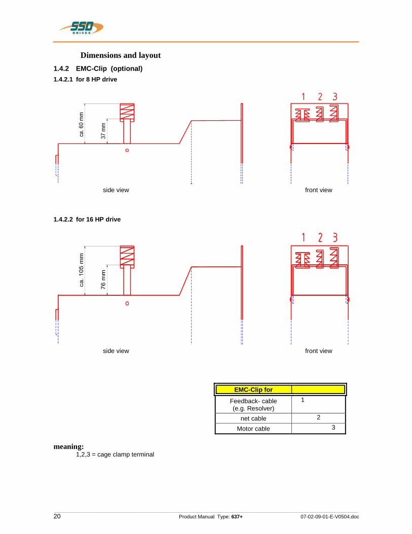
Dimensions and layout 1.4.2 EMC-Clip (optional) 1.4.2.1 for 8 HP drive
side view front view
1.4.2.2 for 16 HP drive
side view front view
EMC-Clip for
Feedback- cable (e.g. Resolver)
1
net cable 2
Motor cable 3
meaning: 1,2,3 = cage clamp terminal
332Z11
OO
EENMEEQN
EE88EEmg8
IJHHHUIIIIn
| |

________________________________________________________________________________________________________________________________________________________________________________________________________________________
07-02-09-01-E-V0504.doc Product Manual Type: 637+ 21
Dimensions and layout 1.4.3 Layout 1.4.3.1 Layout of controller board
Bestückungsseite
slot for option module
X500 X501
X520 X521
Diagn.
COM1
COM2
X10
X30
X40
X50
fuse
Ansicht: Deckblech demontiert
X300
A C B
D
D
C
B
A
possible component variant see chapter 2.6.2
possible component variant see chapter 2.4.1
slot for option module
slot for option module
slot for option module
Note: The option modules for the slots A / B / C can only be reached after removing the cooling plate.
1.4.3.2 Layout of power board
X30
X40
H15-power plug
solder jumper jpxxx - functionen chapter 7.1see:
JP100JP102
1 3
JP101
solder side
diagnostics
COM1
COM2
X10
JP1 JP2
JP3 JP4
JP2.8JP2.3JP2.7JP2.2
2
1
3 3
2
1
3
2
12
1
3
3
2
1
3
2
1
2
X50
OO
]]|_________
BUSESBUSES
UUSUBUB
O0
HQ
/m/nu
BUBEDD
DUBBUB

________________________________________________________________________________________________________________________________________________________________________________________________________________________
22 Product Manual Type: 637+ 07-02-09-01-E-V0504.doc
2 Connector assignment and functions 2.1 General view of connections of the compact device 637+/ K D6R 02 - 10 Width 14 HP
RB+ RB- M1 M2 M3
2 3 4 5 6
8 9 10 11 12
XNP1A
XNP2
XNP1B0V 24V
PE
Grounding barswitsching cabinet
230VAC
24VDC
LINE
LOAD
LNF B
L1L2L3 L3PE PE
power connection 1 * (not K D6R10) or 3 * 230V AC or 3 * 400 … 460V AC
shielding and assignmentsee chapterl 2.6.2
connections see chapter 2.3.2
connections see chapter 2.4.2
connections see chapter 2.5
Kn PC 637+/631Eurotherm - cable
or
NL1 L1
N
PE PELNF E
X50
Remote IN :(only with Interbus S connection)-
see chapter 2.6.2.8
connections see chapter 2.2.1
optional: X20014 inputs / 10 outputsSUB D 26 (high density)
connector assignment see motor description
M6 for ground connectionoptional: external break resistor
KK MB...
AC-Servomotor Eurotherm feed
backsyst.
3 ~
Eurotherm-motor -cable
see chapter 2.6.2.10
L3L2L1
COM 1 RS232
COM 2BUS I/O
X30
M-F
EED
BA
CK
X40INCR. I/O
LINE
LOAD
X10CONTROL I/O
X30
444‘
E""§“E
£0’:
QEQQUN
IICOO‘
____
0
3
V_H?R’__Knmm"‘
'___#2"_______W
O.IOQ.
7/7/W“‘\ //

________________________________________________________________________________________________________________________________________________________________________________________________________________________
07-02-09-01-E-V0504.doc Product Manual Type: 637+ 23
Connector assignment and functions 2.1.2 General view of connections of the compact device 637+/K D6R 16...30 Width 20 HP
RB+RB- M1 M2 M3
2 3
4 5 6 8 9 10 11 12
X1A
X1B
0V 24V
L3 L2 L1
PE
230VAC
24VDC
N
N
L I
E A
L O D
LNF B
L1L2L3 L3
L2L1
PE PE
power connection: 3 * 400 … 460V AC
X50
L1 L2 L3
M6 for ground connectionoptional: external ballast resistor
R
PE
ground barswitsching cable
Remote IN :(only with Interbus S connection)-
see chapter 2.6.2.8
connections see chapter 2.2.1
connector assignment see motor description
KK MB...
AC-Servomotor Eurotherm feed
backsyst.
3 ~
Eurotherm-motor -cable
X30
optional: X20014 inputs / 10 outputsSUB D 26 (high density)see chapter 2.6.2.10
Shielding and assignment see chapterl 2.6.2
connections see chapter 2.3.2
connections see chapter 2.4.2
connections see chapter 2.5
COM 1 RS232
COM 2BUS I/O
X30
M-F
EE
DB
AC
K
X40INCR. I/O
X10CONTROL I/O
Kn PC 637+/631Eurotherm - cable
mQAS
“__7/
0%_/_J%A;iZ
________________________________________________________________________________________________________________________________________________________________________________________________________________________
24 Product Manual Type: 637+ 07-02-09-01-E-V0504.doc
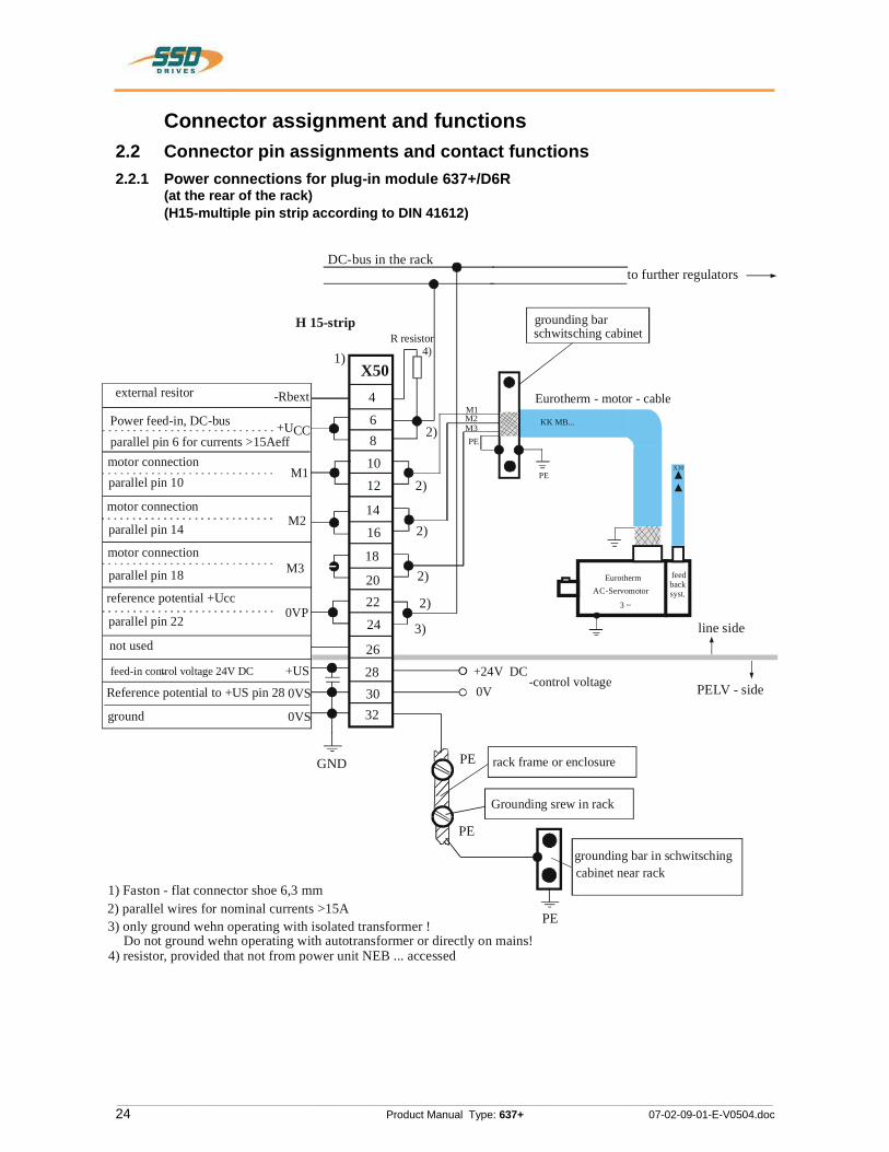
Connector assignment and functions 2.2 Connector pin assignments and contact functions 2.2.1 Power connections for plug-in module 637+/D6R (at the rear of the rack) (H15-multiple pin strip according to DIN 41612)
PE
+24V DC0V
-control voltage
M1M2M3
DC-bus in the rack
R resistor
GND
3)
to further regulators
grounding barschwitsching cabinet
Eurotherm - motor - cable
H 15-strip
Grounding srew in rack
PE
PE
grounding bar in schwitschingcabinet near rack
PE
rack frame or enclosure
line side
PELV - side
2)
2)
2)
2)
2)
4) 1) X50
4
6 8 10 12
14 16
18
20 22
24
26 28 30 32
+UCC
M1
M2
M3
-Rbext
0VP
0VS
+US
external resitor
parallel pin 6 for currents >15AeffPower feed-in, DC-bus
motor connectionparallel pin 10
parallel pin 14
reference potential +Ucc
parallel pin 22
parallel pin 18
not used
-feed-in control voltage 24V DC
Reference potential to +US pin 28
ground 0VS
1) Faston - flat connector shoe 6,3 mm
3) only ground wehn operating with isolated transformer ! Do not ground wehn operating with autotransformer or directly on mains!
2) parallel wires for nominal currents >15A
4) resistor, provided that not from power unit NEB ... accessed
PE
KK MB...
AC-ServomotorEurotherm feed
backsyst.
3 ~
X30
motor connection
motor connection
1
T
F:
__
“4‘‘w§~'O'hO
-
‘l
__. iiI >$WA§F_J.‘
E_

________________________________________________________________________________________________________________________________________________________________________________________________________________________
07-02-09-01-E-V0504.doc Product Manual Type: 637+ 25
Connector assignment and functions 2.3.1 Signal connections 2.3.2 Control signal plug X10
SUB D25 socket Complete representation X10
X10
I-Limit
Rela is
Relais
JP1001 23
Nsetpoint
1142
153
164175
186
197
208219
2210231124122513 OUT
IN
OUT
IN
Aktive OK
GND
Aktive
IN 0V PLC
ready
warning
optionally
IN
IN
IN
IN
shield
OUT +12V 80mA
OUT -12V 80mA
reference potential
0..+-10V can be normed
JP1021
23
0V PLC
3
+12V
JP101monitor MP2
analog-monitor MP1
IN
analog-
JP1JP2
JP3JP4
0V PLC
external
customer side
IN 24V PLC
637+ internal
OUT
IN
0..+-10V can be normed
0..+-10V can be normed
0..+-10V can be normed
€€!?
A:k§—-*1:-|:1—%i~
15.4.?Iv21>|_rlikqjé
'—|T*I%'i\:H>kPEGEP
________________________________________________________________________________________________________________________________________________________________________________________________________________________
26 Product Manual Type: 637+ 07-02-09-01-E-V0504.doc
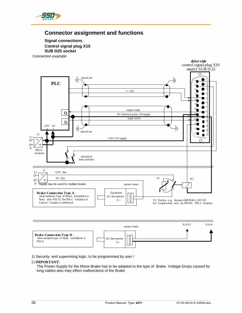
Connector assignment and functions Signal connections Control signal plug X10 SUB D25 socket Connection example
model: SUB D 25control signal plug X10
1
2
3
4
5
6
7
8
9
10
11
12
13
14
15
16
17
18
19
20
21
22
23
24
25
drive side
spread out
spread out
PLC+/- 10V
+24V, I/O-supply
output ready
input active0V reference point, I/O-supply
24V+ -0V
mecanical limit switches
1)
1)
~=
L1
N
2)
~=
L1
N option: brake
EurothermAC-Servomotor
3 ~
V1 K1
+24V (br)
0V (br)
AC-Servomotor3 ~
X10.23 X10.9
Brake-Connection Type A : when Isolation-Type of Break - Installation is Basic (not PELV). The PELC - Isolation of Control - Cirquits is uneffected.
Brake-Connection Type B : when isolation-type of break - installation is PELV.
PELV-isolation
2)
V1: Varistor e.g.. Siemens Q69X3431, 38V DC K1: Couple-relais min. 2A,/60VDC PELV Isolation
Supply may be used for mutliple brakes
option: brake
1) Security- and supervising logic, to be programmed by user ! 2) IMPORTANT:
The Power-Supply for the Motor-Brake has to be adapted to the type of Brake. Voltage-Drops caused by long cables also may effect malfunctions of the Brake
D H | V ES
— “J 5
M HQ “T

________________________________________________________________________________________________________________________________________________________________________________________________________________________
07-02-09-01-E-V0504.doc Product Manual Type: 637+ 27
Connector assignment and functions Signal connections
Control signal plug X10 SUB D25 socketInputs / outputs
PIN Function Model In- / output 1 shield connector Shield 2 configurable (chapter 3) OPTO Input 3 stabilized auxiliary voltage
-12VDC; max. 80 mA output auxiliary voltage
4 configurable (chapter 3) OPTO Input 5 Reference point to X10.18 analog input
0...+-10V Ri = 10 kOhm
6 Current monitor can be scaled in the speed controller menu
MP2 analog output, 0…+-10V
7 via JP100 (solder jumper) can be assigned as free and loopable potential of the READY contact
Optional
8 ON: regulator without fault OUT: regulator fault or supply voltage off
Relay Output fixed: ready
9 Reference point for digital inputs Reference point for digital inputs 10 Reference potential for analog signals Ground 11 configurable (chapter 3) OPTO Input 12 configurable (chapter 3) OPTO Output 13 configurable (chapter 3) OPTO Output 14 configurable (chapter 3) OPTO Input 15 configurable (chapter 3) OPTO Input 16 stabilized auxiliary voltage +12V DC;
max 80 mA output auxiliary voltage
17 actual speed value monitor, scalable MP1 analog output, 0…+-10V
18 nominal speed value; scalable differential referenced to X10.5
Analog input 0...+-10V Ri = 10 kOhm
19 Setting of the current limit can be activated and scaled (0..+10V for 0.. Imax)
analog input 0..+10V Ri = 10 kOhm
20 configurable (chapter 3) OPTO Output 21 Nominal: 24V DC Supply for outputs 22 H = output stage is active
L = output stage inactive OPTO input
fixed: active 23 configurable (chapter 3) Relay output 24 configurable (chapter 3) OPTO input 25 configurable (chapter 3) OPTO input
Data of the digital inputs and outputs see chapter 11 General technical data
€€!?
id
________________________________________________________________________________________________________________________________________________________________________________________________________________________
28 Product Manual Type: 637+ 07-02-09-01-E-V0504.doc
Connector assignment and functions 2.4 Feedback-Sensor-Connection X30 The Feedback-System generates a digital value, representing the rotor-position Derivated from this value:
commutation according to pole pair number
actual speed value position value for position regulation
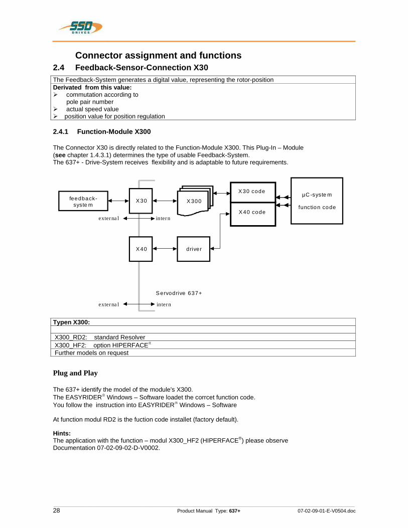
2.4.1 Function-Module X300
The Connector X30 is directly related to the Function-Module X300. This Plug-In – Module (see chapter 1.4.3.1) determines the type of usable Feedback-System. The 637+ - Drive-System receives flexibility and is adaptable to future requirements.
feedback-syste m
X30 X 300 µC -syste m
function code
intern externa l
µP - S yste m X 30 code
X 40 code
X40 driver
intern externa l
S ervodrive 637+
Typen X300:
X300_RD2: standard Resolver X300_HF2: option HIPERFACE Further models on request
Plug and Play
The 637+ identify the model of the module's X300. The EASYRIDER Windows – Software loadet the corrcet function code. You follow the instruction into EASYRIDER Windows – Software
At function modul RD2 is the fuction code installet (factory default).
Hints: The application with the function – modul X300_HF2 (HIPERFACE®) please observe Documentation 07-02-09-02-D-V0002.
ۤ!?{
>
IHE4+
4+
®
®
®

________________________________________________________________________________________________________________________________________________________________________________________________________________________
07-02-09-01-E-V0504.doc Product Manual Type: 637+ 29
Connector assignment and functions Feedback-Sensor-Connection X30 2.4.2 Resolver connection X30
SUB D 09 socket Required Function-Module:X300_RD2 (Standard) Use only Eurotherm approved resolvers
motor side
SSD Drives - motor size 0...4
Type: AC _G_. AC B, AC Mg,AC M2_n, AC M2K; ACMZGAC MRW, AC MRL
view solderside
-
w~ O0
_Ooc
ow
o_mo“
onflu
R8SO|V8l' CO|'1l'18CtOl'
regulator side
SSD Drives - servo drives
Model: 631/635 and 637/637+l637f
view solderslde
:| E - o. _.
006 '3 .,. ;~o '“° ch
roll 0-, . _1 ‘-||= - o
SIR KIR -BST.O200.0001 KA.O0D3.6301
SUB - D 09 SIMST.1002.2001
PIN - Nr. colour function PIN - Nr.while.4- sin + -F
brownN sin - W
(J green 605+ bi
yellow-8-‘~ 00$- \|
redOI PTC optional N
O7 blue PTC optional U)
\l pink ‘Dcarrier -G 9'3)! carrier + 5
case \ SCl’86fl C388
Mafistab I scale:Typl modal:
KK RT GMR-xx.xIB/5:0) |D R I V E 5
us | ACMZK 1o.oa.o4|04 I ACMRL 21.11.os|us | ACMRW o2.10.oa|
DLDL
Ir-:1 10.05.01 | EH|"= |
5,,,‘|_&;_o5‘°1 I D|_ Bezeichnung I designation:Blue resolver cablefor SSD Drives standard motors and servo drives
O2 ACMZG 15.08.03 DL ‘Znichnungsnummor I drawing No: Blalt
1Z-RK.6300.xxxx *"°°‘O1 G37f 16.04.03 DLZusl ;|.‘ l \- Dalum |Namel_Ursorung ]DmIn|m|!F1Imam= z-R-.s30o-Em: I
________________________________________________________________________________________________________________________________________________________________________________________________________________________
30 Product Manual Type: 637+ 07-02-09-01-E-V0504.doc
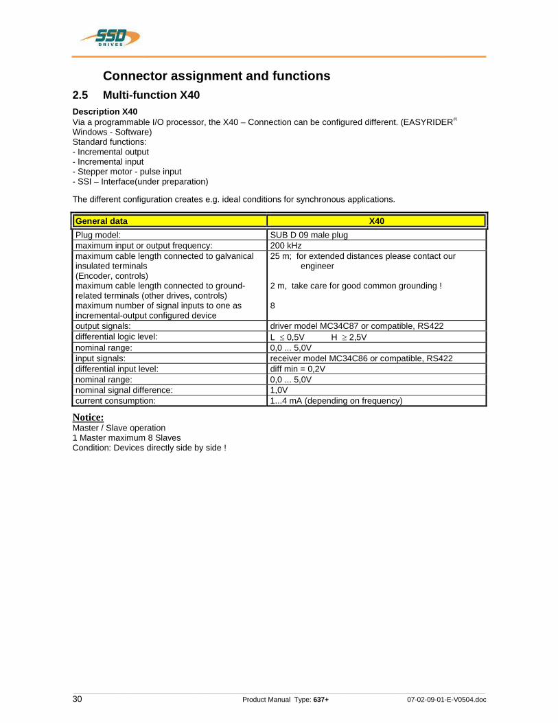
Connector assignment and functions 2.5 Multi-function X40 Description X40 Via a programmable I/O processor, the X40 – Connection can be configured different. (EASYRIDERWindows - Software) Standard functions: - Incremental output - Incremental input - Stepper motor - pulse input - SSI – Interface(under preparation)
The different configuration creates e.g. ideal conditions for synchronous applications.
General data X40Plug model: SUB D 09 male plug maximum input or output frequency: 200 kHz maximum cable length connected to galvanical insulated terminals (Encoder, controls) maximum cable length connected to ground-related terminals (other drives, controls) maximum number of signal inputs to one as incremental-output configured device
25 m; for extended distances please contact our engineer
2 m, take care for good common grounding !
8
output signals: driver model MC34C87 or compatible, RS422 differential logic level: L 0,5V H 2,5V nominal range: 0,0 ... 5,0V input signals: receiver model MC34C86 or compatible, RS422 differential input level: diff min = 0,2V nominal range: 0,0 ... 5,0V nominal signal difference: 1,0V current consumption: 1...4 mA (depending on frequency)
Notice:Master / Slave operation 1 Master maximum 8 Slaves Condition: Devices directly side by side !
ۤ!?
§ 2
________________________________________________________________________________________________________________________________________________________________________________________________________________________
07-02-09-01-E-V0504.doc Product Manual Type: 637+ 31
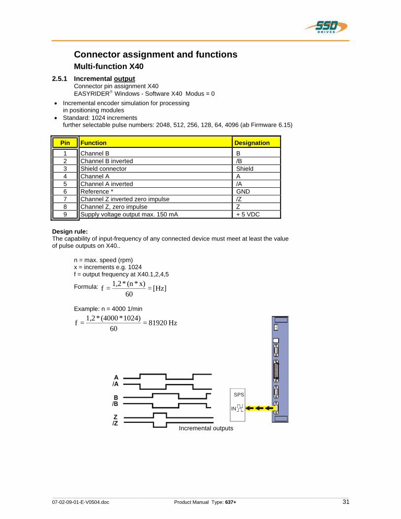
Connector assignment and functions Multi-function X40 2.5.1 Incremental output Connector pin assignment X40
EASYRIDER Windows - Software X40 Modus = 0 Incremental encoder simulation for processing
in positioning modules Standard: 1024 increments
further selectable pulse numbers: 2048, 512, 256, 128, 64, 4096 (ab Firmware 6.15)
Pin Function Designation1 Channel B B 2 Channel B inverted /B 3 Shield connector Shield 4 Channel A A 5 Channel A inverted /A 6 Reference * GND 7 Channel Z inverted zero impulse /Z 8 Channel Z, zero impulse Z 9 Supply voltage output max. 150 mA + 5 VDC
Design rule: The capability of input-frequency of any connected device must meet at least the value of pulse outputs on X40..
n = max. speed (rpm) x = increments e.g. 1024 f = output frequency at X40.1,2,4,5
Formula: [Hz]=60
x)*(n *1,2=f
Example: n = 4000 1/min
Hz81920=60
1024)*(4000*1,2=f
Incremental outputs
SPS
IN
SE
5VRD
_®:___
__MnUAMBB2E?

________________________________________________________________________________________________________________________________________________________________________________________________________________________
32 Product Manual Type: 637+ 07-02-09-01-E-V0504.doc
Connector assignment and functions Multi-function X40 2.5.2 Incremental input
EASYRIDER Windows - Software X40 Modus = 1
Parameter area of the input signals: 10...1000000 increments
Pin Function Designation
1 Channel B B 2 Channel B inverted /B 3 Shield connector Shield 4 Channel A A 5 Channel A inverted /A 6 Reference potential * GND 7 Channel Z inverted zero impulse /Z 8 Channel Z, zero impulse Z 9 Supply voltage output max. 150 mA +5 VDC
Note: The operation of incremental encoders via long cables may cause a voltage drop of the encoder power supply. We suggest the use of external supply if necessary.
Incremental input
SE
gqRD fiME?
»»®
AmBBZ2
_H_
________________________________________________________________________________________________________________________________________________________________________________________________________________________
07-02-09-01-E-V0504.doc Product Manual Type: 637+ 33
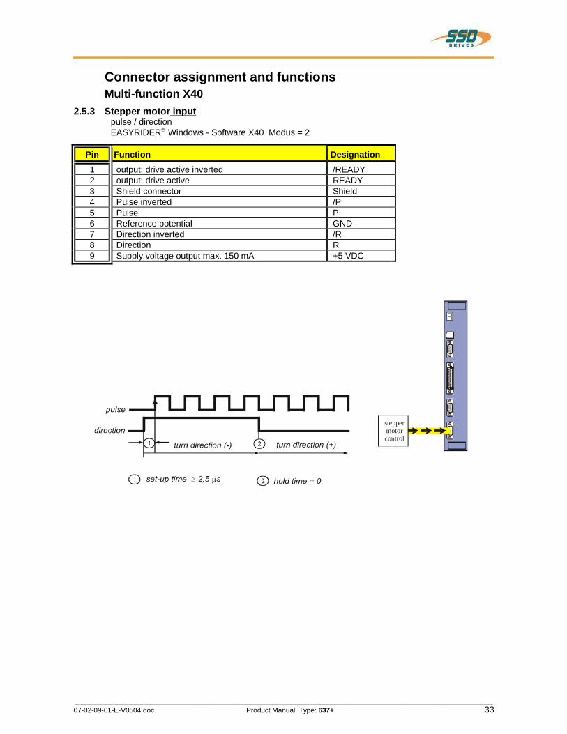
Connector assignment and functions Multi-function X402.5.3 Stepper motor input
pulse / direction EASYRIDER Windows - Software X40 Modus = 2
Pin Function Designation1 output: drive active inverted /READY 2 output: drive active READY 3 Shield connector Shield 4 Pulse inverted /P 5 Pulse P 6 Reference potential GND 7 Direction inverted /R 8 Direction R 9 Supply voltage output max. 150 mA +5 VDC
steppermotorcontrol
®
ii
pulse
direction' turn direction (-) turn direction (+)
P P
Q) set-up time 2 2,5 1.18 @ he/d time = 0
ۤ!?
T
$1
1J1

________________________________________________________________________________________________________________________________________________________________________________________________________________________
34 Product Manual Type: 637+ 07-02-09-01-E-V0504.doc
Connector assignment and functions Multi-function X402.5.4 Stepper motor input
pulse positive / negative EASYRIDER Windows - Software X40 Modus = 3
Pin Function Designation1 output: drive active inverted /READY 2 output: drive active READY 3 Shield connector Shield 4 Pulse direction (-) inverted /P- 5 Pulse direction (-) P- 6 Reference potential GND 7 Pulse direction (+) inverted /P+ 8 Pulse direction (+) P+ 9 Supply voltage output max. 150 mA +5 VDC
pulse directionsteppermotorcontrol
(+)
pulse direction (-)
__H
éGHH_H_H
________________________________________________________________________________________________________________________________________________________________________________________________________________________
07-02-09-01-E-V0504.doc Product Manual Type: 637+ 35
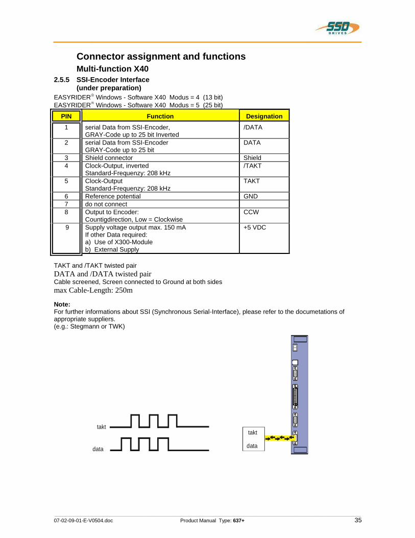
Connector assignment and functions Multi-function X40 2.5.5 SSI-Encoder Interface
(under preparation)EASYRIDER Windows - Software X40 Modus = 4 (13 bit)EASYRIDER Windows - Software X40 Modus = 5 (25 bit)
PIN Function Designation 1 serial Data from SSI-Encoder,
GRAY-Code up to 25 bit Inverted /DATA
2 serial Data from SSI-Encoder GRAY-Code up to 25 bit
DATA
3 Shield connector Shield 4 Clock-Output, inverted
Standard-Frequenzy: 208 kHz /TAKT
5 Clock-Output Standard-Frequenzy: 208 kHz
TAKT
6 Reference potential GND 7 do not connect 8 Output to Encoder:
Countigdirection, Low = Clockwise CCW
9 Supply voltage output max. 150 mA If other Data required: a) Use of X300-Module b) External Supply
+5 VDC
TAKT and /TAKT twisted pair DATA and /DATA twisted pair Cable screened, Screen connected to Ground at both sides max Cable-Length: 250m
Note: For further informations about SSI (Synchronous Serial-Interface), please refer to the documetations of appropriate suppliers. (e.g.: Stegmann or TWK)
takt
data
takt
data
S
®®
E:_m_________m__fl_E§§Emazm
‘__$U
________________________________________________________________________________________________________________________________________________________________________________________________________________________
36 Product Manual Type: 637+ 07-02-09-01-E-V0504.doc
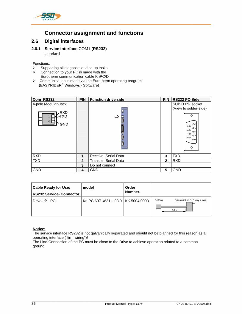
Connector assignment and functions 2.6 Digital interfaces 2.6.1 Service interface COM1 (RS232) standard
Functions: Supporting all diagnosis and setup tasks Connection to your PC is made with the
Eurotherm communication cable KnPC/D Communication is made via the Eurotherm operating program
(EASYRIDER Windows - Software)
Com RS232 PIN Function drive side PIN RS232 PC-Side 4-pole Modular-Jack
RXDTXD
GND
14
SUB D 09- socket (View to solder-side)
RXD 1 Receive Serial Data 3 TXD TXD 2 Transmit Serial Data 2 RXD
3 Do not connect GND 4 GND 5 GND
Cable Ready for Use:
RS232 Service- Connector
model Order Number.
Drive PC Kn PC 637+/631 – 03.0 KK.5004.0003 RJ Plug
3.0m
Sub-miniature D, 9 way female
Notice:The service interface RS232 is not galvanically separated and should not be planned for this reason as a operating interface ("firm wiring")! The Line-Connection of the PC must be close to the Drive to achieve operation related to a common ground.
>>>
0WWMMWOOOOOQwNo

________________________________________________________________________________________________________________________________________________________________________________________________________________________
07-02-09-01-E-V0504.doc Product Manual Type: 637+ 37
Connector assignment and functions Digital interfaces 2.6.2 Fieldbus interface COM2 Option module (SUB D09 socket)Many different functions can be implemented using optional option module. Layout, see chapter 1.4.3
Overview:
modul- designation interface galvanic seperation design
RP 232 RS 232 - A
RP 422 RS 422/485 - A
RP 485 RS 422/485 X A
RP CAN CAN X A
RP PDP Profibus DP X B
RP SUC SUCOnet K X B
RP IBS 1) Interbus S X B
RP DEV DeviceNet X B
1) additional plug Interbus Rem. IN (SUB D)
2.6.2.1 additional In-/Outputs
modul- designation Inputs Outputs connection via design
RP EA5 2) 5 2 COM2 B
RP EAE 14 10 X200 C
2) no Fieldbus possibility (Interface)
Caution:The connections COM2 and X30 are implemented via SUB D09 socket. The customer have to be guaranteed that an interchanging is not possible!
The solderring jumper JP2.8, 2.3, 2.7, 2.2 have to switched dependent on Configuration Interface. See chapter 7.1 (in plant adjusted)
ۤ!?
)' ii ii '1"!
________________________________________________________________________________________________________________________________________________________________________________________________________________________
38 Product Manual Type: 637+ 07-02-09-01-E-V0504.doc
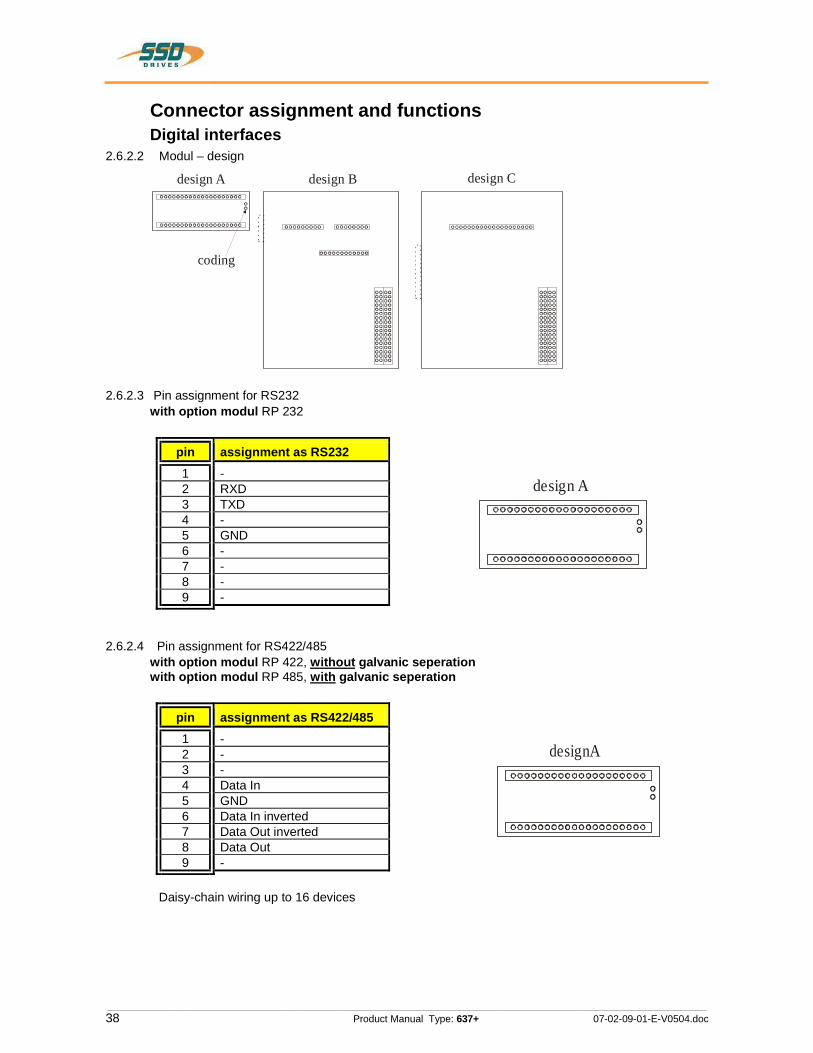
Connector assignment and functions Digital interfaces 2.6.2.2 Modul – design
2.6.2.3 Pin assignment for RS232 with option modul RP 232
pin assignment as RS232 1 - 2 RXD 3 TXD 4 - 5 GND 6 - 7 - 8 - 9 -
2.6.2.4 Pin assignment for RS422/485 with option modul RP 422, without galvanic seperation
with option modul RP 485, with galvanic seperation
pin assignment as RS422/485 1 - 2 - 3 - 4 Data In 5 GND 6 Data In inverted 7 Data Out inverted 8 Data Out 9 -
Daisy-chain wiring up to 16 devices
design A design B design C
coding
design A
designA
ۤ!?
oooooooooooooooooooo0
i°°°°°°°°°°°°°°°°°°° 5 |i\~<>o<>o~=<><=<> ooooooo
oooooooooooo
00 O000 oo00 0o00 onoo oooo oo00 O0oc cooo oooo oooo onoo oooo oooo oo00 oooo oono oo
00 0000 oooo oono nooo oooo coO0 O0oo oooo oooo ooon oooo oooo 00oo co00 oooo oooo co
_______J
_______J
OOOOOOOOOUOOOOOOOOUOO0
OOOOOOOOOOOOOOOOOOO0
OOOOOOOOOOOOOOOOOOOOOO
OOOOOOOOOOOOOOOOOOOO
________________________________________________________________________________________________________________________________________________________________________________________________________________________
07-02-09-01-E-V0504.doc Product Manual Type: 637+ 39
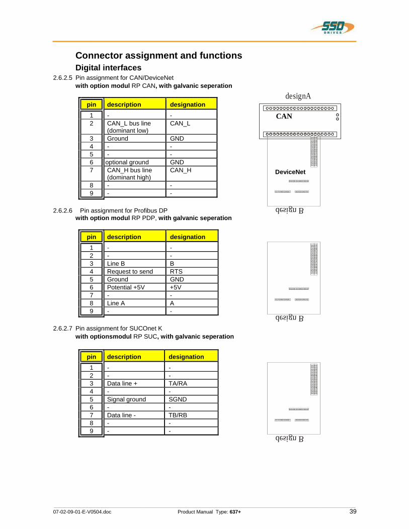
Connector assignment and functions Digital interfaces 2.6.2.5 Pin assignment for CAN/DeviceNet with option modul RP CAN, with galvanic seperation
pin description designation 1 - - 2 CAN_L bus line
(dominant low) CAN_L
3 Ground GND 4 - - 5 - - 6 optional ground GND 7 CAN_H bus line
(dominant high) CAN_H
8 - - 9 - -
2.6.2.6 Pin assignment for Profibus DP with option modul RP PDP, with galvanic seperation
pin description designation 1 - - 2 - - 3 Line B B 4 Request to send RTS 5 Ground GND 6 Potential +5V +5V 7 - - 8 Line A A 9 - -
2.6.2.7 Pin assignment for SUCOnet K with optionsmodul RP SUC, with galvanic seperation
pin description designation 1 - - 2 - - 3 Data line + TA/RA 4 - - 5 Signal ground SGND 6 - - 7 Data line - TB/RB 8 - - 9 - -
CAN
DeviceNet
design B
designA
design B
design B
ۤQ
OUOOOOOOOUUOOOOOOOOOOO
I I 1» O[r"""""""'T""'""""""_.090
ii
ii
ii
ououooooooooooooo ooooooooooooooooo oooooooooooooocloi»
oooooooooeo
000 coo coocanooucoooooooocoooooooocoooooooonoonoonoo
ooooooooooo
ouoooooooououoooo oaoaooooooooooooo ooocmuooooooooooo
ooooooooooo
oaooaoooo ooocoooo
________________________________________________________________________________________________________________________________________________________________________________________________________________________
40 Product Manual Type: 637+ 07-02-09-01-E-V0504.doc
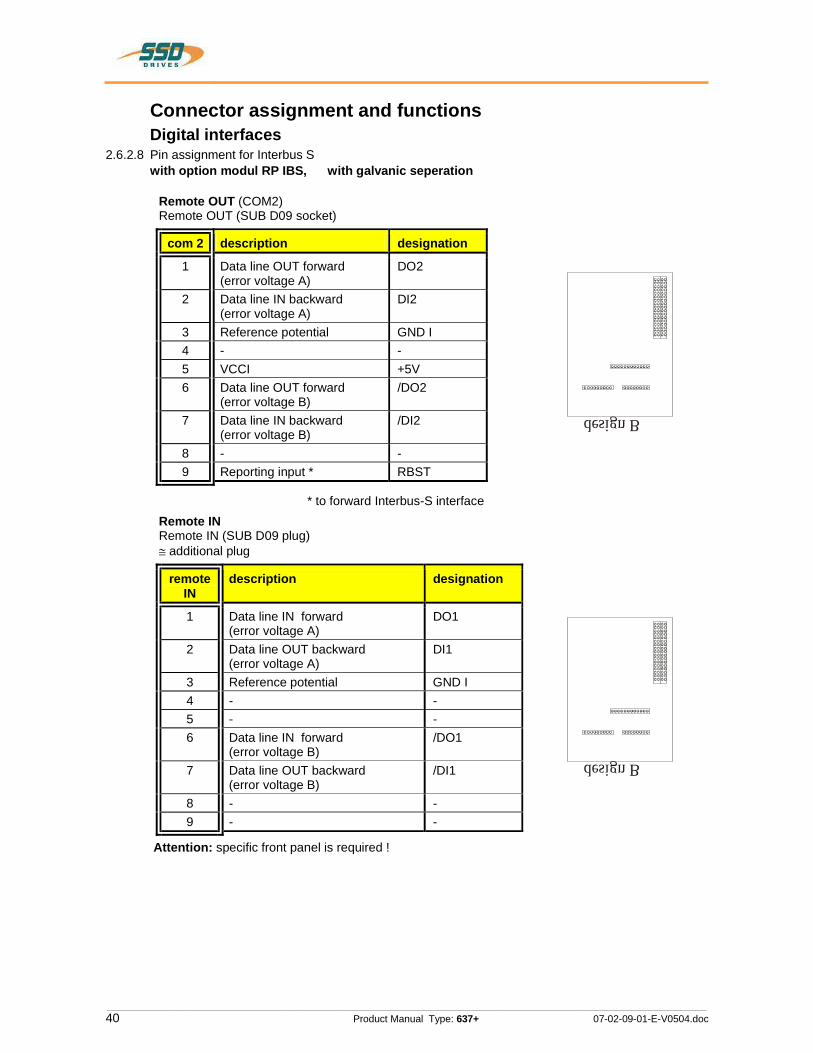
Connector assignment and functions Digital interfaces 2.6.2.8 Pin assignment for Interbus S with option modul RP IBS, with galvanic seperation
Remote OUT (COM2) Remote OUT (SUB D09 socket)
com 2 description designation
1 Data line OUT forward (error voltage A)
DO2
2 Data line IN backward (error voltage A)
DI2
3 Reference potential GND I 4 - - 5 VCCI +5V 6 Data line OUT forward
(error voltage B) /DO2
7 Data line IN backward (error voltage B)
/DI2
8 - - 9 Reporting input * RBST
* to forward Interbus-S interface Remote IN Remote IN (SUB D09 plug)
additional plug
remote IN
description designation
1 Data line IN forward (error voltage A)
DO1
2 Data line OUT backward (error voltage A)
DI1
3 Reference potential GND I 4 - - 5 - - 6 Data line IN forward
(error voltage B) /DO1
7 Data line OUT backward (error voltage B)
/DI1
8 - - 9 - -
Attention: specific front panel is required !
design B
design B
ۤ!?
ii
ii
oooooooooooo
000000000 oooooooo
ooooooooo oooooooo
ooooooooooooooooo oooooaooooooooooo ooooooooooooooooo
ooocoooooooooooooononooacooooocooooocoooooooooooooo

________________________________________________________________________________________________________________________________________________________________________________________________________________________
07-02-09-01-E-V0504.doc Product Manual Type: 637+ 41
Connector assignment and functions Digital interfaces 2.6.2.9 Pin assignment for I/O interface with option modul RP EA5, with galvanic seperation
Digitale I/O Option COM2 SUB D09 socket
(I = input; O = output)
com 2 designation comment status
1 BIAS input 101 standard E
2 BIAS input 102 standard E
3 BIAS input 107 standard E
4 BIAS input 108 standard E
5 0VSPS ground reference 0VSPS
B
6 BIAS input 106 standard E
7 BIAS output 109 standard A
8 BIAS output 110 standard A
9 +24VSPS ext. +24V feed-in UB
Notice !!The input´s with the internal number 107 and 108 must be connected to the pin´s with number 3 and 4. The output´s with the internal number 109 and 110 must be connected to the pin´s with number 7 and 8.
design B
il
ۤ!?
--on--no..¢=-voo..oo..oo.~oo..uu..oo. on..@¢..oo..oo..oo-.00-.00..oo
________________________________________________________________________________________________________________________________________________________________________________________________________________________
42 Product Manual Type: 637+ 07-02-09-01-E-V0504.doc
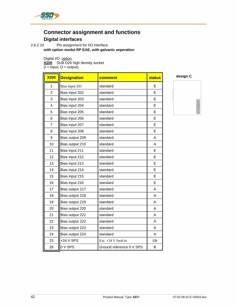
Connector assignment and functions Digital interfaces 2.6.2.10 Pin assignment for I/O interface with option modul RP EAE, with galvanic seperation
Digital I/O option X200 SUB D26 high density socket
(I = input; O = output)
X200 Designation comment status
1 Bias input 201 standard E
2 Bias input 202 standard E
3 Bias input 203 standard E
4 Bias input 204 standard E
5 Bias input 205 standard E
6 Bias input 206 standard E
7 Bias input 207 standard E
8 Bias input 208 standard E
9 Bias output 209 standard A
10 Bias output 210 standard A
11 Bias input 211 standard E
12 Bias input 212 standard E
13 Bias input 213 standard E
14 Bias input 214 standard E
15 Bias input 215 standard E
16 Bias input 216 standard E
17 Bias output 217 standard A
18 Bias output 218 standard A
19 Bias output 219 standard A
20 Bias output 220 standard A
21 Bias output 221 standard A
22 Bias output 222 standard A
23 Bias output 223 standard A
24 Bias output 224 standard A
25 +24 V SPS Ext. +24 V feed-in Ub
26 0 V SPS Ground reference 0 V SPS B
design C
ۤ!?
--on.-no. on..nn..oo..0o..oo..uu..oo. no..oo-.00. on..oo..oo..oo..oo
ii

________________________________________________________________________________________________________________________________________________________________________________________________________________________
07-02-09-01-E-V0504.doc Product Manual Type: 637+ 43
3 Operating modes The preselection of the device functions is carried out by choosing the operating modes 0...5 according to the following table, see chapter 3.1, (EASYRIDER Windows - Software).
Each operating mode allows the assignment of different in- and output functions (F0..F5).
Betriebsart Sollwertquelle Hinweise zur Auswahl der Betriebsart
0 1 2
analog (X10.5/18) switchable the operating modes 1 and 2 by input X10.24
speed control analog
torque controller analog
3 analog (X10.5/18) / digital
simple applications with requirement of switching between position and speed control position controller (input X10.24) handling like operating mode 4
4 digital or analog in acc. to parameter set
general position-controlled systems. Up to 10 positions can be stored under identifier-numbers and activated like shown.
pos. selection (Nr 0..9) function F2 datd 2 ...2
input start
t1 = 2 ms minimum t2 = 2 ms minimum
axis moves to selected position-number
output position reached function F0 X10.12
function F2 X10.2
t1 t2 t
0 4
5 digital or analog in acc. to programming or via digital communication (e.g. fieldbus)
simple to complex systems using instructions BIAS (up to 1500 command blocks) PLC - functions for further informations: see chapter 13.1 and 13.2
ۤ!?
1—Tié

________________________________________________________________________________________________________________________________________________________________________________________________________________________
44 Product Manual Type: 637+ 07-02-09-01-E-V0504.doc
Operating modes 3.1 Operating modes and pin functions
operating modes
Available pins
number
0 torque / speed-
control
1 speed control
2 torque control
3 position /
speed-control
4 position control
5 position control
+ BIAS functions
input X10.14
F0, F1 F0, F1 F0, F1 F0, F1, F2, F3
F0, F1, F2, F3
F0, F1, F2
input X10.15
F0, F1 F0, F1 F0, F1 F0, F1, F2, F3
F0, F1, F2, F3
F0, F1, F2
input X10.4
--- --- --- --- F2 F0, F2, F3
input X10.25
--- --- --- --- F2 F0, F2, F3
input X10.11
F1 F1 F1 F1 F1,F2 F0, F1, F2, F3
input X10.24
F0 L = torque- H = speed control
--- --- F0 L = torque- H = speed control
F1, F2 F1, F2, F3
input X10.2
--- --- --- --- F0 F2, F3
output X10.12
F0, F2, F5 F0, F2, F5 F0, F2, F5 F0, F1,F3, F5 F0, F1,F3, F5 F0, F1, F2, F3, F4, F5
output X10.13
F0, F2, F5 F0, F2, F5 F0, F2, F5 F0, F1,F3, F5 F0, F1,F3, F5 F0, F1, F2, F3, F4, F5
output X10.20
F0, F2, F5 F0, F2, F5 F0, F2, F5 F0, F1,F3, F5 F0, F1,F3, F5 F0, F1, F2, F3, F4, F5
output X10.23
F0, F2, F5 F0, F2, F5 F0, F2, F5 F0, F1,F3, F5 F0, F1,F3, F5 F0, F1, F2, F3, F4, F5
The assignment of the functions F0..F5 is listed in the following table
iii?

________________________________________________________________________________________________________________________________________________________________________________________________________________________
07-02-09-01-E-V0504.doc Product Manual Type: 637+ 45
Operating modes 3.2 Configurable pin-functions (depending on the operating mode)
Input functions (depending on the operating modes)
inputNr.
functionF0
functionF1
functionF2
functionF3
functionF4
functionF5
input X10.14
limit switch + *) set selection data 20
move manually +
input X10.15
limit switch - *) set selection data 2a
move manually -
input X10.4
latch input 1 extended latch
*) set selection data 2b
input X10.25
latch input 2 *) set selection data 2c
input X10.11
start (slope 0-->1) for BIAS -move commands
regulator trouble reset
*) set selection data 2d
input X10.24
operating mode selection
(0) – 1or 2 (3) – 1or 4
reference sensor *) set selection data 2max
input X10.2
start (slope 0-->1) with position set selection in position control (4)
strobe (slope 0-->1) for BIAS-set selection
output X10.12
position reached reference output
tracking window exceded
synchron-format trigger
non regulator trouble
output X10.13
temperature monitoring
reference output
tracking window exceded
start offset trigger
non regulator trouble
output X10.20
warning reference output
tracking window exceded
non regulator trouble
output X10.23
active ok (motor brake)
reference output
tracking window exceded
non regulator trouble
BIAS-function, free programmable.(in operating mode 5) resp. no function in operating mode 0 at 4. *) With every row (from the top to the bottom) in which the function F2 is assigned to an input, the binary value (2n) increases by 1. (see example) Operating mode 4: only permissible set number 0 - 9 !
fast input for optimal timing
€€!?
X X
X X
X X X
>< X X
X X X
X X X

________________________________________________________________________________________________________________________________________________________________________________________________________________________
46 Product Manual Type: 637+ 07-02-09-01-E-V0504.doc
Operating modes 3.3 Function diagrams from inputs and outputs
Temp.
t
V1V2
R_NTC1R_PTC
R_NTC2
t1 t2
Temp.
t
V1V2
R_NTC1R_PTC
R_NTC2
t1 t2
/h//9/
/h//9/
I-LIM IT
/h//9/
/8//5/
/5/
I-LIM IT
95 °C
90 °C100 °C
/8//4/
/4/
I-LIM IT
/8//3/
/3/
I-LIM IT
Nsoll
Fa ult s ignal / protectio n functio n
Pro te ctio n mode switching offin acc. with EASYRIDER config.- menue
Protectio n mo de limitingacc. with EAS YR ID ER co nfig . menue
re gulator prote ctionoutp ut Warning(F0) X 10.20
outp ut Ready X10.8
Warnin g disp lay
fault signa l d isp lay
ma x. cu rrent rated curr ent of re gulator
outp ut Warning(F0) X10.20
outp ut Ready X10.8
Warnin g disp lay
fault signa l d isp lay
motor prote ction
outp ut Warning(F0) X 10.20
outp ut Ready X 10.8
Warnin g disp lay
fault signa l d isp lay
NTC -output stage protection
Warnin g t ime ap p rox. 3 sec.
ma x. cu rrent rated curr ent of motor
Warnin g t ime ap p rox. 3 sec.
Warnin g t ime ap p rox. 6 sec.
current l im it in g
assume motor t emp eraturecurve
NTC-motor protection
outp ut T emp .(F0) X10.13
outp ut Ready X10.8
Warnin g disp lay
fault signa l d isp lay
no lim itin g funct ion w ith PT C
sw itch off w ith R_ PT C after w arning t imePTC -motor protection
outp ut T emp .(F0) X 10.13outp ut Ready X 10.8
Warnin g disp lay
fault signa l d isp lay
Function Passive -D elay (re commande d by use of motor brake)
react ion t ime for br ake
inp ut A CT IVE X 10.22
setp oint internally to z ero
outp ut stage Act ive
outp ut AK TIVE -O K (F0) X 10.23 (holdin g br ake)
sw itch off w ith R_ N T C2
Nsetp oint
decrease as of R_NT C1
I 2t
I 2t
Warnin g t ime ap p rox. 6 sec.
_%ygMm_E:E
_E
:::HSS%HHV%?fi

________________________________________________________________________________________________________________________________________________________________________________________________________________________
07-02-09-01-E-V0504.doc Product Manual Type: 637+ 47
4 Mechanical installation 4.1 Mounting Eurotherm digital servo drives may be installed only in a vertical position to guarantee the best air circulation for the cooling ribs of the heat sink. Vertical installation above other drive racks or above other heat producing devices can lead to overheating. In addition the drives are to be operated exclusively in Eurotherm racks or the compact enclosure respectively.
4.2 Control cabinet - mounting Installation should be carried out only in a control cabinet in which the inside must be free from dust, corrosive fumes, gases, and all liquids.
Make absolutely sure that the condensing of evaporating liquids including atmospheric moisture, is avoided. Should the digital servo drive be installed in a place where condensation is likely, a suitable anticondensation heater must be installed. The heater must be SWITCHED OFF during normal operation.
Automatic switch off is recommended Eurotherm-digital servo drives should not be installed in are as which have been classified as dangerous, if they have not been installed in an approved enclosure an accordance with regulations and checked.
Make sure, there is enough cooling and space ! (see sketch)
only horizontal !
on the side no distance is required
rack
100 mm space
100 mm space
Servo-drives637+
above
below
General rule:It is better to place heat-producing devices low in an enclosure to support internal convection and to spread the heat. If placing such devices up high is unavoidable, enlarging the upper dimensions at the expense of height or installing fans should be considered.
4.3 Cooling The digital servo drives are protected against damages caused by overheating. There is a thermal sensor installed on the heat sink. When the temperature rises to >95°C, the drive is automatically switched off. This setting cannot be changed. Make sure a cabinet of proper size is selected for adequate air circulation
If the device becomes operated in a not ventilated device, the case volume of the specified control cabinet must be calculated in accordance with the following table !
Gerät Volumen/Schaltschrank 637+/D6R02...D6R10 0,12 m³ 637+/D6R16...D6R30 0,25 m³
For more exact information, please, address to the control-cabinet manufacture
W
l‘ i ‘i
ۤQ

________________________________________________________________________________________________________________________________________________________________________________________________________________________
48 Product Manual Type: 637+ 07-02-09-01-E-V0504.doc
5 Electrical installation5.1 SafetyThe voltages carried by power supply cables, motor cables, connectors, and certain parts of the drive can cause serious electric shocks and even death 5.2 The danger of electric shocks
CAUTION !
Risk of electrical shock, wait 3 minutes after switching off, for discharging the capacitors. Disconnect Eurotherm plug-in units from mains before working on them. A period of three minutes mustpass after switching off so that the internal capacitors can discharge completely. Until the discharge time is over, there can be dangerous voltages in the module ! Persons, which monitoring or carrying out electrical installation and maintenance must be adequately qualified and schooled in these activities.
5.3 Danger areas The use of variable speed drives of all kinds can invalidate the certification for dangerous areas (apparatus group and/or temperature class) of explosion-protected motors. Inspection and certification for the complete installation of servo motors and electronic components must be obtained.
5.4 Grounding, safety grounding The grounding impedance must meet the requirements of local industrial safety regulations and should be inspected and checked at appropriate and regular intervals
5.4.1 Ground connections It is recommended to attach a ground bus of high conductivity copper as near as possible to the servo-rack or regulator modules in order to minimize the length of the cable connections. The recommended dimensions are:
Thickness: d = 5 to 6 mmLength (m)
Width (mm)
< 0,5 20 0,5 < 1,0 40 1,0 < 1,5 50
bgrounding bus-bar
d
l
Ways of raised discharge currents DC 10mA resp. AC 3,5mA the PE-Bolt of the drive has to be connected to PE using copper-cable minimum 10mm² !
5.5 Short-circuit capability and discharge currentsDue to the working-principle of servo drives there may discharge currents to PE exceeding DC 10mA resp. AC 3,5mA. Suitable for use on a circuit capable of delivery not more than 5000 RMS symmetrical amperes 505V maximum. (Note according to UL508C)
ۤ!?
A

________________________________________________________________________________________________________________________________________________________________________________________________________________________
07-02-09-01-E-V0504.doc Product Manual Type: 637+ 49
Electrical installation 5.6 Fuses, contactors, filtersCompact units 637+/ KD6R 02
.S4 KD6R 04
.S4 KD6R 06
.S4 KD6R 10
.S4 KD6R 16
.S4 KD6R 22
.S4 KD6R 30
.S4 -3 -7 -3 -7 -3 -7 -3 -7 -7 -7 -7
Fuses, Contactors 4) RCD-switch not recommended. Required setpoint: 300 mA, no protection against life danger mains input currents [A] 3,5 5 7,5 12 19 26 30 mains protection 1) mode
lT10A T10A T10A T20A T25A (T32A) 35A (T32A) 35A
protector-switch 2) model
PKZM0-16 PKZM0-16 PKZM0-16 PKZM0-16 PKZM0-25 PKZ2/ZM32 PKZ2/ZM32
mains fuse 2) model
DIL 00M DIL 00M DIL 00M DIL 00M DIL 0M DIL 0M DIL 0M
Line filters 4) generall only for use in earth referenced supplies(TN). Current drain to PE !
single-phase industrial env. max. motor cable 50m (EN55011 A)
model
LNF E 1*230/012 up to AC 230V !!
+ferrite core FR 3
not possible
residential env. max. motor cable 20m (EN55011 B)
model
LNF E 1*230/012 up to AC 230V !!
+ferrite core FR 3
not possible
3-phase industrial env. max. motor cable 50m (EN55011 A)
model
LNF B 3*480/008 +
ferrite core FR 3
LNF B 3*480/018 +
ferrite core FR 6
LNF B 3*480/033 +
ferrite core FR 6 residential env. max motor cable 20m (EN55011 B)
model
LNF B 3*480/008 +
ferrite core FR 3
LNF B 3*480/018 +
ferrite core FR 3
LNF B 3*480/033 +
ferrite core FR 3 3-phasen, max. 3 Geräte versorgt durch einen gemeinsamen Filter
industrial env. max. motor cable 20m (EN55011 A)
model
LNF B 3*480/018; LNF B *480/033 + ferrite core FR other models upon request
(according to ref.measurements with 3 units, supplied by common line) residential env. max motor cable 20m (EN55011 B)
3) mode
lLNF B 3*480/018; LNF B 3*480/033 + ferrite core FR
other models upon request (according to ref.measurements with 3 units, supplied by common line)
Plug-in modules 637+ / D6R 02.S4
D6R 04.S4
D6R 06.S4
D6R 10.S4
D6R 16 .S4
D6R 22 .S4
D6R 30 .S4
-3 -7 -3 -7 -3 -7 -3 -7 -3 -7 -3 -7 -3 -7
Fuses, contactors, filters
4) 1)
generall Orientation: Table for compact units and the addition of rated currents of used units on the DC-Bus. Depending on the application, energy sharing effects by DC-link may reduce the required supply current considerable.
fuses Rule of the thumb: single-phase operation: 2...3 times of added rated currents Rule of the thumb: 3-phase operation: 1,5...2 times of added rated currents
peak making currents Depending on power-supply unit, limiting equipment is requiered (delay contactor) filters only for use in earth referenced supplies(TN). Current drain to PE ! filter models Orientation: Table of compact units. Further models: see separate manual 1) recommended for UL-requirements: Bussmann Type FRS-R, 600V, use only UL-approved fuse-holders ! 2) recommended, Klöckner Moeller for instance 3) Measurement of conducted emissions only 4) for applications with continuous load: see notes in chapter 5.7
€€!?

________________________________________________________________________________________________________________________________________________________________________________________________________________________
50 Product Manual Type: 637+ 07-02-09-01-E-V0504.doc
Electrical installation 5.7 Correction of supply current Attention in case of continous load: Due to the capacitive input impedance of DC-Bus, the input current is deformated. This guides to RMS -values higher than the sinus-based calculated values. Fuses, contactors and line filters have to be selected in respect to this effect. In typical servo application with Stop/Go-operation (S3-Operation), the rating to nominal data will be sufficient. In other cases, the value has to be corrected using the following diagram.
1,01,2
1,4
1,6
1,8
2,0
2,2Correction-Factor
Iac sinus calculated [A]
5 10 1510 20 3013 26
637+/KD6R02..10.S4-7637+/KD6R16..30.S3-7637+/KD6R02..10.S3-3
2,5 7,5 12,55 15 256,5 19,5
2,4
1-Phase Supply 637+/ KD6R02..06.S4-3
Example
3-Phase Supply
Example:Drive type 637+/KD6R16.S4-3 is supplied by AC 230V 3-ph. Output data to the motor: AC 200V 16A Output-power: Pout = 200V x 16A x 1,73 = 5,54 kW This output-power must be generated by: calculated supply-current Iac sinus = 5,54kW / (230V x 1,73) = 13,9 A Correction-Factor from diagram: 1,6 RMS. Supply-Current Ieff = Iac sinus x 1,6 = 22,3 A
Result: All supply-equipment has to be selected in respect tothe enhanced current.
ۤ!?

________________________________________________________________________________________________________________________________________________________________________________________________________________________
07-02-09-01-E-V0504.doc Product Manual Type: 637+ 51
Electrical installation 5.8 Brake resistor 5.8.1 Selection of the brake resistor The energy of a moving system flows back to the Drive. The DC-Bus capacitors are able to take a small value. The rest has to be converted to heat by a resistor. Switching of this brake resistor depends on the DC-Bus voltage. The load of the resistor is simulated and supervised electronically (EASYRIDER Windows - Software). Peak power (Pmax) and continuous power (Pd) ratings have to be sufficient to meet the requirements of the application.
n1 RPM
T tb1 t [sec]
Movement
I [A]
Ib t [sec] Braking-Current
Values for Example
n1 = 3000 RPMtb1 = 0,1 sec.T = 2,0 sec.J = 0,0005 kgm²Total Inertia
Definition of Data
RL = 0,3 Ohm
Speed at Brake-StartBraking TimeCycle-Time
Cable-Resistance
Braking-Current Ib = 3,2 AMotor-Resistance Rph = 3,6 Ohm
Calculation Step 1
Calculation of brake-power(Approximation. Capacitor-load, friction-and drive-losses neglected)
example
Power of motion: Pkin = 0,0055 * J * n1² / tb1 [W]
Pkin = 0,0055 * 0,0005 * 3000²/0,1 Pkin = 247 W
Motor-losses: Pvmot = Ib² * (Ri + RL) [W]
Pvmot = 3,2² * (3,6 + 0,3) Pvmot = 40 W
Cont. Power: Pd = 0,9 * (Pkin-Pvmot) * tb1 / T [W]
Pd = 0,9 * (247 - 40) * 0,1 / 2 Pd = 9,3 W
Peak-Power: Pmax = (1,8 * Pkin) - Pvmot [W]
Pmax = (1,8 * 247) - 40 Pmax = 405 W
used units: J total inertia [kgm²] n1 speed at Brake-Start [RPM] tb1 braking time [Sec] T cykle time [Sec] Ib brake-current [A] Rph resistance of motor (between terminals) [ ] RL line resistance of motor cable [ ]
ۤ!?
/>lie/XI[1
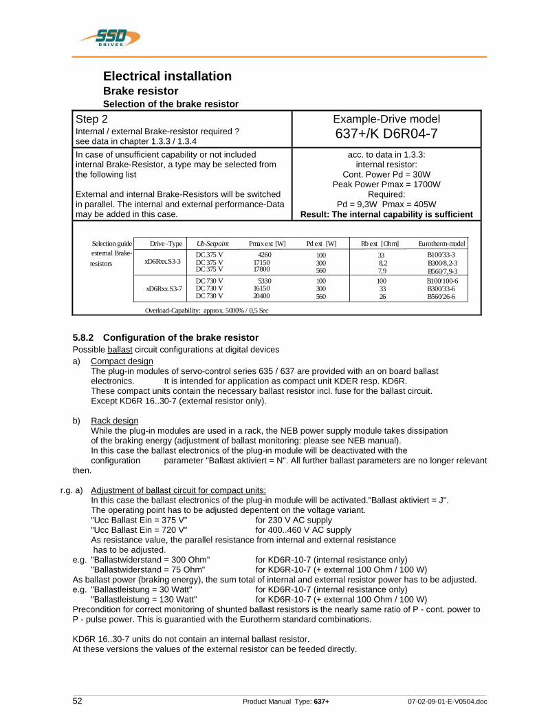
________________________________________________________________________________________________________________________________________________________________________________________________________________________
52 Product Manual Type: 637+ 07-02-09-01-E-V0504.doc
Electrical installation Brake resistor Selection of the brake resistorStep 2Internal / external Brake-resistor required ? see data in chapter 1.3.3 / 1.3.4
Example-Drive model 637+/K D6R04-7
In case of unsufficient capability or not included internal Brake-Resistor, a type may be selected from the following list
External and internal Brake-Resistors will be switched in parallel. The internal and external performance-Data may be added in this case.
acc. to data in 1.3.3: internal resistor:
Cont. Power Pd = 30W Peak Power Pmax = 1700W
Required: Pd = 9,3W Pmax = 405W
Result: The internal capability is sufficient
Selection guide Eurotherm-model Pd ext [W] Rb ext [Ohm]B100/33-3 100 33
B100/100-6 100 100
B300/8,2-3 300 8,2
B300/33-6 300 33
B560/7,9-3 560 7,9
B560/26-6 560 26
Ub-Setpoint DC 375 V DC 375 V DC 375 V DC 730 V DC 730 V DC 730 V
Pmax ext [W] 4260
17150 17800
5330 16150 20400
external Brake- resistors
Drive -Type
xD6Rxx.S3-3
xD6Rxx.S3-7
Overload-Capability: approx. 5000% / 0,5 Sec
5.8.2 Configuration of the brake resistor Possible ballast circuit configurations at digital devices a) Compact design The plug-in modules of servo-control series 635 / 637 are provided with an on board ballast electronics. It is intended for application as compact unit KDER resp. KD6R. These compact units contain the necessary ballast resistor incl. fuse for the ballast circuit. Except KD6R 16..30-7 (external resistor only).
b) Rack design While the plug-in modules are used in a rack, the NEB power supply module takes dissipation of the braking energy (adjustment of ballast monitoring: please see NEB manual). In this case the ballast electronics of the plug-in module will be deactivated with the configuration parameter "Ballast aktiviert = N". All further ballast parameters are no longer relevant then.
r.g. a) Adjustment of ballast circuit for compact units: In this case the ballast electronics of the plug-in module will be activated."Ballast aktiviert = J". The operating point has to be adjusted depentent on the voltage variant. "Ucc Ballast Ein = 375 V" for 230 V AC supply "Ucc Ballast Ein = 720 V" for 400..460 V AC supply As resistance value, the parallel resistance from internal and external resistance has to be adjusted. e.g. "Ballastwiderstand = 300 Ohm" for KD6R-10-7 (internal resistance only) "Ballastwiderstand = 75 Ohm" for KD6R-10-7 (+ external 100 Ohm / 100 W) As ballast power (braking energy), the sum total of internal and external resistor power has to be adjusted. e.g. "Ballastleistung = 30 Watt" for KD6R-10-7 (internal resistance only) "Ballastleistung = 130 Watt" for KD6R-10-7 (+ external 100 Ohm / 100 W) Precondition for correct monitoring of shunted ballast resistors is the nearly same ratio of P - cont. power to P - pulse power. This is guarantied with the Eurotherm standard combinations.
KD6R 16..30-7 units do not contain an internal ballast resistor. At these versions the values of the external resistor can be feeded directly.
iii?
l I
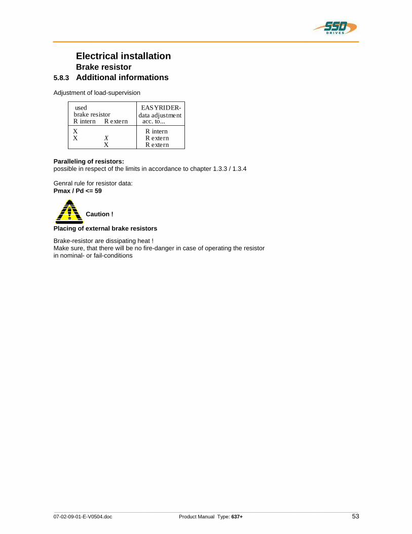
________________________________________________________________________________________________________________________________________________________________________________________________________________________
07-02-09-01-E-V0504.doc Product Manual Type: 637+ 53
Electrical installation Brake resistor 5.8.3 Additional informations
Adjustment of load-supervision
brake resistor R intern R extern
data adjustment acc. to...
X X X
X
R intern R extern R extern
EASYRIDER- used
Paralleling of resistors:possible in respect of the limits in accordance to chapter 1.3.3 / 1.3.4
Genral rule for resistor data: Pmax / Pd <= 59
Caution !
Placing of external brake resistors
Brake-resistor are dissipating heat ! Make sure, that there will be no fire-danger in case of operating the resistor in nominal- or fail-conditions
ۤQ

________________________________________________________________________________________________________________________________________________________________________________________________________________________
54 Product Manual Type: 637+ 07-02-09-01-E-V0504.doc
6 Wiring instructions 6.1 General Information Digital servo drives are designed for operation in metallic grounded enclosures. For perfect operation as well as for observance of all regulations the front board must be connected with the enclosure electrically and fixed.
6.2 Control cabling Recommended cross section 0,25 mm².The control signal lines must be laid seperate from the power signal lines.(see chapter 6.7.1) The resolver cable should contain three shielded pairs and be shielded as a whole. The shielding should be connected to the ground spread out on the regulator side.We recommend using Eurotherm resolver cable KIR. Cable for transmitting data are always to be laid shielded !
6.3 Power cabling Recommended section according to rated current. Use only 75° Cu-cables.
6.4 Installation of the rack When the rack is secured not in a hinged bay but on a mounting plate, it is recommended to do the wiring of the connections for the power connector X50 on the rear of the rack before installing. With hinged-bay installation, the customer must ensure that the parts sensitive to voltage such as the Ucc bus, mains supply lines, etc., are protected against electric shock.
6.5 Analog setpoint The setpoint input is a differential input. Therefore the poling can be done depending on the requirements. Important: the setpoint voltage must be galvanically connected to the reference potential of the control connections (plug X10). It is possible to connect one pole directly to GND.
6.6 Safety rules
CAUTION !
Plug / unplug all modules only when Ucc (DC-BUS) is off, that is, the green LED on the power supply module is off and the discharge time > 3 minutes has elapsed. The user must ensure protection against accidental touching.
6.7 Electromagnetic compatibility (EMC) Confirmity in accordance with the EEC Directive 89/336/EEC has been evaluated using a reference-system, consisting of a compact type drive and a line-filter on mounting-plate, connected to an AC-syncronous motor. Mainly responsible for EMC-emissions is the motor cable. So this has to be installed exeptional carefully. The layout of grounding is very important. Grounding has to be low-impedant for high frequences. That means, all ground-connecting parts have to use area. The measurements made are valid under the use of Eurotherm - cables, suppression aids and line filters and by application of the following wiring instructions:
ۤ!?
A
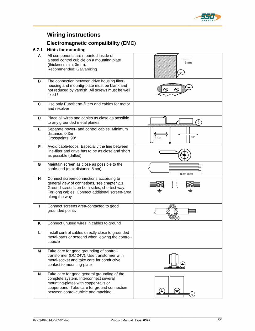
________________________________________________________________________________________________________________________________________________________________________________________________________________________
07-02-09-01-E-V0504.doc Product Manual Type: 637+ 55
Wiring instructions Electromagnetic compatibility (EMC) 6.7.1 Hints for mounting
A All components are mounted inside of a steel control cubicle on a mounting plate (thickness min. 3mm). Recommended: Galvanizing
3mm
B The connection between drive housing filter-housing and mountig-plate must be blank and not reduced by varnish. All screws must be well fixed !
C Use only Eurotherm-filters and cables for motor and resolver
D Place all wires and cables as close as possible to any grounded metal planes
E Separate power- and control cables. Minimum distance: 0,3m Crosspoints: 90° 0,3 m 90°
F Avoid cable-loops. Especially the line between line-filter and drive has to be as close and short as possible (drilled)
G Maintain screen as close as possible to the cable-end (max distance 8 cm)
8 cm max
H Connect screen-connections according to general view of connetions, see chapter 2.1. Ground screens on both sides, shortest way. For long cables: Connect additional screen-area along the way
I Connect screens area-contacted to good grounded points
K Connect unused wires in cables to ground
L Install control cables directly close to grounded metal-parts or screend when leaving the control-cubicle
M Take care for good grounding of control-transformer (DC 24V). Use transformer with metal-socket and take care for conductive contact to mounting-plate
N Take care for good general grounding of the complete system. Interconnect several mounting-plates with copper-rails or copperband. Take care for ground connection between conrol-cubicle and machine !
gVMD
_3|___7Mm-3®“__HGI I__WMASA/_//_('”",H__H_Hh__U___m__//_Ah

________________________________________________________________________________________________________________________________________________________________________________________________________________________
56 Product Manual Type: 637+ 07-02-09-01-E-V0504.doc
Wiring instructions Electromagnetic compatibility (EMC) 6.7.2 Example for mounting
Control cubibcle grounding bar
cable channel for power cables
Cable channel for control l ines
Leitungen dicht an Metallteilen führen
Place cables close to metal-partsund von Leistungsleitungen trennen
and separate them f rom power-lines
COM2
X10
X30
X40
AC power input
Eurotherm-motor cable Type KM...
Line-Fiter
Eurotherm resol ver cable model KIR
Line feed-in
conductive area, remove vanish
ground connection
Conductive area to screen or EMC-Clamp ( accessories)
Conductive area to screen
Toroidal Ferrite Eurotherm-model FR i f required (see chapter 5.6)
Control voltageDC 24V
expanded view
put wires into insulation-tube
Output
Input
Mounting plate in the control cabinet
Flat cable in case of short distance.
otherwise: screen Cable
COM1
ۤQ
/
|I\"'I4E
rIE!‘
/ I_. A Is’‘S CD
®
F S
E @ \o
ow i iii
X21
/
I Ii ® @-

________________________________________________________________________________________________________________________________________________________________________________________________________________________
07-02-09-01-E-V0504.doc Product Manual Type: 637+ 57
Wiring instructions Electromagnetic compatibility (EMC) 6.7.3 Achieveable specifications and conditions
conditions additional conditions
Area Class Standard Motor-cable length
Eurothermline filters mounting in additiona
l
Emissions: transmitted by cable or by air
Industrial A EN50081-2/ EN55011Klasse A
see chapter
5.6
LNF S/E LNF B
closed cabinet with
15 dB attenuation
toroidal ferrite cores see
Residential B EN50081-1/ EN55011 Klasse B
see chapter
5.6
LNF S/E LNF B
chapter 5.6
Interference immunity: ( radiation) transmitted by cable or by air
Industrial A EN50082-2 - - - -
Residential B - - - -
iii?
2

________________________________________________________________________________________________________________________________________________________________________________________________________________________
58 Product Manual Type: 637+ 07-02-09-01-E-V0504.doc
7 Setting and programming 7.1 Jumper All jumpers are set to a standard position in production !
JP100, bridged pad... 2 and 3 (standard)
READY contact with reference to common output supply voltage on X10.21
1 and 3 READY contact can be wired freely
JP101, bridged pad... 2 and 3 (standard)
Analog input X10.19 without internal Pull-up.
1 and 3 Analog input X10.19 with internal Pull-up to +12 V (FRR compatible)
JP102, bridged pad... 2 and 3 (standard)
X10.23 = active ok. output
1 and 3 X10.23 = GND internal (FRR compatible)
JP1, JP2 bridged pad...
adjust identically !
2 and 3 (standard)
X10.15 = high-active
1 and 3 X10.15 = low-active
JP3, JP4 bridged pad...
adjust identically !
2 and 3 (standard)
X10.14 = high-active
1 and 3 X10.14 = low-active
JP2.8, JP2.3 JP2.7, JP2.2 open Default, RP CAN,RP DEV, RP PDP close RP 232, RP 422, RP 485,
RP IBS,RP EA5, RP SUC
7.2 Digital communication see chapter 1.1.1
ۤQ

________________________________________________________________________________________________________________________________________________________________________________________________________________________
07-02-09-01-E-V0504.doc Product Manual Type: 637+ 59
8 Commissioning
CAUTION !
Wiring errors or incompatible operation may cause unpredictable motions. Avoid danger for men and machine !
8.1 Preparation For PC-link use the Eurotherm communication software
EASYRIDER® Windows - Software. For the start, we suggest exercises in simulation mode to get familiar with EASYRIDER.This chapter presumes the knowledge how to handle EASYRIDER.Suggestions: Use testequipment to train yourself. EASYRIDER® Windows - Software contains interactive HELP - functions.
For security-reasons the access to several functions is blocked by password. Commissioning has to be executed by trained stuff only.
Users may have their application-adapted commissioning methode when familiar with the product, on their own resposibility.
The system must be in accordance with all valid safety specifications. The function of all safety equipment (limit-switches for example) have to be checked.
To activate the power-stage of the drive, the "ACTIVE"-signal (X10.22 against X10.9) has to be exited.
iii?
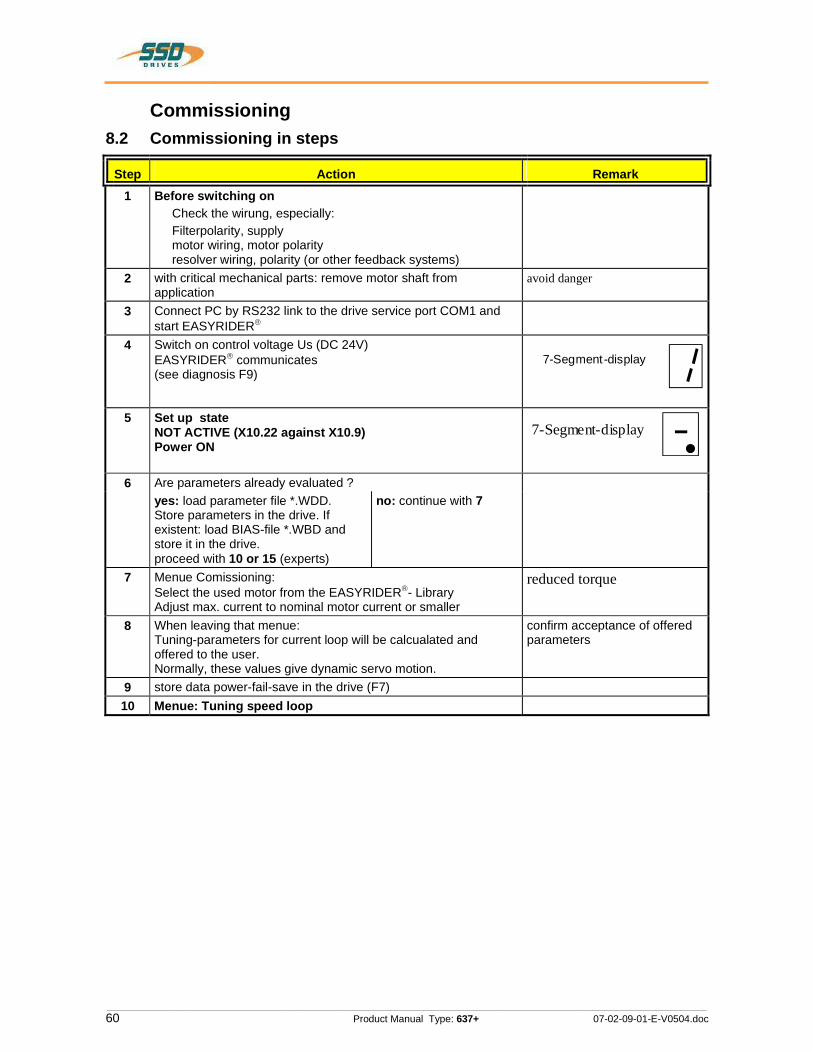
________________________________________________________________________________________________________________________________________________________________________________________________________________________
60 Product Manual Type: 637+ 07-02-09-01-E-V0504.doc
Commissioning 8.2 Commissioning in steps
Step Action Remark 1 Before switching on
Check the wirung, especially: Filterpolarity, supply motor wiring, motor polarity resolver wiring, polarity (or other feedback systems)
2 with critical mechanical parts: remove motor shaft from application
avoid danger
3 Connect PC by RS232 link to the drive service port COM1 and start EASYRIDER
4 Switch on control voltage Us (DC 24V) EASYRIDER communicates (see diagnosis F9)
7-Segment-display
5 Set up state NOT ACTIVE (X10.22 against X10.9) Power ON
7-Segment-display
6 Are parameters already evaluated ? yes: load parameter file *.WDD.
Store parameters in the drive. If existent: load BIAS-file *.WBD and store it in the drive. proceed with 10 or 15 (experts)
no: continue with 7
7 Menue Comissioning: Select the used motor from the EASYRIDER - Library Adjust max. current to nominal motor current or smaller
reduced torque
8 When leaving that menue: Tuning-parameters for current loop will be calcualated and offered to the user. Normally, these values give dynamic servo motion.
confirm acceptance of offered parameters
9 store data power-fail-save in the drive (F7) 10 Menue: Tuning speed loop
ۤ!?
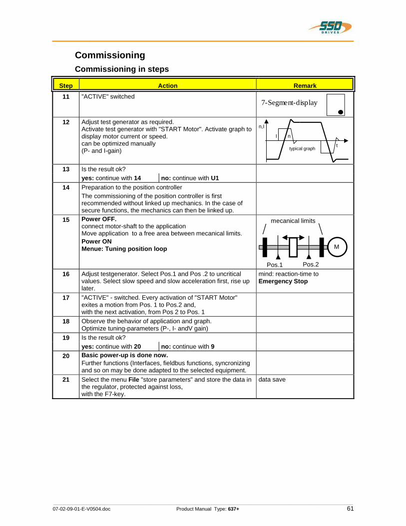
________________________________________________________________________________________________________________________________________________________________________________________________________________________
07-02-09-01-E-V0504.doc Product Manual Type: 637+ 61
Commissioning Commissioning in steps
Step Action Remark
11 "ACTIVE" switched7-Segment-display
12 Adjust test generator as required. Activate test generator with "START Motor". Activate graph to display motor current or speed. can be optimized manually (P- and I-gain)
t
n,I
I n
typical graph
13 Is the result ok? yes: continue with 14 no: continue with U1
14 Preparation to the position controller The commissioning of the position controller is first recommended without linked up mechanics. In the case of secure functions, the mechanics can then be linked up.
15 Power OFF.connect motor-shaft to the application Move application to a free area between mecanical limits. Power ON Menue: Tuning position loop
Pos.1 Pos.2
mecanical limits
M
16 Adjust testgenerator. Select Pos.1 and Pos .2 to uncritical values. Select slow speed and slow acceleration first, rise up later.
mind: reaction-time to Emergency Stop
17 "ACTIVE" - switched. Every activation of "START Motor" exites a motion from Pos. 1 to Pos.2 and, with the next activation, from Pos 2 to Pos. 1
18 Observe the behavior of application and graph. Optimize tuning-parameters (P-, I- andV gain)
19 Is the result ok? yes: continue with 20 no: continue with 9
20 Basic power-up is done now.Further functions (Interfaces, fieldbus functions, syncronizing and so on may be done adapted to the selected equipment.
21 Select the menu File "store parameters" and store the data in the regulator, protected against loss, with the F7-key.
data save
\/

________________________________________________________________________________________________________________________________________________________________________________________________________________________
62 Product Manual Type: 637+ 07-02-09-01-E-V0504.doc
Commissioning Commissioning in steps
Step Action Remark
U1.1 Menue: Tuning Speed LoopStable parameters are calculated bases on the system data; and can be called up with F5. Sometimes it is recommanded to make further manual tuning. Rated values can be sourced either digital by the internal generator or analog by using +/-10V at X10.5/18. ATTENTION !Too hard tuning will cause current- ripple and high power-dissipation.
t
I
P-Gain too high or I-time constantMotor-noise
Motor-current
too small
U1.2 Too weak adjustment causes slow loop-reactions, that may cause problems for the tuning of position loops.
n
t
Speed
P-Gain too smal l or I-time constanttoo high
U1.3 Is the result ok? yes: continue with 9 no: continue with U2.1
U2.1 Menue: Tuning Current LoopStable parameters are calculated bases on the system data and can be called up with F5. Manual tuning may be sensfull. Rated values can be sourced either digital by the internal generator or analog by using +/-10V at X10.5/18.
ATTENTION !Tuning of current loop should be only done after consultation of Eurotherm experts. continue with 9
ۤ!?
Aililitiiis
El
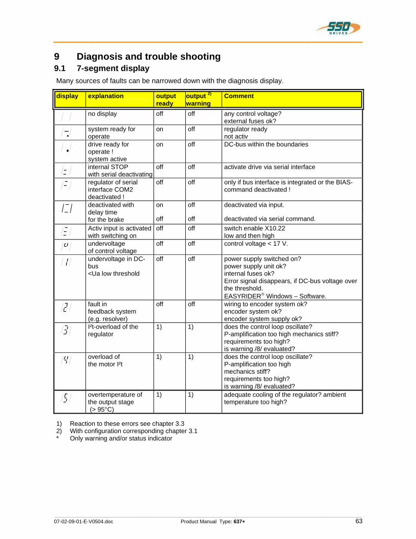
________________________________________________________________________________________________________________________________________________________________________________________________________________________
07-02-09-01-E-V0504.doc Product Manual Type: 637+ 63
9 Diagnosis and trouble shooting 9.1 7-segment display Many sources of faults can be narrowed down with the diagnosis display.
display explanation output ready
output 2)
warning Comment
no display off off any control voltage? external fuses ok?
system ready for operate
on off regulator ready not activ
drive ready for operate ! system active
on off DC-bus within the boundaries
internal STOP with serial deactivating
off off activate drive via serial interface
regulator of serial interface COM2 deactivated !
off off only if bus interface is integrated or the BIAS-command deactivated !
on off deactivated via input. deactivated with delay time for the brake off off deactivated via serial command. Activ input is activated with switching on
off off switch enable X10.22 low and then high
undervoltage of control voltage
off off control voltage < 17 V.
undervoltage in DC-bus <Ua low threshold
off off power supply switched on? power supply unit ok? internal fuses ok? Error signal disappears, if DC-bus voltage over the threshold. EASYRIDER Windows – Software.
fault in feedback system (e.g. resolver)
off off wiring to encoder system ok? encoder system ok? encoder system supply ok?
I²t-overload of the regulator
1) 1) does the control loop oscillate? P-amplification too high mechanics stiff? requirements too high? is warning /8/ evaluated?
overload of the motor I²t
1) 1) does the control loop oscillate? P-amplification too high mechanics stiff? requirements too high? is warning /8/ evaluated?
overtemperature of the output stage (> 95°C)
1) 1) adequate cooling of the regulator? ambient temperature too high?
1) Reaction to these errors see chapter 3.3 2) With configuration corresponding chapter 3.1 * Only warning and/or status indicator
®
ff/fflfffff
..III__________,_I_I_I___,_
///////////

________________________________________________________________________________________________________________________________________________________________________________________________________________________
64 Product Manual Type: 637+ 07-02-09-01-E-V0504.doc
Diagnosis and trouble shooting 7-segment display
display explanation output ready
output 2)
warning Comment
overvoltage on DC bus
1) 1) ballast module ok? adequate ballast module?
chassis shorting and short circuit due to hardware
off off motor cabling ok? digital-loops setup ok? short circuit to chassis in the motor? braking resistor: ohm- value too low? try to start fresh! send in for repair
* WARNING! overload of the regulator I²t or motor I²t or temp.-output stage too high. If no reaction within approx. 3sec.it switches off with signals /3/, /4/ or /5/. Signal /8/ clears when there is no more danger or it is switched off
off 1) mechanics stiff? defective bearings; cold grease? reduce requirements and creep to next possible STOP
overtemperature motor(NTC/PTC)
off check overload of the motor / cooling etc.
* motor temperature too high
on 1) check overload of the motor / cooling etc.
ballast active Brake energy is removed
warning I²t ballast too high
on 1) ballast resistance usage >90%
switch off ballast
on 1) ballast resistance overloaded
X 300 – Modul not inserted or wrong inserted or defect
off off X 300 testing Chapter1.4.3.1 Layout
X 300 – setting wrong
off off X 30 / X40 Counter-Configuration test in the EASYRIDER Windows – Software
* tracking window exceeded
only in operation mode position control, will be deleted with the next run-command
tracking error with switch off
only in operation mode "position control"
memory-checksum-error
off off try new start
1) Reaction to these errors see chapter 3.3 2) With configuration corresponding chapter 3.1 * Only warning respect. status indicator The error signals are shown as long as there is control voltage (Us), also when the power (DC-Bus) is switched off for safety reasons.
ffl
—I
/I_
//
l_”l
I_”//
IL/L!/_

________________________________________________________________________________________________________________________________________________________________________________________________________________________
07-02-09-01-E-V0504.doc Product Manual Type: 637+ 65
Diagnosis and trouble shooting 9.2 Reset of a regulator trouble The error signals 2 - 7, 9, , U, u, Y, II, H of the drive can be reset via:
1. Control voltage OFF/ON, 2. the serial command “Drive Reset“ 0x02
The host login must be occurred. The drive must be deactivated via the serial command“deactivate Drive“ 0x00.
3. the fieldbus-command “ Drive Reset“ 0x16 (22 decimal) The host login must be occurred via the BUS command 0x01.The drive must be deactivated
via the BUS command“deactivate Drive“ 0x14. The fieldbus command “Drive Reset“ with constant repetition of the fieldbus command 0x16 will be works-off only once. For further processing, it is necessary, meanwhile to send another control word (e.g. 0 status order).
4. a 0 – 1 flank on input X10.11Precondition: - The input X10.11 is with function 1“Reset drive fault“ configured
(EASYRIDER Windows – Software) - There is no host login. - The input Active,(X10.22) is inactive (0V)- The signal must be present min. 250 ms
A general precondition for correct execution of the Reset is the elimination of the error cause
Notice !! After remove of the tracking error deactivation “ “, the warning message “L“ (tracking error) is active up to the next move command.
The error signal “ “(releasing before ready) can be reset by deactivation the drive.

________________________________________________________________________________________________________________________________________________________________________________________________________________________
66 Product Manual Type: 637+ 07-02-09-01-E-V0504.doc
Diagnosis and trouble shooting 9.3 Trouble shooting The following list refers to faults which can occur during operation.
Display:
Error Explanation and remedy
no motor run despite current flow motor mechanically blocked? motor brake released?
1)
motor runs unevently check setpoint wiring check grounding and shielding too high P-amplification in the speed controller reduce value (with EASYRIDER setting/speed controlle) too small I-time in the speed controller? reduce value (with EASYRIDER setting/speed controlle)
no reaction of setpoint progression, despite torque in standstill
Limit switch functions effective (BIAS)
no current flow; no torque despite activating the regulator correctly
motor cables interrupted? Is input "I extern" (X10.19) activated (config. menu) and not notched up? limit switch - input activated and not notched up?
Interference symptoms with power frequency Ground loops in setpoint or actual value wiring? Shieldings laid on both sides? Signal cables near high voltage cables?
Motor takes up preferred positions after activation
Position encoder or motor cables with reversed poles? Resolver orFeedback- encoder incorrectly adjusted?Number of motor poles wrong matching? (config. menu)
1)
Motor runs up immediately after activation although there is no setpoint
Motor cables or feedback- cables reversed? Encoder incorrectly adjusted? (e.g. Resolver)
1)
Motor reaches in idling cycle very different speed when running to the right or to the left
Feedback-Encoder incorrectly adjusted (e.g. Resolver)
1) Display /3./ or /4./ mostly short after activating; before warning /8./
ۤQ
/ ./
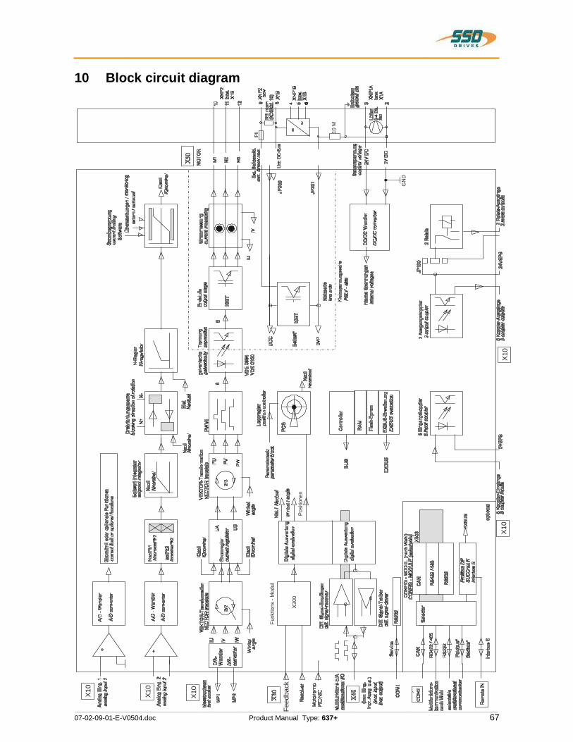
________________________________________________________________________________________________________________________________________________________________________________________________________________________
07-02-09-01-E-V0504.doc Product Manual Type: 637+ 67
10 Block circuit diagram
Funk
tions
- M
odul
X10
X10
X10
Feed
back
X10
X10
Pos
ition
en
GN
D
10 M
NI‘H
__°_‘____§ma:
__I8>__IVEagiwwamm_|_VgemE25‘ui
EEM‘__!__£n_I_____mE(EaF(V _=8"SqVwgigEgg
M‘__‘8‘Ii_V___ ‘Iva;gunS_________8w!___8___5v
figsE===§":1QGKV____________mlH___°____________________IA‘
__i|>E\_Wgm§______.__<_________DI\_|_|_|_|1s_§_________.__n__o_v__°__g__8IA5
ii.‘-‘-l||||||_|_|_|_|||||i_|_|_|_|||||ialwpm|||||||||||||||||5“
gag‘EggEu
Q\‘VZ)Vn_>__M_.____m___w___m_____3w__ED|
§n__@I__________
exQ‘m_____zMA____N_m_mrlzx_‘I___m0_L-_!__m i‘Eiimg“OOMX
_is_gm‘
ExQ)_HgW A______1EEzxQEXE____|
Ezx
2|
ogfiifiwm__m>§|_18__mE__<__‘_____3_mGw__w>___1°__=___@__h__§“
_§E°w!E8____
5AV
__M_i______
_XE695___%_____2|_‘Q5‘Sit _“"
___3_i
_“_
_w“AV
HH1%NWEflNWME_kg?”Lg?IEit
SE__iR_iEE!<n!&9‘w___&_fiO8n§ E5AZ60
kg:§§_%
;_____;___3________<inn
QSE_JH§____§_§EE2
_H‘V‘_m”_—I_______S__8§___g__igaa‘E“Efin£305
__em>____m85mg_h_‘__“fiE__8DD____s_____>
_émg_
all2I_EEF_m___V§_g__8_\_Ew__Egggs_§_
H‘wrEmegu____!______E_m$5g_____!____£a___§__aEggIFm°_c_m>__8_8-_____°_“._____$5
_
Gun|||||||||||||||||||||||||||||||||||||||||||||||||||||||||||||||||||_LEa____________zIE2_____z
EggX_>ۤs
_LWDEEgg
__g_/_
L25:2Egg:LIEU;IOz_ ____§>_E___2
NGIAFM1E5_z2Esis
_______§w\FE_°_?%z_§_§______SEgag§_§§_T§_____8
€E_____°___\__8_____§______BD’__&'E_§_§__iD
25:8__________E§_§é_u_§_88__§_§§
!____£__OZ
‘z_§§IEaisii§§§=E
‘iii
___-;fig
‘_5__9__E_EE9_
_!__§__a______:
IE
__i§5.5I509:IGE8
|T$8
8:5“
____s__°Eis5%___:__§<___9__gmE:
\Eggas<mé°__v_____________z
QEE
A%_2_%____A_°___8.mA
Eiv$5‘VES
SEE=§_5¥
INasgwN______m_33_Egg\_gm835

________________________________________________________________________________________________________________________________________________________________________________________________________________________
68 Product Manual Type: 637+ 07-02-09-01-E-V0504.doc
11 General technical data 11.1 Power circuitgalvanic separation from control circuit in acc. with EN 50178 / VDE 0160 specification in accordance with UL 508C and cUL short circuit and to frame proof for Min. 2000 releasings overvoltage monitoring D6R..-3 Max. 400V DC 5V DC overvoltage monitoring D6R..-7 Max. 765V DC 10V DC undervoltage monitoring min. 15V DC; configurable overtemperature switch off at 95 ° C +/- 5% clock frequency 4,75 kHz frequency of current ripple 9,5 kHz
11.2 Control circuitgalvanic separation from power circuit in acc. with EN 50178 / VDE 0160 further informations: see concept of insulation chapter 1.3.1 see data compact units chapter. 1.3.3 see data plug-in modules chapter 1.3.4
11.3 Signal inputs and outputs, connection X10additional galvanic separation from power and control circuit nominal voltage of the in- and outputs 24 V DC number of outputs signal outputs via OPTO coupler
5 Umax = 45V DC; I = 0..60 mA; short circuit proof, resistive load
signal outputs via RELAY Umax = 45V DC; I = 1uA...1,2A
contact protection with inductive load internal varistor number of inputs signal outputs via OPTO coupler
8 L = 0...7 V DC or open H = 15...30 V DC Iin 24VDC @ 8 mA
reaction time of the intputs X10.2, X10.4, X10.11, X10.14, X10.15, X10.24
> 1 ms
reaction time of the intputs X10.4, X10.25 (configured as latch input "see chapter 3")
0,2 ms
Effect of cycle-time 0,02 ms
ۤ!?
i
i
S

________________________________________________________________________________________________________________________________________________________________________________________________________________________
07-02-09-01-E-V0504.doc Product Manual Type: 637+ 69
General technical data 11.4 Digital control current control Loop-Cycle-Time 105 µs settings according to factory specifications or motor data
speed control -Menue current limits, Adjustment by: Analog Input 0..10V = 0..100%; can be normed, 10Bit
speed control Loop-Cycle-Time 210 µs settings speed control menu
Usoll = 10 V, can be normed; Ri = 10k differential setpoint input analog resolution (including sign) 14 bit digital setpoint input via interfaces
position control Loop-Cycle-Time 840 µs
11.5 Digital communication RS232 - service interface COM1
19200 baud, 8 databits, 1 startbit, 1 stopbit, parity: even
Optional RS232 / RS 422 / RS 485 on SUB D – socket
COM2
CAN, Profibus DP, SUCOnet K on SUB D - socket Interbus S on SUB D - socket (OUT) Interbus S (Remote IN) additional SUB D plug
11.6 Resolverauswertung / TransmitterprinzipGeneral:The specified data refer to the combination of the standard resolver interface with Function-Module X300_RD2; operated with the Eurotherm resolver R 21-T05, R15-T05
carrier frequency ft = 4,75 kHz ripple of the speed actual value signal
2% 1)
max. position resolution for one revolution
65536 / 16 bit
absolute position accuracy +/- 0,7 ° 1)
relative position accuracy +/- 0,08 ° 1)
1) Data under check, Reality: Quality improved
ۤ!?

________________________________________________________________________________________________________________________________________________________________________________________________________________________
70 Product Manual Type: 637+ 07-02-09-01-E-V0504.doc
General technical data 11.7 Controllersystem system run-up time after switching on the control voltage
max. 6 sec.
data memory / organization Flash Eprom 256 KB RAM 64 KB; EEPROM 32 kByte
11.8 Analog-Outps
measuring pin X10.17
signal range -10V.....0.....+10V magnifier function can be normed
resolution 8 bit, independend of norming internal resistance 1,8 kOhm
measuring pin X10.6
signal range -10V.....0.....+10V magnifier function can be normed
resolution 10 bit, independend of norming internal resistance 1,8 kOhm
11.9 Thermal data thermal data see chapter 1.3
11.10 Mechanical data dimensions see chapter 1.4 weight see chapter 1.3
Further data you will find in chapter 1.3
iii?
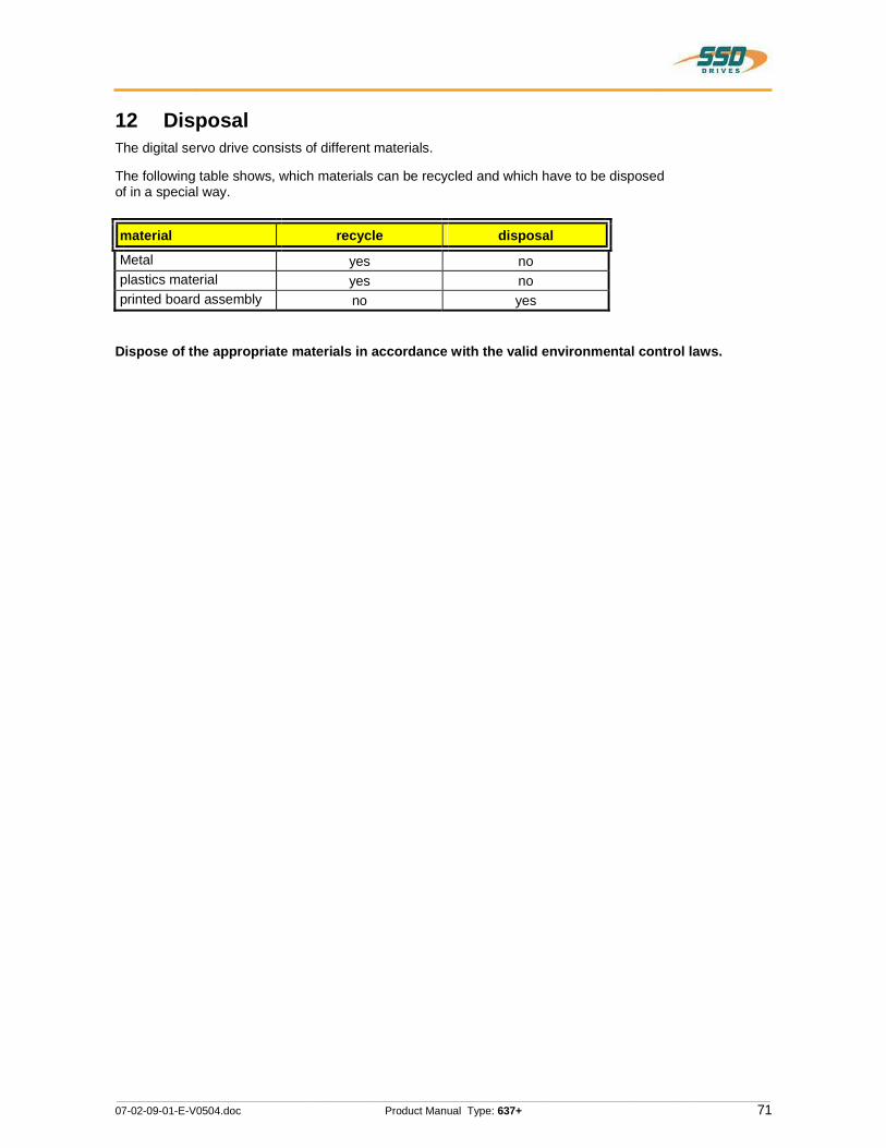
________________________________________________________________________________________________________________________________________________________________________________________________________________________
07-02-09-01-E-V0504.doc Product Manual Type: 637+ 71
12 Disposal The digital servo drive consists of different materials.
The following table shows, which materials can be recycled and which have to be disposed of in a special way.
material recycle disposal
Metal yes no plastics material yes no printed board assembly no yes
Dispose of the appropriate materials in accordance with the valid environmental control laws.
ۤ!?

________________________________________________________________________________________________________________________________________________________________________________________________________________________
72 Product Manual Type: 637+ 07-02-09-01-E-V0504.doc
13 Software13.1 EASYRIDER Windows - Software EASYRIDER Windows - Software is an comfortable tool to use all drive functions. Detailed Online-Help-infomations and instructons are available..
EASYRIDER Instructions: (extract)
Autopilote-function as interactive tutorial System identification BIAS - instruction-set editor Oszilloscope-function start-up and comissioning-tools Setting of parameters Setting of configurations Servo-diagnostics Interface diagnostics Fieldbus diagnostics
Motor library save system data in file load system data from file send system data to servodrive save system data in servodrive
load system data from servodrive
Important: Edited data in EASYRIDER are transmitted to the RAM of the servodrive and active after use of the instruction SEND. Only the instruction SAVE in EEPROM writes data into a nonvolatile memory. Data are stored there power-fail save.
SEVRU
OOOOOOOOOOOOOOOO

________________________________________________________________________________________________________________________________________________________________________________________________________________________
07-02-09-01-E-V0504.doc Product Manual Type: 637+ 73
Software 13.2 Eurotherm programming language BIAS In Operating mode 5 – Position control with BIAS, three user-defined programs can be executed parallel. The BIAS-program and the PLC-program (sequence cascades, 1 command per position controller sampling = 844 uSec) as well as the Mathematics program (cyclic execution in remaining time of processor).
The BIAS-program is primary intended for administration of travel commands. If application permits, also simple calculations can be performed and analog/digital I/O‘s can be serviced in this task. The PLC-task is conceived to perform I/O logic, sequence control, monitoring and CAN-Bus communication. The Mathematics program is designed for complex calculations, e.g. computing of a cam, executed by the BIAS-program afterwards. But it is also possible to store the same tasks here, as basically defined for PLC-task, which can increase PLC performance of the 637+ controller approx. twenty times.
While the BIAS-program will be executed from the start block directly after activation ofoperating mode 5, the PLC-program will be first started by BIAS-command "PLC-program" and the Mathematics program by command "Mathematics program". At reaching the command "End of program" (Mode = 0) the respective execution pointer re-jumps to his start label. Within the command set the following command groups are provided:
Pogram flow control - Fixing start/end of main- and sub-programs - Conditional and unconditional jump commands
Travel relevant commands -Positioning commands -Parameter commands -Technology functions >Register positioning >PID-control >Synchronous applications
Logic commands - Logic commands for coils and internal relays
Variable commands -Writing and reading of parameters -Fundamental operations of arithmetic with long integer -Type-conversions long integer <=> double float (Math.task only) -Fundamental operations of arithmetic with double float (Math.task only) -SIN(x),COS(x),SQRT(x) with double float (Math.task only) -Writing and reading of synchronous profile tables.
CAN-Bus commands -Communication with other Eurotherm products

________________________________________________________________________________________________________________________________________________________________________________________________________________________
74 Product Manual Type: 637+ 07-02-09-01-E-V0504.doc
Software Eurotherm programming language BIAS
The user has the possibility to program his sequence himself from this set of commands.
Available program area
Set number 0000 - ... | ... | can be selected via ... | data inputs X10.xx ... | max. to block no. 63 and ... | and Strobe X10.2 ... | 0063 - ... ... 1499 last block
The BIAS operation set is listed on the next page. You can read the exact function of the individual commands in the help function of the EASYRIDERWindows -Software in the BIAS editor or in the BIAS command description (UL:10.06.05)
iii?
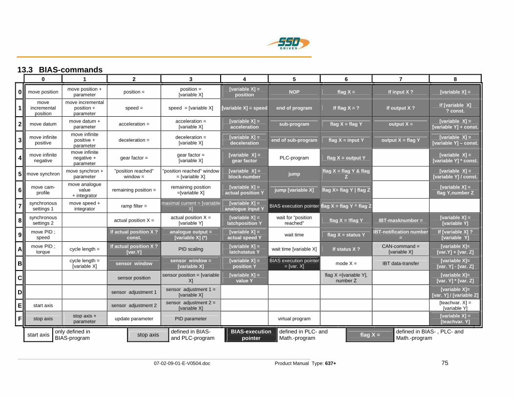
________________________________________________________________________________________________________________________________________________________________________________________________________________________
07-02-09-01-E-V0504.doc Product Manual Type: 637+ 75
13.3 BIAS-commands 0 1 2 3 4 5 6 7 8
0 move position move position + parameter position = position =
[variable X] [variable X] =
position NOP flag X = If input X ? [variable X] =
1 move
incremental position
move incremental position + parameter
speed = speed = [variable X] [variable X] = speed end of program If flag X = ? If output X ? If [variable X] ? const.
2 move datum move datum + parameter acceleration = acceleration =
[variable X] [variable X] = acceleration sub-program flag X = flag Y output X = [variable X] =
[variable Y] + const.
3 move infinite positive
move infinite positive + parameter
deceleration = deceleration = [variable X]
[variable X] = deceleration end of sub-program flag X = input Y output X = flag Y [variable X] =
[variable Y] – const.
4 move infinite negative
move infinite negative + parameter
gear factor = gear factor = [variable X]
[variable X] = gear factor PLC-program flag X = output Y [variable X] =
[variable Y] * const.
5 move synchron move synchron + parameter
"position reached" window =
"position reached" window = [variable X]
[variable X] = block-number jump flag X = flag Y & flag
Z [variable X] =
[variable Y] / const.
6 move cam-profile
move analogue value
+ integrator remaining position = remaining position
=[variable X] [variable X] =
actual position Y jump [variable X] flag X= flag Y | flag Z [variable X] = flag Y,number Z
7 synchronous settings 1
move speed + integrator ramp filter = maximal current = [variable
X] [variable X] =
analogue input Y BIAS execution pointer flag X = flag Y ^ flag Z
8 synchronous settings 2 actual position X = actual position X =
[variable Y] [variable X] =
latchposition Y wait for ”position
reached” flag X = !flag Y IBT-masknumber = [variable X] = [variable Y]
9 move PID ; speed
If actual position X ? const.
analogue output = [variable X] (*)
[variable X] = actual speed Y wait time flag X = status Y IBT-notification number
= If [variable X] ?
[variable Y]
A move PID ; torque cycle length = If actual position X ?
[var.Y] PID scaling [variable X] = latchstatus Y wait time [variable X] If status X ? CAN-command =
[variable X] [variable X]=
[var.Y] + [var. Z]
B cycle length = [variable X] sensor window sensor window =
[variable X] [variable X] =
position Y BIAS execution pointer
= [var. X] mode X = IBT data-transfer [variable X]= [var. Y] - [var. Z]
C sensor position sensor position = [variable X]
[variable X] = value Y
flag X =[variable Y],number Z
[variable X]= [var. Y] * [var. Z]
D sensor adjustment 1 sensor adjustment 1 = [variable X]
[variable X]= [var. Y] / [variable Z]
E start axis sensor adjustment 2 sensor adjustment 2 = [variable X]
[teachvar. X] = [variable Y]
F stop axis stop axis + parameter update parameter PID parameter virtual program [variable X] =
[teachvar. Y]
start axis only defined in BIAS-program stop axis defined in BIAS-
and PLC-program BIAS-execution
pointer defined in PLC- and Math.-program flag X = defined in BIAS- , PLC- and
Math.-program li
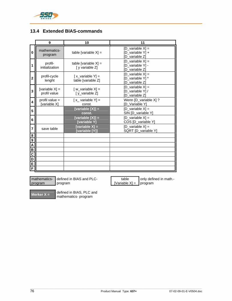
________________________________________________________________________________________________________________________________________________________________________________________________________________________
76 Product Manual Type: 637+ 07-02-09-01-E-V0504.doc
13.4 Extended BIAS-commands
9 10 11
0 mathematics- program table [variable X] =
[D_variable X] = [D_variable Y] + [D_variable Z]
1 profil-initialization
table [variable X] = [ y variable Z]
[D_variable X] = [D_variable Y] - [D_variable Z]
2 profil-cycle lenght
[ x_variable Y] = table [variable Z]
[D_variable X] = [D_variable Y] * [D_variable Z]
3 [variable X] = profil value
[ w_variable X] = [ y_variable Z]
[D_variable X] = [D_variable Y] / [D_variable Z]
4 profil value = [variable X]
[ x_ variable Y] = const.
Wenn [D_variable X] ? [D_Variable Y]
5 [variable [X]] = const.
[D_variable X] = SIN [D_variable Y]
6 [variable [X]] = [variable Y]
[D_variable X] = COS [D_variable Y]
7 save table [variable X] = [variable [Y]]
[D_variable X] = SQRT [D_variable Y]
8 9 A B C D E F
mathematics- program
defined in BIAS and PLC-program
table [Variable X] =
only defined in math.-program
Merker X = defined in BIAS, PLC and mathematics- program
/550%n n | v E s "J"
'311

________________________________________________________________________________________________________________________________________________________________________________________________________________________
07-02-09-01-E-V0504.doc Product Manual Type: 637+ 77
14 Certificates
Testing and Certification The 637+ Servodrive is based on the construction of Type 637. Essential changes are only effecting the control-cirquits of the device. Following our technical point of view, this fact enables to apply all certificates related to Type 637 (see next pages) to the type 637+ as well.
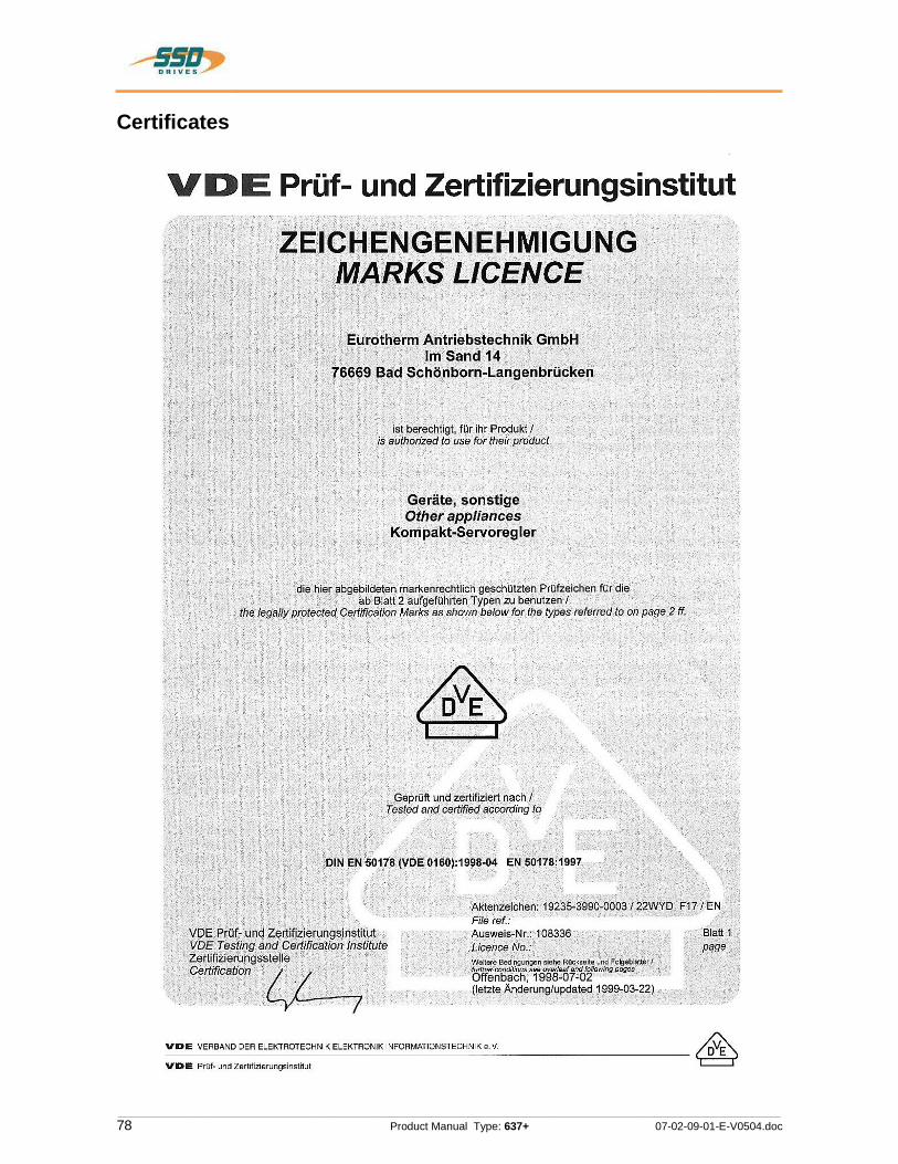
________________________________________________________________________________________________________________________________________________________________________________________________________________________
78 Product Manual Type: 637+ 07-02-09-01-E-V0504.doc
Certificates
ۤ!?
VDE Prijf- und Zertifizierungsinstitut
~VZEICHENGENEHMIGUNG LICENCE Ye;-3jE_u'rd'téherm Antriebetechnik GmbH
r ‘ r (elm Sand 14 j 7-6669 Bad LSch6nborn-Langenbriicken .
j‘ f \ ‘istberechtigi, ffir ihr Produkt] _iseuthorized to use fortheirpr0duct_ \
r Geréite, sonstiger _- Other appliances
_ i Kompakt-Servoregler
V 1 _ , . are hier ebgebildeteh rharkenreehtlich geschfilztehFrufzeichenxfur die‘ ’ V‘ ~_ V\ ‘. 1» "'ab_B!att2 aufgefllhrten Typen zu benutzenl ~ ‘. ‘
' _ r ‘the.‘legaIi_y ‘protected Cerfificatjon Marks as shown below for the types referred to on page 215‘. r ; ?GéprUfi und zertifiziert r 1_ach/N
‘I ‘V ,_ Tested and certified ecoo:'ding‘to ‘
rié?-;.‘j§|j|r§| EN 5501130/D'E o1ao)=199vs-04 EN su11a=1:-191 1
V . eh V. V Aktenzeicheni19235-399070003/22\NYDIF1" " “ " ‘V ' Fr'feref.: v V
> V-Ausweis,-Nr.:1O833‘6 y = ‘ _'‘v|5EiP‘r‘dr-“urid Zénzriziemfi éinetitut *,Licence|No.:_. I ~ “f j. - w ‘VDE Testing and Certification Institute é
‘I \ '2-er:t|,fiZ‘|eru,ngsSte."e r 3 ‘r ' -‘ 1 » ‘ Q I Waheré Bedingurigenéiehe Rflckseite und Fulgebléfierfr r°**#"f"¢@¢i¢v A A A r7‘ea:a"s2'%fi,‘%“§§%1fe1%>'%'""'"@"W‘5‘J '1 \ I , (Ietztei-inderung/updated1999-03-22) V. .
VDE VEHBAND DER ELEKTROTECHNIK ELEKTFIONIK INFOFIMATIONSTECHNIK e.V.
VDE PrLif- und Zertifizierungsinstitut
7-/EN 3Blatt 1
‘page _.

________________________________________________________________________________________________________________________________________________________________________________________________________________________
07-02-09-01-E-V0504.doc Product Manual Type: 637+ 79
Certificates
VDE Prfif- und ZertifizierungsinstitutZeichengenehmigung
Namumfihdubhuqumhrflguqe-lnh&onlNImuHrogiIuIdulld0nMIhLblrmhddlr
Eurotherm Antriebstechnik GmbH, lm Sand 1476669 Bad Schonbom-Langenbrilcken
Akbn:0k:‘\lnIFi0rI£ hcuhauqlmaud19235-3990-0003 I 22WYD F17 / EN 1999-03-22 1998-07-02
Auwnb-Nr. ILinnncoflo.
108336
DQIHIDIM
Dieses Blarl gilt nur in Verbindung mit Blatt 1 des Zeichengenehmigungsausweises Nr. 106336.This supplement is only valid in conjunction with page 1 of the Marks Licence N0. 108336.
Gertlte, sonotlgeOther appliances
Tvptenl I Tvpetsli837tK D6R02.S3-3BSTIK D6R02.S3-T637IK D6R04.S3-3637IK D6FlO4.S3-7637lK DBR06.S3-3637lK D6ROB.$3-76371K D8R10.S3-3637lK D8R10.S3-T637IK D6R18.S3-3637fK D6R16.S3-7631IK D6R22.S3-3637IK D6R22.S3-T6371K D6R30.S3-3637lK D6R30.S3-7
NennspannungNominal Voltage
NennstromNominal input
zulflssigeUmgebungstemperaturAmbient temperature
SchutzmallnahmeProtection against electric shock
SchutzartDegree ofprotection
1iNlPE 230 V oder 3PE AC 230 V;50l60 Hz (S3-3 Typen)3lPE AC 460 V; 50/60 Hz (S3-7 Typen)
siehe Anlage Nr. 1see Appendix No. 1‘
0...40°C
Schutzklasse IClass I
Einbaugarét, die Servoregler sind aus-schliefllich zur Speisung von Eurotherm (odervon Eurotherm fi-eigegeben) Servomotorenbestimmt.Built in devise, the servo controller are usedonly for Eurothenn servo motors or released fromEurotherm if others.
Fortsetzung siehe Blatt 3 Icontinued on page 3
VD€YlII|lgl||dCOI\HoIlblllrIfllIfl'llI1IlllV§¢‘1lIfldIClfflelI0n
550DRIVES
BillPIP!
2
Jdvngdrflhnn-Einluobuu IAnraunlhnllll
30,00
HIMIIUIII 2!. D-63MB Otllnhioh Telolon (H-9] (N) ‘MM-0Teltu (~40) (N) I1-555

________________________________________________________________________________________________________________________________________________________________________________________________________________________
80 Product Manual Type: 637+ 07-02-09-01-E-V0504.doc
Certificates
550*.-DRIVES ‘
Aunnob-Nr.l' Butt!' |JoonooNo. pageVDE Prirf- und Zertifizierungsinstitut 108336 3
Zeichengenehmigung
Nwmudslmdnlddnnpndnnigunp-lwubunlflomrnrugiflnudnfldfinlnhthumhddw
Eurotherm Antriebstechnik GmbH, lm Sand 1476669 Bad Schbnbom-Langenbrflcken
mmaumrriunr. |maAnou\ml|.pauod Ddulnlboto1 9235-3990-0003 / 22WYD F17 I EN 1999-O3-22 1 998-07-02
Dieses Blatt gilt nur in Verbindung mit Blatt 1 des Zeichengenehmigungsausweises Nr. 108336.This supplement is only valid in conjunction with page 1 of the Marks Licence N0. 108336.
.ldnq|b0l\nn-EinhohnlArnullblmll
Uberspannungskategorie IIIovervoltage category
Kurzschlulifastigkoit bedingt kurzschlultfestShort-circuit with stand capability conditionally short-circuit-proof
Transformator Fa. J. Lasslop, Typ TIVZDERTransformer Az.: 19235-3990-0002
conditionally short-circuit-proofFa. Pulse FEE Typ MTA 12358 2.00
Weitere Angaben vergleiche Anlagen Nr. 1 und 2.Further information see Appendix N0. 1 and 2.
des genehmigten Erzeugnisses. der entsprechend der zugehorigen lnstallations- anleitung zu erfolgen hat,ist darauf zu achten, dais alle Anforderungen geméfl» der oben genannten Bestimmungten) eingehalten sind.When the certified product is build in, installation must be in accordance to the provided installationinstructions and requirements of the referenced standards must be assured
Summe der Jahrasgebfihren-Elnhelten 32 0°Sum ofannual fee units ,_%='==
Dieser Zeichengenehmigungs-Ausweis bildet die Grundlage ffir die EG-Konformitatserklarung undCE-Kennzeichnung durch den Hersteller oder dessen Bevollmachtigten und bescheinigt dieKonformitét mit den genannten Normen im Sinne der EB-NIederspannungsrichtllnle T3l23lEWGmit ihren Anderungen.This Marks Licence is the basis for the EC Declaration of Conformity and the CE Marking by themanufacturer or his agent and shows the conformity with the said standards as defined by the ECLow-Voltage Directive 73/23/EEC including amendments.
VDE PrlJf- und ZertifizierungsinstitutVDE Testing and Certification lnstit te ‘Fachgebiet F17 f. ,Section F17
. 1 '~
VDETlQ1lnglndClrflliolIunIIfiQ'IIiI|1VDEd'ElllhOQdOCOlIlflflI0lI
unuwuna. lnanuaorlumqat Tdllnn (~|e)(u)uos-0nururwn memos-ass
________________________________________________________________________________________________________________________________________________________________________________________________________________________
07-02-09-01-E-V0504.doc Product Manual Type: 637+ 81
Certificates
- 5501DRIVES
Armani-Nr.! Blbilll
VDE Priif- und Zertifizierungsinstitut fag; W“Zeichengenehmigung
Numud5ltoIZoblwquItmhunqrW\dIoINqmmdrogiuuldnId0nMUhLbenoohddv
Eurotherm Antriebsteohnik GmbH. lm Sand 1476669 Bad Schonbom-Langenbrflcken
Nbrwliohonl Fin nr. htzhlrnoorlrig r undated 0-mm r om19235-3990-0003 I 22WYD F17 I EN 1999-03-16 1998-O7-02
Disses Beiblatt ist Bestandteil des Zeichengenehmigungsausweises Nr. 108336.This supplement is part of the Marks Licence No. 108336.
Gerate, sonstlgeOtherappliances
Fertlgungsstittfln)Place(s) ofmanufacture
AA Eurotherm Antriebstechnik GmbH. lm Sand 14, 76669 Bad Schonbom-Langenbrfloken
VDE Pr01- und ZertifinerungsinstitutVDE Testing and Certification InstituteFachgebiet F17 - flDepartment F17 I- '
r./L .
VDITfilI\]lIlflCIl\lfiOfl0llIIIlIlb'IIIl|llV$¢‘El\lUO\CI%IMlU01l
mm-mu zaoosoooorrmmrr Toldon(+40}(O8)0306-0nun may ran) muss

________________________________________________________________________________________________________________________________________________________________________________________________________________________
82 Product Manual Type: 637+ 07-02-09-01-E-V0504.doc
Certificates
Nombroolr. Illinois - (B4?) 2i2 -8800Meivile. New York -1516} 271-6200S3013 Clara. Catnomia ' [4081 935-2-100
Research Triangle Parts.Nont\Carolina~l919] 549-1400
® Underwriters Laboratories Inc.-.1:-1 Camas.Wasl:m9‘°"'(35'3l air-sew
aunondmam Aurarrissrncrmnc GMBHMR w oocx, MAN cmc omscron , -BEREICH SERVOANTRIEBSSYSTEME l Iflfl ' ""1"" "IMSAND14 J“ """76669 BAD SCHOENBORNH "* ""‘LANGENBRUECKEN FED REP GERMANY
RE: Project Number(s) - 98-2224 ~
Your most recent listing is shown below. Please review this information and report anyinaccuracies to the UL Engineering staff member who handled your project.
For information on placing an order for UL Listing Cards in a 3 x 5 inch format, please referto the enclosed ordering information.
NMMS ' January 5, 201DPower Conversion Equipment
EUROTHERM ANTRIEBSTECHNIK GMBH E178235BEREICH SERVOANTRIEBSSYSTEME IM SAND 14 76669 BADSCHOENBORN, LANGENBRUECKEN FED REP GERMANY
Po\\rert0nv¢nionoqui!:|ent.SerisKD6R)O(.X3-Y wt\crcYanbe02,0-L06, l0,l6,Z2or30,Yca|\be3or7;ModclI(DERtollorwodhylB.05, 07or 10; 635 Series Io wed l:ry03,05,07, I0.
LOOK FOR LISTING MARK ON PRODUCT
7041171001 page 1 of 1 Al‘l0l"lOf-|JlOlllO(Q3l1lZQ.TlDl’ldedtcaled to public safety andcOt1'\f|'t1l1Bd to quality service

________________________________________________________________________________________________________________________________________________________________________________________________________________________
07-02-09-01-E-V0504.doc Product Manual Type: 637+ 83
Certificates
ۤ!?
NameIAnschrifl des Ausstellers: Eurotherm Antriebsteohnik GmbHlm Sand 1476669 Bad Sch6nb0m-Langénbffiékéfl
Produktbezeichnung: Gerite, sonstige
Typenbezeichnung: 6371K D6R02.S3-3, 6371K D6R02.S3-7, 63'!IK D6R04.S3-3, 637IK DGRO4.S3-7, 6371K D6R06.S3-3, 637IK D6R06.S3-7. 6371K D6R10.S3-3, 6371KD6R10.S3-7, 637/K D6R16.$3-3. 6371K D6R16.S3-7, 637lK D6R22.S3-3.637/K D6R22.S3-7, 637./K D6R30.S3-3, 6371K D6R30.S3-7
Das bezeichnete Proclukt erfflill die Bestimmungen der Richtlinie:
73/23/EWGmlt Kndarungen
"Rlchtllnla dos Rates zur Anglelchung der Rechtsvorschrlfton der Mltgliedstaaten betreffondeloktrlscho Botrlobsmlttal zur Verwandung Innarhalb bostlmmtor Spannungsgrenzen“.
Die Ubereinstimmung das bezeichneten Produktes mit den Bestimmungen der Richtlinie wird durch die vollstfindigeEinhaltung folgendar Norman nachgewiessn:
DIN EN 50178 (VDE lI160):1998-04 EN 5017811997
Das VDE PrOf- und Zertifiziemngsinstitut (EU-Kenn-Nr. 0366), Merianstr. 26, D-63069 Offenbach, hat das Produktgeprflfl und zertifiziert. Der Zeichengenehmigungsausweis berechtigt zum Fflhren das untenslehenden Zeichens desVDE.
Zeichengenehmigungsausweis: 108336
Aktenzeichen: 19235-3990-0003 I 22WYD F17 I EN
~Q-40;»-50", 0?-05-99

________________________________________________________________________________________________________________________________________________________________________________________________________________________
84 Product Manual Type: 637+ 07-02-09-01-E-V0504.doc
15 Index7
7-segment display ................................................ 63, 64
AAchieveable specifications and conditions ................. 57 additional In-/Outputs ................................................. 37 Analog setpoint .......................................................... 54 Analog-Outps ............................................................. 70
BBIAS- command blocks.............................................. 11 BIAS commands ........................................................ 73 BIAS-commands ........................................................ 74 Block circuit diagram .................................................. 67 Brake resistor ............................................................. 51
CCertificates ..............................76, 77, 78, 79, 80, 81, 82 Commissioning......................................... 59, 60, 61, 62 Commissioning in steps ................................. 60, 61, 62 Connector pin assignment X40 .................................. 31 Control cabling ........................................................... 54 Control circuit ............................................................. 68 Controllersystem ........................................................ 70 Cooling ....................................................................... 47
DDanger areas ............................................................. 48 Description X40 ........................................................ 30 Diagnosis and trouble shooting ................ 63, 64, 65, 66 Digital communication ................................................ 69 Digital control ............................................................. 69 Disposal ..................................................................... 71
EEASYRIDER .............................................................. 72 EASYRIDER Instructions ........................................... 72 Electrical installation......................48, 49, 50, 51, 52, 53 Electromagnetic compatibility (EMC).......................... 54 Eurotherm programming language............................. 73 Example for mounting ................................................ 56 Extended BIAS-commands ........................................ 75
FFeedback-Sensor-Connection X30 ............................ 28 Fieldbus interface COM2............................................ 37
GGeneral technical data ................................... 68, 69, 70 Ground connections ................................................... 48 Grounding, safety grounding ...................................... 48
HHints for mounting ...................................................... 55
IIncremental input........................................................ 32 Incremental output ..................................................... 31 Installation of the rack ................................................ 54
Mmeasuring pin X10.17................................................. 70 measuring pin X10.6................................................... 70 Mechanical data ......................................................... 70 Mechanical installation ............................................... 47 Modification Record.................................................... 85 Modul – design ........................................................... 38 Mounting..................................................................... 47
OOperating modes ............................................ 44, 45, 46 option modul RP 232 .................................................. 38 option modul RP 422 .................................................. 38 option modul RP 485 .................................................. 38 option modul RP CAN ................................................ 39 option modul RP EA5 ................................................. 41 option modul RP EAE................................................. 42
P
Power cabling............................................................. 54 Preparation................................................................. 59
RReset of a regulator trouble ........................................ 65 Resolver connection X30............................................ 29 Resolverauswertung / Transmitterprinzip ................... 69
SSafety ......................................................................... 48 Safety precautions........................................................ 8 Safety rules ................................................................ 54 Schaltschrank-Einbau................................................. 47 Selection of the brake resistor .................................... 51 Setting and programming ........................................... 58 Signal inputs and outputs ........................................... 68 Software ............................................................... 72, 73 SSI-Encoder Interface ................................................ 35 Steckerbelegung für SUCOnet K................................ 39 Stepper motor input .................................................... 33 Stepper motor input .................................................... 34
TThe danger of electric shocks..................................... 48 Trouble shooting......................................................... 66
W
Wiring instructions ...................................................... 54 Wiring instructions .......................................... 55, 56, 57
X
X200 ........................................................................... 42
€€!?
llillllill\
| ||"i'|
| I II
L
€|| ||
\
\ \
_ | ||\
\ \ \

________________________________________________________________________________________________________________________________________________________________________________________________________________________
07-02-09-01-E-V0504.doc Product Manual Type: 637+ 85
16 Notes

________________________________________________________________________________________________________________________________________________________________________________________________________________________
86 Product Manual Type: 637+ 07-02-09-01-E-V0504.doc
17 Modification RecordVersion Modification Chapter Date Name Comment
Initial PL Based on Manual V01.41PL00
V02.49DL00 corrections - 12.12.2000 N.Dreilich V0301 corrections - 26.04.2001 N.Dreilich V0402 compl. modification 28.05.2002
separation german / english N.Dreilich
ۤ!?

AUSTRALIENEurotherm Pty LtdUnit 120-22 Foundry RoadSeven HillsNew South Wales 2147Tel: +61 2 9838 0099Fax: +61 2 9838 9288
ENGLANDSSD Drives LtdNew Courtwick LaneLittlehamptonWest Sussex BN17 7RZTel: +44 1903 737000Fax: +44 1903 737100
IRLANDSSD Drives2004/4 Orchard AveCitywest Business ParkNaas Rd, Dublin 24T641 +353 1 4691800FHXI +353 1 4691300
KOREAMyungshin Drives Co. Ltd.1308, Daeryung Techno Town8th Bldg., 481-11 Gasan-Dong,Geumcheon-Gu,Seoul 153-803Tel: +82 2 2163 6677Fax: +82 2 2163 8982
SPANIENEurotherm Espana S.A.Pol. Ind. AlcobendasCl La Granja, 7428108 MadridTel: +34 9166160 01Fax: +34 91 661 90 93
CHINAEurotherm Pty LtdApt. 1805, 8 Building Hua Wei LiChao Yang District,Beijing 100021Tel: +86 10 87785520Fax:+86 10 87790272
FRANKREICHSSD Drives SAS15 Avenue de NorvegeVillebon sur Yvette91953 Courtaboeuf Cedex / ParisTel: +331 69185151FaXI +331 69 185159
ITALIENSSD Drives SpAVia Gran Sasso 920030 Lentate Sul SevesoMilanoTel: +39 0362 557308Fax: +39 0362 557312
NIEDERLANDEEurotherm BVGenielaan 42404CHAlphen aan den RijnTeli +31 172411752FaXI +31 172 417 260
SCHWEDENSSD Drives ABMontérgatan 7S-30260 HalmstadTel: +46 35 177300Fax: +46 35 108407
DANEMARKEurotherm GmbHEnghavevej 11DK-7100 VejleTel: +45 70 201311Fax: +45 70 201312
HONG KONGEurotherm LtdUnit D18/F Gee Chang Hong Centre65 Wong Chuk Hang RoadAberdeenTeli +852 2873 3826Fax: +852 2870 0148
JAPANPTI Japan Ltd7F, Yurakucho Building10-1, Yuakucho 1-ChomeChiyoda-ku, Tokyo 100-0006Teli +81332132111FHXI +81 3 32131900
POLENOBR-USNul. Batorego 107PL 87-100 TorunTel: +48 56 62340-21Fax: +48 56 62344-25
SCHWEIZlndur Antriebstechnik AGMargarethenstrafie 87CH 4008 BaselTel: +41 61 27929-00Fax: +41 61 27929-10
Weitere Niederlassungen und Vertretungen in:
DEUTSCHLANDSSD DRIVES GmbHVon-Humboldt-StralSe 1064646 HeppenheimTel: +49 6252 7982-00Fax: +49 6252 7982-05
INDIENEurotherm DEL India Ltd152, Developed Plots EstatePerungudiChennai 600 096, IndiaTeli +91 44 2496 1129FBXI +91 44 2496 1831
KANADASSD Drives Inc880 Laurentian DriveBurlingtonOntarioCanada, L7N 3V6Tel: +1 905 333-7787Fax: +1 905 632-0107
RUMANIENServosisteme SRLSibiu 17061535 BukarestTel: +40 723348999Fax: +40 214131290
U.S.ASSD Drives Inc.9225 Forsyth Park DriveCharlotteNorth Carolina 28273-3884Tel: +1 704 588 3246Fax: +1 704 588 3249
Agypten - Argentinien - Bangladesch - Brasilien - Chile - Costa Rica - Ecuador - Griechenland - lndonesien - Island - IsraelKo|_umbien - Kuwait - Litauen - Malaysia - Marokko - Mexico - Neuseeland - Nigeria - Peru - Philippinen - Portugal
Osterreich - Saudi Arabien - Singapur - Slowenien - Sri Lanka - Siid Afrika - Taiwan - Thailand - TschechienTiirkei - Ungarn -Vereinigte Arabische Emirate - Vietnam -Zypern
SSD Drives GmbHlm Sand 14 76669 Bad Schtinborn Tel.: +49 7253 9404-0, Fax: +49 7253 9404-99
www.ssddrives.com - [email protected]
Related Documents