Copyright © 2004 OPNET Technologies, Inc. Confidential, not for distribution to third parties. Enhanced General Packet Radio Service OPNET Model Renju Narayanan, Paulman Chan, Mikael Johansson, Frank Zimmermann, and Ljiljana Trajković Presenter: Kun (Karen) Wu Communication Networks Laboratory Simon Fraser University Vancouver, BC, Canada Session 1540 GPRS/3G Wireless Networks I

Welcome message from author
This document is posted to help you gain knowledge. Please leave a comment to let me know what you think about it! Share it to your friends and learn new things together.
Transcript
Copyright © 2004 OPNET Technologies, Inc. Confidential, not for distribution to third parties.
Enhanced General Packet Radio Service OPNET ModelRenju Narayanan, Paulman Chan, Mikael Johansson, Frank Zimmermann, and Ljiljana Trajković
Presenter: Kun (Karen) Wu
Communication Networks LaboratorySimon Fraser UniversityVancouver, BC, Canada
Session 1540GPRS/3G Wireless Networks I

Copyright © 2004 OPNET Technologies, Inc. Confidential, not for distribution to third parties. 2222
Road map
� Introduction� GPRS overview� Base Station Subsystem� Logical Link Control layer� Cell update� OPNET model implementation� Simulation scenarios and results� Conclusions� Future work
Copyright © 2004 OPNET Technologies, Inc. Confidential, not for distribution to third parties. 3333
Introduction
� General Packet Radio Service (GPRS) is a packet-switched wireless network technology based on Global System for Mobile Communications (GSM).
� GSM and GPRS are standardized by the European Telecommunications Standards Institute (ETSI).
� GSM employs circuit switching technology with a data transmission rate of 9.6 kbps.
� GSM frequencies used in Europe:� 900 MHz and 1800 MHz � 1900 MHz in North America.
� GPRS offers data transmission rates up to 171.2 kbps.
Copyright © 2004 OPNET Technologies, Inc. Confidential, not for distribution to third parties. 4444
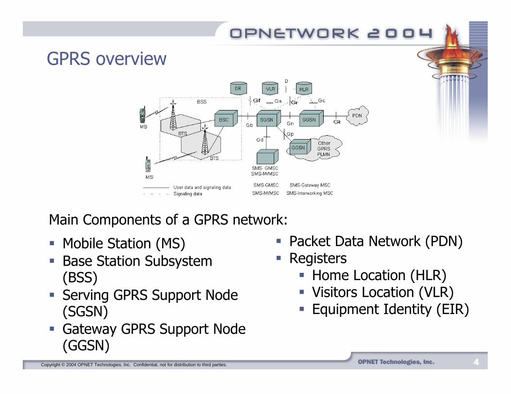
GPRS overview
� Mobile Station (MS)� Base Station Subsystem
(BSS)� Serving GPRS Support Node
(SGSN)� Gateway GPRS Support Node
(GGSN)
� Packet Data Network (PDN)� Registers
� Home Location (HLR)� Visitors Location (VLR)� Equipment Identity (EIR)
Main Components of a GPRS network:
Copyright © 2004 OPNET Technologies, Inc. Confidential, not for distribution to third parties. 5555
� Base Station Subsystem (BSS) consists of Base Transceiver Stations (BTSs) or Base Stations (BSs) and a Base Station Controller (BSC).
� The BSC manages the Radio Resource (RR) functions: � evaluating measurement results from MSs and BTSs� controlling handover and power for GSM connections.
� The BTS enables wireless connections of MSs to the network over the air interface.
Base Station Subsystem

Copyright © 2004 OPNET Technologies, Inc. Confidential, not for distribution to third parties. 6666
Logical Link Control layer
� LLC, a sub-layer of layer 2 in the ISO 7-layer reference model, conveys information between layer-3 entities in the MS and the SGSN.
� Two modes of operation supported by LLC:� Unacknowledged peer-to-peer operation, known as
Asynchronous Disconnected Mode (ADM)� Acknowledged peer-to-peer operation, called Asynchronous
Balanced Mode (ABM).
Copyright © 2004 OPNET Technologies, Inc. Confidential, not for distribution to third parties. 7777
Internal LLC layer structure
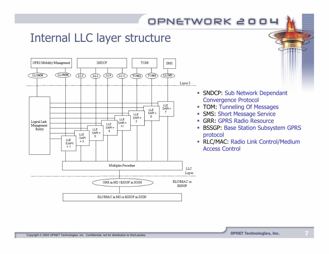
� SNDCP: Sub Network Dependant Convergence Protocol
� TOM: Tunneling Of Messages� SMS: Short Message Service� GRR: GPRS Radio Resource� BSSGP: Base Station Subsystem GPRS
protocol� RLC/MAC: Radio Link Control/Medium
Access Control

Copyright © 2004 OPNET Technologies, Inc. Confidential, not for distribution to third parties. 8888
LLC components and functions
� Logical Link Management Entity (LLME) performs parameter initialization, error processing, and connection flow control invocation.
� Logical Link Entities (LLEs) control the information flow of individual connections.
� Multiplex Procedure:� when a frame is transmitted, it generates and inserts a
Frame Check Sequence (FCS), performs frame ciphering,and provides contention resolution between LLEs.
� on frame reception, the multiplex procedure performs theframe decipher function and sends it to the appropriate LLE after checking the FCS.
Copyright © 2004 OPNET Technologies, Inc. Confidential, not for distribution to third parties. 9999
LLC frame format
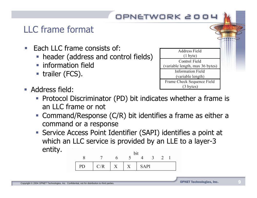
� Address field:� Protocol Discriminator (PD) bit indicates whether a frame is
an LLC frame or not� Command/Response (C/R) bit identifies a frame as either a
command or a response� Service Access Point Identifier (SAPI) identifies a point at
which an LLC service is provided by an LLE to a layer-3 entity.
� Each LLC frame consists of:� header (address and control fields)� information field� trailer (FCS).

Copyright © 2004 OPNET Technologies, Inc. Confidential, not for distribution to third parties. 10101010
LLC frame format
� Control field identifies the frame type.� Four types of control field formats:
� confirmed information transfer (I format)
� supervisory functions (S format)� unconfirmed information transfer
(UI format)� control functions (U format).
� Information field consists of 140 to 1,520 bytes depending on the format specified in the control field.
� Frame Check Sequence field consists of a 24-bit cyclic redundancy check (CRC) code. The code is used to detectbit errors in the frame header and information fields.

Copyright © 2004 OPNET Technologies, Inc. Confidential, not for distribution to third parties. 11111111
Cell update procedure
� The cell update procedure has to be performed when the MS moves to the coverage area of another BTS with better reception.
� The MS periodically measures the signal levels on the Broadcast Control Channels (BCCHs) of the serving BTS and the neighboring BTSs.
� The cell update can be controlled by either the MS or the network.
� Three modes of cell update are defined:� NC0: MS performs autonomous cell reselection, but does
not send measurement reports to the network� NC1: MS performs autonomous cell reselection and
periodically sends measurement reports to the network� NC2: Network controls cell reselection procedure.

Copyright © 2004 OPNET Technologies, Inc. Confidential, not for distribution to third parties. 12121212
OPNET model implementation: original model
� The original GPRS model consisted of:� Mobile Station (MS)� Serving GPRS Support Node (SGSN)� Home Location Register (HLR)� Gateway GPRS Support Node (GGSN)� Sink representing an external packet data network.
Copyright © 2004 OPNET Technologies, Inc. Confidential, not for distribution to third parties. 13131313
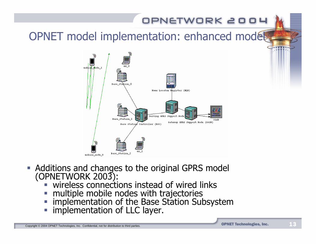
OPNET model implementation: enhanced model
� Additions and changes to the original GPRS model (OPNETWORK 2003):� wireless connections instead of wired links� multiple mobile nodes with trajectories� implementation of the Base Station Subsystem� implementation of LLC layer.
Copyright © 2004 OPNET Technologies, Inc. Confidential, not for distribution to third parties. 14141414
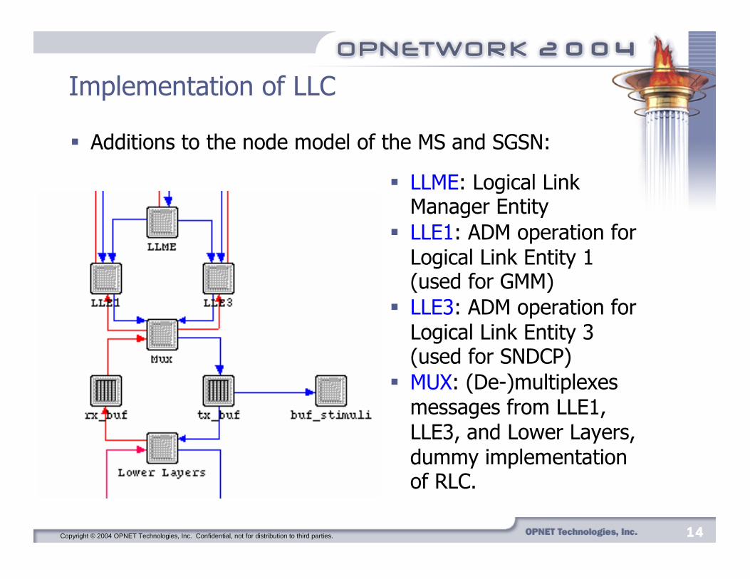
Implementation of LLC
� Additions to the node model of the MS and SGSN:
� LLME: Logical Link Manager Entity
� LLE1: ADM operation for Logical Link Entity 1 (used for GMM)
� LLE3: ADM operation for Logical Link Entity 3 (used for SNDCP)
� MUX: (De-)multiplexes messages from LLE1, LLE3, and Lower Layers, dummy implementation of RLC.

Copyright © 2004 OPNET Technologies, Inc. Confidential, not for distribution to third parties. 15151515
Implementation of LLC
� LLC packet format used in our implementation contains a new field, Temporary Logical Link Identifier (TLLI), not specified in the LLC specification.
� This field was added to enable functionality in an incomplete protocol stack.
Copyright © 2004 OPNET Technologies, Inc. Confidential, not for distribution to third parties. 16161616
Simplifications:
� We only implemented:� unacknowledged Asynchronous Disconnected Mode (ADM) � two Logical Link Entities, LLE1 and LLE3
� LLC in the SGSN and MS are identical.� LLC does not implement the correct service primitives for
communication between LLC and lower layers because BSSGP and MAC are not implemented in this OPNET model.
� Frame ciphering and error control are not implemented.

Copyright © 2004 OPNET Technologies, Inc. Confidential, not for distribution to third parties. 17171717
Base Station Controller
� Routes packets from the BTSs to the SGSN and from the SGSN to the BTSs based on the stream number of the incoming packet and the TLLI, respectively.
Copyright © 2004 OPNET Technologies, Inc. Confidential, not for distribution to third parties. 18181818
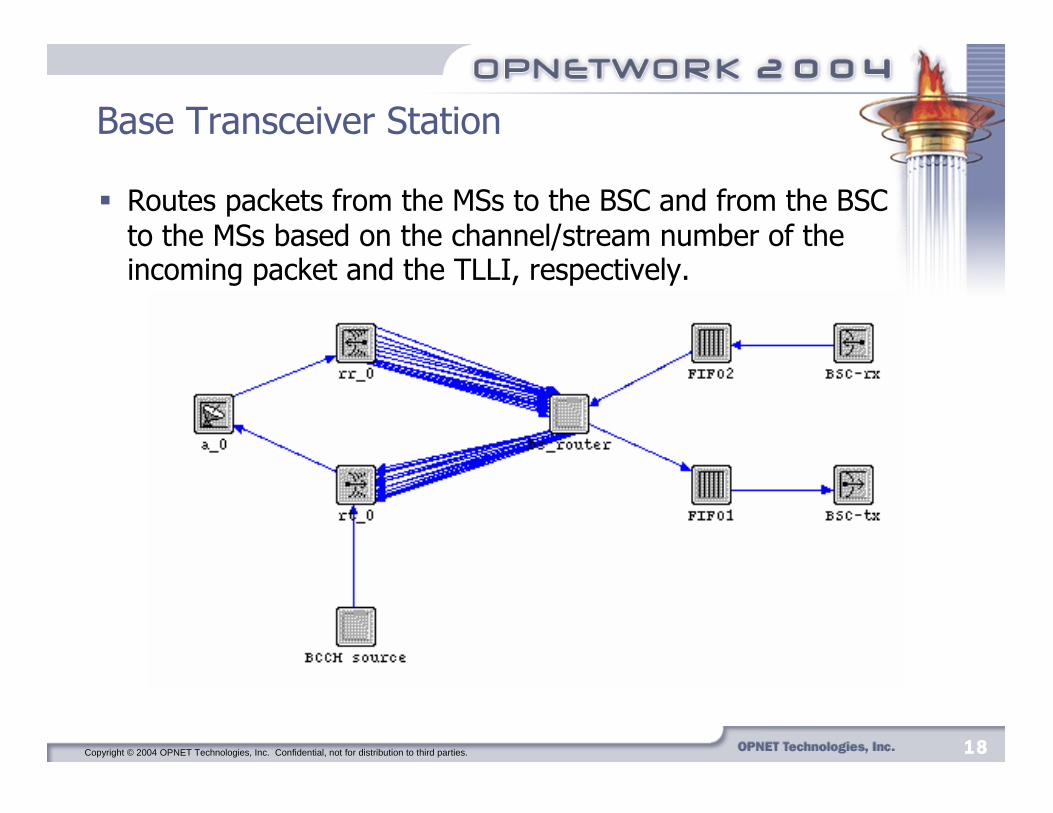
Base Transceiver Station
� Routes packets from the MSs to the BSC and from the BSC to the MSs based on the channel/stream number of the incoming packet and the TLLI, respectively.

Copyright © 2004 OPNET Technologies, Inc. Confidential, not for distribution to third parties. 19191919
Base Transceiver Station
� BTS in this model can support 15 MSs.� BTS has a radio transmitter-receiver pair with 15 channels.� MSs cannot share the same frequency/channel, as the
RLC/MAC layer is not implemented.� 16th channel was added to the wireless transmitter to represent
the Broadcast Control Channel (BCCH).� Every 5 seconds, the BTS transmits a packet through the BCCH
to allow power measurements in the MSs.
Copyright © 2004 OPNET Technologies, Inc. Confidential, not for distribution to third parties. 20202020
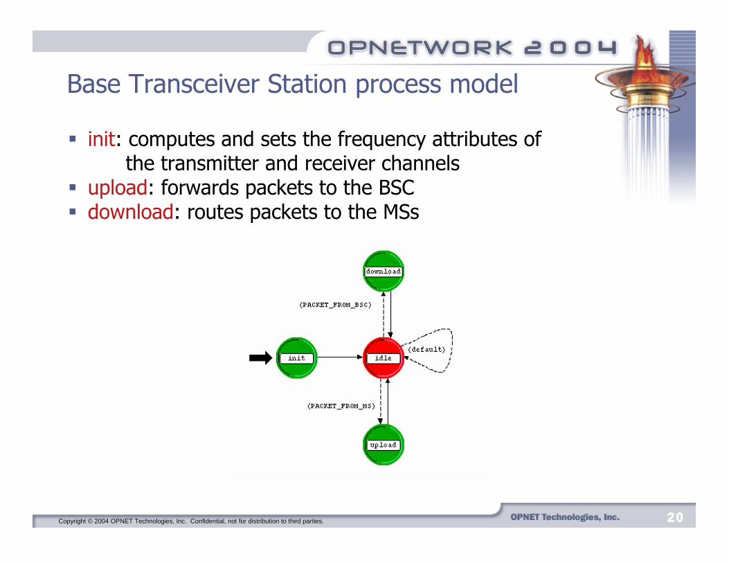
Base Transceiver Station process model
� init: computes and sets the frequency attributes of the transmitter and receiver channels
� upload: forwards packets to the BSC� download: routes packets to the MSs
Copyright © 2004 OPNET Technologies, Inc. Confidential, not for distribution to third parties. 21212121
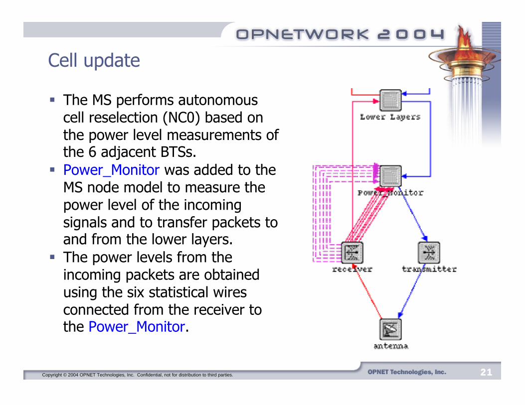
Cell update
� The MS performs autonomous cell reselection (NC0) based on the power level measurements of the 6 adjacent BTSs.
� Power_Monitor was added to the MS node model to measure the power level of the incoming signals and to transfer packets to and from the lower layers.
� The power levels from the incoming packets are obtained using the six statistical wires connected from the receiver to the Power_Monitor.
Copyright © 2004 OPNET Technologies, Inc. Confidential, not for distribution to third parties. 22222222
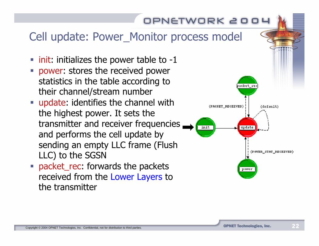
Cell update: Power_Monitor process model
� init: initializes the power table to -1� power: stores the received power
statistics in the table according to their channel/stream number
� update: identifies the channel with the highest power. It sets the transmitter and receiver frequencies and performs the cell update by sending an empty LLC frame (Flush LLC) to the SGSN
� packet_rec: forwards the packets received from the Lower Layers to the transmitter
Copyright © 2004 OPNET Technologies, Inc. Confidential, not for distribution to third parties. 23232323
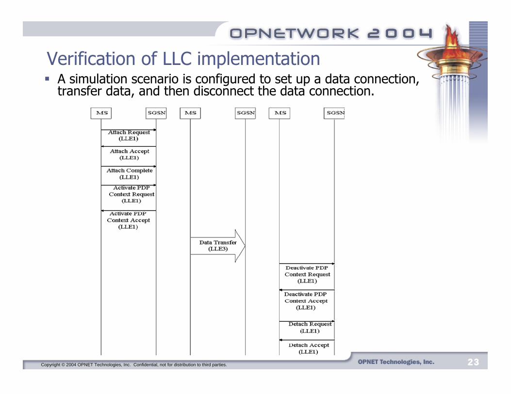
Verification of LLC implementation� A simulation scenario is configured to set up a data connection,
transfer data, and then disconnect the data connection.

Copyright © 2004 OPNET Technologies, Inc. Confidential, not for distribution to third parties. 24242424
Verification of LLC implementation
� The collected statistics indicate that a packet has been using either Service Access Point (SAP) 1 or 3 when traversing the LLC layer.
� Initial and final control messages are sent through LLE1 and data traffic in between is sent through LLE3.
� The simulation proves that the control messages (GMM) and user data (SNDCP) are correctly multiplexed onto separate SAPs.
Copyright © 2004 OPNET Technologies, Inc. Confidential, not for distribution to third parties. 25252525
� We simulated three different scenarios:� single MS connected to BTS with a wired link and without
a BSC� wireless scenario without a BSC � wireless scenario with a BSC.
� In order to verify the implementation of the wireless connection and the BSC, we measure the packet end-to-end delay from the mobile station to the sink.
Verification of BSS implementation

Copyright © 2004 OPNET Technologies, Inc. Confidential, not for distribution to third parties. 26262626
Verification of the BSS implementation: results
� The end-to-end delay obtained when the MS was connected to the SGSN through a BSC is the largest.
� The reason is the delay imposed by the BSC in receiving, processing, and routing packets.
Copyright © 2004 OPNET Technologies, Inc. Confidential, not for distribution to third parties. 27272727
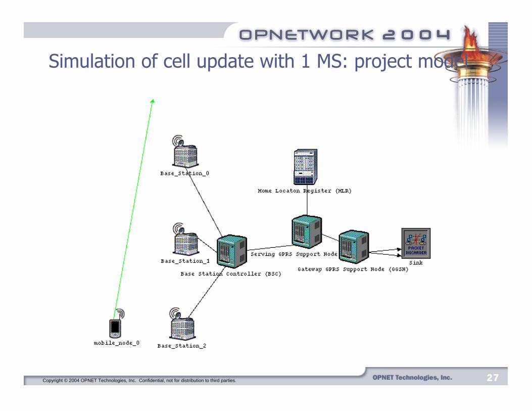
Simulation of cell update with 1 MS: project model
Copyright © 2004 OPNET Technologies, Inc. Confidential, not for distribution to third parties. 28282828
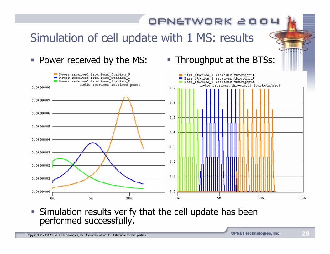
Simulation of cell update with 1 MS: results
� Power received by the MS:
� Simulation results verify that the cell update has been performed successfully.
� Throughput at the BTSs:

Copyright © 2004 OPNET Technologies, Inc. Confidential, not for distribution to third parties. 29292929
Simulation of cell update with 2 MSs: project model
� The MS mobile_node_1 moves between Base_Station_0 and Base_Station_1 only.

Copyright © 2004 OPNET Technologies, Inc. Confidential, not for distribution to third parties. 30303030
Simulation of cell update with 2 MSs: results
� Power received by mobile_node_1:
� Channel 1 receiver throughput at the BTSs:
Copyright © 2004 OPNET Technologies, Inc. Confidential, not for distribution to third parties. 31313131
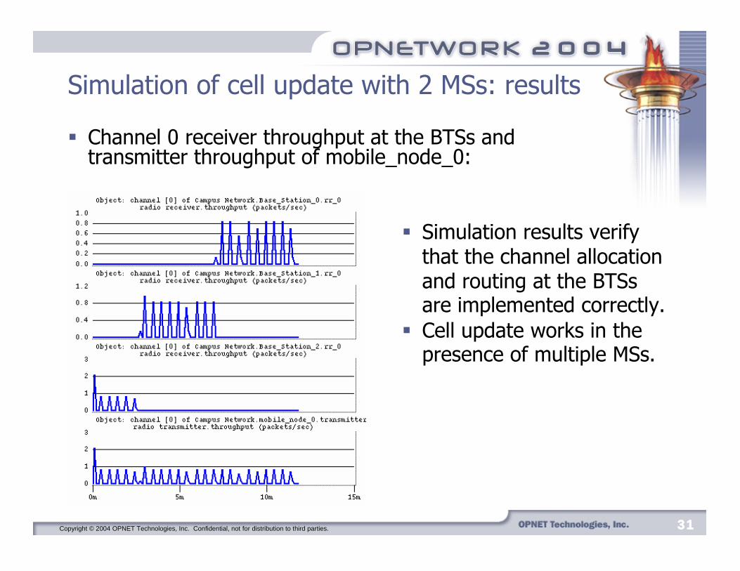
Simulation of cell update with 2 MSs: results
� Simulation results verify that the channel allocation and routing at the BTSs are implemented correctly.
� Cell update works in the presence of multiple MSs.
� Channel 0 receiver throughput at the BTSs and transmitter throughput of mobile_node_0:

Copyright © 2004 OPNET Technologies, Inc. Confidential, not for distribution to third parties. 32323232
Conclusions
� We implemented LLC layer and Base Station Subsystem (BSC and BTS) in an existing OPNET model for GPRS.
� We made several modifications to the existing OPNET model and implemented an autonomous cell update procedure.
� Various simulation scenarios demonstrated that the implementations were done correctly.
� The enhanced GPRS model (release 10.0.A PL2) has been uploaded to the OPNET Contributed Model Depot.

Copyright © 2004 OPNET Technologies, Inc. Confidential, not for distribution to third parties. 33333333
Future work
� Further improve the cell update procedure by introducing cell identifiers.
� Implement the Base Station Subsystem GPRS Protocol (BSSGP).� Add the Radio Link Control/Medium Access Control (RLC/MAC).� Employ simulation scenarios using genuine traffic traces.
Copyright © 2004 OPNET Technologies, Inc. Confidential, not for distribution to third parties. 34343434
References
� H. K. Hannu, GPRS, http://www.ee.oulu.fi/~fiat/gprs.html (June 2004).� V. Vukadinovic and Lj. Trajkovi�, “OPNET implementation of the Mobile
Application Part protocol,” OPNETWORK 2003, Washington, DC, Aug. 2003.
� GSM World, http://www.gsmworld.com/technology/gprs/intro.shtml (June 2004).
� 3rd Generation Partnership Project, TS 03.60 version 7.9.0 General Packet Radio Service (GPRS) Service description.
� E. Seurre, P. Savelli, and P. Pietri, GPRS for Mobile Internet. Boston: Artech House, 2003.
� 3rd Generation Partnership Project, TS 04.64 version 8.7.0 General Packet Radio Service (GPRS) Logical Link Control (LLC) layer specification.
� R. Ng and Lj. Trajkovi�, “Simulation of General Packet Radio Service network,” OPNETWORK 2002, Washington, DC, Aug. 2002.
� G. Jain and P. Shekhar, “GPRS model enhancements,” OPNETWORK 2003, Washington, DC, Aug. 2003.
Related Documents