SERVICE MANUAL SPLIT-TYPE, HEAT PUMP AIR CONDITIONERS CONTENTS 1. REFERENCE MANUAL··································2 2. SAFETY PRECAUTION··································3 3. FEATURES ·····················································7 4. SPECIFICATIONS···········································8 5. DATA·····························································10 6. OUTLINES AND DIMENSIONS····················15 7. WIRING DIAGRAM ·······································18 8. WIRING SPECIFICATIONS ··························21 9. REFRIGERANT SYSTEM DIAGRAM··············26 10. TROUBLESHOOTING ··································29 11. FUNCTION SETTING····································85 12. MONITORING THE OPERATION DATABY THE REMOTE CONTROLLER············91 13. DISASSEMBLY PROCEDURE ···················101 14. PARTS LIST ················································123 No.OC334 R410A June 2005 Outdoor unit [model names] PUHZ-RP35VHA PUHZ-RP50VHA PUHZ-RP60VHA PUHZ-RP71VHA PUHZ-RP100VHA PUHZ-RP125VHA PUHZ-RP140VHA PUHZ-RP100YHA PUHZ-RP125YHA PUHZ-RP140YHA [Service Ref.] PUHZ-RP35VHA PUHZ-RP50VHA PUHZ-RP60VHA PUHZ-RP71VHA PUHZ-RP100VHA PUHZ-RP125VHA PUHZ-RP140VHA PUHZ-RP100YHA PUHZ-RP125YHA PUHZ-RP140YHA • This manual describes only service data of the outdoor units. PUHZ-RP60VHA PUHZ-RP71VHA

Welcome message from author
This document is posted to help you gain knowledge. Please leave a comment to let me know what you think about it! Share it to your friends and learn new things together.
Transcript

SERVICE MANUAL
SPLIT-TYPE, HEAT PUMP AIR CONDITIONERS
CONTENTS1. REFERENCE MANUAL··································22. SAFETY PRECAUTION··································33. FEATURES ·····················································74. SPECIFICATIONS···········································85. DATA ·····························································106. OUTLINES AND DIMENSIONS····················157. WIRING DIAGRAM·······································188. WIRING SPECIFICATIONS ··························219. REFRIGERANT SYSTEM DIAGRAM ··············26
10. TROUBLESHOOTING ··································2911. FUNCTION SETTING····································8512. MONITORING THE OPERATION DATA BY THE REMOTE CONTROLLER ············9113. DISASSEMBLY PROCEDURE ···················10114. PARTS LIST ················································123
No.OC334
R410A
June 2005
Outdoor unit[model names]
PUHZ-RP35VHA
PUHZ-RP50VHA
PUHZ-RP60VHA
PUHZ-RP71VHA
PUHZ-RP100VHA
PUHZ-RP125VHA
PUHZ-RP140VHA
PUHZ-RP100YHA
PUHZ-RP125YHA
PUHZ-RP140YHA
[Service Ref.]
PUHZ-RP35VHAPUHZ-RP50VHAPUHZ-RP60VHAPUHZ-RP71VHAPUHZ-RP100VHAPUHZ-RP125VHAPUHZ-RP140VHAPUHZ-RP100YHAPUHZ-RP125YHAPUHZ-RP140YHA
• This manual describes only service data of the outdoor units.
PUHZ-RP60VHAPUHZ-RP71VHA
OC334-1.qxp 05.5.26 6:09 PM Page 1
2
1 REFERENCE MANUAL
Model name Service Ref. ServiceManual No.
PLA-RP35/50/60/71AA PLA-RP35/50/60/71AA.UK OC335PLA-RP100/125/140AA PLA-RP100/125/140AA.UK
PLA-RP35/50/60/71AA OC327PLA-RP100/125/140AA.UK
PCA-RP50/60/71GA PCA-RP50/60/71GA OC328PCA-RP100/125/140GA PCA-RP100/125/140GAPCA-RP71/125HA PCA-RP71/125HA OC329
PKA-RP35/50GAL PKA-RP35/50GAL OC330
PKA-RP60/71/100FAL PKA-RP60/71/100FAL OC331
PSA-RP71/100/125/140GA PSA-RP71/100/125/140GA OC332
PEA-RP71/100/125/140EA PEA-RP71/100/125/140EA.TH-A OC326
PEAD-RP35/50/60/71EA PEAD-RP35/50/60/71EA.UK -PEAD-RP100/125/140EA PEAD-RP100/125/140EA.UKPEAD-RP60/71/100GA PEAD-RP60/71/100GA.UK -
1-2.TECHNICAL DATA BOOK
Manual No. OCS01
1-1. INDOOR UNIT’S SERVICE MANUAL
OC334-1.qxp 05.5.26 6:09 PM Page 2

3
2 SAFETY PRECAUTION
Cautions for units utilizing refrigerant R410A
2-1. CAUTIONS RELATED TO NEW REFRIGERANT
Use new refrigerant pipes.
Make sure that the inside and outside of refrige-rant piping is clean and it has no contaminationsuch as sulfur hazardous for use, oxides, dirt, shaving particles, etc.In addition, use pipes with specified thickness.
Store the piping to be used during installationindoors and keep both ends of the piping sealed until just before brazing. (Leave elbow joints, etc. in their packaging.)
Use ester oil, ether oil or alkylbenzene oil (small amount) as the refrigerant oil applied to flares and flange connections.
In case of using the existing pipes for R22, be careful withthe followings.· For RP100, 125 and 140, be sure to perform replacement operation before test run.· Change flare nut to the one provided with this product. Use a newly flared pipe. · Avoid using thin pipes.
Charge refrigerant from liquid phase of gascylinder.
If the refrigerant is charged from gas phase, composition change may occur in refrigerant and the efficiency will be lowered.
Do not use refrigerant other than R410A.
If other refrigerant (R22 etc.) is used, chlorine in refrige-rant can cause deterioration of refrigerant oil etc.
Use a vacuum pump with a reverse flow check valve.Vacuum pump oil may flow back into refrigerant cycle and that can cause deterioration of refrigerant oil etc.
Use the following tools specifically designed for use with R410A refrigerant.
The following tools are necessary to use R410A refrigerant.
Keep the tools with care.
If dirt, dust or moisture enter into refrigerant cycle, that cancause deterioration of refrigerant oil or malfunction of com-pressor.
Do not use a charging cylinder.
If a charging cylinder is used, the composition of refrigera-nt will change and the efficiency will be lowered.
Flare tool
Electronic refrigerant charging scale
Vacuum pump adaptorSize adjustment gauge
Gauge manifold
Torque wrenchGas leak detectorCharge hose
Tools for R410A
Contamination inside refrigerant piping can cause deterio-ration of refrigerant oil etc.
If dirt, dust or moisture enter into refrigerant cycle, that can cause deterioration of refrigerant oil or malfunction of com-pressor.
If large amount of mineral oil enter, that can cause deterio-ration of refrigerant oil etc.
Ventilate the room if refrigerant leaks during operation. If refrigerant comes into contact witha flame, poisonous gases will be released.
[1] Cautions for service(1) Perform service after collecting the refrigerant left in unit completely.(2) Do not release refrigerant in the air.(3) After completing service, charge the cycle with specified amount of refrigerant.(4) When performing service, install a filter drier simultaneously.
Be sure to use a filter drier for new refrigerant.
[2] Additional refrigerant chargeWhen charging directly from cylinder· Check that cylinder for R410A on the market is syphon type.· Charging should be performed with the cylinder of syphon stood vertically. (Refrigerant is charged from liquid phase.)
OC334-1.qxp 05.5.26 6:09 PM Page 3
4
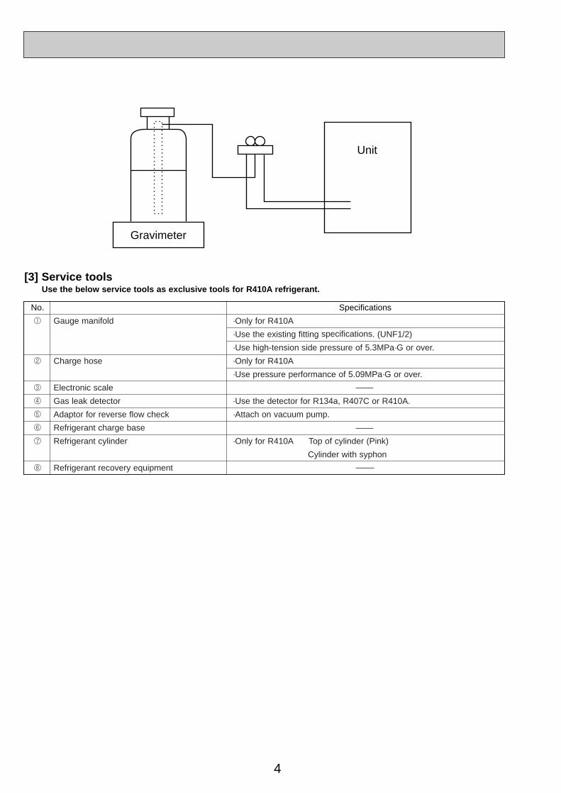
Gravimeter
Unit
[3] Service toolsUse the below service tools as exclusive tools for R410A refrigerant.
No. Specifications
1 Gauge manifold ·Only for R410A
·Use the existing fitting specifications. (UNF1/2)
·Use high-tension side pressure of 5.3MPa·G or over.
2 Charge hose ·Only for R410A
·Use pressure performance of 5.09MPa·G or over.
3 Electronic scale
4 Gas leak detector ·Use the detector for R134a, R407C or R410A.
5 Adaptor for reverse flow check ·Attach on vacuum pump.
6 Refrigerant charge base
7 Refrigerant cylinder ·Only for R410A Top of cylinder (Pink)
Cylinder with syphon
8 Refrigerant recovery equipment
OC334-1.qxp 05.5.26 6:09 PM Page 4

5
2-2. CHANGED POINT• Precautions when reusing existing R22 refrigerant pipes (1) Flowchart
Connecting a new air conditioner1Flaring work should be done so that flare meets the dimension for R410A. Use flare nut provided with indoor and outdoor unit.
2When using gas piping of [19.05mm for RP100, 125 or 140. Make sure that DIP SW8-1 on outdoor unit controller board is set to ON. WThis is to keep the pressure on pipes within permissible range. ●Use different diameter joint or adjust the piping size by brazing.
3When using pipes larger than specified size for RP35, 50, 60 or 71. Make sure that DIP SW8-1 on outdoor unit controller board is set to ON. WThis is to prevent oil flow ratio from lowering due to the decrease in flowing refrigerant. ●Use different diameter joint or adjust the piping size by brazing.
4When existing pipes are specified size. The pipes can be reused referring to TECHNICAL DATA BOOK (OCS01). ●Use different diameter joint or adjust the piping size by brazing.
★When using existing pipes for RP100, 125 and 140. Make sure that DIP SW8-2 on outdoor unit controller board is set to ON and perform replacement operation. wChemical compounds containing chlorine left in existing pipes are collected by rep- lace filter. ●The air conditioner automatically performs cooling operation through replace filter for about 2 hours.
Measure the existing pipe thickness and check for damage.
Check if existing air conditioner can operate.
Existing air conditioner canoperate.
Disconnect existing air con-ditioner from piping.
Existing pipes can be reused.
In case the unit is RP35, 50, 60 or 71 which utilizes AB oil.
In case the unit is RP100, 125 or 140 which utilize ester oil.
Perform cooling operationfor about 30 minutes andthen do a pump down work.
Use a refrigerant recovery equipment to collect the re-frigerant.
Check the oil condition when collecting the refrige-rant.
Disconnect existing air conditioner from pipes and clean pipes using cleaning device.
Existing air conditioner cannot operate.
The existing pipe thickness meets speci-fications and the pipes are not damaged.
The existing pipe thickness does not meetspecifications or the pipes are damaged.
Oil is clean.
Connect a new air conditioner. Connect a new air conditioner.
Perform replacement operation.
Oil is dirty.
Attach a filter drier.
When the compressor bearings are glazed, rotation scratches are present, or the compressor breaks down, iron particles or oil deterioration will blacken the oil.
·When performing replacement operation, make sure that DIP SW8-2 on outdoor unit controller board is set to ON.wChemical compounds containing chlorine left in existing pipes are collected by replace filter.●The air conditioner automatically performs cooling operation through replace filter for about 2 hours.
Existing pipes cannot be reused. Use new pipes.
OC334-1.qxp 05.5.26 6:09 PM Page 5
6
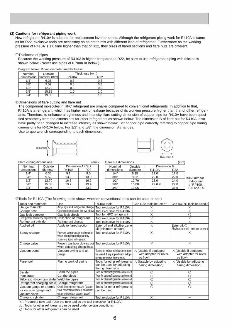
(2) Cautions for refrigerant piping workNew refrigerant R410A is adopted for replacement inverter series. Although the refrigerant piping work for R410A is same as for R22, exclusive tools are necessary so as not to mix with different kind of refrigerant. Furthermore as the working pressure of R410A is 1.6 time higher than that of R22, their sizes of flared sections and flare nuts are different.
1Thickness of pipesBecause the working pressure of R410A is higher compared to R22, be sure to use refrigerant piping with thickness shown below. (Never use pipes of 0.7mm or below.)
2Dimensions of flare cutting and flare nutThe component molecules in HFC refrigerant are smaller compared to conventional refrigerants. In addition to that, R410A is a refrigerant, which has higher risk of leakage because of its working pressure higher than that of other refriger-ants. Therefore, to enhance airtightness and intensity, flare cutting dimension of copper pipe for R410A have been speci-fied separately from the dimensions for other refrigerants as shown below. The dimension B of flare nut for R410A also have partly been changed to increase intensity as shown below. Set copper pipe correctly referring to copper pipe flaring dimensions for R410A below. For 1/2” and 5/8”, the dimension B changes. Use torque wrench corresponding to each dimension.
3Tools for R410A (The following table shows whether conventional tools can be used or not.)
1/4”3/8”1/2”5/8”3/4”
6.359.5212.7015.8819.05
0.80.80.81.0—
0.80.80.81.01.0
Nominaldimensions
Diagram below: Piping diameter and thickness
Outsidediameter (mm)
Thickness (mm)R410A R22
1/4”3/8”1/2”5/8”3/4”
6.359.5212.7015.8819.05
9.113.216.619.7—
9.013.016.219.423.3
Nominaldimensions
Flare cutting dimensionsOutsidediameter
Dimension A ( )+0-0.4
(mm)
R410A R221/4”3/8”1/2”5/8”3/4”
6.359.5212.7015.8819.05
17.022.026.029.0—
17.022.024.027.036.0
Nominaldimensions
Flare nut dimensionsOutsidediameter
Dimension B(mm)
R410A
w
w36.0mm for indoor unit of RP100, 125 and 140
R22
Gauge manifoldCharge hoseGas leak detectorRefrigerant recovery equipmentRefrigerant cylinderApplied oil
Safety charger
Charge valve
Vacuum pump
Flare tool
BenderPipe cutterWelder and nitrogen gas cylinderRefrigerant charging scaleVacuum gauge or thermis-tor vacuum gauge and vacuum valveCharging cylinder
Air purge and refrigerant chargeOperation check and the two aboveGas leak checkCollection of refrigerantRefrigerant chargeApply to flared section
Prevent compressor malfunction when charging refrigerant by spraying liquid refrigerantPrevent gas from blowing out when detaching charge hoseVacuum drying and airpurge
Flaring work of piping
Bend the pipesCut the pipesWeld the pipesCharge refrigerantCheck the degree of vacuum. (Vacuum valve prevents back flow of oil and refri-gerant to thermistor vacuum gauge)Charge refrigerant
Tool exclusive for R410ATool exclusive for R410ATool for HFC refrigerantTool exclusive for R410ATool exclusive for R410AEster oil and alkylbenzeneoil (minimum amount)Tool exclusive for R410A
Tool exclusive for R410A
Tools for other refrigerants can be used if equipped with adop-ter for reverse flow checkTools for other refrigerants can be used by adjusting flaring dimensionTools for other refrigerants can be usedTools for other refrigerants can be usedTools for other refrigerants can be usedTools for other refrigerants can be usedTools for other refrigerants can be used
Tool exclusive for R410A
Tools and materials Use R410A tools Can R22 tools be used?
(Usable if equipped with adopter for rever- se flow) (Usable by adjusting flaring dimension)
Can R407C tools be used?
Ester oil: Alkylbenzene oil: minimum amount
(Usable if equipped with adopter for rever- se flow) (Usable by adjusting flaring dimension)
: Prepare a new tool. (Use the new tool as the tool exclusive for R410A.) : Tools for other refrigerants can be used under certain conditions.: Tools for other refrigerants can be used.
Dimension A
Dimension B
OC334-1.qxp 05.5.26 6:09 PM Page 6
7
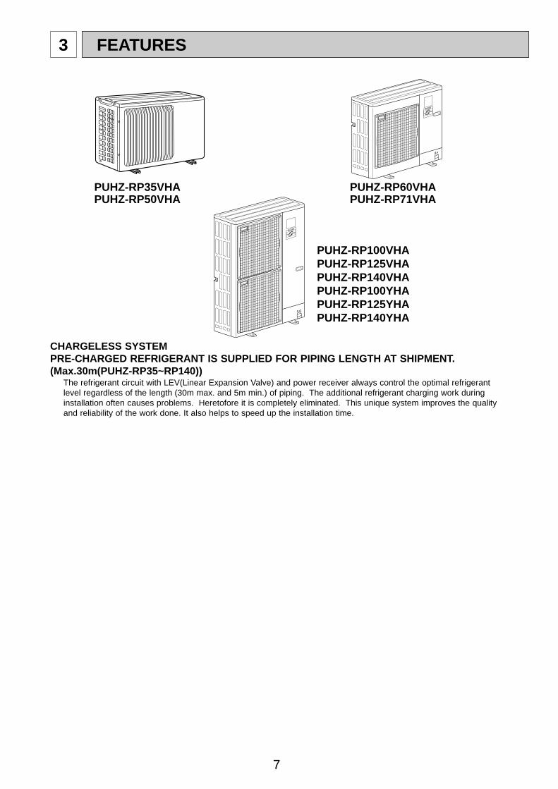
3 FEATURES
CHARGELESS SYSTEMPRE-CHARGED REFRIGERANT IS SUPPLIED FOR PIPING LENGTH AT SHIPMENT.(Max.30m(PUHZ-RP35~RP140))
The refrigerant circuit with LEV(Linear Expansion Valve) and power receiver always control the optimal refrigerantlevel regardless of the length (30m max. and 5m min.) of piping. The additional refrigerant charging work duringinstallation often causes problems. Heretofore it is completely eliminated. This unique system improves the qualityand reliability of the work done. It also helps to speed up the installation time.
PUHZ-RP60VHAPUHZ-RP71VHA
PUHZ-RP100VHAPUHZ-RP125VHAPUHZ-RP140VHAPUHZ-RP100YHAPUHZ-RP125YHAPUHZ-RP140YHA
PUHZ-RP35VHAPUHZ-RP50VHA
OC334-1.qxp 05.5.26 6:09 PM Page 7
8
4 SPECIFICATIONS
AA
kW
W
kWK/min(CFM)
dBdB
mm(in.)mm(in.)mm(in.)kg(lbs)
kg(lbs)L
mm(in.)mm(in.)
Power supply (phase, cycle, voltage)Running currentMax. current
External finishRefrigerant controlCompressor
ModelMotor outputStarter typeProtection devices
Crankcase heaterHeat exchangerFan Fan(drive) o No.
Fan motor outputAirflow
Defrost methodNoise level
Dimensions
WeightRefrigerant
ChargeOil (Model)
Pipe size O.D.
Connection method
Between the indoor & outdoor unit
Mode
CoolingHeating
WDH
LiquidGas
Indoor sideOutdoor sideHeight differencePiping length
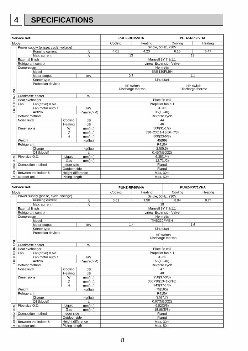
Service Ref. PUHZ-RP35VHA PUHZ-RP50VHA
Cooling
4.0113
0.8
Munsell 3Y 7.8/1.1Linear Expansion Valve
HermeticSNB130FLBH
Line start
—Plate fin coil
Propeller fan o 10.043
35(1,240)Reverse cycle
4446
800(31-1/2)330+23(11-13/16+7/8)
600(23-5/8)45(99)R410A2.5(5.5)
0.45(NEO22)6.35(1/4)12.7(1/2)
FlaredFlared
Max. 30mMax. 50m
Heating
4.23
Cooling
6.1613
1.1
Heating
6.47
HP switchDischarge thermo
HP switchDischarge thermo
Single, 50Hz, 230V
OU
TD
OO
R U
NIT
REFR
IGER
ANT P
IPIN
G
AA
kW
W
kWK/min(CFM)
dBdB
mm(in.)mm(in.)mm(in.)kg(lbs)
kg(lbs)L
mm(in.)mm(in.)
Power supply (phase, cycle, voltage)Running currentMax. current
External finishRefrigerant controlCompressor
ModelMotor outputStarter typeProtection devices
Crankcase heaterHeat exchangerFan Fan(drive) o No.
Fan motor outputAirflow
Defrost methodNoise level
Dimensions
WeightRefrigerant
ChargeOil (Model)
Pipe size O.D.
Connection method
Between the indoor & outdoor unit
Mode
CoolingHeating
WDH
LiquidGas
Indoor sideOutdoor sideHeight differencePiping length
Service Ref. PUHZ-RP71VHAPUHZ-RP60VHACooling
8.04
TNB220FMBH
Propeller fan o 10.060
55(1,940)
4748
943(37-1/8)75(165)
3.5(7.7)0.87(NEO22)
Max. 50m
Munsell 3Y 7.8/1.1Linear Expansion Valve
Hermetic
Line start
—Plate fin coil
Reverse cycle
950(37-3/8)330+30(13+1-3/16)
R410A
9.52(3/8)15.88(5/8)
FlaredFlared
Max. 30m
Heating
9.74
Cooling
6.61
Heating
7.50
HP switchDischarge thermo
Single, 50Hz, 230V
OU
TD
OO
R U
NIT
REFR
IGER
ANT P
IPIN
G
1.61.4
19
OC334-1.qxp 05.5.26 6:09 PM Page 8
9
AA
kW
W
kWK/min(CFM)
dBdB
mm(in.)mm(in.)mm(in.)kg(lbs)
kg(lbs)
Lmm(in.)mm(in.)
Power supply (phase, cycle, voltage)Running currentMax. current
External finishRefrigerant controlCompressor
ModelMotor outputStarter typeProtection devices
Crankcase heaterHeat exchangerFan Fan(drive) o No.
Fan motor outputAirflow
Defrost methodNoise level
Dimensions
WeightRefrigerant
Charge
Oil (Model)Pipe size O.D.
Connection method
Between the indoor & outdoor unit
Mode
CoolingHeating
WDH
LiquidGas
Indoor sideOutdoor sideHeight differencePiping length
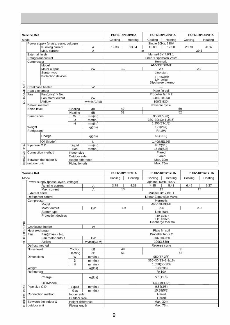
Service Ref. PUHZ-RP140VHAPUHZ-RP125VHAPUHZ-RP100VHA
Cooling
15.80
4951
Munsell 3Y 7.8/1.1Linear Expansion Valve
Hermetic
Line start
—Plate fin coil
Propeller fan o 20.060+0.060100(3,530)
Reverse cycle
950(37-3/8)330+30(13+1-3/16)
1,350(53-1/8)121(267)R410A
5.0(11.0)
1.40(MEL56)9.52(3/8)15.88(5/8)
FlaredFlared
Max. 30mMax. 75m
Heating
17.50
Cooling
12.33
Heating
13.94
Cooling
20.7329.5
2.9
Heating
20.37
HP switchLP switch
Discharge thermo
Single 50Hz, 230V
OU
TD
OO
R U
NIT
REFR
IGER
ANT P
IPIN
G
2.41.9
28
ANV33FDDMT
5052
AA
kW
W
kWK/min(CFM)
dBdB
mm(in.)mm(in.)mm(in.)kg(lbs)
kg(lbs)
Lmm(in.)mm(in.)
Power supply (phase, cycle, voltage)Running currentMax. current
External finishRefrigerant controlCompressor
ModelMotor outputStarter typeProtection devices
Crankcase heaterHeat exchangerFan Fan(drive) o No.
Fan motor outputAirflow
Defrost methodNoise level
Dimensions
WeightRefrigerant
Charge
Oil (Model)Pipe size O.D.
Connection method
Between the indoor & outdoor unit
Mode
CoolingHeating
WDH
LiquidGas
Indoor sideOutdoor sideHeight differencePiping length
Service Ref. PUHZ-RP140YHAPUHZ-RP125YHAPUHZ-RP100YHA
Cooling
4.8513
4951
13Munsell 3Y 7.8/1.1
Linear Expansion ValveHermetic
Line start
—Plate fin coil
Propeller fan o 20.060+0.060100(3,530)
Reverse cycle
950(37-3/8)330+30(13+1-3/16)
1,350(53-1/8)135(298)R410A
5.0(11.0)
1.40(MEL56)9.52(3/8)15.88(5/8)
FlaredFlared
Max. 30mMax. 75m
Heating
5.41
Cooling
3.79
Heating
4.33
Cooling
6.4913
2.9
Heating
6.37
HP switchLP switch
Discharge thermo
3phase, 50Hz, 400V
OU
TD
OO
R U
NIT
REFR
IGER
ANT P
IPIN
G
2.41.9ANV33FDBMT
5052
OC334-1.qxp 05.5.26 6:09 PM Page 9
10
5 DATA
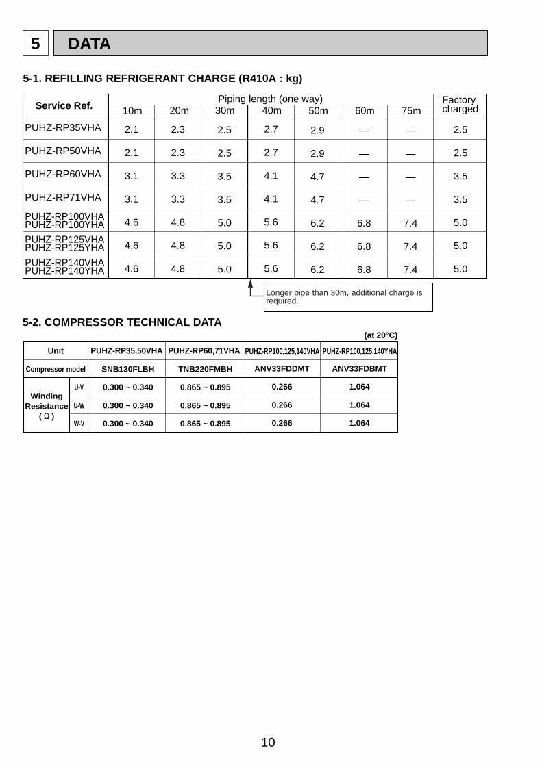
5-1. REFILLING REFRIGERANT CHARGE (R410A : kg)
5-2. COMPRESSOR TECHNICAL DATA
Piping length (one way)10m 20m 30m 40m 50m
Factorycharged
2.1
2.1
3.1
3.1
4.6
4.6
4.6
2.3
2.3
3.3
3.3
4.8
4.8
4.8
2.5
2.5
3.5
3.5
5.0
5.0
5.0
2.7
2.7
4.1
4.1
5.6
5.6
5.6
2.9
2.9
4.7
4.7
6.2
6.2
6.2
60m
—
—
—
—
6.8
6.8
6.8
75m
—
—
—
—
7.4
7.4
7.4
2.5
2.5
3.5
3.5
5.0
5.0
5.0
Service Ref.
PUHZ-RP35VHA
PUHZ-RP50VHA
PUHZ-RP60VHA
PUHZ-RP71VHA
PUHZ-RP100VHAPUHZ-RP100YHA
PUHZ-RP125VHAPUHZ-RP125YHA
PUHZ-RP140VHAPUHZ-RP140YHA
U-V
U-W
W-V
Unit
Compressor model
WindingResistance
( " )
ANV33FDDMT
(at 20°C)
0.266
0.266
0.266
SNB130FLBH
0.300 ~ 0.340
0.300 ~ 0.340
0.300 ~ 0.340
PUHZ-RP100,125,140VHA
ANV33FDBMT
1.064
1.064
1.064
PUHZ-RP100,125,140YHAPUHZ-RP35,50VHA
TNB220FMBH
0.865 ~ 0.895
0.865 ~ 0.895
0.865 ~ 0.895
PUHZ-RP60,71VHA
Longer pipe than 30m, additional charge isrequired.
OC334-1.qxp 05.5.26 6:09 PM Page 10
11
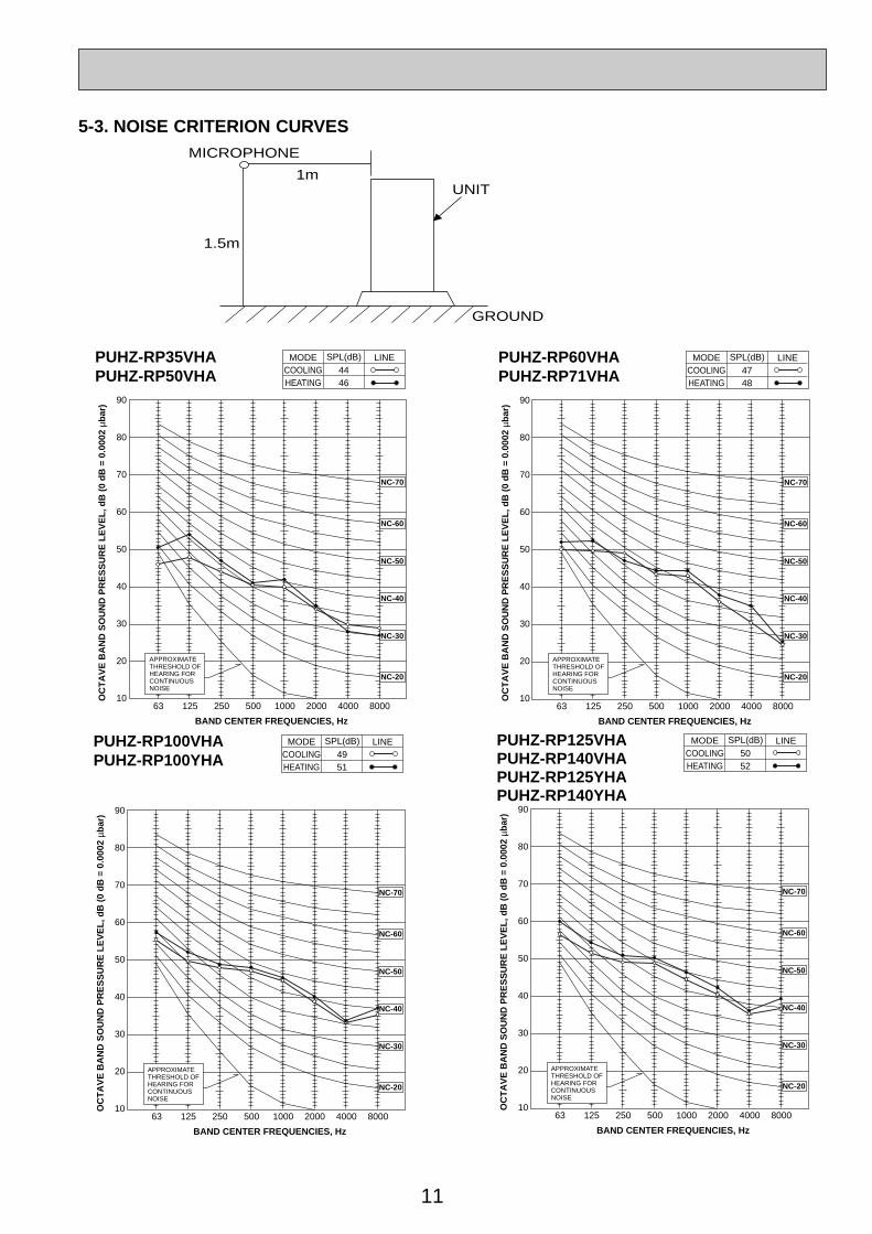
1.5m
1m
MICROPHONE
UNIT
GROUND
90
80
70
60
50
40
30
20
1063 125 250 500 1000 2000 4000 8000
APPROXIMATETHRESHOLD OFHEARING FORCONTINUOUSNOISE
NC-60
NC-50
NC-40
NC-30
NC-20
NC-70
OC
TA
VE
BA
ND
SO
UN
D P
RE
SS
UR
E L
EV
EL
, dB
(0
dB
= 0
.000
2 µb
ar)
BAND CENTER FREQUENCIES, Hz
PUHZ-RP60VHAPUHZ-RP71VHA COOLING
MODE
HEATING47
SPL(dB)
48
LINE
5-3. NOISE CRITERION CURVES
90
80
70
60
50
40
30
20
1063 125 250 500 1000 2000 4000 8000
APPROXIMATETHRESHOLD OFHEARING FORCONTINUOUSNOISE
OC
TA
VE
BA
ND
SO
UN
D P
RE
SS
UR
E L
EV
EL
, dB
(0
dB
= 0
.000
2 µb
ar)
BAND CENTER FREQUENCIES, Hz
NC-60
NC-50
NC-40
NC-30
NC-20
NC-70
PUHZ-RP100VHAPUHZ-RP100YHA COOLING
MODE
HEATING49
SPL(dB)
51
LINE
90
80
70
60
50
40
30
20
1063 125 250 500 1000 2000 4000 8000
APPROXIMATETHRESHOLD OFHEARING FORCONTINUOUSNOISE
OC
TA
VE
BA
ND
SO
UN
D P
RE
SS
UR
E L
EV
EL
, dB
(0
dB
= 0
.000
2 µb
ar)
BAND CENTER FREQUENCIES, Hz
NC-60
NC-50
NC-40
NC-30
NC-20
NC-70
PUHZ-RP125VHAPUHZ-RP140VHAPUHZ-RP125YHAPUHZ-RP140YHA
COOLINGMODE
HEATING50
SPL(dB)
52
LINE
90
80
70
60
50
40
30
20
1063 125 250 500 1000 2000 4000 8000
APPROXIMATETHRESHOLD OFHEARING FORCONTINUOUSNOISE
NC-60
NC-50
NC-40
NC-30
NC-20
NC-70
OC
TA
VE
BA
ND
SO
UN
D P
RE
SS
UR
E L
EV
EL
, dB
(0
dB
= 0
.000
2 µb
ar)
BAND CENTER FREQUENCIES, Hz
PUHZ-RP35VHAPUHZ-RP50VHA COOLING
MODE
HEATING44
SPL(dB)
46
LINE
OC334-1.qxp 05.5.26 6:09 PM Page 11
12
5-4. STANDARD OPERATION DATA
Tot
alE
lect
rical
circ
uit
Ref
riger
ant c
ircui
tIn
door
sid
eO
utdo
orsi
de
Representative matching
SHF
BF
W
kW
Mode
Capacity
Input
PLA-RP71AA
PLA-RP71AA
Cooling
7,100
1.97
Heating
8,000
2.34
8.04
2.68
0.94
70
46
10
5
27
19
14.2
35
24
0.74
0.18
9.74
2.87
0.73
74
48
1
5
20
15
41.6
7
6
—
—
1 , 50
230
0.79
PUHZ-RP71VHA
1 , 50
230
Phase , Hz
Volts
Amperes
Outdoor unit
Phase , Hz
Volts
Current
Discharge pressure
Suction pressure
Discharge temperature
Condensing temperature
Suction temperature
Ref. pipe length
Intake air temperature
Discharge air temperature
Intake air temperature
V
A
V
A
MPa
MPa
°C
°C
°C
m
°C
°C
°C
°C
°C
Indoor unit
D.B.
W.B.
D.B.
D.B.
W.B.
PLA-RP35AA PLA-RP50AA PLA-RP60AA
PLA-RP35AA PLA-RP50AA PLA-RP60AA
Cooling
3,600
1.07
Heating
4,100
1.12
Cooling
5,000
1.55
Heating
6,000
1.62
Cooling
6,000
1.65
Heating
7,000
1.85
4.01
2.70
1.01
70
46
15
5
27
19
15.6
35
24
0.89
0.11
4.23
2.69
0.74
71
41
2
5
20
15
35.5
7
6
—
—
6.16
2.91
0.99
73
49
11
5
27
19
15.4
35
24
0.86
0.14
6.47
2.76
0.67
77
44
-1
5
20
15
37.8
7
6
—
—
6.61
2.60
0.99
65
44
12
5
27
19
14.3
35
24
0.78
0.14
7.50
2.63
0.70
81
44
8
5
20
15
40.9
7
6
—
—
1 , 50
230
0.79
PUHZ-RP35VHA
1 , 50
230
1 , 50
230
0.79
PUHZ-RP50VHA
1 , 50
230
1 , 50
230
0.79
PUHZ-RP60VHA
1 , 50
230
The unit of pressure has been changed to MPa based on international SI system.The conversion factor is : 1(MPa)=10.2(kgf/ ff)
OC334-1.qxp 05.5.26 6:09 PM Page 12
13
Tot
alE
lect
rical
circ
uit
Ref
riger
ant c
ircui
tIn
door
sid
eO
utdo
orsi
de
Representative matching
SHF
BF
W
kW
Mode
Capacity
Input
Phase , Hz
Volts
Amperes
Outdoor unit
Phase , Hz
Volts
Current
Discharge pressure
Suction pressure
Discharge temperature
Condensing temperature
Suction temperature
Ref. pipe length
Intake air temperature
Discharge air temperature
Intake air temperature
V
A
V
A
MPa
MPa
°C
°C
°C
m
°C
°C
°C
°C
°C
Indoor unit
D.B.
W.B.
D.B.
D.B.
W.B.
PLA-RP100AA PLA-RP125AA PLA-RP140AA
PLA-RP100AA PLA-RP125AA PLA-RP140AA
Cooling
10,000
3.03
Heating
11,200
3.39
Cooling
12,500
3.89
Heating
14,000
4.27
Cooling
14,000
4.99
Heating
16,000
4.91
12.33
2.63
0.92
70
45
11
5
27
19
14.0
35
24
0.75
0.15
13.94
2.80
0.72
76
48
3
5
20
15
41.6
7
6
—
—
15.80
2.72
0.89
70
46
8
5
27
19
12.2
35
24
0.74
0.06
17.50
2.77
0.71
77
47
1
5
20
15
45.5
7
6
—
—
20.73
2.86
0.80
79
48
8
5
27
19
11.2
35
24
0.71
0.06
20.37
3.03
0.69
83
51
1
5
20
15
49.5
7
6
—
—
1 , 50
230
1.25
1 , 50
230
1 , 50
230
1.64
1 , 50
230
1 , 50
230
1.64
1 , 50
230
PUHZ-RP100VHA PUHZ-RP125VHA PUHZ-RP140VHA
The unit of pressure has been changed to MPa based on international SI system.The conversion factor is : 1(MPa)=10.2(kgf/ ff)
OC334-1.qxp 05.5.26 6:09 PM Page 13
14
Tot
alE
lect
rical
circ
uit
Ref
riger
ant c
ircui
tIn
door
sid
eO
utdo
orsi
de
Representative matching
SHF
BF
W
kW
Mode
Capacity
Input
PLA-RP100AA PLA-RP125AA PLA-RP140AA
PLA-RP100AA PLA-RP125AA PLA-RP140AA
Cooling
10,000
3.03
Heating
11,200
3.39
Cooling
12,500
3.89
Heating
14,000
4.27
Cooling
14,000
4.99
Heating
16,000
4.91
3.79
2.63
0.92
70
45
11
5
27
19
14.0
35
24
0.75
0.15
4.33
2.80
0.72
76
48
3
5
20
15
41.6
7
6
—
—
4.85
2.72
0.89
70
46
8
5
27
19
12.2
35
24
0.74
0.06
5.41
2.77
0.71
77
47
1
5
20
15
45.5
7
6
—
—
6.49
2.86
0.80
79
48
8
5
27
19
11.2
35
24
0.71
0.06
6.37
3.03
0.69
83
51
1
5
20
15
49.5
7
6
—
—
1 , 50
230
1.25
3 , 50
400
1 , 50
230
1.64
3 , 50
400
1 , 50
230
1.64
3 , 50
400
Phase , Hz
Volts
Amperes
Outdoor unit
Phase , Hz
Volts
Current
Discharge pressure
Suction pressure
Discharge temperature
Condensing temperature
Suction temperature
Ref. pipe length
Intake air temperature
Discharge air temperature
Intake air temperature
V
A
V
A
MPa
MPa
°C
°C
°C
m
°C
°C
°C
°C
°C
Indoor unit
D.B.
W.B.
D.B.
D.B.
W.B.
PUHZ-RP100YHA PUHZ-RP125YHA PUHZ-RP140YHA
The unit of pressure has been changed to MPa based on international SI system.The conversion factor is : 1(MPa)=10.2(kgf/ ff)
OC334-1.qxp 05.5.26 6:09 PM Page 14
15
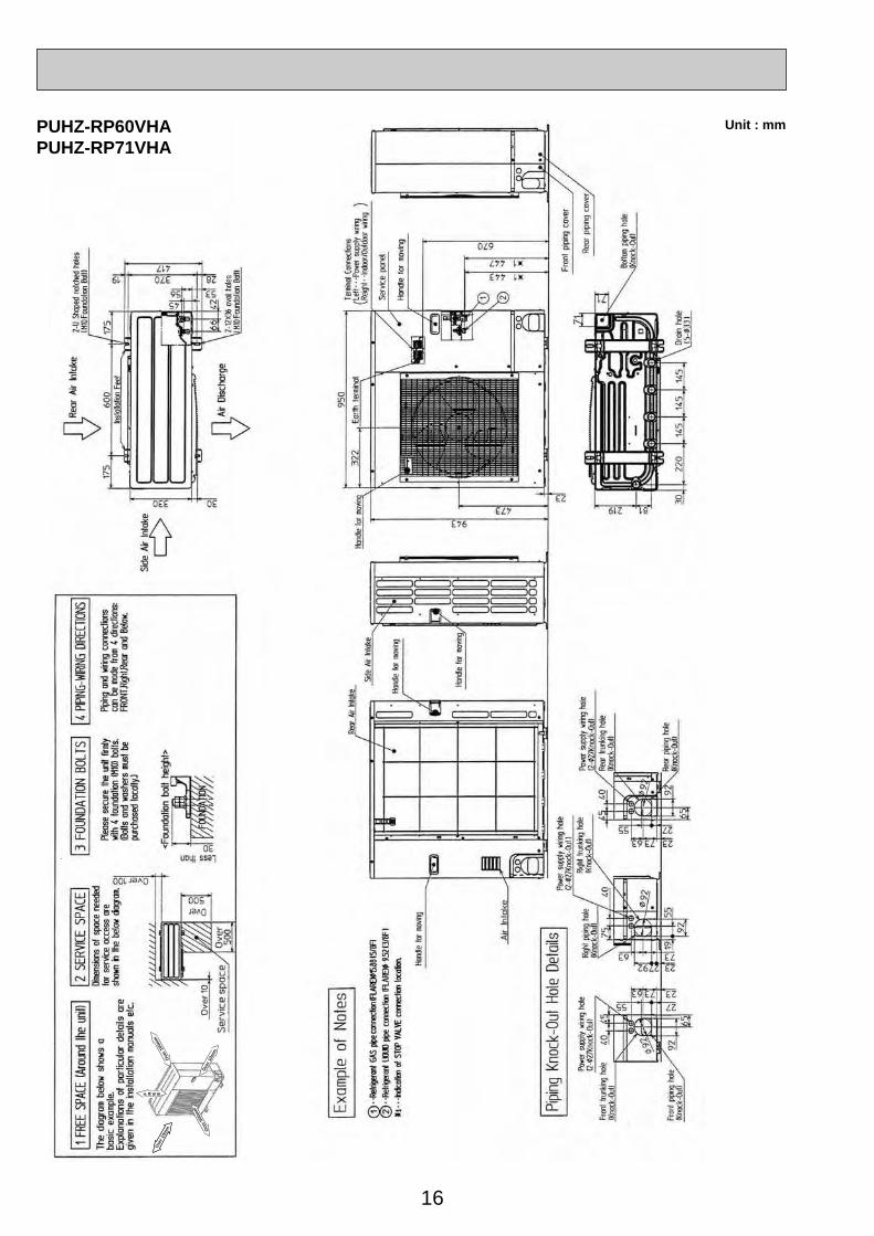
6 OUTLINES AND DIMENSIONS
Service panel for charge plug
w 1 In the place where short cycle tends to occur, cooling and heating capacity and power consumption might get lowered 10%. Air outlet guide (optional PAC-SG58SG) will help them improve.
w 2 If air discharges to the wall, the surface might get stained.
Minimum installation space for outdoor unit
100 mm or more as long as no obstacle is placed on the rear and light-and-left sides of the unit.
2 sides should be open in the right, left and rear side.
w 2w 1
100 mm or more
500 mm or more
Bas
ical
ly o
pen
100 mm or more
Free space around the outdoor unit (basic example)
350 mm or more
w 1
Air intake
Air discharge
Air intake
Connection for gas pipe
Service port
Connection for liquid pipe
Service panel4-10 o 21 oval hole(M10 foundation bolt)
[33 drain hole
[33 drain hole
43.6
152
155
400
347.5
45.4
365
330
300
40
Handle for moving
600
10
300
150
287.5
Installation bolt pitch: 500
800
69
35 43
183
90155
23
32.5
18
1. FOUNDATION BOLTS 2. PIPING-WIRING DIRECTIONPiping and wiring connection can be made from the rear direction only.
3. ATTACHING THE CONDUITIn order to attach the conduit, it is necessary to fix the metal plate with 2 screws to the back panel. Procure the metal plate and make screw holes locally. It is recommended to use the metal plate shown below. Align the metal plate to the marks on the unit and attach it.
<Foundation bolt height>
Please secure the unit firmly with 4 foundation (M10) bolts. (Bolts, washer and nut must be purchased locally.)
18 o
r bel
ow
4020
60 80
w Conduit hole
w The position and the size of conduit hole depend on the conduit to be used.
Holes for metal plate fixing screww The size of hole depends on the screw to be used.
FOUNDATION
PUHZ-RP35VHAPUHZ-RP50VHA
Unit : mm
OC334-1.qxp 05.5.26 6:09 PM Page 15
16
Unit : mmPUHZ-RP60VHAPUHZ-RP71VHA
Ove
r 10m
m
F R E E
Ove
r 500
mm
Ove
r 100
mm
Ove
r 10m
m
OC334-1.qxp 05.5.26 6:09 PM Page 16
17
21Han
dle
for m
ovin
g
Serv
ice
pane
l
Han
dle
for
mov
ing
Han
dle
for m
ovin
g
Rea
r Air
Inta
ke
Air
inta
ke
Rea
r pi
ping
cov
er
Fro
nt p
ipin
g co
ver
Sid
e A
ir In
take
Han
dle
for m
ovin
g
Pipi
ng K
nock
-Out
Hol
e De
tails
Exa
mpl
e of
Not
es
•
• • R
efrig
eran
t GA
S p
ipe
conn
ctio
n (F
LAR
E)[
15.8
8 (5
/8F)
•
• • R
efrig
eran
t LIQ
UID
pip
e co
nnec
tion
(FLA
RE
)[ 9
.52
(3/8
F)w
1 • •
• In
dica
tion
of S
TOP
VA
LVE
con
nect
ion
loca
tion.
1 2
Sid
e A
ir In
take
Rea
r A
ir In
take
Air
Dis
char
ge
600
175
175
370 2819
4556 53
6642
417
330
Inst
alla
tion
Fee
t
2-12
o36
Ova
l hol
es(F
ound
atio
n B
olt M
10)
2-U
Sha
ped
notc
hed
hole
s(F
ound
atio
n B
olt M
10)
30
63 73 23
55 27
92
65
4045
Pow
er s
uppl
y w
iring
hol
e(2
-[27
Kno
ck-O
ut)
Rea
r tru
nkin
g ho
le(K
nock
-Out
)
Rea
r pip
ing
hole
(Kno
ck-O
ut)
[92
92 27 23
63 73
4075
92
5519
Pow
er s
uppl
y w
iring
hol
e(2
-[27
Kno
ck-O
ut)
Rig
ht tr
unki
ng h
ole
(Kno
ck-O
ut)
Rig
ht p
ipin
g ho
le(K
nock
-Out
)
[92
63 73 23
55 27
4045 65
92
Pow
er s
uppl
y w
iring
hol
e(2
-[27
Kno
ck-O
ut)
Fro
nt tr
unki
ng h
ole
(Kno
ck-O
ut)
Fron
t pip
ing
hole
(Kno
ck-O
ut)
[92
81219
145
145
220
3014
5
71
71
Dra
in h
ole
(5-[
33)
Bot
tom
pip
ing
hole
(Kno
ck-O
ut)A
322
635 371
w1 443
w1 447
950
23
1350
Han
dle
for m
ovin
gEa
rth te
rmin
al
Ter
min
al c
onne
ctio
nLe
ft • •
• Po
wer
sup
ply
wiri
ngR
ight
• • I
ndoo
r/Out
door
wiri
ng
A
1,07
6
930
RP
·VH
A
RP
·YH
A
PUHZ-RP100VHA PUHZ-RP100YHAPUHZ-RP125VHA PUHZ-RP125YHAPUHZ-RP140VHA PUHZ-RP140YHA
Unit : mm
Ove
r
Over OverO
ver
Less than
Pip
ing
and
wiri
ng c
onne
ctio
nsca
n be
mad
e fro
m 4
dire
ctio
ns:
FRO
NT,
Rig
ht,R
ear a
nd B
elow
.
4 PIP
ING-
WIR
ING
DIRE
CTIO
NS3
FOUN
DATI
ON
BOLT
S2
SERV
ICE
SPAC
E1
FREE
SPA
CE (A
roun
d th
e un
it)P
leas
e se
cure
the
unit
firm
lyw
ith 4
foun
datio
n (M
10) b
olts
.(B
olts
and
was
hers
mus
t be
purc
hase
d lo
cally
.)
<F
ound
atio
n bo
lt he
ight
>
Dim
ensi
ons
of s
pace
nee
ded
for s
ervi
ce a
cces
s ar
esh
own
in th
e be
low
dia
gram
.
The
diag
ram
bel
ow s
how
s a
basi
c ex
ampl
e.E
xpla
ntio
n of
par
ticul
ar d
etai
ls a
regi
ven
in th
e in
stal
latio
n m
anua
ls e
tc.
FREE
Ove
r 10m
m
Ove
r 10m
m
Ove
r 150
mm
Ove
r 150
mm
30
FOUN
DATI
ON
10
500
500100S
ervi
ce s
pace
OC334-1.qxp 05.5.26 6:09 PM Page 17
18
7 WIRING DIAGRAM
PUHZ-RP35VHA PUHZ-RP50VHAPUHZ-RP60VHA PUHZ-RP71VHA
1 2 3 4 5 6OFFON
35V
MODEL SW6
1 MODEL SELECT
2 RP60/71V only
SW10
1 2OFFON
1 2 3 4 5 6OFFON
50V1 2
OFFON
1 2 3 4 5 6OFFON
60V1 2
OFFON
1 2 3 4 5 6OFFON
71V1 2
OFFON
TB1MCMF121S463H
TH3TH4TH6TH7TH8LEV(A),LEV(B)ACL
Terminal Block (Power Supply, Indoor/Outdoor)Motor for CompressorFan Motors Solenoid Valve (Four-Way Valve)High Pressure Switch
SV Solenoid Valve (Bypass Valve)Thermistor (Outdoor Pipe)Thermistor (Discharge)Thermistor (Outdoor 2-Phase Pipe)Thermistor (Outdoor)Thermistor (Radiator Panel)Electronic Expansion ValveReactorPower Circuit Board
Connection Terminal (U/V/W-Phase)Connector
P.B.
U/V/W
Noise Filter Circuit BoardConnection Terminal (L-Phase)
Connection Terminal (Ground)
N.F.LI/LO
Connection Terminal (N-Phase)NI/NOE
Fuse (6.3 A)
Controller Circuit Board
Connector
Switch (Forced Defrost, Defect History Record Reset, Refrigerant Address)Switch (Test Operation)Switch (Function Switch)
Switch (Function Setup)
Switch (Pump Down)Connector (Emergency Operation)
CNAC1/2
F1~4
SW1
SW4SW5
SW7SwitchSW8
SWPCN31CNACCNDCCNS
CNMSV2
CNVMNT
CNDM
CN2~5
LED1,LED2 Light Emitting Diodes (Operation Inspection Indicators)
ConnectorConnectorConnector
Connector (A-Control Service Inspection Kit)Connector
Connector (Connected to Optional M-NET Adapter Board)Connector ( Connected for Option (Contact Input))
C.B.
ConverterPFCInverterIPMMain Smoothing CapacitorCB1~CB3
ConnectorCN5ConnectorCN52C52C Relay52C
SYMBOL NAME SYMBOL NAME SYMBOL NAME
Connection Terminal (L/N-Phase)R/S
CNMNT Connector (Connected to Optional M-NET Adapter Board)
Switch (Model Select)SW6
SwitchSW9Switch (Model Select)SW10
X51,X52,X55 Reray
CNF1 ConnectorSS Connector (Connection for Option)
SYMBOL
M-NET ADAPTERNAME
TB7CN5CNDCN2MSW1SW11
Terminal Block (M-net connection)Connector (Transmission)Connector (Power Supply)Connector (M-NET communication)Switch (Status of communication)Switch (Address setting : 1st digit)
SW12LED1LED2LED3LED4LED5
Switch (Address setting : 2nd digit)LED (Power Supply : DC5V)LED (Connection to Outdoor Unit)LED (Transmission : Sending)LED (Transmission : Recelving)LED (Power Supply : DC12V)
CN3(WHT)
CN5(RED)
CN2(WHT)
CN4(WHT)
21
12
CN52C(BLK)
52C
21
TH8
2
12
16
72
34
5
N . F .
LO NO
CNAC2(RED)
13
CNAC1(WHT)
13
1 2
(RED)CN5
NIELI
L N S1 S2 S3
NO FUSEBREAKER
POWER SUPPLY ~/N230V 50Hz
INDOORUNIT
TB1
ACL
MC
U
V
W
R
S
PFC
CB1 CB2 CB3
I P M
P . B .
CN
5(W
HT)
1 2 3
LED2
SW1
SW11
SW12LED3
LED4
TB7
LED
1
LED
5
45
32
12
1
CN
D(W
HT)CN
2M(W
HT)
M-NET SUBSTRATE
M-NET
A B S
When M-NET adaptor is connected
CNVMNT(WHT)
321
13
CN
DM
(WH
T)C
N51
(WH
T)
32
15
42
13
CNMNT(WHT)
CNM(WHT)
4 5321LEV-A(WHT)
LEV-AC.B.
4 5 6321LEV-B(RED)
LEV-B
4 5 6321TH7/6(RED)
63H
(YLW
)
TRANS
X55
X51
TH3(WHT)
CNDC(PNK)
CNF1(WHT)
TH4(WHT)
TH7 TH6 TH3 TH4
4321 21 21
SW7
SW6
SW1 SW
9SW
10CN31
1110 12 13 1465 7 8 91 2 3 4
MF1
65 71 4
CN2(WHT)
CNS(WHT)
CNAC(WHT)
CN4(WHT)
SV2(BLU) 13
SS(WHT)
21S4(GRN)
432 21 1
CN52C(RED)1 25 6 7
LED
1
LED
2
3
13
X52
F1
F2
F5
F4
F3
1
1
13 22143
SW5
SW8
SW4
SWP
13
SV21S4
1
OC334-1.qxp 05.5.26 6:09 PM Page 18
19
PUHZ-RP100VHA PUHZ-RP125VHA PUHZ-RP140VHA
TB1MCMF1,MF221S4
63H63LTH3TH4TH6TH7TH8LEV-A,BDCL52C
Terminal Block (Power Supply, Indoor/Outdoor )Motor for CompressorFan Motors Solenoid Valve (Four-Way Valve)
High Pressure SwitchSV Solenoid Valve (Bypass Valve)
Low Pressure SwitchThermistor (Outdoor Pipe)Thermistor (Discharge)Thermistor (Outdoor 2-Phase Pipe)Thermistor (Outdoor)Thermistor (Heat Sink)Electronic Expansion ValveReactor52C Relay
RS Rush Current Protect ResistorACTM Active Filter ModuleCB Main Smoothing Capacitor
Power Circuit BoardConnection Terminal (U/V/W-Phase)
ConnectorConnector
Diode Bridge
P.B.TABU/V/W
Noise Filter Circuit BoardConnection Lead (L-Phase)
Connection Terminal (Ground)
N.F.LI/LO
Connection Lead (N-Phase)NI/NOEI
Controller Circuit Board
Switch (Model Select)Switch (Pump Down)Connector (Emergency Operation)
SwitchSW8
SW10SWPCN31
C.B.
CN2~5CNDC
ConnectorCNAFDS2,3
Power ModuleIPM
SYMBOL NAME SYMBOL NAME SYMBOL NAME
Connection Terminal (L/N-Phase)
Connection Terminal (DC Voltage)
TABS/T
TABP1/P2/PConnection Terminal (DC Voltage)TABN1/N2/N SwitchSW9
ConnectorCNAC1/2ConnectorCN5
Fuse (6.3 A)Switch (Forced Defrost, Defect History Record Reset, Refrigerant Address)Switch (Test Operation)Switch (Function Switch)Switch (Model Select)
F1~4SW1
SW4SW5SW6
Switch (Function Setup)SW7
LED1,LED2 Light Emitting Diodes (Operation Inspection Indicators)
CNACCNDCCNS
ConnectorConnectorConnector
CN2 Connector
CNF1 ConnectorCNF2 Connector52C Connector21S4 Connector
CNMSV2
CNMNTCNVMNTCNDM
Connector (A-Control Service Inspection Kit)Connector
Connector (Connected to Optional M-NET Adapter Board)Connector (Connected to Optional M-NET Adapter Board)Connector ( Connected for Option (Contact Input))
SS Connector (Connection for Option)
1 2 3 4 5 6OFFON
100V
MODEL SW6
1MODEL SELECTSW10
1 2OFFON
1 2 3 4 5 6OFFON
125V1 2
OFFON
1 2 3 4 5 6OFFON
140V1 2
OFFON
SYMBOL
M-NET ADAPTERNAME
TB7CN5CNDCN2MSW1SW11SW12LED1LED2LED3LED4LED5
Terminal Block (M-net connection)Connector (Transmission)Connector (Power Supply)Connector (M-NET communication)Switch (Status of communication)Switch (Address setting : 1st digit)Switch (Address setting : 2nd digit)LED (Power Supply : DC5V)LED (Connection to Outdoor Unit)LED (Transmission : Sending)LED (Transmission : Recelving)LED (Power Supply : DC12V)
NO FUSEBREAKER
POWER SUPPLY ~/N230V 50Hz
INDOORUNIT
1 2
1 2 3 4 5 6
(RED)CNAC2
CN5(RED)
(WHT)CNAC1
LO
LI
NINO
EI
-
+
N . F .
DCL
52C
TB1 L N S1 S2 S3
RSACTM
3 1 3 1
L1 L2
P
N1N2I
CN
5(W
HT)
1 2 3
LED2
SW1
SW11
SW12LED3
LED4
TB7
LED
1
LED
5
45
32
12
1
CN
D(W
HT)CN
2M(W
HT)
M-NET SUBSTRATE
M-NET
A B S
When M-NET adaptor is connected
CNVMNT(WHT)
321
13
CN
DM
(WH
T)C
N51
(WH
T)3
21
54
21
3
CNMNT(WHT)
CNM(WHT)
4 5321LEV-A(WHT)
LEV-AC.B.
4 5 6321LEV-B(RED)
LEV-B
4 5 6321TH7/6(RED)
63H
(YLW
)
TRANSF5
X55
X51
TH3(WHT)
CNDC(PNK)
CNF1(WHT)
CNF2(WHT)
TH4(WHT)
TH7 TH6 TH3 TH4
4321 21 21
SW7
SW6
SW1 SW
9SW
10CN31
1110 12131465 7 8 91 2 3 465 71 4
MF1
MF2
65 71 4
CN2(WHT)
CNS(WHT)
CNAC(WHT)
CN4(WHT)
SV2(BLU) 13
SS(WHT)
21S4(GRN)
52C(BLK)
432 21 15 6 7
LED
1
LED
2
3
13
X52
X53
F1
F2
F4
F3
1
1
13 22143
SW5
SW8
SW4
SWP
13
321
P.B.
13
MC
CN
DC
(PN
K)
+
+
- ~~+
- ~~+
+ -
IPM
TAB
UTABN
TABP TAB
V
TAB
W
TABSDS3
DS2
TABT
TABP1
TABN2
TABN1
TABP2
43
21
56
CN3(WHT)
CNAF(WHT)
43
21
56
7
CN2(WHT)
CN4(WHT)
CN5(RED)
TH8
21
21
21
U
CB
V W
SV21S4
13
63L(RED)
1
OC334-1.qxp 05.5.26 6:09 PM Page 19

20
PUHZ-RP100YHA PUHZ-RP125YHA PUHZ-RP140YHA
TB1
MCMF1,MF221S4
63H63LTH3TH4TH6TH7LEVACL1~ACL4
Terminal Block (Power Supply )
TB7 Terminal Block (M-NET connection )CN5 Connector (Transmission)CND Connector (Power Supply)CN2M Connector (M-NET communication)SW1 Switch (Status of communication)SW11 Switch (Address setting: 1st digit)
SW12 Switch (Address setting. 2nd digit )LED1 LED (Power Supply: DC5V)LED2 LED (Connection to Outdoor Unit)LED3 LED (Transmission: Sending)LED4 LED (Transmission: Receiving)LED5 LED (Power Supply: DC12V)
TB2 Terminal Block (Indoor/Outdoor )Motor for CompressorFan Motor Solenoid Valve (Four-Way Valve)
High Pressure SwitchSV Solenoid Valve (Bypass Valve)
Low Pressure SwitchThermistor (Outdoor Pipe)Thermistor (Discharge)Thermistor (Outdoor 2-Phase Pipe)Thermistor (Outdoor)Linear Expansion ValveReactor
RS Rush Current Protect Resistor
CB1,CB2 Main Smoothing CapacitorCK Capacitor
Power Circuit BoardConnection Terminal (U/V/W-Phase)
Connector
Connector
P.B.TB-U/V/W
Noise Filter Circuit BoardConnection Terminal (L1/L2/L3/N-Power Supply)
N.F.LI1/LI2/LI3/NI
Connection Terminal (L1/L2/L3/N-Power Supply)LO1/LO2/LO3/NO
Controller Circuit Board
Switch (Pump Down)Connector (Emergency Operation)
Switch (Function Switch)SW8
SWPCN31
C.B.
CN2
CNAC1ConnectorCNAC2ConnectorCNCTConnectorCNDC
ConnectorN-INConnectorCK-OUConnectorCN7
ConnectorCNLConnection Terminal (Ground)GD1
Connection Terminal (L1-Power Supply)L1-A1/IN
SYMBOL
M-NET ADAPTER
NAME SYMBOL NAME SYMBOL NAME
Connection TerminalTB-P2Connection TerminalTB-C1Connection TerminalTB-N1
ConnectorCN4ConnectorCN5ConnectorCN7
Current TransCT1, CT2
Connection Terminal (L1/L2/L3-Power Supply)TB-L1/L2/L3
Switch (Function Switch)SW9
Switch (Model Select)SW10
Connection Terminal (L1-Power Supply)L1-A2/OUConnection Terminal (L2-Power Supply)L2-A2/OUConnection Terminal (L3-Power Supply)L3-A2/OU
Converter Circuit BoardCONV.B
FUSE (6.3 A)
Switch (Forced Defrost, Defect History Record Reset, Refrigerant Adress)
Switch (Function Switch)
Switch (Function Switch)
F1,F2
SW1
SW5Switch (Model Select)SW6
SW7
FUSE (6.3 A)F3,F4
Switch (Test Operation)SW4
CNAC
CNDCCNS
Connector
ConnectorConnector
CN2 ConnectorCN4 ConnectorLEV-A/LEV-B Connector (LEV)63H Connector (High Pressure Switch)63L Connector (Low Pressure Switch)TH3 Connector (Thermistor)TH4 Connector (Thermistor)TH7/6 Connector (Thermistor)CNF1/CNF2 Connector (Fan Motor Operation)LED1/LED2 LED (Operatiion Inspection Indicators)
21S4 Connector (Four-Way Valve)
CNM
SV2
CNMNTCNVMNT
Connector (A-Control Service Inspection Kit)
Connector (Bypass Valve)
Connector (Connect to Optional M-NET Adapter Board)Connector (Connect to Optional M-NET Adapter Board)
CN3S Connector ( Connection for Option)CNDM Connector ( Connection for Option)CN51 Connector ( Connection for Option)
SS Connector (Connection for Option)
LEV-A(WHT)
LEV
4 5 6321
31
321
3
321
32
1
3 1
31
21
21
21
13
LEV-B(RED)
LEV
4 5 6321CNVMNT
(WHT)
CN4(WHT)
CNMNT(WHT)
CNM
CN
3S(W
HT)
CN
DM
(WH
T)C
N51
(WH
T)
321
32
13
21
4 5321
45
32
1
CN
5(W
HT)
1 2 3
LED2
SW1SW11
SW12LED3
LED4
TB7
LED
1
LED
5
45
32
12
1
CN
D(W
HT)
CN
2M(W
HT)
M-NET
A B S
M-NET ADAPTER (OPTION)
SW7
SW6
SW1 SW
9
SW4
SW10
SWP
SW5
SW8
CN311
1
1110 12131465 7 8 91 2 3 4
65 71 2 3 4
65 71 2 3 4
1 23 4
2 1
LED
1
LED
2
TH7/6(RED)
CN3N
63L(RED)
63H
(YLW
)
TH3(WHT)
CNS(WHT) 13
21S4(GRN)
TH4(WHT)
TH7 TH6 TH3 TH463H 63L
4321 21 214 5 6 71
4 5 6 71
MF1
TRANS
MF2
CNF1(WHT)
CNF2(WHT)
13
CNDC(PNK)
CN2(WHT)
CNAC(WHT)
21S4
13SV2
(BLU)
X55
X51
X52
13SS
(WHT)
SV
+
-
-
+
ACL1
ACL2
ACL3
ACL4
CN7(WHT)
CN2(WHT) CT2
TB-P2
CB1 CB2 CK
TB-C1
L3-O
U
L2-O
U
L1-O
U
L3-A
2
L2-A
2
L1-A
2
L1-A
1
L1-IN N-IN
CK
-OU
TB-N1
TB-W BLK
WHT
RED
BLK
WHT
RED
BLK
BLU
WHT
RED
BLK
BLU
WHT
RED
TB-V
TB-U
TB-L3
TB-L2
TB-L1
CT1
W
V
U
MC
CN
4(W
HT)
CNAC1(WHT)
CN
7(W
HT)
CN
5(R
ED
)
CNCT(RED)
CNAC2(RED)
CNL(BLU)
31CNDC(PNK)
RS
P . B .
C . B .
N . F .
CONV.B.
LO1
GD1 GD2
LO2
LO3
NO
LI1
LI2
LI3
NI
L1
L2
L3
N
TB1NO FUSEBREAKER
TB2S1
S2
S3
POWER SUPPLY3N~400V50Hz
INDOORUNIT
12
F2
F5
F1
F3
F4
31
MODELS
100Y
SW6 SW10
125Y
140Y
( 1 MODEL SELECT)
ONOFF 1 2 3 4 5 6
ONOFF 1 2
ONOFF 1 2
ONOFF 1 2
ONOFF 1 2 3 4 5 6
ONOFF 1 2 3 4 5 6
OC334-1.qxp 05.5.26 6:09 PM Page 20

21
8 WIRING SPECIFICATIONS
Outdoor unit modelOutdoor unit power supply
Outdoor unit input capacity *1Main switch (Breaker)
Outdoor unit power supplyOutdoor unit power supply earthIndoor unit-Outdoor unit *2Indoor unit-Outdoor unit earth *2Remote controller-Indoor unit *3Outdoor unit L-N (single)
*4Outdoor unit L1-N, L2-N, L3-N (3 phase)Indoor unit-Outdoor unit S1-S2 *4Indoor unit-Outdoor unit S2-S3 *4Remote controller-Indoor unit *4
Wir
ing
Wire
No.
osi
ze (
mm
2 )C
ircui
t rat
ing
RP35, 50V RP60, 71V RP100, 125V RP140V RP100, 125, 140Y~/N (single), 50 Hz, ~/N (single), 50 Hz, ~/N (single), 50 Hz, ~/N (single), 50 Hz, 3N ~ (3phase), 50 Hz,
230 V 230 V 230 V 230 V 400 V
16 A 25 A 32 A 40 A 16 A
2 o Min. 1.5 2 o Min. 2.5 2 o Min. 4 2 o Min. 6 4 o Min. 1.51 o Min. 1.5 1 o Min. 2.5 1 o Min. 4 1 o Min. 6 1 o Min. 1.5
3 o 1.5 (Polar) 3 o 1.5 (Polar) 3 o 1.5 (Polar) 3 o 1.5 (Polar) 3 o 1.5 (Polar)1 o Min. 1.5 1 o Min. 1.5 1 o Min. 1.5 1 o Min. 1.5 1 o Min. 1.5
2 o 0.3 (Non-polar) 2 o 0.3 (Non-polar) 2 o 0.3 (Non-polar) 2 o 0.3 (Non-polar) 2 o 0.3 (Non-polar)
AC 230 V AC 230 V AC 230 V AC 230 V AC 230 V
AC 230 V AC 230 V AC 230 V AC 230 V AC 230 VDC 24 V DC 24 V DC 24 V DC 24 V DC 24 VDC 12 V DC 12 V DC 12 V DC 12 V DC 12 V
*1. A breaker with at least 3 mm contact separation in each poles shall be provided. Use non-fuse breaker (NF) or earth leakage breaker (NV).*2. Refer to 8-3.*3. The 10 m wire is attached in the remote controller accessory.*4. The figures are NOT always against the ground.
S3 terminal has DC 24 V against S2 terminal. However between S3 and S1, these terminals are NOT electrically insulataed by the transformer or other device.
Notes: 1. Wiring size must comply with the applicable local and national code.2. Power supply cords and Indoor/Outdoor unit connecting cords shall not be lighter than polychloroprene sheathed flexible cord. (Design 245 IEC 57)3. Install an earth longer than other cables.
S1
S2
S3
S1
S2
S3
Warning:In case of A-control wiring, there is high voltage potential on the S3 terminal caused by electrical circuit design that has no electrical insulation between power lineand communication signal line. Therefore, please turn off the main power supply when servicing. And do not touch the S1, S2, S3 terminals when the power isenergized. If isolator should be used between indoor unit and outdoor unit, please use 3-poles type.
230VSingle phase
Isolator 3 poles isolator
A-ControlOutdoor Unit
A-ControlIndoor Unit
8-1. FIELD ELECTRICAL WIRING (power wiring specifications)
12
S1S2S3
S1S2S3
Indoor/outdoor unit connection cable
Indoor unit
Unitpowersupply
Outdoor unit
Remote controller
LB N
B Earth leakage breakerC wiring circuit breaker or isolating switch
C B
B Earth leakage breakerC wiring circuit breaker or isolating switch
C
LN
12
12
S1
Indoor unit
S2S3
S1S2S3
S1S2S3
Unitpowersupply Indoor/outdoor
unit connection cable
Indoor unit
Outdoor unit
Remote controller
B
B Earth leakage breakerC wiring circuit breaker or isolating switch
C
12
12
12
S1S2S3
S1S2S3
S1S2S3
S1S2S3
Indoor/outdoorconnection cable
Indoor unit
Unitpowersupply
Indoor unit
Indoor unit
Outdoor unit
Remote controller
LN
1:1 system Synchronized twin and triple system Electrical wiring• Synchronized twin
• Synchronized triple
OC334-1.qxp 05.5.26 6:09 PM Page 21
22
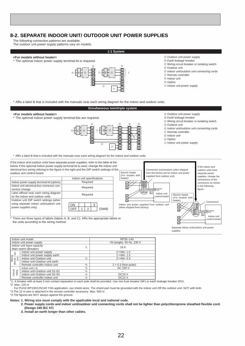
The following connection patterns are available.The outdoor unit power supply patterns vary on models.
1:1 System
<For models without heater>* The optional indoor power supply terminal kit is required.
S1S2
LN
12
LN
S1S2S3S3
A CB
D
J
E
B C
F
G
H
S1S2
LN
12
LN
S1S2S3
12
LN
S1S2S3
12
LN
S1S2S3S3
A B C
D
E
J B C
F
G G
H
G
* Affix a label B that is included with the manuals near each wiring diagram for the indoor and outdoor units.
A Outdoor unit power supplyB Earth leakage breakerC Wiring circuit breaker or isolating switchD Outdoor unitE Indoor unit/outdoor unit connecting cordsF Remote controllerG Indoor unitH OptionJ
A
B
C
D
E
F
G
H
J
Indoor unit power supply
<For models without heater>* The optional indoor power supply terminal kits are required.
Simultaneous twin/triple system
If the indoor and outdoor units have separate power supplies, refer to the table at thebelow. If the optional indoor power supply terminal kit is used, change the indoor unitelectrical box wiring refering to the figure in the right and the DIP switch settings of theoutdoor unit control board.
* Affix a label B that is included with the manuals near each wiring diagram for the indoor and outdoor units.
Outdoor unit power supplyEarth leakage breakerWiring circuit breaker or isolating switchOutdoor unitIndoor unit/outdoor unit connecting cordsRemote controllerIndoor unitOptionIndoor unit power supply
ONOFF 1 2 (SW8)
3
Indoor power supply terminal kit (option)Indoor unit electrical box connector con-nection changeLabel affixed near each wiring diagramfor the indoor and outdoor unitsOutdoor unit DIP switch settings (whenusing separate indoor unit/outdoor unitpower supplies only)
Indoor unit specificationsRequired
Required
Required
*1. A breaker with at least 3 mm contact separation in each pole shall be provided. Use non-fuse breaker (NF) or earth leakage breaker (NV).*2. Max. 120 m For PUHZ-RP100/125/140 YHA application, use shield wires. The shield part must be grounded with the indoor unit OR the outdoor unit, NOT with both.*3.The 10 m wire is attached in the remote controller accessory. Max. 500 m*4.The figures are NOT always against the ground.
Notes: 1. Wiring size must comply with the applicable local and national code.2. Power supply cords and indoor unit/outdoor unit connecting cords shall not be lighter than polychloroprene sheathed flexible cord. (Design 245 IEC 57)3. Install an earth longer than other cables.
Indoor unit modelIndoor unit power supplyIndoor unit input capacity
*1Main switch (Breaker)
Indoor unit power supplyIndoor unit power supply earthIndoor unit-Outdoor unit *2Indoor unit-Outdoor unit earthRemote controller-Indoor unit *3Indoor unit L-N *4Indoor unit-Outdoor unit S1-S2 *4Indoor unit-Outdoor unit S2-S3 *4Remote controller-Indoor unit *4
RP35~140~/N (single), 50 Hz, 230 V
16 A
2 o Min. 1.51 o Min. 1.52 o Min. 0.3
–2 o 0.3 (Non-polar)
AC 230 V–
DC24 VDC12 V
Circ
uit
ratin
g
Wiri
ngW
ire N
o. o
size
(mm
2 )
Electric heater(For models withheater)
Connectors (connections when shippedfrom the factory are for indoor unit powersupplied from outdoor unit)
Indoor unit power supplied from outdoor unit(when shipped from factory)
If the indoor andoutdoor units haveseparate powersupplies, change theconnections of theconnectors as shownin the followingfigure.
Connectors
Indoor unitcontrol board
Separate indoor unit/outdoor unit powersupplies
Electric heater(For models withheater)
S1
S2
S3
L
N
BLU
E
BLU
E
YELLOW
YELLOW
CN
D
CNDORANGE
CNDORANGE
S1
S2
S3
L
N
YELLOW
BLU
E
BLU
E
YELLOW
CN
D
Indoor unitcontrol board
* There are three types of labels (labels A, B, and C). Affix the appropriate labels tothe units according to the wiring method.
8-2. SEPARATE INDOOR UNIT/ OUTDOOR UNIT POWER SUPPLIES
OC334-1.qxp 05.5.26 6:09 PM Page 22

23
8-3. INDOOR – OUTDOOR CONNECTING CABLE
The cable shall not be lighter than design 245 IEC or 227 IEC.
w The Max. cable length may vary depending on the condition of installation, humidity or materials, etc.
Indoor unit-Outdoor unit
Outdoor power supplyMax. 45m
3 o 1.5 (polar)
1 o Min. 1.5
Max. 50m
3 o 2.5 (polar)
1 o Min. 2.5
Max. 80m
3 o 2.5 (polar) and S3 separated
1 o Min. 2.5Indoor unit-Outdoor unit earth
Wire No. o Size (E)
Be sure to connect the indoor-outdoor connecting cables directly to the units (no intermediate connections).Intermediate connections can lead to communication errors if water enters the cables and causes insufficient insulation to ground or a poor electrical contact at the intermediate connection point.(If an intermediate connection is necessary, be sure to take measures to prevent water from entering the cables.)
When the shield line is not used, several dB is exceeded with 30 ~ 40 MHz .(There is a possibility to be used by the wireless for the ship etc. though it is not used for radio and TV.)
Indoor unit-Outdoor unit
Indoor/Outdoor separatepower supply Max. 120m
2 o Min. 0.3
—Indoor unit-Outdoor unit earth
Wire No. o Size (E)
w The optional indoor power supply terminal kit is necessary
For 100, 125, 140Y application, use shield wire. (For EMC DIRECTIVE)The shield part must be grounded with the indoor unit or the outdoor unit, not with both.
OC334-1.qxp 05.5.26 6:09 PM Page 23

24
8-4. M-NET WIRING METHOD(Points to notice)(1) Outside the unit, transmission wires should stay away from electric wires in order to prevent electromagnetic noise from
making an influence on the signal communication. Place them at intervals of more than 5cm. Do not put them in the sameconduit tube.
(2) Terminal block (TB7) for transmission wires should never be connected to 220~240V power supply. If it is connected, electronic parts on M-NET p.c. board may be burn out.
(3) Use 2-core x 1.25mm2
shield wire (CVVS, CPEVS) for the transmission wire. Transmission signals may not be sent orreceived normally if different types of transmission wires are put together in the same multi-conductor cable. Never do thisbecause this may cause a malfunction.
It would be ok if M-NET wire (non-polar, 2-cores) is arranged in addition to the wiring for A-control.
(4) Ground only one of any appliances through M-NET transmission wire (shield wire). Communication error may occur due tothe influence of electromagnetic noise.
“Ed” error will appear on the LED display of outdoor unit.“0403” error will appear on the central-control remote controller.
If there are more than two grounding spots on the shield wire, noise may enter into the shield wire because the ground wireand shield wire form one circuit and the electric potential difference occurs due to the impedance difference among ground-ing spots. In case of single spot grounding, noise does not enter into the shield wire because the ground wire and shieldwire do not form one circuit.
To avoid communication errors caused by noise, make sure to observe the single spot grounding method described in theinstallation manual.
Groupremotecontroller
Refrigerantaddress 00M-NETaddress 01
A-controlremotecontroller
A-controlremotecontroller
A-controlremotecontroller
Refrigerantaddress 00M-NETaddress 02
Refrigerantaddress 00M-NETaddress 03Power
supplyunit fortransmissionwire
Centralremotecontroller
M-NET transmission wire
✕ Bad example (Multi spot grounding of shield wire)
Good example 1 (Single spot grounding of shield wire)
Power supplyappliance
M-NET typeoutdoor unit
Centralremotecontroller
Power supplyappliance
M-NET typeoutdoor unit
M-NET typeoutdoor unit
M-NET typeoutdoor unit
M-NET transmission wire
M-NET typeoutdoor unit
M-NET typeoutdoor unit
Centralremotecontroller
Power supplyappliance
M-NET typeoutdoor unit
M-NET transmission wire
M-NET typeoutdoor unit
M-NET typeoutdoor unit
Good example 2 (Single spot grounding of shield wire)
OC334-1.qxp 05.5.26 6:09 PM Page 24

25
8-4-3. Regulations in address settingsIn case of multiple grouping system, M-NET and refrigerant address settings should be done as explained in the above sec-tion. Set the lowest number in the group for the outdoor unit whose refrigerant address is “00” as its M-NET address.
w Refrigerant addresses can be overlapped if they are in the different group.
w In group B, M-NET address of the outdoor unit whose refrigerant address is “00” is not set to the minimum in the group. As“3” is right for this situation, the setting is wrong. Taking group A as a good sample, set the minimum M-NET address inthe group for the outdoor unit whose refrigerant address is “00”.
8-4-1. M-NET address settingIn A-control models, M-NET address and refrigerant address should be set only for the outdoor unit. Similar to Free Combosystem, there is no need to set the address of outdoor unit and remote controller. To construct a central control system, thesetting of M-NET address should be conducted only upon the outdoor unit. The setting range should be 1 to 50 (the same asthat of the indoor unit in Free Combo system), and the address number should be consecutively set in a same group.
Address number can be set by using rotary switches (SW11 for ones digit and SW12 for tens digit), which is located on the M-NET board of outdoor unit. (Factory setting: all addresses are set to “0”.)
8-4-2. Refrigerant address settingIn case of multiple grouping system (multiple refrigerant circuits in one group), indoor units should be connected by remotecontroller wiring (TB5) and the refrigerant address needs to be set. Leave the refrigerant addresses to “00” if the group set-ting is not conducted. Set the refrigerant address by using DIP SW1-3 to -6 on the outdoor controller board. [Factory setting:all switches are OFF. (All refrigerant addresses are “00”.)]
1234567890
1234567890
1234567890
1234567890
12345678901234567890
1 2
~
50M-NET Address No.<Setting example>
Switngsetting
SW11onesdigit
SW12tensdigit
OFF
ON
1 2 3 4 5 6 1 2 3 4 5 6 1 2 3 4 5 6 1 2 3 4 5 6 1 2 3 4 5 6 1 2 3 4 5 6 1 2 3 4 5 6 1 2 3 4 5 6
1 2 3 4 5 61 2 3 4 5 61 2 3 4 5 61 2 3 4 5 61 2 3 4 5 61 2 3 4 5 61 2 3 4 5 61 2 3 4 5 6
0Refuigrant address
OFF
ON
8
OFF
ON
1
OFF
ON
9
OFF
ON
10
OFF
ON
11
OFF
ON
12
OFF
ON
13
OFF
ON
14
OFF
ON
15
OFF
ON
2
OFF
ON
3
OFF
ON
4
OFF
ON
5
OFF
ON
6
OFF
ON
7
Systemcontroller
A-controlremotecontroller
Group A Group B Group C
A-controlremotecontroller
TB5
A-controlremotecontroller
Refrigerantaddress 00M-NETaddress 01
Refrigerantaddress 00M-NETaddress 02
Refrigerantaddress 01M-NETaddress 03
Refrigerantaddress 00M-NETaddress 04Power
supplyunit fortransmissionwire
A-controlremotecontroller
A-controlremotecontroller
TB5
Group A Group B
Refrigerantaddress 00M-NETaddress 01
Refrigerantaddress 01M-NETaddress 02
Refrigerantaddress 00M-NETaddress 04
Refrigerantaddress 01M-NETaddress 03
Refrigerantaddress 02M-NETaddress 05
Systemcontroller
Powersupplyunit fortransmissionwire
● M-NET wiring
(1) Use 2-core x 1.25mm2
shield wire for electric wires.(Excluding the case connecting to system controller.)
(2) Connect the wire to the M-NET terminal block.Connect one core of the transmission wire (non-polar) to A terminal and the other to B. Peel the shield wire, twist the shield part to a string and connect it to S terminal.
(3) In the system which several outdoor units are being connected, the terminal (A, B, S) on M-NET terminal block should be individually wired to the other outdoor unit’s terminal, i.e. A to A, B to B and S to S.In this case, choose one of those outdoor units and drive a screw to fix an ground wire on the plate as shown on the right figure.
Transmissionwire
Shield part
M-NET terminal block Ground
wire
A B S
OC334-1.qxp 05.5.26 6:09 PM Page 25
26
9 REFRIGERANT SYSTEM DIAGRAM
PUHZ-RP60VHAPUHZ-RP71VHA
PUHZ-RP35VHAPUHZ-RP50VHA
Thermistor TH7(Outdoor)Heat exchanger
Refrigerant GAS pipeconnection(1/2F)
Refrigerant LIQUID pipeconnection(1/4F)
Stop valve
Strainer#100
Powerreceiver
Linear expansion valve B
Thermistor TH6(Outdoor 2-phase pipe)
Thermistor TH3(Outdoor pipe)
Charge plug
High pressureswitch 63H
Thermistor TH4(Discharge)
Compressor
Strainer#50
Solenoid valve(Four-way valve)
Muffler
Distributor
Linear expansion valve A
Strainer #100
Muffler
Stop valve(with service port)
Distributor
Thermistor TH7(Outdoor)Heat exchanger
Refrigerant GAS pipeconnection(5/8F)
Refrigerant LIQUID pipeconnection(3/8F)
Stop valve(with service port)
Strainer#100
Powerreceiver
Linear expansion valve B
Linear expansion valve A
Strainer #100
Strainer#100
Strainer#100
Thermistor TH6(Outdoor 2-phase pipe)
Thermistor TH3(Outdoor pipe)
Charge plug(Low pressure)
Charge plug(High pressure)
High pressureswitch 63H
Bypass valve
Oil separator
Thermistor TH4(Discharge)
Muffler
Strainer#50
4-way valve
Compressor
Ball valve
Capillary tubeO.D.4.0OI.D.2.4OL500
Capillary tubeO.D.2.5OI.D.0.6OL1000
Refrigerant flow in cooling
Refrigerant flow in heating
OC334-1.qxp 05.5.26 6:09 PM Page 26
27
PUHZ-RP100VHA PUHZ-RP100YHAPUHZ-RP125VHA PUHZ-RP125YHAPUHZ-RP140VHA PUHZ-RP140YHA
Distributor
Thermistor TH7(Outdoor)Heat exchanger
Refrigerant GAS pipeconnection(5/8F)
Refrigerant LIQUID pipeconnection(3/8F)
Stop valve(with service port)
Strainer#100
Powerreceiver
Linear expansion valve B
Linear expansion valve A
Strainer#100Strainer
#100
Strainer#100
Thermistor TH6(Outdoor 2-phase pipe)
Thermistor TH3(Outdoor pipe)
Charge plug(Low pressure)
Charge plug(High pressure)
High pressureswitch 63H
Replace filter
Thermistor TH4(Discharge)
Compressor
Strainer#50
Solenoid valve(Four-way valve)
Strainer#100
Strainer#100
Low pressureswitch 63L
Muffler
Ball valve
Restrictorvalve
Solenoid valve(Bypass valve)
Refrigerant flow in cooling
Refrigerant flow in heating
OC334-1.qxp 05.5.26 6:09 PM Page 27

28
1. Refrigerant collecting (pump down)Perform the following procedures to collect the refrigerant when moving the indoor unit or the outdoor unit.1Turn on the power supply (circuit breaker).wWhen power is supplied, make sure that “CENTRALLY CONTROLLED” is not displayed on the remote controller. If
“CENTRALLY CONTROLLED” is displayed, the refrigerant collecting (pump down) cannot be completed normally.2After the liquid stop valve is closed, set the SWP switch on the control board of the outdoor unit to ON. The compressor
(outdoor unit) and ventilators (indoor and outdoor units) start operating and refrigerant collecting operation begins. LED1 andLED2 on the control board of the outdoor unit are lit.wSet the SWP switch (push-button type) to ON in order to perform refrigerant collecting operation only when the unit is
stopped. However, refrigerant collecting operation cannot be performed until compressor stops even if the unit is stopped. Wait three minutes until compressor stops and set the SWP switch to ON again.
3Because the unit automatically stops in about two to three minutes after the refrigerant collecting operation (LED1 is not lit and LED2 is lit), be sure to quickly close the gas stop valve.wIn case the outdoor unit is stopped when LED1 is lit and LED2 is not lit, open the liquid stop valve completely, and then
repeat step 2 three minutes later.wIf the refrigerant collecting operation has been completed normally (LED1 is not lit and LED2 is lit), the unit will remain
stopped until the power supply is turned off.4Turn off the power supply (circuit breaker.)
2. Unit replacement operationWhen reusing the existing pipes that carried R22 refrigerant for the RP100, RP125 and RP140 models, replacementoperation must be performed before performing a test run.
1If new pipes are used, these procedures are not necessary.2If existing pipes that carried R22 refrigerant are used for the RP71 model, these procedures are not necessary.
(The replace-ment operation cannot be performed.)3During replacement operation, “C5” is displayed on “A-Control Service Tool(PAC-SK52ST)”. (This is applied to only RP100,
RP125 and RP140 models.)
• Replacement operation procedures1Turn on the power supply.2Set DIP switch SW8-2 on the control board of the outdoor unit to ON to start replacement operation.
• The replacement operation is performed using the cooling system. Cool air will flow from the indoor unit during the replace-ment operation.
• During the replacement operation, is displayed on the remote controller and LED1 (green) and LED2 (red) on the control board of the outdoor unit flash together.
3Replacement operation requires at least two hours to complete.• After setting switch SW8-2 to ON, the unit automatically stops after two hours.• Replacement operation can be performed repeatedly by setting switch SW8-2 from OFF to ON. Make sure to perform the
operation more than 2 hours. (If the operation is performed less than 2 hours, the existing pipes cannot be cleaned enough and the unit may be damaged.)
• If replacement operation is performed over 2 hours, this action is recorded into nonvolatile memory of control board.4Set switch SW8-2 to OFF. (Replacement operation is completed.)wThe unit can be operated normally by remote controller even if SW8-2 remains ON.wIf the indoor temperature is less than 15:, the compressor will operate intermittently but the unit is not faulty.
TEST RUN
3. Start and finish of test run• Operation from the indoor unit
Execute the test run using the installation manual for the indoor unit.• Operation from the outdoor unit
By using the DIP switch SW4 on the control board of outdoor unit, test run can be started and finished, and its operation mode (cooling/heating) can be set up.1Set the operation mode (cooling/heating) using SW4-2.2Turn on SW4-1 to start test run with the operation mode set by SW4-2.3Turn off SW4-1 to finish the test run.
• There may be a faint knocking sound around the machine room after power is supplied, but this isno problem with product because the linear expansion pipe is just moving to adjust opening pulse.
• There may be a knocking sound around the machine room for several seconds after compressor starts operating, but this is no problem with product because the check valve, itself, generates the sound because pressure difference is small in the refrigerant circuit.
Note:The operation mode cannot be changed by SW4-2 during test run. (To change test run mode, stop the unit by SW4-1,change the operation mode and restart the test run by SW4-1.)
OFF1 2
ON
<SW4>
A B
C D
A Stop C operationB Cooling D Heating
OC334-1.qxp 05.5.26 6:09 PM Page 28

29
10 TROUBLESHOOTING
<Error code display by self-diagnosis and actions to be taken for service (summary)>Present and past error codes are logged and displayed on the wired remote controller and control board of outdoor unit.Actions to be taken for service, which depends on whether or not the inferior phenomenon is reoccurring at service, are sum-marized in the table below. Check the contents below before investigating details.
10-1. TROUBLESHOOTING
Unit conditions at service Error code Actions to be taken for service (summary)
The inferior phenomenon isreoccurring.
Displayed
Not displayed
Judge what is wrong and take a corrective action according to “10-4. Self-diagnosis action table”.
Conduct trouble shooting and ascertain the cause of theinferior phenomenon according to “10-5. Troubleshooting by inferior phenomena”.
The inferior phenomenon is not reoccurring.
Logged
Not logged
1Consider the temporary defects such as the work of protection devices in the refrigerant circuit including compressor, poor connection of wiring, noise and etc. Re-check the symptom, and check the installation environment, refrigerant amount, weather when the inferior phenomenon occurred, matters related to wiring and etc. 2Reset error code logs and restart the unit after finishing service.3There is no abnormality concerning of parts such as electrical component, controller board, remote controller and etc.
1Re-check the abnormal symptom.2Conduct trouble shooting and ascertain the cause of the inferior phenomenon according to “10-5. Troubleshooting by inferior phenomena”.3Continue to operate unit for the time being if the cause is not ascertained.4There is no abnormality concerning of parts such as electrical component, controller board, remote controller and etc.
10-2. CHECK POINT UNDER TEST RUN
(1) Before test run• After installation of indoor and outdoor units, piping work and electric wiring work, re-check that there is no refrigerant leak-
age, loosened connections and incorrect polarity.• Measure impedance between the ground and the power supply terminal block(L, N) on the outdoor unit by 500V Merger and
check that it is 1.0M" or over.wDon’t use 500V Merger to indoor/outdoor connecting wire terminal block(S1, S2, S3) and remote controller terminal block
(1, 2). This may cause malfunction.• Make sure that test run switch (SW4) is set to OFF before turning on power supply.• Turn on power supply twelve hours before test run in order to protect compressor.• For specific models which requires higher ceiling settings or auto-recovery feature from power failure, make proper changes
of settings referring to the description of “Selection of Functions through Remote Controller”.Make sure to read operation manual before test run. (Especially items to secure safety.)
OC334-1.qxp 05.5.26 6:09 PM Page 29
30
[TEST] button
Pipe (liquid) temperature
Displays the remainingtest run time.
"TEST RUN" and the currently selectedoperation mode are displayed altemately.
A
B
C
• In case of test run, the OFF timer will be activated, and the test run will automatically stop after two hours.• The room temperature display section shows the pipe temperature of indoor units during the test run.• Check that all the indoor units are running properly in case of simultaneous twin and triple operation. Malfunctions may not
be displayed regardless of incorrect wiring.w1 After turning on the power supply, the system will go into startup mode, “PLEASE WAIT” will blink on the display section of
the room temperature, and lamp(green) of the remote controller will flash.As to INDOOR BOARD LED, LED1 will be lit up, LED2 will either be lit up in case the address is 0 or turned off in case the address is not 0. LED3 will blink.As to OUTDOOR BOARD LED, LED1(green) and LED2(red) will light up. (After the startup mode of the system finishes, LED2(red) will be turned off.)In case OUTDOOR BOARD LED is digital display, — and — will be displayed alternately every second.
• If one of the above operations doesn’t function correctly, the causes written below should be considered. Find causes from the symptoms.The below symptoms are under test run mode. “startup” in the table means the display status of w1 written above.
Remote Controller DisplaySymptoms in test run mode
OUTDOOR BOARD LED Display Cause
Remote controller displays “PLEASE WAIT”, and cannot be operated.
After power is turned on, “PLEASE WAIT” is displayed for 3 minutes, then error code is displayed.
No display appears even when remote controller operation switch is turned on.(Operation lamp does not light up.)
Display appears but soon disappears even when remote controller is operated.
• After power is turned on, “PLEASE WAIT” is displayed for 2 minutes during system startup. (Normal)
• Incorrect connection of outdoor terminal block (L1, L2, L3 and S1, S2, S3.)
• Outdoor unit’s safeguard installation connector is open.
• Incorrect wiring between the indoor and outdoor unit (Polarity is wrong for S1, S2, S3.)• Remote controller transmission wire short.• There is no outdoor unit of address 0. (Address is other than 0.)• Remote controller transmission wire burnout.• After canceling function selection, operation is not possible for about 30 seconds. (Normal)
After “startup” is displayed, only green lights up. <00>After “startup” is displayed, green(once) and red(once) blink alternately. <F1>After “startup” is displayed, green(once) and red(twice) blink alternately. <F3, F5, F9>After “startup” is displayed, green(twice) and red(once) blink alternately. <EA. Eb>
After “startup” is displayed, only green lights up. <00>
After “startup” is displayed, only green lights up. <00>
< > indicates digital display.
2. Press TEST button twice.
1. Turn on the main power supply.
3. Press OPERATION SWITCH button.
4. Press AIR DIRECTION button.
5. Check the outdoor unit fan for correct running.
6. Press the ON/OFF button to reset the test run in progress.
7. Register the contact number.
While the room temperature display on the remote controller is “PLEASE WAIT”, the remote controller is disabled. Wait until “PLEASE WAIT” disappears before using remote controller. “PLEASE WAIT” appears for about 2 minutes after power supply is turned on. w1
The outdoor unit features automatic capacity control to provide optimum fan speeds. Therefore, the fan keeps running at a low speed to meet the current outside air condition unless it exceeds its available maximum power. Then, in actuality, the fan may stop or run in the reverse direction depending on the outside air, but this does not mean malfunction.
Check for correct motion of auto-vanes.
Cooling mode: Check if cool air blows and water is drained.Heating mode: Check if warm air blows. (It takes a little while until warm air blows.)
The TEST RUN appears on the screen.
Operating procedures
B
C
A
w Press the remote controller’s CHECK button twice to perform self-diagnosis. See the table below for the contents of LCDdisplay.
LCD Contents of inferior phenomenaP1P2P4P5P6P8P9Fb
Abnormality of room temperature thermistorAbnormality of pipe temperature thermistor/LiquidAbnormality of drain sensorDrain overflow protection is working.Freezing/overheating protection is working.Abnormality of pipe temperatureAbnormality of pipe temperature thermistor/Cond./EvaAbnormality of indoor controller board
LCD Contents of inferior phenomenaU1~UPF3~F9E0~E5E6~EF
----FFFF
Malfunction outdoor unitMalfunction outdoor unitRemote controller transmitting errorIndoor/outdoor unit communication errorNo error historyNo applied unit
LED1 (microcomputer power supply)
LED2 (remote controller)
LED3 (indoor/outdoor communication)
Lits when power is supplied.Lits when power is supplied for wired remote controller.The indoor unit should be connected to the outdoor unit with address “0” setting.
Flash when indoor and outdoor unit are communicating.
See the table below for details of the LED display (LED 1, 2, 3) on the indoor controller board.
OC334-1.qxp 05.5.26 6:09 PM Page 30

31
ON/OFF TEMP
FAN
VANEMODE
CHECK LOUVER
TEST RUN
AUTO STOP
AUTO START
h
min
TEST RUN
RESETSET CLOCK
7
5
6
2
3,4
Test run [for wireless remote controller]Measure an impedance between the power supply terminal block onthe outdoor unit and ground with a 500V Megger and check that it isequal to or greater than 1.0M".1 Turn on the main power to the unit.2 Press the button twice continuously.
(Start this operation from the status of remote controller displayturned off.)A and current operation mode are displayed.
3 Press the ( ) button to activate mode, thencheck whether cool air is blown out from the unit.
4 Press the ( ) button to activate mode, thencheck whether warm air is blown out from the unit.
5 Press the button and check whether strong air is blown outfrom the unit.
6 Press the button and check whether the auto vane operatesproperly.
7 Press the ON/OFF button to stop the test run.
Note:• Point the remote controller towards the indoor unit receiver
while following steps 22 to 77.• It is not possible to run the in FAN, DRY or AUTO mode.
MODE
MODECOOL
HEAT
TEST RUN
FAN
VANE
TEST RUN
OC334-2.qxp 05.5.26 6:06 PM Page 31
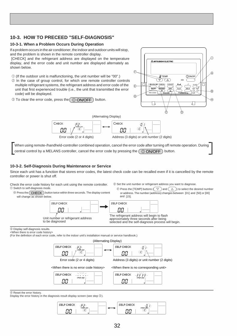
32
10-3. HOW TO PRECEED "SELF-DIAGNOSIS"10-3-1. When a Problem Occurs During OperationIf a problem occurs in the air conditioner, the indoor and outdoor units will stop,and the problem is shown in the remote controller display.[CHECK] and the refrigerant address are displayed on the temperature
display, and the error code and unit number are displayed alternately asshown below.
1 (If the outdoor unit is malfunctioning, the unit number will be "00".)2 In the case of group control, for which one remote controller controls
multiple refrigerant systems, the refrigerant address and error code of theunit that first experienced trouble (i.e., the unit that transmitted the errorcode) will be displayed.
3 To clear the error code, press the ON/OFF button.
When using remote-/handheld-controller combined operation, cancel the error code after turning off remote operation. During
central control by a MELANS controller, cancel the error code by pressing the ON/OFF button.
10-3-2. Self-Diagnosis During Maintenance or ServiceSince each unit has a function that stores error codes, the latest check code can be recalled even if it is cancelled by the remotecontroller or power is shut off.
Check the error code history for each unit using the remote controller.1 Switch to self-diagnosis mode.
H Press the CHECK button twice within three seconds. The display contentwill change as shown below.
2 Set the unit number or refrigerant address you want to diagnose.
F Press the [TEMP] buttons ( and ) to select the desired numberor address. The number (address) changes between [01] and [50] or [00]
3 Display self-diagnosis results.<When there is error code history>(For the definition of each error code, refer to the indoor unit's installation manual or service handbook.)
4 Reset the error history.Display the error history in the diagnosis result display screen (see step 3).
F
E
G
C D
H
B
A
I
Error code (2 or 4 digits)
(Alternating Display)
Address (3 digits) or unit number (2 digits)
The refrigerant address will begin to flashapproximately three seconds after beingselected and the self-diagnosis process will begin.
Unit number or refrigerant addressto be diagnosed
Error code (2 or 4 digits)
(Alternating Display)
Address (3 digits) or unit number (2 digits)
<When there is no error code history> <When there is no corresponding unit>
and [15].
OC334-2.qxp 05.5.26 6:06 PM Page 32
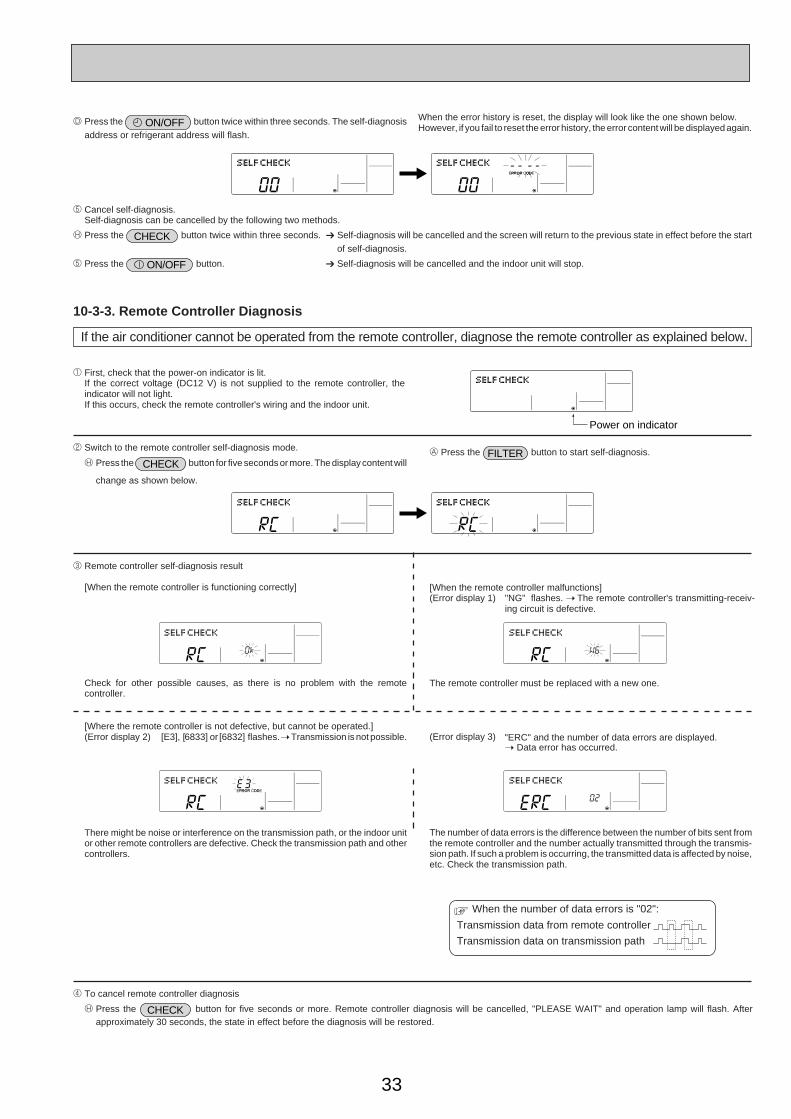
33
Transmission data from remote controller
Transmission data on transmission path
When the number of data errors is "02":
D Press the ON/OFF button twice within three seconds. The self-diagnosis
address or refrigerant address will flash.
When the error history is reset, the display will look like the one shown below.However, if you fail to reset the error history, the error content will be displayed again.
5 Cancel self-diagnosis.Self-diagnosis can be cancelled by the following two methods.
H Press the CHECK button twice within three seconds. ➔ Self-diagnosis will be cancelled and the screen will return to the previous state in effect before the start
of self-diagnosis.
5 Press the ON/OFF button. ➔ Self-diagnosis will be cancelled and the indoor unit will stop.
10-3-3. Remote Controller Diagnosis
If the air conditioner cannot be operated from the remote controller, diagnose the remote controller as explained below.
1 First, check that the power-on indicator is lit.If the correct voltage (DC12 V) is not supplied to the remote controller, theindicator will not light.If this occurs, check the remote controller's wiring and the indoor unit.
2 Switch to the remote controller self-diagnosis mode.
H Press the CHECK button for five seconds or more. The display content will
change as shown below.
A Press the FILTER button to start self-diagnosis.
3 Remote controller self-diagnosis result
[When the remote controller is functioning correctly]
Check for other possible causes, as there is no problem with the remotecontroller.
[When the remote controller malfunctions](Error display 1) "NG" flashes. ➝ The remote controller's transmitting-receiv-
ing circuit is defective.
The remote controller must be replaced with a new one.
[Where the remote controller is not defective, but cannot be operated.](Error display 2) [E3], [6833] or [6832] flashes. ➝ Transmission is not possible.
There might be noise or interference on the transmission path, or the indoor unitor other remote controllers are defective. Check the transmission path and othercontrollers.
(Error display 3) "ERC" and the number of data errors are displayed.➝ Data error has occurred.
The number of data errors is the difference between the number of bits sent fromthe remote controller and the number actually transmitted through the transmis-sion path. If such a problem is occurring, the transmitted data is affected by noise,etc. Check the transmission path.
4 To cancel remote controller diagnosis
H Press the CHECK button for five seconds or more. Remote controller diagnosis will be cancelled, "PLEASE WAIT" and operation lamp will flash. Afterapproximately 30 seconds, the state in effect before the diagnosis will be restored.
Power on indicator
OC334-2.qxp 05.5.26 6:06 PM Page 33
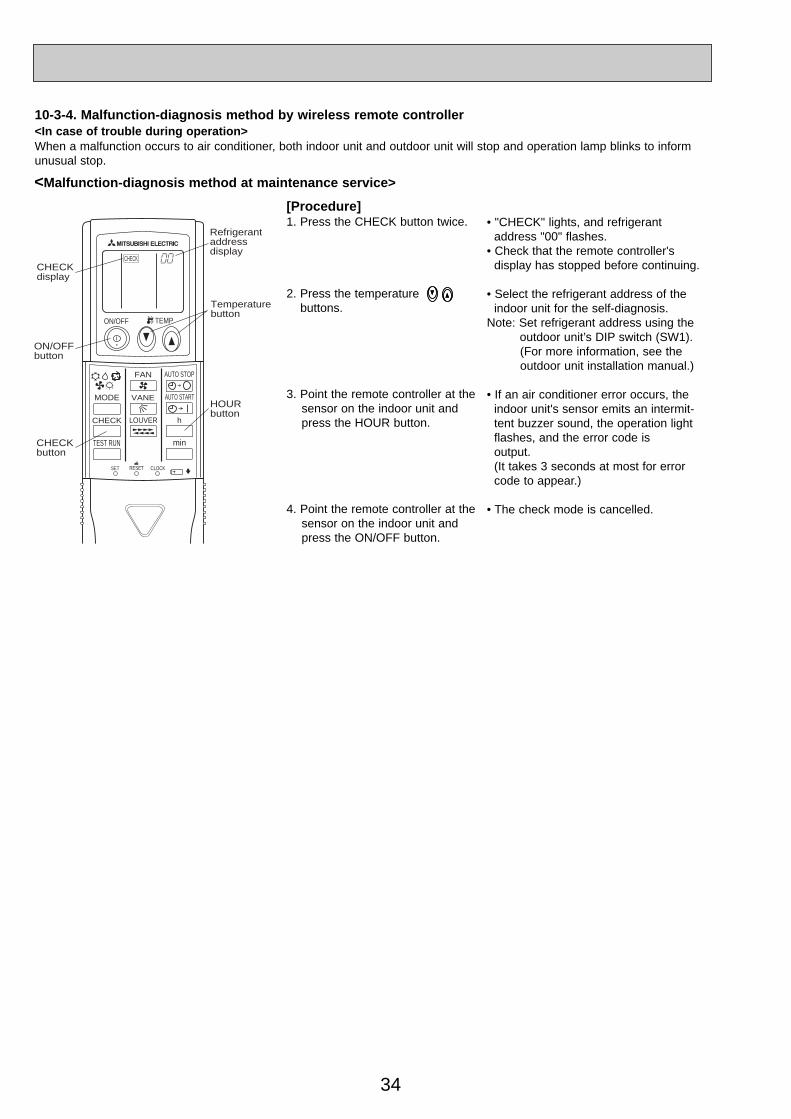
34
[Procedure]1. Press the CHECK button twice.
2. Press the temperaturebuttons.
3. Point the remote controller at the sensor on the indoor unit andpress the HOUR button.
4. Point the remote controller at thesensor on the indoor unit andpress the ON/OFF button.
• "CHECK" lights, and refrigerant address "00" flashes.
• Check that the remote controller'sdisplay has stopped before continuing.
• Select the refrigerant address of theindoor unit for the self-diagnosis.
Note: Set refrigerant address using the outdoor unit’s DIP switch (SW1).(For more information, see theoutdoor unit installation manual.)
• If an air conditioner error occurs, theindoor unit's sensor emits an intermit-tent buzzer sound, the operation lightflashes, and the error code isoutput.(It takes 3 seconds at most for error code to appear.)
• The check mode is cancelled.
<Malfunction-diagnosis method at maintenance service>
10-3-4. Malfunction-diagnosis method by wireless remote controller<In case of trouble during operation>When a malfunction occurs to air conditioner, both indoor unit and outdoor unit will stop and operation lamp blinks to informunusual stop.
ON/OFF TEMP
FAN
VANEMODE
CHECK LOUVER
TEST RUN
AUTO STOP
AUTO START
h
min
RESETSET CLOCK
CHECKCHECKdisplay
Temperaturebutton
CHECKbutton
Refrigerantaddressdisplay
HOURbutton
ON/OFFbutton
OC334-2.qxp 05.5.26 6:06 PM Page 34
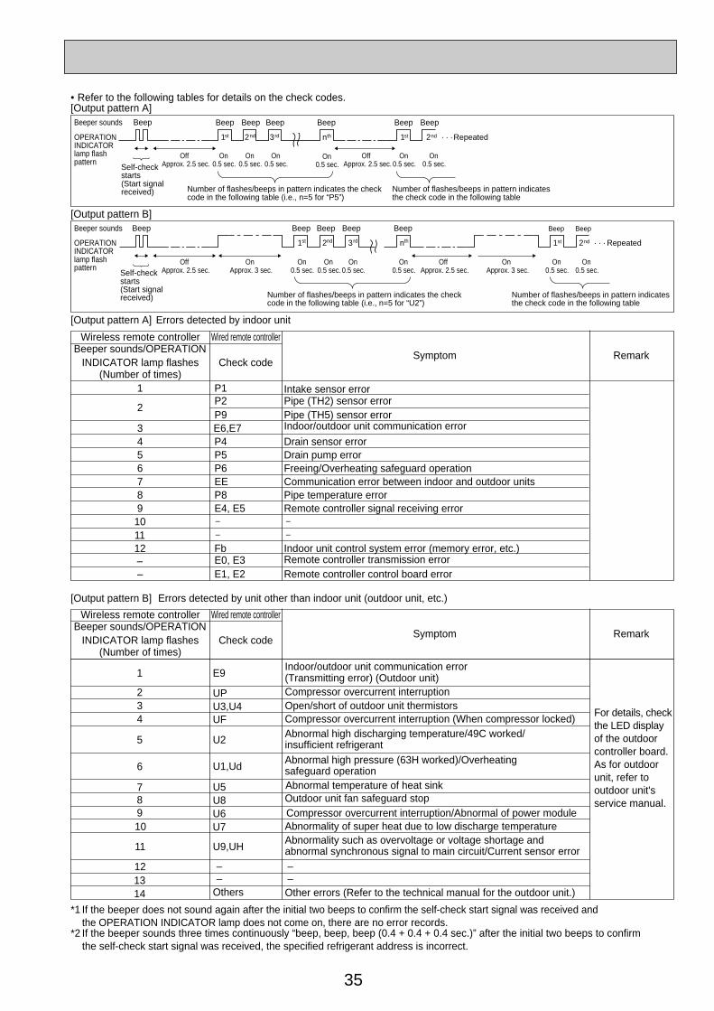
35
[Output pattern A] Errors detected by indoor unit
[Output pattern B]
E9
*1 If the beeper does not sound again after the initial two beeps to confirm the self-check start signal was received and the OPERATION INDICATOR lamp does not come on, there are no error records.
*2 If the beeper sounds three times continuously “beep, beep, beep (0.4 + 0.4 + 0.4 sec.)” after the initial two beeps to confirm the self-check start signal was received, the specified refrigerant address is incorrect.
OPERATIONINDICATORlamp flashpattern
Beep Beep Beep Beep Beep Beep Beep
OffApprox. 2.5 sec.
OnApprox. 3 sec.
On0.5 sec.
On0.5 sec.
On0.5 sec.
On0.5 sec.
OffApprox. 2.5 sec.
OnApprox. 3 sec.
On0.5 sec.
On0.5 sec.
· · · Repeated
Number of flashes/beeps in pattern indicates the checkcode in the following table (i.e., n=5 for “U2”)
Number of flashes/beeps in pattern indicatesthe check code in the following table
nth1st 2nd 3rd 1st 2nd
Self-checkstarts(Start signalreceived)
Beeper sounds
[Output pattern B]
OPERATIONINDICATORlamp flashpattern
Beep Beep Beep Beep Beep Beep Beep
OffApprox. 2.5 sec.
On0.5 sec.
On0.5 sec.
On0.5 sec.
On0.5 sec.
OffApprox. 2.5 sec.
On0.5 sec.
On0.5 sec.
· · · Repeated
Number of flashes/beeps in pattern indicates the checkcode in the following table (i.e., n=5 for “P5”)
Number of flashes/beeps in pattern indicatesthe check code in the following table
nth1st 2nd 3rd 1st 2nd
Self-checkstarts(Start signalreceived)
Beeper sounds
• Refer to the following tables for details on the check codes.[Output pattern A]
Beeper sounds/OPERATIONINDICATOR lamp flashes Check code
Symptom Remark
(Number of times)
Wireless remote controller Wired remote controller
Beeper sounds/OPERATIONINDICATOR lamp flashes Check code
(Number of times)
Wireless remote controller Wired remote controller
1 P1 Intake sensor error
P9 Pipe (TH5) sensor error2
P2 Pipe (TH2) sensor error
3 E6,E7 Indoor/outdoor unit communication error
4 P4 Drain sensor error5 P5 Drain pump error6 P6 Freeing/Overheating safeguard operation7 EE Communication error between indoor and outdoor units8 P8 Pipe temperature error9 E4, E5 Remote controller signal receiving error
10 –
11 –
–
–
Errors detected by unit other than indoor unit (outdoor unit, etc.)
Symptom Remark
1Indoor/outdoor unit communication error
2(Transmitting error) (Outdoor unit)
3 Open/short of outdoor unit thermistors4 Compressor overcurrent interruption (When compressor locked)
5Abnormal high discharging temperature/49C worked/insufficient refrigerant
6Abnormal high pressure (63H worked)/Overheating safeguard operation
7 Abnormal temperature of heat sink8 Outdoor unit fan safeguard stop9 Compressor overcurrent interruption/Abnormal of power module10 Abnormality of super heat due to low discharge temperature
11Abnormality such as overvoltage or voltage shortage and abnormal synchronous signal to main circuit/Current sensor error
1213
U2
U5
UPU3,U4UF
U1,Ud
U8U6U7
U9,UH
Others
––
––
14 Other errors (Refer to the technical manual for the outdoor unit.)
For details, checkthe LED display of the outdoor controller board.As for outdoor unit, refer to outdoor unit's service manual.
12 Fb Indoor unit control system error (memory error, etc.)– E0, E3– E1, E2 Remote controller control board error
Remote controller transmission error
Compressor overcurrent interruption
OC334-2.qxp 05.5.26 6:06 PM Page 35

36
10-4. SELF-DIAGNOSIS ACTION TABLE<Abnormalities detected when the power is put on> (Note 1) Refer to indoor unit section for code P and code E.
Error Code Meaning of error code and detection method Case Judgment and action
None —
1 No voltage is supplied to terminalblock(TB1) of outdoor unit.a) Power supply breaker is put
off.b) Contact failure or discon-
nection of power supply terminal
c) Open phase (L or N phase)2 Electric power is not charged
to power supply terminal ofoutdoor power circuit board.a) Contact failure of power
supply terminalb) Open phase on the outdoor
power circuit boardRP35-71V :Disconnection ofconnector R or SRP100V~140V:Disconnection of connectorTABT or TABS
3 Electric power is not supplied tooutdoor controller circuit board.a) Disconnection of connector
(CNDC)
4 Disconnection of reactor (DCLor ACL)
5 Disconnection of outdoor noisefilter circuit board or parts failurein outdoor noise filter circuitboard
6 Defective outdoor power circuitboard
7 Defective outdoor controller circuit board
1 Check following items.a) Power supply breakerb) Connection of power supply terminal block.
(TB1)c) Connection of power supply terminal block.
(TB1)
2 Check following items.a) Connection of power supply terminal block.
(TB1)b) Connection of terminal on outdoor power
circuit board.RP35-71V :Disconnection of connector R or S.
Refer to 10-9.RP100V-140V :Disconnection of connector
TABT or TABS. Refer to 10-9.
3 Check connection of the connector (CNDC)on the outdoor controller circuit board. Check connection of the connector, LD1 andLD2 for RP35-71V and CNDC for RP100-140, on the outdoor power circuit board (V) /noise filter(Y).Refer to 10-9..
4 Check connection of reactor. (DCL or ACL)RP35-71V: Check connection of “LO” and “NO” on the outdoor noise filter circuit board.Check connection of “R” and “S” on the outdoor power circuit board.
RP100-140V: Check connection of “L1” and “L2” on the active filter module.(ACTM) Refer to 10-9.
5 a) Check connection of outdoor noise filter circuit board.
b) Replace outdoor noise filter circuit board.Refer to 10-9.
6 Replace outdoor power circuit board.
7 Replace controller board (When items aboveare checked but the units can not be repaired.)
F3(5202)
63L connector openAbnormal if 63L connector circuit is openfor three minutes continuously after powersupply.63L: Low-pressure switch
<PUHZ-RP100-140VHA,RP100-140YHA only>
1 Disconnection or contact failureof 63L connector on outdoorcontroller circuit board
2 Disconnection or contact failureof 63L
3 63L is working due to refriger-ant leakage or defective parts.
4 Defective outdoor controller circuit board
1 Check connection of 63L connector on outdoor controller circuit board. Refer to 10-9.
2 Check the 63L side of connecting wire.
3 Check refrigerant pressure.Charge additional refrigerant.Check continuity by tester.Replace the parts if the parts are defective.
4 Replace outdoor controller circuit board.
F5(5201)
63H connector openAbnormal if 63H connector circuit is openfor three minutes continuously after powersupply.63H: High-pressure switch
1 Disconnection or contact failureof 63H connector on outdoorcontroller circuit board
2 Disconnection or contact failureof 63H
3 63H is working due to defectiveparts.
4 Defective outdoor controller circuit board
1 Check connection of 63H connector on outdoor controller circuit board. Refer to 10-9.
2 Check the 63H side of connecting wire.
3 Check continuity by tester.Replace the parts if the parts are defective.
4 Replace outdoor controller circuit board.
OC334-2.qxp 05.5.26 6:06 PM Page 36
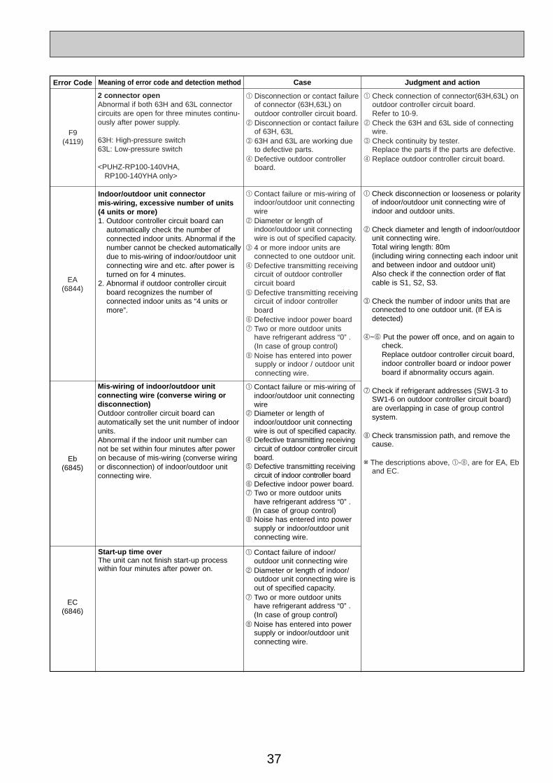
37
Error Code Meaning of error code and detection method Judgment and action
Eb(6845)
Mis-wiring of indoor/outdoor unit connecting wire (converse wiring ordisconnection)Outdoor controller circuit board can automatically set the unit number of indoorunits.Abnormal if the indoor unit number can not be set within four minutes after poweron because of mis-wiring (converse wiringor disconnection) of indoor/outdoor unitconnecting wire.
EC(6846)
Start-up time overThe unit can not finish start-up processwithin four minutes after power on.
Case
1 Contact failure of indoor/outdoor unit connecting wire
2 Diameter or length of indoor/outdoor unit connecting wire isout of specified capacity.
7 Two or more outdoor unitshave refrigerant address “0” .(In case of group control)
8 Noise has entered into powersupply or indoor/outdoor unitconnecting wire.
1 Contact failure or mis-wiring ofindoor/outdoor unit connectingwire
2 Diameter or length ofindoor/outdoor unit connectingwire is out of specified capacity.
4 Defective transmitting receivingcircuit of outdoor controller circuitboard.
5 Defective transmitting receivingcircuit of indoor controller board
6 Defective indoor power board.7 Two or more outdoor units
have refrigerant address “0” .(In case of group control)
8 Noise has entered into powersupply or indoor/outdoor unitconnecting wire.
Indoor/outdoor unit connector mis-wiring, excessive number of units(4 units or more)1. Outdoor controller circuit board can
automatically check the number of connected indoor units. Abnormal if thenumber cannot be checked automaticallydue to mis-wiring of indoor/outdoor unitconnecting wire and etc. after power isturned on for 4 minutes.
2. Abnormal if outdoor controller circuitboard recognizes the number of connected indoor units as “4 units ormore”.
1 Check disconnection or looseness or polarityof indoor/outdoor unit connecting wire ofindoor and outdoor units.
2 Check diameter and length of indoor/outdoorunit connecting wire.Total wiring length: 80m(including wiring connecting each indoor unitand between indoor and outdoor unit)Also check if the connection order of flatcable is S1, S2, S3.
3 Check the number of indoor units that areconnected to one outdoor unit. (If EA isdetected)
4~6 Put the power off once, and on again to check.Replace outdoor controller circuit board, indoor controller board or indoor power board if abnormality occurs again.
7 Check if refrigerant addresses (SW1-3 toSW1-6 on outdoor controller circuit board)are overlapping in case of group control system.
8 Check transmission path, and remove thecause.
w The descriptions above, 1-8, are for EA, Eband EC.
1 Contact failure or mis-wiring ofindoor/outdoor unit connectingwire
2 Diameter or length ofindoor/outdoor unit connectingwire is out of specified capacity.
3 4 or more indoor units are connected to one outdoor unit.
4 Defective transmitting receivingcircuit of outdoor controller circuit board
5 Defective transmitting receivingcircuit of indoor controllerboard
6 Defective indoor power board7 Two or more outdoor units
have refrigerant address “0” .(In case of group control)
8 Noise has entered into powersupply or indoor / outdoor unit connecting wire.
EA(6844)
F9(4119)
2 connector openAbnormal if both 63H and 63L connectorcircuits are open for three minutes continu-ously after power supply.
63H: High-pressure switch63L: Low-pressure switch
<PUHZ-RP100-140VHA,RP100-140YHA only>
1 Disconnection or contact failureof connector (63H,63L) on outdoor controller circuit board.
2 Disconnection or contact failureof 63H, 63L
3 63H and 63L are working dueto defective parts.
4 Defective outdoor controllerboard.
1 Check connection of connector(63H,63L) on outdoor controller circuit board. Refer to 10-9.
2 Check the 63H and 63L side of connectingwire.
3 Check continuity by tester.Replace the parts if the parts are defective.
4 Replace outdoor controller circuit board.
OC334-2.qxp 05.5.26 6:06 PM Page 37
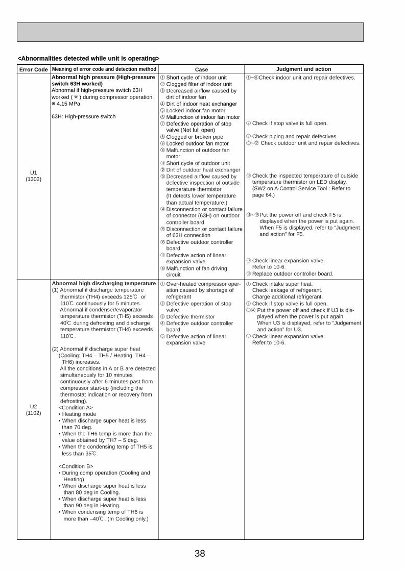
38
<Abnormalities detected while unit is operating>
Error Code Meaning of error code and detection method Judgment and action
U1(1302)
Abnormal high pressure (High-pressureswitch 63H worked)Abnormal if high-pressure switch 63Hworked ( w ) during compressor operation.w 4.15 MPa
63H: High-pressure switch
1 Short cycle of indoor unit2 Clogged filter of indoor unit3 Decreased airflow caused by
dirt of indoor fan4 Dirt of indoor heat exchanger5 Locked indoor fan motor6 Malfunction of indoor fan motor7 Defective operation of stop
valve (Not full open)8 Clogged or broken pipe9 Locked outdoor fan motor0 Malfunction of outdoor fan
motor1 Short cycle of outdoor unit2 Dirt of outdoor heat exchanger3 Decreased airflow caused by
defective inspection of outsidetemperature thermistor (It detects lower temperaturethan actual temperature.)
4 Disconnection or contact failureof connector (63H) on outdoorcontroller board
5 Disconnection or contact failureof 63H connection
6 Defective outdoor controllerboard
7 Defective action of linearexpansion valve
8 Malfunction of fan driving circuit
1~6Check indoor unit and repair defectives.
7 Check if stop valve is full open.
8 Check piping and repair defectives.9~2 Check outdoor unit and repair defectives.
3 Check the inspected temperature of outsidetemperature thermistor on LED display. (SW2 on A-Control Service Tool : Refer topage 64.)
4~6Put the power off and check F5 is displayed when the power is put again.When F5 is displayed, refer to “Judgmentand action” for F5.
7 Check linear expansion valve.Refer to 10-6.
8 Replace outdoor controller board.
Case
U2(1102)
Abnormal high discharging temperature(1) Abnormal if discharge temperature
thermistor (TH4) exceeds 125: or 110: continuously for 5 minutes.Abnormal if condenser/evaporator temperature thermistor (TH5) exceeds 40: during defrosting and discharge temperature thermistor (TH4) exceeds 110:.
(2) Abnormal if discharge super heat (Cooling: TH4 – TH5 / Heating: TH4 –
TH6) increases.All the conditions in A or B are detected simultaneously for 10 minutes continuously after 6 minutes past from compressor start-up (including the thermostat indication or recovery from defrosting).
<Condition A>• Heating mode• When discharge super heat is less
than 70 deg.• When the TH6 temp is more than the
value obtained by TH7 – 5 deg.• When the condensing temp of TH5 is
less than 35:.
<Condition B>• During comp operation (Cooling and
Heating)• When discharge super heat is less
than 80 deg in Cooling.• When discharge super heat is less
than 90 deg in Heating.• When condensing temp of TH6 is
more than –40:. (In Cooling only.)
1 Over-heated compressor oper-ation caused by shortage ofrefrigerant
2 Defective operation of stopvalve
3 Defective thermistor4 Defective outdoor controller
board5 Defective action of linear
expansion valve
1 Check intake super heat.Check leakage of refrigerant.Charge additional refrigerant.
2 Check if stop valve is full open.34 Put the power off and check if U3 is dis-
played when the power is put again.When U3 is displayed, refer to “Judgementand action” for U3.
5 Check linear expansion valve.Refer to 10-6.
<Abnormalities detected while unit is operating>
OC334-2.qxp 05.5.26 6:06 PM Page 38

39
ThermistorsOpen detection Short detection
Symbol Name
TH3TH6TH7TH8
– 40: or below– 40: or below– 40: or below– 27: or below
90: or above90: or above90: or above102: or above
Thermistor <Outdoor pipe>Thermistor <Outdoor 2-phase pipe>
Thermistor <Outdoor>Thermistor <Heat sink> RP35-140VHA
TH8 – 35: or below 170: or aboveInternal thermistor RP100-140YHA
Error Code Meaning of error code and detection method Case Judgment and action
U5(4230)
Abnormal temperature of heat sinkAbnormal if heat sink thermistor(TH8)detects temperature indicated below.RP35V, 50VHA··············84:RP60V, 71VHA··············77:RP100-140VHA·············77:RP100-140YHA·············95:
1 The outdoor fan motor islocked.
2 Failure of outdoor fan motor3 Air flow path is clogged.4 Rise of ambient temperature5 Defective thermistor6 Defective input circuit of
outdoor power circuit board7 Failure of outdoor fan drive
circuit
12 Check outdoor fan.
3 Check air flow path for cooling.4 Check if there is something which causes
temperature rise around outdoor unit.(Upper limit of ambient temperature is 46:.)Turn off power, and on again to check if U5 is displayed within 30 minutes.If U4 is displayed instead of U5, follow the action to be taken for U4.
5 Check resistance value of thermistor (TH8)or temperature by microcomputer.(Thermistor/TH8: Refer to 10-6.)(SW2 on A-Control Service Tool: Refer to 10-10.)
6 Replace outdoor power circuit board.7 Replace outdoor controller circuit board.
U3(5104)
Open/short circuit of discharge temperature thermistor (TH4)Abnormal if open (3: or less) or short(217: or more) is detected during compressor operation.(Detection is inoperative for 10 minutes ofcompressor starting process and for 10minutes after and during defrosting.)
1 Disconnection or contact failure of connector (TH4) onthe outdoor controller circuitboard.
2 Defective thermistor3 Defective outdoor controller
circuit board
1 Check connection of connector (TH4) on theoutdoor controller circuit board.Check breaking of the lead wire for thermistor (TH4). Refer to 10-9.
2 Check resistance value of thermistor (TH4) ortemperature by microcomputer.(Thermistor/TH4: Refer to 10-6.)(SW2 on A-Control Service Tool: Refer to 10-10.)
3 Replace outdoor controller board.
U4(TH3:5105)(TH6:5107)(TH7:5106)(TH8:5110)
Open/short of outdoor unit thermistors(TH3, TH6, TH7, and TH8)Abnormal if open or short is detected during compressor operation.Open detection of thermistors TH3 andTH6 is inoperative for 10 seconds to 10minutes after compressor starting and 10minutes after and during defrosting.WCheck which unit has abnormality in its
thermistor by switching the mode of SW2. (PAC-SK52ST)(Refer to 10-10.)
1 Disconnection or contact failureof connectorsOutdoor controller circuit board: TH3,TH6/TH7Outdoor power circuit board:CN3
2 Defective thermistor3 Defective outdoor controller
circuit board
1 Check connection of connector (TH3,TH6/TH7)on the outdoor controller circuit board.Check connection of connector (CN3) on theoutdoor power circuit board.Check breaking of the lead wire for thermistor(TH3,TH6,TH7,TH8). Refer to 10-9.
2 Check resistance value of thermistor(TH3,TH6,TH7,TH8) or check temperature bymicrocomputer. (Thermistor/TH3,TH6,TH7,TH8: Refer to 10-6.)(SW2 on A-Control Service Tool: Refer to 10-10.)
3 Replace outdoor controller circuit board.WEmergency operation is available in case of
abnormalities of TH3, TH6 and TH7. Refer to 10-8.
( )
U6(4250)
Abnormality of power moduleCheck abnormality by driving power modulein case overcurrent is detected. (UF or UP error condition)
1 Outdoor stop valve is closed.2 Decrease of power supply voltage3 Looseness, disconnection or
converse of compressor wiringconnection
4 Defective compressor5 Defective outdoor power circuit
board
1 Open stop valve.2 Check facility of power supply.3 Correct the wiring (U•V•W phase) to
compressor. Refer to 10-9 (Outdoor powercircuit board).
4 Check compressor referring to 10-6.5 Replace outdoor power circuit board.
OC334-2.qxp 05.5.26 6:06 PM Page 39
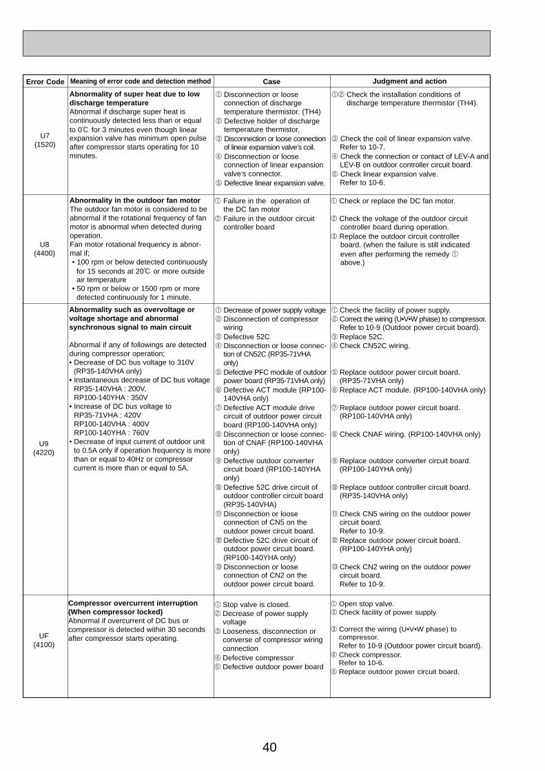
40
Error Code Meaning of error code and detection method Case Judgment and action
U7(1520)
Abnormality of super heat due to lowdischarge temperatureAbnormal if discharge super heat is continuously detected less than or equal to 0: for 3 minutes even though linearexpansion valve has minimum open pulseafter compressor starts operating for 10minutes.
1 Disconnection or loose connection of discharge temperature thermistor. (TH4)
2 Defective holder of dischargetemperature thermistor.
3 Disconnection or loose connectionof linear expansion valve’s coil.
4 Disconnection or loose connection of linear expansionvalve’s connector.
5 Defective linear expansion valve.
12 Check the installation conditions of discharge temperature thermistor (TH4).
3 Check the coil of linear expansion valve.Refer to 10-7.
4 Check the connection or contact of LEV-A andLEV-B on outdoor controller circuit board.
5 Check linear expansion valve.Refer to 10-6.
U8(4400)
Abnormality in the outdoor fan motorThe outdoor fan motor is considered to be abnormal if the rotational frequency of fan motor is abnormal when detected during operation.Fan motor rotational frequency is abnor-mal if;• 100 rpm or below detected continuously
for 15 seconds at 20: or more outside air temperature
• 50 rpm or below or 1500 rpm or more detected continuously for 1 minute.
1 Failure in the operation of the DC fan motor
2 Failure in the outdoor circuit controller board
1 Check or replace the DC fan motor.
2 Check the voltage of the outdoor circuitcontroller board during operation.
3 Replace the outdoor circuit controller board. (when the failure is still indicated even after performing the remedy 1above.)
U9(4220)
Abnormality such as overvoltage orvoltage shortage and abnormal synchronous signal to main circuit
Abnormal if any of followings are detectedduring compressor operation;• Decrease of DC bus voltage to 310V
(RP35-140VHA only)• Instantaneous decrease of DC bus voltage
RP35-140VHA : 200V, RP100-140YHA : 350V
• Increase of DC bus voltage to RP35-71VHA : 420V RP100-140VHA : 400VRP100-140YHA : 760V
• Decrease of input current of outdoor unitto 0.5A only if operation frequency is morethan or equal to 40Hz or compressor current is more than or equal to 5A.
1 Decrease of power supply voltage2 Disconnection of compressor
wiring3 Defective 52C4 Disconnection or loose connec-
tion of CN52C (RP35-71VHAonly)
5 Defective PFC module of outdoorpower board (RP35-71VHA only)
6 Defective ACT module (RP100-140VHA only)
7 Defective ACT module drivecircuit of outdoor power circuitboard (RP100-140VHA only)
8 Disconnection or loose connec-tion of CNAF (RP100-140VHAonly)
9 Defective outdoor converter circuit board (RP100-140YHAonly)
0 Defective 52C drive circuit ofoutdoor controller circuit board(RP35-140VHA)
1 Disconnection or loose connection of CN5 on the outdoor power circuit board.
2 Defective 52C drive circuit ofoutdoor power circuit board.(RP100-140YHA only)
3 Disconnection or loose connection of CN2 on the outdoor power circuit board.
1 Check the facility of power supply.2 Correct the wiring (U•V•W phase) to compressor.
Refer to 10-9 (Outdoor power circuit board).3 Replace 52C.4 Check CN52C wiring.
5 Replace outdoor power circuit board. (RP35-71VHA only)
6 Replace ACT module. (RP100-140VHA only)
7 Replace outdoor power circuit board. (RP100-140VHA only)
8 Check CNAF wiring. (RP100-140VHA only)
9 Replace outdoor converter circuit board.(RP100-140YHA only)
0 Replace outdoor controller circuit board.(RP35-140VHA only)
1 Check CN5 wiring on the outdoor power circuit board.Refer to 10-9.
2 Replace outdoor power circuit board.(RP100-140YHA only)
3 Check CN2 wiring on the outdoor power circuit board.Refer to 10-9.
UF(4100)
Compressor overcurrent interruption(When compressor locked)Abnormal if overcurrent of DC bus or compressor is detected within 30 secondsafter compressor starts operating.
1 Stop valve is closed.2 Decrease of power supply
voltage3 Looseness, disconnection or
converse of compressor wiringconnection
4 Defective compressor5 Defective outdoor power board
1 Open stop valve.2 Check facility of power supply.
3 Correct the wiring (U•V•W phase) to compressor.Refer to 10-9 (Outdoor power circuit board).
4 Check compressor.Refer to 10-6.
5 Replace outdoor power circuit board.
OC334-2.qxp 05.5.26 6:06 PM Page 40
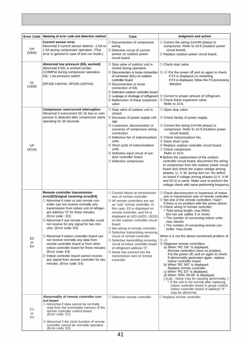
41
Error Code Meaning of error code and detection method Judgment and action
UL(1300)
Abnormal low pressure (63L worked)Abnormal if 63L is worked (under-0.03MPa) during compressor operation.63L: Low-pressure switch
(RP100-140VHA, RP100-140YHA)
1 Stop valve of outdoor unit isclosed during operation.
2 Disconnection or loose connectionof connector (63L) on outdoorcontroller board
3 Disconnection or loose connection of 63L
4 Defective outdoor controller board5 Leakage or shortage of refrigerant6 Malfunction of linear expansion
valve
1 Check stop valve.
2~4 Put the power off and on again to check if F3 is displayed on restarting.If F3 is displayed, follow the F3 processingdirection.
5 Correct to proper amount of refrigerant.6 Check linear expansion valve.
Refer to 10-6.
Case
UH(5300)
Current sensor errorAbnormal if current sensor detects –1.5A to1.5A during compressor operation. (Thiserror is ignored in case of test run mode.)
1 Disconnection of compressorwiring
2 Defective circuit of current sensor on outdoor power circuit board
1 Correct the wiring (U•V•W phase) to compressor. Refer to 10-9 (Outdoor power
circuit board).2 Replace outdoor power circuit board.
UP(4210)
Compressor overcurrent interruptionAbnormal if overcurrent DC dc bus or com-pressor is detected after compressor startsoperating for 30 seconds.
1 Stop valve of outdoor unit isclosed.
2 Decrease of power supply volt-age
3 Looseness, disconnection orconverse of compressor wiringconnection
4 Defective fan of indoor/outdoorunits
5 Short cycle of indoor/outdoorunits
6 Defective input circuit of out-door controller board
7 Defective compressor
1 Open stop valve.
2 Check facility of power supply.
3 Correct the wiring (U•V•W phase) to compressor. Refer to 10-9 (Outdoor power
circuit board).4 Check indoor/outdoor fan.5 Solve short cycle.6 Replace outdoor controller circuit board.7 Check compressor.
Refer to 10-6.W Before the replacement of the outdoor
controller circuit board, disconnect the wiring to compressor from the outdoor power circuit board and check the output voltage among phases, U, V, W, during test run. No defect on board if voltage among phases (U-V, V-W and W-U) is same. Make sure to perform the voltage check with same performing frequency.
E0orE4
Remote controller transmissionerror(E0)/signal receiving error(E4)1 Abnormal if main or sub remote con-
troller can not receive normally anytransmission from indoor unit of refriger-ant address “0” for three minutes.(Error code : E0)
2 Abnormal if sub remote controller couldnot receive for any signal for two min-utes. (Error code: E0)
1 Abnormal if indoor controller board cannot receive normally any data fromremote controller board or from otherindoor controller board for three minutes.(Error code: E4)
2 Indoor controller board cannot receiveany signal from remote controller for twominutes. (Error code: E4)
1 Check disconnection or looseness of indoorunit or transmission wire of remote controller.
2 Set one of the remote controllers “main”.If there is no problem with the action above.
3 Check wiring of remote controller.• Total wiring length: max.500m
(Do not use cablex 3 or more)• The number of connecting indoor units:
max.16units• The number of connecting remote con-
troller: max.2units
When it is not the above-mentioned problem of1~34 Diagnose remote controllers.
a) When “RC OK” is displayed,Remote controllers have no problem. Put the power off, and on again to check.If abnormality generates again, replaceindoor controller board.
b) When “RC NG” is displayed,Replace remote controller.
c) When “RC E3” is displayed,d) When “ERC 00-06” is displayed,[ c),d)→Noise may be causing abnormality. ]
∗ If the unit is not normal after replacingindoor controller board in group control,indoor controller board of address “0”may be abnormal.
1 Contact failure at transmissionwire of remote controller
2 All remote controllers are setas “sub” remote controller. Inthis case, E0 is displayed onremote controller, and E4 isdisplayed at LED (LED1, LED2)on the outdoor controller circuitboard.
3 Mis-wiring of remote controller.4 Defective transmitting receiving
circuit of remote controller5 Defective transmitting receiving
circuit of indoor controller boardof refrigerant address “0”.
6 Noise has entered into thetransmission wire of remotecontroller.
E1orE2
Abnormality of remote controller con-trol board1 Abnormal if data cannot be normally
read from the nonvolatile memory of theremote controller control board.(Error code: E1)
2 Abnormal if the clock function of remotecontroller cannot be normally operated.(Error code: E2)
1 Defective remote controller. 1 Replace remote controller.
OC334-2.qxp 05.5.26 6:06 PM Page 41

42
Error Code Meaning of error code and detection method Judgment and action
E9(6841)
Indoor/outdoor unit communicationerror (Transmitting error) (Outdoor unit)(1) Abnormal if “0” receiving is detected 30
times continuously though outdoor con-troller circuit board has transmitted “1”.
(2) Abnormal if outdoor controller circuitboard could not find blank of transmissionpath for three minutes.
1 Indoor/ outdoor unit connectingwire has contact failure.
2 Defective communication circuitof outdoor controller circuit board.
3 Noise has entered power supply.4 Noise has entered indoor/ out-
door unit connecting wire.
1 Check disconnection or looseness ofindoor/outdoor unit connecting wire.
2~4 Put the power off, and on again to check.Replace outdoor controller circuit board ifabnormality is displayed again.
EF(6607
or6608)
Non defined error codeThis code is displayed when non definederror code is received.
1 Noise has entered transmis-sion wire of remote controller.
2 Noise has entered indoor/ out-door unit connecting wire.
3 Outdoor unit is not a series ofpower-inverter.
4 Model name of remote con-troller is PAR-S25A.
12 Put the power off, and on again to check. Replace indoor controller board or outdoor controller circuit board if abnormality is displayed again.
3 Replace outdoor unit with power-inverter typeoutdoor unit.
4 Replace remote controller with MA remotecontroller.
Case
Ed(0403)
Serial communication error1.Abnormal if serial communication
between outdoor controller circuit board and outdoor power circuit board is defective.
1 Breaking of wire or contact failure of connector CN2between the outdoor controllercircuit board and the outdoorpower circuit board.
2 Breaking of wire or contact failure of connector CN4between the outdoor controllercircuit board and the outdoorpower circuit board.
3 Defective communication circuitof outdoor power circuit board
4 Defective communication circuitof outdoor controller circuit boardfor outdoor power circuit board
12 Check connection of each connector CN2and CN4 between the outdoor controllercircuit board and the outdoor power circuitboard.
3 Replace outdoor power circuit board.
4 Replace outdoor controller circuit board.
1 Breaking of wire or contact failure of connector betweenoutdoor controller circuit boardand M-NET board
2 Contact failure of M-NET boardpower supply line
3 Noise has entered into M-NETtransmission wire.
2. Abnormal if communication between outdoor controller circuit board and M-NET board is not available.
1 Check disconnection, looseness, or breaking ofconnection wire between outdoor controller cir-cuit board (CNMNT) and M-NET board (CN5).
2 Check disconnection, looseness, or breaking ofconnection wire between outdoor controller cir-cuit board(CNMNT) and M-NET board (CND).
3 Check M-NET transmission wiring method.
E8(6840)
Indoor/outdoor unit communicationerror (Signal receiving error)(Outdoor unit)(1) Abnormal if outdoor controller circuit
board could not receive anything normally for three minutes.
1 Contact failure of indoor/out-door unit connecting wire.
2 Defective communication circuitof outdoor controller circuit board.
3 Defective communication cir-cuit of indoor controller board
4 Noise has entered into indoor/outdoor unit connecting wire.
1 Check disconnection or looseness of indoor/outdoor unit connecting wire of indoor or out-door units.
2~4 Put the power off, and on again to check.Replace indoor controller board or outdoorcontroller circuit board if abnormality is displayed again.
E3orE5
Remote controller transmissionerror(E3)/signal receiving error(E5)1 Abnormal if remote controller could not
find blank of transmission path for sixseconds and could not transmit.(Error code: E3)
2 Remote controller receives transmitteddata at the same time, compares thedata, and when detecting it, judges different data to be abnormal 30 continuous times. (Error code: E3)
1 Abnormal if indoor controller board couldnot find blank of transmission path.(Error code: E5)
2 Indoor controller board receives trans-mitted data at the same time, comparesthe data,and when detecting it, judgesdifferent data to be abnormal 30 continuous times. (Error code: E5)
1 Set a remote controller to main, and theother to sub.
2 Remote controller is connected with only oneindoor unit.
3 The address changes to a separate setting.
4~6 Diagnose remote controller.a) When “RC OK”is displayed, remote con-
trollers have no problem.Put the power off,and on again to check.When becoming abnormal again, replaceindoor controller board.
b)When “RC NG”is displayed, replaceremote controller.
c)When “RC E3”or “ERC 00-66”is displayed,noise may be causing abnormality.
1 Two remote controller are setas “main.” (In case of 2 remote con-trollers)
2 Remote controller is connectedwith two indoor units or more.
3 Repetition of refrigerantaddress.
4 Defective transmitting receivingcircuit of remote controller.
5 Defective transmitting receivingcircuit of indoor controllerboard.
6 Noise has entered into trans-mission wire of remote con-troller.
OC334-2.qxp 05.5.26 6:06 PM Page 42
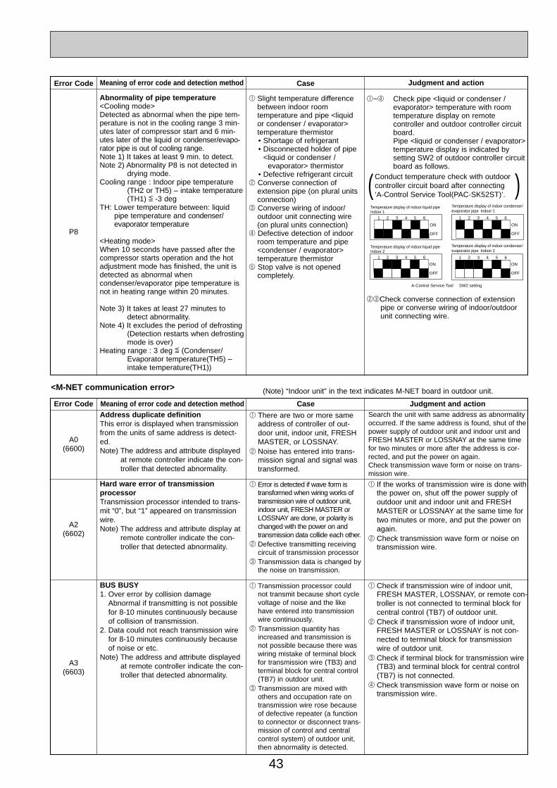
43
Error Code Meaning of error code and detection method Case Judgment and action
A0(6600)
Address duplicate definitionThis error is displayed when transmissionfrom the units of same address is detect-ed.Note) The address and attribute displayed
at remote controller indicate the con-troller that detected abnormality.
1 There are two or more sameaddress of controller of out-door unit, indoor unit, FRESHMASTER, or LOSSNAY.
2 Noise has entered into trans-mission signal and signal wastransformed.
Search the unit with same address as abnormalityoccurred. If the same address is found, shut of thepower supply of outdoor unit and indoor unit andFRESH MASTER or LOSSNAY at the same timefor two minutes or more after the address is cor-rected, and put the power on again.Check transmission wave form or noise on trans-mission wire.
A2(6602)
Hard ware error of transmission processorTransmission processor intended to trans-mit “0”, but “1” appeared on transmissionwire.Note) The address and attribute display at
remote controller indicate the con-troller that detected abnormality.
1 Error is detected if wave form istransformed when wiring works oftransmission wire of outdoor unit,indoor unit, FRESH MASTER orLOSSNAY are done, or polarity ischanged with the power on andtransmission data collide each other.
2 Defective transmitting receivingcircuit of transmission processor
3 Transmission data is changed bythe noise on transmission.
1 If the works of transmission wire is done withthe power on, shut off the power supply ofoutdoor unit and indoor unit and FRESHMASTER or LOSSNAY at the same time fortwo minutes or more, and put the power onagain.
2 Check transmission wave form or noise ontransmission wire.
A3(6603)
BUS BUSY1. Over error by collision damage
Abnormal if transmitting is not possiblefor 8-10 minutes continuously becauseof collision of transmission.
2. Data could not reach transmission wirefor 8-10 minutes continuously becauseof noise or etc.
Note) The address and attribute displayedat remote controller indicate the con-troller that detected abnormality.
1 Transmission processor couldnot transmit because short cyclevoltage of noise and the likehave entered into transmissionwire continuously.
2 Transmission quantity hasincreased and transmission isnot possible because there waswiring mistake of terminal blockfor transmission wire (TB3) andterminal block for central control(TB7) in outdoor unit.
3 Transmission are mixed with others and occupation rate ontransmission wire rose becauseof defective repeater (a functionto connector or disconnect trans-mission of control and centralcontrol system) of outdoor unit,then abnormality is detected.
1 Check if transmission wire of indoor unit,FRESH MASTER, LOSSNAY, or remote con-troller is not connected to terminal block forcentral control (TB7) of outdoor unit.
2 Check if transmission wore of indoor unit,FRESH MASTER or LOSSNAY is not con-nected to terminal block for transmissionwire of outdoor unit.
3 Check if terminal block for transmission wire(TB3) and terminal block for central control(TB7) is not connected.
4 Check transmission wave form or noise ontransmission wire.
<M-NET communication error> (Note) “Indoor unit” in the text indicates M-NET board in outdoor unit.
Error Code Meaning of error code and detection method Case Judgment and action
P8
1 Slight temperature differencebetween indoor room temperature and pipe <liquid or condenser / evaporator> temperature thermistor• Shortage of refrigerant• Disconnected holder of pipe
<liquid or condenser / evaporator> thermistor
• Defective refrigerant circuit2 Converse connection of
extension pipe (on plural unitsconnection)
3 Converse wiring of indoor/outdoor unit connecting wire(on plural units connection)
4 Defective detection of indoorroom temperature and pipe<condenser / evaporator> temperature thermistor
5 Stop valve is not opened completely.
Abnormality of pipe temperature<Cooling mode>Detected as abnormal when the pipe tem-perature is not in the cooling range 3 min-utes later of compressor start and 6 min-utes later of the liquid or condenser/evapo-rator pipe is out of cooling range.Note 1) It takes at least 9 min. to detect.Note 2) Abnormality P8 is not detected in
drying mode.Cooling range : Indoor pipe temperature
(TH2 or TH5) – intake temperature(TH1) [ -3 deg
TH: Lower temperature between: liquidpipe temperature and condenser/ evaporator temperature
<Heating mode>When 10 seconds have passed after thecompressor starts operation and the hotadjustment mode has finished, the unit isdetected as abnormal whencondenser/evaporator pipe temperature isnot in heating range within 20 minutes.
Note 3) It takes at least 27 minutes todetect abnormality.
Note 4) It excludes the period of defrosting(Detection restarts when defrostingmode is over)
Heating range : 3 deg [ (Condenser/Evaporator temperature(TH5) –intake temperature(TH1))
1~4 Check pipe <liquid or condenser /evaporator> temperature with room temperature display on remote controller and outdoor controller circuit board.Pipe <liquid or condenser / evaporator>temperature display is indicated by setting SW2 of outdoor controller circuitboard as follows.
23Check converse connection of extension pipe or converse wiring of indoor/outdoor unit connecting wire.
Conduct temperature check with outdoorcontroller circuit board after connecting ‘A-Control Service Tool(PAC-SK52ST)’.( )
1 2 3 4 5 6
ON
OFF
1 2 3 4 5 6
ON
OFF
1 2 3 4 5 6
ON
OFF
1 2 3 4 5 6
ON
OFF
A-Control Service Tool SW2 setting
Temperature display of indoor liquid pipeIndoor 1
Temperature display of indoor liquid pipeIndoor 2
Temperature display of indoor condenser/evaporator pipe Indoor 1
Temperature display of indoor condenser/evaporator pipe Indoor 2
OC334-2.qxp 05.5.26 6:06 PM Page 43

44
A6(6606)
Communication error with communica-tion processorDefective communication between unitprocessor and transmission processorNote) The address and attribute display at
remote controller indicate the con-troller that detected abnormality.
1 Data of transmission proces-sor or unit processor is nottransmitted normally becauseof accidental trouble such asnoise or thunder surge.
2 Address forwarding from unitprocessor is not transmittednormally because of defectivetransmission processor hard-ware.
Shut of the power supply of outdoor unit andindoor unit and FRESH MASTER or LOSSNAYat the same time for two minutes or more, andput the power on again. System returns nor-mally if abnormality was accidental malfunction.If the same abnormality generates again,abnormality-generated controller may be defec-tive.
Continued to the next page.
Error Code Meaning of error code and detection method Case Judgment and action
A7(6607)
NO ACK signal1. Transmitting side controller detects
abnormal if a massage was transmittedbut there is no reply (ACK) that a mas-sage was received. Transmitting sidedetects abnormality every 30 seconds,six times continuously.
Note) The address and attribute displayedat remote controller is indicate thecontroller that did not reply (ACK).
Common factor that has no rela-tion with abnormality source.1 The unit of former address
does not exist as addressswitch has changed while theunit was energized.
2 Extinction of transmission wirevoltage and signal is caused byover-range transmission wire.• Maximum distance ······200m• Remote controller line ··(12m)
3 Extinction of transmission wirevoltage and signal is caused bytype-unmatched transmissionwire.Type ······
With shield wire- CVVS, CPEVS
With normal wire (no shield)-VCTF, VCTFK, CVV CVS, VVR, VVF, VCT
Diameter····1.25mm2 or more 4 Extinction of transmission wire
voltage and signal is causedby over-numbered units.
5 Accidental malfunction ofabnormality-detected controller(noise, thunder surge)
6 Defective of abnormality-gen-erated controller
2. If displayed address or attribute is out-door unit,Indoor unit detects abnormality whenindoor unit transmitted to outdoor unitand there was no reply (ACK).
1 Contact failure of transmissionwire of outdoor unit or indoor unit
2 Disconnection of transmissionconnector (CN2M) of outdoor unit
3 Defective transmitting receiv-ing circuit of outdoor unit orindoor unit
Always try the followings when the error “A7” occurs.
1 Shut off the power supply of outdoor unit andindoor unit and FRESH MASTER or LOSS-NAY at the same time for two minutes ormore, and put the power on again. If mal-function was accidental, the unit returns tonormal.
2 Check address switch of abnormality-gener-ated address.
3 Check disconnection or looseness of abnor-mality-generated or abnormality-detectedtransmission wire (terminal block and con-nector)
4 Check if tolerance range of transmission wireis not exceeded.
5 Check if type of transmission wire is corrector not.
If there were some trouble of 1-5 above,repair the defective, then shut off the powersupply of outdoor unit and indoor unit andFRESH MASTER or LOSSNAY at the sametime for two minutes or more, and put thepower on again.• If there was no trouble with 1-5 above in sin-
gle refrigerant system (one outdoor unit), con-troller of displayed address or attribute isdefective.
• If there was no trouble with 1-5 above in dif-ferent refrigerant system (two or more outdoorunits), judge with 6.
6 If address of abnormality source is theaddress that should not exist, there is theunit that memorizes nonexistent addressinformation. Delete useless address informa-tion with manual setting function of remotecontroller.Only the system FRESH MASTER or LOSS-NAY are connected to, or the system that isequipped with group setting of differentrefrigerant system.
If there was no trouble with 1-6 above,replace the controller board of displayedaddress or attribute.If the unit does not return normally, multi-con-troller board of outdoor unit may be defective(repeater circuit).Replace multi-controller board one by one tocheck if the unit returns normally.
3. If displayed address or attribute isindoor unit,Remote controller detects abnormalitywhen remote controller transmitted toindoor unit and there was no reply(ACK).
1 During group operation withindoor unit of multi- refrigerantsystem, if remote controllertransmit to indoor unit whileoutdoor unit power supply ofone refrigerant system is putoff or within two minutes ofrestart, abnormality is detected.
2 Contact failure of transmissionwire of remote controller orindoor unit
3 Disconnection of transmissionconnector (CN2M) of indoor unit
4 Defective transmitting receiv-ing circuit of indoor unit orremote controller
OC334-2.qxp 05.5.26 6:06 PM Page 44

45
Error Code Meaning of error code and detection method Case Judgment and action
A7(6607)
5. If displayed address or attribute isFRESH MASTER, Indoor unit detects abnormality whenindoor unit transmitted to FRESH MAS-TER and there was no reply (ACK).
1 During sequential operation ofindoor unit and FRESH MAS-TER of other refrigerant sys-tem, if indoor unit transmits toFRESH MASTER while out-door unit power supply ofsame refrigerant system withFRESH MASTER is put off orwithin two minutes of restart,abnormality is detected.
2 Contact failure of transmissionwire of indoor unit or FRESHMASTER
3 Disconnection of transmissionconnector (CN2M) of indoorunit or FRESH MASTER
4 Defective transmitting receiv-ing circuit of indoor unit orFRESH MASTER
6. If displayed address or attribute isLOSSNAY,Indoor unit detects abnormality whenindoor unit transmitted to LOSSNAY andthere was no reply (ACK).
1 If the power supply of LOSS-NAY is off, indoor unit detectsabnormality when it transmitsto LOSSNAY.
2 During sequential operation ofindoor unit and LOSSNAY ofother refrigerant system, ifindoor unit transmits to LOSS-NAY while outdoor unit powersupply of same refrigerant sys-tem with LOSSNAY is put offor within two minutes ofrestart, abnormality is detect-ed.
3 Contact failure of transmissionwire of indoor unit of LOSS-NAY
4 Disconnection of transmissionconnector (CN2M) of indoorunit
5 Defective transmitting receiv-ing circuit of indoor unit orLOSSNAY
7. If displayed address or attribute isnonexistent,
1 The unit of former addressdoes not exist as addressswitch has changed while theunit was energized.
2 Abnormality is detected whenindoor unit transmittedbecause the address ofFRESH MASTER and LOSS-NAY are changed aftersequential operation ofFRESH MASTER and LOSS-NAY by remote controller.
From the previous page.
4. If displayed address or attribute isremote controller,Indoor unit detects abnormality whenindoor unit transmitted to remote con-troller and there was no reply (ACK).
1 During group operation withindoor unit of multi- refrigerantsystem, if indoor unit transmitto remote controller while out-door unit power supply of onerefrigerant system is put off orwithin two minutes of restart,abnormality is detected.
2 Contact failure of transmissionwire of remote controller orindoor unit
3 Disconnection of transmissionconnector (CN2M) of indoorunit
4 Defective transmitting receiv-ing circuit of indoor unit orremote controller
Same as mentioned in “A7” of the previous page.
OC334-2.qxp 05.5.26 6:06 PM Page 45

46
10-5. TROUBLESHOOTING BY INFERIOR PHENOMENAPhenomena Factor Countermeasure
1. Remote controller display does notwork.
2. “PLEASE WAIT” display is remainedon the remote controller.
3. When pressing the remote controlleroperation switch the OPERATIONdisplay is appeared but it will beturned off soon.
1After cancelling to select function from the remotecontroller, the remote controller operation switch willbe not accepted for approx. 30 seconds.
1Normal operation
1At longest 2 minutes after the power supply “PLEASEWAIT” is displayed to start up.
2Communication error between the remote controllerand indoor unit
3Communication error between the indoor and outdoorunit
4Outdoor unit protection device connector is open.
1DC12V is not supplied to remote controller.(Power supply display is not indicated on LCD.)
2DC12~15V is supplied to remote controller, however,no display is indicated.
• “PLEASE WAIT” is not displayed. • “PLEASE WAIT” is displayed.
1Check LED2 on indoor controller board.(1) When LED2 is lit.
Check the remote controller wiring for breaking or contact failure.
(2) When LED2 is blinking.Check short circuit of remote controller wiring.
(3) When LED2 is not lit.Refer to No.3 below.
2Check the following.• Failure of remote controller if “PLEASE
WAIT” is not displayed• Refer to No.2 below if “PLEASE WAIT” is
displayed.
1Normal operation2Self-diagnosis of remote controller3”PLEASE WAIT” is displayed for 6 min-utes at most. in
case of indoor/outdoor unit communica- tion error. Check LED3 on indoor con-troller board.(1)When LED3 is not blinking.
Check indoor/outdoor connecting wire for mis-wiring.(Converse wiring of S1 and S2, or break of S3 wiring.)
(2)When LED3 is blinking.Indoor/outdoor connecting wire is nor-mal.
4Check LED display on outdoor controller circuit board. Refer to 10-10.Check protection device connector (63Land 63H) for contact failure.Refer to 10-9.
Error Code Meaning of error code and detection method Case Judgment and action
A8(6608)
M-NET•NO RESPONSEAbnormal if a massage was transmittedand there were reply (ACK) that massagewas received, but response commanddoes not return. Transmitting side detectsabnormality every 30 seconds, six timescontinuously.Note) The address and attribute displayed
at remote controller is indicate thecontroller that did not reply (ACK).
1 Transmitting condition isrepeated fault because ofnoise and the like.
2 Extension of transmission wirevoltage and signal is causedby over-range transmissionwire.• Maximum distance ······200m• Remote controller line ··(12m)
3 Extension of transmission wirevoltage and signal is causedby type-unmatched transmis-sion wire.Type ······
With shield wire- CVVS, CPEVS
With normal wire (no shield)-VCTF, VCTFK, CVV CVS, VVR, VVF, VCT
Diameter····1.25mm2 or more 4 Accidental malfunction of
abnormality-generated controller
1 Check transmission wave form or noise ontransmission wire.
2 Shut off the power supply of outdoor unit andindoor unit and FRESH MASTER or LOSS-NAY at the same time for two minutes ormore, and put the power on again. If mal-function was accidental, the unit returns tonormal. If the same abnormality generatesagain, controller of displayed address andattribute may be defective.
OC334-2.qxp 05.5.26 6:06 PM Page 46

47
Phenomena Factor Countermeasure
7. Remote controller display works nor-mally and the unit performs heatingoperation, however, the capacitycannot be fully obtained.
1Linear expansion valve faultOpening cannot be adjusted well due to linear expan-sion valve fault.
2Refrigerant shortage3Lack of insulation for refrigerant piping4Filter clogging5Heat exchanger clogging6Air duct short cycle 7Bypass circuit of outdoor unit fault
1• Discharging temperature and indoor heat exchanger temperature does not rise.Inspect the failure by checking discharg-ing pressure.
• Replace linear expansion valve.2• If refrigerant leaks, discharging tempera
ture rises and LEV opening increases.Inspect leakage by checking the tem- perature and opening.
• Check pipe connections for gas leakage.3Check the insulation.4Open suction grill and check the filter.
Clean the filter by removing dirt or dust on it.
5• If the filter is clogged, indoor pipe tem- perature rises and discharging pressure increases. Check if heat exchanger is clogged by inspecting discharging pres-sure.
• Clean the heat exchanger.6Remove the shield.7Check refrigerant system during operation.
8. 1For 3 minutes after temperature adjuster turns off, the compressor will not start operating even if temperature adjuster is turned on.
2For 3 minutes after temperature adjuster turns on, the compressor will not stop operating even if temperature adjuster is turned off.(Compressor stops operating immediately when turning off by the remote controller.)
12Normal operation(For protection of compressor)
12Normal operation
4. Even controlling by the wirelessremote controller no beep is heardand the unit does not start operat-ing. Operation display is indicatedon wireless remote controller.
1The pair number settings of the wireless remotecontroller and indoor controller board are mis-matched.
1Check the pair number settings.
5. When operating by the wirelessremote controller, beep sound isheard, however, unit does not startoperating.
1No operation for 2 minutes at most after the powersupply ON.
2Hand-held remote controller operation is prohibited.• Remote controlling adaptor is connected to CN32on the indoor controller board.
• Hand-held remote controller operation is prohibited by centralised controller etc. since it is connected to MELANS.
3Factor of No.2 above.
1Normal operation
2Normal operation
3Check the details of No.2 above.
6. Remote controller display works normally and the unit performscooling operation, however, thecapacity cannot be fully obtained.(The air does not cool well.)
1Refrigerant shortage2Filter clogging3Heat exchanger clogging4Air duct short cycle
1• If refrigerant leaks, discharging tempera-ture rises and LEV opening increases.Inspect leakage by checking the tem- perature and opening.
• Check pipe connections for gas leakage.2Open suction grill and check the filter.
Clean the filter by removing dirt or dust on it.
3• If the filter is clogged, indoor pipe tem- perature rises and discharging pressure increases. Check if heat exchanger is clogged by inspecting discharging pressure.
• Clean the heat exchanger.4Remove the shield.
OC334-2.qxp 05.5.26 6:06 PM Page 47

48
How long is “PLEASE WAIT” kept being displayed on the
remote controller?
6 minutes or more
2 minutes or less
2 to 6 minutes
NO
NO
YES
YES
Are any error codes displayed on the
remote controller?
Are any error codes displayed on the LED?
Symptoms: “PLEASE WAIT” is kept being displayed on the remote controller.
Check the display time of “PLEASE WAIT” after turning on the main power.
• “PLEASE WAIT” will be displayed during the start-up diagnosis after turning on the main power.
• Normal. The start-up diagnosis will be over in around 2 minutes.
• Mis-wiring of indoor/ outdoor connecting wire• Breaking of indoor/ outdoor connecting wire (S3)• Defective indoor controller board• Defective outdoor controller circuit board
• Refer to “Self-diagnosis action table” in order to solve the trouble.
• In case of communication errors, the display of remote controller may not match the LED display of the outdoor unit.
• Defective indoor controller board• Defective remote controller
Check the LED display of the outdoor controller circuit board.
Diagnosis flow Cause Inspection method and troubleshooting
OC334-2.qxp 05.5.26 6:06 PM Page 48

49
AC 198V to AC 264V?
AC 198V to AC 264V?
AC 198V to AC 264V?
DC 12V to DC 16V?
DC 12V to DC 16V?
NO
YES
NO
YES
NO
YES
YES
NO
YES
NO
Check the voltage between S1 and S2 on the terminal block (TB4) of the indoor unit which is used to connect the indoor unit and the outdoor unit.
Check the voltage among L(L3) and N on the terminal block (TB1) of the outdoor power circuit board.
Check the voltage of indoor controller board (CN2D).
Check the voltage of the unit after removing the indoor power board (CN2S).
Check the voltage between S1 and S2 on the terminal block (TB1) of the outdoor unit which is used to connect the indoor unit and the outdoor unit.
• Troubles concerning power supply.
• Check the power wiring to the outdoor unit.• Check the breaker.
• Bad wiring of the outdoor controller board.• The fuses on the outdoor controller circuit board are blown.
• Check the wiring of the outdoor unit.• Check if the wiring is bad. Check if the fuses are blown. The fuses on the outdoor controller circuit board will be blown when the indoor /outdoor connecting wire short-circuits.
• Bad wiring of the outdoor controller board.• The fuses on the outdoor controller circuit board are blown.
• Check if mis-wiring, breaking or poor contact is causing this problem. Indoor/outdoor connecting wire is polarized 3-core type. Connect the indoor unit and the outdoor unit by wiring each pair of S1, S2 and S3 on the both side of indoor/outdoor terminal blocks.
• Defective indoor power board
• Replace the indoor power board.
• Defective indoor controller board
• Replace the indoor controller board.
• Mis-wiring, breaking or poor connection of in door/outdoor connecting wire.
• Check if there is mis-wiring or breaking of wire.
Symptoms: Nothing is displayed on the remote controller 1
Diagnosis flow Cause Inspection method and troubleshooting
LED display of the indoor controller boardLED1 :LED2 : LED3 :
OC334-2.qxp 05.5.26 6:06 PM Page 49

50
AC 198V to AC 264V?
Are there looseness or disconnection of the indoor/outdoor connecting wire?
Is anything displayed?
DC 17V to DC 28V?
Is “E8” displayed?
Can all the indoor unit be operated?
Check the voltage between S2 and S3 on the terminal block of the outdoor unit.
NO
YES
Not lighting.
Blinking.
NO
YES
NO
YES
Not displayed.
Displayed.
YES
NO
YES
NO
Check the voltage between S1 and S2 on the terminal block (TB4) of the indoor unit which is used to connect the indoor unit and the outdoor unit.
Check the refrigerant address of the outdoor unit. (SW1-3 to 1-6)
Check the looseness or disconnection of the indoor/outdoor connecting wire.
Check the LED display of the outdoor unit after turning on the main power again.
Can the unit be restarted?
• Breaking or poor contact of the indoor/outdoor connecting wire.
• Fix the breaking or poor contact of the indoor/outdoor connecting wire.
• Defective outdoor controller circuit board.
• Replace the outdoor controller circuit board.
• Normal. Only the unit which has the refrigerant address “0” supplies power to the remote controller.
• Set the refrigerant address to “0”. In case of the multiple grouping system, recheck the refrigerant address again.
• Defective indoor power board.
• Replace the indoor power board.
• Defective outdoor power circuit board.
• Replace the outdoor power circuit board.
• Defective indoor controller board
• Replace the indoor controller board of the indoor unit which doesn’t operate.
• Defective outdoor controller circuit board.
• Replace the outdoor controller circuit board.
• Influence of electromagnetic noise.
• Not abnormal. There may be the influence of electromagnetic noise. Check the transmission wire and get rid of the causes.
Symptoms: Nothing is displayed on the remote controller 2
Diagnosis flow Cause Inspection method and troubleshooting
LED display of the indoor controller boardLED1 :LED2 : LED3 : or
Check the status of the indoor controller board LED3 display.
Is the refrigerant address “0”?
NO
YES
NO
YES
Is “EA” or “Eb” displayed?
OC334-2.qxp 05.5.26 6:06 PM Page 50

51
DC 10V to DC 16V?YES
NO
Lighting
Blinking
Lighting
Blinking
Check the voltage of the terminal block (TB6) of the remote controller.
Check the status of the LED2 after disconnecting the remote controller wire from the terminal block (TB5) of the indoor unit.
• Defective remote controller.
• Replace the remote controller.
• Breaking or poor contact of the remote controller wire.
• Check if there is breaking or poor contact of the remote controller wire. Check the voltage of the terminal block (TB5) connecting the remote controller wire. If it is not between DC 10V and DC16V, the indoor controller board must be defective.
• The remote controller wire short-circuits.
• Check if the remote controller wire is short-circuited.
• Defective indoor controller board.
• Replace the indoor controller board.
Diagnosis flow Cause Inspection method and troubleshooting
Symptoms: Nothing is displayed on the remote controller 3
LED display of the indoor controller boardLED1 :LED2 : or LED3 : —
Check the status of the LED2.
Check the status of the LED2.
OC334-2.qxp 05.5.26 6:06 PM Page 51
52
1 The operating display of remote controller does not come on.
Phone Calls From Customers How to Respond Note1 Check if power is supplied to air conditioner.
Nothing appears on the display unless power is supplied.
2 Unit cannot be restarted for a while after it’s stopped.
2 Wait around 3 minutes. to restart unit.The air conditioner is in a state of being protected by the microcomputer’s directive. Once the compressor is stopped, the unit cannot be restarted for 3 minutes. This control is also applied when the unit is turned on and off by remote controller or thermostat.
3 Error code appears and blinks on the display of remote controller.
Refer to “SELF-DIAGNOSIS ACTION TABLE”. Check if servicing is required for the error.
Display time of “FILTER” depends on the model. Long life filter: 2500 hrs.Regular filter: 100 hrs.
3 Error code will be displayed if any protection devices of the air conditioner are actuated.What is error code?
1 “PLEASE WAIT” is displayed on the screen.
1 Wait around 2 minutes.An automatic startup test will be conducted for 2 minutes when power is supplied to the air conditioner. “PLEASE WAIT” will be kept being
displayed
2 “FILTER” is displayed on the screen.
2 This indicates that it is time to clean the air filters. Clean the air filters. Press the FILTER button on the remote controller twice to clear “FILTER” from the display. See the operation manual that came with the product for how to clean the filters.
3 “STANDBY” is displayed on the screen.
3 This is displayed when the unit starts HEAT operation, when the thermostat puts the compressor in operation mode, or when the outdoor unit ends DEFROST operation and returns to HEAT operation. The display will automatically disappear around 10 minutes later. While “STANDBY” is displayed on the remote controller, the airflow amount will be restricted because the indoor unit’s heat exchanger is not fully heated up. In addition to that, the up/down vane will be automatically set to horizontal blow in order to prevent cold air from directly blowing out to human body. The up/down vane will return to the setting specified by the remote controller when “STANDBY” is released.
4 “DEFROSTING” is displayed on the screen. (No air comes out of the unit.)
4 The outdoor unit gets frosted when the outside temperature is low and the humidity is high. “DEFROSTING” indicates the DEFROST operation is being performed to melt this frost. The DEFROST operation ends in around 10 minutes (at most 15 minutes). During the DEFROST operation, the indoor unit’s heat exchanger becomes cold, so the blower is stopped. The up/down vane will be automatically set to horizontal blow in order to prevent cold air from directly blowing out to human body. The display will turn into “STANDBY” when DEFROST operation ends.
Unit does not operate at all.
Remote controller.
• Before repair Frequent calling from customers.
OC334-2.qxp 05.5.26 6:06 PM Page 52
53
Phone Calls From Customers How to Respondm Note1 Check the set temperature of remote controller. The outdoor unit cannot be operated if the set temperature is not appropriate. The outdoor unit operates in the following modes. COOL: When the set temperature is lower than the room temperature. HEAT: When the set temperature is higher than the room temperature.
2 Check if filters are not dirty and clogged. If filters are clogged, the airflow amount will be reduced and the unit capacity will be lowered. See the instruction manual that came with the product for how to clean the filters.
3 Check there is enough space around the air conditioner. If there are any obstacles in the air intake or air outlet of indoor/outdoor units, they block the airflow direction so that the unit capacity will be lowered.
1 An gas escaping sound is heard sometimes.
1 This is not a malfunction. This is the sound which is heard when the flow of refrigerant in the air conditioner is switched.
2 A cracking sound is heard sometimes.
2 This is not a malfunction. This is the sound which is heard when internal parts of units expand or contract when the temperature changes.
3 A buzzing sound is heard sometimes.
3 This is not a malfunction. This is the sound which is heard when the outdoor unit starts operating.
4 A ticking sound is heard from the outdoor unit sometimes.
4 This is not a malfunction. This is the sound which is heard when the blower of the outdoor unit is controlling the airflow amount in order to keep the optimum operating condition.
5 A sound, similar to water flowing, is heard from the unit.
5 This is not a malfunction. This is the sound which is heard when the refrigerant is flowing inside the indoor unit.
2 The fan speed doesn’t match the setting of the remote controller in HEAT operation.
The up/down vane will be automatically set to horizontal blow in these cases listed up on the left (1~3). After a while, the up/down vane will be automatically moved according to the setting of the remote controller.
2 This is not a malfunction. 1) When the HEAT operation starts, to prevent the unit from blowing cold air, the fan speed is gradually increased from zero to the set speed, in proportion to the temperature rise of the discharged air. 2) When the room temperature reaches the set temperature and the outdoor unit stops, the unit starts the LOW AIR operation. 3) During the HEAT operation, the DEFROST operation is performed to defrost the outdoor unit. During the DEFROST operation, the blower is stopped to prevent cold air coming
Sound comes out from the air conditioner.
1 The fan speed doesn’t match the setting of the remote controller during DRY operation.(No air comes out sometimes during DRY operation.)
1 This is not a malfunction. During the DRY operation, the blower’s ON/OFF is controlled by the microcomputer to prevent overcooling and to ensure efficient dehumidification. The fan speed cannot be set by the remote controller during DRY operation.
Something is wrong with the blower…..
The room cannot be cooled or heated sufficiently.
OC334-2.qxp 05.5.26 6:06 PM Page 53

54
3 Air blows out for a while after HEAT operation is stopped.
Phone Calls From Customers How to Respond Note
3 This is not a malfunction. The blower is operating just for cooling down the heated-up air conditioner. This will be done within one minute. This control is conducted only when the HEAT operation is stopped with the electric heater ON.
However, this control is also applied to the models which has no electric heater.
“STANDBY” will be displayed on the remote controller in case of 1 and 2. “DEFROSTING” will be displayed on the screen in case of 3.
1 The airflow direction is changed during COOL operation.
1 If the up/down vane is set to downward in COOL operation, it will be automatically set to horizontal blow by the microcomputer in order to prevent water from dropping down. “1 Hr.” will be displayed on the remote controller if the up/down vane is set to downward with the fan speed set to be less than “LOW”.
2 The airflow direction is changed during HEAT operation. (The airflow direction cannot be set by remote controller.)
2 In HEAT operation, the up/down vane is automatically controlled according to the temperature of the indoor unit’s heat exchanger. In the following cases written below, the up/down vane will be set to horizontal blow, and the setting cannot be changed by remote controller. 1) At the beginning of the HEAT operation 2) While the outdoor unit is being stopped by thermostat or when the outdoor unit gets started to operate. 3) During DEFROST operation The airflow direction will be back to the setting of remote controller when the above situations are released.
3 The airflow direction doesn’t change. (Up/down vane, left/right louver)
3 1) Check if the vane is set to a fixed position. (Check if the vane motor connector is removed.) 2) Check if the air conditioner has a function for switching the air direction. 3) If the air conditioner doesn’t have that function, “NOT AVAILABLE” will be displayed on the remote controller when “AIR
Something is wrong with the blower…..
Something is wrong with the airflow direction….
1 Check if you set ON/OFF timer. The air conditioner starts operating at the time designated if ON timer has been set before.
2 Check if any operations are ordered by distant control system or the central remote controller. While “CENTRALLY CONTROLLED INDICATOR” is displayed on the remote controller, the air conditioner is under the control of external directive.
The air conditioner starts operating even though any buttons on the remote controller are not pressed.
1 Check if you set ON/OFF timer. The air conditioner stops operating at the time designated if OFF timer has been set before.
The air conditioner stops even though any buttons on the remote controller are not pressed.
There might be a case that “CENTRALLY CONTROLLED INDICATOR” will not be displayed.
There might be a case that “CENTRALLY CONTROLLED INDICATOR” will not be displayed.
3 Check if power is recovered from power failure (black out). The units will automatically start operating when power is recovered after power failure (black out) occurs. This function is called “auto recovery feature from power ”.
2 Check if any operations are ordered by distant control system or the central remote controller. While “CENTRALLY CONTROLLED INDICATOR” is displayed on the remote controller, the air conditioner is under the control of external directive.
OC334-2.qxp 05.5.26 6:06 PM Page 54
55
Phone Calls From Customers How to Respond Note
This is not a malfunction.This may occur when the operation gets started in the room of high humidity.
A white mist is expelled from the indoor unit.
Cooling; when pipes or piping joints are cooled, they get sweated and water drips down.Heating; water drips down from the heat exchanger.* Make use of optional parts “Drain Socket” and “Drain pan” if these water needs to be collected and drained out for once.
Water or moisture is expelled from the outdoor unit.
Batteries are being exhausted. Replace them and press the reset button of remote controller.
The display of wireless remote controller gets dim or doesn’t come on.The indoor unit doesn’t receive a signal from remote controller at a long distance.
OC334-2.qxp 05.5.26 6:06 PM Page 55
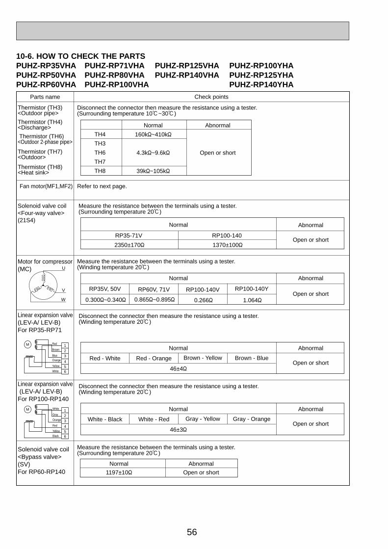
56
123
456
M
123
456
M
Parts name Check points
Disconnect the connector then measure the resistance using a tester. (Surrounding temperature 10:~30:)
Disconnect the connector then measure the resistance using a tester. (Winding temperature 20:)
Thermistor (TH3)<Outdoor pipe>
Thermistor (TH4)<Discharge>
Thermistor (TH6)<Outdoor 2-phase pipe>
Thermistor (TH7)<Outdoor>
Thermistor (TH8)<Heat sink>
Normal
160k"~410k"
4.3k"~9.6k"
39k"~105k"
TH4
TH3
TH6
TH7
TH8
Abnormal
Open or short
Normal
Red - White Red - Orange Brown - Yellow Brown - Blue
Abnormal
46±4"
Measure the resistance between the terminals using a tester. (Surrounding temperature 20:)
Solenoid valve coil<Four-way valve> (21S4)
Motor for compressor(MC)
Linear expansion valve (LEV-A/ LEV-B)For RP35-RP71
Linear expansion valve (LEV-A/ LEV-B)For RP100-RP140
Normal Abnormal
Open or shortRP35-71V RP100-140
Open or short
Disconnect the connector then measure the resistance using a tester. (Winding temperature 20:)
Normal
White - Black White - Red Gray - Yellow Gray - Orange
Abnormal
46±3"Open or short
Measure the resistance between the terminals using a tester.(Surrounding temperature 20:)
Normal
1197±10"
Abnormal
Open or short
Solenoid valve coil<Bypass valve> (SV)For RP60-RP140
Refer to next page.Fan motor(MF1,MF2)
2350±170" 1370±100"
RP35V, 50V RP100-140V RP100-140Y
0.300"~0.340"
RP60V, 71V
0.865"~0.895" 0.266" 1.064"
Measure the resistance between the terminals using a tester. (Winding temperature 20:)
Normal Abnormal
Open or shortW
V
U
Red
Brown
BlueOrange
Yellow
White
White
Gray
Orange
Red
Yellow
Black
10-6. HOW TO CHECK THE PARTSPUHZ-RP35VHA PUHZ-RP71VHA PUHZ-RP125VHA PUHZ-RP100YHAPUHZ-RP50VHA PUHZ-RP80VHA PUHZ-RP140VHA PUHZ-RP125YHAPUHZ-RP60VHA PUHZ-RP100VHA PUHZ-RP140YHA
OC334-2.qxp 05.5.26 6:06 PM Page 56
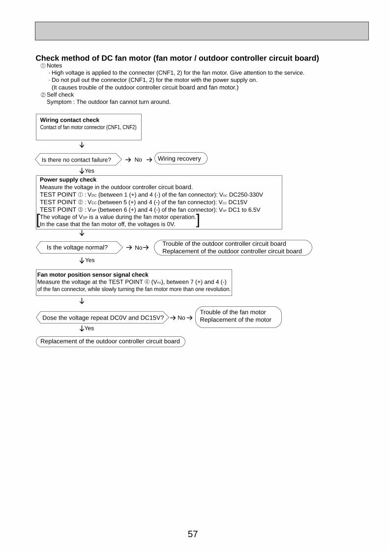
57
Notes · High voltage is applied to the connecter (CNF1, 2) for the fan motor. Give attention to the service. · Do not pull out the connector (CNF1, 2) for the motor with the power supply on. (It causes trouble of the outdoor controller circuit board and fan motor.)Self checkSymptom : The outdoor fan cannot turn around.
No
Wiring contact checkContact of fan motor connector (CNF1, CNF2)
Power supply checkMeasure the voltage in the outdoor controller circuit board.TEST POINT 1 : VDC (between 1 (+) and 4 (-) of the fan connector): VDC DC250-330VTEST POINT 2 : VCC (between 5 (+) and 4 (-) of the fan connector): VCC DC15VTEST POINT 3 : VSP (between 6 (+) and 4 (-) of the fan connector): VSP DC1 to 6.5VThe voltage of VSP is a value during the fan motor operation.In the case that the fan motor off, the voltages is 0V.
Fan motor position sensor signal checkMeasure the voltage at the TEST POINT 4 (VFG), between 7 (+) and 4 (-) of the fan connector, while slowly turning the fan motor more than one revolution.
Wiring recovery
Trouble of the outdoor controller circuit boardReplacement of the outdoor controller circuit board
Trouble of the fan motor Replacement of the motorDose the voltage repeat DC0V and DC15V?
Replacement of the outdoor controller circuit board
Is the voltage normal?
Is there no contact failure?
Yes
1
2
No
Yes
No
Yes
Check method of DC fan motor (fan motor / outdoor controller circuit board)
[ ]
OC334-2.qxp 05.5.26 6:06 PM Page 57
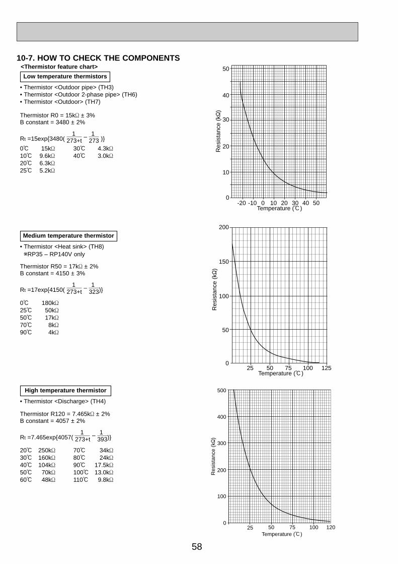
58
10-7. HOW TO CHECK THE COMPONENTS<Thermistor feature chart>
Low temperature thermistors
• Thermistor <Outdoor pipe> (TH3)• Thermistor <Outdoor 2-phase pipe> (TH6)• Thermistor <Outdoor> (TH7)
Thermistor R0 = 15k' ± 3%B constant = 3480 ± 2%
Rt =15exp{3480( 273+t –
273 )}
0: 15k'10: 9.6k'20: 6.3k'25: 5.2k'
0: 180k'25: 50k'50: 17k'70: 8k'90: 4k'
30: 4.3k'40: 3.0k'
1 1
Thermistor R50 = 17k' ± 2%B constant = 4150 ± 3%
Rt =17exp{4150( 273+t –
323)}1 1
Thermistor R120 = 7.465k' ± 2%B constant = 4057 ± 2%
Rt =7.465exp{4057( 273+t –
393)}1 1
Medium temperature thermistor
• Thermistor <Heat sink> (TH8)wRP35 – RP140V only
20: 250k'30: 160k'40: 104k'50: 70k'60: 48k'
70: 34k'80: 24k'90: 17.5k'100: 13.0k'110: 9.8k'
High temperature thermistor
• Thermistor <Discharge> (TH4)
0
10
20
30
40
50
-20 -10 0 10 20 30 40 50Temperature (:)
Res
ista
nce
(k"
)
200
150
100
50
025 50 75 100 125
Temperature (:)
Res
ista
nce
(k"
)
500
400
300
200
100
025 50 75 100 120
Temperature (:)
Res
ista
nce
(k"
)
OC334-2.qxp 05.5.26 6:06 PM Page 58
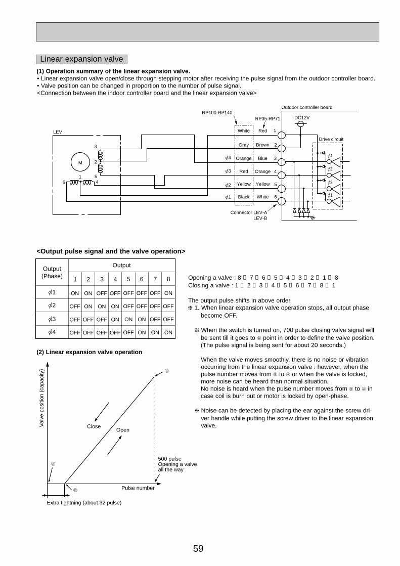
59
<Output pulse signal and the valve operation>
(2) Linear expansion valve operation
A
B
C
Open
Extra tightning (about 32 pulse)
Pulse number
500 pulseOpening a valveall the way
CloseVal
ve p
ositi
on (
capa
city
)
Opening a valve : 8 → 7 → 6 → 5 → 4 → 3 → 2 → 1 → 8Closing a valve : 1 → 2 → 3 → 4 → 5 → 6 → 7 → 8 → 1
The output pulse shifts in above order.❈ 1. When linear expansion valve operation stops, all output phase
become OFF.
❈ When the switch is turned on, 700 pulse closing valve signal willbe sent till it goes to A point in order to define the valve position.(The pulse signal is being sent for about 20 seconds.)
When the valve moves smoothly, there is no noise or vibrationoccurring from the linear expansion valve : however, when thepulse number moves from B to A or when the valve is locked,more noise can be heard than normal situation.No noise is heard when the pulse number moves from B to A in case coil is burn out or motor is locked by open-phase.
❈ Noise can be detected by placing the ear against the screw dri-ver handle while putting the screw driver to the linear expansionvalve.
LEV
M
16
[4 [4
[3
[2
[1
2
1Red
RP100-RP140RP35-RP71
Brown
Blue
Orange
Yellow
White
White
Gray
Orange
Red
Yellow
Black
3
4
5
6
Connector LEV-ALEV-B
DC12V
Outdoor controller board
Drive circuit
[3
[2
[1
3
2
54
Linear expansion valve(1) Operation summary of the linear expansion valve.• Linear expansion valve open/close through stepping motor after receiving the pulse signal from the outdoor controller board.• Valve position can be changed in proportion to the number of pulse signal.<Connection between the indoor controller board and the linear expansion valve>
1
ON
OFF
OFF
OFF
ON
ON
OFF
OFF
OFF
ON
OFF
OFF
OFF
ON
ON
OFF
[1
Output(Phase)
Output
[2
[3
[4
2 3 4 5 6 7 8
OFF
OFF
ON
OFF
OFF
OFF
ON
ON
OFF
OFF
OFF
ON
ON
OFF
OFF
ON
OC334-2.qxp 05.5.26 6:06 PM Page 59
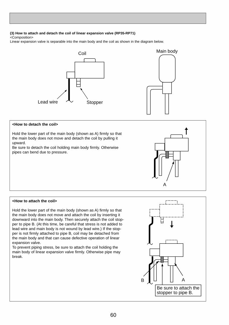
60
Main body
Lead wire Stopper
Coil
A
Be sure to attach thestopper to pipe B.
B A
(3) How to attach and detach the coil of linear expansion valve (RP35-RP71)<Composition>Linear expansion valve is separable into the main body and the coil as shown in the diagram below.
<How to detach the coil>
Hold the lower part of the main body (shown as A) firmly so thatthe main body does not move and detach the coil by pulling itupward.Be sure to detach the coil holding main body firmly. Otherwisepipes can bend due to pressure.
<How to attach the coil>
Hold the lower part of the main body (shown as A) firmly so thatthe main body does not move and attach the coil by inserting itdownward into the main body. Then securely attach the coil stop-per to pipe B. (At this time, be careful that stress is not added tolead wire and main body is not wound by lead wire.) If the stop-per is not firmly attached to pipe B, coil may be detached fromthe main body and that can cause defective operation of linearexpansion valve.To prevent piping stress, be sure to attach the coil holding themain body of linear expansion valve firmly. Otherwise pipe maybreak.
OC334-2.qxp 05.5.26 6:06 PM Page 60

61
Main body
Lead wire
StopperCoil
A
Be sure to attach the stopper.
A
(4) How to attach and detach the coil of linear expansion valve (RP100-RP140)<Composition>Linear expansion valve is separable into the main body and the coil as shown in the diagram below.
<How to detach the coil>
Hold the lower part of the main body (shown as A) firmly so thatthe main body does not move and detach the coil by pulling itupward.Be sure to detach the coil holding main body firmly. Otherwisepipes can bend due to pressure.
<How to attach the coil>
Hold the lower part of the main body (shown as A) firmly so thatthe main body does not move and attach the coil by inserting itdownward into the main body. Then securely attach the coil stop-per to main body. (At this time, be careful that stress is not addedto lead wire and main body is not wound by lead wire.) If thestopper is not firmly attached to main body, coil may be detachedfrom the main body and that can cause defective operation of lin-ear expansion valve.To prevent piping stress, be sure to attach the coil holding themain body of linear expansion valve firmly. Otherwise pipe maybreak.
OC334-3.qxp 05.5.26 6:03 PM Page 61
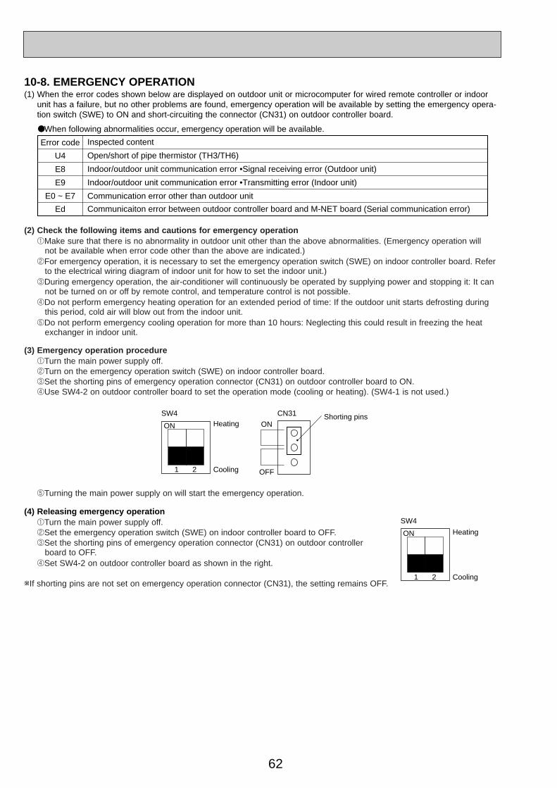
62
10-8. EMERGENCY OPERATION (1) When the error codes shown below are displayed on outdoor unit or microcomputer for wired remote controller or indoor
unit has a failure, but no other problems are found, emergency operation will be available by setting the emergency opera-tion switch (SWE) to ON and short-circuiting the connector (CN31) on outdoor controller board.
(4) Releasing emergency operation 1Turn the main power supply off.2Set the emergency operation switch (SWE) on indoor controller board to OFF.3Set the shorting pins of emergency operation connector (CN31) on outdoor controller
board to OFF.4Set SW4-2 on outdoor controller board as shown in the right.
wIf shorting pins are not set on emergency operation connector (CN31), the setting remains OFF.
(2) Check the following items and cautions for emergency operation 1Make sure that there is no abnormality in outdoor unit other than the above abnormalities. (Emergency operation will
not be available when error code other than the above are indicated.)2For emergency operation, it is necessary to set the emergency operation switch (SWE) on indoor controller board. Refer
to the electrical wiring diagram of indoor unit for how to set the indoor unit.)3During emergency operation, the air-conditioner will continuously be operated by supplying power and stopping it: It can
not be turned on or off by remote control, and temperature control is not possible.4Do not perform emergency heating operation for an extended period of time: If the outdoor unit starts defrosting during
this period, cold air will blow out from the indoor unit.5Do not perform emergency cooling operation for more than 10 hours: Neglecting this could result in freezing the heat
exchanger in indoor unit.
(3) Emergency operation procedure 1Turn the main power supply off.2Turn on the emergency operation switch (SWE) on indoor controller board.3Set the shorting pins of emergency operation connector (CN31) on outdoor controller board to ON.4Use SW4-2 on outdoor controller board to set the operation mode (cooling or heating). (SW4-1 is not used.)
5Turning the main power supply on will start the emergency operation.
SW4
1 2 Cooling
HeatingON ON
OFF
CN31 Shorting pins
SW4
1 2 Cooling
HeatingON
Inspected content
Open/short of pipe thermistor (TH3/TH6)
Indoor/outdoor unit communication error •Signal receiving error (Outdoor unit)
Indoor/outdoor unit communication error •Transmitting error (Indoor unit)
Communication error other than outdoor unit
Communicaiton error between outdoor controller board and M-NET board (Serial communication error)
Error code
U4
E8
E9
E0 ~ E7
Ed
●When following abnormalities occur, emergency operation will be available.
OC334-3.qxp 05.5.26 6:03 PM Page 62

63
(5) Operation data during emergency operationDuring emergency operation, no communication is performed with the indoor unit, so the data items needed for operationare set to the following values:
Operation data
Intake temperature (TH1)
Indoor fluid pipe temperature (TH2)
Indoor 2-phase pipe temperature (TH5)
Set temperature
Outdoor fluid pipe temperature (TH3)
Outdoor discharge pipe temperature (TH4)
Outdoor 2-phase pipe temperature (TH6)
Outdoor air temperature (TH7)
Temperature difference code (intake temperature - set temperature) (∆Tj)
Discharge super heat (SHd)
Sub-cool (SC)
Operation mode
COOL
27:
5:
5:
25:
45:
80:
50:
35:
5
30deg
5deg
HEAT
20.5:
45:
50:
22:
5:
80:
5:
7:
5
30deg
5deg
(w1)
(w1)
(w1)
(w1)
(w2)
(w2)
Remarks
w1: If the thermistor temperature data is normal (not open/short), that data is loaded into the control as valid data.
If the unit enters emergency operation because TH values have become mismatched, setting the thermistors
to open/short corrects the settings.
w2: If one thermistor is set to open/short, the values for each will be different.
[Example] When liquid temperature thermistor (TH3) has an open or short circuit.
COOL
45:
Ta
Tc
5:
5:
HEAT
5:
Tb
Td
50:
45:
Thermistor
TH3
TH6
TH4
TH5
TH2
Regard normal firure as effective data.
Regard normal firure as effective data.
Discharge superheat (SHd) Cooling = TH4 - TH6 = Tc - Ta Heating = TH4 - TH5 = Td - 50
Degree of subcooling (SC) Cooling = TH6- TH3 = Ta -45 Heating = TH5- TH2 = 50 - 45 = 5 deg.
OC334-3.qxp 05.5.26 6:03 PM Page 63

64
10-9. TEST POINT DIAGRAMOutdoor controller circuit boardPUHZ-RP35/ 50/ 60/ 71/ 100/ 125/ 140VHAPUHZ-RP100/ 125/ 140YHA
Communicationpower supply ZD71 Voltage developed across:16-30V DC
–
+
CNS(Indoor/outdoor unit connecting wire)
CNAC2 to 4: Power supply foroutdoor controller circuit board(220V-240V AC)1 to 3: Power supply forindoor and outdoor unitconnection wire (220V-240V AC)
CN2Connect to the outdoorpower circuit board (CN2)1-5:Power circuit board ➔Transmitting signal to the controller circuit board(0-5V DC)2-5: Zero cross signal
(0-5V DC)3-4: Not used
(RP35-71VHA)(RP100-140YHA)18V DC(RP100-140VHA)
6-5: 16V DC7-5: 16V DC[5: – 1,2,6,7: + ]
21S4Four-way valve
63HHigh pressure switch
63LLow pressure switchOnly for RP100-140
SV2RP60-71 : Bypass valveRP100-140 : Replace
valve
CN4Transmission to outdoorpower circuitboard (CN4)
SW10Model select
SW4Test operation
SW6Model select
SW5Function switch
SW1Forced defrost, detect history record reset,refrigerant address
CNDM1 to 2: Input of silent mode1 to 3: Input of external
contact point
TH4Thermistor<Discharge>
TH3Thermistor<Outdoor pipe>
TH7Thermistor<Outdoor>
TH6Thermistor <Outdoor 2-phase pipe>
CNDCDC280V-380VConnect from out-door power circuitboard for RP·VHA,connect from noisefilter board forRP·YHA(CNDC)
–
+ }
VCC (TEST POINT 2)(voltage between pins of C6B): DC 15V
VDC (TEST POINT 1)(voltage between pins of C5E): DC250V-380V
VFG (TEST POINT 4)(voltage between rightpins of PC5C andPC5D, pin 3 and pin 4)
VSP (TEST POINT 3)(voltage between pins ofC5A, C5B): DC 0V (whenstopped), DC 1– 6.5V (when operated)
<CAUTION> TEST POINT1 is high voltage.
SW7Demand control settingSW9CN51
External signal output• Compressor operating signal• Abnormal signal
LEV-A,-BLinear expansion valve
SWPpump downCN52C
(Connect to the outdoornoise filter circuit board(CN52C))Only for RP35-RP71VHA
OC334-3.qxp 05.5.26 6:03 PM Page 64
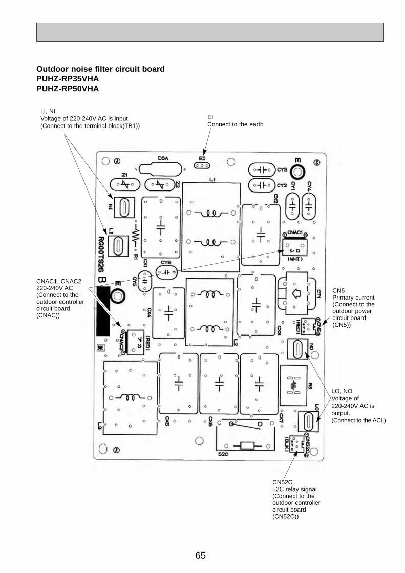
65
Outdoor noise filter circuit boardPUHZ-RP35VHAPUHZ-RP50VHA
LO, NOVoltage of 220-240V AC is output. (Connect to the ACL)
CN52C52C relay signal(Connect to the outdoor controller circuit board(CN52C))
CN5Primary current(Connect to theoutdoor power circuit board(CN5))
CNAC1, CNAC2220-240V AC(Connect to theoutdoor controllercircuit board(CNAC))
EIConnect to the earth
LI, NIVoltage of 220-240V AC is input. (Connect to the terminal block(TB1))
OC334-3.qxp 05.5.26 6:03 PM Page 65

66
Outdoor noise filter circuit boardPUHZ-RP60VHAPUHZ-RP71VHA
LO, NOVoltage of 220-240V AC is output.(Connect ACL)
CN52C52C relay signal(Connect to the outdoor controller circuit board(CN52C))
CN5Primary current(Connect to theoutdoor power circuit board(CN5))
CNAC1, CNAC2220-240V AC(Connect to theoutdoor controllercircuit board(CNAC))
EIConnect to the earth
LI, NIVoltage of 220-240V AC is input. (Connect to the terminal block(TB1))
OC334-3.qxp 05.5.26 6:03 PM Page 66

67
CNAC1, CNAC2220-240V AC(Connect to theoutdoor controllercircuit board(CNAC))
EIConnect to the earth
LI, NIVoltage of 220-240V AC is input(Connect to the terminal block(TB1))
CN5Primary current(Connect to theoutdoor powercircuit board(CN5))
LO, NOVoltage of 220-240V AC is output(Connect to the outdoor power circuit board (TABS, TABT))
Outdoor noise filter circuit boardPUHZ-RP100VHAPUHZ-RP125VHAPUHZ-RP140VHA
OC334-3.qxp 05.5.26 6:03 PM Page 67

68
Outdoor noise filter circuit boardPUHZ-RP100YHAPUHZ-RP125YHAPUHZ-RP140YHA LI1, LI2, LI3, NI
POWER SUPPLYLI1-LI2/LI-LI3/LI3-LI1 : AC380/400/415V inputLI1-NI/LI2-NI/LI3-NI : AC220/230/240V input(Connect to the terminal block (TB1))
GD1Connect to the earth
CNAC1, CNAC2AC220/230/240V(Connect to theoutdoor controllercircuit board (CNAC))
CNDC(Connect to the outdoor controller circuit board (CNDC))
LO1, LO2, LO3POWER SUPPLYLO1-LO2/LO2-LO3/LO3-LO1 : AC380/400/415V OUTPUT(Connect to the outdoor converter circuit board and ACL(L1-IN, ACL2, ACL3))
CNCTPrimary current(Connect to the outdoor powercircuit board (CN5))
NOConnect to theoutdoor convertercircuit board.(N-IN)
CNLConnect to the ACL4
OC334-3.qxp 05.5.26 6:03 PM Page 68
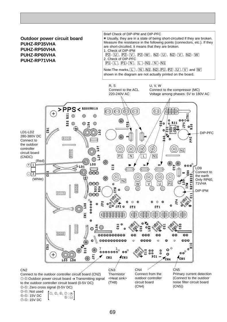
CN2Connect to the outdoor controller circuit board (CN2)1-5:Outdoor power circuit board ➔ Transmitting signalto the outdoor controller circuit board (0-5V DC)2-5: Zero cross signal (0-5V DC)3-4: Not used6-5: 15V DC7-5: 15V DC
69
17
Outdoor power circuit boardPUHZ-RP35VHAPUHZ-RP50VHAPUHZ-RP60VHAPUHZ-RP71VHA
1
3
(Red)
(White)
1, 2, 6, 7 : +5 : – ][
–
+
P1 N L N1
N1
W V U P2N2
Brief Check of DIP-IPM and DIP-PFCW Usually, they are in a state of being short-circuited if they are broken.Measure the resistance in the following points (connectors, etc.). If theyare short-circuited, it means that they are broken.1. Check of DIP-IPM
P2 - U , P2 - V , P2 - W , N2 - U , N2 - V , N2 - W2. Check of DIP-PFC
P1 - L , P1 - N , L - N1 , N - N1
Note:The marks, L , N , N1 , N2 , P1 , P2 , U , V and Wshown in the diagram are not actually printed on the board.
LD1-LD2280-380V DCConnect to the outdoorcontroller circuit board(CNDC)
R, SConnect to the ACL220-240V AC
U, V, WConnect to the compressor (MC)Voltage among phases: 5V to 180V AC
LD9Connect tothe earth Only RP60,71VHA
CN5Primary current detection(Connect to the outdoornoise filter circuit board(CN5))
CN4Connect from the outdoor controller circuit board(CN4)
CN3Thermistor<Heat sink> (TH8)
DIP-IPM
DIP-PFC
OC334-3.qxp 05.5.26 6:03 PM Page 69
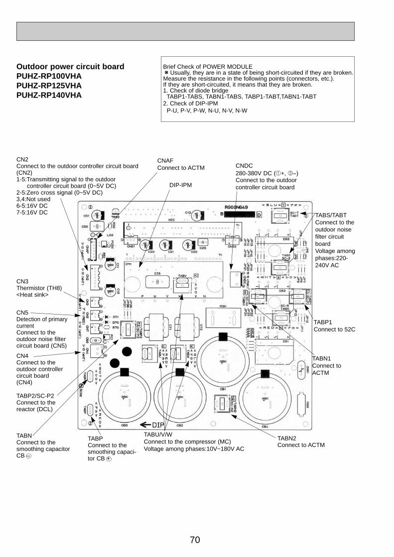
70
Outdoor power circuit boardPUHZ-RP100VHAPUHZ-RP125VHAPUHZ-RP140VHA
TABP1Connect to 52C
TABP2/SC-P2Connect to thereactor (DCL)
CN4Connect to theoutdoor controllercircuit board(CN4)
CN2Connect to the outdoor controller circuit board(CN2)1-5:Transmitting signal to the outdoor
controller circuit board (0~5V DC)2-5:Zero cross signal (0~5V DC)3,4:Not used6-5:16V DC7-5:16V DC
CN3 Thermistor (TH8)<Heat sink>
CN5 Detection of primarycurrentConnect to the outdoor noise filter circuit board (CN5)
CNDC 280-380V DC (1+, 3–)Connect to the outdoorcontroller circuit board
TABS/TABTConnect to theoutdoor noisefilter circuitboard Voltage among phases:220-240V AC
Brief Check of POWER MODULEW Usually, they are in a state of being short-circuited if they are broken.Measure the resistance in the following points (connectors, etc.). If they are short-circuited, it means that they are broken.1. Check of diode bridge
TABP1-TABS, TABN1-TABS, TABP1-TABT,TABN1-TABT2. Check of DIP-IPM
P-U, P-V, P-W, N-U, N-V, N-W
TABN2Connect to ACTM
TABNConnect to thesmoothing capacitor CB –
TABU/V/WConnect to the compressor (MC) Voltage among phases:10V~180V AC
TABPConnect to thesmoothing capaci-tor CB +
TABN1Connect toACTM
DIP-IPM
CNAFConnect to ACTM
OC334-3.qxp 05.5.26 6:04 PM Page 70

71
Brief Check of POWER MODULEW Usually, they are in a state of being short-circuited if they are broken.Measure the resistance in the following points (connectors, etc.). If they are short-circuited, it means that they are broken.1. Check of POWER MODULE1.Check of DIODE circuitL1 - P1 , L2 - P1 , L3 - P1 , L1 - N1 , L2 - N1 , L3 - N12.Check of IGBT circuitP2 - U , P2 - V , P2 - W , N2 - U , N2 - V , N2 - W
Outdoor power circuit boardPUHZ-RP100YHAPUHZ-RP125YHAPUHZ-RP140YHA
CN5Detection of primary current(Connect to the outdoor noise filter circuit board (CNCT))
CN4Connect to the outdoor controller circuit board(CN4)
CN2Connect to the outdoor controller circuit board (CN2)1-5: Power circuit board ➔ Transmitting
signal to the controller board (0-5V DC)2-5: Zero cross signal (0-5V DC)3-4: Not used6-5: 16V DC7-5: 16V DC
[ 5 : – 1, 2, 6, 7 : + ]
Note:The marks, L1 , L2 , L3 , N1 , N2 , P1 , P2 , U , V and W shown in the diagram are not actually printed on the board.
W
N2N1P2
P1 L1
L2
L3
W
W
TAB connecteron X52AConnect to theRS resistor
POWER MODULE
TB-C1Connect to thesmoothing capacitorCB1 – , CB2 +
TB-P2Connect to the smoothingcapacitor CB1 +
TB-U, TB-V, TB-WConnect to the compressor (MC)Voltage among phases: 10V-400V AC
TB-L1, TB-L2, TB-L3Connect to the outdoor convertercircuit board(L1-OU, L2-OU,L3-OU)
380V-415V AC
TB-N1Connect to thesmoothing capacitorCB2 – and the CKcapacitor
CN7Connect to the outdoor convertercircuit board(CN7)
OC334-3.qxp 05.5.26 6:04 PM Page 71
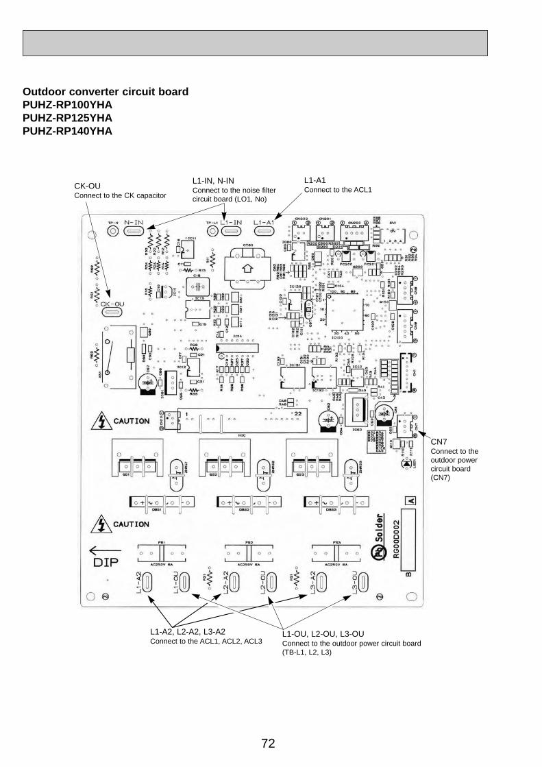
72
Outdoor converter circuit boardPUHZ-RP100YHAPUHZ-RP125YHAPUHZ-RP140YHA
L1-A2, L2-A2, L3-A2Connect to the ACL1, ACL2, ACL3
CN7Connect to theoutdoor powercircuit board(CN7)
CK-OUConnect to the CK capacitor
L1-IN, N-INConnect to the noise filter circuit board (LO1, No)
L1-A1Connect to the ACL1
L1-OU, L2-OU, L3-OUConnect to the outdoor power circuit board(TB-L1, L2, L3)
OC334-3.qxp 05.5.26 6:04 PM Page 72
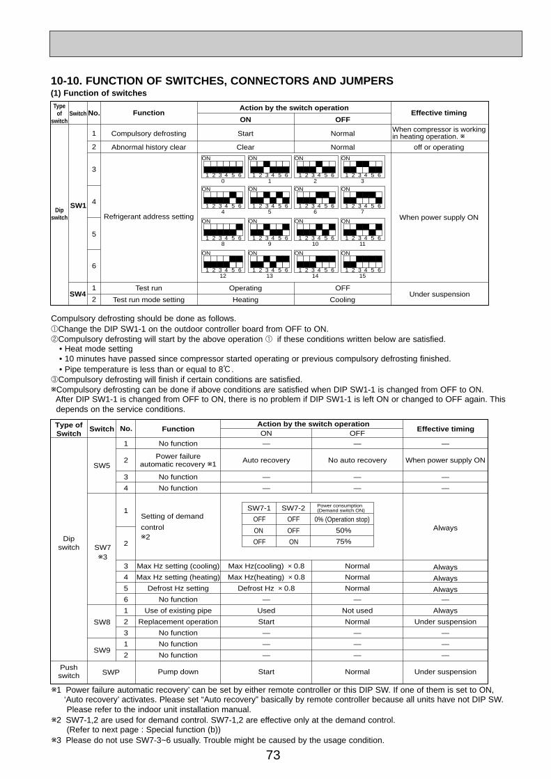
73
SwitchType
ofswitch
Dipswitch
SW1
1
2
No. Function Effective timingAction by the switch operation
Compulsory defrosting Start NormalWhen compressor is working in heating operation. w
Abnormal history clear
Refrigerant address setting When power supply ON
Clear Normal off or operating
SW41
6
5
4
3
2
Test run Operating OFFUnder suspension
Test run mode setting Heating Cooling
ON OFF
1 2 30 1 2 3
4 5 6
ON
1 2 3 4 5 6
ON
1 2 3 4 5 6
ON
1 2 3 4 5 6
ON
1 2 34 5 6 7
4 5 6
ON
1 2 3 4 5 6
ON
1 2 3 4 5 6
ON
1 2 3 4 5 6
ON
1 2 38 9 10 11
4 5 6
ON
1 2 3 4 5 6
ON
1 2 3 4 5 6
ON
1 2 3 4 5 6
ON
1 2 312 13 14 15
4 5 6
ON
1 2 3 4 5 6
ON
1 2 3 4 5 6
ON
1 2 3 4 5 6
ON
Compulsory defrosting should be done as follows.1Change the DIP SW1-1 on the outdoor controller board from OFF to ON.2Compulsory defrosting will start by the above operation 1 if these conditions written below are satisfied.
• Heat mode setting• 10 minutes have passed since compressor started operating or previous compulsory defrosting finished.• Pipe temperature is less than or equal to 8:.
3Compulsory defrosting will finish if certain conditions are satisfied.wCompulsory defrosting can be done if above conditions are satisfied when DIP SW1-1 is changed from OFF to ON.
After DIP SW1-1 is changed from OFF to ON, there is no problem if DIP SW1-1 is left ON or changed to OFF again. This depends on the service conditions.
10-10. FUNCTION OF SWITCHES, CONNECTORS AND JUMPERS (1) Function of switches
w1 Power failure automatic recovery’ can be set by either remote controller or this DIP SW. If one of them is set to ON, ‘Auto recovery’ activates. Please set “Auto recovery” basically by remote controller because all units have not DIP SW.Please refer to the indoor unit installation manual.
w2 SW7-1,2 are used for demand control. SW7-1,2 are effective only at the demand control.(Refer to next page : Special function (b))
w3 Please do not use SW7-3~6 usually. Trouble might be caused by the usage condition.
1
2
3
4
3
4
5
6
1
2
3
1
2
ON OFFNo. Function Effective timing
Action by the switch operation
No function
Power failureautomatic recovery w1
No function
No function
Max Hz setting (cooling)
Max Hz setting (heating)
Defrost Hz setting
No function
Use of existing pipe
Replacement operation
No function
No function
No function
Pump down
Switch
SW5
SW7w3
Dipswitch
SW8
SW9
Pushswitch SWP
Type ofSwitch
—
Auto recovery
—
—
Max Hz(cooling) o 0.8
Max Hz(heating) o 0.8
Defrost Hz o 0.8
—
Used
Start
—
—
—
Start
—
No auto recovery
—
—
Normal
Normal
Normal
—
Not used
Normal
—
—
—
Normal
—
When power supply ON
—
—
Always
Always
Always
Always—
Always
Under suspension
—
—
—
Under suspension
Setting of demand
controlw2
1
2
SW7-1 SW7-2
OFF 0% (Operation stop)
75%
50%
OFF
ON
OFF
OFF
ON
Power consumption (Demand switch ON)
OC334-3.qxp 05.5.26 6:04 PM Page 73

74
(2) Function of connectors and switches
CN31
TypesConnector
SwitchFunction Effective timing
Connector
SW6
SW10
SW6-1SW6-2SW6-3SW6-4SW6-5SW6-6
SW10-1SW10-2
Start
Short Open
Action by open/ short operation
Model select
Emergency operation When power supply ONNormal
1 2 3 4 5 6OFFON
35V
MODEL SW6 SW10
1 2OFFON
1 2 3 4 5 6OFFON
50V1 2
OFFON
1 2 3 4 5 6OFFON
60V1 2
OFFON
1 2 3 4 5 6OFFON
71V1 2
OFFON
MODEL SW6 SW10
1 2 3 4 5 6OFFON
100V1 2
OFFON
1 2 3 4 5 6OFFON
125V1 2
OFFON
1 2 3 4 5 6OFFON
140V1 2
OFFON
MODELS
100Y
SW6 SW10
125Y
140Y
ONOFF 1 2 3 4 5 6
ONOFF 1 2
ONOFF 1 2
ONOFF 1 2
ONOFF 1 2 3 4 5 6
ONOFF 1 2 3 4 5 6
Special function(a) Low-level sound priority mode (Local wiring)
Unit enters into Low-level sound priority mode by external signal input setting.Inputting external signals to the outdoor unit decreases the outdoor unit operation sound 3 to 4 dB lower than that of usual. Adding a commercial timer or on-off switch contactor setting to the CNDM connector which is optional contactor for Demandinput located on the outdoor controller board enables to control compressor operation frequency.W The performance is depends on the load of conditioned outdoor temperature.
How to wiring
1) Make the circuit as shown above with Adaptor for external signal input(PAC-SC36NA).2) Turn SW1 to on for Low-level sound priority mode.
Turn SW1 to off to release Low-level sound priority mode and normal operation.
(b) On demand control (Local wiring)Demand control is available by external input. In this mode, power consumption is decreased within the range of usual0~100%.
How to wiringBasically, the wiring is the same (a).Connect an SW 1 which is procured at field to the between Orange and Red(1 and 3) of the Adaptor for external signal input(PAC-SC36NA), and insulate the tip of the brown lead wire.
It is possible to set it to the following power consumption (compared with ratings) by setting the SW7-1, 2.
CNDMXSW1~
X
Max. 10 m including local wiringSW1 : Switch X : Relay (Contact spec. : DC1mA)
Relay supply
RedBrown
Orange
3
2
1
Purchased at local
Adaptor for external signal input(PAC-SC36NA)
Outdoor unit controller board
3
2
1
Insulate this point securely as this is not used.
<Low-level sound priority mode circuit>
SW7-1 SW7-2
OFF 0% (Operation stop)
75%
50%
OFF
ON
OFF
OFF
ON
Power consumption (SW1 on)
OC334-3.qxp 05.5.26 6:04 PM Page 74

75
<Display function of inspection for outdoor unit>The blinking patterns of both LED1(green) and LED2(red) indicate the types of abnormality when it occurs. Types of abnormality can be indicated in details by connecting an optional part ‘A-Control Service Tool (PAC-SK52ST)’ to connectorCNM on outdoor controller board.
F3F5F9—
—
—
E6
E7
—
—
E0
E3
E4
E5
EF
Ed
A0~A8
[Display] (1)Normal condition
(2)Abnormal condition
Unit conditionOutdoor controller board A-Control Service Tool
LED1 (Green) LED2 (Red) Error code
When the power is turned onWhen unit stopsWhen compressor is warming upWhen unit operates
Lighted LightedLightedLightedLighted
Not lighted
Indication of the display
Alternately blinking displayOperation mode
Not lightedLighted
00, etc.08, etc.
C5, H7 etc.
Indication ErrorErrorcodew1
Outdoor controller boardContents Inspection method
LED1 (Green) LED2 (Red)
1 blinking 2 blinking
2 blinking 1 blinking
2 blinking
3 blinking
4 blinking
5 blinking
Connector(63L) is open.Connector(63H) is open.2 connectors are open.
Startup time over
Error code is not defined.
Mis-wiring of indoor/outdoor unit conne-cting wire, excessive number of indoor units (4 units or more)Mis-wiring of indoor/outdoor unit co-nnecting wire (converse wiring or di-sconnection)
Indoor/outdoor unit communication error(signal receiving error) is detected by in-door unit.Indoor/outdoor unit communication error(transmitting error) is detected by indoorunit.Indoor/outdoor unit communication error(signal receiving error) is detected by outdoor unit.Indoor/outdoor unit communication error (transmitting error) is detected by outdoorunit.
Remote controller signal receiving error is detected by remote controller.
Remote controller transmitting error is detected by remote controller.
Remote controller signal receiving error is detected by indoor unit.
Remote controller transmitting error is detected by indoor unit.
Serial communication error<Communication between outdoor controller board and outdoor power board><Communication between outdoor controller board and M-NET p.c. board>Communication error of high prior signal(M-NET)
W1.Error code displayed on remote controller.W2.Refer to service manual for indoor unit.
1Check if indoor/outdoor connecting wire is connected correctly.2Check if 4 or more indoor units are connected to outdoor unit.3Check if noise entered into indoor/outdoor connecting wire or power supply.4Re-check error by turning off power, and on again.
1Check if connector (63L or 63H) on the outdoor controller board is not disconnected. 2Check continuity of pressure switch (63L or 63H) by tester.
1Check if connector (CN4) on outdoor controller board and outdoor power board is not disconnected.2Check if there is poor connection of connector on outdoor controller board(CNMNT and CNVMNT).3Check M-NET communication signal.
1Check if remote controller is MA remote controller(PAR-21MAA).2Check if noise entered into transmission wire of remote controller.3Check if noise entered into indoor/outdoor connecting wire.4Re-check error by turning off power, and on again.
1Check if connecting wire of indoor unit or remote controller is connected correctly.2Check if noise entered into transmission wire of remote controller.3Re-check error by turning off power, and on again.
1Check if indoor/outdoor connecting wire is connected correctly.2Check if noise entered into indoor/outdoor connecting wire or power supply.3Check if noise entered into indoor/outdoor controller board.4Re-check error by turning off power, and on again.
P.36P.36P.37P.37(EA)P.37(Eb)P.37(EC)w2
w2
P.42(E8)P.42(E9)P.41
P.42
P.41
P.42
P.42
P.42
P.43~P.46
Detailedreference
page
OC334-3.qxp 05.5.26 6:04 PM Page 75
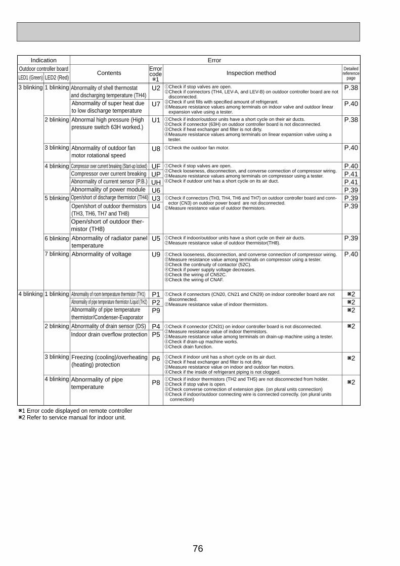
76
U2
U7
U1
U8
UFUPUHU6U3U4
U5
U9
P1P2P9
P4P5
P6
P8
Indication ErrorErrorcodew1
Outdoor controller boardContents Inspection method
LED1 (Green) LED2 (Red)
3 blinking 1 blinking
2 blinking
3 blinking
W1 Error code displayed on remote controllerW2 Refer to service manual for indoor unit.
4 blinking
5 blinking
6 blinking
7 blinking
1 blinking
2 blinking
3 blinking
4 blinking
4 blinking
Abnormality of shell thermostatand discharging temperature (TH4)Abnormality of super heat dueto low discharge temperature
1Check if stop valves are open.2Check if connectors (TH4, LEV-A, and LEV-B) on outdoor controller board are not disconnected.3Check if unit fills with specified amount of refrigerant.4Measure resistance values among terminals on indoor valve and outdoor linear expansion valve using a tester.
Abnormal high pressure (High pressure switch 63H worked.)
Abnormality of outdoor fan motor rotational speed
1Check if indoor/outdoor units have a short cycle on their air ducts.2Check if connector (63H) on outdoor controller board is not disconnected.3Check if heat exchanger and filter is not dirty.4Measure resistance values among terminals on linear expansion valve using a tester.
1Check if stop valves are open.2Check looseness, disconnection, and converse connection of compressor wiring.3Measure resistance values among terminals on compressor using a tester.4Check if outdoor unit has a short cycle on its air duct.
Compressor over current breaking (Start-up locked)Compressor over current breakingAbnormality of current sensor (P.B.)Abnormality of power moduleOpen/short of discharge thermistor (TH4)
Open/short of outdoor ther-mistor (TH8)
Open/short of outdoor thermistors(TH3, TH6, TH7 and TH8)
1Check if connectors (TH3, TH4, TH6 and TH7) on outdoor controller board and conn- ector (CN3) on outdoor power board are not disconnected.2Measure resistance value of outdoor thermistors.
Abnormality of radiator panel temperature
1Check if indoor/outdoor units have a short cycle on their air ducts.2Measure resistance value of outdoor thermistor(TH8).
1Check the outdoor fan motor.
Abnormality of voltage 1Check looseness, disconnection, and converse connection of compressor wiring.2Measure resistance value among terminals on compressor using a tester.3Check the continuity of contactor (52C).4Check if power supply voltage decreases.5Check the wiring of CN52C.6Check the wiring of CNAF.
Abnormality of room temperature thermistor (TH1)Abnormality of pipe temperature thermistor /Liquid (TH2)Abnormality of pipe temperature thermistor/Condenser-Evaporator
1Check if connectors (CN20, CN21 and CN29) on indoor controller board are not disconnected.2Measure resistance value of indoor thermistors.
Abnormality of drain sensor (DS)Indoor drain overflow protection
1Check if connector (CN31) on indoor controller board is not disconnected.2Measure resistance value of indoor thermistors.3Measure resistance value among terminals on drain-up machine using a tester.4Check if drain-up machine works.5Check drain function.
Freezing (cooling)/overheating (heating) protection
1Check if indoor unit has a short cycle on its air duct.2Check if heat exchanger and filter is not dirty.3Measure resistance value on indoor and outdoor fan motors.4Check if the inside of refrigerant piping is not clogged.
Abnormality of pipe temperature
1Check if indoor thermistors (TH2 and TH5) are not disconnected from holder.2Check if stop valve is open.3Check converse connection of extension pipe. (on plural units connection)4Check if indoor/outdoor connecting wire is connected correctly. (on plural units connection)
P.38
P.40
P.38
P.40
P.40P.41P.41P.39P.39P.39
P.39
P.40
W2W2W2
W2
W2
W2
Detailedreference
page
OC334-3.qxp 05.5.26 6:04 PM Page 76
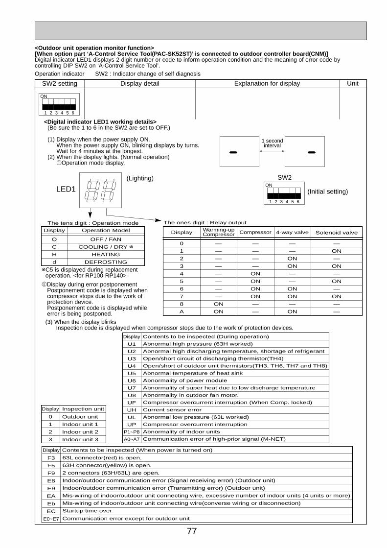
77
<Outdoor unit operation monitor function>[When option part ‘A-Control Service Tool(PAC-SK52ST)’ is connected to outdoor controller board(CNM)]Digital indicator LED1 displays 2 digit number or code to inform operation condition and the meaning of error code by controlling DIP SW2 on ‘A-Control Service Tool’.
SW2 setting
1
ON
2 3 4 5 6
Display detail Explanation for display Unit
Operation indicator SW2 : Indicator change of self diagnosis
<Digital indicator LED1 working details>(Be sure the 1 to 6 in the SW2 are set to OFF.)
(1) Display when the power supply ON.When the power supply ON, blinking displays by turns.Wait for 4 minutes at the longest.
(2) When the display lights. (Normal operation)1Operation mode display.
1
ON
2 3 4 5 6
(Initial setting)
SW2
1 secondinterval
LED1(Lighting)
Display Operation Model
The tens digit : Operation mode The ones digit : Relay output
O
C
H
d
Display
0
1
2
3
4
5
6
7
8
A
CompressorWarming-upCompressor 4-way valve Solenoid valve
—
—
—
—
ON
ON
ON
ON
—
—
—
—
—
—
—
—
—
—
ON
ON
—
—
ON
ON
—
—
ON
ON
—
ON
—
ON
—
ON
—
ON
—
ON
—
—
OFF / FAN
COOLING / DRY w
HEATING
DEFROSTING
2Display during error postponementPostponement code is displayed when compressor stops due to the work of protection device.Postponement code is displayed while error is being postponed.
wC5 is displayed during replacement operation. <for RP100-RP140>
(3) When the display blinksInspection code is displayed when compressor stops due to the work of protection devices.
Display Contents to be inspected (When power is turned on)
F3
F5
F9
E8
E9
EA
Eb
EC
E0~E7
63L connector(red) is open.
63H connector(yellow) is open.
2 connectors (63H/63L) are open.
Indoor/outdoor communication error (Signal receiving error) (Outdoor unit)
Indoor/outdoor communication error (Transmitting error) (Outdoor unit)
Mis-wiring of indoor/outdoor unit connecting wire, excessive number of indoor units (4 units or more)
Mis-wiring of indoor/outdoor unit connecting wire(converse wiring or disconnection)
Startup time over
Communication error except for outdoor unit
Display Inspection unit
0
1
2
3
Outdoor unit
Indoor unit 1
Indoor unit 2
Indoor unit 3
Display Contents to be inspected (During operation)
U1
U2
U3
U4
U5
U6
U7
U8
UF
UH
UL
UP
P1~P8
A0~A7
Abnormal high pressure (63H worked)
Abnormal high discharging temperature, shortage of refrigerant
Open/short circuit of discharging thermistor(TH4)
Open/short of outdoor unit thermistors(TH3, TH6, TH7 and TH8)
Abnormal temperature of heat sink
Abnormality of power module
Abnormality of super heat due to low discharge temperature
Abnormality in outdoor fan motor.
Compressor overcurrent interruption (When Comp. locked)
Current sensor error
Abnormal low pressure (63L worked)
Compressor overcurrent interruption
Abnormality of indoor units
Communication error of high-prior signal (M-NET)
OC334-3.qxp 05.5.26 6:04 PM Page 77
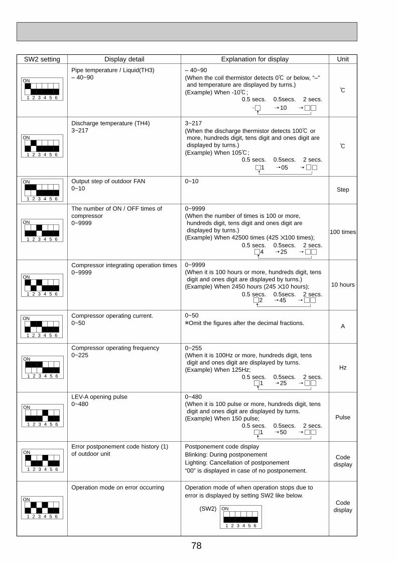
78
SW2 setting
1
ON
2 3 4 5 6
Display detail Explanation for display Unit
Pipe temperature / Liquid(TH3)– 40~90
– 40~90(When the coil thermistor detects 0: or below, “–” and temperature are displayed by turns.)
(Example) When -10:;0.5 secs. 0.5secs. 2 secs.
:
1
ON
2 3 4 5 6
1
ON
2 3 4 5 6
1
ON
2 3 4 5 6
1
ON
2 3 4 5 6
Discharge temperature (TH4)3~217
Output step of outdoor FAN0~10
The number of ON / OFF times ofcompressor0~9999
Compressor integrating operation times0~9999
3~217(When the discharge thermistor detects 100: or more, hundreds digit, tens digit and ones digit are displayed by turns.)
(Example) When 105:; 0.5 secs. 0.5secs. 2 secs.
:
Step
100 times
10 hours
0~10
0~9999(When the number of times is 100 or more,hundreds digit, tens digit and ones digit are displayed by turns.)
(Example) When 42500 times (425 ✕100 times);0.5 secs. 0.5secs. 2 secs.
0~9999(When it is 100 hours or more, hundreds digit, tens digit and ones digit are displayed by turns.)
(Example) When 2450 hours (245 ✕10 hours);0.5 secs. 0.5secs. 2 secs.
1
ON
2 3 4 5 6
1
ON
2 3 4 5 6
1
ON
2 3 4 5 6
Compressor operating current.0~50
LEV-A opening pulse0~480
0~50wOmit the figures after the decimal fractions.
0~480(When it is 100 pulse or more, hundreds digit, tens digit and ones digit are displayed by turns.
(Example) When 150 pulse;0.5 secs. 0.5secs. 2 secs.
A
Pulse
Error postponement code history (1)of outdoor unit
Postponement code displayBlinking: During postponementLighting: Cancellation of postponement“00” is displayed in case of no postponement.
Codedisplay
Codedisplay
Operation mode on error occurring Operation mode of when operation stops due toerror is displayed by setting SW2 like below.
1
ON
2 3 4 5 6
(SW2)
10
1
ON
2 3 4 5 6
Compressor operating frequency0~225
0~255(When it is 100Hz or more, hundreds digit, tens digit and ones digit are displayed by turns.
(Example) When 125Hz;0.5 secs. 0.5secs. 2 secs.
Hz
1 05
4 25
2 45
1 25
1 50
1
ON
2 3 4 5 6
OC334-3.qxp 05.5.26 6:04 PM Page 78
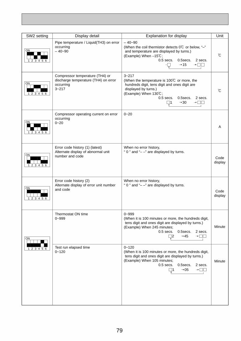
79
SW2 setting
1
ON
2 3 4 5 6
Display detail Explanation for display Unit
Pipe temperature / Liquid(TH3) on erroroccurring– 40~90
– 40~90(When the coil thermistor detects 0: or below, “–” and temperature are displayed by turns.)
(Example) When –15:;0.5 secs. 0.5secs. 2 secs.
:
1
ON
2 3 4 5 6
1
ON
2 3 4 5 6
1
ON
2 3 4 5 6
1
ON
2 3 4 5 6
Compressor temperature (TH4) or discharge temperature (TH4) on erroroccurring3~217
Compressor operating current on erroroccurring0~20
Error code history (1) (latest)Alternate display of abnormal unitnumber and code
Error code history (2) Alternate display of error unit numberand code
3~217(When the temperature is 100: or more, the hundreds digit, tens digit and ones digit are displayed by turns.)
(Example) When 130:;0.5 secs. 0.5secs. 2 secs.
:
A
Codedisplay
Codedisplay
0~20
When no error history, “ 0 ” and “– –” are displayed by turns.
When no error history, “ 0 ” and “– –” are displayed by turns.
1
ON
2 3 4 5 6
Thermostat ON time0~999
Test run elapsed time0~120
0~999(When it is 100 minutes or more, the hundreds digit,tens digit and ones digit are displayed by turns.)
(Example) When 245 minutes;0.5 secs. 0.5secs. 2 secs.
0~120(When it is 100 minutes or more, the hundreds digit,tens digit and ones digit are displayed by turns.)
(Example) When 105 minutes;0.5 secs. 0.5secs. 2 secs.
Minute
Minute
15
1 30
2 45
1 05
OC334-3.qxp 05.5.26 6:04 PM Page 79
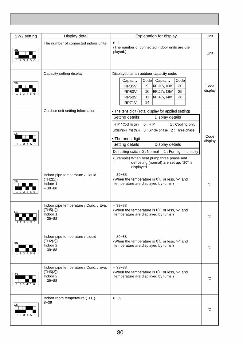
80
SW2 setting
1
ON
2 3 4 5 6
Display detail Explanation for display Unit
Capacity setting display Displayed as an outdoor capacity code.
Codedisplay
1
ON
2 3 4 5 6
1
ON
2 3 4 5 6
Outdoor unit setting information
Indoor pipe temperature / Liquid(TH2(1))Indoor 1– 39~88
Codedisplay
:
– 39~88(When the temperature is 0: or less, “–” andtemperature are displayed by turns.)
1
ON
2 3 4 5 6
1
ON
2 3 4 5 6
Indoor room temperature (TH1)8~39
Capacity
RP35VRP50VRP60VRP71V
Code9101114
CapacityRP100V, 100YRP125V, 125YRP140V, 140Y
Code202528
Setting details
• The tens digit (Total display for applied setting)
• The ones digit
H·P / Cooling only
Single phase / Three phase
Display details
0 : H·P 1 : Cooling only
0 : Single phase 2 : Three phase
Setting details
Defrosting switch
Display details
0 : Normal 1 : For high humidity
(Example) When heat pump,three phase and defrosting (normal) are set up, “20” is displayed.
1
ON
2 3 4 5 6
1
ON
2 3 4 5 6
Indoor pipe temperature / Cond. / Eva.(TH5(1))Indoor 1– 39~88
– 39~88(When the temperature is 0: or less, “–” andtemperature are displayed by turns.)
:
– 39~88(When the temperature is 0: or less, “–” andtemperature are displayed by turns.)
– 39~88(When the temperature is 0: or less, “–” andtemperature are displayed by turns.)
:
:
:
8~39
Indoor pipe temperature / Liquid(TH2(2))Indoor 2– 39~88
Indoor pipe temperature / Cond. / Eva.(TH5(2))Indoor 2– 39~88
1
ON
2 3 4 5 6
The number of connected indoor units
Unit
0~3(The number of connected indoor units are dis-played.)
OC334-3.qxp 05.5.26 6:04 PM Page 80
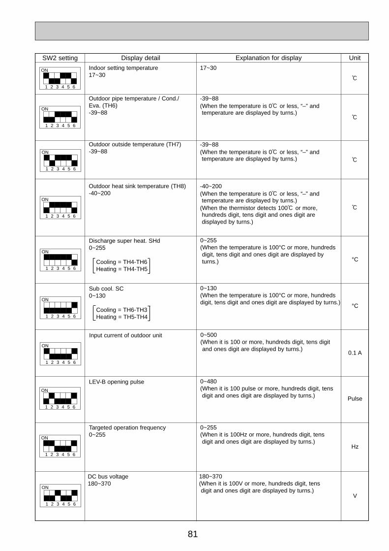
81
1
ON
2 3 4 5 6
°C
Discharge super heat. SHd0~255
Cooling = TH4-TH6Heating = TH4-TH5
0~255(When the temperature is 100°C or more, hundredsdigit, tens digit and ones digit are displayed byturns.)
°C
Sub cool. SC0~130
Cooling = TH6-TH3Heating = TH5-TH4
0~130(When the temperature is 100°C or more, hundredsdigit, tens digit and ones digit are displayed by turns.)
0.1 A
Input current of outdoor unit 0~500(When it is 100 or more, hundreds digit, tens digitand ones digit are displayed by turns.)
Pulse
LEV-B opening pulse 0~480(When it is 100 pulse or more, hundreds digit, tensdigit and ones digit are displayed by turns.)
Hz
Targeted operation frequency0~255
0~255(When it is 100Hz or more, hundreds digit, tens digit and ones digit are displayed by turns.)
DC bus voltage180~370
180~370(When it is 100V or more, hundreds digit, tens digit and ones digit are displayed by turns.)
V
1
ON
2 3 4 5 6
1
ON
2 3 4 5 6
1
ON
2 3 4 5 6
1
ON
2 3 4 5 6
1
ON
2 3 4 5 6
SW2 setting
1
ON
2 3 4 5 6
Display detail Explanation for display Unit
:
1
ON
2 3 4 5 6
1
ON
2 3 4 5 6
1
ON
2 3 4 5 6
Indoor setting temperature17~30
Outdoor pipe temperature / Cond./Eva. (TH6)-39~88
Outdoor heat sink temperature (TH8)-40~200
17~30
:
:
:
-39~88(When the temperature is 0: or less, “–” and temperature are displayed by turns.)
-40~200(When the temperature is 0: or less, “–” and temperature are displayed by turns.)
(When the thermistor detects 100: or more, hundreds digit, tens digit and ones digit are displayed by turns.)
Outdoor outside temperature (TH7)-39~88
-39~88(When the temperature is 0: or less, “–” and temperature are displayed by turns.)
OC334-3.qxp 05.5.26 6:04 PM Page 81

82
SW2 setting Display detail Explanation for display Unit
1
ON
2 3 4 5 6
%
Capacity save0~100When air conditioner is connected to M-NET and capacity save mode isdemanded, “0”~”100” is displayed.
When there is no setting of capacity save “100” is displayed.
0~100(When the capacity is 100% hundreds digit, tens digitand ones digit are displayed by turns.)(Example) When 100%;
0.5 secs. 0.5secs. 2 secs.
Code display
Error postponement code history (2)of outdoor unit
Postponement code displayBlinking: During postponementLighting: Cancellation of postponement“00” is displayed in case of no postponement.
Code display
Error postponement code history (3)of outdoor unit
Postponement code displayBlinking: During postponementLighting: Cancellation of postponement“00” is displayed in case of no postponement.
Code display
Error code history (3) (Oldest)Alternate display of abnormal unit num-ber and code.
When no error history, “0” and “– –“ are displayed byturns.
Error thermistor display
When there is no error thermistor, “–“ is displayed.
3: Outdoor pipe temperature /Liquid (TH3)6: Outdoor pipe temperature /Cond./Eva. (TH6)7: Outdoor outside temperature (TH7)8: Outdoor radiator panel (TH8)
1
ON
2 3 4 5 6
1
ON
2 3 4 5 6
1
ON
2 3 4 5 6
1
ON
2 3 4 5 6
Code display
Operation frequency on error occurring0~255
0~255(When it is 100Hz or more, hundreds digit, tens digitand ones digit are displayed by turns.)(Example) When 125Hz;
0.5 secs. 0.5secs. 2 secs.
1
ON
2 3 4 5 6Hz
Fan step on error occurring0~10
0~10
1
ON
2 3 4 5 6Step
001
251
OC334-3.qxp 05.5.26 6:04 PM Page 82
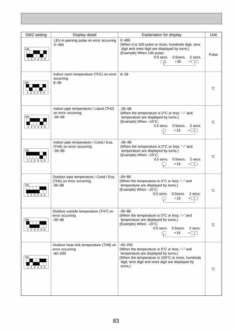
83
SW2 setting Display detail Explanation for display Unit
1
ON
2 3 4 5 6
Pulse
LEV-A opening pulse on error occurring0~480
0~480(When it is 100 pulse or more, hundreds digit, tensdigit and ones digit are displayed by turns.)
(Example) When 130 pulse;0.5 secs. 0.5secs. 2 secs.
:
Indoor room temperature (TH1) on erroroccurring8~39
8~39
:
Indoor pipe temperature / Liquid (TH2)on error occurring-39~88
-39~88(When the temperature is 0°C or less, “–” and temperature are displayed by turns.)
(Example) When –15°C;0.5 secs. 0.5secs. 2 secs.
Indoor pipe temperature / Cond./ Eva.(TH5) on error occurring-39~88
-39~88(When the temperature is 0°C or less, “–” and temperature are displayed by turns.)
(Example) When –15°C;0.5 secs. 0.5secs. 2 secs.
Outdoor pipe temperature / Cond./ Eva.(TH6) on error occurring-39~88
-39~88(When the temperature is 0°C or less, “–” and temperature are displayed by turns.)
(Example) When –15°C;0.5 secs. 0.5secs. 2 secs.
Outdoor outside temperature (TH7) onerror occurring-39~88
-39~88(When the temperature is 0°C or less, “–” and temperature are displayed by turns.)
(Example) When –15°C;0.5 secs. 0.5secs. 2 secs.
Outdoor heat sink temperature (TH8) onerror occurring-40~200
-40~200(When the temperature is 0°C or less, “–” and temperature are displayed by turns.)
(When the temperature is 100°C or more, hundredsdigit, tens digit and ones digit are displayed byturns.)
301
1
ON
2 3 4 5 6
1
ON
2 3 4 5 6
1
ON
2 3 4 5 6
1
ON
2 3 4 5 6
1
ON
2 3 4 5 6
1
ON
2 3 4 5 6
15
15
15
15
:
:
:
:
OC334-3.qxp 05.5.26 6:04 PM Page 83
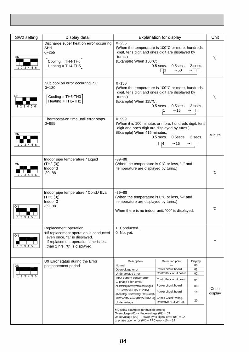
84
SW2 setting Display detail Explanation for display Unit
:
0~255(When the temperature is 100°C or more, hundredsdigit, tens digit and ones digit are displayed by turns.)
(Example) When 150°C;0.5 secs. 0.5secs. 2 secs.
Sub cool on error occurring. SC0~130
Cooling = TH6-TH3Heating = TH5-TH2
0~130(When the temperature is 100°C or more, hundredsdigit, tens digit and ones digit are displayed byturns.)
(Example) When 115°C;0.5 secs. 0.5secs. 2 secs.
Thermostat-on time until error stops0~999
0~999(When it is 100 minutes or more, hundreds digit, tensdigit and ones digit are displayed by turns.)
(Example) When 415 minutes; 0.5 secs. 0.5secs. 2 secs.
Indoor pipe temperature / Liquid(TH2 (3))Indoor 3-39~88
-39~88(When the temperature is 0°C or less, “–” and temperature are displayed by turns.)
Indoor pipe temperature / Cond./ Eva.(TH5 (3))Indoor 3-39~88
-39~88(When the temperature is 0°C or less, “–” and temperature are displayed by turns.)
When there is no indoor unit, “00” is displayed.
501
:
1
ON
2 3 4 5 6
Discharge super heat on error occurringSHd0~255
Cooling = TH4-TH6Heating = TH4-TH5
Replacement operationWIf replacement operation is conducted
even once, “1” is displayed.If replacement operation time is less than 2 hrs. “0” is displayed.
1
ON
2 3 4 5 6
1
ON
2 3 4 5 6
1
ON
2 3 4 5 6
1
ON
2 3 4 5 6
1
ON
2 3 4 5 6
:
Minute
:
–
1: Conducted.0: Not yet.
151
154
1
ON
2 3 4 5 6
NormalOvervoltage errorUndervoltage errorInput current sensor error.L1-phase open error.Abnormal power synchronous signalPFC error (RP35-71VHA) (Overvoltage / Undervoltage / Overcurrent)PFC/ ACTM error (RP35-140VHA)Undervoltage
W Display examples for multiple errors:Overvoltage (01) + Undervoltage (02) = 03Undervoltage (02) + Power-sync signal error (08) = 0AL1 phase open error (04) + PFC error (10) = 14
Power circuit boardController circuit board
Controller circuit board
Power circuit board
Power circuit board
Check CNAF wiring.Defective ACTM/ P.B.
—Description Detection point Display
000102
04
08
10
20
U9 Error status during the Error postponement period
Code display
OC334-3.qxp 05.5.26 6:04 PM Page 84
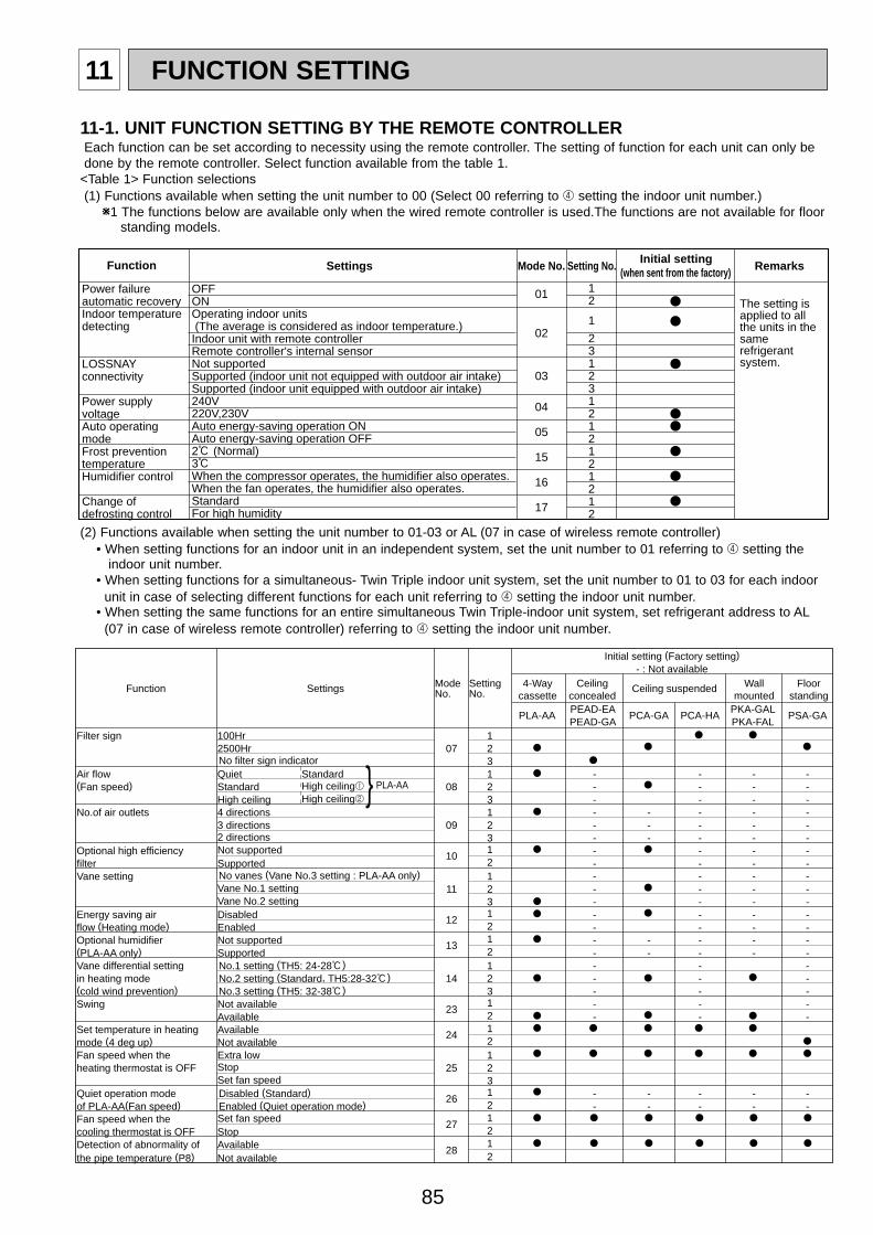
85
11 FUNCTION SETTING
Function Settings No.Mode
No.Setting
Initial setting (Factory setting)- : Not available
4-Waycassette
Ceilingconcealed
Ceiling suspended Wallmounted
Floorstanding
PLA-AAPEAD-EA
PCA-GA PCA-HAPKA-GAL
PSA-GAPEAD-GA PKA-FAL
Filter sign 100Hr 12500Hr 07 2No filter sign indicator 3
Air flow Quiet Standard 1 - - - -(Fan speed) Standard High ceiling1 08 2 - - - -
High ceiling High ceiling2 3 - - - -No.of air outlets 4 directions 1 - - - - -
3 directions 09 2 - - - - -2 directions 3 - - - - -
Optional high efficiency Not supported10
1 - - - -filter Supported 2 - - - -Vane setting No vanes (Vane No.3 setting : PLA-AA only) 1 - - - -
Vane No.1 setting 11 2 - - - -Vane No.2 setting 3 - - - -
Energy saving air Disabled 121 - - - -
flow (Heating mode) Enabled 2 - - - -Optional humidifier Not supported 13
1 - - - - -(PLA-AA only) Supported 2 - - - - -Vane differential setting No.1 setting (TH5: 24-28:) 1 - - -in heating mode No.2 setting (Standard, TH5:28-32:) 14 2 - - -(cold wind prevention) No.3 setting (TH5: 32-38:) 3 - - -Swing Not available 23
1 - - -Available 2 - - -
Set temperature in heating Available 241
mode (4 deg up) Not available 2Fan speed when the Extra low 1heating thermostat is OFF Stop 25 2
Set fan speed 3Quiet operation mode Disabled (Standard)
261 - - - - -
of PLA-AA(Fan speed) Enabled (Quiet operation mode) 2 - - - - -Fan speed when the Set fan speed
271
cooling thermostat is OFF Stop 2Detection of abnormality of Available 28
1the pipe temperature (P8) Not available 2
} PLA-AA
Function Settings Mode No. Setting No. Initial setting
(when sent from the factory) Remarks
Power failure automatic recoveryIndoor temperature detecting
LOSSNAY connectivity
Power supply voltageAuto operating modeFrost prevention temperatureHumidifier control
Change of defrosting control
OFFONOperating indoor units (The average is considered as indoor temperature.)Indoor unit with remote controllerRemote controller's internal sensorNot supportedSupported (indoor unit not equipped with outdoor air intake)Supported (indoor unit equipped with outdoor air intake)240V220V,230VAuto energy-saving operation ONAuto energy-saving operation OFF2: (Normal)3:When the compressor operates, the humidifier also operates.When the fan operates, the humidifier also operates.StandardFor high humidity
12
1
231231212121212
01
02
03
04
05
15
16
17
The setting is applied to all the units in the same refrigerant system.
11-1. UNIT FUNCTION SETTING BY THE REMOTE CONTROLLEREach function can be set according to necessity using the remote controller. The setting of function for each unit can only be done by the remote controller. Select function available from the table 1.
<Table 1> Function selections(1) Functions available when setting the unit number to 00 (Select 00 referring to 4 setting the indoor unit number.)
W1 The functions below are available only when the wired remote controller is used.The functions are not available for floor standing models.
(2) Functions available when setting the unit number to 01-03 or AL (07 in case of wireless remote controller)• When setting functions for an indoor unit in an independent system, set the unit number to 01 referring to 4 setting the
indoor unit number.• When setting functions for a simultaneous- Twin Triple indoor unit system, set the unit number to 01 to 03 for each indoor
unit in case of selecting different functions for each unit referring to 4 setting the indoor unit number.• When setting the same functions for an entire simultaneous Twin Triple-indoor unit system, set refrigerant address to AL
(07 in case of wireless remote controller) referring to 4 setting the indoor unit number.
OC334-3.qxp 05.5.26 6:04 PM Page 85
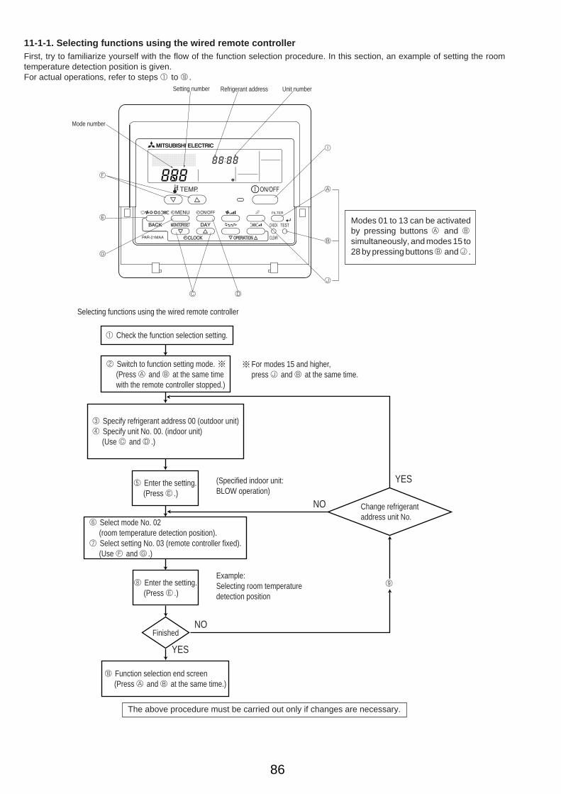
86
6 Select mode No. 02 (room temperature detection position).7 Select setting No. 03 (remote controller fixed). (Use F and G .)
8 Enter the setting. (Press E .)
Finished
0 Function selection end screen (Press A and B at the same time.)
Example:Selecting room temperaturedetection position
YES
YES
NO
NO
9
Selecting functions using the wired remote controller
1 Check the function selection setting.
For modes 15 and higher,press J and B at the same time.
3 Specify refrigerant address 00 (outdoor unit)4 Specify unit No. 00. (indoor unit) (Use C and D .)
5 Enter the setting. (Press E .)
(Specified indoor unit:BLOW operation)
Change refrigerantaddress unit No.
2 Switch to function setting mode. (Press A and B at the same time with the remote controller stopped.)
11-1-1. Selecting functions using the wired remote controllerFirst, try to familiarize yourself with the flow of the function selection procedure. In this section, an example of setting the roomtemperature detection position is given.For actual operations, refer to steps 1 to 0 .
Setting number Refrigerant address Unit number
Mode number
F
E
G
C D
J
B
A
I
Modes 01 to 13 can be activatedby pressing buttons A and Bsimultaneously, and modes 15 to28 by pressing buttons B and J .
The above procedure must be carried out only if changes are necessary.
OC334-3.qxp 05.5.26 6:04 PM Page 86
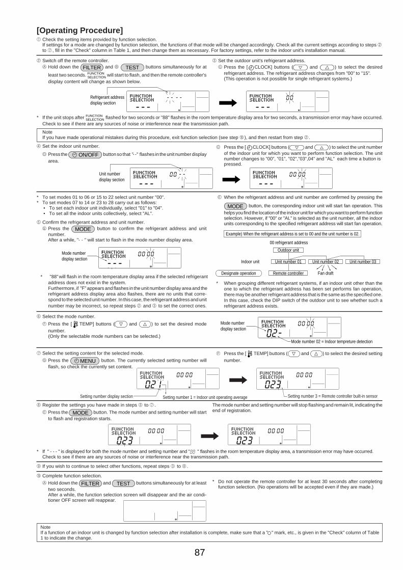
87
[Operating Procedure]1 Check the setting items provided by function selection.
If settings for a mode are changed by function selection, the functions of that mode will be changed accordingly. Check all the current settings according to steps 2to 7 , fill in the "Check" column in Table 1, and then change them as necessary. For factory settings, refer to the indoor unit's installation manual.
2 Switch off the remote controller.A Hold down the FILTER and B TEST buttons simultaneously for at
least two seconds. FUNCTIONSELECTION will start to flash, and then the remote controller's
display content will change as shown below.
3 Set the outdoor unit's refrigerant address.C Press the [ CLOCK] buttons ( and ) to select the desired
refrigerant address. The refrigerant address changes from "00" to "15". (This operation is not possible for single refrigerant systems.)
* If the unit stops after FUNCTIONSELECTION flashed for two seconds or "88" flashes in the room temperature display area for two seconds, a transmission error may have occurred.
Check to see if there are any sources of noise or interference near the transmission path.
NoteIf you have made operational mistakes during this procedure, exit function selection (see step 0 ), and then restart from step 2 .
4 Set the indoor unit number.
D Press the ON/OFF button so that "- -" flashes in the unit number displayarea.
C Press the [ CLOCK] buttons ( and ) to select the unit numberof the indoor unit for which you want to perform function selection. The unitnumber changes to "00", "01", "02","03",04" and "AL" each time a button ispressed.
* To set modes 01 to 06 or 15 to 22 select unit number "00".* To set modes 07 to 14 or 23 to 28 carry out as follows:
• To set each indoor unit individually, select "01" to "04".• To set all the indoor units collectively, select "AL".
5 Confirm the refrigerant address and unit number.E Press the MODE button to confirm the refrigerant address and unit
number.After a while, "- - " will start to flash in the mode number display area.
E When the refrigerant address and unit number are confirmed by pressing the
MODE button, the corresponding indoor unit will start fan operation. This
helps you find the location of the indoor unit for which you want to perform functionselection. However, if "00" or "AL" is selected as the unit number, all the indoorunits corresponding to the specified refrigerant address will start fan operation.
* "88" will flash in the room temperature display area if the selected refrigerantaddress does not exist in the system.Furthermore, if "F" appears and flashes in the unit number display area and therefrigerant address display area also flashes, there are no units that corre-spond to the selected unit number. In this case, the refrigerant address and unitnumber may be incorrect, so repeat steps 2 and 3 to set the correct ones.
* When grouping different refrigerant systems, if an indoor unit other than theone to which the refrigerant address has been set performs fan operation,there may be another refrigerant address that is the same as the specified one.In this case, check the DIP switch of the outdoor unit to see whether such arefrigerant address exists.
6 Select the mode number.
F Press the [ TEMP] buttons ( and ) to set the desired modenumber.(Only the selectable mode numbers can be selected.)
7 Select the setting content for the selected mode.
G Press the MENU button. The currently selected setting number willflash, so check the currently set content.
F Press the [ TEMP] buttons ( and ) to select the desired setting
number.
8 Register the settings you have made in steps 3 to 7 .
E Press the MODE button. The mode number and setting number will startto flash and registration starts.
The mode number and setting number will stop flashing and remain lit, indicating theend of registration.
* If " - - - " is displayed for both the mode number and setting number and " " flashes in the room temperature display area, a transmission error may have occurred.Check to see if there are any sources of noise or interference near the transmission path.
9 If you wish to continue to select other functions, repeat steps 3 to 8 .
0 Complete function selection.
A Hold down the FILTER and TEST buttons simultaneously for at leasttwo seconds.After a while, the function selection screen will disappear and the air condi-tioner OFF screen will reappear.
* Do not operate the remote controller for at least 30 seconds after completingfunction selection. (No operations will be accepted even if they are made.)
NoteIf a function of an indoor unit is changed by function selection after installation is complete, make sure that a " " mark, etc., is given in the "Check" column of Table1 to indicate the change.
Refrigerant addressdisplay section
Unit numberdisplay section
Mode numberdisplay section
00 refrigerant address
Indoor unit
Fan draftRemote controller
Unit number 01 Unit number 02
Outdoor unit
Unit number 03
Designate operation
Example) When the refrigerant address is set to 00 and the unit number is 02.
Mode numberdisplay section
Mode number 02 = Indoor tempreture detection
Setting number display section Setting number 3 = Remote controller built-in sensorSetting number 1 = Indoor unit operating average
OC334-3.qxp 05.5.26 6:04 PM Page 87
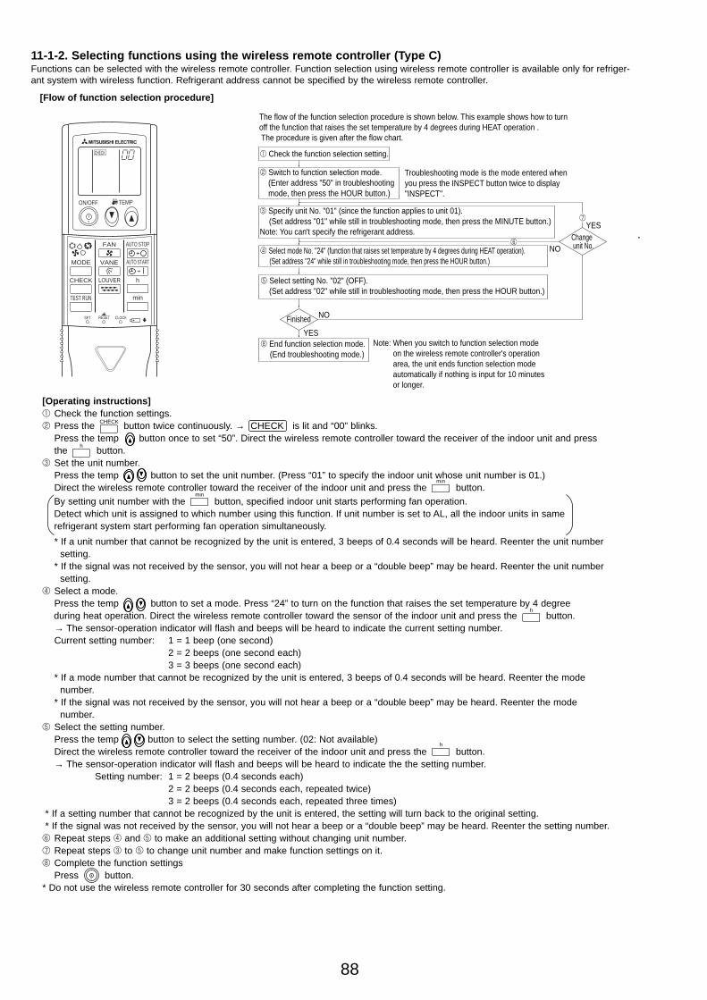
88
By setting unit number with the button, specified indoor unit starts performing fan operation. Detect which unit is assigned to which number using this function. If unit number is set to AL, all the indoor units in same refrigerant system start performing fan operation simultaneously.
[Operating instructions]1 Check the function settings.2 Press the button twice continuously. → CHECK is lit and “00” blinks.
Press the temp button once to set “50”. Direct the wireless remote controller toward the receiver of the indoor unit and press the button.
3 Set the unit number.Press the temp button to set the unit number. (Press “01” to specify the indoor unit whose unit number is 01.) Direct the wireless remote controller toward the receiver of the indoor unit and press the button.
* If a unit number that cannot be recognized by the unit is entered, 3 beeps of 0.4 seconds will be heard. Reenter the unit number setting.
* If the signal was not received by the sensor, you will not hear a beep or a “double beep” may be heard. Reenter the unit number setting.
4 Select a mode.Press the temp button to set a mode. Press “24” to turn on the function that raises the set temperature by 4 degree during heat operation. Direct the wireless remote controller toward the sensor of the indoor unit and press the button.→ The sensor-operation indicator will flash and beeps will be heard to indicate the current setting number.Current setting number: 1 = 1 beep (one second)
2 = 2 beeps (one second each)3 = 3 beeps (one second each)
* If a mode number that cannot be recognized by the unit is entered, 3 beeps of 0.4 seconds will be heard. Reenter the mode number.
* If the signal was not received by the sensor, you will not hear a beep or a “double beep” may be heard. Reenter the mode number.
5 Select the setting number.Press the temp button to select the setting number. (02: Not available)Direct the wireless remote controller toward the receiver of the indoor unit and press the button.→ The sensor-operation indicator will flash and beeps will be heard to indicate the the setting number.
Setting number: 1 = 2 beeps (0.4 seconds each)2 = 2 beeps (0.4 seconds each, repeated twice)3 = 2 beeps (0.4 seconds each, repeated three times)
* If a setting number that cannot be recognized by the unit is entered, the setting will turn back to the original setting.* If the signal was not received by the sensor, you will not hear a beep or a “double beep” may be heard. Reenter the setting number.6 Repeat steps 4 and 5 to make an additional setting without changing unit number.7 Repeat steps 3 to 5 to change unit number and make function settings on it.8 Complete the function settings
Press button.* Do not use the wireless remote controller for 30 seconds after completing the function setting.
ON/OFF TEMP
FAN
VANEMODE
CHECK LOUVER
TEST RUN
AUTO STOP
AUTO START
h
min
CHECK
RESETSET CLOCK
h
CHECK
min
h
The flow of the function selection procedure is shown below. This example shows how to turn off the function that raises the set temperature by 4 degrees during HEAT operation . The procedure is given after the flow chart.
1 Check the function selection setting.
2 Switch to function selection mode.(Enter address "50" in troubleshootingmode, then press the HOUR button.)
Troubleshooting mode is the mode entered whenyou press the INSPECT button twice to display"INSPECT".
3 Specify unit No. "01" (since the function applies to unit 01).(Set address "01" while still in troubleshooting mode, then press the MINUTE button.)
Note: You can't specify the refrigerant address.
4 Select mode No. "24" (function that raises set temperature by 4 degrees during HEAT operation).(Set address "24" while still in troubleshooting mode, then press the HOUR button.)
6
Finished
8 End function selection mode.(End troubleshooting mode.)
YES
NO
Note: When you switch to function selection modeon the wireless remote controller's operationarea, the unit ends function selection modeautomatically if nothing is input for 10 minutesor longer.
5 Select setting No. "02" (OFF).(Set address "02" while still in troubleshooting mode, then press the HOUR button.)
Change unit No.
YES
NO
7
[Flow of function selection procedure]
11-1-2. Selecting functions using the wireless remote controller (Type C)Functions can be selected with the wireless remote controller. Function selection using wireless remote controller is available only for refriger-ant system with wireless function. Refrigerant address cannot be specified by the wireless remote controller.
h
min
OC334-3.qxp 05.5.26 6:04 PM Page 88

89
11-2. FUNCTION SELECTION OF REMOTE CONTROLLER
The setting of the following remote controller functions can be changed using the remote controller function selection mode.Change the setting when needed.
Item 11.Change Language("CHANGE LANGUAGE")2.Function limit("FUNCTION SELECTION")
3.Mode selection("MODE SELECTION")
4.Display change("DISP MODE SETTING")
Item 3 (Setting content)• Display in multiple languages is possible.
• Setting the range of operation limit (operation lock)• Setting the use or non-use of "automatic" operation mode• Setting the temperature adjustable range (maximum, minimum)• Selecting main or sub remote controller
* When two remote controllers are connected to one group, one controller must be set to sub.• Setting the use or non-use of clock function• Setting the timer type• Contact number display in case of error• Setting the telephone number• Setting the temperature unit (: or °F) to display• Setting the use or non-use of the display of indoor (suction) air temperature• Setting the use or non-use of the display of "Cooling" or "Heating" display during operation with automatic mode
Item 2Language setting to display
(1) Operation function limit setting (operation lock) ("LOCKING FUNCTION")(2) Use of automatic mode setting ("SELECT AUTO MODE")(3) Temperature range limit setting ("LIMIT TEMP FUNCTION")(1) Remote controller main/sub setting ("CONTROLLER MAIN/SUB")
(2) Use of clock setting ("CLOCK")(3) Timer function setting ("WEEKLY TIMER")(4) Contact number setting for error situation ("CALL.")
(1) Temperature display :/°F setting ("TEMP MODE :/°F")(2) Suction air temperature display setting ("ROOM TEMP DISP SELECT")(3) Automatic cooling/heating display setting ("AUTO MODE DISP C/H")
[Function selection flowchart] Refer to next page.[1] Stop the air conditioner to start remote controller function selection mode. [2] Select from item1. [3] Select from item2. [4] Make the setting.(Details are specified in item3) [5] Setting completed. [6] Change the display to the normal one. (End)
➔➔➔
➔ ➔
[Detailed setting][4] -1. CHANGE LANGUAGE settingThe language that appears on the dot display can be selected.• Press the [ MENU] button to change the language.1 Japanese (JP), 2English (GB), 3German (D), 4Spanish (E),5 Russian (RU), 6 Italian (I), 7Chinese (CH), 8 French (F)
[4] -2. Function limit(1) Operation function limit setting (operation lock)• To switch the setting, press the [ ON/OFF] button.1 no1 : Operation lock setting is made on all buttons other than
the [ ON/OFF] button.2 no2 : Operation lock setting is made on all buttons.3 OFF (Initial setting value) : Operation lock setting is not made* To make the operation lock setting valid on the normal screen, it is
necessary to press buttons (Press and hold down the [FILTER]and [ ON/OFF] buttons at the same time for two seconds.) onthe normal screen after the above setting is made..
(2) Use of automatic mode settingWhen the remote controller is connected to the unit that has auto-matic operation mode, the following settings can be made.• To switch the setting, press the [ ON/OFF] button.1 ON (Initial setting value) : The automatic mode is displayed when
the operation mode is selected.2 OFF : The automatic mode is not display
when the operation mode is selected.
[4] -3. Mode selection setting(1) Remote controller main/sub setting• To switch the setting, press the [ ON/OFF] button.1 Main : The controller will be the main controller.2 Sub : The controller will be the sub controller.
(2) Use of clock setting• To switch the setting, press the [ ON/OFF] button.1 ON : The clock function can be used.2 OFF: The clock function cannot be used.
(3) Timer function setting• To switch the setting, press the [ ON/OFF] button (Choose one of
the followings.).1 WEEKLY TIMER (initial setting on MA deluxe):
The weekly timer can be used.2 AUTO OFF TIMER: The auto off timer can be used.
SIMPLE TIMER (Default setting on MA smooth):The simple timer can be used.
4
3
TIMER MODE OFF: The timer mode cannot be used.* When the use of clock setting is OFF, the "WEEKLY TIMER" cannot be
used.
(4) Contact number setting for error situation• To switch the setting, press the [ ON/OFF] button.1 CALL OFF: The set contact numbers are not displayed in case of error.2 CALL **** *** **** : The set contact numbers are displayed in case
of error.
(3) Temperature range limit settingAfter this setting is made, the temperature can be changed within the set range.• To switch the setting, press the [ ON/OFF] button.1 LIMIT TEMP COOL MODE :
The temperature range can be changed on cooling/dry mode.2 LIMIT TEMP HEAT MODE :
The temperature range can be changed on heating mode.3 LIMIT TEMP AUTO MODE :
The temperature range can be changed on automatic mode.4 OFF (initial setting) : The temperature range limit is not active.* When the setting, other than OFF, is made, the temperature range limit setting
on cooling, heating and automatic mode is made at the same time. Howeverthe range cannot be limited when the set temperature range has not changed.
• To increase or decrease the temperature, press the [ TEMP ( ) or ( )] button.• To switch the upper limit setting and the lower limit setting, press the [ ]
button. The selected setting will flash and the temperature can be set. • Settable range
Cooling/Dry mode : Lower limit: 19 : ~ 30: Upper limit: 30 : ~ 19:Heating mode : Lower limit: 17 : ~ 28: Upper limit: 28 : ~ 17:Automatic mode : Lower limit: 19 : ~ 28: Upper limit: 28 : ~ 19:
CALL_ : The contact number can be set when the display is asshown on the left.
• Setting the contact numbersTo set the contact numbers, follow the following procedures.Move the flashing cursor to set numbers. Press the [ TEMP. ( ) and( )] button to move the cursor to the right (left). Press the [ CLOCK( ) and ( )] button to set the numbers.
[4] -4. Display change setting(1) Temperature display :/ F setting• To switch the setting, press the [ ON/OFF] button.1: : The temperature unit : is used.2 F: The temperature unit
°
° °F is used.
(2) Suction air temperature display setting• To switch the setting, press the [ ON/OFF] button.1 ON : The suction air temperature is displayed.2 OFF: The suction air temperature is not displayed.
(3) Automatic cooling/heating display setting• To switch the setting, press the [ ON/OFF] button.1 ON : One of "Automatic cooling" and "Automatic heating" is displayed
under the automatic mode is running.2 OFF: Only "Automatic" is displayed under the automatic mode.
OC334-3.qxp 05.5.26 6:04 PM Page 89

90
OFF
on1
on2
OFF
ON
OFF
ON
OFF
OFF
CALL-
ON
OFF
ON
OFF
:
°F
PAR-21MAA
ON/OFF
FILTER
CHECK
OPERATION CLEAR
TEST
TEMP.
MENU
BACK DAYMONITOR/SET
CLOCK
ON/OFF
F
E
G
C D
H
B
A
I
G
G
G
G
G
G
E
E
G
G
G
G
E
G
E
G
G
G
G
D
D
D
D
D
D
D
D
D
D
D
D
D
D
D
D
D
D
D
D
D
D
D
D
D
D
D
D
D
D
EN
GE
ES
RU
IT
ZH
FR
JA
Hold down the E button and press the D button for 2 seconds.
Hold down the E button and press the D button for 2 seconds.
Remote controller function selection mode
E Press the operation mode button.G Press the TIMER MENU button.D Press the TIMER ON/OFF button.
Item1 Item2 Dot display
Item3
Room air temperature is not displayed.
One of "Automatic cooling" and "Automatic heating" is displayedunder the automatic mode is running. (Initial setting value)
Only "Automatic" is displayed under the automatic mode.
Normal display(Display when the air condition is not running)
ChangeLanguage
Functionselection
Modeselection
Displaymode setting
Operation lock setting is not used.(Initial setting value)
Operation lock setting is except On/Off buttons.
Operation lock setting is All buttons.
The automatic mode is displayed when the operation mode isselected. (Initial setting value)
The automatic mode is not displayed when the operation mode is selected.
The temperature range limit is not active. (Initial setting value)
The temperature range can be changed on cooling/dry mode.
The temperature range can be changed on heating mode.
The temperature range can be changed on automatic mode.
The remote controller will be the main controller. (Initial setting value)
The remote controller will be the sub controller.
The clock function can be used. (Initial setting value)
The clock function can not be used.
Weekly timer can be used. (Initial setting value)
Auto off timer can be used.
Simple timer can be used.
Timer mode can not be used.
The set contact numbers are not displayed in case of error.(Initial setting value)
The set contact numbers are displayed in case of error.
The temperature unit : is used. (Initial setting value)
The temperature unit °F is used.
Room air temperature is displayed. (Initial setting value)
Flowchart of Function SettingSetting language (English)
OC334-3.qxp 05.5.26 6:04 PM Page 90
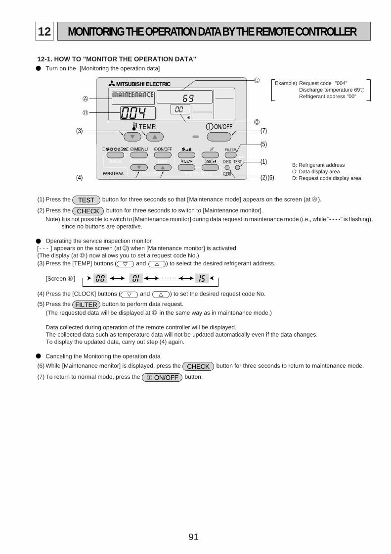
91
12 MONITORING THE OPERATION DATABYTHE REMOTE CONTROLLER
12-1. HOW TO "MONITOR THE OPERATION DATA"• Turn on the [Monitoring the operation data]
A
D
C
B
(1)
(2)
(3)
(4)
(5)
(6)
(7)
(1) Press the TEST button for three seconds so that [Maintenance mode] appears on the screen (at A ).
(2) Press the CHECK button for three seconds to switch to [Maintenance monitor].
Note) It is not possible to switch to [Maintenance monitor] during data request in maintenance mode (i.e., while "- - - -" is flashing),since no buttons are operative.
Operating the service inspection monitor- - - ] appears on the screen (at D) when [Maintenance monitor] is activated.
(The display (at D ) now allows you to set a request code No.)(3) Press the [TEMP] buttons ( and ) to select the desired refrigerant address.
[Screen B ]
(4) Press the [CLOCK] buttons ( and ) to set the desired request code No.
(5) Press the FILTER button to perform data request.
(The requested data will be displayed at C in the same way as in maintenance mode.)
Data collected during operation of the remote controller will be displayed.The collected data such as temperature data will not be updated automatically even if the data changes.To display the updated data, carry out step (4) again.
Canceling the Monitoring the operation data
(6) While [Maintenance monitor] is displayed, press the CHECK button for three seconds to return to maintenance mode.
(7) To return to normal mode, press the ON/OFF button.
Example) Request code "004"Discharge temperature 69 ;Refrigerant address "00"
B: Refrigerant addressC: Data display areaD: Request code display area
[
OC334-4.qxp 05.5.26 5:58 PM Page 91
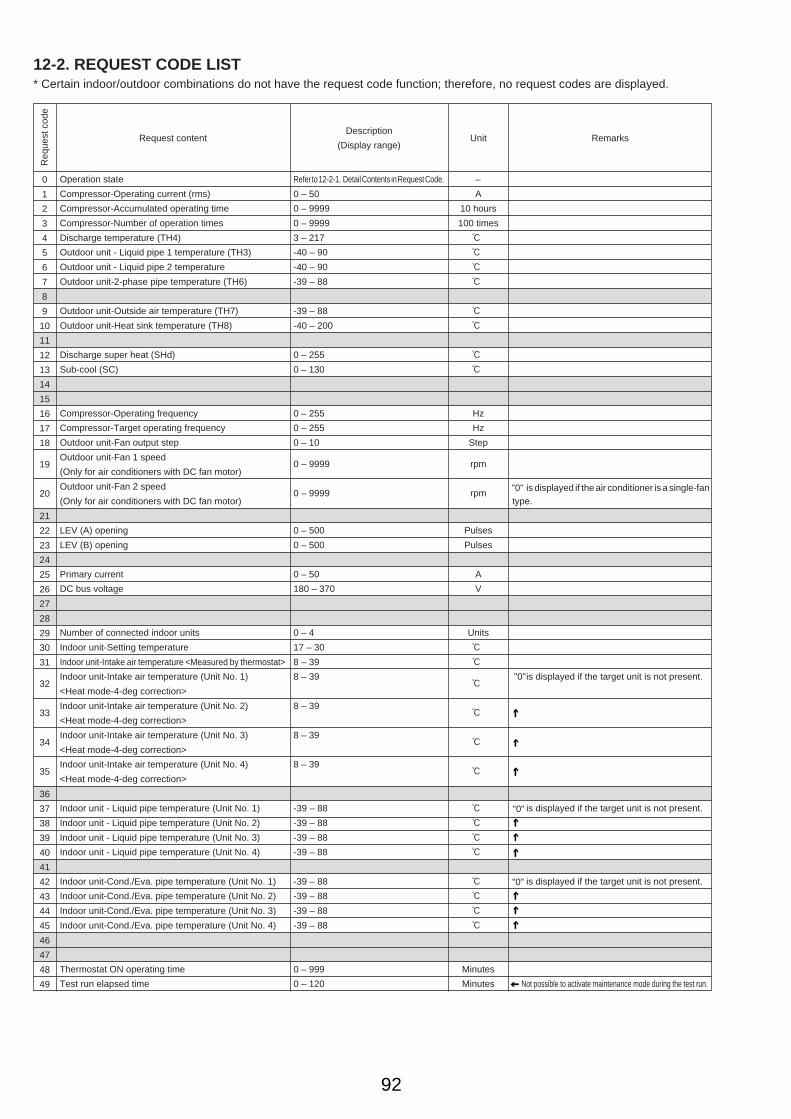
92
12-2. REQUEST CODE LIST* Certain indoor/outdoor combinations do not have the request code function; therefore, no request codes are displayed.
Req
uest
cod
e
Request contentDescription
(Display range)Unit Remarks
0
1
2
3
4
5
6
7
8
9
10
11
12
13
14
15
16
17
18
19
20
21
22
23
24
25
26
27
28
29
30
31
32
33
34
35
36
37
38
39
40
41
42
43
44
45
46
47
48
49
Operation state
Compressor-Operating current (rms)
Compressor-Accumulated operating time
Compressor-Number of operation times
Discharge temperature (TH4)
Outdoor unit - Liquid pipe 1 temperature (TH3)
Outdoor unit - Liquid pipe 2 temperature
Outdoor unit-2-phase pipe temperature (TH6)
Outdoor unit-Outside air temperature (TH7)
Outdoor unit-Heat sink temperature (TH8)
Discharge super heat (SHd)
Sub-cool (SC)
Compressor-Operating frequency
Compressor-Target operating frequency
Outdoor unit-Fan output step
Outdoor unit-Fan 1 speed
(Only for air conditioners with DC fan motor)
Outdoor unit-Fan 2 speed
(Only for air conditioners with DC fan motor)
LEV (A) opening
LEV (B) opening
Primary current
DC bus voltage
Number of connected indoor units
Indoor unit-Setting temperature
Indoor unit-Intake air temperature <Measured by thermostat>
Indoor unit-Intake air temperature (Unit No. 1)
<Heat mode-4-deg correction>
Indoor unit-Intake air temperature (Unit No. 2)
<Heat mode-4-deg correction>
Indoor unit-Intake air temperature (Unit No. 3)
<Heat mode-4-deg correction>
Indoor unit-Intake air temperature (Unit No. 4)
<Heat mode-4-deg correction>
Indoor unit - Liquid pipe temperature (Unit No. 1)
Indoor unit - Liquid pipe temperature (Unit No. 2)
Indoor unit - Liquid pipe temperature (Unit No. 3)
Indoor unit - Liquid pipe temperature (Unit No. 4)
Indoor unit-Cond./Eva. pipe temperature (Unit No. 1)
Indoor unit-Cond./Eva. pipe temperature (Unit No. 2)
Indoor unit-Cond./Eva. pipe temperature (Unit No. 3)
Indoor unit-Cond./Eva. pipe temperature (Unit No. 4)
Thermostat ON operating time
Test run elapsed time
Refer to 12-2-1. Detail Contents in Request Code.
0 – 50
0 – 9999
0 – 9999
3 – 217
-40 – 90
-40 – 90
-39 – 88
-39 – 88
-40 – 200
0 – 255
0 – 130
0 – 255
0 – 255
0 – 10
0 – 9999
0 – 9999
0 – 500
0 – 500
0 – 50
180 – 370
0 – 4
17 – 30
8 – 39
8 – 39
8 – 39
8 – 39
8 – 39
-39 – 88
-39 – 88
-39 – 88
-39 – 88
-39 – 88
-39 – 88
-39 – 88
-39 – 88
0 – 999
0 – 120
–
A
10 hours
100 times
:
:
:
:
:
:
:
:
Hz
Hz
Step
rpm
rpm
Pulses
Pulses
A
V
Units
:
:
:
:
:
:
:
:
:
:
:
:
:
:
Minutes
Minutes
"0" is displayed if the air conditioner is a single-fantype.
"0" is displayed if the target unit is not present.
"0" is displayed if the target unit is not present.
"0" is displayed if the target unit is not present.
Not possible to activate maintenance mode during the test run.
OC334-4.qxp 05.5.26 5:58 PM Page 92
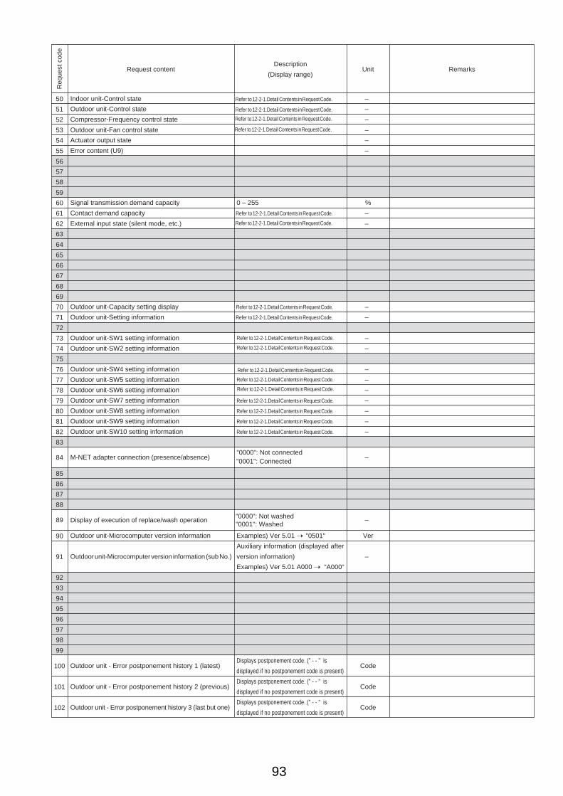
93
Req
uest
cod
e
Request contentDescription
(Display range)Unit Remarks
50
51
52
53
54
55
56
57
58
59
60
61
62
63
64
65
66
67
68
69
70
71
72
73
74
75
76
77
78
79
80
81
82
83
84
85
86
87
88
89
90
91
92
93
94
95
96
97
98
99
100
101
102
Indoor unit-Control state
Outdoor unit-Control state
Compressor-Frequency control state
Outdoor unit-Fan control state
Actuator output state
Error content (U9)
Signal transmission demand capacity
Contact demand capacity
External input state (silent mode, etc.)
Outdoor unit-Capacity setting display
Outdoor unit-Setting information
Outdoor unit-SW1 setting information
Outdoor unit-SW2 setting information
Outdoor unit-SW4 setting information
Outdoor unit-SW5 setting information
Outdoor unit-SW6 setting information
Outdoor unit-SW7 setting information
Outdoor unit-SW8 setting information
Outdoor unit-SW9 setting information
Outdoor unit-SW10 setting information
M-NET adapter connection (presence/absence)
Display of execution of replace/wash operation
Outdoor unit-Microcomputer version information
Outdoor unit-Microcomputer version information (sub No.)
Outdoor unit - Error postponement history 1 (latest)
Outdoor unit - Error postponement history 2 (previous)
Outdoor unit - Error postponement history 3 (last but one)
0 – 255
Refer to 12-2-1.Detail Contents in Request Code.
Refer to 12-2-1.Detail Contents in Request Code.
Refer to 12-2-1.Detail Contents in Request Code.
Refer to 12-2-1.Detail Contents in Request Code.
"0000": Not connected
Examples) Ver 5.01 ➝
Auxiliary information (displayed after
version information)
Examples) Ver 5.01 A000 ➝
Displays postponement code. (" - - " is
displayed if no postponement code is present)
Displays postponement code. (" - - " is
displayed if no postponement code is present)
Displays postponement code. (" - - " is
displayed if no postponement code is present)
–
–
–
–
–
–
%
–
–
–
–
–
–
–
–
–
–
–
–
–
–
–
Ver
–
Code
Code
Code
Refer to 12-2-1.Detail Contents in Request Code.
Refer to 12-2-1.Detail Contents in Request Code.
Refer to 12-2-1.Detail Contents in Request Code.
Refer to 12-2-1.Detail Contents in Request Code.
Refer to 12-2-1.Detail Contents in Request Code.
Refer to 12-2-1.Detail Contents in Request Code.
Refer to 12-2-1.Detail Contents in Request Code.
Refer to 12-2-1.Detail Contents in Request Code.
Refer to 12-2-1.Detail Contents in Request Code.
Refer to 12-2-1.Detail Contents in Request Code.
Refer to 12-2-1.Detail Contents in Request Code.
Refer to 12-2-1.Detail Contents in Request Code.
Refer to 12-2-1.Detail Contents in Request Code.
"0001": Connected
"0000": Not washed"0001": Washed
"0501"
"A000"
OC334-4.qxp 05.5.26 5:58 PM Page 93
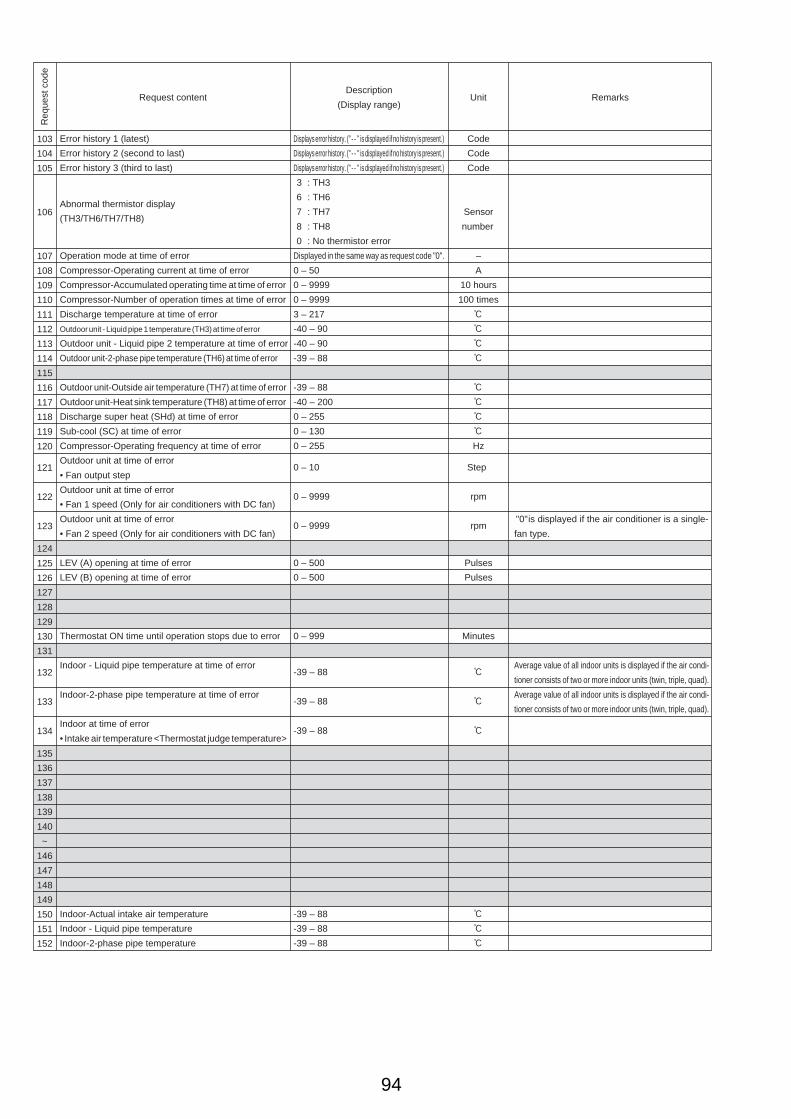
94
Req
uest
cod
e
Request contentDescription
(Display range)Unit Remarks
103
104
105
106
107
108
109
110
111
112
113
114
115
116
117
118
119
120
121
122
123
124
125
126
127
128
129
130
131
132
133
134
135
136
137
138
139
140
~
146
147
148
149
150
151
152
Displays error history. (" - - " is displayed if no history is present.)
Displays error history. (" - - " is displayed if no history is present.)
Displays error history. (" - - " is displayed if no history is present.)
: TH3
6 : TH6
7 : TH7
8 : TH8
0 : No thermistor error
Displayed in the same way as request code "0".
0 – 50
0 – 9999
0 – 9999
3 – 217
-40 – 90
-40 – 90
-39 – 88
-39 – 88
-40 – 200
0 – 255
0 – 130
0 – 255
0 – 10
0 – 9999
0 – 9999
0 – 500
0 – 500
0 – 999
-39 – 88
-39 – 88
-39 – 88
-39 – 88
-39 – 88
-39 – 88
Code
Code
Code
Sensor
number
–
A
10 hours
100 times
:
:
:
:
:
:
:
:
Hz
Step
rpm
rpm
Pulses
Pulses
Minutes
:
:
:
:
:
:
"0" is displayed if the air conditioner is a single-
fan type.
Average value of all indoor units is displayed if the air condi-
tioner consists of two or more indoor units (twin, triple, quad).
Average value of all indoor units is displayed if the air condi-
tioner consists of two or more indoor units (twin, triple, quad).
Error history 1 (latest)
Error history 2 (second to last)
Error history 3 (third to last)
Abnormal thermistor display
(TH3/TH6/TH7/TH8)
Operation mode at time of error
Compressor-Operating current at time of error
Compressor-Accumulated operating time at time of error
Compressor-Number of operation times at time of error
Discharge temperature at time of error
Outdoor unit - Liquid pipe 1 temperature (TH3) at time of error
Outdoor unit - Liquid pipe 2 temperature at time of error
Outdoor unit-2-phase pipe temperature (TH6) at time of error
Outdoor unit-Outside air temperature (TH7) at time of error
Outdoor unit-Heat sink temperature (TH8) at time of error
Discharge super heat (SHd) at time of error
Sub-cool (SC) at time of error
Compressor-Operating frequency at time of error
Outdoor unit at time of error
• Fan output step
Outdoor unit at time of error
• Fan 1 speed (Only for air conditioners with DC fan)
Outdoor unit at time of error
• Fan 2 speed (Only for air conditioners with DC fan)
LEV (A) opening at time of error
LEV (B) opening at time of error
Thermostat ON time until operation stops due to error
Indoor - Liquid pipe temperature at time of error
Indoor-2-phase pipe temperature at time of error
Indoor at time of error
• Intake air temperature <Thermostat judge temperature>
Indoor-Actual intake air temperature
Indoor - Liquid pipe temperature
Indoor-2-phase pipe temperature
3
OC334-4.qxp 05.5.26 5:58 PM Page 94

95
Req
uest
cod
e
Request contentDescription
(Display range)Unit Remarks
153
154
155
156
157
158
159
160
161
162
163
164
165
166
167
~
189
190
191
192
~
764
765
766
767
0 – 9999
0 – 9999
0 – 255 Fan control data
00 **" "**" indicates fan control data.
"00 **" "**" indicates fan control data.
Refer to 12-2-1 Detail Contents in Request Code.
Undefined
Refer to 12-2-1 Detail Contents in Request Code.
Undefined
Examples) Ver 5.01 ➝ "0501"
Auxiliary information (displayed after version information)
Examples) Ver 5.01 A000 ➝ "A000"
1 hour
10 hours
–
–
–
–
–
–
–
–
Ver
–
For indoor fan phase control
For indoor fan pulsation control
For indoor DC brushless motor control
Indoor-Fan operating time
(After filter is reset)
Indoor-Total operating time
(Fan motor ON time)
Indoor fan output value (Sj value)
Indoor fan output value
(Pulsation ON/OFF)
Indoor fan output value (duty value)
Indoor unit-Model setting information
Indoor unit-Capacity setting information
Indoor unit-SW3 information
Wireless pair No. (indoor control board side) setting
Indoor unit-SW5 information
Indoor unit-Microcomputer version information
Indoor unit-Microcomputer version information (sub No.)
Stable operation (Heat mode)
Stable operation (Cool mode)
Stable operation cancellation
This request code is not provided to collect data. It is used to fix the operation state.
This request code is not provided to collect data. It is used to fix the operation state.
This request code is not provided to collect data. It is used to cancel the operation state that has been
fixed by request codes "765" and "766".
"
Refer to 12-2-1 Detail Contents in Request Code.
OC334-4.qxp 05.5.26 5:58 PM Page 95

96
Frequency control state 2
DisplayDischarge temperature Condensation temperature Anti-freeze Heat sink temperature
overheat prevention overheat prevention protection control overheat prevention01 Controlled2 Controlled3 Controlled Controlled4 Controlled5 Controlled Controlled6 Controlled Controlled7 Controlled Controlled Controlled8 Controlled9 Controlled ControlledA Controlled Controlledb Controlled Controlled ControlledC Controlled Controlledd Controlled Controlled ControlledE Controlled Controlled ControlledF Controlled Controlled Controlled Controlled
12-2-1. Detail Contents in Request Code
[Operation state] (Request code ":0")
Data display
Example) Request code "004"Discharge temperature 69 :Refrigerant address "00"
B: Refrigerant addressC: Data display areaD: Request code display area
A
B
C
D
C 4Relay output state
Operation mode
[Indoor unit – Control state] (Request code :"50 ")
Data display
Operation mode
Display Operation mode0 STOP • FANC COOL • DRYH HEATd Defrost
Relay output state
DisplayPower currently
Compressor Four-way valve Solenoid valvesupplied to compressor
Unit No. 4 state
Unit No. 3 state
Unit No. 2 state
Unit No. 1 state
Display State0 Normal1 Preparing for heat operation.2 –3 –4 Heater is ON.5 Anti-freeze protection is ON.6 Overheat protection is ON.7 Requesting compressor to turn OFF.F There are no corresponding units.
[Outdoor unit – Control state] (Request code ":51")
Data display State
0 0 0 0 Normal0 0 0 1 Preparing for heat operation.0 0 0 2 Defrost
[Compressor – Frequency control state] (Request code ":52")
Data display
0 0Frequency control state 2
Frequency control state 1
Frequency control state 1
Display Current limit control0 No current limit1 Primary current limit control is ON.2 Secondary current limit control is ON.
–
ONON
012345678A
–
ONONONON
–
ONON
ONON
ON
–ON
ON
ON
ON
OC334-4.qxp 05.5.26 5:58 PM Page 96
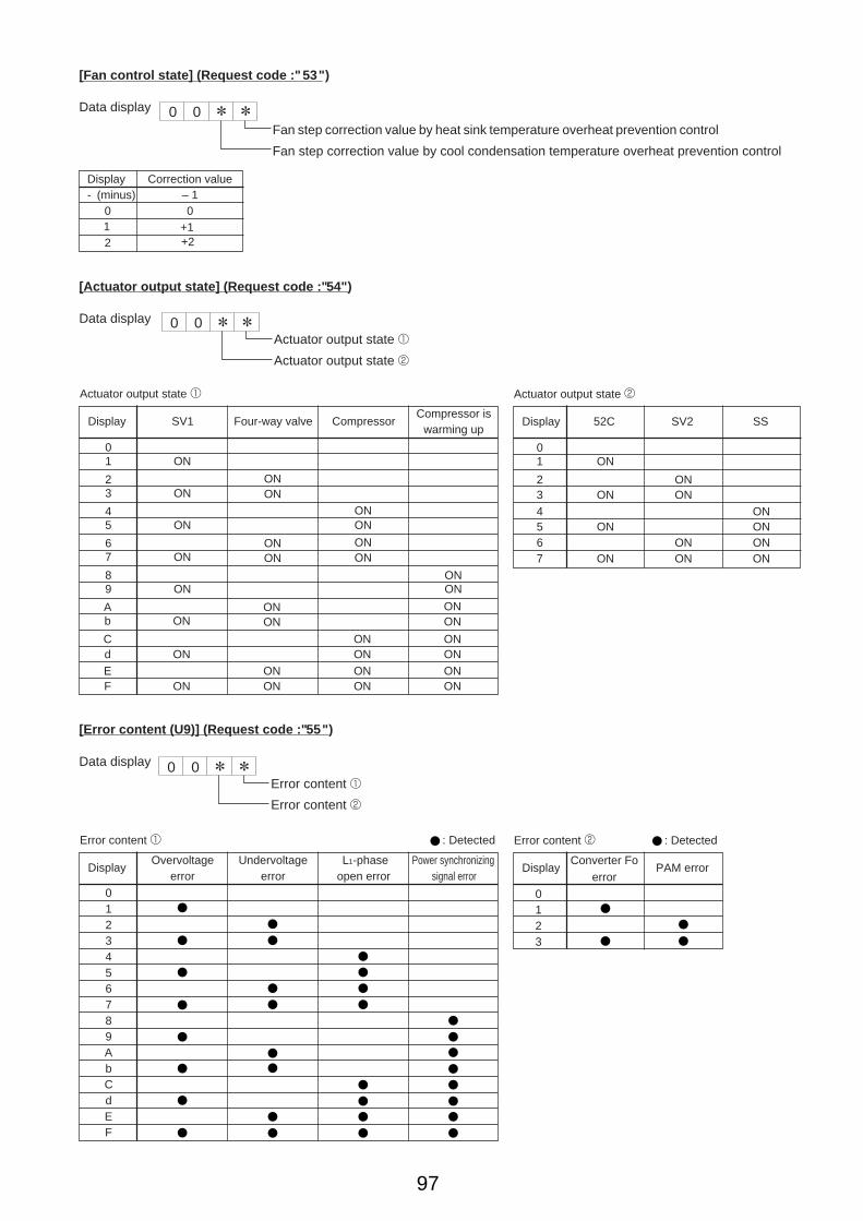
97
[Fan control state] (Request code :"53")
Data display
Fan step correction value by heat sink temperature overheat prevention control
Fan step correction value by cool condensation temperature overheat prevention control
0 0
Display Correction value- (minus) – 1
0 0
2
[Actuator output state] (Request code :"54")
Data display
Actuator output state 1
Actuator output state 2
0 0
Actuator output state 1
Display SV1 Four-way valve Compressor
01
23
45
67
89
Ab
CdEF
ON
ON
ON
ON
ON
ON
ON
ON
ONON
ONON
ONON
ONON
ONON
ONON
ONONONON
ONON
ONON
ONONONON
Actuator output state 2
Display 52C SV2 SS
01
234567
ON
ON
ON
ON
ONON
ONON
ONONONON
[Error content (U9)] (Request code :"55")
Data display
Error content 1
Error content 2
0 0
Error content 1 : Detected
DisplayOvervoltage Undervoltage L1-phase Power synchronizing
error error open error signal error0123456789AbCdEF
Error content 2 : Detected
DisplayConverter Fo
PAM errorerror
0123
Compressor iswarming up
1 +1+2
OC334-4.qxp 05.5.26 5:58 PM Page 97
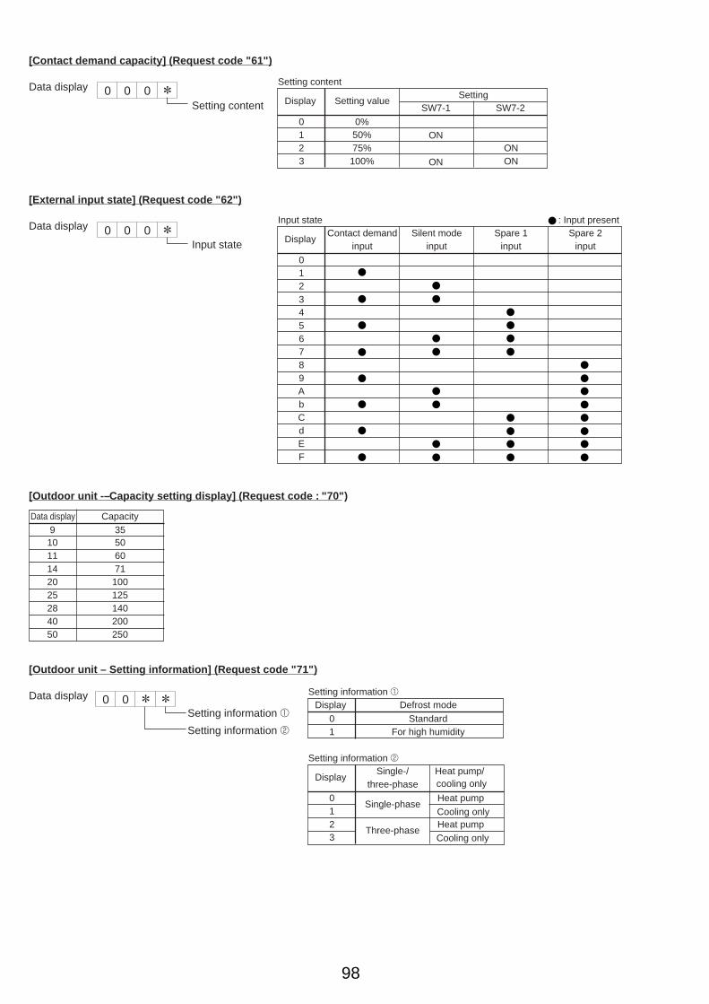
98
[Contact demand capacity] (Request code "61")
Data display 0 0 0Setting content
[External input state] (Request code "62")
Data display 0 0 0Input state
Input state : Input present
DisplayContact demand Silent mode Spare 1 Spare 2
input input input input
0123456789AbCdEF
[Outdoor unit -– Capacity setting display] (Request code : "70")
Data display Capacity
10 50 9 35
11 6014 7120 10025 12528 14040 20050 250
[Outdoor unit – Setting information] (Request code "71")
Data display
Setting information 1
Setting information 2
0 0Setting information 1
Display Defrost mode0 Standard1 For high humidity
Setting information 2
DisplaySingle-/ Heat pump/
three-phase cooling only
0Single-phase
Heat pump1 Cooling only2
Three-phaseHeat pump
3 Cooling only
Setting content
Display Setting valueSetting
SW7-1 SW7-2
01 50% ON
ON
2 75% ONON
0%
3 100%
OC334-4.qxp 05.5.26 5:58 PM Page 98
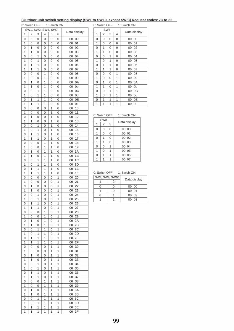
99
SW1, SW2, SW6, SW71 2 3 4 5 6
0 0 0 0 0 0 00 001 0 0 0 0 0 00 010 1 0 0 0 0 00 021 1 0 0 0 0 00 030 0 1 0 0 0 00 041 0 1 0 0 0 00 050 1 1 0 0 0 00 061 1 1 0 0 0 00 070 0 0 1 0 0 00 081 0 0 1 0 0 00 090 1 0 1 0 0 00 0A1 1 0 1 0 0 00 0b0 0 1 1 0 0 00 0C1 0 1 1 0 0 00 0d0 1 1 1 0 0 00 0E1 1 1 1 0 0 00 0F0 0 0 0 1 0 00 101 0 0 0 1 00 1 0 0 1 01 1 0 0 1 00 0 1 0 1 01 0 1 0 1 00 1 1 0 1 01 1 1 0 1 00 0 0 1 1 01 0 0 1 1 00 1 0 1 1 01 1 0 1 1 00 0 1 1 1 01 0 1 1 1 00 1 1 1 1 01 1 1 1 1 00 0 0 0 0 11 0 0 0 0 10 1 0 0 0 11 1 0 0 0 10 0 1 0 0 11 0 1 0 0 10 1 1 0 0 11 1 1 0 0 10 0 0 1 0 11 0 0 1 0 10 1 0 1 0 11 1 0 1 0 10 0 1 1 0 11 0 1 1 0 10 1 1 1 0 11 1 1 1 0 10 0 0 0 1 11 0 0 0 1 10 1 0 0 1 11 1 0 0 1 10 0 1 0 1 11 0 1 0 1 10 1 1 0 1 11 1 1 0 1 10 0 0 1 1 11 0 0 1 1 10 1 0 1 1 11 1 0 1 1 10 0 1 1 1 11 0 1 1 1 10 1 1 1 1 11 1 1 1 1 1
[Outdoor unit switch setting display (SW1 to SW10, except SW3)] Request codes: 73 to 820: Swich OFF 1: Swich ON
Data displaySW5
1 2 3 4
0 0 0 0 00 001 0 0 0 00 010 1 0 0 00 021 1 0 0 00 030 0 1 0 00 041 0 1 0 00 050 1 1 0 00 061 1 1 0 00 070 0 0 1 00 081 0 0 1 00 090 1 0 1 00 0A1 1 0 1 00 0b0 0 1 1 00 0C1 0 1 1 00 0d0 1 1 1 00 0E1 1 1 1 00 0F
0: Swich OFF 1: Swich ON
Data display
SW81 2 3
0 0 0 00 001 0 0 00 010 1 0 00 021 1 0 00 030 0 1 00 041 0 1 00 050 1 1 00 061 1 1 00 07
0: Swich OFF 1: Swich ON
Data display
SW4, SW9, SW101 2
0 0 00 001 0 00 010 1 00 021 1 00 03
0: Swich OFF 1: Swich ON
Data display
00 1100 1200 1300 1400 1500 1600 1700 1800 1900 1A00 1B00 1C00 1D00 1E00 1F00 2000 2100 2200 2300 2400 2500 2600 2700 2800 2900 2A00 2B00 2C00 2D00 2E00 2F00 3000 3100 3200 3300 3400 3500 3600 3700 3800 3900 3A00 3B00 3C00 3D00 3E00 3F
OC334-4.qxp 05.5.26 5:58 PM Page 99

100
[Indoor unit – Model setting information] (Request code : 162)
Data display
0 0
See the table on the right.
Display Model setting state Display Model setting state
00 PSA-RP•GA, PSH-PGAH 2001 21 PKA-RP•FAL, PKH-P•FALH02 PEAD-RP•EA/GA, PEHD-P•EAH 22 PCA-RP•GA, PCH-P•GAH03 SEZ-KA•VA 2304 2405 SLZ-KA•VA(L) 2506 PCA-RP•HA 2607 2708 2809 290A 2A0b 2b PKA-RP•GAL, PKH-P•GALH0C 2C0d 2d0E 2E0F 2F PLA-RP• AA10 3011 PEA-RP•EA 31 PLH-P•AAH12 MEXZ-GA•VA(L) 3213 3314 3415 3516 3617 3718 3819 391A 3A1b 3b1C 3C1d 3d1E 3E1F 3F
[Indoor unit – Capacity setting information] (Request code 163 )
Data display
0 0
See the table on the right.
Display Capacity setting state Display Capacity setting state
00 12 10 11201 16 11 12502 22 12 14003 25 13 16004 28 14 20005 32 15 22406 36 16 25007 40 17 28008 45 1809 50 190A 56 1A0b 63 1b0C 71 1C0d 80 1d0E 90 1E0F 100 1F
Display Pair No. setting state
00 No. 001 No. 1 J41 disconnected02 No. 2 J42 disconnected03 No. 3 J41, J42 disconnected
[Wireless pair No. (indoor control board side) setting] (Request code 165 )
Data display
0 0
See the table on the right.
OC334-4.qxp 05.5.26 5:58 PM Page 100

101
13 DISASSEMBLY PROCEDURE
OPERATING PROCEDURE PHOTOS
PUHZ-RP35VHA PUHZ-RP50VHA
1. Removing the top panel, service panel, front panel and back panel(1) Remove the top panel fixing screws (4 ✕ 10), one from the
right and two from the eft side, and detach the top panel.
(2) Remove 1 service panel fixing screw (4 ✕ 10) and detach the service panel by pulling it downward. (See photo 2.)
(3) Remove the front panel fixing screws (4 ✕ 10), 5 from the front, 2 from the right and 2 from the left side, and detach the front panel.
(4) Remove the back panel fixing screws (4 ✕ 10), 4 from the right and 3 from the rear side, and detach the back panel.
2. Removing the fan motor(1) Remove the top panel. (See photo 1.)(2) Remove the front panel. (See photo 1.)(3) Remove 1 nut (M6, left-screw) and detach the propeller. (4) Disconnect the connector CNF1 on the controller circuit
board in the electrical parts box.(5) Loosen the clamp for the lead wire in the motor support. (6) Remove 4 fan motor fixing screws (4 ✕ 18) and detach the
fan motor. (See photo 3.)
Photo 1
Photo 2
Top panel Top panel fixing screws
Service panel
Service panel for charge plugGrille
Front panel
Back panel
4 hooks
Pull down
Service panel fixing screw
Photo 3
Propeller
Nut
Electrical parts box
Photo 4
Fan motor(MF1)
Fan motor fixing screws
Fan motor fixing screws
Motor support
Clamp
OC334-4.qxp 05.5.26 5:58 PM Page 101
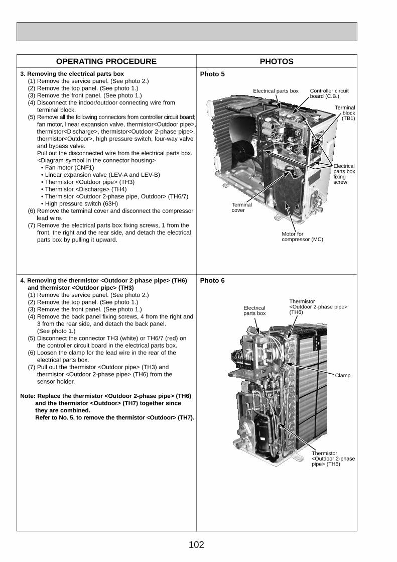
102
Electrical parts box Controller circuitboard (C.B.)
Electrical parts box fixingscrew
Terminalblock(TB1)
OPERATING PROCEDURE PHOTOS
4. Removing the thermistor <Outdoor 2-phase pipe> (TH6) and thermistor <Outdoor pipe> (TH3)(1) Remove the service panel. (See photo 2.)(2) Remove the top panel. (See photo 1.)(3) Remove the front panel. (See photo 1.)(4) Remove the back panel fixing screws, 4 from the right and
3 from the rear side, and detach the back panel. (See photo 1.)
(5) Disconnect the connector TH3 (white) or TH6/7 (red) on the controller circuit board in the electrical parts box.
(6) Loosen the clamp for the lead wire in the rear of the electrical parts box.
(7) Pull out the thermistor <Outdoor pipe> (TH3) and thermistor <Outdoor 2-phase pipe> (TH6) from the sensor holder.
Note: Replace the thermistor <Outdoor 2-phase pipe> (TH6)and the thermistor <Outdoor> (TH7) together since they are combined. Refer to No. 5. to remove the thermistor <Outdoor> (TH7).
3. Removing the electrical parts box(1) Remove the service panel. (See photo 2.)(2) Remove the top panel. (See photo 1.)(3) Remove the front panel. (See photo 1.)(4) Disconnect the indoor/outdoor connecting wire from
terminal block.(5) Remove all the following connectors from controller circuit board;
fan motor, linear expansion valve, thermistor<Outdoor pipe>,thermistor<Discharge>, thermistor<Outdoor 2-phase pipe>, thermistor<Outdoor>, high pressure switch, four-way valve and bypass valve. Pull out the disconnected wire from the electrical parts box.<Diagram symbol in the connector housing>
• Fan motor (CNF1) • Linear expansion valve (LEV-A and LEV-B) • Thermistor <Outdoor pipe> (TH3) • Thermistor <Discharge> (TH4) • Thermistor <Outdoor 2-phase pipe, Outdoor> (TH6/7) • High pressure switch (63H)
(6) Remove the terminal cover and disconnect the compressorlead wire.
(7) Remove the electrical parts box fixing screws, 1 from the front, the right and the rear side, and detach the electrical parts box by pulling it upward.
Photo 5
Motor forcompressor (MC)
Terminal cover
Photo 6
Thermistor <Outdoor 2-phase pipe>(TH6)
Clamp
Electrical parts box
Thermistor <Outdoor 2-phase pipe> (TH6)
OC334-4.qxp 05.5.26 5:58 PM Page 102
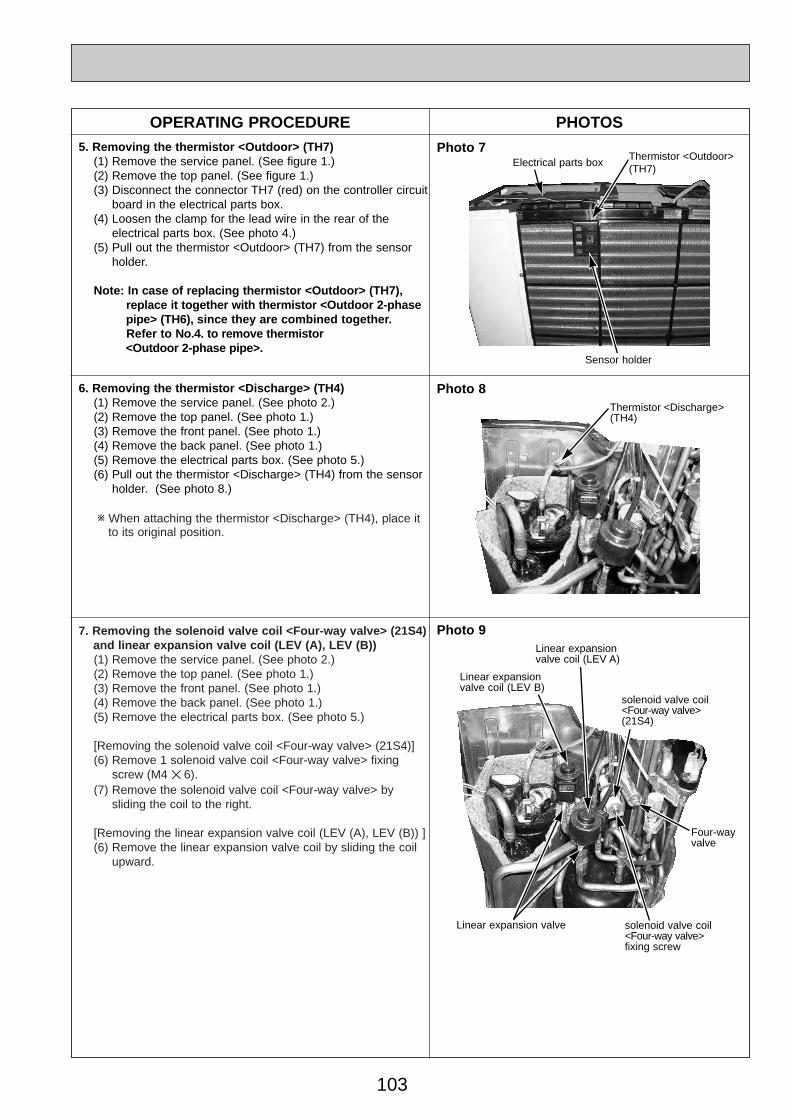
103
OPERATING PROCEDURE PHOTOS5. Removing the thermistor <Outdoor> (TH7)
(1) Remove the service panel. (See figure 1.)(2) Remove the top panel. (See figure 1.)(3) Disconnect the connector TH7 (red) on the controller circuit
board in the electrical parts box.(4) Loosen the clamp for the lead wire in the rear of the
electrical parts box. (See photo 4.)(5) Pull out the thermistor <Outdoor> (TH7) from the sensor
holder.
Note: In case of replacing thermistor <Outdoor> (TH7), replace it together with thermistor <Outdoor 2-phase pipe> (TH6), since they are combined together. Refer to No.4. to remove thermistor <Outdoor 2-phase pipe>.
Photo 7
Photo 9
6. Removing the thermistor <Discharge> (TH4)(1) Remove the service panel. (See photo 2.)(2) Remove the top panel. (See photo 1.)(3) Remove the front panel. (See photo 1.)(4) Remove the back panel. (See photo 1.)(5) Remove the electrical parts box. (See photo 5.)(6) Pull out the thermistor <Discharge> (TH4) from the sensor
holder. (See photo 8.)
w When attaching the thermistor <Discharge> (TH4), place it to its original position.
7. Removing the solenoid valve coil <Four-way valve> (21S4) and linear expansion valve coil (LEV (A), LEV (B))(1) Remove the service panel. (See photo 2.)(2) Remove the top panel. (See photo 1.)(3) Remove the front panel. (See photo 1.)(4) Remove the back panel. (See photo 1.)(5) Remove the electrical parts box. (See photo 5.)
[Removing the solenoid valve coil <Four-way valve> (21S4)](6) Remove 1 solenoid valve coil <Four-way valve> fixing
screw (M4 ✕ 6).(7) Remove the solenoid valve coil <Four-way valve> by
sliding the coil to the right.
[Removing the linear expansion valve coil (LEV (A), LEV (B)) ](6) Remove the linear expansion valve coil by sliding the coil
upward.
Thermistor <Outdoor>(TH7)
Sensor holder
Electrical parts box
Photo 8Thermistor <Discharge> (TH4)
solenoid valve coil<Four-way valve> fixing screw
Four-way valve
Linear expansion valve coil (LEV B)
Linear expansion valve coil (LEV A)
solenoid valve coil<Four-way valve> (21S4)
Linear expansion valve
OC334-4.qxp 05.5.26 5:58 PM Page 103

104
OPERATING PROCEDURE PHOTOS8. Removing the four-way valve
(1) Remove the service panel. (See photo 2.)(2) Remove the top panel. (See photo 1.)(3) Remove the front panel. (See photo 1.)(4) Remove the back panel. (See photo 1.)(5) Remove the electrical parts box. (See photo 5.)(6) Remove the solenoid valve coil <Four-way valve>
(See photo 8.)(7) Collect the refrigerant.(8) Remove the welded part of four-way valve.Note 1: Collect refrigerant without spreading it in the air.Note 2: The welded part can be removed easily by remov-
ing the right side panel.Note 3: When installing the four-way valve, cover it with a
we cloth to prevent it from heating (120°C or more), then braze the pipes so that the inside of pipesare not oxidized.
Photo 10
Photo 11
9. Removing linear expansion valve(1) Remove the service panel. (See photo 2.)(2) Remove the top panel. (See photo 1.)(3) Remove the front panel. (See photo 1.)(4) Remove the back panel. (See photo 1.)(5) Remove the electrical parts box. (See photo 5.)(6) Remove the linear expansion valve coil . (See photo 8.)(7) Collect the refrigerant.(8) Remove the welded part of linear expansion valve.Note 1: Collect refrigerant without spreading it in the air.Note 2: The welded part can be removed easily by remov-
ing the back panel.Note 3: When installing the linear expansion valve, cover
it with a wet cloth to prevent it from heating(120°C or more), then braze the pipes so that theinside of pipes are not oxidized.
10. Removing the high pressure switch (63H)(1) Remove the service panel. (See photo 2.)(2) Remove the top panel. (See photo 1.)(3) Remove the front panel. (See photo 1.)(4) Remove the back panel. (See photo 1.)(5) Remove the electrical parts box. (See photo 5.)(6) Pull out the lead wire of high pressure switch.(7) Collect the refrigerant.(8) Remove the welded part of high pressure switch.
Note 1: Collect refrigerant without spreading it in the air.Note 2: The welded part can be removed easily by
removing the back panel.Note 3: When installing the high pressure switch, cover it
with a wet cloth to prevent it from heating (100°C or more), then braze the pipes so that the inside of pipes are not oxidized.
Reactor fixing screw
High pressure switch (63H)
Reactor fixing screws
Reactor(ACL)
Electrical parts box
11. Removing the reactor (ACL)(1) Remove the service panel. (See photo 2.)(2) Remove the top panel. (See photo 1.)(3) Remove the front panel. (See photo 1.)(4) Remove the back panel. (See photo 1.)(5) Remove 3 reactor fixing screws (4 ✕ 20) and remove the
reactor.w The reactor is attached to the rear of the electrical parts box.
solenoid valve coil<Four-way valve> fixing screw
Four-way valve
Linear expansion valve coil (LEV B)
Linear expansion valve coil (LEV A)
solenoid valve coil<Four-way valve> (21S4)
Linear expansion valve
Photo 12
Charge plug
OC334-4.qxp 05.5.26 5:58 PM Page 104
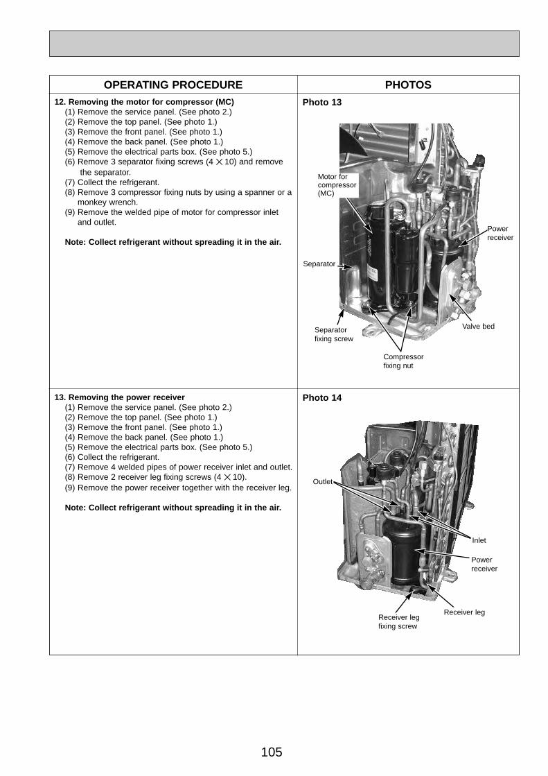
105
OPERATING PROCEDURE PHOTOS
Photo 13
Photo 14
Motor forcompressor(MC)
Valve bed
Separator
Separatorfixing screw
Compressorfixing nut
Powerreceiver
Powerreceiver
Outlet
Inlet
12. Removing the motor for compressor (MC)(1) Remove the service panel. (See photo 2.)(2) Remove the top panel. (See photo 1.)(3) Remove the front panel. (See photo 1.)(4) Remove the back panel. (See photo 1.)(5) Remove the electrical parts box. (See photo 5.)(6) Remove 3 separator fixing screws (4 ✕ 10) and remove
the separator.(7) Collect the refrigerant.(8) Remove 3 compressor fixing nuts by using a spanner or a
monkey wrench.(9) Remove the welded pipe of motor for compressor inlet
and outlet.
Note: Collect refrigerant without spreading it in the air.
Receiver leg fixing screw
Receiver leg
13. Removing the power receiver (1) Remove the service panel. (See photo 2.)(2) Remove the top panel. (See photo 1.)(3) Remove the front panel. (See photo 1.)(4) Remove the back panel. (See photo 1.)(5) Remove the electrical parts box. (See photo 5.)(6) Collect the refrigerant.(7) Remove 4 welded pipes of power receiver inlet and outlet.(8) Remove 2 receiver leg fixing screws (4 ✕ 10).(9) Remove the power receiver together with the receiver leg.
Note: Collect refrigerant without spreading it in the air.
OC334-4.qxp 05.5.26 5:58 PM Page 105
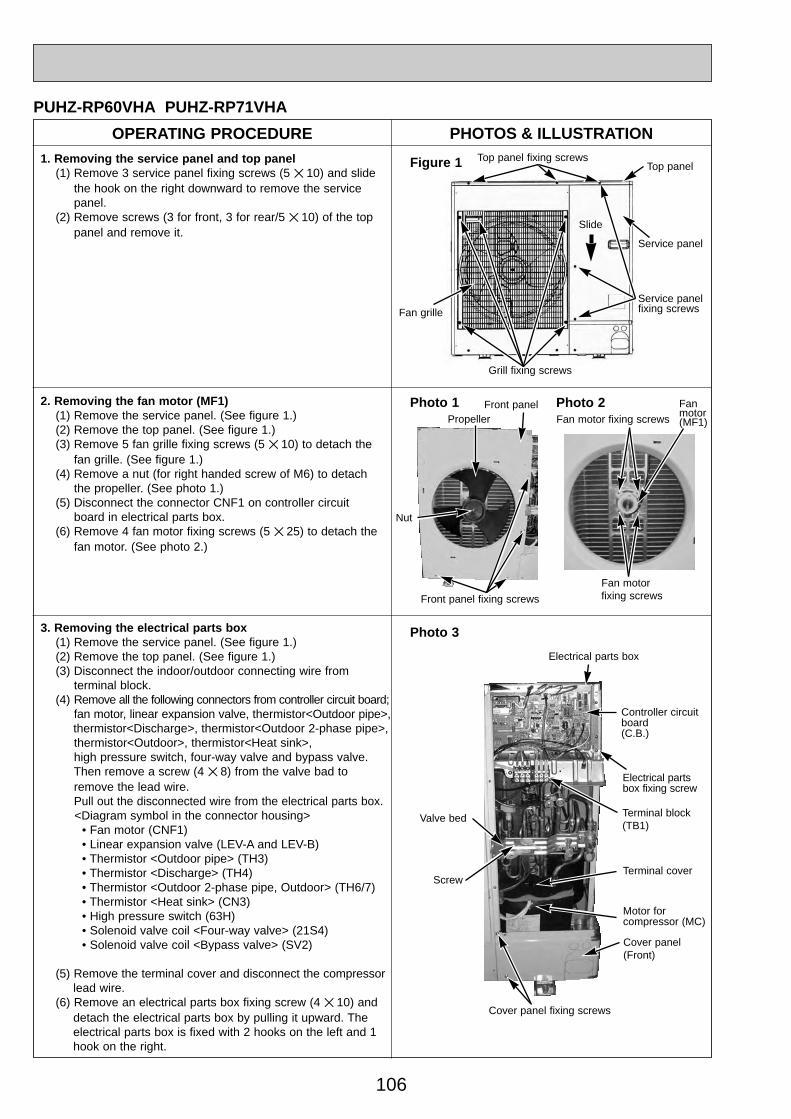
106
OPERATING PROCEDURE PHOTOS & ILLUSTRATION
PUHZ-RP60VHA PUHZ-RP71VHA
1. Removing the service panel and top panel(1) Remove 3 service panel fixing screws (5 ✕ 10) and slide
the hook on the right downward to remove the service panel.
(2) Remove screws (3 for front, 3 for rear/5 ✕ 10) of the top panel and remove it.
Figure 1 Top panel fixing screwsTop panel
Service panelfixing screws
Service panel
Grill fixing screws
Fan grille
2. Removing the fan motor (MF1)(1) Remove the service panel. (See figure 1.)(2) Remove the top panel. (See figure 1.)(3) Remove 5 fan grille fixing screws (5 ✕ 10) to detach the
fan grille. (See figure 1.)(4) Remove a nut (for right handed screw of M6) to detach
the propeller. (See photo 1.)(5) Disconnect the connector CNF1 on controller circuit
board in electrical parts box.(6) Remove 4 fan motor fixing screws (5 ✕ 25) to detach the
fan motor. (See photo 2.)
Fan motor fixing screws
Photo 3
Electrical parts box
Controller circuitboard(C.B.)
Electrical partsbox fixing screw
Terminal cover
Cover panel (Front)
Cover panel fixing screws
Motor forcompressor (MC)
Photo 1 Fan motor(MF1)
Fan motor fixing screws
PropellerFront panel
Front panel fixing screws
Nut
Terminal block(TB1)
Photo 2
Valve bed
Screw
Slide
3. Removing the electrical parts box(1) Remove the service panel. (See figure 1.)(2) Remove the top panel. (See figure 1.)(3) Disconnect the indoor/outdoor connecting wire from
terminal block.(4) Remove all the following connectors from controller circuit board;
fan motor, linear expansion valve, thermistor<Outdoor pipe>,thermistor<Discharge>, thermistor<Outdoor 2-phase pipe>, thermistor<Outdoor>, thermistor<Heat sink>, high pressure switch, four-way valve and bypass valve. Then remove a screw (4 ✕ 8) from the valve bad to remove the lead wire.Pull out the disconnected wire from the electrical parts box.<Diagram symbol in the connector housing>
• Fan motor (CNF1) • Linear expansion valve (LEV-A and LEV-B) • Thermistor <Outdoor pipe> (TH3) • Thermistor <Discharge> (TH4) • Thermistor <Outdoor 2-phase pipe, Outdoor> (TH6/7) • Thermistor <Heat sink> (CN3) • High pressure switch (63H) • Solenoid valve coil <Four-way valve> (21S4) • Solenoid valve coil <Bypass valve> (SV2)
(5) Remove the terminal cover and disconnect the compressorlead wire.
(6) Remove an electrical parts box fixing screw (4 ✕ 10) and detach the electrical parts box by pulling it upward. The electrical parts box is fixed with 2 hooks on the left and 1 hook on the right.
OC334-4.qxp 05.5.26 5:58 PM Page 106
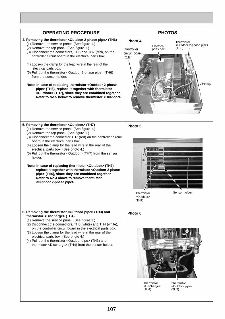
107
Thermistor <Outdoor 2-phase pipe>(TH6)
OPERATING PROCEDURE PHOTOS
Photo 44. Removing the thermistor <Outdoor 2-phase pipe> (TH6)(1) Remove the service panel. (See figure 1.)(2) Remove the top panel. (See figure 1.)(3) Disconnect the connectors, TH6 and TH7 (red), on the
controller circuit board in the electrical parts box.
(4) Loosen the clamp for the lead wire in the rear of the electrical parts box.
(5) Pull out the thermistor <Outdoor 2-phase pipe> (TH6) from the sensor holder.
Note: In case of replacing thermistor <Outdoor 2-phase pipe> (TH6), replace it together with thermistor <Outdoor> (TH7), since they are combined together. Refer to No.5 below to remove thermistor <Outdoor>.
5. Removing the thermistor <Outdoor> (TH7)(1) Remove the service panel. (See figure 1.)(2) Remove the top panel. (See figure 1.)(3) Disconnect the connector TH7 (red) on the controller circuit
board in the electrical parts box.(4) Loosen the clamp for the lead wire in the rear of the
electrical parts box. (See photo 4.)(5) Pull out the thermistor <Outdoor> (TH7) from the sensor
holder.
Note: In case of replacing thermistor <Outdoor> (TH7), replace it together with thermistor <Outdoor 2-phase pipe> (TH6), since they are combined together. Refer to No.4 above to remove thermistor <Outdoor 2-phase pipe>.
Photo 6
Clamp
6. Removing the thermistor <Outdoor pipe> (TH3) and thermistor <Discharge> (TH4)(1) Remove the service panel. (See figure 1.)(2) Disconnect the connectors, TH3 (white) and TH4 (white),
on the controller circuit board in the electrical parts box.(3) Loosen the clamp for the lead wire in the rear of the
electrical parts box. (See photo 4.)(4) Pull out the thermistor <Outdoor pipe> (TH3) and
thermistor <Discharge> (TH4) from the sensor holder.
Electrical parts box
Photo 5
Thermistor<Outdoor>(TH7)
Sensor holder
Thermistor<Discharge> (TH4)
Thermistor <Outdoor pipe> (TH3)
Controller circuit board(C.B.)
OC334-4.qxp 05.5.26 5:58 PM Page 107

108
OPERATING PROCEDURE PHOTOS7. Removing the solenoid valve coil <Four-way valve> (21S4),
linear expansion valve coil (LEV(A), LEV(B)) and solenoid valve coil <Bypass valve> (SV)(1) Remove the service panel. (See figure 1.)(2) Remove the top panel. (See figure 1.)(3) Remove the electrical parts box. (See photo 3.)[Removing the solenoid valve coil <Four-way valve>](4) Remove solenoid valve coil <Four-way valve> fixing screw
(M4 ✕ 6).(5) Remove the solenoid valve coil <Four-way valve> by
sliding the coil toward you.(6) Disconnect the connector 21S4 (green) on the controller
board in the electrical parts box.[Removing the linear expansion valve coil](4) Remove the linear expansion valve coil by sliding the coil upward.(5) Disconnect the connectors, LEV A (white) and LEV B (red),
on the controller circuit board in the electrical parts box.[Removing the solenoid valve coil <Bypass valve>](4) Remove the solenoid valve coil <Bypass valve> fixing screw
(M4 ✕ 6).(5) Remove the solenoid valve coil <Bypass valve> by sliding the
coil upward.(6) Disconnect the connector SV2 (blue) on the controller
circuit board in the electrical parts box.
8. Removing the four-way valve(1) Remove the service panel. (See figure 1.)(2) Remove the top panel. (See figure 1.)(3) Remove the electrical parts box. (See photo 3.)(4) Remove 3 valve bed fixing screws (4 ✕ 10) and 4 ball
valve and stop valve fixing screws (5 ✕ 16) and then remove the valve bed.
(5) Remove 3 right side panel fixing screw (5 ✕ 10) in the rear of the unit and then remove the right side panel.
(6) Remove the solenoid valve coil <Four-way valve>. (See photo 7.)
(7) Collect the refrigerant.(8) Remove the welded part of four-way valve.Note 1: Collect refrigerant without spreading it in the air.Note 2: The welded part can be removed easily by remov-
ing the right side panel.Note 3: When installing the four-way valve, cover it with a wet
cloth to prevent it from heating (120°C or more), thenbraze the pipes so that the inside of pipes are not oxi-dized.
9. Removing the linear expansion valve(1) Remove the service panel. (See figure 1.)(2) Remove the top panel. (See figure 1.)(3) Remove the electrical parts box. (See photo 3.)(4) Remove 3 valve bed fixing screws (4 ✕ 10) and 4 ball
valve and stop valve fixing screws (5 ✕ 16) and then remove the valve bed.
(5) Remove 3 right side panel fixing screw (5 ✕ 10) in the rear of the unit and then remove the right side panel.
(6) Remove the linear expansion valve. (See photo 7.)(7) Collect the refrigerant.(8) Remove the welded part of linear expansion valve.Note 1: Collect refrigerant without spreading it in the air.Note 2: The welded part can be removed easily by remov-
ing the right side panel.Note 3: When installing the linear expansion valve, cover
it with a wet cloth to prevent it from heating(120°C or more), then braze the pipes so that theinside of pip-es are not oxidized.
Photo 7
Photo 8
solenoid valve coil<Four-way valve> fixing screw
Four-way valve
Linear expansion valve coil (LEV B)
Linear expansion valve coil (LEV A)
Solenoid valve coil <Bypass valve> fixing screw
Linear expansion valve coil (LEV B)
Linear expansion valve coil (LEV A)
Linear expansion valve Four-way
valve
Linearexpansion valve
Solenoid valve coil <Bypass valve> (SV)
solenoid valve coil<Four-way valve> (21S4)
solenoid valve coil<Four-way valve> (21S4)
Bypass valve
Solenoid valve coil <Bypass valve> (SV)
Charge plug(High pressure)
Charge plug(Low pressure)
Stop valve
OC334-4.qxp 05.5.26 5:58 PM Page 108

109
OPERATING PROCEDURE PHOTOS10. Removing the bypass valve
(1) Remove the service panel. (See figure 1.)(2) Remove the top panel. (See figure 1.)(3) Remove the electrical parts box. (See photo 3.)(4) Remove 3 right side panel fixing screws (5 ✕ 10) in the
rear of the unit and remove the right side panel.(5) Remove the bypass valve solenoid coil. (See photo 7.).(6) Collect the refrigerant.(7) Remove the welded part of bypass valve.
Note 1: Collect refrigerant without spreading it in the air.Note 2: The welded part can be removed easily by
removing the right side panel.
12. Removing the reactor (ACL)(1) Remove the service panel. (See figure 1.)(2) Remove the top panel. (See figure 1.)(3) Remove the electrical parts box. (See photo 3.)(4) Remove 3 reactor fixing screws (4 ✕ 16) and remove the
reactor.w The reactor is attached to the rear of the electrical parts box.
Photo 9
Reactor fixing screw
11. Removing the high pressure switch (63H)(1) Remove the service panel. (See figure 1.)(2) Remove the top panel. (See figure 1.)(3) Remove the electrical parts box. (See photo 3.)(4) Remove 3 right side panel fixing screws (5 ✕ 10) in the
rear of the unit and remove the right side panel.(5) Pull out the lead wire of high pressure switch.(6) Collect the refrigerant.(7) Remove the welded part of high pressure switch.
Note 1: Collect refrigerant without spreading it in the air.Note 2: The welded part can be removed easily by
removing the right side panel.Note 3: When installing the high pressure switch, cover it
with a wet cloth to prevent it from heating (100°C or more), then braze the pipes so that the inside of pipes are not oxidized.
Linear expansion valve coil (LEV B)
Linear expansion valve coil (LEV A)
Linear expansion valve
Bypass valve
Four-way valve
Lead wire of high pressure switch
High pressure switch (63H)
Reactor fixing screws
Reactor(ACL)
Photo 10
Photo 11
Linearexpansion valve
Electrical parts box
Solenoid valve coil <Bypass valve> (SV)
Solenoid valve coil<Four-way valve> (21S4)
OC334-4.qxp 05.5.26 5:58 PM Page 109

110
OPERATING PROCEDURE PHOTOS13. Removing the motor for compressor (MC)
(1) Remove the service panel. (See figure 1.)(2) Remove the top panel. (See figure 1.)(3) Remove 2 front cover panel fixing screws (5 ✕ 10) and
remove the front cover panel. (See photo 3.)(4) Remove 2 back cover panel fixing screws (5 ✕ 10) and
remove the back cover panel.(5) Remove the electrical parts box. (See photo 3.)(6) Remove 3 valve bed fixing screws (4 ✕ 10) and 4 ball valve
and stop valve fixing screws (5 ✕ 16) and then remove the valve bed.
(7) Remove 3 right side panel fixing screw (5 ✕ 10) in the rearof the unit and then remove the right side panel.
(8) Remove 3 separator fixing screws (4 ✕ 10) and remove the separator.
(9) Collect the refrigerant.(10) Remove the 3 points of the motor for compressor fixing
nut using a spanner or a monkey wrench.(11) Remove the welded pipe of motor for compressor inlet
and outlet and then remove the compressor.
Note: Collect refrigerant without spreading it in the air.
14. Removing the power receiver (1) Remove the service panel. (See figure 1.)(2) Remove the top panel. (See figure 1.)(3) Remove 2 front cover panel fixing screws (5 ✕ 10) and
remove the front cover panel. (See photo 3.)(4) Remove 2 back cover panel fixing screws (5 ✕ 10) and
remove the back cover panel.(5) Remove the electrical parts box. (See photo 3.)(6) Remove 3 valve bed fixing screws (4 ✕ 10) and 4 ball valve
and stop valve fixing screws (5 ✕ 16) and then remove the valve bed.
(7) Remove 3 right side panel fixing screw (5 ✕ 10) in the rear of the unit and then remove the right side panel.
(8) Collect the refrigerant.(9) Remove 4 welded pipes of power receiver inlet and outlet.(10) Remove 2 receiver leg fixing screws (4 ✕ 10).
Note: Collect refrigerant without spreading it in the air.
Photo 12
Receiver leg fixing screws
Motor forcompressor(MC)
Valve bedfixingscrews
Valve bed
Separator
Separatorfixing screw
Compressorfixing nut
Powerreceiver
Powerreceiver
Receiverleg
Inlet
Outlet
Photo 13
OC334-4.qxp 05.5.26 5:58 PM Page 110
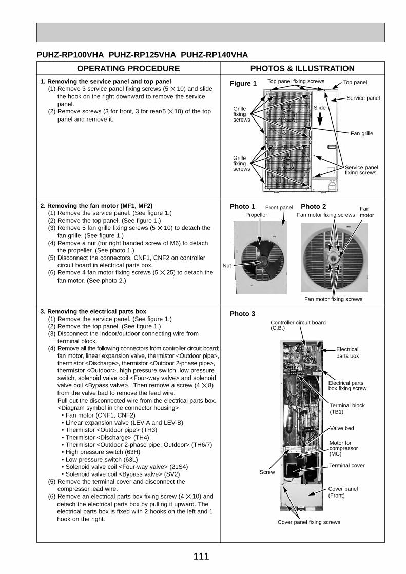
111
OPERATING PROCEDURE PHOTOS & ILLUSTRATION
PUHZ-RP100VHA PUHZ-RP125VHA PUHZ-RP140VHA
1. Removing the service panel and top panel(1) Remove 3 service panel fixing screws (5 ✕ 10) and slide
the hook on the right downward to remove the service panel.
(2) Remove screws (3 for front, 3 for rear/5 ✕ 10) of the top panel and remove it.
Figure 1 Top panel fixing screws Top panel
Service panelfixing screws
Service panel
Grille fixing screws
Fan grille
2. Removing the fan motor (MF1, MF2)(1) Remove the service panel. (See figure 1.)(2) Remove the top panel. (See figure 1.)(3) Remove 5 fan grille fixing screws (5 ✕ 10) to detach the
fan grille. (See figure 1.)(4) Remove a nut (for right handed screw of M6) to detach
the propeller. (See photo 1.)(5) Disconnect the connectors, CNF1, CNF2 on controller
circuit board in electrical parts box.(6) Remove 4 fan motor fixing screws (5 ✕ 25) to detach the
fan motor. (See photo 2.)
Fan motor fixing screws
Photo 33. Removing the electrical parts box(1) Remove the service panel. (See figure 1.)(2) Remove the top panel. (See figure 1.)(3) Disconnect the indoor/outdoor connecting wire from
terminal block.(4) Remove all the following connectors from controller circuit board;
fan motor, linear expansion valve, thermistor <Outdoor pipe>,thermistor <Discharge>, thermistor <Outdoor 2-phase pipe>, thermistor <Outdoor>, high pressure switch, low pressure switch, solenoid valve coil <Four-way valve> and solenoid valve coil <Bypass valve>. Then remove a screw (4 ✕ 8) from the valve bad to remove the lead wire.Pull out the disconnected wire from the electrical parts box.<Diagram symbol in the connector housing>
• Fan motor (CNF1, CNF2) • Linear expansion valve (LEV-A and LEV-B) • Thermistor <Outdoor pipe> (TH3) • Thermistor <Discharge> (TH4) • Thermistor <Outdoor 2-phase pipe, Outdoor> (TH6/7) • High pressure switch (63H) • Low pressure switch (63L) • Solenoid valve coil <Four-way valve> (21S4) • Solenoid valve coil <Bypass valve> (SV2)
(5) Remove the terminal cover and disconnect the compressor lead wire.
(6) Remove an electrical parts box fixing screw (4 ✕ 10) and detach the electrical parts box by pulling it upward. The electrical parts box is fixed with 2 hooks on the left and 1 hook on the right.
Electrical parts box
Controller circuit board(C.B.)
Electrical partsbox fixing screw
Terminal cover
Cover panel (Front)
Cover panel fixing screws
Motor forcompressor(MC)
Photo 1 Fanmotor
Fan motor fixing screws
PropellerFront panel
Nut
Terminal block(TB1)
Photo 2
Valve bed
Screw
Grille fixing screws
Slide
OC334-4.qxp 05.5.26 5:58 PM Page 111
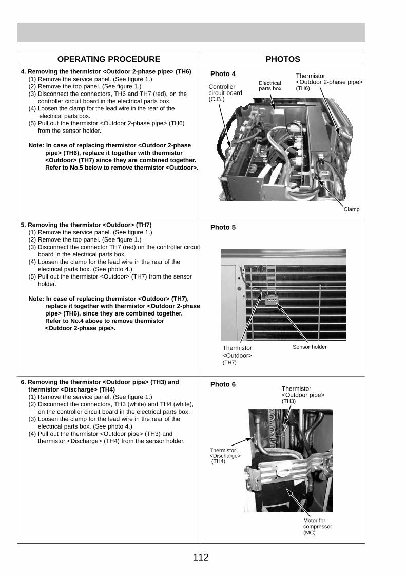
112
OPERATING PROCEDURE PHOTOS
Photo 44. Removing the thermistor <Outdoor 2-phase pipe> (TH6)(1) Remove the service panel. (See figure 1.)(2) Remove the top panel. (See figure 1.)(3) Disconnect the connectors, TH6 and TH7 (red), on the
controller circuit board in the electrical parts box.(4) Loosen the clamp for the lead wire in the rear of the
electrical parts box.(5) Pull out the thermistor <Outdoor 2-phase pipe> (TH6)
from the sensor holder.
Note: In case of replacing thermistor <Outdoor 2-phase pipe> (TH6), replace it together with thermistor <Outdoor> (TH7) since they are combined together. Refer to No.5 below to remove thermistor <Outdoor>.
5. Removing the thermistor <Outdoor> (TH7)(1) Remove the service panel. (See figure 1.)(2) Remove the top panel. (See figure 1.)(3) Disconnect the connector TH7 (red) on the controller circuit
board in the electrical parts box.(4) Loosen the clamp for the lead wire in the rear of the
electrical parts box. (See photo 4.)(5) Pull out the thermistor <Outdoor> (TH7) from the sensor
holder.
Note: In case of replacing thermistor <Outdoor> (TH7), replace it together with thermistor <Outdoor 2-phase pipe> (TH6), since they are combined together. Refer to No.4 above to remove thermistor <Outdoor 2-phase pipe>.
Photo 6
Clamp
Controller circuit board(C.B.)
Thermistor <Outdoor 2-phase pipe>(TH6)
6. Removing the thermistor <Outdoor pipe> (TH3) and thermistor <Discharge> (TH4)(1) Remove the service panel. (See figure 1.)(2) Disconnect the connectors, TH3 (white) and TH4 (white),
on the controller circuit board in the electrical parts box.(3) Loosen the clamp for the lead wire in the rear of the
electrical parts box. (See photo 4.)(4) Pull out the thermistor <Outdoor pipe> (TH3) and
thermistor <Discharge> (TH4) from the sensor holder.
Electrical parts box
Photo 5
Thermistor <Outdoor>(TH7)
Sensor holder
Thermistor <Discharge> (TH4)
Thermistor <Outdoor pipe>(TH3)
Motor forcompressor(MC)
OC334-4.qxp 05.5.26 5:58 PM Page 112
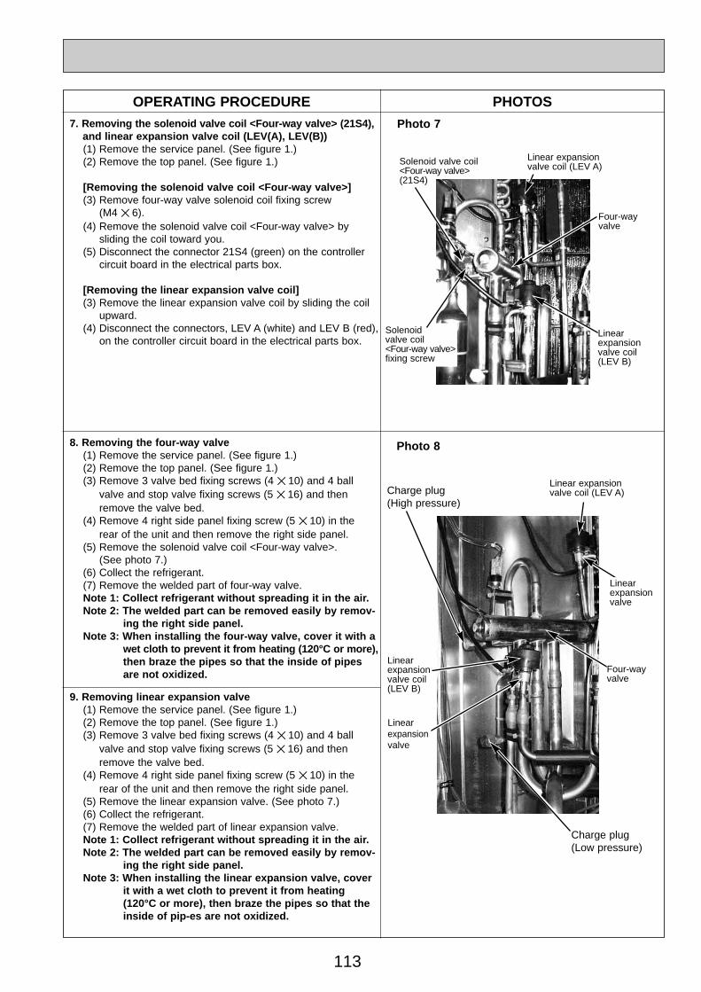
113
Solenoid valve coil<Four-way valve> (21S4)
OPERATING PROCEDURE PHOTOS7. Removing the solenoid valve coil <Four-way valve> (21S4),
and linear expansion valve coil (LEV(A), LEV(B))(1) Remove the service panel. (See figure 1.)(2) Remove the top panel. (See figure 1.)
[Removing the solenoid valve coil <Four-way valve>](3) Remove four-way valve solenoid coil fixing screw
(M4 ✕ 6).(4) Remove the solenoid valve coil <Four-way valve> by
sliding the coil toward you.(5) Disconnect the connector 21S4 (green) on the controller
circuit board in the electrical parts box.
[Removing the linear expansion valve coil](3) Remove the linear expansion valve coil by sliding the coil
upward.(4) Disconnect the connectors, LEV A (white) and LEV B (red),
on the controller circuit board in the electrical parts box.
8. Removing the four-way valve(1) Remove the service panel. (See figure 1.)(2) Remove the top panel. (See figure 1.)(3) Remove 3 valve bed fixing screws (4 ✕ 10) and 4 ball
valve and stop valve fixing screws (5 ✕ 16) and then remove the valve bed.
(4) Remove 4 right side panel fixing screw (5 ✕ 10) in the rear of the unit and then remove the right side panel.
(5) Remove the solenoid valve coil <Four-way valve>. (See photo 7.)
(6) Collect the refrigerant.(7) Remove the welded part of four-way valve.Note 1: Collect refrigerant without spreading it in the air.Note 2: The welded part can be removed easily by remov-
ing the right side panel.Note 3: When installing the four-way valve, cover it with a
wet cloth to prevent it from heating (120°C or more), then braze the pipes so that the inside of pipesare not oxidized.
9. Removing linear expansion valve(1) Remove the service panel. (See figure 1.)(2) Remove the top panel. (See figure 1.)(3) Remove 3 valve bed fixing screws (4 ✕ 10) and 4 ball
valve and stop valve fixing screws (5 ✕ 16) and then remove the valve bed.
(4) Remove 4 right side panel fixing screw (5 ✕ 10) in the rear of the unit and then remove the right side panel.
(5) Remove the linear expansion valve. (See photo 7.)(6) Collect the refrigerant.(7) Remove the welded part of linear expansion valve.Note 1: Collect refrigerant without spreading it in the air.Note 2: The welded part can be removed easily by remov-
ing the right side panel.Note 3: When installing the linear expansion valve, cover
it with a wet cloth to prevent it from heating(120°C or more), then braze the pipes so that theinside of pip-es are not oxidized.
Photo 7
Photo 8
Four-wayvalve
Linear expansion valve coil (LEV A)
Linear expansion valve coil (LEV B)
Linear expansion valve coil (LEV A)
Four-way valve
Linear expansion valve
Linear expansion valve coil (LEV B)
Linear expansion valve
Solenoid valve coil<Four-way valve> fixing screw
Charge plug(High pressure)
Charge plug(Low pressure)
OC334-4.qxp 05.5.26 5:58 PM Page 113
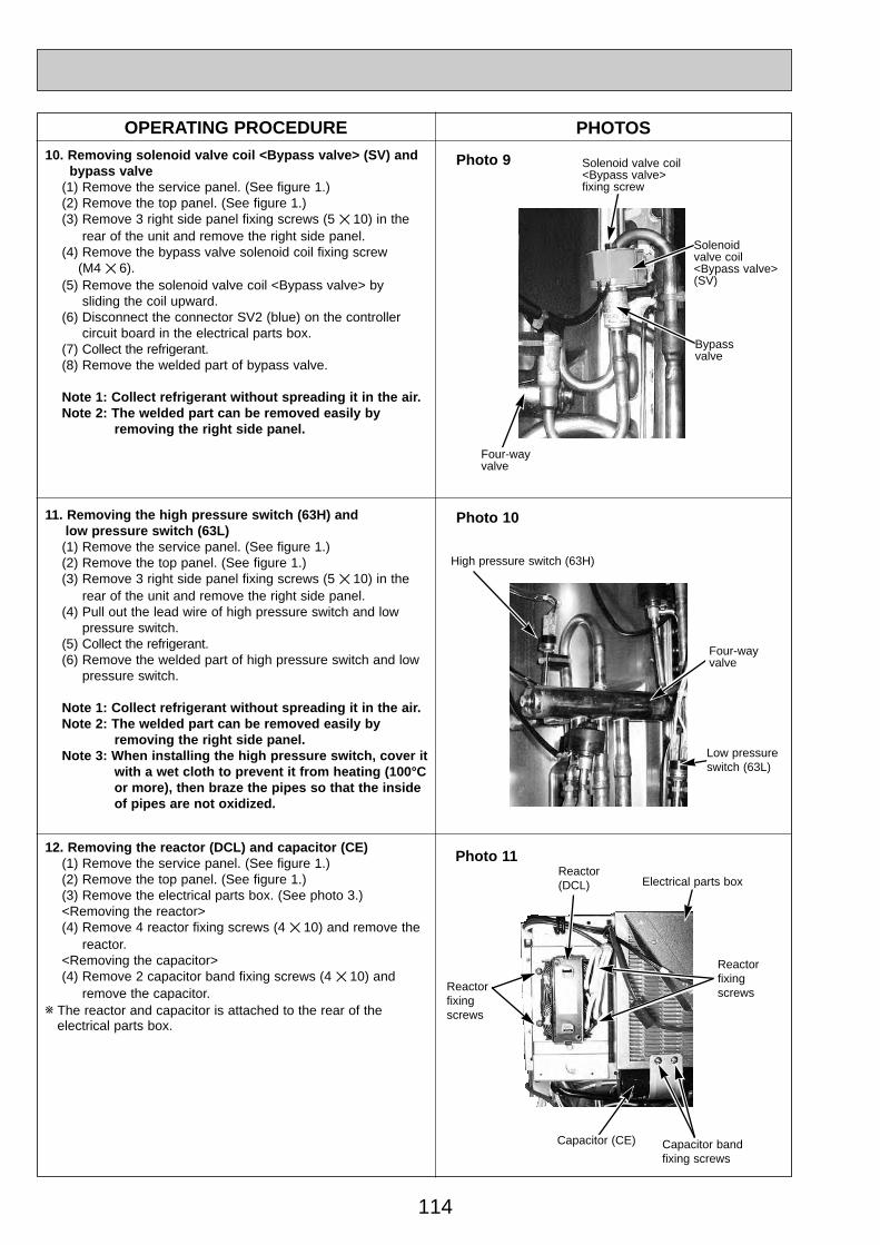
114
OPERATING PROCEDURE PHOTOS10. Removing solenoid valve coil <Bypass valve> (SV) and
bypass valve(1) Remove the service panel. (See figure 1.)(2) Remove the top panel. (See figure 1.)(3) Remove 3 right side panel fixing screws (5 ✕ 10) in the
rear of the unit and remove the right side panel.(4) Remove the bypass valve solenoid coil fixing screw
(M4 ✕ 6).(5) Remove the solenoid valve coil <Bypass valve> by
sliding the coil upward.(6) Disconnect the connector SV2 (blue) on the controller
circuit board in the electrical parts box.(7) Collect the refrigerant.(8) Remove the welded part of bypass valve.
Note 1: Collect refrigerant without spreading it in the air.Note 2: The welded part can be removed easily by
removing the right side panel.
12. Removing the reactor (DCL) and capacitor (CE)(1) Remove the service panel. (See figure 1.)(2) Remove the top panel. (See figure 1.)(3) Remove the electrical parts box. (See photo 3.)<Removing the reactor>(4) Remove 4 reactor fixing screws (4 ✕ 10) and remove the
reactor.<Removing the capacitor>(4) Remove 2 capacitor band fixing screws (4 ✕ 10) and
remove the capacitor.w The reactor and capacitor is attached to the rear of the
electrical parts box.
Photo 9
Capacitor band fixing screws
11. Removing the high pressure switch (63H) and low pressure switch (63L)(1) Remove the service panel. (See figure 1.)(2) Remove the top panel. (See figure 1.)(3) Remove 3 right side panel fixing screws (5 ✕ 10) in the
rear of the unit and remove the right side panel.(4) Pull out the lead wire of high pressure switch and low
pressure switch.(5) Collect the refrigerant.(6) Remove the welded part of high pressure switch and low
pressure switch.
Note 1: Collect refrigerant without spreading it in the air.Note 2: The welded part can be removed easily by
removing the right side panel.Note 3: When installing the high pressure switch, cover it
with a wet cloth to prevent it from heating (100°C or more), then braze the pipes so that the inside of pipes are not oxidized.
Bypass valve
High pressure switch (63H)
Photo 10
Photo 11
Four-way valve
Reactor fixing screws
Reactor fixing screws
Reactor(DCL) Electrical parts box
Capacitor (CE)
Solenoid valve coil <Bypass valve> fixing screw
Solenoid valve coil <Bypass valve> (SV)
Low pressure switch (63L)
Four-way valve
OC334-4.qxp 05.5.26 5:58 PM Page 114

115
OPERATING PROCEDURE PHOTOS13. Removing the motor for compressor (MC)
(1) Remove the service panel. (See figure 1.)(2) Remove the top panel. (See figure 1.)(3) Remove 2 front cover panel fixing screws (5 ✕ 10) and
remove the front cover panel. (See photo 3.)(4) Remove 2 back cover panel fixing screws (5 ✕ 10) and
remove the back cover panel.(5) Remove the electrical parts box. (See photo 3.)(6) Remove 3 valve bed fixing screws (4 ✕ 10) and 4 ball valve
and stop valve fixing screws (5 ✕ 16) and then remove the valve bed.
(7) Remove 3 right side panel fixing screw (5 ✕ 10) in the rearof the unit and then remove the right side panel.
(8) Remove 3 separator fixing screws (4 ✕ 10) and remove the separator.
(9) Collect the refrigerant.(10) Remove the 3 points of the motor for compressor fixing
nut using a spanner or a monkey wrench.(11) Remove the welded pipe of motor for compressor inlet
and outlet and then remove the compressor.
Note: Collect refrigerant without spreading it in the air.
14. Removing the power receiver (1) Remove the service panel. (See figure 1.)(2) Remove the top panel. (See figure 1.)(3) Remove 2 front cover panel fixing screws (5 ✕ 10) and
remove the front cover panel. (See photo 3.)(4) Remove 2 back cover panel fixing screws (5 ✕ 10) and
remove the back cover panel.(5) Remove the electrical parts box. (See photo 3.)(6) Remove 3 valve bed fixing screws (4 ✕ 10) and 4 ball valve
and stop valve fixing screws (5 ✕ 16) and then remove the valve bed.
(7) Remove 3 right side panel fixing screw (5 ✕ 10) in the rear of the unit and then remove the right side panel.
(8) Collect the refrigerant.(9) Remove 4 welded pipes of power receiver inlet and outlet.(10) Remove 2 receiver leg fixing screws (4 ✕ 10).
Note: Collect refrigerant without spreading it in the air.
Photo 12
Motor forcompressor(MC)
Valve bed
Separator
Separatorfixing screw
Powerreceiver
Photo 13
Valve bedfixingscrews
Compressorfixing nut
Receiver leg fixing screws
Powerreceiver
Receiverleg
Inlet
Outlet
Motor forcompressor(MC)
OC334-4.qxp 05.5.26 5:59 PM Page 115

116
OPERATING PROCEDURE PHOTOS & ILLUSTRATION
PUHZ-RP100YHA PUHZ-RP125YHA PUHZ-RP140YHA
1. Removing the service panel and top panel(1) Remove 3 service panel fixing screws (5 ✕ 10) and slide
the hook on the right downward to remove the service panel.
(2) Remove screws (3 for front, 3 for rear/5 ✕ 10) of the top panel and remove it.
Figure 1 Top panel fixing screws Top panel
Service panelfixing screws
Service panel
Grille fixing screws
Fan grille
2. Removing the fan motor (MF1, MF2)(1) Remove the service panel. (See figure 1.)(2) Remove the top panel. (See figure 1.)(3) Remove 5 fan grille fixing screws (5 ✕ 10) to detach the
fan grille. (See figure 1.)(4) Remove a nut (for right handed screw of M6) to detach
the propeller. (See photo 1.)(5) Disconnect the connectors, CNF1 and CNF2 on controller
circuit board in electrical parts box.(6) Remove 4 fan motor fixing screws (5 ✕ 25) to detach the
fan motor. (See photo 2.)
Fan motor fixing screws
Photo 33. Removing the electrical parts box(1) Remove the service panel. (See figure 1.)(2) Remove the top panel. (See figure 1.)(3) Disconnect the indoor/outdoor connecting wire from
terminal block.(4) Disconnect the connector CNF1, CNF2, LEV-A and LEV-B
on the controller circuit board.<Symbols on the board>• CNF1, CNF2 : Fan motor• LEV-A, LEV-B : Linear expansion valve
(5) Disconnect the pipe-side connections of the following parts.• Thermistor <Outdoor pipe>(TH3)• Thermistor <Discharge>(TH4)• Thermistor <Outdoor 2-phase pipe>(TH6)• Thermistor <Outdoor>(TH7)• High pressure switch (63H)• Low pressure switch (63L)• Solenoid valve coil <Four-Way Valve>(21S4)• Solenoid valve coil <Bypass Valve>(SV)
Electrical parts box
Noise filter circuitboard (N.F.)
Terminal cover
Cover panel fixing screws
Motor forcompressor(MC)
Photo 1 Fanmotor
Fan motor fixing screws
PropellerFront panel
Nut
Photo 2
Valve bed
Screw9
Grille fixing screws
Slide
Terminal block (TB2)
Screw8
Front panel
Continued to the next page.
Controller circuit board (C.B.)
Terminalblock (TB1)
Cover panel (Front)
OC334-4.qxp 05.5.26 5:59 PM Page 116
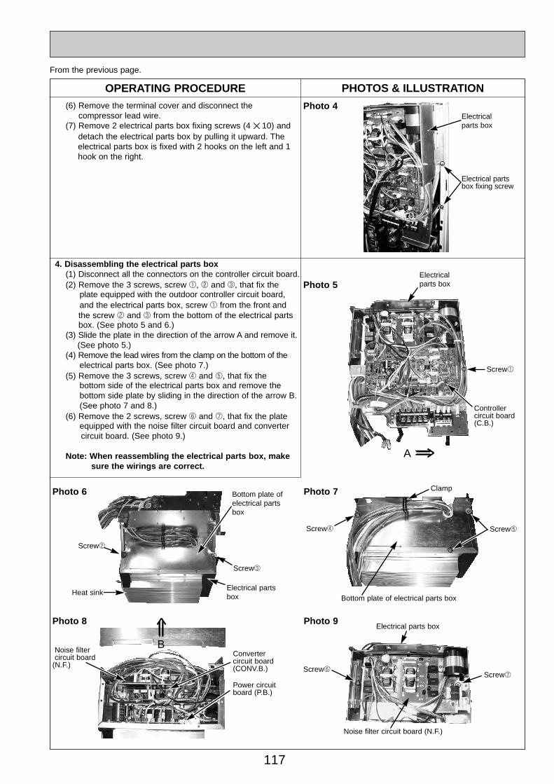
117
OPERATING PROCEDURE PHOTOS & ILLUSTRATION
4. Disassembling the electrical parts box(1) Disconnect all the connectors on the controller circuit board.(2) Remove the 3 screws, screw 1, 2 and 3, that fix the
plate equipped with the outdoor controller circuit board, and the electrical parts box, screw 1 from the front and the screw 2 and 3 from the bottom of the electrical partsbox. (See photo 5 and 6.)
(3) Slide the plate in the direction of the arrow A and remove it.(See photo 5.)
(4) Remove the lead wires from the clamp on the bottom of the electrical parts box. (See photo 7.)
(5) Remove the 3 screws, screw 4 and 5, that fix the bottom side of the electrical parts box and remove the bottom side plate by sliding in the direction of the arrow B. (See photo 7 and 8.)
(6) Remove the 2 screws, screw 6 and 7, that fix the plate equipped with the noise filter circuit board and convertercircuit board. (See photo 9.)
Note: When reassembling the electrical parts box, make sure the wirings are correct.
Photo 4(6) Remove the terminal cover and disconnect the compressor lead wire.
(7) Remove 2 electrical parts box fixing screws (4 ✕ 10) anddetach the electrical parts box by pulling it upward. The electrical parts box is fixed with 2 hooks on the left and 1 hook on the right.
Electrical parts box
Electrical partsbox fixing screw
From the previous page.
Photo 5Electrical parts box
Screw1
Controller circuit board (C.B.)
Photo 6
Screw3
Screw2
Bottom plate ofelectrical partsbox
A
Electrical partsbox
Photo 7
Screw5Screw4
Bottom plate of electrical parts box
Clamp
Photo 8
Power circuit board (P.B.)
Noise filtercircuit board
(N.F.)
Photo 9
Screw6
Noise filter circuit board (N.F.)
Electrical parts box
B
Heat sink
Screw7
Convertercircuit board (CONV.B.)
OC334-4.qxp 05.5.26 5:59 PM Page 117
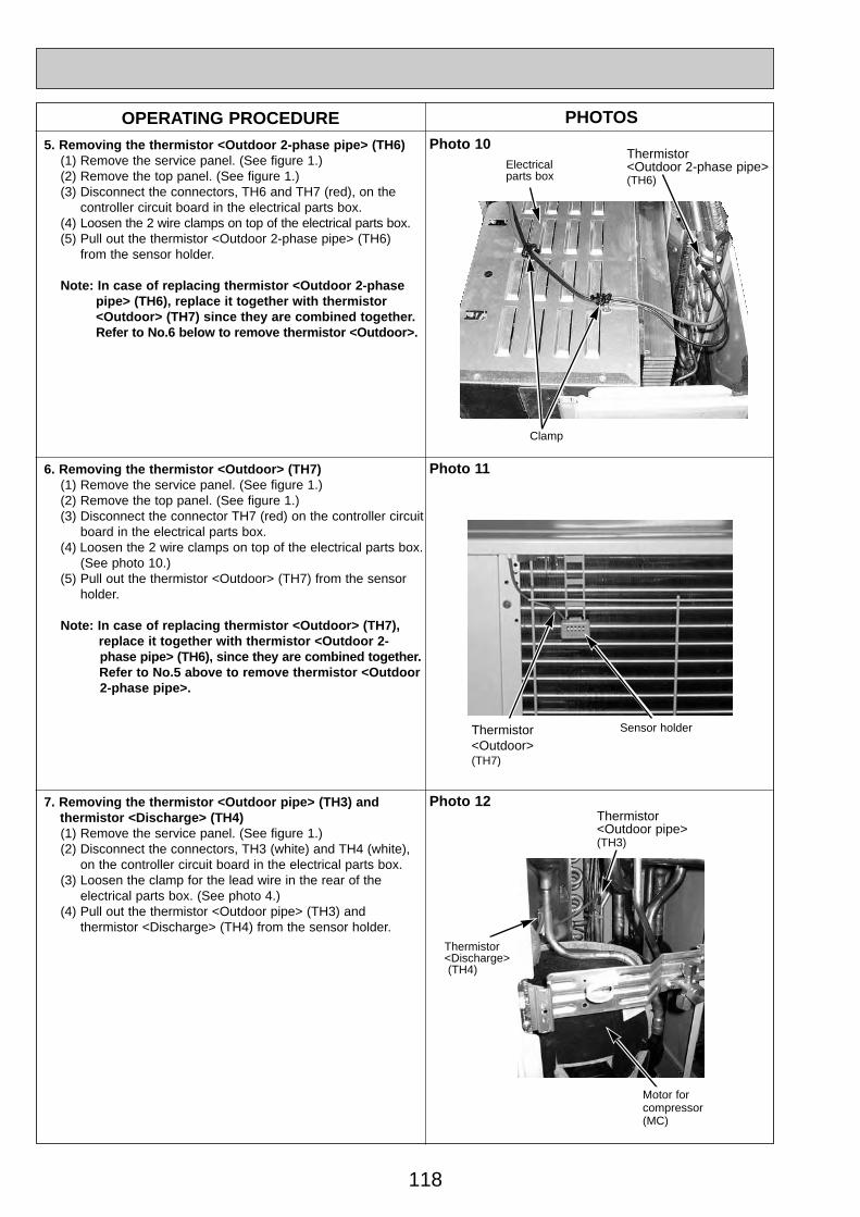
118
OPERATING PROCEDURE PHOTOSPhoto 105. Removing the thermistor <Outdoor 2-phase pipe> (TH6)
(1) Remove the service panel. (See figure 1.)(2) Remove the top panel. (See figure 1.)(3) Disconnect the connectors, TH6 and TH7 (red), on the
controller circuit board in the electrical parts box.(4) Loosen the 2 wire clamps on top of the electrical parts box.(5) Pull out the thermistor <Outdoor 2-phase pipe> (TH6)
from the sensor holder.
Note: In case of replacing thermistor <Outdoor 2-phase pipe> (TH6), replace it together with thermistor <Outdoor> (TH7) since they are combined together. Refer to No.6 below to remove thermistor <Outdoor>.
6. Removing the thermistor <Outdoor> (TH7)(1) Remove the service panel. (See figure 1.)(2) Remove the top panel. (See figure 1.)(3) Disconnect the connector TH7 (red) on the controller circuit
board in the electrical parts box.(4) Loosen the 2 wire clamps on top of the electrical parts box.
(See photo 10.)(5) Pull out the thermistor <Outdoor> (TH7) from the sensor
holder.
Note: In case of replacing thermistor <Outdoor> (TH7), replace it together with thermistor <Outdoor 2- phase pipe> (TH6), since they are combined together. Refer to No.5 above to remove thermistor <Outdoor 2-phase pipe>.
Photo 12
Clamp
Thermistor <Outdoor 2-phase pipe>(TH6)
7. Removing the thermistor <Outdoor pipe> (TH3) and thermistor <Discharge> (TH4)(1) Remove the service panel. (See figure 1.)(2) Disconnect the connectors, TH3 (white) and TH4 (white),
on the controller circuit board in the electrical parts box.(3) Loosen the clamp for the lead wire in the rear of the
electrical parts box. (See photo 4.)(4) Pull out the thermistor <Outdoor pipe> (TH3) and
thermistor <Discharge> (TH4) from the sensor holder.
Electrical parts box
Photo 11
Thermistor <Outdoor>(TH7)
Sensor holder
Thermistor <Discharge> (TH4)
Thermistor <Outdoor pipe>(TH3)
Motor forcompressor(MC)
OC334-4.qxp 05.5.26 5:59 PM Page 118

119
Solenoid valve coil<Four-way valve> (21S4)
OPERATING PROCEDURE PHOTOS8. Removing the solenoid valve coil <Four-way valve> (21S4),
and linear expansion valve coil (LEV(A), LEV(B))(1) Remove the service panel. (See figure 1.)(2) Remove the top panel. (See figure 1.)
[Removing the solenoid valve coil <Four-way valve>](3) Remove four-way valve solenoid coil fixing screw
(M4 ✕ 6).(4) Remove the solenoid valve coil <Four-way valve> by
sliding the coil toward you.(5) Disconnect the connector 21S4 (green) on the controller
circuit board in the electrical parts box.
[Removing the linear expansion valve coil](3) Remove the linear expansion valve coil by sliding the coil
upward.(4) Disconnect the connectors, LEV A (white) and LEV B (red),
on the controller circuit board in the electrical parts box.
9. Removing the four-way valve(1) Remove the service panel. (See figure 1.)(2) Remove the top panel. (See figure 1.)(3) Remove 3 valve bed fixing screws (4 ✕ 10) and 4 ball
valve and stop valve fixing screws (5 ✕ 16) and then remove the valve bed.
(4) Remove 4 right side panel fixing screw (5 ✕ 10) in the rear of the unit and then remove the right side panel.
(5) Remove the solenoid valve coil <Four-way valve>. (See photo 13.)
(6) Collect the refrigerant.(7) Remove the welded part of four-way valve.Note 1: Collect refrigerant without spreading it in the air.Note 2: The welded part can be removed easily by remov-
ing the right side panel.Note 3: When installing the four-way valve, cover it with a
wet cloth to prevent it from heating (120°C or more), then braze the pipes so that the inside of pipesare not oxidized.
10. Removing linear expansion valve(1) Remove the service panel. (See figure 1.)(2) Remove the top panel. (See figure 1.)(3) Remove 3 valve bed fixing screws (4 ✕ 10) and 4 ball
valve and stop valve fixing screws (5 ✕ 16) and then remove the valve bed.
(4) Remove 4 right side panel fixing screw (5 ✕ 10) in the rear of the unit and then remove the right side panel.
(5) Remove the linear expansion valve. (See photo 13.)(6) Collect the refrigerant.(7) Remove the welded part of linear expansion valve.Note 1: Collect refrigerant without spreading it in the air.Note 2: The welded part can be removed easily by remov-
ing the right side panel.Note 3: When installing the linear expansion valve, cover
it with a wet cloth to prevent it from heating(120°C or more), then braze the pipes so that theinside of pip-es are not oxidized.
Photo 13
Photo 14
Four-wayvalve
Linear expansion valve coil (LEV A)
Linear expansion valve coil (LEV-B)
Linear expansion valve coil (LEV-A)
Four-way valve
Linear expansion valve
Linear expansion valve coil (LEV B)
Linear expansion valve
Solenoid valve coil<Four-way valve> fixing screw
Charge plug(High pressure)
Charge plug(Low pressure)
OC334-4.qxp 05.5.26 5:59 PM Page 119
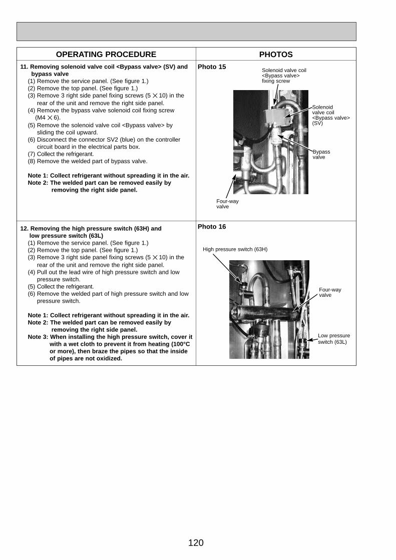
120
OPERATING PROCEDURE PHOTOS11. Removing solenoid valve coil <Bypass valve> (SV) and
bypass valve(1) Remove the service panel. (See figure 1.)(2) Remove the top panel. (See figure 1.)(3) Remove 3 right side panel fixing screws (5 ✕ 10) in the
rear of the unit and remove the right side panel.(4) Remove the bypass valve solenoid coil fixing screw
(M4 ✕ 6).(5) Remove the solenoid valve coil <Bypass valve> by
sliding the coil upward.(6) Disconnect the connector SV2 (blue) on the controller
circuit board in the electrical parts box.(7) Collect the refrigerant.(8) Remove the welded part of bypass valve.
Note 1: Collect refrigerant without spreading it in the air.Note 2: The welded part can be removed easily by
removing the right side panel.
Photo 15
12. Removing the high pressure switch (63H) and low pressure switch (63L)(1) Remove the service panel. (See figure 1.)(2) Remove the top panel. (See figure 1.)(3) Remove 3 right side panel fixing screws (5 ✕ 10) in the
rear of the unit and remove the right side panel.(4) Pull out the lead wire of high pressure switch and low
pressure switch.(5) Collect the refrigerant.(6) Remove the welded part of high pressure switch and low
pressure switch.
Note 1: Collect refrigerant without spreading it in the air.Note 2: The welded part can be removed easily by
removing the right side panel.Note 3: When installing the high pressure switch, cover it
with a wet cloth to prevent it from heating (100°C or more), then braze the pipes so that the inside of pipes are not oxidized.
Bypass valve
High pressure switch (63H)
Photo 16
Four-way valve
Solenoid valve coil <Bypass valve> fixing screw
Solenoid valve coil <Bypass valve> (SV)
Low pressure switch (63L)
Four-way valve
OC334-4.qxp 05.5.26 5:59 PM Page 120
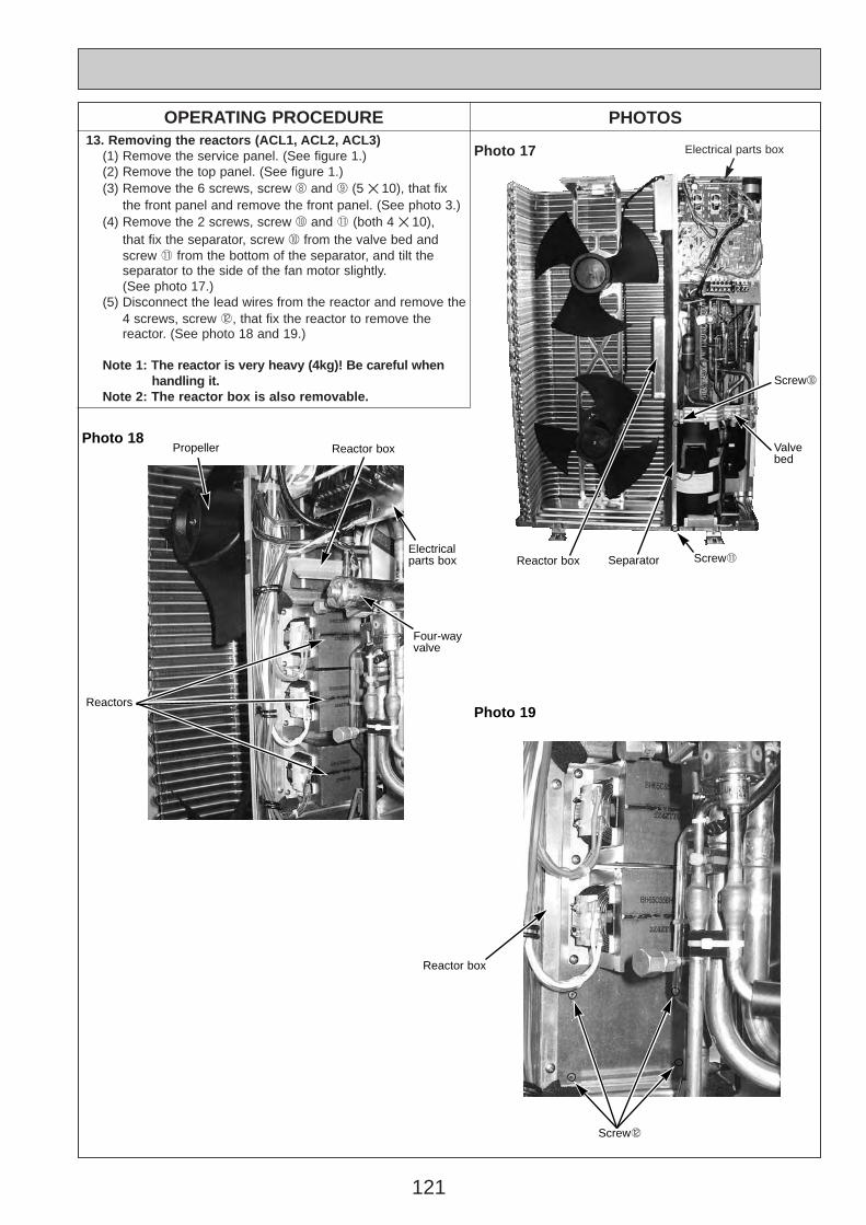
121
13. Removing the reactors (ACL1, ACL2, ACL3)(1) Remove the service panel. (See figure 1.)(2) Remove the top panel. (See figure 1.)(3) Remove the 6 screws, screw 8 and 9 (5 ✕ 10), that fix
the front panel and remove the front panel. (See photo 3.)(4) Remove the 2 screws, screw 0 and 1 (both 4 ✕ 10),
that fix the separator, screw 0 from the valve bed and screw 1 from the bottom of the separator, and tilt the separator to the side of the fan motor slightly.(See photo 17.)
(5) Disconnect the lead wires from the reactor and remove the 4 screws, screw 2, that fix the reactor to remove the reactor. (See photo 18 and 19.)
Note 1: The reactor is very heavy (4kg)! Be careful when handling it.
Note 2: The reactor box is also removable.
OPERATING PROCEDURE PHOTOS
Photo 17 Electrical parts box
Screw0
Valve bed
Screw1SeparatorReactor box
Photo 18
Reactors
Reactor box
Electrical parts box
Four-wayvalve
Photo 19
Screw2
Reactor box
Propeller
OC344-5.qxp 05.5.26 5:54 PM Page 121
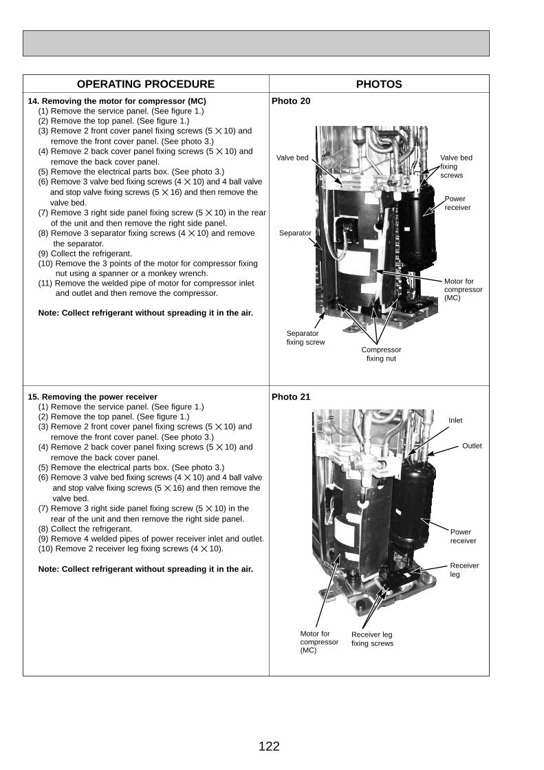
122
OPERATING PROCEDURE PHOTOS14. Removing the motor for compressor (MC)
(1) Remove the service panel. (See figure 1.)(2) Remove the top panel. (See figure 1.)(3) Remove 2 front cover panel fixing screws (5 ✕ 10) and
remove the front cover panel. (See photo 3.)(4) Remove 2 back cover panel fixing screws (5 ✕ 10) and
remove the back cover panel.(5) Remove the electrical parts box. (See photo 3.)(6) Remove 3 valve bed fixing screws (4 ✕ 10) and 4 ball valve
and stop valve fixing screws (5 ✕ 16) and then remove the valve bed.
(7) Remove 3 right side panel fixing screw (5 ✕ 10) in the rearof the unit and then remove the right side panel.
(8) Remove 3 separator fixing screws (4 ✕ 10) and remove the separator.
(9) Collect the refrigerant.(10) Remove the 3 points of the motor for compressor fixing
nut using a spanner or a monkey wrench.(11) Remove the welded pipe of motor for compressor inlet
and outlet and then remove the compressor.
Note: Collect refrigerant without spreading it in the air.
Photo 20
Motor forcompressor(MC)
Valve bed
Separator
Separatorfixing screw
Powerreceiver
Valve bedfixingscrews
Compressorfixing nut
15. Removing the power receiver (1) Remove the service panel. (See figure 1.)(2) Remove the top panel. (See figure 1.)(3) Remove 2 front cover panel fixing screws (5 ✕ 10) and
remove the front cover panel. (See photo 3.)(4) Remove 2 back cover panel fixing screws (5 ✕ 10) and
remove the back cover panel.(5) Remove the electrical parts box. (See photo 3.)(6) Remove 3 valve bed fixing screws (4 ✕ 10) and 4 ball valve
and stop valve fixing screws (5 ✕ 16) and then remove the valve bed.
(7) Remove 3 right side panel fixing screw (5 ✕ 10) in the rear of the unit and then remove the right side panel.
(8) Collect the refrigerant.(9) Remove 4 welded pipes of power receiver inlet and outlet.(10) Remove 2 receiver leg fixing screws (4 ✕ 10).
Note: Collect refrigerant without spreading it in the air.
Photo 21
Receiver leg fixing screws
Powerreceiver
Receiverleg
Inlet
Outlet
Motor forcompressor(MC)
OC344-5.qxp 05.5.26 5:54 PM Page 122
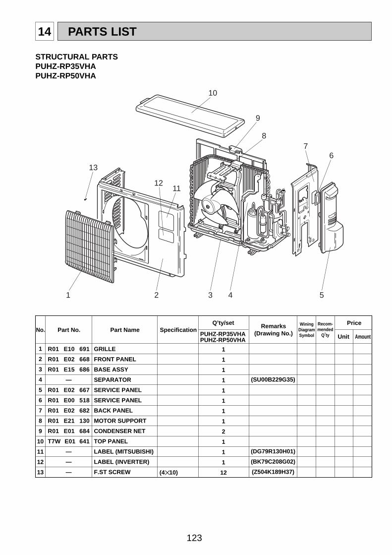
123
14 PARTS LIST
STRUCTURAL PARTSPUHZ-RP35VHAPUHZ-RP50VHA
Part No. SpecificationNo.Wining
DiagramSymbol
Recom-mended
Q,ty
Price
Unit AmountPart Name
Q,ty/set
PUHZ-RP35VHAPUHZ-RP50VHA
Remarks(Drawing No.)
1
2
3
4
5
6
7
8
9
10
11
12
13
1
1
1
1
1
1
1
1
2
1
1
1
12(4✕10)
R01 E10 691
R01 E02 668
R01 E15 686
—
R01 E02 667
R01 E00 518
R01 E02 682
R01 E21 130
R01 E01 684
T7W E01 641
—
—
—
GRILLE
FRONT PANEL
BASE ASSY
SEPARATOR
SERVICE PANEL
SERVICE PANEL
BACK PANEL
MOTOR SUPPORT
CONDENSER NET
TOP PANEL
LABEL (MITSUBISHI)
LABEL (INVERTER)
F.ST SCREW
(SU00B229G35)
(DG79R130H01)
(BK79C208G02)
(Z504K189H37)
1 2 3 4 5
67
8
9
10
1112
13
OC344-5.qxp 05.5.26 5:54 PM Page 123

124
STRUCTURAL PARTSPUHZ-RP60VHAPUHZ-RP71VHA
Part No. SpecificationNo.Wining
DiagramSymbol
Recom-mended
Q,ty
Price
Unit AmountPart Name PUHZ-RP
Q,ty/set
60, 71VHA
Remarks(Drawing No.)
1
2
3
4
5
6
7
8
9
10
11
12
13
14
15
16
17
18
31
1
1
1
1
1
1
1
2
1
1
1
1
1
1
1
1
1
(5✕10)—
R01 E01 662
T7W E02 691
T7W E01 667
—
R01 E13 686
R01 E06 130
—
R01 30L 655
R01 E02 658
R01 E01 658
R01 E03 661
T7W E02 668
—
—
R01 E00 698
R01 E04 641
R01 E00 655
F.ST SCREW
SIDE PANEL (L)
FAN GRILLE
FRONT PANEL
SEPARATOR
BASE ASSY
MOTOR SUPPORT
VALVE BED ASSY
HANDLE
COVER PANEL (FRONT)
COVER PANEL (REAR)
SIDE PANEL (R)
SERVICE PANEL
LABEL (MITSUBISHI)
LABEL (INVERTER)
REAR GUARD
TOP PANEL
HANDLE
(DG12F536H10)
(BK00C143G51)
(BK00C142G16)
(DG79R130H01)
(BK79C208G02)
1
152
4
5
9 11
1412
13
3
6 78
10
9
17
1816
OC344-5.qxp 05.5.26 5:54 PM Page 124

125
Part No. Part Name SpecificatioNo.Wining
DiagramSymbol
Recom-mended
Q,ty
Q,ty/setPUHZ-RP
VHA YHA100, 125, 140
1
2
3
4
5
6
7
8
9
10
11
12
13
14
15
16
17
18
38
1
2
1
1
1
1
1
2
1
1
1
1
1
1
1
1
1
38
1
2
1
1
1
1
1
2
1
1
1
1
1
1
1
1
1
(DG12F536H10)
VHA (BK00C143G67)
YHA (BK00C409G03)
(BK00C142G16)
(DG79R130H01)
(BK79C208G02)
F.ST SCREW
SIDE PANEL (L)
FAN GRILLE
FRONT PANEL
SEPARATOR
BASE ASSY
MOTOR SUPPORT
VALVE BED ASSY
HANDLE
COVER PANEL (FRONT)
COVER PANEL (REAR)
SIDE PANEL (R)
SERVICE PANEL
SERVICE PANEL
LABEL (MITSUBISHI)
LABEL (INVERTER)
REAR GUARD
TOP PANEL
TOP PANEL
HANDLE
(5✕10)
AmountUnit
PriceRemarks
(Drawing No.)
—
R01 E02 662
T7W E02 691
T7W E02 667
—
R01 E14 686
T7W E05 130
—
R01 30L 655
R01 E00 658
R01 E01 658
T7W E15 661
T7W E03 668
T7W E04 668
—
—
R01 E01 698
R01 E04 641
R01 E08 641
R01 E00 655
1
15
2
4
59
11
1412
13
6 78
10
9
17
18
3
16
STRUCTURAL PARTSPUHZ-RP100VHAPUHZ-RP125VHAPUHZ-RP140VHAPUHZ-RP100YHAPUHZ-RP125YHAPUHZ-RP140YHA
OC344-5.qxp 05.5.26 5:54 PM Page 125
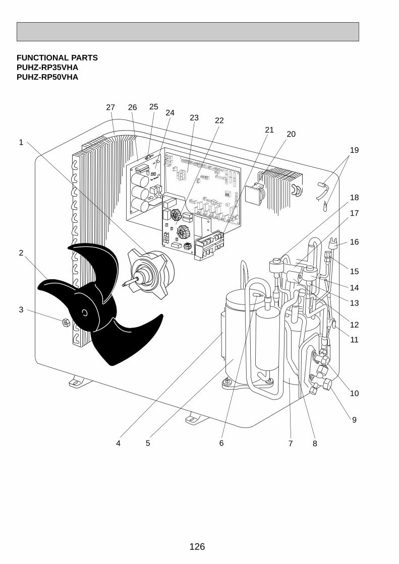
126
FUNCTIONAL PARTSPUHZ-RP35VHAPUHZ-RP50VHA
1
3
4
2
5 6 7 8
9
10
11
12
13
14
17
15
16
18
19
20212223
24252627
OC344-5.qxp 05.5.26 5:54 PM Page 126
127
PricePart No. Part Name SpecificationNo.
WiningDiagramSymbol
Recom-mended
Q,ty Unit Amount
Remarks(Drawing No.)
Q,ty/set
PUHZ-RP35VHAPUHZ-RP50VHA
1
2
3
4
5
6
7
8
9
10
11
12
13
14
15
16
17
18
19
20
21
22
23
24
25
26
27
28
MF1
MC
TH4
TH3
21S4
LEV(A)
63H
LEV(B)
TH6,7
ACL
TB1
N.F.
C.B.
P.B.
TH8
F1,2,3,4
R01 E40 221
R01 E02 115
R01 E04 097
R01 E09 467
T97 420 210
R01 E03 201
R01 E15 440
R01 30L 450
R01 E08 410
R01 E08 411
R01 E56 202
T7W E11 242
R01 E39 401
R01 E16 242
R01 E10 413
T7W E02 208
R01 E08 403
R01 E17 242
R01 E69 202
R01 E06 259
T7W E21 716
T7W E05 346
T7W E28 315
T7W E17 313
R01 E65 202
—
R01 E48 408
T7W 520 239
FAN MOTOR
PROPELLER
NUT
MUFFLER
MOTOR FOR COMPRESSOR
THERMISTOR (DISCHARGE)
POWER RECEIVER
STRAINER
STOP VALVE (GAS)
STOP VALVE (LQUID)
THERMISTOR (OUTDOOR PIPE)
SOLENOID VALVE COIL (FOUR-WAY VALVE)
EXPANSION VALVE
LINEAR EXPANSION VALVE COIL
CHARGE PLUG
HIGH PRESSURE SWITCH
FOUR-WAY VALVE
LINEAR EXPANSION VALVE COIL
THERMISTOR (OUTDOOR 2-PHASE PIPE, OUTDOOR)
REACTOR
TERMINAL BLOCK
NOISE FILTER
CONTROLLER CIRCUIT BOARD
POWER CIRCUIT BOARD
THERMISTOR (HEAT SINK)
ELECTRICAL PARTS BOX
HEAT EXCHANGER
FUSE
1
1
1
1
1
1
1
1
1
1
1
1
2
1
1
1
1
1
1
1
1
1
1
1
1
1
1
4
SNB130FLBHIncluding RUBBER MOUNT
1/2
1/4
6P(L,N,;,S1,S2,S3)
250V 6.3A
(RG00N040G12)
Part numbers that is circled is not shown in the figure.
OC344-5.qxp 05.5.26 5:54 PM Page 127
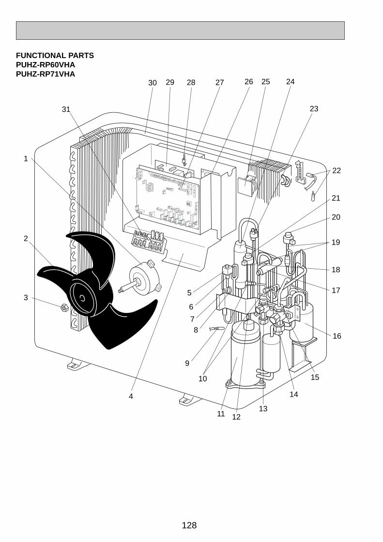
128
FUNCTIONAL PARTSPUHZ-RP60VHAPUHZ-RP71VHA
16
15
14
1
3
21
22
23
2429 2528 2627
4
9
10
5
12
2
20
13
6
78
11
17
18
19
30
31
OC344-5.qxp 05.5.26 5:54 PM Page 128
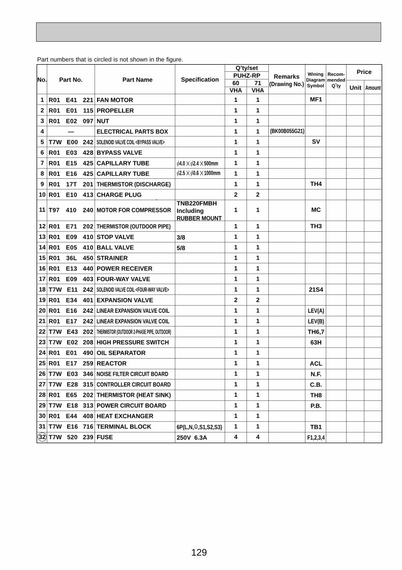
129
PricePart No. Part Name SpecificationNo.
WiningDiagramSymbol
Recom-mended
Q,ty Unit Amount
Remarks(Drawing No.)
Q,ty/setPUHZ-RP60
VHA VHA71
1
2
3
4
5
6
7
8
9
10
11
12
13
14
15
16
17
18
19
20
21
22
23
24
25
26
27
28
29
30
31
32
MF1
SV
TH4
MC
TH3
21S4
LEV(A)
LEV(B)
TH6,7
63H
ACL
N.F.
C.B.
TH8
P.B.
TB1
F1,2,3,4
R01 E41 221
R01 E01 115
R01 E02 097
—
T7W E00 242
R01 E03 428
R01 E15 425
R01 E16 425
R01 17T 201
R01 E10 413
T97 410 240
R01 E71 202
R01 E09 410
R01 E05 410
R01 36L 450
R01 E13 440
R01 E09 403
T7W E11 242
R01 E34 401
R01 E16 242
R01 E17 242
T7W E43 202
T7W E02 208
R01 E01 490
R01 E17 259
T7W E03 346
T7W E28 315
R01 E65 202
T7W E18 313
R01 E44 408
T7W E16 716
T7W 520 239
FAN MOTOR
PROPELLER
NUT
ELECTRICAL PARTS BOX
SOLENOID VALVE COIL <BYPASS VALVE>
BYPASS VALVE
CAPILLARY TUBE
CAPILLARY TUBE
THERMISTOR (DISCHARGE)
CHARGE PLUG
MOTOR FOR COMPRESSOR
THERMISTOR (OUTDOOR PIPE)
STOP VALVE
BALL VALVE
STRAINER
POWER RECEIVER
FOUR-WAY VALVE
SOLENOID VALVE COIL <FOUR-WAY VALVE>
EXPANSION VALVE
LINEAR EXPANSION VALVE COIL
LINEAR EXPANSION VALVE COIL
THERMISTOR (OUTDOOR 2-PHASE PIPE, OUTDOOR)
HIGH PRESSURE SWITCH
OIL SEPARATOR
REACTOR
NOISE FILTER CIRCUIT BOARD
CONTROLLER CIRCUIT BOARD
THERMISTOR (HEAT SINK)
POWER CIRCUIT BOARD
HEAT EXCHANGER
TERMINAL BLOCK
FUSE
1
1
1
1
1
1
1
1
1
2
1
1
1
1
1
1
1
1
2
1
1
1
1
1
1
1
1
1
1
1
1
4
1
1
1
1
1
1
1
1
1
2
1
1
1
1
1
1
1
1
2
1
1
1
1
1
1
1
1
1
1
1
1
4
[4.0 ✕ [2.4 ✕ 500mm
[2.5 ✕ [0.6 ✕ 1000mm
TNB220FMBHIncluding RUBBER MOUNT
3/8
5/8
6P(L,N,;,S1,S2,S3)
250V 6.3A
(BK00B055G21)
Part numbers that is circled is not shown in the figure.
OC344-5.qxp 05.5.26 5:54 PM Page 129

130
FUNCTIONAL PARTSPUHZ-RP100VHAPUHZ-RP125VHAPUHZ-RP140VHA
12
3
56
10
2
9
1
4
78
11
13
14
15
16
17
18
19
20
1521
2223
24
25
2627 28
29
30
3132333435
OC344-5.qxp 05.5.26 5:54 PM Page 130
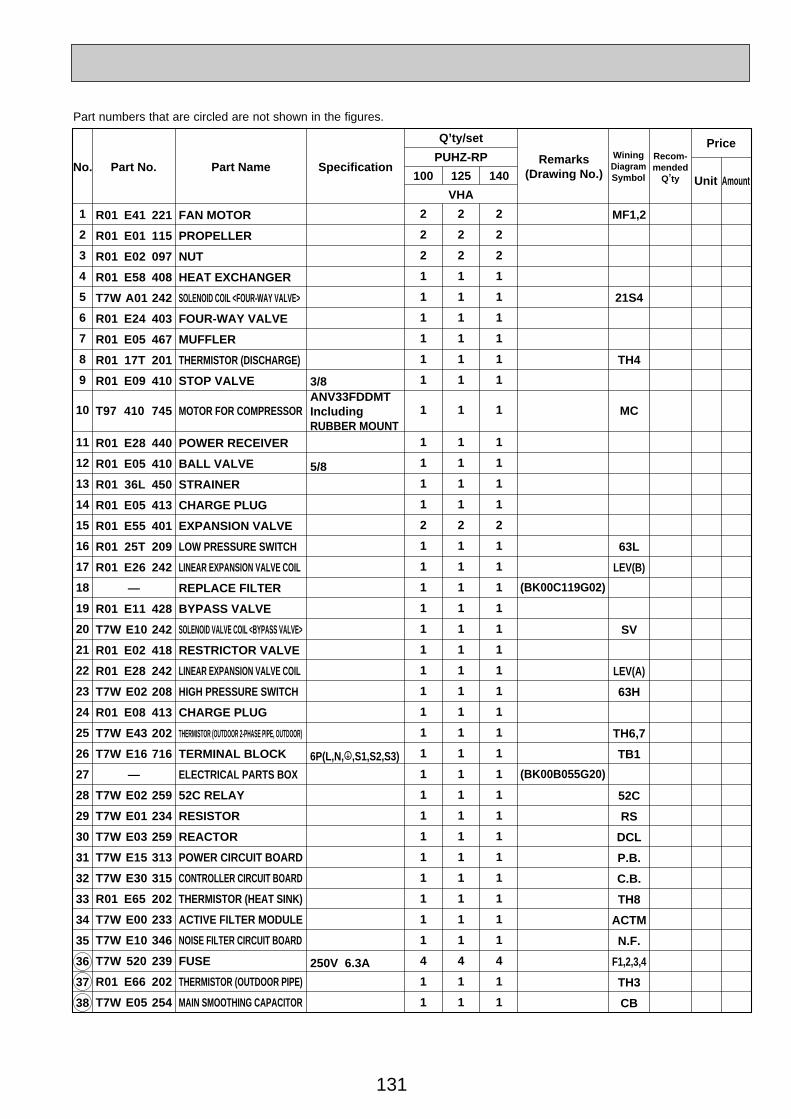
131
Part No. Part Name SpecificationNo.WiningDiagramSymbol
Recom-mended
Q,ty Unit Amount
Remarks(Drawing No.)
Q,ty/set
100 125
VHA
1
2
3
4
5
6
7
8
9
10
11
12
13
14
15
16
17
18
19
20
21
22
23
24
25
26
27
28
29
30
31
32
33
34
35
36
37
38
2
2
2
1
1
1
1
1
1
1
1
1
1
1
2
1
1
1
1
1
1
1
1
1
1
1
1
1
1
1
1
1
1
1
1
4
1
1
2
2
2
1
1
1
1
1
1
1
1
1
1
1
2
1
1
1
1
1
1
1
1
1
1
1
1
1
1
1
1
1
1
1
1
4
1
1
140
2
2
2
1
1
1
1
1
1
1
1
1
1
1
2
1
1
1
1
1
1
1
1
1
1
1
1
1
1
1
1
1
1
1
1
4
1
1
(BK00C119G02)
(BK00B055G20)
R01 E41 221
R01 E01 115
R01 E02 097
R01 E58 408
T7W A01 242
R01 E24 403
R01 E05 467
R01 17T 201
R01 E09 410
T97 410 745
R01 E28 440
R01 E05 410
R01 36L 450
R01 E05 413
R01 E55 401
R01 25T 209
R01 E26 242
—
R01 E11 428
T7W E10 242
R01 E02 418
R01 E28 242
T7W E02 208
R01 E08 413
T7W E43 202
T7W E16 716
—
T7W E02 259
T7W E01 234
T7W E03 259
T7W E15 313
T7W E30 315
R01 E65 202
T7W E00 233
T7W E10 346
T7W 520 239
R01 E66 202
T7W E05 254
FAN MOTOR
PROPELLER
NUT
HEAT EXCHANGER
SOLENOID COIL <FOUR-WAY VALVE>
FOUR-WAY VALVE
MUFFLER
THERMISTOR (DISCHARGE)
STOP VALVE
MOTOR FOR COMPRESSOR
POWER RECEIVER
BALL VALVE
STRAINER
CHARGE PLUG
EXPANSION VALVE
LOW PRESSURE SWITCH
LINEAR EXPANSION VALVE COIL
REPLACE FILTER
BYPASS VALVE
SOLENOID VALVE COIL <BYPASS VALVE>
RESTRICTOR VALVE
LINEAR EXPANSION VALVE COIL
HIGH PRESSURE SWITCH
CHARGE PLUG
THERMISTOR (OUTDOOR 2-PHASE PIPE, OUTDOOR)
TERMINAL BLOCK
ELECTRICAL PARTS BOX
52C RELAY
RESISTOR
REACTOR
POWER CIRCUIT BOARD
CONTROLLER CIRCUIT BOARD
THERMISTOR (HEAT SINK)
ACTIVE FILTER MODULE
NOISE FILTER CIRCUIT BOARD
FUSE
THERMISTOR (OUTDOOR PIPE)
MAIN SMOOTHING CAPACITOR
PUHZ-RPPrice
MF1,2
21S4
TH4
MC
63L
LEV(B)
SV
LEV(A)
63H
TH6,7
TB1
52C
RS
DCL
P.B.
C.B.
TH8
ACTM
N.F.
F1,2,3,4
TH3
CB
3/8ANV33FDDMTIncluding RUBBER MOUNT
5/8
6P(L,N,;,S1,S2,S3)
250V 6.3A
Part numbers that are circled are not shown in the figures.
OC344-5.qxp 05.5.26 5:54 PM Page 131

132
FUNCTIONAL PARTSPUHZ-RP100YHAPUHZ-RP125YHAPUHZ-RP140YHA
1
2
3
2423
22
21
25
26
45
6
7 8
910
11
12
13
14
15
16
17
18
14
20
19
27
2930
3132
33
3435
36
28
OC344-5.qxp 05.5.26 5:54 PM Page 132

133
Part No. Part Name SpecificationNo.WiningDiagramSymbol
Recom-mended
Q,ty Unit Amount
Remarks(Drawing No.)
Q,ty/set
100 125
YHA
1
2
3
4
5
6
7
8
9
10
11
12
13
14
15
16
17
18
19
20
21
22
23
24
25
26
27
28
29
30
31
32
33
34
35
36
37
38
39
2
2
2
3
1
1
1
1
1
1
1
1
1
2
1
1
1
1
1
1
1
1
1
1
1
1
1
1
1
1
1
2
1
1
1
1
4
1
1
2
2
2
3
1
1
1
1
1
1
1
1
1
2
1
1
1
1
1
1
1
1
1
1
1
1
1
1
1
1
1
2
1
1
1
1
4
1
1
2
2
2
3
1
1
1
1
1
1
1
1
1
2
1
1
1
1
1
1
1
1
1
1
1
1
1
1
1
1
1
2
1
1
1
1
4
1
1
140
(BK00C119G02)
(BK00C410G04)
R01 E41 221
R01 E01 115
R01 E02 097
T7W E07 259
R01 E05 413
R01 A19 201
T97 410 743
R01 E09 410
R01 E05 410
R01 36L 450
R01 E28 440
R01 E05 467
R01 25T 209
R01 E55 401
R01 E26 242
R01 E11 428
T7W E10 242
—
R01 E02 418
T7W E09 242
R01 E75 202
R01 E24 403
T7W A01 242
T7W E02 208
R01 E08 413
R01 E58 408
T7W E08 346
T7W E39 310
T7W E13 313
—
R01 E08 233
T7W E03 254
T7W E06 259
T7W E22 716
T7W E06 716
T7W E29 315
R01 E02 239
R01 E66 202
T7W E06 254
FAN MOTOR
PROPELLER
NUT
REACTOR
CHARGE PLUG
THERMISTOR (DISCHARGE)
MOTOR FOR COMPRESSOR
STOP VALVE
BALL VALVE
STRAINER
POWER RECEIVER
MUFFLER
LOW PRESSURE SWITCH
EXPANSION VALVE
LINEAR EXPANSION VALVE COIL
BYPASS VALVE
SOLENOID VALVE COIL <BYPASS VALVE>
REPLACE FILTER
RESTRICTOR VALVE
LINEAR EXPANSION VALVE COIL
THERMISTOR (OUTDOOR 2-PHASE PIPE, OUTDOOR)
FOUR-WAY VALVE
SOLENOID COIL <FOUR-WAY VALVE>
HIGH PRESSURE SWITCH
CHARGE PLUG
HEAT EXCHANGER
NOISE FILTER CIRCUIT BOARD
CONVERTER CIRCUIT BOARD
POWER CIRCUIT BOARD
ELECTRICAL PARTS BOX
RESISTOR
MAIN SMOOTHING CAPACITOR
REACTOR
TERMINAL BLOCK
TERMINAL BLOCK
CONTROLLER CIRCUIT BOARD
FUSE
THERMISTOR (OUTDOOR PIPE)
CAPACITOR
PUHZ-RPPrice
MF1,2
ACL1,2,3
TH4
MC
63L
LEV(B)
SV
LEV(A)
TH6,7
21S4
63H
N.F.
CONV.B.
P.B.
RS
CB1, CB2
ACL4
TB2
TB1
C.B.
F1,2,3,4
TH3
CK
ANV33FDBMTIncluding RUBBER MOUNT
3/8
5/8
3P (S1,S2,S3)
5P (L1,L2,L3,N,;)
250V 6.3A
Part numbers that are circled are not shown in the figures.
OC344-5.qxp 05.5.26 5:54 PM Page 133

HEAD OFFICE : MITSUBISHI DENKI BLDG., 2-2-3, MARUNOUCHI, CHIYODA-KU, TOKYO 100-8310, JAPAN
CCopyright 2005 MITSUBISHI ELECTRIC ENGINEERING CO., LTD.Distributed in Jun. 2005 No.OC334 PDF 9Made in Japan.
New publication, effective Jun. 2005.Specifications subject to change without notice.
TM
OC344-5.qxp 05.5.26 5:54 PM Page 134
Related Documents


![SPLIT-TYPE, HEAT PUMP AIR CONDITIONERSmitsubishitech.co.uk/Data/Mr-Slim_Outdoor/PUHZ-P/... · SPLIT-TYPE, HEAT PUMP AIR CONDITIONERS R410A February 2009 Outdoor unit [model names]](https://static.cupdf.com/doc/110x72/5a71cbd77f8b9a9d538d27af/split-type-heat-pump-air-conditionersmitsubishitechcoukdatamr-slimoutdoorpuhz-ppdf.jpg)