Service Manual WFM 601A, WFM 601E, & WFM 601M Serial Digital Component Waveform Monitor 070-9836-05 This document applies to firmware version 1.00 and above. Warning The servicing instructions are for use by qualified personnel only. To avoid personal injury, do not perform any servicing unless you are qualified to do so. Refer to all safety summaries prior to performing service. www.tektronix.com

Welcome message from author
This document is posted to help you gain knowledge. Please leave a comment to let me know what you think about it! Share it to your friends and learn new things together.
Transcript
Service Manual
WFM 601A, WFM 601E, & WFM 601MSerial Digital Component Waveform Monitor
070-9836-05
This document applies to firmware version 1.00and above.
WarningThe servicing instructions are for use by qualifiedpersonnel only. To avoid personal injury, do notperform any servicing unless you are qualified todo so. Refer to all safety summaries prior toperforming service.
www.tektronix.com

Copyright � Tektronix, Inc. All rights reserved.
Tektronix products are covered by U.S. and foreign patents, issued and pending. Information in this publication supercedesthat in all previously published material. Specifications and price change privileges reserved.
Tektronix, Inc., P.O. Box 500, Beaverton, OR 97077
TEKTRONIX and TEK are registered trademarks of Tektronix, Inc.

WARRANTY
Tektronix warrants that the products that it manufactures and sells will be free from defects in materials and workmanshipfor a period of three (3) years from the date of shipment. If a product proves defective during this warranty period,Tektronix, at its option, either will repair the defective product without charge for parts and labor, or will provide areplacement in exchange for the defective product.
In order to obtain service under this warranty, Customer must notify Tektronix of the defect before the expiration of thewarranty period and make suitable arrangements for the performance of service. Customer shall be responsible forpackaging and shipping the defective product to the service center designated by Tektronix, with shipping charges prepaid.Tektronix shall pay for the return of the product to Customer if the shipment is to a location within the country in which theTektronix service center is located. Customer shall be responsible for paying all shipping charges, duties, taxes, and anyother charges for products returned to any other locations.
This warranty shall not apply to any defect, failure or damage caused by improper use or improper or inadequatemaintenance and care. Tektronix shall not be obligated to furnish service under this warranty a) to repair damage resultingfrom attempts by personnel other than Tektronix representatives to install, repair or service the product; b) to repairdamage resulting from improper use or connection to incompatible equipment; c) to repair any damage or malfunctioncaused by the use of non-Tektronix supplies; or d) to service a product that has been modified or integrated with otherproducts when the effect of such modification or integration increases the time or difficulty of servicing the product.
THIS WARRANTY IS GIVEN BY TEKTRONIX IN LIEU OF ANY OTHER WARRANTIES, EXPRESS ORIMPLIED. TEKTRONIX AND ITS VENDORS DISCLAIM ANY IMPLIED WARRANTIES OFMERCHANTABILITY OR FITNESS FOR A PARTICULAR PURPOSE. TEKTRONIX’ RESPONSIBILITY TOREPAIR OR REPLACE DEFECTIVE PRODUCTS IS THE SOLE AND EXCLUSIVE REMEDY PROVIDED TOTHE CUSTOMER FOR BREACH OF THIS WARRANTY. TEKTRONIX AND ITS VENDORS WILL NOT BELIABLE FOR ANY INDIRECT, SPECIAL, INCIDENTAL, OR CONSEQUENTIAL DAMAGES IRRESPECTIVEOF WHETHER TEKTRONIX OR THE VENDOR HAS ADVANCE NOTICE OF THE POSSIBILITY OF SUCHDAMAGES .

WFM 601A, WFM 601E, & WFM 601M Service Manual i
Table of Contents
General Safety Summary ix. . . . . . . . . . . . . . . . . . . . . . . . . . . . . . . . . . . .
Service Safety Summary xi. . . . . . . . . . . . . . . . . . . . . . . . . . . . . . . . . . . . . Preface xiii. . . . . . . . . . . . . . . . . . . . . . . . . . . . . . . . . . . . . . . . . . . . . . . . . . .
SpecificationsProduct Description 1–1. . . . . . . . . . . . . . . . . . . . . . . . . . . . . . . . . . . . . . . . . . . . . . . Characteristics Tables 1–2. . . . . . . . . . . . . . . . . . . . . . . . . . . . . . . . . . . . . . . . . . . . . .
Operating InformationInstallation 2–1. . . . . . . . . . . . . . . . . . . . . . . . . . . . . . . . . . . . . . . . . . . . . . . . Hardware Installation 2–1. . . . . . . . . . . . . . . . . . . . . . . . . . . . . . . . . . . . . . . . . . . . . . Connecting Power 2–7. . . . . . . . . . . . . . . . . . . . . . . . . . . . . . . . . . . . . . . . . . . . . . . . Rear-Panel Connectors 2–7. . . . . . . . . . . . . . . . . . . . . . . . . . . . . . . . . . . . . . . . . . . . .
Operating Information 2–9. . . . . . . . . . . . . . . . . . . . . . . . . . . . . . . . . . . . . . Front Panel Overview 2–9. . . . . . . . . . . . . . . . . . . . . . . . . . . . . . . . . . . . . . . . . . . . . Using the Menus 2–12. . . . . . . . . . . . . . . . . . . . . . . . . . . . . . . . . . . . . . . . . . . . . . . . . Rear Panel Connectors 2–13. . . . . . . . . . . . . . . . . . . . . . . . . . . . . . . . . . . . . . . . . . . . .
Theory of OperationBlock Diagram Descriptions 3–1. . . . . . . . . . . . . . . . . . . . . . . . . . . . . . . . . . Block Diagram 1, Input and Waveform Display 3–1. . . . . . . . . . . . . . . . . . . . . . . . . Block Diagram 2, Component 3–4. . . . . . . . . . . . . . . . . . . . . . . . . . . . . . . . . . . . . . . Block Diagram 3, Microprocessor and Control 3–5. . . . . . . . . . . . . . . . . . . . . . . . . . Power Supplies 3–6. . . . . . . . . . . . . . . . . . . . . . . . . . . . . . . . . . . . . . . . . . . . . . . . . . .
Performance VerificationEquipment Required 4–1. . . . . . . . . . . . . . . . . . . . . . . . . . . . . . . . . . . . . . . . . . . . . . . Calibration Data Report 4–3. . . . . . . . . . . . . . . . . . . . . . . . . . . . . . . . . . . . . . . . . . . . Performance Verification Procedure 4–6. . . . . . . . . . . . . . . . . . . . . . . . . . . . . . . . . .
Adjustment ProceduresEquipment Required 5–1. . . . . . . . . . . . . . . . . . . . . . . . . . . . . . . . . . . . . . . . . . . . . . . Using the Adjustment Software 5–5. . . . . . . . . . . . . . . . . . . . . . . . . . . . . . . . . . . . . . Using the TG2000/DVG1 Opt S1 Generator 5–9. . . . . . . . . . . . . . . . . . . . . . . . . . . . Adjustment Procedure 5–13. . . . . . . . . . . . . . . . . . . . . . . . . . . . . . . . . . . . . . . . . . . . . Circuit Board Adjustment Locations 5–15. . . . . . . . . . . . . . . . . . . . . . . . . . . . . . . . . . Waveform Illustrations 5–17. . . . . . . . . . . . . . . . . . . . . . . . . . . . . . . . . . . . . . . . . . . . . TV Generator Test Signals 5–24. . . . . . . . . . . . . . . . . . . . . . . . . . . . . . . . . . . . . . . . . .
MaintenanceService Options 6–1. . . . . . . . . . . . . . . . . . . . . . . . . . . . . . . . . . . . . . . . . . . . . . . . . . Preparation 6–2. . . . . . . . . . . . . . . . . . . . . . . . . . . . . . . . . . . . . . . . . . . . . . . . . . . . . .
Table of Contents
ii WFM 601A, WFM 601E, & WFM 601M Service Manual
Inspection and Cleaning 6–3. . . . . . . . . . . . . . . . . . . . . . . . . . . . . . . . . . . . . . . . . . . . Removal and Replacement Instructions 6–5. . . . . . . . . . . . . . . . . . . . . . . . . . . . . . . . Troubleshooting 6–23. . . . . . . . . . . . . . . . . . . . . . . . . . . . . . . . . . . . . . . . . . . . . . . . . . After Repair Adjustments 6–35. . . . . . . . . . . . . . . . . . . . . . . . . . . . . . . . . . . . . . . . . . Installing Upgrade Software 6–36. . . . . . . . . . . . . . . . . . . . . . . . . . . . . . . . . . . . . . . . Repackaging 6–48. . . . . . . . . . . . . . . . . . . . . . . . . . . . . . . . . . . . . . . . . . . . . . . . . . . . .
OptionsOptions 7–1. . . . . . . . . . . . . . . . . . . . . . . . . . . . . . . . . . . . . . . . . . . . . . . . . . .
Replaceable Electrical PartsParts Ordering Information 8–1. . . . . . . . . . . . . . . . . . . . . . . . . . . . . . . . . . . . . . . . . Using the Replaceable Electrical Parts List 8–1. . . . . . . . . . . . . . . . . . . . . . . . . . . . .
DiagramsDiagrams and Circuit Board Illustrations 9–1. . . . . . . . . . . . . . . . . . . . . . Symbols 9–1. . . . . . . . . . . . . . . . . . . . . . . . . . . . . . . . . . . . . . . . . . . . . . . . . . . . . . . . Component Values 9–1. . . . . . . . . . . . . . . . . . . . . . . . . . . . . . . . . . . . . . . . . . . . . . . . Graphic Items and Special Symbols Used in This Manual 9–1. . . . . . . . . . . . . . . . . Component Locator Diagrams 9–1. . . . . . . . . . . . . . . . . . . . . . . . . . . . . . . . . . . . . . .
Replaceable Mechanical PartsParts Ordering Information 10–1. . . . . . . . . . . . . . . . . . . . . . . . . . . . . . . . . . . . . . . . . Using the Replaceable Mechanical Parts List 10–1. . . . . . . . . . . . . . . . . . . . . . . . . . .
Table of Contents
WFM 601A, WFM 601E, & WFM 601M Service Manual iii
List of Figures
Figure 2–1: Dimensions of the 1700F00 cabinet 2–2. . . . . . . . . . . . . . . . . .
Figure 2–2: 1700F02 portable cabinet 2–3. . . . . . . . . . . . . . . . . . . . . . . . . . Figure 2–3: Rear view of the waveform monitor in a 1700F00
cabinet 2–4. . . . . . . . . . . . . . . . . . . . . . . . . . . . . . . . . . . . . . . . . . . . . . . . Figure 2–4: The 1700F05 rack cabinet holds two instruments 2–5. . . . . .
Figure 2–5: 1700F05 cabinet showing utility drawer and blank panel 2–6Figure 2–6: The WFM 601M waveform monitor front panel 2–9. . . . . . .
Figure 2–7: Elements of the waveform monitor menu controls 2–13. . . . . Figure 2–8: Rear panel of the waveform monitor 2–14. . . . . . . . . . . . . . . .
Figure 2–9: Pin assignments for the RS-232 connector 2–15. . . . . . . . . . . .
Figure 2–10: Pin assignments for the REMOTE connector 2–16. . . . . . . .
Figure 3–1: Power supply block diagram 3–6. . . . . . . . . . . . . . . . . . . . . . .
Figure 4–1: Audio cable adapter 4–3. . . . . . . . . . . . . . . . . . . . . . . . . . . . . . Figure 4–2: Timing cursors 4–11. . . . . . . . . . . . . . . . . . . . . . . . . . . . . . . . . .
Figure 4–3: HF Bowtie magnified to measure null offset 4–18. . . . . . . . . .
Figure 4–4: Arrowhead gamut check 4–19. . . . . . . . . . . . . . . . . . . . . . . . . .
Figure 5–1: Jumper cable adapter 5–3. . . . . . . . . . . . . . . . . . . . . . . . . . . . . Figure 5–2: Minimum configurations for remote communications 5–4. .
Figure 5–3: Typical display of the adjustment procedures 5–7. . . . . . . . . Figure 5–4: Location of circuit boards 5–15. . . . . . . . . . . . . . . . . . . . . . . . .
Figure 5–5: A1 Power Supply board 5–15. . . . . . . . . . . . . . . . . . . . . . . . . . .
Figure 5–6: A3 Main board 5–16. . . . . . . . . . . . . . . . . . . . . . . . . . . . . . . . . . Figure 5–7: A5 Serial board 5–16. . . . . . . . . . . . . . . . . . . . . . . . . . . . . . . . . .
Figure 5–8: A7 Component board 5–17. . . . . . . . . . . . . . . . . . . . . . . . . . . . . Figure 5–9: Trace Rotation, Y Alignment, and Geometry – Horizontal
center marks 5–17. . . . . . . . . . . . . . . . . . . . . . . . . . . . . . . . . . . . . . . . . . . Figure 5–10: Post Readout, Offset, and Gain 5–18. . . . . . . . . . . . . . . . . . . .
Figure 5–11: Monitor Out YOffset 5–18. . . . . . . . . . . . . . . . . . . . . . . . . . . . Figure 5–12: Gamut Limit – Strobe pulses 5–19. . . . . . . . . . . . . . . . . . . . . .
Figure 5–13: On-Screen Frequency Response 5–19. . . . . . . . . . . . . . . . . . .
Figure 5–14: Bowtie Timing 5–20. . . . . . . . . . . . . . . . . . . . . . . . . . . . . . . . . . Figure 5–15: Electronic Graticule Adjustment 5–20. . . . . . . . . . . . . . . . . .
Figure 5–16: Diamond Eye Opening 5–21. . . . . . . . . . . . . . . . . . . . . . . . . . .
Table of Contents
iv WFM 601A, WFM 601E, & WFM 601M Service Manual
Figure 5–17: Arrowhead PBPR – A7R827 adjustment 5–21. . . . . . . . . . . .
Figure 5–18: Arrowhead PBPR – A7R868 adjustment 5–21. . . . . . . . . . . . Figure 5–19: Jitter Gain 5–22. . . . . . . . . . . . . . . . . . . . . . . . . . . . . . . . . . . . .
Figure 5–20: Audio Graticule X and Y Offsets 5–23. . . . . . . . . . . . . . . . . . . Figure 5–21: Digital Cursor – Correct waveform and Data Cursor
alignment 5–23. . . . . . . . . . . . . . . . . . . . . . . . . . . . . . . . . . . . . . . . . . . . . .
Figure 5–22: Digital Cursor – Alignment in DATA view 5–24. . . . . . . . . . . Figure 5–23: 100% Color Bars signal 5–25. . . . . . . . . . . . . . . . . . . . . . . . . .
Figure 5–24: 100% Color Bars with Level Reference 5–25. . . . . . . . . . . . . Figure 5–25: 2.5 MHz Bowtie signal 5–26. . . . . . . . . . . . . . . . . . . . . . . . . . .
Figure 5–26: 5-step Staircase signal 5–26. . . . . . . . . . . . . . . . . . . . . . . . . . . . Figure 5–27: Shallow Ramp signal 5–27. . . . . . . . . . . . . . . . . . . . . . . . . . . .
Figure 5–28: 100% Sweep signal 5–27. . . . . . . . . . . . . . . . . . . . . . . . . . . . . . Figure 5–29: Multiburst signal 5–28. . . . . . . . . . . . . . . . . . . . . . . . . . . . . . . .
Figure 6–1: Multiple pin connectors 6–6. . . . . . . . . . . . . . . . . . . . . . . . . . . Figure 6–2: Removing large cable connectors 6–7. . . . . . . . . . . . . . . . . . .
Figure 6–3: Removing the case from the waveform monitor 6–7. . . . . . . Figure 6–4: Removing the CRT bezel 6–8. . . . . . . . . . . . . . . . . . . . . . . . . .
Figure 6–5: Removing the bezel knob panel from the bottom of thewaveform monitor 6–9. . . . . . . . . . . . . . . . . . . . . . . . . . . . . . . . . . . . . . .
Figure 6–6: Replacing graticule light bulbs using tweezers 6–10. . . . . . . .
Figure 6–7: Removing the CRT 6–11. . . . . . . . . . . . . . . . . . . . . . . . . . . . . . . Figure 6–8: Routing for CRT wire harness 6–12. . . . . . . . . . . . . . . . . . . . . .
Figure 6–9: Removing the front-panel assembly 6–13. . . . . . . . . . . . . . . . . Figure 6–10: Front-panel assembly 6–13. . . . . . . . . . . . . . . . . . . . . . . . . . . .
Figure 6–11: Removing the rear-panel input and BNC assembly 6–14. . . . Figure 6–12: Connection locations on the A4 Input board 6–14. . . . . . . . .
Figure 6–13: Disassembling the BNC/Input assembly 6–15. . . . . . . . . . . . .
Figure 6–14: Components of the fan assembly 6–16. . . . . . . . . . . . . . . . . . . Figure 6–15: Connections on the A3 Main Board 6–17. . . . . . . . . . . . . . . .
Figure 6–16: Removing the Power Supply board 6–18. . . . . . . . . . . . . . . . . Figure 6–17: Location of connections on the Serial board 6–19. . . . . . . . .
Figure 6–18: Removing the A5 Serial board 6–20. . . . . . . . . . . . . . . . . . . . . Figure 6–19: Removing the Component and DAC boards 6–21. . . . . . . . .
Figure 6–20: Separating the DAC and Component boards 6–22. . . . . . . . Figure 6–21: Location of circuit board assemblies 6–25. . . . . . . . . . . . . . . .
Figure 6–22: Location of the line fuse on Power Supply board 6–26. . . . .
Figure 6–23: Configuration to troubleshoot the DAC board 6–33. . . . . . .
Table of Contents
WFM 601A, WFM 601E, & WFM 601M Service Manual v
Figure 6–24: Configuration to troubleshoot the Component board 6–34. .
Figure 6–25: Configuration for RS-232 communications 6–38. . . . . . . . . . Figure 6–26: Main board showing location of U13 6–39. . . . . . . . . . . . . . .
Figure 6–27: Repackaging a waveform monitor 6–48. . . . . . . . . . . . . . . . .
Figure 9–1: Main block diagram 1 9–3. . . . . . . . . . . . . . . . . . . . . . . . . . . .
Figure 9–2: Component block diagram 2 9–4. . . . . . . . . . . . . . . . . . . . . . . Figure 9–3: Microprocessor and control block diagram 3 9–5. . . . . . . . .
Figure 9–4: A4 Input board and A4A1 BNC board 9–6. . . . . . . . . . . . . . . Figure 9–5: A5 Serial board (front) 9–8. . . . . . . . . . . . . . . . . . . . . . . . . . . .
Figure 9–6: A5 Serial board (back) 9–10. . . . . . . . . . . . . . . . . . . . . . . . . . . . Figure 9–7: A8 DAC board 9–36. . . . . . . . . . . . . . . . . . . . . . . . . . . . . . . . . . .
Figure 9–8: A7 Component board 9–44. . . . . . . . . . . . . . . . . . . . . . . . . . . . . Figure 9–9: A3 Main board (front) 9–54. . . . . . . . . . . . . . . . . . . . . . . . . . . .
Figure 9–10: A3 Main board (back) 9–57. . . . . . . . . . . . . . . . . . . . . . . . . . .
Figure 9–11: A2 Front Panel board 9–76. . . . . . . . . . . . . . . . . . . . . . . . . . . . Figure 9–12: A1 Power Supply board 9–78. . . . . . . . . . . . . . . . . . . . . . . . . .
Figure 10–1: Front Panel exploded view 10–6. . . . . . . . . . . . . . . . . . . . . . . .
Figure 10–2: DAC Bd, Component Bd, and CRT exploded view 10–8. . . . Figure 10–3: Serial, Power, and Main boards exploded view 10–10. . . . . . .
Figure 10–4: Rear panel and Fan exploded view 10–12. . . . . . . . . . . . . . . . .

Table of Contents
vi WFM 601A, WFM 601E, & WFM 601M Service Manual
Table of Contents
WFM 601A, WFM 601E, & WFM 601M Service Manual vii
List of Tables
Table 1–1: Electrical specifications 1–3. . . . . . . . . . . . . . . . . . . . . . . . . . . .
Table 1–2: CRT display 1–10. . . . . . . . . . . . . . . . . . . . . . . . . . . . . . . . . . . . . Table 1–3: AC power source 1–10. . . . . . . . . . . . . . . . . . . . . . . . . . . . . . . . .
Table 1–4: Environmental characteristics 1–11. . . . . . . . . . . . . . . . . . . . . . Table 1–5: Physical characteristics 1–11. . . . . . . . . . . . . . . . . . . . . . . . . . . .
Table 1–6: Safety standards 1–11. . . . . . . . . . . . . . . . . . . . . . . . . . . . . . . . . . Table 1–7: Safety certification compliance 1–12. . . . . . . . . . . . . . . . . . . . . .
Table 1–8: Certifications and compliances 1–13. . . . . . . . . . . . . . . . . . . . . .
Table 2–1: Remote connector pin assignments and functions 2–16. . . . . .
Table 4–1: Audio values 4–24. . . . . . . . . . . . . . . . . . . . . . . . . . . . . . . . . . . . .
Table 5–1: List of special equipment and where it is used 5–5. . . . . . . . .
Table 5–2: Signals required for adjustment procedure 5–10. . . . . . . . . . .
Table 6–1: Static susceptibility 6–2. . . . . . . . . . . . . . . . . . . . . . . . . . . . . . .
Table 6–2: Circuit board functional names 6–25. . . . . . . . . . . . . . . . . . . . . Table 6–3: Power supply fault symptoms 6–27. . . . . . . . . . . . . . . . . . . . . . .
Table 6–4: Low volts supply voltages 6–28. . . . . . . . . . . . . . . . . . . . . . . . . . Table 6–5: Control circuit test points 6–29. . . . . . . . . . . . . . . . . . . . . . . . . .
Table 6–6: Shut down logic levels 6–31. . . . . . . . . . . . . . . . . . . . . . . . . . . . . Table 6–7: High volts supply fault symptoms 6–31. . . . . . . . . . . . . . . . . . .
Table 6–8: High-voltage oscillator test points 6–32. . . . . . . . . . . . . . . . . . .
Table 6–9: Adjustment required after repairing circuit boards 6–35. . . . Table 6–10: Remote communication parameters 6–38. . . . . . . . . . . . . . . .
Table 6–11: Adjustment and verification required after an upgrade orconfiguration 6–46. . . . . . . . . . . . . . . . . . . . . . . . . . . . . . . . . . . . . . . . . .
Table 8–1: List of circuit board assemblies 8–6. . . . . . . . . . . . . . . . . . . . .
Table 9–1: A4 Input board component locator 9–6. . . . . . . . . . . . . . . . . . .
Table 9–2: A4A1 BNC board component locator 9–6. . . . . . . . . . . . . . . . .
Table 9–3: WFM 601M A5 Serial board (front) component locator 9–8. Table 9–4: WFM 601M A5 Serial board (back) component locator 9–10.
Table 9–5: WFM 601A A5 Serial board (front) component locator* 9–22.
Table of Contents
viii WFM 601A, WFM 601E, & WFM 601M Service Manual
Table 9–6: WFM 601A A5 Serial board (back) component locator* 9–22.
Table 9–7: WFM 601E A5 Serial board (front) component locator* 9–26. Table 9–8: WFM 601E A5 Serial board (back) component locator* 9–27.
Table 9–9: A8 DAC board component locator 9–36. . . . . . . . . . . . . . . . . . . Table 9–10: A7 Component board component locator 9–44. . . . . . . . . . . .
Table 9–11: A3 Main board (front) component locator 9–55. . . . . . . . . . . .
Table 9–12: A3 Main board (back) component locator 9–57. . . . . . . . . . . . Table 9–13: A2 Front Panel board (front) component locator 9–76. . . . . .
Table 9–14: A2 Front Panel board (back) component locator 9–76. . . . . . Table 9–15: A1 Power Supply board component locator 9–79. . . . . . . . . . .
WFM 601A, WFM 601E, & WFM 601M Service Manual ix
General Safety Summary
Review the following safety precautions to avoid injury and prevent damage tothis product or any products connected to it. To avoid potential hazards, use thisproduct only as specified.
Only qualified personnel should perform service procedures.
Use Proper Power Cord. Use only the power cord specified for this product andcertified for the country of use.
Ground the Product. This product is grounded through the grounding conductorof the power cord. To avoid electric shock, the grounding conductor must beconnected to earth ground. Before making connections to the input or outputterminals of the product, ensure that the product is properly grounded.
Do Not Operate Without Covers. Do not operate this product with covers or panelsremoved.
Use Proper Fuse. Use only the fuse type and rating specified for this product.
Avoid Exposed Circuitry. Do not touch exposed connections and componentswhen power is present.
Observe All Terminal Ratings. To avoid fire or shock hazard, observe all ratingsand marking on the product. Consult the product manual for further ratingsinformation before making connections to the product.
Do not apply a potential to any terminal, including the common terminal, thatexceeds the maximum rating of that terminal.
Do Not Operate With Suspected Failures. If you suspect there is damage to thisproduct, have it inspected by qualified service personnel.
Do Not Operate in Wet/Damp Conditions.
Do Not Operate in an Explosive Atmosphere.
Provide Proper Ventilation. Refer to the manual’s installation instructions fordetails on installing the product so it has proper ventilation.
Terms in this Manual. These terms may appear in this manual:
WARNING. Warning statements identify conditions or practices that could resultin injury or loss of life.
To Avoid Fire or Personal Injury
Symbols and Terms
General Safety Summary
x WFM 601A, WFM 601E, & WFM 601M Service Manual
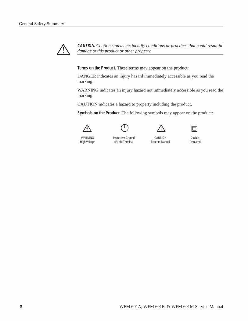
CAUTION. Caution statements identify conditions or practices that could result indamage to this product or other property.
Terms on the Product. These terms may appear on the product:
DANGER indicates an injury hazard immediately accessible as you read themarking.
WARNING indicates an injury hazard not immediately accessible as you read themarking.
CAUTION indicates a hazard to property including the product.
Symbols on the Product. The following symbols may appear on the product:
Protective Ground(Earth) Terminal
CAUTIONRefer to Manual
Double Insulated
WARNINGHigh Voltage

WFM 601A, WFM 601E, & WFM 601M Service Manual xi
Service Safety Summary
Only qualified personnel should perform service procedures. Read this ServiceSafety Summary and the General Safety Summary before performing any serviceprocedures.
Do Not Service Alone. Do not perform internal service or adjustments of thisproduct unless another person capable of rendering first aid and resuscitation ispresent.
Disconnect Power. To avoid electric shock, disconnect the main power by meansof the power cord or, if provided, the power switch.
Use Caution When Servicing the CRT. To avoid electric shock or injury, useextreme caution when handling the CRT. Only qualified personnel familiar withCRT servicing procedures and precautions should remove or install the CRT.
CRTs retain hazardous voltages for long periods of time after power is turned off.Before attempting any servicing, discharge the CRT by shorting the anode tochassis ground. When discharging the CRT, connect the discharge path to groundand then the anode. Rough handling may cause the CRT to implode. Do not nickor scratch the glass or subject it to undue pressure when removing or installing it.When handling the CRT, wear safety goggles and heavy gloves for protection.
Use Care When Servicing With Power On. Dangerous voltages or currents mayexist in this product. Disconnect power, remove battery (if applicable), anddisconnect test leads before removing protective panels, soldering, or replacingcomponents.
To avoid electric shock, do not touch exposed connections.
X-Radiation. To avoid x-radiation exposure, do not modify or otherwise alter thehigh-voltage circuitry or the CRT enclosure. X-ray emissions generated withinthis product have been sufficiently shielded.

Service Safety Summary
xii WFM 601A, WFM 601E, & WFM 601M Service Manual
WFM 601A, WFM 601E, & WFM 601M Service Manual xiii
Preface
This manual provides servicing information for the WFM 601A, WFM 601E,and WFM 601M Serial Digital Component Waveform Monitors. Proceduresdescribed in this manual are designed for experienced service technicians. Fordetailed operating information, refer to your waveform monitor User manual.See section 7, Options, for the part number of the User manuals.
This manual supports both Module Level (for module exchange) and ComponentLevel service. Module Level service uses the block diagram and its descriptionsto isolate a problem to the circuits on a particular circuit board. To supportComponent Level servicing there are schematic diagrams, circuit boardillustrations, and part location tables for each circuit board.
When preparing to service this instrument, remember that its circuit boardscontain surface mount components. Surface mount components require specialtechniques and tools for removal and installation.
Most of the information and procedures in this manual are common across thefamily of waveform monitors. However, each waveform monitor has severalunique features. When a procedure or a description is applies to a specific model,it is indicated with the model number of the waveform monitor in parentheses.
About This ManualThis manual is composed of the following sections:
� Specifications provides a list of all instrument performance requirements,operating environment requirements,and certifications.
� Operating Information provides an overview of the main instrumentfeatures.
� Theory of Operation provides a block diagram description of the instrumentcircuits.
� Performance Verification provides a manual procedure for verifying theperformance requirements in the Specifications section.
� Adjustment Procedures provides an automated procedure for adjusting thewaveform monitor following repair.
� Maintenance provides instructions for troubleshooting and replacinginstrument modules.
� Options provides a list of the available product options.

Preface
xiv WFM 601A, WFM 601E, & WFM 601M Service Manual
� Replaceable Electrical Parts provides a list of all electrical components usedin the instrument.
� Diagrams provides block diagrams, component locators, and schematics.
� Replaceable Mechanical Parts provides a list of all mechanical parts andelectrical modules not contained on a circuit board.
Tektronix maintains a service organization that provides a number of services tohelp you maintain the waveform monitor at its specified levels. These servicesrange from complete repair and adjustment, at a convenient location, tosupplying replacement parts. In addition, Tektronix provides training programsfor service technicians.
NOTE. When considering service offering, remember that Tektronix provides alimited parts and service warranty for all its products. No customer repairsshould be attempted during the warranty period.
Service Training. Tektronix provides service training in a number of programs.Classes are held at our Beaverton campus and at convenient locations byarrangement. To learn more about service training programs, contact your localTektronix field office or representative. U.S. customers can call our serviceorganization directly using 1 (800) TEK WIDE [835-9433]; ask for “ServiceTraining.”
Field Service Centers. Tektronix maintains service centers worldwide. Thesecenters provide repair and calibration services for Tektronix instruments. Theycan be contacted through your Tektronix field office or representative. Inaddition, U.S. and Canadian customers can call 1 (800) TEK WIDE [835-9433]for assistance in contacting their nearest service center.
Module Exchange. The Tektronix module exchange program provides a quick,affordable way to return an instrument to operational status. You exchange adefective module for a calibrated module at a cost well below the new moduleprice. Contact your Tektronix field office or representative for more information.U.S. and Canadian customers can call 1 (800) TEK WIDE [835-9433].
NOTE. Circuit boards that are damaged due to mishandling or containingmodifications not originated by Tektronix are not acceptable for the exchangeprogram.
Tektronix ServiceOfferings
Preface
WFM 601A, WFM 601E, & WFM 601M Service Manual xv
When exchanging a circuit board, it is essential that you have the following keyinformation ready to relay to our technician:
� Instrument type
� Serial number
� Installed options
� Assembly/circuit board number (AX)
� Nine-digit part number (671-XXXX-XX)
� Software version number installed on your waveform monitor
Factory Replacement Parts. Replacement parts are available through the localTektronix field office or representative. However, many common electronic partsare available through local sources. Using a local source, where possible, willeliminate shipping delays.
Changes to Tektronix instruments are sometimes made to accommodateimproved components and to improve circuit performance. Therefore, it isimportant to include the following information when ordering parts:
� Part number
� Instrument type or number
� Serial number
� Modification or option number (if applicable)
If a part has been replaced with a new or improved part, the new part will beshipped, if it is a direct replacement. If not directly replaceable the localTektronix field office or representative will contact the customer concerning anychanges. After any repair, circuit readjustment may be required.
Preface
xvi WFM 601A, WFM 601E, & WFM 601M Service Manual
Contacting Tektronix
Phone 1-800-833-9200*
Address Tektronix, Inc.Department or name (if known)14200 SW Karl Braun DriveP.O. Box 500Beaverton, OR 97077USA
Web site www.tektronix.com
Sales support 1-800-833-9200, select option 1*
Service support 1-800-833-9200, select option 2*
Technical support Email: [email protected]
1-800-833-9200, select option 3*1-503-627-2400
6:00 a.m. – 5:00 p.m. Pacific time
* This phone number is toll free in North America. After office hours, please leave avoice mail message.Outside North America, contact a Tektronix sales office or distributor; see theTektronix web site for a list of offices.

WFM 601A, WFM 601E, & WFM 601M Service Manual 1–1
Specifications
This section provides a brief overview of the WFM 601A, WFM 601E, andWFM 601M waveform monitor product features. The feature list is followed bythe product specifications.
Product DescriptionThe waveform monitors measure and display 4:2:2 component serial digitalsignals. The waveform monitors display serial digital signals as the familiarcomponent signals and in a variety of standard measurement modes. You can usethe EDH (Error Detection and Handling) system and the suite of automatedchecks of the serial digital format to verify data integrity.
Most of the features listed in this section are common across all three waveformmonitors. Where a feature applies only to a specific model, the model is inparentheses following the feature description. The waveform monitors offer thefollowing features:
� Two 270 Mbit serial component loop-through inputs
� Digital video standards SMPTE 259M, ITU-R BT.656, and ITU-R BT.601
� RGB and Y-PB-PR display format for 525 and 625 line signals
� Eye Pattern display with Timing and Voltage Cursors (WFM 601E,WFM 601M)
� Jitter demodulator with numeric jitter readout and video correlated jitterwaveform display (WFM 601M)
� Parade or Waveform display of Y, PB, and PR component signals
� RGB and composite Gamut checks with Diamond and Arrowhead displays
� Field, line, and word select with readout and bright up of selected lines onPicture Monitor Out (Y or G Channel) (WFM 601E, WFM 601M)
� SMPTE RP-165 standard EDH indicator for presence
� Digital Waveform and Data displays with Data-cursor correlation betweendisplay modes (WFM 601M)
� Embedded Audio indentification
� Source-level meter and cable-length readout (WFM 601E, WFM 601M)
Features
Specifications
1–2 WFM 601A, WFM 601E, & WFM 601M Service Manual
� Lightning and Vector displays
� Reclocked Serial Component Digital output following A/B switching
� Video Reference: Internal Serial Component signal (follows A/B switching)or external composite
� Audio Lissajous display (WFM 601A)
An expanded feature set is available through menus. You select menu items withmulti-use bezel buttons and knobs. When you select a menu item, such asVoltage Cursors, on-screen labels show the current function of the bezel buttonsand knobs.
The waveform monitor provides an internal calibrator signal to set both verticaland horizontal gain. The calibrator signal is a 700 mV, 100 kHz signal. Press theCONFIG button and use the bezel knob to select the Calibrate menu. Press theCAL SIG button to turn on the calibrator signal.
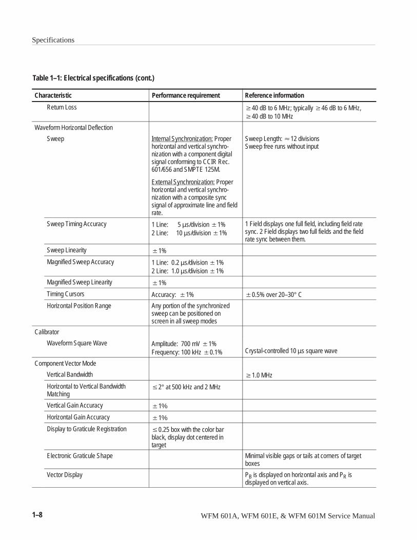
Characteristics TablesTable 1–1 lists the electrical specifications for the waveform monitors. Perfor-mance requirements are generally quantitative and can be tested by the Perfor-mance Verification procedure this manual. Reference information describesuseful operating parameters that have typical values. These parameters are notdirectly checked in the performance verification procedure. Table 1–8 lists theEMC compliance specifications.
The Performance Requirements listed in the electrical specification portion ofthese specifications apply over an ambient temperature range of 0° C to +40° C.The rated accuracies are valid when the instrument is calibrated at an ambienttemperature range of +20° C to +30° C, after a warm-up time of 20 minutes.
Menus
Calibrator
Specifications
WFM 601A, WFM 601E, & WFM 601M Service Manual 1–3
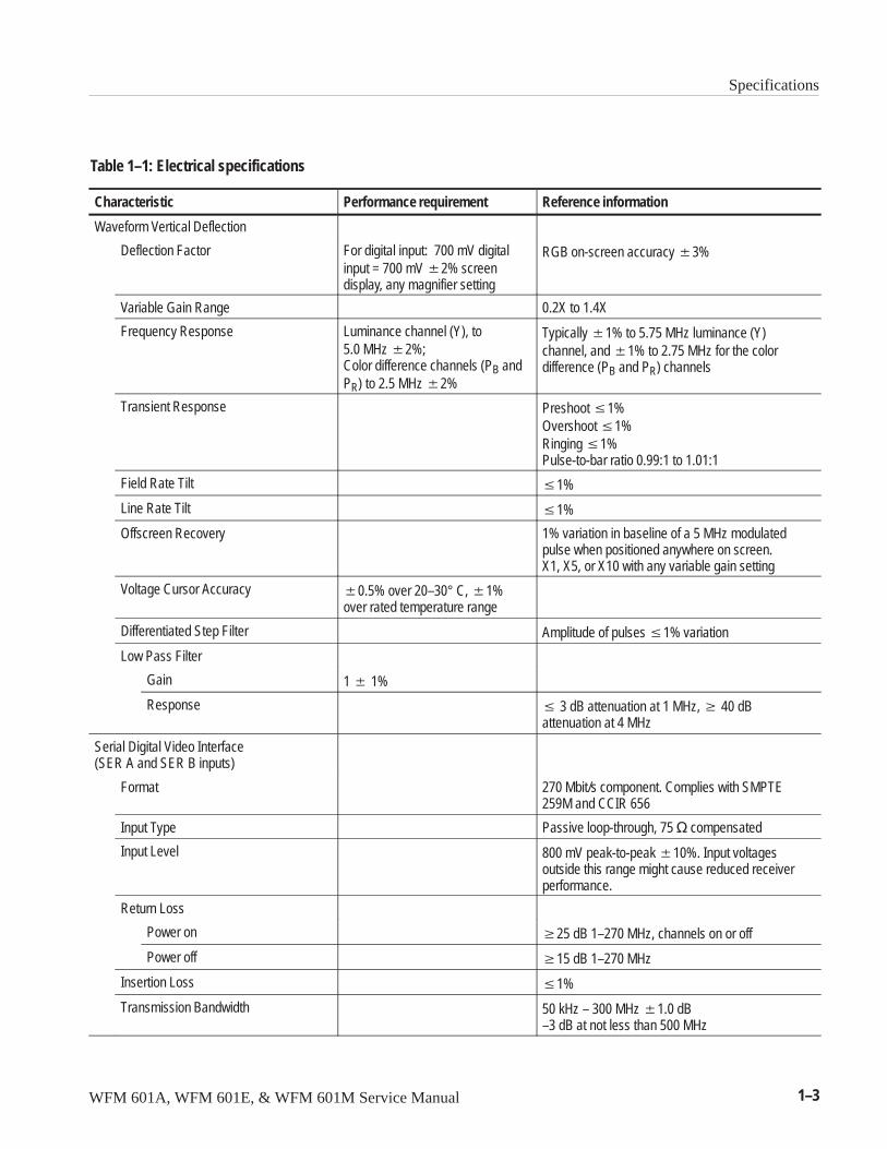
Table 1–1: Electrical specifications
Characteristic Performance requirement Reference information
Waveform Vertical Deflection
Deflection Factor For digital input: 700 mV digitalinput = 700 mV �2% screendisplay, any magnifier setting
RGB on-screen accuracy �3%
Variable Gain Range 0.2X to 1.4X
Frequency Response Luminance channel (Y), to 5.0 MHz �2%;Color difference channels (PB andPR) to 2.5 MHz �2%
Typically �1% to 5.75 MHz luminance (Y)channel, and �1% to 2.75 MHz for the colordifference (PB and PR) channels
Transient Response Preshoot �1%Overshoot �1%Ringing �1%Pulse-to-bar ratio 0.99:1 to 1.01:1
Field Rate Tilt �1%
Line Rate Tilt �1%
Offscreen Recovery 1% variation in baseline of a 5 MHz modulatedpulse when positioned anywhere on screen.X1, X5, or X10 with any variable gain setting
Voltage Cursor Accuracy �0.5% over 20–30° C, �1%over rated temperature range
Differentiated Step Filter Amplitude of pulses �1% variation
Low Pass Filter
Gain 1 � 1%
Response � 3 dB attenuation at 1 MHz, � 40 dBattenuation at 4 MHz
Serial Digital Video Interface(SER A and SER B inputs)
Format 270 Mbit/s component. Complies with SMPTE259M and CCIR 656
Input Type Passive loop-through, 75 � compensated
Input Level 800 mV peak-to-peak �10%. Input voltagesoutside this range might cause reduced receiverperformance.
Return Loss
Power on �25 dB 1–270 MHz, channels on or off
Power off �15 dB 1–270 MHz
Insertion Loss �1%
Transmission Bandwidth 50 kHz – 300 MHz �1.0 dB–3 dB at not less than 500 MHz
Specifications
1–4 WFM 601A, WFM 601E, & WFM 601M Service Manual
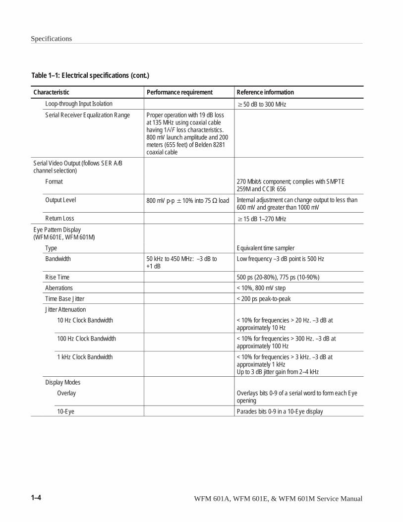
Table 1–1: Electrical specifications (cont.)
Characteristic Reference informationPerformance requirement
Loop-through Input Isolation �50 dB to 300 MHz
Serial Receiver Equalization Range Proper operation with 19 dB lossat 135 MHz using coaxial cablehaving 1/√F loss characteristics.800 mV launch amplitude and 200meters (655 feet) of Belden 8281coaxial cable
Serial Video Output (follows SER A/Bchannel selection)
Format 270 Mbit/s component; complies with SMPTE259M and CCIR 656
Output Level 800 mV p-p �10% into 75 � load Internal adjustment can change output to less than600 mV and greater than 1000 mV
Return Loss �15 dB 1–270 MHz
Eye Pattern Display (WFM 601E, WFM 601M)
Type Equivalent time sampler
Bandwidth 50 kHz to 450 MHz: –3 dB to+1 dB
Low frequency –3 dB point is 500 Hz
Rise Time 500 ps (20-80%), 775 ps (10-90%)
Aberrations < 10%, 800 mV step
Time Base Jitter < 200 ps peak-to-peak
Jitter Attenuation
10 Hz Clock Bandwidth < 10% for frequencies > 20 Hz. –3 dB at approximately 10 Hz
100 Hz Clock Bandwidth < 10% for frequencies > 300 Hz. –3 dB at approximately 100 Hz
1 kHz Clock Bandwidth < 10% for frequencies > 3 kHz. –3 dB at approximately 1 kHzUp to 3 dB jitter gain from 2–4 kHz
Display Modes
Overlay Overlays bits 0-9 of a serial word to form each Eyeopening
10-Eye Parades bits 0-9 in a 10-Eye display
Specifications
WFM 601A, WFM 601E, & WFM 601M Service Manual 1–5
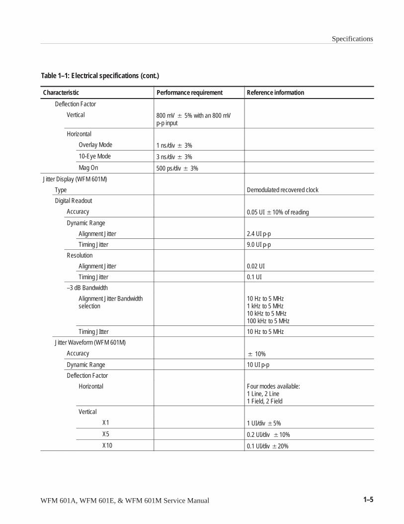
Table 1–1: Electrical specifications (cont.)
Characteristic Reference informationPerformance requirement
Deflection Factor
Vertical 800 mV � 5% with an 800 mVp-p input
Horizontal
Overlay Mode 1 ns/div � 3%
10-Eye Mode 3 ns/div � 3%
Mag On 500 ps/div � 3%
Jitter Display (WFM 601M)
Type Demodulated recovered clock
Digital Readout
Accuracy 0.05 UI �10% of reading
Dynamic Range
Alignment Jitter 2.4 UI p-p
Timing Jitter 9.0 UI p-p
Resolution
Alignment Jitter 0.02 UI
Timing Jitter 0.1 UI
–3 dB Bandwidth
Alignment Jitter Bandwidthselection
10 Hz to 5 MHz1 kHz to 5 MHz10 kHz to 5 MHz100 kHz to 5 MHz
Timing JItter 10 Hz to 5 MHz
Jitter Waveform (WFM 601M)
Accuracy � 10%
Dynamic Range 10 UI p-p
Deflection Factor
Horizontal Four modes available:1 Line, 2 Line1 Field, 2 Field
Vertical
X1 1 UI/div �5%
X5 0.2 UI/div �10%
X10 0.1 UI/div �20%
Specifications
1–6 WFM 601A, WFM 601E, & WFM 601M Service Manual
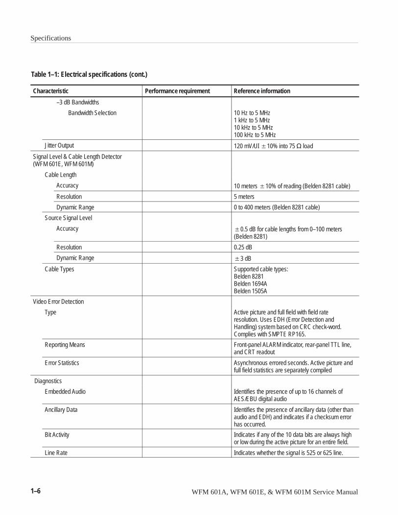
Table 1–1: Electrical specifications (cont.)
Characteristic Reference informationPerformance requirement
–3 dB Bandwidths
Bandwidth Selection 10 Hz to 5 MHz1 kHz to 5 MHz10 kHz to 5 MHz100 kHz to 5 MHz
Jitter Output 120 mV/UI �10% into 75 � load
Signal Level & Cable Length Detector(WFM 601E, WFM 601M)
Cable Length
Accuracy 10 meters �10% of reading (Belden 8281 cable)
Resolution 5 meters
Dynamic Range 0 to 400 meters (Belden 8281 cable)
Source Signal Level
Accuracy �0.5 dB for cable lengths from 0–100 meters(Belden 8281)
Resolution 0.25 dB
Dynamic Range �3 dB
Cable Types Supported cable types:Belden 8281Belden 1694ABelden 1505A
Video Error Detection
Type Active picture and full field with field rateresolution. Uses EDH (Error Detection andHandling) system based on CRC check-word.Complies with SMPTE RP165.
Reporting Means Front-panel ALARM indicator, rear-panel TTL line,and CRT readout
Error Statistics Asynchronous errored seconds. Active picture andfull field statistics are separately compiled
Diagnostics
Embedded Audio Identifies the presence of up to 16 channels ofAES/EBU digital audio
Ancillary Data Identifies the presence of ancillary data (other thanaudio and EDH) and indicates if a checksum errorhas occurred.
Bit Activity Indicates if any of the 10 data bits are always highor low during the active picture for an entire field.
Line Rate Indicates whether the signal is 525 or 625 line.
Specifications
WFM 601A, WFM 601E, & WFM 601M Service Manual 1–7
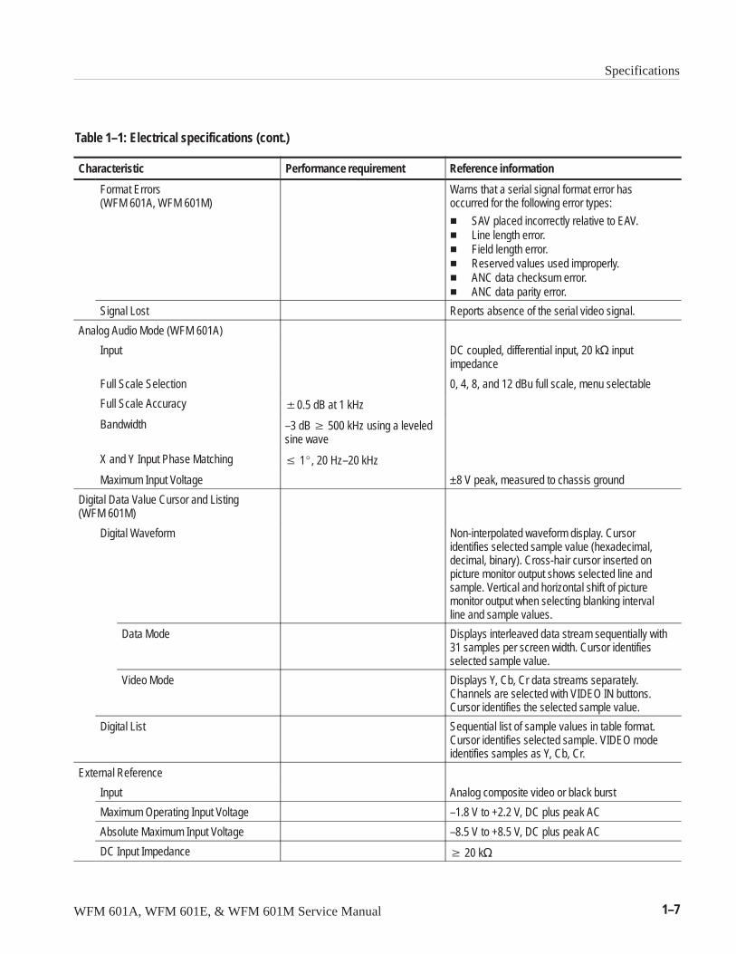
Table 1–1: Electrical specifications (cont.)
Characteristic Reference informationPerformance requirement
Format Errors(WFM 601A, WFM 601M)
Warns that a serial signal format error hasoccurred for the following error types:
� SAV placed incorrectly relative to EAV.� Line length error.� Field length error.� Reserved values used improperly.� ANC data checksum error.� ANC data parity error.
Signal Lost Reports absence of the serial video signal.
Analog Audio Mode (WFM 601A)
Input DC coupled, differential input, 20 k� inputimpedance
Full Scale Selection 0, 4, 8, and 12 dBu full scale, menu selectable
Full Scale Accuracy �0.5 dB at 1 kHz
Bandwidth –3 dB � 500 kHz using a leveledsine wave
X and Y Input Phase Matching � 1�, 20 Hz–20 kHz
Maximum Input Voltage ±8 V peak, measured to chassis ground
Digital Data Value Cursor and Listing(WFM 601M)
Digital Waveform Non-interpolated waveform display. Cursoridentifies selected sample value (hexadecimal,decimal, binary). Cross-hair cursor inserted onpicture monitor output shows selected line andsample. Vertical and horizontal shift of picturemonitor output when selecting blanking intervalline and sample values.
Data Mode Displays interleaved data stream sequentially with31 samples per screen width. Cursor identifiesselected sample value.
Video Mode Displays Y, Cb, Cr data streams separately.Channels are selected with VIDEO IN buttons.Cursor identifies the selected sample value.
Digital List Sequential list of sample values in table format.Cursor identifies selected sample. VIDEO modeidentifies samples as Y, Cb, Cr.
External Reference
Input Analog composite video or black burst
Maximum Operating Input Voltage –1.8 V to +2.2 V, DC plus peak AC
Absolute Maximum Input Voltage –8.5 V to +8.5 V, DC plus peak AC
DC Input Impedance � 20 k�
Specifications
1–8 WFM 601A, WFM 601E, & WFM 601M Service Manual
Table 1–1: Electrical specifications (cont.)
Characteristic Reference informationPerformance requirement
Return Loss �40 dB to 6 MHz; typically �46 dB to 6 MHz,�40 dB to 10 MHz
Waveform Horizontal Deflection
Sweep Internal Synchronization: Properhorizontal and vertical synchro-nization with a component digitalsignal conforming to CCIR Rec.601/656 and SMPTE 125M.
External Synchronization: Properhorizontal and vertical synchro-nization with a composite syncsignal of approximate line and fieldrate.
Sweep Length: �12 divisionsSweep free runs without input
Sweep Timing Accuracy 1 Line: 5 �s/division �1%2 Line: 10 �s/division �1%
1 Field displays one full field, including field ratesync. 2 Field displays two full fields and the fieldrate sync between them.
Sweep Linearity �1%
Magnified Sweep Accuracy 1 Line: 0.2 �s/division �1% 2 Line: 1.0 �s/division �1%
Magnified Sweep Linearity �1%
Timing Cursors Accuracy: �1% �0.5% over 20–30° C
Horizontal Position Range Any portion of the synchronizedsweep can be positioned onscreen in all sweep modes
Calibrator
Waveform Square Wave Amplitude: 700 mV �1%Frequency: 100 kHz �0.1% Crystal-controlled 10 �s square wave
Component Vector Mode
Vertical Bandwidth �1.0 MHz
Horizontal to Vertical BandwidthMatching
�2° at 500 kHz and 2 MHz
Vertical Gain Accuracy �1%
Horizontal Gain Accuracy �1%
Display to Graticule Registration �0.25 box with the color barblack, display dot centered intarget
Electronic Graticule Shape Minimal visible gaps or tails at corners of targetboxes
Vector Display PB is displayed on horizontal axis and PR isdisplayed on vertical axis.
Specifications
WFM 601A, WFM 601E, & WFM 601M Service Manual 1–9
Table 1–1: Electrical specifications (cont.)
Characteristic Reference informationPerformance requirement
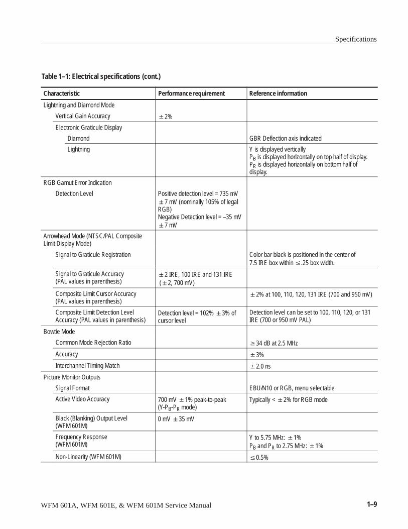
Lightning and Diamond Mode
Vertical Gain Accuracy �2%
Electronic Graticule Display
Diamond GBR Deflection axis indicated
Lightning Y is displayed verticallyPB is displayed horizontally on top half of display.PR is displayed horizontally on bottom half ofdisplay.
RGB Gamut Error Indication
Detection Level Positive detection level = 735 mV�7 mV (nominally 105% of legalRGB)Negative Detection level = –35 mV�7 mV
Arrowhead Mode (NTSC/PAL CompositeLimit Display Mode)
Signal to Graticule Registration Color bar black is positioned in the center of 7.5 IRE box within �.25 box width.
Signal to Graticule Accuracy(PAL values in parenthesis)
�2 IRE, 100 IRE and 131 IRE (�2, 700 mV)
Composite Limit Cursor Accuracy(PAL values in parenthesis)
�2% at 100, 110, 120, 131 IRE (700 and 950 mV)
Composite Limit Detection Level Accuracy (PAL values in parenthesis)
Detection level = 102% �3% ofcursor level
Detection level can be set to 100, 110, 120, or 131IRE (700 or 950 mV PAL)
Bowtie Mode
Common Mode Rejection Ratio �34 dB at 2.5 MHz
Accuracy �3%
Interchannel Timing Match �2.0 ns
Picture Monitor Outputs
Signal Format EBU/N10 or RGB, menu selectable
Active Video Accuracy 700 mV �1% peak-to-peak(Y-PB-PR mode)
Typically < �2% for RGB mode
Black (Blanking) Output Level(WFM 601M)
0 mV �35 mV
Frequency Response(WFM 601M)
Y to 5.75 MHz: �1%PB and PR to 2.75 MHz: �1%
Non-Linearity (WFM 601M) �0.5%
Specifications
1–10 WFM 601A, WFM 601E, & WFM 601M Service Manual
Table 1–1: Electrical specifications (cont.)
Characteristic Reference informationPerformance requirement
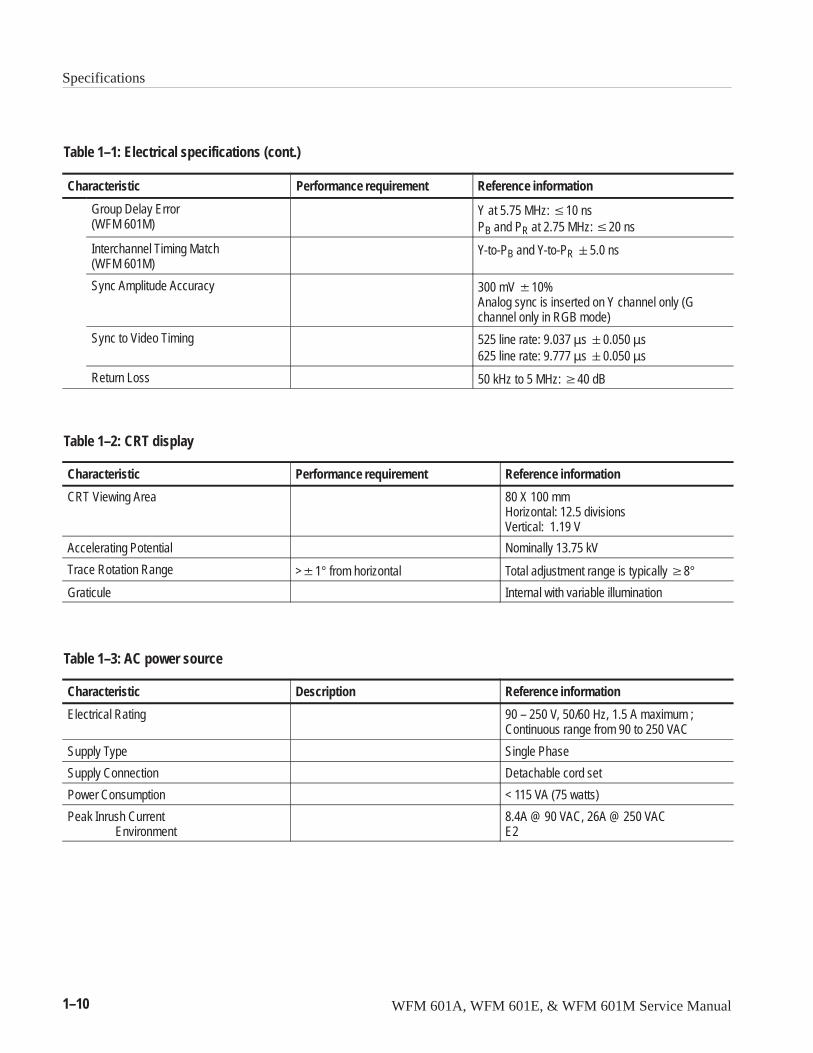
Group Delay Error(WFM 601M)
Y at 5.75 MHz: �10 nsPB and PR at 2.75 MHz: �20 ns
Interchannel Timing Match(WFM 601M)
Y-to-PB and Y-to-PR �5.0 ns
Sync Amplitude Accuracy 300 mV �10%Analog sync is inserted on Y channel only (Gchannel only in RGB mode)
Sync to Video Timing 525 line rate: 9.037 �s �0.050 �s625 line rate: 9.777 �s �0.050 �s
Return Loss 50 kHz to 5 MHz: �40 dB
Table 1–2: CRT display
Characteristic Performance requirement Reference information
CRT Viewing Area 80 X 100 mmHorizontal: 12.5 divisionsVertical: 1.19 V
Accelerating Potential Nominally 13.75 kV
Trace Rotation Range >�1° from horizontal Total adjustment range is typically �8°Graticule Internal with variable illumination
Table 1–3: AC power source
Characteristic Description Reference information
Electrical Rating 90 – 250 V, 50/60 Hz, 1.5 A maximum ;Continuous range from 90 to 250 VAC
Supply Type Single Phase
Supply Connection Detachable cord set
Power Consumption < 115 VA (75 watts)
Peak Inrush CurrentEnvironment
8.4A @ 90 VAC, 26A @ 250 VAC E2
Specifications
WFM 601A, WFM 601E, & WFM 601M Service Manual 1–11
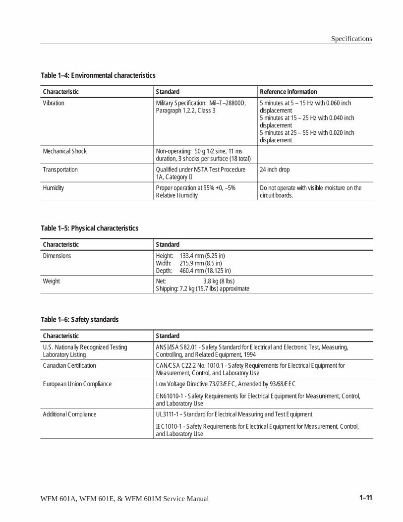
Table 1–4: Environmental characteristics
Characteristic Standard Reference information
Vibration Military Specification: Mil–T–28800D,Paragraph 1.2.2, Class 3
5 minutes at 5 – 15 Hz with 0.060 inchdisplacement5 minutes at 15 – 25 Hz with 0.040 inchdisplacement5 minutes at 25 – 55 Hz with 0.020 inchdisplacement
Mechanical Shock Non-operating: 50 g 1/2 sine, 11 msduration, 3 shocks per surface (18 total)
Transportation Qualified under NSTA Test Procedure1A, Category II
24 inch drop
Humidity Proper operation at 95% +0, –5%Relative Humidity
Do not operate with visible moisture on thecircuit boards.
Table 1–5: Physical characteristics
Characteristic Standard
Dimensions Height: 133.4 mm (5.25 in)Width: 215.9 mm (8.5 in)Depth: 460.4 mm (18.125 in)
Weight Net: 3.8 kg (8 lbs)Shipping: 7.2 kg (15.7 lbs) approximate
Table 1–6: Safety standards
Characteristic Standard
U.S. Nationally Recognized Testing Laboratory Listing
ANSI/ISA S82.01 - Safety Standard for Electrical and Electronic Test, Measuring,Controlling, and Related Equipment, 1994
Canadian Certification CAN/CSA C22.2 No. 1010.1 - Safety Requirements for Electrical Equipment forMeasurement, Control, and Laboratory Use
European Union Compliance Low Voltage Directive 73/23/EEC, Amended by 93/68/EEC
EN61010-1 - Safety Requirements for Electrical Equipment for Measurement, Control,and Laboratory Use
Additional Compliance UL3111-1 - Standard for Electrical Measuring and Test Equipment
IEC1010-1 - Safety Requirements for Electrical Equipment for Measurement, Control,and Laboratory Use
Specifications
1–12 WFM 601A, WFM 601E, & WFM 601M Service Manual
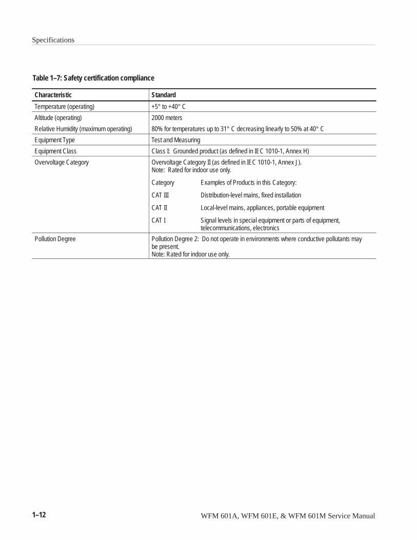
Table 1–7: Safety certification compliance
Characteristic Standard
Temperature (operating) +5° to +40° C
Altitude (operating) 2000 meters
Relative Humidity (maximum operating) 80% for temperatures up to 31° C decreasing linearly to 50% at 40° C
Equipment Type Test and Measuring
Equipment Class Class I: Grounded product (as defined in IEC 1010-1, Annex H)
Overvoltage Category Overvoltage Category II (as defined in IEC 1010-1, Annex J). Note: Rated for indoor use only.
Category Examples of Products in this Category:
CAT III Distribution-level mains, fixed installation
CAT II Local-level mains, appliances, portable equipment
CAT I Signal levels in special equipment or parts of equipment, telecommunications, electronics
Pollution Degree Pollution Degree 2: Do not operate in environments where conductive pollutants maybe present.Note: Rated for indoor use only.
Specifications
WFM 601A, WFM 601E, & WFM 601M Service Manual 1–13
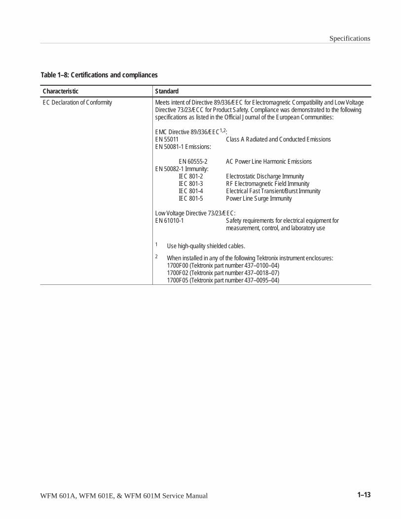
Table 1–8: Certifications and compliances
Characteristic Standard
EC Declaration of Conformity Meets intent of Directive 89/336/EEC for Electromagnetic Compatibility and Low VoltageDirective 73/23/ECC for Product Safety. Compliance was demonstrated to the followingspecifications as listed in the Official Journal of the European Communities:
EMC Directive 89/336/EEC1,2:EN 55011 Class A Radiated and Conducted EmissionsEN 50081-1 Emissions:
EN 60555-2 AC Power Line Harmonic EmissionsEN 50082-1 Immunity:
IEC 801-2 Electrostatic Discharge ImmunityIEC 801-3 RF Electromagnetic Field ImmunityIEC 801-4 Electrical Fast Transient/Burst ImmunityIEC 801-5 Power Line Surge Immunity
Low Voltage Directive 73/23/EEC:EN 61010-1 Safety requirements for electrical equipment for
measurement, control, and laboratory use
1 Use high-quality shielded cables.
2 When installed in any of the following Tektronix instrument enclosures:1700F00 (Tektronix part number 437–0100–04)1700F02 (Tektronix part number 437–0018–07)1700F05 (Tektronix part number 437–0095–04)

Specifications
1–14 WFM 601A, WFM 601E, & WFM 601M Service Manual

WFM 601A, WFM 601E, & WFM 601M Service Manual 2–1
Installation
This section describes how to install and operate the WFM 601A, WFM 601E,and WFM 601M Serial Digital Component Waveform Monitors. It also describeshow to remove the waveform monitors for servicing. Note that repackaginginformation is located at the end of the Maintenance section.
This manual includes one 3.5-inch high-density floppy disk that contains servicesoftware. This software is used for the adjustment procedure. Instructions forusing the disk are located in the Adjustment Procedure section of this manual.
Hardware InstallationBecause operating environments vary, the waveform monitor is not shipped witha cabinet unless one is ordered. All qualification testing for the waveformmonitor was performed in a 1700F00 cabinet. To guarantee compliance withspecifications, you should operate the waveform monitor in one of the cabinetsdescribed here.
WARNING. When power is supplied to the rear panel, line voltage is still presentin the instrument, even if the Power switch LED is off.
The cabinets offered for the waveform monitor provide EMI shielding, protectagainst electrical shock, and protect against the accumulation of dust.
A rear panel fan supplies filtered, cooling air which exits through the cabinetvent holes. Restricting the air flow through the vents or the rear fan can lead to anexcessive internal temperature. To ensure adequate ventilation, provide thefollowing clearance for the waveform monitor: three inches at the rear, twoinches on each side, and one inch each on the top and and the bottom.
NOTE. To meet EMI emission specifications, the waveform monitors must beinstalled in a Tektronix 1700F00, 1700F02, or 1700F05 cabinet. The cabinetfront edges must securely contact the conductive front bezel on all four sides.
Cabinets
Installation
2–2 WFM 601A, WFM 601E, & WFM 601M Service Manual
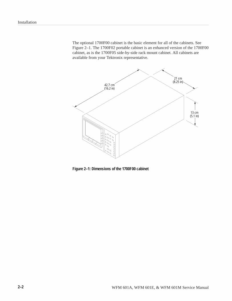
The optional 1700F00 cabinet is the basic element for all of the cabinets. SeeFigure 2–1. The 1700F02 portable cabinet is an enhanced version of the 1700F00cabinet, as is the 1700F05 side-by-side rack mount cabinet. All cabinets areavailable from your Tektronix representative.
13 cm(5.1 in)
21 cm(8.25 in)
42.7 cm(16.2 in)
Figure 2–1: Dimensions of the 1700F00 cabinet
Installation
WFM 601A, WFM 601E, & WFM 601M Service Manual 2–3
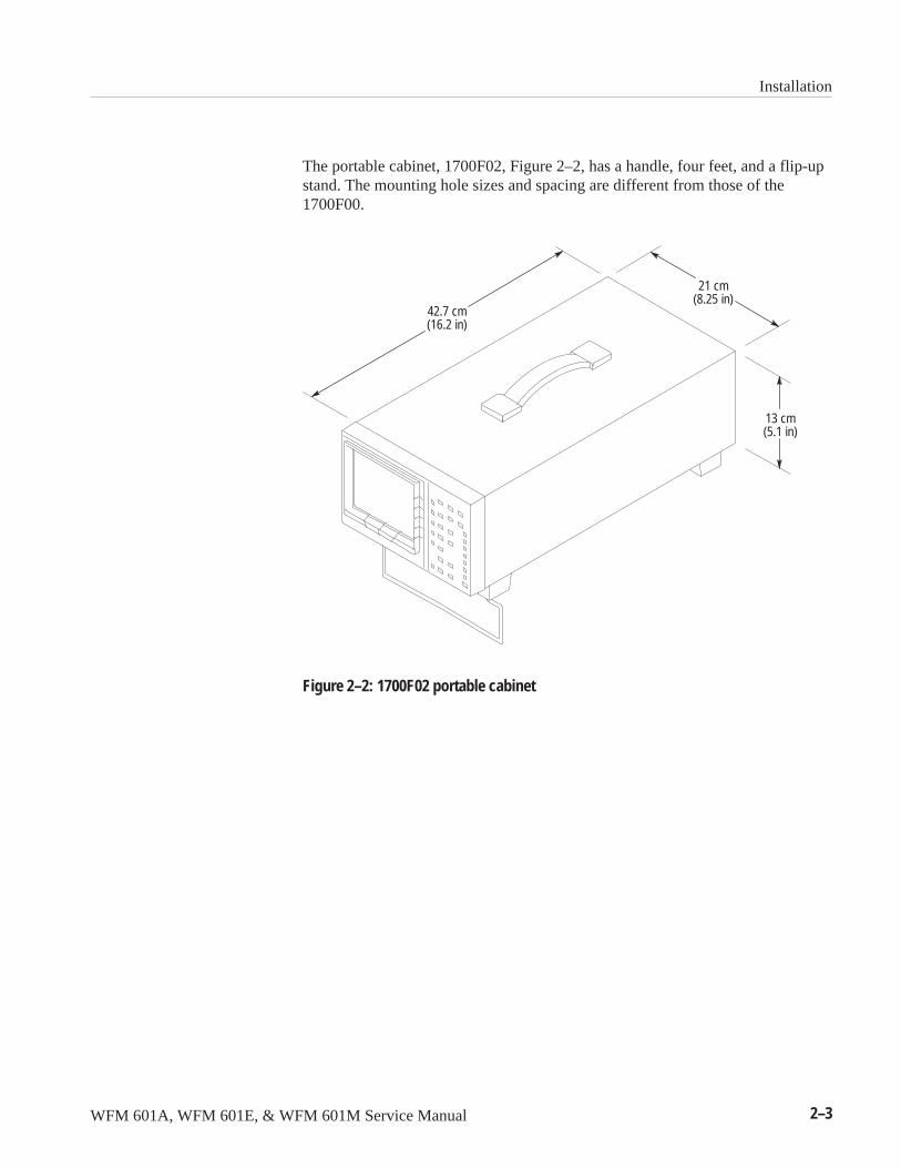
The portable cabinet, 1700F02, Figure 2–2, has a handle, four feet, and a flip-upstand. The mounting hole sizes and spacing are different from those of the1700F00.
21 cm(8.25 in)
42.7 cm(16.2 in)
13 cm(5.1 in)
Figure 2–2: 1700F02 portable cabinet
Installation
2–4 WFM 601A, WFM 601E, & WFM 601M Service Manual
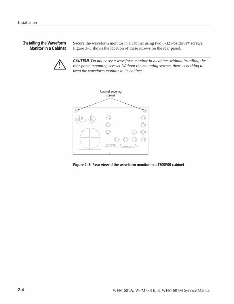
Secure the waveform monitor in a cabinet using two 6-32 Pozidrive� screws.Figure 2–3 shows the location of these screws on the rear panel.
CAUTION. Do not carry a waveform monitor in a cabinet without installing therear panel mounting screws. Without the mounting screws, there is nothing tokeep the waveform monitor in its cabinet.
Cabinet securingscrews
Figure 2–3: Rear view of the waveform monitor in a 1700F00 cabinet
Installing the WaveformMonitor in a Cabinet
Installation
WFM 601A, WFM 601E, & WFM 601M Service Manual 2–5
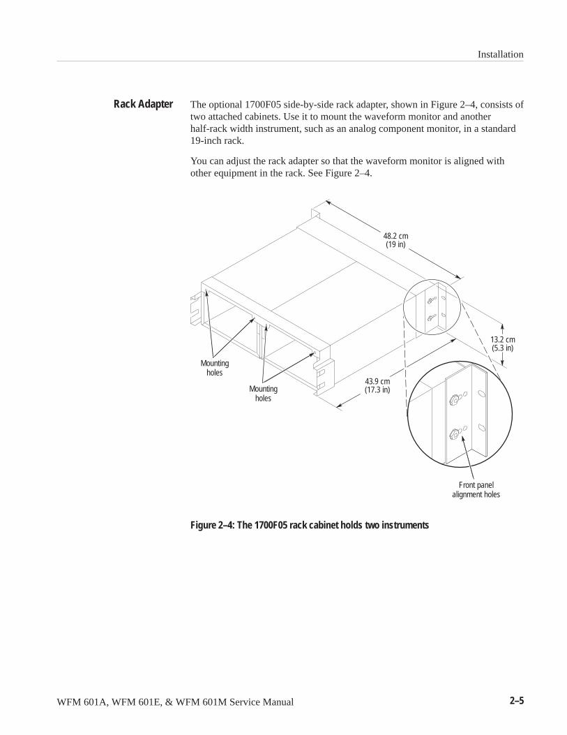
The optional 1700F05 side-by-side rack adapter, shown in Figure 2–4, consists oftwo attached cabinets. Use it to mount the waveform monitor and anotherhalf-rack width instrument, such as an analog component monitor, in a standard19-inch rack.
You can adjust the rack adapter so that the waveform monitor is aligned withother equipment in the rack. See Figure 2–4.
Front panelalignment holes
Mountingholes
Mountingholes
43.9 cm(17.3 in)
48.2 cm(19 in)
13.2 cm(5.3 in)
Figure 2–4: The 1700F05 rack cabinet holds two instruments
Rack Adapter
Installation
2–6 WFM 601A, WFM 601E, & WFM 601M Service Manual
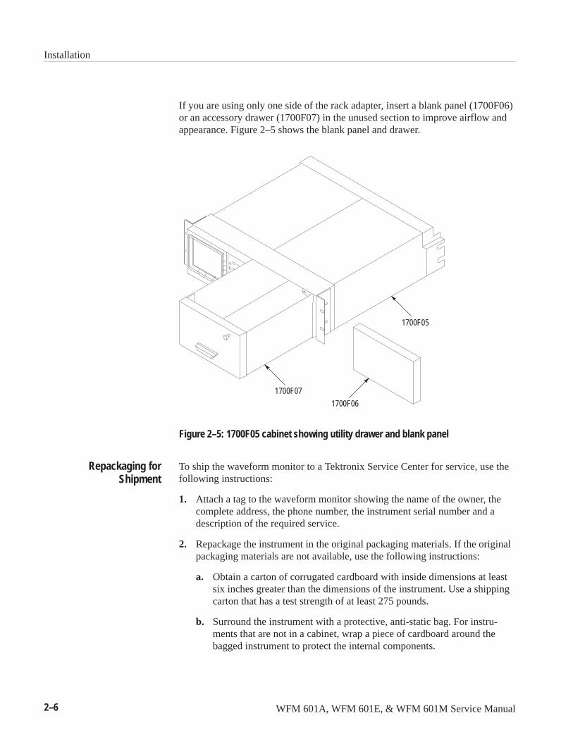
If you are using only one side of the rack adapter, insert a blank panel (1700F06)or an accessory drawer (1700F07) in the unused section to improve airflow andappearance. Figure 2–5 shows the blank panel and drawer.
1700F07
1700F06
1700F05
Figure 2–5: 1700F05 cabinet showing utility drawer and blank panel
To ship the waveform monitor to a Tektronix Service Center for service, use thefollowing instructions:
1. Attach a tag to the waveform monitor showing the name of the owner, thecomplete address, the phone number, the instrument serial number and adescription of the required service.
2. Repackage the instrument in the original packaging materials. If the originalpackaging materials are not available, use the following instructions:
a. Obtain a carton of corrugated cardboard with inside dimensions at leastsix inches greater than the dimensions of the instrument. Use a shippingcarton that has a test strength of at least 275 pounds.
b. Surround the instrument with a protective, anti-static bag. For instru-ments that are not in a cabinet, wrap a piece of cardboard around thebagged instrument to protect the internal components.
Repackaging forShipment
Installation
WFM 601A, WFM 601E, & WFM 601M Service Manual 2–7
c. Pack dunnage or urethane foam between the instrument and the carton. Ifusing Styrofoam kernels, overfill the box and compress when closing thelid. You need three inches of tightly packed cushioning on all sides of theinstrument.
3. Seal the carton with shipping tape or industrial staples.
Connecting PowerThe waveform monitor operates from a single-phase power source with theneutral conductor at or near earth ground. The line conductor is fused forover-current protection. A protective ground connection through the groundingconductor in the power cord is essential for safe operation.
WARNING. When power is supplied to the rear panel, line voltage is still presentin the waveform monitor, even if the POWER switch LED is off.
The waveform monitor operates from an AC line frequency of 50 or 60 Hz, overthe range of 90–250 Volts, without requiring further configuration, except for thepower cord. Refer to page 7–1 for the power cord options. The typical powerdraw is 75 W. Refer to the Specifications section for additional information onpower and environmental requirements.
Rear-Panel ConnectorsFor information on the rear panel connectors, refer to page 2–13.
AC Power Requirements

Installation
2–8 WFM 601A, WFM 601E, & WFM 601M Service Manual
WFM 601A, WFM 601E, & WFM 601M Service Manual 2–9
Operating Information
This section provides a brief description of the waveform monitors front- andrear-panel features and connections. For detailed operating information, refer tothe User manual for the specific model.
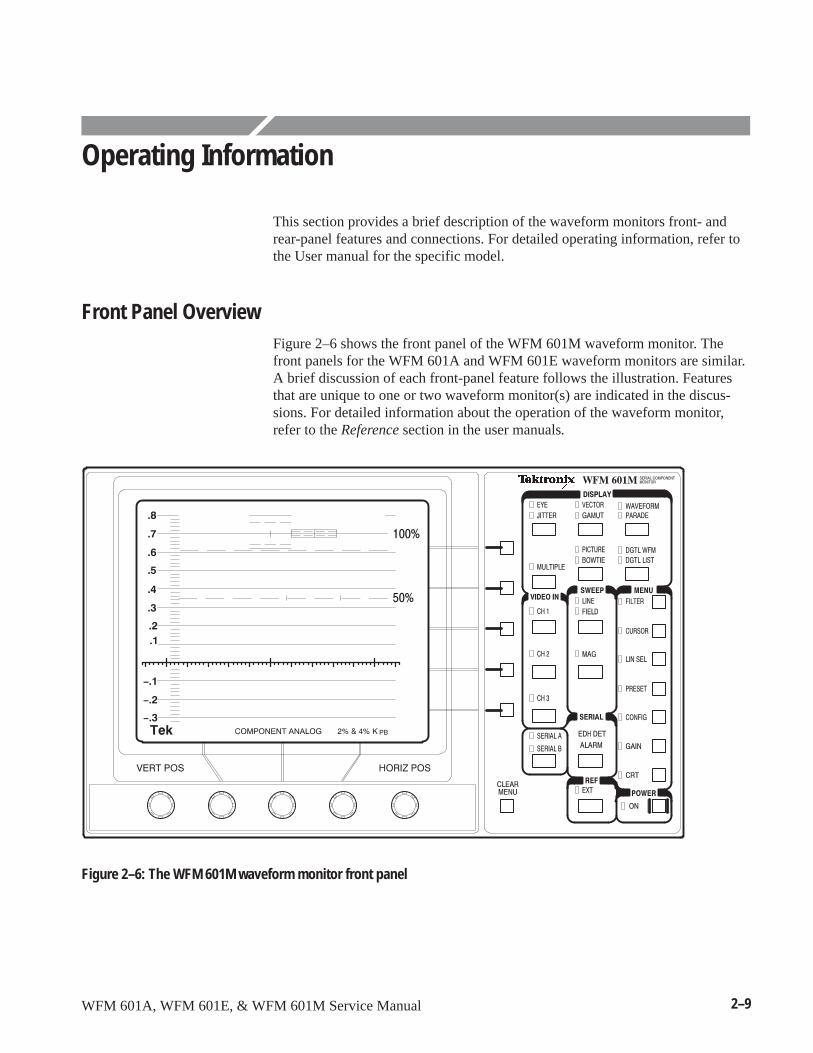
Front Panel OverviewFigure 2–6 shows the front panel of the WFM 601M waveform monitor. Thefront panels for the WFM 601A and WFM 601E waveform monitors are similar.A brief discussion of each front-panel feature follows the illustration. Featuresthat are unique to one or two waveform monitor(s) are indicated in the discus-sions. For detailed information about the operation of the waveform monitor,refer to the Reference section in the user manuals.
Figure 2–6: The WFM 601M waveform monitor front panel
Operating Information
2–10 WFM 601A, WFM 601E, & WFM 601M Service Manual
The center three knobs located below the CRT have multiple functions. Yourselection of DISPLAY or MENU functions or items from on-screen menusdetermine the current function of each knob. A label adjacent to the knobindicates its current function. The outside knobs are permanently assigned tocontrol vertical and horizontal trace position.
The five bezel buttons along the right side of the CRT have multiple functions.Your selection of DISPLAY modes, MENU functions, or on-screen items fromthe displayed menus determine the current function of each button. A labeladjacent to each button indicates its current selection. The buttons either stepthrough a list of two or more items or turn a function on or off.
Six buttons in the DISPLAY area control the type of display. Most buttonsrepresent two related types of displays. Press a button to select one of its twodisplays. Press the button again to select the other. When you select a displaytype, the indicator LED beside it lights up.
EYE. Displays the serial input signal as an Eye pattern display. You can choosestandard or equalized Eye displays (WFM 601E, WFM 601M).
JITTER. Displays the peak-to-peak jitter measurement over a specified band-width. The display includes the demodulated jitter waveform for measurement(WFM 601M).
VECTOR. Displays the component signals as either conventional Vector orLightning mode. Vector mode plots the chrominance signals, Pb and Pr, againsteach other to show their phase and amplitude relationships. The Lightning modeshows amplitude and timing relationships between the luminance and chromi-nance signals. The top of the display plots Y against Pb while the bottom plots Yagainst Pr.
GAMUT. Displays the video signal in Diamond or Arrowhead gamut displays.Diamond mode evaluates RGB signals for gamut limit violations. Arrowheaddisplay plots Y versus chrominance magnitude to show adherence to compositegamut limits. A gamut error message appears at the lower-left when an RGB orComposite gamut error is detected. Turn this alarm on or off in the CONFIGmenu.
WAVEFORM. Displays the video signal as voltage versus time. Any or all of thethree channels can be displayed from a single video line.
PARADE. Displays up to three channels of the video signal in succession.
Bezel Knobs
Bezel Buttons
DISPLAY Buttons
Operating Information
WFM 601A, WFM 601E, & WFM 601M Service Manual 2–11
MULTIPLE. Allows two display modes to be active at the same time. TheWaveform or Parade can be displayed with either Vector, Lightning, or Diamond.
PICTURE. Displays the video signal source. When Line Select is on, the selectedline is highlighted to identify where it is in the video picture.
BOWTIE. Displays a bowtie test signal to determine timing differences betweenthe three component signals, Y, Pb, and Pr. The external video source mustgenerate a Bowtie test signal.
DGTL WFM. Displays the digital word values as a waveform. The data values arenot interpolated to generate the waveform (WFM 601M).
DGTL LIST. Displays the sequential data values in a list. Data may be in lineardata sequence or as groups of four values as they appear in the multiplexed datastream: CB, Y, CR, Y’ (WFM 601M).
ANALOG AUDIO. Displays the stereo analog audio input as a Lissajous pattern.The size of the opening in the pattern is relative to the phase error between the Xand Y audio channels. (WFM 601A)
Turns on or off CH 1 (Y/R), CH 2 (PB/G), and CH 3 (PR/B) and selects theSERIAL A or B digital signal input. At least one input and one channel arealways on.
Selects the waveform monitor sweep rate (LINE/FIELD) and horizontalmagnification (MAG). This area includes two buttons:
LINE / FIELD. Toggles through four sweep rates: 1-Line (5 �s/div), 2-Line(10 �s/division), 1-Field, and 2-Field. Selections are limited in some displaymodes.
MAG. Provides horizontal magnification of waveform signals. Use the HorizontalPosition bezel knob to move left or right on through the waveform.
VIDEO IN
SWEEP
Operating Information
2–12 WFM 601A, WFM 601E, & WFM 601M Service Manual
Displays a status screen providing EDH error statistics, including ANC dataerrors and line/field length errors. In addition, the WFM 601E and WFM 601Mwaveform monitors provide screens that report format errors, signal strength, andcable length information. This area includes two indicators:
EDH DET. Lights up when the serial digital signal has the SMPTE RP165specified Error Detection and Handling (EDH) signal.
ALARM. Lights up when a serial video data or format error occurs, or when theserial signal is lost.
Selects either internal serial digital or external composite video input for theinstrument synchronization reference.
Provides access to configuration and measurement functions that affect theDISPLAY mode. Press a MENU button to display that menu and enable theassociated functions. Press the button again to exit the menu and disable thefunction.
Puts the waveform monitor into the standby or operational state.
Turns off the MENU function readouts without affecting the menu settings. Also,provides access to alternative displays in some display modes.
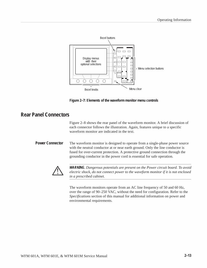
Using the MenusThe waveform monitors have a set of front-panel selectable MENU buttons thatcall up CRT readout menus. These menus operate in conjunction with the fivebezel buttons along the side of the CRT and the three knobs directly beneath it.See Figure 2–7.
Enabled menu selections are surrounded by a rectangle to indicate that they areactive.
Pressing the CLEAR MENU button turns off the menu readout while leaving thefunctions associated with the current Display mode.
Pressing a MENU button when its menu is displayed turns off both the menureadout and, in most cases, disables the function. By selecting Line Select,Cursor, Filter, or Gain, the last settings are returned. For example, if X5 wasactive when you last used the Gain menu, returning to the Gain menu restores X5gain.
SERIAL
REF (Reference)
MENU
POWER
CLEAR MENU
Operating Information
WFM 601A, WFM 601E, & WFM 601M Service Manual 2–13
Display menuswith their
optional selectionsMenu selection buttons
Bezel knobs Menu clear
Bezel buttons
Figure 2–7: Elements of the waveform monitor menu controls
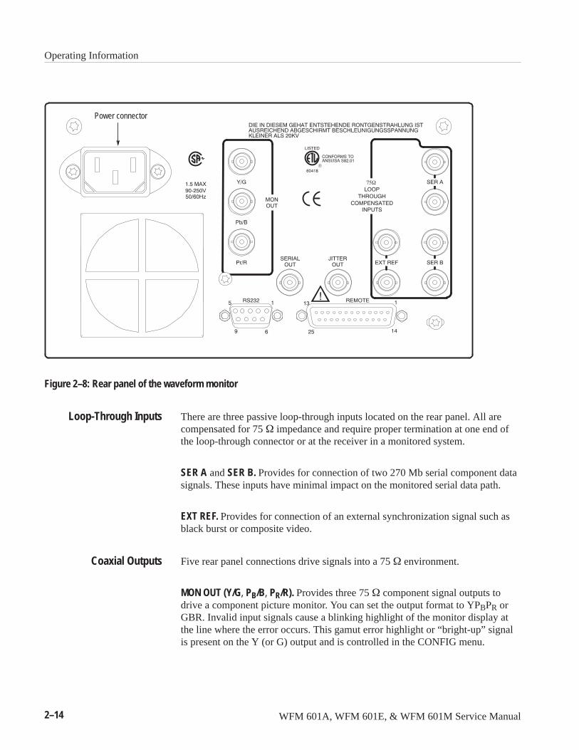
Rear Panel ConnectorsFigure 2–8 shows the rear panel of the waveform monitor. A brief discussion ofeach connector follows the illustration. Again, features unique to a specificwaveform monitor are indicated in the text.
The waveform monitor is designed to operate from a single-phase power sourcewith the neutral conductor at or near earth ground. Only the line conductor isfused for over-current protection. A protective ground connection through thegrounding conductor in the power cord is essential for safe operation.
WARNING. Dangerous potentials are present on the Power circuit board. To avoidelectric shock, do not connect power to the waveform monitor if it is not enclosedin a prescribed cabinet.
The waveform monitors operate from an AC line frequency of 50 and 60 Hz,over the range of 90–250 VAC, without the need for configuration. Refer to theSpecifications section of this manual for additional information on power andenvironmental requirements.
Power Connector
Operating Information
2–14 WFM 601A, WFM 601E, & WFM 601M Service Manual
Power connector
Figure 2–8: Rear panel of the waveform monitor
There are three passive loop-through inputs located on the rear panel. All arecompensated for 75 � impedance and require proper termination at one end ofthe loop-through connector or at the receiver in a monitored system.
SER A and SER B. Provides for connection of two 270 Mb serial component datasignals. These inputs have minimal impact on the monitored serial data path.
EXT REF. Provides for connection of an external synchronization signal such asblack burst or composite video.
Five rear panel connections drive signals into a 75 � environment.
MON OUT (Y/G, PB/B, PR/R). Provides three 75 � component signal outputs todrive a component picture monitor. You can set the output format to YPBPR orGBR. Invalid input signals cause a blinking highlight of the monitor display atthe line where the error occurs. This gamut error highlight or “bright-up” signalis present on the Y (or G) output and is controlled in the CONFIG menu.
Loop-Through Inputs
Coaxial Outputs
Operating Information
WFM 601A, WFM 601E, & WFM 601M Service Manual 2–15
SERIAL OUT. Provides a reclocked version of the selected signal input (SER A orSER B).
JITTER OUT. Provides a 75 � output signal from the jitter demodulator for theWFM 601M waveform monitor. The Jitter high-pass filter (JITTER HPF)selection does not affect this signal. You can view the jitter waveform on thewaveform monitor using the JITTER display mode. This output is disabled onthe WFM 601A and WFM 601E waveform monitors.
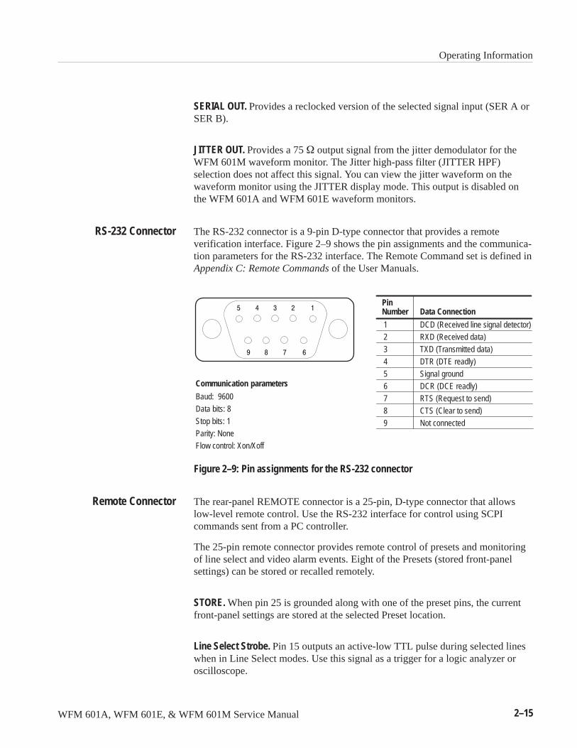
The RS-232 connector is a 9-pin D-type connector that provides a remoteverification interface. Figure 2–9 shows the pin assignments and the communica-tion parameters for the RS-232 interface. The Remote Command set is defined inAppendix C: Remote Commands of the User Manuals.
PinNumber
12
3
45
67
8
9
DCD (Received line signal detector)RXD (Received data)
TXD (Transmitted data)
DTR (DTE readly)Signal ground
DCR (DCE readly)RTS (Request to send)
CTS (Clear to send)
Not connected
Data Connection
Baud: 9600
Data bits: 8
Stop bits: 1Parity: None
Communication parameters
Flow control: Xon/Xoff
Figure 2–9: Pin assignments for the RS-232 connector
The rear-panel REMOTE connector is a 25-pin, D-type connector that allowslow-level remote control. Use the RS-232 interface for control using SCPIcommands sent from a PC controller.
The 25-pin remote connector provides remote control of presets and monitoringof line select and video alarm events. Eight of the Presets (stored front-panelsettings) can be stored or recalled remotely.
STORE. When pin 25 is grounded along with one of the preset pins, the currentfront-panel settings are stored at the selected Preset location.
Line Select Strobe. Pin 15 outputs an active-low TTL pulse during selected lineswhen in Line Select modes. Use this signal as a trigger for a logic analyzer oroscilloscope.
RS-232 Connector
Remote Connector
Operating Information
2–16 WFM 601A, WFM 601E, & WFM 601M Service Manual
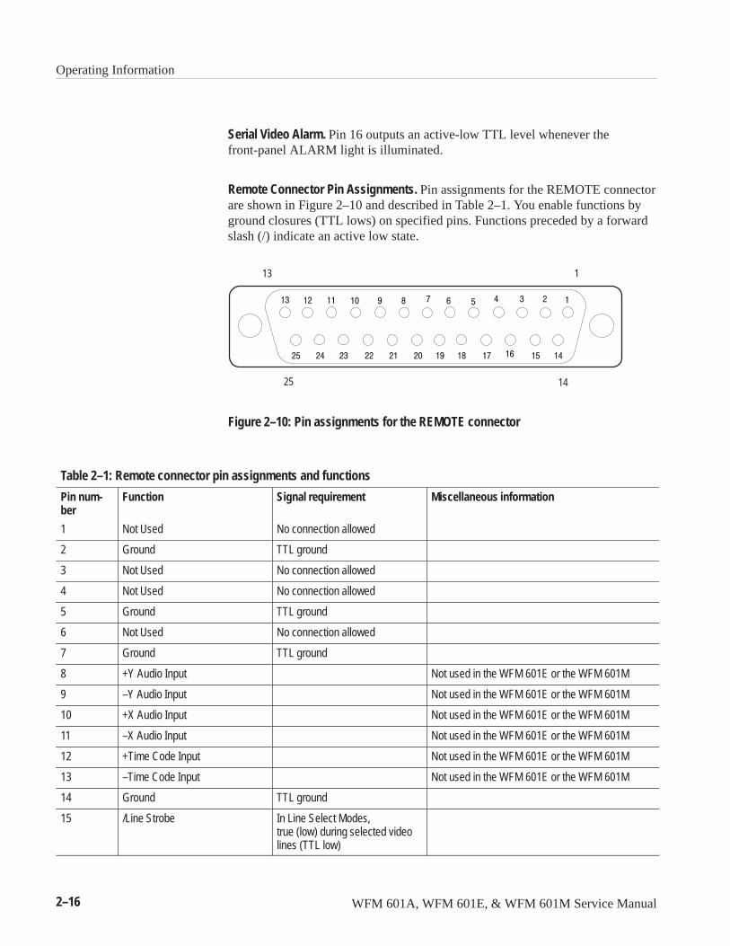
Serial Video Alarm. Pin 16 outputs an active-low TTL level whenever thefront-panel ALARM light is illuminated.
Remote Connector Pin Assignments. Pin assignments for the REMOTE connectorare shown in Figure 2–10 and described in Table 2–1. You enable functions byground closures (TTL lows) on specified pins. Functions preceded by a forwardslash (/) indicate an active low state.
113
1425
Figure 2–10: Pin assignments for the REMOTE connector
Table 2–1: Remote connector pin assignments and functions
Pin num-ber
Function Signal requirement Miscellaneous information
1 Not Used No connection allowed
2 Ground TTL ground
3 Not Used No connection allowed
4 Not Used No connection allowed
5 Ground TTL ground
6 Not Used No connection allowed
7 Ground TTL ground
8 +Y Audio Input Not used in the WFM 601E or the WFM 601M
9 –Y Audio Input Not used in the WFM 601E or the WFM 601M
10 +X Audio Input Not used in the WFM 601E or the WFM 601M
11 –X Audio Input Not used in the WFM 601E or the WFM 601M
12 +Time Code Input Not used in the WFM 601E or the WFM 601M
13 –Time Code Input Not used in the WFM 601E or the WFM 601M
14 Ground TTL ground
15 /Line Strobe In Line Select Modes,true (low) during selected videolines (TTL low)
Operating Information
WFM 601A, WFM 601E, & WFM 601M Service Manual 2–17
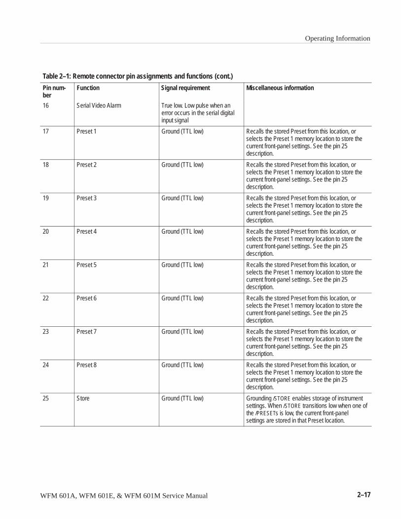
Table 2–1: Remote connector pin assignments and functions (cont.)
Pin num-ber
Miscellaneous informationSignal requirementFunction
16 Serial Video Alarm True low. Low pulse when anerror occurs in the serial digitalinput signal
17 Preset 1 Ground (TTL low) Recalls the stored Preset from this location, orselects the Preset 1 memory location to store thecurrent front-panel settings. See the pin 25description.
18 Preset 2 Ground (TTL low) Recalls the stored Preset from this location, orselects the Preset 1 memory location to store thecurrent front-panel settings. See the pin 25description.
19 Preset 3 Ground (TTL low) Recalls the stored Preset from this location, orselects the Preset 1 memory location to store thecurrent front-panel settings. See the pin 25description.
20 Preset 4 Ground (TTL low) Recalls the stored Preset from this location, orselects the Preset 1 memory location to store thecurrent front-panel settings. See the pin 25description.
21 Preset 5 Ground (TTL low) Recalls the stored Preset from this location, orselects the Preset 1 memory location to store thecurrent front-panel settings. See the pin 25description.
22 Preset 6 Ground (TTL low) Recalls the stored Preset from this location, orselects the Preset 1 memory location to store thecurrent front-panel settings. See the pin 25description.
23 Preset 7 Ground (TTL low) Recalls the stored Preset from this location, orselects the Preset 1 memory location to store thecurrent front-panel settings. See the pin 25description.
24 Preset 8 Ground (TTL low) Recalls the stored Preset from this location, orselects the Preset 1 memory location to store thecurrent front-panel settings. See the pin 25description.
25 Store Ground (TTL low) Grounding /STORE enables storage of instrumentsettings. When /STORE transitions low when one ofthe /PRESETs is low, the current front-panelsettings are stored in that Preset location.

Operating Information
2–18 WFM 601A, WFM 601E, & WFM 601M Service Manual

WFM 601A, WFM 601E, & WFM 601M Service Manual 3–1
Block Diagram Descriptions
This section provides a circuit description based on the three block diagrams, atthe front of Diagrams, section 9. This section also describes the Power Supplybased on the major blocks on the A1 Power Supply schematics, also in section 9.
Block Diagram 1, Input and Waveform DisplayBlock diagram 1 contains the serial inputs and outputs, Eye pattern sampler,vertical and horizontal amplifiers, the CRT, and blanking.
The serial inputs are 75 � compensated (externally terminated) passive loop-through inputs. Input transistors and capacitive coupling buffer the input signalsto keep return loss constant up through 300 MHz. Discreet components select theSER A or SER B input. The switch and amplifier provide a gain of 0.5 toconnectors J1 and J2.
The Serial Out, MON OUT, and Jitter Out signals pass straight through the A4board. The EXT REF input is a 75 � compensated, high impedance loop-throughinput.
The component serial digital video signal is buffered and applied to the SerialReceiver circuit. An unbuffered version of the digital signal is routed to the EyeSampler circuit. The Serial Receiver contains a phase-locked loop circuit thatlocks its clock to the incoming 270 MHz data signal. Jumper P13 is normally onpins 2 and 3, which selects a clock adjust circuit that brings the oscillator close tothe incoming frequency so the PLL can operate. With P13 on pins 1 and 2, youcan adjust R269 to change the oscillator center frequency. If you remove cable J3from the DAC board for troubleshooting, you can move P13 to pins 1 and 2 andadjust R269 to lock on the incoming signal.
If the input signal amplitude is low, the Serial Receiver provides equalization byboosting the high-frequency components of the signal. A Cable Driver circuitbuffers the reclocked serial digital signal for the Serial Out rear-panel output. Adivide by 10 circuit provides the 27 MHz clock for the Eye pattern circuit. AnA/D converter digitizes various analog inputs under microprocessor control.
The Jitter Demodulator is a phase detector that receives a reference clock and the27 MHz clock derived from the input signal. The output is a Jitter signal fordisplay, measurement, and export to the rear panel Jitter output. The PeakDetector circuit splits the incoming Jitter signal into two paths: the high-passpeak detector and the raw peak detector. The selected high-pass filter is applied
Input Switching andOutputs
Serial Receiver
Jitter Demodulator andPeak Detectors
Block Diagram Descriptions
3–2 WFM 601A, WFM 601E, & WFM 601M Service Manual
to the jitter signal then sent to the positive and negative peak detectors. The DCoutputs of these detectors connect to the A/D converter. The unfiltered Jittersignal is separately peak detected and the DC outputs connected to the A/Dconverter. The Jitter circuit includes a switch that selects between the Jitter signaland the sampled Eye signal for display.
The Signal Level Meter compares the amplitude of the serial digital signal at 10 MHz and 77 MHz. The amplitude at each of the frequencies is output as alogarithmic DC voltage to the A/D converter. The microprocessor comparesthese levels to determine the cable length measurement.
The Eye Pattern circuit is an equivalent-time sampler that allows viewing of theserial bit stream as a voltage-versus-time signal. Using a phase locked oscillator,the sample clock (6.75 MHz) is derived from the 27 MHz Parallel Clock andhorizontal line frequency (FH) signals. The input signal is displayed either withserial receiver equalization (Eq Eye) or without (Eye).
The Coprocessor receives 10 bit parallel video input from the Deserializer, therecovered 27 MHz clock, and control instructions from the microprocessor. Thecoprocessor performs gamut and format error checking on the component video.Three horizontal lines of the component video data are stored in a buffer RAMfor the Digital Data displays. The coprocessor outputs the clocks and 10 bitinterleaved video data to enable the recovery of the Y, R–Y and B–Y signals bythe Half Band filters and DACs. In addition, it generates the signals used forclamping, to re-establish the vertical blanking interval, and to provide compositesynchronization. The coprocessor removes nonvideo data from the signal, such asend of active video (EAV), start of active video (SAV), and ancillary data.
The Deserializer receives the 270 MHz component serial data and the recoveredparallel clock. The output is 10 bit video component data for the coprocessor.
The Phase Locked Loop circuit synchronizes an oscillator circuit with therecovered 27 MHz clock. A switch circuit allows selection of the directrecovered clock or the onboard 27 MHz clock, which appears as the front-panelselection CONFIG–FORMAT–SYNC AFC.
The multiplexed video data stream from the coprocessor is converted to analogcomponents by three digital-to-analog converters (DACs). The Y Delay circuitdelays the luminance data to ensure it passes through the Half Band filter andDAC properly synchronized with the chrominance signals. The coprocessorgenerates the clock and timing enable signals for the luminance and two colordifference Half Band filters and DACs.
Signal Level Meter
Eye Pattern Sampler
Coprocessor
Deserializer
Phase Locked Loop andClock Regenerator
Y Delay, Half-Band Filters,and DACs
Block Diagram Descriptions
WFM 601A, WFM 601E, & WFM 601M Service Manual 3–3
The Half Band filters (HBF) use interpolation to double the number of datavalues in order to ensure a smoother product from the DACs. Data timing signalsare 13.5 MHz for luminance and 6.75 MHz for color difference. The HBFs areclocked at 27 MHz for luminance (Y) and 13.5 MHz for Pb and Pr signals. Dataout of the HBFs are input to three DACs. The DAC outputs are the componentanalog signals, Y, Pb, and Pr. Their gain and DC offset is set by the microproces-sor through a Daculator on the Component board, diagram 12.
The three separate Reconstruction Filters are bandpass filters that provideadjustments for matching the delay through the three HB filters, DACs andReconstruction filters. An adjustable offset is added to each signal as required fordisplay.
The Line Rate Controller dictates the selection of display when color differenceor RGB signals are being displayed. The output of the multiplexer drives the Flat,Luminance, and Differentiated Step Inputs of the Filter Multiplexer.
The Filter Selection Multiplexer, which is controlled by the Line Rate Controller,selects the input to be displayed.
The calibrator provides a 700 mV, 100 kHz output. Its amplitude is set by amicroprocessor-controlled DAC, and its timing is set by the Line Rate Controller.
The Vertical Amplifier is a variable gain amplifier that has controlling inputsdriven by either microprocessor or synchronous Line Rate Controller outputs.
Stage gain is controlled by the DAC output voltages. The Line Rate Controllerselects and enables vertical magnification.
An offset voltage from the DACs vertically positions the display. When CRTreadout processing occurs, the Line Rate Controller changes the gain of theamplifier. The differential output of the Vertical Amplifier drives the verticaloutput amplifier, which powers the CRT deflection plates.
The Horizontal Reference Multiplexer selects either the COMPSYNC signalfrom the coprocessor or the External Reference input as the instrument syncreference. The front-panel REF switch controls the multiplexer.
Line and Field Rate signal generators are started and stopped by the retracesignals from the Line Rate Controller. The microprocessor controls the Sweepramp times, which are �17 ms for the field sweep and 64 �s for the line sweep.
Y, Pb and PrReconstruction Filters
Input Multiplexer
Filter SelectionMultiplexer
Square Wave Calibrator
Vertical Amplifier
Horizontal ReferenceMultiplexer and Reference
Switch
Sweep Generators andHorizontal Signal
Multiplexer
Block Diagram Descriptions
3–4 WFM 601A, WFM 601E, & WFM 601M Service Manual
The Line Rate Controller selects the signal from the Horizontal Signal Multiplex-er to drive the Horizontal Amplifier circuit.
The Horizontal Amplifier is a variable gain amplifier with controlling inputsfrom the microprocessor and Line Rate Controller. Stage gain is controlled by theDAC output voltages. The Line Rate Controller selects the magnification gain.
An offset voltage horizontally positions the display. The amount of offsetrequired for the Waveform mode is significantly greater than that required for theother display modes. During processing of the CRT readout, the Line RateController changes the gain of the amplifier as necessary.
The differential output of the Horizontal Amplifier drives the horizontal outputamplifier which powers the CRT deflection plates.
An additional amplifier stage within the Horizontal Amplifier provides adifferential output that controls the intensity for the Picture Monitor mode. Themicroprocessor controls the Picture Monitor contrast.
The Blanking Logic is a multiplexer, which is controlled by the Line RateController. The Blanking Logic selects the blanking/unblanking signals that drivethe Z-Axis Amplifier, which drives the CRT control grid.
Block Diagram 2, Component
The Y, Pb, Pr Reconstruction Filters drive the input selection matrix. Thecoprocessor picks either the component channels or blanking levels for output.Switch output is buffered and becomes the input to the Color Difference to GBRTranscoder, Bypass Switching, and Component display mode switching.
The three component signals enter three mixers that produce GBR signalsaccording to the SMPTE format. An adjustable offset is added to each signal asrequired for display.
The Switch Control Buffers select either the color difference input signals or thetranscoded GBR signals to drive the Picture Monitor Output amplifiers.
The Gamut Limit Comparator includes separate circuits to compare the GBRsignals and the component signals to the user selected gamut limits. The twocomparators generate separate GBR and composite gamut alarm signals. Whenthe signal exceeds the GBR gamut limits, the Monitor output flashes. A gamutinhibit signal causes the 2 Hz blink rate. The Monitor Out display can be either
Horizontal Amplifier
Blanking Logic
Component BlankingSwitching
Color Difference to GBRTranscoder
Bypass Switching
Gamut Limit Comparatorand Monitor Out
Amplifiers
Block Diagram Descriptions
WFM 601A, WFM 601E, & WFM 601M Service Manual 3–5
transcoded GBR or component video channels (Y/Pb/Pr). Composite sync,generated by the coprocessor, is added to the G/Y channel of the Monitor Out.The Y/G, Pb/B, and Pr/R output impedance is set to 75 ��
The transcoded GBR signals drive the GBR to Diamond Transcoder. The outputsfrom the transcoder are B+G and B–G for the top half of the Diamond display,and R+G and R–G for the bottom half of Diamond display. Display modeswitching provides the vertical and horizontal axes inputs for Lightning,Diamond, Component Vector, and Bowtie displays. The microprocessor controlsthe display switching through the Controller circuit.
Block Diagram 3, Microprocessor and Control
The microprocessor has a 32 bit internal architecture and a 16-bit data bus. Atboot up it reads initial code from the Read-Only Memory (ROM). The micropro-cessor then loads program code from EPROM into the RAM for execution. TheNonvolatile Random Access Memory (NVRAM) stores all the calibration andother constants used by the microprocessor.
The 24 bit Address Buffer is unidirectional and is used to select the addresses inthe storage devices (RAM, ROM, and EPROM). The Data Buffer is bidirection-al. The flash EPROM is programmed through the RS-232 port.
The Line Rate Controller (LRC) is a custom IC that loads information fromROM at power up. The microprocessor controls the LRC by placing commandsin the FIFO which the LRC reads. The LRC uses three clock inputs (5.5, 6, and16 MHz) and the H sync pulse to synchronize to the incoming video referenceand to generate synchronous switching signals required to drive the variousdisplays modes.
The Sync Separator strips the sync pulses from either the internal video signal orthe external reference video. It generates H sync and V sync to synchronize theLine Rate Controller.
Data and control signals from the microprocessor are loaded into latches clockedby the Line Rate Controller, which lock their outputs to the incoming videosignal.
The Readout State Machine interprets the readout instructions from the micro-processor and loads digital data into two identical DACs. The DACs drive thevertical and horizontal stroke generators to create the readouts displayed on theCRT.
GBR to DiamondTranscoder and
Component DisplaySwitching
Microprocessor
Line Rate Controllerand FIFO
Sync Separator
Synchronous Outputs
Readout State Machine
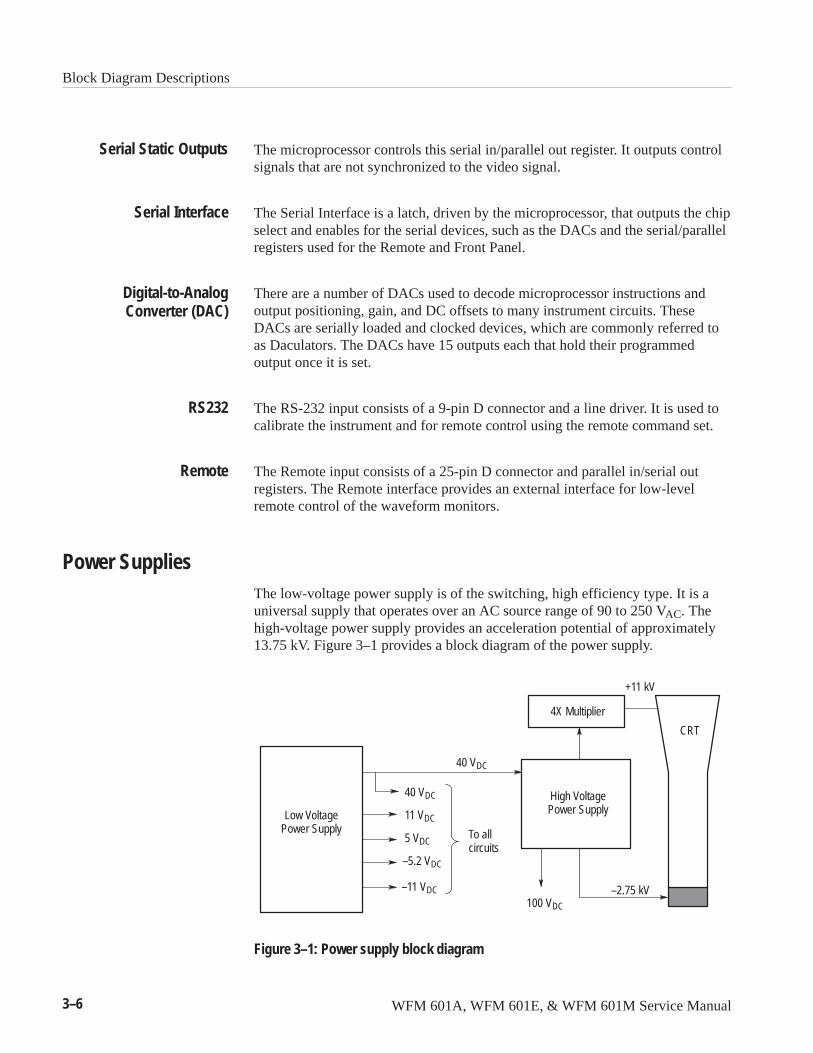
Block Diagram Descriptions
3–6 WFM 601A, WFM 601E, & WFM 601M Service Manual
The microprocessor controls this serial in/parallel out register. It outputs controlsignals that are not synchronized to the video signal.
The Serial Interface is a latch, driven by the microprocessor, that outputs the chipselect and enables for the serial devices, such as the DACs and the serial/parallelregisters used for the Remote and Front Panel.
There are a number of DACs used to decode microprocessor instructions andoutput positioning, gain, and DC offsets to many instrument circuits. TheseDACs are serially loaded and clocked devices, which are commonly referred toas Daculators. The DACs have 15 outputs each that hold their programmedoutput once it is set.
The RS-232 input consists of a 9-pin D connector and a line driver. It is used tocalibrate the instrument and for remote control using the remote command set.
The Remote input consists of a 25-pin D connector and parallel in/serial outregisters. The Remote interface provides an external interface for low-levelremote control of the waveform monitors.
Power SuppliesThe low-voltage power supply is of the switching, high efficiency type. It is auniversal supply that operates over an AC source range of 90 to 250 VAC. Thehigh-voltage power supply provides an acceleration potential of approximately13.75 kV. Figure 3–1 provides a block diagram of the power supply.
Low VoltagePower Supply
High VoltagePower Supply
4X Multiplier
40 VDC
40 VDC
100 VDC
11 VDC
5 VDC
–11 VDC
To allcircuits
+11 kV
–2.75 kV
CRT
–5.2 VDC
Figure 3–1: Power supply block diagram
Serial Static Outputs
Serial Interface
Digital-to-AnalogConverter (DAC)
RS232
Remote
Block Diagram Descriptions
WFM 601A, WFM 601E, & WFM 601M Service Manual 3–7
The following discussion covers the main blocks on the A1 Power Supplyschematics.
Line power enters through an RF filter on the rear panel. The Line Rectifiercircuit correctly converts 90 to 250 VAC. The line voltage or primary side of thepower supply is fully isolated from the secondary or DC side by transformers andoptical signal isolators.
Initial power conversion is controlled by a current-mode pulse width modulatorcircuit centered on U6. The switcher operates at 100 kHz. U6 senses the outputvoltage level from U4 and a ramp voltage representing the current in thetransformer switcher, Q14. On power up, C62 accumulates a trickle charge to16 V, which powers U6.
When the power switch is set to on, the 170 kHz oscillation on the Power SwitchOscillator (Q13 and T2) stops, causing the Mag Latch to switch state. The MagLatch remembers its state mechanically. The output of the Mag Latch is summedwith the output of the Overload Time-out to enable or disable the Controller. Ashutdown occurs within a few milliseconds and lasts 1 second. The Snubbercircuit clamps any voltage that exceeds twice the rectified power line input.
The secondary circuits include the low voltage output filters and error detection.The Error Amplifier signals the Controller to help regulate the +5 V supply. The5 V adjustment is in this circuit. The Overvoltage Protection circuit monitors the+5 V supply and grounds the 5 V supply if it rises above 5.5 V. The –5.2 Vsupply can signal an over-voltage condition through Q21 and ground the 5 Vsupply. The power supply goes through its start up sequence after this grounding.LED DS6 indicates the 5 V supply is on.
The Output Filters rectify the T1 secondary windings and filters the low voltageoutputs. The exception here is the –5.2 V Buck circuit. It provides regulated–5.2 V from the –11 V supply. U10 is the pulse width modulator that operatessimilar to U6 on the primary side. The 100 kHz out of U10 drives Q18 with avarying duty cycle that produces a DC average out of L10. An input from the+5 V secondary helps synchronize the 100 kHz oscillator to the Primary side.
The High Voltage Power Supply is generated by a sine-wave oscillator andstep-up transformer. The main components of the high-voltage oscillator anderror amplifier circuit are Q7 and T3, which form an Armstrong oscillatorrunning at about 22 kHz. Error amplifier U2 regulates the +100 V output andkeeps the High Voltage Power Supply constant under varying load conditions bycontrolling the base current to Q7. C26 and Q8 delays the start up of thehigh-voltage supply until the Low Voltage supply is running.
The CRT cathode supply consists of rectifier CR7 and filtering capacitors. Thesupply provides –2530 V to the CRT cathode. U1 is a four-times multiplier
Primary Side
Secondary Side
High Voltage Supply
Block Diagram Descriptions
3–8 WFM 601A, WFM 601E, & WFM 601M Service Manual
providing +11 kV to the CRT anode. The grid is approximately 75 V negativewith respect to the cathode.
Low frequency blanking information gets to the CRT grid through an amplitudemodulated 200 Vp-p sine wave from the anode of CR15. Positive level clipping isset by the CRT Bias adjustment, R53. Negative clipping level is set by thefront-panel INTENSITY control through the Z-Axis Amplifier. The clipped sinewave is rectified to a DC voltage proportional to the peak-to-peak amplitude andbecomes the CRT control grid bias voltage. DS4 limits the CRT heater to thecathode voltage.
The Z Axis Amplifier takes a signal from the Main board into the junction ofR10 and R5, which is the summing junction for the amplifier. It is at +5 VDC. R5is a feedback resistor, which sets the amplifier gain at 36 V/mA of input current.

WFM 601A, WFM 601E, & WFM 601M Service Manual 4–1
Performance Verification
The procedures in this section verify the performance specifications for theWFM 601A, WFM 601E, and WFM 601M waveform monitors. Procedures thatapply to only one model indicate this limitation in their titles. Procedures withoutsuch limits in their titles apply to all models. Where a procedure, such as MonitorOut Gain Accuracy, differs greatly between models, different versions of theprocedure occur sequentially. Choose the one that pertains to the waveformmonitor under test. Test equipment used in this procedure should be operatingcorrectly and within calibration.
Perform the Performance Verification procedure at regular intervals to ensurethat instrument performance is within tolerance. The recommended interval forperformance verification is 2000 hours of operation or every 12 months.
For help on using the Tektronix TG2000/DVG1 generator recommended for thisprocedure, refer to the information starting on page 5–9.
Equipment RequiredThe following equipment and accessory items are required to perform thePerformance Verification Procedure. Some test equipment is needed to test only aspecific model of waveform monitor. Such equipment dependency is included inparentheses following the equipment name.
The equipment listed generally provides an accuracy ratio of 4:1 or better forwarranted measurement specifications. The equipment used in two proceduresprovide a lesser accuracy ratio as follows:
� (WFM 601A, WFM 601E only) Monitor Out Gain Accuracy is 1.5:1
� (WFM 601A only) Audio Bandwidth is 1.5:1
The list includes the equipment specifications and recommended equipment thatmeets these specifications. The procedures assume you are using the recom-mended equipment. If you use other equipment, you will need to modify someequipment set up and control settings.
1. Test Oscilloscope
Vertical Amplifier: 400 MHz Bandwidth, 2 mV sensitivity.
For example: Tektronix TDS540A Oscilloscope with TV Trigger option.
2. Oscilloscope Probe
For example: Tektronix P6101B X1 Passive Voltage Probe.
Performance Verification
4–2 WFM 601A, WFM 601E, & WFM 601M Service Manual
3. Serial Digital Component Television Signal Generator
Output conforms to CCIR 601/SMPTE 125.
For example: Tektronix TG2000 with module DVG1 Option S1.
4. Video Measurement Set
For example: Tektronix 1780 or Tektronix 1781 Video Measurement Set
5. Leveled Sine Wave Generator (WFM 601M, WFM 601E only)
Output Level Range: –11.55 dBm (200 mV) to 0.43 dBm (800 mV).Frequency: 50 kHz to 450 MHz.
For Example: Tegam SG5030 installed in a TM5006A-Series Power Module.
6. Frequency Counter
Range: 10 Hz to 10 MHz. Accuracy: �0.001%.
For example: Tegam DC503A installed in a TM5006A-Series PowerModule.
7. Function Generator (WFM 601A only)
Range: 10 Hz to 10 MHz. Accuracy: �0.001%.
For example: Tegam FG 503 installed in a TM5006A-Series Power Module.
8. Cable Network
A cable path having a 1/√F loss characteristic and a loss of 14.5 dB at 1/2 theserial clock frequency.
For example: 200 meters (656 feet) of Belden 8281 low loss 75 � cable.
9. Variable Autotransformer
90 to 260 V AC range.
10. 75 � Terminators (4)
Four required. Three should be end-line, two of which are for use on theSerial Inputs. One should be a standard, for use on the External ReferenceInput. The fourth one should be a feed-through type.
For example: Two 75 ��end-line terminations, 26 dB to 300 MHz (TektronixPart No. 011-0163-00) for use on Serial Inputs.
One - 75 �, 0.025% accuracy end-line termination (Tektronix Part No.011-0102-01) for use on the External Reference Input.
One - 75 � feed-through termination (Tektronix Part No. 011-0103-02).
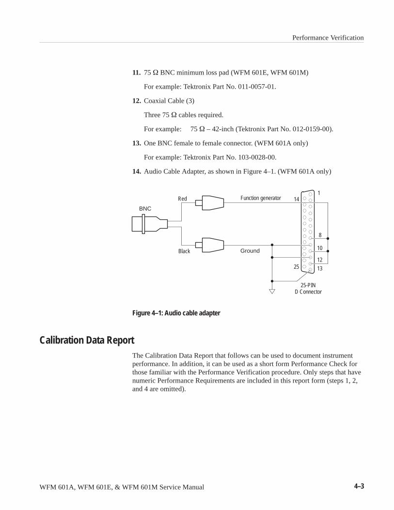
Performance Verification
WFM 601A, WFM 601E, & WFM 601M Service Manual 4–3
11. 75 � BNC minimum loss pad (WFM 601E, WFM 601M)
For example: Tektronix Part No. 011-0057-01.
12. Coaxial Cable (3)
Three 75 � cables required.
For example: 75 � – 42-inch (Tektronix Part No. 012-0159-00).
13. One BNC female to female connector. (WFM 601A only)
For example: Tektronix Part No. 103-0028-00.
14. Audio Cable Adapter, as shown in Figure 4–1. (WFM 601A only)
25
14
Ground
Function generatorRed
Black
BNC
25-PIND Connector
8
1
10
12
13
Figure 4–1: Audio cable adapter
Calibration Data ReportThe Calibration Data Report that follows can be used to document instrumentperformance. In addition, it can be used as a short form Performance Check forthose familiar with the Performance Verification procedure. Only steps that havenumeric Performance Requirements are included in this report form (steps 1, 2,and 4 are omitted).
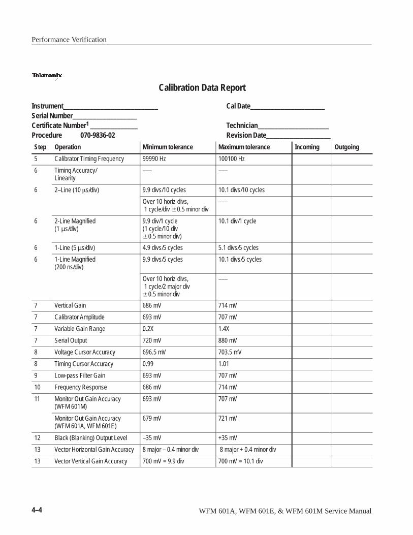
Performance Verification
4–4 WFM 601A, WFM 601E, & WFM 601M Service Manual
Calibration Data Report
Instrument____________________________ Cal Date______________________Serial Number___________________Certificate Number1 ______________ Technician_____________________Procedure 070-9836-02 Revision Date___________________
Step Operation Minimum tolerance Maximum tolerance Incoming Outgoing
5 Calibrator Timing Frequency 99990 Hz 100100 Hz
6 Timing Accuracy/Linearity
––– –––
6 2–Line (10 �s/div) 9.9 divs/10 cycles 10.1 divs/10 cycles
Over 10 horiz divs, 1 cycle/div �0.5 minor div
–––
6 2-Line Magnified (1��s/div)
9.9 div/1 cycle(1 cycle/10 div�0.5 minor div)
10.1 div/1 cycle
6 1-Line (5 �s/div) 4.9 divs/5 cycles 5.1 divs/5 cycles
6 1-Line Magnified(200 ns/div)
9.9 divs/5 cycles 10.1 divs/5 cycles
Over 10 horiz divs, 1 cycle/2 major div �0.5 minor div
–––
7 Vertical Gain 686 mV 714 mV
7 Calibrator Amplitude 693 mV 707 mV
7 Variable Gain Range 0.2X 1.4X
7 Serial Output 720 mV 880 mV
8 Voltage Cursor Accuracy 696.5 mV 703.5 mV
8 Timing Cursor Accuracy 0.99 1.01
9 Low-pass Filter Gain 693 mV 707 mV
10 Frequency Response 686 mV 714 mV
11 Monitor Out Gain Accuracy(WFM 601M)
693 mV 707 mV
Monitor Out Gain Accuracy(WFM 601A, WFM 601E)
679 mV 721 mV
12 Black (Blanking) Output Level –35 mV +35 mV
13 Vector Horizontal Gain Accuracy 8 major – 0.4 minor div 8 major + 0.4 minor div
13 Vector Vertical Gain Accuracy 700 mV = 9.9 div 700 mV = 10.1 div
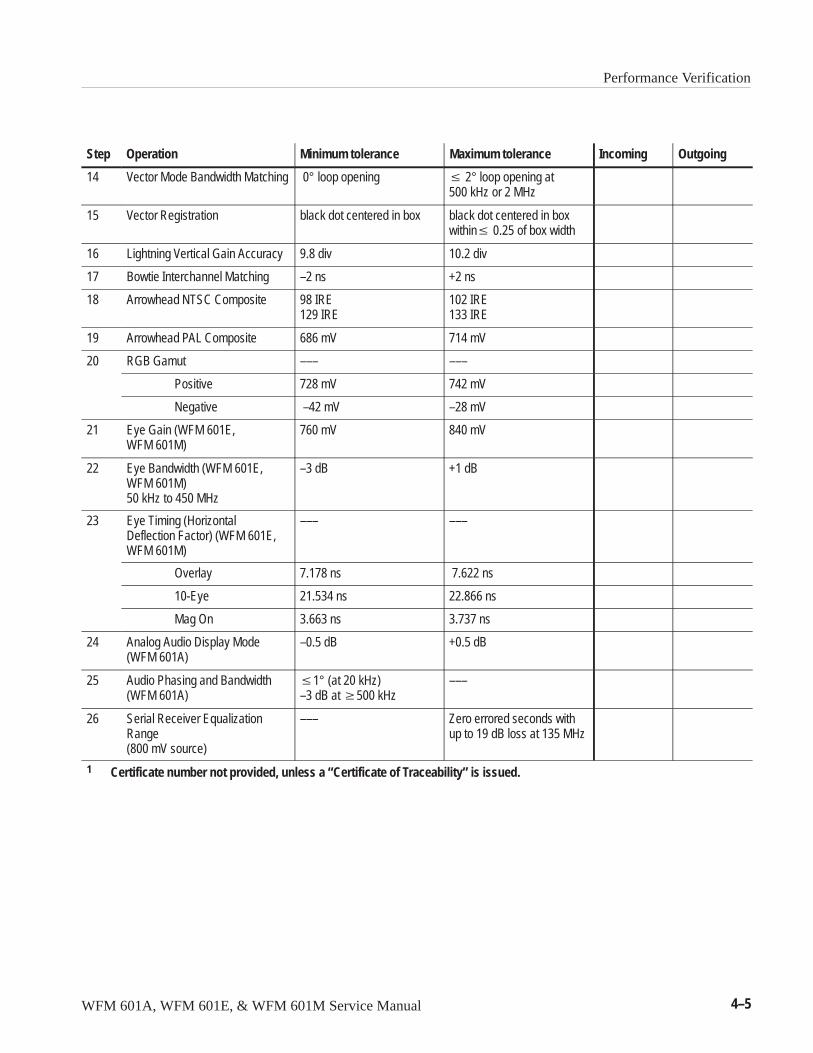
Performance Verification
WFM 601A, WFM 601E, & WFM 601M Service Manual 4–5
Step OutgoingIncomingMaximum toleranceMinimum toleranceOperation
14 Vector Mode Bandwidth Matching 0° loop opening � 2° loop opening at500 kHz or 2 MHz
15 Vector Registration black dot centered in box black dot centered in boxwithin� 0.25 of box width
16 Lightning Vertical Gain Accuracy 9.8 div 10.2 div
17 Bowtie Interchannel Matching –2 ns +2 ns
18 Arrowhead NTSC Composite 98 IRE129 IRE
102 IRE133 IRE
19 Arrowhead PAL Composite 686 mV 714 mV
20 RGB Gamut ––– –––
Positive 728 mV 742 mV
Negative –42 mV –28 mV
21 Eye Gain (WFM 601E,WFM 601M)
760 mV 840 mV
22 Eye Bandwidth (WFM 601E,WFM 601M)50 kHz to 450 MHz
–3 dB +1 dB
23 Eye Timing (HorizontalDeflection Factor) (WFM 601E,WFM 601M)
––– –––
Overlay 7.178 ns 7.622 ns
10-Eye 21.534 ns 22.866 ns
Mag On 3.663 ns 3.737 ns
24 Analog Audio Display Mode(WFM 601A)
–0.5 dB +0.5 dB
25 Audio Phasing and Bandwidth(WFM 601A)
�1° (at 20 kHz)–3 dB at �500 kHz
–––
26 Serial Receiver EqualizationRange(800 mV source)
––– Zero errored seconds withup to 19 dB loss at 135 MHz
1 Certificate number not provided, unless a “Certificate of Traceability” is issued.
Performance Verification
4–6 WFM 601A, WFM 601E, & WFM 601M Service Manual
Performance Verification ProcedurePerform the following steps to verify the performance of a waveform monitor:
1. Preliminary Setup
a. Connect the waveform monitor AC power cord to the variable autotrans-former. Set the mains Power switch for the autotransformer to On. Setthe autotransformer to the local nominal mains voltage (110 V or 220 V).
b. Connect a serial digital output from the serial component signalgenerator to the waveform monitor SER A input. Terminate theremaining side of the loop-through connector with a high-frequency,75 � end-line termination.
c. Connect a second serial digital output from the serial component signalgenerator to the SER B input. Terminate the remaining side of theloop-through connector with a high-frequency, 75 � end-line termina-tion.
d. Connect the digital component television generator black burst signal tothe waveform monitor EXT REF connector. Connect a 75 � end-linetermination to the remaining side of the EXT REF loop-throughconnector.
e. Turn the waveform monitor front-panel POWER switch on.
f. Enter the CRT menu and adjust the bezel controls for best viewing of thedisplay. Exit the CRT menu.
g. To set the waveform monitor to the factory settings, press the PRESETbutton, select FACTORY, and press the RECALL bezel button.
2. Power Supply Operation
REQUIREMENT – Stable operation over an AC input range of 90 – 250 V.
a. Vary the autotransformer from low-line to high-line voltage (90 – 132 Vfor 110 V, or 180 – 250 V for 220 V operation).
b. CHECK – for stable instrument operation over the prescribed voltagerange, 90 – 132 V for 110 V, or 180 – 250 V for 220 V.
c. Set the autotransformer to the nominal mains voltage.
Performance Verification
WFM 601A, WFM 601E, & WFM 601M Service Manual 4–7
3. Trace Rotation Range and Graticule Illumination
REQUIREMENT – Rotation of > �1° from the horizontal.
a. Set the serial component generator output to the 100% Color Bars signal:
Modules DVG1Signal Sets 525–270Test Signals Color BarsColor Bars 100% Color Bars
b. Enter the CRT menu and select TRACE.
c. Position the trace to the graticule baseline.
d. CHECK – that the TRACE ROTATE control moves the trace > �1°from the graticule baseline.
e. Adjust the TRACE ROTATE control for a level trace across the graticulebaseline.
f. From the CRT menu, select DISPLAY.
g. CHECK – that the SCALE control changes the graticule illuminationfrom completely off to fully illuminated.
h. Adjust the SCALE control for the desired graticule illumination.
i. Exit the CRT menu.
NOTE. Intensity, readout intensity, and focus are also controlled from the CRTmenu. If they need adjustment during this procedure, select the CRT menu andadjust as necessary. The levels set will remain after the CLEAR MENU or CRTmenu button is pushed.
4. Horizontal Mag Registration and Position Range
REQUIREMENT – Any portion of the synchronized sweep can bepositioned on-screen in all sweep modes.
a. Set the serial component generator output to the 100% Color Bars signal:
Modules DVG1Signal Sets 525–270Test Signals Color BarsColor Bars 100% Color Bars
b. Horizontally center the display, then press the MAG Line/Sweep buttonto turn on horizontal magnification.
c. CHECK – that the center of the trace is displayed with MAG on.
Performance Verification
4–8 WFM 601A, WFM 601E, & WFM 601M Service Manual
d. CHECK – by adjusting the HORIZ POS control that both ends of thewaveform can be positioned past the center of the CRT.
e. Turn off the MAG Sweep.
5. Calibrator Timing Frequency
REQUIREMENT – Frequency: 100 kHz �0.1%.
a. Set the Frequency Counter Timing to 1 �s.
b. Connect an X1 probe from the frequency counter to the ribbon cable sideof A3R274 (Main board). See Figure 5–6 on page 5–16 in the Adjust-ment Procedure section.
c. Connect the probe ground to the metal shield adjacent to A3L5 on theMain board.
d. Adjust the frequency counter settings for a stable readout.
e. CHECK – that the counter reading is 100 kHz �0.1 kHz.
f. Remove the ground connection and the frequency-counter probe fromA3R274.
6. Timing and Linearity
REQUIREMENT – Sweep Timing Accuracy: 5 �s/div (1 Line), 10 �s/div(2 Line), 0.2 �s/div (1 Line + MAG), 1.0 �s/div (2 Line + MAG), �1%.Sweep Linearity: 1 Line and 2 Line sweeps unmagnified or magnified, �1%.
a. Press the WAVEFORM display button.
b. Enter the CONFIG menu and select CALIBRATE.
c. Select CAL SIG ON. Ensure that the VAR GAIN bezel button is OFF.
d. Push the SWEEP button several times to select the 2-Line Sweep mode.The LINE indicator is on and the time base readout indicates 10 �s/div.
e. Press the CRT button and adjust the Scale bezel knob to increase scaleillumination to a useful level.
f. Press the Clear Menu button.
g. Use the VERT POS and VERT HORIZ knobs to position the calibrationwaveform on the horizontal graticule line for measurement.
h. CHECK – for one cycle of the calibrator signal per major division�0.5 minor division over the 10 major graticule divisions.
i. Turn on the MAG Sweep.
Performance Verification
WFM 601A, WFM 601E, & WFM 601M Service Manual 4–9
j. CHECK – for one cycle of calibrator signal per 10 major divisions �0.5minor division over the center 10 divisions.
k. CHECK – both ends of the magnified sweep for one cycle of calibratorsignal per 10 major divisions � 0.5 minor division over the center10 divisions.
l. Turn off the MAG Sweep and select 1 LINE SWEEP (5 �s/div) and Lineindicator on.
m. CHECK – for one cycle of calibrator signal per two major divisions�1 minor division over the center 10 divisions.
n. Press CONFIG menu to turn the calibrator signal off.
o. Select the high-frequency timing signal (2.5 MHz) from the serialcomponent generator.
p. Turn on the MAG Sweep.
q. CHECK – for one cycle per two divisions �0.5 minor division.
r. Turn off the MAG Sweep.
7. Vertical Gain, Calibrator Amplitude, and Variable Gain Range
REQUIREMENT – 700 mV input = 700 mV �2%. Calibrator Amplitude:700 mV �1%. Variable Gain Range: 0.2X to 1.4X. Serial Output Level =800 mV �10%.
a. To load the factory preset, press the PRESET button, use the bezel knobto pick the FACTORY setting, then press the RECALL bezel button.
b. Set the serial component generator output to the 100% Color Bars signal:
Modules DVG1Signal Sets 525–270Test Signals Color BarsColor Bars 100% Color Bars
c. CHECK – that the signal display is 700 mV �14 mV (1 minor divisionequals 20 mV).
d. Select the Serial B input.
e. CHECK – that the signal display is 700 mV �14 mV (1 minor divisionequals 20 mV).
f. Connect a 75 � coaxial cable, from the waveform monitor rear-panelSERIAL OUT connector through a 75 � feed-through termination to thetest oscilloscope vertical input.
Performance Verification
4–10 WFM 601A, WFM 601E, & WFM 601M Service Manual
g. CHECK – the vertical amplitude on the scope display is from 0.72 to 0.88 volts.
h. Remove the cable from the SERIAL OUT connector.
i. Enter the GAIN menu and select VARIABLE gain.
j. Select X5 and adjust VAR GAIN to make the last step of the color barstaircase 4 divisions high.
k. Select X10 gain.
l. CHECK – that the last step of the color bar staircase is now eightdivisions in amplitude.
m. Select X5 gain.
n. ADJUST – the VAR GAIN control for a seven division signal amplitude(Variable gain should still be on from step i).
o. Select X1 gain.
p. Adjust the VAR GAIN for maximum signal amplitude.
q. Position the bottom of the display to the –0.3 graticule line.
r. CHECK – for a display amplitude of � 9.8 divisions (–0.3 to +0.68).
s. Turn VARIABLE OFF and exit the GAIN menu.
t. Enter the CONFIG menu and select CALIBRATE. Turn CAL SIG ON.Press the CLEAR MENU button to turn off the readout.
u. CHECK – for a calibrator signal display of 700 mV �7 mV.
v. Press the CONFIG button, and turn CAL SIG OFF.
w. Press the CLEAR MENU button.
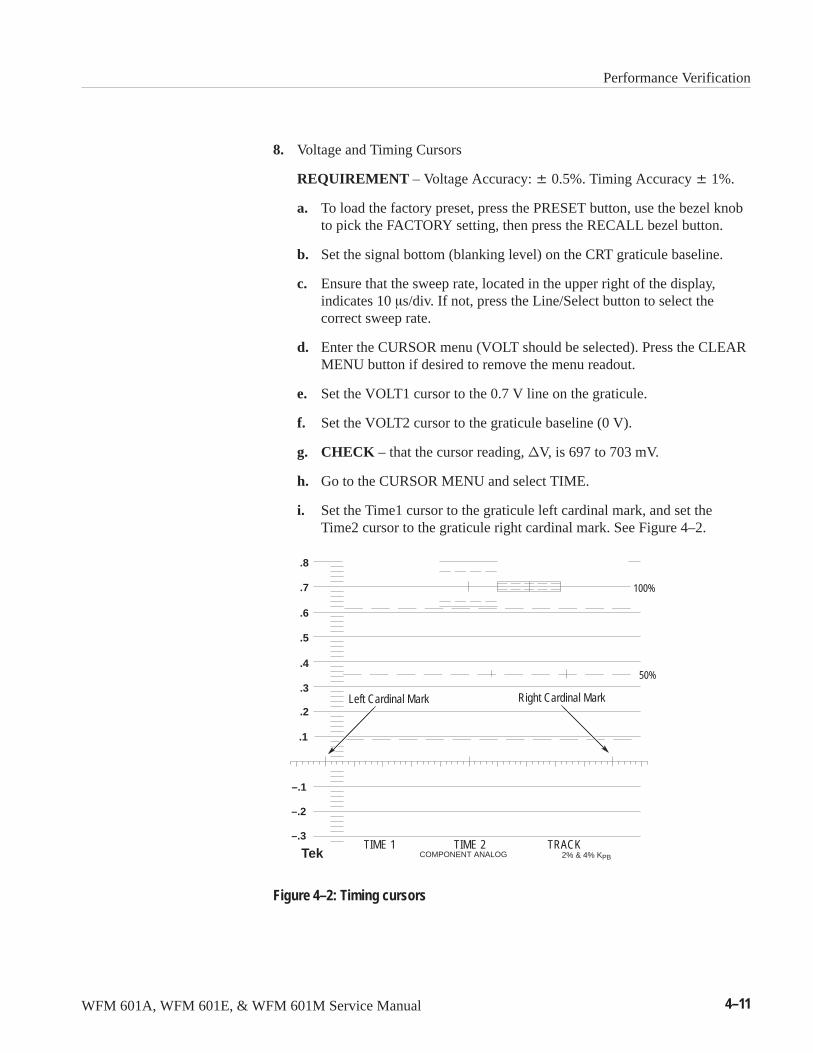
Performance Verification
WFM 601A, WFM 601E, & WFM 601M Service Manual 4–11
8. Voltage and Timing Cursors
REQUIREMENT – Voltage Accuracy: � 0.5%. Timing Accuracy � 1%.
a. To load the factory preset, press the PRESET button, use the bezel knobto pick the FACTORY setting, then press the RECALL bezel button.
b. Set the signal bottom (blanking level) on the CRT graticule baseline.
c. Ensure that the sweep rate, located in the upper right of the display,indicates 10 �s/div. If not, press the Line/Select button to select thecorrect sweep rate.
d. Enter the CURSOR menu (VOLT should be selected). Press the CLEARMENU button if desired to remove the menu readout.
e. Set the VOLT1 cursor to the 0.7 V line on the graticule.
f. Set the VOLT2 cursor to the graticule baseline (0 V).
g. CHECK – that the cursor reading, �V, is 697 to 703 mV.
h. Go to the CURSOR MENU and select TIME.
i. Set the Time1 cursor to the graticule left cardinal mark, and set theTime2 cursor to the graticule right cardinal mark. See Figure 4–2.
TIME 1 TIME 2 TRACK
.7
.6
.8
.5
.4
.3
.2
.1
–.1
–.2
–.3
Tek COMPONENT ANALOG 2% & 4% KPB
100%
50%
Left Cardinal Mark Right Cardinal Mark
Figure 4–2: Timing cursors
Performance Verification
4–12 WFM 601A, WFM 601E, & WFM 601M Service Manual
j. CHECK – that the cursor reading, �T, is 99 to 101 �s.
k. Exit the CURSOR menu.
9. Low-pass Filter Gain
REQUIREMENT – Low Pass Filter Gain: 1 � 1%.
a. To load the factory preset, press the PRESET button, use the bezel knobto pick the FACTORY setting, then press the RECALL bezel button.
b. Turn off CH 2 and CH 3 on the waveform monitor.
c. Set the serial component generator output to the 60% Multiburst signal:
Modules DVG1Signal Sets 525–270Test Signals Frequency RespFrequency Resp 60% Multiburst
d. Select the LPASS filter by pressing the FILTER button and the LPASSbezel button.
e. Select a One Line Sweep display (5 �s/div).
f. CHECK – that the peak-to-peak amplitude of the second packet or burstfrom the left is � 300 mV.
g. Enter the GAIN menu and set the gain for X5.
h. CHECK – that the peak-to-peak amplitude of packets five and six (fromthe left) are � 4 mV (1 minor division).
i. Select the FLAT filter in the Filter menu.
j. Select the Pulse and Bar signal from the serial component generator.
k. With the VERT POS bezel knob, center the baseline of the signal on the0 V graticule line. Gain is still at X5.
l. Press the CURSOR menu button.
m. Use the VOLT2 bezel knob to place the VOLT2 cursor on the baseline ofthe signal.
n. Rotate the VERT POS bezel knob counterclockwise to bring the top ofthe square pulse onto the CRT. Place the top of the square pulse on the.7 V graticule line.
o. Use the VOLT1 bezel knob to place the cursor on the top line of thesquare pulse.
p. Record the cursor voltage reading.
Performance Verification
WFM 601A, WFM 601E, & WFM 601M Service Manual 4–13
q. Select the LPASS filter.
r. Remeasure the square pulse amplitude with the Cursors by repeatingsteps m through p.
s. CHECK – that the LPASS voltage is within �1% (� 7 mV for a700 mV signal) of the FLAT filter voltage reading.
10. Frequency Response On Screen
REQUIREMENT – Luminance (Y) to 5.0 MHz �2%.Chrominance (Pb and Pr) to 2.5 MHz �2%
a. To load the factory preset, press the PRESET button, use the bezel knobto pick the FACTORY setting, then press the RECALL bezel button.
b. Select the 100% Sweep signal on the TG2000.
c. Select the following on the waveform monitor: PARADE display mode, CH 1, CH 2, CH 3 on, and One Line Sweep(5 �s/div).
d. CHECK – that all three channel waveforms are within 2%, 14 mV.
11. Monitor Out Gain Accuracy (WFM 601M only)
REQUIREMENT – Active Video Gain: 700 mV �1%
a. To load the factory preset, press the PRESET button, use the bezel knobto pick the FACTORY setting, then press the RECALL bezel button.
b. Set the serial component generator output to the 100% Color Bars signal:
Modules DVG1Signal Sets 525–270Test Signals Color BarsColor Bars 100% Color Bars
c. Connect the output from the MON OUT Y/G connector to the CH Ainput on the 1780/81 R.
d. Connect the black burst output from the digital component signalgenerator to the waveform monitor EXT REF loop-through input.
e. Connect the other EXT REF loop-through connector to the 1780/81R ExtRef input.
Performance Verification
4–14 WFM 601A, WFM 601E, & WFM 601M Service Manual
f. Select the following on the 1780/81:
INPUT CH AFILTER FLATREF EXTRIGHT DISPLAY WFM+CALWFM HORIZONTAL TWO LINE GAIN X1
g. Select the Configure Menu on the 1780/81. Set the FIXED CAL AMPLto 700, then select page 2 and set the ABS UNITS to mV and set theCAL to VAR.
h. Position the display so the Peak White and blanking level are visible onthe 1780/81.
i. Adjust the large knob on the 1780/81 until the Peak White and blankingof the chopped display are matched. Use X5 Gain for better resolution.
j. CHECK – that the CAL read out on the 1780/81 is 693 mV to 707 mV.
k. Move the 75 ohm cable on the waveform monitor Y/G MON OUTconnector to the MON OUT Pb/B connector.
l. Adjust the large knob on the 1780/81 until the Peak Pb level and negativegoing level of the chopped Pb display are matched.
m. Adjust the vertical position to place the chopped display on the 0 IRE(0 mV PAL) line on the 1780/81 R.
n. CHECK – that the CAL read out on the 1780/81 is 693 mV to 707 mV.
o. Move the 75 ohm cable from the Pb/B MON OUT to the Pr/R MONOUT.
p. Adjust the vertical position to place the chopped display on the 0 IRE(0 mV PAL) line on the 1780/81 R.
q. Adjust the large knob on the 1780/81 until the Peak Pr level and negativegoing level of the chopped Pr display are matched.
r. CHECK – that the CAL read out on the 1780/81 is 693 mV to 707 mV.
s. Disconnect the cable from the MON OUT Pr/R.
Performance Verification
WFM 601A, WFM 601E, & WFM 601M Service Manual 4–15
11. Monitor Out Gain Accuracy (WFM 601A, WFM 601E only)
REQUIREMENT – Active Video Gain: 700 mV �3%
t. To load the factory preset, press the PRESET button, use the bezel knobto pick the FACTORY setting, then press the RECALL bezel button.
u. Set the serial component generator output to the 100% Color Bars signal:
Modules DVG1Signal Sets 525–270Test Signals Color BarsColor Bars 100% Color Bars
v. Connect the output from the MON OUT Y/G connector, through a 75 �
feed-through termination, to Ch 1 of the test oscilloscope.
w. Adjust the test oscilloscope to obtain a stable, triggered display.
x. CHECK – the test oscilloscope for a signal amplitude of 679 to 721 mV,excluding sync.
y. Move the 75 � cable from the MON OUT Y/G connector to the MONOUT Pb/B connector.
z. CHECK – the test oscilloscope for a maximum peak-to-peak signalamplitude of 679 to 721 mV peak-to-peak.
aa. Move the 75� cable from the to the MON OUT Pb/B connector to theMON OUT Pr/R connector.
ab. CHECK – for an overall maximum peak to peak signal amplitude of 679to 721 mVpp.
ac. Disconnect test oscilloscope cable from MON OUT Pr/R.
12. Black (Blanking) Output Level (WFM 601M only)
REQUIREMENT – 0 mV �35 mV
a. Connect a 75 ohm cable from the Y/G MON OUT connector on thewaveform monitor, through a 75 ohm feed-through termination, to thetest oscilloscope CH 1 vertical input.
b. Set the serial component generator output to the 100% Color Bars signal:
Modules DVG1Signal Sets 525–270Test Signals Color BarsColor Bars 100% Color Bars
Performance Verification
4–16 WFM 601A, WFM 601E, & WFM 601M Service Manual
c. Select the following on the test oscilloscope.
Coupling DCVolts/Div 50 mV Trig Source CH 1 Sweep 10 �s
d. Adjust the trigger on the test oscilloscope for a locked display.
e. Select Ground on the test oscilloscope CH 1 input and adjust the trace tothe center line on the graticule.
f. Select DC coupling on test oscilloscope CH 1 input.
g. CHECK – that the Black (blanking) Level is �35 from the groundreference.
h. Repeat steps d through g after moving the 75 ohm cable on the waveformmonitor Y/G MON OUT to each of the Pb/B and Pr/R MON outputs.
i. Remove the cable from the Pr/R MON OUT connector on the waveformmonitor.
13. Vector Horizontal and Vertical Gain Accuracy
REQUIREMENT – Vertical: 700 mV = 10 divisions of deflection �1%;Horizontal: 700 mV = 8 divisions of deflection �1%.
a. Set the serial component generator output to the 100% Color Bars signal:
Modules DVG1Signal Sets 525–270Test Signals Color BarsColor Bars 100% Color Bars
b. Select VECTOR VIDEO DISPLAY.
c. Turn off the generator B–Y output. See page 5–11 for instructions onturning off the TG2000/DVG1 outputs.
d. Vertically position the display between the – 0.3 and 0.7 graticule lines.
e. CHECK – for 10 divisions of deflection �0.5 minor divisions.
f. Turn on the serial component generator B–Y output.
g. Turn off the serial component generator R–Y output.
h. Horizontally and vertically position the display over the center eightdivisions of the graticule 0 line.
i. CHECK – for 8 divisions of horizontal deflection, �0.4 minor divisions.
Performance Verification
WFM 601A, WFM 601E, & WFM 601M Service Manual 4–17
14. Vector Mode Bandwidth Matching
REQUIREMENT – Horizontal-to-Vertical Bandwidth Matching: � 2° loopopening at 500 kHz or 2 MHz.
a. Set the serial component generator output to the 60% Multiburst signal:
Modules DVG1Signal Sets 525–270Test Signals Frequency RespFrequency Resp 60% Multiburst
b. Turn on the serial component generator R–Y signal.
c. CHECK – for � 2° (less than a trace width) of loop opening.
15. Vector Registration
REQUIREMENT – � 0.25 box width with the X1 color black dot centeredin box.
a. To load the factory preset, press the PRESET button, use the bezel knobto pick the FACTORY setting, then press the RECALL bezel button.
b. Set the serial component generator output to the 100% Color Bars signal:
Modules DVG1Signal Sets 525–270Test Signals Color BarsColor Bars 100% Color Bars
c. Select the VECTOR VIDEO DISPLAY.
d. CHECK – that the center dot (the color black dot) is centered in its boxwithin 1/4 of the box width.
e. Enter the GAIN menu and select X1.
f. CHECK – that every dot is within its target box.
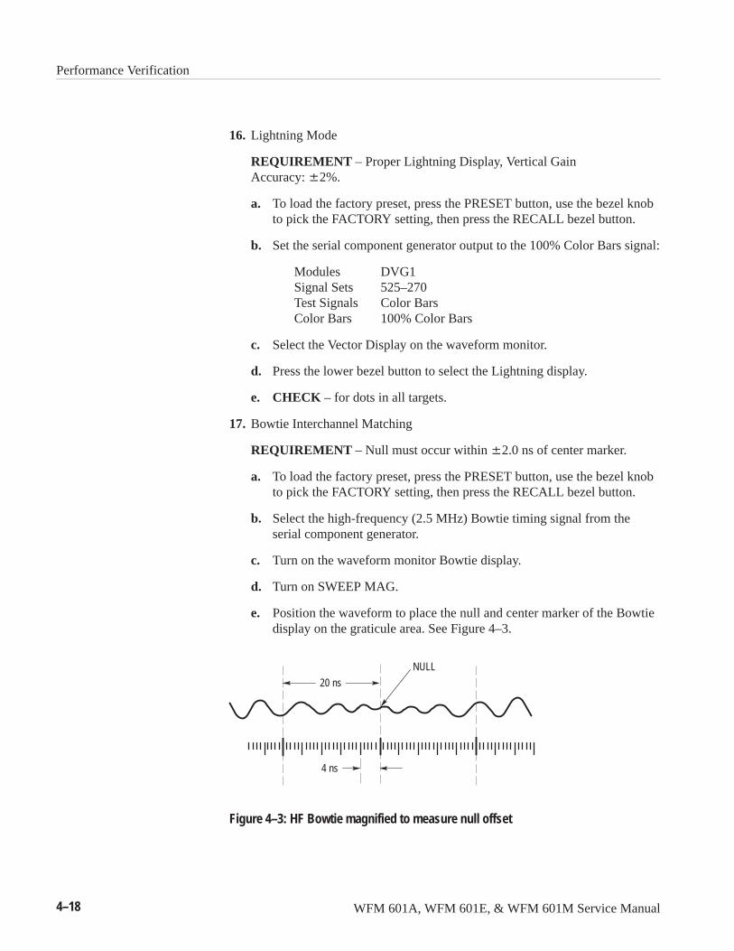
Performance Verification
4–18 WFM 601A, WFM 601E, & WFM 601M Service Manual
16. Lightning Mode
REQUIREMENT – Proper Lightning Display, Vertical Gain Accuracy: �2%.
a. To load the factory preset, press the PRESET button, use the bezel knobto pick the FACTORY setting, then press the RECALL bezel button.
b. Set the serial component generator output to the 100% Color Bars signal:
Modules DVG1Signal Sets 525–270Test Signals Color BarsColor Bars 100% Color Bars
c. Select the Vector Display on the waveform monitor.
d. Press the lower bezel button to select the Lightning display.
e. CHECK – for dots in all targets.
17. Bowtie Interchannel Matching
REQUIREMENT – Null must occur within �2.0 ns of center marker.
a. To load the factory preset, press the PRESET button, use the bezel knobto pick the FACTORY setting, then press the RECALL bezel button.
b. Select the high-frequency (2.5 MHz) Bowtie timing signal from theserial component generator.
c. Turn on the waveform monitor Bowtie display.
d. Turn on SWEEP MAG.
e. Position the waveform to place the null and center marker of the Bowtiedisplay on the graticule area. See Figure 4–3.
4 ns
NULL
20 ns
Figure 4–3: HF Bowtie magnified to measure null offset
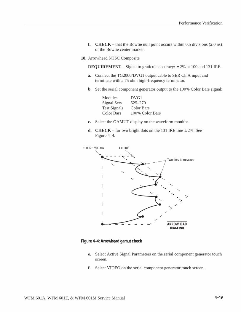
Performance Verification
WFM 601A, WFM 601E, & WFM 601M Service Manual 4–19
f. CHECK – that the Bowtie null point occurs within 0.5 divisions (2.0 ns)of the Bowtie center marker.
18. Arrowhead NTSC Composite
REQUIREMENT – Signal to graticule accuracy: �2% at 100 and 131 IRE.
a. Connect the TG2000/DVG1 output cable to SER Ch A input andterminate with a 75 ohm high-frequency terminator.
b. Set the serial component generator output to the 100% Color Bars signal:
Modules DVG1Signal Sets 525–270Test Signals Color BarsColor Bars 100% Color Bars
c. Select the GAMUT display on the waveform monitor.
d. CHECK – for two bright dots on the 131 IRE line �2%. SeeFigure 4–4.
ARROWHEADDIAMOND
Two dots to measure
100 IRE/700 mV 131 IRE
Figure 4–4: Arrowhead gamut check
e. Select Active Signal Parameters on the serial component generator touchscreen.
f. Select VIDEO on the serial component generator touch screen.
Performance Verification
4–20 WFM 601A, WFM 601E, & WFM 601M Service Manual
g. Adjust the Active Video Gain using the knob on the serial componentgenerator to verify signal to graticule accuracy. The two dots should becentered on the 131 IRE line with video gain set to 100% �2% (98 to102%).
h. Select GAMUT (IRE) 100 on the waveform monitor.
i. Set Active Video Gain to 75% by typing 75 and ENTER on the serialcomponent generator key pad.
j. CHECK – for two bright dots on 100 IRE line �2%.
k. Adjust the Active Video Gain using the Navigation Knob on the serialcomponent generator to verify signal to graticule Accuracy, 75% �2%(or 73.5 to 76.5%).
l. Select RESET on the serial component generator touch screen.
m. Select the Signal Sets button on the serial component generator.
19. Arrowhead PAL Composite
REQUIREMENT – Signal to graticule accuracy: �2% for 700 mV.
a. Connect a 75 ohm cable from the serial component generator output toSER Ch A input and terminate with a 75 ohm high-frequency terminator.
b. Press the serial component generator Signal Set button, then use thetouch screen to select the 625–270 Signal Set for the DVG1 module.
c. Select the 100% Colour Bars signal on the serial component generatortouch screen.
d. Select Active Signal Parameters on the serial component generator touchscreen.
e. Select Video on the serial component generator touch screen.
f. Set Active Video Gain to 75% by typing 75 and ENTER on the serialcomponent generator key pad.
g. Select the GAMUT display on the waveform monitor.
h. CHECK – for two bright dots on the 700 mV line �2%. See Figure 4–4.
i. Select Active Signal Parameters on the serial component generator touchscreen.
j. Select VIDEO on the serial component generator touch screen.
k. Adjust the Active Video Gain using the knob on the serial componentgenerator to verify signal to graticule accuracy. The two dots should be
Performance Verification
WFM 601A, WFM 601E, & WFM 601M Service Manual 4–21
centered on the 700 mV line with video gain set to 75% �2% (73.5 to76.5%).
l. Select RESET on the serial component generator touch screen.
m. Select the Signal Sets button on the serial component generator.
20. RGB Gamut limit
REQUIREMENT – Positive detection level = 735 mV �7 mV.Negative detection level = –35 mV �7 mV.
a. Set the serial component generator output to the Gamut Limit signal:
Modules DVG1Signal Sets 525–270Test Signals MonitorMonitor Gamut Test
b. Connect a 75 � cable through a 75 � feed-through termination, from theY/G MON OUT on the waveform monitor to the test oscilloscope CH 1vertical input.
c. Select the Gamut display mode on the waveform monitor.
d. Enter the Config Gamut menu and set GAMUT CHECK to RGB andALARM DISP to BOTH.
e. Select the following parameters on the test oscilloscope.
Coupling DCVolts/Div 100 mV Trig Source CH 1 Sweep 10 �s
f. Adjust the trigger level for a locked display.
g. Use Vert position on the test oscilloscope to view the top of thewaveform.
h. CHECK – that the positive gamut strobe pulse is flashing at the center� one minor division.
i. Use Vert position on the test oscilloscope to view the bottom of thewaveform.
j. CHECK – that the negative gamut strobe pulse is flashing at the center� one tic mark.
k. CHECK – that an RGB ERR appears at the lower left on the waveformmonitor display.
Performance Verification
4–22 WFM 601A, WFM 601E, & WFM 601M Service Manual
21. Eye Gain (WFM 601E, WFM 601M only)
REQUIREMENT – 800 mV �5% with a 800 mV signal.
a. Connect the leveling head from the leveled sine wave generator to a75 � minimum loss pad. Connect the remaining side of the pad to theSER B input of the waveform monitor.
b. Terminate the channel B loop-through input with a high-frequency, 75 �
terminator.
c. Connect the Black Burst output from the serial component generator tothe waveform monitor Ext Ref input. See page 5–11 for instructions onconnecting the black burst signal.
d. To load the factory preset, press the PRESET button, use the bezel knobto pick the FACTORY setting, then press the RECALL bezel button.
e. Select the Eye display mode and the SERIAL B input.
f. Press the waveform monitor REF button and note that EXT indicatorlights.
g. Set the following parameters on the leveled sine wave generator:
Output Head ONFrequency 4 MHz Amplitude 1.26 V
h. CHECK– for an amplitude of 800 mV �5% (760 to 840 mV).
22. Eye Bandwidth (WFM 601E, WFM 601M only)
REQUIREMENT – 50 kHz to 450 MHz: –3 dB to +1 dB.
a. Connect the leveling head from the leveled sine wave generator to a75 � minimum loss pad. Connect the remaining side of the pad to theSER B input of the waveform monitor.
b. Terminate the channel B loop-through input with a high-frequencyterminator.
c. To load the factory preset, press the PRESET button, use the bezel knobto pick the FACTORY setting, then press the RECALL bezel button.
d. Select the Eye display mode and the SERIAL B input.
e. Set the following parameters on the leveled sine wave generator:
Output Head ONFrequency 10 MHzAmplitude 632 mV
Performance Verification
WFM 601A, WFM 601E, & WFM 601M Service Manual 4–23
f. Adjust the leveled sine wave generator amplitude for a 400 mV displayon the waveform monitor.
g. Set the leveled sine wave generator frequency to 50 kHz.
h. CHECK – that the amplitude on the waveform monitor is greater than280 mV and less than 450 mV.
i. Set the leveled sine wave generator frequency to 270 MHz.
j. CHECK – that the amplitude on the waveform monitor is greater than280 mV and less than 450 mV.
k. Set the leveled sine wave generator frequency to 450 MHz.
l. CHECK – that the amplitude on the waveform monitor is greater than280 mV and less than 450 mV.
m. Disconnect the leveling head from the waveform monitor.
23. Eye Timing (Horizontal Deflection Factor) (WFM 601E, WFM 601M only)
REQUIREMENT – Overlay Mode: 1 ns/div �3%. 10-Eye Mode: 3 ns/div�3%. Mag On: 500 ps/div �3%.
a. Connect the serial component generator to the waveform monitor SER Ainput and terminate the 75 ohm loop-through input.
b. Set the serial component generator output to the 100% Color Bars signal:
Modules DVG1Signal Sets 525–270Test Signals Color BarsColor Bars 100% Color Bars
c. To load the factory preset, press the PRESET button, use the bezel knobto pick the FACTORY setting, then press the RECALL bezel button.
d. Select the EYE display mode.
e. Enter the CURSOR menu and select the TIME cursors.
f. CHECK – using the timing cursors that two cycles of the Eye pattern is7.4 ns �3% (7.178 to 7.622 ns).
g. Press the MAG button.
h. CHECK – using the timing cursors, that one cycle of Eye pattern is 3.7 ns �3% (3.663 to 3.737 ns).
i. Press the MAG button to turn off magnification.
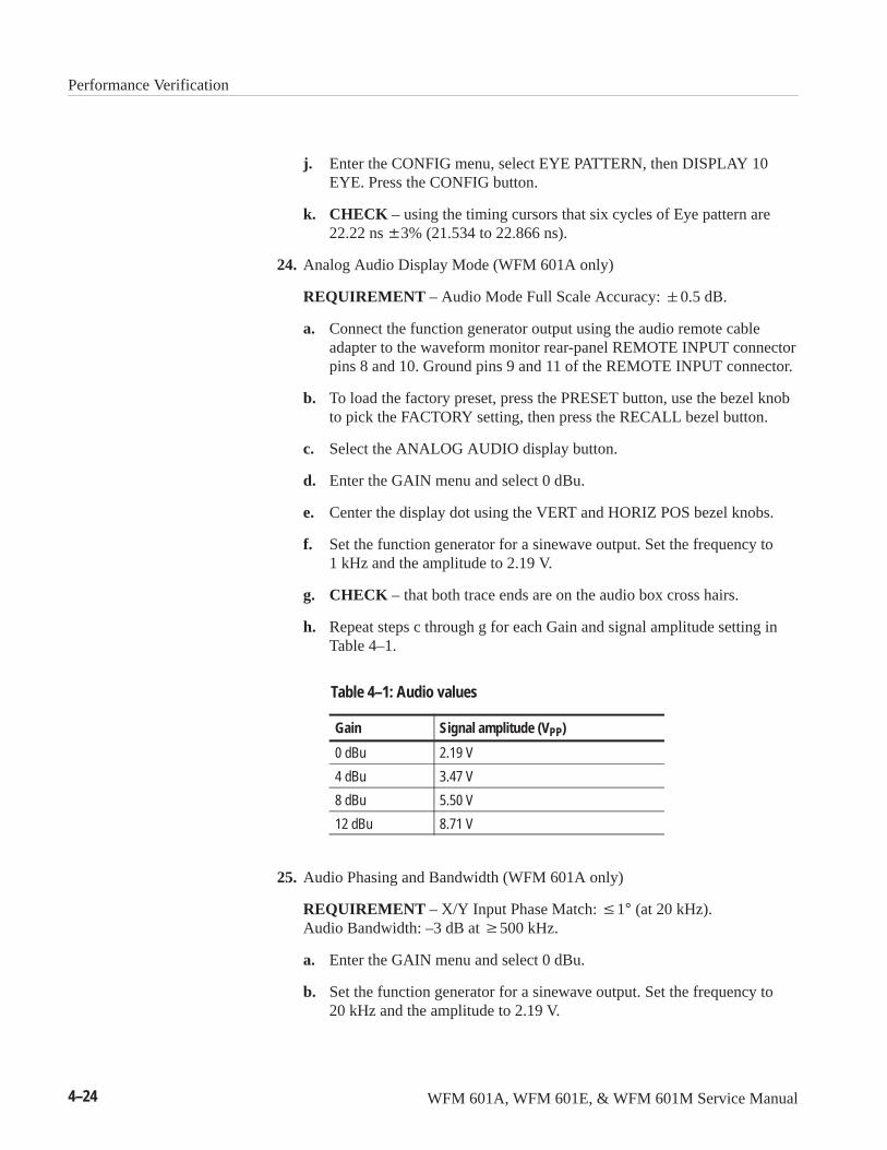
Performance Verification
4–24 WFM 601A, WFM 601E, & WFM 601M Service Manual
j. Enter the CONFIG menu, select EYE PATTERN, then DISPLAY 10EYE. Press the CONFIG button.
k. CHECK – using the timing cursors that six cycles of Eye pattern are22.22 ns �3% (21.534 to 22.866 ns).
24. Analog Audio Display Mode (WFM 601A only)
REQUIREMENT – Audio Mode Full Scale Accuracy: �0.5 dB.
a. Connect the function generator output using the audio remote cableadapter to the waveform monitor rear-panel REMOTE INPUT connectorpins 8 and 10. Ground pins 9 and 11 of the REMOTE INPUT connector.
b. To load the factory preset, press the PRESET button, use the bezel knobto pick the FACTORY setting, then press the RECALL bezel button.
c. Select the ANALOG AUDIO display button.
d. Enter the GAIN menu and select 0 dBu.
e. Center the display dot using the VERT and HORIZ POS bezel knobs.
f. Set the function generator for a sinewave output. Set the frequency to1 kHz and the amplitude to 2.19 V.
g. CHECK – that both trace ends are on the audio box cross hairs.
h. Repeat steps c through g for each Gain and signal amplitude setting inTable 4–1.
Table 4–1: Audio values
Gain Signal amplitude (VPP)
0 dBu 2.19 V
4 dBu 3.47 V
8 dBu 5.50 V
12 dBu 8.71 V
25. Audio Phasing and Bandwidth (WFM 601A only)
REQUIREMENT – X/Y Input Phase Match: �1° (at 20 kHz). Audio Bandwidth: –3 dB at �500 kHz.
a. Enter the GAIN menu and select 0 dBu.
b. Set the function generator for a sinewave output. Set the frequency to20 kHz and the amplitude to 2.19 V.
Performance Verification
WFM 601A, WFM 601E, & WFM 601M Service Manual 4–25
c. Move the waveform onto the audio graticule using the VERT andHORIZ POS bezel knobs. Make sure that both ends of the trace arewithin the 1/2 dB target boxes.
d. CHECK – for no more than a trace width of eye opening in the audiosignal (1%).
e. Set the function generator frequency to 500 kHz.
f. Disconnect the signal from pin 8 of the rear-panel REMOTE connector.
g. CHECK – for a horizontal line greater than 5.6 divisions long.
h. Reconnect the signal to pin 8 and disconnect it from pin 10 of the rearpanel REMOTE connector.
i. CHECK – for a vertical line greater than 7 divisions long.
j. Remove the function generator signal from the REMOTE connector.
26. Serial Receiver Equalization Range
REQUIREMENT – Proper operation with up to 19 dB loss at 135 MHzusing coaxial cable having 1/√F loss characteristics (800 mV launchamplitude).
a. To load the factory preset, press the PRESET button, use the bezel knobto pick FACTORY, then press the RECALL bezel button.
b. Connect 200 meters (656 feet) of Belden 8281 coaxial cable from thesignal generator Serial Output 1 to the waveform monitor SER AINPUT. Terminate the remaining side of the loop-through input with ahigh frequency terminator.
c. Set the serial component generator output to the 100% Color Bars signal:
Modules DVG1Signal Sets 525–270Test Signals Color BarsColor Bars 100% Color Bars
d. CHECK – that a video waveform appears.
e. Press the waveform monitor SERIAL button.
f. CHECK – that the EDH readout appears on screen.
g. Press the Serial menu RESET button.
h. Allow the instrument to run for at least 2.5 minutes.
i. CHECK – that the Errored Seconds, on screen, is zero.
Performance Verification
4–26 WFM 601A, WFM 601E, & WFM 601M Service Manual
j. Press the CLEAR MENU button.
k. Move the Belden cable and terminator to the SER B INPUT.
l. Select SERIAL B.
m. Repeat steps d through i for the Serial B input.
You have completed the Performance Check procedure.

WFM 601A, WFM 601E, & WFM 601M Service Manual 5–1
Adjustment Procedures
This section describes how to calibrate the waveform monitor to meet theperformance levels defined in the Specifications section. These proceduresrequire that you use the Adjustment Procedure software on the 3.5 inch diskincluded with this manual.
This section is organized as follows:
� Equipment Required
� Using the Adjustment Software
� Using the TG2000/DVG1 Opt S1 Generator
� Adjustment Procedure
� Circuit Board Adjustment Locations
� Adjustment Procedure Illustrations
� TV Generator Test Signals
Equipment RequiredThe following equipment and accessory items are required to perform theadjustment procedures. The list includes the equipment specifications andrecommended equipment that meets these specifications. The procedure iswritten assuming you are using the recommended equipment. If you use otherequipment, you will need to modify some equipment set up and control settings.
1. MSDOS Compatible PC
DOS 3.3 or higher.Minimum 640 kbytes of RAM3.5 inch/1.44 Mbytes high-density floppy driveFree RS-232 Port
2. Test Oscilloscope with 1X and 10X probes
Vertical Amplifier:300 MHz Bandwidth, 2 mV Sensitivity.Time Base:10 ns/div to 5 ms/div sweep, triggering to 150 MHz.
For example: Tektronix TDS540A Oscilloscope with TVTrig option andP6109B 10X and P6119B 1X probes.
Adjustment Procedures
5–2 WFM 601A, WFM 601E, & WFM 601M Service Manual
3. Digital Serial Component Television Signal Generator
For example: Tektronix TSG-422 Digital Component Generator, Option 1S.
4. Precision Digital Component Television Signal Generator
For example: Tektronix TG2000 Television Generator Platform with DigitalVideo Generator module DVG1 with Jitter Option S1. Table 5–1 onpage 5–5 lists the the procedures that require this generator.
The TG2000 is suitable for all Adjustment Procedures in place of theTSG-422 Television Signal Generator.
5. Video Measurement Set (WFM 601M only)
For example: Tektronix 1780 or Tektronix 1781 Video Measurement Set
6. Leveled Sine Wave Generator
Output Level Range: –11.55 dBm (200 mV) to 0.43 dBm (800 mV).Frequency: 50 kHz to 450 MHz.
For example: Tegam SG5030 installed in a Tegam TM5006A-Series PowerModule.
7. Function Generator (WFM 601A only)
Range: 10 Hz to 10 MHz. Accuracy: �0.001%.
For example: Tegam FG 503 installed in a TM5006A-Series Power Module.
8. Volt Meter
Range: 0 to �100 VDC. Accuracy: ± 0.3%.
For example: Tektronix DMM247 Digital Multimeter.
9. Cable Network
A cable path having a 1/√F loss characteristic and a loss of 14.5 dB at 1/2 theserial clock frequency.
For example: 100 meters (328 ft) of Belden 8281 low loss 75 � cable.
10. 75 � BNC minimum loss pad
For example: Tektronix Part No. 011-0057-01.
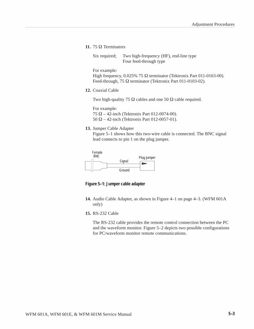
Adjustment Procedures
WFM 601A, WFM 601E, & WFM 601M Service Manual 5–3
11. 75 ��Terminators
Six required; Two high-frequency (HF), end-line typeFour feed-through type
For example:High frequency, 0.025% 75 � terminator (Tektronix Part 011-0163-00).Feed-through, 75 � terminator (Tektronix Part 011-0103-02).
12. Coaxial Cable
Two high-quality 75 � cables and one 50 � cable required.
For example:75 ��– 42-inch (Tektronix Part 012-0074-00).50 ��– 42-inch (Tektronix Part 012-0057-01).
13. Jumper Cable AdapterFigure 5–1 shows how this two-wire cable is connected. The BNC signallead connects to pin 1 on the plug jumper.
BNCSignal
Ground
Plug jumperFemale
Figure 5–1: Jumper cable adapter
14. Audio Cable Adapter, as shown in Figure 4–1 on page 4–3. (WFM 601Aonly)
15. RS-232 Cable
The RS-232 cable provides the remote control connection between the PCand the waveform monitor. Figure 5–2 depicts two possible configurationsfor PC/waveform monitor remote communications.

Adjustment Procedures
5–4 WFM 601A, WFM 601E, & WFM 601M Service Manual
25-Pin FemaleConnector
To PC
9-Pin MaleConnector
To waveformmonitor
25
14
20
13
7
8
5
1
2
3
4
5
1
2
3
4
9
6
8
7
GND
9-Pin FemaleConnector
1 1
59
6
To waveformmonitor
GND
To PC
9-Pin MaleConnector
5
6
9
TXD
RXD
TXD
RXD
Figure 5–2: Minimum configurations for remote communications
Adjustment Procedures
WFM 601A, WFM 601E, & WFM 601M Service Manual 5–5
Two, high-precision test instruments are recommended in a few adjustmentprocedures. Table 5–1 lists the special test equipment and the procedures wherethey are used. In all cases, the special equipment is required due to the measure-ment accuracy required to verify a specification.
Table 5–1: List of special equipment and where it is used
Equipment Procedure where used
TektronixTG2000/DVG1Opt S1
Y/G Monitor Out GainEQEye GainJitter Null AdjustJitter GainArrowhead NTSC CompositeArrowhead PAL Composite
Tektronix 1780/81 Y/G Monitor Out Gain (WFM 601M only)
Using the Adjustment SoftwareThe Adjustment Software is a DOS program on a 3.5 inch disk included with thismanual. The floppy disk contains the Adjustment Procedure software which youuse to return the instrument to its performance specifications. You should eithermake a copy of the Adjustment Software disk or copy the Adjustment Softwareonto a system hard disk.
The software requires an IBM compatible PC with a DOS 3.3 or higher and a3.5-inch high density floppy disk drive.
While you are running the Adjustment Software, you will make some adjust-ments using the arrow keys on the PC. Such adjustment steps follow theadjustment name with “(PC)”. For example, a PC key adjustment might resemblethe following line:
ADJUST – X10 V GAIN (PC) to reduce the waveform to a horizontal line.
To install the Adjustment Software, copy it to a floppy disk or a hard disk andrun it from that source. To make a copy of the Adjustment Software, use thefollowing procedure:
1. Insert the Adjustment Procedures disk into the PC floppy drive. If you wishto make a copy, place a formatted disk in second floppy drive, such as the Bdrive.
NOTE. On your PC, the drive letter for the floppy drive may be A or B. Enter theappropriate letter for your floppy drive in the following steps.
Where Special Equipmentis Used
Installing the Software
Adjustment Procedures
5–6 WFM 601A, WFM 601E, & WFM 601M Service Manual
2. At the DOS prompt, enter the copy commandFor example, ���������������������
3. To copy the files to a hard disk (disk C here) enter the following commands:������������ (or any valid directory name)��������������������
Use the following steps to start the Adjustment Procedure software:
1. Open a DOS window.
2. Change to the drive containing the software by entering the drive letterfollowed by a colon. For example, �.
3. If you installed the Adjustment Software into a directory, change to thatdirectory. For example, ������������.
4. Ensure the RS-232 cable is connected between the PC and the waveformmonitor and that your PC is configured with the communications parametersindicated in Table 6–10, on page 6–38.
5. Power on the waveform monitor.
6. To start the Adjustment Software, type � and press the Return key.
7. The program begins by prompting you for a few configuration parametersbefore beginning the adjustment steps.
Starting the AdjustmentSoftware
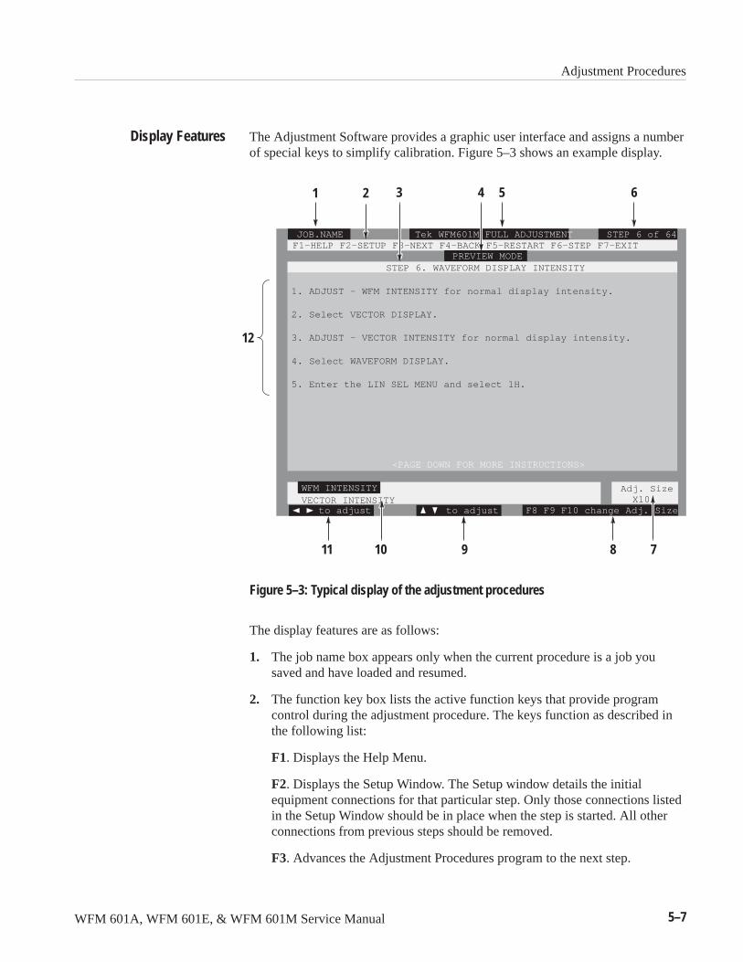
Adjustment Procedures
WFM 601A, WFM 601E, & WFM 601M Service Manual 5–7
The Adjustment Software provides a graphic user interface and assigns a numberof special keys to simplify calibration. Figure 5–3 shows an example display.
1
Tek WFM601M FULL ADJUSTMENT
WFM INTENSITY
STEP 6 of 64
F8 F9 F10 change Adj. Size
STEP 6. WAVEFORM DISPLAY INTENSITY
F1–HELP F2–SETUP F3–NEXT F4–BACK F5–RESTART F6–STEP F7–EXIT
1. ADJUST – WFM INTENSITY for normal display intensity.
2. Select VECTOR DISPLAY.
3. ADJUST – VECTOR INTENSITY for normal display intensity.
4. Select WAVEFORM DISPLAY.
5. Enter the LIN SEL MENU and select 1H.
<PAGE DOWN FOR MORE INSTRUCTIONS>
to adjustVECTOR INTENSITY
JOB.NAME
to adjust
Adj. Size X10
PREVIEW MODE
2 3 4 5 6
89 71011
12
Figure 5–3: Typical display of the adjustment procedures
The display features are as follows:
1. The job name box appears only when the current procedure is a job yousaved and have loaded and resumed.
2. The function key box lists the active function keys that provide programcontrol during the adjustment procedure. The keys function as described inthe following list:
F1. Displays the Help Menu.
F2. Displays the Setup Window. The Setup window details the initialequipment connections for that particular step. Only those connections listedin the Setup Window should be in place when the step is started. All otherconnections from previous steps should be removed.
F3. Advances the Adjustment Procedures program to the next step.
Display Features
Adjustment Procedures
5–8 WFM 601A, WFM 601E, & WFM 601M Service Manual
F4. Returns the Adjustment Procedures program to the previous step.
F5. Returns the Adjustment Procedures program to the beginning of thecurrent step. All front-panel settings and internal instrument settings arereturned to their former state (the same state they were in when the currentstep was started).
F6. Displays the Select Step window. The Select Step window allows theuser to select any step in the procedure. The current step is highlighted whenthe window opens. Selections are made by pressing the PAGE UP or PAGEDOWN keys on the PC. Pressing the ESC key will close the window andreturn the user to the current step.
F7. Displays the Exit menu. The Exit menu allows the user to changeprocedure types, save the current Adjustment job, or to exit to DOS.
3. The step name box displays the current adjustment step number and title.
4. The mode box appears only when the procedure is in the Preview mode. ThePreview mode does not attempt to communicate with the instrument undertest.
5. The title box lists the instrument type and the current procedure. You selectthe current procedure when the program starts from selections such as Fulladjustment and Component board.
6. The step number box lists the current step number and the total steps in theselected procedure.
7. The resolution box displays the adjustment resolution for the currentadjustment.
8. The resolution selection box appears when the current step has an adjustmentcontrolled by the PC up/down arrow keys. Pressing the F8, F9, or F10function key selects the amount of change each press of an Up or Downarrow key has on the adjustment. The current adjustment size is displayedabove this box.
F8. Selects X1 as the adjustment size. The X1 setting provides the smallestadjustment size and is used for fine tuning an adjustment.
F9. Selects X10 as the adjustment size. X10 is the default adjustment sizeand is used to bring an adjustment close to proper position.
F10. Selects X100 as the adjustment size. X100 is the largest adjustment sizeand is used to rough in adjustments that are far out of position.
9. The message box appears when the current step has an adjustment set by thePC up/down arrow keys. The box also reminds you that the arrow keyscontrol the adjustment.
Adjustment Procedures
WFM 601A, WFM 601E, & WFM 601M Service Manual 5–9
10. The adjustment box list the names of the adjustments for the current step.The active adjustment is highlighted. You modify the active adjustment usingthe PC up/down arrow keys. Use the left/right arrow keys to select anadjustment.
For some adjustments you must first make the adjustment, then, to save theadjustment, you must select (highlight) an Assign item and press the Returnkey. In two cases, you select the adjustment name and press the Return key.The procedure will prompt you on how to make these adjustments.
11. The multiple adjustment box appears when the current step has more thanone PC adjustment. Pressing the PC left/right arrow keys will select whichadjustment is currently controlled by the PC up/down arrow keys. The boxserves as a reminder for which arrow keys control the adjustment selection.
12. The instruction window displays the actual procedure steps to perform. Themessage PAGE DOWN FOR MORE INSTRUCTIONS refers to the PageDown key on the PC and it indicates that there are additional steps toperform.
To complete any procedure step, press the F3 function key.
Using the TG2000/DVG1 Opt S1 GeneratorThis discussion briefly covers how to use the Tektronix TG2000 SignalGeneration Platform with the DVG1 Generator in the Adjustment Procedure.Most TG2000 settings required in the procedure are covered in this section. Formore information on using the TG2000/DVG1 generator, refer to the Usermanuals for the TG2000 and DVG1 products.
The DVG1 Option S1 provides adjustable signal jitter. Either output of theDVG1 can be configured to output the signal with added jitter. The DVG1 isshipped with CH 2 configured to generate jitter. For information on setting theSDI jitter level, refer to page 5–11.
The TG2000 with the DVG1 Option S1 generator can be configured with a largenumber of signals. To select a signal, follow these steps:
1. Press the MODULES button. If the front panel does not respond, press theFRONT PANEL ENABLE button to unlock the front panel.
2. Touch the folder icon for the DVG1 module you are using. The SIGNALSETS button will light and several signal sets are displayed.
3. Touch the 525–270 icon for NTSC signals or the 625–270 icon for PALsignals. If either of these are missing, you will need to load signals from the
Configuring the JitterOutput
Selecting Output Signals
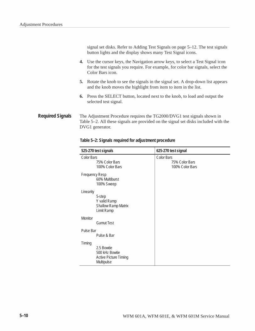
Adjustment Procedures
5–10 WFM 601A, WFM 601E, & WFM 601M Service Manual
signal set disks. Refer to Adding Test Signals on page 5–12. The test signalsbutton lights and the display shows many Test Signal icons.
4. Use the cursor keys, the Navigation arrow keys, to select a Test Signal iconfor the test signals you require. For example, for color bar signals, select theColor Bars icon.
5. Rotate the knob to see the signals in the signal set. A drop-down list appearsand the knob moves the highlight from item to item in the list.
6. Press the SELECT button, located next to the knob, to load and output theselected test signal.
The Adjustment Procedure requires the TG2000/DVG1 test signals shown inTable 5–2. All these signals are provided on the signal set disks included with theDVG1 generator.
Table 5–2: Signals required for adjustment procedure
525-270 test signals 625-270 test signal
Color Bars75% Color Bars100% Color Bars
Frequency Resp60% Multiburst100% Sweep
Linearity5-stepY valid RampShallow Ramp MatrixLimit Ramp
MonitorGamut Test
Pulse BarPulse & Bar
Timing2.5 Bowtie500 kHz BowtieActive Picture TimingMultipulse
Color Bars75% Color Bars100% Color Bars
Required Signals
Adjustment Procedures
WFM 601A, WFM 601E, & WFM 601M Service Manual 5–11
To adjust component channel amplitude or turn off a channel, follow these steps:
1. Press the TEST SIGNAL button, if it is not lighted. Touch Active SignalParameters, then touch Video.
2. Use the Navigation cursor keys to select Luma Amplitude, R–Y or B–YAmplitude.
3. Use the TG2000 knob to adjust the amplitude setting.
4. To turn off a channel, set the amplitude to 0%.
5. To turn channels back on or to reset the amplitude, touch Reset.
6. Press the TEST SIGNALS button to leave the Active Signal Parametersmenu.
To adjust SDI amplitude or enable Embedded Audio, follow these steps:
1. Press the TEST SIGNAL button, if it is not lighted. Touch Module Parame-ters.
2. To enable Embedded Audio, touch the Embedded Audio icon, then touch theAUDIO icon. To disable Embedded Audio, touch the AUDIO icon again.
3. To set the SDI jitter amplitude, touch the SDI icon.
4. Use the Navigation cursor keys to select Jitter Freq or Jitter Amp.
5. Use the TG2000 knob or the numeric keypad to set the jitter frequency oramplitude as required.
6. Press Reset before leaving the menu. Press the TEST SIGNALS button toleave the Module Parameters menu.
The TG2000 outputs the black burst signal from the BG1 module. Connect acable to one of the BG1 outputs. Enable the appropriate black burst signal byfollowing these steps:
1. Press the MODULES button, and touch the BG1 module icon.
2. Select the appropriate signal set, NTSC or PAL, called for by the adjustmentprocedure.
Setting ChannelAmplitude & Turning Y, Pb,
or Pr Channels Off
Setting SDI Amp orEmbedded Audio
Selecting TG2000 BlackBurst Output
Adjustment Procedures
5–12 WFM 601A, WFM 601E, & WFM 601M Service Manual
If the 525–270 or 625-270 signal sets or individual signals called for in anadjustment procedure are missing from the Signal Sets window, you will need toload additional signals from the signal set disks shipped with the DVG1. SeeTable 5–2 on page 5–10 for a list of signals included in the various signalsets. You can also obtain signal sets from the Tektronix bulletin board. ContactTektronix customer support center at 1-800-TEKWIDE. If you need moreinformation on adding test signals than is presented here, refer to the DVG1 Usermanual.
To add test signals to your DVG1 module, use the following procedure:
1. Press the DISK button.
2. Touch the Add Signals soft key. Then touch the Select Source soft key. TheA: drive listing should appear showing the available signal sets.
3. Use the Navigation cursor keys to choose the signal set, such as 625-270, oran individual test signal you need to load. Touch Quit/Load.
4. Touch the Select Destination soft key. Use the Navigation cursor keys tochoose the correct module type and point in the signal hierarchy to load thenew signal(s). You must load signal sets or individual test signals into thesame hierarchy level as their origin level. Touch Quit/Load.
5. Check that the readout Total Tagged: does not exceed the readout Free:. TheTotal Tagged value is the file size of the signals to be loaded. The Free valueis the memory available in the generator module.
6. If insufficient memory is available, delete unnecessary signals from theDVG1 module. Use the following procedure to delete signals:
a. Press the DISK button.
b. Touch the Delete Signals soft key.
c. Select the signals that you do not expect to use soon. Touch the Deletebutton. Press the DISK button to return to Adding Signals.
Adding Test Signals
Adjustment Procedures
WFM 601A, WFM 601E, & WFM 601M Service Manual 5–13
Adjustment Procedure
WARNING. Dangerous voltage levels exist in the Power Supply. The AdjustmentProcedures require you to supply power to the waveform monitor while makingadjustments and measurements to various components without a cover in place.Use extreme caution when performing adjustment procedures.
1. Initial Equipment Connections
a. Connect an RS-232 cable from the waveform monitor rear-panel RS-232connector to the COM 1, 2, 3, or 4 connector on the PC. See theEquipment Required list on page 5–1 for the cable wiring illustrations.
b. Connect the waveform monitor to AC mains power and turn on theinstrument.
2. Allow the waveform monitor to warm for 15 minutes before proceeding withthe adjustments.
3. After major repair, such as replacing a circuit board, perform the followingchecks.
� Check that the fan is running.
� Check that the green LED on the Main board is on.
� Check that A1DS6 (the red LED) on the Power Supply board is on.
NOTE. The waveform monitor power switch must be on before you start theAdjustment procedure software. Turning the instrument on after starting thesoftware may cause your PC to lock up and require a system reset.
4. Start the adjustment software by changing to the disk and directory thatcontain the software and entering the cal command. Refer to page 5–5 forinstructions for installing the adjustment software.
5. The adjustment software will prompt you to make the following choices:
a. Select RS-232 Port – select from COM1 – 4 or Preview mode. Enter theassociated number from the list. Preview mode allows you to lookthrough the procedure without having an instrument connected.
b. Select PRC File to Peruse – lists adjustment files (.prc) when more thanone resides in the adjustment software directory.
c. Select Model to Calibrate – lists instrument model numbers that can beadjusted using the adjustment software.
Adjustment Procedures
5–14 WFM 601A, WFM 601E, & WFM 601M Service Manual
d. Select Calibration Procedure – selects one of the following procedures torun:
� Full – performs most available steps. Run this procedure for overallinstrument calibration. You are asked if the Main board is new. If theMain board was replaced or repaired, enter yes. Otherwise enter no.
� Component – performs adjustments required when the Component boardwas repaired.
� Serial – performs adjustments required when the Serial board wasreplaced or repaired.
� Power Supply – performs adjustments required when the Power Supplyboard was replaced or repaired.
6. Each step begins with a setup screen that describes equipment connectionsand the output signal for the generator. References to HF terminator refer tothe high-frequency terminators specified in the Equipment Requirement liston page 5–1.
7. Escape from a procedure at any time by pressing the F3 or F7 keys. F3advances to the next procedure and F7 allows you to select a differentprocedure. Use the online Help (F1) to get help on the function keys.
8. Continue to perform all steps until a prompt indicates you have reached theend of the selected adjustment procedure.
If an adjustment fails, it could indicate that repair is needed. Verify the connec-tions, calibration, and configuration all test equipment, including connectingcables and high-frequency terminators, as described in the Equipment Require-ment list on page 5–1.
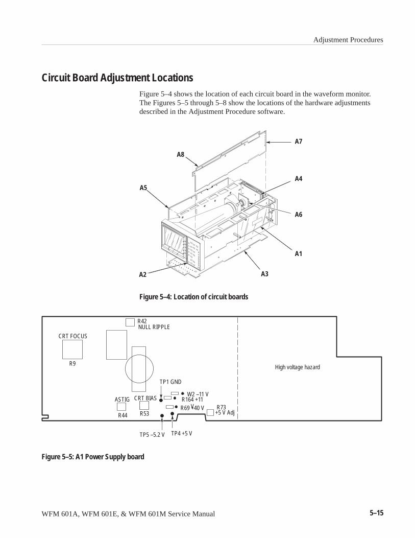
Adjustment Procedures
WFM 601A, WFM 601E, & WFM 601M Service Manual 5–15
Circuit Board Adjustment LocationsFigure 5–4 shows the location of each circuit board in the waveform monitor.The Figures 5–5 through 5–8 show the locations of the hardware adjustmentsdescribed in the Adjustment Procedure software.
A1
A2 A3
A4A5
A7
A8
A6
Figure 5–4: Location of circuit boards
R9
NULL RIPPLE
R44 R53 +5 V Adj
High voltage hazard
W2 –11 VR164 +11
VR69 +40 V
CRT FOCUS
ASTIG CRT BIAS
TP5 –5.2 V
R73
R42
TP4 +5 V
TP1 GND
Figure 5–5: A1 Power Supply board
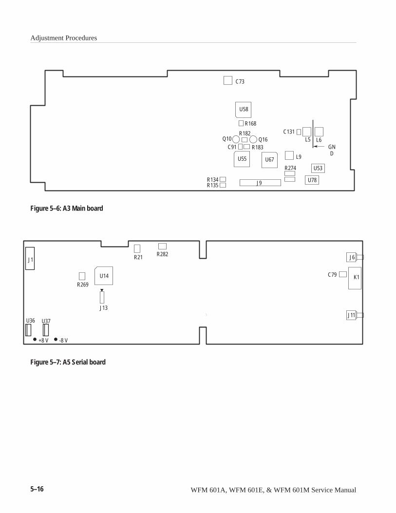
Adjustment Procedures
5–16 WFM 601A, WFM 601E, & WFM 601M Service Manual
U58
Q16Q10
U53
U78
L6L5C131
J9
L9U67U55
C91 R183
R182
R134R135
R168
C73
GND
R274
Figure 5–6: A3 Main board
R21 R282
C79
-8 V +8 V
R269
J1
U14 K1
J6
J11U36 U37
J13
Figure 5–7: A5 Serial board
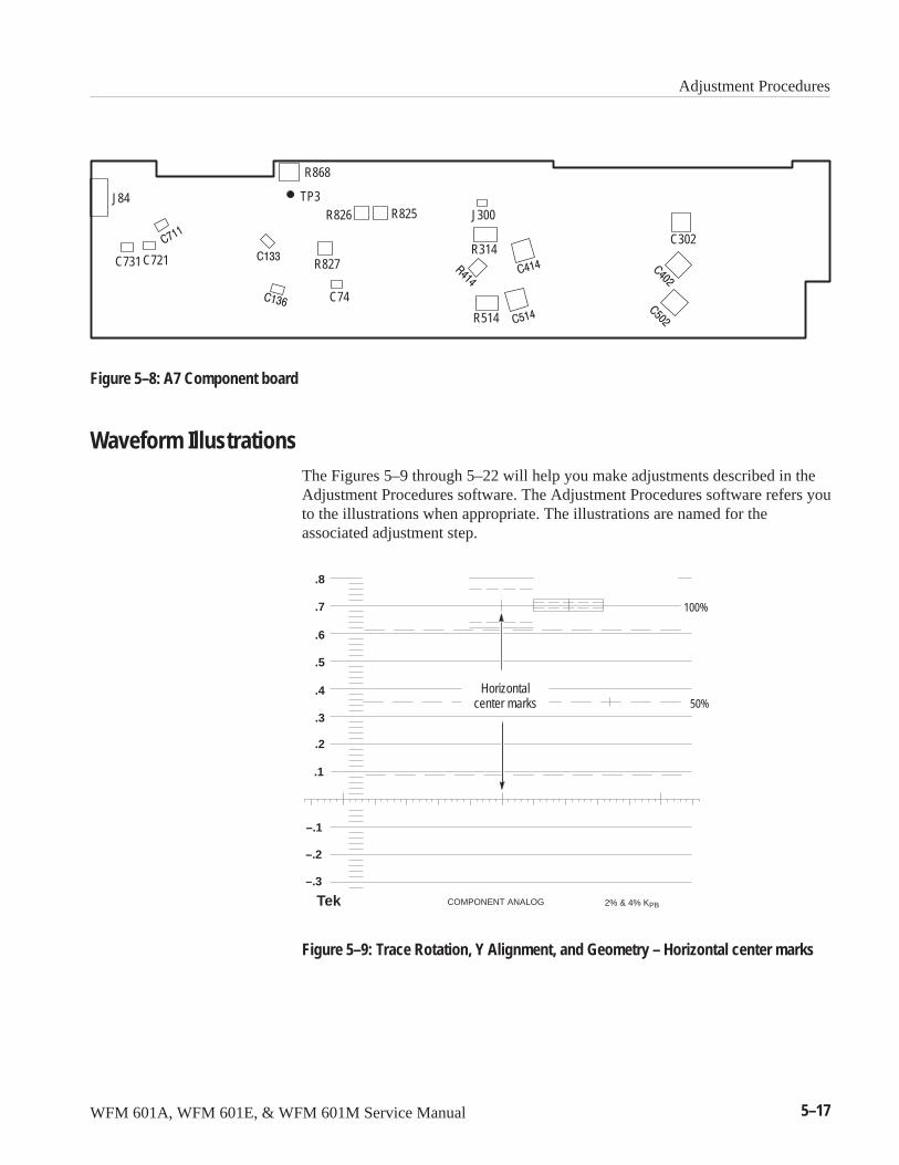
Adjustment Procedures
WFM 601A, WFM 601E, & WFM 601M Service Manual 5–17
J84
C731 C721
C74
R826
R827
R825 J300
R514
C302
R868
TP3
R314
Figure 5–8: A7 Component board
Waveform IllustrationsThe Figures 5–9 through 5–22 will help you make adjustments described in theAdjustment Procedures software. The Adjustment Procedures software refers youto the illustrations when appropriate. The illustrations are named for theassociated adjustment step.
.7
.6
.8
.5
.4
.3
.2
.1
–.1
–.2
–.3
Tek COMPONENT ANALOG 2% & 4% KPB
100%
50%Horizontal
center marks
Figure 5–9: Trace Rotation, Y Alignment, and Geometry – Horizontal center marks
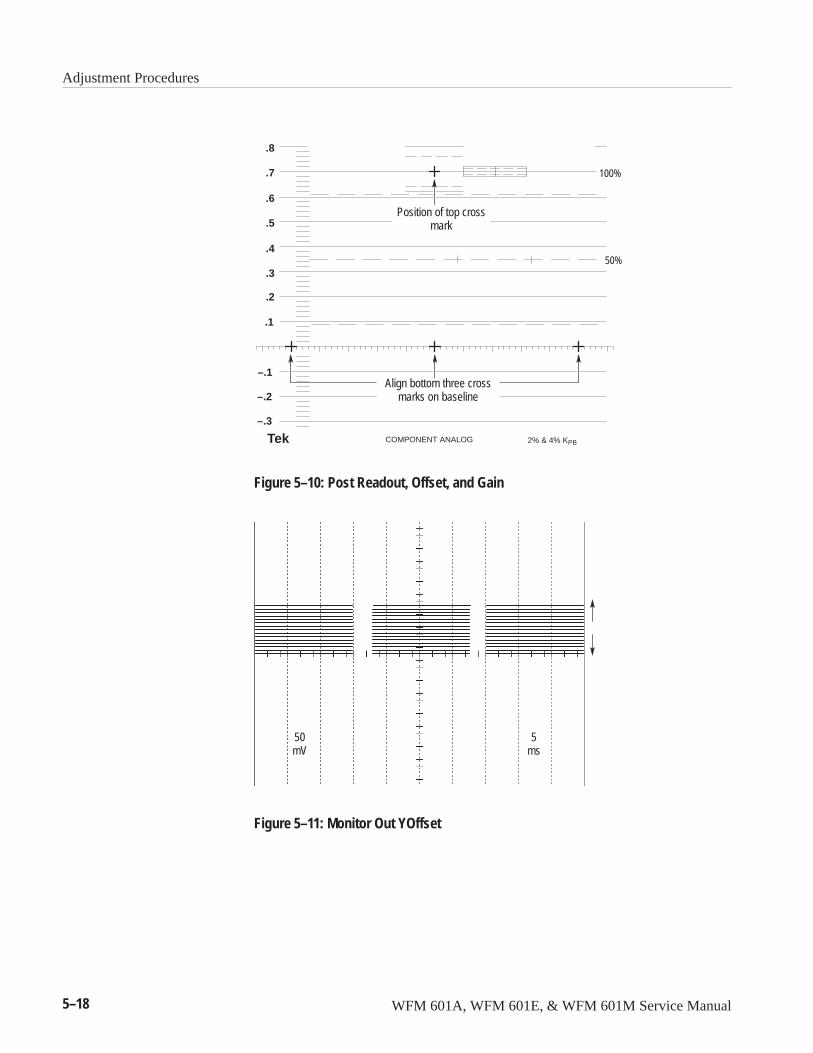
Adjustment Procedures
5–18 WFM 601A, WFM 601E, & WFM 601M Service Manual
.7
.6
.8
.5
.4
.3
.2
.1
–.1
–.2
–.3
Tek COMPONENT ANALOG 2% & 4% KPB
100%
50%
Position of top crossmark
Align bottom three crossmarks on baseline
Figure 5–10: Post Readout, Offset, and Gain
50mV
5ms
Figure 5–11: Monitor Out YOffset
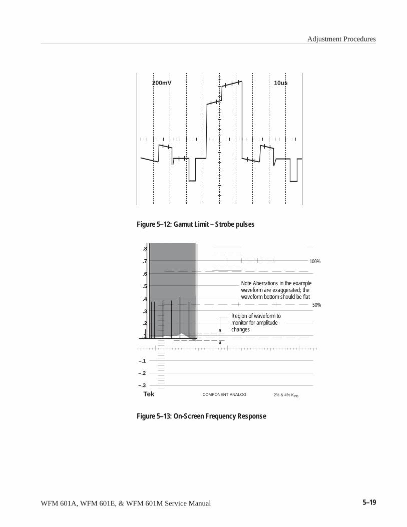
Adjustment Procedures
WFM 601A, WFM 601E, & WFM 601M Service Manual 5–19
200mV 10us
Figure 5–12: Gamut Limit – Strobe pulses
.7
.6
.8
.5
.4
.3
.2
.1
–.1
–.2
–.3
Tek COMPONENT ANALOG 2% & 4% KPB
100%
50%
Region of waveform tomonitor for amplitudechanges
Note Aberrations in the examplewaveform are exaggerated; thewaveform bottom should be flat
Figure 5–13: On-Screen Frequency Response
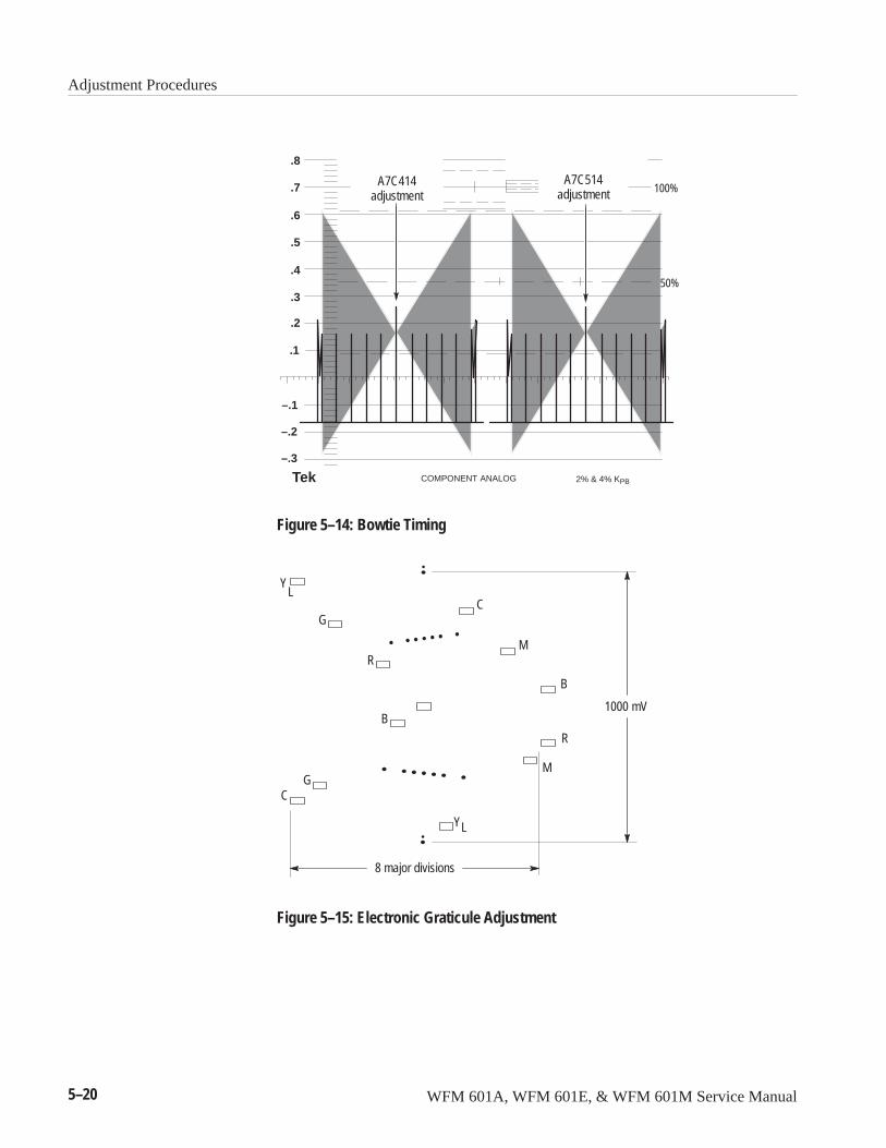
Adjustment Procedures
5–20 WFM 601A, WFM 601E, & WFM 601M Service Manual
.7
.6
.8
.5
.4
.3
.2
.1
–.1
–.2
–.3
Tek COMPONENT ANALOG 2% & 4% KPB
100%
50%
A7C514adjustment
A7C414adjustment
Figure 5–14: Bowtie Timing
R
G
B
B
R
G
C
C
M
M
YL
YL
8 major divisions
1000 mV
Figure 5–15: Electronic Graticule Adjustment
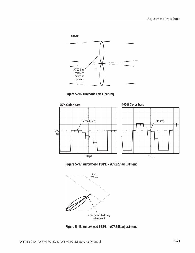
Adjustment Procedures
WFM 601A, WFM 601E, & WFM 601M Service Manual 5–21
625/50
A7C74 forbalancedminimumopenings
Figure 5–16: Diamond Eye Opening
Second step Fifth step
200mV
10 �s 10 �s
75% Color bars 100% Color bars
Figure 5–17: Arrowhead PBPR – A7R827 adjustment
Area to watch duringadjustment
Figure 5–18: Arrowhead PBPR – A7R868 adjustment
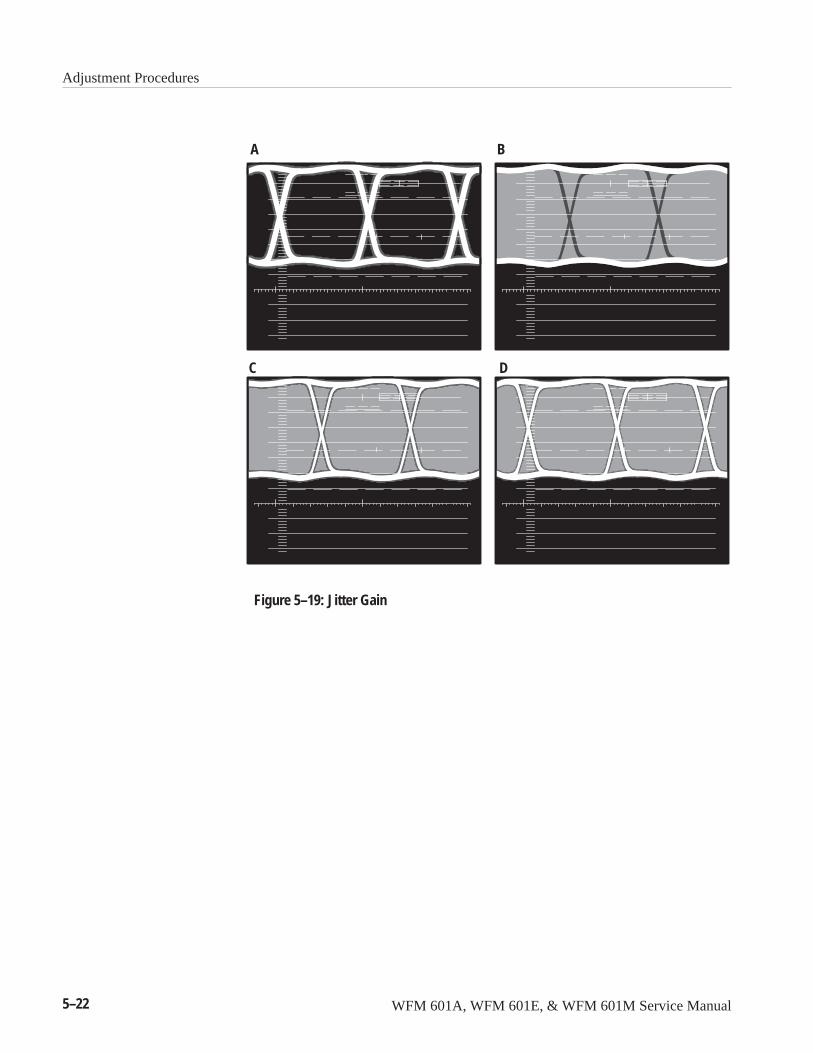
Adjustment Procedures
5–22 WFM 601A, WFM 601E, & WFM 601M Service Manual
A
C
B
D
Figure 5–19: Jitter Gain
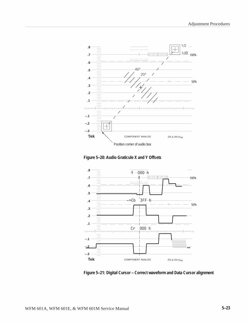
Adjustment Procedures
WFM 601A, WFM 601E, & WFM 601M Service Manual 5–23
Position corner of audio box
.7
.6
.8
.5
.4
.3
.2
.1
–.1
–.2
–.3
Tek COMPONENT ANALOG 2% & 4% KPB
100%
50%
��°��°
���
���
Figure 5–20: Audio Graticule X and Y Offsets
.7
.6
.8
.5
.4
.3
.2
.1
–.1
–.2
–.3
Tek COMPONENT ANALOG 2% & 4% KPB
100%
50%
Figure 5–21: Digital Cursor – Correct waveform and Data Cursor alignment
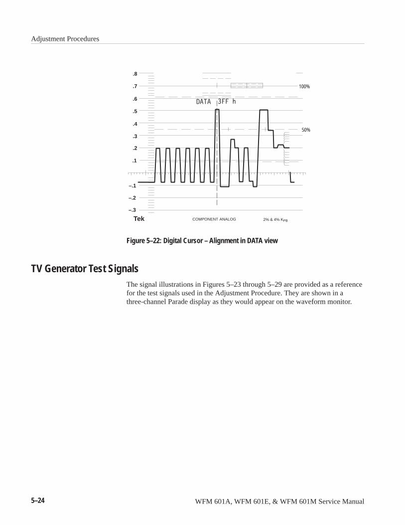
Adjustment Procedures
5–24 WFM 601A, WFM 601E, & WFM 601M Service Manual
.7
.6
.8
.5
.4
.3
.2
.1
–.1
–.2
–.3
Tek COMPONENT ANALOG 2% & 4% KPB
100%
50%
Figure 5–22: Digital Cursor – Alignment in DATA view
TV Generator Test SignalsThe signal illustrations in Figures 5–23 through 5–29 are provided as a referencefor the test signals used in the Adjustment Procedure. They are shown in athree-channel Parade display as they would appear on the waveform monitor.
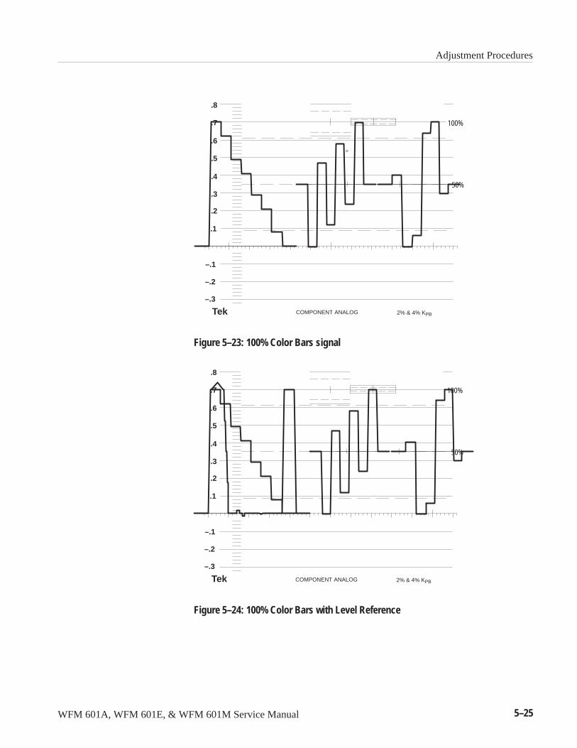
Adjustment Procedures
WFM 601A, WFM 601E, & WFM 601M Service Manual 5–25
.7
.6
.8
.5
.4
.3
.2
.1
–.1
–.2
–.3
Tek COMPONENT ANALOG 2% & 4% KPB
100%
50%
Figure 5–23: 100% Color Bars signal
.7
.6
.8
.5
.4
.3
.2
.1
–.1
–.2
–.3
Tek COMPONENT ANALOG 2% & 4% KPB
100%
50%
Figure 5–24: 100% Color Bars with Level Reference
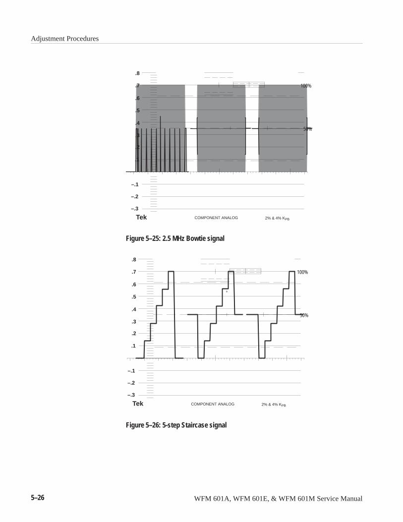
Adjustment Procedures
5–26 WFM 601A, WFM 601E, & WFM 601M Service Manual
.7
.6
.8
.5
.4
.3
.2
.1
–.1
–.2
–.3
Tek COMPONENT ANALOG 2% & 4% KPB
100%
50%
Figure 5–25: 2.5 MHz Bowtie signal
.7
.6
.8
.5
.4
.3
.2
.1
–.1
–.2
–.3
Tek COMPONENT ANALOG 2% & 4% KPB
100%
50%
Figure 5–26: 5-step Staircase signal

Adjustment Procedures
WFM 601A, WFM 601E, & WFM 601M Service Manual 5–27
.7
.6
.8
.5
.4
.3
.2
.1
–.1
–.2
–.3
Tek COMPONENT ANALOG 2% & 4% KPB
100%
50%
Figure 5–27: Shallow Ramp signal
.7
.6
.8
.5
.4
.3
.2
.1
–.1
–.2
–.3
Tek COMPONENT ANALOG 2% & 4% KPB
100%
50%
Figure 5–28: 100% Sweep signal
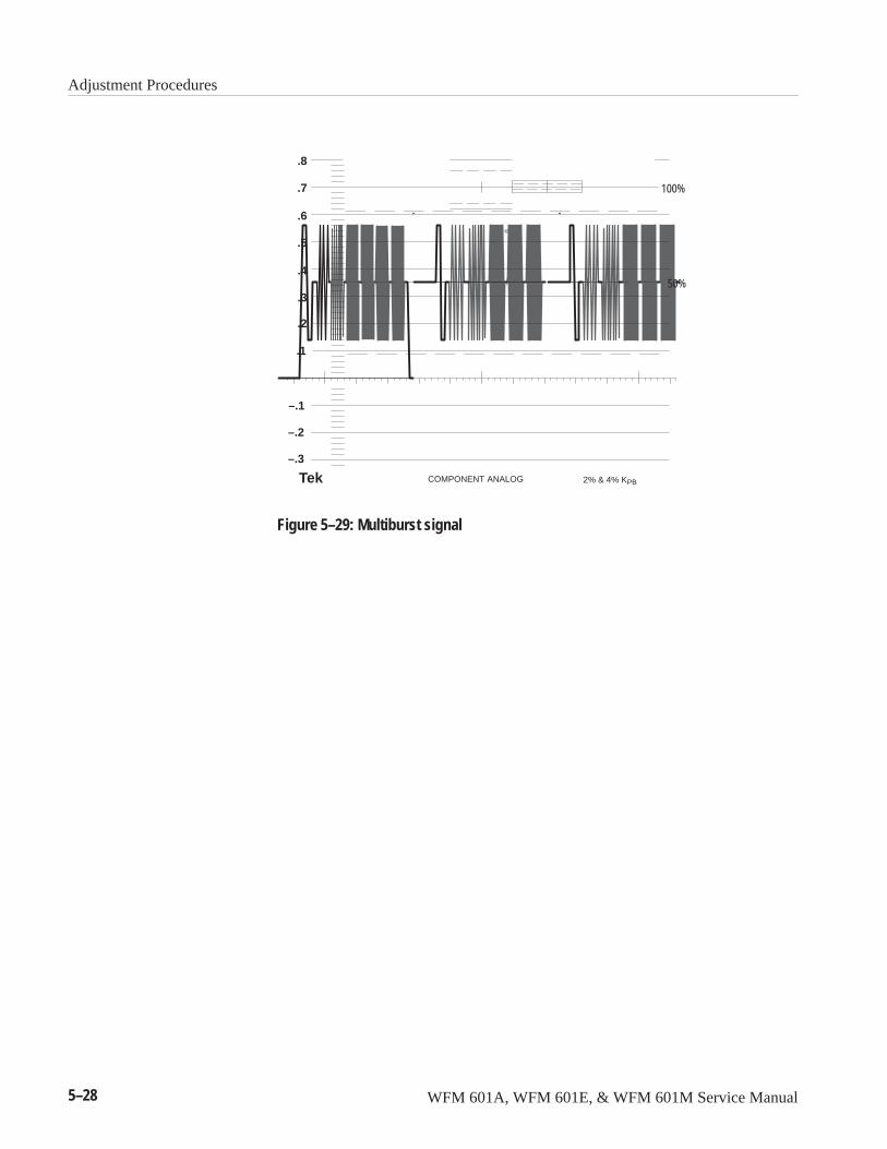
Adjustment Procedures
5–28 WFM 601A, WFM 601E, & WFM 601M Service Manual
.7
.6
.8
.5
.4
.3
.2
.1
–.1
–.2
–.3
Tek COMPONENT ANALOG 2% & 4% KPB
100%
50%
Figure 5–29: Multiburst signal


WFM 601A, WFM 601E, & WFM 601M Service Manual 6–1
Maintenance
This section contains information on preventive maintenance, general trouble-shooting, and corrective maintenance of the WFM 601A, WFM 601E, andWFM 601M Serial Digital Component Waveform Monitors and includesprocedures for the following tasks:
� Inspecting and cleaning the waveform monitor
� Removing and replacing components
� Troubleshooting
� Adjusting the waveform monitor after repair
� Installing upgrade software
� Repackaging the waveform monitor for shipment
Preventive maintenance consists of cleaning, visually inspecting, periodicallyadjusting, and checking the performance of the waveform monitor. Thepreventive maintenance schedule you establish for the waveform monitor shouldbe based on your operating environment and the amount of use your waveformmonitor gets. Under average conditions, schedule preventive maintenance afterevery 2000 hours of operation.
Service OptionsAs with all Tektronix products, a number of servicing options are available.
� Return the instrument to Tektronix for repair and/or calibration. Tektronixsupports service worldwide.
� Exchange a major assembly or circuit board for a fully tested replacementfrom a Tektronix service center.
� Troubleshoot and repair the defective module to component level andpurchase replacement parts from a Tektronix service center. Most circuitboards contain fine-pitch surface mount components, which require specialequipment for replacement.
You should determine which of these options is appropriate for you.
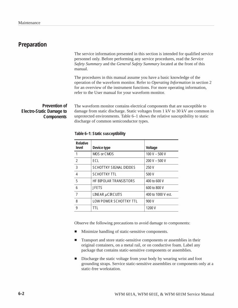
Maintenance
6–2 WFM 601A, WFM 601E, & WFM 601M Service Manual
PreparationThe service information presented in this section is intended for qualified servicepersonnel only. Before performing any service procedures, read the ServiceSafety Summary and the General Safety Summary located at the front of thismanual.
The procedures in this manual assume you have a basic knowledge of theoperation of the waveform monitor. Refer to Operating Information in section 2for an overview of the instrument functions. For more operating information,refer to the User manual for your waveform monitor.
The waveform monitor contains electrical components that are susceptible todamage from static discharge. Static voltages from 1 kV to 30 kV are common inunprotected environments. Table 6–1 shows the relative susceptibility to staticdischarge of common semiconductor types.
Table 6–1: Static susceptibility
Relativelevel Device type Voltage
1 MOS or CMOS 100 V – 500 V
2 ECL 200 V – 500 V
3 SCHOTTKY SIGNAL DIODES 250 V
4 SCHOTTKY TTL 500 V
5 HF BIPOLAR TRANSISTORS 400 to 600 V
6 JFETS 600 to 800 V
7 LINEAR��CIRCUITS 400 to 1000 V est.
8 LOW POWER SCHOTTKY TTL 900 V
9 TTL 1200 V
Observe the following precautions to avoid damage to components:
� Minimize handling of static-sensitive components.
� Transport and store static-sensitive components or assemblies in theiroriginal containers, on a metal rail, or on conductive foam. Label anypackage that contains static-sensitive components or assemblies.
� Discharge the static voltage from your body by wearing wrist and footgrounding straps. Service static-sensitive assemblies or components only at astatic-free workstation.
Prevention ofElectro-Static Damage to
Components
Maintenance
WFM 601A, WFM 601E, & WFM 601M Service Manual 6–3
� Keep static generating items or items capable of holding a static charge awayfrom the workstation surface.
� Keep the component leads shorted together whenever possible.
� Pick up the components by the body, never by the leads.
� Always move components by picking them up first, never by sliding themacross a surface.
� Avoid handling components in areas that have a floor or work surfacecovering capable of generating a static charge.
� Use a soldering iron that is connected to earth ground.
� Use only antistatic suction or wick-type desoldering tools.
Inspection and CleaningClean the instrument often enough to prevent dust or dirt from accumulating. Dirtacts as an insulating blanket that prevents effective heat dissipation and canprovide electrical leakage paths between conductors or components in a humidenvironment.
CAUTION. Do not allow water to get inside enclosed assemblies or components.Do not clean plastic materials with organic cleaning solvents, such as benzene,toluene, xylene, acetone, or similar compounds, because they may damage theplastic.
Clean the dust from the exterior of the instrument by wiping it with a soft clothor small brush. A brush is useful to remove dust from around the buttons, knobs,and connectors. Remove hardened dirt with a cloth dampened in water contain-ing a mild detergent. Do not use abrasive cleaners.
Clean the CRT protective shield, light filter, and CRT face with a soft, lint-freecloth dampened in denatured alcohol.
Clean the interior of the instrument by loosening the accumulated dust with a dry,soft brush. Once the dirt is loose, remove it with low-pressure air. High-velocityair can damage parts. Remove hardened dirt or grease with a cotton-tippedapplicator dampened with a solution of mild detergent and water. Abrasivecleaners should not be used. If the circuit board assemblies must be removed forcleaning, refer to Removal and Replacement on page 6–5.
Cleaning the Exterior
Cleaning the CRT/Display
Cleaning the Interior
Maintenance
6–4 WFM 601A, WFM 601E, & WFM 601M Service Manual
After cleaning, allow the interior to thoroughly dry before applying power to theinstrument.
In order to operate in all environmental conditions the waveform monitorrequires clean unrestricted air flow. The air filter, which cleans the air suppliedby the fan, is located in the fan housing on the rear panel. Check the filterfrequently. A supply of replacement filters was shipped with this instrument.
Filter Replacement. To replace the air filter, pull the fan cover off the fan, lift outthe old filter and replace it. Carefully press the cover into place over the fanhousing. Refer to Figure 6–14 on page 6–16 for details of the fan assembly.
Filter Cleaning. You can clean and reuse the air filters supplied with this instru-ment. Wash the used filters in warm water and mild detergent. Let them drythoroughly before reusing them.
Additional Air Filters. Order additional air filters directly from Tektronix. The partnumber for the air filters is listed in Options, section 7.
After cleaning, carefully check the instrument for defective connections ordamaged parts. If you discover a heat-damaged part, determine the cause ofoverheating before replacing the damaged part to prevent additional damage.
Periodic checks of the transistors and integrated circuits are not recommended.The best measure of performance is the actual operation of the component in thecircuit.
Operation of the waveform monitors is dependent upon the operating softwareloaded in the Flash EPROM on the Main board. New software versions may bereleased to add features or correct reported problems. You can save considerabletime and troubleshooting effort by reporting the software version when callingTektronix for parts or service information.
NOTE. If the Flash EPROM fails, you will need to return the instrument toTektronix to replace the part and restore proper operation.
Replacing and Cleaningthe Air Filter
Visual Inspection
Determining the SoftwareVersion
Maintenance
WFM 601A, WFM 601E, & WFM 601M Service Manual 6–5
Use the following procedure to view the software and coprocessor versionnumbers:
1. Press the CONFIG button.
2. Select the CALIBRATE submenu using the bezel knob.
3. Read the version number from the lower right corner of the CRT. Thesoftware version number is preceded by the letter V. The version number ofthe serial coprocessor code is preceded by the letter C.
Check instrument performance after each 2000 hours of operation or every12 months. This performance check will help to ensure maximum performanceand help you locate defects that may not be apparent during regular operation. Aperformance verification procedure and an adjustment procedure are included inthis manual.
Removal and Replacement InstructionsThe procedures in this section describe how to remove circuit board assembliesfrom the waveform monitor frame. Figure 6–21 on page 6–25 identifies thecircuit boards. To remove most screws, use either a TORX T15 screwdriver tip ora medium Pozidrive screw tip.
WARNING. Before attempting to disassemble the waveform monitor, be sure todisconnect the power cord and wait until DS7 on the Power Supply circuit board(A1) extinguishes.
CAUTION. Do not reinsert screws in the rear panel when the instrument isremoved from the cabinet.
Periodic PerformanceCheck and Adjustment
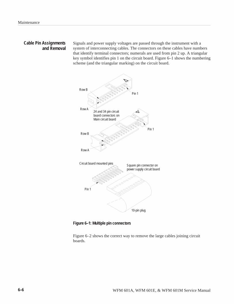
Maintenance
6–6 WFM 601A, WFM 601E, & WFM 601M Service Manual
Signals and power supply voltages are passed through the instrument with asystem of interconnecting cables. The connectors on these cables have numbersthat identify terminal connectors; numerals are used from pin 2 up. A triangularkey symbol identifies pin 1 on the circuit board. Figure 6–1 shows the numberingscheme (and the triangular marking) on the circuit board.
Circuit board mounted pins
Pin 1
10-pin plug
Square pin connector onpower supply circuit board
Pin 1
Pin 1
Row A
Row B
Row B
Row A
24 and 34 pin circuitboard connectors onMain circuit board
Figure 6–1: Multiple pin connectors
Figure 6–2 shows the correct way to remove the large cables joining circuitboards.
Cable Pin Assignmentsand Removal
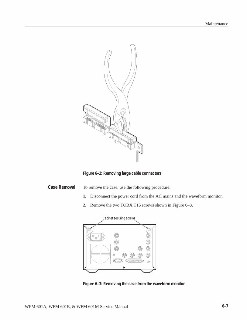
Maintenance
WFM 601A, WFM 601E, & WFM 601M Service Manual 6–7
Figure 6–2: Removing large cable connectors
To remove the case, use the following procedure:
1. Disconnect the power cord from the AC mains and the waveform monitor.
2. Remove the two TORX T15 screws shown in Figure 6–3.
Cabinet securing screws
Figure 6–3: Removing the case from the waveform monitor
Case Removal
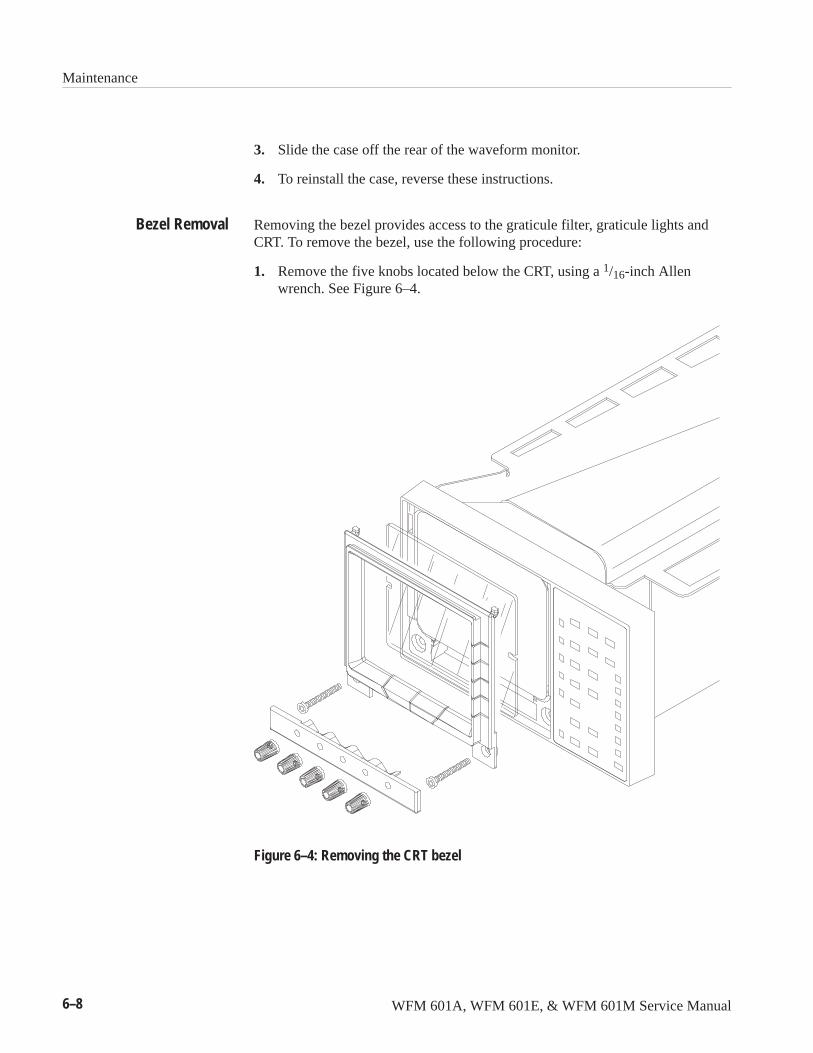
Maintenance
6–8 WFM 601A, WFM 601E, & WFM 601M Service Manual
3. Slide the case off the rear of the waveform monitor.
4. To reinstall the case, reverse these instructions.
Removing the bezel provides access to the graticule filter, graticule lights andCRT. To remove the bezel, use the following procedure:
1. Remove the five knobs located below the CRT, using a 1/16-inch Allenwrench. See Figure 6–4.
Figure 6–4: Removing the CRT bezel
Bezel Removal
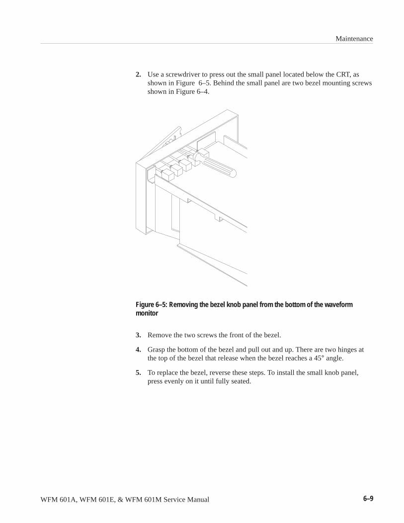
Maintenance
WFM 601A, WFM 601E, & WFM 601M Service Manual 6–9
2. Use a screwdriver to press out the small panel located below the CRT, asshown in Figure 6–5. Behind the small panel are two bezel mounting screwsshown in Figure 6–4.
Figure 6–5: Removing the bezel knob panel from the bottom of the waveformmonitor
3. Remove the two screws the front of the bezel.
4. Grasp the bottom of the bezel and pull out and up. There are two hinges atthe top of the bezel that release when the bezel reaches a 45° angle.
5. To replace the bezel, reverse these steps. To install the small knob panel,press evenly on it until fully seated.
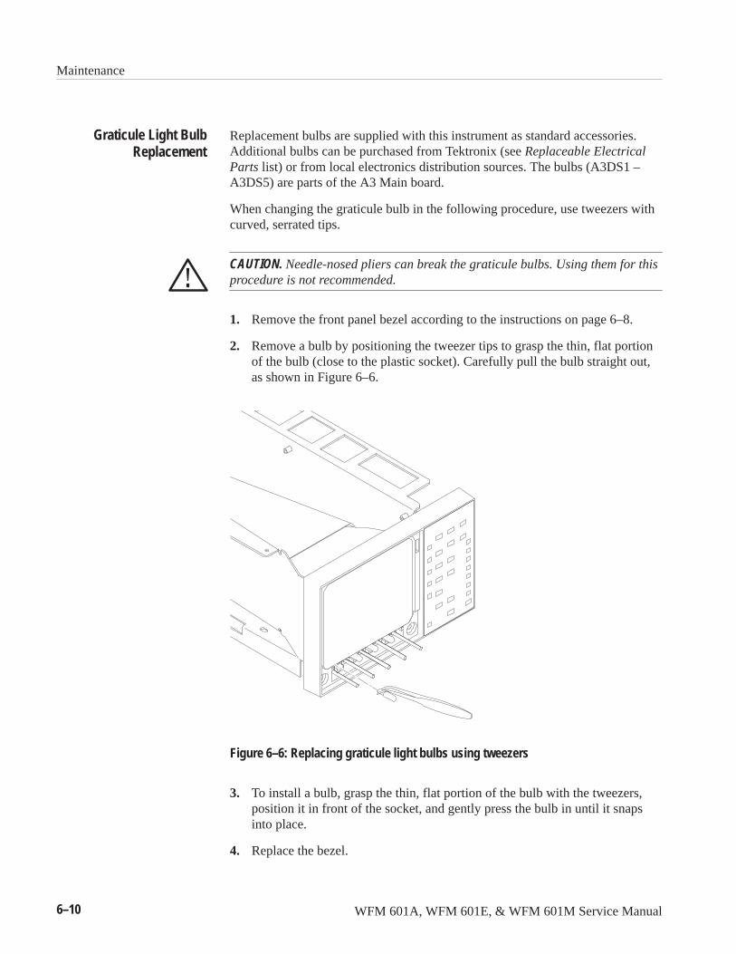
Maintenance
6–10 WFM 601A, WFM 601E, & WFM 601M Service Manual
Replacement bulbs are supplied with this instrument as standard accessories.Additional bulbs can be purchased from Tektronix (see Replaceable ElectricalParts list) or from local electronics distribution sources. The bulbs (A3DS1 –A3DS5) are parts of the A3 Main board.
When changing the graticule bulb in the following procedure, use tweezers withcurved, serrated tips.
CAUTION. Needle-nosed pliers can break the graticule bulbs. Using them for thisprocedure is not recommended.
1. Remove the front panel bezel according to the instructions on page 6–8.
2. Remove a bulb by positioning the tweezer tips to grasp the thin, flat portionof the bulb (close to the plastic socket). Carefully pull the bulb straight out,as shown in Figure 6–6.
Figure 6–6: Replacing graticule light bulbs using tweezers
3. To install a bulb, grasp the thin, flat portion of the bulb with the tweezers,position it in front of the socket, and gently press the bulb in until it snapsinto place.
4. Replace the bezel.
Graticule Light BulbReplacement
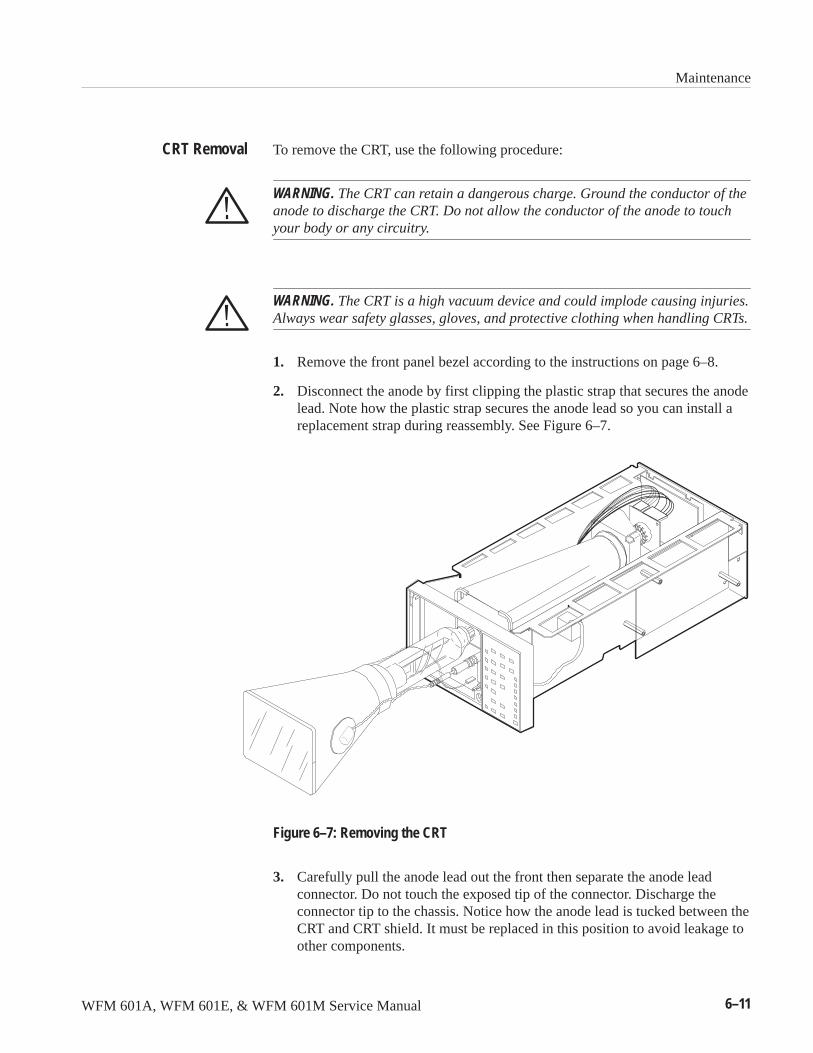
Maintenance
WFM 601A, WFM 601E, & WFM 601M Service Manual 6–11
To remove the CRT, use the following procedure:
WARNING. The CRT can retain a dangerous charge. Ground the conductor of theanode to discharge the CRT. Do not allow the conductor of the anode to touchyour body or any circuitry.
WARNING. The CRT is a high vacuum device and could implode causing injuries.Always wear safety glasses, gloves, and protective clothing when handling CRTs.
1. Remove the front panel bezel according to the instructions on page 6–8.
2. Disconnect the anode by first clipping the plastic strap that secures the anodelead. Note how the plastic strap secures the anode lead so you can install areplacement strap during reassembly. See Figure 6–7.
Figure 6–7: Removing the CRT
3. Carefully pull the anode lead out the front then separate the anode leadconnector. Do not touch the exposed tip of the connector. Discharge theconnector tip to the chassis. Notice how the anode lead is tucked between theCRT and CRT shield. It must be replaced in this position to avoid leakage toother components.
CRT Removal
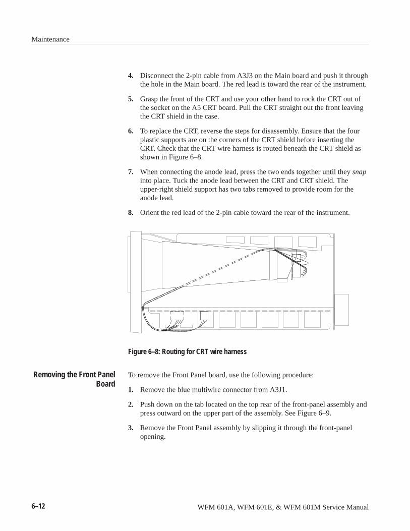
Maintenance
6–12 WFM 601A, WFM 601E, & WFM 601M Service Manual
4. Disconnect the 2-pin cable from A3J3 on the Main board and push it throughthe hole in the Main board. The red lead is toward the rear of the instrument.
5. Grasp the front of the CRT and use your other hand to rock the CRT out ofthe socket on the A5 CRT board. Pull the CRT straight out the front leavingthe CRT shield in the case.
6. To replace the CRT, reverse the steps for disassembly. Ensure that the fourplastic supports are on the corners of the CRT shield before inserting theCRT. Check that the CRT wire harness is routed beneath the CRT shield asshown in Figure 6–8.
7. When connecting the anode lead, press the two ends together until they snapinto place. Tuck the anode lead between the CRT and CRT shield. Theupper-right shield support has two tabs removed to provide room for theanode lead.
8. Orient the red lead of the 2-pin cable toward the rear of the instrument.
Figure 6–8: Routing for CRT wire harness
To remove the Front Panel board, use the following procedure:
1. Remove the blue multiwire connector from A3J1.
2. Push down on the tab located on the top rear of the front-panel assembly andpress outward on the upper part of the assembly. See Figure 6–9.
3. Remove the Front Panel assembly by slipping it through the front-panelopening.
Removing the Front PanelBoard
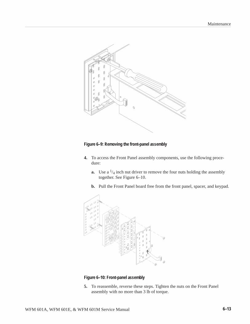
Maintenance
WFM 601A, WFM 601E, & WFM 601M Service Manual 6–13
Figure 6–9: Removing the front-panel assembly
4. To access the Front Panel assembly components, use the following proce-dure:
a. Use a 1/4 inch nut driver to remove the four nuts holding the assemblytogether. See Figure 6–10.
b. Pull the Front Panel board free from the front panel, spacer, and keypad.
Figure 6–10: Front-panel assembly
5. To reassemble, reverse these steps. Tighten the nuts on the Front Panelassembly with no more than 3 lb of torque.
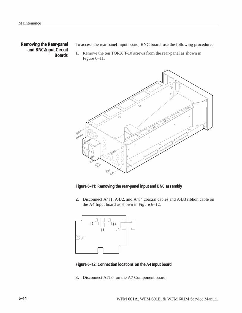
Maintenance
6–14 WFM 601A, WFM 601E, & WFM 601M Service Manual
To access the rear panel Input board, BNC board, use the following procedure:
1. Remove the ten TORX T-10 screws from the rear-panel as shown inFigure 6–11.
Figure 6–11: Removing the rear-panel input and BNC assembly
2. Disconnect A4J1, A4J2, and A4J4 coaxial cables and A4J3 ribbon cable onthe A4 Input board as shown in Figure 6–12.
J4J2
J5
J1
J3
Figure 6–12: Connection locations on the A4 Input board
3. Disconnect A7J84 on the A7 Component board.
Removing the Rear-paneland BNC/Input Circuit
Boards
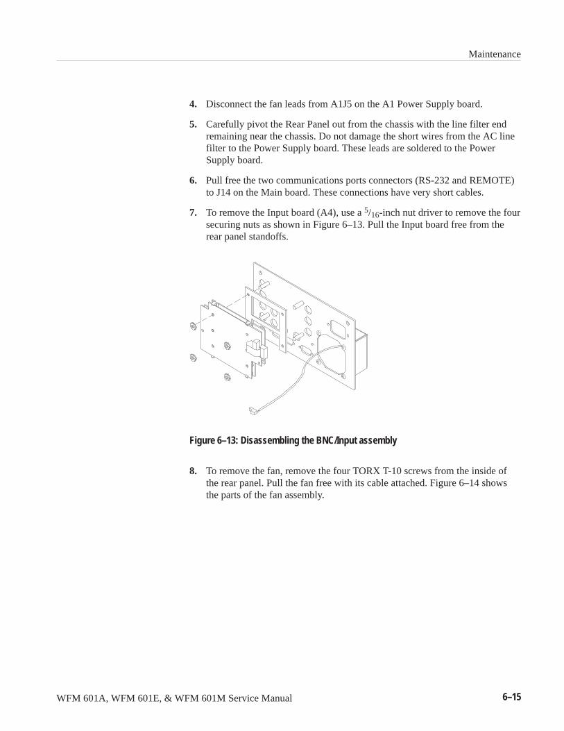
Maintenance
WFM 601A, WFM 601E, & WFM 601M Service Manual 6–15
4. Disconnect the fan leads from A1J5 on the A1 Power Supply board.
5. Carefully pivot the Rear Panel out from the chassis with the line filter endremaining near the chassis. Do not damage the short wires from the AC linefilter to the Power Supply board. These leads are soldered to the PowerSupply board.
6. Pull free the two communications ports connectors (RS-232 and REMOTE)to J14 on the Main board. These connections have very short cables.
7. To remove the Input board (A4), use a 5/16-inch nut driver to remove the foursecuring nuts as shown in Figure 6–13. Pull the Input board free from therear panel standoffs.
Figure 6–13: Disassembling the BNC/Input assembly
8. To remove the fan, remove the four TORX T-10 screws from the inside ofthe rear panel. Pull the fan free with its cable attached. Figure 6–14 showsthe parts of the fan assembly.
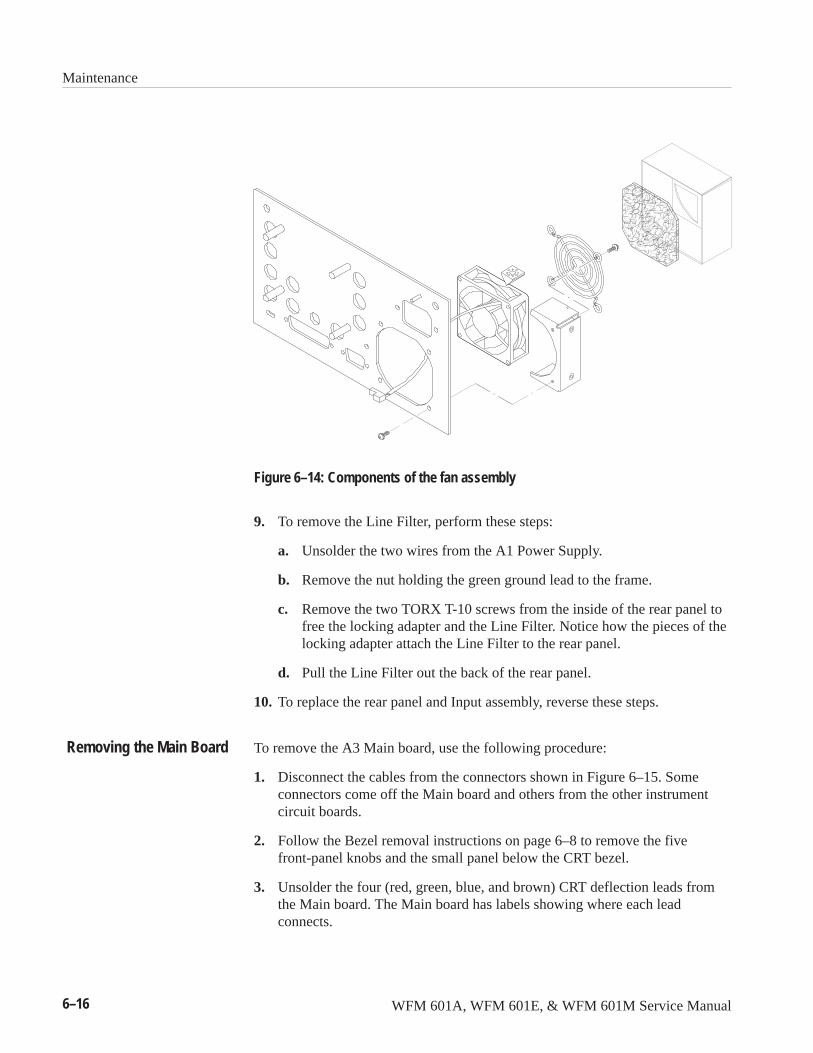
Maintenance
6–16 WFM 601A, WFM 601E, & WFM 601M Service Manual
Figure 6–14: Components of the fan assembly
9. To remove the Line Filter, perform these steps:
a. Unsolder the two wires from the A1 Power Supply.
b. Remove the nut holding the green ground lead to the frame.
c. Remove the two TORX T-10 screws from the inside of the rear panel tofree the locking adapter and the Line Filter. Notice how the pieces of thelocking adapter attach the Line Filter to the rear panel.
d. Pull the Line Filter out the back of the rear panel.
10. To replace the rear panel and Input assembly, reverse these steps.
To remove the A3 Main board, use the following procedure:
1. Disconnect the cables from the connectors shown in Figure 6–15. Someconnectors come off the Main board and others from the other instrumentcircuit boards.
2. Follow the Bezel removal instructions on page 6–8 to remove the fivefront-panel knobs and the small panel below the CRT bezel.
3. Unsolder the four (red, green, blue, and brown) CRT deflection leads fromthe Main board. The Main board has labels showing where each leadconnects.
Removing the Main Board
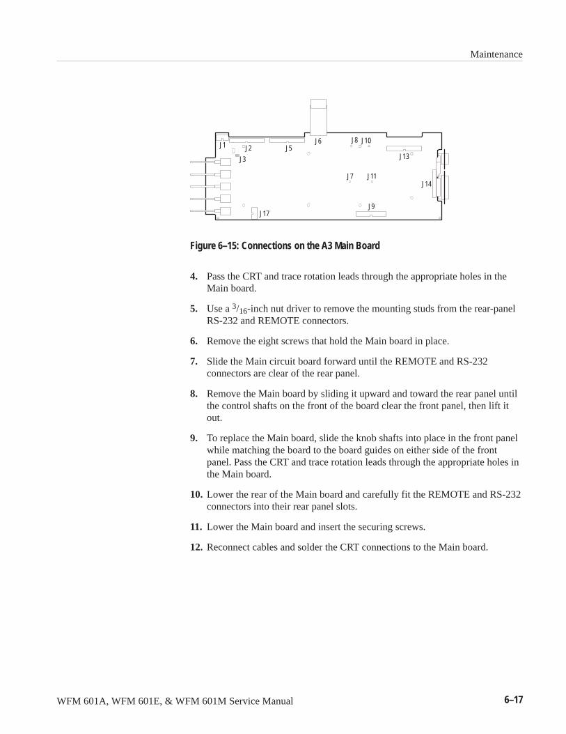
Maintenance
WFM 601A, WFM 601E, & WFM 601M Service Manual 6–17
J1
J17
J2 J5J6
J9
J8 J10
J7 J11
J13
J14
J3
Figure 6–15: Connections on the A3 Main Board
4. Pass the CRT and trace rotation leads through the appropriate holes in theMain board.
5. Use a 3/16-inch nut driver to remove the mounting studs from the rear-panelRS-232 and REMOTE connectors.
6. Remove the eight screws that hold the Main board in place.
7. Slide the Main circuit board forward until the REMOTE and RS-232connectors are clear of the rear panel.
8. Remove the Main board by sliding it upward and toward the rear panel untilthe control shafts on the front of the board clear the front panel, then lift itout.
9. To replace the Main board, slide the knob shafts into place in the front panelwhile matching the board to the board guides on either side of the frontpanel. Pass the CRT and trace rotation leads through the appropriate holes inthe Main board.
10. Lower the rear of the Main board and carefully fit the REMOTE and RS-232connectors into their rear panel slots.
11. Lower the Main board and insert the securing screws.
12. Reconnect cables and solder the CRT connections to the Main board.
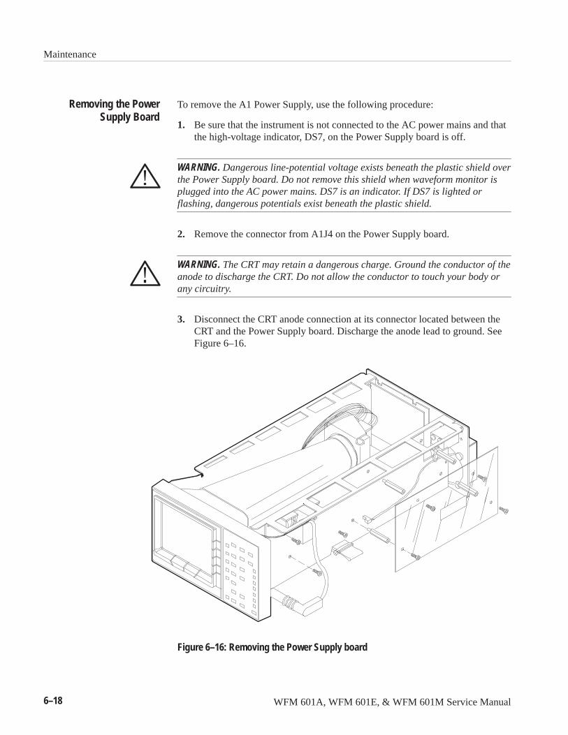
Maintenance
6–18 WFM 601A, WFM 601E, & WFM 601M Service Manual
To remove the A1 Power Supply, use the following procedure:
1. Be sure that the instrument is not connected to the AC power mains and thatthe high-voltage indicator, DS7, on the Power Supply board is off.
WARNING. Dangerous line-potential voltage exists beneath the plastic shield overthe Power Supply board. Do not remove this shield when waveform monitor isplugged into the AC power mains. DS7 is an indicator. If DS7 is lighted orflashing, dangerous potentials exist beneath the plastic shield.
2. Remove the connector from A1J4 on the Power Supply board.
WARNING. The CRT may retain a dangerous charge. Ground the conductor of theanode to discharge the CRT. Do not allow the conductor to touch your body orany circuitry.
3. Disconnect the CRT anode connection at its connector located between theCRT and the Power Supply board. Discharge the anode lead to ground. SeeFigure 6–16.
Figure 6–16: Removing the Power Supply board
Removing the PowerSupply Board
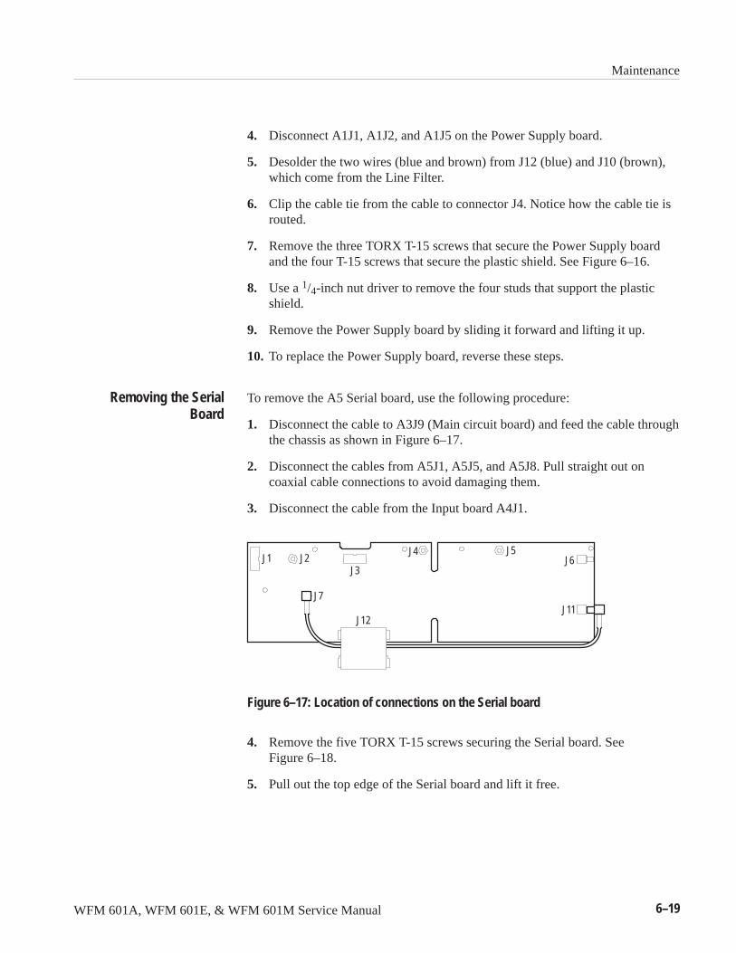
Maintenance
WFM 601A, WFM 601E, & WFM 601M Service Manual 6–19
4. Disconnect A1J1, A1J2, and A1J5 on the Power Supply board.
5. Desolder the two wires (blue and brown) from J12 (blue) and J10 (brown),which come from the Line Filter.
6. Clip the cable tie from the cable to connector J4. Notice how the cable tie isrouted.
7. Remove the three TORX T-15 screws that secure the Power Supply boardand the four T-15 screws that secure the plastic shield. See Figure 6–16.
8. Use a 1/4-inch nut driver to remove the four studs that support the plasticshield.
9. Remove the Power Supply board by sliding it forward and lifting it up.
10. To replace the Power Supply board, reverse these steps.
To remove the A5 Serial board, use the following procedure:
1. Disconnect the cable to A3J9 (Main circuit board) and feed the cable throughthe chassis as shown in Figure 6–17.
2. Disconnect the cables from A5J1, A5J5, and A5J8. Pull straight out oncoaxial cable connections to avoid damaging them.
3. Disconnect the cable from the Input board A4J1.
J1 J2
J7
J12
J3
J5J4J6
J11
Figure 6–17: Location of connections on the Serial board
4. Remove the five TORX T-15 screws securing the Serial board. SeeFigure 6–18.
5. Pull out the top edge of the Serial board and lift it free.
Removing the SerialBoard
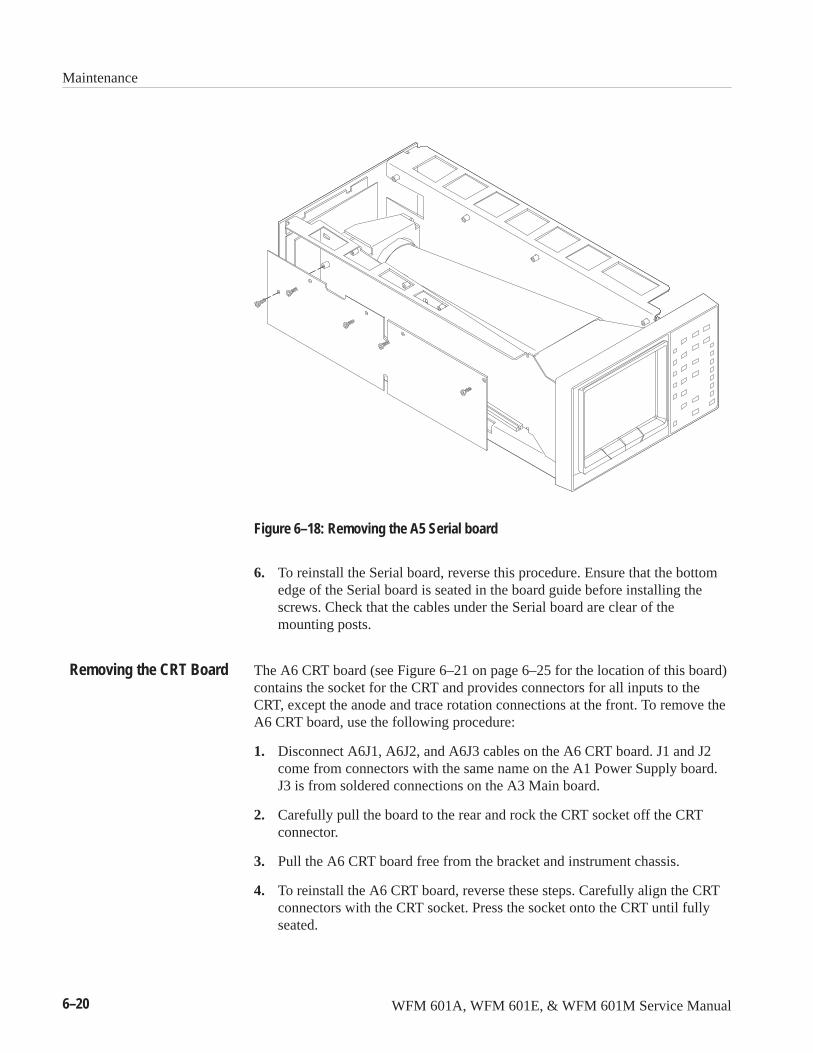
Maintenance
6–20 WFM 601A, WFM 601E, & WFM 601M Service Manual
Figure 6–18: Removing the A5 Serial board
6. To reinstall the Serial board, reverse this procedure. Ensure that the bottomedge of the Serial board is seated in the board guide before installing thescrews. Check that the cables under the Serial board are clear of themounting posts.
The A6 CRT board (see Figure 6–21 on page 6–25 for the location of this board)contains the socket for the CRT and provides connectors for all inputs to theCRT, except the anode and trace rotation connections at the front. To remove theA6 CRT board, use the following procedure:
1. Disconnect A6J1, A6J2, and A6J3 cables on the A6 CRT board. J1 and J2come from connectors with the same name on the A1 Power Supply board.J3 is from soldered connections on the A3 Main board.
2. Carefully pull the board to the rear and rock the CRT socket off the CRTconnector.
3. Pull the A6 CRT board free from the bracket and instrument chassis.
4. To reinstall the A6 CRT board, reverse these steps. Carefully align the CRTconnectors with the CRT socket. Press the socket onto the CRT until fullyseated.
Removing the CRT Board
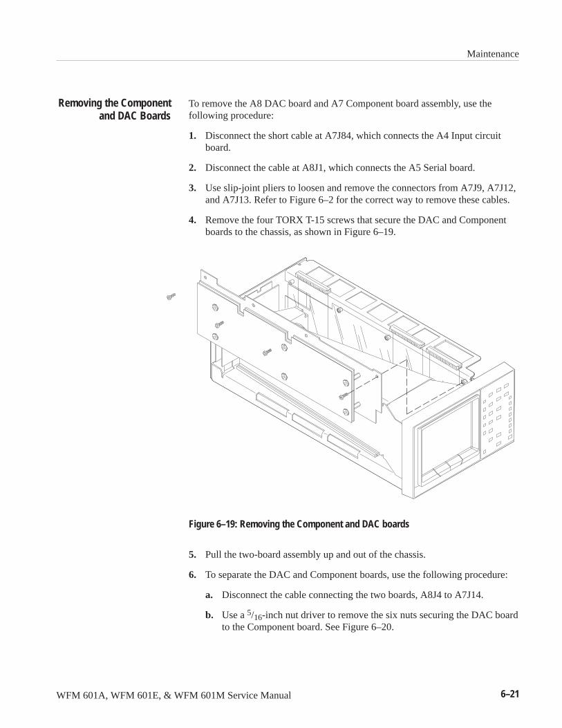
Maintenance
WFM 601A, WFM 601E, & WFM 601M Service Manual 6–21
To remove the A8 DAC board and A7 Component board assembly, use thefollowing procedure:
1. Disconnect the short cable at A7J84, which connects the A4 Input circuitboard.
2. Disconnect the cable at A8J1, which connects the A5 Serial board.
3. Use slip-joint pliers to loosen and remove the connectors from A7J9, A7J12,and A7J13. Refer to Figure 6–2 for the correct way to remove these cables.
4. Remove the four TORX T-15 screws that secure the DAC and Componentboards to the chassis, as shown in Figure 6–19.
Figure 6–19: Removing the Component and DAC boards
5. Pull the two-board assembly up and out of the chassis.
6. To separate the DAC and Component boards, use the following procedure:
a. Disconnect the cable connecting the two boards, A8J4 to A7J14.
b. Use a 5/16-inch nut driver to remove the six nuts securing the DAC boardto the Component board. See Figure 6–20.
Removing the Componentand DAC Boards
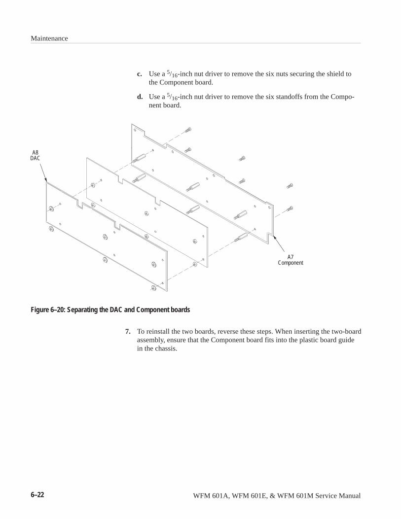
Maintenance
6–22 WFM 601A, WFM 601E, & WFM 601M Service Manual
c. Use a 5/16-inch nut driver to remove the six nuts securing the shield tothe Component board.
d. Use a 5/16-inch nut driver to remove the six standoffs from the Compo-nent board.
A8DAC
A7Component
Figure 6–20: Separating the DAC and Component boards
7. To reinstall the two boards, reverse these steps. When inserting the two-boardassembly, ensure that the Component board fits into the plastic board guidein the chassis.
Maintenance
WFM 601A, WFM 601E, & WFM 601M Service Manual 6–23
TroubleshootingThis section describes the how to troubleshoot the waveform monitor. Followinga general discussion of techniques, specific procedures are given for replacingthe fuse, troubleshooting the Power Supply and configuring the Component andDAC boards for troubleshooting.
The following procedure is designed to help you isolate problems, whichexpedites repairs and minimizes down time.
1. Determine if the malfunction exists in the waveform monitor or in anothersystem component. Make sure that the waveform monitor is being correctlyoperated as intended by Tektronix (see Operating Instructions). Check that aninstrument upstream from the waveform monitor is not malfunctioning.
2. Determine and evaluate all trouble symptoms. Isolate the problem to afunctional block, assembly, or circuit board. Use the Theory of Operation insection 3 and the block diagrams in section 9 for tracing signals and isolatingcircuits.
CAUTION. To avoid damaging components, use care when probing with meterleads or probes. Misplacing leads or a probe could cause a short circuit ortransient voltage capable of destroying components.
3. Determine the nature of the problem. Try to determine whether the waveformmonitor is out of calibration or if there has been a component failure. Oncethe type of failure has been determined, identify the functional area mostlikely at fault.
4. Inspect the suspect assembly for physical defects. Most commonly these willbe components that are broken or loose, improperly seated, or overheated orburned. Chafed insulation is also a common physical defect. Refer to thePower Supply troubleshooting procedure on page 6–26. Repair or replaceobvious defects. In the case of overheated components, determine the causeof overheating and correct the cause before re-applying power.
5. Use successive electrical checks to locate the source of the problem. The besttool for isolating problems is the oscilloscope. Use the PerformanceVerification procedure to check if a circuit is operating within specifications.
6. If the waveform monitor is operating, you should attempt to save thecalibration information into an NVDATA.TXT file using the Upgradeprogram described on page 6–42. This is especially if you may need to repairthe Main board. Saving this information means you can simply load thisNVDATA.TXT file into Main board and avoid running the entire AdjustmentProcedure. If you exchange the Main board for another, you must run the fullAdjustment Procedure described on page 5–1.
General TroubleshootingTechniques
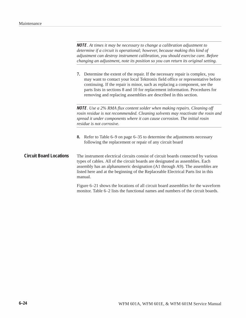
Maintenance
6–24 WFM 601A, WFM 601E, & WFM 601M Service Manual
NOTE. At times it may be necessary to change a calibration adjustment todetermine if a circuit is operational; however, because making this kind ofadjustment can destroy instrument calibration, you should exercise care. Beforechanging an adjustment, note its position so you can return its original setting.
7. Determine the extent of the repair. If the necessary repair is complex, youmay want to contact your local Tektronix field office or representative beforecontinuing. If the repair is minor, such as replacing a component, see theparts lists in sections 8 and 10 for replacement information. Procedures forremoving and replacing assemblies are described in this section.
NOTE. Use a 2% RMA flux content solder when making repairs. Cleaning offrosin residue is not recommended. Cleaning solvents may reactivate the rosin andspread it under components where it can cause corrosion. The initial rosinresidue is not corrosive.
8. Refer to Table 6–9 on page 6–35 to determine the adjustments necessaryfollowing the replacement or repair of any circuit board
The instrument electrical circuits consist of circuit boards connected by varioustypes of cables. All of the circuit boards are designated as assemblies. Eachassembly has an alphanumeric designation (A1 through A9). The assembles arelisted here and at the beginning of the Replaceable Electrical Parts list in thismanual.
Figure 6–21 shows the locations of all circuit board assemblies for the waveformmonitor. Table 6–2 lists the functional names and numbers of the circuit boards.
Circuit Board Locations
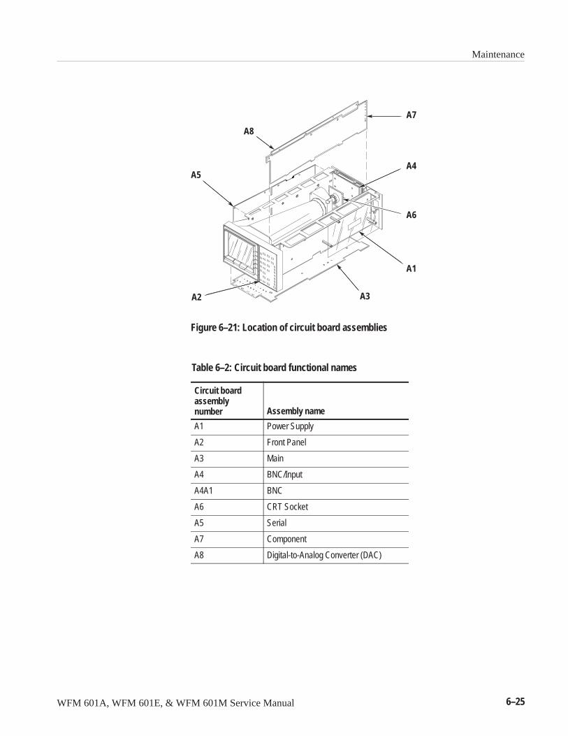
Maintenance
WFM 601A, WFM 601E, & WFM 601M Service Manual 6–25
A1
A2 A3
A4A5
A7
A8
A6
Figure 6–21: Location of circuit board assemblies
Table 6–2: Circuit board functional names
Circuit boardassemblynumber Assembly name
A1 Power Supply
A2 Front Panel
A3 Main
A4 BNC/Input
A4A1 BNC
A6 CRT Socket
A5 Serial
A7 Component
A8 Digital-to-Analog Converter (DAC)
Maintenance
6–26 WFM 601A, WFM 601E, & WFM 601M Service Manual
The waveform monitor is protected with an F-type cartridge fuse. Figure 6–22shows the fuse location on the Power Supply (A1) circuit board. Replace the fusewith the correct type and value. The correct type and value is silk screened on thecircuit board, adjacent to the fuse holder. Using a higher rated or slower actingfuse can damage a circuit.
Line FuseF1
Figure 6–22: Location of the line fuse on Power Supply board
The Power Supply is a switching power supply and requires a specific trouble-shooting procedure to avoid personal danger or instrument damage.
WARNING. Dangerous voltage levels exist in the Power Supply even after the linecord is removed from the main AC supply. Read the instructions in this sectionbefore beginning to troubleshoot this Power Supply.
The Power Supply presents special troubleshooting problems. The Trouble-shooting procedure that follows will help you isolate a problem to a specificcircuit. Analyze the circuit using the schematics to find the defective compo-nent(s), or try part substitution in the suspect circuit.
Line Fuse Replacement
Power SupplyTroubleshooting
Maintenance
WFM 601A, WFM 601E, & WFM 601M Service Manual 6–27
Equipment Required. The equipment needed to troubleshoot the Power Supply:
� Digital Multimeter (DMM), with a diode check function
� Oscilloscope
� 20 VDC Variable Power Supply
� 5 VDC Power Supply
� High Voltage Probe, �1 G� input resistance
The Troubleshooting procedure for the Power Supply (Assembly A1) is in twosections: the Low Volts Supply and High Volts Supply. Start the procedure byisolating the problem to one of these two power supplies.
With the Power Supply installed in the instrument, apply AC power and press thefront-panel POWER switch until the POWER switch LED is lighted. From Table6–3, determine which symptom the Power Supply exhibits and refer to thecorresponding procedure(s).
Table 6–3: Power supply fault symptoms
Symptom Procedure
Line fuse open Rectifier/Switcher/Snubber Check
Power Supply cycles OFF/ONNote: Check instrument for shorts.
Output CheckError Amplifier CheckShut Down Logic Check
Does not power up Controller/Gate Drive CheckError Amplifier CheckShut Down Logic CheckRectifier/Switcher/Snubber Check
+5 V not regulating Error Amplifier Check
Improper CRT display High Volts Supply Checks
Troubleshooting the Low Volts Supply. To troubleshoot the low voltage circuits onthe Power Supply board, follow these steps:
1. Preliminary Checks
a. A properly functioning and loaded Low Volts Supply will output thevoltages listed in Table 6–4. Use the DMM to measure the voltagesbetween TP1 (GND) and the voltage test points. Figure 5–5 onpage 5–15 shows the locations of these test points. If the supply is notregulating properly, continue with the procedure to determine theproblem.
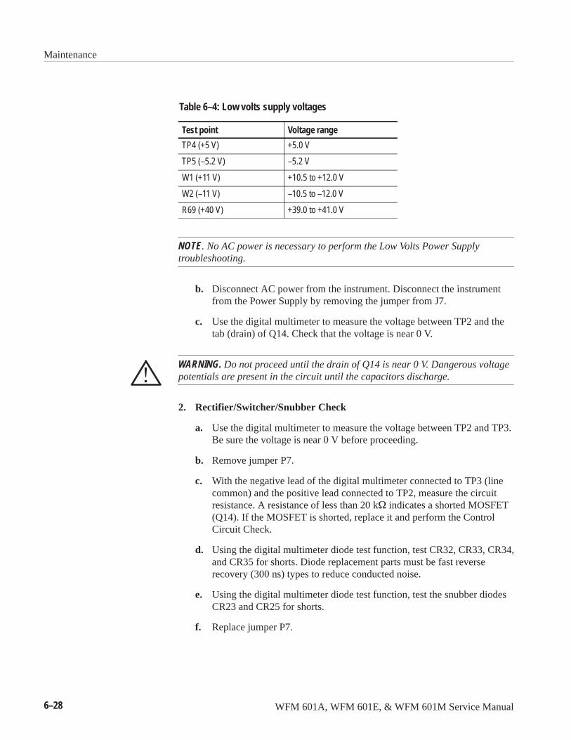
Maintenance
6–28 WFM 601A, WFM 601E, & WFM 601M Service Manual
Table 6–4: Low volts supply voltages
Test point Voltage range
TP4 (+5 V) +5.0 V
TP5 (–5.2 V) –5.2 V
W1 (+11 V) +10.5 to +12.0 V
W2 (–11 V) –10.5 to –12.0 V
R69 (+40 V) +39.0 to +41.0 V
NOTE. No AC power is necessary to perform the Low Volts Power Supplytroubleshooting.
b. Disconnect AC power from the instrument. Disconnect the instrumentfrom the Power Supply by removing the jumper from J7.
c. Use the digital multimeter to measure the voltage between TP2 and thetab (drain) of Q14. Check that the voltage is near 0 V.
WARNING. Do not proceed until the drain of Q14 is near 0 V. Dangerous voltagepotentials are present in the circuit until the capacitors discharge.
2. Rectifier/Switcher/Snubber Check
a. Use the digital multimeter to measure the voltage between TP2 and TP3.Be sure the voltage is near 0 V before proceeding.
b. Remove jumper P7.
c. With the negative lead of the digital multimeter connected to TP3 (linecommon) and the positive lead connected to TP2, measure the circuitresistance. A resistance of less than 20 k� indicates a shorted MOSFET(Q14). If the MOSFET is shorted, replace it and perform the ControlCircuit Check.
d. Using the digital multimeter diode test function, test CR32, CR33, CR34,and CR35 for shorts. Diode replacement parts must be fast reverserecovery (300 ns) types to reduce conducted noise.
e. Using the digital multimeter diode test function, test the snubber diodesCR23 and CR25 for shorts.
f. Replace jumper P7.
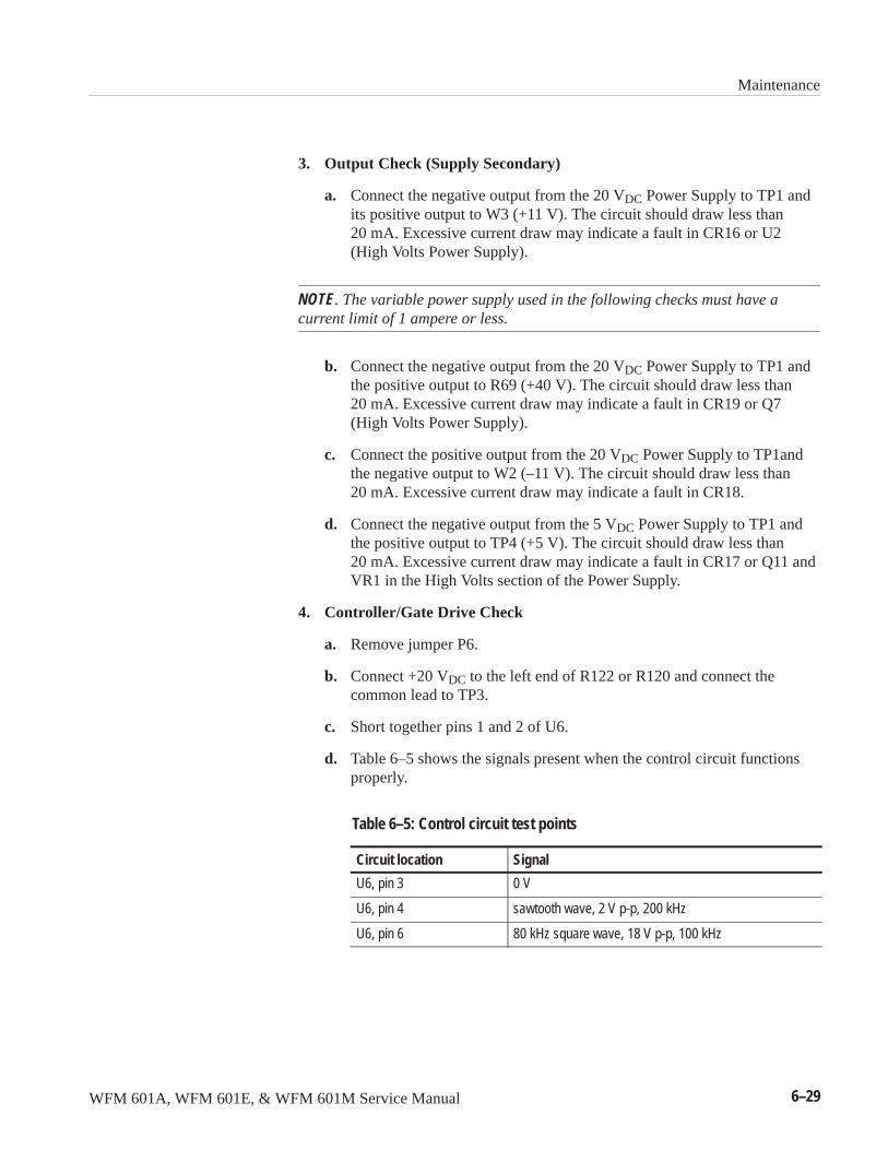
Maintenance
WFM 601A, WFM 601E, & WFM 601M Service Manual 6–29
3. Output Check (Supply Secondary)
a. Connect the negative output from the 20 VDC Power Supply to TP1 andits positive output to W3 (+11 V). The circuit should draw less than20 mA. Excessive current draw may indicate a fault in CR16 or U2(High Volts Power Supply).
NOTE. The variable power supply used in the following checks must have acurrent limit of 1 ampere or less.
b. Connect the negative output from the 20 VDC Power Supply to TP1 andthe positive output to R69 (+40 V). The circuit should draw less than20 mA. Excessive current draw may indicate a fault in CR19 or Q7(High Volts Power Supply).
c. Connect the positive output from the 20 VDC Power Supply to TP1andthe negative output to W2 (–11 V). The circuit should draw less than20 mA. Excessive current draw may indicate a fault in CR18.
d. Connect the negative output from the 5 VDC Power Supply to TP1 andthe positive output to TP4 (+5 V). The circuit should draw less than20 mA. Excessive current draw may indicate a fault in CR17 or Q11 andVR1 in the High Volts section of the Power Supply.
4. Controller/Gate Drive Check
a. Remove jumper P6.
b. Connect +20 VDC to the left end of R122 or R120 and connect thecommon lead to TP3.
c. Short together pins 1 and 2 of U6.
d. Table 6–5 shows the signals present when the control circuit functionsproperly.
Table 6–5: Control circuit test points
Circuit location Signal
U6, pin 3 0 V
U6, pin 4 sawtooth wave, 2 V p-p, 200 kHz
U6, pin 6 80 kHz square wave, 18 V p-p, 100 kHz
Maintenance
6–30 WFM 601A, WFM 601E, & WFM 601M Service Manual
e. Use the oscilloscope to observe the signal at the anode of CR26. Itshould be a 100 kHz square wave, switching between 0 V and 12 V. Thefall time is 0.2 �s and the rise time is 1 �s.
f. Remove the short between pins 1 and 2 of U6.
5. Power Switch and Shutdown Logic
a. Connect the negative output from the +20 VDC Power Supply to TP3.Connect the positive output to a 0.25 W, 150 � resistor and connect theother end of the resistor to the left end of R119 or R121. This connectionshould provide 6 V at 10 mA to run the switching circuit.
b. Connect the oscilloscope probe ground to TP3.
c. Listen for the Maglatch to click when J3 is shorted and unshorted.
d. Using the oscilloscope, observe the signal at the collector of Q13 with J3unshorted. This point should have a 1 V, 170 kHz sine wave riding on 5VDC. With J3 shorted this point should be at 5 VDC.
e. Short pin 2 of U6 to GND (TP3).
f. Check that pin 6 of U9 is high.
6. Error Amplifier, Voltage Reference and Over Voltage Check
a. Set the variable Power Supply to 4.6 VDC. Connect the negative lead toTP1 and the positive output to TP4 (+5 V).
b. Connect the digital multimeter common lead to TP1.
c. Using the digital multimeter measure the voltage at U8, pin 6. It shouldbe at TTL high.
d. Using the digital multimeter, measure the voltage at U8, pin 3. It shouldbe 2.5 V.
e. Set the variable Power Supply to 5.4 V.
f. Using the digital multimeter, measure the voltage at U8, pin 6. It shouldbe 0 V.
g. Slowly increase the voltage of the variable Power Supply. Before thevoltage reaches 6 V, the over-voltage protection circuit should fire andpull it below 1 V.
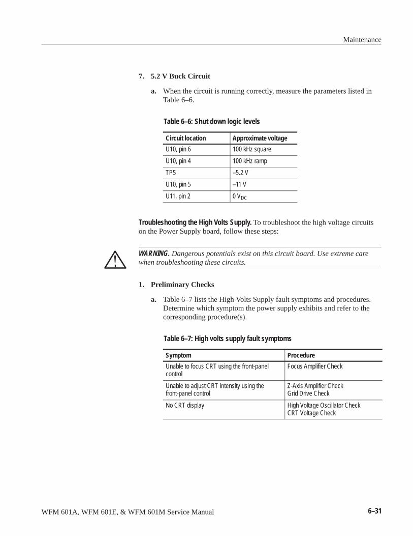
Maintenance
WFM 601A, WFM 601E, & WFM 601M Service Manual 6–31
7. 5.2 V Buck Circuit
a. When the circuit is running correctly, measure the parameters listed inTable 6–6.
Table 6–6: Shut down logic levels
Circuit location Approximate voltage
U10, pin 6 100 kHz square
U10, pin 4 100 kHz ramp
TP5 –5.2 V
U10, pin 5 –11 V
U11, pin 2 0 VDC
Troubleshooting the High Volts Supply. To troubleshoot the high voltage circuitson the Power Supply board, follow these steps:
WARNING. Dangerous potentials exist on this circuit board. Use extreme carewhen troubleshooting these circuits.
1. Preliminary Checks
a. Table 6–7 lists the High Volts Supply fault symptoms and procedures.Determine which symptom the power supply exhibits and refer to thecorresponding procedure(s).
Table 6–7: High volts supply fault symptoms
Symptom Procedure
Unable to focus CRT using the front-panelcontrol
Focus Amplifier Check
Unable to adjust CRT intensity using thefront-panel control
Z-Axis Amplifier CheckGrid Drive Check
No CRT display High Voltage Oscillator CheckCRT Voltage Check
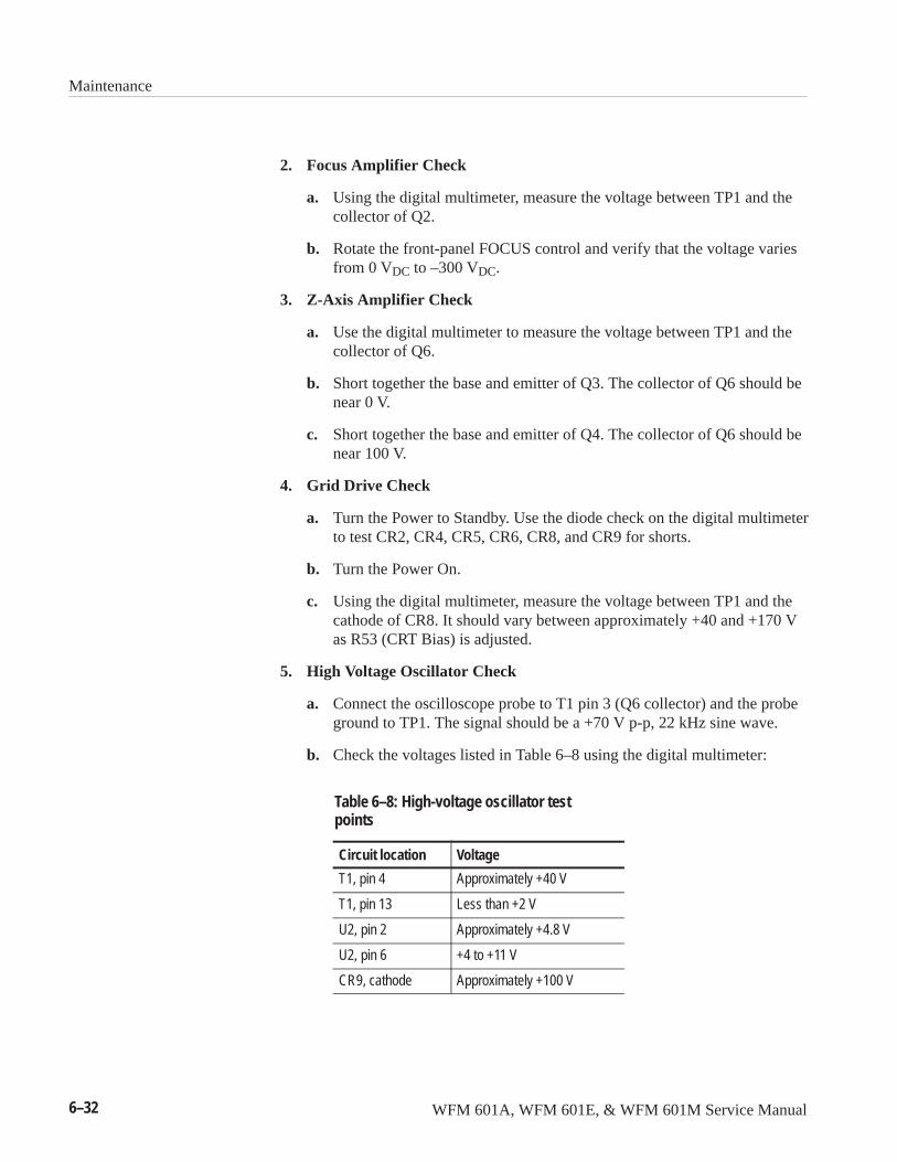
Maintenance
6–32 WFM 601A, WFM 601E, & WFM 601M Service Manual
2. Focus Amplifier Check
a. Using the digital multimeter, measure the voltage between TP1 and thecollector of Q2.
b. Rotate the front-panel FOCUS control and verify that the voltage variesfrom 0 VDC to –300 VDC.
3. Z-Axis Amplifier Check
a. Use the digital multimeter to measure the voltage between TP1 and thecollector of Q6.
b. Short together the base and emitter of Q3. The collector of Q6 should benear 0 V.
c. Short together the base and emitter of Q4. The collector of Q6 should benear 100 V.
4. Grid Drive Check
a. Turn the Power to Standby. Use the diode check on the digital multimeterto test CR2, CR4, CR5, CR6, CR8, and CR9 for shorts.
b. Turn the Power On.
c. Using the digital multimeter, measure the voltage between TP1 and thecathode of CR8. It should vary between approximately +40 and +170 Vas R53 (CRT Bias) is adjusted.
5. High Voltage Oscillator Check
a. Connect the oscilloscope probe to T1 pin 3 (Q6 collector) and the probeground to TP1. The signal should be a +70 V p-p, 22 kHz sine wave.
b. Check the voltages listed in Table 6–8 using the digital multimeter:
Table 6–8: High-voltage oscillator testpoints
Circuit location Voltage
T1, pin 4 Approximately +40 V
T1, pin 13 Less than +2 V
U2, pin 2 Approximately +4.8 V
U2, pin 6 +4 to +11 V
CR9, cathode Approximately +100 V
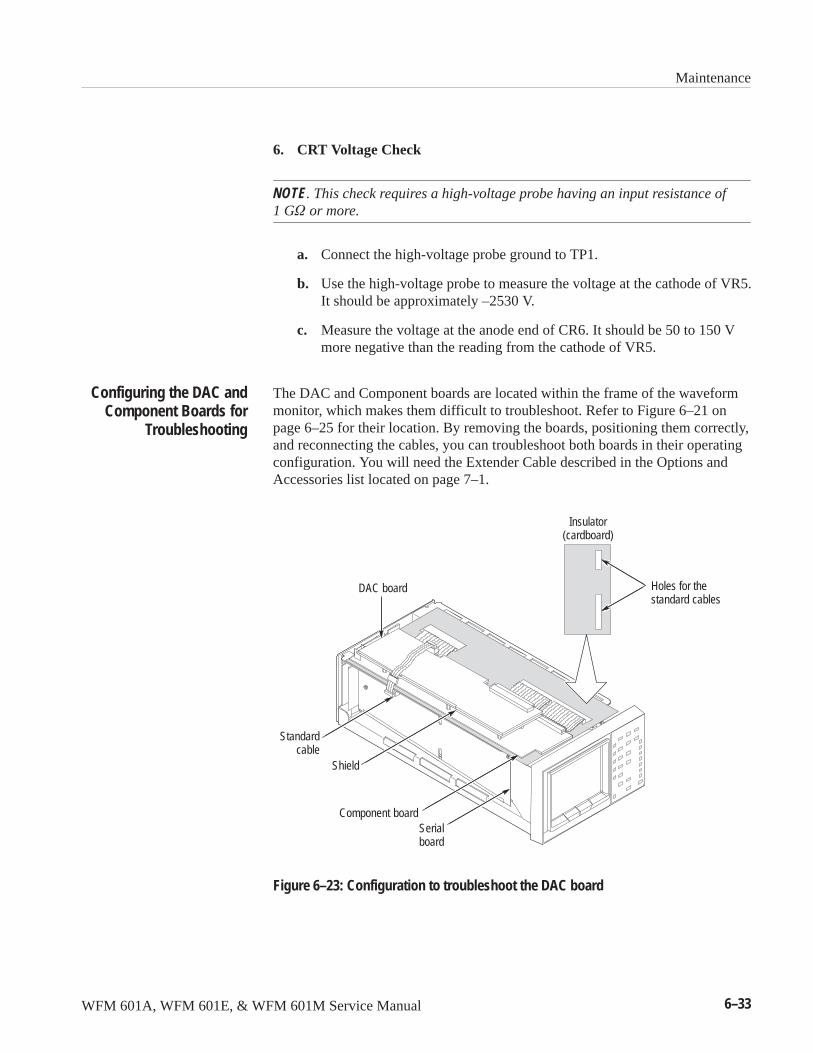
Maintenance
WFM 601A, WFM 601E, & WFM 601M Service Manual 6–33
6. CRT Voltage Check
NOTE. This check requires a high-voltage probe having an input resistance of 1 G� or more.
a. Connect the high-voltage probe ground to TP1.
b. Use the high-voltage probe to measure the voltage at the cathode of VR5.It should be approximately –2530 V.
c. Measure the voltage at the anode end of CR6. It should be 50 to 150 Vmore negative than the reading from the cathode of VR5.
The DAC and Component boards are located within the frame of the waveformmonitor, which makes them difficult to troubleshoot. Refer to Figure 6–21 onpage 6–25 for their location. By removing the boards, positioning them correctly,and reconnecting the cables, you can troubleshoot both boards in their operatingconfiguration. You will need the Extender Cable described in the Options andAccessories list located on page 7–1.
Shield
Serialboard
Component board
Holes for thestandard cables
Insulator(cardboard)
DAC board
Standardcable
Figure 6–23: Configuration to troubleshoot the DAC board
Configuring the DAC andComponent Boards for
Troubleshooting
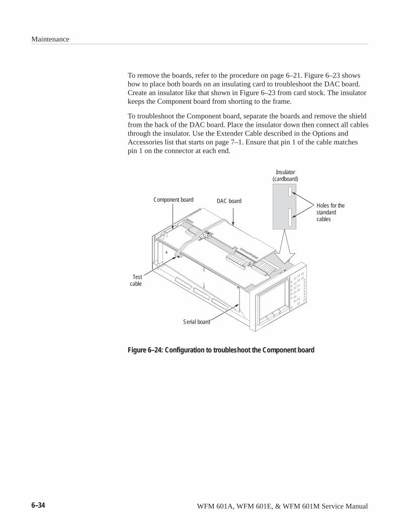
Maintenance
6–34 WFM 601A, WFM 601E, & WFM 601M Service Manual
To remove the boards, refer to the procedure on page 6–21. Figure 6–23 showshow to place both boards on an insulating card to troubleshoot the DAC board.Create an insulator like that shown in Figure 6–23 from card stock. The insulatorkeeps the Component board from shorting to the frame.
To troubleshoot the Component board, separate the boards and remove the shieldfrom the back of the DAC board. Place the insulator down then connect all cablesthrough the insulator. Use the Extender Cable described in the Options andAccessories list that starts on page 7–1. Ensure that pin 1 of the cable matchespin 1 on the connector at each end.
Serial board
Holes for thestandardcables
Insulator(cardboard)
Component board DAC board
Testcable
Figure 6–24: Configuration to troubleshoot the Component board
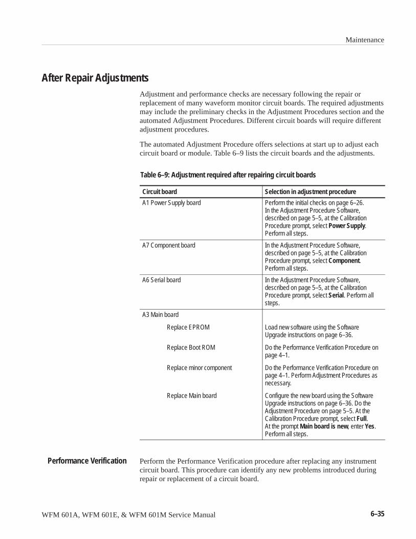
Maintenance
WFM 601A, WFM 601E, & WFM 601M Service Manual 6–35
After Repair AdjustmentsAdjustment and performance checks are necessary following the repair orreplacement of many waveform monitor circuit boards. The required adjustmentsmay include the preliminary checks in the Adjustment Procedures section and theautomated Adjustment Procedures. Different circuit boards will require differentadjustment procedures.
The automated Adjustment Procedure offers selections at start up to adjust eachcircuit board or module. Table 6–9 lists the circuit boards and the adjustments.
Table 6–9: Adjustment required after repairing circuit boards
Circuit board Selection in adjustment procedure
A1 Power Supply board Perform the initial checks on page 6–26.In the Adjustment Procedure Software,described on page 5–5, at the CalibrationProcedure prompt, select Power Supply.Perform all steps.
A7 Component board In the Adjustment Procedure Software,described on page 5–5, at the CalibrationProcedure prompt, select Component.Perform all steps.
A6 Serial board In the Adjustment Procedure Software,described on page 5–5, at the CalibrationProcedure prompt, select Serial. Perform allsteps.
A3 Main board
Replace EPROM
Replace Boot ROM
Replace minor component
Replace Main board
Load new software using the SoftwareUpgrade instructions on page 6–36.
Do the Performance Verification Procedure onpage 4–1.
Do the Performance Verification Procedure onpage 4–1. Perform Adjustment Procedures asnecessary.
Configure the new board using the SoftwareUpgrade instructions on page 6–36. Do theAdjustment Procedure on page 5–5. At theCalibration Procedure prompt, select Full.At the prompt Main board is new, enter Yes.Perform all steps.
Perform the Performance Verification procedure after replacing any instrumentcircuit board. This procedure can identify any new problems introduced duringrepair or replacement of a circuit board.
Performance Verification
Maintenance
6–36 WFM 601A, WFM 601E, & WFM 601M Service Manual
Installing Upgrade SoftwareThe waveform monitor stores its main operating software in EPROM located onthe Main (A3) circuit board. You can replace the EPROM software with a newerversion through the Serial port on the rear panel. The instructions in this sectiondescribe how to use the Upgrade program to upgrade the software in aWFM 601A, WFM 601E, or WFM 601M waveform monitor. New softwareupgrades are released as kits, which give details of the requirements and resultsof the upgrade.
NOTE. Adjustment is required following the software upgrade.
If you load new software, adjustment is necessary. Adjustment is required for thedisplay mode intensities and Arrowhead and Lightning graticules. For moredetails, refer to page 6–46.
The Software Upgrade disk included with this manual contains the upgradeutility software and the latest version of instrument software at the time ofpublication.
NOTE. Check the version of the waveform monitor boot ROM before installingnew software. The boot ROM is the socketed IC U13 on the Main board (A3). SeeFigure 6–26. The A3 Main board is the large board on the bottom of thewaveform monitor. Read the last two digits from the part number label on theboot ROM to determine the version. If the boot ROM version is 00 or 01, youneed to replace it with the 02 boot ROM before loading new software. Contactyour Tektronix Service Representative for more information.
Please read all these instructions before starting the upgrade procedure. Thisprocedure includes the following parts:
� Getting Started
� Replacing the Boot ROM
� Upgrade Procedure
� Configuration after Repairing or Replacing the Main Board
� Using NVDATA.TXT
� Recovering from a Failed or Interrupted Upgrade
� Reloading NVDATA.TXT
� Adjustment and Verification after an Upgrade
Maintenance
WFM 601A, WFM 601E, & WFM 601M Service Manual 6–37
The Upgrade program overwrites the instrument software contained in FlashEPROM with a newer software version. The Upgrade program can also loadsoftware after replacement of the Flash EPROM.
Determining the Current Software Version. Before performing an upgrade, confirmthat your current version of operating software is older than the upgrade version.
To determine the software version on your waveform monitor follow these steps:
1. Press the CONFIG menu button.
2. Select the CALIBRATE submenu.
3. Find the software version number located in the lower right corner of theCALIBRATE submenu. It is preceded by the letter V. The coprocessor code,preceded by the letter C, is not important here.
4. The software version number for the upgrade is printed on the diskette label.If the version number on the diskette is newer (higher) than the versionnumber on your waveform monitor, you may benefit from an upgrade.
NOTE. Check the version of the waveform monitor boot ROM before installingnew software. The boot ROM is the socketed IC U13 on the Main board (A3). SeeFigure 6–26. The A3 Main board is the large board on the bottom of thewaveform monitor. Read the last two digits from the part number label on theboot ROM to determine the version. If the boot ROM version is 00 or 01, youneed to replace it with the 02 boot ROM before loading new software. Contactyour Tektronix Service Representative for more information.
Configure the PC. For better file security and execution speed, you should copythe contents of the 3.5 inch disk to your hard drive and run the program fromthere. You also need to configure your PC for remote communications beforerunning the Upgrade program. You can run the Upgrade program from the floppydrive on your PC, if necessary. To prepare the PC, follow these steps:
1. Insert the upgrade disk into the 3.5 inch floppy drive on the PC and copy thecontents to a directory on your hard drive.
2. Connect the rear-panel RS-232 connector of the waveform monitor to theCOM 1, 2, 3, or 4 connector on the PC using a cable wired as shown inFigure 6–25.
3. Set the serial port communication parameters for the PC as shown inTable 6–10.
Getting Started
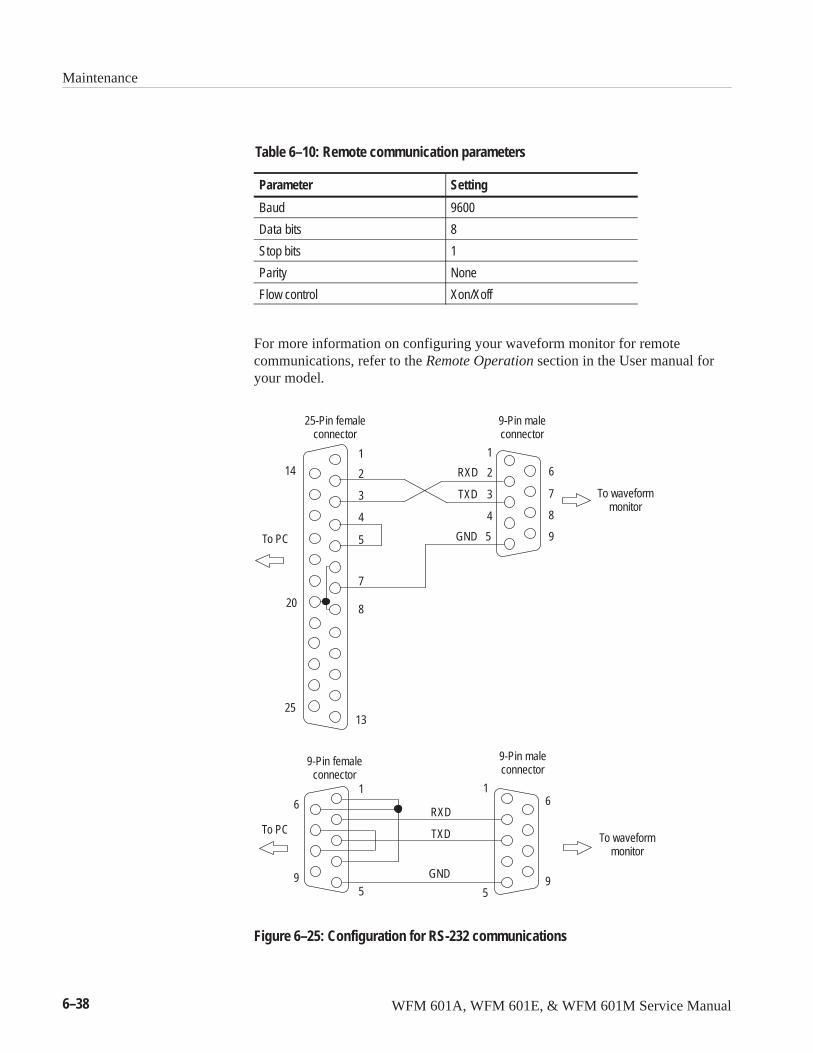
Maintenance
6–38 WFM 601A, WFM 601E, & WFM 601M Service Manual
Table 6–10: Remote communication parameters
Parameter Setting
Baud 9600
Data bits 8
Stop bits 1
Parity None
Flow control Xon/Xoff
For more information on configuring your waveform monitor for remotecommunications, refer to the Remote Operation section in the User manual foryour model.
25-Pin femaleconnector
To PC
9-Pin maleconnector
To waveformmonitor
25
14
20
13
7
8
5
1
2
3
4
5
1
2
3
4
9
6
8
7
GND
9-Pin femaleconnector
1 1
59
6
To waveformmonitor
GND
To PC
9-Pin maleconnector
5
6
9
TXD
RXD
TXD
RXD
Figure 6–25: Configuration for RS-232 communications
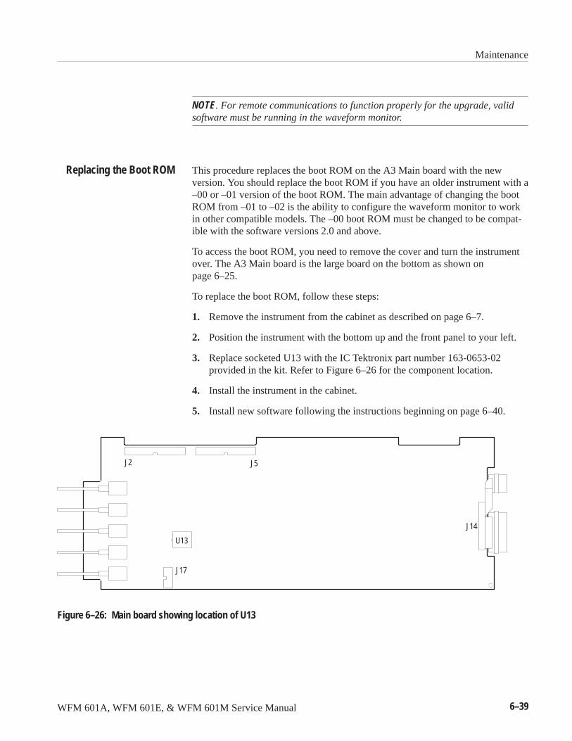
Maintenance
WFM 601A, WFM 601E, & WFM 601M Service Manual 6–39
NOTE. For remote communications to function properly for the upgrade, validsoftware must be running in the waveform monitor.
This procedure replaces the boot ROM on the A3 Main board with the newversion. You should replace the boot ROM if you have an older instrument with a–00 or –01 version of the boot ROM. The main advantage of changing the bootROM from –01 to –02 is the ability to configure the waveform monitor to workin other compatible models. The –00 boot ROM must be changed to be compat-ible with the software versions 2.0 and above.
To access the boot ROM, you need to remove the cover and turn the instrumentover. The A3 Main board is the large board on the bottom as shown onpage 6–25.
To replace the boot ROM, follow these steps:
1. Remove the instrument from the cabinet as described on page 6–7.
2. Position the instrument with the bottom up and the front panel to your left.
3. Replace socketed U13 with the IC Tektronix part number 163-0653-02provided in the kit. Refer to Figure 6–26 for the component location.
4. Install the instrument in the cabinet.
5. Install new software following the instructions beginning on page 6–40.
J17
J2 J5
J14
U13
Figure 6–26: Main board showing location of U13
Replacing the Boot ROM
Maintenance
6–40 WFM 601A, WFM 601E, & WFM 601M Service Manual
Use the following procedure to upgrade the software on your waveform monitor.The procedure takes about 35 minutes to complete.
CAUTION. Interrupting the Upgrade program before normal completion willcorrupt the Flash EPROM. To prevent this, ensure that your PC and waveformmonitor are not used or interrupted while the Upgrade program is running. Torecover from an unsuccessful upgrade attempt, see Recovering from an Inter-rupted or Failed Upgrade on page 6–45. If this recovery procedure is notsuccessful, return the waveform monitor to Tektronix for repair.
1. Ensure that the file NVDATA.TXT is not located in the same directory as theUpgrade program files. NVDATA.TXT is a temporary file created by theUpgrade program to hold user presets and calibration information during theupgrade. If NVDATA.TXT is present, move it to another directory or renameit. For more information about NVDATA.TXT, see Using NVDATA.TXT onpage 6–43.
2. Exit from all applications on your PC.
3. From the DOS prompt, change to the directory containing the upgrade files.
4. Type UPGRADE and press ENTER.
5. When asked for the COM port, enter the number of the port you are using. Ifyou enter an incorrect port number, you are prompted to retry the same portor quit. You must quit to select a different COM port.
6. If the file NVDATA.TXT is detected in your working directory, you areprompted to make the following choice:
� To use the current calibration constants in your waveform monitorNVRAM, type �. This is the normal selection. It lets you to use theexisting cal constants to avoid recalibration following the upgrade.
� To use the NVDATA.TXT file already in your directory to reloadcalibration constants, type �.
NOTE. If you use the pre-existing file to restore calibration constants, theprogram deletes NVDATA.TXT after loading it into NVRAM.
7. If you typed �, you are prompted to make the following choice:
� To overwrite the existing NVDATA.TXT file with the calibrationconstants currently in the NVRAM and to continue the upgrade, type �.
� To exit the Upgrade program without changing your waveform monitor,type �.
Upgrading the Software
Maintenance
WFM 601A, WFM 601E, & WFM 601M Service Manual 6–41
8. The program asks you to confirm the upgrade to a new version of software.
� To upgrade your software, type �.
� To exit the Upgrade program without changing your waveform monitor,type �.
9. The program displays status messages as the upgrade progresses. Theprogram saves NVRAM to NVDATA.txt, then erases both NVRAM andflash EPROM. The program then loads new software into the EPROM, thenloads NVDATA.txt back into NVRAM. After approximately 35 minutes, theprogram completes and displays a message indicating that the upgrade wassuccessful.
If the error message “Failed to restore CAL Constants” appears, try reloadingthe NVDATA.TXT file using the instructions on page 6–45.
You have successfully loaded the new software.
Use the following procedure to configure the Main board in a waveform monitor.You may need to configure the Main board after replacing or repairing it. Youmust always run the Upgrade program following replacement of the Main board.With the Upgrade program (UPGRADE –C), you configure the Main board withthe current Model type, Serial number, and date.
Applying Power After Installing a Main Board. To check a replacement Main board,connect the completely assembled waveform monitor to AC power and press thepower switch. The waveform monitor will either power up and display the usualDisplay mode window or show the following error message:
����� ������
���������������������
This error indicates that you need to use the Upgrade program to configure theMain board and, possibly, load software. If this error occurs after you haveperformed the configuration procedure, it could indicate that you enteredincorrect information during the upgrade. Disconnect power and check that allcircuit boards and connecting cables are properly seated.
CAUTION. Interrupting the Upgrade program before normal completion willcorrupt the Flash EPROM. Ensure that your PC and waveform monitor are notused or interrupted while the Upgrade program is running. To recover from anunsuccessful upgrade attempt, see Recovering from an Interrupted or FailedUpgrade on page 6–45. If this recovery procedure is not successful, return thewaveform monitor to Tektronix for repair.
Configuration AfterReplacing or Repairing
the Main Board
Maintenance
6–42 WFM 601A, WFM 601E, & WFM 601M Service Manual
Follow these steps to configure a replacement Main board or to load newfirmware in a repaired Main board.
1. Ensure that the file NVDATA.TXT is not located in the same directory as theupgrade application files. NVDATA.TXT is a temporary file created by theUpgrade program to hold user presets and calibration information. IfNVDATA.TXT is present, move it to another directory or rename it. Formore information about NVDATA.TXT, see Using NVDATA.TXT onpage 6–43.
2. Exit from all applications on your PC before running the Upgrade program.
3. From the DOS prompt, change to the directory containing the upgrade files.
4. Type �������� and press ENTER.
5. When asked for the COM port, enter the number of the port you are using. Ifyou enter an incorrect port number, you are prompted to retry the same portor quit. You must quit to select a different COM port.
6. The Upgrade program prompts you to supply the following information:
� Model type, either WFM 601A, WFM 601E, or WFM 601M
� Instrument serial number from the rear panel, such as B012345
� Current date in the form MM/DD/YY, such as 03/18/97 for March 18,1997
7. The program asks whether you want to proceed with the changes. Type � toconfirm your entries or � to discard your entries.
8. The program checks the current instrument model and compares it againstthe model type you entered. The program then stores the new configurationin NVRAM. The program asks whether to install new software.
� If the Main board is a replacement from Tektronix, it has the latestversion of software installed. Type � to exit the Upgrade program andproceed to step 10 in this procedure.
� If you have repaired the EPROM on the Main board, you should proceedto load new software. Type � to load the new version of the software.
9. The program displays status messages as the upgrade progresses. Afterapproximately 35 minutes, the program displays a message indicating thatthe upgrade was successful.
10. If you were able to save the calibration information before repairing the Mainboard, reload this information now by following the instructions onpage 6–44.
Configuration Procedure
Maintenance
WFM 601A, WFM 601E, & WFM 601M Service Manual 6–43
11. If you replaced the Main board or were not able to save the calibrationinformation before repair, perform the procedures in the AdjustmentProcedures section of this manual.
When you load software into the empty EPROM, the program loads defaultcalibration information into NVRAM. You must perform the full AdjustmentProcedure in order to adjust the default calibration information. Thisadjustment will ensure that your waveform monitor meets the advertisedspecifications. You can choose to return the waveform monitor to yourTektronix Service Center for a complete calibration.
12. After repairing or replacing the Main board, verify that the waveformmonitor still performs to specifications by performing the procedures in thePerformance Verification section of this manual.
This completes the configuration procedure.
During the upgrade process, the Upgrade program saves user presets andcalibration information from your waveform monitor NVRAM to a temporaryfile named NVDATA.TXT. After the program loads the new software, itautomatically reloads the presets and calibration information from NVDATA.TXT back into NVRAM. This process configures your waveformmonitor with the operating parameters it had before you ran the Upgradeprogram. Before exiting the upgrade, and after ensuring that NVDATA.TXT wasloaded correctly, the program deletes NVDATA.TXT.
If the NVDATA.TXT file is lost, you can recalibrate the waveform monitor byusing the Adjustment Procedures in this manual. Alternatively, if you have saveda copy of the NVDATA.TXT file, you can load the contents of NVDATA.TXTinto the waveform monitor using the UPGRADE –R option described inReloading NVDATA.TXT on page 6–45. Each waveform monitor has uniquecalibration information in its NVRAM. Loading the NVDATA.TXT saved fromone instrument into another instrument will result in second instrument beinguncalibrated.
Backing up Calibration Information and Presets. If NVRAM fails, your waveformmonitor can lose calibration information and stored presets. To ensure that youretain the calibration information, you can copy the NVRAM data into theNVDATA.TXT file using the following procedure. This procedure takes abouttwo minutes.
1. Exit from all applications on your PC.
2. From the DOS prompt, change to the directory containing the upgrade files.
3. Type ��������� and press ENTER.
Using NVDATA.TXT
Maintenance
6–44 WFM 601A, WFM 601E, & WFM 601M Service Manual
The �� option saves the current front-panel settings, presets, and calibrationinformation into the working directory in the file NVDATA.TXT and exits.
4. Rename NVDATA.TXT or move it into another directory to prevent theUpgrade program from overwriting it.
Calibration information is unique to each waveform monitor. Make a separatebackup of the NVDATA.TXT file for each waveform monitor.
Loading NVDATA.TXT into NVRAM. To load an existing NVDATA.TXT file intoNVRAM, use the following procedure. Loading the data file takes about twominutes to complete. Loading the NVDATA.TXT saved from one instrument intoanother instrument will result in second instrument being uncalibrated.
1. Ensure that the NVDATA.TXT file from your waveform monitor is in thesame directory as the Upgrade program files.
2. Verify the RS-232 configuration as shown in Figure 6–25 on page 6–38 andTable 6–10, on page 6–38.
3. Exit from all applications on your PC.
4. From the DOS prompt, change to the directory containing the upgrade files.
5. Type ��������� and press ENTER.
The �� option attempts to reload the NVDATA.TXT file, but makes no otherchanges to your waveform monitor.
6. When asked for the COM port, enter the number of the port you are using.
The Upgrade program now attempts to restore the information from NVDATA.TXT to NVRAM.
In rare cases, the Upgrade program may quit prematurely; for example, if powerto the PC or the waveform monitor is interrupted, the RS-232 connection isbroken, or the Upgrade program is significantly delayed by another application.
If the Upgrade program quits prematurely, use the following procedure.
1. Save a copy of NVDATA.TXT into another file or location.
Saving a copy now will back up your presets and calibration information.Leave a copy of NVDATA.TXT in the directory with the upgrade files. Youcan use this copy to restore the settings to your waveform monitor.
2. Verify the RS-232 configuration as shown in Figure 6–25 on page 6–38 andTable 6–10, on page 6–38.
Recovering from anInterrupted or Failed
Upgrade
Maintenance
WFM 601A, WFM 601E, & WFM 601M Service Manual 6–45
3. Cycle the power on the waveform monitor by pressing the POWER buttontwice.
4. Exit from all applications on your PC.
5. From the DOS prompt, change to the directory containing the upgrade files.
6. Type ������� and press ENTER.
7. When asked for the COM port, enter the number of the port you are using.
8. When asked if you want to use the detected NVDATA.TXT file to reload thecalibration information, choose one of the following options:
� To use the existing file to reload calibration information, type �.
� To quit the Upgrade program without making any changes to thewaveform monitor, type �.
9. If you typed �, the Upgrade program prompts you to confirm that you want toupgrade the current software to the new version. Choose one of the followingoptions:
� To continue with the upgrade, type �.
� To quit the Upgrade program without making any changes to thewaveform monitor, type �.
10. The program displays status messages as the upgrade progresses. Afterapproximately 35 minutes, the program displays a message indicating thatthe upgrade was successful.
In some cases, the Upgrade program will fail to reload the NVDATA.TXT file.See Using NVDATA.TXT on page 6–43 for more information about this file. Ifthis occurs during a normal upgrade, an error message will inform you that thefile was not reloaded.
If the NVDATA.TXT file was not reloaded, use the following procedure torecover the data and restore the waveform monitor to normal operation. Thisprocedure takes about two minutes to complete.
1. Ensure that the NVDATA.TXT file from your waveform monitor is in thesame directory as the Upgrade program files.
2. Verify the RS-232 configuration as shown in Figure 6–25 on page 6–38 andTable 6–10, on page 6–38.
3. Exit from all applications on your PC.
4. From the DOS prompt, change to the directory containing the upgrade files.
Reloading NVDATA.TXT
Maintenance
6–46 WFM 601A, WFM 601E, & WFM 601M Service Manual
5. Type ���������� and press ENTER.
The �� option attempts to reload the NVDATA.TXT file, but makes no otherchanges to your waveform monitor.
6. When asked for the COM port, enter the number of the port you are using.
The Upgrade program now attempts to restore the information from NVDA-TA.TXT to NVRAM.
After completing any of the upgrade or configuration procedures, adjustmentmay be required. All procedures require performance of the procedures in thePerformance Verification section to ensure operation to the advertised specifica-tions. Table 6–11 lists the procedures required following each type of upgrade orconfiguration. If a software upgrade kit indicates different adjustment require-ments than those listed in Table 6–11, follow the kit instructions.
Table 6–11: Adjustment and verification required after an upgrade orconfiguration
Upgrade procedure
Performanceverification
Limited adjustments (seefollowing topic)
Full adjustmentprocedures
Load V2.23 software only Yes Yes No
Replace -00 or -01 boot ROMand load V2.23 software
Yes Yes No
Configure A3 Main board for newmodel1
Yes No Yes
Replace A3 Main board and configure for current model1
Yes No Yes
1 The calibration information stored in the replacement A3 Main board is not optimizedfor the circuitry in the new model or instrument. You must perform the full AdjustmentProcedures to ensure correct and specified operation.
Following the upgrade to V2.23 software, you must adjust the Arrowhead displayoffset and the 1H and 15H Intensities using the included Adjustment ProceduresSoftware disk. To make the required adjustment, follow these steps:
1. Connect the serial output of a television signal generator to the waveformmonitor SER A input. Terminate the loop-through input with a high-frequency (HF) 75 ohm terminator. Select a 100% Color Bar signal.
2. Load the Adjustment Procedures Software disk and run the cal.exe program.Refer to section 5 of this manual for more information on running the cal.exeapplication.
Adjustment andVerification Following an
Upgrade or Configuration
Limited Adjustments

Maintenance
WFM 601A, WFM 601E, & WFM 601M Service Manual 6–47
3. Select your model, such as WFM 601A.
4. Once the main adjustment window appears, press F6 and select the adjust-ment titled CRT Intensities.
5. In this procedure, check and adjust 1H and 15H intensities in all displaymodes. Use the arrow keys for adjustments.
6. At the end of the CRT Intensities procedure, press F6 and select theadjustment titled Arrowhead Graticule Offset & Gain.
7. In this procedure, adjust ARROW YOFF and ARROW XOFF using thearrow keys. This completes the necessary adjustments.
Run the complete procedures in section 4, Performance Verification, to ensureoperation within the advertised specifications.
After running the Upgrade program, you will need to verify that the waveformmonitor still performs to specifications. Perform the procedures in the Perfor-mance Verification section.
Verifying the Performanceof the Waveform Monitor
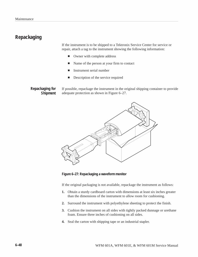
Maintenance
6–48 WFM 601A, WFM 601E, & WFM 601M Service Manual
RepackagingIf the instrument is to be shipped to a Tektronix Service Center for service orrepair, attach a tag to the instrument showing the following information:
� Owner with complete address
� Name of the person at your firm to contact
� Instrument serial number
� Description of the service required
If possible, repackage the instrument in the original shipping container to provideadequate protection as shown in Figure 6–27.
Figure 6–27: Repackaging a waveform monitor
If the original packaging is not available, repackage the instrument as follows:
1. Obtain a sturdy cardboard carton with dimensions at least six inches greaterthan the dimensions of the instrument to allow room for cushioning.
2. Surround the instrument with polyethylene sheeting to protect the finish.
3. Cushion the instrument on all sides with tightly packed dunnage or urethanefoam. Ensure three inches of cushioning on all sides.
4. Seal the carton with shipping tape or an industrial stapler.
Repackaging forShipment

WFM 601A, WFM 601E, & WFM 601M Service Manual 7–1
Options
The waveform monitors are shipped with several standard accessories. Thesestandard accessories and any optional accessories are listed in this section.
The following accessory items are included with this product:
1 User Manual, provides operating information for the products
WFM 601A, WFM 601E, & WFM 601M User manual (Tektronix partnumber 071-0103-XX)
1 Power Cord: United States and Japan only (161–0216–XX)
1 Replacement Fuse Cartridge: 3AG, 2A, 250V, fast-blow (159–0021–00)
3 Replacement Graticule Light Bulbs (150–0168–00)
3 Replacement Air Filters for Fan (378–0415–00)
2 75 � End-line Terminations: 26 dB to 300 MHz (011–0163–00)
1 Smoke Grey CRT Filter, installed on instrument (378–0258–00)
The following options are available when ordering a waveform monitor.
Power Cord Options. If you do not specify a power cord option, the waveformmonitor is shipped with a North American 125 V power cord and one replace-ment fuse. The following power cord options are available when purchasing yourwaveform monitor.
Power cords for use in North America are UL listed and CSA certified. Cords foruse in areas other than North America are approved by at least one test houseacceptable in the country to which the product is shipped.
� Option A1. Power, Universal Europe, 220 V/16 A (Locking Power Cord)
� Option A2. Power, United Kingdom, 240 V/15 A (Power Cord)
� Option A3. Power, Australia, 240 V/10 A (Power Cord)
� Option A4. Power, North America, 250V/10 A (Power Cord)
� Option A5. Power, Swiss, 240 V/6 A (Power Cord)
Standard Accessories
Options
Options
7–2 WFM 601A, WFM 601E, & WFM 601M Service Manual
The following items can be ordered with the monitor or purchased through aTektronix field office or distributor. When ordering, include both the name andpart number (if available) of the option.
WFM 601A, WFM 601E, & WFM 601M Service Manual. (070-9836-XX) Thismanual.
Extender Cable. A 14 inch cable (Tektronix part 174-3285-00) that connects theDAC board to the Serial board while troubleshooting.
Viewing Hood. A viewing hood blocks ambient light, allowing you to view dimwaveform traces.
Front Panel Cover. The front panel cover protects the display face from damageand dust.
Camera, C9 Option 20. Use the camera to document displayed information forlater use.
1700F00 Plain Cabinet. This rack mount cabinet is half-rack width, made ofdurable metal and painted silver-gray. Ventilating holes in the top, bottom, andsides of the cabinet help dissipate heat.
1700F02 Carrying Case. This portable cabinet is similar to the 1700F00, but it hasrubber feet, a carrying handle, a flip-up stand, and a front cover.
1700F05 Side-by-Side Rack Adapter. The 1700F05 allows you to mount twohalf-rack width instruments in a standard 19-inch rack.
1700F06 Blank Panel. When you use only one side of a 1700F05 enclosure, inserta 1700F06 Blank Panel in the unused side to improve appearance and air flow.
1700F07 Utility Drawer. When you use only one side of a 1700F05, install the1700F07 utility drawer in the unused side to provide storage and improveappearance and air flow. The drawer opens and closes freely, unless latched fortransport.
Optional Accessories

WFM 601A, WFM 601E, & WFM 601M Service Manual 8–1
Replaceable Electrical Parts
This section contains a list of the electrical components for the waveformmonitors. Use this list to identify and order replacement parts.
Parts Ordering InformationReplacement parts are available through your local Tektronix field office orrepresentative.
Changes to Tektronix products are sometimes made to accommodate improvedcomponents as they become available and to give you the benefit of the latestimprovements. Therefore, when ordering parts, it is important to include thefollowing information in your order.
� Part number
� Instrument type or model number
� Instrument serial number
� Instrument modification number, if applicable
If you order a part that has been replaced with a different or improved part, yourlocal Tektronix field office or representative will contact you concerning anychange in part number.
Change information, if any, is located at the rear of this manual.
Using the Replaceable Electrical Parts ListThe tabular information in the Replaceable Electrical Parts List is arranged forquick retrieval. Understanding the structure and features of the list will help youfind all of the information you need for ordering replacement parts. Thefollowing table describes each column of the electrical parts list.
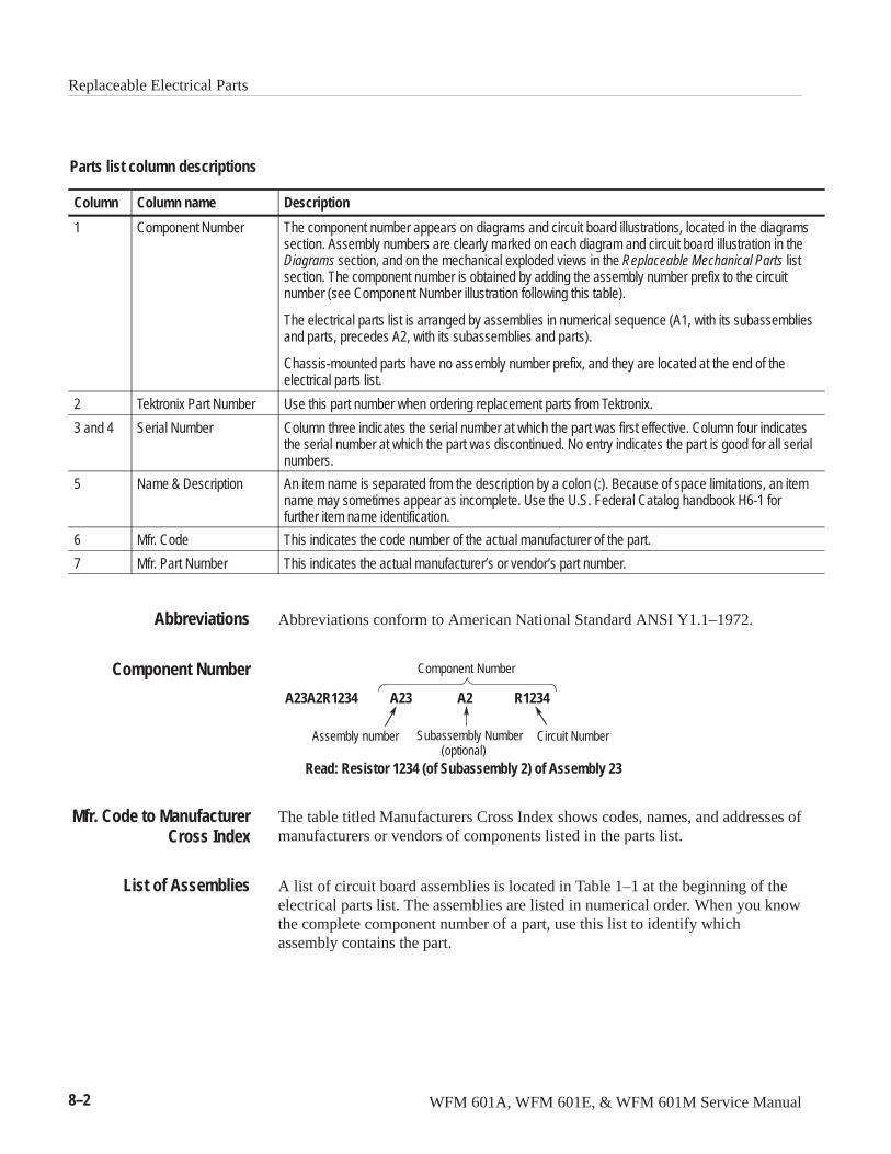
Replaceable Electrical Parts
8–2 WFM 601A, WFM 601E, & WFM 601M Service Manual
Parts list column descriptions
Column Column name Description
1 Component Number The component number appears on diagrams and circuit board illustrations, located in the diagramssection. Assembly numbers are clearly marked on each diagram and circuit board illustration in theDiagrams section, and on the mechanical exploded views in the Replaceable Mechanical Parts listsection. The component number is obtained by adding the assembly number prefix to the circuitnumber (see Component Number illustration following this table).
The electrical parts list is arranged by assemblies in numerical sequence (A1, with its subassembliesand parts, precedes A2, with its subassemblies and parts).
Chassis-mounted parts have no assembly number prefix, and they are located at the end of theelectrical parts list.
2 Tektronix Part Number Use this part number when ordering replacement parts from Tektronix.
3 and 4 Serial Number Column three indicates the serial number at which the part was first effective. Column four indicatesthe serial number at which the part was discontinued. No entry indicates the part is good for all serialnumbers.
5 Name & Description An item name is separated from the description by a colon (:). Because of space limitations, an itemname may sometimes appear as incomplete. Use the U.S. Federal Catalog handbook H6-1 forfurther item name identification.
6 Mfr. Code This indicates the code number of the actual manufacturer of the part.
7 Mfr. Part Number This indicates the actual manufacturer’s or vendor’s part number.
Abbreviations conform to American National Standard ANSI Y1.1–1972.
Component Number
A23A2R1234 A23 R1234
Assembly number Circuit Number
Read: Resistor 1234 (of Subassembly 2) of Assembly 23
A2
Subassembly Number(optional)
The table titled Manufacturers Cross Index shows codes, names, and addresses ofmanufacturers or vendors of components listed in the parts list.
A list of circuit board assemblies is located in Table 1–1 at the beginning of theelectrical parts list. The assemblies are listed in numerical order. When you knowthe complete component number of a part, use this list to identify whichassembly contains the part.
Abbreviations
Component Number
Mfr. Code to ManufacturerCross Index
List of Assemblies
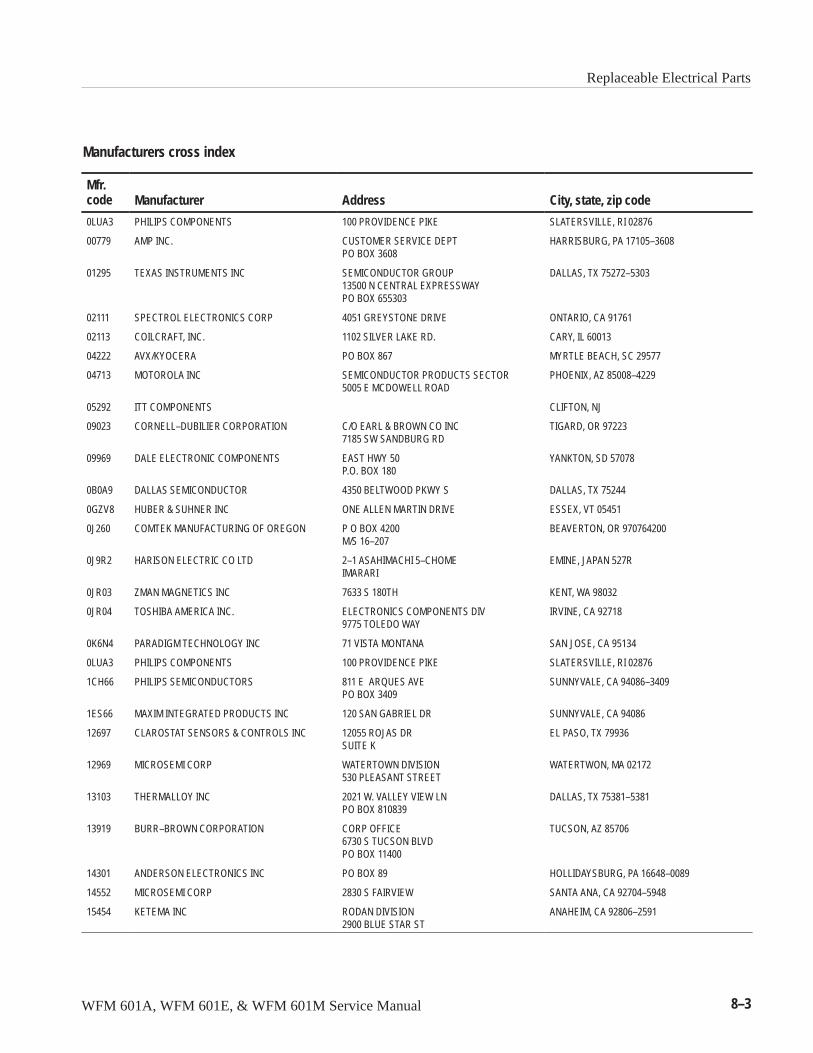
Replaceable Electrical Parts
WFM 601A, WFM 601E, & WFM 601M Service Manual 8–3
Manufacturers cross index
Mfr.code Manufacturer Address City, state, zip code
0LUA3 PHILIPS COMPONENTS 100 PROVIDENCE PIKE SLATERSVILLE, RI 02876
00779 AMP INC. CUSTOMER SERVICE DEPTPO BOX 3608
HARRISBURG, PA 17105–3608
01295 TEXAS INSTRUMENTS INC SEMICONDUCTOR GROUP13500 N CENTRAL EXPRESSWAYPO BOX 655303
DALLAS, TX 75272–5303
02111 SPECTROL ELECTRONICS CORP 4051 GREYSTONE DRIVE ONTARIO, CA 91761
02113 COILCRAFT, INC. 1102 SILVER LAKE RD. CARY, IL 60013
04222 AVX/KYOCERA PO BOX 867 MYRTLE BEACH, SC 29577
04713 MOTOROLA INC SEMICONDUCTOR PRODUCTS SECTOR5005 E MCDOWELL ROAD
PHOENIX, AZ 85008–4229
05292 ITT COMPONENTS CLIFTON, NJ
09023 CORNELL–DUBILIER CORPORATION C/O EARL & BROWN CO INC7185 SW SANDBURG RD
TIGARD, OR 97223
09969 DALE ELECTRONIC COMPONENTS EAST HWY 50P.O. BOX 180
YANKTON, SD 57078
0B0A9 DALLAS SEMICONDUCTOR 4350 BELTWOOD PKWY S DALLAS, TX 75244
0GZV8 HUBER & SUHNER INC ONE ALLEN MARTIN DRIVE ESSEX, VT 05451
0J260 COMTEK MANUFACTURING OF OREGON P O BOX 4200M/S 16–207
BEAVERTON, OR 970764200
0J9R2 HARISON ELECTRIC CO LTD 2–1 ASAHIMACHI 5–CHOMEIMARARI
EMINE, JAPAN 527R
0JR03 ZMAN MAGNETICS INC 7633 S 180TH KENT, WA 98032
0JR04 TOSHIBA AMERICA INC. ELECTRONICS COMPONENTS DIV9775 TOLEDO WAY
IRVINE, CA 92718
0K6N4 PARADIGM TECHNOLOGY INC 71 VISTA MONTANA SAN JOSE, CA 95134
0LUA3 PHILIPS COMPONENTS 100 PROVIDENCE PIKE SLATERSVILLE, RI 02876
1CH66 PHILIPS SEMICONDUCTORS 811 E ARQUES AVEPO BOX 3409
SUNNYVALE, CA 94086–3409
1ES66 MAXIM INTEGRATED PRODUCTS INC 120 SAN GABRIEL DR SUNNYVALE, CA 94086
12697 CLAROSTAT SENSORS & CONTROLS INC 12055 ROJAS DRSUITE K
EL PASO, TX 79936
12969 MICROSEMI CORP WATERTOWN DIVISION530 PLEASANT STREET
WATERTWON, MA 02172
13103 THERMALLOY INC 2021 W. VALLEY VIEW LNPO BOX 810839
DALLAS, TX 75381–5381
13919 BURR–BROWN CORPORATION CORP OFFICE6730 S TUCSON BLVDPO BOX 11400
TUCSON, AZ 85706
14301 ANDERSON ELECTRONICS INC PO BOX 89 HOLLIDAYSBURG, PA 16648–0089
14552 MICROSEMI CORP 2830 S FAIRVIEW SANTA ANA, CA 92704–5948
15454 KETEMA INC RODAN DIVISION2900 BLUE STAR ST
ANAHEIM, CA 92806–2591
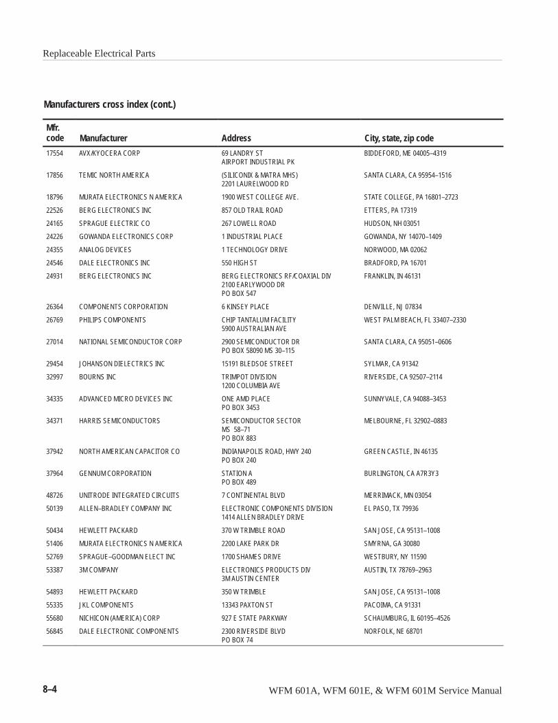
Replaceable Electrical Parts
8–4 WFM 601A, WFM 601E, & WFM 601M Service Manual
Manufacturers cross index (cont.)
Mfr.code City, state, zip codeAddressManufacturer
17554 AVX/KYOCERA CORP 69 LANDRY STAIRPORT INDUSTRIAL PK
BIDDEFORD, ME 04005–4319
17856 TEMIC NORTH AMERICA (SILICONIX & MATRA MHS)2201 LAURELWOOD RD
SANTA CLARA, CA 95954–1516
18796 MURATA ELECTRONICS N AMERICA 1900 WEST COLLEGE AVE. STATE COLLEGE, PA 16801–2723
22526 BERG ELECTRONICS INC 857 OLD TRAIL ROAD ETTERS, PA 17319
24165 SPRAGUE ELECTRIC CO 267 LOWELL ROAD HUDSON, NH 03051
24226 GOWANDA ELECTRONICS CORP 1 INDUSTRIAL PLACE GOWANDA, NY 14070–1409
24355 ANALOG DEVICES 1 TECHNOLOGY DRIVE NORWOOD, MA 02062
24546 DALE ELECTRONICS INC 550 HIGH ST BRADFORD, PA 16701
24931 BERG ELECTRONICS INC BERG ELECTRONICS RF/COAXIAL DIV2100 EARLYWOOD DRPO BOX 547
FRANKLIN, IN 46131
26364 COMPONENTS CORPORATION 6 KINSEY PLACE DENVILLE, NJ 07834
26769 PHILIPS COMPONENTS CHIP TANTALUM FACILITY5900 AUSTRALIAN AVE
WEST PALM BEACH, FL 33407–2330
27014 NATIONAL SEMICONDUCTOR CORP 2900 SEMICONDUCTOR DRPO BOX 58090 MS 30–115
SANTA CLARA, CA 95051–0606
29454 JOHANSON DIELECTRICS INC 15191 BLEDSOE STREET SYLMAR, CA 91342
32997 BOURNS INC TRIMPOT DIVISION1200 COLUMBIA AVE
RIVERSIDE, CA 92507–2114
34335 ADVANCED MICRO DEVICES INC ONE AMD PLACEPO BOX 3453
SUNNYVALE, CA 94088–3453
34371 HARRIS SEMICONDUCTORS SEMICONDUCTOR SECTORMS 58–71PO BOX 883
MELBOURNE, FL 32902–0883
37942 NORTH AMERICAN CAPACITOR CO INDIANAPOLIS ROAD, HWY 240PO BOX 240
GREEN CASTLE, IN 46135
37964 GENNUM CORPORATION STATION APO BOX 489
BURLINGTON, CA A7R3Y3
48726 UNITRODE INTEGRATED CIRCUITS 7 CONTINENTAL BLVD MERRIMACK, MN 03054
50139 ALLEN–BRADLEY COMPANY INC ELECTRONIC COMPONENTS DIVISION1414 ALLEN BRADLEY DRIVE
EL PASO, TX 79936
50434 HEWLETT PACKARD 370 W TRIMBLE ROAD SAN JOSE, CA 95131–1008
51406 MURATA ELECTRONICS N AMERICA 2200 LAKE PARK DR SMYRNA, GA 30080
52769 SPRAGUE–GOODMAN ELECT INC 1700 SHAMES DRIVE WESTBURY, NY 11590
53387 3M COMPANY ELECTRONICS PRODUCTS DIV3M AUSTIN CENTER
AUSTIN, TX 78769–2963
54893 HEWLETT PACKARD 350 W TRIMBLE SAN JOSE, CA 95131–1008
55335 JKL COMPONENTS 13343 PAXTON ST PACOIMA, CA 91331
55680 NICHICON (AMERICA) CORP 927 E STATE PARKWAY SCHAUMBURG, IL 60195–4526
56845 DALE ELECTRONIC COMPONENTS 2300 RIVERSIDE BLVDPO BOX 74
NORFOLK, NE 68701
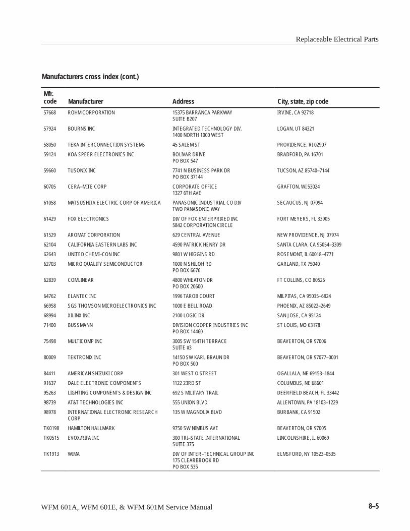
Replaceable Electrical Parts
WFM 601A, WFM 601E, & WFM 601M Service Manual 8–5
Manufacturers cross index (cont.)
Mfr.code City, state, zip codeAddressManufacturer
57668 ROHM CORPORATION 15375 BARRANCA PARKWAYSUITE B207
IRVINE, CA 92718
57924 BOURNS INC INTEGRATED TECHNOLOGY DIV.1400 NORTH 1000 WEST
LOGAN, UT 84321
58050 TEKA INTERCONNECTION SYSTEMS 45 SALEM ST PROVIDENCE, RI 02907
59124 KOA SPEER ELECTRONICS INC BOLIVAR DRIVEPO BOX 547
BRADFORD, PA 16701
59660 TUSONIX INC 7741 N BUSINESS PARK DRPO BOX 37144
TUCSON, AZ 85740–7144
60705 CERA–MITE CORP CORPORATE OFFICE1327 6TH AVE
GRAFTON, WI 53024
61058 MATSUSHITA ELECTRIC CORP OF AMERICA PANASONIC INDUSTRIAL CO DIVTWO PANASONIC WAY
SECAUCUS, NJ 07094
61429 FOX ELECTRONICS DIV OF FOX ENTERPRIXED INC5842 CORPORATION CIRCLE
FORT MEYERS, FL 33905
61529 AROMAT CORPORATION 629 CENTRAL AVENUE NEW PROVIDENCE, NJ 07974
62104 CALIFORNIA EASTERN LABS INC 4590 PATRICK HENRY DR SANTA CLARA, CA 95054–3309
62643 UNITED CHEMI–CON INC 9801 W HIGGINS RD ROSEMONT, IL 60018–4771
62703 MICRO QUALITY SEMICONDUCTOR 1000 N SHILOH RDPO BOX 6676
GARLAND, TX 75040
62839 COMLINEAR 4800 WHEATON DRPO BOX 20600
FT COLLINS, CO 80525
64762 ELANTEC INC 1996 TAROB COURT MILPITAS, CA 95035–6824
66958 SGS THOMSON MICROELECTRONICS INC 1000 E BELL ROAD PHOENIX, AZ 85022–2649
68994 XILINX INC 2100 LOGIC DR SAN JOSE, CA 95124
71400 BUSSMANN DIVISION COOPER INDUSTRIES INCPO BOX 14460
ST LOUIS, MO 63178
75498 MULTICOMP INC 3005 SW 154TH TERRACESUITE #3
BEAVERTON, OR 97006
80009 TEKTRONIX INC 14150 SW KARL BRAUN DRPO BOX 500
BEAVERTON, OR 97077–0001
84411 AMERICAN SHIZUKI CORP 301 WEST O STREET OGALLALA, NE 69153–1844
91637 DALE ELECTRONIC COMPONENTS 1122 23RD ST COLUMBUS, NE 68601
95263 LIGHTING COMPONENTS & DESIGN INC 692 S MILITARY TRAIL DEERFIELD BEACH, FL 33442
98739 AT&T TECHNOLOGIES INC 555 UNION BLVD ALLENTOWN, PA 18103–1229
98978 INTERNATIONAL ELECTRONIC RESEARCHCORP
135 W MAGNOLIA BLVD BURBANK, CA 91502
TK0198 HAMILTON HALLMARK 9750 SW NIMBUS AVE BEAVERTON, OR 97005
TK0515 EVOX/RIFA INC 300 TRI–STATE INTERNATIONALSUITE 375
LINCOLNSHIRE, IL 60069
TK1913 WIMA DIV OF INTER–TECHNICAL GROUP INC175 CLEARBROOK RDPO BOX 535
ELMSFORD, NY 10523–0535
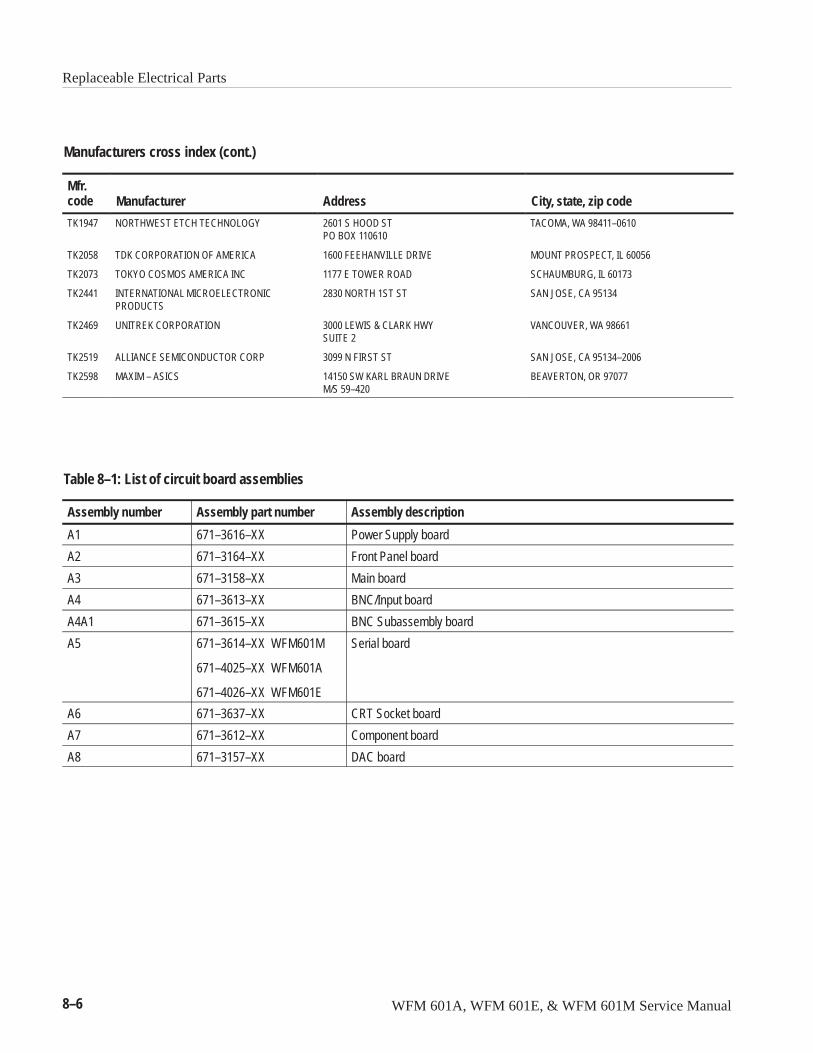
Replaceable Electrical Parts
8–6 WFM 601A, WFM 601E, & WFM 601M Service Manual
Manufacturers cross index (cont.)
Mfr.code City, state, zip codeAddressManufacturer
TK1947 NORTHWEST ETCH TECHNOLOGY 2601 S HOOD STPO BOX 110610
TACOMA, WA 98411–0610
TK2058 TDK CORPORATION OF AMERICA 1600 FEEHANVILLE DRIVE MOUNT PROSPECT, IL 60056
TK2073 TOKYO COSMOS AMERICA INC 1177 E TOWER ROAD SCHAUMBURG, IL 60173
TK2441 INTERNATIONAL MICROELECTRONICPRODUCTS
2830 NORTH 1ST ST SAN JOSE, CA 95134
TK2469 UNITREK CORPORATION 3000 LEWIS & CLARK HWYSUITE 2
VANCOUVER, WA 98661
TK2519 ALLIANCE SEMICONDUCTOR CORP 3099 N FIRST ST SAN JOSE, CA 95134–2006
TK2598 MAXIM – ASICS 14150 SW KARL BRAUN DRIVEM/S 59–420
BEAVERTON, OR 97077
Table 8–1: List of circuit board assemblies
Assembly number Assembly part number Assembly description
A1 671–3616–XX Power Supply board
A2 671–3164–XX Front Panel board
A3 671–3158–XX Main board
A4 671–3613–XX BNC/Input board
A4A1 671–3615–XX BNC Subassembly board
A5 671–3614–XX WFM601M
671–4025–XX WFM601A
671–4026–XX WFM601E
Serial board
A6 671–3637–XX CRT Socket board
A7 671–3612–XX Component board
A8 671–3157–XX DAC board
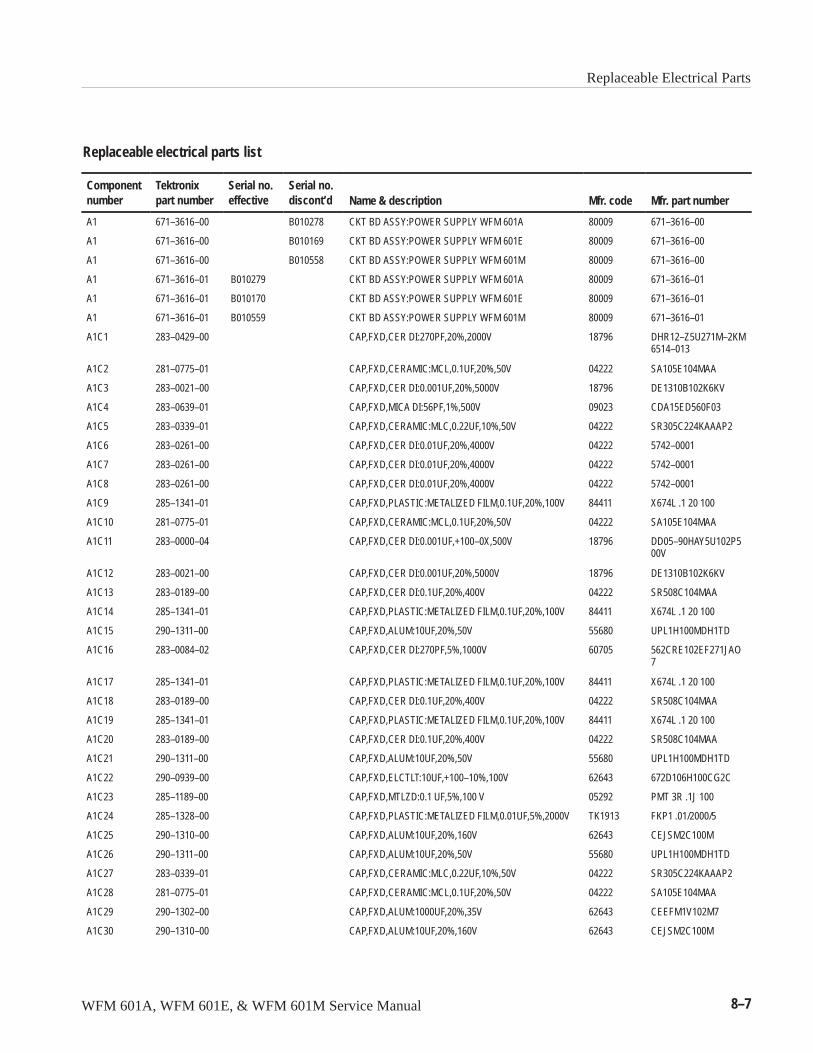
Replaceable Electrical Parts
WFM 601A, WFM 601E, & WFM 601M Service Manual 8–7
Replaceable electrical parts list
Componentnumber
Tektronixpart number
Serial no.effective
Serial no.discont’d Name & description Mfr. code Mfr. part number
A1 671–3616–00 B010278 CKT BD ASSY:POWER SUPPLY WFM 601A 80009 671–3616–00
A1 671–3616–00 B010169 CKT BD ASSY:POWER SUPPLY WFM 601E 80009 671–3616–00
A1 671–3616–00 B010558 CKT BD ASSY:POWER SUPPLY WFM 601M 80009 671–3616–00
A1 671–3616–01 B010279 CKT BD ASSY:POWER SUPPLY WFM 601A 80009 671–3616–01
A1 671–3616–01 B010170 CKT BD ASSY:POWER SUPPLY WFM 601E 80009 671–3616–01
A1 671–3616–01 B010559 CKT BD ASSY:POWER SUPPLY WFM 601M 80009 671–3616–01
A1C1 283–0429–00 CAP,FXD,CER DI:270PF,20%,2000V 18796 DHR12–Z5U271M–2KM6514–013
A1C2 281–0775–01 CAP,FXD,CERAMIC:MCL,0.1UF,20%,50V 04222 SA105E104MAA
A1C3 283–0021–00 CAP,FXD,CER DI:0.001UF,20%,5000V 18796 DE1310B102K6KV
A1C4 283–0639–01 CAP,FXD,MICA DI:56PF,1%,500V 09023 CDA15ED560F03
A1C5 283–0339–01 CAP,FXD,CERAMIC:MLC,0.22UF,10%,50V 04222 SR305C224KAAAP2
A1C6 283–0261–00 CAP,FXD,CER DI:0.01UF,20%,4000V 04222 5742–0001
A1C7 283–0261–00 CAP,FXD,CER DI:0.01UF,20%,4000V 04222 5742–0001
A1C8 283–0261–00 CAP,FXD,CER DI:0.01UF,20%,4000V 04222 5742–0001
A1C9 285–1341–01 CAP,FXD,PLASTIC:METALIZED FILM,0.1UF,20%,100V 84411 X674L .1 20 100
A1C10 281–0775–01 CAP,FXD,CERAMIC:MCL,0.1UF,20%,50V 04222 SA105E104MAA
A1C11 283–0000–04 CAP,FXD,CER DI:0.001UF,+100–0X,500V 18796 DD05–90HAY5U102P500V
A1C12 283–0021–00 CAP,FXD,CER DI:0.001UF,20%,5000V 18796 DE1310B102K6KV
A1C13 283–0189–00 CAP,FXD,CER DI:0.1UF,20%,400V 04222 SR508C104MAA
A1C14 285–1341–01 CAP,FXD,PLASTIC:METALIZED FILM,0.1UF,20%,100V 84411 X674L .1 20 100
A1C15 290–1311–00 CAP,FXD,ALUM:10UF,20%,50V 55680 UPL1H100MDH1TD
A1C16 283–0084–02 CAP,FXD,CER DI:270PF,5%,1000V 60705 562CRE102EF271JAO7
A1C17 285–1341–01 CAP,FXD,PLASTIC:METALIZED FILM,0.1UF,20%,100V 84411 X674L .1 20 100
A1C18 283–0189–00 CAP,FXD,CER DI:0.1UF,20%,400V 04222 SR508C104MAA
A1C19 285–1341–01 CAP,FXD,PLASTIC:METALIZED FILM,0.1UF,20%,100V 84411 X674L .1 20 100
A1C20 283–0189–00 CAP,FXD,CER DI:0.1UF,20%,400V 04222 SR508C104MAA
A1C21 290–1311–00 CAP,FXD,ALUM:10UF,20%,50V 55680 UPL1H100MDH1TD
A1C22 290–0939–00 CAP,FXD,ELCTLT:10UF,+100–10%,100V 62643 672D106H100CG2C
A1C23 285–1189–00 CAP,FXD,MTLZD:0.1 UF,5%,100 V 05292 PMT 3R .1J 100
A1C24 285–1328–00 CAP,FXD,PLASTIC:METALIZED FILM,0.01UF,5%,2000V TK1913 FKP1 .01/2000/5
A1C25 290–1310–00 CAP,FXD,ALUM:10UF,20%,160V 62643 CEJSM2C100M
A1C26 290–1311–00 CAP,FXD,ALUM:10UF,20%,50V 55680 UPL1H100MDH1TD
A1C27 283–0339–01 CAP,FXD,CERAMIC:MLC,0.22UF,10%,50V 04222 SR305C224KAAAP2
A1C28 281–0775–01 CAP,FXD,CERAMIC:MCL,0.1UF,20%,50V 04222 SA105E104MAA
A1C29 290–1302–00 CAP,FXD,ALUM:1000UF,20%,35V 62643 CEEFM1V102M7
A1C30 290–1310–00 CAP,FXD,ALUM:10UF,20%,160V 62643 CEJSM2C100M
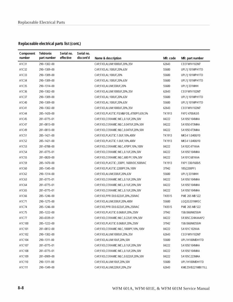
Replaceable Electrical Parts
8–8 WFM 601A, WFM 601E, & WFM 601M Service Manual
Replaceable electrical parts list (cont.)
Componentnumber Mfr. part numberMfr. codeName & description
Serial no.discont’d
Serial no.effective
Tektronixpart number
A1C31 290–1302–00 CAP,FXD,ALUM:1000UF,20%,35V 62643 CEEFM1V102M7
A1C32 290–1309–00 CAP,FXD,AL:100UF,20%,63V 55680 UPL1J101MPH1TD
A1C33 290–1309–00 CAP,FXD,AL:100UF,20% 55680 UPL1J101MPH1TD
A1C34 290–1309–00 CAP,FXD,AL:100UF,20%,63V 55680 UPL1J101MPH1TD
A1C35 290–1314–00 CAP,FXD,ALUM:330UF,20% 55680 UPL1J331MHH
A1C36 290–1302–00 CAP,FXD,ALUM:1000UF,20%,35V 62643 CEEFM1V102M7
A1C37 290–1309–00 CAP,FXD,AL:100UF,20%,63V 55680 UPL1J101MPH1TD
A1C40 290–1309–00 CAP,FXD,AL:100UF,20%,63V 55680 UPL1J101MPH1TD
A1C41 290–1302–00 CAP,FXD,ALUM:1000UF,20%,35V 62643 CEEFM1V102M7
A1C44 285–1420–00 CAP,FXD,PLASTIC:FILM&FOIL,4700PF,63V,5% TK1913 FKP2 4700/63/5
A1C45 281–0775–01 CAP,FXD,CERAMIC:MCL,0.1UF,20%,50V 04222 SA105E104MAA
A1C47 281–0813–00 CAP,FXD,CERAMIC:MLC,0.047UF,20%,50V 04222 SA105E473MAA
A1C49 281–0813–00 CAP,FXD,CERAMIC:MLC,0.047UF,20%,50V 04222 SA105E473MAA
A1C51 285–1421–00 CAP,FXD,PLASTIC:1.0UF,10%,400V TK1913 MKS4 1.0/400/10
A1C52 285–1421–00 CAP,FXD,PLASTIC:1.0UF,10%,400V TK1913 MKS4 1.0/400/10
A1C53 281–0788–00 CAP,FXD,CERAMIC:MLC,470PF,10%,100V 04222 SA102C471KAA
A1C54 281–0775–01 CAP,FXD,CERAMIC:MCL,0.1UF,20%,50V 04222 SA105E104MAA
A1C55 281–0820–00 CAP,FXD,CERAMIC:MLC,680 PF,10%,50V 04222 SA101C681KAA
A1C59 285–1470–00 CAP,FXD,PLASTIC:,330PF, 1600VDC/500VAC TK1913 FKP1 330/1600/5
A1C60 285–1345–00 CAP,FXD,PLASTIC:2200PF,5%,100V 37942 185(2200PF)
A1C62 290–1314–00 CAP,FXD,ALUM:330UF,20%,63V 55680 UPL1J331MHH
A1C63 281–0775–01 CAP,FXD,CERAMIC:MCL,0.1UF,20%,50V 04222 SA105E104MAA
A1C64 281–0775–01 CAP,FXD,CERAMIC:MCL,0.1UF,20%,50V 04222 SA105E104MAA
A1C65 281–0775–01 CAP,FXD,CERAMIC:MCL,0.1UF,20%,50V 04222 SA105E104MAA
A1C66 285–1246–00 CAP,FXD,PPR DI:0.022UF,20%,250VAC TK0515 PME 265 MB 522
A1C71 290–1275–00 CAP,FXD,ALUM:330UF,20%,400V 55680 LGQ2G331MHSC
A1C74 285–1246–00 CAP,FXD,PPR DI:0.022UF,20%,250VAC TK0515 PME 265 MB 522
A1C75 285–1222–00 CAP,FXD,PLASTIC:0.068UF,20%,250V 37942 158/.068/M/250/H
A1C77 283–0339–01 CAP,FXD,CERAMIC:MLC,0.22UF,10%,50V 04222 SR305C224KAAAP2
A1C100 285–1222–00 CAP,FXD,PLASTIC:0.068UF,20%,250V 37942 158/.068/M/250/H
A1C101 281–0812–00 CAP,FXD,CERAMIC:MLC,1000PF,10%,100V 04222 SA101C102KAA
A1C102 290–1302–00 CAP,FXD,ALUM:1000UF,20%,35V 62643 CEEFM1V102M7
A1C104 290–1311–00 CAP,FXD,ALUM:10UF,20%,50V 55680 UPL1H100MDH1TD
A1C107 281–0775–01 CAP,FXD,CERAMIC:MCL,0.1UF,20%,50V 04222 SA105E104MAA
A1C108 281–0775–01 CAP,FXD,CERAMIC:MCL,0.1UF,20%,50V 04222 SA105E104MAA
A1C109 281–0909–00 CAP,FXD,CERAMIC:MLC,0.022UF,20%,50V 04222 SA105C223MAA
A1C110 290–1311–00 CAP,FXD,ALUM:10UF,20%,50V 55680 UPL1H100MDH1TD
A1C111 290–1349–00 CAP,FXD,ALUM:220UF,20%,25V 62643 KME25VB221M8X11LL
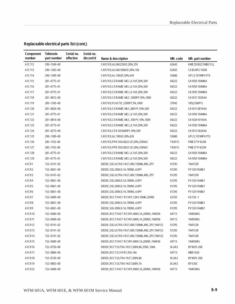
Replaceable Electrical Parts
WFM 601A, WFM 601E, & WFM 601M Service Manual 8–9
Replaceable electrical parts list (cont.)
Componentnumber Mfr. part numberMfr. codeName & description
Serial no.discont’d
Serial no.effective
Tektronixpart number
A1C112 290–1349–00 CAP,FXD,ALUM:220UF,20%,25V 62643 KME25VB221M8X11LL
A1C113 290–1303–00 CAP,FXD,ALUM:1000UF,20%,16V 62643 CEBSM1C102M
A1C114 290–1309–00 CAP,FXD,AL:100UF,20%,63V 55680 UPL1J101MPH1TD
A1C115 281–0775–01 CAP,FXD,CERAMIC:MCL,0.1UF,20%,50V 04222 SA105E104MAA
A1C116 281–0775–01 CAP,FXD,CERAMIC:MCL,0.1UF,20%,50V 04222 SA105E104MAA
A1C117 281–0775–01 CAP,FXD,CERAMIC:MCL,0.1UF,20%,50V 04222 SA105E104MAA
A1C118 281–0812–00 CAP,FXD,CERAMIC:MLC,1000PF,10%,100V 04222 SA101C102KAA
A1C119 285–1345–00 CAP,FXD,PLASTIC:2200PF,5%,100V 37942 185(2200PF)
A1C120 281–0820–00 CAP,FXD,CERAMIC:MLC,680 PF,10%,50V 04222 SA101C681KAA
A1C121 281–0775–01 CAP,FXD,CERAMIC:MCL,0.1UF,20%,50V 04222 SA105E104MAA
A1C122 281–0814–00 CAP,FXD,CERAMIC:MLC,100 PF,10%,100V 04222 SA102A101KAA
A1C123 281–0775–01 CAP,FXD,CERAMIC:MCL,0.1UF,20%,50V 04222 SA105E104MAA
A1C124 281–0273–00 CAP,FXD,CER DI:5600PF,10%,50V 04222 SA101C562KAA
A1C125 290–1309–00 CAP,FXD,AL:100UF,20%,63V 55680 UPL1J101MPH1TD
A1C126 285–1192–00 CAP,FXD,PPR DI:0.0022 UF,20%,250VAC TK0515 PME271Y422M
A1C127 285–1192–00 CAP,FXD,PPR DI:0.0022 UF,20%,250VAC TK0515 PME271Y422M
A1C128 281–0775–01 CAP,FXD,CERAMIC:MCL,0.1UF,20%,50V 04222 SA105E104MAA
A1C129 281–0775–01 CAP,FXD,CERAMIC:MCL,0.1UF,20%,50V 04222 SA105E104MAA
A1CR1 152–0141–02 DIODE,SIG:ULTRA FAST,40V,150MA,4NS,2PF 01295 1N4152R
A1CR2 152–0061–00 DIODE,SIG:200V,0.1A,700NS,4.0PF 01295 PV120 FAMILY
A1CR3 152–0141–02 DIODE,SIG:ULTRA FAST,40V,150MA,4NS,2PF 01295 1N4152R
A1CR4 152–0061–00 DIODE,SIG:200V,0.1A,700NS,4.0PF 01295 PV120 FAMILY
A1CR5 152–0061–00 DIODE,SIG:200V,0.1A,700NS,4.0PF 01295 PV120 FAMILY
A1CR6 152–0061–00 DIODE,SIG:200V,0.1A,700NS,4.0PF 01295 PV120 FAMILY
A1CR7 152–0409–00 DIODE,RECT:FAST RCVRY,12KV,10MA,250NS 62703 VG12X–1
A1CR8 152–0061–00 DIODE,SIG:200V,0.1A,700NS,4.0PF 01295 PV120 FAMILY
A1CR9 152–0061–00 DIODE,SIG:200V,0.1A,700NS,4.0PF 01295 PV120 FAMILY
A1CR10 152–0400–00 DIODE,RECT:FAST RCVRY,400V,1A,200NS,1N4936 04713 1N4936RL
A1CR11 152–0400–00 DIODE,RECT:FAST RCVRY,400V,1A,200NS,1N4936 04713 1N4936RL
A1CR12 152–0141–02 DIODE,SIG:ULTRA FAST,40V,150MA,4NS,2PF,1N4152 01295 1N4152R
A1CR13 152–0141–02 DIODE,SIG:ULTRA FAST,40V,150MA,4NS,2PF,1N4152 01295 1N4152R
A1CR14 152–0141–02 DIODE,SIG:ULTRA FAST,40V,150MA,4NS,2PF,1N4152 01295 1N4152R
A1CR15 152–0400–00 DIODE,RECT:FAST RCVRY,400V,1A,200NS,1N4936 04713 1N4936RL
A1CR16 152–0720–00 DIODE,RECT:ULTRA FAST,200V,8A,25NS,100A 0LUA3 BYW29–200
A1CR17 152–0884–00 DIODE,RECT:SCHTKY,35V,16A 04713 MBR1635
A1CR18 152–0720–00 DIODE,RECT:ULTRA FAST,200V,8A 0LUA3 BYW29–200
A1CR19 152–0863–00 DIODE,RECT:ULTRA FAST,600V,1A 0LUA3 BYV26C
A1CR22 152–0400–00 DIODE,RECT:FAST RCVRY,400V,1A,200NS,1N4936 04713 1N4936RL
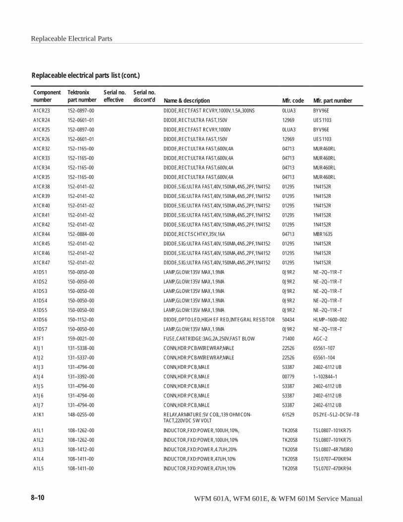
Replaceable Electrical Parts
8–10 WFM 601A, WFM 601E, & WFM 601M Service Manual
Replaceable electrical parts list (cont.)
Componentnumber Mfr. part numberMfr. codeName & description
Serial no.discont’d
Serial no.effective
Tektronixpart number
A1CR23 152–0897–00 DIODE,RECT:FAST RCVRY,1000V,1.5A,300NS 0LUA3 BYV96E
A1CR24 152–0601–01 DIODE,RECT:ULTRA FAST,150V 12969 UES1103
A1CR25 152–0897–00 DIODE,RECT:FAST RCVRY,1000V 0LUA3 BYV96E
A1CR26 152–0601–01 DIODE,RECT:ULTRA FAST,150V 12969 UES1103
A1CR32 152–1165–00 DIODE,RECT:ULTRA FAST,600V,4A 04713 MUR460RL
A1CR33 152–1165–00 DIODE,RECT:ULTRA FAST,600V,4A 04713 MUR460RL
A1CR34 152–1165–00 DIODE,RECT:ULTRA FAST,600V,4A 04713 MUR460RL
A1CR35 152–1165–00 DIODE,RECT:ULTRA FAST,600V,4A 04713 MUR460RL
A1CR38 152–0141–02 DIODE,SIG:ULTRA FAST,40V,150MA,4NS,2PF,1N4152 01295 1N4152R
A1CR39 152–0141–02 DIODE,SIG:ULTRA FAST,40V,150MA,4NS,2PF,1N4152 01295 1N4152R
A1CR40 152–0141–02 DIODE,SIG:ULTRA FAST,40V,150MA,4NS,2PF,1N4152 01295 1N4152R
A1CR41 152–0141–02 DIODE,SIG:ULTRA FAST,40V,150MA,4NS,2PF,1N4152 01295 1N4152R
A1CR42 152–0141–02 DIODE,SIG:ULTRA FAST,40V,150MA,4NS,2PF,1N4152 01295 1N4152R
A1CR44 152–0884–00 DIODE,RECT:SCHTKY,35V,16A 04713 MBR1635
A1CR45 152–0141–02 DIODE,SIG:ULTRA FAST,40V,150MA,4NS,2PF,1N4152 01295 1N4152R
A1CR46 152–0141–02 DIODE,SIG:ULTRA FAST,40V,150MA,4NS,2PF,1N4152 01295 1N4152R
A1CR47 152–0141–02 DIODE,SIG:ULTRA FAST,40V,150MA,4NS,2PF,1N4152 01295 1N4152R
A1DS1 150–0050–00 LAMP,GLOW:135V MAX,1.9MA 0J9R2 NE–2Q–11R–T
A1DS2 150–0050–00 LAMP,GLOW:135V MAX,1.9MA 0J9R2 NE–2Q–11R–T
A1DS3 150–0050–00 LAMP,GLOW:135V MAX,1.9MA 0J9R2 NE–2Q–11R–T
A1DS4 150–0050–00 LAMP,GLOW:135V MAX,1.9MA 0J9R2 NE–2Q–11R–T
A1DS5 150–0050–00 LAMP,GLOW:135V MAX,1.9MA 0J9R2 NE–2Q–11R–T
A1DS6 150–1152–00 DIODE,OPTO:LED,HIGH EF RED,INTEGRAL RESISTOR 50434 HLMP–1600–002
A1DS7 150–0050–00 LAMP,GLOW:135V MAX,1.9MA 0J9R2 NE–2Q–11R–T
A1F1 159–0021–00 FUSE,CARTRIDGE:3AG,2A,250V,FAST BLOW 71400 AGC–2
A1J1 131–5338–00 CONN,HDR:PCB/WIREWRAP,MALE 22526 65561–107
A1J2 131–5337–00 CONN,HDR:PCB/WIREWRAP,MALE 22526 65561–104
A1J3 131–4794–00 CONN,HDR:PCB,MALE 53387 2402–6112 UB
A1J4 131–3392–00 CONN,HDR:PCB,MALE 00779 1–102844–1
A1J5 131–4794–00 CONN,HDR:PCB,MALE 53387 2402–6112 UB
A1J6 131–4794–00 CONN,HDR:PCB,MALE 53387 2402–6112 UB
A1J7 131–4794–00 CONN,HDR:PCB,MALE 53387 2402–6112 UB
A1K1 148–0255–00 RELAY,ARMATURE:5V COIL,139 OHM CON-TACT,220VDC SW VOLT
61529 DS2YE–SL2–DC5V–TB
A1L1 108–1262–00 INDUCTOR,FXD:POWER,100UH,10%, TK2058 TSL0807–101KR75
A1L2 108–1262–00 INDUCTOR,FXD:POWER,100UH,10% TK2058 TSL0807–101KR75
A1L3 108–1412–00 INDUCTOR,FXD:POWER,4.7UH,20% TK2058 TSL0807–4R7M3R0
A1L4 108–1411–00 INDUCTOR,FXD:POWER,47UH,10% TK2058 TSL0707–470KR94
A1L5 108–1411–00 INDUCTOR,FXD:POWER,47UH,10% TK2058 TSL0707–470KR94
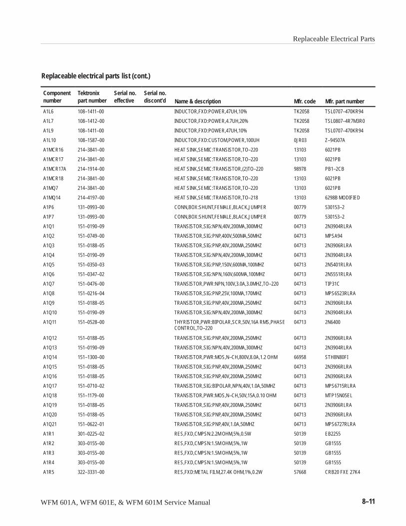
Replaceable Electrical Parts
WFM 601A, WFM 601E, & WFM 601M Service Manual 8–11
Replaceable electrical parts list (cont.)
Componentnumber Mfr. part numberMfr. codeName & description
Serial no.discont’d
Serial no.effective
Tektronixpart number
A1L6 108–1411–00 INDUCTOR,FXD:POWER,47UH,10% TK2058 TSL0707–470KR94
A1L7 108–1412–00 INDUCTOR,FXD:POWER,4.7UH,20% TK2058 TSL0807–4R7M3R0
A1L9 108–1411–00 INDUCTOR,FXD:POWER,47UH,10% TK2058 TSL0707–470KR94
A1L10 108–1587–00 INDUCTOR,FXD:CUSTOM,POWER,100UH 0JR03 Z–94507A
A1MCR16 214–3841–00 HEAT SINK,SEMIC:TRANSISTOR,TO–220 13103 6021PB
A1MCR17 214–3841–00 HEAT SINK,SEMIC:TRANSISTOR,TO–220 13103 6021PB
A1MCR17A 214–1914–00 HEAT SINK,SEMIC:TRANSISTOR,(2)TO–220 98978 PB1–2CB
A1MCR18 214–3841–00 HEAT SINK,SEMIC:TRANSISTOR,TO–220 13103 6021PB
A1MQ7 214–3841–00 HEAT SINK,SEMIC:TRANSISTOR,TO–220 13103 6021PB
A1MQ14 214–4197–00 HEAT SINK,SEMIC:TRANSISTOR,TO–218 13103 6298B MODIFIED
A1P6 131–0993–00 CONN,BOX:SHUNT,FEMALE,BLACK,JUMPER 00779 530153–2
A1P7 131–0993–00 CONN,BOX:SHUNT,FEMALE,BLACK,JUMPER 00779 530153–2
A1Q1 151–0190–09 TRANSISTOR,SIG:NPN,40V,200MA,300MHZ 04713 2N3904RLRA
A1Q2 151–0749–00 TRANSISTOR,SIG:PNP,400V,500MA,50MHZ 04713 MPSA94
A1Q3 151–0188–05 TRANSISTOR,SIG:PNP,40V,200MA,250MHZ 04713 2N3906RLRA
A1Q4 151–0190–09 TRANSISTOR,SIG:NPN,40V,200MA,300MHZ 04713 2N3904RLRA
A1Q5 151–0350–03 TRANSISTOR,SIG:PNP,150V,600MA,100MHZ 04713 2N5401RLRA
A1Q6 151–0347–02 TRANSISTOR,SIG:NPN,160V,600MA,100MHZ 04713 2N5551RLRA
A1Q7 151–0476–00 TRANSISTOR,PWR:NPN,100V,3.0A,3.0MHZ,TO–220 04713 TIP31C
A1Q8 151–0216–04 TRANSISTOR,SIG:PNP,25V,100MA,170MHZ 04713 MPS6523RLRA
A1Q9 151–0188–05 TRANSISTOR,SIG:PNP,40V,200MA,250MHZ 04713 2N3906RLRA
A1Q10 151–0190–09 TRANSISTOR,SIG:NPN,40V,200MA,300MHZ 04713 2N3904RLRA
A1Q11 151–0528–00 THYRISTOR,PWR:BIPOLAR,SCR,50V,16A RMS,PHASECONTROL,TO–220
04713 2N6400
A1Q12 151–0188–05 TRANSISTOR,SIG:PNP,40V,200MA,250MHZ 04713 2N3906RLRA
A1Q13 151–0190–09 TRANSISTOR,SIG:NPN,40V,200MA,300MHZ 04713 2N3904RLRA
A1Q14 151–1300–00 TRANSISTOR,PWR:MOS,N–CH,800V,8.0A,1.2 OHM 66958 STH8N80FI
A1Q15 151–0188–05 TRANSISTOR,SIG:PNP,40V,200MA,250MHZ 04713 2N3906RLRA
A1Q16 151–0188–05 TRANSISTOR,SIG:PNP,40V,200MA,250MHZ 04713 2N3906RLRA
A1Q17 151–0710–02 TRANSISTOR,SIG:BIPOLAR,NPN,40V,1.0A,50MHZ 04713 MPS6715RLRA
A1Q18 151–1179–00 TRANSISTOR,PWR:MOS,N–CH,50V,15A,0.10 OHM 04713 MTP15N05EL
A1Q19 151–0188–05 TRANSISTOR,SIG:PNP,40V,200MA,250MHZ 04713 2N3906RLRA
A1Q20 151–0188–05 TRANSISTOR,SIG:PNP,40V,200MA,250MHZ 04713 2N3906RLRA
A1Q21 151–0622–01 TRANSISTOR,SIG:PNP,40V,1.0A,50MHZ 04713 MPS6727RLRA
A1R1 301–0225–02 RES,FXD,CMPSN:2.2M OHM,5%,0.5W 50139 EB2255
A1R2 303–0155–00 RES,FXD,CMPSN:1.5M OHM,5%,1W 50139 GB1555
A1R3 303–0155–00 RES,FXD,CMPSN:1.5M OHM,5%,1W 50139 GB1555
A1R4 303–0155–00 RES,FXD,CMPSN:1.5M OHM,5%,1W 50139 GB1555
A1R5 322–3331–00 RES,FXD:METAL FILM,27.4K OHM,1%,0.2W 57668 CRB20 FXE 27K4
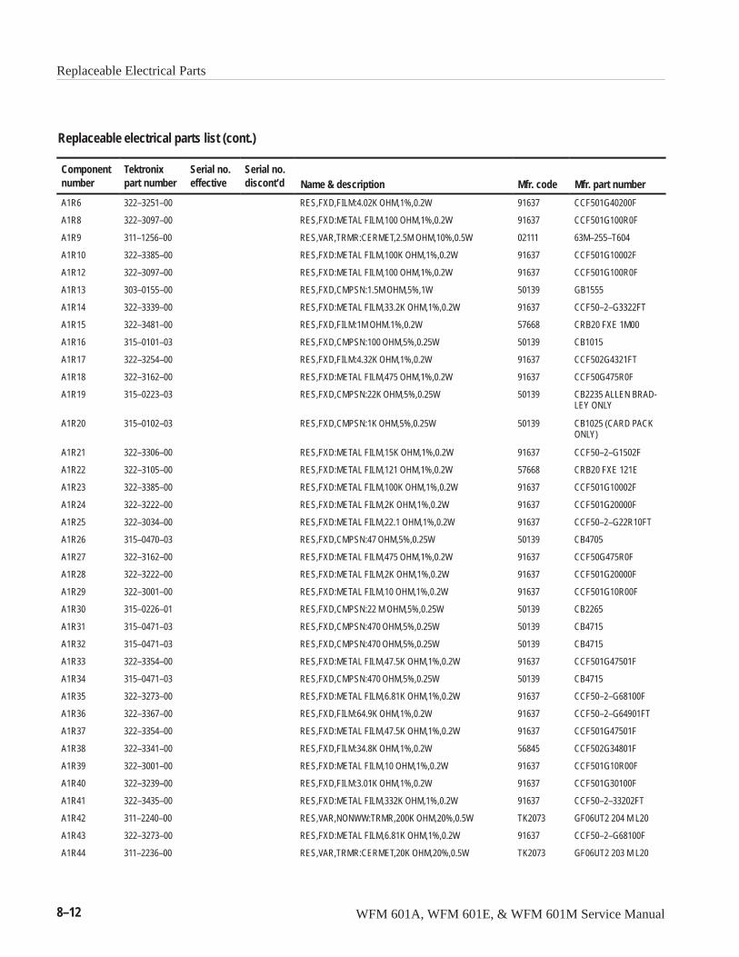
Replaceable Electrical Parts
8–12 WFM 601A, WFM 601E, & WFM 601M Service Manual
Replaceable electrical parts list (cont.)
Componentnumber Mfr. part numberMfr. codeName & description
Serial no.discont’d
Serial no.effective
Tektronixpart number
A1R6 322–3251–00 RES,FXD,FILM:4.02K OHM,1%,0.2W 91637 CCF501G40200F
A1R8 322–3097–00 RES,FXD:METAL FILM,100 OHM,1%,0.2W 91637 CCF501G100R0F
A1R9 311–1256–00 RES,VAR,TRMR:CERMET,2.5M OHM,10%,0.5W 02111 63M–255–T604
A1R10 322–3385–00 RES,FXD:METAL FILM,100K OHM,1%,0.2W 91637 CCF501G10002F
A1R12 322–3097–00 RES,FXD:METAL FILM,100 OHM,1%,0.2W 91637 CCF501G100R0F
A1R13 303–0155–00 RES,FXD,CMPSN:1.5M OHM,5%,1W 50139 GB1555
A1R14 322–3339–00 RES,FXD:METAL FILM,33.2K OHM,1%,0.2W 91637 CCF50–2–G3322FT
A1R15 322–3481–00 RES,FXD,FILM:1M OHM.1%,0.2W 57668 CRB20 FXE 1M00
A1R16 315–0101–03 RES,FXD,CMPSN:100 OHM,5%,0.25W 50139 CB1015
A1R17 322–3254–00 RES,FXD,FILM:4.32K OHM,1%,0.2W 91637 CCF502G4321FT
A1R18 322–3162–00 RES,FXD:METAL FILM,475 OHM,1%,0.2W 91637 CCF50G475R0F
A1R19 315–0223–03 RES,FXD,CMPSN:22K OHM,5%,0.25W 50139 CB2235 ALLEN BRAD-LEY ONLY
A1R20 315–0102–03 RES,FXD,CMPSN:1K OHM,5%,0.25W 50139 CB1025 (CARD PACKONLY)
A1R21 322–3306–00 RES,FXD:METAL FILM,15K OHM,1%,0.2W 91637 CCF50–2–G1502F
A1R22 322–3105–00 RES,FXD:METAL FILM,121 OHM,1%,0.2W 57668 CRB20 FXE 121E
A1R23 322–3385–00 RES,FXD:METAL FILM,100K OHM,1%,0.2W 91637 CCF501G10002F
A1R24 322–3222–00 RES,FXD:METAL FILM,2K OHM,1%,0.2W 91637 CCF501G20000F
A1R25 322–3034–00 RES,FXD:METAL FILM,22.1 OHM,1%,0.2W 91637 CCF50–2–G22R10FT
A1R26 315–0470–03 RES,FXD,CMPSN:47 OHM,5%,0.25W 50139 CB4705
A1R27 322–3162–00 RES,FXD:METAL FILM,475 OHM,1%,0.2W 91637 CCF50G475R0F
A1R28 322–3222–00 RES,FXD:METAL FILM,2K OHM,1%,0.2W 91637 CCF501G20000F
A1R29 322–3001–00 RES,FXD:METAL FILM,10 OHM,1%,0.2W 91637 CCF501G10R00F
A1R30 315–0226–01 RES,FXD,CMPSN:22 M OHM,5%,0.25W 50139 CB2265
A1R31 315–0471–03 RES,FXD,CMPSN:470 OHM,5%,0.25W 50139 CB4715
A1R32 315–0471–03 RES,FXD,CMPSN:470 OHM,5%,0.25W 50139 CB4715
A1R33 322–3354–00 RES,FXD:METAL FILM,47.5K OHM,1%,0.2W 91637 CCF501G47501F
A1R34 315–0471–03 RES,FXD,CMPSN:470 OHM,5%,0.25W 50139 CB4715
A1R35 322–3273–00 RES,FXD:METAL FILM,6.81K OHM,1%,0.2W 91637 CCF50–2–G68100F
A1R36 322–3367–00 RES,FXD,FILM:64.9K OHM,1%,0.2W 91637 CCF50–2–G64901FT
A1R37 322–3354–00 RES,FXD:METAL FILM,47.5K OHM,1%,0.2W 91637 CCF501G47501F
A1R38 322–3341–00 RES,FXD,FILM:34.8K OHM,1%,0.2W 56845 CCF502G34801F
A1R39 322–3001–00 RES,FXD:METAL FILM,10 OHM,1%,0.2W 91637 CCF501G10R00F
A1R40 322–3239–00 RES,FXD,FILM:3.01K OHM,1%,0.2W 91637 CCF501G30100F
A1R41 322–3435–00 RES,FXD:METAL FILM,332K OHM,1%,0.2W 91637 CCF50–2–33202FT
A1R42 311–2240–00 RES,VAR,NONWW:TRMR,200K OHM,20%,0.5W TK2073 GF06UT2 204 M L20
A1R43 322–3273–00 RES,FXD:METAL FILM,6.81K OHM,1%,0.2W 91637 CCF50–2–G68100F
A1R44 311–2236–00 RES,VAR,TRMR:CERMET,20K OHM,20%,0.5W TK2073 GF06UT2 203 M L20

Replaceable Electrical Parts
WFM 601A, WFM 601E, & WFM 601M Service Manual 8–13
Replaceable electrical parts list (cont.)
Componentnumber Mfr. part numberMfr. codeName & description
Serial no.discont’d
Serial no.effective
Tektronixpart number
A1R45 322–3001–00 RES,FXD:METAL FILM,10 OHM,1%,0.2W 91637 CCF501G10R00F
A1R46 322–3322–00 RES,FXD:METAL FILM,22.1K OHM,1%,0.2W 57668 CRB20 FXE 22K1
A1R47 322–3001–00 RES,FXD:METAL FILM,10 OHM,1%,0.2W 91637 CCF501G10R00F
A1R48 322–3001–00 RES,FXD:METAL FILM,10 OHM,1%,0.2W 91637 CCF501G10R00F
A1R49 322–3024–00 RES,FXD,FILM:17.4 OHM,1%,0.2W 91637 CCF50–2–G17R40FT
A1R50 322–3322–00 RES,FXD:METAL FILM,22.1K OHM,1%,0.2W 57668 CRB20 FXE 22K1
A1R51 322–3001–00 RES,FXD:METAL FILM,10 OHM,1%,0.2W 91637 CCF501G10R00F
A1R52 322–3193–00 RES,FXD:METAL FILM,1K OHM,1%,0.2W 91637 CCF501G10000F
A1R53 311–2239–00 RES,VAR,TRMR:CERMET,100K OHM,20%,0.5W TK2073 GF06UT2 104 M L20
A1R54 322–3193–00 RES,FXD:METAL FILM,1K OHM,1%,0.2W 91637 CCF501G10000F
A1R55 322–3481–00 RES,FXD,FILM:1M OHM.1%,0.2W 57668 CRB20 FXE 1M00
A1R56 322–3193–00 RES,FXD:METAL FILM,1K OHM,1%,0.2W 91637 CCF501G10000F
A1R57 322–3235–00 RES,FXD:METAL FILM,2.74K OHM,1%,0.2W 57668 CRB20 FXE 2K74
A1R58 322–3193–00 RES,FXD:METAL FILM,1K OHM,1%,0.2W 91637 CCF501G10000F
A1R59 322–3193–00 RES,FXD:METAL FILM,1K OHM,1%,0.2W 91637 CCF501G10000F
A1R60 322–3260–00 RES,FXD,FILM:4.99K OHM,1%,0.2W 91637 CCF501G49900F
A1R61 322–3261–00 RES,FXD,FILM:5.11K OHM,1%,0.2W 91637 CCF50G5111FT
A1R62 322–3097–00 RES,FXD:METAL FILM,100 OHM,1%,0.2W 91637 CCF501G100R0F
A1R63 322–3001–00 RES,FXD:METAL FILM,10 OHM,1%,0.2W 91637 CCF501G10R00F
A1R64 322–3001–00 RES,FXD:METAL FILM,10 OHM,1%,0.2W 91637 CCF501G10R00F
A1R65 322–3201–00 RES,FXD:METAL FILM,1.21K OHM,1%,0.2W 91637 CCF501G12100F
A1R66 322–3385–00 RES,FXD:METAL FILM,100K OHM,1%,0.2W 91637 CCF501G10002F
A1R67 322–3385–00 RES,FXD:METAL FILM,100K OHM,1%,0.2W 91637 CCF501G10002F
A1R68 322–3339–00 RES,FXD:METAL FILM,33.2K OHM,1%,0.2W 91637 CCF50–2–G3322FT
A1R69 307–0106–00 RES,FXD,CMPSN:4.7 OHM,5%,0.25W 50139 CB47G5
A1R70 308–0441–00 RES,FXD,WW:3 OHM,5%,3W 91637 CW-2B-60-3R00-J-T/R
A1R72 322–3481–00 RES,FXD,FILM:1M OHM.1%,0.2W 57668 CRB20 FXE 1M00
A1R73 311–2238–00 RES,VAR,TRMR:CERMET,50K OHM,20%,0.5W TK2073 GF06UT2 503 M L20
A1R74 322–3367–00 RES,FXD,FILM:64.9K OHM,1%,0.2W 91637 CCF50–2–G64901FT
A1R78 322–3405–00 671-3616-00 RES,FXD,FILM:162K OHM,1%,0.2W 91637 CCF50–1623F–R36
A1R78 322–3389–00 671-3616-01 RES,FXD,FILM:110K OHM,1%,0.2W 56845 CCF50–2–1103F
A1R79 322–3193–00 RES,FXD:METAL FILM,1K OHM,1%,0.2W 91637 CCF501G10000F
A1R81 322–3385–00 RES,FXD:METAL FILM,100K OHM,1%,0.2W 91637 CCF501G10002F
A1R82 322–3322–00 RES,FXD:METAL FILM,22.1K OHM,1%,0.2W 57668 CRB20 FXE 22K1
A1R84 322–3235–00 RES,FXD:METAL FILM,2.74K OHM,1%,0.2W 57668 CRB20 FXE 2K74
A1R86 322–3254–00 RES,FXD,FILM:4.32K OHM,1%,0.2W 91637 CCF502G4321FT
A1R87 322–3289–00 RES,FXD:METAL FILM,10K OHM,1%,0.2W 91637 CCF50G10001F
A1R88 308–0406–00 RES,FXD,WW:1.2K OHM,1%,3W 24165 242EX1K200FQ18
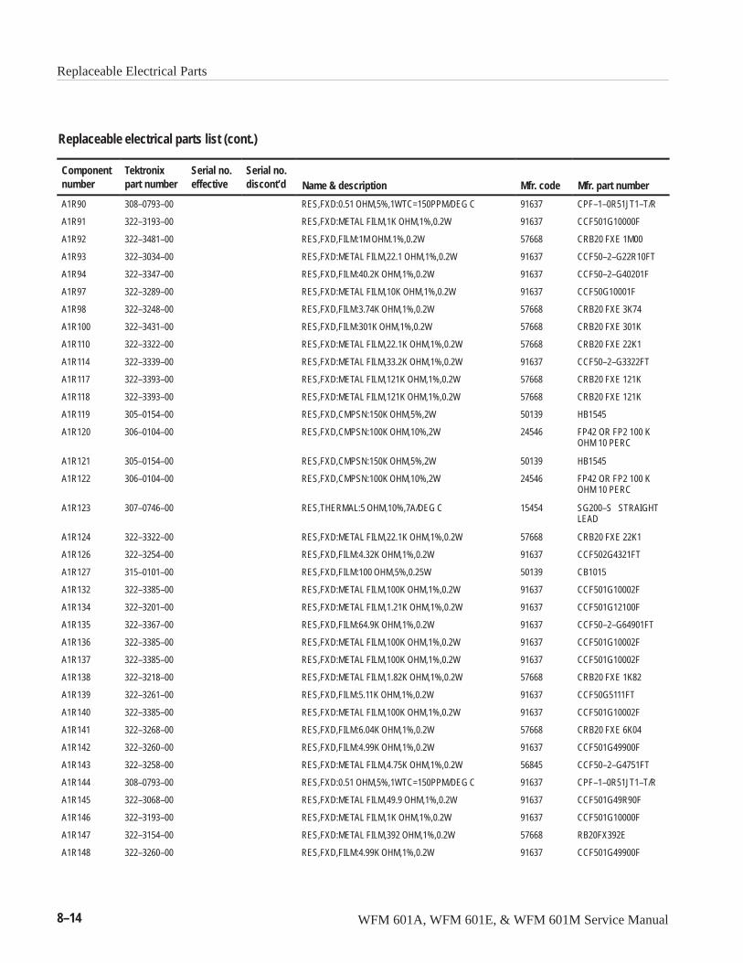
Replaceable Electrical Parts
8–14 WFM 601A, WFM 601E, & WFM 601M Service Manual
Replaceable electrical parts list (cont.)
Componentnumber Mfr. part numberMfr. codeName & description
Serial no.discont’d
Serial no.effective
Tektronixpart number
A1R90 308–0793–00 RES,FXD:0.51 OHM,5%,1WTC=150PPM/DEG C 91637 CPF–1–0R51JT1–T/R
A1R91 322–3193–00 RES,FXD:METAL FILM,1K OHM,1%,0.2W 91637 CCF501G10000F
A1R92 322–3481–00 RES,FXD,FILM:1M OHM.1%,0.2W 57668 CRB20 FXE 1M00
A1R93 322–3034–00 RES,FXD:METAL FILM,22.1 OHM,1%,0.2W 91637 CCF50–2–G22R10FT
A1R94 322–3347–00 RES,FXD,FILM:40.2K OHM,1%,0.2W 91637 CCF50–2–G40201F
A1R97 322–3289–00 RES,FXD:METAL FILM,10K OHM,1%,0.2W 91637 CCF50G10001F
A1R98 322–3248–00 RES,FXD,FILM:3.74K OHM,1%,0.2W 57668 CRB20 FXE 3K74
A1R100 322–3431–00 RES,FXD,FILM:301K OHM,1%,0.2W 57668 CRB20 FXE 301K
A1R110 322–3322–00 RES,FXD:METAL FILM,22.1K OHM,1%,0.2W 57668 CRB20 FXE 22K1
A1R114 322–3339–00 RES,FXD:METAL FILM,33.2K OHM,1%,0.2W 91637 CCF50–2–G3322FT
A1R117 322–3393–00 RES,FXD:METAL FILM,121K OHM,1%,0.2W 57668 CRB20 FXE 121K
A1R118 322–3393–00 RES,FXD:METAL FILM,121K OHM,1%,0.2W 57668 CRB20 FXE 121K
A1R119 305–0154–00 RES,FXD,CMPSN:150K OHM,5%,2W 50139 HB1545
A1R120 306–0104–00 RES,FXD,CMPSN:100K OHM,10%,2W 24546 FP42 OR FP2 100 KOHM 10 PERC
A1R121 305–0154–00 RES,FXD,CMPSN:150K OHM,5%,2W 50139 HB1545
A1R122 306–0104–00 RES,FXD,CMPSN:100K OHM,10%,2W 24546 FP42 OR FP2 100 KOHM 10 PERC
A1R123 307–0746–00 RES,THERMAL:5 OHM,10%,7A/DEG C 15454 SG200–S STRAIGHTLEAD
A1R124 322–3322–00 RES,FXD:METAL FILM,22.1K OHM,1%,0.2W 57668 CRB20 FXE 22K1
A1R126 322–3254–00 RES,FXD,FILM:4.32K OHM,1%,0.2W 91637 CCF502G4321FT
A1R127 315–0101–00 RES,FXD,FILM:100 OHM,5%,0.25W 50139 CB1015
A1R132 322–3385–00 RES,FXD:METAL FILM,100K OHM,1%,0.2W 91637 CCF501G10002F
A1R134 322–3201–00 RES,FXD:METAL FILM,1.21K OHM,1%,0.2W 91637 CCF501G12100F
A1R135 322–3367–00 RES,FXD,FILM:64.9K OHM,1%,0.2W 91637 CCF50–2–G64901FT
A1R136 322–3385–00 RES,FXD:METAL FILM,100K OHM,1%,0.2W 91637 CCF501G10002F
A1R137 322–3385–00 RES,FXD:METAL FILM,100K OHM,1%,0.2W 91637 CCF501G10002F
A1R138 322–3218–00 RES,FXD:METAL FILM,1.82K OHM,1%,0.2W 57668 CRB20 FXE 1K82
A1R139 322–3261–00 RES,FXD,FILM:5.11K OHM,1%,0.2W 91637 CCF50G5111FT
A1R140 322–3385–00 RES,FXD:METAL FILM,100K OHM,1%,0.2W 91637 CCF501G10002F
A1R141 322–3268–00 RES,FXD,FILM:6.04K OHM,1%,0.2W 57668 CRB20 FXE 6K04
A1R142 322–3260–00 RES,FXD,FILM:4.99K OHM,1%,0.2W 91637 CCF501G49900F
A1R143 322–3258–00 RES,FXD:METAL FILM,4.75K OHM,1%,0.2W 56845 CCF50–2–G4751FT
A1R144 308–0793–00 RES,FXD:0.51 OHM,5%,1WTC=150PPM/DEG C 91637 CPF–1–0R51JT1–T/R
A1R145 322–3068–00 RES,FXD:METAL FILM,49.9 OHM,1%,0.2W 91637 CCF501G49R90F
A1R146 322–3193–00 RES,FXD:METAL FILM,1K OHM,1%,0.2W 91637 CCF501G10000F
A1R147 322–3154–00 RES,FXD:METAL FILM,392 OHM,1%,0.2W 57668 RB20FX392E
A1R148 322–3260–00 RES,FXD,FILM:4.99K OHM,1%,0.2W 91637 CCF501G49900F
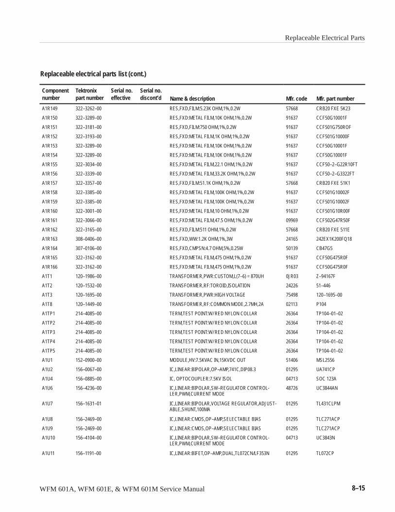
Replaceable Electrical Parts
WFM 601A, WFM 601E, & WFM 601M Service Manual 8–15
Replaceable electrical parts list (cont.)
Componentnumber Mfr. part numberMfr. codeName & description
Serial no.discont’d
Serial no.effective
Tektronixpart number
A1R149 322–3262–00 RES,FXD,FILM:5.23K OHM,1%,0.2W 57668 CRB20 FXE 5K23
A1R150 322–3289–00 RES,FXD:METAL FILM,10K OHM,1%,0.2W 91637 CCF50G10001F
A1R151 322–3181–00 RES,FXD,FILM:750 OHM,1%,0.2W 91637 CCF501G750ROF
A1R152 322–3193–00 RES,FXD:METAL FILM,1K OHM,1%,0.2W 91637 CCF501G10000F
A1R153 322–3289–00 RES,FXD:METAL FILM,10K OHM,1%,0.2W 91637 CCF50G10001F
A1R154 322–3289–00 RES,FXD:METAL FILM,10K OHM,1%,0.2W 91637 CCF50G10001F
A1R155 322–3034–00 RES,FXD:METAL FILM,22.1 OHM,1%,0.2W 91637 CCF50–2–G22R10FT
A1R156 322–3339–00 RES,FXD:METAL FILM,33.2K OHM,1%,0.2W 91637 CCF50–2–G3322FT
A1R157 322–3357–00 RES,FXD,FILM:51.1K OHM,1%,0.2W 57668 CRB20 FXE 51K1
A1R158 322–3385–00 RES,FXD:METAL FILM,100K OHM,1%,0.2W 91637 CCF501G10002F
A1R159 322–3385–00 RES,FXD:METAL FILM,100K OHM,1%,0.2W 91637 CCF501G10002F
A1R160 322–3001–00 RES,FXD:METAL FILM,10 OHM,1%,0.2W 91637 CCF501G10R00F
A1R161 322–3066–00 RES,FXD:METAL FILM,47.5 OHM,1%,0.2W 09969 CCF502G47R50F
A1R162 322–3165–00 RES,FXD,FILM:511 OHM,1%,0.2W 57668 CRB20 FXE 511E
A1R163 308–0406–00 RES,FXD,WW:1.2K OHM,1%,3W 24165 242EX1K200FQ18
A1R164 307–0106–00 RES,FXD,CMPSN:4.7 OHM,5%,0.25W 50139 CB47G5
A1R165 322–3162–00 RES,FXD:METAL FILM,475 OHM,1%,0.2W 91637 CCF50G475R0F
A1R166 322–3162–00 RES,FXD:METAL FILM,475 OHM,1%,0.2W 91637 CCF50G475R0F
A1T1 120–1986–00 TRANSFORMER,PWR:CUSTOM,L(7–6) = 870UH 0JR03 Z–94167F
A1T2 120–1532–00 TRANSFORMER,RF:TOROID,ISOLATION 24226 51–446
A1T3 120–1695–00 TRANSFORMER,PWR:HIGH VOLTAGE 75498 120–1695–00
A1T8 120–1449–00 TRANSFORMER,RF:COMMON MODE,2.7MH,2A 02113 P104
A1TP1 214–4085–00 TERM,TEST POINT:W/ RED NYLON COLLAR 26364 TP104–01–02
A1TP2 214–4085–00 TERM,TEST POINT:W/ RED NYLON COLLAR 26364 TP104–01–02
A1TP3 214–4085–00 TERM,TEST POINT:W/ RED NYLON COLLAR 26364 TP104–01–02
A1TP4 214–4085–00 TERM,TEST POINT:W/ RED NYLON COLLAR 26364 TP104–01–02
A1TP5 214–4085–00 TERM,TEST POINT:W/ RED NYLON COLLAR 26364 TP104–01–02
A1U1 152–0900–00 MODULE,HV:7.5KVAC IN,15KVDC OUT 51406 MSL2556
A1U2 156–0067–00 IC,LINEAR:BIPOLAR,OP–AMP,741C,DIP08.3 01295 UA741CP
A1U4 156–0885–00 IC, OPTOCOUPLER:7.5KV ISOL 04713 SOC 123A
A1U6 156–4236–00 IC,LINEAR:BIPOLAR,SW–REGULATOR CONTROL-LER,PWM,CURRENT MODE
48726 UC3844AN
A1U7 156–1631–01 IC,LINEAR:BIPOLAR,VOLTAGE REGULATOR,ADJUST-ABLE,SHUNT,100MA
01295 TL431CLPM
A1U8 156–2469–00 IC,LINEAR:CMOS,OP–AMP,SELECTABLE BIAS 01295 TLC271ACP
A1U9 156–2469–00 IC,LINEAR:CMOS,OP–AMP,SELECTABLE BIAS 01295 TLC271ACP
A1U10 156–4104–00 IC,LINEAR:BIPOLAR,SW–REGULATOR CONTROL-LER,PWM,CURRENT MODE
04713 UC3843N
A1U11 156–1191–00 IC,LINEAR:BIFET,OP–AMP,DUAL,TL072CN/LF353N 01295 TL072CP
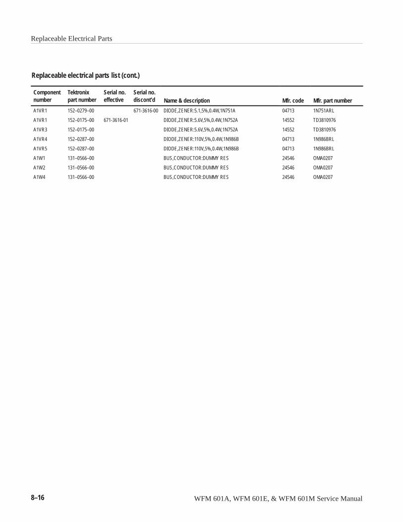
Replaceable Electrical Parts
8–16 WFM 601A, WFM 601E, & WFM 601M Service Manual
Replaceable electrical parts list (cont.)
Componentnumber Mfr. part numberMfr. codeName & description
Serial no.discont’d
Serial no.effective
Tektronixpart number
A1VR1 152–0279–00 671-3616-00 DIODE,ZENER:5.1,5%,0.4W,1N751A 04713 1N751ARL
A1VR1 152–0175–00 671-3616-01 DIODE,ZENER:5.6V,5%,0.4W,1N752A 14552 TD3810976
A1VR3 152–0175–00 DIODE,ZENER:5.6V,5%,0.4W,1N752A 14552 TD3810976
A1VR4 152–0287–00 DIODE,ZENER:110V,5%,0.4W,1N986B 04713 1N986BRL
A1VR5 152–0287–00 DIODE,ZENER:110V,5%,0.4W,1N986B 04713 1N986BRL
A1W1 131–0566–00 BUS,CONDUCTOR:DUMMY RES 24546 OMA0207
A1W2 131–0566–00 BUS,CONDUCTOR:DUMMY RES 24546 OMA0207
A1W4 131–0566–00 BUS,CONDUCTOR:DUMMY RES 24546 OMA0207
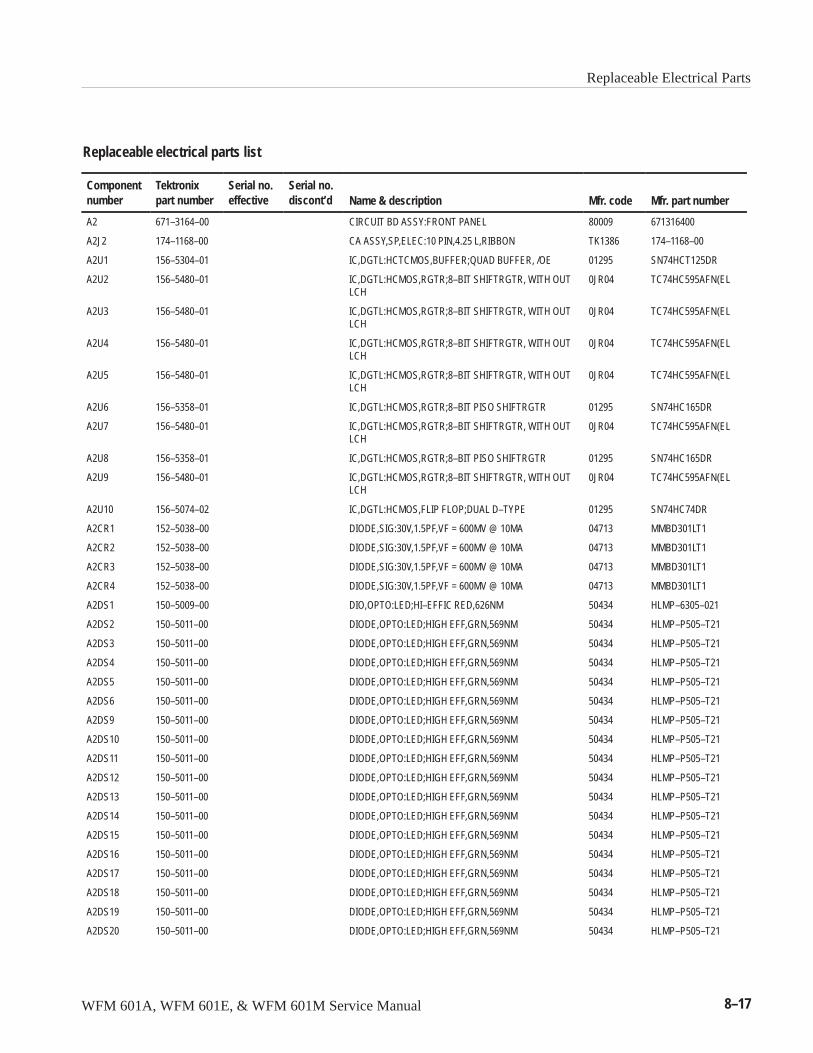
Replaceable Electrical Parts
WFM 601A, WFM 601E, & WFM 601M Service Manual 8–17
Replaceable electrical parts list
Componentnumber
Tektronixpart number
Serial no.effective
Serial no.discont’d Name & description Mfr. code Mfr. part number
A2 671–3164–00 CIRCUIT BD ASSY:FRONT PANEL 80009 671316400
A2J2 174–1168–00 CA ASSY,SP,ELEC:10 PIN,4.25 L,RIBBON TK1386 174–1168–00
A2U1 156–5304–01 IC,DGTL:HCTCMOS,BUFFER;QUAD BUFFER, /OE 01295 SN74HCT125DR
A2U2 156–5480–01 IC,DGTL:HCMOS,RGTR;8–BIT SHIFTRGTR, WITH OUTLCH
0JR04 TC74HC595AFN(EL
A2U3 156–5480–01 IC,DGTL:HCMOS,RGTR;8–BIT SHIFTRGTR, WITH OUTLCH
0JR04 TC74HC595AFN(EL
A2U4 156–5480–01 IC,DGTL:HCMOS,RGTR;8–BIT SHIFTRGTR, WITH OUTLCH
0JR04 TC74HC595AFN(EL
A2U5 156–5480–01 IC,DGTL:HCMOS,RGTR;8–BIT SHIFTRGTR, WITH OUTLCH
0JR04 TC74HC595AFN(EL
A2U6 156–5358–01 IC,DGTL:HCMOS,RGTR;8–BIT PISO SHIFTRGTR 01295 SN74HC165DR
A2U7 156–5480–01 IC,DGTL:HCMOS,RGTR;8–BIT SHIFTRGTR, WITH OUTLCH
0JR04 TC74HC595AFN(EL
A2U8 156–5358–01 IC,DGTL:HCMOS,RGTR;8–BIT PISO SHIFTRGTR 01295 SN74HC165DR
A2U9 156–5480–01 IC,DGTL:HCMOS,RGTR;8–BIT SHIFTRGTR, WITH OUTLCH
0JR04 TC74HC595AFN(EL
A2U10 156–5074–02 IC,DGTL:HCMOS,FLIP FLOP;DUAL D–TYPE 01295 SN74HC74DR
A2CR1 152–5038–00 DIODE,SIG:30V,1.5PF,VF = 600MV @ 10MA 04713 MMBD301LT1
A2CR2 152–5038–00 DIODE,SIG:30V,1.5PF,VF = 600MV @ 10MA 04713 MMBD301LT1
A2CR3 152–5038–00 DIODE,SIG:30V,1.5PF,VF = 600MV @ 10MA 04713 MMBD301LT1
A2CR4 152–5038–00 DIODE,SIG:30V,1.5PF,VF = 600MV @ 10MA 04713 MMBD301LT1
A2DS1 150–5009–00 DIO,OPTO:LED;HI–EFFIC RED,626NM 50434 HLMP–6305–021
A2DS2 150–5011–00 DIODE,OPTO:LED;HIGH EFF,GRN,569NM 50434 HLMP–P505–T21
A2DS3 150–5011–00 DIODE,OPTO:LED;HIGH EFF,GRN,569NM 50434 HLMP–P505–T21
A2DS4 150–5011–00 DIODE,OPTO:LED;HIGH EFF,GRN,569NM 50434 HLMP–P505–T21
A2DS5 150–5011–00 DIODE,OPTO:LED;HIGH EFF,GRN,569NM 50434 HLMP–P505–T21
A2DS6 150–5011–00 DIODE,OPTO:LED;HIGH EFF,GRN,569NM 50434 HLMP–P505–T21
A2DS9 150–5011–00 DIODE,OPTO:LED;HIGH EFF,GRN,569NM 50434 HLMP–P505–T21
A2DS10 150–5011–00 DIODE,OPTO:LED;HIGH EFF,GRN,569NM 50434 HLMP–P505–T21
A2DS11 150–5011–00 DIODE,OPTO:LED;HIGH EFF,GRN,569NM 50434 HLMP–P505–T21
A2DS12 150–5011–00 DIODE,OPTO:LED;HIGH EFF,GRN,569NM 50434 HLMP–P505–T21
A2DS13 150–5011–00 DIODE,OPTO:LED;HIGH EFF,GRN,569NM 50434 HLMP–P505–T21
A2DS14 150–5011–00 DIODE,OPTO:LED;HIGH EFF,GRN,569NM 50434 HLMP–P505–T21
A2DS15 150–5011–00 DIODE,OPTO:LED;HIGH EFF,GRN,569NM 50434 HLMP–P505–T21
A2DS16 150–5011–00 DIODE,OPTO:LED;HIGH EFF,GRN,569NM 50434 HLMP–P505–T21
A2DS17 150–5011–00 DIODE,OPTO:LED;HIGH EFF,GRN,569NM 50434 HLMP–P505–T21
A2DS18 150–5011–00 DIODE,OPTO:LED;HIGH EFF,GRN,569NM 50434 HLMP–P505–T21
A2DS19 150–5011–00 DIODE,OPTO:LED;HIGH EFF,GRN,569NM 50434 HLMP–P505–T21
A2DS20 150–5011–00 DIODE,OPTO:LED;HIGH EFF,GRN,569NM 50434 HLMP–P505–T21
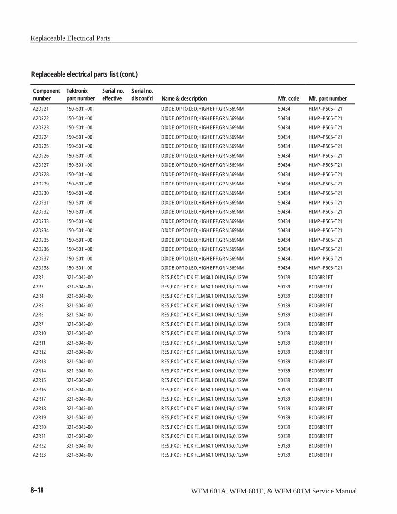
Replaceable Electrical Parts
8–18 WFM 601A, WFM 601E, & WFM 601M Service Manual
Replaceable electrical parts list (cont.)
Componentnumber Mfr. part numberMfr. codeName & description
Serial no.discont’d
Serial no.effective
Tektronixpart number
A2DS21 150–5011–00 DIODE,OPTO:LED;HIGH EFF,GRN,569NM 50434 HLMP–P505–T21
A2DS22 150–5011–00 DIODE,OPTO:LED;HIGH EFF,GRN,569NM 50434 HLMP–P505–T21
A2DS23 150–5011–00 DIODE,OPTO:LED;HIGH EFF,GRN,569NM 50434 HLMP–P505–T21
A2DS24 150–5011–00 DIODE,OPTO:LED;HIGH EFF,GRN,569NM 50434 HLMP–P505–T21
A2DS25 150–5011–00 DIODE,OPTO:LED;HIGH EFF,GRN,569NM 50434 HLMP–P505–T21
A2DS26 150–5011–00 DIODE,OPTO:LED;HIGH EFF,GRN,569NM 50434 HLMP–P505–T21
A2DS27 150–5011–00 DIODE,OPTO:LED;HIGH EFF,GRN,569NM 50434 HLMP–P505–T21
A2DS28 150–5011–00 DIODE,OPTO:LED;HIGH EFF,GRN,569NM 50434 HLMP–P505–T21
A2DS29 150–5011–00 DIODE,OPTO:LED;HIGH EFF,GRN,569NM 50434 HLMP–P505–T21
A2DS30 150–5011–00 DIODE,OPTO:LED;HIGH EFF,GRN,569NM 50434 HLMP–P505–T21
A2DS31 150–5011–00 DIODE,OPTO:LED;HIGH EFF,GRN,569NM 50434 HLMP–P505–T21
A2DS32 150–5011–00 DIODE,OPTO:LED;HIGH EFF,GRN,569NM 50434 HLMP–P505–T21
A2DS33 150–5011–00 DIODE,OPTO:LED;HIGH EFF,GRN,569NM 50434 HLMP–P505–T21
A2DS34 150–5011–00 DIODE,OPTO:LED;HIGH EFF,GRN,569NM 50434 HLMP–P505–T21
A2DS35 150–5011–00 DIODE,OPTO:LED;HIGH EFF,GRN,569NM 50434 HLMP–P505–T21
A2DS36 150–5011–00 DIODE,OPTO:LED;HIGH EFF,GRN,569NM 50434 HLMP–P505–T21
A2DS37 150–5011–00 DIODE,OPTO:LED;HIGH EFF,GRN,569NM 50434 HLMP–P505–T21
A2DS38 150–5011–00 DIODE,OPTO:LED;HIGH EFF,GRN,569NM 50434 HLMP–P505–T21
A2R2 321–5045–00 RES,FXD:THICK FILM;68.1 OHM,1%,0.125W 50139 BCD68R1FT
A2R3 321–5045–00 RES,FXD:THICK FILM;68.1 OHM,1%,0.125W 50139 BCD68R1FT
A2R4 321–5045–00 RES,FXD:THICK FILM;68.1 OHM,1%,0.125W 50139 BCD68R1FT
A2R5 321–5045–00 RES,FXD:THICK FILM;68.1 OHM,1%,0.125W 50139 BCD68R1FT
A2R6 321–5045–00 RES,FXD:THICK FILM;68.1 OHM,1%,0.125W 50139 BCD68R1FT
A2R7 321–5045–00 RES,FXD:THICK FILM;68.1 OHM,1%,0.125W 50139 BCD68R1FT
A2R10 321–5045–00 RES,FXD:THICK FILM;68.1 OHM,1%,0.125W 50139 BCD68R1FT
A2R11 321–5045–00 RES,FXD:THICK FILM;68.1 OHM,1%,0.125W 50139 BCD68R1FT
A2R12 321–5045–00 RES,FXD:THICK FILM;68.1 OHM,1%,0.125W 50139 BCD68R1FT
A2R13 321–5045–00 RES,FXD:THICK FILM;68.1 OHM,1%,0.125W 50139 BCD68R1FT
A2R14 321–5045–00 RES,FXD:THICK FILM;68.1 OHM,1%,0.125W 50139 BCD68R1FT
A2R15 321–5045–00 RES,FXD:THICK FILM;68.1 OHM,1%,0.125W 50139 BCD68R1FT
A2R16 321–5045–00 RES,FXD:THICK FILM;68.1 OHM,1%,0.125W 50139 BCD68R1FT
A2R17 321–5045–00 RES,FXD:THICK FILM;68.1 OHM,1%,0.125W 50139 BCD68R1FT
A2R18 321–5045–00 RES,FXD:THICK FILM;68.1 OHM,1%,0.125W 50139 BCD68R1FT
A2R19 321–5045–00 RES,FXD:THICK FILM;68.1 OHM,1%,0.125W 50139 BCD68R1FT
A2R20 321–5045–00 RES,FXD:THICK FILM;68.1 OHM,1%,0.125W 50139 BCD68R1FT
A2R21 321–5045–00 RES,FXD:THICK FILM;68.1 OHM,1%,0.125W 50139 BCD68R1FT
A2R22 321–5045–00 RES,FXD:THICK FILM;68.1 OHM,1%,0.125W 50139 BCD68R1FT
A2R23 321–5045–00 RES,FXD:THICK FILM;68.1 OHM,1%,0.125W 50139 BCD68R1FT
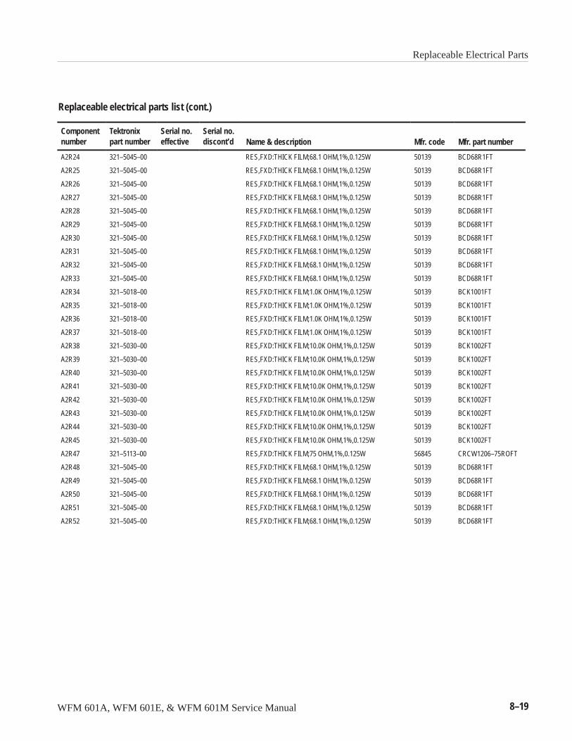
Replaceable Electrical Parts
WFM 601A, WFM 601E, & WFM 601M Service Manual 8–19
Replaceable electrical parts list (cont.)
Componentnumber Mfr. part numberMfr. codeName & description
Serial no.discont’d
Serial no.effective
Tektronixpart number
A2R24 321–5045–00 RES,FXD:THICK FILM;68.1 OHM,1%,0.125W 50139 BCD68R1FT
A2R25 321–5045–00 RES,FXD:THICK FILM;68.1 OHM,1%,0.125W 50139 BCD68R1FT
A2R26 321–5045–00 RES,FXD:THICK FILM;68.1 OHM,1%,0.125W 50139 BCD68R1FT
A2R27 321–5045–00 RES,FXD:THICK FILM;68.1 OHM,1%,0.125W 50139 BCD68R1FT
A2R28 321–5045–00 RES,FXD:THICK FILM;68.1 OHM,1%,0.125W 50139 BCD68R1FT
A2R29 321–5045–00 RES,FXD:THICK FILM;68.1 OHM,1%,0.125W 50139 BCD68R1FT
A2R30 321–5045–00 RES,FXD:THICK FILM;68.1 OHM,1%,0.125W 50139 BCD68R1FT
A2R31 321–5045–00 RES,FXD:THICK FILM;68.1 OHM,1%,0.125W 50139 BCD68R1FT
A2R32 321–5045–00 RES,FXD:THICK FILM;68.1 OHM,1%,0.125W 50139 BCD68R1FT
A2R33 321–5045–00 RES,FXD:THICK FILM;68.1 OHM,1%,0.125W 50139 BCD68R1FT
A2R34 321–5018–00 RES,FXD:THICK FILM;1.0K OHM,1%,0.125W 50139 BCK1001FT
A2R35 321–5018–00 RES,FXD:THICK FILM;1.0K OHM,1%,0.125W 50139 BCK1001FT
A2R36 321–5018–00 RES,FXD:THICK FILM;1.0K OHM,1%,0.125W 50139 BCK1001FT
A2R37 321–5018–00 RES,FXD:THICK FILM;1.0K OHM,1%,0.125W 50139 BCK1001FT
A2R38 321–5030–00 RES,FXD:THICK FILM;10.0K OHM,1%,0.125W 50139 BCK1002FT
A2R39 321–5030–00 RES,FXD:THICK FILM;10.0K OHM,1%,0.125W 50139 BCK1002FT
A2R40 321–5030–00 RES,FXD:THICK FILM;10.0K OHM,1%,0.125W 50139 BCK1002FT
A2R41 321–5030–00 RES,FXD:THICK FILM;10.0K OHM,1%,0.125W 50139 BCK1002FT
A2R42 321–5030–00 RES,FXD:THICK FILM;10.0K OHM,1%,0.125W 50139 BCK1002FT
A2R43 321–5030–00 RES,FXD:THICK FILM;10.0K OHM,1%,0.125W 50139 BCK1002FT
A2R44 321–5030–00 RES,FXD:THICK FILM;10.0K OHM,1%,0.125W 50139 BCK1002FT
A2R45 321–5030–00 RES,FXD:THICK FILM;10.0K OHM,1%,0.125W 50139 BCK1002FT
A2R47 321–5113–00 RES,FXD:THICK FILM;75 OHM,1%,0.125W 56845 CRCW1206–75ROFT
A2R48 321–5045–00 RES,FXD:THICK FILM;68.1 OHM,1%,0.125W 50139 BCD68R1FT
A2R49 321–5045–00 RES,FXD:THICK FILM;68.1 OHM,1%,0.125W 50139 BCD68R1FT
A2R50 321–5045–00 RES,FXD:THICK FILM;68.1 OHM,1%,0.125W 50139 BCD68R1FT
A2R51 321–5045–00 RES,FXD:THICK FILM;68.1 OHM,1%,0.125W 50139 BCD68R1FT
A2R52 321–5045–00 RES,FXD:THICK FILM;68.1 OHM,1%,0.125W 50139 BCD68R1FT
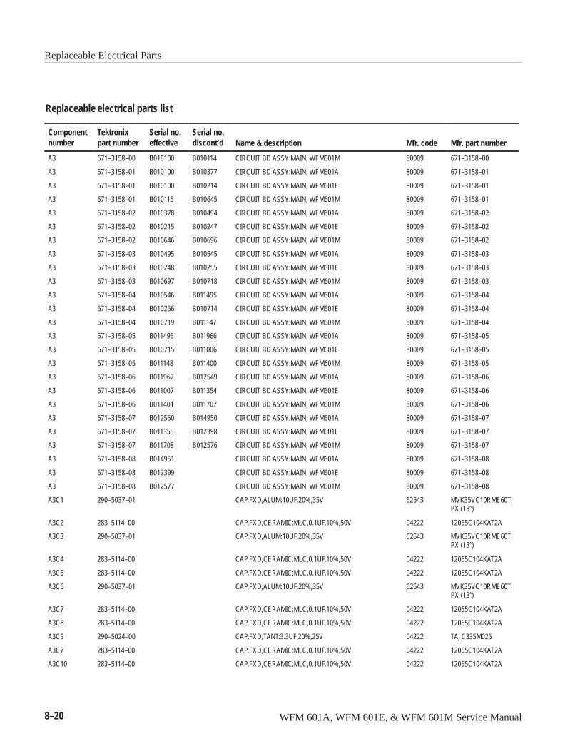
Replaceable Electrical Parts
8–20 WFM 601A, WFM 601E, & WFM 601M Service Manual
Replaceable electrical parts list
Componentnumber
Tektronixpart number
Serial no.effective
Serial no.discont’d Name & description Mfr. code Mfr. part number
A3 671–3158–00 B010100 B010114 CIRCUIT BD ASSY:MAIN, WFM601M 80009 671–3158–00
A3 671–3158–01 B010100 B010377 CIRCUIT BD ASSY:MAIN, WFM601A 80009 671–3158–01
A3 671–3158–01 B010100 B010214 CIRCUIT BD ASSY:MAIN, WFM601E 80009 671–3158–01
A3 671–3158–01 B010115 B010645 CIRCUIT BD ASSY:MAIN, WFM601M 80009 671–3158–01
A3 671–3158–02 B010378 B010494 CIRCUIT BD ASSY:MAIN, WFM601A 80009 671–3158–02
A3 671–3158–02 B010215 B010247 CIRCUIT BD ASSY:MAIN, WFM601E 80009 671–3158–02
A3 671–3158–02 B010646 B010696 CIRCUIT BD ASSY:MAIN, WFM601M 80009 671–3158–02
A3 671–3158–03 B010495 B010545 CIRCUIT BD ASSY:MAIN, WFM601A 80009 671–3158–03
A3 671–3158–03 B010248 B010255 CIRCUIT BD ASSY:MAIN, WFM601E 80009 671–3158–03
A3 671–3158–03 B010697 B010718 CIRCUIT BD ASSY:MAIN, WFM601M 80009 671–3158–03
A3 671–3158–04 B010546 B011495 CIRCUIT BD ASSY:MAIN, WFM601A 80009 671–3158–04
A3 671–3158–04 B010256 B010714 CIRCUIT BD ASSY:MAIN, WFM601E 80009 671–3158–04
A3 671–3158–04 B010719 B011147 CIRCUIT BD ASSY:MAIN, WFM601M 80009 671–3158–04
A3 671–3158–05 B011496 B011966 CIRCUIT BD ASSY:MAIN, WFM601A 80009 671–3158–05
A3 671–3158–05 B010715 B011006 CIRCUIT BD ASSY:MAIN, WFM601E 80009 671–3158–05
A3 671–3158–05 B011148 B011400 CIRCUIT BD ASSY:MAIN, WFM601M 80009 671–3158–05
A3 671–3158–06 B011967 B012549 CIRCUIT BD ASSY:MAIN, WFM601A 80009 671–3158–06
A3 671–3158–06 B011007 B011354 CIRCUIT BD ASSY:MAIN, WFM601E 80009 671–3158–06
A3 671–3158–06 B011401 B011707 CIRCUIT BD ASSY:MAIN, WFM601M 80009 671–3158–06
A3 671–3158–07 B012550 B014950 CIRCUIT BD ASSY:MAIN, WFM601A 80009 671–3158–07
A3 671–3158–07 B011355 B012398 CIRCUIT BD ASSY:MAIN, WFM601E 80009 671–3158–07
A3 671–3158–07 B011708 B012576 CIRCUIT BD ASSY:MAIN, WFM601M 80009 671–3158–07
A3 671–3158–08 B014951 CIRCUIT BD ASSY:MAIN, WFM601A 80009 671–3158–08
A3 671–3158–08 B012399 CIRCUIT BD ASSY:MAIN, WFM601E 80009 671–3158–08
A3 671–3158–08 B012577 CIRCUIT BD ASSY:MAIN, WFM601M 80009 671–3158–08
A3C1 290–5037–01 CAP,FXD,ALUM:10UF,20%,35V 62643 MVK35VC10RME60TPX (13”)
A3C2 283–5114–00 CAP,FXD,CERAMIC:MLC,0.1UF,10%,50V 04222 12065C104KAT2A
A3C3 290–5037–01 CAP,FXD,ALUM:10UF,20%,35V 62643 MVK35VC10RME60TPX (13”)
A3C4 283–5114–00 CAP,FXD,CERAMIC:MLC,0.1UF,10%,50V 04222 12065C104KAT2A
A3C5 283–5114–00 CAP,FXD,CERAMIC:MLC,0.1UF,10%,50V 04222 12065C104KAT2A
A3C6 290–5037–01 CAP,FXD,ALUM:10UF,20%,35V 62643 MVK35VC10RME60TPX (13”)
A3C7 283–5114–00 CAP,FXD,CERAMIC:MLC,0.1UF,10%,50V 04222 12065C104KAT2A
A3C8 283–5114–00 CAP,FXD,CERAMIC:MLC,0.1UF,10%,50V 04222 12065C104KAT2A
A3C9 290–5024–00 CAP,FXD,TANT:3.3UF,20%,25V 04222 TAJC335M025
A3C7 283–5114–00 CAP,FXD,CERAMIC:MLC,0.1UF,10%,50V 04222 12065C104KAT2A
A3C10 283–5114–00 CAP,FXD,CERAMIC:MLC,0.1UF,10%,50V 04222 12065C104KAT2A
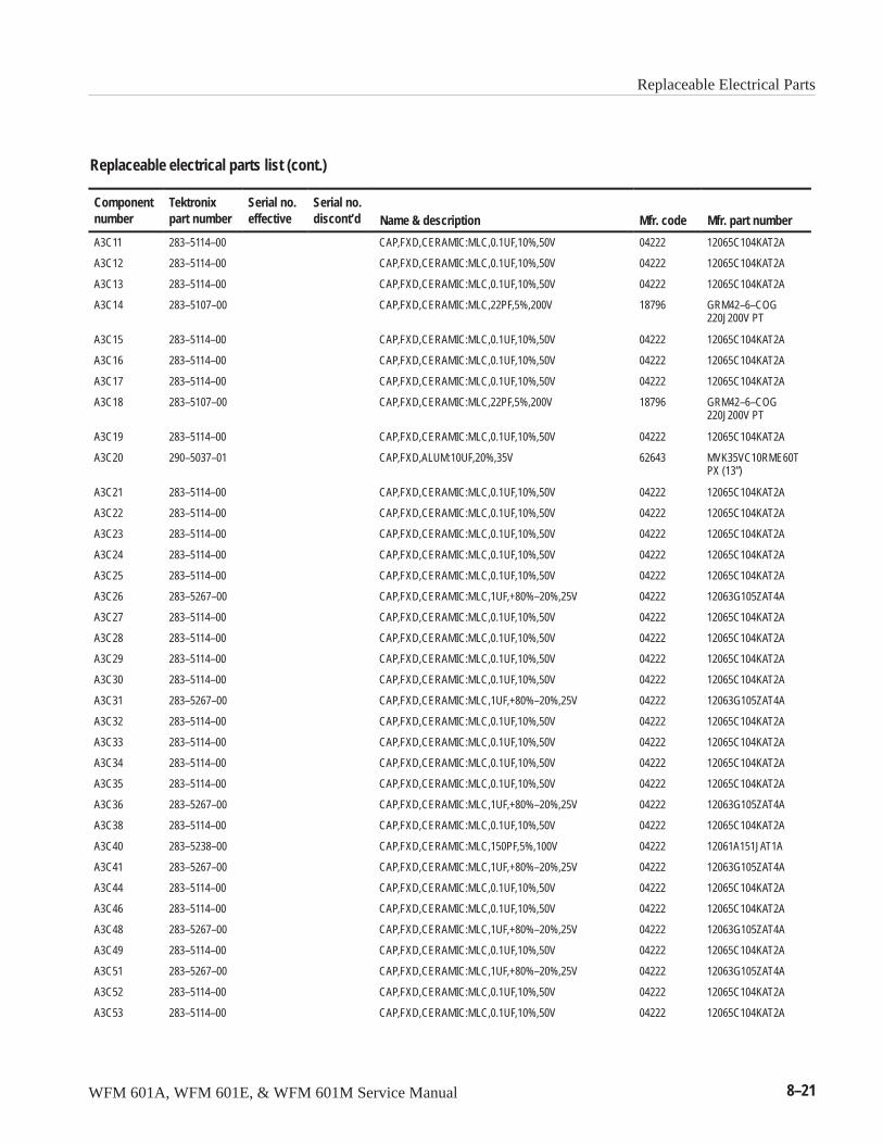
Replaceable Electrical Parts
WFM 601A, WFM 601E, & WFM 601M Service Manual 8–21
Replaceable electrical parts list (cont.)
Componentnumber Mfr. part numberMfr. codeName & description
Serial no.discont’d
Serial no.effective
Tektronixpart number
A3C11 283–5114–00 CAP,FXD,CERAMIC:MLC,0.1UF,10%,50V 04222 12065C104KAT2A
A3C12 283–5114–00 CAP,FXD,CERAMIC:MLC,0.1UF,10%,50V 04222 12065C104KAT2A
A3C13 283–5114–00 CAP,FXD,CERAMIC:MLC,0.1UF,10%,50V 04222 12065C104KAT2A
A3C14 283–5107–00 CAP,FXD,CERAMIC:MLC,22PF,5%,200V 18796 GRM42–6–COG220J200V PT
A3C15 283–5114–00 CAP,FXD,CERAMIC:MLC,0.1UF,10%,50V 04222 12065C104KAT2A
A3C16 283–5114–00 CAP,FXD,CERAMIC:MLC,0.1UF,10%,50V 04222 12065C104KAT2A
A3C17 283–5114–00 CAP,FXD,CERAMIC:MLC,0.1UF,10%,50V 04222 12065C104KAT2A
A3C18 283–5107–00 CAP,FXD,CERAMIC:MLC,22PF,5%,200V 18796 GRM42–6–COG220J200V PT
A3C19 283–5114–00 CAP,FXD,CERAMIC:MLC,0.1UF,10%,50V 04222 12065C104KAT2A
A3C20 290–5037–01 CAP,FXD,ALUM:10UF,20%,35V 62643 MVK35VC10RME60TPX (13”)
A3C21 283–5114–00 CAP,FXD,CERAMIC:MLC,0.1UF,10%,50V 04222 12065C104KAT2A
A3C22 283–5114–00 CAP,FXD,CERAMIC:MLC,0.1UF,10%,50V 04222 12065C104KAT2A
A3C23 283–5114–00 CAP,FXD,CERAMIC:MLC,0.1UF,10%,50V 04222 12065C104KAT2A
A3C24 283–5114–00 CAP,FXD,CERAMIC:MLC,0.1UF,10%,50V 04222 12065C104KAT2A
A3C25 283–5114–00 CAP,FXD,CERAMIC:MLC,0.1UF,10%,50V 04222 12065C104KAT2A
A3C26 283–5267–00 CAP,FXD,CERAMIC:MLC,1UF,+80%–20%,25V 04222 12063G105ZAT4A
A3C27 283–5114–00 CAP,FXD,CERAMIC:MLC,0.1UF,10%,50V 04222 12065C104KAT2A
A3C28 283–5114–00 CAP,FXD,CERAMIC:MLC,0.1UF,10%,50V 04222 12065C104KAT2A
A3C29 283–5114–00 CAP,FXD,CERAMIC:MLC,0.1UF,10%,50V 04222 12065C104KAT2A
A3C30 283–5114–00 CAP,FXD,CERAMIC:MLC,0.1UF,10%,50V 04222 12065C104KAT2A
A3C31 283–5267–00 CAP,FXD,CERAMIC:MLC,1UF,+80%–20%,25V 04222 12063G105ZAT4A
A3C32 283–5114–00 CAP,FXD,CERAMIC:MLC,0.1UF,10%,50V 04222 12065C104KAT2A
A3C33 283–5114–00 CAP,FXD,CERAMIC:MLC,0.1UF,10%,50V 04222 12065C104KAT2A
A3C34 283–5114–00 CAP,FXD,CERAMIC:MLC,0.1UF,10%,50V 04222 12065C104KAT2A
A3C35 283–5114–00 CAP,FXD,CERAMIC:MLC,0.1UF,10%,50V 04222 12065C104KAT2A
A3C36 283–5267–00 CAP,FXD,CERAMIC:MLC,1UF,+80%–20%,25V 04222 12063G105ZAT4A
A3C38 283–5114–00 CAP,FXD,CERAMIC:MLC,0.1UF,10%,50V 04222 12065C104KAT2A
A3C40 283–5238–00 CAP,FXD,CERAMIC:MLC,150PF,5%,100V 04222 12061A151JAT1A
A3C41 283–5267–00 CAP,FXD,CERAMIC:MLC,1UF,+80%–20%,25V 04222 12063G105ZAT4A
A3C44 283–5114–00 CAP,FXD,CERAMIC:MLC,0.1UF,10%,50V 04222 12065C104KAT2A
A3C46 283–5114–00 CAP,FXD,CERAMIC:MLC,0.1UF,10%,50V 04222 12065C104KAT2A
A3C48 283–5267–00 CAP,FXD,CERAMIC:MLC,1UF,+80%–20%,25V 04222 12063G105ZAT4A
A3C49 283–5114–00 CAP,FXD,CERAMIC:MLC,0.1UF,10%,50V 04222 12065C104KAT2A
A3C51 283–5267–00 CAP,FXD,CERAMIC:MLC,1UF,+80%–20%,25V 04222 12063G105ZAT4A
A3C52 283–5114–00 CAP,FXD,CERAMIC:MLC,0.1UF,10%,50V 04222 12065C104KAT2A
A3C53 283–5114–00 CAP,FXD,CERAMIC:MLC,0.1UF,10%,50V 04222 12065C104KAT2A
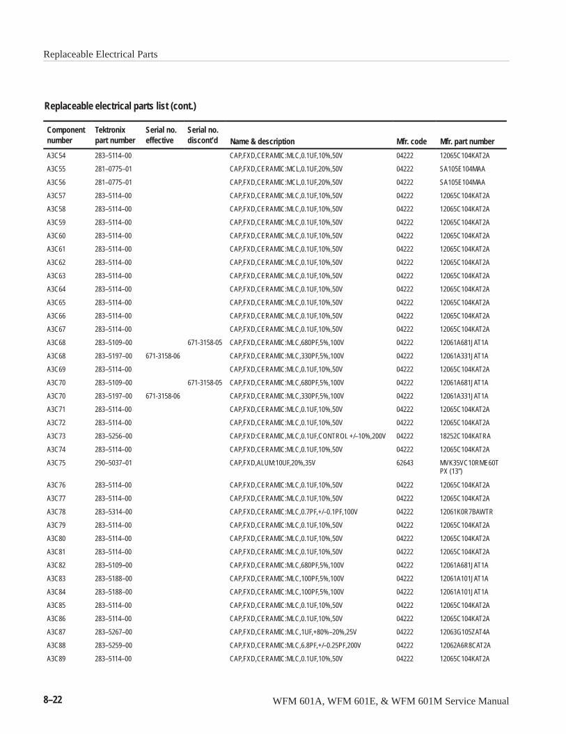
Replaceable Electrical Parts
8–22 WFM 601A, WFM 601E, & WFM 601M Service Manual
Replaceable electrical parts list (cont.)
Componentnumber Mfr. part numberMfr. codeName & description
Serial no.discont’d
Serial no.effective
Tektronixpart number
A3C54 283–5114–00 CAP,FXD,CERAMIC:MLC,0.1UF,10%,50V 04222 12065C104KAT2A
A3C55 281–0775–01 CAP,FXD,CERAMIC:MCL,0.1UF,20%,50V 04222 SA105E104MAA
A3C56 281–0775–01 CAP,FXD,CERAMIC:MCL,0.1UF,20%,50V 04222 SA105E104MAA
A3C57 283–5114–00 CAP,FXD,CERAMIC:MLC,0.1UF,10%,50V 04222 12065C104KAT2A
A3C58 283–5114–00 CAP,FXD,CERAMIC:MLC,0.1UF,10%,50V 04222 12065C104KAT2A
A3C59 283–5114–00 CAP,FXD,CERAMIC:MLC,0.1UF,10%,50V 04222 12065C104KAT2A
A3C60 283–5114–00 CAP,FXD,CERAMIC:MLC,0.1UF,10%,50V 04222 12065C104KAT2A
A3C61 283–5114–00 CAP,FXD,CERAMIC:MLC,0.1UF,10%,50V 04222 12065C104KAT2A
A3C62 283–5114–00 CAP,FXD,CERAMIC:MLC,0.1UF,10%,50V 04222 12065C104KAT2A
A3C63 283–5114–00 CAP,FXD,CERAMIC:MLC,0.1UF,10%,50V 04222 12065C104KAT2A
A3C64 283–5114–00 CAP,FXD,CERAMIC:MLC,0.1UF,10%,50V 04222 12065C104KAT2A
A3C65 283–5114–00 CAP,FXD,CERAMIC:MLC,0.1UF,10%,50V 04222 12065C104KAT2A
A3C66 283–5114–00 CAP,FXD,CERAMIC:MLC,0.1UF,10%,50V 04222 12065C104KAT2A
A3C67 283–5114–00 CAP,FXD,CERAMIC:MLC,0.1UF,10%,50V 04222 12065C104KAT2A
A3C68 283–5109–00 671-3158-05 CAP,FXD,CERAMIC:MLC,680PF,5%,100V 04222 12061A681JAT1A
A3C68 283–5197–00 671-3158-06 CAP,FXD,CERAMIC:MLC,330PF,5%,100V 04222 12061A331JAT1A
A3C69 283–5114–00 CAP,FXD,CERAMIC:MLC,0.1UF,10%,50V 04222 12065C104KAT2A
A3C70 283–5109–00 671-3158-05 CAP,FXD,CERAMIC:MLC,680PF,5%,100V 04222 12061A681JAT1A
A3C70 283–5197–00 671-3158-06 CAP,FXD,CERAMIC:MLC,330PF,5%,100V 04222 12061A331JAT1A
A3C71 283–5114–00 CAP,FXD,CERAMIC:MLC,0.1UF,10%,50V 04222 12065C104KAT2A
A3C72 283–5114–00 CAP,FXD,CERAMIC:MLC,0.1UF,10%,50V 04222 12065C104KAT2A
A3C73 283–5256–00 CAP,FXD:CERAMIC,MLC,0.1UF,CONTROL +/–10%,200V 04222 18252C104KATRA
A3C74 283–5114–00 CAP,FXD,CERAMIC:MLC,0.1UF,10%,50V 04222 12065C104KAT2A
A3C75 290–5037–01 CAP,FXD,ALUM:10UF,20%,35V 62643 MVK35VC10RME60TPX (13”)
A3C76 283–5114–00 CAP,FXD,CERAMIC:MLC,0.1UF,10%,50V 04222 12065C104KAT2A
A3C77 283–5114–00 CAP,FXD,CERAMIC:MLC,0.1UF,10%,50V 04222 12065C104KAT2A
A3C78 283–5314–00 CAP,FXD,CERAMIC:MLC,0.7PF,+/–0.1PF,100V 04222 12061K0R7BAWTR
A3C79 283–5114–00 CAP,FXD,CERAMIC:MLC,0.1UF,10%,50V 04222 12065C104KAT2A
A3C80 283–5114–00 CAP,FXD,CERAMIC:MLC,0.1UF,10%,50V 04222 12065C104KAT2A
A3C81 283–5114–00 CAP,FXD,CERAMIC:MLC,0.1UF,10%,50V 04222 12065C104KAT2A
A3C82 283–5109–00 CAP,FXD,CERAMIC:MLC,680PF,5%,100V 04222 12061A681JAT1A
A3C83 283–5188–00 CAP,FXD,CERAMIC:MLC,100PF,5%,100V 04222 12061A101JAT1A
A3C84 283–5188–00 CAP,FXD,CERAMIC:MLC,100PF,5%,100V 04222 12061A101JAT1A
A3C85 283–5114–00 CAP,FXD,CERAMIC:MLC,0.1UF,10%,50V 04222 12065C104KAT2A
A3C86 283–5114–00 CAP,FXD,CERAMIC:MLC,0.1UF,10%,50V 04222 12065C104KAT2A
A3C87 283–5267–00 CAP,FXD,CERAMIC:MLC,1UF,+80%–20%,25V 04222 12063G105ZAT4A
A3C88 283–5259–00 CAP,FXD,CERAMIC:MLC,6.8PF,+/–0.25PF,200V 04222 12062A6R8CAT2A
A3C89 283–5114–00 CAP,FXD,CERAMIC:MLC,0.1UF,10%,50V 04222 12065C104KAT2A
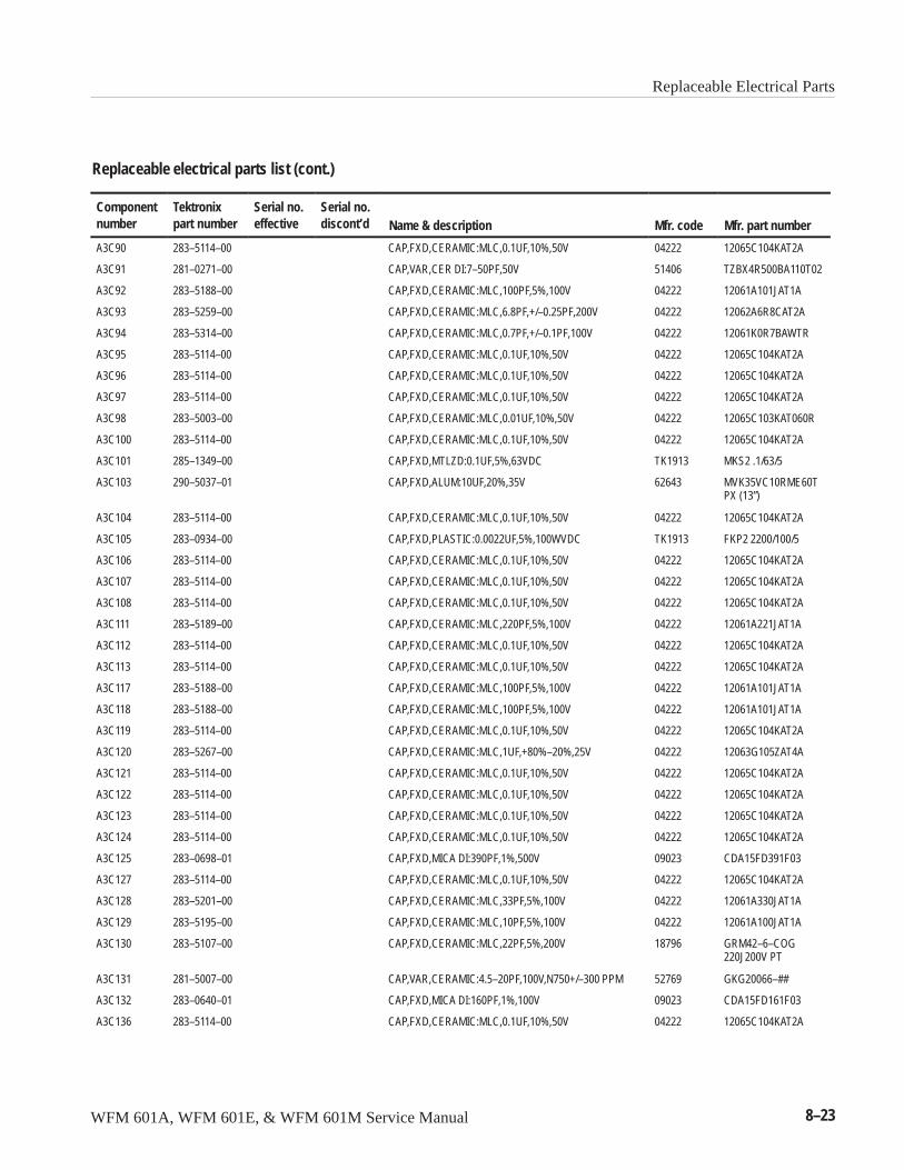
Replaceable Electrical Parts
WFM 601A, WFM 601E, & WFM 601M Service Manual 8–23
Replaceable electrical parts list (cont.)
Componentnumber Mfr. part numberMfr. codeName & description
Serial no.discont’d
Serial no.effective
Tektronixpart number
A3C90 283–5114–00 CAP,FXD,CERAMIC:MLC,0.1UF,10%,50V 04222 12065C104KAT2A
A3C91 281–0271–00 CAP,VAR,CER DI:7–50PF,50V 51406 TZBX4R500BA110T02
A3C92 283–5188–00 CAP,FXD,CERAMIC:MLC,100PF,5%,100V 04222 12061A101JAT1A
A3C93 283–5259–00 CAP,FXD,CERAMIC:MLC,6.8PF,+/–0.25PF,200V 04222 12062A6R8CAT2A
A3C94 283–5314–00 CAP,FXD,CERAMIC:MLC,0.7PF,+/–0.1PF,100V 04222 12061K0R7BAWTR
A3C95 283–5114–00 CAP,FXD,CERAMIC:MLC,0.1UF,10%,50V 04222 12065C104KAT2A
A3C96 283–5114–00 CAP,FXD,CERAMIC:MLC,0.1UF,10%,50V 04222 12065C104KAT2A
A3C97 283–5114–00 CAP,FXD,CERAMIC:MLC,0.1UF,10%,50V 04222 12065C104KAT2A
A3C98 283–5003–00 CAP,FXD,CERAMIC:MLC,0.01UF,10%,50V 04222 12065C103KAT060R
A3C100 283–5114–00 CAP,FXD,CERAMIC:MLC,0.1UF,10%,50V 04222 12065C104KAT2A
A3C101 285–1349–00 CAP,FXD,MTLZD:0.1UF,5%,63VDC TK1913 MKS2 .1/63/5
A3C103 290–5037–01 CAP,FXD,ALUM:10UF,20%,35V 62643 MVK35VC10RME60TPX (13”)
A3C104 283–5114–00 CAP,FXD,CERAMIC:MLC,0.1UF,10%,50V 04222 12065C104KAT2A
A3C105 283–0934–00 CAP,FXD,PLASTIC:0.0022UF,5%,100WVDC TK1913 FKP2 2200/100/5
A3C106 283–5114–00 CAP,FXD,CERAMIC:MLC,0.1UF,10%,50V 04222 12065C104KAT2A
A3C107 283–5114–00 CAP,FXD,CERAMIC:MLC,0.1UF,10%,50V 04222 12065C104KAT2A
A3C108 283–5114–00 CAP,FXD,CERAMIC:MLC,0.1UF,10%,50V 04222 12065C104KAT2A
A3C111 283–5189–00 CAP,FXD,CERAMIC:MLC,220PF,5%,100V 04222 12061A221JAT1A
A3C112 283–5114–00 CAP,FXD,CERAMIC:MLC,0.1UF,10%,50V 04222 12065C104KAT2A
A3C113 283–5114–00 CAP,FXD,CERAMIC:MLC,0.1UF,10%,50V 04222 12065C104KAT2A
A3C117 283–5188–00 CAP,FXD,CERAMIC:MLC,100PF,5%,100V 04222 12061A101JAT1A
A3C118 283–5188–00 CAP,FXD,CERAMIC:MLC,100PF,5%,100V 04222 12061A101JAT1A
A3C119 283–5114–00 CAP,FXD,CERAMIC:MLC,0.1UF,10%,50V 04222 12065C104KAT2A
A3C120 283–5267–00 CAP,FXD,CERAMIC:MLC,1UF,+80%–20%,25V 04222 12063G105ZAT4A
A3C121 283–5114–00 CAP,FXD,CERAMIC:MLC,0.1UF,10%,50V 04222 12065C104KAT2A
A3C122 283–5114–00 CAP,FXD,CERAMIC:MLC,0.1UF,10%,50V 04222 12065C104KAT2A
A3C123 283–5114–00 CAP,FXD,CERAMIC:MLC,0.1UF,10%,50V 04222 12065C104KAT2A
A3C124 283–5114–00 CAP,FXD,CERAMIC:MLC,0.1UF,10%,50V 04222 12065C104KAT2A
A3C125 283–0698–01 CAP,FXD,MICA DI:390PF,1%,500V 09023 CDA15FD391F03
A3C127 283–5114–00 CAP,FXD,CERAMIC:MLC,0.1UF,10%,50V 04222 12065C104KAT2A
A3C128 283–5201–00 CAP,FXD,CERAMIC:MLC,33PF,5%,100V 04222 12061A330JAT1A
A3C129 283–5195–00 CAP,FXD,CERAMIC:MLC,10PF,5%,100V 04222 12061A100JAT1A
A3C130 283–5107–00 CAP,FXD,CERAMIC:MLC,22PF,5%,200V 18796 GRM42–6–COG220J200V PT
A3C131 281–5007–00 CAP,VAR,CERAMIC:4.5–20PF,100V,N750+/–300 PPM 52769 GKG20066–##
A3C132 283–0640–01 CAP,FXD,MICA DI:160PF,1%,100V 09023 CDA15FD161F03
A3C136 283–5114–00 CAP,FXD,CERAMIC:MLC,0.1UF,10%,50V 04222 12065C104KAT2A
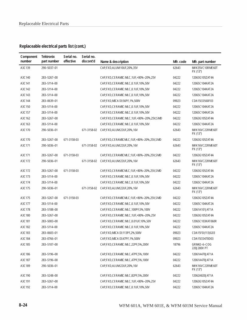
Replaceable Electrical Parts
8–24 WFM 601A, WFM 601E, & WFM 601M Service Manual
Replaceable electrical parts list (cont.)
Componentnumber Mfr. part numberMfr. codeName & description
Serial no.discont’d
Serial no.effective
Tektronixpart number
A3C139 290–5037–01 CAP,FXD,ALUM:10UF,20%,35V 62643 MVK35VC10RME60TPX (13”)
A3C140 283–5267–00 CAP,FXD,CERAMIC:MLC,1UF,+80%–20%,25V 04222 12063G105ZAT4A
A3C141 283–5114–00 CAP,FXD,CERAMIC:MLC,0.1UF,10%,50V 04222 12065C104KAT2A
A3C142 283–5114–00 CAP,FXD,CERAMIC:MLC,0.1UF,10%,50V 04222 12065C104KAT2A
A3C143 283–5114–00 CAP,FXD,CERAMIC:MLC,0.1UF,10%,50V 04222 12065C104KAT2A
A3C144 283–0639–01 CAP,FXD,MICA DI:56PF,1%,500V 09023 CDA15ED560F03
A3C150 283–5114–00 CAP,FXD,CERAMIC:MLC,0.1UF,10%,50V 04222 12065C104KAT2A
A3C157 283–5114–00 CAP,FXD,CERAMIC:MLC,0.1UF,10%,50V 04222 12065C104KAT2A
A3C162 283–5267–00 CAP,FXD,CERAMIC:MLC,1UF,+80%–20%,25V,SMD 04222 12063G105ZAT4A
A3C163 283–5114–00 CAP,FXD,CERAMIC:MLC,0.1UF,10%,50V 04222 12065C104KAT2A
A3C170 290–5036–01 671-3158-02 CAP,FXD,ALUM:22UF,20%,16V 62643 MVK16VC22RME60TPX (13”)
A3C170 283–5267–00 671-3158-03 CAP,FXD,CERAMICMLC;1UF,+80%–20%,25V,SMD 04222 12063G105ZAT4A
A3C171 290–5036–01 671-3158-02 CAP,FXD,ALUM:22UF,20%,16V 62643 MVK16VC22RME60TPX (13”)
A3C171 283–5267–00 671-3158-03 CAP,FXD,CERAMICMLC;1UF,+80%–20%,25V,SMD 04222 12063G105ZAT4A
A3C172 290–5036–01 671-3158-02 CAP,FXD,ALUM:22UF,20%,16V 62643 MVK16VC22RME60TPX (13”)
A3C172 283–5267–00 671-3158-03 CAP,FXD,CERAMICMLC;1UF,+80%–20%,25V,SMD 04222 12063G105ZAT4A
A3C173 283–5114–00 CAP,FXD,CERAMIC:MLC,0.1UF,10%,50V 04222 12065C104KAT2A
A3C174 283–5114–00 CAP,FXD,CERAMIC:MLC,0.1UF,10%,50V 04222 12065C104KAT2A
A3C175 290–5036–01 671-3158-02 CAP,FXD,ALUM:22UF,20%,16V 62643 MVK16VC22RME60TPX (13”)
A3C175 283–5267–00 671-3158-03 CAP,FXD,CERAMICMLC;1UF,+80%–20%,25V,SMD 04222 12063G105ZAT4A
A3C177 283–5114–00 CAP,FXD,CERAMIC:MLC,0.1UF,10%,50V 04222 12065C104KAT2A
A3C178 283–5188–00 CAP,FXD,CERAMIC:MLC,100PF,5%,100V 04222 12061A101JAT1A
A3C180 283–5267–00 CAP,FXD,CERAMIC:MLC,1UF,+80%–20%,25V 04222 12063G105ZAT4A
A3C181 283–5003–00 CAP,FXD,CERAMIC:MLC,0.01UF,10%,50V 04222 12065C103KAT060R
A3C182 283–5114–00 CAP,FXD,CERAMIC:MLC,0.1UF,10%,50V 04222 12065C104KAT2A
A3C183 283–0603–01 CAP,FXD,MICA DI:113PF,2%,500V 09023 CDA15FD(113)G03
A3C184 283–0766–01 CAP,FXD,MICA DI:47PF,1%,500V 09023 CDA15ED470D03
A3C185 283–5107–00 CAP,FXD,CERAMIC:MLC,22PF,5%,200V 18796 GRM42–6–COG220J200V PT
A3C186 283–5196–00 CAP,FXD,CERAMIC:MLC,47PF,5%,100V 04222 12061A470JAT1A
A3C187 283–5196–00 CAP,FXD,CERAMIC:MLC,47PF,5%,100V 04222 12061A470JAT1A
A3C189 290–5036–01 CAP,FXD,ALUM:22UF,20%,16V 62643 MVK16VC22RME60TPX (13”)
A3C190 283–5248–00 CAP,FXD,CERAMIC:MLC,82PF,5%,200V 04222 12062A820JAT1A
A3C191 283–5267–00 CAP,FXD,CERAMIC:MLC,1UF,+80%–20%,25V 04222 12063G105ZAT4A
A3C192 283–5114–00 CAP,FXD,CERAMIC:MLC,0.1UF,10%,50V 04222 12065C104KAT2A
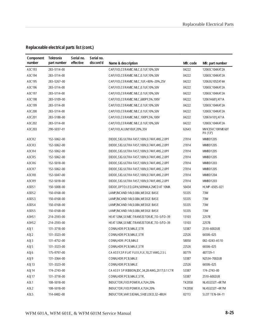
Replaceable Electrical Parts
WFM 601A, WFM 601E, & WFM 601M Service Manual 8–25
Replaceable electrical parts list (cont.)
Componentnumber Mfr. part numberMfr. codeName & description
Serial no.discont’d
Serial no.effective
Tektronixpart number
A3C193 283–5114–00 CAP,FXD,CERAMIC:MLC,0.1UF,10%,50V 04222 12065C104KAT2A
A3C194 283–5114–00 CAP,FXD,CERAMIC:MLC,0.1UF,10%,50V 04222 12065C104KAT2A
A3C195 283–5267–00 CAP,FXD,CERAMIC:MLC,1UF,+80%–20%,25V 04222 12063G105ZAT4A
A3C196 283–5114–00 CAP,FXD,CERAMIC:MLC,0.1UF,10%,50V 04222 12065C104KAT2A
A3C197 283–5114–00 CAP,FXD,CERAMIC:MLC,0.1UF,10%,50V 04222 12065C104KAT2A
A3C198 283–5109–00 CAP,FXD,CERAMIC:MLC,680PF,5%,100V 04222 12061A681JAT1A
A3C199 283–5114–00 CAP,FXD,CERAMIC:MLC,0.1UF,10%,50V 04222 12065C104KAT2A
A3C200 283–5114–00 CAP,FXD,CERAMIC:MLC,0.1UF,10%,50V 04222 12065C104KAT2A
A3C201 283–5188–00 CAP,FXD,CERAMIC:MLC,100PF,5%,100V 04222 12061A101JAT1A
A3C202 283–5114–00 CAP,FXD,CERAMIC:MLC,0.1UF,10%,50V 04222 12065C104KAT2A
A3C203 290–5037–01 CAP,FXD,ALUM:10UF,20%,35V 62643 MVK35VC10RME60TPX (13”)
A3CR2 152–5062–00 DIODE,SIG:ULTRA FAST,100V,0.74VF,4NS,2.0PF 27014 MMBD1205
A3CR3 152–5062–00 DIODE,SIG:ULTRA FAST,100V,0.74VF,4NS,2.0PF 27014 MMBD1205
A3CR4 152–5062–00 DIODE,SIG:ULTRA FAST,100V,0.74VF,4NS,2.0PF 27014 MMBD1205
A3CR5 152–5062–00 DIODE,SIG:ULTRA FAST,100V,0.74VF,4NS,2.0PF 27014 MMBD1205
A3CR6 152–5018–00 DIODE,SIG:ULTRA FAST,100V,0.74VF,4NS,2.0PF 27014 MMBD1203
A3CR7 152–5062–00 DIODE,SIG:ULTRA FAST,100V,0.74VF,4NS,2.0PF 27014 MMBD1205
A3CR8 152–5047–00 DIODE,SIG:ULTRA FAST,100V,0.74VF,4NS,2.0PF 27014 MMBD1204
A3CR9 152–5018–00 DIODE,SIG:ULTRA FAST,100V,0.74VF,4NS,2.0PF 27014 MMBD1203
A3DS1 150–5008–00 DIODE,OPTO:LED,GRN,569NM,4.2MCD AT 10MA 50434 HLMP–6505–021
A3DS2 150–0168–00 LAMP,INCAND:14V,0.08A,WEDGE BASE 55335 73W
A3DS3 150–0168–00 LAMP,INCAND:14V,0.08A,WEDGE BASE 55335 73W
A3DS4 150–0168–00 LAMP,INCAND:14V,0.08A,WEDGE BASE 55335 73W
A3DS5 150–0168–00 LAMP,INCAND:14V,0.08A,WEDGE BASE 55335 73W
A3HS1 214–2593–00 HEAT SINK,SEMIC:TRANSISTOR/IC,TO–5/TO–39 13103 2257B
A3HS2 214–2593–00 HEAT SINK,SEMIC:TRANSISTOR/IC,TO–5/TO–39 13103 2257B
A3J1 131–3718–00 CONN,HDR:PCB,MALE,STR 53387 2510–6002UB
A3J2 131–3323–00 CONN,HDR:PCB,MALE,STR 22526 66506–025
A3J3 131–4752–00 CONN,HDR::PCB,MALE 58050 082–0243–AS10
A3J5 131–3323–00 CONN,HDR:PCB,MALE,STR 22526 66506–025
A3J6 175–9797–00 CA ASSY,SP:FLAT FLEX,FLX,10,27 AWG,2.5 L 00779 487729–1
A3J9 131–3364–00 CONN,HDR:PCB,MALE 53387 N2534–7002UB
A3J13 131–3323–00 CONN,HDR:PCB,MALE 22526 66506–025
A3J14 174–2743–00 CA ASSY SP:RIBBON,IDC,34,28 AWG,2X17,0.1 CTR 53387 174–2743–00
A3J17 131–3718–00 CONN,HDR:PCB,MALE,STR, 53387 2510–6002UB
A3L1 108–5018–00 INDUCTOR,FXD:POWER,4.7UH,20% TK2058 NL453232T–4R7M
A3L2 108–5018–00 INDUCTOR,FXD:POWER,4.7UH,20% TK2058 NL453232T–4R7M
A3L5 114–0482–00 INDUCTOR,VAR:SIGNAL,SHIELDED,32–48UH 02113 SLOT TEN–04–11
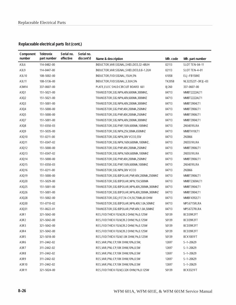
Replaceable Electrical Parts
8–26 WFM 601A, WFM 601E, & WFM 601M Service Manual
Replaceable electrical parts list (cont.)
Componentnumber Mfr. part numberMfr. codeName & description
Serial no.discont’d
Serial no.effective
Tektronixpart number
A3L6 114–0482–00 INDUCTOR,VAR:SIGNAL,SHIELDED,32–48UH 02113 SLOT TEN–04–11
A3L9 114–0447–00 INDUCTOR,VAR:SIGNAL,SHIELDED,0.8–1.2UH 02113 SLOT TEN–4–01
A3L10 108–5002–00 INDUCTOR,FXD:SIGNAL,15UH,5% 61058 ELJ–FB150KE
A3L11 108–5136–00 INDUCTOR,FXD:SIGNAL,3.3UH,5% TK2058 NL322522T–3R3J–03
A3M14 337–0607–00 PLATE,ELEC SHLD:CIRCUIT BOARD 661 0J260 337–0607–00
A3Q1 151–5021–00 TRANSISTOR,SIG:NPN,40V,600MA,300MHZ, 04713 MMBT2222ALT1
A3Q2 151–5021–00 TRANSISTOR,SIG:NPN,40V,600MA,300MHZ 04713 MMBT2222ALT1
A3Q3 151–5001–00 TRANSISTOR,SIG:NPN,40V,200MA,300MHZ 04713 MMBT3904LT1
A3Q4 151–5000–00 TRANSISTOR,SIG:PNP,40V,200MA,250MHZ 04713 MMBT3906LT1
A3Q5 151–5000–00 TRANSISTOR,SIG:PNP,40V,200MA,250MHZ 04713 MMBT3906LT1
A3Q7 151–5001–00 TRANSISTOR,SIG:NPN,40V,200MA,300MHZ 04713 MMBT3904LT1
A3Q8 151–0350–03 TRANSISTOR,SIG:PNP,150V,600MA,100MHZ 04713 2N5401RLRA
A3Q9 151–5035–00 TRANSISTOR,SIG:NPN,25V,30MA,650MHZ 04713 MMBTH10LT1
A3Q10 151–0211–00 TRANSISTOR,SIG:NPN,30V VCEO,55V 04713 2N3866
A3Q11 151–0347–02 TRANSISTOR,SIG:NPN,160V,600MA,100MHZ, 04713 2N5551RLRA
A3Q12 151–5000–00 TRANSISTOR,SIG:PNP,40V,200MA,250MHZ 04713 MMBT3906LT1
A3Q13 151–0347–02 TRANSISTOR,SIG:NPN,160V,600MA,100MHZ 04713 2N5551RLRA
A3Q14 151–5000–00 TRANSISTOR,SIG:PNP,40V,200MA,250MHZ 04713 MMBT3906LT1
A3Q15 151–0350–03 TRANSISTOR,SIG:PNP,150V,600MA,100MHZ 04713 2N5401RLRA
A3Q16 151–0211–00 TRANSISTOR,SIG:NPN,30V VCEO 04713 2N3866
A3Q19 151–5000–00 TRANSISTOR,SIG:BIPOLAR,PNP,40V,200MA,250MHZ 04713 MMBT3906LT1
A3Q20 151–5029–00 TRANSISTOR,SIG:BIPOLAR,NPN,15V,500MA 04713 MMBT2369ALT1
A3Q25 151–5001–00 TRANSISTOR,SIG:BIPOLAR,NPN,40V,200MA,300MHZ 04713 MMBT3904LT1
A3Q26 151–5001–00 TRANSISTOR,SIG:BIPOLAR,NPN,40V,200MA,300MHZ 04713 MMBT3904LT1
A3Q28 151–5002–00 TRANSISTOR,SIG:JFET,N–CH,5V,75MA,60 OHM 04713 MMBF4392LT1
A3Q30 151–0710–02 TRANSISTOR,SIG:BIPOLAR,NPN,40V,1.0A,50MHZ 04713 MPS6715RLRA
A3Q31 151–0622–01 TRANSISTOR,SIG:BIPOLAR,PNP,40V,1.0A,50MHZ 04713 MPS6727RLRA
A3R1 321–5042–00 RES,FXD:THICK FILM,39.2 OHM,1%,0.125W 50139 BCD39R2FT
A3R2 321–5042–00 RES,FXD:THICK FILM,39.2 OHM,1%,0.125W 50139 BCD39R2FT
A3R3 321–5042–00 RES,FXD:THICK FILM,39.2 OHM,1%,0.125W 50139 BCD39R2FT
A3R4 321–5042–00 RES,FXD:THICK FILM,39.2 OHM,1%,0.125W 50139 BCD39R2FT
A3R5 321–5018–00 RES,FXD:THICK FILM,1.0K OHM,1%,0.125W 50139 BCK1001FT
A3R6 311–2442–02 RES,VAR,PNL:CP,10K OHM,10%,0.5W, 12697 S–1–20629
A3R7 311–2442–02 RES,VAR,PNL:CP,10K OHM,10%,0.5W 12697 S–1–20629
A3R8 311–2442–02 RES,VAR,PNL:CP,10K OHM,10%,0.5W 12697 S–1–20629
A3R9 311–2442–02 RES,VAR,PNL:CP,10K OHM,10%,0.5W 12697 S–1–20629
A3R10 311–2442–02 RES,VAR,PNL:CP,10K OHM,10%,0.5W 12697 S–1–20629
A3R11 321–5024–00 RES,FXD:THICK FILM,3.32K OHM,1%,0.125W 50139 BCK3321FT
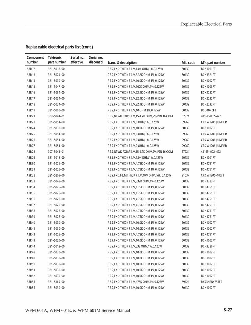
Replaceable Electrical Parts
WFM 601A, WFM 601E, & WFM 601M Service Manual 8–27
Replaceable electrical parts list (cont.)
Componentnumber Mfr. part numberMfr. codeName & description
Serial no.discont’d
Serial no.effective
Tektronixpart number
A3R12 321–5018–00 RES,FXD:THICK FILM,1.0K OHM,1%,0.125W 50139 BCK1001FT
A3R13 321–5024–00 RES,FXD:THICK FILM,3.32K OHM,1%,0.125W 50139 BCK3321FT
A3R14 321–5030–00 RES,FXD:THICK FILM,10.0K OHM,1%,0.125W 50139 BCK1002FT
A3R15 321–5047–00 RES,FXD:THICK FILM,100K OHM,1%,0.125W 50139 BCK1003FT
A3R16 321–5034–00 RES,FXD:THICK FILM,22.1K OHM,1%,0.125W 50139 BCK2212FT
A3R17 321–5034–00 RES,FXD:THICK FILM,22.1K OHM,1%,0.125W 50139 BCK2212FT
A3R18 321–5034–00 RES,FXD:THICK FILM,22.1K OHM,1%,0.125W 50139 BCK2212FT
A3R19 321–5000–00 RES,FXD:THICK FILM,10 OHM,1%,0.125W 50139 BCD10R0FT
A3R21 307–5041–01 RES,NTWK FXD:FILM,15,4.7K OHM,2%,PIN 16 COM 57924 4816P–002–472
A3R23 321–5051–00 RES,FXD:THICK FILM,0 OHM,1%,0.125W 09969 CRCW1206 JUMPER
A3R24 321–5030–00 RES,FXD:THICK FILM,10.0K OHM,1%,0.125W 50139 BCK1002FT
A3R25 321–5051–00 RES,FXD:THICK FILM,0 OHM,1%,0.125W 09969 CRCW1206 JUMPER
A3R26 321–5051–00 RES,FXD:THICK FILM,0 OHM,1%,0.125W 09969 CRCW1206 JUMPER
A3R27 321–5051–00 RES,FXD:THICK FILM,0 OHM,1%,0.125W 09969 CRCW1206 JUMPER
A3R28 307–5041–01 RES,NTWK FXD:FILM,15,4.7K OHM,2%,PIN 16 COM 57924 4816P–002–472
A3R29 321–5018–00 RES,FXD:THICK FILM,1.0K OHM,1%,0.125W 50139 BCK1001FT
A3R30 321–5026–00 RES,FXD:THICK FILM,4.75K OHM,1%,0.125W 50139 BCK4751FT
A3R31 321–5026–00 RES,FXD:THICK FILM,4.75K OHM,1%,0.125W 50139 BCK4751FT
A3R32 321–5208–00 RES,FXD,FILM:THICK FILM,10M OHM, 5%, 0.125W 91637 CRCW1206–106JT
A3R33 321–5048–00 RES,FXD:THICK FILM,332K OHM,1%,0.125W 50139 BCK3323FT
A3R34 321–5026–00 RES,FXD:THICK FILM,4.75K OHM,1%,0.125W 50139 BCK4751FT
A3R35 321–5026–00 RES,FXD:THICK FILM,4.75K OHM,1%,0.125W 50139 BCK4751FT
A3R36 321–5026–00 RES,FXD:THICK FILM,4.75K OHM,1%,0.125W 50139 BCK4751FT
A3R37 321–5026–00 RES,FXD:THICK FILM,4.75K OHM,1%,0.125W 50139 BCK4751FT
A3R38 321–5026–00 RES,FXD:THICK FILM,4.75K OHM,1%,0.125W 50139 BCK4751FT
A3R39 321–5026–00 RES,FXD:THICK FILM,4.75K OHM,1%,0.125W 50139 BCK4751FT
A3R40 321–5030–00 RES,FXD:THICK FILM,10.0K OHM,1%,0.125W 50139 BCK1002FT
A3R41 321–5030–00 RES,FXD:THICK FILM,10.0K OHM,1%,0.125W 50139 BCK1002FT
A3R42 321–5026–00 RES,FXD:THICK FILM,4.75K OHM,1%,0.125W 50139 BCK4751FT
A3R43 321–5030–00 RES,FXD:THICK FILM,10.0K OHM,1%,0.125W 50139 BCK1002FT
A3R44 321–5012–00 RES,FXD:THICK FILM,332 OHM,1%,0.125W 50139 BCK3320FT
A3R48 321–5030–00 RES,FXD:THICK FILM,10.0K OHM,1%,0.125W 50139 BCK1002FT
A3R49 321–5030–00 RES,FXD:THICK FILM,10.0K OHM,1%,0.125W 50139 BCK1002FT
A3R50 321–5030–00 RES,FXD:THICK FILM,10.0K OHM,1%,0.125W 50139 BCK1002FT
A3R51 321–5030–00 RES,FXD:THICK FILM,10.0K OHM,1%,0.125W 50139 BCK1002FT
A3R52 321–5030–00 RES,FXD:THICK FILM,10.0K OHM,1%,0.125W 50139 BCK1002FT
A3R53 321–5169–00 RES,FXD:THICK FILM,475K OHM,1%,0.125W 59124 RK73H2B4753FT
A3R55 321–5030–00 RES,FXD:THICK FILM,10.0K OHM,1%,0.125W 50139 BCK1002FT
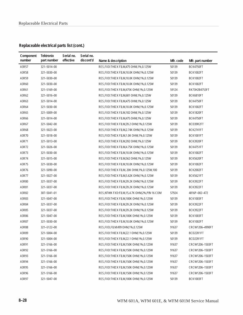
Replaceable Electrical Parts
8–28 WFM 601A, WFM 601E, & WFM 601M Service Manual
Replaceable electrical parts list (cont.)
Componentnumber Mfr. part numberMfr. codeName & description
Serial no.discont’d
Serial no.effective
Tektronixpart number
A3R57 321–5014–00 RES,FXD:THICK FILM,475 OHM,1%,0.125W 50139 BCK4750FT
A3R58 321–5030–00 RES,FXD:THICK FILM,10.0K OHM,1%,0.125W 50139 BCK1002FT
A3R59 321–5030–00 RES,FXD:THICK FILM,10.0K OHM,1%,0.125W 50139 BCK1002FT
A3R60 321–5030–00 RES,FXD:THICK FILM,10.0K OHM,1%,0.125W 50139 BCK1002FT
A3R61 321–5169–00 RES,FXD:THICK FILM,475K OHM,1%,0.125W 59124 RK73H2B4753FT
A3R62 321–5016–00 RES,FXD:THICK FILM,681 OHM,1%,0.125W 50139 BCK6810FT
A3R63 321–5014–00 RES,FXD:THICK FILM,475 OHM,1%,0.125W 50139 BCK4750FT
A3R64 321–5030–00 RES,FXD:THICK FILM,10.0K OHM,1%,0.125W 50139 BCK1002FT
A3R65 321–5009–00 RES,FXD:THICK FILM,182 OHM,1%,0.125W 50139 BCK1820FT
A3R66 321–5014–00 RES,FXD:THICK FILM,475 OHM,1%,0.125W 50139 BCK4750FT
A3R67 321–5042–00 RES,FXD:THICK FILM,39.2 OHM,1%,0.125W 50139 BCD39R2FT
A3R68 321–5023–00 RES,FXD:THICK FILM,2.74K OHM,1%,0.125W 50139 BCK2741FT
A3R70 321–5018–00 RES,FXD:THICK FILM,1.0K OHM,1%,0.125W 50139 BCK1001FT
A3R71 321–5013–00 RES,FXD:THICK FILM,392 OHM,1%,0.125W 50139 BCK3920FT
A3R72 321–5026–00 RES,FXD:THICK FILM,4.75K OHM,1%,0.125W 50139 BCK4751FT
A3R73 321–5030–00 RES,FXD:THICK FILM,10.0K OHM,1%,0.125W 50139 BCK1002FT
A3R74 321–5015–00 RES,FXD:THICK FILM,562 OHM,1%,0.125W 50139 BCK5620FT
A3R75 321–5030–00 RES,FXD:THICK FILM,10.0K OHM,1%,0.125W 50139 BCK1002FT
A3R76 321–5090–00 RES,FXD:THICK FILM, 20K OHM,1%,0.125W,100 50139 BCK2002FT
A3R77 321–5027–00 RES,FXD:THICK FILM,5.62K OHM,1%,0.125W 50139 BCK5621FT
A3R80 321–5037–00 RES,FXD:THICK FILM,39.2K OHM,1%,0.125W 50139 BCK3922FT
A3R81 321–5037–00 RES,FXD:THICK FILM,39.2K OHM,1%,0.125W 50139 BCK3922FT
A3R82 307–5041–01 RES,NTWK FXD:FILM,15,4.7K OHM,2%,PIN 16 COM 57924 4816P–002–472
A3R83 321–5047–00 RES,FXD:THICK FILM,100K OHM,1%,0.125W 50139 BCK1003FT
A3R84 321–5037–00 RES,FXD:THICK FILM,39.2K OHM,1%,0.125W 50139 BCK3922FT
A3R85 321–5037–00 RES,FXD:THICK FILM,39.2K OHM,1%,0.125W 50139 BCK3922FT
A3R86 321–5047–00 RES,FXD:THICK FILM,100K OHM,1%,0.125W 50139 BCK1003FT
A3R87 321–5030–00 RES,FXD:THICK FILM,10.0K OHM,1%,0.125W 50139 BCK1002FT
A3R88 321–5122–00 RES,FXD,FILM:499 OHM,1%,0.125W 91637 CRCW1206–4990FT
A3R89 321–5004–00 RES,FXD:THICK FILM,22.1 OHM,1%,0.125W 50139 BCD22R1FT
A3R90 321–5004–00 RES,FXD:THICK FILM,22.1 OHM,1%,0.125W 50139 BCD22R1FT
A3R91 321–5166–00 RES,FXD:THICK FILM,150K OHM,1%,0.125W 91637 CRCW1206–1503FT
A3R92 321–5166–00 RES,FXD:THICK FILM,150K OHM,1%,0.125W 91637 CRCW1206–1503FT
A3R93 321–5166–00 RES,FXD:THICK FILM,150K OHM,1%,0.125W 91637 CRCW1206–1503FT
A3R94 321–5166–00 RES,FXD:THICK FILM,150K OHM,1%,0.125W 91637 CRCW1206–1503FT
A3R95 321–5166–00 RES,FXD:THICK FILM,150K OHM,1%,0.125W 91637 CRCW1206–1503FT
A3R96 321–5166–00 RES,FXD:THICK FILM,150K OHM,1%,0.125W 91637 CRCW1206–1503FT
A3R97 321–5047–00 RES,FXD:THICK FILM,100K OHM,1%,0.125W 50139 BCK1003FT

Replaceable Electrical Parts
WFM 601A, WFM 601E, & WFM 601M Service Manual 8–29
Replaceable electrical parts list (cont.)
Componentnumber Mfr. part numberMfr. codeName & description
Serial no.discont’d
Serial no.effective
Tektronixpart number
A3R99 321–5030–00 RES,FXD:THICK FILM,10.0K OHM,1%,0.125W 50139 BCK1002FT
A3R100 321–5031–00 RES,FXD:THICK FILM,12.1K OHM,1%,0.125W 50139 BCK1212FT
A3R101 321–5036–00 RES,FXD:THICK FILM,33.2K OHM,1%,0.125W 50139 BCK3322FT
A3R102 321–5035–00 RES,FXD:THICK FILM,27.4K OHM,1%,0.125W 50139 BCK2742FT
A3R103 321–5023–00 RES,FXD:THICK FILM,2.74K OHM,1%,0.125W 50139 BCK2741FT
A3R104 321–5028–00 RES,FXD:THICK FILM,6.81K OHM,1%,0.125W 50139 BCK6811FT
A3R105 321–5028–00 RES,FXD:THICK FILM,6.81K OHM,1%,0.125W 50139 BCK6811FT
A3R106 321–5023–00 RES,FXD:THICK FILM,2.74K OHM,1%,0.125W 50139 BCK2741FT
A3R107 321–5033–00 RES,FXD:THICK FILM,18.2K OHM,1%,0.125W 50139 BCK1822FT
A3R108 321–5047–00 RES,FXD:THICK FILM,100K OHM,1%,0.125W 50139 BCK1003FT
A3R109 321–5122–00 RES,FXD,FILM:499 OHM,1%,0.125W 91637 CRCW1206–4990FT
A3R110 321–5028–00 RES,FXD:THICK FILM,6.81K OHM,1%,0.125W 50139 BCK6811FT
A3R111 321–5021–00 RES,FXD:THICK FILM,1.82K OHM,1%,0.125W 50139 BCK1821FT
A3R112 321–5037–00 RES,FXD:THICK FILM,39.2K OHM,1%,0.125W 50139 BCK3922FT
A3R113 321–5024–00 RES,FXD:THICK FILM,3.32K OHM,1%,0.125W 50139 BCK3321FT
A3R114 321–5020–00 RES,FXD:THICK FILM,1.5K OHM,1%,0.125W 50139 BCK1501FT
A3R115 321–5023–00 RES,FXD:THICK FILM,2.74K OHM,1%,0.125W 50139 BCK2741FT
A3R116 321–5023–00 RES,FXD:THICK FILM,2.74K OHM,1%,0.125W 50139 BCK2741FT
A3R117 321–5020–00 RES,FXD:THICK FILM,1.5K OHM,1%,0.125W 50139 BCK1501FT
A3R118 321–5030–00 RES,FXD:THICK FILM,10.0K OHM,1%,0.125W 50139 BCK1002FT
A3R119 321–5017–00 RES,FXD:THICK FILM,825 OHM,1%,0.125W 50139 BCK8250FT
A3R120 321–5026–00 RES,FXD:THICK FILM,4.75K OHM,1%,0.125W 50139 BCK4751FT
A3R121 321–5026–00 RES,FXD:THICK FILM,4.75K OHM,1%,0.125W 50139 BCK4751FT
A3R122 321–5013–00 RES,FXD:THICK FILM,392 OHM,1%,0.125W 50139 BCK3920FT
A3R123 321–5030–00 RES,FXD:THICK FILM,10.0K OHM,1%,0.125W 50139 BCK1002FT
A3R124 321–5047–00 RES,FXD:THICK FILM,100K OHM,1%,0.125W 50139 BCK1003FT
A3R125 321–5032–00 RES,FXD:THICK FILM,15.0K OHM,1%,0.125W 50139 BCK1502FT
A3R126 321–5036–00 RES,FXD:THICK FILM,33.2K OHM,1%,0.125W 50139 BCK3322FT
A3R128 321–5020–00 RES,FXD:THICK FILM,1.5K OHM,1%,0.125W 50139 BCK1501FT
A3R129 321–5025–00 RES,FXD:THICK FILM,3.92K OHM,1%,0.125W 50139 BCK3921FT
A3R130 321–5020–00 RES,FXD:THICK FILM,1.5K OHM,1%,0.125W 50139 BCK1501FT
A3R131 321–5020–00 RES,FXD:THICK FILM,1.5K OHM,1%,0.125W 50139 BCK1501FT
A3R132 321–5020–00 RES,FXD:THICK FILM,1.5K OHM,1%,0.125W 50139 BCK1501FT
A3R133 321–5020–00 RES,FXD:THICK FILM,1.5K OHM,1%,0.125W 50139 BCK1501FT
A3R134 311–5036–00 RES,VAR,TRMR:CERMET,5K OHM,25%,0.1W 32997 3314J–1–502E
A3R135 311–5036–00 RES,VAR,TRMR:CERMET,5K OHM,25%,0.1W 32997 3314J–1–502E
A3R136 321–5023–00 RES,FXD:THICK FILM,2.74K OHM,1%,0.125W 50139 BCK2741FT
A3R137 321–5047–00 RES,FXD:THICK FILM,100K OHM,1%,0.125W 50139 BCK1003FT

Replaceable Electrical Parts
8–30 WFM 601A, WFM 601E, & WFM 601M Service Manual
Replaceable electrical parts list (cont.)
Componentnumber Mfr. part numberMfr. codeName & description
Serial no.discont’d
Serial no.effective
Tektronixpart number
A3R138 321–5000–00 RES,FXD:THICK FILM,10 OHM,1%,0.125W 50139 BCD10R0FT
A3R139 321–5013–00 RES,FXD:THICK FILM,392 OHM,1%,0.125W 50139 BCK3920FT
A3R140 321–5027–00 RES,FXD:THICK FILM,5.62K OHM,1%,0.125W 50139 BCK5621FT
A3R141 321–5012–00 RES,FXD:THICK FILM,332 OHM,1%,0.125W 50139 BCK3320FT
A3R142 321–5012–00 RES,FXD:THICK FILM,332 OHM,1%,0.125W 50139 BCK3320FT
A3R143 321–5012–00 RES,FXD:THICK FILM,332 OHM,1%,0.125W 50139 BCK3320FT
A3R144 321–5012–00 RES,FXD:THICK FILM,332 OHM,1%,0.125W 50139 BCK3320FT
A3R145 321–5006–00 RES,FXD:THICK FILM,100 OHM,1%,0.125W 50139 BCK1000FT
A3R146 321–5006–00 RES,FXD:THICK FILM,100 OHM,1%,0.125W 50139 BCK1000FT
A3R147 321–5006–00 RES,FXD:THICK FILM,100 OHM,1%,0.125W 50139 BCK1000FT
A3R148 321–5023–00 RES,FXD:THICK FILM,2.74K OHM,1%,0.125W 50139 BCK2741FT
A3R149 321–5025–00 RES,FXD:THICK FILM,3.92K OHM,1%,0.125W 50139 BCK3921FT
A3R150 321–5023–00 RES,FXD:THICK FILM,2.74K OHM,1%,0.125W 50139 BCK2741FT
A3R151 321–5047–00 RES,FXD:THICK FILM,100K OHM,1%,0.125W 50139 BCK1003FT
A3R152 321–5051–00 RES,FXD:THICK FILM,0 OHM,1%,0.125W 09969 CRCW1206 JUMPER
A3R153 321–5047–00 RES,FXD:THICK FILM,100K OHM,1%,0.125W 50139 BCK1003FT
A3R154 321–5020–00 RES,FXD:THICK FILM,1.5K OHM,1%,0.125W 50139 BCK1501FT
A3R155 321–5012–00 RES,FXD:THICK FILM,332 OHM,1%,0.125W 50139 BCK3320FT
A3R156 321–5015–00 RES,FXD:THICK FILM,562 OHM,1%,0.125W 50139 BCK5620FT
A3R157 321–5012–00 RES,FXD:THICK FILM,332 OHM,1%,0.125W 50139 BCK3320FT
A3R158 321–5012–00 RES,FXD:THICK FILM,332 OHM,1%,0.125W 50139 BCK3320FT
A3R159 321–5012–00 RES,FXD:THICK FILM,332 OHM,1%,0.125W 50139 BCK3320FT
A3R160 321–5012–00 RES,FXD:THICK FILM,332 OHM,1%,0.125W 50139 BCK3320FT
A3R161 321–5012–00 RES,FXD:THICK FILM,332 OHM,1%,0.125W 50139 BCK3320FT
A3R162 321–5012–00 RES,FXD:THICK FILM,332 OHM,1%,0.125W 50139 BCK3320FT
A3R163 321–5012–00 RES,FXD:THICK FILM,332 OHM,1%,0.125W 50139 BCK3320FT
A3R164 321–5012–00 RES,FXD:THICK FILM,332 OHM,1%,0.125W 50139 BCK3320FT
A3R165 321–5022–00 RES,FXD:THICK FILM,2.21K OHM,1%,0.125W 50139 BCK2211FT
A3R166 321–5009–00 RES,FXD:THICK FILM,182 OHM,1%,0.125W 50139 BCK1820FT
A3R167 321–5047–00 RES,FXD:THICK FILM,100K OHM,1%,0.125W 50139 BCK1003FT
A3R168 311–5041–00 RES,VAR,TRMR:CERMET,100K OHM,25%,0.25W 32997 3314J–1–104E
A3R169 321–5143–00 RES,FXD,FILM:301 OHM,1%,0.125W 91637 CRCW12063010FT
A3R170 321–5022–00 RES,FXD:THICK FILM,2.21K OHM,1%,0.125W 50139 BCK2211FT
A3R171 321–5009–00 RES,FXD:THICK FILM,182 OHM,1%,0.125W 50139 BCK1820FT
A3R172 321–5047–00 RES,FXD:THICK FILM,100K OHM,1%,0.125W 50139 BCK1003FT
A3R173 321–5012–00 RES,FXD:THICK FILM,332 OHM,1%,0.125W 50139 BCK3320FT
A3R174 321–5024–00 RES,FXD:THICK FILM,3.32K OHM,1%,0.125W 50139 BCK3321FT
A3R175 321–5012–00 RES,FXD:THICK FILM,332 OHM,1%,0.125W 50139 BCK3320FT
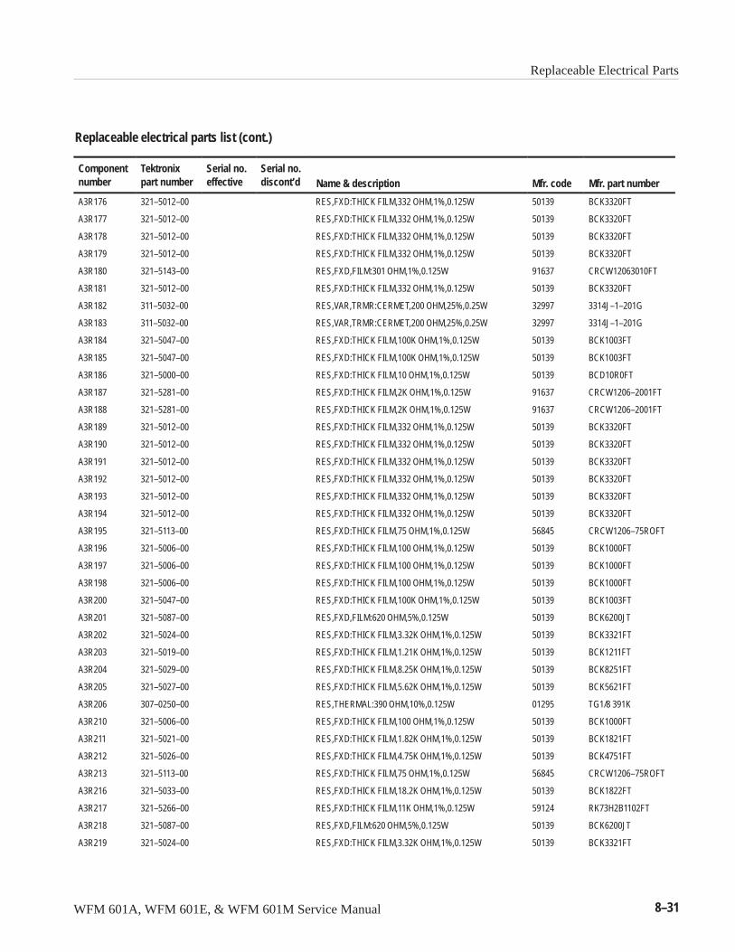
Replaceable Electrical Parts
WFM 601A, WFM 601E, & WFM 601M Service Manual 8–31
Replaceable electrical parts list (cont.)
Componentnumber Mfr. part numberMfr. codeName & description
Serial no.discont’d
Serial no.effective
Tektronixpart number
A3R176 321–5012–00 RES,FXD:THICK FILM,332 OHM,1%,0.125W 50139 BCK3320FT
A3R177 321–5012–00 RES,FXD:THICK FILM,332 OHM,1%,0.125W 50139 BCK3320FT
A3R178 321–5012–00 RES,FXD:THICK FILM,332 OHM,1%,0.125W 50139 BCK3320FT
A3R179 321–5012–00 RES,FXD:THICK FILM,332 OHM,1%,0.125W 50139 BCK3320FT
A3R180 321–5143–00 RES,FXD,FILM:301 OHM,1%,0.125W 91637 CRCW12063010FT
A3R181 321–5012–00 RES,FXD:THICK FILM,332 OHM,1%,0.125W 50139 BCK3320FT
A3R182 311–5032–00 RES,VAR,TRMR:CERMET,200 OHM,25%,0.25W 32997 3314J–1–201G
A3R183 311–5032–00 RES,VAR,TRMR:CERMET,200 OHM,25%,0.25W 32997 3314J–1–201G
A3R184 321–5047–00 RES,FXD:THICK FILM,100K OHM,1%,0.125W 50139 BCK1003FT
A3R185 321–5047–00 RES,FXD:THICK FILM,100K OHM,1%,0.125W 50139 BCK1003FT
A3R186 321–5000–00 RES,FXD:THICK FILM,10 OHM,1%,0.125W 50139 BCD10R0FT
A3R187 321–5281–00 RES,FXD:THICK FILM,2K OHM,1%,0.125W 91637 CRCW1206–2001FT
A3R188 321–5281–00 RES,FXD:THICK FILM,2K OHM,1%,0.125W 91637 CRCW1206–2001FT
A3R189 321–5012–00 RES,FXD:THICK FILM,332 OHM,1%,0.125W 50139 BCK3320FT
A3R190 321–5012–00 RES,FXD:THICK FILM,332 OHM,1%,0.125W 50139 BCK3320FT
A3R191 321–5012–00 RES,FXD:THICK FILM,332 OHM,1%,0.125W 50139 BCK3320FT
A3R192 321–5012–00 RES,FXD:THICK FILM,332 OHM,1%,0.125W 50139 BCK3320FT
A3R193 321–5012–00 RES,FXD:THICK FILM,332 OHM,1%,0.125W 50139 BCK3320FT
A3R194 321–5012–00 RES,FXD:THICK FILM,332 OHM,1%,0.125W 50139 BCK3320FT
A3R195 321–5113–00 RES,FXD:THICK FILM,75 OHM,1%,0.125W 56845 CRCW1206–75ROFT
A3R196 321–5006–00 RES,FXD:THICK FILM,100 OHM,1%,0.125W 50139 BCK1000FT
A3R197 321–5006–00 RES,FXD:THICK FILM,100 OHM,1%,0.125W 50139 BCK1000FT
A3R198 321–5006–00 RES,FXD:THICK FILM,100 OHM,1%,0.125W 50139 BCK1000FT
A3R200 321–5047–00 RES,FXD:THICK FILM,100K OHM,1%,0.125W 50139 BCK1003FT
A3R201 321–5087–00 RES,FXD,FILM:620 OHM,5%,0.125W 50139 BCK6200JT
A3R202 321–5024–00 RES,FXD:THICK FILM,3.32K OHM,1%,0.125W 50139 BCK3321FT
A3R203 321–5019–00 RES,FXD:THICK FILM,1.21K OHM,1%,0.125W 50139 BCK1211FT
A3R204 321–5029–00 RES,FXD:THICK FILM,8.25K OHM,1%,0.125W 50139 BCK8251FT
A3R205 321–5027–00 RES,FXD:THICK FILM,5.62K OHM,1%,0.125W 50139 BCK5621FT
A3R206 307–0250–00 RES,THERMAL:390 OHM,10%,0.125W 01295 TG1/8 391K
A3R210 321–5006–00 RES,FXD:THICK FILM,100 OHM,1%,0.125W 50139 BCK1000FT
A3R211 321–5021–00 RES,FXD:THICK FILM,1.82K OHM,1%,0.125W 50139 BCK1821FT
A3R212 321–5026–00 RES,FXD:THICK FILM,4.75K OHM,1%,0.125W 50139 BCK4751FT
A3R213 321–5113–00 RES,FXD:THICK FILM,75 OHM,1%,0.125W 56845 CRCW1206–75ROFT
A3R216 321–5033–00 RES,FXD:THICK FILM,18.2K OHM,1%,0.125W 50139 BCK1822FT
A3R217 321–5266–00 RES,FXD:THICK FILM,11K OHM,1%,0.125W 59124 RK73H2B1102FT
A3R218 321–5087–00 RES,FXD,FILM:620 OHM,5%,0.125W 50139 BCK6200JT
A3R219 321–5024–00 RES,FXD:THICK FILM,3.32K OHM,1%,0.125W 50139 BCK3321FT
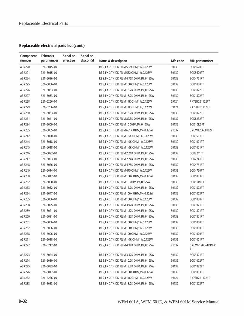
Replaceable Electrical Parts
8–32 WFM 601A, WFM 601E, & WFM 601M Service Manual
Replaceable electrical parts list (cont.)
Componentnumber Mfr. part numberMfr. codeName & description
Serial no.discont’d
Serial no.effective
Tektronixpart number
A3R220 321–5015–00 RES,FXD:THICK FILM,562 OHM,1%,0.125W 50139 BCK5620FT
A3R221 321–5015–00 RES,FXD:THICK FILM,562 OHM,1%,0.125W 50139 BCK5620FT
A3R224 321–5026–00 RES,FXD:THICK FILM,4.75K OHM,1%,0.125W 50139 BCK4751FT
A3R225 321–5006–00 RES,FXD:THICK FILM,100 OHM,1%,0.125W 50139 BCK1000FT
A3R226 321–5033–00 RES,FXD:THICK FILM,18.2K OHM,1%,0.125W 50139 BCK1822FT
A3R227 321–5033–00 RES,FXD:THICK FILM,18.2K OHM,1%,0.125W 50139 BCK1822FT
A3R228 321–5266–00 RES,FXD:THICK FILM,11K OHM,1%,0.125W 59124 RK73H2B1102FT
A3R229 321–5266–00 RES,FXD:THICK FILM,11K OHM,1%,0.125W 59124 RK73H2B1102FT
A3R230 321–5033–00 RES,FXD:THICK FILM,18.2K OHM,1%,0.125W 50139 BCK1822FT
A3R231 321–5041–00 RES,FXD:THICK FILM,82.5K OHM,1%,0.125W 50139 BCK8252FT
A3R234 321–5000–00 RES,FXD:THICK FILM,10 OHM,1%,0.125W 50139 BCD10R0FT
A3R235 321–5055–00 RES,FXD:THICK FILM,681K OHM,1%,0.125W 91637 CRCW120668102FT
A3R242 321–5020–00 RES,FXD:THICK FILM,1.5K OHM,1%,0.125W 50139 BCK1501FT
A3R244 321–5018–00 RES,FXD:THICK FILM,1.0K OHM,1%,0.125W 50139 BCK1001FT
A3R245 321–5018–00 RES,FXD:THICK FILM,1.0K OHM,1%,0.125W 50139 BCK1001FT
A3R246 321–5022–00 RES,FXD:THICK FILM,2.21K OHM,1%,0.125W 50139 BCK2211FT
A3R247 321–5023–00 RES,FXD:THICK FILM,2.74K OHM,1%,0.125W 50139 BCK2741FT
A3R248 321–5026–00 RES,FXD:THICK FILM,4.75K OHM,1%,0.125W 50139 BCK4751FT
A3R249 321–5014–00 RES,FXD:THICK FILM,475 OHM,1%,0.125W 50139 BCK4750FT
A3R250 321–5047–00 RES,FXD:THICK FILM,100K OHM,1%,0.125W 50139 BCK1003FT
A3R252 321–5000–00 RES,FXD:THICK FILM,10 OHM,1%,0.125W 50139 BCD10R0FT
A3R253 321–5032–00 RES,FXD:THICK FILM,15.0K OHM,1%,0.125W 50139 BCK1502FT
A3R254 321–5047–00 RES,FXD:THICK FILM,100K OHM,1%,0.125W 50139 BCK1003FT
A3R255 321–5006–00 RES,FXD:THICK FILM,100 OHM,1%,0.125W 50139 BCK1000FT
A3R258 321–5025–00 RES,FXD:THICK FILM,3.92K OHM,1%,0.125W 50139 BCK3921FT
A3R259 321–5021–00 RES,FXD:THICK FILM,1.82K OHM,1%,0.125W 50139 BCK1821FT
A3R260 321–5021–00 RES,FXD:THICK FILM,1.82K OHM,1%,0.125W 50139 BCK1821FT
A3R261 321–5006–00 RES,FXD:THICK FILM,100 OHM,1%,0.125W 50139 BCK1000FT
A3R262 321–5006–00 RES,FXD:THICK FILM,100 OHM,1%,0.125W 50139 BCK1000FT
A3R268 321–5006–00 RES,FXD:THICK FILM,100 OHM,1%,0.125W 50139 BCK1000FT
A3R271 321–5018–00 RES,FXD:THICK FILM,1.0K OHM,1%,0.125W 50139 BCK1001FT
A3R272 321–5212–00 RES,FXD:THICK FILM,4.99K OHM,1%,0.125W 91637 CRCW–1206–4991FRT1
A3R273 321–5024–00 RES,FXD:THICK FILM,3.32K OHM,1%,0.125W 50139 BCK3321FT
A3R274 321–5030–00 RES,FXD:THICK FILM,10.0K OHM,1%,0.125W 50139 BCK1002FT
A3R275 321–5033–00 RES,FXD:THICK FILM,18.2K OHM,1%,0.125W 50139 BCK1822FT
A3R276 321–5047–00 RES,FXD:THICK FILM,100K OHM,1%,0.125W 50139 BCK1003FT
A3R282 321–5266–00 RES,FXD:THICK FILM,11K OHM,1%,0.125W 59124 RK73H2B1102FT
A3R283 321–5033–00 RES,FXD:THICK FILM,18.2K OHM,1%,0.125W 50139 BCK1822FT
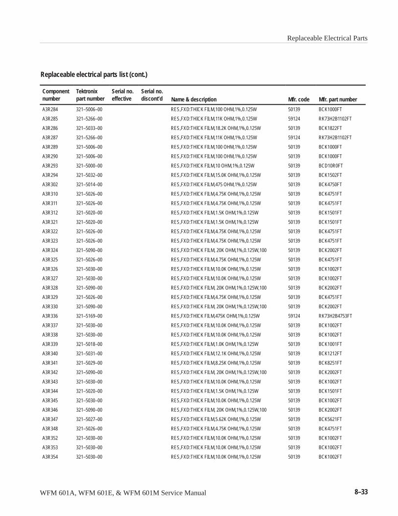
Replaceable Electrical Parts
WFM 601A, WFM 601E, & WFM 601M Service Manual 8–33
Replaceable electrical parts list (cont.)
Componentnumber Mfr. part numberMfr. codeName & description
Serial no.discont’d
Serial no.effective
Tektronixpart number
A3R284 321–5006–00 RES,FXD:THICK FILM,100 OHM,1%,0.125W 50139 BCK1000FT
A3R285 321–5266–00 RES,FXD:THICK FILM,11K OHM,1%,0.125W 59124 RK73H2B1102FT
A3R286 321–5033–00 RES,FXD:THICK FILM,18.2K OHM,1%,0.125W 50139 BCK1822FT
A3R287 321–5266–00 RES,FXD:THICK FILM,11K OHM,1%,0.125W 59124 RK73H2B1102FT
A3R289 321–5006–00 RES,FXD:THICK FILM,100 OHM,1%,0.125W 50139 BCK1000FT
A3R290 321–5006–00 RES,FXD:THICK FILM,100 OHM,1%,0.125W 50139 BCK1000FT
A3R293 321–5000–00 RES,FXD:THICK FILM,10 OHM,1%,0.125W 50139 BCD10R0FT
A3R294 321–5032–00 RES,FXD:THICK FILM,15.0K OHM,1%,0.125W 50139 BCK1502FT
A3R302 321–5014–00 RES,FXD:THICK FILM,475 OHM,1%,0.125W 50139 BCK4750FT
A3R310 321–5026–00 RES,FXD:THICK FILM,4.75K OHM,1%,0.125W 50139 BCK4751FT
A3R311 321–5026–00 RES,FXD:THICK FILM,4.75K OHM,1%,0.125W 50139 BCK4751FT
A3R312 321–5020–00 RES,FXD:THICK FILM,1.5K OHM,1%,0.125W 50139 BCK1501FT
A3R321 321–5020–00 RES,FXD:THICK FILM,1.5K OHM,1%,0.125W 50139 BCK1501FT
A3R322 321–5026–00 RES,FXD:THICK FILM,4.75K OHM,1%,0.125W 50139 BCK4751FT
A3R323 321–5026–00 RES,FXD:THICK FILM,4.75K OHM,1%,0.125W 50139 BCK4751FT
A3R324 321–5090–00 RES,FXD:THICK FILM, 20K OHM,1%,0.125W,100 50139 BCK2002FT
A3R325 321–5026–00 RES,FXD:THICK FILM,4.75K OHM,1%,0.125W 50139 BCK4751FT
A3R326 321–5030–00 RES,FXD:THICK FILM,10.0K OHM,1%,0.125W 50139 BCK1002FT
A3R327 321–5030–00 RES,FXD:THICK FILM,10.0K OHM,1%,0.125W 50139 BCK1002FT
A3R328 321–5090–00 RES,FXD:THICK FILM, 20K OHM,1%,0.125W,100 50139 BCK2002FT
A3R329 321–5026–00 RES,FXD:THICK FILM,4.75K OHM,1%,0.125W 50139 BCK4751FT
A3R330 321–5090–00 RES,FXD:THICK FILM, 20K OHM,1%,0.125W,100 50139 BCK2002FT
A3R336 321–5169–00 RES,FXD:THICK FILM,475K OHM,1%,0.125W 59124 RK73H2B4753FT
A3R337 321–5030–00 RES,FXD:THICK FILM,10.0K OHM,1%,0.125W 50139 BCK1002FT
A3R338 321–5030–00 RES,FXD:THICK FILM,10.0K OHM,1%,0.125W 50139 BCK1002FT
A3R339 321–5018–00 RES,FXD:THICK FILM,1.0K OHM,1%,0.125W 50139 BCK1001FT
A3R340 321–5031–00 RES,FXD:THICK FILM,12.1K OHM,1%,0.125W 50139 BCK1212FT
A3R341 321–5029–00 RES,FXD:THICK FILM,8.25K OHM,1%,0.125W 50139 BCK8251FT
A3R342 321–5090–00 RES,FXD:THICK FILM, 20K OHM,1%,0.125W,100 50139 BCK2002FT
A3R343 321–5030–00 RES,FXD:THICK FILM,10.0K OHM,1%,0.125W 50139 BCK1002FT
A3R344 321–5020–00 RES,FXD:THICK FILM,1.5K OHM,1%,0.125W 50139 BCK1501FT
A3R345 321–5030–00 RES,FXD:THICK FILM,10.0K OHM,1%,0.125W 50139 BCK1002FT
A3R346 321–5090–00 RES,FXD:THICK FILM, 20K OHM,1%,0.125W,100 50139 BCK2002FT
A3R347 321–5027–00 RES,FXD:THICK FILM,5.62K OHM,1%,0.125W 50139 BCK5621FT
A3R348 321–5026–00 RES,FXD:THICK FILM,4.75K OHM,1%,0.125W 50139 BCK4751FT
A3R352 321–5030–00 RES,FXD:THICK FILM,10.0K OHM,1%,0.125W 50139 BCK1002FT
A3R353 321–5030–00 RES,FXD:THICK FILM,10.0K OHM,1%,0.125W 50139 BCK1002FT
A3R354 321–5030–00 RES,FXD:THICK FILM,10.0K OHM,1%,0.125W 50139 BCK1002FT
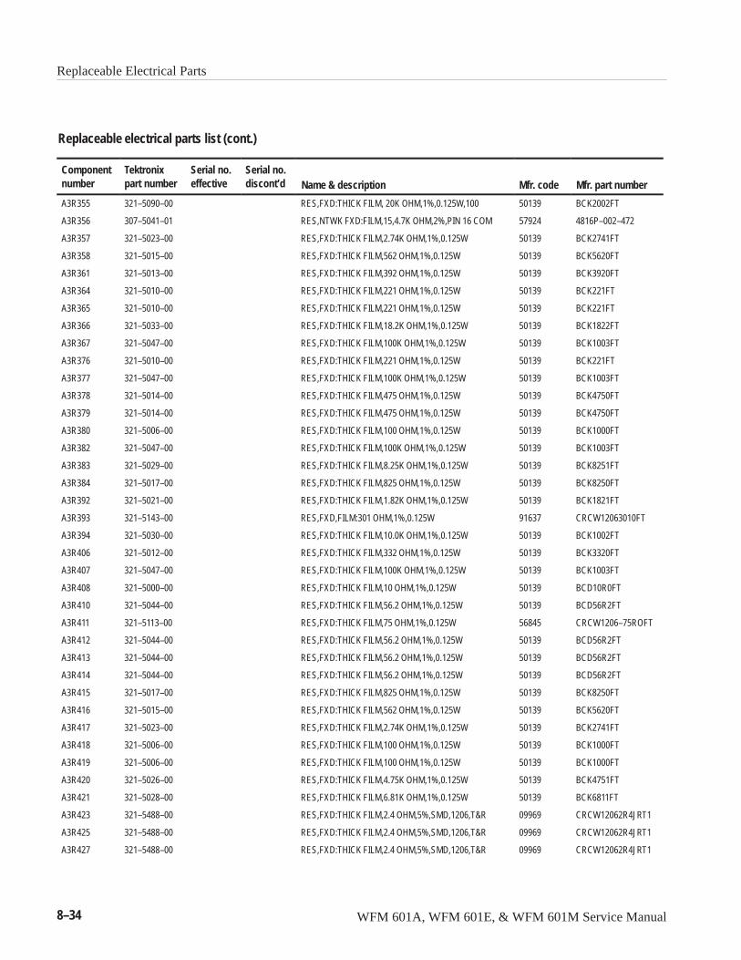
Replaceable Electrical Parts
8–34 WFM 601A, WFM 601E, & WFM 601M Service Manual
Replaceable electrical parts list (cont.)
Componentnumber Mfr. part numberMfr. codeName & description
Serial no.discont’d
Serial no.effective
Tektronixpart number
A3R355 321–5090–00 RES,FXD:THICK FILM, 20K OHM,1%,0.125W,100 50139 BCK2002FT
A3R356 307–5041–01 RES,NTWK FXD:FILM,15,4.7K OHM,2%,PIN 16 COM 57924 4816P–002–472
A3R357 321–5023–00 RES,FXD:THICK FILM,2.74K OHM,1%,0.125W 50139 BCK2741FT
A3R358 321–5015–00 RES,FXD:THICK FILM,562 OHM,1%,0.125W 50139 BCK5620FT
A3R361 321–5013–00 RES,FXD:THICK FILM,392 OHM,1%,0.125W 50139 BCK3920FT
A3R364 321–5010–00 RES,FXD:THICK FILM,221 OHM,1%,0.125W 50139 BCK221FT
A3R365 321–5010–00 RES,FXD:THICK FILM,221 OHM,1%,0.125W 50139 BCK221FT
A3R366 321–5033–00 RES,FXD:THICK FILM,18.2K OHM,1%,0.125W 50139 BCK1822FT
A3R367 321–5047–00 RES,FXD:THICK FILM,100K OHM,1%,0.125W 50139 BCK1003FT
A3R376 321–5010–00 RES,FXD:THICK FILM,221 OHM,1%,0.125W 50139 BCK221FT
A3R377 321–5047–00 RES,FXD:THICK FILM,100K OHM,1%,0.125W 50139 BCK1003FT
A3R378 321–5014–00 RES,FXD:THICK FILM,475 OHM,1%,0.125W 50139 BCK4750FT
A3R379 321–5014–00 RES,FXD:THICK FILM,475 OHM,1%,0.125W 50139 BCK4750FT
A3R380 321–5006–00 RES,FXD:THICK FILM,100 OHM,1%,0.125W 50139 BCK1000FT
A3R382 321–5047–00 RES,FXD:THICK FILM,100K OHM,1%,0.125W 50139 BCK1003FT
A3R383 321–5029–00 RES,FXD:THICK FILM,8.25K OHM,1%,0.125W 50139 BCK8251FT
A3R384 321–5017–00 RES,FXD:THICK FILM,825 OHM,1%,0.125W 50139 BCK8250FT
A3R392 321–5021–00 RES,FXD:THICK FILM,1.82K OHM,1%,0.125W 50139 BCK1821FT
A3R393 321–5143–00 RES,FXD,FILM:301 OHM,1%,0.125W 91637 CRCW12063010FT
A3R394 321–5030–00 RES,FXD:THICK FILM,10.0K OHM,1%,0.125W 50139 BCK1002FT
A3R406 321–5012–00 RES,FXD:THICK FILM,332 OHM,1%,0.125W 50139 BCK3320FT
A3R407 321–5047–00 RES,FXD:THICK FILM,100K OHM,1%,0.125W 50139 BCK1003FT
A3R408 321–5000–00 RES,FXD:THICK FILM,10 OHM,1%,0.125W 50139 BCD10R0FT
A3R410 321–5044–00 RES,FXD:THICK FILM,56.2 OHM,1%,0.125W 50139 BCD56R2FT
A3R411 321–5113–00 RES,FXD:THICK FILM,75 OHM,1%,0.125W 56845 CRCW1206–75ROFT
A3R412 321–5044–00 RES,FXD:THICK FILM,56.2 OHM,1%,0.125W 50139 BCD56R2FT
A3R413 321–5044–00 RES,FXD:THICK FILM,56.2 OHM,1%,0.125W 50139 BCD56R2FT
A3R414 321–5044–00 RES,FXD:THICK FILM,56.2 OHM,1%,0.125W 50139 BCD56R2FT
A3R415 321–5017–00 RES,FXD:THICK FILM,825 OHM,1%,0.125W 50139 BCK8250FT
A3R416 321–5015–00 RES,FXD:THICK FILM,562 OHM,1%,0.125W 50139 BCK5620FT
A3R417 321–5023–00 RES,FXD:THICK FILM,2.74K OHM,1%,0.125W 50139 BCK2741FT
A3R418 321–5006–00 RES,FXD:THICK FILM,100 OHM,1%,0.125W 50139 BCK1000FT
A3R419 321–5006–00 RES,FXD:THICK FILM,100 OHM,1%,0.125W 50139 BCK1000FT
A3R420 321–5026–00 RES,FXD:THICK FILM,4.75K OHM,1%,0.125W 50139 BCK4751FT
A3R421 321–5028–00 RES,FXD:THICK FILM,6.81K OHM,1%,0.125W 50139 BCK6811FT
A3R423 321–5488–00 RES,FXD:THICK FILM,2.4 OHM,5%,SMD,1206,T&R 09969 CRCW12062R4JRT1
A3R425 321–5488–00 RES,FXD:THICK FILM,2.4 OHM,5%,SMD,1206,T&R 09969 CRCW12062R4JRT1
A3R427 321–5488–00 RES,FXD:THICK FILM,2.4 OHM,5%,SMD,1206,T&R 09969 CRCW12062R4JRT1
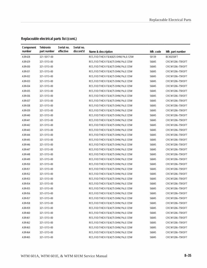
Replaceable Electrical Parts
WFM 601A, WFM 601E, & WFM 601M Service Manual 8–35
Replaceable electrical parts list (cont.)
Componentnumber Mfr. part numberMfr. codeName & description
Serial no.discont’d
Serial no.effective
Tektronixpart number
A3R428 321–5017–00 RES,FXD:THICK FILM,825 OHM,1%,0.125W 50139 BCK8250FT
A3R429 321–5113–00 RES,FXD:THICK FILM,75 OHM,1%,0.125W 56845 CRCW1206–75ROFT
A3R430 321–5113–00 RES,FXD:THICK FILM,75 OHM,1%,0.125W 56845 CRCW1206–75ROFT
A3R431 321–5113–00 RES,FXD:THICK FILM,75 OHM,1%,0.125W 56845 CRCW1206–75ROFT
A3R432 321–5113–00 RES,FXD:THICK FILM,75 OHM,1%,0.125W 56845 CRCW1206–75ROFT
A3R433 321–5113–00 RES,FXD:THICK FILM,75 OHM,1%,0.125W 56845 CRCW1206–75ROFT
A3R434 321–5113–00 RES,FXD:THICK FILM,75 OHM,1%,0.125W 56845 CRCW1206–75ROFT
A3R435 321–5113–00 RES,FXD:THICK FILM,75 OHM,1%,0.125W 56845 CRCW1206–75ROFT
A3R436 321–5113–00 RES,FXD:THICK FILM,75 OHM,1%,0.125W 56845 CRCW1206–75ROFT
A3R437 321–5113–00 RES,FXD:THICK FILM,75 OHM,1%,0.125W 56845 CRCW1206–75ROFT
A3R438 321–5113–00 RES,FXD:THICK FILM,75 OHM,1%,0.125W 56845 CRCW1206–75ROFT
A3R439 321–5113–00 RES,FXD:THICK FILM,75 OHM,1%,0.125W 56845 CRCW1206–75ROFT
A3R440 321–5113–00 RES,FXD:THICK FILM,75 OHM,1%,0.125W 56845 CRCW1206–75ROFT
A3R441 321–5113–00 RES,FXD:THICK FILM,75 OHM,1%,0.125W 56845 CRCW1206–75ROFT
A3R442 321–5113–00 RES,FXD:THICK FILM,75 OHM,1%,0.125W 56845 CRCW1206–75ROFT
A3R443 321–5113–00 RES,FXD:THICK FILM,75 OHM,1%,0.125W 56845 CRCW1206–75ROFT
A3R444 321–5113–00 RES,FXD:THICK FILM,75 OHM,1%,0.125W 56845 CRCW1206–75ROFT
A3R445 321–5113–00 RES,FXD:THICK FILM,75 OHM,1%,0.125W 56845 CRCW1206–75ROFT
A3R446 321–5113–00 RES,FXD:THICK FILM,75 OHM,1%,0.125W 56845 CRCW1206–75ROFT
A3R447 321–5113–00 RES,FXD:THICK FILM,75 OHM,1%,0.125W 56845 CRCW1206–75ROFT
A3R448 321–5113–00 RES,FXD:THICK FILM,75 OHM,1%,0.125W 56845 CRCW1206–75ROFT
A3R449 321–5113–00 RES,FXD:THICK FILM,75 OHM,1%,0.125W 56845 CRCW1206–75ROFT
A3R450 321–5113–00 RES,FXD:THICK FILM,75 OHM,1%,0.125W 56845 CRCW1206–75ROFT
A3R451 321–5113–00 RES,FXD:THICK FILM,75 OHM,1%,0.125W 56845 CRCW1206–75ROFT
A3R452 321–5113–00 RES,FXD:THICK FILM,75 OHM,1%,0.125W 56845 CRCW1206–75ROFT
A3R453 321–5113–00 RES,FXD:THICK FILM,75 OHM,1%,0.125W 56845 CRCW1206–75ROFT
A3R454 321–5113–00 RES,FXD:THICK FILM,75 OHM,1%,0.125W 56845 CRCW1206–75ROFT
A3R455 321–5113–00 RES,FXD:THICK FILM,75 OHM,1%,0.125W 56845 CRCW1206–75ROFT
A3R456 321–5113–00 RES,FXD:THICK FILM,75 OHM,1%,0.125W 56845 CRCW1206–75ROFT
A3R457 321–5113–00 RES,FXD:THICK FILM,75 OHM,1%,0.125W 56845 CRCW1206–75ROFT
A3R458 321–5113–00 RES,FXD:THICK FILM,75 OHM,1%,0.125W 56845 CRCW1206–75ROFT
A3R459 321–5113–00 RES,FXD:THICK FILM,75 OHM,1%,0.125W 56845 CRCW1206–75ROFT
A3R460 321–5113–00 RES,FXD:THICK FILM,75 OHM,1%,0.125W 56845 CRCW1206–75ROFT
A3R461 321–5113–00 RES,FXD:THICK FILM,75 OHM,1%,0.125W 56845 CRCW1206–75ROFT
A3R462 321–5113–00 RES,FXD:THICK FILM,75 OHM,1%,0.125W 56845 CRCW1206–75ROFT
A3R463 321–5113–00 RES,FXD:THICK FILM,75 OHM,1%,0.125W 56845 CRCW1206–75ROFT
A3R464 321–5113–00 RES,FXD:THICK FILM,75 OHM,1%,0.125W 56845 CRCW1206–75ROFT
A3R465 321–5113–00 RES,FXD:THICK FILM,75 OHM,1%,0.125W 56845 CRCW1206–75ROFT
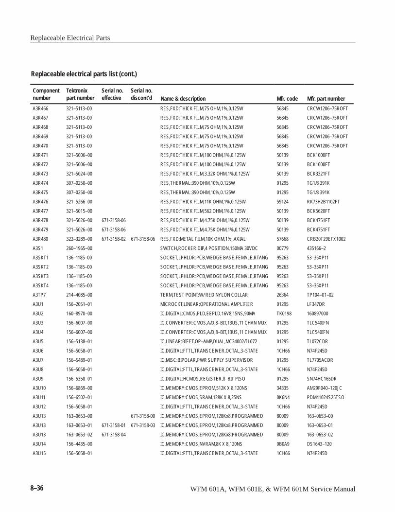
Replaceable Electrical Parts
8–36 WFM 601A, WFM 601E, & WFM 601M Service Manual
Replaceable electrical parts list (cont.)
Componentnumber Mfr. part numberMfr. codeName & description
Serial no.discont’d
Serial no.effective
Tektronixpart number
A3R466 321–5113–00 RES,FXD:THICK FILM,75 OHM,1%,0.125W 56845 CRCW1206–75ROFT
A3R467 321–5113–00 RES,FXD:THICK FILM,75 OHM,1%,0.125W 56845 CRCW1206–75ROFT
A3R468 321–5113–00 RES,FXD:THICK FILM,75 OHM,1%,0.125W 56845 CRCW1206–75ROFT
A3R469 321–5113–00 RES,FXD:THICK FILM,75 OHM,1%,0.125W 56845 CRCW1206–75ROFT
A3R470 321–5113–00 RES,FXD:THICK FILM,75 OHM,1%,0.125W 56845 CRCW1206–75ROFT
A3R471 321–5006–00 RES,FXD:THICK FILM,100 OHM,1%,0.125W 50139 BCK1000FT
A3R472 321–5006–00 RES,FXD:THICK FILM,100 OHM,1%,0.125W 50139 BCK1000FT
A3R473 321–5024–00 RES,FXD:THICK FILM,3.32K OHM,1%,0.125W 50139 BCK3321FT
A3R474 307–0250–00 RES,THERMAL:390 OHM,10%,0.125W 01295 TG1/8 391K
A3R475 307–0250–00 RES,THERMAL:390 OHM,10%,0.125W 01295 TG1/8 391K
A3R476 321–5266–00 RES,FXD:THICK FILM,11K OHM,1%,0.125W 59124 RK73H2B1102FT
A3R477 321–5015–00 RES,FXD:THICK FILM,562 OHM,1%,0.125W 50139 BCK5620FT
A3R478 321–5026–00 671-3158-06 RES,FXD:THICK FILM,4.75K OHM,1%,0.125W 50139 BCK4751FT
A3R479 321–5026–00 671-3158-06 RES,FXD:THICK FILM,4.75K OHM,1%,0.125W 50139 BCK4751FT
A3R480 322–3289–00 671-3158-02 671-3158-06 RES,FXD:METAL FILM,10K OHM,1%,,AXIAL 57668 CRB20T29EFX1002
A3S1 260–1965–00 SWITCH,ROCKER:DIP,4 POSITION,150MA 30VDC 00779 435166–2
A3SKT1 136–1185–00 SOCKET,LPHLDR:PCB,WEDGE BASE,FEMALE,RTANG 95263 53–35XP11
A3SKT2 136–1185–00 SOCKET,LPHLDR:PCB,WEDGE BASE,FEMALE,RTANG 95263 53–35XP11
A3SKT3 136–1185–00 SOCKET,LPHLDR:PCB,WEDGE BASE,FEMALE,RTANG 95263 53–35XP11
A3SKT4 136–1185–00 SOCKET,LPHLDR:PCB,WEDGE BASE,FEMALE,RTANG 95263 53–35XP11
A3TP7 214–4085–00 TERM,TEST POINT:W/ RED NYLON COLLAR 26364 TP104–01–02
A3U1 156–2051–01 MICROCKT,LINEAR:OPERATIONAL AMPLIFIER 01295 LF347DR
A3U2 160–8970–00 IC,DIGITAL:CMOS,PLD,EEPLD,16V8,15NS,90MA TK0198 160897000
A3U3 156–6007–00 IC,CONVERTER:CMOS,A/D,8–BIT,13US,11 CHAN MUX 01295 TLC540IFN
A3U4 156–6007–00 IC,CONVERTER:CMOS,A/D,8–BIT,13US,11 CHAN MUX 01295 TLC540IFN
A3U5 156–5138–01 IC,LINEAR:BIFET,OP–AMP,DUAL,MC34002/TL072 01295 TL072CDR
A3U6 156–5058–01 IC,DIGITAL:FTTL,TRANSCEIVER,OCTAL,3–STATE 1CH66 N74F245D
A3U7 156–5489–01 IC,MISC:BIPOLAR,PWR SUPPLY SUPERVISOR 01295 TL7705ACDR
A3U8 156–5058–01 IC,DIGITAL:FTTL,TRANSCEIVER,OCTAL,3–STATE 1CH66 N74F245D
A3U9 156–5358–01 IC,DIGITAL:HCMOS,REGISTER,8–BIT PISO 01295 SN74HC165DR
A3U10 156–6869–00 IC,MEMORY:CMOS,EPROM,512K X 8,120NS 34335 AM29F040–120JC
A3U11 156–6502–01 IC,MEMORY:CMOS,SRAM,128K X 8,25NS 0K6N4 PDM41024S25TSO
A3U12 156–5058–01 IC,DIGITAL:FTTL,TRANSCEIVER,OCTAL,3–STATE 1CH66 N74F245D
A3U13 163–0653–00 671-3158-00 IC,MEMORY:CMOS,EPROM,128Kx8,PROGRAMMED 80009 163–0653–00
A3U13 163–0653–01 671-3158-01 671-3158-03 IC,MEMORY:CMOS,EPROM,128Kx8,PROGRAMMED 80009 163–0653–01
A3U13 163–0653–02 671-3158-04 IC,MEMORY:CMOS,EPROM,128Kx8,PROGRAMMED 80009 163–0653–02
A3U14 156–4435–00 IC,MEMORY:CMOS,NVRAM,8K X 8,120NS 0B0A9 DS1643–120
A3U15 156–5058–01 IC,DIGITAL:FTTL,TRANSCEIVER,OCTAL,3–STATE 1CH66 N74F245D
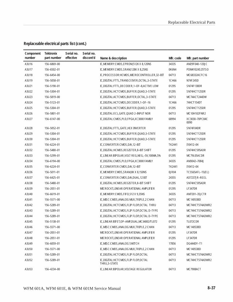
Replaceable Electrical Parts
WFM 601A, WFM 601E, & WFM 601M Service Manual 8–37
Replaceable electrical parts list (cont.)
Componentnumber Mfr. part numberMfr. codeName & description
Serial no.discont’d
Serial no.effective
Tektronixpart number
A3U16 156–6869–00 IC,MEMORY:CMOS,EPROM,512K X 8,120NS 34335 AM29F040–120JC
A3U17 156–6502–01 IC,MEMORY:CMOS,SRAM,128K X 8,25NS 0K6N4 PDM41024S25TSO
A3U18 156–6454–00 IC,PROCESSOR:HCMOS,MICROCONTROLLER,32–BIT 04713 MC68332ACFC16
A3U19 156–5058–01 IC,DIGITAL:FTTL,TRANSCEIVER,OCTAL,3–STATE 1CH66 N74F245D
A3U21 156–5190–01 IC,DIGITAL:FTTL,DECODER,1–OF–8,ACTIVE LOW 01295 SN74F138DR
A3U22 156–5304–01 IC,DIGITAL:HCTCMOS,BUFFER,QUAD,3–STATE 01295 SN74HCT125DR
A3U23 156–5819–00 IC,DIGITAL:ACTCMOS,BUFFER,OCTAL,3–STATE 04713 MC74ACT244DW
A3U24 156–5123–01 IC,DIGITAL:HCTCMOS,DECODER,1–OF–16 1CH66 74HCT154DT
A3U25 156–5304–01 IC,DIGITAL:HCTCMOS,BUFFER,QUAD,3–STATE 01295 SN74HCT125DR
A3U26 156–5801–01 IC,DIGITAL:ECL,GATE,QUAD 2–INPUT NOR 04713 MC10H102FNR2
A3U27 156–6147–00 IC,DIGITAL:CMOS,PLD,FPGA,XC3000 FAMILY 68994 XC3030–70PC84C0090
A3U28 156–5052–01 IC,DIGITAL:FTTL,GATE,HEX INVERTER 01295 SN74F04DR
A3U29 156–5304–01 IC,DIGITAL:HCTCMOS,BUFFER,QUAD,3–STATE 01295 SN74HCT125DR
A3U30 156–5304–01 IC,DIGITAL:HCTCMOS,BUFFER,QUAD,3–STATE 01295 SN74HCT125DR
A3U31 156–6224–01 IC,CONVERTER:CMOS,D/A,12–BIT TK2441 I10412–04
A3U32 156–5480–01 IC,DIGITAL:HCMOS,REGISTER,8–BIT SHIFT 01295 SN74HC595ADR
A3U33 156–5299–01 IC,LINEAR:BIPOLAR,VOLT REG,NEG,–5V,100MA,5% 01295 MC79L05ACDR
A3U34 156–6194–00 IC,DIGITAL:CMOS,PLD,FPGA,XC3000 FAMILY 34335 AM3042–7084J
A3U35 156–6224–01 IC,CONVERTER:CMOS,D/A,12–BIT TK2441 I10412–04
A3U36 156–5011–01 IC,MEMORY:CMOS,SRAM,8K X 8,150NS 0JR04 TC5565AFL–15(EL)
A3U37 156–6425–01 IC,CONVERTER:CMOS,D/A,DUAL,12 BIT 24355 AD7237JR–REEL
A3U38 156–5480–01 IC,DIGITAL:HCMOS,REGISTER,8–BIT SHIFT 01295 SN74HC595ADR
A3U39 156–2051–01 MICROCKT,LINEAR:OPERATIONAL AMPLIFIER 01295 LF347DR
A3U40 156–6619–01 IC,MEMORY:CMOS,FIFO,512 X 9,35NS 34335 AM7201–35JCTR
A3U41 156–5571–00 IC,MISC:CMOS,ANALOG MUX,TRIPLE,2 CHAN 04713 MC14053BD
A3U42 156–5289–01 IC,DIGITAL:HCTCMOS,FLIP FLOP,OCTAL THRU 04713 MC74HCT574ADWR2
A3U43 156–5289–01 IC,DIGITAL:HCTCMOS,FLIP FLOP,OCTAL D–TYPE 04713 MC74HCT574ADWR2
A3U44 156–5289–01 IC,DIGITAL:HCTCMOS,FLIP FLOP,OCTAL D–TYPE 04713 MC74HCT574ADWR2
A3U45 156–5138–01 IC,LINEAR:BIFET,OP–AMP,DUAL,MC34002/TL072 01295 TL072CDR
A3U46 156–5571–00 IC,MISC:CMOS,ANALOG MUX,TRIPLE,2 CHAN 04713 MC14053BD
A3U47 156–2051–01 MICROCKT,LINEAR:OPERATIONAL AMPLIFIER 01295 LF347DR
A3U48 156–2051–01 MICROCKT,LINEAR:OPERATIONAL AMPLIFIER 01295 LF347DR
A3U49 156–6059–01 IC,MISC:CMOS,ANALOG SWITCH 17856 DG444DY–T1
A3U50 156–5571–00 IC,MISC:CMOS,ANALOG MUX,TRIPLE,2 CHAN 04713 MC14053BD
A3U51 156–5289–01 IC,DIGITAL:HCTCMOS,FLIP FLOP,OCTAL 04713 MC74HCT574ADWR2
A3U52 156–5289–01 IC,DIGITAL:HCTCMOS,FLIP FLOP,OCTALTHRU,3–STATE
04713 MC74HCT574ADWR2
A3U53 156–4234–00 IC,LINEAR:BIPOLAR,VOLTAGE REGULATOR 04713 MC7908ACT
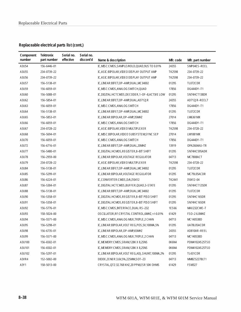
Replaceable Electrical Parts
8–38 WFM 601A, WFM 601E, & WFM 601M Service Manual
Replaceable electrical parts list (cont.)
Componentnumber Mfr. part numberMfr. codeName & description
Serial no.discont’d
Serial no.effective
Tektronixpart number
A3U54 156–6446–01 IC,MISC:CMOS,SAMPLE/HOLD,QUAD,9US TO 0.01% 24355 SMP04ES–REEL
A3U55 234–0739–22 IC,ASIC:BIPOLAR,VIDEO DISPLAY OUTPUT AMP TK2598 234–0739–22
A3U56 234–0739–22 IC,ASIC:BIPOLAR,VIDEO DISPLAY OUTPUT AMP TK2598 234–0739–22
A3U57 156–5138–01 IC,LINEAR:BIFET,OP–AMP,DUAL,MC34002 01295 TL072CDR
A3U59 156–6059–01 IC,MISC:CMOS,ANALOG SWITCH,QUAD 17856 DG444DY–T1
A3U60 156–5088–01 IC,DIGITAL:HCTCMOS,DECODER,1–OF–8,ACTIVE LOW 01295 SN74HCT138DR
A3U62 156–5854–01 IC,LINEAR:BIFET,OP–AMP,DUAL,AD712JR 24355 AD712JR–REEL7
A3U63 156–6059–01 IC,MISC:CMOS,ANALOG SWITCH 17856 DG444DY–T1
A3U64 156–5138–01 IC,LINEAR:BIFET,OP–AMP,DUAL,MC34002 01295 TL072CDR
A3U65 156–5853–01 IC,LINEAR:BIPOLAR,OP–AMP,35MHZ 27014 LM6361MX
A3U66 156–6059–01 IC,MISC:CMOS,ANALOG SWITCH 17856 DG444DY–T1
A3U67 234–0728–22 IC,ASIC:BIPOLAR,VIDEO MULTIPLEXER TK2598 234–0728–22
A3U68 156–5694–01 IC,MISC:BIPOLAR,VIDEO SUBSYSTEM,SYNC SEP 27014 LM1881MX
A3U70 156–6059–01 IC,MISC:CMOS,ANALOG SWITCH 17856 DG444DY–T1
A3U72 156–6716–01 IC,LINEAR:BIFET,OP–AMP,DUAL,20MHZ 13919 OPA2604AU–TR
A3U77 156–5480–01 IC,DIGITAL:HCMOS,REGISTER,8–BIT SHIFT 01295 SN74HC595ADR
A3U78 156–2959–00 IC,LINEAR:BIPOLAR,VOLTAGE REGULATOR 04713 MC7808ACT
A3U79 234–0728–22 IC,ASIC:BIPOLAR,VIDEO MULTIPLEXER TK2598 234–0728–22
A3U84 156–5138–01 IC,LINEAR:BIFET,OP–AMP,DUAL,MC34002 01295 TL072CDR
A3U85 156–5299–01 IC,LINEAR:BIPOLAR,VOLTAGE REGULATOR 01295 MC79L05ACDR
A3U86 156–6224–01 IC,CONVERTER:CMOS,D/A,I10412 TK2441 I10412–04
A3U87 156–5304–01 IC,DIGITAL:HCTCMOS,BUFFER,QUAD,3–STATE 01295 SN74HCT125DR
A3U88 156–5138–01 IC,LINEAR:BIFET,OP–AMP,DUAL,MC34002 01295 TL072CDR
A3U90 156–5358–01 IC,DIGITAL:HCMOS,REGISTER,8–BIT PISO SHIFT 01295 SN74HC165DR
A3U91 156–5358–01 IC,DIGITAL:HCMOS,REGISTER,8–BIT PISO SHIFT 01295 SN74HC165DR
A3U92 156–5776–01 IC,MISC:CMOS,INTERFACE,DUAL RS–232 1ES66 MAX232CWE–T
A3U93 158–5024–00 OSCILLATOR,RF:CRYSTAL CONTROL,6MHZ,+/–0.01% 61429 FSO–2 6.0MHZ
A3U94 156–5571–00 IC,MISC:CMOS,ANALOG MUX,TRIPLE,2 CHAN 04713 MC14053BD
A3U95 156–5298–01 IC,LINEAR:BIPOLAR,VOLT REG,POS,5V,100MA,5% 01295 UA78L05ACDR
A3U98 156–6735–01 IC,LINEAR:BIPOLAR,OP–AMP,65MHZ 24355 AD810AR–REEL
A3U99 156–5571–00 IC,MISC:CMOS,ANALOG MUX,TRIPLE,2 CHAN 04713 MC14053BD
A3U100 156–6502–01 IC,MEMORY:CMOS,SRAM,128K X 8,25NS 0K6N4 PDM41024S25TSO
A3U101 156–6502–01 IC,MEMORY:CMOS,SRAM,128K X 8,25NS 0K6N4 PDM41024S25TSO
A3U102 156–5297–01 IC,LINEAR:BIPOLAR,VOLT REG,ADJ,SHUNT,100MA,2% 01295 TL431CDR
A3VR4 152–5002–00 DIODE,ZENER:3.6V,5%,225MW,SOT–23 04713 MMBZ5227BLT1
A3Y1 158–5013–00 CRYSTAL,QTZ:32.768 KHZ,20 PPM,ESR 50K OHMS 61429 FSM327
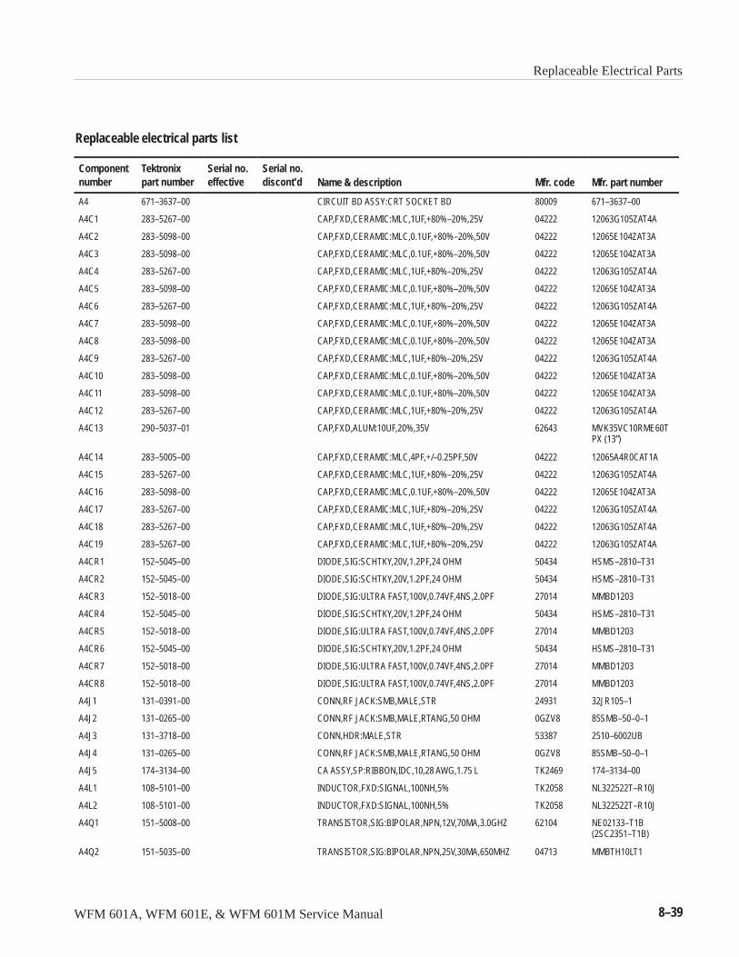
Replaceable Electrical Parts
WFM 601A, WFM 601E, & WFM 601M Service Manual 8–39
Replaceable electrical parts list
Componentnumber
Tektronixpart number
Serial no.effective
Serial no.discont’d Name & description Mfr. code Mfr. part number
A4 671–3637–00 CIRCUIT BD ASSY:CRT SOCKET BD 80009 671–3637–00
A4C1 283–5267–00 CAP,FXD,CERAMIC:MLC,1UF,+80%–20%,25V 04222 12063G105ZAT4A
A4C2 283–5098–00 CAP,FXD,CERAMIC:MLC,0.1UF,+80%–20%,50V 04222 12065E104ZAT3A
A4C3 283–5098–00 CAP,FXD,CERAMIC:MLC,0.1UF,+80%–20%,50V 04222 12065E104ZAT3A
A4C4 283–5267–00 CAP,FXD,CERAMIC:MLC,1UF,+80%–20%,25V 04222 12063G105ZAT4A
A4C5 283–5098–00 CAP,FXD,CERAMIC:MLC,0.1UF,+80%–20%,50V 04222 12065E104ZAT3A
A4C6 283–5267–00 CAP,FXD,CERAMIC:MLC,1UF,+80%–20%,25V 04222 12063G105ZAT4A
A4C7 283–5098–00 CAP,FXD,CERAMIC:MLC,0.1UF,+80%–20%,50V 04222 12065E104ZAT3A
A4C8 283–5098–00 CAP,FXD,CERAMIC:MLC,0.1UF,+80%–20%,50V 04222 12065E104ZAT3A
A4C9 283–5267–00 CAP,FXD,CERAMIC:MLC,1UF,+80%–20%,25V 04222 12063G105ZAT4A
A4C10 283–5098–00 CAP,FXD,CERAMIC:MLC,0.1UF,+80%–20%,50V 04222 12065E104ZAT3A
A4C11 283–5098–00 CAP,FXD,CERAMIC:MLC,0.1UF,+80%–20%,50V 04222 12065E104ZAT3A
A4C12 283–5267–00 CAP,FXD,CERAMIC:MLC,1UF,+80%–20%,25V 04222 12063G105ZAT4A
A4C13 290–5037–01 CAP,FXD,ALUM:10UF,20%,35V 62643 MVK35VC10RME60TPX (13”)
A4C14 283–5005–00 CAP,FXD,CERAMIC:MLC,4PF,+/–0.25PF,50V 04222 12065A4R0CAT1A
A4C15 283–5267–00 CAP,FXD,CERAMIC:MLC,1UF,+80%–20%,25V 04222 12063G105ZAT4A
A4C16 283–5098–00 CAP,FXD,CERAMIC:MLC,0.1UF,+80%–20%,50V 04222 12065E104ZAT3A
A4C17 283–5267–00 CAP,FXD,CERAMIC:MLC,1UF,+80%–20%,25V 04222 12063G105ZAT4A
A4C18 283–5267–00 CAP,FXD,CERAMIC:MLC,1UF,+80%–20%,25V 04222 12063G105ZAT4A
A4C19 283–5267–00 CAP,FXD,CERAMIC:MLC,1UF,+80%–20%,25V 04222 12063G105ZAT4A
A4CR1 152–5045–00 DIODE,SIG:SCHTKY,20V,1.2PF,24 OHM 50434 HSMS–2810–T31
A4CR2 152–5045–00 DIODE,SIG:SCHTKY,20V,1.2PF,24 OHM 50434 HSMS–2810–T31
A4CR3 152–5018–00 DIODE,SIG:ULTRA FAST,100V,0.74VF,4NS,2.0PF 27014 MMBD1203
A4CR4 152–5045–00 DIODE,SIG:SCHTKY,20V,1.2PF,24 OHM 50434 HSMS–2810–T31
A4CR5 152–5018–00 DIODE,SIG:ULTRA FAST,100V,0.74VF,4NS,2.0PF 27014 MMBD1203
A4CR6 152–5045–00 DIODE,SIG:SCHTKY,20V,1.2PF,24 OHM 50434 HSMS–2810–T31
A4CR7 152–5018–00 DIODE,SIG:ULTRA FAST,100V,0.74VF,4NS,2.0PF 27014 MMBD1203
A4CR8 152–5018–00 DIODE,SIG:ULTRA FAST,100V,0.74VF,4NS,2.0PF 27014 MMBD1203
A4J1 131–0391–00 CONN,RF JACK:SMB,MALE,STR 24931 32JR105–1
A4J2 131–0265–00 CONN,RF JACK:SMB,MALE,RTANG,50 OHM 0GZV8 85SMB–50–0–1
A4J3 131–3718–00 CONN,HDR:MALE,STR 53387 2510–6002UB
A4J4 131–0265–00 CONN,RF JACK:SMB,MALE,RTANG,50 OHM 0GZV8 85SMB–50–0–1
A4J5 174–3134–00 CA ASSY,SP:RIBBON,IDC,10,28 AWG,1.75 L TK2469 174–3134–00
A4L1 108–5101–00 INDUCTOR,FXD:SIGNAL,100NH,5% TK2058 NL322522T–R10J
A4L2 108–5101–00 INDUCTOR,FXD:SIGNAL,100NH,5% TK2058 NL322522T–R10J
A4Q1 151–5008–00 TRANSISTOR,SIG:BIPOLAR,NPN,12V,70MA,3.0GHZ 62104 NE02133–T1B(2SC2351–T1B)
A4Q2 151–5035–00 TRANSISTOR,SIG:BIPOLAR,NPN,25V,30MA,650MHZ 04713 MMBTH10LT1
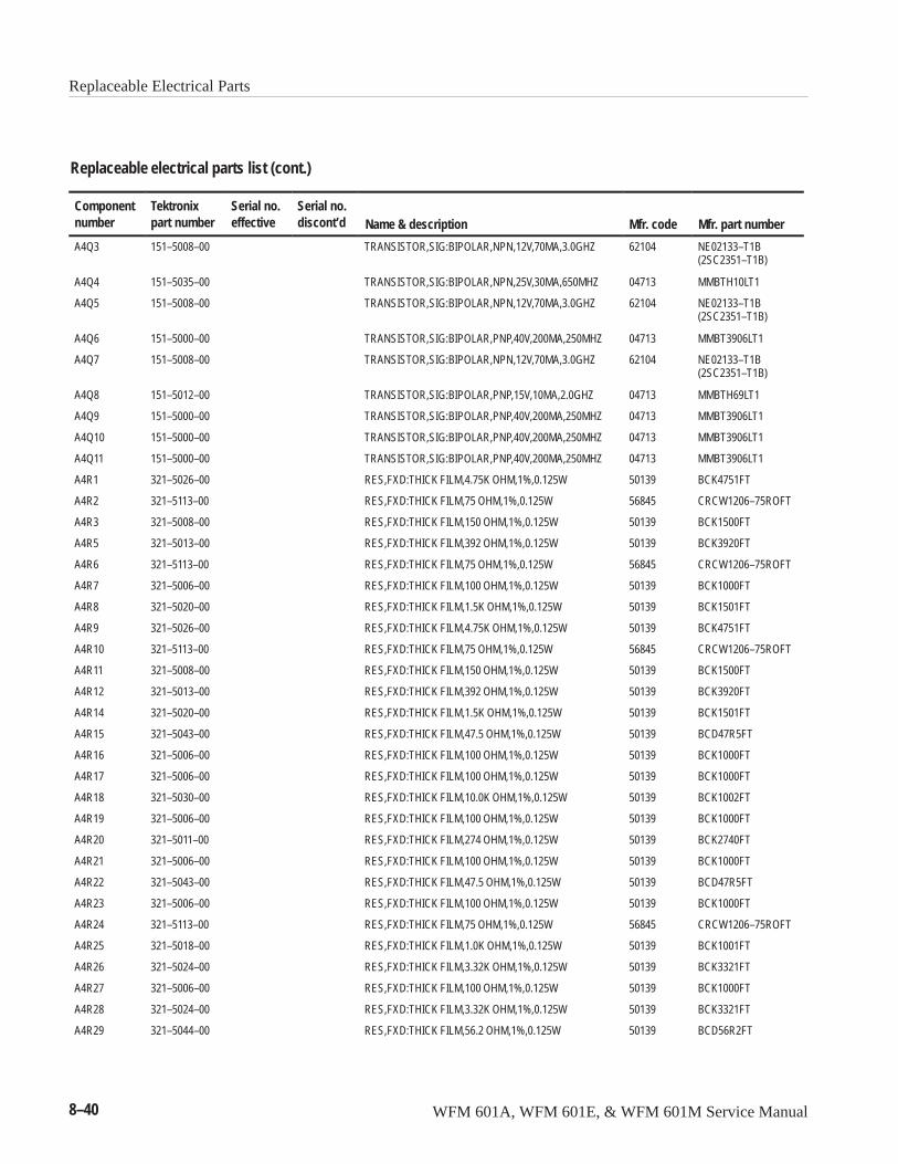
Replaceable Electrical Parts
8–40 WFM 601A, WFM 601E, & WFM 601M Service Manual
Replaceable electrical parts list (cont.)
Componentnumber Mfr. part numberMfr. codeName & description
Serial no.discont’d
Serial no.effective
Tektronixpart number
A4Q3 151–5008–00 TRANSISTOR,SIG:BIPOLAR,NPN,12V,70MA,3.0GHZ 62104 NE02133–T1B(2SC2351–T1B)
A4Q4 151–5035–00 TRANSISTOR,SIG:BIPOLAR,NPN,25V,30MA,650MHZ 04713 MMBTH10LT1
A4Q5 151–5008–00 TRANSISTOR,SIG:BIPOLAR,NPN,12V,70MA,3.0GHZ 62104 NE02133–T1B(2SC2351–T1B)
A4Q6 151–5000–00 TRANSISTOR,SIG:BIPOLAR,PNP,40V,200MA,250MHZ 04713 MMBT3906LT1
A4Q7 151–5008–00 TRANSISTOR,SIG:BIPOLAR,NPN,12V,70MA,3.0GHZ 62104 NE02133–T1B(2SC2351–T1B)
A4Q8 151–5012–00 TRANSISTOR,SIG:BIPOLAR,PNP,15V,10MA,2.0GHZ 04713 MMBTH69LT1
A4Q9 151–5000–00 TRANSISTOR,SIG:BIPOLAR,PNP,40V,200MA,250MHZ 04713 MMBT3906LT1
A4Q10 151–5000–00 TRANSISTOR,SIG:BIPOLAR,PNP,40V,200MA,250MHZ 04713 MMBT3906LT1
A4Q11 151–5000–00 TRANSISTOR,SIG:BIPOLAR,PNP,40V,200MA,250MHZ 04713 MMBT3906LT1
A4R1 321–5026–00 RES,FXD:THICK FILM,4.75K OHM,1%,0.125W 50139 BCK4751FT
A4R2 321–5113–00 RES,FXD:THICK FILM,75 OHM,1%,0.125W 56845 CRCW1206–75ROFT
A4R3 321–5008–00 RES,FXD:THICK FILM,150 OHM,1%,0.125W 50139 BCK1500FT
A4R5 321–5013–00 RES,FXD:THICK FILM,392 OHM,1%,0.125W 50139 BCK3920FT
A4R6 321–5113–00 RES,FXD:THICK FILM,75 OHM,1%,0.125W 56845 CRCW1206–75ROFT
A4R7 321–5006–00 RES,FXD:THICK FILM,100 OHM,1%,0.125W 50139 BCK1000FT
A4R8 321–5020–00 RES,FXD:THICK FILM,1.5K OHM,1%,0.125W 50139 BCK1501FT
A4R9 321–5026–00 RES,FXD:THICK FILM,4.75K OHM,1%,0.125W 50139 BCK4751FT
A4R10 321–5113–00 RES,FXD:THICK FILM,75 OHM,1%,0.125W 56845 CRCW1206–75ROFT
A4R11 321–5008–00 RES,FXD:THICK FILM,150 OHM,1%,0.125W 50139 BCK1500FT
A4R12 321–5013–00 RES,FXD:THICK FILM,392 OHM,1%,0.125W 50139 BCK3920FT
A4R14 321–5020–00 RES,FXD:THICK FILM,1.5K OHM,1%,0.125W 50139 BCK1501FT
A4R15 321–5043–00 RES,FXD:THICK FILM,47.5 OHM,1%,0.125W 50139 BCD47R5FT
A4R16 321–5006–00 RES,FXD:THICK FILM,100 OHM,1%,0.125W 50139 BCK1000FT
A4R17 321–5006–00 RES,FXD:THICK FILM,100 OHM,1%,0.125W 50139 BCK1000FT
A4R18 321–5030–00 RES,FXD:THICK FILM,10.0K OHM,1%,0.125W 50139 BCK1002FT
A4R19 321–5006–00 RES,FXD:THICK FILM,100 OHM,1%,0.125W 50139 BCK1000FT
A4R20 321–5011–00 RES,FXD:THICK FILM,274 OHM,1%,0.125W 50139 BCK2740FT
A4R21 321–5006–00 RES,FXD:THICK FILM,100 OHM,1%,0.125W 50139 BCK1000FT
A4R22 321–5043–00 RES,FXD:THICK FILM,47.5 OHM,1%,0.125W 50139 BCD47R5FT
A4R23 321–5006–00 RES,FXD:THICK FILM,100 OHM,1%,0.125W 50139 BCK1000FT
A4R24 321–5113–00 RES,FXD:THICK FILM,75 OHM,1%,0.125W 56845 CRCW1206–75ROFT
A4R25 321–5018–00 RES,FXD:THICK FILM,1.0K OHM,1%,0.125W 50139 BCK1001FT
A4R26 321–5024–00 RES,FXD:THICK FILM,3.32K OHM,1%,0.125W 50139 BCK3321FT
A4R27 321–5006–00 RES,FXD:THICK FILM,100 OHM,1%,0.125W 50139 BCK1000FT
A4R28 321–5024–00 RES,FXD:THICK FILM,3.32K OHM,1%,0.125W 50139 BCK3321FT
A4R29 321–5044–00 RES,FXD:THICK FILM,56.2 OHM,1%,0.125W 50139 BCD56R2FT
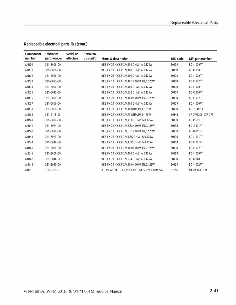
Replaceable Electrical Parts
WFM 601A, WFM 601E, & WFM 601M Service Manual 8–41
Replaceable electrical parts list (cont.)
Componentnumber Mfr. part numberMfr. codeName & description
Serial no.discont’d
Serial no.effective
Tektronixpart number
A4R30 321–5006–00 RES,FXD:THICK FILM,100 OHM,1%,0.125W 50139 BCK1000FT
A4R31 321–5006–00 RES,FXD:THICK FILM,100 OHM,1%,0.125W 50139 BCK1000FT
A4R32 321–5006–00 RES,FXD:THICK FILM,100 OHM,1%,0.125W 50139 BCK1000FT
A4R33 321–5033–00 RES,FXD:THICK FILM,18.2K OHM,1%,0.125W 50139 BCK1822FT
A4R34 321–5006–00 RES,FXD:THICK FILM,100 OHM,1%,0.125W 50139 BCK1000FT
A4R35 321–5012–00 RES,FXD:THICK FILM,332 OHM,1%,0.125W 50139 BCK3320FT
A4R36 321–5030–00 RES,FXD:THICK FILM,10.0K OHM,1%,0.125W 50139 BCK1002FT
A4R37 321–5006–00 RES,FXD:THICK FILM,100 OHM,1%,0.125W 50139 BCK1000FT
A4R38 321–5000–00 RES,FXD:THICK FILM,10 OHM,1%,0.125W 50139 BCD10R0FT
A4R39 321–5113–00 RES,FXD:THICK FILM,75 OHM,1%,0.125W 56845 CRCW1206–75ROFT
A4R40 321–5020–00 RES,FXD:THICK FILM,1.5K OHM,1%,0.125W 50139 BCK1501FT
A4R41 321–5024–00 RES,FXD:THICK FILM,3.32K OHM,1%,0.125W 50139 BCK3321FT
A4R42 321–5028–00 RES,FXD:THICK FILM,6.81K OHM,1%,0.125W 50139 BCK6811FT
A4R43 321–5020–00 RES,FXD:THICK FILM,1.5K OHM,1%,0.125W 50139 BCK1501FT
A4R44 321–5018–00 RES,FXD:THICK FILM,1.0K OHM,1%,0.125W 50139 BCK1001FT
A4R45 321–5030–00 RES,FXD:THICK FILM,10.0K OHM,1%,0.125W 50139 BCK1002FT
A4R46 321–5006–00 RES,FXD:THICK FILM,100 OHM,1%,0.125W 50139 BCK1000FT
A4R47 321–5011–00 RES,FXD:THICK FILM,274 OHM,1%,0.125W 50139 BCK2740FT
A4R48 321–5030–00 RES,FXD:THICK FILM,10.0K OHM,1%,0.125W 50139 BCK1002FT
A4U1 156–5299–01 IC,LINEAR:BIPOLAR,VOLT REG,NEG,–5V,100MA,5% 01295 MC79L05ACDR
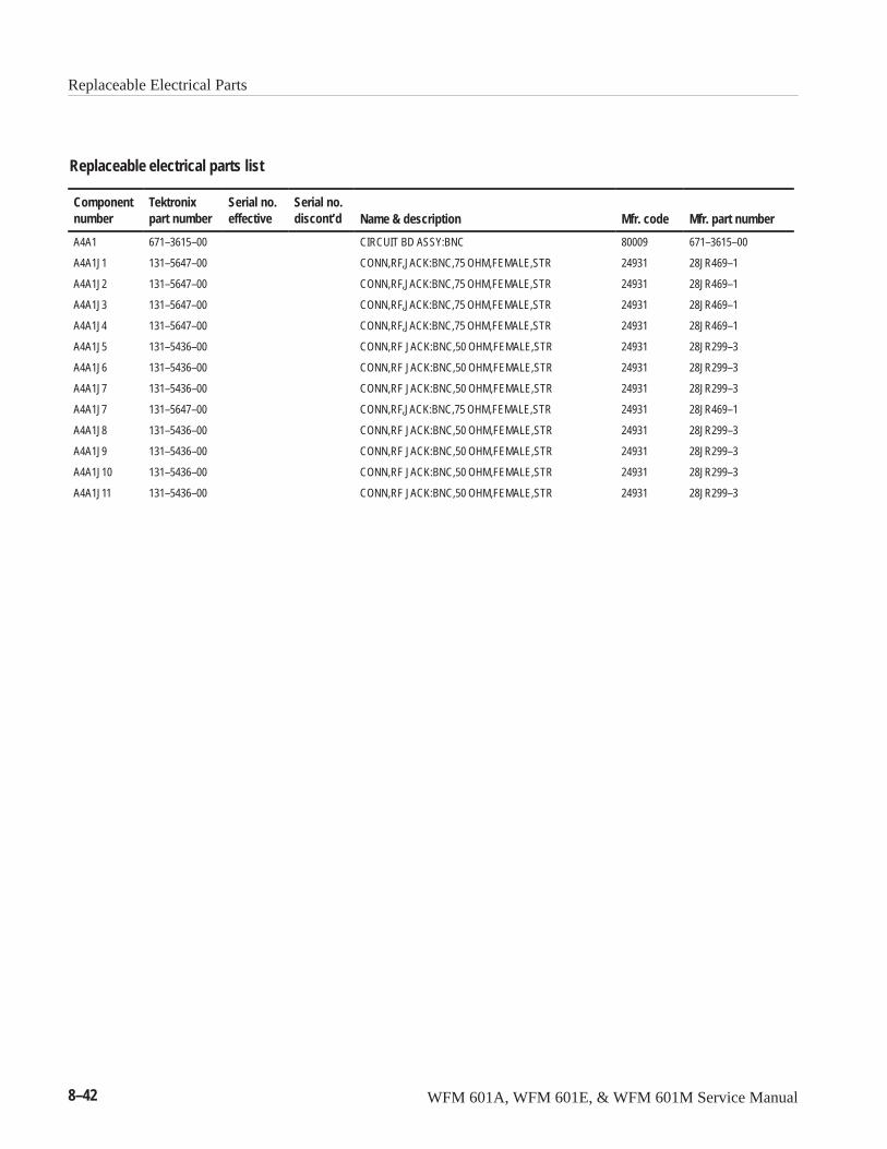
Replaceable Electrical Parts
8–42 WFM 601A, WFM 601E, & WFM 601M Service Manual
Replaceable electrical parts list
Componentnumber
Tektronixpart number
Serial no.effective
Serial no.discont’d Name & description Mfr. code Mfr. part number
A4A1 671–3615–00 CIRCUIT BD ASSY:BNC 80009 671–3615–00
A4A1J1 131–5647–00 CONN,RF,JACK:BNC,75 OHM,FEMALE,STR 24931 28JR469–1
A4A1J2 131–5647–00 CONN,RF,JACK:BNC,75 OHM,FEMALE,STR 24931 28JR469–1
A4A1J3 131–5647–00 CONN,RF,JACK:BNC,75 OHM,FEMALE,STR 24931 28JR469–1
A4A1J4 131–5647–00 CONN,RF,JACK:BNC,75 OHM,FEMALE,STR 24931 28JR469–1
A4A1J5 131–5436–00 CONN,RF JACK:BNC,50 OHM,FEMALE,STR 24931 28JR299–3
A4A1J6 131–5436–00 CONN,RF JACK:BNC,50 OHM,FEMALE,STR 24931 28JR299–3
A4A1J7 131–5436–00 CONN,RF JACK:BNC,50 OHM,FEMALE,STR 24931 28JR299–3
A4A1J7 131–5647–00 CONN,RF,JACK:BNC,75 OHM,FEMALE,STR 24931 28JR469–1
A4A1J8 131–5436–00 CONN,RF JACK:BNC,50 OHM,FEMALE,STR 24931 28JR299–3
A4A1J9 131–5436–00 CONN,RF JACK:BNC,50 OHM,FEMALE,STR 24931 28JR299–3
A4A1J10 131–5436–00 CONN,RF JACK:BNC,50 OHM,FEMALE,STR 24931 28JR299–3
A4A1J11 131–5436–00 CONN,RF JACK:BNC,50 OHM,FEMALE,STR 24931 28JR299–3
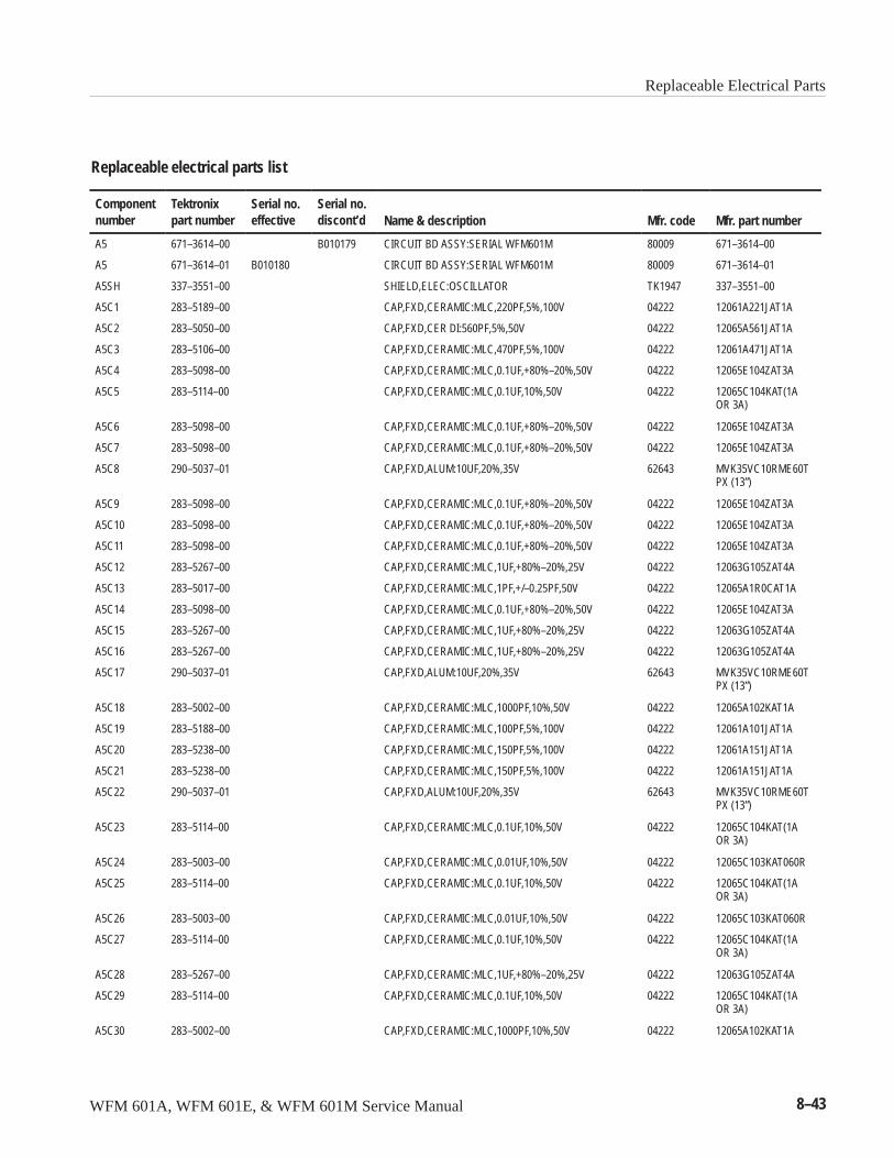
Replaceable Electrical Parts
WFM 601A, WFM 601E, & WFM 601M Service Manual 8–43
Replaceable electrical parts list
Componentnumber
Tektronixpart number
Serial no.effective
Serial no.discont’d Name & description Mfr. code Mfr. part number
A5 671–3614–00 B010179 CIRCUIT BD ASSY:SERIAL WFM601M 80009 671–3614–00
A5 671–3614–01 B010180 CIRCUIT BD ASSY:SERIAL WFM601M 80009 671–3614–01
A5SH 337–3551–00 SHIELD,ELEC:OSCILLATOR TK1947 337–3551–00
A5C1 283–5189–00 CAP,FXD,CERAMIC:MLC,220PF,5%,100V 04222 12061A221JAT1A
A5C2 283–5050–00 CAP,FXD,CER DI:560PF,5%,50V 04222 12065A561JAT1A
A5C3 283–5106–00 CAP,FXD,CERAMIC:MLC,470PF,5%,100V 04222 12061A471JAT1A
A5C4 283–5098–00 CAP,FXD,CERAMIC:MLC,0.1UF,+80%–20%,50V 04222 12065E104ZAT3A
A5C5 283–5114–00 CAP,FXD,CERAMIC:MLC,0.1UF,10%,50V 04222 12065C104KAT(1AOR 3A)
A5C6 283–5098–00 CAP,FXD,CERAMIC:MLC,0.1UF,+80%–20%,50V 04222 12065E104ZAT3A
A5C7 283–5098–00 CAP,FXD,CERAMIC:MLC,0.1UF,+80%–20%,50V 04222 12065E104ZAT3A
A5C8 290–5037–01 CAP,FXD,ALUM:10UF,20%,35V 62643 MVK35VC10RME60TPX (13”)
A5C9 283–5098–00 CAP,FXD,CERAMIC:MLC,0.1UF,+80%–20%,50V 04222 12065E104ZAT3A
A5C10 283–5098–00 CAP,FXD,CERAMIC:MLC,0.1UF,+80%–20%,50V 04222 12065E104ZAT3A
A5C11 283–5098–00 CAP,FXD,CERAMIC:MLC,0.1UF,+80%–20%,50V 04222 12065E104ZAT3A
A5C12 283–5267–00 CAP,FXD,CERAMIC:MLC,1UF,+80%–20%,25V 04222 12063G105ZAT4A
A5C13 283–5017–00 CAP,FXD,CERAMIC:MLC,1PF,+/–0.25PF,50V 04222 12065A1R0CAT1A
A5C14 283–5098–00 CAP,FXD,CERAMIC:MLC,0.1UF,+80%–20%,50V 04222 12065E104ZAT3A
A5C15 283–5267–00 CAP,FXD,CERAMIC:MLC,1UF,+80%–20%,25V 04222 12063G105ZAT4A
A5C16 283–5267–00 CAP,FXD,CERAMIC:MLC,1UF,+80%–20%,25V 04222 12063G105ZAT4A
A5C17 290–5037–01 CAP,FXD,ALUM:10UF,20%,35V 62643 MVK35VC10RME60TPX (13”)
A5C18 283–5002–00 CAP,FXD,CERAMIC:MLC,1000PF,10%,50V 04222 12065A102KAT1A
A5C19 283–5188–00 CAP,FXD,CERAMIC:MLC,100PF,5%,100V 04222 12061A101JAT1A
A5C20 283–5238–00 CAP,FXD,CERAMIC:MLC,150PF,5%,100V 04222 12061A151JAT1A
A5C21 283–5238–00 CAP,FXD,CERAMIC:MLC,150PF,5%,100V 04222 12061A151JAT1A
A5C22 290–5037–01 CAP,FXD,ALUM:10UF,20%,35V 62643 MVK35VC10RME60TPX (13”)
A5C23 283–5114–00 CAP,FXD,CERAMIC:MLC,0.1UF,10%,50V 04222 12065C104KAT(1AOR 3A)
A5C24 283–5003–00 CAP,FXD,CERAMIC:MLC,0.01UF,10%,50V 04222 12065C103KAT060R
A5C25 283–5114–00 CAP,FXD,CERAMIC:MLC,0.1UF,10%,50V 04222 12065C104KAT(1AOR 3A)
A5C26 283–5003–00 CAP,FXD,CERAMIC:MLC,0.01UF,10%,50V 04222 12065C103KAT060R
A5C27 283–5114–00 CAP,FXD,CERAMIC:MLC,0.1UF,10%,50V 04222 12065C104KAT(1AOR 3A)
A5C28 283–5267–00 CAP,FXD,CERAMIC:MLC,1UF,+80%–20%,25V 04222 12063G105ZAT4A
A5C29 283–5114–00 CAP,FXD,CERAMIC:MLC,0.1UF,10%,50V 04222 12065C104KAT(1AOR 3A)
A5C30 283–5002–00 CAP,FXD,CERAMIC:MLC,1000PF,10%,50V 04222 12065A102KAT1A

Replaceable Electrical Parts
8–44 WFM 601A, WFM 601E, & WFM 601M Service Manual
Replaceable electrical parts list (cont.)
Componentnumber Mfr. part numberMfr. codeName & description
Serial no.discont’d
Serial no.effective
Tektronixpart number
A5C31 283–5202–00 CAP,FXD,CERAMIC:MLC,0.022UF,10%,50V 04222 12065C223KAT1A
A5C32 283–5202–00 CAP,FXD,CERAMIC:MLC,0.022UF,10%,50V 04222 12065C223KAT1A
A5C33 283–5003–00 CAP,FXD,CERAMIC:MLC,0.01UF,10%,50V 04222 12065C103KAT060R
A5C34 283–5238–00 CAP,FXD,CERAMIC:MLC,150PF,5%,100V 04222 12061A151JAT1A
A5C35 283–5239–00 CAP,FXD,CERAMIC:MLC,1200PF,5%,100V 04222 12061A122JAT1A
A5C36 283–5239–00 CAP,FXD,CERAMIC:MLC,1200PF,5%,100V 04222 12061A122JAT1A
A5C37 283–5003–00 CAP,FXD,CERAMIC:MLC,0.01UF,10%,50V 04222 12065C103KAT060R
A5C38 283–5003–00 CAP,FXD,CERAMIC:MLC,0.01UF,10%,50V 04222 12065C103KAT060R
A5C39 283–5114–00 CAP,FXD,CERAMIC:MLC,0.1UF,10%,50V 04222 12065C104KAT(1AOR 3A)
A5C40 283–5267–00 CAP,FXD,CERAMIC:MLC,1UF,+80%–20%,25V 04222 12063G105ZAT4A
A5C41 283–5196–00 CAP,FXD,CERAMIC:MLC,47PF,5%,100V 04222 12061A470JAT1A
A5C42 283–5196–00 CAP,FXD,CERAMIC:MLC,47PF,5%,100V 04222 12061A470JAT1A
A5C43 283–5195–00 CAP,FXD,CERAMIC:MLC,10PF,5%,100V 04222 12061A100JAT1A
A5C44 283–5187–00 CAP,FXD,CERAMIC:MLC,15PF,5%,100V 04222 12061A150JAT1A
A5C45 283–5267–00 CAP,FXD,CERAMIC:MLC,1UF,+80%–20%,25V 04222 12063G105ZAT4A
A5C46 283–5282–00 CAP,FXD,CERAMIC:MLC,2.2UF,+80–20%,16V 04222 1206YG225ZAT2A
A5C47 283–5282–00 CAP,FXD,CERAMIC:MLC,2.2UF,+80–20%,16V 04222 1206YG225ZAT2A
A5C48 283–5068–00 CAP,FXD,CERAMIC:MLC,2200PF,10%,50V 04222 12065C222KAT1A
A5C49 283–5003–00 CAP,FXD,CERAMIC:MLC,0.01UF,10%,50V 04222 12065C103KAT060R
A5C50 283–5265–00 CAP,FXD,CERAMIC:MLC,0.0033UF,5%,50V 04222 12065A332JAT1A
A5C51 283–5114–00 CAP,FXD,CERAMIC:MLC,0.1UF,10%,50V 04222 12065C104KAT(1AOR 3A)
A5C52 283–5098–00 CAP,FXD,CERAMIC:MLC,0.1UF,+80%–20%,50V 04222 12065E104ZAT3A
A5C53 283–5195–00 CAP,FXD,CERAMIC:MLC,10PF,5%,100V 04222 12061A100JAT1A
A5C54 283–5114–00 CAP,FXD,CERAMIC:MLC,0.1UF,10%,50V 04222 12065C104KAT(1AOR 3A)
A5C55 283–5267–00 CAP,FXD,CERAMIC:MLC,1UF,+80%–20%,25V 04222 12063G105ZAT4A
A5C56 283–5098–00 CAP,FXD,CERAMIC:MLC,0.1UF,+80%–20%,50V 04222 12065E104ZAT3A
A5C57 283–5267–00 CAP,FXD,CERAMIC:MLC,1UF,+80%–20%,25V 04222 12063G105ZAT4A
A5C58 283–5203–00 CAP,FXD,CERAMIC:MLC,1000PF,10%,100V 04222 12061C102KAT1A
A5C59 283–5026–00 CAP,FXD,CERAMIC:MLC,390PF,5%,50V 04222 12065A391JAT1A
A5C60 283–5026–00 CAP,FXD,CERAMIC:MLC,390PF,5%,50V 04222 12065A391JAT1A
A5C61 283–5195–00 CAP,FXD,CERAMIC:MLC,10PF,5%,100V 04222 12061A100JAT1A
A5C62 283–5195–00 CAP,FXD,CERAMIC:MLC,10PF,5%,100V 04222 12061A100JAT1A
A5C63 283–5026–00 CAP,FXD,CERAMIC:MLC,390PF,5%,50V 04222 12065A391JAT1A
A5C64 283–5026–00 CAP,FXD,CERAMIC:MLC,390PF,5%,50V 04222 12065A391JAT1A
A5C65 290–5037–01 CAP,FXD,ALUM:10UF,20%,35V 62643 MVK35VC10RME60TPX (13”)
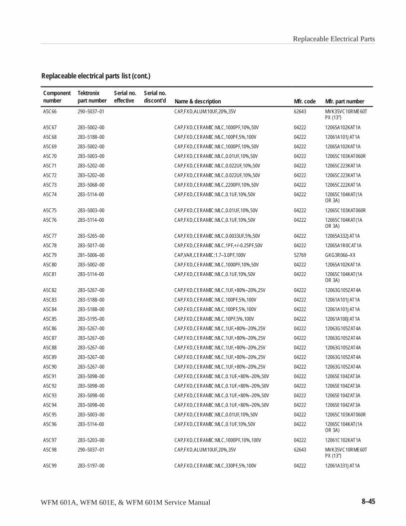
Replaceable Electrical Parts
WFM 601A, WFM 601E, & WFM 601M Service Manual 8–45
Replaceable electrical parts list (cont.)
Componentnumber Mfr. part numberMfr. codeName & description
Serial no.discont’d
Serial no.effective
Tektronixpart number
A5C66 290–5037–01 CAP,FXD,ALUM:10UF,20%,35V 62643 MVK35VC10RME60TPX (13”)
A5C67 283–5002–00 CAP,FXD,CERAMIC:MLC,1000PF,10%,50V 04222 12065A102KAT1A
A5C68 283–5188–00 CAP,FXD,CERAMIC:MLC,100PF,5%,100V 04222 12061A101JAT1A
A5C69 283–5002–00 CAP,FXD,CERAMIC:MLC,1000PF,10%,50V 04222 12065A102KAT1A
A5C70 283–5003–00 CAP,FXD,CERAMIC:MLC,0.01UF,10%,50V 04222 12065C103KAT060R
A5C71 283–5202–00 CAP,FXD,CERAMIC:MLC,0.022UF,10%,50V 04222 12065C223KAT1A
A5C72 283–5202–00 CAP,FXD,CERAMIC:MLC,0.022UF,10%,50V 04222 12065C223KAT1A
A5C73 283–5068–00 CAP,FXD,CERAMIC:MLC,2200PF,10%,50V 04222 12065C222KAT1A
A5C74 283–5114–00 CAP,FXD,CERAMIC:MLC,0.1UF,10%,50V 04222 12065C104KAT(1AOR 3A)
A5C75 283–5003–00 CAP,FXD,CERAMIC:MLC,0.01UF,10%,50V 04222 12065C103KAT060R
A5C76 283–5114–00 CAP,FXD,CERAMIC:MLC,0.1UF,10%,50V 04222 12065C104KAT(1AOR 3A)
A5C77 283–5265–00 CAP,FXD,CERAMIC:MLC,0.0033UF,5%,50V 04222 12065A332JAT1A
A5C78 283–5017–00 CAP,FXD,CERAMIC:MLC,1PF,+/–0.25PF,50V 04222 12065A1R0CAT1A
A5C79 281–5006–00 CAP,VAR,CERAMIC:1.7–3.0PF,100V 52769 GKG3R066–XX
A5C80 283–5002–00 CAP,FXD,CERAMIC:MLC,1000PF,10%,50V 04222 12065A102KAT1A
A5C81 283–5114–00 CAP,FXD,CERAMIC:MLC,0.1UF,10%,50V 04222 12065C104KAT(1AOR 3A)
A5C82 283–5267–00 CAP,FXD,CERAMIC:MLC,1UF,+80%–20%,25V 04222 12063G105ZAT4A
A5C83 283–5188–00 CAP,FXD,CERAMIC:MLC,100PF,5%,100V 04222 12061A101JAT1A
A5C84 283–5188–00 CAP,FXD,CERAMIC:MLC,100PF,5%,100V 04222 12061A101JAT1A
A5C85 283–5195–00 CAP,FXD,CERAMIC:MLC,10PF,5%,100V 04222 12061A100JAT1A
A5C86 283–5267–00 CAP,FXD,CERAMIC:MLC,1UF,+80%–20%,25V 04222 12063G105ZAT4A
A5C87 283–5267–00 CAP,FXD,CERAMIC:MLC,1UF,+80%–20%,25V 04222 12063G105ZAT4A
A5C88 283–5267–00 CAP,FXD,CERAMIC:MLC,1UF,+80%–20%,25V 04222 12063G105ZAT4A
A5C89 283–5267–00 CAP,FXD,CERAMIC:MLC,1UF,+80%–20%,25V 04222 12063G105ZAT4A
A5C90 283–5267–00 CAP,FXD,CERAMIC:MLC,1UF,+80%–20%,25V 04222 12063G105ZAT4A
A5C91 283–5098–00 CAP,FXD,CERAMIC:MLC,0.1UF,+80%–20%,50V 04222 12065E104ZAT3A
A5C92 283–5098–00 CAP,FXD,CERAMIC:MLC,0.1UF,+80%–20%,50V 04222 12065E104ZAT3A
A5C93 283–5098–00 CAP,FXD,CERAMIC:MLC,0.1UF,+80%–20%,50V 04222 12065E104ZAT3A
A5C94 283–5098–00 CAP,FXD,CERAMIC:MLC,0.1UF,+80%–20%,50V 04222 12065E104ZAT3A
A5C95 283–5003–00 CAP,FXD,CERAMIC:MLC,0.01UF,10%,50V 04222 12065C103KAT060R
A5C96 283–5114–00 CAP,FXD,CERAMIC:MLC,0.1UF,10%,50V 04222 12065C104KAT(1AOR 3A)
A5C97 283–5203–00 CAP,FXD,CERAMIC:MLC,1000PF,10%,100V 04222 12061C102KAT1A
A5C98 290–5037–01 CAP,FXD,ALUM:10UF,20%,35V 62643 MVK35VC10RME60TPX (13”)
A5C99 283–5197–00 CAP,FXD,CERAMIC:MLC,330PF,5%,100V 04222 12061A331JAT1A
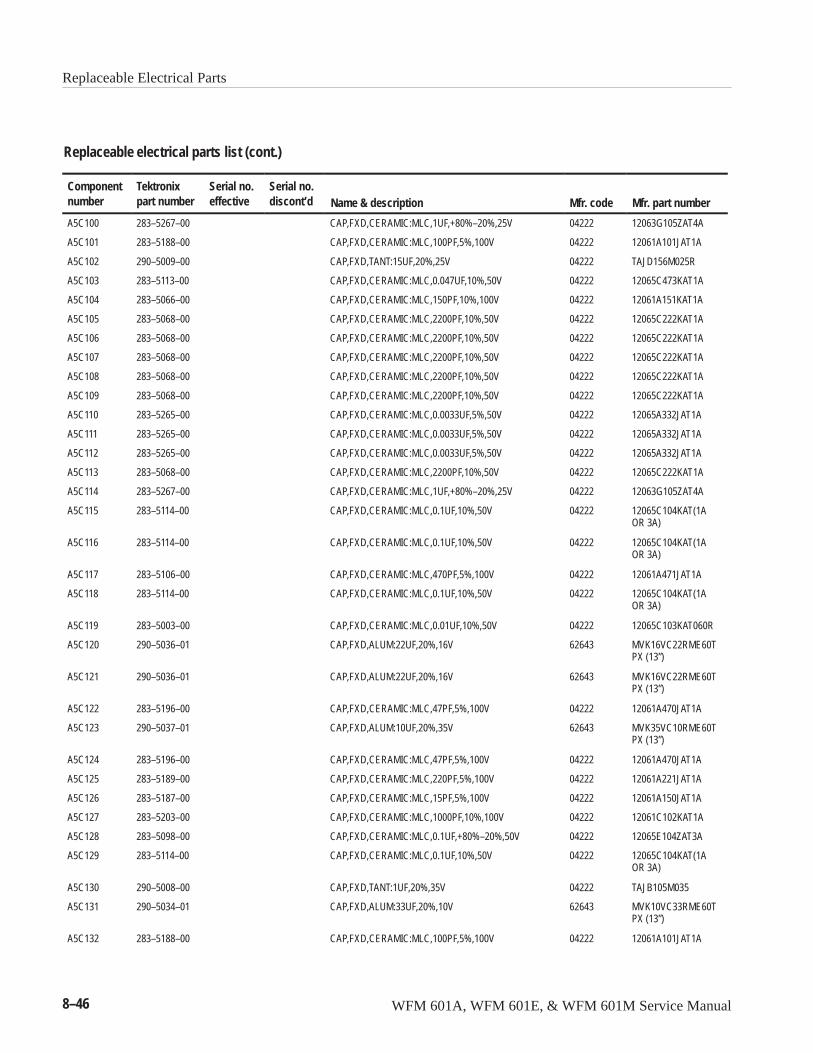
Replaceable Electrical Parts
8–46 WFM 601A, WFM 601E, & WFM 601M Service Manual
Replaceable electrical parts list (cont.)
Componentnumber Mfr. part numberMfr. codeName & description
Serial no.discont’d
Serial no.effective
Tektronixpart number
A5C100 283–5267–00 CAP,FXD,CERAMIC:MLC,1UF,+80%–20%,25V 04222 12063G105ZAT4A
A5C101 283–5188–00 CAP,FXD,CERAMIC:MLC,100PF,5%,100V 04222 12061A101JAT1A
A5C102 290–5009–00 CAP,FXD,TANT:15UF,20%,25V 04222 TAJD156M025R
A5C103 283–5113–00 CAP,FXD,CERAMIC:MLC,0.047UF,10%,50V 04222 12065C473KAT1A
A5C104 283–5066–00 CAP,FXD,CERAMIC:MLC,150PF,10%,100V 04222 12061A151KAT1A
A5C105 283–5068–00 CAP,FXD,CERAMIC:MLC,2200PF,10%,50V 04222 12065C222KAT1A
A5C106 283–5068–00 CAP,FXD,CERAMIC:MLC,2200PF,10%,50V 04222 12065C222KAT1A
A5C107 283–5068–00 CAP,FXD,CERAMIC:MLC,2200PF,10%,50V 04222 12065C222KAT1A
A5C108 283–5068–00 CAP,FXD,CERAMIC:MLC,2200PF,10%,50V 04222 12065C222KAT1A
A5C109 283–5068–00 CAP,FXD,CERAMIC:MLC,2200PF,10%,50V 04222 12065C222KAT1A
A5C110 283–5265–00 CAP,FXD,CERAMIC:MLC,0.0033UF,5%,50V 04222 12065A332JAT1A
A5C111 283–5265–00 CAP,FXD,CERAMIC:MLC,0.0033UF,5%,50V 04222 12065A332JAT1A
A5C112 283–5265–00 CAP,FXD,CERAMIC:MLC,0.0033UF,5%,50V 04222 12065A332JAT1A
A5C113 283–5068–00 CAP,FXD,CERAMIC:MLC,2200PF,10%,50V 04222 12065C222KAT1A
A5C114 283–5267–00 CAP,FXD,CERAMIC:MLC,1UF,+80%–20%,25V 04222 12063G105ZAT4A
A5C115 283–5114–00 CAP,FXD,CERAMIC:MLC,0.1UF,10%,50V 04222 12065C104KAT(1AOR 3A)
A5C116 283–5114–00 CAP,FXD,CERAMIC:MLC,0.1UF,10%,50V 04222 12065C104KAT(1AOR 3A)
A5C117 283–5106–00 CAP,FXD,CERAMIC:MLC,470PF,5%,100V 04222 12061A471JAT1A
A5C118 283–5114–00 CAP,FXD,CERAMIC:MLC,0.1UF,10%,50V 04222 12065C104KAT(1AOR 3A)
A5C119 283–5003–00 CAP,FXD,CERAMIC:MLC,0.01UF,10%,50V 04222 12065C103KAT060R
A5C120 290–5036–01 CAP,FXD,ALUM:22UF,20%,16V 62643 MVK16VC22RME60TPX (13”)
A5C121 290–5036–01 CAP,FXD,ALUM:22UF,20%,16V 62643 MVK16VC22RME60TPX (13”)
A5C122 283–5196–00 CAP,FXD,CERAMIC:MLC,47PF,5%,100V 04222 12061A470JAT1A
A5C123 290–5037–01 CAP,FXD,ALUM:10UF,20%,35V 62643 MVK35VC10RME60TPX (13”)
A5C124 283–5196–00 CAP,FXD,CERAMIC:MLC,47PF,5%,100V 04222 12061A470JAT1A
A5C125 283–5189–00 CAP,FXD,CERAMIC:MLC,220PF,5%,100V 04222 12061A221JAT1A
A5C126 283–5187–00 CAP,FXD,CERAMIC:MLC,15PF,5%,100V 04222 12061A150JAT1A
A5C127 283–5203–00 CAP,FXD,CERAMIC:MLC,1000PF,10%,100V 04222 12061C102KAT1A
A5C128 283–5098–00 CAP,FXD,CERAMIC:MLC,0.1UF,+80%–20%,50V 04222 12065E104ZAT3A
A5C129 283–5114–00 CAP,FXD,CERAMIC:MLC,0.1UF,10%,50V 04222 12065C104KAT(1AOR 3A)
A5C130 290–5008–00 CAP,FXD,TANT:1UF,20%,35V 04222 TAJB105M035
A5C131 290–5034–01 CAP,FXD,ALUM:33UF,20%,10V 62643 MVK10VC33RME60TPX (13”)
A5C132 283–5188–00 CAP,FXD,CERAMIC:MLC,100PF,5%,100V 04222 12061A101JAT1A
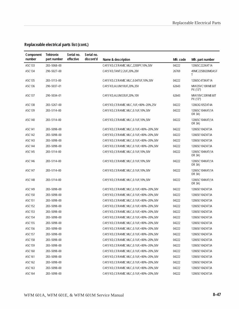
Replaceable Electrical Parts
WFM 601A, WFM 601E, & WFM 601M Service Manual 8–47
Replaceable electrical parts list (cont.)
Componentnumber Mfr. part numberMfr. codeName & description
Serial no.discont’d
Serial no.effective
Tektronixpart number
A5C133 283–5068–00 CAP,FXD,CERAMIC:MLC,2200PF,10%,50V 04222 12065C222KAT1A
A5C134 290–5027–00 CAP,FXD,TANT:2.2UF,20%,20V 26769 49MC225B020MOASFT
A5C135 283–5113–00 CAP,FXD,CERAMIC:MLC,0.047UF,10%,50V 04222 12065C473KAT1A
A5C136 290–5037–01 CAP,FXD,ALUM:10UF,20%,35V 62643 MVK35VC10RME60TPX (13”)
A5C137 290–5034–01 CAP,FXD,ALUM:33UF,20%,10V 62643 MVK10VC33RME60TPX (13”)
A5C138 283–5267–00 CAP,FXD,CERAMIC:MLC,1UF,+80%–20%,25V 04222 12063G105ZAT4A
A5C139 283–5114–00 CAP,FXD,CERAMIC:MLC,0.1UF,10%,50V 04222 12065C104KAT(1AOR 3A)
A5C140 283–5114–00 CAP,FXD,CERAMIC:MLC,0.1UF,10%,50V 04222 12065C104KAT(1AOR 3A)
A5C141 283–5098–00 CAP,FXD,CERAMIC:MLC,0.1UF,+80%–20%,50V 04222 12065E104ZAT3A
A5C142 283–5098–00 CAP,FXD,CERAMIC:MLC,0.1UF,+80%–20%,50V 04222 12065E104ZAT3A
A5C143 283–5098–00 CAP,FXD,CERAMIC:MLC,0.1UF,+80%–20%,50V 04222 12065E104ZAT3A
A5C144 283–5098–00 CAP,FXD,CERAMIC:MLC,0.1UF,+80%–20%,50V 04222 12065E104ZAT3A
A5C145 283–5114–00 CAP,FXD,CERAMIC:MLC,0.1UF,10%,50V 04222 12065C104KAT(1AOR 3A)
A5C146 283–5114–00 CAP,FXD,CERAMIC:MLC,0.1UF,10%,50V 04222 12065C104KAT(1AOR 3A)
A5C147 283–5114–00 CAP,FXD,CERAMIC:MLC,0.1UF,10%,50V 04222 12065C104KAT(1AOR 3A)
A5C148 283–5114–00 CAP,FXD,CERAMIC:MLC,0.1UF,10%,50V 04222 12065C104KAT(1AOR 3A)
A5C149 283–5098–00 CAP,FXD,CERAMIC:MLC,0.1UF,+80%–20%,50V 04222 12065E104ZAT3A
A5C150 283–5098–00 CAP,FXD,CERAMIC:MLC,0.1UF,+80%–20%,50V 04222 12065E104ZAT3A
A5C151 283–5098–00 CAP,FXD,CERAMIC:MLC,0.1UF,+80%–20%,50V 04222 12065E104ZAT3A
A5C152 283–5098–00 CAP,FXD,CERAMIC:MLC,0.1UF,+80%–20%,50V 04222 12065E104ZAT3A
A5C153 283–5098–00 CAP,FXD,CERAMIC:MLC,0.1UF,+80%–20%,50V 04222 12065E104ZAT3A
A5C154 283–5098–00 CAP,FXD,CERAMIC:MLC,0.1UF,+80%–20%,50V 04222 12065E104ZAT3A
A5C155 283–5098–00 CAP,FXD,CERAMIC:MLC,0.1UF,+80%–20%,50V 04222 12065E104ZAT3A
A5C156 283–5098–00 CAP,FXD,CERAMIC:MLC,0.1UF,+80%–20%,50V 04222 12065E104ZAT3A
A5C157 283–5098–00 CAP,FXD,CERAMIC:MLC,0.1UF,+80%–20%,50V 04222 12065E104ZAT3A
A5C158 283–5098–00 CAP,FXD,CERAMIC:MLC,0.1UF,+80%–20%,50V 04222 12065E104ZAT3A
A5C159 283–5098–00 CAP,FXD,CERAMIC:MLC,0.1UF,+80%–20%,50V 04222 12065E104ZAT3A
A5C160 283–5098–00 CAP,FXD,CERAMIC:MLC,0.1UF,+80%–20%,50V 04222 12065E104ZAT3A
A5C161 283–5098–00 CAP,FXD,CERAMIC:MLC,0.1UF,+80%–20%,50V 04222 12065E104ZAT3A
A5C162 283–5098–00 CAP,FXD,CERAMIC:MLC,0.1UF,+80%–20%,50V 04222 12065E104ZAT3A
A5C163 283–5098–00 CAP,FXD,CERAMIC:MLC,0.1UF,+80%–20%,50V 04222 12065E104ZAT3A
A5C164 283–5098–00 CAP,FXD,CERAMIC:MLC,0.1UF,+80%–20%,50V 04222 12065E104ZAT3A
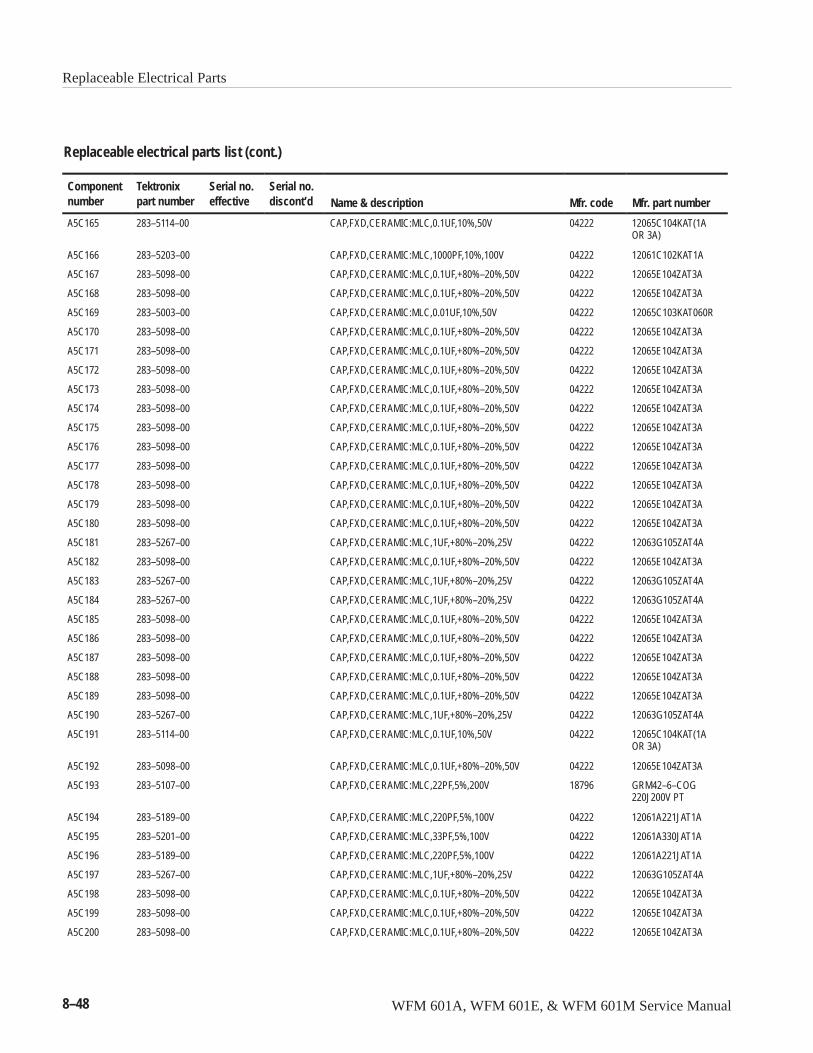
Replaceable Electrical Parts
8–48 WFM 601A, WFM 601E, & WFM 601M Service Manual
Replaceable electrical parts list (cont.)
Componentnumber Mfr. part numberMfr. codeName & description
Serial no.discont’d
Serial no.effective
Tektronixpart number
A5C165 283–5114–00 CAP,FXD,CERAMIC:MLC,0.1UF,10%,50V 04222 12065C104KAT(1AOR 3A)
A5C166 283–5203–00 CAP,FXD,CERAMIC:MLC,1000PF,10%,100V 04222 12061C102KAT1A
A5C167 283–5098–00 CAP,FXD,CERAMIC:MLC,0.1UF,+80%–20%,50V 04222 12065E104ZAT3A
A5C168 283–5098–00 CAP,FXD,CERAMIC:MLC,0.1UF,+80%–20%,50V 04222 12065E104ZAT3A
A5C169 283–5003–00 CAP,FXD,CERAMIC:MLC,0.01UF,10%,50V 04222 12065C103KAT060R
A5C170 283–5098–00 CAP,FXD,CERAMIC:MLC,0.1UF,+80%–20%,50V 04222 12065E104ZAT3A
A5C171 283–5098–00 CAP,FXD,CERAMIC:MLC,0.1UF,+80%–20%,50V 04222 12065E104ZAT3A
A5C172 283–5098–00 CAP,FXD,CERAMIC:MLC,0.1UF,+80%–20%,50V 04222 12065E104ZAT3A
A5C173 283–5098–00 CAP,FXD,CERAMIC:MLC,0.1UF,+80%–20%,50V 04222 12065E104ZAT3A
A5C174 283–5098–00 CAP,FXD,CERAMIC:MLC,0.1UF,+80%–20%,50V 04222 12065E104ZAT3A
A5C175 283–5098–00 CAP,FXD,CERAMIC:MLC,0.1UF,+80%–20%,50V 04222 12065E104ZAT3A
A5C176 283–5098–00 CAP,FXD,CERAMIC:MLC,0.1UF,+80%–20%,50V 04222 12065E104ZAT3A
A5C177 283–5098–00 CAP,FXD,CERAMIC:MLC,0.1UF,+80%–20%,50V 04222 12065E104ZAT3A
A5C178 283–5098–00 CAP,FXD,CERAMIC:MLC,0.1UF,+80%–20%,50V 04222 12065E104ZAT3A
A5C179 283–5098–00 CAP,FXD,CERAMIC:MLC,0.1UF,+80%–20%,50V 04222 12065E104ZAT3A
A5C180 283–5098–00 CAP,FXD,CERAMIC:MLC,0.1UF,+80%–20%,50V 04222 12065E104ZAT3A
A5C181 283–5267–00 CAP,FXD,CERAMIC:MLC,1UF,+80%–20%,25V 04222 12063G105ZAT4A
A5C182 283–5098–00 CAP,FXD,CERAMIC:MLC,0.1UF,+80%–20%,50V 04222 12065E104ZAT3A
A5C183 283–5267–00 CAP,FXD,CERAMIC:MLC,1UF,+80%–20%,25V 04222 12063G105ZAT4A
A5C184 283–5267–00 CAP,FXD,CERAMIC:MLC,1UF,+80%–20%,25V 04222 12063G105ZAT4A
A5C185 283–5098–00 CAP,FXD,CERAMIC:MLC,0.1UF,+80%–20%,50V 04222 12065E104ZAT3A
A5C186 283–5098–00 CAP,FXD,CERAMIC:MLC,0.1UF,+80%–20%,50V 04222 12065E104ZAT3A
A5C187 283–5098–00 CAP,FXD,CERAMIC:MLC,0.1UF,+80%–20%,50V 04222 12065E104ZAT3A
A5C188 283–5098–00 CAP,FXD,CERAMIC:MLC,0.1UF,+80%–20%,50V 04222 12065E104ZAT3A
A5C189 283–5098–00 CAP,FXD,CERAMIC:MLC,0.1UF,+80%–20%,50V 04222 12065E104ZAT3A
A5C190 283–5267–00 CAP,FXD,CERAMIC:MLC,1UF,+80%–20%,25V 04222 12063G105ZAT4A
A5C191 283–5114–00 CAP,FXD,CERAMIC:MLC,0.1UF,10%,50V 04222 12065C104KAT(1AOR 3A)
A5C192 283–5098–00 CAP,FXD,CERAMIC:MLC,0.1UF,+80%–20%,50V 04222 12065E104ZAT3A
A5C193 283–5107–00 CAP,FXD,CERAMIC:MLC,22PF,5%,200V 18796 GRM42–6–COG220J200V PT
A5C194 283–5189–00 CAP,FXD,CERAMIC:MLC,220PF,5%,100V 04222 12061A221JAT1A
A5C195 283–5201–00 CAP,FXD,CERAMIC:MLC,33PF,5%,100V 04222 12061A330JAT1A
A5C196 283–5189–00 CAP,FXD,CERAMIC:MLC,220PF,5%,100V 04222 12061A221JAT1A
A5C197 283–5267–00 CAP,FXD,CERAMIC:MLC,1UF,+80%–20%,25V 04222 12063G105ZAT4A
A5C198 283–5098–00 CAP,FXD,CERAMIC:MLC,0.1UF,+80%–20%,50V 04222 12065E104ZAT3A
A5C199 283–5098–00 CAP,FXD,CERAMIC:MLC,0.1UF,+80%–20%,50V 04222 12065E104ZAT3A
A5C200 283–5098–00 CAP,FXD,CERAMIC:MLC,0.1UF,+80%–20%,50V 04222 12065E104ZAT3A
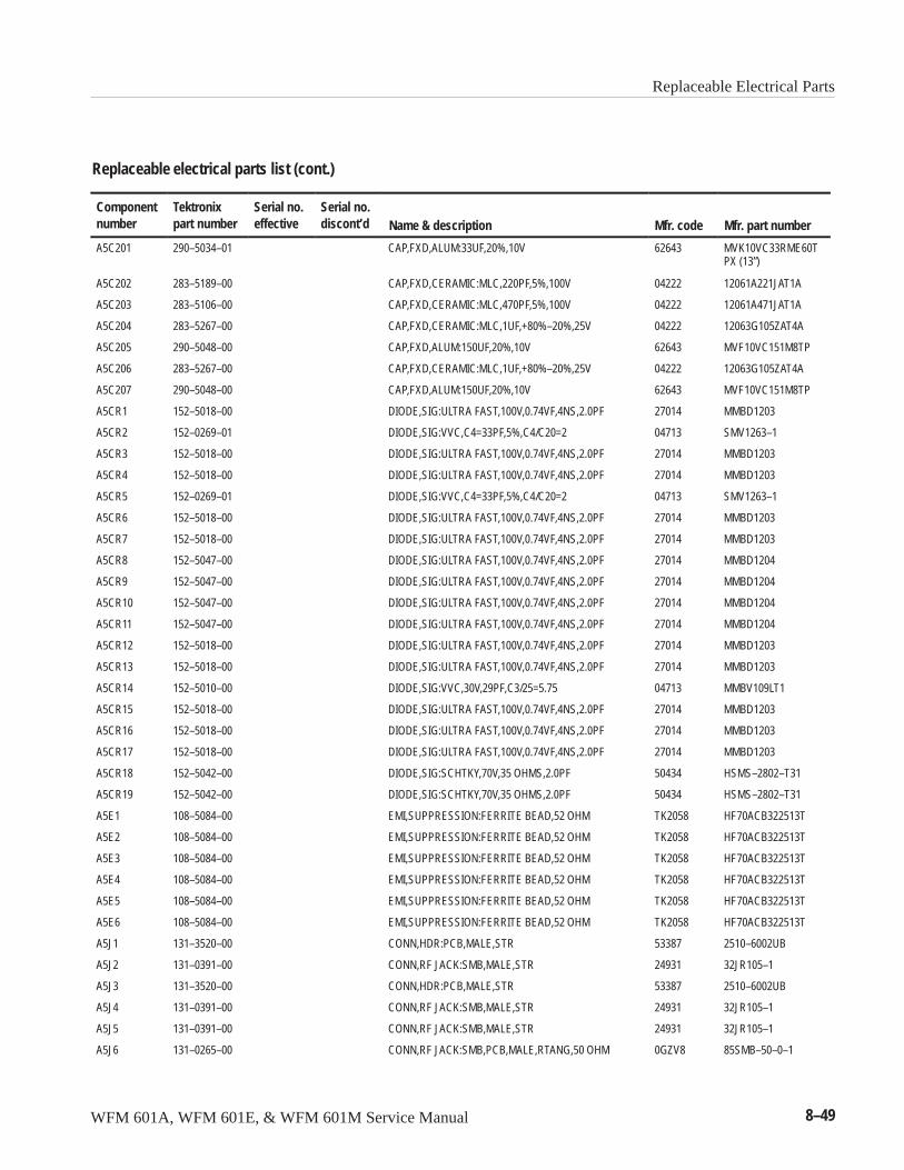
Replaceable Electrical Parts
WFM 601A, WFM 601E, & WFM 601M Service Manual 8–49
Replaceable electrical parts list (cont.)
Componentnumber Mfr. part numberMfr. codeName & description
Serial no.discont’d
Serial no.effective
Tektronixpart number
A5C201 290–5034–01 CAP,FXD,ALUM:33UF,20%,10V 62643 MVK10VC33RME60TPX (13”)
A5C202 283–5189–00 CAP,FXD,CERAMIC:MLC,220PF,5%,100V 04222 12061A221JAT1A
A5C203 283–5106–00 CAP,FXD,CERAMIC:MLC,470PF,5%,100V 04222 12061A471JAT1A
A5C204 283–5267–00 CAP,FXD,CERAMIC:MLC,1UF,+80%–20%,25V 04222 12063G105ZAT4A
A5C205 290–5048–00 CAP,FXD,ALUM:150UF,20%,10V 62643 MVF10VC151M8TP
A5C206 283–5267–00 CAP,FXD,CERAMIC:MLC,1UF,+80%–20%,25V 04222 12063G105ZAT4A
A5C207 290–5048–00 CAP,FXD,ALUM:150UF,20%,10V 62643 MVF10VC151M8TP
A5CR1 152–5018–00 DIODE,SIG:ULTRA FAST,100V,0.74VF,4NS,2.0PF 27014 MMBD1203
A5CR2 152–0269–01 DIODE,SIG:VVC,C4=33PF,5%,C4/C20=2 04713 SMV1263–1
A5CR3 152–5018–00 DIODE,SIG:ULTRA FAST,100V,0.74VF,4NS,2.0PF 27014 MMBD1203
A5CR4 152–5018–00 DIODE,SIG:ULTRA FAST,100V,0.74VF,4NS,2.0PF 27014 MMBD1203
A5CR5 152–0269–01 DIODE,SIG:VVC,C4=33PF,5%,C4/C20=2 04713 SMV1263–1
A5CR6 152–5018–00 DIODE,SIG:ULTRA FAST,100V,0.74VF,4NS,2.0PF 27014 MMBD1203
A5CR7 152–5018–00 DIODE,SIG:ULTRA FAST,100V,0.74VF,4NS,2.0PF 27014 MMBD1203
A5CR8 152–5047–00 DIODE,SIG:ULTRA FAST,100V,0.74VF,4NS,2.0PF 27014 MMBD1204
A5CR9 152–5047–00 DIODE,SIG:ULTRA FAST,100V,0.74VF,4NS,2.0PF 27014 MMBD1204
A5CR10 152–5047–00 DIODE,SIG:ULTRA FAST,100V,0.74VF,4NS,2.0PF 27014 MMBD1204
A5CR11 152–5047–00 DIODE,SIG:ULTRA FAST,100V,0.74VF,4NS,2.0PF 27014 MMBD1204
A5CR12 152–5018–00 DIODE,SIG:ULTRA FAST,100V,0.74VF,4NS,2.0PF 27014 MMBD1203
A5CR13 152–5018–00 DIODE,SIG:ULTRA FAST,100V,0.74VF,4NS,2.0PF 27014 MMBD1203
A5CR14 152–5010–00 DIODE,SIG:VVC,30V,29PF,C3/25=5.75 04713 MMBV109LT1
A5CR15 152–5018–00 DIODE,SIG:ULTRA FAST,100V,0.74VF,4NS,2.0PF 27014 MMBD1203
A5CR16 152–5018–00 DIODE,SIG:ULTRA FAST,100V,0.74VF,4NS,2.0PF 27014 MMBD1203
A5CR17 152–5018–00 DIODE,SIG:ULTRA FAST,100V,0.74VF,4NS,2.0PF 27014 MMBD1203
A5CR18 152–5042–00 DIODE,SIG:SCHTKY,70V,35 OHMS,2.0PF 50434 HSMS–2802–T31
A5CR19 152–5042–00 DIODE,SIG:SCHTKY,70V,35 OHMS,2.0PF 50434 HSMS–2802–T31
A5E1 108–5084–00 EMI,SUPPRESSION:FERRITE BEAD,52 OHM TK2058 HF70ACB322513T
A5E2 108–5084–00 EMI,SUPPRESSION:FERRITE BEAD,52 OHM TK2058 HF70ACB322513T
A5E3 108–5084–00 EMI,SUPPRESSION:FERRITE BEAD,52 OHM TK2058 HF70ACB322513T
A5E4 108–5084–00 EMI,SUPPRESSION:FERRITE BEAD,52 OHM TK2058 HF70ACB322513T
A5E5 108–5084–00 EMI,SUPPRESSION:FERRITE BEAD,52 OHM TK2058 HF70ACB322513T
A5E6 108–5084–00 EMI,SUPPRESSION:FERRITE BEAD,52 OHM TK2058 HF70ACB322513T
A5J1 131–3520–00 CONN,HDR:PCB,MALE,STR 53387 2510–6002UB
A5J2 131–0391–00 CONN,RF JACK:SMB,MALE,STR 24931 32JR105–1
A5J3 131–3520–00 CONN,HDR:PCB,MALE,STR 53387 2510–6002UB
A5J4 131–0391–00 CONN,RF JACK:SMB,MALE,STR 24931 32JR105–1
A5J5 131–0391–00 CONN,RF JACK:SMB,MALE,STR 24931 32JR105–1
A5J6 131–0265–00 CONN,RF JACK:SMB,PCB,MALE,RTANG,50 OHM 0GZV8 85SMB–50–0–1
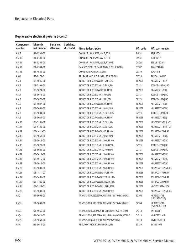
Replaceable Electrical Parts
8–50 WFM 601A, WFM 601E, & WFM 601M Service Manual
Replaceable electrical parts list (cont.)
Componentnumber Mfr. part numberMfr. codeName & description
Serial no.discont’d
Serial no.effective
Tektronixpart number
A5J7 131–0391–00 CONN,RF JACK:SMB,MALE,STR 24931 32JR105–1
A5J10 131–0391–00 CONN,RF JACK:SMB,MALE,STR 24931 32JR105–1
A5J11 131–0265–00 CONN,RF JACK:SMB,MALE,RTANG 0GZV8 85SMB–50–0–1
A5J12 174–2744–00 CA ASSY,SP,ELEC:34,28 AWG, 3.25 L,RIBBON 53387 174–2744–00
A5J13 131–4530–00 CONN,HDR:PCB,MALE,STR 00779 104344–1
A5K1 148–0173–01 RELAY,ARMATURE:1 FM C, 50 & 75 OHM 61529 RK1E–12V–H10
A5L1 108–5046–00 INDUCTOR,FXD:POWER,1.2UH,5% TK2058 NL453232T–1R2J
A5L2 108–5109–00 INDUCTOR,FXD:SIGNAL,3.3UH,5% 02113 1008CS–332–XJBC
A5L3 108–5024–00 INDUCTOR,FXD:POWER,39UH,5% TK2058 NL453232T–390J
A5L4 108–5072–00 INDUCTOR,FXD:SIGNAL,1UH,5% 02113 1008CS–102XJBC
A5L5 108–5072–00 INDUCTOR,FXD:SIGNAL,1UH,5% 02113 1008CS–102XJBC
A5L6 108–5037–00 INDUCTOR,FXD:POWER,22UH,5% TK2058 NL453232T–220J
A5L7 108–5051–00 INDUCTOR,FXD:SIGNAL,10UH,10% TK2058 NL453232T–100K
A5L8 108–5004–00 INDUCTOR,FXD:SIGNAL,1.8UH,10% 02113 1008CS–182XKBC
A5L9 108–5024–00 INDUCTOR,FXD:POWER,39UH,5% TK2058 NL453232T–390J
A5L10 108–5136–00 INDUCTOR,FXD:SIGNAL,3.3UH,5% TK2058 NL322522T–3R3J–03
A5L11 108–5136–00 INDUCTOR,FXD:SIGNAL,3.3UH,5% TK2058 NL322522T–3R3J–03
A5L12 108–1411–00 INDUCTOR,FXD:POWER,47UH,10% TK2058 TSL0707–470KR94
A5L13 108–5051–00 INDUCTOR,FXD:SIGNAL,10UH,10% TK2058 NL453232T–100K
A5L14 108–5015–00 INDUCTOR,FXD:SIGNAL,100UH,10% TK2058 NL453232T–101K
A5L15 108–5020–00 INDUCTOR,FXD:SIGNAL,270NH,5% 02113 1008CS–271XJBC
A5L16 108–5020–00 INDUCTOR,FXD:SIGNAL,270NH,5% 02113 1008CS–271XJBC
A5L17 108–5015–00 INDUCTOR,FXD:SIGNAL,100UH,10% TK2058 NL453232T–101K
A5L18 108–5015–00 INDUCTOR,FXD:SIGNAL,100UH,10% TK2058 NL453232T–101K
A5L19 108–5015–00 INDUCTOR,FXD:SIGNAL,100UH,10% TK2058 NL453232T–101K
A5L20 108–5080–00 INDUCTOR,FXD:SIGNAL,560NH,10% TK2058 NL322522T–R56K–03
A5L21 108–1411–00 INDUCTOR,FXD:POWER,47UH,10% TK2058 TSL0707–470KR94
A5L22 108–1485–00 INDUCTOR,FXD:POWER,220UH,10% TK2058 TSL0707–221KR44
A5L23 108–1485–00 INDUCTOR,FXD:POWER,220UH,10% TK2058 TSL0707–221KR44
A5L24 108–5124–01 INDUCTOR,FXD:POWER,1.0UH,10% TK2058 NLC453232T–1R0K
A5L25 108–5080–00 INDUCTOR,FXD:SIGNAL,560NH,10% TK2058 NL322522T–R56K–03
A5Q1 151–5008–00 TRANSISTOR,SIG:BIPOLAR,NPN,12V,70MA,3.0GHZ 62104 NE02133–T1B(2SC2351–T1B)
A5Q2 151–5008–00 TRANSISTOR,SIG:BIPOLAR,NPN,12V,70MA,3.0GHZ 62104 NE02133–T1B(2SC2351–T1B)
A5Q3 151–5066–00 TRANSISTOR,SIG:MOS,N–CH,60V,0.115A,7.5 OHM 04713 2N7002LT1
A5Q4 151–5021–00 TRANSISTOR,SIG:BIPOLAR,NPN,40V,600MA,300MHZ 04713 MMBT2222ALT1
A5Q5 151–5058–00 TRANSISTOR,SIG:BIPOLAR,PNP,12V,80MA 04713 MMBT3640LT1
A5R1 321–5016–00 RES,FXD:THICK FILM,681 OHM,1% 50139 BCK6810FT

Replaceable Electrical Parts
WFM 601A, WFM 601E, & WFM 601M Service Manual 8–51
Replaceable electrical parts list (cont.)
Componentnumber Mfr. part numberMfr. codeName & description
Serial no.discont’d
Serial no.effective
Tektronixpart number
A5R2 321–5042–00 RES,FXD:THICK FILM,39.2 OHM,1% 50139 BCD39R2FT
A5R3 321–5042–00 RES,FXD:THICK FILM,39.2 OHM,1% 50139 BCD39R2FT
A5R4 321–5004–00 RES,FXD:THICK FILM,22.1 OHM,1% 50139 BCD22R1FT
A5R5 321–5014–00 RES,FXD:THICK FILM,475 OHM,1% 50139 BCK4750FT
A5R6 321–5004–00 RES,FXD:THICK FILM,22.1 OHM,1% 50139 BCD22R1FT
A5R7 321–5014–00 RES,FXD:THICK FILM,475 OHM,1% 50139 BCK4750FT
A5R8 321–5006–00 RES,FXD:THICK FILM,100 OHM,1% 50139 BCK1000FT
A5R9 321–5000–00 RES,FXD:THICK FILM,10 OHM,1% 50139 BCD10R0FT
A5R10 321–5006–00 RES,FXD:THICK FILM,100 OHM,1% 50139 BCK1000FT
A5R11 321–5113–00 RES,FXD:THICK FILM,75 OHM,1% 56845 CRCW1206–75ROFT
A5R12 321–5113–00 RES,FXD:THICK FILM,75 OHM,1% 56845 CRCW1206–75ROFT
A5R13 321–5194–00 RES,FXD:THICK FILM,49.9 OHM,1% 91637 CRCW–1206–49R–90–FT
A5R14 321–5004–00 RES,FXD:THICK FILM,22.1 OHM,1% 50139 BCD22R1FT
A5R15 321–5014–00 RES,FXD:THICK FILM,475 OHM,1% 50139 BCK4750FT
A5R16 321–5000–00 RES,FXD:THICK FILM,10 OHM,1% 50139 BCD10R0FT
A5R17 321–5000–00 RES,FXD:THICK FILM,10 OHM,1% 50139 BCD10R0FT
A5R18 321–5051–00 RES,FXD:THICK FILM,0 OHM,1% 09969 CRCW1206 JUMPER
A5R19 321–5030–00 RES,FXD:THICK FILM,10.0K OHM,1% 50139 BCK1002FT
A5R20 321–5008–00 RES,FXD:THICK FILM,150 OHM,1% 50139 BCK1500FT
A5R21 311–5040–00 RES,VAR,TRMR:CERMET,10K OHM,25%,0.1W 32997 3314J–1–103E
A5R22 321–5008–00 RES,FXD:THICK FILM,150 OHM,1% 50139 BCK1500FT
A5R23 321–5018–00 RES,FXD:THICK FILM,1.0K OHM,1% 50139 BCK1001FT
A5R24 321–5281–00 RES,FXD:THICK FILM,2K OHM,1% 91637 CRCW1206–2001FT
A5R25 321–5004–00 RES,FXD:THICK FILM,22.1 OHM,1% 50139 BCD22R1FT
A5R26 321–5281–00 RES,FXD:THICK FILM,2K OHM,1% 91637 CRCW1206–2001FT
A5R27 321–5018–00 RES,FXD:THICK FILM,1.0K OHM,1% 50139 BCK1001FT
A5R28 321–5045–00 RES,FXD:THICK FILM,68.1 OHM,1% 50139 BCD68R1FT
A5R29 321–5004–00 RES,FXD:THICK FILM,22.1 OHM,1% 50139 BCD22R1FT
A5R30 321–5004–00 RES,FXD:THICK FILM,22.1 OHM,1% 50139 BCD22R1FT
A5R31 321–5018–00 RES,FXD:THICK FILM,1.0K OHM,1% 50139 BCK1001FT
A5R32 321–5014–00 RES,FXD:THICK FILM,475 OHM,1% 50139 BCK4750FT
A5R33 321–5014–00 RES,FXD:THICK FILM,475 OHM,1% 50139 BCK4750FT
A5R34 321–5009–00 RES,FXD:THICK FILM,182 OHM,1% 50139 BCK1820FT
A5R35 321–5018–00 RES,FXD:THICK FILM,1.0K OHM,1% 50139 BCK1001FT
A5R36 321–5014–00 RES,FXD:THICK FILM,475 OHM,1% 50139 BCK4750FT
A5R37 321–5045–00 RES,FXD:THICK FILM,68.1 OHM,1% 50139 BCD68R1FT
A5R38 321–5010–00 RES,FXD:THICK FILM,221 OHM,1% 50139 BCK221FT
A5R39 321–5010–00 RES,FXD:THICK FILM,221 OHM,1% 50139 BCK221FT
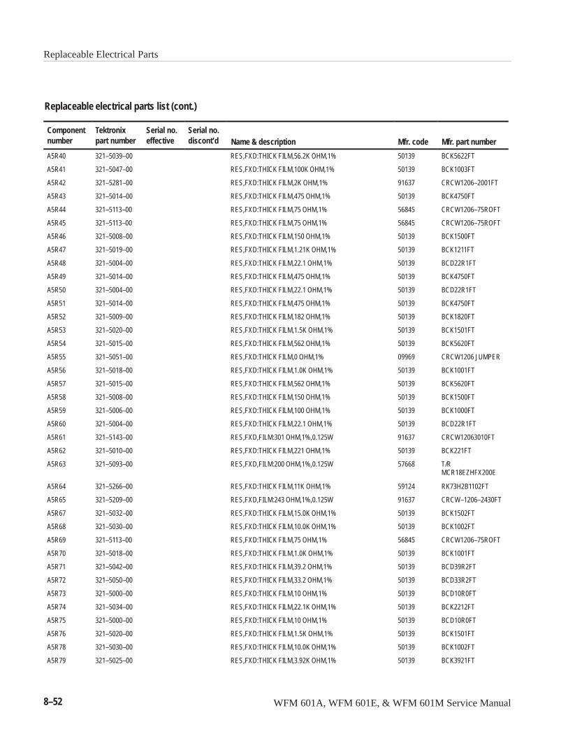
Replaceable Electrical Parts
8–52 WFM 601A, WFM 601E, & WFM 601M Service Manual
Replaceable electrical parts list (cont.)
Componentnumber Mfr. part numberMfr. codeName & description
Serial no.discont’d
Serial no.effective
Tektronixpart number
A5R40 321–5039–00 RES,FXD:THICK FILM,56.2K OHM,1% 50139 BCK5622FT
A5R41 321–5047–00 RES,FXD:THICK FILM,100K OHM,1% 50139 BCK1003FT
A5R42 321–5281–00 RES,FXD:THICK FILM,2K OHM,1% 91637 CRCW1206–2001FT
A5R43 321–5014–00 RES,FXD:THICK FILM,475 OHM,1% 50139 BCK4750FT
A5R44 321–5113–00 RES,FXD:THICK FILM,75 OHM,1% 56845 CRCW1206–75ROFT
A5R45 321–5113–00 RES,FXD:THICK FILM,75 OHM,1% 56845 CRCW1206–75ROFT
A5R46 321–5008–00 RES,FXD:THICK FILM,150 OHM,1% 50139 BCK1500FT
A5R47 321–5019–00 RES,FXD:THICK FILM,1.21K OHM,1% 50139 BCK1211FT
A5R48 321–5004–00 RES,FXD:THICK FILM,22.1 OHM,1% 50139 BCD22R1FT
A5R49 321–5014–00 RES,FXD:THICK FILM,475 OHM,1% 50139 BCK4750FT
A5R50 321–5004–00 RES,FXD:THICK FILM,22.1 OHM,1% 50139 BCD22R1FT
A5R51 321–5014–00 RES,FXD:THICK FILM,475 OHM,1% 50139 BCK4750FT
A5R52 321–5009–00 RES,FXD:THICK FILM,182 OHM,1% 50139 BCK1820FT
A5R53 321–5020–00 RES,FXD:THICK FILM,1.5K OHM,1% 50139 BCK1501FT
A5R54 321–5015–00 RES,FXD:THICK FILM,562 OHM,1% 50139 BCK5620FT
A5R55 321–5051–00 RES,FXD:THICK FILM,0 OHM,1% 09969 CRCW1206 JUMPER
A5R56 321–5018–00 RES,FXD:THICK FILM,1.0K OHM,1% 50139 BCK1001FT
A5R57 321–5015–00 RES,FXD:THICK FILM,562 OHM,1% 50139 BCK5620FT
A5R58 321–5008–00 RES,FXD:THICK FILM,150 OHM,1% 50139 BCK1500FT
A5R59 321–5006–00 RES,FXD:THICK FILM,100 OHM,1% 50139 BCK1000FT
A5R60 321–5004–00 RES,FXD:THICK FILM,22.1 OHM,1% 50139 BCD22R1FT
A5R61 321–5143–00 RES,FXD,FILM:301 OHM,1%,0.125W 91637 CRCW12063010FT
A5R62 321–5010–00 RES,FXD:THICK FILM,221 OHM,1% 50139 BCK221FT
A5R63 321–5093–00 RES,FXD,FILM:200 OHM,1%,0.125W 57668 T/RMCR18EZHFX200E
A5R64 321–5266–00 RES,FXD:THICK FILM,11K OHM,1% 59124 RK73H2B1102FT
A5R65 321–5209–00 RES,FXD,FILM:243 OHM,1%,0.125W 91637 CRCW–1206–2430FT
A5R67 321–5032–00 RES,FXD:THICK FILM,15.0K OHM,1% 50139 BCK1502FT
A5R68 321–5030–00 RES,FXD:THICK FILM,10.0K OHM,1% 50139 BCK1002FT
A5R69 321–5113–00 RES,FXD:THICK FILM,75 OHM,1% 56845 CRCW1206–75ROFT
A5R70 321–5018–00 RES,FXD:THICK FILM,1.0K OHM,1% 50139 BCK1001FT
A5R71 321–5042–00 RES,FXD:THICK FILM,39.2 OHM,1% 50139 BCD39R2FT
A5R72 321–5050–00 RES,FXD:THICK FILM,33.2 OHM,1% 50139 BCD33R2FT
A5R73 321–5000–00 RES,FXD:THICK FILM,10 OHM,1% 50139 BCD10R0FT
A5R74 321–5034–00 RES,FXD:THICK FILM,22.1K OHM,1% 50139 BCK2212FT
A5R75 321–5000–00 RES,FXD:THICK FILM,10 OHM,1% 50139 BCD10R0FT
A5R76 321–5020–00 RES,FXD:THICK FILM,1.5K OHM,1% 50139 BCK1501FT
A5R78 321–5030–00 RES,FXD:THICK FILM,10.0K OHM,1% 50139 BCK1002FT
A5R79 321–5025–00 RES,FXD:THICK FILM,3.92K OHM,1% 50139 BCK3921FT
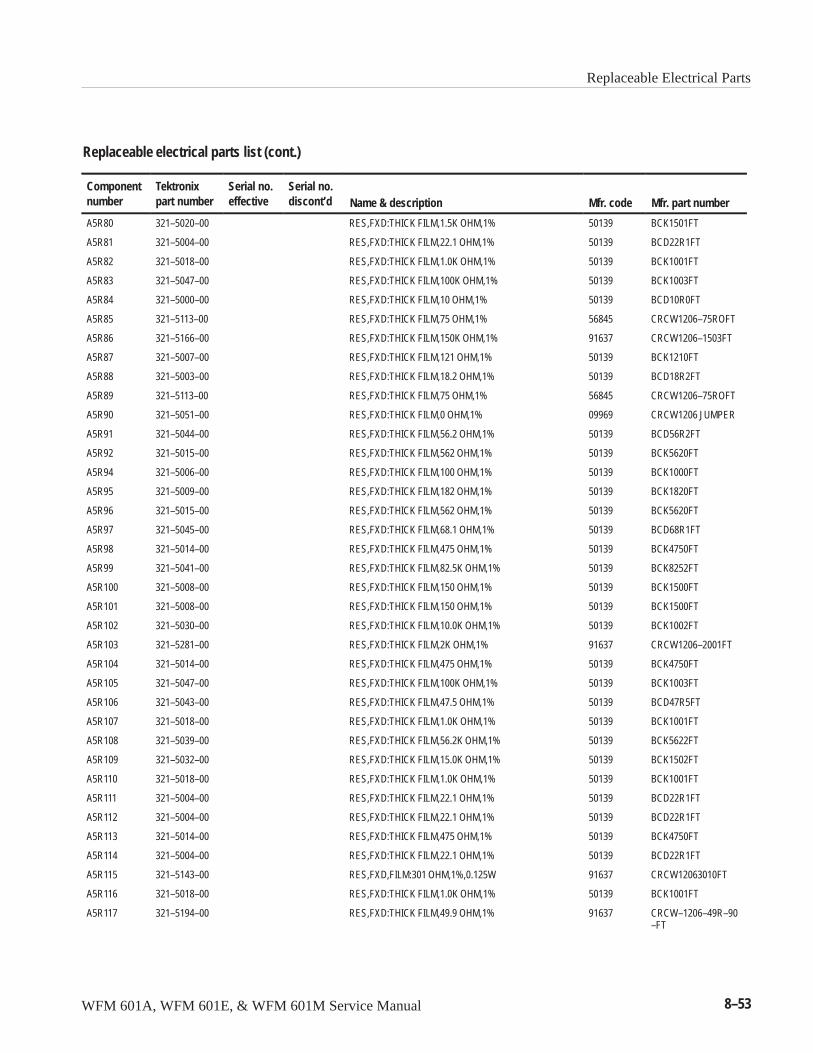
Replaceable Electrical Parts
WFM 601A, WFM 601E, & WFM 601M Service Manual 8–53
Replaceable electrical parts list (cont.)
Componentnumber Mfr. part numberMfr. codeName & description
Serial no.discont’d
Serial no.effective
Tektronixpart number
A5R80 321–5020–00 RES,FXD:THICK FILM,1.5K OHM,1% 50139 BCK1501FT
A5R81 321–5004–00 RES,FXD:THICK FILM,22.1 OHM,1% 50139 BCD22R1FT
A5R82 321–5018–00 RES,FXD:THICK FILM,1.0K OHM,1% 50139 BCK1001FT
A5R83 321–5047–00 RES,FXD:THICK FILM,100K OHM,1% 50139 BCK1003FT
A5R84 321–5000–00 RES,FXD:THICK FILM,10 OHM,1% 50139 BCD10R0FT
A5R85 321–5113–00 RES,FXD:THICK FILM,75 OHM,1% 56845 CRCW1206–75ROFT
A5R86 321–5166–00 RES,FXD:THICK FILM,150K OHM,1% 91637 CRCW1206–1503FT
A5R87 321–5007–00 RES,FXD:THICK FILM,121 OHM,1% 50139 BCK1210FT
A5R88 321–5003–00 RES,FXD:THICK FILM,18.2 OHM,1% 50139 BCD18R2FT
A5R89 321–5113–00 RES,FXD:THICK FILM,75 OHM,1% 56845 CRCW1206–75ROFT
A5R90 321–5051–00 RES,FXD:THICK FILM,0 OHM,1% 09969 CRCW1206 JUMPER
A5R91 321–5044–00 RES,FXD:THICK FILM,56.2 OHM,1% 50139 BCD56R2FT
A5R92 321–5015–00 RES,FXD:THICK FILM,562 OHM,1% 50139 BCK5620FT
A5R94 321–5006–00 RES,FXD:THICK FILM,100 OHM,1% 50139 BCK1000FT
A5R95 321–5009–00 RES,FXD:THICK FILM,182 OHM,1% 50139 BCK1820FT
A5R96 321–5015–00 RES,FXD:THICK FILM,562 OHM,1% 50139 BCK5620FT
A5R97 321–5045–00 RES,FXD:THICK FILM,68.1 OHM,1% 50139 BCD68R1FT
A5R98 321–5014–00 RES,FXD:THICK FILM,475 OHM,1% 50139 BCK4750FT
A5R99 321–5041–00 RES,FXD:THICK FILM,82.5K OHM,1% 50139 BCK8252FT
A5R100 321–5008–00 RES,FXD:THICK FILM,150 OHM,1% 50139 BCK1500FT
A5R101 321–5008–00 RES,FXD:THICK FILM,150 OHM,1% 50139 BCK1500FT
A5R102 321–5030–00 RES,FXD:THICK FILM,10.0K OHM,1% 50139 BCK1002FT
A5R103 321–5281–00 RES,FXD:THICK FILM,2K OHM,1% 91637 CRCW1206–2001FT
A5R104 321–5014–00 RES,FXD:THICK FILM,475 OHM,1% 50139 BCK4750FT
A5R105 321–5047–00 RES,FXD:THICK FILM,100K OHM,1% 50139 BCK1003FT
A5R106 321–5043–00 RES,FXD:THICK FILM,47.5 OHM,1% 50139 BCD47R5FT
A5R107 321–5018–00 RES,FXD:THICK FILM,1.0K OHM,1% 50139 BCK1001FT
A5R108 321–5039–00 RES,FXD:THICK FILM,56.2K OHM,1% 50139 BCK5622FT
A5R109 321–5032–00 RES,FXD:THICK FILM,15.0K OHM,1% 50139 BCK1502FT
A5R110 321–5018–00 RES,FXD:THICK FILM,1.0K OHM,1% 50139 BCK1001FT
A5R111 321–5004–00 RES,FXD:THICK FILM,22.1 OHM,1% 50139 BCD22R1FT
A5R112 321–5004–00 RES,FXD:THICK FILM,22.1 OHM,1% 50139 BCD22R1FT
A5R113 321–5014–00 RES,FXD:THICK FILM,475 OHM,1% 50139 BCK4750FT
A5R114 321–5004–00 RES,FXD:THICK FILM,22.1 OHM,1% 50139 BCD22R1FT
A5R115 321–5143–00 RES,FXD,FILM:301 OHM,1%,0.125W 91637 CRCW12063010FT
A5R116 321–5018–00 RES,FXD:THICK FILM,1.0K OHM,1% 50139 BCK1001FT
A5R117 321–5194–00 RES,FXD:THICK FILM,49.9 OHM,1% 91637 CRCW–1206–49R–90–FT
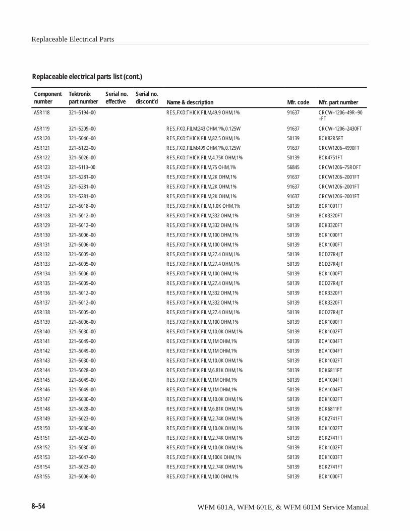
Replaceable Electrical Parts
8–54 WFM 601A, WFM 601E, & WFM 601M Service Manual
Replaceable electrical parts list (cont.)
Componentnumber Mfr. part numberMfr. codeName & description
Serial no.discont’d
Serial no.effective
Tektronixpart number
A5R118 321–5194–00 RES,FXD:THICK FILM,49.9 OHM,1% 91637 CRCW–1206–49R–90–FT
A5R119 321–5209–00 RES,FXD,FILM:243 OHM,1%,0.125W 91637 CRCW–1206–2430FT
A5R120 321–5046–00 RES,FXD:THICK FILM,82.5 OHM,1% 50139 BCK82R5FT
A5R121 321–5122–00 RES,FXD,FILM:499 OHM,1%,0.125W 91637 CRCW1206–4990FT
A5R122 321–5026–00 RES,FXD:THICK FILM,4.75K OHM,1% 50139 BCK4751FT
A5R123 321–5113–00 RES,FXD:THICK FILM,75 OHM,1% 56845 CRCW1206–75ROFT
A5R124 321–5281–00 RES,FXD:THICK FILM,2K OHM,1% 91637 CRCW1206–2001FT
A5R125 321–5281–00 RES,FXD:THICK FILM,2K OHM,1% 91637 CRCW1206–2001FT
A5R126 321–5281–00 RES,FXD:THICK FILM,2K OHM,1% 91637 CRCW1206–2001FT
A5R127 321–5018–00 RES,FXD:THICK FILM,1.0K OHM,1% 50139 BCK1001FT
A5R128 321–5012–00 RES,FXD:THICK FILM,332 OHM,1% 50139 BCK3320FT
A5R129 321–5012–00 RES,FXD:THICK FILM,332 OHM,1% 50139 BCK3320FT
A5R130 321–5006–00 RES,FXD:THICK FILM,100 OHM,1% 50139 BCK1000FT
A5R131 321–5006–00 RES,FXD:THICK FILM,100 OHM,1% 50139 BCK1000FT
A5R132 321–5005–00 RES,FXD:THICK FILM,27.4 OHM,1% 50139 BCD27R4JT
A5R133 321–5005–00 RES,FXD:THICK FILM,27.4 OHM,1% 50139 BCD27R4JT
A5R134 321–5006–00 RES,FXD:THICK FILM,100 OHM,1% 50139 BCK1000FT
A5R135 321–5005–00 RES,FXD:THICK FILM,27.4 OHM,1% 50139 BCD27R4JT
A5R136 321–5012–00 RES,FXD:THICK FILM,332 OHM,1% 50139 BCK3320FT
A5R137 321–5012–00 RES,FXD:THICK FILM,332 OHM,1% 50139 BCK3320FT
A5R138 321–5005–00 RES,FXD:THICK FILM,27.4 OHM,1% 50139 BCD27R4JT
A5R139 321–5006–00 RES,FXD:THICK FILM,100 OHM,1% 50139 BCK1000FT
A5R140 321–5030–00 RES,FXD:THICK FILM,10.0K OHM,1% 50139 BCK1002FT
A5R141 321–5049–00 RES,FXD:THICK FILM,1M OHM,1% 50139 BCA1004FT
A5R142 321–5049–00 RES,FXD:THICK FILM,1M OHM,1% 50139 BCA1004FT
A5R143 321–5030–00 RES,FXD:THICK FILM,10.0K OHM,1% 50139 BCK1002FT
A5R144 321–5028–00 RES,FXD:THICK FILM,6.81K OHM,1% 50139 BCK6811FT
A5R145 321–5049–00 RES,FXD:THICK FILM,1M OHM,1% 50139 BCA1004FT
A5R146 321–5049–00 RES,FXD:THICK FILM,1M OHM,1% 50139 BCA1004FT
A5R147 321–5030–00 RES,FXD:THICK FILM,10.0K OHM,1% 50139 BCK1002FT
A5R148 321–5028–00 RES,FXD:THICK FILM,6.81K OHM,1% 50139 BCK6811FT
A5R149 321–5023–00 RES,FXD:THICK FILM,2.74K OHM,1% 50139 BCK2741FT
A5R150 321–5030–00 RES,FXD:THICK FILM,10.0K OHM,1% 50139 BCK1002FT
A5R151 321–5023–00 RES,FXD:THICK FILM,2.74K OHM,1% 50139 BCK2741FT
A5R152 321–5030–00 RES,FXD:THICK FILM,10.0K OHM,1% 50139 BCK1002FT
A5R153 321–5047–00 RES,FXD:THICK FILM,100K OHM,1% 50139 BCK1003FT
A5R154 321–5023–00 RES,FXD:THICK FILM,2.74K OHM,1% 50139 BCK2741FT
A5R155 321–5006–00 RES,FXD:THICK FILM,100 OHM,1% 50139 BCK1000FT
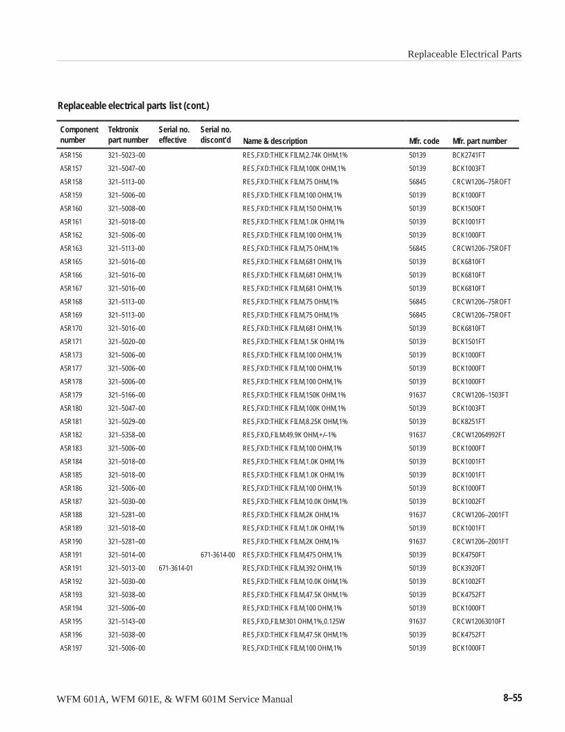
Replaceable Electrical Parts
WFM 601A, WFM 601E, & WFM 601M Service Manual 8–55
Replaceable electrical parts list (cont.)
Componentnumber Mfr. part numberMfr. codeName & description
Serial no.discont’d
Serial no.effective
Tektronixpart number
A5R156 321–5023–00 RES,FXD:THICK FILM,2.74K OHM,1% 50139 BCK2741FT
A5R157 321–5047–00 RES,FXD:THICK FILM,100K OHM,1% 50139 BCK1003FT
A5R158 321–5113–00 RES,FXD:THICK FILM,75 OHM,1% 56845 CRCW1206–75ROFT
A5R159 321–5006–00 RES,FXD:THICK FILM,100 OHM,1% 50139 BCK1000FT
A5R160 321–5008–00 RES,FXD:THICK FILM,150 OHM,1% 50139 BCK1500FT
A5R161 321–5018–00 RES,FXD:THICK FILM,1.0K OHM,1% 50139 BCK1001FT
A5R162 321–5006–00 RES,FXD:THICK FILM,100 OHM,1% 50139 BCK1000FT
A5R163 321–5113–00 RES,FXD:THICK FILM,75 OHM,1% 56845 CRCW1206–75ROFT
A5R165 321–5016–00 RES,FXD:THICK FILM,681 OHM,1% 50139 BCK6810FT
A5R166 321–5016–00 RES,FXD:THICK FILM,681 OHM,1% 50139 BCK6810FT
A5R167 321–5016–00 RES,FXD:THICK FILM,681 OHM,1% 50139 BCK6810FT
A5R168 321–5113–00 RES,FXD:THICK FILM,75 OHM,1% 56845 CRCW1206–75ROFT
A5R169 321–5113–00 RES,FXD:THICK FILM,75 OHM,1% 56845 CRCW1206–75ROFT
A5R170 321–5016–00 RES,FXD:THICK FILM,681 OHM,1% 50139 BCK6810FT
A5R171 321–5020–00 RES,FXD:THICK FILM,1.5K OHM,1% 50139 BCK1501FT
A5R173 321–5006–00 RES,FXD:THICK FILM,100 OHM,1% 50139 BCK1000FT
A5R177 321–5006–00 RES,FXD:THICK FILM,100 OHM,1% 50139 BCK1000FT
A5R178 321–5006–00 RES,FXD:THICK FILM,100 OHM,1% 50139 BCK1000FT
A5R179 321–5166–00 RES,FXD:THICK FILM,150K OHM,1% 91637 CRCW1206–1503FT
A5R180 321–5047–00 RES,FXD:THICK FILM,100K OHM,1% 50139 BCK1003FT
A5R181 321–5029–00 RES,FXD:THICK FILM,8.25K OHM,1% 50139 BCK8251FT
A5R182 321–5358–00 RES,FXD,FILM:49.9K OHM,+/–1% 91637 CRCW12064992FT
A5R183 321–5006–00 RES,FXD:THICK FILM,100 OHM,1% 50139 BCK1000FT
A5R184 321–5018–00 RES,FXD:THICK FILM,1.0K OHM,1% 50139 BCK1001FT
A5R185 321–5018–00 RES,FXD:THICK FILM,1.0K OHM,1% 50139 BCK1001FT
A5R186 321–5006–00 RES,FXD:THICK FILM,100 OHM,1% 50139 BCK1000FT
A5R187 321–5030–00 RES,FXD:THICK FILM,10.0K OHM,1% 50139 BCK1002FT
A5R188 321–5281–00 RES,FXD:THICK FILM,2K OHM,1% 91637 CRCW1206–2001FT
A5R189 321–5018–00 RES,FXD:THICK FILM,1.0K OHM,1% 50139 BCK1001FT
A5R190 321–5281–00 RES,FXD:THICK FILM,2K OHM,1% 91637 CRCW1206–2001FT
A5R191 321–5014–00 671-3614-00 RES,FXD:THICK FILM,475 OHM,1% 50139 BCK4750FT
A5R191 321–5013–00 671-3614-01 RES,FXD:THICK FILM,392 OHM,1% 50139 BCK3920FT
A5R192 321–5030–00 RES,FXD:THICK FILM,10.0K OHM,1% 50139 BCK1002FT
A5R193 321–5038–00 RES,FXD:THICK FILM,47.5K OHM,1% 50139 BCK4752FT
A5R194 321–5006–00 RES,FXD:THICK FILM,100 OHM,1% 50139 BCK1000FT
A5R195 321–5143–00 RES,FXD,FILM:301 OHM,1%,0.125W 91637 CRCW12063010FT
A5R196 321–5038–00 RES,FXD:THICK FILM,47.5K OHM,1% 50139 BCK4752FT
A5R197 321–5006–00 RES,FXD:THICK FILM,100 OHM,1% 50139 BCK1000FT

Replaceable Electrical Parts
8–56 WFM 601A, WFM 601E, & WFM 601M Service Manual
Replaceable electrical parts list (cont.)
Componentnumber Mfr. part numberMfr. codeName & description
Serial no.discont’d
Serial no.effective
Tektronixpart number
A5R198 321–5143–00 RES,FXD,FILM:301 OHM,1%,0.125W 91637 CRCW12063010FT
A5R199 321–5018–00 RES,FXD:THICK FILM,1.0K OHM,1% 50139 BCK1001FT
A5R200 321–5143–00 RES,FXD,FILM:301 OHM,1%,0.125W 91637 CRCW12063010FT
A5R201 321–5281–00 RES,FXD:THICK FILM,2K OHM,1% 91637 CRCW1206–2001FT
A5R202 321–5055–00 RES,FXD:THICK FILM,681K OHM,1% 91637 CRCW120668102FT
A5R203 321–5066–00 RES,FXD:THICK FILM,121K OHM,1% 91637 CRCW1206–1213FT
A5R204 321–5038–00 RES,FXD:THICK FILM,47.5K OHM,1% 50139 BCK4752FT
A5R205 321–5004–00 RES,FXD:THICK FILM,22.1 OHM,1% 50139 BCD22R1FT
A5R206 321–5033–00 RES,FXD:THICK FILM,18.2K OHM,1% 50139 BCK1822FT
A5R207 321–5209–00 RES,FXD,FILM:243 OHM,1%,0.125W 91637 CRCW–1206–2430FT
A5R208 321–5209–00 RES,FXD,FILM:243 OHM,1%,0.125W 91637 CRCW–1206–2430FT
A5R209 321–5209–00 RES,FXD,FILM:243 OHM,1%,0.125W 91637 CRCW–1206–2430FT
A5R210 321–5014–00 RES,FXD:THICK FILM,475 OHM,1% 50139 BCK4750FT
A5R211 321–5281–00 RES,FXD:THICK FILM,2K OHM,1% 91637 CRCW1206–2001FT
A5R212 321–5028–00 RES,FXD:THICK FILM,6.81K OHM,1% 50139 BCK6811FT
A5R213 321–5000–00 RES,FXD:THICK FILM,10 OHM,1% 50139 BCD10R0FT
A5R214 321–5281–00 RES,FXD:THICK FILM,2K OHM,1% 91637 CRCW1206–2001FT
A5R215 321–5004–00 RES,FXD:THICK FILM,22.1 OHM,1% 50139 BCD22R1FT
A5R216 321–5014–00 RES,FXD:THICK FILM,475 OHM,1% 50139 BCK4750FT
A5R217 321–5047–00 RES,FXD:THICK FILM,100K OHM,1% 50139 BCK1003FT
A5R218 321–5046–00 RES,FXD:THICK FILM,82.5 OHM,1% 50139 BCK82R5FT
A5R219 321–5030–00 RES,FXD:THICK FILM,10.0K OHM,1% 50139 BCK1002FT
A5R220 321–5030–00 RES,FXD:THICK FILM,10.0K OHM,1% 50139 BCK1002FT
A5R221 321–5028–00 RES,FXD:THICK FILM,6.81K OHM,1% 50139 BCK6811FT
A5R222 321–5024–00 RES,FXD:THICK FILM,3.32K OHM,1% 50139 BCK3321FT
A5R223 321–5030–00 RES,FXD:THICK FILM,10.0K OHM,1% 50139 BCK1002FT
A5R224 321–5021–00 RES,FXD:THICK FILM,1.82K OHM,1% 50139 BCK1821FT
A5R225 321–5018–00 RES,FXD:THICK FILM,1.0K OHM,1% 50139 BCK1001FT
A5R226 321–5006–00 RES,FXD:THICK FILM,100 OHM,1% 50139 BCK1000FT
A5R227 321–5006–00 RES,FXD:THICK FILM,100 OHM,1% 50139 BCK1000FT
A5R228 321–5000–00 RES,FXD:THICK FILM,10 OHM,1% 50139 BCD10R0FT
A5R229 321–5018–00 RES,FXD:THICK FILM,1.0K OHM,1% 50139 BCK1001FT
A5R230 321–5010–00 RES,FXD:THICK FILM,221 OHM,1% 50139 BCK221FT
A5R231 321–5028–00 RES,FXD:THICK FILM,6.81K OHM,1% 50139 BCK6811FT
A5R232 321–5030–00 RES,FXD:THICK FILM,10.0K OHM,1% 50139 BCK1002FT
A5R233 321–5281–00 RES,FXD:THICK FILM,2K OHM,1% 91637 CRCW1206–2001FT
A5R234 321–5028–00 RES,FXD:THICK FILM,6.81K OHM,1% 50139 BCK6811FT
A5R235 321–5049–00 RES,FXD:THICK FILM,1M OHM,1% 50139 BCA1004FT
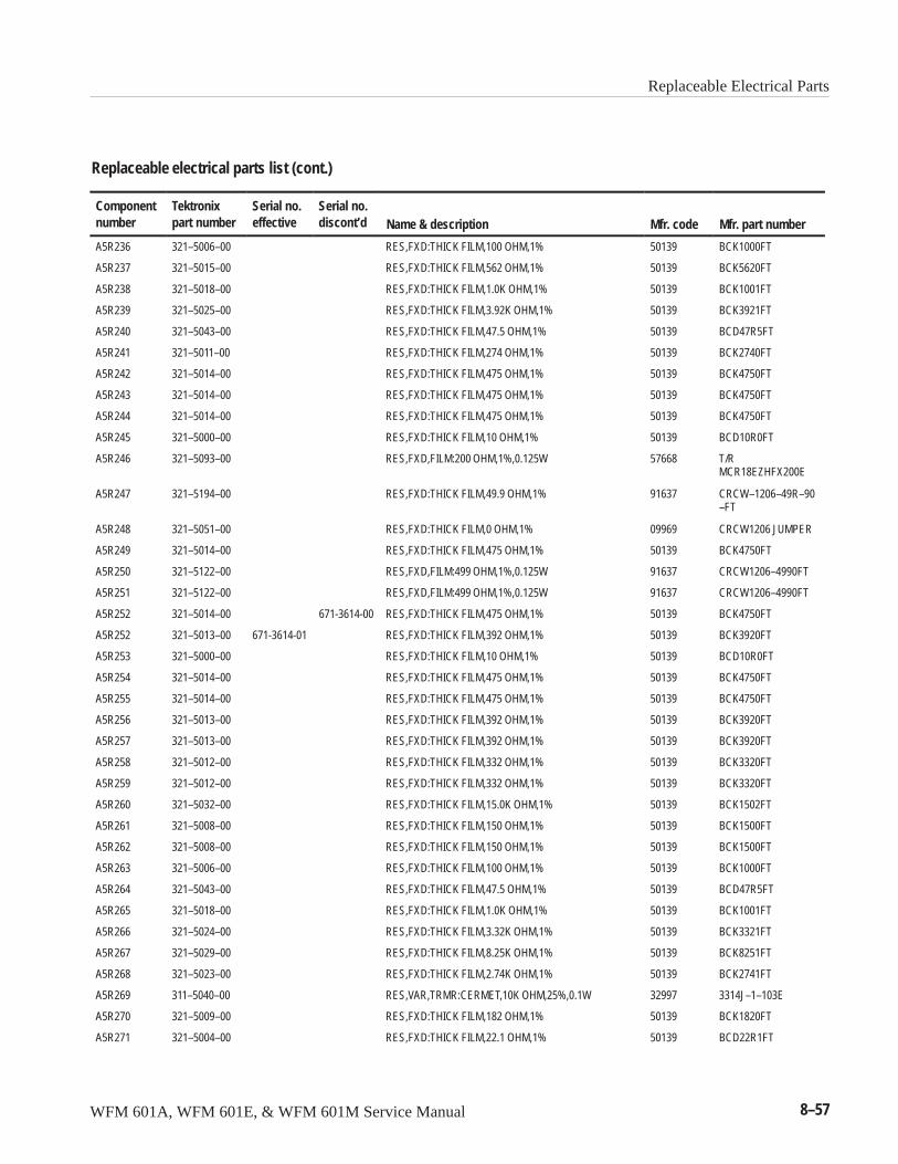
Replaceable Electrical Parts
WFM 601A, WFM 601E, & WFM 601M Service Manual 8–57
Replaceable electrical parts list (cont.)
Componentnumber Mfr. part numberMfr. codeName & description
Serial no.discont’d
Serial no.effective
Tektronixpart number
A5R236 321–5006–00 RES,FXD:THICK FILM,100 OHM,1% 50139 BCK1000FT
A5R237 321–5015–00 RES,FXD:THICK FILM,562 OHM,1% 50139 BCK5620FT
A5R238 321–5018–00 RES,FXD:THICK FILM,1.0K OHM,1% 50139 BCK1001FT
A5R239 321–5025–00 RES,FXD:THICK FILM,3.92K OHM,1% 50139 BCK3921FT
A5R240 321–5043–00 RES,FXD:THICK FILM,47.5 OHM,1% 50139 BCD47R5FT
A5R241 321–5011–00 RES,FXD:THICK FILM,274 OHM,1% 50139 BCK2740FT
A5R242 321–5014–00 RES,FXD:THICK FILM,475 OHM,1% 50139 BCK4750FT
A5R243 321–5014–00 RES,FXD:THICK FILM,475 OHM,1% 50139 BCK4750FT
A5R244 321–5014–00 RES,FXD:THICK FILM,475 OHM,1% 50139 BCK4750FT
A5R245 321–5000–00 RES,FXD:THICK FILM,10 OHM,1% 50139 BCD10R0FT
A5R246 321–5093–00 RES,FXD,FILM:200 OHM,1%,0.125W 57668 T/RMCR18EZHFX200E
A5R247 321–5194–00 RES,FXD:THICK FILM,49.9 OHM,1% 91637 CRCW–1206–49R–90–FT
A5R248 321–5051–00 RES,FXD:THICK FILM,0 OHM,1% 09969 CRCW1206 JUMPER
A5R249 321–5014–00 RES,FXD:THICK FILM,475 OHM,1% 50139 BCK4750FT
A5R250 321–5122–00 RES,FXD,FILM:499 OHM,1%,0.125W 91637 CRCW1206–4990FT
A5R251 321–5122–00 RES,FXD,FILM:499 OHM,1%,0.125W 91637 CRCW1206–4990FT
A5R252 321–5014–00 671-3614-00 RES,FXD:THICK FILM,475 OHM,1% 50139 BCK4750FT
A5R252 321–5013–00 671-3614-01 RES,FXD:THICK FILM,392 OHM,1% 50139 BCK3920FT
A5R253 321–5000–00 RES,FXD:THICK FILM,10 OHM,1% 50139 BCD10R0FT
A5R254 321–5014–00 RES,FXD:THICK FILM,475 OHM,1% 50139 BCK4750FT
A5R255 321–5014–00 RES,FXD:THICK FILM,475 OHM,1% 50139 BCK4750FT
A5R256 321–5013–00 RES,FXD:THICK FILM,392 OHM,1% 50139 BCK3920FT
A5R257 321–5013–00 RES,FXD:THICK FILM,392 OHM,1% 50139 BCK3920FT
A5R258 321–5012–00 RES,FXD:THICK FILM,332 OHM,1% 50139 BCK3320FT
A5R259 321–5012–00 RES,FXD:THICK FILM,332 OHM,1% 50139 BCK3320FT
A5R260 321–5032–00 RES,FXD:THICK FILM,15.0K OHM,1% 50139 BCK1502FT
A5R261 321–5008–00 RES,FXD:THICK FILM,150 OHM,1% 50139 BCK1500FT
A5R262 321–5008–00 RES,FXD:THICK FILM,150 OHM,1% 50139 BCK1500FT
A5R263 321–5006–00 RES,FXD:THICK FILM,100 OHM,1% 50139 BCK1000FT
A5R264 321–5043–00 RES,FXD:THICK FILM,47.5 OHM,1% 50139 BCD47R5FT
A5R265 321–5018–00 RES,FXD:THICK FILM,1.0K OHM,1% 50139 BCK1001FT
A5R266 321–5024–00 RES,FXD:THICK FILM,3.32K OHM,1% 50139 BCK3321FT
A5R267 321–5029–00 RES,FXD:THICK FILM,8.25K OHM,1% 50139 BCK8251FT
A5R268 321–5023–00 RES,FXD:THICK FILM,2.74K OHM,1% 50139 BCK2741FT
A5R269 311–5040–00 RES,VAR,TRMR:CERMET,10K OHM,25%,0.1W 32997 3314J–1–103E
A5R270 321–5009–00 RES,FXD:THICK FILM,182 OHM,1% 50139 BCK1820FT
A5R271 321–5004–00 RES,FXD:THICK FILM,22.1 OHM,1% 50139 BCD22R1FT
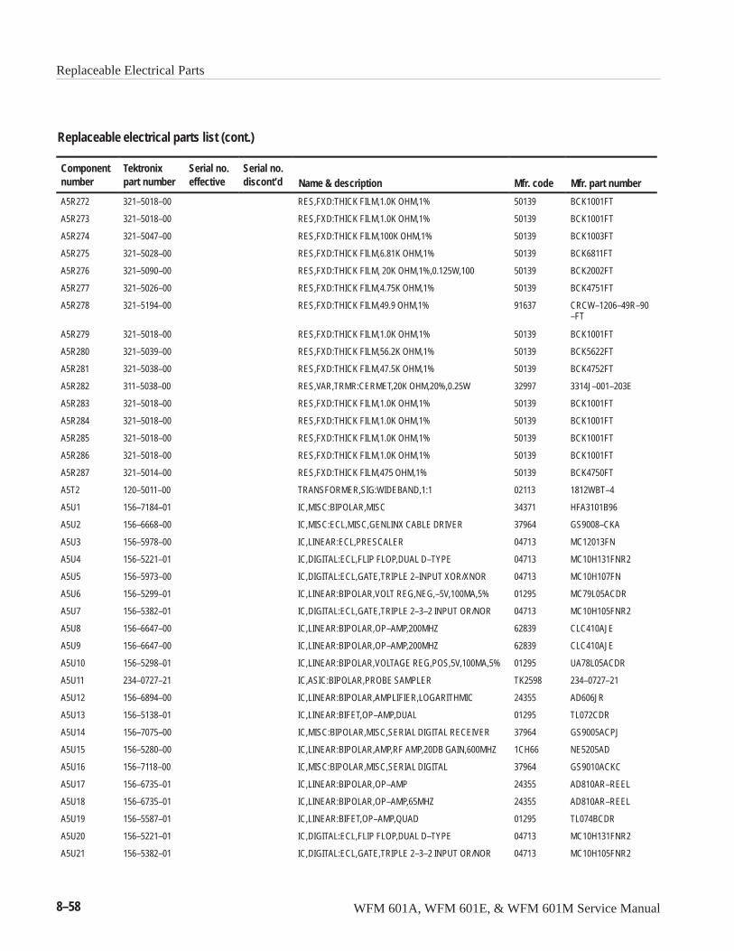
Replaceable Electrical Parts
8–58 WFM 601A, WFM 601E, & WFM 601M Service Manual
Replaceable electrical parts list (cont.)
Componentnumber Mfr. part numberMfr. codeName & description
Serial no.discont’d
Serial no.effective
Tektronixpart number
A5R272 321–5018–00 RES,FXD:THICK FILM,1.0K OHM,1% 50139 BCK1001FT
A5R273 321–5018–00 RES,FXD:THICK FILM,1.0K OHM,1% 50139 BCK1001FT
A5R274 321–5047–00 RES,FXD:THICK FILM,100K OHM,1% 50139 BCK1003FT
A5R275 321–5028–00 RES,FXD:THICK FILM,6.81K OHM,1% 50139 BCK6811FT
A5R276 321–5090–00 RES,FXD:THICK FILM, 20K OHM,1%,0.125W,100 50139 BCK2002FT
A5R277 321–5026–00 RES,FXD:THICK FILM,4.75K OHM,1% 50139 BCK4751FT
A5R278 321–5194–00 RES,FXD:THICK FILM,49.9 OHM,1% 91637 CRCW–1206–49R–90–FT
A5R279 321–5018–00 RES,FXD:THICK FILM,1.0K OHM,1% 50139 BCK1001FT
A5R280 321–5039–00 RES,FXD:THICK FILM,56.2K OHM,1% 50139 BCK5622FT
A5R281 321–5038–00 RES,FXD:THICK FILM,47.5K OHM,1% 50139 BCK4752FT
A5R282 311–5038–00 RES,VAR,TRMR:CERMET,20K OHM,20%,0.25W 32997 3314J–001–203E
A5R283 321–5018–00 RES,FXD:THICK FILM,1.0K OHM,1% 50139 BCK1001FT
A5R284 321–5018–00 RES,FXD:THICK FILM,1.0K OHM,1% 50139 BCK1001FT
A5R285 321–5018–00 RES,FXD:THICK FILM,1.0K OHM,1% 50139 BCK1001FT
A5R286 321–5018–00 RES,FXD:THICK FILM,1.0K OHM,1% 50139 BCK1001FT
A5R287 321–5014–00 RES,FXD:THICK FILM,475 OHM,1% 50139 BCK4750FT
A5T2 120–5011–00 TRANSFORMER,SIG:WIDEBAND,1:1 02113 1812WBT–4
A5U1 156–7184–01 IC,MISC:BIPOLAR,MISC 34371 HFA3101B96
A5U2 156–6668–00 IC,MISC:ECL,MISC,GENLINX CABLE DRIVER 37964 GS9008–CKA
A5U3 156–5978–00 IC,LINEAR:ECL,PRESCALER 04713 MC12013FN
A5U4 156–5221–01 IC,DIGITAL:ECL,FLIP FLOP,DUAL D–TYPE 04713 MC10H131FNR2
A5U5 156–5973–00 IC,DIGITAL:ECL,GATE,TRIPLE 2–INPUT XOR/XNOR 04713 MC10H107FN
A5U6 156–5299–01 IC,LINEAR:BIPOLAR,VOLT REG,NEG,–5V,100MA,5% 01295 MC79L05ACDR
A5U7 156–5382–01 IC,DIGITAL:ECL,GATE,TRIPLE 2–3–2 INPUT OR/NOR 04713 MC10H105FNR2
A5U8 156–6647–00 IC,LINEAR:BIPOLAR,OP–AMP,200MHZ 62839 CLC410AJE
A5U9 156–6647–00 IC,LINEAR:BIPOLAR,OP–AMP,200MHZ 62839 CLC410AJE
A5U10 156–5298–01 IC,LINEAR:BIPOLAR,VOLTAGE REG,POS,5V,100MA,5% 01295 UA78L05ACDR
A5U11 234–0727–21 IC,ASIC:BIPOLAR,PROBE SAMPLER TK2598 234–0727–21
A5U12 156–6894–00 IC,LINEAR:BIPOLAR,AMPLIFIER,LOGARITHMIC 24355 AD606JR
A5U13 156–5138–01 IC,LINEAR:BIFET,OP–AMP,DUAL 01295 TL072CDR
A5U14 156–7075–00 IC,MISC:BIPOLAR,MISC,SERIAL DIGITAL RECEIVER 37964 GS9005ACPJ
A5U15 156–5280–00 IC,LINEAR:BIPOLAR,AMP,RF AMP,20DB GAIN,600MHZ 1CH66 NE5205AD
A5U16 156–7118–00 IC,MISC:BIPOLAR,MISC,SERIAL DIGITAL 37964 GS9010ACKC
A5U17 156–6735–01 IC,LINEAR:BIPOLAR,OP–AMP 24355 AD810AR–REEL
A5U18 156–6735–01 IC,LINEAR:BIPOLAR,OP–AMP,65MHZ 24355 AD810AR–REEL
A5U19 156–5587–01 IC,LINEAR:BIFET,OP–AMP,QUAD 01295 TL074BCDR
A5U20 156–5221–01 IC,DIGITAL:ECL,FLIP FLOP,DUAL D–TYPE 04713 MC10H131FNR2
A5U21 156–5382–01 IC,DIGITAL:ECL,GATE,TRIPLE 2–3–2 INPUT OR/NOR 04713 MC10H105FNR2
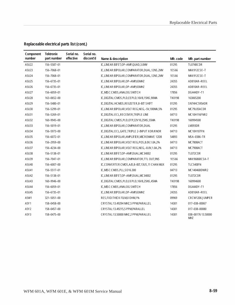
Replaceable Electrical Parts
WFM 601A, WFM 601E, & WFM 601M Service Manual 8–59
Replaceable electrical parts list (cont.)
Componentnumber Mfr. part numberMfr. codeName & description
Serial no.discont’d
Serial no.effective
Tektronixpart number
A5U22 156–5587–01 IC,LINEAR:BIFET,OP–AMP,QUAD,3.0MV 01295 TL074BCDR
A5U23 156–7068–01 IC,LINEAR:BIPOLAR,COMPARATOR,DUAL,12NS,2MV 1ES66 MAX912CSE–T
A5U24 156–7068–01 IC,LINEAR:BIPOLAR,COMPARATOR,DUAL,12NS,2MV 1ES66 MAX912CSE–T
A5U25 156–6735–01 IC,LINEAR:BIPOLAR,OP–AMP,65MHZ 24355 AD810AR–REEL
A5U26 156–6735–01 IC,LINEAR:BIPOLAR,OP–AMP,65MHZ 24355 AD810AR–REEL
A5U27 156–6059–01 IC,MISC:CMOS,ANALOG SWITCH 17856 DG444DY–T1
A5U28 163–0652–00 IC,DIGITAL:CMOS,PLD,EEPLD,16V8,15NS,90MA TK0198 163065200
A5U29 156–5480–01 IC,DIGITAL:HCMOS,REGISTER,8–BIT SHIFT 01295 SN74HC595ADR
A5U30 156–5299–01 IC,LINEAR:BIPOLAR,VOLT REG,NEG,–5V,100MA,5% 01295 MC79L05ACDR
A5U31 156–5269–01 IC,DIGITAL:ECL,RECEIVER,TRIPLE LINE 04713 MC10H116FNR2
A5U32 160–9945–00 IC,DIGITAL:CMOS,PLD,OTP,22V10,25NS,55MA TK0198 160994500
A5U33 156–5019–01 IC,LINEAR:BIPOLAR,COMPARATOR,DUAL 01295 LM393DR
A5U34 156–5973–00 IC,DIGITAL:ECL,GATE,TRIPLE 2–INPUT XOR/XNOR 04713 MC10H107FN
A5U35 156–6072–01 IC,LINEAR:BIPOLAR,AMPLIFIER,MICROWAVE 12DB 54893 MSA–0386–TR
A5U36 156–2959–00 IC,LINEAR:BIPOLAR,VOLT REG,POS,8.0V,1.0A,2% 04713 MC7808ACT
A5U37 156–4234–00 IC,LINEAR:BIPOLAR,VOLT REG,NEG,–8.0V,1.0A,2% 04713 MC7908ACT
A5U38 156–5138–01 IC,LINEAR:BIFET,OP–AMP,DUAL,MC34002 01295 TL072CDR
A5U39 156–7047–01 IC,LINEAR:BIPOLAR,COMPARATOR,TTL OUT,9NS 1ES66 MAX9686BCSA–T
A5U40 156–6007–00 IC,CONVERTER:CMOS,A/D,8–BIT,13US,11 CHAN MUX 01295 TLC540IFN
A5U41 156–5517–01 IC,MISC:CMOS,PLL,SO16.300 04713 MC14046BDWR2
A5U42 156–5138–01 IC,LINEAR:BIFET,OP–AMP,DUAL,MC34002 01295 TL072CDR
A5U43 160–9946–00 IC,DIGITAL:CMOS,PLD,EEPLD,16V8,25NS,45MA TK0198 160994600
A5U44 156–6059–01 IC,MISC:CMOS,ANALOG SWITCH 17856 DG444DY–T1
A5U45 156–6735–01 IC,LINEAR:BIPOLAR,OP–AMP,65MHZ 24355 AD810AR–REEL
A5W1 321–5051–00 RES,FXD:THICK FILM,0 OHM,1% 09969 CRCW1206 JUMPER
A5Y1 158–0458–00 CRYSTAL:13.49294 MHZ,5 PPM,PARALLEL 14301 017–038–00067
A5Y2 158–0457–00 CRYSTAL:13.49215,5 PPM,PARALLEL 14301 017–038–00080
A5Y3 158–0475–00 CRYSTAL:13.50000 MHZ,2 PPM,PARALLEL 14301 038–00176 13.50000MHZ
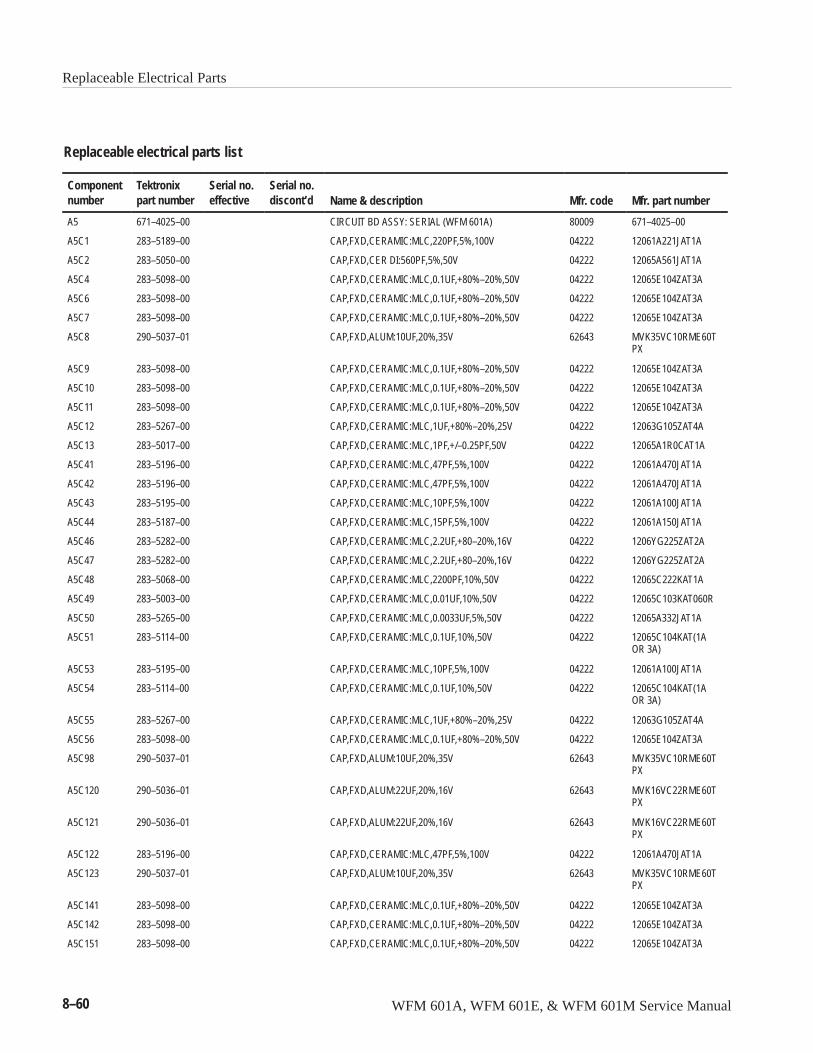
Replaceable Electrical Parts
8–60 WFM 601A, WFM 601E, & WFM 601M Service Manual
Replaceable electrical parts list
Componentnumber
Tektronixpart number
Serial no.effective
Serial no.discont’d Name & description Mfr. code Mfr. part number
A5 671–4025–00 CIRCUIT BD ASSY: SERIAL (WFM 601A) 80009 671–4025–00
A5C1 283–5189–00 CAP,FXD,CERAMIC:MLC,220PF,5%,100V 04222 12061A221JAT1A
A5C2 283–5050–00 CAP,FXD,CER DI:560PF,5%,50V 04222 12065A561JAT1A
A5C4 283–5098–00 CAP,FXD,CERAMIC:MLC,0.1UF,+80%–20%,50V 04222 12065E104ZAT3A
A5C6 283–5098–00 CAP,FXD,CERAMIC:MLC,0.1UF,+80%–20%,50V 04222 12065E104ZAT3A
A5C7 283–5098–00 CAP,FXD,CERAMIC:MLC,0.1UF,+80%–20%,50V 04222 12065E104ZAT3A
A5C8 290–5037–01 CAP,FXD,ALUM:10UF,20%,35V 62643 MVK35VC10RME60TPX
A5C9 283–5098–00 CAP,FXD,CERAMIC:MLC,0.1UF,+80%–20%,50V 04222 12065E104ZAT3A
A5C10 283–5098–00 CAP,FXD,CERAMIC:MLC,0.1UF,+80%–20%,50V 04222 12065E104ZAT3A
A5C11 283–5098–00 CAP,FXD,CERAMIC:MLC,0.1UF,+80%–20%,50V 04222 12065E104ZAT3A
A5C12 283–5267–00 CAP,FXD,CERAMIC:MLC,1UF,+80%–20%,25V 04222 12063G105ZAT4A
A5C13 283–5017–00 CAP,FXD,CERAMIC:MLC,1PF,+/–0.25PF,50V 04222 12065A1R0CAT1A
A5C41 283–5196–00 CAP,FXD,CERAMIC:MLC,47PF,5%,100V 04222 12061A470JAT1A
A5C42 283–5196–00 CAP,FXD,CERAMIC:MLC,47PF,5%,100V 04222 12061A470JAT1A
A5C43 283–5195–00 CAP,FXD,CERAMIC:MLC,10PF,5%,100V 04222 12061A100JAT1A
A5C44 283–5187–00 CAP,FXD,CERAMIC:MLC,15PF,5%,100V 04222 12061A150JAT1A
A5C46 283–5282–00 CAP,FXD,CERAMIC:MLC,2.2UF,+80–20%,16V 04222 1206YG225ZAT2A
A5C47 283–5282–00 CAP,FXD,CERAMIC:MLC,2.2UF,+80–20%,16V 04222 1206YG225ZAT2A
A5C48 283–5068–00 CAP,FXD,CERAMIC:MLC,2200PF,10%,50V 04222 12065C222KAT1A
A5C49 283–5003–00 CAP,FXD,CERAMIC:MLC,0.01UF,10%,50V 04222 12065C103KAT060R
A5C50 283–5265–00 CAP,FXD,CERAMIC:MLC,0.0033UF,5%,50V 04222 12065A332JAT1A
A5C51 283–5114–00 CAP,FXD,CERAMIC:MLC,0.1UF,10%,50V 04222 12065C104KAT(1AOR 3A)
A5C53 283–5195–00 CAP,FXD,CERAMIC:MLC,10PF,5%,100V 04222 12061A100JAT1A
A5C54 283–5114–00 CAP,FXD,CERAMIC:MLC,0.1UF,10%,50V 04222 12065C104KAT(1AOR 3A)
A5C55 283–5267–00 CAP,FXD,CERAMIC:MLC,1UF,+80%–20%,25V 04222 12063G105ZAT4A
A5C56 283–5098–00 CAP,FXD,CERAMIC:MLC,0.1UF,+80%–20%,50V 04222 12065E104ZAT3A
A5C98 290–5037–01 CAP,FXD,ALUM:10UF,20%,35V 62643 MVK35VC10RME60TPX
A5C120 290–5036–01 CAP,FXD,ALUM:22UF,20%,16V 62643 MVK16VC22RME60TPX
A5C121 290–5036–01 CAP,FXD,ALUM:22UF,20%,16V 62643 MVK16VC22RME60TPX
A5C122 283–5196–00 CAP,FXD,CERAMIC:MLC,47PF,5%,100V 04222 12061A470JAT1A
A5C123 290–5037–01 CAP,FXD,ALUM:10UF,20%,35V 62643 MVK35VC10RME60TPX
A5C141 283–5098–00 CAP,FXD,CERAMIC:MLC,0.1UF,+80%–20%,50V 04222 12065E104ZAT3A
A5C142 283–5098–00 CAP,FXD,CERAMIC:MLC,0.1UF,+80%–20%,50V 04222 12065E104ZAT3A
A5C151 283–5098–00 CAP,FXD,CERAMIC:MLC,0.1UF,+80%–20%,50V 04222 12065E104ZAT3A
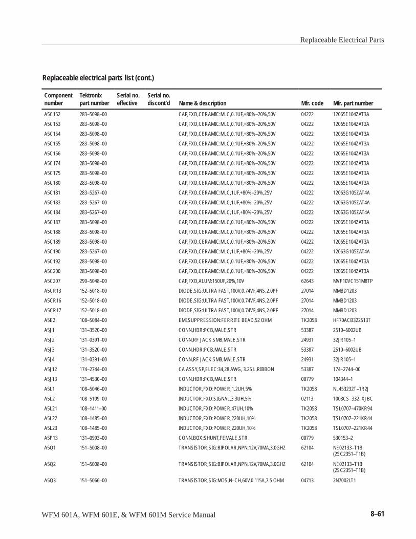
Replaceable Electrical Parts
WFM 601A, WFM 601E, & WFM 601M Service Manual 8–61
Replaceable electrical parts list (cont.)
Componentnumber Mfr. part numberMfr. codeName & description
Serial no.discont’d
Serial no.effective
Tektronixpart number
A5C152 283–5098–00 CAP,FXD,CERAMIC:MLC,0.1UF,+80%–20%,50V 04222 12065E104ZAT3A
A5C153 283–5098–00 CAP,FXD,CERAMIC:MLC,0.1UF,+80%–20%,50V 04222 12065E104ZAT3A
A5C154 283–5098–00 CAP,FXD,CERAMIC:MLC,0.1UF,+80%–20%,50V 04222 12065E104ZAT3A
A5C155 283–5098–00 CAP,FXD,CERAMIC:MLC,0.1UF,+80%–20%,50V 04222 12065E104ZAT3A
A5C156 283–5098–00 CAP,FXD,CERAMIC:MLC,0.1UF,+80%–20%,50V 04222 12065E104ZAT3A
A5C174 283–5098–00 CAP,FXD,CERAMIC:MLC,0.1UF,+80%–20%,50V 04222 12065E104ZAT3A
A5C175 283–5098–00 CAP,FXD,CERAMIC:MLC,0.1UF,+80%–20%,50V 04222 12065E104ZAT3A
A5C180 283–5098–00 CAP,FXD,CERAMIC:MLC,0.1UF,+80%–20%,50V 04222 12065E104ZAT3A
A5C181 283–5267–00 CAP,FXD,CERAMIC:MLC,1UF,+80%–20%,25V 04222 12063G105ZAT4A
A5C183 283–5267–00 CAP,FXD,CERAMIC:MLC,1UF,+80%–20%,25V 04222 12063G105ZAT4A
A5C184 283–5267–00 CAP,FXD,CERAMIC:MLC,1UF,+80%–20%,25V 04222 12063G105ZAT4A
A5C187 283–5098–00 CAP,FXD,CERAMIC:MLC,0.1UF,+80%–20%,50V 04222 12065E104ZAT3A
A5C188 283–5098–00 CAP,FXD,CERAMIC:MLC,0.1UF,+80%–20%,50V 04222 12065E104ZAT3A
A5C189 283–5098–00 CAP,FXD,CERAMIC:MLC,0.1UF,+80%–20%,50V 04222 12065E104ZAT3A
A5C190 283–5267–00 CAP,FXD,CERAMIC:MLC,1UF,+80%–20%,25V 04222 12063G105ZAT4A
A5C192 283–5098–00 CAP,FXD,CERAMIC:MLC,0.1UF,+80%–20%,50V 04222 12065E104ZAT3A
A5C200 283–5098–00 CAP,FXD,CERAMIC:MLC,0.1UF,+80%–20%,50V 04222 12065E104ZAT3A
A5C207 290–5048–00 CAP,FXD,ALUM:150UF,20%,10V 62643 MVF10VC151M8TP
A5CR13 152–5018–00 DIODE,SIG:ULTRA FAST,100V,0.74VF,4NS,2.0PF 27014 MMBD1203
A5CR16 152–5018–00 DIODE,SIG:ULTRA FAST,100V,0.74VF,4NS,2.0PF 27014 MMBD1203
A5CR17 152–5018–00 DIODE,SIG:ULTRA FAST,100V,0.74VF,4NS,2.0PF 27014 MMBD1203
A5E2 108–5084–00 EMI,SUPPRESSION:FERRITE BEAD,52 OHM TK2058 HF70ACB322513T
A5J1 131–3520–00 CONN,HDR:PCB,MALE,STR 53387 2510–6002UB
A5J2 131–0391–00 CONN,RF JACK:SMB,MALE,STR 24931 32JR105–1
A5J3 131–3520–00 CONN,HDR:PCB,MALE,STR 53387 2510–6002UB
A5J4 131–0391–00 CONN,RF JACK:SMB,MALE,STR 24931 32JR105–1
A5J12 174–2744–00 CA ASSY,SP,ELEC:34,28 AWG, 3.25 L,RIBBON 53387 174–2744–00
A5J13 131–4530–00 CONN,HDR:PCB,MALE,STR 00779 104344–1
A5L1 108–5046–00 INDUCTOR,FXD:POWER,1.2UH,5% TK2058 NL453232T–1R2J
A5L2 108–5109–00 INDUCTOR,FXD:SIGNAL,3.3UH,5% 02113 1008CS–332–XJBC
A5L21 108–1411–00 INDUCTOR,FXD:POWER,47UH,10% TK2058 TSL0707–470KR94
A5L22 108–1485–00 INDUCTOR,FXD:POWER,220UH,10% TK2058 TSL0707–221KR44
A5L23 108–1485–00 INDUCTOR,FXD:POWER,220UH,10% TK2058 TSL0707–221KR44
A5P13 131–0993–00 CONN,BOX:SHUNT,FEMALE,STR 00779 530153–2
A5Q1 151–5008–00 TRANSISTOR,SIG:BIPOLAR,NPN,12V,70MA,3.0GHZ 62104 NE02133–T1B(2SC2351–T1B)
A5Q2 151–5008–00 TRANSISTOR,SIG:BIPOLAR,NPN,12V,70MA,3.0GHZ 62104 NE02133–T1B(2SC2351–T1B)
A5Q3 151–5066–00 TRANSISTOR,SIG:MOS,N–CH,60V,0.115A,7.5 OHM 04713 2N7002LT1
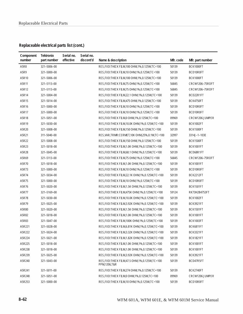
Replaceable Electrical Parts
8–62 WFM 601A, WFM 601E, & WFM 601M Service Manual
Replaceable electrical parts list (cont.)
Componentnumber Mfr. part numberMfr. codeName & description
Serial no.discont’d
Serial no.effective
Tektronixpart number
A5R8 321–5006–00 RES,FXD:THICK FILM,100 OHM,1%,0.125W,TC=100 50139 BCK1000FT
A5R9 321–5000–00 RES,FXD:THICK FILM,10 OHM,1%,0.125W,TC=100 50139 BCD10R0FT
A5R10 321–5006–00 RES,FXD:THICK FILM,100 OHM,1%,0.125W,TC=100 50139 BCK1000FT
A5R11 321–5113–00 RES,FXD:THICK FILM,75 OHM,1%,0.125W,TC=100 56845 CRCW1206–75ROFT
A5R12 321–5113–00 RES,FXD:THICK FILM,75 OHM,1%,0.125W,TC=100 56845 CRCW1206–75ROFT
A5R14 321–5004–00 RES,FXD:THICK FILM,22.1 OHM,1%,0.125W,TC=100 50139 BCD22R1FT
A5R15 321–5014–00 RES,FXD:THICK FILM,475 OHM,1%,0.125W,TC=100 50139 BCK4750FT
A5R16 321–5000–00 RES,FXD:THICK FILM,10 OHM,1%,0.125W,TC=100 50139 BCD10R0FT
A5R17 321–5000–00 RES,FXD:THICK FILM,10 OHM,1%,0.125W,TC=100 50139 BCD10R0FT
A5R18 321–5051–00 RES,FXD:THICK FILM,0 OHM,1%,0.125W,TC=100 09969 CRCW1206 JUMPER
A5R19 321–5030–00 RES,FXD:THICK FILM,10.0K OHM,1%,0.125W,TC=100 50139 BCK1002FT
A5R20 321–5008–00 RES,FXD:THICK FILM,150 OHM,1%,0.125W,TC=100 50139 BCK1500FT
A5R21 311–5040–00 RES,VAR,TRMR:CERMET,10K OHM,25%,0.1W,TC=100 32997 3314J–1–103E
A5R22 321–5008–00 RES,FXD:THICK FILM,150 OHM,1%,0.125W,TC=100 50139 BCK1500FT
A5R23 321–5018–00 RES,FXD:THICK FILM,1.0K OHM,1%,0.125W,TC=100 50139 BCK1001FT
A5R28 321–5045–00 RES,FXD:THICK FILM,68.1 OHM,1%,0.125W,TC=100 50139 BCD68R1FT
A5R69 321–5113–00 RES,FXD:THICK FILM,75 OHM,1%,0.125W,TC=100 56845 CRCW1206–75ROFT
A5R70 321–5018–00 RES,FXD:THICK FILM,1.0K OHM,1%,0.125W,TC=100 50139 BCK1001FT
A5R73 321–5000–00 RES,FXD:THICK FILM,10 OHM,1%,0.125W,TC=100 50139 BCD10R0FT
A5R74 321–5034–00 RES,FXD:THICK FILM,22.1K OHM,1%,0.125W,TC=100 50139 BCK2212FT
A5R75 321–5000–00 RES,FXD:THICK FILM,10 OHM,1%,0.125W,TC=100 50139 BCD10R0FT
A5R76 321–5020–00 RES,FXD:THICK FILM,1.5K OHM,1%,0.125W,TC=100 50139 BCK1501FT
A5R77 321–5169–00 RES,FXD:THICK FILM,475K OHM,1%,0.125W,TC=100 59124 RK73H2B4753FT
A5R78 321–5030–00 RES,FXD:THICK FILM,10.0K OHM,1%,0.125W,TC=100 50139 BCK1002FT
A5R79 321–5025–00 RES,FXD:THICK FILM,3.92K OHM,1%,0.125W,TC=100 50139 BCK3921FT
A5R80 321–5020–00 RES,FXD:THICK FILM,1.5K OHM,1%,0.125W,TC=100 50139 BCK1501FT
A5R82 321–5018–00 RES,FXD:THICK FILM,1.0K OHM,1%,0.125W,TC=100 50139 BCK1001FT
A5R83 321–5047–00 RES,FXD:THICK FILM,100K OHM,1%,0.125W,TC=100 50139 BCK1003FT
A5R221 321–5028–00 RES,FXD:THICK FILM,6.81K OHM,1%,0.125W,TC=100 50139 BCK6811FT
A5R222 321–5024–00 RES,FXD:THICK FILM,3.32K OHM,1%,0.125W,TC=100 50139 BCK3321FT
A5R224 321–5021–00 RES,FXD:THICK FILM,1.82K OHM,1%,0.125W,TC=100 50139 BCK1821FT
A5R225 321–5018–00 RES,FXD:THICK FILM,1.0K OHM,1%,0.125W,TC=100 50139 BCK1001FT
A5R238 321–5018–00 RES,FXD:THICK FILM,1.0K OHM,1%,0.125W,TC=100 50139 BCK1001FT
A5R239 321–5025–00 RES,FXD:THICK FILM,3.92K OHM,1%,0.125W,TC=100 50139 BCK3921FT
A5R240 321–5043–00 RES,FXD:THICK FILM,47.5 OHM,1%,0.125W,TC=100PPM,1206,T&R
50139 BCD47R5FT
A5R241 321–5011–00 RES,FXD:THICK FILM,274 OHM,1%,0.125W,TC=100 50139 BCK2740FT
A5R248 321–5051–00 RES,FXD:THICK FILM,0 OHM,1%,0.125W,TC=100 09969 CRCW1206 JUMPER
A5R253 321–5000–00 RES,FXD:THICK FILM,10 OHM,1%,0.125W,TC=100 50139 BCD10R0FT
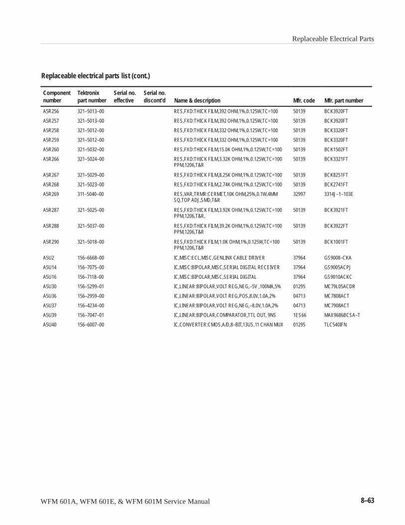
Replaceable Electrical Parts
WFM 601A, WFM 601E, & WFM 601M Service Manual 8–63
Replaceable electrical parts list (cont.)
Componentnumber Mfr. part numberMfr. codeName & description
Serial no.discont’d
Serial no.effective
Tektronixpart number
A5R256 321–5013–00 RES,FXD:THICK FILM,392 OHM,1%,0.125W,TC=100 50139 BCK3920FT
A5R257 321–5013–00 RES,FXD:THICK FILM,392 OHM,1%,0.125W,TC=100 50139 BCK3920FT
A5R258 321–5012–00 RES,FXD:THICK FILM,332 OHM,1%,0.125W,TC=100 50139 BCK3320FT
A5R259 321–5012–00 RES,FXD:THICK FILM,332 OHM,1%,0.125W,TC=100 50139 BCK3320FT
A5R260 321–5032–00 RES,FXD:THICK FILM,15.0K OHM,1%,0.125W,TC=100 50139 BCK1502FT
A5R266 321–5024–00 RES,FXD:THICK FILM,3.32K OHM,1%,0.125W,TC=100PPM,1206,T&R
50139 BCK3321FT
A5R267 321–5029–00 RES,FXD:THICK FILM,8.25K OHM,1%,0.125W,TC=100 50139 BCK8251FT
A5R268 321–5023–00 RES,FXD:THICK FILM,2.74K OHM,1%,0.125W,TC=100 50139 BCK2741FT
A5R269 311–5040–00 RES,VAR,TRMR:CERMET,10K OHM,25%,0.1W,4MMSQ,TOP ADJ,SMD,T&R
32997 3314J–1–103E
A5R287 321–5025–00 RES,FXD:THICK FILM,3.92K OHM,1%,0.125W,TC=100PPM,1206,T&R,
50139 BCK3921FT
A5R288 321–5037–00 RES,FXD:THICK FILM,39.2K OHM,1%,0.125W,TC=100PPM,1206,T&R
50139 BCK3922FT
A5R290 321–5018–00 RES,FXD:THICK FILM,1.0K OHM,1%,0.125W,TC=100PPM,1206,T&R
50139 BCK1001FT
A5U2 156–6668–00 IC,MISC:ECL,MISC,GENLINX CABLE DRIVER 37964 GS9008–CKA
A5U14 156–7075–00 IC,MISC:BIPOLAR,MISC,SERIAL DIGITAL RECEIVER 37964 GS9005ACPJ
A5U16 156–7118–00 IC,MISC:BIPOLAR,MISC,SERIAL DIGITAL 37964 GS9010ACKC
A5U30 156–5299–01 IC,LINEAR:BIPOLAR,VOLT REG,NEG,–5V ,100MA,5% 01295 MC79L05ACDR
A5U36 156–2959–00 IC,LINEAR:BIPOLAR,VOLT REG,POS,8.0V,1.0A,2% 04713 MC7808ACT
A5U37 156–4234–00 IC,LINEAR:BIPOLAR,VOLT REG,NEG,–8.0V,1.0A,2% 04713 MC7908ACT
A5U39 156–7047–01 IC,LINEAR:BIPOLAR,COMPARATOR,TTL OUT, 9NS 1ES66 MAX9686BCSA–T
A5U40 156–6007–00 IC,CONVERTER:CMOS,A/D,8–BIT,13US,11 CHAN MUX 01295 TLC540IFN
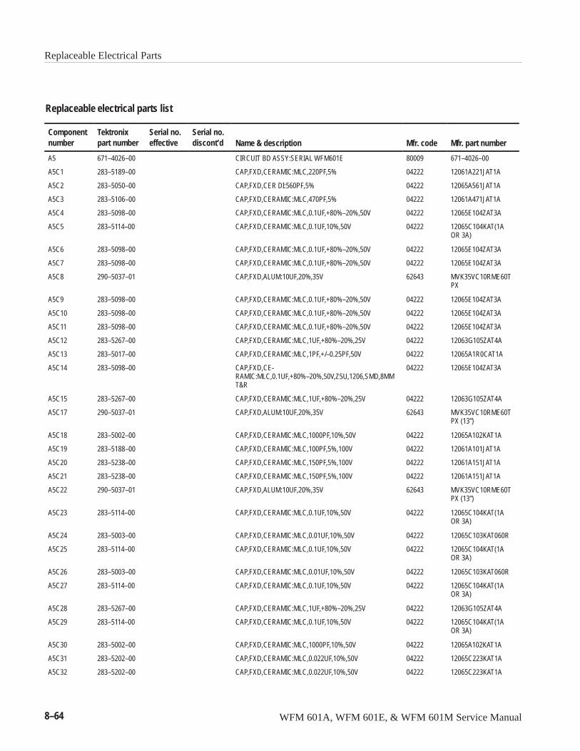
Replaceable Electrical Parts
8–64 WFM 601A, WFM 601E, & WFM 601M Service Manual
Replaceable electrical parts list
Componentnumber
Tektronixpart number
Serial no.effective
Serial no.discont’d Name & description Mfr. code Mfr. part number
A5 671–4026–00 CIRCUIT BD ASSY:SERIAL WFM601E 80009 671–4026–00
A5C1 283–5189–00 CAP,FXD,CERAMIC:MLC,220PF,5% 04222 12061A221JAT1A
A5C2 283–5050–00 CAP,FXD,CER DI:560PF,5% 04222 12065A561JAT1A
A5C3 283–5106–00 CAP,FXD,CERAMIC:MLC,470PF,5% 04222 12061A471JAT1A
A5C4 283–5098–00 CAP,FXD,CERAMIC:MLC,0.1UF,+80%–20%,50V 04222 12065E104ZAT3A
A5C5 283–5114–00 CAP,FXD,CERAMIC:MLC,0.1UF,10%,50V 04222 12065C104KAT(1AOR 3A)
A5C6 283–5098–00 CAP,FXD,CERAMIC:MLC,0.1UF,+80%–20%,50V 04222 12065E104ZAT3A
A5C7 283–5098–00 CAP,FXD,CERAMIC:MLC,0.1UF,+80%–20%,50V 04222 12065E104ZAT3A
A5C8 290–5037–01 CAP,FXD,ALUM:10UF,20%,35V 62643 MVK35VC10RME60TPX
A5C9 283–5098–00 CAP,FXD,CERAMIC:MLC,0.1UF,+80%–20%,50V 04222 12065E104ZAT3A
A5C10 283–5098–00 CAP,FXD,CERAMIC:MLC,0.1UF,+80%–20%,50V 04222 12065E104ZAT3A
A5C11 283–5098–00 CAP,FXD,CERAMIC:MLC,0.1UF,+80%–20%,50V 04222 12065E104ZAT3A
A5C12 283–5267–00 CAP,FXD,CERAMIC:MLC,1UF,+80%–20%,25V 04222 12063G105ZAT4A
A5C13 283–5017–00 CAP,FXD,CERAMIC:MLC,1PF,+/–0.25PF,50V 04222 12065A1R0CAT1A
A5C14 283–5098–00 CAP,FXD,CE-RAMIC:MLC,0.1UF,+80%–20%,50V,Z5U,1206,SMD,8MMT&R
04222 12065E104ZAT3A
A5C15 283–5267–00 CAP,FXD,CERAMIC:MLC,1UF,+80%–20%,25V 04222 12063G105ZAT4A
A5C17 290–5037–01 CAP,FXD,ALUM:10UF,20%,35V 62643 MVK35VC10RME60TPX (13”)
A5C18 283–5002–00 CAP,FXD,CERAMIC:MLC,1000PF,10%,50V 04222 12065A102KAT1A
A5C19 283–5188–00 CAP,FXD,CERAMIC:MLC,100PF,5%,100V 04222 12061A101JAT1A
A5C20 283–5238–00 CAP,FXD,CERAMIC:MLC,150PF,5%,100V 04222 12061A151JAT1A
A5C21 283–5238–00 CAP,FXD,CERAMIC:MLC,150PF,5%,100V 04222 12061A151JAT1A
A5C22 290–5037–01 CAP,FXD,ALUM:10UF,20%,35V 62643 MVK35VC10RME60TPX (13”)
A5C23 283–5114–00 CAP,FXD,CERAMIC:MLC,0.1UF,10%,50V 04222 12065C104KAT(1AOR 3A)
A5C24 283–5003–00 CAP,FXD,CERAMIC:MLC,0.01UF,10%,50V 04222 12065C103KAT060R
A5C25 283–5114–00 CAP,FXD,CERAMIC:MLC,0.1UF,10%,50V 04222 12065C104KAT(1AOR 3A)
A5C26 283–5003–00 CAP,FXD,CERAMIC:MLC,0.01UF,10%,50V 04222 12065C103KAT060R
A5C27 283–5114–00 CAP,FXD,CERAMIC:MLC,0.1UF,10%,50V 04222 12065C104KAT(1AOR 3A)
A5C28 283–5267–00 CAP,FXD,CERAMIC:MLC,1UF,+80%–20%,25V 04222 12063G105ZAT4A
A5C29 283–5114–00 CAP,FXD,CERAMIC:MLC,0.1UF,10%,50V 04222 12065C104KAT(1AOR 3A)
A5C30 283–5002–00 CAP,FXD,CERAMIC:MLC,1000PF,10%,50V 04222 12065A102KAT1A
A5C31 283–5202–00 CAP,FXD,CERAMIC:MLC,0.022UF,10%,50V 04222 12065C223KAT1A
A5C32 283–5202–00 CAP,FXD,CERAMIC:MLC,0.022UF,10%,50V 04222 12065C223KAT1A
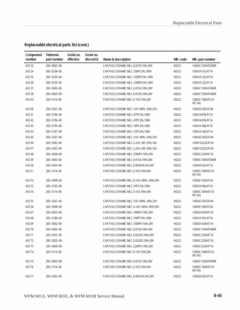
Replaceable Electrical Parts
WFM 601A, WFM 601E, & WFM 601M Service Manual 8–65
Replaceable electrical parts list (cont.)
Componentnumber Mfr. part numberMfr. codeName & description
Serial no.discont’d
Serial no.effective
Tektronixpart number
A5C33 283–5003–00 CAP,FXD,CERAMIC:MLC,0.01UF,10%,50V 04222 12065C103KAT060R
A5C34 283–5238–00 CAP,FXD,CERAMIC:MLC,150PF,5%,100V 04222 12061A151JAT1A
A5C35 283–5239–00 CAP,FXD,CERAMIC:MLC,1200PF,5%,100V 04222 12061A122JAT1A
A5C36 283–5239–00 CAP,FXD,CERAMIC:MLC,1200PF,5%,100V 04222 12061A122JAT1A
A5C37 283–5003–00 CAP,FXD,CERAMIC:MLC,0.01UF,10%,50V 04222 12065C103KAT060R
A5C38 283–5003–00 CAP,FXD,CERAMIC:MLC,0.01UF,10%,50V 04222 12065C103KAT060R
A5C39 283–5114–00 CAP,FXD,CERAMIC:MLC,0.1UF,10%,50V 04222 12065C104KAT(1AOR 3A)
A5C40 283–5267–00 CAP,FXD,CERAMIC:MLC,1UF,+80%–20%,25V 04222 12063G105ZAT4A
A5C41 283–5196–00 CAP,FXD,CERAMIC:MLC,47PF,5%,100V 04222 12061A470JAT1A
A5C42 283–5196–00 CAP,FXD,CERAMIC:MLC,47PF,5%,100V 04222 12061A470JAT1A
A5C43 283–5195–00 CAP,FXD,CERAMIC:MLC,10PF,5%,100V 04222 12061A100JAT1A
A5C44 283–5187–00 CAP,FXD,CERAMIC:MLC,15PF,5%,100V 04222 12061A150JAT1A
A5C45 283–5267–00 CAP,FXD,CERAMIC:MLC,1UF,+80%–20%,25V 04222 12063G105ZAT4A
A5C46 283–5282–00 CAP,FXD,CERAMIC:MLC,2.2UF,+80–20%,16V 04222 1206YG225ZAT2A
A5C47 283–5282–00 CAP,FXD,CERAMIC:MLC,2.2UF,+80–20%,16V 04222 1206YG225ZAT2A
A5C48 283–5068–00 CAP,FXD,CERAMIC:MLC,2200PF,10%,50V 04222 12065C222KAT1A
A5C49 283–5003–00 CAP,FXD,CERAMIC:MLC,0.01UF,10%,50V 04222 12065C103KAT060R
A5C50 283–5265–00 CAP,FXD,CERAMIC:MLC,0.0033UF,5%,50V 04222 12065A332JAT1A
A5C51 283–5114–00 CAP,FXD,CERAMIC:MLC,0.1UF,10%,50V 04222 12065C104KAT(1AOR 3A)
A5C52 283–5098–00 CAP,FXD,CERAMIC:MLC,0.1UF,+80%–20%,50V 04222 12065E104ZAT3A
A5C53 283–5195–00 CAP,FXD,CERAMIC:MLC,10PF,5%,100V 04222 12061A100JAT1A
A5C54 283–5114–00 CAP,FXD,CERAMIC:MLC,0.1UF,10%,50V 04222 12065C104KAT(1AOR 3A)
A5C55 283–5267–00 CAP,FXD,CERAMIC:MLC,1UF,+80%–20%,25V 04222 12063G105ZAT4A
A5C56 283–5098–00 CAP,FXD,CERAMIC:MLC,0.1UF,+80%–20%,50V 04222 12065E104ZAT3A
A5C67 283–5002–00 CAP,FXD,CERAMIC:MLC,1000PF,10%,50V 04222 12065A102KAT1A
A5C68 283–5188–00 CAP,FXD,CERAMIC:MLC,100PF,5%,100V 04222 12061A101JAT1A
A5C69 283–5002–00 CAP,FXD,CERAMIC:MLC,1000PF,10%,50V 04222 12065A102KAT1A
A5C70 283–5003–00 CAP,FXD,CERAMIC:MLC,0.01UF,10%,50V 04222 12065C103KAT060R
A5C71 283–5202–00 CAP,FXD,CERAMIC:MLC,0.022UF,10%,50V 04222 12065C223KAT1A
A5C72 283–5202–00 CAP,FXD,CERAMIC:MLC,0.022UF,10%,50V 04222 12065C223KAT1A
A5C73 283–5068–00 CAP,FXD,CERAMIC:MLC,2200PF,10%,50V 04222 12065C222KAT1A
A5C74 283–5114–00 CAP,FXD,CERAMIC:MLC,0.1UF,10%,50V 04222 12065C104KAT(1AOR 3A)
A5C75 283–5003–00 CAP,FXD,CERAMIC:MLC,0.01UF,10%,50V 04222 12065C103KAT060R
A5C76 283–5114–00 CAP,FXD,CERAMIC:MLC,0.1UF,10%,50V 04222 12065C104KAT(1AOR 3A)
A5C77 283–5265–00 CAP,FXD,CERAMIC:MLC,0.0033UF,5%,50V 04222 12065A332JAT1A
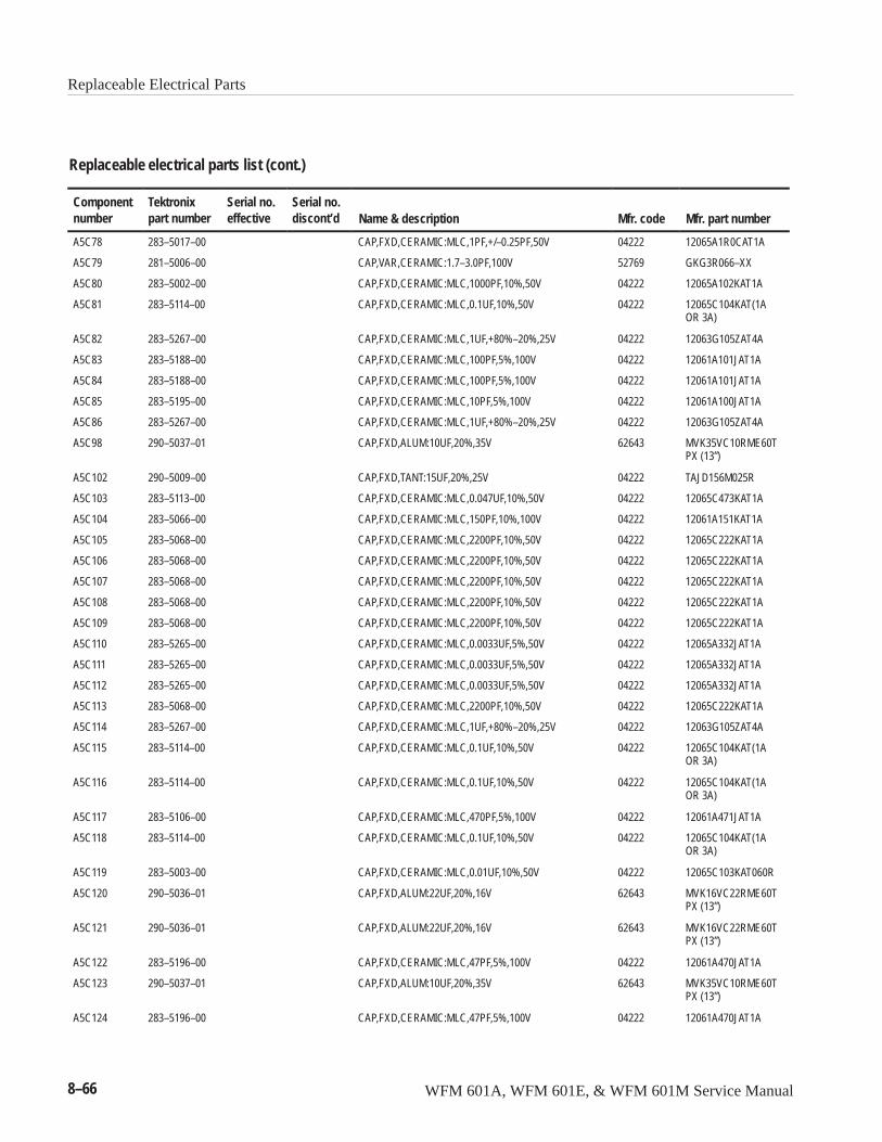
Replaceable Electrical Parts
8–66 WFM 601A, WFM 601E, & WFM 601M Service Manual
Replaceable electrical parts list (cont.)
Componentnumber Mfr. part numberMfr. codeName & description
Serial no.discont’d
Serial no.effective
Tektronixpart number
A5C78 283–5017–00 CAP,FXD,CERAMIC:MLC,1PF,+/–0.25PF,50V 04222 12065A1R0CAT1A
A5C79 281–5006–00 CAP,VAR,CERAMIC:1.7–3.0PF,100V 52769 GKG3R066–XX
A5C80 283–5002–00 CAP,FXD,CERAMIC:MLC,1000PF,10%,50V 04222 12065A102KAT1A
A5C81 283–5114–00 CAP,FXD,CERAMIC:MLC,0.1UF,10%,50V 04222 12065C104KAT(1AOR 3A)
A5C82 283–5267–00 CAP,FXD,CERAMIC:MLC,1UF,+80%–20%,25V 04222 12063G105ZAT4A
A5C83 283–5188–00 CAP,FXD,CERAMIC:MLC,100PF,5%,100V 04222 12061A101JAT1A
A5C84 283–5188–00 CAP,FXD,CERAMIC:MLC,100PF,5%,100V 04222 12061A101JAT1A
A5C85 283–5195–00 CAP,FXD,CERAMIC:MLC,10PF,5%,100V 04222 12061A100JAT1A
A5C86 283–5267–00 CAP,FXD,CERAMIC:MLC,1UF,+80%–20%,25V 04222 12063G105ZAT4A
A5C98 290–5037–01 CAP,FXD,ALUM:10UF,20%,35V 62643 MVK35VC10RME60TPX (13”)
A5C102 290–5009–00 CAP,FXD,TANT:15UF,20%,25V 04222 TAJD156M025R
A5C103 283–5113–00 CAP,FXD,CERAMIC:MLC,0.047UF,10%,50V 04222 12065C473KAT1A
A5C104 283–5066–00 CAP,FXD,CERAMIC:MLC,150PF,10%,100V 04222 12061A151KAT1A
A5C105 283–5068–00 CAP,FXD,CERAMIC:MLC,2200PF,10%,50V 04222 12065C222KAT1A
A5C106 283–5068–00 CAP,FXD,CERAMIC:MLC,2200PF,10%,50V 04222 12065C222KAT1A
A5C107 283–5068–00 CAP,FXD,CERAMIC:MLC,2200PF,10%,50V 04222 12065C222KAT1A
A5C108 283–5068–00 CAP,FXD,CERAMIC:MLC,2200PF,10%,50V 04222 12065C222KAT1A
A5C109 283–5068–00 CAP,FXD,CERAMIC:MLC,2200PF,10%,50V 04222 12065C222KAT1A
A5C110 283–5265–00 CAP,FXD,CERAMIC:MLC,0.0033UF,5%,50V 04222 12065A332JAT1A
A5C111 283–5265–00 CAP,FXD,CERAMIC:MLC,0.0033UF,5%,50V 04222 12065A332JAT1A
A5C112 283–5265–00 CAP,FXD,CERAMIC:MLC,0.0033UF,5%,50V 04222 12065A332JAT1A
A5C113 283–5068–00 CAP,FXD,CERAMIC:MLC,2200PF,10%,50V 04222 12065C222KAT1A
A5C114 283–5267–00 CAP,FXD,CERAMIC:MLC,1UF,+80%–20%,25V 04222 12063G105ZAT4A
A5C115 283–5114–00 CAP,FXD,CERAMIC:MLC,0.1UF,10%,50V 04222 12065C104KAT(1AOR 3A)
A5C116 283–5114–00 CAP,FXD,CERAMIC:MLC,0.1UF,10%,50V 04222 12065C104KAT(1AOR 3A)
A5C117 283–5106–00 CAP,FXD,CERAMIC:MLC,470PF,5%,100V 04222 12061A471JAT1A
A5C118 283–5114–00 CAP,FXD,CERAMIC:MLC,0.1UF,10%,50V 04222 12065C104KAT(1AOR 3A)
A5C119 283–5003–00 CAP,FXD,CERAMIC:MLC,0.01UF,10%,50V 04222 12065C103KAT060R
A5C120 290–5036–01 CAP,FXD,ALUM:22UF,20%,16V 62643 MVK16VC22RME60TPX (13”)
A5C121 290–5036–01 CAP,FXD,ALUM:22UF,20%,16V 62643 MVK16VC22RME60TPX (13”)
A5C122 283–5196–00 CAP,FXD,CERAMIC:MLC,47PF,5%,100V 04222 12061A470JAT1A
A5C123 290–5037–01 CAP,FXD,ALUM:10UF,20%,35V 62643 MVK35VC10RME60TPX (13”)
A5C124 283–5196–00 CAP,FXD,CERAMIC:MLC,47PF,5%,100V 04222 12061A470JAT1A
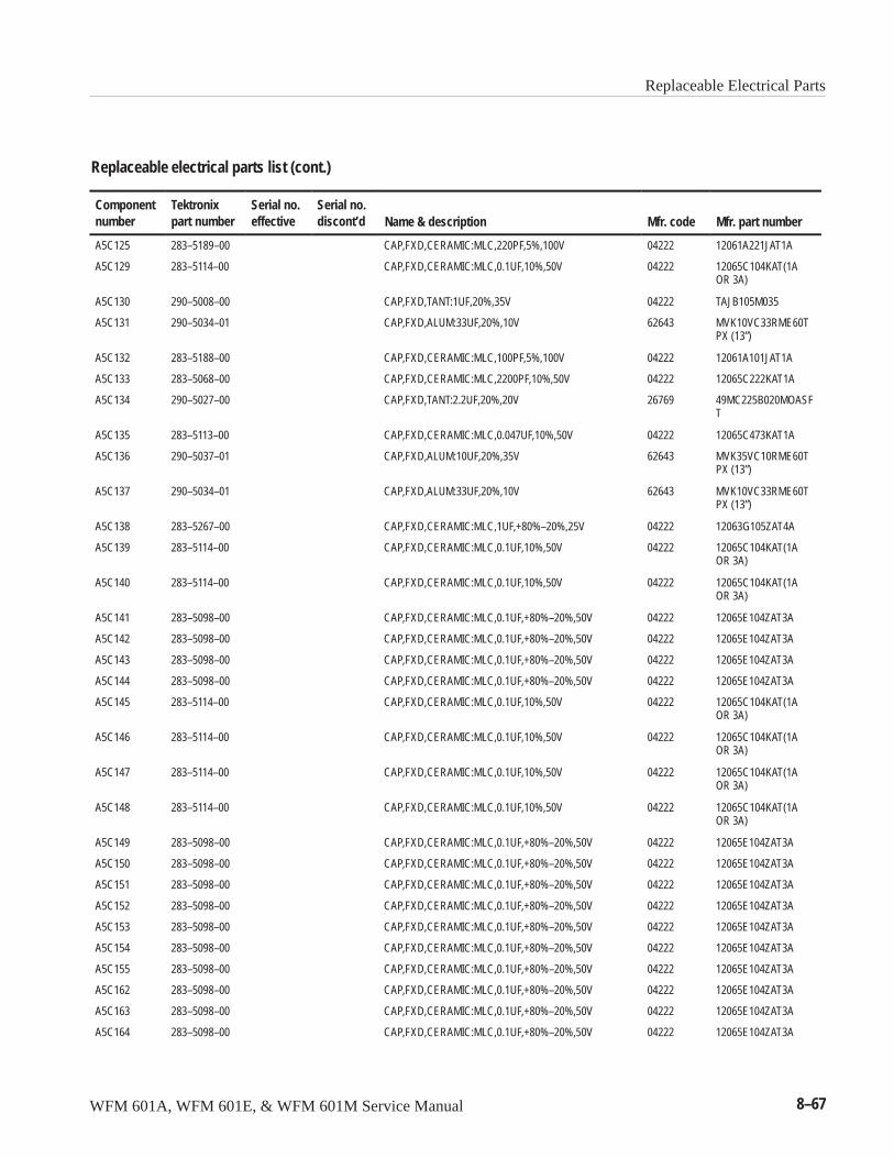
Replaceable Electrical Parts
WFM 601A, WFM 601E, & WFM 601M Service Manual 8–67
Replaceable electrical parts list (cont.)
Componentnumber Mfr. part numberMfr. codeName & description
Serial no.discont’d
Serial no.effective
Tektronixpart number
A5C125 283–5189–00 CAP,FXD,CERAMIC:MLC,220PF,5%,100V 04222 12061A221JAT1A
A5C129 283–5114–00 CAP,FXD,CERAMIC:MLC,0.1UF,10%,50V 04222 12065C104KAT(1AOR 3A)
A5C130 290–5008–00 CAP,FXD,TANT:1UF,20%,35V 04222 TAJB105M035
A5C131 290–5034–01 CAP,FXD,ALUM:33UF,20%,10V 62643 MVK10VC33RME60TPX (13”)
A5C132 283–5188–00 CAP,FXD,CERAMIC:MLC,100PF,5%,100V 04222 12061A101JAT1A
A5C133 283–5068–00 CAP,FXD,CERAMIC:MLC,2200PF,10%,50V 04222 12065C222KAT1A
A5C134 290–5027–00 CAP,FXD,TANT:2.2UF,20%,20V 26769 49MC225B020MOASFT
A5C135 283–5113–00 CAP,FXD,CERAMIC:MLC,0.047UF,10%,50V 04222 12065C473KAT1A
A5C136 290–5037–01 CAP,FXD,ALUM:10UF,20%,35V 62643 MVK35VC10RME60TPX (13”)
A5C137 290–5034–01 CAP,FXD,ALUM:33UF,20%,10V 62643 MVK10VC33RME60TPX (13”)
A5C138 283–5267–00 CAP,FXD,CERAMIC:MLC,1UF,+80%–20%,25V 04222 12063G105ZAT4A
A5C139 283–5114–00 CAP,FXD,CERAMIC:MLC,0.1UF,10%,50V 04222 12065C104KAT(1AOR 3A)
A5C140 283–5114–00 CAP,FXD,CERAMIC:MLC,0.1UF,10%,50V 04222 12065C104KAT(1AOR 3A)
A5C141 283–5098–00 CAP,FXD,CERAMIC:MLC,0.1UF,+80%–20%,50V 04222 12065E104ZAT3A
A5C142 283–5098–00 CAP,FXD,CERAMIC:MLC,0.1UF,+80%–20%,50V 04222 12065E104ZAT3A
A5C143 283–5098–00 CAP,FXD,CERAMIC:MLC,0.1UF,+80%–20%,50V 04222 12065E104ZAT3A
A5C144 283–5098–00 CAP,FXD,CERAMIC:MLC,0.1UF,+80%–20%,50V 04222 12065E104ZAT3A
A5C145 283–5114–00 CAP,FXD,CERAMIC:MLC,0.1UF,10%,50V 04222 12065C104KAT(1AOR 3A)
A5C146 283–5114–00 CAP,FXD,CERAMIC:MLC,0.1UF,10%,50V 04222 12065C104KAT(1AOR 3A)
A5C147 283–5114–00 CAP,FXD,CERAMIC:MLC,0.1UF,10%,50V 04222 12065C104KAT(1AOR 3A)
A5C148 283–5114–00 CAP,FXD,CERAMIC:MLC,0.1UF,10%,50V 04222 12065C104KAT(1AOR 3A)
A5C149 283–5098–00 CAP,FXD,CERAMIC:MLC,0.1UF,+80%–20%,50V 04222 12065E104ZAT3A
A5C150 283–5098–00 CAP,FXD,CERAMIC:MLC,0.1UF,+80%–20%,50V 04222 12065E104ZAT3A
A5C151 283–5098–00 CAP,FXD,CERAMIC:MLC,0.1UF,+80%–20%,50V 04222 12065E104ZAT3A
A5C152 283–5098–00 CAP,FXD,CERAMIC:MLC,0.1UF,+80%–20%,50V 04222 12065E104ZAT3A
A5C153 283–5098–00 CAP,FXD,CERAMIC:MLC,0.1UF,+80%–20%,50V 04222 12065E104ZAT3A
A5C154 283–5098–00 CAP,FXD,CERAMIC:MLC,0.1UF,+80%–20%,50V 04222 12065E104ZAT3A
A5C155 283–5098–00 CAP,FXD,CERAMIC:MLC,0.1UF,+80%–20%,50V 04222 12065E104ZAT3A
A5C162 283–5098–00 CAP,FXD,CERAMIC:MLC,0.1UF,+80%–20%,50V 04222 12065E104ZAT3A
A5C163 283–5098–00 CAP,FXD,CERAMIC:MLC,0.1UF,+80%–20%,50V 04222 12065E104ZAT3A
A5C164 283–5098–00 CAP,FXD,CERAMIC:MLC,0.1UF,+80%–20%,50V 04222 12065E104ZAT3A
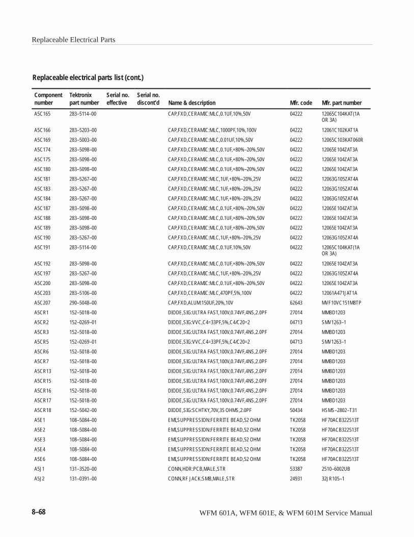
Replaceable Electrical Parts
8–68 WFM 601A, WFM 601E, & WFM 601M Service Manual
Replaceable electrical parts list (cont.)
Componentnumber Mfr. part numberMfr. codeName & description
Serial no.discont’d
Serial no.effective
Tektronixpart number
A5C165 283–5114–00 CAP,FXD,CERAMIC:MLC,0.1UF,10%,50V 04222 12065C104KAT(1AOR 3A)
A5C166 283–5203–00 CAP,FXD,CERAMIC:MLC,1000PF,10%,100V 04222 12061C102KAT1A
A5C169 283–5003–00 CAP,FXD,CERAMIC:MLC,0.01UF,10%,50V 04222 12065C103KAT060R
A5C174 283–5098–00 CAP,FXD,CERAMIC:MLC,0.1UF,+80%–20%,50V 04222 12065E104ZAT3A
A5C175 283–5098–00 CAP,FXD,CERAMIC:MLC,0.1UF,+80%–20%,50V 04222 12065E104ZAT3A
A5C180 283–5098–00 CAP,FXD,CERAMIC:MLC,0.1UF,+80%–20%,50V 04222 12065E104ZAT3A
A5C181 283–5267–00 CAP,FXD,CERAMIC:MLC,1UF,+80%–20%,25V 04222 12063G105ZAT4A
A5C183 283–5267–00 CAP,FXD,CERAMIC:MLC,1UF,+80%–20%,25V 04222 12063G105ZAT4A
A5C184 283–5267–00 CAP,FXD,CERAMIC:MLC,1UF,+80%–20%,25V 04222 12063G105ZAT4A
A5C187 283–5098–00 CAP,FXD,CERAMIC:MLC,0.1UF,+80%–20%,50V 04222 12065E104ZAT3A
A5C188 283–5098–00 CAP,FXD,CERAMIC:MLC,0.1UF,+80%–20%,50V 04222 12065E104ZAT3A
A5C189 283–5098–00 CAP,FXD,CERAMIC:MLC,0.1UF,+80%–20%,50V 04222 12065E104ZAT3A
A5C190 283–5267–00 CAP,FXD,CERAMIC:MLC,1UF,+80%–20%,25V 04222 12063G105ZAT4A
A5C191 283–5114–00 CAP,FXD,CERAMIC:MLC,0.1UF,10%,50V 04222 12065C104KAT(1AOR 3A)
A5C192 283–5098–00 CAP,FXD,CERAMIC:MLC,0.1UF,+80%–20%,50V 04222 12065E104ZAT3A
A5C197 283–5267–00 CAP,FXD,CERAMIC:MLC,1UF,+80%–20%,25V 04222 12063G105ZAT4A
A5C200 283–5098–00 CAP,FXD,CERAMIC:MLC,0.1UF,+80%–20%,50V 04222 12065E104ZAT3A
A5C203 283–5106–00 CAP,FXD,CERAMIC:MLC,470PF,5%,100V 04222 12061A471JAT1A
A5C207 290–5048–00 CAP,FXD,ALUM:150UF,20%,10V 62643 MVF10VC151M8TP
A5CR1 152–5018–00 DIODE,SIG:ULTRA FAST,100V,0.74VF,4NS,2.0PF 27014 MMBD1203
A5CR2 152–0269–01 DIODE,SIG:VVC,C4=33PF,5%,C4/C20=2 04713 SMV1263–1
A5CR3 152–5018–00 DIODE,SIG:ULTRA FAST,100V,0.74VF,4NS,2.0PF 27014 MMBD1203
A5CR5 152–0269–01 DIODE,SIG:VVC,C4=33PF,5%,C4/C20=2 04713 SMV1263–1
A5CR6 152–5018–00 DIODE,SIG:ULTRA FAST,100V,0.74VF,4NS,2.0PF 27014 MMBD1203
A5CR7 152–5018–00 DIODE,SIG:ULTRA FAST,100V,0.74VF,4NS,2.0PF 27014 MMBD1203
A5CR13 152–5018–00 DIODE,SIG:ULTRA FAST,100V,0.74VF,4NS,2.0PF 27014 MMBD1203
A5CR15 152–5018–00 DIODE,SIG:ULTRA FAST,100V,0.74VF,4NS,2.0PF 27014 MMBD1203
A5CR16 152–5018–00 DIODE,SIG:ULTRA FAST,100V,0.74VF,4NS,2.0PF 27014 MMBD1203
A5CR17 152–5018–00 DIODE,SIG:ULTRA FAST,100V,0.74VF,4NS,2.0PF 27014 MMBD1203
A5CR18 152–5042–00 DIODE,SIG:SCHTKY,70V,35 OHMS,2.0PF 50434 HSMS–2802–T31
A5E1 108–5084–00 EMI,SUPPRESSION:FERRITE BEAD,52 OHM TK2058 HF70ACB322513T
A5E2 108–5084–00 EMI,SUPPRESSION:FERRITE BEAD,52 OHM TK2058 HF70ACB322513T
A5E3 108–5084–00 EMI,SUPPRESSION:FERRITE BEAD,52 OHM TK2058 HF70ACB322513T
A5E4 108–5084–00 EMI,SUPPRESSION:FERRITE BEAD,52 OHM TK2058 HF70ACB322513T
A5E6 108–5084–00 EMI,SUPPRESSION:FERRITE BEAD,52 OHM TK2058 HF70ACB322513T
A5J1 131–3520–00 CONN,HDR:PCB,MALE,STR 53387 2510–6002UB
A5J2 131–0391–00 CONN,RF JACK:SMB,MALE,STR 24931 32JR105–1
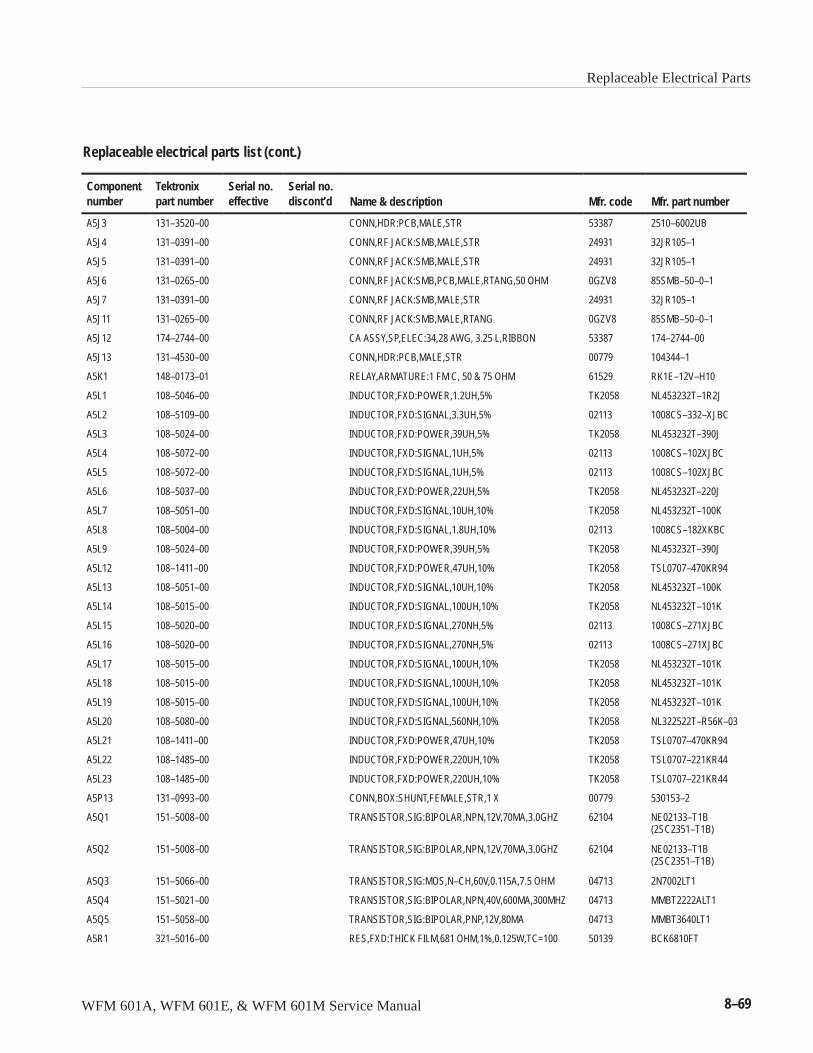
Replaceable Electrical Parts
WFM 601A, WFM 601E, & WFM 601M Service Manual 8–69
Replaceable electrical parts list (cont.)
Componentnumber Mfr. part numberMfr. codeName & description
Serial no.discont’d
Serial no.effective
Tektronixpart number
A5J3 131–3520–00 CONN,HDR:PCB,MALE,STR 53387 2510–6002UB
A5J4 131–0391–00 CONN,RF JACK:SMB,MALE,STR 24931 32JR105–1
A5J5 131–0391–00 CONN,RF JACK:SMB,MALE,STR 24931 32JR105–1
A5J6 131–0265–00 CONN,RF JACK:SMB,PCB,MALE,RTANG,50 OHM 0GZV8 85SMB–50–0–1
A5J7 131–0391–00 CONN,RF JACK:SMB,MALE,STR 24931 32JR105–1
A5J11 131–0265–00 CONN,RF JACK:SMB,MALE,RTANG 0GZV8 85SMB–50–0–1
A5J12 174–2744–00 CA ASSY,SP,ELEC:34,28 AWG, 3.25 L,RIBBON 53387 174–2744–00
A5J13 131–4530–00 CONN,HDR:PCB,MALE,STR 00779 104344–1
A5K1 148–0173–01 RELAY,ARMATURE:1 FM C, 50 & 75 OHM 61529 RK1E–12V–H10
A5L1 108–5046–00 INDUCTOR,FXD:POWER,1.2UH,5% TK2058 NL453232T–1R2J
A5L2 108–5109–00 INDUCTOR,FXD:SIGNAL,3.3UH,5% 02113 1008CS–332–XJBC
A5L3 108–5024–00 INDUCTOR,FXD:POWER,39UH,5% TK2058 NL453232T–390J
A5L4 108–5072–00 INDUCTOR,FXD:SIGNAL,1UH,5% 02113 1008CS–102XJBC
A5L5 108–5072–00 INDUCTOR,FXD:SIGNAL,1UH,5% 02113 1008CS–102XJBC
A5L6 108–5037–00 INDUCTOR,FXD:POWER,22UH,5% TK2058 NL453232T–220J
A5L7 108–5051–00 INDUCTOR,FXD:SIGNAL,10UH,10% TK2058 NL453232T–100K
A5L8 108–5004–00 INDUCTOR,FXD:SIGNAL,1.8UH,10% 02113 1008CS–182XKBC
A5L9 108–5024–00 INDUCTOR,FXD:POWER,39UH,5% TK2058 NL453232T–390J
A5L12 108–1411–00 INDUCTOR,FXD:POWER,47UH,10% TK2058 TSL0707–470KR94
A5L13 108–5051–00 INDUCTOR,FXD:SIGNAL,10UH,10% TK2058 NL453232T–100K
A5L14 108–5015–00 INDUCTOR,FXD:SIGNAL,100UH,10% TK2058 NL453232T–101K
A5L15 108–5020–00 INDUCTOR,FXD:SIGNAL,270NH,5% 02113 1008CS–271XJBC
A5L16 108–5020–00 INDUCTOR,FXD:SIGNAL,270NH,5% 02113 1008CS–271XJBC
A5L17 108–5015–00 INDUCTOR,FXD:SIGNAL,100UH,10% TK2058 NL453232T–101K
A5L18 108–5015–00 INDUCTOR,FXD:SIGNAL,100UH,10% TK2058 NL453232T–101K
A5L19 108–5015–00 INDUCTOR,FXD:SIGNAL,100UH,10% TK2058 NL453232T–101K
A5L20 108–5080–00 INDUCTOR,FXD:SIGNAL,560NH,10% TK2058 NL322522T–R56K–03
A5L21 108–1411–00 INDUCTOR,FXD:POWER,47UH,10% TK2058 TSL0707–470KR94
A5L22 108–1485–00 INDUCTOR,FXD:POWER,220UH,10% TK2058 TSL0707–221KR44
A5L23 108–1485–00 INDUCTOR,FXD:POWER,220UH,10% TK2058 TSL0707–221KR44
A5P13 131–0993–00 CONN,BOX:SHUNT,FEMALE,STR,1 X 00779 530153–2
A5Q1 151–5008–00 TRANSISTOR,SIG:BIPOLAR,NPN,12V,70MA,3.0GHZ 62104 NE02133–T1B(2SC2351–T1B)
A5Q2 151–5008–00 TRANSISTOR,SIG:BIPOLAR,NPN,12V,70MA,3.0GHZ 62104 NE02133–T1B(2SC2351–T1B)
A5Q3 151–5066–00 TRANSISTOR,SIG:MOS,N–CH,60V,0.115A,7.5 OHM 04713 2N7002LT1
A5Q4 151–5021–00 TRANSISTOR,SIG:BIPOLAR,NPN,40V,600MA,300MHZ 04713 MMBT2222ALT1
A5Q5 151–5058–00 TRANSISTOR,SIG:BIPOLAR,PNP,12V,80MA 04713 MMBT3640LT1
A5R1 321–5016–00 RES,FXD:THICK FILM,681 OHM,1%,0.125W,TC=100 50139 BCK6810FT
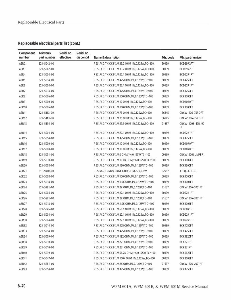
Replaceable Electrical Parts
8–70 WFM 601A, WFM 601E, & WFM 601M Service Manual
Replaceable electrical parts list (cont.)
Componentnumber Mfr. part numberMfr. codeName & description
Serial no.discont’d
Serial no.effective
Tektronixpart number
A5R2 321–5042–00 RES,FXD:THICK FILM,39.2 OHM,1%,0.125W,TC=100 50139 BCD39R2FT
A5R3 321–5042–00 RES,FXD:THICK FILM,39.2 OHM,1%,0.125W,TC=100 50139 BCD39R2FT
A5R4 321–5004–00 RES,FXD:THICK FILM,22.1 OHM,1%,0.125W,TC=100 50139 BCD22R1FT
A5R5 321–5014–00 RES,FXD:THICK FILM,475 OHM,1%,0.125W,TC=100 50139 BCK4750FT
A5R6 321–5004–00 RES,FXD:THICK FILM,22.1 OHM,1%,0.125W,TC=100 50139 BCD22R1FT
A5R7 321–5014–00 RES,FXD:THICK FILM,475 OHM,1%,0.125W,TC=100 50139 BCK4750FT
A5R8 321–5006–00 RES,FXD:THICK FILM,100 OHM,1%,0.125W,TC=100 50139 BCK1000FT
A5R9 321–5000–00 RES,FXD:THICK FILM,10 OHM,1%,0.125W,TC=100 50139 BCD10R0FT
A5R10 321–5006–00 RES,FXD:THICK FILM,100 OHM,1%,0.125W,TC=100 50139 BCK1000FT
A5R11 321–5113–00 RES,FXD:THICK FILM,75 OHM,1%,0.125W,TC=100 56845 CRCW1206–75ROFT
A5R12 321–5113–00 RES,FXD:THICK FILM,75 OHM,1%,0.125W,TC=100 56845 CRCW1206–75ROFT
A5R13 321–5194–00 RES,FXD:THICK FILM,49.9 OHM,1%,0.125W,TC=100 91637 CRCW–1206–49R–90–FT
A5R14 321–5004–00 RES,FXD:THICK FILM,22.1 OHM,1%,0.125W,TC=100 50139 BCD22R1FT
A5R15 321–5014–00 RES,FXD:THICK FILM,475 OHM,1%,0.125W,TC=100 50139 BCK4750FT
A5R16 321–5000–00 RES,FXD:THICK FILM,10 OHM,1%,0.125W,TC=100 50139 BCD10R0FT
A5R17 321–5000–00 RES,FXD:THICK FILM,10 OHM,1%,0.125W,TC=100 50139 BCD10R0FT
A5R18 321–5051–00 RES,FXD:THICK FILM,0 OHM,1%,0.125W,TC=100 09969 CRCW1206 JUMPER
A5R19 321–5030–00 RES,FXD:THICK FILM,10.0K OHM,1%,0.125W,TC=100 50139 BCK1002FT
A5R20 321–5008–00 RES,FXD:THICK FILM,150 OHM,1%,0.125W,TC=100 50139 BCK1500FT
A5R21 311–5040–00 RES,VAR,TRMR:CERMET,10K OHM,25%,0.1W 32997 3314J–1–103E
A5R22 321–5008–00 RES,FXD:THICK FILM,150 OHM,1%,0.125W,TC=100 50139 BCK1500FT
A5R23 321–5018–00 RES,FXD:THICK FILM,1.0K OHM,1%,0.125W,TC=100 50139 BCK1001FT
A5R24 321–5281–00 RES,FXD:THICK FILM,2K OHM,1%,0.125W,TC=100 91637 CRCW1206–2001FT
A5R25 321–5004–00 RES,FXD:THICK FILM,22.1 OHM,1%,0.125W,TC=100 50139 BCD22R1FT
A5R26 321–5281–00 RES,FXD:THICK FILM,2K OHM,1%,0.125W,TC=100 91637 CRCW1206–2001FT
A5R27 321–5018–00 RES,FXD:THICK FILM,1.0K OHM,1%,0.125W,TC=100 50139 BCK1001FT
A5R28 321–5045–00 RES,FXD:THICK FILM,68.1 OHM,1%,0.125W,TC=100 50139 BCD68R1FT
A5R29 321–5004–00 RES,FXD:THICK FILM,22.1 OHM,1%,0.125W,TC=100 50139 BCD22R1FT
A5R30 321–5004–00 RES,FXD:THICK FILM,22.1 OHM,1%,0.125W,TC=100 50139 BCD22R1FT
A5R32 321–5014–00 RES,FXD:THICK FILM,475 OHM,1%,0.125W,TC=100 50139 BCK4750FT
A5R33 321–5014–00 RES,FXD:THICK FILM,475 OHM,1%,0.125W,TC=100 50139 BCK4750FT
A5R34 321–5009–00 RES,FXD:THICK FILM,182 OHM,1%,0.125W,TC=100 50139 BCK1820FT
A5R38 321–5010–00 RES,FXD:THICK FILM,221 OHM,1%,0.125W,TC=100 50139 BCK221FT
A5R39 321–5010–00 RES,FXD:THICK FILM,221 OHM,1%,0.125W,TC=100 50139 BCK221FT
A5R40 321–5039–00 RES,FXD:THICK FILM,56.2K OHM,1%,0.125W,TC=100 50139 BCK5622FT
A5R41 321–5047–00 RES,FXD:THICK FILM,100K OHM,1%,0.125W,TC=100 50139 BCK1003FT
A5R42 321–5281–00 RES,FXD:THICK FILM,2K OHM,1%,0.125W,TC=100 91637 CRCW1206–2001FT
A5R43 321–5014–00 RES,FXD:THICK FILM,475 OHM,1%,0.125W,TC=100 50139 BCK4750FT
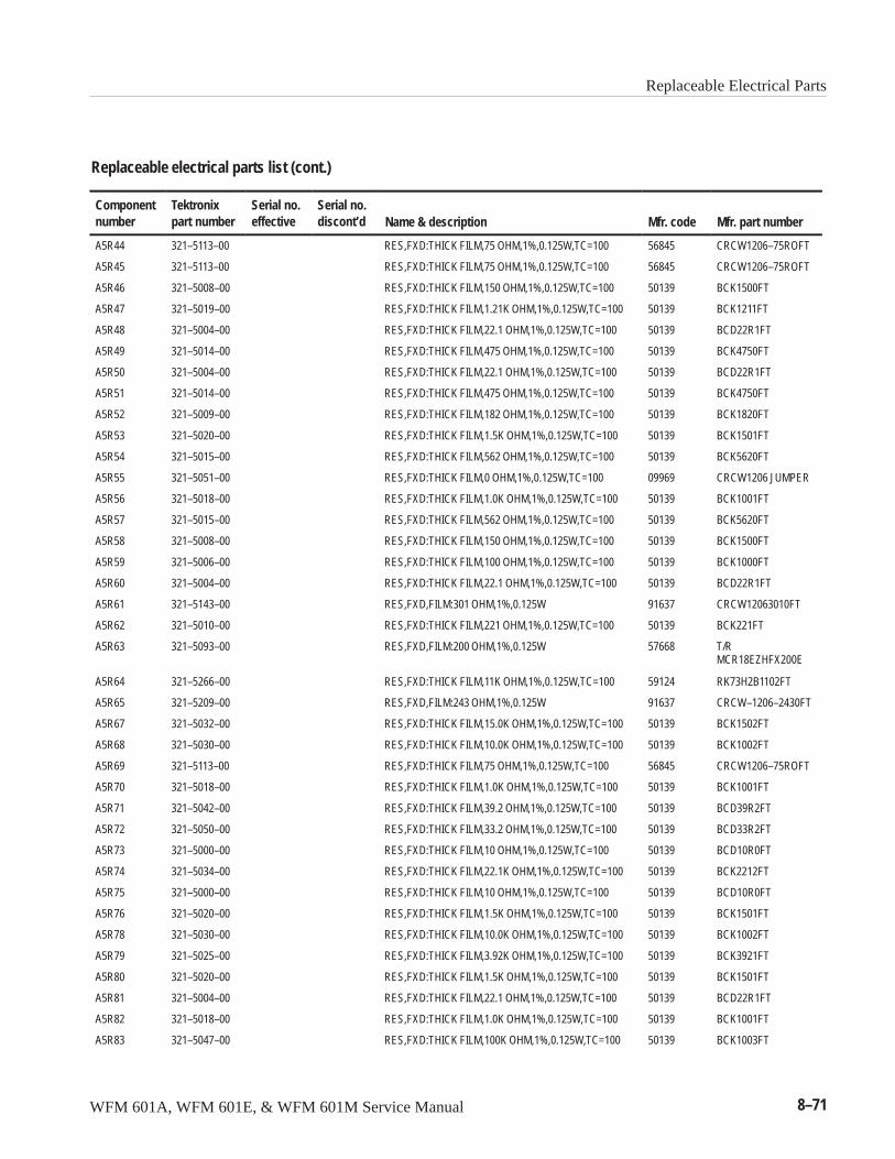
Replaceable Electrical Parts
WFM 601A, WFM 601E, & WFM 601M Service Manual 8–71
Replaceable electrical parts list (cont.)
Componentnumber Mfr. part numberMfr. codeName & description
Serial no.discont’d
Serial no.effective
Tektronixpart number
A5R44 321–5113–00 RES,FXD:THICK FILM,75 OHM,1%,0.125W,TC=100 56845 CRCW1206–75ROFT
A5R45 321–5113–00 RES,FXD:THICK FILM,75 OHM,1%,0.125W,TC=100 56845 CRCW1206–75ROFT
A5R46 321–5008–00 RES,FXD:THICK FILM,150 OHM,1%,0.125W,TC=100 50139 BCK1500FT
A5R47 321–5019–00 RES,FXD:THICK FILM,1.21K OHM,1%,0.125W,TC=100 50139 BCK1211FT
A5R48 321–5004–00 RES,FXD:THICK FILM,22.1 OHM,1%,0.125W,TC=100 50139 BCD22R1FT
A5R49 321–5014–00 RES,FXD:THICK FILM,475 OHM,1%,0.125W,TC=100 50139 BCK4750FT
A5R50 321–5004–00 RES,FXD:THICK FILM,22.1 OHM,1%,0.125W,TC=100 50139 BCD22R1FT
A5R51 321–5014–00 RES,FXD:THICK FILM,475 OHM,1%,0.125W,TC=100 50139 BCK4750FT
A5R52 321–5009–00 RES,FXD:THICK FILM,182 OHM,1%,0.125W,TC=100 50139 BCK1820FT
A5R53 321–5020–00 RES,FXD:THICK FILM,1.5K OHM,1%,0.125W,TC=100 50139 BCK1501FT
A5R54 321–5015–00 RES,FXD:THICK FILM,562 OHM,1%,0.125W,TC=100 50139 BCK5620FT
A5R55 321–5051–00 RES,FXD:THICK FILM,0 OHM,1%,0.125W,TC=100 09969 CRCW1206 JUMPER
A5R56 321–5018–00 RES,FXD:THICK FILM,1.0K OHM,1%,0.125W,TC=100 50139 BCK1001FT
A5R57 321–5015–00 RES,FXD:THICK FILM,562 OHM,1%,0.125W,TC=100 50139 BCK5620FT
A5R58 321–5008–00 RES,FXD:THICK FILM,150 OHM,1%,0.125W,TC=100 50139 BCK1500FT
A5R59 321–5006–00 RES,FXD:THICK FILM,100 OHM,1%,0.125W,TC=100 50139 BCK1000FT
A5R60 321–5004–00 RES,FXD:THICK FILM,22.1 OHM,1%,0.125W,TC=100 50139 BCD22R1FT
A5R61 321–5143–00 RES,FXD,FILM:301 OHM,1%,0.125W 91637 CRCW12063010FT
A5R62 321–5010–00 RES,FXD:THICK FILM,221 OHM,1%,0.125W,TC=100 50139 BCK221FT
A5R63 321–5093–00 RES,FXD,FILM:200 OHM,1%,0.125W 57668 T/RMCR18EZHFX200E
A5R64 321–5266–00 RES,FXD:THICK FILM,11K OHM,1%,0.125W,TC=100 59124 RK73H2B1102FT
A5R65 321–5209–00 RES,FXD,FILM:243 OHM,1%,0.125W 91637 CRCW–1206–2430FT
A5R67 321–5032–00 RES,FXD:THICK FILM,15.0K OHM,1%,0.125W,TC=100 50139 BCK1502FT
A5R68 321–5030–00 RES,FXD:THICK FILM,10.0K OHM,1%,0.125W,TC=100 50139 BCK1002FT
A5R69 321–5113–00 RES,FXD:THICK FILM,75 OHM,1%,0.125W,TC=100 56845 CRCW1206–75ROFT
A5R70 321–5018–00 RES,FXD:THICK FILM,1.0K OHM,1%,0.125W,TC=100 50139 BCK1001FT
A5R71 321–5042–00 RES,FXD:THICK FILM,39.2 OHM,1%,0.125W,TC=100 50139 BCD39R2FT
A5R72 321–5050–00 RES,FXD:THICK FILM,33.2 OHM,1%,0.125W,TC=100 50139 BCD33R2FT
A5R73 321–5000–00 RES,FXD:THICK FILM,10 OHM,1%,0.125W,TC=100 50139 BCD10R0FT
A5R74 321–5034–00 RES,FXD:THICK FILM,22.1K OHM,1%,0.125W,TC=100 50139 BCK2212FT
A5R75 321–5000–00 RES,FXD:THICK FILM,10 OHM,1%,0.125W,TC=100 50139 BCD10R0FT
A5R76 321–5020–00 RES,FXD:THICK FILM,1.5K OHM,1%,0.125W,TC=100 50139 BCK1501FT
A5R78 321–5030–00 RES,FXD:THICK FILM,10.0K OHM,1%,0.125W,TC=100 50139 BCK1002FT
A5R79 321–5025–00 RES,FXD:THICK FILM,3.92K OHM,1%,0.125W,TC=100 50139 BCK3921FT
A5R80 321–5020–00 RES,FXD:THICK FILM,1.5K OHM,1%,0.125W,TC=100 50139 BCK1501FT
A5R81 321–5004–00 RES,FXD:THICK FILM,22.1 OHM,1%,0.125W,TC=100 50139 BCD22R1FT
A5R82 321–5018–00 RES,FXD:THICK FILM,1.0K OHM,1%,0.125W,TC=100 50139 BCK1001FT
A5R83 321–5047–00 RES,FXD:THICK FILM,100K OHM,1%,0.125W,TC=100 50139 BCK1003FT
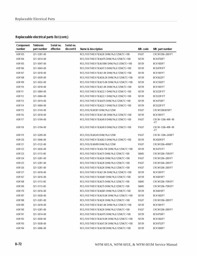
Replaceable Electrical Parts
8–72 WFM 601A, WFM 601E, & WFM 601M Service Manual
Replaceable electrical parts list (cont.)
Componentnumber Mfr. part numberMfr. codeName & description
Serial no.discont’d
Serial no.effective
Tektronixpart number
A5R103 321–5281–00 RES,FXD:THICK FILM,2K OHM,1%,0.125W,TC=100 91637 CRCW1206–2001FT
A5R104 321–5014–00 RES,FXD:THICK FILM,475 OHM,1%,0.125W,TC=100 50139 BCK4750FT
A5R105 321–5047–00 RES,FXD:THICK FILM,100K OHM,1%,0.125W,TC=100 50139 BCK1003FT
A5R106 321–5043–00 RES,FXD:THICK FILM,47.5 OHM,1%,0.125W,TC=100 50139 BCD47R5FT
A5R107 321–5018–00 RES,FXD:THICK FILM,1.0K OHM,1%,0.125W,TC=100 50139 BCK1001FT
A5R108 321–5039–00 RES,FXD:THICK FILM,56.2K OHM,1%,0.125W,TC=100 50139 BCK5622FT
A5R109 321–5032–00 RES,FXD:THICK FILM,15.0K OHM,1%,0.125W,TC=100 50139 BCK1502FT
A5R110 321–5018–00 RES,FXD:THICK FILM,1.0K OHM,1%,0.125W,TC=100 50139 BCK1001FT
A5R111 321–5004–00 RES,FXD:THICK FILM,22.1 OHM,1%,0.125W,TC=100 50139 BCD22R1FT
A5R112 321–5004–00 RES,FXD:THICK FILM,22.1 OHM,1%,0.125W,TC=100 50139 BCD22R1FT
A5R113 321–5014–00 RES,FXD:THICK FILM,475 OHM,1%,0.125W,TC=100 50139 BCK4750FT
A5R114 321–5004–00 RES,FXD:THICK FILM,22.1 OHM,1%,0.125W,TC=100 50139 BCD22R1FT
A5R115 321–5143–00 RES,FXD,FILM:301 OHM,1%,0.125W 91637 CRCW12063010FT
A5R116 321–5018–00 RES,FXD:THICK FILM,1.0K OHM,1%,0.125W,TC=100 50139 BCK1001FT
A5R117 321–5194–00 RES,FXD:THICK FILM,49.9 OHM,1%,0.125W,TC=100 91637 CRCW–1206–49R–90–FT
A5R118 321–5194–00 RES,FXD:THICK FILM,49.9 OHM,1%,0.125W,TC=100 91637 CRCW–1206–49R–90–FT
A5R119 321–5209–00 RES,FXD,FILM:243 OHM,1%,0.125W 91637 CRCW–1206–2430FT
A5R120 321–5046–00 RES,FXD:THICK FILM,82.5 OHM,1%,0.125W,TC=100 50139 BCK82R5FT
A5R121 321–5122–00 RES,FXD,FILM:499 OHM,1%,0.125W 91637 CRCW1206–4990FT
A5R122 321–5026–00 RES,FXD:THICK FILM,4.75K OHM,1%,0.125W,TC=100 50139 BCK4751FT
A5R123 321–5113–00 RES,FXD:THICK FILM,75 OHM,1%,0.125W,TC=100 56845 CRCW1206–75ROFT
A5R124 321–5281–00 RES,FXD:THICK FILM,2K OHM,1%,0.125W,TC=100 91637 CRCW1206–2001FT
A5R125 321–5281–00 RES,FXD:THICK FILM,2K OHM,1%,0.125W,TC=100 91637 CRCW1206–2001FT
A5R126 321–5281–00 RES,FXD:THICK FILM,2K OHM,1%,0.125W,TC=100 91637 CRCW1206–2001FT
A5R127 321–5018–00 RES,FXD:THICK FILM,1.0K OHM,1%,0.125W,TC=100 50139 BCK1001FT
A5R167 321–5016–00 RES,FXD:THICK FILM,681 OHM,1%,0.125W,TC=100 50139 BCK6810FT
A5R168 321–5113–00 RES,FXD:THICK FILM,75 OHM,1%,0.125W,TC=100 56845 CRCW1206–75ROFT
A5R169 321–5113–00 RES,FXD:THICK FILM,75 OHM,1%,0.125W,TC=100 56845 CRCW1206–75ROFT
A5R170 321–5016–00 RES,FXD:THICK FILM,681 OHM,1%,0.125W,TC=100 50139 BCK6810FT
A5R187 321–5030–00 RES,FXD:THICK FILM,10.0K OHM,1%,0.125W,TC=100 50139 BCK1002FT
A5R188 321–5281–00 RES,FXD:THICK FILM,2K OHM,1%,0.125W,TC=100 91637 CRCW1206–2001FT
A5R189 321–5018–00 RES,FXD:THICK FILM,1.0K OHM,1%,0.125W,TC=100 50139 BCK1001FT
A5R190 321–5281–00 RES,FXD:THICK FILM,2K OHM,1%,0.125W,TC=100 91637 CRCW1206–2001FT
A5R191 321–5014–00 RES,FXD:THICK FILM,475 OHM,1%,0.125W,TC=100 50139 BCK4750FT
A5R192 321–5030–00 RES,FXD:THICK FILM,10.0K OHM,1%,0.125W,TC=100 50139 BCK1002FT
A5R193 321–5038–00 RES,FXD:THICK FILM,47.5K OHM,1%,0.125W,TC=100 50139 BCK4752FT
A5R194 321–5006–00 RES,FXD:THICK FILM,100 OHM,1%,0.125W,TC=100 50139 BCK1000FT
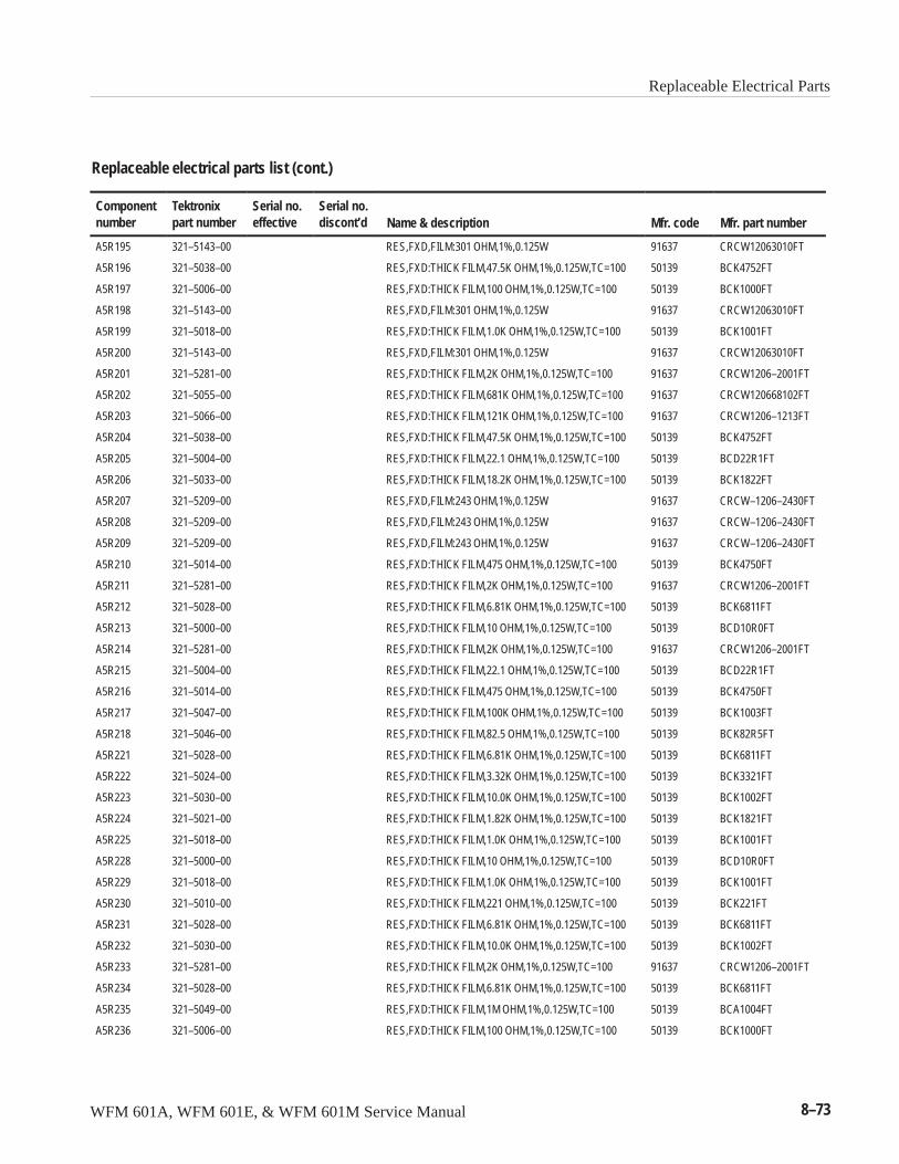
Replaceable Electrical Parts
WFM 601A, WFM 601E, & WFM 601M Service Manual 8–73
Replaceable electrical parts list (cont.)
Componentnumber Mfr. part numberMfr. codeName & description
Serial no.discont’d
Serial no.effective
Tektronixpart number
A5R195 321–5143–00 RES,FXD,FILM:301 OHM,1%,0.125W 91637 CRCW12063010FT
A5R196 321–5038–00 RES,FXD:THICK FILM,47.5K OHM,1%,0.125W,TC=100 50139 BCK4752FT
A5R197 321–5006–00 RES,FXD:THICK FILM,100 OHM,1%,0.125W,TC=100 50139 BCK1000FT
A5R198 321–5143–00 RES,FXD,FILM:301 OHM,1%,0.125W 91637 CRCW12063010FT
A5R199 321–5018–00 RES,FXD:THICK FILM,1.0K OHM,1%,0.125W,TC=100 50139 BCK1001FT
A5R200 321–5143–00 RES,FXD,FILM:301 OHM,1%,0.125W 91637 CRCW12063010FT
A5R201 321–5281–00 RES,FXD:THICK FILM,2K OHM,1%,0.125W,TC=100 91637 CRCW1206–2001FT
A5R202 321–5055–00 RES,FXD:THICK FILM,681K OHM,1%,0.125W,TC=100 91637 CRCW120668102FT
A5R203 321–5066–00 RES,FXD:THICK FILM,121K OHM,1%,0.125W,TC=100 91637 CRCW1206–1213FT
A5R204 321–5038–00 RES,FXD:THICK FILM,47.5K OHM,1%,0.125W,TC=100 50139 BCK4752FT
A5R205 321–5004–00 RES,FXD:THICK FILM,22.1 OHM,1%,0.125W,TC=100 50139 BCD22R1FT
A5R206 321–5033–00 RES,FXD:THICK FILM,18.2K OHM,1%,0.125W,TC=100 50139 BCK1822FT
A5R207 321–5209–00 RES,FXD,FILM:243 OHM,1%,0.125W 91637 CRCW–1206–2430FT
A5R208 321–5209–00 RES,FXD,FILM:243 OHM,1%,0.125W 91637 CRCW–1206–2430FT
A5R209 321–5209–00 RES,FXD,FILM:243 OHM,1%,0.125W 91637 CRCW–1206–2430FT
A5R210 321–5014–00 RES,FXD:THICK FILM,475 OHM,1%,0.125W,TC=100 50139 BCK4750FT
A5R211 321–5281–00 RES,FXD:THICK FILM,2K OHM,1%,0.125W,TC=100 91637 CRCW1206–2001FT
A5R212 321–5028–00 RES,FXD:THICK FILM,6.81K OHM,1%,0.125W,TC=100 50139 BCK6811FT
A5R213 321–5000–00 RES,FXD:THICK FILM,10 OHM,1%,0.125W,TC=100 50139 BCD10R0FT
A5R214 321–5281–00 RES,FXD:THICK FILM,2K OHM,1%,0.125W,TC=100 91637 CRCW1206–2001FT
A5R215 321–5004–00 RES,FXD:THICK FILM,22.1 OHM,1%,0.125W,TC=100 50139 BCD22R1FT
A5R216 321–5014–00 RES,FXD:THICK FILM,475 OHM,1%,0.125W,TC=100 50139 BCK4750FT
A5R217 321–5047–00 RES,FXD:THICK FILM,100K OHM,1%,0.125W,TC=100 50139 BCK1003FT
A5R218 321–5046–00 RES,FXD:THICK FILM,82.5 OHM,1%,0.125W,TC=100 50139 BCK82R5FT
A5R221 321–5028–00 RES,FXD:THICK FILM,6.81K OHM,1%,0.125W,TC=100 50139 BCK6811FT
A5R222 321–5024–00 RES,FXD:THICK FILM,3.32K OHM,1%,0.125W,TC=100 50139 BCK3321FT
A5R223 321–5030–00 RES,FXD:THICK FILM,10.0K OHM,1%,0.125W,TC=100 50139 BCK1002FT
A5R224 321–5021–00 RES,FXD:THICK FILM,1.82K OHM,1%,0.125W,TC=100 50139 BCK1821FT
A5R225 321–5018–00 RES,FXD:THICK FILM,1.0K OHM,1%,0.125W,TC=100 50139 BCK1001FT
A5R228 321–5000–00 RES,FXD:THICK FILM,10 OHM,1%,0.125W,TC=100 50139 BCD10R0FT
A5R229 321–5018–00 RES,FXD:THICK FILM,1.0K OHM,1%,0.125W,TC=100 50139 BCK1001FT
A5R230 321–5010–00 RES,FXD:THICK FILM,221 OHM,1%,0.125W,TC=100 50139 BCK221FT
A5R231 321–5028–00 RES,FXD:THICK FILM,6.81K OHM,1%,0.125W,TC=100 50139 BCK6811FT
A5R232 321–5030–00 RES,FXD:THICK FILM,10.0K OHM,1%,0.125W,TC=100 50139 BCK1002FT
A5R233 321–5281–00 RES,FXD:THICK FILM,2K OHM,1%,0.125W,TC=100 91637 CRCW1206–2001FT
A5R234 321–5028–00 RES,FXD:THICK FILM,6.81K OHM,1%,0.125W,TC=100 50139 BCK6811FT
A5R235 321–5049–00 RES,FXD:THICK FILM,1M OHM,1%,0.125W,TC=100 50139 BCA1004FT
A5R236 321–5006–00 RES,FXD:THICK FILM,100 OHM,1%,0.125W,TC=100 50139 BCK1000FT
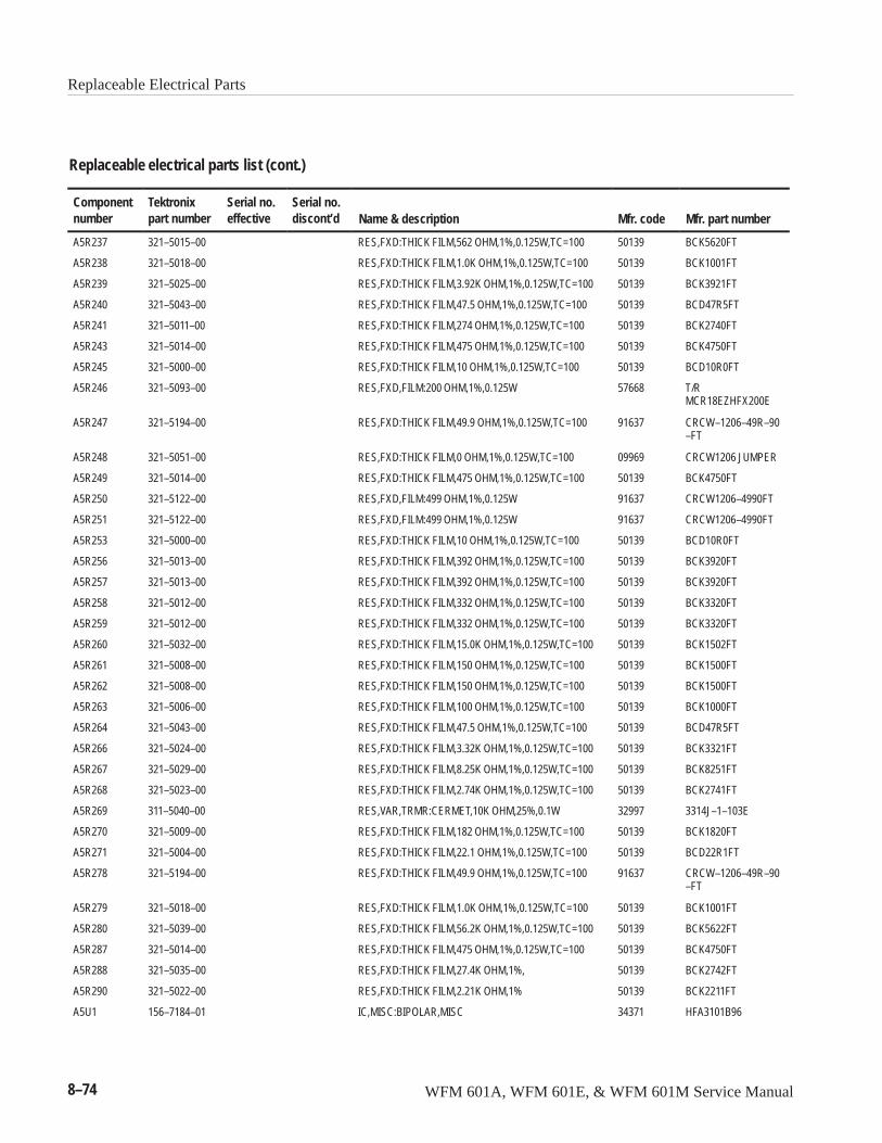
Replaceable Electrical Parts
8–74 WFM 601A, WFM 601E, & WFM 601M Service Manual
Replaceable electrical parts list (cont.)
Componentnumber Mfr. part numberMfr. codeName & description
Serial no.discont’d
Serial no.effective
Tektronixpart number
A5R237 321–5015–00 RES,FXD:THICK FILM,562 OHM,1%,0.125W,TC=100 50139 BCK5620FT
A5R238 321–5018–00 RES,FXD:THICK FILM,1.0K OHM,1%,0.125W,TC=100 50139 BCK1001FT
A5R239 321–5025–00 RES,FXD:THICK FILM,3.92K OHM,1%,0.125W,TC=100 50139 BCK3921FT
A5R240 321–5043–00 RES,FXD:THICK FILM,47.5 OHM,1%,0.125W,TC=100 50139 BCD47R5FT
A5R241 321–5011–00 RES,FXD:THICK FILM,274 OHM,1%,0.125W,TC=100 50139 BCK2740FT
A5R243 321–5014–00 RES,FXD:THICK FILM,475 OHM,1%,0.125W,TC=100 50139 BCK4750FT
A5R245 321–5000–00 RES,FXD:THICK FILM,10 OHM,1%,0.125W,TC=100 50139 BCD10R0FT
A5R246 321–5093–00 RES,FXD,FILM:200 OHM,1%,0.125W 57668 T/RMCR18EZHFX200E
A5R247 321–5194–00 RES,FXD:THICK FILM,49.9 OHM,1%,0.125W,TC=100 91637 CRCW–1206–49R–90–FT
A5R248 321–5051–00 RES,FXD:THICK FILM,0 OHM,1%,0.125W,TC=100 09969 CRCW1206 JUMPER
A5R249 321–5014–00 RES,FXD:THICK FILM,475 OHM,1%,0.125W,TC=100 50139 BCK4750FT
A5R250 321–5122–00 RES,FXD,FILM:499 OHM,1%,0.125W 91637 CRCW1206–4990FT
A5R251 321–5122–00 RES,FXD,FILM:499 OHM,1%,0.125W 91637 CRCW1206–4990FT
A5R253 321–5000–00 RES,FXD:THICK FILM,10 OHM,1%,0.125W,TC=100 50139 BCD10R0FT
A5R256 321–5013–00 RES,FXD:THICK FILM,392 OHM,1%,0.125W,TC=100 50139 BCK3920FT
A5R257 321–5013–00 RES,FXD:THICK FILM,392 OHM,1%,0.125W,TC=100 50139 BCK3920FT
A5R258 321–5012–00 RES,FXD:THICK FILM,332 OHM,1%,0.125W,TC=100 50139 BCK3320FT
A5R259 321–5012–00 RES,FXD:THICK FILM,332 OHM,1%,0.125W,TC=100 50139 BCK3320FT
A5R260 321–5032–00 RES,FXD:THICK FILM,15.0K OHM,1%,0.125W,TC=100 50139 BCK1502FT
A5R261 321–5008–00 RES,FXD:THICK FILM,150 OHM,1%,0.125W,TC=100 50139 BCK1500FT
A5R262 321–5008–00 RES,FXD:THICK FILM,150 OHM,1%,0.125W,TC=100 50139 BCK1500FT
A5R263 321–5006–00 RES,FXD:THICK FILM,100 OHM,1%,0.125W,TC=100 50139 BCK1000FT
A5R264 321–5043–00 RES,FXD:THICK FILM,47.5 OHM,1%,0.125W,TC=100 50139 BCD47R5FT
A5R266 321–5024–00 RES,FXD:THICK FILM,3.32K OHM,1%,0.125W,TC=100 50139 BCK3321FT
A5R267 321–5029–00 RES,FXD:THICK FILM,8.25K OHM,1%,0.125W,TC=100 50139 BCK8251FT
A5R268 321–5023–00 RES,FXD:THICK FILM,2.74K OHM,1%,0.125W,TC=100 50139 BCK2741FT
A5R269 311–5040–00 RES,VAR,TRMR:CERMET,10K OHM,25%,0.1W 32997 3314J–1–103E
A5R270 321–5009–00 RES,FXD:THICK FILM,182 OHM,1%,0.125W,TC=100 50139 BCK1820FT
A5R271 321–5004–00 RES,FXD:THICK FILM,22.1 OHM,1%,0.125W,TC=100 50139 BCD22R1FT
A5R278 321–5194–00 RES,FXD:THICK FILM,49.9 OHM,1%,0.125W,TC=100 91637 CRCW–1206–49R–90–FT
A5R279 321–5018–00 RES,FXD:THICK FILM,1.0K OHM,1%,0.125W,TC=100 50139 BCK1001FT
A5R280 321–5039–00 RES,FXD:THICK FILM,56.2K OHM,1%,0.125W,TC=100 50139 BCK5622FT
A5R287 321–5014–00 RES,FXD:THICK FILM,475 OHM,1%,0.125W,TC=100 50139 BCK4750FT
A5R288 321–5035–00 RES,FXD:THICK FILM,27.4K OHM,1%, 50139 BCK2742FT
A5R290 321–5022–00 RES,FXD:THICK FILM,2.21K OHM,1% 50139 BCK2211FT
A5U1 156–7184–01 IC,MISC:BIPOLAR,MISC 34371 HFA3101B96
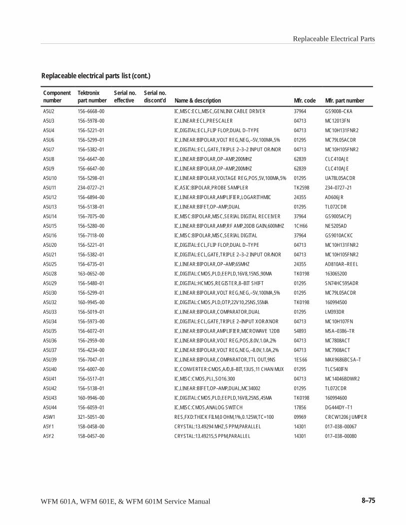
Replaceable Electrical Parts
WFM 601A, WFM 601E, & WFM 601M Service Manual 8–75
Replaceable electrical parts list (cont.)
Componentnumber Mfr. part numberMfr. codeName & description
Serial no.discont’d
Serial no.effective
Tektronixpart number
A5U2 156–6668–00 IC,MISC:ECL,MISC,GENLINX CABLE DRIVER 37964 GS9008–CKA
A5U3 156–5978–00 IC,LINEAR:ECL,PRESCALER 04713 MC12013FN
A5U4 156–5221–01 IC,DIGITAL:ECL,FLIP FLOP,DUAL D–TYPE 04713 MC10H131FNR2
A5U6 156–5299–01 IC,LINEAR:BIPOLAR,VOLT REG,NEG,–5V,100MA,5% 01295 MC79L05ACDR
A5U7 156–5382–01 IC,DIGITAL:ECL,GATE,TRIPLE 2–3–2 INPUT OR/NOR 04713 MC10H105FNR2
A5U8 156–6647–00 IC,LINEAR:BIPOLAR,OP–AMP,200MHZ 62839 CLC410AJE
A5U9 156–6647–00 IC,LINEAR:BIPOLAR,OP–AMP,200MHZ 62839 CLC410AJE
A5U10 156–5298–01 IC,LINEAR:BIPOLAR,VOLTAGE REG,POS,5V,100MA,5% 01295 UA78L05ACDR
A5U11 234–0727–21 IC,ASIC:BIPOLAR,PROBE SAMPLER TK2598 234–0727–21
A5U12 156–6894–00 IC,LINEAR:BIPOLAR,AMPLIFIER,LOGARITHMIC 24355 AD606JR
A5U13 156–5138–01 IC,LINEAR:BIFET,OP–AMP,DUAL 01295 TL072CDR
A5U14 156–7075–00 IC,MISC:BIPOLAR,MISC,SERIAL DIGITAL RECEIVER 37964 GS9005ACPJ
A5U15 156–5280–00 IC,LINEAR:BIPOLAR,AMP,RF AMP,20DB GAIN,600MHZ 1CH66 NE5205AD
A5U16 156–7118–00 IC,MISC:BIPOLAR,MISC,SERIAL DIGITAL 37964 GS9010ACKC
A5U20 156–5221–01 IC,DIGITAL:ECL,FLIP FLOP,DUAL D–TYPE 04713 MC10H131FNR2
A5U21 156–5382–01 IC,DIGITAL:ECL,GATE,TRIPLE 2–3–2 INPUT OR/NOR 04713 MC10H105FNR2
A5U25 156–6735–01 IC,LINEAR:BIPOLAR,OP–AMP,65MHZ 24355 AD810AR–REEL
A5U28 163–0652–00 IC,DIGITAL:CMOS,PLD,EEPLD,16V8,15NS,90MA TK0198 163065200
A5U29 156–5480–01 IC,DIGITAL:HCMOS,REGISTER,8–BIT SHIFT 01295 SN74HC595ADR
A5U30 156–5299–01 IC,LINEAR:BIPOLAR,VOLT REG,NEG,–5V,100MA,5% 01295 MC79L05ACDR
A5U32 160–9945–00 IC,DIGITAL:CMOS,PLD,OTP,22V10,25NS,55MA TK0198 160994500
A5U33 156–5019–01 IC,LINEAR:BIPOLAR,COMPARATOR,DUAL 01295 LM393DR
A5U34 156–5973–00 IC,DIGITAL:ECL,GATE,TRIPLE 2–INPUT XOR/XNOR 04713 MC10H107FN
A5U35 156–6072–01 IC,LINEAR:BIPOLAR,AMPLIFIER,MICROWAVE 12DB 54893 MSA–0386–TR
A5U36 156–2959–00 IC,LINEAR:BIPOLAR,VOLT REG,POS,8.0V,1.0A,2% 04713 MC7808ACT
A5U37 156–4234–00 IC,LINEAR:BIPOLAR,VOLT REG,NEG,–8.0V,1.0A,2% 04713 MC7908ACT
A5U39 156–7047–01 IC,LINEAR:BIPOLAR,COMPARATOR,TTL OUT,9NS 1ES66 MAX9686BCSA–T
A5U40 156–6007–00 IC,CONVERTER:CMOS,A/D,8–BIT,13US,11 CHAN MUX 01295 TLC540IFN
A5U41 156–5517–01 IC,MISC:CMOS,PLL,SO16.300 04713 MC14046BDWR2
A5U42 156–5138–01 IC,LINEAR:BIFET,OP–AMP,DUAL,MC34002 01295 TL072CDR
A5U43 160–9946–00 IC,DIGITAL:CMOS,PLD,EEPLD,16V8,25NS,45MA TK0198 160994600
A5U44 156–6059–01 IC,MISC:CMOS,ANALOG SWITCH 17856 DG444DY–T1
A5W1 321–5051–00 RES,FXD:THICK FILM,0 OHM,1%,0.125W,TC=100 09969 CRCW1206 JUMPER
A5Y1 158–0458–00 CRYSTAL:13.49294 MHZ,5 PPM,PARALLEL 14301 017–038–00067
A5Y2 158–0457–00 CRYSTAL:13.49215,5 PPM,PARALLEL 14301 017–038–00080
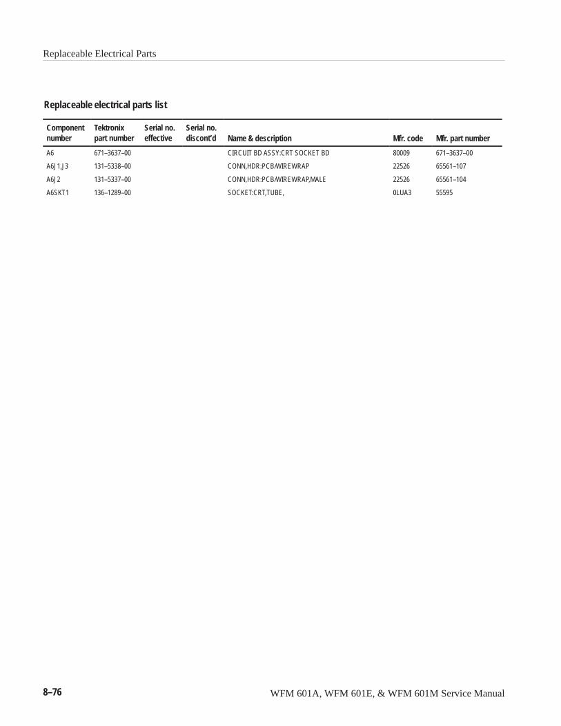
Replaceable Electrical Parts
8–76 WFM 601A, WFM 601E, & WFM 601M Service Manual
Replaceable electrical parts list
Componentnumber
Tektronixpart number
Serial no.effective
Serial no.discont’d Name & description Mfr. code Mfr. part number
A6 671–3637–00 CIRCUIT BD ASSY:CRT SOCKET BD 80009 671–3637–00
A6J1,J3 131–5338–00 CONN,HDR:PCB/WIREWRAP 22526 65561–107
A6J2 131–5337–00 CONN,HDR:PCB/WIREWRAP,MALE 22526 65561–104
A6SKT1 136–1289–00 SOCKET:CRT,TUBE, 0LUA3 55595
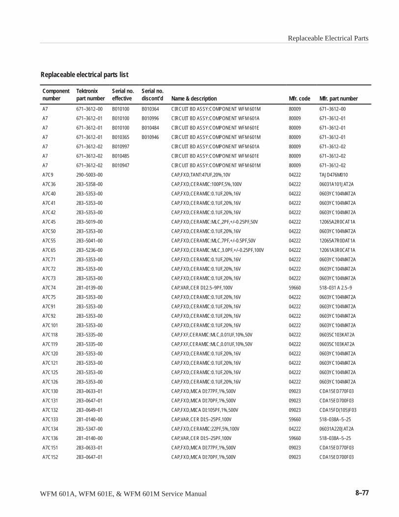
Replaceable Electrical Parts
WFM 601A, WFM 601E, & WFM 601M Service Manual 8–77
Replaceable electrical parts list
Componentnumber
Tektronixpart number
Serial no.effective
Serial no.discont’d Name & description Mfr. code Mfr. part number
A7 671–3612–00 B010100 B010364 CIRCUIT BD ASSY:COMPONENT WFM 601M 80009 671–3612–00
A7 671–3612–01 B010100 B010996 CIRCUIT BD ASSY:COMPONENT WFM 601A 80009 671–3612–01
A7 671–3612–01 B010100 B010484 CIRCUIT BD ASSY:COMPONENT WFM 601E 80009 671–3612–01
A7 671–3612–01 B010365 B010946 CIRCUIT BD ASSY:COMPONENT WFM 601M 80009 671–3612–01
A7 671–3612–02 B010997 CIRCUIT BD ASSY:COMPONENT WFM 601A 80009 671–3612–02
A7 671–3612–02 B010485 CIRCUIT BD ASSY:COMPONENT WFM 601E 80009 671–3612–02
A7 671–3612–02 B010947 CIRCUIT BD ASSY:COMPONENT WFM 601M 80009 671–3612–02
A7C9 290–5003–00 CAP,FXD,TANT:47UF,20%,10V 04222 TAJD476M010
A7C36 283–5358–00 CAP,FXD,CERAMIC:100PF,5%,100V 04222 06031A101JAT2A
A7C40 283–5353–00 CAP,FXD,CERAMIC:0.1UF,20%,16V 04222 0603YC104MAT2A
A7C41 283–5353–00 CAP,FXD,CERAMIC:0.1UF,20%,16V 04222 0603YC104MAT2A
A7C42 283–5353–00 CAP,FXD,CERAMIC:0.1UF,20%,16V 04222 0603YC104MAT2A
A7C45 283–5019–00 CAP,FXD,CERAMIC:MLC,2PF,+/–0.25PF,50V 04222 12065A2R0CAT1A
A7C50 283–5353–00 CAP,FXD,CERAMIC:0.1UF,20%,16V 04222 0603YC104MAT2A
A7C55 283–5041–00 CAP,FXD,CERAMIC:MLC,7PF,+/–0.5PF,50V 04222 12065A7R0DAT1A
A7C65 283–5236–00 CAP,FXD,CERAMIC:MLC,3.0PF,+/–0.25PF,100V 04222 12061A3R0CAT1A
A7C71 283–5353–00 CAP,FXD,CERAMIC:0.1UF,20%,16V 04222 0603YC104MAT2A
A7C72 283–5353–00 CAP,FXD,CERAMIC:0.1UF,20%,16V 04222 0603YC104MAT2A
A7C73 283–5353–00 CAP,FXD,CERAMIC:0.1UF,20%,16V 04222 0603YC104MAT2A
A7C74 281–0139–00 CAP,VAR,CER DI:2.5–9PF,100V 59660 518–031 A 2.5–9
A7C75 283–5353–00 CAP,FXD,CERAMIC:0.1UF,20%,16V 04222 0603YC104MAT2A
A7C91 283–5353–00 CAP,FXD,CERAMIC:0.1UF,20%,16V 04222 0603YC104MAT2A
A7C92 283–5353–00 CAP,FXD,CERAMIC:0.1UF,20%,16V 04222 0603YC104MAT2A
A7C101 283–5353–00 CAP,FXD,CERAMIC:0.1UF,20%,16V 04222 0603YC104MAT2A
A7C118 283–5335–00 CAP,FXF,CERAMIC:MLC,0.01UF,10%,50V 04222 06035C103KAT2A
A7C119 283–5335–00 CAP,FXF,CERAMIC:MLC,0.01UF,10%,50V 04222 06035C103KAT2A
A7C120 283–5353–00 CAP,FXD,CERAMIC:0.1UF,20%,16V 04222 0603YC104MAT2A
A7C121 283–5353–00 CAP,FXD,CERAMIC:0.1UF,20%,16V 04222 0603YC104MAT2A
A7C125 283–5353–00 CAP,FXD,CERAMIC:0.1UF,20%,16V 04222 0603YC104MAT2A
A7C126 283–5353–00 CAP,FXD,CERAMIC:0.1UF,20%,16V 04222 0603YC104MAT2A
A7C130 283–0633–01 CAP,FXD,MICA DI:77PF,1%,500V 09023 CDA15ED770F03
A7C131 283–0647–01 CAP,FXD,MICA DI:70PF,1%,500V 09023 CDA15ED700F03
A7C132 283–0649–01 CAP,FXD,MICA DI:105PF,1%,500V 09023 CDA15FD(105)F03
A7C133 281–0140–00 CAP,VAR,CER DI:5–25PF,100V 59660 518–038A–5–25
A7C134 283–5347–00 CAP,FXD,CERAMIC:22PF,5%,100V 04222 06031A220JAT2A
A7C136 281–0140–00 CAP,VAR,CER DI:5–25PF,100V 59660 518–038A–5–25
A7C151 283–0633–01 CAP,FXD,MICA DI:77PF,1%,500V 09023 CDA15ED770F03
A7C152 283–0647–01 CAP,FXD,MICA DI:70PF,1%,500V 09023 CDA15ED700F03
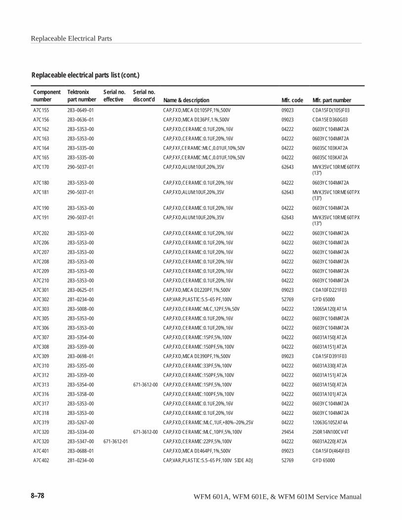
Replaceable Electrical Parts
8–78 WFM 601A, WFM 601E, & WFM 601M Service Manual
Replaceable electrical parts list (cont.)
Componentnumber Mfr. part numberMfr. codeName & description
Serial no.discont’d
Serial no.effective
Tektronixpart number
A7C155 283–0649–01 CAP,FXD,MICA DI:105PF,1%,500V 09023 CDA15FD(105)F03
A7C156 283–0636–01 CAP,FXD,MICA DI:36PF,1.%,500V 09023 CDA15ED360G03
A7C162 283–5353–00 CAP,FXD,CERAMIC:0.1UF,20%,16V 04222 0603YC104MAT2A
A7C163 283–5353–00 CAP,FXD,CERAMIC:0.1UF,20%,16V 04222 0603YC104MAT2A
A7C164 283–5335–00 CAP,FXF,CERAMIC:MLC,0.01UF,10%,50V 04222 06035C103KAT2A
A7C165 283–5335–00 CAP,FXF,CERAMIC:MLC,0.01UF,10%,50V 04222 06035C103KAT2A
A7C170 290–5037–01 CAP,FXD,ALUM:10UF,20%,35V 62643 MVK35VC10RME60TPX(13”)
A7C180 283–5353–00 CAP,FXD,CERAMIC:0.1UF,20%,16V 04222 0603YC104MAT2A
A7C181 290–5037–01 CAP,FXD,ALUM:10UF,20%,35V 62643 MVK35VC10RME60TPX(13”)
A7C190 283–5353–00 CAP,FXD,CERAMIC:0.1UF,20%,16V 04222 0603YC104MAT2A
A7C191 290–5037–01 CAP,FXD,ALUM:10UF,20%,35V 62643 MVK35VC10RME60TPX(13”)
A7C202 283–5353–00 CAP,FXD,CERAMIC:0.1UF,20%,16V 04222 0603YC104MAT2A
A7C206 283–5353–00 CAP,FXD,CERAMIC:0.1UF,20%,16V 04222 0603YC104MAT2A
A7C207 283–5353–00 CAP,FXD,CERAMIC:0.1UF,20%,16V 04222 0603YC104MAT2A
A7C208 283–5353–00 CAP,FXD,CERAMIC:0.1UF,20%,16V 04222 0603YC104MAT2A
A7C209 283–5353–00 CAP,FXD,CERAMIC:0.1UF,20%,16V 04222 0603YC104MAT2A
A7C210 283–5353–00 CAP,FXD,CERAMIC:0.1UF,20%,16V 04222 0603YC104MAT2A
A7C301 283–0625–01 CAP,FXD,MICA DI:220PF,1%,500V 09023 CDA10FD221F03
A7C302 281–0234–00 CAP,VAR,PLASTIC:5.5–65 PF,100V 52769 GYD 65000
A7C303 283–5008–00 CAP,FXD,CERAMIC:MLC,12PF,5%,50V 04222 12065A120JAT1A
A7C305 283–5353–00 CAP,FXD,CERAMIC:0.1UF,20%,16V 04222 0603YC104MAT2A
A7C306 283–5353–00 CAP,FXD,CERAMIC:0.1UF,20%,16V 04222 0603YC104MAT2A
A7C307 283–5354–00 CAP,FXD,CERAMIC:15PF,5%,100V 04222 06031A150JAT2A
A7C308 283–5359–00 CAP,FXD,CERAMIC:150PF,5%,100V 04222 06031A151JAT2A
A7C309 283–0698–01 CAP,FXD,MICA DI:390PF,1%,500V 09023 CDA15FD391F03
A7C310 283–5355–00 CAP,FXD,CERAMIC:33PF,5%,100V 04222 06031A330JAT2A
A7C312 283–5359–00 CAP,FXD,CERAMIC:150PF,5%,100V 04222 06031A151JAT2A
A7C313 283–5354–00 671-3612-00 CAP,FXD,CERAMIC:15PF,5%,100V 04222 06031A150JAT2A
A7C316 283–5358–00 CAP,FXD,CERAMIC:100PF,5%,100V 04222 06031A101JAT2A
A7C317 283–5353–00 CAP,FXD,CERAMIC:0.1UF,20%,16V 04222 0603YC104MAT2A
A7C318 283–5353–00 CAP,FXD,CERAMIC:0.1UF,20%,16V 04222 0603YC104MAT2A
A7C319 283–5267–00 CAP,FXD,CERAMIC:MLC,1UF,+80%–20%,25V 04222 12063G105ZAT4A
A7C320 283–5334–00 671-3612-00 CAP,FXD CERAMIC:MLC,10PF,5%,100V 29454 250R14N100CV4T
A7C320 283–5347–00 671-3612-01 CAP,FXD,CERAMIC:22PF,5%,100V 04222 06031A220JAT2A
A7C401 283–0688–01 CAP,FXD,MICA DI:464PF,1%,500V 09023 CDA15FD(464)F03
A7C402 281–0234–00 CAP,VAR,PLASTIC:5.5–65 PF,100V SIDE ADJ 52769 GYD 65000
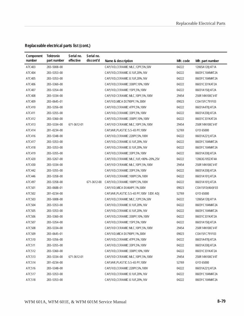
Replaceable Electrical Parts
WFM 601A, WFM 601E, & WFM 601M Service Manual 8–79
Replaceable electrical parts list (cont.)
Componentnumber Mfr. part numberMfr. codeName & description
Serial no.discont’d
Serial no.effective
Tektronixpart number
A7C403 283–5008–00 CAP,FXD,CERAMIC:MLC,12PF,5%,50V 04222 12065A120JAT1A
A7C404 283–5353–00 CAP,FXD,CERAMIC:0.1UF,20%,16V 04222 0603YC104MAT2A
A7C405 283–5353–00 CAP,FXD,CERAMIC:0.1UF,20%,16V 04222 0603YC104MAT2A
A7C406 283–5360–00 CAP,FXD,CERAMIC:330PF,10%,100V 04222 06031C331KAT2A
A7C407 283–5354–00 CAP,FXD,CERAMIC:15PF,5%,100V 04222 06031A150JAT2A
A7C408 283–5334–00 CAP,FXD CERAMIC:MLC,10PF,5%,100V 29454 250R14N100CV4T
A7C409 283–0645–01 CAP,FXD,MICA DI:790PF,1%,300V 09023 CDA15FC791F03
A7C410 283–5356–00 CAP,FXD,CERAMIC:47PF,5%,100V 04222 06031A470JAT2A
A7C411 283–5355–00 CAP,FXD,CERAMIC:33PF,5%,100V 04222 06031A330JAT2A
A7C412 283–5360–00 CAP,FXD,CERAMIC:330PF,10%,100V 04222 06031C331KAT2A
A7C413 283–5334–00 671-3612-01 CAP,FXD CERAMIC:MLC,10PF,5%,100V 29454 250R14N100CV4T
A7C414 281–0234–00 CAP,VAR,PLASTIC:5.5–65 PF,100V 52769 GYD 65000
A7C416 283–5348–00 CAP,FXD,CERAMIC:220PF,5%,100V 04222 06031A221JAT2A
A7C417 283–5353–00 CAP,FXD,CERAMIC:0.1UF,20%,16V 04222 0603YC104MAT2A
A7C418 283–5353–00 CAP,FXD,CERAMIC:0.1UF,20%,16V 04222 0603YC104MAT2A
A7C419 283–5355–00 CAP,FXD,CERAMIC:33PF,5%,100V 04222 06031A330JAT2A
A7C420 283–5267–00 CAP,FXD,CERAMIC:MLC,1UF,+80%–20%,25V 04222 12063G105ZAT4A
A7C430 283–5334–00 CAP,FXD CERAMIC:MLC,10PF,5%,100V 29454 250R14N100CV4T
A7C442 283–5355–00 CAP,FXD,CERAMIC:33PF,5%,100V 04222 06031A330JAT2A
A7C446 283–5358–00 CAP,FXD,CERAMIC:100PF,5%,100V 04222 06031A101JAT2A
A7C497 283–5358–00 671-3612-00 CAP,FXD,CERAMIC:100PF,5%,100V 04222 06031A101JAT2A
A7C501 283–0688–01 CAP,FXD,MICA DI:464PF,1%,500V 09023 CDA15FD(464)F03
A7C502 281–0234–00 CAP,VAR,PLASTIC:5.5–65 PF,100V SIDE ADJ 52769 GYD 65000
A7C503 283–5008–00 CAP,FXD,CERAMIC:MLC,12PF,5%,50V 04222 12065A120JAT1A
A7C504 283–5353–00 CAP,FXD,CERAMIC:0.1UF,20%,16V 04222 0603YC104MAT2A
A7C505 283–5353–00 CAP,FXD,CERAMIC:0.1UF,20%,16V 04222 0603YC104MAT2A
A7C506 283–5360–00 CAP,FXD,CERAMIC:330PF,10%,100V 04222 06031C331KAT2A
A7C507 283–5354–00 CAP,FXD,CERAMIC:15PF,5%,100V 04222 06031A150JAT2A
A7C508 283–5334–00 CAP,FXD CERAMIC:MLC,10PF,5%,100V 29454 250R14N100CV4T
A7C509 283–0645–01 CAP,FXD,MICA DI:790PF,1%,300V 09023 CDA15FC791F03
A7C510 283–5356–00 CAP,FXD,CERAMIC:47PF,5%,100V 04222 06031A470JAT2A
A7C511 283–5355–00 CAP,FXD,CERAMIC:33PF,5%,100V 04222 06031A330JAT2A
A7C512 283–5360–00 CAP,FXD,CERAMIC:330PF,10%,100V 04222 06031C331KAT2A
A7C513 283–5334–00 671-3612-01 CAP,FXD CERAMIC:MLC,10PF,5%,100V 29454 250R14N100CV4T
A7C514 281–0234–00 CAP,VAR,PLASTIC:5.5–65 PF,100V 52769 GYD 65000
A7C516 283–5348–00 CAP,FXD,CERAMIC:220PF,5%,100V 04222 06031A221JAT2A
A7C517 283–5353–00 CAP,FXD,CERAMIC:0.1UF,20%,16V 04222 0603YC104MAT2A
A7C518 283–5353–00 CAP,FXD,CERAMIC:0.1UF,20%,16V 04222 0603YC104MAT2A
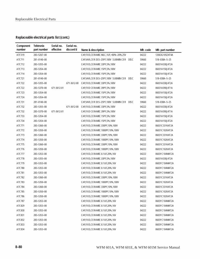
Replaceable Electrical Parts
8–80 WFM 601A, WFM 601E, & WFM 601M Service Manual
Replaceable electrical parts list (cont.)
Componentnumber Mfr. part numberMfr. codeName & description
Serial no.discont’d
Serial no.effective
Tektronixpart number
A7C519 283–5267–00 CAP,FXD,CERAMIC:MLC,1UF,+80%–20%,25V 04222 12063G105ZAT4A
A7C711 281–0140–00 CAP,VAR,CER DI:5–25PF,100V SUBMIN CER DISC 59660 518–038A–5–25
A7C712 283–5355–00 CAP,FXD,CERAMIC:33PF,5%,100V 04222 06031A330JAT2A
A7C713 283–5354–00 CAP,FXD,CERAMIC:15PF,5%,100V 04222 06031A150JAT2A
A7C714 283–5354–00 CAP,FXD,CERAMIC:15PF,5%,100V 04222 06031A150JAT2A
A7C721 281–0140–00 CAP,VAR,CER DI:5–25PF,100V SUBMIN CER DISC 59660 518–038A–5–25
A7C722 283–5355–00 671-3612-00 CAP,FXD,CERAMIC:33PF,5%,100V 04222 06031A330JAT2A
A7C722 283–5370–00 671-3612-01 CAP,FXD CERAMIC:39PF,5%,100V 04222 06031A390JAT1A
A7C723 283–5354–00 CAP,FXD,CERAMIC:15PF,5%,100V 04222 06031A150JAT2A
A7C724 283–5354–00 CAP,FXD,CERAMIC:15PF,5%,100V 04222 06031A150JAT2A
A7C731 281–0140–00 CAP,VAR,CER DI:5–25PF,100V SUBMIN CER DISC 59660 518–038A–5–25
A7C732 283–5355–00 671-3612-00 CAP,FXD,CERAMIC:33PF,5%,100V 04222 06031A330JAT2A
A7C732 283–5370–00 671-3612-01 CAP,FXD CERAMIC:39PF,5%,100V 04222 06031A390JAT1A
A7C733 283–5354–00 CAP,FXD,CERAMIC:15PF,5%,100V 04222 06031A150JAT2A
A7C734 283–5354–00 CAP,FXD,CERAMIC:15PF,5%,100V 04222 06031A150JAT2A
A7C771 283–5360–00 CAP,FXD,CERAMIC:330PF,10%,100V 04222 06031C331KAT2A
A7C772 283–5350–00 CAP,FXD,CERAMIC:1000PF,10%,100V 04222 06031C102KAT2A
A7C773 283–5360–00 CAP,FXD,CERAMIC:330PF,10%,100V 04222 06031C331KAT2A
A7C774 283–5350–00 CAP,FXD,CERAMIC:1000PF,10%,100V 04222 06031C102KAT2A
A7C775 283–5360–00 CAP,FXD,CERAMIC:330PF,10%,100V 04222 06031C331KAT2A
A7C776 283–5350–00 CAP,FXD,CERAMIC:1000PF,10%,100V 04222 06031C102KAT2A
A7C777 283–5353–00 CAP,FXD,CERAMIC:0.1UF,20%,16V 04222 0603YC104MAT2A
A7C778 283–5355–00 CAP,FXD,CERAMIC:33PF,5%,100V 04222 06031A330JAT2A
A7C779 283–5353–00 CAP,FXD,CERAMIC:0.1UF,20%,16V 04222 0603YC104MAT2A
A7C780 283–5353–00 CAP,FXD,CERAMIC:0.1UF,20%,16V 04222 0603YC104MAT2A
A7C781 283–5353–00 CAP,FXD,CERAMIC:0.1UF,20%,16V 04222 0603YC104MAT2A
A7C782 283–5360–00 CAP,FXD,CERAMIC:330PF,10%,100V 04222 06031C331KAT2A
A7C783 283–5350–00 CAP,FXD,CERAMIC:1000PF,10%,100V 04222 06031C102KAT2A
A7C784 283–5360–00 CAP,FXD,CERAMIC:330PF,10%,100V 04222 06031C331KAT2A
A7C785 283–5350–00 CAP,FXD,CERAMIC:1000PF,10%,100V 04222 06031C102KAT2A
A7C786 283–5350–00 CAP,FXD,CERAMIC:1000PF,10%,100V 04222 06031C102KAT2A
A7C787 283–5353–00 CAP,FXD,CERAMIC:0.1UF,20%,16V 04222 0603YC104MAT2A
A7C829 283–5353–00 CAP,FXD,CERAMIC:0.1UF,20%,16V 04222 0603YC104MAT2A
A7C830 283–5353–00 CAP,FXD,CERAMIC:0.1UF,20%,16V 04222 0603YC104MAT2A
A7C831 283–5353–00 CAP,FXD,CERAMIC:0.1UF,20%,16V 04222 0603YC104MAT2A
A7C832 283–5353–00 CAP,FXD,CERAMIC:0.1UF,20%,16V 04222 0603YC104MAT2A
A7C833 283–5353–00 CAP,FXD,CERAMIC:0.1UF,20%,16V 04222 0603YC104MAT2A
A7C834 283–5353–00 CAP,FXD,CERAMIC:0.1UF,20%,16V 04222 0603YC104MAT2A
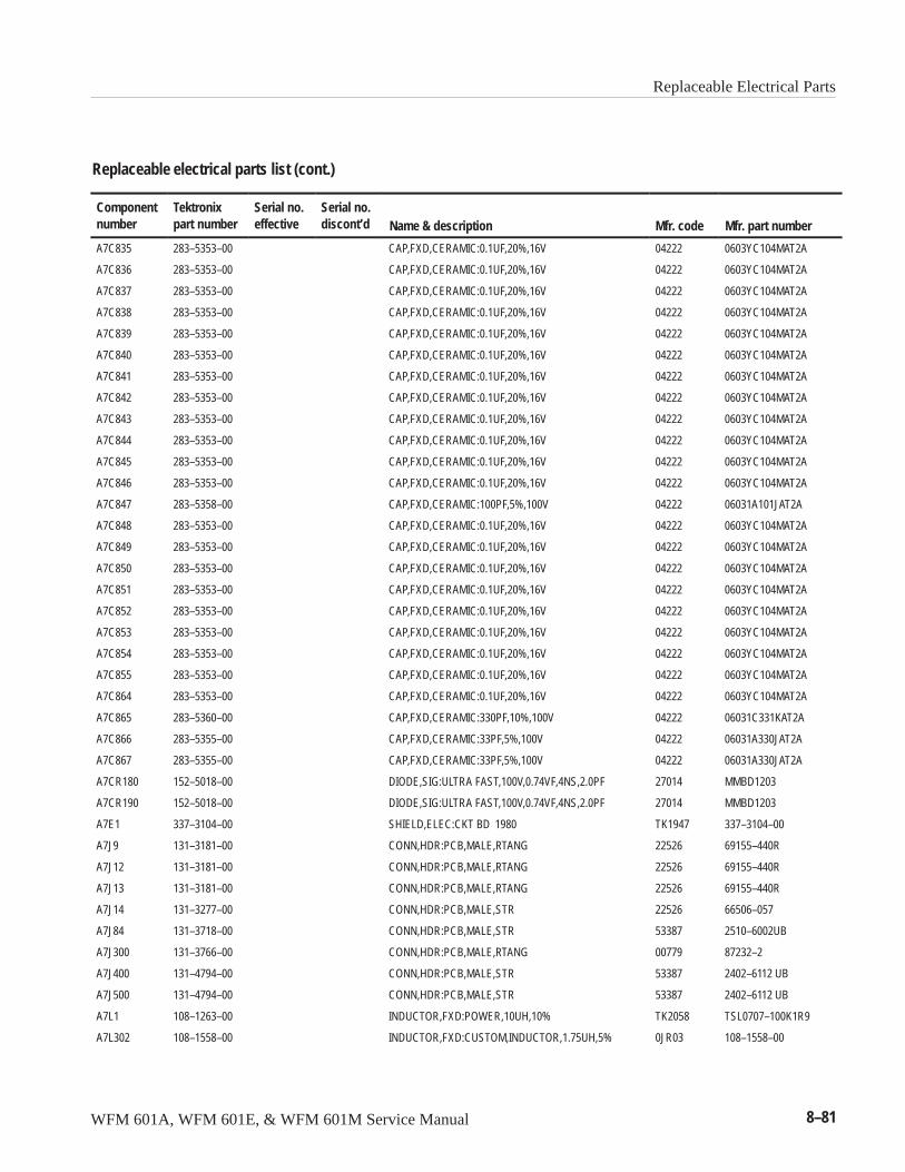
Replaceable Electrical Parts
WFM 601A, WFM 601E, & WFM 601M Service Manual 8–81
Replaceable electrical parts list (cont.)
Componentnumber Mfr. part numberMfr. codeName & description
Serial no.discont’d
Serial no.effective
Tektronixpart number
A7C835 283–5353–00 CAP,FXD,CERAMIC:0.1UF,20%,16V 04222 0603YC104MAT2A
A7C836 283–5353–00 CAP,FXD,CERAMIC:0.1UF,20%,16V 04222 0603YC104MAT2A
A7C837 283–5353–00 CAP,FXD,CERAMIC:0.1UF,20%,16V 04222 0603YC104MAT2A
A7C838 283–5353–00 CAP,FXD,CERAMIC:0.1UF,20%,16V 04222 0603YC104MAT2A
A7C839 283–5353–00 CAP,FXD,CERAMIC:0.1UF,20%,16V 04222 0603YC104MAT2A
A7C840 283–5353–00 CAP,FXD,CERAMIC:0.1UF,20%,16V 04222 0603YC104MAT2A
A7C841 283–5353–00 CAP,FXD,CERAMIC:0.1UF,20%,16V 04222 0603YC104MAT2A
A7C842 283–5353–00 CAP,FXD,CERAMIC:0.1UF,20%,16V 04222 0603YC104MAT2A
A7C843 283–5353–00 CAP,FXD,CERAMIC:0.1UF,20%,16V 04222 0603YC104MAT2A
A7C844 283–5353–00 CAP,FXD,CERAMIC:0.1UF,20%,16V 04222 0603YC104MAT2A
A7C845 283–5353–00 CAP,FXD,CERAMIC:0.1UF,20%,16V 04222 0603YC104MAT2A
A7C846 283–5353–00 CAP,FXD,CERAMIC:0.1UF,20%,16V 04222 0603YC104MAT2A
A7C847 283–5358–00 CAP,FXD,CERAMIC:100PF,5%,100V 04222 06031A101JAT2A
A7C848 283–5353–00 CAP,FXD,CERAMIC:0.1UF,20%,16V 04222 0603YC104MAT2A
A7C849 283–5353–00 CAP,FXD,CERAMIC:0.1UF,20%,16V 04222 0603YC104MAT2A
A7C850 283–5353–00 CAP,FXD,CERAMIC:0.1UF,20%,16V 04222 0603YC104MAT2A
A7C851 283–5353–00 CAP,FXD,CERAMIC:0.1UF,20%,16V 04222 0603YC104MAT2A
A7C852 283–5353–00 CAP,FXD,CERAMIC:0.1UF,20%,16V 04222 0603YC104MAT2A
A7C853 283–5353–00 CAP,FXD,CERAMIC:0.1UF,20%,16V 04222 0603YC104MAT2A
A7C854 283–5353–00 CAP,FXD,CERAMIC:0.1UF,20%,16V 04222 0603YC104MAT2A
A7C855 283–5353–00 CAP,FXD,CERAMIC:0.1UF,20%,16V 04222 0603YC104MAT2A
A7C864 283–5353–00 CAP,FXD,CERAMIC:0.1UF,20%,16V 04222 0603YC104MAT2A
A7C865 283–5360–00 CAP,FXD,CERAMIC:330PF,10%,100V 04222 06031C331KAT2A
A7C866 283–5355–00 CAP,FXD,CERAMIC:33PF,5%,100V 04222 06031A330JAT2A
A7C867 283–5355–00 CAP,FXD,CERAMIC:33PF,5%,100V 04222 06031A330JAT2A
A7CR180 152–5018–00 DIODE,SIG:ULTRA FAST,100V,0.74VF,4NS,2.0PF 27014 MMBD1203
A7CR190 152–5018–00 DIODE,SIG:ULTRA FAST,100V,0.74VF,4NS,2.0PF 27014 MMBD1203
A7E1 337–3104–00 SHIELD,ELEC:CKT BD 1980 TK1947 337–3104–00
A7J9 131–3181–00 CONN,HDR:PCB,MALE,RTANG 22526 69155–440R
A7J12 131–3181–00 CONN,HDR:PCB,MALE,RTANG 22526 69155–440R
A7J13 131–3181–00 CONN,HDR:PCB,MALE,RTANG 22526 69155–440R
A7J14 131–3277–00 CONN,HDR:PCB,MALE,STR 22526 66506–057
A7J84 131–3718–00 CONN,HDR:PCB,MALE,STR 53387 2510–6002UB
A7J300 131–3766–00 CONN,HDR:PCB,MALE,RTANG 00779 87232–2
A7J400 131–4794–00 CONN,HDR:PCB,MALE,STR 53387 2402–6112 UB
A7J500 131–4794–00 CONN,HDR:PCB,MALE,STR 53387 2402–6112 UB
A7L1 108–1263–00 INDUCTOR,FXD:POWER,10UH,10% TK2058 TSL0707–100K1R9
A7L302 108–1558–00 INDUCTOR,FXD:CUSTOM,INDUCTOR,1.75UH,5% 0JR03 108–1558–00
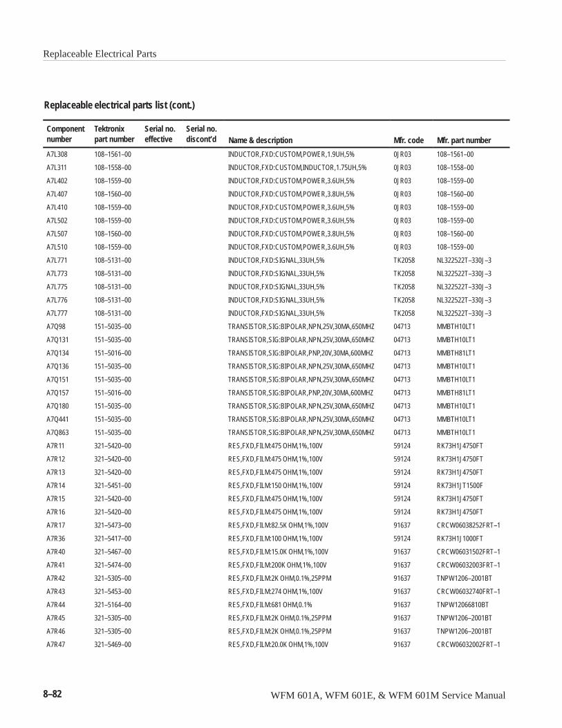
Replaceable Electrical Parts
8–82 WFM 601A, WFM 601E, & WFM 601M Service Manual
Replaceable electrical parts list (cont.)
Componentnumber Mfr. part numberMfr. codeName & description
Serial no.discont’d
Serial no.effective
Tektronixpart number
A7L308 108–1561–00 INDUCTOR,FXD:CUSTOM,POWER,1.9UH,5% 0JR03 108–1561–00
A7L311 108–1558–00 INDUCTOR,FXD:CUSTOM,INDUCTOR,1.75UH,5% 0JR03 108–1558–00
A7L402 108–1559–00 INDUCTOR,FXD:CUSTOM,POWER,3.6UH,5% 0JR03 108–1559–00
A7L407 108–1560–00 INDUCTOR,FXD:CUSTOM,POWER,3.8UH,5% 0JR03 108–1560–00
A7L410 108–1559–00 INDUCTOR,FXD:CUSTOM,POWER,3.6UH,5% 0JR03 108–1559–00
A7L502 108–1559–00 INDUCTOR,FXD:CUSTOM,POWER,3.6UH,5% 0JR03 108–1559–00
A7L507 108–1560–00 INDUCTOR,FXD:CUSTOM,POWER,3.8UH,5% 0JR03 108–1560–00
A7L510 108–1559–00 INDUCTOR,FXD:CUSTOM,POWER,3.6UH,5% 0JR03 108–1559–00
A7L771 108–5131–00 INDUCTOR,FXD:SIGNAL,33UH,5% TK2058 NL322522T–330J–3
A7L773 108–5131–00 INDUCTOR,FXD:SIGNAL,33UH,5% TK2058 NL322522T–330J–3
A7L775 108–5131–00 INDUCTOR,FXD:SIGNAL,33UH,5% TK2058 NL322522T–330J–3
A7L776 108–5131–00 INDUCTOR,FXD:SIGNAL,33UH,5% TK2058 NL322522T–330J–3
A7L777 108–5131–00 INDUCTOR,FXD:SIGNAL,33UH,5% TK2058 NL322522T–330J–3
A7Q98 151–5035–00 TRANSISTOR,SIG:BIPOLAR,NPN,25V,30MA,650MHZ 04713 MMBTH10LT1
A7Q131 151–5035–00 TRANSISTOR,SIG:BIPOLAR,NPN,25V,30MA,650MHZ 04713 MMBTH10LT1
A7Q134 151–5016–00 TRANSISTOR,SIG:BIPOLAR,PNP,20V,30MA,600MHZ 04713 MMBTH81LT1
A7Q136 151–5035–00 TRANSISTOR,SIG:BIPOLAR,NPN,25V,30MA,650MHZ 04713 MMBTH10LT1
A7Q151 151–5035–00 TRANSISTOR,SIG:BIPOLAR,NPN,25V,30MA,650MHZ 04713 MMBTH10LT1
A7Q157 151–5016–00 TRANSISTOR,SIG:BIPOLAR,PNP,20V,30MA,600MHZ 04713 MMBTH81LT1
A7Q180 151–5035–00 TRANSISTOR,SIG:BIPOLAR,NPN,25V,30MA,650MHZ 04713 MMBTH10LT1
A7Q441 151–5035–00 TRANSISTOR,SIG:BIPOLAR,NPN,25V,30MA,650MHZ 04713 MMBTH10LT1
A7Q863 151–5035–00 TRANSISTOR,SIG:BIPOLAR,NPN,25V,30MA,650MHZ 04713 MMBTH10LT1
A7R11 321–5420–00 RES,FXD,FILM:475 OHM,1%,100V 59124 RK73H1J4750FT
A7R12 321–5420–00 RES,FXD,FILM:475 OHM,1%,100V 59124 RK73H1J4750FT
A7R13 321–5420–00 RES,FXD,FILM:475 OHM,1%,100V 59124 RK73H1J4750FT
A7R14 321–5451–00 RES,FXD,FILM:150 OHM,1%,100V 59124 RK73H1JT1500F
A7R15 321–5420–00 RES,FXD,FILM:475 OHM,1%,100V 59124 RK73H1J4750FT
A7R16 321–5420–00 RES,FXD,FILM:475 OHM,1%,100V 59124 RK73H1J4750FT
A7R17 321–5473–00 RES,FXD,FILM:82.5K OHM,1%,100V 91637 CRCW06038252FRT–1
A7R36 321–5417–00 RES,FXD,FILM:100 OHM,1%,100V 59124 RK73H1J1000FT
A7R40 321–5467–00 RES,FXD,FILM:15.0K OHM,1%,100V 91637 CRCW06031502FRT–1
A7R41 321–5474–00 RES,FXD,FILM:200K OHM,1%,100V 91637 CRCW06032003FRT–1
A7R42 321–5305–00 RES,FXD,FILM:2K OHM,0.1%,25PPM 91637 TNPW1206–2001BT
A7R43 321–5453–00 RES,FXD,FILM:274 OHM,1%,100V 91637 CRCW06032740FRT–1
A7R44 321–5164–00 RES,FXD,FILM:681 OHM,0.1% 91637 TNPW12066810BT
A7R45 321–5305–00 RES,FXD,FILM:2K OHM,0.1%,25PPM 91637 TNPW1206–2001BT
A7R46 321–5305–00 RES,FXD,FILM:2K OHM,0.1%,25PPM 91637 TNPW1206–2001BT
A7R47 321–5469–00 RES,FXD,FILM:20.0K OHM,1%,100V 91637 CRCW06032002FRT–1
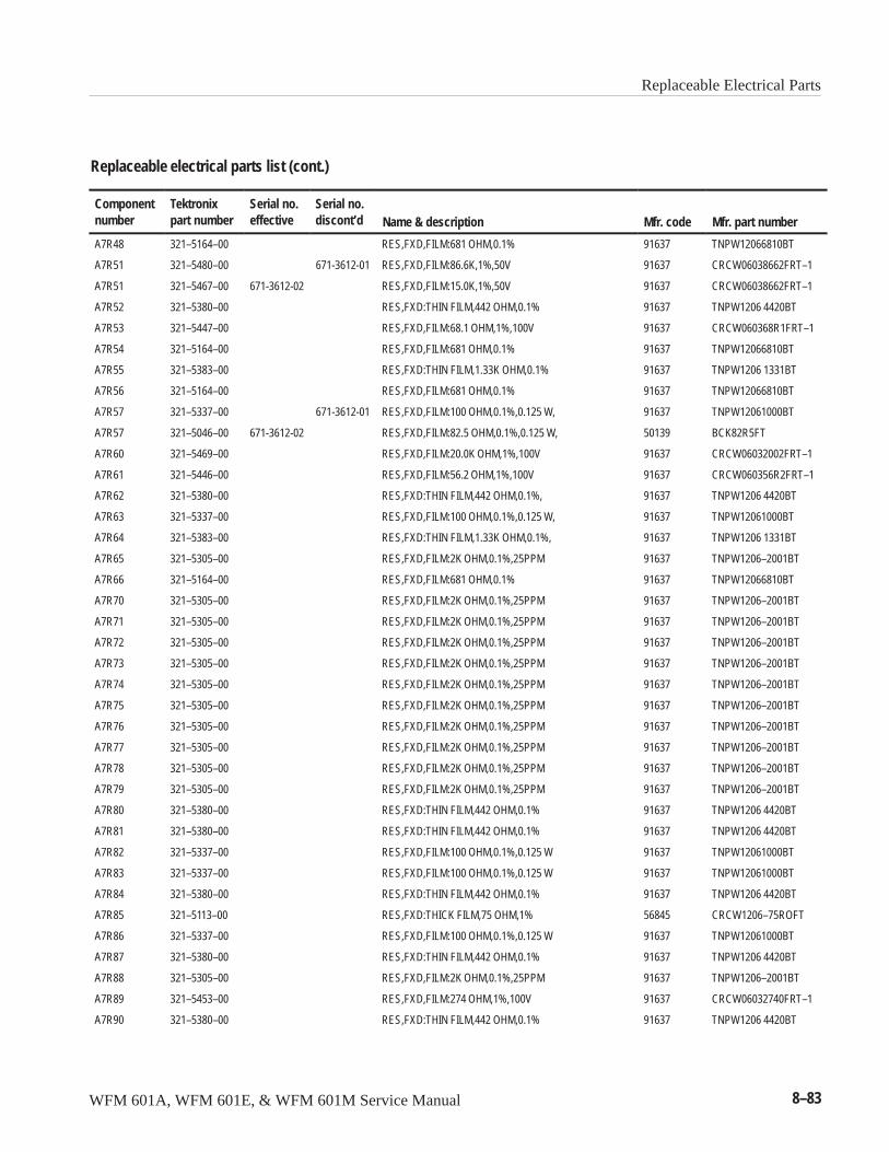
Replaceable Electrical Parts
WFM 601A, WFM 601E, & WFM 601M Service Manual 8–83
Replaceable electrical parts list (cont.)
Componentnumber Mfr. part numberMfr. codeName & description
Serial no.discont’d
Serial no.effective
Tektronixpart number
A7R48 321–5164–00 RES,FXD,FILM:681 OHM,0.1% 91637 TNPW12066810BT
A7R51 321–5480–00 671-3612-01 RES,FXD,FILM:86.6K,1%,50V 91637 CRCW06038662FRT–1
A7R51 321–5467–00 671-3612-02 RES,FXD,FILM:15.0K,1%,50V 91637 CRCW06038662FRT–1
A7R52 321–5380–00 RES,FXD:THIN FILM,442 OHM,0.1% 91637 TNPW1206 4420BT
A7R53 321–5447–00 RES,FXD,FILM:68.1 OHM,1%,100V 91637 CRCW060368R1FRT–1
A7R54 321–5164–00 RES,FXD,FILM:681 OHM,0.1% 91637 TNPW12066810BT
A7R55 321–5383–00 RES,FXD:THIN FILM,1.33K OHM,0.1% 91637 TNPW1206 1331BT
A7R56 321–5164–00 RES,FXD,FILM:681 OHM,0.1% 91637 TNPW12066810BT
A7R57 321–5337–00 671-3612-01 RES,FXD,FILM:100 OHM,0.1%,0.125 W, 91637 TNPW12061000BT
A7R57 321–5046–00 671-3612-02 RES,FXD,FILM:82.5 OHM,0.1%,0.125 W, 50139 BCK82R5FT
A7R60 321–5469–00 RES,FXD,FILM:20.0K OHM,1%,100V 91637 CRCW06032002FRT–1
A7R61 321–5446–00 RES,FXD,FILM:56.2 OHM,1%,100V 91637 CRCW060356R2FRT–1
A7R62 321–5380–00 RES,FXD:THIN FILM,442 OHM,0.1%, 91637 TNPW1206 4420BT
A7R63 321–5337–00 RES,FXD,FILM:100 OHM,0.1%,0.125 W, 91637 TNPW12061000BT
A7R64 321–5383–00 RES,FXD:THIN FILM,1.33K OHM,0.1%, 91637 TNPW1206 1331BT
A7R65 321–5305–00 RES,FXD,FILM:2K OHM,0.1%,25PPM 91637 TNPW1206–2001BT
A7R66 321–5164–00 RES,FXD,FILM:681 OHM,0.1% 91637 TNPW12066810BT
A7R70 321–5305–00 RES,FXD,FILM:2K OHM,0.1%,25PPM 91637 TNPW1206–2001BT
A7R71 321–5305–00 RES,FXD,FILM:2K OHM,0.1%,25PPM 91637 TNPW1206–2001BT
A7R72 321–5305–00 RES,FXD,FILM:2K OHM,0.1%,25PPM 91637 TNPW1206–2001BT
A7R73 321–5305–00 RES,FXD,FILM:2K OHM,0.1%,25PPM 91637 TNPW1206–2001BT
A7R74 321–5305–00 RES,FXD,FILM:2K OHM,0.1%,25PPM 91637 TNPW1206–2001BT
A7R75 321–5305–00 RES,FXD,FILM:2K OHM,0.1%,25PPM 91637 TNPW1206–2001BT
A7R76 321–5305–00 RES,FXD,FILM:2K OHM,0.1%,25PPM 91637 TNPW1206–2001BT
A7R77 321–5305–00 RES,FXD,FILM:2K OHM,0.1%,25PPM 91637 TNPW1206–2001BT
A7R78 321–5305–00 RES,FXD,FILM:2K OHM,0.1%,25PPM 91637 TNPW1206–2001BT
A7R79 321–5305–00 RES,FXD,FILM:2K OHM,0.1%,25PPM 91637 TNPW1206–2001BT
A7R80 321–5380–00 RES,FXD:THIN FILM,442 OHM,0.1% 91637 TNPW1206 4420BT
A7R81 321–5380–00 RES,FXD:THIN FILM,442 OHM,0.1% 91637 TNPW1206 4420BT
A7R82 321–5337–00 RES,FXD,FILM:100 OHM,0.1%,0.125 W 91637 TNPW12061000BT
A7R83 321–5337–00 RES,FXD,FILM:100 OHM,0.1%,0.125 W 91637 TNPW12061000BT
A7R84 321–5380–00 RES,FXD:THIN FILM,442 OHM,0.1% 91637 TNPW1206 4420BT
A7R85 321–5113–00 RES,FXD:THICK FILM,75 OHM,1% 56845 CRCW1206–75ROFT
A7R86 321–5337–00 RES,FXD,FILM:100 OHM,0.1%,0.125 W 91637 TNPW12061000BT
A7R87 321–5380–00 RES,FXD:THIN FILM,442 OHM,0.1% 91637 TNPW1206 4420BT
A7R88 321–5305–00 RES,FXD,FILM:2K OHM,0.1%,25PPM 91637 TNPW1206–2001BT
A7R89 321–5453–00 RES,FXD,FILM:274 OHM,1%,100V 91637 CRCW06032740FRT–1
A7R90 321–5380–00 RES,FXD:THIN FILM,442 OHM,0.1% 91637 TNPW1206 4420BT
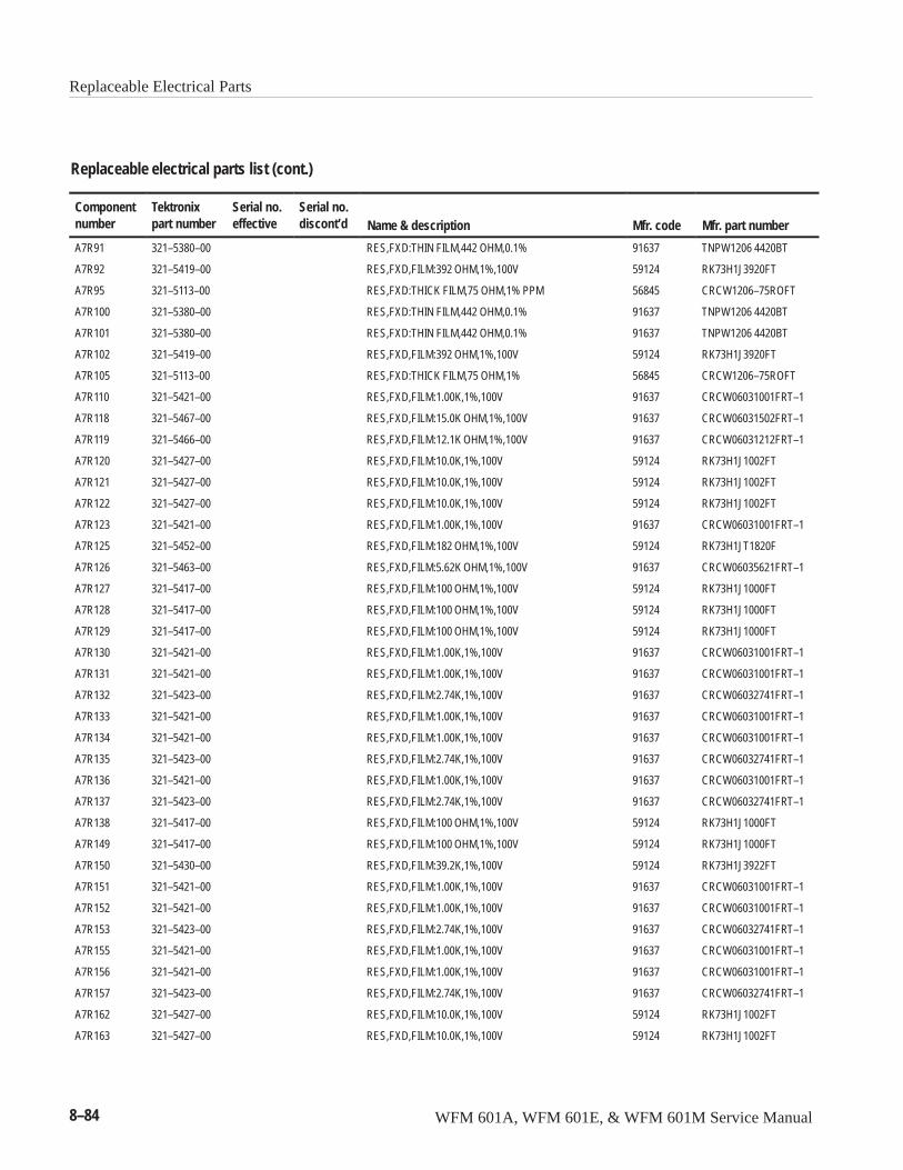
Replaceable Electrical Parts
8–84 WFM 601A, WFM 601E, & WFM 601M Service Manual
Replaceable electrical parts list (cont.)
Componentnumber Mfr. part numberMfr. codeName & description
Serial no.discont’d
Serial no.effective
Tektronixpart number
A7R91 321–5380–00 RES,FXD:THIN FILM,442 OHM,0.1% 91637 TNPW1206 4420BT
A7R92 321–5419–00 RES,FXD,FILM:392 OHM,1%,100V 59124 RK73H1J3920FT
A7R95 321–5113–00 RES,FXD:THICK FILM,75 OHM,1% PPM 56845 CRCW1206–75ROFT
A7R100 321–5380–00 RES,FXD:THIN FILM,442 OHM,0.1% 91637 TNPW1206 4420BT
A7R101 321–5380–00 RES,FXD:THIN FILM,442 OHM,0.1% 91637 TNPW1206 4420BT
A7R102 321–5419–00 RES,FXD,FILM:392 OHM,1%,100V 59124 RK73H1J3920FT
A7R105 321–5113–00 RES,FXD:THICK FILM,75 OHM,1% 56845 CRCW1206–75ROFT
A7R110 321–5421–00 RES,FXD,FILM:1.00K,1%,100V 91637 CRCW06031001FRT–1
A7R118 321–5467–00 RES,FXD,FILM:15.0K OHM,1%,100V 91637 CRCW06031502FRT–1
A7R119 321–5466–00 RES,FXD,FILM:12.1K OHM,1%,100V 91637 CRCW06031212FRT–1
A7R120 321–5427–00 RES,FXD,FILM:10.0K,1%,100V 59124 RK73H1J1002FT
A7R121 321–5427–00 RES,FXD,FILM:10.0K,1%,100V 59124 RK73H1J1002FT
A7R122 321–5427–00 RES,FXD,FILM:10.0K,1%,100V 59124 RK73H1J1002FT
A7R123 321–5421–00 RES,FXD,FILM:1.00K,1%,100V 91637 CRCW06031001FRT–1
A7R125 321–5452–00 RES,FXD,FILM:182 OHM,1%,100V 59124 RK73H1JT1820F
A7R126 321–5463–00 RES,FXD,FILM:5.62K OHM,1%,100V 91637 CRCW06035621FRT–1
A7R127 321–5417–00 RES,FXD,FILM:100 OHM,1%,100V 59124 RK73H1J1000FT
A7R128 321–5417–00 RES,FXD,FILM:100 OHM,1%,100V 59124 RK73H1J1000FT
A7R129 321–5417–00 RES,FXD,FILM:100 OHM,1%,100V 59124 RK73H1J1000FT
A7R130 321–5421–00 RES,FXD,FILM:1.00K,1%,100V 91637 CRCW06031001FRT–1
A7R131 321–5421–00 RES,FXD,FILM:1.00K,1%,100V 91637 CRCW06031001FRT–1
A7R132 321–5423–00 RES,FXD,FILM:2.74K,1%,100V 91637 CRCW06032741FRT–1
A7R133 321–5421–00 RES,FXD,FILM:1.00K,1%,100V 91637 CRCW06031001FRT–1
A7R134 321–5421–00 RES,FXD,FILM:1.00K,1%,100V 91637 CRCW06031001FRT–1
A7R135 321–5423–00 RES,FXD,FILM:2.74K,1%,100V 91637 CRCW06032741FRT–1
A7R136 321–5421–00 RES,FXD,FILM:1.00K,1%,100V 91637 CRCW06031001FRT–1
A7R137 321–5423–00 RES,FXD,FILM:2.74K,1%,100V 91637 CRCW06032741FRT–1
A7R138 321–5417–00 RES,FXD,FILM:100 OHM,1%,100V 59124 RK73H1J1000FT
A7R149 321–5417–00 RES,FXD,FILM:100 OHM,1%,100V 59124 RK73H1J1000FT
A7R150 321–5430–00 RES,FXD,FILM:39.2K,1%,100V 59124 RK73H1J3922FT
A7R151 321–5421–00 RES,FXD,FILM:1.00K,1%,100V 91637 CRCW06031001FRT–1
A7R152 321–5421–00 RES,FXD,FILM:1.00K,1%,100V 91637 CRCW06031001FRT–1
A7R153 321–5423–00 RES,FXD,FILM:2.74K,1%,100V 91637 CRCW06032741FRT–1
A7R155 321–5421–00 RES,FXD,FILM:1.00K,1%,100V 91637 CRCW06031001FRT–1
A7R156 321–5421–00 RES,FXD,FILM:1.00K,1%,100V 91637 CRCW06031001FRT–1
A7R157 321–5423–00 RES,FXD,FILM:2.74K,1%,100V 91637 CRCW06032741FRT–1
A7R162 321–5427–00 RES,FXD,FILM:10.0K,1%,100V 59124 RK73H1J1002FT
A7R163 321–5427–00 RES,FXD,FILM:10.0K,1%,100V 59124 RK73H1J1002FT
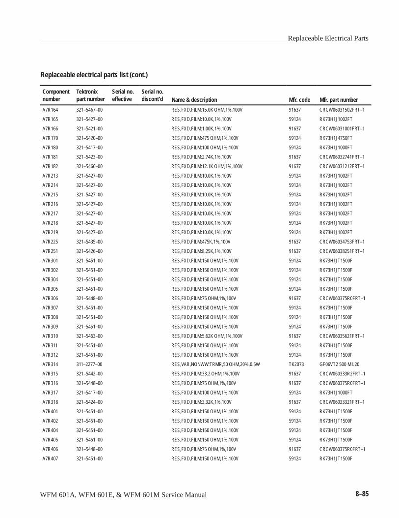
Replaceable Electrical Parts
WFM 601A, WFM 601E, & WFM 601M Service Manual 8–85
Replaceable electrical parts list (cont.)
Componentnumber Mfr. part numberMfr. codeName & description
Serial no.discont’d
Serial no.effective
Tektronixpart number
A7R164 321–5467–00 RES,FXD,FILM:15.0K OHM,1%,100V 91637 CRCW06031502FRT–1
A7R165 321–5427–00 RES,FXD,FILM:10.0K,1%,100V 59124 RK73H1J1002FT
A7R166 321–5421–00 RES,FXD,FILM:1.00K,1%,100V 91637 CRCW06031001FRT–1
A7R170 321–5420–00 RES,FXD,FILM:475 OHM,1%,100V 59124 RK73H1J4750FT
A7R180 321–5417–00 RES,FXD,FILM:100 OHM,1%,100V 59124 RK73H1J1000FT
A7R181 321–5423–00 RES,FXD,FILM:2.74K,1%,100V 91637 CRCW06032741FRT–1
A7R182 321–5466–00 RES,FXD,FILM:12.1K OHM,1%,100V 91637 CRCW06031212FRT–1
A7R213 321–5427–00 RES,FXD,FILM:10.0K,1%,100V 59124 RK73H1J1002FT
A7R214 321–5427–00 RES,FXD,FILM:10.0K,1%,100V 59124 RK73H1J1002FT
A7R215 321–5427–00 RES,FXD,FILM:10.0K,1%,100V 59124 RK73H1J1002FT
A7R216 321–5427–00 RES,FXD,FILM:10.0K,1%,100V 59124 RK73H1J1002FT
A7R217 321–5427–00 RES,FXD,FILM:10.0K,1%,100V 59124 RK73H1J1002FT
A7R218 321–5427–00 RES,FXD,FILM:10.0K,1%,100V 59124 RK73H1J1002FT
A7R219 321–5427–00 RES,FXD,FILM:10.0K,1%,100V 59124 RK73H1J1002FT
A7R225 321–5435–00 RES,FXD,FILM:475K,1%,100V 91637 CRCW06034753FRT–1
A7R251 321–5426–00 RES,FXD,FILM:8.25K,1%,100V 91637 CRCW06038251FRT–1
A7R301 321–5451–00 RES,FXD,FILM:150 OHM,1%,100V 59124 RK73H1JT1500F
A7R302 321–5451–00 RES,FXD,FILM:150 OHM,1%,100V 59124 RK73H1JT1500F
A7R304 321–5451–00 RES,FXD,FILM:150 OHM,1%,100V 59124 RK73H1JT1500F
A7R305 321–5451–00 RES,FXD,FILM:150 OHM,1%,100V 59124 RK73H1JT1500F
A7R306 321–5448–00 RES,FXD,FILM:75 OHM,1%,100V 91637 CRCW060375R0FRT–1
A7R307 321–5451–00 RES,FXD,FILM:150 OHM,1%,100V 59124 RK73H1JT1500F
A7R308 321–5451–00 RES,FXD,FILM:150 OHM,1%,100V 59124 RK73H1JT1500F
A7R309 321–5451–00 RES,FXD,FILM:150 OHM,1%,100V 59124 RK73H1JT1500F
A7R310 321–5463–00 RES,FXD,FILM:5.62K OHM,1%,100V 91637 CRCW06035621FRT–1
A7R311 321–5451–00 RES,FXD,FILM:150 OHM,1%,100V 59124 RK73H1JT1500F
A7R312 321–5451–00 RES,FXD,FILM:150 OHM,1%,100V 59124 RK73H1JT1500F
A7R314 311–2277–00 RES,VAR,NONWW:TRMR,50 OHM,20%,0.5W TK2073 GF06VT2 500 M L20
A7R315 321–5442–00 RES,FXD,FILM:33.2 OHM,1%,100V 91637 CRCW060333R2FRT–1
A7R316 321–5448–00 RES,FXD,FILM:75 OHM,1%,100V 91637 CRCW060375R0FRT–1
A7R317 321–5417–00 RES,FXD,FILM:100 OHM,1%,100V 59124 RK73H1J1000FT
A7R318 321–5424–00 RES,FXD,FILM:3.32K,1%,100V 91637 CRCW06033321FRT–1
A7R401 321–5451–00 RES,FXD,FILM:150 OHM,1%,100V 59124 RK73H1JT1500F
A7R402 321–5451–00 RES,FXD,FILM:150 OHM,1%,100V 59124 RK73H1JT1500F
A7R404 321–5451–00 RES,FXD,FILM:150 OHM,1%,100V 59124 RK73H1JT1500F
A7R405 321–5451–00 RES,FXD,FILM:150 OHM,1%,100V 59124 RK73H1JT1500F
A7R406 321–5448–00 RES,FXD,FILM:75 OHM,1%,100V 91637 CRCW060375R0FRT–1
A7R407 321–5451–00 RES,FXD,FILM:150 OHM,1%,100V 59124 RK73H1JT1500F
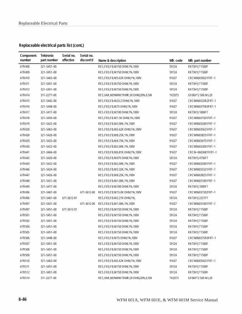
Replaceable Electrical Parts
8–86 WFM 601A, WFM 601E, & WFM 601M Service Manual
Replaceable electrical parts list (cont.)
Componentnumber Mfr. part numberMfr. codeName & description
Serial no.discont’d
Serial no.effective
Tektronixpart number
A7R408 321–5451–00 RES,FXD,FILM:150 OHM,1%,100V 59124 RK73H1JT1500F
A7R409 321–5451–00 RES,FXD,FILM:150 OHM,1%,100V 59124 RK73H1JT1500F
A7R410 321–5463–00 RES,FXD,FILM:5.62K OHM,1%,100V 91637 CRCW06035621FRT–1
A7R411 321–5451–00 RES,FXD,FILM:150 OHM,1%,100V 59124 RK73H1JT1500F
A7R412 321–5451–00 RES,FXD,FILM:150 OHM,1%,100V 59124 RK73H1JT1500F
A7R414 311–2277–00 RES,VAR,NONWW:TRMR,50 OHM,20%,0.5W TK2073 GF06VT2 500 M L20
A7R415 321–5442–00 RES,FXD,FILM:33.2 OHM,1%,100V 91637 CRCW060333R2FRT–1
A7R416 321–5448–00 RES,FXD,FILM:75 OHM,1%,100V 91637 CRCW060375R0FRT–1
A7R417 321–5417–00 RES,FXD,FILM:100 OHM,1%,100V 59124 RK73H1J1000FT
A7R418 321–5459–00 RES,FXD,FILM:1.5K OHM,1%,100V 91637 CRCW06031501FRT–1
A7R419 321–5422–00 RES,FXD,FILM:2.00K,1%,100V 91637 CRCW06032001FRT–1
A7R420 321–5463–00 RES,FXD,FILM:5.62K OHM,1%,100V 91637 CRCW06035621FRT–1
A7R428 321–5426–00 RES,FXD,FILM:8.25K,1%,100V 91637 CRCW06038251FRT–1
A7R429 321–5425–00 RES,FXD,FILM:4.75K,1%,100V 91637 CRCW06034751FRT–1
A7R430 321–5422–00 RES,FXD,FILM:2.00K,1%,100V 91637 CRCW06032001FRT–1
A7R441 321–5464–00 RES,FXD,FILM:6.81K OHM,1%,100V 91637 CRCW–06036811FRT–1
A7R442 321–5420–00 RES,FXD,FILM:475 OHM,1%,100V 59124 RK73H1J4750FT
A7R443 321–5422–00 RES,FXD,FILM:2.00K,1%,100V 91637 CRCW06032001FRT–1
A7R446 321–5424–00 RES,FXD,FILM:3.32K,1%,100V 91637 CRCW06033321FRT–1
A7R447 321–5426–00 RES,FXD,FILM:8.25K,1%,100V 91637 CRCW06038251FRT–1
A7R448 321–5421–00 RES,FXD,FILM:1.00K,1%,100V 91637 CRCW06031001FRT–1
A7R449 321–5417–00 RES,FXD,FILM:100 OHM,1%,100V 59124 RK73H1J1000FT
A7R496 321–5467–00 671-3612-00 RES,FXD,FILM:15.0K OHM,1%,100V 91637 CRCW06031502FRT–1
A7R496 321–5461–00 671-3612-01 RES,FXD,FILM:2.21K OHM,1%, 59124 RK73H1J2221FT
A7R497 321–5421–00 671-3612-00 RES,FXD,FILM:1.00K,1%,100V 91637 CRCW06031001FRT–1
A7R497 321–5451–00 671-3612-01 RES,FXD,FILM:150 OHM,1%,100V 59124 RK73H1JT1500F
A7R501 321–5451–00 RES,FXD,FILM:150 OHM,1%,100V 59124 RK73H1JT1500F
A7R502 321–5451–00 RES,FXD,FILM:150 OHM,1%,100V 59124 RK73H1JT1500F
A7R504 321–5451–00 RES,FXD,FILM:150 OHM,1%,100V 59124 RK73H1JT1500F
A7R505 321–5451–00 RES,FXD,FILM:150 OHM,1%,100V 59124 RK73H1JT1500F
A7R506 321–5448–00 RES,FXD,FILM:75 OHM,1%,100V 91637 CRCW060375R0FRT–1
A7R507 321–5451–00 RES,FXD,FILM:150 OHM,1%,100V 59124 RK73H1JT1500F
A7R508 321–5451–00 RES,FXD,FILM:150 OHM,1%,100V 59124 RK73H1JT1500F
A7R509 321–5451–00 RES,FXD,FILM:150 OHM,1%,100V 59124 RK73H1JT1500F
A7R510 321–5463–00 RES,FXD,FILM:5.62K OHM,1%,100V 91637 CRCW06035621FRT–1
A7R511 321–5451–00 RES,FXD,FILM:150 OHM,1%,100V 59124 RK73H1JT1500F
A7R512 321–5451–00 RES,FXD,FILM:150 OHM,1%,100V 59124 RK73H1JT1500F
A7R514 311–2277–00 RES,VAR,NONWW:TRMR,50 OHM,20%,0.5W TK2073 GF06VT2 500 M L20
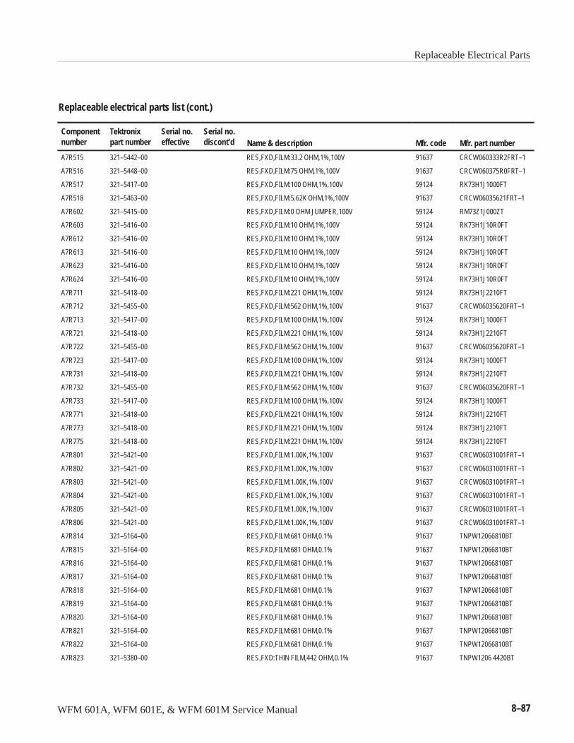
Replaceable Electrical Parts
WFM 601A, WFM 601E, & WFM 601M Service Manual 8–87
Replaceable electrical parts list (cont.)
Componentnumber Mfr. part numberMfr. codeName & description
Serial no.discont’d
Serial no.effective
Tektronixpart number
A7R515 321–5442–00 RES,FXD,FILM:33.2 OHM,1%,100V 91637 CRCW060333R2FRT–1
A7R516 321–5448–00 RES,FXD,FILM:75 OHM,1%,100V 91637 CRCW060375R0FRT–1
A7R517 321–5417–00 RES,FXD,FILM:100 OHM,1%,100V 59124 RK73H1J1000FT
A7R518 321–5463–00 RES,FXD,FILM:5.62K OHM,1%,100V 91637 CRCW06035621FRT–1
A7R602 321–5415–00 RES,FXD,FILM:0 OHM JUMPER,100V 59124 RM73Z1J000ZT
A7R603 321–5416–00 RES,FXD,FILM:10 OHM,1%,100V 59124 RK73H1J10R0FT
A7R612 321–5416–00 RES,FXD,FILM:10 OHM,1%,100V 59124 RK73H1J10R0FT
A7R613 321–5416–00 RES,FXD,FILM:10 OHM,1%,100V 59124 RK73H1J10R0FT
A7R623 321–5416–00 RES,FXD,FILM:10 OHM,1%,100V 59124 RK73H1J10R0FT
A7R624 321–5416–00 RES,FXD,FILM:10 OHM,1%,100V 59124 RK73H1J10R0FT
A7R711 321–5418–00 RES,FXD,FILM:221 OHM,1%,100V 59124 RK73H1J2210FT
A7R712 321–5455–00 RES,FXD,FILM:562 OHM,1%,100V 91637 CRCW06035620FRT–1
A7R713 321–5417–00 RES,FXD,FILM:100 OHM,1%,100V 59124 RK73H1J1000FT
A7R721 321–5418–00 RES,FXD,FILM:221 OHM,1%,100V 59124 RK73H1J2210FT
A7R722 321–5455–00 RES,FXD,FILM:562 OHM,1%,100V 91637 CRCW06035620FRT–1
A7R723 321–5417–00 RES,FXD,FILM:100 OHM,1%,100V 59124 RK73H1J1000FT
A7R731 321–5418–00 RES,FXD,FILM:221 OHM,1%,100V 59124 RK73H1J2210FT
A7R732 321–5455–00 RES,FXD,FILM:562 OHM,1%,100V 91637 CRCW06035620FRT–1
A7R733 321–5417–00 RES,FXD,FILM:100 OHM,1%,100V 59124 RK73H1J1000FT
A7R771 321–5418–00 RES,FXD,FILM:221 OHM,1%,100V 59124 RK73H1J2210FT
A7R773 321–5418–00 RES,FXD,FILM:221 OHM,1%,100V 59124 RK73H1J2210FT
A7R775 321–5418–00 RES,FXD,FILM:221 OHM,1%,100V 59124 RK73H1J2210FT
A7R801 321–5421–00 RES,FXD,FILM:1.00K,1%,100V 91637 CRCW06031001FRT–1
A7R802 321–5421–00 RES,FXD,FILM:1.00K,1%,100V 91637 CRCW06031001FRT–1
A7R803 321–5421–00 RES,FXD,FILM:1.00K,1%,100V 91637 CRCW06031001FRT–1
A7R804 321–5421–00 RES,FXD,FILM:1.00K,1%,100V 91637 CRCW06031001FRT–1
A7R805 321–5421–00 RES,FXD,FILM:1.00K,1%,100V 91637 CRCW06031001FRT–1
A7R806 321–5421–00 RES,FXD,FILM:1.00K,1%,100V 91637 CRCW06031001FRT–1
A7R814 321–5164–00 RES,FXD,FILM:681 OHM,0.1% 91637 TNPW12066810BT
A7R815 321–5164–00 RES,FXD,FILM:681 OHM,0.1% 91637 TNPW12066810BT
A7R816 321–5164–00 RES,FXD,FILM:681 OHM,0.1% 91637 TNPW12066810BT
A7R817 321–5164–00 RES,FXD,FILM:681 OHM,0.1% 91637 TNPW12066810BT
A7R818 321–5164–00 RES,FXD,FILM:681 OHM,0.1% 91637 TNPW12066810BT
A7R819 321–5164–00 RES,FXD,FILM:681 OHM,0.1% 91637 TNPW12066810BT
A7R820 321–5164–00 RES,FXD,FILM:681 OHM,0.1% 91637 TNPW12066810BT
A7R821 321–5164–00 RES,FXD,FILM:681 OHM,0.1% 91637 TNPW12066810BT
A7R822 321–5164–00 RES,FXD,FILM:681 OHM,0.1% 91637 TNPW12066810BT
A7R823 321–5380–00 RES,FXD:THIN FILM,442 OHM,0.1% 91637 TNPW1206 4420BT
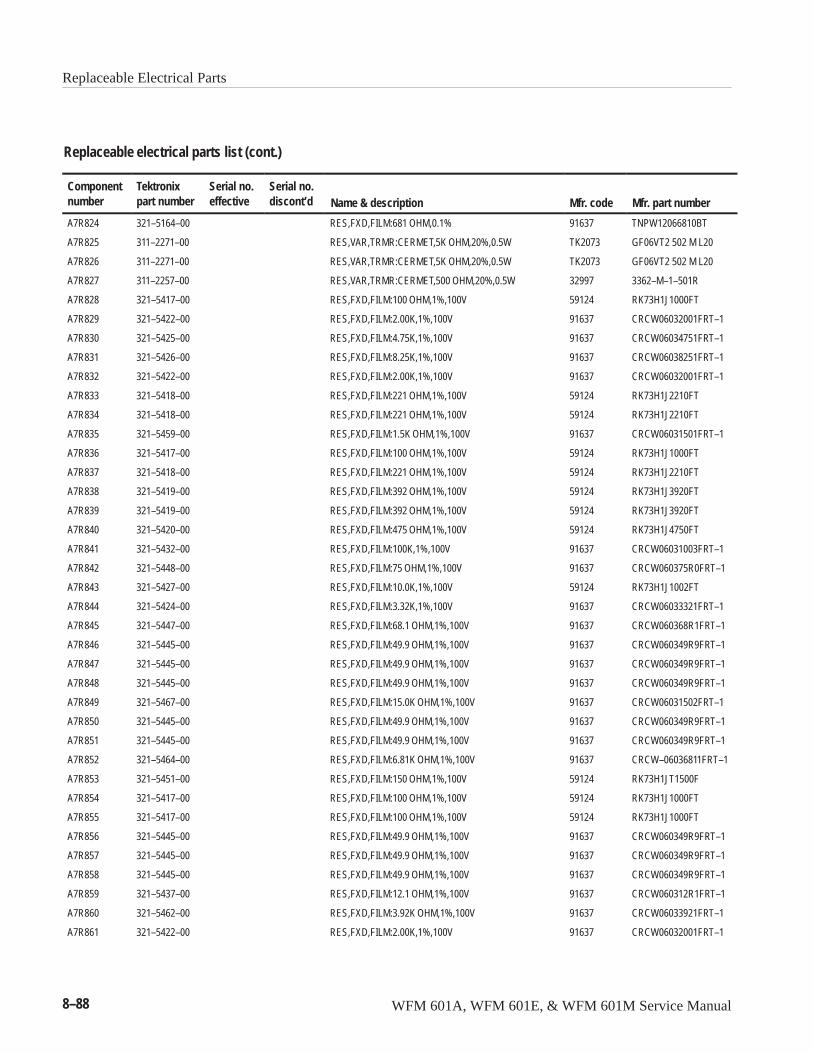
Replaceable Electrical Parts
8–88 WFM 601A, WFM 601E, & WFM 601M Service Manual
Replaceable electrical parts list (cont.)
Componentnumber Mfr. part numberMfr. codeName & description
Serial no.discont’d
Serial no.effective
Tektronixpart number
A7R824 321–5164–00 RES,FXD,FILM:681 OHM,0.1% 91637 TNPW12066810BT
A7R825 311–2271–00 RES,VAR,TRMR:CERMET,5K OHM,20%,0.5W TK2073 GF06VT2 502 M L20
A7R826 311–2271–00 RES,VAR,TRMR:CERMET,5K OHM,20%,0.5W TK2073 GF06VT2 502 M L20
A7R827 311–2257–00 RES,VAR,TRMR:CERMET,500 OHM,20%,0.5W 32997 3362–M–1–501R
A7R828 321–5417–00 RES,FXD,FILM:100 OHM,1%,100V 59124 RK73H1J1000FT
A7R829 321–5422–00 RES,FXD,FILM:2.00K,1%,100V 91637 CRCW06032001FRT–1
A7R830 321–5425–00 RES,FXD,FILM:4.75K,1%,100V 91637 CRCW06034751FRT–1
A7R831 321–5426–00 RES,FXD,FILM:8.25K,1%,100V 91637 CRCW06038251FRT–1
A7R832 321–5422–00 RES,FXD,FILM:2.00K,1%,100V 91637 CRCW06032001FRT–1
A7R833 321–5418–00 RES,FXD,FILM:221 OHM,1%,100V 59124 RK73H1J2210FT
A7R834 321–5418–00 RES,FXD,FILM:221 OHM,1%,100V 59124 RK73H1J2210FT
A7R835 321–5459–00 RES,FXD,FILM:1.5K OHM,1%,100V 91637 CRCW06031501FRT–1
A7R836 321–5417–00 RES,FXD,FILM:100 OHM,1%,100V 59124 RK73H1J1000FT
A7R837 321–5418–00 RES,FXD,FILM:221 OHM,1%,100V 59124 RK73H1J2210FT
A7R838 321–5419–00 RES,FXD,FILM:392 OHM,1%,100V 59124 RK73H1J3920FT
A7R839 321–5419–00 RES,FXD,FILM:392 OHM,1%,100V 59124 RK73H1J3920FT
A7R840 321–5420–00 RES,FXD,FILM:475 OHM,1%,100V 59124 RK73H1J4750FT
A7R841 321–5432–00 RES,FXD,FILM:100K,1%,100V 91637 CRCW06031003FRT–1
A7R842 321–5448–00 RES,FXD,FILM:75 OHM,1%,100V 91637 CRCW060375R0FRT–1
A7R843 321–5427–00 RES,FXD,FILM:10.0K,1%,100V 59124 RK73H1J1002FT
A7R844 321–5424–00 RES,FXD,FILM:3.32K,1%,100V 91637 CRCW06033321FRT–1
A7R845 321–5447–00 RES,FXD,FILM:68.1 OHM,1%,100V 91637 CRCW060368R1FRT–1
A7R846 321–5445–00 RES,FXD,FILM:49.9 OHM,1%,100V 91637 CRCW060349R9FRT–1
A7R847 321–5445–00 RES,FXD,FILM:49.9 OHM,1%,100V 91637 CRCW060349R9FRT–1
A7R848 321–5445–00 RES,FXD,FILM:49.9 OHM,1%,100V 91637 CRCW060349R9FRT–1
A7R849 321–5467–00 RES,FXD,FILM:15.0K OHM,1%,100V 91637 CRCW06031502FRT–1
A7R850 321–5445–00 RES,FXD,FILM:49.9 OHM,1%,100V 91637 CRCW060349R9FRT–1
A7R851 321–5445–00 RES,FXD,FILM:49.9 OHM,1%,100V 91637 CRCW060349R9FRT–1
A7R852 321–5464–00 RES,FXD,FILM:6.81K OHM,1%,100V 91637 CRCW–06036811FRT–1
A7R853 321–5451–00 RES,FXD,FILM:150 OHM,1%,100V 59124 RK73H1JT1500F
A7R854 321–5417–00 RES,FXD,FILM:100 OHM,1%,100V 59124 RK73H1J1000FT
A7R855 321–5417–00 RES,FXD,FILM:100 OHM,1%,100V 59124 RK73H1J1000FT
A7R856 321–5445–00 RES,FXD,FILM:49.9 OHM,1%,100V 91637 CRCW060349R9FRT–1
A7R857 321–5445–00 RES,FXD,FILM:49.9 OHM,1%,100V 91637 CRCW060349R9FRT–1
A7R858 321–5445–00 RES,FXD,FILM:49.9 OHM,1%,100V 91637 CRCW060349R9FRT–1
A7R859 321–5437–00 RES,FXD,FILM:12.1 OHM,1%,100V 91637 CRCW060312R1FRT–1
A7R860 321–5462–00 RES,FXD,FILM:3.92K OHM,1%,100V 91637 CRCW06033921FRT–1
A7R861 321–5422–00 RES,FXD,FILM:2.00K,1%,100V 91637 CRCW06032001FRT–1
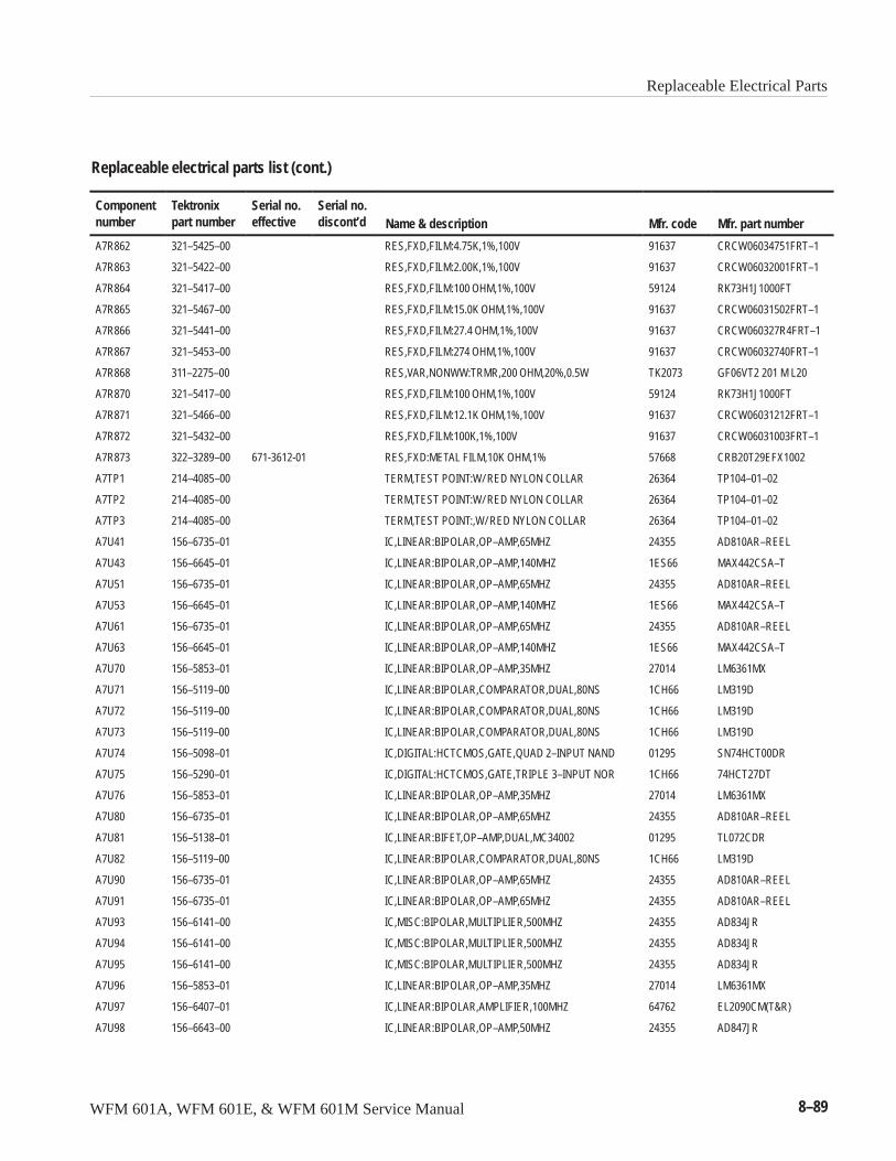
Replaceable Electrical Parts
WFM 601A, WFM 601E, & WFM 601M Service Manual 8–89
Replaceable electrical parts list (cont.)
Componentnumber Mfr. part numberMfr. codeName & description
Serial no.discont’d
Serial no.effective
Tektronixpart number
A7R862 321–5425–00 RES,FXD,FILM:4.75K,1%,100V 91637 CRCW06034751FRT–1
A7R863 321–5422–00 RES,FXD,FILM:2.00K,1%,100V 91637 CRCW06032001FRT–1
A7R864 321–5417–00 RES,FXD,FILM:100 OHM,1%,100V 59124 RK73H1J1000FT
A7R865 321–5467–00 RES,FXD,FILM:15.0K OHM,1%,100V 91637 CRCW06031502FRT–1
A7R866 321–5441–00 RES,FXD,FILM:27.4 OHM,1%,100V 91637 CRCW060327R4FRT–1
A7R867 321–5453–00 RES,FXD,FILM:274 OHM,1%,100V 91637 CRCW06032740FRT–1
A7R868 311–2275–00 RES,VAR,NONWW:TRMR,200 OHM,20%,0.5W TK2073 GF06VT2 201 M L20
A7R870 321–5417–00 RES,FXD,FILM:100 OHM,1%,100V 59124 RK73H1J1000FT
A7R871 321–5466–00 RES,FXD,FILM:12.1K OHM,1%,100V 91637 CRCW06031212FRT–1
A7R872 321–5432–00 RES,FXD,FILM:100K,1%,100V 91637 CRCW06031003FRT–1
A7R873 322–3289–00 671-3612-01 RES,FXD:METAL FILM,10K OHM,1% 57668 CRB20T29EFX1002
A7TP1 214–4085–00 TERM,TEST POINT:W/ RED NYLON COLLAR 26364 TP104–01–02
A7TP2 214–4085–00 TERM,TEST POINT:W/ RED NYLON COLLAR 26364 TP104–01–02
A7TP3 214–4085–00 TERM,TEST POINT:,W/ RED NYLON COLLAR 26364 TP104–01–02
A7U41 156–6735–01 IC,LINEAR:BIPOLAR,OP–AMP,65MHZ 24355 AD810AR–REEL
A7U43 156–6645–01 IC,LINEAR:BIPOLAR,OP–AMP,140MHZ 1ES66 MAX442CSA–T
A7U51 156–6735–01 IC,LINEAR:BIPOLAR,OP–AMP,65MHZ 24355 AD810AR–REEL
A7U53 156–6645–01 IC,LINEAR:BIPOLAR,OP–AMP,140MHZ 1ES66 MAX442CSA–T
A7U61 156–6735–01 IC,LINEAR:BIPOLAR,OP–AMP,65MHZ 24355 AD810AR–REEL
A7U63 156–6645–01 IC,LINEAR:BIPOLAR,OP–AMP,140MHZ 1ES66 MAX442CSA–T
A7U70 156–5853–01 IC,LINEAR:BIPOLAR,OP–AMP,35MHZ 27014 LM6361MX
A7U71 156–5119–00 IC,LINEAR:BIPOLAR,COMPARATOR,DUAL,80NS 1CH66 LM319D
A7U72 156–5119–00 IC,LINEAR:BIPOLAR,COMPARATOR,DUAL,80NS 1CH66 LM319D
A7U73 156–5119–00 IC,LINEAR:BIPOLAR,COMPARATOR,DUAL,80NS 1CH66 LM319D
A7U74 156–5098–01 IC,DIGITAL:HCTCMOS,GATE,QUAD 2–INPUT NAND 01295 SN74HCT00DR
A7U75 156–5290–01 IC,DIGITAL:HCTCMOS,GATE,TRIPLE 3–INPUT NOR 1CH66 74HCT27DT
A7U76 156–5853–01 IC,LINEAR:BIPOLAR,OP–AMP,35MHZ 27014 LM6361MX
A7U80 156–6735–01 IC,LINEAR:BIPOLAR,OP–AMP,65MHZ 24355 AD810AR–REEL
A7U81 156–5138–01 IC,LINEAR:BIFET,OP–AMP,DUAL,MC34002 01295 TL072CDR
A7U82 156–5119–00 IC,LINEAR:BIPOLAR,COMPARATOR,DUAL,80NS 1CH66 LM319D
A7U90 156–6735–01 IC,LINEAR:BIPOLAR,OP–AMP,65MHZ 24355 AD810AR–REEL
A7U91 156–6735–01 IC,LINEAR:BIPOLAR,OP–AMP,65MHZ 24355 AD810AR–REEL
A7U93 156–6141–00 IC,MISC:BIPOLAR,MULTIPLIER,500MHZ 24355 AD834JR
A7U94 156–6141–00 IC,MISC:BIPOLAR,MULTIPLIER,500MHZ 24355 AD834JR
A7U95 156–6141–00 IC,MISC:BIPOLAR,MULTIPLIER,500MHZ 24355 AD834JR
A7U96 156–5853–01 IC,LINEAR:BIPOLAR,OP–AMP,35MHZ 27014 LM6361MX
A7U97 156–6407–01 IC,LINEAR:BIPOLAR,AMPLIFIER,100MHZ 64762 EL2090CM(T&R)
A7U98 156–6643–00 IC,LINEAR:BIPOLAR,OP–AMP,50MHZ 24355 AD847JR
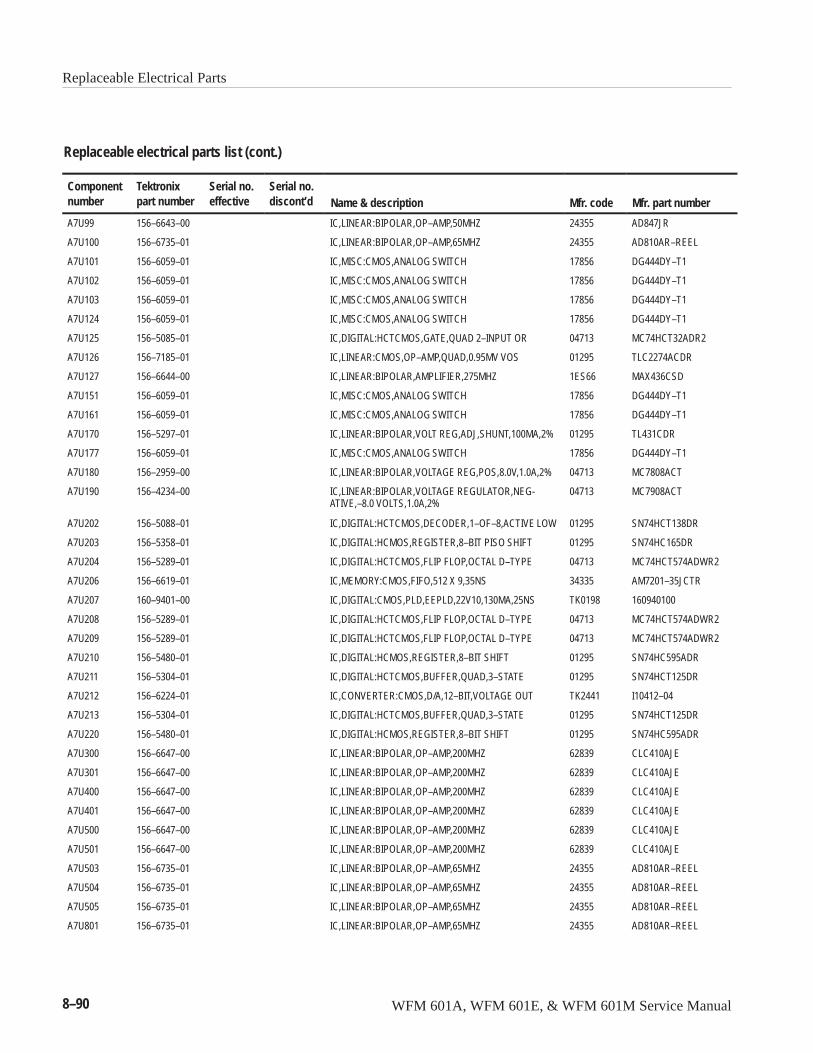
Replaceable Electrical Parts
8–90 WFM 601A, WFM 601E, & WFM 601M Service Manual
Replaceable electrical parts list (cont.)
Componentnumber Mfr. part numberMfr. codeName & description
Serial no.discont’d
Serial no.effective
Tektronixpart number
A7U99 156–6643–00 IC,LINEAR:BIPOLAR,OP–AMP,50MHZ 24355 AD847JR
A7U100 156–6735–01 IC,LINEAR:BIPOLAR,OP–AMP,65MHZ 24355 AD810AR–REEL
A7U101 156–6059–01 IC,MISC:CMOS,ANALOG SWITCH 17856 DG444DY–T1
A7U102 156–6059–01 IC,MISC:CMOS,ANALOG SWITCH 17856 DG444DY–T1
A7U103 156–6059–01 IC,MISC:CMOS,ANALOG SWITCH 17856 DG444DY–T1
A7U124 156–6059–01 IC,MISC:CMOS,ANALOG SWITCH 17856 DG444DY–T1
A7U125 156–5085–01 IC,DIGITAL:HCTCMOS,GATE,QUAD 2–INPUT OR 04713 MC74HCT32ADR2
A7U126 156–7185–01 IC,LINEAR:CMOS,OP–AMP,QUAD,0.95MV VOS 01295 TLC2274ACDR
A7U127 156–6644–00 IC,LINEAR:BIPOLAR,AMPLIFIER,275MHZ 1ES66 MAX436CSD
A7U151 156–6059–01 IC,MISC:CMOS,ANALOG SWITCH 17856 DG444DY–T1
A7U161 156–6059–01 IC,MISC:CMOS,ANALOG SWITCH 17856 DG444DY–T1
A7U170 156–5297–01 IC,LINEAR:BIPOLAR,VOLT REG,ADJ,SHUNT,100MA,2% 01295 TL431CDR
A7U177 156–6059–01 IC,MISC:CMOS,ANALOG SWITCH 17856 DG444DY–T1
A7U180 156–2959–00 IC,LINEAR:BIPOLAR,VOLTAGE REG,POS,8.0V,1.0A,2% 04713 MC7808ACT
A7U190 156–4234–00 IC,LINEAR:BIPOLAR,VOLTAGE REGULATOR,NEG-ATIVE,–8.0 VOLTS,1.0A,2%
04713 MC7908ACT
A7U202 156–5088–01 IC,DIGITAL:HCTCMOS,DECODER,1–OF–8,ACTIVE LOW 01295 SN74HCT138DR
A7U203 156–5358–01 IC,DIGITAL:HCMOS,REGISTER,8–BIT PISO SHIFT 01295 SN74HC165DR
A7U204 156–5289–01 IC,DIGITAL:HCTCMOS,FLIP FLOP,OCTAL D–TYPE 04713 MC74HCT574ADWR2
A7U206 156–6619–01 IC,MEMORY:CMOS,FIFO,512 X 9,35NS 34335 AM7201–35JCTR
A7U207 160–9401–00 IC,DIGITAL:CMOS,PLD,EEPLD,22V10,130MA,25NS TK0198 160940100
A7U208 156–5289–01 IC,DIGITAL:HCTCMOS,FLIP FLOP,OCTAL D–TYPE 04713 MC74HCT574ADWR2
A7U209 156–5289–01 IC,DIGITAL:HCTCMOS,FLIP FLOP,OCTAL D–TYPE 04713 MC74HCT574ADWR2
A7U210 156–5480–01 IC,DIGITAL:HCMOS,REGISTER,8–BIT SHIFT 01295 SN74HC595ADR
A7U211 156–5304–01 IC,DIGITAL:HCTCMOS,BUFFER,QUAD,3–STATE 01295 SN74HCT125DR
A7U212 156–6224–01 IC,CONVERTER:CMOS,D/A,12–BIT,VOLTAGE OUT TK2441 I10412–04
A7U213 156–5304–01 IC,DIGITAL:HCTCMOS,BUFFER,QUAD,3–STATE 01295 SN74HCT125DR
A7U220 156–5480–01 IC,DIGITAL:HCMOS,REGISTER,8–BIT SHIFT 01295 SN74HC595ADR
A7U300 156–6647–00 IC,LINEAR:BIPOLAR,OP–AMP,200MHZ 62839 CLC410AJE
A7U301 156–6647–00 IC,LINEAR:BIPOLAR,OP–AMP,200MHZ 62839 CLC410AJE
A7U400 156–6647–00 IC,LINEAR:BIPOLAR,OP–AMP,200MHZ 62839 CLC410AJE
A7U401 156–6647–00 IC,LINEAR:BIPOLAR,OP–AMP,200MHZ 62839 CLC410AJE
A7U500 156–6647–00 IC,LINEAR:BIPOLAR,OP–AMP,200MHZ 62839 CLC410AJE
A7U501 156–6647–00 IC,LINEAR:BIPOLAR,OP–AMP,200MHZ 62839 CLC410AJE
A7U503 156–6735–01 IC,LINEAR:BIPOLAR,OP–AMP,65MHZ 24355 AD810AR–REEL
A7U504 156–6735–01 IC,LINEAR:BIPOLAR,OP–AMP,65MHZ 24355 AD810AR–REEL
A7U505 156–6735–01 IC,LINEAR:BIPOLAR,OP–AMP,65MHZ 24355 AD810AR–REEL
A7U801 156–6735–01 IC,LINEAR:BIPOLAR,OP–AMP,65MHZ 24355 AD810AR–REEL
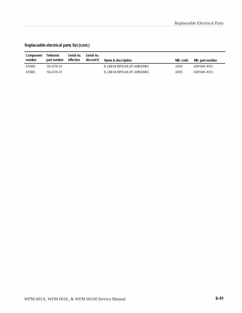
Replaceable Electrical Parts
WFM 601A, WFM 601E, & WFM 601M Service Manual 8–91
Replaceable electrical parts list (cont.)
Componentnumber Mfr. part numberMfr. codeName & description
Serial no.discont’d
Serial no.effective
Tektronixpart number
A7U803 156–6735–01 IC,LINEAR:BIPOLAR,OP–AMP,65MHZ 24355 AD810AR–REEL
A7U805 156–6735–01 IC,LINEAR:BIPOLAR,OP–AMP,65MHZ 24355 AD810AR–REEL
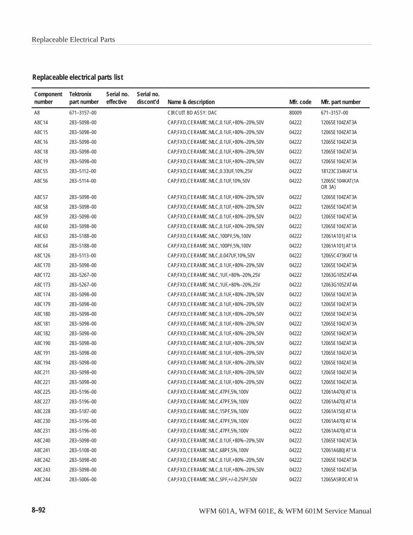
Replaceable Electrical Parts
8–92 WFM 601A, WFM 601E, & WFM 601M Service Manual
Replaceable electrical parts list
Componentnumber
Tektronixpart number
Serial no.effective
Serial no.discont’d Name & description Mfr. code Mfr. part number
A8 671–3157–00 CIRCUIT BD ASSY: DAC 80009 671–3157–00
A8C14 283–5098–00 CAP,FXD,CERAMIC:MLC,0.1UF,+80%–20%,50V 04222 12065E104ZAT3A
A8C15 283–5098–00 CAP,FXD,CERAMIC:MLC,0.1UF,+80%–20%,50V 04222 12065E104ZAT3A
A8C16 283–5098–00 CAP,FXD,CERAMIC:MLC,0.1UF,+80%–20%,50V 04222 12065E104ZAT3A
A8C18 283–5098–00 CAP,FXD,CERAMIC:MLC,0.1UF,+80%–20%,50V 04222 12065E104ZAT3A
A8C19 283–5098–00 CAP,FXD,CERAMIC:MLC,0.1UF,+80%–20%,50V 04222 12065E104ZAT3A
A8C55 283–5112–00 CAP,FXD,CERAMIC:MLC,0.33UF,10%,25V 04222 18123C334KAT1A
A8C56 283–5114–00 CAP,FXD,CERAMIC:MLC,0.1UF,10%,50V 04222 12065C104KAT(1AOR 3A)
A8C57 283–5098–00 CAP,FXD,CERAMIC:MLC,0.1UF,+80%–20%,50V 04222 12065E104ZAT3A
A8C58 283–5098–00 CAP,FXD,CERAMIC:MLC,0.1UF,+80%–20%,50V 04222 12065E104ZAT3A
A8C59 283–5098–00 CAP,FXD,CERAMIC:MLC,0.1UF,+80%–20%,50V 04222 12065E104ZAT3A
A8C60 283–5098–00 CAP,FXD,CERAMIC:MLC,0.1UF,+80%–20%,50V 04222 12065E104ZAT3A
A8C63 283–5188–00 CAP,FXD,CERAMIC:MLC,100PF,5%,100V 04222 12061A101JAT1A
A8C64 283–5188–00 CAP,FXD,CERAMIC:MLC,100PF,5%,100V 04222 12061A101JAT1A
A8C126 283–5113–00 CAP,FXD,CERAMIC:MLC,0.047UF,10%,50V 04222 12065C473KAT1A
A8C170 283–5098–00 CAP,FXD,CERAMIC:MLC,0.1UF,+80%–20%,50V 04222 12065E104ZAT3A
A8C172 283–5267–00 CAP,FXD,CERAMIC:MLC,1UF,+80%–20%,25V 04222 12063G105ZAT4A
A8C173 283–5267–00 CAP,FXD,CERAMIC:MLC,1UF,+80%–20%,25V 04222 12063G105ZAT4A
A8C174 283–5098–00 CAP,FXD,CERAMIC:MLC,0.1UF,+80%–20%,50V 04222 12065E104ZAT3A
A8C179 283–5098–00 CAP,FXD,CERAMIC:MLC,0.1UF,+80%–20%,50V 04222 12065E104ZAT3A
A8C180 283–5098–00 CAP,FXD,CERAMIC:MLC,0.1UF,+80%–20%,50V 04222 12065E104ZAT3A
A8C181 283–5098–00 CAP,FXD,CERAMIC:MLC,0.1UF,+80%–20%,50V 04222 12065E104ZAT3A
A8C182 283–5098–00 CAP,FXD,CERAMIC:MLC,0.1UF,+80%–20%,50V 04222 12065E104ZAT3A
A8C190 283–5098–00 CAP,FXD,CERAMIC:MLC,0.1UF,+80%–20%,50V 04222 12065E104ZAT3A
A8C191 283–5098–00 CAP,FXD,CERAMIC:MLC,0.1UF,+80%–20%,50V 04222 12065E104ZAT3A
A8C194 283–5098–00 CAP,FXD,CERAMIC:MLC,0.1UF,+80%–20%,50V 04222 12065E104ZAT3A
A8C211 283–5098–00 CAP,FXD,CERAMIC:MLC,0.1UF,+80%–20%,50V 04222 12065E104ZAT3A
A8C221 283–5098–00 CAP,FXD,CERAMIC:MLC,0.1UF,+80%–20%,50V 04222 12065E104ZAT3A
A8C225 283–5196–00 CAP,FXD,CERAMIC:MLC,47PF,5%,100V 04222 12061A470JAT1A
A8C227 283–5196–00 CAP,FXD,CERAMIC:MLC,47PF,5%,100V 04222 12061A470JAT1A
A8C228 283–5187–00 CAP,FXD,CERAMIC:MLC,15PF,5%,100V 04222 12061A150JAT1A
A8C230 283–5196–00 CAP,FXD,CERAMIC:MLC,47PF,5%,100V 04222 12061A470JAT1A
A8C231 283–5196–00 CAP,FXD,CERAMIC:MLC,47PF,5%,100V 04222 12061A470JAT1A
A8C240 283–5098–00 CAP,FXD,CERAMIC:MLC,0.1UF,+80%–20%,50V 04222 12065E104ZAT3A
A8C241 283–5108–00 CAP,FXD,CERAMIC:MLC,68PF,5%,100V 04222 12061A680JAT1A
A8C242 283–5098–00 CAP,FXD,CERAMIC:MLC,0.1UF,+80%–20%,50V 04222 12065E104ZAT3A
A8C243 283–5098–00 CAP,FXD,CERAMIC:MLC,0.1UF,+80%–20%,50V 04222 12065E104ZAT3A
A8C244 283–5006–00 CAP,FXD,CERAMIC:MLC,5PF,+/–0.25PF,50V 04222 12065A5R0CAT1A
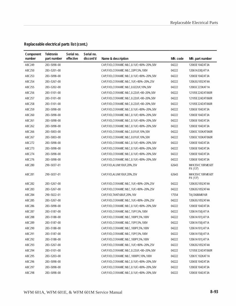
Replaceable Electrical Parts
WFM 601A, WFM 601E, & WFM 601M Service Manual 8–93
Replaceable electrical parts list (cont.)
Componentnumber Mfr. part numberMfr. codeName & description
Serial no.discont’d
Serial no.effective
Tektronixpart number
A8C249 283–5098–00 CAP,FXD,CERAMIC:MLC,0.1UF,+80%–20%,50V 04222 12065E104ZAT3A
A8C250 283–5201–00 CAP,FXD,CERAMIC:MLC,33PF,5%,100V 04222 12061A330JAT1A
A8C253 283–5098–00 CAP,FXD,CERAMIC:MLC,0.1UF,+80%–20%,50V 04222 12065E104ZAT3A
A8C254 283–5267–00 CAP,FXD,CERAMIC:MLC,1UF,+80%–20%,25V 04222 12063G105ZAT4A
A8C255 283–5202–00 CAP,FXD,CERAMIC:MLC,0.022UF,10%,50V 04222 12065C223KAT1A
A8C256 283–5101–00 CAP,FXD,CERAMIC:MLC,0.22UF,+80–20%,50V 04222 12105E224ZAT060R
A8C257 283–5101–00 CAP,FXD,CERAMIC:MLC,0.22UF,+80–20%,50V 04222 12105E224ZAT060R
A8C258 283–5101–00 CAP,FXD,CERAMIC:MLC,0.22UF,+80–20%,50V 04222 12105E224ZAT060R
A8C259 283–5098–00 CAP,FXD,CERAMIC:MLC,0.1UF,+80%–20%,50V 04222 12065E104ZAT3A
A8C260 283–5098–00 CAP,FXD,CERAMIC:MLC,0.1UF,+80%–20%,50V 04222 12065E104ZAT3A
A8C261 283–5098–00 CAP,FXD,CERAMIC:MLC,0.1UF,+80%–20%,50V 04222 12065E104ZAT3A
A8C262 283–5098–00 CAP,FXD,CERAMIC:MLC,0.1UF,+80%–20%,50V 04222 12065E104ZAT3A
A8C266 283–5003–00 CAP,FXD,CERAMIC:MLC,0.01UF,10%,50V 04222 12065C103KAT060R
A8C267 283–5003–00 CAP,FXD,CERAMIC:MLC,0.01UF,10%,50V 04222 12065C103KAT060R
A8C272 283–5098–00 CAP,FXD,CERAMIC:MLC,0.1UF,+80%–20%,50V 04222 12065E104ZAT3A
A8C273 283–5098–00 CAP,FXD,CERAMIC:MLC,0.1UF,+80%–20%,50V 04222 12065E104ZAT3A
A8C274 283–5098–00 CAP,FXD,CERAMIC:MLC,0.1UF,+80%–20%,50V 04222 12065E104ZAT3A
A8C276 283–5098–00 CAP,FXD,CERAMIC:MLC,0.1UF,+80%–20%,50V 04222 12065E104ZAT3A
A8C280 290–5037–01 CAP,FXD,ALUM:10UF,20%,35V 62643 MVK35VC10RME60TPX (13”)
A8C281 290–5037–01 CAP,FXD,ALUM:10UF,20%,35V 62643 MVK35VC10RME60TPX (13”)
A8C282 283–5267–00 CAP,FXD,CERAMIC:MLC,1UF,+80%–20%,25V 04222 12063G105ZAT4A
A8C283 283–5267–00 CAP,FXD,CERAMIC:MLC,1UF,+80%–20%,25V 04222 12063G105ZAT4A
A8C284 290–5022–01 CAP,FXD,TANT:68UF,20%,16V 17554 TAJD686M016R
A8C285 283–5267–00 CAP,FXD,CERAMIC:MLC,1UF,+80%–20%,25V 04222 12063G105ZAT4A
A8C286 283–5098–00 CAP,FXD,CERAMIC:MLC,0.1UF,+80%–20%,50V 04222 12065E104ZAT3A
A8C287 283–5187–00 CAP,FXD,CERAMIC:MLC,15PF,5%,100V 04222 12061A150JAT1A
A8C288 283–5188–00 CAP,FXD,CERAMIC:MLC,100PF,5%,100V 04222 12061A101JAT1A
A8C289 283–5187–00 CAP,FXD,CERAMIC:MLC,15PF,5%,100V 04222 12061A150JAT1A
A8C290 283–5188–00 CAP,FXD,CERAMIC:MLC,100PF,5%,100V 04222 12061A101JAT1A
A8C291 283–5187–00 CAP,FXD,CERAMIC:MLC,15PF,5%,100V 04222 12061A150JAT1A
A8C292 283–5188–00 CAP,FXD,CERAMIC:MLC,100PF,5%,100V 04222 12061A101JAT1A
A8C293 283–5267–00 CAP,FXD,CERAMIC:MLC,1UF,+80%–20%,25V 04222 12063G105ZAT4A
A8C294 283–5101–00 CAP,FXD,CERAMIC:MLC,0.22UF,+80–20%,50V 04222 12105E224ZAT060R
A8C295 283–5203–00 CAP,FXD,CERAMIC:MLC,1000PF,10%,100V 04222 12061C102KAT1A
A8C296 283–5098–00 CAP,FXD,CERAMIC:MLC,0.1UF,+80%–20%,50V 04222 12065E104ZAT3A
A8C297 283–5098–00 CAP,FXD,CERAMIC:MLC,0.1UF,+80%–20%,50V 04222 12065E104ZAT3A
A8C298 283–5098–00 CAP,FXD,CERAMIC:MLC,0.1UF,+80%–20%,50V 04222 12065E104ZAT3A
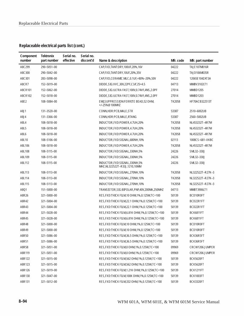
Replaceable Electrical Parts
8–94 WFM 601A, WFM 601E, & WFM 601M Service Manual
Replaceable electrical parts list (cont.)
Componentnumber Mfr. part numberMfr. codeName & description
Serial no.discont’d
Serial no.effective
Tektronixpart number
A8C299 290–5051–00 CAP,FXD,TANT:DRY,100UF,20%,16V 04222 TAJE107M016R
A8C300 290–5042–00 CAP,FXD,TANT:DRY,10UF,20%,35V 04222 TAJD106M035R
A8C301 283–5098–00 CAP,FXD,CERAMIC:MLC,0.1UF,+80%–20%,50V 04222 12065E104ZAT3A
A8CR7 152–5019–00 DIODE,SIG:VVC,30V,22PF,C3/C25=4.5 04713 MMBV3102LT1
A8CR101 152–5062–00 DIODE,SIG:ULTRA FAST,100V,0.74VF,4NS,2.0PF 27014 MMBD1205
A8CR102 152–5018–00 DIODE,SIG:ULTRA FAST,100V,0.74VF,4NS,2.0PF 27014 MMBD1203
A8E2 108–5084–00 EMI,SUPPRESSION:FERRITE BEAD,52 OHM,+/–25%@100MHZ
TK2058 HF70ACB322513T
A8J1 131–3520–00 CONN,HDR:PCB,MALE,STR 53387 2510–6002UB
A8J4 131–3366–00 CONN,HDR:PCB,MALE,RTANG 53387 2560–5002UB
A8L4 108–5018–00 INDUCTOR,FXD:POWER,4.7UH,20% TK2058 NL453232T–4R7M
A8L5 108–5018–00 INDUCTOR,FXD:POWER,4.7UH,20% TK2058 NL453232T–4R7M
A8L6 108–5018–00 INDUCTOR,FXD:POWER,4.7UH,20% TK2058 NL453232T–4R7M
A8L10 108–5106–00 INDUCTOR,FXD:SIGNAL,680NH,10% 02113 1008CS–681–XKBC
A8L106 108–5018–00 INDUCTOR,FXD:POWER,4.7UH,20% TK2058 NL453232T–4R7M
A8L108 108–5115–00 INDUCTOR,FXD:SIGNAL,330NH,5% 24226 SML32–330J
A8L109 108–5115–00 INDUCTOR,FXD:SIGNAL,330NH,5% 24226 SML32–330J
A8L112 108–5115–00 INDUCTOR,FXD:SIGNAL,330NH,5%MHZ,NL322522T–R33J,1210,10MM
24226 SML32–330J
A8L113 108–5113–00 INDUCTOR,FXD:SIGNAL,270NH,10% TK2058 NL322522T–R27K–3
A8L114 108–5113–00 INDUCTOR,FXD:SIGNAL,270NH,10% TK2058 NL322522T–R27K–3
A8L115 108–5113–00 INDUCTOR,FXD:SIGNAL,270NH,10% TK2058 NL322522T–R27K–3
A8Q1 151–5000–00 TRANSISTOR,SIG:BIPOLAR,PNP,40V,200MA,250MHZ 04713 MMBT3906LT1
A8R26 321–5000–00 RES,FXD:THICK FILM,10 OHM,1%,0.125W,TC=100 50139 BCD10R0FT
A8R42 321–5004–00 RES,FXD:THICK FILM,22.1 OHM,1%,0.125W,TC=100 50139 BCD22R1FT
A8R43 321–5004–00 RES,FXD:THICK FILM,22.1 OHM,1%,0.125W,TC=100 50139 BCD22R1FT
A8R44 321–5028–00 RES,FXD:THICK FILM,6.81K OHM,1%,0.125W,TC=100 50139 BCK6811FT
A8R45 321–5028–00 RES,FXD:THICK FILM,6.81K OHM,1%,0.125W,TC=100 50139 BCK6811FT
A8R48 321–5000–00 RES,FXD:THICK FILM,10 OHM,1%,0.125W,TC=100 50139 BCD10R0FT
A8R49 321–5000–00 RES,FXD:THICK FILM,10 OHM,1%,0.125W,TC=100 50139 BCD10R0FT
A8R50 321–5086–00 RES,FXD:THICK FILM,36.5 OHM,1%,0.125W,TC=100 50139 BCK36R5FT
A8R51 321–5086–00 RES,FXD:THICK FILM,36.5 OHM,1%,0.125W,TC=100 50139 BCK36R5FT
A8R58 321–5051–00 RES,FXD:THICK FILM,0 OHM,1%,0.125W,TC=100 09969 CRCW1206 JUMPER
A8R119 321–5051–00 RES,FXD:THICK FILM,0 OHM,1%,0.125W,TC=100 09969 CRCW1206 JUMPER
A8R122 321–5015–00 RES,FXD:THICK FILM,562 OHM,1%,0.125W,TC=100 50139 BCK5620FT
A8R123 321–5015–00 RES,FXD:THICK FILM,562 OHM,1%,0.125W,TC=100 50139 BCK5620FT
A8R126 321–5019–00 RES,FXD:THICK FILM,1.21K OHM,1%,0.125W,TC=100 50139 BCK1211FT
A8R130 321–5047–00 RES,FXD:THICK FILM,100K OHM,1%,0.125W,TC=100 50139 BCK1003FT
A8R131 321–5012–00 RES,FXD:THICK FILM,332 OHM,1%,0.125W,TC=100 50139 BCK3320FT
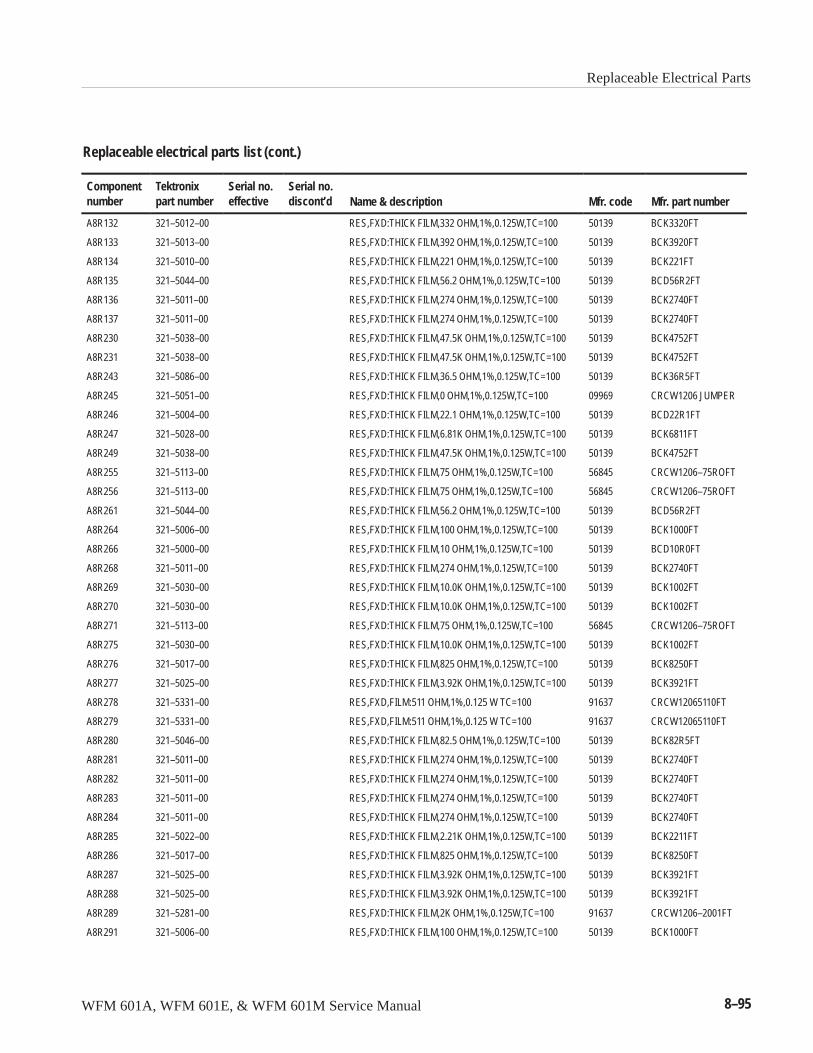
Replaceable Electrical Parts
WFM 601A, WFM 601E, & WFM 601M Service Manual 8–95
Replaceable electrical parts list (cont.)
Componentnumber Mfr. part numberMfr. codeName & description
Serial no.discont’d
Serial no.effective
Tektronixpart number
A8R132 321–5012–00 RES,FXD:THICK FILM,332 OHM,1%,0.125W,TC=100 50139 BCK3320FT
A8R133 321–5013–00 RES,FXD:THICK FILM,392 OHM,1%,0.125W,TC=100 50139 BCK3920FT
A8R134 321–5010–00 RES,FXD:THICK FILM,221 OHM,1%,0.125W,TC=100 50139 BCK221FT
A8R135 321–5044–00 RES,FXD:THICK FILM,56.2 OHM,1%,0.125W,TC=100 50139 BCD56R2FT
A8R136 321–5011–00 RES,FXD:THICK FILM,274 OHM,1%,0.125W,TC=100 50139 BCK2740FT
A8R137 321–5011–00 RES,FXD:THICK FILM,274 OHM,1%,0.125W,TC=100 50139 BCK2740FT
A8R230 321–5038–00 RES,FXD:THICK FILM,47.5K OHM,1%,0.125W,TC=100 50139 BCK4752FT
A8R231 321–5038–00 RES,FXD:THICK FILM,47.5K OHM,1%,0.125W,TC=100 50139 BCK4752FT
A8R243 321–5086–00 RES,FXD:THICK FILM,36.5 OHM,1%,0.125W,TC=100 50139 BCK36R5FT
A8R245 321–5051–00 RES,FXD:THICK FILM,0 OHM,1%,0.125W,TC=100 09969 CRCW1206 JUMPER
A8R246 321–5004–00 RES,FXD:THICK FILM,22.1 OHM,1%,0.125W,TC=100 50139 BCD22R1FT
A8R247 321–5028–00 RES,FXD:THICK FILM,6.81K OHM,1%,0.125W,TC=100 50139 BCK6811FT
A8R249 321–5038–00 RES,FXD:THICK FILM,47.5K OHM,1%,0.125W,TC=100 50139 BCK4752FT
A8R255 321–5113–00 RES,FXD:THICK FILM,75 OHM,1%,0.125W,TC=100 56845 CRCW1206–75ROFT
A8R256 321–5113–00 RES,FXD:THICK FILM,75 OHM,1%,0.125W,TC=100 56845 CRCW1206–75ROFT
A8R261 321–5044–00 RES,FXD:THICK FILM,56.2 OHM,1%,0.125W,TC=100 50139 BCD56R2FT
A8R264 321–5006–00 RES,FXD:THICK FILM,100 OHM,1%,0.125W,TC=100 50139 BCK1000FT
A8R266 321–5000–00 RES,FXD:THICK FILM,10 OHM,1%,0.125W,TC=100 50139 BCD10R0FT
A8R268 321–5011–00 RES,FXD:THICK FILM,274 OHM,1%,0.125W,TC=100 50139 BCK2740FT
A8R269 321–5030–00 RES,FXD:THICK FILM,10.0K OHM,1%,0.125W,TC=100 50139 BCK1002FT
A8R270 321–5030–00 RES,FXD:THICK FILM,10.0K OHM,1%,0.125W,TC=100 50139 BCK1002FT
A8R271 321–5113–00 RES,FXD:THICK FILM,75 OHM,1%,0.125W,TC=100 56845 CRCW1206–75ROFT
A8R275 321–5030–00 RES,FXD:THICK FILM,10.0K OHM,1%,0.125W,TC=100 50139 BCK1002FT
A8R276 321–5017–00 RES,FXD:THICK FILM,825 OHM,1%,0.125W,TC=100 50139 BCK8250FT
A8R277 321–5025–00 RES,FXD:THICK FILM,3.92K OHM,1%,0.125W,TC=100 50139 BCK3921FT
A8R278 321–5331–00 RES,FXD,FILM:511 OHM,1%,0.125 W TC=100 91637 CRCW12065110FT
A8R279 321–5331–00 RES,FXD,FILM:511 OHM,1%,0.125 W TC=100 91637 CRCW12065110FT
A8R280 321–5046–00 RES,FXD:THICK FILM,82.5 OHM,1%,0.125W,TC=100 50139 BCK82R5FT
A8R281 321–5011–00 RES,FXD:THICK FILM,274 OHM,1%,0.125W,TC=100 50139 BCK2740FT
A8R282 321–5011–00 RES,FXD:THICK FILM,274 OHM,1%,0.125W,TC=100 50139 BCK2740FT
A8R283 321–5011–00 RES,FXD:THICK FILM,274 OHM,1%,0.125W,TC=100 50139 BCK2740FT
A8R284 321–5011–00 RES,FXD:THICK FILM,274 OHM,1%,0.125W,TC=100 50139 BCK2740FT
A8R285 321–5022–00 RES,FXD:THICK FILM,2.21K OHM,1%,0.125W,TC=100 50139 BCK2211FT
A8R286 321–5017–00 RES,FXD:THICK FILM,825 OHM,1%,0.125W,TC=100 50139 BCK8250FT
A8R287 321–5025–00 RES,FXD:THICK FILM,3.92K OHM,1%,0.125W,TC=100 50139 BCK3921FT
A8R288 321–5025–00 RES,FXD:THICK FILM,3.92K OHM,1%,0.125W,TC=100 50139 BCK3921FT
A8R289 321–5281–00 RES,FXD:THICK FILM,2K OHM,1%,0.125W,TC=100 91637 CRCW1206–2001FT
A8R291 321–5006–00 RES,FXD:THICK FILM,100 OHM,1%,0.125W,TC=100 50139 BCK1000FT
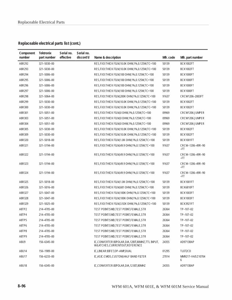
Replaceable Electrical Parts
8–96 WFM 601A, WFM 601E, & WFM 601M Service Manual
Replaceable electrical parts list (cont.)
Componentnumber Mfr. part numberMfr. codeName & description
Serial no.discont’d
Serial no.effective
Tektronixpart number
A8R292 321–5030–00 RES,FXD:THICK FILM,10.0K OHM,1%,0.125W,TC=100 50139 BCK1002FT
A8R293 321–5030–00 RES,FXD:THICK FILM,10.0K OHM,1%,0.125W,TC=100 50139 BCK1002FT
A8R294 321–5006–00 RES,FXD:THICK FILM,100 OHM,1%,0.125W,TC=100 50139 BCK1000FT
A8R295 321–5006–00 RES,FXD:THICK FILM,100 OHM,1%,0.125W,TC=100 50139 BCK1000FT
A8R296 321–5006–00 RES,FXD:THICK FILM,100 OHM,1%,0.125W,TC=100 50139 BCK1000FT
A8R297 321–5006–00 RES,FXD:THICK FILM,100 OHM,1%,0.125W,TC=100 50139 BCK1000FT
A8R298 321–5064–00 RES,FXD:THICK FILM,200K OHM,1%,0.125W,TC=100 91637 CRCW1206–2003FT
A8R299 321–5030–00 RES,FXD:THICK FILM,10.0K OHM,1%,0.125W,TC=100 50139 BCK1002FT
A8R300 321–5030–00 RES,FXD:THICK FILM,10.0K OHM,1%,0.125W,TC=100 50139 BCK1002FT
A8R301 321–5051–00 RES,FXD:THICK FILM,0 OHM,1%,0.125W,TC=100 09969 CRCW1206 JUMPER
A8R303 321–5051–00 RES,FXD:THICK FILM,0 OHM,1%,0.125W,TC=100 09969 CRCW1206 JUMPER
A8R304 321–5051–00 RES,FXD:THICK FILM,0 OHM,1%,0.125W,TC=100 09969 CRCW1206 JUMPER
A8R305 321–5030–00 RES,FXD:THICK FILM,10.0K OHM,1%,0.125W,TC=100 50139 BCK1002FT
A8R309 321–5030–00 RES,FXD:THICK FILM,10.0K OHM,1%,0.125W,TC=100 50139 BCK1002FT
A8R320 321–5018–00 RES,FXD:THICK FILM,1.0K OHM,1%,0.125W,TC=100 50139 BCK1001FT
A8R321 321–5194–00 RES,FXD:THICK FILM,49.9 OHM,1%,0.125W,TC=100 91637 CRCW–1206–49R–90–FT
A8R322 321–5194–00 RES,FXD:THICK FILM,49.9 OHM,1%,0.125W,TC=100 91637 CRCW–1206–49R–90–FT
A8R323 321–5194–00 RES,FXD:THICK FILM,49.9 OHM,1%,0.125W,TC=100 91637 CRCW–1206–49R–90–FT
A8R324 321–5194–00 RES,FXD:THICK FILM,49.9 OHM,1%,0.125W,TC=100 91637 CRCW–1206–49R–90–FT
A8R325 321–5018–00 RES,FXD:THICK FILM,1.0K OHM,1%,0.125W,TC=100 50139 BCK1001FT
A8R326 321–5016–00 RES,FXD:THICK FILM,681 OHM,1%,0.125W,TC=100 50139 BCK6810FT
A8R327 321–5047–00 RES,FXD:THICK FILM,100K OHM,1%,0.125W,TC=100 50139 BCK1003FT
A8R328 321–5047–00 RES,FXD:THICK FILM,100K OHM,1%,0.125W,TC=100 50139 BCK1003FT
A8R329 321–5025–00 RES,FXD:THICK FILM,3.92K OHM,1%,0.125W,TC=100 50139 BCK3921FT
A8TP2 214–4705–00 TEST POINT:SMD,TEST POINT,FEMALE,STR 26364 TP–107–02
A8TP4 214–4705–00 TEST POINT:SMD,TEST POINT,FEMALE,STR 26364 TP–107–02
A8TP5 214–4705–00 TEST POINT:SMD,TEST POINT,FEMALE,STR 26364 TP–107–02
A8TP6 214–4705–00 TEST POINT:SMD,TEST POINT,FEMALE,STR 26364 TP–107–02
A8TP8 214–4705–00 TEST POINT:SMD,TEST POINT,FEMALE,STR 26364 TP–107–02
A8TP9 214–4705–00 TEST POINT:SMD,TEST POINT,FEMALE,STR 26364 TP–107–02
A8U9 156–6345–00 IC,CONVERTER:BIPOLAR,D/A,12BIT,80MHZ,TTL INPUT,W/LATCHES,CURRENTOUT,REFERENCE
24355 AD9713BAP
A8U14 156–1989–00 IC,LINEAR:BIFET,OP–AMP,DUAL 01295 TL072CD
A8U17 156–6233–00 IC,ASIC:CMOS,CUSTOM,HALF BAND FILTER 27014 MM9217–V4/SZ107046
A8U18 156–6345–00 IC,CONVERTER:BIPOLAR,D/A,12 BIT,80MHZ 24355 AD9713BAP
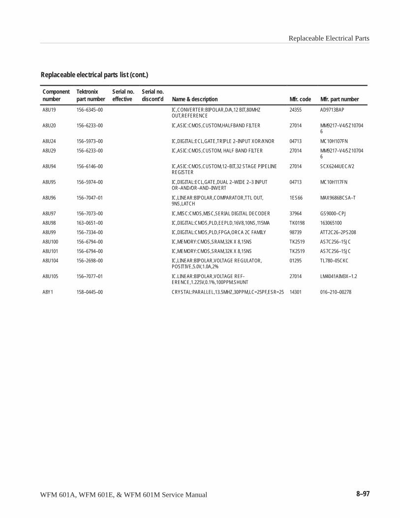
Replaceable Electrical Parts
WFM 601A, WFM 601E, & WFM 601M Service Manual 8–97
Replaceable electrical parts list (cont.)
Componentnumber Mfr. part numberMfr. codeName & description
Serial no.discont’d
Serial no.effective
Tektronixpart number
A8U19 156–6345–00 IC,CONVERTER:BIPOLAR,D/A,12 BIT,80MHZOUT,REFERENCE
24355 AD9713BAP
A8U20 156–6233–00 IC,ASIC:CMOS,CUSTOM,HALFBAND FILTER 27014 MM9217–V4/SZ107046
A8U24 156–5973–00 IC,DIGITAL:ECL,GATE,TRIPLE 2–INPUT XOR/XNOR 04713 MC10H107FN
A8U29 156–6233–00 IC,ASIC:CMOS,CUSTOM, HALF BAND FILTER 27014 MM9217–V4/SZ107046
A8U94 156–6146–00 IC,ASIC:CMOS,CUSTOM,12–BIT,32 STAGE PIPELINEREGISTER
27014 SCX6244UEC/V2
A8U95 156–5974–00 IC,DIGITAL:ECL,GATE,DUAL 2–WIDE 2–3 INPUTOR–AND/OR–AND–INVERT
04713 MC10H117FN
A8U96 156–7047–01 IC,LINEAR:BIPOLAR,COMPARATOR,TTL OUT,9NS,LATCH
1ES66 MAX9686BCSA–T
A8U97 156–7073–00 IC,MISC:CMOS,MISC,SERIAL DIGITAL DECODER 37964 GS9000–CPJ
A8U98 163–0651–00 IC,DIGITAL:CMOS,PLD,EEPLD,16V8,10NS,115MA TK0198 163065100
A8U99 156–7334–00 IC,DIGITAL:CMOS,PLD,FPGA,ORCA 2C FAMILY 98739 ATT2C26–2PS208
A8U100 156–6794–00 IC,MEMORY:CMOS,SRAM,32K X 8,15NS TK2519 AS7C256–15JC
A8U101 156–6794–00 IC,MEMORY:CMOS,SRAM,32K X 8,15NS TK2519 AS7C256–15JC
A8U104 156–2698–00 IC,LINEAR:BIPOLAR,VOLTAGE REGULATOR,POSITIVE,5.0V,1.0A,2%
01295 TL780–05CKC
A8U105 156–7077–01 IC.LINEAR:BIPOLAR,VOLTAGE REF-ERENCE,1.225V,0.1%,100PPM.SHUNT
27014 LM4041AIM3X–1.2
A8Y1 158–0445–00 CRYSTAL:PARALLEL,13.5MHZ,30PPM,LC=25PF,ESR=25 14301 016–210–00278

Replaceable Electrical Parts
8–98 WFM 601A, WFM 601E, & WFM 601M Service Manual
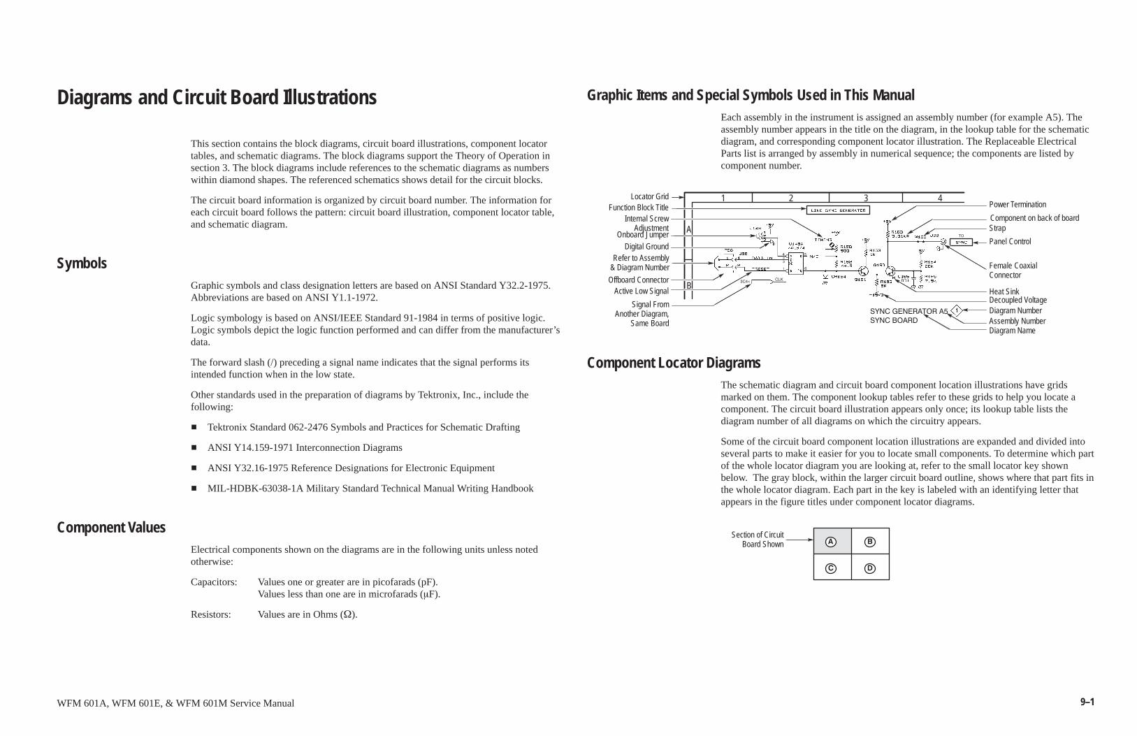
9–1WFM 601A, WFM 601E, & WFM 601M Service Manual
Diagrams and Circuit Board Illustrations
This section contains the block diagrams, circuit board illustrations, component locatortables, and schematic diagrams. The block diagrams support the Theory of Operation insection 3. The block diagrams include references to the schematic diagrams as numberswithin diamond shapes. The referenced schematics shows detail for the circuit blocks.
The circuit board information is organized by circuit board number. The information foreach circuit board follows the pattern: circuit board illustration, component locator table,and schematic diagram.
SymbolsGraphic symbols and class designation letters are based on ANSI Standard Y32.2-1975.Abbreviations are based on ANSI Y1.1-1972.
Logic symbology is based on ANSI/IEEE Standard 91-1984 in terms of positive logic.Logic symbols depict the logic function performed and can differ from the manufacturer’sdata.
The forward slash (/) preceding a signal name indicates that the signal performs itsintended function when in the low state.
Other standards used in the preparation of diagrams by Tektronix, Inc., include thefollowing:
� Tektronix Standard 062-2476 Symbols and Practices for Schematic Drafting
� ANSI Y14.159-1971 Interconnection Diagrams
� ANSI Y32.16-1975 Reference Designations for Electronic Equipment
� MIL-HDBK-63038-1A Military Standard Technical Manual Writing Handbook
Component ValuesElectrical components shown on the diagrams are in the following units unless notedotherwise:
Capacitors: Values one or greater are in picofarads (pF).Values less than one are in microfarads (�F).
Resistors: Values are in Ohms (�).
Graphic Items and Special Symbols Used in This ManualEach assembly in the instrument is assigned an assembly number (for example A5). Theassembly number appears in the title on the diagram, in the lookup table for the schematicdiagram, and corresponding component locator illustration. The Replaceable ElectricalParts list is arranged by assembly in numerical sequence; the components are listed bycomponent number.
Locator GridFunction Block Title
Internal ScrewAdjustment
Onboard JumperDigital Ground
Refer to Assembly& Diagram Number
Offboard ConnectorActive Low Signal
Signal FromAnother Diagram,
Same Board
Power Termination
Strap
Panel Control
Female CoaxialConnector
Heat SinkDecoupled VoltageDiagram Number
Diagram Name
� ������������
Component on back of board
Assembly Number
A
B
1 2 3 4
� ������
Component Locator DiagramsThe schematic diagram and circuit board component location illustrations have gridsmarked on them. The component lookup tables refer to these grids to help you locate acomponent. The circuit board illustration appears only once; its lookup table lists thediagram number of all diagrams on which the circuitry appears.
Some of the circuit board component location illustrations are expanded and divided intoseveral parts to make it easier for you to locate small components. To determine which partof the whole locator diagram you are looking at, refer to the small locator key shownbelow. The gray block, within the larger circuit board outline, shows where that part fits inthe whole locator diagram. Each part in the key is labeled with an identifying letter thatappears in the figure titles under component locator diagrams.
� �
��
Section of CircuitBoard Shown

9–2 WFM 601A, WFM 601E, & WFM 601M Service Manual
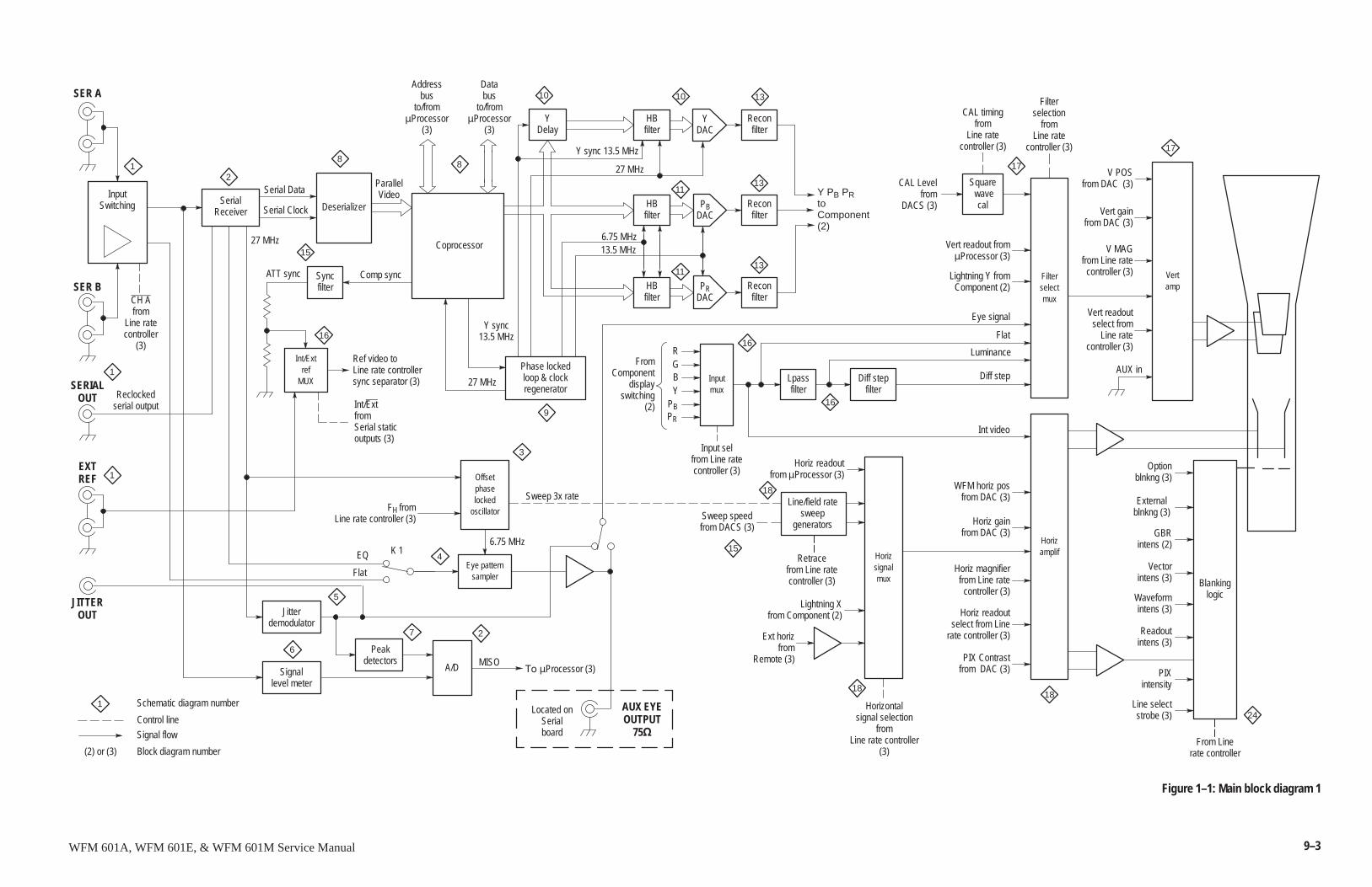
9–3WFM 601A, WFM 601E, & WFM 601M Service Manual
YDAC
Blankinglogic
PIXintensity
Readoutintens (3)
Sweep speedfrom DACS (3)
Horiz readoutfrom �Processor (3)
Reclockedserial output
Vert readout from�Processor (3)
Ref video toLine rate controllersync separator (3)
InputSwitching
Horiz readoutselect from Line
rate controller (3)
PIX Contrastfrom DAC (3)
Horiz magnifierfrom Line rate
controller (3)
Horiz gainfrom DAC (3)
WFM horiz posfrom DAC (3)
Filterselectmux
Line/field ratesweep
generators
Horizsignalmux
Ext horizfrom
Remote (3)
Lightning Xfrom Component (2)
Filterselection
fromLine rate
controller (3)
From Linerate controller
Vert readoutselect from
Line ratecontroller (3)
V MAGfrom Line rate
controller (3)
Horizamplif
V POSfrom DAC (3)
Vertamp
Waveformintens (3)
Vectorintens (3)
Line selectstrobe (3)
Optionblnkng (3)
Externalblnkng (3)
GBRintens (2)
Horizontalsignal selection
fromLine rate controller
(3)
SER A
SER B
SERIALOUT
Y PB PRtoComponent(2)
CH Afrom
Line ratecontroller
(3)
SerialReceiver Deserializer
Coprocessor
YDelay
HBfilter
PBDAC
27 MHz
6.75 MHz
Inputmux
Lpassfilter
Diff stepfilter
Int/Extref
MUX
EXTREF
YPBPR
Input selfrom Line ratecontroller (3)
FromComponent
displayswitching
(2)Int/ExtfromSerial staticoutputs (3)
Lightning Y fromComponent (2)
Luminance
Flat
Diff step
Retracefrom Line ratecontroller (3)
Square wave
cal
CAL Levelfrom
DACS (3)
CAL timingfrom
Line ratecontroller (3)
Control line
Signal flow
Phase lockedloop & clockregenerator
27 MHz
Y sync13.5 MHz
13.5 MHz
Schematic diagram number
(2) or (3) Block diagram number
RGB
Eye signal
Sweep 3x rate
AUX in
Databus
to/from�Processor
(3)
Addressbus
to/from�Processor
(3)
Comp syncSyncfilter
ATT sync
Offsetphaselocked
oscillator
27 MHz
FH fromLine rate controller (3)
Eye patternsampler
EQ
Flat
6.75 MHz
Int video
Located onSerialboard
AUX EYEOUTPUT
75�
Reconfilter
2
3
1
1
1
15
88
10
HBfilter
10
11
13
16
9
13
Reconfilter
16
4
1
Jitterdemodulator
Peakdetectors
A/DSignallevel meter
5
7 2
6MISO
����Processor (3)
16
17
17
1818
24
15
HBfilter
PRDAC
1113
Reconfilter
Vert gainfrom DAC (3)
Y sync 13.5 MHz
Serial Data
Serial Clock
ParallelVideo
JITTEROUT
18
K 1
Figure 1–1: Main block diagram 1
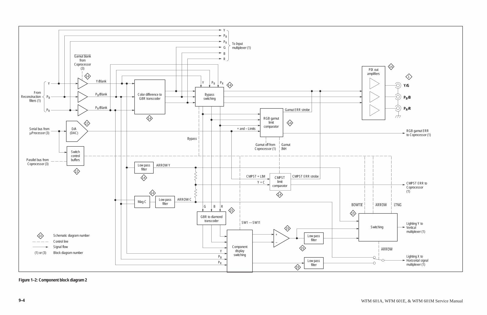
9–4 WFM 601A, WFM 601E, & WFM 601M Service Manual
Control line
Signal flow
Schematic diagram number
(1) or (3) Block diagram number
10
Y
PB
PR
FromReconstruction
filters (1)
Serial bus fromµProcessor (3)
Parallel bus fromCoprocessor (3)
Switchcontrolbuffers
Gamut blankfrom
Coprocessor(3)
Color difference toGBR transcoder
12
12
14
Bypassswitching
Y
PB
PR
R
G
B
To Inputmultiplexer (1)
Y PB PR 14
G B R
GBR to diamondtranscoder
Mag C
CMPSTlimit
comparator
PIX outamplifiers
RGB gamutlimit
comparator
Componentdisplay
switching
Switching
Low passfilter
Low passfilter
Low passfilter
Low passfilter
Gamut ERR strobe
Gamut off fromCoprocessor (1)
RGB gamut ERRto Coprocessor (1)
Y/Blank
PB/Blank
PR/Blank
Y
PB
PR
14
15
14
1
Y/G
PB/B
PR/R
ARROW Y
ARROW C
+ and – Limits
Y + C
CMPST + LIM
CMPST ERR toCoprocessor(1)
BOWTIE ARROW LTNG
Lighting Y toVerticalmultiplexer (1)
Lighting X toHorizontal signalmultiplexer (1)
Bypass
SW1 — SW11
ARROW
CMPST ERR strobe
15
15
+
–
15
GamutINH
D/A(DAC)
14
15
14
14 14
Figure 1–2: Component block diagram 2
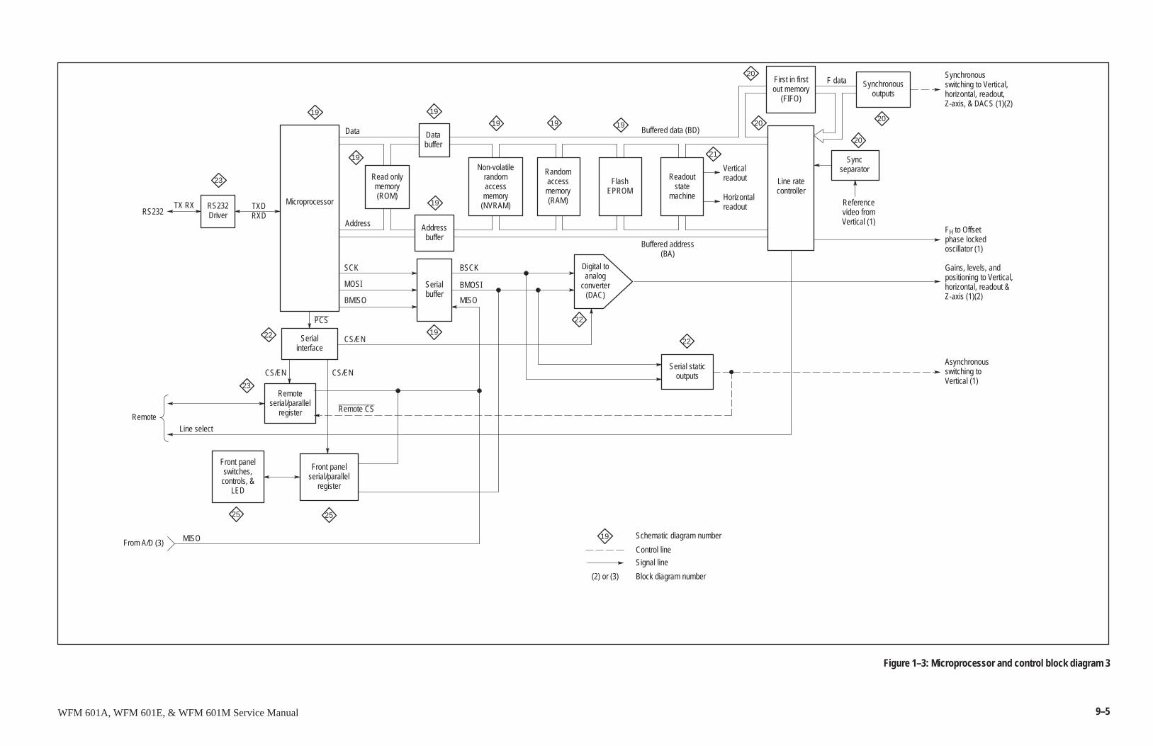
9–5WFM 601A, WFM 601E, & WFM 601M Service Manual
Control line
Signal line
Schematic diagram number
(2) or (3) Block diagram number
19
MicroprocessorRS232Driver
Serialinterface
Remoteserial/parallel
register
Front panelswitches,
controls, &LED
Front panelserial/parallel
register
Read onlymemory(ROM)
Databuffer
Addressbuffer
Serialbuffer
Non-volatilerandomaccessmemory
(NVRAM)
Randomaccessmemory(RAM)
FlashEPROM
Readoutstate
machine
Line ratecontroller
First in firstout memory
(FIFO)
Synchronousoutputs
Syncseparator
Serial staticoutputs
Digital toanalog
converter(DAC)
19
Address
Verticalreadout
Horizontalreadout
25 25
23
22
23
22
19
19
19
19 19 19
21
20
2020
20
22
19
Synchronousswitching to Vertical,horizontal, readout,Z-axis, & DACS (1)(2)
FH to Offsetphase lockedoscillator (1)
Gains, levels, andpositioning to Vertical,horizontal, readout &Z-axis (1)(2)
Asynchronousswitching toVertical (1)
CS/EN
Buffered data (BD)
Buffered address(BA)
Referencevideo fromVertical (1)
F data
Data
TXDRXD
TX RX
MISO
SCK
MOSI
BMISO
CS/EN
PCS
Remote CS
Line select
From A/D (3)
Remote
RS232
CS/EN
MISO
BSCK
BMOSI
Figure 1–3: Microprocessor and control block diagram 3
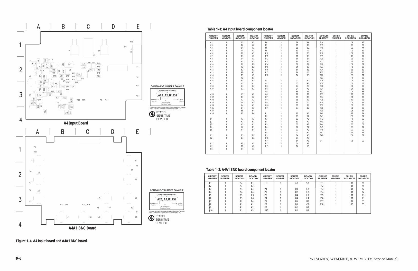
9–6 WFM 601A, WFM 601E, & WFM 601M Service Manual
A4 Input Board
����������������
��� �� �����
�������"����������������������������������!�������
����� #�������������������������������������������
�� ��������������� �
��������������
������������������� ������
������
������� �
�� ����
� �� �������
����������������
��� �� �����
�������"����������������������������������!�������
����� #�������������������������������������������
�� ��������������� �
��������������
������������������� ������
������
������� �
�� ����
� �� �������
A4A1 BNC Board
C2 1 C2 A2C3 1 D2 A2C4 1 B4 A3C5 1 C4 A3C6 1 E2 A3C7 1 D3 A3C8 1 C4 A3C9 1 E2 A2C10 1 D2 B2C11 1 F3 B2C12 1 E2 B2C13 1 F3 B2C14 1 E3 A3C15 1 F2 B3C16 1 E3 B3C17 1 E5 C2C18 1 G3 C2C19 1 G3 C2
CR1 1 C3 A2CR2 1 D3 A2CR3 1 C2 A2CR4 1 C4 A3CR5 1 C4 A3CR6 1 D4 A3CR7 1 B5 B4CR8 1 B5 B4
J1 1 H2 A2J2 1 H2 B1J3 1 H3 C1J4 1 H2 C1J5 1 H1 E1
L1 1 D3 B2L2 1 D4 B3
P1 1 B3 A2P2 1 B2 A2P3 1 B4 A3
P4 1 B4 A4P7 1 B5 B3P8 1 B5 B3P9 1 B2 C3P10 1 B2 D3P11 1 B1 D1P12 1 B1 E1P13 1 B1 E2P14 1 B1 E2P15 1 B1 E3P16 1 B1 E3P17 1 B4 C3P18 1 B4 C3
Q1 1 C2 A2Q2 1 D3 A2Q3 1 C4 A3Q4 1 D4 A3Q5 1 E3 A3Q6 1 F2 B2Q7 1 E3 B3Q8 1 B5 B3Q9 1 F2 C2Q10 1 F3 C2Q11 1 G3 C2
R1 1 B2 A2R2 1 C3 A2R3 1 B2 A2R4 1 B2 A2R5 1 C3 A2R6 1 E2 A2R7 1 C3 A2R8 1 D2 A2R9 1 B4 A3R10 1 C4 A3R11 1 B4 A3R12 1 C4 A3R13 1 B4 A3
R14 1 D4 A3R15 1 D3 A3R16 1 C3 A4R17 1 C2 B2R18 1 E3 B2R19 1 D3 B2R20 1 E2 B2R21 1 F2 B2R22 1 F3 B2R23 1 F3 B2R24 1 E2 B2R25 1 F2 B2R26 1 F2 B2R27 1 F2 B2R28 1 D4 B3R29 1 E3 B3R30 1 E3 B3R31 1 D4 B3R32 1 C4 B3R33 1 B5 B3R34 1 E3 B3R35 1 B5 B3R36 1 D4 B3R37 1 E3 B3R38 1 E3 B3R39 1 C5 B3R40 1 B5 B4R41 1 F2 C2R42 1 F3 C2R43 1 F3 C2R44 1 G3 C2R45 1 G3 C2R46 1 G3 C2R47 1 E2 B3R48 1 F3 B2
U1 1 D5 C2
SCHEMNUMBER
Table 1–1: A4 Input board component locator
CIRCUITNUMBER
SCHEMLOCATION
BOARDLOCATION
SCHEMNUMBER
CIRCUITNUMBER
SCHEMLOCATION
BOARDLOCATION
SCHEMNUMBER
CIRCUITNUMBER
SCHEMLOCATION
BOARDLOCATION
J1 1 A2 E1J2 1 A3 E2J3 1 A4 E3J4 1 A4 E4J5 1 A5 C3J6 1 A5 C4J7 1 A2 B4J8 1 A1 A1J9 1 A1 A2J10 1 A1 A3
J11 1 A4 C4
P1 1 B3 E2P2 1 B2 E2P3 1 B4 E3P4 1 B4 E4P7 1 B5 D3P8 1 B5 C3P9 1 B2 B3P10 1 B2 B3
P11 1 B1 A1P12 1 B1 A1P13 1 B1 A2P14 1 B1 A2P15 1 B1 A3P16 1 B1 A3P17 1 B4 C3P18 1 B5 C3
SCHEMNUMBER
Table 1–2: A4A1 BNC board component locator
CIRCUITNUMBER
SCHEMLOCATION
BOARDLOCATION
SCHEMNUMBER
CIRCUITNUMBER
SCHEMLOCATION
BOARDLOCATION
SCHEMNUMBER
CIRCUITNUMBER
SCHEMLOCATION
BOARDLOCATION
Figure 1–4: A4 Input board and A4A1 BNC board
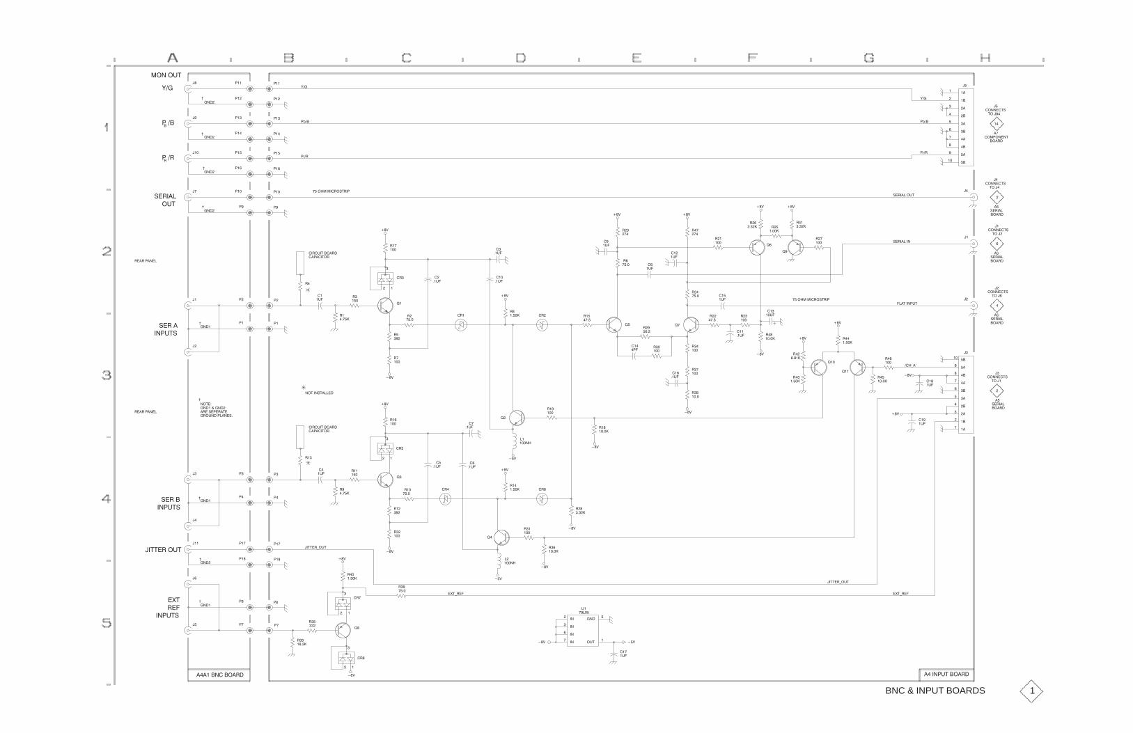
��
� ����%$
�����
����
���
����
����
���
�����
�����
�����
�����
��
)��
)��!��
!����
!��
!�
��
)��
� �� &%
!��#
$�#���
�
#
!���!�
!��
!��
!�
!��
���
���
!��
!�
!��
!��
!�
��
��
���
��� ������# $%#�!
!,�#
!+�� !+��
!,�#
$�#���� &%
% ����
��
� �#�
� �! ���%
��
� ����%$
% ���
��
��
��
� ����%$
% ��
��
� �#�
� ����%$
�
��
$�#���
��
� �#�
$�#���
$�#������
��' ��'
#��
��#�
�����
#
��
#�
���
#�
���"
"�
��' ��'
�
�&�
��
�&�
��
�&�
#
����
#��
��
#�
��
#�
����
�
��&�
���
��&�
��#�&�%�� �#�
��!���% #
��'
#��
���
�
��&�
�
�#
#�
!����
!�
#��#�!����
&%
$�#��
��!&%$
!
!�!�
!
����
��
�
��'
#�
�
#�
�����#
����
"�
#
���
#�
���
��
�&�
��'
#�
������#� �#
���
�!�#�
���
#�
���
#�
���
#�
� �
��
��&�
#��
����
"� "�
��� ������# $%#�!
��'
#�
�����
#�
����
��'
#
����
���
��&� #��
�����
���
�&�
��
��&�
"��
#
�����'
��'
#��
�����
���
�&�
#��
�����
���*��
"��
#�
���
���%���!&%
�
% ���
�
% �� �
�����
����
���
����
����
���
�����
�����
�����
�����
�
� ����%$
��
$�#���
� �#�
� �#�
��
$�#���
��'
���
�&�
��'
��'
#��
�����
#�
����
��'
��
��&�
��
��&�
"
#��
���
��
�����
��'
��#�&�%�� �#�
��!���% #
��'
#�
���
��
��&���
�&�"
�
�#�
#��
���
#�
!
�#��$�!�#�%�
�# &���!����$�
� %��
����������
!�
#��#�!����
$�#��
��!&%$
��%%�#� &%
!�
!��
!��
!�
����
���
!��
!��
��
���
��'
��'
#�
�����
#
���
#�
�
#��
����
��%%�#* &%
��'
#��
�����
#
�����
�
�����
"�
#�
���
�# �#�
��'
#�
��
�(%*#��
��%%�#* &%
��'
���
�&�
�����
����
����
����
�����
&%��
&�
�����
�(%*#��
��'
��'
#��
�����
#�
����
�
�#�
"�
#�
�
�#�
#
����
!�
!�
!�
!�
����
��
�
�(%
#��
��!&%$
���������� �#� ��' �����!&%�� �#�
BNC & INPUT BOARDS 1
-
-
-
-
-
-
-
-
-
� %���$%�����
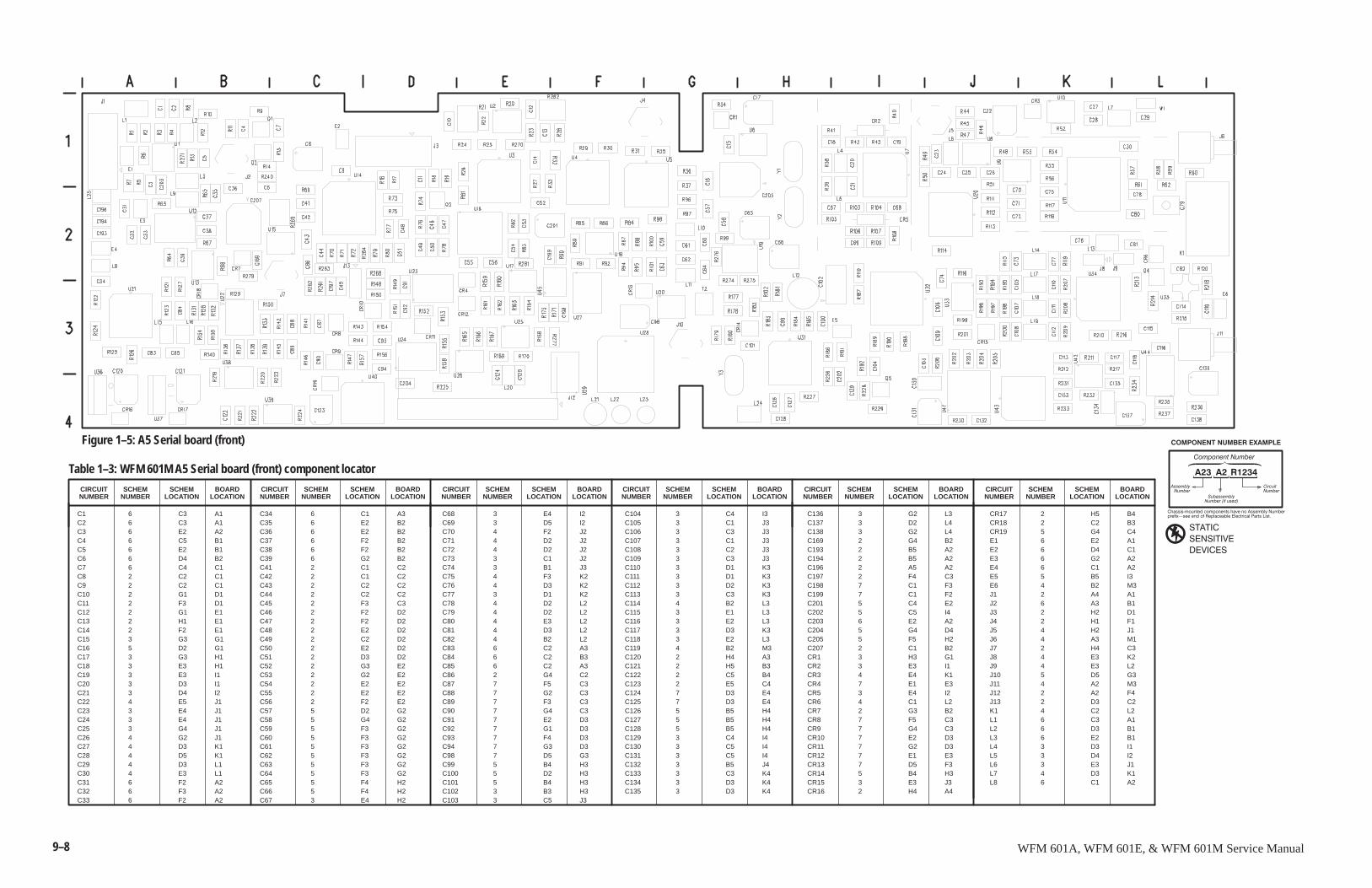
9–8 WFM 601A, WFM 601E, & WFM 601M Service Manual
SCHEMLOCATION
BOARDLOCATION
CIRCUITNUMBER
����������������
��� �� �����
�������"����������������������������������!�������
����� #�������������������������������������������
�� ��������������� �
��������������
������������������� ������
������
������� �
�� ����
� �� �������SCHEM
NUMBER
Table 1–3: WFM 601M A5 Serial board (front) component locator
CIRCUITNUMBER
SCHEMNUMBER
SCHEMLOCATION
BOARDLOCATION
SCHEMNUMBER
CIRCUITNUMBER
SCHEMLOCATION
BOARDLOCATION
SCHEMNUMBER
CIRCUITNUMBER
SCHEMLOCATION
BOARDLOCATION
SCHEMNUMBER
CIRCUITNUMBER
SCHEMLOCATION
BOARDLOCATION
SCHEMNUMBER
CIRCUITNUMBER
SCHEMLOCATION
BOARDLOCATION
C1 6 C3 A1C2 6 C3 A1C3 6 E2 A2C4 6 C5 B1C5 6 E2 B1C6 6 D4 B2C7 6 C4 C1C8 2 C2 C1C9 2 C2 C1C10 2 G1 D1C11 2 F3 D1C12 2 G1 E1C13 2 H1 E1C14 2 F2 E1C15 3 G3 G1C16 5 D2 G1C17 3 G3 H1C18 3 E3 H1C19 3 E3 I1C20 3 D3 I1C21 3 D4 I2C22 4 E5 J1C23 3 E4 J1C24 3 E4 J1C25 3 G4 J1C26 4 G2 J1C27 4 D3 K1C28 4 D5 K1C29 4 D3 L1C30 4 E3 L1C31 6 F2 A2C32 6 F3 A2C33 6 F2 A2
C34 6 C1 A3C35 6 E2 B2C36 6 E2 B2C37 6 F2 B2C38 6 F2 B2C39 6 G2 B2C41 2 C1 C2C42 2 C1 C2C43 2 C2 C2C44 2 C2 C2C45 2 F3 C3C46 2 F2 D2C47 2 F2 D2C48 2 E2 D2C49 2 C2 D2C50 2 E2 D2C51 2 D3 D2C52 2 G3 E2C53 2 G2 E2C54 2 E2 E2C55 2 E2 E2C56 2 F2 E2C57 5 D2 G2C58 5 G4 G2C59 5 F3 G2C60 5 F3 G2C61 5 F3 G2C62 5 F3 G2C63 5 F3 G2C64 5 F3 G2C65 5 F4 H2C66 5 F4 H2C67 3 E4 H2
C68 3 E4 I2C69 3 D5 I2C70 4 F2 J2C71 4 D2 J2C72 4 D2 J2C73 3 C1 J2C74 3 B1 J3C75 4 F3 K2C76 4 D3 K2C77 3 D1 K2C78 4 D2 L2C79 4 D2 L2C80 4 E3 L2C81 4 D3 L2C82 4 B2 L2C83 6 C2 A3C84 6 C2 B3C85 6 C2 A3C86 2 G4 C2C87 7 F5 C3C88 7 G2 C3C89 7 F3 C3C90 7 G4 C3C91 7 E2 D3C92 7 G1 D3C93 7 F4 D3C94 7 G3 D3C98 7 D5 G3C99 5 B4 H3C100 5 D2 H3C101 5 B4 H3C102 3 B3 H3C103 3 C5 J3
C104 3 C4 I3C105 3 C1 J3C106 3 C3 J3C107 3 C1 J3C108 3 C2 J3C109 3 C3 J3C110 3 D1 K3C111 3 D1 K3C112 3 D2 K3C113 3 C3 K3C114 4 B2 L3C115 3 E1 L3C116 3 E2 L3C117 3 D3 K3C118 3 E2 L3C119 4 B2 M3C120 2 H4 A3C121 2 H5 B3C122 2 C5 B4C123 2 E5 C4C124 7 D3 E4C125 7 D3 E4C126 5 B5 H4C127 5 B5 H4C128 5 B5 H4C129 3 C4 I4C130 3 C5 I4C131 3 C5 I4C132 3 B5 J4C133 3 C3 K4C134 3 D3 K4C135 3 D3 K4
C136 3 G2 L3C137 3 D2 L4C138 3 G2 L4C169 2 G4 B2C193 2 B5 A2C194 2 B5 A2C196 2 A5 A2C197 2 F4 C3C198 7 C1 F3C199 7 C1 F2C201 5 C4 E2C202 5 C5 I4C203 6 E2 A2C204 5 G4 D4C205 5 F5 H2C207 2 C1 B2CR1 3 H3 G1CR2 3 E3 I1CR3 4 E4 K1CR4 7 E1 E3CR5 3 E4 I2CR6 4 C1 L2CR7 2 G3 B2CR8 7 F5 C3CR9 7 G4 C3CR10 7 E2 D3CR11 7 G2 D3CR12 7 E1 E3CR13 7 D5 F3CR14 5 B4 H3CR15 3 E3 J3CR16 2 H4 A4
CR17 2 H5 B4CR18 2 C2 B3CR19 5 G4 C4E1 6 E2 A1E2 6 D4 C1E3 6 G2 A2E4 6 C1 A2E5 5 B5 I3E6 4 B2 M3J1 2 A4 A1J2 6 A3 B1J3 2 H2 D1J4 2 H1 F1J5 4 H2 J1J6 4 A3 M1J7 2 H4 C3J8 4 E3 K2J9 4 E3 L2J10 5 D5 G3J11 4 A2 M3J12 2 A2 F4J13 2 D3 C2K1 4 C2 L2L1 6 C3 A1L2 6 D3 B1L3 6 E2 B1L4 3 D3 I1L5 3 D4 I2L6 3 E3 J1L7 4 D3 K1L8 6 C1 A2
Figure 1–5: A5 Serial board (front)
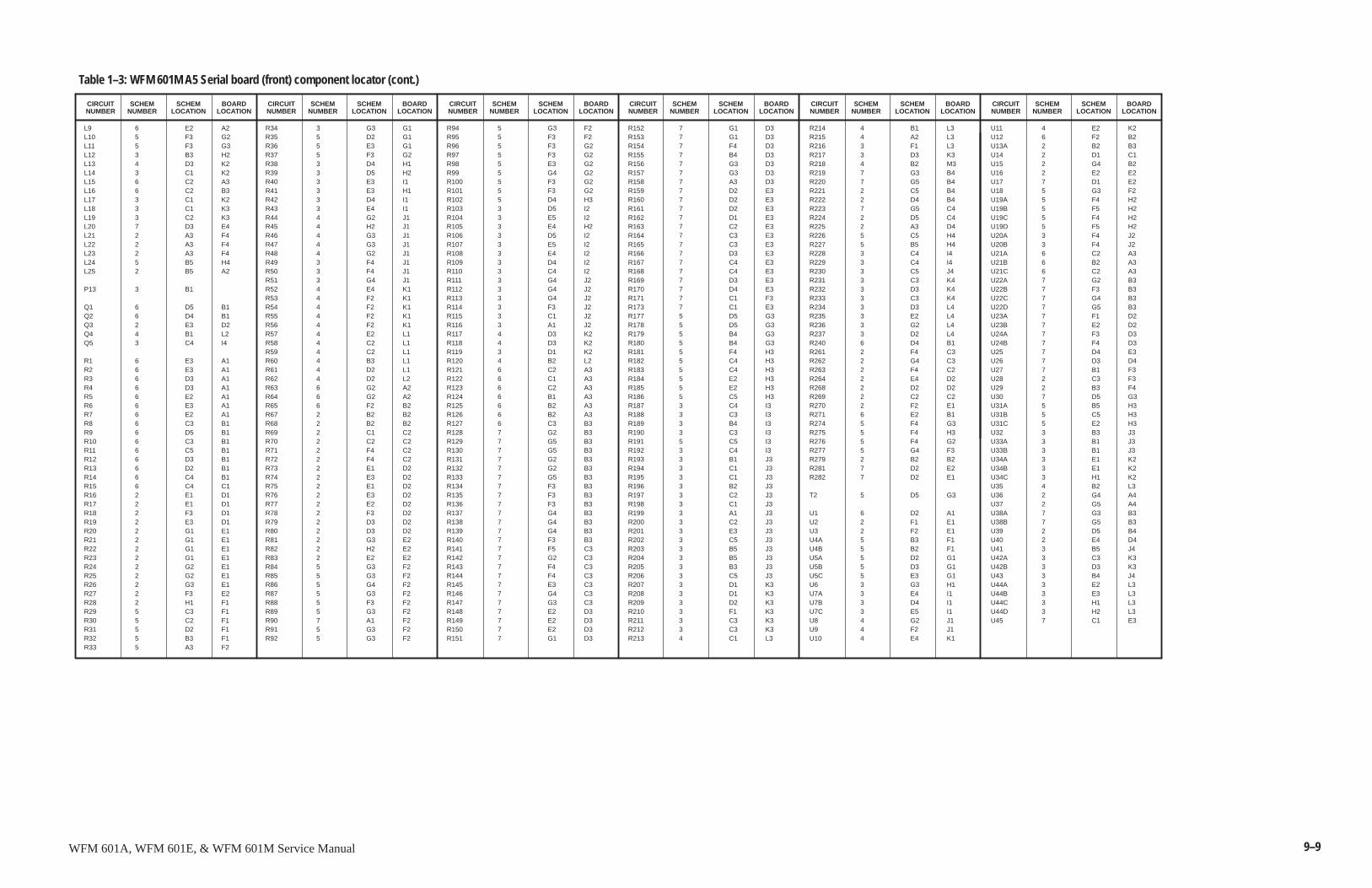
9–9WFM 601A, WFM 601E, & WFM 601M Service Manual
SCHEMNUMBER
CIRCUITNUMBER
SCHEMLOCATION
BOARDLOCATION
SCHEMNUMBER
CIRCUITNUMBER
L9 6 E2 A2L10 5 F3 G2L11 5 F3 G3L12 3 B3 H2L13 4 D3 K2L14 3 C1 K2L15 6 C2 A3L16 6 C2 B3L17 3 C1 K2L18 3 C1 K3L19 3 C2 K3L20 7 D3 E4L21 2 A3 F4L22 2 A3 F4L23 2 A3 F4L24 5 B5 H4L25 2 B5 A2
P13 3 B1
Q1 6 D5 B1Q2 6 D4 B1Q3 2 E3 D2Q4 4 B1 L2Q5 3 C4 I4
R1 6 E3 A1R2 6 E3 A1R3 6 D3 A1R4 6 D3 A1R5 6 E2 A1R6 6 E3 A1R7 6 E2 A1R8 6 C3 B1R9 6 D5 B1R10 6 C3 B1R11 6 C5 B1R12 6 D3 B1R13 6 D2 B1R14 6 C4 B1R15 6 C4 C1R16 2 E1 D1R17 2 E1 D1R18 2 F3 D1R19 2 E3 D1R20 2 G1 E1R21 2 G1 E1R22 2 G1 E1R23 2 G1 E1R24 2 G2 E1R25 2 G2 E1R26 2 G3 E1R27 2 F3 E2R28 2 H1 F1R29 5 C3 F1R30 5 C2 F1R31 5 D2 F1R32 5 B3 F1R33 5 A3 F2
R34 3 G3 G1R35 5 D2 G1R36 5 E3 G1R37 5 F3 G2R38 3 D4 H1R39 3 D5 H2R40 3 E3 I1R41 3 E3 H1R42 3 D4 I1R43 3 E4 I1R44 4 G2 J1R45 4 H2 J1R46 4 G3 J1R47 4 G3 J1R48 4 G2 J1R49 3 F4 J1R50 3 F4 J1R51 3 G4 J1R52 4 E4 K1R53 4 F2 K1R54 4 F2 K1R55 4 F2 K1R56 4 F2 K1R57 4 E2 L1R58 4 C2 L1R59 4 C2 L1R60 4 B3 L1R61 4 D2 L1R62 4 D2 L2R63 6 G2 A2R64 6 G2 A2R65 6 F2 B2R67 2 B2 B2R68 2 B2 B2R69 2 C1 C2R70 2 C2 C2R71 2 F4 C2R72 2 F4 C2R73 2 E1 D2R74 2 E3 D2R75 2 E1 D2R76 2 E3 D2R77 2 E2 D2R78 2 F3 D2R79 2 D3 D2R80 2 D3 D2R81 2 G3 E2R82 2 H2 E2R83 2 E2 E2R84 5 G3 F2R85 5 G3 F2R86 5 G4 F2R87 5 G3 F2R88 5 F3 F2R89 5 G3 F2R90 7 A1 F2R91 5 G3 F2R92 5 G3 F2
R94 5 G3 F2R95 5 F3 F2R96 5 F3 G2R97 5 F3 G2R98 5 E3 G2R99 5 G4 G2R100 5 F3 G2R101 5 F3 G2R102 5 D4 H3R103 3 D5 I2R104 3 E5 I2R105 3 E4 H2R106 3 D5 I2R107 3 E5 I2R108 3 E4 I2R109 3 D4 I2R110 3 C4 I2R111 3 G4 J2R112 3 G4 J2R113 3 G4 J2R114 3 F3 J2R115 3 C1 J2R116 3 A1 J2R117 4 D3 K2R118 4 D3 K2R119 3 D1 K2R120 4 B2 L2R121 6 C2 A3R122 6 C1 A3R123 6 C2 A3R124 6 B1 A3R125 6 B2 A3R126 6 B2 A3R127 6 C3 B3R128 7 G2 B3R129 7 G5 B3R130 7 G5 B3R131 7 G2 B3R132 7 G2 B3R133 7 G5 B3R134 7 F3 B3R135 7 F3 B3R136 7 F3 B3R137 7 G4 B3R138 7 G4 B3R139 7 G4 B3R140 7 F3 B3R141 7 F5 C3R142 7 G2 C3R143 7 F4 C3R144 7 F4 C3R145 7 E3 C3R146 7 G4 C3R147 7 G3 C3R148 7 E2 D3R149 7 E2 D3R150 7 E2 D3R151 7 G1 D3
R152 7 G1 D3R153 7 G1 D3R154 7 F4 D3R155 7 B4 D3R156 7 G3 D3R157 7 G3 D3R158 7 A3 D3R159 7 D2 E3R160 7 D2 E3R161 7 D2 E3R162 7 D1 E3R163 7 C2 E3R164 7 C3 E3R165 7 C3 E3R166 7 D3 E3R167 7 C4 E3R168 7 C4 E3R169 7 D3 E3R170 7 D4 E3R171 7 C1 F3R173 7 C1 E3R177 5 D5 G3R178 5 D5 G3R179 5 B4 G3R180 5 B4 G3R181 5 F4 H3R182 5 C4 H3R183 5 C4 H3R184 5 E2 H3R185 5 E2 H3R186 5 C5 H3R187 3 C4 I3R188 3 C3 I3R189 3 B4 I3R190 3 C3 I3R191 5 C5 I3R192 3 C4 I3R193 3 B1 J3R194 3 C1 J3R195 3 C1 J3R196 3 B2 J3R197 3 C2 J3R198 3 C1 J3R199 3 A1 J3R200 3 C2 J3R201 3 E3 J3R202 3 C5 J3R203 3 B5 J3R204 3 B5 J3R205 3 B3 J3R206 3 C5 J3R207 3 D1 K3R208 3 D1 K3R209 3 D2 K3R210 3 F1 K3R211 3 C3 K3R212 3 C3 K3R213 4 C1 L3
R214 4 B1 L3R215 4 A2 L3R216 3 F1 L3R217 3 D3 K3R218 4 B2 M3R219 7 G3 B4R220 7 G5 B4R221 2 C5 B4R222 2 D4 B4R223 7 G5 C4R224 2 D5 C4R225 2 A3 D4R226 5 C5 H4R227 5 B5 H4R228 3 C4 I4R229 3 C4 I4R230 3 C5 J4R231 3 C3 K4R232 3 D3 K4R233 3 C3 K4R234 3 D3 L4R235 3 E2 L4R236 3 G2 L4R237 3 D2 L4R240 6 D4 B1R261 2 F4 C3R262 2 G4 C3R263 2 F4 C2R264 2 E4 D2R268 2 D2 D2R269 2 C2 C2R270 2 F2 E1R271 6 E2 B1R274 5 F4 G3R275 5 F4 H3R276 5 F4 G2R277 5 G4 F3R279 2 B2 B2R281 7 D2 E2R282 7 D2 E1
T2 5 D5 G3
U1 6 D2 A1U2 2 F1 E1U3 2 F2 E1U4A 5 B3 F1U4B 5 B2 F1U5A 5 D2 G1U5B 5 D3 G1U5C 5 E3 G1U6 3 G3 H1U7A 3 E4 I1U7B 3 D4 I1U7C 3 E5 I1U8 4 G2 J1U9 4 F2 J1U10 4 E4 K1
U11 4 E2 K2U12 6 F2 B2U13A 2 B2 B3U14 2 D1 C1U15 2 G4 B2U16 2 E2 E2U17 7 D1 E2U18 5 G3 F2U19A 5 F4 H2U19B 5 F5 H2U19C 5 F4 H2U19D 5 F5 H2U20A 3 F4 J2U20B 3 F4 J2U21A 6 C2 A3U21B 6 B2 A3U21C 6 C2 A3U22A 7 G2 B3U22B 7 F3 B3U22C 7 G4 B3U22D 7 G5 B3U23A 7 F1 D2U23B 7 E2 D2U24A 7 F3 D3U24B 7 F4 D3U25 7 D4 E3U26 7 D3 D4U27 7 B1 F3U28 2 C3 F3U29 2 B3 F4U30 7 D5 G3U31A 5 B5 H3U31B 5 C5 H3U31C 5 E2 H3U32 3 B3 J3U33A 3 B1 J3U33B 3 B1 J3U34A 3 E1 K2U34B 3 E1 K2U34C 3 H1 K2U35 4 B2 L3U36 2 G4 A4U37 2 G5 A4U38A 7 G3 B3U38B 7 G5 B3U39 2 D5 B4U40 2 E4 D4U41 3 B5 J4U42A 3 C3 K3U42B 3 D3 K3U43 3 B4 J4U44A 3 E2 L3U44B 3 E3 L3U44C 3 H1 L3U44D 3 H2 L3U45 7 C1 E3
Table 1–3: WFM 601M A5 Serial board (front) component locator (cont.)
SCHEMLOCATION
BOARDLOCATION
SCHEMNUMBER
CIRCUITNUMBER
SCHEMLOCATION
BOARDLOCATION
SCHEMNUMBER
CIRCUITNUMBER
SCHEMLOCATION
BOARDLOCATION
SCHEMNUMBER
CIRCUITNUMBER
SCHEMLOCATION
BOARDLOCATION
SCHEMNUMBER
CIRCUITNUMBER
SCHEMLOCATION
BOARDLOCATION
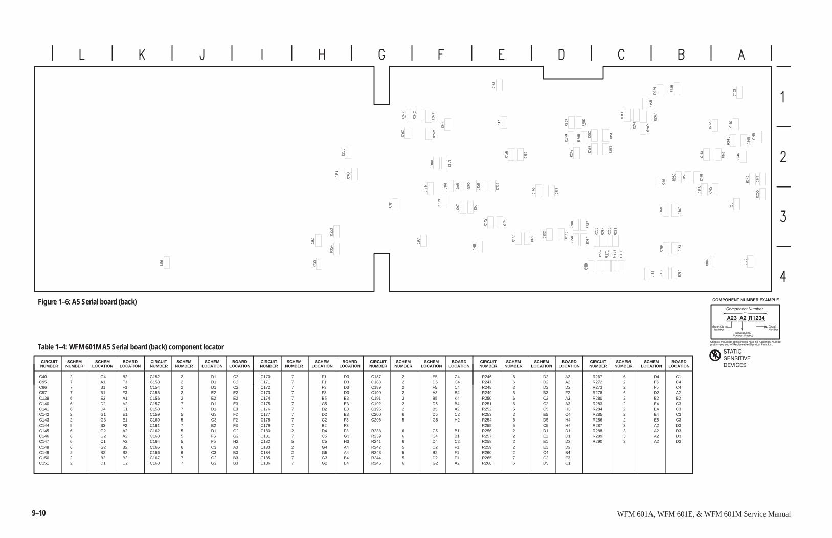
9–10 WFM 601A, WFM 601E, & WFM 601M Service Manual
SCHEMNUMBER
CIRCUITNUMBER
����������������
��� �� �����
�������"����������������������������������!�������
����� #�������������������������������������������
�� ��������������� �
��������������
������������������� ������
������
������� �
�� ����
� �� �������
Table 1–4: WFM 601M A5 Serial board (back) component locator
SCHEMLOCATION
BOARDLOCATION
SCHEMNUMBER
CIRCUITNUMBER
SCHEMLOCATION
BOARDLOCATION
SCHEMNUMBER
CIRCUITNUMBER
SCHEMLOCATION
BOARDLOCATION
SCHEMNUMBER
CIRCUITNUMBER
SCHEMLOCATION
BOARDLOCATION
SCHEMNUMBER
CIRCUITNUMBER
SCHEMLOCATION
BOARDLOCATION
SCHEMNUMBER
CIRCUITNUMBER
SCHEMLOCATION
BOARDLOCATION
C40 2 G4 B2C95 7 A1 F3C96 7 B1 F3C97 7 B1 F3C139 6 E3 A1C140 6 D2 A2C141 6 D4 C1C142 2 G1 E1C143 2 G3 E1C144 5 B3 F2C145 6 G2 A2C146 6 G2 A2C147 6 C1 A2C148 6 G2 B2C149 2 B2 B2C150 2 B2 B2C151 2 D1 C2
C152 2 D1 C2C153 2 D1 C2C154 2 D1 C2C155 2 E2 E2C156 2 E2 E2C157 7 D1 E3C158 7 D1 E3C159 5 G3 F2C160 5 G3 F2C161 7 B2 F3C162 5 D1 G2C163 5 F5 G2C164 5 F5 H2C165 6 C3 A3C166 6 C3 B3C167 7 G2 B3C168 7 G2 B3
C170 7 F1 D3C171 7 F1 D3C172 7 F3 D3C173 7 F3 D3C174 7 B5 E3C175 7 C5 E3C176 7 D2 E3C177 7 D2 E3C178 7 C2 F3C179 7 B2 F3C180 2 D4 F3C181 7 C5 G3C182 5 C5 H3C183 2 G4 A4C184 2 G5 A4C185 7 G3 B4C186 7 G2 B4
C187 2 E5 C4C188 2 D5 C4C189 2 F5 C4C190 2 A3 E4C191 3 B5 K4C192 2 D5 B4C195 2 B5 A2C200 6 D5 C2C206 5 G5 H2
R238 6 C5 B1R239 6 C4 B1R241 6 D4 C2R242 5 D2 F1R243 5 B2 F1R244 5 D2 F1R245 6 G2 A2
R246 6 D2 A2R247 6 D2 A2R248 2 D2 D2R249 5 B2 F2R250 6 C2 A3R251 6 C2 A3R252 5 C5 H3R253 2 E5 C4R254 5 D5 H4R255 5 C5 H4R256 2 D1 D1R257 2 E1 D1R258 2 E1 D2R259 2 E1 D2R260 2 C4 B4R265 7 C2 E3R266 6 D5 C1
R267 6 D4 C1R272 2 F5 C4R273 2 F5 C4R278 6 D2 A2R280 2 B2 B2R283 2 E4 C3R284 2 E4 C3R285 2 E4 C3R286 2 E5 C3R287 3 A2 D3R288 3 A2 D3R289 3 A2 D3R290 3 A2 D3
Figure 1–6: A5 Serial board (back)
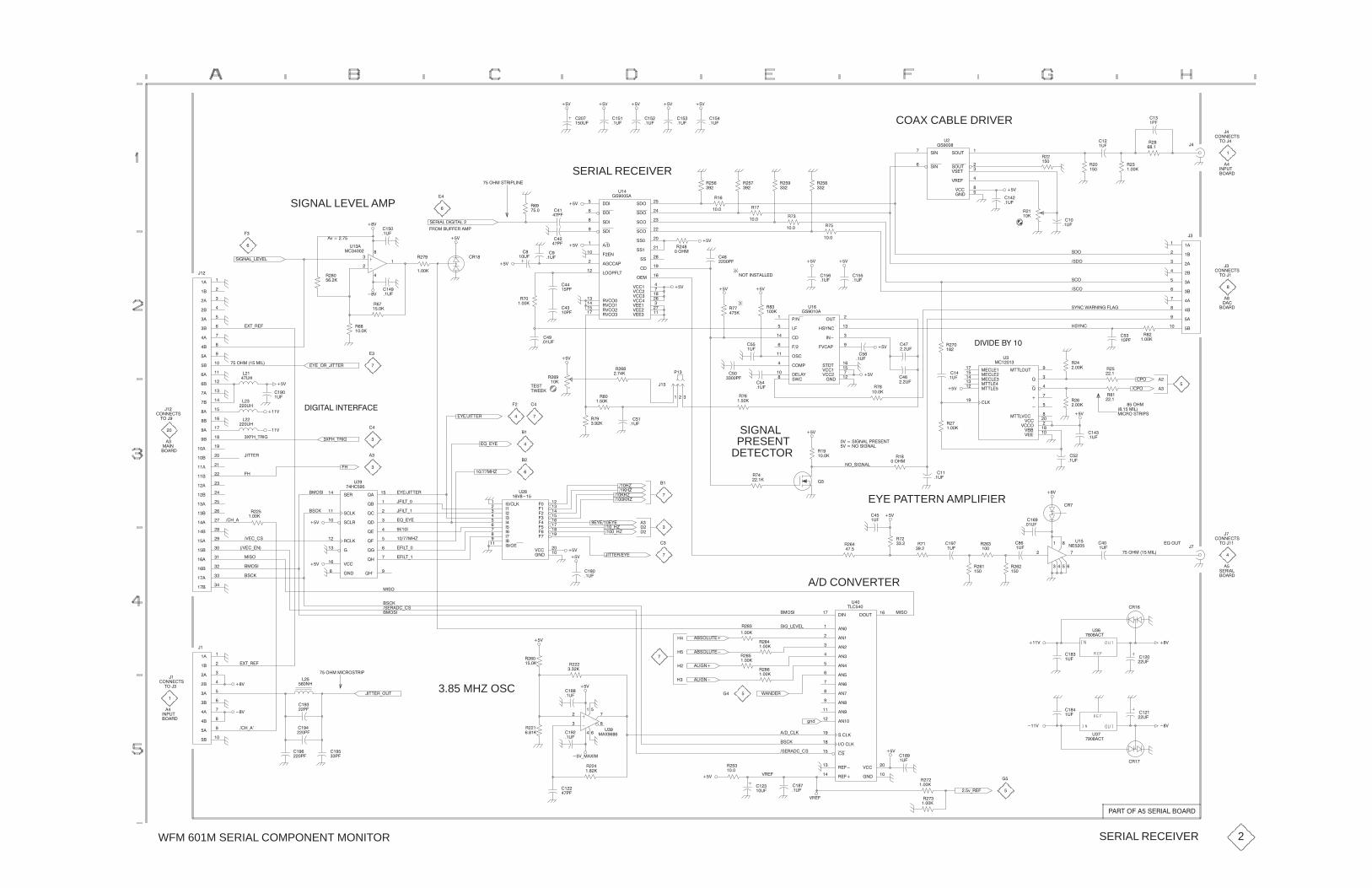
WFM 601M SERIAL COMPONENT MONITOR
�"!!��'&
�
��
#�COAX CABLE DRIVER��
�(�
��)��)
��
�(�
���
�(�
���
�(�
��)��)
���
�(�
��)
��
�
�2�������
SIGNAL LEVEL AMP
&�%��������'����
�%" ��(���%�� #
���"� �&'%�#��!�
��)
��
�(�
%��
���
�
�
��)
SERIAL RECEIVER
��)
��)
� �
�#�
�
�#�
&�����
&�����
�����
&�"��
&�"�
&�"��
&�"��
���!�
&&�
&&�
�����#���
&&��
���
)�����
)�� ��
)����
)�����
)���
)����
������
������
)���
%)�"��
�""#��'��
%)�"�
%)�"���
%)�"���
"� �
(
�&���
%� �
�"�
��)
%�
�%�
�%��
�%��
�
%���
���
%���
���
%���
���
%���
���
&�!���
&�!���
&"('�
&"('��
)&�'��
)%���
)����
�!���
(�
�&��
� �
�(�
��)
%�
��
�(�
%��
�%�
�
%��
���
��
(�
%��
��
�
�!#('
�"�%�
'"��
�
���
����
�����
����
�����
�����
����
����
�����
���
��
�"!!��'&
��
�"�%�
'"��
��
�
���
�&,!�
�&�"
&�"
�&�"
&�"
&,!��*�%!�!������
���
#�
%�
���
%��
��
��)
��)
���
�(�
��)�����,�
���
�(�
%��
��
� �
���(�
� �
��#�
��)��)
���
�(�
��)
#�!��
�����
���
������
"('��
�&,!��
�!���
�)��#��
&'�'�
)���
)�����
�!��
"&��
�" #��
&*����
����,�
(�
�&��
���
(�
%��
���
!"'��!&'�����
%��
�
��)�
�#�
� �
#�
��
�(�
%�
��
� �
�(�
��)
��)
� �
�(�
���
���
�
�
(��
�� � ��
(�%���
��
%��
���
�%�
�+'.%��
&��!��.��)��
%��
��
��
�
%��
������
�
���
����
���
����
����
���
���
����
��
��
���
���
��
���
���
���
���
��
��
��
���
����
���
����
����
���
���
����
���
���
����
����
���
��
��!
�"�%�
�"!!��'&
'"���
��
��
�
���"� ���� ���
�+��.'%��
��)
�)
�)
��''�%
��
(�
���
��(�
��
�(�
���
��(�
�,�."%.��''�%
�+��.'%��
�
�
��
�
����'����!'�%�����,����''�%
�$.�,�
��
�
�
��
��)
%���
�
��
�(�
� �
��
'*���
'�&'
%���
��� �
�
�
#�
%�
���
%��
�����
PRESENTDETECTOR
SIGNAL ��)
��
�(�
��
��#�
%�
��
%��
���
�)���!"�&��!��
)���&��!���#%�&�!'
��)
��)
%�
�"�
������
�������
������
''�� ��
''�����
�����
''�"('��
$��
$�
���
���
)���
)��"��
)���
)��
''�)����
(�
���
%��
��
%��
��
�
�(�� �
���(�
���"�
����� ���
��%"�&'%�#&
� �
�(�
��#"
�#"
%�
���
%��
���
%��
���
��)
���
�(�
��
��
�
�$�"('
�"!!��'&
��
��'"��
��
&�%���
���"� ���� ���
��)
�
(�
���
(�
��� ��
�
�
� �
(�
!����
�%�
%���
�
���
�(�
!".&��!��
EYE PATTERN AMPLIFIER��)
%��
�
%��
���
� �
(�
%��
���� %�
����
���
(�
%���
�
�(�%�
����$�
��)
��
�(�
��-
���-
���-
���-
��)
��,���,�
�.�-
�.�-
��''�%��,�
��
�
�
�
��
��
��
�
�,����''�%
�$.�,�
��� �-
����
��� �-
����'.
����'.
����'.
����'.
�������
����
�����
����
� ���
�����
�����
�����
�����
���"��
���
���
���
� �
���
��
��
��
)���
�!�
(��
�)���
��
�)��.�&
� "&���)
��)���.�
�&��
� "&�
�&"
&�%�
$��
$��
&����
$���
&��%�
$���
$��
%�����
$���
���
$���
$���
$����
�!����
)����
(��
� �����
��
��)��.�!�
%���
��
�
��
���
����
���
����
����
���
���
����
��
�
�&��
�+'.%��
���"� � ��%"&'%�#
�&��
� "&�
�&"
�&�%���.�&
��)
%��
��� %���
�����
�
��
��
��
�
��!��
�"('�
�!��
�!���
�!����
�!���
�! ���
�!����
�!����
�!����
�!����
�!��
�!��
&������
��"������
�&��
%�����
%����
�!�
)���
(
'���
� "&�
&��.��)��
A/D CONVERTER
��&"�('��
��&"�('��
����!�
����!�
%���
��
%��
��
%���
��
%���
��
�&"
�)
��
��(�
���
(�
�%�
(��
�����'
�"�%�
��)
��)�)
��
��(�
��
(�
�%�
(��
�����'
��
�
��)
���
�(�
���2.%��
%���
��
�&��
���.���
��))%��
�&�%���.�&
%���
�
���
(�
���
�(�
*�!��%� �
01/
)%��
��)
���
�#�
��). �+�
���
�(�
%��
����
���
�(�
���
��� �
�
�
�(��
�+����
%��
����
3.85 MHZ OSC��)
��)
���.��
��''�%."('
���
��#�
���
��#�
���
��!�
���
��#�
��
��#�
�"�%�
�
�!#('
�"!!��'&
'"���
%���
��
SERIAL RECEIVER
#�%'�"�����&�%�����"�%�
2

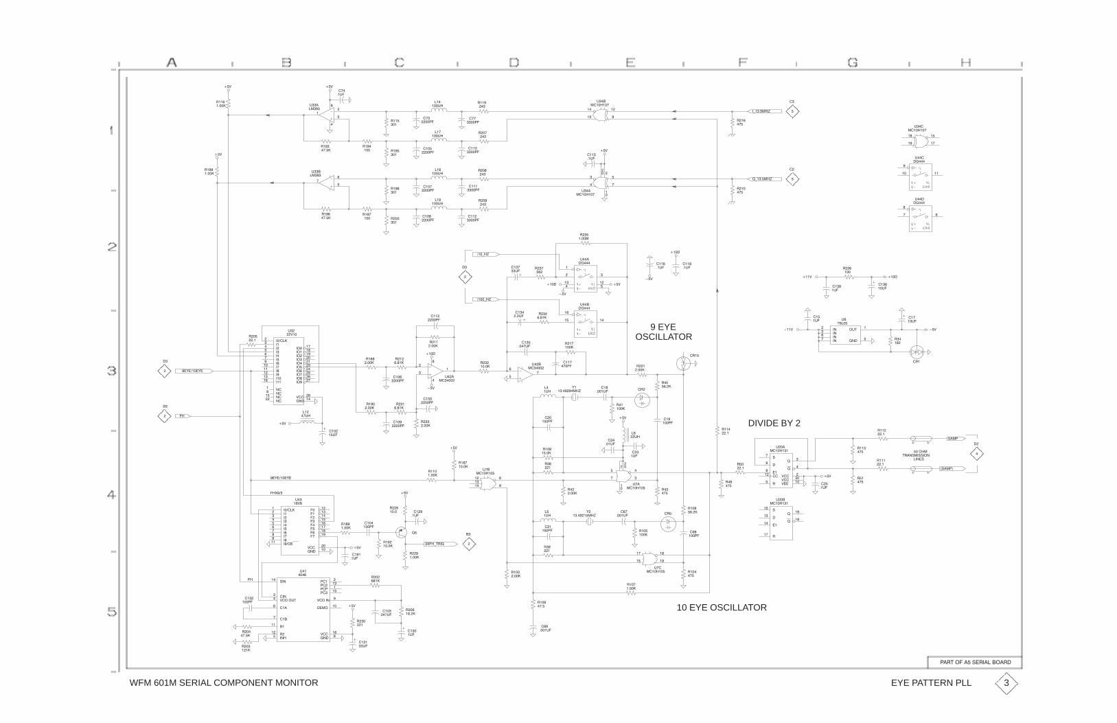
WFM 601M SERIAL COMPONENT MONITOR
���
�)�����(
!�
���
�
��
��
���
��
$��
��������
���
����
!���
�
���
���$�
��
����!���
��
��%
���
��$�
�
�
���
�
�
$�
���
��%
!��
�����
��%
!���
�����
����
����!���
��
����
����!���
��
�
��
���
$�
!��
�����
!���
�������
����
����
����
!��
�
!��
�
���
���$�
���
���$�
��%
����
��$�
��
��
��
���
�
��
$��
��������
)�����(
!��
���
�
�
���
��� ��
$���
�����
���
���
��
��
$��
��������
��
��$����
�$�
���% ����
!
���
���
��� �
$���
�����
��%
��%
����
����
��%
���
�� �
�� �
�����
$���
�����
!�
�����
����
��$�
���
��$�
���)�(
!�
�
���
$�
���
����
!��
�
���
���$�
�
����
����!��
��
!��
�����!���
���
�
��'�����'�
!��
�� ��������
����
����
����
����
�����
� ���
�����
�����
����
�����
�����
����
���
����
�� �
���
����
���
����
�����
�����
%���
�����
�����
�����
�����
���
$
%��
���
����
!���
����
!�
������
��
��
�
�
$��
�����
!
�����
���
��
��
$��
�����
����
����)�(
!�
����
���
�$�
���
����$�
!��
����
���
����
9 EYEOSCILLATOR
!��
� ��
�!��
����
�����
��
��� ��
$���
�����
!��
����
!��
����
���
�$�
���%
!�
��
���
��$�
��%
�!�
�$#��
�����
����
����
�����
����
$
�����
"���
�"����
�
�������
����"
#!��"��""���
!��
���
!���
��
!��
��
DIVIDE BY 2!���
��
!��
��
"���
����
!���
�����
����
�
��
%���
%���
%����
$��
�������
�
$���
���$�
���
���
��
�
�
��
$��
��������
�!
!��
����
'�
��������(
��%���
�����
�
��$�
���
����$�
!���
�����
��
�����
��%
��%
��
����
��
�$�
!���
�����
!�
�
����
����
!�
����
!
����
���
��$�
��
��$�
!���
����
��%
��
�
��'�����'�
��&���
���������
����
���
����
�����
����
� ���
�����
�����
��������
����
� ��
����
���
���
���
���
���
%���
�����
$�
� %�
!��
�����
!�
�����
��%
��%
����
��$�
���
��$�
!�
����
����
�����!���
�����
�
��
��
���
��
��
$��
��������
��
�����
&��)#!��
!���
�����
��
�$�
!�
�
�
!���
����
!�
����
���
���
��
��
$��
��������
!�
���
�!�'
��������(
� �
����$�
!��
���
!���
� ��"
���
���
!���
�����
��
��
$��
�������
� �
�����
!��
���
��%
��
��$�
!���
���
10 EYE OSCILLATOR
!���
�����
!��
����
� �
����$�
!��
����
���
$�
���
�$�
!�
����
!�
�
���
����$�
��%
!�
�������
���
����
�����
%�������
"�����
%����$#���
�����
!��
������
�����
!����
������
�����
%���
������
$��
���
��
��
�����
!�
���
!��
�����
EYE PATTERN PLL
��!#�������"�!�������!�
3

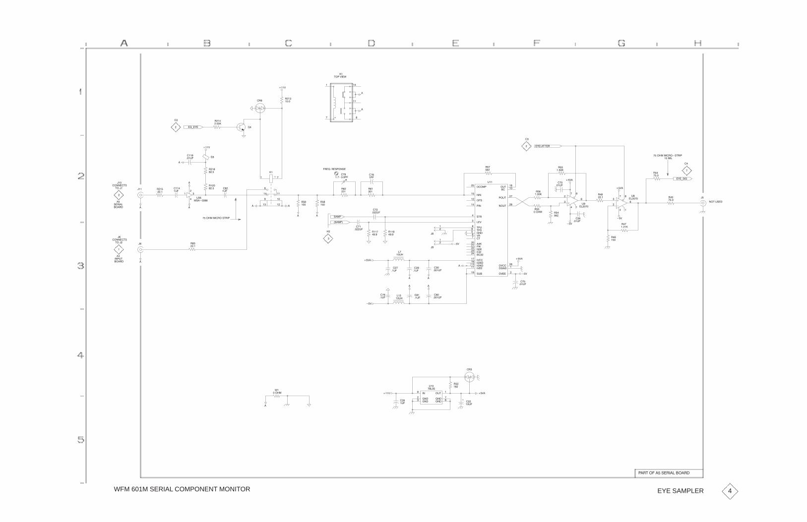
WFM 601M SERIAL COMPONENT MONITOR
��
$� �&��'
��
�!)�(�
"��
����
�
"�
����
���&
�"
!�
�
�
�
��
�
��
�
�
�
��$�%#��
��
��
�
����������"��#$"�
������
�(�)#��
��&�
"��
����
"��
����
��
��
�
�
�
�
�
%�
�����
"��
��
��&�
���
���%�
��
��
�
�
�
�
�
%�
�����
�(����$$�"
"�
�����
"��
�
"�
�����
"��
�����
���� ��
������
��#��
�����
#$"���
��&��
$ %���
$ ����
�%$��
��
�%$�
��%$�
�$���
������
&"��
�����
����
���
��
����
�&�����
������
������
�&�����
#%����
�&���
������
�&��
%��
"��
�
"��
���
�"�!��"�# ��#�
���
� �
���
������ �
"
�
" �
��
��
�%�
"��
���� �
��� ��
��� ��
���
���
��� �
��
"��
���
"��
�������
�%�
���&
�
� �
�
���
�
"��
��
����
���%�
���
�%�
�#����
���
������$#
$����
��
���"�
#�"���
������$#
$���
��
���"�
�
�
�� %$
����������"��#$"�
�
� " �
��
�
��
��%�
���
��%�"���
����
"���
����
��
��%�
#��
�#�� �
�
��&�
��
��%�
�
��
����%�
�
��&
��
�
��
��
�
��
��
��%�
��&�
��&
�
���%�
"�
���
��&
"��
����
���
���%�
��&
���
����%�
� �
� �
���
��%���
��%�
��&
��
��%�
'�
�����
��
�%�
���&
�
��%�
"�
��
��&�
�"
�����
����
�%$��
�����
�����
�����
%��
�����
�
EYE SAMPLER
�"$�������#�"�������"�
4

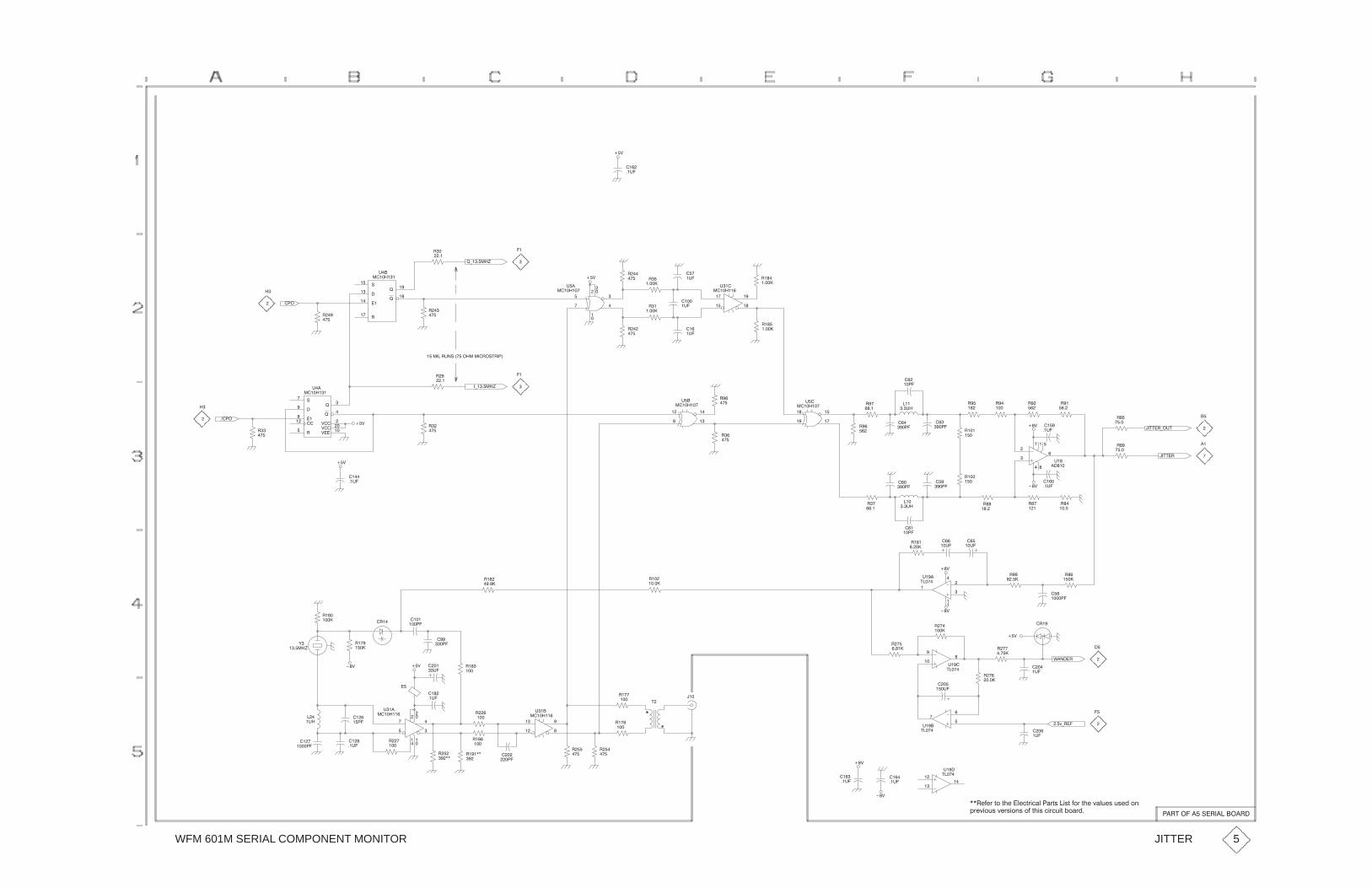
WFM 601M SERIAL COMPONENT MONITOR
��
�%�
� &
"��
����
�
��
�
�
%��
�����
"�
����
� &
���
%�
� �
%�
��
%�
��
���
��
��
�
�
% �
������
"��
��
"�
��
"�
����
"�
����
!*�� ��)
�����"%�#��� ��������"�#$"� �
#�
���
"��
���
!�
!�
%��
�����
"��
��
"��
�
�
�
� �
"��
��
��
��
�� �
� &
"��
��
#���
����
"��
����
���
!��
!��
&���
&���
&���
%��
�����
�*�� ��)
"�
��
"�
�
�
�
�
���
�
�
% �
������
"��
��
"��
��
��
��
�
% �
������
"�
�
"��
���
���
��� �"��
�
���
��� �
�
���%�
��
� �
"�
�
"��
��
��$$�"*�%$��& � �
�%�
"�
�
"�
��
�
�
�
��
���
�
%�
����
"�
� ��
"��
� ��
��$$�"
�
�
�
��&
���
�%�
"��
"��
���
��&
"��
�
��
�%�
"��
���
� �
��� �
��
���%�
��
� �
���
��� �
"��
��
"�
�� �
���
�%�
� &
���
�%�
��&
"��
���
(�
�� ��)
"��
��
� & "��
��
�"�
"�
�����
���
��� �
��
�� �
��
��%�
"�
����
��&
�
��
��
�
%��
$����
"�
����
"��
���
���
��
��
%��
$����
"��
��� �
"��
����
"��
�� �
� �
��� �
'����"
���
%�
�
"��
��
� &
�"�
� ;*"��
���
%�
�
���
�%�
���
�%�
��&
��&
�
��
�
%��
$����
��
�%�
��
�
���
%��
$����
��
" �
��
�
��
�
�
%��
�����
"
��
"��
��
"��
��
$
��
�%�
�
"�
��
"
����"���
��
"�
��
"��
��
��
���
�
�
�
�
�
%��
�����
��
� �
��
%�
��
��� �
��
�%�
��
�
JITTER 5
�"$����� �#�"�������"�
��"/0/7�95�91/��3/-972-+3� +798��289�057�91/�;+3:/8�:8/.�54
67/;25:8�;/782548�50�9128�-27-:29�,5+7.�

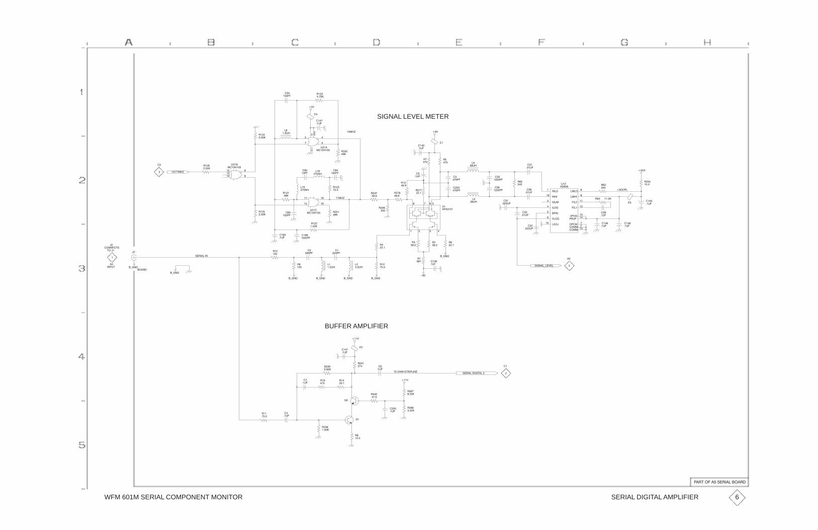
WFM 601M SERIAL COMPONENT MONITOR
�$
��
�����
��
����
�
�� #�
�
��
���
�
��
���
��
#���
�������
����%
SIGNAL LEVEL METER
���
���
���
��#�
� $
��
���
��#�
�����
�$�
��
���
��
��#�
� �����
��
�
����
�
��
���
���#�
��
���#�
���
����#�
�������
�������
�����
������
�!#����
������
������
$������
�����
������
������
� #��
$��!��
������
������
�������
#��
�����
���
���#�
��
��#�
��
��#�
� � �
��
#�
�������
�
�
�
���
��#�
�
��#�
���
������
��
������
��
����
����
���� ���
����
����%
��
��
���
�����
�
�����
���
���
��
��
��
���
��
���
��
���
��
���
���
���
��
�
��
#���
�������
��
�����
�
����
��
�����
���
��
� �
�����
���
��
�
��
#���
�������
�������%
���
�����
��
�
��
������"!
"����
�
���#"
�
��� �
!� ������
��
�&���
�&���
���
�&���
��
���
��
����
���
��#�����
������
���
�����
�&��� �&��� �&���
��
���#�
��
���#�
��
�����
��
���
����
� $
�&��� �
� � ����
��#�
�
����
�
����
�
����
!�����&��$��
���
����#�
��
�
���
��#�
��
��#�
BUFFER AMPLIFIER
��
��#�
���$
������!" ������
���$
���
�����
���
���
��
��#�
���
��#�
��
��
�� ���
�����
��
��
��
�
�
�
����
!� ��������"����
��
�
����
��#�
��
�����
�
����
��
��
���
�
��#�
SERIAL DIGITAL AMPLIFIER 6
�� "������!� ������� �

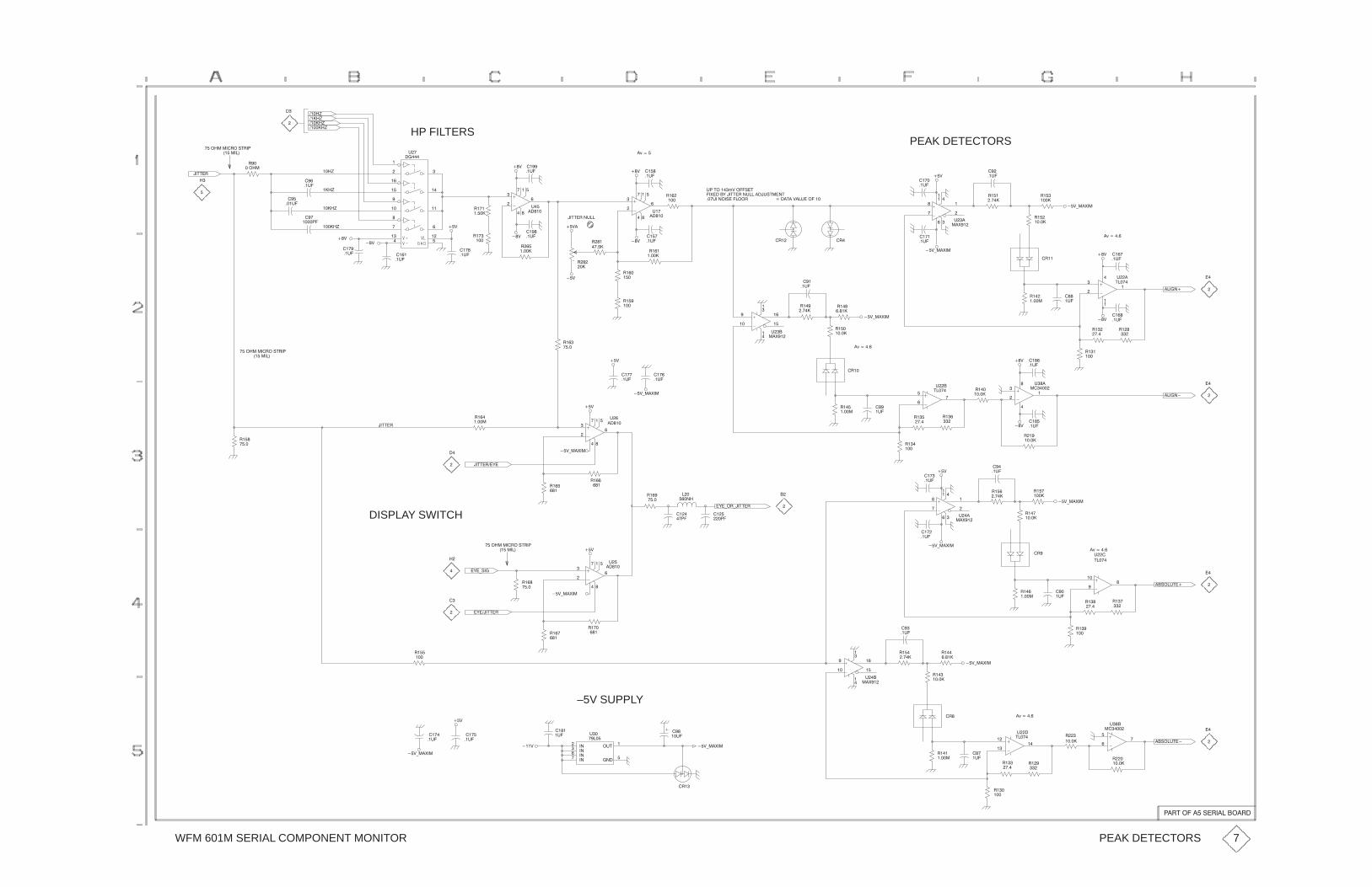
WFM 601M SERIAL COMPONENT MONITOR
���
��
HP FILTERS
����)
����)
�����)
������)
�
��$$�"
��� ������" �#$"�!
�
�
���)
���)
����)
�����)
��������
��&
"��
�� ��
��
��%�
���
���%�
���
����!�
����
��%�
��&
��&
��&
��&
���
�� �
��
��� ��
���
��� ��
���
��� �
�� �
�����
%�
�����
����
��%�
"��
���
"���
�����
�
�
� �
�
��
��
%��
�����
�,����
��&
��&
����
��%�
����
��%� ����
��%�
����
��%�
"�
���
�
�
� �
�
��
��
%��
�������$$�"��%��
��&�
"�
��
"��
�����
�"� �"�
%!�$ ���+&� ��#�$
��'����(���$$�"��%������%#$���$
���%��� �#���� " ����$��&��%�� ����
��&
PEAK DETECTORS
��&*��'��
����
��%�
����
��%�
���
���
��
�
�� �
%�
��'��
��
��%�
"���
����
�,�����
��&*��'��
"��
�����
�"��
"��
����
������
��
���
�%�
��&
��&
"��
�����
��
��
��
�
��
%�
$����
�� �
��%�
�� �
��%�
"�
���
"��
���
"��
�,�����
��&*��'�����
���
�
��
��
�
%�
��'��
���
��%�
"���
�����
"���
����
�"��
"���
����
"� �
�����
"� �
���
"���
���
"�
����
��&
�� �
��%�
" �
�����
��� ������" �#$"�!
��������
"���
����
��$$�"
��$$�"��(�
"� �
�����
��
��&
��&*��'��
��&*��'��
��&
�
�
� �
�
��
��
%
�����
���
��%�
����
��%�
"���
�����
���
�%�
���
��
��
%�
$����
"��
���
"�
"��
���
"���
�����
��&
��&
��
��
��
�
�
%��
�����
���
��%�
����
��%�
"��
�����
������
��
��
�,�����
���
���
��
%�
$����
��&*��'��
"���
����
"���
�����
�"�
��&
��&*��'��
���
��%�
���
��%�
���
���
��
�
�� �
%��
��'��
���
��%�
"��
����
�(�* "*��$$�"
���
�!�
�
��&
"� �
��
"�
��
"� �
����
��
� ���
���
��!�
�
�
� �
�
��
��
%�
�����
��� ������" �#$"�!
��������
�(�*#��
DISPLAY SWITCH
"� �
����
�
�
�(����$$�"
"���
���
�
��&*��'��
"���
��"� �
��
��&*��'�����
���
�
��
��
�
%��
��'��
��
��%�
"���
����
"��
�����
"���
����
���
�%�
"��
�����
"��
���
"��
"��
���
��# �%$��
��# �%$��
��
�,�����
��
��
��
%�
$����
"�
���"��
"
�������
%��
�����
"�
�����
���
�%�
�"�
"���
�����
"��
���
��&*��'�����&
����
�%����
��%�
–5V SUPPLY
�"�
%$��
�����
����
����
�����
����
%�
�����
��&
��&*��'��
����
��%�
����
��%�
PEAK DETECTORS 7
!�"$� �����#�"����� �"�
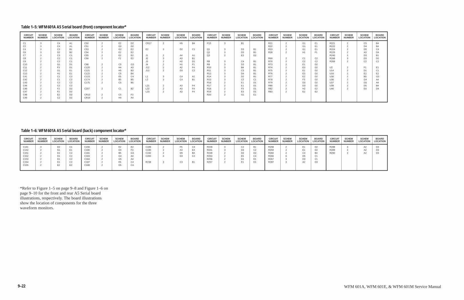
9–22 WFM 601A, WFM 601E, & WFM 601M Service Manual
SCHEMNUMBER
CIRCUITNUMBER
SCHEMLOCATION
BOARDLOCATION
SCHEMNUMBER
CIRCUITNUMBER
C1 3 C4 A1C2 3 C4 A1C4 3 C3 B1C6 3 D2 B2C7 3 C3 C1C8 2 C2 C1C9 2 C2 C1C10 2 G1 D1C11 2 F3 D1C12 2 G1 E1C13 2 H1 E1C41 2 C1 C2C42 2 C1 C2C43 2 C2 C2C44 2 C2 C2C46 2 F2 D2C47 2 F2 D2C48 2 E2 D2C49 2 C2 D2
C50 2 E2 D2C51 2 D3 D2C53 2 G2 E2C54 2 E2 E2C55 2 E2 E2C56 2 F2 E2
C98 2 C5 G3C120 2 H4 A3C121 2 H5 B3C122 2 C5 B4C123 2 E5 C4C174 2 B5 B5C175 2 C5 B5
C207 2 C1 B2
CR13 2 C5 F3CR16 2 H4 A4
CR17 2 H5 B4
E2 3 D2 C1
J1 2 A4 A1J2 3 A3 B1J3 2 H2 D1J4 2 H1 F1J12 2 A2 F4J13 2 D3 C2
L1 3 C4 A1L2 3 C4 B1
L21 2 A3 F4L22 2 A3 F4L23 2 A3 F4
P13 3 B1
Q1 3 D3 B1Q2 3 D3 B1Q3 2 E3 D2
R8 3 C4 B1R9 3 D3 B1R10 3 B4 B1R11 3 C3 B1R12 3 D4 B1R14 3 D2 B1R15 3 C2 C1R16 2 E1 D1R17 2 E1 D1R18 2 F3 D1R19 2 E3 D1R20 2 G1 E1
R21 2 G1 E1R22 2 G1 E1R23 2 G1 E1R28 2 H1 F1
R69 2 C1 C2R70 2 C2 C2R73 2 E1 D2R74 2 E3 D2R75 2 E1 D2R76 2 E3 D2R77 2 E2 D2R78 2 F3 D2R79 2 D3 D2R80 2 D3 D2R82 2 H2 E2R83 2 E2 E2
R221 2 C5 B4R222 2 D4 B4R224 2 D5 C4R225 2 A3 D4R240 3 D3 B1R268 3 D3 D2R269 2 C2 C2
U2 2 F1 E1U14 2 D1 C1U16 2 E2 E2U30 2 B5 G3U36 2 G4 A4U37 2 G5 A4U39 2 D5 B4U40 2 E4 D4
Table 1–5: WFM 601A A5 Serial board (front) component locator*
SCHEMLOCATION
BOARDLOCATION
SCHEMNUMBER
CIRCUITNUMBER
SCHEMLOCATION
BOARDLOCATION
SCHEMNUMBER
CIRCUITNUMBER
SCHEMLOCATION
BOARDLOCATION
SCHEMNUMBER
CIRCUITNUMBER
SCHEMLOCATION
BOARDLOCATION
SCHEMNUMBER
CIRCUITNUMBER
SCHEMLOCATION
BOARDLOCATION
SCHEMNUMBER
CIRCUITNUMBER
SCHEMLOCATION
BOARDLOCATION
SCHEMNUMBER
CIRCUITNUMBER
C141 3 D2 C1C142 2 G1 E1C151 2 D1 C2C152 2 D1 C2C153 2 D1 C2C154 2 D1 C2C155 2 E2 E2
C156 2 E2 E2C180 2 D4 F3C181 2 B5 G3C183 2 G4 A4C184 2 G5 A4C187 2 E5 C4C188 2 D5 C4
C189 2 F5 C4C190 2 A3 E4C192 2 D5 B4C200 3 D3 C2
R238 3 C3 B1
R239 3 C2 B1R241 3 D3 C2R248 2 D2 D2R253 2 E5 C4R256 2 D1 D1R257 2 E1 D1
R258 2 E1 D2R259 2 E1 D2R260 2 C4 B4R266 6 D5 C1R267 3 D3 C1R287 3 A2 D3
R288 3 A2 D3R289 3 A2 D3R290 3 A2 D3
Table 1–6: WFM 601A A5 Serial board (back) component locator*
SCHEMLOCATION
BOARDLOCATION
SCHEMNUMBER
CIRCUITNUMBER
SCHEMLOCATION
BOARDLOCATION
SCHEMNUMBER
CIRCUITNUMBER
SCHEMLOCATION
BOARDLOCATION
SCHEMNUMBER
CIRCUITNUMBER
SCHEMLOCATION
BOARDLOCATION
SCHEMNUMBER
CIRCUITNUMBER
SCHEMLOCATION
BOARDLOCATION
*Refer to Figure 1–5 on page 9–8 and Figure 1–6 onpage 9–10 for the front and rear A5 Serial boardillustrations, respectively. The board illustrationsshow the location of components for the threewaveform monitors.
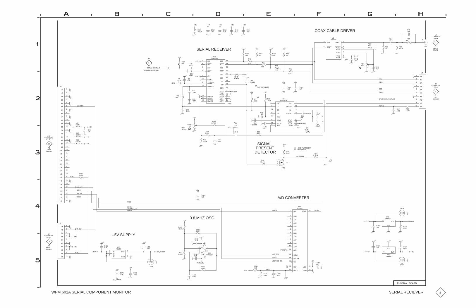
�! ��&%
��
��
"�COAX CABLE DRIVER� �
�'�
� (� (
�
�'�
�
�'�
� �
�'�
� (� (
���
�'�
� (
%�$��������&���
�$!���'���$���"
$��
� ��
��
�
SERIAL RECEIVER
� (
� (
��
��"�
��
��"�
%�����
%�����
�����
%�!
%�!�
%�!�
%�!
�� ��
%%��
%%
�����"��
%%�
���
(���
(����
(����
(����
(����
(����
�����
������
(���
$(�!���
�!!"��&�
$(�!��
$(�!�
$(�!���
!���
'�
�%��� �
$��
��!��
� (
$�
���$�
���$��
���$�
���
$ �
��
$ �
��
$ �
��
$ �
��
%� ���
%� ���
%!'&�
%!'&�
(%�&��
($����
(����
� ��
'
�%����
��
�'�
� (
$
��
��
�'�
$
�$�
�
$�
���
�
'�
$�
����
��
� "'&
�!�$�
&!���
��
���
���
����
����
����
�����
�����
�����
����
���
��
�! ��&%
��
�!�$�
&!��
��
�
���
�%+ �
�%�!
%�!
�%�!
%�!
%+ ��)�$ � ������
� �
�"�
$�
����
� (
� (
�
�'�
� �
�'�
���
�'�
���
��"�
� (� (
� �
�'�
� (
"� ��
����
����
�����
!'&�
�%+ ��
� ���
�(��"��
%&�&�
(��
(����
� �
!%��
�!�"���
%)����
����+��
'�
�%����
�
'�
$��
�� �
!&�� %&�����
$��
���
� (���
"�
���
�"�
��
�'�
$��
����
���
��'�
� (
��
�'�
�*&,$��
��
��
���
���
���
����
����
����
���
��
��
��
���
���
��
���
���
���
���
���
�
�
��
��
��
���
���
���
��
���
���
���
����
����
�
���
�!�$�
�! ��&%
&!���
��
�
�
� (
�(
�(
���
'�
�
�'�
�
��'�
��
�'�
� (
$��
��
�
�'�
�
��
&)���
&�%&
$��
���� "�
$��
� ��
$��
����
PRESENTDETECTOR
SIGNAL � (
� �
�'�
� �
����"�
$�
����
$��
� ��
(��� !�%�� ��
�(���%�� ���"$�%� &
� (
$�
��!��
$��
����
���
�'�
!,%�� ��
�
�'�$��
��#�
���
�'�
� (
��!%�
���,�
��%!
��(��,� �
$
����
�
��
��
���
���
���
����
����
����
���
��
�
�%��
�*&,$��
�%��
��!%�
��%!
�%�$���,�%
� (
$��
��� $
����
3.8 MHZ OSC
�� ��
�!'&�
� ���
� ��
� ���
� ����
� ���
� ���
� ����
� ����
� ����
� ��
� ��
%������
��!������
�%�
$�����
$�����
� ��
(���
'��
&�� ��
��!%�
A/D CONVERTER
��%!
�(
��
'�
���
'�
�$�
'��
������&
��(
��(�(
�
'�
���
'�
�$�
'��
������&
� (
���
�'�
�%��
���,���
� (($��
�%�$���,�%
$ �
���
��
�'�
���
�'�
./-
($��
� (
�
��"�
� (,��*��
��
�'�
$
����
���
�'�
��
��� �
�
� �'��
��*����
$�
���
���
�'�
� (
� (,��*��
��
�'�
�$�
��(
��(
���,���(
��
'�
–5V SUPPLY
���
�'�
!'&�
� ��
� ��
� ���
� ���
� ���
'��
���� �!�$�
��
� "'&
�! ��&%
&!���
WFM 601A SERIAL COMPONENT MONITOR
� (,��*��
SERIAL RECIEVER
� �%�$�����!�$�

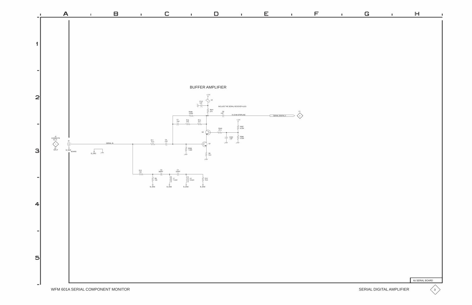
��
����� ������ ���
BUFFER AMPLIFIER
���"
������� �������
����!��� ������� �������"��� ����
�
��!�
����
��!�
��
����
������
�����
��
������ �
����
�
���!
�
�� ��
���� ����
��
�#���
�#���
���
���
��
��!�
�
��!�
����
��!�
��
����
���
���
��
���
����
����
�����
��
����
��
���"
��
�����
��
�����
�#��� �#���
��
���!�
���
���
��
���
�#��� �#���
���
���
��
���!�
��
�����
��
����
WFM 601A SERIAL COMPONENT MONITOR SERIAL DIGITAL AMPLIFIER �
������ ���� ��
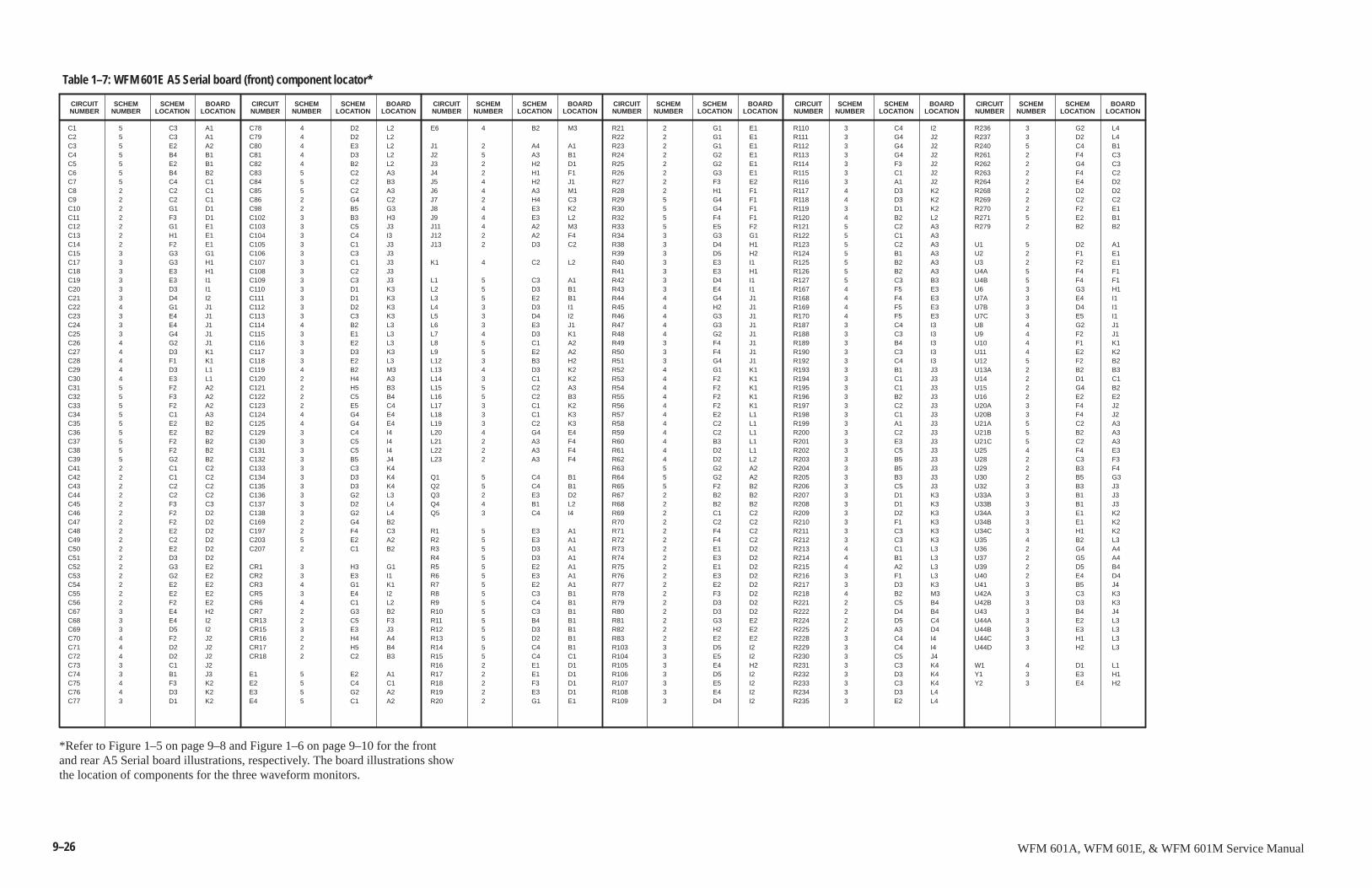
9–26 WFM 601A, WFM 601E, & WFM 601M Service Manual
SCHEMNUMBER
CIRCUITNUMBER
SCHEMLOCATION
BOARDLOCATION
SCHEMNUMBER
CIRCUITNUMBER
C1 5 C3 A1C2 5 C3 A1C3 5 E2 A2C4 5 B4 B1C5 5 E2 B1C6 5 B4 B2C7 5 C4 C1C8 2 C2 C1C9 2 C2 C1C10 2 G1 D1C11 2 F3 D1C12 2 G1 E1C13 2 H1 E1C14 2 F2 E1C15 3 G3 G1C17 3 G3 H1C18 3 E3 H1C19 3 E3 I1C20 3 D3 I1C21 3 D4 I2C22 4 G1 J1C23 3 E4 J1C24 3 E4 J1C25 3 G4 J1C26 4 G2 J1C27 4 D3 K1C28 4 F1 K1C29 4 D3 L1C30 4 E3 L1C31 5 F2 A2C32 5 F3 A2C33 5 F2 A2C34 5 C1 A3C35 5 E2 B2C36 5 E2 B2C37 5 F2 B2C38 5 F2 B2C39 5 G2 B2C41 2 C1 C2C42 2 C1 C2C43 2 C2 C2C44 2 C2 C2C45 2 F3 C3C46 2 F2 D2C47 2 F2 D2C48 2 E2 D2C49 2 C2 D2C50 2 E2 D2C51 2 D3 D2C52 2 G3 E2C53 2 G2 E2C54 2 E2 E2C55 2 E2 E2C56 2 F2 E2C67 3 E4 H2C68 3 E4 I2C69 3 D5 I2C70 4 F2 J2C71 4 D2 J2C72 4 D2 J2C73 3 C1 J2C74 3 B1 J3C75 4 F3 K2C76 4 D3 K2C77 3 D1 K2
C78 4 D2 L2C79 4 D2 L2C80 4 E3 L2C81 4 D3 L2C82 4 B2 L2C83 5 C2 A3C84 5 C2 B3C85 5 C2 A3C86 2 G4 C2C98 2 B5 G3C102 3 B3 H3C103 3 C5 J3C104 3 C4 I3C105 3 C1 J3C106 3 C3 J3C107 3 C1 J3C108 3 C2 J3C109 3 C3 J3C110 3 D1 K3C111 3 D1 K3C112 3 D2 K3C113 3 C3 K3C114 4 B2 L3C115 3 E1 L3C116 3 E2 L3C117 3 D3 K3C118 3 E2 L3C119 4 B2 M3C120 2 H4 A3C121 2 H5 B3C122 2 C5 B4C123 2 E5 C4C124 4 G4 E4C125 4 G4 E4C129 3 C4 I4C130 3 C5 I4C131 3 C5 I4C132 3 B5 J4C133 3 C3 K4C134 3 D3 K4C135 3 D3 K4C136 3 G2 L3C137 3 D2 L4C138 3 G2 L4C169 2 G4 B2C197 2 F4 C3C203 5 E2 A2C207 2 C1 B2
CR1 3 H3 G1CR2 3 E3 I1CR3 4 G1 K1CR5 3 E4 I2CR6 4 C1 L2CR7 2 G3 B2CR13 2 C5 F3CR15 3 E3 J3CR16 2 H4 A4CR17 2 H5 B4CR18 2 C2 B3
E1 5 E2 A1E2 5 C4 C1E3 5 G2 A2E4 5 C1 A2
E6 4 B2 M3
J1 2 A4 A1J2 5 A3 B1J3 2 H2 D1J4 2 H1 F1J5 4 H2 J1J6 4 A3 M1J7 2 H4 C3J8 4 E3 K2J9 4 E3 L2J11 4 A2 M3J12 2 A2 F4J13 2 D3 C2
K1 4 C2 L2
L1 5 C3 A1L2 5 D3 B1L3 5 E2 B1L4 3 D3 I1L5 3 D4 I2L6 3 E3 J1L7 4 D3 K1L8 5 C1 A2L9 5 E2 A2L12 3 B3 H2L13 4 D3 K2L14 3 C1 K2L15 5 C2 A3L16 5 C2 B3L17 3 C1 K2L18 3 C1 K3L19 3 C2 K3L20 4 G4 E4L21 2 A3 F4L22 2 A3 F4L23 2 A3 F4
Q1 5 C4 B1Q2 5 C4 B1Q3 2 E3 D2Q4 4 B1 L2Q5 3 C4 I4
R1 5 E3 A1R2 5 E3 A1R3 5 D3 A1R4 5 D3 A1R5 5 E2 A1R6 5 E3 A1R7 5 E2 A1R8 5 C3 B1R9 5 C4 B1R10 5 C3 B1R11 5 B4 B1R12 5 D3 B1R13 5 D2 B1R14 5 C4 B1R15 5 C4 C1R16 2 E1 D1R17 2 E1 D1R18 2 F3 D1R19 2 E3 D1R20 2 G1 E1
R21 2 G1 E1R22 2 G1 E1R23 2 G1 E1R24 2 G2 E1R25 2 G2 E1R26 2 G3 E1R27 2 F3 E2R28 2 H1 F1R29 5 G4 F1R30 5 G4 F1R32 5 F4 F1R33 5 E5 F2R34 3 G3 G1R38 3 D4 H1R39 3 D5 H2R40 3 E3 I1R41 3 E3 H1R42 3 D4 I1R43 3 E4 I1R44 4 G4 J1R45 4 H2 J1R46 4 G3 J1R47 4 G3 J1R48 4 G2 J1R49 3 F4 J1R50 3 F4 J1R51 3 G4 J1R52 4 G1 K1R53 4 F2 K1R54 4 F2 K1R55 4 F2 K1R56 4 F2 K1R57 4 E2 L1R58 4 C2 L1R59 4 C2 L1R60 4 B3 L1R61 4 D2 L1R62 4 D2 L2R63 5 G2 A2R64 5 G2 A2R65 5 F2 B2R67 2 B2 B2R68 2 B2 B2R69 2 C1 C2R70 2 C2 C2R71 2 F4 C2R72 2 F4 C2R73 2 E1 D2R74 2 E3 D2R75 2 E1 D2R76 2 E3 D2R77 2 E2 D2R78 2 F3 D2R79 2 D3 D2R80 2 D3 D2R81 2 G3 E2R82 2 H2 E2R83 2 E2 E2R103 3 D5 I2R104 3 E5 I2R105 3 E4 H2R106 3 D5 I2R107 3 E5 I2R108 3 E4 I2R109 3 D4 I2
R110 3 C4 I2R111 3 G4 J2R112 3 G4 J2R113 3 G4 J2R114 3 F3 J2R115 3 C1 J2R116 3 A1 J2R117 4 D3 K2R118 4 D3 K2R119 3 D1 K2R120 4 B2 L2R121 5 C2 A3R122 5 C1 A3R123 5 C2 A3R124 5 B1 A3R125 5 B2 A3R126 5 B2 A3R127 5 C3 B3R167 4 F5 E3R168 4 F4 E3R169 4 F5 E3R170 4 F5 E3R187 3 C4 I3R188 3 C3 I3R189 3 B4 I3R190 3 C3 I3R192 3 C4 I3R193 3 B1 J3R194 3 C1 J3R195 3 C1 J3R196 3 B2 J3R197 3 C2 J3R198 3 C1 J3R199 3 A1 J3R200 3 C2 J3R201 3 E3 J3R202 3 C5 J3R203 3 B5 J3R204 3 B5 J3R205 3 B3 J3R206 3 C5 J3R207 3 D1 K3R208 3 D1 K3R209 3 D2 K3R210 3 F1 K3R211 3 C3 K3R212 3 C3 K3R213 4 C1 L3R214 4 B1 L3R215 4 A2 L3R216 3 F1 L3R217 3 D3 K3R218 4 B2 M3R221 2 C5 B4R222 2 D4 B4R224 2 D5 C4R225 2 A3 D4R228 3 C4 I4R229 3 C4 I4R230 3 C5 J4R231 3 C3 K4R232 3 D3 K4R233 3 C3 K4R234 3 D3 L4R235 3 E2 L4
R236 3 G2 L4R237 3 D2 L4R240 5 C4 B1R261 2 F4 C3R262 2 G4 C3R263 2 F4 C2R264 2 E4 D2R268 2 D2 D2R269 2 C2 C2R270 2 F2 E1R271 5 E2 B1R279 2 B2 B2
U1 5 D2 A1U2 2 F1 E1U3 2 F2 E1U4A 5 F4 F1U4B 5 F4 F1U6 3 G3 H1U7A 3 E4 I1U7B 3 D4 I1U7C 3 E5 I1U8 4 G2 J1U9 4 F2 J1U10 4 F1 K1U11 4 E2 K2U12 5 F2 B2U13A 2 B2 B3U14 2 D1 C1U15 2 G4 B2U16 2 E2 E2U20A 3 F4 J2U20B 3 F4 J2U21A 5 C2 A3U21B 5 B2 A3U21C 5 C2 A3U25 4 F4 E3U28 2 C3 F3U29 2 B3 F4U30 2 B5 G3U32 3 B3 J3U33A 3 B1 J3U33B 3 B1 J3U34A 3 E1 K2U34B 3 E1 K2U34C 3 H1 K2U35 4 B2 L3U36 2 G4 A4U37 2 G5 A4U39 2 D5 B4U40 2 E4 D4U41 3 B5 J4U42A 3 C3 K3U42B 3 D3 K3U43 3 B4 J4U44A 3 E2 L3U44B 3 E3 L3U44C 3 H1 L3U44D 3 H2 L3
W1 4 D1 L1Y1 3 E3 H1Y2 3 E4 H2
Table 1–7: WFM 601E A5 Serial board (front) component locator*
SCHEMLOCATION
BOARDLOCATION
SCHEMNUMBER
CIRCUITNUMBER
SCHEMLOCATION
BOARDLOCATION
SCHEMNUMBER
CIRCUITNUMBER
SCHEMLOCATION
BOARDLOCATION
SCHEMNUMBER
CIRCUITNUMBER
SCHEMLOCATION
BOARDLOCATION
SCHEMNUMBER
CIRCUITNUMBER
SCHEMLOCATION
BOARDLOCATION
*Refer to Figure 1–5 on page 9–8 and Figure 1–6 on page 9–10 for the frontand rear A5 Serial board illustrations, respectively. The board illustrations showthe location of components for the three waveform monitors.
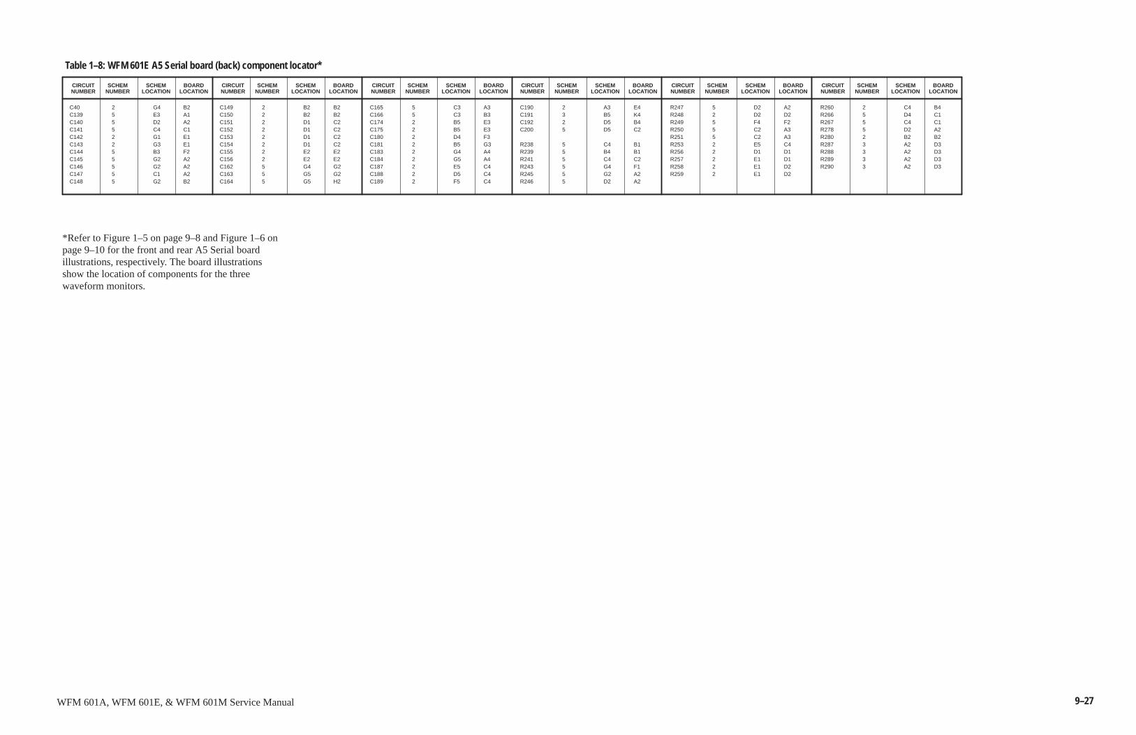
9–27WFM 601A, WFM 601E, & WFM 601M Service Manual
SCHEMNUMBER
CIRCUITNUMBER
SCHEMLOCATION
BOARDLOCATION
SCHEMNUMBER
CIRCUITNUMBER
C40 2 G4 B2C139 5 E3 A1C140 5 D2 A2C141 5 C4 C1C142 2 G1 E1C143 2 G3 E1C144 5 B3 F2C145 5 G2 A2C146 5 G2 A2C147 5 C1 A2C148 5 G2 B2
C149 2 B2 B2C150 2 B2 B2C151 2 D1 C2C152 2 D1 C2C153 2 D1 C2C154 2 D1 C2C155 2 E2 E2C156 2 E2 E2C162 5 G4 G2C163 5 G5 G2C164 5 G5 H2
C165 5 C3 A3C166 5 C3 B3C174 2 B5 E3C175 2 B5 E3C180 2 D4 F3C181 2 B5 G3C183 2 G4 A4C184 2 G5 A4C187 2 E5 C4C188 2 D5 C4C189 2 F5 C4
C190 2 A3 E4C191 3 B5 K4C192 2 D5 B4C200 5 D5 C2
R238 5 C4 B1R239 5 B4 B1R241 5 C4 C2R243 5 G4 F1R245 5 G2 A2R246 5 D2 A2
R247 5 D2 A2R248 2 D2 D2R249 5 F4 F2R250 5 C2 A3R251 5 C2 A3R253 2 E5 C4R256 2 D1 D1R257 2 E1 D1R258 2 E1 D2R259 2 E1 D2
R260 2 C4 B4R266 5 D4 C1R267 5 C4 C1R278 5 D2 A2R280 2 B2 B2R287 3 A2 D3R288 3 A2 D3R289 3 A2 D3R290 3 A2 D3
Table 1–8: WFM 601E A5 Serial board (back) component locator*
SCHEMLOCATION
BOARDLOCATION
SCHEMNUMBER
CIRCUITNUMBER
SCHEMLOCATION
BOARDLOCATION
SCHEMNUMBER
CIRCUITNUMBER
SCHEMLOCATION
BOARDLOCATION
SCHEMNUMBER
CIRCUITNUMBER
SCHEMLOCATION
BOARDLOCATION
SCHEMNUMBER
CIRCUITNUMBER
SCHEMLOCATION
BOARDLOCATION
*Refer to Figure 1–5 on page 9–8 and Figure 1–6 onpage 9–10 for the front and rear A5 Serial boardillustrations, respectively. The board illustrationsshow the location of components for the threewaveform monitors.

9–28 WFM 601A, WFM 601E, & WFM 601M Service Manual
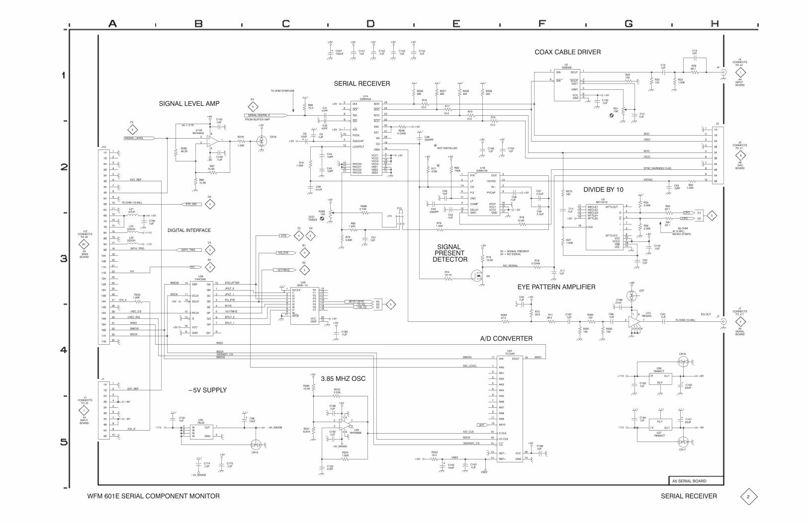
)&�'
�"�%�
�"!!��'&
�
��
#��"�+��������%�)�%��
�(�
��)��)
��
�(�
���
�(�
���
�(�
��)��)
���
�(�
��)
�2�������
&��!�����)���� #
��
�
&�%��������'����
�%" ��(���%�� #
���"� �&'%�#��!�
��)
��
�(�
%��
���
��)
�
�
&�%����%����)�%
��)
��)
� �
�#�
�
�#�
&�����
&�����
�����
&�"��
&�"�
&�"��
&�"��
���!�
&&�
&&�
�����#���
&&��
���
)�����
)�� ��
)����
)�����
)���
)����
������
������
)���
%)�"��
�""#��'��
%)�"�
%)�"���
%)�"���
"� �
(
�&���
%� �
�"�
��)
%�
�%�
�%��
�%��
�
%���
���
%���
���
%���
���
%���
���
&�!���
&�!���
&"('�
&"('��
��
)%���
)����
�!���
(�
�&��
� �
�(�
��)
%�
�
�
�(�
%��
�%�
�
%��
���
��
(�
%��
��
�
�!#('
�"�%�
'"��
�
���
����
�����
����
�����
�����
����
����
�����
���
��
�"!!��'&
��
�"�%�
'"��
��
�
���
�&,!�
�&�"
&�"
�&�"
&�"
&,!��*�%!�!������
���
#�
%�
���
%��
��
��)
��)
���
�(�
��)�����,����
�(�
%��
��
� �
���(�
� �
��#�
��)��)
���
�(�
��)
#�!��
�����
���
������
"('��
�&,!��
�!���
�)��#��
&'�'�
)���
)�����
�!��
"&��
�" #��
&*����
����,�
(�
�&��
���
(�
%��
���
!"'��!&'�����
%��
�
��)�
�#�
� �
#�
��
�(�
%�
��
� �
�(�
��)
��)
� �
�(�
���
���
�
�
(��
�� � ��
(�%���
��
%��
���
�%�
�+'.%��
&��!��.��)��
%��
��
%��
�����
�
��
���
����
���
����
����
���
���
����
��
��
���
���
��
���
���
���
���
��
��
��
���
����
���
����
����
���
���
����
���
���
����
����
���
��
��!
�"!!��'&
'"���
��
��
�
���"� ���� ���
�+��.'%��
��)
�)
�)
��
(�
���
��(�
��
�(�
���
��(�
�+��.'%��
�
�
��
�
����'����!'�%����
�,�.&��
�$.�,�
�
��
��
�
�,�
��)
%���
�
��
�(�
� �
��
'*���
'�&'
%���
��� � #�
%�
���
%��
�����
�
#%�&�!'
��'��'"%
&��!����)
��
�(�
��
��#�
%�
��
%��
���
�)���!"�&��!��
)���&��!���#%�&�!'
��)
��)
%�
�"�
������
�������
������
''�� ��
''�����
�����
''�"('��
$��
$�
���
���
)���
)��"��
)���
)��
''�)����
(�
���
%��
��
%��
��
�
�(�� �
���(�
���"�
����� ���
��%"�&'%�#&
� �
�(�
��#"
�#"
%�
���
%��
���
%��
���
��)
���
�(�
�
��
�
�$�"('
�"!!��'&
��
��'"��
��
&�%���
���"� ���� ���
��)
�
(�
���
(�
��� ��
�
�
� �
(�
!����
�%�
%���
�
���
�(�
!".&��!��
�,��#�''�%!�� #�����%
��)
%��
�
%��
���
� �
(�
%��
���� %�
����
���
(�
%���
�
�(�%�
����$�
��)
��
�(�
��)
��,���,�
�.�-
�.�-
��
��
��
�
�,����''�%
�$.�,�
��� �-
����
��� �-
����'.
����'.
����'.
����'.
�������
����
�����
����
� ���
�����
�����
�����
�����
���"��
���
���
���
� �
���
��
��
��
)���
�!�
(��
�)���
��
�)��.�&
� "&���)
��)���.�
�&��
� "&�
�&"
&�%�
$��
$��
&����
$���
&��%�
$���
$��
%�����
$���
���
$���
$���
$����
�!����
)����
(��
� �����
��
��)��.�!�
%���
��
�
��
���
����
���
����
����
���
���
����
��
�
�&��
�+'.%��
��)�&(##�,
�&��
� "&�
�&"
�&�%���.�&
��)
����� �-�"&�%��
��� %���
�����
��!��
�"('�
�!��
�!���
�!����
�!���
�! ���
�!����
�!����
�!����
�!����
�!��
�!��
&������
��"������
�&��
%�����
%����
�!�
)���
(
'���
� "&�
&��.��)��
�����"!)�%'�%
�&"
�)
��
��(�
���
(�
�%�
(��
�����'
�"�%�
��)
��)�)
��
��(�
��
(�
�%�
(��
�����'
��)
���
�(�
�&��
���.���
��))%��
�&�%���.�&
%���
�
���
(�
���
�(�
01/
)%��
��)
���
�#�
��). �+�
���
�(�
%��
����
���
�(�
���
��� �
�
�
�(��
�+����
%��
����
���
(�
��)
��). �+�
���
�(�
�%�
��)
��)
���.���)
��
(�
��
�(�
"('�
�!���
�!���
�!���
�!���
�!���
(�
�����"�%�
�
�!#('
�"!!��'&
'"���
*� ����&�%�����" #"!�!'� "!�'"%
��). �+�
&�%����%����)�%
���&�%�����"�%�
�

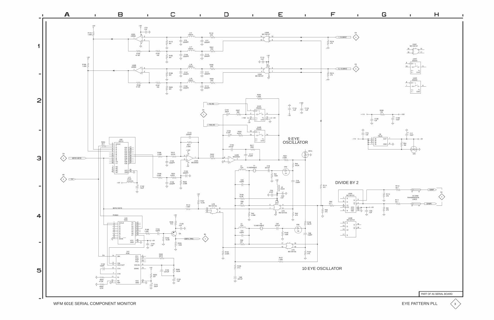
�)�����(
!�
���
��
��
��
���
��
$��
��������
���
����
!���
�
���
���$�
��
����!���
��
��%
���
��$�
�
�
���
�
�
$�
���
��%
!��
�����
��%
!���
�����
����
����!���
��
����
����!���
��
�
��
���
$�
���
!��
�����
!���
�������
����
����
����
!��
�
!��
�
���
���$�
���
���$�
��%
����
��$�
��
��
��
���
�
��
$��
��������
)�����(
!��
���
�
�
���
��� ��
$���
�����
���
���
��
��
$��
��������
��
��$����
�$�
���% ����
!
���
���
��� �
$���
�����
��%
��%
����
����
��%
���
�� �
�� �
�����
$���
�����
!�
�����
����
��$�
���
��$�
���)�(
!�
�
���
$�
���
����
!��
�
���
���$�
�
����
����!��
��
!��
�����
!���
���
�
��'�����'�
!��
�� ��������
����
����
����
����
�����
� ���
�����
�����
����
�����
�����
����
���
����
�� �
���
����
���
����
�����
�����
%���
�����
�����
�����
�����
���
$
%��
���
����
!���
����
!�
������
��
��
�
�
$��
�����
!
�����
���
��
��
$��
�����
����
����)�(
!�
����
���
�$�
���
����$�
!��
����
���
����
9 EYEOSCILLATOR
!��
� ��
�!��
����
�����
��
��� ��
$���
�����
!��
����
!��
����
���
�$�
���%
!�
��
���
��$�
��%
�!�
�$#��
�����
����
����
�����
����
$
�����
"���
�"����
�
�������
����"
#!��"��""���
!��
���
!���
��
!��
��
DIVIDE BY 2!���
��
!��
��
"���
����
!���
�����
����
�
��
%���
%���
%����
$��
�������
�
$�
��
���$�
���
���
��
�
�
��
$��
��������
�!
!��
����
'�
��������(
��%���
�����
�
��$�
���
����$�
!���
�����
��
�����
��%
��%
��
����
��
�$�
!���
�����
!�
�
����
����
!�
����
!
����
���
��$�
��
��$�
!���
����
��%
��
�
��'�����'�
��&���
���������
����
���
����
�����
����
� ���
�����
�����
��������
����
� ��
����
���
���
���
���
���
%���
�����
$�
� %�
!��
�����
!�
�����
��%
��%
����
��$�
���
��$�
!�
����
����
�����!���
�����
�
��
��
���
��
��
$��
��������
��
�����
&��)#!��
!���
�����
��
�$�
!�
�
�
!���
����
!�
����
���
���
��
��
$��
��������
!�
���
�!�'
��������(
� �
����$�
!��
���
!���
� ��"
���
���
!���
�����
��
��
$��
�������
� �
�����
!��
���
��%
��
��$�
!���
���
10 EYE OSCILLATOR
!���
�����
!��
����
� �
����$�
!��
����
���
$�
���
�$�
!�
����
!�
�
���
����$�
��%
!�
�������
���
����
�����
%�������
"�����
%����$#���
�����
!��
������
�����
!����
������
�����
%���
������
$��
���
��
��
�����
!�
���
!��
�����
WFM 601E SERIAL COMPONENT MONITOR EYE PATTERN PLL
��!#�������"�!�������!�

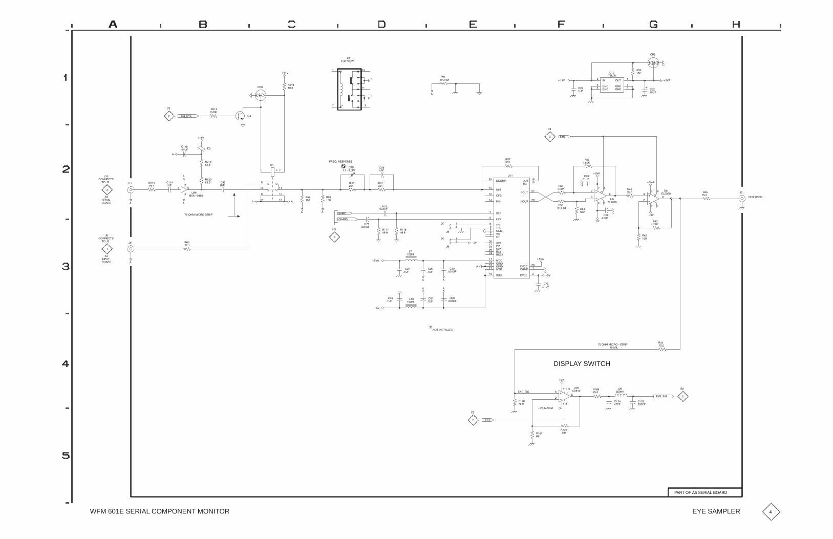
!��
���
�!
#���%��&
��
� )�(�
!��
�����
�
�
!��
����
���%
�!�
�
�
��
�
�
�
�
�
&�
�����
���
�$�
���%
�
�
�����
�����
�$#��
����
������
�����
$��
����
���
��$�
��%�
��#�$"��
��
��%�
!�
�����
���
��
�
�
$�
���� �
!�
����
��%�
� �
���$�
��
���
��
�
�
$�
���� �
!�
�����
!�
���
!��
�����
!��
�����
�(�
��������
������
��"���
�����
"#!��
��%��
#�$���
#�����
�$#��
����
��$#�
��$#��
�#��
������
%!���
�����
������
������
����
�����
�%����
�������
������
�%�����
"$����
�%����
������
�%����
$��
!�
���
!��
���
�!� ��!�"���"�
� �
���
� �
�� �����
!��
���
!��
��
���
�$�
!��
���� �
��� ��
�� ��
���
����
���
��
!���
����
!���
�������
�$�
���%
�
� �
�
���
��
!���
����
����
���$�
���
�
$�
�"�����
���
������#"
#���
��
���!�
"�!���
�
������#"
#����
�
���!�
��
�
���$#
���������!��"#!��
�
�� !��
����
�
� �
����$�
� �
����$�
!���
���
!��
���
�
��$�
"���
�"����
�
��%�
��
��$�
�
��
����$�
�
��%
���
��$�
��
��
��
��
��
��
��%�
��%
���
���$�
!�
���
��%
!
�����
� �
���$�
��%
���
����$�
� �
� �
���
��$�
��#���"#�����
��
��$�
��%
� �
��$�
���������!��"#!��
������
��%
DISPLAY SWITCH
��%)��'��
!���
���
���
��
� �
�
��
���
�
$��
�����
!���
���
�(�)"��
!
���
���
�����
����
�����
��
��(�)"��
!� �
���!��
���
�
� �(�
WFM 601E SERIAL COMPONENT MONITOR EYE SAMPLER
��!#�������"�!�������!�

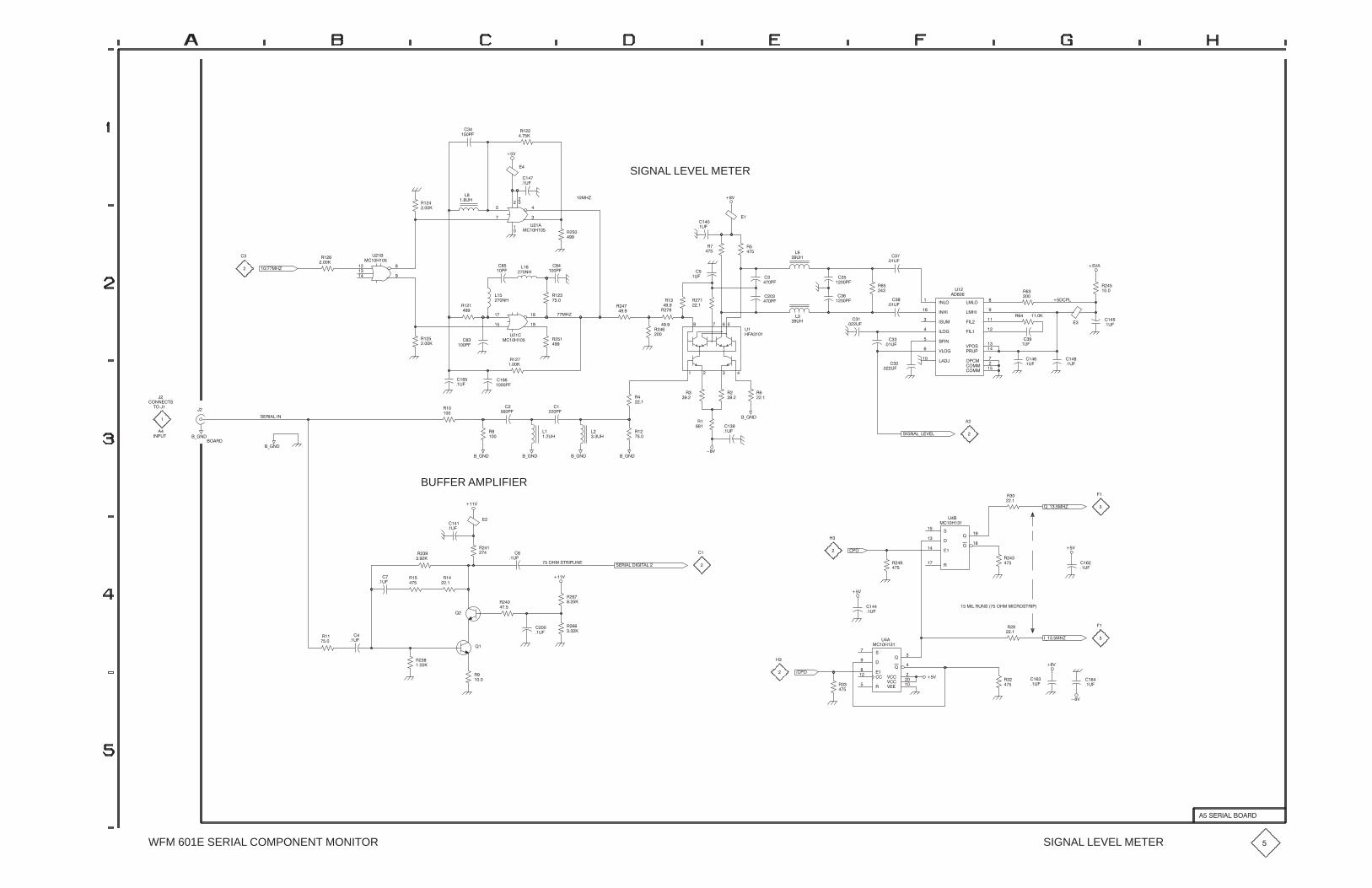
��&
"��
����
��
��� �
��
���%�
��
���
���
��
�
�
��
%��
��������
����'
SIGNAL LEVEL METER
"�
�����
����
��%�
��&
��
��
��%�
���� �
��&�
"
��
����
��%�
" � �����
�
"��
����
" �
�
��
���%�
��
���%�
��
��%�
�������
������
������
������
�#%���
�������
�������
&�����
������
�����
� ����
"% ��
& �#�
�����
�����
�������
%�
�� �
�
���%�
��
�%�
�
�%�
� �
� ��
%�
������
"�
���
"�
���
����
��%�
��
��%�
�
��� �
��
��� �
�
��� �
��
��� �"��
��
����'
"�
����
"��
���
"�
��
��
����
���
��� �
"�
����
"��
���
"��
����
"��
����
��
��
���
��
��
%��
��������
"��
����
���
�� �
���
����
"��
���
��
��� �
���
���
��
��
%��
��������
�������'
"�
����
�
�
������$#
$����
��
�� %$
�
���"�
#�"������
�
�(���
�(���
"�
���
�(���
"��
���
�
� � �
�� �
��%�
��
���� �
"��
�����
�(��� �(��� �(���
��
��%�
�
�%�
��
� �
"�
����
"�
��
��&
�(���"�
�� ���
��%�
"
��
"
��
"
��
#�����(��&��
�
��%�
�
���
��%�
����
��%�
��
��%�
��&
!(�����'
��
� �
"��
���
#���
���
"���
�����
!��
!��
%��
�������
"�
���
"�
��
��
�
#�"��������$����������#$"� ����
BUFFER AMPLIFIER
���&
�
��%�
����
��%�
�
"��
��"�
���
"��
����
��
��%�
!
"��
����
"��
���
"��
��
"�
�����
"�
����
!�
��
��%�
���&
"
�����
��%�
" �
����
�� �
"
���
�
��&
��&
����
��%�
�������"%�#������������"�#$"� �
#���
����
"���
�����
����
!�
!��
&���
&���
&����
%��
�������
"
���
"�
��
�� �
��%�
��
��%�
�(�����'
��&
��
��&
WFM 601E SERIAL COMPONENT MONITOR SIGNAL LEVEL METER �
���#�"�������"�
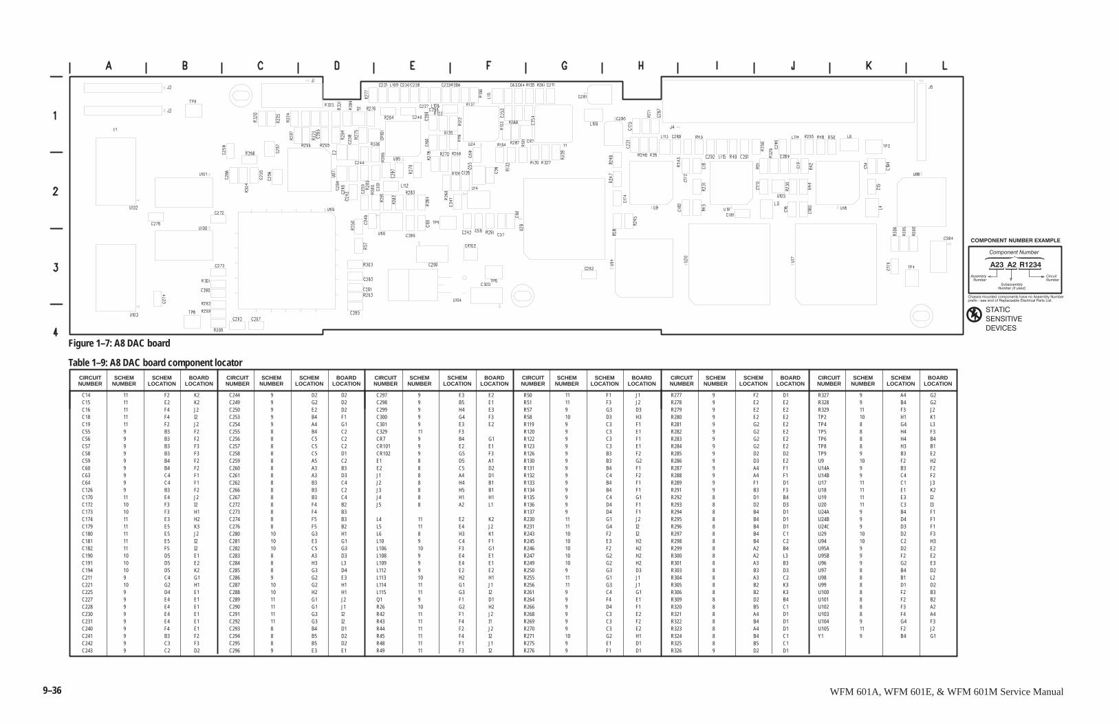
9–36 WFM 601A, WFM 601E, & WFM 601M Service Manual
����������������
��� �� �����
�������"����������������������������������!�������
����� #�������������������������������������������
�� ��������������� �
��������������
������������������� ������
������
������� �
�� ����
� �� �������
C14 11 F2 K2C15 11 E2 K2C16 11 F4 J2C18 11 F4 I2C19 11 F2 J2C55 9 B3 F2C56 9 B3 F2C57 9 B3 F3C58 9 B3 F3C59 9 B4 F2C60 9 B4 F2C63 9 C4 F1C64 9 C4 F1C126 9 B3 F2C170 11 E4 J2C172 10 F3 I2C173 10 F3 H1C174 11 E3 H2C179 11 E5 K3C180 11 E5 J2C181 11 E5 I2C182 11 F5 I2C190 10 D5 E1C191 10 D5 E2C194 10 D5 K2C211 9 C4 G1C221 10 G2 H1C225 9 D4 E1C227 9 E4 E1C228 9 E4 E1C230 9 E4 E1C231 9 E4 E1C240 9 F4 E1C241 9 B3 F2C242 9 C3 F3C243 9 C2 D2
C244 9 D2 D2C249 9 G2 D2C250 9 E2 D2C253 9 B4 F1C254 9 A4 G1C255 8 B4 C2C256 8 C5 C2C257 8 C5 C2C258 8 C5 D1C259 8 A5 C2C260 8 A3 B3C261 8 A3 D3C262 8 B3 C4C266 8 B3 C2C267 8 B3 C4C272 8 F4 B2C273 8 F4 B3C274 8 F5 B3C276 8 F5 B2C280 10 G3 H1C281 10 E3 G1C282 10 C5 G3C283 8 A3 D3C284 8 H3 L3C285 8 G3 D4C286 9 G2 E3C287 10 G2 H1C288 10 H2 H1C289 11 G1 J2C290 11 G1 J1C291 11 G3 I2C292 11 G3 I2C293 8 B4 D1C294 8 B5 D2C295 8 B5 D2C296 9 E3 E1
C297 9 E3 E2C298 9 B5 E1C299 9 H4 E3C300 9 G4 F3C301 9 E3 E2C329 11 F3CR7 9 B4 G1CR101 9 E2 E1CR102 9 G5 F3E1 8 D5 A1E2 8 C5 D2J1 8 A4 D1J2 8 H4 B1J3 8 H5 B1J4 8 H1 H1J5 8 A2 L1
L4 11 E2 K2L5 11 E4 J2L6 8 H3 K1L10 9 C4 F1L106 10 F3 G1L108 9 E4 E1L109 9 E4 E1L112 9 E2 E2L113 10 H2 H1L114 11 G1 J1L115 11 G3 I2Q1 9 F1 D1R26 10 G2 H2R42 11 F1 J2R43 11 F4 I1R44 11 F2 J2R45 11 F4 I2R48 11 F1 J1R49 11 F3 I2
R50 11 F1 J1R51 11 F3 J2R57 9 G3 D3R58 10 D3 H3R119 9 C3 F1R120 9 C3 E1R122 9 C3 F1R123 9 C3 E1R126 9 B3 F2R130 9 B3 G2R131 9 B4 F1R132 9 C4 F2R133 9 B4 F1R134 9 B4 F1R135 9 C4 G1R136 9 D4 F1R137 9 D4 F1R230 11 G1 J2R231 11 G4 I2R243 10 F2 I2R245 10 E3 H2R246 10 F2 H2R247 10 G2 H2R249 10 G2 H2R250 9 G3 D3R255 11 G1 J1R256 11 G3 J1R261 9 C4 G1R264 9 F4 E1R266 9 D4 F1R268 9 C3 E2R269 9 C3 F2R270 9 C3 E2R271 10 G2 H1R275 9 E1 D1R276 9 F1 D1
R277 9 F2 D1R278 9 E2 E2R279 9 E2 E2R280 9 E2 E2R281 9 G2 E2R282 9 G2 E2R283 9 G2 E2R284 9 G2 E2R285 9 D2 D2R286 9 D3 E2R287 9 A4 F1R288 9 A4 F1R289 9 F1 D1R291 9 B3 F3R292 8 D1 B4R293 8 D2 D3R294 8 B4 D1R295 8 B4 D1R296 8 B4 D1R297 8 B4 C1R298 8 B4 C2R299 8 A2 B4R300 8 A2 L3R301 8 A3 B3R303 8 B3 D3R304 8 A3 C2R305 8 B2 K3R306 8 B2 K3R309 8 D2 B4R320 8 B5 C1R321 8 A4 D1R322 8 B4 D1R323 8 A4 D1R324 8 B4 C1R325 8 B5 C1R326 9 D2 D1
R327 9 A4 G2R328 9 B4 G2R329 11 F3 J2TP2 10 H1 K1TP4 8 G4 L3TP5 8 H4 F3TP6 8 H4 B4TP8 8 H3 B1TP9 9 B3 E2U9 10 F2 H2U14A 9 B3 F2U14B 9 C4 F2U17 11 C1 J3U18 11 E1 K2U19 11 E3 I2U20 11 C3 I3U24A 9 B4 F1U24B 9 D4 F1U24C 9 D3 F1U29 10 D2 F3U94 10 C2 H3U95A 9 D2 E2U95B 9 F2 E2U96 9 G2 E3U97 8 B4 D2U98 8 B1 L2U99 8 D1 D2U100 8 F2 B3U101 8 F2 B2U102 8 F3 A2U103 8 F4 A4U104 9 G4 F3U105 11 F2 J2Y1 9 B4 G1
SCHEMNUMBER
Table 1–9: A8 DAC board component locatorCIRCUITNUMBER
SCHEMLOCATION
BOARDLOCATION
SCHEMNUMBER
CIRCUITNUMBER
SCHEMLOCATION
BOARDLOCATION
SCHEMNUMBER
CIRCUITNUMBER
SCHEMLOCATION
BOARDLOCATION
SCHEMNUMBER
CIRCUITNUMBER
SCHEMLOCATION
BOARDLOCATION
SCHEMNUMBER
CIRCUITNUMBER
SCHEMLOCATION
BOARDLOCATION
SCHEMNUMBER
CIRCUITNUMBER
SCHEMLOCATION
BOARDLOCATION
Figure 1–7: A8 DAC board
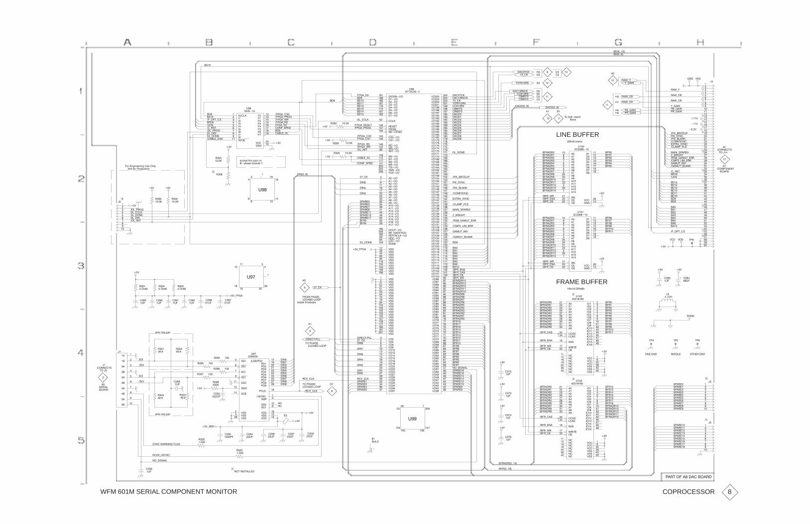
WFM 601M SERIAL COMPONENT MONITOR
����" ��
���"�
(-��
��
��+����,
��+��� ,
"�'-)
�
�
������
�� �
��
��
� ��
��
�
��
��-"#$
�%�#
�"�'
�!- !$-�#
���-!" �
��-���
������-���
��-� ��
��
���
��!��-'"
��!��-"�
��!��-!" �
�����-��
�!��-��
� &
��!��-�#�
� ��-#!��
���
��������
���
����
�����
����
� ���
�����
�����
�����
��� ��
���
���
� �
���
��
��
��
��
&���
����
%��
�&���
�!��-�#
��-����
��!��-!" �
��!��-"�#�$
�!��-��
� &
���
���
��
��
���
���
��
��!��-�#�
� &
"�� ����
"� ����
���
����� ���
���� ���
���� ���
����� �
����� ��
� ��� ��
����� ��
����� �
����� ���
����� ��
����� ��
���� ���
���� ��
����� ���
����� ���
� ��� � �
����� �
����� � �
� %$��� �
��������� �
���� ��
���� ��
����� �
����� ��
� ��� �
����� ��
����� ��
"�)�"������ ��
������ ���
������ ���
�����
"�#�$��
!"����
"������ �
� ����
�#���� �
�#��� ��
"���� ��
'"���
���$��� ���
����
���� �
�����
$����� ��
$�#��� �
$����� ��
�� ����
�� ��
�� ����
�� ����
�� ���
�� ���
�� ���
�� �
�� ���
�� ���
�� �
�� ���
�� ���
�� ���
�� ���
�� ���
�� �����
�� �����
�� �����
�� �����
�� ����
�� ��
�� ����
�� � �
�� ����
�� ����
�� ����
�� � �
�� � �
�� � �
�� ����
�� ��
�� ��
�� ����
�� ����
�� ����
�� ����
�� ����
�� ����
�� ����
�� ��
�� ��
�� ����
�� � �
�� ����
�� ����
�� ����
�� ����
�� ��
�� ��
�� ����
�� � �
�� ����
�� ����
�� ����
�� ����
�� ��
�� ��
�� � �
�� ����
�� ����
�� ����
�� ��
�� ��
�� ����
�� ��
��
�� ��
�� ��
��
�� ��
�� ��
�� ��
��
�� ��
�� ��
�� ��
�� ��
�� ��
�� ��
�� ��
�� ��
�� ����
�� ����
�� ����
�� ����
�� ����
�� ����
�� ��
�� ��
�� ����
�� ����
�� ����
�� ����
�� � �
��
�� � �
�� � �
�� ��
�� ��
�� ����
�� � �
�� ����
�� ����
�� ����
�� ��
�� ����
�� ����
�� � �
�� ����
�� ����
�� ����
�� ����
�� ����
�� � �
�� ����
�� ����
�� ��
�� ����
�� ����
�� ����
�� ����
�� ����
�� ��
�� ����
�� ����
�� � �
&##��
&##��
&##�
&##��
&##�
&##���
&##���
&##�
&##
&##
&## �
&## �
&##��
&##�
&##��
&##��
&���
&����
&�����
&����
&##� �
&##� �
&�����
&##���
&##��
&���
&����
&����
&����
&����
�� ����
����� ��
&##�
�� � �
"�-��$��$� ��
%��
�$$���
�����
����
����
�����
�����
����
�����
�����
�����
�����
)#)��"
����"
���"�
�"�"�
(-��
������
����" ��
����+����,����+����,
����"
�"�"�
)#)��"
��A��>=.9>
LINE BUFFER
�
�368?2=>
$;�5.83�/.:1
�
�
�
�
�
!�(-#)��
�!�(-�����
�!�(-�"�$�%!
�� �!#)��
"�'-�"
"�'-��
)-����
!"-����
!�-����
"�'-)
"�'-��
"�'-�"
)-����
!�-����
!"-����
��
�
��
�
���
�&
� �&
&##
�&
��
��
���
���
��
���
���
���
���
��
�
�
��
��
�
��
��
��
��
��
�
�
��
��
�
��
��
��
��
���
��
��
���
���
��
���
���
���
���
���
��
��
���
���
��
���
���
���
���
� �
�
�
� �
� �
�
� �
� �
� �
� �
���
��
��
� ����$#
$ ���
��
� �! ���$
� �"�
��"�
��"
��"
��"�
��"�
��"
� &
*-�"���$
�����!-!�#
���%$-���
����-#!�"��
����%$-�����
�($"�-#)��
�"��-���%$-�""
���!#-���-�""
�"�'
��-"#$
�%�#
���
���
���
��
��
���
���
��
���
��"��"�
��"��"
��"��"
��"��"�
��"��"�
��"��"
��"��"�
��"��"�
��"��"�
��"��"�
��"��"�
��"��"
��"��"
��"��"�
��"��"�
���"-'"
���"-���
���"- �
����
����
����
�����
�����
� ��
�����
�����
���
����
���
���
���
����
����
�
�
���
��
� �
���
���
��
����
'���
&���
����
���
%��
� ���
�����!-!�#
!�(-#)��
�!�(-�����
��-� ��
�!�(-�"�$�%!
�� �!#)��
�($"�-#)��
� &
��!��-'"
��!��-"�
���-���$
�����-��
����
���
����
�-��
� ��-#!��
#!�"��
#!�"��
#!�"��
"��� ����
>;072?�?56>�<.=?�;:
��<5.>2�/;.=1>���
� &
���+����,
�
�
�
� �
�
�
�
%��
"���
"��
����
� & � &
�;=��:46:22=6:4�%>2� :8B
�;?�3;=�!=;1@0?6;:
"��
����
"���
����
� &�
�
��
��
�
��
��
��
��
�
�
��-���
��-� ��
��-����
���-���$
���-!" �
�
��-� ��
��"�
��"�
� &-�!��
#!�"��
#!�"�
#!�"��
#!�"��
���"-���
*-�"���$
��
���
��
���
���
��
���
��
���%$-���
����-#!�"��
����%$-�����
�"��-���%$-�""
���!#-���-�""
���
��"��"�
��"��"
��"��"
��"��"�
��"��"�
��"��"
��"��"�
��"��"�
��"��"�
��"��"�
��"��"�
��"��"
��"��"
��"��"�
��"��"�
���"-'"
���"-���
���"- �
����
����
����
�����
�����
� ��
�����
�����
���
����
���
���
���
����
����
�
�
���
��
� �
���
���
��
����
'���
&���
����
���
%�
� ���
��"�
��"�
��"�
��"�
��"�
��"
� &
�!- !$-�#
��
&��
� &
��
��
���
���
��
���
&�� $!�
� &
#���
��"�
��"
��"
��"�
��"�
��"
��"�
��"�
��"�
��"�
��"�
��"
� &
��
%�
��
���%�
���
��%�
��"��"�
��"��"
��"��"
��"��"�
��"��"�
��"��"
��"��"�
��"��"�
��"��"�
��"��"�
���"-��#
�A���"��>
FRAME BUFFER
���
��
���
����
����
� ��
����
�����
����
����
� �
� ��
� ���
� ��
� ��
� ���
� ���
� ��
� ��
� ��
� ��
� ��
� ���
� ���
� ��
� ���
'"�$���
"�#��
����
���
����
&����
&���
���
����
%��#���
���#��
&��
&##�
&##�
&## �
����
�����
�����
%�
�#���
��"��"�
��"��"
��"��"
��"��"�
��"��"�
��"��"
��"��"�
��"��"�
��"��"�
��"��"�
��"��"�
��"��"
��"��"
��"��"�
��"��"�
���"-'"
���"- �
���"-��#
��"�
��"�
��"
��"�
��"�
��"�
�-��
>?./82�?692/.>2
� &-�!��
�
�
�
%��
���
��%�
� ������ !
�" ��!��#�
�
�
�
�>?=6<�86:2�<.6=
� &
"��
�� ��
"���
�� ��
"���
�� ��
���
%�
���
�%�
��
�%�
��
�%�
���
��%�
��
��
���
���
���
����
����
����
���
��
�
�
� ����$#
$ ���
�
#�"���
� �"�� &
#��
�#��
#��
�#�� "��
���
"� ��
"�� ��
"�
����
"��
����
"��
����
���
%�
"�
����
"�&-���
"�&-���
����
���
���
����
����
���
����
����
����
����
��"��$�!��
�
��%�
#����
#�����
#�����
#�����
##��
##��
��#��!���
!��
!��
!��
!��
!� �
!���
!��
!���
!���
!����
�#)���
#'���
##��
#'��
&##��
&##���
&## &���
&���
&��
#����
%��
�#����
"�� ��
"�� ��
� ������ !
$ �!��#�
$ �!��#�
����
���
���
����
����
����
����
"�&-���
��"��$�!��
#!�"�
#!�"�
#!�"��
#!�"�
�-��
� ������ !
�
�
��"
��"
��"�
��"
��"�
��"�
��"�
��"�
��"�
��"
��"
#!�"��
#!�"��
#!�"��
#!�"�
#!�"��
#!�"�
#!�"��
#!�"��
� -#�����
��"��"�
��"��"
��"��"
��"��"�
��"��"�
���"-���
���"-'"
���"- �
���
��
���
����
����
� ��
����
�����
����
����
� �
� ��
� ���
� ��
� ��
� ���
� ���
� ��
� ��
� ��
� ��
� ��
� ���
� ���
� ��
� ���
'"�$���
"�#��
����
���
����
&����
&���
���
����
%��#���
���#��
&��
&##�
&##�
&## �
����
�����
�����
%��
�#���
� &
��
�%�
���
�%�
� & #!�"��
#!�"�
#!�"�
#!�"��
#!�"��
#!�"�
��"
��"�
��"�
��"
��"�
� &
������ ������
$!� $!
$��"����
$!�
��
��
���
���
��
���
���
���
���
��
�
��
��
���
���
��
���
���
���
���
��
��
#!�"��
#!�"��
#!�"��
#!�"��
#!�"��
#!�"�
#!�"�
#!�"��
#!�"��
#!�"�
#!�"��
#!�"��
#!�"��
��"�
��"�
� &
��"��"�
��"��"�
��"��"
��"��"
��"��"�
��"��"+����,
��"��"
��"��"�
��"��"�
��"��"�
��"��"�
���"-��#
���"-���
���"-'"
���"- �
���
�%�
���
�%�
� &
� &
� �
�
��
%��
�
��
�
#���
� &
��
��
"��
����
� �
�%�
� �
�%�
� �
�%�
� &
� &-#�"
�
���
�%�
��
���!�
#)���'�"���������
"�&"-�#)��
>?=6<�86:2�<.6=
� -#�����
"�
����
� �
�%� � $���#$�����
��"+����,
COPROCESSOR
!�"$� ���������� �"�
8

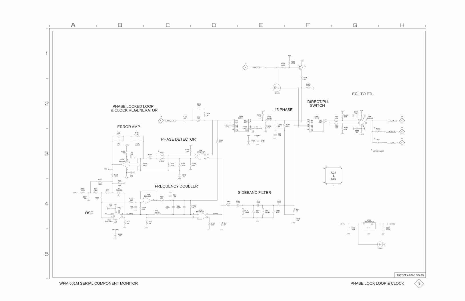
WFM 601M SERIAL COMPONENT MONITOR
��$
��$
�� ��"����
� ���
� �
�����
�
�
��$
��$
���
�����
��
� �
���
�
�
��$
� (��
ECL TO TTL
��
�
���
�� �
� �
�
#��
��%����
���
��#�
��
�
DIRECT/PLLSWITCH
�
����
�����
������
�����
�����
������
�#"��
�#"��
#���
�����
–45 PHASE
������
�����
������
������
������
�#"�
�#"�
$����
$�����
$�����
#���
����� ����
���
� �
�����
��#� ���
�����
��
���
��
���
�$(���
�
�
PHASE LOCKED LOOP& CLOCK REGENERATOR
ERROR AMP���
�#�
���
��#�
���
�����
PHASE DETECTOR
���
�����
���$
����
�� #�
��
��#� ���
���
���
���
�
��
��
���
��
#��
�������
���
���
���
���
��$
����
�� � �
���
���
����
������
��$ ������
����
��#�
���
��#�
���
��#�
���
�
����$
���� ��
�%(��
���
�
����
��#�
�
���
��"���!"�����
��
�
��
�
�
�
�
�
�
��
��
#�
#��
�
SIDEBAND FILTER
���
��#�
��
���
���
�����
����$
���
����
����
��#�
� �
�����
FREQUENCY DOUBLER
�����#�
��
�
���
�
#��
�����
&�
�����'
"��
����$
���
���� � ��
����
��
����
�
����
��
����
��
��
�
OSC
��$
���
��#�
���
��#�
���
��
���
��
#��
�������
���
�#�
������ �
���
��
�
���
�����
���
��#�
��
�����
�����'
�
��
���
���
�
#��
����� ���
����
� ��'���
���
�
�
#��
�������
��
�����
��
�
�
�
��
����
���
����
����
���
����
������
��
����
����
���
��
���
��
����
��
���
��#�
��
���
���������$
����
���#�
���
��#�
#��
�� �����"
� ���
������
����
��#�
PHASE LOCK LOOP & CLOCK
�� "�������������� �
9

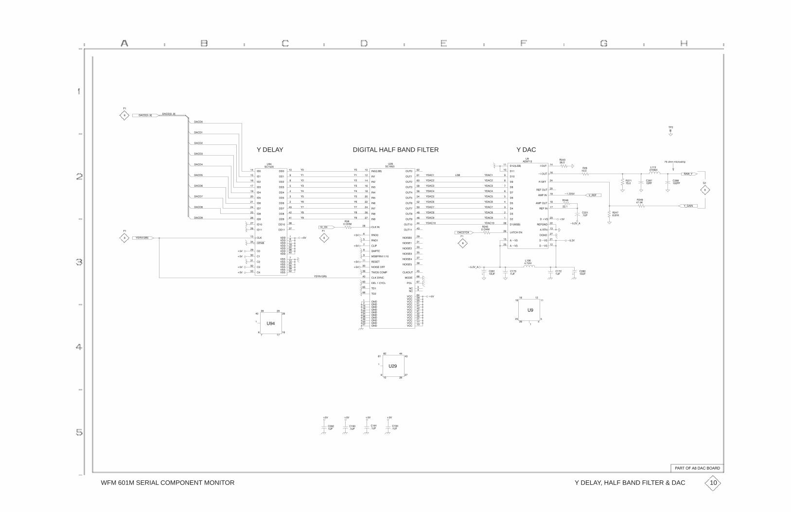
WFM 601M SERIAL COMPONENT MONITOR
��$
��$
��
�
�����
�����
����(����)����(����)
"�
'*����
�%*'
���
����� ��
�
���/,.�.-+1/231-0
��
����
��
�����
����
���
����
���
����
$* ��
Y DAC
'����
'���
'���
'����
'����
'���
����
���
����
�����
� ���
����
�����
�����
������
������
����!�����
�� "��
���#"��
���$!�
���$!���
����#"�
�������
�����#"��
��������
����#"�
���$!�
�����
���$!
�!�"�
���$!��
��"������
�����
����!����
#�
����� �
��
�
��
����$
'����
'���
'���
'����
'����
'���
�!�
'�
'�
'
'
'�
'�
'
������
�����
���
����
������
�����
�������
!��"����
�!�� ���������
�����!�����
�!�"���
�����
$���
�����
������
����
$����
������
������
�����
$���
�� �
����
�����
$���
����
�����
��������
���!���
���!�������
���!���
$��
���!�
�����
���!��
"%�!������
���!���
�����
���!���
����!'�����
$����
$���
�#"���
�#"����
����#"��
�#"��
$����
�#"���
������
�#"���
$����
�#" �
�����
�#"���
$����
�#"��
������
�#"��
$����
�#" �
�#"� �
�#"�
�������'���
$�� �
"��� �
"��
��� �
���� �
#�
!����
DIGITAL HALF BAND FILTER
'�
'�
'
'
'�
'�
'
������
������
����
�����
������
�����
�� ��
�����
�����
����
������
������
����
����
���
��
���
$����
$���
$����
$��
$��
$����
�����
�����
����
����
�����
����
�� �
����
����
�����
�����
�����
������
$!!��
$!!�
$!!
$!!�
$!!��
�����
$!!�
$����
#��
!����
Y DELAY����
����
�����
�����
����
�����
��
� '!'�� �
�����
�����
'�
'�
'�
��$
��$
��$
'�
'�
'�
�&*��
��
�����
��$
��$
��$
��$
��
�
'����
'����
'����
'�����
���$*�
������
��
�����
��
�
'����
'����
'����
'�����
���$
��$
���
���#�
���$*�
��
����
��
��#�
���
�#�
���
�#�
���
��#�
�
�
��
���
��
�
#�
�
��$
���
��#�
'!'�� �
�
��
��
#���
� ��
��
�
�
�
�
#�
��
�
�
��
��$
����
��#�
��$��$
����
��#�����
��#�
��$
��
�#�
Y DELAY, HALF BAND FILTER & DAC
�� "�������������� �
10

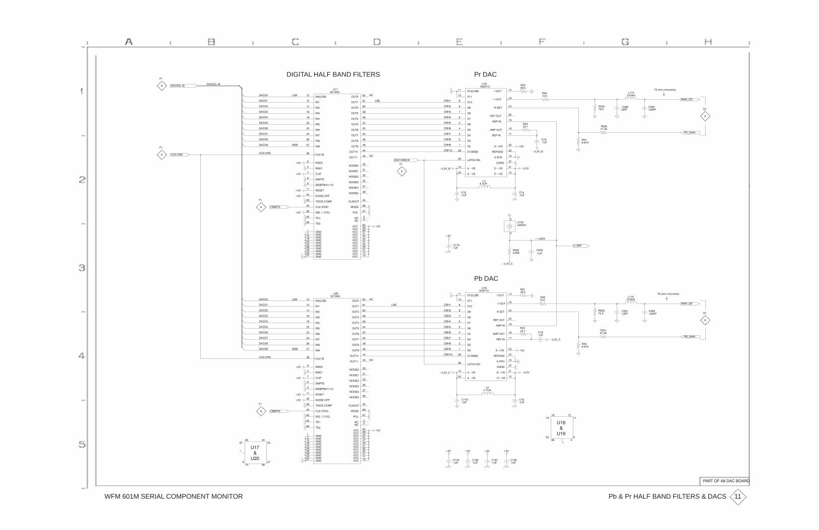
WFM 601M SERIAL COMPONENT MONITOR
!��
Pr DACDIGITAL HALF BAND FILTERS�
�����(����)
����(����)
�"������
����
����
�����
�����
����
�����
�����
�����
�"�
�����
�����
����
����
!����
!������
��� ���
"� #����
�"� !������
�����"����
!�"�#�
���
%���
����
����
�����
%���
�����
�����
�� ��
%��
����
�����
�����
%��
�����
�����
��������
���"���
���"��������
���"��
%���
���"���
������
���"���
#&�"���� ���
���"����
������
���"� ��
����"'�����
%���
%���
�$#��
�$#���
����$#�
�$#���
%����
�$#���
������
�$#� �
%��
�$#�
���� �
�$# �
%��
�$#� �
���� �
�$#� �
%�� �
�$#��
�$#�
�$#��
������'�����
%����
#���
#����
����
������
$�
"�� �
��
�!�
�!�
�!��
�!��
�!�
�!��
�!��
�!��
���
����
�����
� ���
����
�����
�����
�����
�����
���
���"���
��!#��
���$#�
���%"
���%"�
����$#�
!������
�� ��$#�
�� ����
!����$#�
���%"
!�����
���%"�
!�"�#�
���%"�
��#�������
�����
���"����
$�
�����! �
���
!�
�
!
� ��
!��
����
!��
���
��
�$�
!�&*�!
!*����
!��
��� �
� �/,.�.-+1/231-0
��
����
���
�
���
�� � �
�
� �%
� %
� �%*�
��
�$�
�!��
�!��
� �%*�
��
���$�
�
�$�
��
����! ��
�
�
�"�
�!�!�
����!
� %
� %
� %
� %
�����
�
�
����!
�
�
� %
� %
���
�$�
� %
� �%*�
%*!��
!��
����
�� %
�
$�
�����
���
�$�
�
�
!�&*��
�*����
!�
��� �
� �/,.�.-+1/231-0
��
�� �
�
����
��
�
� �%*�
!
���
���
�$�
!�
����
! �
� ��
!��
���
���
���
����
����
���
����
����
���
����
�����
� ���
����
�����
�����
�����
�����
���
���"���
��!#��
���$#�
���%"
���%"�
����$#�
!������
�� ��$#�
�� ����
!����$#�
���%"
!�����
���%"�
!�"�#�
���%"�
��#�������
�����
���"����
$�
�����
Pb DAC
�"�
�����
�����
����
����
!����
!������
��� ���
"� #����
�"� !������
�����"����
!�"�#�
���
%���
����
����
�����
%���
�����
�����
�� ��
%��
����
�����
�����
%��
�����
�����
��������
���"���
���"��������
���"��
%���
���"���
������
���"���
#&�"���� ���
���"����
������
���"� ��
����"'�����
%���
%���
�$#��
�$#���
����$#�
�$#���
%����
�$#���
������
�$#� �
%��
�$#�
���� �
�$# �
%��
�$#� �
���� �
�$#� �
%�� �
�$#��
�$#�
�$#��
������'�����
%����
#���
#����
����
������
$�
"�� �
���"������
����
����
�����
�����
����
�����
�����
�"�
����!
� %
� %
� %
� %
�����
�����
��
����
����
����
� �%*�
�
���$�
���
�$�
� �%
� %
��
�$�
��
�$�
� %
$�
�
�
�
�
�
$�
���
�$�
���
�$�
��
�$�
� %� %� %
� %
���!�
�
�
�
��
����
�
$�
�
�
$�
�
�
Pb & Pr HALF BAND FILTERS & DACS
�!#��������������!�
11
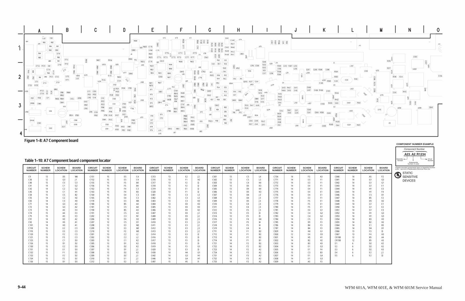
9–44 WFM 601A, WFM 601E, & WFM 601M Service Manual
C9 13 D5 M4C36 12 G3 J1C40 15 C5 C3C41 14 C1 G2C42 14 C2 G2C45 14 C1 H1C50 15 C5 B2C55 14 C2 H2C65 14 C3 H3C71 14 G3 A3C72 14 G3 A2C73 15 A5 E4C74 15 A4 E3C75 15 A5 E3C91 14 H3 A2C92 14 H3 A1C101 14 H3 A1C118 15 E2 C3C119 15 E3 C3C120 15 F2 C3C121 15 F3 C3C125 15 C1 D3C126 15 D1 D2C130 15 E2 D3C131 15 E1 D3C132 15 F1 D2C133 15 F2 D2C134 15 F2 D2C136 15 D1 D3
C151 15 E5 C4C152 15 E5 C4C155 15 F5 B4C156 15 F5 B4C162 15 F4 C3C163 15 F4 B3C164 15 E4 C3C165 15 E4 C3C170 12 E3 M3C180 12 B5 A4C181 12 C5 A4C190 12 B5 A3C191 12 C5 A3C202 12 C3 N1C206 12 E4 O2C207 12 C5 O1C208 12 E3 M2C209 12 E3 M2C210 12 F2 M3C301 13 C2 L2C302 13 C2 L2C303 13 C1 K2C305 13 D1 K2C306 13 D2 K2C307 13 D1 J2C308 13 D2 K2C309 13 D2 J2C310 13 E1 J2C312 13 E2 J2
C313 13 E2 J2C316 13 F1 H2C317 13 F2 I2C318 13 F2 I2C319 13 E1 I2C320 13 F1 I2C401 13 C3 L3C402 13 C3 L3C403 13 C3 K3C404 13 D3 K3C405 13 D3 K3C406 13 D3 K2C407 13 D3 J2C408 13 D3 J2C409 13 D3 J3C410 13 E3 J3C411 13 E3 J2C412 13 E3 J3C413 13 E3 J2C414 13 E3 I2C416 13 F3 I3C417 13 F3 I3C418 13 F3 I3C419 14 F3 G1C420 13 E3 I3C430 14 H4 G1C442 14 G3 H1C446 14 G4 H1C497 15 H5 I1
C501 13 C5 L4C502 13 C5 L3C503 13 C4 K4C504 13 D5 K3C505 13 D4 K4C506 13 D5 K3C507 13 D4 J3C508 13 D4 J3C509 13 D5 J3C510 13 E4 J3C511 13 E4 J3C512 13 E5 J3C513 13 E5 I3C514 13 E5 I3C516 13 F4 H4C517 13 F5 I4C518 13 F5 I4C519 13 E4 I4C711 14 F1 B2C712 14 F1 B2C713 14 F1 B2C714 14 F1 B1C721 14 F2 B2C722 14 F2 B2C723 14 F2 A2C724 14 F2 A2C731 14 F3 A2C732 14 F3 A2C733 14 F2 A2
C734 14 F3 A3C771 14 E3 F1C772 14 E3 F1C773 14 E4 F1C774 14 E4 F1C775 14 E4 E1C776 14 E4 E1C777 14 E3 F1C778 14 F5 E1C779 14 F5 E1C780 14 F5 E1C781 14 E4 G1C782 14 C4 G2C783 14 C4 G2C784 14 C5 F3C785 14 D5 F3C786 14 B4 F3C787 14 B4 F3C829 14 H4 G1C830 12 E4 O3C831 14 H5 H1C832 14 B2 H2C833 14 B3 H3C834 14 E1 G3C835 14 E1 F4C836 15 C3 B3C837 14 E1 G4C838 14 E1 G3C839 14 A5 F3
C840 14 A5 F2C841 14 G1 G3C842 14 G1 G1C843 14 G1 E1C844 14 H1 E3C845 14 H1 F4C846 15 C5 D1C847 14 B5 F2C848 15 D5 D2C849 14 G1 E1C850 14 G1 E2C851 14 G1 E3C852 14 H1 G3C853 14 H1 G3C854 14 B3 H3C855 14 B2 H2C864 14 E1 B3C865 14 D4 D1C866 13 F3 I3C867 13 F4 H3CR180 12 B5 A4CR190 12 B5 A3E1 6 D2 K2E2 6 D2 K2E3 6 D2 K3E4 6 E2 J2E5 6 E2 I3
SCHEMNUMBER
Table 1–10: A7 Component board component locator
CIRCUITNUMBER
SCHEMLOCATION
BOARDLOCATION
SCHEMNUMBER
CIRCUITNUMBER
SCHEMLOCATION
BOARDLOCATION
SCHEMNUMBER
CIRCUITNUMBER
SCHEMLOCATION
BOARDLOCATION
SCHEMNUMBER
CIRCUITNUMBER
SCHEMLOCATION
BOARDLOCATION
SCHEMNUMBER
CIRCUITNUMBER
SCHEMLOCATION
BOARDLOCATION
SCHEMNUMBER
CIRCUITNUMBER
SCHEMLOCATION
BOARDLOCATION
����������������
��� �� �����
�������"����������������������������������!�������
����� #�������������������������������������������
�� ��������������� �
��������������
������������������� ������
������
������� �
�� ����
� �� �������
Figure 1–8: A7 Component board
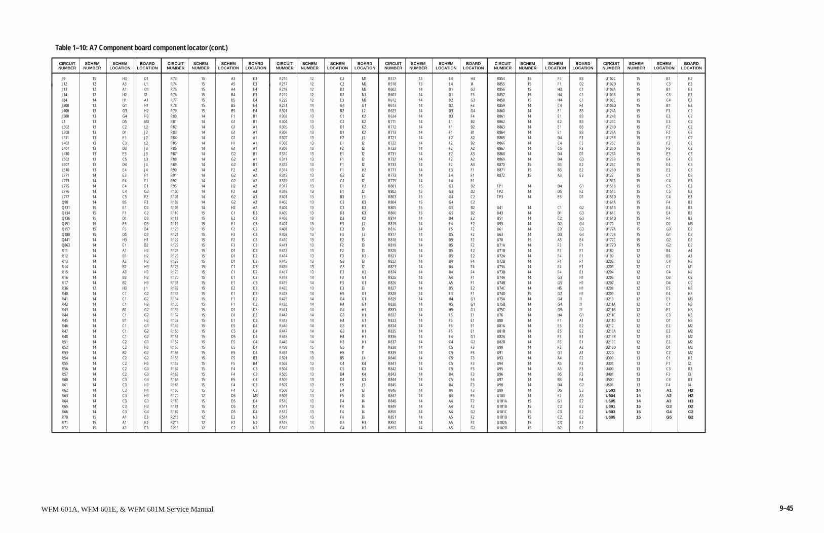
9–45WFM 601A, WFM 601E, & WFM 601M Service Manual
J9 15 H3 D1J12 12 A3 L1J13 12 A1 O1J14 12 H2 I2J84 14 H1 A1J300 13 G1 H1J400 13 G3 H2J500 13 G4 H3L1 13 D5 M3L302 13 C2 L2L308 13 D1 J2L311 13 E1 J2L402 13 C3 L2L407 13 D3 J3L410 13 E3 J3L502 13 C5 L3L507 13 D4 J4L510 13 E4 J4L771 14 E3 F1L773 14 E4 F1L775 14 E4 E1L776 14 C4 G2L777 14 C5 F2Q98 14 B5 F3Q131 15 E1 D2Q134 15 F1 C2Q136 15 D1 D3Q151 15 E5 D3Q157 15 F5 B4Q180 15 D5 D3Q441 14 H3 H1Q863 14 E1 B2R11 14 A1 H2R12 14 B1 H2R13 14 A2 H3R14 14 B2 H3R15 14 A3 H3R16 14 B3 H3R17 14 B2 H3R36 12 H3 J1R40 14 C1 G2R41 14 C1 G2R42 14 C1 H2R43 14 B1 G2R44 14 C1 G2R45 14 B1 H2R46 14 C1 G1R47 14 C1 G2R48 14 C1 G2R51 14 C2 G3R52 14 C2 H3R53 14 B2 G2R54 14 C2 G2R55 14 C2 H3R56 14 C2 G3R57 14 C2 G3R60 14 C3 G4R61 14 C3 H3R62 14 C3 H4R63 14 C3 H3R64 14 C3 G3R65 14 C3 H3R66 14 C3 G4R70 15 A1 E3R71 15 A1 E2R72 15 A3 E3
R73 15 A3 E3R74 15 A5 E3R75 15 A4 E4R76 15 B4 E3R77 15 B5 E4R78 15 B5 E4R79 15 B5 E4R80 14 F1 B1R81 14 G1 B1R82 14 G1 A1R83 14 G1 A1R84 14 G1 A1R85 14 H1 A1R86 14 G1 A1R87 14 G2 B1R88 14 G2 A1R89 14 G2 B1R90 14 F2 A2R91 14 G2 A2R92 14 G2 A2R95 14 H2 A2R100 14 F2 A3R101 14 G2 A3R102 14 G2 A2R105 14 H2 A2R110 15 C1 D3R118 15 E2 C3R119 15 E1 C3R120 15 F2 C3R121 15 F3 C3R122 15 F2 C3R123 15 F3 C3R125 15 D1 D3R126 15 D1 D2R127 15 D1 D3R128 15 C1 D3R129 15 C1 D2R130 15 E1 C3R131 15 E1 C3R132 15 E2 D3R133 15 E1 D3R134 15 F1 D2R135 15 F1 C2R136 15 D1 D3R137 15 D1 D3R138 15 E1 D3R149 15 E5 D4R150 15 C5 D4R151 15 D5 D4R152 15 E5 C4R153 15 E5 D4R155 15 E5 D4R156 15 F5 B3R157 15 F5 B4R162 15 F4 C3R163 15 F4 C3R164 15 E5 C4R165 15 F4 C3R166 15 F4 C3R170 12 D3 M3R180 15 D5 D4R181 15 D5 D4R182 15 D5 D4R213 12 E2 N3R214 12 E2 N2R215 12 C2 N3
R216 12 C2 M1R217 12 C2 M2R218 12 D2 M2R219 12 D2 N3R225 12 E3 M2R251 14 G4 G1R301 13 B2 L2R302 13 C1 K2R304 13 C2 K2R305 13 D1 K2R306 13 D1 K2R307 13 E2 J2R308 13 E1 I2R309 13 F2 I2R310 13 E1 I2R311 13 F1 I2R312 13 F1 I2R314 13 F1 H2R315 13 G2 I2R316 13 G1 I2R317 13 E1 H2R318 13 E1 I2R401 13 B3 L3R402 13 C3 K3R404 13 C3 K3R405 13 D3 K3R406 13 D3 K2R407 13 E3 J2R408 13 E3 I3R409 13 F3 J3R410 13 E2 I3R411 13 F2 I3R412 13 F2 I3R414 13 F3 H3R415 13 G3 I3R416 13 G3 I2R417 13 E3 H3R418 14 F3 G1R419 14 F3 G1R420 13 E3 I3R428 14 H5 G1R429 14 G4 G1R430 14 H4 G1R441 14 G4 H1R442 14 G3 H1R443 14 H4 G1R446 14 G3 H1R447 14 G3 H1R448 14 H4 H1R449 14 H3 H1R496 15 G5 I1R497 15 H5 I1R501 13 B5 L4R502 13 C4 K4R504 13 C5 K3R505 13 D4 K4R506 13 D4 K3R507 13 E5 J3R508 13 E4 I3R509 13 F5 I3R510 13 E4 I4R511 13 F4 I4R512 13 F4 I4R514 13 F4 I3R515 13 G5 H3R516 13 G4 H3
R517 13 E4 H4R518 13 E4 I4R602 14 D1 G2R603 14 D1 F3R612 14 D2 G3R613 14 D2 F3R623 14 D3 G4R624 14 D3 F4R711 14 E1 B2R712 14 F1 B2R713 14 F1 B1R721 14 E2 A2R722 14 F2 B2R723 14 F2 A2R731 14 E2 A3R732 14 F2 A2R733 14 F2 A3R771 14 E3 F1R773 14 E4 F1R775 14 E4 E1R801 15 G3 D2R802 15 G3 D2R803 15 G4 C2R804 15 G4 C2R805 15 G5 B2R806 15 G5 B2R814 14 D4 E2R815 14 E4 E2R816 14 E5 F2R817 14 D5 F2R818 14 D5 F2R819 14 D5 F2R820 14 D5 E2R821 14 D5 E2R822 14 B4 F4R823 14 B4 F4R824 14 B4 F4R825 14 A4 F1R826 14 A5 F1R827 14 D5 E2R828 14 E3 F1R829 14 H4 G1R830 14 H5 G1R831 14 H5 G1R832 14 F5 E1R833 14 F5 E1R834 14 F5 E1R835 14 F5 E1R836 14 E4 G1R837 14 C4 G2R838 14 C5 F3R839 14 C5 F3R840 14 C5 F3R841 14 C5 F3R842 14 C5 F3R843 14 B4 F3R844 14 C5 F4R845 14 B4 F3R846 14 B4 F3R847 14 B4 F3R848 14 A4 F2R849 14 A4 F2R850 14 A4 G2R851 14 A5 F2R852 14 A5 F2R853 14 A5 G2
R854 15 F5 B3R855 15 F1 D2R856 15 H3 C1R857 15 H4 C1R858 15 H4 C1R859 14 C4 F4R860 14 E1 B3R861 14 E1 B3R862 14 E2 B3R863 14 E1 B3R864 14 E1 B3R865 14 D4 F3R866 14 C4 F3R867 14 C5 F3R868 14 D4 D1R869 14 D4 G3R870 15 B3 E2R871 15 B3 E2R872 15 A3 E3
TP1 14 D4 G1TP2 14 D5 F2TP3 14 E5 D1
U41 14 C1 G2U43 14 D1 G3U51 14 C2 G3U53 14 D2 G4U61 14 C3 G3U63 14 D3 G4U70 15 A5 E4U71A 14 F3 F1U71B 14 F3 F1U72A 14 F4 F1U72B 14 F4 F1U73A 14 F4 E1U73B 14 F4 E1U74A 14 G3 H1U74B 14 G5 H1U74C 14 H5 H1U74D 15 G2 H1U75A 14 G4 I1U75B 14 G4 I1U75C 14 G5 I1U76 14 H4 G1U80 14 F1 A1U81A 14 E5 E2U81B 14 E5 E2U82A 14 F5 E1U82B 14 F5 E1U90 14 F2 A2U91 14 G1 A1U93 14 A4 F2U94 14 A5 F2U95 14 A5 F3U96 14 B5 F3U97 14 B4 F4U98 14 D4 G2U99 14 D5 E3U100 14 F2 A3U101A 15 G1 E2U101B 15 C2 E2U101C 15 C3 E2U101D 15 C2 E2U102A 15 C3 E2U102B 15 B2 E2
U102C 15 B1 E2U102D 15 C3 E2U103A 15 B1 E3U103B 15 C3 E3U103C 15 C4 E3U103D 15 B1 E3U124A 15 F3 C2U124B 15 E2 C2U124C 15 E3 C2U124D 15 F2 C2U125A 15 F2 C2U125B 15 F3 C2U125C 15 F3 C2U125D 15 F5 C2U126A 15 E3 C3U126B 15 E4 C3U126C 15 E4 C3U126D 15 E2 C3U127 15 C1 D3U151A 15 C4 E3U151B 15 C5 E3U151C 15 C5 E3U151D 15 C4 E3U161A 15 F4 B3U161B 15 E4 B3U161C 15 E4 B3U161D 15 F4 B3U170 12 D2 M3U177A 15 G3 D2U177B 15 G1 D2U177C 15 G2 D2U177D 15 G2 D2U180 12 B4 A4U190 12 B5 A3U202 12 C4 N2U203 12 C1 M1U204 12 C4 N2U206 12 D3 O2U207 12 D4 O2U208 12 E5 N3U209 12 E4 N3U210 12 E1 M3U211A 12 C1 N3U211B 12 E1 N3U211C 12 C3 N3U211D 12 D1 N3U212 12 E2 M2U213A 12 E2 M2U213B 12 E2 M2U213C 12 E2 M2U213D 12 D1 M2U220 12 C2 M2U300 13 C1 K2U301 13 F1 I2U400 13 C3 K3U401 13 F3 I3U500 13 C4 K3U501 13 F4 I4U503 14 A1 H2U504 14 A2 H2U505 14 A3 H3U801 15 G3 D2U803 15 G4 C2U805 15 G5 B2
SCHEMNUMBER
Table 1–10: A7 Component board component locator (cont.)
CIRCUITNUMBER
SCHEMLOCATION
BOARDLOCATION
SCHEMNUMBER
CIRCUITNUMBER
SCHEMLOCATION
BOARDLOCATION
SCHEMNUMBER
CIRCUITNUMBER
SCHEMLOCATION
BOARDLOCATION
SCHEMNUMBER
CIRCUITNUMBER
SCHEMLOCATION
BOARDLOCATION
SCHEMNUMBER
CIRCUITNUMBER
SCHEMLOCATION
BOARDLOCATION
SCHEMNUMBER
CIRCUITNUMBER
SCHEMLOCATION
BOARDLOCATION

9–46 WFM 601A, WFM 601E, & WFM 601M Service Manual
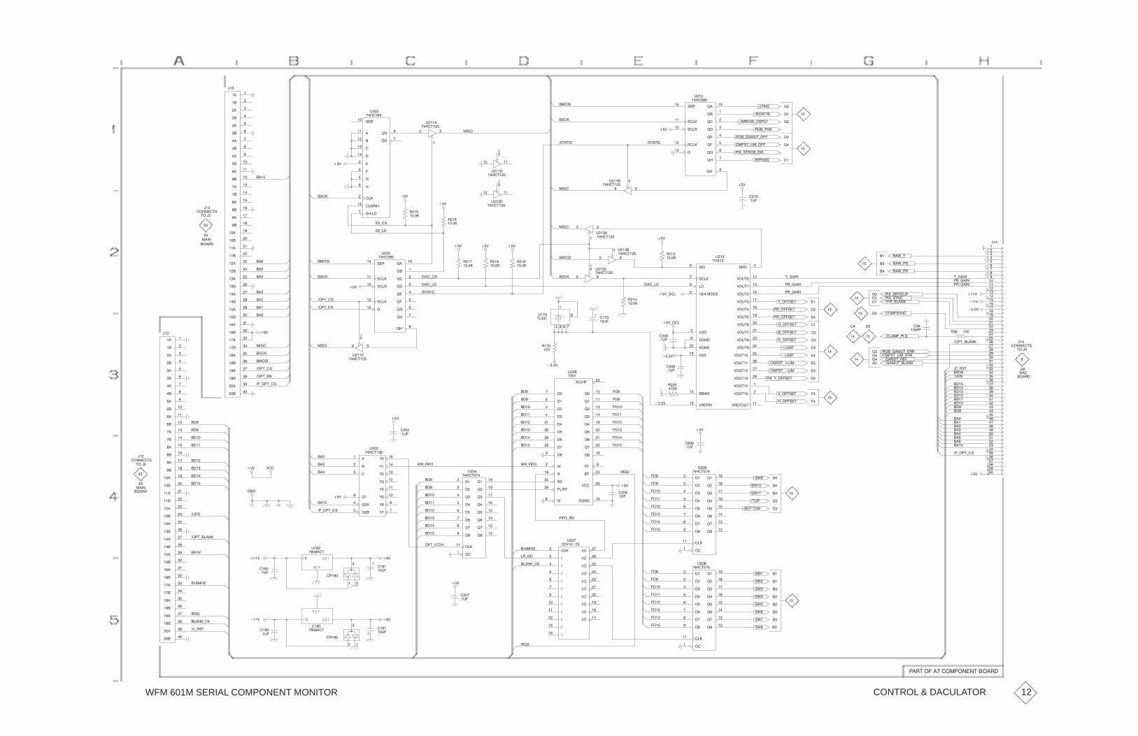
WFM 601M SERIAL COMPONENT MONITOR
��#���
��#��
���&#��
��
��
��
��
"�!��
���
���
"������
���
"��!���
��
��
!������
���
���
���
��
����
$���
�����
���"�
����
����
���
���
���
���
��
���
����
����
����
����
��
��
����
����
���
����
�����
�����
�����
�����
����
����
����
����
���
����
�����
����
����
����
� �
� �
����
����
���
����
����
����
��
����
�"�� ��%
��%
"�!���
����
����
���
���
���
���
����
����
������
���������
"�������
���
��
$��
�����
��� �
�
$����
��#���
��� ��
�
$���
��#���
��� ��
�
$����
��#���
��"�
�"��
��"�
�"#�#��
�����
$����
��#���
�"#�#��
��%
�(��""
��%
����
��$�
��!!�&*�"��(
���"#*���*���
�
�
��
�
!��*��!
��'*"#!��*��"
!��*���$#*���
���%
���
���
��
��
���
���
��
���
���
���
���
���
��
��
���
���
��
���
���
���
���
���
��
��
���
���
��
���
���
��
��
��
�
�
��
��
�
��
��
��
��
��
�
�
��
��
�
��
��
���
���
���
��
��
���
���
��
���
���
���
��
!�&*(
!�&*��
!�&*�!
(*����
�!*����
��*����
��'*�!�#�$�
��
�
�
�
��
�
��
�
(*����
��*����
�!*����
"���
%�$#��
%�$#���
%�$#���
%�$#�
%�$#��
%�$#���
%�$#���
%�$# ��
%�$#��
%�$#��
%�$#����
%�$#����
%�$#���
%�$#���
%�$#���
%�$#����
"�����
%!���$#��
%!�������
"�����
�����
�����������
!���"���
%����
�������
�������
%""��
$���
�����
��� ��
�� $���
��#���
����
�
$���
��� ��
$���
��#���
����*��
��%
��%*���
!��
�����
!��
��������"�
�"��
��"�
��% ��% ��%
��%
!���
�����
!��
�����
!���
�����
!���
�����
���*�"
����*�"
���*��
"�!��
���
���
"������
���
"��!���
��
��
!������
���
���
���
��
����
$���
�����
�"��
���"�
�"#�#��
����*����%
!���
�����
����
���!�
������#"
�
��
#����
��
��
���
���
�
����
����
���
���
���
���
��
���
����
����
����
����
��
��
����
����
���
����
�����
�����
�����
�����
����
����
����
����
���
����
�����
����
����
����
� �
� �
����
����
���
����
����
����
���
��"�
�"��
���"�
���#*�"
���#*��
���
���
���
��%
���#*��
���#*�"
��"� �����
��
$����
��#���
����%
�
�
� �
$� �
#��
!� �
�
���
���
��
�
��
���
���
��
���
'�����
����
� ���
�����
����
���
���
�����
�����
����
&���
!���
!"���
���!#���
'����
����
���
������
%���
$���
���
��%*���
����%
�� �
��$�
����
��$�
����
��$�
�����#
�*���"�#
�*���"�#
!*���"�#
�����#
�!*���"�#
��*���"�#
(*���"�#
��'*(*���"�#
���"#*����
���"#*����
��
��
�
�
��
��
�
�
�
��
��
�
�
����"(��
���$#*���
�$�"
�!�&
��*!"#
������*��"
����$#*�����
���'*�����
��'*"(��
�!��*���$#*�!!
����"#*���*�!!
��
�����
����
�
�
��
��
�
��
�
��
�
���#*�����
!� ���
���%
����%
��
������#"
#���
�
��
���
���!�
��%
���
���
���
��
��
���
���
����
����
����
���
���
����
��*��#*�"
���
����
���
%*���"�#
�*���"�#
��%
���
��$�
�
�
��
���
���
����
����
����
���
���
����
�! �
����%
!���
��
�����
���
����
���
���
�
����
��
�����
���
����
��
� ���
�
�����
���
������
�����
$���
��#�
���
���
����
����
����
���
���
����
&!*����&!*����
��
��
���
��%
����
��$�
����
����
���
�����
�����
������
(���
(��
(��
(��
(��
(���
(���
( �
$���
��#��
���
���
���
����
����
����
��*��#*�"
��% %��
������#"
���
#����
�
����
���!�
� ����
���
�$�"
�!�&
���
���%
$���
�����#
���#*�����
����
��$�
���
���
����
����
����
���
���
����
��#*�#��
��*��#*�"
����
��%
��%
����*!�
�!*��
�������
���
���
����
����
���
����
����
����
����
���
����
����
�����
�����
����
����
�����
�����
�����
�����
����
$��
��%�����
�����)
�����
���
����
���
���
�
����
��
�����
���
����
��
� ���
�
�����
���
������
�����
$��
��#� ���
���
����
����
����
���
���
����
��%
����
��$�
"&�
"&��
"&��
�#��
���##��
�
�
�
��
�
��
�
"&�
"&�
"&
"&
"&�
"&�
"&
"&�
��
��
��
��
��
�
�
��
���
���
����
����
����
���
���
����
�����
���
����
���
���
�
����
��
�����
���
����
��
� ���
�
�����
���
������
�����
$���
��#� �����*��
�! �
��%
���
��$�
����
��$�
��%
��
�!���
� �
�!���
�����)
�����*��
�! �
��*!"#
���%
����
��$�
����
��$�
$���
�����#
��!#����� ���������#����!�
CONTROL & DACULATOR 12

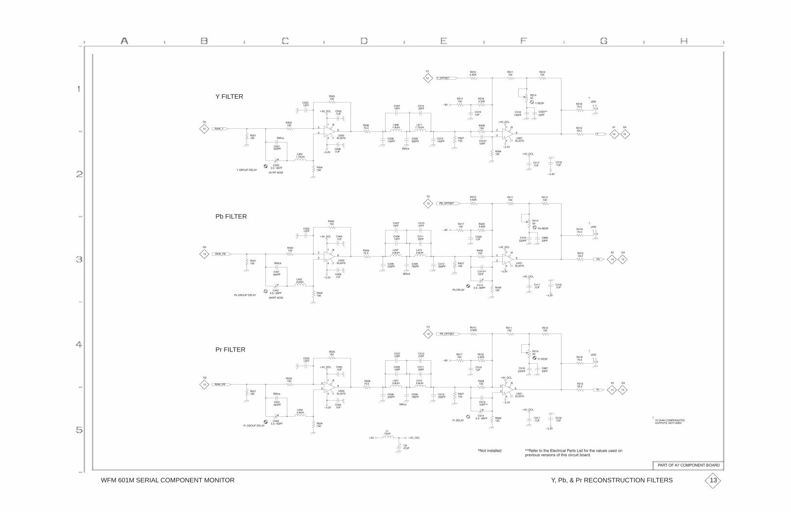
WFM 601M SERIAL COMPONENT MONITOR
���
���
���
���
%&��� �!
���
�����
��
��
��
��
Y FILTER
��$&%
�.)'
���
���
���
���
��������
��
���
��
�
�
"��
���� �
��#&���
���
���"�
���
���
���
��"�
���
�����
���
���
��
����
���
�� �"�
���
����
��
����
���
��
���
�����
��
���
���
���
��#
��
���
���
���
���
�"�
���
����
��#&���
%��� �
��
���
��
�
�
"��
���� �
��
��
���
�����
�����
����
%
���
���
���
��
� �
���
��
�
�
��
����#
����#
��#&���
���
���
���
���
��
��"�
���
��"�
���
���
�.)'
��&��� �!
���
�����
��
��
����#
��
���
���
��"�
%����"������%
���
�� �"�
� ������
���
��������
��
��
Pb FILTER
��$&��
�.)'
���
���
���
���
���
���
��
���
��
�
�
"��
���� �
��#&���
��
��"�
���
��"�
���
���
���
���
���
���
��
����
���
����
���
��"�
��
����
���
����
���
��
���
��
���
���
��
���
���
���
��#
��
���
���
�����
���
�"�
����
����
�(��� �
��#&���
��
���
��
�
�
"��
���� �
��
��
���
�����
����
��
�(
���
���
���
��
� �
���
�
��
��
�
����#
��#&���
����#
���
���
��
��"�
���
��"�
�(�����%
�.)'
��
��
��
��������
����#
��
���
��
��"�
�(����"������%
���
��"�
�������
���
��������
��
�� ��$&��
����
���
����
���
Pr FILTER
��#&���
��
���
��
�
�
"���
���� �
���
��"�
����
���
����
��"�
����
���
���
����
����
��"�����
���
���
���
����
��
����
��
����
����
���
����
��&��� �!
��#
����
�����
����
�"�
����
�����
���
���
��
���
��
�
�
"���
���� �
����
���
����
���
��#&���
���
��
����
�����
�3��� �
���
��
�3
����
���� �
����
����
��
�
�
�
��
�"!�"! ����!�" ���
������������ �!��
����#
��#&���
����
���
���
��"�
����
��"�
����#
��#&���
�3�����%
����
����
�.)'
����
���
��
"�
���
��������
���
������
��
��"�
��#
����#
���
���
����
���
���
��"�����
��"�
�.)'
����
���
�3����"������%
����
��������
Y, Pb, & Pr RECONSTRUCTION FILTERS
���!����� ���������!������
13
���+,+3�51�5-+��/+)53.)'/��'354��.45�,13�5-+�7'/6+4�64+*�10
23+7.164�7+34.104�1,�5-.4�).3)6.5�(1'3*�
��15�.045'//+*

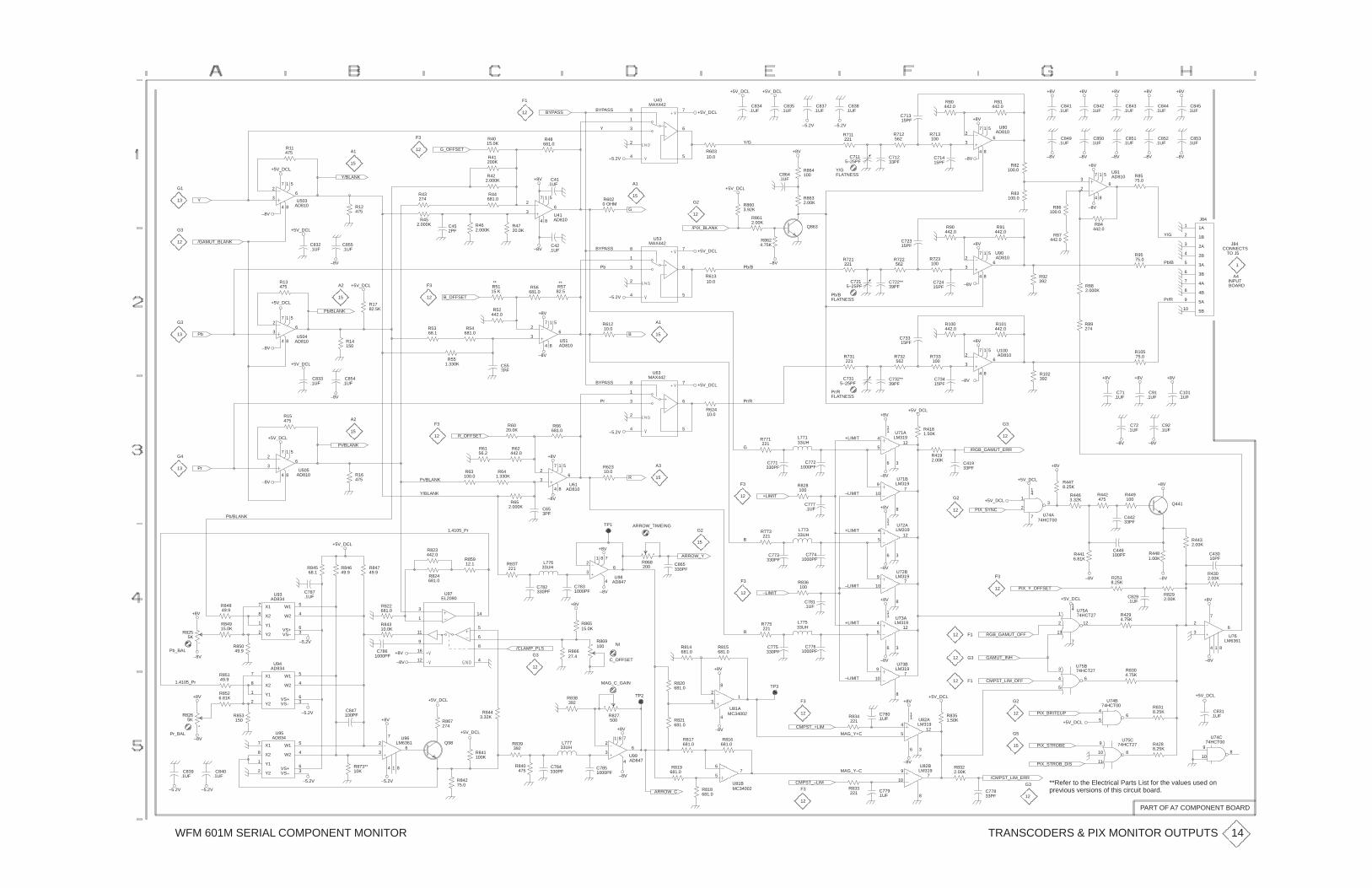
WFM 601M SERIAL COMPONENT MONITOR
2
3
VS+
AD847
C853.1UF
C845.1UF
+8V+8V
C841.1UF
C852.1UF
C842.1UF
C843.1UF
C844.1UF
+8V +8V +8V
C850.1UF
C851.1UF
C849.1UF
+8V–5.2V
7
4
1 5
8
2
36
U80AD810
R81442.0
R80442.0
C71315PF
+5V_DCL
+5V_DCL +5V_DCL
–5.2V
C834.1UF
C835.1UF
C837.1UF
C838.1UF
5 4
7
2
8
1
3 6
U43MAX442
BYPASS
Y
BYPASS
F1
12
Y
/GAMUT_BLANK
G1
13
G3
12
+5V_DCL
–8V
Y/BLANK
+5V_DCL
C832.1UF
C855.1UF
7
4
1 5
8
2
36
U503AD810
R11475
R12475
A1
15
G_OFFSET
R422.000K
R452.000K
R4015.0K
R43274
R44681.0
R462.000K
R4720.0K
F3
12
C452PF
R41200K
G
+8V
–8V
–5.2V
R6020 OHM
C41.1UF
C42.1UF
R48681.0
7
4
1 5
8
2
36
U41AD810
A1
15
Y/G
Y/GFLATNESS
G2
12
/PIX_BLANK
R60310.0
+5V_DCL
+8V
Q863
R8612.00K
R8624.75K
R8603.92K
R8632.00K
C864.1UF
R864100
C7115–25PF
–8V
R711221
R712562
R713100
R90442.0
R91442.0
C71233PF
C71415PF
C72315PF
R8575.0
+8V
–8V
–8V–8V –8V–8V
R84442.0
7
4
1 5
8
3
26
U91AD810
R83100.0
R82100.0
R86100.0
R87442.0
Y/G
1A 1
1B 2
2A 3
2B 4
3A 5
3B 6
4A 7
4B 8
5A 9
5B 10
J84
–8V
Pb/B
Pr/R
BOARD
CONNECTS
A4
J84
TO J5
INPUT
1
R9575.0
R92392
R882.000K
R89274
C7215–25PF –8V
+8V
+8V
R721221
R722562
R723100
C722**39PF
C72415PF
C73315PF
R100442.0
R101442.0
7
4
1 5
8
2
36
U90AD810
7
4
1 5
8
2
36
U100AD810
Pb/B
FLATNESSPb/B
+5V_DCL
R61310.0
–8V
5 4
7
2
8
1
3 6
U53MAX442
B
BYPASS
+8V
–8V
–5.2V
Pb
R61210.0
R56681.0
R5782.5
7
4
1 5
8
2
36
U51AD810
A1
15
B_OFFSET
R551.330K
R5368.1
R54681.0
R5115 K
R52442.0
F3
12+5V_DCL
–8V
Pb/BLANK
–8V
R13475
7
4
1 5
8
2
36
U504AD810
A2
15
R14150
+5V_DCL
R1782.5K
Pb
G3
13
G4
13
+5V_DCL
Pr/BLANK
–8V
+5V_DCL
C833.1UF
C854.1UF
7
4
1 5
8
2
36
U505AD810
R15475 A2
15R_OFFSET
R6156.2
R62442.0
R6020.0K
C557PF
F3
12
5 4
7
2
8
1
3 6
U63MAX442
BYPASS
–5.2V
Pr
R66681.0
Pr/RFLATNESSPr/R
+5V_DCL
G
L77133UH
R771221
C771330PF
C7721000PF
R62410.0
4
512
11
6 3
U71ALM319
C7315–25PF
+LIMIT
+8V
/RGB_GAMUT_ERR
–8V
+5V_DCL
R731221
R732562
R733100
R4181.50K
C41933PF
R4192.00K
C732**39PF
C73415PF
+8V+8V
–8V
R10575.0
C72.1UF
C92.1UF
C71.1UF
C91.1UF
R102392
G3
12
+8V
–8V
C101.1UF
+8V
–8V
R4432.00K
C43010PF
R4481.00K
+8V
–8V
+5V_DCLQ441
R4463.32K
R442475
R4416.81K
C446100PF
1
2 3
14
7 U74A74HCT00
+5V_DCL
C44233PF
R4478.25K
R449100
9
10 7
8
U71BLM319
4
512
11
6 3
U72ALM319
–LIMIT
+LIMIT
+8V
–8V
–8V
PIX_SYNC
G2
12
+LIMIT
B
L77333UH
C7741000PF
C773330PF
R773221
R828100
C777.1UF
G2
15
F3
12
R
+8V
–8V
ARROW_Y
+8V
L77633UH
R62310.0
6
1 8
4
7 2
3U98
AD847
TP1
7
4
1 5
8
2
36
U61AD810
A3
15
C653PF
ARROW_TIMEING
R868200 C865
330PF
1.4105_Pr
Y/BLANK
Pr/BLANK
R837221
R823442.0
R824681.0
R85912.1
R641.330K
R63100.0
R652.000K
–8V
Pb/BLANK
R16475
R84749.9
R84649.9
+5V_DCL
R84568.1
Pr
–8V
+8V
Pb_BAL
R8255K
–5.2V
R84915.0K
X1 7
X2 8
Y1 1
Y2 2
W1 5
W2 4
VS– 3 6
U93AD834
R84849.9
R85049.9
X1 7
X2 8
Y1 1
Y2 2
W1 5
W2 4
VS– 3VS+ 6
U94AD834
C787.1UF
/CLAMP_PLS+8V
–8V
R822681.0
R84310.0K
C7861000PF
3
1
4 12
11
14
5
6
16 8
9
U97EL2090
–8VC782330PF
C7831000PF
R814681.0
R820681.0
G3
12
+8V
R86515.0K
C_OFFSET
R869100 NI
R86627.4
–LIMIT
R
L77533UH
+8V
C7761000PF
R775221
C775330PF
R815681.0
R836100
C781.1UF
F3
12
9
10 7
8
U73BLM319
4
512
11
6 3
U73ALM319
9
10 7
8
U72BLM319
–LIMIT
+LIMIT
+8V
–8VGAMUT_INH
F112
F112
G312
F3
12
RGB_GAMUT_OFF
+5V_DCL
1
2
13
12
14
7
U75A74HCT27
3
4
5
6
U75B74HCT27
PIX_Y_OFFSET
R4294.75K
R8304.75K
R2518.25K
C829.1UF +8V
–8V
3
2
1 8
6
7
4
U76LM6361
R4302.00K
R8292.00K
C831.1UF
+5V_DCL
9
10 8
U74C74HCT00
PIX_STROBE 9
10
11
8
U75C74HCT27
PIX_BRITEUP
+5V_DCL
R8318.25K
R4288.25K
4
5 6
U74B74HCT00
G3
12
G2
12
G5
15
PIX_STROB_DIS
–LIMIT
–8V
+5V_DCL
MAG_Y+C
MAG_Y–C
/CMPST_LIM_ERR
+8V
C77833PF
R834221
R8351.50K
CMPST_LIM_OFF
4
512
11
6 3
U82ALM319
9
10 7
8
U82BLM319
C780.1UF
R833221 C779
.1UF
R8322.00K
CMPST_+LIM
CMPST_–LIM
–8V
R816681.0
R818681.0
F3
12
TP3 2
3 1
8
4
U81AMC34002
6
5 7
U81BMC34002
L77733UH
–8V
+8V
MAG_C_GAIN
R840475
C784330PF
C7851000PF
TP2R838392
6
1 8
4
7
U99
R817681.0
R819681.0
R821681.0
R827500
+5V_DCL
+8V
–5.2V R84275.0
3
2
1 8
6
7
4
U96LM6361 Q98
+5V_DCL
R841100K
R839392
R8443.32K
R867274
–5.2V
–5.2V
X1 7
X2 8
Y1 1
Y2 2
W1 5
W2 4
VS– 3VS+ 6
U95AD834
R85149.9
R8526.81K
R853150
C847100PF
1.4105_Pr
–8V
+8V
Pr_BAL
–5.2V
C839.1UF
C840.1UF
–5.2V
R8265K
ARROW_CF3
12
TRANSCODERS & PIX MONITOR OUTPUTS
PART OF A7 COMPONENT BOARD
14
**Refer to the Electrical Parts List for the values used onprevious versions of this circuit board.
R873**10K
****

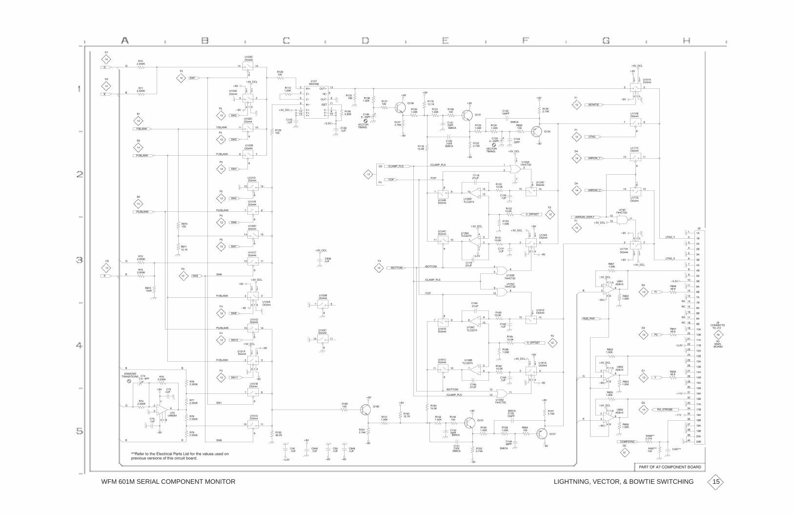
WFM 601M SERIAL COMPONENT MONITOR
��%
��%*���
!���
���
����
��
$���
��
"&�
�
! �
������
��
��
�
��
�
�
��
�
(������
�
! �
������
��
�
"&�
"&
(������
��%*���
��%*���
��%
��%
!���
�����
����
��$�
!���
���
����
�
��
�
�
$���
��
�����
�
$����
��
��
��
��
��
#�����
%��#�!
���
������
������
)���
)����
������
�$#��
�$#���
�"�#��
%����
%����
%���
%��
%���
%���
��
$��
��'�
����
��$�
!���
��� !��
����� !��
���
����%
!���
�����
���
��
��%
��%
��%
��
��
���
���
"����
!�
�� �
!��
�����
!��
�����
!��
���
!�
�����
!��
�� �
��%
!���
�����
��
������
���
�����
��%
��%
�
"����
!�
�����
!��
�� �
!���
���
��
����
��
��
��
��
���&#��
��#��
��%
����
�
��
�
�
$����
��
�� ��
�
$� �
��
�!!�&*(
�!!�&*�����
��
$� �
��
��� ��
�
$� �
��#�����
%��#�!
���
���
�
�
$����
��#�
��� �
��
$���
��
��%*���
!���
�����
����
��$�
�
�
�
��� ��
�
$���
��
�#��
��%
������*��"
"����!���
�����
����
���$�
�
��
��
$����
#����
�#��
������*��"�
�
��
"&
"&�
�7������ � ���
�
$����
��
��� �
��
$����
��
��
��
��
��
�7������
��
�
�
�
�
�
�,������
�
! �
������
!� �
���
!� �
�����
"&�
"&
�,������ �� ��
�
$����
��
����
��
$����
��
��� ��
�
$����
��
��
��
��
��
��%*���
���
��$� �
��
�����
�
$���
��
����
���$�
��%*���
����%
�
��
���
��
$����
#����
��
���
��
$����
��#�
��� �
�
��
�
�
$���
��
%*���"�#
��%
��%*���
��%
��!!�&*�"��(
!���
�����
!��
�����
!���
�����
����
��$�
�
��
��
��
�#��*(
�#��*'
��%*���
��%
��%*���
����
�
��
�
�
$� �
��
��%
���
��
��
$ �
��#��
�����
�����
����
����
����
����
���
����
�����
�����
�����
�����
���
���
�����
�����
����
�����
������
������
������
������
�����
�����
�����
�����
����
�����
������
�����
�����
�����
� ��
� ��
�����
�����
����
�����
�����
�����
��
��
������#"
#����
����%
��
��
��
��
!���
���
��
�7�
�
�
�
�
��%*���
!��*��!
��%
!���
�����
!���
�����
� �
�
���
��
�
$���
�����
���
���
��
$����
��#�
��� �
��
$����
��!��
�����
���
��$�
�� ��
�
$����
��
���##��
�#��
������*��"
���
���$�
��
��
���
$����
#����
���##��
�� ��
�
$���
��
��� �
��
$����
��
"&�
"&�
�7������
�,������
��%
��%*���
��%
����
�
��
�
�
$����
���
��
"&�!
!
������
��
��
!� �
����
!
�������
#!��"�#���"
! �
������
�
�������
� �
! �
������
"&��
"&��
�7������
��%*���
��%
��%
��� �
�
��
�
�
$����
��
�� ��
�
$����
��
�
��
�
��
��� ��
�
$���
��
�����
�
$����
��
���##��
����
���$�
��
��
��
$����
#����
��� �
�
��
�
�
$����
��
���
��
��
$����
��#�
�*���"�#
��%
��%*���
��%
!���
�����
!���
�����
!���
�����
����
��$�
�
��
(
�,
�
��
�
��%*���
��%
!��
�����
!��
�����
� �
�
���
��
�
$��
�����
����
���!�
�
����%
!���
���
!��
���
���%
���%
����"(��
��'*"#!���
!
!� ��
���
!����
�����
��
�
��
��
�� ��
��%*���
��%
!���
�����
!���
�����
� �
�
���
��
�
$���
�����
����
���
����
�����
��%
��%
��
"����
"���� !��
�� �
!���
�����
!��
���
����
��
��%
������*��"
���
����
���
"����
"����
!���
�����
!��
�� �
!���
�����
!��
���
��%
!���
�����
!��
�����
��%
��%
��%
���
!���
�����
!���
�� �
!���
���
���
��$�
���
��$�
���
��$�
��%
��%
"&�
"&�
!���
����
��� ��
�
$����
��
����%
��
��$�
��
���
� �
��
$ �
�����
!
������
! �
������
! �
������
�
! !
��%
��%
!
������
�
��$�
� �
��$�
��%
LIGHTNING, VECTOR, & BOWTIE SWITCHING
��!#����� ���������#����!�
15
��!/0/7�95�91/��3/-972-+3��+798��289�057�91/�;+3:/8�:8/.�54
67/;25:8�;/782548�50�9128�-27-:29�,5+7.�
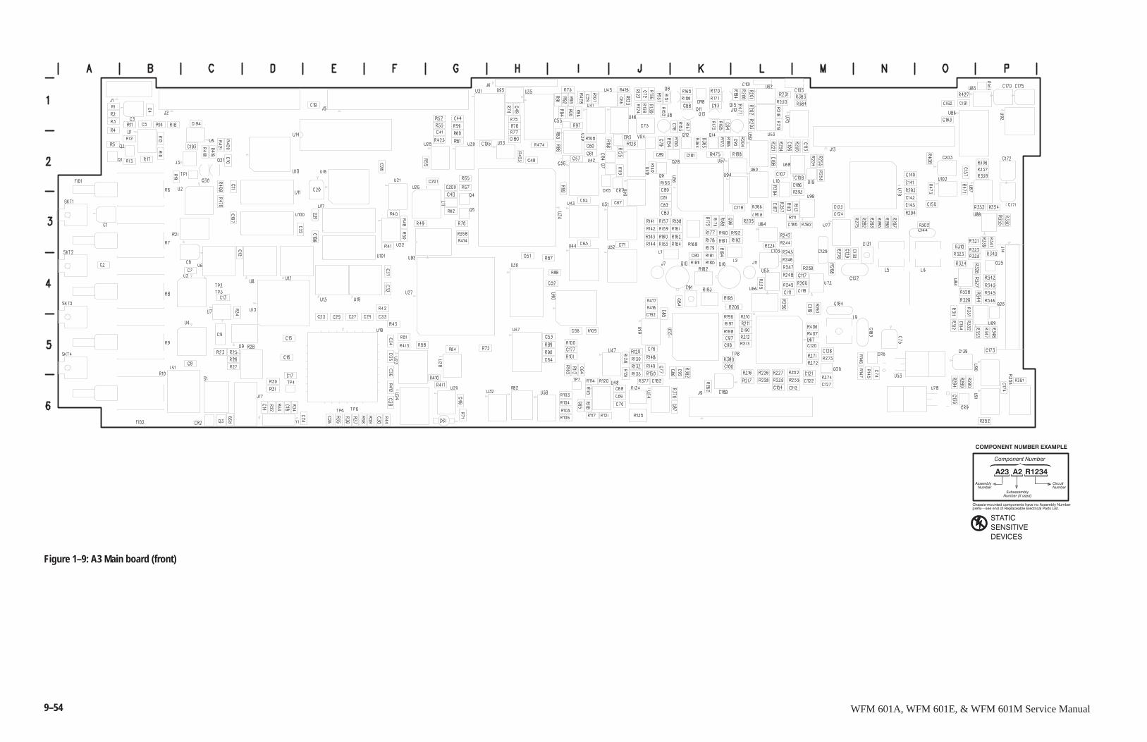
9–54 WFM 601A, WFM 601E, & WFM 601M Service Manual
����������������
��� �� �����
�������"����������������������������������!�������
����� #�������������������������������������������
�� ��������������� �
��������������
������������������� ������
������
������� �
�� ����
� �� �������
Figure 1–9: A3 Main board (front)
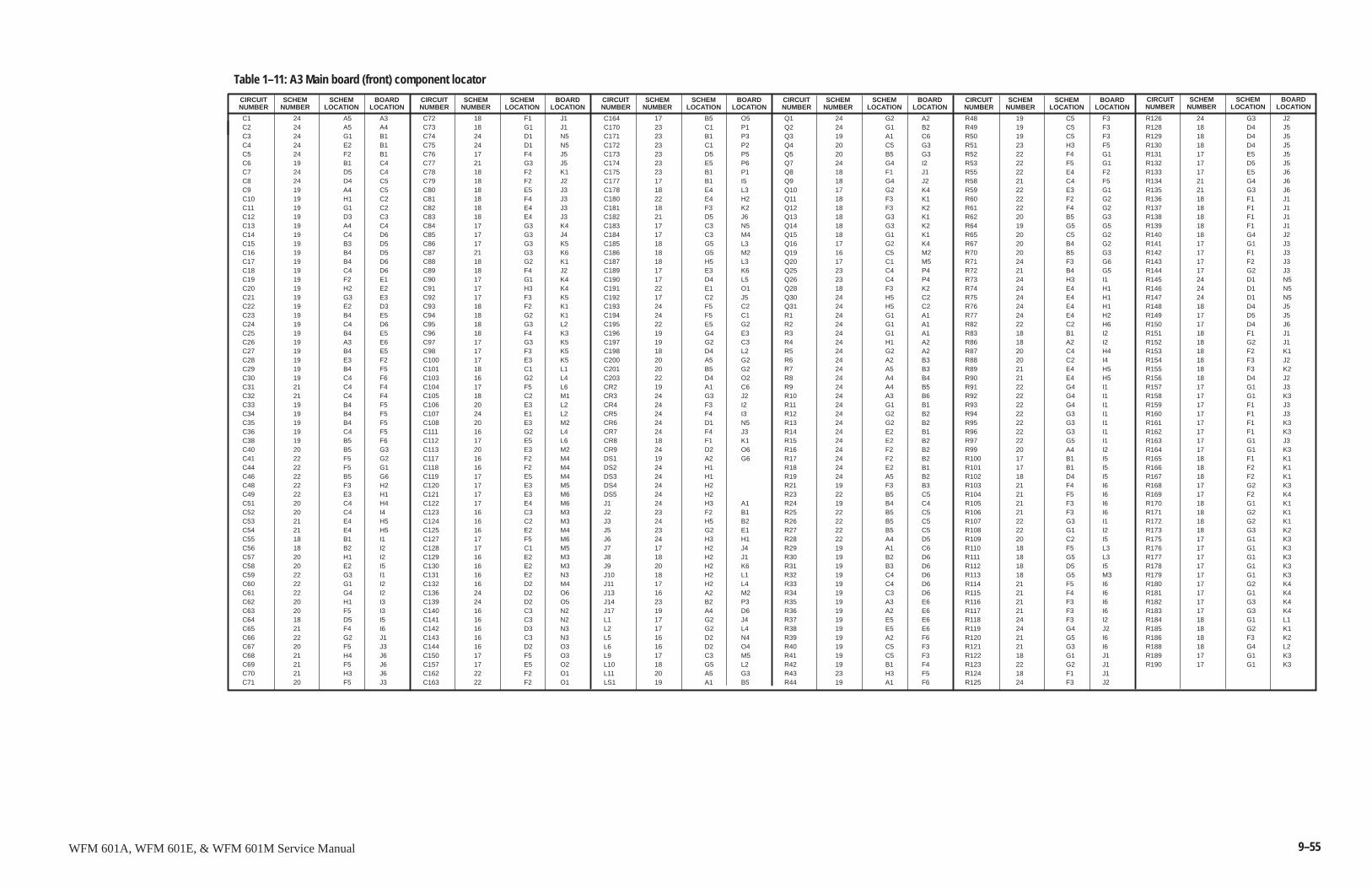
9–55WFM 601A, WFM 601E, & WFM 601M Service Manual
C1 24 A5 A3C2 24 A5 A4C3 24 G1 B1C4 24 E2 B1C5 24 F2 B1C6 19 B1 C4C7 24 D5 C4C8 24 D4 C5C9 19 A4 C5C10 19 H1 C2C11 19 G1 C2C12 19 D3 C3C13 19 A4 C4C14 19 C4 D6C15 19 B3 D5C16 19 B4 D5C17 19 B4 D6C18 19 C4 D6C19 19 F2 E1C20 19 H2 E2C21 19 G3 E3C22 19 E2 D3C23 19 B4 E5C24 19 C4 D6C25 19 B4 E5C26 19 A3 E6C27 19 B4 E5C28 19 E3 F2C29 19 B4 F5C30 19 C4 F6C31 21 C4 F4C32 21 C4 F4C33 19 B4 F5C34 19 B4 F5C35 19 B4 F5C36 19 C4 F5C38 19 B5 F6C40 20 B5 G3C41 22 F5 G2C44 22 F5 G1C46 22 B5 G6C48 22 F3 H2C49 22 E3 H1C51 20 C4 H4C52 20 C4 I4C53 21 E4 H5C54 21 E4 H5C55 18 B1 I1C56 18 B2 I2C57 20 H1 I2C58 20 E2 I5C59 22 G3 I1C60 22 G1 I2C61 22 G4 I2C62 20 H1 I3C63 20 F5 I3C64 18 D5 I5C65 21 F4 I6C66 22 G2 J1C67 20 F5 J3C68 21 H4 J6C69 21 F5 J6C70 21 H3 J6C71 20 F5 J3
C72 18 F1 J1C73 18 G1 J1C74 24 D1 N5C75 24 D1 N5C76 17 F4 J5C77 21 G3 J5C78 18 F2 K1C79 18 F2 J2C80 18 E5 J3C81 18 F4 J3C82 18 E4 J3C83 18 E4 J3C84 17 G3 K4C85 17 G3 J4C86 17 G3 K5C87 21 G3 K6C88 18 G2 K1C89 18 F4 J2C90 17 G1 K4C91 17 H3 K4C92 17 F3 K5C93 18 F2 K1C94 18 G2 K1C95 18 G3 L2C96 18 F4 K3C97 17 G3 K5C98 17 F3 K5C100 17 E3 K5C101 18 C1 L1C103 16 G2 L4C104 17 F5 L6C105 18 C2 M1C106 20 E3 L2C107 24 E1 L2C108 20 E3 M2C111 16 G2 L4C112 17 E5 L6C113 20 E3 M2C117 16 F2 M4C118 16 F2 M4C119 17 E5 M4C120 17 E3 M5C121 17 E3 M6C122 17 E4 M6C123 16 C3 M3C124 16 C2 M3C125 16 E2 M4C127 17 F5 M6C128 17 C1 M5C129 16 E2 M3C130 16 E2 M3C131 16 E2 N3C132 16 D2 M4C136 24 D2 O6C139 24 D2 O5C140 16 C3 N2C141 16 C3 N2C142 16 D3 N3C143 16 C3 N3C144 16 D2 O3C150 17 F5 O3C157 17 E5 O2C162 22 F2 O1C163 22 F2 O1
C164 17 B5 O5C170 23 C1 P1C171 23 B1 P3C172 23 C1 P2C173 23 D5 P5C174 23 E5 P6C175 23 B1 P1C177 17 B1 I5C178 18 E4 L3C180 22 E4 H2C181 18 F3 K2C182 21 D5 J6C183 17 C3 N5C184 17 C3 M4C185 18 G5 L3C186 18 G5 M2C187 18 H5 L3C189 17 E3 K6C190 17 D4 L5C191 22 E1 O1C192 17 C2 J5C193 24 F5 C2C194 24 F5 C1C195 22 E5 G2C196 19 G4 E3C197 19 G2 C3C198 18 D4 L2C200 20 A5 G2C201 20 B5 G2C203 22 D4 O2CR2 19 A1 C6CR3 24 G3 J2CR4 24 F3 I2CR5 24 F4 I3CR6 24 D1 N5CR7 24 F4 J3CR8 18 F1 K1CR9 24 D2 O6DS1 19 A2 G6DS2 24 H1DS3 24 H1DS4 24 H2DS5 24 H2J1 24 H3 A1J2 23 F2 B1J3 24 H5 B2J5 23 G2 E1J6 24 H3 H1J7 17 H2 J4J8 18 H2 J1J9 20 H2 K6J10 18 H2 L1J11 17 H2 L4J13 16 A2 M2J14 23 B2 P3J17 19 A4 D6L1 17 G2 J4L2 17 G2 L4L5 16 D2 N4L6 16 D2 O4L9 17 C3 M5L10 18 G5 L2L11 20 A5 G3LS1 19 A1 B5
Q1 24 G2 A2Q2 24 G1 B2Q3 19 A1 C6Q4 20 C5 G3Q5 20 B5 G3Q7 24 G4 I2Q8 18 F1 J1Q9 18 G4 J2Q10 17 G2 K4Q11 18 F3 K1Q12 18 F3 K2Q13 18 G3 K1Q14 18 G3 K2Q15 18 G1 K1Q16 17 G2 K4Q19 16 C5 M2Q20 17 C1 M5Q25 23 C4 P4Q26 23 C4 P4Q28 18 F3 K2Q30 24 H5 C2Q31 24 H5 C2R1 24 G1 A1R2 24 G1 A1R3 24 G1 A1R4 24 H1 A2R5 24 G2 A2R6 24 A2 B3R7 24 A5 B3R8 24 A4 B4R9 24 A4 B5R10 24 A3 B6R11 24 G1 B1R12 24 G2 B2R13 24 G2 B2R14 24 E2 B1R15 24 E2 B2R16 24 F2 B2R17 24 F2 B2R18 24 E2 B1R19 24 A5 B2R21 19 F3 B3R23 22 B5 C5R24 19 B4 C4R25 22 B5 C5R26 22 B5 C5R27 22 B5 C5R28 22 A4 D5R29 19 A1 C6R30 19 B2 D6R31 19 B3 D6R32 19 C4 D6R33 19 C4 D6R34 19 C3 D6R35 19 A3 E6R36 19 A2 E6R37 19 E5 E6R38 19 E5 E6R39 19 A2 F6R40 19 C5 F3R41 19 C5 F3R42 19 B1 F4R43 23 H3 F5R44 19 A1 F6
R48 19 C5 F3R49 19 C5 F3R50 19 C5 F3R51 23 H3 F5R52 22 F4 G1R53 22 F5 G1R55 22 E4 F2R58 21 C4 F5R59 22 E3 G1R60 22 F2 G2R61 22 F4 G2R62 20 B5 G3R64 19 G5 G5R65 20 C5 G2R67 20 B4 G2R70 20 B5 G3R71 24 F3 G6R72 21 B4 G5R73 24 H3 I1R74 24 E4 H1R75 24 E4 H1R76 24 E4 H1R77 24 E4 H2R82 22 C2 H6R83 18 B1 I2R86 18 A2 I2R87 20 C4 H4R88 20 C2 I4R89 21 E4 H5R90 21 E4 H5R91 22 G4 I1R92 22 G4 I1R93 22 G4 I1R94 22 G3 I1R95 22 G3 I1R96 22 G3 I1R97 22 G5 I1R99 20 A4 I2R100 17 B1 I5R101 17 B1 I5R102 18 D4 I5R103 21 F4 I6R104 21 F5 I6R105 21 F3 I6R106 21 F3 I6R107 22 G3 I1R108 22 G1 I2R109 20 C2 I5R110 18 F5 L3R111 18 G5 L3R112 18 D5 I5R113 18 G5 M3R114 21 F5 I6R115 21 F4 I6R116 21 F3 I6R117 21 F3 I6R118 24 F3 I2R119 24 G4 J2R120 21 G5 I6R121 21 G3 I6R122 18 G1 J1R123 22 G2 J1R124 18 F1 J1R125 24 F3 J2
R126 24 G3 J2R128 18 D4 J5R129 18 D4 J5R130 18 D4 J5R131 17 E5 J5R132 17 D5 J5R133 17 E5 J6R134 21 G4 J6R135 21 G3 J6R136 18 F1 J1R137 18 F1 J1R138 18 F1 J1R139 18 F1 J1R140 18 G4 J2R141 17 G1 J3R142 17 F1 J3R143 17 F2 J3R144 17 G2 J3R145 24 D1 N5R146 24 D1 N5R147 24 D1 N5R148 18 D4 J5R149 17 D5 J5R150 17 D4 J6R151 18 F1 J1R152 18 G2 J1R153 18 F2 K1R154 18 F3 J2R155 18 F3 K2R156 18 D4 J2R157 17 G1 J3R158 17 G1 K3R159 17 F1 J3R160 17 F1 J3R161 17 F1 K3R162 17 F1 K3R163 17 G1 J3R164 17 G1 K3R165 18 F1 K1R166 18 F2 K1R167 18 F2 K1R168 17 G2 K3R169 17 F2 K4R170 18 G1 K1R171 18 G2 K1R172 18 G2 K1R173 18 G3 K2R175 17 G1 K3R176 17 G1 K3R177 17 G1 K3R178 17 G1 K3R179 17 G1 K3R180 17 G2 K4R181 17 G1 K4R182 17 G3 K4R183 17 G3 K4R184 18 G1 L1R185 18 G2 K1R186 18 F3 K2R188 18 G4 L2R189 17 G1 K3R190 17 G1 K3
SCHEMNUMBER
Table 1–11: A3 Main board (front) component locator
CIRCUITNUMBER
SCHEMLOCATION
BOARDLOCATION
SCHEMNUMBER
CIRCUITNUMBER
SCHEMLOCATION
BOARDLOCATION
SCHEMNUMBER
CIRCUITNUMBER
SCHEMLOCATION
BOARDLOCATION
SCHEMNUMBER
CIRCUITNUMBER
SCHEMLOCATION
BOARDLOCATION
SCHEMNUMBER
CIRCUITNUMBER
SCHEMLOCATION
BOARDLOCATION
SCHEMNUMBER
CIRCUITNUMBER
SCHEMLOCATION
BOARDLOCATION
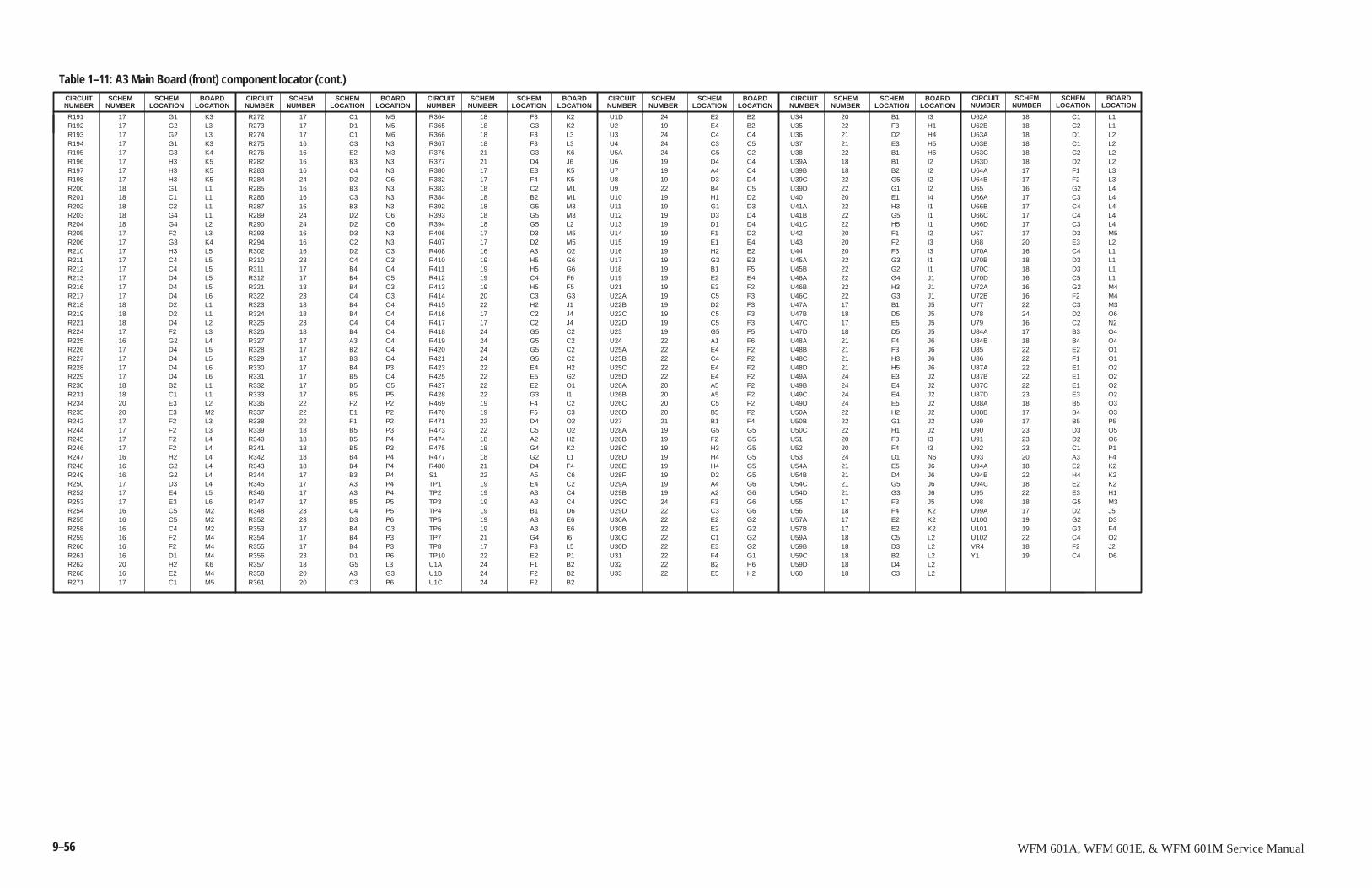
9–56 WFM 601A, WFM 601E, & WFM 601M Service Manual
R191 17 G1 K3R192 17 G2 L3R193 17 G2 L3R194 17 G1 K3R195 17 G3 K4R196 17 H3 K5R197 17 H3 K5R198 17 H3 K5R200 18 G1 L1R201 18 C1 L1R202 18 C2 L1R203 18 G4 L1R204 18 G4 L2R205 17 F2 L3R206 17 G3 K4R210 17 H3 L5R211 17 C4 L5R212 17 C4 L5R213 17 D4 L5R216 17 D4 L5R217 17 D4 L6R218 18 D2 L1R219 18 D2 L1R221 18 D4 L2R224 17 F2 L3R225 16 G2 L4R226 17 D4 L5R227 17 D4 L5R228 17 D4 L6R229 17 D4 L6R230 18 B2 L1R231 18 C1 L1R234 20 E3 L2R235 20 E3 M2R242 17 F2 L3R244 17 F2 L3R245 17 F2 L4R246 17 F2 L4R247 16 H2 L4R248 16 G2 L4R249 16 G2 L4R250 17 D3 L4R252 17 E4 L5R253 17 E3 L6R254 16 C5 M2R255 16 C5 M2R258 16 C4 M2R259 16 F2 M4R260 16 F2 M4R261 16 D1 M4R262 20 H2 K6R268 16 E2 M4R271 17 C1 M5
R272 17 C1 M5R273 17 D1 M5R274 17 C1 M6R275 16 C3 N3R276 16 E2 M3R282 16 B3 N3R283 16 C4 N3R284 24 D2 O6R285 16 B3 N3R286 16 C3 N3R287 16 B3 N3R289 24 D2 O6R290 24 D2 O6R293 16 D3 N3R294 16 C2 N3R302 16 D2 O3R310 23 C4 O3R311 17 B4 O4R312 17 B4 O5R321 18 B4 O3R322 23 C4 O3R323 18 B4 O4R324 18 B4 O4R325 23 C4 O4R326 18 B4 O4R327 17 A3 O4R328 17 B2 O4R329 17 B3 O4R330 17 B4 P3R331 17 B5 O4R332 17 B5 O5R333 17 B5 P5R336 22 F2 P2R337 22 E1 P2R338 22 F1 P2R339 18 B5 P3R340 18 B5 P4R341 18 B5 P3R342 18 B4 P4R343 18 B4 P4R344 17 B3 P4R345 17 A3 P4R346 17 A3 P4R347 17 B5 P5R348 23 C4 P5R352 23 D3 P6R353 17 B4 O3R354 17 B4 P3R355 17 B4 P3R356 23 D1 P6R357 18 G5 L3R358 20 A3 G3R361 20 C3 P6
R364 18 F3 K2R365 18 G3 K2R366 18 F3 L3R367 18 F3 L3R376 21 G3 K6R377 21 D4 J6R380 17 E3 K5R382 17 F4 K5R383 18 C2 M1R384 18 B2 M1R392 18 G5 M3R393 18 G5 M3R394 18 G5 L2R406 17 D3 M5R407 17 D2 M5R408 16 A3 O2R410 19 H5 G6R411 19 H5 G6R412 19 C4 F6R413 19 H5 F5R414 20 C3 G3R415 22 H2 J1R416 17 C2 J4R417 17 C2 J4R418 24 G5 C2R419 24 G5 C2R420 24 G5 C2R421 24 G5 C2R423 22 E4 H2R425 22 E5 G2R427 22 E2 O1R428 22 G3 I1R469 19 F4 C2R470 19 F5 C3R471 22 D4 O2R473 22 C5 O2R474 18 A2 H2R475 18 G4 K2R477 18 G2 L1R480 21 D4 F4S1 22 A5 C6TP1 19 E4 C2TP2 19 A3 C4TP3 19 A3 C4TP4 19 B1 D6TP5 19 A3 E6TP6 19 A3 E6TP7 21 G4 I6TP8 17 F3 L5TP10 22 E2 P1U1A 24 F1 B2U1B 24 F2 B2U1C 24 F2 B2
U1D 24 E2 B2U2 19 E4 B2U3 24 C4 C4U4 24 C3 C5U5A 24 G5 C2U6 19 D4 C4U7 19 A4 C4U8 19 D3 D4U9 22 B4 C5U10 19 H1 D2U11 19 G1 D3U12 19 D3 D4U13 19 D1 D4U14 19 F1 D2U15 19 E1 E4U16 19 H2 E2U17 19 G3 E3U18 19 B1 F5U19 19 E2 E4U21 19 E3 F2U22A 19 C5 F3U22B 19 D2 F3U22C 19 C5 F3U22D 19 C5 F3U23 19 G5 F5U24 22 A1 F6U25A 22 E4 F2U25B 22 C4 F2U25C 22 E4 F2U25D 22 E4 F2U26A 20 A5 F2U26B 20 A5 F2U26C 20 C5 F2U26D 20 B5 F2U27 21 B1 F4U28A 19 G5 G5U28B 19 F2 G5U28C 19 H3 G5U28D 19 H4 G5U28E 19 H4 G5U28F 19 D2 G5U29A 19 A4 G6U29B 19 A2 G6U29C 24 F3 G6U29D 22 C3 G6U30A 22 E2 G2U30B 22 E2 G2U30C 22 C1 G2U30D 22 E3 G2U31 22 F4 G1U32 22 B2 H6U33 22 E5 H2
U34 20 B1 I3U35 22 F3 H1U36 21 D2 H4U37 21 E3 H5U38 22 B1 H6U39A 18 B1 I2U39B 18 B2 I2U39C 22 G5 I2U39D 22 G1 I2U40 20 E1 I4U41A 22 H3 I1U41B 22 G5 I1U41C 22 H5 I1U42 20 F1 I2U43 20 F2 I3U44 20 F3 I3U45A 22 G3 I1U45B 22 G2 I1U46A 22 G4 J1U46B 22 H3 J1U46C 22 G3 J1U47A 17 B1 J5U47B 18 D5 J5U47C 17 E5 J5U47D 18 D5 J5U48A 21 F4 J6U48B 21 F3 J6U48C 21 H3 J6U48D 21 H5 J6U49A 24 E3 J2U49B 24 E4 J2U49C 24 E4 J2U49D 24 E5 J2U50A 22 H2 J2U50B 22 G1 J2U50C 22 H1 J2U51 20 F3 I3U52 20 F4 I3U53 24 D1 N6U54A 21 E5 J6U54B 21 D4 J6U54C 21 G5 J6U54D 21 G3 J6U55 17 F3 J5U56 18 F4 K2U57A 17 E2 K2U57B 17 E2 K2U59A 18 C5 L2U59B 18 D3 L2U59C 18 B2 L2U59D 18 D4 L2U60 18 C3 L2
U62A 18 C1 L1U62B 18 C2 L1U63A 18 D1 L2U63B 18 C1 L2U63C 18 C2 L2U63D 18 D2 L2U64A 17 F1 L3U64B 17 F2 L3U65 16 G2 L4U66A 17 C3 L4U66B 17 C4 L4U66C 17 C4 L4U66D 17 C3 L4U67 17 D3 M5U68 20 E3 L2U70A 16 C4 L1U70B 18 D3 L1U70C 18 D3 L1U70D 16 C5 L1U72A 16 G2 M4U72B 16 F2 M4U77 22 C3 M3U78 24 D2 O6U79 16 C2 N2U84A 17 B3 O4U84B 18 B4 O4U85 22 E2 O1U86 22 F1 O1U87A 22 E1 O2U87B 22 E1 O2U87C 22 E1 O2U87D 23 E3 O2U88A 18 B5 O3U88B 17 B4 O3U89 17 B5 P5U90 23 D3 O5U91 23 D2 O6U92 23 C1 P1U93 20 A3 F4U94A 18 E2 K2U94B 22 H4 K2U94C 18 E2 K2U95 22 E3 H1U98 18 G5 M3U99A 17 D2 J5U100 19 G2 D3U101 19 G3 F4U102 22 C4 O2VR4 18 F2 J2Y1 19 C4 D6
SCHEMNUMBER
Table 1–11: A3 Main Board (front) component locator (cont.)CIRCUITNUMBER
SCHEMLOCATION
BOARDLOCATION
SCHEMNUMBER
CIRCUITNUMBER
SCHEMLOCATION
BOARDLOCATION
SCHEMNUMBER
CIRCUITNUMBER
SCHEMLOCATION
BOARDLOCATION
SCHEMNUMBER
CIRCUITNUMBER
SCHEMLOCATION
BOARDLOCATION
SCHEMNUMBER
CIRCUITNUMBER
SCHEMLOCATION
BOARDLOCATION
SCHEMNUMBER
CIRCUITNUMBER
SCHEMLOCATION
BOARDLOCATION
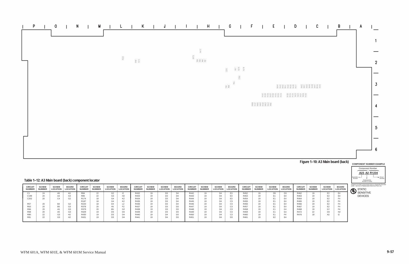
9–57WFM 601A, WFM 601E, & WFM 601M Service Manual
����������������
��� �� �����
�������"����������������������������������!�������
����� #�������������������������������������������
�� ��������������� �
��������������
������������������� ������
������
������� �
�� ����
� �� �������
C1 24 A5 A3C199 20 A4 G3C202 20 C4 G2
R57 20 B4 G2R63 20 B5 G3R66 20 A5 G3R68 20 A5 G3R80 22 G3 H2R81 22 G3 H2
R84 22 G2 I2R85 22 G3 H2R174 18 G4 K2R187 18 G4 K2R220 18 D4 L2R378 20 A5 F2R379 20 B5 G2R429 19 D3 D4R430 19 D3 D4R431 19 D3 D4
R432 19 D3 D4R433 19 D3 D4R434 19 D3 D4R435 19 D3 D4R436 19 D3 D4R437 19 D3 D3R438 19 D3 D3R439 19 D3 D3R440 19 D4 D3R441 19 D4 D3
R442 19 D4 E3R443 19 D4 E3R444 19 D4 E3R445 19 D4 C3R446 19 D4 C3R447 19 D4 C3R448 19 D4 C3R449 19 D4 C3R450 19 D4 C3R451 19 D4 D3
R452 19 D5 D3R453 19 E1 E4R454 19 E1 E4R455 19 E1 E4R456 19 E1 E4R457 19 E1 E4R458 19 E1 E4R459 19 E1 E4R460 19 E1 F4R461 19 E2 E4
R462 19 E2 E4R463 19 E2 E4R464 19 E2 F4R465 19 E2 F4R466 19 E2 F4R467 19 E2 F4R468 19 E2 F4R472 22 D4 H2R476 18 A2 I2
SCHEMNUMBER
Table 1–12: A3 Main board (back) component locator
CIRCUITNUMBER
SCHEMLOCATION
BOARDLOCATION
SCHEMNUMBER
CIRCUITNUMBER
SCHEMLOCATION
BOARDLOCATION
SCHEMNUMBER
CIRCUITNUMBER
SCHEMLOCATION
BOARDLOCATION
SCHEMNUMBER
CIRCUITNUMBER
SCHEMLOCATION
BOARDLOCATION
SCHEMNUMBER
CIRCUITNUMBER
SCHEMLOCATION
BOARDLOCATION
SCHEMNUMBER
CIRCUITNUMBER
SCHEMLOCATION
BOARDLOCATION
Figure 1–10: A3 Main board (back)

9–58 WFM 601A, WFM 601E, & WFM 601M Service Manual
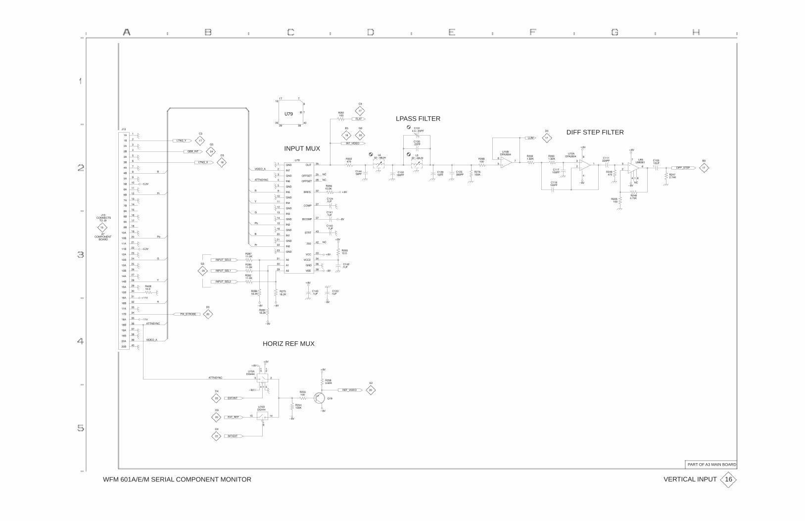
WFM 601A/E/M SERIAL COMPONENT MONITOR
����
����
����
���
���
����
���
��
���
���
����
����
����
���
��
���
����
���
�����
�����
�����
�����
�����
����
����
�����
����
���
����
����
�����
�����
�����
����
� ��
� ���
�����
����
�����
����
���
�
�
��
�
�
�� ��
�
�
�#��
LPASS FILTER���"
��
��
�
�
��
��
���
���
����
������ ��
��
��
��
��
�
���
����'!"��
� $
� $
��
�
����
�����
���
���
�
��
�
#�
����������
��#�
��
����
��
���
DIFF STEP FILTER�#�
� $
� $
���
�� ��
��
�� �����
��
��
#���
������
���
���
��
#���
������
����
�����
���
�����
����
����
���
����
���
�����
����
����
��
���
�
��� #�
��
��
����
�����
��"'$����
� $
��
����
���
�
��
���
��
��� #�
INPUT MUX
$����'�
�""�!&��
������
������
������
�����
�����
�����
������
�����
������
������
�����
�����
������
������
������
������
������
�����
�����
�����
�#"�
$���
�����
$����
$����
!" "�
���
�������
������
� �!��
���!�"��
���!�"�
#��
��
�
�"��'&
�"��'%
�� '��"
���$
�
�)
��
��
��
�
���
������"!
"����
��
��������"
��� �
�
���#"'!���
�(
�
���$
&
�
�(
�
�)
� �
�����
��
���
��#�
���
����
���
��#�
���
�#�
� $
� $
� $
���
��#�
����
��#�
� $
� $
� $
��
� ���
� �
� ���
� �
� ���
���
��#�
� $
� $
� $
� �
�����
�
�����
���#"'!���
���#"'!���
��%'!" ���
���$
���$
�
����
&
�""�!&��
��
��
��
��
$����'�
�""�!&��
HORIZ REF MUX
�����
�
��
��
#���
��
�$
� $
� $
�
����� ��
�� ��'$����
� $
���
�� �
��
#���
��
�
����
��"��%"
�%"' ��
�%"���"
� $
� $ �
���
�
��
��
��
�
��
VERTICAL INPUT
PART OF A3 MAIN BOARD
16

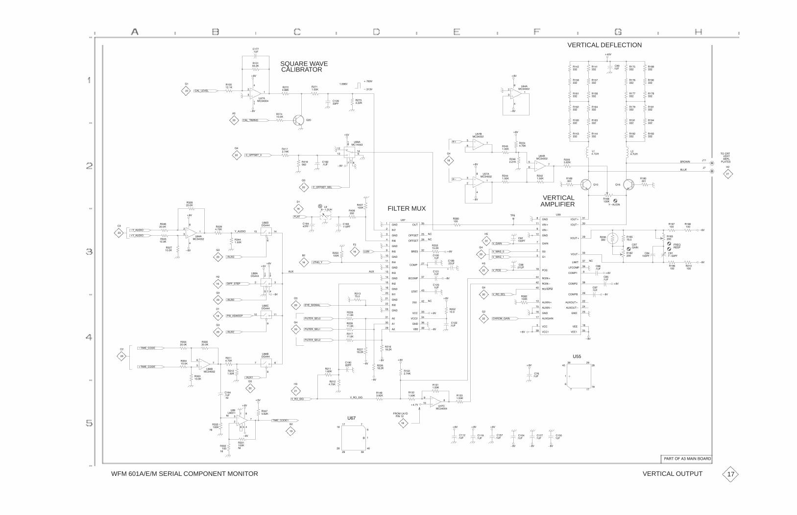
WFM 601A/E/M SERIAL COMPONENT MONITOR
�����
� $
� �
���
��
���
���
��#�
��$
VERTICAL DEFLECTION
��
���
��
���
SQUARE WAVE ���
�����
����
��#�
���(��$��
��
��
CALIBRATOR
���
�����
��
�����
���
����
���
��������
���
��
��
#��
�����
���("�����
� $
� $
���
��
��
�����$
��� �$
�����$
���
����
���
�����
��
���
�
���
��
���
���
���
��
���
���
���
�
���
��
���
���
���
���
���
� $
� $
���
���
��
#��
������
���
���
��
���
���
���
���
���
���
���
���
���
���
���
� �
���
��
���
���
���
"��� "
$� "
����
���"�!
��#�
� �%�
��
���
��
��
��
��#�
��
����
���
� �
���
��
����
�
�����
�
�����
��
���
��
����� ��
���
��
#��
������
� $
��
��#�
��
����
���
���
���
���
���
��
#��
������
��
���
��
#��
������
��
��
� $
� $
�
� ����
��#�
�$
���
���
�
��
��
��
�
#���
�����
� $
�(���!�"($
�(���!�"(!��
��
����
��
��
�
��
��
��
�'(�#���
�'(�#���
��
��
��
�����
���
�����
���
���
��
# �
������
���
���
� $
� $ ��
��
��
�����
�
�����
�� �
��
#���
��
���"
��#&�
'(�#���
��
��
��
��
�
����
��
���
FILTER MUX
�� �
�����
�#�
��
���
��
����
������
������
������
�����
�����
�����
������
�����
������
������
�����
�����
������
������
������
������
������
�����
�����
�����
�#"�
$���
�����
$����
$����
!" "�
���
�������
������
� �!��
���!�"��
���!�"�
#��
��
� ����#�
��
��
��
����
��
��
��
����
$(����
$(���(�
$(���(�
� $
� �
���
�
��
�
��
VERTICALAMPLIFIER
�����
$������
$������
������
�������
�����
�����
��!���
�����
������
��%����
��#"���
��#"���
$�#"���
$�#"���
����"��
����
�#&�#"��
�#&�#"���
�������
������
�������
�#&�������
������
�#&�����
�#&������
$����
$������
$����
$���
��������
#"�
���
�����
� "
����
� ��
�!�
�'������
���
�����
� �
���
� �
���
��
���
���
���
���
���
�
�����
� $
��
���
� $
���
���
��
���
��#�
�
��#�
� �
��#�
� $
� $
� $
���
���
� �
����
��
���#�
��
��
����
����
��#�
����
��#�
����
�#�
����
��#�
$(��!
$( �(!��
�� ��(����
� $
� $
� $
�
��
��
�
��
��
��
�� �
��#�
���
�����
�#&
���
���
��� ��
�
��
��
#���
��
��� ��
�
#���
��
���"� (!���
�"��('
��&($!%���
��#&�
����(!"��
�'�(!�����
�#&
� $
�$
� $
��
��
��
�
��
��
��
��
��
��
�
�����
���
�����
�"���(����
�"���(����
��
�����
���
��
��
# �
������
�
�����
��
��
���
������ ��
#���
��
���
����
���"� (!���
���"� (!���
��#&�
��#&�
��
��
�
��
��
����
��
�����
���
�����
���
� ���
���
� ���
���
� ���
���
�� ��
���
���
� $� $
� $
� $����
���
� $
#
�
����
�
���
��#�
� $ �
� $
�
�
� ��
����
��#�
���
��#�
���
��#�
� $ � $� $
���
���
�
#��
�����
����
��#�
����
��#�
���
��#�
���
����
���
����
���
����
� $ � $� $
���$
#��
�
�
��
�
�
�
��
�����$( �(!��
� ���#��
������
�
��
����
$( �(!��
"���(�����
�$
� $
� $
��
��
��
��
���
���
��
�
�
# �
��
���
����
�� ���
���
��
���
����
��
���
��#�
��
�
�� ��
�
�� "��������������� �
VERTICAL OUTPUT 17

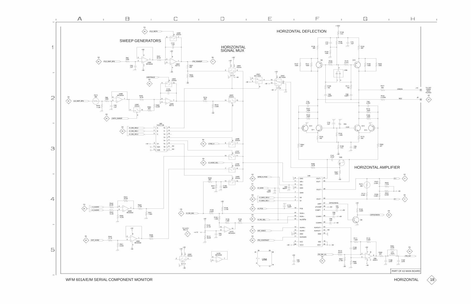
WFM 601A/E/M SERIAL COMPONENT MONITOR
��
����
���
�������
��#�
����$
���
��#�
HORIZONTAL DEFLECTION�����
#���
��
���) �"
�
��
SWEEP GENERATORS
���)!%�)!��
�
����
��
��
����
��#�
���
������
���
��
��
#���
�����
� �" ���
� $
� $
� $
� $
���
���
��
#���
������
��#�
HORIZONTALSIGNAL MUX
��� ��
�
��
��
#���
��
���
�����
���
���
��&)$!%����$
� $
� $
�
��
�$
��
���
�
�
#��
�����
��
�����
���
�����
�
��
����
��
����
���
����
���
���
�
��
�
���
���
�
����
���
����
��
"��� "
����
���"�!
�� �(
���
�
��
��
��
�����
�
�� ��
� ���
��
���
� �
���
����
��
�����
��
��
��
�����
���
� �
���
�� ��
���
����
� $
� $
� $
���
���
�
��
��
��
�
#��
�����
��
������
��
#���
��
� $
� $
���
�����
���
� ���
�����
�
#���
��
�����
�
#��
�� � �
��� �
�
���
��
��
#���
�����
���
������
��
��
���
��
��
#���
�����
�
����
��
��
��
��#� ��
�����
�
���
��)!%�)!��
��
��
�)!��)!���
�)!��)!���
�)!��)!���
��&��)!%���
��
��
��
��
����
����
����
�����
�����
�����
'��
'��
'���
'���
'��
'��
'���
'���
#��
���"��
�$�����
#��
��
�"��)&
��
��
����$
���
��#�
�
����
�
���
� �
����
��
���
� $
��
����
���
���
$
��
��#�
���
���
��
���
�
����
��
���
��
��
HORIZONTAL AMPLIFIER
��
� �
����� ���
�����
��
���
�
���
���
� ���
� $
��
���
����
�� �
���#�
�����
$������
$������
������
�������
�����
�����
��!���
�����
������
��%����
��#"���
��#"���
$�#"���
$�#"���
����"��
����
�#&�#"��
�#&�#"���
�������
������
�������
�#&�������
������
�#&�����
�#&������
$����
$������
$����
$���
��������
#�
�)����
%��)�)��!
� �
�����
��
��
��
��� �
� ���
���
��
#��
��
��� ��
#���
��
��� ��
�
#���
��
&)�� ()!��
���
��
���
� ��� ���
��
�
��
���
��
��
# �
������
��
�����
���
�����
��
�����
��
�����
�&)�#���
�&)�#���
��
��
���
����
���
���
�
��
���
���
�
#��
�����
��
����
���
����
�
���� ���
�����
�) �)!��
� $
� $
��
��
���
����
�) �)!��
�)���)!���
�)���)!���
�)��!
���
�����
��
��
�
��
�
��
� �
��#�
� �
��#�
���
��#�
���!� ���
� $
� $
� $
� $ ��
����
���!� ���
��
�$
� $
��
��
��
��
����� �
�������
��
��&)��"
��
�
���
�� ��
��
����
���
�� ��
�� �
���
���
�#�
� $
� $
�� �
���
���
�����
��
�����
���
���
��
�
�
#�
�� ��
���
���
��
��
����
���
�� ��
��&)��)�$�� $
� $
� $
�
��#�
�
�
�
����
�
� �
��#�
��&)���" �!"
��")$����
� $
��
��
�
��
��
��#�
���
��
��
#��
�����
���$
���
�����
"��#��
������
��� ��
�
��
��
#��
��
���
�����
� $
� $
� $ �$
��
���
���
��
# �
������
��
�����
��
���
�&")�� (
�
��
� $
� ��
�
PART OF A3 MAIN BOARD
HORIZONTAL 18

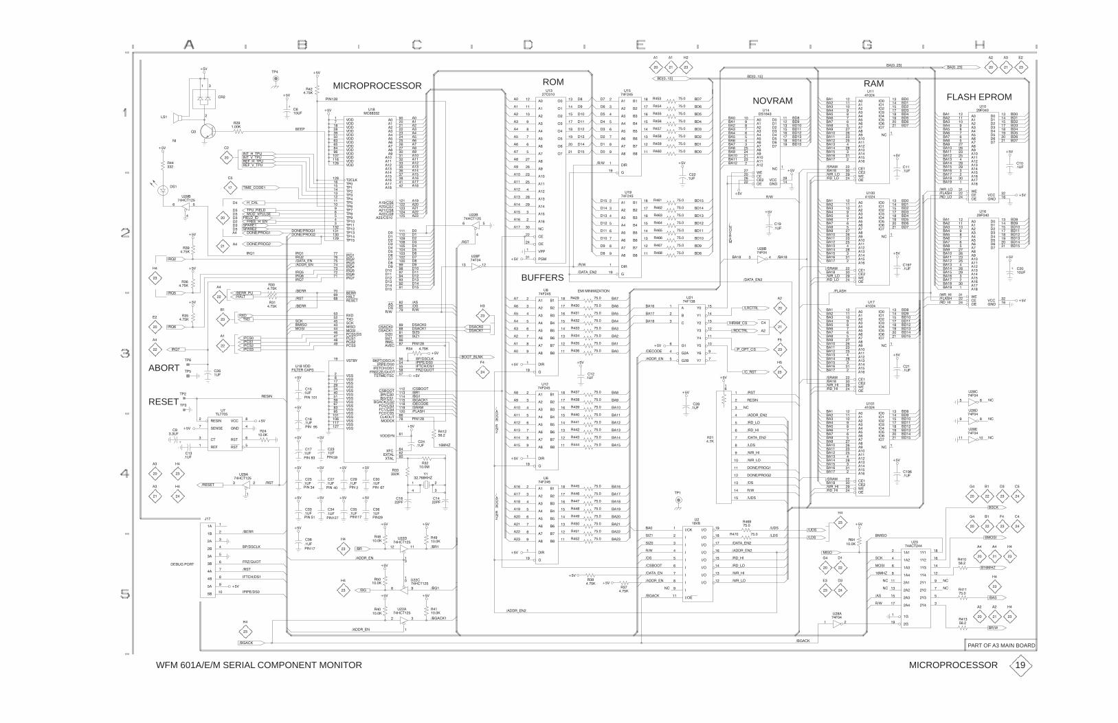
WFM 601A/E/M SERIAL COMPONENT MONITOR
� ���!
���� �
���� �
����'���"�!
! !���! �
��
��
��
��
��
��
RAM
��(�����)��(�����)
�����
�����
�����
����
�����
����
���
����
�����
� ��
������
�����
������
������
������
�����
�����
�����
�����
����
�����
�����
���
����
�����
������
������
$���
�����
���
"��
�����
��(����)
�����
����
�����
����
�����
���
����
���
���
���
����
���
�����
����
����
����
������
���
"�
�����
��(����)
��� ���
��
��
��
��
��
��
ROM
�����
�����
�����
����
�����
����
���
����
�����
� ��
������
�����
������
������
�����
�����
�����
�����
�����
#�����
������
����
����
���
����
����
��
���
����
�����
"��
������
MICROPROCESSOR���
����
�#
�#
�
��
���
!��
���
���
�#
� �
� �
��
�
��"�
��!*�*!�"
��!*#*!�"
���*�*!�"
���*#*!�"
����
�#
��
�����
��
��
��
�
��
#�����
#�����
#�����
#�����
#����
#����
#����
#���
#�����
#���
#�����
#����
#����
!�������
!����
!����
!�����
!�����
!�����
!����
!����
!����
!����
!� ��
!������
!������
!������
!������
!������
!����
�������
������
������
�������
������
������
�������
�������
���!�
�� �!��
�%���
!%���
����
�� ����
�� ����
�� �� ��
�� ����
�� ����
�� ���
# !�&��
# ���
# ���
# ���
# ��
# ���
# ���
# ��
# �
# ��
# ���
# �
# ���
# ��
# ���
# ���
�� �
����
����
����
����
���
��
���
����
� ��
�����
�����
�����
����
����
����
����
�����
�����
�� �� ���
����� ����
����� ����
����� ���
����� ����
�����
�����
����
�����
����
����
����
�����
�����
�
��� �
��� �
��� �
��� �
��� �
�� �
� ��
� �
��$�
� �����
� ������
�'���
�'���
����
�#����
���!�� ���
������� ��
���!���� �
�
�
���
���
���
������� ���
����� ����
����� ���
����� ���
����"!
�������
#�� &��
%���
�%!���
%!���
"��
������
��
��
��
��
��
�
�
��
��
�
���
���
���
���
���
��
��
���
������
�#
��
��
��
��
�
�
��
��
�
���
���
��
���
��"�
��
��
��
��
��
�
�
����
�
���
���
���
���
���
��
���$ �#
��� ���
�� ���
�� ���
��� ���
��� ���
�� ���
��� ���
NOVRAM
���
���
���
���
���
��
��
���
���
���
���
���
���
��
��
���
���
��
����
����
����
���
��
����
����
����
����
����
���
�#��
�
�����
����
�����
�����
����
���
����
�����
����
� ���
������
������
������
�����
�����
$����
����
����
����
���
���
���
���
���
#����
�����
�����
"��
� ���
FLASH EPROM
���
��"�
���
���
���
���
��
��
���
���
��
����
����
����
����
����
���
���
����
���
���
���
���
���
��
��
���
���
���
���
���
��
��
���
���
��
����
����
����
����
����
���
���
����
����
� ���
�$�*��
���*��
�#
���
�����
���
��"�
���
���
���
���
���
��
��
���
�#
�����
�����
�����
����
�����
����
���
����
�����
� ��
������
�����
������
������
�����
�����
�����
����
����
���
����
����
��
���
����
�����
�����
$����
������
������
#����
����
"��
� ����
���
��"�
���
��
����
����
����
����
����
���
�#
�#
�����
�����
�����
����
�����
����
���
����
�����
� ��
������
�����
������
������
�����
�����
�����
����
����
���
����
����
��
���
����
�����
�����
$����
������
������
#����
����
"�
� ����
���
���
���
���
��
��
���
���
��
����
����
����
����
����
���
���� �
���*��
�$�*��
���
���
���
���
��
��
���
���
��
����
����
����
����
����
���
���
����
� ���
���
���
���
���
���
��
��
���
����
�#
�� �
��"�
�����
�����
�����
����
�����
����
���
����
�����
� ��
������
�����
������
������
������
�����
�����
�����
�����
����
�����
�����
���
����
�����
������
������
$���
�����
���
"���
�����
��� ��
"���
�����
��
��"�
���
��
����
����
����
����
����
���
��$
�#
�#
���#���
���� �����
�����
����
�����
����
�����
���
����
���
���
���
����
���
�����
����
����
����
������
���
"�
�����
��
�
���
���
���
���
���
��
���!�*���
���$
��� ���
��� ���
�� ���
�� ���
��� ���
��� ���
��� ���
��� ���
��� ��
"���
�����
���
�
"���
����!��
���
���
���
��
��
���
�� !
�#
��
��
��
��
��
�
�
��
��
�
���
���
���
��
���
���
���
���
��
����
���
�
"� �
����!��
����������
����������
!���*�����
�*���
!�"*�����
���*#�"� �
�����*��
����*�*��
�����
�����
��������
����
���
�����*��
���!�*��
����������
����������
�#
�#��
��
��
��
��
��
��
��
��
����
����
��
��
���
���
����
��
��
��
��
���
����
���
����
��
����
��
����
�%�
!%�
��� �
��� �
��� �
��� �
����!
����
��
�� �
��� �
���
�� !
�#
!�
����������*�"
�����
��
��
��
��
��
��
���
���
���
��
��
�'�
�'�
��
������
��$
�#
���� ���
��� ����
� ����
� ����
BUFFERS
� ����
� ����
��
��
��
��
��
�
�
��
���!*����
�����
����
�����
����
�����
���
����
���
���
���
����
���
�����
����
����
����
������
���
"�
�����
��
��
����
����
����
����
������
�����
&��
&���
&���
&���
&���
&��
&�
&���
"��
������
���
���
���
���
���
��
��
���
���
����
����
�������
�����*��
�#
����������'�!���
��� ���
��� ���
���� ���
���� ���
���� ���
���� ���
���� ���
��� ���
�����*�
����!��
����!��
��*��!*�
���!�*���
��
��
��
��
��
�
��
���
���
���
���
��
��
���
���
��
����
����
����
����
����
���
��
����
����
����
����
����
���
���
����
����
���� �
�$�*��
���*��
�#
���� �
���
�$�*��
���*��
�����
�����
�����
����
�����
����
���
����
�����
� ��
������
�����
������
������
������
�����
�����
�����
�����
����
�����
�����
���
����
�����
������
������
$���
�����
���
"��
�����
�#
��
��
��
�� �
"���
�����
�� ��
"���
�����
��� ��
"���
�����
���
��"�
���
���
����
� ���
�$�*��
���*��
���
���
���
���
��
��
���
���
��
����
����
���
��
����
����
����
����
����
���
�����
�����
�����
�����
����
�����
����
���
����
�����
� ��
������
�����
������
������
������
�����
�����
�����
�����
����
�����
�����
���
����
�����
������
������
$���
�����
���
"���
�������
�
��
��
��
��
�
�
��
��
�
��
��
��
��
��
�
���
����
�� ��
�� !
���
���!�*���
���*��
���*��
�����*���
�#
��*� !
�
��
���
��"�
���
��"�
���
��
����
����
����
����
����
���
�#
�#
���� ���
���� ���
���� ���
���� ���
���� ���
��� ���
���� ���
���� �����
�����
��
�����
����
�����
���
����
���
���
���
����
���
�����
����
����
����
������
���
"��
�����
��
�
���
���
���
���
���
�����'
�#
�����*���
��
��
���
��"�
���
��"�
�� ���!
������
� ���
���� �
����
����
�������
�������
�#
�#
�#
������� �
��!���� �
��'��"�!
����
��
���
�����
���
��"�
�� �����
�� ����
�����
#����
� !�
� !�
������
�!���
"�
!����
��
�"�
���
��"�
��
��"�
��
��"�
�� ��
�#
�#
�#
�#
�#
!��
!��
!�
������
���
���!������
"���#��
RESET
ABORT
�
���"�
��
��
��
��
��
��
��
��
���
��"�
��
��"�
���
��"�
�����
�
"� �
����!��
��� �!�� !
�#
�#
�#
�����
����
����
����
����
���
���
����
����
��
���
���
��
��
�
���
���
���
���
�����
��� �
����
&�
�������'
���
����
��
�����
���
��"�
��
��"�
���
��"�
��
��"�
���
��"�
�#�#
�#
�# �#�#
�#�#
��
�"�
���
����
���
�����
�� � �
������ ������ �
���
��� ��� ���
���
�����
����
�����
����
�����
���
����
���
���
���
����
���
�����
����
����
����
������
���
"
�����
���
����
��
���
���
��
���
���
���
�#
�����*���
�������
����
����
����
���
���
����
����
���
����
�����
�����
����
����
�����
�����
�����
�������
"�
�#�
���
����
����
���
����
����
���
�'�
����
!��
��� ���
��� ���
��� ���
��� ���
���� ���
���� ���
��� ���
��� ���
���
�"�
���
��$
�$�*��
�$�*��
��
�"�
����������
����������
�"�
��
���
���� ���
��
�����
��� �
�#
����
����
����
���
���
����
� ���
�$�*��
���*��
����
�#
��
��"�
��
��
� ��
��� �
��
��
��
��
��
��
��
��
��
��
��
��
��
��
�
��
���
���$
����'
����
��
����
���
����
��
��
��
��
��
��
��
��
��
��
��
��
��
��
��
��
����
��
��� ��
"���
�����
�� �
��
�� �
��
���'
��$
������
�&���
������
�&��
�����
�&���
������
�&���
������
�&��
������
�&���
�����
�&��
������
�&���
�����
����
"��
����!���
��
��
��
��
���!�*���
�����*���
���*��
���*��
�$�*��
�$�*��
��
��
��
����
���
����
���
����
�'�
����
��$
��
�� ���!
���!�*��
�����*��
������
�#
�#
���
�#
�����*���
��� ��
��
"���
����!��
� ���
�� "���
����!��
��� ��
�
"���
����!��
��
�����
���
�����
���
�����
���
�������
����
�������
�����*��
�#
�#
�#
��
��
��
��
�#
���� ���
��'��"�!
�� !
��!���� �
������� �
�����
��
��
���"�����!
������
�����*��
������
MICROPROCESSOR
PART OF A3 MAIN BOARD
19

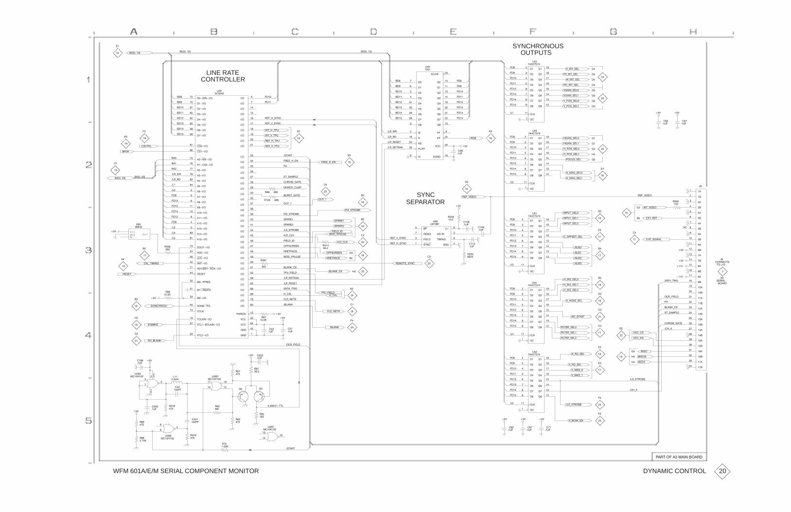
WFM 601A/E/M SERIAL COMPONENT MONITOR
��������
OUTPUTSSYNCHRONOUS
�����
����
�����
���
����
����
���
���
����
��
�����
���
����
����
� ���
� ��
������
�����
#�
���"�
$+��"+!����
��)����*��)����*��)����*
��
��
LINE RATECONTROLLER
�������������
���������
���������
��������
��������
��������
�������
��������
�!��������
�!��������
���%!������
����!��������
���������
��������
������ �
������
���������
��������
� �������
���������
����������
���������
���������
����������
������� �
������� �
��#"�������
���������
����������
���"������
�'��!'� ���������
�!�"�
��� " �����
��� ��"����
���������
��������
������
"������������
&"���������������
&"��������
�����
�����
����
����
�����
�����
����
�����
�����
�����
�����
����
����
�����
�����
����
�����
�����
����
�����
����
�����
����
����
���
���
����
����
���
����
����
����
����
����
�����
����
�����
�����
��� �
�% ����
$����
$���
����
�����
#�
&����
��
���
����
����
����
����
�����"+�+"�#
����
����
��+$+!'��
��+�+!'��
��
���
����
����
����
����
���
���
����
����
����
���
���
���
����
����
� �
&������
� ���
����
�����
����
����
����
����
�����
�����
%���
��
!��
��� "���
&���
����
���
������
$����
#�
����
��
���
����
����
����
����
���
���
�+��"+!��
�&+��"+!��
%+��"+!��
$+��!+!���
$+��!+!���
$����+!���
$����+!���
���
����
����
����
����
���
���
���
���
��#�
�$
�
�
��
��
��
�
��
�
�
�
��
��#�
�$
�����
�����
�����
����
����
�����
����
���
����
����
�����
�����
�����
����
���
����
�����
����
������
������
������
������
������
�����
�����
������
�����
����
�����
�����
������
������
������
�����
��
��
��
�
�
��
��
�
�
�����
����
�����
���
����
����
���
���
����
��
�����
���
����
����
� ���
� ��
������
�����
#�
���"�
�+���+!���
�+���+!���
�+��!+!���
�+��!+!���
�����+!���
�����+!���
���#!+!��
��
���
����
����
����
����
���
���
���
�
��#�
� ��
�$
��
��
�
��
� ��+�+��
�� + �
�� + �!�"
�� + �" ��
�� +%
��
��
�
��
��"+$+"�#
��+�+"�#
��+$+"�#
�!"� "
�� ��+��"�
� ��+�+��
��
��� ��
��
�����+����
!"+!�����
��
��
�� �" �
���
��)�����*
���
���
���
���
�� + �
�� +%
���
��
��
��)�����*
� �%
�
��
��
��
�$
���
��
���
����
��
����
���
���
��
�
��
#��
���(
��
��
��!+!" ���
�#"+�
!�� ��
!�� ��
��&+!" ���
���+���
�����+��
���!� ���
� �" ���
�# !"+��"�
���!� ���
���+���
���+$�#�!�
�����+��
!�� ��
!�� ��
��+�+!'��
��+$+!'��
��&+!" ���
�#"+�
�
���
�
��
��
��
�
��
�
�
�
SYNCSEPARATOR
���
��#�
�$
$��
$�������
"�������
����
����
����&���
��������
!'�����
#�
��� �
��
� ��
��
����
��+$����
����
��#�
����
��#�
�����
����
�����
���
����
����
���
���
����
��
�����
���
����
����
� ���
� ��
������
�����
#�
���"�
���#"+!���
���#"+!���
���#"+!���
��#&�
��#&�
��
���
����
����
����
����
���
�+���!�"+!��
��"+$����
�&"+ ��
�'�+!�����
��+$����
��
��
��
�
��
�
��
�
��
��
��
�$
���
���
��
��
������"!
�
��� �
���$
���$
�$
�
"�����
!� ����&��+" ��
���+�����
�����+��
��
!"+!�����
��
�
��
�
��
��
�����
����
�����
���
����
����
���
���
����
��
�����
���
����
����
� ���
� ��
������
�����
#
���"�
&+�� (+!��
�+!��+!���
�+!��+!���
�+!��+!���
��#&�
��#&�
�+!"� "
���
��
���
����
����
����
����
���
��
��
� �" ���
"�#+�����
�+���
���+ �"
�����+��
���"�+!'��
� ��
��
��
��
�
�
�����
�� + �!�"
�� + �" ��
�&��+" ��
�����+��
�$
���+$�#�!�
"�#+�����
���+ �"
�+���
������
���
���
��
�����
������ ���
���+"�����
�$��
��
�
��
� �!�"
�
��
�����(
�+�����
��
��
�$
��
���
��
��
#���
��������
����
��#�
���
���#���
���
��
���
��
#���
��
�#���
��#�
���+�����
�$
�$
��
���� �
�
����
��#�
������
�
�
�����
����
�����
���
����
����
���
���
����
��
�����
���
����
����
� ���
� ��
������
�����
#�
���"� �+ �+!��
$+ �+!��
$+���+�
$+���+�
���"� +!���
���"� +!���
���"� +!���
���
���
��
���
����
����
����
��
�$��+��
�$��+�!
��!�
�!��
���!�
��!+!" ���
�� ��+��"�
���+�
�
��
�
�
��
��
�
�
�
��
��
��
���+�
��
�
��
�
���
��#�
���
��#�
���
��#�
&+����+��
��!+!" ���
����
���
���
��
�$ �$�$
���(�""�
���
��
�
#���
��������
�
� �
��
�
��
�$
���
�
��
� �
��
����
����
�����
��
�����
��#�
��
�
�
����
��
���
�
#���
��������
�!"� "
��
�����
�� "��������������� �
DYNAMIC CONTROL 20

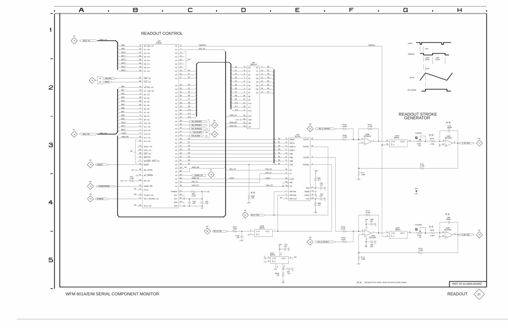
WFM 601A/E/M SERIAL COMPONENT MONITOR
�--�7*8:9�319:�.68�-*831-8�<*3;-9�*5,�9-81*3�5;4+-8�8*5/-9�
��
�� ��'����(��'����(
��
���
����
����
����
����
READOUT CONTROL
��
�������������
���������
���������
��������
��������
��������
�������
��������
����������
����������
���#�������
�������������
���������
��������
������ �
������
���������
��������
� �������
���������
����������
���������
���������
����������
������� �
������� �
��! �������
���������
����������
��� ������
��%���%�����������
���� �
���� ������
������ ����
���������
��������
������
������������
$ ���������������
$ ��������
�����
�����
����
����
�����
�����
����
�����
�����
�����
�����
����
����
�����
�����
����
�����
�����
����
�����
����
�����
����
����
���
���
����
����
���
����
����
����
����
����
�����
����
�����
�����
��� �
�#�����
"����
"���
����
�����
!��
$�����
�������
���)��
�������
9473 063,
�����
�� !� ���!�
�!�
�������
9:862-
�!�
��)�����
��
��
��
��
�
�
��
��
�����
�����
����
�����
����
���
����
�����
� ��
����
������
������
������
����
����
����
���
���
���
���
����
������
������
#����
�����
!��
������
��
��
��
��
�
�
��
��
�
��
���
���
��
��
��
��
�
�
��
��
�
��
���� ��
���#
���
���
���
���
���
���
��
��
��
�
��
��
�� ��'�����(��'�����(
���
���
��
���
����
����
����
����)��
�����
��)�� ����
��)�� ����
��)�� ����
��)� ��
��)�����
��
��
��
���
���
���
���
����)��
����)#�
����)��
�"
�
�
��
�
�
���� ��
�������
���������
���������
�����
�����
�����
������
�����
�����
�������
#����
����
����������
����������
�����! ���
"����
������
������
"����
"�! ���
������
"�! ��
������
!��
������
��)")�����
��
��
��
�
��
���
��
��
! �
�����
����
����
����
����
���
�� ��
"������
READOUT STROKEGENERATOR
��� �
���
!�
����
���
�
���
���
�
! �
��������
���")��)���
�
��
���
�����
����
���
��
����
����
�
��!�
���
����
��
�
�
��
��
���)��
��#�)��
�����
���)��
� "
�����
���)��
�"
��
��
��
�
�����
�����)��
��
�
�
��
��
����)#�
����)��
���)��
��#�)��
��
��
���
���
�����
����������
�"
�"
�
��
��
��
��
��
�����&
�
��
���
�!�
���
��!�
�� ��
���
!�
����
��)�)���
��)")���
����
����
�
��
�
��
� �
��� ��
� �
����
��
��!�
� "
����
����
���
����
��
��!�
���
���
��
��
! �
�����
� "
�������
��� �
���
!�
����
���
�
���
���
�
! �
�������
���
�
�
��
�����
�)��)���
����
���
���
�� ��
���
��!�� "
���
����
��
���
��!�
� �
�!�
��)�)�����
� "
����
���
�
��
��� ��
��
���
��
!�
����
�� �
��!�
� "
��� �����������������
READOUT ��

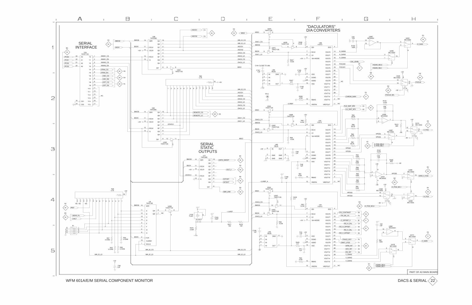
WFM 601A/E/M SERIAL COMPONENT MONITOR
���
��
�
�
#���
�����
�
��
���
��#�
��
���
�
#��
����
”DACULATORS”D/A CONVERTERS
�
�����
��$
����
�
#� �
��"���
��!���!�
����!�
����!�
���(��(�!
�
��
�
��
�
!� ��
����
����
!������
����
!�� ���
���
���
������
����
���
����
���
�����
#�
�����
���!����!�
�
��
INTERFACE
���!�
���!�
���!�
���!
�
��
SERIAL�!��
�����(�!
�����(��
�$��(�!
������(�!
������(��
������(�!
������(��
'���
'���
'��
'�
'��
'���
'��
' ��
'���
'���
'����
'���
'���
'���
'���
'���
�!����
�!����
����
�����
�����
����
#�
��"��
��
���
��� ��
��
#��
��"���
�!��
��$
�����(�!
�����(��
����(�!
����(��
���(��(��
����!�
����!�
��!�
�����
��� ��
�� #� �
��"���
��� ��
#� �
��"���
�����(��
�����(�!
�!��
���!�
�����
�����
����
�����
����
�#"��
#��
����
��������!��"��#��
����
�#�
���#!�
���#!�
�(�����
�(�����
�(����
���
��#�
��$
��$
!���
$�#"��
$�#"���
$�#"���
$�#"�
$�#"��
$�#"���
$�#"���
$�#" ��
$�#"��
$�#"��
$�#"����
$�#"����
$�#"���
$�#"���
$�#"���
$�#"����
!�����
$ ���#"��
$ �������
!�����
�����
�����������
���!���
$����
�������
�������
$!!��
#��
�����
���(��$��
�����(!���
�����(!���
���
����
���
���
��
��
#���
�����
��
��
��
�
�(����
��$
�
�
���#!
��
�����
���#!(!��
��$
���
��
�
��
��
��
�
#���
�����
���
��#�
�
�
��
��
��
��
��
���(!%�(!��
��(!%�(!��
�� ��(����
��
��
�
��
����
�#�
��
����
�
#��
��"���
��!�
���$
"���
�
��
���� ��
� ���"�(�!
� ���"�(��
���(��(�!
����!�
����!�
�����(�!
�����(��
����(�!
����(��
��$
��
!� ��
����
����
!������
����
!�� ���
���
���
������
����
���
����
���
�����
#�
�����
��
��
�
�
��
��
���� ����
��
� �
���!�
��
�$��(��
���"(�!
���"(��
���
��� ��
�
#���
��"���
�!��
�!"�"���
��$
OUTPUTSSTATICSERIAL
�����(�!
�����(��
��!� ��
�����
��� ��
� #��
��"���
��
��#�
�����(��
�����(�!
�!��
���!�
��$ �#"��
�����
������
�����
�����
����
#��
����
��� ��
#��
��"���
$��!�
$��!
��$
!���
$�#"��
$�#"���
$�#"���
$�#"�
$�#"��
$�#"���
$�#"���
$�#" ��
$�#"��
$�#"��
$�#"����
$�#"����
$�#"���
$�#"���
$�#"���
$�#"����
!�����
$ ���#"��
$ �������
!�����
�����
�����������
���!���
$����
�������
�������
$!!��
#�
�����
��
�����
�
����
��
����
��
����
��
����
���
���
�
#��
�����
$(��!(!���
$(��!(!���
$��!
$��!���$
��
���
���
��
�
�
#��
�����
��
�����
��
��
$(��!
��$
��$
���
��
�
��
��
��
�
#��
�����
�
�
%��(�(��!
���
���
��
��
#��
�����
�
��
�
�����
��
��
�
#��
�����
���
��#�
�(��!(!���
���!�
��$
��$��$
��
����
��
����
�
����
��
����
��
����
�
����
��$
�����
��
����
��
��
��
�#�
����
�#�
����
�
#���
��"���
���� ��(�
!� ��
����
����
!������
����
!�� ���
���
���
������
����
���
����
���
�����
#
�����
�#"(�
��"��&"
�&��(!%���
�&"���"
���!�
�!��
��$
��
��
�
�
��
��
��
�
�!"�"���
��
��
���� ����
��
��
�
�
��
��
� �
� �
����"
��
��
�
�
���
��
���
���
!�
��� (�#
�
��
�
��
����
��$
��
!� ���
����
����
���
���
���
���
����
����
������
���������
!�������
����
���
#�
�����
��� ��
#���
��"���
���!�
!� (����
�
�
� �
#���
"�����
��#�
�
���
�
���
���
���� ��
��� ��
�� #���
��"���
��
�����
����(�!
����(��
��!�
�!��
���!�
�
��
��� ��
�
#���
��"���
��
�����
��&(���" �!"
�(�(���!�"
�(�(���
��&(��(�$�
���!
���!�
��$
��$
!���
$�#"��
$�#"���
$�#"���
$�#"�
$�#"��
$�#"���
$�#"���
$�#" ��
$�#"��
$�#"��
$�#"����
$�#"����
$�#"���
$�#"���
$�#"���
$�#"����
!�����
$ ���#"��
$ �������
!�����
�����
�����������
���!���
$����
�������
�������
$!!��
#�
�����
�(���!�"($
���
��#�
�(��!(!���
��$
���
��
�
��
��
��
�
#��
�����
�
��
�
�
��
��
��
��
��
��
�� �
�(��!���
���
��
��
#��
�����
$(����
���
��
�
�
#��
�����
�
�
���
���
��
#��
����
�
����
$����(!���
���
���
��
��
#��
�����
��
��
��
��
��
�
�
�
$(�����
$(����
$(�����
" ���( �"
� �"(��"�!
�($(���!�"
�($(���
%��(��"
$��(��"
�(��"
��$�
��#�
�
��
��
��
��
�#���$
�����
�����
����
�����
����
�#"��
#
����
����
�#�
���(��(��
���(��(�!
���$
���(��(�!
�!��
���(��(��
�
�����
�
�����
��
�����
��
�����
��
��#�
���(��(��
��$
��$����(!���
DACS & SERIAL
PART OF A3 MAIN BOARD
22

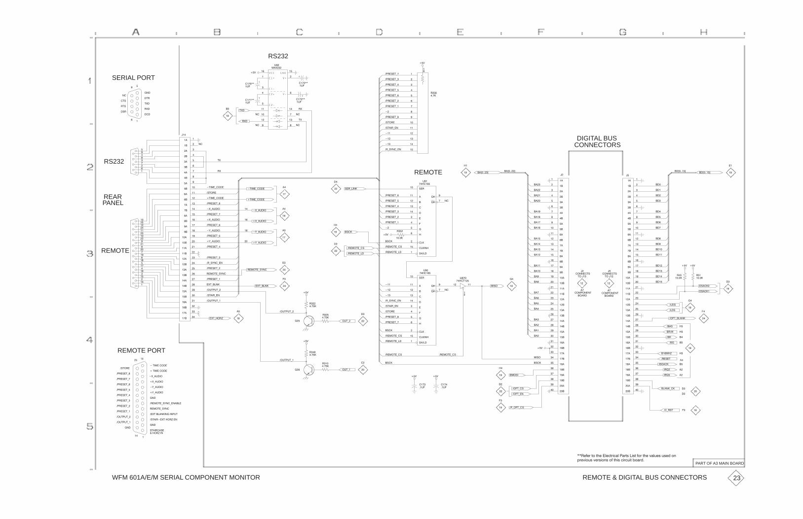
WFM 601A/E/M SERIAL COMPONENT MONITOR
��� ����$ ��� ����$
��&
RS232
�� ��
��� �
���
��� ��
���
�� �
��
��� ��
��� �
��
%�
��(
SERIAL PORT
�#"
"$#
�$#
��
�
���
"(�
$(�
�$"
���
�
�
�
��
��
�� ��
��
������
�%�
�����
�%�
"(�
$(�"(
$(
��&
������
�%�
������
�%�
� "�#�$-�
� "�#�$-
� "�#�$-�
� "�#�$-�
� "�#�$-
� "�#�$-�
�#$�"�
�#$��"-��
�
� "�#�$-�
� "�#�$-
�
���
��
��
���
���
��
���
���
���
���
���
��
��
���
���
"�
����
��+�����,
��
��
���
���
��
��+�����,
����
���
��
���
���
��
����
����
����
����
���
��
���
����
����
���
����
����
�����
����
����
���
��
���
���
��
����
����
����
����
� ��
� �
���
����
����
���
����
����
���
����
��
CONNECTORSDIGITAL BUS
��+���,
���
��
��
�����
����
���
����
����
���
�����
�����
�����
�����
����
���
����
�����
�����
����
�����
�����
������
�����
�����
����
���
����
����
���
�����
�����
�����
�����
� ���
� ��
����
�����
�����
����
�����
�����
����
�����
�REMOTE
#�"���
����
���
���
����
���
����
����
���
�����
���������
#�������
!���
!���
%��
����� �
��+���,
��
��
#�"-����
� "�#�$-
�"-#)��-��
���
��
��
��
�$���-������
��
��
"(
$(
�$���-����
�#$�"�
����
���
��
���
���
��
����
����
����
����
���
��
���
����
����
���
����
����
�����
����
����
���
��
���
���
��
����
����
����
����
� ��
� �
���
����
���
RS232��
�
�
��
�
��
��
��
��
REMOTE
REARPANEL
�
�
�
�
��
��
��
�
��
�
��
��
�
��
��
��
��
�
�
��
�
��
��
�$���-����
� "�#�$-�
� "�#�$-
� "�#�$-�
� "�#�$-�
� "�#�$-
� "�#�$-�
�(-�%���
�(-�%���
�)-�%���
�)-�%���
�$���-����
�)-�%���
�)-�%���
�(-�%���
�(-�%�����
�
��
�
��
��
�
��
�"���$�-��
�"���$�-�#
�#��
� "�#�$-�
� "�#�$-
� "�#�$-
� "�#�$-�
� "�#�$-�
�
�#��
�"���$�-�#
�"���$�-��
��&
"�
�����
��
��
�
��
���
���
����
����
����
���
����
����
��� ��
���
���
��
���
���
���
����
����
"��
�����
�#����
�#����
��& ��&
�
��
��
�
��
��
��
������$#
$����
��
���"�
"�
�����
�� $-�����
���#
�%�#
���
���
����
�����
�
������$#
$����
��
���"�
��
���
���
��
���
���
���
����
����
�
��
��
��
#�"���
����
���
���
����
���
����
����
���
�����
���������
#�������
!���
!���
%��
����� �
�� ��
�
%���
����$��
��#�
"�
�����
�%$-� "�#�$-�
�#$�"�
�"-#)��-��
�#$��"-��
��
��
���
� "�#�$-�
�
"
�����
�($-����
��%$ %$-
��&
!�
"���$�-#)��
�
�
��
��
�
�
�($-��"*
�($-����
� "�#�$-
� "�#�$-�
��%$ %$-
��%$ %$-�
�#$��"-��
�"-#)��-��
"���$�-#)��
REMOTE PORT
�#$�"�
� "�#�$-�
� "�#�$-
� "�#�$-�
��$��������
��$��������
��
�(-�%���
�(-�%���
"��
�����
��%$ %$-�
��&
!
"��
�����
�%$-�
�#��
�"���$�-�#
�"���$�-��
�"���$�-�#
�#���
�
����
��%�
���
��%�
�"���$�-�#
��&��&
��
��
�
���#�
���
���
��
��#�
�#��
��&
��
��
��
��
��
��
�
��"!�
�"!
������
�"�#�$
�� ��*
���
��"
�"�'
���#
��
��
�
��
��
�����-��
��-"#$ �
� -� $-�#
�� $-�#
�� $-��
�
��
���
��($������������ %$
�#$��"��($���"*���
#$��"��#�
����"*���
���
"���$�-#)��
�"���$�-#)��-������
���
�)-�%���
�)-�%���
���
� "�#�$-�
� "�#�$-�
� "�#�$-
� "�#�$-
� "�#�$-�
��%$ %$-�
��%$ %$-
REMOTE & DIGITAL BUS CONNECTORS
PART OF A3 MAIN BOARD
23
��"232:�<8�<42��620<:50.6� .:<;��5;<�38:�<42�>.6=2;�=;21�87
9:2>58=;�>2:;587;�83�<45;�05:0=5<�/8.:1�

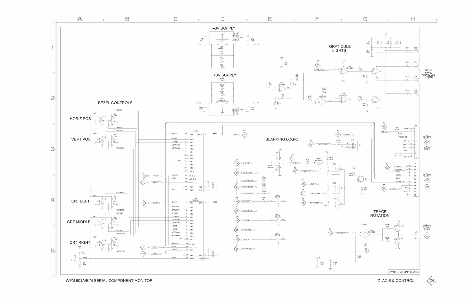
WFM 601A/E/M SERIAL COMPONENT MONITOR
�
����
�
����
�
����
����
���$
��
��#�
–8V SUPPLY
��
��#�
� �
�
� �
#�
��� ��"
+8V SUPPLY
���$
��
���
��
���
�
���
����
��#�
�$
� $
GRATICULELIGHTS
���
���
��
��
#��
�����
�
��#�
� �")��"�!
���$�
��
��
�����
��
�����
��
��#�
���$
���$
�� � ��"
������ �"��#��
����"!
�!�
���
���
!�"
���
���
!�"� �!�
�!
���
���
!�"�
���
���
!�"� �!
�����
��
�����
���$
���$
���$
��
��
�����
��
��������
���
�
#��
����� ��
���
��
#��
�����
���$
�
�����
���
���
�
#��
����� �
�����
�
��#�
����
��#�
� $
�
����
����
��#�
���$
��
�
� �
�
���
� �
���
���
���
#�
� � ��"
BEZEL CONTROLS
�� �(�
$ ��
VERT POS
HORIZ POS� �
� �
��
���
�
��
�
���
� �
� �
��
���
�
��
��
���
$� "�����
$� "�����
�� �(�
$ ��
$� "�����
$� "�����
�� �(�
�� �(�
���!����
�����#"
��
������
������
������
�����
����
�����
������
�����
�� ���
������
�������
!�������
���������
�!��
������
�����
�����
$����
#
"���
��!���!�
BLANKING LOGIC
� $
�
��
��
��
����
�� )��"
��!)!" ���
��
��
�
��
��
�����
���#!
��%� )��
�(�&�!
��
���
���
� �
��
��
��
������"!
"���
��
��%�
!#���'�$
����$
��$
���$
����
����
����
��
��
����
����
��
����
�����
��
���$
��
��
��
������"!
"����
��
� ��"
�����
���$
�����
�����
�����
����
����
�����
����
���
����
����
��
�
���
�
���
�����
�����)�!
�����)��
� �!�"
��%� )��
��!�
���!�
�!��
� $
��
�
��
��
��
��
�����
��� �
��
#���
���"��
&)����)��
������
�$
��
���
��
���
���
�
��
���
���
�
�
��
�
��
��� ��
�
��
��
#��
��
�
�����
��
�����
��&)��" �&")����
�)��"��!�
�)��"��!�
�&)��")!��
�$
� $
��
��
�
��
�
��#�
�$
�
�
��
��
��
��
��
����!�
���)���
$ ��
�!��
���)���
����
����
CRT LEFT
CRT MIDDLE� �
� �
��
���
�
��
���
� �
� �
��
���
�
��
�
���
� "���"�
� "���"�
� "����
$ ��
$ ��
���!�
� "����
� "����
� " ���"�
� " ���"�
� "���"�
� "���"�
���!�
�� �(�
��� ������
��#"��
������
������
������
�����
����
�����
������
�����
�� ���
������
�������
!�������
���������
�!��
������
�����
�����
$����
#�
"���
��!�
�
��
��
��
�
��
��
��
��
����
��� ��
�
#��
��
��� ��
#��
��
�)��")!��
$��)��"
�)��"
�)��"��!�
�
��
���")�����
���")������
���
���
� �
��
��
��
TRACEROTATION
���$
���$
�
��� ���
��
������"!
�$
"������
���� "
���
���
�� ��
��
����$
���$
���$
��
��� ���
��
�� ��
��
���
���
���
��
#�
������" ���) �"
����
��#�
���
��#�
���$
�
��
�� �
��
#��
��
%��)��"
$)��")!��
%)��")!��
��
��#�
�$
�
��
��
��
�!��
����!�
$ ��
�!��
���)���
����!�
�� �(�
$� "�����
$� "�����
��
����
���
� �
� �
��
���
�
��
�
���
��
����
��
��#�
$ ��
� " ���"�
� " ���"�
� "����
$ ��
�$
CRT RIGHT
��
��#�
���$
�� "��������������� �
Z–AXIS & CONTROL 24
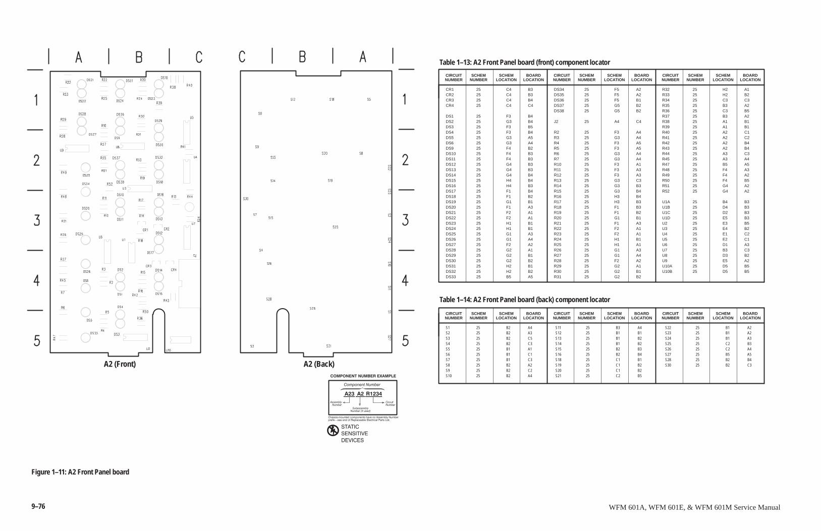
9–76 WFM 601A, WFM 601E, & WFM 601M Service Manual
A2 (Front)
CR1 25 C4 B3CR2 25 C4 B3CR3 25 C4 B4CR4 25 C4 C4
DS1 25 F3 B4DS2 25 G3 B4DS3 25 F3 B5DS4 25 F3 B4DS5 25 G3 A5DS6 25 G3 A4DS9 25 F4 B2DS10 25 F4 B3DS11 25 F4 B3DS12 25 G4 B3DS13 25 G4 B3DS14 25 G4 B4DS15 25 H4 B4DS16 25 H4 B3DS17 25 F1 B4DS18 25 F1 B2DS19 25 G1 B1DS20 25 F1 A3DS21 25 F2 A1DS22 25 F2 A1DS23 25 H1 B1DS24 25 H1 B1DS25 25 G1 A3DS26 25 G1 A4DS27 25 F2 A2DS28 25 G2 A1DS29 25 G2 B1DS30 25 G2 B2DS31 25 H2 B1DS32 25 H2 B2DS33 25 B5 A5
DS34 25 F5 A2DS35 25 F5 A2DS36 25 F5 B1DS37 25 G5 B2DS38 25 G5 B2
J2 25 A4 C4
R2 25 F3 A4R3 25 G3 A4R4 25 F3 A5R5 25 F3 A5R6 25 G3 A4R7 25 G3 A4R10 25 F3 A1R11 25 F3 A3R12 25 F3 A3R13 25 G3 C3R14 25 G3 B3R15 25 G3 B4R16 25 H3 B4R17 25 H3 B3R18 25 F1 B3R19 25 F1 B2R20 25 G1 B1R21 25 F1 A3R22 25 F2 A1R23 25 F2 A1R24 25 H1 B1R25 25 H1 A1R26 25 G1 A3R27 25 G1 A4R28 25 F2 A2R29 25 G2 A1R30 25 G2 B1R31 25 G2 B2
R32 25 H2 A1R33 25 H2 B2R34 25 C3 C3R35 25 B3 A2R36 25 C3 B5R37 25 B3 A2R38 25 A1 B1R39 25 A1 B1R40 25 A2 C1R41 25 A2 C2R42 25 A2 B4R43 25 A2 B4R44 25 A3 C3R45 25 A3 A4R47 25 B5 A5R48 25 F4 A3R49 25 F4 A2R50 25 F4 B5R51 25 G4 A2R52 25 G4 A2
U1A 25 B4 B3U1B 25 D4 B3U1C 25 D2 B3U1D 25 E5 B3U2 25 E3 B5U3 25 E4 B2U4 25 E1 C2U5 25 E2 C1U6 25 D1 A3U7 25 B3 C3U8 25 D3 B2U9 25 E5 A2U10A 25 D5 B5U10B 25 D5 B5
SCHEMNUMBER
Table 1–13: A2 Front Panel board (front) component locator
CIRCUITNUMBER
SCHEMLOCATION
BOARDLOCATION
SCHEMNUMBER
CIRCUITNUMBER
SCHEMLOCATION
BOARDLOCATION
SCHEMNUMBER
CIRCUITNUMBER
SCHEMLOCATION
BOARDLOCATION
S1 25 B2 A4S2 25 B2 A3S3 25 B2 C5S4 25 B2 C3S5 25 B1 A1S6 25 B1 C1S7 25 B1 C3S8 25 B2 A2S9 25 B2 C2S10 25 B2 A4
S11 25 B3 A4S12 25 B1 B1S13 25 B1 B2S14 25 B1 B2S15 25 B2 B3S16 25 B2 B4S18 25 C1 B1S19 25 C1 B2S20 25 C1 B2S21 25 C2 B5
S22 25 B1 A2S23 25 B1 A2S24 25 B1 A3S25 25 C2 B3S26 25 C2 A4S27 25 B5 A5S28 25 B2 B4S30 25 B2 C3
SCHEMNUMBER
Table 1–14: A2 Front Panel board (back) component locator
CIRCUITNUMBER
SCHEMLOCATION
BOARDLOCATION
SCHEMNUMBER
CIRCUITNUMBER
SCHEMLOCATION
BOARDLOCATION
SCHEMNUMBER
CIRCUITNUMBER
SCHEMLOCATION
BOARDLOCATION
A2 (Back)
����������������
��� �� �����
�������"����������������������������������!�������
����� #�������������������������������������������
�� ��������������� �
��������������
������������������� ������
������
������� �
�� ����
� �� �������
Figure 1–11: A2 Front Panel board
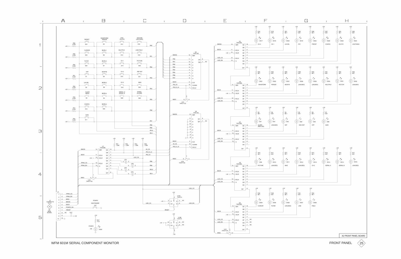
WFM 601M SERIAL COMPONENT MONITOR
��
���
"�
���
"�
���
�#�
��& ��&
"�
���
"
���
"�
���
�#�� �#� �# �#
��& ��& ��&
"��
���
"��
���
"�
���
�#�� �#�� �#�
��& ��& ��&
&��$�"�
����$����
�)��
�!��)� "�#�$
'�&���"��
�"���
�%"#�"
���$�"
��*���
��*���
#�#�
# #
# #�"��
�����
"�
�����
"�
�����
��&
��&
��&
�����������%�$� ��
���� ��$%"�
#� #��
#�#��
#� #��
��
��
�
��
��
�
�
��
���#�#�"
���
����
���
���
����
���
����
����
���
�����
���������
#�������
!���
!���
%
����� �
��
���#�
�#��
����+��
����+�#
��&
#�"���
!���
!���
#������
!��
#��"���
!��
!���
"�����
!���
���
!��
!���
!����
%�
�������
����#����� ����
"
���
"
���
"�
���
��& ��&��&
������ "�#�$�)�
"�
���
"�
���
"�
���
��&��&��&
�!��)� ����$����
"
���
"
���
��&��&
&��$�" �%�%#���
�#
�%�%#��� �%�%#��� �%�$� ��
�#��#��#��#�
'�&���"� �"��� ��'$��
�#��#�#�
�#��
����+��
����+�#
��&
#�"���
!���
!���
#������
!��
#��"���
!��
!���
"�����
!���
���
!��
!���
!����
%�
�������
�����
��
%��
����$��
��
�
��
�#��
� �+�#
� �+��+��
��#�
���
��� "����($
#�"������
#�"�����
���
#�"���
����"��
# #�
#� #�
#�#��
�
��
��
����#��
�"$
����"
��*���
��*��
���%
��'$��
#�#
# #�
#�#�
"�
�����
"�
�����
"��
�����
��&
��&
��&
������ ��*��
����
#��
#�� #�
"��
�����
"��
�����
��&
��&
�
��
��
��
���
���
���#�#�"
���
����
���
�
����
���
����
����
���
�����
���������
#�������
!���
!���
%�
����� �
��
�#��
��&
#�"���
!���
!���
#������
!��
#��"���
!��
!���
"�����
!���
���
!��
!���
!����
%
�������
�($���"� �%�%#���
�"�������
"�
���
"�
���
"
���
�#� �#
��&��&��&
�#�
����������$ �"$
"�
���
"
���
"
���
�# �#� �#
��&��&��&
#�"����� �%�%#���
"��
���
"�
���
�#�
��&��&
�%�%#��� ��� #�"�����
"��
���
"�
���
"��
���
�#���#���#��#�
��&��&��&
��� ��$%"� �%�%#���
"��
���
"��
���
"�
���
�#���#���#�
��&��&��&
����+��
����+�#
#�"���
!���
!���
#������
!��
#��"���
!��
!���
"�����
!���
���
!��
!���
!����
%
�������
����
�
%��
����$��
�#��
���+�#
� �+��+��
��#�
"�
�����
"�
�����
"�
�����
"
�����
��
�"�
��
�"
��
��
� �+�#
���+�#
� �+��+��
����+�#
��& ��& ��& ��&
#�"���
!���
!���
#������
!��
#��"���
!��
!���
"�����
!���
���
!��
!���
!����
%�
�������
�� ��+�#
�� ��+��
���#�
�#��
��&
���
�
�
���
���
�
���
���
���
����
�
���
�
%��
����$��
�� ��+�#
�� ��+��
��#�
��
�"
��
�"�
���
���
����+�#
��&
�#��
����+��
����+�#
��&
"��
���
"��
���
"��
���
��& ��& ��&
"�
���
"��
���
��& ��&
���� �����
�#� �#�
�%"#�" ���$�"
��
��
��
�#� �#� �#
�%�%#���
�#��
����+��
����+�#
��&
#�"���
!���
!���
#������
!��
#��" !��
!���
"�����
!���
���
!��
!���
!����
%�
�������
��
��
���
��!
��
����
!�
"
�
��
�
%���
������
���
!��
�����
!��
"
��
��
�
%���
������
����+��
�"�#�$
��&
��&
��&
����+�#
��
��
�'�"
�'�"
���#$����)
#�
�#
"��
����
�'�"+��
��#�
���#�
�#��
�"�#�$
&��
��&��&
�
������$#
$����
�
����
���"�
�
��&
����
�
%��
����$��
��#�
FRONT PANEL
���"��$� ��������"�
25
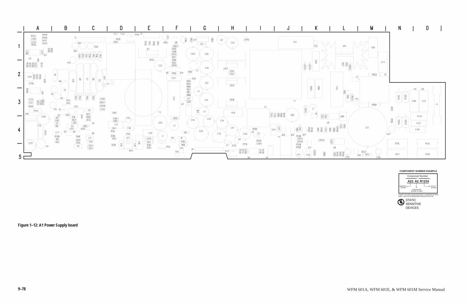
9–78 WFM 601A, WFM 601E, & WFM 601M Service Manual
����������������
��� �� �����
�������"����������������������������������!�������
����� #�������������������������������������������
�� ��������������� �
��������������
������������������� ������
������
������� �
�� ����
� �� �������
Figure 1–12: A1 Power Supply board
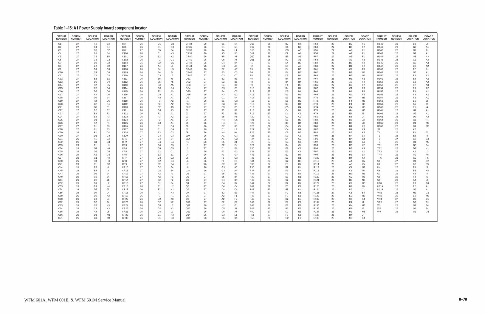
9–79WFM 601A, WFM 601E, & WFM 601M Service Manual
C1 27 F4 B3C2 27 B4 B4C3 27 D3 C2C4 27 B5 B4C5 27 C5 B5C6 27 C3 C2C7 27 D3 C2C8 27 E2 C2C9 27 D4 C3C10 27 C4 C4C11 27 C4 C4C12 27 E2 B2C13 27 D2 D4C14 27 F2 D5C15 27 C2 D4C16 27 D2 D4C17 27 F3 D4C18 27 D2 E4C19 27 F2 D5C20 27 C2 E4C21 26 G2 F1C22 27 B2 E2C23 27 B3 F2C24 27 B2 F3C25 27 D1 E4C26 27 A2 F1C27 27 B1 F3C28 27 B1 F3C29 26 F2 G1C30 27 D1 G4C31 26 F1 G2C32 26 G1 G4C33 26 F1 H1C34 26 G1 H4C35 26 G2 G4C36 26 F2 G2C37 26 G1 H4C40 26 H4 H4C41 26 F1 G3C44 26 E5 I4C45 26 E5 I3C47 26 D5 J4C49 26 C5 J4C51 26 D2 J1C52 26 D1 L2C53 26 B3 K4C54 26 D5 J3C55 26 D4 L4C59 26 D2 K2C60 26 B3 L4C62 26 D2 J4C63 26 C3 K3C64 26 C3 K3C65 26 A4 L5C66 26 D1 M1C71 26 C1 M4
C74 26 D1 M2C75 26 B1 O3C77 27 C5 B4C100 26 B1 N3C101 26 E2 H2C102 26 F2 G1C104 26 B2 M5C107 26 A4 L4C108 26 F4 H5C109 26 E4 I5C110 26 C3 L5C111 26 B5 J5C112 26 B5 K5C113 26 G3 A5C114 26 G3 G4C115 26 F3 A3C116 26 G3 A1C117 26 H3 A1C118 26 F3 A2C119 26 F3 A2C120 26 E2 A3C121 26 G3 A3C122 26 F2 A1C123 26 F3 A2C124 26 F2 A1C125 26 G3 A4C126 26 B1 O4C127 26 B1 O4C128 27 B3 C3C129 27 C3 C3CR1 27 C4 B4CR2 27 D4 C4CR3 27 C4 C5CR4 27 D5 C5CR5 27 E2 C1CR6 27 E2 B1CR7 27 C3 C2CR8 27 D2 D4CR9 27 E2 D4CR10 27 D2 E4CR11 27 D2 E4CR12 27 A2 F1CR13 27 A2 F1CR14 27 B2 F2CR15 27 C1 F4CR16 26 F1 H2CR17 26 F2 H2CR18 26 F1 H3CR19 26 F1 H1CR22 26 D2 K3CR23 26 D2 K2CR24 26 D3 L3CR25 26 D2 K2CR26 26 D3 L2CR32 26 B1 N3CR33 26 C1 N3
CR34 26 B1 N4CR35 26 C1 N4CR38 26 A4 L4CR39 26 A5 K5CR40 26 B5 J5CR41 26 C5 J4CR42 26 C4 K4CR44 26 G3 A4CR45 26 E2 A3CR46 27 B3 C3CR47 27 C3 C3DS1 27 E2 B1DS2 27 E3 B1DS3 27 E4 B4DS4 27 D3 C1DS5 27 E4 C3DS6 26 H3 G2DS7 26 C1 N4F1 26 B1 O3FIL1 27 C3 D1FIL2 27 C3 D1J1 27 F3 B1J2 27 F2 E1J3 26 E5 H5J4 26 H4 G5J5 26 H4 I4J6 26 D2 K3J7 26 D1 L2J9 26 H4 H4J10 26 A1 O3J12 26 A1 O3K1 26 B5 J4L1 27 B2 E4L2 27 D1 F4L3 26 F2 G2L4 26 F1 G3L5 26 F1 G3L6 26 F1 H1L7 26 D2 K3L9 26 G3 A5L10 26 G3 A4Q1 27 E5 B3Q2 27 E5 B4Q3 27 C4 B4Q4 27 D4 B4Q5 27 D4 C4Q6 27 D4 C4Q7 27 B2 E1Q8 27 A2 F1Q9 27 A2 F2Q10 27 B2 F2Q11 26 H2 G1Q12 26 D5 J4Q13 26 D5 J4Q14 26 D3 L1Q15 26 C5 K4
Q16 26 B2 M5Q17 26 C5 K5Q18 26 G3 A3Q19 26 E2 A1Q20 26 E3 A2Q21 26 H2 A1R1 27 E4 B2R2 27 E4 A3R3 27 E4 B3R4 27 E4 B3R5 27 D5 B4R6 27 B4 B4R8 27 B4 B4R9 27 F4 B2R10 27 B4 B4R12 27 D5 B4R13 27 E3 B2R14 27 E5 B3R15 27 E5 B3R16 27 D4 B4R17 27 C5 B4R18 27 C4 B4R19 27 D3 C1R20 27 C3 C3R21 27 E5 B3R22 27 B5 B4R23 27 C4 C4R24 27 C4 B4R25 27 C5 B5R26 27 D3 C3R27 27 D4 C3R28 27 C4 C4R29 27 D4 C4R30 27 E2 C1R31 27 E3 C1R32 27 E2 B3R33 27 E3 D1R34 27 D2 B3R35 27 F3 D4R36 27 F1 D4R37 27 F2 D4R38 27 F2 D5R39 27 E3 D1R40 27 C2 D3R41 27 D2 D4R42 27 E3 E1R43 27 F3 D4R44 27 F2 D5R45 27 F2 E1R46 27 D2 E5R47 27 F2 E1R48 27 F3 E1R49 27 B3 E2R50 27 D2 E5R51 27 F3 E1R52 26 G2 F1
R53 27 D2 F5R54 27 B2 F2R55 27 A2 F1R56 27 A2 F1R57 27 A2 F1R58 27 A2 F2R59 27 B3 F2R60 27 B1 F2R61 27 C2 F3R62 26 H2 G1R63 26 H2 G1R64 26 H3 F2R65 27 A2 F2R66 27 C2 F2R67 27 C1 F3R68 27 B1 F3R69 26 G1 F5R70 26 H4 H3R72 26 F4 H5R73 26 F4 H5R74 26 G4 H5R78 26 G4 H5R79 26 E4 I5R81 26 D5 J4R82 26 D5 J3R84 26 D5 J3R86 26 B4 K5R87 26 B4 K4R88 26 D2 K2R90 26 D4 L3R91 26 D4 L3R92 26 D4 L4R93 26 D3 L2R94 26 B3 K4R97 26 D3 L2R98 26 B3 L4R100 26 B4 K4R110 26 A4 L5R114 26 A3 L5R117 26 C1 N3R118 26 C1 N4R119 26 B2 N5R120 26 C2 O5R121 26 B2 N5R122 26 C2 O5R123 26 B1 O4R124 26 D5 J3R126 27 C5 B4R127 26 E2 H2R132 26 C5 K4R134 26 F4 I4R135 26 G4 H5R136 26 F4 I5R137 26 B2 M5R138 26 B4 J4R139 26 C5 K4
R140 26 B3 L5R141 26 G2 A1R142 26 G2 A1R143 26 G2 A1R144 26 G3 A3R145 26 G3 A3R146 26 G3 A3R147 26 E2 A2R148 26 F2 A1R149 26 G3 A1R150 26 F3 A2R151 26 E3 A2R152 26 E3 A2R153 26 E2 A3R154 26 F3 A2R155 26 F3 A2R156 26 F3 A2R157 26 F2 A1R158 26 B5 J5R159 26 B5 J5R160 26 E5 I4R161 26 H2 A1R162 26 G2 A1R163 26 D2 K2R164 26 G1 F4R165 26 C1 M2R166 26 C1 M3S1 26 A2T1 26 E1 J3T2 26 E5 I3T3 27 C2 E3T8 26 C1 M2TP1 26 G5 F4TP2 26 D3 K1TP3 26 A2 L3TP4 26 G2 F5TP5 26 G2 F5U1 27 D1 D2U2 27 B2 F3U4 26 E4 I5U6 26 B3 K4U7 26 F4 I4U8 26 F4 I5U9 26 A4 L5U10 26 F3 A3U11A 26 F2 A1U11B 26 G2 A1VR1 26 H2 G1VR3 26 B2 M5VR4 27 D3 C1VR5 27 D3 C1W1 26 G2 F4W2 26 G1 F4W4 26 G1 G3
SCHEMNUMBER
Table 1–15: A1 Power Supply board component locator
CIRCUITNUMBER
SCHEMLOCATION
BOARDLOCATION
SCHEMNUMBER
CIRCUITNUMBER
SCHEMLOCATION
BOARDLOCATION
SCHEMNUMBER
CIRCUITNUMBER
SCHEMLOCATION
BOARDLOCATION
SCHEMNUMBER
CIRCUITNUMBER
SCHEMLOCATION
BOARDLOCATION
SCHEMNUMBER
CIRCUITNUMBER
SCHEMLOCATION
BOARDLOCATION
SCHEMNUMBER
CIRCUITNUMBER
SCHEMLOCATION
BOARDLOCATION

9–80 WFM 601A, WFM 601E, & WFM 601M Service Manual
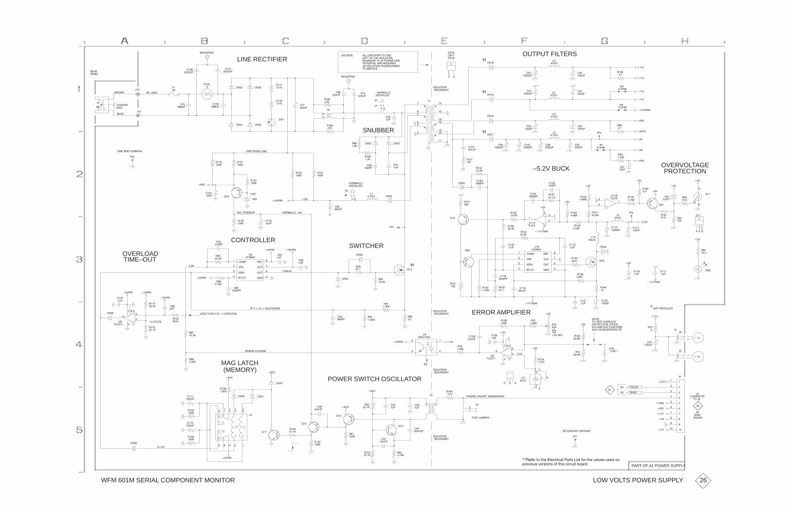
WFM 601M SERIAL COMPONENT MONITOR
���)
����
%� �
���
OUTPUT FILTERS�%�
��
��(�
��
����(�
��
���(�� �
�%�
�%��
�%��
�
��('�"!� ������%�(�'%,�'"�'��
"(!'�!�
���'�"��'����&"��'�"!
�"(!��%,��&��'�#"*�%���!�
#"'�!'�����!��%�$(�%�&
�!��&"��'�"!�'%�!&�"% �%
'"�&�%)�������
���(�
LINE RECTIFIER "(!'�!�
��
���(�%��%
#�!��
���&&�&
�%"*!
��(�
�����)
���
�� �(�
%�
�
�!�
��
�
��
���
���
�(�
����
�� �(�
�%�%
�%� �%�
%���
���
%���
���
�&�
SNUBBER
�!&'�����
!"% ���,
�
��
#�
'�
���
��(�
��
�(�
%��
���
�
��(�
%�
���
%� �
���
�"(!��%,
�&"��'�"!
�
�
��� ��
�
�
��
��
��
��
���
���
��
��
�
�
'�
�
���(�
�
��(��%��
�%����
��(�
���
����(�
�%��
��
���(�
�
���(�
�
���(�
*
��"�
% �
���
����
���)
���)�
���)
��)
���)�%�*
*�
��"�
'#�
�
�
%
����
��)
��)
$��
)%�
�� )��
OVERVOLTAGEPROTECTION
*�
��"�
%�
�����
���
��)�
��
��(�
��)
��)
��)
%��
����� ��
���
��
(���
'���%��
�����
$�
%�
���
��
�(�
�
����(�
���
����(�
��
����(�
���
� ��#�%���
�����
��
���#�
–5.2V BUCK
����
����(�
%��
���
%���
�
%��
�����
���
��#��%��
�!&'�����
!"% ���,
�
� �%
��
���(�
�%�
���
�#�
#
%�
����
�
�(�
���
�(�
�%
%�
���
�� )
%��
����
�� )#%�)%
%��
����
%��
����
����
��(� $�
�� )
�%��'��������!�
%���
����
� )�
'#
��!��&�����" "!
OVERLOADTIME–OUT
CONTROLLER
�
��(�
� �
��(�%��
����
��)#%� �� )#%�
�" #���
)����
�&�!��
%'��'���
%����
)����
"('�
�!���
(
(����
����
��(�
)�.#%�&�!'
��
���#�
%���
����
!"% ���,�� )
SWITCHER�%
'#
$��
$�
$��
��)
����
��(�
��
��(�
��)
���)�%�*
%��
��
%���
����� �
�
���
�
�
(���
'���
%���
�����
%���
����
�" #���
)����
�&�!��
%'��'���
%����
)����
"('�
�!���
(��
(���
%���
���
%���
�����
����
���(�
���)
���
����(�
$��
�%��
%���
���� ��
��(�
%� �
����
���
���(�
'#�
�
� � �
$��
% �
����
��)
%
���
�&
#%"'��'�"!�'"(��
'"�'�&'�")�%)"�'
!"'��
%����!��%���'"��'��% %��
���)
��)
����
��(�
���
���(�
���
��(�
���)�%�*
��)
%��
�����
%���
���
!"'��!&'�����
%�
���
��)
%�
����
���
��(����)�%�*
����
��#�
%���
������
����(�
%�
����
�"(!��%,
�&"��'�"! ERROR AMPLIFIER
�
%��
���
%���
���%��
�����
%��
�����
�%� %��
�����
%�
��
���
��#�%�
����
���)����)���&�('�"*!
��)#%�
�����-
%��
����
� �
��#�
��)
%��
�����
��)#%���)#%�
��)"�'&
��&&�'��!���)���")�%�"��
��
��
�
�
�
(�
'����
%���
���
%���
��
%���
���
��)#%�
� �
��(�
����
��(�
�%�
%�
���
�%%"%�)"�'���
MAG LATCH(MEMORY)
� )�
� )�
�%�
%��
����
POWER SWITCH OSCILLATOR
!�
%��
�����
��
�
���
���
(�
"�����
��)#%�
�"(!��%,
�&"��'�"!
��)
����
��(�
��)����
%��
����
��)
��)
��)
�
%
�
� %�
����
��(�
��
��
�
�
�
(�
'����
�(�
���
*�'��&�%�*�%�)�%�'�#�
�"�(&
���
���(�
%��
������
%��
����
%��
����
��
��
�
���
��
��
����
��
��
����
����
��
����
����
����
�����
��
���
��
��
���)
�"!!��'&
�
��!
�"�%�
'"��
��
����)
���)
���)
���)
��)
-�+�&
&��"!��%,��%"(!�
'#�
'�&'��( #�%
���
��
����
��(�
���
�����(�
#"*�%."!�"��. " �!'�%,
�"(!��%,
�&"��'�"!
'
%� �
����
���
��(�
$�
���
����(�
%��
���
%�
���
$�
%��
����
� )�
� )�
$��
%�
����
���
����(�
%��
����
��)#%�
�
��
�
���
� � �
��
�%���%��
$��
%��
�����
56�944
�%�
%���
����
%���
����
���
�(�
����
�(�
PART OF A1 POWER SUPPLY
LOW VOLTS POWER SUPPLY 26
��%343;�=9�=53��731=;61/7�#/;=<��6<=�49;�=53�?/7>3<�><32�98
:;3?69><�?3;<698<�94�=56<�16;1>6=�09/;2�

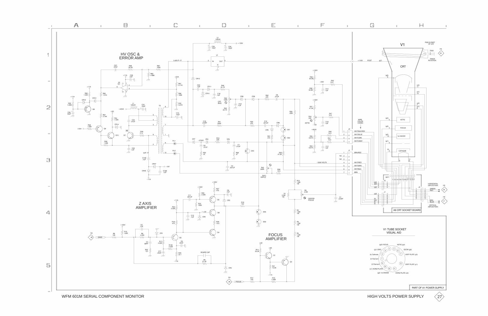
WFM 601M SERIAL COMPONENT MONITOR
���#� �"$
����"$&�
�
���%�
����&
��
��%�
��
��%�
ERROR AMPHV OSC &
��
��%�
" �
��
��
�%�
����
�
�
��
�
�
�
�
%
���
����&� �
" �
�����
" �
�����
��&�
" �
����
�"��
����
�%$
�
�
%�
����&
"��
������&
"�
����
"
����
�#$����&
�"$
�/��
�/��
�
"�$�$���
$"���
���
��
�9�
��
�
�
�
�
��
�9��
�:�
�:��
����"
����#
'�"� �#$���
�/��
�#$�����
��%�
���
��%�
����&
���&
"��
����
"�
�����
"��
��
��
����%�
��
���%�
"�
����"
"�
�
"
����"�
�"$
���#
"�
���
"�
����
"��
���
��
�� �
��
��%�
�"�
�"��
���
��%�
�"��
��
��%�
"��
�
"��
����
"
����
�
��%�
���
��%����
���
��
��
��
��
�
��
��
��
��
$
��
���%�
" �
����
"�
�����
"��
����
"��
����� ��
���%�
����
���
���&�
!�
!�
�"�
�"�
�"��
"��
�����
����
�
��%�
�
"��
�����
"��
�����
�
��%�
��&�
!�� !�
�& �
���
��%�
"��
����
����
���
"�
��
��
���%�
"
��
"��
�&"�&"��"�
�
���%�
����&
"
�����
�#�
�#��"�
�#
"�
���
��
��
"�
����
"�
����
"��
����
"��
����
���
��%�
���&�
����
��
��
����
����
��
����
��
����
��
��
����
�
����&��$#
'�$���%�
'�$��"�)
�"��"��
'�$�"��
'�$�����"��
'�$��"�
�78������
���%#
��
��$����
�
�
�/�
�
�/�
�/��
�2�
�.� �.�
��
�
�
��
��
�
��
�"���
"��
�"�
��%�
��"�*��$��
������$���
�
���
��
��
���
���
��
���
�
��
�
��
'�$��"�
'�$����
�"�
���
��
��
���
���
��
���
�.�
�/��
�2�
�/�
�/�
�/��
�/��
#�$�
��
�
��
�
�
��
��
�
�
��
��
�
��
� � � � � ���������
���
��
��
���
���$�"
���%#
��
�� �
"�
���
�'
�'
�%��
"� ��
"�
��
"�
��� "�
����
"�
����
��
��%�
"�
���
"�
����
"
����
���
����%�
����&
����&
�"!�
�
����%�
����
����
���&
���
��%�
�"��
�"�
"��
����
*�(�#
����&
"�
���
��
AMPLIFIERZ AXIS
"�
����
��
� �
"
����
�
��%�
"��
���
�"�
!
"��
���
;�&
"�
����
���
��%�
!�
"�
���
!
�"
�'
�'
�'
AMPLIFIERFOCUS
�#�
�#
"
����
"
����
"�
����
&��$%���#����$
&�#%������
�.�
� ��"$�#����$����"�
������$���
&�"$����
��
�
� ��
�
�
��
�
�#$����/��
������/��
&�"$� ��$���:�
&�"$� ��$���:��
�/���78������
�9�����"�*� ��$�
�.���13+4-58
�.���13+4-58
�2���+806,-
�/����"��
�/�����%#
��"�*� ��$���9�
"�
�����
"��
�����
"��
��
���
���
����
!�
!
"�
���
���"����
�"�
"�
����
��
��
�%�
"�
��
���
�%�
"�
���
����
"
��
���%#
HIGH VOLTS POWER SUPPLY
�"$������� �'�"�#% �)
27

WFM 601A, WFM 601E, & WFM 601M Service Manual 10–1
Replaceable Mechanical Parts
This section contains a list of the replaceable mechanical components for thewaveform monitors. Use this list to identify and order replacement parts.
Parts Ordering InformationReplacement parts are available through your local Tektronix field office orrepresentative.
Changes to Tektronix products are sometimes made to accommodate improvedcomponents as they become available and to give you the benefit of the latestimprovements. Therefore, when ordering parts, it is important to include thefollowing information in your order.
� Part number
� Instrument type or model number
� Instrument serial number
� Instrument modification number, if applicable
If you order a part that has been replaced with a different or improved part, yourlocal Tektronix field office or representative will contact you concerning anychange in part number.
Change information, if any, is located at the rear of this manual.
Using the Replaceable Mechanical Parts ListThe tabular information in the Replaceable Mechanical Parts List is arranged forquick retrieval. Understanding the structure and features of the list will help youfind all of the information you need for ordering replacement parts. Thefollowing table describes the content of each column in the parts list.

Replaceable Mechanical Parts
10–2 WFM 601A, WFM 601E, & WFM 601M Service Manual
Parts list column descriptions
Column Column name Description
1 Figure & Index Number Items in this section are referenced by figure and index numbers to the exploded view illustrationsthat follow.
2 Tektronix Part Number Use this part number when ordering replacement parts from Tektronix.
3 and 4 Serial Number Column three indicates the serial number at which the part was first effective. Column fourindicates the serial number at which the part was discontinued. No entries indicates the part isgood for all serial numbers.
5 Qty This indicates the quantity of parts used.
6 Name & Description An item name is separated from the description by a colon (:). Because of space limitations, anitem name may sometimes appear as incomplete. Use the U.S. Federal Catalog handbook H6-1for further item name identification.
7 Mfr. Code This indicates the code of the actual manufacturer of the part.
8 Mfr. Part Number This indicates the actual manufacturer’s or vendor’s part number.
Abbreviations conform to American National Standard ANSI Y1.1–1972.
The table titled Manufacturers Cross Index shows codes, names, and addresses ofmanufacturers or vendors of components listed in the parts list.
Abbreviations
Mfr. Code to ManufacturerCross Index
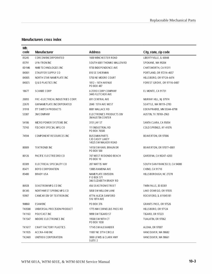
Replaceable Mechanical Parts
WFM 601A, WFM 601E, & WFM 601M Service Manual 10–3
Manufacturers cross index
Mfr.code Manufacturer Address City, state, zip code
05245 CORCOM INCORPORATED 1600 WINCHESTER ROAD LIBERTYVILLE, IL 60048
05791 LYN–TRON INC SOUTH 6001 THOMAS MALLEN RD SPOKANE, WA 99204
0D1M6 NMB TECHNOLOGIES INC 9730 INDEPENDENCE AVE CHATSWORTH, CA 91311
0KB01 STAUFFER SUPPLY CO 810 SE SHERMAN PORTLAND, OR 97214–4657
0KB05 NORTH STAR NAMEPLATE INC 5750 NE MOORE COURT HILLSBORO, OR 97124–6474
0KBZ5 Q & D PLASTICS INC 1812 – 16TH AVENUEPO BOX 487
FOREST GROVE, OR 97116–0487
18677 SCANBE CORP A ZERO CORP COMPANY3445 FLETCHER AVE
EL MONTE, CA 91731
20093 FRC–ELECTRICAL INDUSTRIES CORP. 691 CENTRAL AVE MURRAY HILL, NJ 07974
22670 GM NAMEPLATE INCORPORATED 2040 15TH AVE WEST SEATTLE, WA 98119–2783
31918 ITT SWITCH PRODUCTS 8081 WALLACE RD EDEN PRAIRIE, MN 55344–8798
53387 3M COMPANY ELECTRONICS PRODUCTS DIV3M AUSTIN CENTER
AUSTIN, TX 78769–2963
54186 MICRO POWER SYSTEMS INC 3151 JAY ST SANTA CLARA, CA 95054
73743 FISCHER SPECIAL MFG CO 111 INDUSTRIAL RDPO BOX 76500
COLD SPRINGS, KY 41076
74594 COMPONENT RESOURCES INC BUSSMAN PARTSC/O CASEY LAKEY14525 SW WALKER ROAD
BEAVERTON, OR 97006
80009 TEKTRONIX INC 14150 SW KARL BRAUN DRPO BOX 500
BEAVERTON, OR 97077–0001
80126 PACIFIC ELECTRICORD CO 747 WEST REDONDO BEACHPO BOX 10
GARDENA, CA 90247–4203
83309 ELECTRICAL SPECIALITY CO 287 WATTIS WAY SOUTH SAN FRANCISCO, CA 94080
85471 BOYD CORPORATION 13885 RAMONA AVE CHINO, CA 91710
85480 BRADY USA NAMEPLATE DIVISIONP O BOX 571346 ELIZABETH BRADY RD
HILLSBOROUGH, NC 27278
86928 SEASTROM MFG CO INC 456 SEASTROM STREET TWIN FALLS, ID 83301
8X345 NORTHWEST SPRING MFG CO 5858 SW WILLOW LANE LAKE OSWEGO, OR 97035
93907 CAMCAR DIV OF TEXTRON INC ATTN: ALICIA SANFORD516 18TH AVE
ROCKFORD, IL 611045181
9M860 ESAM INC PO BOX 376 GRANTS PASS, OR 97526
TK0588 UNIVERSAL PRECISION PRODUCT 1775 NW CORNELIUS PASS RD HILLSBORO, OR 97124
TK1163 POLYCAST INC 9898 SW TIGARD ST TIGARD, OR 97223
TK1547 MOORE ELECTRONICS INC 19500 SW 90TH CTPO BOX 1030
TUALATIN, OR 97062
TK1617 CRAFT FACTORY PLASTICS 17145 SW ALEXANDER ALOHA, OR 97007
TK1935 ACCRA–FAB INC 11007 NE 37TH CIRCLE VANCOUVER, WA 98682
TK2469 UNITREK CORPORATION 3000 LEWIS & CLARK HWYSUITE 2
VANCOUVER, WA 98661
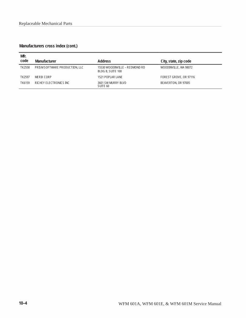
Replaceable Mechanical Parts
10–4 WFM 601A, WFM 601E, & WFM 601M Service Manual
Manufacturers cross index (cont.)
Mfr.code City, state, zip codeAddressManufacturerTK2558 PRISM SOFTWARE PRODUCTION, LLC 15530 WOODINVILLE – REDMOND RD
BLDG B, SUITE 100WOODINVILLE, WA 98072
TK2597 MERIX CORP 1521 POPLAR LANE FOREST GROVE, OR 97116
TK6159 RICHEY ELECTRONICS INC 3601 SW MURRY BLVDSUITE 60
BEAVERTON, OR 97005
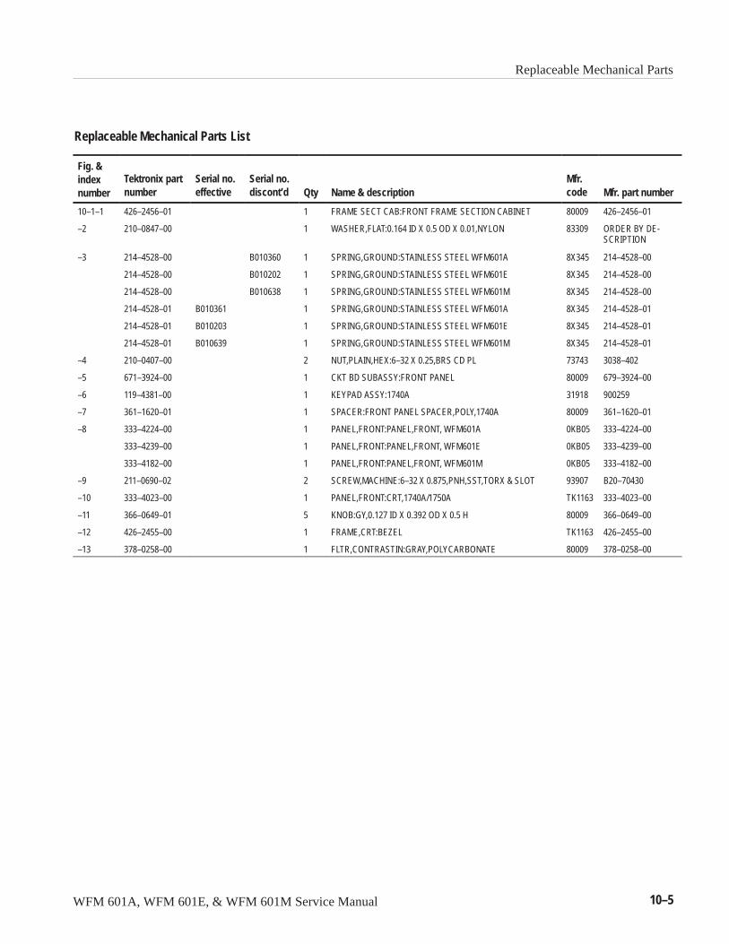
Replaceable Mechanical Parts
WFM 601A, WFM 601E, & WFM 601M Service Manual 10–5
Replaceable Mechanical Parts List
Fig. &indexnumber
Tektronix partnumber
Serial no.effective
Serial no.discont’d Qty Name & description
Mfr.code Mfr. part number
10–1–1 426–2456–01 1 FRAME SECT CAB:FRONT FRAME SECTION CABINET 80009 426–2456–01
–2 210–0847–00 1 WASHER,FLAT:0.164 ID X 0.5 OD X 0.01,NYLON 83309 ORDER BY DE-SCRIPTION
–3 214–4528–00 B010360 1 SPRING,GROUND:STAINLESS STEEL WFM601A 8X345 214–4528–00
214–4528–00 B010202 1 SPRING,GROUND:STAINLESS STEEL WFM601E 8X345 214–4528–00
214–4528–00 B010638 1 SPRING,GROUND:STAINLESS STEEL WFM601M 8X345 214–4528–00
214–4528–01 B010361 1 SPRING,GROUND:STAINLESS STEEL WFM601A 8X345 214–4528–01
214–4528–01 B010203 1 SPRING,GROUND:STAINLESS STEEL WFM601E 8X345 214–4528–01
214–4528–01 B010639 1 SPRING,GROUND:STAINLESS STEEL WFM601M 8X345 214–4528–01
–4 210–0407–00 2 NUT,PLAIN,HEX:6–32 X 0.25,BRS CD PL 73743 3038–402
–5 671–3924–00 1 CKT BD SUBASSY:FRONT PANEL 80009 679–3924–00
–6 119–4381–00 1 KEYPAD ASSY:1740A 31918 900259
–7 361–1620–01 1 SPACER:FRONT PANEL SPACER,POLY,1740A 80009 361–1620–01
–8 333–4224–00 1 PANEL,FRONT:PANEL,FRONT, WFM601A 0KB05 333–4224–00
333–4239–00 1 PANEL,FRONT:PANEL,FRONT, WFM601E 0KB05 333–4239–00
333–4182–00 1 PANEL,FRONT:PANEL,FRONT, WFM601M 0KB05 333–4182–00
–9 211–0690–02 2 SCREW,MACHINE:6–32 X 0.875,PNH,SST,TORX & SLOT 93907 B20–70430
–10 333–4023–00 1 PANEL,FRONT:CRT,1740A/1750A TK1163 333–4023–00
–11 366–0649–01 5 KNOB:GY,0.127 ID X 0.392 OD X 0.5 H 80009 366–0649–00
–12 426–2455–00 1 FRAME,CRT:BEZEL TK1163 426–2455–00
–13 378–0258–00 1 FLTR,CONTRASTIN:GRAY,POLYCARBONATE 80009 378–0258–00
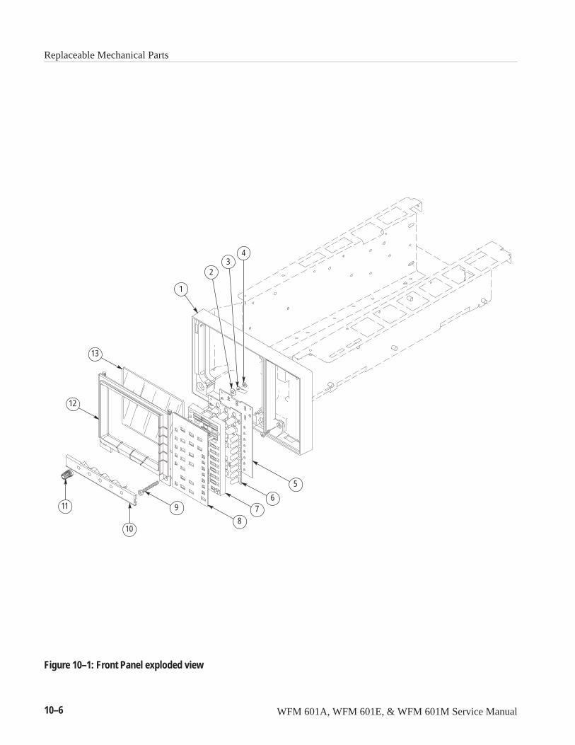
Replaceable Mechanical Parts
10–6 WFM 601A, WFM 601E, & WFM 601M Service Manual
1
23
4
5
67
8
9
10
11
12
13
Figure 10–1: Front Panel exploded view
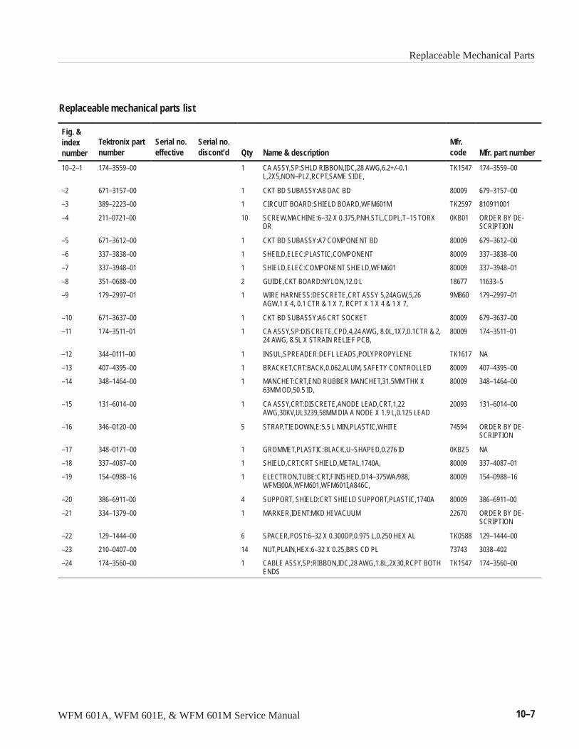
Replaceable Mechanical Parts
WFM 601A, WFM 601E, & WFM 601M Service Manual 10–7
Replaceable mechanical parts list
Fig. &indexnumber
Tektronix partnumber
Serial no.effective
Serial no.discont’d Qty Name & description
Mfr.code Mfr. part number
10–2–1 174–3559–00 1 CA ASSY,SP:SHLD RIBBON,IDC,28 AWG,6.2+/–0.1L,2X5,NON–PLZ,RCPT,SAME SIDE,
TK1547 174–3559–00
–2 671–3157–00 1 CKT BD SUBASSY:A8 DAC BD 80009 679–3157–00
–3 389–2223–00 1 CIRCUIT BOARD:SHIELD BOARD,WFM601M TK2597 810911001
–4 211–0721–00 10 SCREW,MACHINE:6–32 X 0.375,PNH,STL,CDPL,T–15 TORXDR
0KB01 ORDER BY DE-SCRIPTION
–5 671–3612–00 1 CKT BD SUBASSY:A7 COMPONENT BD 80009 679–3612–00
–6 337–3838–00 1 SHEILD,ELEC:PLASTIC,COMPONENT 80009 337–3838–00
–7 337–3948–01 1 SHIELD,ELEC:COMPONENT SHIELD,WFM601 80009 337–3948–01
–8 351–0688–00 2 GUIDE,CKT BOARD:NYLON,12.0 L 18677 11633–5
–9 179–2997–01 1 WIRE HARNESS:DESCRETE,CRT ASSY 5,24AGW,5,26AGW,1 X 4, 0.1 CTR & 1 X 7, RCPT X 1 X 4 & 1 X 7,
9M860 179–2997–01
–10 671–3637–00 1 CKT BD SUBASSY:A6 CRT SOCKET 80009 679–3637–00
–11 174–3511–01 1 CA ASSY,SP:DISCRETE,CPD,4,24 AWG, 8.0L,1X7,0.1CTR & 2,24 AWG, 8.5L X STRAIN RELIEF PCB,
80009 174–3511–01
–12 344–0111–00 1 INSUL,SPREADER:DEFL LEADS,POLYPROPYLENE TK1617 NA
–13 407–4395–00 1 BRACKET,CRT:BACK,0.062,ALUM, SAFETY CONTROLLED 80009 407–4395–00
–14 348–1464–00 1 MANCHET:CRT,END RUBBER MANCHET,31.5MM THK X63MM OD,50.5 ID,
80009 348–1464–00
–15 131–6014–00 1 CA ASSY,CRT:DISCRETE,ANODE LEAD,CRT,1,22AWG,30KV,UL3239,58MM DIA A NODE X 1.9 L,0.125 LEAD
20093 131–6014–00
–16 346–0120–00 5 STRAP,TIEDOWN,E:5.5 L MIN,PLASTIC,WHITE 74594 ORDER BY DE-SCRIPTION
–17 348–0171–00 1 GROMMET,PLASTIC:BLACK,U–SHAPED,0.276 ID 0KBZ5 NA
–18 337–4087–00 1 SHIELD,CRT:CRT SHIELD,METAL,1740A, 80009 337–4087–01
–19 154–0988–16 1 ELECTRON,TUBE:CRT,FINISHED,D14–375WA/988,WFM300A,WFM601,WFM601I,A846C,
80009 154–0988–16
–20 386–6911–00 4 SUPPORT, SHIELD:CRT SHIELD SUPPORT,PLASTIC,1740A 80009 386–6911–00
–21 334–1379–00 1 MARKER,IDENT:MKD HI VACUUM 22670 ORDER BY DE-SCRIPTION
–22 129–1444–00 6 SPACER,POST:6–32 X 0.300DP,0.975 L,0.250 HEX AL TK0588 129–1444–00
–23 210–0407–00 14 NUT,PLAIN,HEX:6–32 X 0.25,BRS CD PL 73743 3038–402
–24 174–3560–00 1 CABLE ASSY,SP:RIBBON,IDC,28 AWG,1.8L,2X30,RCPT BOTHENDS
TK1547 174–3560–00
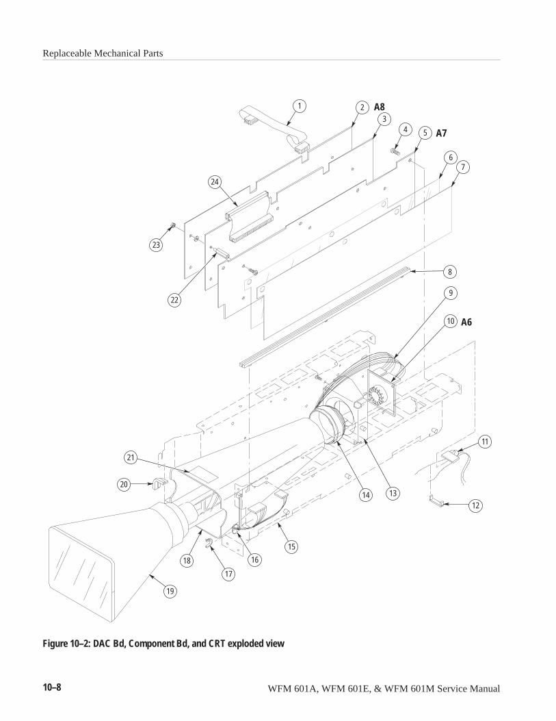
Replaceable Mechanical Parts
10–8 WFM 601A, WFM 601E, & WFM 601M Service Manual
1 2 A83
4 5 A7
67
8
9
10
11
12
1314
A6
15
16
17
18
19
20
21
22
23
24
Figure 10–2: DAC Bd, Component Bd, and CRT exploded view
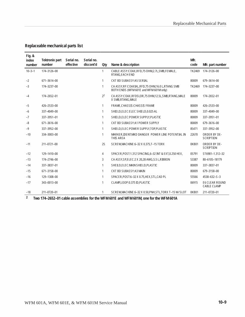
Replaceable Mechanical Parts
WFM 601A, WFM 601E, & WFM 601M Service Manual 10–9
Replaceable mechanical parts list
Fig. &indexnumber
Tektronix partnumber
Serial no.effective
Serial no.discont’d Qty Name & description
Mfr.code Mfr. part number
10–3–1 174–3126–00 1 CABLE ASSY:COAX,RFD,75 OHM,2.7L,SMB,FEMALE,RTANG,EACH END
TK2469 174–3126–00
–2 671–3614–00 1 CKT BD SUBASSY:A5 SERIAL 80009 679–3614–00
–3 174–3237–00 1 CA ASSY,RF:COAXIAL,RFD,75 OHM,16.0 L,RTANG SMBBOTH ENDS (WFM 601E and WFM 601M only)
TK2469 174–3237–00
–4 174–2652–01 22 CA ASSY:COAX,RFDSLDR,75 OHM,12.5L,SMB,RTANG,MALEX SMB,RTANG,MALE
80009 174–2652–01
–5 426–2533–00 1 FRAME,CHASSIS:CHASSIS FRAME 80009 426–2533–00
–6 337–4049–00 1 SHIELD,ELEC:ELEC SHIELD,0.025 AL 80009 337–4049–00
–7 337–3951–01 1 SHIELD,ELEC:POWER SUPPLY,PLASTIC 80009 337–3951–01
–8 671–3616–00 1 CKT BD SUBASSY:A1 POWER SUPPLY 80009 679–3616–00
–9 337–3952–00 1 SHIELD,ELEC:POWER SUPPLY,TOP,PLASTIC 85471 337–3952–00
–10 334–3003–00 1 MARKER,IDENT:MKD DANGER POWER LINE POTENTIAL INTHIS AREA
22670 ORDER BY DE-SCRIPTION
–11 211–0721–00 25 SCREW,MACHINE:6–32 X 0.375,T–15 TORX 0KB01 ORDER BY DE-SCRIPTION
–12 129–1410–00 4 SPACER,POST:1.312 SPACING,6–32 INT & EXT,0.250 HEX, 05791 ST6981–1.312–32
–13 174–2746–00 3 CA ASSY,SP,ELEC:2 X 20,28 AWG,5.5 L,RIBBON 53387 80–6105–18179
–14 337–3837–01 1 SHEILD,ELEC:MAIN SHIELD,PLASTIC 80009 337–3837–01
–15 671–3158–00 1 CKT BD SUBASSY:A3 MAIN 80009 679–3158–00
–16 129–1308–00 1 SPACER,POST:6–32 X 0.75,HEX,STL,CAD PL 55566 4538–632–S–3
–17 343–0013–00 1 CLAMP,LOOP:0.375 ID,PLASTIC 06915 E6 CLEAR ROUNDCABLE CLAMP
–18 211–0720–01 1 SCREW,MACHINE:6–32 X 0.50,PNH,STL,TORX T–15 W/ SLOT 0KB01 211–0720–01
2 Two 174–2652–01 cable assemblies for the WFM 601E and WFM 601M, one for the WFM 601A

Replaceable Mechanical Parts
10–10 WFM 601A, WFM 601E, & WFM 601M Service Manual
12
3
4
5
6
7
8 9
10
11
12
13
14
15
A5
A1
A316
17 18
Figure 10–3: Serial, Power, and Main boards exploded view
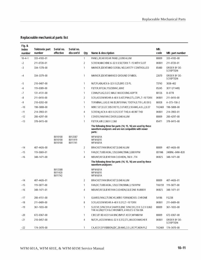
Replaceable Mechanical Parts
WFM 601A, WFM 601E, & WFM 601M Service Manual 10–11
Replaceable mechanical parts list
Fig. &indexnumber
Tektronix partnumber
Serial no.effective
Serial no.discont’d Qty Name & description
Mfr.code Mfr. part number
10–4–1 333–4183–01 1 PANEL,REAR:REAR PANEL,0.090 ALUM 80009 333–4183–00
–2 211–0720–01 2 SCREW,MACHINE:6–32 X 0.50,TORX T–15 WITH SLOT 0KB01 211–0720–01
–3 334–1378–00 1 MARKER,IDENT:MKD SERIAL NO,SAFETY CONTROLLED 85480 ORDER BY DE-SCRIPTION
–4 334–3379–00 1 MARKER,IDENT:MARKED GROUND SYMBOL 22670 ORDER BY DE-SCRIPTION
–5 210–0407–00 1 NUT,PLAIN,HEX:6–32 X 0.25,BRS CD PL 73743 3038–402
–6 119–0389–00 1 FILTER,RFI:3A,115/230VAC,60HZ 05245 3EF1 (F1449)
–7 131–4131–00 1 CONN,PLUG,ELEC:MALE W/LOCKING ADPTR 80126 B–0778
–8 211–0410–00 2 SCR,ASSEM WSHR:4–40 X 0.437,PNH,STL,CDPL,T–10 TORX 0KB01 211–0410–00
–9 210–0202–00 1 TERMINAL,LUG:0.146 ID,INTERNAL TOOTH,0.719 L,45 DEG 86928 A–373–158–2
–10 198–5808–00 1 WIRE SET,ELEC:DISCRETE,CUT/KIT,3,18 AWG,4.0 L,2,0.37 TK2469 198–5808–00
–11 214–3903–01 4 SCREW,JACK:4–40 X 0.312 EXT THD,4–40 INT THD 0KB01 214–3903–01
–12 200–4297–00 1 COVER,FAN:FAN COVER,0.040 ALUM 80009 200–4297–00
–13 378–0415–00 1 FILTER,AIR:2.360 X 2.360 85471 378–0415–00
The following three fan parts (14, 15, 16) are used by thesewaveform analyzers and are not compatible with newerparts:
B010100B010100B010100
B012587B011419B011741
WFM 601AWFM 601EWFM 601A
–14 407–4426–00 2 BRACKET:FAN BRACKET,0.040 ALUM 80009 407–4426–00
–15 119–5069–01 1 FAN,DC:TUBEAXIAL,12V,0.84W,70MA,3,000 RPM 0D1M6 2408NL–04W–B20
–16 348–1471–00 4 MOUNT,RESILIENT:FAN CUSHION,.760 X .774 0KBZ5 348–1471–00
The following three fan parts (14, 15, 16) are used by thesewaveform analyzers:
B012588B011420B011742
WFM 601AWFM 601EWFM 601A
–14 407–4426–01 2 BRACKET:FAN BRACKET,0.040 ALUM 80009 407–4426–01
–15 119–5877–00 1 FAN,DC:TUBEAXIAL,12V,0.72W,90MA,3,150 RPM TK6159 119–5877–00
–16 348–1471–01 4 MOUNT,RESILIENT:FAN CUSHION,SILICONE RUBBER 0KBZ5 348–1471–01
–17 200–4151–00 1 GUARD,FAN:2,75 INCHS,WIRE FORM,NICKEL CHROME 54186 FG238
–18 211–0409–00 8 SCR,ASSEM WSHR:4–40 X 0.312,T–10 TORX 0KB01 211–0409–00
–19 361–1655–00 1 SLEEVE,SPACER:A SHAPED,BNC SPACER,2.9 X 3.2 X 0.063THK ALUM,ETCH & CHROMATE,4 HOLES 0.156 DIA
80009 361–1655–00
–20 672–0367–00 1 CIRCUIT BD ASSY:A4 BNC/INPUT ASSY,WFM601M 80009 672–0367–00
–21 210–0457–00 4 NUT,PL,ASSEM WA:6–32 X 0.312,STL,W/LOCKWASHER 0KB01 ORDER BY DE-SCRIPTION
–22 174–3470–00 1 CA,ASSY,SP:RIBBON,IDC,28 AWG,3.5 L,RCPT,NON PLZ TK2469 174–3470–00
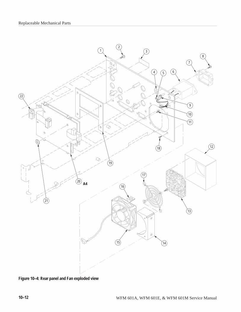
Replaceable Mechanical Parts
10–12 WFM 601A, WFM 601E, & WFM 601M Service Manual
12
3
4 5 6
7
8
9
10
11
12
13
1415
16
17
18
19
20
21
22
A4
Figure 10–4: Rear panel and Fan exploded view


Related Documents