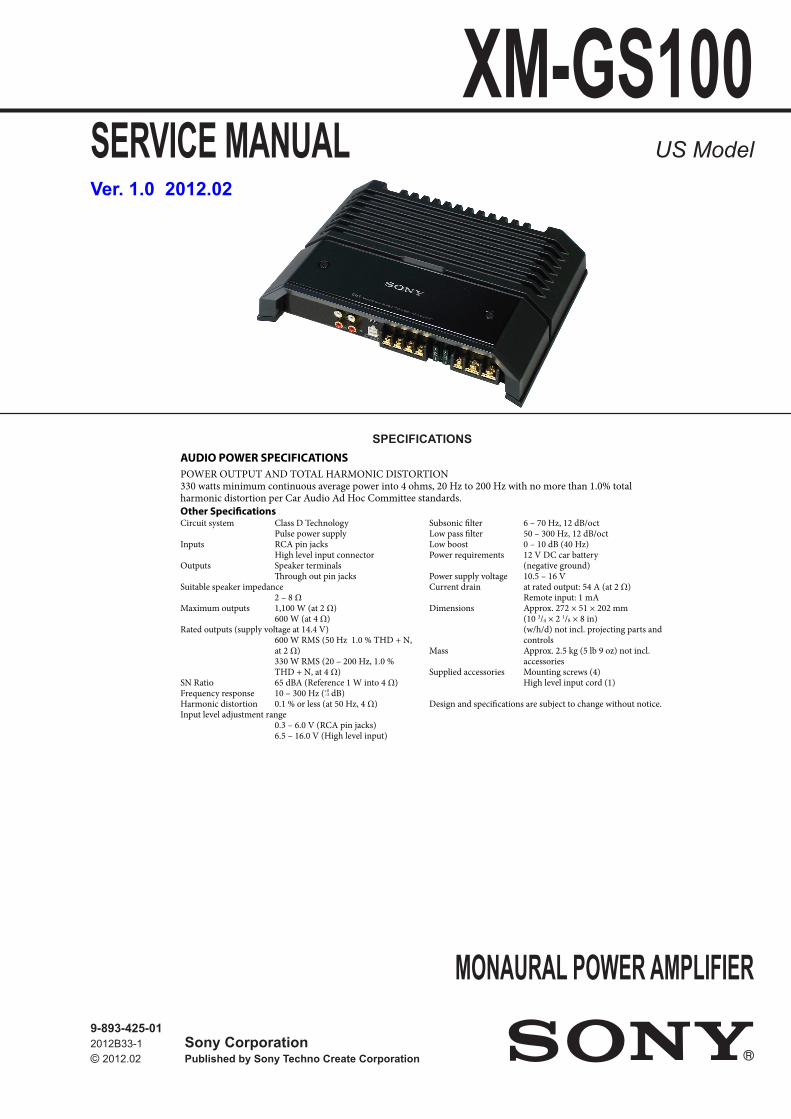
SERVICE MANUAL Sony Corporation Published by Sony Techno Create Corporation XM-GS100 SPECIFICATIONS MONAURAL POWER AMPLIFIER 9-893-425-01 2012B33-1 © 2012.02 US Model Ver. 1.0 2012.02 AUDIO POWER SPECIFICATIONS POWER OUTPUT AND TOTAL HARMONIC DISTORTION 330 watts minimum continuous average power into 4 ohms, 20 Hz to 200 Hz with no more than 1.0% total harmonic distortion per Car Audio Ad Hoc Committee standards. Other Specifications Circuit system Class D Technology Pulse power supply Inputs RCA pin jacks High level input connector Outputs Speaker terminals rough out pin jacks Suitable speaker impedance 2 – 8 Ω Maximum outputs 1,100 W (at 2 Ω) 600 W (at 4 Ω) Rated outputs (supply voltage at 14.4 V) 600 W RMS (50 Hz 1.0 % THD + N, at 2 Ω) 330 W RMS (20 – 200 Hz, 1.0 % THD + N, at 4 Ω) SN Ratio 65 dBA (Reference 1 W into 4 Ω) Frequency response 10 – 300 Hz ( dB) Harmonic distortion 0.1 % or less (at 50 Hz, 4 Ω) Input level adjustment range 0.3 – 6.0 V (RCA pin jacks) 6.5 – 16.0 V (High level input) Subsonic filter 6 – 70 Hz, 12 dB/oct Low pass filter 50 – 300 Hz, 12 dB/oct Low boost 0 – 10 dB (40 Hz) Power requirements 12 V DC car battery (negative ground) Power supply voltage 10.5 – 16 V Current drain at rated output: 54 A (at 2 Ω) Remote input: 1 mA Dimensions Approx. 272 × 51 × 202 mm (10 3 /4 × 2 1 /8 × 8 in) (w/h/d) not incl. projecting parts and controls Mass Approx. 2.5 kg (5 lb 9 oz) not incl. accessories Supplied accessories Mounting screws (4) High level input cord (1) Design and specifications are subject to change without notice.

Welcome message from author
This document is posted to help you gain knowledge. Please leave a comment to let me know what you think about it! Share it to your friends and learn new things together.
Transcript
SERVICE MANUAL
Sony CorporationPublished by Sony Techno Create Corporation
XM-GS100
SPECIFICATIONS
MONAURAL POWER AMPLIFIER9-893-425-012012B33-1© 2012.02
US Model
Ver. 1.0 2012.02
AUDIO POWER SPECIFICATIONS
POWER OUTPUT AND TOTAL HARMONIC DISTORTION 330 watts minimum continuous average power into 4 ohms, 20 Hz to 200 Hz with no more than 1.0% total harmonic distortion per Car Audio Ad Hoc Committee standards.
Other SpecificationsCircuit system Class D Technology Pulse power supplyInputs RCA pin jacks High level input connectorOutputs Speaker terminals Through out pin jacksSuitable speaker impedance 2 – 8 Ω Maximum outputs 1,100 W (at 2 Ω) 600 W (at 4 Ω)Rated outputs (supply voltage at 14.4 V) 600 W RMS (50 Hz 1.0 % THD + N,
at 2 Ω) 330 W RMS (20 – 200 Hz, 1.0 %
THD + N, at 4 Ω)SN Ratio 65 dBA (Reference 1 W into 4 Ω)Frequency response 10 – 300 Hz ( dB)Harmonic distortion 0.1 % or less (at 50 Hz, 4 Ω)Input level adjustment range
0.3 – 6.0 V (RCA pin jacks)6.5 – 16.0 V (High level input)
Subsonic filter 6 – 70 Hz, 12 dB/octLow pass filter 50 – 300 Hz, 12 dB/octLow boost 0 – 10 dB (40 Hz)Power requirements 12 V DC car battery
(negative ground)Power supply voltage 10.5 – 16 VCurrent drain at rated output: 54 A (at 2 Ω) Remote input: 1 mADimensions Approx. 272 × 51 × 202 mm
(10 3/4 × 2 1/8 × 8 in) (w/h/d) not incl. projecting parts and controls
Mass Approx. 2.5 kg (5 lb 9 oz) not incl. accessories
Supplied accessories Mounting screws (4) High level input cord (1)
Design and specifications are subject to change without notice.
XM-GS100
2
TABLE OF CONTENTS
NOTES ON CHIP COMPONENT REPLACEMENT• Never reuse a disconnected chip component.• Notice that the minus side of a tantalum capacitor may be dam-
aged by heat.
1. SERVICING NOTES ............................................. 2
2. GENERAL .................................................................. 3
3. DISASSEMBLY3-1. Disassembly Flow ........................................................... 53-2. Bottom Plate Block ......................................................... 53-3. MAIN Board Block ........................................................ 63-4. MAIN Board ................................................................... 63-5. CONTROL Board Block ................................................ 7
4. DIAGRAMS4-1. Printed Wiring Board
- MAIN Board (Component Side) (Suffi x-11) - ............. 94-2. Printed Wiring Board
- MAIN Board (Conductor Side) (Suffi x-11) - ............... 104-3. Printed Wiring Board
- MAIN Board (Component Side) (Suffi x-12) - ............. 114-4. Printed Wiring Board
- MAIN Board (Conductor Side) (Suffi x-12) - ............... 124-5. Schematic Diagram - MAIN Board (1/2) - ..................... 134-6. Schematic Diagram - MAIN Board (2/2) - ..................... 144-7. Printed Wiring Boards - CONTROL/LED Boards - ....... 154-8. Schematic Diagram - CONTROL/LED Boards - ........... 16
5. EXPLODED VIEWS5-1. Heat Sink (Main) Section ............................................... 175-2. MAIN Board Section ...................................................... 185-3. CONTROL Board Section .............................................. 19
6. ELECTRICAL PARTS LIST ............................ 20
Accessories are given in the last of the electrical parts list.
SECTION 1SERVICING NOTES
UNLEADED SOLDERBoards requiring use of unleaded solder are printed with the lead-free mark (LF) indicating the solder contains no lead.(Caution: Some printed circuit boards may not come printed with
the lead free mark due to their particular size)
: LEAD FREE MARKUnleaded solder has the following characteristics.• Unleaded solder melts at a temperature about 40 °C higher
than ordinary solder. Ordinary soldering irons can be used but the iron tip has to be
applied to the solder joint for a slightly longer time. Soldering irons using a temperature regulator should be set to
about 350 °C.Caution: The printed pattern (copper foil) may peel away if
the heated tip is applied for too long, so be careful!• Strong viscosity Unleaded solder is more viscous (sticky, less prone to fl ow)
than ordinary solder so use caution not to let solder bridges occur such as on IC pins, etc.
• Usable with ordinary solder It is best to use only unleaded solder but unleaded solder may
also be added to ordinary solder.
CONFIRMING THE OPERATIONPlease confi rm the car audio unit works even if REM output is not connected when you connect this unit with the car audio unit by the HIGH LEVEL input.
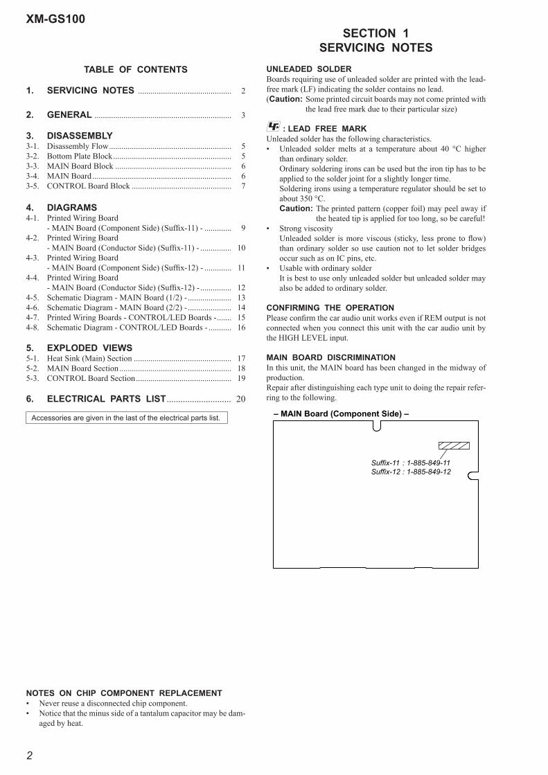
MAIN BOARD DISCRIMINATIONIn this unit, the MAIN board has been changed in the midway of production.Repair after distinguishing each type unit to doing the repair refer-ring to the following.
– MAIN Board (Component Side) –
Suffix-11 : 1-885-849-11Suffix-12 : 1-885-849-12
XM-GS100
3
SECTION 2GENERAL
This section is extracted from instruction manual.
Power Connection Wires (not supplied)
Câbles d’alimentation (non fournis)
Cables de conexión de alimentación (no suministrados)
to a metal point of the car
vers une partie métallique de la carrosserie
a un punto metálico del automóvil
Connections/Connexions/Conexiones
+12V car battery Batterie de voiture +12V
Batería de automóvil de +12V
Car audio unit
Autoradio
Sistema de audio para automóvil
Remote output*1
Sortie de télécommande*1
(REM OUT)Salida remota*1
(REM OUT)less than 450 mm (18 in)moins de 450 mm (18 po)menos de 450 mm
*2
CautionsBefore making any connections, disconnect the ground terminal of the car battery to avoid short circuits.Be sure to use speakers with an adequate power rating. If you use small capacity speakers, they may be damaged.Do not connect the terminal of the speaker system to the car chassis, and do not connect the terminal of the right speaker with that of the left speaker.Install the input and output cords away from the power supply wire as running them close together can generate some interference noise.
This unit is a high powered amplifier. Therefore, it may not perform to its full potential if used with the speaker cords supplied with the car.
If your car is equipped with a computer system for navigation or some other purpose, do not remove the ground wire from the car battery. If you disconnect the wire, the computer memory may be erased. To avoid short circuits when making connections, disconnect the +12V power supply wire until all the other wires have been connected.
Notes on the power supply Connect the +12V power supply wire only after all the other wires have been connected.
Be sure to connect the ground wire of the unit securely to a metal point of the car. A loose connection may cause a malfunction of the amplifier.
Be sure to connect the remote control wire of the car audio unit to the remote terminal.
When using a car audio unit without a remote output on the amplifier, connect the remote input terminal (REMOTE) to the accessory power supply.
Use a power supply wire with a fuse attached (60 A).
All power wires connected to the positive battery post should be fused within 450 mm (18 in) of the battery post, and before they pass through any metal.
Make sure that the vehicle’s battery wires connected to the vehicle are of a wire gauge at least equal to that of the main power wire connected from the battery to the amplifier.
Make sure that the wires to be connected to the +12V and GND terminals of this unit are at least 4-Gauge (AWG-4) or have a sectional area of more than 22.0 mm2 (7/8 in2).
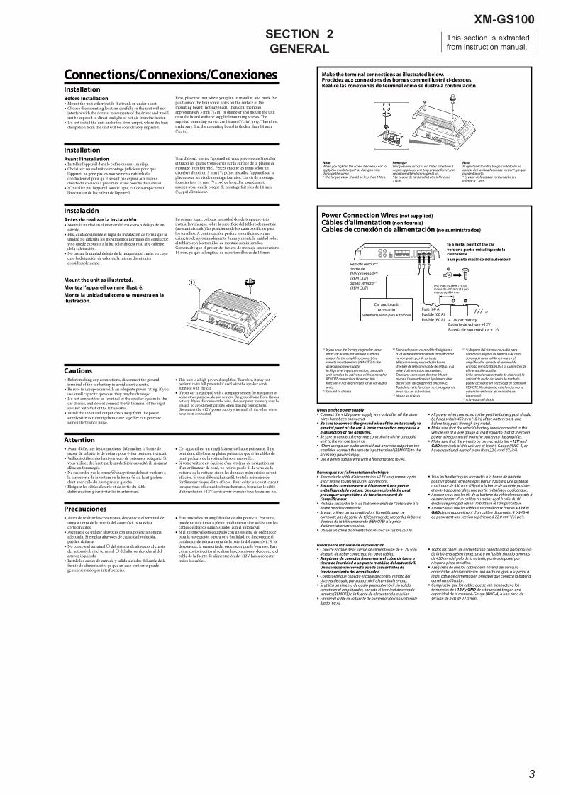
Mount the unit as illustrated.
Montez l’appareil comme illustré.
Monte la unidad tal como se muestra en la ilustración.
InstallationBefore Installation
Mount the unit either inside the trunk or under a seat.Choose the mounting location carefully so the unit will not interfere with the normal movements of the driver and it will not be exposed to direct sunlight or hot air from the heater.Do not install the unit under the floor carpet, where the heat dissipation from the unit will be considerably impaired.
First, place the unit where you plan to install it, and mark the positions of the four screw holes on the surface of the mounting board (not supplied). Then drill the holes approximately 3 mm (1/8 in) in diameter and mount the unit onto the board with the supplied mounting screws. The supplied mounting screws are 14 mm (9/16 in) long. Therefore, make sure that the mounting board is thicker than 14 mm (9/16 in).
*1 If you have the factory original or some other car audio unit without a remote output for the amplifier, connect the remote input terminal (REMOTE) to the accessory power supply. In High level input connection, car audio unit can also be activated without need for REMOTE connection. However, this function is not guaranteed for all car audio units.
*2 Ground to chassis
*1 Si vous disposez du modèle d’origine ou d’un autre autoradio dont l’amplificateur ne comporte pas de sortie de télécommande, raccordez la borne d’entrée de télécommande (REMOTE) à la prise d’alimentation accessoires. Dans une connexion d’entrée à haut niveau, l’autoradio peut également être activé sans raccordement à REMOTE. Toutefois, cette fonction n’est pas garantie pour tous les autoradios.
*2 Masse au châssis
*1 Si dispone del sistema de audio para automóvil original de fábrica o de otro sistema sin una salida remota en el amplificador, conecte el terminal de entrada remota (REMOTE) al suministro de alimentación auxiliar. En la conexión de entrada de alto nivel, la unidad de audio del vehículo también puede activarse sin necesidad de conexión REMOTE. No obstante, esta función no se garantiza en todas las unidades de automóvil.
*2 A la masa del chasis
InstallationAvant l’installation
Installez l’appareil dans le coffre ou sous un siège.Choisissez un endroit de montage judicieux pour que l’appareil ne gêne pas les mouvements naturels du conducteur et pour qu’il ne soit pas exposé aux rayons directs du soleil ou à proximité d’une bouche d’air chaud.N’installez pas l’appareil sous le tapis, car cela empêcherait l’évacuation de la chaleur de l’appareil.
Tout d’abord, mettez l’appareil où vous prévoyez de l’installer et tracez les quatre trous de vis sur la surface de la plaque de montage (non fournie). Percez ensuite les trous selon un diamètre d’environ 3 mm (1/8 po) et installez l’appareil sur la plaque avec les vis de montage fournies. Les vis de montage fournies font 14 mm (9/16 po) de long. Par conséquent, assurez-vous que la plaque de montage fait plus de 14 mm (9/16 po) d’épaisseur.
AttentionAvant d’effectuer les connexions, débranchez la borne de masse de la batterie de voiture pour éviter tout court-circuit.Veillez à utiliser des haut-parleurs de puissance adéquate. Si vous utilisez des haut-parleurs de faible capacité, ils risquent d’être endommagés.Ne raccordez pas la borne du système de haut-parleurs à la carrosserie de la voiture ou la borne du haut-parleur droit avec celle du haut-parleur gauche.Éloignez les câbles d’entrée et de sortie du câble d’alimentation pour éviter les interférences.
Cet appareil est un amplificateur de haute puissance. Il ne peut donc déployer sa pleine puissance que si les câbles de haut-parleurs de la voiture lui sont raccordés.Si votre voiture est équipée d’un système de navigation ou d’un ordinateur de bord, ne retirez pas le fil de terre de la batterie de la voiture, sinon les données mémorisées seront effacées. Si vous débranchez ce fil, toute la mémoire de l’ordinateur risque d’être effacée. Pour éviter un court-circuit lorsque vous effectuez les branchements, branchez le câble d’alimentation +12V après avoir branché tous les autres fils.
Make the terminal connections as illustrated below.Procédez aux connexions des bornes comme illustré ci-dessous.Realice las conexiones de terminal como se ilustra a continuación.
NoteWhen you tighten the screw, be careful not to apply too much torque* as doing so may damage the screw.*
RemarqueLorsque vous vissez la vis, faites attention à ne pas appliquer une trop grande force*, car cela pourrait endommager la vis.* Le couple de torsion doit être inférieur à
NotaAl apretar el tornillo, tenga cuidado de no aplicar demasiada fuerza de torsión*, ya que puede dañarlo.* El valor de fuerza de torsión debe ser
Fuse (60 A)
Fusible (60 A)
Fusible (60 A)
Remarques sur l’alimentation électrique Raccordez le câble d’alimentation +12V uniquement après avoir réalisé toutes les autres connexions.
Raccordez correctement le fil de terre à une partie métallique de la voiture. Une connexion lâche peut provoquer un problème de fonctionnement de l’amplificateur.
Veillez à raccorder le fil de télécommande de l’autoradio à la borne de télécommande.
Si vous utilisez un autoradio dont l’amplificateur ne comporte pas de sortie de télécommande, raccordez la borne d’entrée de la télécommande (REMOTE) à la prise d’alimentation accessoires.
Utilisez un câble d’alimentation muni d’un fusible (60 A).
Tous les fils électriques raccordés à la borne de batterie positive doivent être protégés par un fusible à une distance maximum de 450 mm (18 po) à la borne de batterie positive et avant de passer dans une partie métallique quelconque.
Assurez-vous que les fils de la batterie du véhicule raccordés à ce dernier sont d’un calibre au moins égal à celui du fil électrique principal reliant la batterie et l’amplificateur.
Assurez-vous que les câbles à raccorder aux bornes +12V et GND de cet appareil sont d’un calibre d’au moins 4 (AWG-4) ou possèdent une section supérieure à 22,0 mm2 (7/8 po2).
Notas sobre la fuente de alimentación Conecte el cable de la fuente de alimentación de +12V sólo después de haber conectado los otros cables.
Asegúrese de conectar firmemente el cable de toma a tierra de la unidad a un punto metálico del automóvil. Una conexión incorrecta puede causar fallos de funcionamiento del amplificador.
Compruebe que conecta el cable de control remoto del sistema de audio para automóvil al terminal remoto.
Si utiliza un sistema de audio para automóvil sin salida remota en el amplificador, conecte el terminal de entrada remota (REMOTE) a la fuente de alimentación auxiliar.
Emplee el cable de la fuente de alimentación con un fusible fijado (60 A).
Todos los cables de alimentación conectados al polo positivo de la batería deben conectarse a un fusible situado a menos de 450 mm del polo de la batería, y antes de pasar por ninguna pieza metálica.
Asegúrese de que los cables de la batería del vehículo conectados al mismo tienen una anchura igual o superior a la del cable de alimentación principal que conecta la batería con el amplificador.
Compruebe que los cables que se van a conectar a los terminales de +12V y GND de esta unidad tengan una capacidad de al menos 4-Gauge (AWG-4) o una zona de sección de más de 22,0 mm2.
InstalaciónAntes de realizar la instalación
Monte la unidad en el interior del maletero o debajo de un asiento.Elija cuidadosamente el lugar de instalación de forma que la unidad no dificulte los movimientos normales del conductor y no quede expuesta a la luz solar directa ni al aire caliente de la calefacción.No instale la unidad debajo de la moqueta del suelo, en cuyo caso la disipación de calor de la misma disminuirá considerablemente.
En primer lugar, coloque la unidad donde tenga previsto instalarla y marque sobre la superficie del tablero de montaje (no suministrado) las posiciones de los cuatro orificios para los tornillos. A continuación, perfore los orificios con un diámetro de aproximadamente 3 mm y monte la unidad sobre el tablero con los tornillos de montaje suministrados. Compruebe que el grosor del tablero de montaje sea superior a 14 mm, ya que la longitud de estos tornillos es de 14 mm.
PrecaucionesAntes de realizar las conexiones, desconecte el terminal de toma a tierra de la batería del automóvil para evitar cortocircuitos.Asegúrese de utilizar altavoces con una potencia nominal adecuada. Si emplea altavoces de capacidad reducida, pueden dañarse.No conecte el terminal del sistema de altavoces al chasis del automóvil, ni el terminal del altavoz derecho al del altavoz izquierdo.Instale los cables de entrada y salida alejados del cable de la fuente de alimentación, ya que en caso contrario puede generarse ruido por interferencias.
Esta unidad es un amplificador de alta potencia. Por tanto, puede no funcionar a pleno rendimiento si se utiliza con los cables de altavoz suministrados con el automóvil.Si el automóvil está equipado con un sistema de ordenador para la navegación o para otra finalidad, no desconecte el conductor de toma a tierra de la batería del automóvil. Si lo desconecta, la memoria del ordenador puede borrarse. Para evitar cortocircuitos al realizar las conexiones, desconecte el cable de la fuente de alimentación de +12V hasta conectar todos los cables.

XM-GS100
4
Input ConnectionsFor details on the settings of controls, refer to “Location and Function of Controls”.
Line Input Connection (with Speaker Connection )
Connexion d’entrée de ligne (avec connexion de haut-parleur )
Conexión de entrada de línea (con conexión de altavoces )
Line Input Connection (with Speaker Connection )
Connexion d’entrée de ligne (avec connexion de haut-parleur )
Conexión de entrada de línea (con conexión de altavoces )
High Level Input Connection (with Speaker Connection or )
Connexion d’entrée de haut niveau (avec connexion de haut-parleur ou )
Conexión de entrada de alto nivel (con conexión de altavoces o )
Car audio unit
Autoradio
Sistema de audio para automóvil
LINE OUT
Car audio unit
Autoradio
Sistema de audio para automóvil
LINE OUT
Right channel
Canal droit
Canal derecho
Left channel
Canal gaucheCanal izquierdo
Lorsque vous raccordez des amplificateurs à l’aide des prises à broches THROUGH OUT, vous pouvez raccorder jusqu’à trois amplificateurs.Sinon, les niveaux de sortie requis ne peuvent pas être obtenus et votre autoradio risque d’être endommagé.
Utilisez la borne THROUGH OUT lorsque vous installez plusieurs amplificateurs. Les signaux audio transitent par les prises à broches THROUGH OUT sans subir aucun traitement.
When you connect amplifiers using the THROUGH OUT pin jacks, it allows you to connect up to a maximum of three.Otherwise the necessary output levels cannot be obtained, and your car audio unit may be damaged.
Use the THROUGH OUT terminal when you install more amplifiers. Audio signals pass through the THROUGH OUT pin jacks unaffected by any signal processing.
Car audio unit
Autoradio
Sistema de audio para automóvil
LINE OUT
Rear
Arrière
Traseros
Front
Avant
Delanteros
LINE OUT
THROUGH OUT INPUT
Connexions d’entréePour plus de détails sur les réglages des commandes, reportez-vous à « Emplacement et fonction des commandes ».
Si conecta los amplificadores mediante las tomas de pines THROUGH OUT, podrá conectar un máximo de tres.De lo contrario, no se podrán obtener los niveles de salida necesarios y el sistema de audio para automóvil podría dañarse.
Si instala varios amplificadores, utilice el terminal THROUGH OUT. Las señales de audio se emitirán a través de las tomas de pines THROUGH OUT que no estén afectadas por ningún proceso de señal.
1-Speaker System (with Input Connection or )
Système à 1 haut-parleur (avec connexion d’entrée ou )
Sistema de 1 altavoz (con conexión de entrada o )
Speaker ConnectionsFor details on the settings of controls, refer to “Location and Function of Controls”.
2-Speaker System (with Input Connection or )
Système à 2 haut-parleurs (avec connexion d’entrée ou )
Sistema de 2 altavoces (con conexión de entrada o )
1-Speaker System (with Input Connection )
Système à 1 haut-parleur (avec connexion d’entrée )
Sistema de 1 altavoz (con conexión de entrada )
2-Way System (with Input Connection )
Système à 2 voies (avec connexion d’entrée )
Sistema de 2 vías (con conexión de entrada )
Subwoofer* (min. TOTAL 2 Ω)
Caisson de graves* (min. TOTAL 2 Ω)
Altavoz potenciador de graves* (mín. TOTAL 2 Ω)
Right subwoofer* (min. TOTAL 2 Ω)
Caisson de graves droit* (min. TOTAL 2 Ω)
Altavoz potenciador de graves derecho* (mín. TOTAL 2 Ω)
Left subwoofer* (min. TOTAL 2 Ω)
Caisson de graves gauche* (min. TOTAL 2 Ω)
Altavoz potenciador de graves izquierdo* (mín. TOTAL 2 Ω)
Subwoofer* (min. TOTAL 4 Ω)
Caisson de graves* (min. TOTAL 4 Ω)
Altavoz potenciador de graves* (mín. TOTAL 4 Ω)
Subwoofer* (min. TOTAL 4 Ω)
Caisson de graves* (min. TOTAL 4 Ω)
Altavoz potenciador de graves* (mín. TOTAL 4 Ω)
Subwoofer* (min. TOTAL 2 Ω)
Caisson de graves* (min. TOTAL 2 Ω)
Altavoz potenciador de graves* (mín. TOTAL 2 Ω)
Rear speaker (min. 2 Ω)
Haut-parleurs arrière (min. 2 Ω)
Altavoces traseros (mín. 2 Ω)
Front speaker (min. 2 Ω)
Haut-parleurs avant (min. 2 Ω)
Altavoces delanteros (mín. 2 Ω)
Connexions de haut-parleursPour plus de détails sur les réglages des commandes, reportez-vous à « Emplacement et fonction des commandes ».
* Les bornes de sortie des haut-parleurs sont câblées parallèlement en interne. Lorsque les deux bornes sont utilisées, l’impédance minimale de chaque haut-parleur doit être égale à 4 Ω.
* Los terminales de salida del altavoz están conectados internamente en paralelo. Al usar ambos terminales de altavoz, la impedancia mínima de cada altavoz debe ser de 4 Ω.
* The speaker output terminals are wired in parallel internally. When using both speaker terminals, the minimum impedance of each speaker must be 4 Ω.
Conexiones de entr adaPara obtener más información sobre los ajustes de controles, consulte “Ubicación y función de los controles”.
Line Input Connection (with Speaker Connection or )
Connexion d’entrée de ligne (avec connexion de haut-parleur ou )
Conexión de entrada de línea (con conexión de altavoces o )
Conexiones de los alta vocesPara obtener más información sobre los ajustes de los controles, consulte “Ubicación y función de los controles”.
*terminal.
2 Ω in total.
*vous raccordez.
égale à 2 Ω au total.
*de salida.
2 Ω en total.
*terminal.
2 Ω in total.
*vous raccordez.
égale à 2 Ω au total.
*de salida.
2 Ω en total.
*terminal.
2 Ω in total.
*vous raccordez.
égale à 2 Ω au total.
*de salida.
2 Ω en total.
Car audio unitAutoradio
Sistema de audio para automóvil
Left speaker
Haut-parleur gauche
Altavoz izquierdo
Right speaker
Haut-parleur droit
Altavoz derecho
Gray/Black striped
Rayé gris/noir
Con rayas grises o negras
White/Black striped
Rayé blanc/noir
Con rayas blancas o negras
Gray
Gris
Gris
White
Blanc
Blanco
Left
Gauche
Izquierdo
Left
Gauche
Izquierdo
Right
Droit
Derecho
Right
Droit
Derecho
XM-GS100
5
SECTION 3DISASSEMBLY
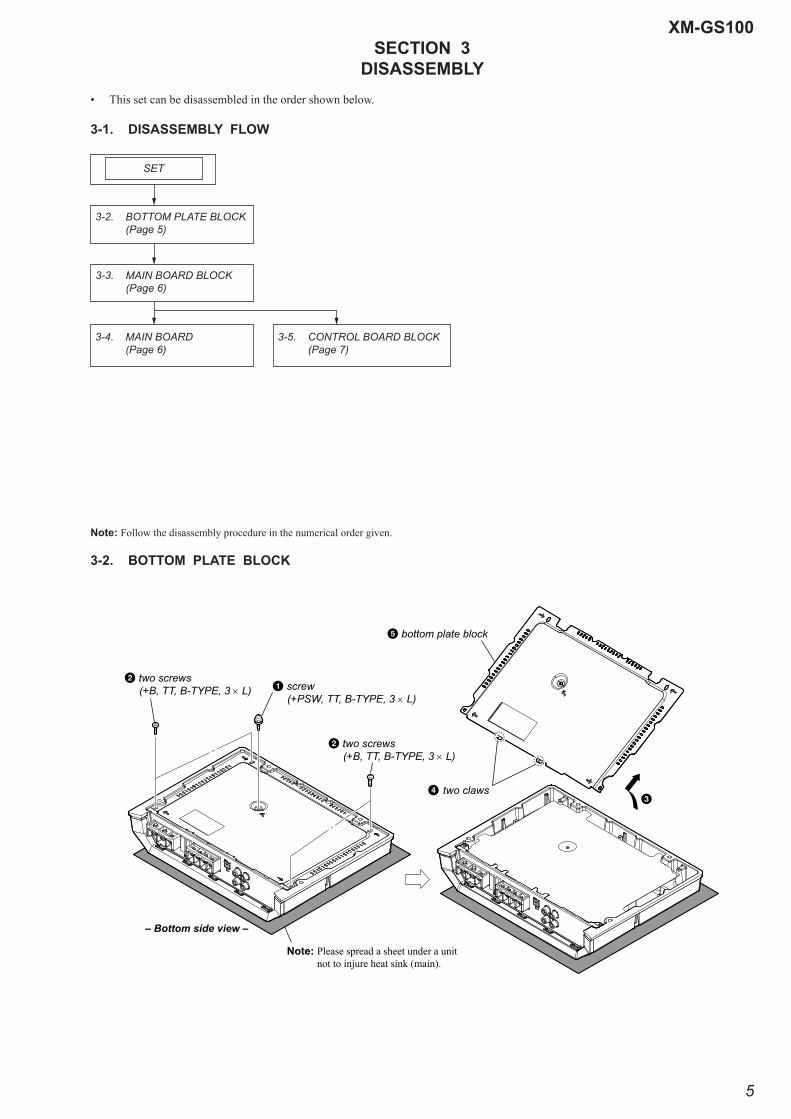
• This set can be disassembled in the order shown below.
3-1. DISASSEMBLY FLOW
Note: Follow the disassembly procedure in the numerical order given.
3-2. BOTTOM PLATE BLOCK
3-2. BOTTOM PLATE BLOCK (Page 5)
3-3. MAIN BOARD BLOCK (Page 6)
SET
3-4. MAIN BOARD (Page 6)
3-5. CONTROL BOARD BLOCK (Page 7)
– Bottom side view –
Note: Please spread a sheet under a unit not to injure heat sink (main).
5 bottom plate block
2 two screws (+B, TT, B-TYPE, 3 L)
2 two screws (+B, TT, B-TYPE, 3 L)
1 screw (+PSW, TT, B-TYPE, 3 L)
34 two claws
XM-GS100
6
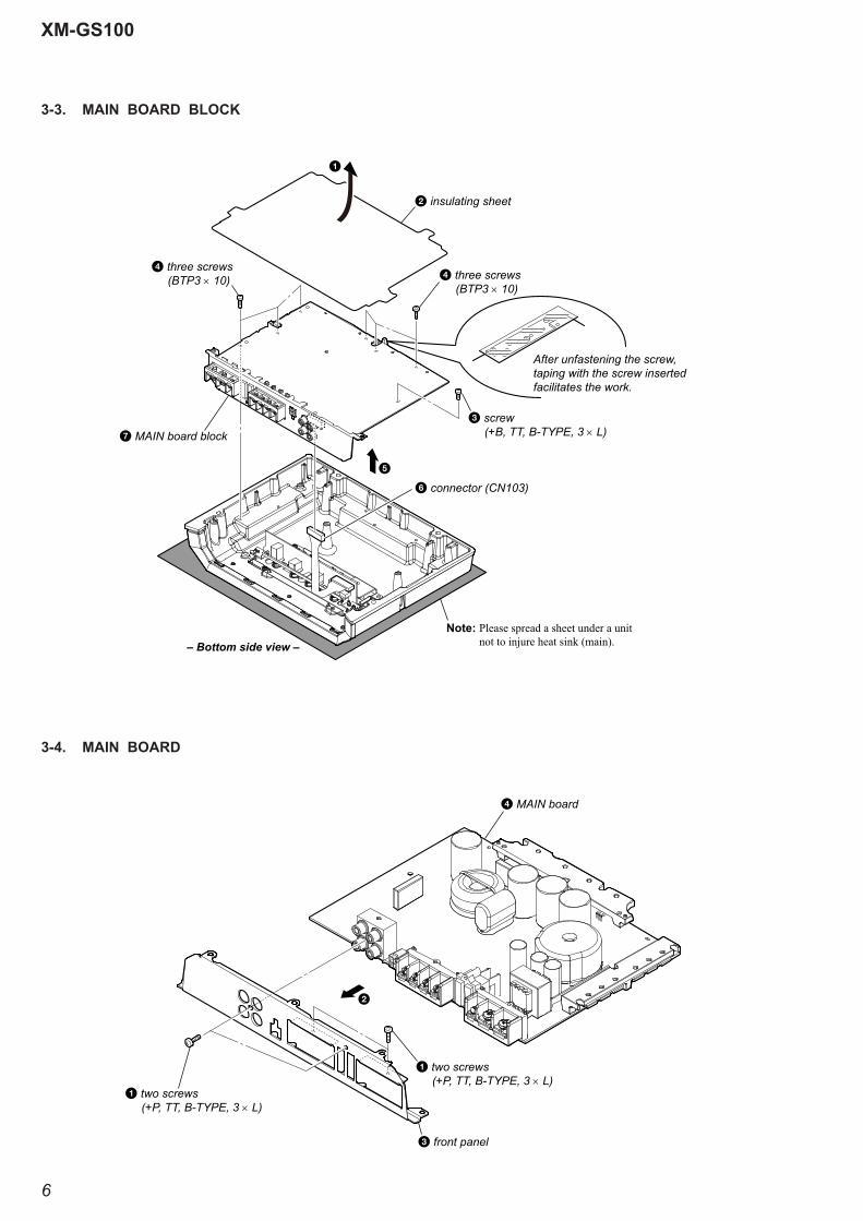
3-3. MAIN BOARD BLOCK
3-4. MAIN BOARD
– Bottom side view –
5
Note: Please spread a sheet under a unit not to injure heat sink (main).
3 screw (+B, TT, B-TYPE, 3 L)7 MAIN board block
4 three screws (BTP3 10) 4 three screws
(BTP3 10)
2 insulating sheet
After unfastening the screw,taping with the screw insertedfacilitates the work.
1
6 connector (CN103)
3 front panel
4 MAIN board
1 two screws (+P, TT, B-TYPE, 3 L)
1 two screws (+P, TT, B-TYPE, 3 L)
2
XM-GS100
XM-GS100
77
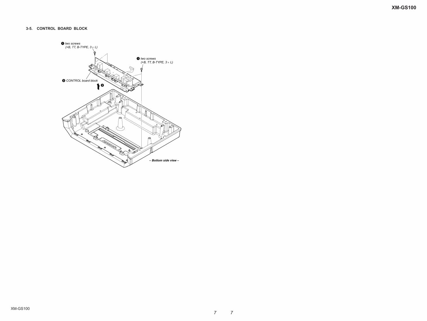
3-5. CONTROL BOARD BLOCK
– Bottom side view –
3 CONTROL board block2
1 two screws (+B, TT, B-TYPE, 3 L)
1 two screws (+B, TT, B-TYPE, 3 L)

XM-GS100
XM-GS100
88
SECTION 4DIAGRAMS
For Schematic Diagrams.Note:• All capacitors are in μF unless otherwise noted. (p: pF) 50
WV or less are not indicated except for electrolytics and tantalums.
• All resistors are in Ω and 1/4 W or less unless otherwise specifi ed.
• 2 : Nonfl ammable resistor.• C : Panel designation.• A : B+ Line.• B : B– Line.• Power voltage is dc 14.4 V and fed with regulated dc
power supply from +12 V and REM terminals.• Voltages and waveforms are dc with respect to ground
under no-signal conditions. no mark : POWER ON• Voltages are taken with VOM (Input impedance 10 M). Voltage variations may be noted due to normal production
tolerances.• Waveforms are taken with a oscilloscope. Voltage variations may be noted due to normal production
tolerances.• Circled numbers refer to waveforms.• Signal path. F : AUDIO
THIS NOTE IS COMMON FOR PRINTED WIRING BOARDS AND SCHEMATIC DIAGRAMS.(In addition to this, the necessary note is printed in each block.)
For Printed Wiring Boards.Note:• X : Parts extracted from the component side.• Y : Parts extracted from the conductor side.• : Pattern from the side which enables seeing. (The other layers’ patterns are not indicated.)
• Indication of transistor.
C
BThese are omitted.
E
Q
C EBThese are omitted.
B
These are omitted.
C E
Q
• Waveforms
– MAIN Board –
+–
DTC
1IN+
ERRORAMPLIFIER 1
PWMCOMPALATOR
UNDERVOLTAGELOCKOUTCONTROL
C1 1D
CTCCOMPALATOR
FEEDBACK
2IN+2IN–
1
3
4
0.7mA15
16
OSCILLATOR
PULSE-STEERINGFLIP-FLOP
REF14
1IN– 2
CTRT
OUTPUT CTRL
56
13
VCC12
GND 7
+–
ERRORAMPLIFIER 2
C1 8 E19
E210
C211
REFERENCEREGURATOR
• IC Block Diagrams
– MAIN Board –IC112 IRS2110S
Caution:Pattern face side:(Conductor Side)Parts face side: (Component Side)
Parts on the pattern face side seen from the pattern face are indicated.Parts on the parts face side seen from the parts face are indicated.
IC901 TL594INSR
5
2
1
HIN
SD
12
VDD
9
10
11
6
7
8
SR Q
SR Q
COM
LO
43 VCC
VS
VB
HO
VDD/VCCLEVELSHIFT
13
LIN 14VDD/VCC
LEVELSHIFT
VSS 15
16
PULSEGEN
UVDETECT
DELAY
R QRS
UVDETECT
PULSEFILTER
HVLEVELSHIFT
36.4 s28.8 Vp-p
2 Q905, 906, 909, 910 (Drain)
10 V/DIV, 20 s/DIV
3 IC901 5 (CT)
1 V/DIV, 10 s/DIV18.4 s
3 Vp-p
1 Q905, 906, 909, 910 (Gate)
5 V/DIV, 20 s/DIV
36.4 s12.6 Vp-p
4 IC901 9 (E1), q; (E2)
5 V/DIV, 20 s/DIV
36.4 s14.6 Vp-p
XM-GS100
XM-GS100
99
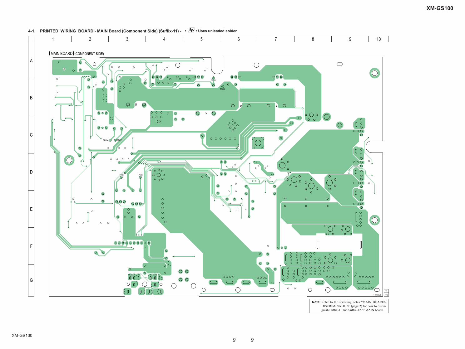
4-1. PRINTED WIRING BOARD - MAIN Board (Component Side) (Suffi x-11) - • : Uses unleaded solder.
TP021
TP022
TP023TP024
TP025TP026
MAIN BOARD (COMPONENT SIDE)
1-885-849-
11
(11)
A
B
C
D
E
F
G
1 2 3 4 5 6 7 8 9 10
Note: Refer to the servicing notes “MAIN BOARDS DISCRIMINATION” (page 2) for how to distin-guish Suffi x-11 and Suffi x-12 of MAIN board.

XM-GS100
XM-GS100
1010
4-2. PRINTED WIRING BOARD - MAIN Board (Conductor Side) (Suffi x-11) - • : Uses unleaded solder.
1 8
916
14 89 16
8 1
1 7
14 8
1 7
Q851Q852Q853Q854
R801
R803
R804
R805 R8
06R8
07
R809
R810
R811
R812
R813
R814
R818
R820
R823
R824
R825
R826
R828
R829
R830
R831
R832
R833
R834
R838
R839
C803
R840
C804
C805
R841
TH801
C806
TH802
TH803
R851
R852
R853
R854
R855
R856
R857
R858
C821
C822
C823
R860
C824
R861
C825
R862
C826
R863
C828
C831
C832
C833
R870
C836
Q102
Q103
R874
C838
R875
C839
R876
R877
Q108 Q109
C840
Q110Q111
C851
Q702
Q902Q903
Q904
Q907
Q912Q913
Q915
Q914
Q804
Q802 Q803
Q923
Q924
D851
D852
D853
D855
R121
FB90
2FB
903
FB904 FB905
R701
FB906
R702
R127
R901
R902
R903
R904
R953
R905
R906
R907
R908
R139
R909
R910
R911
R912
R915
R916
R917
R918
R919
TP001
TP002
TP003TP004
R920
R922
TP005
R921
TP006
TP007
R923
TP008
R154
R924
TP009
R925
R926
R927
R928
R931
R936
R159
TP010
TP011 TP012
TP013
TP014
R160
R930
TP015
R161
C125
TP016
R162
TP017
R163
TP018
R164
TP019
R165
R935
R166
R167
R168
R938
R169
TP020
C902
C903
R170
R940
C904
R171
R941
R172
R942
TP027
R173
C907
TP028
R174
C138
TP029
R175
C139
R176
R177
R178
TP030
TP031
TP032
C912
TP033
TP034
R180
R950
TP035
R181
R951
R952
R183
R184
R954
C918
R185
R186
R187
TP040
TP041
TP042
C152
TP043
C923
TP044
R190
C924
TP045
R191
TP046
R192
R962
C926
TP047
R193
R963
R194
R964
R195
R965
C159
C929
R966
R967R968
C930
C161
C931 C932
R970
R969
C164
R971
C933
R972
C166
C934
R973
C937
D107
R974
C938
D108
R975
C169
R976
R977
R978
R979
C171
C172
C173
C943
R980
C944
R981
C175
C945
D115
C176
C946
D116
C177
C947
D117
R984
C948
D118
R985
D119
R986R987
R988
R989
D120 C9
51
D121
C952
D122
C953
D123
C954
D124
C955
D125
D701
D126
D702
D127
C957
D703
D128
IC109
Q805Q806Q807
IC110
IC111
D901
IC112
D902
C963
C964
C966
C967
C968
D909
C970
D910
C971
C972
D912
C973
D913
D914 D915
C975
D916
C977
D917
C978
C979
Q821
Q822
Q823
Q824Q825
Q827
Q828
C981
IC901
C982
C980
C976
IC902
C983
C984
D924
C985
C986D9
26
C987
D927
C988
D928
C989
D929
D931
D161
D932
D933
R201
R202
R203
R204
EB
DG SDG S
BEB E
CE
1 10
BE
BE
G
S
G
S
G
S
G
S
D
D
D
D
R822R837
C801
C802
JW001
C827
Q104
Q106
Q112
Q115
L101
Q901
Q909
Q906
Q905
Q910
L901
Q916 Q917
FB101
TB102
FB107
CN101
CN103
FB908FB907
C105
C701
C901
C905 C908
C906C913C914C915
R182
C149
C919
R188C920 C921 C922
C925
C156
C927 C928
C160C162
C935
C936
C165
CAM002CAM003
CAM005
D906D905
C974
IC900
T901DC/DC CONVERTER
TRANSFORMER
MAIN BOARD (CONDUCTOR SIDE)
1-885-849-
11
(11)
E
E
E
E E
K
K
A
E
A
E
A
K
E
EE
E
EA
K
KK
KA
AA
KK
A
A
KK
A
E
A
AA K
K
K
KKKK
AAAA
K
E E
AE
E E E E
A
K K
A
A
A
K
K
A
K
A
K
A
K
K A
KA
A
K
A
A K
E
E
E
K
AK
KA
A
E
E E
A1CONTROL BOARD
CN002
1
1 4
58
4
58
(CHASSIS)
(CHASSIS)
(CHASSIS)
+––+
+ +
––
(L+R) (L+R)
SPEAKER OUT
GND +12V REM
F902 F90130A 30A
TB101 TB102
INPUT
J101
CN101
L R
L
R
L
RSENSING POWER ON
HIGH LEVEL INPUT (THROUGH)OUTPUT
A
B
C
D
E
F
G
H
1 2 3 4 5 6 7 8 9 10
E EE
(Page 15)
Note: Refer to the servicing notes “MAIN BOARDS DISCRIMINATION” (page 2) for how to distin-guish Suffi x-11 and Suffi x-12 of MAIN board.

XM-GS100
XM-GS100
1111
4-3. PRINTED WIRING BOARD - MAIN Board (Component Side) (Suffi x-12) - • : Uses unleaded solder.
TP021
TP022
TP023TP024
TP025TP026
MAIN BOARD (COMPONENT SIDE)
1-885-849-
12
(12)
A
B
C
D
E
F
G
1 2 3 4 5 6 7 8 9 10
Note: Refer to the servicing notes “MAIN BOARDS DISCRIMINATION” (page 2) for how to distin-guish Suffi x-11 and Suffi x-12 of MAIN board.
XM-GS100
XM-GS100
1212
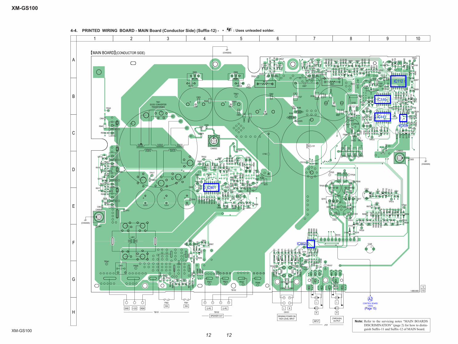
4-4. PRINTED WIRING BOARD - MAIN Board (Conductor Side) (Suffi x-12) - • : Uses unleaded solder.
1 8
916
14 89 16
8 1
1 7
14 8
1 7
Q851Q852Q853Q854
R801
R803
R804
R805 R8
06R8
07
R809
R810
R811
R812
R813
R814
R818
R820
R823
R824
R825
R826
R828
R829
R830
R831
R832
R833
R834
R838
R839
C803
R840
C804
C805
R841
TH801
C806
TH802
TH803
R851
R852
R853
R854
R855
R856
R857
R858
C821
C822
C823
R860
C824
R861
C825
R862
C826
R863
C828
C831
C832
C833
R870
C836
Q102
Q103
R874
C838
R875
C839
R876
R877
Q108 Q109
C840
Q110Q111
C851
Q702
Q902Q903
Q904
Q907
Q912Q913
Q915
Q914
Q804
Q802 Q803
Q923
Q924
D851
D852
D853
D855
R121
FB90
2FB
903
FB904 FB905
R701
FB906
R702
R127
R901
R902
R903
R904
R953
R905
R906
R907
R908
R139
R909
R910
R911
R912
R915
R916
R917
R918
R919
TP001
TP002
TP003TP004
R920
R922
TP005
R921
TP006
TP007
R923
TP008
R154
R924
TP009
R925
R926
R927
R928
R931
R936
R159
TP010
TP011 TP012
TP013
TP014
R160
R930
TP015
R161
C125
TP016
R162
TP017
R163
TP018
R164
TP019
R165
R935
R166
R167
R168
R938
R169
TP020
C902
C903
R170
R940
C904
R171
R941
R172
R942
TP027
R173
C907
TP028
R174
C138
TP029
R175
C139
R176
R177
R178
TP030
TP031
TP032
C912
TP033
TP034
R180
R950
TP035
R181
R951
R952
R183
R184
R954
C918
R185
R186
R187
TP040
TP041
TP042
C152
TP043
C923
TP044
R190
C924
TP045
R191
TP046
R192
R962
C926
TP047
R193
R963
R194
R964
R195
R965
C159
C929
R966
R967R968
C930
C161
C931 C932
R970
R969
C164
R971
C933
R972
C166
C934
R973
C937
D107
R974
C938
D108
R975
C169
R976
R977
R978
R979
C171
C172
C173
C943
R980
C944
R981
C175
C945
D115
C176
C946
D116
C177
C947
D117
R984
C948
D118
R985
D119
R986R987
R988
R989
D120 C9
51
D121
C952
D122
C953
D123
C954
D124
C955
D125
D701
D126
D702
D127
C957
D703
D128
IC109
Q805Q806Q807
IC110
IC111
D901
IC112
D902
C963
C964
C966
C967
C968
D909
C970
D910
C971
C972
D912
C973
D913
D914 D915
C975
D916
C977
D917
C978
C979
Q821
Q822
Q823
Q824Q825
Q827
Q828
C981
IC901
C982
C980
C976
IC902
C983
C984
D924
C985
C986D9
26
C987
D927
C988
D928
C989
D929
D931
D161
D932
D933
R201
R202
R203
R204
EB
DG SDG S
BEB E
CE
1 10
BE
BE
G
S
G
S
G
S
G
S
D
D
D
D
R822R837
C801
C802
JW001
C827
Q104
Q106
Q112
Q115
L101
Q901
Q909
Q906
Q905
Q910
L901
Q916 Q917
FB101
TB102
FB107
CN101
CN103
FB908FB907
C105
C701
TP021
C901
TP022
TP023 TP024
TP025
C905 C908
TP026
C906C913C914C915
R182
C149
C919
R188C920 C921 C922
C925
C156
C927 C928
C160C162
C935
C936
C165
CAM002CAM003
CAM005
D906D905
C974
IC900
T901DC/DC CONVERTER
TRANSFORMER
MAIN BOARD (CONDUCTOR SIDE)
1-885-849-
12
(12)
E
E
E
E E
K
K
A
E
A
E
A
K
E
EE
E
EA
K
KK
KA
AA
KK
A
A
KK
A
E
A
AA K
K
K
KKKK
AAAA
K
E E
AE
E E E E
A
K K
A
A
A
K
K
A
K
A
K
A
K
K A
KA
A
K
A
A K
E
E
E
K
AK
KA
A
E
E E
A2CONTROL BOARD
CN002
1
1 4
58
4
58
(CHASSIS)
(CHASSIS)
(CHASSIS)
+––+
+ +
––
(L+R) (L+R)
SPEAKER OUT
GND +12V REM
F902 F90130A 30A
TB101 TB102
INPUT
J101
CN101
L R
L
R
L
RSENSING POWER ON
HIGH LEVEL INPUT (THROUGH)OUTPUT
A
B
C
D
E
F
G
H
1 2 3 4 5 6 7 8 9 10
E EE
(Page 15)
Note: Refer to the servicing notes “MAIN BOARDS DISCRIMINATION” (page 2) for how to distin-guish Suffi x-11 and Suffi x-12 of MAIN board.

XM-GS100
XM-GS100
1313
4-5. SCHEMATIC DIAGRAM - MAIN Board (1/2) - • See page 8 for waveforms. • See page 8 for IC Block Diagrams.
BOARD
1(2/2)
MAIN
BOARD
ACN002
CONTROL
IC B/D
3
1
1
2
2
4
00
0
00
0
-14.2
14.8
0 67.6
68.45
5
0
8.5
8.2
67.6
00 3 0
0.9
1.5
3.8
14.2
3 5 5 14.2
14.2
3.9
3.9
6.2
0
0
0.7
14.2
13.5
14.2
14.2 14.2
13.514.2
14.2
0
0
0.7
14.2
0
0.5
4.8
4.8
0.5
4.8
14.2
14.2
4.8
4.8
14.2
14.2
4.8
3.9
3.9
5
5
1000pC138
1000pC139
470pC804
1000pC806
10kR809
10kR810
10kR811
10kR812
10kR813
10kR814
100kR818
47kR834
1000pC902
1000pC903
0.01C904
0.022C912
16V2200C913
16V2200C914
16V2200C915
0.022C918
80V1800C919
80V1800C920
80V1800C921
80V1800C922
0.22C948
FCH
20A2
0D
905
FRH
20A2
0D
906
FB905
FB906
FB907
FB908
KTA1281Y-ATQ901
1kR121
4.7kR127
10kR876
10kR903
2.2kR908
3.3kR909
22k
R91
1
1kR915
1kR916
FB1071.1uH
16 15 14 13 12 11 10 9
87654321
TL594INSRIC901
15uHL901
321 4
4.7kR951
4.7kR950
22R938
22R94022
R918
22R917
1kR925
1kR928
FB904
100kR923
100kR924
100kR926
100kR927
1000pC906
10kR902
C9644700p
C9634700p
DA2J10100LD855
DZ2J160M0LD902
2SC3052EF-T1-LEFQ807
2SC3052EF-T1-LEFQ806
2SC3052EF-T1-LEFQ903
ISA1235AC1-T112-1EFQ805
RT1N441C-TP-1Q907
RT1N141C-TP-1Q902
1kR906
ISA1235AC1-T112-1EFQ904
DA2J10100LD901
2.2kR905
100kR907
1.5kR952
10kR953
10kR954
270R904
S
FKV575Q906
S
FKV575Q910
S
FKV575Q909
S
FKV575Q905
47kR963
47kR964
47kR965
47kR966
10kR967
100pC972
100pC973
10kR968
16V47
C974
1
2
3
4
4PCN101
220pC975
220pC976
220pC977
220pC978
220pC979
220pC980
220pC981
220pC982
2.2kR969
2.2kR970
470kR971
470kR972
470kR973
470kR974
22kR975
22kR976
22kR977
22kR978
DA2
J101
00L
D92
6
DA2
J101
00L
D92
7
DA2
J101
00L
D92
8
DA2
J101
00L
D92
9
1000pC987
10kR979
+
-
NJM4565M(TE2)IC902
3
21
+
-
NJM4565M(TE2)IC902
5
67
NJM4565M(TE2)IC902
8POWER
4GND
47kR980
4700pC988
4700pC989
47kR981
1kR874
16V47
C905
0.01C125
0.1C983
0.1C825
0.1C984
0.1C985
0.1C986
0.1C907
0.1C926
16V
C908100
50V4.7
C105
50V4.7
C801
50V220
C925
250V0.1
C923
250V0.1
C924
10kR901
2.2R935
2.2R936
2.2R930
2.2R931
2.2kR921
2.2kR922
2.2kR919
2.2kR920
GN1GD910
GN1GD913
GN1GD912
GN1GD909
5
7
3
2
6
1
4
11
8
9
10
T901
2SC3326N-TE85L-BQ914
2SC3326N-TE85L-BQ915
1kR875
1kR877
0.01C805
0.01C947
1
24
3
PC-17K1IC900
DZ2J300M0LD931
DZ2J300M0LD932
DZ2J160M0LD933
22kR984
100kR985
470kR986
10kR987
1kR988
220R989
KTC4373Q924
TP045
TP044
TP041
TP033
TP031
TP032
TP001
TP021
TP00
2TP
022
TP003 TP023
TP004 TP024
TP042
TP043
1
2
3
4
5
6
7
8
9
10
10PCN103
Line in
Second GND
First GND
LED Blue
LED Red
Line out
+15V
–15V
Active Thermal control
ESD
C9011
2SC4357-T11-1EQ913
2SC4357-T11-1EQ912
15kR910
100kR912
PRE AMP
(1/3)IC902
PRE AMP
(3/3)IC902
(2/3)
1
2
4
6
7
8
9
5
3
10
12
11
13
DC/DC CONVERTER
IC901DC/DC CONVERTER
DC BALANCE DETECT
(1/2)MAIN BOARD
SENSING POWER ONHIGH LEVEL INPUT
L+
R+
R–
L–
(CHASSIS)
CAM003DC DETECT
DC BALANCEDETECT
TRANSFORMER
BUFFER
BUFFER
SWITCHINGDRIVER
DRIVERSWITCHING
DRIVERSWITCHING
DRIVERSWITCHING
SWITCHING DRIVER
SWITCHING DRIVER
LED DRIVER
2IN
+1I
N+
2IN
-1I
N-
REF
FEED
BAC
K
OU
TPU
T C
TRL
DTC
VCC
CT
C2
RT
E2G
ND
E1C
1(CHASSIS)
CAM005
DC DETECT
OVER VOLTAGE DETECT
Q901, 903B+ SWITCH LED DRIVER
Q805, 806
30A
+12V
30V
TB101
J101
GND
30A
30A
30V
30A
F901
REM
F902
L
R
R
L
INPUT
OUTPUT(THROUGH)
168
I
142 1512
A
D
5
K
B
M
7
C
L
176 113
H
F
13
G
9
E
101
J
184
(Page 14)
(Page 16)
XM-GS100
XM-GS100
1414
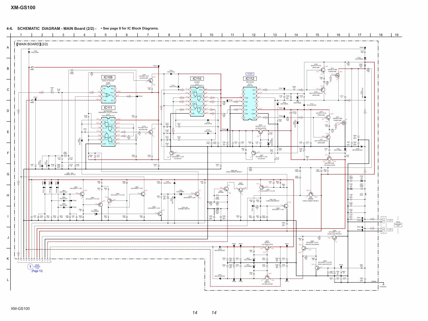
4-6. SCHEMATIC DIAGRAM - MAIN Board (2/2) - • See page 8 for IC Block Diagrams.
MAIN
(1/2)1 BOARD
IC B/D
13.9
55.1
5.2
0
6.4
6.2
0
5.2
6.2
13.9
6.2
6.4
6.2
5.2
5.2
0
15.1
14.5 23.8
0 58.9
58.9
14.7
0
14.7
0
14.7
58
0
0
-58
-58
0
0
0
0.60
0
5.9
7.8
2.2
4.9
0
0.6
0
0.6
0
14.7
7.8
8
2.7
0
5.6
8.5
7.4
8.5
7.8
7.4
7.4
14.814.8
14.8
0
0
2.7
2.5
5.6
2.5
2.3
5.6
0
14.8
-14.2
0
0
14.8
2
0
0.8
5.6
5
5
2.7
2.3
5
2.7
2.3
5
2.3
2.3
6.2
13.9
0
13.9
6.2
13.95
5.6
0.6
0
12.2
-14.2
0
12.2
-14.221.6
15.3
14.7
-21 -14.2
-14.7
-14.2
0
250V10
C156
470pC164
100pC171
220pC172
470pC173
0.01C177
1000pC803
100pC821
0.01C822
1000pC824
250V1
C827
1000pC832
1000pC833
4.7kR160
4.7kR161
47kR162
4.7kR163
1kR164
10kR165
1kR166
1kR167
2.2kR168
4.7kR169
680R170
680R171
4.7kR174
1kR176
100kR181
2W10
R182
220R183
220R184
100R185
150R186
4.7R190
100kR191 100
R192
150R193
4.7kR201
4.7kR202
22R203
100R204
33kR701
470kR801
1MR803
10kR804
10kR805
10kR80610k
R807
1kR820
5W0.015R822
1.5kR823
1.5kR825
100kR826
10kR828
10kR829
10kR830
10kR831
5W0.015R837
4.7kR838
1kR839
4.7kR84010k
R841
RF101L2STE25D121
8
7
6
54
3
2
1
NJM318IC109
FB1011.1uH
FB902
FB903
2SD1758-TLQRQ102
2SC2873Y-TE12LQ108
2SA1734(T2LSONY,F)Q109
2SC2873Y-TE12LQ110
2SA1734(T2LSONY,F)Q111
4.7kR154
100kR854
10kR856
1kR857
1kR858
3.3kR861
3.3kR862
1kR870
TH80
1
TH80
2
TH80
3
10kR824
68kR139
33kR173
4.7kR172
100kR180
100kR177
2W
R18810
S
2SK3591-01MRQ112
S
2SK3591-01MRQ115
150kR702
4.7kR195
22R187
22R194
2200pC831
2200pC826
4.7kR941
4.7kR942
0.22C932
0.22C931
6.8kR833
6.8kR832
100V
C966100p
C970
100V1000p
C971
100V1000p
DA2
J101
00L
D11
5
DA2
J101
00L
D11
6
DA2J10100LD108
DA2J10100LD122
DA2J10100LD123
DA2J10100LD851
DA2J10100LD852
DA2J10100LD853
DA2
J101
00L
D12
6
DZ2J150M0LD917
DZ2J150M0LD916
DZ2J150M0LD117
DZ2
J056
M0L
D11
8
DZ2
J082
M0L
D16
1
DZ2J180M0LD125 DZ2J180M0L
D124
DA2J10100LD120
DA2J10100LD119
TC4011BF(TB,EL,N,F)IC111
1
2
3
4
5
6
7 8
9
10
11
12
13
14
TC74HC00AF(TB,EL,F)IC110
1
2
3
4
5
6
7 8
9
10
11
12
13
14
2SC3052EF-T1-LEFQ828
2SC3052EF-T1-LEFQ827
2SC3052EF-T1-LEFQ851
2SC3052EF-T1-LEFQ854
2SC3052EF-T1-LEFQ823
2SC3052EF-T1-LEFQ802
2SC3052EF-T1-LEFQ804
2SC3052EF-T1-LEFQ702
DA2J10100LD702
DA2
J101
00L
D70
3
ISA1235AC1-T112-1EFQ803
ISA1235AC1-T112-1EFQ821
ISA1235AC1-T112-1EFQ853
ISA1235AC1-T112-1EFQ852
DZ2J068M0LD701
DZ2J056M0LD107
2SC3052EF-T1-LEFQ923
3.3kR855
1kR962
DZ2J056M0LD924
IRS2110SIC112
1
2
3
4
5
6
7
89
10
11
12
13
14
15
16
16V47
C162
16V47
C802
16V47
C149
50V22
C701
0.1C935
0.1C955
0.1C936
0.1C951
0.1C836
0.1C838
0.1C175
0.1C937
0.1C159
0.1C851
0.1C839
0.1C161
0.1C176
0.1C938
0.1C954
0.1C823
0.1C166
0.1C169
0.1C952
0.1C929
0.1C957
0.1C953
0.1C930
16V100
C160
16V220
C933
16V220
C934
50V220
C927
50V220
C928
250V0.1
C945
250V0.1
C152
250V0.1
C946
250V0.1
C828
250V0.1
C943
250V0.1
C840
250V0.1
C944
C9683300p
C9673300p
50V4.7
C165
2SD2012Q916
2SB1375Q917
1SR159-200TE25D914
1SR159-200TE25D915
1SR
159-
200T
E25
D12
7
1SR159-200TE25D128
330R175
68R178
2SA2026Q822
2SC5625Q825
2SC5625Q824
TP005 TP025
TP006 TP026
TP014
TP015
TP01
7
TP01
8
TP01
9
TP020
TP030
TP011
TP012
TP01
0
TP007
TP008
TP027
TP028
TP035
TP034
TP013
TP016
TP009
TP029
1.5kR863
100kR159
TP046
TP047
KTA1268-Y-AT/PQ104
KTA1268-Y-AT/PQ106
3.3kR851
3.3kR852
3.3kR853
6.8kR860
80uHL101
2SC4357-T11-1EQ103
DIVIDER
IC110PRE DRIVER
IC112
BUFFER AMP,
IC111
NOISE FILTER AMP
IC109
(2/2)MAIN BOARD
21 5 93 6 7 8 124 1310 11
POWER AMP
DRIVE AMP
DRIVE AMP
DRIVE AMP
DRIVE AMP
POWER AMP
–
+
–
+L+R
L+R
SPEAKEROUT
TB102
(CHASSIS)
CAM002
+15V REGULATOR
-15V REGULATOR
+15V REGULATOR
OVER CURRENT DETECTQ821, 823
OVER LOAD DETECT
OVER LOAD PROTECT
PROTECTOR DRIVER
OVER LOAD PROTECT
DC DETECT
+5V REGULATOR
DC DETECT
OVER CURRENT DETECTQ824, 825
Q702, 923STANDBY SWITCH
Q851 - 854THERMAL DETECT
BUFFER AMP
BUFFER AMP
EMERGENCY STOP CONTROL
VSS
VCC
VEE
VCCNC
VEE
NC
NC
VCC
HO
VDD
VCC
HIN
SD
VB
VS
COM
LO
LIN
VSS
168
I
142 1512
A
D
5
K
B
7
C
L
176 113
H
F
13
G
9
E
101 19
J
184
(Page 13)
XM-GS100
XM-GS100
1515
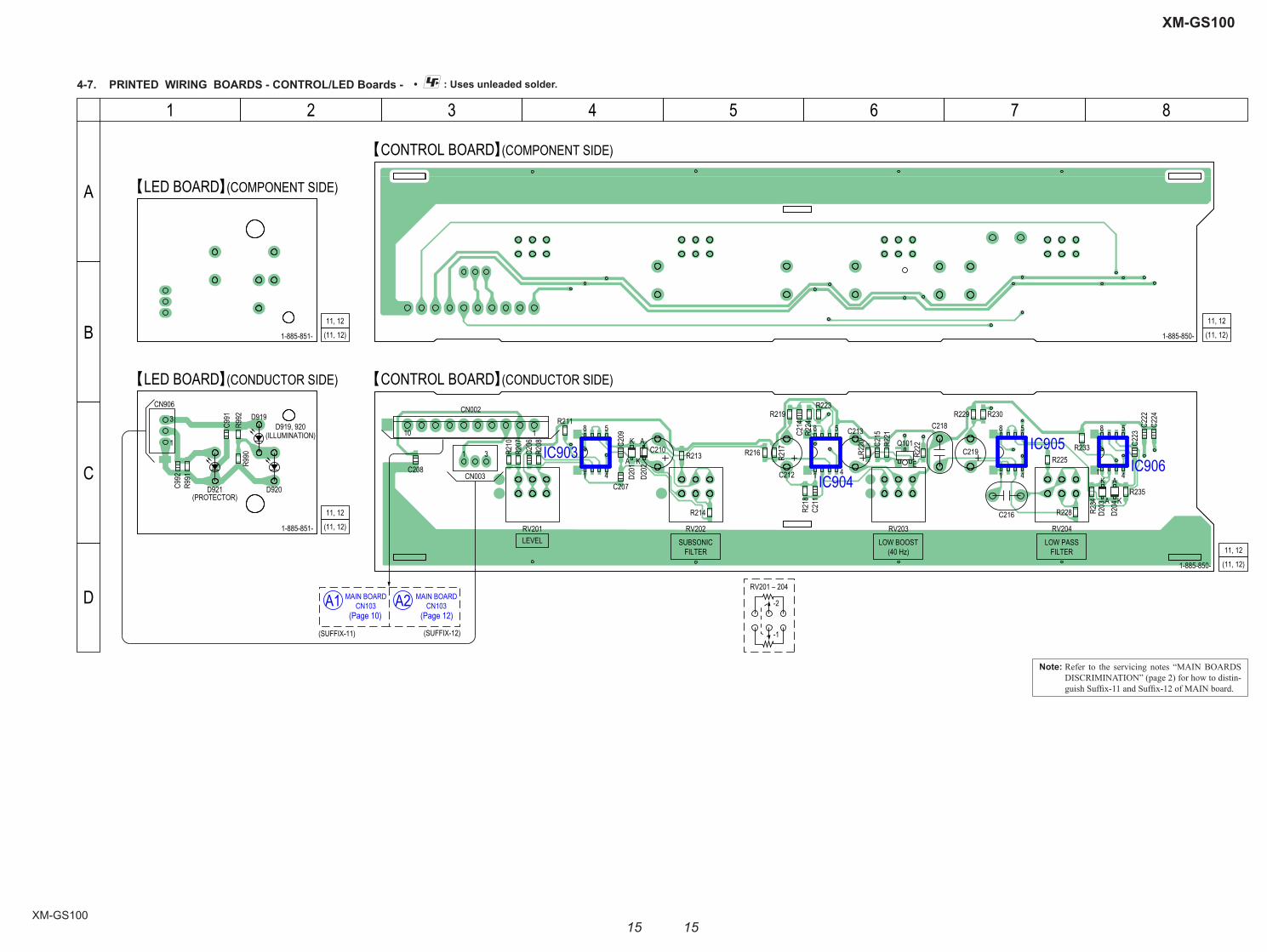
4-7. PRINTED WIRING BOARDS - CONTROL/LED Boards - • : Uses unleaded solder.
1 3
110
CN002
CN003
C210
C212
C213
C216
C218
C219
RV201 RV202 RV203 RV204
R210
R211
R213
R214
R216 R217
R218
R219
R220 R2
21
R222
R223
R224
R225
R228
R229 R230
R233
R234
R235
C206
C207
C208
C209
C211
C214
C215
C222
C223
C224
Q101
D201
D202
D203
D204
IC903
IC904
IC905IC906
R207
R2081
3
CN906D919
D920D921
R990
R991
R992
C991
C992
A K
A
E
K A
KA
K
1-885-850-
11, 12
(11, 12)
1-885-850-
CONTROL BOARD (COMPONENT SIDE)
CONTROL BOARD (CONDUCTOR SIDE)
LED BOARD (COMPONENT SIDE)
LED BOARD (CONDUCTOR SIDE)
1-885-851-
11, 12
(11, 12)
11, 12
(11, 12)1-885-851-
(PROTECTOR)
(ILLUMINATION)D919, 920
-1
58
41
58
41
58
41
58
41
-2
RV201 – 204
LEVEL SUBSONICFILTER
LOW BOOST(40 Hz)
LOW PASSFILTER
A
B
C
D
1 2 3 4 5 6 7 8
11, 12
(11, 12)
A1 MAIN BOARDCN103 A2 MAIN BOARD
CN103
(SUFFIX-11) (SUFFIX-12)
(Page 10) (Page 12)
Note: Refer to the servicing notes “MAIN BOARDS DISCRIMINATION” (page 2) for how to distin-guish Suffi x-11 and Suffi x-12 of MAIN board.
XM-GS100
XM-GS100
1616
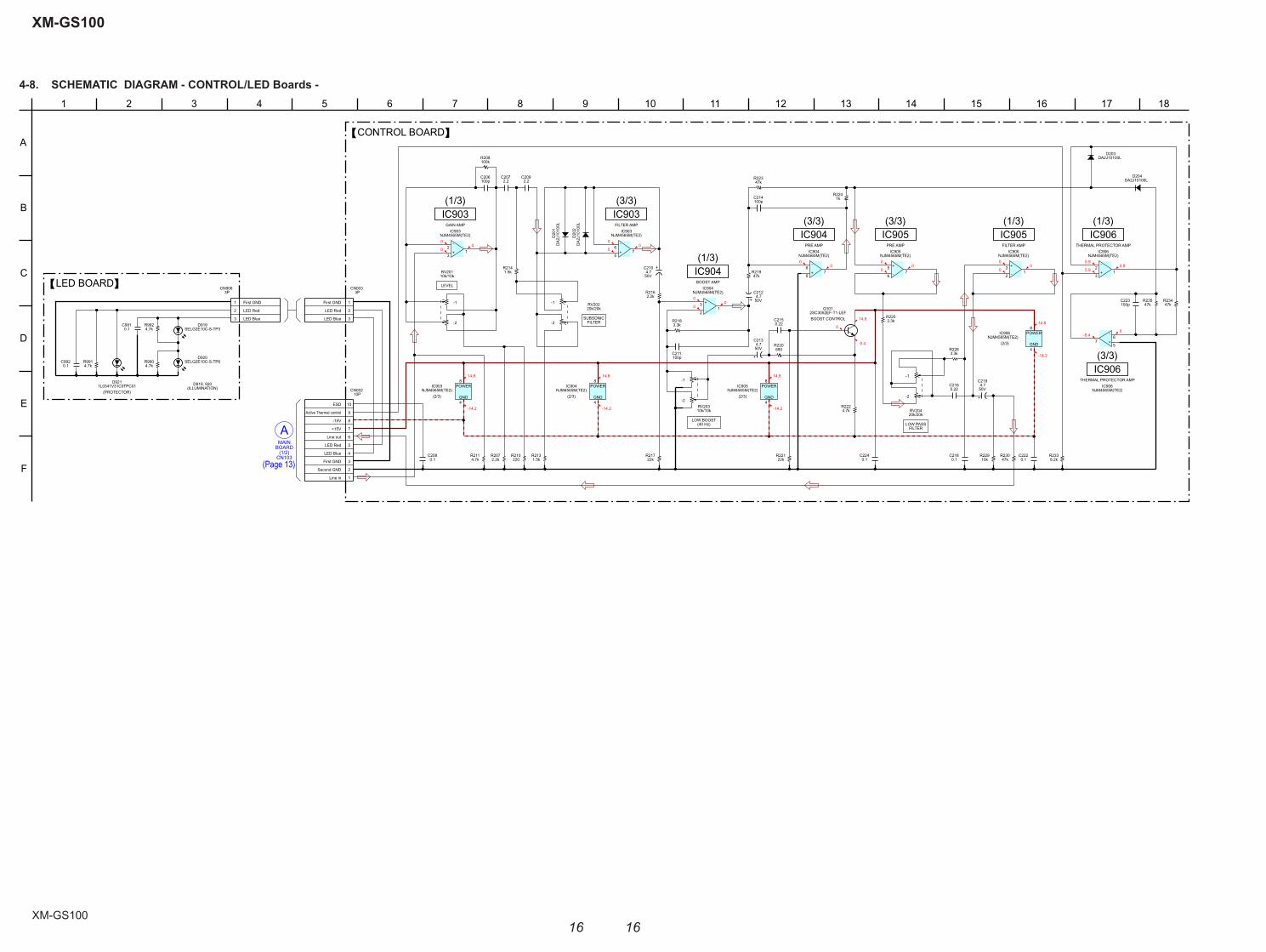
4-8. SCHEMATIC DIAGRAM - CONTROL/LED Boards -
CN103
BOARD
A(1/2)
MAIN
00
0
00
0
5.95.9
5.9
00
00
0
00
0
-5.40
00
0
14.8
-14.2
14.8
-14.2
14.8
-14.2
14.8
-14.2
14.8
0
-0.4
100pC206
100pC211
100pC223
3.3kR218
R220680
R22122k
47kR219
47kR223
1kR224
47kR235
47kR234
R2253.3k
R2283.3k
47kR230
22kR217R207
2.2k
R2141.5k
R2131.5k 0.1
C218
DA2
J101
00L
D20
1
DA2
J101
00L
D20
2
DA2J10100LD203
DA2J10100LD204
2SC3052EF-T1-LEFQ101
100pC214
1
2
3
3PCN003
First GND
LED Red
LED Blue
50V4.7
C219
50V4.7
C210
50V
C2134.7
50V4.7
C212
RV20420k/20k
0.22C215
4.7kR211
4.7kR222
10kR229
8.2kR233
0.1C208
0.1C222
0.1C224
+
-
NJM4565M(TE2)IC904
5
67 +
-
NJM4565M(TE2)IC906
3
21
+
-
NJM4565M(TE2)IC906
5
67
+
-
NJM4565M(TE2)IC903
3
21
+
-
NJM4565M(TE2)IC905
3
21
+
-
NJM4565M(TE2)IC903
5
67
+
-
NJM4565M(TE2)IC905
5
67
+
-
NJM4565M(TE2)IC904
3
21
NJM4565M(TE2)IC906
8POWER
4GND
NJM4565M(TE2)IC904
8POWER
4GND
NJM4565M(TE2)IC903
8POWER
4GND
NJM4565M(TE2)IC905
8POWER
4GND
R210220
100kR208
C2072.2 2.2
C209
2.2kR216
0.22C216
RV20310k/10k
RV20110k/10k
1
2
3
4
5
6
7
8
9
10
10PCN002
Line in
Second GND
First GND
LED Blue
LED Red
Line out
+15V
-15V
Active Thermal control
ESD
4.7kR991
1
2
3
3PCN906
First GND
LED Red
LED Blue
0.1C991
0.1C992
4.7kR992
4.7kR990
1L0341V31C0TPC01D921
SELG2E10C-S-TP6D920
SELG2E10C-S-TP3D919
(2/3)
(1/3)IC903
(2/3) (2/3)
IC903(3/3)
IC904BOOST AMP
(1/3)PRE AMP
IC904(3/3)
PRE AMP
IC905(3/3) (1/3)
IC905FILTER AMP
(2/3)
THERMAL PROTECTOR AMP
(1/3)IC906
CONTROL BOARD
(3/3)IC906
LED BOARD
(PROTECTOR)
D919, 920(ILLUMINATION)
-1
-2
-1
-2
-1
-2
-2
-1
LEVEL
LOW PASSFILTER
LOW BOOST(40 Hz)
SUBSONICFILTER
FILTER AMPGAIN AMP
THERMAL PROTECTOR AMP
BOOST CONTROL
168 142 1512
A
D
5
B
7
C
176 113
F
139
E
101 184
RV20220k/20k
(Page 13)
17
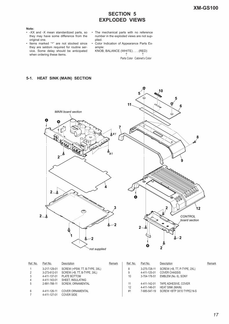
XM-GS100SECTION 5
EXPLODED VIEWS
1 3-217-129-01 SCREW (+PSW, TT, B-TYPE, 3XL) 2 3-273-612-01 SCREW (+B, TT, B-TYPE, 3XL) 3 4-411-137-01 PLATE BOTTOM 4 4-411-143-01 SHEET, INSULATING 5 2-891-788-11 SCREW, ORNAMENTAL
6 4-411-126-11 COVER ORNAMENTAL 7 4-411-127-01 COVER SIDE
8 3-275-728-11 SCREW (+B, TT, P-TYPE, 2XL) 9 4-411-125-01 COVER CHASSIS 10 3-704-176-51 EMBLEM (No. 6), SONY
11 4-411-142-01 TAPE ADHESIVE, COVER 12 4-411-146-01 HEAT SINK (MAIN) #1 7-685-547-19 SCREW +BTP 3X10 TYPE2 N-S
Ref. No. Part No. Description Remark Ref. No. Part No. Description Remark
Note:• -XX and -X mean standardized parts, so
they may have some difference from the original one.
• Items marked “*” are not stocked since they are seldom required for routine ser-vice. Some delay should be anticipated when ordering these items.
• The mechanical parts with no reference number in the exploded views are not sup-plied.
• Color Indication of Appearance Parts Ex-ample:
KNOB, BALANCE (WHITE) . . . (RED) Parts Color Cabinet’s Color
5-1. HEAT SINK (MAIN) SECTION
6
2
2
2
55
2
3
2
2
2
1
2
2 12
11
10
MAIN board section
#1
#1
CONTROLboard section
7
4
8
9
not supplied
AB
A
B

18
XM-GS100
5-2. MAIN BOARD SECTION
51 4-411-134-12 PANEL FRONT 52 3-277-208-11 SCREW (+P, TT, B-TYPE, 3XL) 53 A-1869-877-A MAIN BOARD, COMPLETE 54 3-225-184-12 SCREW (+PS. TT. 3XL) 55 4-427-195-01 SHEET, INSULATING SUBHEAT
(for MAIN board Suffi x-11)
D905 6-501-398-01 DIODE FCH20A20 D906 6-501-399-01 DIODE FRH20A20 F901 1-532-947-11 FUSE (BLADE TYPE) (AUTO FUSE) (30 A/32 V) F902 1-532-947-11 FUSE (BLADE TYPE) (AUTO FUSE) (30 A/32 V) L101 1-457-377-21 COIL, CHOKE (SP-OUT) 80uH
Q112 6-551-828-01 FET 2SK3591-01MR Q115 6-551-828-01 FET 2SK3591-01MR Q905 6-552-281-01 FET FKV575 Q906 6-552-281-01 FET FKV575 Q909 6-552-281-01 FET FKV575
Q910 6-552-281-01 FET FKV575 T901 1-697-139-11 TRANSFORMER, DC-DC CONVERTER TB101 1-780-337-11 TERMINAL BOARD (3P+FUSE)
(30A, REM, +12V, GND) TB102 1-694-985-21 TERMINAL BOARD (SPEAKER OUT)
Ref. No. Part No. Description Remark Ref. No. Part No. Description Remark
not supplied
not supplied
not supplied
MAIN board
Q115
D906
Q112
54D905
TB102
TB101
F901
F902L101 T901
51
52
52
54
54
54
53
5454
54
54
55
55
5454
54
52
not supplied
Q905
Q906
52
52
52
52
54
Q910
Q909
(for MAIN boardsuffix-11)
(for MAIN board suffix-11)
Note: Ref. No. 55 are used only for the MAIN board of suffi x-11. Refer to “MAIN BOARD DISCRIMINATION” (page 2) for suffi x-11.

19
XM-GS100
5-3. CONTROL BOARD SECTION
101 A-1870-253-A CONTROL BOARD, COMPLETE 102 4-411-138-01 KNOB VOL 103 3-277-208-01 SCREW (+P, TT, B-TYPE, 3XL) 104 A-1870-252-A LED BOARD, COMPLETE 105 4-411-128-01 REFLECTOR
106 4-411-129-01 LIGHT GUIDE
107 4-411-130-01 INDICATOR 108 4-411-147-01 WINDOW 109 4-411-141-01 TAPE ADHESIVE, WINDOW 110 2-580-628-01 SCREW, +BVTP S3X6 TYPE2
#2 7-685-790-09 SCREW +PTT 2.6X4 (S)
Ref. No. Part No. Description Remark Ref. No. Part No. Description Remark
not supplied
103110
101
102
105
108
104
106
107
109
#2
#2
20
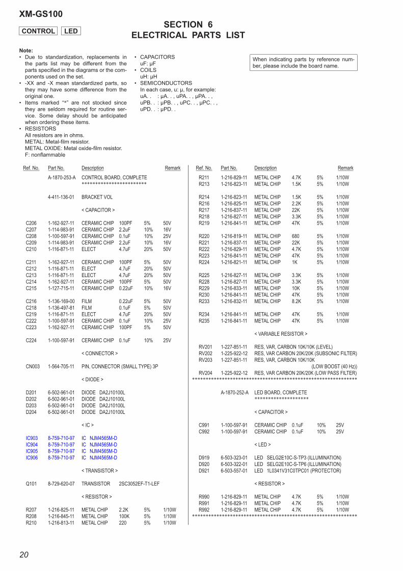
XM-GS100SECTION 6
ELECTRICAL PARTS LIST
A-1870-253-A CONTROL BOARD, COMPLETE ************************
4-411-136-01 BRACKET VOL
< CAPACITOR >
C206 1-162-927-11 CERAMIC CHIP 100PF 5% 50V C207 1-114-983-91 CERAMIC CHIP 2.2uF 10% 16V C208 1-100-597-91 CERAMIC CHIP 0.1uF 10% 25V C209 1-114-983-91 CERAMIC CHIP 2.2uF 10% 16V C210 1-116-871-11 ELECT 4.7uF 20% 50V
C211 1-162-927-11 CERAMIC CHIP 100PF 5% 50V C212 1-116-871-11 ELECT 4.7uF 20% 50V C213 1-116-871-11 ELECT 4.7uF 20% 50V C214 1-162-927-11 CERAMIC CHIP 100PF 5% 50V C215 1-127-715-11 CERAMIC CHIP 0.22uF 10% 16V
C216 1-136-169-00 FILM 0.22uF 5% 50V C218 1-136-497-81 FILM 0.1uF 5% 50V C219 1-116-871-11 ELECT 4.7uF 20% 50V C222 1-100-597-91 CERAMIC CHIP 0.1uF 10% 25V C223 1-162-927-11 CERAMIC CHIP 100PF 5% 50V
C224 1-100-597-91 CERAMIC CHIP 0.1uF 10% 25V
< CONNECTOR >
CN003 1-564-705-11 PIN, CONNECTOR (SMALL TYPE) 3P
< DIODE >
D201 6-502-961-01 DIODE DA2J10100L D202 6-502-961-01 DIODE DA2J10100L D203 6-502-961-01 DIODE DA2J10100L D204 6-502-961-01 DIODE DA2J10100L
< IC >
IC903 8-759-710-97 IC NJM4565M-D IC904 8-759-710-97 IC NJM4565M-D IC905 8-759-710-97 IC NJM4565M-D IC906 8-759-710-97 IC NJM4565M-D
< TRANSISTOR >
Q101 8-729-620-07 TRANSISTOR 2SC3052EF-T1-LEF
< RESISTOR >
R207 1-216-825-11 METAL CHIP 2.2K 5% 1/10W R208 1-216-845-11 METAL CHIP 100K 5% 1/10W R210 1-216-813-11 METAL CHIP 220 5% 1/10W
R211 1-216-829-11 METAL CHIP 4.7K 5% 1/10W R213 1-216-823-11 METAL CHIP 1.5K 5% 1/10W
R214 1-216-823-11 METAL CHIP 1.5K 5% 1/10W R216 1-216-825-11 METAL CHIP 2.2K 5% 1/10W R217 1-216-837-11 METAL CHIP 22K 5% 1/10W R218 1-216-827-11 METAL CHIP 3.3K 5% 1/10W R219 1-216-841-11 METAL CHIP 47K 5% 1/10W
R220 1-216-819-11 METAL CHIP 680 5% 1/10W R221 1-216-837-11 METAL CHIP 22K 5% 1/10W R222 1-216-829-11 METAL CHIP 4.7K 5% 1/10W R223 1-216-841-11 METAL CHIP 47K 5% 1/10W R224 1-216-821-11 METAL CHIP 1K 5% 1/10W
R225 1-216-827-11 METAL CHIP 3.3K 5% 1/10W R228 1-216-827-11 METAL CHIP 3.3K 5% 1/10W R229 1-216-833-11 METAL CHIP 10K 5% 1/10W R230 1-216-841-11 METAL CHIP 47K 5% 1/10W R233 1-216-832-11 METAL CHIP 8.2K 5% 1/10W
R234 1-216-841-11 METAL CHIP 47K 5% 1/10W R235 1-216-841-11 METAL CHIP 47K 5% 1/10W
< VARIABLE RESISTOR >
RV201 1-227-851-11 RES, VAR, CARBON 10K/10K (LEVEL) RV202 1-225-922-12 RES, VAR CARBON 20K/20K (SUBSONIC FILTER) RV203 1-227-851-11 RES, VAR, CARBON 10K/10K
(LOW BOOST (40 Hz)) RV204 1-225-922-12 RES, VAR CARBON 20K/20K (LOW PASS FILTER)*************************************************************
A-1870-252-A LED BOARD, COMPLETE ********************
< CAPACITOR >
C991 1-100-597-91 CERAMIC CHIP 0.1uF 10% 25V C992 1-100-597-91 CERAMIC CHIP 0.1uF 10% 25V
< LED >
D919 6-503-323-01 LED SELG2E10C-S-TP3 (ILLUMINATION) D920 6-503-322-01 LED SELG2E10C-S-TP6 (ILLUMINATION) D921 6-503-557-01 LED 1L0341V31C0TPC01 (PROTECTOR)
< RESISTOR >
R990 1-216-829-11 METAL CHIP 4.7K 5% 1/10W R991 1-216-829-11 METAL CHIP 4.7K 5% 1/10W R992 1-216-829-11 METAL CHIP 4.7K 5% 1/10W*************************************************************
Ref. No. Part No. Description Remark Ref. No. Part No. Description Remark
LEDCONTROL
When indicating parts by reference num-ber, please include the board name.
Note:• Due to standardization, replacements in
the parts list may be different from the parts specifi ed in the diagrams or the com-ponents used on the set.
• -XX and -X mean standardized parts, so they may have some difference from the original one.
• Items marked “*” are not stocked since they are seldom required for routine ser-vice. Some delay should be anticipated when ordering these items.
• RESISTORS All resistors are in ohms. METAL: Metal-fi lm resistor. METAL OXIDE: Metal oxide-fi lm resistor. F: nonfl ammable
• CAPACITORS uF: μF• COILS uH: μH• SEMICONDUCTORS In each case, u: μ, for example: uA. . : μA. . , uPA. . , μPA. . , uPB. . : μPB. . , uPC. . , μPC. . , uPD. . : μPD. .

Ref. No. Part No. Description Remark Ref. No. Part No. Description Remark
XM-GS100
2121
A-1869-877-A MAIN BOARD, COMPLETE ********************
3-225-184-12 SCREW (+PS.TT.3XL) 3-277-208-11 SCREW (+P, TT, B-TYPE, 3XL)
< CAPACITOR >
C105 1-116-871-11 ELECT 4.7uF 20% 50V C125 1-114-323-11 CERAMIC CHIP 0.01uF 10% 50V C138 1-162-964-11 CERAMIC CHIP 0.001uF 10% 50V C139 1-162-964-11 CERAMIC CHIP 0.001uF 10% 50V C149 1-116-868-11 ELECT 47uF 20% 16V
C152 1-100-996-21 CERAMIC CHIP 0.1uF 10% 250V C156 1-112-813-11 MYLAR 10uF 10% 250V C159 1-100-597-91 CERAMIC CHIP 0.1uF 10% 25V C160 1-116-869-11 ELECT 100uF 20% 16V C161 1-100-597-91 CERAMIC CHIP 0.1uF 10% 25V
C162 1-116-868-11 ELECT 47uF 20% 16V C164 1-164-315-11 CERAMIC CHIP 470PF 5% 50V C165 1-116-871-11 ELECT 4.7uF 20% 50V C166 1-114-868-11 CERAMIC CHIP 0.1uF 10% 50V C169 1-114-868-11 CERAMIC CHIP 0.1uF 10% 50V
C171 1-162-927-11 CERAMIC CHIP 100PF 5% 50V C172 1-164-816-11 CERAMIC CHIP 220PF 2% 50V C173 1-164-315-11 CERAMIC CHIP 470PF 5% 50V C175 1-100-597-91 CERAMIC CHIP 0.1uF 10% 25V C176 1-100-597-91 CERAMIC CHIP 0.1uF 10% 25V
C177 1-162-970-11 CERAMIC CHIP 0.01uF 10% 25V C701 1-116-872-11 ELECT 22uF 20% 50V C801 1-116-871-11 ELECT 4.7uF 20% 50V C802 1-116-868-11 ELECT 47uF 20% 16V C803 1-162-964-11 CERAMIC CHIP 0.001uF 10% 50V
C804 1-164-315-11 CERAMIC CHIP 470PF 5% 50V C805 1-114-323-11 CERAMIC CHIP 0.01uF 10% 50V C806 1-162-964-11 CERAMIC CHIP 0.001uF 10% 50V C821 1-162-927-11 CERAMIC CHIP 100PF 5% 50V C822 1-162-970-11 CERAMIC CHIP 0.01uF 10% 25V
C823 1-114-868-11 CERAMIC CHIP 0.1uF 10% 50V C824 1-162-964-11 CERAMIC CHIP 0.001uF 10% 50V C825 1-100-597-91 CERAMIC CHIP 0.1uF 10% 25V C826 1-162-966-11 CERAMIC CHIP 0.0022uF 10% 50V C827 1-135-620-11 MYLAR 1uF 10% 250V
C828 1-100-996-21 CERAMIC CHIP 0.1uF 10% 250V C831 1-162-966-11 CERAMIC CHIP 0.0022uF 10% 50V C832 1-162-964-11 CERAMIC CHIP 0.001uF 10% 50V C833 1-162-964-11 CERAMIC CHIP 0.001uF 10% 50V C836 1-100-597-91 CERAMIC CHIP 0.1uF 10% 25V
C838 1-100-597-91 CERAMIC CHIP 0.1uF 10% 25V C839 1-100-597-91 CERAMIC CHIP 0.1uF 10% 25V C840 1-100-996-21 CERAMIC CHIP 0.1uF 10% 250V C851 1-100-597-91 CERAMIC CHIP 0.1uF 10% 25V C901 1-137-198-81 FILM 1uF 5% 50V
C902 1-162-964-11 CERAMIC CHIP 0.001uF 10% 50V C903 1-162-964-11 CERAMIC CHIP 0.001uF 10% 50V C904 1-162-970-11 CERAMIC CHIP 0.01uF 10% 25V C905 1-116-868-11 ELECT 47uF 20% 16V C906 1-164-720-91 CERAMIC 0.001uF 5% 50V
C907 1-100-597-91 CERAMIC CHIP 0.1uF 10% 25V C908 1-116-869-11 ELECT 100uF 20% 16V C912 1-164-227-11 CERAMIC CHIP 0.022uF 10% 25V C913 1-131-731-12 ELECT 2200uF 20% 16V
MAIN
C914 1-131-731-12 ELECT 2200uF 20% 16V
C915 1-131-731-12 ELECT 2200uF 20% 16V C918 1-164-227-11 CERAMIC CHIP 0.022uF 10% 25V C919 1-114-286-11 ELECT (BLOCK) 1800uF 20% 80V C920 1-114-286-11 ELECT (BLOCK) 1800uF 20% 80V C921 1-114-286-11 ELECT (BLOCK) 1800uF 20% 80V
C922 1-114-286-11 ELECT (BLOCK) 1800uF 20% 80V C923 1-100-996-21 CERAMIC CHIP 0.1uF 10% 250V C924 1-100-996-21 CERAMIC CHIP 0.1uF 10% 250V C925 1-116-873-11 ELECT 220uF 20% 50V C926 1-114-868-11 CERAMIC CHIP 0.1uF 10% 50V
C927 1-116-873-11 ELECT 220uF 20% 50V C928 1-116-873-11 ELECT 220uF 20% 50V C929 1-114-868-11 CERAMIC CHIP 0.1uF 10% 50V C930 1-114-868-11 CERAMIC CHIP 0.1uF 10% 50V C931 1-127-715-11 CERAMIC CHIP 0.22uF 10% 16V
C932 1-127-715-11 CERAMIC CHIP 0.22uF 10% 16V C933 1-116-870-11 ELECT 220uF 20% 16V C934 1-116-870-11 ELECT 220uF 20% 16V C935 1-100-597-91 CERAMIC CHIP 0.1uF 10% 25V C936 1-100-597-91 CERAMIC CHIP 0.1uF 10% 25V
C937 1-100-597-91 CERAMIC CHIP 0.1uF 10% 25V C938 1-100-597-91 CERAMIC CHIP 0.1uF 10% 25V C943 1-100-996-21 CERAMIC CHIP 0.1uF 10% 250V C944 1-100-996-21 CERAMIC CHIP 0.1uF 10% 250V C945 1-100-996-21 CERAMIC CHIP 0.1uF 10% 250V
C946 1-100-996-21 CERAMIC CHIP 0.1uF 10% 250V C947 1-114-323-11 CERAMIC CHIP 0.01uF 10% 50V C948 1-127-715-11 CERAMIC CHIP 0.22uF 10% 16V C951 1-100-597-91 CERAMIC CHIP 0.1uF 10% 25V C952 1-114-868-11 CERAMIC CHIP 0.1uF 10% 50V
C953 1-114-868-11 CERAMIC CHIP 0.1uF 10% 50V C954 1-100-597-91 CERAMIC CHIP 0.1uF 10% 25V C955 1-100-597-91 CERAMIC CHIP 0.1uF 10% 25V C957 1-114-868-11 CERAMIC CHIP 0.1uF 10% 50V C963 1-162-968-11 CERAMIC CHIP 0.0047uF 10% 50V
C964 1-162-968-11 CERAMIC CHIP 0.0047uF 10% 50V C966 1-100-152-91 CERAMIC CHIP 100PF 5% 100V C967 1-114-811-11 CERAMIC CHIP 0.0033uF 10% 50V C968 1-114-811-11 CERAMIC CHIP 0.0033uF 10% 50V C970 1-100-158-91 CERAMIC CHIP 1000PF 5% 100V
C971 1-100-158-91 CERAMIC CHIP 1000PF 5% 100V C972 1-162-927-11 CERAMIC CHIP 100PF 5% 50V C973 1-162-927-11 CERAMIC CHIP 100PF 5% 50V C974 1-116-868-11 ELECT 47uF 20% 16V C975 1-164-816-11 CERAMIC CHIP 220PF 2% 50V
C976 1-164-816-11 CERAMIC CHIP 220PF 2% 50V C977 1-164-816-11 CERAMIC CHIP 220PF 2% 50V C978 1-164-816-11 CERAMIC CHIP 220PF 2% 50V C979 1-164-816-11 CERAMIC CHIP 220PF 2% 50V C980 1-164-816-11 CERAMIC CHIP 220PF 2% 50V
C981 1-164-816-11 CERAMIC CHIP 220PF 2% 50V C982 1-164-816-11 CERAMIC CHIP 220PF 2% 50V C983 1-100-597-91 CERAMIC CHIP 0.1uF 10% 25V C984 1-100-597-91 CERAMIC CHIP 0.1uF 10% 25V C985 1-100-597-91 CERAMIC CHIP 0.1uF 10% 25V
C986 1-100-597-91 CERAMIC CHIP 0.1uF 10% 25V C987 1-162-964-11 CERAMIC CHIP 0.001uF 10% 50V C988 1-162-968-11 CERAMIC CHIP 0.0047uF 10% 50V C989 1-162-968-11 CERAMIC CHIP 0.0047uF 10% 50V
Ref. No. Part No. Description Remark Ref. No. Part No. Description Remark
XM-GS100
22
MAIN
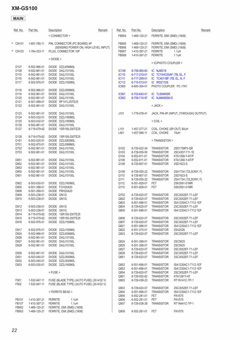
< CONNECTOR >
* CN101 1-691-785-11 PIN, CONNECTOR (PC BOARD) 4P (SENSING POWER ON, HIGH LEVEL INPUT)
* CN103 1-764-333-11 PLUG, CONNECTOR 10P
< DIODE >
D107 6-502-966-01 DIODE DZ2J056M0L D108 6-502-961-01 DIODE DA2J10100L D115 6-502-961-01 DIODE DA2J10100L D116 6-502-961-01 DIODE DA2J10100L D117 6-502-976-01 DIODE DZ2J150M0L
D118 6-502-966-01 DIODE DZ2J056M0L D119 6-502-961-01 DIODE DA2J10100L D120 6-502-961-01 DIODE DA2J10100L D121 6-501-089-01 DIODE RF101L2STE25 D122 6-502-961-01 DIODE DA2J10100L
D123 6-502-961-01 DIODE DA2J10100L D124 6-503-032-01 DIODE DZ2J180M0L D125 6-503-032-01 DIODE DZ2J180M0L D126 6-502-961-01 DIODE DA2J10100L D127 8-719-079-92 DIODE 1SR159-200TE25
D128 8-719-079-92 DIODE 1SR159-200TE25 D161 6-503-020-01 DIODE DZ2J082M0L D701 6-502-970-01 DIODE DZ2J068M0L D702 6-502-961-01 DIODE DA2J10100L D703 6-502-961-01 DIODE DA2J10100L
D851 6-502-961-01 DIODE DA2J10100L D852 6-502-961-01 DIODE DA2J10100L D853 6-502-961-01 DIODE DA2J10100L D855 6-502-961-01 DIODE DA2J10100L D901 6-502-961-01 DIODE DA2J10100L
D902 6-503-030-01 DIODE DZ2J160M0L D905 6-501-398-01 DIODE FCH20A20 D906 6-501-399-01 DIODE FRH20A20 D909 6-503-238-01 DIODE GN1G D910 6-503-238-01 DIODE GN1G
D912 6-503-238-01 DIODE GN1G D913 6-503-238-01 DIODE GN1G D914 8-719-079-92 DIODE 1SR159-200TE25 D915 8-719-079-92 DIODE 1SR159-200TE25 D916 6-502-976-01 DIODE DZ2J150M0L
D917 6-502-976-01 DIODE DZ2J150M0L D924 6-502-966-01 DIODE DZ2J056M0L D926 6-502-961-01 DIODE DA2J10100L D927 6-502-961-01 DIODE DA2J10100L D928 6-502-961-01 DIODE DA2J10100L
D929 6-502-961-01 DIODE DA2J10100L D931 6-503-040-01 DIODE DZ2J300M0L D932 6-503-040-01 DIODE DZ2J300M0L D933 6-503-030-01 DIODE DZ2J160M0L
< FUSE >
F901 1-532-947-11 FUSE (BLADE TYPE) (AUTO FUSE) (30 A/32 V) F902 1-532-947-11 FUSE (BLADE TYPE) (AUTO FUSE) (30 A/32 V)
< FERRITE BEAD >
FB101 1-410-397-21 FERRITE 1.1uH FB107 1-410-397-21 FERRITE 1.1uH FB902 1-469-120-21 FERRITE, EMI (SMD) (1608) FB903 1-469-120-21 FERRITE, EMI (SMD) (1608)
FB904 1-469-120-21 FERRITE, EMI (SMD) (1608)
FB905 1-469-120-21 FERRITE, EMI (SMD) (1608) FB906 1-469-120-21 FERRITE, EMI (SMD) (1608) FB907 1-410-397-21 FERRITE 1.1uH FB908 1-410-397-21 FERRITE 1.1uH
< IC/PHOTO COUPLER >
IC109 8-759-065-60 IC NJM318 IC110 6-717-210-01 IC TC74HC00AF (TB, EL, F IC111 6-717-209-01 IC TC4011BF (TB, EL, N, F IC112 6-710-513-01 IC IRS2110S IC900 6-600-354-01 PHOTO COUPLER PC-17K1
IC901 6-703-643-01 IC TL594INSR IC902 8-759-710-97 IC NJM4565M-D
< JACK >
J101 1-779-078-41 JACK, PIN 4P (INPUT, (THROUGH) OUTPUT)
< COIL >
L101 1-457-377-21 COIL, CHOKE (SP-OUT) 80uH L901 1-457-586-11 COIL, CHOKE 15uH
< TRANSISTOR >
Q102 8-729-922-34 TRANSISTOR 2SD1758F5-QR Q103 8-729-055-50 TRANSISTOR 2SC4357-T11-1E Q104 6-552-811-01 TRANSISTOR KTA1268-Y-AT/P Q106 6-552-811-01 TRANSISTOR KTA1268-Y-AT/P Q108 8-729-807-51 TRANSISTOR 2SD1623-S
Q109 8-729-055-22 TRANSISTOR 2SA1734 (T2LSONY, F) Q110 8-729-807-51 TRANSISTOR 2SD1623-S Q111 8-729-055-22 TRANSISTOR 2SA1734 (T2LSONY, F) Q112 6-551-828-01 FET 2SK3591-01MR Q115 6-551-828-01 FET 2SK3591-01MR
Q702 8-729-620-07 TRANSISTOR 2SC3052EF-T1-LEF Q802 8-729-620-07 TRANSISTOR 2SC3052EF-T1-LEF Q803 6-551-696-01 TRANSISTOR ISA1235AC1-T112-1EF Q804 8-729-620-07 TRANSISTOR 2SC3052EF-T1-LEF Q805 6-551-696-01 TRANSISTOR ISA1235AC1-T112-1EF
Q806 8-729-620-07 TRANSISTOR 2SC3052EF-T1-LEF Q807 8-729-620-07 TRANSISTOR 2SC3052EF-T1-LEF Q821 6-551-696-01 TRANSISTOR ISA1235AC1-T112-1EF Q822 6-551-270-01 TRANSISTOR 2SA2026 Q823 8-729-620-07 TRANSISTOR 2SC3052EF-T1-LEF
Q824 6-551-268-01 TRANSISTOR 2SC5625 Q825 6-551-268-01 TRANSISTOR 2SC5625 Q827 8-729-620-07 TRANSISTOR 2SC3052EF-T1-LEF Q828 8-729-620-07 TRANSISTOR 2SC3052EF-T1-LEF Q851 8-729-620-07 TRANSISTOR 2SC3052EF-T1-LEF
Q852 6-551-696-01 TRANSISTOR ISA1235AC1-T112-1EF Q853 6-551-696-01 TRANSISTOR ISA1235AC1-T112-1EF Q854 8-729-620-07 TRANSISTOR 2SC3052EF-T1-LEF Q901 8-729-052-82 TRANSISTOR KTA1281Y-AT Q902 8-729-038-23 TRANSISTOR RT1N141C-TP-1
Q903 8-729-620-07 TRANSISTOR 2SC3052EF-T1-LEF Q904 6-551-696-01 TRANSISTOR ISA1235AC1-T112-1EF Q905 6-552-281-01 FET FKV575 Q906 6-552-281-01 FET FKV575 Q907 8-729-038-28 TRANSISTOR RT1N441C-TP-1
Q909 6-552-281-01 FET FKV575
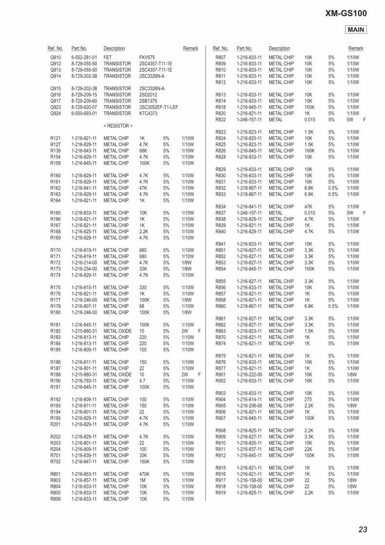
Ref. No. Part No. Description Remark Ref. No. Part No. Description Remark
XM-GS100
2323
Q910 6-552-281-01 FET FKV575 Q912 8-729-055-50 TRANSISTOR 2SC4357-T11-1E Q913 8-729-055-50 TRANSISTOR 2SC4357-T11-1E Q914 8-729-202-38 TRANSISTOR 2SC3326N-A
Q915 8-729-202-38 TRANSISTOR 2SC3326N-A Q916 8-729-209-15 TRANSISTOR 2SD2012 Q917 8-729-209-60 TRANSISTOR 2SB1375 Q923 8-729-620-07 TRANSISTOR 2SC3052EF-T1-LEF Q924 6-550-693-01 TRANSISTOR KTC4373
< RESISTOR >
R121 1-216-821-11 METAL CHIP 1K 5% 1/10W R127 1-216-829-11 METAL CHIP 4.7K 5% 1/10W R139 1-216-843-11 METAL CHIP 68K 5% 1/10W R154 1-216-829-11 METAL CHIP 4.7K 5% 1/10W R159 1-216-845-11 METAL CHIP 100K 5% 1/10W
R160 1-216-829-11 METAL CHIP 4.7K 5% 1/10W R161 1-216-829-11 METAL CHIP 4.7K 5% 1/10W R162 1-216-841-11 METAL CHIP 47K 5% 1/10W R163 1-216-829-11 METAL CHIP 4.7K 5% 1/10W R164 1-216-821-11 METAL CHIP 1K 5% 1/10W
R165 1-216-833-11 METAL CHIP 10K 5% 1/10W R166 1-216-821-11 METAL CHIP 1K 5% 1/10W R167 1-216-821-11 METAL CHIP 1K 5% 1/10W R168 1-216-825-11 METAL CHIP 2.2K 5% 1/10W R169 1-216-829-11 METAL CHIP 4.7K 5% 1/10W
R170 1-216-819-11 METAL CHIP 680 5% 1/10W R171 1-216-819-11 METAL CHIP 680 5% 1/10W R172 1-216-214-00 METAL CHIP 4.7K 5% 1/8W R173 1-216-234-00 METAL CHIP 33K 5% 1/8W R174 1-216-829-11 METAL CHIP 4.7K 5% 1/10W
R175 1-216-815-11 METAL CHIP 330 5% 1/10W R176 1-216-821-11 METAL CHIP 1K 5% 1/10W R177 1-216-246-00 METAL CHIP 100K 5% 1/8W R178 1-216-807-11 METAL CHIP 68 5% 1/10W R180 1-216-246-00 METAL CHIP 100K 5% 1/8W
R181 1-216-845-11 METAL CHIP 100K 5% 1/10W R182 1-215-880-31 METAL OXIDE 10 5% 2W F R183 1-216-813-11 METAL CHIP 220 5% 1/10W R184 1-216-813-11 METAL CHIP 220 5% 1/10W R185 1-216-809-11 METAL CHIP 100 5% 1/10W
R186 1-216-811-11 METAL CHIP 150 5% 1/10W R187 1-216-801-11 METAL CHIP 22 5% 1/10W R188 1-215-880-31 METAL OXIDE 10 5% 2W F R190 1-216-793-11 METAL CHIP 4.7 5% 1/10W R191 1-216-845-11 METAL CHIP 100K 5% 1/10W
R192 1-216-809-11 METAL CHIP 100 5% 1/10W R193 1-216-811-11 METAL CHIP 150 5% 1/10W R194 1-216-801-11 METAL CHIP 22 5% 1/10W R195 1-216-829-11 METAL CHIP 4.7K 5% 1/10W R201 1-216-829-11 METAL CHIP 4.7K 5% 1/10W
R202 1-216-829-11 METAL CHIP 4.7K 5% 1/10W R203 1-216-801-11 METAL CHIP 22 5% 1/10W R204 1-216-809-11 METAL CHIP 100 5% 1/10W R701 1-216-839-11 METAL CHIP 33K 5% 1/10W R702 1-216-847-11 METAL CHIP 150K 5% 1/10W
R801 1-216-853-11 METAL CHIP 470K 5% 1/10W R803 1-216-857-11 METAL CHIP 1M 5% 1/10W R804 1-216-833-11 METAL CHIP 10K 5% 1/10W R805 1-216-833-11 METAL CHIP 10K 5% 1/10W R806 1-216-833-11 METAL CHIP 10K 5% 1/10W
R807 1-216-833-11 METAL CHIP 10K 5% 1/10W R809 1-216-833-11 METAL CHIP 10K 5% 1/10W R810 1-216-833-11 METAL CHIP 10K 5% 1/10W R811 1-216-833-11 METAL CHIP 10K 5% 1/10W R812 1-216-833-11 METAL CHIP 10K 5% 1/10W
R813 1-216-833-11 METAL CHIP 10K 5% 1/10W R814 1-216-833-11 METAL CHIP 10K 5% 1/10W R818 1-216-845-11 METAL CHIP 100K 5% 1/10W R820 1-216-821-11 METAL CHIP 1K 5% 1/10W R822 1-246-157-11 METAL 0.015 5% 5W F
R823 1-216-823-11 METAL CHIP 1.5K 5% 1/10W R824 1-216-833-11 METAL CHIP 10K 5% 1/10W R825 1-216-823-11 METAL CHIP 1.5K 5% 1/10W R826 1-216-845-11 METAL CHIP 100K 5% 1/10W R828 1-216-833-11 METAL CHIP 10K 5% 1/10W
R829 1-216-833-11 METAL CHIP 10K 5% 1/10W R830 1-216-833-11 METAL CHIP 10K 5% 1/10W R831 1-216-833-11 METAL CHIP 10K 5% 1/10W R832 1-218-867-11 METAL CHIP 6.8K 0.5% 1/10W R833 1-218-867-11 METAL CHIP 6.8K 0.5% 1/10W
R834 1-216-841-11 METAL CHIP 47K 5% 1/10W R837 1-246-157-11 METAL 0.015 5% 5W F R838 1-216-829-11 METAL CHIP 4.7K 5% 1/10W R839 1-216-821-11 METAL CHIP 1K 5% 1/10W R840 1-216-829-11 METAL CHIP 4.7K 5% 1/10W
R841 1-216-833-11 METAL CHIP 10K 5% 1/10W R851 1-216-827-11 METAL CHIP 3.3K 5% 1/10W R852 1-216-827-11 METAL CHIP 3.3K 5% 1/10W R853 1-216-827-11 METAL CHIP 3.3K 5% 1/10W R854 1-216-845-11 METAL CHIP 100K 5% 1/10W
R855 1-216-827-11 METAL CHIP 3.3K 5% 1/10W R856 1-216-833-11 METAL CHIP 10K 5% 1/10W R857 1-216-821-11 METAL CHIP 1K 5% 1/10W R858 1-216-821-11 METAL CHIP 1K 5% 1/10W R860 1-218-867-11 METAL CHIP 6.8K 0.5% 1/10W
R861 1-216-827-11 METAL CHIP 3.3K 5% 1/10W R862 1-216-827-11 METAL CHIP 3.3K 5% 1/10W R863 1-216-823-11 METAL CHIP 1.5K 5% 1/10W R870 1-216-821-11 METAL CHIP 1K 5% 1/10W R874 1-216-821-11 METAL CHIP 1K 5% 1/10W
R875 1-216-821-11 METAL CHIP 1K 5% 1/10W R876 1-216-833-11 METAL CHIP 10K 5% 1/10W R877 1-216-821-11 METAL CHIP 1K 5% 1/10W R901 1-216-222-00 METAL CHIP 10K 5% 1/8W R902 1-216-833-11 METAL CHIP 10K 5% 1/10W
R903 1-216-833-11 METAL CHIP 10K 5% 1/10W R904 1-216-814-11 METAL CHIP 270 5% 1/10W R905 1-216-206-00 METAL CHIP 2.2K 5% 1/8W R906 1-216-821-11 METAL CHIP 1K 5% 1/10W R907 1-216-845-11 METAL CHIP 100K 5% 1/10W
R908 1-216-825-11 METAL CHIP 2.2K 5% 1/10W R909 1-216-827-11 METAL CHIP 3.3K 5% 1/10W R910 1-216-835-11 METAL CHIP 15K 5% 1/10W R911 1-216-837-11 METAL CHIP 22K 5% 1/10W R912 1-216-845-11 METAL CHIP 100K 5% 1/10W
R915 1-216-821-11 METAL CHIP 1K 5% 1/10W R916 1-216-821-11 METAL CHIP 1K 5% 1/10W R917 1-216-158-00 METAL CHIP 22 5% 1/8W R918 1-216-158-00 METAL CHIP 22 5% 1/8W R919 1-216-825-11 METAL CHIP 2.2K 5% 1/10W
MAIN
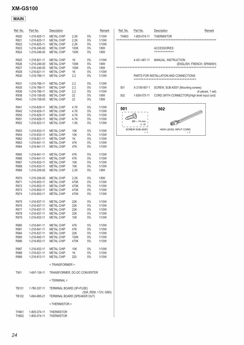
Ref. No. Part No. Description Remark Ref. No. Part No. Description Remark
XM-GS100
24
R920 1-216-825-11 METAL CHIP 2.2K 5% 1/10W R921 1-216-825-11 METAL CHIP 2.2K 5% 1/10W R922 1-216-825-11 METAL CHIP 2.2K 5% 1/10W R923 1-216-246-00 METAL CHIP 100K 5% 1/8W R924 1-216-246-00 METAL CHIP 100K 5% 1/8W
R925 1-216-821-11 METAL CHIP 1K 5% 1/10W R926 1-216-246-00 METAL CHIP 100K 5% 1/8W R927 1-216-246-00 METAL CHIP 100K 5% 1/8W R928 1-216-821-11 METAL CHIP 1K 5% 1/10W R930 1-216-789-11 METAL CHIP 2.2 5% 1/10W
R931 1-216-789-11 METAL CHIP 2.2 5% 1/10W R935 1-216-789-11 METAL CHIP 2.2 5% 1/10W R936 1-216-789-11 METAL CHIP 2.2 5% 1/10W R938 1-216-158-00 METAL CHIP 22 5% 1/8W R940 1-216-158-00 METAL CHIP 22 5% 1/8W
R941 1-216-829-11 METAL CHIP 4.7K 5% 1/10W R942 1-216-829-11 METAL CHIP 4.7K 5% 1/10W R950 1-216-829-11 METAL CHIP 4.7K 5% 1/10W R951 1-216-829-11 METAL CHIP 4.7K 5% 1/10W R952 1-216-823-11 METAL CHIP 1.5K 5% 1/10W
R953 1-216-833-11 METAL CHIP 10K 5% 1/10W R954 1-216-833-11 METAL CHIP 10K 5% 1/10W R962 1-216-821-11 METAL CHIP 1K 5% 1/10W R963 1-216-841-11 METAL CHIP 47K 5% 1/10W R964 1-216-841-11 METAL CHIP 47K 5% 1/10W
R965 1-216-841-11 METAL CHIP 47K 5% 1/10W R966 1-216-841-11 METAL CHIP 47K 5% 1/10W R967 1-216-833-11 METAL CHIP 10K 5% 1/10W R968 1-216-833-11 METAL CHIP 10K 5% 1/10W R969 1-216-206-00 METAL CHIP 2.2K 5% 1/8W
R970 1-216-206-00 METAL CHIP 2.2K 5% 1/8W R971 1-216-853-11 METAL CHIP 470K 5% 1/10W R972 1-216-853-11 METAL CHIP 470K 5% 1/10W R973 1-216-853-11 METAL CHIP 470K 5% 1/10W R974 1-216-853-11 METAL CHIP 470K 5% 1/10W
R975 1-216-837-11 METAL CHIP 22K 5% 1/10W R976 1-216-837-11 METAL CHIP 22K 5% 1/10W R977 1-216-837-11 METAL CHIP 22K 5% 1/10W R978 1-216-837-11 METAL CHIP 22K 5% 1/10W R979 1-216-833-11 METAL CHIP 10K 5% 1/10W
R980 1-216-841-11 METAL CHIP 47K 5% 1/10W R981 1-216-841-11 METAL CHIP 47K 5% 1/10W R984 1-216-837-11 METAL CHIP 22K 5% 1/10W R985 1-216-845-11 METAL CHIP 100K 5% 1/10W R986 1-216-853-11 METAL CHIP 470K 5% 1/10W
R987 1-216-833-11 METAL CHIP 10K 5% 1/10W R988 1-216-821-11 METAL CHIP 1K 5% 1/10W R989 1-216-813-11 METAL CHIP 220 5% 1/10W
< TRANSFORMER >
T901 1-697-139-11 TRANSFORMER, DC-DC CONVERTER
< TERMINAL >
TB101 1-780-337-11 TERMINAL BOARD (3P+FUSE) (30A, REM, +12V, GND)
TB102 1-694-985-21 TERMINAL BOARD (SPEAKER OUT)
< THERMISTOR >
TH801 1-805-074-11 THERMISTOR TH802 1-805-074-11 THERMISTOR
TH803 1-805-074-11 THERMISTOR*************************************************************
ACCESSORIES ************
4-421-487-11 MANUAL, INSTRUCTION (ENGLISH, FRENCH, SPANISH)
*************************************************************
PARTS FOR INSTALLATION AND CONNECTIONS **************************************
501 X-2159-907-1 SCREW, SUB ASSY (Mounting screws) (4 pieces, 1 set)
502 1-839-575-11 CORD (WITH CONNECTOR)(High level input cord)
MAIN
501 502
HIGH LEVEL INPUT CORD 1
SCREW SUB ASSY 1
Ø4 14 mm( 4)

MEMO
XM-GS100
25

XM-GS100
REVISION HISTORY
Checking the version allows you to jump to the revised page.Also, clicking the version at the top of the revised page allows you to jump to the next revised page.
Ver. Date Description of Revision1.0 2012.02 New
Related Documents