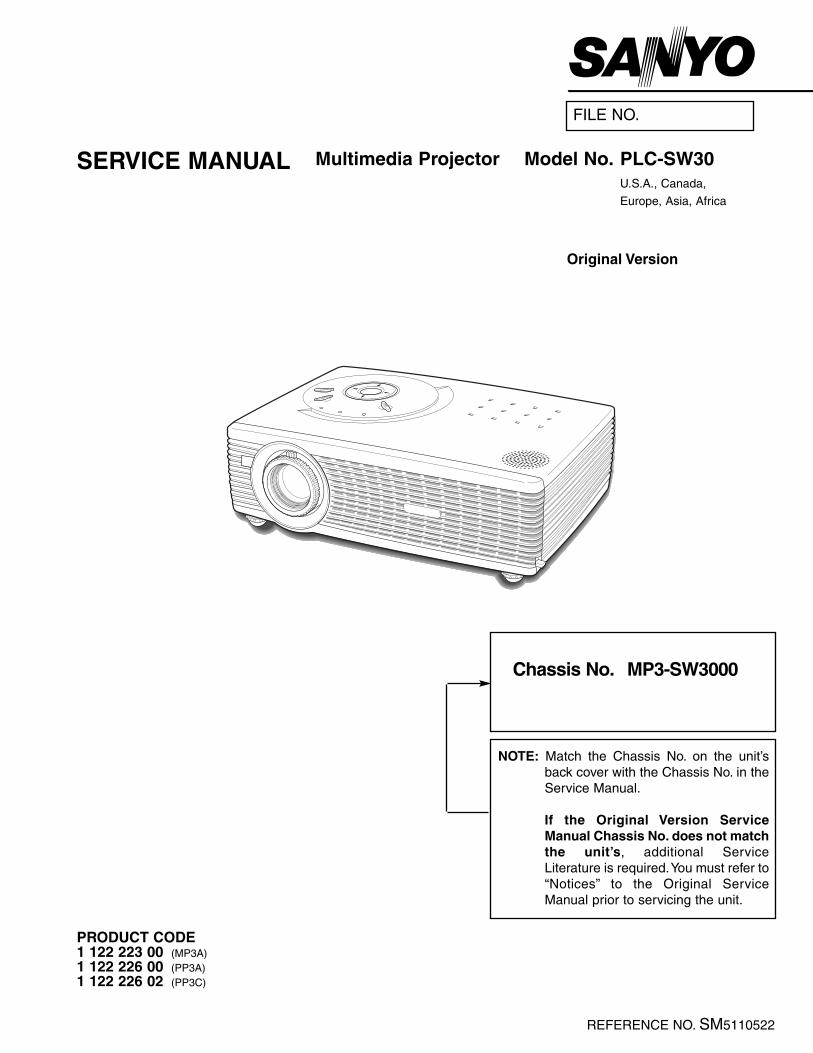
Multimedia Projector SERVICE MANUAL PRODUCT CODE 1 122 223 00 (MP3A) 1 122 226 00 (PP3A) 1 122 226 02 (PP3C) Original Version REFERENCE NO. SM5110522 FILE NO. Model No. PLC-SW30 U.S.A., Canada, Europe, Asia, Africa Chassis No. MP3-SW3000 NOTE: Match the Chassis No. on the unit’s back cover with the Chassis No. in the Service Manual. If the Original Version Service Manual Chassis No. does not match the unit’s, additional Service Literature is required.You must refer to “Notices” to the Original Service Manual prior to servicing the unit.

Welcome message from author
This document is posted to help you gain knowledge. Please leave a comment to let me know what you think about it! Share it to your friends and learn new things together.
Transcript
Multimedia ProjectorSERVICE MANUAL
PRODUCT CODE 1 122 223 00 (MP3A)1 122 226 00 (PP3A)1 122 226 02 (PP3C)
Original Version
REFERENCE NO. SM5110522
FILE NO.
Model No. PLC-SW30U.S.A., Canada,
Europe, Asia, Africa
Chassis No. MP3-SW3000
NOTE: Match the Chassis No. on the unit’sback cover with the Chassis No. in theService Manual.
If the Original Version ServiceManual Chassis No. does not matchthe unit’s, additional ServiceLiterature is required.You must refer to“Notices” to the Original ServiceManual prior to servicing the unit.

2
Contents
Safety instructions ________________________________________________3
Specifications __________________________________________________ 4
Circuit protections ______________________________________________ 5-6
Fuse ____________________________________________________ 5
Thermal switch ____________________________________________ 5
Lamp cover switch __________________________________________ 5
Warning temperature and power failure protection ________________ 6
Lamp replacement ______________________________________________ 7
Mechanical disassemblies ______________________________________ 8-13
Optical parts disassemblies ____________________________________ 14-16
LCD panel/prism ass’y replacement ________________________________ 17
Adjustments after parts replacement ________________________________ 18
Optical adjustments __________________________________________ 19-21
Contrast adjustment ________________________________________ 19
Condenser lens adjustment __________________________________ 20
Relay lens adjustment ______________________________________ 21
Electric adjustments __________________________________________ 22-30
Service adjustment menu operation____________________________ 22
Circuit adjustments ______________________________________ 23-25
Service adjustment data table______________________________ 26-29
Test points and locations ____________________________________ 30
Circuit block diagrams ________________________________________ 31-33
Power supply lines ______________________________________________ 34
Troubleshooting ______________________________________________ 35-38
Indicators and Projector Condition ____________________________ 35
No power ________________________________________________ 36
No picture ________________________________________________ 37
No sound ________________________________________________ 38
Waveforms ____________________________________________________ 39
Control port functions ________________________________________ 40-43
Cleaning ______________________________________________________ 44
IC block diagrams ____________________________________________ 45-48
Service parts lists ____________________________________________ 49-67
Electrical parts list ______________________________________ 49-63
Mechanical parts list ____________________________________ 64-65
Optical parts list ________________________________________ 66-67
Drawings & Diagrams ________________________________________ A1-A9
Parts description and reading in schematic diagram ____________________ A2
Schematic diagrams __________________________________________ A3-A6
Printed wiring board diagrams __________________________________ A7-A8
Pins description of ICs, transistors, diodes __________________________ A9
3
Safety Instructions
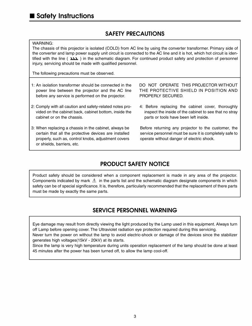
WARNING:The chassis of this projector is isolated (COLD) from AC line by using the converter transformer. Primary side ofthe converter and lamp power supply unit circuit is connected to the AC line and it is hot, which hot circuit is iden-tified with the line ( ) in the schematic diagram. For continued product safety and protection of personnelinjury, servicing should be made with qualified personnel.
The following precautions must be observed.
SAFETY PRECAUTIONS
1: An isolation transformer should be connected in thepower line between the projector and the AC linebefore any service is performed on the projector.
2: Comply with all caution and safety-related notes pro-vided on the cabinet back, cabinet bottom, inside thecabinet or on the chassis.
3: When replacing a chassis in the cabinet, always becertain that all the protective devices are installedproperly, such as, control knobs, adjustment coversor shields, barriers, etc.
DO NOT OPERATE THIS PROJECTOR WITHOUTTHE PROTECTIVE SHIELD IN POSITION ANDPROPERLY SECURED.
4: Before replacing the cabinet cover, thoroughlyinspect the inside of the cabinet to see that no strayparts or tools have been left inside.
Before returning any projector to the customer, theservice personnel must be sure it is completely safe tooperate without danger of electric shock.
SERVICE PERSONNEL WARNING
Eye damage may result from directly viewing the light produced by the Lamp used in this equipment. Always turnoff Lamp before opening cover. The Ultraviolet radiation eye protection required during this servicing.Never turn the power on without the lamp to avoid electric-shock or damage of the devices since the stabilizergenerates high voltages(15kV - 20kV) at its starts.Since the lamp is very high temperature during units operation replacement of the lamp should be done at least45 minutes after the power has been turned off, to allow the lamp cool-off.
PRODUCT SAFETY NOTICE
Product safety should be considered when a component replacement is made in any area of the projector.Components indicated by mark in the parts list and the schematic diagram designate components in whichsafety can be of special significance. It is, therefore, particularly recommended that the replacement of there partsmust be made by exactly the same parts.

4
Specifications
The specifications are subject to change without notice.
This symbol on the nameplate means the product is Listed by UnderwritersLaboratories Inc. It is designed and manufactured to meet rigid U.L. safety stan-dards against risk of fire, casualty and electrical hazards.
Projector Type Multi-media Projector
Dimensions (W x H x D) 10.63” x 3.07” x 7.48” (270mm x 78mm x 190mm) (not including Adjustable Feet)
Net Weight 4.6 lbs (2.1 kg)
LCD Panel System 0.5” TFT Active Matrix type, 3 panels
Panel Resolution 800 x 600 dots
Number of Pixels 1,440,000 (800 x 600 x 3 panels)
Color System PAL, SECAM, NTSC, NTSC4.43, PAL-M and PAL-N
High Definition TV SIgnal 480i, 480p, 575i, 575p, 720p, 1035i and 1080i
Scanning Frequency H-sync. 15 ~ 80 kHz, V-sync. 50 ~ 100 Hz
Projection Image Size (Diagonal) Adjustable from 34” to 200”
Projection Lens F 1.6 ~ 1.8 lens with f 18.3 mm ~ 21.9 mm with manual zoom and focus
Throw Distance 4.3’ ~ 21.2’ (1.3 m ~ 6.5 m)
Projection Lamp 160 W
Video Input Jack RCA Type x 1 (Video) and and Mini DIN 4 pin x 1 (S-Video)
AV Audio Input Jack Mini Jack (stereo) x 1
Computer Input Terminal (VGA) HDB 15 Terminal x 1
Computer Audio Input Jack Mini Jack (stereo) x 1
Control Port Connector Mini DIN 8 pin x 1
USB Connector USB Series B receptacle x 1
Internal Audio Amp 0.8 W RMS
Build-in Speaker 1 speaker, ø1.3" (32 mm)
Feet Adjustment 0˚ to 8.0˚
Voltage and AC 100 ~ 120V (2.4A Max. Ampere), 50/60Hz (The U.S.A and Canada)
Power Consumption AC 200 ~ 240V (1.2A Max. Ampere), 50/60Hz (Continental Europe and The U.K.)
Operating Temperature 41 ˚F ~ 95 ˚F (5˚C ~ 35˚C)
Storage Temperature 14 ˚F ~ 140 ˚F (-10˚C ~ 60˚C)
Remote Control Unit Wireless Remote Control, batteries AAA, SUM-04 or R03 type x 2
Presentation Remote Control, batteries AAA, SUM-04 or R03 type x 2
Presentation Remote Receiver
The CE Mark is a Directive conformity mark of the European Community (EC).

-5-
Lamp cover switchThe lamp cover switch (SW8801) cuts off the drive signal to thelamp circuit when the lamp cover is removed or no close com-pletely. After opening the lamp cover for replacing the lamp ass’y,place the lamp cover correctly otherwise the projector can notturn on.
Thermal switchThere is the thermal switch (SW902) inside of the projector toprevent the internal temperature rising abnormally. When theinternal temperature reaches near 100˚C, turn off the AC mainpower supply automatically.The thermal switch is not reset to normal automatically even if theinternal temperature becomes normal. Reset the thermal switchfollowing procedure.Check the resistance between terminals of thermal switch byusing the tester. If it has high impedance, thermal switch may bein operative.
How to reset the thermal switch1. Remove the cabinet top following to “Mechanical
Disassemblies”.2. Press the reset button on the thermal switch with a sharp-
pointed tool.
CAUTION:Before press the reset button, make sure that the AC cord mustbe disconnected from the AC outlet.
Circuit Protections
This projector provides the following circuit protections to operate in safety. If the abnormality occurs inside the pro-jector, it will automatically turn off by operating one of the following protection circuits.
FuseA fuse is located inside of the projector. When the POWER indica-tor is not lightning, the fuse may be opened. Check the fuse as fol-lowing steps.The fuse should be used with the following type;
How to replace the fuse1. Remove the cabinet top following to “Mechanical
Disassemblies”.2. Remove the cover on the Filter Board.3. Remove fuse from fuse holder.To install the fuse, take reversed step in the above.
Fuse Part No.: 423 022 2102 TYPE T4.0AH 250V FUSELITTEL FUSE INC. TYPE 215004
Fuse
Filter Board
Thermal Switch
Lamp Cover
Lamp Cover Switch

-6-
Circuit Protections
Warning temperature and power failure protectionThe WARNING indicator flashes red and the projector will automatically turn off when the internal temperature ofthe projector exceeds the normal temperature or when stopping cooling fans or when the internal power supplylines are failed.
Check the following possible causes and wait until stopping the WARNING indicator flashing.
Possible causes- Air filter is clogged with dust particles. Remove dust from the air filter by following instructions in the “Air filter
care and cleaning” below.- Ventilation slots of the projector are blocked. In such an event, reposition the projector so that ventilation slots are
not obstructed.- Check if projector is used at higher temperature place (Normal operating temperature is 5 to 35 ˚C or 41 to 95˚F)
If the WARNING indicator still continues to flash, there may be defects on cooling fans or power supply circuits.Please check fan operation and power supply lines referring to the “Power Supply Lines Chart”.
Air filter care and cleaningThe removable air filter prevents dust from accumulation on the surface of the projection lens and projection mirror.Should the air filters become clogged with dust particles, it will reduce the cooling fan’s effectiveness and mayresult in internal heat build up and adversely affect the life of the projector.
To clean up the air filters, follow the cleaning procedurebelow:1. Turn the projector off, and disconnect the AC power
cord from the AC outlet.2. Turn the projector upside down and remove the air fil-
ters by pulling the latches upward.3. Clean the air filters with a brush or wash out dust and
particles.4. Replace each air filter properly. Make sure that the air
filters are fully inserted.
CAUTION:Do not operate the projector with the air filters removed.Dust may accumulate on the LCD panel and the mirror,and it may spoil the fine picture image.Do not put the small parts into the air intake vents. It mayresult in the malfunction of the projector. The air filter issmall parts. Take care that children don’t eat or swallow it.
RECOMMENDATIONWe recommend avoiding dusty, smoky environments when operating the projector. Usage in these environmentsmay cause poor image quality.When using under dusty or smoky conditions, dust may accumulate on optical elements inside the projector. Thecondition may degrade the quality of a projected image.When the above symptoms are noticed, please clean up the LCD panel and lens following to the “CleaningMethod”.
Air filters

-7-
WARNING:- Allow a projector to cool, for at least 45 minutes before you open Lamp
Cover. The inside of a projector can become very hot.- For continued safety, replace with a lamp assembly of the same type.- Do not drop a lamp assembly or touch a glass bulb! The glass can
shatter and may cause injury.
Procedure1 Turn off the projector and disconnect the AC plug. Allow the projector to
cool at least for 45 minutes.2 Remove 1 screw and remove the lamp cover.3 Remove 2 screws and pull out the lamp assembly by grasping the han-
dle.4 Replace the lamp assembly securely and tighten 2 screws.5 Close the lamp cover and tighten 1 screw.6 Connect the AC Power Cord to the projector and turn on the projector.
Note:- Do not reset the Lamp Replace Counter, except after lamp is replaced.- The projector can not be turned-on with lamp cover removed, because
when the lamp cover is removed, the lamp cover switch is also releasedto switch off the mains power for safety.
7 Reset the Lamp Replace Counter, see below explanation.
Lamp Replacement
1 Turn the projector on, and press the MENU buttonand the on-screen menu will appear. Press thePOINT LEFT/RIGHT buttons to move the red framepointer to the Setting Menu icon.
2 Press the POINT DOWN button to move the redframe pointer to “Lamp counter reset” and then pressthe SELECT button. The message “Lamp replacecounter reset?” is displayed. Move the pointer to [Yes]and then press the SELECT button.
3 Another confirmation dialog box appears and select[Yes] to reset Lamp Replace Counter .
Please refer to the owners manual for further informa-tion.
RecommendationShould the air filter become clogged with dust particles,it will reduce the cooling fan’s effectiveness and mayresult in internal heat build up and short lamp life. Werecommend cleaning the air filter after the projectionlamp is replaced.Refer to “Air Filter Cleaning”.
The LAMP REPLACE indicator will light yellow whenthe total lamp used time reaches 2000 hours. This isto indicate that lamp replacement is required.The total lamp used time is calculated by using thebelow expression;Total lamp used time = Teco + Tnomal (1+1/4)
Teco : used time in the Eco modeTnormal : used time in the Normal and Auto mode
You can check the lamp replace counter following tobelow procedure.1 Press and hold the POWER ON-OFF button on the
projector or the remote control unit for more than 20
seconds.2 The projector used time and lamp used time will be
displayed on the screen briefly.
Lamp cover
Counter
ProjectorLamp
Normal
Eco
Total
130H
24H
100H
130H
Total lamp used time
ORDER REPLACEMENT LAMPType No. Service Parts No.POA-LMP57 610 308 3117
How to reset Lamp Replace Counter
How to check Lamp used time
ScrewsHandle
Lamp Assembly
Screw
Projector used time
-8-
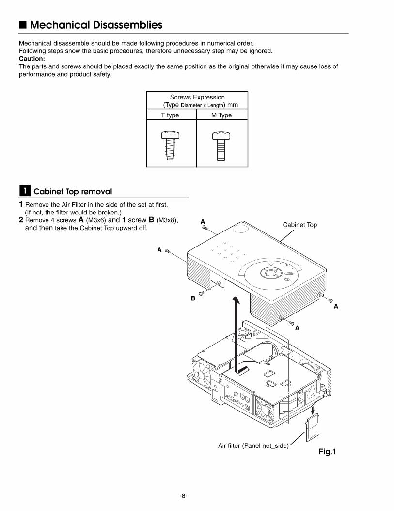
1 Remove the Air Filter in the side of the set at first.(If not, the filter would be broken.)
2 Remove 4 screws A (M3x6) and 1 screw B (M3x8),and then take the Cabinet Top upward off.
Mechanical Disassemblies
Mechanical disassemble should be made following procedures in numerical order.Following steps show the basic procedures, therefore unnecessary step may be ignored.Caution:The parts and screws should be placed exactly the same position as the original otherwise it may cause loss ofperformance and product safety.
Fig.1
Cabinet Top removal1
Screws Expression (Type Diameter x Length) mm
T type M Type
A
A
A
B
A
Air filter (Panel net_side)
Cabinet Top
-9-
Mechanical Disassemblies
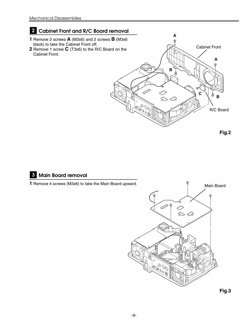
1 Remove 4 screws (M3x6) to take the Main Board upward.
Fig.3
Main Board removal3
Main Board
1 Remove 2 screws A (M3x6) and 2 screws B (M3x6black) to take the Cabinet Front off.
2 Remove 1 screw C (T3x6) to the R/C Board on theCabinet Front.
Fig.2
Cabinet Front and R/C Board removal2
C
A
A
B
B
R/C Board
Cabinet Front

-10-
Mechanical Disassemblies
1 Remove 1 screw (M3x6) to take the Thermal Switch(SW902) and the Cover Spacer off.
Fig.5
Thermal SW removal5
Thermal SW
Lamp Cover Spacer
Fig.4
1 Remove 1 screw A (M4x4) and take the Rear Panelass’y upward off.
2 Remove 2 screws B (T3x8) to take the fan (FN903) off.3 Remove 4 screws C (T3x6) and take AV Board from the
Rear Panel ass’y off.
Rear Panel, AV Board and FN903 removal4
A
B
C
B
C C
C
AV Board
Rear Panel
FN903
Thermal SW Cover

-11-
Mechanical Disassemblies
1 Remove 4 screws A (T2x4) to take off the spacer sheetand the shield plate on the Power Board.
2 Remove 1 screw B (M3x8) to take the Speaker(SP901)off.
3 Remove 2 screws C (T3x8) and 1 screw D (M4x4) to takethe Power Unit and the Fan(FN906) off.
4 Take the Fan(FN906) from the Holder by pulling it.5 Remove 3 screws E (T3x6) to take the Power Unit off.
Notes:You can remove the connectors on the Power Unit after the Lamp Ballast Unit removal.
Fig.7
Power Unit, Speaker and FN906 removal7A
A
A
A
B
E
EED
C
Spacer Sheet
Speaker Holder
Speaker (SP901)
Power Board
FN906
Holder
Fig.6
1 Remove 2 screws A (M3x8) and take the Lamp Cableoff.
2 Remove 6 screws B (T3x10) and take the Optical Unitupward off.
Optical Unit removal6
AA
B
B
B
B
BB
Optical Unit
Lamp Cable
Shield Plate
C
Cover lens sheet
-12-
Mechanical Disassemblies
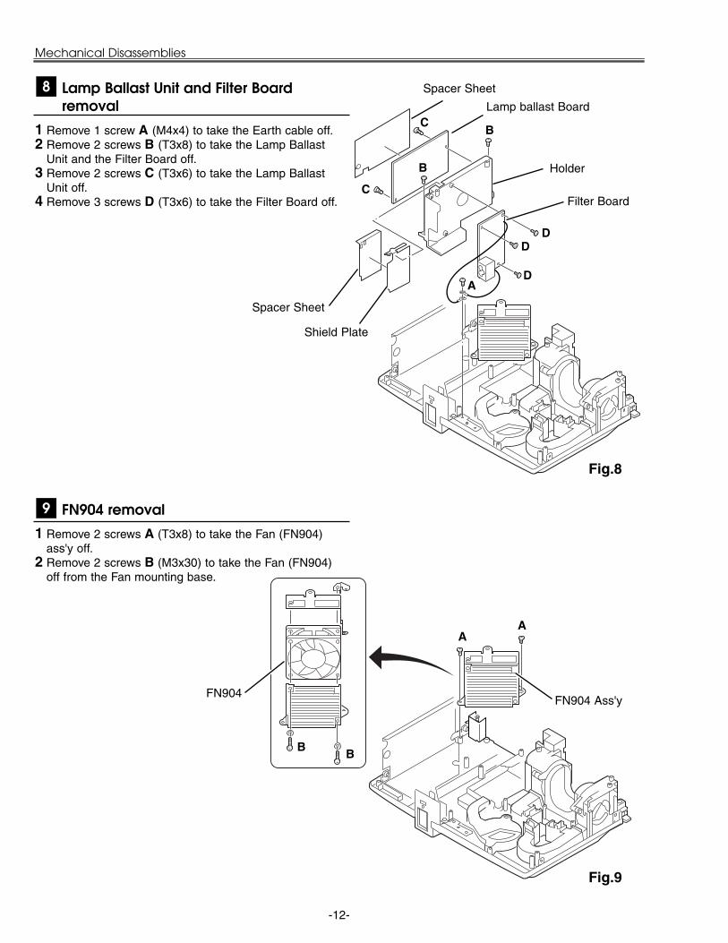
1 Remove 2 screws A (T3x8) to take the Fan (FN904)ass'y off.
2 Remove 2 screws B (M3x30) to take the Fan (FN904)off from the Fan mounting base.
Fig.9
FN904 removal9
AA
BB
FN904 Ass'yFN904
Fig.8
1 Remove 1 screw A (M4x4) to take the Earth cable off.2 Remove 2 screws B (T3x8) to take the Lamp Ballast
Unit and the Filter Board off.3 Remove 2 screws C (T3x6) to take the Lamp Ballast
Unit off.4 Remove 3 screws D (T3x6) to take the Filter Board off.
Lamp Ballast Unit and Filter Boardremoval
8
A
B
B
C
C
D
DD
Lamp ballast Board
Holder
Filter Board
Spacer Sheet
Spacer Sheet
Shield Plate

-13-
1 Remove 1 screws A (T4x4) to take the shield plate off.2 Remove 2 screws B (T3x8) to take the Fan (FN901) and
the duct off.3 Remove 2 screws C (T3x8) to take the SW Board and
the spring off.
Mechanical Disassemblies
Fig.11
FN901 and Lamp Cover SW removal11
FN901
SW Board
Spring
Earth Plate
Duct
B
B
C
C
1 Remove 1 screw A (T3x8) to take the Duct under thePanel.
2 Remove 1 screw B (T3x8) to take the Holder with theFans(FN902 and FN905) off.
3 Remove 2 screws C (T3x10) to take the Fans (FN902and FN905) off.
4 Remove 1 screw D (T3x6) to take the Sensor Board off.
Fig.10
FN902, FN905 and Sensor Board removal10
A
B
C
C
D Sensor Board
FN902
FN905
Shield Plate
A
Spacer sheet
Spacer
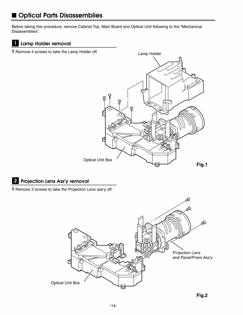
Optical Parts Disassemblies
Before taking this procedure, remove Cabinet Top, Main Board and Optical Unit following to the “MechanicalDisassemblies”.
Fig.2
-14-
Fig.1
1 Remove 4 screws to take the Lamp Holder off.
Lamp Holder removal1
1 Remove 3 screws to take the Projection Lens ass'y off.
Projection Lens Ass'y removal2
Optical Unit Box
Lamp Holder
Optical Unit Box
Projection Lensand Panel/Prism Ass'y
-15-
Fig.4
Fig.3-1
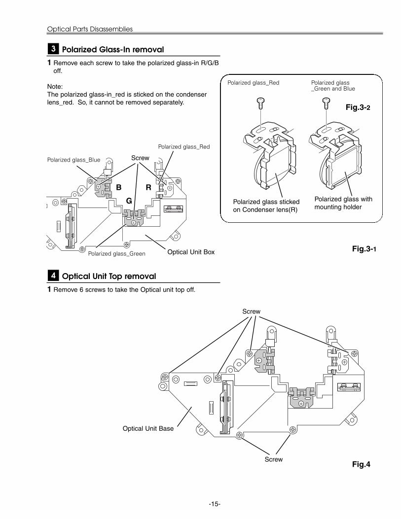
1 Remove each screw to take the polarized glass-in R/G/Boff.
Note:The polarized glass-in_red is sticked on the condenserlens_red. So, it cannot be removed separately.
Polarized Glass-In removal3
1 Remove 6 screws to take the Optical unit top off.
Optical Unit Top removal4
Optical Unit Box
Optical Unit Base
Polarized glass_Red Polarized glass_Green and Blue
Polarized glass stickedon Condenser lens(R)
Polarized glass withmounting holder
Fig.3-2
RB
G
Screw
Polarized glass_Red
Polarized glass_Blue
Polarized glass_Green
Screw
Screw
Optical Parts Disassemblies
-16-
Optical Parts Disassemblies
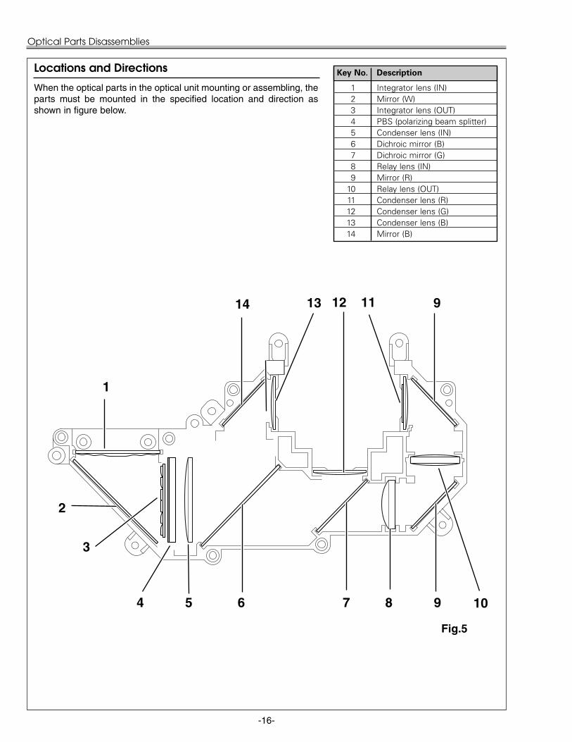
When the optical parts in the optical unit mounting or assembling, theparts must be mounted in the specified location and direction asshown in figure below.
14 12
Fig.5
3
1
2
4
9
Locations and Directions
13
6
1 Integrator lens (IN)2 Mirror (W)3 Integrator lens (OUT)4 PBS (polarizing beam splitter)5 Condenser lens (IN)6 Dichroic mirror (B)7 Dichroic mirror (G)8 Relay lens (IN)9 Mirror (R)
10 Relay lens (OUT)11 Condenser lens (R)12 Condenser lens (G)13 Condenser lens (B)14 Mirror (B)
Key No. Description
10
11
5 7 8 9

-17-
UP
LCD Panel/Prism Ass’y Replacement
IMPORTANT NOTICE on LCD Panel/Prism Ass'y ReplacementLCD panels used for this model can not be replaced separately. Do not disassemble the LCD Panel/Prism Ass’y.These LCD panels are installed with precision at the factory. When replacing the LCD panel, should be replacedwhole of the LCD panels and prism ass’y at once.After replacing LCD Panel/Prism ass’y, please check the following adjustments.
- Check the “Condenser Lens Adjustment” and “Relay Lens Adjustment” following to chapter “OpticalAdjustment”.
- Check the “White Balance Adjustment” and “Common Centre Adjustment” following to chapter“Electrical Adjustment”.
- Check the white uniformity on the screen.If you find the color shading, please adjust the white uniformity by using the proper computer and“Color Shading Correction” software supplied separately. The software can be ordered as follows;
COLOR SHADING CORRECTION Ver. 3.0Service Parts No. 645 056 6288
1 Remove 4 screws to take the Projection Lens off.
LCD Panel/Prism Ass'y removal1
Projection Lens
Panel/Prism Ass'yFig.1
1 Tighten 4 screws to fix the Projection Lens securely,making sure that the zoom lever is upside.
Note:Do not replace the LCD panel separately otherwise it cannot obtain proper picture.Do not touch the prism, the LCD panel and the electrodeof flexible cable.
LCD Panel/Prism Ass'y attachment2
Zoom Lever
-18-
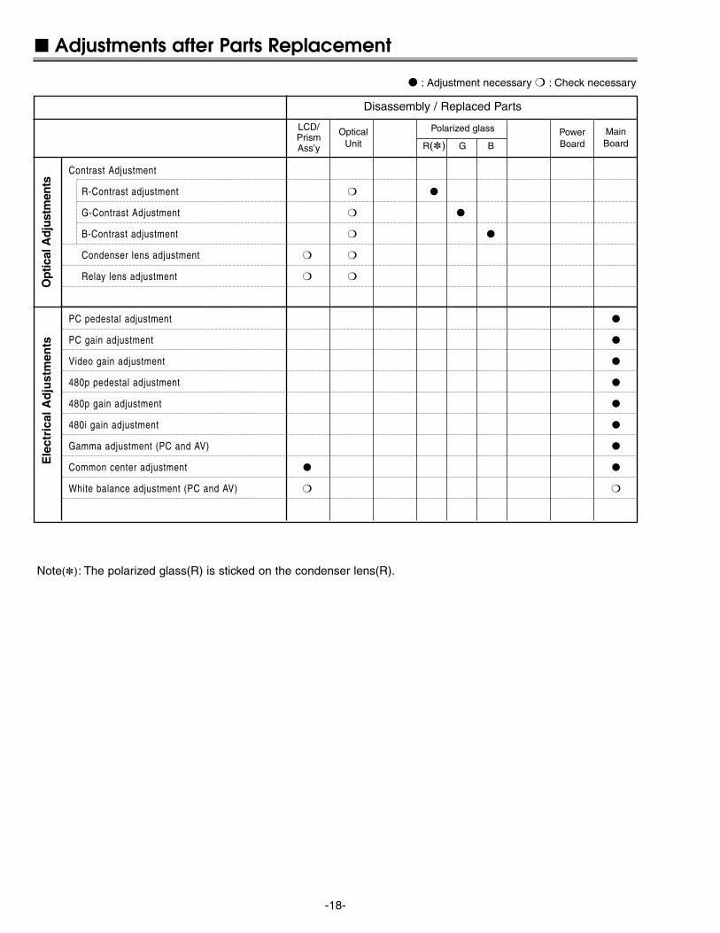
: Adjustment necessary : Check necessary
Adjustments after Parts Replacement
Contrast Adjustment
R-Contrast adjustment
G-Contrast Adjustment
B-Contrast adjustment
Condenser lens adjustment
Relay lens adjustment
PC pedestal adjustment
PC gain adjustment
Video gain adjustment
480p pedestal adjustment
480p gain adjustment
480i gain adjustment
Gamma adjustment (PC and AV)
Common center adjustment
White balance adjustment (PC and AV)
Disassembly / Replaced Parts
LCD/PrismAss’y
OpticalUnit
Polarized glass
R() G B
Opt
ical
Adj
ustm
ents
Ele
ctri
cal A
dju
stm
ents
PowerBoard
MainBoard
Note(): The polarized glass(R) is sticked on the condenser lens(R).

-19-
G-Polarized GlassMounting Base
R-Polarized GlassMounting Base
B-Polarized GlassMounting Base
AA
A
Fig.1-2
Optical Adjustments
Main Board
Before taking optical adjustments below, remove the Cabinet Top and Main Board following to the “MechanicalDisassemblies”Adjustments require a plus screwdriver, 2.0mm hex wrench and a slot screwdriver.Note: Do not disconnect connectors K8A, K8B, K8H, K48K, K48L, K66A, K66B, K66C, K66D, K66E and K66F
on the main board, because the projector can not turn on due to operate the power failure protection.
Fig.1-1
Polarized glassmounting baseA
[Before Adjustment]- Input a 100% of black raster signal.
[R/G/B-CONTRAST ADJUSTMENT]1 Loosen a screw A (Fig.1-1/1-2) on the polarized glass mounting
base which you intend to adjust.2 Turn the polarized glass mounting base as shown in Fig.1-1 to
obtain the darkest brightness on the screen.3 Tighten the screw A to fix the polarized glass mounting base.
Repeat steps 1 to 3 for remaining polarized glasses.
Contrast adjustment
-20-
Optical Adjustments
Fig.2-2
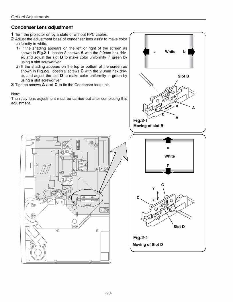
1 Turn the projector on by a state of without FPC cables.2 Adjust the adjustment base of condenser lens ass’y to make color
uniformity in white.1) If the shading appears on the left or right of the screen as
shown in Fig.2-1, loosen 2 screws A with the 2.0mm hex driv-er, and adjust the slot B to make color uniformity in green byusing a slot screwdriver.
2) If the shading appears on the top or bottom of the screen asshown in Fig.2-2, loosen 2 screws C with the 2.0mm hex driv-er, and adjust the slot D to make color uniformity in green byusing a slot screwdriver
3 Tighten screws A and C to fix the Condenser lens unit.
Note:The relay lens adjustment must be carried out after completing thisadjustment.
y
x
Moving of Slot D
Slot D
a b
b
a
Moving of slot BFig.2-1
Slot B
A
C x
y
White
White
Condenser Lens adjustment
A
C

-21-
1 Turn the projector on by a state of without FPC cables.2 Adjust the adjustment base of relay lens ass’y to make color unifor-
mity in white.1) If the cyan bar appears on the left or right of the screen as shown
in Fig.4-1, loosen 2 screws A with the 2.0mm hex driver, andadjust the slot B to make color uniformity in white by using a slotscrewdriver.
2) If the cyan bar appears on the top or bottom of the screen asshown in Fig.4-2, loosen 2 screws C with the 2.0mm hex driver,and adjust the slot D to make color uniformity in white by usinga slot screwdriver.
3 Tighten the screws A and C to fix the relay lens unit.
Fig.4-1
A
Slot B
b
a
a
Moving of slot B
bWhite
Fig.4-2
Slot D
Moving of slot D
y
x
C
Optical Adjustments
x
y
Relay lens-Out adjustment
White
C
Cyan
Cyan
A
-22-
Electrical Adjustments
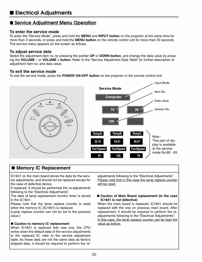
To enter the service modeTo enter the “Service Mode”, press and hold the MENU and INPUT button on the projector at the same time formore than 3 seconds, or press and hold the MENU button on the remote control unit for more than 20 seconds.The service menu appears on the screen as follows.
To adjust service dataSelect the adjustment item no. by pressing the pointer UP or DOWN button, and change the data value by press-ing the VOLUME – or VOLUME + button. Refer to the “Service Adjustment Data Table” for further description ofadjustment item no. and data value.
To exit the service modeTo exit the service mode, press the POWER ON-OFF button on the projector or the remote control unit.
Service Adjustment Menu Operation
Computer
70
100
35
Service Mode
TempA TempB TempC
Fan1Speed Fan2Speed Fan3Speed
32.10 43.21 45.67
97 105 79
IC1841 on the main board stores the data for the serv-ice adjustments, and should not be replaced except forthe case of defective device.If replaced, it should be performed the re-adjustmentsfollowing to the “Electrical Adjustments”.The data of lamp replacement monitor timer is storedin the IC1841.Please note that the lamp replace counter is resetwhen the memory IC (IC1841) is replaced.(Lamp replace counter can not be set to the previousvalue.)
Caution to memory IC replacementWhen IC1841 is replaced with new one, the CPUwrites down the default data of the service adjustmentsto the replaced IC, refer to the service adjustmenttable. As these data are not the same data as factoryshipped data, it should be required to perform the re-
adjustments following to the “Electrical Adjustments”.Please note that in this case the lamp replace counterwill be reset.
Caution of Main Board replacement (in the caseIC1841 is not defective)
When the main board is replaced, IC1841 should bereplaced with the one on previous main board. Afterreplacement, it should be required to perform the re-adjustments following to the “Electrical Adjustments”.In this case, the lamp replace counter can be kept thevalue as before.
Memory IC Replacement
POWER LAMPREPLACE
WARNING
INPUT
MENU
ON-OFF
SELECT
VOLU
ME–
VOLU
ME+
Data value
Item No.
Input Mode
Version No.
Note :This part of dis-play is availableat the servicemode No.60 - 83.

1. Receive the 16-step gray scale computer signal withCOMPUTER IN [RGB] mode.
2. Enter the service mode.3. Connect an oscilloscope to test point “TPR1” (+) and
chassis ground (-).4. Select item no. “7” and change data value to adjust
waveform “a” to be minimum amplitude.5. Connect an oscilloscope to test point “TPG1” (+) and
chassis ground (-).6. Select item no. “8” and change data value to adjust
waveform “a” to be minimum amplitude.7. Connect an oscilloscope to test point “TPB1” (+) and
chassis ground (-).8. Select item no. “9” and change data value to adjust
waveform “a” to be minimum amplitude.
(a)
White Level
-23-
Circuit Adjustments
CAUTION: The each circuit has been made by the fine adjustment at factory. Do not attempt to adjust the follow-ing adjustments except requiring the readjustments in servicing otherwise it may cause loss of per-formance and product safety.
Electrical Adjustments
[Adjustment Condition] Input signal
Video signal .......................... 1.0Vp-p/75Ω terminated, 16 steps grayscale, white 100% and white 50% pat-tern (Composite video signal)
Computer signal .................... 0.7Vp-p/75Ω terminated, 16 steps grayscale pattern (SVGA)
Component Video signal........ 0.7Vp-p/75Ω terminated, 16 steps grayscale, white 100% and black 0% pat-tern (480i format and 480p format)
Picture control mode ................ “STANDARD” mode unless otherwisenoted.
Note:* Please refer to “Service Adjustment Menu Operation” for entering to the service mode and adjusting the service
data.
White 100% Black 100%
x PC Gain adjustment
16 steps gray scale pattern
1. Receive the 16-step gray scale computer signal withCOMPUTER IN [RGB] mode.
2. Enter the service mode.3. Connect an oscilloscope to test point “TPR1” (+) and
chassis ground (-).4. Select item no. “275” and change data value to adjust
the pedestal level and black level to be the samelevel.
5. Connect an oscilloscope to test point “TPG1” (+) andchassis ground (-).
6. Select item no. “276” and change data value to adjustthe pedestal level and black level to be the samelevel.
7. Connect an oscilloscope to test point “TPB1” (+) andchassis ground (-).
8. Select item no. “277” and change data value to adjustthe pedestal level and black level to be the samelevel.
Bla
ck L
ebel
Ped
esta
l Leb
el
z PC Pedestal adjustment

-24-
1. Receive the 16-step gray scale component signal(480i format) with COMPUTER IN [COMPONENT]mode.
2. Enter the service mode.3. Connect an oscilloscope to test point “TPR1” (+) and
chassis ground (-).4. Select item no. “7” and change data value to adjust
waveform “a” to be minimum amplitude.5. Connect an oscilloscope to test point “TPG1” (+) and
chassis ground (-).6. Select item no. “8” and change data value to adjust
waveform “a” to be minimum amplitude.7. Connect an oscilloscope to test point “TPB1” (+) and
chassis ground (-).8. Select item no. “9” and change data value to adjust
waveform “a” to be minimum amplitude.
(a)
White Level
1. Receive the 16-step gray scale component signal(480p format) with COMPUTER IN [COMPONENT]mode.
2. Enter the service mode.3. Connect an oscilloscope to test point “TPR1” (+) and
chassis ground (-).4. Select item no. “7” and change data value to adjust
waveform “a” to be minimum amplitude.5. Connect an oscilloscope to test point “TPG1” (+) and
chassis ground (-).6. Select item no. “8” and change data value to adjust
waveform “a” to be minimum amplitude.7. Connect an oscilloscope to test point “TPB1” (+) and
chassis ground (-).8. Select item no. “9” and change data value to adjust
waveform “a” to be minimum amplitude.
(a)
White Level
1. Receive the 16-step gray scale composite video sig-nal with Video [Video] mode.
2. Enter the service mode.3. Connect an oscilloscope to test point “TPR1” (+) and
chassis ground (-).4. Select item no. “7” and change data value to adjust
waveform “a” to be minimum amplitude.5. Connect an oscilloscope to test point “TPG1” (+) and
chassis ground (-).6. Select item no. “8” and change data value to adjust
waveform “a” to be minimum amplitude.7. Connect an oscilloscope to test point “TPB1” (+) and
chassis ground (-).8. Select item no. “9” and change data value to adjust
waveform “a” to be minimum amplitude.
(a)
White Level
c Video Gain adjustment
Electrical Adjustments
b 480p Gain adjustment
n 480i Gain adjustment1. Receive the 16-step gray scale component signal
(480p format) with COMPUTER IN [COMPONENT]mode.
2. Enter the service mode.3. Connect an oscilloscope to test point “TPR1” (+) and
chassis ground (-).4. Select item no. “275” and change data value to adjust
the pedestal level and black level to be the samelevel.
5. Connect an oscilloscope to test point “TPG1” (+) andchassis ground (-).
6. Select item no. “276” and change data value to adjustthe pedestal level and black level to be the samelevel.
7. Connect an oscilloscope to test point “TPB1” (+) andchassis ground (-).
8. Select item no. “277” and change data value to adjustthe pedestal level and black level to be the samelevel.
Bla
ck L
ebel
Ped
esta
l Leb
el
v 480p Pedestal adjustment
-25-
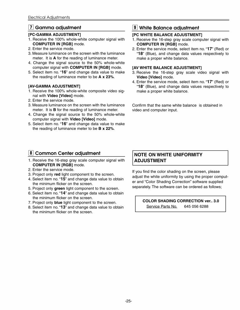
1. Receive the 16-step gray scale computer signal withCOMPUTER IN [RGB] mode.
2. Enter the service mode.3. Project only red light component to the screen.4. Select item no. “15” and change data value to obtain
the minimum flicker on the screen.5. Project only green light component to the screen.6. Select item no. “14” and change data value to obtain
the minimum flicker on the screen.7. Project only blue light component to the screen.8. Select item no. “13” and change data value to obtain
the minimum flicker on the screen.
, Common Center adjustment
[PC-GAMMA ADJUSTMENT]1. Receive the 100% whole-white computer signal with
COMPUTER IN [RGB] mode.2. Enter the service mode.3. Measure luminance on the screen with the luminance
meter. It is A for the reading of luminance meter.4. Change the signal source to the 50% whole-white
computer signal with COMPUTER IN [RGB] mode.5. Select item no. “16” and change data value to make
the reading of luminance meter to be A x 23%.
[AV-GAMMA ADJUSTMENT]1. Receive the 100% whole-white composite video sig-
nal with Video [Video] mode.2. Enter the service mode.3. Measure luminance on the screen with the luminance
meter. It is B for the reading of luminance meter.4. Change the signal source to the 50% whole-white
computer signal with Video [Video] mode.5. Select item no. “16” and change data value to make
the reading of luminance meter to be B x 22%.
m Gamma adjustment
Electrical Adjustments
[PC WHITE BALANCE ADJUSTMENT]1. Receive the 16-step gray scale computer signal with
COMPUTER IN [RGB] mode.2. Enter the service mode, select item no. “17” (Red) or
“18” (Blue), and change data values respectively tomake a proper white balance.
[AV WHITE BALANCE ADJUSTMENT]3. Receive the 16-step gray scale video signal with
Video [Video] mode.4. Enter the service mode, select item no. “17” (Red) or
“18” (Blue), and change data values respectively tomake a proper white balance.
Confirm that the same white balance is obtained invideo and computer input.
. White Balance adjustment
If you find the color shading on the screen, pleaseadjust the white uniformity by using the proper comput-er and “Color Shading Correction” software suppliedseparately. The software can be ordered as follows;
COLOR SHADING CORRECTION ver.. 3.0Service Parts No. 645 056 6288
NOTE ON WHITE UNIFORMITYADJUSTMENT

-26-
1 R-VIDEOCNT M62392FP 1432 G-VIDEOCNT M62392FP 143 Video Center Adjustment ( = R/G/B-V1)3 B-VIDEOCNT M62392FP 1434 R-Sub-Bright L3E7070K0A 05 G-Sub-Bright L3E7070K0A 0 Sub-Bright Adjustment6 B-Sub-Bright L3E7070K0A 07 R-Sub-Gain L3E7070K0A 550 560 540 530 Gain Adjustment [R]8 G-Sub-Gain L3E7070K0A 550 560 540 530 Gain Adjustment [G]9 B-Sub-Gain L3E7070K0A 530 550 540 530 Gain Adjustment [B]
10 REF-R M62392FP 19011 REF-G M62392FP 19012 REF-B M62392FP 19013 BVCOM L3E6100D0A 13014 GVCOM L3E6100D0A 130 Common Center Adjustment15 RVCOM L3E6100D0A 13016 G-Gamma-Shift L3E7070K0A 512 512 512 512 Gamma Adjustment17 R-Gamma-Shift L3E7070K0A 512 512 512 512 White Balance Adjustment [R]18 B-Gamma-Shift L3E7070K0A 512 512 512 512 White Balance Adjustment [B]19 NRS-B M62393FP 153 NRS Adjustment (up side)20 NRS-A M62392FP 35 NRS Adjustment (down side)21 R-V2 M62392FP 16322 G-V2 M62392FP 163 Video Center Adjustment (Link to Item No.1-3)23 B-V2 M62392FP 16324 SubBright PW168 128 128 128 12825 SubColor PW168 85 85 85 N/A26 SubTint PW168 128 128 128 N/A27 - 028 SubBright (Video) VPC3230 N/A Note 1 N/A 128 127 Note 1: 575i = the same as PAL29 SubCont (Video) VPC3230 N/A Note 1 N/A 50 4930 SubColor (Video) VPC3230 N/A Note 1 N/A 2070 207031 SubTint (Video) VPC3230 N/A Note 1 N/A 512 51232 SubBright (480i,575i) VPC3230 N/A 199 N/A 196 19733 SubCont (480i,575i) VPC3230 N/A 25 N/A 25 2634 SubColor (480i,575i) VPC3230 N/A 31 N/A 23 23 Note 2: 480i = the same as NTSC35 SubColor (480i,575i) VPC3230 N/A Note 2 N/A 29 29 575i = the same as PAL36 - 037 V-Line Color Shading Correction Setting (R1) L3E7070K0A 2 Vertical Line Color Shading Correction38 V-Line Color Shading Correction Setting (R2) L3E7070K0A 139 V-Line Color Shading Correction Setting (R3) L3E7070K0A 25440 V-Line Color Shading Correction Setting (G1) L3E7070K0A 241 V-Line Color Shading Correction Setting (G2) L3E7070K0A 142 V-Line Color Shading Correction Setting (G3) L3E7070K0A 25443 V-Line Color Shading Correction Setting (B1) L3E7070K0A 244 V-Line Color Shading Correction Setting (B2) L3E7070K0A 145 V-Line Color Shading Correction Setting (B3) L3E7070K0A 25446 R-Reference voltage (H) L3E7070K0A 047 R-Reference voltage (L) L3E7070K0A 048 G-Reference voltage (H) L3E7070K0A 049 G-Reference voltage (L) L3E7070K0A 050 B-Reference voltage (H) L3E7070K0A 051 B-Reference voltage (L) L3E7070K0A 052 Color Shading Correction ON/OFF L3E7070K0A 153 Lamp Life Time 0 Read only54 Baud Rate 1 0: 9600 / 1: 19200 / 2: 3840055 Shoot Out Mode 0 0: Normal / 1: Shoot out 156 Forced NOBRAND 0 0: Normal / 1: NOBRAND
FAN CONTROL Range60 Fan Control SW 0 0-1 0: Auto / 1: manual61 Fan Min. control (Fan 1) 97 70-21062 Fan Min. control (Fan 2) 118 70-210
InitialItemNo. Name Device PC YCbCr Video Detail
480i(+) 480p(+) NTSC PAL Note: 480i(+) = 480i & 575i, 480p(+) = 480p & HDTV
Service Adjustment Data Table These initial values are the reference data written from the CPUROM to memory IC when replaced new memory IC. The adjust-ment items indicated with “” are required to readjust followingto the “Electrical adjustments”. Other items should be used withthe initial data value.
Electrical Adjustments

-27-
Electrical Adjustments
Range63 Fan Min. control (Fan 3) 79 70-21065 Fan Max. control (Fan 1) 205 70-21066 Fan Max. control (Fan 2) 147 70-21067 Fan Max. control (Fan 3) 205 70-21069 Temp. Low ( Sensor 1) 28 10-10070 Temp High (Sensor 1) 34 30-10071 Temp. Error (Sensor 1) 40 30-10072 Temp. Low ( Sensor 2) 43 10-10073 Fan 2 Low Speed Cooling Time at the first half period 0 0-20 0: 20sec / 1: 22sec / ... / 20: 60sec74 Fan 2 Low Speed Cooling Voltage at the first half period 62 70-21075 Temp. High (Sensor 2) 41 30-10076 Temp. Error (Sensor 2) 51 30-10077 Temp. Error (Sensor 1-3) 30 10-10078 Temp. Error Cooling TIme 3 0-15 0: always ON / 1: 30s / 2: 60s / ... / 15: 450s79 Cooling Time 3 1-15 1: 30sec / 2: 60sec / ... / 15: 450sec80 HighLand Mode 0 0-3 0: Auto / 1: ON Low / 2: ON Mid / 3: ON High81 Fan1 Speed 205 Fan Speed at Manual Setting82 Fan2 Speed 14783 Fan3 Speed 20584 Min. Temp. (Sensor 2) at temp. error (Sensor 1-2) 45 30-10085 Normal Fan Mode 0 0-2 0: Auto / 1: manual / 2: HighLand Mode86 Cooling Fan Mode 087 Service Fan Mode 0
VPC323090 Notch Filter Select VPC3230 N/A Note 1 N/A 3 3 Note 1: 480i = the same as NTSC91 Diagonal Dot Reduction VPC3230 N/A Note 1 N/A 1 1 575i = the same as PAL92 Horizontal Differential Gain VPC3230 N/A Note 1 N/A 3 393 Vertical Differential Gain VPC3230 N/A Note 1 N/A 0 094 Vertical Peaking Gain VPC3230 N/A Note 1 N/A 7 795 AFC other1 VPC3230 N/A Note 1 N/A 540 54096 AFC other2 VPC3230 N/A Note 1 N/A 536 53697 Horizontal Peaking Filter VPC3230 N/A Note 1 N/A 1 198 Peaking Gain VPC3230 N/A Note 1 N/A 2 299 Peaking Filter Coring Enable VPC3230 N/A Note 1 N/A 0 0
101 Horizontal Lowpass Filter VPC3230 N/A Note 1 N/A 1 1102 Horizontal Lowpass Filter Chroma VPC3230 N/A Note 1 N/A 0 0103 DOR VPC3230 N/A Note 1 N/A 0 0104 COR VPC3230 N/A Note 1 N/A 0 0105 SGAIN VPC3230 N/A Note 1 N/A 15 15106 YC Delay VPC3230 N/A Note 1 N/A 62 62
ADC272 REDGAIN AD9883 70 N/A 70 N/A N/A273 GRNGAIN AD9883 70 N/A 70 N/A N/A274 BLUGAIN AD9883 70 N/A 70 N/A N/A275 REDOFST AD9883 60 N/A 60 N/A N/A Pedestal Adjustment [R]276 GRNOFST AD9883 60 N/A 65 N/A N/A Pedestal Adjustment [G]277 BLUOFST AD9883 65 N/A 65 N/A N/A Pedestal Adjustment [B]278 Clamp Duration AD9883 N/A N/A279 Clamp Placement AD9883 N/A N/A281 RACLP M62399FP 0282 GACLP M62399FP 0283 BACLP M62399FP 0
FAN CONTROL 2288 Eco Fan Max. Control (Fan 1) 170289 Eco Fan Max. Control (Fan 2) 71290 Eco Fan Max. Control (Fan 3) 130291 DLY3.3V_ON 100292 DLY5V_ON 100293 Eco Fan Min. Control (Fan 1) 79294 Eco Fan Min. Control (Fan 2) 62295 Eco Fan Min. Control (Fan 3) 71
OverScan297 Expand Ratio (Vertical) 60Hz PIXEL N/A 1 N/A Video and S-Video mode only.298 Expand Ratio (Horizontal) 60Hz PIXEL N/A 17 N/A Progressive OFF299 Position (Horizontal) 60Hz PIXEL N/A 513 N/A
InitialItemNo. Name Device PC YCbCr Video Detail
480i(+) 480p(+) NTSC PAL Note: 480i(+) = 480i & 575i, 480p(+) = 480p & HDTV

-28-
300 Position (Vertical) 60Hz PIXEL N/A 384 N/A301 Expand Ratio (Vertical) 50Hz PIXEL N/A 5 Video and S-Video mode only302 Expand Ratio (Horizontal) 50Hz PIXEL N/A 24 Progressive OFF303 Position (Horizontal) 50Hz PIXEL N/A 519304 Position (Vertical) 50Hz PIXEL N/A 383305 Expand Ratio (Vertical) 480i PIXEL N/A 1 N/A For Component 480i mode306 Expand Ratio (Horizontal) 480i PIXEL N/A 17 N/A Progressive OFF307 Position (Horizontal) 480i PIXEL N/A 513 N/A308 Position (Vertical) 480i PIXEL N/A 384 N/A309 Expand Ratio (Vertical) 575i PIXEL N/A 5 N/A For Component 575i mode310 Expand Ratio (Horizontal) 575i PIXEL N/A 24 N/A Progressive OFF311 Position (Horizontal) 575i PIXEL N/A 519 N/A312 Position (Vertical) 575i PIXEL N/A 383 N/A313 Expand Ratio (Vertical) 480p PIXEL N/A 10 N/A For Component 480p mode314 Expand Ratio (Horizontal) 480p PIXEL N/A 32 N/A315 Position (Horizontal) 480p PIXEL N/A 517 N/A316 Position (Vertical) 480p PIXEL N/A 382 N/A317 Expand Ratio (Vertical) 575p PIXEL N/A 18 N/A For Component 575p mode318 Expand Ratio (Horizontal) 575p PIXEL N/A 29 N/A319 Position (Horizontal) 575p PIXEL N/A 517 N/A320 Position (Vertical) 575p PIXEL N/A 393 N/A321 Expand Ratio (Vertical) 720p PIXEL 9 N/A 10 N/A For Component and RGB 720p mode322 Expand Ratio (Horizontal) 720p PIXEL 15 N/A 14 N/A323 Position (Horizontal) 720p PIXEL 513 N/A 525 N/A324 Position (Vertical) 720p PIXEL 385 N/A 385 N/A325 Expand Ratio (Vertical) 1035i PIXEL 5 N/A 5 N/A For Component mode and RGB HDTV 1035i326 Expand Ratio (Horizontal) 1035i PIXEL 23 N/A 23 N/A327 Position (Horizontal) 1035i PIXEL 510 N/A 519 N/A328 Position (Vertical) 1035i PIXEL 382 N/A 382 N/A329 Expand Ratio (Vertical) 1080i PIXEL 7 N/A 7 N/A For Component mode and RGB HDTV 1080i330 Expand Ratio (Horizontal) 1080i PIXEL 22 N/A 23 N/A331 Position (Horizontal) 1080i PIXEL 508 N/A 517 N/A332 Position (Vertical) 1080i PIXEL 382 N/A 383 N/A333 Expand Ratio (Vertical) 60Hz PIXEL 7 N/A For RGB NTSC 480i334 Expand Ratio (Horizontal) 60Hz PIXEL 36 N/A335 Position (Horizontal) 60Hz PIXEL 517 N/A336 Position (Vertical) 60Hz PIXEL 383 N/A337 Expand Ratio (Vertical) 50Hz PIXEL 20 N/A For RGB PAL 575i338 Expand Ratio (Horizontal) 50Hz PIXEL 40 N/A339 Position (Horizontal) 50Hz PIXEL 515 N/A340 Position (Vertical) 50Hz PIXEL 384 N/A341 Expand Ratio (Vertical) 50Hz PIXEL 7 N/A 7 N/A For 1080i_50Hz and RGB HDTV 1080i_50Hz342 Expand Ratio (Horizontal) 50Hz PIXEL 14 N/A 14 N/A343 Position (Horizontal) 50Hz PIXEL 517 N/A 522 N/A344 Position (Vertical) 50Hz PIXEL 384 N/A 384 N/A345 Expand Ratio (Vertical) SCART PIXEL 5 N/A For RGB SCART346 Expand Ratio (Horizontal) SCART PIXEL 23 N/A Progressive OFF347 Position (Horizontal) SCART PIXEL 518 N/A348 Position (Vertical) SCART PIXEL 383 N/A349 Expand Ratio (Vertical) 60Hz PIXEL N/A 2 N/A For Video and S-Video only350 Expand Ratio (Horizontal) 60Hz PIXEL N/A 17 N/A Progressive ON351 Position (Horizontal) 60Hz PIXEL N/A 513 N/A352 Position (Vertical) 50Hz PIXEL N/A 383 N/A353 Expand Ratio (Vertical) 50Hz PIXEL N/A 5354 Expand Ratio (Horizontal) 50Hz PIXEL N/A 23355 Position (Horizontal) 50Hz PIXEL N/A 519356 Position (Vertical) 50Hz PIXEL N/A 383357 Expand ratio (Vertical) 480i PIXEL N/A 2 N/A For Component 480i mode358 Expand Ratio (Horizontal) 480i PIXEL N/A 17 N/A Progressive ON359 Position (Horizontal) 480i PIXEL N/A 513 N/A360 Position (Vertical) 480i PIXEL N/A 383 N/A361 Expand ratio (Vertical) 575i PIXEL N/A 5 N/A For Component 575i mode362 Expand Ratio (Horizontal) 575i PIXEL N/A 24 N/A Progressive ON363 Position (Horizontal) 575i PIXEL N/A 519 N/A364 Position (Vertical) 575i PIXEL N/A 383 N/A365 Expand ratio (Vertical) SCART PIXEL 5 N/A For RGB SCART
Electrical Adjustments
InitialItemNo. Name Device PC YCbCr Video Detail
480i(+) 480p(+) NTSC PAL Note: 480i(+) = 480i & 575i, 480p(+) = 480p & HDTV

-29-
Electrical Adjustments
366 Expand Ratio (Horizontal) SCART PIXEL 23 N/A For RGB SCART367 Position (Horizontal) SCART PIXEL 518 N/A Progressive ON368 Position (Vertical) SCART PIXEL 383 N/A369 Expand ratio (Vertical) 60Hz PIXEL 10 N/A For RGB 480p370 Expand Ratio (Horizontal) 60Hz PIXEL 33 N/A371 Position (Horizontal) 60Hz PIXEL 508 N/A372 Position (Vertical) 60Hz PIXEL 375 N/A373 Expand ratio (Vertical) 50Hz PIXEL 21 N/A For RGB 575p374 Expand Ratio (Horizontal) 50Hz PIXEL 30 N/A375 Position (Horizontal) 50Hz PIXEL 512 N/A376 Position (Vertical) 50Hz PIXEL 385 N/A
400 Gamma Shift Combination ON/OFF 1 0: each source separate / 1: PC source only separate401 PC Frame Lock OFF 0 0: ON for all source / 1: OFF at PC402 Auto Grayscale black control start point 31403 Auto Grayscale black control limit point 16404 Auto Grayscale black control target point 0405 Auto Grayscale white control start point 33406 Auto Grayscale white control limit point 56407 Auto Grayscale white control target point 0
InitialItemNo. Name Device PC YCbCr Video Detail
480i(+) 480p(+) NTSC PAL Note: 480i(+) = 480i & 575i, 480p(+) = 480p & HDTV
-30-
TPG
VS
K66
EK
66C
K48
K
PART SIDE
TPG
HS
TP62
02G
TP62
02B
IC5302
TP62
02R TE
101
TP103TEG
FBK
TPV
VS
IC101
K8W
TE30
1
K8V
K8G
1AA4B10C3650A
K8A IC301
K25G
K8F
K25
B
TPR
ES
ET
TP
G1
TPD
VS
K25
R
TPD
HS
K8E
IC3561
IC3551
TPB1
IC3571
IC501
K66A K66B
IC401
IC531TE
GN
D2
K8H
IC561
TPR1
TP2561
IC9401
IC3501
TP25
31
TPVHS
IC8201
TP
G1
TPB1 TPR1
Electrical Adjustments
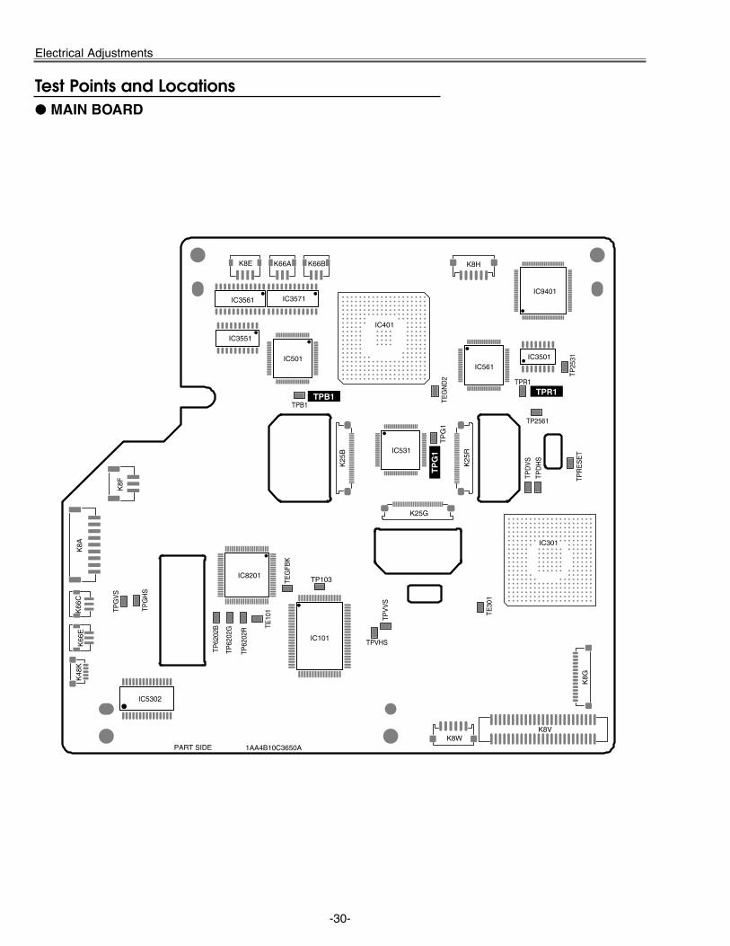
MAIN BOARD
Test Points and Locations
-31-
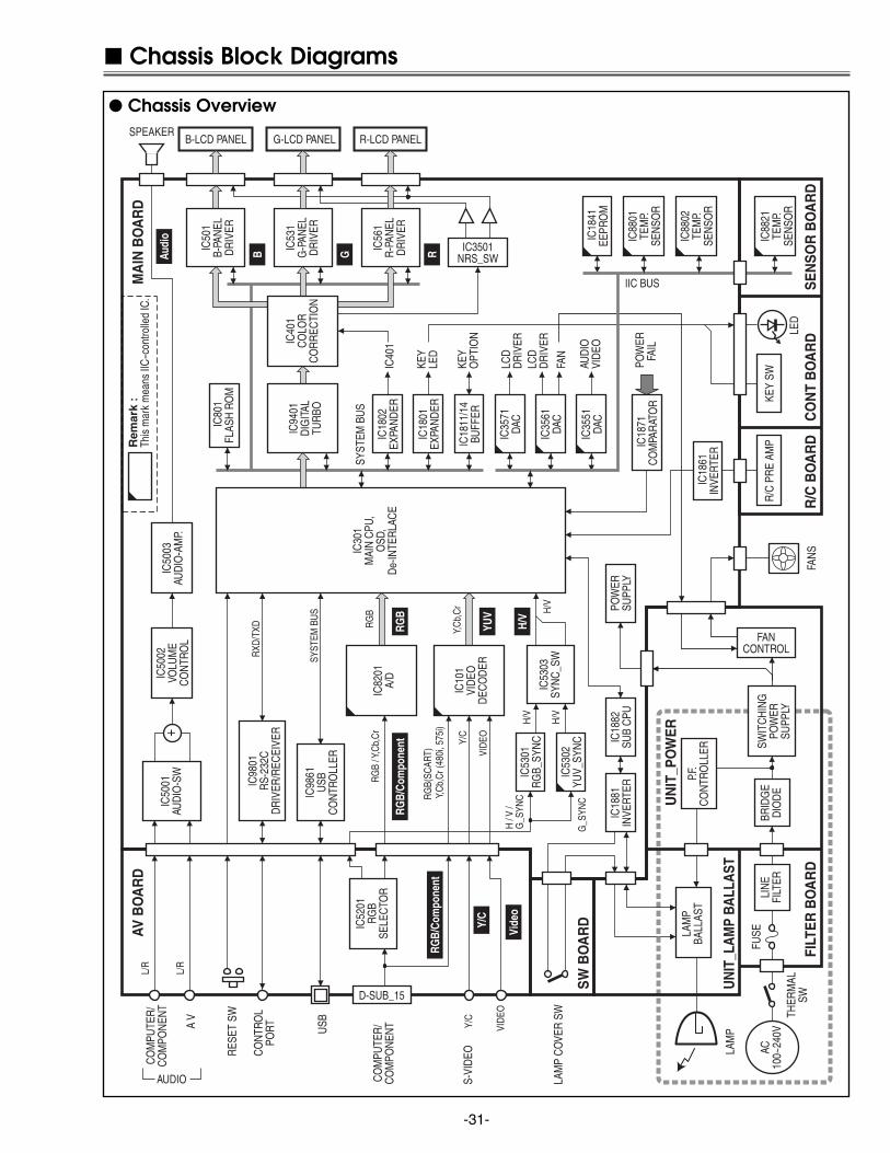
Chassis Block Diagrams
IC94
01D
IGIT
ALTU
RBO
B-LCD PANEL G-LCD PANEL R-LCD PANEL
IC82
01A/
D
IC3501NRS_SW
IC10
1VI
DEO
DEC
OD
ER
IC53
03SY
NC
_SW
POW
ERSU
PPLY
CO
MPU
TER
/C
OM
PON
ENT
CO
MPU
TER
/C
OM
PON
ENT
IC50
01AU
DIO
-SW
IC50
02VO
LUM
EC
ON
TRO
L
IC50
03AU
DIO
-AM
P.
SPEAKER
CO
NTR
OL
PORT USB
IC98
01R
S-23
2CD
RIV
ER/R
ECEI
VER
IC98
61U
SBC
ON
TRO
LLER
SWIT
CH
ING
POW
ERSU
PPLY
BRID
GE
DIO
DE
LIN
EFI
LTER
IC88
21TE
MP.
SEN
SOR
IC88
02TE
MP.
SEN
SOR
IC88
01TE
MP.
SEN
SOR
KEY
SWR
/C P
RE
AMP
AC10
0~24
0V
LAM
PBA
LLAS
T
LAM
P
S-VI
DEO
A V
IC80
1FL
ASH
RO
M
IC18
41EE
PRO
M
IC18
61IN
VERT
ER
AUDIO
H /
V /
G_S
YNC
G_S
YNC
H/V
H/V
H/V
VID
EO
Y/C
Y/C
RES
ET S
W
RG
B(SC
ART)
Y,
Cb,
Cr (
480i
, 575
i)
RG
B / Y
,Cb,
Cr
L/R
L/R
RGB
H/V
Vide
o
Y/C
Audi
o
RGB/
Com
pone
nt
B G R
IC53
01R
GB_
SYN
C
IC53
02YU
V_SY
NC
IC18
81IN
VERT
ERIC
1882
SUB
CPU
FANCONTROL
FAN
S
LED
PO
WER
FAIL
SYS
TEM
BU
S
IIC BUS
SYS
TEM
BU
S
VID
EO
RG
B
YUV
IC52
01R
GB
SELE
CTO
R
IC30
1M
AIN
CPU
,O
SD,
De-
INTE
RLA
CE
IC40
1C
OLO
RC
OR
REC
TIO
N
IC50
1B-
PAN
ELD
RIV
ER
IC53
1G
-PAN
ELD
RIV
ER
IC56
1R
-PAN
ELD
RIV
ER
+
D-SUB_15
UN
IT_L
AM
P BA
LLA
ST
FILT
ER
BO
AR
DTH
ERM
ALSW
SW
BO
AR
D
CO
NT
BO
AR
DS
EN
SO
R B
OA
RD
UN
IT_P
OW
ER
R/C
BO
AR
D
LAM
P C
OVE
R S
W
IC18
01EX
PAN
DER
IC18
02EX
PAN
DER
IC35
51DA
C
IC35
61DA
C
IC35
71DA
C
Y,C
b,C
r
KEY
LED
IC40
1
AUD
IOVI
DEO
LCD
DR
IVER
FAN
LCD
DR
IVER
AV B
OA
RD
MA
IN B
OA
RD
IC18
71C
OM
PAR
ATO
R
Rem
ark
:Th
is m
ark
mea
ns II
C-c
ontro
lled
IC.
IC18
11/1
4BU
FFER
KEY
OPT
ION
RXD
/TXD
FUSE
P.F.
CO
NTR
OLL
ER
RGB/
Com
pone
nt
Chassis Overview
-32-
IC94
01D
IGIT
ALTU
RBO
<LC
2408
5>
IC30
1C
PUFR
C, C
RC,
OSD
De-
INTE
RLA
CE
<PW
168A
>
IC82
01A/
D<A
D98
83A>
IC52
01R
GB
SW
/SY
NC
SEP
.<A
N58
70>
IC10
1D
IGIT
ALD
ECO
DER
<VPC
3230
>
IC53
01R
GB_
SYN
C<B
A707
8>
IC53
02YU
V_SY
NC
<TA1
370>
IC50
1B-
LCD
DR
IVER
<L3E
0610
0>
IC53
1G
-LC
DD
RIV
ER<L
3E06
100>
IC56
1R
-LC
DD
RIV
ER<L
3E06
100>
IC35
21N
RS
BUFF
ER<L
M71
71>
IC35
31N
RS
BUFF
ER<L
T120
6>
B-LC
DPA
NEL
G-L
CD
PAN
EL
R-L
CD
PAN
EL
SCLK
/SDA
TA
TP25
31
TP25
61
K25RK25GK25B
GR
GG
GB
+ +
IC40
1C
OLO
RSH
ADIN
GC
OR
REC
TIO
N<L
3E07
070>
IC35
31N
RS_
SW<4
053>
K10D
K50A
K10E
K50B
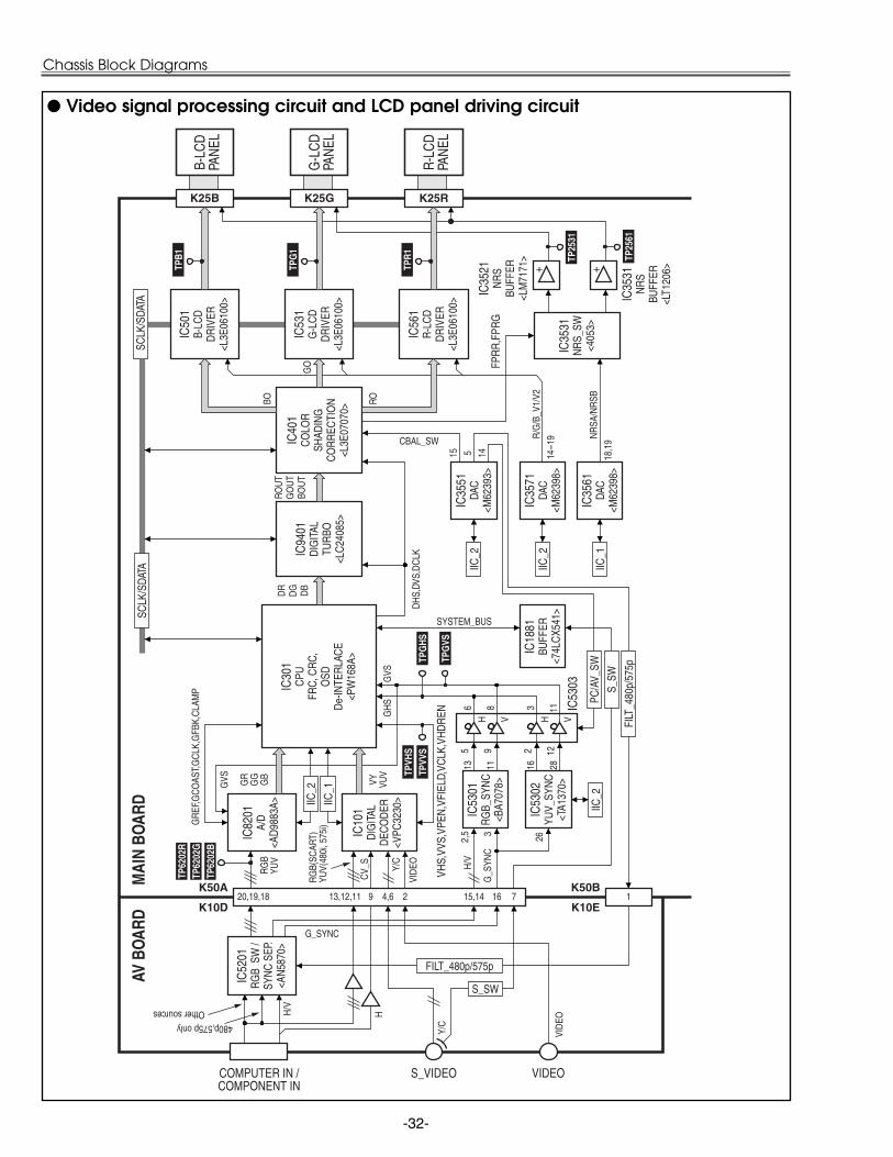
COMPUTER IN /COMPONENT IN
VIDEOS_VIDEO
VY VUV
G_S
YNC
G_SYNC
480p,575p onlyOther sources H
/V
H
RG
B(SC
ART)
YUV(
480i
, 575
i)
RG
BYU
V
VID
EOY/C
GR
EF,G
CO
AST,
GC
LK,G
FBK,
CLA
MP
GVS
IIC_2
IIC_1
VHS,
VVS,
VPEN
,VFI
ELD,
VCLK
,VH
DR
EN
IC53
03
PC/A
V_SW
S_SW
FILT_480p/575p
GVS
GH
S
DR
DG DB
ROU
TG
OU
TBO
UT
RO
DH
S,DV
S,D
CLK
TPR1
SCLK
/SDA
TA
IC35
61DA
C<M
6239
8>
IC35
71DA
C<M
6239
8>
IC35
51DA
C<M
6239
3>
IC18
81BU
FFER
<74L
CX5
41>
BO
GO
IIC_2
IIC_2
IIC_1
TPG
1
TPB1
NR
SA/N
RSB
R/G
/B_V
1/V2
CBAL_SW
FPR
R,F
PRG
14515 18,1
9
14-1
9
FILT
_480
p/57
5p
IIC_2
H HV V
3 26
13 11
5 9
6 8
16 28
3 11
2 12
TPG
HS
TPG
VS
TP62
02B
TP62
02G
TP62
02R
TPVH
STP
VVS
MAI
N BO
ARD
AV B
OARD
116 715,1420,19,18 13,12,11 4,6 29
Y/C
VID
EO
CV_
S H/V
2,5
SYSTEM_BUS
S_SW
Video signal processing circuit and LCD panel driving circuit
Chassis Block Diagrams
-33-
Chassis Block Diagrams
IC301MAIN CPU
POW
ERLA
MP_
REP
R_C
USB
CO
NTR
OL
PORT
KEY
SWIT
TCH
R/C
REC
EIVE
R
LED
-On:
H
R/C
BOAR
D
CONT
ROL
BOAR
D
AV B
OARD
SENS
OR
BOAR
D
MAI
N BO
ARD
IC1801OUTPUT
EXPANDER
IC1871COMPARATOR
OPTIONRESISTORS
K10E
K8E
121
16 13
WAR
NIN
G15 14
K8G
K68B
45,4
6
174
182
From the power faildetection diodes.
IC52
01SE
LEC
TOR
IC101VIDEO
DECODER
IC50
03AM
P
IC40
1C
OLO
RCO
RREC
T
IC50
01AU
D_S
W
IC50
02VO
LUM
E
IC53
03SY
NC
_SW
IC1841EEPROM
IC4801NAND
IC98
61U
SBC
ON
TRO
L
IC8801TEMP.
SENSOR
IC8802TEMP.
SENSOR
IC88
21TE
MP.
SEN
SOR
M_S
CL2/
SDA2
Q18
43Q
1844
44,1
16M
_SCL
1/SD
A1
P_SC
L2/S
DA2
P_SC
L1/S
DA1
Q18
41Q
1842
IC501,IC531,IC561S&H
IC98
01R
S232
CD
RIV
ERR
ECEI
VER
173
47,1
81
140
1 2
178
K50B
K10D
K50A
RES
ETSW
K8H
K88A
P_FA
IL
KEY0
1-03
17-1
9
REA
DY12
MU
TE
FAN
_SW
ON
_3.3
VIC
5631
IC1802OUTPUT
EXPANDER
19
TUR
BO_S
T13 12
R/G
/B_S
T14
-16
R_V
1/V2
14-1
5
B_V1
/V2
18-1
9
G_V
1/V2
16-1
7
PC/A
V_SW
VOL
IC3551DAC
1415
AUD
_PC
/AV
12 13
FILT
_480
P5
CBA
L_SW
NR
SA/B
FAN
_CO
NT3
IC3561DAC
18-1
9
4-6
FAN
_CO
NT2
15 16
FAN
_CO
NT1
14
REF
_RG
B
KEY1
1-13
2-4
S_SW
9
LAM
P_ER
R8
OPT
ION
2O
PTIO
N1
6 75
OPT
ION
3
3,5 1 15-141917-18 7
K881
1K4
8L
K68C
Alw
ays
Ava
ilabl
e A
lway
s A
vaila
ble
Sta
ndby
off
Sta
ndby
off
POW
ER
LAM
P_R
EP
WAR
NIN
G
IC1811BUFFER
32
D0
- D15
A1 -
A21
SCLK
/SDA
TA_P
W
IC1882SUB CPU
IC1881INVERTER
S-VI
DEO
S_SW
USB
+/U
SB-
CPU
_RES
ET
RXD
1/TX
D1
FILT
_480
P
DIM
MER
ON
/OFF
LAM
P_D
ET
FAN
CO
NTR
OL
POW
_ON
IC35
1BU
FFER
IC94
01TU
RBO
POW
ER B
OARD
CN
202
K8A
3 4 5 2
LAM
P BA
LLAS
TC
N30
0K4
8K
1 5 4
SW
BO
AR
D
LAM
P C
OVE
R S
WSW
8801
1-2 3-4
NM
I
RXD
/TXD
56,1
27W
R/R
D
LAM
P_PO
W
FAN
_ER
R
LAM
P_PW
M
117,
180
SCLK
/SDA
TA
65
IC18
21BU
FFER
IC8201A/D
IC3571DAC
IC5302YUV_SYNC
4
7 4 3
1 6 4
2 9 11
10 2 4
16
IC36
1O
R G
ATE
53
IC80
1FL
ASH
TXL
SCEL
RXL
IC18
61IN
VERT
ER
P_SC
L1/S
DA1
ERRO
R :
L
ERRO
R :
L
Lam
p-O
N :
H
Pow
er-O
N :
H
ERRO
R :
H
ERRO
R :
H
ERRO
R :
Ope
n
Lam
p-O
N :
L
Lam
p D
imm
er C
ontro
lL
= Lo
w b
eam
. H =
Hig
h Be
am
Mut
e-O
N :
H
3.3V
to 5
V
3.3V
to 5
V
red
yello
w
gree
n
red
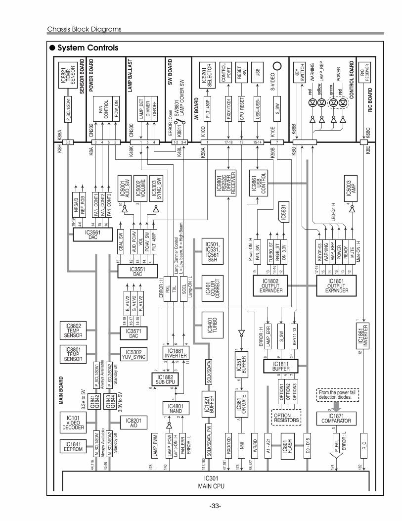
System Controls

-34-
Power Supply Lines
2 4 6
AV B
OARD
Lam
p Er
ror:
H Lamp-On: LFN
902
FN90
5FN
901
12
12
12
FN90
4
12
FN90
3
12
FN90
6
12
16V
5V_A
U
5V -5V
16V
5V_A
U
5V -5V
CN
101
CN
102
UN
IT_P
OW
ER
BRID
GE
DIO
DE
P.F.
CO
NTR
OL
MC
201
FAN
CO
NTR
OL
MC
202
FAN
CO
NTR
OL
MC
203
FAN
CO
NTR
OL
IC30
1PO
WER
OSC
.
T101
CO
NVE
RTER
TRAN
S.
PC30
1
PC30
2
PC30
3
8 3 4-5 10 32 7 4 8 5 9
8 3 4-5 10 32 7 4 8 5 9 51 43
AC
INP
UT
THERMAL SW
FUSE
FILTER BOARD
K6A
K60
1
CN
100
IC56
4112
V
Q25
01
ON
_15V
15V
L
IC56
429V
L251
115
VP
D56
41
IC56
313.
3VIC
491
1.8V
D49
1,D
492
L370
5V_P
WIC
371
IC10
23.
3V_M
Q37
21.
5V_P
W
Q37
13.
3V_P
W
IC39
22.
5V_P
W
D56
31
D25
11
D10
1
Q35
825V
A
5V_S
W
SW
BO
AR
D
LAM
P C
OVE
R S
W
UN
IT_L
AM
PB
AL
LA
ST
IC18
71C
OM
PAR
ATO
RIC
301
SYST
EMC
ON
TRO
L
IC88
21TE
MP.
SEN
SOR
SE
NS
OR
BO
AR
D
12V
5V -5V
FAN
_SW
FAN
_CO
NT1
FAN
_CO
NT2
FAN
_CO
NT3
IC18
02EX
PAN
DER
IC35
61DA
C
IC18
82SU
B C
PU
IC1881INVERTER
PC30
3
PC50
1
PC30
0
5VLA
MP_
POW
LAM
P_PW
M
FAN
_ER
RIC
4801
NAN
D
RXL TX
L SCEL
51 43
CN
300
15VB
375V
IGN
ITO
R
K48
L
K88
11
SW88
01
K48
K
MAI
N BO
ARD
Pow
er F
ail:
L
Pow
er F
ail:
L
Fan Error : L
Stan
d-by
: L
Stan
d-by
: L
PWM
Lamp-On: H
Pow
er-O
n: H
BLUE
LCD
PANE
L
GRE
ENLC
DPA
NEL
RED
LCD
PANE
L
15V
P
19 16 15 14
174
65
478 3
32
7472
140
178
K50
BK
10E
K25B K25G K25R
K8H
K88
A
CN
201
K8B
CN
202
K8A
FAN1
FAN2
FAN3
FAN
3
FAN
2
FAN
1
IC88
02TE
MP.
SEN
SOR
IC88
01TE
MP.
SEN
SOR
5V
P_SC
LK1/
SDA1
IC18
11BU
FFER
LAM
P_ER
R
Fan
Lock
: H
PR
IMA
RY
CIR
CU
IT
61 4
9
2 11
4
Q56
11
D56
22
D5624
D5619
D5612
K66A
K66B
K66C
K66D
K66E
K66F
Lam
p Er
ror:
H
Power supply circuit, Protection circuit and Fan control circuit

-35-
Troubleshooting
Check the indicators for projector condition.
• • • lights green. • • • lights red.• • •off• • • flashes green.
When the life of the projection lamp draws to an end, the LAMP REPLACE indicator lights yellow. When this indicator lights yellow,replace the projection lamp with a new one promptly. Reset the Lamp replace counter after replacement of the lamp.
The projector is OFF. (The AC power cord is unplugged.)
The projector is preparing for stand-by or the projection lamp is being cooleddown. The projector cannot be turned on until cooling is completed.
The temperature inside the projector is abnormally high. The projector can-not be turned on. When the projector is cooled down enough and the tem-perature returns to normal, the POWER indicator lights red and the projec-tor can be turned on. (The WARNING . indicator keeps flashing.) Check andclean the Air filter.
Projector Condition
The projector is ready to be turned on with the POWER ON-OFF button.
POWERred/green
Indicators
LAMPREPLACE
yellow
WARNING red
The projector detects an abnormal condition and cannot be turned on.Unplug the AC power cord and plug it again to turn on the projector. If theprojector is turned off again, disconnect the AC power cord and contact thedealer or the service center for service and checkup. Do not leave the pro-jector on. It may cause electric shock or a fire hazard.
The projector is operating normally.
The projector is in the Power management mode.
The projector has been cooled down enough and the temperature returns tonormal. When turning on the projector, the WARNING indicator stops flash-ing. Check and clean the air filters.
• • • flashes red.
Indicators and Projector Condition

-36-
Troubleshooting
No Power
- When all the LED indicators are not lighting, the symptom indicates that the primary power supply circuitdoes not operate properly. Check the power primary circuit and parts as follow;
AC cordF601 (Fuse)Power boardSW902 (Thermal sw.) ......short in normal
SW902 opens when the surrounding temperature of the switch exceeds 100°C.
This projector provides a function which can be specified a defective area simply by indicating the LEDs on the con-trol panel. Connect the AC cord and press the Power button once and then check the LED indication.
- When the WARNING (red) indicator lights, the symptom indicates that the projector detected an abnormalityin the cooling fan operation or in the power supply secondary circuits. Check fan operation and power supplylines, and the driving signal status.
An abnormality occurs on the secondary power supply lines.Power failure detection diodes detect abnormal voltage on the power supply circuits.POWER_FAIL (Error:L) signals are sent to pin 174 of IC301(System Controller) via IC1871(Comparator).Check the shortage of secondary circuits, ICs, condensers, etc.Check power supply lines, 15VP, 9V, 3.3V and 1.8V on the Main Board.
An abnormality occurs on the fan control circuits.Power failure detection diodes detect the fan operation stop. Check FN901, FN902, FN903, FN904, FN905,FN906 and peripheral circuit.Check fan's power supply lines and detection diodes D5612, D5619 and D5624.Check fan lock signal(Lock:H) and Q5611, D5622 and peripheral circuit.
An abnormality occurs on power starter signals (FAN_SW, 5V_SW, ON_15V).FAN_SW signal (Power-on:H) is output from pin 19 of IC1802 and applied to the Power Board. It drivesthe power oscillation circuit and power supply for the cooling fans in Power Board.5V_SW signal(Power-on:H) is output from pin 74 of IC301 and sent to Q3582, then 5VA line is supplied.ON_15V signal(Power-on:H) is output from pin 72 of IC301 and sent to Q2501, then 15VL line is supplied.
An abnormality occurs on Lamp drive signal (LAMP_POW, LAMP_ERR).- LAMP_POW signal(Power-on:H) is output from pin 140 of IC301 and sent to IC1882 via IC4801.
SCEL signal(Lamp-on:L) is output from pin 4 of IC4801 via IC1881 and sent to Lamp Ballast Unit throughSW8801(Lamp Cover SW).
- TXL signal is output from pin 3 of IC1882 and sent to Lamp ballast Unit via IC1881.(TXL signal is applied for lamp power control. Lo: Low power, Hi: High power)
- RXL signal(Lamp status signal) is output from Lamp Ballast Unit and sent to pin 4 of IC1882 via IC1881,then LAMP_ERR signal is output from pin 7 of IC1882 and sent to IC301 via IC1811.If an abnormality occurred on the lamp ballast unit, RXL signal and LAMP_ERR signal become "H" andthen IC301 shuts down the power supply circuit.
- When the WARNING(red) and POWER(red) indicators are flashing, the symptom indicates that the projec-tor detected an abnormal temperature risen inside the projector. Check the air filters and remove the objectnear the intake and exhaust fan openings, and wait until the POWER indicator stops flashing, and then try toturn on the projector.
The internal temperature is monitored by sensor ICs, IC8821 on Sensor Board, IC8801 and IC8802 on Main Board.
Reset switchThe microprocessor inside theprojector may occasionally mal-function and does not allow anycontrols. In this case, press thereset switch on the rear panelwith a sharp tool to restart theprojector.
Lamp cover switchMake sure that the lamp coveris mounted correctly. If not orthe lamp cover removed, thelamp does not light on for thesafety. Check the lamp coverand lamp cover switch(SW8801).
-37-
Troubleshooting
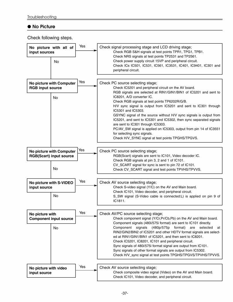
No Picture
No picture with all ofinput sources
Check signal processing stage and LCD driving stage;Check RGB S&H signals at test points TPR1, TPG1, TPB1.Check NRS signals at test points TP2531 and TP2561.Check power supply circuit 15VP and peripheral circuit.Check ICs IC501, IC531, IC561, IC3531, IC401, IC9401, IC301 andperipheral circuit.
No picture with ComputerRGB input source
Check PC source selecting stage;Check IC5201 and peripheral circuit on the AV board.RGB signals are selected at RIN1/GIN1/BIN1 of IC5201 and sent toIC8201, A/D converter IC.Check RGB signals at test points TP6202R/G/B.H/V sync signal is output from IC5201 and sent to IC301 throughIC5301 and IC5303.GSYNC signal of the source without H/V sync signals is output fromIC5201, and sent to IC5301 and IC5302, then sync separated signalsare sent to IC301 through IC5303.PC/AV_SW signal is applied on IC5303, output from pin 14 of IC3551for selecting sync signals.Check H/V_SYNC signal at test points TPGHS/TPGVS.
No picture with ComputerRGB(Scart) input source
Yes
Yes
Yes
No
No
No
Check following steps.
Check AV source selecting stage;Check composite video signal (Video) on the AV and Main board.Check IC101, Video decoder, and peripheral circuit.
No picture with videoinput source
Yes
Check PC source selecting stage;RGB(Scart) signals are sent to IC101, Video decoder IC.Check RGB signals at pin 3, 2 and 1 of IC101.CV_SCART signal for sync is sent to pin 72 of IC101.Check CV_SCART signal and test points TPVHS/TPVVS.
Check AV source selecting stage;Check S-video signal (Y/C) on the AV and Main board.Check IC101, Video decoder, and peripheral circuit.S_SW signal (S-Video cable is connected:L) is applied on pin 9 ofIC1811.
No picture with S-VIDEOinput source
Check AV/PC source selecting stage;Check component signal (Y/Cr,Pr/Cb,Pb) on the AV and Main board.Component signals (480i/575i format) are sent to IC101 directly.Component signals (480p/575p format) are selected atRIN2/GIN2/BIN2 of IC5201 and other HDTV format signals are select-ed at RIN1/GIN1/BIN1 of IC5201, and then sent to IC8201.Check IC5201, IC8201, IC101 and peripheral circuit.Sync signals of 480i/575i format signal are output from IC101.Sync signals of other format signals are output from IC5302.Check H/V_sync signal at test points TPGHS/TPGVS/TPVHS/TPVVS.
No picture withComponent input source
No
Yes
Yes
No
-38-
Troubleshooting
Q5002
Q5006
Q5003
Q5001
Q5004
12
102
114
1
5 3
3
8
121312
5
13
Mute: H
Mute: L
K8F
K50B
K10E
P_SCLK2
P_SCDA2
AUD_PC/AV_SW
VOLU
ME
MAIN BOARDAVBOARD IC5003
AMP.<LM4865M>
IC5002VOLUME
<BA7655A>
L
R
L
R
L
R
PCAUDIO-IN
AVAUDIO-IN
SP901
IC1801OUTPUT
EXPANDER<74LCX574>
IC3551D/A
CONVERTER<M62393>
IC301SYSTEM
CONTROL<PW168A>
PC AV
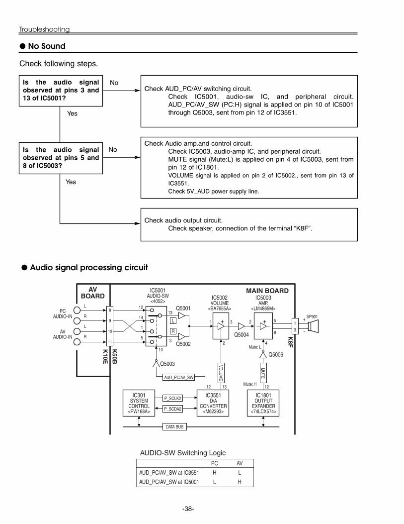
AUD_PC/AV_SW at IC3551 H L
AUD_PC/AV_SW at IC5001 L H
AUDIO-SW Switching Logic
MU
TE
IC5001AUDIO-SW
<4052>
+ 2 +
4
8
9
10
11
13
+
-
DATA BUS
Audio signal processing circuit
No Sound
Check AUD_PC/AV switching circuit.Check IC5001, audio-sw IC, and peripheral circuit.AUD_PC/AV_SW (PC:H) signal is applied on pin 10 of IC5001through Q5003, sent from pin 12 of IC3551.
Is the audio signalobserved at pins 3 and13 of IC5001?
Check Audio amp.and control circuit.Check IC5003, audio-amp IC, and peripheral circuit.MUTE signal (Mute:L) is applied on pin 4 of IC5003, sent frompin 12 of IC1801.VOLUME signal is applied on pin 2 of IC5002., sent from pin 13 ofIC3551.Check 5V_AUD power supply line.
Is the audio signalobserved at pins 5 and8 of IC5003?
Check audio output circuit.Check speaker, connection of the terminal “K8F”.
Yes
No
Yes
No
Check following steps.

-39-
Waveforms
VIDEO-IN <TP103, IC101-75> Analog H-SYNC <TPGHS> Analog V-SYNC <TPGVS>
Digital H-SYNC <TPDHS> Digital V-SYNC <TPDVS> NRS <TP2531,TP2561>
R-S&H OUT <TPR1> G-S&H OUT <TPG1> B-S&H OUT <TPB1>

-40-
System Control & I/O Port Table (IC301)
Control Port Functions
178 Port A7 LAMP_PWM PWM Output to Sub-CPU PWM O115 Port A6 MUPO_ON I44 Port A5 M_SCL1 I/O
116 Port A4 M_SDA1 O45 Port A3 M_SCL2 I/O46 Port A2 M_SDA2 O
117 Port A1 SCLK 3 Line Serial Bus Clock O180 Port A0 SDATA 3 Line Serial Bus Data O173 Port B7 NMI Reset SW Input I111 Port B6 IRM_STB 3 Line Serial Bus Strobe O40 Port B5 3L_EN 3 Line Serial Bus Enable O
174 Port B4 POWER_FAIL Power Fail Detection Error = L I41 Port B3 A23 Address Bus 23
175 Port B2 A22 Address Bus 22112 Port B1 A21 Address Bus 21229 Port B0 A20 Address Bus 2071 Port E7 5V_SW Standby 5V OFF Standby = L O
139 Port E6 DCLK_SW O200 Port E5 VHDPEN IC101 Video Decoder Enable O140 Port E4 LAMP_POW Lamp ON to Sub-CPU Lamp-ON = H O201 Port E3 USB_VBUS USB Connector Detection Not used I141 Port E2 USB_RST USB Device Reset Output O72 Port E1 ON_15V Standby 15V OFF Standby = L O
142 Port E0 USB_EN USB Device Enable Output O119 Port F7 IRRCVR1 IR Receiver Input 1 Not used I182 Port F6 IRRCVR0 IR Receiver Input 0 I47 Port F5 RXD I
182 Port F4 TXD O189 Port F3 CS0 I/O Expander Chip Select (Output) O55 Port F2 CS1 I/O Expander Chip Select (Input) O
207 Port F1 DCLKEXT D-port Clock External Input Not used I257 Port F0 MCLKEXT Memory System Clock Input Not used I194 A19 A19 Address Bus 1963 A19 A18 Address Bus 18
132 A17 A17 Address Bus 1762 A16 A16 Address Bus 1661 A15 A15 Address Bus 15
131 A14 A14 Address Bus 14193 A13 A13 Address Bus 13247 A12 A12 Address Bus 1260 A11 A11 Address Bus 11
246 A10 A10 Address Bus 1059 A9 A9 Address Bus 9
130 A8 A8 Address Bus 8129 A7 A7 Address Bus 7192 A6 A6 Address Bus 6128 A5 A5 Address Bus 558 A4 A4 Address Bus 4
191 A3 A3 Address Bus 3190 A2 A2 Address Bus 2245 A1 A1 Address Bus 1244 A0 A0 Address Bus 0242 D15 D15 Data Bus 15 I/O241 D14 D14 Data Bus 14 I/O187 D13 D13 Data Bus 13 I/O53 D12 D12 Data Bus 12 I/O
124 D11 D11 Data Bus 11 I/O186 D10 D10 Data Bus 10 I/O240 D9 D9 Data Bus 9 I/O123 D8 D8 Data Bus 8 I/O185 D7 D7 Data Bus 7 I/O122 D6 D6 Data Bus 6 I/O51 D5 D5 Data Bus 5 I/O
184 D4 D4 Data Bus 4 I/O121 D3 D3 Data Bus 3 I/O50 D2 D2 Data Bus 2 I/O49 D1 D1 Data Bus 1 I/O
183 D0 D0 Data Bus 0 I/O127 RD RD Read Enable Not used I/O56 WR WR Write Enable Not used I/O
118 BHEN BHEN High Byte Enable Not used I/O
Pin No. Name Function Name Function Polarity I/O
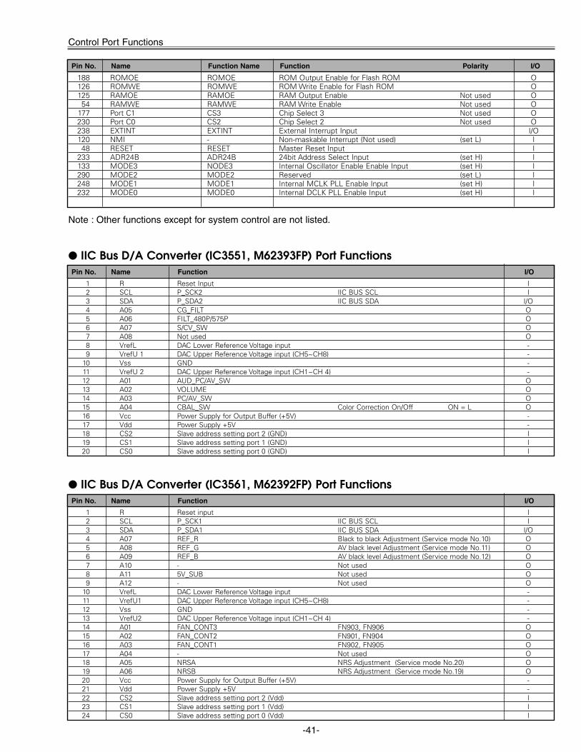
-41-
188 ROMOE ROMOE ROM Output Enable for Flash ROM O126 ROMWE ROMWE ROM Write Enable for Flash ROM O125 RAMOE RAMOE RAM Output Enable Not used O54 RAMWE RAMWE RAM Write Enable Not used O
177 Port C1 CS3 Chip Select 3 Not used O230 Port C0 CS2 Chip Select 2 Not used O238 EXTINT EXTINT External Interrupt Input I/O120 NMI - Non-maskable Interrupt (Not used) (set L) I48 RESET RESET Master Reset Input I
233 ADR24B ADR24B 24bit Address Select Input (set H) I133 MODE3 NODE3 Internal Oscillator Enable Enable Input (set H) I290 MODE2 MODE2 Reserved (set L) I248 MODE1 MODE1 Internal MCLK PLL Enable Input (set H) I232 MODE0 MODE0 Internal DCLK PLL Enable Input (set H) I
Pin No. Name Function Name Function Polarity I/O
Control Port Functions
Note : Other functions except for system control are not listed.
1 R Reset input I2 SCL P_SCK1 IIC BUS SCL I3 SDA P_SDA1 IIC BUS SDA I/O4 A07 REF_R Black to black Adjustment (Service mode No.10) O5 A08 REF_G AV black level Adjustment (Service mode No.11) O6 A09 REF_B AV black level Adjustment (Service mode No.12) O7 A10 - Not used O8 A11 5V_SUB Not used O9 A12 - Not used O
10 VrefL DAC Lower Reference Voltage input -11 VrefU1 DAC Upper Reference Voltage input (CH5~CH8) -12 Vss GND -13 VrefU2 DAC Upper Reference Voltage input (CH1~CH 4) -14 A01 FAN_CONT3 FN903, FN906 O15 A02 FAN_CONT2 FN901, FN904 O16 A03 FAN_CONT1 FN902, FN905 O17 A04 - Not used O18 A05 NRSA NRS Adjustment (Service mode No.20) O19 A06 NRSB NRS Adjustment (Service mode No.19) O20 Vcc Power Supply for Output Buffer (+5V) -21 Vdd Power Supply +5V -22 CS2 Slave address setting port 2 (Vdd) I23 CS1 Slave address setting port 1 (Vdd) I24 CS0 Slave address setting port 0 (Vdd) I
Pin No. Name Function I/O
IIC Bus D/A Converter (IC3561, M62392FP) Port Functions
1 R Reset Input I2 SCL P_SCK2 IIC BUS SCL I3 SDA P_SDA2 IIC BUS SDA I/O4 A05 CG_FILT O5 A06 FILT_480P/575P O6 A07 S/CV_SW O7 A08 Not used O8 VrefL DAC Lower Reference Voltage input -9 VrefU 1 DAC Upper Reference Voltage input (CH5~CH8) -
10 Vss GND -11 VrefU 2 DAC Upper Reference Voltage input (CH1~CH 4) -12 A01 AUD_PC/AV_SW O13 A02 VOLUME O14 A03 PC/AV_SW O15 A04 CBAL_SW Color Correction On/Off ON = L O16 Vcc Power Supply for Output Buffer (+5V) -17 Vdd Power Supply +5V -18 CS2 Slave address setting port 2 (GND) I19 CS1 Slave address setting port 1 (GND) I20 CS0 Slave address setting port 0 (GND) I
Pin No. Name Function I/O
IIC Bus D/A Converter (IC3551, M62393FP) Port Functions
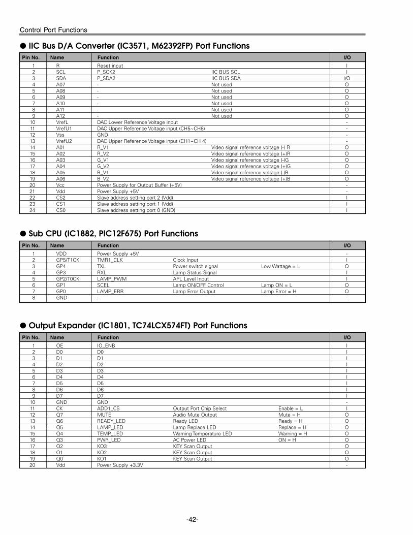
-42-
Control Port Functions
1 VDD Power Supply +5V -2 GP5/T1CKI TMR1_CLK Clock Input I3 GP4 TXL Power switch signal Low Wattage = L O4 GP3 RXL Lamp Status Signal I5 GP2/T0CKI LAMP_PWM APL Level Input I6 GP1 SCEL Lamp ON/OFF Control Lamp ON = L O7 GP0 LAMP_ERR Lamp Error Output Lamp Error = H O8 GND - -
Pin No. Name Function I/O
Sub CPU (IC1882, PIC12F675) Port Functions
1 R Reset input I2 SCL P_SCK2 IIC BUS SCL I3 SDA P_SDA2 IIC BUS SDA I/O4 A07 - Not used O5 A08 - Not used O6 A09 - Not used O7 A10 - Not used O8 A11 - Not used O9 A12 - Not used O
10 VrefL DAC Lower Reference Voltage input -11 VrefU1 DAC Upper Reference Voltage input (CH5~CH8) -12 Vss GND -13 VrefU2 DAC Upper Reference Voltage input (CH1~CH 4) -14 A01 R_V1 Video signal reference voltage (-) R O15 A02 R_V2 Video signal reference voltage (+)R O16 A03 G_V1 Video signal reference voltage (-)G O17 A04 G_V2 Video signal reference voltage (+)G O18 A05 B_V1 Video signal reference voltage (-)B O19 A06 B_V2 Video signal reference voltage (+)B O20 Vcc Power Supply for Output Buffer (+5V) -21 Vdd Power Supply +5V -22 CS2 Slave address setting port 2 (Vdd) I23 CS1 Slave address setting port 1 (Vdd) I24 CS0 Slave address setting port 0 (GND) I
Pin No. Name Function I/O
IIC Bus D/A Converter (IC3571, M62392FP) Port Functions
1 OE IO_ENB I2 D0 D0 I3 D1 D1 I4 D2 D2 I5 D3 D3 I6 D4 D4 I7 D5 D5 I8 D6 D6 I9 D7 D7 I
10 GND GND -11 CK ADD1_CS Output Port Chip Select Enable = L I12 Q7 MUTE Audio Mute Output Mute = H O13 Q6 READY_LED Ready LED Ready = H O14 Q5 LAMP_LED Lamp Replace LED Replace = H O15 Q4 TEMP_LED Warning Temperature LED Warning = H O16 Q3 PWR_LED AC Power LED ON = H O17 Q2 KO3 KEY Scan Output O18 Q1 KO2 KEY Scan Output O19 Q0 KO1 KEY Scan Output O20 Vdd Power Supply +3.3V -
Pin No. Name Function I/O
Output Expander (IC1801, TC74LCX574FT) Port Functions

-43-
Control Port Functions
1 OE IO_ENB I2 D0 D0 I3 D1 D1 I4 D2 D2 I5 D3 D3 I6 D4 D4 I7 D5 D5 I8 D6 D6 I9 D7 D7 I
10 GND GND -11 CK ADD1_CS Output Port Chip Select Enable = L I12 Q7 ON_3.3V 3.3V OFF at standby mode O13 Q6 TURBO_C Strobe for Turbo (IC9401) O14 Q5 SH_B_ST Strobe for B sample & hold (IC501) O15 Q4 SH_G_ST Strobe for G sample & hold (IC531) O16 Q3 SH_R_ST Strobe for R sample & hold (IC561) O17 Q2 IRM_RS Reset for IC401 O18 Q1 MCLK_SW Switch for MCLK O19 Q0 FAN_SW Switch for FAN O20 Vdd Power Supply +3.3V -
Pin No. Name Function I/O
Output Expander (IC1802, TC74LCX574FT) Port Functions
1 OE1 IO_ENB 1 CS1 Enable = L (OE1 and OE2) I2 A1 K11 KEY Scan Input I3 A2 K12 KEY Scan Input I4 A3 K13 KEY Scan Input I5 A4 OPTION1 Option Resistor 1 I6 A5 OPTION2 Option Resistor 2 I7 A6 OPTION3 Option Resistor 3 I8 A7 LAMP_ERR Lamp Error Input I9 A8 S_SW S-video Detection I
10 GND GND -11 Y8 D7 O12 Y7 D6 O13 Y6 D5 O14 Y5 D4 O15 Y4 D3 O16 Y3 D2 O17 Y2 D1 O18 Y1 D0 O19 OE2 IO_ENB 2 Enable = L (OE1 and OE2) I20 Vdd Power Supply +3.3V -
Pin No. Name Function I/O
Input Expander (IC1811, TC74LCX541FT) Port Functions

-44-
Cleaning
Cleaning with air spray
1. Remove the cabinet top following to “MechanicalDisassemblies”.
2. Clean up the LCD panel and polarizing plate by usingthe air spray from the cabinet top opening.
Caution:Use a commercial (inert gas) air spray designed forcleaning camera and computer equipment. Use a resin-based nozzle only. Be vary careful not to damage opti-cal parts with the nozzle tip. Never use any kind ofcleanser on the unit. Also, never use abrasive materialson the unit as this may cause irreparable damage.
After long periods of use, dust and other particles will accumulate on the LCD panel, prism, mirror, polarized glass,lens, etc., causing the picture to darken or color to blur. If this occurs, clean the inside of optical unit.
Remove dust and other particles using air spray. If dirt cannot be removed by air spray, disassemble and cleanthe optical unit.
Disassembly Cleaning
Disassembly cleaning method should only be per-formed when the unit is considerable dirty and cannotbe sufficiently cleaned by air spraying alone.Be sure to readjust the optical system after per-forming disassembly cleaning.
1. Remove the cabinet top and main units following to“Mechanical Disassemblies”.
2. Remove the optical base top following to “Optical UnitDisassemblies”. If the LCD panel needs cleaning,remove the LCD panel unit following to “LCD panelreplacement”.
3. Clean the optical parts with a soft cloth. Cleanextremely dirty areas using a cloth moistened withalcohol.
Caution:The surface of the optical components consists of mul-tiple dielectric layers with varying degrees of refraction.Never use organic solvents (thinner, etc.) or any kind ofcleanser on these components.Since the LCD panel is equipped with an electronic cir-cuit, never use any liquids (water, etc.) to clean the unit.Use of liquid may cause the unit to malfunction.
Cleaning the Projection Lens
Follow these steps to clean the projection lens:
1. Apply a non-abrasive camera lens cleaner to a soft,dry cleaning cloth. Avoid using an excessive amountof cleaner. Abrasive cleaners, solvents or other harshchemicals might scratch a surface.
2. Lightly wipe Projection Lens with a cleaning cloth.3. When the projector is not in use, replace the Lens
Cover.

-45-
IC Block Diagrams
AN5870SB <RGB SW, G_Sync Separator, IC5201>
AD9883AKST <Analog Flat Panel Interface, IC8201>
RAIN ROUTA
GAIN GOUTA
BAIN BOUTA
MIDSCV
SYNCPROCESSINGAND CLOCKGENERATION
HSYNC
COAST
CLAMP
FILT
DTACK
HSOUT
VSOUT
SOGOUT
REF REFBYPASS
SERIAL REGISTERAND
POWER MANAGEMENT
SCL
SDA
A0AD9883A
CLAMP8
A/D
CLAMP8
A/D
CLAMP8
A/D

-46-
BA9743AFV <DC-DC Converter, IC371>
IC Block Diagrams
BA7078AF <Sync Detector, IC5301>
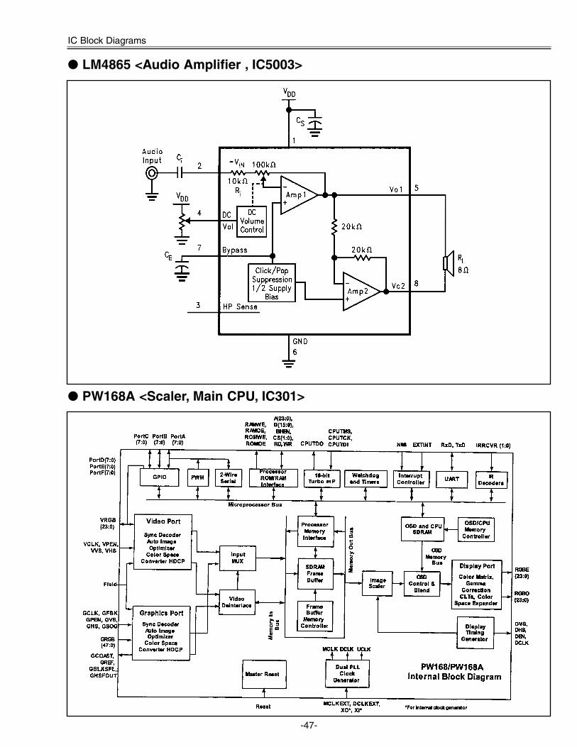
-47-
IC Block Diagrams
LM4865 <Audio Amplifier , IC5003>
PW168A <Scaler, Main CPU, IC301>

-48-
VPC3230D <Video Decoder, IC101>
IC Block Diagrams
TA1370FG <Sync Separator, Frequency Counter, IC5302>
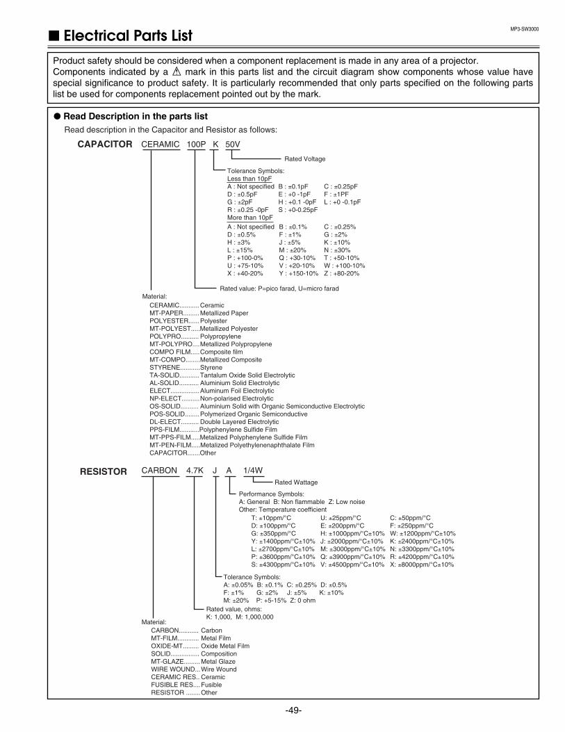
MP3-SW3000
-49-
Electrical Parts ListProduct safety should be considered when a component replacement is made in any area of a projector. Components indicated by a ! mark in this parts list and the circuit diagram show components whose value havespecial significance to product safety. It is particularly recommended that only parts specified on the following partslist be used for components replacement pointed out by the mark.
Read description in the Capacitor and Resistor as follows:
CAPACITOR CERAMIC 100P K 50V
Rated Voltage
Tolerance Symbols:Less than 10pFA : Not specified B : ±0.1pF C : ±0.25pFD : ±0.5pF E : +0 -1pF F : ±1PF G : ±2pF H : +0.1 -0pF L : +0 -0.1pFR : ±0.25 -0pF S : +0-0.25pFMore than 10pFA : Not specified B : ±0.1% C : ±0.25%D : ±0.5% F : ±1% G : ±2%H : ±3% J : ±5% K : ±10%L : ±15% M : ±20% N : ±30%P : +100-0% Q : +30-10% T : +50-10%U : +75-10% V : +20-10% W : +100-10%X : +40-20% Y : +150-10% Z : +80-20%
Rated value: P=pico farad, U=micro faradMaterial:
CERAMIC........... CeramicMT-PAPER......... Metallized PaperPOLYESTER...... PolyesterMT-POLYEST.....Metallized PolyesterPOLYPRO.......... PolypropyleneMT-POLYPRO.... Metallized PolypropyleneCOMPO FILM..... Composite filmMT-COMPO........ Metallized CompositeSTYRENE........... StyreneTA-SOLID........... Tantalum Oxide Solid ElectrolyticAL-SOLID........... Aluminium Solid ElectrolyticELECT................ Aluminum Foil ElectrolyticNP-ELECT.......... Non-polarised ElectrolyticOS-SOLID.......... Aluminium Solid with Organic Semiconductive ElectrolyticPOS-SOLID........ Polymerized Organic Semiconductive DL-ELECT.......... Double Layered ElectrolyticPPS-FILM...........Polyphenylene Sulfide FilmMT-PPS-FILM.....Metalized Polyphenylene Sulfide FilmMT-PEN-FILM.....Metalized Polyethylenenaphthalate FilmCAPACITOR.......Other
CARBON 4.7K J A 1/4WRated Wattage
Performance Symbols:A: General B: Non flammable Z: Low noiseOther: Temperature coefficient
Tolerance Symbols:A: ±0.05% B: ±0.1% C: ±0.25% D: ±0.5%F: ±1% G: ±2% J: ±5% K: ±10%M: ±20% P: +5-15% Z: 0 ohm
Rated value, ohms:K: 1,000, M: 1,000,000
Material:CARBON........... CarbonMT-FILM............ Metal FilmOXIDE-MT......... Oxide Metal FilmSOLID................ CompositionMT-GLAZE......... Metal GlazeWIRE WOUND... Wire WoundCERAMIC RES.. CeramicFUSIBLE RES.... FusibleRESISTOR ........ Other
T: ±10ppm/°C U: ±25ppm/°C C: ±50ppm/°CD: ±100ppm/°C E: ±200ppm/°C F: ±250ppm/°CG: ±350ppm/°C H: ±1000ppm/°C±10% W: ±1200ppm/°C±10%Y: ±1400ppm/°C±10% J: ±2000ppm/°C±10% K: ±2400ppm/°C±10%L: ±2700ppm/°C±10% M: ±3000ppm/°C±10% N: ±3300ppm/°C±10%P: ±3600ppm/°C±10% Q: ±3900ppm/°C±10% R: ±4200ppm/°C±10%S: ±4300ppm/°C±10% V: ±4500ppm/°C±10% X: ±8000ppm/°C±10%
RESISTOR
Read Description in the parts list
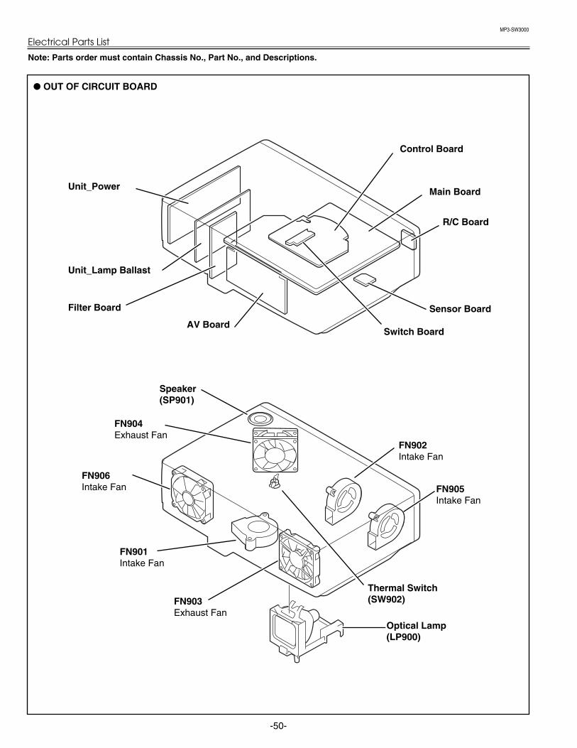
MP3-SW3000
Electrical Parts List
-50-
OUT OF CIRCUIT BOARD
Thermal Switch(SW902)
Note: Parts order must contain Chassis No., Part No., and Descriptions.
FN901Intake Fan
FN903Exhaust Fan
AV Board
Main Board
FN902Intake Fan
FN905Intake Fan
FN904Exhaust Fan
FN906Intake Fan
Filter Board
Unit_Lamp Ballast
Unit_Power
Sensor Board
R/C Board
Control Board
Switch Board
Speaker(SP901)
Optical Lamp(LP900)

MP3-SW3000
-51-
Electrical Parts List
!610 306 8992 ASSY,PWB,MAIN,- MP3A
!610 306 9005 ASSY,PWB,R/C- MP3A
!610 306 9012 ASSY,PWB,SENSOR- MP3A
!610 306 9029 ASSY,PWB,A/V -MP3A
!610 306 9036 ASSY,PWB,CONT-MP3A
!610 308 1021 ASSY,PWB,FILTER -MP3A
!610 308 1038 ASSY,PWB,SW-MP3A
!LP900 610 308 3117 COMPL,OPTICAL LAMP-MP3A L901 645 040 2593 CORE,FERRITE
!A601 645 061 0080 UNIT,POWER !A901 645 061 0097 UNIT,BALLAST !FN901 645 061 8604 MOTOR,FAN DC 2.4W !FN902 645 061 8611 MOTOR,FAN DC 2.30W !FN903 645 061 8666 MOTOR,FAN DC 2.04W !FN904 645 061 8642 MOTOR,FAN DC 2.16W !FN905 645 061 8611 MOTOR,FAN DC 2.30W !FN906 645 061 8659 MOTOR,FAN DC 1.92W
SP901 645 063 1504 SPEAKER,8 !SW902 645 048 3158 SWITCH,THERMAL
WK48K 645 043 5645 CORD,ID CONNECTOR WK48L 645 065 3513 CORD,ID CONNECTOR WK8A 645 064 9905 CORD,ID CONNECTOR WK8B 645 065 4756 CORD,ID CONNECTOR WK8E 645 040 3156 CORD,ID CONNECTOR WK8H 645 064 1794 CORD,ID CONNECTOR
610 306 8992 ASSY,PWB,MAIN,- MP3ATRANSISTOR Q101 405 014 4509 TR 2SC2412K T146 R
405 014 4608 TR 2SC2412K T146 S 405 015 8704 TR 2SC2812-L6-TB 405 015 8902 TR 2SC2812-L7-TB 405 163 1602 TR 2SC2812N-L6-TB0 405 163 1701 TR 2SC2812N-L7-TB0
Q1841 405 045 8705 TR 2SK536-TB Q1842 405 045 8705 TR 2SK536-TB Q1843 405 045 8705 TR 2SK536-TB Q1844 405 045 8705 TR 2SK536-TB Q2501 405 002 8304 TR 2SA1203-Y-TE12L Q2502 405 014 4509 TR 2SC2412K T146 R
405 014 4608 TR 2SC2412K T146 S 405 015 8704 TR 2SC2812-L6-TB 405 015 8902 TR 2SC2812-L7-TB 405 163 1602 TR 2SC2812N-L6-TB0 405 163 1701 TR 2SC2812N-L7-TB0
Q301 405 045 8705 TR 2SK536-TB Q3501 405 014 4509 TR 2SC2412K T146 R
405 014 4608 TR 2SC2412K T146 S 405 015 8704 TR 2SC2812-L6-TB 405 015 8902 TR 2SC2812-L7-TB 405 163 1602 TR 2SC2812N-L6-TB0 405 163 1701 TR 2SC2812N-L7-TB0
Q3502 405 014 4509 TR 2SC2412K T146 R 405 014 4608 TR 2SC2412K T146 S 405 015 8704 TR 2SC2812-L6-TB 405 015 8902 TR 2SC2812-L7-TB
405 163 1602 TR 2SC2812N-L6-TB0 405 163 1701 TR 2SC2812N-L7-TB0
Q3581 405 014 4509 TR 2SC2412K T146 R 405 014 4608 TR 2SC2412K T146 S 405 015 8704 TR 2SC2812-L6-TB 405 015 8902 TR 2SC2812-L7-TB 405 163 1602 TR 2SC2812N-L6-TB0 405 163 1701 TR 2SC2812N-L7-TB0
Q3582 405 002 8304 TR 2SA1203-Y-TE12L Q371 406 017 8402 TR RTQ025P02-TR Q372 406 017 8402 TR RTQ025P02-TR Q4001 405 134 5905 TR 2SA1037AK-T146-R
405 147 2205 TR 2SA1037AK-S-T146 405 002 0308 TR 2SA1037K T146 R 405 002 0407 TR 2SA1037K T146 S 405 002 6706 TR 2SA1179-M6-TB 405 002 6904 TR 2SA1179-M7-TB 405 163 1503 TR 2SA1179N-M6-TB 405 163 2708 TR 2SA1179N-M7-TB
Q4807 405 014 4509 TR 2SC2412K T146 R 405 014 4608 TR 2SC2412K T146 S 405 015 8704 TR 2SC2812-L6-TB 405 015 8902 TR 2SC2812-L7-TB 405 163 1602 TR 2SC2812N-L6-TB0 405 163 1701 TR 2SC2812N-L7-TB0
Q5001 405 014 4509 TR 2SC2412K T146 R 405 014 4608 TR 2SC2412K T146 S 405 015 8704 TR 2SC2812-L6-TB 405 015 8902 TR 2SC2812-L7-TB 405 163 1602 TR 2SC2812N-L6-TB0 405 163 1701 TR 2SC2812N-L7-TB0
Q5002 405 014 4509 TR 2SC2412K T146 R 405 014 4608 TR 2SC2412K T146 S 405 015 8704 TR 2SC2812-L6-TB 405 015 8902 TR 2SC2812-L7-TB 405 163 1602 TR 2SC2812N-L6-TB0 405 163 1701 TR 2SC2812N-L7-TB0
Q5003 405 014 4509 TR 2SC2412K T146 R 405 014 4608 TR 2SC2412K T146 S 405 015 8704 TR 2SC2812-L6-TB 405 015 8902 TR 2SC2812-L7-TB 405 163 1602 TR 2SC2812N-L6-TB0 405 163 1701 TR 2SC2812N-L7-TB0
Q5004 405 134 5905 TR 2SA1037AK-T146-R 405 147 2205 TR 2SA1037AK-S-T146 405 002 0308 TR 2SA1037K T146 R 405 002 0407 TR 2SA1037K T146 S 405 002 6706 TR 2SA1179-M6-TB 405 002 6904 TR 2SA1179-M7-TB 405 163 1503 TR 2SA1179N-M6-TB 405 163 2708 TR 2SA1179N-M7-TB
Q5006 405 014 4509 TR 2SC2412K T146 R 405 014 4608 TR 2SC2412K T146 S 405 015 8704 TR 2SC2812-L6-TB 405 015 8902 TR 2SC2812-L7-TB 405 163 1602 TR 2SC2812N-L6-TB0 405 163 1701 TR 2SC2812N-L7-TB0
Q5301 405 014 4509 TR 2SC2412K T146 R 405 014 4608 TR 2SC2412K T146 S 405 015 8704 TR 2SC2812-L6-TB 405 015 8902 TR 2SC2812-L7-TB 405 163 1602 TR 2SC2812N-L6-TB0 405 163 1701 TR 2SC2812N-L7-TB0
Q5302 405 134 5905 TR 2SA1037AK-T146-R 405 147 2205 TR 2SA1037AK-S-T146 405 002 0308 TR 2SA1037K T146 R 405 002 0407 TR 2SA1037K T146 S
MAIN BOARD
OUT OF CIRCUIT BOARDS
ASSEMBLIED BOARDS
Key No. Part No. Description Key No. Part No. Description
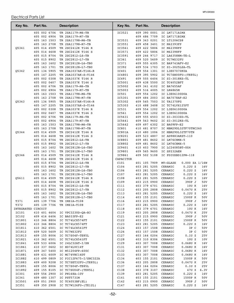
MP3-SW3000
Electrical Parts List
-52-
405 002 6706 TR 2SA1179-M6-TB 405 002 6904 TR 2SA1179-M7-TB 405 163 1503 TR 2SA1179N-M6-TB 405 163 2708 TR 2SA1179N-M7-TB
Q5341 405 014 4509 TR 2SC2412K T146 R 405 014 4608 TR 2SC2412K T146 S 405 015 8704 TR 2SC2812-L6-TB 405 015 8902 TR 2SC2812-L7-TB 405 163 1602 TR 2SC2812N-L6-TB0 405 163 1701 TR 2SC2812N-L7-TB0
Q5342 405 134 5905 TR 2SA1037AK-T146-R 405 147 2205 TR 2SA1037AK-S-T146 405 002 0308 TR 2SA1037K T146 R 405 002 0407 TR 2SA1037K T146 S 405 002 6706 TR 2SA1179-M6-TB 405 002 6904 TR 2SA1179-M7-TB 405 163 1503 TR 2SA1179N-M6-TB 405 163 2708 TR 2SA1179N-M7-TB
Q5343 405 134 5905 TR 2SA1037AK-T146-R 405 147 2205 TR 2SA1037AK-S-T146 405 002 0308 TR 2SA1037K T146 R 405 002 0407 TR 2SA1037K T146 S 405 002 6706 TR 2SA1179-M6-TB 405 002 6904 TR 2SA1179-M7-TB 405 163 1503 TR 2SA1179N-M6-TB 405 163 2708 TR 2SA1179N-M7-TB
Q5344 405 014 4509 TR 2SC2412K T146 R 405 014 4608 TR 2SC2412K T146 S 405 015 8704 TR 2SC2812-L6-TB 405 015 8902 TR 2SC2812-L7-TB 405 163 1602 TR 2SC2812N-L6-TB0 405 163 1701 TR 2SC2812N-L7-TB0
Q5346 405 014 4509 TR 2SC2412K T146 R 405 014 4608 TR 2SC2412K T146 S 405 015 8704 TR 2SC2812-L6-TB 405 015 8902 TR 2SC2812-L7-TB 405 163 1602 TR 2SC2812N-L6-TB0 405 163 1701 TR 2SC2812N-L7-TB0
Q5611 405 014 4509 TR 2SC2412K T146 R 405 014 4608 TR 2SC2412K T146 S 405 015 8704 TR 2SC2812-L6-TB 405 015 8902 TR 2SC2812-L7-TB 405 163 1602 TR 2SC2812N-L6-TB0 405 163 1701 TR 2SC2812N-L7-TB0
T371 405 139 7706 TR IMZ1A-T108 T372 405 139 7706 TR IMZ1A-T108
INTEGRATED CIRCUIT IC101 410 401 4604 IC VPC3230D-QA-B3 IC102 409 416 6406 IC BA033FP-E2 IC1801 410 346 8804 IC TC74LCX574FT IC1802 410 346 8804 IC TC74LCX574FT IC1811 410 362 6501 IC TC74LCX541FT IC1812 409 520 5609 IC TC7WZ32FU IC1813 409 155 8006 IC TC7S04F-TE85L IC1821 410 362 6501 IC TC74LCX541FT IC1841 409 533 6006 IC 24LC32AT-I/SN IC1861 410 337 0602 IC HD74LVC14T IC1871 409 347 5400 IC M51204FP-600C IC1881 409 431 6009 IC MC74VHC14DT IC1882 410 499 0809 IC PIC12F675-I/SNC322A IC1883 409 400 9208 IC TC7SET32FU-(TE85L) IC1891 409 155 8006 IC TC7S04F-TE85L IC1892 409 155 8105 IC TC7SU04F-(TE85L) IC301 409 556 2900 IC PW168A-10V IC341 409 480 1307 IC PST573IM IC3501 409 051 2900 IC TC4053BF(EL) IC351 409 350 2908 IC TC7W126FU-(TE12L)
IC3521 409 390 0001 IC LM7171AIMX 409 486 7709 IC LM7171BIMX
IC3531 409 343 0201 IC LT1206CS8 IC3551 409 458 3401 IC M62393FP IC3561 409 422 5806 IC M62398FP IC3571 409 422 5806 IC M62398FP IC3591 409 246 9717 IC LA6358NM-TE-L IC361 409 520 5609 IC TC7WZ32FU IC371 409 555 6305 IC BA9743AFV-E2 IC392 409 534 1703 IC SI-3025LSA-TL IC401 409 554 1301 IC L3E07070K0A IC4801 409 395 5902 IC TC7SH00FU-(TE85L) IC491 409 555 6404 IC SI-3018KS-TL IC5001 409 438 5500 IC TC4052BFT IC5002 409 341 4102 IC BA7655AF IC5003 409 516 4005 IC LM4865M IC501 409 554 1202 IC L3E06100D0A IC5301 409 484 2003 IC BA7078AF-E2 IC5302 409 545 7503 IC TA1370FG IC5303 410 488 3408 IC TC74LVX125FT IC531 409 554 1202 IC L3E06100D0A IC561 409 554 1202 IC L3E06100D0A IC5631 409 555 6503 IC SI-3033ZD-TL IC5641 409 563 9602 IC SI-3012KS-TL IC5642 409 497 6302 IC BA09FP-E2 IC801 410 481 8707 IC MBM29DL32TF70TNC260 IC801A 410 480 1006 IC MBM29DL32TF70TN IC8201 409 523 4807 IC AD9883AKST-110 IC8801 409 481 8602 IC LM76CHMX-5 IC8802 409 481 8602 IC LM76CHMX-5 IC9401 410 403 7900 IC LC24085BT-UG4 IC9801 409 565 9600 IC SP232AEN IC9861 409 502 5108 IC PDIUSBD12PW-118
CAPACITOR C101 401 105 7909 MT-GLAZE 0.000 ZA 1/16W C104 403 281 5205 CERAMIC 0.22U Z 16V C106 403 281 5205 CERAMIC 0.22U Z 16V C107 403 281 5205 CERAMIC 0.22U Z 16V C108 403 281 5205 CERAMIC 0.22U Z 16V C109 403 215 0900 CERAMIC 390P J 50V C111 403 379 6701 CERAMIC 10U K 16V C112 403 205 2808 CERAMIC 0.047U K 25V C113 403 281 5205 CERAMIC 0.22U Z 16V C114 403 155 2101 CERAMIC 1500P K 50V C116 403 215 0900 CERAMIC 390P J 50V C117 403 281 5205 CERAMIC 0.22U Z 16V C118 403 379 6701 CERAMIC 10U K 16V C119 403 205 2808 CERAMIC 0.047U K 25V C121 403 215 0900 CERAMIC 390P J 50V C122 403 155 2101 CERAMIC 1500P K 50V C123 403 281 5205 CERAMIC 0.22U Z 16V C124 403 157 1508 CERAMIC 3P C 50V C126 403 157 1508 CERAMIC 3P C 50V C127 403 164 0204 CERAMIC 0.1U Z 25V C128 403 310 8306 CERAMIC 10U Z 10V C129 403 307 7008 CERAMIC 0.068U K 16V C131 403 307 7008 CERAMIC 0.068U K 16V C132 403 307 7008 CERAMIC 0.068U K 16V C133 403 307 7008 CERAMIC 0.068U K 16V C134 403 155 2101 CERAMIC 1500P K 50V C136 403 205 2808 CERAMIC 0.047U K 25V C137 403 164 0204 CERAMIC 0.1U Z 25V C138 403 378 3107 CERAMIC 47U Z 6.3V C139 403 281 5205 CERAMIC 0.22U Z 16V C141 403 155 2101 CERAMIC 1500P K 50V C142 403 215 0900 CERAMIC 390P J 50V C147 403 281 5205 CERAMIC 0.22U Z 16V
Key No. Part No. Description Key No. Part No. Description
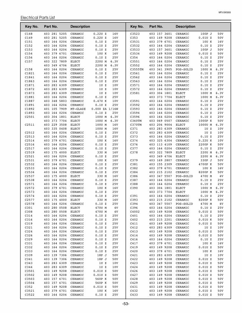
MP3-SW3000
-53-
Electrical Parts List
C148 403 281 5205 CERAMIC 0.22U Z 16V C149 403 281 5205 CERAMIC 0.22U Z 16V C151 403 164 0204 CERAMIC 0.1U Z 25V C152 403 164 0204 CERAMIC 0.1U Z 25V C153 403 164 0204 CERAMIC 0.1U Z 25V C154 403 379 6701 CERAMIC 10U K 16V C156 403 164 0204 CERAMIC 0.1U Z 25V C157 403 322 7809 ELECT 220U M 6.3V
403 349 4706 ELECT 220U M 6.3V C158 403 164 0204 CERAMIC 0.1U Z 25V C1821 403 164 0204 CERAMIC 0.1U Z 25V C1841 403 164 0204 CERAMIC 0.1U Z 25V C1863 403 164 0204 CERAMIC 0.1U Z 25V C1871 403 283 6309 CERAMIC 1U Z 10V C1872 403 283 6309 CERAMIC 1U Z 10V C1873 403 283 6309 CERAMIC 1U Z 10V C1881 403 164 0204 CERAMIC 0.1U Z 25V C1887 403 348 5803 CERAMIC 0.47U K 10V C1891 403 164 0204 CERAMIC 0.1U Z 25V C1892 401 105 7909 MT-GLAZE 0.000 ZA 1/16W C1893 403 164 0204 CERAMIC 0.1U Z 25V C2501 403 304 1801 ELECT 100U M 6.3V
403 373 7704 ELECT 100U M 6.3V C2511 403 229 3508 ELECT 100U M 16V
403 335 0408 ELECT 100U M 16V C2512 403 164 0204 CERAMIC 0.1U Z 25V C2513 403 164 0204 CERAMIC 0.1U Z 25V C2514 403 379 6701 CERAMIC 10U K 16V C2516 403 164 0204 CERAMIC 0.1U Z 25V C2517 403 164 0204 CERAMIC 0.1U Z 25V C2519 403 175 4000 ELECT 33U M 16V C2521 403 164 0204 CERAMIC 0.1U Z 25V C2531 403 379 6701 CERAMIC 10U K 16V C2532 403 164 0204 CERAMIC 0.1U Z 25V C2533 403 164 0204 CERAMIC 0.1U Z 25V C2534 403 164 0204 CERAMIC 0.1U Z 25V C2537 403 175 4000 ELECT 33U M 16V C2538 403 164 0204 CERAMIC 0.1U Z 25V C2571 403 164 0204 CERAMIC 0.1U Z 25V C2572 403 379 6701 CERAMIC 10U K 16V C2573 403 164 0204 CERAMIC 0.1U Z 25V C2574 403 164 0204 CERAMIC 0.1U Z 25V C2577 403 175 4000 ELECT 33U M 16V C2578 403 164 0204 CERAMIC 0.1U Z 25V C301 403 280 0508 ELECT 470U M 4V C308 403 280 0508 ELECT 470U M 4V C314 403 164 0204 CERAMIC 0.1U Z 25V C316 403 164 0204 CERAMIC 0.1U Z 25V C319 403 164 0204 CERAMIC 0.1U Z 25V C321 403 164 0204 CERAMIC 0.1U Z 25V C324 403 164 0204 CERAMIC 0.1U Z 25V C326 403 164 0204 CERAMIC 0.1U Z 25V C329 403 164 0204 CERAMIC 0.1U Z 25V C331 403 164 0204 CERAMIC 0.1U Z 25V C332 403 164 0204 CERAMIC 0.1U Z 25V C333 403 164 0204 CERAMIC 0.1U Z 25V C339 403 139 7306 CERAMIC 18P J 50V C341 403 139 7306 CERAMIC 18P J 50V C343 403 283 6309 CERAMIC 1U Z 10V C344 403 283 6309 CERAMIC 1U Z 10V C3501 403 149 9208 CERAMIC 0.01U Z 50V C3502 403 149 9208 CERAMIC 0.01U Z 50V C3503 403 157 6701 CERAMIC 560P K 50V C3504 403 157 6701 CERAMIC 560P K 50V C352 403 149 9208 CERAMIC 0.01U Z 50V C3521 403 379 6701 CERAMIC 10U K 16V C3522 403 164 0204 CERAMIC 0.1U Z 25V
C3523 403 157 3601 CERAMIC 100P J 50V C353 403 149 9208 CERAMIC 0.01U Z 50V C3531 403 379 6701 CERAMIC 10U K 16V C3532 403 164 0204 CERAMIC 0.1U Z 25V C3533 403 157 3601 CERAMIC 100P J 50V C3534 403 149 9208 CERAMIC 0.01U Z 50V C354 403 164 0204 CERAMIC 0.1U Z 25V C3551 403 164 0204 CERAMIC 0.1U Z 25V C3552 403 164 0204 CERAMIC 0.1U Z 25V C3555TM 403 341 3905 POS-SOLID 100U M 6.3V C3561 403 164 0204 CERAMIC 0.1U Z 25V C3562 403 164 0204 CERAMIC 0.1U Z 25V C3563 403 164 0204 CERAMIC 0.1U Z 25V C3571 403 164 0204 CERAMIC 0.1U Z 25V C3572 403 164 0204 CERAMIC 0.1U Z 25V C3581 403 304 1801 ELECT 100U M 6.3V
403 373 7704 ELECT 100U M 6.3V C3591 403 164 0204 CERAMIC 0.1U Z 25V C3592 403 164 0204 CERAMIC 0.1U Z 25V C3593 403 164 0204 CERAMIC 0.1U Z 25V C3594 403 164 0204 CERAMIC 0.1U Z 25V C3596 403 164 0204 CERAMIC 0.1U Z 25V C360TM 403 069 0507 CERAMIC 1000P K 50VC370TM 403 206 9004 ELECT 1000U M 6.3VC371 403 283 6309 CERAMIC 1U Z 10V C372 403 283 6309 CERAMIC 1U Z 10V C373 403 164 0204 CERAMIC 0.1U Z 25V C374 403 325 6304 CERAMIC 0.22U K 10V C376 403 113 4109 CERAMIC 2200P K 50V C377 403 164 0204 CERAMIC 0.1U Z 25V C378 403 322 7809 ELECT 220U M 6.3V
403 349 4706 ELECT 220U M 6.3V C379 403 169 2807 CERAMIC 330P J 50V C381 403 155 2309 CERAMIC 4700P K 50V C382 403 379 6701 CERAMIC 10U K 16V C384 403 215 2102 CERAMIC 8200P K 50V C386 403 347 5507 POS-SOLID 470U M 4V C387 403 164 0204 CERAMIC 0.1U Z 25V C388 403 164 0204 CERAMIC 0.1U Z 25V C390 403 304 1801 ELECT 100U M 6.3V
403 373 7704 ELECT 100U M 6.3V C391 403 164 0204 CERAMIC 0.1U Z 25V C393 403 215 2102 CERAMIC 8200P K 50V C394 403 347 5507 POS-SOLID 470U M 4V C396 403 164 0204 CERAMIC 0.1U Z 25V C4002 403 149 9208 CERAMIC 0.01U Z 50V C401 403 164 0204 CERAMIC 0.1U Z 25V C402 403 215 2201 CERAMIC 0.01U K 50V C411 403 149 9208 CERAMIC 0.01U Z 50V C412 403 283 6309 CERAMIC 1U Z 10V C413 403 149 9208 CERAMIC 0.01U Z 50V C414 403 149 9208 CERAMIC 0.01U Z 50V C416 403 164 0204 CERAMIC 0.1U Z 25V C417 403 379 6701 CERAMIC 10U K 16V C419 403 149 9208 CERAMIC 0.01U Z 50V C420 403 379 6701 CERAMIC 10U K 16V C421 403 283 6309 CERAMIC 1U Z 10V C422 403 149 9208 CERAMIC 0.01U Z 50V C423 403 149 9208 CERAMIC 0.01U Z 50V C424 403 149 9208 CERAMIC 0.01U Z 50V C426 403 149 9208 CERAMIC 0.01U Z 50V C427 403 149 9208 CERAMIC 0.01U Z 50V C428 403 149 9208 CERAMIC 0.01U Z 50V C429 403 149 9208 CERAMIC 0.01U Z 50V C431 403 149 9208 CERAMIC 0.01U Z 50V C432 403 149 9208 CERAMIC 0.01U Z 50V C433 403 149 9208 CERAMIC 0.01U Z 50V
Key No. Part No. Description Key No. Part No. Description
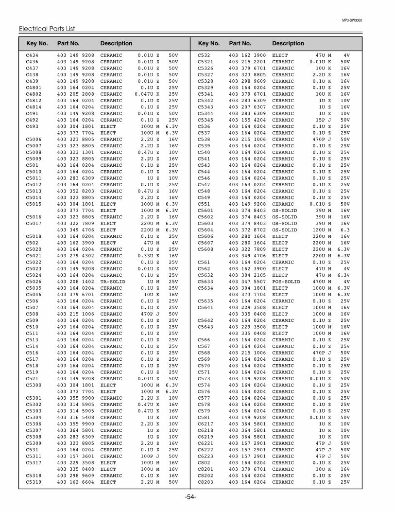
MP3-SW3000
Electrical Parts List
-54-
C434 403 149 9208 CERAMIC 0.01U Z 50V C436 403 149 9208 CERAMIC 0.01U Z 50V C437 403 149 9208 CERAMIC 0.01U Z 50V C438 403 149 9208 CERAMIC 0.01U Z 50V C439 403 149 9208 CERAMIC 0.01U Z 50V C4801 403 164 0204 CERAMIC 0.1U Z 25V C4802 403 205 2808 CERAMIC 0.047U K 25V C4812 403 164 0204 CERAMIC 0.1U Z 25V C4814 403 164 0204 CERAMIC 0.1U Z 25V C491 403 149 9208 CERAMIC 0.01U Z 50V C492 403 164 0204 CERAMIC 0.1U Z 25V C493 403 304 1801 ELECT 100U M 6.3V
403 373 7704 ELECT 100U M 6.3V C5006 403 323 8805 CERAMIC 2.2U Z 16V C5007 403 323 8805 CERAMIC 2.2U Z 16V C5008 403 323 1301 CERAMIC 0.47U Z 10V C5009 403 323 8805 CERAMIC 2.2U Z 16V C501 403 164 0204 CERAMIC 0.1U Z 25V C5010 403 164 0204 CERAMIC 0.1U Z 25V C5011 403 283 6309 CERAMIC 1U Z 10V C5012 403 164 0204 CERAMIC 0.1U Z 25V C5013 403 352 8203 CERAMIC 0.47U Z 16V C5014 403 323 8805 CERAMIC 2.2U Z 16V C5015 403 304 1801 ELECT 100U M 6.3V
403 373 7704 ELECT 100U M 6.3V C5016 403 323 8805 CERAMIC 2.2U Z 16V C5017 403 322 7809 ELECT 220U M 6.3V
403 349 4706 ELECT 220U M 6.3V C5018 403 164 0204 CERAMIC 0.1U Z 25V C502 403 162 3900 ELECT 47U M 4V C5020 403 164 0204 CERAMIC 0.1U Z 25V C5021 403 279 4302 CERAMIC 0.33U K 16V C5022 403 164 0204 CERAMIC 0.1U Z 25V C5023 403 149 9208 CERAMIC 0.01U Z 50V C5024 403 164 0204 CERAMIC 0.1U Z 25V C5026 403 208 1402 TA-SOLID 1U M 25V C5035 403 164 0204 CERAMIC 0.1U Z 25V C5046 403 379 6701 CERAMIC 10U K 16V C506 403 164 0204 CERAMIC 0.1U Z 25V C507 403 164 0204 CERAMIC 0.1U Z 25V C508 403 215 1006 CERAMIC 470P J 50V C509 403 164 0204 CERAMIC 0.1U Z 25V C510 403 164 0204 CERAMIC 0.1U Z 25V C511 403 164 0204 CERAMIC 0.1U Z 25V C513 403 164 0204 CERAMIC 0.1U Z 25V C514 403 164 0204 CERAMIC 0.1U Z 25V C516 403 164 0204 CERAMIC 0.1U Z 25V C517 403 164 0204 CERAMIC 0.1U Z 25V C518 403 164 0204 CERAMIC 0.1U Z 25V C519 403 164 0204 CERAMIC 0.1U Z 25V C521 403 149 9208 CERAMIC 0.01U Z 50V C5300 403 304 1801 ELECT 100U M 6.3V
403 373 7704 ELECT 100U M 6.3V C5301 403 355 9900 CERAMIC 2.2U K 10V C5302 403 314 5905 CERAMIC 0.47U K 16V C5303 403 314 5905 CERAMIC 0.47U K 16V C5304 403 316 5408 CERAMIC 1U K 10V C5306 403 355 9900 CERAMIC 2.2U K 10V C5307 403 364 5801 CERAMIC 1U K 10V C5308 403 283 6309 CERAMIC 1U Z 10V C5309 403 323 8805 CERAMIC 2.2U Z 16V C531 403 164 0204 CERAMIC 0.1U Z 25V C5311 403 157 3601 CERAMIC 100P J 50V C5317 403 229 3508 ELECT 100U M 16V
403 335 0408 ELECT 100U M 16V C5318 403 298 9609 CERAMIC 0.1U K 16V C5319 403 162 6604 ELECT 2.2U M 50V
C532 403 162 3900 ELECT 47U M 4V C5321 403 215 2201 CERAMIC 0.01U K 50V C5326 403 379 6701 CERAMIC 10U K 16V C5327 403 323 8805 CERAMIC 2.2U Z 16V C5328 403 298 9609 CERAMIC 0.1U K 16V C5329 403 164 0204 CERAMIC 0.1U Z 25V C5341 403 379 6701 CERAMIC 10U K 16V C5342 403 283 6309 CERAMIC 1U Z 10V C5343 403 207 0307 CERAMIC 1U Z 16V C5344 403 283 6309 CERAMIC 1U Z 10V C5345 403 155 4204 CERAMIC 15P J 50V C536 403 164 0204 CERAMIC 0.1U Z 25V C537 403 164 0204 CERAMIC 0.1U Z 25V C538 403 215 1006 CERAMIC 470P J 50V C539 403 164 0204 CERAMIC 0.1U Z 25V C540 403 164 0204 CERAMIC 0.1U Z 25V C541 403 164 0204 CERAMIC 0.1U Z 25V C543 403 164 0204 CERAMIC 0.1U Z 25V C544 403 164 0204 CERAMIC 0.1U Z 25V C546 403 164 0204 CERAMIC 0.1U Z 25V C547 403 164 0204 CERAMIC 0.1U Z 25V C548 403 164 0204 CERAMIC 0.1U Z 25V C549 403 164 0204 CERAMIC 0.1U Z 25V C551 403 149 9208 CERAMIC 0.01U Z 50V C5601 403 374 8403 OS-SOLID 39U M 16V C5602 403 374 8403 OS-SOLID 39U M 16V C5603 403 374 8403 OS-SOLID 39U M 16V C5604 403 372 8702 OS-SOLID 120U M 6.3 C5606 403 280 1604 ELECT 220U M 16V C5607 403 280 1604 ELECT 220U M 16V C5608 403 322 7809 ELECT 220U M 6.3V
403 349 4706 ELECT 220U M 6.3V C561 403 164 0204 CERAMIC 0.1U Z 25V C562 403 162 3900 ELECT 47U M 4V C5632 403 304 2105 ELECT 47U M 6.3V C5633 403 347 5507 POS-SOLID 470U M 4V C5634 403 304 1801 ELECT 100U M 6.3V
403 373 7704 ELECT 100U M 6.3V C5635 403 164 0204 CERAMIC 0.1U Z 25V C5641 403 229 3508 ELECT 100U M 16V
403 335 0408 ELECT 100U M 16V C5642 403 164 0204 CERAMIC 0.1U Z 25V C5643 403 229 3508 ELECT 100U M 16V
403 335 0408 ELECT 100U M 16V C566 403 164 0204 CERAMIC 0.1U Z 25V C567 403 164 0204 CERAMIC 0.1U Z 25V C568 403 215 1006 CERAMIC 470P J 50V C569 403 164 0204 CERAMIC 0.1U Z 25V C570 403 164 0204 CERAMIC 0.1U Z 25V C571 403 164 0204 CERAMIC 0.1U Z 25V C573 403 149 9208 CERAMIC 0.01U Z 50V C574 403 164 0204 CERAMIC 0.1U Z 25V C576 403 164 0204 CERAMIC 0.1U Z 25V C577 403 164 0204 CERAMIC 0.1U Z 25V C578 403 164 0204 CERAMIC 0.1U Z 25V C579 403 164 0204 CERAMIC 0.1U Z 25V C581 403 149 9208 CERAMIC 0.01U Z 50V C6217 403 364 5801 CERAMIC 1U K 10V C6218 403 364 5801 CERAMIC 1U K 10V C6219 403 364 5801 CERAMIC 1U K 10V C6221 403 157 2901 CERAMIC 47P J 50V C6222 403 157 2901 CERAMIC 47P J 50V C6223 403 157 2901 CERAMIC 47P J 50V C802 403 164 0204 CERAMIC 0.1U Z 25V C8201 403 379 6701 CERAMIC 10U K 16V C8202 403 164 0204 CERAMIC 0.1U Z 25V C8203 403 164 0204 CERAMIC 0.1U Z 25V
Key No. Part No. Description Key No. Part No. Description

MP3-SW3000
-55-
Electrical Parts List
C8204 403 164 0204 CERAMIC 0.1U Z 25V C8206 403 283 2905 CERAMIC 0.082U K 16V C8207 403 215 2102 CERAMIC 8200P K 50V C8209 403 164 0204 CERAMIC 0.1U Z 25V C8211 403 164 0204 CERAMIC 0.1U Z 25V C8212 403 379 6701 CERAMIC 10U K 16V C8213 403 164 0204 CERAMIC 0.1U Z 25V C8214 403 164 0204 CERAMIC 0.1U Z 25V C8216 403 164 0204 CERAMIC 0.1U Z 25V C8217 403 164 0204 CERAMIC 0.1U Z 25V C8218 403 164 0204 CERAMIC 0.1U Z 25V C8219 403 164 0204 CERAMIC 0.1U Z 25V C8221 403 164 0204 CERAMIC 0.1U Z 25V C8222 403 164 0204 CERAMIC 0.1U Z 25V C8223 403 164 0204 CERAMIC 0.1U Z 25V C8224 403 164 0204 CERAMIC 0.1U Z 25V C8801 403 155 1609 CERAMIC 33P J 50V C8802 403 155 1609 CERAMIC 33P J 50V C8803 403 164 0204 CERAMIC 0.1U Z 25V C8804 403 155 1609 CERAMIC 33P J 50V C8806 403 155 1609 CERAMIC 33P J 50V C8807 403 164 0204 CERAMIC 0.1U Z 25V C9401 403 379 6701 CERAMIC 10U K 16V C9402 403 164 0204 CERAMIC 0.1U Z 25V C9403 403 164 0204 CERAMIC 0.1U Z 25V C9404 403 164 0204 CERAMIC 0.1U Z 25V C9406 403 164 0204 CERAMIC 0.1U Z 25V C9407 403 164 0204 CERAMIC 0.1U Z 25V C9408 403 164 0204 CERAMIC 0.1U Z 25V C9409 403 164 0204 CERAMIC 0.1U Z 25V C9411 403 164 0204 CERAMIC 0.1U Z 25V C9412 403 164 0204 CERAMIC 0.1U Z 25V C9413 403 164 0204 CERAMIC 0.1U Z 25V C9414 403 164 0204 CERAMIC 0.1U Z 25V C9801 403 310 8306 CERAMIC 10U Z 10V C9802 403 310 8306 CERAMIC 10U Z 10V C9803 403 310 8306 CERAMIC 10U Z 10V C9804 403 310 8306 CERAMIC 10U Z 10V C9806 403 283 6309 CERAMIC 1U Z 10V
RESISTOR RB101 645 036 0985 R-NETWORK 47X4 1/32W
645 037 0830 R-NETWORK 47X4 1/32W RB102 645 036 0985 R-NETWORK 47X4 1/32W
645 037 0830 R-NETWORK 47X4 1/32W RB103 645 036 0985 R-NETWORK 47X4 1/32W
645 037 0830 R-NETWORK 47X4 1/32W RB104 645 036 0985 R-NETWORK 47X4 1/32W
645 037 0830 R-NETWORK 47X4 1/32W RB1401 645 037 0656 R-NETWORK 0X4 0.063W
645 024 7477 R-NETWORK 0X4 1/16W RB1402 645 037 0656 R-NETWORK 0X4 0.063W
645 024 7477 R-NETWORK 0X4 1/16W RB1403 645 037 0656 R-NETWORK 0X4 0.063W
645 024 7477 R-NETWORK 0X4 1/16W RB1404 645 037 0656 R-NETWORK 0X4 0.063W
645 024 7477 R-NETWORK 0X4 1/16W RB1406 645 037 0656 R-NETWORK 0X4 0.063W
645 024 7477 R-NETWORK 0X4 1/16W RB1407 645 037 0656 R-NETWORK 0X4 0.063W
645 024 7477 R-NETWORK 0X4 1/16W RB2501 645 037 0656 R-NETWORK 0X4 0.063W
645 024 7477 R-NETWORK 0X4 1/16W RB2502 645 037 0656 R-NETWORK 0X4 0.063W
645 024 7477 R-NETWORK 0X4 1/16W RB2503 645 037 0656 R-NETWORK 0X4 0.063W
645 024 7477 R-NETWORK 0X4 1/16W RB2531 645 037 0656 R-NETWORK 0X4 0.063W
645 024 7477 R-NETWORK 0X4 1/16W RB2532 645 037 0656 R-NETWORK 0X4 0.063W
645 024 7477 R-NETWORK 0X4 1/16W RB2533 645 037 0656 R-NETWORK 0X4 0.063W
645 024 7477 R-NETWORK 0X4 1/16W RB2561 645 037 0656 R-NETWORK 0X4 0.063W
645 024 7477 R-NETWORK 0X4 1/16W RB2562 645 037 0656 R-NETWORK 0X4 0.063W
645 024 7477 R-NETWORK 0X4 1/16W RB2563 645 037 0656 R-NETWORK 0X4 0.063W
645 024 7477 R-NETWORK 0X4 1/16W RB301 645 036 3528 R-NETWORK 0X4 1/32W RB302 645 036 3528 R-NETWORK 0X4 1/32W RB303 645 036 3528 R-NETWORK 0X4 1/32W RB304 645 036 3528 R-NETWORK 0X4 1/32W RB306 645 036 3528 R-NETWORK 0X4 1/32W RB307 645 036 3528 R-NETWORK 0X4 1/32W RB401 645 037 0656 R-NETWORK 0X4 0.063W
645 024 7477 R-NETWORK 0X4 1/16W RB402 645 037 0656 R-NETWORK 0X4 0.063W
645 024 7477 R-NETWORK 0X4 1/16W RB403 645 037 0656 R-NETWORK 0X4 0.063W
645 024 7477 R-NETWORK 0X4 1/16W RB404 645 037 0656 R-NETWORK 0X4 0.063W
645 024 7477 R-NETWORK 0X4 1/16W RB406 645 037 0656 R-NETWORK 0X4 0.063W
645 024 7477 R-NETWORK 0X4 1/16W RB407 645 037 0656 R-NETWORK 0X4 0.063W
645 024 7477 R-NETWORK 0X4 1/16W RB408 645 037 0656 R-NETWORK 0X4 0.063W
645 024 7477 R-NETWORK 0X4 1/16W RB409 645 037 0656 R-NETWORK 0X4 0.063W
645 024 7477 R-NETWORK 0X4 1/16W RB8201 645 037 3107 R-NETWORK 10X4 0.063W
645 028 5981 R-NETWORK 10X4 1/16W RB8202 645 037 3107 R-NETWORK 10X4 0.063W
645 028 5981 R-NETWORK 10X4 1/16W RB8203 645 037 3107 R-NETWORK 10X4 0.063W
645 028 5981 R-NETWORK 10X4 1/16W RB8204 645 037 3107 R-NETWORK 10X4 0.063W
645 028 5981 R-NETWORK 10X4 1/16W RB8206 645 037 3107 R-NETWORK 10X4 0.063W
645 028 5981 R-NETWORK 10X4 1/16W RB8207 645 037 3107 R-NETWORK 10X4 0.063W
645 028 5981 R-NETWORK 10X4 1/16W RB9401 645 037 0656 R-NETWORK 0X4 0.063W
645 024 7477 R-NETWORK 0X4 1/16W RB9402 645 037 0656 R-NETWORK 0X4 0.063W
645 024 7477 R-NETWORK 0X4 1/16W RB9403 645 037 0656 R-NETWORK 0X4 0.063W
645 024 7477 R-NETWORK 0X4 1/16W RB9404 645 037 0656 R-NETWORK 0X4 0.063W
645 024 7477 R-NETWORK 0X4 1/16W RB9406 645 037 0656 R-NETWORK 0X4 0.063W
645 024 7477 R-NETWORK 0X4 1/16W RB9407 645 037 0656 R-NETWORK 0X4 0.063W
645 024 7477 R-NETWORK 0X4 1/16W R100 401 105 0504 MT-GLAZE 1K JA 1/16W R101 401 105 0306 MT-GLAZE 10 JA 1/16W R102 401 105 0306 MT-GLAZE 10 JA 1/16W R103 401 105 0306 MT-GLAZE 10 JA 1/16W R104 401 105 5202 MT-GLAZE 470 JA 1/16W R105 401 105 5202 MT-GLAZE 470 JA 1/16W R109 401 105 7909 MT-GLAZE 0.000 ZA 1/16W R111 401 105 7909 MT-GLAZE 0.000 ZA 1/16W R112 401 105 7909 MT-GLAZE 0.000 ZA 1/16W R113 401 105 0306 MT-GLAZE 10 JA 1/16W
Key No. Part No. Description Key No. Part No. Description

MP3-SW3000
Electrical Parts List
-56-
R114 401 105 0306 MT-GLAZE 10 JA 1/16W R116 401 105 0306 MT-GLAZE 10 JA 1/16W R121 401 037 5004 MT-GLAZE 0.000 ZA 1/10W R123 401 105 7909 MT-GLAZE 0.000 ZA 1/16W R126 645 026 1022 INDUCTOR,4.7U M R131 401 105 5103 MT-GLAZE 47 JA 1/16W R134 401 105 5103 MT-GLAZE 47 JA 1/16W R136 401 105 5103 MT-GLAZE 47 JA 1/16W R138 401 105 7909 MT-GLAZE 0.000 ZA 1/16W R1381 401 105 0405 MT-GLAZE 100 JA 1/16W R1382 401 105 0405 MT-GLAZE 100 JA 1/16W R1383 401 105 4106 MT-GLAZE 3.3K JA 1/16W R1384 401 105 0603 MT-GLAZE 10K JA 1/16W R1386 401 105 0603 MT-GLAZE 10K JA 1/16W R1403 401 105 0306 MT-GLAZE 10 JA 1/16W R141 401 105 0405 MT-GLAZE 100 JA 1/16W R1417 401 105 0306 MT-GLAZE 10 JA 1/16W R142 401 105 0405 MT-GLAZE 100 JA 1/16W R1421 401 105 7909 MT-GLAZE 0.000 ZA 1/16W R1422 401 105 7909 MT-GLAZE 0.000 ZA 1/16W R143 401 105 0405 MT-GLAZE 100 JA 1/16W R1438 401 105 0306 MT-GLAZE 10 JA 1/16W R1443 401 105 7909 MT-GLAZE 0.000 ZA 1/16W R1444 401 105 7909 MT-GLAZE 0.000 ZA 1/16W R146 401 105 0603 MT-GLAZE 10K JA 1/16W R1463 401 105 0306 MT-GLAZE 10 JA 1/16W R1467 401 105 7909 MT-GLAZE 0.000 ZA 1/16W R1468 401 105 7909 MT-GLAZE 0.000 ZA 1/16W R1469 401 105 7909 MT-GLAZE 0.000 ZA 1/16W R1471 401 105 0405 MT-GLAZE 100 JA 1/16W R1472 401 105 0504 MT-GLAZE 1K JA 1/16W R1814 401 105 0603 MT-GLAZE 10K JA 1/16W R1816 401 105 0603 MT-GLAZE 10K JA 1/16W R1817 401 105 0603 MT-GLAZE 10K JA 1/16W R1818 401 105 0603 MT-GLAZE 10K JA 1/16W R1819 401 105 0603 MT-GLAZE 10K JA 1/16W R1822 401 105 7909 MT-GLAZE 0.000 ZA 1/16W R1823 401 105 7909 MT-GLAZE 0.000 ZA 1/16W R1824 401 105 7909 MT-GLAZE 0.000 ZA 1/16W R1826 401 105 7909 MT-GLAZE 0.000 ZA 1/16W R1827 401 105 7909 MT-GLAZE 0.000 ZA 1/16W R1829 401 105 7909 MT-GLAZE 0.000 ZA 1/16W R1841 401 105 7909 MT-GLAZE 0.000 ZA 1/16W R1842 401 105 0306 MT-GLAZE 10 JA 1/16W R1843 401 105 0306 MT-GLAZE 10 JA 1/16W R1844 401 105 4106 MT-GLAZE 3.3K JA 1/16W R1846 401 105 4106 MT-GLAZE 3.3K JA 1/16W R1847 401 105 5301 MT-GLAZE 4.7K JA 1/16W R1848 401 105 5301 MT-GLAZE 4.7K JA 1/16W R1849 401 105 4106 MT-GLAZE 3.3K JA 1/16W R1851 401 105 4106 MT-GLAZE 3.3K JA 1/16W R1852 401 105 5301 MT-GLAZE 4.7K JA 1/16W R1853 401 105 5301 MT-GLAZE 4.7K JA 1/16W R1861 401 105 5905 MT-GLAZE 560 JA 1/16W R1863 401 105 0405 MT-GLAZE 100 JA 1/16W R1864 401 105 7909 MT-GLAZE 0.000 ZA 1/16W R1866 401 105 7909 MT-GLAZE 0.000 ZA 1/16W R1867 401 105 7909 MT-GLAZE 0.000 ZA 1/16W R1871 401 105 0603 MT-GLAZE 10K JA 1/16W R1872 401 105 0306 MT-GLAZE 10 JA 1/16W R1873 401 105 1105 MT-GLAZE 12K JA 1/16W R1874 401 105 2508 MT-GLAZE 20K JA 1/16W R1876 401 105 7909 MT-GLAZE 0.000 ZA 1/16W R1877 401 105 0603 MT-GLAZE 10K JA 1/16W R1880 401 105 7909 MT-GLAZE 0.000 ZA 1/16W R1881 401 105 2706 MT-GLAZE 220 JA 1/16W R1882 401 105 2706 MT-GLAZE 220 JA 1/16W
R1883 401 105 7909 MT-GLAZE 0.000 ZA 1/16W R1884 401 105 7909 MT-GLAZE 0.000 ZA 1/16W R1885 401 105 0504 MT-GLAZE 1K JA 1/16W R1887 401 105 0603 MT-GLAZE 10K JA 1/16W R1888 401 105 7909 MT-GLAZE 0.000 ZA 1/16W R1890 401 105 7909 MT-GLAZE 0.000 ZA 1/16W R1892 401 105 8005 MT-GLAZE 1M JA 1/16W R1893 401 105 0306 MT-GLAZE 10 JA 1/16W R2501 401 105 1501 MT-GLAZE 1.5K JA 1/16W R2502 401 105 5301 MT-GLAZE 4.7K JA 1/16W R2503 401 105 5301 MT-GLAZE 4.7K JA 1/16W R2504 401 105 0504 MT-GLAZE 1K JA 1/16W R2511 401 105 7909 MT-GLAZE 0.000 ZA 1/16W R2512 401 105 7909 MT-GLAZE 0.000 ZA 1/16W R2513 401 105 7909 MT-GLAZE 0.000 ZA 1/16W R2514 401 105 7909 MT-GLAZE 0.000 ZA 1/16W R2516 401 105 7909 MT-GLAZE 0.000 ZA 1/16W R2518 401 105 7909 MT-GLAZE 0.000 ZA 1/16W R2519 401 105 7909 MT-GLAZE 0.000 ZA 1/16W R2522 401 148 6006 MT-GLAZE 2.2 JA 1/16W R2523 401 148 6006 MT-GLAZE 2.2 JA 1/16W R2527 401 105 7909 MT-GLAZE 0.000 ZA 1/16W R2531 401 105 7909 MT-GLAZE 0.000 ZA 1/16W R2532 401 105 7909 MT-GLAZE 0.000 ZA 1/16W R2533 401 105 7909 MT-GLAZE 0.000 ZA 1/16W R2534 401 105 7909 MT-GLAZE 0.000 ZA 1/16W R2536 401 105 7909 MT-GLAZE 0.000 ZA 1/16W R2538 401 105 7909 MT-GLAZE 0.000 ZA 1/16W R2539 401 105 7909 MT-GLAZE 0.000 ZA 1/16W R2542 401 148 6006 MT-GLAZE 2.2 JA 1/16W R2543 401 148 6006 MT-GLAZE 2.2 JA 1/16W R2548 401 105 7909 MT-GLAZE 0.000 ZA 1/16W R2561 401 105 7909 MT-GLAZE 0.000 ZA 1/16W R2562 401 105 7909 MT-GLAZE 0.000 ZA 1/16W R2563 401 105 7909 MT-GLAZE 0.000 ZA 1/16W R2564 401 105 7909 MT-GLAZE 0.000 ZA 1/16W R2566 401 105 7909 MT-GLAZE 0.000 ZA 1/16W R2568 401 105 7909 MT-GLAZE 0.000 ZA 1/16W R2569 401 105 7909 MT-GLAZE 0.000 ZA 1/16W R2572 401 148 6006 MT-GLAZE 2.2 JA 1/16W R2573 401 148 6006 MT-GLAZE 2.2 JA 1/16W R2576 401 105 7909 MT-GLAZE 0.000 ZA 1/16W R303 401 105 7909 MT-GLAZE 0.000 ZA 1/16W R304 401 105 7909 MT-GLAZE 0.000 ZA 1/16W R306 401 105 0306 MT-GLAZE 10 JA 1/16W R308 401 105 0306 MT-GLAZE 10 JA 1/16W R312 401 105 0603 MT-GLAZE 10K JA 1/16W R314 401 105 0603 MT-GLAZE 10K JA 1/16W R316 401 105 4007 MT-GLAZE 330 JA 1/16W R317 401 105 6506 MT-GLAZE 680 JA 1/16W R318 401 105 7909 MT-GLAZE 0.000 ZA 1/16W R322 401 105 7909 MT-GLAZE 0.000 ZA 1/16W R324 401 105 0603 MT-GLAZE 10K JA 1/16W R327 401 105 0603 MT-GLAZE 10K JA 1/16W R329 401 105 7909 MT-GLAZE 0.000 ZA 1/16W R331 401 105 0306 MT-GLAZE 10 JA 1/16W R332 401 105 0306 MT-GLAZE 10 JA 1/16W R333 401 105 0306 MT-GLAZE 10 JA 1/16W R334 401 105 0306 MT-GLAZE 10 JA 1/16W R3503 401 105 0603 MT-GLAZE 10K JA 1/16W R3504 401 105 0603 MT-GLAZE 10K JA 1/16W R3507 401 105 7909 MT-GLAZE 0.000 ZA 1/16W R3508 401 105 2805 MT-GLAZE 2.2K JA 1/16W R3509 401 105 7909 MT-GLAZE 0.000 ZA 1/16W R351 401 105 7909 MT-GLAZE 0.000 ZA 1/16W R3511 401 105 2805 MT-GLAZE 2.2K JA 1/16W R3512 401 105 6001 MT-GLAZE 5.6K JA 1/16W
Key No. Part No. Description Key No. Part No. Description
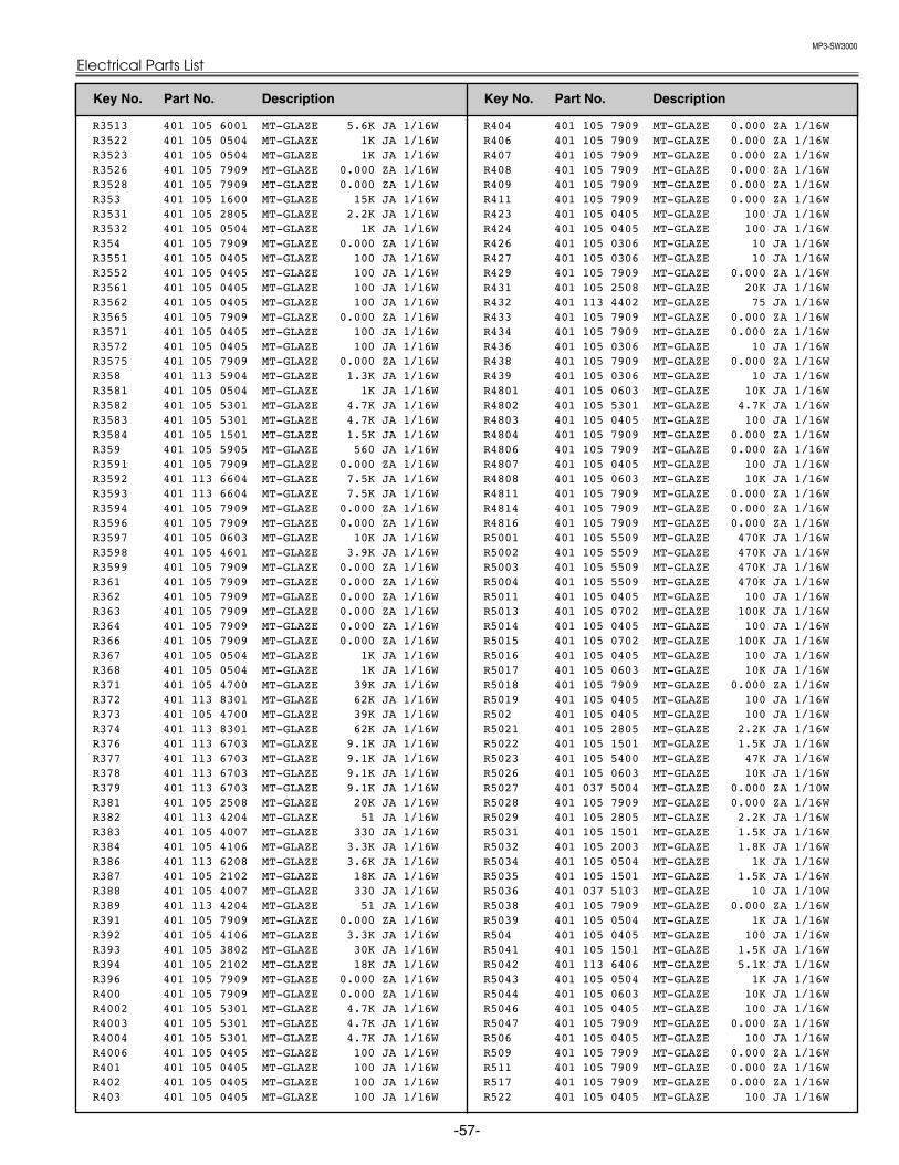
MP3-SW3000
-57-
Electrical Parts List
R3513 401 105 6001 MT-GLAZE 5.6K JA 1/16W R3522 401 105 0504 MT-GLAZE 1K JA 1/16W R3523 401 105 0504 MT-GLAZE 1K JA 1/16W R3526 401 105 7909 MT-GLAZE 0.000 ZA 1/16W R3528 401 105 7909 MT-GLAZE 0.000 ZA 1/16W R353 401 105 1600 MT-GLAZE 15K JA 1/16W R3531 401 105 2805 MT-GLAZE 2.2K JA 1/16W R3532 401 105 0504 MT-GLAZE 1K JA 1/16W R354 401 105 7909 MT-GLAZE 0.000 ZA 1/16W R3551 401 105 0405 MT-GLAZE 100 JA 1/16W R3552 401 105 0405 MT-GLAZE 100 JA 1/16W R3561 401 105 0405 MT-GLAZE 100 JA 1/16W R3562 401 105 0405 MT-GLAZE 100 JA 1/16W R3565 401 105 7909 MT-GLAZE 0.000 ZA 1/16W R3571 401 105 0405 MT-GLAZE 100 JA 1/16W R3572 401 105 0405 MT-GLAZE 100 JA 1/16W R3575 401 105 7909 MT-GLAZE 0.000 ZA 1/16W R358 401 113 5904 MT-GLAZE 1.3K JA 1/16W R3581 401 105 0504 MT-GLAZE 1K JA 1/16W R3582 401 105 5301 MT-GLAZE 4.7K JA 1/16W R3583 401 105 5301 MT-GLAZE 4.7K JA 1/16W R3584 401 105 1501 MT-GLAZE 1.5K JA 1/16W R359 401 105 5905 MT-GLAZE 560 JA 1/16W R3591 401 105 7909 MT-GLAZE 0.000 ZA 1/16W R3592 401 113 6604 MT-GLAZE 7.5K JA 1/16W R3593 401 113 6604 MT-GLAZE 7.5K JA 1/16W R3594 401 105 7909 MT-GLAZE 0.000 ZA 1/16W R3596 401 105 7909 MT-GLAZE 0.000 ZA 1/16W R3597 401 105 0603 MT-GLAZE 10K JA 1/16W R3598 401 105 4601 MT-GLAZE 3.9K JA 1/16W R3599 401 105 7909 MT-GLAZE 0.000 ZA 1/16W R361 401 105 7909 MT-GLAZE 0.000 ZA 1/16W R362 401 105 7909 MT-GLAZE 0.000 ZA 1/16W R363 401 105 7909 MT-GLAZE 0.000 ZA 1/16W R364 401 105 7909 MT-GLAZE 0.000 ZA 1/16W R366 401 105 7909 MT-GLAZE 0.000 ZA 1/16W R367 401 105 0504 MT-GLAZE 1K JA 1/16W R368 401 105 0504 MT-GLAZE 1K JA 1/16W R371 401 105 4700 MT-GLAZE 39K JA 1/16W R372 401 113 8301 MT-GLAZE 62K JA 1/16W R373 401 105 4700 MT-GLAZE 39K JA 1/16W R374 401 113 8301 MT-GLAZE 62K JA 1/16W R376 401 113 6703 MT-GLAZE 9.1K JA 1/16W R377 401 113 6703 MT-GLAZE 9.1K JA 1/16W R378 401 113 6703 MT-GLAZE 9.1K JA 1/16W R379 401 113 6703 MT-GLAZE 9.1K JA 1/16W R381 401 105 2508 MT-GLAZE 20K JA 1/16W R382 401 113 4204 MT-GLAZE 51 JA 1/16W R383 401 105 4007 MT-GLAZE 330 JA 1/16W R384 401 105 4106 MT-GLAZE 3.3K JA 1/16W R386 401 113 6208 MT-GLAZE 3.6K JA 1/16W R387 401 105 2102 MT-GLAZE 18K JA 1/16W R388 401 105 4007 MT-GLAZE 330 JA 1/16W R389 401 113 4204 MT-GLAZE 51 JA 1/16W R391 401 105 7909 MT-GLAZE 0.000 ZA 1/16W R392 401 105 4106 MT-GLAZE 3.3K JA 1/16W R393 401 105 3802 MT-GLAZE 30K JA 1/16W R394 401 105 2102 MT-GLAZE 18K JA 1/16W R396 401 105 7909 MT-GLAZE 0.000 ZA 1/16W R400 401 105 7909 MT-GLAZE 0.000 ZA 1/16W R4002 401 105 5301 MT-GLAZE 4.7K JA 1/16W R4003 401 105 5301 MT-GLAZE 4.7K JA 1/16W R4004 401 105 5301 MT-GLAZE 4.7K JA 1/16W R4006 401 105 0405 MT-GLAZE 100 JA 1/16W R401 401 105 0405 MT-GLAZE 100 JA 1/16W R402 401 105 0405 MT-GLAZE 100 JA 1/16W R403 401 105 0405 MT-GLAZE 100 JA 1/16W
R404 401 105 7909 MT-GLAZE 0.000 ZA 1/16W R406 401 105 7909 MT-GLAZE 0.000 ZA 1/16W R407 401 105 7909 MT-GLAZE 0.000 ZA 1/16W R408 401 105 7909 MT-GLAZE 0.000 ZA 1/16W R409 401 105 7909 MT-GLAZE 0.000 ZA 1/16W R411 401 105 7909 MT-GLAZE 0.000 ZA 1/16W R423 401 105 0405 MT-GLAZE 100 JA 1/16W R424 401 105 0405 MT-GLAZE 100 JA 1/16W R426 401 105 0306 MT-GLAZE 10 JA 1/16W R427 401 105 0306 MT-GLAZE 10 JA 1/16W R429 401 105 7909 MT-GLAZE 0.000 ZA 1/16W R431 401 105 2508 MT-GLAZE 20K JA 1/16W R432 401 113 4402 MT-GLAZE 75 JA 1/16W R433 401 105 7909 MT-GLAZE 0.000 ZA 1/16W R434 401 105 7909 MT-GLAZE 0.000 ZA 1/16W R436 401 105 0306 MT-GLAZE 10 JA 1/16W R438 401 105 7909 MT-GLAZE 0.000 ZA 1/16W R439 401 105 0306 MT-GLAZE 10 JA 1/16W R4801 401 105 0603 MT-GLAZE 10K JA 1/16W R4802 401 105 5301 MT-GLAZE 4.7K JA 1/16W R4803 401 105 0405 MT-GLAZE 100 JA 1/16W R4804 401 105 7909 MT-GLAZE 0.000 ZA 1/16W R4806 401 105 7909 MT-GLAZE 0.000 ZA 1/16W R4807 401 105 0405 MT-GLAZE 100 JA 1/16W R4808 401 105 0603 MT-GLAZE 10K JA 1/16W R4811 401 105 7909 MT-GLAZE 0.000 ZA 1/16W R4814 401 105 7909 MT-GLAZE 0.000 ZA 1/16W R4816 401 105 7909 MT-GLAZE 0.000 ZA 1/16W R5001 401 105 5509 MT-GLAZE 470K JA 1/16W R5002 401 105 5509 MT-GLAZE 470K JA 1/16W R5003 401 105 5509 MT-GLAZE 470K JA 1/16W R5004 401 105 5509 MT-GLAZE 470K JA 1/16W R5011 401 105 0405 MT-GLAZE 100 JA 1/16W R5013 401 105 0702 MT-GLAZE 100K JA 1/16W R5014 401 105 0405 MT-GLAZE 100 JA 1/16W R5015 401 105 0702 MT-GLAZE 100K JA 1/16W R5016 401 105 0405 MT-GLAZE 100 JA 1/16W R5017 401 105 0603 MT-GLAZE 10K JA 1/16W R5018 401 105 7909 MT-GLAZE 0.000 ZA 1/16W R5019 401 105 0405 MT-GLAZE 100 JA 1/16W R502 401 105 0405 MT-GLAZE 100 JA 1/16W R5021 401 105 2805 MT-GLAZE 2.2K JA 1/16W R5022 401 105 1501 MT-GLAZE 1.5K JA 1/16W R5023 401 105 5400 MT-GLAZE 47K JA 1/16W R5026 401 105 0603 MT-GLAZE 10K JA 1/16W R5027 401 037 5004 MT-GLAZE 0.000 ZA 1/10W R5028 401 105 7909 MT-GLAZE 0.000 ZA 1/16W R5029 401 105 2805 MT-GLAZE 2.2K JA 1/16W R5031 401 105 1501 MT-GLAZE 1.5K JA 1/16W R5032 401 105 2003 MT-GLAZE 1.8K JA 1/16W R5034 401 105 0504 MT-GLAZE 1K JA 1/16W R5035 401 105 1501 MT-GLAZE 1.5K JA 1/16W R5036 401 037 5103 MT-GLAZE 10 JA 1/10W R5038 401 105 7909 MT-GLAZE 0.000 ZA 1/16W R5039 401 105 0504 MT-GLAZE 1K JA 1/16W R504 401 105 0405 MT-GLAZE 100 JA 1/16W R5041 401 105 1501 MT-GLAZE 1.5K JA 1/16W R5042 401 113 6406 MT-GLAZE 5.1K JA 1/16W R5043 401 105 0504 MT-GLAZE 1K JA 1/16W R5044 401 105 0603 MT-GLAZE 10K JA 1/16W R5046 401 105 0405 MT-GLAZE 100 JA 1/16W R5047 401 105 7909 MT-GLAZE 0.000 ZA 1/16W R506 401 105 0405 MT-GLAZE 100 JA 1/16W R509 401 105 7909 MT-GLAZE 0.000 ZA 1/16W R511 401 105 7909 MT-GLAZE 0.000 ZA 1/16W R517 401 105 7909 MT-GLAZE 0.000 ZA 1/16W R522 401 105 0405 MT-GLAZE 100 JA 1/16W
Key No. Part No. Description Key No. Part No. Description

MP3-SW3000
Electrical Parts List
-58-
R523 401 105 0405 MT-GLAZE 100 JA 1/16W R524 401 105 7909 MT-GLAZE 0.000 ZA 1/16W R527 401 105 0405 MT-GLAZE 100 JA 1/16W R5302 401 105 0405 MT-GLAZE 100 JA 1/16W R5304 401 105 8005 MT-GLAZE 1M JA 1/16W R5307 401 035 4108 MT-GLAZE 0.000 ZA 1/8W R5308 401 105 7909 MT-GLAZE 0.000 ZA 1/16W R5309 401 105 7909 MT-GLAZE 0.000 ZA 1/16W R5310 645 026 1022 INDUCTOR,4.7U M R5311 401 105 4601 MT-GLAZE 3.9K JA 1/16W R5316 401 105 7909 MT-GLAZE 0.000 ZA 1/16W R5317 401 105 6001 MT-GLAZE 5.6K JA 1/16W R5318 401 113 5201 MT-GLAZE 360 JA 1/16W R532 401 105 0405 MT-GLAZE 100 JA 1/16W R5327 401 105 0603 MT-GLAZE 10K JA 1/16W R5328 401 105 0405 MT-GLAZE 100 JA 1/16W R5330 401 105 5202 MT-GLAZE 470 JA 1/16W R5331 401 105 0405 MT-GLAZE 100 JA 1/16W R5332 401 105 0405 MT-GLAZE 100 JA 1/16W R5333 401 105 4106 MT-GLAZE 3.3K JA 1/16W R5334 401 105 0405 MT-GLAZE 100 JA 1/16W R5335 401 105 6605 MT-GLAZE 6.8K JA 1/16W R5336 401 037 5004 MT-GLAZE 0.000 ZA 1/10W R5337 401 105 5202 MT-GLAZE 470 JA 1/16W R5338 401 105 6605 MT-GLAZE 6.8K JA 1/16W R5339 401 105 0504 MT-GLAZE 1K JA 1/16W R534 401 105 0405 MT-GLAZE 100 JA 1/16W R5341 645 026 1022 INDUCTOR,4.7U M R5342 401 105 2805 MT-GLAZE 2.2K JA 1/16W R5343 401 105 0504 MT-GLAZE 1K JA 1/16W R5344 401 105 6100 MT-GLAZE 560K JA 1/16W R5346 401 105 0603 MT-GLAZE 10K JA 1/16W R5347 401 105 7909 MT-GLAZE 0.000 ZA 1/16W R5348 401 105 0405 MT-GLAZE 100 JA 1/16W R5351 401 105 0504 MT-GLAZE 1K JA 1/16W R5352 401 105 2805 MT-GLAZE 2.2K JA 1/16W R5353 401 105 0504 MT-GLAZE 1K JA 1/16W R536 401 105 0405 MT-GLAZE 100 JA 1/16W R5361 401 105 7909 MT-GLAZE 0.000 ZA 1/16W R5362 401 105 7909 MT-GLAZE 0.000 ZA 1/16W R5363 401 105 7909 MT-GLAZE 0.000 ZA 1/16W R5364 401 105 7909 MT-GLAZE 0.000 ZA 1/16W R5366 401 105 7909 MT-GLAZE 0.000 ZA 1/16W R5367 401 105 7909 MT-GLAZE 0.000 ZA 1/16W R5368 401 105 7909 MT-GLAZE 0.000 ZA 1/16W R5369 401 105 7909 MT-GLAZE 0.000 ZA 1/16W R539 401 105 7909 MT-GLAZE 0.000 ZA 1/16W R541 401 105 7909 MT-GLAZE 0.000 ZA 1/16W R547 401 105 7909 MT-GLAZE 0.000 ZA 1/16W R552 401 105 0405 MT-GLAZE 100 JA 1/16W R553 401 105 0405 MT-GLAZE 100 JA 1/16W R554 401 105 7909 MT-GLAZE 0.000 ZA 1/16W R557 401 105 0405 MT-GLAZE 100 JA 1/16W R5602 401 105 0504 MT-GLAZE 1K JA 1/16W R5611 401 105 0603 MT-GLAZE 10K JA 1/16W R5612 401 105 0603 MT-GLAZE 10K JA 1/16W R5613 401 105 0603 MT-GLAZE 10K JA 1/16W R5614 401 105 0603 MT-GLAZE 10K JA 1/16W R5616 401 105 0603 MT-GLAZE 10K JA 1/16W R5617 401 105 0603 MT-GLAZE 10K JA 1/16W R5618 401 105 7909 MT-GLAZE 0.000 ZA 1/16W R5619 401 105 6001 MT-GLAZE 5.6K JA 1/16W R562 401 105 0405 MT-GLAZE 100 JA 1/16W R5620 401 105 0504 MT-GLAZE 1K JA 1/16W R5631 401 105 0405 MT-GLAZE 100 JA 1/16W R5632 401 105 7909 MT-GLAZE 0.000 ZA 1/16W R564 401 105 0405 MT-GLAZE 100 JA 1/16W
R5641 401 105 7909 MT-GLAZE 0.000 ZA 1/16W R5642 401 113 8905 MT-GLAZE 200K JA 1/16 R5643 401 113 7106 MT-GLAZE 24K JA 1/16W R566 401 105 0405 MT-GLAZE 100 JA 1/16W R569 401 105 7909 MT-GLAZE 0.000 ZA 1/16W R571 401 105 7909 MT-GLAZE 0.000 ZA 1/16W R577 401 105 7909 MT-GLAZE 0.000 ZA 1/16W R582 401 105 0405 MT-GLAZE 100 JA 1/16W R583 401 105 0405 MT-GLAZE 100 JA 1/16W R584 401 105 7909 MT-GLAZE 0.000 ZA 1/16W R587 401 105 0405 MT-GLAZE 100 JA 1/16W R6201 401 105 0405 MT-GLAZE 100 JA 1/16W R6202 401 105 0405 MT-GLAZE 100 JA 1/16W R6203 401 105 0405 MT-GLAZE 100 JA 1/16W R6204 401 105 3208 MT-GLAZE 270 JA 1/16W R6206 401 105 3208 MT-GLAZE 270 JA 1/16W R6207 401 105 3208 MT-GLAZE 270 JA 1/16W R6216 401 105 7909 MT-GLAZE 0.000 ZA 1/16W R6217 401 105 7909 MT-GLAZE 0.000 ZA 1/16W R6218 401 105 7909 MT-GLAZE 0.000 ZA 1/16W R6223 401 105 7909 MT-GLAZE 0.000 ZA 1/16W R6224 401 105 7909 MT-GLAZE 0.000 ZA 1/16W R6226 401 105 7909 MT-GLAZE 0.000 ZA 1/16W R6253 401 105 7909 MT-GLAZE 0.000 ZA 1/16W R6254 401 105 7909 MT-GLAZE 0.000 ZA 1/16W R6256 401 105 7909 MT-GLAZE 0.000 ZA 1/16W R6823 401 105 0306 MT-GLAZE 10 JA 1/16W R6851 401 105 0306 MT-GLAZE 10 JA 1/16W R6852 401 105 0306 MT-GLAZE 10 JA 1/16W R6854 401 105 0306 MT-GLAZE 10 JA 1/16W R6856 401 105 0306 MT-GLAZE 10 JA 1/16W R6857 401 105 0306 MT-GLAZE 10 JA 1/16W R6858 401 105 0306 MT-GLAZE 10 JA 1/16W R6859 401 105 0306 MT-GLAZE 10 JA 1/16W R6861 401 105 0306 MT-GLAZE 10 JA 1/16W R6862 401 105 0306 MT-GLAZE 10 JA 1/16W R803 401 105 0603 MT-GLAZE 10K JA 1/16W R804 401 105 7909 MT-GLAZE 0.000 ZA 1/16W R807 401 105 0603 MT-GLAZE 10K JA 1/16W R808 401 105 0603 MT-GLAZE 10K JA 1/16W R811 401 105 0603 MT-GLAZE 10K JA 1/16W R8201 401 037 5004 MT-GLAZE 0.000 ZA 1/10W R8204 401 105 0306 MT-GLAZE 10 JA 1/16W R8206 401 105 3307 MT-GLAZE 2.7K JA 1/16W R8207 401 105 0306 MT-GLAZE 10 JA 1/16W R8208 401 105 0306 MT-GLAZE 10 JA 1/16W R8209 401 105 0306 MT-GLAZE 10 JA 1/16W R8212 401 105 0603 MT-GLAZE 10K JA 1/16W R8213 401 105 0405 MT-GLAZE 100 JA 1/16W R8214 401 105 0405 MT-GLAZE 100 JA 1/16W R843 401 105 7909 MT-GLAZE 0.000 ZA 1/16W R844 401 105 7909 MT-GLAZE 0.000 ZA 1/16W R853 401 105 7909 MT-GLAZE 0.000 ZA 1/16W R854 401 105 7909 MT-GLAZE 0.000 ZA 1/16W R863 401 105 7909 MT-GLAZE 0.000 ZA 1/16W R864 401 105 7909 MT-GLAZE 0.000 ZA 1/16W R873 401 105 7909 MT-GLAZE 0.000 ZA 1/16W R874 401 105 7909 MT-GLAZE 0.000 ZA 1/16W R8801 401 105 0306 MT-GLAZE 10 JA 1/16W R8802 401 105 0306 MT-GLAZE 10 JA 1/16W R8803 401 105 0603 MT-GLAZE 10K JA 1/16W R8804 401 105 0603 MT-GLAZE 10K JA 1/16W R8808 401 105 0306 MT-GLAZE 10 JA 1/16W R8809 401 105 0306 MT-GLAZE 10 JA 1/16W R8812 401 105 0603 MT-GLAZE 10K JA 1/16W R9401 401 105 0405 MT-GLAZE 100 JA 1/16W R9402 401 105 0405 MT-GLAZE 100 JA 1/16W
Key No. Part No. Description Key No. Part No. Description
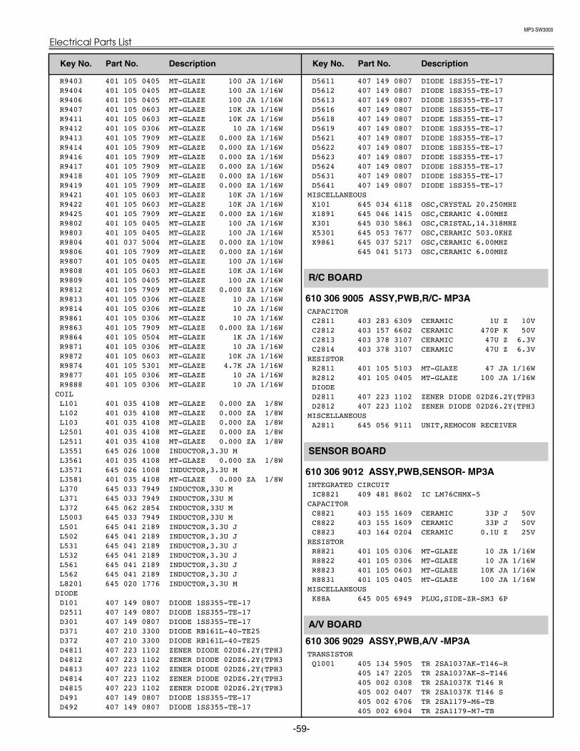
MP3-SW3000
-59-
Electrical Parts List
R9403 401 105 0405 MT-GLAZE 100 JA 1/16W R9404 401 105 0405 MT-GLAZE 100 JA 1/16W R9406 401 105 0405 MT-GLAZE 100 JA 1/16W R9407 401 105 0603 MT-GLAZE 10K JA 1/16W R9411 401 105 0603 MT-GLAZE 10K JA 1/16W R9412 401 105 0306 MT-GLAZE 10 JA 1/16W R9413 401 105 7909 MT-GLAZE 0.000 ZA 1/16W R9414 401 105 7909 MT-GLAZE 0.000 ZA 1/16W R9416 401 105 7909 MT-GLAZE 0.000 ZA 1/16W R9417 401 105 7909 MT-GLAZE 0.000 ZA 1/16W R9418 401 105 7909 MT-GLAZE 0.000 ZA 1/16W R9419 401 105 7909 MT-GLAZE 0.000 ZA 1/16W R9421 401 105 0603 MT-GLAZE 10K JA 1/16W R9422 401 105 0603 MT-GLAZE 10K JA 1/16W R9425 401 105 7909 MT-GLAZE 0.000 ZA 1/16W R9802 401 105 0405 MT-GLAZE 100 JA 1/16W R9803 401 105 0405 MT-GLAZE 100 JA 1/16W R9804 401 037 5004 MT-GLAZE 0.000 ZA 1/10W R9806 401 105 7909 MT-GLAZE 0.000 ZA 1/16W R9807 401 105 0405 MT-GLAZE 100 JA 1/16W R9808 401 105 0603 MT-GLAZE 10K JA 1/16W R9809 401 105 0405 MT-GLAZE 100 JA 1/16W R9812 401 105 7909 MT-GLAZE 0.000 ZA 1/16W R9813 401 105 0306 MT-GLAZE 10 JA 1/16W R9814 401 105 0306 MT-GLAZE 10 JA 1/16W R9861 401 105 0306 MT-GLAZE 10 JA 1/16W R9863 401 105 7909 MT-GLAZE 0.000 ZA 1/16W R9864 401 105 0504 MT-GLAZE 1K JA 1/16W R9871 401 105 0306 MT-GLAZE 10 JA 1/16W R9872 401 105 0603 MT-GLAZE 10K JA 1/16W R9874 401 105 5301 MT-GLAZE 4.7K JA 1/16W R9877 401 105 0306 MT-GLAZE 10 JA 1/16W R9888 401 105 0306 MT-GLAZE 10 JA 1/16W
COIL L101 401 035 4108 MT-GLAZE 0.000 ZA 1/8W L102 401 035 4108 MT-GLAZE 0.000 ZA 1/8W L103 401 035 4108 MT-GLAZE 0.000 ZA 1/8W L2501 401 035 4108 MT-GLAZE 0.000 ZA 1/8W L2511 401 035 4108 MT-GLAZE 0.000 ZA 1/8W L3551 645 026 1008 INDUCTOR,3.3U M L3561 401 035 4108 MT-GLAZE 0.000 ZA 1/8W L3571 645 026 1008 INDUCTOR,3.3U M L3581 401 035 4108 MT-GLAZE 0.000 ZA 1/8W L370 645 033 7949 INDUCTOR,33U M L371 645 033 7949 INDUCTOR,33U M L372 645 062 2854 INDUCTOR,33U M L5003 645 033 7949 INDUCTOR,33U M L501 645 041 2189 INDUCTOR,3.3U J L502 645 041 2189 INDUCTOR,3.3U J L531 645 041 2189 INDUCTOR,3.3U J L532 645 041 2189 INDUCTOR,3.3U J L561 645 041 2189 INDUCTOR,3.3U J L562 645 041 2189 INDUCTOR,3.3U J L8201 645 020 1776 INDUCTOR,3.3U M
DIODE D101 407 149 0807 DIODE 1SS355-TE-17 D2511 407 149 0807 DIODE 1SS355-TE-17 D301 407 149 0807 DIODE 1SS355-TE-17 D371 407 210 3300 DIODE RB161L-40-TE25 D372 407 210 3300 DIODE RB161L-40-TE25 D4811 407 223 1102 ZENER DIODE 02DZ6.2Y(TPH3 D4812 407 223 1102 ZENER DIODE 02DZ6.2Y(TPH3 D4813 407 223 1102 ZENER DIODE 02DZ6.2Y(TPH3 D4814 407 223 1102 ZENER DIODE 02DZ6.2Y(TPH3 D4815 407 223 1102 ZENER DIODE 02DZ6.2Y(TPH3 D491 407 149 0807 DIODE 1SS355-TE-17 D492 407 149 0807 DIODE 1SS355-TE-17
D5611 407 149 0807 DIODE 1SS355-TE-17 D5612 407 149 0807 DIODE 1SS355-TE-17 D5613 407 149 0807 DIODE 1SS355-TE-17 D5616 407 149 0807 DIODE 1SS355-TE-17 D5618 407 149 0807 DIODE 1SS355-TE-17 D5619 407 149 0807 DIODE 1SS355-TE-17 D5621 407 149 0807 DIODE 1SS355-TE-17 D5622 407 149 0807 DIODE 1SS355-TE-17 D5623 407 149 0807 DIODE 1SS355-TE-17 D5624 407 149 0807 DIODE 1SS355-TE-17 D5631 407 149 0807 DIODE 1SS355-TE-17 D5641 407 149 0807 DIODE 1SS355-TE-17
MISCELLANEOUS X101 645 034 6118 OSC,CRYSTAL 20.250MHZ X1891 645 046 1415 OSC,CERAMIC 4.00MHZ X301 645 030 5863 OSC,CRISTAL,14.318MHZ X5301 645 053 7677 OSC,CERAMIC 503.0KHZ X9861 645 037 5217 OSC,CERAMIC 6.00MHZ
645 041 5173 OSC,CERAMIC 6.00MHZ
610 306 9005 ASSY,PWB,R/C- MP3ACAPACITOR C2811 403 283 6309 CERAMIC 1U Z 10V C2812 403 157 6602 CERAMIC 470P K 50V C2813 403 378 3107 CERAMIC 47U Z 6.3V C2814 403 378 3107 CERAMIC 47U Z 6.3V
RESISTOR R2811 401 105 5103 MT-GLAZE 47 JA 1/16W R2812 401 105 0405 MT-GLAZE 100 JA 1/16W DIODE D2811 407 223 1102 ZENER DIODE 02DZ6.2Y(TPH3 D2812 407 223 1102 ZENER DIODE 02DZ6.2Y(TPH3
MISCELLANEOUS A2811 645 056 9111 UNIT,REMOCON RECEIVER
610 306 9012 ASSY,PWB,SENSOR- MP3AINTEGRATED CIRCUIT IC8821 409 481 8602 IC LM76CHMX-5
CAPACITOR C8821 403 155 1609 CERAMIC 33P J 50V C8822 403 155 1609 CERAMIC 33P J 50V C8823 403 164 0204 CERAMIC 0.1U Z 25V
RESISTOR R8821 401 105 0306 MT-GLAZE 10 JA 1/16W R8822 401 105 0306 MT-GLAZE 10 JA 1/16W R8823 401 105 0603 MT-GLAZE 10K JA 1/16W R8831 401 105 0405 MT-GLAZE 100 JA 1/16W
MISCELLANEOUS K88A 645 005 6949 PLUG,SIDE-ZR-SM3 6P
610 306 9029 ASSY,PWB,A/V -MP3ATRANSISTOR Q1001 405 134 5905 TR 2SA1037AK-T146-R
405 147 2205 TR 2SA1037AK-S-T146 405 002 0308 TR 2SA1037K T146 R 405 002 0407 TR 2SA1037K T146 S 405 002 6706 TR 2SA1179-M6-TB 405 002 6904 TR 2SA1179-M7-TB
A/V BOARD
SENSOR BOARD
R/C BOARD
Key No. Part No. Description Key No. Part No. Description

MP3-SW3000
Electrical Parts List
-60-
405 163 1503 TR 2SA1179N-M6-TB 405 163 2708 TR 2SA1179N-M7-TB
Q1002 405 134 5905 TR 2SA1037AK-T146-R 405 147 2205 TR 2SA1037AK-S-T146 405 002 0308 TR 2SA1037K T146 R 405 002 0407 TR 2SA1037K T146 S 405 002 6706 TR 2SA1179-M6-TB 405 002 6904 TR 2SA1179-M7-TB 405 163 1503 TR 2SA1179N-M6-TB 405 163 2708 TR 2SA1179N-M7-TB
Q1003 405 134 5905 TR 2SA1037AK-T146-R 405 147 2205 TR 2SA1037AK-S-T146 405 002 0308 TR 2SA1037K T146 R 405 002 0407 TR 2SA1037K T146 S 405 002 6706 TR 2SA1179-M6-TB 405 002 6904 TR 2SA1179-M7-TB 405 163 1503 TR 2SA1179N-M6-TB 405 163 2708 TR 2SA1179N-M7-TB
Q1004 405 134 5905 TR 2SA1037AK-T146-R 405 147 2205 TR 2SA1037AK-S-T146 405 002 0308 TR 2SA1037K T146 R 405 002 0407 TR 2SA1037K T146 S 405 002 6706 TR 2SA1179-M6-TB 405 002 6904 TR 2SA1179-M7-TB 405 163 1503 TR 2SA1179N-M6-TB 405 163 2708 TR 2SA1179N-M7-TB
Q1006 405 014 4509 TR 2SC2412K T146 R 405 014 4608 TR 2SC2412K T146 S 405 015 8704 TR 2SC2812-L6-TB 405 015 8902 TR 2SC2812-L7-TB 405 163 1602 TR 2SC2812N-L6-TB0 405 163 1701 TR 2SC2812N-L7-TB0
Q2001 405 014 4509 TR 2SC2412K T146 R 405 014 4608 TR 2SC2412K T146 S 405 015 8704 TR 2SC2812-L6-TB 405 015 8902 TR 2SC2812-L7-TB 405 163 1602 TR 2SC2812N-L6-TB0 405 163 1701 TR 2SC2812N-L7-TB0
Q2002 405 014 4509 TR 2SC2412K T146 R 405 014 4608 TR 2SC2412K T146 S 405 015 8704 TR 2SC2812-L6-TB 405 015 8902 TR 2SC2812-L7-TB 405 163 1602 TR 2SC2812N-L6-TB0 405 163 1701 TR 2SC2812N-L7-TB0
Q2003 405 014 4509 TR 2SC2412K T146 R 405 014 4608 TR 2SC2412K T146 S 405 015 8704 TR 2SC2812-L6-TB 405 015 8902 TR 2SC2812-L7-TB 405 163 1602 TR 2SC2812N-L6-TB0 405 163 1701 TR 2SC2812N-L7-TB0
Q5201 405 014 4509 TR 2SC2412K T146 R 405 014 4608 TR 2SC2412K T146 S 405 015 8704 TR 2SC2812-L6-TB 405 015 8902 TR 2SC2812-L7-TB 405 163 1602 TR 2SC2812N-L6-TB0 405 163 1701 TR 2SC2812N-L7-TB0
Q5202 405 014 4509 TR 2SC2412K T146 R 405 014 4608 TR 2SC2412K T146 S 405 015 8704 TR 2SC2812-L6-TB 405 015 8902 TR 2SC2812-L7-TB 405 163 1602 TR 2SC2812N-L6-TB0 405 163 1701 TR 2SC2812N-L7-TB0
Q5203 405 014 4509 TR 2SC2412K T146 R 405 014 4608 TR 2SC2412K T146 S 405 015 8704 TR 2SC2812-L6-TB 405 015 8902 TR 2SC2812-L7-TB 405 163 1602 TR 2SC2812N-L6-TB0
405 163 1701 TR 2SC2812N-L7-TB0 Q5204 405 014 4509 TR 2SC2412K T146 R
405 014 4608 TR 2SC2412K T146 S 405 015 8704 TR 2SC2812-L6-TB 405 015 8902 TR 2SC2812-L7-TB 405 163 1602 TR 2SC2812N-L6-TB0 405 163 1701 TR 2SC2812N-L7-TB0
Q5205 405 134 5905 TR 2SA1037AK-T146-R 405 147 2205 TR 2SA1037AK-S-T146 405 002 0308 TR 2SA1037K T146 R 405 002 0407 TR 2SA1037K T146 S 405 002 6706 TR 2SA1179-M6-TB 405 002 6904 TR 2SA1179-M7-TB 405 163 1503 TR 2SA1179N-M6-TB 405 163 2708 TR 2SA1179N-M7-TB
INTEGRATED CIRCUIT IC5201 409 530 7204 IC AN5870SB
CAPACITOR C1001 403 164 0204 CERAMIC 0.1U Z 25V C1007 403 164 0204 CERAMIC 0.1U Z 25V C1008 403 323 8805 CERAMIC 2.2U Z 16V C1051 403 164 0204 CERAMIC 0.1U Z 25V C2001 403 298 9609 CERAMIC 0.1U K 16V C2009 403 304 3300 ELECT 47U M 16V C2011 403 304 1801 ELECT 100U M 6.3V C2012 403 304 1801 ELECT 100U M 6.3V C2013 403 164 0204 CERAMIC 0.1U Z 25V C2014 403 164 0204 CERAMIC 0.1U Z 25V C2016 403 164 0204 CERAMIC 0.1U Z 25V C5001 403 157 3601 CERAMIC 100P J 50V C5002 403 157 3601 CERAMIC 100P J 50V C5003 403 157 3601 CERAMIC 100P J 50V C5004 403 157 3601 CERAMIC 100P J 50V C5201 403 323 8805 CERAMIC 2.2U Z 16V C5202 403 323 8805 CERAMIC 2.2U Z 16V C5203 403 323 8805 CERAMIC 2.2U Z 16V C5204 403 372 8702 OS-SOLID 120U M 6.3 C5206 403 283 6309 CERAMIC 1U Z 10V C5207 403 233 3808 CERAMIC 10P C 50V C5208 403 323 8805 CERAMIC 2.2U Z 16V C5209 403 283 6309 CERAMIC 1U Z 10V C5211 403 314 5905 CERAMIC 0.47U K 16V C5212 403 233 3808 CERAMIC 10P C 50V C5214 403 323 8805 CERAMIC 2.2U Z 16V C5216 403 233 3808 CERAMIC 10P C 50V C5217 403 323 8805 CERAMIC 2.2U Z 16V C5218 403 304 3300 ELECT 47U M 16V C5219 403 207 0307 CERAMIC 1U Z 16V C5226 403 149 9208 CERAMIC 0.01U Z 50V C5228 403 348 5803 CERAMIC 0.47U K 10V C5229 403 298 9609 CERAMIC 0.1U K 16V
RESISTOR R1001 401 260 4102 MT-GLAZE 75 JA 1/3W R1002 401 260 4102 MT-GLAZE 75 JA 1/3W R1003 401 260 4102 MT-GLAZE 75 JA 1/3W R1004 401 105 5400 MT-GLAZE 47K JA 1/16W R1006 401 105 5400 MT-GLAZE 47K JA 1/16W R1007 401 105 0405 MT-GLAZE 100 JA 1/16W R1008 401 105 0405 MT-GLAZE 100 JA 1/16W R1012 401 035 4108 MT-GLAZE 0.000 ZA 1/8W R1013 401 105 2706 MT-GLAZE 220 JA 1/16W R1014 401 105 2706 MT-GLAZE 220 JA 1/16W R1016 401 105 2706 MT-GLAZE 220 JA 1/16W R1017 401 105 0504 MT-GLAZE 1K JA 1/16W R1018 401 105 2805 MT-GLAZE 2.2K JA 1/16W R1019 401 105 2805 MT-GLAZE 2.2K JA 1/16W R1021 401 105 2805 MT-GLAZE 2.2K JA 1/16W
Key No. Part No. Description Key No. Part No. Description
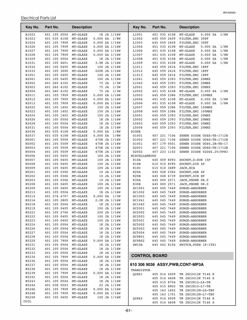
MP3-SW3000
-61-
Electrical Parts List
R1022 401 105 0504 MT-GLAZE 1K JA 1/16W R1023 401 035 4108 MT-GLAZE 0.000 ZA 1/8W R1024 401 105 7909 MT-GLAZE 0.000 ZA 1/16W R1026 401 105 7909 MT-GLAZE 0.000 ZA 1/16W R1027 401 105 7909 MT-GLAZE 0.000 ZA 1/16W R1028 401 105 7909 MT-GLAZE 0.000 ZA 1/16W R1029 401 105 0504 MT-GLAZE 1K JA 1/16W R1031 401 105 4601 MT-GLAZE 3.9K JA 1/16W R1032 401 105 0405 MT-GLAZE 100 JA 1/16W R1033 401 105 3000 MT-GLAZE 220K JA 1/16W R1051 401 105 0405 MT-GLAZE 100 JA 1/16W R2001 401 105 0405 MT-GLAZE 100 JA 1/16W R2002 401 260 4102 MT-GLAZE 75 JA 1/3W R2003 401 260 4102 MT-GLAZE 75 JA 1/3W R2004 401 260 4102 MT-GLAZE 75 JA 1/3W R2011 401 105 7909 MT-GLAZE 0.000 ZA 1/16W R2012 401 105 7909 MT-GLAZE 0.000 ZA 1/16W R2013 401 105 7909 MT-GLAZE 0.000 ZA 1/16W R2022 401 105 1402 MT-GLAZE 150 JA 1/16W R2023 401 105 1402 MT-GLAZE 150 JA 1/16W R2024 401 105 1402 MT-GLAZE 150 JA 1/16W R2026 401 105 0504 MT-GLAZE 1K JA 1/16W R2028 401 105 0504 MT-GLAZE 1K JA 1/16W R2031 401 105 0504 MT-GLAZE 1K JA 1/16W R2036 401 035 4108 MT-GLAZE 0.000 ZA 1/8W R2037 401 035 4108 MT-GLAZE 0.000 ZA 1/8W R5001 401 105 5509 MT-GLAZE 470K JA 1/16W R5002 401 105 5509 MT-GLAZE 470K JA 1/16W R5003 401 105 5509 MT-GLAZE 470K JA 1/16W R5004 401 105 5509 MT-GLAZE 470K JA 1/16W R5006 401 105 0405 MT-GLAZE 100 JA 1/16W R5007 401 105 0405 MT-GLAZE 100 JA 1/16W R5008 401 105 0405 MT-GLAZE 100 JA 1/16W R5009 401 105 0405 MT-GLAZE 100 JA 1/16W R5201 401 105 0306 MT-GLAZE 10 JA 1/16W R5202 401 105 0306 MT-GLAZE 10 JA 1/16W R5203 401 105 0306 MT-GLAZE 10 JA 1/16W R5208 401 105 0405 MT-GLAZE 100 JA 1/16W R5209 401 105 0405 MT-GLAZE 100 JA 1/16W R5213 401 105 0504 MT-GLAZE 1K JA 1/16W R5214 401 276 4707 MT-GLAZE 0.000 ZA 1/3W R5216 401 105 2805 MT-GLAZE 2.2K JA 1/16W R5218 401 105 0504 MT-GLAZE 1K JA 1/16W R5219 401 105 0405 MT-GLAZE 100 JA 1/16W R5221 401 105 2706 MT-GLAZE 220 JA 1/16W R5222 401 105 0405 MT-GLAZE 100 JA 1/16W R5223 401 105 0405 MT-GLAZE 100 JA 1/16W R5224 401 105 0504 MT-GLAZE 1K JA 1/16W R5226 401 105 0504 MT-GLAZE 1K JA 1/16W R5227 401 105 0504 MT-GLAZE 1K JA 1/16W R5228 401 105 0504 MT-GLAZE 1K JA 1/16W R5229 401 105 7909 MT-GLAZE 0.000 ZA 1/16W R5231 401 105 0504 MT-GLAZE 1K JA 1/16W R5232 401 105 0504 MT-GLAZE 1K JA 1/16W R5233 401 105 0504 MT-GLAZE 1K JA 1/16W R5234 401 105 7909 MT-GLAZE 0.000 ZA 1/16W R5236 401 105 0504 MT-GLAZE 1K JA 1/16W R5237 401 105 0504 MT-GLAZE 1K JA 1/16W R5238 401 105 0504 MT-GLAZE 1K JA 1/16W R5239 401 105 7909 MT-GLAZE 0.000 ZA 1/16W R5242 401 105 0504 MT-GLAZE 1K JA 1/16W R5243 401 105 0504 MT-GLAZE 1K JA 1/16W R5244 401 038 0503 MT-GLAZE 22 JA 1/10W R5246 401 105 7909 MT-GLAZE 0.000 ZA 1/16W R5248 401 105 7909 MT-GLAZE 0.000 ZA 1/16W R5249 401 105 0405 MT-GLAZE 100 JA 1/16W
COIL
L1001 401 035 4108 MT-GLAZE 0.000 ZA 1/8W L1002 645 059 2409 FILTER,EMI 35PF L1003 645 059 2409 FILTER,EMI 35PF L1004 401 035 4108 MT-GLAZE 0.000 ZA 1/8W L1006 401 035 4108 MT-GLAZE 0.000 ZA 1/8W L1007 401 035 4108 MT-GLAZE 0.000 ZA 1/8W L1008 401 035 4108 MT-GLAZE 0.000 ZA 1/8W L1009 401 035 4108 MT-GLAZE 0.000 ZA 1/8W L1011 645 059 2416 FILTER,EMI 18PF L1012 645 059 2416 FILTER,EMI 18PF L1013 645 059 2416 FILTER,EMI 18PF L1041 645 059 2393 FILTER,EMI 20MHZ L1042 645 059 2393 FILTER,EMI 20MHZ L2001 645 059 2393 FILTER,EMI 20MHZ L2002 401 035 4108 MT-GLAZE 0.000 ZA 1/8W L2003 645 059 2386 FILTER,EMI 100MHZ L2004 401 035 4108 MT-GLAZE 0.000 ZA 1/8W L2006 401 035 4108 MT-GLAZE 0.000 ZA 1/8W L2007 645 059 2386 FILTER,EMI 100MHZ L2008 645 059 2386 FILTER,EMI 100MHZ L5001 645 059 2393 FILTER,EMI 20MHZ L5002 645 059 2393 FILTER,EMI 20MHZ L5003 645 059 2393 FILTER,EMI 20MHZ L5004 645 059 2393 FILTER,EMI 20MHZ
DIODE D1001 407 221 7106 ZENER DIODE UDZS-TE-1712B D1002 407 221 7106 ZENER DIODE UDZS-TE-1712B D1051 407 179 0501 ZENER DIODE UDZ6.2B-TE-17 D2001 407 221 7106 ZENER DIODE UDZS-TE-1712B D2002 407 223 1102 ZENER DIODE 02DZ6.2Y(TPH3
MISCELLANEOUS K10A 645 009 8093 SOCKET,D-SUB 15P K10B 610 010 8295 SOCKET,DIN 4P K10C 610 010 3689 JACK,RCA K20A 645 028 0382 SOCKET,USB 4P K20B 645 048 6739 SOCKET,DIN 8P K30A 645 000 2571 JACK,PHONE D8.0 K30B 645 000 2571 JACK,PHONE D8.0 SC1001 645 045 7449 SURGE-ABSORBER SC1002 645 045 7449 SURGE-ABSORBER SC1003 645 045 7449 SURGE-ABSORBER SC1041 645 045 7449 SURGE-ABSORBER SC1042 645 045 7449 SURGE-ABSORBER SC2001 645 045 7449 SURGE-ABSORBER SC2002 645 045 7449 SURGE-ABSORBER SC2003 645 045 7449 SURGE-ABSORBER SC5001 645 045 7449 SURGE-ABSORBER SC5002 645 045 7449 SURGE-ABSORBER SC5003 645 045 7449 SURGE-ABSORBER SC5004 645 045 7449 SURGE-ABSORBER SC9801 645 045 7449 SURGE-ABSORBER SC9802 645 045 7449 SURGE-ABSORBER SW10A 645 042 8104 SWITCH,PUSH 1P-1TX1
610 306 9036 ASSY,PWB,CONT-MP3ATRANSISTOR Q2861 405 014 4509 TR 2SC2412K T146 R
405 014 4608 TR 2SC2412K T146 S 405 015 8704 TR 2SC2812-L6-TB 405 015 8902 TR 2SC2812-L7-TB 405 163 1602 TR 2SC2812N-L6-TB0 405 163 1701 TR 2SC2812N-L7-TB0
Q2862 405 014 4509 TR 2SC2412K T146 R 405 014 4608 TR 2SC2412K T146 S
CONTROL BOARD
Key No. Part No. Description Key No. Part No. Description

MP3-SW3000
Electrical Parts List
-62-
405 015 8704 TR 2SC2812-L6-TB 405 015 8902 TR 2SC2812-L7-TB 405 163 1602 TR 2SC2812N-L6-TB0 405 163 1701 TR 2SC2812N-L7-TB0
Q2863 405 014 4509 TR 2SC2412K T146 R 405 014 4608 TR 2SC2412K T146 S 405 015 8704 TR 2SC2812-L6-TB 405 015 8902 TR 2SC2812-L7-TB 405 163 1602 TR 2SC2812N-L6-TB0 405 163 1701 TR 2SC2812N-L7-TB0
Q2864 405 134 5905 TR 2SA1037AK-T146-R 405 147 2205 TR 2SA1037AK-S-T146 405 002 0308 TR 2SA1037K T146 R 405 002 0407 TR 2SA1037K T146 S 405 002 6706 TR 2SA1179-M6-TB 405 002 6904 TR 2SA1179-M7-TB 405 163 1503 TR 2SA1179N-M6-TB 405 163 2708 TR 2SA1179N-M7-TB
CAPACITOR C2861 403 164 0204 CERAMIC 0.1U Z 25V C2862 403 379 6701 CERAMIC 10U K 16V
RESISTOR R2862 401 105 0504 MT-GLAZE 1K JA 1/16W R2864 401 105 5301 MT-GLAZE 4.7K JA 1/16W R2866 401 105 0504 MT-GLAZE 1K JA 1/16W R2868 401 105 5301 MT-GLAZE 4.7K JA 1/16W R2869 401 105 4502 MT-GLAZE 390 JA 1/16W R2872 401 105 6506 MT-GLAZE 680 JA 1/16W R2874 401 105 5301 MT-GLAZE 4.7K JA 1/16W R2876 401 105 0504 MT-GLAZE 1K JA 1/16W R2878 401 105 0504 MT-GLAZE 1K JA 1/16W R2891 401 105 5301 MT-GLAZE 4.7K JA 1/16W R6801 401 105 5103 MT-GLAZE 47 JA 1/16W R6802 401 105 5103 MT-GLAZE 47 JA 1/16W R6803 401 105 5103 MT-GLAZE 47 JA 1/16W
DIODE D2861 407 234 6103 LED SML-310YT-K-T86
407 234 4000 LED SML-310YT-L-T86 407 234 4109 LED SML-310YT-M-T86
D2862 407 234 3805 LED SML-310LT-M-T86 407 234 3904 LED SML-310LT-N-T86
D2863 407 222 4807 LED SML-521MUW T86 D2866 407 223 1102 ZENER DIODE 02DZ6.2Y(TPH3 D2867 407 223 1102 ZENER DIODE 02DZ6.2Y(TPH3 D2868 407 223 1102 ZENER DIODE 02DZ6.2Y(TPH3 D2869 407 223 1102 ZENER DIODE 02DZ6.2Y(TPH3 D2871 407 223 1102 ZENER DIODE 02DZ6.2Y(TPH3 D2872 407 223 1102 ZENER DIODE 02DZ6.2Y(TPH3 D6801 407 149 0807 DIODE 1SS355-TE-17 D6802 407 149 0807 DIODE 1SS355-TE-17 D6803 407 149 0807 DIODE 1SS355-TE-17 D6804 407 223 1102 ZENER DIODE 02DZ6.2Y(TPH3 D6806 407 223 1102 ZENER DIODE 02DZ6.2Y(TPH3 D6807 407 223 1102 ZENER DIODE 02DZ6.2Y(TPH3 D6808 407 223 1102 ZENER DIODE 02DZ6.2Y(TPH3 D6809 407 223 1102 ZENER DIODE 02DZ6.2Y(TPH3 D6811 407 223 1102 ZENER DIODE 02DZ6.2Y(TPH3
MISCELLANEOUS SW6801 645 026 2791 SWITCH,PUSH 1P-1TX1 SW6802 645 026 2791 SWITCH,PUSH 1P-1TX1 SW6804 645 026 2791 SWITCH,PUSH 1P-1TX1 SW6806 645 026 2791 SWITCH,PUSH 1P-1TX1 SW6807 645 026 2791 SWITCH,PUSH 1P-1TX1 SW6808 645 026 2791 SWITCH,PUSH 1P-1TX1 SW6809 645 026 2791 SWITCH,PUSH 1P-1TX1 SW6811 645 026 2791 SWITCH,PUSH 1P-1TX1
610 308 1021 ASSY,PWB,FILTER -MP3ACAPACITOR
!C601 404 081 4702 MT-POLYEST 0.22U M 275V !C603 404 081 4702 MT-POLYEST 0.22U M 275V !C604 404 081 4702 MT-POLYEST 0.22U M 275V !C606 404 073 4505 CERAMIC 2200P K 250V RESISTOR R601 401 008 8607 CARBON 220K JA 1/2W
VARIABLE RESISTOR !VA601 408 018 9808 VARISTOR ENC471D-14AS COIL
!L601 645 041 4961 LINE FILTER !L602 645 041 4961 LINE FILTER MISCELLANEOUS
!F601 423 022 2102 FUSE 250V 4A F601A 645 006 4760 HOLDER,FUSE F601B 645 006 4760 HOLDER,FUSE
!K601 645 055 6647 SOCKET,INLET AC 3P
610 308 1038 ASSY,PWB,SW-MP3AMISCELLANEOUS SW8801 645 063 5175 SWITCH,PUSH 2P-2TX3
SW BOARD
FILTER BOARD
Key No. Part No. Description Key No. Part No. Description

MP3-SW3000
-63-
Electrical Parts List
PRINTED MATTER / OWNER'S MANUAL(English) 610 308 4503 OWNER'S MANUAL-MP3A (Germany) 610 308 4510 OWNER'S MANUAL-MP3A-D (French) 610 308 4527 OWNER'S MANUAL-MP3A-F (Italian) 610 308 4534 OWNER'S MANUAL-MP3A-I (Spanish) 610 308 4541 OWNER'S MANUAL-MP3A-E
REMOTE CONTROL645 061 7904 ASSY,REMOCON CXPK 645 063 7896 ASSY,REMOCON CXPW 610 308 3612 RC-BATTERY LID-CXPK
AC CORD! 645 064 9103 CORD,POWER-1.85MK,US
CABLE AND ADAPTER645 063 8022 UNIT,USB IR RECEIVER 645 057 2999 CABLE,INTERFACE VGA
MISCELLANEOUS610 294 3351 COVER,DUST-MA8A 610 309 4618 STRAP CAP MF7A 610 308 4442 CARRY BAG-MP3A
ACCESSORIES
Key No. Part No. Description Key No. Part No. Description

MP3-SW3000
-64-
Note: Parts order must contain Chassis No., Part No., and Descriptions.
CABINET PARTS
1
18
17
10
14
9
7
2
24
413
3
8
11
6
15
5
23
3029 33
35
31
52
53
2
52
51
51
52
52
25
3234
26
27
21
22
12
42
52
52
Mechanical Parts List
36
37
16
2838
39
41
40

MP3-SW3000
-65-
Mechanical Parts List
1 610 308 3032 ASSY,BUTTON-MP3A 2 610 308 2646 ASSY,STAND LEG-MP3A 3 610 289 1812 BADGE V MARK S-MK6A 4 610 308 3124 BUTTON SEESAW-MP3A 5 610 308 2660 CABINET TOP-MP3A 6 610 308 2677 CABINET FRONT MP3A 7 610 308 2707 CABINET BOTTOM-MP3A 8 610 308 3223 CAP BUTTON SELECT-MP3A 9 610 308 2769 COVER LAMP-MP3A
10 610 311 0875 COVER LENS SHEET-MP3A 11 610 308 2790 DEC RC F-MP3A 12 610 308 3315 DEC RING-MP3A 13 610 308 3322 DEC LED-MP3A 14 610 308 2806 DEC AV SHEET-MP3A 15 610 308 2981 PANEL AV-MP3A 16 610 311 4521 SPACER BOTTOM C-MP3A17 610 311 1025 SPACER FRONT MP3A 18 645 047 8031 BADGE,SANYO*26.2X5.7L26.0
21 610 308 2721 CAP LNS-MP3A 22 610 308 2776 COVER, POWER BTM-MP3A 23 610 308 3230 COVER, DUCT PBS-MP3A 24 610 308 3261 COVER, DUCT PNL A-MP3A 25 610 309 1815 COVER LAMP BST-MP3A 26 610 309 2195 COVER, DUCT PNL B-MP3A 27 610 308 3308 COVER POWER TOP-MP3A 28 610 311 4804 COVER BST SHEET-MP3A29 610 311 0912 DEC LEG-MP3A 30 610 308 3490 MOUNTING FN-MP3A 31 610 308 3513 MOUNTING LMP FAN-MP3A 32 610 308 3520 PANEL NET S-MP3A 33 610 308 3537 PANEL NET F-MP3A 34 610 308 3544 PANEL NET B-MP3A 35 610 308 3551 PANEL NET PBS-MP3A 36 610 311 0998 SPACER OPT LMP MP3A 37 610 308 3636 SPACER SHEET-POWER MP3A 38 610 311 1032 SPACER LEG MP3A 39 610 311 2596 SPACER TEMPB SW-MP3A40 610 311 4866 SPACER POWERMP3A41 610 311 5153 SPACER BST-MP3A
51 411 025 6500 SCR S-TPG BIN 3X8 52 411 001 8801 SCR BIN 3X6 53 411 031 9304 SCR BIN 3X8
61 610 311 0073 ASSY,LCD PNL/PRISM-MP3A 62 645 061 9229 LENS,PROJECTION 63 645 061 9205 ASSY,OPTICAL
(Including Key No.64-69)64 645 061 9496 POLARIZED GLASS(IN/G) 65 645 061 9502 POLARIZED GLASS(IN/B) 66 645 065 2530 LENS CONDENSER(R)67 645 065 2547 LENS INTEGRATOR(IN)68 645 065 2554 LENS INTEGRATOR(OUT)69 645 065 2561 PRISM(PBS)
70 610 308 3803 OPTICAL LP-MP3A
OPTICAL PARTS
SCREWS-CHASSIS-
SCREWS-CABINET-
CHASSIS PARTS
CABINET PARTS
Key No. Part No. Description Key No. Part No. Description

MP3-SW3000
-66-
Optical Parts ListNote: Parts order must contain Chassis No., Part No., and Descriptions.
62
63
70
61

MP3-SW3000
-67-
Optical Parts List
66 : Red
67
68
69
63
64 : Green65 : Blue
Polarized glass stickedon Condenser lens(R)
Polarized glass withmounting holder
65
64
66

A1
MP3-SW3000
These schematic diagrams and printed wiring board drawings are part of the serv-ice manual original for chassis No. MP3-SW3000 model PLC-SW30.File with the service manual No. SM5110522-00.
Note:All the information of part numbers and values indicated on these diagrams are at the beginningof production. To improve the performance, there may be some differences to the actual set.When you order the service parts, use service parts code mentioned on the parts list in thisservice manual.
Schematic DiagramsPrinted Wiring Board Drawings
Model Chassis No.PLC-SW30 MP3-SW3000
Diagrams & Drawings
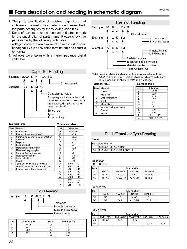
A2
MP3-SW3000
Parts description and reading in schematic diagram
1. The parts specification of resistors, capacitors andcoils are expressed in designated code. Please checkthe parts description by the following code table.
2. Some of transistors and diodes are indicated in markfor the substitution of parts name. Please check theparts name by the following code table.
3.Voltages and waveforms were taken with a video colorbar signal(1Vp-p at 75 ohms terminated) and controlsto normal.
4. Voltages were taken with a high-impedance digitalvoltmeter.
Example 2000 K K 1000 BG
CharacteristicExample 160 E M 10
Capacitance value
ToleranceTypeRated voltage
Excepting electric capacitors, allcapacitance values of less than 1are expressed in µF and morethan 1 are in pF.
Example L2 C1 4R7 K N
ToleranceInductance valueManufacture codeUnique code
Mark MaterialE ElectrolyticP Electrolytic (non-polarized)C Ceramic (temperature compensation)K CeramicF PolyesterN PolypropyleneM Metalized polypropyleneH Metalized polypromylarB Ceramic (semiconductor)G Metalized polyestelY Composite filmS StyrolT Tantalum oxide solid electrolyticU Organic semiconductive electrolyteD Electric double layer electrolytic
Mark ToleranceA not specifiedB ±0.1C ±0.25D ±0.5F ±1G ±2E ±2.5H ±3J ±5K ± 0M ±20N ±30P +100 -0Q +30 -10T +50 -10U +75 -10V +20 -10W +100 -10X +40 -20Y +150 -10Z +80 -20
Mark Tolerance (nH) Mark Tolerance (%)C ±0.25 G ±2D ±0.5 J ±5S ±0.3 K ±10A ±0.2 L ±15
M ±20
Coil Reading
Capacitor Reading
Example 1/2 D J 10K B
Example 6 W K 8.2
Example 1/2 C K 1M
Resistor Reading
Characteristic
Z (Carbon fuse)B (Non-burnable)
Resistance valueTolerance (see below table)Material (see below table)Rated wattage (W)
K indicates in KM indicate in M
Note: Resistor which is indicated with resistance value only are1/6W carbon resistor. Resistor which is indicated with materi-al, tolerance and value are 1/4W rated wattage.
Mark MaterialD CarbonN Metal filmS Oxide metal filmC SolidG Metal glaze W Wire wounding or cementH CeramicF Fusible
Mark ToleranceA ±0.05B ±0.1C ±0.25D ±0.5F ±1G ±2J ±5K ±10M ±20P +5 -15Z used in 0 ohm
Tolerance table
Material table
Material table
Mark Type numberR 1S2076A,1S2473,1N4148
AA 1S2076A,1S2473,1SS133,1N4148
Diode
Mark Type number-- 2SC536 2SC945A 2SC1815 2SC1740S
AD NF, NG PA, QA Y, GR Q, R, SAE NF, NG PA, QA, RA O, Y, GR Q, R, S
Transistor (1) NPN type
Diode/Transistor Type Reading
Mark Type number-- 2SA608 2SA564A 2SA1015 2SA933S
AB NF R Y, GR RAC NF Q, R O, Y, GR Q, R
(2) PNP type
Mark Type number-- 2SA1179/N 2SA1037K 2SA1037AK 2SC2812/N 2SC2412KAJ M6, M7 R, S R, SAH L6, L7 R, S
(3) Chip type
Tolerance table

K8F 13
A10B30900SP1
S10B5470NSW902
K8A
1
9
CN201
1
9
1
10
CN10112
CN10214
CN10014
K48K
1
5
CN300
1
5
K8B1
10
CN202
21
J601
J30B1630N
K602
1
J30B1630N
K603
1
J30B1630N
K604
1
J602J603
J30B1630NK606
1
J30B1630NK607
1
(LIVE)
INLET
(NEUT)
J10EM020N
K6A
1/2DJ220KR601
J30B1260NK600GA
1
275GM0.22UVCA
C603
275GM0.22UVCA
C601275GM0.22UVCA
C604
VEV0043VA601
250KK1000XH
C606
J20B0040N
F601A
J11B5760NK601
2
1
F35B0880NL601
F35B0880NL602
J20B0040N
F601B
4A250VTCSL
F601
CO
MNO
NC
S10B6470NSW8801
12
3
J10AS040NK8811
1
4
K48L
1
4
AC100-120VAC200-240V
K25R
1
30
30
1
30
1
K25G
K25B
EL901
EL902
EL903
LP901
(Set to open at 100+/-5 ºC)
F.G.
1 2 3 4 5 6 7 8
A
B
C
D
E
F
G
H
I
J
K
L
MP3A-01
AC CORD FILTER
THERMAL SW
SW
CFU
LAMP COVER SW
SPEAKER
METAL HALIDE LAMP150W
REDLCD
PANEL
GREENLCD
PANEL
BLUELCD
PANEL
RXL
GND
5V
SCEL
TXL
15V
DC
GN
D
N/C
375V
DC
GND_AUD
5V_AUD
GND
5V
5V
GND
GND
15.5V
GND
-5V
GND
FAN_DRIVE
FAN_CONT1
FAN_CONT2
FAN_CONT3
GND
FAN1
FAN2
FAN3
POWER
LAMP BALLAST
+(H
IGH
VO
LTA
GE
)
-(H
IGH
VO
LTA
GE
)
SP
+
N/C
SP-
PRIMARY CIRCUIT HOT SIDE
COLD SIDE SECONDARY CIRCUIT
Schematic Diagrams
SCH_MP3A
-1-
Schematic Diagrams PLC-SW30 A3 [Left]
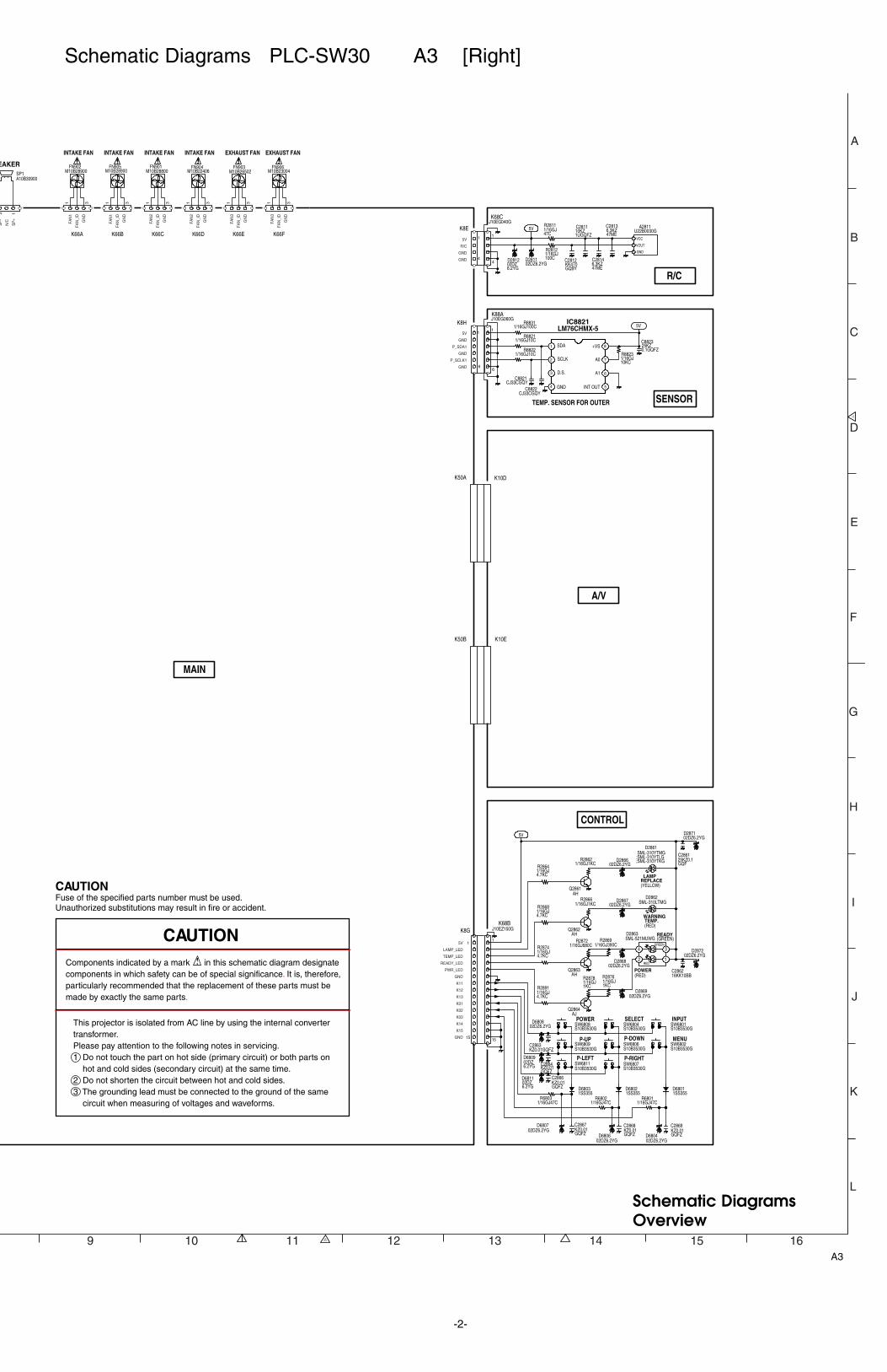
K8E
1
4
K66A
1 3
K66B
1 3
K66C
1 3
K66D
1 3
K66E1 3
K8H
1
6
13
A10B30900SP1
K66F
1 3
M10B23004FN906
M10B28900FN902
M10B28800FN901
M10B26502FN903
M10B28900FN905
M10B22406FN904
6.3KZ47ME
C2813
6.3KZ47ME
C2814
10KZ1UGQFZ
C2811
KK470GQBY
C2812
J10EG040GK68C
1
4
5V
02DZ6.2YG
D281202DZ6.2YGD2811
1/16GJ47C
R2811
1/16GJ100C
R2812
U22B0030GA2811
1 VCC
2 VOUT
3 GND
1 SDA
2 SCLK
3 D.S.
4 GND 5INT OUT
6A1
7A0
8+VS 25KZ0.1GQFZ
C8823
CJ33CGQYC8822
CJ33CGQYC8821
5VJ10EG060GK88A
1
6
1/16GJ10KC
R8823
1/16GJ10CR8821
1/16GJ10CR8822
1/16GJ100CR8831
K8G
1
15
READY(GREEN)
SML-310LTMGD2862
WARNING TEMP. (RED)
25KZ0.1GQF
C2861
16KK10BBC2862
AHQ2861
AHQ2862
AHQ2863
AJQ2864
S10B3530GSW6808POWER
S10B3530GSW6804SELECT
S10B3530GSW6801INPUT
S10B3530G
P-UPSW6809
S10B3530G
P-DOWNSW6806
S10B3530G
MENUSW6802
S10B3530G
P-LEFTSW6811
S10B3530G
P-RIGHTSW6807
1SS355D6802
1SS355D6803
5V
02DZ6.2YGD2867
02DZ6.2YGD2869
02DZ6.2YGD2868
02DZ6.2YGD2866
02DZ6.2YGD2871
02DZ6.2YGD2872
SML-310YTMG;SML-310YTLG;SML-310YTKG
D2861
LAMPREPLACE(YELLOW)
02DZ6.2YGD6807
02DZ6.2YGD6806
SML-521MUWGD2863
POWER(RED)
12RED
34GREEN
J10EZ150GK68B
1
15
02DZ6.2YG
D6809
02DZ6.2YG
D6811
02DZ6.2YGD6808
KZ0.01GQFZC2863
KZ0.01GQFZ
C2864
KZ0.01GQFZ
C2866
KZ0.01GQFZ
C2867KZ0.01GQFZ
C2868KZ0.01GQFZ
C2869
1SS355D6801
02DZ6.2YGD6804
1/16GJ47CR6802
1/16GJ1KCR2862
1/16GJ4.7KC
R2864
1/16GJ4.7KC
R28681/16GJ1KC
R2866
1/16GJ680CR2872
1/16GJ4.7KC
R2874
1/16GJ1KC
R2876
1/16GJ4.7KC
R28911/16GJ1KC
R2878
1/16GJ390CR2869
1/16GJ47CR6803
1/16GJ47CR6801
K50A K10D
K50B K10E
9 10 11 12 13 14 15 16
A
B
C
D
E
F
G
H
I
J
K
R/C
LM76CHMX-5IC8821
SENSOR
A/V
CONTROL
CAUTIONFuse of the specified parts number must be used.Unauthorized substitutions may result in fire or accident.
Components indicated by a mark in this schematic diagram designatecomponents in which safety can be of special significance. It is, therefore,particularly recommended that the replacement of these parts must be made by exactly the same parts.
This projector is isolated from AC line by using the internal convertertransformer.Please pay attention to the following notes in servicing.1 Do not touch the part on hot side (primary circuit) or both parts on hot and cold sides (secondary circuit) at the same time.2 Do not shorten the circuit between hot and cold sides.3 The grounding lead must be connected to the ground of the same circuit when measuring of voltages and waveforms.
CAUTION
MAIN
EAKER
INTAKE FAN INTAKE FANINTAKE FAN EXHAUST FANEXHAUST FANINTAKE FAN
TEMP. SENSOR FOR OUTER
SP
+
N/C
SP- GN
D
FAN
_ID
FAN
1
GN
D
FAN
_ID
FAN
1
GN
D
FAN
_ID
FAN
2
GN
D
FAN
_ID
FAN
2
GN
D
FAN
_ID
FAN
3
GN
D
FAN
_ID
FAN
3
5V
R/C
GND
GND
5V
GND
P_SDA1
GND
P_SCLK1
GND
5V
LAMP_LED
TEMP_LED
READY_LED
PWR_LED
GND
K11
K12
K13
K01
K02
K03
K14
K15
GND
L
A3
Schematic DiagramsOverview
-2-
Schematic Diagrams PLC-SW30 A3 [Right]

AHQ5002
-5V
1 02 23
3415
ENA6VEE7GND8
32109HHLL
10B
11HLHL
12
A
13
3
14
0
151
162
AHQ5001
AHQ5003
10KZ0.47GQFY
C500816KZ2.2FA
C500625K0.1G
C50
16KZ2.2FA
C5007
AUD_PC/AV_SW (F
16EM1C5317
16KK0.47BA
C5303
10KK2.2GMB
C5306
5V
16KK0.1GQ
C5318
CJ100CGQYC5311
AHQ5341
AHQ5344
AHQ5346
1
2
3
4
5
6
7
8
9 10
11
12
13
14
15
16
17
18
10KZ1UGQFZ
C5344
10KK1UGMB
C5304
C530216KK0.47BA
5V
-5V
12V
CGR/CR_AD
CGG/Y_AD
CGB/CB_AD
CGR/CR_M (TO IC101 3P)
CGG/Y_M (TO IC101 2P)
CGB/CB_M (TO IC101 1P)
CV_SCART (TO IC101 72P)
H_OUT (TO IC5301 2P)
V_OUT (TO IC5301 5P)
GSYNC (TO IC5301 3P)
VIDEO (TO IC101 75P)
H_OUT
V_OUT
GSYNC
RXD1
CPU_RESET
TXD1
AJQ5342
AJQ4001
KZ0.01GQFZ
C4002
16KZ2.2FA
C5014
16KZ2.2FA
C5016
S_SW (FROM IC1881 9P)
J11NT200GK50B
1 2
19 20
AJQ5343
10KZ1UGQFZ
C5011
5V
16KK10BBC5341
10KK2.2GMB
C5301
10KK1LZB
C5307
USB_VBUS
USB_D-
USB_D+
S_Y (TO IC101 73P)
S_CHROMA (TO IC101 71P)
(FROM
J11NT200GK50A
22
1/16GJ100CR5016
1/10GZ0.0R5027
1/16GJ100CR5019
1/16GJ10KC
1/16GJ1KC
R5346
1/16GJ47KC
R5023
1/16GJ1KCR5353
1/16GJ2.2KC
R50211/16GJ10KC
R5017
R5343
1/16GJ470KC
R5001
1/16GJ470KC
R5002
1/16GJ100C
R5348
1/16GZ0CR5309
1/16GJ470KC
R5003
1/16G2.2KC
R502
1/16GZ0CR5028
1/16GJ470KC
R5004
1/16GJ4.7KC
R4003
1/8GZ000R5307
1/16GJ4.7KC
R4002
1/16GJ4.7KC
R4004
1/16GJ2.2KC
R5342
1/16GZ0CR5363
1/16GJ100C
R5302
1/16GZ0CR5362
1/16GJ1KC
R5351
1/16GZ0CR5361
1/16GZ0CR5364
1/16GJ2.2KC
R5352
1/16GZ0CR5308
XR5349
1/16GZ0C
R5316
1/16GJ10CR9813
1/16GJ560KC
R5344
XR9811
1/16GJ10CR9814
1/16GZ0CR9812
1/16GJ3.9KC
R5311
1/16GJ100KC
R5013
1/16GJ100KC
R5015
1/16GZ0CR5369
XR5024
1/16GZ0CR5367
1/16GZ0CR5368
1/16GZ0C
R5018
1/16GZ0CR5347
1/16GJ10KC
R5026
1/16GZ0CR5366
1/16GJ1.5KC
R5022
1/16GJ1MCR5304
1/16GJ100CR5011
1/16GJ100CR5014
XC5340
CJ15CLC5345
16KZ1FAC5343
FILT_480P/575P
XR4007
1/16GJ100CR4006
16KZ2.2FAC5309
10KZ1UGQFZ
C5342
10KZ1UGQFZ
C5308
6.3EM100WM
C5300
L2PD4R7MGR5341
L2PD4R7MGR5310
USB
RESET_SW
SERVICE_PORT
RGB/YCbCr
S-VIDEO
VIDEO
PC AUDIO_IN
AV AUDIO_IN
PC_R/AUD
USB_D+
USB_VBUS
TXD1
USB_D-
AV_R/AUD
AV_L/AUD
CPU_RESET
PC_L/AUD
RXD1
5V
12V
AHQ5201
J11B0990NK10A
1
3
4
5
6
7
8
9
10
11
12
13
14
15
2
16
17
J11B0850NK10B
Z30B0120GSC1042
Z30B0120GSC1041
Z30B0120G
SC2001
Z30B0120G
SC2002
Z30B0120G
SC2003
AHQ2001
AHQ2002
AHQ2003
5V
-5V
Z30B0120GSC1001
1/8GZ000L1001
1/8GZ000L1004
Z30B0120GSC10031/8GZ000
L1006
1/8GZ000L2002
1/8GZ000L2004
1/8GZ000L2006
Z30B0120GSC1002
AJQ1001
AJQ1002
AJQ1003
AJQ1004
-5V
5V
Z30B0120G
SC5001
Z30B0120G
SC5002
Z30B0120G
SC5003
Z30B0120G
SC5004
XC5222
16KZ2.2FA
C5202
CJ100CGQY
C5002
XC2003
CJ100CGQY
C5001
XC2002
16KZ2.2FA
C5203
10KZ1UGQF
C5206
CJ100CGQY
C5004
25KZ0.1GQF
C1001
10KZ1UGQF
C5209
10KK0.47GQB
C5228
CJ100CGQY
C5003
XC522716KK
0.47BA
C5211
XC5224
XC5213
16KK0.1GQBY
C2001
XC2004
16KZ2.2FA
C5201
16KK0.1GQBY
C5229
25KZ0.1GQF
C1051
1
2 1
43
J11B2770NK20A
1
2
3
4
5
6
7
8
9
UDZS12BGD2001
UDZS12BGD1002
UDZS12BGD1001
16KZ1FAC5219
30GSYNC
31GND
32GOUT
33VCC2
34ROUT
35GND
10 VCC1
36VCC2
11 BIN1
12 GND
13 BIN2
14 VCC1
15 HIN1
16 HIN2
17 VIN1
18 VIN2 19GND
1 RIN1
2 GND
3 RIN2
20V-OUT
21GND
4 VCC
22H-OUT
5 GIN1
23GND
6 GND
24HDETECT
7 GIN2
25SYNCIN
8 VCC1
26SW
9 VCC1
27GND
28BOUT
29GND
-5V
5V
12V
J10NC200GK10E
1 2
19 20
25KZ0.1GQF
C2013
25KZ0.1GQF
C2014
25KZ0.1GQF
C2016
16EM47WM
C2009
6.3EM100WM
C2011
6.3EM100WM
C2012
XD9801
Z30B0120GSC9801
Z30B0120GSC9802
UDZ6.2BD1051
J30B1630NK100G
1
1/8G
Z000
L100
7
1/8G
Z000
L100
8
1/8G
Z000
L100
9
J11B4970NK20B
1 1
12
2
33
445
56
6
7
7
8 8
8
S10B5110NSW10A
6.3UM120CG
C5204 16EM47WM
C5218
AHQ5202
AHQ5203
AHQ5204
AJQ5205
5V
F34DE180PL1011
F34DE180PL1012
F34DE180PL1013
F34DE350PL1002
F34DE350PL1003
F34DD107PL2003
F34DD107PL2007
F34DD107PL2008
F34DD206PL1041
F34DD206PL1042
J10NC200GK10D
1
20
19
J12B08900K10C
F34DD206PL5003
F34DD206PL5001
F34DD206PL5002
F34DD206PL5004
F34DD206PL2001
J12A00400K30A
J12A00400K30B
5V
5V
16KZ2.2FA
C1008
AHQ1006
5V
25KZ0.1GQF
C1007
1/3GJ75R2004
1/3GJ75R2003
XR1009
1/16GJ470KC
R5003
1/16GJ220C
R1016
1/16GJ220C
R5221
1/16GJ150C
R2022
XR5211
1/16GJ100C
R5007
1/16GJ47KC
R1006
1/16GZ0C
R2011
1/16GZ0C
R5246
1/16GJ1KC
R5242X
R5247
1/16GJ1KCR5233
1/16GZ0C
R5248
1/16GJ1KCR5238
1/16GZ0CR1024
1/16GZ0CR1026
1/16GZ0CR1027
1/16GZ0CR1028
1/16GJ100C
R5249
1/16GJ100C
R1032
1/16GJ220KC
R1033
XR2033
XR2034
1/16GJ1KC
R1029
1/16GJ3.9KC
R1031
1/8GZ000R2036
1/3GJ000R5214
1/16GJ1KCR5228
1/16GJ1KC
R5226
1/16GJ1KCR5231
1/16GJ1KCR5236
1/16GJ1KC
R5237
1/16GJ1KC
R5232
1/16GJ1KC
R5227
1/16GZ0CR5239
1/16GZ0CR5234
1/16GZ0CR5229
1/16GJ2.2KC
R1018
XR9801
1/16GJ1KC
R1022
1/8GZ000R1023
1/16GJ150C
R2024
XR2008
1/16GJ2.2KC
R1021
1/16GZ0C
R2012
1/16GJ470KC
R5004
1/16GJ100C
R2001
1/16GJ470KC
R5002
1/16GJ1KC
R2031
1/16GJ100CR5223
XR5212
1/16GJ10C
R5202
XR2007
1/3GJ75R1001
1/16GJ100C
R1008
1/16GZ0C
R2013
1/16GJ1KC
R2028
XR2009
1/16GJ10C
R5203
1/16GJ1KC
R5218
XR1011
1/16GJ220C
R10141/16GJ2.2KC
R1019
XR2032
1/16GJ1KC
R1017
1/16GJ100C
R1051
1/3GJ75R2002
1/16GJ47KC
R1004
1/16GJ100C
R5219
XR5217
1/3GJ75R1003
1/16GJ100C
R5009
1/8GZ000R1012
1/16GJ10C
R5201
XR2029
XR2027
1/16GJ470KC
R5001
1/16GJ100C
R5208
1/16GJ100C
R1007
1/3GJ75R1002
XR2006
1/16GJ220C
R1013
1/16GJ100C
R5222
1/16GJ150C
R2023
1/16GJ100C
R5006
1/16GJ2.2KC
R5216
1/16GJ100C
R5209
1/8GZ000R2037
1/16GJ1KC
R2026
1/16GJ100C
R5008
16KZ2.2FA
C52081/16GJ1KC
R5213
16KZ2.2FA
C52141/16GJ1KC
R5224
16KZ2.2FA
C5217
CJ10CGQ
C5216
CJ10CGQ
C5207
CJ10CGQ
C5212
1/16GJ1KC
R5243
1/10GJ22R5244
CH0.01GQFC5226
UDZS6.2BG
D2002
AV_L/AUD
AV_R/AUD
PC_R/AUD
PC_L_AUD
VDRV_OUT
HDRV_OUT
VDRV
CLAMP
HDRVCVPOL
GND
VCCVSYNCIN
CPSEL
EXIVVSEPA
CVEXI
POLVG-SYNCIN(VIDEOIN)
EXIHC/HSYNCIN
POLH
CPWID
HSCTL
20
1
19
1 2 3 4 5 6 7 8 9
A
B
C
D
E
F
G
H
I
J
K
L
MP3A-02
AN5870SBIC5201
BA7078AF-E2IC5301
SYNC SEPARATOR
TC4052BFTIC5001
AUDIO_SW
RGB SW,SYNC SEPARATOR
AUDIO_L
AUDIO_R
MIX
R/Cr
G/Y
B/Cb
H
V
480p,575p
480p,575p
480p,575p
480i,575i
480i,575i
480i,575i
R_SCART/Cr
G_SCART/Y
B_SCART/Cb
CV_SCART
S_SW
S_C
S_Y
VIDEO
H
PC_L/AUD
PC_R/AUD
AV_L/AUD
AV_R/AUD
H
V
G_SYNC
COMPUTER IN /COMPONENT IN
(FROM IC3
(FROM IC3551 5P)
G_SYNC
A4
-3-
Schematic Diagrams PLC-SW30 A4 [Left]
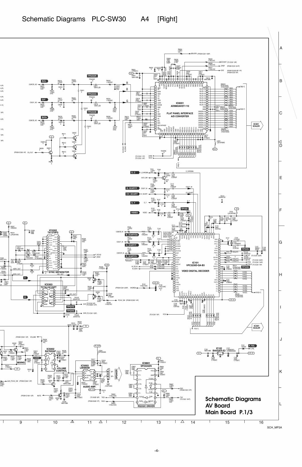
RXD(FROM IC301 47P)
10KZ10MC
C9802
10KZ10MC
C9803
5V
5V
TXD(TO IC301 181P)
10KZ10MC
C9804
10KZ10MC
C9801
10KZ1UGQFZ
C9806
16KZ2.2FA
C50095V
J10EP030GK8F
1SP+
3SP-
AHQ5002
-5V
AHQ5001
5V_AUD
MUTE(FROM IC1801 12P)
25KZ0.1GQFZ
C5012
AUD_PC/AV_SW (FROM IC3551 12P)
16KZ0.47GQF
C5013
5V
M_SDA1
CC3CGQC124
XC146
VUV[0-7]
CJ390CGQ
C142
C101
16KK
0.06
8GQ
C13
325KK0.047GQ
C136
VY[0-7]
XC143
1
B1/CBIN
2 G1/YIN
3 R1/CRIN
4 B2/CB2IN
5 G2/Y2IN
6 R2/CR2IN
7 ASGF
8 NC
9 VSUPCAP
10 VSUPD
11 GND0
12 GNDCAP
13 SCL
14 SDA
15 RESQ
16 TEST
17 VGAV
18 YCOEQ
19 FFIE
20 FFWE
21 FFRSTW
22 FFRE
23 FFOE
24
CLK20
25G
NDPA
26VS
UPPA
27LL
C2
28LL
C1
29VS
UPLL
C
30G
NDLL
C
31Y7
32Y6
33Y5
34Y4
35G
ND
36VD
UPY
37Y3
38Y2
39Y1
40Y0
41C7
42C6
43C5
44C4
45VSUPC
46GNDC
47C3
48C2
49C1
50C0
51GNDSY
52VSUPSY
53INTLC
54AVD
55FSY/HC
56MSY/MS
57VS
58FPDAT
59VSTBY
60CLKS
61NC
62XTAL1
63XTAL2
64ASGF
65G
NDF
66VR
T
67IS
CSEL
68IS
GND
69VS
UPF
70VO
UT
71CI
N
72VI
N1
73VI
N2
74VI
N3
75VI
N4
76VS
UPA1
77G
NDA1
78VR
EF
79FB
1IN
80AI
SGND
VCLK(TO IC301 73P)
XC144
6.3KZ47ME
C138
16KZ0.22GQF
C107
16KZ0.22GQF
C108
KK1500GQ
C122
16KK0.068GQ
C129VFIELD (TO IC301 74P)
CGR/CR_M
C151
C151,C152,C153
XTP103
25KZ0.1GQFZ
C127
16KK
0.06
8GQ
C13
2
25KZ0.1GQFZ
C137
J30A00102TPVVS
C152
KK1500GQ
C141
V10B3830GX101
C153
XC103
VIDEO
C147
C147,C148,C149
16KZ0.22GQF
C104
CJ390CGQ
C121
CV_SCART
16KZ0.22GQF
C113
1/8GZ000L103
25KK0.047GQ
C119
1/8GZ000L102
CGB/CB_M
M_SCLK1
VHS (TO IC301 202P)
1/8GZ000L101
16KK0.068GQ
C131
CJ390CGQC116
S_CHROMA
5V
VVS (TO IC301 203P)
KK1500GQC134
16KZ0.22GQF
C106
3.3V_M
25KK0.047GQ
C112
16KZ0.22GQF
C123
CC3CGQC126
VHDREN(FROM IC301 200P)
C148CGG/Y_M
J30A00102TPVHS
VPEN (TO IC301 134P)
S_Y
16KZ0.22GQF
C139
KK1500GQC114
XC102
C149
3.3V_M
EM2.2DC5319
KK0.01GQBY
C5321
16EM100DC5317
16KK0.1GQBY
C5328
P_SDA2
J30A00102TPGVS
PC/AV_SW (FROM IC3551 14P)
P_SCLK2
3.3V
9V5V
J30A00102TPGHS
16KK0.1GQBY
C5318
QY
GHS (TO IC301 152P)
V11B1640GX5301
GVS (TO IC301 9P)(TO IC8201 31P)
AHQ5301
25KZ0.1GQFZ
C8217
M_S
DA2
25KZ0.1GQFZ
C8202
R1A41004G;R1EA1004G
RB8203
25KZ0.1GQFZ
C8223
GCLK(TO IC301 10P)
25KZ0.1GQFZ
C8213
R1A
4100
4GR
B820
7
;R1E
A100
4G
25KZ0.1GQFZ
C8216
25KZ0.1GQFZ
C8221
GR
[0-7
]
16KK0.082GQBY
C8206
C6223
GREF (FROM IC301 241P)
C6222
25KZ
0.1G
QFZ
C82
03
R1A41004G;R1EA1004G
RB8204
XTP6202R
25KZ
0.1G
QFZ
C82
04
M_S
CLK
2
25KZ0.1GQFZ
C8224
KK8200GQBY
C8207
25KZ0.1GQFZ
C8222
25KZ0.1GQFZ
C8214
GB[0-7]
25KZ0.1GQFZ
C8218
25KZ0.1GQFZ
C8211
10KK1LZBC6217
R1A
4100
4GR
B820
6
;R1E
A100
4G
10KK1LZBC6218
GVS (FROM IC5303 8P,11P)
XTP6202B
XTP6202G
R1A41004G;R1EA1004G
RB8202
25KZ0.1GQFZ
C8209
XC6207
XC6206
GFBK(TO IC301 11P)
GBLKSPL (FROM IC301 156P)
10KK1LZBC6219
1GND2GREEN<7>3GREEN<6>4GREEN<5>5GREEN<4>6GREEN<3>7GREEN<2>8GREEN<1>9GREEN<0>
10GND11VDD12BLUE<7>13BLUE<6>14BLUE<5>15BLUE<4>16BLUE<3>17BLUE<2>18BLUE<1>19BLUE<0>20GND
21
GN
D
22
VDD
23
VDD
24
GN
D
25
GN
D
26
PVD
27
PVD
28
GN
D
29
CO
AST
30
HSY
NC
31
VSYN
C
32
GN
D
33
FILT
34
PVD
35
PVD
36
GN
D
37
MID
SCV
38
CLA
MP
39
VD
40
GN
D
41GND
42 VD43 BAIN44 GND45 VD46 VD47 GND48 GAIN49 SOGIN50 GND51 VD52 VD53 GND54 RAIN55 A056 SCL57 SDA58 REF BYPASS59 VD60 GND
61
GN
D
62
VD
63
GN
D
64
VSO
UT
65
SOG
OU
T
66
HSO
UT
67
DAT
ACK
68
GN
D
69
VDD
70
RED
<7>
71
RED
<6>
72
RED
<5>
73
RED
<4>
74
RED
<3>
75
RED
<2>
76
RED
<1>
77
RED
<0>
78
VDD
79
VDD
80
GN
D
3.3V
3.3V XC
8208
25KZ0.1GQFZ
C8219
C6221
XC6204
GG[0-7]
L2A73R3MGL8201
GCOAST (TO IC301 18P)
R1A41004G;R1EA1004G
RB8201
CGB/CB_AD
CGG/Y_AD
CGR/CR_AD
01 3P)
01 2P)
01 1P)
72P)
01 2P)
01 5P)
01 3P)
75P)
TXD1
RXD1
25KZ0.1GQFZ
C158
P_FAIL
5V 3.3V_M
6.3EM220F1C157
;6.3EM220WM
1SS355D101
25KZ0.1GQFZ
C156
J30A00102TE101
81 9P)
25KZ0.1GQFZ
C5329
25KZ0.1GQFZC5010
16KK10BB
C118
16KK10BB
C5326
16KK10BBC154
16KK10BBC821216KK10BB
C8201
16KK10BBC111
30DAC3
10NC
11VCC
12DAC2
13VD3-IN
14HD3-IN
15CP-OUT
16HD1-OUT
17NC
18D-GND
19HD2-OUT
1 HD2-IN
2VD2-IN
3HD1-IN
20NC
21SDA
4VD1-IN
22SCL
5A-GND
23ADDRESS-SW
6NC
24SYNC2-IN7AFC-FIL
25DAC1
8NC
26SYNC1-IN
9HVCO
27NC
28VD1-OUT
29VD2-OUT
3.3V_M
R1E
B470
4GR
B104
;R1J
A470
4G
R1EB4704GRB101
;R1JA4704G
R1E
B470
4GR
B103
;R1J
A470
4G
R1EB4704GRB102
;R1JA4704G
12
3
C109
16KZ0.22GQF
C117
CGG/Y_M
73P)
71P)
1234567 GND 8
91011121314VCC
5V
1
2
3
4 5
6
7
8
6.3EM100WM
C5015
25KZ0.1GQFZ
C5020
25KZ0.1GQFZ
C5024 25TM1FD
C5026
VOLUME(FROM IC3551 13P)
6.3EM220WM
C5017
;6.3EM220F1
25KZ0.1GQFZ
C5018
AHQ5006
25KZ0.1GQFZ
C5022
KZ0.01GQFZ
C5023
XC5019GND_AUD
XC5330
1 VDD
2 IN
3 HP SENSE
4 MUTE 5OUT +
6GND
7SVR8OUT -
1/16GZ0CR5047
1/10GZ0.0R5027
1/16GJ360CR5318
1/16GJ1KC
R5034
1/16GJ1.8KC
R5032
1/16GJ100C
R5334
XR8203
1/16GJ47KC
R5023
1/16GZ0C
R112
1/16GJ10KC
R5044
1/16GJ2.2KC
R5021
1/16GZ0C
R6223
1/16GJ10KC
R8212
XR5323
1/16GJ100C
R5046
1/10GJ10
R5036
1/16GJ100CR143
1/16GJ1KC
R5043
1/16GZ0C
R111
1/16GJ6.8KC
R5338
1/16GJ10C
R8204
1/16GJ1KCR5339
1/10GZ0.0R5336
1/16GZ0CR5309
XR127
1/16GJ2.2KC
R5029
1/16GZ0CR5028
XR133
1/16GJ5.6KCR5317
1/16
GZ0
CR
138
1/16GJ10KC
R5327
1/16GJ10C
R103
1/8GZ000R5307
1/16GJ100C
R6203
1/16GJ100C
R5331
1/16GZ0C
R6226
1/16GJ270C
R6204
1/16GJ47CR136
XR
139
1/16
GZ
0CR12
3
1/16GJ100C
R5332
1/16GJ100C
R6202
1/16GJ10C
R114
1/16GJ10C
R113
XR117
1/16GJ100C
R6201
1/10
GZ0
.0R
121
1/16GJ10C
R102
1/16GJ100C
R5328
1/16GJ10C
R101
1/16GJ3.3KC
R5333
1/16GJ100C
R8214
1/16GJ100CR141
1/16GZ0CR5308
1/16GJ47CR134
1/16GJ47CR131
XR107
1/16GZ0C
R5316
1/16GZ0C
R6224
1/10GZ0.0R8201
XR118
1/16GZ0C
R6218
1/16GZ0C
R9806
1/16GJ100CR9802
1/16GJ100CR142
1/16GJ3.9KC
R5311
1/16GJ10CR8209
1/16GZ0CR6253
1/16GJ100C
R9807
XR119
1/10GZ0.0R9804
1/16GJ10CR8208
1/16GJ100C
R8213
1/16GZ0C
R6216
1/16GJ100CR9803
1/16GJ10CR8207
1/16GJ10KC
R9808
XR124
1/16GJ10C
R116
1/16GJ100C
R9809
1/16GJ470C
R105
1/16GZ0CR6254
1/16GJ1.5KC
R5031
XR106
XR8202
1/16GZ0C
R109
1/16GZ0C
R6217
1/16GJ1.5KC
R5035
XR5033
1/16GJ2.7KC
R8206
1/16GJ270C
R6207
1/16GJ1.5KC
R5041
1/16GJ470C
R104
1/16GJ270C
R6206
1/16GZ0CR6256
1/16GZ0C
R5038
1/16GJ470C
R5337
1/16GJ10KCR146
1/16GJ1.5KC
R5022
XR108
XR5324
XR147
XTEGFBK
XC115
XC110
1 C1+
2 V+
3 C1-
4 C2+
5 C2-
6 V-
7 T2/OUT
8 R2/IN 9R2/OUT
10T2/IN
11T1/IN
12R1/OUT
13R1/IN
14T1/OUT
15GND
16VCC
16KK10BBC5046
AJQ5302
1/16GJ470C
R5330
1/16GJ6.8KC
R5335
25KZ0.1GQFZ
C5035
AJQ5004
1/16GJ1KC
R5039 1/16GJ5.1KC
R5042
XR6211
XR6212
XR6213
XQ6202
XQ6203
XQ6204
XQ6201
XR6209
CG_FILT
XR6208
XC6201
XC6202
XC6203
16KZ2.2FA
C532710KZ10MC
C128
L2PJ330MGL5003
XC6209
5V
16KZ2.2FAC5309
16KK0.33BAC5021
XR5313
6.3EM100WM
C5300L2PD4R7MGR5310
L2PD4R7MGR126
AHQ101
S/CV_SW
1/16GJ1KC
R100
VUV[3]
VIDEO
VUV[6]
VY[3
]
VUV[5]
VY[0
]VY
[1]
VUV[0]
VY[5
]
VY[2
]
VY[4
]
VUV[7]
VUV[2]
S_CHROMA
S_Y
VUV[1]
VUV[4]
VY[7
]VY
[6]
VD1_OUT
HD1_OUT
GB[7]
GR
[2]
GR
[4]
GR
[5]
GR
[3]
GB[5]
GG[3]
GR
[6]
GG[7]
GR
[7]
GB[4]
GG[0]
GB[2]
GB[6]
GG[1]
GG[5]GG[4]
GB[3]
GB[1]
GG[6]
GG[2]
GR
[0]
GB[0]
GR
[1]
CV_SCART
CGG/Y_M
VDRV_OUT
HDRV_OUT
25KZ0.1GQFZ
G
B
R
16KZ0.22GQF
CD10CGQ
CD10CGQ
CD10CGQ
1/16GZ0C
CJ390CGQ
9 10 11 12 13 14 15 16
A
B
C
D
E
F
G
H
I
J
K
IC8201AD9883AKST-110
FLAT PANEL INTERFACEA/D CONVERTER
IC101VPC3230D-QA-B3
VIDEO DIGITAL DECODER
IC5303TC74LVX125FT
TA1370FGIC5302
SYNC SEPARATOR
BA7655AFIC5002
LM4865MIC5003
VOLUMECONTROL
AUDIO AMP.
SP232AENIC9801
RS232C DRIVER
BA033FP-E2IC102
MIXING
AUDIO
SPEA
KER
TP6202R
TP6202G
TP6202B
IC301SCALER
IC301SCALER
TP103
R/Cr
G/Y
B/Cb
B_SCART/Cb
G_SCART/Y
R_SCART/Cr
CV_SCART
S_C
S_Y
VIDEO
G_SCART/Y
H
V
TPGVS
TPGHS
TPVVS
TPVHS
(FROM IC3551 4P)
(FROM IC301 9P)
(TO K50B 18P)
(FROM K50B 17P)
P_FAIL
L
SCH_MP3A
Schematic DiagramsAV BoardMain Board P.1/3
-4-
Schematic Diagrams PLC-SW30 A4 [Right]
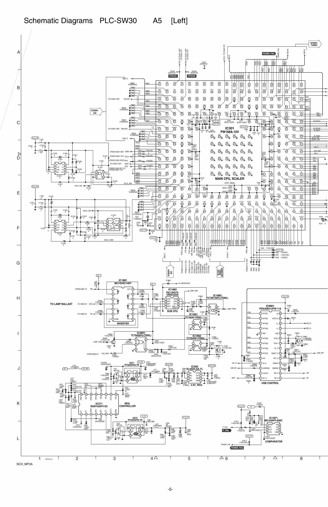
DCLK_SW
DVS
DC
LK_S
W
5V_S
W(T
O Q
3581
B)
DH
S
CS1_B
INTR
USB_D-
USB_D+
GREF(TO IC8201 30P)
GBLKSPL
GCOAST
GVS
GHS(FROM IC5303 3P,6P)
GCLK(FROM IC8201 67P)
GFBK(FROM IC8201 66P)
POW
ER_F
AIL
VFIE
LD(F
RO
M IC
101
53P)
VCLK
(FR
OM
IC10
1 27
P)
DC
LK
VVS
(FR
OM
IC10
1 57
P)
VHS
(FR
OM
IC10
1 55
P)
VPEN
VY[0
-7]
VUV[
0-7]
GR
[0-7
]
GG[0-7]
GB[0-7]
DG
[0-9
]
DR
[0-9
]
DB[
0-9]
XC318
KK2200GQBY
C376
XC9964
CJ330CGQYC379
XIC1301
1 X1
2 VDD
3 GND
4 REF 5CLK
6S0
7S1
8X2
XX1301
1 IN2 NC3 IN4 SW 5GND
6GND7OUT8OUT
KK4700GQBYC381
XC311
10KK0.22GQ
C374
25KZ0.1GQFZ
C391
XC313
XC309
10KZ1UGQFZ
C371
25KZ0.1GQFZ
C373
10KZ1UGQFZ
C372
XIC1321
1
2
3 4
5X
C1306
XC9861
XC1322
25KZ0.1GQFZ
C377
XC1303
XC1304
XC1321
XC9863
XC317
XC9862
25KZ0.1GQFZ
C388
10KZ
1UG
QFZ
C18
72
10KZ1UGQFZC1871
XD18
71
1 VREF2 VIN3 OUT4 VCC 5GND
6NC7NC8NC
5V
10KZ1UGQFZC1873
P_FAIL
S3.3V_PW
S1.5V_PW
S3.3V_PW
S2.5V_PW
S1.5V_PW
S3.3V_PW
S3.3V_PW
S1.5V_PW
S2.5V_PW
XL1301
XL1302
XC1301
XC1302
S3.3V_PW
4VM470D
C386
4VM470D
C394
XC308
XC304
25KZ0.1GQFZ
C333
25KZ0.1GQFZ
C332
25KZ0.1GQFZ
C314
25KZ0.1GQFZ
C316
25KZ0.1GQFZC319
25KZ0.1GQFZC321
25KZ0.1GQFZ
C326
25KZ0.1GQFZ
C324
XC312
XC322
XC323
XC328
XC327
25KZ0.1GQFZC329
25KZ0.1GQFZC331
XC303
XC302
XC307 X
C306
XC338
XC337
25KZ0.1GQFZ
C387
25KZ0.1GQFZ
C396
VCC
GND
1
2
3
4
5
6
7 8
9
10
11
12
13
14
5V
SCEL
RXL
TXL
3
LAM
P_PO
WU
SB_V
BUS
(FR
OM
K50
B)
J30A00102TE301
J30A00102TPDHS
J30A00102TPDVS
AHQ4807
LAMP_POW
25KK0.047GQC4802
1
2
3 4
5
FAN_ERR
25KZ0.1GQFZC4801
I
N
POWER_FAIL
V10B3600GX301
CJ18CGQ
C341CJ18CGQ
C339
S3.3V_PW
LAMP_ERR
LAMP_PWM
MCLK_SWX
C1334
XC1338
XL1331
XC
1341
XC1337
XC1331
XL1332
XIC1341
1234
GND5678VCC
XC1333
XC1336
XC1332
S3.3V_PW
XIC1331
1 X1
2 VDD
3 GND
4 REF 5CLK
6S0
7S1
8X2
R1EB0R04GRB306
R1EB0R04GRB301
R1EB0R04GRB303
R1EB0R04GRB302
1CT
2RT
3N
ON
1
4IN
V1
5FB
1
6D
T1
7O
UT1
8G
ND
9VC
C
10O
UT2
11D
T2
12FB
2
13IN
V2
14N
ON
2
15SC
P
16VR
EF
XX1331
WR
RD
USB
_EN
(TO
IC98
61 1
2P)
USB
_RST
(TO
IC98
61 2
0P)
ON
_15V
USB_RST
USB_EN
VHD
REN
(TO
IC10
1 15
P)
1
2
3 4
5
6
1
2
3 4
5
6
S2.5V_PW
L2GE330MGL372
L2PJ330MGL371
RB161L-40G
D371
RB161L-40G
D372
R1EB0R04GRB304
R1EB0R04GRB307
IMZ1AGT371
IMZ1AGT372
KK8200GQ
C393
KK8200GQ
C384
6.3EM100WMC390
;6.3EM100F1
1 VDD2 GP53 GP44 GP3 5GP2/
TOCK1
6GP17GP08GND
XR1339
XR1333
XR1336
XR1344
XR1337
XR1346
XR1334
XR1341
XR1338
1/16GJ10KCR1877
1/16GJ220CR1882
1/16GJ4.7KC
R9874
XR1304
1/16GJ220CR1881
1/16GJ51CR389
XR301
1/16GZ0CR303
XR
328
1/16GJ330CR388
1/16GZ0CR329
XR319
XR1886
XR9869
XR1302
1/16GZ0CR1884
XR1324
1/16GZ0CR1883
1/16GJ10CR9871
XR1321
XR
323
XR1323
XR9876
1/16GJ10KCR324
XR
321
1/16GZ0CR322
XR1322
1/16GJ10KCR327
1/16GZ0CR304
XR
326
1/16GJ10C
R9877
1/16GZ0C
R391
1/16R318
1/16GJ10CR308
XR1306
XR9878
1/16GJ51C
R382
1/16GJ10KC
R9872
XR302
XR9873
1/16GJ9.1KC
R376
1/16GJ330C
R383
XR307
1/16GJ3.6KC
R386
1/16GJ3.3KC
R384
1/16GJ10CR306
1/16GJ18KC
R387
1/16GJ9.1KCR378
1/16GJ9.1KCR377
1/16GJ20KC
R381
1/16GJ62KC
R372
1/16GJ39KC
R371 1/16GJ18KC
R394
1/16GZ0CR4806
XR1307
1/16GJ9.1KC
R379
XR9862
1/16GJ30KC
R3931/16GZ0C
R396
1/16GJ3.3KC
R392
1/16GJ100CR4803
1/16GZ0CR9863
XR9866
1/16GZ0CR1876
1/16GZ0CR4804
1/16
GJ2
0KC
R18
74
XR1303
XR9868
1/16GJ39KC
R373
1/16GJ4.7KCR4802
XR9867
1/16
GJ1
2KC
R18
73
1/16GJ10KCR4808
XR1301
1/16GJ10CR1872
1/16GJ10CR9888
1/16GJ10KCR1871
1/16GJ10KCR4801
1/16GJ1KCR9864
1/16
GJ1
0CR
331
1/16GJ62KC
R374
1/16GJ100CR4807
1/16
GJ1
0CR
332
XR1331
1/16
GJ1
0CR
333
XR
1343
XR1342
XR9879
1/16
GJ1
0CR
334
XR1332
1/16GJ10CR986125KZ
0.1GQFZ
C1881
1/16GZ0C
R1888
XR1889
5V_MICROCHIP
<TOP_VIEW>
1
GND
2
VDD2.5
3
XI
4
GRO7
5
GRO3
6
GRO0
7GGE6
8GGE3
9GVS
10GCLK
11GFBK
12GGO7
13GGO4
14GGO2
15GBE7
16GBE6
17
GBE5
18
GCOAST
19
GBE3
20
GBE1
21
DNC
22
DVS
23
DBO4
24
DBO0
25
DGO5
26
DGO2
27
DRO6
28
DRO3
29
DRO1
30
DBE7
31
DBE2
32
DBE1
33
DGE7
34
DGE3
35
DGE1
36
DRE7
37
DRE6
38
DRE5
39
DRE1
40
PORTB5
41PORTB3
42PORTC7
43
PORTC3
44PORTA5
45PORTA3
46PORTA2
47RXD
48
RESET
49D1
50D2
51
D5
52GND
53D12
54
RAMWE
55
CS1
56
WR
57
CPUTCK
58
A4
59
A9
60
A11
61
A15
62
A16
63
A18
64
CPUTMS
65
VB6
66
VB5
67
VB1
68
VG7
69
VG4
70
VG1
71
VR7
72
VR1
73
VCLK
74
FIELD
75
GRE5
76
GRE2
77
GND
78GND
79
VDD1.5P
80
GRO5
81GRO2
82GGE7
83GGE4
84GPEN
85GSOG
86GGE2
87GGE1
88GGO6
89GGO3
90GGO1
91GBE4
92
GBE2
93
GBE0
94
GBO3
95
DNC
96
DBO5
97
DBO1
98
DGO6
99
DGO3
100
DRO7
101
DRO5
102
DRO0
103
DBE6
104
DBE4
105
DEN
106
DGE6
107
DGE2
108
DGE0
109
DRE3
110
DRE0
111
PORTB6
112PORTB1
113PORTC6
114
PORTC2
115PORTA6
116PORTA4
117PORTA1
118BHEN
119
IRRCVR1
120
NMI
121D3
122D6
123D8
124
D11
125RAMOE
126
ROMWE
127
RD
128
A5
129
A7
130
A8
131
A14
132
A17
133
MODE3
134
VPEN
135
VB7
136
VB0
137
VG6
138
VG3
139
VR6
140
VR4
141
VR2
142
VR0
143
GRE7
144
GRE4
145
GRE1
146
VDD1.5P
147
XO
148GRO6
149GRO1
150GGE5
151GHSFOUT
152GHS
153GGE0
154GGO5
155GGO0
156GBLKSPL
157GBO6
158GBO5
159
GBO2
160
GBO0
161
DHS
162DBO2
163DGO7
164DGO4
165DGO0
166DRO4
167DRO2
168GND
169DGE4
170GND
171DGE5
172DRE4
173PORTB7
174PORTB4
175PORTB2
176
PORTC4
177
PORTC1
178PORTA7
179DNC
180PORTA0
181TXD
182
IRRCVR0
183
D0
184D4
185D7
186D10
187
D13
188
ROMOE
189
CS0
190
A2
191
A3
192
A6
193
A13
194
A19
195
CPUTDO
196
VB4
197
VB2
198
VG5
199
VG2
200
VR5
201
VR3
202
VHS
203
VVS
204
GRE6
205
GND
206
GND
207
DCKEXT
208GRO4
209GND
210GND
211GREF
212GND
213GND
214GND
215GBO7
216GND
217DBO6
218
DBO7
219GBO1
220DBO3
221GND
222DGO1
223DCLK
224DBE5
225DBE3
226DBE0
227GND
228GND
229PORTB0
230PORTC0
231PORTC5
232
MODE0
233ADR24B
234GND
235
VDD2.5
236GND
237VDD2.5
238
EXTINT
239
VDD2.5
240D9
241D14
242
D15
243
VDD2.5
244A0
245
A1
246
A10
247
A12
248
MODE1
249
CPUTDI
250
VB3
251
GND
252
VG0
253
GND
254
GND
255
GRE3
256
GRE0
257
MCKEXT
258
259VDD1.5
260VDD3.3
261VDD1.5
262VDD1.5
263VDD1.5
264VDD1.5
265VDD1.5
266VDD1.5
267VDD1.5
268GBO4
269VDD1.5
270VDD3.3
271VDD1.5
272VDD3.3
273VDD1.5
274VDD3.3
275VDD3.3
276VDD1.5
277VDD1.5
278
DRE2
279
VDD2.5
280VDD1.5
281VDD1.5
282
VDD1.5
283VDD1.5
284VDD1.5
285
VDD1.5
286
VDD1.5
287
VDD3.3
288VDD1.5
289
VDD1.5
290
MODE2
291
GND
292VDD1.5
293VDD1.5
294VDD3.3
295VDD1.5
296VDD1.5
297VDD1.5
298VDD1.5
299
VDD3.3
300
VDD3.3
301
VDD3.3
302
303VDD3.3
304VDD3.3
305VDD3.3
306VDD1.5
307VDD1.5
308VDD1.5
309VDD1.5
310VDD1.5
311
VDD3.3
312
VDD3.3
313
VDD3.3
314VDD1.5
315VDD1.5
316VDD3.3
317GND
318GND
319GND
320GND
321GND
322GND
323GND
324GND
325GND
326GND
327GND
328GND
329GND
330GND
331GND
332GND
333GND
334GND
335GND
336GND
337GND
338GND
339GND
340GND
341GND
342GND
343GND
344GND
345GND
346GND
347GND
348GND
349GND
350GND
351GND
352GND
1/16
GJ1
KCR
1885
5V
V11B0930GX9861
;V11B1250G
1
2
3 4
5
1
2
3 4
5
V11B1470GX1891
1/16GJ10C
R1893
1/16GJ1MC
R1892
XC1894
XC1896
XR1891
25KZ0.1GQFZ
C1893
1/16GJ10KC
R1887
25KZ0.1GQFZ
C1891
1/16GZ0CC1892
1 DATA[1]
2 DATA[1]
3 DATA[2]
4 DATA[3]
5 GND
6 DATA[4]
7 DATA[5]
8 DATA[6]
9 DATA[7]
10 ALE
11 CS_N
12 SUSPEND
13 CLKOUT
14 INT_N 15RD_N
16WR_N
17DIMREQ
18DMACK
19EOT_N
20RESET_N
21GL_N
22XTAL1
23XTAL2
24VDD
25D-
26D+
27VOUT3.3
28A0
1/16GZ0CR1880
5V_PW
5V_PW
5V_PW5V
4EM470DC301
6.3EM220WMC378
;6.3EM220F1
S3.3V_PW
L2PJ330MGL370
XC375
XC380
1
2
34
5
XR1895
1/16GZ0C
R1890
XC1890
16KK10BBC382
10KK0.47GQ
C1887
DG
[7]
GG[2]
DG
[9]
DR
[8]
DG
[5]
GG[4]
DB[
4]
GB[5]
DB[
9]
DG
[3]
DG
[8]
GG[5]
GG[7]
DR
[7]
D[1]
D[2]
D[3]
D[5]
D[7]
D[6]
D[4]
GG[6]
GR
[4]
GG[1]
GG[0]
GB[3]GB[0]
GB[1]
DB[
7]
DB[
8]
DB[
6]
DB[
5]D
B[2]
DG
[6]
DR
[9]
DR
[4]
DR
[3]
DR
[2]
DR
[6]
DG
[4]
DG
[2]
D[1]
D[3]D[2]
D[4]
D[6]D[5]
D[9]
D[8]D[10]D[14]
D[11]D[12]
D[15]
A[4]
A[9]
A[11
]
A[15
]
A[16
]
A[18
]
A[5]
A[14
]A[
6]A[
1]
A[17
]A[
10]
A[13
]
A[12
]A[
19]
D[0]
VY[3
]
VY[5
]
VY[6
]
VY[4
]
VY[7
]
VUV[
1]VU
V[0]
VUV[
5]
GR
[2]
VUV[
3]
VUV[
4]VU
V[2]
VUV[
7]
GB[2]
GB[6]
GB[7]
GG[3]
A[7]
A[2]
A[3]
A[0]
A[8]
VUV[
6]
GR
[7]
GR
[5]
DG
[0]
DR
[0]
DR
[1]
GR
[1]
GR
[0]
GR
[6]
GR
[3]
D[13]
DB[1]DB[0]
DB[
3]
VY[1
]
DR
[5]
DG
[1]
C/R_0
VY[0
]VY
[2]
D[7]
DCLK_40M
C/R_1
SDATA_PW
M_SCLK2
SCLK_PW
M_SCLK1
CPU_RST
A[23]
A[21]
A[20]
A[22]
MCLK_160M
M_SDA1
M_SDA2
D[0]
GB[4]
LAMP_PW
(TO IC8201 29P)
(TO IC8201 38P)
(FROM IC5303 8P,11P)(FROM IC8201 31P)
(FR
OM
IC10
1 54
P)
(TO
IC40
1 14
3P)
(TO
IC40
1 14
2P)
(TO
IC94
01 4
P)
(TO
IC94
01 5
P)
(TO
IC94
01 9
P)
(FROM K48K 1P)
(TO K48K 4P)
(TO K48K 5P)
(FROM D5622 K)
VDD3.3
6.3EM1000CDC370TM
1 2 3 4 5 6 7 8
A
B
C
D
E
F
G
H
I
J
K
L
MP3A-03
PW168A-10VIC301
MC74VHC14DTIC1881
INVERTER
PIC12F675-I/SNC322A
IC1882
SUB CPU
TC7SU04F-(TE85L)IC1892
TC7S04F-(TE85L)IC1891
TC7SET32FU-(TE85L)IC1883
SI-3025LSA-TLIC392
2.5V_REG.
Q371RTQ025P02-TR
TC7SH00FU-(TE85L)IC4801
Q372RTQ025P02-TR
BA9743AFV-E2IC371
PDIUSBD12PW-118IC9861
USB CONTROL
M51204FP-600CIC1871
COMPARATOR
REG.CONTROLLER
IC9401TURBO
TPDVS TPDHS
POWER_FAIL
POWER_FAIL
P_FAIL
IC10
1VI
DEO
DECO
DER
IC82
01A/
D
IC8201A/D
(TO
Q25
01 B
)
(TO
R13
22)
(TO
R48
02)
MAIN CPU, SCALER
TO LAMP BALLAST
SCH_MP3A
-5-
Schematic Diagrams PLC-SW30 A5 [Left]
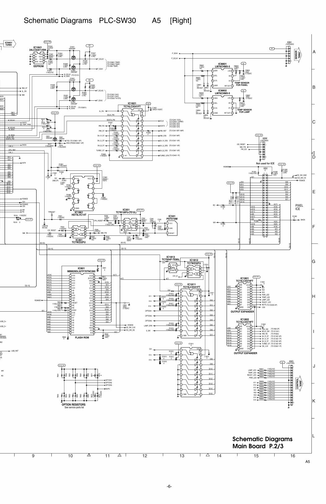
TXD (TO IC9801 10P)
CPU_RESET
3L_EN
IRM_RS
IRM_ST
3.3V
SCLK
SDATA
IRM_RST
IRM_STB
USB_D-
USB_D+
K01K02K03PWR_LEDTEMP_LEDLAMP_LEDREADY_LED
CS1
K11
K12
K13
OPTION1
OPTION2
OPTION3
LAMP_ERR
S_SW
CS1
LAMP_PWM
BHEN
INTR
ROMWECS0
CS1
RDWR
ROMOE
CS0
RXD (FROM IC9801 12P)
[]
5V
XC1801
1234 GND 5
678VCC
XC1862
XC1811
1
2
3 GND 4
5VCC
XC1802
1
2
3
4
5
6
7
8
9
10 GND 11
12
13
14
15
16
17
18
19
20VCC
1 A0
2 A1
3 A2
4 VSS 5SDA6SCL7TEST8VDD
1234
GND5678VCC
1
2
3
25KZ0.1GQFZC1821
XC1812
10KZ1UGQFZ
C343
25KZ0.1GQFZ
C354
VCC
GND
1
2
3
4
5
6
7 8
9
10
11
12
13
14
2SK536PQ1841
2SK536PQ1842
1 OE2 D03 D14 D25 D36 D47 D58 D69 D7
10 GND 11CK
12Q7
13Q6
14Q5
15Q4
16Q3
17Q2
18Q1
19Q0
20VCC
KZ0.01GQFZ
C352
25KZ0.1GQFZ
C1863
KZ0.01GQFZ
C353
862
25KZ0.1GQFZ
C1841
XC1861
CS1_B
S3.3V_PW
S3.3V_PW
S3.3V_PW
S3.3V_PW
S3.3V_PW
XD1811
XD1812
XD1813
S3.3V_PW
1
2
3
4
5
6
7
8
9
10 GND 11
12
13
14
15
16
17
18
19
20VCC
1SS355D3012SK536P
Q301
S3.3V_PW
OPTION1OPTION2OPTION3
XC346
XTPRESET
5V
K11
K13K12
K01
TEMP_LED
PWR_LED
K03K02
LAMP_LED
READY_LED
S3.3V_PW
2SK536PQ1844
2SK536PQ1843
3L_EN
SH_B_ST (TO IC1821 8P)
MCLK_SWIRM_RS
FAN_SW (TO K8A 2P)(TO IC1341)
MUTE
M_SDA1M_SCLK1
M_SDA2M_SCLK2
5V
41D13
42D6
43D14
44D7
45D15
46VSS
47BYTE
48A161 A152 A143 A134 A125 A116 A107 A98 A89 A19
10 A2011 WE12 RESET13 NC14 NC15 RYBY16 A1817 A1718 A719 A620 A521 A422 A323 A224 A1 25A0
26CE
27VSS
28OE
29D0
30D8
31D1
32D9
33D2
34D10
35D3
36D11
37VCC
38D4
39D12
40D5
ROMWE
25KZ0.1GQFZ
C802
ROMOE
XC801
S3.3V_PW
P_SDA1
P_SCLK1
P_SDA2
P_SCLK2IRM_ST
NMI
R/C
P_SCLK1
25KZ0.1GQFZ
C8807
5V
5V
25KZ0.1GQFZ
C8803
1 SDA
2 SCL
3 O.S.
4 GND 5INT OUT
6A1
7A0
8+VS
CJ33CGQY
C8801
CJ33CGQY
C8806
P_SDA1
CJ33CGQY
C8802
CJ33CGQY
C8804
J10EG060GK8H
1
6
5V
1 SDA
2 SCL
3 O.S.
4 GND 5INT OUT
6A1
7A0
8+VS
ROMWE
S3.3V_PW
ROMOE
J10EG060GK8W
1
6
S3.3V_PW
ICE_RESET
NMI_PW
1234 GND 5
678VCC
ICE_RESETNMI_PW
S3.3V_PW
BHEN
S3.3V_PW
RD
WR
SH_G_ST (TO IC1821 7P)SH_R_ST (TO IC1821 6P)
PW_ICE
SH_R_STB (TO IC501 10P)
SH_G_STB (TO IC531 10P)
SH_B_STB (TO IC561 10P)
SH_R_ST
SH_G_ST
SH_B_ST
TURBO_ST
TURBO_STB (TO IC9401 1P)
TURBO_ST (TO IC1821 9P)ON_3.3V (TO IC5631 1P)
WR
RD
1 OE2 D03 D14 D25 D36 D47 D58 D69 D7
10 GND 11CK
12Q7
13Q6
14Q5
15Q4
16Q3
17Q2
18Q1
19Q0
20VCC
USB_RST
XK8V
12
4950
MUPO
MUPO
1/16GZ0CR1824
1/16GJ10CR6858
1/16GJ3.3KC
R1851
1/16GJ10KC
R8812
1/16GJ10KC
R811
R86
4
1/16GJ3.3KC
R1383
1/16GJ10KC
R8803
R86
3
6GJKC
874
R85
4
1/16GZ0CR366
R85
3
1/16GZ0CR363
1/16GJ560C
R359
1/16GJ10KC
R808
R84
4
1/16GZ0CR362
1/16GJ10KCR807
R84
3
1/16GZ0CR361
1/16GJ10C
R8802
R86
2
1/16
GJ1
0KC
R13
84
XR319
1/16GJ680CR317
XR806
R86
1
1/16GJ100C
R1382
XR357
R85
2
1/16GJ1KC
R368
1/16GJ100CR1381
1/16GJ1.3KCR358
R84
1
1/16GJ330CR316
1/16GZ0CR1829
R85
11/16GJ10C
R8801R
842
1/16GJ1KC
R367
1/16GJ10KC
R8804
1/16GJ10C
R8808
1/16GZ0CR364
X876
1/16GZ0CR351
1/16
GJ1
0KC
R13
86
1/16GJ10CR6862
XR1388
1/16GJ10CR6861
1/16GJ10C
R8809
1/16GJ10CR6859
1/16GJ4.7KC
R1852
1/16GZ0CR318
XR1828
1/16GZ0C
R354
1/16GZ0CR1826
1/16GZ0C
R1841
1/16GZ0CR1827
1/16GJ4.7KC
R1853R
873
1/16GJ3.3KC
R1849
R87
1
R87
2
1/16GJ10KCR1819
1/16GJ10KCR1818
XR1390
1/16GJ100C
R1863
1/16GJ10KCR1817
1/16GJ10KCR1816
XR313
1/16GJ10KCR1814
1/16GZ0CR1866
1/16GZ0CR1864
1/16GJ4.7KC
R1848
XR311
1/16GJ10KCR314
1/16GJ4.7KC
R1847
1/16GJ560CR1861
XR1392
XR1393
1/16GZ0CR1823
1/16GJ10KCR803
XR1862
1/16GZ0CR1867
R87
4
1/16GZ0CR804
1/16GJ3.3KC
R1846
1/16GJ3.3KC
R1844
1/16GJ10KCR312
1/16GJ10C
R1842
1/16GZ0CR1822
XR1821
1/16GJ10CR6857
1/16GJ10CR1843
1/16GJ10CR6856
1/16GJ10CR68541/16GJ10CR68231/16GJ10CR68521/16GJ10CR6851
ICE_SW_OEICE_SW_3.3V
ICD_SW_CSICE_SW_GND
1B0930G861
1B1250G
NMI
XR1815
K14
S3.3V_PW
1
2
3
4
5
6
7
8
9
10 GND 11
12
13
14
15
16
17
18
19
20VCC
K15
XD1816
XR1810
XD1814
XC1813
CS1
1/16GJ10CR6863
K151/16GJ10CR6864
K14
J10EZ150GK8G
1
15
1/16GJ15KC
R353
10KZ1UGQFZ
C344
D[1]D[2]D[3]D[4]D[5]D[6]D[7]
D[9]D[8]
D[14]D[13]D[12]D[11]
D[15]
D[10]
D[1]
D[3]D[2]
D[4]
D[6]D[5]
D[9]
D[8]D[10]D[14]
D[11]D[12]
D[15]
CS0
D[0]
D[2]
D[3]
D[4]
D[5]
D[6]
D[13]
DB[1]DB[0]
C/R_0
D[7]
C/R_1
SDATA_PW
SDATA_PW
D[5]
D[6]
A[8]
A[19]
A[3]
A[13]
D[8]
A[5]
A[14]
D[1]
D[4]
D[7]
A[2]
D[11]
A[7]
A[9]
D[0]
D[12]
D[15]
A[16]
D[10]
A[4]
A[11]
D[2]D[9]
D[14]
A[15]
D[13]
A[18]
A[10]
D[3]
A[6]
A[12]
A[1]
D[0
-15]
D[0
-15]
D[0-15]
D[1]
D[0]
D[0]
A[17]
M_SCLK2
SCLK_PW
SCLK_PW
M_SCLK1
A[0-
23]
D[0
-15]
D[0
-15]
D[0-15]D[0-15]
A[0-
23]
A[0-23]A[0-23]
A[2]A[4]A[6]A[8]A[19]
A[9]A[11]A[13]A[15]
D[15]D[14]D[13]D[12]
D[3]D[2]D[1]D[0]
A[1]
A[3]A[5]A[7]
A[18]A[20]
A[10]A[12]A[14]A[16]A[17]
D[7]D[6]D[5]D[4]
D[11]D[10]
D[9]D[8]
A[23]
A[21]A[0]
A[21]A[20]
CPU_RST
A[23]
A[21]
A[20]
A[22]
A[22]
M_SDA1
M_SDA2
A[7]A[7]
A[1]
D[7]
D[8]
D[9]
D[10]
D[11]
D[12]
D[13]
D[14]
D[15]
VCC
GND
RESET
(TO R1822)
(TO IC5003 4P)
TEMP SENSORFOR LAMP
TEMP SENSORFOR PANEL
(TO IC8201)
(TO IC8801 TRMP)(TO IC8802 TEMP)(TO K8H TEMP)
(TO IC3551 DAC)(TO IC3571 DAC)(TO IC5302 TA1370)
PIXELICE
(K8E 2P)
(TO IC401 7070)(TO IC9401 TURBO)(TO IC501 S/H)(TO IC531 S/H)(TO IC561 S/H)
(TO IC401 95P,199P)
(TO IC401 94P)
XIC1814
1/16
GZ0
C
1/16
GZ0
C
XX
KK1000C360TM
9 10 11 12 13 14 15 16
A
B
C
D
E
F
G
H
I
J
K
IC801MBM29DL32TF70TNC260
FLASH ROM
IC1811TC74LCX541FT
TC7WZ32FUIC1812TC7S04F-TE85L
IC1813
PST573IMIC341
TC7W126FU-(TE12L)IC351
IC1861HD74LVC14T
TC7WZ32FUIC361
IC1821TC74LCX541FT
24LC32AT-I/SNIC1841
EEPROM
LM76CHMX-5IC8802
LM76CHMX-5IC8801
IC1801TC74LCX574FT
IC1802TC74LCX574FT
OUTPUT EXPANDER
OUTPUT EXPANDER
CONT
ROL
"K68
B"
SENS
OR
"K88
A"
IC9401TURBO
OPTION RESISTORSSee service parts list
Not used for ICE
(TO IC101)
L
A5
Schematic DiagramsMain Board P.2/3
-6-
Schematic Diagrams PLC-SW30 A5 [Right]
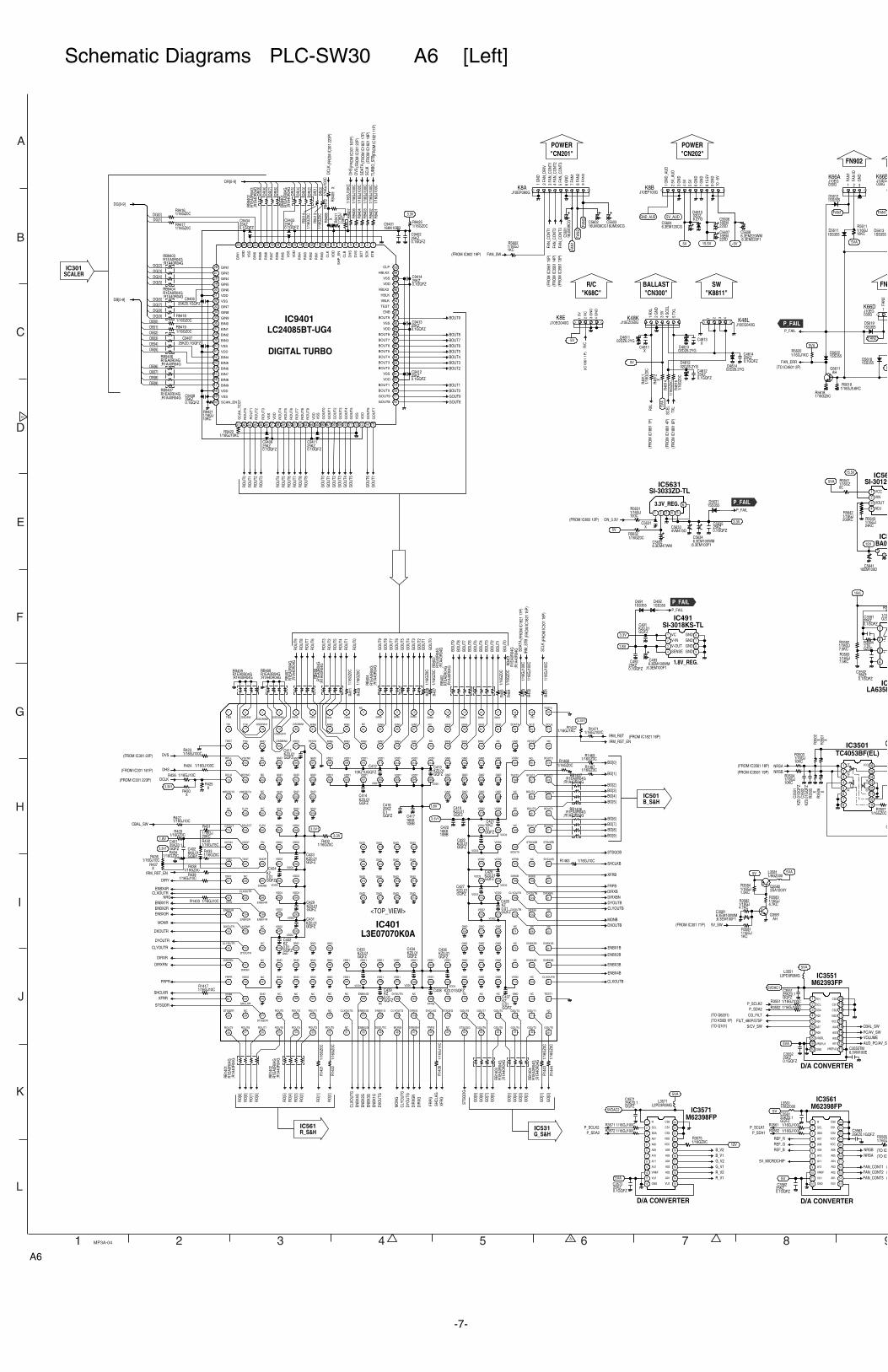
DC
LK(F
RO
M IC
301
223P
)
DH
S(F
RO
M IC
301
161P
)D
VS(F
RO
M IC
301
22P)
SDAT
A(F
RO
M IC
1821
17P
)SC
LK(F
RO
M IC
1821
18P
)TU
RBO
_STB
(FR
OM
IC18
21 1
1P)
3.3V
RO
UT0
RO
UT1
RO
UT2
RO
UT3
RO
UT4
RO
UT5
RO
UT6
RO
UT7
RO
UT8
RO
UT9
GO
UT0
GO
UT1
GO
UT2
GO
UT3
GO
UT4
GO
UT5
GO
UT6
GO
UT7
GOUT9GOUT8
BOUT0BOUT1
BOUT2BOUT3BOUT4BOUT5BOUT6BOUT7BOUT8
BOUT9
1 1Y
2 0Y3 1Z
45 0Z678 9
1011120X
131X141516VCCNRSA(FROM IC3561 18P)
NRSB(FROM IC3561 19P)
5VA R_V1R_V2G_V1G_V2B_V1B_V2
5VA
P_SCLK2P_SDA2
REF_BREF_GREF_R
P_SCLK2
NRSA (TO IC
5VA
P_SDA2
NRSB (TO IC
L2PD3R3MGL3571
L2PD3R3MGL3551
5VDAC2
3.3V 1 VC2 V-IN3 V-OUT4 SENSE 5GND
6GND7GND8GND
1.8V
P_FAIL
BOU
T9
GO
UT3
DIRXB
GO
[5]
GO
UT0
DIRXR
3.3V1
BOU
T6
DIRXBN
GO
[2]
GO
UT1
BOU
T2
DYOUTB
GO
[1]
RO
[9]
FRPR
BOU
T3
3.3V
RO
[8]
BOU
T5
3.3V1
RO
[7]
BOU
T4
RO
[6]
SHCLKR
CBAL_SW
BOU
T1
RO
[3]
BOU
T0
RO
[4]
XFRR
SDAT
A(F
RO
M IC
1821
17P
)
ENBX
1G
RO
[2]
IRM
_STB
(FR
OM
IC18
21 1
5P)
DXO
UTG
ENBX4R
RO
[5]
STSQOR
RO
UT9
SCLK
(FR
OM
IC30
1 18
P)
CLY
OU
TG
RO
[1]
RO
UT8
IRM_RST (FROM IC1821 16P)
DVS(FROM IC301 22P)
DIR
XGN
CLXOUTR
RO
[0]
RO
UT7
ENBX3R
BO[0]
DHS(FROM IC301 161P)
DIR
XG
CLX
OU
TG
RO
UT6
ENBX1R
BO[1]DCLK(FROM IC301 223P)
DYO
UTG
ENBX
4G
RO
UT5
BO[2]
MO
NG
ENBX
2G
RO
UT4
BO[3]
FRPG
ENBX
3G
RO
UT3
3.3V1
ENBX2R
BO[4]
XFR
G
CLYOUTB
RO
UT2
BO[5]
SHC
LKG
MONR
RO
UT1
BO[9]
DXOUTR
RO
UT0
1.8V
BO[6]
STSQ
OG
MONB
GO
UT7
BO[7]
GO
[7]
DXOUTB
DYOUTR
GO
UT8
GO
[0]
BO[8]
GO
[8]
ENBX1B
GO
UT6
STSQOB
GO
[6]
ENBX2B
CLYOUTR
GO
UT2
GO
UT9
SHCLKB
GO
[9]
ENBX3B
BOU
T7
GO
UT4
1.8V
XFRB
GO
[3]
ENBX4B
DIRXRN
BOU
T8
GO
UT5
IRM_RST_EN
FRPB
GO
[4]
CLXOUTB
FAN
_CO
NT3
(FR
OM
IC35
61 1
3P)FAN_SW(FROM IC802 19P)
J10EZ050GK48K 1
RXL
2 G
ND
3 5V
4 SC
EL
5 TX
L
VOLUME
CG_FILT
12
TXL
(FR
OM
IC18
81 6
P)
5VA
5V -5V
FAN
_CO
NT2
(FR
OM
IC35
61 1
4P)
FAN
_CO
NT1
(FR
OM
IC35
61 1
5P)
J10EG030G
K66A1
FAN
1
2
FAN
ID
3
GN
D
J10EG030G
K66B
3.3V1
FAN1
5VA
FAN1
J10EG030G
K66D 1
FAN
2
5
FAN2
P_FAIL
3.3V
5V
ON_3.3V
1SS355D5611
1SS355D5613
1SS355D5618
1SS355D5612
1SS355D5619
1SS355D5622
FAN_CONT2 (FAN_CONT3 (
FAN_CONT1 (
DR[0-9]
DG[0-9]
DB[0-9]
25KZ0.1GQFZ
C3551
KZ0.01GQFZ
C41310KZ1UGQFZ
C412
KZ0.01GQFZ
C426
25KZ0.1GQFZ
C3552
25KZ0.1GQFZC3563
6.3VM100EC3555TM
KZ0.01GQFZ
C422
25KZ0.1GQFZ
C9408
KZ0.01GQFZ
C431
KZ0.01GQFZ
C411
KZ0.01GQFZ
C434
KZ0.01GQFZ
C439
25KZ0.1GQFZ
C9412
KZ0.
01G
QFZ
C35
02
25KZ0.1GQFZ
C3571
KZ0.01GQFZ
C424
25KZ0.1GQFZ
C9409
KZ0.01GQFZ
C428
KZ0.01GQFZ
C433
KZ0.01GQFZ
C491
25KZ0.1GQFZC9406
KZ0.01GQFZ
C414
25KZ0.1GQFZ
C9411
KZ0.01GQFZ
C437
25KZ0.1GQFZ
C401
KZ0.01GQFZ
C436
25KZ0.1GQFZ
C9404
KZ0.01GQFZC438
25KZ0.1GQFZ
C3572
25KZ0.1GQFZ
C9414
25KZ0.1GQFZ
C5635
KZ0.
01G
QFZ
C35
01
10KZ1UGQFZ
C421
KZ0.01GQFZ
C427
25KZ0.1GQFZ
C416
XC4811
25KZ0.1GQFZ
C9413
25KZ0.1GQFZ
C9402
KZ0.01GQFZ
C423
KZ0.01GQFZ
C432
25KZ0.1GQFZC9407
KZ0.01GQFZ
C429
KZ0.01GQFZ
C419
C940325KZ0.1GQFZ
KK0.01GQBY
C402
25KZ0.1GQFZ
C492
4VM470DC5633
6.3EM100WM;6.3EM100F1
C493
16EM220D
C56076.3EM220WMC5608
;6.3EM220F1
6.3EM120CGC5604
1SS355D492
1SS355D491
1SS355D5631
R1EA0R04GRB9404
;R1A40R04G
R1EA0R04GRB9407
;R1A40R04G
R1E
A0R
04G
RB9
401
;R1A
40R
04G
R1EA0R04GRB9406
;R1A40R04G
R1E
A0R
04G
RB9
402
;R1A
40R
04G
R1EA0R04GRB9403
;R1A40R04G
Q
AHQ5611
J10EG040GK8E 1
5V
2 R
C
3 G
ND
4 G
ND
5V
R/C
16EM220D
C5606
6.3EM100WM;6.3EM100F1
C5634
XC5631
1 2 3 4 5
6
12V
16EM100DC5641
15.5V
FAN
1FA
N2
FAN
3
02DZ6.2YGD4811
02DZ6.2YGD4812
J10EP090GK8A
1 G
ND
2 FA
N_D
RIV
3 FA
N_C
ON
T14
FAN
_CO
NT2
5 FA
N_C
ON
T36
GN
D7
FAN
18
FAN
29
FA
N3
SCEL
(FR
OM
IC18
81 4
P)
DIRY
NRG
FAN_ERR
P_FAIL
GND_AUD
5VA
R1E
A0R
04G
;R1A
40R
04G
RB4
07
R1E
A0R
04G
;R1A
40R
04G
RB4
04
R1E
A0R
04G
;R1A
40R
04G
RB1
403
R1E
A0R
04G
;R1A
40R
04G
RB4
01
R1E
A0R
04G
;R1A
40R
04G
RB4
03
R1E
A0R
04G
;R1A
40R
04G
RB1
401
R1E
A0R
04G
;R1A
40R
04G
RB4
06
R1E
A0R
04G
;R1A
40R
04G
RB1
402
R1E
A0R
04G
;R1A
40R
04G
RB1
404
R1E
A0R
04G
;R1A
40R
04G
RB4
02
16KK10BBC9401
16KK10BB
C417
16KK10BB
C420
5VDAC1
5VA
P_SDA1
25KZ0.1GQFZ
C3562
P_SCLK1
25KZ0.1GQFZ
C35615V
CBAL_SW
5V_AUD
15.5V
RXL
(FR
OM
IC18
81 1
P)
02DZ6.2YGD4813
XC4813
12V
IRM_RST_EN
2
SC
K
3
SD
T
4
DV
S
5
DH
S
6
CLB
7
SH
P_E
N
8
VD
D
9
CLK
10
RIN
0
11
RIN
1
12
RIN
2
13
RIN
3
14
RIN
4
15
VD
D
16
VS
S
17
RIN
5
18
RIN
6
19
RIN
7
20
RIN
8
21
RIN
9
22
GIN
0
23V
SS
24V
DD
25
GIN
1
26 GIN2
27 GIN3
28 GIN4
29 GIN5
30 GIN6
31 VDD
32 VSS
33 GIN7
34 GIN835 GIN9
36 BIN0
37 BIN1
38 BIN239 BIN3
40 VSS
41 VDD
42 BIN4
43 BIN5
44 BIN6
45 BIN7
46 BIN8
47 BIN9
48 VDD
49 VSS
50 SCAN_EN
51
SC
AN
_TE
ST
52
RO
UT
0
53
RO
UT
1
54
RO
UT
2
55
RO
UT
3
56
VS
S
57
VD
D
58
RO
UT
4
59
RO
UT
5
60
RO
UT
6
61
RO
UT
7
62
RO
UT
8
63
RO
UT
9
64
VD
D
65
VS
S
66
GO
UT
0
67
GO
UT
1
68
GO
UT
2
69
GO
UT
3
70
GO
UT
4
71
GO
UT
5
72
VS
S
73
VD
D
74
GO
UT
6
75
GO
UT
7
76GOUT8
77GOUT9
78BOUT0
79BOUT1
80VDD
81VSS
82BOUT2
83BOUT3
84BOUT4
85BOUT5
86BOUT6
87BOUT7
88BOUT8
89VDD
90VSS
91BOUT9
92ENB
93TEST
94VBLK
95HBLK
96VBLK2
97VDD
98VSS
99HBLK2
100CLP
1
ST
B
R1EA0R04GRB408
;R1A40R04GR1EA0R04GRB409
;R1A40R04G
J10EP100GK8B 1
GN
D_A
UD
2 5V
_AU
D
3 G
ND
4 5V
5 5V
6 G
ND
7 G
ND
8 15
.5V
9 G
ND
10-5
V
R1EA0R04G;R1A40R04G
RB1407
R1EA0R04G;R1A40R04G
RB1406
1 R(-)
2 SCL
3 SDA
4 A05
5 A06
6 A07
7 A08
8 VREFL
9 VREFU1
10 GND 11VREFU2
12A01
13A02
14A03
15A04
16VCC
17VDD
18CS2
19CS1
20CS0
6.3EM47WMC5632
AHQ3581
1/8GZ000L3581
2SA1203YQ3582
6.3EM100WM;6.3EM100F1
C3581
5V_SW(FROM IC301 71P)
5V 5VA
1 VCC2 VIN3 VOUT4 ADJ
1
2
3
4
25KZ0.1GQFZ
C3592
25KZ0.1GQFZ
C3591
15VL
3.3V1
02DZ6.2YGD4814
1/16GJ1KC
R3581
1/16GJ5.6KCR5619
1/16
GZ0
CR
1444
1/16GJ100CR35611/16GJ100CR3572
1/16
GZ0
CR
406
1/16GJ4.7KC
R3582
1/16
GZ0
CR
1443
1/16GJ1.5KC
R3584
1/16
GJ1
00C
R94
02
1/16GJ100CR3552
1/16GJ10CR436
1/16
GJ1
00C
R94
12
1/16GJ10CR439
1/16GZ0CR9419
1/16
GJ1
0KC
R94
07
1/16GJ100CR3562
1/16GJ10CR427
1/16GJ10KC
R5611
1/16GZ0CR1468
1/16
GZ0
CR
4816
1/16GZ0CR433
1/16GZ0CR400
1/16GJ10KC
R3504
1/16GJ200KC
R5642
1/16GJ100CR424
1/16
GZ0
CR
411
1/16
GJ1
00C
R94
01
XR
3506
1/16GZ0CR9416
XR
9409
1/16GJ10KCR9422
1/16
GJ1
00C
R94
06
1/16GJ24KC
R5643
1/16GZR3565
1/16
GZ0
CR
1421
1/16
GJ1
00C
R40
1
1/16GJ7.5KC
R3593
R94
111/
16G
J10
KC
1/16GZ0CR429
1/16GZ0
R3
1/16
GZ0
CR
407
XR
3505
1/16GZ0CR5632
1/16GZ0CR56181/
16G
Z0C
R48
14
1/16GZ0CR434
1/16GJ100CR3551
1/16
GZ0
CR
4811
XR
4812
1/16
GZ0
CR
409
1/16GJ10CR426
1/16GZ0CR9418
1/16GJ100CR1471
1/16
GJ1
00C
R40
2
1/16GZ0CR9425
1/16
GZ0
CR
404
XR437
1/16GJ1KCR5620
1/16GZ0CR9417
1/16GZ0CR438
1/16GJ7.5KC
R3592
1/16GZ0CR3507
1/16GJ10CR1403
1/16GJ20KC
R431
XR
9408
1/16GZ0C
R3594
1/16
GZ0
CR
9414
1/16GJ1KCR1472
1/16
GJ1
00C
R94
03
1/16
GZ0
CR
1422
1/16
GZ0
CR
408
XR
3501
1/16
GJ1
00C
R40
3
1/16GJ10CR1417
1/16GJ75CR432
1/16
GJ1
0CR
1438
1/16GZ0C
R5641
1/16GZ0CR1469
XR
3502
1/16GJ10CR1463
1/16GJ1KC
R5602
XR425
XR430
1/16GZ0CR3575
1/16GZ0CR1467
1/16GJ100CR3571
1/16GJ4.7KC
R3583
1/16GJ10KC
R9421
1/16
GJ1
00C
R94
04
1/16GJ10KC
R35031/16GJ100CR423
1/16
GZ0
CR
9413
1/16GJ100C
R5631
1/8GZ000L3561
5V
5V_MICROCHIP
5VA
AUD_PC/AV_SW
<TOP_VIEW>
1
TMS
2
OSDSW
3
OSDRIN0
4
OSDGIN0
5
RIN9
6
RIN7
7
RIN4
8
RIN1
9
NC
10
GIN9
11
GIN6
12
GIN3
13
GIN0
14
NC
15
BIN7
16
BIN4
17
BIN1
18
NC
19
NC
20
TEST3
21
SCLK
22
NC
23
BOUT0
24
BOUT2
25
BOUT4
26
BOUT6
27
BOUT8
28
STSQEB
29
SHCLKB
30
NC
31
DIRXBN
32
NC
33
NC
34
ENBX1B
35
ENBX3B
36
CLXOUTB
37
TEST1
38
NC
39
GOUT0
40
GOUT2
41
GOUT4
42
GOUT6
43
GOUT8
44
STSQOG
45
NC
46
FRPG
47
DIRXGN
48
MONG
49
DXOUTG
50
ENBX2G
51
NC
52
ROUT0
53
ROUT2
54
ROUT4
55
ROUT6
56
ROUT7
57
ROUT8
58
ROUT9
59
STSQER
60
XFRR
61
FRPR
62
DIRXRN
63
CLYOUTR
64
DXOUTR
65
ENBX3R
66
NRG
67
DIRY
68
VSEL
69
VCOIN
70
CPOUT
71
NC
72
HRESET0
73
DCLK
74
HPLL
75
TRST
76
TDI
77
TCK
78
OSDRIN1
79
OSDGIN1
80
OSDBIN1
81
RIN8
82
RIN5
83
RIN2
84
NC
85
GIN8
86
GIN5
87
GIN2
88
NC
89
BIN9
90
BIN6
91
BIN3
92
BIN0
93
SDATA
94
SCS
95
RESET
96
NC
97
BOUT1
98
BOUT3
99
BOUT5
100
BOUT7
101
STSQOB
102
NC
103
FRPB
104
DYOUTB
105
MONB
106
NC
107
ENBX2B
108
ENBX4B
109
NC
110
NC
111
GOUT1
112
GOUT3
113
GOUT5
114
GOUT7
115
GOUT9
116
STSQEG
117
SHCLKG
118
DIRXG
119
CLYOUTG
120
ENBX1G
121
ENBX3G
122
CLXOUTG
123
NC
124
ROUT1
125
ROUT3
126
ROUT5
127
STSQOR
128
NC
129
SHCLKR
130
VDD2
131
DIRXR
132
DYOUTR
133
MONR
134
ENBX2R
135
CLXOUTR
136
NC
137
TEST
138
VDDP
139
SELECT
140
CLP1
141
VRESET0
142
HSYNC
143
VSYNC
144
TD0
145
GND
146
OSDBIN0
147
VDD2
148
TEST4
149
RIN6
150
RIN3
151
RIN0
152
GIN7
153
GIN4
154
GIN1
155
NC
156
BIN8
157
BIN5
158
BIN2
159
NC
160
GND
161
VDD2
162
TEST2
163
NC
164
NC
165
NC
166
BOUT9
167
XFRB
168
DIRXB
169
CLYOUTB
170
DXOUTB
171
NC
172
NC
173
NC
174
VDD2
175
GND
176
NC
177
NC
178
NC
179
NC
180
XFRG
181
NC
182
DYOUTG
183
NC
184
ENBX4G
185
NC
186
NC
187
NC
188
NC
189
NC
190
GND
191
NC
192
NC
193
NC
194
NC
195
ENBX1R
196
ENBX4R
197
SHENB
198
GNDP
199
EN
200
CLP2
201
NC
202
NC
203
NC
204
NC
205
GND
206
GND
207
GND
208
VDD1
209
VDD1
210
VDD1
211
VDD1
212
VDD1
213
VDD1
214
VDD1
215
GND
216
GND
217
GND
218
GND
219
GND
220
GND
221
VDD2
222
VDD2
223
VDD2
224
VDD2
225
VDD2
226
VDD2
227VDD2
228
GND
229
GND
230
GND
231
GND
232
GND
233
GND
234
VDD1
235
VDD1
236VDD1
237
VDD1
238
VDD1
239
VDD1
240
VDD1
241
GND
242
GND
243
GND
244
GND
245
GND
246
GND
247
VDD2
248
VDD2
249
VDD2
250
VDD2
251
VDD2
252
VDD2
253
VDD2
254
GND
255
GND
256
GND
257
GND
258
GND
259
VDD1
260
VDD1
261
VDD1
262VDD1
263
VDD1
264
VDD1
265
VDD1
266
GND
267
GND
268
GND
269
GND
270
VDD2
271
VDD2
272VDD2
273
VDD2
274
VDD2
275VDD2
276
VDD2
277
GND
278
GND
279
GND
280
GND
281
VDD1
282
VDD1
283
VDD1
284
VDD1
285
VDD1
286
VDD1
287
VDD1
288
GND
289
GND
290
GND
291
GND
292VDD2
293VDD2
294
VDD2
295
VDD2
296VDD2
297
VDD2
298
VDD2
299
GND
300
GND
301
GND
302
GND
303
GND
304
GND
305
GND
306
GND
307
GND
308
GND
309
GND310
GND
311
GND
312
GND
313GND
314
GND
315
GND
316
GND
317
GND
318
GND
319
GND
320
GND
321
GND
322
GND
323
GND
324
GND
J10EG040GK48L1 2 3 4
PC/AV_SW
1 R
2 SCL
3 SDA
4 A07
5 A08
6 A09
7 A10
8 A11
9 A12
10 VREF
11 VU1
12 GND 13VU2
14A01
15A02
16A03
17A04
18A05
19A06
20VCC
21VDD
22CS2
23CS1
24CS0 1 R
2 SCL
3 SDA
4 A07
5 A08
6 A09
7 A10
8 A11
9 A12
10 VREF
11 VU1
12 GND 13VU2
14A01
15A02
16A03
17A04
18A05
19A06
20VCC
21VDD
22CS2
23CS1
24CS0
25KZ0.1GQFZ
C4814
25KZ0.1GQFZ
C4812
02DZ6.2YG
D4815
FILT_480P/575P
16UM39CGC5602
16UM39CGC5603
16U
M39
CG
C56
01
S/CV_SW
DG[0]DG[1]
DG[2]DG[3]DG[4]DG[5]
DG[6]DG[7]DG[8]DG[9]
DB[0]DB[1]DB[2]DB[3]DB[4]DB[5]
DB[6]DB[7]DB[8]DB[9]
DR
[9]
DR
[8]
DR
[7]
DR
[6]
DR
[5]
DR
[4]
DR
[3]
DR
[2]
DR
[1]
DR
[0]
(IC
1861
1P
)
-
+
5V
1 2 3 4 5 6 7 8 9
A
B
C
D
E
F
G
H
I
J
K
L
MP3A-04
TC4053BF(EL)IC3501
LA6358IC
SI-3012IC56
BA09IC5
IC9401LC24085BT-UG4
DIGITAL TURBO
M62393FPIC3551
M62398FPIC3561
D/A CONVERTER
D/A CONVERTERD/A CONVERTER
M62398FPIC3571
SI-3018KS-TLIC491
SI-3033ZD-TLIC5631
1.8V_REG.
3.3V_REG.
L3E07070K0AIC401
IC561R_S&H
IC501B_S&H
IC531G_S&H
IC301SCALER
FN902
FN
POWER"CN202"
POWER"CN201"
SW"K8811"
BALLAST"CN300"
R/C"K68C"
(FROM IC802 12P)
(TO IC4801 2P)
(TO Q101)(TO K50B 1P)(TO Q6201)
P_FAIL
P_FAIL
P_FAIL
A6
-7-
Schematic Diagrams PLC-SW30 A6 [Left]
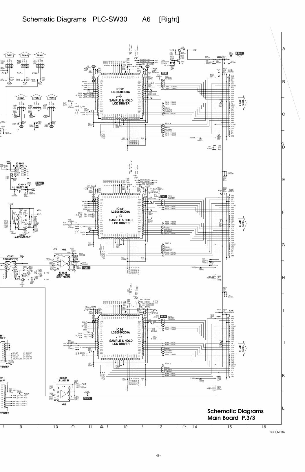
V_COMR
V_COMG
V_COMB
15VL
15VL
1
2
3
4 5
6
7
8
1
2
3
4 5
6
7
8
BO[9
]BO
[8]
BO[7
]BO
[6]
BO[5
]BO
[4]
BO[3
]BO
[2]
BO[1
]BO
[0]
L2F73R3JGL501
3.3V 15VL
L2F73R3JGL502
3.3VB 15VB
SHCLKBXFRB
STSQOBFRPB
DIRXB
SDATASH_B_STB
SCLK
SVRLSVRH
DIRY
DYO
UTB
CLY
OU
TBNR
G
MO
NB
DXO
UTB
ENBX
1BEN
BX2B
ENBX
3BEN
BX4B
CLX
OU
TB
REF
_B
B_V2B_V1
V_COMB
1 1Y
2 0Y3 1Z
45 0Z678 9
1011120X
131X141516VCC
15VL
G_V2
STSQOG
GO
[2]
SVRH
DXO
UTG
GO
[8]
G_V1
FRPG
GO
[1]
ENBX
1G
GO
[7]
GO
[0]
ENBX
2G
GO
[6]
SDATA
DYO
UTG
L2F73R3JGL531
ENBX
3G
V_COMG
GO
[5]
SH_G_STB
CLY
OU
TG
3.3V
REF
_G
SHCLKG
ENBX
4G
GO
[4]
3.3VG
SCLK
NR
G
15VL
XFRG
CLX
OU
TG
GO
[3]
15VG
SVRL
MO
NG
GO
[9]
L2F73R3JGL532
R_V2
STSQOR
RO
[2]
SVRH
DXO
UTR
RO
[8]
R_V1
FRPR
RO
[1]
ENBX
1R
RO
[7]
RO
[0]
ENBX
2R
RO
[6]
SDATA
DYO
UTR
L2F73R3JGL561
ENBX
3R
V_COMR
RO
[5]
SH_R_STB
CLY
OU
TR
3.3V
REF
_R
SHCLKR
ENBX
4R
RO
[4]
3.3VR
SCLK
NR
G
15VL
XFRR
CLX
OU
TR
RO
[3]
15VR
SVRL
RO
[9]
L2F73R3JGL562
FRPG
FRPR
NRSA (TO IC3501 1P,3P)
NRSB (TO IC3501 2P,5P)
15.5VP
2SA1203YQ2501
15.5V 15VL1/8GZ000
L2501
DIRXBN
DIRXG
DIRYDIRXGN
DIRXR
DIRXRNDIRY
MO
NR
VOLUME (TO IC5002 2P)
9V12
3
J10EG030G
K66A1
FAN
1
2
FAN
ID
3
GN
D
J10EG030G
K66B1
FAN
1
2
FAN
ID
3
GN
D
FAN1
5VA 5VA
FAN1
5VA
FAN2
J10EG030G
K66C1
FAN
2
2
FAN
ID
3
GN
D
J10EG030G
K66D 1
FAN
2
2
FAN
ID
3
GN
D
5VA
FAN2
5VA
FAN3
J10EG031G
K66E 1
FAN
3
2
FAN
ID
3
GN
D
1SS355D5611
1SS355D5613
1SS355D5616
1SS355D5618
1SS355D5621
P_FAIL
P_FAIL
1SS355D5612
1SS355D5619
1SS355D5622
1SS355D5624
12V
FAN_CONT2 (TO K8A 4P)FAN_CONT3 (TO K8A 5P)
FAN_CONT1 (TO K8A 3P)
25KZ0.1GQFZ
C2538
25KZ0.1GQFZ
C567
25KZ0.1GQFZ
C536
25KZ0.1GQFZ
C566
25KZ0.1GQFZ
C510
KZ0.01GQFZ
C551
25KZ0.1GQFZ
C2573
25KZ0.1GQFZC3563
6.3VM100EC3555TM
25KZ0.1GQFZ
C2533
25KZ0.1GQFZC571
25KZ0.1GQFZ
C511
25KZ0.1GQFZ
C2521
25KZ0.1GQFZ
C2574
25KZ0.1GQFZ
C543
25KZ0.1GQFZ
C2578
25KZ0.1GQFZ
C531
25KZ0.1GQFZ
C561
25KZ0.1GQFZ
C3522
25KZ0.1GQFZ
C507
25KZ0.1GQFZ
C2517
25KZ0.1GQFZ
C544
25KZ0.1GQFZ
C514
25KZ0.1GQFZC509
XC35
24
25KZ0.1GQFZ
C540
CJ100CGQY
C3523
25KZ0.1GQFZ
C3532
25KZ0.1GQFZ
C537
25KZ0.1GQFZ
C569
25KZ0.1GQFZ
C513
25KZ0.1GQFZC541
25KZ0.1GQFZ
C2534
KZ0.01GQFZ
C581
CJ100CGQY
C3533
KZ0.01GQFZ
C573
25KZ0.1GQFZ
C2512
25KZ0.1GQFZ
C506
KZ0.01GQFZ
C521
25KZ0.1GQFZ
C2513
25KZ0.1GQFZ
C2571
25KZ0.1GQFZ
C574
25KZ0.1GQFZ
C2532
25KZ0.1GQFZ
C5642
25KZ0.1GQFZ
C50125KZ0.1GQFZ
C2516
KZ0.01GQFZ
C3534
25KZ0.1GQFZ
C570
25KZ0.1GQFZ
C539
4EM47DC562
4EM47DC502
16EM100F1;16EM100D
C2511
4EM47DC532
16EM100DC5643
1SS355D5641
1SS355D2511
1/8GZ000L2511
R1EA0R04GRB2562
;R1A40R04G
R1EA0R04GRB2561
;R1A40R04G
R1EA0R04GRB2563
;R1A40R04G
R1EA0R04GRB2532
;R1A40R04G
R1EA0R04GRB2503
;R1A40R04G
R1EA0R04GRB2533
;R1A40R04G
AHQ3502
AHQ3501
AHQ2502
AHQ5611
J30A00102TPG1
J30A00102TP2561
J30A00102TEGND2
J30A00102TPB1
J30A00102TP2531
J30A00102TPR1
CJ470CGQY
C568
C538CJ470CGQY
CJ470CGQY
C508
12V
16EM100DC5641
15.5V
KK560GQBY
C3503
KK560GQBY
C3504
XC512
XC542
XC572
J10EG031G
K66F1
FAN
3
2
FAN
ID
3
GN
D
5VA
FAN3
1SS355D5623
16KK10BBC3521
16KK10BBC2514
16KK10BBC2531
16KK10BBC2572
16KK10BBC3531
CBAL_SW
J11EB300GK25R
1 N.C.DYCLY/CLYVDDYLCCOMNRS1NRGENB1ENB2ENB3ENB4DIRXCLX/CLXVDDXDXVSSXVID1VID2VID3VID4VID5VID6NRS2LCCOMDIRYVSSYDY
30MON.
GND
GND
25KZ0.1GQFZC57725KZ0.1GQFZ
C579 25KZ0.1GQFZ
C578
25KZ0.1GQFZC576
XC
563
XC
564
25KZ0.1GQFZC54625KZ0.1GQFZC547
XC
534
25KZ0.1GQFZ
C548
25KZ0.1GQFZ
C549
XC
533
XC
503
XC
504
25KZ0.1GQFZ
C518
25KZ0.1GQFZ
C519
25KZ0.1GQFZC51725KZ0.1GQFZC516
J11EB300GK25G
1 N.C.DYCLY/CLYVDDYLCCOMNRS1NRGENB1ENB2ENB3ENB4DIRXCLX/CLXVDDXDXVSSXVID1VID2VID3VID4VID5VID6NRS2LCCOMDIRYVSSYDY
30MON.
GND
GNDR1EA0R04GRB2531
;R1A40R04G
11VREFU2
12A01
13A02
14A03
15A04
16VCC
17VDD
18CS2
19CS1
20CS0
6.3EM100WM;6.3EM100F1
C2501
ON_15V
1 VCC2 VIN3 VOUT4 ADJ 5GND
6GND
7GND
8GND
1
2
3
4 5
6
7
8
25KZ0.1GQFZ
C359225KZ0.1GQFZ
C3596
25KZ0.1GQFZ
C3594
25KZ0.1GQFZ
C3591
15VL
25KZ0.1GQFZ
C3593 SVRH
SVRL
J11EB300GK25B
1 N.C.DYCLY/CLYVDDYLCCOMNRS1NRGENB1ENB2ENB3ENB4DIRXCLX/CLXVDDXDXVSSXVID1VID2VID3VID4VID5VID6NRS2LCCOMDIRYVSSYDY
30MON.
GND
GND
1/16GJ100CR564
1/16GJ5.6KCR5619
1/16GJ100CR582
1/16GJ1.5KC
R2501
1/16GZ0CR2562
XR
525
1/16GJ100CR502
1/16GZ0CR2568
1/16GZ0C
R3509
XR2517
XR2537
1/16GZ0CR2569
1/16GZ0CR2512
1/16GJ100CR534
1/16GJ2.2C
R2522
1/16GZ0CR2576
1/16GZ0CR547
1/16GJ10KC
R5611
1/16GZ0CR539
1/16GZ0CR2564
1/16GJ1KCR3522
1/16GJ200KC
R5642
1/16GZ0CR571
1/16GJ10KC
R3597
1/16GZ0CR2519
1/16GZ0CR2531
1/16GJ3.9KC
R3598
XR578
1/16GZ0C
R3599
XR2521
1/16GJ10KC
R5612
1/16GJ24KC
R5643
1/16
GZ0
CR
584
1/16GZ0CR3565
1/16
GZ0
CR
554
1/16GZ0CR2539
1/16GZ0C
R3528
1/16GJ4.7KC
R2503
1/16GJ10KC
R5617
1/16GJ7.5KC
R3593
XR2541
1/16GZ0CR2532
1/16GZ0C
R3591
1/16GJ2.2C
R2523
1/16GJ100CR553
1/16GZ0CR509
1/16GZ0C
R3596
1/16GZ0CR569
1/16GJ1KCR3523
1/16GZ0CR2513
1/16GZ0CR577
1/16GZ0CR2518
0C
1/16GJ2.2KC
R3508
1/16GZ0CR2563
1/16
GJ1
00C
R55
7
1/16GJ10KC
R5614
XR3524
1/16GJ100CR504
XR3521
1/16GZ0CR541
1/16GJ4.7KC
R2502
1/16GJ10KC
R5616
1/16GZ0CR2527
XR3527
1/16GZ0CR517
1/16GZ0CR2534
1/16GZ0CR2514
1/16GZ0CR511
1/16GJ7.5KC
R3592
1/16GZ0CR3507
1/16GJ100CR562
1/16GZ0C
R3594
1/16GJ1KCR3532
1/16GJ2.2KC
R3511
1/16GJ100CR566
1/16GZ0CR2536
1/16GJ15KC
R3531
1/16GJ2.2C
R2573
1/16GJ100CR506
X
XR
555
1/16GZ0CR3526
XR2567
XR
585
1/16GJ5.6KC
R3512
1/16GJ10KC
R5613
1/16GZ0CR2511
XR548
XR3529
1/16
GZ0
CR
524
1/16GZ0CR2538
XR
565
XR
560
1/16GZ0CR2566
1/16GJ1KC
R2504
1/16
GJ1
00C
R52
7
1/16GJ100CR523
1/16GZ0CR2533
1/16GZ0C
R5641
1/16GJ100CR552
1/16GJ100CR532
1/16GJ100CR536
1/16GJ100CR522
1/16GJ2.2C
R2572
1/16GZ0CR2548
XR
500
XR518
XR
505
XR2571
XR
535
1/16GZ0CR2516
XR
530
1/16GJ5.6KC
R3513
1/16GJ2.2CR2542
1/16GZ0CR2561
1/16GJ100CR583
1/16GJ2.2CR2543
1/16
GJ1
00C
R58
7
XR2544
5VA
AUD_PC/AV_SW (TO IC5001 10P)
R1EA0R04GRB2501
;R1A40R04G
R1EA0R04GRB2502
;R1A40R04G
PC/AV_SW
13VU2
14A01
15A02
16A03
17A04
18A05
19A06
20VCC
21VDD
22CS2
23CS1
24CS0
1
DGND2
STBY3CLK
4 XFR
5 STSQ
6 INV
7 R/L
8 E/O
9 SDI
10 SEN
11 SCL
12 NC
13 AGNDS
14 SVRL
15 SVRH
16 VAO1
17 VAO2
18 AVCCS
19DIRXIN
20DIRYIN
21
DY
IN
22
CLY
IN
23
DIR
X
24
DIR
Y
25
DY
26
CLY
27
CLY
N
28
AV
CC
L
29N
RG
IN30
NR
G31
AG
ND
L
32
MO
NIT
I
33
NC
34
MO
NIT
O
35
DX
IN
36
EN
BX
1I
37
EN
BX
2I
38
EN
BX
3I
39
EN
BX
4I
40
CLXI
N 41
DX 42ENBX1 43ENBX2
44ENBX3
45ENBX4
46CLX
47CLXN
48AGND5
49VID5
50AVCC45
51VID4
52AGND34
53VID3
54AVCC23
55VID2
56AGND12
57VID1
58AVCC01
59
VID0
60
AGND0
61
BY
P
62
V1
63
V2
64
VR
LO
65
VR
HI
66
AV
CC
D
67
AG
ND
D
68
NC
69
NC
70
DB
0
71
DB
1
72
DB
2
73
DB
3
74
DB
4
75
DB
5
76
DB
6
77
DB
7
78
DB
8
79
DB
9
80
DV
CC
81
VCC
1
DGND2STBY
3 CLK
4 XFR
5 STSQ
6 INV
7 R/L
8 E/O
9 SDI
10 SEN
11 SCL
12 NC
13 AGNDS
14 SVRL
15 SVRH
16 VAO1
17 VAO2
18 AVCCS
19DIRXIN
20DIRYIN
21
DY
IN
22
CLY
IN
23
DIR
X
24
DIR
Y
25
DY
26
CLY
27
CLY
N
28
AV
CC
L
29
NR
GIN
30
NR
G
31
AG
ND
L
32
MO
NIT
I
33
NC
34
MO
NIT
O
35
DX
IN
36
EN
BX
1I
37
EN
BX
2I
38
EN
BX
3I
39
EN
BX
4I
40
CLXI
N 41DX 42
ENBX143
ENBX244ENBX3
45ENBX4
46CLX
47CLXN
48AGND5
49VID5
50AVCC45
51VID4
52AGND34
53VID3
54AVCC23
55VID2
56AGND12
57VID1
58AVCC01
59VID0
60
AGND0
61
BY
P
62
V1
63
V2
64
VR
LO
65
VR
HI
66
AV
CC
D
67
AG
ND
D
68
NC
69
NC
70
DB
0
71
DB
1
72
DB
2
73
DB
3
74
DB
4
75
DB
5
76
DB
6
77
DB
7
78
DB
8
79
DB
9
80
DV
CC
81
VCC
1
DGND2
STBY3CLK
4 XFR
5 STSQ
6 INV
7 R/L
8 E/O
9 SDI
10 SEN
11 SCL
12 NC
13 AGNDS
14 SVRL
15 SVRH
16 VAO1
17 VAO2
18 AVCCS
19DIRXIN
20DIRYIN
21
DY
IN
22
CLY
IN
23
DIR
X
24
DIR
Y
25
DY
26
CLY
27
CLY
N
28
AV
CC
L
29
NR
GIN
30
NR
G
31
AG
ND
L
32
MO
NIT
I
33
NC
34
MO
NIT
O
35
DX
IN
36
EN
BX
1I
37
EN
BX
2I
38
EN
BX
3I
39
EN
BX
4I
40
CLXI
N 41DX 42
ENBX143ENBX244ENBX3
45ENBX4
46CLX
47CLXN
48AGND5
49VID5
50AVCC45
51VID4
52AGND34
53VID3
54AVCC23
55VID2
56AGND12
57VID1
58AVCC01
59
VID0
60
AGND0
61
BY
P
62
V1
63
V2
64
VR
LO
65
VR
HI
66
AV
CC
D
67
AG
ND
D
68
NC
69
NC
70
DB
0
71
DB
1
72
DB
2
73
DB
3
74
DB
4
75
DB
5
76
DB
6
77
DB
7
78
DB
8
79
DB
9
80
DV
CC
81
VCC
16EM33DC2577
16EM33DC2537
16EM33DC2519
DYO
UTG
NRG
CLYO
UTG
-
+ -
+
9 10 11 12 13 14 15 16
A
B
C
D
E
F
G
H
I
J
K
LM7171AIMX;LM7171BIMX
IC3521
TC4053BF(EL)IC3501
LA6358NM-TP-T1IC3591
SI-3012KS-TLIC5641
BA09FP-E2IC5642
L3E06100D0AIC501
SAMPLE & HOLDLCD DRIVER
L3E06100D0AIC531
SAMPLE & HOLDLCD DRIVER
L3E06100D0AIC561
SAMPLE & HOLDLCD DRIVER
LT1206CS8IC3531
393FP551
98FP561
NVERTER
NVERTER
TP2561
TP2531
TPB1
TPG1
TPR1
NRS
NRS
FN901FN905FN902
FN906FN903FN904
B_LC
DPA
NEL
G_L
CDPA
NEL
R_LC
DPA
NEL
-
+
(TO R5339)(TO IC401 139P)
P_FAIL
P_FAIL
L
SCH_MP3A
Schematic DiagramsMain Board P.3/3
-8-
Schematic Diagrams PLC-SW30 A6 [Right]
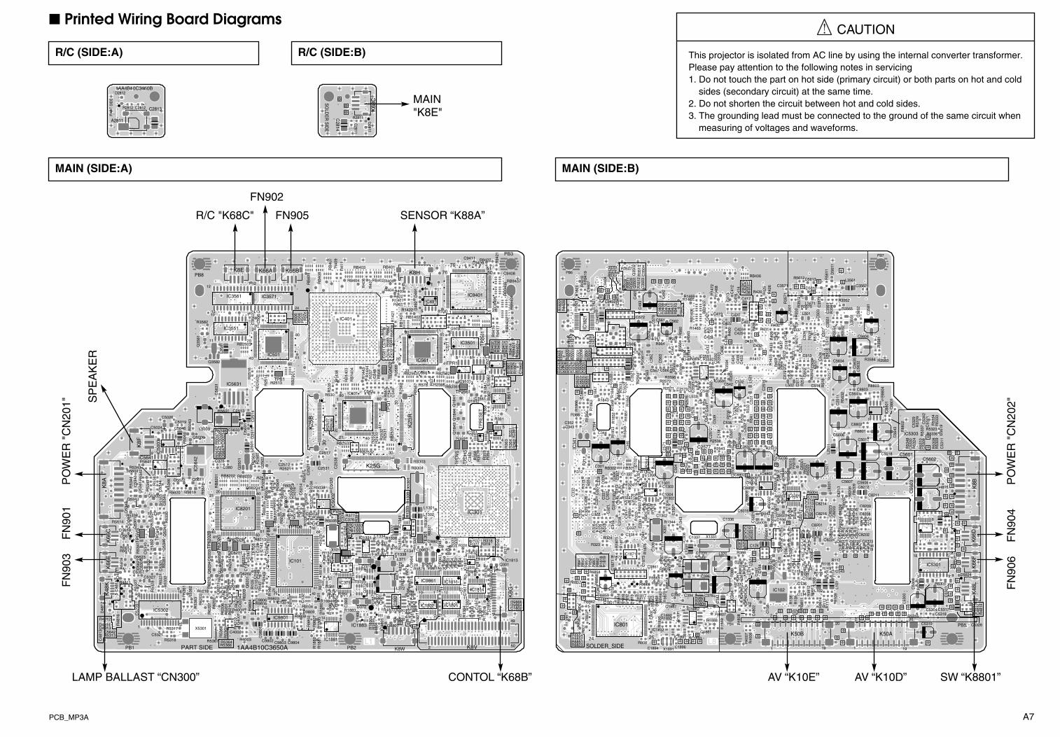
PCB_MP3A A7
L1
TPG
VS
D5623
D56
21
D5618
D5616
D4814D4813
D48
12
D48
11
Q53
01
R5617
R56
16
R5614
R5613
R5338
R53
27
R5313
R48
16R4812
R4811
C62
09
C5642
C53
40
C53
28
C5307
C48
13
C48
11
C53
06R
5341
PB1
K66
EK
66C
K48
K
5
1
30
1
PART SIDE
TPG
HS
TP62
02G
TP62
02B
Q62
04
Q53
46Q
5344
R62
26
R6218
R62
13 R62
12
R62
07R62
03
R62
02
R53
68
R5367
R53
63R
5362
R53
61
R53
53
R53
51R
5332
R53
31
R53
28
R5318
R5317
R53
02
C62
07
C62
03
C5321
C53
01
15
16
IC5302
4140
X5301
TP6202R
TE10
1
Q6202
Q62
01
Q40
01
R62
24
R62
23
R62
16
R6211R6209
R62
08
R62
04
R62
01R
5369
R4004
R4003
R40
02
R10
5
C62
06
C62
04
C62
02
C6201
C4002
C14
8
C14
7C
144
C13
9C
110
R98
04
Q62
03R
6217
R62
06
R5366R5364
R5335
C5327
C53
02
TP103
TEG
FBK
D10
1
R9809R9808
R98
07
R9803
R98
02
R18
85R
1882
R18
81
R14
6R
143
R12
4R
123
C5013
C14
6C
142
C133 C13
2
C11
9
R50
27
C11
8
C9802 C9803 C9804
124
65
2541
80
40
1
61
1
16
8
9
IC9801
RB
103
RB104
TPV
VS
R5035
R18
86
R1883
R1332
R39
1
R387
R38
6
R384
R381
R37
8 R377
R134R133
C18
90
C1333C1332
C39
3
C379
C377
C376C37
4
C131
C129
C12
6C
124
D371
D372
1
4
1 7
8
IC1881
IC1883
1
16
8
9
IC371
4
PB2
3
43
4
Q37
2
T37
1
T372
X101
R1884
R18
80R
127
RB
102
RB
101
14
IC101
64
16
K8W
Q4807
R98
79R
9861
R48
04
R4803
R4802
R4801
R18
95 R13
83
R13
82R
1381
R13
46
R13
42
R13
41R1338R1337
R1336R1334R1331
R87
4R
873
R87
2
R87
1R
396
C99
64
C48
01
C1341C1338
C1334
C39
1
C38
8C
387
6
1
6
1
L372
L371
L133
2
IC9861
28
1
IC48
01
IC39
25 4
8 1
11
IC13
41 5
4
8
18
TE30
1
D1816R9877
R98
71
R18
15R
1393R
1392
R13
86
R13
84
R86
4R
863
R85
4R
853
R84
4R
843
R33
4 R33
3R
332
R331 R322R321C9862
C18
13
C1812
C18
11
RB
307RB
306
L1302
K8V2
1
15
14
11
10IC
1812
5
4
8
1
IC1811
11
10
20
1
20
1
IC1801
11
10
20
1
R9878
C9863
10
IC1802
X9861
D18
14D
301
R9866R9864
R68
64R
6863
R18
10
R31
7R31
6
C1802
IC1813
1
20
1
15
K8G
50
49
Q301
R13
90
R319R318
IC1814
R18
90R
1887
5
IC1331
Q371
1AA4B10C3650A
R9806
R8213
R14
7
C9806
C14
9C
141
60
C98
01
D5622 Q5611
Q5343
Q53
41
Q5302R5620 R5619 R
5618
R5602
R53
52
R53
49 R53
47
R53
46
R53
44
R5343
R53
42
C53
45C
5344
C380
C53
43
14
12021
K8A
RB
8201 RB8202 RB8203
Q50
03
R5038
R50
34
R50
26R50
24
R50
23
R50
17R
5003
R50
02
R5001
R25
27
R2521
R25
04
C50
35
C50
20
C25
21C2512
C50
16
C50
14
C50
07 C50
06
IC50
02
58
C2531
R13
39X
1301
RB304
L1301IC301
K25G
R2503
RB8204
80
D56
41
D56
31
D25
11
Q5006
R56
43R
5642
R5631
R50
47
R5046
R50
44R
5043
C5024
C50
23C
5022
C5019
C2513
C25
14
C5026
C5046 C5633
1
8
4
5
IC50
03
8 5IC5641
K8F
L250
1
L5003 R25
37R
2536
C2517
RB2533
1
K25
B
301
4021
20
TPR
ES
ETTP
G1
TPD
VS
R25
33R
2532
R25
31
R36
6
R36
4R
363
R36
2
R361
R359
R35
8
R35
4R
353
R35
1
RB
2531
Q18
44Q
1843
Q1842
K25
R
301
30
41
IC36
15
4
8
1
IC351
54
81
71
R25
34
RB2532
TPD
HS
Q25
02R5641 R25
02R
2501
R35
7
C25
38C375 C35
3
IC56
42
Q25
01 RB303
R3582
Q35
81
R25
16
C56
31
C35
63
RB2503
RB
2502
Q3582
PB8
L358
1
K8E
IC5631
40
2120
12
IC3561
13
12
24
1
IC3551
11
10
20
1
TPB1
R25
14
R2513
R50
6
R50
5
R50
4R
502
1
24
IC3571
1
61
80
60
IC501
K66A K66B
RB
2501 R14
44R
1443
R14
38
R53
5
R530
R41
1
R40
9
R40
8
IC401
80 IC531
RB
1403
RB
1404
RB403
RB404
RB
407
RB
408
RB
409
C50
6
13
41
TEG
ND
2
D49
2D
491
R25
69R
2568
R25
67
R1471
R1422
R14
21
R58
7R
585
R58
4R
583
R58
2
R55
4
R55
3
R406
R404 R403R402
R401
C58
1C
578
C57
7C
576
C54
9
C54
8
C54
7
RB402
RB401
RB2563
RB
1401
K8H
6
IC561
80
21
20
1
TPR1
TP2561
R2566R57
7
C9411
C573
C57
1
RB2562
RB2561
1
IC9401
75
100
76
1
60
40
41
61
IC491
5
4
8
1
IC3531
5
4
8
1
8
1
IC3501
9
8
16
1
R578
C568
RB1402
R55
7R
407
C54361
R94
21R
9417
R94
16
R94
14R
9413
R94
12R
9406
R94
04R
9402
R18
67R
1862
R18
61
R18
41
C9408
C94
06
C18
62
C18
61
RB9407
RB
9406
RB
9404
RB
9403
RB
9402
RB
9401
PB3
5051
2625
IC35
21
5
814
IC18
41
5
4
8
1
TP25
31
R9422C9409
4
R36
7
C1841
Q18
41601
IC18
61TPVHSQ
5342
R53
30
R50
19R
5016
R50
14R
5011
R13
33IC8201
RB
8206
RB
8207
Printed Wiring Board Diagrams
This projector is isolated from AC line by using the internal converter transformer.Please pay attention to the following notes in servicing1. Do not touch the part on hot side (primary circuit) or both parts on hot and cold
sides (secondary circuit) at the same time.2. Do not shorten the circuit between hot and cold sides.3. The grounding lead must be connected to the ground of the same circuit when
measuring of voltages and waveforms.
CAUTION
MAIN (SIDE:A)
R/C (SIDE:A) R/C (SIDE:B)
L8SOLDER_SIDE
D5624
R53
11
R5304
R48
14
C5318 C48
14C
4812
C53
03
PB5
K66
FK
66D
K48
L
8
7
10
9
C5326
C5317
R8204
R6256
R5316
C8208C8204
C8202
C6223
C6219
C53
08
C53
00
1
18
IC5301
1
14
20
19
K50A
R53
07
R82
14
R82
12
R6253
R119R118
R117
R11
4R
113
R11
2R
111 R10
9
C8224 C82
22
C82
21C
8219
C82
18
C6221
C6217
C143
1
220
19
L101
R8203R8202
R6254
C82
17
C8207
C6222
C6218
C5304
C5319
C101
IC102
Q10
1
Q5002
R98
13R
9812
R98
11
R50
41
R50
39
R142R141
R13
9R
138
R10
8
R107
R10
6
R10
4R
103
R102R101
R100
C15
8
C156
C153C152C151
C13
7
C136
C134
C115
C112
C109
C10
8C
107
C106
C10
4C
103
C102
C111
C13
8
1
2
K50B
L103
C1336
R48
08
R4807
R40
07R
4006
R18
89
R394R393
R392
R38
9
R388
R379
R376
R374
R373
R372R371
R136R131
C48
02
C38
4
C381
C37
3
C372 C37
1
C127
C123C122C121
C50
21C
157
C38
2
L370
PB4
R126
C15
4
Q5004
R5042
C128
D18
71
R9876
R98
74R
9873
R4806
R1892 R18
91
R18
74
R18
73
R1344
R13
43
R383R382
C1896
C1893
C1892
C18
91
C1887
C18
72
C1337
C1331
C31
1X
301
X1891
L133
1
IC1891
IC18825 4
8 1
C394C390
C386
C30
8
D18
13D
1812
D18
11 R9888
R98
63R
9862R6861
R6859
R18
77
R18
76
R1872
R18
71
R18
19R
1818
R1817
R18
16R
1814
R811
R808
R32
9R
328
R324
R30
2
C18
73
C18
71
C1801
C80
2
C34
1C
339
C338
C337C31
9
C31
8
C30
9
IC801
25
48
IC1871
5
4
8
1
R9872R9869
R98
68 R98
67R
1893
C9861
C1894
C1302
IC1892
R6862
R6857
R6854R6852R6851R6823
R13
88
R86
1R
852
R85
1R
842
R84
1R
807R80
6R
804
R80
3
R32
6
1
24
R6858
R68
56R
862
R32
7
R323
C322
C80
1
R1888
C1881
C396
C378
X1331
R98
14
R116
C8216
R8201
L102
C8201
D4815
R82
09R
8208
R82
07
R8206
C82
13
C8211
C8209
C25
01
C56
03C5606C5607C8212 K
8B
L820
1R88
12
R8809
R88
08
R50
33
R50
32
R5031R5029
R50
22R
5021
R5004
C8807
C8806C8804
C5010
C50
08
C25
34
C116C114C113R121
C5009IC88025
4
8
1 IC5001
9
8
16
1
R1324
R1323
R13
22
R1307
R13
06
R1302
R31
4R
313
R312
R30
8
R307
C1322 C1306
C1304
C1303
C33
2
C33
1C
329
C32
8C
327
C32
6
C32
4
C31
6 C31
4C
313
C31
2C
307
C30
6C
303
C30
2
RB302 RB301
IC13
21
IC1301
5
4
8
1
C30
4C301
C8214
D56
19
R88
02
R8801
R53
48
R53
39R
5337
R53
34R
5333
R53
24
R5323
R53
09R
5308
C8802 C53
42
C53
30C
5329
C53
11
C5018
R5336
C53
09C5017
C53
41
C5601
C5608 C56
43
IC5303
1 4
L251
1
R53
10R25
48
R2543
R2539
R2538
R2523R2522
R548R547
R54
1
R53
9
R53
6 R53
4
R53
2
C53
9C
538
C53
7
C536
C53
4
C53
3
R5036
C25
72
C2537
R25
73
R18
64
R18
53R
1852
R18
51R
1849
R368 C25
78
C2574
C25
71
C2533
C544
C54
1C
540
C35
4C352
C344
C343
IC34
1
C34
6
C2577
Q50
01
R50
18R
5015R25
44R
2542
R25
41
R13
21
R31
1
C25
32
C13
21 C25
19
C5602
D56
11
R88
04
R8803
R56
11
R3584 R3583
R35
81
R3565
R3562
R35
61
R35
52
R35
51
R25
19R
2518
R25
17
R51
8
C8803
C56
35
C3562
C35
61
C35
52
C35
51C
507
PB7
L3561
L355
1
C5641
C5634
C56
32
C5604
C51
2
C35
81
D5613
D5612
R5612
R3575R35
72
R35
71
R25
12
R25
11R
527
R525R524
R52
3
R52
2
R51
7R
511
R50
9
R50
0
R43
9R
437
R43
4
R427
C35
72
C3571
C52
1
C51
9C
518
C51
7C51
6
C514
C513
C51
1
C51
0 C50
9
C50
4
C50
3C50
1C
402
C40
1
C502
L3571
L501
L502
R35
94R35
93
R35
91
R14
72R
1468
R1417
R14
03
R438
R43
6
R43
3
R431
R430 R42
6R
425R424
R423
R40
0
C35
92
C3591
C25
16
C55
1
C43
9
C43
8C
436
C43
4
C43
3
C432C431
C429C424
C423C422
C419
C41
6 C41
4
C41
3 C41
2
C411
C417
C420
C532C542
1
4
L531
RB406
R432
R42
9
C50
8
R94
11R
9408
R94
07R
9403
R94
01R
3599
R35
98
R3597
R3596
R2571
R1469R1467
R1463
R57
1R
569
R56
6
R56
5
R562
R56
0
R55
5
C35
96C
3594
C35
93
C2573
C56
4
C49
2
C43
7C
421R
B14
07
RB
1406
L532
5
8
C562
Q35
02Q
3501
R94
25
R35
31
R35
13R
3512
R35
11R
3509
R35
08
R3507
R25
64
R25
63
R25
62
R25
61
R18
46
R18
42C
9414
C94
13C
9412
C94
04
C94
03
C9402
C35
33
C35
22
C35
04C
3503
C57
9C
574
C570
C569
C567
C49
1
L562
C572
C49
3
C35
21
R94
09
R2572
R564
C566
C56
3
C561
L561
R3592
R55
2
C546
C428C427C426
IC3591
R94
19R
9418
R35
32
R35
29
R35
28R
3527
R35
26R
3524
R35
23
R35
22R
3521
R35
06
R35
05
R35
04
R35
03
R35
02
R35
01
R18
47R
1829
R18
28
R18
27R
1826
R18
24
R18
23
R18
22
R18
21
C94
07
C35
34
C35
32
C35
24
C35
23C
3502
C35
01
C18
63
C18
21
PB6
IC18
21
10
1
C35
31
C94
01
20
11
R56
32
R25
76
R18
66
R18
63
R18
48
R18
44R1843
C88
01C53
1
IC88
01
58
C25
11
R50
28R
5013R
1304
R13
03R
1301
R30
6
R30
4 R30
3
R30
1
C82
23
C82
06
C82
03
C50
12
C50
11C13
01
C33
3
C32
3
C32
1
C31
7 C117C5015
MAIN (SIDE:B)
1AA4B10C3650B
PA
RT
SID
E
A2811
C2813
D2812
R2812 C2812
SO
LDE
R S
IDE
K68
C
C2814
C2811
R2811
D2811
MAIN"K8E"
SENSOR “K88A”FN905
FN902
R/C "K68C"
CONTOL “K68B”LAMP BALLAST “CN300”
FN
903
FN
901
PO
WE
R "
CN
201" S
PE
AK
ER
PO
WE
R "
CN
202"
FN
906
FN
904
SW “K8801”AV “K10D”AV “K10E”

A8 PCB_MP3A
AV (SIDE:A)
L1
R5236
R5231
R5226
R5222R5219
R5218R5217C5227
C5224
C52
09C
5208
C52
01
K100G
C52
04
SW10A
L100
2
K10D
L100
3
1
18
R52
34
R52
33R
5232
R52
27C
5226
C5222
C52
19 C5218
K10A
L1013
20
L1006
19
36
IC52
01
L1011
Q52
03
C20
16
C20
12
20
K30A
L1012
L2003
L200
7
L5001
K10C
1
SC5001
SC
2002
SC
2001
R1012
L200
6
L100
9
L100
7
L1001
L2008
L1004
L1008
SC1001
SC2003
1AA
4B10
C36
60A
K20A
D9801
R9801
R2034
R2033
R2006
R20
01
R10
28
R1027R1026
R1024
R1022
R1021R1019
R1018
R1017
R1016R1014
R1013
C20
01
C20
09
C2011
K10B
1
K10E
K30B
L104
1
L104
2
L2001
L5003 L5004
K20B
R10
23
SC5003S
C50
04L5002
SC
5002
L2004L2002
part side
L4
solder side
R52
24R52
13
R5212
R5202
R1004
C5213
C52
12
C52
06
R5244
C52
02
D1001
Q52
05Q
5204
Q52
01
Q2003
R5249
R52
43
R5242
R5237
R52
23
R5221
R5216
R2024R2013
R10
32
R1009
C52
29
C5216 C52
07
C2004
C5217
C52
14
C5211
C52
03
C10
08
R2004
R10
03
R5214
R20
32
Q52
02
Q10
06
Q1001
R5248R5247R5246
R52
28
R5209
R5203
R5001
R2011
R1031
R1029
C5003
C5001
C1007C1001
C5228
SC1002
R20
02
R10
02
R1001
R5239
R5238
R5229
R5211
R2031
R2009
R1033
R1011R1008R1006
SC1003
R2037
Q2001
R5002
Q1003
C2014
D2002
D2001
Q1004
R5009
R50
08
R5004
R5003
R2027R2026R2022
R2012
R2008
C5004
C5002
C2013
C2003
R2003
R2036
SC1041
SC1042
SC9801SC9802
R2028R2029R2023Q2002
Q1002
R5007
R5006
R2007C2002
D1051
D1002
R52
08
R5201
R1051
R1007
C1051
K20A
K100G
K10B
K10AK30A
K30B
SW10A
K20B
K10C
1AA
4B10C
3670A
PA
RTS
SID
E
LAMPREPLACE
WARNING
SELECTLEFT RIGHT
DOWN
MENU
POWER
POWER/READY
INPUT
UP
R2895
SW6808
SW
6807
SW6811
SW6806
SW68
01
SW
6804
SW6802
SW6809
Q2864
Q2863
Q2862
Q2861
151
K68B
R2877
R2869
R2878
R2879
R2891
R2876
R2873 R
2874
R2872
R2871
R2867
R2866
R2868
R2864
R2863
R2862
R2861
R6801
R6802
R6803
D2863
D2862D2861
D6811
D6808
D6809 D6804
D6806
D6807
D2872
D2871
D2866
D2868
D2869
D2867
D6803
D6802
D6801
C2862
C2861
C2868
C2867
C2863
C2869
C2864
C2866
SOLD
ER S
IDE
AV (SIDE:B)
CONTROL (SIDE:A) CONTROL (SIDE:B)
L1
PA
RTS
SID
E
F601
TY
PE
:215
004
T4A
H25
0V(L
IVE
)
F.G
.
1AA
4B10
C36
80A
C607
L603
R60
1L6
01
C60
8
3
K6A
1
L604
L602
C60
6
C60
3C
601
C60
4K
601
VA60
1
FILTER (SIDE:A)
ACCORD
L2
SO
LDE
R S
IDE
(LIVE
)
K6A
L601
L602
C607L604
L603
1 3
VA601
C606
C608
C601
C603
K601
C604
R601
FILTER (SIDE:B)
1AA
0B10
C36
50C
PA
RT
SID
E
185 4
IC8821C8823
R8823
C88
22
C8821
R8821
R8822
R8831
K88A
SENSOR (SIDE:A)
SO
LDE
R S
IDE
SENSOR (SIDE:B)
MAIN"K8H"
MAIN “K50A” MAIN “K50B”
MAIN “K8G”
41
PARTS SIDE1AA4B10C3680B
K88
11
SW8801
SW (SIDE:A)
SOLDER SIDE
K8811 SW8801
SW (SIDE:B)
MAIN"K48L"
POWER (SIDE:A)
CN101
CN102
CN
201
CN
202
GND
CN
100
CN300
LAMP BALLAST (SIDE:A)
LAM
P B
ALL
AS
T
“CN
100”
MA
IN “
K8A
”M
AIN
“K
8B”
PO
WE
R “
CN
102"
MA
IN “
K48
K”
LAM
P
F. G.
F. G.
SW902(Thermal SW)

A9
MP3-SW3000
Pin description of diode, transistor and IC
AK
C
B E
C2C1
B1 B2E
C
CB E
K A
C
B
E
B2B1
C1 C2
E
E
B
C
B2B1
C1 C2
E
B2
B1C1C2
E1
E2
K
A A
A
K K
K
A
K
A
CB
E CB
EC
B
E
1
2
34
5
6
Index
1 2
N
IndexIndex
1 2
N
2
1 3(IN) (OUT)
(GND)
21 4
2
13
Index
1
N
Index1
N
Index1
N
Index1
N
Index1
N
Index
1 N
21
31
2 32
1
3
RESET GND
Vdd
5
3
DG
SD
G
S
K: CathodeA: Anode
C: CollectorB: BaseE: Emitter
D: DrainG: GateS: Source
Diode
Transistor/FET
IC
E1C2
E2 C1B2
B1
Index
Diode
Transistor/FET
IC
FET

Diagrams & Drawings (MP3A)
Related Documents