7 A CORROSION PROTECTION SERVICE MANUAL NUMBER 14 90-818177--3 APRIL 2001 Page 7A-1 CORROSION PROTECTION Section 7A - All Models Table of Contents Specifications 7A-2 . . . . . . . . . . . . . . . . . . . . . . . Special Tools 7A-2 . . . . . . . . . . . . . . . . . . . . . Lubricants/Sealers/Adhesives 7A-2 . . . . . . Continuity Circuit 7A-2 . . . . . . . . . . . . . . . . . . . . Anodic Block 7A-5 . . . . . . . . . . . . . . . . . . . . . . . Trim Cylinder Anodes 7A-9 . . . . . . . . . . . . . . . . Anodic Trim Tab or Plate 7A-10 . . . . . . . . . . . . . Replacement 7A-10 . . . . . . . . . . . . . . . . . . . . . Integral MerCathode System 7A-12 . . . . . . . . . . Removing Electrode Assembly 7A-12 . . . . . Installing Electrode Assembly 7A-13 . . . . . . . . . Connect Electrical Leads to Controller Assembly 7A-17 . . . . . . . . . . . . . . Wiring Diagrams 7A-18 . . . . . . . . . . . . . . . . . . . . MerCathode Monitor 7A-18 . . . . . . . . . . . . . . MerCathode Controller 7A-19 . . . . . . . . . . . . Quicksilver Isolator 7A-20 . . . . . . . . . . . . . . . . . . Corrosion Protection Testing and Troubleshooting 7A-20 . . . . . . . . . . . . . . . . . . . . Test Equipment Set-Up 7A-23 . . . . . . . . . . . . Low Readings 7A-24 . . . . . . . . . . . . . . . . . . . . Low Readings (continued) 7A-25 . . . . . . . . . High Reading 7A-26 . . . . . . . . . . . . . . . . . . . . Normal Reading But Corrosion is Evident 7A-26 . . . . . . . . . . . . . . . . . . . . . . . . .

Welcome message from author
This document is posted to help you gain knowledge. Please leave a comment to let me know what you think about it! Share it to your friends and learn new things together.
Transcript

7A
CORROSION PROTECTIONSERVICE MANUAL NUMBER 14
90-818177--3 APRIL 2001 Page 7A-1
CORROSION PROTECTIONSection 7A - All Models
Table of Contents
Specifications 7A-2. . . . . . . . . . . . . . . . . . . . . . . Special Tools 7A-2. . . . . . . . . . . . . . . . . . . . . Lubricants/Sealers/Adhesives 7A-2. . . . . .
Continuity Circuit 7A-2. . . . . . . . . . . . . . . . . . . . Anodic Block 7A-5. . . . . . . . . . . . . . . . . . . . . . . Trim Cylinder Anodes 7A-9. . . . . . . . . . . . . . . . Anodic Trim Tab or Plate 7A-10. . . . . . . . . . . . .
Replacement 7A-10. . . . . . . . . . . . . . . . . . . . . Integral MerCathode System 7A-12. . . . . . . . . .
Removing Electrode Assembly 7A-12. . . . . Installing Electrode Assembly 7A-13. . . . . . . . .
Connect Electrical Leads to Controller Assembly 7A-17. . . . . . . . . . . . . .
Wiring Diagrams 7A-18. . . . . . . . . . . . . . . . . . . . MerCathode Monitor 7A-18. . . . . . . . . . . . . . MerCathode Controller 7A-19. . . . . . . . . . . .
Quicksilver Isolator 7A-20. . . . . . . . . . . . . . . . . . Corrosion Protection Testing and Troubleshooting 7A-20. . . . . . . . . . . . . . . . . . . .
Test Equipment Set-Up 7A-23. . . . . . . . . . . . Low Readings 7A-24. . . . . . . . . . . . . . . . . . . . Low Readings (continued) 7A-25. . . . . . . . . High Reading 7A-26. . . . . . . . . . . . . . . . . . . . Normal Reading But Corrosion is Evident 7A-26. . . . . . . . . . . . . . . . . . . . . . . . .

CORROSION PROTECTION SERVICE MANUAL NUMBER 14
Page 7A-2 90-818177--3 APRIL 2001
Specifications
Special Tools
Description Part Number
MerCathode Reference Electrode Test 91-76675T1
Quicksilver VOA Meter* 91-93572
*If you do not already have this meter, use a digital multi-meter (such as Radio Shack22-191). DO NOT use a standard analog (Needle-Type) Meter as inaccurate readings willresult.
IMPORTANT: Quicksilver Volt/Ohm Meter 91-93572 and Multi-Meter DVA/Tester91-99750 are no longer recommended for testing corrosion protection.
Lubricants/Sealers/Adhesives
Description Part Number
Quicksilver Liquid Neoprene 92-25711-3
Continuity Circuit
Transom assembly and sterndrive unit are equipped with ground circuit wires to ensuregood electrical continuity between engine, transom assembly, and sterndrive components.Good continuity is essential for the zinc trim tab and MerCathode System to functioneffectively.
Inspect the following ground circuit components, at scheduled intervals (Section 1B), forloose connections, broken or fraying wires.
22028
a
a - Steering Lever Ground Wire

CORROSION PROTECTIONSERVICE MANUAL NUMBER 14
90-818177--3 APRIL 2001 Page 7A-3
22650 22754
a
b
a - Inner Transom Plate to Gimbal Housing Ground Wireb - Driveshaft Housing to Gear Housing Ground Plate (Inside Trim Tab Cavity)
22230
a
a - Gimbal Housing to Gimbal Ring Ground Wire
22028 50242c
b
a
b
a
c
Gasoline Models Diesel Models
a - Flywheel Housing Grounding Studb - Ground Wirec - Inner Transom Plate Grounding Screw
IMPORTANT: Do Not Ground any accessories at the Transom Plate Grounding Screw.
CORROSION PROTECTION SERVICE MANUAL NUMBER 14
Page 7A-4 90-818177--3 APRIL 2001
22755
22031
a
b
a - Gimbal Ring To Bell Housing Ground Wireb - Drive Unit To Bell Housing Ground Plate
7057522230
a
b
a - Driveshaft Housing To Gear Housing Anodic Plateb - Hydraulic Connector Block To Gimbal Housing Ground Washer
70759
a
a
a - Anodic Block To Hydraulic Manifold And Ground Washers (Beneath Screws).

CORROSION PROTECTIONSERVICE MANUAL NUMBER 14
90-818177--3 APRIL 2001 Page 7A-5
50383 22079
a b
a - U-joint Bellows Ground Clipb - Exhaust Bellows Ground Clips
Anodic Block
CAUTIONDO NOT paint new anodic block as this will render it ineffective as a galvanic corro-sion inhibitor.
1. Remove screws, ground washers and gasket from anodic block. Remove anodic blockto hydraulic manifold gasket and discard.
70759
70763b
a
c
de
Earlier Style Anodic Blocka - Anodic Blockb - Screwsc - Continuity Washersd - Gaskete - Seal
CORROSION PROTECTION SERVICE MANUAL NUMBER 14
Page 7A-6 90-818177--3 APRIL 2001
73892
73315 b
c
de
a
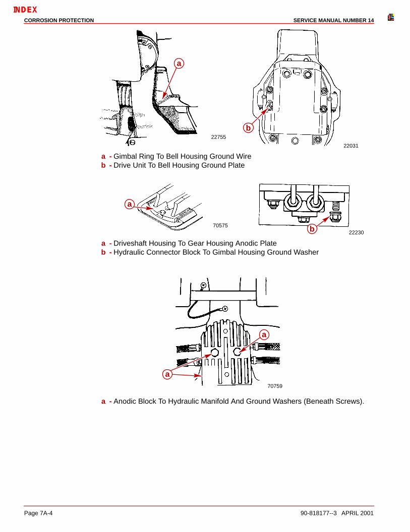
Later Style Anodic Blocka - Anodic Blockb - Screwc - Continuity Washerd - Gaskete - Seal
2. Check condition of hydraulic manifold and clean any debris from threaded holes.
70748
b
a
a - Threaded Holesb - Hydraulic Manifold

CORROSION PROTECTIONSERVICE MANUAL NUMBER 14
90-818177--3 APRIL 2001 Page 7A-7
3. Examine rubber seal inside of hydraulic manifold block for signs of leakage or wear.Replace if necessary.
70748
5070773a b
a - Hydraulic Manifoldb - Rubber Seal
4. If rubber seal needs replacement, push old seal out of hydraulic manifold and install newseal as shown.
70774a b
a - Hydraulic Manifoldb - Rubber Seal

CORROSION PROTECTION SERVICE MANUAL NUMBER 14
Page 7A-8 90-818177--3 APRIL 2001
5. Install screws and washers into block as shown.
70760
a
c
b
a - Screws (2)b - Anodic Blockc - Continuity Washers (2)
CAUTIONTo be effective, new anodic block MUST make good continuity contact with gimbalhousing.
6. Be sure new gasket is in proper position between anodic block and hydraulic manifold.Apply Quicksilver Perfect Seal to threads of screw once they are through block.
70772
a
b
c
a - Screws (2)b - Anodic Blockc - Gasket
7. Snug both screws evenly into hydraulic manifold, then torque to 100 lb-in. (11.5 Nm).
70759
ab
a - Screws and Washersb - Anodic Block
CORROSION PROTECTIONSERVICE MANUAL NUMBER 14
90-818177--3 APRIL 2001 Page 7A-9
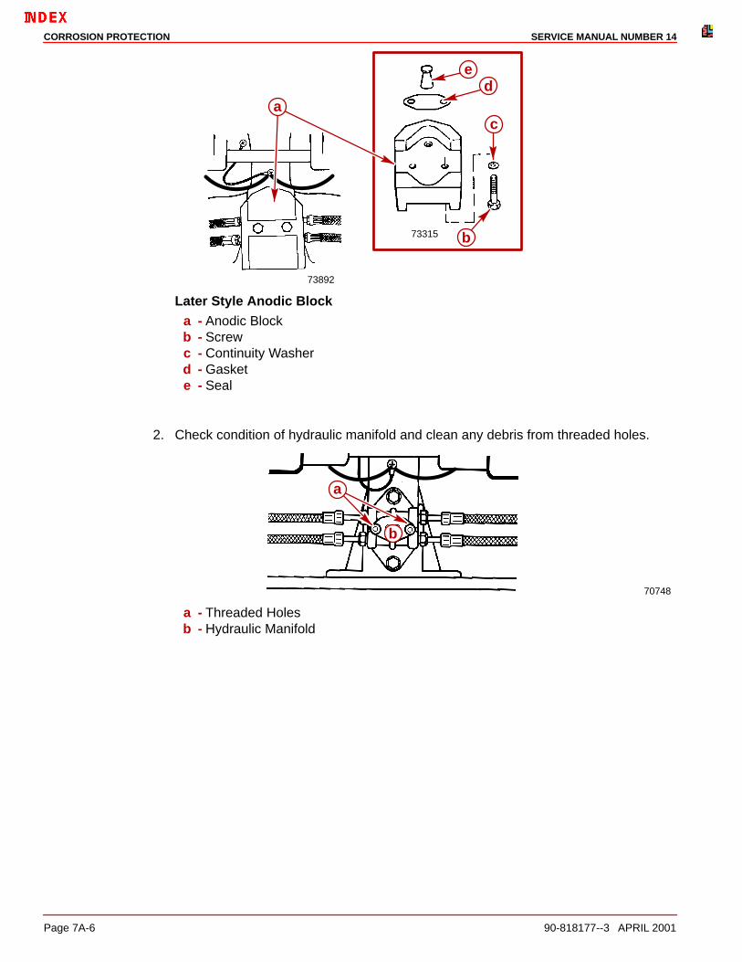
Trim Cylinder Anodes
CAUTIONDO NOT paint new trim cylinder anodes, as this will render them ineffective as a gal-vanic corrosion inhibitor.
1. Remove screws that secure anodes to trim cylinders. Remove anodes.
71966
a
b
a - Screwsb - Trim Cylinder Anodes
2. Scrape mounting surface on cylinder end-cap down to bare metal.
3. Install new anodes and tighten securely.
CORROSION PROTECTION SERVICE MANUAL NUMBER 14
Page 7A-10 90-818177--3 APRIL 2001
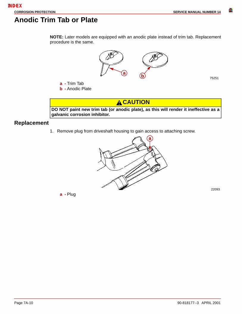
Anodic Trim Tab or Plate
NOTE: Later models are equipped with an anodic plate instead of trim tab. Replacementprocedure is the same.
75251
ab
a - Trim Tabb - Anodic Plate
CAUTIONDO NOT paint new trim tab (or anodic plate), as this will render it ineffective as agalvanic corrosion inhibitor.
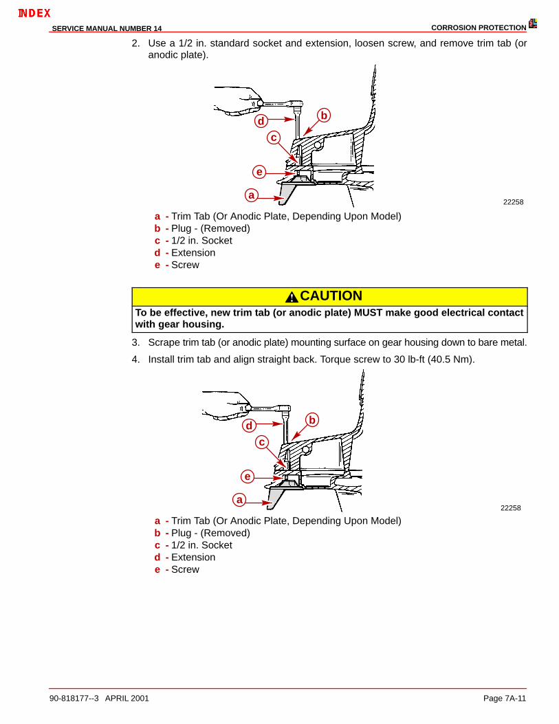
Replacement1. Remove plug from driveshaft housing to gain access to attaching screw.
22093
a
a - Plug
CORROSION PROTECTIONSERVICE MANUAL NUMBER 14
90-818177--3 APRIL 2001 Page 7A-11
2. Use a 1/2 in. standard socket and extension, loosen screw, and remove trim tab (oranodic plate).
22258a
e
c
bd
a - Trim Tab (Or Anodic Plate, Depending Upon Model)b - Plug - (Removed)c - 1/2 in. Socketd - Extensione - Screw
CAUTIONTo be effective, new trim tab (or anodic plate) MUST make good electrical contactwith gear housing.
3. Scrape trim tab (or anodic plate) mounting surface on gear housing down to bare metal.
4. Install trim tab and align straight back. Torque screw to 30 lb-ft (40.5 Nm).
22258a
e
c
bd
a - Trim Tab (Or Anodic Plate, Depending Upon Model)b - Plug - (Removed)c - 1/2 in. Socketd - Extensione - Screw

CORROSION PROTECTION SERVICE MANUAL NUMBER 14
Page 7A-12 90-818177--3 APRIL 2001
5. Reinstall plug in driveshaft housing.
22093
a
Integral MerCathode System
Removing Electrode Assembly1. Disconnect electrode assembly wires from MerCathode Controller.
22032a
b
cd
e
a - Electrode Assembly Wire (Orange)b - Electrode Assembly Wire (Brown)c - Earlier Models - Trim Position Sender Wire (Black)d - Earlier Models - Trim Position Sender Wire (Black)e - Earlier Models - Wire to Trim Position Gauge (Brown/White)

CORROSION PROTECTIONSERVICE MANUAL NUMBER 14
90-818177--3 APRIL 2001 Page 7A-13
2. Remove two screws, flat washers and lock washers; then remove electrode assembly.
70771
e
db
c
a
a - Electrode Assemblyb - Screw (2)c - Flat Washer (2)d - Lock Washer (2)e - Hydraulic Connector Block
Installing Electrode Assembly
CAUTIONO-ring MUST BE properly seated in groove of electrode assembly or water leakageinto boat will result.
1. Earlier Model Electrodes: Install the O-ring over the orange and brown wires from theelectrode assembly. Seat the O-ring in the groove. DO NOT use any type of sealer onthe O-ring.
70756
a
b
a - O-ring Grooveb - O-ring
CORROSION PROTECTION SERVICE MANUAL NUMBER 14
Page 7A-14 90-818177--3 APRIL 2001
2. Later Model Electrodes: Later model electrodes have a factory installed rubbergrommet and DO NOT require an O-ring.
71862ba
a - Electrodeb - Rubber Grommet
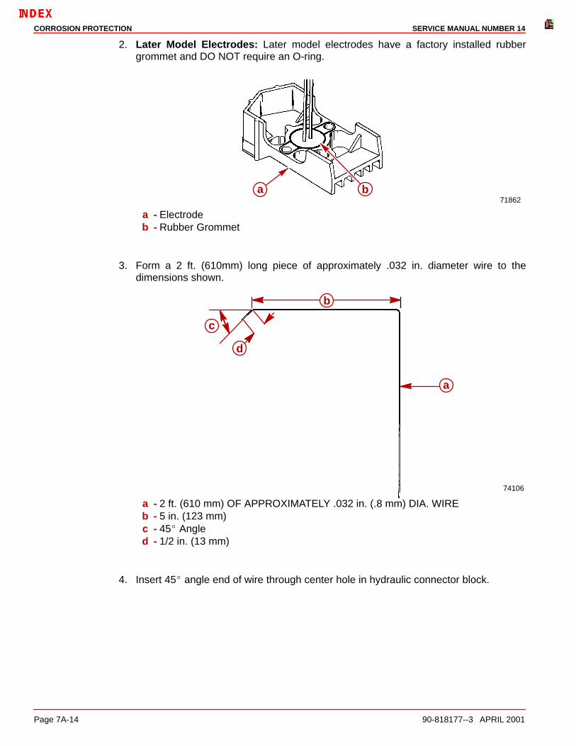
3. Form a 2 ft. (610mm) long piece of approximately .032 in. diameter wire to thedimensions shown.
74106
a
b
c
d
a - 2 ft. (610 mm) OF APPROXIMATELY .032 in. (.8 mm) DIA. WIREb - 5 in. (123 mm)c - 45� Angled - 1/2 in. (13 mm)
4. Insert 45� angle end of wire through center hole in hydraulic connector block.
CORROSION PROTECTIONSERVICE MANUAL NUMBER 14
90-818177--3 APRIL 2001 Page 7A-15
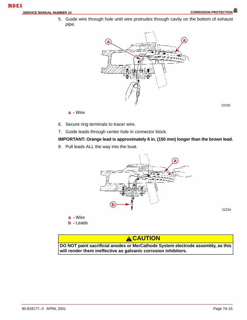
5. Guide wire through hole until wire protrudes through cavity on the bottom of exhaustpipe.
22235
a a
a - Wire
6. Secure ring terminals to tracer wire.
7. Guide leads through center hole in connector block.
IMPORTANT: Orange lead is approximately 6 in. (150 mm) longer than the brown lead.
8. Pull leads ALL the way into the boat.
22234b
a
a - Wireb - Leads
CAUTIONDO NOT paint sacrificial anodes or MerCathode System electrode assembly, as thiswill render them ineffective as galvanic corrosion inhibitors.
CORROSION PROTECTION SERVICE MANUAL NUMBER 14
Page 7A-16 90-818177--3 APRIL 2001
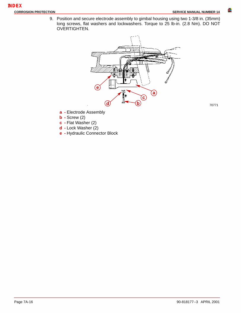
9. Position and secure electrode assembly to gimbal housing using two 1-3/8 in. (35mm)long screws, flat washers and lockwashers. Torque to 25 lb-in. (2.8 Nm). DO NOTOVERTIGHTEN.
70771
e
d bc
a
a - Electrode Assemblyb - Screw (2)c - Flat Washer (2)d - Lock Washer (2)e - Hydraulic Connector Block

CORROSION PROTECTIONSERVICE MANUAL NUMBER 14
90-818177--3 APRIL 2001 Page 7A-17
Connect Electrical Leads to Controller AssemblyNOTE: If black (ground) wire is not available at terminal block or from wire harness, installa separate lead between controller negative (–) terminal and negative (–) battery cableattaching point on engine.
1. Connect electrical leads to controller assembly, securely. (See applicable WiringDiagrams, following.)
2. Apply a thin coat of Quicksilver Liquid Neoprene (92-25711) to ALL electricalconnections.
CORROSION PROTECTION SERVICE MANUAL NUMBER 14
Page 7A-18 90-818177--3 APRIL 2001
Wiring Diagrams
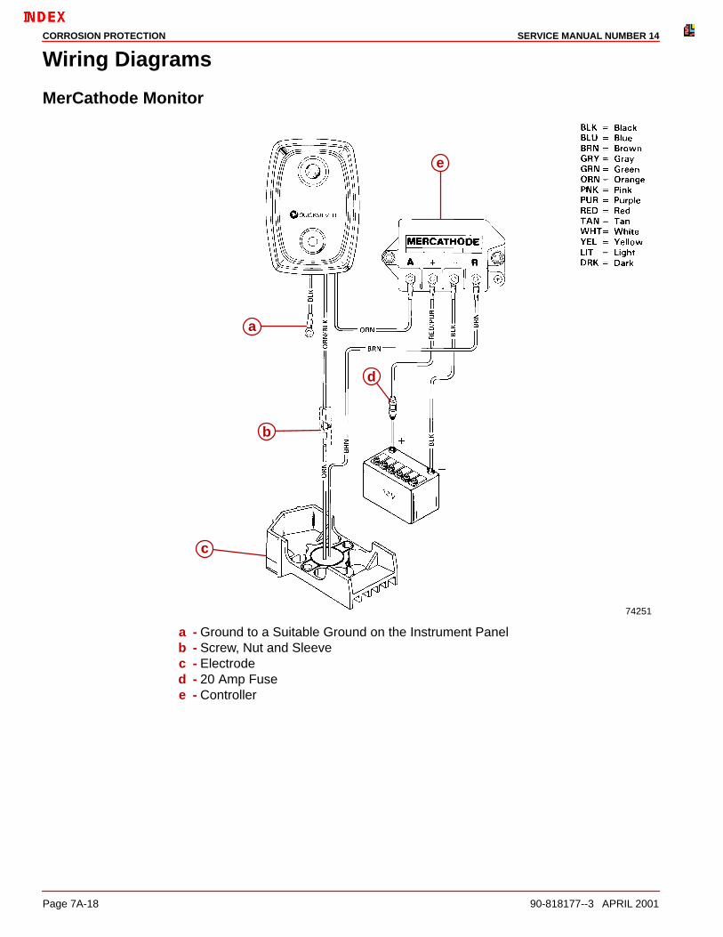
MerCathode Monitor
74251
a
b
c
d
e
a - Ground to a Suitable Ground on the Instrument Panelb - Screw, Nut and Sleevec - Electroded - 20 Amp Fusee - Controller

CORROSION PROTECTIONSERVICE MANUAL NUMBER 14
90-818177--3 APRIL 2001 Page 7A-19
MerCathode Controller
73596
a
b
c
a - Controllerb - 20 Amp Fusec - Electrode

CORROSION PROTECTION SERVICE MANUAL NUMBER 14
Page 7A-20 90-818177--3 APRIL 2001
Quicksilver Isolator
Boats, which are connected to A.C. shore power require additional protection, to preventdestructive low voltage galvanic currents from passing thru the shore power ground wire.A Quicksilver Isolator (18478A2) can be installed to block the passage of these currents,while still providing a path to ground for dangerous fault (shock) currents.
CAUTIONIf A.C. shore power is not isolated from boat ground, the MerCathode System andsacrificial anodes may be unable to handle the increased galvanic corrosion poten-tial.
70972
a
a - Quicksilver Isolator
Corrosion Protection Testing and Troubleshooting
NOTE: The following corrosion protection test supersedes all previously issued tests. Thistest can be used on applications with or without a MerCathode System.
If the unit is equipped with a MerCathode System, this test should be performed annuallywhere the boat is moored to ensure that the system is functioning properly.
Test requires the us of MerCathode Reference Electrode Test 76675A1 and QuicksilverVOA meter 91-62562A1. This meter is no longer available from Mercury Marine. If you donot already have this meter, a digital multi-meter must be used. A STANDARD ANALOGMETER CANNOT BE USED, AS AN INACCURATE READING WILL RESULT.
IMPORTANT: Quicksilver Volt/Ohm Meter 91–93572 and Multi-Meter DVA/Tester91-99750 are no longer recommended for testing corrosion protection.
CORROSION PROTECTIONSERVICE MANUAL NUMBER 14
90-818177--3 APRIL 2001 Page 7A-21
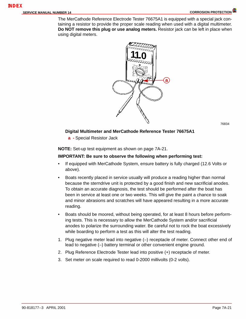
The MerCathode Reference Electrode Tester 76675A1 is equipped with a special jack con-taining a resistor to provide the proper scale reading when used with a digital multimeter.Do NOT remove this plug or use analog meters. Resistor jack can be left in place whenusing digital meters.
76834
a
11.0
Digital Multimeter and MerCathode Reference Tester 76675A1a - Special Resistor Jack
NOTE: Set-up test equipment as shown on page 7A-21.
IMPORTANT: Be sure to observe the following when performing test:
• If equipped with MerCathode System, ensure battery is fully charged (12.6 Volts orabove).
• Boats recently placed in service usually will produce a reading higher than normalbecause the sterndrive unit is protected by a good finish and new sacrificial anodes.To obtain an accurate diagnosis, the test should be performed after the boat hasbeen in service at least one or two weeks. This will give the paint a chance to soakand minor abrasions and scratches will have appeared resulting in a more accuratereading.
• Boats should be moored, without being operated, for at least 8 hours before perform-ing tests. This is necessary to allow the MerCathode System and/or sacrificialanodes to polarize the surrounding water. Be careful not to rock the boat excessivelywhile boarding to perform a test as this will alter the test reading.
1. Plug negative meter lead into negative (–) receptacle of meter. Connect other end oflead to negative (–) battery terminal or other convenient engine ground.
2. Plug Reference Electrode Tester lead into positive (+) receptacle of meter.
3. Set meter on scale required to read 0-2000 millivolts (0-2 volts).

CORROSION PROTECTION SERVICE MANUAL NUMBER 14
Page 7A-22 90-818177--3 APRIL 2001
4. Immerse Electrode Tester in the water within 6 in. (150 mm) of aft end of sterndrive unit.
IMPORTANT: There will be different voltage readings depending on the type of Mer-Cathode System you are testing.
76868
Electrode Mounted on Bottom of Transom Assembly
71895
Electrodes Mounted on Boat Transom
5. The following readings indicate that the sterndrive unit is adequately protected:
a. MODELS WITH ELECTRODE MOUNTED ON BOAT TRANSOM
Fresh Water Areas Salt, Polluted or MineralLaden Water Areas
Quicksilver VOA Meter 7.5 - 10.5 millivolts 8.8 - 10.5 millivolts
Digital Meter 750 - 1050 millivolts 880 - 1050 millivolts
b. MODELS WITH ELECTRODE MOUNTED ON BOTTOM OF TRANSOM ASSEMBLY
Fresh Water Areas Salt, Polluted or MineralLaden Water Areas
Quicksilver VOA Meter 6.2 - 11.8 millivolts 7.5 - 11.8 millivolts
Digital Meter 620 - 1180 millivolts 750 - 1180 millivolts
6. If the reading is not within specified limits, or if reading is within specifications but thereis evidence of corrosion on sterndrive, refer to the following troubleshooting charts toaid in diagnosis.

CORROSION PROTECTIONSERVICE MANUAL NUMBER 14
90-818177--3 APRIL 2001 Page 7A-23
Test Equipment Set-Up
70755
6 IN. (150 MM)(MAX.)
CORROSION PROTECTION SERVICE MANUAL NUMBER 14
Page 7A-24 90-818177--3 APRIL 2001
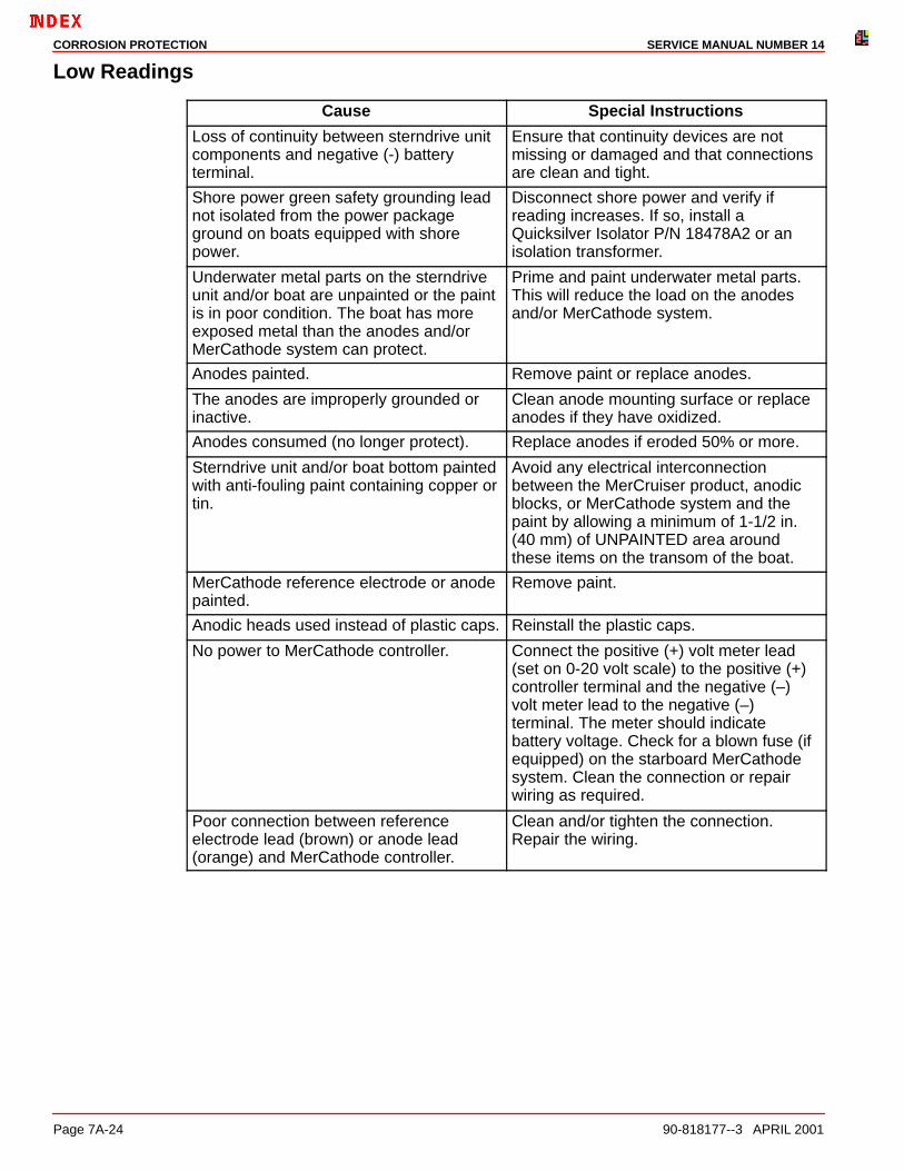
Low Readings
Cause Special Instructions
Loss of continuity between sterndrive unitcomponents and negative (-) batteryterminal.
Ensure that continuity devices are notmissing or damaged and that connectionsare clean and tight.
Shore power green safety grounding leadnot isolated from the power packageground on boats equipped with shorepower.
Disconnect shore power and verify ifreading increases. If so, install aQuicksilver Isolator P/N 18478A2 or anisolation transformer.
Underwater metal parts on the sterndriveunit and/or boat are unpainted or the paintis in poor condition. The boat has moreexposed metal than the anodes and/orMerCathode system can protect.
Prime and paint underwater metal parts.This will reduce the load on the anodesand/or MerCathode system.
Anodes painted. Remove paint or replace anodes.
The anodes are improperly grounded orinactive.
Clean anode mounting surface or replaceanodes if they have oxidized.
Anodes consumed (no longer protect). Replace anodes if eroded 50% or more.
Sterndrive unit and/or boat bottom paintedwith anti-fouling paint containing copper ortin.
Avoid any electrical interconnectionbetween the MerCruiser product, anodicblocks, or MerCathode system and thepaint by allowing a minimum of 1-1/2 in.(40 mm) of UNPAINTED area aroundthese items on the transom of the boat.
MerCathode reference electrode or anodepainted.
Remove paint.
Anodic heads used instead of plastic caps. Reinstall the plastic caps.
No power to MerCathode controller. Connect the positive (+) volt meter lead(set on 0-20 volt scale) to the positive (+)controller terminal and the negative (–)volt meter lead to the negative (–)terminal. The meter should indicatebattery voltage. Check for a blown fuse (ifequipped) on the starboard MerCathodesystem. Clean the connection or repairwiring as required.
Poor connection between referenceelectrode lead (brown) or anode lead(orange) and MerCathode controller.
Clean and/or tighten the connection.Repair the wiring.
CORROSION PROTECTIONSERVICE MANUAL NUMBER 14
90-818177--3 APRIL 2001 Page 7A-25
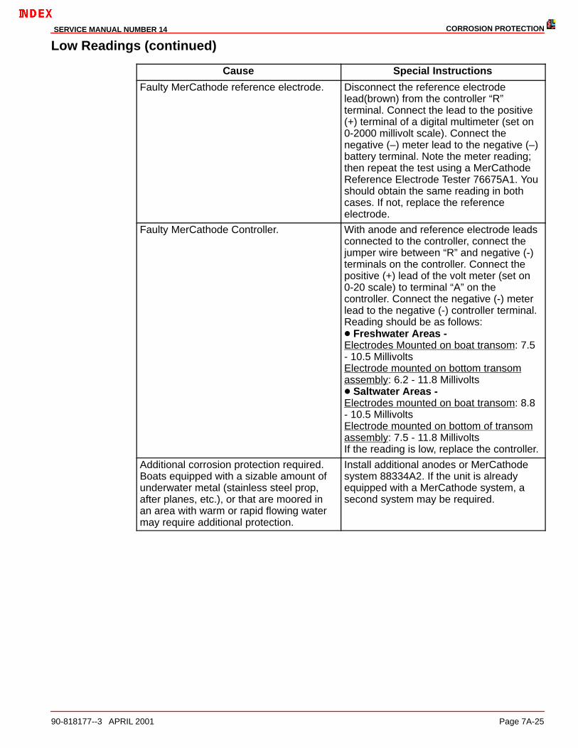
Low Readings (continued)
Cause Special Instructions
Faulty MerCathode reference electrode. Disconnect the reference electrodelead(brown) from the controller “R”terminal. Connect the lead to the positive(+) terminal of a digital multimeter (set on0-2000 millivolt scale). Connect thenegative (–) meter lead to the negative (–)battery terminal. Note the meter reading;then repeat the test using a MerCathodeReference Electrode Tester 76675A1. Youshould obtain the same reading in bothcases. If not, replace the referenceelectrode.
Faulty MerCathode Controller. With anode and reference electrode leadsconnected to the controller, connect thejumper wire between “R” and negative (-)terminals on the controller. Connect thepositive (+) lead of the volt meter (set on0-20 scale) to terminal “A” on thecontroller. Connect the negative (-) meterlead to the negative (-) controller terminal.Reading should be as follows:� Freshwater Areas - Electrodes Mounted on boat transom: 7.5- 10.5 MillivoltsElectrode mounted on bottom transomassembly: 6.2 - 11.8 Millivolts� Saltwater Areas - Electrodes mounted on boat transom: 8.8- 10.5 MillivoltsElectrode mounted on bottom of transomassembly: 7.5 - 11.8 MillivoltsIf the reading is low, replace the controller.
Additional corrosion protection required.Boats equipped with a sizable amount ofunderwater metal (stainless steel prop,after planes, etc.), or that are moored inan area with warm or rapid flowing watermay require additional protection.
Install additional anodes or MerCathodesystem 88334A2. If the unit is alreadyequipped with a MerCathode system, asecond system may be required.

CORROSION PROTECTION SERVICE MANUAL NUMBER 14
Page 7A-26 90-818177--3 APRIL 2001
High Reading
Cause Special Instructions
Stray current corrosion. If an electrical current flowing along a metal conductorleaves the metal for a water path, it willcause ionization of the metal, and an areaof rapid corrosion.
Observe the reading while disconnectingthe electrical components one at a timeuntil you eliminate the high reading.Correct the course of stray current.
Poor connection between MerCathodereference electrode lead (brown) and “R”terminal on controller.
Clean and /or tighten connection. Repairwiring as required.
Faulty MerCathode reference electrode. Disconnect the reference electrode lead(brown) from “R” terminal on the controller.Connect the lead to the positive (+)terminal of a digital multi-meter (set on0-2000 millivolt scale). Connect thenegative (–) meter lead to the negative (–)battery terminal. Note the meter reading;then, repeat the test using MerCathodeReference Electrode Tester 76675A1.Both tools should produce the samereading. If not, replace the referenceelectrode.
Faulty MerCathode controller. Replace the controller.
Normal Reading But Corrosion is Evident
CORROSION ON THE ENTIRE STERNDRIVE UNIT
Cause Special Instructions
The sterndrive unit is raised so that the sacrificial anodic trim tab is out of the water.
Leave the sterndrive unit in the IN/DOWN position when the boat is moored to ensure the trim tab is in the water, providing protection.
CORROSION PROBLEM DEVELOPED AFTER REFINISHING THE DRIVE UNIT
Cause Special Instructions
A steel wire brush was used to clean the aluminum casting. Steel particles became en-trapped and set up a small galvanic cell.
Use only a nylon or bristle brush.
PAINT BLISTERING ON DRIVE UNIT
Cause Special Instructions
Battery charger, using 110 volt shore power improperly connected to the battery.
Ensure the charger is connected correctly.
CORROSION PROTECTIONSERVICE MANUAL NUMBER 14
90-818177--3 APRIL 2001 Page 7A-27
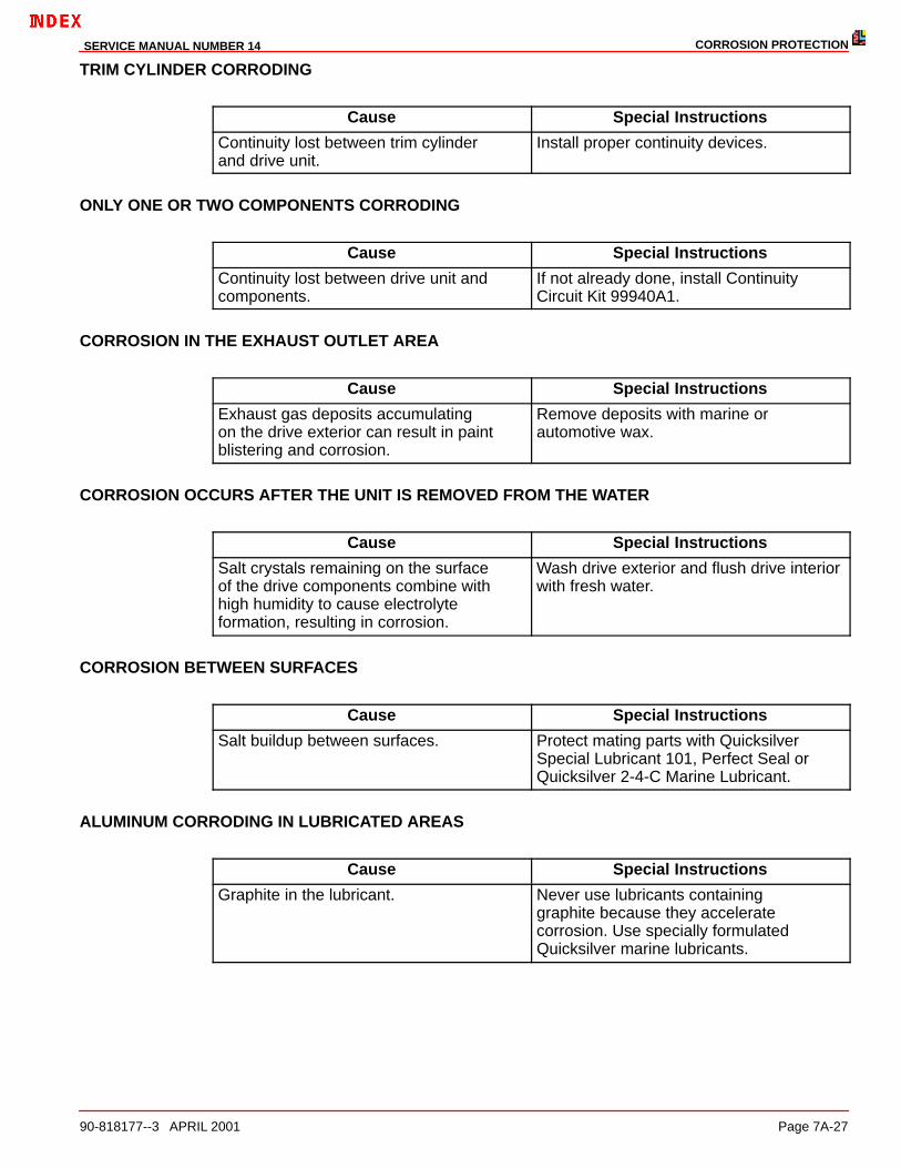
TRIM CYLINDER CORRODING
Cause Special Instructions
Continuity lost between trim cylinder and drive unit.
Install proper continuity devices.
ONLY ONE OR TWO COMPONENTS CORRODING
Cause Special Instructions
Continuity lost between drive unit and components.
If not already done, install Continuity Circuit Kit 99940A1.
CORROSION IN THE EXHAUST OUTLET AREA
Cause Special Instructions
Exhaust gas deposits accumulating on the drive exterior can result in paint blistering and corrosion.
Remove deposits with marine or automotive wax.
CORROSION OCCURS AFTER THE UNIT IS REMOVED FROM THE WATER
Cause Special Instructions
Salt crystals remaining on the surface of the drive components combine with high humidity to cause electrolyteformation, resulting in corrosion.
Wash drive exterior and flush drive interiorwith fresh water.
CORROSION BETWEEN SURFACES
Cause Special Instructions
Salt buildup between surfaces. Protect mating parts with Quicksilver Special Lubricant 101, Perfect Seal orQuicksilver 2-4-C Marine Lubricant.
ALUMINUM CORRODING IN LUBRICATED AREAS
Cause Special Instructions
Graphite in the lubricant. Never use lubricants containing graphite because they accelerate corrosion. Use specially formulated Quicksilver marine lubricants.
CORROSION PROTECTION SERVICE MANUAL NUMBER 14
Page 7A-28 90-818177--3 APRIL 2001
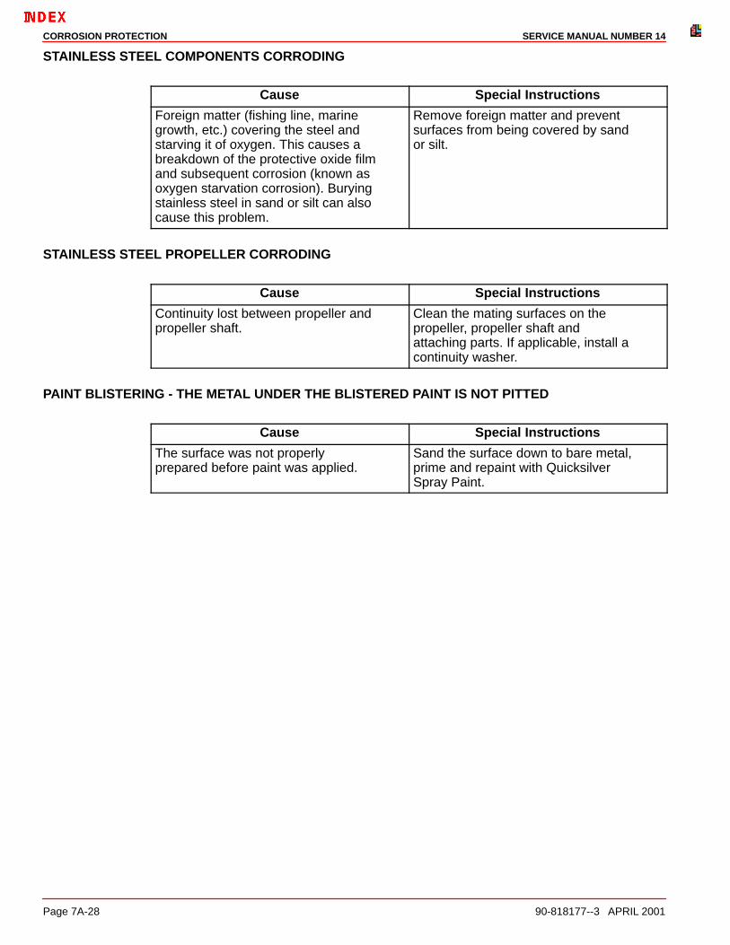
STAINLESS STEEL COMPONENTS CORRODING
Cause Special Instructions
Foreign matter (fishing line, marine growth, etc.) covering the steel and starving it of oxygen. This causes a breakdown of the protective oxide film and subsequent corrosion (known as oxygen starvation corrosion). Burying stainless steel in sand or silt can also cause this problem.
Remove foreign matter and prevent surfaces from being covered by sand or silt.
STAINLESS STEEL PROPELLER CORRODING
Cause Special Instructions
Continuity lost between propeller and propeller shaft.
Clean the mating surfaces on the propeller, propeller shaft and attaching parts. If applicable, install a continuity washer.
PAINT BLISTERING - THE METAL UNDER THE BLISTERED PAINT IS NOT PITTED
Cause Special Instructions
The surface was not properly prepared before paint was applied.
Sand the surface down to bare metal, prime and repaint with Quicksilver Spray Paint.

CORROSION PROTECTIONSERVICE MANUAL NUMBER 14
90-818177--3 APRIL 2001 Page 7A-29
THIS PAGE IS INTENTIONALLY BLANK

CORROSION PROTECTION SERVICE MANUAL NUMBER 14
Page 7A-30 90-818177--3 APRIL 2001
THIS PAGE IS INTENTIONALLY BLANK
Related Documents