Service Manual for Chery QQ6 (Electrical, Circuit) After Sales Service Department of Chery Automobile Sales Co., Ltd

Welcome message from author
This document is posted to help you gain knowledge. Please leave a comment to let me know what you think about it! Share it to your friends and learn new things together.
Transcript
Service Manual for Chery QQ6
(Electrical, Circuit)
After Sales Service Department of Chery Automobile Sales Co., Ltd
TABLES OF CONTENTS Chapter One Control Principle of Some Systems ..................................................................4
I. Control Principle of Starting System.....................................................................................4 1. Starting System .............................................................................................................4 2. Charging System...........................................................................................................4 3. Troubleshooting and Elimination..................................................................................5
3.1. The starter not operate, low power output or its fuse burnout............................5 3.2. Generator not work or low power output ...........................................................5
II. BCM Control.....................................................................................................................6 1. Ceiling Lamp Control ................................................................................................6 2. Window Glass UP/DOWN Function ............................................................................6 3. Central Door Lock ........................................................................................................6 4. Anti-theft Alarm System ...............................................................................................7
III. Fog and Position Lamps Control ........................................................................................9 1. Principle of Fog Lamp Control ...................................................................................10 2. Principle of Clearance Lamp Control ......................................................................... 11 3. Night Light and Electric Headlamp Control ............................................................... 11
IV. Headlamp Control ............................................................................................................. 11 1. Principle of low beam lamp control ............................................................................12 2. Principle of high beam lamp control...........................................................................12 3. Principle of the passing lamp control..........................................................................13
V. Turn Signal Lamp Control..................................................................................................13 1. Principle of turn signal lamp control...........................................................................14
VI. Electric Rear-View Mirror ................................................................................................14 1. Control principle .........................................................................................................15
VII. Wiper Motor Control .......................................................................................................15 1. Control principle .........................................................................................................16 2. Wiper return and stop function....................................................................................16
Chapter Two Schematic Diagrams of Circuit Control .................................................................17 I. Definition of Main Harness Connectors ...........................................................................17 II. Drawing Description .......................................................................................................21
1. Main Symbol Description ...........................................................................................21 2. Drawing Description...................................................................................................21 3. Definition of Main Controller .....................................................................................22 4. Position of Body Grounding Points ............................................................................22
III. Schematic Diagram of Main Electric Box and Module Position ......................................24 IV. Electrical Box Description ................................................................................................25
1. Instrument Electrical Box ...........................................................................................25 2. Compartment Electrical Box.......................................................................................25
V. Schematic Diagrams of Circuit Control .............................................................................26 1. Starting and Charging System.....................................................................................26 2. Electric Rear-View Mirror ..........................................................................................27

3. Engine’s Anti-Theft System........................................................................................28 4. A/C and Defrost Systems ............................................................................................29 5. Horn, Backup Lamp, Cigaretter Lighter, Ceiling Lamp and Luggage Boot Light .....30 6. Radio...........................................................................................................................31 7. Front/Rear Wiper ........................................................................................................32 8. Turn Signal Lamp System...........................................................................................33 9. Air Bag........................................................................................................................34 10. Instrument System ....................................................................................................35 11. Engine’s Electronic Fuel Injection System ...............................................................36 12. BCM system..............................................................................................................37

Chapter One Control Principle of Some Systems
I. Control Principle of Starting System
1. Starting System
When the ignition switch is turned to ST position, the pull-in winding of the starter powers on, and then the starting gear of stater motor is pushed to and engaged with the gear of flywheel. At the same time, when the gears engage, the contact on the pull-in winding works and connects the power supply from the battery to the starter motor so as to turn the motor and start up the engine. When the ignition key returns back to the IG position, the holding coil of the starter powers off, and under the action of spring force of the gear the motor disengages from the flywheel and the flywheel of starter motor disconnects at the same time. The starting signal is transmitted to BCM at the same time. The BCM utilizes the starting signal to determine that the system is in the starting condition. In this case, the BCM will stop the action of motor of window glass regulator so as to ensure that there is electric engergy enough to be supplied to starter motor.
2. Charging System
When the ignition switch is in IG position, the power supply from the ignition switch F17 is used to excite the generator so as to ensure that it can generate electric power during the generator is
A t B o d y A t
T r a n s m i s s i o n
I g n i t i o n S w i t c h
B a t t e r y
S t a r t e r
G e n e r a t o r
3 0
3 0a
15
15 a
K a
I g n i t i o n S w i t c h
T o F u s e F 1 7
operating. When the generator itself can generate electric power, the system will switch to the self-excitation mode. In addition, when the generator is generating electric power, it gives a signal to the relevant instrument via the D+ terminal. After the instrument receive the signal from the generator, the battery indicator on the instrument will be extinguished.
3. Troubleshooting and Elimination
3.1. The starter not operate, low power output or its fuse burnout
Not operate: When the key is in starting position, if the sound of action of pull-in winding can be heard while the motor doesn’t operate, this may be caused due to the battery no power output, contact in pull-in winding failure or starter ground poor. Low power output: The starter can operate while with low power output. The cause may be low power output of battery, or high resistance of engine mechanical parts. Fuse burnout: If the fuse burns out frequently when starting, it may be caused due to the starter ground poor, wire connection poor or starter interior and engine interior resistance overhigh.
3.2. Generator not work or low power output
Generator not work: Generator’s not working may make an influence on many systems, and also result that the battery is used out rapidly. The cause to result the generator doesn’t work may be the exciting circuit work poor, and also may be the rotor, carbon brush or rectification regulator inside generator failure. Of course, the generator is now unallowable to be repaired. If the trouble is caused due to the generator problem, please replace the generator assy.. Power output low or overhigh: When the generator’s power output is low, it may result that the system voltage is low and many systems fail to work normally. For the vehicle equipped with ABS system, the ABS system is very sensitive to the power output of generator. In case that the power output is low, the system immediately changes to the failure mode. The main cause to result the low power output may be the reguator inside the generator work poor or generator’s belt loose and etc. The power output overhigh generally means that the voltage is overhigh, which easily damages the electical devices. This is a very dangerous failure which may result the electrical harness catches a fire. The generator voltage overhigh is mainly caused due to the regulating circuit inside the generator work poor.

II. BCM Control
1. Ceiling Lamp Control
l When any door opens, the ceiling lamp lights automatically, and then extighuishes 15 minutes later after the door opens.
l The ignition switch is placed to OFF position, and, 8s later after all four doors close, the ceiling lamp gradually extinguishes, with duration of 2s.
l During the ceiling lamp delays 8s, if the ignition switch changes OFF position to ON position, the ceiling lamp extinguishes immediately.
l If the ignition switch is in ON position and all four doors close, after any door opens and then closes, the ceiling lamp immediately extinguishes without time delay.
l When all four doors close and the ceiling lamp lights, press down the LOCK button on the remote controller and then the lamp immediately extinguishes.
l Press the UNLOCK button once, then the ceiling lamp lights and keeps lighting for 8s, and the lamp extinguishes slowly within the subsequent 2 s.
Note: When the switch of ceiling lamp is placed to the controlled position, the ceiling lamp control
function is available.
2. Window Glass UP/DOWN Function
l The electric window control is allowable only when the ignition switch is in ON position, or only within 1 minute after the ignition key changes from ON to OFF, otherwise, the electric window control is prohibited.
l Temporarily stop the lifting of window glass when starting l Automatic/manual control
Manual control UP: If the driver-side door or passenger-side door window UP switch is pulled up, the window will be driven by a motor and lift. Note: Without the automatic window lift function, only with the manual lift function).
Automatic/manual DOWN: If the switch input time t < 300 ms, the window will aumatically fall down. When t is greater than or equal to 300 ms, the window will manually fall down.
l Press the LOCK pushbutton for 2s every time to remote control the lifting of window glass, and releasae the pushbutton to stop the lifting of window glass.
3. Central Door Lock
l The front left door key independently control the unlocking/locking of the central door lock.
l The door lock and window glass regulator can’t act at the same time, and the former is preferred if conflict.
l Automatic door lock control (pre-reserved signal, suitable for the speed locking of vehicle equipped with air bag and the unlocking after the air bag explodes).
4. Anti-theft Alarm System
4.1. Door lock remote control function When the remote control key’s UNLOCK/LOCK pushbutton is pressed down, the door
lock motor will act 0.6 s ± 50 ms. When the door unlocks, the right/left turn signal lamp flashes: 0.5s ± 50ms On; 0.5s ±
50ms Off; 0.5s ± 50ms On. And then it extinguishes. When the door locks, the right/left turn signal lamp flashes: 0.5s ± 50ms.
4.2. Vehicle safety system has five modes: Ø Arming mode – When a driver presses down the ALARM button, the vehicle is in
arming condition. Ø Disarm mode – The arming mode is removed by the driver. Ø Alarm mode – When a invasion event is detected, the system may give an alarm (not
give an alarm for the vehicle without the alarm horn). Ø Disalarm mode – The driver returns back to the side of vehicle and turns off the alarm. Ø Arming failure mode – The vehicle fails to successfully establish the arming condition.
4.3. Arming mode: a) How to enter into the arming mode:
Condition: ① Four doors close; ② Front hood and rear trunck close.
Operation : Press down the “LOCK” button on the remote controller.
b) Representation when entering into the arming mode:
Before the body enters into the normal arming mode: ① the left/right turn signal lamp
flashes once; ② the body anti-theft horn gives an alarm once (not give an alarm for the
vehicle without the alarm horn).
c) Specific representation when the failure to enter into the arming mode:
When the failure to enter into the arming mode, the system will has the following
representations: ① the left/right turn signal lamp continuously flashes twice; ② the body
anti-theft horn doesn’t give an alarm (not give an alarm for the vehicle without the alarm
horn).
d) Body state after entering into the arming mod:
After the body enters into the normal arming mode: ① the four doors are locked; ② the

arming indicator light continuously flashes; ③ if the ceiling lamp switch is in the
controlled position and the ceiling lamp is in OPEN position, the ceiling lamp closes.
4.4. Disarm mode: a) How to disarm:
Condition: The body is in the normal arming mode.
Operation: Press down the “UNLOCK” button on the remote controller.
b) Representation when disarming:
Before the body changes from the normal arming mode to the disarm mode: ① the
left/right turn signal lamp continuously flashes twice; ② the body anti-theft horn
continuously gives an alarm twice (not give an alarm for the vehicle without the alarm
horn).
c) Body state after disarming:
After the body is disarmed: ① the four doors can be freely opened; ② the arming
indicator light stops flashing; ③ the ceiling lamp automatically extinguishes within 8 s
after it turns on.
(CAUTION: If no action on the body is implemented within 28 s after disarming, 28 s
later, the body control module will automatically make the body enter again into the
arming condition.
4.5. Alarm mode: a) How to trigger the alarm mode:
Condition: The body is in the normal arming mode.
Operation: ① Enfocedly open any of four doors; ② enforcedly open front hood or trunk;
③ turn on the ignition switch.
b) Representation when entering the alarm mode:
After the body enters into the alarm mode: ① the left/right turn signal lamp continuously
flashes for 28 s; ② the body anti-theft horn continuously give an alarm for 28 s; ③ after
stopping alarming, 28 s later, if four door, front hood and trunk close and then open, the
left/right turn signal lamp and the body anti-theft horn will be triggered for 28 s, and
cycles; ④ if the door open or “ignition” state exists at all times, the alarm is given ten
cycles and then stops, with the cycle interval of 2 s (not give an alarm for the vehicle
without the alarm horn).
4.6. Disalarm mode a) How to disalarm:
After the body enters into the alarm mode: ① press down any pushbutton on the remote
controller.
b) Body state after disalarming:
1. If the triggered alarm door is in open state (not give an alarm for the vehicle without
the alarm horn).
Press down the UNLOCK pushbutton on the remote controller to ① disalarm; ② unlock
the central door lock.
Press down the LOCK pushbutton on the remote controller to ① disalarm; ②enable the
arming to be failed.
2. If the triggered alarm door is in close state (not give an alarm for the vehicle without
the alarm horn):
Press down the LOCK pushbutton on the remote controller to ① disalarm; ② disarm, and
carry out the secondary arming after 28 s.
Press down the LOCK pushbutton on the remote controller to ① disalarm; ② enter into
the arming mode.
4.7. Arming failure mode a) If door, engine hood, trunk fail to close at the same time, pressing the Arm key can’t set
up the arming condition:
After the failure of body arming: ① the left/right turn signal lamp lights.
III. Fog and Position Lamps Control

1. Principle of Fog Lamp Control
The fog lamp is controlled by the combination light switch which is used to control the open/close of the fog lamp relay. When the light switch is turned to the clearance lamp position, the electric power from the fuse F4 is supplied to the fog lamp switch via the angle 7#. When the fog lamp switch is in the front fog lamp position, the 3# terminal of the fog lamp switch is successfully connected to the 2# terminal to make the front fog lamp relay engaged and thus light up the front fog lamp. When the fog lamp switch is in the rear fog lamp position, all terminals 3#, 2# and 9# of the fog lamp switch turn on, and the rear fog lamp relay also engages. In this case, the front and rear fog lamps light at the same time. So, the principle of the fog lamp control is just to turn on the clearance lamp (position lamp) and then turn on the front fog lamp, and the rear fog lamp can be turned on only after the front fog lamp turns on (this is implemented using the switch).
Terminal
Light Control Switch
Rear Right Tail Lamp
Right Clearance Lamp
License Plate Lamp
Front Fog Lamp To Instrument
Rear Fog Lamp Relay
To Instrument
OFF
HeadlampPowerClearance Lamp
15a
Ka
30a
15
30
To Each Night Light Switch
Power
Left Clearance Lamp
Rear Left Tail Lamp
Front Right Fog Lamp
Front Left Fog Lamp
Rear Right Fog Lamp
Rear Left Fog Lamp
Clearance Lamp
Headlamp
Front Fog Lamp Relay
2. Principle of Clearance Lamp Control
The clearance lamp is controlled using a light switch. When the switch is in the clearance lamp position, the terminals 5# and 6# of the light switch will be turned on to make the power supply from the fuse F4 get to the clearance lamp via the angle 5#, and the front and rear clearance lamps connect to the fuses F13 and F14 respectively. In addition, the license plate lamp also lights.
3. Night Light and Electric Headlamp Control
When the light switch is in the clearance lamp position, the terminals 6# and 9# of the light switch are turned on, which supplies the electric power to the terminal 4# of the nightlight regulating switch and thus makes all nightlight circuit power on. Surely, the brightness is controlled by the regulation resistance mounted on the nightlight switch. When the light switch is in the headlamp position, the power supply from the fuse F11 is connected via the angles 3# and 8# of the headlamp switch which are used to supply the electric power to the electric switch and headlamp relay. In this case, the electric switch can employ its slide resistor to control the operation of electric motor. So, from the principles above, it can be concluded that the night light works only when the light switch is in the clearance lamp or headlamp position, and the electric headlamp can be adjustable only when the light switch is in the headlamp position.
IV. Headlamp Control

1. Principle of low beam lamp control
When the light switch is in the headlamp position, the terminal 8# of the light switch offers the light control switch’s 6# terminal the electric power. When the light control switch is in the low beam position, the switch will turn on the terminals 6# and 5# to make the low beam relay close and thus light up the low beam lamp.
2. Principle of high beam lamp control
When the light control switch is in the headlamp position, the switch will connect the power supply from the terminal 8# of the light switch and the terminal 4# of light control switch, which makes the high beam relay close and thus lights up the high beam lamp.
Right High Beam
Right Low Beam
Left High Beam
Left Low Beam
Light Switch
Light Regulating Switch
High Beam Indicator
High Beam Relay
Low Beam Relay
Terminal
Light Control Lamp
OFF
HeadlampPowerClearance
Lamp
15a
Ka
30a
15
30
Power
Clearance Lamp
Headlamp
3. Principle of the passing lamp control
When the light control switch is in PASS position (passing lamp position), the switch directly offers the high beam relay the electric power from the fuse F4, without via the light switch, which lights up the high beam lamp. So, it is unnecessary to open the light switch when the passing lamp is in service.
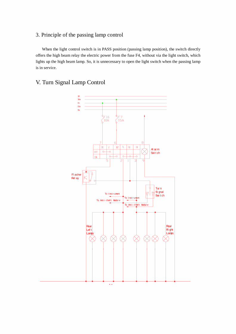
V. Turn Signal Lamp Control
Rear Right Lamps
Rear Left Lamps
To Anti-theft Module
To Instrument
Turn Signal Switch
Flasher Relay
Alarm Switch
14
30
30a
15a
15
Ka
To Anti-theft Module
To Instrument
1. Principle of turn signal lamp control
The turn signal lamp control is divided into three categories while the final control is implemented by the flasher relay.
Alarm switch control: The alarm switch has the power supply from the battery F7 fuse. So, it ensures that the switch can work in case that the ignition switch doesn’t turn on. When the alarm switch is in ON position, the flasher relay is powered by the terminals 5# and 6# of the alarm switch. In this case, the emitter electrode of the relay will provide a intermittent voltage signal, and the terminals 1#, 2# and 3# of two alarm switches utilize this intermittent signal to turn on the turn signal lamp and make the turn signal lamp work.
Turn signal lamp control: When the alarm switch is out of service, the electric power of flasher relay base electrode is supplied from the terminal F16 of the ignition switch. In case that the turn signal lamp switch turns on the left or right circuit, the intermittent power supply from flasher relay will enable the corresponding turn signal lamp to work. So, the turn signal lamp control is just the direct switch control.
BCM control: For the sake of body anti-theft requirement, the turn signal lamp is required to work when remote control of arming and the elimination of anti-theft. So, BCM also controls the turn signal lamp. This control is not via the alarm and turn signal switches, and its intermittent signal is implemented with its internal circuit.
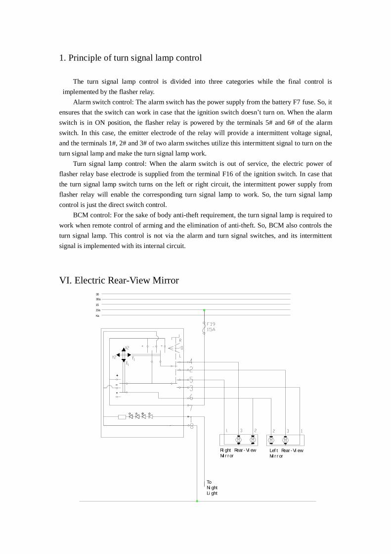
VI. Electric Rear-View Mirror
30
30a
15
15a
Ka
To Night Light
Right Rear-View Mirror
Left Rear-View Mirror

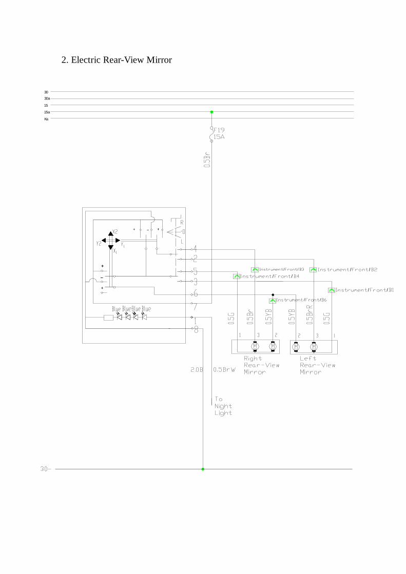
1. Control principle
The electric rear-view mirrorr is controlled by a switch, without any relay. When the L position is selected, the Nos 2 and 3 circuits form a loop respectively with the internal circuit of the switch. Take the Y1 direction as an example, when pushing the switch in the Y1 direction, the switch connects to the power supply from F19 while the power supply connects with the No 2 circuit (with Nos 2 and 3 circuits when the switch is in L position). So, the current flows across the motor, goes through No 3 circuit and then gets to the ground. Similarly, when the switch is in R position, the Nos 4 and 5 circuits connect to the corresponding circuit and form a loop.
VII. Wiper Motor Control
Wiper Intermittern Relay
Front Wiper Motor
Front Washer Motor
WASHERHIGHLOWFRONT RETURNPOWER
WIPER SWITCH
09
Ka
15a
15
30a
30
POWER
1. Control principle
This wiper system’s control is a switch type one while the intermitten control adopts the intermitten relay. The wiper motor is grounded itself. When the switch is in the Low Speed position, the wiper switch is used to connect the power supply from F19 with the No 1 terminal of the wiper motor, and the wiper starts to operate at low speed. When the switch is in the High Speed position, the wiper switch is employed to connect the power supply from F19 with the No 2 terminal of wiper motor so as to enable the wiper motor to operate at high speed. When the switch is in the Intermittent posistion, the wiper switch is used to connect the power supply from F19 with the No 7 terminal of the switch, which offers the base electrode of triode of intermittent relay the power supply. The triode controls the internal switches to make the power supply of wiper motor 3 go through No 4 circuit and via the intermitten relay controlled switch and then get to the wiper switch 6. Then, through the low speed circuit, the wiper motor is intermittently controlled.
2. Wiper return and stop function
In order to ensure that the wiper can return back to its original position when the wiper stops working, there are two sets of contact mechanisms inside the wiper motor: one is return contact, and the other is stop contact. When the wiper operates at low or high speed, both sets of contacts are out of service. However, when the low or high speed power supply of the wiper disconnects, the wiper motor is powered by the No 3 power supply of motor and keeps continuous operation. When the motor operates to the specified position (the wiper blade returns back to the original position), the No 3 power supply of wiper motor is disconnected while the No 4 applies the power supply from F19 on the normal low level side of the wiper motor by turning on the intermittent relay switch. In this case, it enable the motor to produce the trend of rotation in reverse. This trend just counteracts the movement of wiper motor generated due to the inertia after power off, which makes the motor braked immediately and stop operation.

Chapter Two Schematic Diagrams of Circuit Control
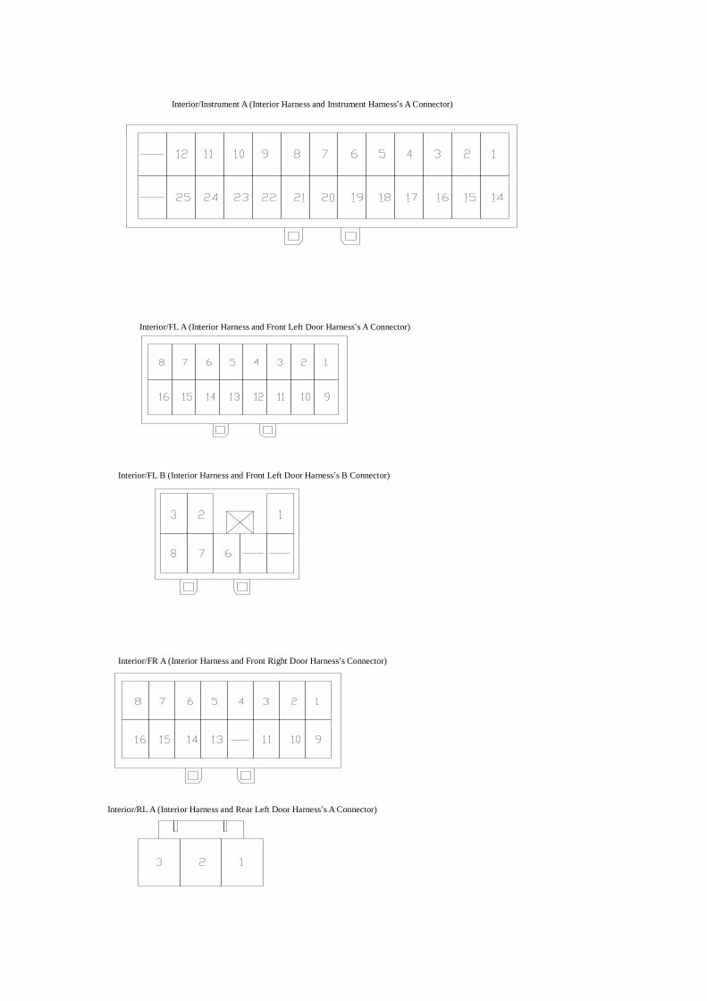
I. Definition of Main Harness Connectors
发/前(发动机线束和前仓线束插接件)
前/仪 (前仓和仪表线束的 插件)
前/仪 (前仓和仪表线束的 插件)
Engine/Compartment (Engine and Compartment Harness’s Connector)
Compartment /Instrument A (Compartment and Instrument Harness’s A Connector
Compartment /Instrument B (Compartment and Instrument Harness’s B Connector)

前/室(前仓和室内线束的插件)
针脚定义
针脚定义
室/仪 (室内线束和仪表线束的 插件)
Compartment /Interior (Compartment and Interior Harness’s Connector)
Interior/Instrument B (Interior Harness and Instrument Harness’s A Connector)
Definition of ECU Pin
Definition of ABS Pin
室/仪 (室内线束和仪表线束的 插件)
室/左前 (室内线束和左前门线束的 插件)
室/左前 (室内线束和左前门线束的 插件)
室 右前(室内线束和左前门线束的插件)
室/左后 (室内线束和左后门线束的 插件)
Interior/Instrument A (Interior Harness and Instrument Harness’s A Connector)
Interior/FL A (Interior Harness and Front Left Door Harness’s A Connector)
Interior/FL B (Interior Harness and Front Left Door Harness’s B Connector)
Interior/FR A (Interior Harness and Front Right Door Harness’s Connector)
Interior/RL A (Interior Harness and Rear Left Door Harness’s A Connector)
室/左后 (室内线束和左后门线束的 插件)
室/右后 (室内线束和右后门线束的 插件)
室/右后 (室内线束和右后门线束的 插件)
室/后(室内线束和后背门线束的插件)
( 插头阵脚定义)
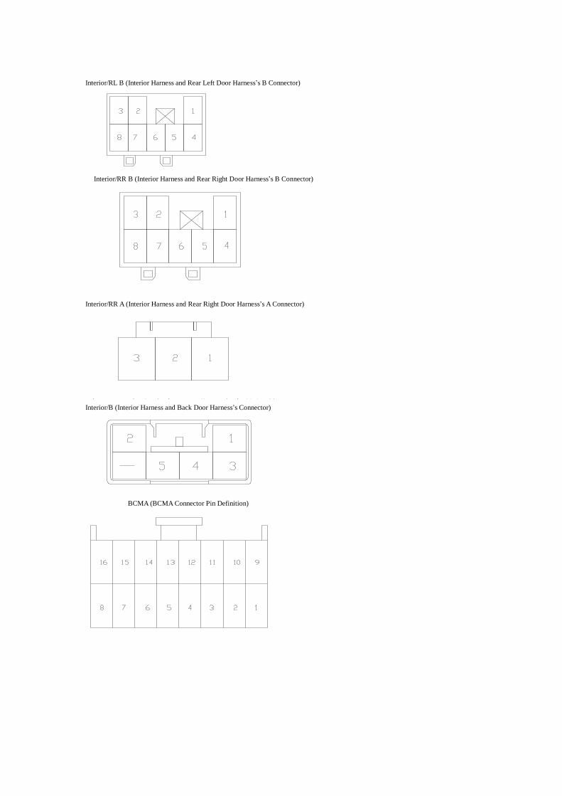
Interior/RL B (Interior Harness and Rear Left Door Harness’s B Connector)
Interior/RR B (Interior Harness and Rear Right Door Harness’s B Connector)
Interior/RR A (Interior Harness and Rear Right Door Harness’s A Connector)
Interior/B (Interior Harness and Back Door Harness’s Connector)
BCMA (BCMA Connector Pin Definition)
( 插头阵脚定义)
II. Drawing Description
1. Main Symbol Description
Symbol Meaning Symbol Meaning
Circuit Connection
Motor
Fuse Position and SPecification
Bulb
Relay
ON/OFF Control
Shielded Wire
Resistor Element
Shielded Wire Solenoid
This section is not involved in this
system
LED
Connector
Ground
Remark: Please refer to circuit and real object to confirm another symbols.
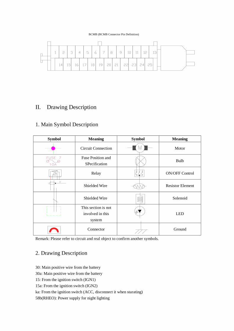
2. Drawing Description
30: Main positive wire from the battery 30a: Main positive wire from the battery 15: From the ignition switch (IGN1) 15a: From the ignition switch (IGN2) ka: From the ignition switch (ACC, disconnect it when starating) 58b(RHEO): Power supply for night lighting
BCMB (BCMB Connector Pin Definition)

31– (GROUND): ground cable, from the negative electrode of the battery Wire diameter and color:
3. Definition of Main Controller
In this schematic diagram of circuit control, “CE/” means the instrument electrical box integrated with relay connector; In this schematic diagram of circuit control, “ECU” means the engine control computer; In this schematic diagram of circuit control, “BCM” means body control computer.
4. Position of Body Grounding Points
The grounding point of back door is located in the inside of back door.
Grounding position of battery negative. In this model, there is no independent electric unit which directly connects to battery negative.
Two grounding points of ECU at the inside of front left fender: one is signal ground, the other is power ground.
ABS grounding pointis located at the bottom of ABS controller and underA/C high/low pressure switch.
Grounding point of
engine hood harness at
the canister.
Grounding point of fan motor, at the left side member and near headlamp.
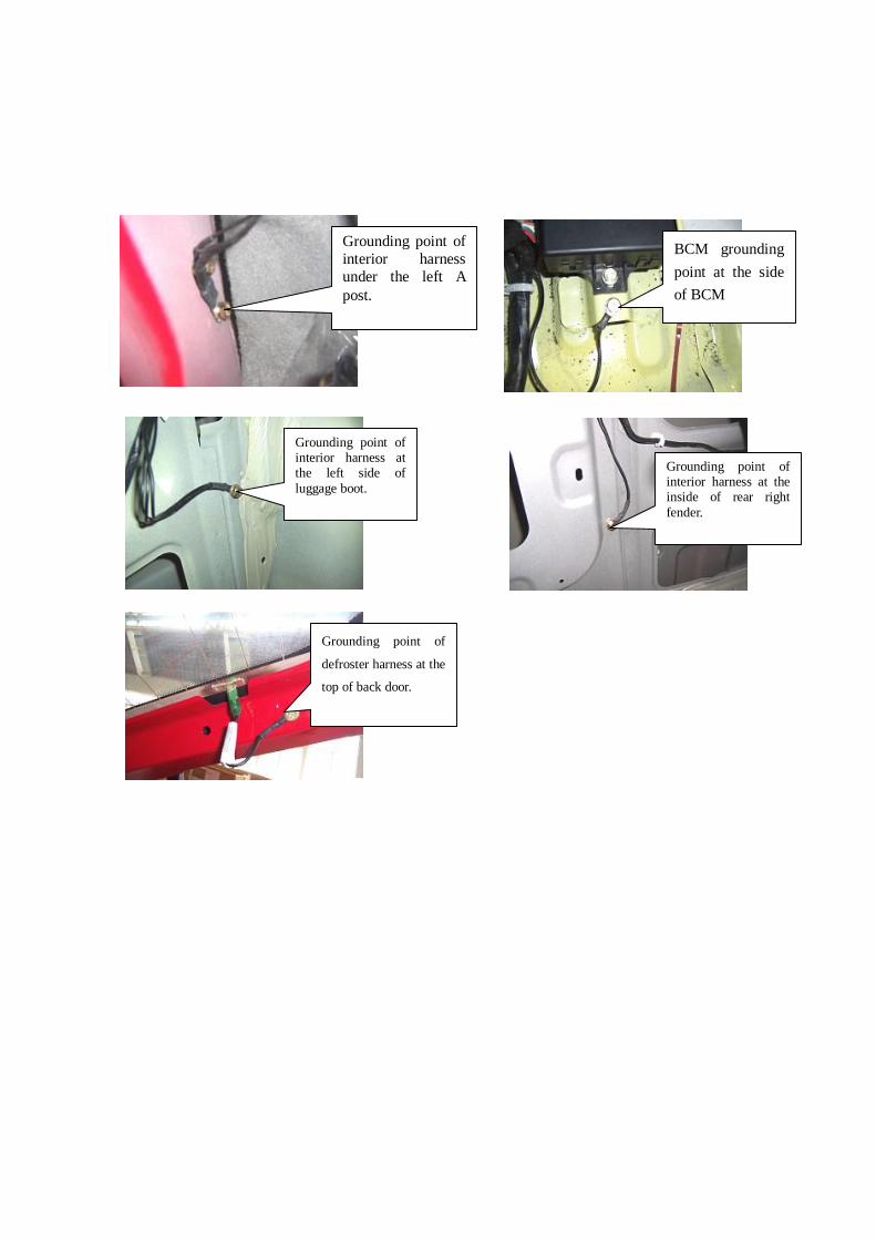
Grounding point of interior harness under the left A post.
BCM grounding point at the side of BCM
Grounding point of
defroster harness at the
top of back door.
Grounding point of interior harness at the left side of luggage boot.
Grounding point of interior harness at the inside of rear right fender.

III. Schematic Diagram of Main Electric Box and Module Position
Engine’s ECU Instrument Electrical Box OBD Diagnostic Interface At the driver side, and located at the clutch pedal.
Engine Compartment Electrical Box At the right side of engine (viewing it from the front to back)
Body Control Module (BCM) is located under the driver’s seat.

IV. Electrical Box Description
1. Instrument Electrical Box
2. Compartment Electrical Box
ABS
IGN SW
(30A)
FUSE PULLER
C/FA
N(LO)
RE
LAY
H/
LP
LO R
ELA
Y
C/FAN HI RELAY
FANRELAY
FRT FOG RELAY
ECU (10A) (10A)
H/L LOW LH
ABS
(30A)
SPARE
(30A) MAIN RELAY
(15A)FRONT FOG LAMP
(20A)
C/FAN(LO)
SPARE
ABS
(30A)
SPARE
(15A)
O2 SENSOR(2)
(10A)
ILL.LH
(10A)
ILL.RH
(10A)
H/L HI RH
(10A)
H/L LOW RH
(10A)
H/L HI LH
C/FAN (HI)
(30A)
(20A) FAN
(30A)BCM
FU
LE
PUM
P
REL
AY
MAIN
RE
LAY
H/
LP
HI
REL
AY
SPAR
ESP
ARE
SPA
RE
SPA
RE
(30A)
IP

V. Schematic Diagrams of Circuit Control
1. Starting and Charging System
F17
Ka
15a
15
30a
30
2. Electric Rear-View Mirror
Ka
15a
15
30a
30
/ /
/ /
/ /
/ /
/ /

3. Engine’s Anti-Theft System
Ka
15a
15
30a
30

4. A/C and Defrost Systems
58
Ka
15a
15
30a
30
/ /11
/ /
/ /
/ 42 1
2
1

5. Horn, Backup Lamp, Cigaretter Lighter, Ceiling Lamp and Luggage
Boot Light
30-
/
1
/
//27
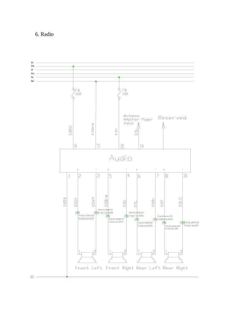
6. Radio
58
Ka
15a
15
30a
30
/
/
/
/
/
/
/
/ /
/
/
/
//
/
/
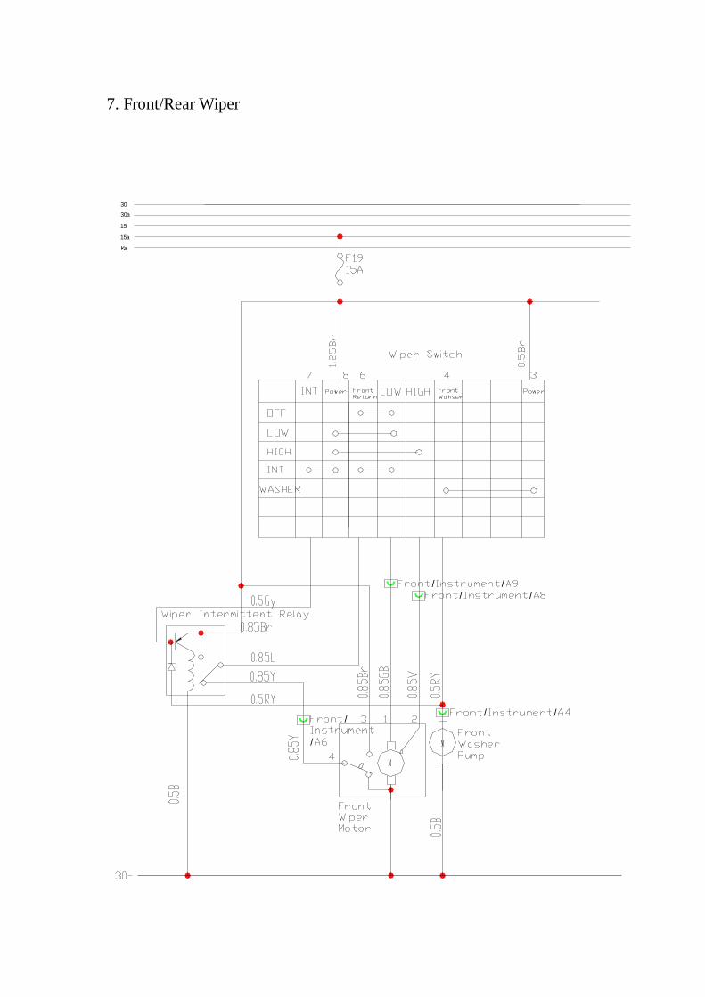
7. Front/Rear Wiper
Ka
15a
15
30a
30
/ // /
/
/
/ /

8. Turn Signal Lamp System
30
30a
15a
15
Ka
22
24
24
// 3

9. Air Bag
30-
Ka
15a
15
30a
30

10. Instrument System
8
/
/
/
/ 41
/
/
/ /
/
/
/
/
/
/
/

11. Engine’s Electronic Fuel Injection System
/ /
// 11
1
/42
/ /
( )
/ /
/ /1/3
/ /
/ /
/ /
/ /
/ /
/ 11
2
2
7
20
5#
31
r
/
39/
38
/
27
/
20
/ 8
/
/
/
7
/24
/
20
/
21/
22
/
23
4
2 3 4
/
40
/ 20
/
14
29
/
17
/
4/
3
/
13
/
/
/
/
/
//
/
10
/ /
/ /
/ /
23

12. BCM system
Diagnosis
FR Door Lock
FL Door LockAnti-theft Indicator
StarterAir Bag Signal
RR Window Motor
RL Window Motor
FR Window Motor
FL Window Motor
Instrument/Interior
Interior/Rear Bumper 3
Engine Hood SW
Right Turn Si
gnal Indicator
Interior/Rear Right
Interior/Rear Right
Interior/Rear Left
Interior/Rear Left
Interior/Front Right
Interior/Front Right
Interior/Front Left
Interior/Front Left
Instrument/Interior
Interior/Front Left 10Instrument/Interior
Interior/Front Right
Interior/Front Left 3
Interior/Rear Left
Interior/Front Left
Interior/Front Left
Interior/Front
Instrument/Interior
Interior/Rear Right B8Interior/Front Left B7
Interior/Rear Left B8Interior/Front
Left A2
Interior/Front Right 6
Interior/Front Left A4
RR Window SW
RL Window SW
FR Window SW
FL Window SW
Antenna Interior/Front 19
Interior/Front 5
Anti-theft Module
A/C Relay
Brake SW
( )
To Alarm Lamp SW
Luggage Boot Door Contact SW
Four Door Contact SW
高电位开锁高电位闭锁
RL Door Lock
RR Door Lock
Left Turn Signal Indicator
Related Documents