0 f j 1 1R1 1M o o @ 7 o I r t Jot I 0 4 V J 7 F 4 2 V y oomm llI IP c J ffi DRAKE PUBLlSHERS INC r

Welcome message from author
This document is posted to help you gain knowledge. Please leave a comment to let me know what you think about it! Share it to your friends and learn new things together.
Transcript

0fj 1
1R1 1M oo @
7
o
I
r t
Jot
I0
4VJ
7
F
42 V
y
oomm llI IPcJ
ffiDRAKE PUBLlSHERS INC
r

DATSU ORANGE 1969 1973
MAINTENANCE REPAIR
BY DRAKE AUTOMOTIVE EDITORS
Quick Reference IndelMAINTENANCE TUNE UP
ENGINE
ELECTRICAL SYSTEM
FUEL SYSTEM
COOLING SYSTEM
BRAKES
FRONT SUSPENSION
STEERING
REAR DRIVE SUSPENSION
CLUTCH
TRANSMISSION
BODY WORK
SPECIFICATIONS
5
21
39
67
77
81
89
Tho purpose of this manual to provide the utomobila owner nd mechanic witheference source with which he perform normal ervice operations
We ndeavor to rporato the late t manufacturing design changes nd upto date
specifications at the time of publication While ryeffort made to attain cy
the Publisher not be held Ipon ible for manufacturing changes typographicalrors or omissions
Upon ompiting the formation contained herein we have tried to be brief and
impls elying on the combination of photograph illustration nd tel 1 to
make this manual elul tool
DRAKEPUBLlSHERS ING
381 PARK AVENUE SOUTH
NEW YORK NY 1CXJ16
91
95
99
107
115
119

ISBN 87749 302 2
Published in 1973 byDlake Publishers Inc
381 Palk Avenue South
NewYolk N Y 10016
@Dlake Publishels Inc 1973
Printed in the United States of America

able of Contents
MAINTENANCE TUNE UP CHARGING CIRCUITDESCRIPTION 40ALTERNATOR 41
VALVE CLEARANCE 6 Description 41FAN BELT 6 Removal 41ENGINE OIL 6 Installation 44OIL FILTER 6 VOLTAGE REGULATOR 44COOLANT 7 Description 44
Nissan Long Life Coolant 7 Measure ofVoltage 45COMPRESSION 7 Adjustment 47
Test Result 8 Charging Relay 48BATTERY 8 ALTERNATOR 49IGNITION TIMING 9 FUSES FUSIBLE LINKS 49POINTS 9 EMISSION CONTROL DIAGRAMS 50CONDENSER 9 DISTRIBUTOR 52SPARK PLUGS 10 Construction 52CARBURETOR 10 Disassembly 52
Idle Limiter Cap 11 Assembly 53CHECKING ADJUSTING DASH IGNITION COIL 56
POT Automatic Transmission Only 11 Construction 56Installed on Engine 11 Description 57
DUAL POINT DISTRIBUTOR 12 SPARK PLUGS 5Cap and Rotor Head 12 Description 5Point 12 Inspection 58Phase Difference 12 Cleaning and Regap 58
TUNE UP GUIDE 14 TROUBLE SHOOTING IGNITION 58TROUBLE SHOOTING 15 HEATER UNIT REMOVAL 59
TROUBLESHOOTING HEADLIGHT 62
TROUBLESHOOTINQ HORN 63
ENGINE RADIO 63Removal 63
DESCRIPTION 22TROUBLESHOOTING
REMOVAL 23SPEEDOMETER 64
INSTALLATION 24TROUBLESHOOTING HEATER 65
DISASSEMBLY 24TROUBLESHOOTING RADIO 65
Pistons and Connecting Rods 2NOISE PREVENTION CHART 66
Cylinder Head 27 FUEL SYSTEMASSEMBLY 27
Cylinder Head 28 AIR CLEANER ELEMENT 68Piston and Connecting Rods 29 AUTOMATIC TEMPERATUREEngine 30 CONTROL AIR CLEANER 68
OIL PUMP 36 AIR CONTROL VALVE 68Removal 36 Idle Compensator 69Installation 3 TEMPERATURE SENSOR 69
Removal 69
Installation 69ELECTRiCAL SYSTEM FUELPUMP 69
Removal and Disassembly 69STARTER 40 Inspection O
Removal 40 Assembly 70
1

Table ofGontents
CARBURETOR 3 FRONT SUSPENSIONRemoval 3
Disassembly 3 RECOMMENDATIONS 90Float Chamber 74
ANTI DIESELING SOLENOID 74Removal 4 STEERINGInstallation 74
BOOST CONTROLLED STEERING GEAR COMPONENTS 92DECELERATION DEVICE 74 RECOMMENDATIONS 92
Assembly and Installation 74 ASSEMBLY 93Cleaning and Inspection 74 STEERING LINKAGE 93
JETS 5
REAR DRIVESUSPENSION
COOLING SYSTEMSHOCK ABSORBERS 96
DRAINING FLUSHING 78 Removal 96
WATER PUMP 78 Inspection 96
Removal 78Installation 96
Disassemb y 79DRIVE SHAFf 97
Inspection 79 RECOMMENDATIONS 97
Installation 79THERMOSTAT 79
Removal and Installation 79 CLUTCHRADIATOR 79
Removal and Installation 9 REMOVAL 102Inspection 80 RELEASE BEARING 102
REPAIR 103
Refacing Pressure Plate 103ADJUSTMENT 104
BRAKES INSTALLATION 104MASTER CYLINDER 105
MASTER CYLINDER 82Removal 105
Removal 82 Disassembly 105
Installation 82Inspection 106
FRONT DISC BRAKE 82 Assembly 106Installation 106Description 82
BLEEDING CLUTCH SYSTEM 106Removal 82
Disassembly 84
Inspection and Repair 84Piston Seal Replacement 85 TRANSMISSIONAssembly and Installation 85Pad Replacement 86 REMOVAL 109
REAR BRAKE 86 INSTALLATION IIIRemovaland Disassembly 86 4SPEED TRANSMISSION 113Inspection 87 Removal and Installation 113Assembly 88 RECOMMENDATIONS 113
2

Table of Gontents
BODY WORK SPARK PLUGS 122
VALVES 122
FRONT FENDER 116 OIL PUMP 122
Removal and Installation 116 GENERAL 123
HOOD 116 ELECTRICAL 123
Removal and Installation 116 MANUAL TRANSMISSION 12
Adjustment 11 CARBURETOR 131
TRUNK LID 11 CLUTCH 134
Removal and Installation 11 ENGINE TORQUE INFORMATION 136
Torsion Bar Removal TUNE UP 138
and Adjustment 117 LUBRICANTS SAE 138
CAPACITIES PRESSURES 139
AUTOMATIC TRANSMISSION 140
SPECIFICAliONS PROPELLER SHAFT 144
BRAKE CHASSIS WHEEL
SfARTER 120 ALIGNMENT 146
DISTRIBUTOR 121 NOTES 14
a

llaiDteDlDce Tune up
VALVE CLEARANCE 6FAN BELT 6ENGINE OIL 6OIL FILTER 6COOLANT 7
Nissan Long Life Coolant 7
COMPRESSION 7Test Result 8
BATTERY 8IGNITION TIMING 9POINTS 9CONDENSER 9SPARK PLUGS 10CARBURETOR 10
Idle Limiter Cap 11
CHECKING ADJUSTING DASHPOT Automatic Transmission Only 11
Installed on Engine 11
DUAL POINTDISTRIBUTOR 12
Cap and Rotor Head 12Point 12Phase Difference 12
TUNE UP GUIDE 14TROUBLE SHOOTING 15
I

IlaiDteDlDce TUDe up
VALVE CLEARANCE
Valve clearance adjustment is performed with
the engine not running The initial adjustment is made while the engine is cold
Remove the air cleaner Unbolt and remove
the camshaft cover Each valve must be ad
justed with the valve completely closed that
is the rocker arm should be at the base
Ilowest point of the cam lobe Loosen the
locking nut and turn the adjusting screw until
the specified clearance is obtained as checked
with a fuel gauge between the rocker arm and
camshaft Straighten the locking nut Repeatthis procedure on each valve turning the
engine over bv hand to position each valve as
necessary Temporarily replace the camshaft
cover with two or three bolts and warm up the
engi ne Remove the cover and recheck the
valve clearance according to the warranty cer
tilicates Readjust as necessary Replace the
camshaft cover using a new gasket if the old
gasket appears tlattened or broken Run
engine and check for leaks from the gasket
Valve clearanceUnit mOl in
I
Intake 0 20 0 008
Cold
Exhaust 0 25 0 010
Intake 0 25 0 010
Warm
Exhaust 030 0 012
Ag 1 Adjusting valve clearance
8
FAN BELT
Check for cracks or damage Replace if
necessary
Adjust belt tension It is correct if detlection is0 315 to 0472 in when thumb pressure 122 0lbl is applied midway between fan and alter
nator pulleys
ENGINE OIL
Check if oil is diluted with water or gasolineDrain and refill oilif necessary
Notes
a A milky oil indicates the presence of
cooling water Isolate the cause and take
corrective measure
b An oil with extremely low viscosity in
dicates dilution with gasoline
Check oil level If below the specitied level
raise it up to the H level
Engine oil capacity
including oillilterl
Maximum H leveli
41 U S qts
Minimum IL leveli
31 U S qts
OIL FILTER
The oillilter is ofa cartridge type
Fig 2 Drive belt tension

llaiDteDlDce TUDe up
bBoiHng point
Percent C0ncentralion0 Q ki
2 I FreeLprotectionSea level
em coning
system HeUUre
3mI060C 1240C 2SSor lSOC SoF2210F
50I090C Inlle 61UF 3SoC 3IOP228OF
Water caplcity
610 620 5to
Without heater6 0 1 U S gal S I U S gal 6 4t O U S gal
1 X Imper gal I 1 Imper gal I Imper gal
With heater65 I Y Us gal 6 0 t U S gal 6 81 1 U U S gal
I Imper gal 1 Imper gal I i Imper gal
Check for oil leaks past gasketed flange If
anv leakage is found retighten just enough to
stop leakage Ifretightening is no longer effec
tive replace tilter as an assembly
When installing oiltilter tighten by hand
Note Do not overtighten oil filter lest
leakage should occur
COOLANT
Nissan Long Life Coolant
LLC is an ethylene glycol base product con
taining chemical inhibitors to protect the
cooling system from rusting and corrosion
The L LC does not contain any glycerineethyl or alcohol It will not evaporate or boil
away and can be used with either high or low
temperature thermostats Itflows freely tran
sfers heat eniciently and will not clog the
passages in the cooling system The L L C
must not be mixed with other product This
coolant can be used throughout the seasons of
the year
Whenever any coolant is changed the coolingsystem must be tlushed and relilled with a
new coolant Check the level
COMPRESSION
When it becomes necessary to check cylindercompression it is essential to remove an
spark plugs The purpose of this test is to
determine whether there is excessive leakage
past the piston rings head gasket etc To test
the engine should be heated to the operatingtemperature and throttle and choke valves
opened
Cylinder compression in cylinders should not
be less than 80cf of the highest reading Dif
c OF
0 32
10 14
20 4
30 2
I
I
I
Il
I
tt
40 40
so 58
EG001
Fig 3 Protection concentration
30to 20 40 so
7

llaiDteDaDce Tune up
fClcnt comprc sion in two or more cylinderll llalh indiL ntean improperlv seated valveor hrokpll piston ring
Low ornpn ion in cYlinders can result from
oln piqoll ring Thi trouhle may usuallvhe i1 ol1lpanit rl bv excessive fuel
nnu mption
1 R ult
If lindf1 c ll1pre sion in one or more cvlinell l i low pOlla Illall quantity of engine oilinto cylinder through the spark plug holesnnd retest compression
II adding oil Iwlpthe compression pressureIlll challn an t hat rings arcdefective
II pn s ure tn low the likelihood is thatalve is sticking 01 seating improperly
II l linder compression in any two adjacentdinder is low and if adding oil does not
help the compres ion this could be leakagepast the gasketed surface
Oil and water in comhustion in any two ad
ja ent cylinder is low and if adding oil doesnot help the compression this could be
I akage past the gasketed surface
Oil and water in comhustion chambers can
1 11 from this trouhle
nmpre ion prC Sl1re
p i at rpm
Standard 1 c1350Minimum 128 350
BATTERY
Check electrolyte level in each batterv cell
Unscrew each liller cap and inspect lluidlevel Ifthe lluid is low add distilled water to
bring the level up approximately 0 394 to
0 787 in above the plates Do not overlill
Measure the specitic gravity of battery elec
trolyte
Clean top of battery and terminals with a
solution of baking soda and water Rinse 011and dry wi h compressed air Top of battery
8
Permissible
value
Full chargevalue
at 20ne 6SoF
Frigid climates rTropical climates Over I
Other climates Over I 10
I 28
123
126
Fig 4 Testing compression pressure
ET002
Fig 5 Checking specific gravity of battery electrolyte
must be clean to prevent current leakage between terminals and from positive terminal tohold down clampIn addition to current leakage prolonged ac
cumulation of acid and dirt on top of batterymay cause blistering of the material coveringconnector straps and corrosion of straps After
tightening terminals coat them with
petroleum vaseline to protect them fromcorrosion

l1aiDteDIDce TUDe up
IGNITION TIMING
Check spark plugs and distributor breaker
points for condition
Thoroughly wipe oIl dirt and dust from timingmark on crank pulley and timing indicator on
and front cover
Warm up engine sufticiently
Install a timing light on No 1 cylinder sparkplug wire and install a tachometer
Set idling speed to approximately 800 rpm
Check ignition timing if it is 50 B T D l
iBefore Top of Dead Center by the use of
timing light
Ifnecessary adjust it as follows
Loosen set screw to such an extent that
distributor can be moved bv hand
Adjust ignition timing to 5 BT D C
Lock distributor set screw and make sure
thaI timing is correct
Ignition timing
5 t Retard side
1 Z Advance side
POINTS
Check the distributor breaker points for ab
normal pitting and wear Replace if necessary
Make sure they are in correct alignment for
Fig 6 Adjusting ignition timing
full contact and that point dwell and gap are
correct Clean and apply distributor grease to
the earn and wick
Note Donot apply grease excessively
Point gap
0 0177 to 0 0217 in
Dwell angle49 to 55 degrees
CONDENSER
Clean outlet of condenser lead wire and check
for loose et screw Retighten if necessary
Check condenser capacity witb a capacitVmeter Condenser insulation resistance may
be also checked using a testcr by adjusting its
range to measure large resistance value
When condenscr is normal the tester pointer
swings largely and rapidly and moves
gradually back to the intinite side When thc
pointer does not stay still or it points zero in
resistance replacement is necessary
Fig 7 Checking ignition timing
Fig 8 Checking distributor point gap

llainteDance Tune up
Condeneer capacity
Hctard side 0 05 I F
Micro Farad
Advance oide 0 22IF
Micro Farad
Condenser insulation resistance
5MlltMega ohms
SPARK PLUGS
Remove and clean plugs in a sand blastcleaner Inspect each spark plug Make sure
that thev are of the specitied heat range In
spect insulator lor cracks and chips Checkboth center and ground electrodes Ifthey are
excessively worn replace with new sparkplugs File center electrode l1at Set the gap to
0 028 to 0 031 in using proper adjusting tooL
Tighten plugs to 110 to 15 0ft lb torque
CARBURETOR
Idle mixture adjustment requires the use of a
CO meter When preparing to adjust idlemixture it is essential to have the meter
thoroughly warmed and calibrated
Warm up engine sulliciently
Continue engine operation tor one minute at
idling speed
Adjust throttle adjusting screw so that enginespeed is 800 rpm 1 in N range tor automatictransmission L
EEOBO
Fig 9 Checking spark plug point gap
10
Check ignition timing if neceesary adjust it to
the specillcations 15 800 rpm retard sidel
Adjust idle adjusting screw so that CO per
centage is 1 5 0 5
Repeat the procedures as described in items 3and 5 above so that CO percentage is1 5 0 5 at 800 rpm
Caution
a On automatic transmission equippedmodel check should be done in the D
range
Be sure to apply parking brake and to
lock both front and rear wheels witbwheel chocks
b Hold brake pedal while stepping downon accelerator pedal Otherwise car willrush out dangerouslyOn automatic transmission equipped modelmake sure that the adjustment has been madewith the selector lever in N position
And then check the specitications with thelever in D position Insure that CO percent and idle speed are as tollows
Idling rpm 650
CO percentage 1 50 5
Readjust by turning in or out throttle ad
justing screw or idle adjusting screw if stillout
Notes
a Do not attempt to screw down idle ad
2
Fig 10 Throttle and idle adjusting screws
l1aiDteDlDce TUDe up
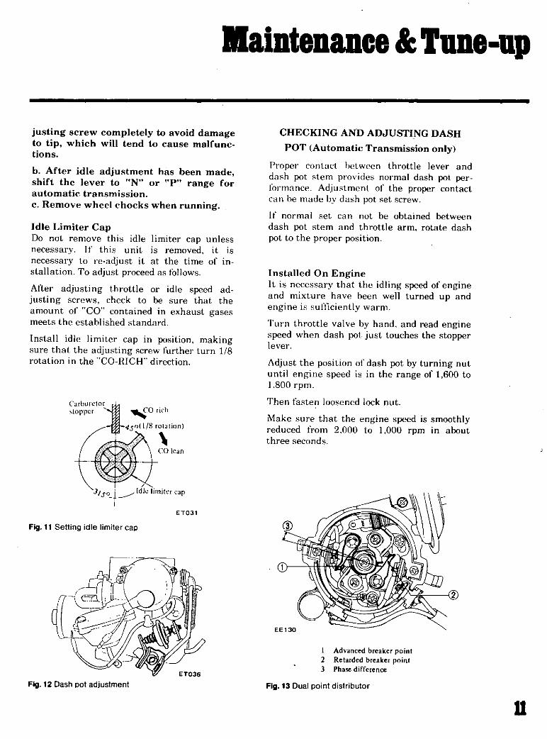
justing screw completely to avoid damageto tip which will tend to cause maIfunctions
b After idle adjustment has been madeshift the lever to Not or plt range forautomatic transmissionc Remove wheel chocks when running
Idle Limiter CapDo not remove this idle limiter cap unless
necessary If this unit is removed it is
necessary to re adjust it at the time of installation To adjust proceed as follows
After adjusting throttle or idle speed ad
justing screws check to be sure that theamount of CO contained in exhaust gasesmeets the estahlished standard
Install idle limiter cap in position makingsure that the adjusting screw further turn 18rotation in the CO RICH direction
C rburctor
topper h
alation
COlcan
JIsoy1dlelimiter Jp
ET031
Fig 11 Setting idle limiter cap
Fig 12 Dash pot adjustment
CHECKING AND ADJUSTING DASH
POT Automatic Transmission only
Proper contact hetween throttle lever anddash pot stem provides normal dash pot perlonnance Adju tmenl of the proper contact
can he made bv dash pot set screw
If normal set can not be obtained betweendash pot stem and throttle arm rotate dash
pot to the proper position
Installed On EngineIt is necessary that the idling speed of engineand mixture have been well turned up and
engine itsufticiently warm
Turn throttle valve by hand and read enginespeed when dash pot just touches the stopperlever
Adjust the position of dash pot by turning nutuntil engine speed is in the range of 1 600 to
1800 rpm
Then fasten loosened lock nut
Make sure that the engine speed is smoothlyreduced from 2 000 to t 000 rpm in about
three seconds
EE130
I Advanced breakerpoint2 Retarded breaker point3 Pha difference
Fig 13 Dual point distributor
u

l1aiDteDlDce uDe up
DUAL POINT DISTRIBUTOR
fi trihlltor has two breaker points located op
po itp each othlr with a phase ditlcrence as
hwn in Figure I
The ditl rence in pha e can be adjusted bv the
adju ting screw A phase dillerence of 7 crank
ilnfh i adopted
Th e two breaker points are placed parallelin thp pi imarv ignition circuit The retarded
hreaker point orkwhen the relay is turned
01and the advanced breaker point works
wht lllht 1C lav i turned OFF
ap lind Rotor lIead
al and rotor hend must be inspected at
ref iliaI inlervah I n addition remove cap and
e11 1Il all dut and carhon dc sits from caplnd rotor Ii om time to time Ifcap is cracked
0 i Ipaking replace with a new one
PointStandard gaps of both points are 0 0177 to
0 0Z17 in If the gap is ot1 the standard ad
justment must be made by loosening pointscrewlS Gap gauge is required for adjustment
Roth gapmust he checked from time to time
When point surface is rough take ot1 any
irregularities with tine sand paper of No 500or tiOt or with oil slone
At this time grease must be supplied to
canHhaft and carn heel Do not applv ex
cessively 1 When wear on each breaker pointi noticeable replace points together with con
tact an11
Fig 14 Checking of distributor breaker point gap
12
Point gap
C018 to z in
Dwell angle
49 to 550
If point gap IS adjusted by examining dwell
angle install distributor on engine and
proceed as follows
Disconnect wiring harness of distributor from
engine harnes
Using a lead wire connect B black of engineharness and B black of distributor harnessI advance side
Adjust dwell angle of advance side byloosening point screw
Disconnect lead wire from B t black of
distributor harness and then connect it to Y
vellowl ofdistributor I Retard side
Adjust dwell angle of retard side by looseningpoint screw
After adjustment disconnect lead wire then
connect engine harness and distributor har
ness securely
Phase Difference
To check phase dil1erence install distributor
on engine and proceed as follows
Disconnect wiring harness of distributor from
engine harness
Using a lead wire connect B Iblackl of engineharness and B black of distributor harness
IAdvance sidel See Figure 15
EE135
Fog 15 Connecllead wire

lIaiDteDance TUDe up
Spark timing sontrol system for Automatic T smission
Spark timingThrottle SW
Advance Retard
Engine start ON 0
Idling ON 0
Partial throttle opening ON 0
Wide throttle opening OFF 0and high speed rousing
Adjuster plateset screws
EE136
Fig 16 Adjuster plate set screws
Fig 17
With engine idling adjust ignition timing byrotating distributor to specitications 112 800
rpm advance side
Disconnect lead wire from B tblack ofdistributor harness and then connect it to Y
yellow of distributor harness IRetard side
With engine still idling check to determinethat phase delay is 7 degrees in terms ofcrank shaft angular displacement
EEl38
Fig 18 Phase difference adjusting scale
To correct further proceed as follows
Referring to Figure 6 turn out adjuster plateset screw 12 to 2 turns The screw is locatedat contact set on retard side
Using a notch in adjuster place as a hold turn
adjuster plate as required until correct delayis ohtained Ignition is retarded when plate is
turned counterclockwise
Note Refer to graduations on breaker
plate to make adjustment easier One
graduation corresponds to crankshaft
angular displacement of 4 degrees
Tighten adjuster plate set screws to secure the
adjustment
Make sure that the ignition timing ofadvanceside is the specilications
After adjustment remove lead wire and con
nect wiring harness of distributor to engineharness securely
13

lJaiDteDance Tuneup
1Jlllitiun nd fll1 1t1T
1 t1illutl tirnmll
Dislrihlltol
I linl lJP
Dwellanglc
C Id niCf lpadty
rlnd n er lSuliliOIl lanc
Idling ldjustmtnt
Manual Trnnsmission
Automatic Transmission
Dash pot 3djuslrnenl
TUNE UP GUIDE
dcgre
in
degree
F
MH
deg erpm
COil
degree rpm
call
Anlidie ling solenoid tightening torque kg em lin Ib
pm
Spark timing conlrol system
lluottle switch operating angleL18
L16 t5tO
Lib 620
AfT
MfT
AfT MfT
degK e
degree
degree
Thermo switchoperating temperature or OF
Adjustment of operating pressure f a cO D
R C 0 0 set pressure
AfT
MfT
A T C Air cleaner
A T C Valve opening temperature
H
mmHg inHg
mmHg inHg
Or OF
5 IB T O C
0 451005510 0177 toO 02t7
49 to 55
retard side 0 05
advance side 0 22
5
50 800 retard side
1 5t 0 5
50 650 retard side 0 range
1 5t0 5
1 600 to 1 800
35 to 55 30 to 48
350
400
450
5 to 13 4to55
480t 20 t8 9t0 787
500t 20 19 7t 0787
375 to 4S 100 to 1 8
llaiDteDlDce TUDe up
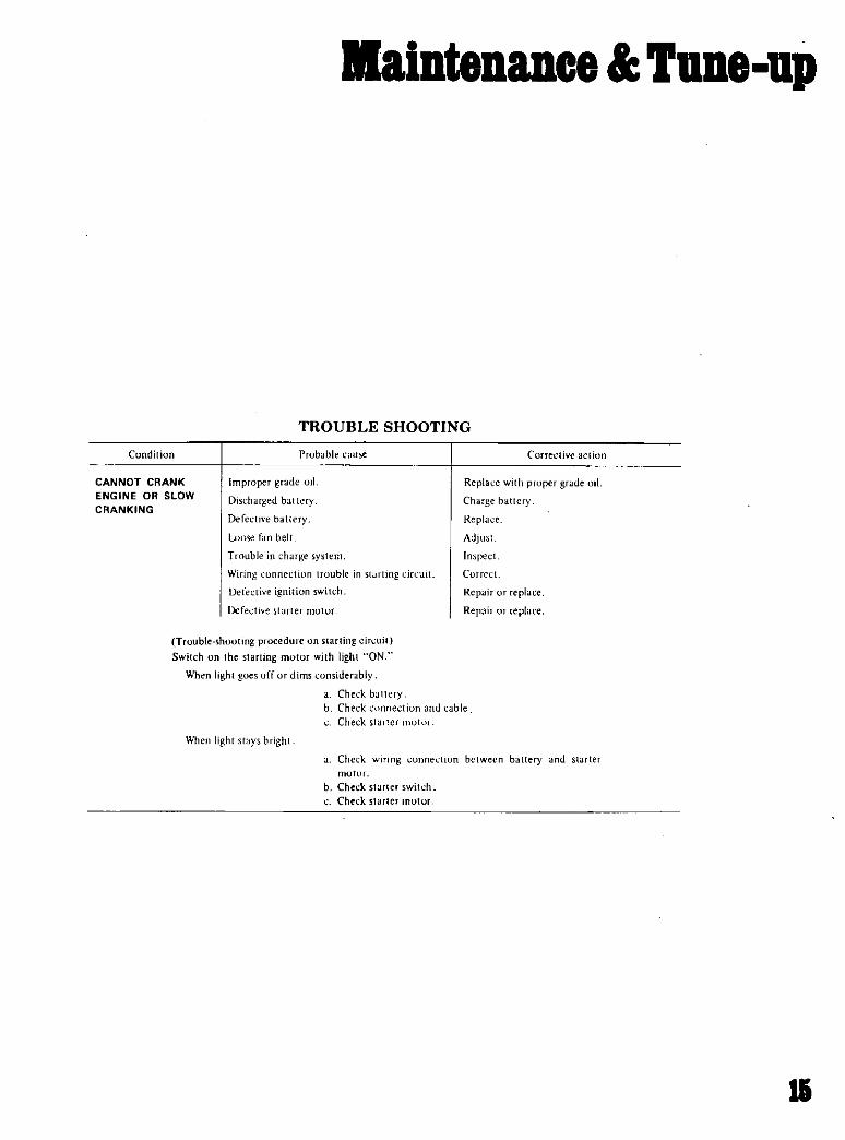
TROUBLE SHOOTING
Condition Probable C rel tive elion
CANNOT CRANK
ENGINE OR StOW
CRANKING
Improper grade II
DIscharged bat tery
Defective battery
Loose fan belt
T wble in charge system
Wiring onnectiun trouble in Sl Hting
Detective igmllon switch
Defctive stlrter oloL
Replac with proper grade il
Charge ballery
Replace
Adjust
Inspect
Correcln
Repair
Repair
replace
replace
T ouble shooting procedure starting cin uilSwitch on the starting motor with light ON
When light goesoff dims nsiderably
Chek balteryb Check nnection and able
Check s aller olur
When light 51 sbright
Chek wiring cllOn between hlttery nd Slarter
OllH
h Chelk starter switch
Check starter ulm
1

II
llaiDtelllDce IUD8 UP
Condition Probable cause Corrective action
Low orno current
Ignition system in
trouble
Burned distributor point
Improper point gap
Defective ondenser
leak at rotor ap and rotor
Defective spark plug
Improper ignition timmg
Defective ignition oil
Disconnection of high tension cable
L005C connection or disconnection in
primary Tcuit
Fuel system trouble la k of fue
Dirty fuel strainer
Dirty or clogged fuel pipeFuel pump will ot work properlyCarburetor choke will 01 work properly
Improper adjustment of float level
Improper idling
Dirty ordo ed carburetor
Clogged breather pipe of fud tank
Damaged antidieseling olenoid
Low compreuion Incorrect spark plug tightening ordefective
gasket
Improper grade engine it low viscosityIncorrect valve clearance
Compression leak fromvaIve seat
Sticky valve stem
Weak defective alve springs
Compression leak at cylinder head gasket
Slicking ordefective piston ingWorn piston ing cylinder
Trouble shooting procedurePour the engine iI from plug hole nd then measure
cylinder compression
Compression increases
Compression does notchange
Check for loose terminal ordisconnection
primary circuit
Check for burned points
Repair replace
Adjust
ReplaceClean eplaceClean adjust plug gap or replace
Adjust
Replace
Replace
Repair replace
Supp1r
ReplaceClean
Repair replaceCheck tnd adjustCorrect
AdjustDisassemble nd clean
Repair nd clean
Replace
Tighten to normal torque or replace gasket
Replace with proper grade oil
AdjustRemove cylinder head and lap valves
Correct replace alve nd lIve guide
Replace valve springs
Replace gasket
Replace pIston ngs
Overhaul engine
Trouble ill cylinder orpiston ring
Compression leak from valve cylinder head
orhead gasket
18
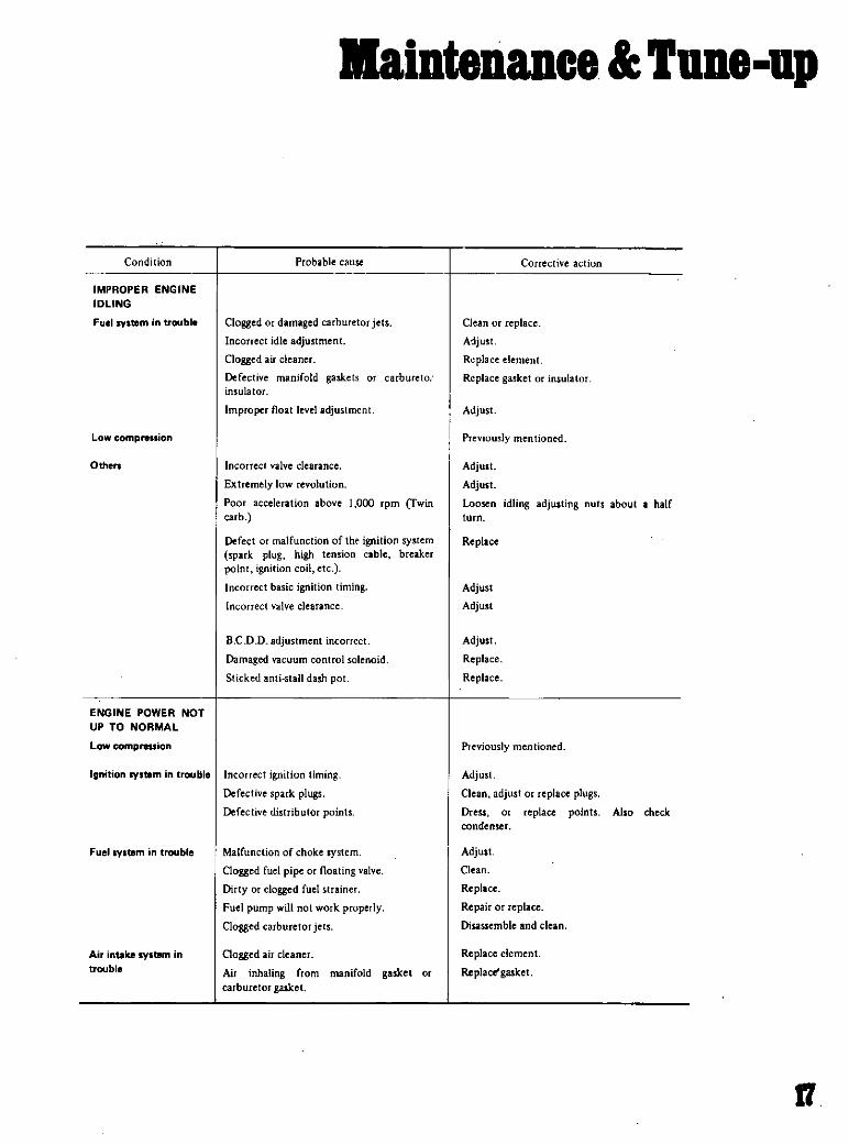
Condition
IMPROPER ENGINE
IDLING
Fuelsyltem trouble
Low compreSlion
Others
ENGINE POWER NOT
UP TO NORMAL
Low comprnsion
llaiDteDlDce Tune up
Probable cause
Clogged ordamaged carburetor jets
Incorrect idle adjustment
Clogged air cleaner
Defective manifold gaskets or carbureto
insulator
Improper float level adjustment
Incorrect valve clearance
Extremely low revolution
Poor acceleration above 1 000 rpm Twincarb
Defect ormalfunction of the ignition systemspark plug high tension cable breaker
point ignition coil etc
Incorrect basic ignition timing
Incorrect alve clearance
8 C D D adjustment incorrect
Damaged vacuum control solenoid
Sticked antistall dash pot
Ignition syltem trouble Incorrect ignition timingDefective spark plugsDefective distributor points
Fuel system trouble
Air ntake syltem in
trouble
Malfunction of choke system
Clogged fuel pipe orfloating valve
Dirty orclogged fuel strainer
Fuel pump will notwork properly
Clogged carburetor jets
Gagged air cleaner
Air inhaling from manifold gasket or
carburetorgasket
Corrective action
Clean replace
A1just
Rplace element
Replace gasket insulator
Adjust
i Previously mentionedII
Adjust
AdjustLoosen idling adjusting nuts about a half
turn
Replace
Adjust
Adjust
Adjust
Replace
Replace
Previously mentioned
AdjustClean adjust or replace plugsDress or replace points Also check
condenser
AdjustClean
Replace
Repair or eplaceDisassemble and clean
Replace element
RepJace gasket
fl

IlainteDance TUDe up
Condition
Owrheating
Owenooling
Othen
NOISY ENGINE
Car knodting
Mechmicll kncdtinll
Crankshaft bearingknocking
Connecting rod
bearing knocking
Piston and cylindernoise
18
Probable cause
Insufficient coolant
Loose fan belt
Worn ordefective fanbelt
Defective thermostat
Defective water pump
Oogged or leaky radiator
Defective radiator mlct cap
Air in cooling system
Improper e eoil gradeIncorrect ignition timing
Defective carburetor lean mixture
Defective thermostat
Improper octane fuel
Improper tire pressure
Dragging brake
Clutch dipping
Overloaded engineCarbon knocking
Timing knockingFuelknocking
Preignition misusing of spark plug
ThU strong dull noise increases when engineis accelerated To locate the place cause a
misflTe on each cylinder If the noise stop3by the misfut this cylinder generates the
noise
This is a little hisher pitched n9ise than thecrankshaft knocking and also increases
when engine is accelerated Cause amisfueon each cylinder and if the noise deminiwialmost completely this crankshaft bearinggenerates the noise
When you hear an overlapping metalic noise
which increases its magnitude with the
revolution of enaine and which decreases u
engiIe is warmed up this noi3e is caused bypiston and cylinder To locate the placecause amisfue on each cylinder
Corrective action
ReplenWt
Adjust fanbelt
Replace
Replace
ReplaceFlush repair or replace
Replace
Retighten eachpart of cooling system
Replace withproper grade oil
AdjustOverhaul carburetor
Replace
Repbce withspecified octane fuel
Inflate to specifted pressure
Adjust
Adjust
Use right gear in driving
Disassemble cylinder head and remove
carbon
Adjust ignition timingUse specified octane fuel
Use specified spark plug
This is caused by worn ordamaged bearingsor uneyeny worn crankshaft Renew
bearinp and adjust or change crankshaftCheck lubrication system
Same as the case of crankshaft bearinas
This may cause an abnormal wearing of
cylinder and lower compression which in
turn will cause I lower out put power andexcessive consumption of oil
erhaul engine

Condition
Piston pin noise
Water pump noise
Others
ABNORMAL
COMBUSTIONback fue after fire
run on etc
Improper ignition timing
Fuel system in trouble
of8C1iYe eylinder hem
EXCESSIVE OIL
CONSUMPTION
Oil I
IlaiDteDance TUDe ail
Probable cause
This noise is heared at each ryighest andlowest dead end of piston To locale the
place cause a misfire on ach cylinder
This noise may be caused by worn
damaged bearings orby the uneven surface
of iding parts
An improper adjustment of alve clearance
Noiseof timing chain
An excessive end play on ankshaft
Note This noise will be heared when clutch
is disengaaed
Wear on clutch pilot bushingNote Uta noise will be hur when
clutch is disenpged
Improper ignition timing
Improper heat range of spark plugs
Damaged carburetor or manifold gasketback fire after fire
Defective carburetor jet
Improper function of the noaL
Uneven idling Run on
Improperly adjusted valve clearance
Excess carbon in combustion chamber
DaJllaged valve spring back fire after fire
Loose oil drain plugLoose or damaged oil pan gasket
Loose ordamaged chain overgasket
Defective oil seal in front and rear ofcrankshaft
Loose ordamaged locker cover gasket
fmproper tightening of oil mter
Loose ordamaged oil pressure switch
Corrective action
This may cause a wear on piston pin or
piston pin holeRenew piston and piston pin usembly
Replace water pump with a new one
Adjust
Adjust the tension of chain
Disassemhle engine and new main bearing
Renew bush and adjust drive shaft
Adjust ignition timing
especified spaTk plugs
Replace them with new parh
Disas efnb e calburetor and check it
Adjust the level and check needle valve
Adjust
Adjust
Remove head and gel ridof carbon
Replace it with a new one
Tighten it
Renew gasket or tighten it
Renew gasket or tighten it
Renew oil seal
Renew gasket or tighten it but ot too
much
Renew gasket and tighten itwith the proper
torque
Renew oil pressure switch or tighten it
18

l1aiDteDIDce TUDe up
Condition
Excessive oil
consumption
Otben
POOR FUEL ECONOMY
See the explanationof the power deerea
Others
TROUBLE IN OTHER
FUNCTIONS
Oecreased oil pressure
ExcessiYe wear on the
sliding pam
Scuffing of slidingPO
20
Probable cause
Cylinder and piston wear
Improper location of piston ring gap or
reversely assembled piston ng
Damage piston rings
Worn piston ing groove and ing
Fatigue of valve oil seal lipWornvalve stem
Inadequate quality of engine oil
Engine overheat
Exceeding idling revolution
Defective acceleration ecovery
Fuel leakage
Inadequate oil qualityOverheat
Defective function of il pump regulatorvalve
Functional deterioration of oil pump
Blocked oil filter
Increased clearance in various sliding part
Blocked oil strainer
Troubles in oil gauge pressure switch
Oil pressure decreases
Defective quality orcontamination of oil
Defective air cleaner
Overheat orovercoal
Improper fuel mixture
Decrease of oil pressure
lnsufficient clearances
Overheat
Improper fuel mixture
Corrective action
Overhaul cylinder and new pistonRemount piston ings
Renew rings
Repair or renew piston and cylinder
Renew piston and piston ring
Replace seal lip withanew one
Renew valve orguide
Use the designated oil
Previously mentioned
Adjust it to the designated rpm
Adjust it
Repair or tighten the connection of fuel
pipes
Use thedesignated oil
Previously mentioned
Disassemble oil pump nd repair or enew it
Repair or replace it withanew one
Renew it
Disassemble and replace theworn parts with
new ones
Oean it
Replace it with a new one
Previously mentioned
Exchange the oil with proper
change element
Change element
Previously mentioned
Check the fuel system
and
Previously mentioned
Readjust to the designated clearances
Previously mentioned
Check thefuel system

IDgine
DESCRIPTIONREMOVAL
INSTALLATIONDISASSEMBLY
Pistons and Connecting Rods
Cylinder Head
ASSEMBLY
Cylinder Head
Piston and Connecting Rods
EngineOIL PUMP
Removal
Installation
22
23
24
2427
27
27
28
29
30
36
36
37
21

rBDglDe
DESCRIPTION crankshaft to turn out smooth dependablepower The cylinder block is cast in a singleunit featuring deep skirtingThe L16 and L18 engines feature a H C
valves wedge shaped combustion chamber
alminum heads and fully balanced 5 bearing These engines are equipped with a single
EM256
Fig 19Cross section view
22

BngiD8
2 harreL downdraft carburetor that incor
porates a special device to control emissiuns
Experience has shown that it is much easier
to remove the engine with transmission as a
single unit than to remove the engine only
The engine can then be separated from the
transmission assembly
REMOVAL
Scribe alignmcnt marks on hood around hood
hinges and remove hood from hinge
Completelv drain the cooling system engmeand transmission lubricant
Hcmove blow hy hosc ti om rocker cover and
remove air cleaner
Hemove the radiator grille
Disconnect the battery cable and remove the
battcrv off the car
Take oil hoth upper and lower radiator hoses
by removing thc hosc clamps Then loosen the
lixing holts of the radiator and take it out in
sequence
Note If equipped with automatic tran
smission remove the torque convertor
cooling pipes from the radiator
Rcmove engine fan and pulley
Flg 20 Removing clutchoperating cylinder
Disconnect thc fuel tube from the fuel pump
If equippcd with heater remove its hoses at
engine attachment
Disconncct accelerator control linkage and
choke wire at the carburetor side
Disconnect the wirings for the starter alter
n tor ignition coil oil pressure switch and
thcrmaI transmitter
Hemove the clutcb operating cylinder and its
return spring
Disconnect the speedometer cable Disconnect
tlat attaching plug connector from the reverse
lamp switch
Disconnect the shift rods and select rods and
then remove the cros shart a sembly bv
rcmoving the cross shail bracket from the side
memher
Disconnect thc front exhaust tube from thc
exhaust manifold
Disconnect the center tuhe from the rear tube
and remove the front tube pre mumer and
center tube assembly
Disconnect the propeller shaft by disconncc
ting it from the companion tlange of the gear
carrier
Jack up thc transmission a little and thcn
remove the rear engine mounting cross mem
ber by removing the tixing bolts of the enginemounting insulator mounting cross member
and hand brake cable clamp
Fig 21 Lilting engine
23

IDgine
Remove the tixing bolts securing the front
engine mounting insulators to cross member
Hook with cable or chain to the stringerst hooks which are installed on the enginecylinder head one at the front and the other at
the rear
At this lifting lower the jack placed under the
transmission gradually Idraw oil the jack at
adequate stage hoist up engine observing the
tension of wire and adjusting the position of
chain block so that the engine tilts in order to
make it cleared on the body At this liftingtake care that accessories installed on the
body side do not touch the engine and
transmission
INSTALLATION
Reverse the removal procedure but do not con
nect any parts to the engine steadily until the
engine mounting insulators have been
replaced and power unit weight is taken bythem
Fig 22 Engine on ngine stand
Fig 23 Removing thermostat housing
24
DlSASSEMBL Y
Remove transmission from engine
Thoroughly drain engine oil and coolant byremoving drain plugs
Place engine assembly on the engine stand
Remove fan and fan pulley
Remove engine mounting R H
Remove oil tilter
Remove oil pressure switch
Install engine attachment to cylinder block
using bolt holes securing alternator bracket
and water drain plug
Set engine on the stand
Remove oil level gauge
Remove clutch assembly
Remove high tension cable
Remove spark plugs
Remove thermostat housing
Fig 24 Removing manifolds
EM091
Fig 25 Removing camshaft sprocket

BDgiDe
Remove rocker cover
Remove carburetor
Remove intake and exhaust manifolds
Remove engine mounting L H
Remove crank pullev
Remove water pump
Remove fuel pump
Remove fuel pump drive earn
Remove camshaft sprocket
Remove cylinder head assembly Loosen bolts
from 1 to 10 as shown in Figure 26
Note For the convenience of cylinderhead replacement special tool Chain
Stopper STt742000I is prepared to sup
port timing chain during the service
operation By using this tool timingmarks on crankshaft sprocket and timing
EM095Fig 26 Cylinder head bolt loosening sequence
fig 29 Removing chain tensioner and timing chain
j 1rJpr kI
WEM096
Fig 27 Supporting timing chain Fig 30 Removing chain drive sprocket
Fig 28 Removing oil strainer and oil pump Fig 31 Removing piston and connecting rod assembly
21i

rI
IDgine
EM1Q2
Fig 32 Removing flywheel Fig 36 Removing piston ring
ST I 3030001
EM103
STl651S000
JEM099
Fig 33 Removing rear main bearing cap Fig 37 Removing piston pin
II
Fig 34 Removing rear oil seal
Fig 38 Removing rocker arm
EM105
Fig 35 Removing buffle plate and net Fig 39 Removing camshaft
28

BDgine
chain will be unchanged So the work for
aligning timing marks will be saved so
much
Invert engine
Remove oil pan and oil strainer
Remove oil pump and its drive spindle
Remove front cover
Remove chain tensioner
Remove timing chain
Remove oil thrower crankshaft worm gear
and chain drive sprocket
Hemove piston and connecting rod assemblyTake otr connecting rod bearings and keepthem in order
Hemove tlywheel Be careful not to drop it
Remove main bearing caps
Use special tool Crankshaft Main BearingCap Puller ST1651S0000 to remove center
and rear main bearing caps Keep them in or
del
Hemove rear oil seal
Remove crankshaft
Remove baffie plate and cylinder block net
Pistons and Connecting Rods
Remove piston rings with a ring remover
Press allt piston pinKeep the disassembled parts in order
STl2070000
EM106
Fig 40 Removing valve
Cylinder Head
Loosen valve rocker pivot lock nut and
remove rocker arm by pressing down valve
spnng
Note Take care not to lose valve rocker
guide
Hemove camshaft
Note At this time take care not to
damage camshaft bearings and cam
lohes
Remove valves
Take care not to lose valve spring seat oil
seal valve collet and valve rocker guide
Note Be sure to leave camshaft bearingintact Because the bearing center is
liable to be out of alignment
ASSEMBLY
Precautions
Use thoroughIv cleaned parts Particularlymake sure that oil holes are clear of toreignmatter
When installing sliding parts such as
bearings be sure to apply engine oil to them
Use new packings and oil seals
Do not reuse lock washers that have been
removed
Keep tools and work benches clean
GG
it
Exhaust Intake
Fig 41 Valve components
EM107
rz

rI
BDgme
Keep the necessary part and tools ready near
at hand
H ure to follow specitied tightening torqueand order
Applying sealant
U e ealant to eliminate water and oil leaks
Partrequiring sealant are
Front cover gasket Front side of cylinderhlock and cover gasket See Figure 42
Front cover Top affront cover see Figure 42
Main bearing cap and cylinder block Eachide of rear main bem ing cap and each corner
of cvlindl r hlock See Figure 43
Cylinder block Set portions at four matingurlan o n lilldlr hloek to tront chain cover
and ylindt 1 hlock to rpar main bearing caplSrI j lgurl I
Not110 nut apply sealant too much
Cylindl H ad
Vain assemhly and valve spring
l EM153
Fig 42 Applying scalant Front cover and gasket
20 to 25 mm
I I7 to 0 984 in
U1Points to be appl ed sealant
all
II E
iEM151 S
Fig 43 Applying sealant Main bearing cap and cylinderblock
28
Using special tool Valve Lifter STt2070000
et valve spring seat in po ition and tit valve
guide with oil seal
Assemble valve in the order shown below
alve inner and outer valve springs springretainer valve collet and valve rocker guide
Notes
a Check whether the valve face is free
from foreign matter
b The L16 and LIS engines use double
type valve springs
Valve rocker pivot assemblyScrew valve rocker pivots joined with lock
nuts into pivot bushingCamshaft assemblv
Set locating plate and install camshaft in
cvlinder head caretullv Do not damage the
bearing inside The oblong groove of locating
Points to be applied sealant
EM152
Fig 44 Applying sealant ICylinder block
Fig 45 Installing valve

Ingine
plate must be directed toward the front side of
engl ne
Install camshaft sprocket on camshaft and
tighten it together with fuel pump cam to the
specilied torque
Tightening torque
86 to 6 ft lb
At this time check camshaft end play
EM154
Fig 46 Installing camshaft sprocket
EM155
Fig 47 Assembling cylinder head
STl3030001
Fig 48lnstalling piston pin
Install rocker arms lw pressing down valve
springs with a screwdriver
Install valve rocker springs
After assembling cylinder head turn cam
shaft until No piston is at T D C on its
compreHsion stroke
Piston and Connecting Rod
Assemnle pistons pistn pins and connectingrods to the designated cylinder
Notes
a Piston is pressed into connecting rod
and fitting force is 0 5 to 15 tons and the
aid of special tool Piston Pin Press
Stand ST13030001 is necessary
When pressing piston pin in connec
ting rod apply engine oil to pin and small
end of connecting rod
b Arrange so thatoil jet ofconnecting lod
big end is directed toward the right side
of cylinder block
c Be sure to install piston in cylinderswith notch mark of piston head toward
the front ofengine
EM1S7
Fig 49 Assembling piston and connecting rod
l
gd
EM158
o
Fig 50 Installing piston ring
28

rIDgiDe
I nstall piston ringsIn tall top and second rings in right positionwith the malked side up
Top ring is chromium pIated on liner con
tacting face
Second ring has larger taper surface than
top ringIn the combined oil ring upper rail is thesame as tower one
I ix hearings on connecting rod and con nee
tingIOd capNote Clean the back side of bearingcarefully
EngineThe IIlst tep in engine assemblv is to bolt
pecial tool Engine Attachment ST05260001
to right hand side of cylinder hlock In suc
cession install block in another special tool
Engine Stand ST050tSOOO with engine bot
tom up
Set main beal ings at the proper portion of
cylinder block
Install hatlle plate including cylinder blocknet
Notes
Only center bearing No 3 is a flangedtype
All inter bearings No 2 and No 4 are the
same type
Front bearing No 1 is also the same typeas rear bearing No 5 The difference is
that an oil hole is provided in the front
bearing
All bearings except No 1 bearing have an
interchangeability between upper and
lower bearings
Applv engine oil to main bearing surfaces on
hoth sides ofcylinder block and cap
Install crankshaft
Install main bearing cap and tighten bolts to
pecitied torque
Tightening tOlque
32 5 to 39 8 ft lb
Notes
Apply sealant to each side of rear main
bearing cap and each corner of cylinderblock as shown in Figure 43
Arrange the parts so that the arrow markon bearing cap faces toward the front of
engine
Prior to tightening bearing cap bolts
place bearing cap in proper position byshifting crankshaft in the axial direction
Tighten bearing cap bolts gradually in
separating two to three stages and out
wardly from center bearing in the
sequence as shown in Figure 52
After securing bearing cap bolts ascer
tain that crankshaft turn smoothly
Rear Front ID CD @ J
fi ll m L0 D D D D
g aliS 14 113 112 III @ @
@ 60EM159
Fig 51 Main bearings Fig 52 Torque sequence of cap bolts
30

BogiDe
Make sure that there exists proper end play at
cranksahft
Crankshaft end play
0 0020 to 0 007t in
Fig 53 Checking crankshaft end play
Fig 54 Driving side oil seal
rEM163
STl5310000
Ag 55 Installing rear oil seal
Install side oil seals into rear main bearingcap Prior to installing applv sealant to theseseals
Install rear oil seal using special toolCrankshaft Rear Oil Seal Drift STt5310000
Applv a lithium grease to sealing lip of oilseal
Install rearend plate
Install tlywheel securely and tighten bolts to
specitied torque
Tightening torque
101 to 116 ft Ib
IjPi r ction
Fig 56 Installing piston rod assembly
Fig 57 Piston ring direction
Fig 58 Installing connecting rod cap
31

Bngine
Insert pistons in corresponding cylinder usingpecial tool Piston Ring Compresor
EM03470000
Notes
Apply engine oil to sliding parts
Arrange so that the notch mark on pistonhead faces to the front ofengine
Install piston rings at 180 to each other
avoiding their fit in the thrust and pistonpin directions
Install connecting rod caps
Tightening torque
lor Ll6
23 to 28 ft lb
for LI8
33 to 40 ft Ih
Note Arrange connecting rods and con
necting rod caps so that the cylinder num
bers face in the same direction
Make sure that thereexists proper end play at
connecting rod big end
Big end play
0 0079 to 0 0118 in
Install cylinder head assembly
Thoroughly clean cvlinder block and head sur
face
Do not apply sealant to any other part of
cvlinder block and head surface
Fig 59 Checking big end play
32
Turn crankshaft until No 1 piston is at
T D C on its compression stroke
Make sure that camshaft sprocket locationnotch and plate oblong groove are aligned at
their correct positionsWhen installing cylinder head make sure
that all valves are apart from heads of
pistons
Do not rotate crankshatl and camshatl
separately because valves will hit heads of
pistons
Temporarily tighten two bolts 1 2 shown in
Figure 60
Tightening torque
14 5ft lb
Install cranksahll sprocket and distributor
drive gear and fIt oil thrower
Note Make sure that the mating marks ofcrankshaft sprocket faces to the front
Install timing chain
Fig 60 Tightening sequence
fJ
LI
6 Oj2
@ 1
IID o s
61
j
Fuel pump drive eam
Chain guideChain tensioner
Crank sprocketearn sprocketChain uide
EM169
Fig 61 Installing timing chain

BDgine
Notes
Make sure that crankshaft and camshaft
keys point upwardsSet timing chain by making its matingmarks align with those of crankshaft
sprocket and camshaft sprocket at the
right hand side There are forty twa chain
links between twa mating marks of timingchain
No 2 hole is factary adjusted When chain
stretches elcessiveIy adjust camshaft
sprocket at No 3 hole
Use a set Of timing marks and location
hole numbers
Install chain guide to cylinder block
Install chain tensioner
Note Adjust the protrusion of chain ten
sioner spindle to 0 in
Press new oil seal in front cover front cover
oil seal should be replaced when front cover is
disassembled I
Fig 62 Installing chain tensioner
Fig 63 Installing runt cover
Instal1 front cover with gasket in place
Notes
Apply sealant to front side of cylinderblock and front cover gasket as shown in
Figure 42
Apply sealant only ta the top of front
cover as shown in Figure 42
Install front cover with head gasket in
place
Check the height difference between
cylinder block upper face and front cover
upper face Its difference must be less
than 0 0059 in
Nate that different types of bolts are
used
Apply a lithium grease to sealing lip of oil
seal
Tightening torque
Size M8
10 3151
7 2 to 116 ft lb
Size M6
10 236 in
2 9 to 5 8 ft lb
Install crankshaft pulley and water pump
then set No 1 piston at T D C on its com
pression stroke
Crankshaft pulley nut
tightening torque
86 8 to 115 7 ft lb
EM 172
Fig 64 Front cover bolts
33

r
BDgine
Finallv tighten head bolts to the specitiedtorque in three steps according to the
tightening sequence as shown in Figure 60
Note that two tvpes of bolts are used
Tightening torque
st turn
t2H 9ft lb
2nd turn
434 ft lb
3rd turn
47 0 to 615 ft lb
Notes
Be sure to tighten two small bolts
After engine has been operated for
several minutes if necessary retighten
Install oil pump and distributor driving spindle into front cover
EM175
Fig 65 Installing crankshaft pulley and water pump
8 0o A
B 00 A
B 0 0 B
8 0 o A
B O 0 A
EM176
FIg 66 Cylinder head bolts
at
Tightening torque
8 0 to 10 8 ft lb
Notes
Assemble oil pump and drive spindlemaking driving spindle mark face to oil
pump hole
Install oil pump together with drive spindle so that the projection on its top is
41
E LOO9
Ftg 67 Setting distributor driving spindle
Fig 68 Installing oil pump
Fig 69 Adjusting valve clearance

IDliD8
located in 11 25 am position At this time
tbe smaUer bow shape will be placedtoward the front
Do not forget to install gasket
Install fuel pump water inlet elbow and front
engine slinger in their positions
Fuel pump tightening torque
Note Do not forget to instaU fuel pump
spacer and packings inserted between
spacer and block spacer and fuel pump
Install oil strainer oil pan gasket and oil pan
Notes
Apply sealant to the step portions at four
mating surfaces as shown in Figure 44
Tightening oil pan should be performedin criss cross pattern and finally to 4 3 to
6 5 ft Ib torque
Adjust valve clearance to the specitied dimen
Hons
Tightening torque
36 2 to 434 ft lb
Notes
First set clearance to the cold
specifications
After engine has been assembled run it
for at least several minutes finally adjustthe clearance to the warm specifications
Install rear engine slinger exhaust manifold
and intake manifold
Tightening torque
8 7 to 116 ft lb
Install distributor assembly
Install carburetor assembly and carburetor in
sulator with stamp facing upward Tighteningtorque 3 6 to 7 2 ft lb
Install fuel pipes and vacuum hose
All pipes and hoses should be clampedsecurely being careful not to allow them to in
terfere with adjacent or surrounding parts
Install thermostat housing thermostat and
water outlet in their positions Do not forgetto install gasket
Install rocker cover
Note Bond gasket to rocker Cover usingsealant Then install rocker cover to
cylinder hea 1
Install spark plugsConnect distributor to plug high tension lead
wire
Install engine mount bracket on left handside
Install clutch assembly
Fig 70 Installing manitolds
L16 and LIB
Intake 0 2 0 0079
Cold
Valve clearanceExhaust 0 25 00098
mm inIntake 0 25 0 0098
Warm
Exha1Jsr 0 30 0 0118

IDgiDe
Tightening torque
8 7 to 15 9 ft lb
Using an overhead hoist and lifting cable
hoist engine up away from engine stand and
then down onto engine carrier Install alter
nator bracket adjusting bar alternator fan
pulley fan and fan belt in this order Then
check to be sure that deflection of fan belt is
Fig 71 Installing clutch assembly
Fig 72 Fan belt tension
Pumch mark
El009
Fig 73 Aligning punch mark and oil hole
38
ETOO7
held within 0 315 to 0472 in when thumb
pressure is applied midway between pulleysA pressed force is about 22 0 lb
Install engine mount bracket right hand oil
filter oil pressure switch oil level gauge and
water drain plug When installing an oil
filter fasten it on cylinder block by hand
Note Do not overtighten filter or oil
Ieakage may occur
Pour engine oil up to specified level
OIL PUMP
Removal
Remove distributor
Drain engine oil
Remove front stabilizer
Remove splash shield board
Remove oil pump body with drive spindleassembly
II
II
Front
Fig 74 Setting drive spindle
E LO 11
Fog 75 Installing oil pump

Installation
Before installing oil pump in engine turn
crankshaft so that No 1 piston is at T D C
Fill pump housing with engine oil then alignpunch mark of spindle with hole in oil pump
as shown in Figure 73
Using a new gasket install oil pump and
drive spindle assembly so that the projection
BDgine
on its top is located in 11 25 a m position at
this time the smaller bow shape will be
placed toward the front as shown in Figure74
Ascertain whether the engagement is order or
not by checking the top of spindle throughdistributor fitting hole
Tighten bolts securing oil pump to front cover
11

B1ectrlcal IJStem
STARTER 40
Removal 40
CHARGING CIRCUIT DESCRIPTION 40
ALTERNATOR 41
Description 41
Removal 41
Installation 44
VOLTAGE REGULATOR 44
Description 44
Measure of Voltage 45
Adjustment 47
ChargingRelay 48
ALTERNATOR
FUSES FUSIBLE LINKS 49
EMISSION CONTROL DIAGRAMS 50
DISTRIBUTOR 52
Construction 52
Disassembly 52
Assembly 53
IGNITION COIL 56
Construction 56
Description 57
SPARK PLUGS 57
Description 57
Inspection 58
Cleaning and Regap 58
TROUBLE SHOOTING IGNITION 58
HEATER UNITREMOVAL 59
TROUBLESHOOTING HEADLIGHT 62
TROUBLESHOOTING HORN 63
RADIO 63
RerilQyal 63
TROUBLESHOOTINGSPEEDOMETER 64
TROUBLESHOOTING HEATER 65
TROUBLESHOOTING RADIO 65
NOISE PREVENTION CHART 66
39

Ileetrical IJStem
STARTER
LfJ@
le1l iY@O
1e
I
I@
Pinion opperPiniontel runDinSclutchField coil
YoBrulflBrothBrush sprinSBrush holder Auy
Metal
Rear over
Throush bolt
I ShiflleYerpin 13
2 Gur ue
3 hilt COftr IS
Shiftlcvcr 165 Dusl 176 Masnetic switchAssy 187 Armature 198 Thrustw shcr 209 Metal 21
10 Thrust washer 22II Sloppershcr 23
12 Slopperelipe 2
@@@@EE007
Fig 76 Exploded view of starting motor
to operate all electrically operated units and
to keep the battery fully charged
When the ignition switch is set to ON
current flows from the battery to groundthrough the ignition switch voltage regulatorIG terminal primary side contact point PI
movable contact point P2 voltage regulatorF terminal alternator F terminal ield
coil and alternator E terminal as shown in
Figure 77 by full line arrow marks Then the
rotor in the alternator is excited On the other
hand current flows from the battery to
ground through the ignition switch warninglamp voltage regulator L terminal lampside contact point P4 movable contact pointP5 and voltage regulator E terminal as
shown by dotted line arrow marks Then the
warning lamp lights
When the alternator begins to operatethree phase alternating current is induced in
the stator coil This alternating current is roc
tified by the positive and negative silicon
RemovalDisconnect battery ground cable
Disconnect black wire with yellow tracer from
magnetic switch terminal and black batterycable from battery terminal of magneticswitch
Remove two bolts securing starting motor to
gear case Pull starter assembly forward and
remove starting motor
Installation
Installation is the reversal of removal
CHARGING CIRCUIT DESCmPTION
The charging circuit consists of the batteryalternator regulator and necessary wiring to
connect these parts The purpose of this
system is to convert mechanical energy from
the engine into electrical energy which is used
to

IlectricalSptem
diodes The rectified direct current outputreaches the alternator A and E terminals
On the other hand the neutral point voltagereaches N and E terminals Inearly a half
of the output voltage and current flows from
voltage regulator N terminal to E ter
minaI or ground through the coil VCI as
shown in Figure 78 by the dotted line arrow
marks Then the coil VCl is excited and the
movable contact point P5 comes into contact
with voltage winding side contact point P6
This action causes to turn off the warninglamp and complete the voltage winding circuit
as shown by the full line arrow marks
When the alternator speed is increased or the
voltage starts to rise excessively the movable
contact point P2 is separated from the
primary side contact PI by the magneticforce of coil VC2 Therefore register Rl is
applied into the rotor circuit and outputvoltage is decreased As the output voltage isdecreased the movable contact point P2 and
primary side contact PI comes into contact
once again and the alternator voltage in
creases Thus the rapid vibration of the
movable contact point voltage constant
When the alternator speed is further in
creased or the voltage starts to rise ex
cessively the movable contact point P2
rII
comes into contact with secondary lIide contact
point P3 Then the rotor current is shut offand alternator output voltage is decreased im
mediately This action causes to separatemovable contact P2 from secondary contactP3 Thus the rapid vibration of the movable
contact point P2 or breaking and completingthe rotor circuit maintains an alternator out
put voltage constant
ALTERNATOR
Description
Alternator Vehicle
LTl5005B510 and 610 models
except for Canada
LTl60 19SlOand610modelsfor Canada
LTl35 13B 620 model
Removal
Disconnect negative battery terminal
Disconnect two lead wires and connector from
alternator
t
T BlItt ry
1
rI
ItI
J
Voltage regulator
iJ
Alternator
fig T7 Charging Circuit 1
tl

Ilectrical Sptem
r r Ignition itch
Ln JAlternator
I
t
Voltage regulator
a
Ii 8c0
5 0
E i2o
lS
EIi
Cl
ell
Btmery
T
rfig 78 Olarging Circuit 2
TROUBLE DIAGNOSES AND CORRECTIONS
Condition Probable cause Corrective action
Starting motor wiD Discharged batter Charge or replace batteryot operate Defective solenoid switch Repair eplace Olenoid switch
Loose connections of terminal Clean and tighten terminal
Defective brushes Replace brushes
Defective startina motor Remove starting motor and mab test
Noisy starting motor Loose securing bolt Tighten bolt
Wornpinion gear Replace pinion gear
Poor lubrication Fill in oil
Worncommutator Disassemble motor
Wornbrushes Replace brushes
Starting motor Discharged battery Charge Or replace barterycranks slowly loose connection of terminal Clean and tighten terminal
Worn brushes Replace brushes
Locked brushes Inspect brush spring tension or repair brush
holder
Starting motor Dirty orworn commutator Clean nd epalfuanks slowly Armature rubs field coil Replace assembly
Defective solenoid switch Repair or replace switch
Starting motor Worn pinion Replace pinion
operates but doe Locked pinion guide Repair pinion guidenot rankengine
Worn ringgur Replace ring gear
Starting motor will Defective solenoid switch Repair or replace solenoid switch
not disengage even Defective gear teeth Replace defective gearignition switch is
turned off
t2

7
I1ectricalSptem
I Pulley Slembly2 Front
Front bearing4 Rotor5 Rear bearing6 Brush IScmbly1 RearcoVtr8 Diode sel plate aittmby9 Diode over
10 Throuhbolts
Rg 79 Exploded View of LT 15058 LT 135 138
2
I P ulley ssemb y
Front over
J Front bearing4 Rotor5 Rear bearin
6 Stator7 Diode set pbtc embly8 Rear
9 Brush embl
10 Diode
11 Through bolts
t
J9
o
Rg 80 Exploded View of LT 160 19
a

Blectrical Sptem
I Fron beuing2 RotorJ Stalor
3
4 Pulley5 Rear
6 Enca d diode
Rg B1 Sectional View ot LT 15056 LT 135 136
@
I Front bearinlRotor
3 Startor4 Pulley
5 Rear
6 Brush holder ssembly7 DiOde eE121
Flg 82 Sectional View of L T 16019
Loosen adjusting bolt
Remove alternator drive belt
Remove parts associated with alternator from
engine
Remove alternator from vehicle
Installation
Installation is the reversal of removal
VOLTAGE REGULATOR
DescriptionThe regulator consists basically of a voltageregulator and a charge relay The voltage

B1ectrical Iptem
regulator has two sets of contact points a
lower set and upper set to control alternator
voltage An armature plate placed between
the two sets of contacts moves upward or
downward or vibrates The lower contacts
when closed complete the field circuit direct
to ground and the upper contacts when
closed complete the field circuit to groundthrough a resistance field coil and producesalternator output
The charge relay is similar in construction to
the voltage regulator
When the upper contacts are closed ignitionwarning lamp goes on
8Fig 83 View of Removing Cover
1 Point
2 lower3 ArmillurC
4 Core ap
S Yokep
6 CnTl I ifll pTin1 YokeII Atlju rlnlE cw
J Lock ul
10 Adjust pringII Coil
12 3mm O 11l11 n dir
screw
I 4 mm 0 1575 n di
Crew
14 Conlact set
15 Upper nber
VOLTAGE REGULATOR
Measurement of VoItageRegulator voltage is measured with regulatorassembled with alternator When measuring
voltage with regulator mounted on vehicle it
is necessary to rotate engine at high speed
Connect DC voltmeter 05 30Vl DC ammeter
15 30Al battery and resistor 0 25 ohms
with cables as shown
Check to be sure that all electrical loads such
as lamps air conditioner radio etc are discon
nected
Before starting engine be sure to make short
circuit with a cable between fuse side ter
minal of resistor 0250 and negative side
terminal of ammeter Failure to follow this
caution causes needle of ammeter to swingviolently and reversely resulting in a
damaged ammeter
Refer to the following chart to determine if
regulator and relative parts are in good con
dition
Notes a Do not measure voltage im
mediately after driving Do this while
regulator is cold
b To measure voltage raise engine speedgradually from idling to rated speed
EEOSA
I Pointglp2 Cliugc day CI
3 ConMCting e
4 Armature
5 Core gap
6 Yoke gap
7 Yoke8 Adju ting w
9 Vultage egulator
10 Lock Ul
II Adjust spring12 Coil
J3 3mmlO lJ81 n discrew
14 4mm 01575 n di
w
IS Contact set
a Corutruction of ollag relU14tOT
Ag 84 Structural View
b COfUtUction of chart rrlay
tI

IlectricallJStem
GENERATOR
AE
CONNECTOR
WI RE HARNESS
Short ircuit h betweenfuse side terminel and Hterminal of ammeter beforestarting the operation
RESISTOR FORBATTERY V
MEASUREMENT AMMETER VOLTMETERIDA IJOV
Rg 85 Measuring Regulator Voltage with Regulator on Vehicle
I Start engine2 Rotate ngine at 2 500 rpm for several minutes
After racing for several minutes ammeter reading Afler racing for several minutes ammeter
below SA readingover SA
FuUy charged battery available Fully charged battery notavailableI Replace with fuUy charged battery I Connect a0 25 ohm resistor in series
2 Check to see ifcurrent falls below SA
I 1
Current falls below SA Currentdoes nol fall below SA
Recharge battery and see if current falls below
SA
TI
Reduce engine speed to idling and thenraise it to 2 500 rpm while observing needle of voltmeter
I 1
Needle of voltmeter held within limits shown in the below Needle of voltmeter out of limits shown in
table lhe following chart
Regulator functioning properly Regulator ou or order Have it repaired at
authoriled shop
llectrical Iptem
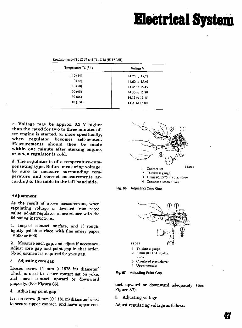
Regulator model TLlZ 57 and TLlZ S8 HITACHI
Temperature oc oF Voltage V
to 14
0 32
10 50
20 6S
30 86
40104 1475 to 15 75
14 60 to 15 60
14 45 to 15 45
1430 to 15 30
14 15 to 15 15
14 00 to 15 00
c Voltage may be approx 0 3 V higberthan the rated for two to three minutes af
ter engine is started or more specificallywhen regulator becomes self heated
Measurements should then be made
within one minute after starting engineor when regulator is cold
d The regulator is of a temperature com
pensating type Before measuring voltagebe sure to measure surrounding tem
perature and correct measurements ac
cording to the table in the left hand side
1 Contact set
2 Thickness gauge
3 4mm O 1575in dia screw
4 CIOsshead screwdriver
Ag 86 Adjusting Core Gap
AdjustmentAs the result of above measurement when
regulating voltage is deviated from rated
value adjust regulator in accordance with the
following instructions
1 Inspect contact surface and if roughlightly polish surface with fine emery paper
500 or 600
2 Measure each gap and adjust ifnecessary
Adjust core gap and point gap in that order
No adjustment is required for yoke gap
3 Adjusting core gap
Loosen screw 4 mm 0 1575 in diameter
which is used to secure contact set on yokeand move contact upward or downward
properly See Figure 86
4 Adjusting point gap
Loosen screw 3 mm 0 1181 m diameter used
to secure upper contact and move upper con
EE057
I Thickness gauge2 3 mm 0 1181 in dia
screw
3 Crosshead screwdriver4 Upper contact
Ag Adjusting Point Gap
tact upward or downward adequately See
Figure 87
5 Adjusting voltage
Adjust regulating voltage as follows
II

lIeetricalSptem
Loosen lock nut securing adjusting screw
Turn this screw clockwise to increase or coun
terclockwise to decrease regulating voltageSee Figure 88
EE058Charging relayNormal relay operating voltage is 8 to 10V as
measured at alternator A terminal Relay it
self however operates at 4 to 5V
Use a DC voltmeter and set up a circuit as
shown in Figure 89
UI
234
Wrench
Cro ead screwdriver
Adjusting screw
Lock nut
Fig 88 Adjusting Regulating Voltage
l Connect positive tenninal of voltmeter to regulator lead connector N terminal with negative terminal
groundedStarl engine od keep it idle
3 Take voltmeter reading
aVail Below 5 2 Volts Over 5 2 Volts
l Check fm ntinuity b Pilot lamp remains lit Pilot lamp emainslit
tween N terminals of l Check fan belt tension Pilot lamp relay Oil ontact
gulator and alternator If reet remove egulator points Qui of rdef
Alternator circuit defective od adjust as necessary Replace regul1torifcontinuity exists
Over 5 2 Valls
Pilot lamp does001 lit
Pilot lamp clay assembly is in good odition
TROUBLE DIAGNOSES AND CORRECTIONS Including alternator
Condition Probable cause CorrectiYe action
No output Sticking brushes
Dirty brushes and slip ringsLoose connections orbroken leads
Correct orreplace brushes and brush springsQean
Retighten orsolder connections
Replace leads if ecessary
Repair or replace stator
Replace rotor
Replace diodes
Replace rotor
Repair or replace stator
Replace insulator
Replace belt
Open stator winding
Open rotor winding
Open diodes
Shorted rotor
Shorted stator
Grounded BAT terminaL
Broken ran belt
t8

IlectrieallJStem
Excessive Otltput Broken neutral wire color of wire is whitt Replace wire
Defective voltage regulator Check regulator operation and repair or
replace as required
Poor grounding of alternator and voltage Retighten terminal connection
regula tor E terminal
Broken ground wire color of wire is black Replace wire
Low output Loose orworn fan belt Retighten or replace belt
Sticking brushes Correct or replace brushes and springs if
necessary
Low brush spring tension Replace brush springs
Defective voltage regulator Check egulator operation and repair or
replace as required
Dirty slip ngs Clean
Partial short ground or open in stator Replace stator
winding
Partially shorted orgrounded rotor winding Replace rotor
Open ordefective diode Replace diode
Noisy alternator Loose mounting Retighten mounting bolts
Loose drive puUey Retighten pulley correctly
Defective ballbearing Replace bearing
Improperly seated brushes Seat brushes correctly
Alternator Fuses and Fusible Links
EtIi Iu r tor N r Qo wt Lou
M La t
P re O lp t@C ftlorN br
A p L320 Engine compartment1 LS20 ight
L521Mitllubillhi 2 500 24 5 PL521
AS203Al PUlO
R Mit lbishi 2SOO 24 5WPLSIO
AC1lli I2X2H 215@ LOO Engine compartmenthigh temp riht fender well
U20 Mitsubishi 2 500 23 SPL3II Inside glove clmpa ntAS2030A2 SHL3ll
LIB Hitachi 500 22 L8ll0 Under instrumfttt panel Between batteryLTl3041 KLBllO ight of steering column and alternA tor
124 Hitachi 2 500 34 HLSJO Under sh tray console At alternator
LTl45 35 5000 45 at starter
AI2 Hitachi 2500 24LTl35 05 5000 33
Morethan
41

IlectricalSptem
EMISSION CONTROL DIAGRAMS
IGNITION KEY
LENOID
lr
TO OITJlIIUTO
IGNmClC COIL
no
I NEUTRAl QEAfl SWITQt
DUAL PenNYOlSTRI8UTOII
ANCEDUlCER
RETARDEDBREAKER
I
CLUTOt PEDAL
CARSURfTDR
MTCH DETECTING CLOSE THIIOTTLE IlO5lnON
Datsun emission control system manual transmission
IGNITION WITOI
BATTERY
lAUTOMATICTRANSMISSION
TO OISTRIJUTOfI
ICHITlON COIL
DUAL IIOINTOISTRI8UTOII
RTAROED
Pat KE
swtTQt DETlCTING DI CftNnfROTTU POSlnON
SWITCH DETECTINGCLCIS
THROTTLE POSITION
Datsun emission control system with automatic transmission
50

IIectricalSptem
1FROMCARBURETORAIR CLEANER
FROMFUEL TANK
2TOCllAHKCAlI
VAPOR VENT LINE
FLOW GUIDE VALVEThe v lv opanwhen the pr IeIe over 0 4 in Hg
CV lIE
FUEL TANK
Datsun evaporative emission control system
51
IIectricalSpt
I Battery
Retarded breaker point
Coo
1L nDiStri IO
ReslSlor
To starter
C P
Rotor bead
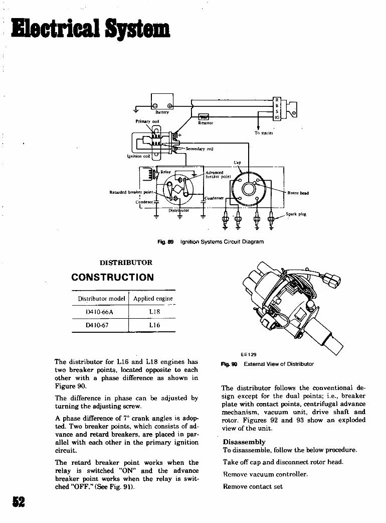
Fig 89 Ignition Systems Circuit Diagram
DISTRIBUTOR
CONSTRUCTION
Distributor model Applied engine
0410 66A LIS
0410 67 LI 6
The distributor for L1G and LIS engines has
two breaker points located opposite to each
other with a phase difference as shown in
Figure 90
The difference in phase can be adjusted byturning the adjusting screw
A phase difference of 70 crank angles is adopted Two breaker points which consists ofad
vance and retard breakers are placed in para1Iel with each other in the primary ignitioncircuit
The retard breaker point works when the
relay is switched ON and the advance
breaker point works when the relay is swit
ched OFF See Fig 91
12
fig 90 External View of Distributor
The distributor follows the conventional de
sign except for the dual points i e breaker
plate with contact points centrifugal advance
mechanism vacuum unit drive shaft and
rotor Figures 92 and 93 show an explodedview of the unit
DisassemblyTo disassemble follow the below procedure
Take off cap and disconnect rotor head
Remove vacuum controller
Remove contact set

I1ectrical Iptem
When cam is to be removed first remove set
screw since shaft head is fastened by the
screw to hold cam down Put matih mark
across cam and shaft so that original com
bination can be restored at assembly
When governor weight and spring are discon
nected be careful not to stretch or deform
governor springAfter disassembling apply grease to governor
weights
Unscrew two contact breaker set screws and
remove contact breaker assembly
Pull knock pin out and disconnect collar to
remove the entire rotating parts
1 Advanced breaker point2 Retrded breaker pomt3 Phase difft rence
AssemblyAssemblv can be made in reverse sequence of
disassembly Refer to Figure 101 for
replacement and reassembly of governor
spring and cam
In assembling distributor use caution so that
rotor head positioning tip at cam is set on
governor spring circular hook side
Then weight pin for governor spring A with
circular hook comes in long rectangular holeFIg 91 External View of Dual Points
l
1 Center carbon2 Rotor head3 Breaker plate Contact
4 CondenserS Shaft6 Hou ing
Rg 92 Construction
7 Governor weight8 Cap9 Side plug
13
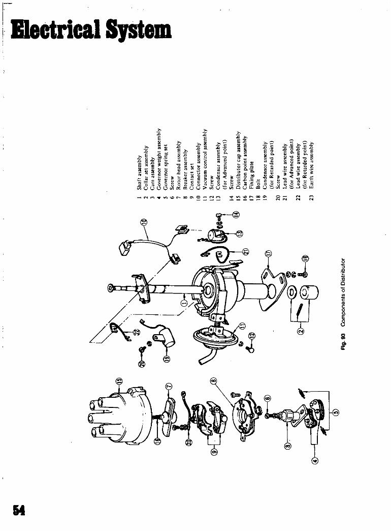
4
7iJi
o
I I
1
Flg93
ComponentsofDistributor
I
J
Shaftassembly2
Collarset
assembly3
Camassembly
4
Governorweightassembly
5
Governorspringset
6
Screw7
Rotorheadassembly
8
Breakerassembly
9
Contactset
10
Connectorassembly
II
Vacuumcontrolassembly
12
Screw13
Condensorassembly
forAdvancedpoint
14
Screw15
Distributorcap
assembly
16
Carbonpointassembly
17
Fixingplate
18
Bolt19
Condensorassembly
forRetardedpoint
20
Screw21
Leadwireas
embly
forAdvanced
point
22
Leadwireassembly
forRetardedpoint
23
Earthwireassembly
iE1

IlectricalSJStem
4
EE07D
Fig 98 Removing Rotation Parts
EE074
Fig 94 Disassembling Vacuum Controller
Also check to be sure that weight pin on
spring A is in slit in cam plate with a
clearance between the two at beginning and
end ofgovernor operation
Meanwhile weight pin on opposite side comes
in short rectangular hole
Fig 95 Unscrewing Breaker Sets Screws Fig 99 Removing Carn
Qi
EE141
Ag 96 Removing Contact Breaker
Fog 100 Exploded View
EE073
Fig fJ11 Removing Knock Pin
EE075
s
b
5

B1ectricalSptem
1 5
Shaft enter
2
EE071
Ag 101 Setting Governor s Spring and earn
IGNITION COIL
CD12
4
@
EE143
@J
@
Fig l02 Construction
18
I Governor Ieighl2 Clearance fOl slart and
end of advancin angle3 Rectangular hook
4 Governor printt R
5 am plate6 Weight pin7 Circular hook
8 Gm ernuT spring A
9 Rotor positioning tip
l rillliJr lnitlal
Sl l ndary It Tmin1
CJp
4 Sprln5 Side
h
7
8
9
III
II
Primary III
S ndar
In uhllllr HI
il
l nlcr
SegmentCase

IIectricalSJStem
It does not leave clearance either at the start
and end ofadvancing
With unit assembled check to be sure that
driven slit and rotor position tip 9 are set in
the same direction See Figure 101
After assembly check operation of governorbefore installing it on engine
Ignition timing should be tested with unit
mounted on engine
IGNITION COIL
DescriptionThe ignition coil is of an oil filled type The ignition coil case is filled with oil which has
good insulating and heat radiating charac
teristics
The ignition coil has a greater ratio between
the primary and secondary windings to step
up the battery voltage to the high voltage to
cause stronger sparks to jump the spark pluggap
The cap is made of alkyd resin which offers
high resistance to electric arc and increased
insulation
Normal
Overheating
The resistor in the ignition coil circuit helpsproduce strong sparks from starting to
high speed full power operation
The internal resistor limits to a maximum
safe flow of the primary current through the
coil and distributor contact points Thus it
protects the contact points during slow speedoperation when they are closed for long inter
vals
The ignition coil and resistor should be han
dled as a matched set
SPARK PLUGS
DescriptionThe spark plugs are of the resistor typehaving 0 551 in threads and 0 0276 to 0 0315
in gap The inspection and cleaning should be
made every suitable maintenance period If
necessary replace
Note All spark plugs installed on an
engine must be of the same brand and
number of heat range
i l
Carbon fould
Life
Fig 103 Spark Plugs
17

IlectricalSptem
InspectionRemove spark plug wire by pulling on boot
not on wire itself
Remove spark plugs
Check electrodes and inner and outer por
celains of plugs noting the type of depositsand the degree of electrode erosion
Normal Brown to grayish tan deposits and
slight electrode wear indicate correct sparkplug heat range
Carbon fouled Dry fluffy carbon deposits on
the insulator and electrode were mostlycaused by slow speed driving in city weak ignition too rich fuel mixture dirty air cleaner
etc
It is advisable to replace with plugs havinghotter heat range
Oil fouled Wet black deposits show excessive
oil entrance into combustion chamber throughworn rings and pistons or excessive clearance
between valve guides and stems If the same
condition remains after repair use a hotter
plug
Overheating White or light gray insulator
with black or gray brown spots and bluish
burnt electrodes indicate engine overheatingMoreover the appearance results from in
correct ignition timing loose spark plugs low
fuel pump pressure wrong selection of fuel a
hotter plug etc
It is advisable to replace with plugs havingcolder heat range
After cleaning dress electrodes with a small
fine file to flatten the surfaces of both center
and side electrodes in parallel Set spark pluggap to specification
Install spark plugs and torque each plug to 11
to 15 ft lbConnect spark pi ug wires
Cleaning and RegapClean spark plugs in a sand blast typecleaner Avoid excessive blasting Clean and
remove carbon or oxide deposits but do not
wear away porcelain Ifdeposits are too stub
born discard plugs
Fig 104 Selling Spark Plug Gap
TROUBLE SHOOTING IGNITION
Spark length Trouble location Causes Remedies
No sparks at all Distributor Defective insulation of condenser Replace
Breakage of lead wire low tension ide Repair
Defective insulation of cap and rotor head ReplacePoint does at open close Repair
19nition coil Wire breakage short cuit of coil Replace with new ne
High tension cable Wire coming off Repair
Defective insulation Replace
I to 2 mm 0 0394 Distributor Point gap too wide Correcl
to 0 0787 in or Oil sticking on point Clean
irregularPoint burnt too much Replace
18

IlectricalSpt
T ublt Trouble location Cause Remedies
Less than 6 mm Spark plugs Electrode gap too wide Correct or eplace0 2362 in Too much carbon Clean or replace
Broken neck of insulator Replace
Expiry of plug life Replace
Engine misses Distributor
Ignitjo il
High tension code
Spark plugs
Engine causes
knocking veryoften
Distributor
Spark plugs
Engine doesnot
give enoughpower
Distributor
Spark plugs
Dirty point
Improper point gap
leak of electricity of cap and olor head
Defective insulation of condenser
Defective arm
Defective spring of rm
Breakage of lead wire
Worn out orshaky breahr plateWorn out or shaky distributor shaft
Layer short circuit or of oferior quality
Deterioration f insulation and leak of
electricity
DirtyLeak of electricity at upper porcelainnsulater
Improper and advance timing
Coming off or breakage of governor springA pin or a hole of governor portion worn
out
Burnt too much
Improper and etarded timing
Defective function of governor
Dirty point
Point gap too narrow
Dirty
After cleaning spark plugs renew firing sur
face of electrodes with file mentioned aboveThen gap spark plugs to 0 0276 to 0 0315 in
using a round wire feeler gauge All sparkplugs new or used should have the gapchecked and reset by bending groundelectrode
HEATER UNIT REMOVAL
Drain out coolant
Clean
Correct
Repair or replace
ReplaceOil shaft
Replace assembly
Replace
Replace assembly
Replace assembly
Replace withgood one
Replace
Clean
Repair or replace
Correct the fittingCorrect or replace
Replace
Replace
Correct the fitting
Replace assemblyClean
Correct
Clean
Disconnect connector ofheater to engine wellhot water pipe
Remove defroster hose
Disconnect connector motor
Remove the two heater control wires at heaterunit
Remove the four bolts and take out ventilator
Remove the four heater unit fixing bolts and
detach heater unit
18

syste1ll
1
uJJ
a E2 t03 o
ii5
38 tD t
J
At
sh
3
Ift
0
11 Irr
1 111 a
I 11I
d CII
HP
El
II
I 7O
lll nIi J
oo lU1il III
W t
lr J lJ 1
C
rfuoO
L
TisifI
irJ
II I JI q l t lI i irl r l Ii
I
II
S III J I i 1 11c
1 Q l II ilt
I ylI C ti II l f1 I 1
1 1 JSI I m @s3iiLIINi1J lc
1t
11
lII I
li II I IIr fiFo II
II II I
1 I i Illii
mnnmm 1J2lt l
l1 1 I I I IIiI IlI c
A
1 C1
LtItti1nT
f rtIII
dJr
o 1
Je
lW I III IC Ii i
11 I0
C
rW T I I l III i
I
J Iic
IJi3r
JI
I i XrfFl
I lJ
ilrsr
o
r
I
e
0hill IF
it 111
5 u
It
I
0
I
aft
0
il
4
u
co
Eil
ii
c
E
z
c
0
E
is
ll
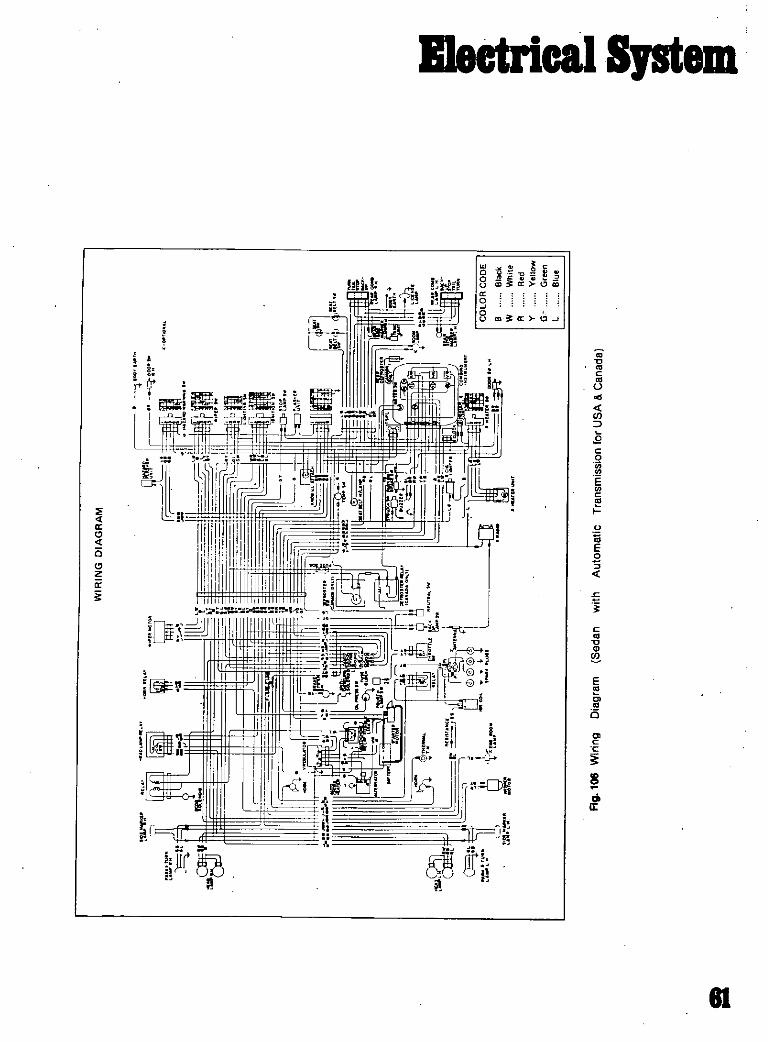
IleCtricalSystem
Q 0P 11
8 iii aao
8 CD a t1J
l
a
c
za1
rraa 1Il
ir
t lf1l
g or
c
1l
gco
Ec
EE
cS
c
E
is
8
dlIt
81
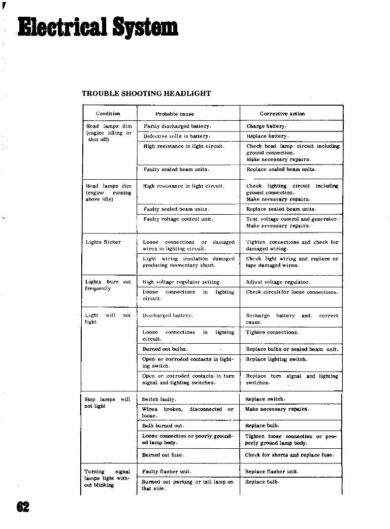
B1ectrical SpteJD
TROUBLE SHOOTING HEADLIGHT
Condition Probable cause Corrective action
Head lamps dim Partly discharged battery Charge batteryengine idling or
Defective cells in battery Replace batteryshut offHigh resistance in light circuit Check head lamp circuit including
ground connection
Make necessary repairs
Faulty sealed beam units Replace sealed beam units
Head lamps dim High istance light circuit Check lighting circuit includ
engine running ground connection
above idle Make necessary repairs
Faulty sealed beam units Replace sealed beam units
Faulty voltage control unit Test voltage control and generatorMake necessary repairs
Lights flicker Loose connections or damaged Tighten connections and check for
wires in lighting ircuit damag d wiring
Light wiring nsulation damaged Check light wiring and replace or
producing momentary short tape damaged wires
Lights burn cut High oltage regulator setting Adjust voltage regulatorfrequently Loose cOIUlections in lighting Check circuitCor loose connections
circuit
LIght will not Discharged battery Recharge battery and correct
light cause
Loose connections in lighting Tighten connections
circuit
Burned out bulbs Replace bulbs or sealed beam unit
Open or corroded contacts in light Replace lighting switch
ing switch
Open or corroded contacts in turn Replace turn signal and lightingsignal and lighting switches switches
Slop lamps will Switch faulty Replace switch
not light Wires broken disconnected or Make necessary repairsloose
Bulb burned out Replace bulb
Loose connection orpoorly ground Tighten loose connectIon or prood lamp body perly ground tamp body
Burned out fuse Check for shorts and replace fuse
Turning signal Faulty n sher unit Replace flasher unIt
lamps light withBurned out parking or tail lamp on Replace bulb
out btinklng that side
82

IIectricalSJStem
Blinking on one Loose contact of bulb Make necessary repairside too fast
Improper capacity of bulb Replace bulb
Turn indicator Faulty mechanism of turn signal Replace with new partslever does not switch
return automati
cally
TROUBLE SHOOTING HORN
Condition Probable cause Corrective action
Horn does not F burned ut Replace fuse
operate Improper mtaet uf horn bulton Check and repair horn button
Open circuit f harness Repair or replace harness
Improper mtaet of ch terminal Correct each terminal
Dead battery yharge battery
Improper contact of horn relay Correct
point
Open circuit or rong ground coo Replace or repair horn
nection of horn interior
Wear of horn point Adjust adjusting screw
Low volume Improper contact of fuse or 000 Correct contact
improper tone nector
Open circuit of harness Repair
Improper contact of horn point Correct horn point
Wear of horn point Adjust adjusting screw
Crack in diaphragm Rephlce horn
RADIO
1 iz z
gI ii I8 i
il
2 2 i
I L J
COILIOINT
Removal
Disconnect all connections
Remove tuning knob and volume control
knob
HORN RELAY
BATTERY
Remove ashtray
Remove cluster lid by unscrewing four cluster
lid fixing screws
Separate cluster lid finisher board and radioby unscrewing lock nutsAg 107 Horn Relay Wiring
83

B1ectrical Sptm
TROUBLE SHOOTING SPEEDOMETER
Condition Probable cause Corrective action
Speedometer does Improper setting of speedometer Correct settingDot operate cable union nut
Broken speedometer cable Replace cable
Broken speedometer drive gears Replace meter
Defective speedometer Replace meter
Swing of pointer Excessive bend in speedometer Correct cable installation or re
place cable
Broken speedometer drive gear Replace speedometer
Defective speedometer Replace speedometerf
Unsteady pointer Improper setting of speedometer Correct settingcable union nut
Defective speedometer cable Replace cable
Defective speedometer Replace speedometer
Strange sound Excessive bend lack of lubricant Replace or lubricate cableeyncbronized and twist of meter cable inner wire
witbrunning Defective speedometer Replace speedometerspeed
Inaccurate Replace speedometerindication of
pointer
Defective Improper gearing of second and Replace speedometerodometer third gears in speedometer
Improper feed caused by deforma Replace speedometertion of pinion carrier
ry1
Cil@
@f
1
fig 108 Heater System
84

TROUBLE SHOOTING HEATER
Condition
Hot air does not
come out
Motor does
not
operate
Fan cannot be
rotated
smoothly byhand
Hot air does
Dot come out
although lesfJ
fan is
rotating
Air temperatureis low
Hot wate r
does not
circulate
Water tem
perature is
low
Water leakagerom heater
Defective
defroster
Vibrating noise
Probable cause
Open or short circuit of feed
harness
Defective switch
Defective motor
Fin is clogged
Slow rotation of fan
Looseness of fan stallation
Defective water pump
Bending or clogging of connectirghose
Defective hot water cock
Air is left in the hose
Defective thermostat
Defective water hose
Loose clipping of water hose
Defective cylinder head gasket
Improper soldering of heater core
Defroster hose is removed
Bend or break of defroster hose
Looseness of heater BUpport
Looseness of each fixing screw
TROUBLE SHOOTING RADIO
IIectricalSpteJD
Corrective action
Check and repair wiring harness
Replace switch
Replace motor
Clean fin
Replace motor
Repai r
Repair water pump
Check or clean piping
Repair
Purge air out of hose
Replace thermostat
Replace water hose
Retighten clipReplace gasket
Solder leaking position
Correct connection
Correct or replace
Tighten completely
Retighten each screw
Condition Probable cause Corrective action
Pilot lamp does Melt away fuse Replacenot light when
Improper connection of cable or Inspect and tightenswitch is onconnector
Broken pilot lamp Replace
Improper switch operation Repair or replace
Pilot lamp lightsbut sound doesnot come out
Improper connection of antenna
Improper connection of speakerImproper circuit of radio itself
Tighten
TightenConsult Service Shop of radiomanufacturer
85

B1ectrical I em
NOISE PREVENTION CHART
Condition Apparent cause Repair
Ignition system
Noise present synchronized High tension cord Do not worry about high tension cord
with engine revolution because anti noise cable is uBed
Ignition coil Keep choke wire away from ignitioncoil as far a8 P08 fl
Set 0 5 IJ F condenser at primary side
B terminal of ignition coil
Note If the COI6 is set at
ondary or primbraker side
engine will not p
Connect with bond wire between engineand ignition coil locating area of body
Secure ground of ignition coil
Distributor Secure contact of carbon electric poleand rotor
Eliminate excessive tips at rotor poleor cap pole scrubbing by driver
Check stagger betveen rotor and
starter
Charging system
Sound of alternating current Alternator Set 0 5 F condenser at chargingpresent terminal A
Note 00 not add mote condan r
If more conden is added alter
nator coil will be broken
hen pressing down or re Regulator Set 0 5 F condenser at B or Bat
leasing accelerator pedal terminal of voltage regulatornoise present
88

Fuel SptemAIR CLEANER ELEMENT 68AUTOMATIC TEMPERATURE
CONTROL AIR CLEANER 68AIR CONTROL VALVE 68
Idle Compensator 69TEMPERATURE SENSOR 69
Removal 69Installation 69
FUELPUMP 69Removal and Disassembly 69
Inspection 70
Assembly 70CARBURETOR 73
Removal 73
Disassembly 73Float Chamber 74
ANTI DIESEUNG SOLENOID 74Removal 74Installation 74
BOOST CONTROLLEDDECELERATION DEVICE 74
Assembly and Installation 74
Cleaning and Inspection 74
JETS 75
81

raelSpt
AIR CLEANER ELEMENT
ThE air cleaner element is of a viscous paper
type and does not require any cleaning until
replacementlote Do not brush or blast element
before replacement
AUTOMATIC TEMPERATURE
CONTROL AIR CLEANER
The automatic temperature control air
cleaner is provided with a temperature sensor
and avacuum operated valve The vacuum ac
ted upon the air control valve is controlled bythe sensor See Figure 109
If the temperature of suction air is low when
the engine is running the air control valve
closes the underhood air inlet and introduces
hot air through the cover which is installed on
the exhaust manifold See Figure 110l
When the temperature ofsuction air around
the sensor reaches 37SC IIOOF or above
the sensor actuates to open the air control
valve When the temperature of suction air
around the sensor further rises and reaches
above 480C 11S0Fl the air control valve
completely opens to prevent the entrance of
hot air and allows under hood air alone to be
introduced into the carburetor See Figure111
AIR CONTROL VALVE
The air control valve acts in the manner
described previously and the temperature of
s ci n ira IL he sensor is always keptat about 430C II10oFl
When the engine is operating under heavyload the air control valve fully opens the un
ECMl
@
I Air nlet pipe2 Vacuum molor s y
3 Temperature censor ass y4 Hot rpipe5 Air ntrol alve
6 Idle compresalor
Rg l09 Automatic Temperature Control Air Cleaner
ITomanifold
3 Diaphragmspring4 Diaphragm5 Vacuum hose
6 Air bleed valve
Partwly openHot 7 Hot air pipe
I Air inlet pipe 8 Temperature censor
2 Air control ly ECOO7
Hg l10 Hot Air Delivery Mold During Cold EngineOperation
I Airinlclpipe2 Air ntrolvalvc
3 Diaphrapn prins4 Diaphrqrn5 Vacuum hoses
6 Air b1cedvahrcfully open
7 Hot PJPC
8 Temperature Kllsor
b1ECOOB
fig 111 Underhood Air Delivery Mold lOuring HotEngine Operation

FuelSptem
derhood air inlet to obtain full power regardless ofthe temperature around sensor
This control of carburetor air temperaturesallows leaner carburetor calibration with ac
companying reduced emissions than conven
tional controls and also eliminates carburetor
icing
Idle CompensatorThe idle compensator is essentially ather
mostatic valve to compensate for excessive
enriching of the mixture as a result of highidle temperatures When the under the hood
temperatures are high the bimetal located inthe air cleaner is heated by intake hot air andlifts the valve to open This pennits additionalfresh air that is properly calibrated by the 1 4
mm 0 055 in dia orifice compensates for theincreased richness of into the intake manifoldand the air fuel mixture in order to maintainsmooth idle engine operationThe idle compensator thermostatic valve partially opens at 650C l490F and fully opensat 750C l670F
Never attempt to disassemble this unit sinceit is sealed for tightness and properly adjustedfor valve timing
TEMPERATURE SENSOR
Removal
Flatten tabs ofclip with pliersPull off hoses
Note Note the respective positions ofhoses from which they wereremovedTake off sensor and clip
InstallationInstall sensor and gasket assembly In the
proper positions See Figure 113
Insert clip Be sure to hold sensor at itscorrect position in Fig 113 to avoid damageSee Fig 114
Press fit clips into pipe while straighteningtabs
Note Use care not to damage sensor
Connect hoses to their proper positions See
Figure 115
FUEL PUMP
Removal and DisassemblyRemove fuel pump assembly by unscrewingtwo mounting nuts and disassemble in the
following order
1 Pipe2 Catch3 Fixed with
ad hesivc
4 Hose5 Tab6 CHp7 GaSket
Ag 112 Removal 01 Sensor
Ag 113 Installing Sensor
Ag 114 Inserting Clip
81

laelSpteIIl
Separate upper body and lower body by un
screwing body set screws
Take off cap and cap gasket by removing capscrews
Unscrew elbow and connector
Take off valve retainer by unscrewing two
valve retainer screws and two valves are
easily removed
To remove diaphragm press down its center
against spring force With diaphragm presseddown tilt it until the end of pull rod touches
the inner wall of body Then release the
diaphragm to unhook push rod Use care
Ag 115 Connecting Hoses
during this operation not to damagediaphragm or oil seal
Drive out rocker arm pin by using a press or
hammer
InspectionCheck upper body and lower body for cracks
Check val ve assembly for wear on valve and
valve spring Blow valve assembly with
breath to examine its function
Check diaphragm for small holes cracks or
wear
Check rocker arm for wear at the portion incontact with camshaft
Check rocker arm pin for wear A worn pm
may cause oil leakage
Check all other components for any abnor
malities and replace with new parts if
necessary
AssemblyReverse the order of disassembly Closely ob
serve the following instructions
Use new gaskets
1 OutIetvalve
2 Diaphragm3 Diaphragm spring4 Inlet valve
5 Rocker arm
fig 116 Schematic View ot Fuel Pump
70

uelSJStem
Ag 117 Removing Pole Rod
i
o
2
Lubricate rocker arm rocker arm link androcker arm pin before installation
To test the function proceed as follows
Position fuel pump assembly about 3 3 ftabove fuel level of fuel strainer and connect a
pipe from strainer to fuel pump
Operate rocker arm by hand If fuel is drawn
up soon after rocker arm is released fuel
pump is functioning properly
@
1 Fuel pump cap
2 Cap gasket3 Valve packing Ass y4 Fuel pump valve Ass y
5 Valve retainer6 Diaphragm Ass y7 Diaphragm spring8 PUU rod
9 Lower body seal washer10 Lower body seal
11 Inlet connector
12 Outlet connector
13 Rocker arm spring14 Rocker arm
15 Rocker arm side pin16 Fuel pump packing17 Spacer Cuel pump to
cylinder blockEF008
FIg 118 Structure of Fuel Pump
71

iI
1
6
doof
c
I
9
9
i
1
Floatvalve
2
Float3
Chokevalve
4
Primarysmallventuri
5
Primarymain
nozzle
6
Mainaicbleed
7
Primaryemulsiontube
8
P
I
st
slowairbleed
9
P
2ndgOWairbleed
10
P
slowjet
II
P
bypasshole
12
P
throttlevalve
t
3
S
mainnozzle
14
S
smallventuri
15
S
mainairbleed
16
S
slowjet
17
S
slowairbleed
18
S
emulsiontube
19
S
mainjet
20
S
bypasshole
21
S
throttlevalve
Fig119SectionalViewofCarburetor

Fuellptem
CARBURETOR
Removal
Remove air cleaner
Disconnect fuel and vacuum lines from car
buretor
Remove throttle lever
Remove four nuts and washers retaining car
buretor to manifold
Life carburetor off manifold
Remove and discard the gasket used betweencarburetor and manifold Replace it if
ynecessary
DisassemblyDo not remove throttle platesCarburetor assembly
Remove throttle return spring from primaryside
1 Ventui
2 Main air bleed3 Emuleion take
Rg 120 Removing Thermostat
ET038
4 Secondary5 Primary
1
2 ET039
fig 121 Removing Diaphragm Chamber
Remove pump lever and pump rod
Remove cam connecting rod
Remove thermostat cover by unscrewing threeset screws
1 Needlevalve
2 Stopper plate3 Filter
4 Filter l
screw
S Nipple
o11@
ET040
Fig 122 Removing Filter
Rg I23
wo
@ CIDI Chock chamber ET0412 Thermostat cover
3 Pump lever4 Throttle return spring5 Pump rod
Removing Venturies
EF134
Flg 124 B C D D Securing Screws
73

laelSptem
Remove choke chamber by unscrewing four
et screw and remove throttle return springfrom secondary side
Separate float chamber and throttle chamber
by unscrewing four set screws
Float Chamber
Remove diaphragm chamber assembly and
diaphragm chamber gasket
Remove fast idle cam cam spring and counter
lever
Remove filter set screw nipple filter needlevalve and stopper plate
Remove cylinder plate pump cover pistonpiston return spring and inlet valve by un
screwing two set screws
Remove injector spring and outlet valve
Remove small venturies main air bleeds and
emulsion tubes from primary and secondarysides
Remove slow jet and slow air bleed
Remove primary and secondary main jets
Remove level gauge cover float chamber
level gauge rubber seal float shaft colour and
float
Remove power valve
Remove return plate sleeve fast idle lever
spring hanger and throttle lever
ANTI DIESELING SOLENOID
Removal
Solenoid is cemented at factoryUse a pair of pliers to loosen body out of
position
Installation
Before installing a solenoid it is essential to
clean all threaded parts of carburetor and
solenoid Supply screws in holes and turnthem in two or three pitches
First without disturbing the above settingcoat all exposed threads with adhesive the
Stud Lock ofLOCTITE or equivalent
Then torque screws to 30 to 48 in lb
R
After inotalling anti dieseling solenoid leave
carburetor more than 12 hours without
operation
After replacement is over start engine and
check to be sure that fuel is not leaking and
that anti dieseling solenoid is in good con
ditionNotes a Do not allow adhesive getting on
valve Failure to follow thiscaution would
result in improper valve performance or
clogged fuel passage
b In installing valve use caution not to
hold body directly Instead use specialtool tightening nuts as requiredc After installing a new solenoid checkto be certain that there is no leakagecracks or otherwide deformation
BOOST CONTROLLED
DECELERATION DEVICE
Remove B C D D by unscrewing three
securing screws 1 Do not unscrew three
B C D n assembly scrcw 2
When installing after screwing three
securing screws 1 rescrew three BC D D
assembly screws 2 in order to prevent the
warp of B C D D body
Tighten torque17 to 35 in lb
Assembly and Installation
Follow disassembly and removal procedures in
reverse
Replace gaskets if necessary
In disassembling interlock link and related
components be careful not to bend or deform
any of components
Careful reassembly will rest9re smooth
operation ofall interlock parts
Cleaning and InspectionDirt gum water or carbon contamination in
or on exterior moving parts of a carburetor
are often responsible for unsatisfactory performance For this reason efficient carburetion
depends upon careful cleaning and inspectionwhile servicing

ruel IJStem
Blow all passages and castings with com
pressed air and blow oft all parts until dryNote Do not pass drills or wires throughcalibrated jets or passages as this mayenlarge orifice and seriously affect car
buretor calibration
Check all parts for wear If wear is noteddefective parts must be replaced Note
especially the following
Push connecting rod of diaphragm chamberand block passage of vacuum by finger Andwhen connecting rod becomes free check for
leakage ofair and damage of diaphragmCheck float needle and seat for wear Ifwear
is noted assembly must be replacedCheck throttle and choke shaft bores in throttIe chamber and choke chamber for wear or
out of roundness
Inspect idle adjusting needle for burrs or
ridges Such a condition requires replacement
Inspect gaskets to see if they appear hard or
brittle or if edges are torn or distorted Ifanysuch condition is noted they must be
replaced
Check filter screen for dirt or lint
Clean and if it is distorted or remains
plugged replaceCheck linkage for operating condition
Inspect operation of accelerating pump Pourfuel into float chamber and make throttlelever operate And check condition of fuel in
jection from the accelerating nozzle
JETS
The carburetor performance depends on jetsand air bleeds That is why these componentsmust be fabricated with utmost care To cleanthem use cleaning solvent and blow air on
them Larger inner numbers stamped on the
jets indicate larger diameters Accordinglymain and slow jets with larger numbers
provice richer mixture and the smaller num
bers the leaner mixture Inversely the mainand slow air bleeds which are for air to pass
through make the fuel leaner if they bear
larger numbers and the smaller numbers thericher fuel
71

GaoUDI SptemDRAINING FLUSHINGWATER PUMP
Removal
DisssemblyInspectionInstallation
THERMOSTATRemoval and Installation
RADIATOR
Removal and Installation
Inspection
78
7878
79
7979
79
79
79
79
80
11

Cooling Sptem
r
C0013
JJ
CiJ @
FIg 125 Cooling System
DRAINING AND FLUSffiNG
To drain the cooling system remove the
radiator cap release the drain cock at the bot
tom of the radiator and drain plug on the
right side of the cylinder block If the heater
system is installed set the heater temperature control valve at open position
After the coolant is drained completely close
the drain cock and plug and refill the systemwith clean water
WATER PUMP
Thwater 1ump is of a centrifugal typewhich is mounted on the engine front cover
The fan and pulley are bolted at the pulleyhub
The pump shaft is supported by a double row
ball bearing press fit in an aluminum die cast
pump body The bearings are permanentlylubricated and sealed to prevent loss of
lubricant and entry ofdirt
78
The pump contains an impeller that turns on
a steel shaft which rotates in the ball
bearings and the volute chamber is built in
the front cover assembly The inlet of the
pump is connected to the radiator lower tank
by ahose
Removal
Drain coolant into a clean container
Loosen four bolts retaining fan shroud to
radiator and remove shroud
fill 126 Removing Water Pump

Cooling IJStem
Loosen belt then remove fan blade and pulleyfrom hub
Remove five bolts pump assembly and gasketfrom front cover
DisassemblyThe water pump body is made of aluminum
and its bearing outer race is press fit For this
reason the body shaft bearing should not be
disassembled
InspectionInspect pump assembly for the following con
ditions and replace it if necessary
Badly rusted or corroded body assembly and
vane
Excessive end play or roughness of bearingsin operation
InstallationMake sure to clean the gasket surfaces on
pump and front cover Always use new gasketwhen installing pump assembly Be sure to
tighten bolts uniformly
Fill cooling system and check for leaks at
pump
Install fan pulley and fan blade and tightenfixing bolts securely Install belt and adjustfor proper tension
THERMOSTAT
A wax pellet type thermostat is mounted in
the thermostat housing at the cylinder head
water outlet adjacent to the inlet manifoldThe function of thermostat is to control the
flow of coolant facilitating fast engine warm
up and regulating coolant temperature The
thermostats are designed to open and close at
predetermined temperatures and if not
opemting properly should be removed and
tested as listed below
Removal and Installation
Drain coolant partiallyDisconnect upper radiator hose at water
outlet
fig 127 Removing Thermostat
Loosen two securing nuts and remove water
outlet gasket and thermostat from ther
mostat housing
After checking thermostat satisfactorily in
stall replacing with a new housing gasket
Reinstall water outlet and tighten securingnuts
Replenish coolant and check for leaks
RADIATOR
The radiator is a conventional down flow typehaving the top and bottom tanks to distributethe coolant flow uniformly through the ver
tical tube of the radiator core
The mdiator filler cap is designed to maintaina pre set pressure 09 kglem2 13 Ib sq in
above atmospheric pressure The relief valve
consists of a bIowlf1 valve and a vacuum
valve It helps to prevent coolant loss from
boiling for by raising the pressure on thecoolant On the contrary as the pressure is
reduced below atmospheric pressure thevacuum valve allows air to reenter theradiator preventing the formation of vacuum
in the cooling system
The bottom tank on cars equipped with the
automatic transmission inoorplrates an oil
cooler for the transmission fluid
Removal and InstallationDrain coolant into a clean container
Remove front grille
19
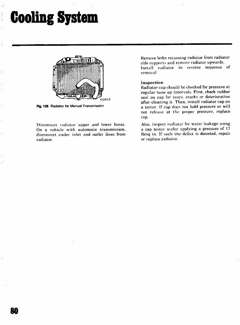
GooUDI SJStem
Ag 128 Radiator for Manual Transmission
Disconnect radiator upper and lower hoses
On a vehicle with automatic transmission
disconnect cooler inlet and outlet lines from
radiator
80
Iemove bolts retaining radiator from radiator
side support3 and removradiator upwardsInstall radiator in reverse sequense of
removal
InspectionIadiator cap should be checked for pressure at
regular tune up intervals First check rubber
seal Oil cap for tears cracks or deterioration
after cleaning it Then install radiator cap on
a te ter If cap docs not hold pressure or will
not release at thp proper pressure replacecap
Also in pect radiator for water leakage using
a cap tester unde applying a pressure of 17
lblsq in If uch the defect is detected repairor replace radiator

Brakes
MASTER CYLINDERRemoval
Installation
FRONT DISC BRAKEDescriptionRemoval
DisassemblyInspection and RepairPiston Seal ReplacementAssembly and InstallationPad Replacement
REAR BRAKE
Removal and DisassemblyInspectionAssembly
82
82
82
82
82
82
84
84
85
85
86
86
86
87
88
II

Brakes
MASTER CYLINDER
Removal
Remove the clevis pin connecting the push rodwith the brake pedal and disengage themaster cylinder from the pedal
Disconnect the brake tube from the master
cylinder
Screw out master cylinder fixing nuts and
remove the master cylinder from the dash
board
Installation
Installation is a reversal of the removal
procedure but the following operation shouldbe added
Adjust the pedal height by changing the pushrod length of the master cylinderBleed air out of the master cylinder
FRONT DISC BRAKE
DescriptionFigure 130 shows the relation of forces
working As brake pedal is depressed
IiI
Ijcf 6
@7
4Y
hydraulic pressure from the master cylinderforces the piston of wheel cylinder out of the
caliper bore and thrusts inner pad forward un
til it contacts disc and simultaneously pushesouter pad by reaction force F These forces
cause rotating moment which increases reac
tion force F This is called self energizing ac
tion In this SC brake it is around 50
As pad wears movement of piston is in
creased and when seal is deflected more than
its elastic deformation piston wiil slide out
ward causing slip between seal and pistonthus assuring constant clearance between padand disc
Removal
Jack up the vehicle and support it on stands
and remove the wheel
Disconnect the front brake hose from the
brake tube
Note Plug up the brake tube with a
wooden peg to avoid spilling fluid duringwork on caliper
Screw out the bolts fixing the caliper to the
knuckle flange and remove the caliperassembly
Il Y
0
t Push rod ass y
2 Dust cover
3 Stopper ring4 Piston ass y A
5 PistOn ass1y 86 Secondary piston cap
7 Pbton
8 Primary piston cap
9 Master cylinder body10 Reservoir band ass y
11 Reservoir
12 Reservoir cap ass1y13 Filter
14 Bleeder screw
15 Check valve spring16 Check valve ass y
17 Valve cap gasket18 Valve cap
Fig I29 Tandem Master Cylinder
82

4
3I
2
9 11
I
QD1
@
I
10
17
Fig 130 Front Disc Brake
FIg 131 Sectional View ot Front Disc Brake
6
Brakes
1 Cylinder2 Pi ton eal
3 Wiper eal
4 Eletainer
5 Piston
6 Clip7 Shim
8 Pad
9 Caliper plate10 Torsion ipring11 Cotter pin12 Nut
13 Washer
14 Support bracket
15 Hold down pin16 Pivot pin17 Mounting bracket
18 Spring
83

I lk
Ag 132 Removing Front Brake Hose
Ag 133 Removing Caliper Assembly
fig 134 Removing Brake Disc
M
Remove the spindle nut and the disc hub and
separate the rotor from the hub assembly
DisassemblyRemove the anti rattle clip from the caliperplate and then pick up the pad
Remove the tension springs and pull the cylinder out ofthe caliper plate
To take out piston apply air or hydraulicpressure from inlet hole Remove the rubber
seal from the groove on the cylinder Remove
the retainer and wiper seal and then it can be
easily taken out
Inspection and RepairCheck the cylinder assembly for oil leakageand any damage and replace the cylinderassembly if any abnormal condition is detec
ted on it
Note Unlike the wheel cylinder cup of
drum brakes the piston seal of SC typedisc brake has three important functions
sealing retracting piston and automatic
adjusting If pistonseal is damagedreplace whole cylinder assembly as a unit
However if it is necessary to replacepiston seal replace wiper seal at the
same time Whenpads are replaced two or
three times cylinder assembly or seal
should be replaced though they still seem
to be in good condition
Fag 135 Removing Piston

Brakes
Check the pad for wear and crack replace if it
is damaged or become worn to less than 0 04
in in thickness Inot including the metal
hacking plate
Check the caliper for damages and replace it
if any damage is detected
Check the rotor and if it shows score ex
ccssive out of roundness and so forth recon
ditioning by machining is required
Limit of reconditioning in thickness is 0 331
tn
Standard rotor thickness 0 0394 in
Kunout of the rotor should be less than 0 0048
in total indicator reading
If an ahnormal condition such as crack
distortion or excessive run out is detected
r place the rotor
Piston Seal ReplacementIf oil leakage is found on the piston seal it
hould bc replaced paying attention to the
following points
Aftcr disassembly rinse the cylinder borc
with brake fluid Insert new seal into the
groove taking great care not to damage the
seal Attach the wiper seal Apply a thin
coati ng of specified grease to the cylindcr
hol
Fig 136 Measuring Runout of Disc
Clean the piston Check that no damage exists
on piston surface Insert the piston Take care
that the relieved position of the piston faces
pivot pin Insert fin t two inches gentlyavoiding tilting
Assembly and InstallationClean the mounting surface and disc surface
Attacb the disc to thc hub
Install tbc bub to tbe knucklc pindle
lnsc t the piston into the cylinder till the face
or piston hl ad hecomes almost flush with the
jace of the Iptailwt of the wiper seal
Install the cylindcr into the caliper platc and
seCure in place bv two tor ion springs
emble the hold down pin spring wa her
and nut in this order to support bracket
lnsert a cotter pin to the nut
Sccurc the mounting bracket and caliper platewith the pivot pin washer spring washer
and nul in that ordcr Tighten nut completeand set a cotter pin
Pry up and hold down bracket by a screw
drh and hook up to the upper end of the
mOll Ilt i ng bracket Turn tbe caliper platc to
mak sure that it can slide smoothly
Install the calipcr assembly to the knuckle
flange
Ftg l37 Assembling Piston Seals and Retainer
85

Brakes
Attach a shim to inner pad for noise proof and
heat insulation
Be sure to set the inner pad first Draw the
caliper plate enough toward inside toward
center of chassis Insert lower cuts on both
ends of the pad into the mounting bracket
and then push the pad until the pad contacts
the piston
Draw the caliper plate toward outside Insert
upper cuts and center indentation ofouter padinto the caliper plate
Attach the anti rattle clip Be sure the direc
tion coincides as indicated by the sticker on
the clip
Pad ReplacementThe clearance between the pad and rotor is
adjusted automatically
Check the pad for wear after the first 6 000
miles and every 3 000 miles and thereafter
Pad thickness is easily checked by removingthe anti rattle clip When linings become
worn to less than 0 04 in in thickness not in
cluding the metal backing plate replace all
pads
Note Always replace the pads in full sets
offour using genuine parts
Remove the road wheel Remove the anti rat
tie clip from the caliper plate
Fig 138 Removing Anti Rattle Clip
88
Loosen the bleed screw Pull the caliper plateoutwards outward of chassis Push the pistonin by 0 lIS to 0 157 in
Outer pad is loosened and can be easily pulledout
Draw the caliper plate inwards and remove
inner pad Wipe exposed surface of the pistonthoroughly Push the piston enough into the
cylinder bore Insert new pad into the caliperplate
REAR BRAKE
Removal and DisassemblyJack up the vehicle and support it on stands
and remove the wheels
Fig 139 Pushing Pin
t
Fig 140 Removing Pad

Brakes
@ ic J
rjji
Fig 141 ectional View of Rear Brake
Release the parking brake and disconnect thecross rod from the lever of the rear wheel
cylinder
Remove the brake drum
Remove the return springs and then take out
the brake shoe assemblies
Disconnect the brake tube from the wheel
cylinder
Remove the wheel cylinder by removing com
ponents as in the order of dust cover platesand adjust shims then it is ready to beremoved from the brake disc
The wheel cylinder is easily disassembled byremoving the snap ring and dust cover
Remove the adjuster assembly
Remove the brake disc
InspectionDrums If they show score excessive out ofroundness and so forth reconditioning bymachining is requiredDrum inside out of
roundness below 0 0020 in
Nominal inner diameter
of the drum is 8999 in
Limit ofreconditioning
in diameter is 9 040 in
Linings If shoe linings are incompletelyseated soiled or greasy or deteriorated due toexcess heating repair or replace them If thethickness of the lining is found less than
0 0591 in replace it
Notes a If oil or grease is found in
81

Brakes
1
V
Fig l42 Sectional View of Rear Brake
linings clean thoroughly with carbon
tetrachloride or gasoline
b After lining installation and bondinggrind the lining face to a diameter equalto that of the brake drum
Check and adjust cams for their smooth
operation
Springs If they are considerably weak
replace them
Check the brake disc for distortion
Check the bore of the wheel cylinder for wear
sign of rust and damage
If the clearance between the cylinder and the
piston exceeds 0 0059 in replace them
88
When the wheel cylinder is overhauled it is
recommendable to replace cups even if ap
parently they are in satisfactory conditions
and they must be replaced if deformed due to
damage crack corrosion and ageing
AssemblyAssemble in the reverse order of disassembly
Be careful not to smear the brake linings with
oil or grease
Apply grease thinly to the sliding areas such
as shoes and discs cam adjuster stud and
spacer
Adjust the shoe clearance and bleed the
hydraulic system

rroDt Suspension
5
1 Stnrt mounting insulator
2 Coil spring3 Strut assembly4 Suspension cross member
5 Stbilizer
6 Tension rod
7 Transverse link
8 Steering knuckle ann
Ag 143 Front Suspension Assembly
6 7
RECOMMENDATIONS
U to the need for a large number of speciallonland alignment equipment it is recom
80
mended that repairs to the front end be left to
a completely equipped shop
SteeringSTEERING GEAR COMPONENTS 92
RECOMMENDATIONS 92
ASSEMBLY 93
STEERINGLINKAGE 93
81

Steering
STEERING GEAR COMPONENTS
o
01
1 Steering gear housing 5 Shim worm bearing 9 Ass y bearing steering worm
2 Shaft steering sector 6 0 ing housing cover 10 Ass y nut ball
3 Cover sectorshaft 7 Camp jacket column II Assfy column steering4 Screw adjurting roller shaft 8 Ass y bearing column
Fig 144 Steering Gear Components
RECOMMENDATIONS
Due to the nepd for a large number of specialtooJand al ignment equipment it is recom
mended that repairs to the steering com
pOllenb be left to a completely equipped shop
82

Steering
ASSEMBLY
Tightening orque I 8 2 5 kg m 13 0 18 1 ft Ib
Tightening torque 1 8 2 5 kg m 13 0 18 1 ft lb
Select the lhiml thatthr c1 arance
0 01 0 03 0 0004 0 0012
i
f
Apply greue
here when
auemblingI l
GtarumE
Tigbteningtorque
12 5
90
14kg m
101 ft Ib
The rtandard distance
between the bottom of
tlw T groove Ild the
lurfacof the housingthe uml p itlOD
orque 1 8 2 5 kg m 13 0 18 1ft Ib
t17mm6 693
1i 1
r JIBIJ IdJ
M thod of the gear assembly
II BEARING PRE LOADADJUSTMENT
Adjust the thickn uof the wormadjust ahim thou the
be 0 to 6 0 kg em 55 83 1 before the sector lhaft
rque of tbe steering whrel ames
fiaed
II 1 Place the tor 5hah the
2 AdJun the location of the
th ball hit ch ther
3 Lock the adjult ew with the lock mporarily4 Move the gear for Iera imel from the ide of the Beu arm E nd mak
smoothly5 After this t backl uh OIl the op of the s ar arm should be brtweeD 0 O 1 mm 0 0 0039
the uual point6 If the backlash more tban O 1 mm 0 0039 I ew th adjust 5Crew funher IIId peat the
th procees of 2 5 til ome within the ndard figure7 Finally the adjust by 1 8 1 6 turn nd lock firmly with the lock
al pointtor 5haft by turning the adju t crew os that the ctor 5ha ft ad
turn
lll OILING
Apply sear it MP90 about O 33 liter5 34U S pu S 8lrnper pliIV STANDARD flACKLASH
The backlashshould be 0 the ldius 22 75 mm 0 896 of the sector pitch when tbe backlashthe al point 0 ad the turning angle of the sectOr haft O
Ag l45 Sectional View of Steering Gear
STEERING LINKAGE
Fig l46 Front Bottom View of Steering Linkage on Vehicle
83

Bear Drive SuspensionSHOCK ABSORBERS
Remvval
InspectionInstallation
DRIVE SHAFT
RECOMMENDATIONS
96
96
96
96
97
97
85

Bear Drive SuspensiOD
8
7
I I16 5
1 Suspension member 7 Spring seat
2 Suspension arm B Shock absorber
3 Member mounting insulator 9 Drive shaft
4 Differential mcunting insulator 10 Differential mounting member
5 Coil spring 11 Differential carrier
6 Bumper rubber
Fig 147 Rear Axle on Suspension
SHOCK ABSORBER
RemovalOpen the trunk and remove the trunk finisher
assembly
Remove the double nuts which fasten the up
per end of the rear shock absorber to the body
Remove the shock absorber from its lower
mounting bracket on the axle housing
InspectionTest the shock absorber and replace if
necessary
Check for oil leakage and cracks Also checkthe shaft for straightness
Inspect the rubber bushings for damagecracks and deformation Replace the parts if
necessary
88
InstallationInstallation uf the shock absorber is the rever
al ofthc procedure given for rcmoval
Ag 148 Installation of Rear Shock Absorber UpperEnd

Bear Drive Suspension
DRIVE SHAFT
8
Drive shaft 6 Boot band 11 Flange yoke2 Drive shaft ball 7 Snap ng 12 Oil ea
3 Ball spacer 8 Sleeve yoke 13 Needle bearing4 Drive shaft stopper 9 Sleeve yoke plug 14 Snap ing5 Rubber boot 10 Spider journal
Rg 149 Drive Shaft
RECOMMENDATIONS
Due to the large number of special tools
required and the advanced knowledge
necessary it is recommended that theoverhaul of the differential be left to a
properly equipped shop
87

Olutch
REMOVAL 102
RELEASE BEARING 102
REPAIR 103
Refacing Pressure Plate 103
ADJUSTMENT 104
INSTALLATION 104
MASTER CYLINDER 105
Removal 105
Disassembly 105
Ins pection 106
Assembly 106
Installation 106
BLEEDING CLUTCH SYSTEM 106
81

Clutch
M
5
JJ
o
2
FLY WHEEl
RING GEAR
12
II1 11
1 Clutch disc 8 Bearing sleeve
2Clutch cover assembly with plate
9 Clutch elease bearing3 10 Bearing sleeve bolder spring4 Bolt 11 Dust cover
5 Lock washer t2 Return spIing6 Clutch withdrawal lever 13 Withdrawal lever push7 Retainer spring t4 Lock nut
Rg 150 Outch Diaphragm Spring Type

2
oN
1 N
m
m
l
1 Clutch disc 9 Release lever 17 Retainer pring2 Clutch assembly 10 Relea e tevet at 18 Seasing sleeve
3 Clutch cover 11 Lock nut 19 Clutch eleue bearing
4 PreSUre plate t2 Release lever support 20 Bearing deeve holder spring
S Prelllure plate bolt 13 Retaining spring 21 Dun cover
6 Eye bolt pin 14 Bolt 22 Return pring7 Pre sure fpring IS Lock washer 23 Lock nut
8 PreJrlUe spring retainer 16 Clutch withdrawal lever 24 Withdrawal lever push nut
F1g 151 Clutch Coil Spring Type
Olutch
101

11uteb
REMOVAL
Remove the transmission assemblyTrom the
engineal Diaphragm spring type
Fully insert aspecial tool Clutch aligning Bar
ST20600000l on the clutch disc hub spring to
support the clutch
Ib Coil spring type
Temporarily lock the release lever with the
release lever stopper
Note If the release lever stopper is not
placed under each levers the release
lever will be over Ioaded with excessive
force when the clutch assembly is
removed
Loosen the six bolts which are holding the
cover assembly to the flywheel a turn at a
time by diagonal selection until the springpressure is relieved
IIE EE E
0
N N
i io 0
I
E E
EE E
Eo
i01
r4H17 Bmm mm
52 m
Remove the screws completely and lift the
clutch assembly away from the flywheel
Note Be sure not to soil with grease or oil
the surface of the disc
RELEASE BEARING
Replace if there is rough spot or wear on the
release lever control surface or if the inside
wearcauses too much play
Ifit is judged that the remaining grease is not
enough iJeausc of the lCJlkage place the
bearing
If the clearance between the transmission
front cover and the inside diiuneter of the
sleeve is more than 0 5 mm 0 0197 in or
there is step wear at the contacting surface
with the withdrawal lever replace or repair
Replace if there is excessive wear or defor
mation
Rg 152 Clutch Cover Assembly Diaphragm Spring Typel
102

Glatah
mm
A
lDlDN
0
EE
B
Rg l53 Clutch Cover Assembly Coil Spring Type
Ag l54 Removing Release Bearing Fig 155 Installing Release Bearing
REPAIR The refacing limit is 10 mm 0 0394 in from
specified standard di mension
Ifit needs to be cut more than 1 0 mm 0 0394
in the unit must be replaced After refacingthe out of flatness should be less than 0 1 mm
0 0039 in
Refacing Pressure Plate
The pressure plate can be refaced if the sur
face is rough or has uneven wear In this case
the tension of clutch springs working on the
pressure plate will be weakened
103

Clutch
Note In case of the diaphragm springtype the pressure plate should not be
refaced at any times
Replacing Release BearingRemoving the bearing
Remove the bearing by using universal puller
Pressing the bearing in
There are two types of the release bearingSpecification of both bearings is quite the
same but particular attention is requiredbecause of different construction when in
stalling the bearing into the bearing sleeve as
follows
a Diaphragm spring type Release
Bearing Fitting press fit the bearing in placeon the bearing sleeve with the force of400 kg880 Ibs applied at the outer race as shown in
Fig 155
ADJUSTMENT
Screw the center pillar into the base plate and
slip the high finger over the pillar
Adjust the height of the release levers byscrewing or unscrewing the eye bolt nuts un
til the height when rotated just contact the
highest point on the tip of the release lev r
Ag 156 Adjusting Release Lever Height
104
Replace the height finger and pillar by the
clutch actuating mechanism and actuate the
clutch several times by operating the handle
Note This will enable the parts to settle
down on their knife edges
Replace the height linger and recheck the
height of the release levers checked for run
out as near the edge as possible if the error
is more than 0 020 in adjust until it is true
within spec limit
INSTALLATION
It is important to keep friction facings free
from oil or grease
Place the disc assembly on the flywheel with
the longer chamfered splined end of the disc
assembly towards the transmission
Set the position of the disc assembly by a
dummy drive shaft which fit the splined bore
of the disc assembly hub and the pilot bearingof the flywheel
Tighten six bolts which are holding the clutch
cover assembly to the flywheel a turn at a
time by diagonal selection
Note There are two dowels on the
flywheel to locate the clutch cover
Fig l57 Actuating Clutch
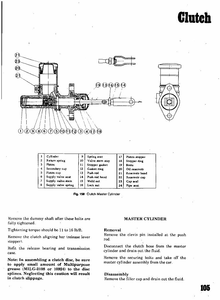
Olutch
O@ Q 1J
I Cylinder 9 Spring seat 17 Piston Hopper2 Return spring 10 Valve rtem stop 18 Stopper ring3 Pi ton 11 Stopper gasket 19 Boot
4 Secondary cup 12 Calket ing 20 Oil reservoIr
S Piston cup 13 Pwh rod 21 Reservoir band
6 Supply valve eat 14 Pwb Od bead 22 Reservoir cap7 Supply valve Item IS Weld Dut 23 Cap seal8 Supply valve spring 16 Lock nut 24 Pipe Ieat
Ag l58 Clulch Master Cylinder
Remove the dummy shaft after these bolts are
fully tightened
Tightening torque should be 11 to 16 lb ft
Remove the clutch aligning bar Irelease lever
stopperl
Refit the release bearing and transmission
case
Note In assembling a clutch disc be sure
to apply small amount of Multipurposegrease MILG 2108 or 10924 to the disc
splines Neglecting this caution will result
in clutch slippage
MASTER CYLINDER
Removal
Remove the clevis pm installed at the pushrod
Disconnect the clutch hose from the master
cylinder and drain out the fluid
Remove the securing bolts and take off themaster cylinder assembly from the car
DisassemblyRemove the filler cap and drain out the fluid
105

Clutch
Pull back the rubber boot and remove the
snap ring and then the push rod and ring can
be removed
Unscrew the piston stopper screw and remove
the piston assembly completely
The piston assembly can be separated by lif
ting the spring seat edge over the shouldered
end of the piston
InspectionPrior to inspection all parts should be cleaned
or washed
Note To clean or wash all parts ofmaster
cylinder operating cylinder and pipingsclean brake fluid must be used Never use
mineral oils such as gasoline and
kerosene etc as to do so will ruin the rub
ber parts of the hydraulic system To do
so will ruin the the hydraulic parts of the
hydraulic system
Check cylinder and piston for abnormal one
sided wear and damage and replace if found
If the clearance between cylinder and piston is
more than 0 005 in replace cylinder
Renew piston cup in principle when
disassembled It must also be replaced when
swell wear deformation due to fatigue and
damage etc are found
Damaged dust cover oil reservoir and cap
etc should be replaced
Piston spring and inlet valve spring must also
be replaced when they are broken or weak
Replace clutch hose and tube if any abnormal
signs of damage or deformation are found
108
AssemblyThis is accomplished by reversing the
disassembling procedure but the followingpoints should be observed
Prior to assembly piston cup should be soaked
in brake fluid Install piston cup taking care it
is correctly faced
Coat well brake fluid to cylinder and pistonand assemble them
Installation
Installation is a reversal of the removal
procedure but the following operation should
be added
Adjust the pedal height by changing the pushrod length
Bleed air out of the hydraulic system
BLEEDING CLUTCH SYSTEM
Remove the bleed screw dust cap of the
operating cylinder open the bleed screw ap
proximately three quarters of a turn and at
tach a tube immersing the open end into a
clean receptacle containing a small amount of
brake fluid
Fill the master cylinder reservoir with the
recommended fluid and by using slow full
strokes pump the clutch pedal until the fluid
entering the container is free from air bub
bles
Screw up the bleed screw on a down stroke of
the pedal remove the bleed tube and replacethe dust cap

TraDsmissioD
REMOVAL
INSTALLATION4 SPEED TRANSMISSION
Removal and Installation
RECOMMENDATIONS
J09
III
113
113
113
lOl

TraDsmissioD
11
I
II
i
I
Fig 159 3Forward Speed Transmission
C I
Ll
Fig l60 4Forward Speed Transmission
108

Transmission
FIg 161 3Forward Speed Transmission
REMOVAL
When removing the transmission from the
vehicle it is necessary to follow the undermen
tioned procedure
Jack up the vehicle and support it with four
stands If available a hydraulic hoist or open
pit can be utilized
Disconnect the hand brake wire at the
equalizer pivot as shown in Figure 163
Loosen the two exhaust center pipe clampsand turn the premuffier complete with center
pipe to the left as shown in Figure 164 This
will allow sufficient room for the propellershaft to be removed
Remove the propeller shaft by disconnectingthe four securing bolts at the companion
flange of the gear carrier Seal the end of the
rear extension housing to prevent oil leakage FIg I62 Underside of Vehicle
108

Transmission
Fig 163 Disconnecting Hand Brake Wire
Rg 164 Removing Propeller Shaft
Ag l65 Disconnecting Speedometer Cable
no
Disconnect the speedometer drive cable from
the adapter in the transmission extension
housing See Fig 165
Disconnect the lower shift rods from the shift
levers and remove the cross shaft assemblyfrom the transmission case See Fig 166
Remove the clutch operating cylinder from
the clutch housing
Support the engine with a jack placed under
the oil pan Do not locate the jack under the
Fig 166 Disconnecting Remote Control Linkage
Fig 167 Detaching Clutch Operating Cylinder

Transmission
oil pan drain plug To prevent damage to theoil pan insert a wooden block between the panand jackRemove the two bolts attaching the tran
smission to the rear engine mount Place a
jack under the transmission and remove the
four bolts fixing the rear engine mountingcross member to the body
Fig 168 Cross Member Removal
Lower the jack supporting the engine to incline the engine in a rearward direction Thiswill allow sufficient room for the transmissionto be removed
Remove the starting motor and the bolts at
taching the clutch housing to the engineLower the jack gradually and withdraw thetransmission
INSTALLATION
Installation of the transmission is the reversal
of the procedure given for removal However
attention should be given to the followingpoints
Notes a Fill the transmission with the
recommended gear oil MP 90
Oil capacity 045 U S gal
b Adjust the clutch operating cylinder at
the push rod so that the play at the with
drawaI lever will be 0 087 in
Fig 169 4Forward Speed Transmission
lD

Transmission
AUTOMATIC TRANSlISSION
L JII
I
@ CID @ CIDi
@ @ @ @ j @
ifrT 1L LJ
I
@ @I
@ @ @ @ F @ @@
AT260
I Transmission case II Governor Tightening torque CT of @T 0 5 to 0 7 kg m
2 Oil pump 12 Output lihafl bolts and nuts 3 6 to 5 1 ft Ib3 Fronl clutch 13 Rear exlenion @T 4 to 5 kg m
h 2 0 to 2 5 kg m
4 Band brake 14 Oil pan 29 to 36 ft Ib 14 to 18 f Ib5 Rear clutch 15 Control valve @T 14 to 16 kg m
h 13 to 18 kg m
6 Front planetary gear 16 Input shaft101 to 116 ft Ib 94 to 13 ftlb
7 Rear planetary gear 17 Torque converter @T 0 6 to 0 8 kg m @T 055 to 0 75 kg m
8 One way clutch t8 Converter housin1 4 3 to 5 8 ft Ib 4 0 to 5 4 ft Ib
9 Low Reverse brakC 19 Drive plate @T 0 25 to 0 35 kg m
10 Oil distributor 1 9 to 2 5 ft Ib
Fig 170 Cross Sectional View of 3N71 B Automatic Transmission
U2

Transmission
4 SPEED TRANSMISSION
Removal and Installation
Removal and installation of the 4 forward
speed transmission are similar to the
procedure given for the 3 speed transmission
However the 4 speed transmission is of the
floor shift type therefore in addition to com
pleting the operations described in the section
covering the 3 forward speed transmission it
will be necessary to remove the shift lever
from the control lever bracket On the 4 speedtransmission the rear engine mounting sup
port is securely placed between the upper sup
port plate and rubber insulator on one hand
and the lower support plate and rubber in
sulator on the other
RECOMMENDATIONS
Due to the complexity of setting up a
disassembled transmission as well as the
special tools necessary it is recommendedthat internal repairs be left to a fully equipped shop
U3
Bod Work
FRONT FENDER
Removal and InstallationHOOD
Removal and Installation
AdjustmentTRUNK LID
Removal and Installation
Torsion Bar Removaland Adjustment
116
116
116
116
117
117
117
117
U5

Bod Work
FRONT FENDER
Removal and Installation
Remove the radiator grill head light and
head light finisher
Remove all bolts securing the fender and then
remove the fender
Installation of the fender is the reversal of the
procedure given for removal
Fig 171 Removing the Fender
fill 172 Removing the Hood
U8
HOOD
Removal and Installation
Open hood and place a protective cover over
the front fenders to prevent damage to painted areas
Scribe Ipencithe location of the hinge strapson under surface of hood
Replace the bolts attaching the hinge to the
hood With the aid of a helper remove the
hood
Fig 173 Removing the Hood Support Rod
BOWENCH
1
fig 174 Removing Trunk Lid

Bod ork
Uing screw driver as shown in Figure 173
remove the hood support rod from the supportbracket
Installation of the hood is the reversal of the
procedure given for removal However alignthe hinges within the scribe marks
Rg 175 Removing the Torsion Bar
7
13 Alosr 4
5 cd6
8
i
10
0
AdjustmentTo adjust the hood release the hinge attachingbolts and move the hood to the desired
position After the adjustment has been made
tighten the hinge bolts
TRUNK LID
Removal and Installation
Open trunk lid and place a cover over the rear
fenders and rear panel to protect them from
damage to painted area
With the aid of a helper remove the trunk lid
attaching bolts and remove trunk lid See Fig174
Torsion Bar Removal and AdjustmentRemove torsion bar fixing wire then using a
screw driver as shown in Fig 175 remove the
torsion bar
The tension of the torsion bar can be adjustedby changing the location of the bar with the
use of ascrew driver
iIII tj IEGfIe r
J
I csI 1 IIII 10 1IN
J I111
I
1 J
1 Outside handle
2 Out ide handle rod
3 Clip4 Pull knob
5 uOJtcheon
6 Spring clip7 Inside handle
8 Remote ontrol
9 Lockass y
10 Striker
11 Key cylinder12 Bell crank
Rg 176 Door Lock Mechanism
117

Bod Work
1
z
3
Fig 177 Window Regulator
U8
1 Froot door glass2 Bottom channel
3 Front egulator ass y
4 Regulater handle
S RaUer guide6 Stopper7 Connecting clip8 Nyloo washer
9 Rear docx glass10 Rear egulater ass y

SpecificationsSTARTER 120DISTRIBUTOR 121SPARK PLUGS 122VALVES I
OIL PUMP 122GENERAL 123ELECTRICAL 123MANUAL TRANSMISSION 127CARBURETOR 131CLUTCH 134ENGINE TORQUE INFORMATION 136TUNE UP 138LUBRICANTS SAE 138CAPACITIES PRESSURES 139AUTOMATIC TRANSMISSION 140PROPELLER SHAFT 144BRAKE CHASSIS WHEEL
ALIGNMENT 146NOTES 147
D8
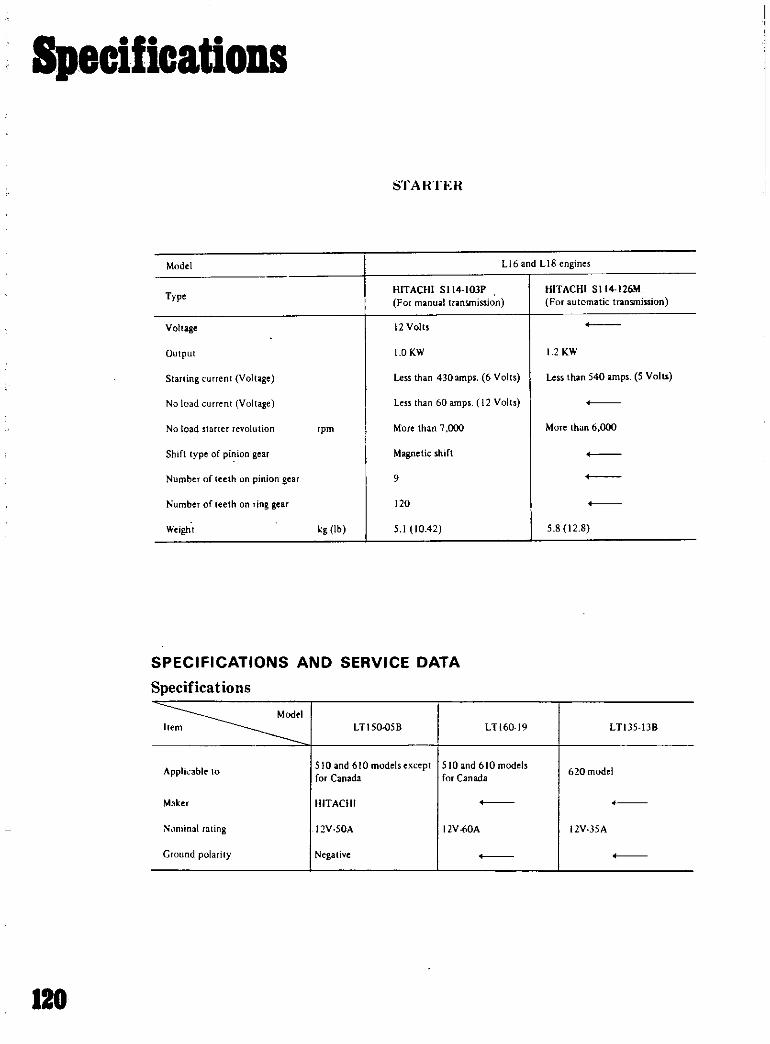
Specifications
STARTER
Model LI6 and LI8engines
TypeHITACHI S1l4 IOJP
For manual transmission
HITACHI SII4 126M
For utomatic transmiuion
Voltage 12 Volts
Output 10KW 1 KW
Slarling current Voltage Less than 430 amps 6 Volts Less than 540 amps 5 Volts
No load rent Voltage Less than 60 amps 12 Volts
No load starter revolution pm More than 7 000 More than 6 000
Shift type of pinion gear Magnetic shift
Numberof teeth on pinion gear 9
Numberof teeth on ring gear 120
Weight g lb 5 1 10 42 5 8 12 8
SPECIFICATIONS AND SERVICE DATA
Specifications
ModelItem LTI50o58 LTI6019 LTlJ5 1J8
AppliLable to510 and 610 models except 510 and 610 models
620 modelfor Canada for Canada
Maker HITACHI
N lminal ating 12V SOA 12V 60A 12V 35A
Ground polarity Negative
120

Specifications
DISTRIBUTOR
SPECIFICATIONS AND SERVICE DATA
Distributor type D1O 66A 0410 67
Make HITACHI
Applied engine Ll8 610 Ub SQand 6Qvehicle
Firing order 1 42
Rotating direction Counterclockwise
Ignition timing degree SO B T DC
Idling adjustment
MIT 5u 800 rpm
AfT 5Uj6S0rpm0 range
vel angle degree 490 to 550
Condenser capacity p F
Advanced isde 0 2 to 0 24
Retarded side O 05t 15
Phase difference 70 at k ngleldegree
All distributors
Shaft diameter upper pi in
045100 55 0 9177 to 0 027
AJvauccd ld Retarded side cqllllly
0 50 to 0 65I 1010 I 43
r 430 to I 440 041 94 to 048 8
450 to 4Ml 0 4402 to 04 09
001 In O G3R 0 0004 h 0 00 5
0 011 0003 I
0005 00002H O JI50 1
Ot1l4 0 0006
H000 It x 1115 lUISO ltl0
1 156J
0015 II Jfi 9 D002 tu 0 0 11
4 972 104 990 0 1959100 1 5
5 000 10 5 018 0 1 9 to 0 1976
0 01 tnO 046 0 0004 tv O OOI
Point gap mmin
Point pTt ssure
Shaft diJlll eT lower pari
J1011in inner diameter
Iclram p hp wren hafl nd hOll il1g
Repair limit harilnre
kglb1 in
in
in
in
C III ti lllcter
C1c name nc lIl cro shllf lrod un
Weight pivot diamctlo
Weighl hole diameter
Clcilr mce b lw n i ot and hole
in
mmfin
mmin
n in
tnm ill
121

SpecificatioDS
SPARK PLUGS
SERVICE DATA AND SPECIFICATIONS
Make NGK
Model B6ES
Applied engine
Size screw dia x reach
mmin Ll6and Ll8
14 x 19
0 55 x 0 75
0 7 to 0 8
0 028 to 0 031
1 5 to 2 5
110 to 15 0
Plug gap mm in
Tightening torquekg m ft lb
VALVES
In 42 Qtn42 2 654fO 1661lib
Valve head diameterEx 33 0 to 33 2 1 299 10 1 307
Hnun in
In 42 01041 2 1 654 10 1 661
LIB
Ex 35 01035 2 1378101386
Valve length lI6In 114 9 to 115 2 4 524104535
L
mmin LIBEx 115 7 to 116 0 4 555 104567
Valve stem diameter lI6 In 7 965 to 7 980 0 3136 to 0 3142
Dmmin LIB
Ex 7 945 107 960 0 3128 100 3134
a Valve seat angle In Ex 45030
OIL PUMP
Ii lth ning turque
Oil pump mounting bolts
Oil pump cover bolts
Cap nut regulator alve
kg m ftIb
kg m fl Ib
kg m fl Ib
11 to 15 8010 II
0 71010 5 1 to 7 2
4 to 5 29 to 26
Specifications
Oil preuure at idling
Regulator valve spring
Free length
Pressured length
Regulator valve opening pressure
kgcm Ib in 0 8102 8 1110 40
mm in
mm in
kgcm Ib n
525 2 067
34 8I 370
35t05 0 501071
122

Specifications
GENERAL SPECIFICATIONSModel Li6 Li8
Cylinder arrangement
DisplacementBore and stroke
4 in line
Firing rder
Engine iule
MIT
A T
I i4 2
1770 108 01
85 78 3 3465 3 0709
O H C
1 4
cc cu in
mm in
1 595 62 80
83 737 3 2677 2 9016
O H CV31ve ngemenl
rrlll
Compression 111l
Engine idle fold
at idle TPIll
M T
AIT
lHg inllgl
800
650 in l range
8 5
I
IBO Ih c
390 154 in N 1ge
Oil pressureVarm at 000 rpm
kgem
psi 35104 0 49 8 to ill 9
M T MalHI 11 rransllil n AIT Automatk Transmission
STARTING MOTOR SPECIFICATIONSDistributor Specifications
h
f flcut Sprint CUrr N L d
Hum T llen D C1W Cur t
lb PI
67 61 MII ubl hI 1 1 2 1 00ME rla
666 HiluM 1 51 00
5 114 2
6667 MIt hl 51 00114 IA
19 72 Hltochl 1 51
114 103
1 912 Hlt chl 1 511
5 1t4 122
71 72 HII ehl 151 42
S 114 1I7L
N pi DWtrilu lorCr1Iln p 1 v AtIu
S t 1
JI t1 @oJ
IltaTt E
ND fIjq OHD
J Hitachi 50 11 15@ 3947 69@411 53 2 400 13 4
LI6 Hitachi 4 1O@ 5 9 9@01lh5ll 1 500 124
L2 Hitachi 4 6@ J 9 5 5@D60652 1 000 96
At2 Hitachi 550 12 5@ 98 65@1412 63 2 100 13 8
C lllrlr II IAdDnu1 VD U AdII
Pol t Dw n srlnll
y M I DI trlbut 0 AIIIII T II n SIDrI Inl F Inchfull Ad
Inllln rlNo IlIe D O e @ @ @ V cuu hll 01 D
pm pm pm SIDrt @VeuuftlItn
967 I dll 1 16@ 12@ 12 6D407 51 0 1 1 41 475 5
021 5054 4DO55O 1100
Mltful hl5r6
1 6 J 01 I 11 15@ 6 @ IJD411 53 5055 1 411 41 5
OU 2400
@10 10@n14Q7 n 06 4955 1 1411 O@020 40000 1 00
1 72 l I 04105 011 4 1 1 1 41 IO@ @ @ 12
022 OGO 1500
Wi7i L 24 D I2 52 016 1 1 1 411 @14 @11 1
02Q 00 100 1400
1200 D412 011 4955 11 1 4 12 5@ @9 95@ 12
021 55 1200 00
DISTRIBUTOR SPECIFICATIONS
IDJ cuu dVDII d cII t d with S I x
123
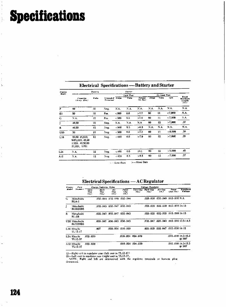
Specifications
Electrical Specifications Battery and Starter
1 1l U T StGTt T
ModTll od rut No L Tut
111 V to oI A V T Ao V V
U I Tn 1 1 b WiiLUI1tJ
f
P 60 12 e X A A N A N A N A NA N A
El 50 12 P 500 8 0 7 7 60 11 7000 NA
G X A 12 Po 500 9 5 0 60 7 OIXl A
40 50 12 Neg XA N A NA 60 12 7 000 31
R 40 SO 12 Xeg 500 9 5 fL5 N A N o N A
V20 50 12 Xeg 500 60 7 2 60 6 000 30
Ll6 50 60 PLSlO 12 eg 480 6 0 79 60 12 7000 28
WPL510 10 501 520 40 50 60
i L521 LS21
L24 A 12 Xeg 460 6 0 10 1 60 12 5000 9
A12 XA 12 Xeg 420 6 3 6 5 60 12 7000 31
Ltssthan fore than
Electrical Specifications AC Regulatori CACTI trul Rd V tA6R
4IM c s Ai 1 CouG Go A i G P d R IOIG G p G Gap rfJ i i J Yoolt
i J i i i
G fiuubishi 032 044 U12 J 48 032 044 028 036 032 040 012 016 N A
RLA l
litsum hi 032 043 o32 147 032 043 028 035 032 039 012 01614 15
RL2220B5
R Mit uhishi 032 043 032 047 032 043 028 035 032 035 012 015 14 15RL 2B
U20 liIslIhishi 035 047 030 043 030 043 032 047 032 043 012 01613 5 14 5
RU220B5
LIB Hitachi 1m 020 024 016 020 035 039 032 047 012 01614 15
TL l li
L24 Hihlthi tn2 039 016 024 024 019 012 01614 315 3
TI 1 Z 7 @50F
0 12 Hitachi 032 039 016 24 024 039 012 016 14 315 3TLI Z 37 50F
i HiJhlV Left
XOTF
t1 wllwlITU
t t ltlllatOTilll t lClllatllrRillhl d left
a left it TLIZ 111
right it TLlZ 17letennilloo with the Jt glllltor tenninals Illlm s pluJI
124

Specifications
hlClemodel
Appli Int tlIO L1RI SIOllln b O 1I6
Item
Mau rldtype HANSHIN HS IS I HANSHIN HS 15 HITACHI 6R 1
ApplIed resister RC IS St60R SIO
Ptimuvoltage V
Sparkpp mm in nIOrt Ihln7 0 1756
PlimlloiY hlll Cen 117 14J
fC I68 F
conduy Kn 11 lb8
10 f8OF
Externn LJ J7
OCthaoF
Light Bulb Specifications
u Wdlag Mlld l v
UlO Headlights 50 42 Baclcup 15
Front paning turn 21 6 License plate 8
Stnp tlil turn 216 M p 5
L plate 10 Side rker 8
lnstrument panel 8flasher ming light 15 1520 Headlilthn 37 5 50
PLUO Headlights 31 5 SO50
Fr mt parking turn 25 831 5 Tail top 25 8
Parldng B Rear turn backup 25Turn 25 License plate BLicense plate 8 Interior BInterior light 5
Backup 25
Warning lights 1 5 L521 Headlights 37 5 50Instrument 5 PLS21 37 5
SPL310 HeadliRhts 50 Front turn parking 25 B
Front parking turtI 25 5 TilU top 25 B
Tail stop 2l6 Irtun 25
LictrlIeplate 8 B clcup 25
In rior 6 Interior 6
Instrumrnll warning 15 L seplate 8
Inspection lamp B PL5lO Headlights 37 5 50Radio I WPLSlO 37 5
PUll Headlighu 31 5 50 Front parking bun 25 8
RUll 37 5 T i1 tum 25 B
Side marken 8 StOP 25
Tail 8 ckup 25
License plate 8 License plate B
Stop 25 Interior 10
Backup 25 HLS3Q Headligh 50Interior 5 Side marker tum 2311Fog 35
Inspection BSide marker license pIte 7 5Tall 7
Parling B Stop 23Turn 25 Reartunl
Instrument J23
Warning 15ckup 23
Instrument warning glove J
SPUll Headlight 50 40 compartment clock
SRL3Il Front turn parking 25 SFour way Suhet 23
Stop tail turn 28 B P B
125

Specifications
WIRING DIAGRAMS
IIICD COOlI
y
o 0
Lr
PLSIO utomatic transmwion
JIrr 11l II
I tCOLOIlCODE
G IIn
j llll t4L11 I iil 1 i Icnm
w
1 11JlI
1 71
VJfrdll i111111 In
IF I II IJ I
r
i I l I ij r i r r III l o II i
I
d 71 ar1rtJ e
f3luJo
Jlr c 11 7lItl II L L
A lfI
l af
DPTlONAL EQU PMEm
1 10 ltomatic trarumission
126

Specifications
CO COOl
I
v
0
PL510 standard traosmiuion
MANUAL TRANSMISSION
APPLICATION Of TRANSMISSION MODELS
Type of Transmission Applied Model edome r gear Final gear atio1
N510 S V NL510 S V R3W65L
3 Forward speed JN510SU JNL510S lot 3 263 19 5 4 375
Column shiftP510 SlV PL510 Sl
2nd IS451715 3 900
Warner type synchromesh 3rd 1000
WP510U WPL510 Rev 3 355 17 5 3 S99
fF4W63L
P510 S TV JNL510 S T lot 3382
PL510 S T 2nd 2 013IS 5 3 700
N510TU 3rd 1312
P510TKU PL510TK 4th 10004 Fmwro peed
IRPL510SWTV PL510TV Rev 3 364
FloofS uft
Warner type synchromeshF4W63L
ht 3657
WP510TU 2nd 177 16 5 3 700WPL510T 3 d 1 419 I
4th 1000 I
Rev 3 63R i
127

I
Specifications
Manual Transmission Ratios
V I FiN s Tli Tel 1i u Rn
160 900 1562 1 000 No N 3015
L320 94 301 173 100 No 6 6
L520 3657 2 177 1419 1000 None 3638
941 3009 1726 1000 No 6462
PL521 3657 2177 1419 1 000 None 3 636
PUlO 3518 1725 100 No NOM 4 125
3 197 1725 100 No N 125
3945 94 1490 1000 N 5 159
3945 2403 1490 1000 No 5 159
PL411 3 197 1725 1000 N e None 4 125
394 240 149 100 None 5 159
3657 2 177 1419 1000 None 3638
RL411 3382 2013 1312 1000 None 3 365
SPL311PL510
SPJ110 3515 2140 1 328 1000 None 5l7
SRL311 2957 1858 1311 1000 65 2 922
PL510 3 657 2 177 1419 1 000 None 3 638
3382 2013 1312 1000 None 3 634
3 382 2013 1312 1000 N 3 634
HLS30 3549 2 197 1420 1000 None 3 164
2 957 1 857 1311 1000 852 922
LHllO KLBllO 3 757 2 169 1404 1000 None 3 640
CD L60 transfer cue ratiOl 2 264 1 nd I I
1Condition Probable cause CorrectivE ction
Loosened bolts such as side nange id
retainer orgear camero
Tighten thebolts to specified torque
Defective gasket oraring Replace defective parts with ew nes
Loose tiller ordrain plug Tighwn theplug
Clogged ordamaged breather Repair orreplace
128

Specifications
SERVICE DATA AND SPECIFICATIONS
Nominal diameter of ring gear mm in 160 6 30
Gear carrier material Malleable cast iron
Gear ratio number of teeth 3 700 37 10
with AfT mQdel for
U S nd Canada
4111 37 9
Drive pinion preload adjusted by Shim
DriePinion
Preload kg em in lb
withoutoil seal
with oil seal
At ompanion flange bolt hole kg Ib
without oil seal
withoil seal
7 to 10 6 1 to 8 7
S to 11 7 0 to 9 6
2 0 to 2 9 44to 64
2 3 to 3 2 5 1 to 7 1
Thickness of pinion height adjusting washer
mm in 3 09 0 1217
3 12 0 12283 15 0 1240
3 18 0 1252
3 21 0 1264
3 24 0 127S3 27 0 12S7
3 30 0 12993 33 0 1311
3 3S 0 13233 39 0 1335
3 42 0 134S
3 45 0 135S
348 0 13703 51 0 1382
3 54 0 1394
3 57 0 14063 60 0 1417
3 63 0 1429
3 6S 0 1441
129

Specifications
Thickness of pinion bearing adjusting spacer
and washer mm in
Spacer
Washer
5S 2 2 2t26
56 4 2 2205
56 S 2 2283
56 8 2 23S2
57 0 2 2441
57 2 2 2520
2 59 0 102012 57 0 1012
2 55 0 1004
2 53 0 099612 51 0 0988
249 0 0980
247 0 0972
245 100965243 0 0957
241 0 0949
2 39 0 0941
2 37 0 09332 35 10 0925
2 33 0 0917
2 31 10 0909
Side gelr and pinion mate
Thickness of side gear thrust
washer mm in Q to 0 80
0 0295 to 0 03151
0 80 to 0 85
0 0315 to 0 03351
0 85 to 0 90
0 0335 to 0 03541
Backlash in pinion mate and side
gear orclearance between ide gear
and thrust washer mm in 0 1 to 0 2
0 0039 to 0 0079
Ring ar
Backlash between ring gear and
drivepinion mm in 0 1 to 0 2
O 0039 to 0 0079
Runnut of reat ide of iog gear
gear mm in
Thickness of side retainer adjustingshim mm in
Less than 0 05 10 0020
Side bearing standard with mm in
0 20 0 0079
0 25 10 009810 30 0 0118
040 0 0158
0 50 10 0197
20 0 0 7874
130

Specifications
Carburetor Specifications
f r f lI It C
i l U Ir ti1 h l
l
P SO
Leo 880
Pwlthnission
LBO
EI 079 75eDPUIO
El 145 7501320
J 85@1520
J 850PUll
with N A
emission
controlL52ll
L501
R 11950
R with 23 M 39 with Jrlemisrion 38W5 M 70 95icontrol with 38W6
U20 87SU 950
UOO sM nll t
Sole
U20 32 N i1with 8 87with emiuion 46W 5 N 25 950
with 46W 7
LIB 071 87PL510 95D
LIe 071 87 ISO
withemwion 95 13
lrol
L24 23 N 21 rrTwth 079 950emialoncontrol
HLS30
At2 71with 78CDemissioncontrol
UllOnJlllO
@From SOIt chamber top to fuelleYel
131

tI
CDft Nt ft
CarburetorSpecifications
8
i
l
f
i
I
ii
3
i
l
I
i
li
il
I
tIn
f
7
0
0
c
h
f
l
l
1
l
e
Et
l
r
P
Hitachi
142
135
70
25
210
L60
VC424A
Pwlth
Rochestr
eml
7015013 Imgle
controlthroat
LOO
downdraftEl
Nihonki
1102
827
9B
80
B
100
55
14
PUlO
kakl
181
1024
115ec
BO
el
48I
220
2D3OCE
2nd
dual
120
thrOllt downdl1lftEl
Nlhonkl
1
102
827
96
BO
B
100
55
14
1320
kat
181
1024
1151C1C
60
tS
ec
220
2D3OC
2nd
dUlll
120
throat downdraftJ
Nihooki
1022
788
90
B
0
45
14
1520
hln
1180
106
14
ICf
48sec
D2630AM
dUIlI thmt downdraft
J
Nihonlia
1022
788
92
60
48
100
40
024
14
PlAll
blu
LlSO
106
140sec
60
4Hlt240
2nd
D2630AM
tWsce
dual throo downdNt
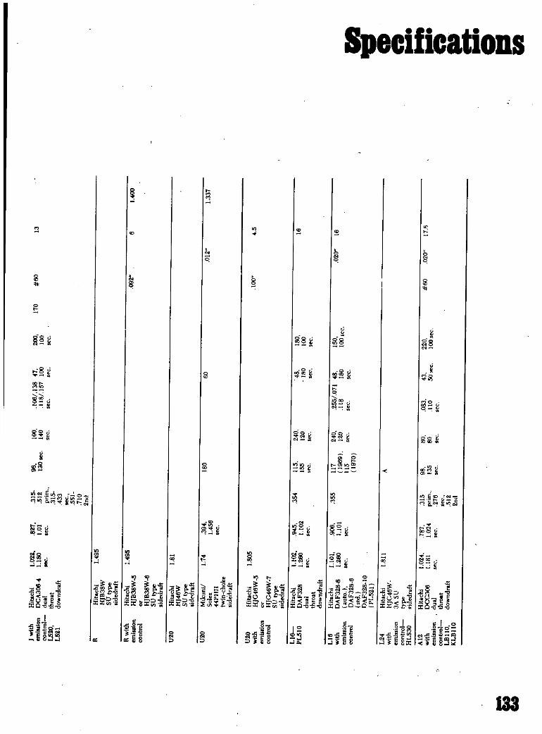
with
Hitacln
l02i
627
315
96
100
106
138
41
200
11
60
13
emJsJlonDCA306f
1180
101
512
130sec
14
118157
100
100
contml
dUIill
pnm
15
throat
315
L5U
downdraft
433 551 710 nJ
R
Hitachi
1495
HJB38W SUtype IldedraftRwith
Hitachi
495
092
6
1400
emlulonHJB38W
control
HJB38W6
SUtype IIdedrahU
HitachI
181
HJ46W SUtype Ildedraft
U
Mikunil
174
394
16
6
011
1131
SoJex
1456
f
PHH twmchoke Ildedraft
U
Hitachi
1605
100
45
with
HJG46W5
emlDmn control
HJC46W7
StItype Ildedraft
1
16
Hitachi
1l2
945
35
ll5
240
46
180
16
puna
DAF328
1200
U02
155
120
18
100
dual
C
C
fC
C
see
C
throat downdraft116
Hitachi
1101
900
155
1I1
240
255071
48
ISO
02016
with
DAF3288
1
260
1I01
1969
I
118
16
100
emiSSIOn
auto
c
15
C
cont
DAF3286
1970
itd DAF32810
PL521
CD
124
Hitachi
L811
A
with
HJG46W
P
enulllonASU
control
tyP
HLS30
sidedrllhAI2
HitllChl
1
024
787
315
96
BO
083
3
220
JIM
020
I1
with
DCC306
1181
1
024
pnm
135
8
110
5Oec
100ec
n
emission
du
216
S
COTltrol
throat
LBlIO
downdrah
SL2
KLBllO
2nd
i
8

i
CDat ft
ClutchSpecifications
y
c
6pr1
R
fiJlII
N
lI
c
N
lftM
M
Z
I
P
1
O
D
X
I
D
laidtI
1I
Irnll
bl
j
fr
r
XUd
I
d
pl
11
0
Vo
pl
l
qUo
f
J
0
8
I
r
1
J
1
tlww
t
i
d
g
Ii
LOO
roll
180190
2
5
IOaX
7
NA
012
020
8
1
10
pring
US6
B
9X
85
15
N
A
14
Eady
roll
132176
226
7
MX
we
e
012
020
A
98
L320
Prhag
@141
232
500X
118
I
14
Lo
i1
787
I
187X
338
e
012
020
N
A
10
L320
spring
@115
2
00
S
12X
358
15
PLUO
187199
1
18
PUll
2
0for
RUll
PlAlllr RIAll
SPL310
i1
169178
2
04
7
87X
333
e
012
020
6
10
JIO
spring
@J
156
2
011
S76X
8
60
80
2
17
13
SPL311
diaphrgm
NA
781X
NA
N
A
012
020
N
A
Il
SRL311
spring
5
12X
2
1
1
PUIO
il
9261014
191
1
87X
339
e
012
020
8lts
98
WPL510
pring
@11S
201
5
UX
314
2
00
1
510
diaphragm
I
7
87X
339
B
012
020B
15
98
WPL510
sprina
177
5
12X
314
1
15IOLS21
roll
161179
198
787X
339
9
012
020
534
98
PL021
sprinll
@1I5
iOI
512
X
354
546
l
87
14
without
199
1
stop
HlAlO
dlaphl1ll1J1
I
a
86X
127
e
012
020
8
00
39
177
590X
350
5
N
A
LBllO
pbrallJl
114
7
00X
299
e
012
020
5
57
118
uBllO
1211
40
92X
315
NA

Specifications
SERVICE DATA AND SPECIFICATIONS
Pressure springFree lengthFitted length loadQut of right angleAllowable min spring force
3 mm 2 00 in
29 2 mm 44 kg l 14Din AJ7100 1m 0 196tl 9 7 ill
l j f
II
l Ib I
ICluth release lever
Release bearing ta diaphragm springrelease lever clearance
Diaphragm spring ta flywheel height
Release lever ta flywheel height
1 2 1 j mm 0 04i O ll j 1I
lJ O t 10m 1 o O Hll
O i 0 0 in 1 9ti8 t O 019in J
Clutch disc
Facing ze
Outer dia x inside dia thickness 2001 O mtu
Total friction area
Thickness of disc assemblyFree
Compressed
7 H7
362
120 x O ItO in
12 6 11 i02
MaterialNumber of torsion springAllowable min depth of rivet head
from facing surface
Allowable facing ron out
Allowable free play of spline
8 6 9 0 nm 0 J38G O 1 in
7 6 7 9 IllIl1 0 3012 O 31lU in I
HITACHI HT50S 17 AKEBOXO A50
G
0 3 mm 0 Ollb in
O mm 0 0197 in
0 4 rom 0 0157 in
Pressure platlllAllowable refacing limit 10 mm 0 0394 in
Clutch pedalPedal height when not depressed
Free stroke of pedal head
Pressing strength at full stroke
182 7 17 in R H
207 1m 8 1 0 in L H
2 mm 0 981 in
L kg 33 Ib
Master cylinder clutch
Dia master cylinderAllowable max clearance between
cylinder and piston
15 87 mm il 8 in
0 13 mm 0 0051 in
Tightening torque
Clutch assembly securing bolt 2 2 Gkg m 17 IS S ftlb
135

Specifications
ENGINE TORQUE
nlBS
Op elle I IIi
CI1 heo ns I ls lu n 112 5 lu 0I 325
1 l nettu n J
c cti l i31 i i 5 219 119 5 239
b h 7 O 54 2J 216 JIe 75 9
Ma ri 1 S 4 I 32 5 5
cap It
C h ft 2 9 J4 7 30 2 U I 2 43 4
1o 1t
200
011 U i29ii 2 91 05 1
I ub oli3 52 1 I IS 2
I 6 5 5 7 S U
10 1
e nk uUayboll
15 7 UO lil157 130
PISTONS PINS RINGS CRANKSHAFT BEARINGS
Ih lI End 0 I d B lnlll II
iI Motna rlng
h ck Inch IM rI
I hto 1Y CI I C 01 Shott 8 in Shoff Il n h t Shft
I101111 h ck
IJilek tn CI o cI 01 Cl u h
iInch Inch B I 1
N Inch
966 i Iooa 671 1 1 0 1 9n 0005 1
0131 013 002
001 T 1 2 04 2 360 001
0016 010 012 002701
a
012
U 20 0012 T 1 2045 0013 2 47 1
010 012 0024 0021 I 012
016
a
012
1
121L I
I001 1 12 1 7 a 2 161 1
009 012 0026 002 012
015
i 1
01212L U 001 T 1 1 67 0001 1 4
009 012 0026 0021 012
01S
1
012
1970721 1 012 617 1 770 1 1 967 1
0017 014 035 0024 011
138

Specifications
VALVE ADJUSTMENT
I V IL h V AIIIII Vol
1 Clearenc SteDl
M cI Inch DS hlI
to
V o
h lll lnl bh lt feu ll @l Intah bh IIII Inteke bh
19 014 I ur21 @ 1l 00 00 00 0 4 014
Out r 64@ 1 00
0 Q17G l @ 1t 001 001 004 014 0 114
I @ 1 00
U 20 OO @ QUIl l160 172 0004 002 00 014 034
@ 00
I210 @
19 72 L 4 OtOIl oliID l ut o5@ 11fw 001 00 0312 oil211l r 56@ Jtb 00
197072 L 24 OiG 0 120 Out 90100 IS 00 0 3112004
I4o 5@1
1200 014 In@II001 00 00 0 12 0112
00
I IIM
Y d I r ll Dltpl nm1I1
ICeI Ma T Cl Ne
fn l Inch C1e Inch R l 8 k H P fl t OIlP un
Ice @ plll @ pm nd
I
j Enlllneh t
1966 I
1 0
196661
71
1 2
j 1200
1972 1 16
l 14
1200
ENGINE
GENERAL SPECIFICATIONS
2 174 J OSS 19 21 7 @ 5200 In@ 2100 I 2040
n nS 1299 2
4U 2 30 97 22 0 @ 6000 I 103 @ 4000 5 0
17 3 6 9 U9S
2 433 3 261 U0 92 SU b
I@ 00
I3040
17 2 n 09 U 125 @ 6000
5 1 b 131@ 100
150@ 000
2 2 902 97 I 9 @ 00 I 100@ 2600 I 0
113 2 73 76 1595
2 2 2 902 0 151@56OO1 1 @4400 1 lo460
1 3 2 n76 U92
74 2 756 71 5 0 @ 000 I 70 @ 4000 I 42 50
12 11 117H2 26 2 7 I 96 @ 00 I 100 @ noo I 5 60
U2 72 76 1595
2 2 02 14 1 1 151 @S6OO1 @ 4400 I 5 60
12 2 n 7 n 2
2 74 2 7 71 5 0 @ 6000 70 @ 4000 4 50
IT1 6t 7 11171
137

Specifications
TUNEUP SPECIFICATIONS
I I SI II Dbtrlbvt 11I1I tllI TIh
I Ie
I IPlrI l Ihll
Y M d 1 T G 1 1 D ell 04 0 M k S
Elllln Inch G A e fTDC L e N
Rch D
1 6661 I J 027 03 0 022
0671
027031 0U012
I U 2Q 027 01 016 020
1 72 I 1 16 031 035 017 022
191072
I DO o on 017 0211
l 24 0311 035 Olt D20
B20 with S I
SO55 1 2 4
I I 11340
st 61
MI hI
ltlt IS 11 14 1
1 55 I 1 42
1 55 11 3 4 2
t 35 41 I 3 62
vlleyIt I vll
vlleyn
7 n
pvn 75
ADJUSTMENT OF IDLING
Adjust the ngine at normal idling setting
Engine idling Idlin liming0 1
rpm ldeg e relard side
M Tvehicle 800 51 BlOC 15 05
A Tvehicle 650io D mge 511 BTlX 15 05
Recommended Lubricants SAE
T r U4 T
Oro tI
IOW 30lOW
W 20
IOW 10
IOW O
lOW
1lI 30 IOW 10lOW 40 IOW 40
20 20W 4010
90 140
F 1IA inc ilAPI
dl ilnall n
IS ilSE
carOilAPI
1 iJIli tion
f1 EI l fPS
jIJ 0
40W Ilyhe used forhi h speeds
Icmpcrutures
00
138

Specifications
Capacities and Pressures
Wttd l l1iru r RAtU tln lli T t Yo Cool urd azike ON Pc T f s u rul eta f
R pt 11m f qld l u
fl r 0 Hii qtf
Wi WiLl M A ePiJi T Filt
UIS s
LBO 36 S A 4 20 26 front 19 0 5 2 N A N A
nd rear
PlAID 33 30 3 8 20 10 8 5 4 N A 6
SIL1W 4 2 4 6 1 8 113 6 9 N A 4 6
PIAlI A u R 4 7 2 2 110 5 7 N A 6
HUll A J 5 4 3 19 110 7 1 N A 4 6
S1 11 1 1 A 4 3 4 6 2 0 11 4 8 3 4 4 6
Slt1111 1 3 54 20 111 90 3 44 3 13
SI 111 11 7 5 5 4 2 0 114 9 0 34 4 3 13
ithtwlJtwin I hoke
rhuretors
L 12O 1 8 32 43 18 93 5 7 N A N A
Li20 L521 38 32 4 2 17 10 8 5 9 21 2 5 6
1L51O 52 4 4 6 4 IL4@ 11 1l9 6 8 16 3 4 137 2 withheater
WlL51D 5 2 4 6 4 IIA@ 2 1 119 68 2 6 34 11
7 2withheater
PL521 4 36 42 17 10 8 68 2 6 34 11
7 4 withheater
HLS30 4 7 4 3 3 2 32 12 8 2 1 15 9 8 5 14 4 3 1 1
LBllO N A 2 9 4 3 16 L1 57 NA 13
Q48 pb witllollt power takeoff 78 rll trnnder
@ 1 5 pts uil Oler
138

SpecilicatioDS
AUTOMATIC TRANSMISSION
V alt pring h rl
1 10 dIn lalled
I pfll11i Jla
tliJNo ul free length
II mm in length Loadlinl
mmOn qlb
lallllal Uh lIl13 6 0 15 0 3 4 265 55
O OSI 1 1O Jb2 1276 1043 12
PrlSSllrt gULHllTI 10 5 13 0 43 0 23 5 2 8
to 04nl 004134 1693 0 925 6 2
Prssute Jdificr004 X O 5 0 18 5 9 0 0 1
10 01571 10 31501 0 728 0 3543 0 2
1st Id shill0 6 6 0 16 0 32 0 16 0 0 625
O O 36 10 2162 1260 0 630 14
d 3rd shifl0 7 6 2 18 0 410 17 0 140
0 02761 0 24411 1 614 0 669 3 1
ud 3rd timing0 7 55 15 0 32 5 27 0 0 55
0 01761 0 2165 1280 1063 12
Throttle k Ip0 8 6 5 14 0 36 0 18 8 192
10 0315 10 2559 1417 0 740 4 2
Sulenoid downshift0 55 5 0 12 0 22 0 125 0 60
10 0217 0 1969 0866 0492 13
Seund lok055 5 0 16 0 335 210 0 60
0 0217 0 1969 1319 0 827 13
Throttle elief0 9 5 6 14 0 26 8 19 0 2 19
0 0354 0 2205 1055 0 748 4 8
Orifice check0 2 4 8 15 0 215 115 om
10 078 0 1890 0 846 0453 0 02
Primary governor045 83 5 0 218 7 5 0 215
0 0177 0 3268 0 858 0 2953 0 5
Secondary governor0 7 85 5 5 25 1 10 5 110
0 0276 0 3346 0 988 0 413 24
140
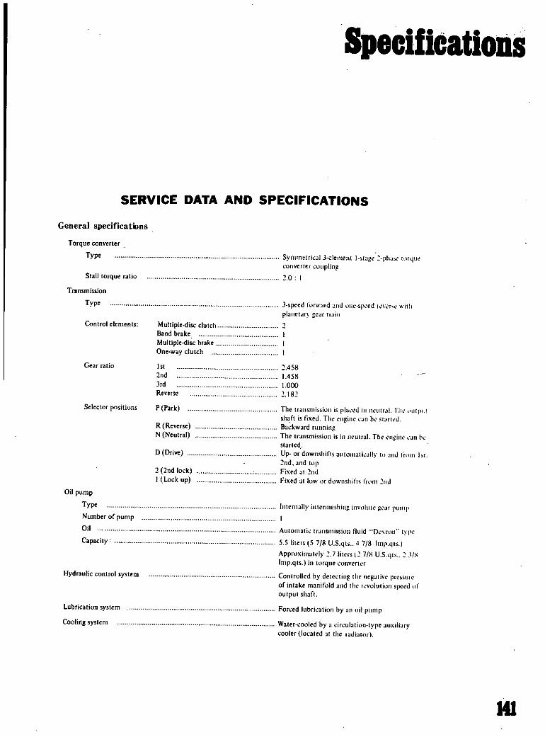
SpecifiCations
SERVICE DATA AND SPECIFICATIONS
General specifications
Torque converter
Type
Stall torque alia
Transmission
Type
Control elements
Gear ratio
Selector positions
Oil pump
Type
Number of pump
Oil
Capacity
Hydraulic control system
Lubrication system
Cooling system
SYllImelrit l1 J e1emc 1t I Sllge phJx llfl Utonverter ollpling0
J speed lorward ld lI spd r r l iT
pl lIletal lrJin
Multiple disc clutchBand brake
Multipledisc brah
One way clutch
1st
2 d
3rd
Reverse
458
1458
1000
18
P ParkJ The transmission
shaft is fixed ThlBackwardThe transmission
slarlc4Up ordownshillS ltom lIiltlly hI
nd and lOpFixed at ld
Fixed allow downshifls tWill
plal cd llolIlr IL Till
19inc illlbl qarkullpl
R Reverse
N Neutral t utral TI1 I ill b
o Drive IU tr llllbl
2 d lock
I Lock up J
11Ilernally I termeshing 11l1 p l ar pUlllp
AUlOlllath transmissiOll fluid Dl rull IYlk
5 5 liters 57 8 U S qls 4718 Imp qls 1
ApproxilllJTdy 7 Iillrs I 7S U Sqh lS
Imp qts in torque T1cr
Controlled by detecting Ih nepati e prc sllle
of intake manifold and the YOhllioll speed It
output shafl
Fon ed lubrkation by an Iii pump
Water cooedbya culaliOlHypc Ixili JfYcooler located at the dialOr
HI

Specifications
Specifications and adjustment
Automatic transmission nsembly
Model code number X0400
Torque converter assembly
tamped mark on the TIC 16 8
Front lutch
Number of drive r1ates
Number of driven plates
Clearance
Thickness of retaining plat
mmin
mmin 331 6 to 1 8 0 0630 to 0 0709
10 6 0 417
10 8 0425
110 0 433
112 0441
114 0 449
116 0457
Rearclutch
Number of drive platesNumber of driven plates
Clearance
Thickness of retaining plate
mm in
mmin 441 0 to 15 0 039 to 0 059
48 0 189
IttW reverse hrake
Number of drive plattos
Number of driven platesClearance
Thickn s of retaining plate
mmin
mm in
4
4
080 to 105 0 031 to 0 041
118 0 46512 0 0472
12 2 0 4S0
12 4 0 488
t2 6 0 496
12 8 0504
Brake band
Piston size mm in
Big dia
Small dia
64 2520
40 1575
Control valve assembly
Stamped mark strainer
Governor assembly
Stamped mark on governor body
E
35
142

Specifications
Engine idling and stall revolution
Engine with emission control device
Idling rColution rpm
Stall revolution
650 at D position800 al N position
I 800 to 2000pm
Tightening torque kg m ft lb
Drive plate to nhhaft
Drive plale to torque verter
Converter housing to ngine
Transmission case 0comelIer housingTransmission ase to extension
Oil pan to transmission case
Servo piSlon retainerto transmission case
Piston stem when adjuting band brake
Piston stem lock ut
One way clutch nner ace to transmission case
Control valve body to transmiiSion ase
Lower vain body to upper valve bodySide plate to control valve bodyNut for oOlrol valve reamer bolt
Oil strainer to lower alvc body
Governor alve body to iI distributor
Oil pump housing to oil pump COVeT
Inhibitor switch to transmission case
Manual shaft lock ut
lock nut for oil cooler pipe connector to transmission case
Oil cooler pipt onnecting nut
Test plug oil pressure inspection hole
Suppor actuator parking rod inserting position to extension
Oil charging pipe to ase
Dust ver to converter housingSelector range lever to manual shaft
Selector rod lock nut
Control lever boll
Control lever bracket to floor
COfltlOj lever knob to evel
14 0 to 16 0
4 0 to 5 0
4 0 to 5 0
4 0 to 5 0
0 to 5
0 5 to 0 7
05 tnO
1 210 I 5
1 5104 0
13 to 18
0 55100 75
0 75 to 0 35
0 25 to 0 35
0 5 to 0 7
0 25 to 0 35
05 to 0 7
0 6 to 0 8
05 to 0 7
3 0 to 4 0
3 0 to 5 0
0 7 to JJ
14 to 1
0 8 to 11
0s5 to 0 75
055 100 75
3 0 to 0
0 8 tu 0
1 6 to
0 1 ItJ 04
0 0 h O S
Turn back two turns after lightening
101 to 6
00 u16
30101c
30 t 1 1hl
Ii In IX
3 61 II
3 1 1
8 7 to IU i1
11 to 9
941013
4 0 to 54
19102 5
19 to 25
3 6 to 5 1
19 to 25
36105 1
4 4 to 5 8
3 6105 1
22 to 29
22 to 36
5 0 to 7 9
1010 15
5 8 to 7 9
4 0 In 54
4 0to 5 4
tll II
5 10
tI to tt
610 I
I t I I 1
143

Specilications
PROPELLER SHAFT
SERVICE DATA ANDSPECIFICATIONS
For Wagon
Length ut diD x dia mm in
1080 63 5 60 3
42 5 2 5 24
1 242 75 0 71 8
48 9 x 30 2 8
0 08 mm 0 0315 in
o 0 08 mm 0 0 0031
0 5 mm 0 0197
0 6 mm 0 0236
0 15 mm 0 0059 j
Propeller shaft
For Sedan
Axial play of the spider journaJ
Sleeve yoke spline to mainshaft
Spline lash wear limit
Maximum runout of propeller shaft
Spider journal diameter wear limit
Pennissible unbalance
Dynamic 35 grcm 0 486 in oz at 5 800 p m
Thickness of availablesnap rings
Standard
Oversize
white
yellowI
green
blue
brown
colorless
pink
2 00 mm 0 0787 in
2 02 mm 0 0795
2 04 mm 0 0803 in
2 06 mm O OSll in
2 08 mm 0 0819 in
2 10 mm 0 0827 in
2 12 mm 0 0835 in
2 14 mm 0 0843 in
Tightening torque
Fixing nutsof flange yoke to
companion flange
20 2 7 kg m
14 20 nIb
144

Specifications
Tightening torque
Drive pinion ut
kg m ft Ibl
Ring gear bolt
Side etainer rolt
Side flange fix bolt
Rear cover fix bolt
Rear cover to mounting member lock nut
Differential carrier to uspension member fix bolt
Differential to drive shaft fix bolt
Differential mounting member elf lock nul
Companion flange to propeller shaftfix bolt
Oil dram nd filler plug
17 to 20 122 9 to 144 6
7 to S 50 S to 57 8
0 9 to 12 6 5 to S 7
1910 2 6 13 7 10 18 8
19 to 2 6 13 710 lS S
6 to 8 43 410 57 S
5 to 7 3S 2 10 50 6
5 to 6 36 2 to 434
7 to 10 50 6 to 72 3
2 0 to 2 7 14 5 to 19 5
4 to 6 28 9 to 43 4
Oil Ipali y ahOllO liter D S qt Imper qt 0 8 7 8 3 4
djll tiltg ethods
Variation umbers opressed by mm G O
Oummv shaft u
III
L
Dri pinion adjusting formula T W N H D
S OOlJ 0 2
Tl A C Gl D
0 01 0 76 ESide bearing adjusting formula
T2 B D G2
0 01 0 76 F
145

Specifications
Brake SpecificationsS C i Bore nJ D
LM rti J
r R Mu w cuur r R
CIi n
F t R
1 60 Drum Drum 1000 1000 USO 11 5 115
PIAW Drum Drum 875 1000 93ll KA i A
SPL310 Drum Drum 875 1000 93ll NA S A
PL411 Drum Drum 875 1 000 93 9 0 9 0
HUll Dbl Dmm 875 2 000 9 1
SPL311 Dbc DrUllI 750 125 811 112 9 tJ
SRLl11 l i1 l Dnllll 750 125 11 2 l ll
1320 Drum DrUIll 77 77 10 0 10 0
1520 L521 Irnm Drom 750 750 i50 10 0 10 0
PL510 Di1c Drum 750 000 tln 9 1 9 0
WPL5lO Disc Dn m 750 000 l U3 9 1 9 0
PL521 Drum Drum KA KA 10 0 10 0
HLS30 Disc Dnnn 875 2 125 875 10 7 9 0
LBllO KLBllO Disc Drum 688 1894 688 8 4 8 0
Chassis and Wheel Alignment SpecificationsMod C WrlAIa
w r tf CukT IIq J C kr u T KilO W Pii o bd R U
ill lio 1 0g Wltul w
1 Rur q B JIIIf f
S dt ll Ii
UlO M 54 B 55 3 30 1 30 12 166 45 2S 25 327 15
WL60 98 4 54 B 55 3 130 1 30 12 16 6 45 2S 25 327 15
PUlO 93 8 47 5 47 0 1030 1030 00 13 6030 3B 28036
5PL310 89 8 47 8 47 1 1030 1026 06 13 6034 38 28036
PUll 93 7 7 5 47 2 0 1045 06 136015 38 28036
RU11 93 7 47 5 472 0 1045 13 6015 3B 28036
5P1311 89 8 50 47 2 1 30 1025 08 12 6035 36016 29020
5RL3ll 89 8 50 47 2 30 1025 08 12 6035 36016 29020
L320 97 2 46 1 46 7 3 30 1 30 08 126 34 29030
L520 99 B 49 2 49 9 SO SO 105O 1 20 0812 6 34 29 30
P1510 95 3 50 4 50 35 478 3839 22030
3030
WP1510 95 3 50 49 6 1 10 12 24 7050 3B 39 22033030
WI 99 B 49 2 49 9 3 SO 50 I oSO 1020 08 126 34 29 30
PWI
HLS3Oj 90 7 83 3 83 0 2025 2055 20 1020 50 os 20 11040 3213 310243025 12040 32024
LBllo JLBllO 90 0 48 8 49 0 40 040 1 10 35 1035 OOS 1 24 7oSS 42 3537
iUoooded
148

s
b
ro

17
r
IfC fIT7L7 7JrwF ftrflif tI 1iJJ u UJ wM u 4
1 cif
I
1
AUTOBODYR IRING AND REFINISIUNG by B B Weston
This b delves deeply into the highly ompetitive auto body repir tfide Every possible phase is
discus and eXplained in light of the correct repair techniques and tools to be used to returna damagedauto to likenew condition Topics such at constroctin materials welding hand tools and auto bodydesign are just afew of the major areas clearly explained in this text Designed to serve as a shop mahualfor auto body men and as a reference tool for the owners of auto repair shops it is a must for any well
equipped school shop or librarySBN 87749030 9 58 95
MTOR RACING THE GRA X GltEA1 bY 13arrie Gill
Banie Gill the internationally famous r ejert has created a book that offers portraits of ten
c ntenders for the honor fbeing the gre driver of t1iem all Graham Jill tirIing M s J en
dt Ju@ryIanuel FangJQ Ienny Huhnlt iklHawthorn JunClmk Jack Brabham Bruce McLaren
ndJackieStewait Eaclimim is disCjlssed ii1 this book by the sports writerSo knew 1llm th ebest andh shiueCi his triumphs agedies Tl book will give evettracing enthusiast a fresh livly and
SIde lookat some oftheworld s most cOIoffWand courageous sPfirtsment SBN 87749 229 8 5 95
1 lof yII
U rJbTI AeBESSORIESRE5l IDE by Edward J Mezo
illiiI teitieatis e on the latest autom ccessory developments and rejl8iring adjustment and
di oslJm1Jtho s for theimtomobile Qwneranll theprofessionaI mechanic
rt djlC s c1nditi o b e reIease signals cigare li Hters eIec ic cloc s tum sign lmdl at ii p w r t power wmdowlifts speedqmeters and wmdshieId Ysl1ers and Wipers There 1
4
eve1 a s sl9tl n 11 voted to controls for the handicapped
l JD SBl87749 128 3 paper 1 9i
1 b S N 87749 129 1 3 95 ijELECTRO CP JECTS FOR CARAND GARAGE by R M Marston
fT
This book Contains lcore fsimple and very useful electric devices that can be made at home for the car
and garage fnclldeil are circuits for the car that warn of danger from ice arid overheating an autoinatic
widshieId wipertqntrol and an automatic sidelight switch Two projects that will be Of great help in the
garage are a ef atiilgbattery charger and a speed control for electric drills
Each project is described by ll d and easily understandable instructions and ilustrateq by clear
diagrams Allnecessary components ate listed fot each device This book wilI le ofgreat value to all car tiowners meMtanics and electricians
SBN 87749 32 1 5 95
df E
c
it
Lli
TUNING YOuRBIUTISH SPORTSCAR by Charles Williams
This bOOK will liel t ers of British made cars tune them for maximum power and speed TUNING
YOUR BRITIS ORTSCAR gives a non technical but practical guide tohow f8InllY cars can be made
to behave mpre liKe sport cars An added feature is a list of major Americ8n suppliers of the British IlUideauto parts discuss in this book TUNING YOUR BRITISH SPORTSCAR is profusely illustrated with
many photos and iJiigramsSBN 87749 165 8 7 95
f
Related Documents