Service Manual Heat Recovery 60 Hz REYQ72-456XATJU(A) REYQ72-456XAYDU(A) REYQ72-432XAYCU(A) SiUS371901EB

Welcome message from author
This document is posted to help you gain knowledge. Please leave a comment to let me know what you think about it! Share it to your friends and learn new things together.
Transcript
ServiceManual
Heat Recovery 60 Hz
REYQ72-456XATJU(A)REYQ72-456XAYDU(A)REYQ72-432XAYCU(A)
SiUS371901EB
SiUS371901EB
Introduction .......................................................................................11. Safety Cautions...........................................................................................2
1.1 Warnings and Cautions Regarding Safety of Workers................................. 21.2 Warnings and Cautions Regarding Safety of Users..................................... 4
2. Icons Used ..................................................................................................73. Revision History ..........................................................................................8
Part 1 General Information ............................................................... 91. Model Names ............................................................................................10
1.1 Indoor Unit.................................................................................................. 101.2 Outdoor Unit ............................................................................................... 111.3 Air Treatment Equipment ........................................................................... 121.4 Branch Selector Unit .................................................................................. 12
2. External Appearance.................................................................................132.1 Indoor Unit.................................................................................................. 132.2 Outdoor Unit ............................................................................................... 142.3 Air Treatment Equipment ........................................................................... 152.4 Branch Selector Unit .................................................................................. 15
3. Combination of Outdoor Units...................................................................163.1 REYQ-XATJU(A), REYQ-XAYDU(A), REYQ-XAYCU(A)........................... 16
4. Capacity Range.........................................................................................174.1 Combination Ratio...................................................................................... 174.2 Outdoor Unit Combinations ........................................................................ 184.3 Limitation of Capacity Index for Heat Recovery ......................................... 19
5. Specifications ............................................................................................205.1 REYQ-XATJU(A)........................................................................................ 205.2 REYQ-XAYDU(A)....................................................................................... 375.3 REYQ-XAYCU(A)....................................................................................... 54
Part 2 Refrigerant Circuit................................................................ 701. Refrigerant Circuit (Piping Diagrams) .......................................................71
1.1 Outdoor Unit ............................................................................................... 711.2 Indoor Unit.................................................................................................. 751.3 Outdoor-Air Processing Unit....................................................................... 771.4 Branch Selector Unit .................................................................................. 78
2. Functional Parts Layout ............................................................................872.1 REYQ72/96/120XATJU(A), REYQ72/96/120XAYDU(A),
REYQ72/96/120XAYCU(A) ........................................................................ 872.2 REYQ144/168XATJU(A), REYQ144/168XAYDU(A),
REYQ144/168XAYCU(A) ........................................................................... 893. Refrigerant Flow for Each Operation Mode...............................................91
3.1 Cooling Operation ...................................................................................... 913.2 Heating Operation ...................................................................................... 923.3 Simultaneous Cooling and Heating Operation ........................................... 933.4 Cooling Oil Return Operation ..................................................................... 943.5 Defrost Heating Oil Return Operation ........................................................ 95
i Table of Contents
SiUS371901EB
3.6 Oil Return Operation at Simultaneous Cooling and Heating Operation ..... 96
Part 3 Remote Controller ................................................................ 971. Applicable Models .....................................................................................982. Names and Functions ...............................................................................99
2.1 BRC1E73 ................................................................................................... 992.2 BRC1H71W.............................................................................................. 1022.3 Wireless Remote Controller ..................................................................... 110
3. Main/Sub Setting.....................................................................................1113.1 BRC1E73 ................................................................................................. 1113.2 BRC1H71W.............................................................................................. 1133.3 When Wireless Remote Controller is Used Together............................... 115
4. Address Setting for Wireless Remote Controller.....................................1165. Centralized Control Group No. Setting....................................................118
5.1 BRC1E73 ................................................................................................. 1185.2 BRC1H71W.............................................................................................. 1205.3 Wireless Remote Controller ..................................................................... 1205.4 Group No. Setting Example...................................................................... 121
6. Service Settings Menu, Maintenance Menu............................................1226.1 BRC1E73 ................................................................................................. 122
7. Administrator Menu, Installer Menu ........................................................1267.1 BRC1H71W.............................................................................................. 126
Part 4 Functions and Control ........................................................ 1271. Operation Flowchart................................................................................129
1.1 Outdoor Unit ............................................................................................. 1291.2 Branch Selector Unit & Indoor Unit Operation Mode Detail ..................... 130
2. Stop Control ............................................................................................1312.1 Stop due to Error ...................................................................................... 1312.2 When System is in Stop Mode ................................................................. 1312.3 Slave Unit Stops during Master Unit Operation........................................ 131
3. Standby Control ......................................................................................1323.1 Restart Standby........................................................................................ 1323.2 Crankcase Heater Control........................................................................ 132
4. Startup Control ........................................................................................1334.1 Startup Control in Cooling ........................................................................ 1334.2 Startup Control in Heating ........................................................................ 134
5. Basic Control...........................................................................................1355.1 Normal Control ......................................................................................... 1355.2 Compressor PI Control............................................................................. 1365.3 Compressor Step Control......................................................................... 1375.4 Electronic Expansion Valve PI Control..................................................... 1395.5 Step Control of Outdoor Fans .................................................................. 1405.6 Heat Exchanger Control ........................................................................... 141
6. Protection Control ...................................................................................1426.1 High Pressure Protection Control............................................................. 142
Table of Contents ii
SiUS371901EB
6.2 Low Pressure Protection Control.............................................................. 1446.3 Discharge Pipe Protection Control ........................................................... 1456.4 Compressor Body Protection Control....................................................... 1466.5 Inverter Protection Control ....................................................................... 146
7. Special Control........................................................................................1487.1 Pump Down Residual Operation .............................................................. 1487.2 Oil Return Operation ................................................................................ 1497.3 Defrost Operation ..................................................................................... 1527.4 Outdoor Unit Rotation............................................................................... 1537.5 Cooling/Heating Mode Switching ............................................................. 154
8. Other Control...........................................................................................1578.1 Backup Operation..................................................................................... 1578.2 Demand Operation ................................................................................... 1578.3 Heating Operation Prohibition .................................................................. 157
9. Outline of Control (Indoor Unit) ...............................................................1599.1 Operation Flowchart ................................................................................. 1599.2 Set Temperature and Control Target Temperature.................................. 1639.3 Remote Controller Thermistor .................................................................. 1659.4 Thermostat Control................................................................................... 1679.5 Drain Pump Control.................................................................................. 1709.6 Control of Electronic Expansion Valve ..................................................... 1729.7 Freeze-Up Prevention Control.................................................................. 1739.8 List of Swing Flap Operations .................................................................. 1759.9 Hot Start Control (In Heating Operation Only).......................................... 1769.10 Louver Control for Preventing Ceiling Dirt................................................ 1779.11 Heater Control (Except FXTQ-TA Models)............................................... 1789.12 Heater Control (FXTQ-TA Models)........................................................... 1799.13 Gas Furnace Control (CXTQ-TA Models) ................................................ 1829.14 3-Step Thermostat Processing (FXTQ-TA Models) ................................. 1839.15 Fan Control (Heater Residual) (FXTQ-TA Models) .................................. 1849.16 Interlocked with External Equipment (FXTQ-TA and CXTQ-TA Models). 184
Part 5 Field Settings and Test Operation ..................................... 1861. Field Settings for Indoor Unit...................................................................187
1.1 Field Settings with Remote Controller ...................................................... 1871.2 List of Field Settings for Indoor Unit ......................................................... 1941.3 Applicable Field Settings .......................................................................... 1961.4 Details of Field Settings for Indoor Unit.................................................... 2001.5 Gas Furnace Set Up................................................................................. 2171.6 List of Field Settings for Outdoor-Air Processing Unit .............................. 2191.7 Setting of Operation Control Mode........................................................... 219
2. Field Setting from Outdoor Unit...............................................................2212.1 DIP Switch Setting when Mounting a Spare PCB .................................... 2222.2 Accessing the BS Buttons on the PCB..................................................... 2242.3 Operating the BS Buttons and DIP Switches on the PCB........................ 2252.4 Connecting the PC Configurator to the Outdoor Unit ............................... 2282.5 Monitoring Function and Field Settings .................................................... 2292.6 Cool/Heat Mode Changeover................................................................... 252
iii Table of Contents
SiUS371901EB
2.7 Night-Time Low Noise Operation and Demand Operation....................... 2533. Field Settings for Branch Selector Unit ...................................................258
3.1 Field Settings for Single Branch Selector Unit ......................................... 2583.2 Field Settings for Multi Branch Selector Unit (Standard Series)............... 2593.3 Field Settings for Multi Branch Selector Unit (Flex Series) ...................... 2603.4 How to Check Miswiring for Multi Branch Selector Unit ........................... 262
4. Test Operation ........................................................................................2634.1 Checks before Test Operation ................................................................. 2634.2 Checkpoints.............................................................................................. 2634.3 Gas Furnace Test Operation.................................................................... 264
Part 6 Service Diagnosis ...............................................................2651. Symptom-based Troubleshooting ...........................................................268
1.1 Indoor Unit Overall ................................................................................... 2681.2 With Gas Furnace .................................................................................... 2711.3 Gas Furnace Lockout Reset..................................................................... 2711.4 With Optional Infrared Presence/Floor Sensor......................................... 272
2. Troubleshooting with Remote Controller.................................................2732.1 BRC1E73 ................................................................................................. 2732.2 BRC1H71W.............................................................................................. 2742.3 Wireless Remote Controller ..................................................................... 274
3. Troubleshooting by Error Code ...............................................................2773.1 Error Codes and Descriptions .................................................................. 2773.2 Error Codes (Sub Codes)......................................................................... 2803.3 External Protection Device Abnormality ................................................... 2903.4 Indoor Unit Control PCB Abnormality....................................................... 2923.5 Drain Level Control System Abnormality.................................................. 2933.6 Indoor Fan Motor Lock, Overload............................................................. 2953.7 Indoor Fan Motor Abnormality.................................................................. 2973.8 Overload/Overcurrent/Lock of Indoor Fan Motor...................................... 3013.9 Blower Motor Not Running ....................................................................... 3023.10 Indoor Fan Motor Status Abnormality....................................................... 3033.11 Low Indoor Airflow.................................................................................... 3043.12 Swing Flap Motor Abnormality ................................................................. 3053.13 Power Supply Voltage Abnormality .......................................................... 3073.14 Blower Motor Stops for Over/Under Voltage ............................................ 3083.15 Electronic Expansion Valve Coil Abnormality, Dust Clogging .................. 3093.16 Gas Furnace Abnormality......................................................................... 3103.17 Drain Level above Limit............................................................................ 3113.18 Capacity Determination Device Abnormality ............................................ 3123.19 Transmission Abnormality between Indoor Unit Control PCB and Fan
PCB.......................................................................................................... 3133.20 Blower Motor Communication Error ......................................................... 3153.21 Climate Talk Communication Error .......................................................... 3163.22 Thermistor Abnormality ............................................................................ 3173.23 Combination Error between Indoor Unit Control PCB and Fan PCB ....... 3183.24 Blower Motor HP Mismatch...................................................................... 3193.25 Indoor Blower Does Not Have Required Parameters to Function............ 320
Table of Contents iv
SiUS371901EB
3.26 Remote Sensor Abnormality .................................................................... 3213.27 Humidity Sensor System Abnormality ...................................................... 3223.28 Infrared Presence/Floor Sensor Error ...................................................... 3233.29 Remote Controller Thermistor Abnormality .............................................. 3283.30 Outdoor Unit Main PCB Abnormality........................................................ 3293.31 Detection of Ground Leakage by Leak Detection Circuit ......................... 3303.32 Missing of Ground Leakage Detection Core ............................................ 3313.33 Activation of High Pressure Switch .......................................................... 3323.34 Activation of Low Pressure Sensor .......................................................... 3343.35 Compressor Motor Lock ........................................................................... 3363.36 Compressor Damage Alarm..................................................................... 3383.37 Outdoor Fan Motor Abnormality ............................................................... 3403.38 Electronic Expansion Valve Coil Abnormality........................................... 3443.39 Discharge Pipe Temperature Abnormality ............................................... 3453.40 Wet Alarm................................................................................................. 3473.41 Refrigerant Overcharged.......................................................................... 3493.42 Branch Selector Unit Electronic Expansion Valve Abnormality................ 3503.43 Harness Abnormality (between Outdoor Unit Main PCB and Inverter
PCB)......................................................................................................... 3523.44 Outdoor Fan Motor Signal Abnormality .................................................... 3533.45 Outdoor Fan PCB Abnormality................................................................. 3543.46 Thermistor Abnormality ............................................................................ 3553.47 High Pressure Sensor Abnormality .......................................................... 3573.48 Low Pressure Sensor Abnormality ........................................................... 3583.49 Inverter PCB Abnormality......................................................................... 3593.50 Momentary Power Failure during Test Operation .................................... 3613.51 Reactor Temperature Rise Abnormality ................................................... 3623.52 Inverter Radiation Fin Temperature Rise Abnormality ............................. 3633.53 Compressor Instantaneous Overcurrent .................................................. 3663.54 Compressor Overcurrent.......................................................................... 3683.55 Compressor Startup Abnormality ............................................................. 3703.56 Transmission Error between Inverter PCB and Outdoor Unit Main PCB . 3723.57 Power Supply Voltage Imbalance ............................................................ 3743.58 Reactor Surface Thermistor Abnormality ................................................. 3763.59 Inverter Radiation Fin Temperature Abnormality ..................................... 3773.60 Field Setting after Replacing Outdoor Unit Main PCB Abnormality or
Combination of PCB Abnormality............................................................. 3793.61 Refrigerant Shortage ................................................................................ 3803.62 Reverse Phase, Open Phase................................................................... 3813.63 Power Supply Insufficient or Instantaneous Abnormality ......................... 3833.64 Check Operation Not Executed................................................................ 3853.65 Transmission Error between Indoor Units and Outdoor Units, Open
Phase in Power Supply Wiring ................................................................. 3863.66 Transmission Error between Remote Controller and Indoor Unit............. 3893.67 Transmission Error between Outdoor Units ............................................. 3903.68 Transmission Error between Main and Sub Remote Controllers ............. 3963.69 Transmission Error between Indoor Units and Outdoor Units in the
Same System........................................................................................... 3973.70 Improper Combination of Indoor, Branch Selector and Outdoor Units..... 398
v Table of Contents
SiUS371901EB
3.71 Incorrect Gas Furnace Connecting Number............................................. 4053.72 Incorrect Electric Heater Capacity Setting................................................ 4063.73 Address Duplication of Centralized Controller.......................................... 4073.74 Transmission Error between Centralized Controller and Indoor Unit ....... 4083.75 System Not Set Yet .................................................................................. 4113.76 System Abnormality, Refrigerant System Address Undefined ................. 4123.77 Climate Talk Communication System Combination Error (Before Initial
Setting for Communication Completes).................................................... 4143.78 Climate Talk Communication System Combination Error (After Initial
Setting for Communication Completes).................................................... 4154. Check ......................................................................................................416
4.1 High Pressure Check ............................................................................... 4164.2 Low Pressure Check ................................................................................ 4174.3 Superheat Operation Check..................................................................... 4194.4 Power Transistor Check ........................................................................... 4214.5 Refrigerant Overcharge Check................................................................. 4264.6 Refrigerant Shortage Check..................................................................... 4274.7 Vacuuming and Dehydration Procedure .................................................. 4284.8 Thermistor Check ..................................................................................... 4294.9 Pressure Sensor Check ........................................................................... 4324.10 Broken Wire Check of the Relay Wires .................................................... 4334.11 Fan Motor Connector Check (Power Supply Cable) ................................ 4354.12 Fan Motor Connector Check (Signal Cable) ............................................ 4374.13 Electronic Expansion Valve Coil Check ................................................... 4394.14 Fan Motor Connector Check for FXTQ-TA............................................... 442
Part 7 Appendix ............................................................................. 4461. Wiring Diagrams......................................................................................447
1.1 Outdoor Unit ............................................................................................. 4471.2 Indoor Unit................................................................................................ 4521.3 Air Treatment Equipment ......................................................................... 4661.4 Branch Selector Unit ................................................................................ 469
Table of Contents vi
SiUS371901EB
1 Introduction
1. Safety Cautions...........................................................................................21.1 Warnings and Cautions Regarding Safety of Workers................................. 21.2 Warnings and Cautions Regarding Safety of Users..................................... 4
2. Icons Used ..................................................................................................73. Revision History ..........................................................................................8
Introduction
SiUS371901EB Safety Cautions
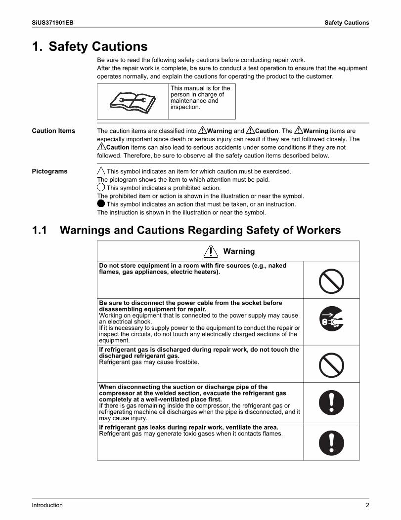
1. Safety CautionsBe sure to read the following safety cautions before conducting repair work.After the repair work is complete, be sure to conduct a test operation to ensure that the equipment operates normally, and explain the cautions for operating the product to the customer.
Caution Items The caution items are classified into Warning and Caution. The Warning items are especially important since death or serious injury can result if they are not followed closely. The
Caution items can also lead to serious accidents under some conditions if they are not followed. Therefore, be sure to observe all the safety caution items described below.
Pictograms This symbol indicates an item for which caution must be exercised.The pictogram shows the item to which attention must be paid.
This symbol indicates a prohibited action.The prohibited item or action is shown in the illustration or near the symbol.
This symbol indicates an action that must be taken, or an instruction.The instruction is shown in the illustration or near the symbol.
1.1 Warnings and Cautions Regarding Safety of Workers
This manual is for the person in charge of maintenance and inspection.
WarningDo not store equipment in a room with fire sources (e.g., naked flames, gas appliances, electric heaters).
Be sure to disconnect the power cable from the socket before disassembling equipment for repair.Working on equipment that is connected to the power supply may cause an electrical shock.If it is necessary to supply power to the equipment to conduct the repair or inspect the circuits, do not touch any electrically charged sections of the equipment.If refrigerant gas is discharged during repair work, do not touch the discharged refrigerant gas.Refrigerant gas may cause frostbite.
When disconnecting the suction or discharge pipe of the compressor at the welded section, evacuate the refrigerant gas completely at a well-ventilated place first.If there is gas remaining inside the compressor, the refrigerant gas or refrigerating machine oil discharges when the pipe is disconnected, and it may cause injury.If refrigerant gas leaks during repair work, ventilate the area.Refrigerant gas may generate toxic gases when it contacts flames.
Introduction 2
Safety Cautions SiUS371901EB
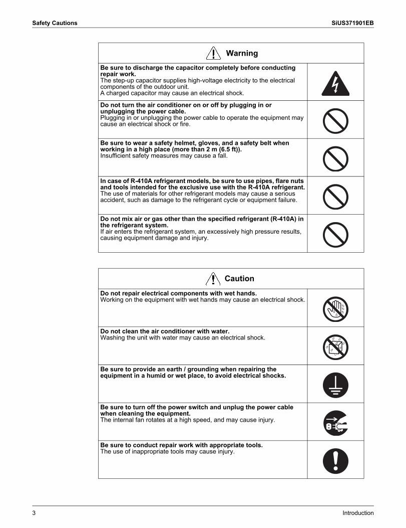
Be sure to discharge the capacitor completely before conducting repair work.The step-up capacitor supplies high-voltage electricity to the electrical components of the outdoor unit.A charged capacitor may cause an electrical shock.
Do not turn the air conditioner on or off by plugging in or unplugging the power cable.Plugging in or unplugging the power cable to operate the equipment may cause an electrical shock or fire.
Be sure to wear a safety helmet, gloves, and a safety belt when working in a high place (more than 2 m (6.5 ft)).Insufficient safety measures may cause a fall.
In case of R-410A refrigerant models, be sure to use pipes, flare nuts and tools intended for the exclusive use with the R-410A refrigerant.The use of materials for other refrigerant models may cause a serious accident, such as damage to the refrigerant cycle or equipment failure.
Do not mix air or gas other than the specified refrigerant (R-410A) in the refrigerant system.If air enters the refrigerant system, an excessively high pressure results, causing equipment damage and injury.
CautionDo not repair electrical components with wet hands.Working on the equipment with wet hands may cause an electrical shock.
Do not clean the air conditioner with water.Washing the unit with water may cause an electrical shock.
Be sure to provide an earth / grounding when repairing the equipment in a humid or wet place, to avoid electrical shocks.
Be sure to turn off the power switch and unplug the power cable when cleaning the equipment.The internal fan rotates at a high speed, and may cause injury.
Be sure to conduct repair work with appropriate tools.The use of inappropriate tools may cause injury.
Warning
3 Introduction
SiUS371901EB Safety Cautions
1.2 Warnings and Cautions Regarding Safety of Users
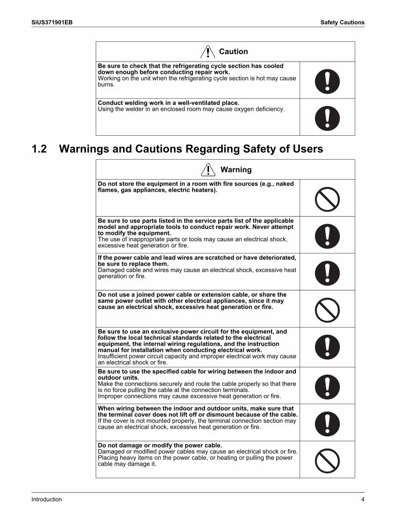
Be sure to check that the refrigerating cycle section has cooled down enough before conducting repair work.Working on the unit when the refrigerating cycle section is hot may cause burns.
Conduct welding work in a well-ventilated place.Using the welder in an enclosed room may cause oxygen deficiency.
Caution
WarningDo not store the equipment in a room with fire sources (e.g., naked flames, gas appliances, electric heaters).
Be sure to use parts listed in the service parts list of the applicable model and appropriate tools to conduct repair work. Never attempt to modify the equipment.The use of inappropriate parts or tools may cause an electrical shock, excessive heat generation or fire.
If the power cable and lead wires are scratched or have deteriorated, be sure to replace them.Damaged cable and wires may cause an electrical shock, excessive heat generation or fire.
Do not use a joined power cable or extension cable, or share the same power outlet with other electrical appliances, since it may cause an electrical shock, excessive heat generation or fire.
Be sure to use an exclusive power circuit for the equipment, and follow the local technical standards related to the electrical equipment, the internal wiring regulations, and the instruction manual for installation when conducting electrical work.Insufficient power circuit capacity and improper electrical work may cause an electrical shock or fire.Be sure to use the specified cable for wiring between the indoor and outdoor units.Make the connections securely and route the cable properly so that there is no force pulling the cable at the connection terminals.Improper connections may cause excessive heat generation or fire.
When wiring between the indoor and outdoor units, make sure that the terminal cover does not lift off or dismount because of the cable.If the cover is not mounted properly, the terminal connection section may cause an electrical shock, excessive heat generation or fire.
Do not damage or modify the power cable.Damaged or modified power cables may cause an electrical shock or fire.Placing heavy items on the power cable, or heating or pulling the power cable may damage it.
Introduction 4
Safety Cautions SiUS371901EB
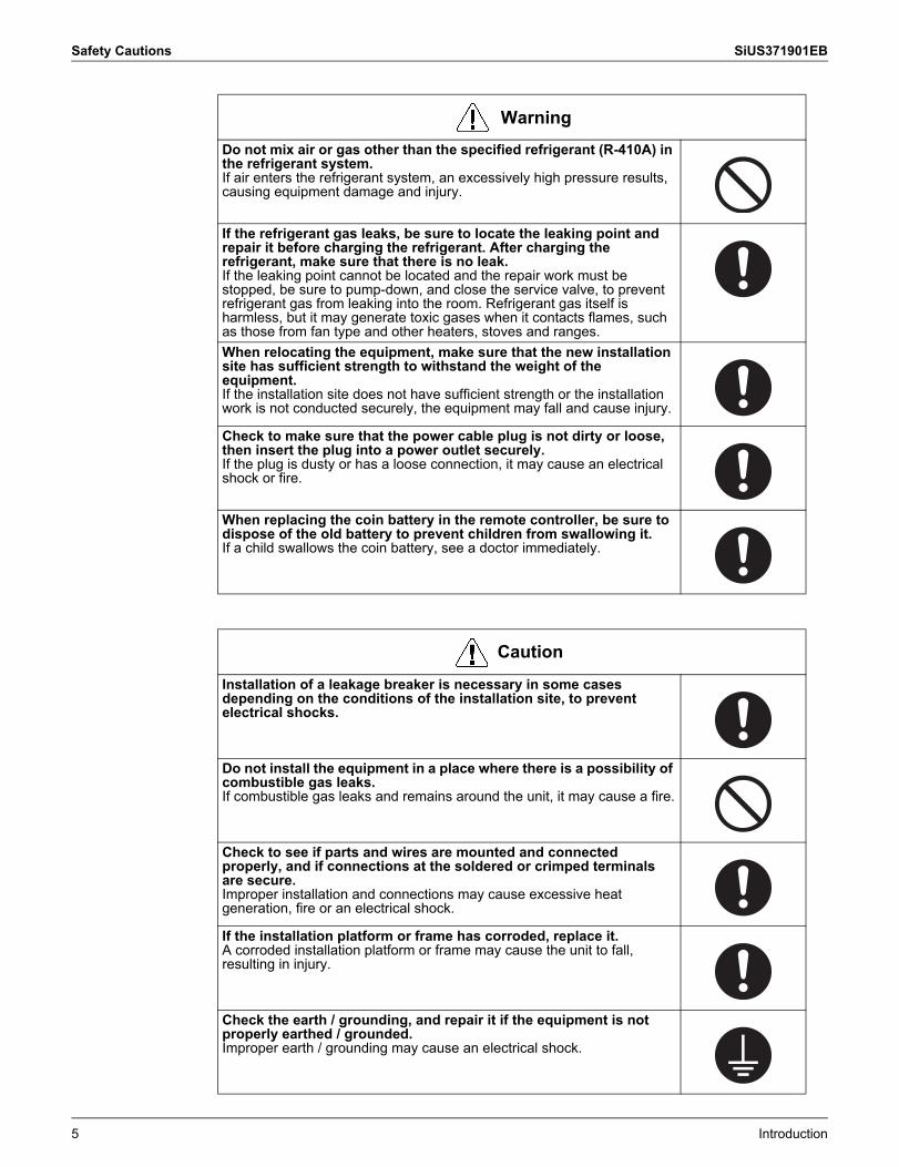
Do not mix air or gas other than the specified refrigerant (R-410A) in the refrigerant system.If air enters the refrigerant system, an excessively high pressure results, causing equipment damage and injury.
If the refrigerant gas leaks, be sure to locate the leaking point and repair it before charging the refrigerant. After charging the refrigerant, make sure that there is no leak.If the leaking point cannot be located and the repair work must be stopped, be sure to pump-down, and close the service valve, to prevent refrigerant gas from leaking into the room. Refrigerant gas itself is harmless, but it may generate toxic gases when it contacts flames, such as those from fan type and other heaters, stoves and ranges.When relocating the equipment, make sure that the new installation site has sufficient strength to withstand the weight of the equipment.If the installation site does not have sufficient strength or the installation work is not conducted securely, the equipment may fall and cause injury.
Check to make sure that the power cable plug is not dirty or loose, then insert the plug into a power outlet securely.If the plug is dusty or has a loose connection, it may cause an electrical shock or fire.
When replacing the coin battery in the remote controller, be sure to dispose of the old battery to prevent children from swallowing it.If a child swallows the coin battery, see a doctor immediately.
CautionInstallation of a leakage breaker is necessary in some cases depending on the conditions of the installation site, to prevent electrical shocks.
Do not install the equipment in a place where there is a possibility of combustible gas leaks.If combustible gas leaks and remains around the unit, it may cause a fire.
Check to see if parts and wires are mounted and connected properly, and if connections at the soldered or crimped terminals are secure.Improper installation and connections may cause excessive heat generation, fire or an electrical shock.
If the installation platform or frame has corroded, replace it.A corroded installation platform or frame may cause the unit to fall, resulting in injury.
Check the earth / grounding, and repair it if the equipment is not properly earthed / grounded.Improper earth / grounding may cause an electrical shock.
Warning
5 Introduction
SiUS371901EB Safety Cautions
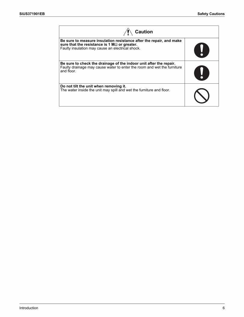
Be sure to measure insulation resistance after the repair, and make sure that the resistance is 1 MΩ or greater.Faulty insulation may cause an electrical shock.
Be sure to check the drainage of the indoor unit after the repair.Faulty drainage may cause water to enter the room and wet the furniture and floor.
Do not tilt the unit when removing it.The water inside the unit may spill and wet the furniture and floor.
Caution
Introduction 6
Icons Used SiUS371901EB
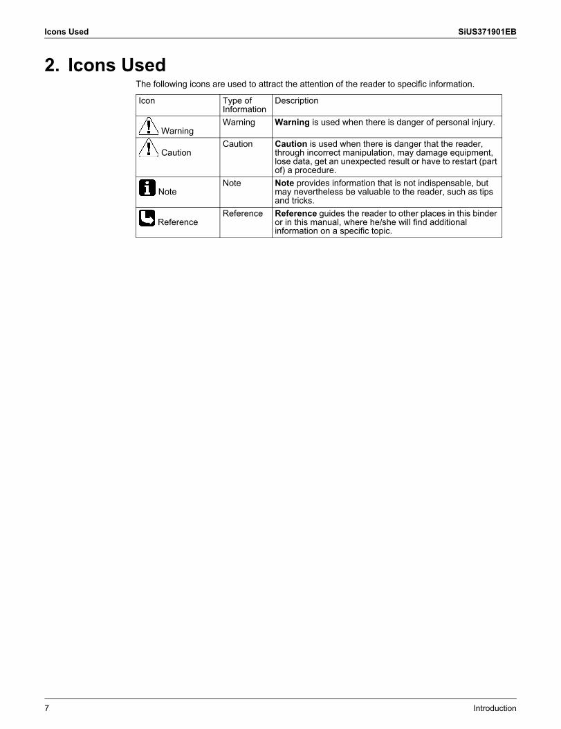
2. Icons UsedThe following icons are used to attract the attention of the reader to specific information.
Icon Type of Information
Description
WarningWarning Warning is used when there is danger of personal injury.
CautionCaution Caution is used when there is danger that the reader,
through incorrect manipulation, may damage equipment, lose data, get an unexpected result or have to restart (part of) a procedure.
NoteNote Note provides information that is not indispensable, but
may nevertheless be valuable to the reader, such as tips and tricks.
ReferenceReference Reference guides the reader to other places in this binder
or in this manual, where he/she will find additional information on a specific topic.
7 Introduction
SiUS371901EB Revision History
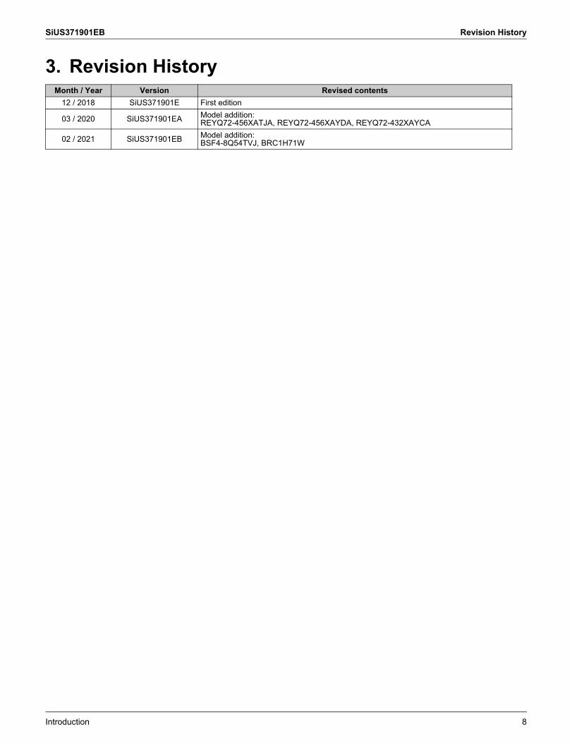
3. Revision HistoryMonth / Year Version Revised contents
12 / 2018 SiUS371901E First edition
03 / 2020 SiUS371901EA Model addition:REYQ72-456XATJA, REYQ72-456XAYDA, REYQ72-432XAYCA
02 / 2021 SiUS371901EB Model addition:BSF4-8Q54TVJ, BRC1H71W
Introduction 8
SiUS371901EB
9 Part 1 General Information
1. Model Names ............................................................................................101.1 Indoor Unit.................................................................................................. 101.2 Outdoor Unit ............................................................................................... 111.3 Air Treatment Equipment ........................................................................... 121.4 Branch Selector Unit .................................................................................. 12
2. External Appearance.................................................................................132.1 Indoor Unit.................................................................................................. 132.2 Outdoor Unit ............................................................................................... 142.3 Air Treatment Equipment ........................................................................... 152.4 Branch Selector Unit .................................................................................. 15
3. Combination of Outdoor Units...................................................................163.1 REYQ-XATJU(A), REYQ-XAYDU(A), REYQ-XAYCU(A)........................... 16
4. Capacity Range.........................................................................................174.1 Combination Ratio...................................................................................... 174.2 Outdoor Unit Combinations ........................................................................ 184.3 Limitation of Capacity Index for Heat Recovery ......................................... 19
5. Specifications ............................................................................................205.1 REYQ-XATJU(A)........................................................................................ 205.2 REYQ-XAYDU(A)....................................................................................... 375.3 REYQ-XAYCU(A)....................................................................................... 54
Part 1 General Information
SiUS371901EB Model Names
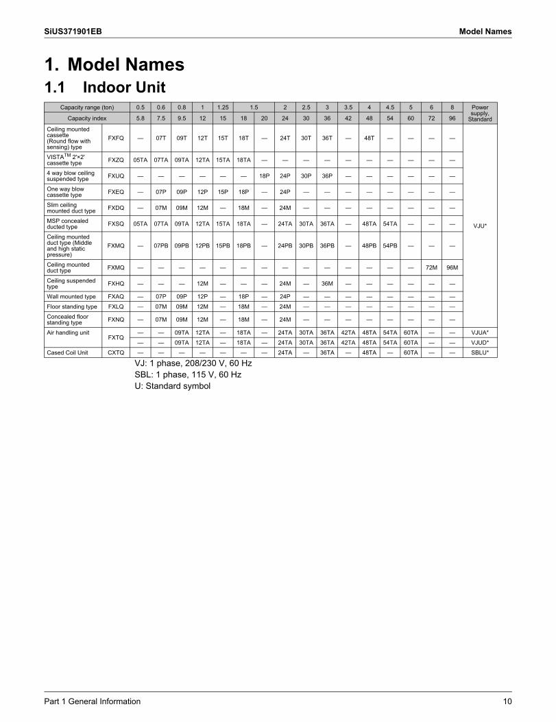
1. Model Names1.1 Indoor Unit
VJ: 1 phase, 208/230 V, 60 HzSBL: 1 phase, 115 V, 60 HzU: Standard symbol
Capacity range (ton) 0.5 0.6 0.8 1 1.25 1.5 2 2.5 3 3.5 4 4.5 5 6 8 Power supply,
StandardCapacity index 5.8 7.5 9.5 12 15 18 20 24 30 36 42 48 54 60 72 96
Ceiling mounted cassette (Round flow with sensing) type
FXFQ — 07T 09T 12T 15T 18T — 24T 30T 36T — 48T — — — —
VJU*
VISTATM 2'×2' cassette type FXZQ 05TA 07TA 09TA 12TA 15TA 18TA — — — — — — — — — —
4 way blow ceiling suspended type FXUQ — — — — — — 18P 24P 30P 36P — — — — — —
One way blow cassette type FXEQ — 07P 09P 12P 15P 18P — 24P — — — — — — — —
Slim ceiling mounted duct type FXDQ — 07M 09M 12M — 18M — 24M — — — — — — — —
MSP concealed ducted type FXSQ 05TA 07TA 09TA 12TA 15TA 18TA — 24TA 30TA 36TA — 48TA 54TA — — —
Ceiling mounted duct type (Middle and high static pressure)
FXMQ — 07PB 09PB 12PB 15PB 18PB — 24PB 30PB 36PB — 48PB 54PB — — —
Ceiling mounted duct type FXMQ — — — — — — — — — — — — — — 72M 96M
Ceiling suspended type FXHQ — — — 12M — — — 24M — 36M — — — — — —
Wall mounted type FXAQ — 07P 09P 12P — 18P — 24P — — — — — — — —Floor standing type FXLQ — 07M 09M 12M — 18M — 24M — — — — — — — —Concealed floor standing type FXNQ — 07M 09M 12M — 18M — 24M — — — — — — — —
Air handling unitFXTQ
— — 09TA 12TA — 18TA — 24TA 30TA 36TA 42TA 48TA 54TA 60TA — — VJUA*— — 09TA 12TA — 18TA — 24TA 30TA 36TA 42TA 48TA 54TA 60TA — — VJUD*
Cased Coil Unit CXTQ — — — — — — — 24TA — 36TA — 48TA — 60TA — — SBLU*
Part 1 General Information 10
Model Names SiUS371901EB
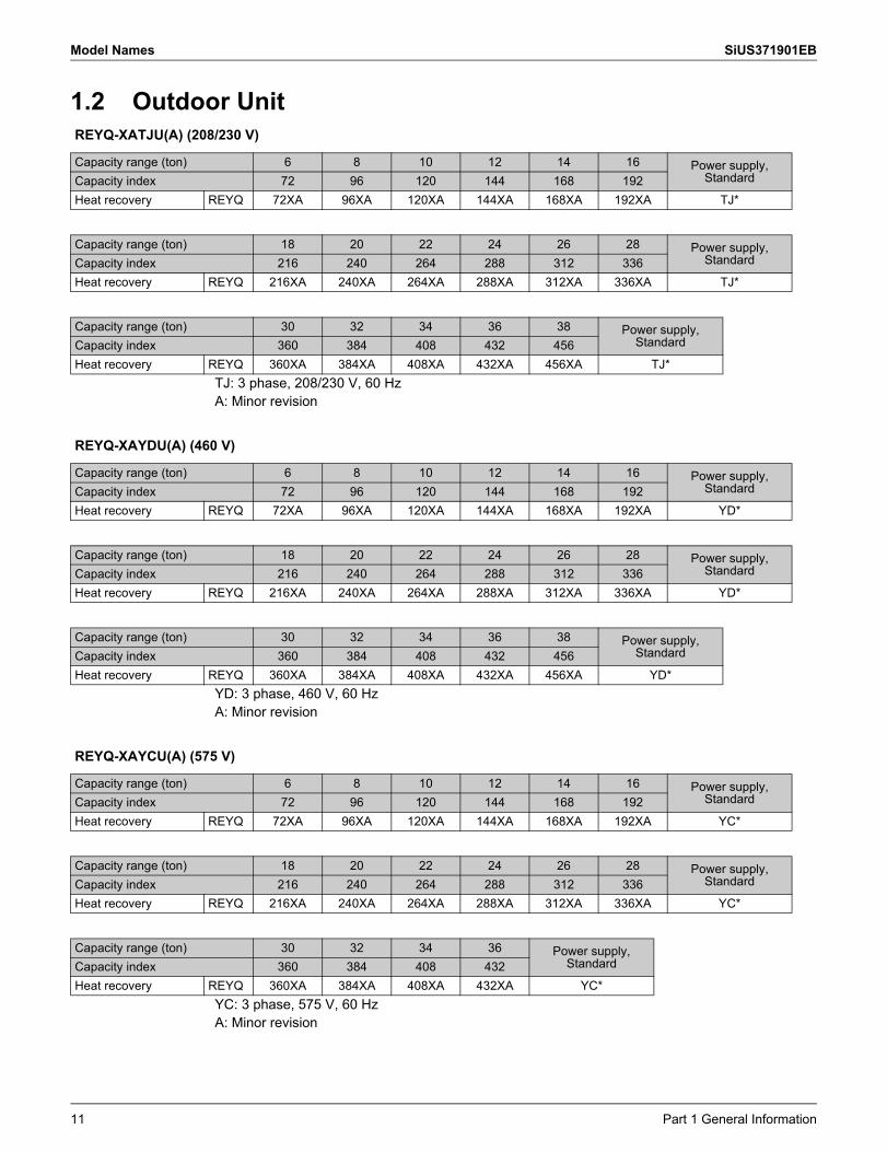
1.2 Outdoor Unit
TJ: 3 phase, 208/230 V, 60 HzA: Minor revision
YD: 3 phase, 460 V, 60 HzA: Minor revision
YC: 3 phase, 575 V, 60 HzA: Minor revision
REYQ-XATJU(A) (208/230 V)
Capacity range (ton) 6 8 10 12 14 16 Power supply, StandardCapacity index 72 96 120 144 168 192
Heat recovery REYQ 72XA 96XA 120XA 144XA 168XA 192XA TJ*
Capacity range (ton) 18 20 22 24 26 28 Power supply, StandardCapacity index 216 240 264 288 312 336
Heat recovery REYQ 216XA 240XA 264XA 288XA 312XA 336XA TJ*
Capacity range (ton) 30 32 34 36 38 Power supply, StandardCapacity index 360 384 408 432 456
Heat recovery REYQ 360XA 384XA 408XA 432XA 456XA TJ*
REYQ-XAYDU(A) (460 V)
Capacity range (ton) 6 8 10 12 14 16 Power supply, StandardCapacity index 72 96 120 144 168 192
Heat recovery REYQ 72XA 96XA 120XA 144XA 168XA 192XA YD*
Capacity range (ton) 18 20 22 24 26 28 Power supply, StandardCapacity index 216 240 264 288 312 336
Heat recovery REYQ 216XA 240XA 264XA 288XA 312XA 336XA YD*
Capacity range (ton) 30 32 34 36 38 Power supply, StandardCapacity index 360 384 408 432 456
Heat recovery REYQ 360XA 384XA 408XA 432XA 456XA YD*
REYQ-XAYCU(A) (575 V)
Capacity range (ton) 6 8 10 12 14 16 Power supply, StandardCapacity index 72 96 120 144 168 192
Heat recovery REYQ 72XA 96XA 120XA 144XA 168XA 192XA YC*
Capacity range (ton) 18 20 22 24 26 28 Power supply, StandardCapacity index 216 240 264 288 312 336
Heat recovery REYQ 216XA 240XA 264XA 288XA 312XA 336XA YC*
Capacity range (ton) 30 32 34 36 Power supply, StandardCapacity index 360 384 408 432
Heat recovery REYQ 360XA 384XA 408XA 432XA YC*
11 Part 1 General Information
SiUS371901EB Model Names
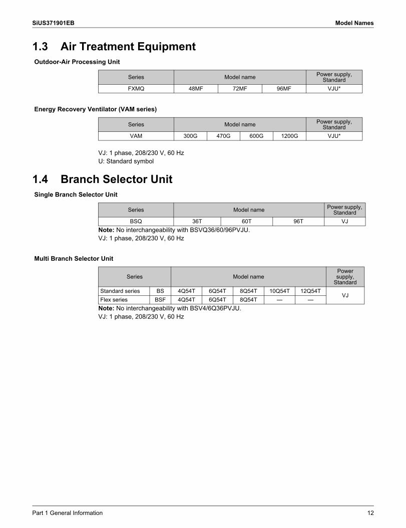
1.3 Air Treatment Equipment
VJ: 1 phase, 208/230 V, 60 HzU: Standard symbol
1.4 Branch Selector Unit
Note: No interchangeability with BSVQ36/60/96PVJU.VJ: 1 phase, 208/230 V, 60 Hz
Note: No interchangeability with BSV4/6Q36PVJU.VJ: 1 phase, 208/230 V, 60 Hz
Outdoor-Air Processing Unit
Series Model name Power supply, Standard
FXMQ 48MF 72MF 96MF VJU*
Energy Recovery Ventilator (VAM series)
Series Model name Power supply, Standard
VAM 300G 470G 600G 1200G VJU*
Single Branch Selector Unit
Series Model name Power supply, Standard
BSQ 36T 60T 96T VJ
Multi Branch Selector Unit
Series Model namePower supply,
StandardStandard series BS 4Q54T 6Q54T 8Q54T 10Q54T 12Q54T
VJFlex series BSF 4Q54T 6Q54T 8Q54T — —
Part 1 General Information 12
External Appearance SiUS371901EB
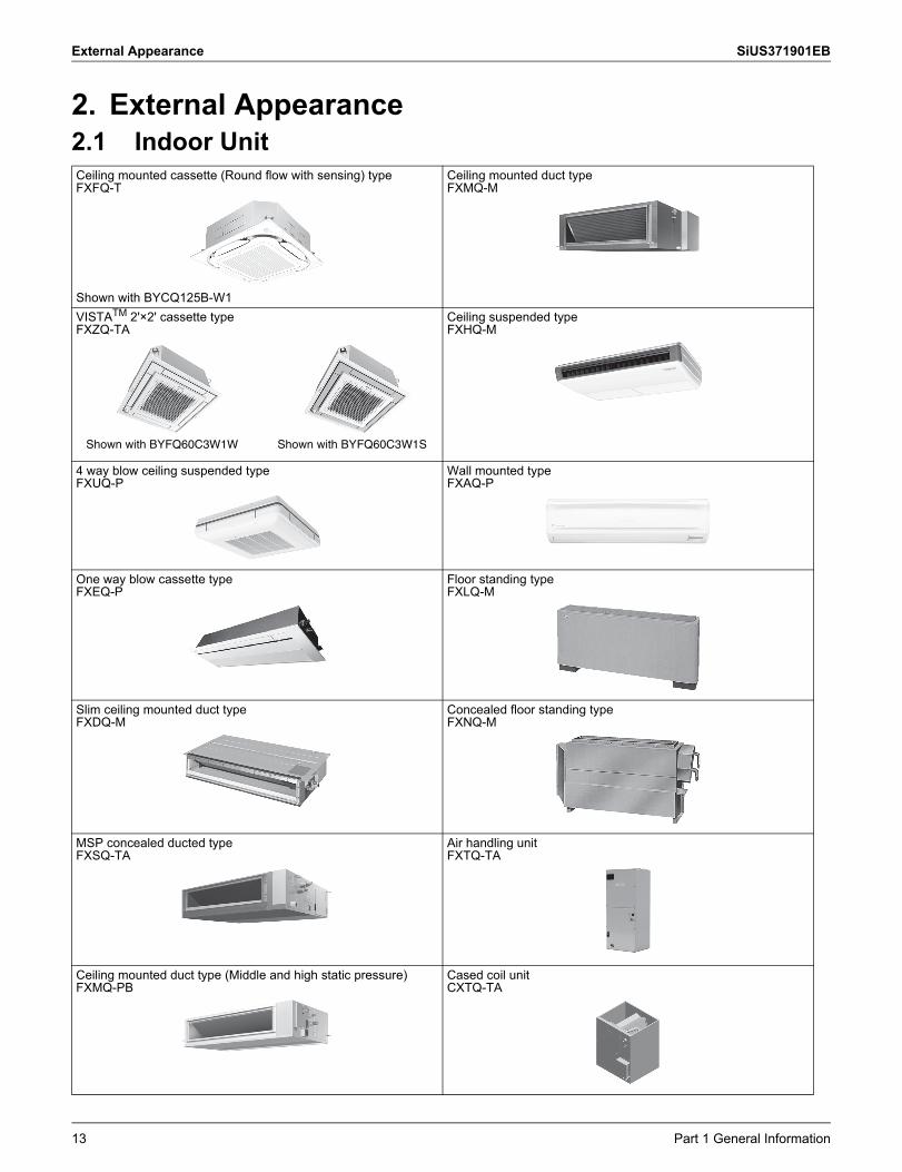
2. External Appearance2.1 Indoor UnitCeiling mounted cassette (Round flow with sensing) typeFXFQ-T
Shown with BYCQ125B-W1
Ceiling mounted duct typeFXMQ-M
VISTATM 2'×2' cassette typeFXZQ-TA
Ceiling suspended typeFXHQ-M
4 way blow ceiling suspended typeFXUQ-P
Wall mounted typeFXAQ-P
One way blow cassette typeFXEQ-P
Floor standing typeFXLQ-M
Slim ceiling mounted duct typeFXDQ-M
Concealed floor standing typeFXNQ-M
MSP concealed ducted typeFXSQ-TA
Air handling unitFXTQ-TA
Ceiling mounted duct type (Middle and high static pressure) FXMQ-PB
Cased coil unitCXTQ-TA
Shown with BYFQ60C3W1W Shown with BYFQ60C3W1S
13 Part 1 General Information
SiUS371901EB External Appearance
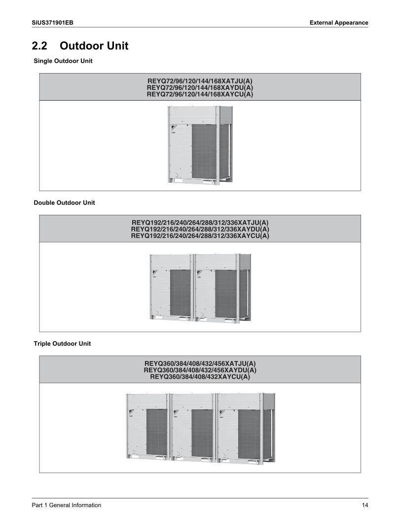
2.2 Outdoor UnitSingle Outdoor Unit
Double Outdoor Unit
Triple Outdoor Unit
REYQ72/96/120/144/168XATJU(A)REYQ72/96/120/144/168XAYDU(A)REYQ72/96/120/144/168XAYCU(A)
REYQ192/216/240/264/288/312/336XATJU(A)REYQ192/216/240/264/288/312/336XAYDU(A)REYQ192/216/240/264/288/312/336XAYCU(A)
REYQ360/384/408/432/456XATJU(A)REYQ360/384/408/432/456XAYDU(A)
REYQ360/384/408/432XAYCU(A)
Part 1 General Information 14
External Appearance SiUS371901EB
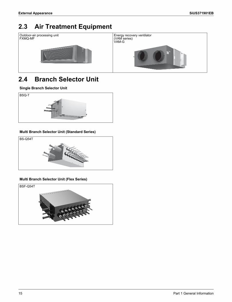
2.3 Air Treatment Equipment
2.4 Branch Selector Unit
Outdoor-air processing unitFXMQ-MF
Energy recovery ventilator(VAM series)VAM-G
Single Branch Selector Unit
BSQ-T
Multi Branch Selector Unit (Standard Series)
BS-Q54T
Multi Branch Selector Unit (Flex Series)
BSF-Q54T
15 Part 1 General Information
SiUS371901EB Combination of Outdoor Units
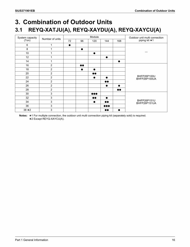
3. Combination of Outdoor Units3.1 REYQ-XATJU(A), REYQ-XAYDU(A), REYQ-XAYCU(A)
System capacity(Ton) Number of units
Module Outdoor unit multi connection piping kit 172 96 120 144 168
6 1 h
—8 1 h
10 1 h
12 1 h
14 1 h
16 2 hh
BHFP26P100UBHFP26P100UA
18 2 h h
20 2 hh
22 2 h h
24 2 hh
26 2 h h
28 2 hh
30 3 hhh
BHFP26P151UBHFP26P151UA
32 3 hh h
34 3 h hh
36 3 hhh
38 2 3 hh h
Notes: 1 For multiple connection, the outdoor unit multi connection piping kit (separately sold) is required.2 Except REYQ-XAYCU(A).
Part 1 General Information 16
Capacity Range SiUS371901EB
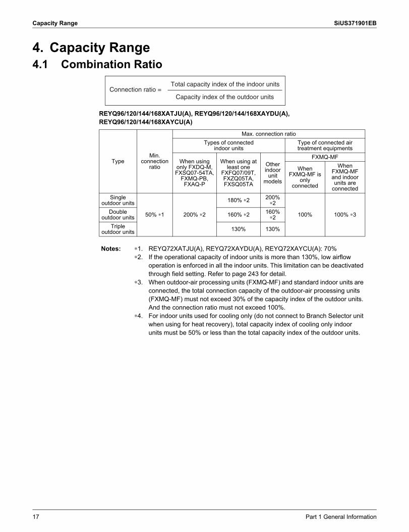
4. Capacity Range4.1 Combination Ratio
REYQ96/120/144/168XATJU(A), REYQ96/120/144/168XAYDU(A), REYQ96/120/144/168XAYCU(A)
TypeMin.
connection ratio
Max. connection ratioTypes of connected
indoor unitsType of connected air treatment equipments
When using only FXDQ-M, FXSQ07-54TA,
FXMQ-PB, FXAQ-P
When using at least one
FXFQ07/09T, FXZQ05TA, FXSQ05TA
Otherindoor
unit models
FXMQ-MF
When FXMQ-MF is
only connected
When FXMQ-MF and indoor units are
connectedSingle
outdoor units
50% ∗1 200% ∗2
180% ∗2 200% ∗2
100% 100% ∗3Double outdoor units 160% ∗2 160%
∗2Triple
outdoor units 130% 130%
Notes: ∗1.∗2.
∗3.
∗4.
REYQ72XATJU(A), REYQ72XAYDU(A), REYQ72XAYCU(A): 70%If the operational capacity of indoor units is more than 130%, low airflow operation is enforced in all the indoor units. This limitation can be deactivated through field setting. Refer to page 243 for detail.When outdoor-air processing units (FXMQ-MF) and standard indoor units are connected, the total connection capacity of the outdoor-air processing units (FXMQ-MF) must not exceed 30% of the capacity index of the outdoor units. And the connection ratio must not exceed 100%.For indoor units used for cooling only (do not connect to Branch Selector unit when using for heat recovery), total capacity index of cooling only indoor units must be 50% or less than the total capacity index of the outdoor units.
Connection ratio = Total capacity index of the indoor units
Capacity index of the outdoor units
17 Part 1 General Information
SiUS371901EB Capacity Range
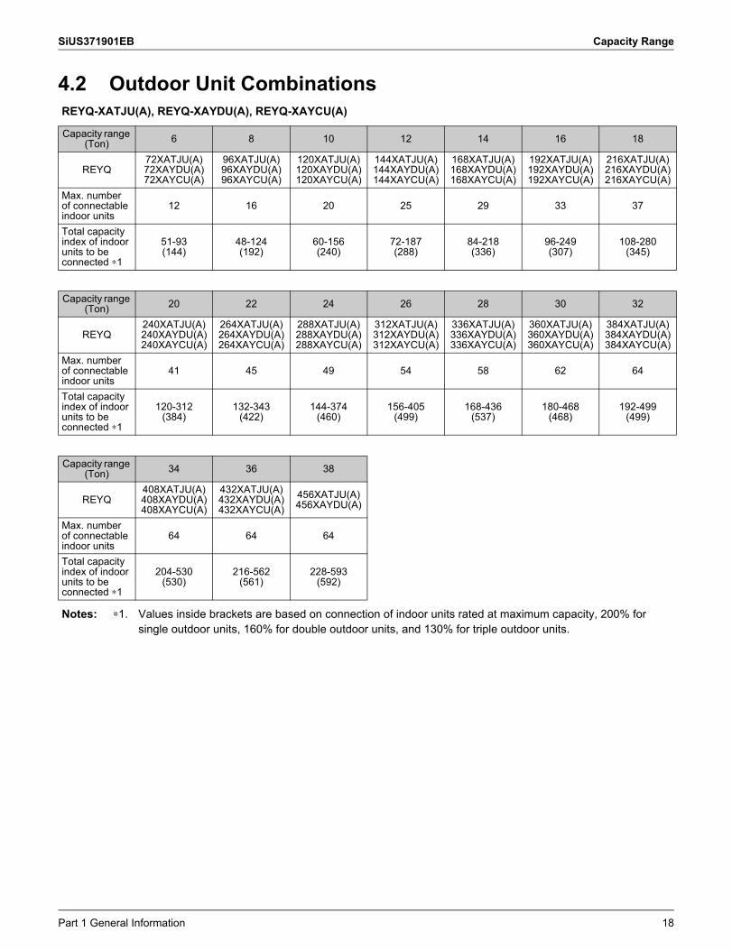
4.2 Outdoor Unit CombinationsREYQ-XATJU(A), REYQ-XAYDU(A), REYQ-XAYCU(A)
Capacity range (Ton) 6 8 10 12 14 16 18
REYQ72XATJU(A)72XAYDU(A)72XAYCU(A)
96XATJU(A)96XAYDU(A)96XAYCU(A)
120XATJU(A)120XAYDU(A)120XAYCU(A)
144XATJU(A)144XAYDU(A)144XAYCU(A)
168XATJU(A)168XAYDU(A)168XAYCU(A)
192XATJU(A)192XAYDU(A)192XAYCU(A)
216XATJU(A)216XAYDU(A)216XAYCU(A)
Max. number of connectable indoor units
12 16 20 25 29 33 37
Total capacity index of indoor units to be connected ∗1
51-93(144)
48-124(192)
60-156(240)
72-187(288)
84-218(336)
96-249(307)
108-280(345)
Capacity range (Ton) 20 22 24 26 28 30 32
REYQ240XATJU(A)240XAYDU(A)240XAYCU(A)
264XATJU(A)264XAYDU(A)264XAYCU(A)
288XATJU(A)288XAYDU(A)288XAYCU(A)
312XATJU(A)312XAYDU(A)312XAYCU(A)
336XATJU(A)336XAYDU(A)336XAYCU(A)
360XATJU(A)360XAYDU(A)360XAYCU(A)
384XATJU(A)384XAYDU(A)384XAYCU(A)
Max. number of connectable indoor units
41 45 49 54 58 62 64
Total capacity index of indoor units to be connected ∗1
120-312(384)
132-343(422)
144-374(460)
156-405(499)
168-436(537)
180-468(468)
192-499(499)
Capacity range (Ton) 34 36 38
REYQ408XATJU(A)408XAYDU(A)408XAYCU(A)
432XATJU(A)432XAYDU(A)432XAYCU(A)
456XATJU(A)456XAYDU(A)
Max. number of connectable indoor units
64 64 64
Total capacity index of indoor units to be connected ∗1
204-530(530)
216-562(561)
228-593(592)
Notes: ∗1. Values inside brackets are based on connection of indoor units rated at maximum capacity, 200% for single outdoor units, 160% for double outdoor units, and 130% for triple outdoor units.
Part 1 General Information 18
Capacity Range SiUS371901EB
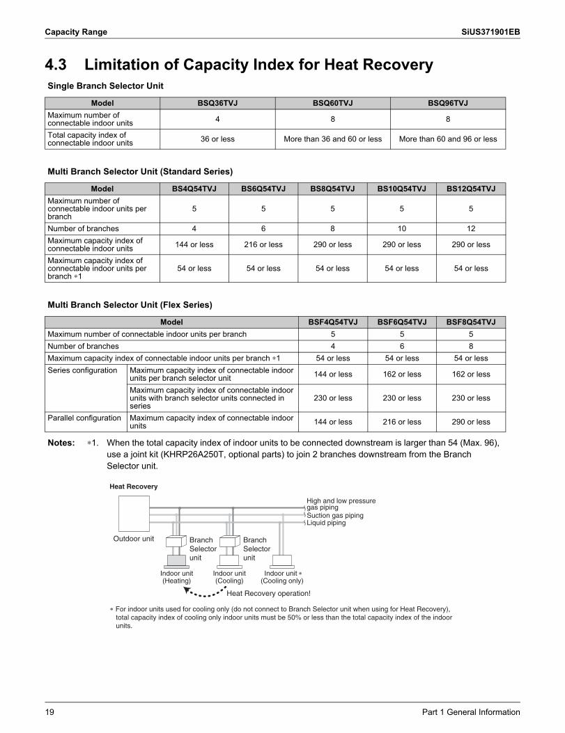
4.3 Limitation of Capacity Index for Heat RecoverySingle Branch Selector Unit
Model BSQ36TVJ BSQ60TVJ BSQ96TVJMaximum number of connectable indoor units 4 8 8
Total capacity index of connectable indoor units 36 or less More than 36 and 60 or less More than 60 and 96 or less
Multi Branch Selector Unit (Standard Series)
Model BS4Q54TVJ BS6Q54TVJ BS8Q54TVJ BS10Q54TVJ BS12Q54TVJMaximum number of connectable indoor units per branch
5 5 5 5 5
Number of branches 4 6 8 10 12Maximum capacity index of connectable indoor units 144 or less 216 or less 290 or less 290 or less 290 or less
Maximum capacity index of connectable indoor units per branch ∗1
54 or less 54 or less 54 or less 54 or less 54 or less
Multi Branch Selector Unit (Flex Series)
Model BSF4Q54TVJ BSF6Q54TVJ BSF8Q54TVJMaximum number of connectable indoor units per branch 5 5 5Number of branches 4 6 8Maximum capacity index of connectable indoor units per branch ∗1 54 or less 54 or less 54 or lessSeries configuration Maximum capacity index of connectable indoor
units per branch selector unit 144 or less 162 or less 162 or less
Maximum capacity index of connectable indoor units with branch selector units connected in series
230 or less 230 or less 230 or less
Parallel configuration Maximum capacity index of connectable indoor units 144 or less 216 or less 290 or less
Notes: ∗1. When the total capacity index of indoor units to be connected downstream is larger than 54 (Max. 96), use a joint kit (KHRP26A250T, optional parts) to join 2 branches downstream from the Branch Selector unit.
Suction gas pipingLiquid piping
Indoor unit(Heating)
Indoor unit(Cooling)
Indoor unit (Cooling only)
Heat Recovery operation!
Branch Selector unit
Branch Selector unit
Heat Recovery
Outdoor unit
High and low pressure gas piping
For indoor units used for cooling only (do not connect to Branch Selector unit when using for Heat Recovery), total capacity index of cooling only indoor units must be 50% or less than the total capacity index of the indoor units.
19 Part 1 General Information
SiUS371901EB Specifications
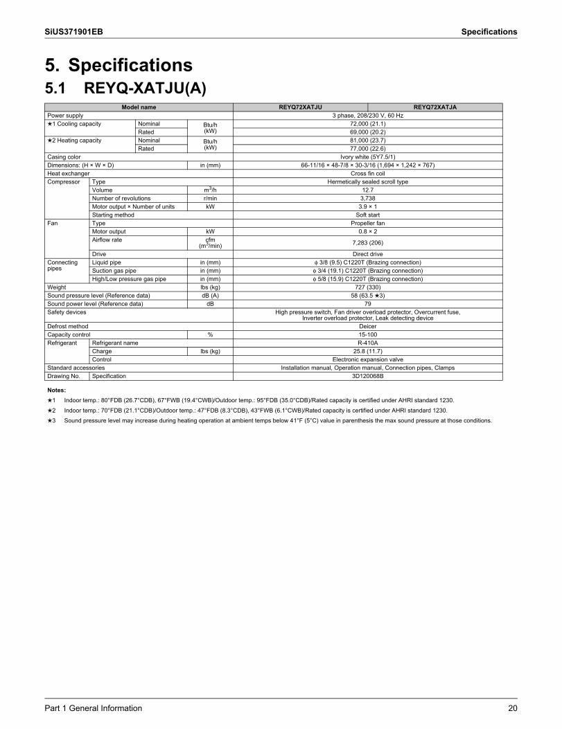
5. Specifications5.1 REYQ-XATJU(A)
Model name REYQ72XATJU REYQ72XATJAPower supply 3 phase, 208/230 V, 60 Hz1 Cooling capacity Nominal Btu/h
(kW)72,000 (21.1)
Rated 69,000 (20.2)2 Heating capacity Nominal Btu/h
(kW)81,000 (23.7)
Rated 77,000 (22.6)Casing color Ivory white (5Y7.5/1)Dimensions: (H × W × D) in (mm) 66-11/16 × 48-7/8 × 30-3/16 (1,694 × 1,242 × 767)Heat exchanger Cross fin coilCompressor Type Hermetically sealed scroll type
Volume m3/h 12.7Number of revolutions r/min 3,738Motor output × Number of units kW 3.9 × 1Starting method Soft start
Fan Type Propeller fanMotor output kW 0.8 × 2Airflow rate cfm
(m3/min) 7,283 (206)
Drive Direct driveConnecting pipes
Liquid pipe in (mm) φ 3/8 (9.5) C1220T (Brazing connection)Suction gas pipe in (mm) φ 3/4 (19.1) C1220T (Brazing connection)High/Low pressure gas pipe in (mm) φ 5/8 (15.9) C1220T (Brazing connection)
Weight lbs (kg) 727 (330)Sound pressure level (Reference data) dB (A) 58 (63.5 3)Sound power level (Reference data) dB 79Safety devices High pressure switch, Fan driver overload protector, Overcurrent fuse,
Inverter overload protector, Leak detecting deviceDefrost method DeicerCapacity control % 15-100Refrigerant Refrigerant name R-410A
Charge lbs (kg) 25.8 (11.7)Control Electronic expansion valve
Standard accessories Installation manual, Operation manual, Connection pipes, ClampsDrawing No. Specification 3D120068B
Notes:1 Indoor temp.: 80°FDB (26.7°CDB), 67°FWB (19.4°CWB)/Outdoor temp.: 95°FDB (35.0°CDB)/Rated capacity is certified under AHRI standard 1230.2 Indoor temp.: 70°FDB (21.1°CDB)/Outdoor temp.: 47°FDB (8.3°CDB), 43°FWB (6.1°CWB)/Rated capacity is certified under AHRI standard 1230.3 Sound pressure level may increase during heating operation at ambient temps below 41°F (5°C) value in parenthesis the max sound pressure at those conditions.
Part 1 General Information 20

Specifications SiUS371901EB
Model name REYQ96XATJU REYQ96XATJAPower supply 3 phase, 208/230 V, 60 Hz1 Cooling capacity Nominal Btu/h
(kW)96,000 (28.1)
Rated 92,000 (27.0)2 Heating capacity Nominal Btu/h
(kW)108,000 (31.7)
Rated 103,000 (30.2)Casing color Ivory white (5Y7.5/1)Dimensions: (H × W × D) in (mm) 66-11/16 × 48-7/8 × 30-3/16 (1,694 × 1,242 × 767)Heat exchanger Cross fin coilCompressor Type Hermetically sealed scroll type
Volume m3/h 17.4Number of revolutions r/min 5,142Motor output × Number of units kW 5.4 × 1Starting method Soft start
Fan Type Propeller fanMotor output kW 0.8 × 2Airflow rate cfm
(m3/min) 7,989 (226)
Drive Direct driveConnecting pipes
Liquid pipe in (mm) φ 3/8 (9.5) C1220T (Brazing connection)Suction gas pipe in (mm) φ 7/8 (22.2) C1220T (Brazing connection)High/Low pressure gas pipe in (mm) φ 3/4 (19.1) C1220T (Brazing connection)
Weight lbs (kg) 727 (330)Sound pressure level (Reference data) dB (A) 61 (64.5 3)Sound power level (Reference data) dB 80Safety devices High pressure switch, Fan driver overload protector, Overcurrent fuse,
Inverter overload protector, Leak detecting deviceDefrost method DeicerCapacity control % 13-100Refrigerant Refrigerant name R-410A
Charge lbs (kg) 25.8 (11.7)Control Electronic expansion valve
Standard accessories Installation manual, Operation manual, Connection pipes, ClampsDrawing No. Specification 3D120068B
Notes:1 Indoor temp.: 80°FDB (26.7°CDB), 67°FWB (19.4°CWB)/Outdoor temp.: 95°FDB (35.0°CDB)/Rated capacity is certified under AHRI standard 1230.2 Indoor temp.: 70°FDB (21.1°CDB)/Outdoor temp.: 47°FDB (8.3°CDB), 43°FWB (6.1°CWB)/Rated capacity is certified under AHRI standard 1230.3 Sound pressure level may increase during heating operation at ambient temps below 41°F (5°C) value in parenthesis the max sound pressure at those conditions.
21 Part 1 General Information
SiUS371901EB Specifications
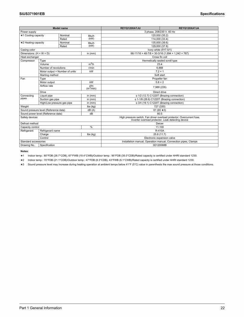
Model name REYQ120XATJU REYQ120XATJAPower supply 3 phase, 208/230 V, 60 Hz1 Cooling capacity Nominal Btu/h
(kW)120,000 (35.2)
Rated 114,000 (33.4)2 Heating capacity Nominal Btu/h
(kW)135,000 (39.6)
Rated 129,000 (37.8)Casing color Ivory white (5Y7.5/1)Dimensions: (H × W × D) in (mm) 66-11/16 × 48-7/8 × 30-3/16 (1,694 × 1,242 × 767)Heat exchanger Cross fin coilCompressor Type Hermetically sealed scroll type
Volume m3/h 23.4Number of revolutions r/min 6,888Motor output × Number of units kW 7.2 × 1Starting method Soft start
Fan Type Propeller fanMotor output kW 0.8 × 2Airflow rate cfm
(m3/min) 7,989 (226)
Drive Direct driveConnecting pipes
Liquid pipe in (mm) φ 1/2 (12.7) C1220T (Brazing connection)Suction gas pipe in (mm) φ 1-1/8 (28.6) C1220T (Brazing connection)High/Low pressure gas pipe in (mm) φ 3/4 (19.1) C1220T (Brazing connection)
Weight lbs (kg) 727 (330)Sound pressure level (Reference data) dB (A) 61 (65 3)Sound power level (Reference data) dB 80.5Safety devices High pressure switch, Fan driver overload protector, Overcurrent fuse,
Inverter overload protector, Leak detecting deviceDefrost method DeicerCapacity control % 11-100Refrigerant Refrigerant name R-410A
Charge lbs (kg) 25.8 (11.7)Control Electronic expansion valve
Standard accessories Installation manual, Operation manual, Connection pipes, ClampsDrawing No. Specification 3D120068B
Notes:1 Indoor temp.: 80°FDB (26.7°CDB), 67°FWB (19.4°CWB)/Outdoor temp.: 95°FDB (35.0°CDB)/Rated capacity is certified under AHRI standard 1230.2 Indoor temp.: 70°FDB (21.1°CDB)/Outdoor temp.: 47°FDB (8.3°CDB), 43°FWB (6.1°CWB)/Rated capacity is certified under AHRI standard 1230.3 Sound pressure level may increase during heating operation at ambient temps below 41°F (5°C) value in parenthesis the max sound pressure at those conditions.
Part 1 General Information 22

Specifications SiUS371901EB
Model name REYQ144XATJU REYQ144XATJAPower supply 3 phase, 208/230 V, 60 Hz1 Cooling capacity Nominal Btu/h
(kW)144,000 (42.2)
Rated 138,000 (40.4)2 Heating capacity Nominal Btu/h
(kW)162,000 (47.5)
Rated 154,000 (45.1)Casing color Ivory white (5Y7.5/1)Dimensions: (H × W × D) in (mm) 66-11/16 × 48-7/8 × 30-3/16 (1,694 × 1,242 × 767)Heat exchanger Cross fin coilCompressor Type Hermetically sealed scroll type
Volume m3/h 27.7Number of revolutions r/min 5,214Motor output × Number of units kW 8.0 × 1Starting method Soft start
Fan Type Propeller fanMotor output kW 0.8 × 2Airflow rate cfm
(m3/min) 9,480 (268)
Drive Direct driveConnecting pipes
Liquid pipe in (mm) φ 1/2 (12.7) C1220T (Brazing connection)Suction gas pipe in (mm) φ 1-1/8 (28.6) C1220T (Brazing connection)High/Low pressure gas pipe in (mm) φ 7/8 (22.2) C1220T (Brazing connection)
Weight lbs (kg) 793 (360)Sound pressure level (Reference data) dB (A) 65Sound power level (Reference data) dB 87Safety devices High pressure switch, Fan driver overload protector, Overcurrent fuse,
Inverter overload protector, Leak detecting deviceDefrost method DeicerCapacity control % 14-100Refrigerant Refrigerant name R-410A
Charge lbs (kg) 25.8 (11.7)Control Electronic expansion valve
Standard accessories Installation manual, Operation manual, Connection pipes, ClampsDrawing No. Specification 3D120068B
Notes:1 Indoor temp.: 80°FDB (26.7°CDB), 67°FWB (19.4°CWB)/Outdoor temp.: 95°FDB (35.0°CDB)/Rated capacity is certified under AHRI standard 1230.2 Indoor temp.: 70°FDB (21.1°CDB)/Outdoor temp.: 47°FDB (8.3°CDB), 43°FWB (6.1°CWB)/Rated capacity is certified under AHRI standard 1230.3 Sound pressure level may increase during heating operation at ambient temps below 41°F (5°C) value in parenthesis the max sound pressure at those conditions.
23 Part 1 General Information

SiUS371901EB Specifications
Model name REYQ168XATJU REYQ168XATJAPower supply 3 phase, 208/230 V, 60 Hz1 Cooling capacity Nominal Btu/h
(kW)168,000 (49.2)
Rated 160,000 (46.9)2 Heating capacity Nominal Btu/h
(kW)188,000 (55.1)
Rated 180,000 (52.7)Casing color Ivory white (5Y7.5/1)Dimensions: (H × W × D) in (mm) 66-11/16 × 48-7/8 × 30-3/16 (1,694 × 1,242 × 767)Heat exchanger Cross fin coilCompressor Type Hermetically sealed scroll type
Volume m3/h 33.6Number of revolutions r/min 6,330Motor output × Number of units kW 9.7 × 1Starting method Soft start
Fan Type Propeller fanMotor output kW 0.8 × 2Airflow rate cfm
(m3/min) 9,480 (268)
Drive Direct driveConnecting pipes
Liquid pipe in (mm) φ 5/8 (15.9) C1220T (Brazing connection)Suction gas pipe in (mm) φ 1-1/8 (28.6) C1220T (Brazing connection)High/Low pressure gas pipe in (mm) φ 7/8 (22.2) C1220T (Brazing connection)
Weight lbs (kg) 793 (360)Sound pressure level (Reference data) dB (A) 65 (65.5 3)Sound power level (Reference data) dB 88Safety devices High pressure switch, Fan driver overload protector, Overcurrent fuse,
Inverter overload protector, Leak detecting deviceDefrost method DeicerCapacity control % 12-100Refrigerant Refrigerant name R-410A
Charge lbs (kg) 25.8 (11.7)Control Electronic expansion valve
Standard accessories Installation manual, Operation manual, Connection pipes, ClampsDrawing No. Specification 3D120068B
Notes:1 Indoor temp.: 80°FDB (26.7°CDB), 67°FWB (19.4°CWB)/Outdoor temp.: 95°FDB (35.0°CDB)/Rated capacity is certified under AHRI standard 1230.2 Indoor temp.: 70°FDB (21.1°CDB)/Outdoor temp.: 47°FDB (8.3°CDB), 43°FWB (6.1°CWB)/Rated capacity is certified under AHRI standard 1230.3 Sound pressure level may increase during heating operation at ambient temps below 41°F (5°C) value in parenthesis the max sound pressure at those conditions.
Part 1 General Information 24

Specifications SiUS371901EB
Model name (Combination unit) REYQ192XATJU REYQ192XATJA
Model name (Independent unit) REYQ96XATJUREYQ96XATJU
REYQ96XATJAREYQ96XATJA
Power supply 3 phase, 208/230 V, 60 Hz1 Cooling capacity Nominal Btu/h
(kW)192,000 (56.3)
Rated 184,000 (53.9)2 Heating capacity Nominal Btu/h
(kW)216,000 (63.3)
Rated 206,000 (60.4)Casing color Ivory white (5Y7.5/1)Dimensions: (H × W × D) in (mm) 66-11/16 × 48-7/8 × 30-3/16 + 66-11/16 × 48-7/8 × 30-3/16
(1,694 × 1,242 × 767 + 1,694 × 1,242 × 767)Heat exchanger Cross fin coilCompressor Type Hermetically sealed scroll type
Volume m3/h 17.7 + 17.7Number of revolutions r/min 5,214 + 5,214Motor output × Number of units kW 5.4 × 1 + 5.4 × 1Starting method Soft start
Fan Type Propeller fanMotor output kW (0.8 × 2) × 2Airflow rate cfm
(m3/min) 7,989 + 7,989 (226 + 226)
Drive Direct driveConnecting pipes
Liquid pipe in (mm) φ 5/8 (15.9) C1220T (Brazing connection)Suction gas pipe in (mm) φ 1-1/8 (28.6) C1220T (Brazing connection)High/Low pressure gas pipe in (mm) φ 1-1/8 (28.6) C1220T (Brazing connection)
Weight lbs (kg) 727 + 727 (330 + 330)Sound pressure level (Reference data) dB (A) 64 (67.5 3)Sound power level (Reference data) dB 83Safety devices High pressure switch, Fan driver overload protector, Overcurrent fuse,
Inverter overload protector, Leak detecting deviceDefrost method DeicerCapacity control % 6-100Refrigerant Refrigerant name R-410A
Charge lbs (kg) 25.8 + 25.8 (11.7 + 11.7)Control Electronic expansion valve
Standard accessories Installation manual, Operation manual, Connection pipes, ClampsDrawing No. Specification 3D120069B
Notes:1 Indoor temp.: 80°FDB (26.7°CDB), 67°FWB (19.4°CWB)/Outdoor temp.: 95°FDB (35.0°CDB)/Rated capacity is certified under AHRI standard 1230.2 Indoor temp.: 70°FDB (21.1°CDB)/Outdoor temp.: 47°FDB (8.3°CDB), 43°FWB (6.1°CWB)/Rated capacity is certified under AHRI standard 1230.3 Sound pressure level may increase during heating operation at ambient temps below 41°F (5°C) value in parenthesis the max sound pressure at those conditions.
25 Part 1 General Information
SiUS371901EB Specifications
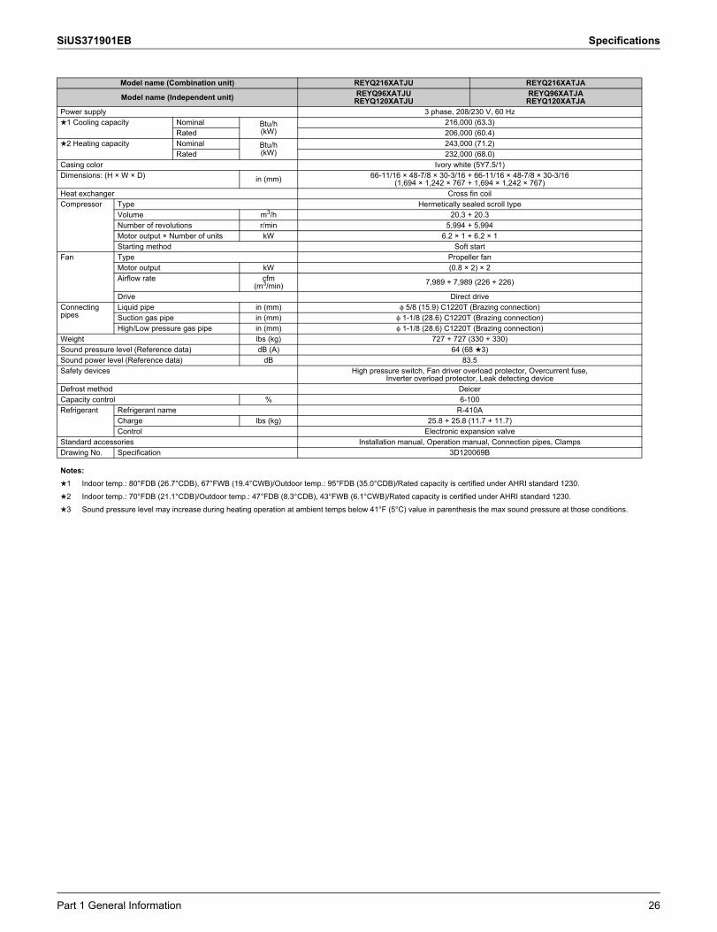
Model name (Combination unit) REYQ216XATJU REYQ216XATJA
Model name (Independent unit) REYQ96XATJUREYQ120XATJU
REYQ96XATJAREYQ120XATJA
Power supply 3 phase, 208/230 V, 60 Hz1 Cooling capacity Nominal Btu/h
(kW)216,000 (63.3)
Rated 206,000 (60.4)2 Heating capacity Nominal Btu/h
(kW)243,000 (71.2)
Rated 232,000 (68.0)Casing color Ivory white (5Y7.5/1)Dimensions: (H × W × D) in (mm) 66-11/16 × 48-7/8 × 30-3/16 + 66-11/16 × 48-7/8 × 30-3/16
(1,694 × 1,242 × 767 + 1,694 × 1,242 × 767)Heat exchanger Cross fin coilCompressor Type Hermetically sealed scroll type
Volume m3/h 20.3 + 20.3Number of revolutions r/min 5,994 + 5,994Motor output × Number of units kW 6.2 × 1 + 6.2 × 1Starting method Soft start
Fan Type Propeller fanMotor output kW (0.8 × 2) × 2Airflow rate cfm
(m3/min) 7,989 + 7,989 (226 + 226)
Drive Direct driveConnecting pipes
Liquid pipe in (mm) φ 5/8 (15.9) C1220T (Brazing connection)Suction gas pipe in (mm) φ 1-1/8 (28.6) C1220T (Brazing connection)High/Low pressure gas pipe in (mm) φ 1-1/8 (28.6) C1220T (Brazing connection)
Weight lbs (kg) 727 + 727 (330 + 330)Sound pressure level (Reference data) dB (A) 64 (68 3)Sound power level (Reference data) dB 83.5Safety devices High pressure switch, Fan driver overload protector, Overcurrent fuse,
Inverter overload protector, Leak detecting deviceDefrost method DeicerCapacity control % 6-100Refrigerant Refrigerant name R-410A
Charge lbs (kg) 25.8 + 25.8 (11.7 + 11.7)Control Electronic expansion valve
Standard accessories Installation manual, Operation manual, Connection pipes, ClampsDrawing No. Specification 3D120069B
Notes:1 Indoor temp.: 80°FDB (26.7°CDB), 67°FWB (19.4°CWB)/Outdoor temp.: 95°FDB (35.0°CDB)/Rated capacity is certified under AHRI standard 1230.2 Indoor temp.: 70°FDB (21.1°CDB)/Outdoor temp.: 47°FDB (8.3°CDB), 43°FWB (6.1°CWB)/Rated capacity is certified under AHRI standard 1230.3 Sound pressure level may increase during heating operation at ambient temps below 41°F (5°C) value in parenthesis the max sound pressure at those conditions.
Part 1 General Information 26
Specifications SiUS371901EB
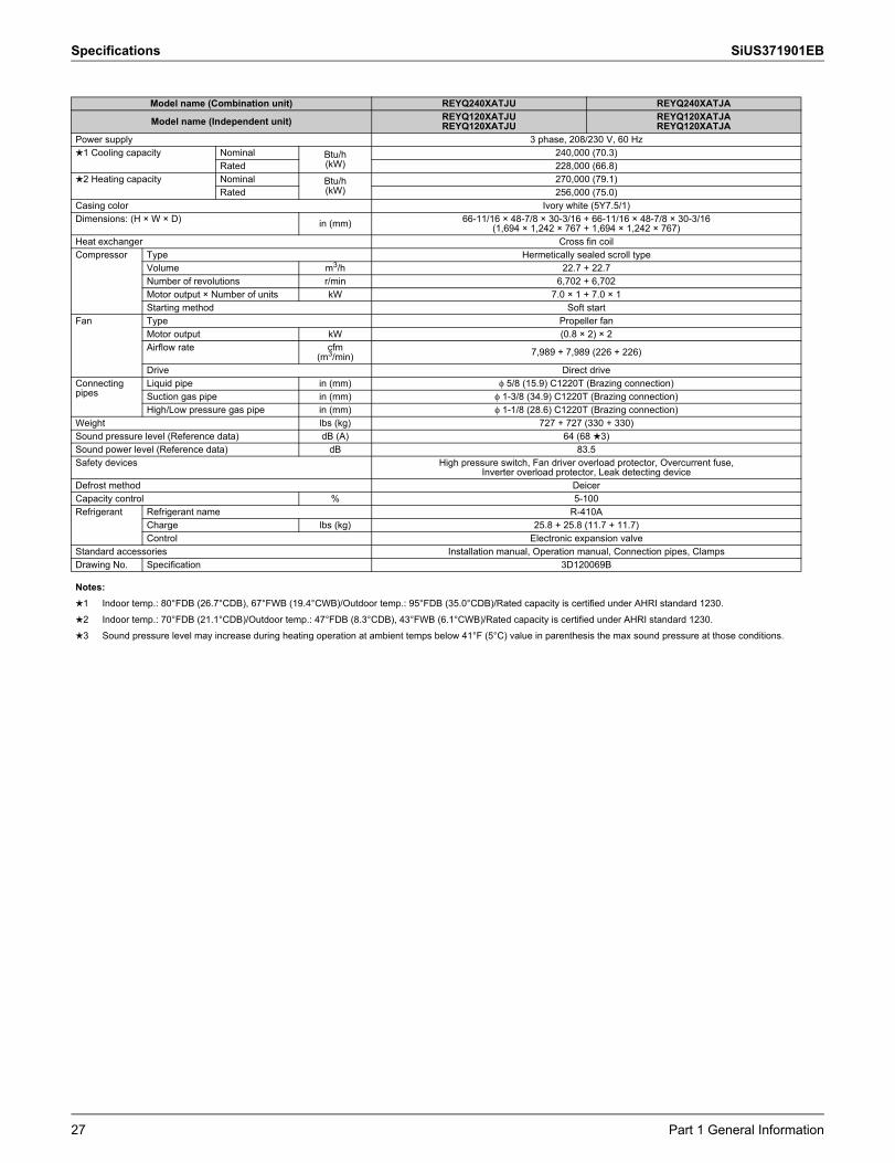
Model name (Combination unit) REYQ240XATJU REYQ240XATJA
Model name (Independent unit) REYQ120XATJUREYQ120XATJU
REYQ120XATJAREYQ120XATJA
Power supply 3 phase, 208/230 V, 60 Hz1 Cooling capacity Nominal Btu/h
(kW)240,000 (70.3)
Rated 228,000 (66.8)2 Heating capacity Nominal Btu/h
(kW)270,000 (79.1)
Rated 256,000 (75.0)Casing color Ivory white (5Y7.5/1)Dimensions: (H × W × D) in (mm) 66-11/16 × 48-7/8 × 30-3/16 + 66-11/16 × 48-7/8 × 30-3/16
(1,694 × 1,242 × 767 + 1,694 × 1,242 × 767)Heat exchanger Cross fin coilCompressor Type Hermetically sealed scroll type
Volume m3/h 22.7 + 22.7Number of revolutions r/min 6,702 + 6,702Motor output × Number of units kW 7.0 × 1 + 7.0 × 1Starting method Soft start
Fan Type Propeller fanMotor output kW (0.8 × 2) × 2Airflow rate cfm
(m3/min) 7,989 + 7,989 (226 + 226)
Drive Direct driveConnecting pipes
Liquid pipe in (mm) φ 5/8 (15.9) C1220T (Brazing connection)Suction gas pipe in (mm) φ 1-3/8 (34.9) C1220T (Brazing connection)High/Low pressure gas pipe in (mm) φ 1-1/8 (28.6) C1220T (Brazing connection)
Weight lbs (kg) 727 + 727 (330 + 330)Sound pressure level (Reference data) dB (A) 64 (68 3)Sound power level (Reference data) dB 83.5Safety devices High pressure switch, Fan driver overload protector, Overcurrent fuse,
Inverter overload protector, Leak detecting deviceDefrost method DeicerCapacity control % 5-100Refrigerant Refrigerant name R-410A
Charge lbs (kg) 25.8 + 25.8 (11.7 + 11.7)Control Electronic expansion valve
Standard accessories Installation manual, Operation manual, Connection pipes, ClampsDrawing No. Specification 3D120069B
Notes:1 Indoor temp.: 80°FDB (26.7°CDB), 67°FWB (19.4°CWB)/Outdoor temp.: 95°FDB (35.0°CDB)/Rated capacity is certified under AHRI standard 1230.2 Indoor temp.: 70°FDB (21.1°CDB)/Outdoor temp.: 47°FDB (8.3°CDB), 43°FWB (6.1°CWB)/Rated capacity is certified under AHRI standard 1230.3 Sound pressure level may increase during heating operation at ambient temps below 41°F (5°C) value in parenthesis the max sound pressure at those conditions.
27 Part 1 General Information

SiUS371901EB Specifications
Model name (Combination unit) REYQ264XATJU REYQ264XATJA
Model name (Independent unit) REYQ120XATJUREYQ144XATJU
REYQ120XATJAREYQ144XATJA
Power supply 3 phase, 208/230 V, 60 Hz1 Cooling capacity Nominal Btu/h
(kW)264,000 (77.4)
Rated 252,000 (73.9)2 Heating capacity Nominal Btu/h
(kW)297,000 (87.0)
Rated 282,000 (82.6)Casing color Ivory white (5Y7.5/1)Dimensions: (H × W × D) in (mm) 66-11/16 × 48-7/8 × 30-3/16 + 66-11/16 × 48-7/8 × 30-3/16
(1,694 × 1,242 × 767 + 1,694 × 1,242 × 767)Heat exchanger Cross fin coilCompressor Type Hermetically sealed scroll type
Volume m3/h 22.0 + 27.7Number of revolutions r/min 6,504 + 5,214Motor output × Number of units kW 6.8 × 1 + 8.0 × 1Starting method Soft start
Fan Type Propeller fanMotor output kW (0.8 × 2) × 2Airflow rate cfm
(m3/min) 7,989 + 9,480 (226 + 268)
Drive Direct driveConnecting pipes
Liquid pipe in (mm) φ 3/4 (19.1) C1220T (Brazing connection)Suction gas pipe in (mm) φ 1-3/8 (34.9) C1220T (Brazing connection)High/Low pressure gas pipe in (mm) φ 1-1/8 (28.6) C1220T (Brazing connection)
Weight lbs (kg) 727 + 793 (330 + 360)Sound pressure level (Reference data) dB (A) 66.5 (68 3)Sound power level (Reference data) dB 88Safety devices High pressure switch, Fan driver overload protector, Overcurrent fuse,
Inverter overload protector, Leak detecting deviceDefrost method DeicerCapacity control % 5-100Refrigerant Refrigerant name R-410A
Charge lbs (kg) 25.8 + 25.8 (11.7 + 11.7)Control Electronic expansion valve
Standard accessories Installation manual, Operation manual, Connection pipes, ClampsDrawing No. Specification 3D120069B
Notes:1 Indoor temp.: 80°FDB (26.7°CDB), 67°FWB (19.4°CWB)/Outdoor temp.: 95°FDB (35.0°CDB)/Rated capacity is certified under AHRI standard 1230.2 Indoor temp.: 70°FDB (21.1°CDB)/Outdoor temp.: 47°FDB (8.3°CDB), 43°FWB (6.1°CWB)/Rated capacity is certified under AHRI standard 1230.3 Sound pressure level may increase during heating operation at ambient temps below 41°F (5°C) value in parenthesis the max sound pressure at those conditions.
Part 1 General Information 28

Specifications SiUS371901EB
Model name (Combination unit) REYQ288XATJU REYQ288XATJA
Model name (Independent unit) REYQ144XATJUREYQ144XATJU
REYQ144XATJAREYQ144XATJA
Power supply 3 phase, 208/230 V, 60 Hz1 Cooling capacity Nominal Btu/h
(kW)288,000 (84.4)
Rated 274,000 (80.3)2 Heating capacity Nominal Btu/h
(kW)324,000 (95.0)
Rated 294,000 (86.1)Casing color Ivory white (5Y7.5/1)Dimensions: (H × W × D) in (mm) 66-11/16 × 48-7/8 × 30-3/16 + 66-11/16 × 48-7/8 × 30-3/16
(1,694 × 1,242 × 767 + 1,694 × 1,242 × 767)Heat exchanger Cross fin coilCompressor Type Hermetically sealed scroll type
Volume m3/h 25.4 + 25.4Number of revolutions r/min 4,794 + 4,794Motor output × Number of units kW 7.3 × 1 + 7.3 × 1Starting method Soft start
Fan Type Propeller fanMotor output kW (0.8 × 2) × 2Airflow rate cfm
(m3/min) 9,480 + 9,480 (268 + 268)
Drive Direct driveConnecting pipes
Liquid pipe in (mm) φ 3/4 (19.1) C1220T (Brazing connection)Suction gas pipe in (mm) φ 1-3/8 (34.9) C1220T (Brazing connection)High/Low pressure gas pipe in (mm) φ 1-1/8 (28.6) C1220T (Brazing connection)
Weight lbs (kg) 793 + 793 (360 + 360)Sound pressure level (Reference data) dB (A) 68Sound power level (Reference data) dB 90Safety devices High pressure switch, Fan driver overload protector, Overcurrent fuse,
Inverter overload protector, Leak detecting deviceDefrost method DeicerCapacity control % 7-100Refrigerant Refrigerant name R-410A
Charge lbs (kg) 25.8 + 25.8 (11.7 + 11.7)Control Electronic expansion valve
Standard accessories Installation manual, Operation manual, Connection pipes, ClampsDrawing No. Specification 3D120069B
Notes:1 Indoor temp.: 80°FDB (26.7°CDB), 67°FWB (19.4°CWB)/Outdoor temp.: 95°FDB (35.0°CDB)/Rated capacity is certified under AHRI standard 1230.2 Indoor temp.: 70°FDB (21.1°CDB)/Outdoor temp.: 47°FDB (8.3°CDB), 43°FWB (6.1°CWB)/Rated capacity is certified under AHRI standard 1230.3 Sound pressure level may increase during heating operation at ambient temps below 41°F (5°C) value in parenthesis the max sound pressure at those conditions.
29 Part 1 General Information
SiUS371901EB Specifications
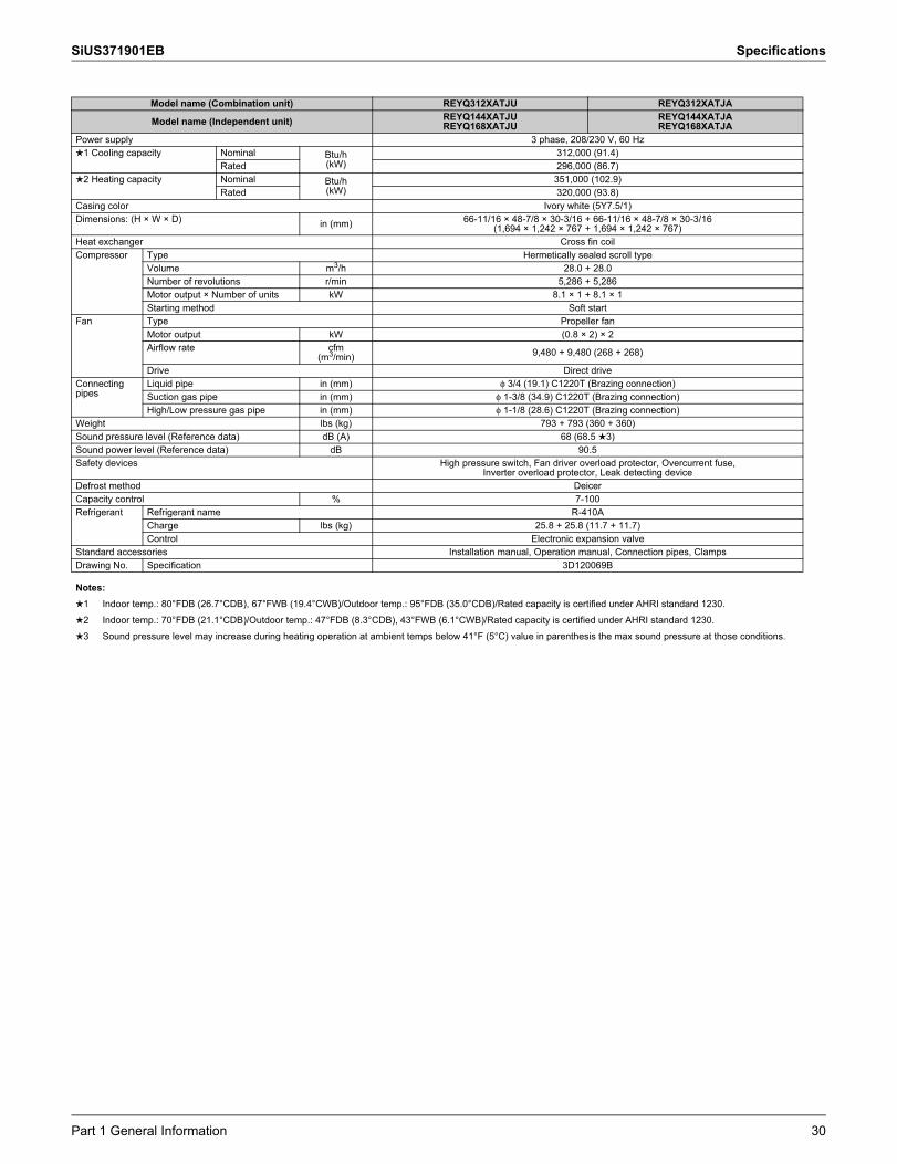
Model name (Combination unit) REYQ312XATJU REYQ312XATJA
Model name (Independent unit) REYQ144XATJUREYQ168XATJU
REYQ144XATJAREYQ168XATJA
Power supply 3 phase, 208/230 V, 60 Hz1 Cooling capacity Nominal Btu/h
(kW)312,000 (91.4)
Rated 296,000 (86.7)2 Heating capacity Nominal Btu/h
(kW)351,000 (102.9)
Rated 320,000 (93.8)Casing color Ivory white (5Y7.5/1)Dimensions: (H × W × D) in (mm) 66-11/16 × 48-7/8 × 30-3/16 + 66-11/16 × 48-7/8 × 30-3/16
(1,694 × 1,242 × 767 + 1,694 × 1,242 × 767)Heat exchanger Cross fin coilCompressor Type Hermetically sealed scroll type
Volume m3/h 28.0 + 28.0Number of revolutions r/min 5,286 + 5,286Motor output × Number of units kW 8.1 × 1 + 8.1 × 1Starting method Soft start
Fan Type Propeller fanMotor output kW (0.8 × 2) × 2Airflow rate cfm
(m3/min) 9,480 + 9,480 (268 + 268)
Drive Direct driveConnecting pipes
Liquid pipe in (mm) φ 3/4 (19.1) C1220T (Brazing connection)Suction gas pipe in (mm) φ 1-3/8 (34.9) C1220T (Brazing connection)High/Low pressure gas pipe in (mm) φ 1-1/8 (28.6) C1220T (Brazing connection)
Weight lbs (kg) 793 + 793 (360 + 360)Sound pressure level (Reference data) dB (A) 68 (68.5 3)Sound power level (Reference data) dB 90.5Safety devices High pressure switch, Fan driver overload protector, Overcurrent fuse,
Inverter overload protector, Leak detecting deviceDefrost method DeicerCapacity control % 7-100Refrigerant Refrigerant name R-410A
Charge lbs (kg) 25.8 + 25.8 (11.7 + 11.7)Control Electronic expansion valve
Standard accessories Installation manual, Operation manual, Connection pipes, ClampsDrawing No. Specification 3D120069B
Notes:1 Indoor temp.: 80°FDB (26.7°CDB), 67°FWB (19.4°CWB)/Outdoor temp.: 95°FDB (35.0°CDB)/Rated capacity is certified under AHRI standard 1230.2 Indoor temp.: 70°FDB (21.1°CDB)/Outdoor temp.: 47°FDB (8.3°CDB), 43°FWB (6.1°CWB)/Rated capacity is certified under AHRI standard 1230.3 Sound pressure level may increase during heating operation at ambient temps below 41°F (5°C) value in parenthesis the max sound pressure at those conditions.
Part 1 General Information 30

Specifications SiUS371901EB
Model name (Combination unit) REYQ336XATJU REYQ336XATJA
Model name (Independent unit) REYQ168XATJUREYQ168XATJU
REYQ168XATJAREYQ168XATJA
Power supply 3 phase, 208/230 V, 60 Hz1 Cooling capacity Nominal Btu/h
(kW)336,000 (98.5)
Rated 320,000 (93.8)2 Heating capacity Nominal Btu/h
(kW)378,000 (110.8)
Rated 338,000 (99.1)Casing color Ivory white (5Y7.5/1)Dimensions: (H × W × D) in (mm) 66-11/16 × 48-7/8 × 30-3/16 + 66-11/16 × 48-7/8 × 30-3/16
(1,694 × 1,242 × 767 + 1,694 × 1,242 × 767)Heat exchanger Cross fin coilCompressor Type Hermetically sealed scroll type
Volume m3/h 30.0 + 30.0Number of revolutions r/min 5,664 + 5,664Motor output × Number of units kW 8.7 × 1 + 8.7 × 1Starting method Soft start
Fan Type Propeller fanMotor output kW (0.8 × 2) × 2Airflow rate cfm
(m3/min) 9,480 + 9,480 (268 + 268)
Drive Direct driveConnecting pipes
Liquid pipe in (mm) φ 3/4 (19.1) C1220T (Brazing connection)Suction gas pipe in (mm) φ 1-3/8 (34.9) C1220T (Brazing connection)High/Low pressure gas pipe in (mm) φ 1-1/8 (28.6) C1220T (Brazing connection)
Weight lbs (kg) 793 + 793 (360 + 360)Sound pressure level (Reference data) dB (A) 68 (68.5 3)Sound power level (Reference data) dB 91Safety devices High pressure switch, Fan driver overload protector, Overcurrent fuse,
Inverter overload protector, Leak detecting deviceDefrost method DeicerCapacity control % 6-100Refrigerant Refrigerant name R-410A
Charge lbs (kg) 25.8 + 25.8 (11.7 + 11.7)Control Electronic expansion valve
Standard accessories Installation manual, Operation manual, Connection pipes, ClampsDrawing No. Specification 3D120069B
Notes:1 Indoor temp.: 80°FDB (26.7°CDB), 67°FWB (19.4°CWB)/Outdoor temp.: 95°FDB (35.0°CDB)/Rated capacity is certified under AHRI standard 1230.2 Indoor temp.: 70°FDB (21.1°CDB)/Outdoor temp.: 47°FDB (8.3°CDB), 43°FWB (6.1°CWB)/Rated capacity is certified under AHRI standard 1230.3 Sound pressure level may increase during heating operation at ambient temps below 41°F (5°C) value in parenthesis the max sound pressure at those conditions.
31 Part 1 General Information

SiUS371901EB Specifications
Model name (Combination unit) REYQ360XATJU REYQ360XATJA
Model name (Independent unit)REYQ120XATJUREYQ120XATJUREYQ120XATJU
REYQ120XATJAREYQ120XATJAREYQ120XATJA
Power supply 3 phase, 208/230 V, 60 Hz1 Cooling capacity Nominal Btu/h
(kW)360,000 (105.5)
Rated 342,000 (100.2)2 Heating capacity Nominal Btu/h
(kW)405,000 (118.7)
Rated 376,000 (110.2)Casing color Ivory white (5Y7.5/1)Dimensions: (H × W × D) in (mm) 66-11/16 × 48-7/8 × 30-3/16 + 66-11/16 × 48-7/8 × 30-3/16 + 66-11/16 × 48-7/8 × 30-3/16
(1,694 × 1,242 × 767 + 1,694 × 1,242 × 767 + 1,694 × 1,242 × 767)Heat exchanger Cross fin coilCompressor Type Hermetically sealed scroll type
Volume m3/h 22.4 + 22.4 + 22.4Number of revolutions r/min 6,606 + 6,606 + 6,606Motor output × Number of units kW 6.9 × 1 + 6.9 × 1 + 6.9 × 1Starting method Soft start
Fan Type Propeller fanMotor output kW (0.8 × 2) × 3Airflow rate cfm
(m3/min) 7,989 + 7,989 + 7,989 (226 + 226 + 226)
Drive Direct driveConnecting pipes
Liquid pipe in (mm) φ 3/4 (19.1) C1220T (Brazing connection)Suction gas pipe in (mm) φ 1-5/8 (41.3) C1220T (Brazing connection)High/Low pressure gas pipe in (mm) φ 1-3/8 (34.9) C1220T (Brazing connection)
Weight lbs (kg) 727 + 727 + 727 (330 + 330 + 330)Sound pressure level (Reference data) dB (A) 66 (70 3)Sound power level (Reference data) dB 85.5Safety devices High pressure switch, Fan driver overload protector, Overcurrent fuse,
Inverter overload protector, Leak detecting deviceDefrost method DeicerCapacity control % 4-100Refrigerant Refrigerant name R-410A
Charge lbs (kg) 25.8 + 25.8 + 25.8 (11.7 + 11.7 + 11.7)Control Electronic expansion valve
Standard accessories Installation manual, Operation manual, Connection pipes, ClampsDrawing No. Specification 3D120070B
Notes:1 Indoor temp.: 80°FDB (26.7°CDB), 67°FWB (19.4°CWB)/Outdoor temp.: 95°FDB (35.0°CDB)/Rated capacity is certified under AHRI standard 1230.2 Indoor temp.: 70°FDB (21.1°CDB)/Outdoor temp.: 47°FDB (8.3°CDB), 43°FWB (6.1°CWB)/Rated capacity is certified under AHRI standard 1230.3 Sound pressure level may increase during heating operation at ambient temps below 41°F (5°C) value in parenthesis the max sound pressure at those conditions.
Part 1 General Information 32
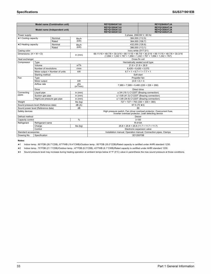
Specifications SiUS371901EB
Model name (Combination unit) REYQ384XATJU REYQ384XATJA
Model name (Independent unit)REYQ120XATJUREYQ120XATJUREYQ144XATJU
REYQ120XATJAREYQ120XATJAREYQ144XATJA
Power supply 3 phase, 208/230 V, 60 Hz1 Cooling capacity Nominal Btu/h
(kW)384,000 (112.5)
Rated 364,000 (106.7)2 Heating capacity Nominal Btu/h
(kW)432,000 (126.6)
Rated 386,000 (113.1)Casing color Ivory white (5Y7.5/1)Dimensions: (H × W × D) in (mm) 66-11/16 × 48-7/8 × 30-3/16 + 66-11/16 × 48-7/8 × 30-3/16 + 66-11/16 × 48-7/8 × 30-3/16
(1,694 × 1,242 × 767 + 1,694 × 1,242 × 767 + 1,694 × 1,242 × 767)Heat exchanger Cross fin coilCompressor Type Hermetically sealed scroll type
Volume m3/h 21.8 + 21.8 + 26.9Number of revolutions r/min 6,426 + 6,426 + 5,070Motor output × Number of units kW 6.7 × 1 + 6.7 × 1 + 7.7 × 1Starting method Soft start
Fan Type Propeller fanMotor output kW (0.8 × 2) × 3Airflow rate cfm
(m3/min) 7,989 + 7,989 + 9,480 (226 + 226 + 268)
Drive Direct driveConnecting pipes
Liquid pipe in (mm) φ 3/4 (19.1) C1220T (Brazing connection)Suction gas pipe in (mm) φ 1-5/8 (41.3) C1220T (Brazing connection)High/Low pressure gas pipe in (mm) φ 1-3/8 (34.9) C1220T (Brazing connection)
Weight lbs (kg) 727 + 727 + 793 (330 + 330 + 360)Sound pressure level (Reference data) dB (A) 67.5 (70 3)Sound power level (Reference data) dB 89Safety devices High pressure switch, Fan driver overload protector, Overcurrent fuse,
Inverter overload protector, Leak detecting deviceDefrost method DeicerCapacity control % 3-100Refrigerant Refrigerant name R-410A
Charge lbs (kg) 25.8 + 25.8 + 25.8 (11.7 + 11.7 + 11.7)Control Electronic expansion valve
Standard accessories Installation manual, Operation manual, Connection pipes, ClampsDrawing No. Specification 3D120070B
Notes:1 Indoor temp.: 80°FDB (26.7°CDB), 67°FWB (19.4°CWB)/Outdoor temp.: 95°FDB (35.0°CDB)/Rated capacity is certified under AHRI standard 1230.2 Indoor temp.: 70°FDB (21.1°CDB)/Outdoor temp.: 47°FDB (8.3°CDB), 43°FWB (6.1°CWB)/Rated capacity is certified under AHRI standard 1230.3 Sound pressure level may increase during heating operation at ambient temps below 41°F (5°C) value in parenthesis the max sound pressure at those conditions.
33 Part 1 General Information

SiUS371901EB Specifications
Model name (Combination unit) REYQ408XATJU REYQ408XATJA
Model name (Independent unit)REYQ120XATJUREYQ144XATJUREYQ144XATJU
REYQ120XATJAREYQ144XATJAREYQ144XATJA
Power supply 3 phase, 208/230 V, 60 Hz1 Cooling capacity Nominal Btu/h
(kW)408,000 (119.6)
Rated 388,000 (113.7)2 Heating capacity Nominal Btu/h
(kW)459,000 (134.5)
Rated 394,000 (115.5)Casing color Ivory white (5Y7.5/1)Dimensions: (H × W × D) in (mm) 66-11/16 × 48-7/8 × 30-3/16 + 66-11/16 × 48-7/8 × 30-3/16 + 66-11/16 × 48-7/8 × 30-3/16
(1,694 × 1,242 × 767 + 1,694 × 1,242 × 767 + 1,694 × 1,242 × 767)Heat exchanger Cross fin coilCompressor Type Hermetically sealed scroll type
Volume m3/h 20.9 + 23.7 + 23.7Number of revolutions r/min 6,162 + 4,470 + 4,470Motor output × Number of units kW 6.4 × 1 + 6.8 × 1 + 6.8 × 1Starting method Soft start
Fan Type Propeller fanMotor output kW (0.8 × 2) × 3Airflow rate cfm
(m3/min) 7,989 + 9,480 + 9,480 (226 + 268 + 268)
Drive Direct driveConnecting pipes
Liquid pipe in (mm) φ 3/4 (19.1) C1220T (Brazing connection)Suction gas pipe in (mm) φ 1-5/8 (41.3) C1220T (Brazing connection)High/Low pressure gas pipe in (mm) φ 1-3/8 (34.9) C1220T (Brazing connection)
Weight lbs (kg) 727 + 727 + 793 (330 + 330 + 360)Sound pressure level (Reference data) dB (A) 69 (70 3)Sound power level (Reference data) dB 90.5Safety devices High pressure switch, Fan driver overload protector, Overcurrent fuse,
Inverter overload protector, Leak detecting deviceDefrost method DeicerCapacity control % 3-100Refrigerant Refrigerant name R-410A
Charge lbs (kg) 25.8 + 25.8 + 25.8 (11.7 + 11.7 + 11.7)Control Electronic expansion valve
Standard accessories Installation manual, Operation manual, Connection pipes, ClampsDrawing No. Specification 3D120070B
Notes:1 Indoor temp.: 80°FDB (26.7°CDB), 67°FWB (19.4°CWB)/Outdoor temp.: 95°FDB (35.0°CDB)/Rated capacity is certified under AHRI standard 1230.2 Indoor temp.: 70°FDB (21.1°CDB)/Outdoor temp.: 47°FDB (8.3°CDB), 43°FWB (6.1°CWB)/Rated capacity is certified under AHRI standard 1230.3 Sound pressure level may increase during heating operation at ambient temps below 41°F (5°C) value in parenthesis the max sound pressure at those conditions.
Part 1 General Information 34

Specifications SiUS371901EB
Model name (Combination unit) REYQ432XATJU REYQ432XATJA
Model name (Independent unit)REYQ144XATJUREYQ144XATJUREYQ144XATJU
REYQ144XATJAREYQ144XATJAREYQ144XATJA
Power supply 3 phase, 208/230 V, 60 Hz1 Cooling capacity Nominal Btu/h
(kW)432,000 (126.6)
Rated 410,000 (120.2)2 Heating capacity Nominal Btu/h
(kW)486,000 (142.4)
Rated 405,000 (118.7)Casing color Ivory white (5Y7.5/1)Dimensions: (H × W × D) in (mm) 66-11/16 × 48-7/8 × 30-3/16 + 66-11/16 × 48-7/8 × 30-3/16 + 66-11/16 × 48-7/8 × 30-3/16
(1,694 × 1,242 × 767 + 1,694 × 1,242 × 767 + 1,694 × 1,242 × 767)Heat exchanger Cross fin coilCompressor Type Hermetically sealed scroll type
Volume m3/h 23.1 + 23.1 + 23.1Number of revolutions r/min 4,350 + 4,350 + 4,350Motor output × Number of units kW 6.6 × 1 + 6.6 × 1 + 6.6 × 1Starting method Soft start
Fan Type Propeller fanMotor output kW (0.8 × 2) × 3Airflow rate cfm
(m3/min) 9,480 + 9,480 + 9,480 (268 + 268 + 268)
Drive Direct driveConnecting pipes
Liquid pipe in (mm) φ 3/4 (19.1) C1220T (Brazing connection)Suction gas pipe in (mm) φ 1-5/8 (41.3) C1220T (Brazing connection)High/Low pressure gas pipe in (mm) φ 1-3/8 (34.9) C1220T (Brazing connection)
Weight lbs (kg) 727 + 727 + 793 (330 + 330 + 360)Sound pressure level (Reference data) dB (A) 70Sound power level (Reference data) dB 92Safety devices High pressure switch, Fan driver overload protector, Overcurrent fuse,
Inverter overload protector, Leak detecting deviceDefrost method DeicerCapacity control % 5-100Refrigerant Refrigerant name R-410A
Charge lbs (kg) 25.8 + 25.8 + 25.8 (11.7 + 11.7 + 11.7)Control Electronic expansion valve
Standard accessories Installation manual, Operation manual, Connection pipes, ClampsDrawing No. Specification 3D120070B
Notes:1 Indoor temp.: 80°FDB (26.7°CDB), 67°FWB (19.4°CWB)/Outdoor temp.: 95°FDB (35.0°CDB)/Rated capacity is certified under AHRI standard 1230.2 Indoor temp.: 70°FDB (21.1°CDB)/Outdoor temp.: 47°FDB (8.3°CDB), 43°FWB (6.1°CWB)/Rated capacity is certified under AHRI standard 1230.3 Sound pressure level may increase during heating operation at ambient temps below 41°F (5°C) value in parenthesis the max sound pressure at those conditions.
35 Part 1 General Information
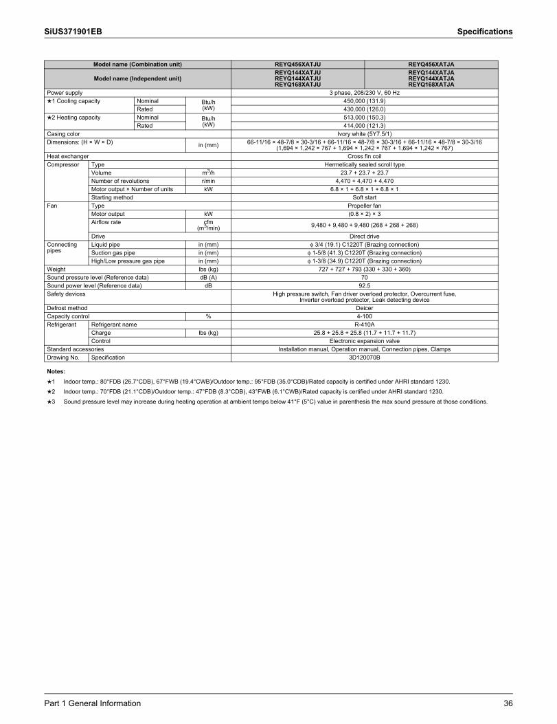
SiUS371901EB Specifications
Model name (Combination unit) REYQ456XATJU REYQ456XATJA
Model name (Independent unit)REYQ144XATJUREYQ144XATJUREYQ168XATJU
REYQ144XATJAREYQ144XATJAREYQ168XATJA
Power supply 3 phase, 208/230 V, 60 Hz1 Cooling capacity Nominal Btu/h
(kW)450,000 (131.9)
Rated 430,000 (126.0)2 Heating capacity Nominal Btu/h
(kW)513,000 (150.3)
Rated 414,000 (121.3)Casing color Ivory white (5Y7.5/1)Dimensions: (H × W × D) in (mm) 66-11/16 × 48-7/8 × 30-3/16 + 66-11/16 × 48-7/8 × 30-3/16 + 66-11/16 × 48-7/8 × 30-3/16
(1,694 × 1,242 × 767 + 1,694 × 1,242 × 767 + 1,694 × 1,242 × 767)Heat exchanger Cross fin coilCompressor Type Hermetically sealed scroll type
Volume m3/h 23.7 + 23.7 + 23.7Number of revolutions r/min 4,470 + 4,470 + 4,470Motor output × Number of units kW 6.8 × 1 + 6.8 × 1 + 6.8 × 1Starting method Soft start
Fan Type Propeller fanMotor output kW (0.8 × 2) × 3Airflow rate cfm
(m3/min) 9,480 + 9,480 + 9,480 (268 + 268 + 268)
Drive Direct driveConnecting pipes
Liquid pipe in (mm) φ 3/4 (19.1) C1220T (Brazing connection)Suction gas pipe in (mm) φ 1-5/8 (41.3) C1220T (Brazing connection)High/Low pressure gas pipe in (mm) φ 1-3/8 (34.9) C1220T (Brazing connection)
Weight lbs (kg) 727 + 727 + 793 (330 + 330 + 360)Sound pressure level (Reference data) dB (A) 70Sound power level (Reference data) dB 92.5Safety devices High pressure switch, Fan driver overload protector, Overcurrent fuse,
Inverter overload protector, Leak detecting deviceDefrost method DeicerCapacity control % 4-100Refrigerant Refrigerant name R-410A
Charge lbs (kg) 25.8 + 25.8 + 25.8 (11.7 + 11.7 + 11.7)Control Electronic expansion valve
Standard accessories Installation manual, Operation manual, Connection pipes, ClampsDrawing No. Specification 3D120070B
Notes:1 Indoor temp.: 80°FDB (26.7°CDB), 67°FWB (19.4°CWB)/Outdoor temp.: 95°FDB (35.0°CDB)/Rated capacity is certified under AHRI standard 1230.2 Indoor temp.: 70°FDB (21.1°CDB)/Outdoor temp.: 47°FDB (8.3°CDB), 43°FWB (6.1°CWB)/Rated capacity is certified under AHRI standard 1230.3 Sound pressure level may increase during heating operation at ambient temps below 41°F (5°C) value in parenthesis the max sound pressure at those conditions.
Part 1 General Information 36
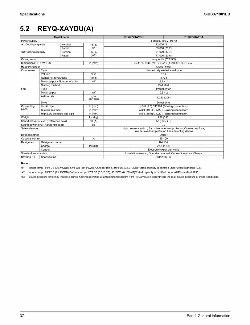
Specifications SiUS371901EB
5.2 REYQ-XAYDU(A)Model name REYQ72XAYDU REYQ72XAYDA
Power supply 3 phase, 460 V, 60 Hz1 Cooling capacity Nominal Btu/h
(kW)72,000 (21.1)
Rated 69,000 (20.2)2 Heating capacity Nominal Btu/h
(kW)81,000 (23.7)
Rated 77,000 (22.6)Casing color Ivory white (5Y7.5/1)Dimensions: (H × W × D) in (mm) 66-11/16 × 48-7/8 × 30-3/16 (1,694 × 1,242 × 767)Heat exchanger Cross fin coilCompressor Type Hermetically sealed scroll type
Volume m3/h 12.7Number of revolutions r/min 3,738Motor output × Number of units kW 3.9 × 1Starting method Soft start
Fan Type Propeller fanMotor output kW 0.6 × 2Airflow rate cfm
(m3/min) 7,283 (206)
Drive Direct driveConnecting pipes
Liquid pipe in (mm) φ 3/8 (9.5) C1220T (Brazing connection)Suction gas pipe in (mm) φ 3/4 (19.1) C1220T (Brazing connection)High/Low pressure gas pipe in (mm) φ 5/8 (15.9) C1220T (Brazing connection)
Weight lbs (kg) 727 (330)Sound pressure level (Reference data) dB (A) 58 (63.5 3)Sound power level (Reference data) dB 79Safety devices High pressure switch, Fan driver overload protector, Overcurrent fuse,
Inverter overload protector, Leak detecting deviceDefrost method DeicerCapacity control % 15-100Refrigerant Refrigerant name R-410A
Charge lbs (kg) 25.8 (11.7)Control Electronic expansion valve
Standard accessories Installation manual, Operation manual, Connection pipes, ClampsDrawing No. Specification 3D120071C
Notes:1 Indoor temp.: 80°FDB (26.7°CDB), 67°FWB (19.4°CWB)/Outdoor temp.: 95°FDB (35.0°CDB)/Rated capacity is certified under AHRI standard 1230.2 Indoor temp.: 70°FDB (21.1°CDB)/Outdoor temp.: 47°FDB (8.3°CDB), 43°FWB (6.1°CWB)/Rated capacity is certified under AHRI standard 1230.3 Sound pressure level may increase during heating operation at ambient temps below 41°F (5°C) value in parenthesis the max sound pressure at those conditions.
37 Part 1 General Information

SiUS371901EB Specifications
Model name REYQ96XAYDU REYQ96XAYDAPower supply 3 phase, 460 V, 60 Hz1 Cooling capacity Nominal Btu/h
(kW)96,000 (28.1)
Rated 92,000 (27.0)2 Heating capacity Nominal Btu/h
(kW)108,000 (31.7)
Rated 103,000 (30.2)Casing color Ivory white (5Y7.5/1)Dimensions: (H × W × D) in (mm) 66-11/16 × 48-7/8 × 30-3/16 (1,694 × 1,242 × 767)Heat exchanger Cross fin coilCompressor Type Hermetically sealed scroll type
Volume m3/h 17.4Number of revolutions r/min 5,142Motor output × Number of units kW 5.4 × 1Starting method Soft start
Fan Type Propeller fanMotor output kW 0.6 × 2Airflow rate cfm
(m3/min) 7,989 (226)
Drive Direct driveConnecting pipes
Liquid pipe in (mm) φ 3/8 (9.5) C1220T (Brazing connection)Suction gas pipe in (mm) φ 7/8 (22.2) C1220T (Brazing connection)High/Low pressure gas pipe in (mm) φ 3/4 (19.1) C1220T (Brazing connection)
Weight lbs (kg) 727 (330)Sound pressure level (Reference data) dB (A) 61 (64.5 3)Sound power level (Reference data) dB 80Safety devices High pressure switch, Fan driver overload protector, Overcurrent fuse,
Inverter overload protector, Leak detecting deviceDefrost method DeicerCapacity control % 13-100Refrigerant Refrigerant name R-410A
Charge lbs (kg) 25.8 (11.7)Control Electronic expansion valve
Standard accessories Installation manual, Operation manual, Connection pipes, ClampsDrawing No. Specification 3D120071C
Notes:1 Indoor temp.: 80°FDB (26.7°CDB), 67°FWB (19.4°CWB)/Outdoor temp.: 95°FDB (35.0°CDB)/Rated capacity is certified under AHRI standard 1230.2 Indoor temp.: 70°FDB (21.1°CDB)/Outdoor temp.: 47°FDB (8.3°CDB), 43°FWB (6.1°CWB)/Rated capacity is certified under AHRI standard 1230.3 Sound pressure level may increase during heating operation at ambient temps below 41°F (5°C) value in parenthesis the max sound pressure at those conditions.
Part 1 General Information 38

Specifications SiUS371901EB
Model name REYQ120XAYDU REYQ120XAYDAPower supply 3 phase, 460 V, 60 Hz1 Cooling capacity Nominal Btu/h
(kW)120,000 (35.2)
Rated 114,000 (33.4)2 Heating capacity Nominal Btu/h
(kW)135,000 (39.6)
Rated 129,000 (37.8)Casing color Ivory white (5Y7.5/1)Dimensions: (H × W × D) in (mm) 66-11/16 × 48-7/8 × 30-3/16 (1,694 × 1,242 × 767)Heat exchanger Cross fin coilCompressor Type Hermetically sealed scroll type
Volume m3/h 23.4Number of revolutions r/min 6,888Motor output × Number of units kW 7.2 × 1Starting method Soft start
Fan Type Propeller fanMotor output kW 0.6 × 2Airflow rate cfm
(m3/min) 7,989 (226)
Drive Direct driveConnecting pipes
Liquid pipe in (mm) φ 1/2 (12.7) C1220T (Brazing connection)Suction gas pipe in (mm) φ 1-1/8 (28.6) C1220T (Brazing connection)High/Low pressure gas pipe in (mm) φ 3/4 (19.1) C1220T (Brazing connection)
Weight lbs (kg) 727 (330)Sound pressure level (Reference data) dB (A) 61 (65 3)Sound power level (Reference data) dB 80.5Safety devices High pressure switch, Fan driver overload protector, Overcurrent fuse,
Inverter overload protector, Leak detecting deviceDefrost method DeicerCapacity control % 11-100Refrigerant Refrigerant name R-410A
Charge lbs (kg) 25.8 (11.7)Control Electronic expansion valve
Standard accessories Installation manual, Operation manual, Connection pipes, ClampsDrawing No. Specification 3D120071C
Notes:1 Indoor temp.: 80°FDB (26.7°CDB), 67°FWB (19.4°CWB)/Outdoor temp.: 95°FDB (35.0°CDB)/Rated capacity is certified under AHRI standard 1230.2 Indoor temp.: 70°FDB (21.1°CDB)/Outdoor temp.: 47°FDB (8.3°CDB), 43°FWB (6.1°CWB)/Rated capacity is certified under AHRI standard 1230.3 Sound pressure level may increase during heating operation at ambient temps below 41°F (5°C) value in parenthesis the max sound pressure at those conditions.
39 Part 1 General Information

SiUS371901EB Specifications
Model name REYQ144XAYDU REYQ144XAYDAPower supply 3 phase, 460 V, 60 Hz1 Cooling capacity Nominal Btu/h
(kW)144,000 (42.2)
Rated 138,000 (40.4)2 Heating capacity Nominal Btu/h
(kW)162,000 (47.5)
Rated 154,000 (45.1)Casing color Ivory white (5Y7.5/1)Dimensions: (H × W × D) in (mm) 66-11/16 × 48-7/8 × 30-3/16 (1,694 × 1,242 × 767)Heat exchanger Cross fin coilCompressor Type Hermetically sealed scroll type
Volume m3/h 27.7Number of revolutions r/min 5,214Motor output × Number of units kW 8.0 × 1Starting method Soft start
Fan Type Propeller fanMotor output kW 0.6 × 2Airflow rate cfm
(m3/min) 9,480 (268)
Drive Direct driveConnecting pipes
Liquid pipe in (mm) φ 1/2 (12.7) C1220T (Brazing connection)Suction gas pipe in (mm) φ 1-1/8 (28.6) C1220T (Brazing connection)High/Low pressure gas pipe in (mm) φ 7/8 (22.2) C1220T (Brazing connection)
Weight lbs (kg) 793 (360)Sound pressure level (Reference data) dB (A) 65Sound power level (Reference data) dB 87Safety devices High pressure switch, Fan driver overload protector, Overcurrent fuse,
Inverter overload protector, Leak detecting deviceDefrost method DeicerCapacity control % 14-100Refrigerant Refrigerant name R-410A
Charge lbs (kg) 25.8 (11.7)Control Electronic expansion valve
Standard accessories Installation manual, Operation manual, Connection pipes, ClampsDrawing No. Specification 3D120071C
Notes:1 Indoor temp.: 80°FDB (26.7°CDB), 67°FWB (19.4°CWB)/Outdoor temp.: 95°FDB (35.0°CDB)/Rated capacity is certified under AHRI standard 1230.2 Indoor temp.: 70°FDB (21.1°CDB)/Outdoor temp.: 47°FDB (8.3°CDB), 43°FWB (6.1°CWB)/Rated capacity is certified under AHRI standard 1230.3 Sound pressure level may increase during heating operation at ambient temps below 41°F (5°C) value in parenthesis the max sound pressure at those conditions.
Part 1 General Information 40

Specifications SiUS371901EB
Model name REYQ168XAYDU REYQ168XAYDAPower supply 3 phase, 460 V, 60 Hz1 Cooling capacity Nominal Btu/h
(kW)168,000 (49.2)
Rated 160,000 (46.9)2 Heating capacity Nominal Btu/h
(kW)188,000 (55.1)
Rated 180,000 (52.7)Casing color Ivory white (5Y7.5/1)Dimensions: (H × W × D) in (mm) 66-11/16 × 48-7/8 × 30-3/16 (1,694 × 1,242 × 767)Heat exchanger Cross fin coilCompressor Type Hermetically sealed scroll type
Volume m3/h 33.6Number of revolutions r/min 6,330Motor output × Number of units kW 9.7 × 1Starting method Soft start
Fan Type Propeller fanMotor output kW 0.6 × 2Airflow rate cfm
(m3/min) 9,480 (268)
Drive Direct driveConnecting pipes
Liquid pipe in (mm) φ 5/8 (15.9) C1220T (Brazing connection)Suction gas pipe in (mm) φ 1-1/8 (28.6) C1220T (Brazing connection)High/Low pressure gas pipe in (mm) φ 7/8 (22.2) C1220T (Brazing connection)
Weight lbs (kg) 793 (360)Sound pressure level (Reference data) dB (A) 65 (65.5 3)Sound power level (Reference data) dB 88Safety devices High pressure switch, Fan driver overload protector, Overcurrent fuse,
Inverter overload protector, Leak detecting deviceDefrost method DeicerCapacity control % 12-100Refrigerant Refrigerant name R-410A
Charge lbs (kg) 25.8 (11.7)Control Electronic expansion valve
Standard accessories Installation manual, Operation manual, Connection pipes, ClampsDrawing No. Specification 3D120071C
Notes:1 Indoor temp.: 80°FDB (26.7°CDB), 67°FWB (19.4°CWB)/Outdoor temp.: 95°FDB (35.0°CDB)/Rated capacity is certified under AHRI standard 1230.2 Indoor temp.: 70°FDB (21.1°CDB)/Outdoor temp.: 47°FDB (8.3°CDB), 43°FWB (6.1°CWB)/Rated capacity is certified under AHRI standard 1230.3 Sound pressure level may increase during heating operation at ambient temps below 41°F (5°C) value in parenthesis the max sound pressure at those conditions.
41 Part 1 General Information

SiUS371901EB Specifications
Model name (Combination unit) REYQ192XAYDU REYQ192XAYDA
Model name (Independent unit) REYQ96XAYDUREYQ96XAYDU
REYQ96XAYDAREYQ96XAYDA
Power supply 3 phase, 460 V, 60 Hz1 Cooling capacity Nominal Btu/h
(kW)192,000 (56.3)
Rated 184,000 (53.9)2 Heating capacity Nominal Btu/h
(kW)216,000 (63.3)
Rated 206,000 (60.4)Casing color Ivory white (5Y7.5/1)Dimensions: (H × W × D) in (mm) 66-11/16 × 48-7/8 × 30-3/16 + 66-11/16 × 48-7/8 × 30-3/16
(1,694 × 1,242 × 767 + 1,694 × 1,242 × 767)Heat exchanger Cross fin coilCompressor Type Hermetically sealed scroll type
Volume m3/h 17.7 + 17.7Number of revolutions r/min 5,214 + 5,214Motor output × Number of units kW 5.4 × 1 + 5.4 × 1Starting method Soft start
Fan Type Propeller fanMotor output kW (0.6 × 2) × 2Airflow rate cfm
(m3/min) 7,989 + 7,989 (226 + 226)
Drive Direct driveConnecting pipes
Liquid pipe in (mm) φ 5/8 (15.9) C1220T (Brazing connection)Suction gas pipe in (mm) φ 1-1/8 (28.6) C1220T (Brazing connection)High/Low pressure gas pipe in (mm) φ 1-1/8 (28.6) C1220T (Brazing connection)
Weight lbs (kg) 727 + 727 (330 + 330)Sound pressure level (Reference data) dB (A) 64 (67.5 3)Sound power level (Reference data) dB 83Safety devices High pressure switch, Fan driver overload protector, Overcurrent fuse,
Inverter overload protector, Leak detecting deviceDefrost method DeicerCapacity control % 6-100Refrigerant Refrigerant name R-410A
Charge lbs (kg) 25.8 + 25.8 (11.7 + 11.7)Control Electronic expansion valve
Standard accessories Installation manual, Operation manual, Connection pipes, ClampsDrawing No. Specification 3D120072B
Notes:1 Indoor temp.: 80°FDB (26.7°CDB), 67°FWB (19.4°CWB)/Outdoor temp.: 95°FDB (35.0°CDB)/Rated capacity is certified under AHRI standard 1230.2 Indoor temp.: 70°FDB (21.1°CDB)/Outdoor temp.: 47°FDB (8.3°CDB), 43°FWB (6.1°CWB)/Rated capacity is certified under AHRI standard 1230.3 Sound pressure level may increase during heating operation at ambient temps below 41°F (5°C) value in parenthesis the max sound pressure at those conditions.
Part 1 General Information 42

Specifications SiUS371901EB
Model name (Combination unit) REYQ216XAYDU REYQ216XAYDA
Model name (Independent unit) REYQ96XAYDUREYQ120XAYDU
REYQ96XAYDAREYQ120XAYDA
Power supply 3 phase, 460 V, 60 Hz1 Cooling capacity Nominal Btu/h
(kW)216,000 (63.3)
Rated 206,000 (60.4)2 Heating capacity Nominal Btu/h
(kW)243,000 (71.2)
Rated 232,000 (68.0)Casing color Ivory white (5Y7.5/1)Dimensions: (H × W × D) in (mm) 66-11/16 × 48-7/8 × 30-3/16 + 66-11/16 × 48-7/8 × 30-3/16
(1,694 × 1,242 × 767 + 1,694 × 1,242 × 767)Heat exchanger Cross fin coilCompressor Type Hermetically sealed scroll type
Volume m3/h 20.3 + 20.3Number of revolutions r/min 5,994 + 5,994Motor output × Number of units kW 6.2 × 1 + 6.2 × 1Starting method Soft start
Fan Type Propeller fanMotor output kW (0.6 × 2) × 2Airflow rate cfm
(m3/min) 7,989 + 7,989 (226 + 226)
Drive Direct driveConnecting pipes
Liquid pipe in (mm) φ 5/8 (15.9) C1220T (Brazing connection)Suction gas pipe in (mm) φ 1-1/8 (28.6) C1220T (Brazing connection)High/Low pressure gas pipe in (mm) φ 1-1/8 (28.6) C1220T (Brazing connection)
Weight lbs (kg) 727 + 727 (330 + 330)Sound pressure level (Reference data) dB (A) 64 (68 3)Sound power level (Reference data) dB 83.5Safety devices High pressure switch, Fan driver overload protector, Overcurrent fuse,
Inverter overload protector, Leak detecting deviceDefrost method DeicerCapacity control % 6-100Refrigerant Refrigerant name R-410A
Charge lbs (kg) 25.8 + 25.8 (11.7 + 11.7)Control Electronic expansion valve
Standard accessories Installation manual, Operation manual, Connection pipes, ClampsDrawing No. Specification 3D120072B
Notes:1 Indoor temp.: 80°FDB (26.7°CDB), 67°FWB (19.4°CWB)/Outdoor temp.: 95°FDB (35.0°CDB)/Rated capacity is certified under AHRI standard 1230.2 Indoor temp.: 70°FDB (21.1°CDB)/Outdoor temp.: 47°FDB (8.3°CDB), 43°FWB (6.1°CWB)/Rated capacity is certified under AHRI standard 1230.3 Sound pressure level may increase during heating operation at ambient temps below 41°F (5°C) value in parenthesis the max sound pressure at those conditions.
43 Part 1 General Information

SiUS371901EB Specifications
Model name (Combination unit) REYQ240XAYDU REYQ240XAYDA
Model name (Independent unit) REYQ120XAYDUREYQ120XAYDU
REYQ120XAYDAREYQ120XAYDA
Power supply 3 phase, 460 V, 60 Hz1 Cooling capacity Nominal Btu/h
(kW)240,000 (70.3)
Rated 228,000 (66.8)2 Heating capacity Nominal Btu/h
(kW)270,000 (79.1)
Rated 256,000 (75.0)Casing color Ivory white (5Y7.5/1)Dimensions: (H × W × D) in (mm) 66-11/16 × 48-7/8 × 30-3/16 + 66-11/16 × 48-7/8 × 30-3/16
(1,694 × 1,242 × 767 + 1,694 × 1,242 × 767)Heat exchanger Cross fin coilCompressor Type Hermetically sealed scroll type
Volume m3/h 22.7 + 22.7Number of revolutions r/min 6,702 + 6,702Motor output × Number of units kW 7.0 × 1 + 7.0 × 1Starting method Soft start
Fan Type Propeller fanMotor output kW (0.6 × 2) × 2Airflow rate cfm
(m3/min) 7,989 + 7,989 (226 + 226)
Drive Direct driveConnecting pipes
Liquid pipe in (mm) φ 5/8 (15.9) C1220T (Brazing connection)Suction gas pipe in (mm) φ 1-3/8 (34.9) C1220T (Brazing connection)High/Low pressure gas pipe in (mm) φ 1-1/8 (28.6) C1220T (Brazing connection)
Weight lbs (kg) 727 + 727 (330 + 330)Sound pressure level (Reference data) dB (A) 64 (68 3)Sound power level (Reference data) dB 83.5Safety devices High pressure switch, Fan driver overload protector, Overcurrent fuse,
Inverter overload protector, Leak detecting deviceDefrost method DeicerCapacity control % 5-100Refrigerant Refrigerant name R-410A
Charge lbs (kg) 25.8 + 25.8 (11.7 + 11.7)Control Electronic expansion valve
Standard accessories Installation manual, Operation manual, Connection pipes, ClampsDrawing No. Specification 3D120072B
Notes:1 Indoor temp.: 80°FDB (26.7°CDB), 67°FWB (19.4°CWB)/Outdoor temp.: 95°FDB (35.0°CDB)/Rated capacity is certified under AHRI standard 1230.2 Indoor temp.: 70°FDB (21.1°CDB)/Outdoor temp.: 47°FDB (8.3°CDB), 43°FWB (6.1°CWB)/Rated capacity is certified under AHRI standard 1230.3 Sound pressure level may increase during heating operation at ambient temps below 41°F (5°C) value in parenthesis the max sound pressure at those conditions.
Part 1 General Information 44

Specifications SiUS371901EB
Model name (Combination unit) REYQ264XAYDU REYQ264XAYDA
Model name (Independent unit) REYQ120XAYDUREYQ144XAYDU
REYQ120XAYDAREYQ144XAYDA
Power supply 3 phase, 460 V, 60 Hz1 Cooling capacity Nominal Btu/h
(kW)264,000 (77.4)
Rated 252,000 (73.9)2 Heating capacity Nominal Btu/h
(kW)297,000 (87.0)
Rated 282,000 (82.6)Casing color Ivory white (5Y7.5/1)Dimensions: (H × W × D) in (mm) 66-11/16 × 48-7/8 × 30-3/16 + 66-11/16 × 48-7/8 × 30-3/16
(1,694 × 1,242 × 767 + 1,694 × 1,242 × 767)Heat exchanger Cross fin coilCompressor Type Hermetically sealed scroll type
Volume m3/h 22.0 + 27.7Number of revolutions r/min 6,504 + 5,214Motor output × Number of units kW 6.8 × 1 + 8.0 × 1Starting method Soft start
Fan Type Propeller fanMotor output kW (0.6 × 2) × 2Airflow rate cfm
(m3/min) 7,989 + 9,480 (226 + 268)
Drive Direct driveConnecting pipes
Liquid pipe in (mm) φ 3/4 (19.1) C1220T (Brazing connection)Suction gas pipe in (mm) φ 1-3/8 (34.9) C1220T (Brazing connection)High/Low pressure gas pipe in (mm) φ 1-1/8 (28.6) C1220T (Brazing connection)
Weight lbs (kg) 727 + 793 (330 + 360)Sound pressure level (Reference data) dB (A) 66.5 (58 3)Sound power level (Reference data) dB 88Safety devices High pressure switch, Fan driver overload protector, Overcurrent fuse,
Inverter overload protector, Leak detecting deviceDefrost method DeicerCapacity control % 5-100Refrigerant Refrigerant name R-410A
Charge lbs (kg) 25.8 + 25.8 (11.7 + 11.7)Control Electronic expansion valve
Standard accessories Installation manual, Operation manual, Connection pipes, ClampsDrawing No. Specification 3D120072B
Notes:1 Indoor temp.: 80°FDB (26.7°CDB), 67°FWB (19.4°CWB)/Outdoor temp.: 95°FDB (35.0°CDB)/Rated capacity is certified under AHRI standard 1230.2 Indoor temp.: 70°FDB (21.1°CDB)/Outdoor temp.: 47°FDB (8.3°CDB), 43°FWB (6.1°CWB)/Rated capacity is certified under AHRI standard 1230.3 Sound pressure level may increase during heating operation at ambient temps below 41°F (5°C) value in parenthesis the max sound pressure at those conditions.
45 Part 1 General Information

SiUS371901EB Specifications
Model name (Combination unit) REYQ288XAYDU REYQ288XAYDA
Model name (Independent unit) REYQ144XAYDUREYQ144XAYDU
REYQ144XAYDAREYQ144XAYDA
Power supply 3 phase, 460 V, 60 Hz1 Cooling capacity Nominal Btu/h
(kW)288,000 (84.4)
Rated 274,000 (80.3)2 Heating capacity Nominal Btu/h
(kW)324,000 (95.0)
Rated 294,000 (86.1)Casing color Ivory white (5Y7.5/1)Dimensions: (H × W × D) in (mm) 66-11/16 × 48-7/8 × 30-3/16 + 66-11/16 × 48-7/8 × 30-3/16
(1,694 × 1,242 × 767 + 1,694 × 1,242 × 767)Heat exchanger Cross fin coilCompressor Type Hermetically sealed scroll type
Volume m3/h 25.4 + 25.4Number of revolutions r/min 4,794 + 4,794Motor output × Number of units kW 7.3 × 1 + 7.3 × 1Starting method Soft start
Fan Type Propeller fanMotor output kW (0.6 × 2) × 2Airflow rate cfm
(m3/min) 9,480 + 9,480 (268 + 268)
Drive Direct driveConnecting pipes
Liquid pipe in (mm) φ 3/4 (19.1) C1220T (Brazing connection)Suction gas pipe in (mm) φ 1-3/8 (34.9) C1220T (Brazing connection)High/Low pressure gas pipe in (mm) φ 1-1/8 (28.6) C1220T (Brazing connection)
Weight lbs (kg) 793 + 793 (360 + 360)Sound pressure level (Reference data) dB (A) 68Sound power level (Reference data) dB 90Safety devices High pressure switch, Fan driver overload protector, Overcurrent fuse,
Inverter overload protector, Leak detecting deviceDefrost method DeicerCapacity control % 7-100Refrigerant Refrigerant name R-410A
Charge lbs (kg) 25.8 + 25.8 (11.7 + 11.7)Control Electronic expansion valve
Standard accessories Installation manual, Operation manual, Connection pipes, ClampsDrawing No. Specification 3D120072B
Notes:1 Indoor temp.: 80°FDB (26.7°CDB), 67°FWB (19.4°CWB)/Outdoor temp.: 95°FDB (35.0°CDB)/Rated capacity is certified under AHRI standard 1230.2 Indoor temp.: 70°FDB (21.1°CDB)/Outdoor temp.: 47°FDB (8.3°CDB), 43°FWB (6.1°CWB)/Rated capacity is certified under AHRI standard 1230.3 Sound pressure level may increase during heating operation at ambient temps below 41°F (5°C) value in parenthesis the max sound pressure at those conditions.
Part 1 General Information 46
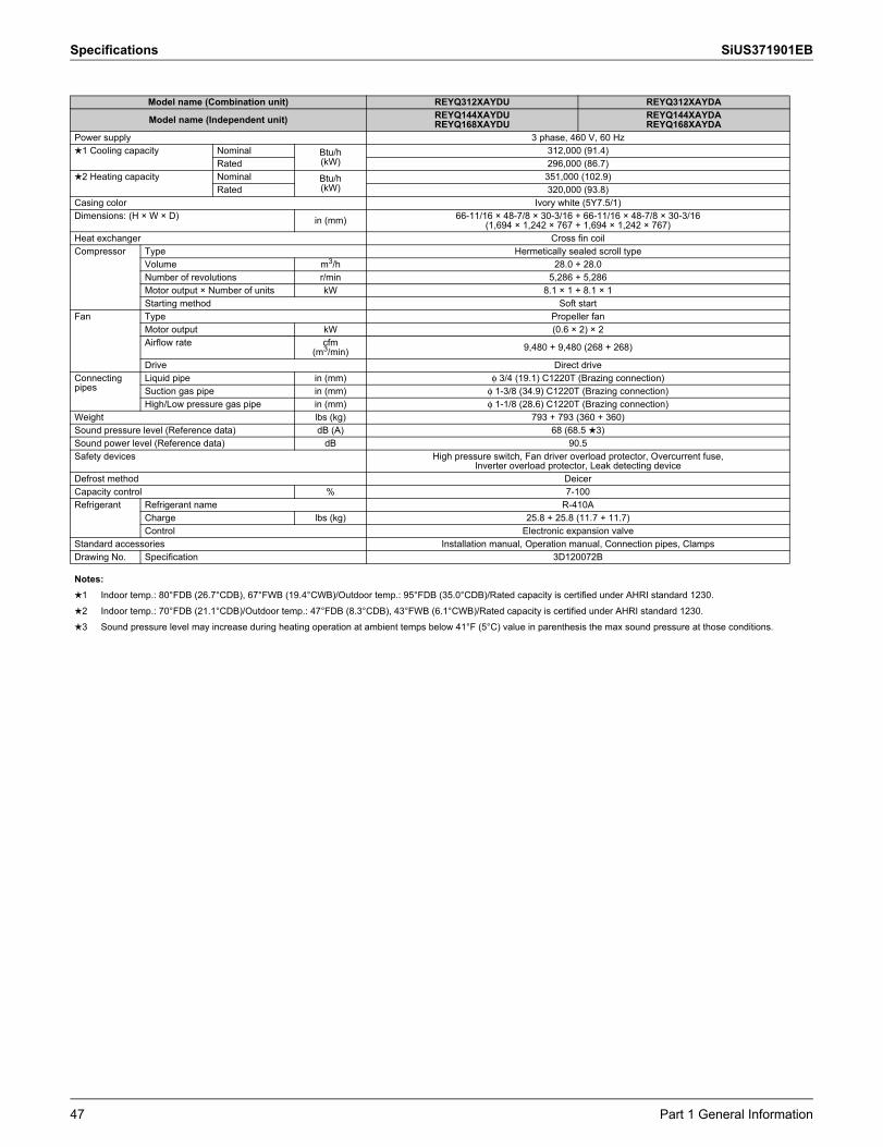
Specifications SiUS371901EB
Model name (Combination unit) REYQ312XAYDU REYQ312XAYDA
Model name (Independent unit) REYQ144XAYDUREYQ168XAYDU
REYQ144XAYDAREYQ168XAYDA
Power supply 3 phase, 460 V, 60 Hz1 Cooling capacity Nominal Btu/h
(kW)312,000 (91.4)
Rated 296,000 (86.7)2 Heating capacity Nominal Btu/h
(kW)351,000 (102.9)
Rated 320,000 (93.8)Casing color Ivory white (5Y7.5/1)Dimensions: (H × W × D) in (mm) 66-11/16 × 48-7/8 × 30-3/16 + 66-11/16 × 48-7/8 × 30-3/16
(1,694 × 1,242 × 767 + 1,694 × 1,242 × 767)Heat exchanger Cross fin coilCompressor Type Hermetically sealed scroll type
Volume m3/h 28.0 + 28.0Number of revolutions r/min 5,286 + 5,286Motor output × Number of units kW 8.1 × 1 + 8.1 × 1Starting method Soft start
Fan Type Propeller fanMotor output kW (0.6 × 2) × 2Airflow rate cfm
(m3/min) 9,480 + 9,480 (268 + 268)
Drive Direct driveConnecting pipes
Liquid pipe in (mm) φ 3/4 (19.1) C1220T (Brazing connection)Suction gas pipe in (mm) φ 1-3/8 (34.9) C1220T (Brazing connection)High/Low pressure gas pipe in (mm) φ 1-1/8 (28.6) C1220T (Brazing connection)
Weight lbs (kg) 793 + 793 (360 + 360)Sound pressure level (Reference data) dB (A) 68 (68.5 3)Sound power level (Reference data) dB 90.5Safety devices High pressure switch, Fan driver overload protector, Overcurrent fuse,
Inverter overload protector, Leak detecting deviceDefrost method DeicerCapacity control % 7-100Refrigerant Refrigerant name R-410A
Charge lbs (kg) 25.8 + 25.8 (11.7 + 11.7)Control Electronic expansion valve
Standard accessories Installation manual, Operation manual, Connection pipes, ClampsDrawing No. Specification 3D120072B
Notes:1 Indoor temp.: 80°FDB (26.7°CDB), 67°FWB (19.4°CWB)/Outdoor temp.: 95°FDB (35.0°CDB)/Rated capacity is certified under AHRI standard 1230.2 Indoor temp.: 70°FDB (21.1°CDB)/Outdoor temp.: 47°FDB (8.3°CDB), 43°FWB (6.1°CWB)/Rated capacity is certified under AHRI standard 1230.3 Sound pressure level may increase during heating operation at ambient temps below 41°F (5°C) value in parenthesis the max sound pressure at those conditions.
47 Part 1 General Information

SiUS371901EB Specifications
Model name (Combination unit) REYQ336XAYDU REYQ336XAYDA
Model name (Independent unit) REYQ168XAYDUREYQ168XAYDU
REYQ168XAYDAREYQ168XAYDA
Power supply 3 phase, 460 V, 60 Hz1 Cooling capacity Nominal Btu/h
(kW)336,000 (98.5)
Rated 320,000 (93.8)2 Heating capacity Nominal Btu/h
(kW)378,000 (110.8)
Rated 338,000 (99.1)Casing color Ivory white (5Y7.5/1)Dimensions: (H × W × D) in (mm) 66-11/16 × 48-7/8 × 30-3/16 + 66-11/16 × 48-7/8 × 30-3/16
(1,694 × 1,242 × 767 + 1,694 × 1,242 × 767)Heat exchanger Cross fin coilCompressor Type Hermetically sealed scroll type
Volume m3/h 30.0 + 30.0Number of revolutions r/min 5,664 + 5,664Motor output × Number of units kW 8.7 × 1 + 8.7 × 1Starting method Soft start
Fan Type Propeller fanMotor output kW (0.6 × 2) × 2Airflow rate cfm
(m3/min) 9,480 + 9,480 (268 + 268)
Drive Direct driveConnecting pipes
Liquid pipe in (mm) φ 3/4 (19.1) C1220T (Brazing connection)Suction gas pipe in (mm) φ 1-3/8 (34.9) C1220T (Brazing connection)High/Low pressure gas pipe in (mm) φ 1-1/8 (28.6) C1220T (Brazing connection)
Weight lbs (kg) 793 + 793 (360 + 360)Sound pressure level (Reference data) dB (A) 68 (68.5 3)Sound power level (Reference data) dB 91Safety devices High pressure switch, Fan driver overload protector, Overcurrent fuse,
Inverter overload protector, Leak detecting deviceDefrost method DeicerCapacity control % 6-100Refrigerant Refrigerant name R-410A
Charge lbs (kg) 25.8 + 25.8 (11.7 + 11.7)Control Electronic expansion valve
Standard accessories Installation manual, Operation manual, Connection pipes, ClampsDrawing No. Specification 3D120072B
Notes:1 Indoor temp.: 80°FDB (26.7°CDB), 67°FWB (19.4°CWB)/Outdoor temp.: 95°FDB (35.0°CDB)/Rated capacity is certified under AHRI standard 1230.2 Indoor temp.: 70°FDB (21.1°CDB)/Outdoor temp.: 47°FDB (8.3°CDB), 43°FWB (6.1°CWB)/Rated capacity is certified under AHRI standard 1230.3 Sound pressure level may increase during heating operation at ambient temps below 41°F (5°C) value in parenthesis the max sound pressure at those conditions.
Part 1 General Information 48

Specifications SiUS371901EB
Model name (Combination unit) REYQ360XAYDU REYQ360XAYDA
Model name (Independent unit)REYQ120XAYDUREYQ120XAYDUREYQ120XAYDU
REYQ120XAYDAREYQ120XAYDAREYQ120XAYDA
Power supply 3 phase, 460 V, 60 Hz1 Cooling capacity Nominal Btu/h
(kW)360,000 (105.5)
Rated 342,000 (100.2)2 Heating capacity Nominal Btu/h
(kW)405,000 (118.7)
Rated 376,000 (110.2)Casing color Ivory white (5Y7.5/1)Dimensions: (H × W × D) in (mm) 66-11/16 × 48-7/8 × 30-3/16 + 66-11/16 × 48-7/8 × 30-3/16 + 66-11/16 × 48-7/8 × 30-3/16
(1,694 × 1,242 × 767 + 1,694 × 1,242 × 767 + 1,694 × 1,242 × 767)Heat exchanger Cross fin coilCompressor Type Hermetically sealed scroll type
Volume m3/h 22.4 + 22.4 + 22.4Number of revolutions r/min 6,606 + 6,606 + 6,606Motor output × Number of units kW 6.9 × 1 + 6.9 × 1 + 6.9 × 1Starting method Soft start
Fan Type Propeller fanMotor output kW (0.6 × 2) × 3Airflow rate cfm
(m3/min) 7,989 + 7,989 + 7,989 (226 + 226 + 226)
Drive Direct driveConnecting pipes
Liquid pipe in (mm) φ 3/4 (19.1) C1220T (Brazing connection)Suction gas pipe in (mm) φ 1-5/8 (41.3) C1220T (Brazing connection)High/Low pressure gas pipe in (mm) φ 1-3/8 (34.9) C1220T (Brazing connection)
Weight lbs (kg) 727 + 727 + 727 (330 + 330 + 330)Sound pressure level (Reference data) dB (A) 66 (70 3)Sound power level (Reference data) dB 85.5Safety devices High pressure switch, Fan driver overload protector, Overcurrent fuse,
Inverter overload protector, Leak detecting deviceDefrost method DeicerCapacity control % 4-100Refrigerant Refrigerant name R-410A
Charge lbs (kg) 25.8 + 25.8 + 25.8 (11.7 + 11.7 + 11.7)Control Electronic expansion valve
Standard accessories Installation manual, Operation manual, Connection pipes, ClampsDrawing No. Specification 3D120073B
Notes:1 Indoor temp.: 80°FDB (26.7°CDB), 67°FWB (19.4°CWB)/Outdoor temp.: 95°FDB (35.0°CDB)/Rated capacity is certified under AHRI standard 1230.2 Indoor temp.: 70°FDB (21.1°CDB)/Outdoor temp.: 47°FDB (8.3°CDB), 43°FWB (6.1°CWB)/Rated capacity is certified under AHRI standard 1230.3 Sound pressure level may increase during heating operation at ambient temps below 41°F (5°C) value in parenthesis the max sound pressure at those conditions.
49 Part 1 General Information

SiUS371901EB Specifications
Model name (Combination unit) REYQ384XAYDU REYQ384XAYDA
Model name (Independent unit)REYQ120XAYDUREYQ120XAYDUREYQ144XAYDU
REYQ120XAYDAREYQ120XAYDAREYQ144XAYDA
Power supply 3 phase, 460 V, 60 Hz1 Cooling capacity Nominal Btu/h
(kW)384,000 (112.5)
Rated 364,000 (106.7)2 Heating capacity Nominal Btu/h
(kW)432,000 (126.6)
Rated 386,000 (113.1)Casing color Ivory white (5Y7.5/1)Dimensions: (H × W × D) in (mm) 66-11/16 × 48-7/8 × 30-3/16 + 66-11/16 × 48-7/8 × 30-3/16 + 66-11/16 × 48-7/8 × 30-3/16
(1,694 × 1,242 × 767 + 1,694 × 1,242 × 767 + 1,694 × 1,242 × 767)Heat exchanger Cross fin coilCompressor Type Hermetically sealed scroll type
Volume m3/h 21.8 + 21.8 + 26.9Number of revolutions r/min 6,426 + 6,426 + 5,070Motor output × Number of units kW 6.7 × 1 + 6.7 × 1 + 7.7 × 1Starting method Soft start
Fan Type Propeller fanMotor output kW (0.6 × 2) × 3Airflow rate cfm
(m3/min) 7,989 + 7,989 + 9,480 (226 + 226 + 268)
Drive Direct driveConnecting pipes
Liquid pipe in (mm) φ 3/4 (19.1) C1220T (Brazing connection)Suction gas pipe in (mm) φ 1-5/8 (41.3) C1220T (Brazing connection)High/Low pressure gas pipe in (mm) φ 1-3/8 (34.9) C1220T (Brazing connection)
Weight lbs (kg) 727 + 727 + 793 (330 + 330 + 360)Sound pressure level (Reference data) dB (A) 67.5 (70 3)Sound power level (Reference data) dB 89Safety devices High pressure switch, Fan driver overload protector, Overcurrent fuse,
Inverter overload protector, Leak detecting deviceDefrost method DeicerCapacity control % 3-100Refrigerant Refrigerant name R-410A
Charge lbs (kg) 25.8 + 25.8 + 25.8 (11.7 + 11.7 + 11.7)Control Electronic expansion valve
Standard accessories Installation manual, Operation manual, Connection pipes, ClampsDrawing No. Specification 3D120073B
Notes:1 Indoor temp.: 80°FDB (26.7°CDB), 67°FWB (19.4°CWB)/Outdoor temp.: 95°FDB (35.0°CDB)/Rated capacity is certified under AHRI standard 1230.2 Indoor temp.: 70°FDB (21.1°CDB)/Outdoor temp.: 47°FDB (8.3°CDB), 43°FWB (6.1°CWB)/Rated capacity is certified under AHRI standard 1230.3 Sound pressure level may increase during heating operation at ambient temps below 41°F (5°C) value in parenthesis the max sound pressure at those conditions.
Part 1 General Information 50

Specifications SiUS371901EB
Model name (Combination unit) REYQ408XAYDU REYQ408XAYDA
Model name (Independent unit)REYQ120XAYDUREYQ144XAYDUREYQ144XAYDU
REYQ120XAYDAREYQ144XAYDAREYQ144XAYDA
Power supply 3 phase, 460 V, 60 Hz1 Cooling capacity Nominal Btu/h
(kW)408,000 (119.6)
Rated 388,000 (113.7)2 Heating capacity Nominal Btu/h
(kW)459,000 (134.5)
Rated 394,000 (115.5)Casing color Ivory white (5Y7.5/1)Dimensions: (H × W × D) in (mm) 66-11/16 × 48-7/8 × 30-3/16 + 66-11/16 × 48-7/8 × 30-3/16 + 66-11/16 × 48-7/8 × 30-3/16
(1,694 × 1,242 × 767 + 1,694 × 1,242 × 767 + 1,694 × 1,242 × 767)Heat exchanger Cross fin coilCompressor Type Hermetically sealed scroll type
Volume m3/h 20.9 + 23.7 + 23.7Number of revolutions r/min 6,162 + 4,470 + 4,470Motor output × Number of units kW 6.4 × 1 + 6.8 × 1 + 6.8 × 1Starting method Soft start
Fan Type Propeller fanMotor output kW (0.6 × 2) × 3Airflow rate cfm
(m3/min) 7,989 + 9,480 + 9,480 (226 + 268 + 268)
Drive Direct driveConnecting pipes
Liquid pipe in (mm) φ 3/4 (19.1) C1220T (Brazing connection)Suction gas pipe in (mm) φ 1-5/8 (41.3) C1220T (Brazing connection)High/Low pressure gas pipe in (mm) φ 1-3/8 (34.9) C1220T (Brazing connection)
Weight lbs (kg) 727 + 727 + 793 (330 + 330 + 360)Sound pressure level (Reference data) dB (A) 69 (70 3)Sound power level (Reference data) dB 90.5Safety devices High pressure switch, Fan driver overload protector, Overcurrent fuse,
Inverter overload protector, Leak detecting deviceDefrost method DeicerCapacity control % 3-100Refrigerant Refrigerant name R-410A
Charge lbs (kg) 25.8 + 25.8 + 25.8 (11.7 + 11.7 + 11.7)Control Electronic expansion valve
Standard accessories Installation manual, Operation manual, Connection pipes, ClampsDrawing No. Specification 3D120073B
Notes:1 Indoor temp.: 80°FDB (26.7°CDB), 67°FWB (19.4°CWB)/Outdoor temp.: 95°FDB (35.0°CDB)/Rated capacity is certified under AHRI standard 1230.2 Indoor temp.: 70°FDB (21.1°CDB)/Outdoor temp.: 47°FDB (8.3°CDB), 43°FWB (6.1°CWB)/Rated capacity is certified under AHRI standard 1230.3 Sound pressure level may increase during heating operation at ambient temps below 41°F (5°C) value in parenthesis the max sound pressure at those conditions.
51 Part 1 General Information

SiUS371901EB Specifications
Model name (Combination unit) REYQ432XAYDU REYQ432XAYDA
Model name (Independent unit)REYQ144XAYDUREYQ144XAYDUREYQ144XAYDU
REYQ144XAYDAREYQ144XAYDAREYQ144XAYDA
Power supply 3 phase, 460 V, 60 Hz1 Cooling capacity Nominal Btu/h
(kW)432,000 (126.6)
Rated 410,000 (120.2)2 Heating capacity Nominal Btu/h
(kW)486,000 (142.4)
Rated 405,000 (118.7)Casing color Ivory white (5Y7.5/1)Dimensions: (H × W × D) in (mm) 66-11/16 × 48-7/8 × 30-3/16 + 66-11/16 × 48-7/8 × 30-3/16 + 66-11/16 × 48-7/8 × 30-3/16
(1,694 × 1,242 × 767 + 1,694 × 1,242 × 767 + 1,694 × 1,242 × 767)Heat exchanger Cross fin coilCompressor Type Hermetically sealed scroll type
Volume m3/h 23.1 + 23.1 + 23.1Number of revolutions r/min 4,350 + 4,350 + 4,350Motor output × Number of units kW 6.6 × 1 + 6.6 × 1 + 6.6 × 1Starting method Soft start
Fan Type Propeller fanMotor output kW (0.6 × 2) × 3Airflow rate cfm
(m3/min) 9,480 + 9,480 + 9,480 (268 + 268 + 268)
Drive Direct driveConnecting pipes
Liquid pipe in (mm) φ 3/4 (19.1) C1220T (Brazing connection)Suction gas pipe in (mm) φ 1-5/8 (41.3) C1220T (Brazing connection)High/Low pressure gas pipe in (mm) φ 1-3/8 (34.9) C1220T (Brazing connection)
Weight lbs (kg) 727 + 727 + 793 (330 + 330 + 360)Sound pressure level (Reference data) dB (A) 70Sound power level (Reference data) dB 92Safety devices High pressure switch, Fan driver overload protector, Overcurrent fuse,
Inverter overload protector, Leak detecting deviceDefrost method DeicerCapacity control % 5-100Refrigerant Refrigerant name R-410A
Charge lbs (kg) 25.8 + 25.8 + 25.8 (11.7 + 11.7 + 11.7)Control Electronic expansion valve
Standard accessories Installation manual, Operation manual, Connection pipes, ClampsDrawing No. Specification 3D120073B
Notes:1 Indoor temp.: 80°FDB (26.7°CDB), 67°FWB (19.4°CWB)/Outdoor temp.: 95°FDB (35.0°CDB)/Rated capacity is certified under AHRI standard 1230.2 Indoor temp.: 70°FDB (21.1°CDB)/Outdoor temp.: 47°FDB (8.3°CDB), 43°FWB (6.1°CWB)/Rated capacity is certified under AHRI standard 1230.3 Sound pressure level may increase during heating operation at ambient temps below 41°F (5°C) value in parenthesis the max sound pressure at those conditions.
Part 1 General Information 52

Specifications SiUS371901EB
Model name (Combination unit) REYQ456XAYDU REYQ456XAYDA
Model name (Independent unit)REYQ144XAYDUREYQ144XAYDUREYQ168XAYDU
REYQ144XAYDAREYQ144XAYDAREYQ168XAYDA
Power supply 3 phase, 460 V, 60 Hz1 Cooling capacity Nominal Btu/h
(kW)450,000 (131.9)
Rated 430,000 (126.0)2 Heating capacity Nominal Btu/h
(kW)513,000 (150.3)
Rated 414,000 (121.3)Casing color Ivory white (5Y7.5/1)Dimensions: (H × W × D) in (mm) 66-11/16 × 48-7/8 × 30-3/16 + 66-11/16 × 48-7/8 × 30-3/16 + 66-11/16 × 48-7/8 × 30-3/16
(1,694 × 1,242 × 767 + 1,694 × 1,242 × 767 + 1,694 × 1,242 × 767)Heat exchanger Cross fin coilCompressor Type Hermetically sealed scroll type
Volume m3/h 23.7 + 23.7 + 23.7Number of revolutions r/min 4,470 + 4,470 + 4,470Motor output × Number of units kW 6.8 × 1 + 6.8 × 1 + 6.8 × 1Starting method Soft start
Fan Type Propeller fanMotor output kW (0.6 × 2) × 3Airflow rate cfm
(m3/min) 9,480 + 9,480 + 9,480 (268 + 268 + 268)
Drive Direct driveConnecting pipes
Liquid pipe in (mm) φ 3/4 (19.1) C1220T (Brazing connection)Suction gas pipe in (mm) φ 1-5/8 (41.3) C1220T (Brazing connection)High/Low pressure gas pipe in (mm) φ 1-3/8 (34.9) C1220T (Brazing connection)
Weight lbs (kg) 727 + 727 + 793 (330 + 330 + 360)Sound pressure level (Reference data) dB (A) 70Sound power level (Reference data) dB 92.5Safety devices High pressure switch, Fan driver overload protector, Overcurrent fuse,
Inverter overload protector, Leak detecting deviceDefrost method DeicerCapacity control % 4-100Refrigerant Refrigerant name R-410A
Charge lbs (kg) 25.8 + 25.8 + 25.8 (11.7 + 11.7 + 11.7)Control Electronic expansion valve
Standard accessories Installation manual, Operation manual, Connection pipes, ClampsDrawing No. Specification 3D120073B
Notes:1 Indoor temp.: 80°FDB (26.7°CDB), 67°FWB (19.4°CWB)/Outdoor temp.: 95°FDB (35.0°CDB)/Rated capacity is certified under AHRI standard 1230.2 Indoor temp.: 70°FDB (21.1°CDB)/Outdoor temp.: 47°FDB (8.3°CDB), 43°FWB (6.1°CWB)/Rated capacity is certified under AHRI standard 1230.3 Sound pressure level may increase during heating operation at ambient temps below 41°F (5°C) value in parenthesis the max sound pressure at those conditions.
53 Part 1 General Information
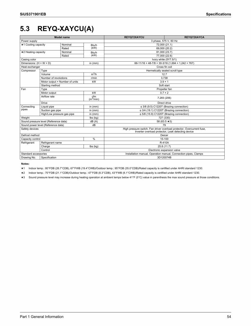
SiUS371901EB Specifications
5.3 REYQ-XAYCU(A)Model name REYQ72XAYCU REYQ72XAYCA
Power supply 3 phase, 575 V, 60 Hz1 Cooling capacity Nominal Btu/h
(kW)72,000 (21.1)
Rated 69,000 (20.2)2 Heating capacity Nominal Btu/h
(kW)81,000 (23.7)
Rated 77,000 (22.6)Casing color Ivory white (5Y7.5/1)Dimensions: (H × W × D) in (mm) 66-11/16 × 48-7/8 × 30-3/16 (1,694 × 1,242 × 767)Heat exchanger Cross fin coilCompressor Type Hermetically sealed scroll type
Volume m3/h 12.7Number of revolutions r/min 3,738Motor output × Number of units kW 3.9 × 1Starting method Soft start
Fan Type Propeller fanMotor output kW 0.7 × 2Airflow rate cfm
(m3/min) 7,283 (206)
Drive Direct driveConnecting pipes
Liquid pipe in (mm) φ 3/8 (9.5) C1220T (Brazing connection)Suction gas pipe in (mm) φ 3/4 (19.1) C1220T (Brazing connection)High/Low pressure gas pipe in (mm) φ 5/8 (15.9) C1220T (Brazing connection)
Weight lbs (kg) 727 (330)Sound pressure level (Reference data) dB (A) 58 (63.5 3)Sound power level (Reference data) dB 79Safety devices High pressure switch, Fan driver overload protector, Overcurrent fuse,
Inverter overload protector, Leak detecting deviceDefrost method DeicerCapacity control % 15-100Refrigerant Refrigerant name R-410A
Charge lbs (kg) 25.8 (11.7)Control Electronic expansion valve
Standard accessories Installation manual, Operation manual, Connection pipes, ClampsDrawing No. Specification 3D120074B
Notes:1 Indoor temp.: 80°FDB (26.7°CDB), 67°FWB (19.4°CWB)/Outdoor temp.: 95°FDB (35.0°CDB)/Rated capacity is certified under AHRI standard 1230.2 Indoor temp.: 70°FDB (21.1°CDB)/Outdoor temp.: 47°FDB (8.3°CDB), 43°FWB (6.1°CWB)/Rated capacity is certified under AHRI standard 1230.3 Sound pressure level may increase during heating operation at ambient temps below 41°F (5°C) value in parenthesis the max sound pressure at those conditions.
Part 1 General Information 54
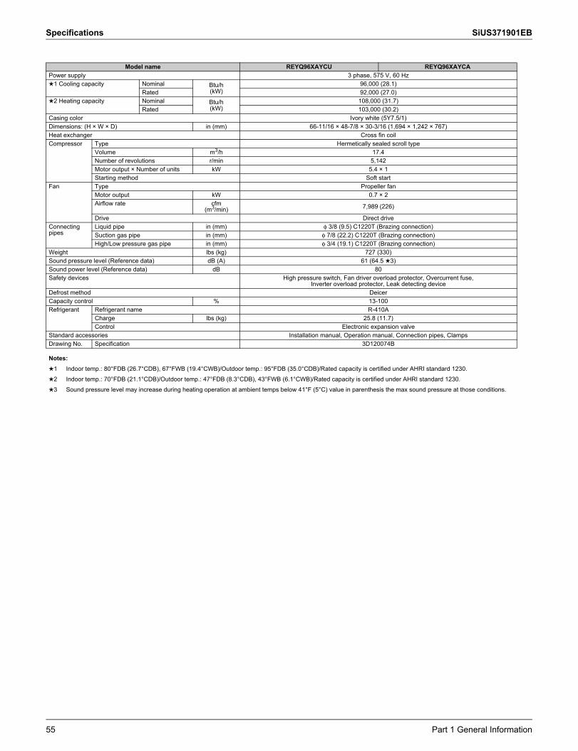
Specifications SiUS371901EB
Model name REYQ96XAYCU REYQ96XAYCAPower supply 3 phase, 575 V, 60 Hz1 Cooling capacity Nominal Btu/h
(kW)96,000 (28.1)
Rated 92,000 (27.0)2 Heating capacity Nominal Btu/h
(kW)108,000 (31.7)
Rated 103,000 (30.2)Casing color Ivory white (5Y7.5/1)Dimensions: (H × W × D) in (mm) 66-11/16 × 48-7/8 × 30-3/16 (1,694 × 1,242 × 767)Heat exchanger Cross fin coilCompressor Type Hermetically sealed scroll type
Volume m3/h 17.4Number of revolutions r/min 5,142Motor output × Number of units kW 5.4 × 1Starting method Soft start
Fan Type Propeller fanMotor output kW 0.7 × 2Airflow rate cfm
(m3/min) 7,989 (226)
Drive Direct driveConnecting pipes
Liquid pipe in (mm) φ 3/8 (9.5) C1220T (Brazing connection)Suction gas pipe in (mm) φ 7/8 (22.2) C1220T (Brazing connection)High/Low pressure gas pipe in (mm) φ 3/4 (19.1) C1220T (Brazing connection)
Weight lbs (kg) 727 (330)Sound pressure level (Reference data) dB (A) 61 (64.5 3)Sound power level (Reference data) dB 80Safety devices High pressure switch, Fan driver overload protector, Overcurrent fuse,
Inverter overload protector, Leak detecting deviceDefrost method DeicerCapacity control % 13-100Refrigerant Refrigerant name R-410A
Charge lbs (kg) 25.8 (11.7)Control Electronic expansion valve
Standard accessories Installation manual, Operation manual, Connection pipes, ClampsDrawing No. Specification 3D120074B
Notes:1 Indoor temp.: 80°FDB (26.7°CDB), 67°FWB (19.4°CWB)/Outdoor temp.: 95°FDB (35.0°CDB)/Rated capacity is certified under AHRI standard 1230.2 Indoor temp.: 70°FDB (21.1°CDB)/Outdoor temp.: 47°FDB (8.3°CDB), 43°FWB (6.1°CWB)/Rated capacity is certified under AHRI standard 1230.3 Sound pressure level may increase during heating operation at ambient temps below 41°F (5°C) value in parenthesis the max sound pressure at those conditions.
55 Part 1 General Information

SiUS371901EB Specifications
Model name REYQ120XAYCU REYQ120XAYCAPower supply 3 phase, 575 V, 60 Hz1 Cooling capacity Nominal Btu/h
(kW)120,000 (35.2)
Rated 114,000 (33.4)2 Heating capacity Nominal Btu/h
(kW)135,000 (39.6)
Rated 129,000 (37.8)Casing color Ivory white (5Y7.5/1)Dimensions: (H × W × D) in (mm) 66-11/16 × 48-7/8 × 30-3/16 (1,694 × 1,242 × 767)Heat exchanger Cross fin coilCompressor Type Hermetically sealed scroll type
Volume m3/h 23.4Number of revolutions r/min 6,888Motor output × Number of units kW 7.2 × 1Starting method Soft start
Fan Type Propeller fanMotor output kW 0.7 × 2Airflow rate cfm
(m3/min) 7,989 (226)
Drive Direct driveConnecting pipes
Liquid pipe in (mm) φ 1/2 (12.7) C1220T (Brazing connection)Suction gas pipe in (mm) φ 1-1/8 (28.6) C1220T (Brazing connection)High/Low pressure gas pipe in (mm) φ 3/4 (19.1) C1220T (Brazing connection)
Weight lbs (kg) 727 (330)Sound pressure level (Reference data) dB (A) 61 (65 3)Sound power level (Reference data) dB 80.5Safety devices High pressure switch, Fan driver overload protector, Overcurrent fuse,
Inverter overload protector, Leak detecting deviceDefrost method DeicerCapacity control % 11-100Refrigerant Refrigerant name R-410A
Charge lbs (kg) 25.8 (11.7)Control Electronic expansion valve
Standard accessories Installation manual, Operation manual, Connection pipes, ClampsDrawing No. Specification 3D120074B
Notes:1 Indoor temp.: 80°FDB (26.7°CDB), 67°FWB (19.4°CWB)/Outdoor temp.: 95°FDB (35.0°CDB)/Rated capacity is certified under AHRI standard 1230.2 Indoor temp.: 70°FDB (21.1°CDB)/Outdoor temp.: 47°FDB (8.3°CDB), 43°FWB (6.1°CWB)/Rated capacity is certified under AHRI standard 1230.3 Sound pressure level may increase during heating operation at ambient temps below 41°F (5°C) value in parenthesis the max sound pressure at those conditions.
Part 1 General Information 56

Specifications SiUS371901EB
Model name REYQ144XAYCU REYQ144XAYCAPower supply 3 phase, 575 V, 60 Hz1 Cooling capacity Nominal Btu/h
(kW)144,000 (42.2)
Rated 138,000 (40.4)2 Heating capacity Nominal Btu/h
(kW)162,000 (47.5)
Rated 154,000 (45.1)Casing color Ivory white (5Y7.5/1)Dimensions: (H × W × D) in (mm) 66-11/16 × 48-7/8 × 30-3/16 (1,694 × 1,242 × 767)Heat exchanger Cross fin coilCompressor Type Hermetically sealed scroll type
Volume m3/h 27.7Number of revolutions r/min 5,214Motor output × Number of units kW 8.0 × 1Starting method Soft start
Fan Type Propeller fanMotor output kW 0.7 × 2Airflow rate cfm
(m3/min) 9,480 (268)
Drive Direct driveConnecting pipes
Liquid pipe in (mm) φ 1/2 (12.7) C1220T (Brazing connection)Suction gas pipe in (mm) φ 1-1/8 (28.6) C1220T (Brazing connection)High/Low pressure gas pipe in (mm) φ 7/8 (22.2) C1220T (Brazing connection)
Weight lbs (kg) 793 (360)Sound pressure level (Reference data) dB (A) 65Sound power level (Reference data) dB 87Safety devices High pressure switch, Fan driver overload protector, Overcurrent fuse,
Inverter overload protector, Leak detecting deviceDefrost method DeicerCapacity control % 14-100Refrigerant Refrigerant name R-410A
Charge lbs (kg) 25.8 (11.7)Control Electronic expansion valve
Standard accessories Installation manual, Operation manual, Connection pipes, ClampsDrawing No. Specification 3D120074B
Notes:1 Indoor temp.: 80°FDB (26.7°CDB), 67°FWB (19.4°CWB)/Outdoor temp.: 95°FDB (35.0°CDB)/Rated capacity is certified under AHRI standard 1230.2 Indoor temp.: 70°FDB (21.1°CDB)/Outdoor temp.: 47°FDB (8.3°CDB), 43°FWB (6.1°CWB)/Rated capacity is certified under AHRI standard 1230.3 Sound pressure level may increase during heating operation at ambient temps below 41°F (5°C) value in parenthesis the max sound pressure at those conditions.
57 Part 1 General Information

SiUS371901EB Specifications
Model name REYQ168XAYCU REYQ168XAYCAPower supply 3 phase, 575 V, 60 Hz1 Cooling capacity Nominal Btu/h
(kW)168,000 (49.2)
Rated 160,000 (46.9)2 Heating capacity Nominal Btu/h
(kW)188,000 (55.1)
Rated 180,000 (52.7)Casing color Ivory white (5Y7.5/1)Dimensions: (H × W × D) in (mm) 66-11/16 × 48-7/8 × 30-3/16 (1,694 × 1,242 × 767)Heat exchanger Cross fin coilCompressor Type Hermetically sealed scroll type
Volume m3/h 33.6Number of revolutions r/min 6,330Motor output × Number of units kW 9.7 × 1Starting method Soft start
Fan Type Propeller fanMotor output kW 0.7 × 2Airflow rate cfm
(m3/min) 9,480 (268)
Drive Direct driveConnecting pipes
Liquid pipe in (mm) φ 5/8 (15.9) C1220T (Brazing connection)Suction gas pipe in (mm) φ 1-1/8 (28.6) C1220T (Brazing connection)High/Low pressure gas pipe in (mm) φ 7/8 (22.2) C1220T (Brazing connection)
Weight lbs (kg) 793 (360)Sound pressure level (Reference data) dB (A) 65 (65.5 3)Sound power level (Reference data) dB 88Safety devices High pressure switch, Fan driver overload protector, Overcurrent fuse,
Inverter overload protector, Leak detecting deviceDefrost method DeicerCapacity control % 12-100Refrigerant Refrigerant name R-410A
Charge lbs (kg) 25.8 (11.7)Control Electronic expansion valve
Standard accessories Installation manual, Operation manual, Connection pipes, ClampsDrawing No. Specification 3D120074B
Notes:1 Indoor temp.: 80°FDB (26.7°CDB), 67°FWB (19.4°CWB)/Outdoor temp.: 95°FDB (35.0°CDB)/Rated capacity is certified under AHRI standard 1230.2 Indoor temp.: 70°FDB (21.1°CDB)/Outdoor temp.: 47°FDB (8.3°CDB), 43°FWB (6.1°CWB)/Rated capacity is certified under AHRI standard 1230.3 Sound pressure level may increase during heating operation at ambient temps below 41°F (5°C) value in parenthesis the max sound pressure at those conditions.
Part 1 General Information 58

Specifications SiUS371901EB
Model name (Combination unit) REYQ192XAYCU REYQ192XAYCA
Model name (Independent unit) REYQ96XAYCUREYQ96XAYCU
REYQ96XAYCAREYQ96XAYCA
Power supply 3 phase, 575 V, 60 Hz1 Cooling capacity Nominal Btu/h
(kW)192,000 (56.3)
Rated 184,000 (53.9)2 Heating capacity Nominal Btu/h
(kW)216,000 (63.3)
Rated 206,000 (60.4)Casing color Ivory white (5Y7.5/1)Dimensions: (H × W × D) in (mm) 66-11/16 × 48-7/8 × 30-3/16 + 66-11/16 × 48-7/8 × 30-3/16
(1,694 × 1,242 × 767 + 1,694 × 1,242 × 767)Heat exchanger Cross fin coilCompressor Type Hermetically sealed scroll type
Volume m3/h 17.7 + 17.7Number of revolutions r/min 5,214 + 5,214Motor output × Number of units kW 5.4 × 1 + 5.4 × 1Starting method Soft start
Fan Type Propeller fanMotor output kW (0.7 × 2) × 2Airflow rate cfm
(m3/min) 7,989 + 7,989 (226 + 226)
Drive Direct driveConnecting pipes
Liquid pipe in (mm) φ 5/8 (15.9) C1220T (Brazing connection)Suction gas pipe in (mm) φ 1-1/8 (28.6) C1220T (Brazing connection)High/Low pressure gas pipe in (mm) φ 1-1/8 (28.6) C1220T (Brazing connection)
Weight lbs (kg) 727 + 727 (330 + 330)Sound pressure level (Reference data) dB (A) 64 (67.5 3)Sound power level (Reference data) dB 83Safety devices High pressure switch, Fan driver overload protector, Overcurrent fuse,
Inverter overload protector, Leak detecting deviceDefrost method DeicerCapacity control % 6-100Refrigerant Refrigerant name R-410A
Charge lbs (kg) 25.8 + 25.8 (11.7 + 11.7)Control Electronic expansion valve
Standard accessories Installation manual, Operation manual, Connection pipes, ClampsDrawing No. Specification 3D120075B
Notes:1 Indoor temp.: 80°FDB (26.7°CDB), 67°FWB (19.4°CWB)/Outdoor temp.: 95°FDB (35.0°CDB)/Rated capacity is certified under AHRI standard 1230.2 Indoor temp.: 70°FDB (21.1°CDB)/Outdoor temp.: 47°FDB (8.3°CDB), 43°FWB (6.1°CWB)/Rated capacity is certified under AHRI standard 1230.3 Sound pressure level may increase during heating operation at ambient temps below 41°F (5°C) value in parenthesis the max sound pressure at those conditions.
59 Part 1 General Information

SiUS371901EB Specifications
Model name (Combination unit) REYQ216XAYCU REYQ216XAYCA
Model name (Independent unit) REYQ96XAYCUREYQ120XAYCU
REYQ96XAYCAREYQ120XAYCA
Power supply 3 phase, 575 V, 60 Hz1 Cooling capacity Nominal Btu/h
(kW)216,000 (63.3)
Rated 206,000 (60.4)2 Heating capacity Nominal Btu/h
(kW)243,000 (71.2)
Rated 232,000 (68.0)Casing color Ivory white (5Y7.5/1)Dimensions: (H × W × D) in (mm) 66-11/16 × 48-7/8 × 30-3/16 + 66-11/16 × 48-7/8 × 30-3/16
(1,694 × 1,242 × 767 + 1,694 × 1,242 × 767)Heat exchanger Cross fin coilCompressor Type Hermetically sealed scroll type
Volume m3/h 20.3 + 20.3Number of revolutions r/min 5,994 + 5,994Motor output × Number of units kW 6.2 × 1 + 6.2 × 1Starting method Soft start
Fan Type Propeller fanMotor output kW (0.7 × 2) × 2Airflow rate cfm
(m3/min) 7,989 + 7,989 (226 + 226)
Drive Direct driveConnecting pipes
Liquid pipe in (mm) φ 5/8 (15.9) C1220T (Brazing connection)Suction gas pipe in (mm) φ 1-1/8 (28.6) C1220T (Brazing connection)High/Low pressure gas pipe in (mm) φ 1-1/8 (28.6) C1220T (Brazing connection)
Weight lbs (kg) 727 + 727 (330 + 330)Sound pressure level (Reference data) dB (A) 64 (68 3)Sound power level (Reference data) dB 83.5Safety devices High pressure switch, Fan driver overload protector, Overcurrent fuse,
Inverter overload protector, Leak detecting deviceDefrost method DeicerCapacity control % 6-100Refrigerant Refrigerant name R-410A
Charge lbs (kg) 25.8 + 25.8 (11.7 + 11.7)Control Electronic expansion valve
Standard accessories Installation manual, Operation manual, Connection pipes, ClampsDrawing No. Specification 3D120075B
Notes:1 Indoor temp.: 80°FDB (26.7°CDB), 67°FWB (19.4°CWB)/Outdoor temp.: 95°FDB (35.0°CDB)/Rated capacity is certified under AHRI standard 1230.2 Indoor temp.: 70°FDB (21.1°CDB)/Outdoor temp.: 47°FDB (8.3°CDB), 43°FWB (6.1°CWB)/Rated capacity is certified under AHRI standard 1230.3 Sound pressure level may increase during heating operation at ambient temps below 41°F (5°C) value in parenthesis the max sound pressure at those conditions.
Part 1 General Information 60

Specifications SiUS371901EB
Model name (Combination unit) REYQ240XAYCU REYQ240XAYCA
Model name (Independent unit) REYQ120XAYCUREYQ120XAYCU
REYQ120XAYCAREYQ120XAYCA
Power supply 3 phase, 575 V, 60 Hz1 Cooling capacity Nominal Btu/h
(kW)240,000 (70.3)
Rated 228,000 (66.8)2 Heating capacity Nominal Btu/h
(kW)270,000 (79.1)
Rated 256,000 (75.0)Casing color Ivory white (5Y7.5/1)Dimensions: (H × W × D) in (mm) 66-11/16 × 48-7/8 × 30-3/16 + 66-11/16 × 48-7/8 × 30-3/16
(1,694 × 1,242 × 767 + 1,694 × 1,242 × 767)Heat exchanger Cross fin coilCompressor Type Hermetically sealed scroll type
Volume m3/h 22.7 + 22.7Number of revolutions r/min 6,702 + 6,702Motor output × Number of units kW 7.0 × 1 + 7.0 × 1Starting method Soft start
Fan Type Propeller fanMotor output kW (0.7 × 2) × 2Airflow rate cfm
(m3/min) 7,989 + 7,989 (226 + 226)
Drive Direct driveConnecting pipes
Liquid pipe in (mm) φ 5/8 (15.9) C1220T (Brazing connection)Suction gas pipe in (mm) φ 1-3/8 (34.9) C1220T (Brazing connection)High/Low pressure gas pipe in (mm) φ 1-1/8 (28.6) C1220T (Brazing connection)
Weight lbs (kg) 727 + 727 (330 + 330)Sound pressure level (Reference data) dB (A) 64 (68 3)Sound power level (Reference data) dB 83.5Safety devices High pressure switch, Fan driver overload protector, Overcurrent fuse,
Inverter overload protector, Leak detecting deviceDefrost method DeicerCapacity control % 5-100Refrigerant Refrigerant name R-410A
Charge lbs (kg) 25.8 + 25.8 (11.7 + 11.7)Control Electronic expansion valve
Standard accessories Installation manual, Operation manual, Connection pipes, ClampsDrawing No. Specification 3D120075B
Notes:1 Indoor temp.: 80°FDB (26.7°CDB), 67°FWB (19.4°CWB)/Outdoor temp.: 95°FDB (35.0°CDB)/Rated capacity is certified under AHRI standard 1230.2 Indoor temp.: 70°FDB (21.1°CDB)/Outdoor temp.: 47°FDB (8.3°CDB), 43°FWB (6.1°CWB)/Rated capacity is certified under AHRI standard 1230.3 Sound pressure level may increase during heating operation at ambient temps below 41°F (5°C) value in parenthesis the max sound pressure at those conditions.
61 Part 1 General Information

SiUS371901EB Specifications
Model name (Combination unit) REYQ264XAYCU REYQ264XAYCA
Model name (Independent unit) REYQ120XAYCUREYQ144XAYCU
REYQ120XAYCAREYQ144XAYCA
Power supply 3 phase, 575 V, 60 Hz1 Cooling capacity Nominal Btu/h
(kW)264,000 (77.4)
Rated 252,000 (73.9)2 Heating capacity Nominal Btu/h
(kW)297,000 (87.0)
Rated 282,000 (82.6)Casing color Ivory white (5Y7.5/1)Dimensions: (H × W × D) in (mm) 66-11/16 × 48-7/8 × 30-3/16 + 66-11/16 × 48-7/8 × 30-3/16
(1,694 × 1,242 × 767 + 1,694 × 1,242 × 767)Heat exchanger Cross fin coilCompressor Type Hermetically sealed scroll type
Volume m3/h 22.0 + 27.7Number of revolutions r/min 6,504 + 5,214Motor output × Number of units kW 6.8 × 1 + 8.0 × 1Starting method Soft start
Fan Type Propeller fanMotor output kW (0.7 × 2) × 2Airflow rate cfm
(m3/min) 7,989 + 9,480 (226 + 268)
Drive Direct driveConnecting pipes
Liquid pipe in (mm) φ 3/4 (19.1) C1220T (Brazing connection)Suction gas pipe in (mm) φ 1-3/8 (34.9) C1220T (Brazing connection)High/Low pressure gas pipe in (mm) φ 1-1/8 (28.6) C1220T (Brazing connection)
Weight lbs (kg) 727 + 793 (330 + 360)Sound pressure level (Reference data) dB (A) 66.5 (68 3)Sound power level (Reference data) dB 88Safety devices High pressure switch, Fan driver overload protector, Overcurrent fuse,
Inverter overload protector, Leak detecting deviceDefrost method DeicerCapacity control % 5-100Refrigerant Refrigerant name R-410A
Charge lbs (kg) 25.8 + 25.8 (11.7 + 11.7)Control Electronic expansion valve
Standard accessories Installation manual, Operation manual, Connection pipes, ClampsDrawing No. Specification 3D120075B
Notes:1 Indoor temp.: 80°FDB (26.7°CDB), 67°FWB (19.4°CWB)/Outdoor temp.: 95°FDB (35.0°CDB)/Rated capacity is certified under AHRI standard 1230.2 Indoor temp.: 70°FDB (21.1°CDB)/Outdoor temp.: 47°FDB (8.3°CDB), 43°FWB (6.1°CWB)/Rated capacity is certified under AHRI standard 1230.3 Sound pressure level may increase during heating operation at ambient temps below 41°F (5°C) value in parenthesis the max sound pressure at those conditions.
Part 1 General Information 62

Specifications SiUS371901EB
Model name (Combination unit) REYQ288XAYCU REYQ288XAYCA
Model name (Independent unit) REYQ144XAYCUREYQ144XAYCU
REYQ144XAYCAREYQ144XAYCA
Power supply 3 phase, 575 V, 60 Hz1 Cooling capacity Nominal Btu/h
(kW)288,000 (84.4)
Rated 274,000 (80.3)2 Heating capacity Nominal Btu/h
(kW)324,000 (95.0)
Rated 294,000 (86.1)Casing color Ivory white (5Y7.5/1)Dimensions: (H × W × D) in (mm) 66-11/16 × 48-7/8 × 30-3/16 + 66-11/16 × 48-7/8 × 30-3/16
(1,694 × 1,242 × 767 + 1,694 × 1,242 × 767)Heat exchanger Cross fin coilCompressor Type Hermetically sealed scroll type
Volume m3/h 25.4 + 25.4Number of revolutions r/min 4,794 + 4,794Motor output × Number of units kW 7.3 × 1 + 7.3 × 1Starting method Soft start
Fan Type Propeller fanMotor output kW (0.7 × 2) × 2Airflow rate cfm
(m3/min) 9,480 + 9,480 (268 + 268)
Drive Direct driveConnecting pipes
Liquid pipe in (mm) φ 3/4 (19.1) C1220T (Brazing connection)Suction gas pipe in (mm) φ 1-3/8 (34.9) C1220T (Brazing connection)High/Low pressure gas pipe in (mm) φ 1-1/8 (28.6) C1220T (Brazing connection)
Weight lbs (kg) 793 + 793 (360 + 360)Sound pressure level (Reference data) dB (A) 68Sound power level (Reference data) dB 90Safety devices High pressure switch, Fan driver overload protector, Overcurrent fuse,
Inverter overload protector, Leak detecting deviceDefrost method DeicerCapacity control % 7-100Refrigerant Refrigerant name R-410A
Charge lbs (kg) 25.8 + 25.8 (11.7 + 11.7)Control Electronic expansion valve
Standard accessories Installation manual, Operation manual, Connection pipes, ClampsDrawing No. Specification 3D120075B
Notes:1 Indoor temp.: 80°FDB (26.7°CDB), 67°FWB (19.4°CWB)/Outdoor temp.: 95°FDB (35.0°CDB)/Rated capacity is certified under AHRI standard 1230.2 Indoor temp.: 70°FDB (21.1°CDB)/Outdoor temp.: 47°FDB (8.3°CDB), 43°FWB (6.1°CWB)/Rated capacity is certified under AHRI standard 1230.3 Sound pressure level may increase during heating operation at ambient temps below 41°F (5°C) value in parenthesis the max sound pressure at those conditions.
63 Part 1 General Information

SiUS371901EB Specifications
Model name (Combination unit) REYQ312XAYCU REYQ312XAYCA
Model name (Independent unit) REYQ144XAYCUREYQ168XAYCU
REYQ144XAYCAREYQ168XAYCA
Power supply 3 phase, 575 V, 60 Hz1 Cooling capacity Nominal Btu/h
(kW)312,000 (91.4)
Rated 296,000 (86.7)2 Heating capacity Nominal Btu/h
(kW)351,000 (102.9)
Rated 320,000 (93.8)Casing color Ivory white (5Y7.5/1)Dimensions: (H × W × D) in (mm) 66-11/16 × 48-7/8 × 30-3/16 + 66-11/16 × 48-7/8 × 30-3/16
(1,694 × 1,242 × 767 + 1,694 × 1,242 × 767)Heat exchanger Cross fin coilCompressor Type Hermetically sealed scroll type
Volume m3/h 28.0 + 28.0Number of revolutions r/min 5,286 + 5,286Motor output × Number of units kW 8.1 × 1 + 8.1 × 1Starting method Soft start
Fan Type Propeller fanMotor output kW (0.7 × 2) × 2Airflow rate cfm
(m3/min) 9,480 + 9,480 (268 + 268)
Drive Direct driveConnecting pipes
Liquid pipe in (mm) φ 3/4 (19.1) C1220T (Brazing connection)Suction gas pipe in (mm) φ 1-3/8 (34.9) C1220T (Brazing connection)High/Low pressure gas pipe in (mm) φ 1-1/8 (28.6) C1220T (Brazing connection)
Weight lbs (kg) 793 + 793 (360 + 360)Sound pressure level (Reference data) dB (A) 68 (68.5 3)Sound power level (Reference data) dB 90.5Safety devices High pressure switch, Fan driver overload protector, Overcurrent fuse,
Inverter overload protector, Leak detecting deviceDefrost method DeicerCapacity control % 7-100Refrigerant Refrigerant name R-410A
Charge lbs (kg) 25.8 + 25.8 (11.7 + 11.7)Control Electronic expansion valve
Standard accessories Installation manual, Operation manual, Connection pipes, ClampsDrawing No. Specification 3D120075B
Notes:1 Indoor temp.: 80°FDB (26.7°CDB), 67°FWB (19.4°CWB)/Outdoor temp.: 95°FDB (35.0°CDB)/Rated capacity is certified under AHRI standard 1230.2 Indoor temp.: 70°FDB (21.1°CDB)/Outdoor temp.: 47°FDB (8.3°CDB), 43°FWB (6.1°CWB)/Rated capacity is certified under AHRI standard 1230.3 Sound pressure level may increase during heating operation at ambient temps below 41°F (5°C) value in parenthesis the max sound pressure at those conditions.
Part 1 General Information 64

Specifications SiUS371901EB
Model name (Combination unit) REYQ336XAYCU REYQ336XAYCA
Model name (Independent unit) REYQ168XAYCUREYQ168XAYCU
REYQ168XAYCAREYQ168XAYCA
Power supply 3 phase, 575 V, 60 Hz1 Cooling capacity Nominal Btu/h
(kW)336,000 (98.5)
Rated 320,000 (93.8)2 Heating capacity Nominal Btu/h
(kW)378,000 (110.8)
Rated 338,000 (99.1)Casing color Ivory white (5Y7.5/1)Dimensions: (H × W × D) in (mm) 66-11/16 × 48-7/8 × 30-3/16 + 66-11/16 × 48-7/8 × 30-3/16
(1,694 × 1,242 × 767 + 1,694 × 1,242 × 767)Heat exchanger Cross fin coilCompressor Type Hermetically sealed scroll type
Volume m3/h 30.0 + 30.0Number of revolutions r/min 5,664 + 5,664Motor output × Number of units kW 8.7 × 1 + 8.7 × 1Starting method Soft start
Fan Type Propeller fanMotor output kW (0.7 × 2) × 2Airflow rate cfm
(m3/min) 9,480 + 9,480 (268 + 268)
Drive Direct driveConnecting pipes
Liquid pipe in (mm) φ 3/4 (19.1) C1220T (Brazing connection)Suction gas pipe in (mm) φ 1-3/8 (34.9) C1220T (Brazing connection)High/Low pressure gas pipe in (mm) φ 1-1/8 (28.6) C1220T (Brazing connection)
Weight lbs (kg) 793 + 793 (360 + 360)Sound pressure level (Reference data) dB (A) 68 (68.5 3)Sound power level (Reference data) dB 91Safety devices High pressure switch, Fan driver overload protector, Overcurrent fuse,
Inverter overload protector, Leak detecting deviceDefrost method DeicerCapacity control % 6-100Refrigerant Refrigerant name R-410A
Charge lbs (kg) 25.8 + 25.8 (11.7 + 11.7)Control Electronic expansion valve
Standard accessories Installation manual, Operation manual, Connection pipes, ClampsDrawing No. Specification 3D120075B
Notes:1 Indoor temp.: 80°FDB (26.7°CDB), 67°FWB (19.4°CWB)/Outdoor temp.: 95°FDB (35.0°CDB)/Rated capacity is certified under AHRI standard 1230.2 Indoor temp.: 70°FDB (21.1°CDB)/Outdoor temp.: 47°FDB (8.3°CDB), 43°FWB (6.1°CWB)/Rated capacity is certified under AHRI standard 1230.3 Sound pressure level may increase during heating operation at ambient temps below 41°F (5°C) value in parenthesis the max sound pressure at those conditions.
65 Part 1 General Information

SiUS371901EB Specifications
Model name (Combination unit) REYQ360XAYCU REYQ360XAYCA
Model name (Independent unit)REYQ120XAYCUREYQ120XAYCUREYQ120XAYCU
REYQ120XAYCAREYQ120XAYCAREYQ120XAYCA
Power supply 3 phase, 575 V, 60 Hz1 Cooling capacity Nominal Btu/h
(kW)360,000 (105.5)
Rated 342,000 (100.2)2 Heating capacity Nominal Btu/h
(kW)405,000 (118.7)
Rated 376,000 (110.2)Casing color Ivory white (5Y7.5/1)Dimensions: (H × W × D) in (mm) 66-11/16 × 48-7/8 × 30-3/16 + 66-11/16 × 48-7/8 × 30-3/16 + 66-11/16 × 48-7/8 × 30-3/16
(1,694 × 1,242 × 767 + 1,694 × 1,242 × 767 + 1,694 × 1,242 × 767)Heat exchanger Cross fin coilCompressor Type Hermetically sealed scroll type
Volume m3/h 22.4 + 22.4 + 22.4Number of revolutions r/min 6,606 + 6,606 + 6,606Motor output × Number of units kW 6.9 × 1 + 6.9 × 1 + 6.9 × 1Starting method Soft start
Fan Type Propeller fanMotor output kW (0.7 × 2) × 3Airflow rate cfm
(m3/min) 7,989 + 7,989 + 7,989 (226 + 226 + 226)
Drive Direct driveConnecting pipes
Liquid pipe in (mm) φ 3/4 (19.1) C1220T (Brazing connection)Suction gas pipe in (mm) φ 1-5/8 (41.3) C1220T (Brazing connection)High/Low pressure gas pipe in (mm) φ 1-3/8 (34.9) C1220T (Brazing connection)
Weight lbs (kg) 727 + 727 + 727 (330 + 330 + 330)Sound pressure level (Reference data) dB (A) 66 (70 3)Sound power level (Reference data) dB 85.5Safety devices High pressure switch, Fan driver overload protector, Overcurrent fuse,
Inverter overload protector, Leak detecting deviceDefrost method DeicerCapacity control % 4-100Refrigerant Refrigerant name R-410A
Charge lbs (kg) 25.8 + 25.8 + 25.8 (11.7 + 11.7 + 11.7)Control Electronic expansion valve
Standard accessories Installation manual, Operation manual, Connection pipes, ClampsDrawing No. Specification 3D120076B
Notes:1 Indoor temp.: 80°FDB (26.7°CDB), 67°FWB (19.4°CWB)/Outdoor temp.: 95°FDB (35.0°CDB)/Rated capacity is certified under AHRI standard 1230.2 Indoor temp.: 70°FDB (21.1°CDB)/Outdoor temp.: 47°FDB (8.3°CDB), 43°FWB (6.1°CWB)/Rated capacity is certified under AHRI standard 1230.3 Sound pressure level may increase during heating operation at ambient temps below 41°F (5°C) value in parenthesis the max sound pressure at those conditions.
Part 1 General Information 66

Specifications SiUS371901EB
Model name (Combination unit) REYQ384XAYCU REYQ384XAYCA
Model name (Independent unit)REYQ120XAYCUREYQ120XAYCUREYQ144XAYCU
REYQ120XAYCAREYQ120XAYCAREYQ144XAYCA
Power supply 3 phase, 575 V, 60 Hz1 Cooling capacity Nominal Btu/h
(kW)384,000 (112.5)
Rated 364,000 (106.7)2 Heating capacity Nominal Btu/h
(kW)432,000 (126.6)
Rated 386,000 (113.1)Casing color Ivory white (5Y7.5/1)Dimensions: (H × W × D) in (mm) 66-11/16 × 48-7/8 × 30-3/16 + 66-11/16 × 48-7/8 × 30-3/16 + 66-11/16 × 48-7/8 × 30-3/16
(1,694 × 1,242 × 767 + 1,694 × 1,242 × 767 + 1,694 × 1,242 × 767)Heat exchanger Cross fin coilCompressor Type Hermetically sealed scroll type
Volume m3/h 21.8 + 21.8 + 26.9Number of revolutions r/min 6,426 + 6,426 + 5,070Motor output × Number of units kW 6.7 × 1 + 6.7 × 1 + 7.7 × 1Starting method Soft start
Fan Type Propeller fanMotor output kW (0.7 × 2) × 3Airflow rate cfm
(m3/min) 7,989 + 7,989 + 9,480 (226 + 226 + 268)
Drive Direct driveConnecting pipes
Liquid pipe in (mm) φ 3/4 (19.1) C1220T (Brazing connection)Suction gas pipe in (mm) φ 1-5/8 (41.3) C1220T (Brazing connection)High/Low pressure gas pipe in (mm) φ 1-3/8 (34.9) C1220T (Brazing connection)
Weight lbs (kg) 727 + 727 + 793 (330 + 330 + 360)Sound pressure level (Reference data) dB (A) 67.5 (70 3)Sound power level (Reference data) dB 89Safety devices High pressure switch, Fan driver overload protector, Overcurrent fuse,
Inverter overload protector, Leak detecting deviceDefrost method DeicerCapacity control % 3-100Refrigerant Refrigerant name R-410A
Charge lbs (kg) 25.8 + 25.8 + 25.8 (11.7 + 11.7 + 11.7)Control Electronic expansion valve
Standard accessories Installation manual, Operation manual, Connection pipes, ClampsDrawing No. Specification 3D120076B
Notes:1 Indoor temp.: 80°FDB (26.7°CDB), 67°FWB (19.4°CWB)/Outdoor temp.: 95°FDB (35.0°CDB)/Rated capacity is certified under AHRI standard 1230.2 Indoor temp.: 70°FDB (21.1°CDB)/Outdoor temp.: 47°FDB (8.3°CDB), 43°FWB (6.1°CWB)/Rated capacity is certified under AHRI standard 1230.3 Sound pressure level may increase during heating operation at ambient temps below 41°F (5°C) value in parenthesis the max sound pressure at those conditions.
67 Part 1 General Information

SiUS371901EB Specifications
Model name (Combination unit) REYQ408XAYCU REYQ408XAYCA
Model name (Independent unit)REYQ120XAYCUREYQ144XAYCUREYQ144XAYCU
REYQ120XAYCAREYQ144XAYCAREYQ144XAYCA
Power supply 3 phase, 575 V, 60 Hz1 Cooling capacity Nominal Btu/h
(kW)408,000 (119.6)
Rated 388,000 (113.7)2 Heating capacity Nominal Btu/h
(kW)459,000 (134.5)
Rated 394,000 (115.5)Casing color Ivory white (5Y7.5/1)Dimensions: (H × W × D) in (mm) 66-11/16 × 48-7/8 × 30-3/16 + 66-11/16 × 48-7/8 × 30-3/16 + 66-11/16 × 48-7/8 × 30-3/16
(1,694 × 1,242 × 767 + 1,694 × 1,242 × 767 + 1,694 × 1,242 × 767)Heat exchanger Cross fin coilCompressor Type Hermetically sealed scroll type
Volume m3/h 20.9 + 23.7 + 23.7Number of revolutions r/min 6,162 + 4,470 + 4,470Motor output × Number of units kW 6.4 × 1 + 6.8 × 1 + 6.8 × 1Starting method Soft start
Fan Type Propeller fanMotor output kW (0.7 × 2) × 3Airflow rate cfm
(m3/min) 7,989 + 9,480 + 9,480 (226 + 268 + 268)
Drive Direct driveConnecting pipes
Liquid pipe in (mm) φ 3/4 (19.1) C1220T (Brazing connection)Suction gas pipe in (mm) φ 1-5/8 (41.3) C1220T (Brazing connection)High/Low pressure gas pipe in (mm) φ 1-3/8 (34.9) C1220T (Brazing connection)
Weight lbs (kg) 727 + 727 + 793 (330 + 330 + 360)Sound pressure level (Reference data) dB (A) 69 (70 3)Sound power level (Reference data) dB 90.5Safety devices High pressure switch, Fan driver overload protector, Overcurrent fuse,
Inverter overload protector, Leak detecting deviceDefrost method DeicerCapacity control % 3-100Refrigerant Refrigerant name R-410A
Charge lbs (kg) 25.8 + 25.8 + 25.8 (11.7 + 11.7 + 11.7)Control Electronic expansion valve
Standard accessories Installation manual, Operation manual, Connection pipes, ClampsDrawing No. Specification 3D120076B
Notes:1 Indoor temp.: 80°FDB (26.7°CDB), 67°FWB (19.4°CWB)/Outdoor temp.: 95°FDB (35.0°CDB)/Rated capacity is certified under AHRI standard 1230.2 Indoor temp.: 70°FDB (21.1°CDB)/Outdoor temp.: 47°FDB (8.3°CDB), 43°FWB (6.1°CWB)/Rated capacity is certified under AHRI standard 1230.3 Sound pressure level may increase during heating operation at ambient temps below 41°F (5°C) value in parenthesis the max sound pressure at those conditions.
Part 1 General Information 68

Specifications SiUS371901EB
Model name (Combination unit) REYQ432XAYCU REYQ432XAYCA
Model name (Independent unit)REYQ144XAYCUREYQ144XAYCUREYQ144XAYCU
REYQ144XAYCAREYQ144XAYCAREYQ144XAYCA
Power supply 3 phase, 575 V, 60 Hz1 Cooling capacity Nominal Btu/h
(kW)426,000 (124.8)
Rated 410,000 (120.2)2 Heating capacity Nominal Btu/h
(kW)486,000 (142.4)
Rated 405,000 (118.7)Casing color Ivory white (5Y7.5/1)Dimensions: (H × W × D) in (mm) 66-11/16 × 48-7/8 × 30-3/16 + 66-11/16 × 48-7/8 × 30-3/16 + 66-11/16 × 48-7/8 × 30-3/16
(1,694 × 1,242 × 767 + 1,694 × 1,242 × 767 + 1,694 × 1,242 × 767)Heat exchanger Cross fin coilCompressor Type Hermetically sealed scroll type
Volume m3/h 23.1 + 23.1 + 23.1Number of revolutions r/min 4,350 + 4,350 + 4,350Motor output × Number of units kW 6.6 × 1 + 6.6 × 1 + 6.6 × 1Starting method Soft start
Fan Type Propeller fanMotor output kW (0.7 × 2) × 3Airflow rate cfm
(m3/min) 9,480 + 9,480 + 9,480 (268 + 268 + 268)
Drive Direct driveConnecting pipes
Liquid pipe in (mm) φ 3/4 (19.1) C1220T (Brazing connection)Suction gas pipe in (mm) φ 1-5/8 (41.3) C1220T (Brazing connection)High/Low pressure gas pipe in (mm) φ 1-3/8 (34.9) C1220T (Brazing connection)
Weight lbs (kg) 727 + 727 + 793 (330 + 330 + 360)Sound pressure level (Reference data) dB (A) 70Sound power level (Reference data) dB 92Safety devices High pressure switch, Fan driver overload protector, Overcurrent fuse,
Inverter overload protector, Leak detecting deviceDefrost method DeicerCapacity control % 5-100Refrigerant Refrigerant name R-410A
Charge lbs (kg) 25.8 + 25.8 + 25.8 (11.7 + 11.7 + 11.7)Control Electronic expansion valve
Standard accessories Installation manual, Operation manual, Connection pipes, ClampsDrawing No. Specification 3D120076B
Notes:1 Indoor temp.: 80°FDB (26.7°CDB), 67°FWB (19.4°CWB)/Outdoor temp.: 95°FDB (35.0°CDB)/Rated capacity is certified under AHRI standard 1230.2 Indoor temp.: 70°FDB (21.1°CDB)/Outdoor temp.: 47°FDB (8.3°CDB), 43°FWB (6.1°CWB)/Rated capacity is certified under AHRI standard 1230.3 Sound pressure level may increase during heating operation at ambient temps below 41°F (5°C) value in parenthesis the max sound pressure at those conditions.
69 Part 1 General Information
SiUS371901EB
Part 2 Refrigerant Circuit 70
1. Refrigerant Circuit (Piping Diagrams) .......................................................711.1 Outdoor Unit ............................................................................................... 711.2 Indoor Unit.................................................................................................. 751.3 Outdoor-Air Processing Unit....................................................................... 771.4 Branch Selector Unit .................................................................................. 78
2. Functional Parts Layout ............................................................................872.1 REYQ72/96/120XATJU(A), REYQ72/96/120XAYDU(A),
REYQ72/96/120XAYCU(A) ........................................................................ 872.2 REYQ144/168XATJU(A), REYQ144/168XAYDU(A),
REYQ144/168XAYCU(A) ........................................................................... 893. Refrigerant Flow for Each Operation Mode...............................................91
3.1 Cooling Operation ...................................................................................... 913.2 Heating Operation ...................................................................................... 923.3 Simultaneous Cooling and Heating Operation ........................................... 933.4 Cooling Oil Return Operation ..................................................................... 943.5 Defrost Heating Oil Return Operation ........................................................ 953.6 Oil Return Operation at Simultaneous Cooling and Heating Operation ..... 96
Part 2 Refrigerant Circuit
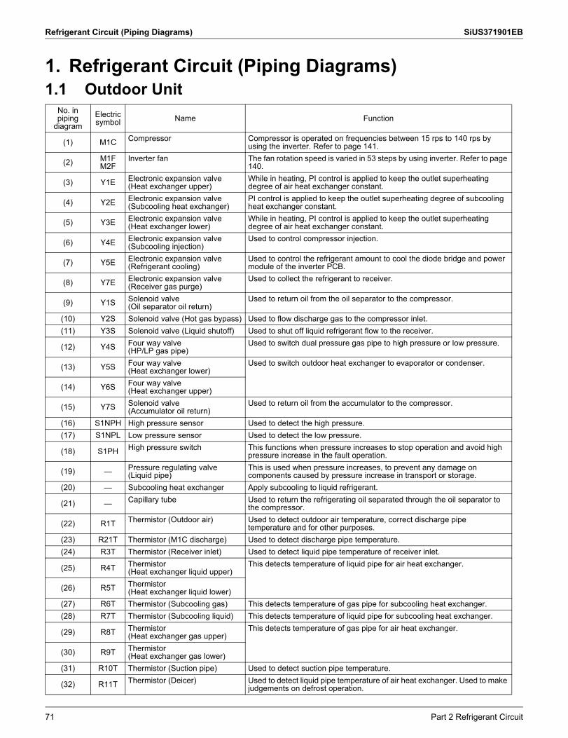
Refrigerant Circuit (Piping Diagrams) SiUS371901EB
1. Refrigerant Circuit (Piping Diagrams)1.1 Outdoor Unit
No. in piping
diagramElectric symbol Name Function
(1) M1C Compressor Compressor is operated on frequencies between 15 rps to 140 rps by using the inverter. Refer to page 141.
(2) M1F M2F
Inverter fan The fan rotation speed is varied in 53 steps by using inverter. Refer to page 140.
(3) Y1E Electronic expansion valve (Heat exchanger upper)
While in heating, PI control is applied to keep the outlet superheating degree of air heat exchanger constant.
(4) Y2E Electronic expansion valve (Subcooling heat exchanger)
PI control is applied to keep the outlet superheating degree of subcooling heat exchanger constant.
(5) Y3E Electronic expansion valve (Heat exchanger lower)
While in heating, PI control is applied to keep the outlet superheating degree of air heat exchanger constant.
(6) Y4E Electronic expansion valve (Subcooling injection)
Used to control compressor injection.
(7) Y5E Electronic expansion valve (Refrigerant cooling)
Used to control the refrigerant amount to cool the diode bridge and power module of the inverter PCB.
(8) Y7E Electronic expansion valve (Receiver gas purge)
Used to collect the refrigerant to receiver.
(9) Y1S Solenoid valve (Oil separator oil return)
Used to return oil from the oil separator to the compressor.
(10) Y2S Solenoid valve (Hot gas bypass) Used to flow discharge gas to the compressor inlet.(11) Y3S Solenoid valve (Liquid shutoff) Used to shut off liquid refrigerant flow to the receiver.
(12) Y4S Four way valve (HP/LP gas pipe)
Used to switch dual pressure gas pipe to high pressure or low pressure.
(13) Y5S Four way valve(Heat exchanger lower)
Used to switch outdoor heat exchanger to evaporator or condenser.
(14) Y6S Four way valve(Heat exchanger upper)
(15) Y7S Solenoid valve (Accumulator oil return)
Used to return oil from the accumulator to the compressor.
(16) S1NPH High pressure sensor Used to detect the high pressure.(17) S1NPL Low pressure sensor Used to detect the low pressure.
(18) S1PH High pressure switch This functions when pressure increases to stop operation and avoid high pressure increase in the fault operation.
(19) — Pressure regulating valve (Liquid pipe)
This is used when pressure increases, to prevent any damage on components caused by pressure increase in transport or storage.
(20) — Subcooling heat exchanger Apply subcooling to liquid refrigerant.
(21) — Capillary tube Used to return the refrigerating oil separated through the oil separator to the compressor.
(22) R1T Thermistor (Outdoor air) Used to detect outdoor air temperature, correct discharge pipe temperature and for other purposes.
(23) R21T Thermistor (M1C discharge) Used to detect discharge pipe temperature.(24) R3T Thermistor (Receiver inlet) Used to detect liquid pipe temperature of receiver inlet.
(25) R4T Thermistor (Heat exchanger liquid upper)
This detects temperature of liquid pipe for air heat exchanger.
(26) R5T Thermistor (Heat exchanger liquid lower)
(27) R6T Thermistor (Subcooling gas) This detects temperature of gas pipe for subcooling heat exchanger.(28) R7T Thermistor (Subcooling liquid) This detects temperature of liquid pipe for subcooling heat exchanger.
(29) R8T Thermistor (Heat exchanger gas upper)
This detects temperature of gas pipe for air heat exchanger.
(30) R9T Thermistor (Heat exchanger gas lower)
(31) R10T Thermistor (Suction pipe) Used to detect suction pipe temperature.
(32) R11T Thermistor (Deicer) Used to detect liquid pipe temperature of air heat exchanger. Used to make judgements on defrost operation.
71 Part 2 Refrigerant Circuit
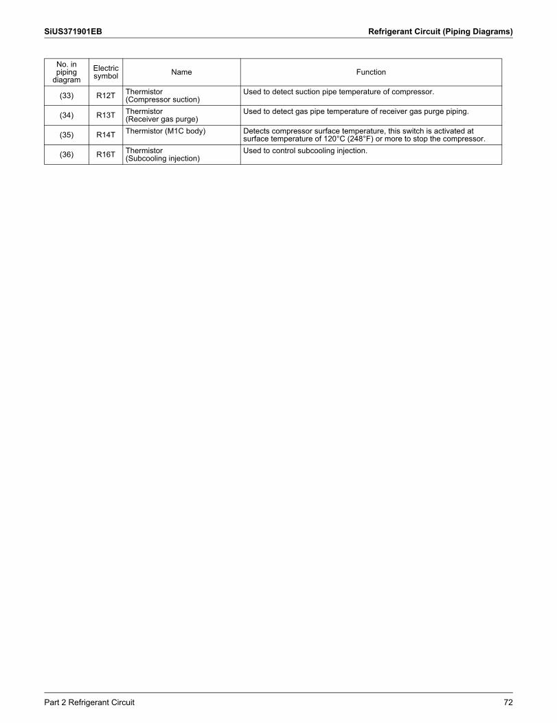
SiUS371901EB Refrigerant Circuit (Piping Diagrams)
(33) R12T Thermistor (Compressor suction)
Used to detect suction pipe temperature of compressor.
(34) R13T Thermistor(Receiver gas purge)
Used to detect gas pipe temperature of receiver gas purge piping.
(35) R14T Thermistor (M1C body) Detects compressor surface temperature, this switch is activated at surface temperature of 120°C (248°F) or more to stop the compressor.
(36) R16T Thermistor (Subcooling injection)
Used to control subcooling injection.
No. in piping
diagramElectric symbol Name Function
Part 2 Refrigerant Circuit 72
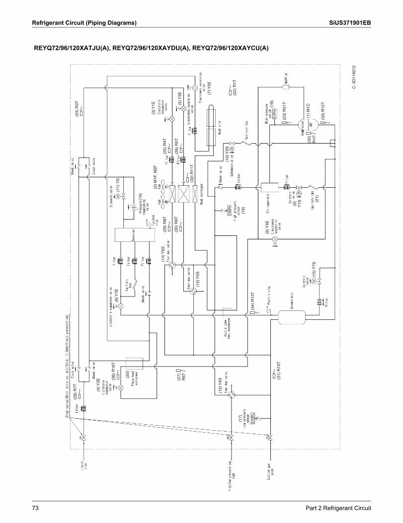
Refrigerant Circuit (Piping Diagrams) SiUS371901EB
REYQ72/96/120XATJU(A), REYQ72/96/120XAYDU(A), REYQ72/96/120XAYCU(A)
S1P
H
S1NP
H
S1NP
L
C: 3
D11
9212
(28)
R7T
(36)
R16
T
(29)
R8T
(25)
R4T
(24)
R3T
(26)
R5T
(30)
R9T
(32)
R11
T
(10)
Y2S
(22)
R1T
(4) Y
2E
(8) Y
7E(1
1) Y
3S
(19)
(14)
Y6S
(16)
(6) Y
4E
(15)
Y7S
(9)
Y1S (2
1)
(13)
Y5S
(2)
M1F
, M2F
(3) Y
1E (5) Y
3E (7) Y
5E
(20)
(27)
R6T
(35)
R14T
(33)
R12
T
(23)
R21
T
(1)
M1C(1
8)
(34)
R13
T
(31)
R10
T
(17)
(12)
Y4S
73 Part 2 Refrigerant Circuit
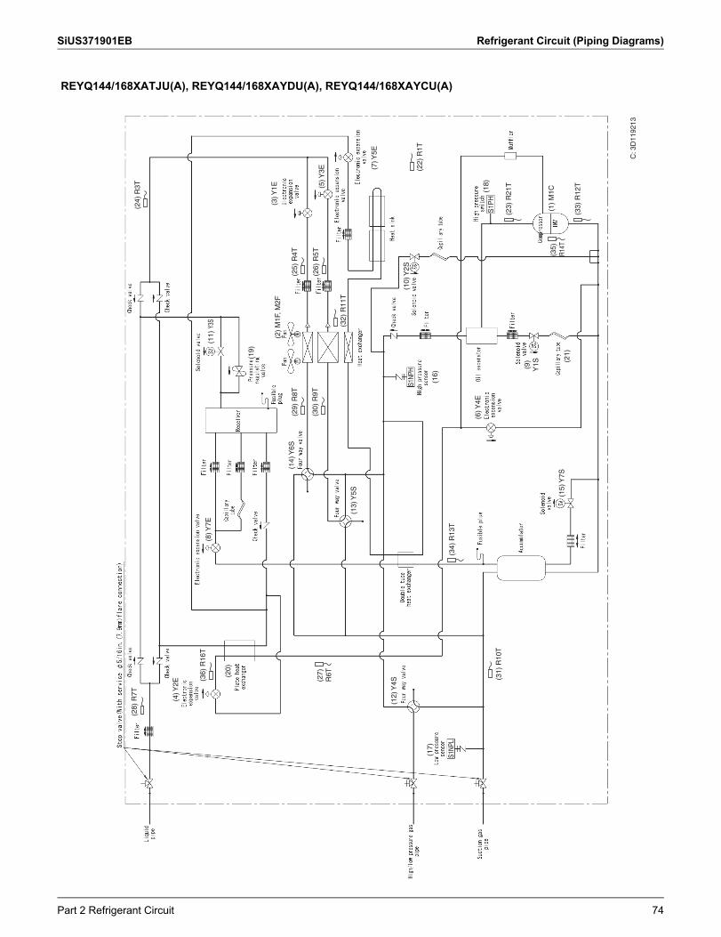
SiUS371901EB Refrigerant Circuit (Piping Diagrams)
REYQ144/168XATJU(A), REYQ144/168XAYDU(A), REYQ144/168XAYCU(A)
S1P
H
S1NP
H
S1NP
L
C: 3
D11
9213
(28)
R7T
(36)
R16
T
(29)
R8T
(25)
R4T
(24)
R3T
(26)
R5T
(30)
R9T
(32)
R11
T
(10)
Y2S
(22)
R1T
(4) Y
2E
(8) Y
7E(1
1) Y
3S
(19)
(14)
Y6S
(16)
(6) Y
4E
(15)
Y7S
(9)
Y1S (2
1)
(13)
Y5S
(2)
M1F
, M2F
(3) Y
1E (5) Y
3E (7) Y
5E
(20)
(27)
R6T
(35)
R14T
(33)
R12
T
(23)
R21
T
(1)
M1C(1
8)
(34)
R13
T
(31)
R10
T
(17)
(12)
Y4S
Part 2 Refrigerant Circuit 74
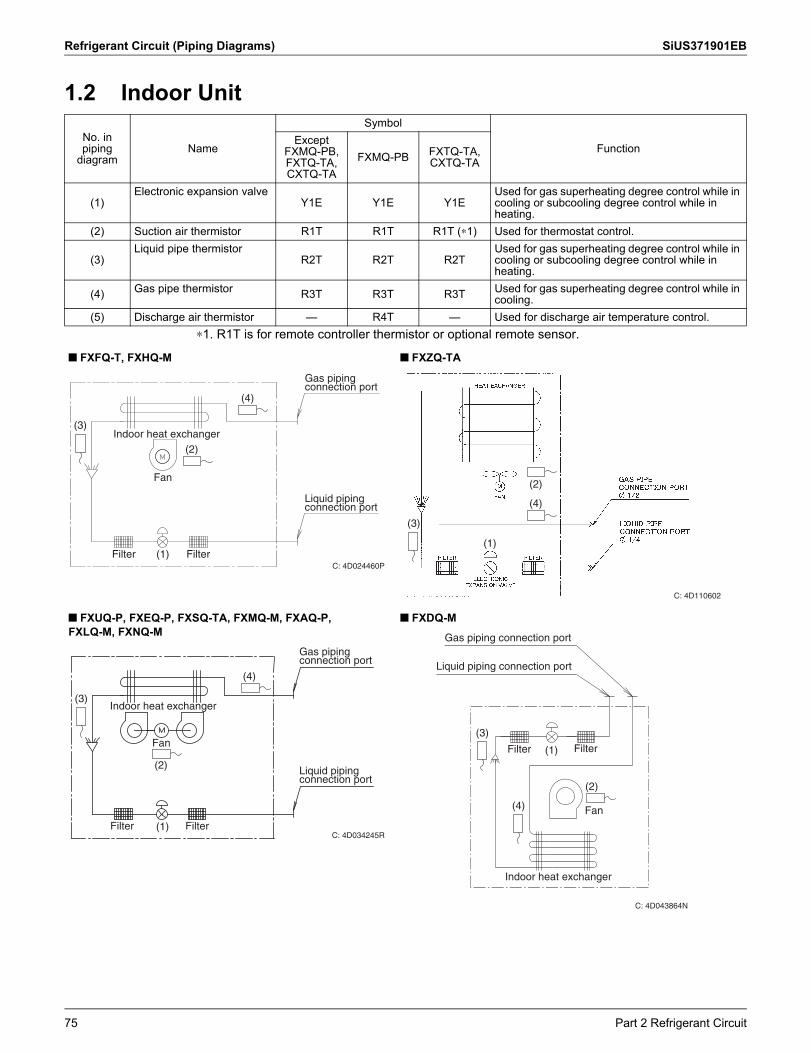
Refrigerant Circuit (Piping Diagrams) SiUS371901EB
1.2 Indoor Unit
∗1. R1T is for remote controller thermistor or optional remote sensor.
No. in piping
diagramName
Symbol
FunctionExcept
FXMQ-PB, FXTQ-TA, CXTQ-TA
FXMQ-PB FXTQ-TA, CXTQ-TA
(1)Electronic expansion valve
Y1E Y1E Y1EUsed for gas superheating degree control while in cooling or subcooling degree control while in heating.
(2) Suction air thermistor R1T R1T R1T (∗1) Used for thermostat control.
(3)Liquid pipe thermistor
R2T R2T R2TUsed for gas superheating degree control while in cooling or subcooling degree control while in heating.
(4) Gas pipe thermistor R3T R3T R3T Used for gas superheating degree control while in cooling.
(5) Discharge air thermistor — R4T — Used for discharge air temperature control.
FXFQ-T, FXHQ-M FXZQ-TA
FXUQ-P, FXEQ-P, FXSQ-TA, FXMQ-M, FXAQ-P,FXLQ-M, FXNQ-M
FXDQ-M
C: 4D024460P
(4)
(3)Indoor heat exchanger
Fan
Filter Filter(1)
Gas piping connection port
Liquid piping connection port
(2)
(4)
(3)
(1)
(2)
C: 4D110602
Indoor heat exchanger
Fan
Filter Filter
(4)
(2)
(1)
(3)
Gas piping connection port
Liquid piping connection port
C: 4D034245R
Fan
Indoor heat exchanger
FilterFilter
Liquid piping connection port
Gas piping connection port
(3)
(4)
(2)
(1)
C: 4D043864N
75 Part 2 Refrigerant Circuit
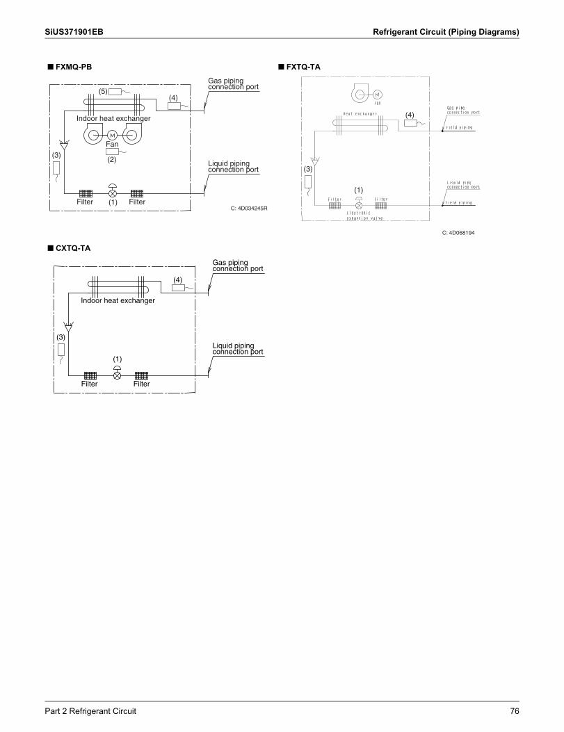
SiUS371901EB Refrigerant Circuit (Piping Diagrams)
FXMQ-PB FXTQ-TA
CXTQ-TA
Indoor heat exchanger
Fan
Filter Filter
(4)
(2)
(1)
(3)
Gas piping connection port
Liquid piping connection port
C: 4D034245R
(5)
C: 4D068194
(4)
(1)
(3)
Indoor heat exchanger
Filter Filter
(4)
(1)
(3)
Gas piping connection port
Liquid piping connection port
Part 2 Refrigerant Circuit 76
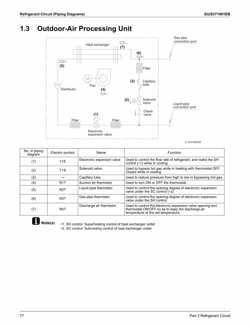
Refrigerant Circuit (Piping Diagrams) SiUS371901EB
Note(s)
1.3 Outdoor-Air Processing Unit
∗1. SH control: Superheating control of heat exchanger outlet∗2. SC control: Subcooling control of heat exchanger outlet
No. in piping diagram Electric symbol Name Function
(1) Y1E Electronic expansion valve Used to control the flow rate of refrigerant, and make the SH control (∗1) while in cooling.
(2) Y1S Solenoid valve Used to bypass hot gas while in heating with thermostat OFF. Closed while in cooling.
(3) — Capillary tube Used to reduce pressure from high to low in bypassing hot gas.(4) R1T Suction air thermistor Used to turn ON or OFF the thermostat.
(5) R2T Liquid pipe thermistor Used to control the opening degree of electronic expansion valve under the SC control (∗2).
(6) R3T Gas pipe thermistor Used to control the opening degree of electronic expansion valve under the SH control.
(7) R4TDischarge air thermistor Used to control the electronic expansion valve opening and
thermostat ON/OFF so as to keep the discharge air temperature at the set temperature.
C: 4D018650D
Heat exchanger
DistributorFan
Filter
Filter
Filter
Electronic expansion valve
Capillary tube
Solenoid valve
Check valve
Gas pipe connection port
Liquid pipe connection port
(5)
(7)
(6)
(3)
(2)
(1)
(4)
77 Part 2 Refrigerant Circuit
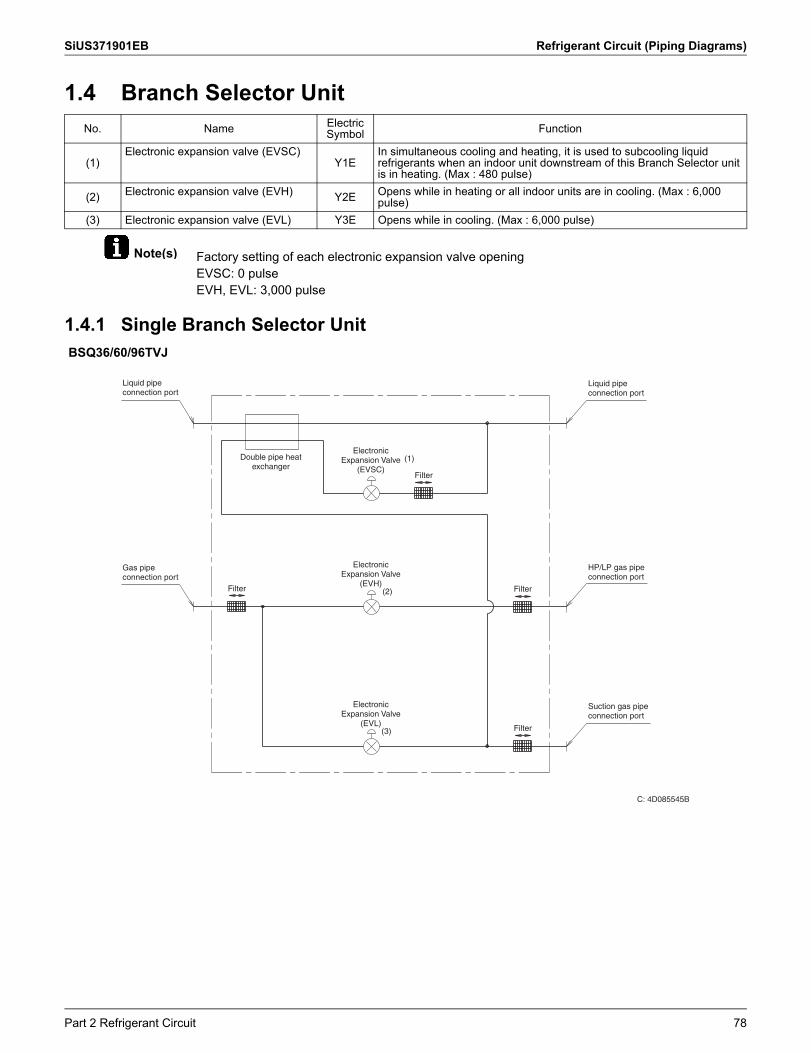
SiUS371901EB Refrigerant Circuit (Piping Diagrams)
Note(s)
1.4 Branch Selector Unit
Factory setting of each electronic expansion valve openingEVSC: 0 pulseEVH, EVL: 3,000 pulse
1.4.1 Single Branch Selector Unit
No. Name Electric Symbol Function
(1)Electronic expansion valve (EVSC)
Y1EIn simultaneous cooling and heating, it is used to subcooling liquid refrigerants when an indoor unit downstream of this Branch Selector unit is in heating. (Max : 480 pulse)
(2) Electronic expansion valve (EVH) Y2E Opens while in heating or all indoor units are in cooling. (Max : 6,000 pulse)
(3) Electronic expansion valve (EVL) Y3E Opens while in cooling. (Max : 6,000 pulse)
BSQ36/60/96TVJ
Filter
Filter Filter
Filter
Liquid pipe connection port
Gas pipe connection port
Double pipe heat exchanger
Electronic Expansion Valve
(EVSC)
Electronic Expansion Valve
(EVH)
Electronic Expansion Valve
(EVL)
Suction gas pipe connection port
HP/LP gas pipe connection port
Liquid pipe connection port
C: 4D085545B
(1)
(2)
(3)
Part 2 Refrigerant Circuit 78
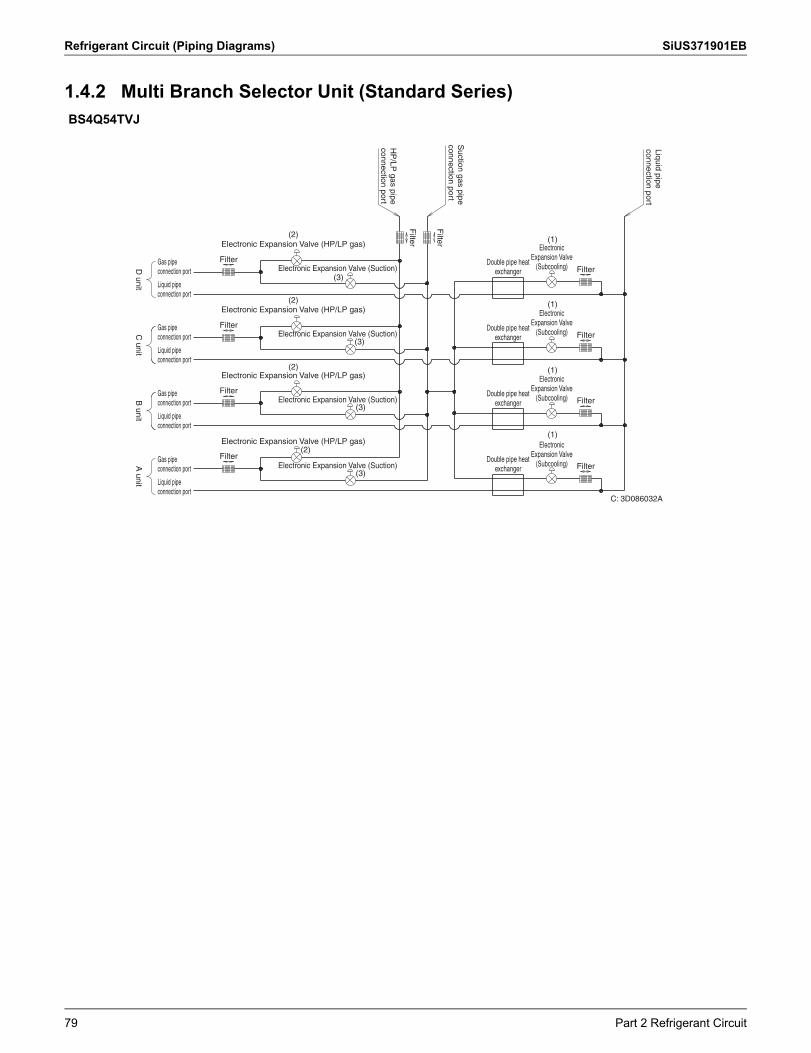
Refrigerant Circuit (Piping Diagrams) SiUS371901EB
1.4.2 Multi Branch Selector Unit (Standard Series)BS4Q54TVJ
Filter
Filter
Filter
Filter
Filter
Filter
Filter
Filter
Filter
Filter
tinu
B
tinu
D
t inu
A
t inu
C
Liquid pipe connection port
Suction gas pipe
connection port
HP
/LP gas pipe
connection port
Double pipe heat exchanger
Double pipe heat exchanger
Double pipe heat exchanger
Double pipe heat exchanger
Electronic (1)
(1)
(1)
(1)
Expansion Valve (Subcooling)
Electronic Expansion Valve
(Subcooling)
Electronic Expansion Valve
(Subcooling)
Electronic Expansion Valve
(Subcooling)
Electronic Expansion Valve (HP/LP gas)(2)
(3)
(3)
(3)
(3)
(2)
(2)
(2)
Electronic Expansion Valve (Suction)
Electronic Expansion Valve (HP/LP gas)
Electronic Expansion Valve (Suction)
Electronic Expansion Valve (HP/LP gas)
Electronic Expansion Valve (Suction)
Electronic Expansion Valve (HP/LP gas)
Electronic Expansion Valve (Suction)
Gas pipe connection port
Liquid pipe connection port
Gas pipe connection port
Liquid pipe connection port
Gas pipe connection port
Liquid pipe connection port
Gas pipe connection port
Liquid pipe connection port
C: 3D086032A
79 Part 2 Refrigerant Circuit
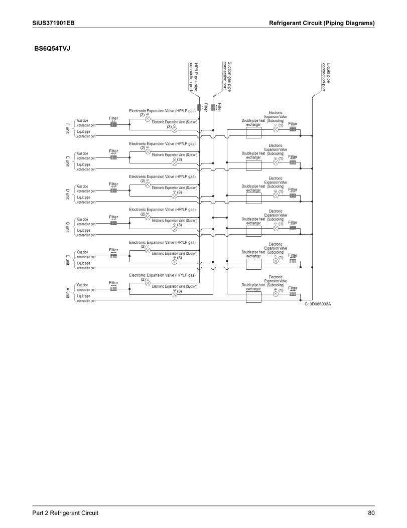
SiUS371901EB Refrigerant Circuit (Piping Diagrams)
BS6Q54TVJ
Filter
Filter
Filter
Filter
Filter
Filter
Filter
Filter
Electronic Expansion Valve (Suction)
Electronic Expansion Valve (Suction)
Electronic Expansion Valve (Suction)
Electronic Expansion Valve (Suction)
Electronic Expansion Valve (Suction)
Electronic Expansion Valve (Suction)
Electronic Expansion Valve (HP/LP gas)
Electronic Expansion Valve (HP/LP gas)
Electronic Expansion Valve (HP/LP gas)
Electronic Expansion Valve (HP/LP gas)
Electronic Expansion Valve (HP/LP gas)
Electronic Expansion Valve (HP/LP gas)
Filter
Filter
Filter
Filter
Filter
Filter
B unit
A unit
C unit
D unit
E unit
F unit
Liquid pipe connection port
Suction gas pipe
connection port
HP
/LP gas pipe
connection port
Gas pipe connection port
Liquid pipe connection port
Gas pipe connection port
Liquid pipe connection port
Gas pipe connection port
Liquid pipe connection port
Gas pipe connection port
Liquid pipe connection port
Gas pipe connection port
Liquid pipe connection port
Gas pipe connection port
Liquid pipe connection port
Double pipe heat exchanger
Electronic Expansion Valve
(Subcooling)
Double pipe heat exchanger
Electronic Expansion Valve
(Subcooling)
Double pipe heat exchanger
Electronic Expansion Valve
(Subcooling)
Double pipe heat exchanger
Electronic Expansion Valve
(Subcooling)
Double pipe heat exchanger
Electronic Expansion Valve
(Subcooling)
Double pipe heat exchanger
Electronic Expansion Valve
(Subcooling)
C: 3D086033A
(1)
(1)
(1)
(1)
(1)(3)
(2)
(2)
(2)
(2)
(2)
(2)
(3)
(3)
(3)
(3)
(3)
(1)
Part 2 Refrigerant Circuit 80
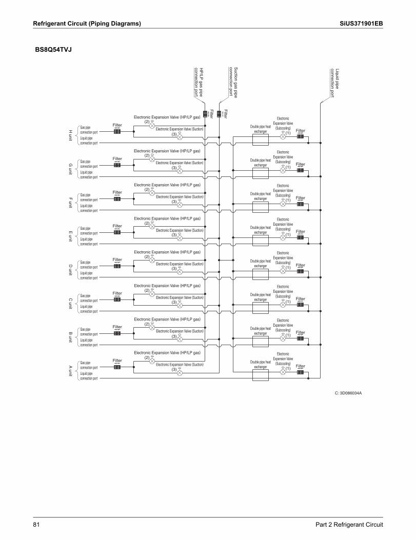
Refrigerant Circuit (Piping Diagrams) SiUS371901EB
BS8Q54TVJ
Filter
Filter
Filter
Filter
Filter
Filter
Filter
Filter
Filter
FilterElectronic Expansion Valve (HP/LP gas)
Electronic Expansion Valve (Suction)
Electronic Expansion Valve (HP/LP gas)
Electronic Expansion Valve (Suction)
Electronic Expansion Valve (HP/LP gas)
Electronic Expansion Valve (Suction)
Electronic Expansion Valve (HP/LP gas)
Electronic Expansion Valve (Suction)
Electronic Expansion Valve (HP/LP gas)
Electronic Expansion Valve (Suction)
Electronic Expansion Valve (HP/LP gas)
Electronic Expansion Valve (Suction)
Electronic Expansion Valve (HP/LP gas)
Electronic Expansion Valve (Suction)
Electronic Expansion Valve (HP/LP gas)
Electronic Expansion Valve (Suction)
Filter
Filter
Filter
Filter
Filter
Filter
Filter
Filter
D unit
F unit
H unit
A unit
tin u
B
t inu
C
t inu
E
tinu
G
Gas pipe connection portLiquid pipe connection port
Gas pipe connection portLiquid pipe connection port
Gas pipe connection portLiquid pipe connection port
Gas pipe connection portLiquid pipe connection port
Gas pipe connection portLiquid pipe connection port
Gas pipe connection portLiquid pipe connection port
Gas pipe connection portLiquid pipe connection port
Gas pipe connection portLiquid pipe connection port
Suction gas pipe
connection port
Liquid pipe connection port
HP
/LP gas pipe
connection port
Double pipe heat exchanger
Electronic Expansion Valve
(Subcooling)
Double pipe heat exchanger
Electronic Expansion Valve
(Subcooling)
Double pipe heat exchanger
Electronic Expansion Valve
(Subcooling)
Double pipe heat exchanger
Electronic Expansion Valve
(Subcooling)
Double pipe heat exchanger
Electronic Expansion Valve
(Subcooling)
Double pipe heat exchanger
Electronic Expansion Valve
(Subcooling)
Double pipe heat exchanger
Electronic Expansion Valve
(Subcooling)
Double pipe heat exchanger
Electronic Expansion Valve
(Subcooling)
C: 3D086034A
(1)
(1)
(1)
(1)
(1)
(1)
(1)
(1)
(3)
(3)
(3)
(3)
(3)
(3)
(3)
(3)
(2)
(2)
(2)
(2)
(2)
(2)
(2)
(2)
81 Part 2 Refrigerant Circuit
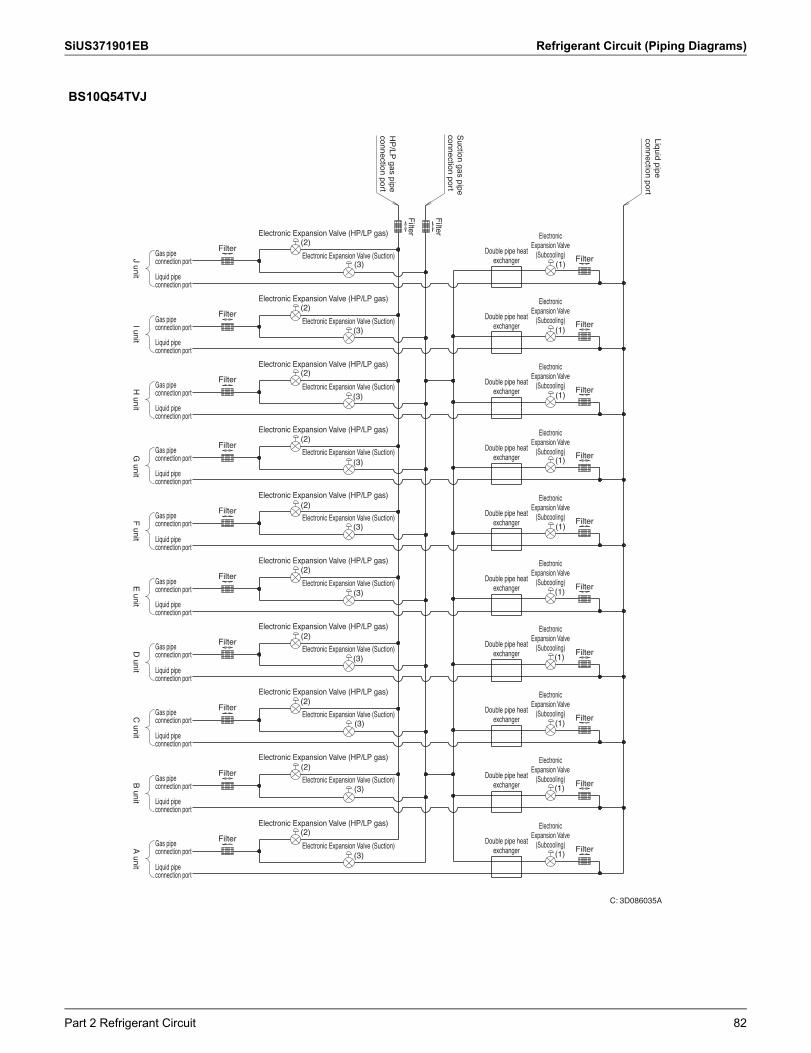
SiUS371901EB Refrigerant Circuit (Piping Diagrams)
BS10Q54TVJ
Filter
Filter
Filter
Filter
Filter
Filter
Filter
Filter
Filter
Filter
Filter
Filter
Filter
Filter
Filter
Filter
Filter
Filter
Filter
Filter
Filter
Filter
tinu
B
tinu
F
G unit
J unitI unit
D unit
tinu
A
tinu
C
t inu
E
tinu
H
Liquid pipe connection port
Suction gas pipe
connection port
HP
/LP gas pipe
connection port
Gas pipe connection port
Liquid pipe connection port
Gas pipe connection port
Liquid pipe connection port
Gas pipe connection port
Liquid pipe connection port
Gas pipe connection port
Liquid pipe connection port
Gas pipe connection port
Liquid pipe connection port
Gas pipe connection port
Liquid pipe connection port
Gas pipe connection port
Liquid pipe connection port
Gas pipe connection port
Liquid pipe connection port
Gas pipe connection port
Liquid pipe connection port
Gas pipe connection port
Liquid pipe connection port
Electronic Expansion Valve (HP/LP gas)
Electronic Expansion Valve (Suction)
Electronic Expansion Valve (HP/LP gas)
Electronic Expansion Valve (Suction)
Electronic Expansion Valve (HP/LP gas)
Electronic Expansion Valve (Suction)
Electronic Expansion Valve (HP/LP gas)
Electronic Expansion Valve (Suction)
Electronic Expansion Valve (HP/LP gas)
Electronic Expansion Valve (Suction)
Electronic Expansion Valve (HP/LP gas)
Electronic Expansion Valve (Suction)
Electronic Expansion Valve (HP/LP gas)
Electronic Expansion Valve (Suction)
Electronic Expansion Valve (HP/LP gas)
Electronic Expansion Valve (Suction)
Electronic Expansion Valve (HP/LP gas)
Electronic Expansion Valve (Suction)
Electronic Expansion Valve (HP/LP gas)
Electronic Expansion Valve (Suction)
Double pipe heat exchanger
Electronic Expansion Valve
(Subcooling)
Double pipe heat exchanger
Electronic Expansion Valve
(Subcooling)
Double pipe heat exchanger
Electronic Expansion Valve
(Subcooling)
Double pipe heat exchanger
Electronic Expansion Valve
(Subcooling)
Double pipe heat exchanger
Electronic Expansion Valve
(Subcooling)
Double pipe heat exchanger
Electronic Expansion Valve
(Subcooling)
Double pipe heat exchanger
Electronic Expansion Valve
(Subcooling)
Double pipe heat exchanger
Electronic Expansion Valve
(Subcooling)
Double pipe heat exchanger
Electronic Expansion Valve
(Subcooling)
Double pipe heat exchanger
Electronic Expansion Valve
(Subcooling)
C: 3D086035A
(1)
(1)
(1)
(1)
(1)
(1)
(1)
(1)
(1)
(1)
(3)
(3)
(3)
(3)
(3)
(3)
(3)
(3)
(3)
(3)
(2)
(2)
(2)
(2)
(2)
(2)
(2)
(2)
(2)
(2)
Part 2 Refrigerant Circuit 82
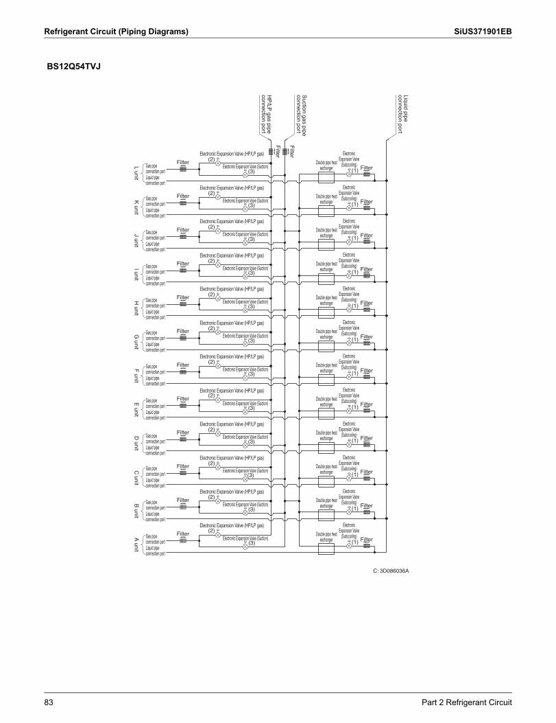
Refrigerant Circuit (Piping Diagrams) SiUS371901EB
BS12Q54TVJ
Filter
Filter
Filter
Filter
Filter
Filter
Filter
Filter
Filter
Filter
Filter
Filter
Filter
Filter
Filter
Filter
Filter
Filter
Filter
Filter
Filter
Filter
Filter
Filter
Filter
Filter
tinu
E
tin u
Jt i
nu
Dt i
nu
GL unit
C unit
A unit
F unit
I unitH
unitB
unitK
unit
Electronic Expansion Valve (HP/LP gas)
Electronic Expansion Valve (Suction)
Electronic Expansion Valve (HP/LP gas)
Electronic Expansion Valve (Suction)
Electronic Expansion Valve (HP/LP gas)
Electronic Expansion Valve (Suction)
Electronic Expansion Valve (HP/LP gas)
Electronic Expansion Valve (Suction)
Electronic Expansion Valve (HP/LP gas)
Electronic Expansion Valve (Suction)
Electronic Expansion Valve (HP/LP gas)
Electronic Expansion Valve (Suction)
Electronic Expansion Valve (HP/LP gas)
Electronic Expansion Valve (Suction)
Electronic Expansion Valve (HP/LP gas)
Electronic Expansion Valve (Suction)
Electronic Expansion Valve (HP/LP gas)
Electronic Expansion Valve (Suction)
Electronic Expansion Valve (HP/LP gas)
Electronic Expansion Valve (Suction)
Electronic Expansion Valve (HP/LP gas)
Electronic Expansion Valve (Suction)
Electronic Expansion Valve (HP/LP gas)
Electronic Expansion Valve (Suction)
Gas pipe connection portLiquid pipe connection port
Gas pipe connection portLiquid pipe connection port
Gas pipe connection portLiquid pipe connection port
Gas pipe connection portLiquid pipe connection port
Gas pipe connection portLiquid pipe connection port
Gas pipe connection portLiquid pipe connection port
Gas pipe connection portLiquid pipe connection port
Gas pipe connection portLiquid pipe connection port
Gas pipe connection portLiquid pipe connection port
Gas pipe connection portLiquid pipe connection port
Gas pipe connection portLiquid pipe connection port
Gas pipe connection portLiquid pipe connection port
Suction gas pipe
connection port
Liquid pipe connection port
HP
/LP gas pipe
connection port
Double pipe heat exchanger
Electronic Expansion Valve
(Subcooling)
Double pipe heat exchanger
Electronic Expansion Valve
(Subcooling)
Double pipe heat exchanger
Electronic Expansion Valve
(Subcooling)
Double pipe heat exchanger
Electronic Expansion Valve
(Subcooling)
Double pipe heat exchanger
Electronic Expansion Valve
(Subcooling)
Double pipe heat exchanger
Electronic Expansion Valve
(Subcooling)
Double pipe heat exchanger
Electronic Expansion Valve
(Subcooling)
Double pipe heat exchanger
Electronic Expansion Valve
(Subcooling)
Double pipe heat exchanger
Electronic Expansion Valve
(Subcooling)
Double pipe heat exchanger
Electronic Expansion Valve
(Subcooling)
Double pipe heat exchanger
Electronic Expansion Valve
(Subcooling)
Double pipe heat exchanger
Electronic Expansion Valve
(Subcooling)
C: 3D086036A
(1)
(1)
(1)
(1)
(1)
(1)
(1)
(1)
(1)
(1)
(1)
(1)
(3)
(3)
(3)
(3)
(3)
(3)
(3)
(3)
(3)
(3)
(3)
(3)
(2)
(2)
(2)
(2)
(2)
(2)
(2)
(2)
(2)
(2)
(2)
(2)
83 Part 2 Refrigerant Circuit
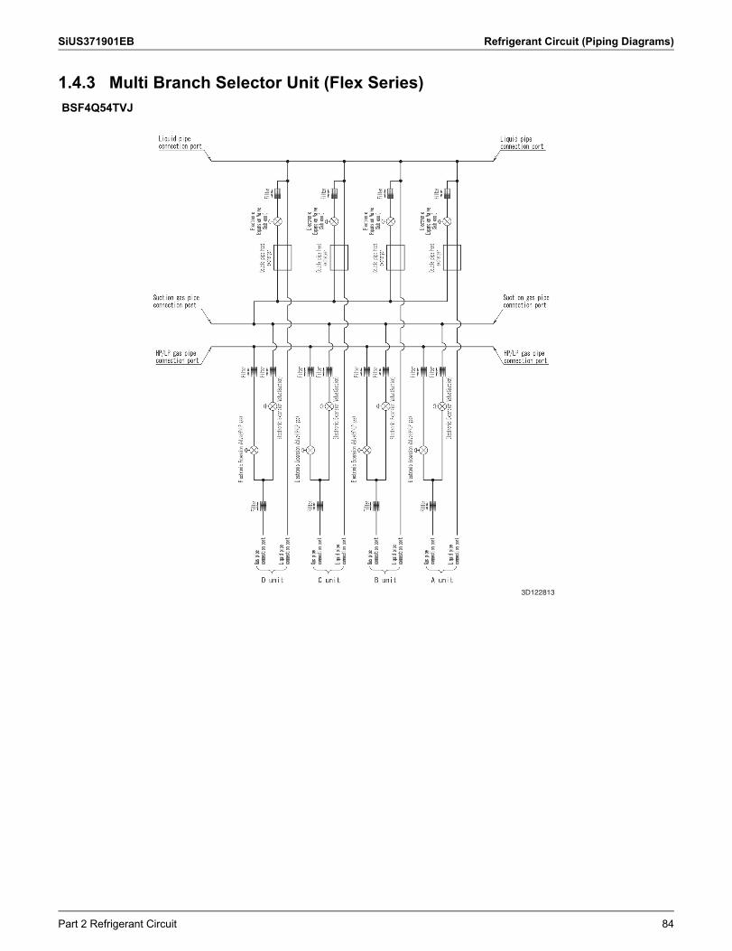
SiUS371901EB Refrigerant Circuit (Piping Diagrams)
1.4.3 Multi Branch Selector Unit (Flex Series)BSF4Q54TVJ
3D122813
Part 2 Refrigerant Circuit 84
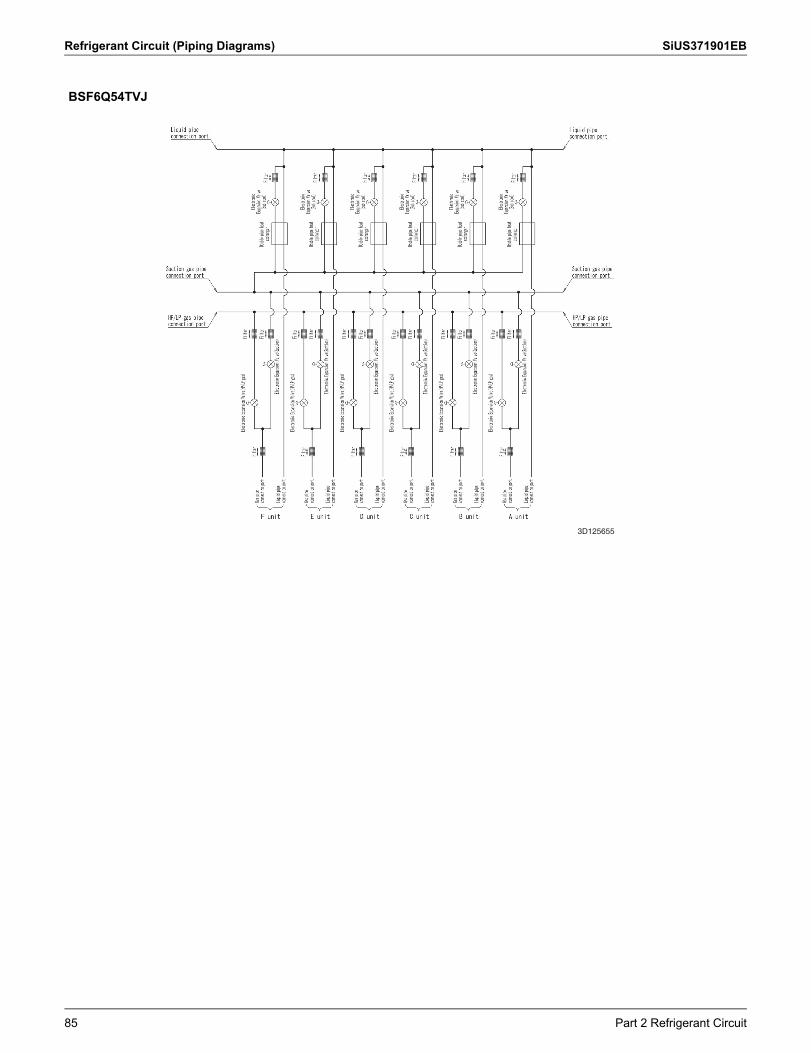
Refrigerant Circuit (Piping Diagrams) SiUS371901EB
BSF6Q54TVJ
3D125655
85 Part 2 Refrigerant Circuit
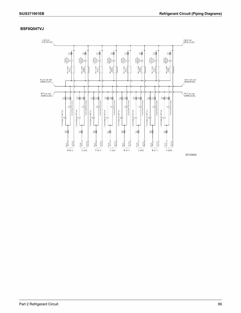
SiUS371901EB Refrigerant Circuit (Piping Diagrams)
BSF8Q54TVJ
3D125656
Part 2 Refrigerant Circuit 86
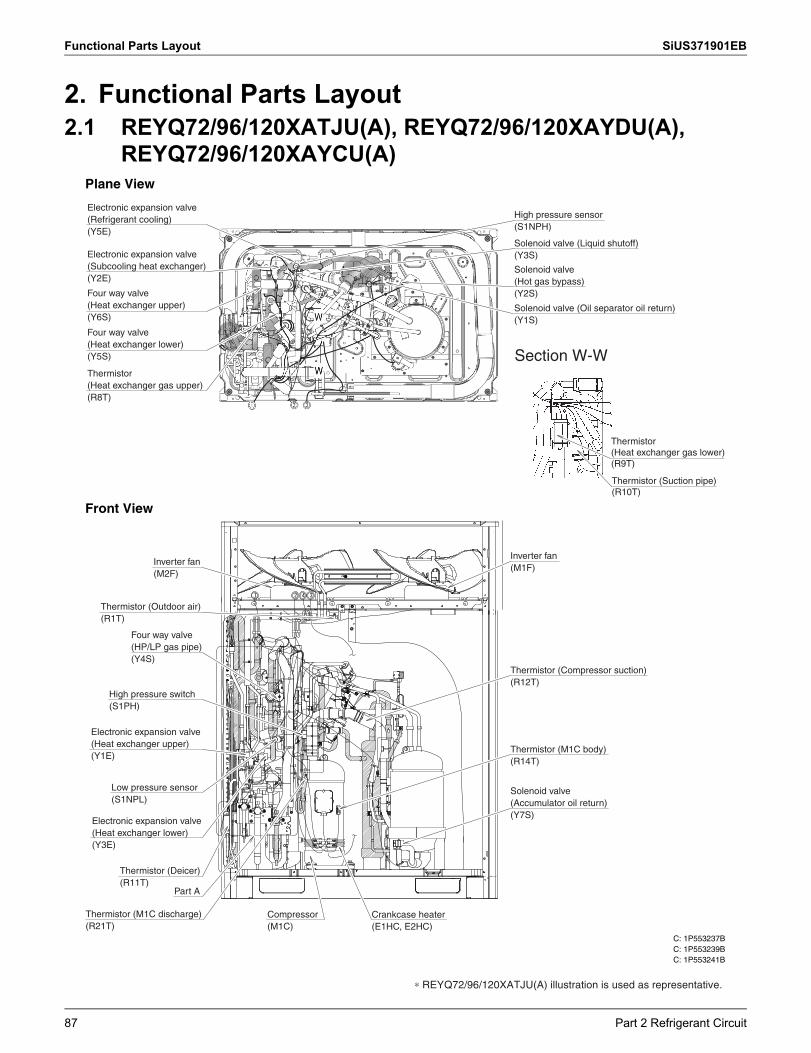
Functional Parts Layout SiUS371901EB
2. Functional Parts Layout2.1 REYQ72/96/120XATJU(A), REYQ72/96/120XAYDU(A),
REYQ72/96/120XAYCU(A)Plane View
Front View
C: 1P553237BC: 1P553239BC: 1P553241B
∗ REYQ72/96/120XATJU(A) illustration is used as representative.
Electronic expansion valve (Refrigerant cooling)(Y5E)
Electronic expansion valve (Subcooling heat exchanger)(Y2E)
Four way valve(Heat exchanger upper)(Y6S)
Four way valve(Heat exchanger lower)(Y5S)
Thermistor(Heat exchanger gas upper)(R8T)
Solenoid valve (Oil separator oil return)(Y1S)
Solenoid valve(Hot gas bypass)(Y2S)
Solenoid valve (Liquid shutoff)(Y3S)
High pressure sensor(S1NPH)
Section W-W
Thermistor(Heat exchanger gas lower)(R9T)
Thermistor (Suction pipe)(R10T)
Inverter fan(M2F)
Thermistor (Outdoor air)(R1T)
Four way valve (HP/LP gas pipe)(Y4S)
High pressure switch(S1PH)
Electronic expansion valve (Heat exchanger upper)(Y1E)
Thermistor (Deicer)(R11T)
Part A
Electronic expansion valve (Heat exchanger lower)(Y3E)
Low pressure sensor(S1NPL)
Compressor(M1C)
Solenoid valve(Accumulator oil return)(Y7S)
Thermistor (M1C body)(R14T)
Inverter fan(M1F)
Thermistor (Compressor suction)(R12T)
Crankcase heater(E1HC, E2HC)
Thermistor (M1C discharge)(R21T)
87 Part 2 Refrigerant Circuit
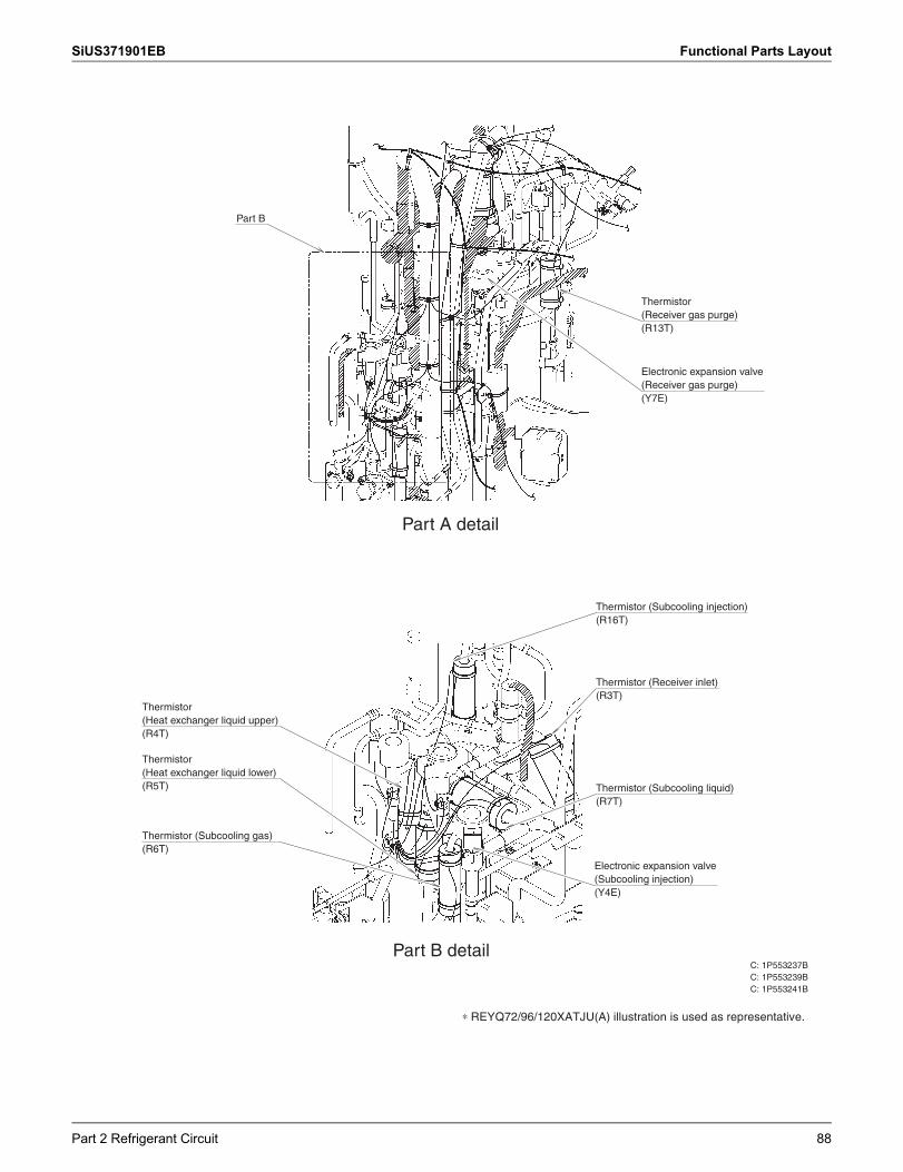
SiUS371901EB Functional Parts Layout
C: 1P553237BC: 1P553239BC: 1P553241B
∗ REYQ72/96/120XATJU(A) illustration is used as representative.
Part B
Part A detail
Thermistor(Receiver gas purge)(R13T)
Electronic expansion valve (Receiver gas purge)(Y7E)
Thermistor(Heat exchanger liquid upper)(R4T)
Thermistor(Heat exchanger liquid lower)(R5T)
Thermistor (Subcooling gas)(R6T)
Part B detail
Electronic expansion valve(Subcooling injection)(Y4E)
Thermistor (Subcooling liquid)(R7T)
Thermistor (Receiver inlet)(R3T)
Thermistor (Subcooling injection)(R16T)
Part 2 Refrigerant Circuit 88
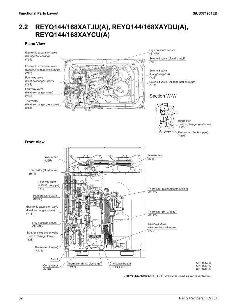
Functional Parts Layout SiUS371901EB
2.2 REYQ144/168XATJU(A), REYQ144/168XAYDU(A), REYQ144/168XAYCU(A)
Plane View
Front View
C: 1P553238BC: 1P553240BC: 1P553242B
� REYQ144/168XATJU(A) illustration is used as representative.
Electronic expansion valve (Refrigerant cooling)(Y5E)
Electronic expansion valve (Subcooling heat exchanger)(Y2E)
Four way valve(Heat exchanger upper)(Y6S)
Four way valve(Heat exchanger lower)(Y5S)
Thermistor(Heat exchanger gas upper)(R8T)
Solenoid valve (Oil separator oil return)(Y1S)
Solenoid valve(Hot gas bypass)(Y2S)
Solenoid valve (Liquid shutoff)(Y3S)
High pressure sensor(S1NPH)
Section W-W
Thermistor(Heat exchanger gas lower)(R9T)
Thermistor (Suction pipe)(R10T)
1 2 3 4
Inverter fan(M2F)
Thermistor (Outdoor air)(R1T)
Four way valve (HP/LP gas pipe)(Y4S)
High pressure switch(S1PH)
Electronic expansion valve (Heat exchanger upper)(Y1E)
Thermistor (Deicer)(R11T)
Part A
Electronic expansion valve (Heat exchanger lower)(Y3E)
Low pressure sensor(S1NPL)
Compressor(M1C)
Crankcase heater(E1HC, E2HC)
Solenoid valve(Accumulator oil return)(Y7S)
Thermistor (M1C body)(R14T)
Inverter fan(M1F)
Thermistor (Compressor suction)(R12T)
Thermistor (M1C discharge)(R21T)
89 Part 2 Refrigerant Circuit
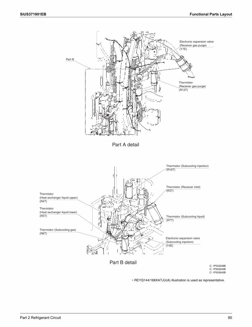
SiUS371901EB Functional Parts Layout
C: 1P553238BC: 1P553240BC: 1P553242B
∗ REYQ144/168XATJU(A) illustration is used as representative.
Part B
Part A detail
Thermistor(Receiver gas purge)(R13T)
Electronic expansion valve (Receiver gas purge)(Y7E)
Thermistor(Heat exchanger liquid upper)(R4T)
Thermistor(Heat exchanger liquid lower)(R5T)
Thermistor (Subcooling gas)(R6T)
Part B detail
Electronic expansion valve(Subcooling injection)(Y4E)
Thermistor (Subcooling liquid)(R7T)
Thermistor (Receiver inlet)(R3T)
Thermistor (Subcooling injection)(R16T)
Part 2 Refrigerant Circuit 90
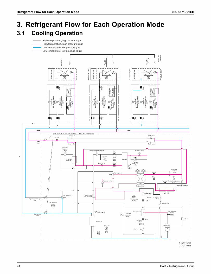
Refrigerant Flow for Each Operation Mode SiUS371901EB
3. Refrigerant Flow for Each Operation Mode3.1 Cooling Operation
High temperature, high pressure gas
High temperature, high pressure liquid
Low temperature, low pressure gas
Low temperature, low pressure liquid
S1NPH
S1PH
S1NPL
Filt
er
Filt
erF
ilter
Filt
er
Dou
ble
pipe
he
at
exch
ange
rE
lect
roni
c E
xpan
sion
Val
ve
(EV
SC
)
Ele
ctro
nic
Exp
ansi
on V
alve
(E
VH
)
Ele
ctro
nic
Exp
ansi
on V
alve
(E
VL)
OF
F
Fan
OF
F
Coo
ling
Uni
t
Dou
ble
pipe
he
at
exch
ange
rE
lect
roni
c E
xpan
sion
Val
ve
(EV
SC
)
Ele
ctro
nic
Exp
ansi
on V
alve
(E
VH
)
Ele
ctro
nic
Exp
ansi
on V
alve
(E
VL)
Filt
er
Filt
erF
ilter
Filt
er
The
rmos
tat "
OF
F"
Coo
ling
Uni
t
ON
Fan
ON
Dou
ble
pipe
he
at
exch
ange
rE
lect
roni
c E
xpan
sion
Val
ve
(EV
SC
)
Ele
ctro
nic
Exp
ansi
on V
alve
(E
VH
)
Ele
ctro
nic
Exp
ansi
on V
alve
(E
VL)
Filt
er
Filt
erF
ilter
Filt
er
Indo
or U
nit
The
rmos
tat "
ON
"
Coo
ling
Uni
t
ON
Fan
ON
Indo
or u
nit
Ope
ratio
n
C: 3D119212C: 3D119213
91 Part 2 Refrigerant Circuit
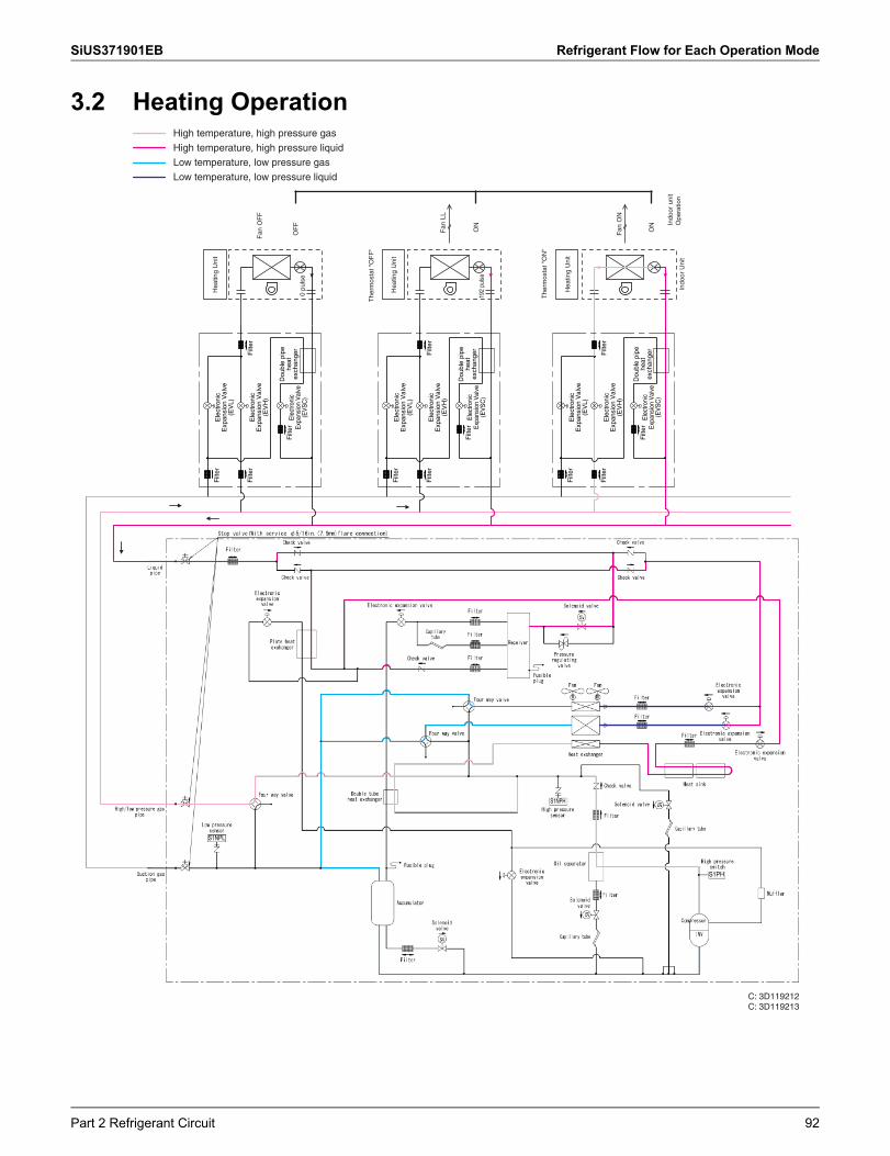
SiUS371901EB Refrigerant Flow for Each Operation Mode
3.2 Heating OperationHigh temperature, high pressure gas
High temperature, high pressure liquid
Low temperature, low pressure gas
Low temperature, low pressure liquid
S1NPH
S1PH
S1NPL
Filt
er
Filt
erF
ilter
Filt
er
Dou
ble
pipe
he
at
exch
ange
rE
lect
roni
c E
xpan
sion
Val
ve
(EV
SC
)
Ele
ctro
nic
Exp
ansi
on V
alve
(E
VH
)
Ele
ctro
nic
Exp
ansi
on V
alve
(E
VL)
Dou
ble
pipe
he
at
exch
ange
rE
lect
roni
c E
xpan
sion
Val
ve
(EV
SC
)
Ele
ctro
nic
Exp
ansi
on V
alve
(E
VH
)
Ele
ctro
nic
Exp
ansi
on V
alve
(E
VL)
Dou
ble
pipe
he
at
exch
ange
rE
lect
roni
c E
xpan
sion
Val
ve
(EV
SC
)
Ele
ctro
nic
Exp
ansi
on V
alve
(E
VH
)
Ele
ctro
nic
Exp
ansi
on V
alve
(E
VL)
Filt
er
Filt
erF
ilter
Filt
er
Filt
er
Filt
erF
ilter
Filt
er
Indo
or U
nit
The
rmos
tat "
OF
F"
OF
F
Fan
OF
F
Hea
ting
Uni
t
Hea
ting
Uni
t
ON
192
puls
e
0 pu
lse
Fan
LL
The
rmos
tat "
ON
"
Hea
ting
Uni
t
ON
Fan
ON
Indo
or u
nit
Ope
ratio
n
C: 3D119212C: 3D119213
Part 2 Refrigerant Circuit 92
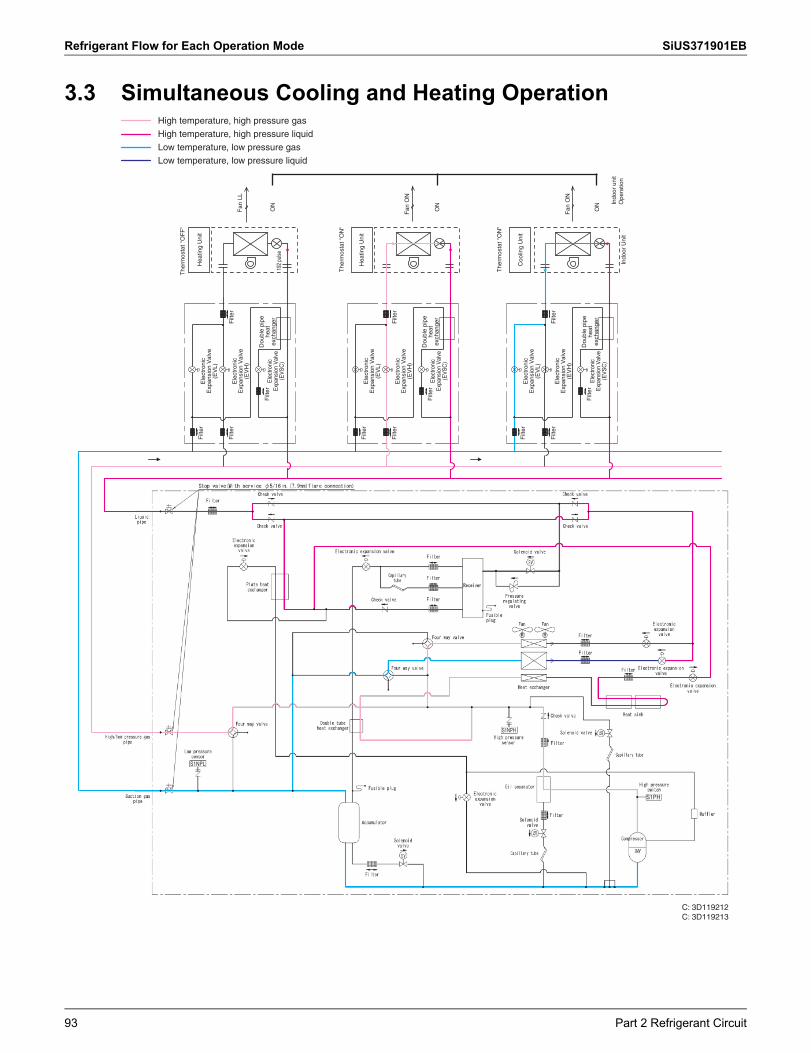
Refrigerant Flow for Each Operation Mode SiUS371901EB
3.3 Simultaneous Cooling and Heating Operation
S1NPH
S1PH
S1NPL
High temperature, high pressure gas
High temperature, high pressure liquid
Low temperature, low pressure gas
Low temperature, low pressure liquid
C: 3D119212C: 3D119213
Filt
er
Filt
erF
ilter
Filt
er
Dou
ble
pipe
he
at
exch
ange
rE
lect
roni
c E
xpan
sion
Val
ve
(EV
SC
)
Ele
ctro
nic
Exp
ansi
on V
alve
(E
VH
)
Ele
ctro
nic
Exp
ansi
on V
alve
(E
VL)
Dou
ble
pipe
he
at
exch
ange
rE
lect
roni
c E
xpan
sion
Val
ve
(EV
SC
)
Ele
ctro
nic
Exp
ansi
on V
alve
(E
VH
)
Ele
ctro
nic
Exp
ansi
on V
alve
(E
VL)
Dou
ble
pipe
he
at
exch
ange
rE
lect
roni
c E
xpan
sion
Val
ve
(EV
SC
)
Ele
ctro
nic
Exp
ansi
on V
alve
(E
VH
)
Ele
ctro
nic
Exp
ansi
on V
alve
(E
VL)
Filt
er
Filt
erF
ilter
Filt
er
Filt
er
Filt
erF
ilter
Filt
er
Indo
or U
nit
The
rmos
tat "
ON
"
ON
192
pulse
Fan
LL
The
rmos
tat
"OF
F"
Hea
ting
Uni
t
Hea
ting
Uni
t
ON
Fan
ON
The
rmos
tat "
ON
"
Coo
ling
Uni
t
ON
Fan
ON
Indo
or u
nit
Ope
ratio
n
93 Part 2 Refrigerant Circuit
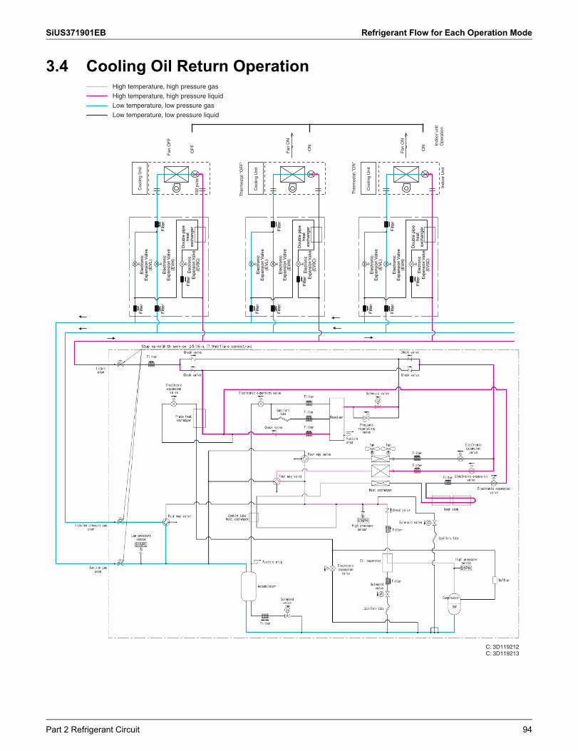
SiUS371901EB Refrigerant Flow for Each Operation Mode
3.4 Cooling Oil Return Operation
S1NPH
S1PH
S1NPL
High temperature, high pressure gas
High temperature, high pressure liquid
Low temperature, low pressure gas
Low temperature, low pressure liquid
C: 3D119212C: 3D119213
Filt
er
Filt
erF
ilter
Filt
er
Dou
ble
pipe
he
at
exch
ange
rE
lect
roni
c E
xpan
sion
Val
ve
(EV
SC
)
Ele
ctro
nic
Exp
ansi
on V
alve
(E
VH
)
Ele
ctro
nic
Exp
ansi
on V
alve
(E
VL)
Dou
ble
pipe
he
at
exch
ange
rE
lect
roni
c E
xpan
sion
Val
ve
(EV
SC
)
Ele
ctro
nic
Exp
ansi
on V
alve
(E
VH
)
Ele
ctro
nic
Exp
ansi
on V
alve
(E
VL)
Dou
ble
pipe
he
at
exch
ange
rE
lect
roni
c E
xpan
sion
Val
ve
(EV
SC
)
Ele
ctro
nic
Exp
ansi
on V
alve
(E
VH
)
Ele
ctro
nic
Exp
ansi
on V
alve
(E
VL)
Filt
er
Filt
erF
ilter
Filt
er
Filt
er
Filt
erF
ilter
Filt
er
Indo
or U
nit
The
rmos
tat "
OF
F"
OF
F19
2 pu
lse
Fan
OF
F
Coo
ling
Uni
t
Coo
ling
Uni
t
ON
Fan
ON
The
rmos
tat "
ON
"
Coo
ling
Uni
t
ON
Fan
ON
Indo
or u
nit
Ope
ratio
n
Part 2 Refrigerant Circuit 94
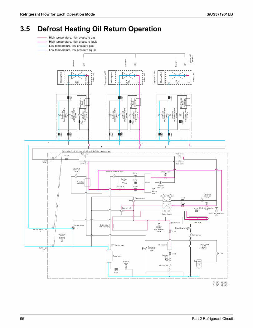
Refrigerant Flow for Each Operation Mode SiUS371901EB
3.5 Defrost Heating Oil Return Operation
S1NPH
S1PH
S1NPL
High temperature, high pressure gas
High temperature, high pressure liquid
Low temperature, low pressure gas
Low temperature, low pressure liquid
C: 3D119212C: 3D119213
Filt
er
Filt
erF
ilter
Filt
er
Dou
ble
pipe
he
at
exch
ange
rE
lect
roni
c E
xpan
sion
Val
ve
(EV
SC
)
Ele
ctro
nic
Exp
ansi
on V
alve
(E
VH
)
Ele
ctro
nic
Exp
ansi
on V
alve
(E
VL)
Dou
ble
pipe
he
at
exch
ange
rE
lect
roni
c E
xpan
sion
Val
ve
(EV
SC
)
Ele
ctro
nic
Exp
ansi
on V
alve
(E
VH
)
Ele
ctro
nic
Exp
ansi
on V
alve
(E
VL)
Dou
ble
pipe
he
at
exch
ange
rE
lect
roni
c E
xpan
sion
Val
ve
(EV
SC
)
Ele
ctro
nic
Exp
ansi
on V
alve
(E
VH
)
Ele
ctro
nic
Exp
ansi
on V
alve
(E
VL)
Filt
er
Filt
erF
ilter
Filt
er
Filt
er
Filt
erF
ilter
Filt
er
Indo
or U
nit
Indo
or U
nit
Indo
or U
nit
The
rmos
tat "
OF
F"
OF
F
Fan
OF
F
Hea
ting
Uni
t
Hea
ting
Uni
t
ON
224
puls
e
Fan
OF
F
The
rmos
tat "
ON
"
Hea
ting
Uni
t
ON
Fan
OF
F
Indo
or u
nit
Ope
ratio
n
95 Part 2 Refrigerant Circuit
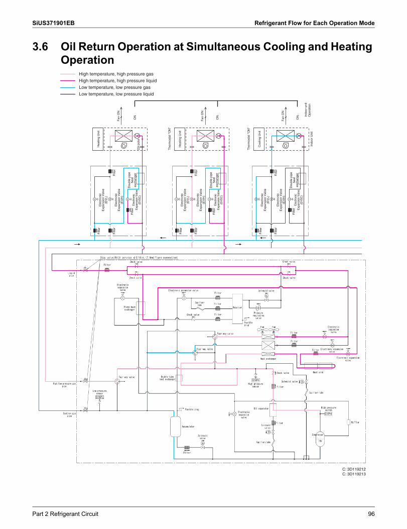
SiUS371901EB Refrigerant Flow for Each Operation Mode
3.6 Oil Return Operation at Simultaneous Cooling and Heating Operation
S1NPH
S1PH
S1NPL
High temperature, high pressure gas
High temperature, high pressure liquid
Low temperature, low pressure gas
Low temperature, low pressure liquid
C: 3D119212C: 3D119213
Filt
er
Filt
erF
ilter
Filt
er
Dou
ble
pipe
he
at
exch
ange
rE
lect
roni
c E
xpan
sion
Val
ve
(EV
SC
)
Ele
ctro
nic
Exp
ansi
on V
alve
(E
VH
)
Ele
ctro
nic
Exp
ansi
on V
alve
(E
VL)
Dou
ble
pipe
he
at
exch
ange
rE
lect
roni
c E
xpan
sion
Val
ve
(EV
SC
)
Ele
ctro
nic
Exp
ansi
on V
alve
(E
VH
)
Ele
ctro
nic
Exp
ansi
on V
alve
(E
VL)
Dou
ble
pipe
he
at
exch
ange
rE
lect
roni
c E
xpan
sion
Val
ve
(EV
SC
)
Ele
ctro
nic
Exp
ansi
on V
alve
(E
VH
)
Ele
ctro
nic
Exp
ansi
on V
alve
(E
VL)
Filt
er
Filt
erF
ilter
Filt
er
Filt
er
Filt
erF
ilter
Filt
er
Indo
or U
nit
The
rmos
tat "
ON
"
ON
224
puls
e
Fan
ON
Hea
ting
Uni
t
Hea
ting
Uni
t
ON
Fan
ON
The
rmos
tat "
ON
"
Coo
ling
Uni
t
ON
Fan
ON
Indo
or u
nit
Ope
ratio
n
Part 2 Refrigerant Circuit 96
SiUS371901EB
97 Part 3 Remote Controller
1. Applicable Models .....................................................................................982. Names and Functions ...............................................................................99
2.1 BRC1E73 ................................................................................................... 992.2 BRC1H71W.............................................................................................. 1022.3 Wireless Remote Controller ..................................................................... 110
3. Main/Sub Setting.....................................................................................1113.1 BRC1E73 ................................................................................................. 1113.2 BRC1H71W.............................................................................................. 1133.3 When Wireless Remote Controller is Used Together............................... 115
4. Address Setting for Wireless Remote Controller.....................................1165. Centralized Control Group No. Setting....................................................118
5.1 BRC1E73 ................................................................................................. 1185.2 BRC1H71W.............................................................................................. 1205.3 Wireless Remote Controller ..................................................................... 1205.4 Group No. Setting Example...................................................................... 121
6. Service Settings Menu, Maintenance Menu............................................1226.1 BRC1E73 ................................................................................................. 122
7. Administrator Menu, Installer Menu ........................................................1267.1 BRC1H71W.............................................................................................. 126
Part 3 Remote Controller
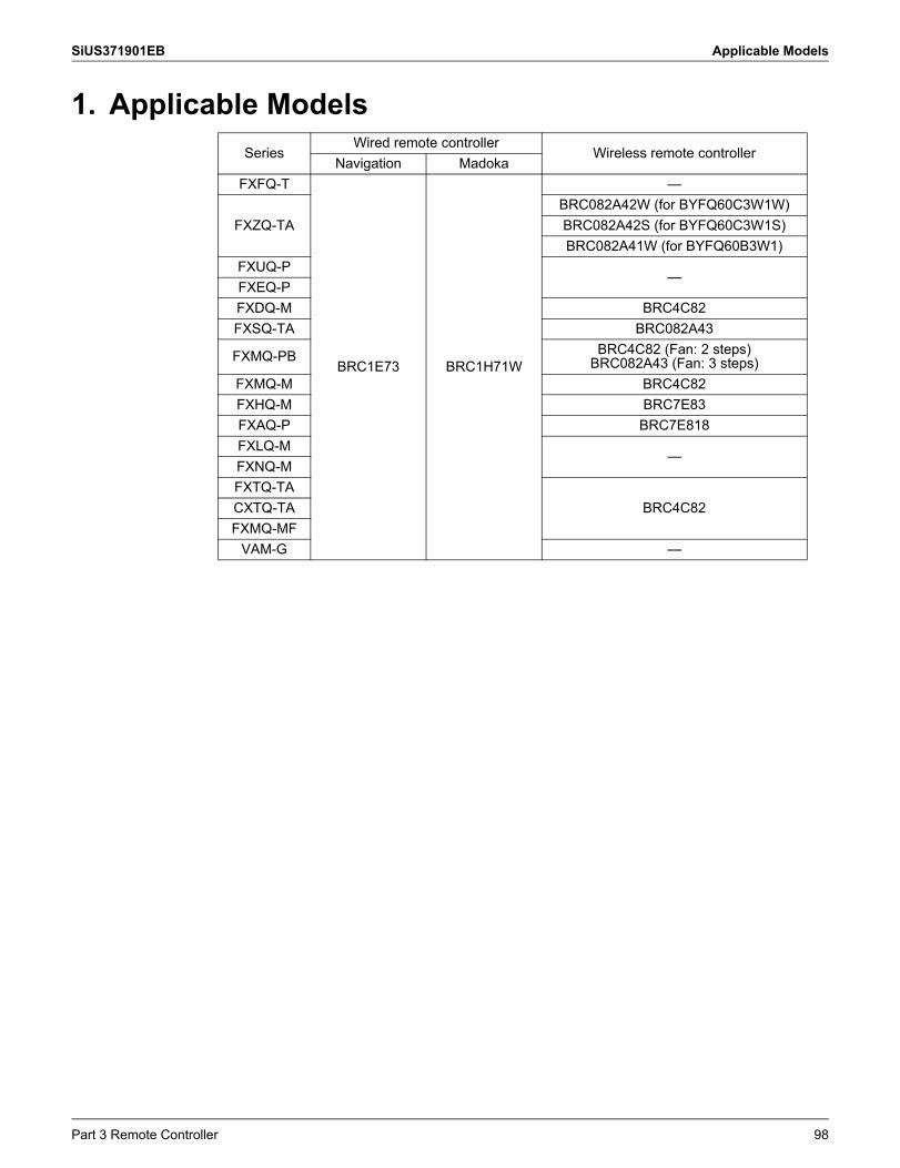
SiUS371901EB Applicable Models
1. Applicable ModelsSeries
Wired remote controllerWireless remote controller
Navigation MadokaFXFQ-T
BRC1E73 BRC1H71W
—
FXZQ-TABRC082A42W (for BYFQ60C3W1W)BRC082A42S (for BYFQ60C3W1S)BRC082A41W (for BYFQ60B3W1)
FXUQ-P—
FXEQ-PFXDQ-M BRC4C82FXSQ-TA BRC082A43
FXMQ-PB BRC4C82 (Fan: 2 steps)BRC082A43 (Fan: 3 steps)
FXMQ-M BRC4C82FXHQ-M BRC7E83FXAQ-P BRC7E818FXLQ-M
—FXNQ-MFXTQ-TA
BRC4C82CXTQ-TAFXMQ-MF
VAM-G —
Part 3 Remote Controller 98
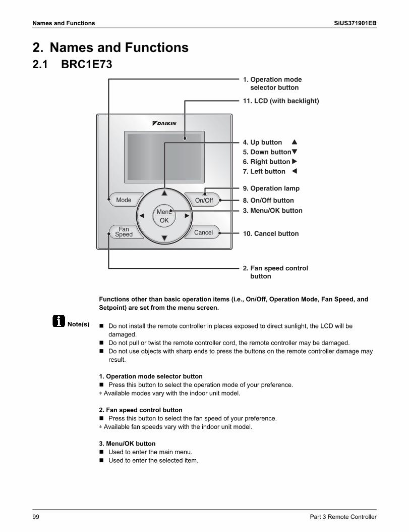
Names and Functions SiUS371901EB
Note(s)
2. Names and Functions2.1 BRC1E73
Functions other than basic operation items (i.e., On/Off, Operation Mode, Fan Speed, and Setpoint) are set from the menu screen.
Do not install the remote controller in places exposed to direct sunlight, the LCD will be damaged.
Do not pull or twist the remote controller cord, the remote controller may be damaged. Do not use objects with sharp ends to press the buttons on the remote controller damage may
result.
1. Operation mode selector button Press this button to select the operation mode of your preference.∗ Available modes vary with the indoor unit model.
2. Fan speed control button Press this button to select the fan speed of your preference.∗ Available fan speeds vary with the indoor unit model.
3. Menu/OK button Used to enter the main menu. Used to enter the selected item.
3. Menu/OK button
8. On/Off button
10. Cancel button
9. Operation lamp
11. LCD (with backlight)
4. Up button5. Down button6. Right button7. Left button
1. Operation mode selector button
2. Fan speed control button
99 Part 3 Remote Controller
SiUS371901EB Names and Functions
4. Up button Used to raise the setpoint. The item above the current selection will be highlighted. (The highlighted items will be scrolled
continuously when the button is continuously pressed.) Used to change the selected item.
5. Down button Used to lower the setpoint. The item below the current selection will be highlighted. (The highlighted items will be scrolled
continuously when the button is continuously pressed.) Used to change the selected item.
6. Right button Used to highlight the next items on the right-hand side. Each screen is scrolled in the right-hand direction.
7. Left button Used to highlight the next items on the left-hand side. Each screen is scrolled in the left-hand direction.
8. On/Off button Press this button and system will start. Press this button again to stop the system.
9. Operation lamp This lamp illuminates solid green during normal operation. This lamp blinks if an error occurs.
10. Cancel button Used to return to the previous screen.
11. LCD (with backlight) The backlight will be illuminated for approximately 30 seconds by pressing any button. If two remote controllers are used to control a single indoor unit, only the controller accessed
first will have backlight functionality.
Part 3 Remote Controller 100
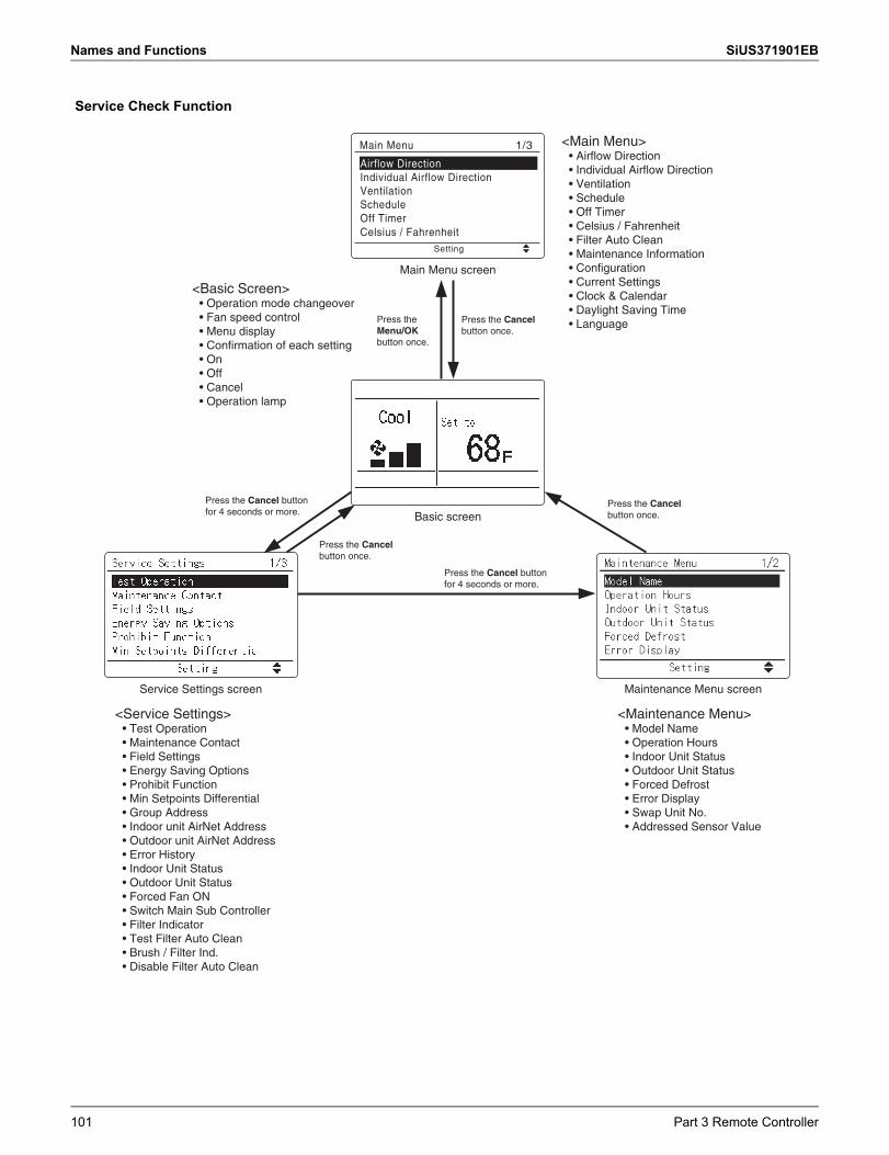
Names and Functions SiUS371901EB
Service Check Function
Basic screen
Main Menu screen
Service Settings screen Maintenance Menu screen
Setting
Main Menu
Airflow DirectionIndividual Airflow DirectionVentilationScheduleOff TimerCelsius / Fahrenheit
1/3 <Main Menu>• Airflow Direction• Individual Airflow Direction• Ventilation• Schedule• Off Timer• Celsius / Fahrenheit• Filter Auto Clean• Maintenance Information• Configuration• Current Settings• Clock & Calendar• Daylight Saving Time• LanguagePress the Cancel
button once.Press the Menu/OK button once.
<Basic Screen>• Operation mode changeover• Fan speed control• Menu display• Confirmation of each setting• On• Off• Cancel• Operation lamp
Press the Cancel button for 4 seconds or more.
Press the Cancel button once.
Press the Cancel button for 4 seconds or more.
Press the Cancel button once.
<Maintenance Menu>• Model Name• Operation Hours• Indoor Unit Status• Outdoor Unit Status• Forced Defrost• Error Display• Swap Unit No.• Addressed Sensor Value
<Service Settings>• Test Operation• Maintenance Contact• Field Settings• Energy Saving Options• Prohibit Function• Min Setpoints Differential• Group Address• Indoor unit AirNet Address• Outdoor unit AirNet Address• Error History• Indoor Unit Status• Outdoor Unit Status• Forced Fan ON• Switch Main Sub Controller• Filter Indicator• Test Filter Auto Clean• Brush / Filter Ind.• Disable Filter Auto Clean
101 Part 3 Remote Controller
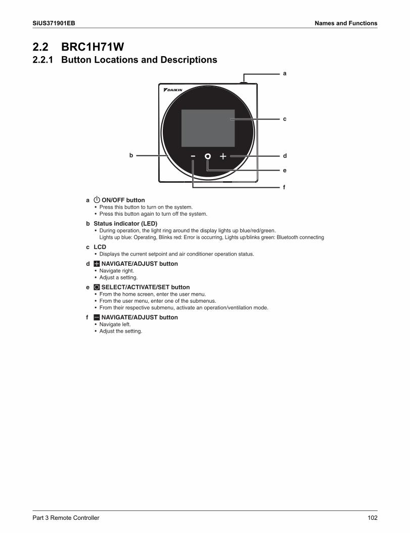
SiUS371901EB Names and Functions
2.2 BRC1H71W2.2.1 Button Locations and Descriptions
a
b
c
d
e
f
+-
a ON/OFF button• Press this button to turn on the system.•
b Status indicator (LED)• During operation, the light ring around the display lights up blue/red/green.
Lights up blue: Operating, Blinks red: Error is occurring, Lights up/blinks green: Bluetooth connecting
c LCD • Displays the current setpoint and air conditioner operation status.
d NAVIGATE/ADJUST button• Navigate right.• Adjust a setting.
e SELECT/ACTIVATE/SET button• From the home screen, enter the user menu.• From the user menu, enter one of the submenus.• From their respective submenu, activate an operation/ventilation mode.
f NAVIGATE/ADJUST button• Navigate left.• Adjust the setting.
Press this button again to turn off the system.
Part 3 Remote Controller 102
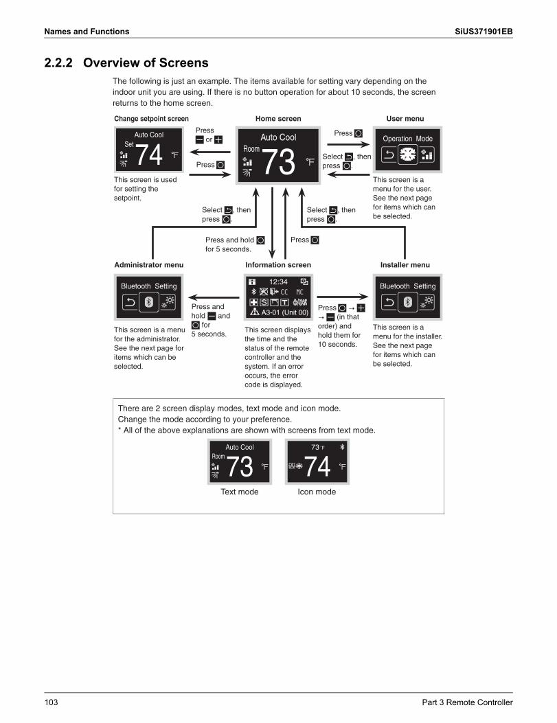
Names and Functions SiUS371901EB
2.2.2 Overview of ScreensThe following is just an example. The items available for setting vary depending on the indoor unit you are using. If there is no button operation for about 10 seconds, the screen returns to the home screen.
Change setpoint screen
Auto CoolSet
74This screen is used for setting the setpoint.
Press or
Press
Home screen
Auto Cool
73Room
Press
User menu
Operation Mode
This screen is a menu for the user. See the next page for items which can be selected.
Administrator menu Information screen Installer menu
Bluetooth Setting
This screen is a menu for the administrator. See the next page for items which can be selected.
12:34
A3-01 (Unit 00)
This screen displays the time and the status of the remote controller and the system. If an error occurs, the error code is displayed.
Bluetooth Setting
This screen is a menu for the installer. See the next page for items which can be selected.
There are 2 screen display modes, text mode and icon mode.Change the mode according to your preference.* All of the above explanations are shown with screens from text mode.
Auto Cool
73Room
73 ˚F
74Text mode Icon mode
Select , then press .
Press and hold for 5 seconds.
Press
Select , then press .
Select , then press .
Press and hold and
for 5 seconds.
Press � � (in that order) and hold them for 10 seconds.
103 Part 3 Remote Controller
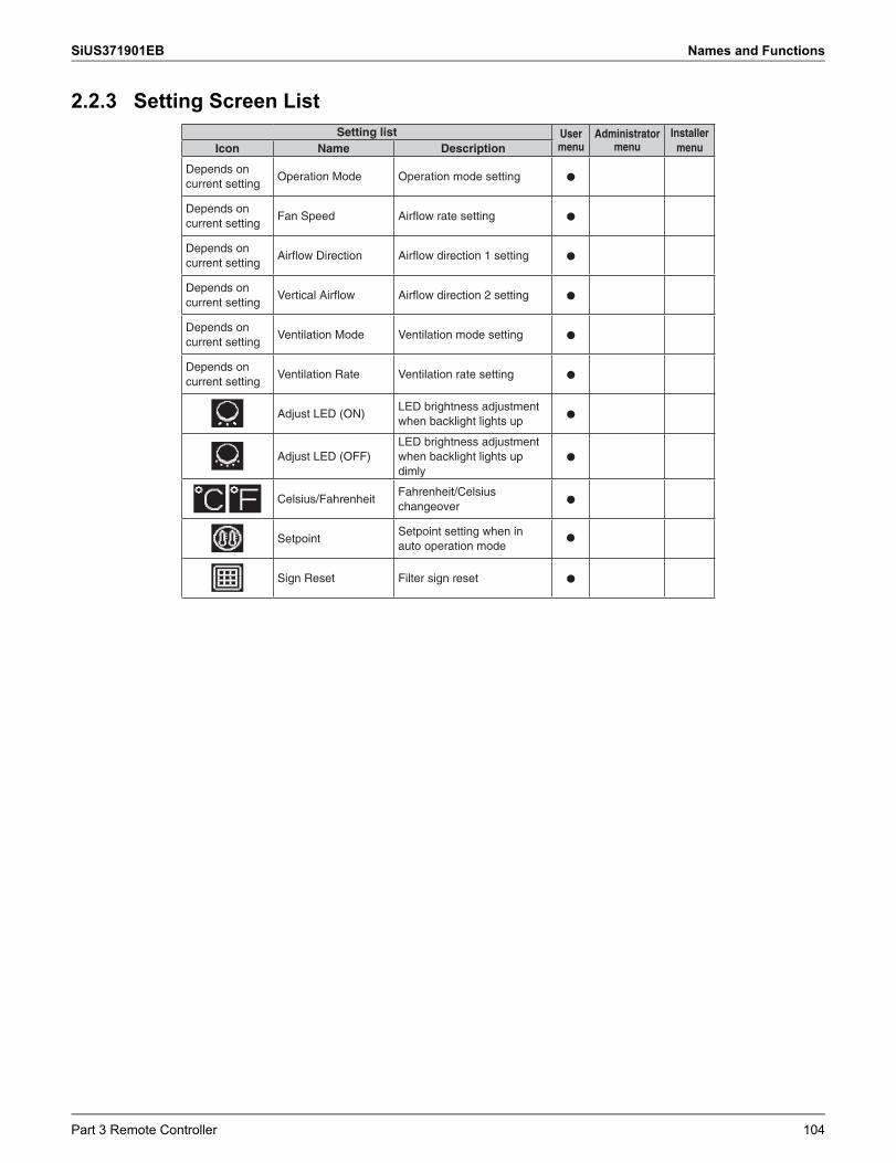
SiUS371901EB Names and Functions
2.2.3 Setting Screen ListSetting list User
menuAdministrator
menuInstaller
menuIcon Name Description
Depends on current setting
Operation Mode Operation mode setting h
Depends on current setting
Fan Speed Airflow rate setting h
Depends on current setting
Airflow Direction Airflow direction 1 setting h
Depends on current setting
Vertical Airflow Airflow direction 2 setting h
Depends on current setting
Ventilation Mode Ventilation mode setting h
Depends on current setting
Ventilation Rate Ventilation rate setting h
Adjust LED (ON)LED brightness adjustment when backlight lights up
h
Adjust LED (OFF)LED brightness adjustment when backlight lights up dimly
h
Celsius/Fahrenheit
Fahrenheit/Celsius changeover
h
SetpointSetpoint setting when in auto operation mode
Sign Reset Filter sign reset h
h
Part 3 Remote Controller 104
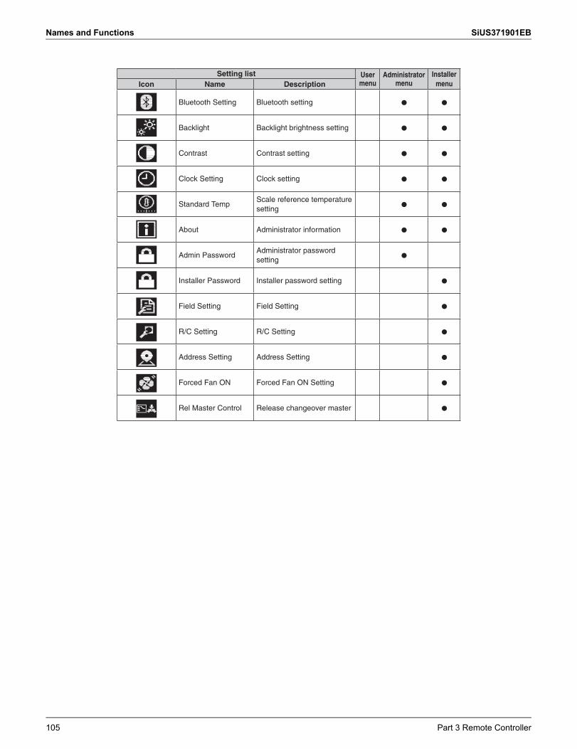
Names and Functions SiUS371901EB
Setting list User menu
Administrator menu
Installer menuIcon Name Description
Bluetooth Setting Bluetooth setting h h
Backlight Backlight brightness setting h h
Contrast Contrast setting h h
Clock Setting Clock setting h h
Standard TempScale reference temperature setting
h h
About Administrator information h h
Admin PasswordAdministrator password setting
h
Installer Password Installer password setting h
Field Setting Field Setting h
R/C Setting R/C Setting h
Address Setting Address Setting h
Forced Fan ON Forced Fan ON Setting h
Rel Master Control Release changeover master h
105 Part 3 Remote Controller
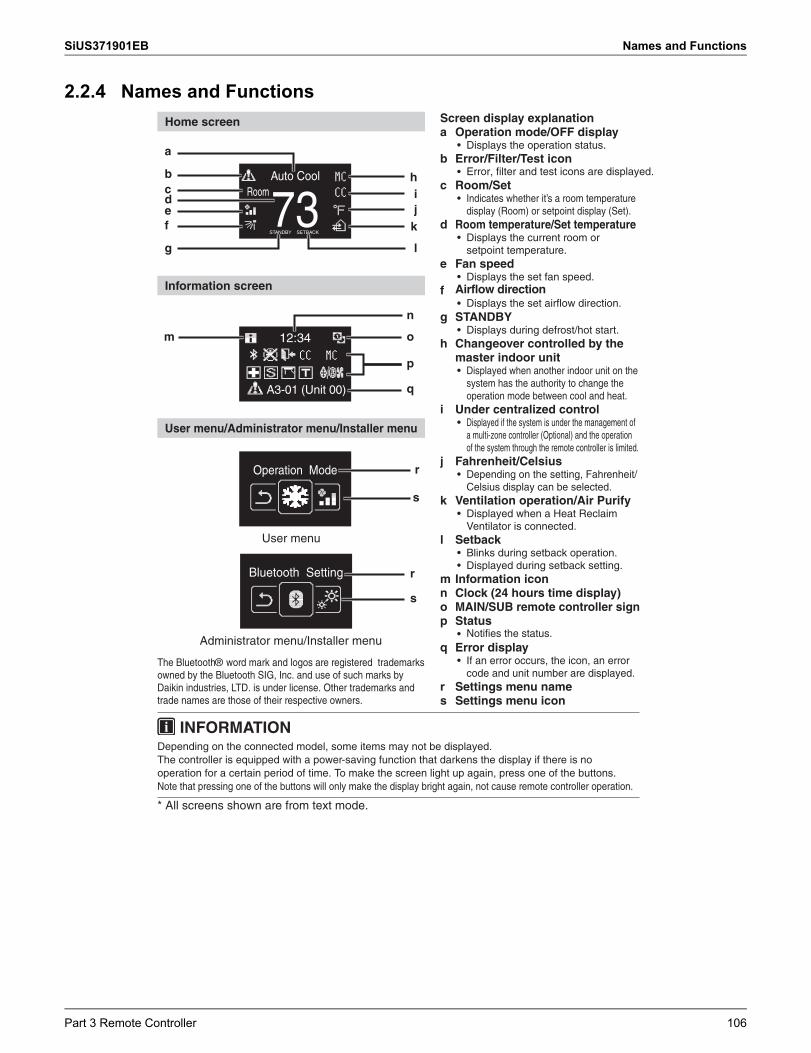
SiUS371901EB Names and Functions
2.2.4 Names and FunctionsHome screen
Auto Cool
73Room
STANDBY SETBACK
jk
ih
ed
f
cb
g l
a
Information screen
12:34
A3-01 (Unit 00)
m o
q
p
n
User menu/Administrator menu/Installer menu
Operation Mode r
s
User menu
Bluetooth Setting r
s
Administrator menu/Installer menu
The Bluetooth® word mark and logos are registered trademarks owned by the Bluetooth SIG, Inc. and use of such marks by Daikin industries, LTD. is under license. Other trademarks and trade names are those of their respective owners.
Screen display explanationa Operation mode/OFF display
• Displays the operation status.b Error/Filter/Test icon
• c Room/Set
• Indicates whether it’s a room temperature display (Room) or setpoint display (Set).
d Room temperature/Set temperature• Displays the current room or
setpoint temperature.e Fan speed
• Displays the set fan speed.f
• g STANDBY
• Displays during defrost/hot start.h Changeover controlled by the
master indoor unit• Displayed when another indoor unit on the
system has the authority to change the operation mode between cool and heat.
i Under centralized control• Displayed if the system is under the management of
a multi-zone controller (Optional) and the operation of the system through the remote controller is limited.
j Fahrenheit/Celsius• Depending on the setting, Fahrenheit/
Celsius display can be selected.k Ventilation operation/Air Purify
• Displayed when a Heat Reclaim Ventilator is connected.
l Setback• Blinks during setback operation.• Displayed during setback setting.
m Information iconn Clock (24 hours time display)o MAIN/SUB remote controller signp Status
• q Error display
• If an error occurs, the icon, an error code and unit number are displayed.
r Settings menu names Settings menu icon
INFORMATIONDepending on the connected model, some items may not be displayed.The controller is equipped with a power-saving function that darkens the display if there is no operation for a certain period of time. To make the screen light up again, press one of the buttons. Note that pressing one of the buttons will only make the display bright again, not cause remote controller operation.
* All screens shown are from text mode.
Error, filter and test icons are displayed.
Displays the set airflow direction.Airflow direction
Notifies the status.
Part 3 Remote Controller 106
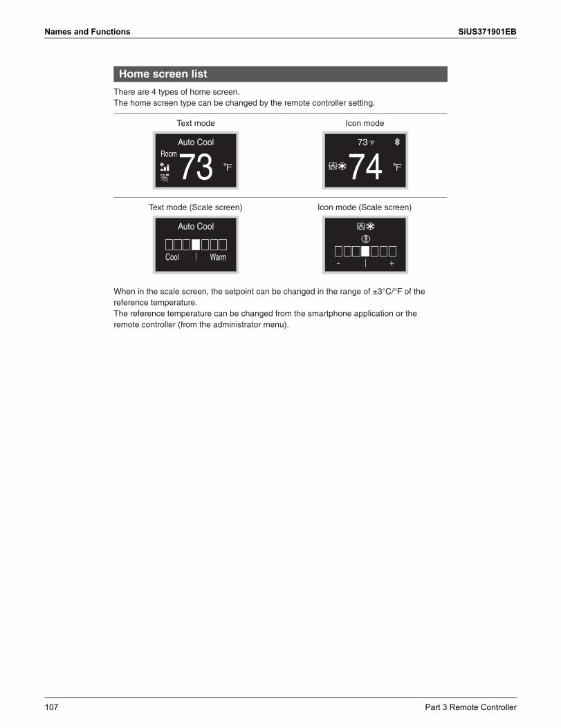
Names and Functions SiUS371901EB
Home screen list
There are 4 types of home screen.The home screen type can be changed by the remote controller setting.
Text mode
Auto Cool
73Room
Icon mode
73 ˚F
74Text mode (Scale screen)
Auto Cool
Cool Warm
Icon mode (Scale screen)
+-
When in the scale screen, the setpoint can be changed in the range of ±3°C/°F of the reference temperature.The reference temperature can be changed from the smartphone application or the remote controller (from the administrator menu).
107 Part 3 Remote Controller
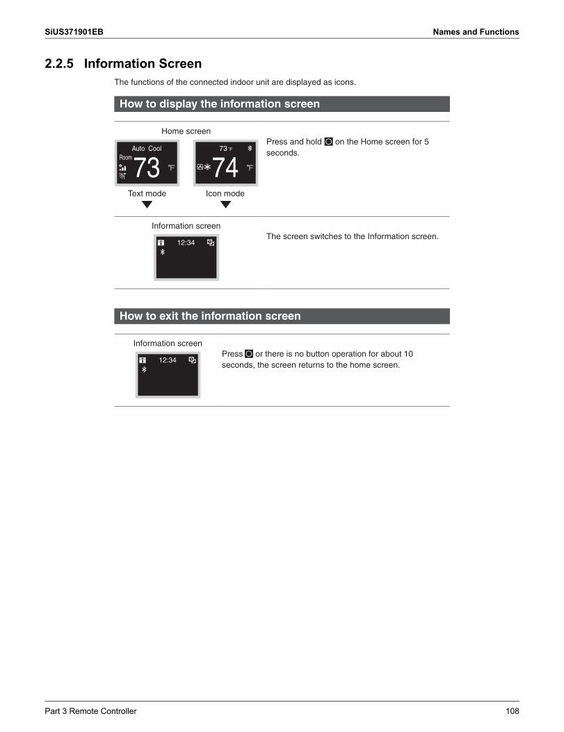
SiUS371901EB Names and Functions
2.2.5 Information ScreenThe functions of the connected indoor unit are displayed as icons.
How to display the information screen
Home screen
Auto Cool
73Room
73 ˚F
74Text mode Icon mode
Press and hold on the Home screen for 5 seconds.
Information screen
12:34The screen switches to the Information screen.
How to exit the information screen
Information screen
12:34Press or there is no button operation for about 10 seconds, the screen returns to the home screen.
Part 3 Remote Controller 108
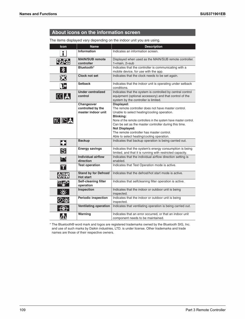
Names and Functions SiUS371901EB
About icons on the information screen
The items displayed vary depending on the indoor unit you are using.
Icon Name DescriptionInformation Indicates an information screen.
MAIN/SUB remote controller
Displayed when used as the MAIN/SUB remote controller.1=main, 2=sub
Bluetooth* Indicates that the controller is communicating with a mobile device, for use with the app.
Clock not set Indicates that the clock needs to be set again.
Setback Indicates that the indoor unit is operating under setback conditions.
Under centralized control
Indicates that the system is controlled by central control equipment (optional accessory) and that control of the system by the controller is limited.
Changeover controlled by the master indoor unit
Displayed:The remote controller does not have master control.Unable to select heating/cooling operation.Blinking:None of the remote controllers in the system have master control.Can be set as the master controller during this time.Not Displayed:The remote controller has master control.Able to select heating/cooling operation.
Backup Indicates that backup operation is being carried out.
Energy savings Indicates that the system’s energy consumption is being limited, and that it is running with restricted capacity.
Individual airflow direction
Indicates that the individual airflow direction setting is enabled.
Test operation Indicates that Test Operation mode is active.
Stand by for Defrost/Hot start
Indicates that the defrost/hot start mode is active.
Self-cleaning filter operation
Indicates that selfcleaning filter operation is active.
Inspection Indicates that the indoor or outdoor unit is being inspected.
Periodic inspection Indicates that the indoor or outdoor unit is being inspected.
Ventilating operation Indicates that ventilating operation is being carried out.
Warning Indicates that an error occurred, or that an indoor unit component needs to be maintained.
* The Bluetooth® word mark and logos are registered trademarks owned by the Bluetooth SIG, Inc. and use of such marks by Daikin industries, LTD. is under license. Other trademarks and trade names are those of their respective owners.
109 Part 3 Remote Controller
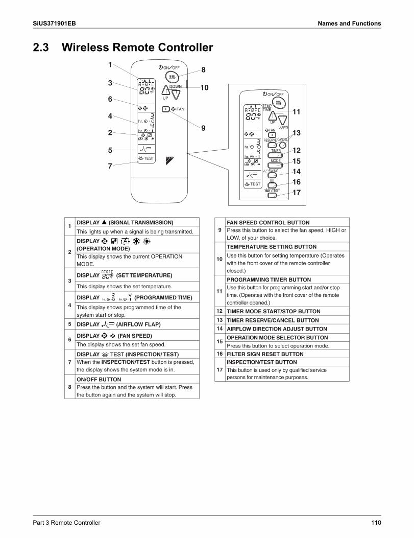
SiUS371901EB Names and Functions
2.3 Wireless Remote Controller
DOWN
FAN
UP
ON OFF
MH L
hr.
hr.
TEST
F
MODE
TIMER
RESERVE CANCEL
DOWNUP
TEST
SWING
FAN
TIMETEMP
ON OFF
MH L
hr.
hr.
TEST
F
1
3
4
6
2
5
7
8
10
913
11
1215141617
1
2
3
4
5
6
7
8
hr. hr.
DISPLAY (SIGNAL TRANSMISSION)
DISPLAY (SET TEMPERATURE)
DISPLAY (PROGRAMMED TIME)
DISPLAY (AIRFLOW FLAP)
DISPLAY TEST (INSPECTION/ TEST)
DISPLAY (FAN SPEED)
ON/OFF BUTTONPress the button and the system will start. Press the button again and the system will stop.
This lights up when a signal is being transmitted.
This display shows the set temperature.
This display shows programmed time of the system start or stop.
The display shows the set fan speed.
When the INSPECTION/TEST button is pressed, the display shows the system mode is in.
13
14
15
16
17
TIMER RESERVE/CANCEL BUTTON
AIRFLOW DIRECTION ADJUST BUTTON
OPERATION MODE SELECTOR BUTTON
FILTER SIGN RESET BUTTONINSPECTION/TEST BUTTON
Press this button to select operation mode.
This button is used only by qualified service persons for maintenance purposes.
11
12
Use this button for programming start and/or stop time. (Operates with the front cover of the remote controller opened.)
PROGRAMMING TIMER BUTTON
TIMER MODE START/STOP BUTTON
9
10
FAN SPEED CONTROL BUTTON
TEMPERATURE SETTING BUTTON
Press this button to select the fan speed, HIGH or LOW, of your choice.
Use this button for setting temperature (Operates with the front cover of the remote controller closed.)
DISPLAY (OPERATION MODE)This display shows the current OPERATION MODE.
MH L
F
Part 3 Remote Controller 110
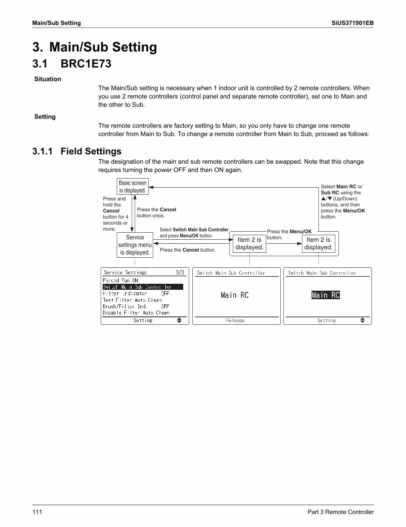
Main/Sub Setting SiUS371901EB
3. Main/Sub Setting3.1 BRC1E73
The Main/Sub setting is necessary when 1 indoor unit is controlled by 2 remote controllers. When you use 2 remote controllers (control panel and separate remote controller), set one to Main and the other to Sub.
The remote controllers are factory setting to Main, so you only have to change one remote controller from Main to Sub. To change a remote controller from Main to Sub, proceed as follows:
3.1.1 Field SettingsThe designation of the main and sub remote controllers can be swapped. Note that this change requires turning the power OFF and then ON again.
Situation
Setting
Select Switch Main Sub Controller and press Menu/OK button.Service
settings menu is displayed.
Item 2 is displayed.
Basic screen is displayed.
Press and hold the Cancel button for 4 seconds or more.
Press the Cancel button.
Item 2 is displayed.
Press the Menu/OK button.
Select Main RC or Sub RC using the
�/� (Up/Down) buttons, and then press the Menu/OK button.
Press the Cancel button once.
111 Part 3 Remote Controller
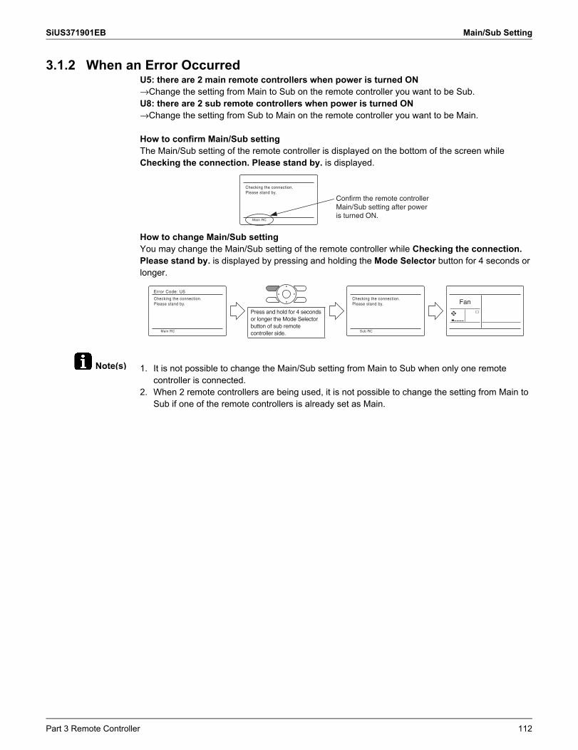
SiUS371901EB Main/Sub Setting
Note(s)
3.1.2 When an Error OccurredU5: there are 2 main remote controllers when power is turned ON→Change the setting from Main to Sub on the remote controller you want to be Sub.U8: there are 2 sub remote controllers when power is turned ON→Change the setting from Sub to Main on the remote controller you want to be Main.
How to confirm Main/Sub settingThe Main/Sub setting of the remote controller is displayed on the bottom of the screen while Checking the connection. Please stand by. is displayed.
How to change Main/Sub settingYou may change the Main/Sub setting of the remote controller while Checking the connection. Please stand by. is displayed by pressing and holding the Mode Selector button for 4 seconds or longer.
1. It is not possible to change the Main/Sub setting from Main to Sub when only one remote controller is connected.
2. When 2 remote controllers are being used, it is not possible to change the setting from Main to Sub if one of the remote controllers is already set as Main.
Checking the connection.Please stand by.
Main RC
Confirm the remote controller Main/Sub setting after power is turned ON.
Checking the connection.Please stand by.
Error Code: U5
Main RC
Press and hold for 4 seconds or longer the Mode Selector button of sub remote controller side.
Checking the connection.Please stand by.
Sub RC
Fan
Part 3 Remote Controller 112
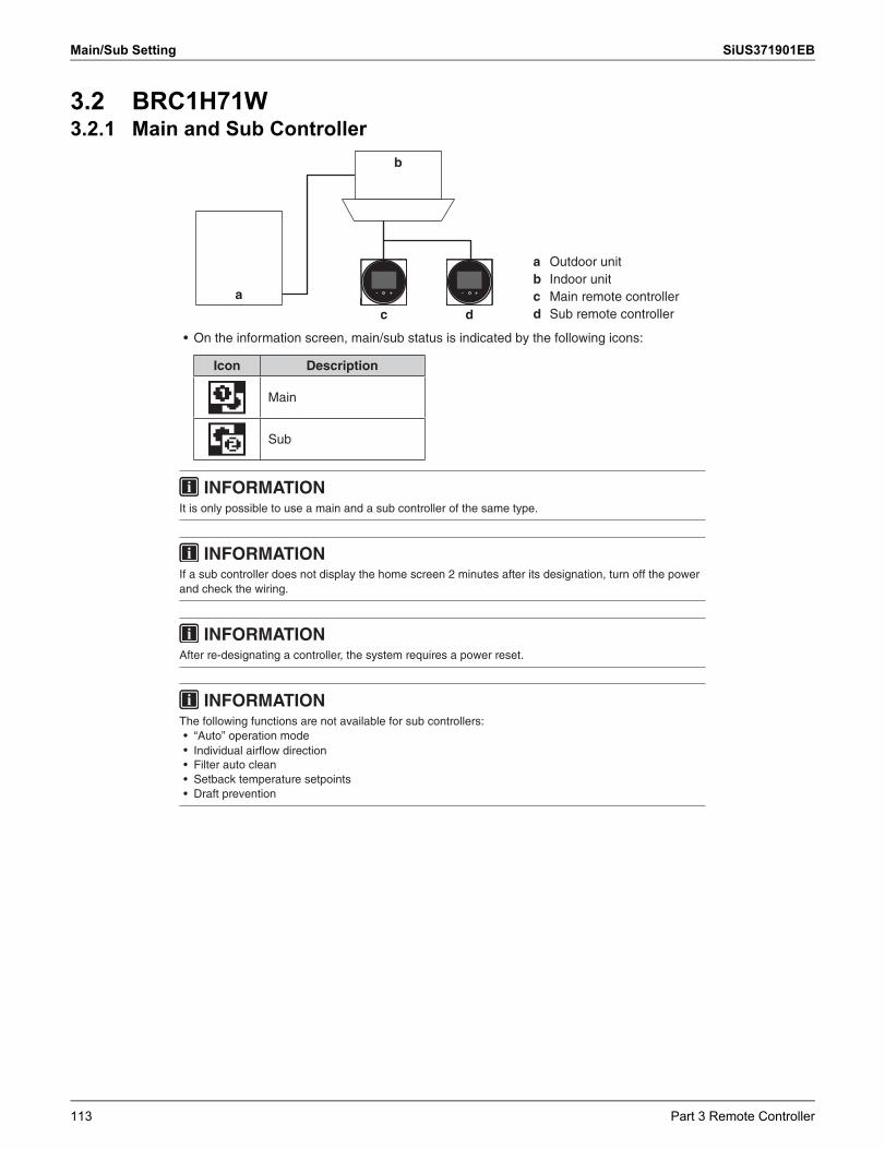
Main/Sub Setting SiUS371901EB
3.2 BRC1H71W3.2.1 Main and Sub Controller
INFORMATION
and check the wiring.
INFORMATIONAfter re-designating a controller, the system requires a power reset.
INFORMATIONThe following functions are not available for sub controllers:• “Auto” operation mode• • Filter auto clean• Setback temperature setpoints• Draft prevention
If a sub controller does not display the home screen 2 minutes after its designation, turn off the power
Individual airflow direction
a
b
c d
a Outdoor unitb Indoor unitc Main remote controllerd Sub remote controller
• On the information screen, main/sub status is indicated by the following icons:
Icon Description
Main
Sub
INFORMATIONIt is only possible to use a main and a sub controller of the same type.
113 Part 3 Remote Controller
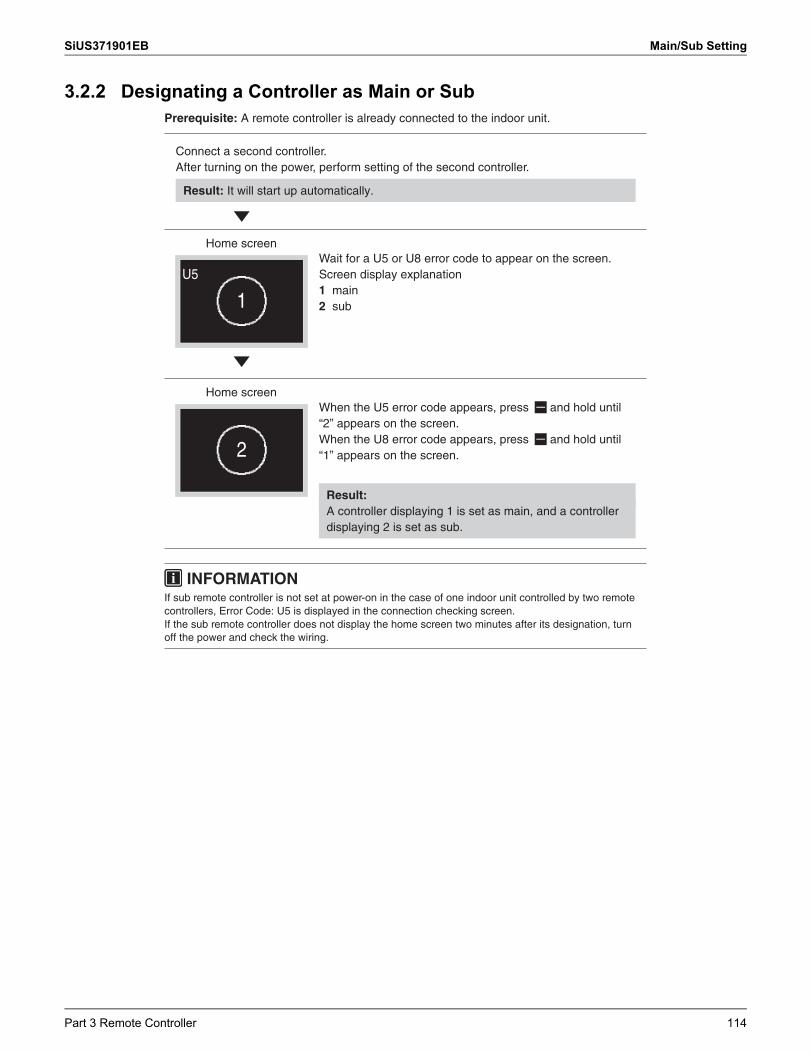
SiUS371901EB Main/Sub Setting
3.2.2 Designating a Controller as Main or SubPrerequisite: A remote controller is already connected to the indoor unit.
Connect a second controller.After turning on the power, perform setting of the second controller.
Result: It will start up automatically.
Home screen
U5
1
Wait for a U5 or U8 error code to appear on the screen.Screen display explanation1 main2 sub
Home screen
2
When the U5 error code appears, press and hold until “2” appears on the screen.When the U8 error code appears, press and hold until “1” appears on the screen.
Result: A controller displaying 1 is set as main, and a controller displaying 2 is set as sub.
INFORMATIONIf sub remote controller is not set at power-on in the case of one indoor unit controlled by two remote controllers, Error Code: U5 is displayed in the connection checking screen.If the sub remote controller does not display the home screen two minutes after its designation, turn off the power and check the wiring.
Part 3 Remote Controller 114
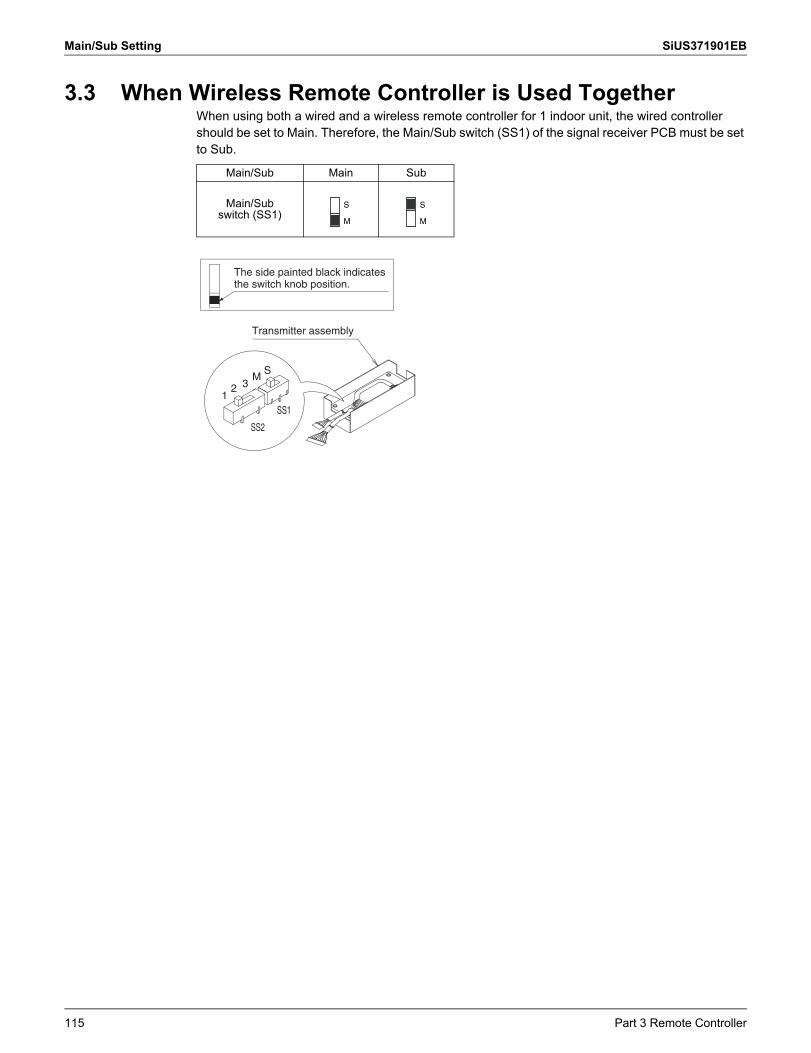
Main/Sub Setting SiUS371901EB
3.3 When Wireless Remote Controller is Used TogetherWhen using both a wired and a wireless remote controller for 1 indoor unit, the wired controller should be set to Main. Therefore, the Main/Sub switch (SS1) of the signal receiver PCB must be set to Sub.
Main/Sub Main Sub
Main/Subswitch (SS1)
S
M
S
M
Transmitter assembly
12 3
MS
SS2
SS1
The side painted black indicates the switch knob position.
115 Part 3 Remote Controller
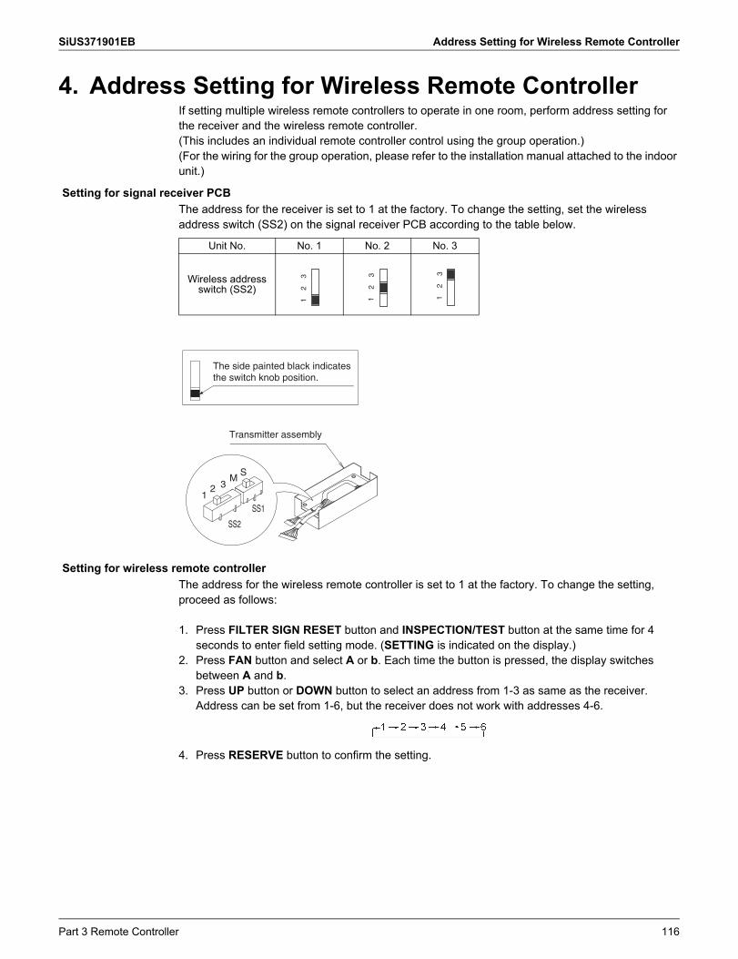
SiUS371901EB Address Setting for Wireless Remote Controller
4. Address Setting for Wireless Remote ControllerIf setting multiple wireless remote controllers to operate in one room, perform address setting for the receiver and the wireless remote controller.(This includes an individual remote controller control using the group operation.)(For the wiring for the group operation, please refer to the installation manual attached to the indoor unit.)
The address for the receiver is set to 1 at the factory. To change the setting, set the wireless address switch (SS2) on the signal receiver PCB according to the table below.
The address for the wireless remote controller is set to 1 at the factory. To change the setting, proceed as follows:
1. Press FILTER SIGN RESET button and INSPECTION/TEST button at the same time for 4 seconds to enter field setting mode. (SETTING is indicated on the display.)
2. Press FAN button and select A or b. Each time the button is pressed, the display switches between A and b.
3. Press UP button or DOWN button to select an address from 1-3 as same as the receiver. Address can be set from 1-6, but the receiver does not work with addresses 4-6.
4. Press RESERVE button to confirm the setting.
Setting for signal receiver PCB
Unit No. No. 1 No. 2 No. 3
Wireless addressswitch (SS2)
1
2
3
1
2
3
1
2
3Transmitter assembly
12 3
MS
SS2
SS1
The side painted black indicates the switch knob position.
Setting for wireless remote controller
Part 3 Remote Controller 116
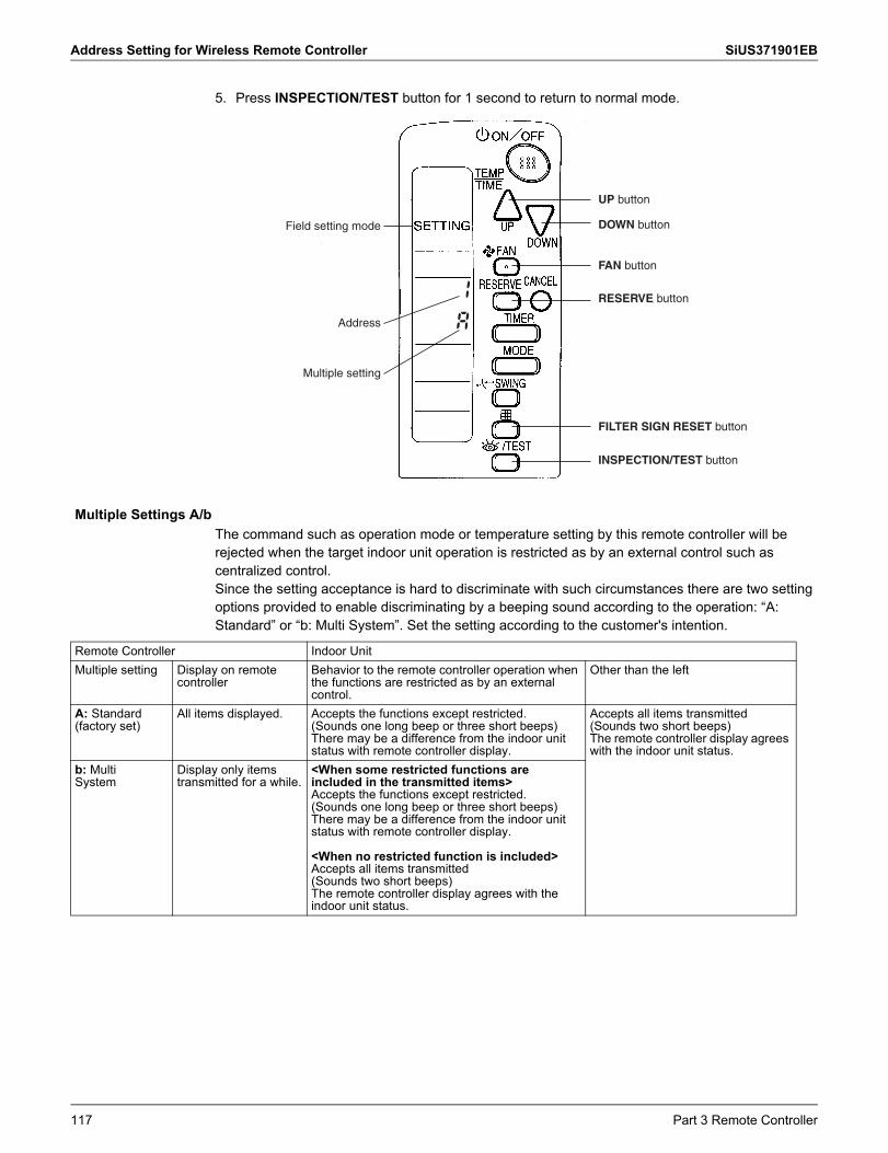
Address Setting for Wireless Remote Controller SiUS371901EB
5. Press INSPECTION/TEST button for 1 second to return to normal mode.
The command such as operation mode or temperature setting by this remote controller will be rejected when the target indoor unit operation is restricted as by an external control such as centralized control.Since the setting acceptance is hard to discriminate with such circumstances there are two setting options provided to enable discriminating by a beeping sound according to the operation: “A: Standard” or “b: Multi System”. Set the setting according to the customer's intention.
Field setting mode
Address
Multiple setting
UP button
DOWN button
FAN button
RESERVE button
FILTER SIGN RESET button
INSPECTION/TEST button
Multiple Settings A/b
Remote Controller Indoor UnitMultiple setting Display on remote
controllerBehavior to the remote controller operation when the functions are restricted as by an external control.
Other than the left
A: Standard (factory set)
All items displayed. Accepts the functions except restricted. (Sounds one long beep or three short beeps)There may be a difference from the indoor unit status with remote controller display.
Accepts all items transmitted (Sounds two short beeps)The remote controller display agrees with the indoor unit status.
b: MultiSystem
Display only items transmitted for a while.
<When some restricted functions are included in the transmitted items>Accepts the functions except restricted. (Sounds one long beep or three short beeps)There may be a difference from the indoor unit status with remote controller display.
<When no restricted function is included>Accepts all items transmitted (Sounds two short beeps)The remote controller display agrees with the indoor unit status.
117 Part 3 Remote Controller
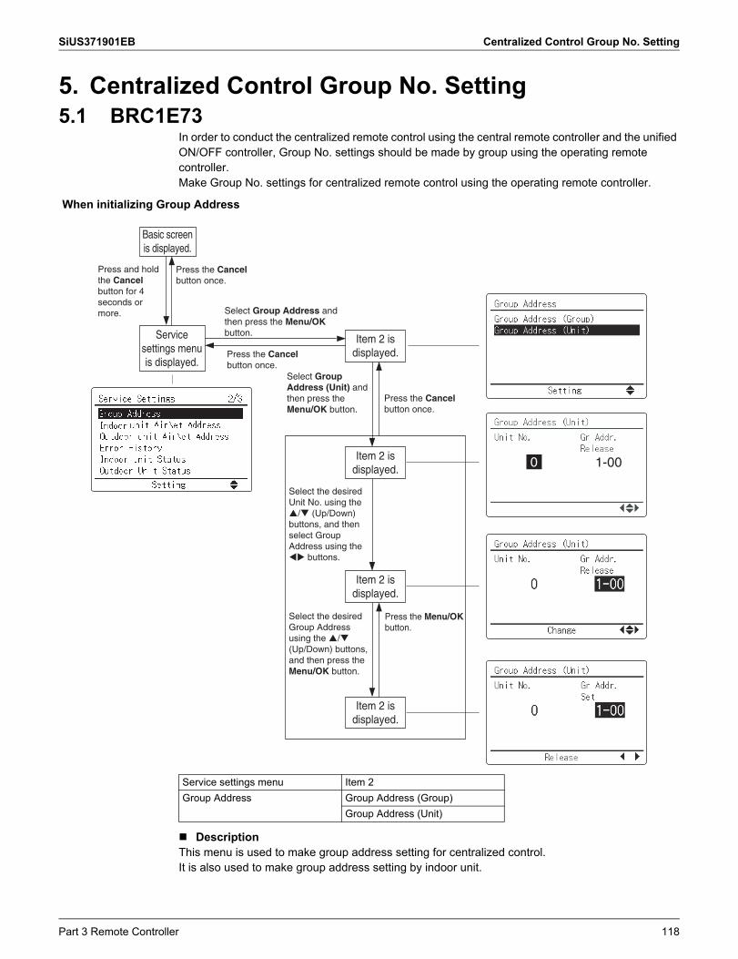
SiUS371901EB Centralized Control Group No. Setting
5. Centralized Control Group No. Setting5.1 BRC1E73
In order to conduct the centralized remote control using the central remote controller and the unified ON/OFF controller, Group No. settings should be made by group using the operating remote controller.Make Group No. settings for centralized remote control using the operating remote controller.
DescriptionThis menu is used to make group address setting for centralized control.It is also used to make group address setting by indoor unit.
When initializing Group Address
Select Group Address and then press the Menu/OK button.
Press the Cancel button once.
Press the Cancel button once.
Service settings menu is displayed.
Item 2 is displayed.
Item 2 is displayed.
Item 2 is displayed.
Basic screen is displayed.
Press the Cancel button once.
Select the desired Group Address using the �/� (Up/Down) buttons, and then press the Menu/OK button.
Item 2 is displayed.
Select the desired Unit No. using the �/� (Up/Down) buttons, and then select Group Address using the �� buttons.
0 1-00
Press and hold the Cancel button for 4 seconds or more.
Select Group Address (Unit) and then press the Menu/OK button.
Press the Menu/OK button.
Service settings menu Item 2Group Address Group Address (Group)
Group Address (Unit)
Part 3 Remote Controller 118
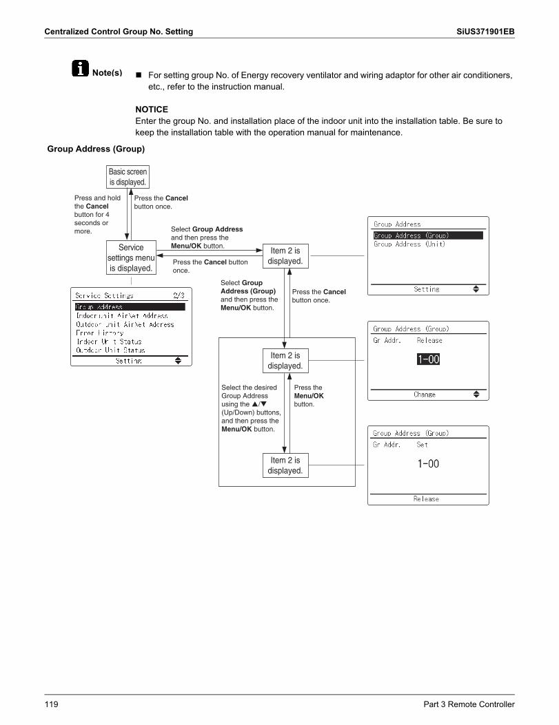
Centralized Control Group No. Setting SiUS371901EB
Note(s) For setting group No. of Energy recovery ventilator and wiring adaptor for other air conditioners, etc., refer to the instruction manual.
NOTICEEnter the group No. and installation place of the indoor unit into the installation table. Be sure to keep the installation table with the operation manual for maintenance.
Group Address (Group)
Select Group Address and then press the Menu/OK button.
Select Group Address (Group) and then press the Menu/OK button.
Select the desired Group Address using the �/� (Up/Down) buttons, and then press the Menu/OK button.
Service settings menu is displayed.
Item 2 is displayed.
Item 2 is displayed.
Item 2 is displayed.
Basic screen is displayed.
Press and hold the Cancel button for 4 seconds or more.
Press the Cancel button once.
Press the Cancel button once.
Press the Cancel button once.
Press the Menu/OK button.
119 Part 3 Remote Controller
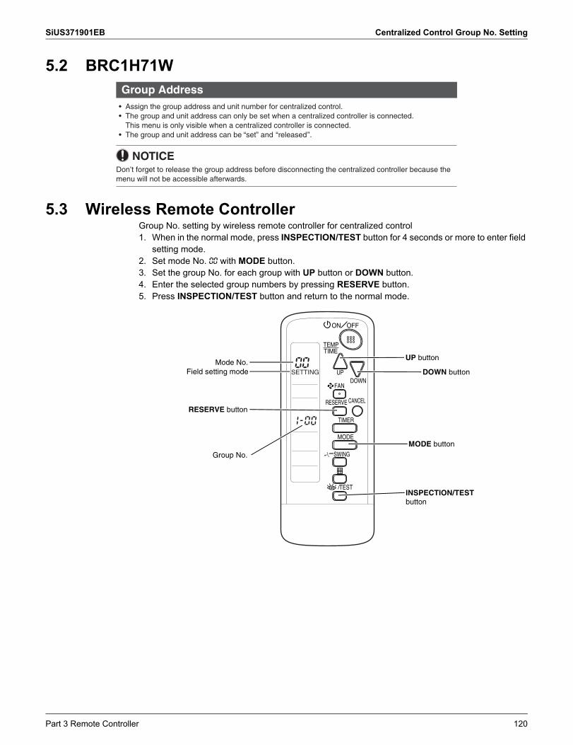
SiUS371901EB Centralized Control Group No. Setting
5.2 BRC1H71W
5.3 Wireless Remote ControllerGroup No. setting by wireless remote controller for centralized control1. When in the normal mode, press INSPECTION/TEST button for 4 seconds or more to enter field
setting mode.2. Set mode No. 00 with MODE button.3. Set the group No. for each group with UP button or DOWN button.4. Enter the selected group numbers by pressing RESERVE button.5. Press INSPECTION/TEST button and return to the normal mode.
Group Address• Assign the group address and unit number for centralized control.• The group and unit address can only be set when a centralized controller is connected.
This menu is only visible when a centralized controller is connected.• The group and unit address can be “set” and “released”.
NOTICEDon’t forget to release the group address before disconnecting the centralized controller because the menu will not be accessible afterwards.
UP button
DOWN button
MODE button
RESERVE button
Mode No.Field setting mode
Group No.
INSPECTION/TEST button
Part 3 Remote Controller 120
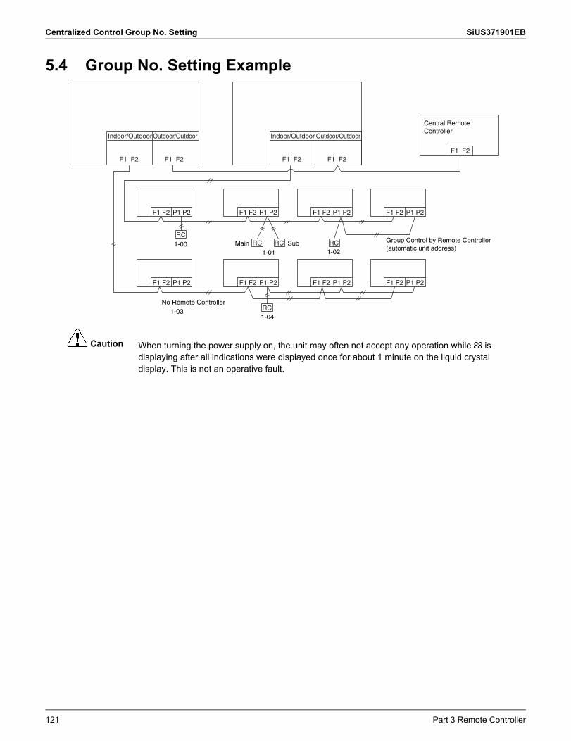
Centralized Control Group No. Setting SiUS371901EB
Caution
5.4 Group No. Setting Example
When turning the power supply on, the unit may often not accept any operation while 88 isdisplaying after all indications were displayed once for about 1 minute on the liquid crystaldisplay. This is not an operative fault.
Central Remote Controller
F1 F2
F1 F2 F1 F2F1 F2
P1 P2
RC
RC
RC RC RC
F1 F2 P1 P2 F1 F2 P1 P2 F1 F2 P1 P2
F1 F2 P1 P2 F1 F2 P1 P2 F1 F2 P1 P2 F1 F2 P1 P2
No Remote Controller1-03
1-001-01
Main Sub1-02
1-04
Indoor/Outdoor Outdoor/Outdoor
F1 F2 F1 F2
Indoor/Outdoor Outdoor/Outdoor
Group Control by Remote Controller (automatic unit address)
121 Part 3 Remote Controller
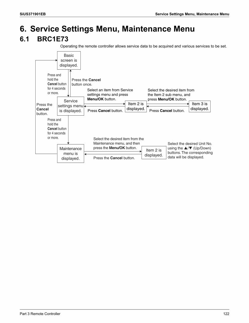
SiUS371901EB Service Settings Menu, Maintenance Menu
6. Service Settings Menu, Maintenance Menu6.1 BRC1E73
Operating the remote controller allows service data to be acquired and various services to be set.
Service settings menu is displayed.
Basic screen is displayed.
Press the Cancel button once.
Press the Cancelbutton.
Press and hold the Cancel button for 4 seconds or more.
Press and hold the Cancel button for 4 seconds or more.
Select the desired item from the Maintenance menu, and then press the Menu/OK button.Maintenance
menu is displayed.
Item 2 is displayed.
Press the Cancel button.
Select the desired Unit No. using the / (Up/Down) buttons. The corresponding data will be displayed.
Select an item from Service settings menu and press Menu/OK button.
Select the desired item from the Item 2 sub menu, and press Menu/OK button.
Item 2 is displayed.
Item 3 is displayed.Press Cancel button. Press Cancel button.
Part 3 Remote Controller 122
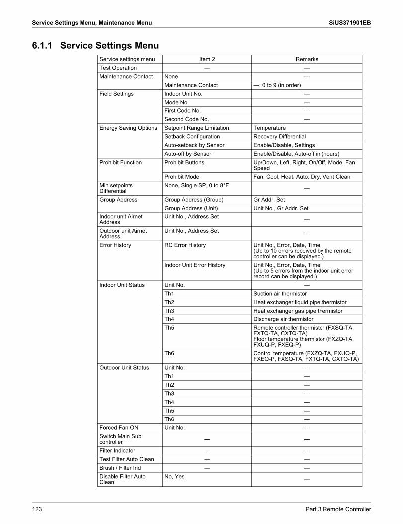
Service Settings Menu, Maintenance Menu SiUS371901EB
6.1.1 Service Settings MenuService settings menu Item 2 RemarksTest Operation — —Maintenance Contact None —
Maintenance Contact —, 0 to 9 (in order)Field Settings Indoor Unit No. —
Mode No. —First Code No. —Second Code No. —
Energy Saving Options Setpoint Range Limitation TemperatureSetback Configuration Recovery DifferentialAuto-setback by Sensor Enable/Disable, SettingsAuto-off by Sensor Enable/Disable, Auto-off in (hours)
Prohibit Function Prohibit Buttons Up/Down, Left, Right, On/Off, Mode, Fan Speed
Prohibit Mode Fan, Cool, Heat, Auto, Dry, Vent CleanMin setpoints Differential
None, Single SP, 0 to 8°F —
Group Address Group Address (Group) Gr Addr. SetGroup Address (Unit) Unit No., Gr Addr. Set
Indoor unit Airnet Address
Unit No., Address Set —
Outdoor unit Airnet Address
Unit No., Address Set —
Error History RC Error History Unit No., Error, Date, Time(Up to 10 errors received by the remotecontroller can be displayed.)
Indoor Unit Error History Unit No., Error, Date, Time(Up to 5 errors from the indoor unit errorrecord can be displayed.)
Indoor Unit Status Unit No. —Th1 Suction air thermistorTh2 Heat exchanger liquid pipe thermistorTh3 Heat exchanger gas pipe thermistorTh4 Discharge air thermistorTh5 Remote controller thermistor (FXSQ-TA,
FXTQ-TA, CXTQ-TA)Floor temperature thermistor (FXZQ-TA, FXUQ-P, FXEQ-P)
Th6 Control temperature (FXZQ-TA, FXUQ-P, FXEQ-P, FXSQ-TA, FXTQ-TA, CXTQ-TA)
Outdoor Unit Status Unit No. —Th1 —Th2 —Th3 —Th4 —Th5 —Th6 —
Forced Fan ON Unit No. —Switch Main Sub controller — —
Filter Indicator — —Test Filter Auto Clean — —Brush / Filter Ind — —Disable Filter Auto Clean
No, Yes —
123 Part 3 Remote Controller
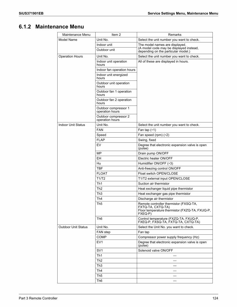
SiUS371901EB Service Settings Menu, Maintenance Menu
6.1.2 Maintenance MenuMaintenance Menu Item 2 Remarks
Model Name Unit No. Select the unit number you want to check.Indoor unit The model names are displayed.
(A model code may be displayed instead, depending on the particular model.)Outdoor unit
Operation Hours Unit No. Select the unit number you want to check.Indoor unit operation hours
All of these are displayed in hours.
Indoor fan operation hoursIndoor unit energized hoursOutdoor unit operation hoursOutdoor fan 1 operation hoursOutdoor fan 2 operation hoursOutdoor compressor 1 operation hoursOutdoor compressor 2 operation hours
Indoor Unit Status Unit No. Select the unit number you want to check.FAN Fan tap (∗1)Speed Fan speed (rpm) (∗2)FLAP Swing, fixedEV Degree that electronic expansion valve is open
(pulse)MP Drain pump ON/OFFEH Electric heater ON/OFFHu Humidifier ON/OFF (∗3)TBF Anti-freezing control ON/OFFFLOAT Float switch OPEN/CLOSET1/T2 T1/T2 external input OPEN/CLOSETh1 Suction air thermistorTh2 Heat exchanger liquid pipe thermistorTh3 Heat exchanger gas pipe thermistorTh4 Discharge air thermistorTh5 Remote controller thermistor (FXSQ-TA,
FXTQ-TA, CXTQ-TA)Floor temperature thermistor (FXZQ-TA, FXUQ-P, FXEQ-P)
Th6 Control temperature (FXZQ-TA, FXUQ-P, FXEQ-P, FXSQ-TA, FXTQ-TA, CXTQ-TA)
Outdoor Unit Status Unit No. Select the Unit No. you want to check.FAN step Fan tapCOMP Compressor power supply frequency (Hz)EV1 Degree that electronic expansion valve is open
(pulse)SV1 Solenoid valve ON/OFFTh1 —Th2 —Th3 —Th4 —Th5 —Th6 —
Part 3 Remote Controller 124
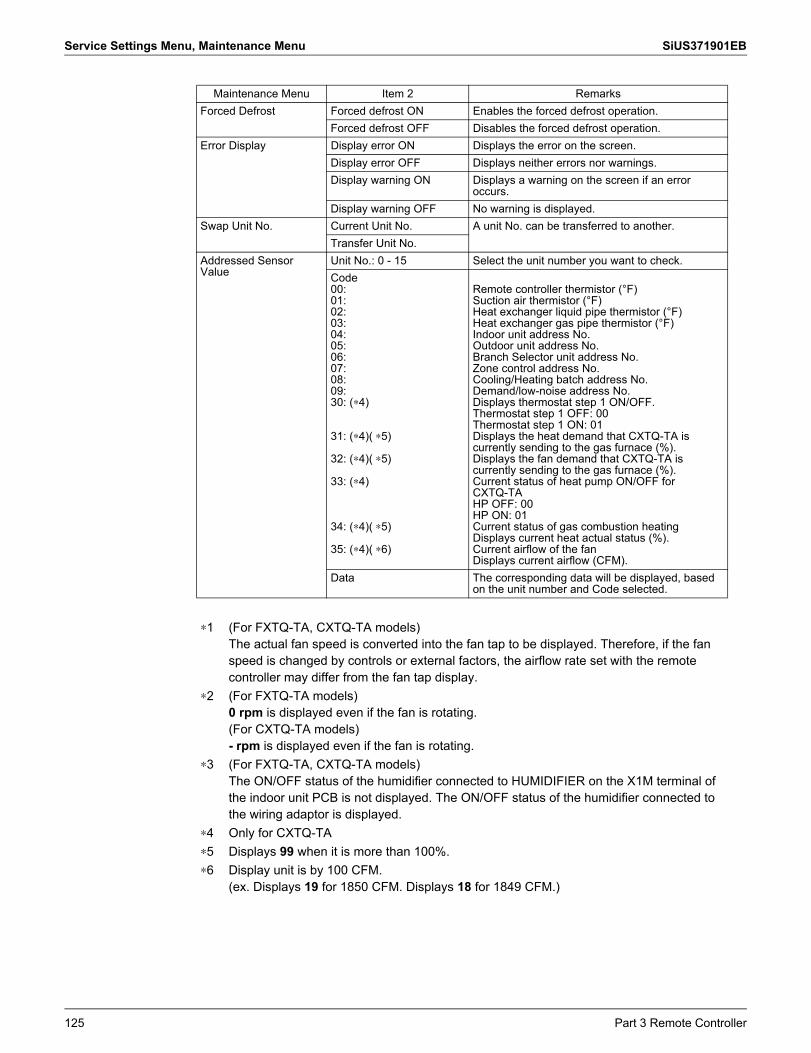
Service Settings Menu, Maintenance Menu SiUS371901EB
Forced Defrost Forced defrost ON Enables the forced defrost operation.Forced defrost OFF Disables the forced defrost operation.
Error Display Display error ON Displays the error on the screen.Display error OFF Displays neither errors nor warnings.Display warning ON Displays a warning on the screen if an error
occurs.Display warning OFF No warning is displayed.
Swap Unit No. Current Unit No. A unit No. can be transferred to another.Transfer Unit No.
Addressed Sensor Value
Unit No.: 0 - 15 Select the unit number you want to check.Code00:01:02:03:04:05:06:07:08:09:30: (∗4)
31: (∗4)( ∗5)
32: (∗4)( ∗5)
33: (∗4)
34: (∗4)( ∗5)
35: (∗4)( ∗6)
Remote controller thermistor (°F)Suction air thermistor (°F)Heat exchanger liquid pipe thermistor (°F)Heat exchanger gas pipe thermistor (°F)Indoor unit address No.Outdoor unit address No.Branch Selector unit address No.Zone control address No.Cooling/Heating batch address No.Demand/low-noise address No.Displays thermostat step 1 ON/OFF.Thermostat step 1 OFF: 00Thermostat step 1 ON: 01Displays the heat demand that CXTQ-TA is currently sending to the gas furnace (%).Displays the fan demand that CXTQ-TA is currently sending to the gas furnace (%).Current status of heat pump ON/OFF for CXTQ-TAHP OFF: 00HP ON: 01Current status of gas combustion heatingDisplays current heat actual status (%).Current airflow of the fanDisplays current airflow (CFM).
Data The corresponding data will be displayed, based on the unit number and Code selected.
∗1 (For FXTQ-TA, CXTQ-TA models)The actual fan speed is converted into the fan tap to be displayed. Therefore, if the fan speed is changed by controls or external factors, the airflow rate set with the remote controller may differ from the fan tap display.
∗2 (For FXTQ-TA models)0 rpm is displayed even if the fan is rotating.(For CXTQ-TA models)- rpm is displayed even if the fan is rotating.
∗3 (For FXTQ-TA, CXTQ-TA models)The ON/OFF status of the humidifier connected to HUMIDIFIER on the X1M terminal of the indoor unit PCB is not displayed. The ON/OFF status of the humidifier connected to the wiring adaptor is displayed.
∗4 Only for CXTQ-TA∗5 Displays 99 when it is more than 100%.∗6 Display unit is by 100 CFM.
(ex. Displays 19 for 1850 CFM. Displays 18 for 1849 CFM.)
Maintenance Menu Item 2 Remarks
125 Part 3 Remote Controller
SiUS371901EB Administrator Menu, Installer Menu
7. Administrator Menu, Installer Menu7.1 BRC1H71W
Refer to page 104 for details.
Part 3 Remote Controller 126
SiUS371901EB
Part 4 Functions and Control
1. Operation Flowchart................................................................................1291.1 Outdoor Unit ............................................................................................. 1291.2 Branch Selector Unit & Indoor Unit Operation Mode Detail ..................... 130
2. Stop Control ............................................................................................1312.1 Stop due to Error ...................................................................................... 1312.2 When System is in Stop Mode ................................................................. 1312.3 Slave Unit Stops during Master Unit Operation........................................ 131
3. Standby Control ......................................................................................1323.1 Restart Standby........................................................................................ 1323.2 Crankcase Heater Control........................................................................ 132
4. Startup Control ........................................................................................1334.1 Startup Control in Cooling ........................................................................ 1334.2 Startup Control in Heating ........................................................................ 134
5. Basic Control...........................................................................................1355.1 Normal Control ......................................................................................... 1355.2 Compressor PI Control............................................................................. 1365.3 Compressor Step Control......................................................................... 1375.4 Electronic Expansion Valve PI Control..................................................... 1395.5 Step Control of Outdoor Fans .................................................................. 1405.6 Heat Exchanger Control ........................................................................... 141
6. Protection Control ...................................................................................1426.1 High Pressure Protection Control............................................................. 1426.2 Low Pressure Protection Control.............................................................. 1446.3 Discharge Pipe Protection Control ........................................................... 1456.4 Compressor Body Protection Control....................................................... 1466.5 Inverter Protection Control ....................................................................... 146
7. Special Control........................................................................................1487.1 Pump Down Residual Operation .............................................................. 1487.2 Oil Return Operation ................................................................................ 1497.3 Defrost Operation ..................................................................................... 1527.4 Outdoor Unit Rotation............................................................................... 1537.5 Cooling/Heating Mode Switching ............................................................. 154
8. Other Control...........................................................................................1578.1 Backup Operation..................................................................................... 1578.2 Demand Operation ................................................................................... 1578.3 Heating Operation Prohibition .................................................................. 157
9. Outline of Control (Indoor Unit) ...............................................................1599.1 Operation Flowchart ................................................................................. 159
127 Part 4 Functions and Control
SiUS371901EB
9.2 Set Temperature and Control Target Temperature.................................. 1639.3 Remote Controller Thermistor .................................................................. 1659.4 Thermostat Control................................................................................... 1679.5 Drain Pump Control.................................................................................. 1709.6 Control of Electronic Expansion Valve ..................................................... 1729.7 Freeze-Up Prevention Control.................................................................. 1739.8 List of Swing Flap Operations .................................................................. 1759.9 Hot Start Control (In Heating Operation Only).......................................... 1769.10 Louver Control for Preventing Ceiling Dirt................................................ 1779.11 Heater Control (Except FXTQ-TA Models)............................................... 1789.12 Heater Control (FXTQ-TA Models)........................................................... 1799.13 Gas Furnace Control (CXTQ-TA Models) ................................................ 1829.14 3-Step Thermostat Processing (FXTQ-TA Models) ................................. 1839.15 Fan Control (Heater Residual) (FXTQ-TA Models) .................................. 1849.16 Interlocked with External Equipment (FXTQ-TA and CXTQ-TA Models). 184
Part 4 Functions and Control 128
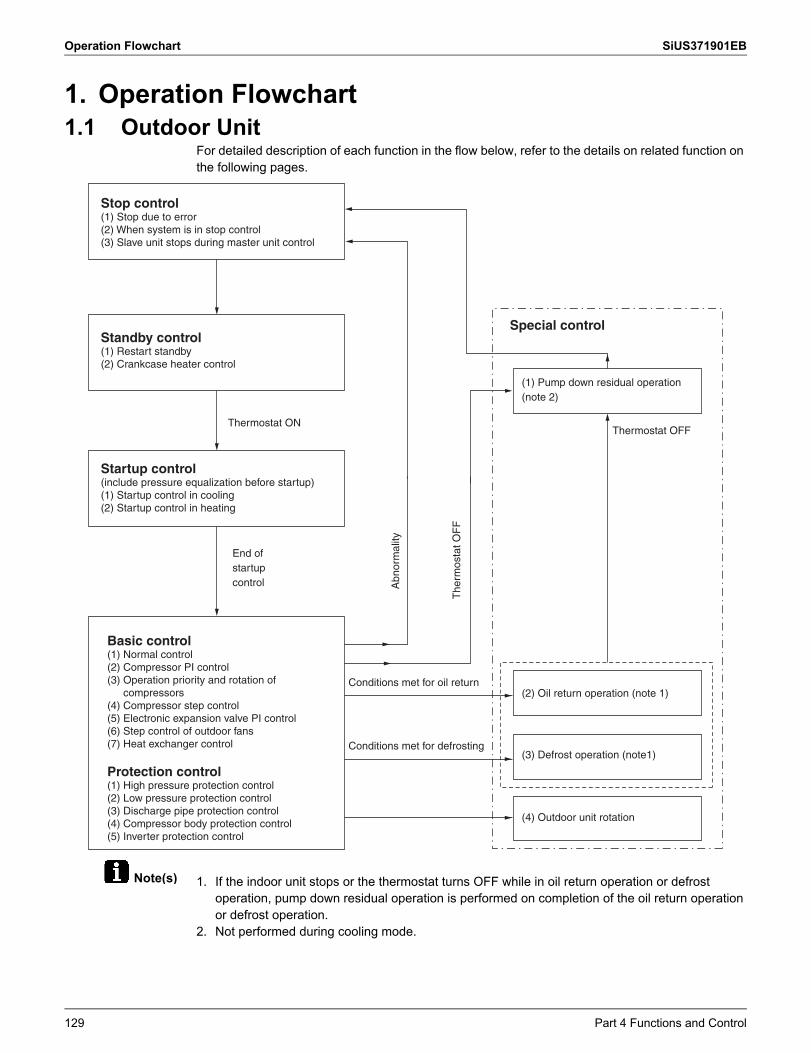
Operation Flowchart SiUS371901EB
Note(s)
1. Operation Flowchart1.1 Outdoor Unit
For detailed description of each function in the flow below, refer to the details on related function on the following pages.
1. If the indoor unit stops or the thermostat turns OFF while in oil return operation or defrost operation, pump down residual operation is performed on completion of the oil return operation or defrost operation.
2. Not performed during cooling mode.
Stop control(1) Stop due to error(2) When system is in stop control(3) Slave unit stops during master unit control
Standby control(1) Restart standby(2) Crankcase heater control
Startup control(include pressure equalization before startup)(1) Startup control in cooling(2) Startup control in heating
Basic control(1) Normal control(2) Compressor PI control(3) Operation priority and rotation of
compressors(4) Compressor step control(5) Electronic expansion valve PI control(6) Step control of outdoor fans(7) Heat exchanger control
Protection control(1) High pressure protection control(2) Low pressure protection control(3) Discharge pipe protection control(4) Compressor body protection control(5) Inverter protection control
Thermostat ON
End of startupcontrol A
bnor
mal
ity
The
rmos
tat O
FF
Conditions met for oil return
Special control
(1) Pump down residual operation (note 2)
(4) Outdoor unit rotation
Thermostat OFF
(2) Oil return operation (note 1)
Conditions met for defrosting(3) Defrost operation (note1)
129 Part 4 Functions and Control
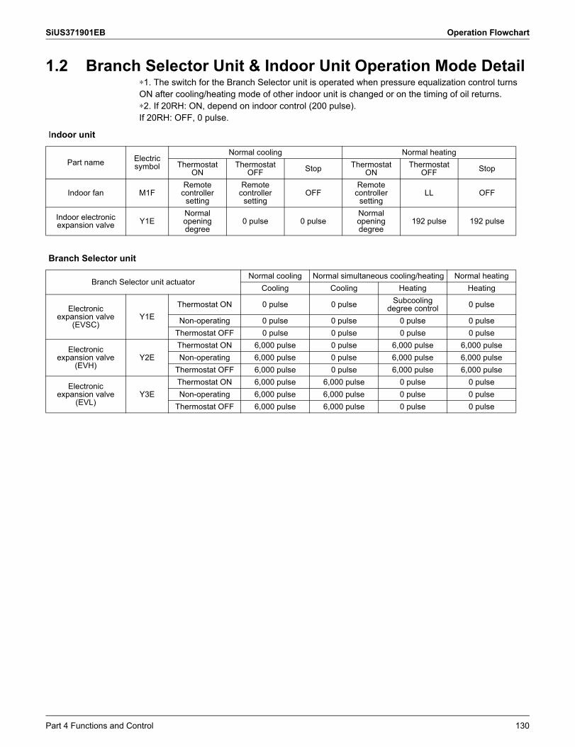
SiUS371901EB Operation Flowchart
1.2 Branch Selector Unit & Indoor Unit Operation Mode Detail∗1. The switch for the Branch Selector unit is operated when pressure equalization control turnsON after cooling/heating mode of other indoor unit is changed or on the timing of oil returns.∗2. If 20RH: ON, depend on indoor control (200 pulse).If 20RH: OFF, 0 pulse.
Indoor unit
Part name Electric symbol
Normal cooling Normal heatingThermostat
ONThermostat
OFF Stop Thermostat ON
Thermostat OFF Stop
Indoor fan M1FRemote
controller setting
Remote controller
settingOFF
Remote controller
settingLL OFF
Indoor electronic expansion valve Y1E
Normal opening degree
0 pulse 0 pulseNormal opening degree
192 pulse 192 pulse
Branch Selector unit
Branch Selector unit actuatorNormal cooling Normal simultaneous cooling/heating Normal heating
Cooling Cooling Heating Heating
Electronicexpansion valve
(EVSC)Y1E
Thermostat ON 0 pulse 0 pulse Subcooling degree control 0 pulse
Non-operating 0 pulse 0 pulse 0 pulse 0 pulseThermostat OFF 0 pulse 0 pulse 0 pulse 0 pulse
Electronicexpansion valve
(EVH)Y2E
Thermostat ON 6,000 pulse 0 pulse 6,000 pulse 6,000 pulseNon-operating 6,000 pulse 0 pulse 6,000 pulse 6,000 pulse
Thermostat OFF 6,000 pulse 0 pulse 6,000 pulse 6,000 pulse
Electronicexpansion valve
(EVL)Y3E
Thermostat ON 6,000 pulse 6,000 pulse 0 pulse 0 pulseNon-operating 6,000 pulse 6,000 pulse 0 pulse 0 pulse
Thermostat OFF 6,000 pulse 6,000 pulse 0 pulse 0 pulse
Part 4 Functions and Control 130
Stop Control SiUS371901EB
2. Stop Control2.1 Stop due to Error
In order to protect compressors, if any of the abnormal state occurs, the system will stop with thermostat OFF and the error will be determined when the retry times reaches certain number.(Refer to Error Codes and Descriptions on page 277 of the troubleshooting for the items to determine the error.)
2.2 When System is in Stop ModeThe four way valves retain the condition (ON) when heating operation is stopped.
2.3 Slave Unit Stops during Master Unit OperationWhen slave unit is stopped (because of low demand), conditions for this units are set same as system stop. System stops until this unit is required to operate (increase of load).
131 Part 4 Functions and Control
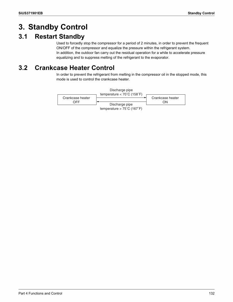
SiUS371901EB Standby Control
3. Standby Control3.1 Restart Standby
Used to forcedly stop the compressor for a period of 2 minutes, in order to prevent the frequent ON/OFF of the compressor and equalize the pressure within the refrigerant system.In addition, the outdoor fan carry out the residual operation for a while to accelerate pressure equalizing and to suppress melting of the refrigerant to the evaporator.
3.2 Crankcase Heater ControlIn order to prevent the refrigerant from melting in the compressor oil in the stopped mode, this mode is used to control the crankcase heater.
Crankcase heaterOFF
Crankcase heaterON
Discharge pipetemperature < 70˚C (158˚F)
Discharge pipetemperature > 75˚C (167˚F)
Part 4 Functions and Control 132
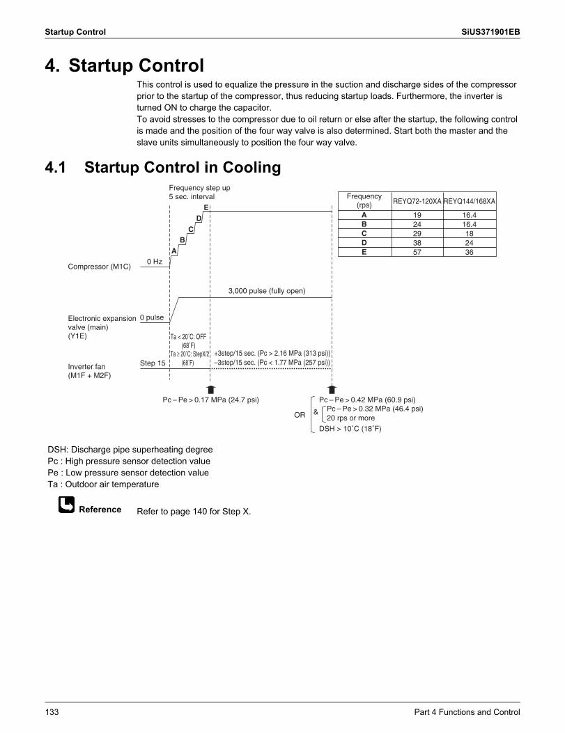
Startup Control SiUS371901EB
Reference
4. Startup ControlThis control is used to equalize the pressure in the suction and discharge sides of the compressor prior to the startup of the compressor, thus reducing startup loads. Furthermore, the inverter is turned ON to charge the capacitor.To avoid stresses to the compressor due to oil return or else after the startup, the following control is made and the position of the four way valve is also determined. Start both the master and the slave units simultaneously to position the four way valve.
4.1 Startup Control in Cooling
Refer to page 140 for Step X.
DSH: Discharge pipe superheating degree Pc : High pressure sensor detection value Pe : Low pressure sensor detection value Ta : Outdoor air temperature
0 Hz
0 pulse
3,000 pulse (fully open)
Step 15
Pc – Pe > 0.42 MPa (60.9 psi)
DSH > 10˚C (18˚F)
Pc – Pe > 0.32 MPa (46.4 psi)20 rps or moreOR &
Ta < 20˚C: OFF(68˚F)
Ta ≥ 20˚C: StepX/2(68˚F)
Frequency step up 5 sec. interval
+3step/15 sec. (Pc > 2.16 MPa (313 psi))–3step/15 sec. (Pc < 1.77 MPa (257 psi))
Compressor (M1C)
Electronic expansion valve (main)(Y1E)
Inverter fan(M1F + M2F)
Pc – Pe > 0.17 MPa (24.7 psi)
AB
C
DE
REYQ72-120XA
1924293857
REYQ144/168XA
16.416.4182436
ABCDE
Frequency (rps)
133 Part 4 Functions and Control
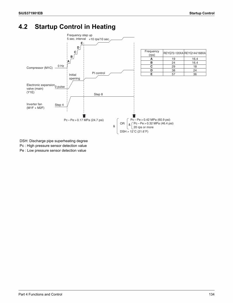
SiUS371901EB Startup Control
4.2 Startup Control in Heating
DSH: Discharge pipe superheating degree Pc : High pressure sensor detection value Pe : Low pressure sensor detection value
0 Hz
+10 rps/10 sec.
A
B
C
DE
0 pulse
Step 4
Step 8
OR &
PI control
Compressor (M1C)
Electronic expansion valve (main)(Y1E)
Inverter fan(M1F + M2F)
Frequency step up 5 sec. interval
Initial opening
Pc – Pe > 0.42 MPa (60.9 psi)
DSH > 12˚C (21.6˚F)
Pc – Pe > 0.32 MPa (46.4 psi)20 rps or more
Pc – Pe > 0.17 MPa (24.7 psi)
&
REYQ72-120XA
1924293857
Frequency (rps) REYQ144/168XA
16.416.4182436
ABCDE
Part 4 Functions and Control 134
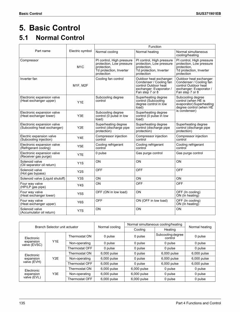
Basic Control SiUS371901EB
5. Basic Control5.1 Normal Control
Part name Electric symbolFunction
Normal cooling Normal heating Normal simultaneous cooling/heating
Compressor
M1C
PI control, High pressure protection, Low pressure protection,Td protection, Inverter protection
PI control, High pressure protection, Low pressure protection,Td protection, Inverter protection
PI control, High pressure protection, Low pressure protection,Td protection, Inverter protection
Inverter fan
M1F, M2F
Cooling fan control Outdoor heat exchanger: Condenser / Cooling fan control Outdoor heat exchanger: Evaporator / Fan step 7 or 8
Outdoor heat exchanger: Condenser / Cooling fan control Outdoor heat exchanger: Evaporator / Fan step 7 or 8
Electronic expansion valve (Heat exchanger upper) Y1E
Subcooling degree control
Superheating degree control (Subcooling degree control in low load)
Subcooling degree control (when HE is evaporator) Superheating degree control (when HE is condenser)Electronic expansion valve
(Heat exchanger lower) Y3ESubcooling degree control (0 pulse in low load)
Superheating degree control (0 pulse in low load)
Electronic expansion valve (Subcooling heat exchanger) Y2E
Superheating degree control (discharge pipe protection)
Superheating degree control (discharge pipe protection)
Superheating degree control (discharge pipe protection)
Electric expansion valve (Subcooling injection) Y4E Compressor injection
controlCompressor injection control
Compressor injection control
Electronic expansion valve (Refrigerant cooling) Y5E Cooling refrigerant
controlCooling refrigerant control
Cooling refrigerant control
Electronic expansion valve (Receiver gas purge) Y7E 0 pulse Gas purge control Gas purge control
Solenoid valve (Oil separator oil return) Y1S ON ON ON
Solenoid valve (Hot gas bypass) Y2S OFF OFF OFF
Solenoid valve (Liquid shutoff) Y3S ON ON ONFour way valve (HP/LP gas pipe) Y4S ON OFF OFF
Four way valve (Heat exchanger lower) Y5S OFF (ON in low load) ON OFF (In cooling)
ON (In heating)Four way valve (Heat exchanger upper) Y6S OFF ON (OFF in low load) OFF (In cooling)
ON (In heating)Solenoid valve (Accumulator oil return) Y7S ON ON ON
Branch Selector unit actuator Normal coolingNormal simultaneous cooling/heating
Normal heatingCooling Heating
Electronic expansion
valve (EVSC)Y1E
Thermostat ON 0 pulse 0 pulse Subcooling degree control 0 pulse
Non-operating 0 pulse 0 pulse 0 pulse 0 pulseThermostat OFF 0 pulse 0 pulse 0 pulse 0 pulse
Electronic expansion
valve (EVH)Y2E
Thermostat ON 6,000 pulse 0 pulse 6,000 pulse 6,000 pulseNon-operating 6,000 pulse 0 pulse 6,000 pulse 6,000 pulse
Thermostat OFF 6,000 pulse 0 pulse 6,000 pulse 6,000 pulse
Electronic expansion
valve (EVL)Y3E
Thermostat ON 6,000 pulse 6,000 pulse 0 pulse 0 pulseNon-operating 6,000 pulse 6,000 pulse 0 pulse 0 pulse
Thermostat OFF 6,000 pulse 6,000 pulse 0 pulse 0 pulse
135 Part 4 Functions and Control
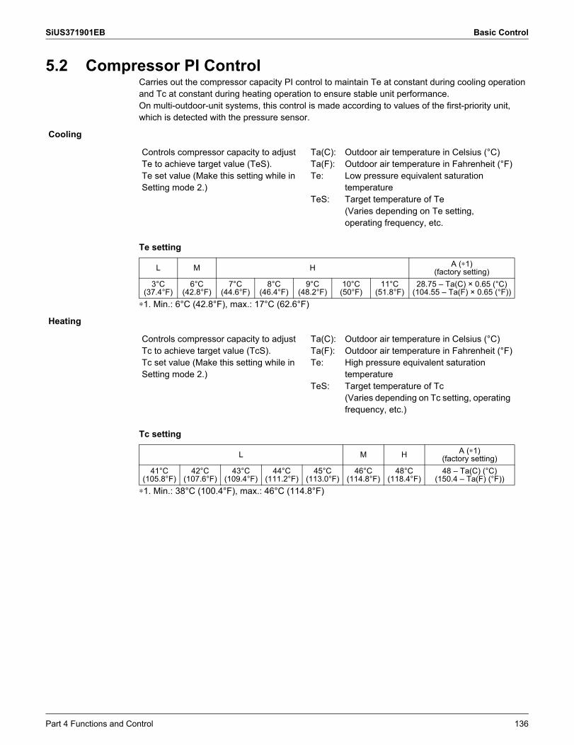
SiUS371901EB Basic Control
5.2 Compressor PI ControlCarries out the compressor capacity PI control to maintain Te at constant during cooling operation and Tc at constant during heating operation to ensure stable unit performance.On multi-outdoor-unit systems, this control is made according to values of the first-priority unit, which is detected with the pressure sensor.
Te setting
∗1. Min.: 6°C (42.8°F), max.: 17°C (62.6°F)
Tc setting
∗1. Min.: 38°C (100.4°F), max.: 46°C (114.8°F)
Cooling
Controls compressor capacity to adjust Te to achieve target value (TeS).Te set value (Make this setting while in Setting mode 2.)
Ta(C):Ta(F):Te:
TeS:
Outdoor air temperature in Celsius (°C)Outdoor air temperature in Fahrenheit (°F)Low pressure equivalent saturation temperatureTarget temperature of Te(Varies depending on Te setting, operating frequency, etc.
L M H A (∗1)(factory setting)
3°C (37.4°F)
6°C (42.8°F)
7°C (44.6°F)
8°C (46.4°F)
9°C (48.2°F)
10°C (50°F)
11°C (51.8°F)
28.75 – Ta(C) × 0.65 (°C)(104.55 – Ta(F) × 0.65 (°F))
Heating
Controls compressor capacity to adjust Tc to achieve target value (TcS).Tc set value (Make this setting while in Setting mode 2.)
Ta(C):Ta(F):Te:
TeS:
Outdoor air temperature in Celsius (°C) Outdoor air temperature in Fahrenheit (°F)High pressure equivalent saturation temperatureTarget temperature of Tc(Varies depending on Tc setting, operating frequency, etc.)
L M H A (∗1)(factory setting)
41°C (105.8°F)
42°C (107.6°F)
43°C (109.4°F)
44°C (111.2°F)
45°C (113.0°F)
46°C (114.8°F)
48°C (118.4°F)
48 – Ta(C) (°C) (150.4 – Ta(F) (°F))
Part 4 Functions and Control 136
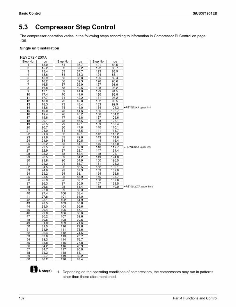
Basic Control SiUS371901EB
Note(s)
5.3 Compressor Step Control
1. Depending on the operating conditions of compressors, the compressors may run in patterns other than those aforementioned.
The compressor operation varies in the following steps according to information in Compressor PI Control on page 136.
Single unit installation
REYQ72-120XAStep No. rps Step No. rps Step No. rps
1 15.0 61 36.7 121 84.52 15.2 62 37.2 122 85.73 15.4 63 37.7 123 86.94 15.6 64 38.3 124 88.15 15.9 65 38.8 125 89.46 16.2 66 39.3 126 90.67 16.5 67 39.9 127 91.98 16.8 68 40.5 128 93.29 17.1 69 41.0 129 94.510 17.4 70 41.6 130 95.811 17.7 71 42.2 131 97.212 18.0 72 42.8 132 98.513 18.3 73 43.4 133 99.914 18.6 74 44.0 134 101.315 19.0 75 44.6 135 102.716 19.4 76 45.2 136 104.217 19.8 77 45.8 137 105.618 20.1 78 46.5 138 107.119 20.5 79 47.1 139 108.420 20.7 80 47.8 140 110.121 21.0 81 48.5 141 111.722 21.3 82 49.1 142 113.223 21.6 83 49.8 143 114.824 21.9 84 50.5 144 116.425 22.2 85 51.1 145 118.026 22.5 86 52.0 146 119.727 22.9 87 52.7 147 121.428 23.2 88 53.4 148 123.129 23.5 89 54.2 149 124.830 23.8 90 54.9 150 126.531 24.2 91 55.7 151 128.332 24.5 92 56.5 152 130.133 24.9 93 57.3 153 132.034 25.2 94 58.1 154 133.835 25.5 95 58.9 155 135.736 25.9 96 59.7 156 137.637 26.3 97 60.5 157 139.538 26.6 98 61.4 158 140.039 27.0 99 62.340 27.4 100 63.441 27.8 101 64.042 28.1 102 64.943 28.5 103 65.644 29.0 104 66.645 29.4 105 67.746 29.8 106 68.647 30.2 107 69.648 30.6 108 70.649 31.0 109 71.650 31.5 110 72.651 31.9 111 73.652 32.4 112 74.653 32.8 113 75.754 33.3 114 76.755 33.8 115 77.856 34.2 116 78.957 34.7 117 80.058 35.2 118 81.159 35.7 119 82.260 36.2 120 83.4
REYQ72XA upper limit
REYQ96XA upper limit
REYQ120XA upper limit
137 Part 4 Functions and Control
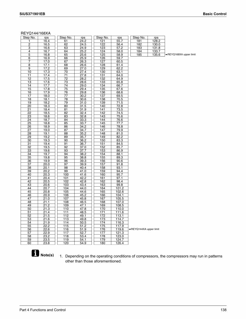
SiUS371901EB Basic Control
Note(s) 1. Depending on the operating conditions of compressors, the compressors may run in patterns other than those aforementioned.
REYQ144/168XAStep No. rps Step No. rps Step No. rps Step No. rps
1 16.4 61 24.2 121 55.7 181 128.22 16.5 62 24.5 122 56.4 182 130.03 16.6 63 24.9 123 57.2 183 131.84 16.7 64 25.2 124 58.0 184 133.75 16.8 65 25.6 125 58.9 185 135.66 16.9 66 25.9 126 59.77 17.0 67 26.3 127 60.58 17.1 68 26.6 128 61.49 17.2 69 27.0 129 62.210 17.3 70 27.4 130 63.111 17.4 71 27.8 131 64.012 17.5 72 28.2 132 64.913 17.6 73 28.6 133 65.814 17.7 74 29.0 134 66.715 17.8 75 29.4 135 67.616 17.9 76 29.8 136 68.617 18.0 77 30.2 137 69.518 18.1 78 30.6 138 70.519 18.2 79 31.0 139 71.520 18.3 80 31.5 140 72.821 18.4 81 31.9 141 73.522 18.5 82 32.4 142 74.523 18.6 83 32.8 143 75.624 18.7 84 33.3 144 76.625 18.8 85 33.7 145 77.726 18.9 86 34.2 146 78.827 19.0 87 34.7 147 79.928 19.1 88 35.2 148 81.029 19.2 89 35.7 149 82.230 19.3 90 36.2 150 83.331 19.4 91 36.7 151 84.532 19.5 92 37.0 152 85.733 19.6 93 37.7 153 86.934 19.7 94 38.2 154 88.135 19.8 95 38.8 155 89.336 19.9 96 39.3 156 90.637 20.0 97 39.9 157 91.838 20.1 98 40.4 158 93.139 20.2 99 41.0 159 94.440 20.3 100 41.6 160 95.741 20.4 101 42.2 161 97.142 20.5 102 42.8 162 98.443 20.6 103 43.4 163 99.844 20.7 104 44.0 164 101.245 20.8 105 44.6 165 102.646 20.9 106 45.2 166 104.147 21.0 107 45.8 167 105.548 21.1 108 46.5 168 107.049 21.2 109 47.1 169 108.550 21.3 110 47.8 170 110.051 21.4 111 48.5 171 111.652 21.5 112 49.1 172 113.153 21.6 113 49.8 173 114.754 21.9 114 50.5 174 116.355 22.2 115 51.2 175 117.956 22.6 116 51.9 176 119.657 22.9 117 52.7 177 121.358 23.2 118 53.4 178 123.059 23.5 119 54.1 179 124.760 23.8 120 54.9 180 126.4
REYQ168XA upper limit
REYQ144XA upper limit
Part 4 Functions and Control 138
Basic Control SiUS371901EB
5.4 Electronic Expansion Valve PI Control
When the outdoor unit heat exchanging is performed via the condenser (Y5S or Y6S is set to OFF), this function is used to exert PI control on the electronic expansion valve (Y1E or Y3E) so that the condenser outlet subcooling degree (SC) will become constant.
When the outdoor unit heat exchanging is performed via the evaporator (Y5S or Y6S is set to ON), this function is used to exert PI control on the electronic expansion valve (Y1E or Y3E) so that the evaporator outlet superheating degree (SH) will become constant.
In order to make the maximum use of the subcooling heat exchanger, this function is used to exert PI control on the electronic expansion valve (Y2E, Y5E or Y3E) so that the evaporator-side gas pipe superheating degree (SH) will become constant.
Main electronic expansion valve EVM control
SC = Tc – Tf SC:Tc:
Tf:
Condenser outlet subcooling degreeHigh pressure equivalent saturatedtemperatureLiquid pipe temperature detected by heatexchanger liquid pipe thermistor R4T,R5T
SH = Tg – Te SH:Tg:
Te:
Evaporator outlet superheating degreeSuction pipe temperature detected byheat exchanger gas pipe thermistor R8T,R9TLow pressure equivalent saturatedtemperature
Subcooling electronic expansion valve EVT control
SH = Tsh – Tm SH:Tsh:
Tm:
Evaporator outlet superheating degreeSuction pipe temperature detected bythe subcooling heat exchanger outletthermistor R5TLow or middle pressure equivalentsaturated temperature
139 Part 4 Functions and Control
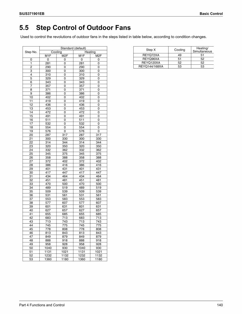
SiUS371901EB Basic Control
5.5 Step Control of Outdoor FansUsed to control the revolutions of outdoor fans in the steps listed in table below, according to condition changes.
Step No.Standard (default)
Cooling HeatingM1F M2F M1F M2F
0 0 0 0 01 281 0 281 02 290 0 290 03 300 0 300 04 310 0 310 05 329 0 329 06 343 0 343 07 357 0 357 08 371 0 371 09 386 0 386 0
10 402 0 402 011 419 0 419 012 436 0 436 013 453 0 453 014 472 0 472 015 491 0 491 016 511 0 511 017 532 0 532 018 554 0 554 019 576 0 576 020 287 317 287 31721 300 330 300 33022 314 344 314 34423 320 350 320 35024 332 362 332 36225 345 375 345 37526 358 388 358 38827 372 402 372 40228 386 416 386 41629 401 431 401 43130 417 447 417 44731 434 464 434 46432 451 481 451 48133 470 500 470 50034 489 519 489 51935 509 539 509 53936 531 561 531 56137 553 583 553 58338 577 607 577 60739 601 631 601 63140 627 657 627 65741 655 685 655 68542 683 713 683 71343 713 743 713 74344 745 775 745 77545 778 808 778 80846 813 843 813 84347 849 879 849 87948 888 918 888 91849 958 928 958 92850 1040 930 1040 93051 1131 1021 1131 102152 1232 1132 1232 113253 1360 1180 1360 1180
Step X Cooling Heating/Simultaneous
REYQ72XA 49 51REYQ96XA 51 52
REYQ120XA 52 52REYQ144/168XA 53 53
Part 4 Functions and Control 140
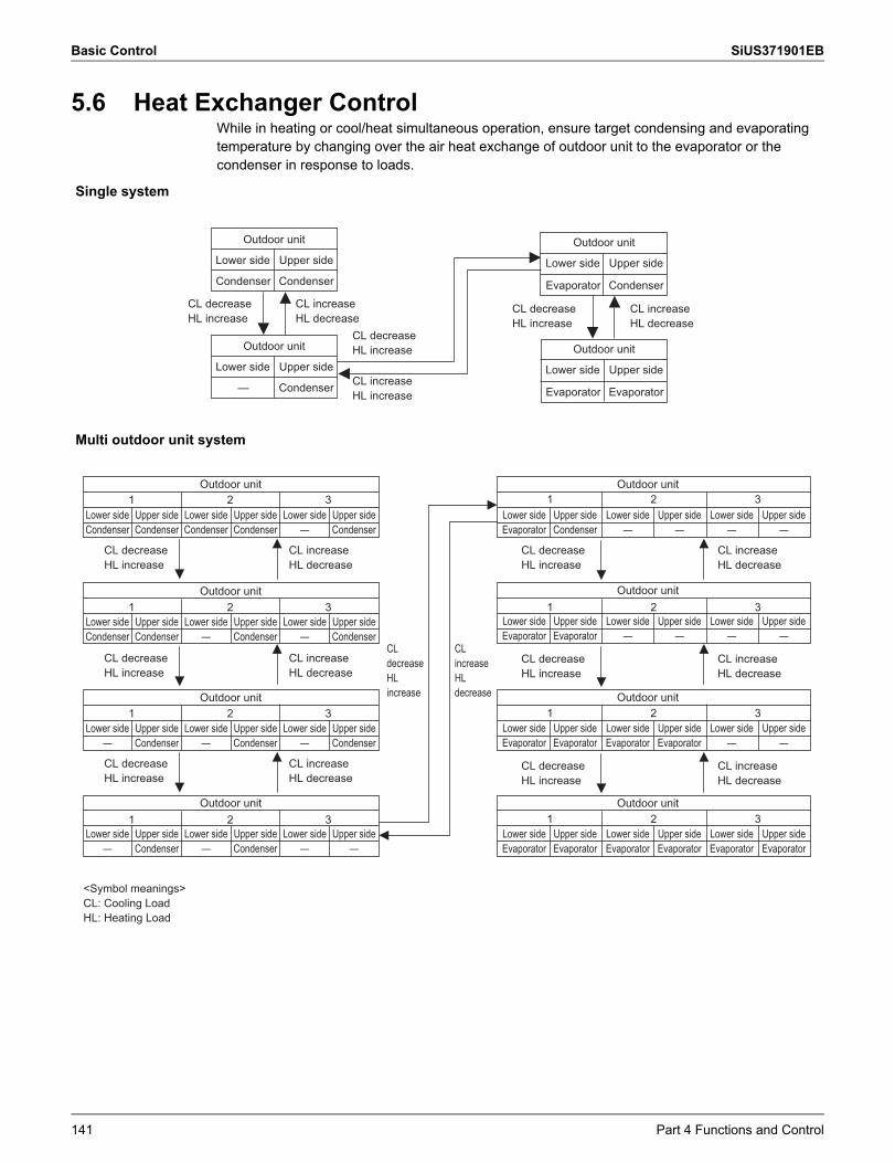
Basic Control SiUS371901EB
5.6 Heat Exchanger ControlWhile in heating or cool/heat simultaneous operation, ensure target condensing and evaporating temperature by changing over the air heat exchange of outdoor unit to the evaporator or the condenser in response to loads.
Single system
Multi outdoor unit system
Outdoor unit
Lower side
Condenser
Upper side
Condenser
Outdoor unit
Lower side
Evaporator
Upper side
Condenser
Outdoor unit
Lower side
Evaporator
Upper side
Evaporator
Outdoor unit
Lower side
—
Upper side
Condenser
CL decreaseHL increase
CL decreaseHL increase
CL increaseHL decrease
CL decreaseHL increase
CL increaseHL decrease
CL increaseHL increase
1 3
1 3
1 3
1 3
12
2
2
2
2 3
1 2 3
1 2 3
1 2 3
Lower side Upper side
Outdoor unit
Lower side Upper side Lower side Upper sideCondenser CondenserCondenser Condenser — Condenser
Lower side Upper side
Outdoor unit
Lower side Upper side Lower side Upper side— CondenserCondenser Condenser — Condenser
Lower side Upper side
Outdoor unit
Lower side Upper side Lower side Upper side— Condenser— Condenser — Condenser
Lower side Upper side
Outdoor unit
Lower side Upper side Lower side Upper side— Condenser— Condenser — —
CL decreaseHL increase
CL increaseHL decrease
Lower side Upper side
Outdoor unit
Lower side Upper side Lower side Upper side— —Evaporator Condenser — —
Lower side Upper side
Outdoor unit
Lower side Upper side Lower side Upper side— —Evaporator Evaporator — —
CL decreaseHL increase
CL increaseHL decrease
CL decreaseHL increase
CL increaseHL decrease
Lower side Upper side
Outdoor unit
Lower side Upper side Lower side Upper sideEvaporator EvaporatorEvaporator Evaporator — —
Lower side Upper side
Outdoor unit
Lower side Upper side Lower side Upper sideEvaporator EvaporatorEvaporator Evaporator Evaporator Evaporator
CL decreaseHL increase
CL increaseHL decrease
CL decreaseHL increase
CL increaseHL decrease
<Symbol meanings>CL: Cooling LoadHL: Heating Load
CL decreaseHL increase
CL increaseHL decrease
CL decreaseHL increase
CL increaseHL decrease
141 Part 4 Functions and Control
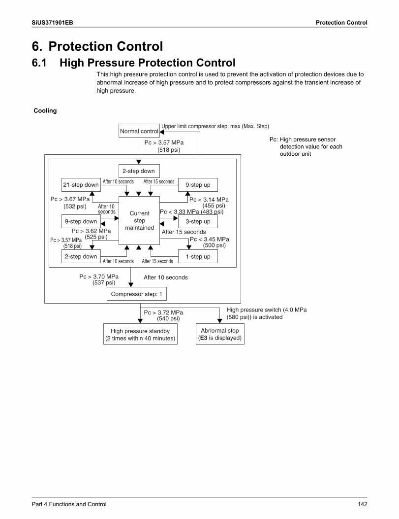
SiUS371901EB Protection Control
6. Protection Control6.1 High Pressure Protection Control
This high pressure protection control is used to prevent the activation of protection devices due to abnormal increase of high pressure and to protect compressors against the transient increase of high pressure.
Cooling
Normal control
21-step down 9-step up
9-step down 3-step up
2-step down
1-step up2-step down
After 10 seconds After 15 seconds
After 15 secondsAfter 10 seconds
Pc > 3.57 MPa(518 psi)
Pc > 3.70 MPa(537 psi)
Pc < 3.14 MPa(455 psi)
Pc < 3.45 MPa(500 psi)
Pc > 3.67 MPa(532 psi)
Pc > 3.62 MPa(525 psi)Pc > 3.57 MPa
(518 psi)
Compressor step: 1
After 15 seconds
Pc < 3.33 MPa (483 psi)
After 10 seconds
Upper limit compressor step: max (Max. Step)
Pc > 3.72 MPa(540 psi)
Pc: High pressure sensor detection value for each outdoor unit
Current step
maintained
Abnormal stop (E3 is displayed)
High pressure standby (2 times within 40 minutes)
After 10 seconds
High pressure switch (4.0 MPa (580 psi)) is activated
Part 4 Functions and Control 142
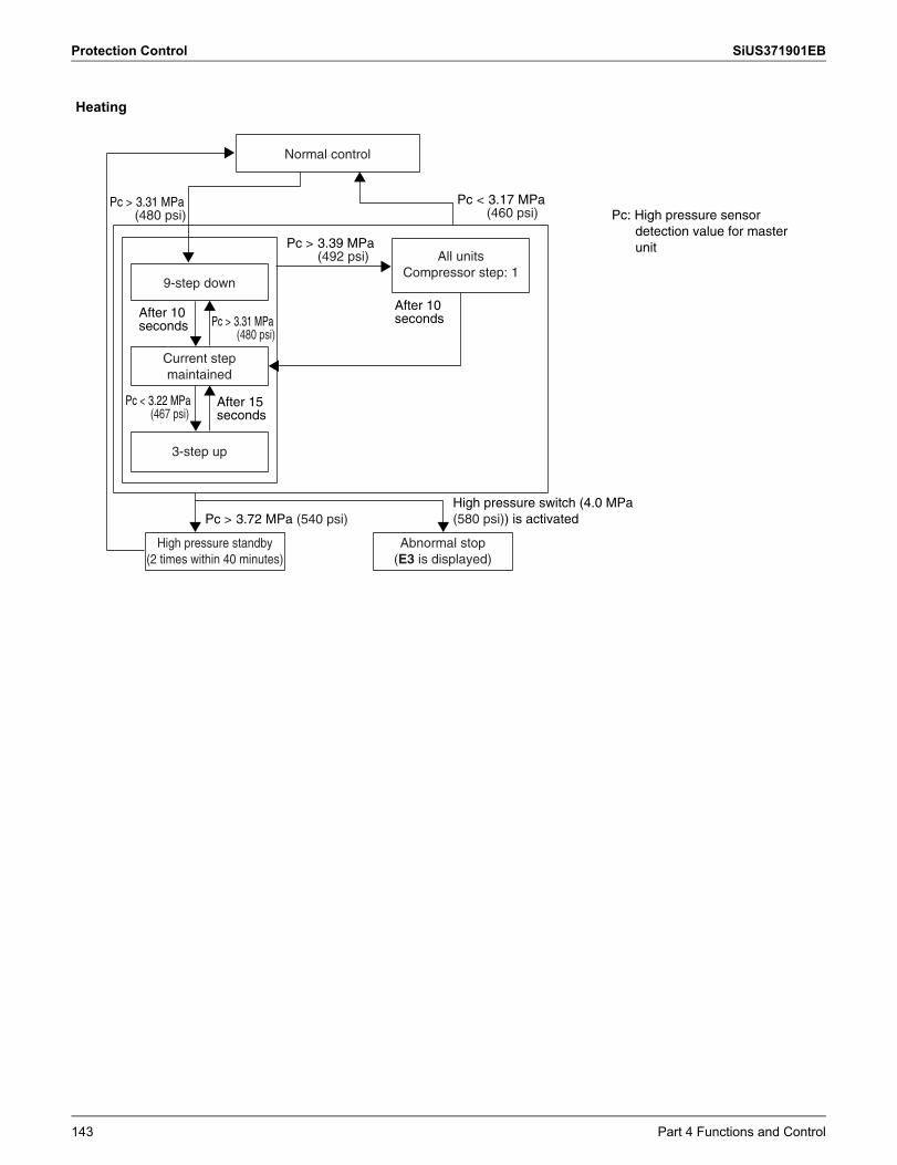
Protection Control SiUS371901EB
Heating
Pc < 3.17 MPa(460 psi)
Pc < 3.22 MPa(467 psi)
Pc > 3.39 MPa(492 psi)
Pc > 3.31 MPa(480 psi)
Pc > 3.72 MPa (540 psi)
Normal control
9-step down
All units Compressor step: 1
3-step up
Current step maintained
High pressure standby (2 times within 40 minutes)
Pc: High pressure sensor detection value for master unit
Abnormal stop (E3 is displayed)
Pc > 3.31 MPa(480 psi)
After 10 seconds
After 10 seconds
After 15 seconds
High pressure switch (4.0 MPa (580 psi)) is activated
143 Part 4 Functions and Control
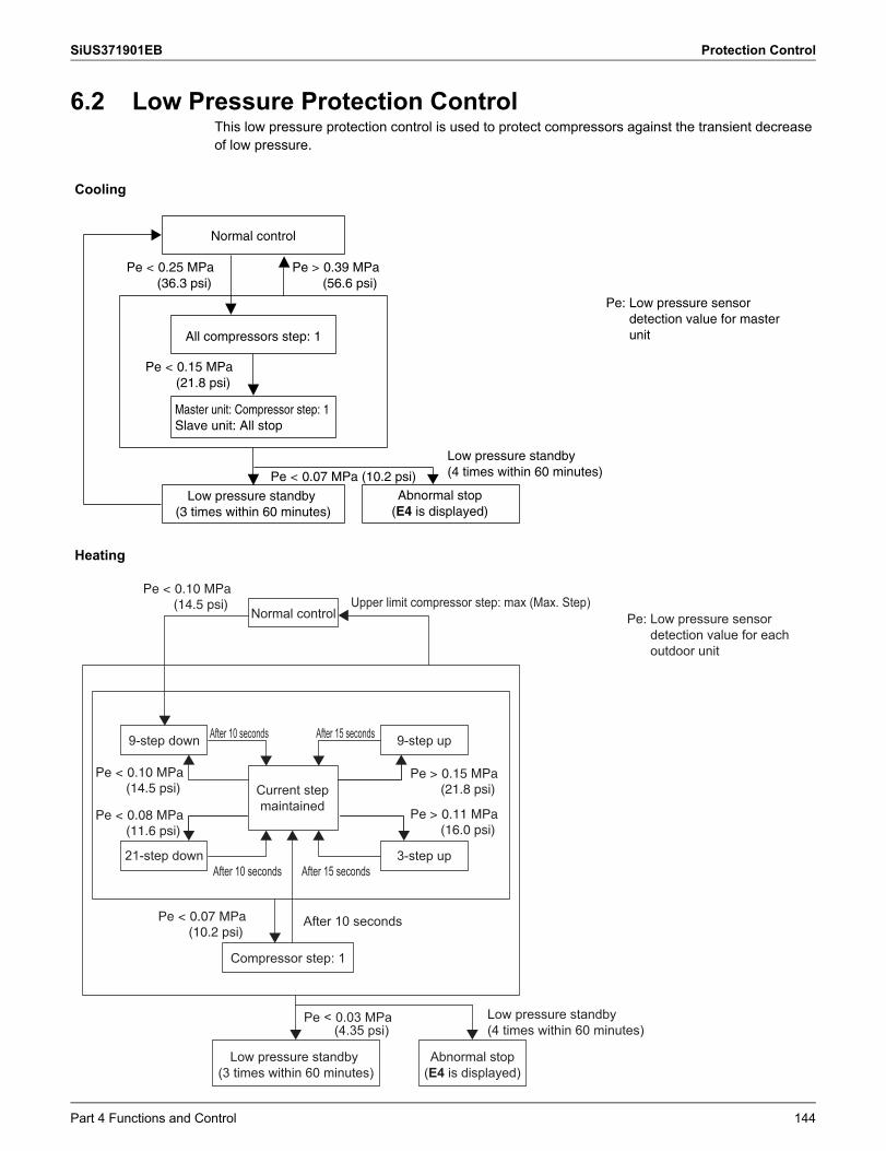
SiUS371901EB Protection Control
6.2 Low Pressure Protection ControlThis low pressure protection control is used to protect compressors against the transient decrease of low pressure.
Cooling
Heating
Normal control
All compressors step: 1
Pe < 0.15 MPa(21.8 psi)
Pe < 0.25 MPa(36.3 psi)
Pe > 0.39 MPa(56.6 psi)
Pe < 0.07 MPa (10.2 psi)
Pe: Low pressure sensor detection value for master unit
Master unit: Compressor step: 1 Slave unit: All stop
Abnormal stop (E4 is displayed)
Low pressure standby (3 times within 60 minutes)
Low pressure standby (4 times within 60 minutes)
Normal control
9-step down 9-step up
3-step up21-step down
After 10 seconds After 15 seconds
After 15 secondsAfter 10 seconds
Pe < 0.10 MPa(14.5 psi)
Pe < 0.07 MPa(10.2 psi)
Pe > 0.15 MPa(21.8 psi)
Pe > 0.11 MPa(16.0 psi)
Pe < 0.10 MPa(14.5 psi)
Pe < 0.08 MPa(11.6 psi)
Compressor step: 1
After 10 seconds
Upper limit compressor step: max (Max. Step)
Pe < 0.03 MPa(4.35 psi)
Pe: Low pressure sensor detection value for each outdoor unit
Current step maintained
Abnormal stop (E4 is displayed)
Low pressure standby (3 times within 60 minutes)
Low pressure standby (4 times within 60 minutes)
Part 4 Functions and Control 144
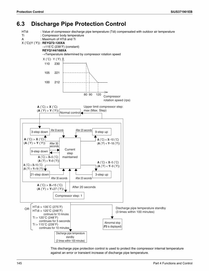
Protection Control SiUS371901EB
6.3 Discharge Pipe Protection Control
This discharge pipe protection control is used to protect the compressor internal temperatureagainst an error or transient increase of discharge pipe temperature.
Normal control
3-step down 9-step up
9-step down
3-step up21-step down
After 30 seconds After 20 seconds
After 20 secondsAfter 30 seconds
A (˚C) > X (˚C) (A (˚F) > Y (˚F))
A (˚C) < X–10 (˚C) (A (˚F) < Y–18 (˚F))
A (˚C) > X+5 (˚C) (A (˚F) > Y+9 (˚F)) A (˚C) < X–5 (˚C)
(A (˚F) < Y–9 (˚F))A (˚C) > X+10 (˚C) (A (˚F) > Y+18 (˚F))
A (˚C) > X+15 (˚C) (A (˚F) > Y+27 (˚F))
A (˚C) > X (˚C) (A (˚F) > Y (˚F))
Compressor step: 1
After 20 seconds
HTdi > 135˚C (275˚F)HTdi > 120˚C (248˚F)
continues for 10 minutesTi > 120˚C (248˚F)
continues for 5 secondsTi > 115˚C (239˚F)
continues for 10 minutes
OR
HTdi : Value of compressor discharge pipe temperature (Tdi) compensated with outdoor air temperatureTi : Compressor body temperatureA : Maximum of HTdi and TiX (˚C)(Y (˚F)) : REYQ72-120XA
→115˚C (239˚F) (constant)REYQ144/168XA→Temperature determined by compressor rotation speed
Upper limit compressor step: max (Max. Step)
Current step
maintained
Discharge pipe temperature standby (3 times within 100 minutes)
Abnormal stop(F3 is displayed)
Discharge pipe temperature standby
(2 times within 100 minutes)
After 30 seconds
100
105
110
X (˚C)
212
221
230
80 90 120
Y (˚F)
Compressor rotation speed (rps)
145 Part 4 Functions and Control
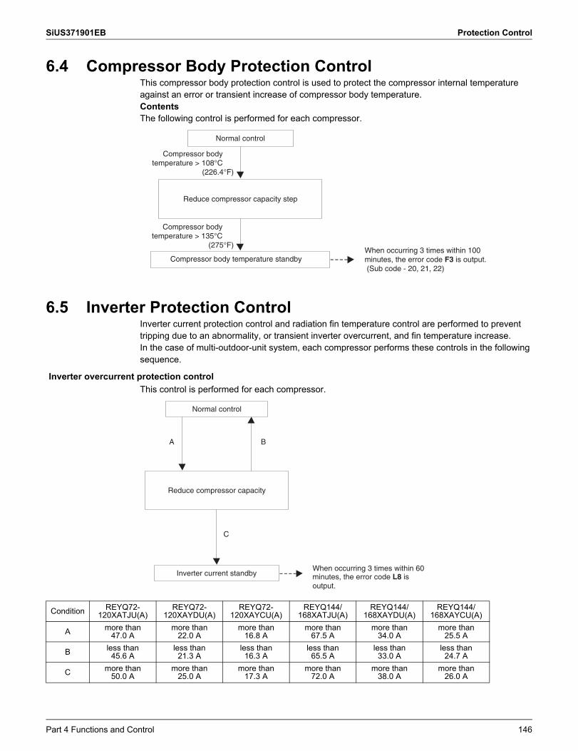
SiUS371901EB Protection Control
6.4 Compressor Body Protection ControlThis compressor body protection control is used to protect the compressor internal temperatureagainst an error or transient increase of compressor body temperature.ContentsThe following control is performed for each compressor.
6.5 Inverter Protection ControlInverter current protection control and radiation fin temperature control are performed to preventtripping due to an abnormality, or transient inverter overcurrent, and fin temperature increase.In the case of multi-outdoor-unit system, each compressor performs these controls in the following sequence.
This control is performed for each compressor.
Normal control
Compressor body temperature standby
Reduce compressor capacity step
Compressor body temperature > 108°C
(226.4°F)
Compressor body temperature > 135°C
(275°F)When occurring 3 times within 100 minutes, the error code F3 is output. (Sub code - 20, 21, 22)
Inverter overcurrent protection control
Condition REYQ72- 120XATJU(A)
REYQ72- 120XAYDU(A)
REYQ72- 120XAYCU(A)
REYQ144/ 168XATJU(A)
REYQ144/ 168XAYDU(A)
REYQ144/ 168XAYCU(A)
A more than 47.0 A
more than 22.0 A
more than 16.8 A
more than 67.5 A
more than 34.0 A
more than 25.5 A
B less than 45.6 A
less than 21.3 A
less than 16.3 A
less than 65.5 A
less than 33.0 A
less than 24.7 A
C more than 50.0 A
more than 25.0 A
more than 17.3 A
more than 72.0 A
more than 38.0 A
more than 26.0 A
Normal control
Inverter current standby
Reduce compressor capacity
A B
When occurring 3 times within 60 minutes, the error code L8 is output.
C
Part 4 Functions and Control 146
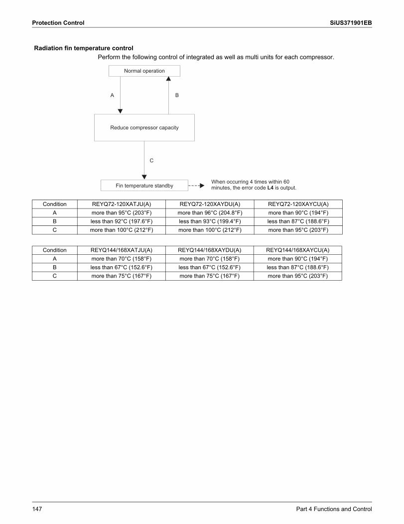
Protection Control SiUS371901EB
Perform the following control of integrated as well as multi units for each compressor.Radiation fin temperature control
Condition REYQ72-120XATJU(A) REYQ72-120XAYDU(A) REYQ72-120XAYCU(A)A more than 95°C (203°F) more than 96°C (204.8°F) more than 90°C (194°F)B less than 92°C (197.6°F) less than 93°C (199.4°F) less than 87°C (188.6°F)C more than 100°C (212°F) more than 100°C (212°F) more than 95°C (203°F)
Normal operation
Fin temperature standby
Reduce compressor capacity
When occurring 4 times within 60 minutes, the error code L4 is output.
A B
C
Condition REYQ144/168XATJU(A) REYQ144/168XAYDU(A) REYQ144/168XAYCU(A)A more than 70°C (158°F) more than 70°C (158°F) more than 90°C (194°F)B less than 67°C (152.6°F) less than 67°C (152.6°F) less than 87°C (188.6°F)C more than 75°C (167°F) more than 75°C (167°F) more than 95°C (203°F)
147 Part 4 Functions and Control
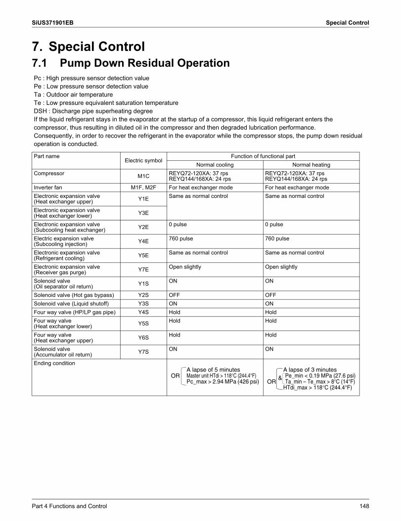
SiUS371901EB Special Control
7. Special Control7.1 Pump Down Residual OperationPc : High pressure sensor detection valuePe : Low pressure sensor detection valueTa : Outdoor air temperatureTe : Low pressure equivalent saturation temperatureDSH : Discharge pipe superheating degreeIf the liquid refrigerant stays in the evaporator at the startup of a compressor, this liquid refrigerant enters the compressor, thus resulting in diluted oil in the compressor and then degraded lubrication performance.Consequently, in order to recover the refrigerant in the evaporator while the compressor stops, the pump down residual operation is conducted.
Part nameElectric symbol
Function of functional partNormal cooling Normal heating
Compressor M1C REYQ72-120XA: 37 rpsREYQ144/168XA: 24 rps
REYQ72-120XA: 37 rpsREYQ144/168XA: 24 rps
Inverter fan M1F, M2F For heat exchanger mode For heat exchanger modeElectronic expansion valve (Heat exchanger upper) Y1E Same as normal control Same as normal control
Electronic expansion valve (Heat exchanger lower) Y3E
Electronic expansion valve (Subcooling heat exchanger) Y2E 0 pulse 0 pulse
Electric expansion valve (Subcooling injection) Y4E 760 pulse 760 pulse
Electronic expansion valve (Refrigerant cooling) Y5E Same as normal control Same as normal control
Electronic expansion valve (Receiver gas purge) Y7E Open slightly Open slightly
Solenoid valve (Oil separator oil return) Y1S ON ON
Solenoid valve (Hot gas bypass) Y2S OFF OFFSolenoid valve (Liquid shutoff) Y3S ON ONFour way valve (HP/LP gas pipe) Y4S Hold HoldFour way valve (Heat exchanger lower) Y5S Hold Hold
Four way valve (Heat exchanger upper) Y6S Hold Hold
Solenoid valve (Accumulator oil return) Y7S ON ON
Ending conditionA lapse of 5 minutesMaster unit HTdi > 118°C (244.4°F)Pc_max > 2.94 MPa (426 psi)
ORA lapse of 3 minutesPe_min < 0.19 MPa (27.6 psi)Ta_min – Te_max > 8°C (14°F)
HTdi_max > 118°C (244.4°F)OR
&
Part 4 Functions and Control 148
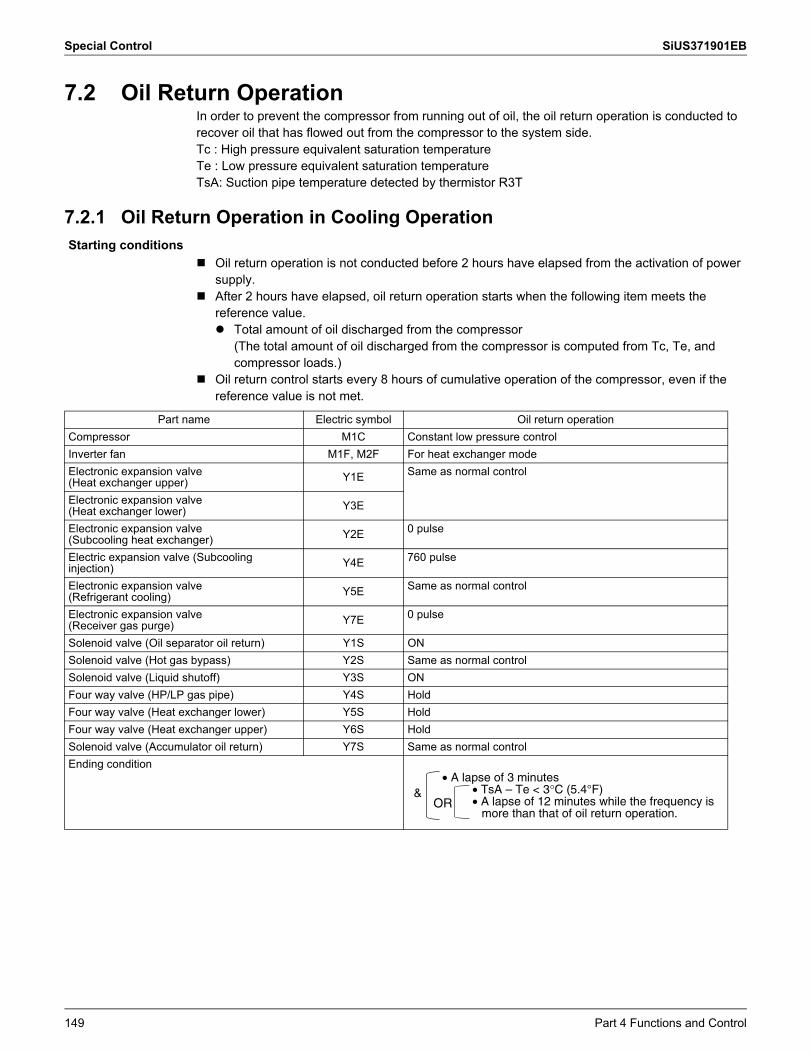
Special Control SiUS371901EB
7.2 Oil Return OperationIn order to prevent the compressor from running out of oil, the oil return operation is conducted to recover oil that has flowed out from the compressor to the system side.Tc : High pressure equivalent saturation temperatureTe : Low pressure equivalent saturation temperatureTsA: Suction pipe temperature detected by thermistor R3T
7.2.1 Oil Return Operation in Cooling Operation
Oil return operation is not conducted before 2 hours have elapsed from the activation of power supply.
After 2 hours have elapsed, oil return operation starts when the following item meets the reference value. Total amount of oil discharged from the compressor
(The total amount of oil discharged from the compressor is computed from Tc, Te, and compressor loads.)
Oil return control starts every 8 hours of cumulative operation of the compressor, even if the reference value is not met.
Starting conditions
Part name Electric symbol Oil return operationCompressor M1C Constant low pressure controlInverter fan M1F, M2F For heat exchanger modeElectronic expansion valve (Heat exchanger upper) Y1E Same as normal control
Electronic expansion valve (Heat exchanger lower) Y3E
Electronic expansion valve (Subcooling heat exchanger) Y2E 0 pulse
Electric expansion valve (Subcooling injection) Y4E 760 pulse
Electronic expansion valve (Refrigerant cooling) Y5E Same as normal control
Electronic expansion valve (Receiver gas purge) Y7E 0 pulse
Solenoid valve (Oil separator oil return) Y1S ONSolenoid valve (Hot gas bypass) Y2S Same as normal controlSolenoid valve (Liquid shutoff) Y3S ONFour way valve (HP/LP gas pipe) Y4S HoldFour way valve (Heat exchanger lower) Y5S HoldFour way valve (Heat exchanger upper) Y6S HoldSolenoid valve (Accumulator oil return) Y7S Same as normal controlEnding condition
• A lapse of 3 minutes• TsA – Te < 3°C (5.4°F)• A lapse of 12 minutes while the frequency is
more than that of oil return operation.
&OR
149 Part 4 Functions and Control
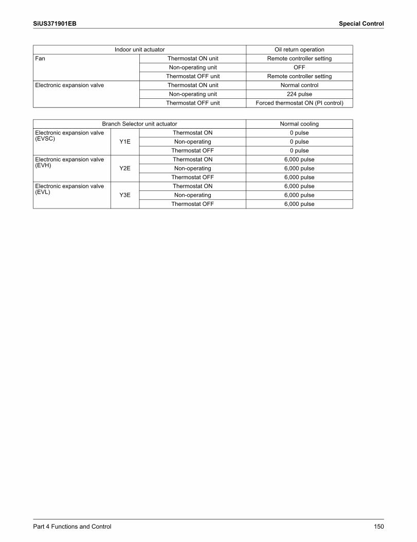
SiUS371901EB Special Control
Indoor unit actuator Oil return operationFan Thermostat ON unit Remote controller setting
Non-operating unit OFFThermostat OFF unit Remote controller setting
Electronic expansion valve Thermostat ON unit Normal controlNon-operating unit 224 pulse
Thermostat OFF unit Forced thermostat ON (PI control)
Branch Selector unit actuator Normal coolingElectronic expansion valve (EVSC) Y1E
Thermostat ON 0 pulseNon-operating 0 pulse
Thermostat OFF 0 pulseElectronic expansion valve (EVH) Y2E
Thermostat ON 6,000 pulseNon-operating 6,000 pulse
Thermostat OFF 6,000 pulseElectronic expansion valve (EVL) Y3E
Thermostat ON 6,000 pulseNon-operating 6,000 pulse
Thermostat OFF 6,000 pulse
Part 4 Functions and Control 150
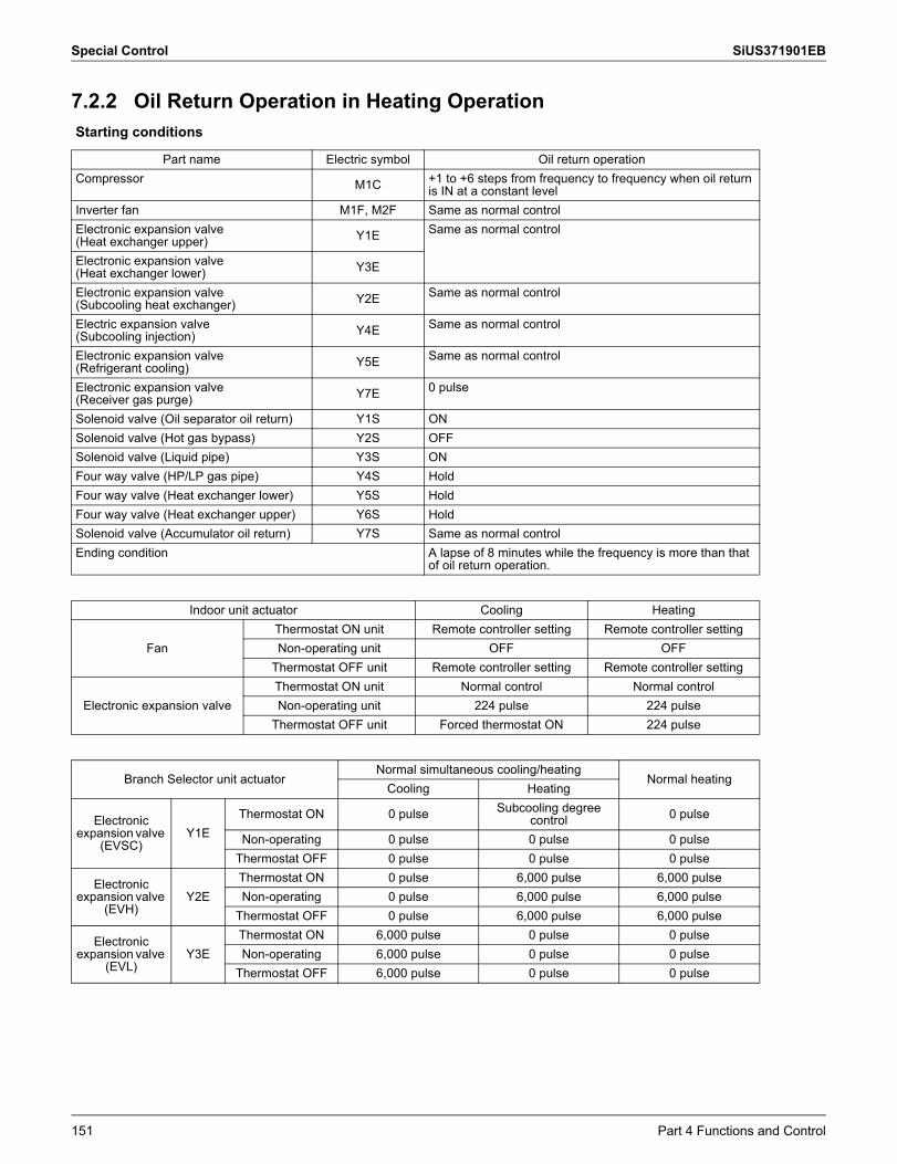
Special Control SiUS371901EB
7.2.2 Oil Return Operation in Heating OperationStarting conditions
Part name Electric symbol Oil return operationCompressor M1C +1 to +6 steps from frequency to frequency when oil return
is IN at a constant levelInverter fan M1F, M2F Same as normal controlElectronic expansion valve (Heat exchanger upper) Y1E Same as normal control
Electronic expansion valve (Heat exchanger lower) Y3E
Electronic expansion valve (Subcooling heat exchanger) Y2E Same as normal control
Electric expansion valve (Subcooling injection) Y4E Same as normal control
Electronic expansion valve (Refrigerant cooling) Y5E Same as normal control
Electronic expansion valve (Receiver gas purge) Y7E 0 pulse
Solenoid valve (Oil separator oil return) Y1S ONSolenoid valve (Hot gas bypass) Y2S OFFSolenoid valve (Liquid pipe) Y3S ONFour way valve (HP/LP gas pipe) Y4S HoldFour way valve (Heat exchanger lower) Y5S HoldFour way valve (Heat exchanger upper) Y6S HoldSolenoid valve (Accumulator oil return) Y7S Same as normal controlEnding condition A lapse of 8 minutes while the frequency is more than that
of oil return operation.
Indoor unit actuator Cooling Heating
FanThermostat ON unit Remote controller setting Remote controller settingNon-operating unit OFF OFF
Thermostat OFF unit Remote controller setting Remote controller setting
Electronic expansion valveThermostat ON unit Normal control Normal controlNon-operating unit 224 pulse 224 pulse
Thermostat OFF unit Forced thermostat ON 224 pulse
Branch Selector unit actuatorNormal simultaneous cooling/heating
Normal heatingCooling Heating
Electronic expansion valve
(EVSC)Y1E
Thermostat ON 0 pulse Subcooling degree control 0 pulse
Non-operating 0 pulse 0 pulse 0 pulseThermostat OFF 0 pulse 0 pulse 0 pulse
Electronic expansion valve
(EVH)Y2E
Thermostat ON 0 pulse 6,000 pulse 6,000 pulseNon-operating 0 pulse 6,000 pulse 6,000 pulse
Thermostat OFF 0 pulse 6,000 pulse 6,000 pulse
Electronic expansion valve
(EVL)Y3E
Thermostat ON 6,000 pulse 0 pulse 0 pulseNon-operating 6,000 pulse 0 pulse 0 pulse
Thermostat OFF 6,000 pulse 0 pulse 0 pulse
151 Part 4 Functions and Control
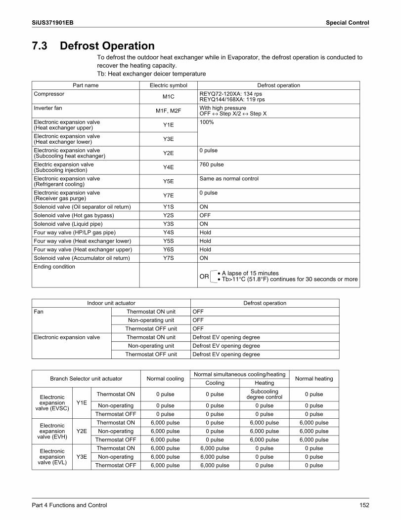
SiUS371901EB Special Control
7.3 Defrost OperationTo defrost the outdoor heat exchanger while in Evaporator, the defrost operation is conducted to recover the heating capacity.Tb: Heat exchanger deicer temperature
Part name Electric symbol Defrost operationCompressor M1C REYQ72-120XA: 134 rps
REYQ144/168XA: 119 rpsInverter fan M1F, M2F With high pressure
OFF ↔ Step X/2 ↔ Step XElectronic expansion valve (Heat exchanger upper) Y1E 100%
Electronic expansion valve (Heat exchanger lower) Y3E
Electronic expansion valve (Subcooling heat exchanger) Y2E 0 pulse
Electric expansion valve (Subcooling injection) Y4E 760 pulse
Electronic expansion valve (Refrigerant cooling) Y5E Same as normal control
Electronic expansion valve (Receiver gas purge) Y7E 0 pulse
Solenoid valve (Oil separator oil return) Y1S ONSolenoid valve (Hot gas bypass) Y2S OFFSolenoid valve (Liquid pipe) Y3S ONFour way valve (HP/LP gas pipe) Y4S HoldFour way valve (Heat exchanger lower) Y5S HoldFour way valve (Heat exchanger upper) Y6S HoldSolenoid valve (Accumulator oil return) Y7S ONEnding condition
• A lapse of 15 minutes• Tb>11°C (51.8°F) continues for 30 seconds or moreOR
Indoor unit actuator Defrost operationFan Thermostat ON unit OFF
Non-operating unit OFFThermostat OFF unit OFF
Electronic expansion valve Thermostat ON unit Defrost EV opening degreeNon-operating unit Defrost EV opening degree
Thermostat OFF unit Defrost EV opening degree
Branch Selector unit actuator Normal coolingNormal simultaneous cooling/heating
Normal heatingCooling Heating
Electronic expansion
valve (EVSC)Y1E
Thermostat ON 0 pulse 0 pulse Subcooling degree control 0 pulse
Non-operating 0 pulse 0 pulse 0 pulse 0 pulseThermostat OFF 0 pulse 0 pulse 0 pulse 0 pulse
Electronic expansion
valve (EVH)Y2E
Thermostat ON 6,000 pulse 0 pulse 6,000 pulse 6,000 pulseNon-operating 6,000 pulse 0 pulse 6,000 pulse 6,000 pulse
Thermostat OFF 6,000 pulse 0 pulse 6,000 pulse 6,000 pulse
Electronic expansion
valve (EVL)Y3E
Thermostat ON 6,000 pulse 6,000 pulse 0 pulse 0 pulseNon-operating 6,000 pulse 6,000 pulse 0 pulse 0 pulse
Thermostat OFF 6,000 pulse 6,000 pulse 0 pulse 0 pulse
Part 4 Functions and Control 152
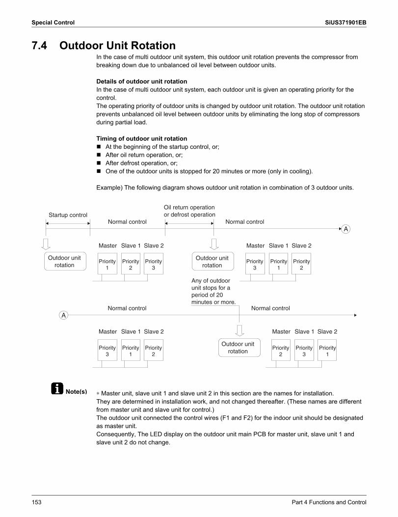
Special Control SiUS371901EB
Note(s)
7.4 Outdoor Unit RotationIn the case of multi outdoor unit system, this outdoor unit rotation prevents the compressor from breaking down due to unbalanced oil level between outdoor units.
Details of outdoor unit rotationIn the case of multi outdoor unit system, each outdoor unit is given an operating priority for the control.The operating priority of outdoor units is changed by outdoor unit rotation. The outdoor unit rotation prevents unbalanced oil level between outdoor units by eliminating the long stop of compressors during partial load.
Timing of outdoor unit rotation At the beginning of the startup control, or; After oil return operation, or; After defrost operation, or; One of the outdoor units is stopped for 20 minutes or more (only in cooling).
Example) The following diagram shows outdoor unit rotation in combination of 3 outdoor units.
∗ Master unit, slave unit 1 and slave unit 2 in this section are the names for installation.They are determined in installation work, and not changed thereafter. (These names are different from master unit and slave unit for control.)The outdoor unit connected the control wires (F1 and F2) for the indoor unit should be designated as master unit.Consequently, The LED display on the outdoor unit main PCB for master unit, slave unit 1 and slave unit 2 do not change.
Normal control Normal control
Normal control Normal control
Master Slave 1 Slave 2
Master Slave 1 Slave 2
Master Slave 1 Slave 2
Master Slave 1 Slave 2
A
A
Startup control
Outdoor unit rotation
Outdoor unit rotation
Outdoor unit rotation
Priority 1
Priority 1
Priority 2
Priority 2
Priority 3
Priority 3
Priority 1
Priority 2
Priority 3
Priority 3
Priority 1
Priority 2
Oil return operation or defrost operation
Any of outdoor unit stops for a period of 20 minutes or more.
153 Part 4 Functions and Control
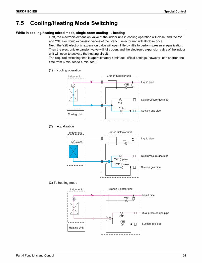
SiUS371901EB Special Control
7.5 Cooling/Heating Mode SwitchingWhile in cooling/heating mixed mode, single-room cooling → heating
First, the electronic expansion valve of the indoor unit in cooling operation will close, and the Y2E and Y3E electronic expansion valves of the branch selector unit will all close once.Next, the Y2E electronic expansion valve will open little by little to perform pressure equalization.Then the electronic expansion valve will fully open, and the electronic expansion valve of the indoor unit will open to activate the heating circuit.The required switching time is approximately 6 minutes. (Field settings, however, can shorten the time from 6 minutes to 4 minutes.)
(1) In cooling operation
(2) In equalization
(3) To heating mode
Y2E
Y3E
Y1ELiquid pipe
Dual pressure gas pipe
Suction gas pipe
Branch Selector unitIndoor unit
Cooling Unit
Y2E (open)
Y3E (close)
Y1E
Branch Selector unitIndoor unit
(close)Liquid pipe
Suction gas pipe
Dual pressure gas pipe
Y2E
Y3E
Y1E
Heating Unit
Branch Selector unitIndoor unit
Dual pressure gas pipe
Suction gas pipe
Liquid pipe
Part 4 Functions and Control 154
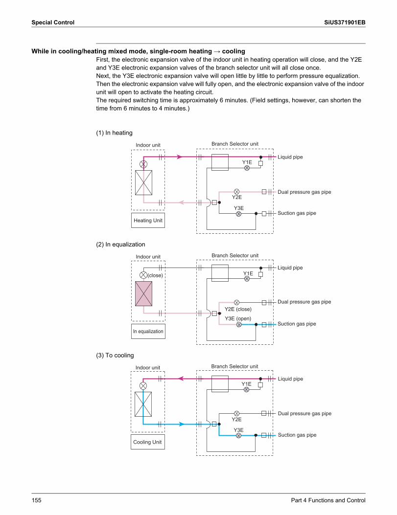
Special Control SiUS371901EB
While in cooling/heating mixed mode, single-room heating → coolingFirst, the electronic expansion valve of the indoor unit in heating operation will close, and the Y2E and Y3E electronic expansion valves of the branch selector unit will all close once.Next, the Y3E electronic expansion valve will open little by little to perform pressure equalization.Then the electronic expansion valve will fully open, and the electronic expansion valve of the indoor unit will open to activate the heating circuit.The required switching time is approximately 6 minutes. (Field settings, however, can shorten the time from 6 minutes to 4 minutes.)
(1) In heating
(2) In equalization
(3) To cooling
Y2E
Y3E
Y1E
Heating Unit
Branch Selector unitIndoor unit
Dual pressure gas pipe
Liquid pipe
Suction gas pipe
Y2E (close)
Y3E (open)
Y1E
In equalization
(close)
Branch Selector unitIndoor unit
Liquid pipe
Dual pressure gas pipe
Suction gas pipe
Y2E
Y3E
Y1E
Branch Selector unitIndoor unit
Cooling Unit
Liquid pipe
Dual pressure gas pipe
Suction gas pipe
155 Part 4 Functions and Control
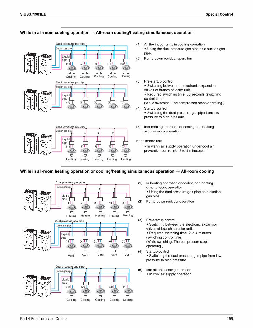
SiUS371901EB Special Control
While in all-room cooling operation → All-room cooling/heating simultaneous operation
While in all-room heating operation or cooling/heating simultaneous operation → All-room cooling
(1) All the indoor units in cooling operation Using the dual pressure gas pipe as a suction gas pipe.
(2) Pump-down residual operation
(3) Pre-startup control Switching between the electronic expansion valves of branch selector unit. Required switching time: 30 seconds (switching control time)(While switching: The compressor stops operating.)
(4) Startup control Switching the dual pressure gas pipe from low pressure to high pressure.
(5) Into heating operation or cooling and heating simultaneous operation
Each indoor unit In warm air supply operation under cool air prevention control (for 3 to 5 minutes).
(1) In heating operation or cooling and heating simultaneous operation Using the dual pressure gas pipe as a suction gas pipe.
(2) Pump-down residual operation
(3) Pre-startup control Switching between the electronic expansion valves of branch selector unit. Required switching time: 2 to 4 minutes (switching control time)(While switching: The compressor stops operating.)
(4) Startup control Switching the dual pressure gas pipe from low pressure to high pressure.
(5) Into all-unit cooling operation In cool air supply operation
Suction gas pipeDual pressure gas pipe
Cooling Cooling Cooling Cooling Cooling
Suction gas pipeDual pressure gas pipe
Heating Heating Heating Heating
(1) (2) (3) (4) (5)
(1) (2) (3) (4) (5)
(1) (2) (3) (4) (5)
Heating
Liquid pipe
Liquid pipe
Suction gas pipeDual pressure gas pipe
Liquid pipe
Suction gas pipeDual pressure gas pipe
Heating Heating Heating Heating Heating
Suction gas pipeDual pressure gas pipe
Vent Vent VentVentVent
Cooling Cooling CoolingCooling
Suction gas pipeDual pressure gas pipe
Cooling
(1) (2) (3) (4) (5)
(1) (2) (3) (4) (5)
(1) (2) (3) (4) (5)
Liquid pipe
Liquid pipe
Liquid pipe
Part 4 Functions and Control 156
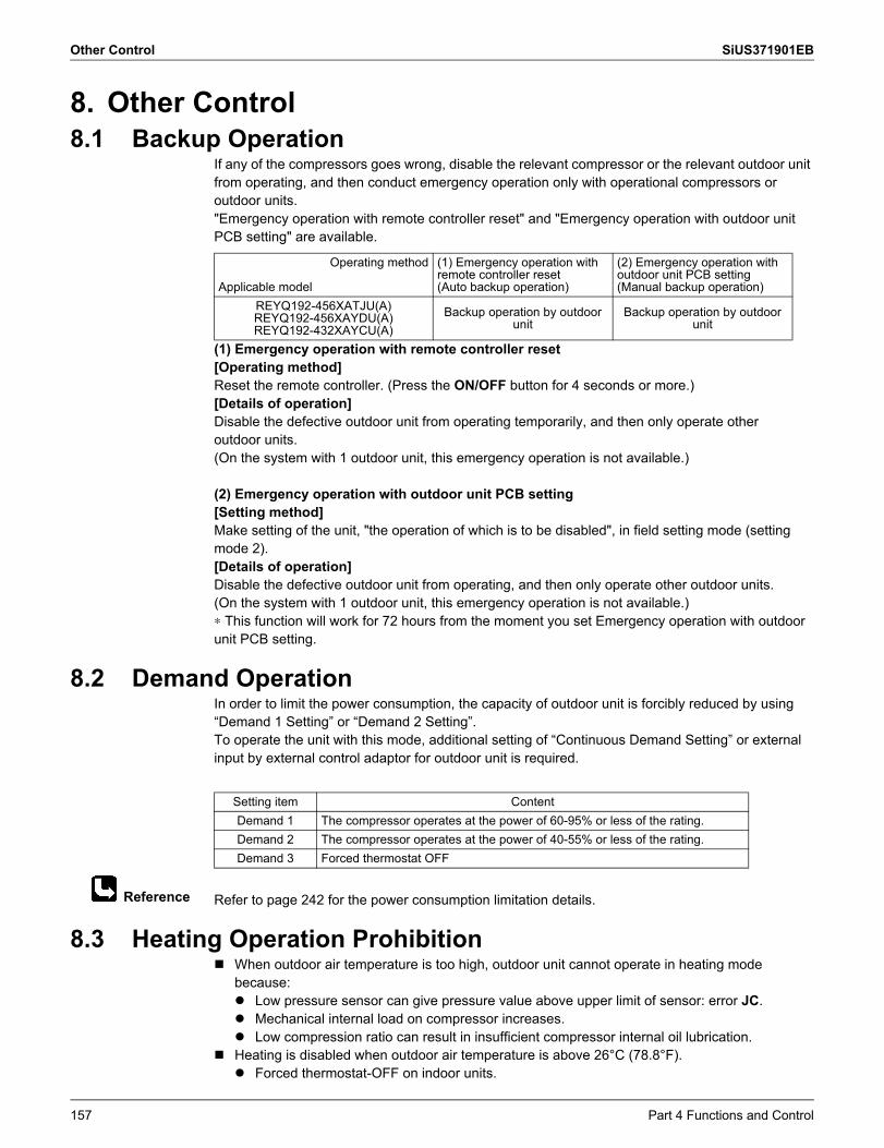
Other Control SiUS371901EB
Reference
8. Other Control8.1 Backup Operation
If any of the compressors goes wrong, disable the relevant compressor or the relevant outdoor unit from operating, and then conduct emergency operation only with operational compressors or outdoor units."Emergency operation with remote controller reset" and "Emergency operation with outdoor unitPCB setting" are available.
(1) Emergency operation with remote controller reset[Operating method]Reset the remote controller. (Press the ON/OFF button for 4 seconds or more.)[Details of operation]Disable the defective outdoor unit from operating temporarily, and then only operate otheroutdoor units.(On the system with 1 outdoor unit, this emergency operation is not available.)
(2) Emergency operation with outdoor unit PCB setting[Setting method]Make setting of the unit, "the operation of which is to be disabled", in field setting mode (setting mode 2).[Details of operation]Disable the defective outdoor unit from operating, and then only operate other outdoor units.(On the system with 1 outdoor unit, this emergency operation is not available.)∗ This function will work for 72 hours from the moment you set Emergency operation with outdoor unit PCB setting.
8.2 Demand OperationIn order to limit the power consumption, the capacity of outdoor unit is forcibly reduced by using“Demand 1 Setting” or “Demand 2 Setting”.To operate the unit with this mode, additional setting of “Continuous Demand Setting” or external input by external control adaptor for outdoor unit is required.
Refer to page 242 for the power consumption limitation details.
8.3 Heating Operation Prohibition When outdoor air temperature is too high, outdoor unit cannot operate in heating mode
because: Low pressure sensor can give pressure value above upper limit of sensor: error JC. Mechanical internal load on compressor increases. Low compression ratio can result in insufficient compressor internal oil lubrication.
Heating is disabled when outdoor air temperature is above 26°C (78.8°F). Forced thermostat-OFF on indoor units.
Operating method
Applicable model
(1) Emergency operation withremote controller reset(Auto backup operation)
(2) Emergency operation withoutdoor unit PCB setting(Manual backup operation)
REYQ192-456XATJU(A)REYQ192-456XAYDU(A)REYQ192-432XAYCU(A)
Backup operation by outdoorunit
Backup operation by outdoorunit
Setting item ContentDemand 1 The compressor operates at the power of 60-95% or less of the rating.Demand 2 The compressor operates at the power of 40-55% or less of the rating.Demand 3 Forced thermostat OFF
157 Part 4 Functions and Control
SiUS371901EB Other Control
Outdoor fan operates at “step 1”. Heating operation is enabled when outdoor air temperature drops below 24°C (75.2°F).
Part 4 Functions and Control 158
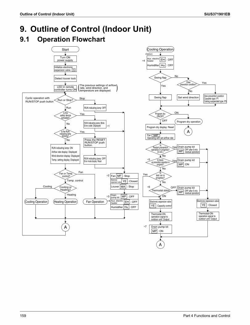
Outline of Control (Indoor Unit) SiUS371901EB
9. Outline of Control (Indoor Unit)9.1 Operation Flowchart
Is test run in progress?
Is freeze-up prevention operation in
progress?
Is Restart prevention
operation in progress?(5 min.)
Dew prevention condition?
Is the safety device
activated?
Start
Heating Operation Fan OperationCooling Operation
Cooling Operation
Detect louver lock
( )Run or Stop?
RUN indicating lamp: OFF
RUN indicating lamp: BlinkError code: Displayed
RUN indicating lamp: OFFError mode display: Reset
Thermostat status
Swing flap
Swing flap Set wind direction
Program dry display: Reset
Program dry operation
A
A
A
Stop
Run
Yes
Yes
Yes
Yes
Yes
Yes
No
No
No
No
ON
OFF
No
No
No
∗1
Fan
Temp. control
Heating
Cooling
∗2 Fan : Stop
Louver : Stop
∗3
∗4
∗7
∗4
∗6
∗5
(Option)
OFF
ON
MF
MF
: OFFMP
Drain pump kit
MP
Drain pump kit
MP
Drain pump kit
:ONMP
Drain pump kit
: ONMP
: Closed
Electronic expansion valve
: Capacity control
Electronic expansion valve
: ClosedYE
MA
: OFFEH
: OFFEH
Humidifier : OFFHu
Humidifier : OFFHu
YE
The previous settings of airflow rate, wind direction, and temperature are displayed.
Is the RUN indicating lamp
blinking?
Press the RESET RUN/STOP push button.
Electronic expansion valve
Thermostat-ON-operation signal to outdoor unit: Output
Thermostat-ON-operation signal to outdoor unit: Output
RUN indicating lamp: ON
Airflow rate display: Displayed
Wind direction display: Displayed
Temp. setting display: Displayed
Turn ON power supply
Initialize electronic expansion valve
LED in remote controller turns ON
Cyclic operation with RUN/STOP push button
Fan or Temp. control?
Cooling or Heating?
Drain pump kit
Aux. electric heater
Aux. electric heater
Dew prevention position Cassette type: P1Ceiling suspended type: P0
Program dry ON/OFF
Fan:Operating with set airflow rate
: OFF after 5-min. residual operation
: OFF after 5-min. residual operation
Yes
YE
YE
159 Part 4 Functions and Control
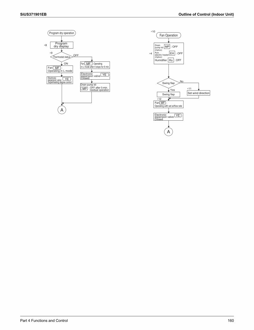
SiUS371901EB Outline of Control (Indoor Unit)
Program dry operationFan Operation
Thermostat status
A
A
OFF
Yes
ON
No
∗8
∗9
∗10
∗11
∗12
(Option)
(Option)
: OFFMP
: OFFEH
Humidifier : OFFHu
Fan :Operating in L mode
MF
Fan : Operatingin L mode after it stops for 6 min.
MF
YE :
Drain pump kit
YE :
MP
Swing flap
Swing flap Set wind direction
Fan MF :Operating with set airflow rate
YE :Closed
Program dry display
Electronic expansion valve Superheating degree control
Electronic expansion valve Closed
Electronic expansion valve
Drain pump kit
: OFF after 5-min. residual operation
Aux. electric heater∗4
Part 4 Functions and Control 160
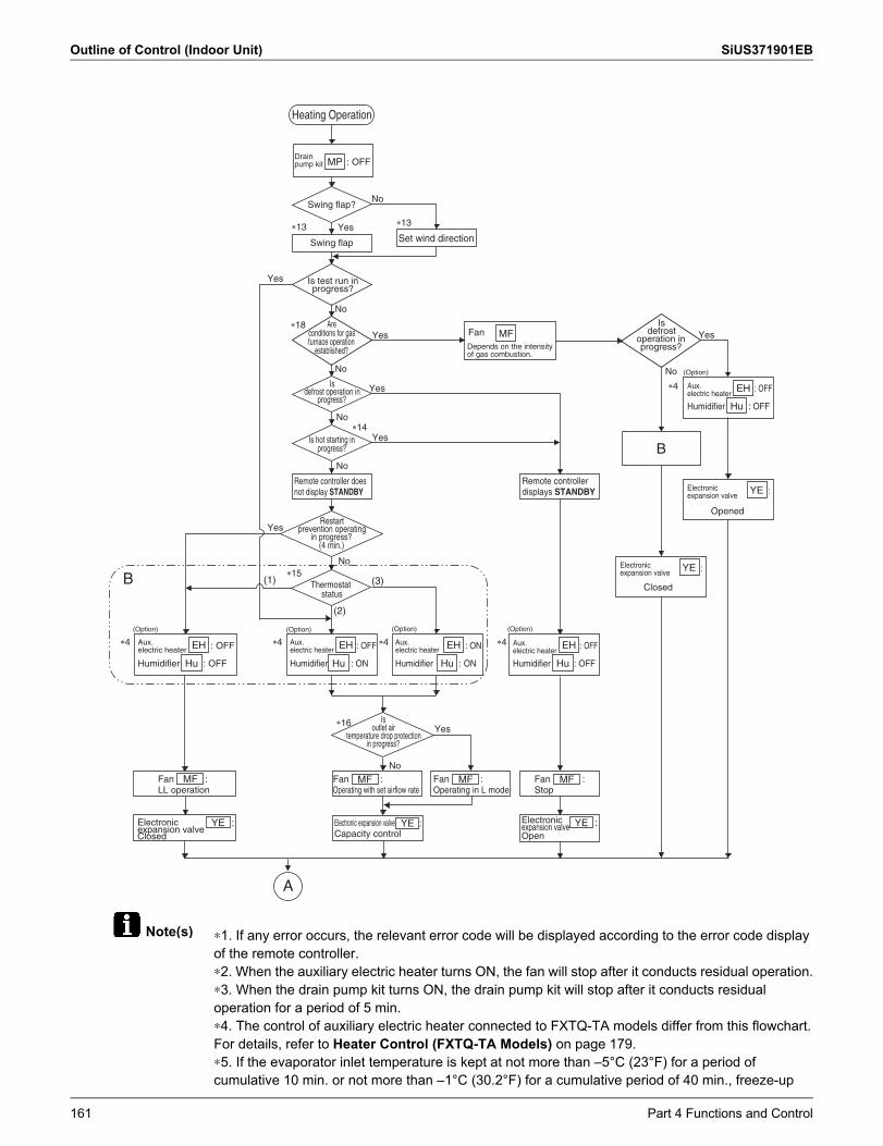
Outline of Control (Indoor Unit) SiUS371901EB
Note(s) ∗1. If any error occurs, the relevant error code will be displayed according to the error code display of the remote controller.∗2. When the auxiliary electric heater turns ON, the fan will stop after it conducts residual operation.∗3. When the drain pump kit turns ON, the drain pump kit will stop after it conducts residual operation for a period of 5 min.∗4. The control of auxiliary electric heater connected to FXTQ-TA models differ from this flowchart.For details, refer to Heater Control (FXTQ-TA Models) on page 179.∗5. If the evaporator inlet temperature is kept at not more than –5°C (23°F) for a period of cumulative 10 min. or not more than –1°C (30.2°F) for a cumulative period of 40 min., freeze-up
Is outlet air
temperature drop protection in progress?
Restart prevention operating
in progress?(4 min.)
Is hot starting in progress?
Is defrost operation in
progress?
Heating Operation
A
B Thermostat status
No
No
�15
�16
(Option) (Option) (Option) (Option)
: OFF
Humidifier : ON
: OFF
Humidifier : OFF
: ON
Humidifier : ON
: OFF
Humidifier : OFF
: OFFMP
Yes
Yes
No
No
No
No
�13
�14
�13
�18
Yes
Yes
Yes
Yes
Swing flap?
Is defrost
operation in progress?
Yes
No
Yes
Swing flap Set wind direction
Fan :Operating with set airflow rate
Fan :LL operation
Fan :Operating in L mode
Fan :Stop
(3)
(2)
(1)
Remote controller does not display STANDBY
Closed
Remote controller displays STANDBY
Drain pump kit
MFFanDepends on the intensity of gas combustion.
Electronic expansion valve Capacity control
Electronic expansion valve Open
Electronic expansion valve
Aux. electric heater
Aux. electric heater
Aux. electric heater
Aux. electric heater
: OFFEH
Humidifier : OFF
Opened
Hu
Aux. electric heater
Electronic expansion valve
Closed
Electronic expansion valve
�4 �4�4�4
Is test run in progress?
No
Are conditions for gas furnace operation
established?
B
:
:
YE
YE
EH
Hu
EH
Hu
EH
Hu
EH
Hu
MF MF MF MF
YE : YE : YE :
(Option)
�4
161 Part 4 Functions and Control
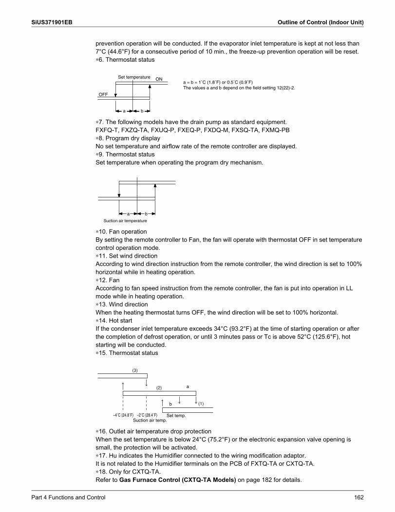
SiUS371901EB Outline of Control (Indoor Unit)
prevention operation will be conducted. If the evaporator inlet temperature is kept at not less than 7°C (44.6°F) for a consecutive period of 10 min., the freeze-up prevention operation will be reset.∗6. Thermostat status
∗7. The following models have the drain pump as standard equipment.FXFQ-T, FXZQ-TA, FXUQ-P, FXEQ-P, FXDQ-M, FXSQ-TA, FXMQ-PB∗8. Program dry displayNo set temperature and airflow rate of the remote controller are displayed.∗9. Thermostat statusSet temperature when operating the program dry mechanism.
∗10. Fan operationBy setting the remote controller to Fan, the fan will operate with thermostat OFF in set temperature control operation mode.∗11. Set wind directionAccording to wind direction instruction from the remote controller, the wind direction is set to 100% horizontal while in heating operation.∗12. FanAccording to fan speed instruction from the remote controller, the fan is put into operation in LL mode while in heating operation.∗13. Wind directionWhen the heating thermostat turns OFF, the wind direction will be set to 100% horizontal.∗14. Hot startIf the condenser inlet temperature exceeds 34°C (93.2°F) at the time of starting operation or after the completion of defrost operation, or until 3 minutes pass or Tc is above 52°C (125.6°F), hot starting will be conducted.∗15. Thermostat status
∗16. Outlet air temperature drop protectionWhen the set temperature is below 24°C (75.2°F) or the electronic expansion valve opening is small, the protection will be activated.∗17. Hu indicates the Humidifier connected to the wiring modification adaptor.It is not related to the Humidifier terminals on the PCB of FXTQ-TA or CXTQ-TA.∗18. Only for CXTQ-TA.Refer to Gas Furnace Control (CXTQ-TA Models) on page 182 for details.
OFF
ON
a b
Set temperaturea = b = 1˚C (1.8˚F) or 0.5˚C (0.9˚F)The values a and b depend on the field setting 12(22)-2.
Suction air temperature
ba
–2˚C (28.4˚F)–4˚C (24.8˚F)Suction air temp.
Set temp.
b
a
(3)
(2)
(1)
Part 4 Functions and Control 162
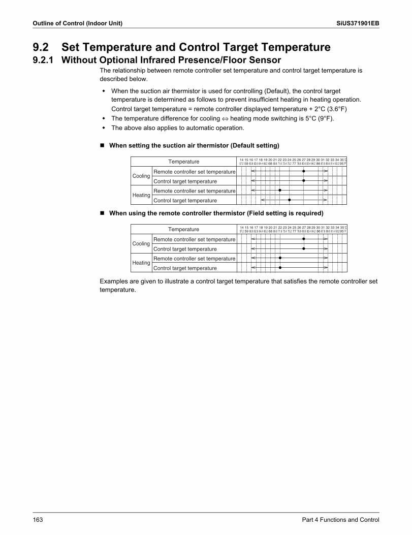
Outline of Control (Indoor Unit) SiUS371901EB
9.2 Set Temperature and Control Target Temperature9.2.1 Without Optional Infrared Presence/Floor Sensor
The relationship between remote controller set temperature and control target temperature is described below.
When setting the suction air thermistor (Default setting)
When using the remote controller thermistor (Field setting is required)
Examples are given to illustrate a control target temperature that satisfies the remote controller set temperature.
When the suction air thermistor is used for controlling (Default), the control target temperature is determined as follows to prevent insufficient heating in heating operation.Control target temperature = remote controller displayed temperature + 2°C (3.6°F)
The temperature difference for cooling ⇔ heating mode switching is 5°C (9°F). The above also applies to automatic operation.
Remote controller set temperature
Control target temperature
Remote controller set temperature
Control target temperature
14 15 16 17 18 19 20 21 22 23 24 25 26 27 28 29 30 31 32 33 34 35˚C
Cooling
Heating
57.2 60.8 69.862.6 71.664.4 73.466.2 75.259 68 78.8 80.6 82.4 84.277 87.8 89.6 91.4 93.2 95˚F86Temperature
Remote controller set temperature
Control target temperature
Remote controller set temperature
Control target temperature
14 15 16 17 18 19 20 21 22 23 24 25 26 27 28 29 30 31 32 33 34 35˚C
Cooling
Heating
57.2 60.8 69.862.6 71.664.4 73.466.2 75.259 68 78.8 80.6 82.4 84.277 87.8 89.6 91.4 93.2 95˚F86Temperature
163 Part 4 Functions and Control
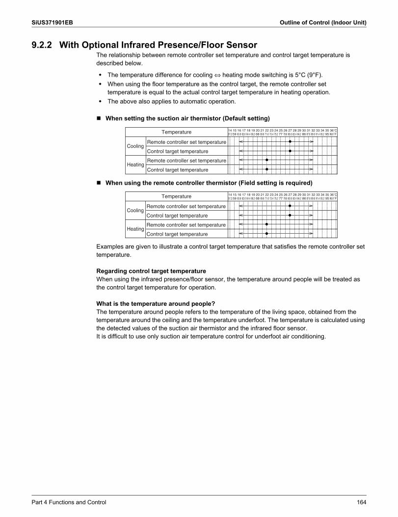
SiUS371901EB Outline of Control (Indoor Unit)
9.2.2 With Optional Infrared Presence/Floor SensorThe relationship between remote controller set temperature and control target temperature is described below.
When setting the suction air thermistor (Default setting)
When using the remote controller thermistor (Field setting is required)
Examples are given to illustrate a control target temperature that satisfies the remote controller set temperature.
Regarding control target temperatureWhen using the infrared presence/floor sensor, the temperature around people will be treated as the control target temperature for operation.
What is the temperature around people?The temperature around people refers to the temperature of the living space, obtained from the temperature around the ceiling and the temperature underfoot. The temperature is calculated using the detected values of the suction air thermistor and the infrared floor sensor.It is difficult to use only suction air temperature control for underfoot air conditioning.
The temperature difference for cooling ⇔ heating mode switching is 5°C (9°F). When using the floor temperature as the control target, the remote controller set
temperature is equal to the actual control target temperature in heating operation. The above also applies to automatic operation.
35 36˚C31 32 33 3427 28 3023 24 25 2620 21 22 2916 17 18 1914 15
Remote controller set temperature
Control target temperature
Remote controller set temperature
Control target temperature
Cooling
Heating
57.2 60.8 69.862.6 71.664.4 73.466.2 75.259 68 78.8 80.6 82.4 84.277 87.8 96.889.6 91.4 93.2 ˚F86 95Temperature
Remote controller set temperature
Control target temperature
Remote controller set temperature
Control target temperature
Cooling
Heating
35 36˚C31 32 33 3427 28 3023 24 25 2620 21 22 2916 17 18 1914 1557.2 60.8 69.862.6 71.664.4 73.466.2 75.259 68 78.8 80.6 82.4 84.277 87.8 96.889.6 91.4 93.2 ˚F86 95Temperature
Part 4 Functions and Control 164
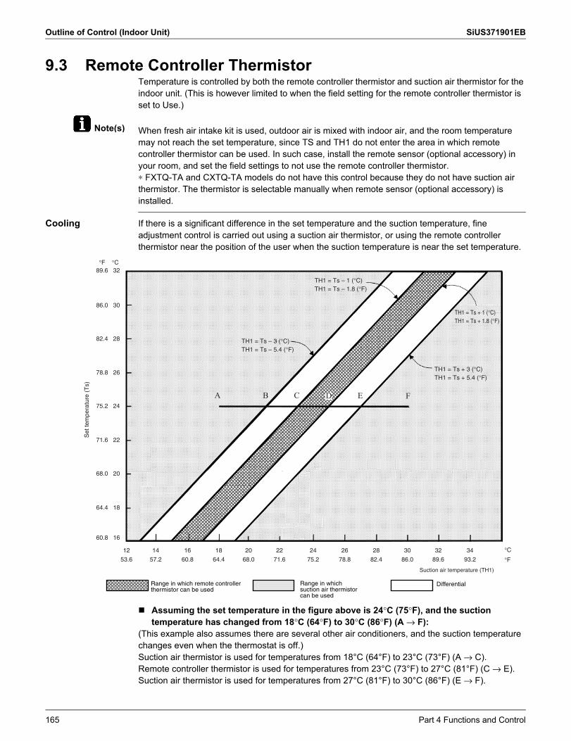
Outline of Control (Indoor Unit) SiUS371901EB
Note(s)
9.3 Remote Controller ThermistorTemperature is controlled by both the remote controller thermistor and suction air thermistor for the indoor unit. (This is however limited to when the field setting for the remote controller thermistor is set to Use.)
When fresh air intake kit is used, outdoor air is mixed with indoor air, and the room temperature may not reach the set temperature, since TS and TH1 do not enter the area in which remote controller thermistor can be used. In such case, install the remote sensor (optional accessory) in your room, and set the field settings to not use the remote controller thermistor.∗ FXTQ-TA and CXTQ-TA models do not have this control because they do not have suction air thermistor. The thermistor is selectable manually when remote sensor (optional accessory) is installed.
Cooling If there is a significant difference in the set temperature and the suction temperature, fineadjustment control is carried out using a suction air thermistor, or using the remote controllerthermistor near the position of the user when the suction temperature is near the set temperature.
Assuming the set temperature in the figure above is 24°C (75°F), and the suction temperature has changed from 18°C (64°F) to 30°C (86°F) (A → F):
(This example also assumes there are several other air conditioners, and the suction temperature changes even when the thermostat is off.)Suction air thermistor is used for temperatures from 18°C (64°F) to 23°C (73°F) (A → C).Remote controller thermistor is used for temperatures from 23°C (73°F) to 27°C (81°F) (C → E).Suction air thermistor is used for temperatures from 27°C (81°F) to 30°C (86°F) (E → F).
Range in which remote controller thermistor can be used
Range in which suction air thermistor can be used
Differential
Set
tem
pera
ture
(T
s)
12 14 16 18 20 22 24 26 28 30 32 34
53.6 57.2 60.8 64.4 68.0 71.6 75.2 78.8 82.4 86.0 89.6 93.2
°C°F
°C32
30
28
26
24
22
20
18
16
°F89.6
86.0
82.4
78.8
75.2
71.6
68.0
64.4
60.8
TH1 = Ts + 1 (°C)TH1 = Ts + 1.8 (°F)
TH1 = Ts + 3 (°C)TH1 = Ts + 5.4 (°F)
TH1 = Ts – 3 (°C)TH1 = Ts – 5.4 (°F)
TH1 = Ts – 1 (°C)TH1 = Ts – 1.8 (°F)
Suction air temperature (TH1)
165 Part 4 Functions and Control
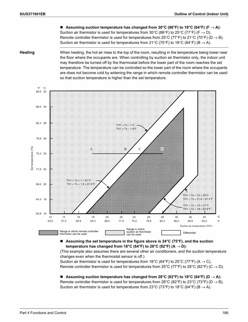
SiUS371901EB Outline of Control (Indoor Unit)
Assuming suction temperature has changed from 30°C (86°F) to 18°C (64°F) (F → A): Suction air thermistor is used for temperatures from 30°C (86°F) to 25°C (77°F) (F → D).Remote controller thermistor is used for temperatures from 25°C (77°F) to 21°C (70°F) (D → B).Suction air thermistor is used for temperatures from 21°C (70°F) to 18°C (64°F) (B → A).
Heating When heating, the hot air rises to the top of the room, resulting in the temperature being lower near the floor where the occupants are. When controlling by suction air thermistor only, the indoor unit may therefore be turned off by the thermostat before the lower part of the room reaches the set temperature. The temperature can be controlled so the lower part of the room where the occupants are does not become cold by widening the range in which remote controller thermistor can be used so that suction temperature is higher than the set temperature.
Assuming the set temperature in the figure above is 24°C (75°F), and the suction temperature has changed from 18°C (64°F) to 28°C (82°F) (A → D):
(This example also assumes there are several other air conditioners, and the suction temperature changes even when the thermostat sensor is off.)Suction air thermistor is used for temperatures from 18°C (64°F) to 25°C (77°F) (A → C).Remote controller thermistor is used for temperatures from 25°C (77°F) to 28°C (82°F) (C → D).
Assuming suction temperature has changed from 28°C (82°F) to 18°C (64°F) (D → A): Remote controller thermistor is used for temperatures from 28°C (82°F) to 23°C (73°F) (D → B).Suction air thermistor is used for temperatures from 23°C (73°F) to 18°C (64°F) (B → A).
Range in which remote controller thermistor can be used
Range in which suction air thermistor can be used
Differential
Suction air temperature (TH1)
Set
tem
pera
ture
(T
s)
12 14 16 18 20 22 24 26 28 30 32 34
53.6 57.2 60.8 64.4 68.0 71.6 75.2 78.8 82.4 86.0 89.6 93.2
°C°F
°C32
30
28
26
24
22
20
18
16
°F89.6
86.0
82.4
78.8
75.2
71.6
68.0
64.4
60.8
TH1 = Ts + 12 ≤ 33°CTH1 = Ts + 21.6 ≤ 91.4°F
TH1 = Ts + 10 ≤ 31°CTH1 = Ts + 18 ≤ 87.8°F
TH1 = Ts + 1 ≤ 31°CTH1 = Ts + 1.8 ≤ 87.8°F
TH1 = Ts – 1°CTH1 = Ts – 1.8°F
Part 4 Functions and Control 166
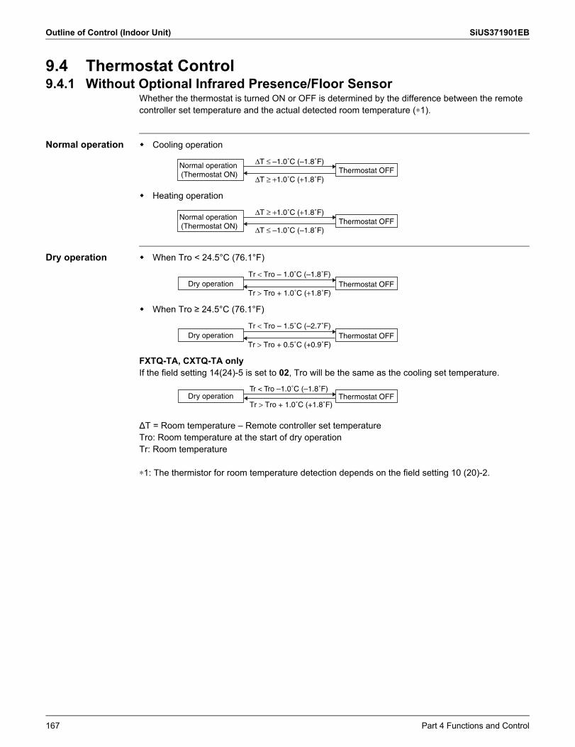
Outline of Control (Indoor Unit) SiUS371901EB
9.4 Thermostat Control9.4.1 Without Optional Infrared Presence/Floor Sensor
Whether the thermostat is turned ON or OFF is determined by the difference between the remote controller set temperature and the actual detected room temperature (∗1).
Normal operation Cooling operation
Heating operation
Dry operation When Tro < 24.5°C (76.1°F)
When Tro ≥ 24.5°C (76.1°F)
FXTQ-TA, CXTQ-TA onlyIf the field setting 14(24)-5 is set to 02, Tro will be the same as the cooling set temperature.
ΔT = Room temperature – Remote controller set temperatureTro: Room temperature at the start of dry operationTr: Room temperature
∗1: The thermistor for room temperature detection depends on the field setting 10 (20)-2.
Thermostat OFFNormal operation (Thermostat ON)
ΔT ≤ –1.0˚C (–1.8˚F)
ΔT ≥ +1.0˚C (+1.8˚F)
Thermostat OFFNormal operation (Thermostat ON)
ΔT ≥ +1.0˚C (+1.8˚F)
ΔT ≤ –1.0˚C (–1.8˚F)
Thermostat OFFDry operationTr < Tro – 1.0˚C (–1.8˚F)
Tr > Tro + 1.0˚C (+1.8˚F)
Thermostat OFFDry operationTr < Tro – 1.5˚C (–2.7˚F)
Tr > Tro + 0.5˚C (+0.9˚F)
Thermostat OFFDry operationTr < Tro –1.0˚C (–1.8˚F)
Tr > Tro + 1.0˚C (+1.8˚F)
167 Part 4 Functions and Control
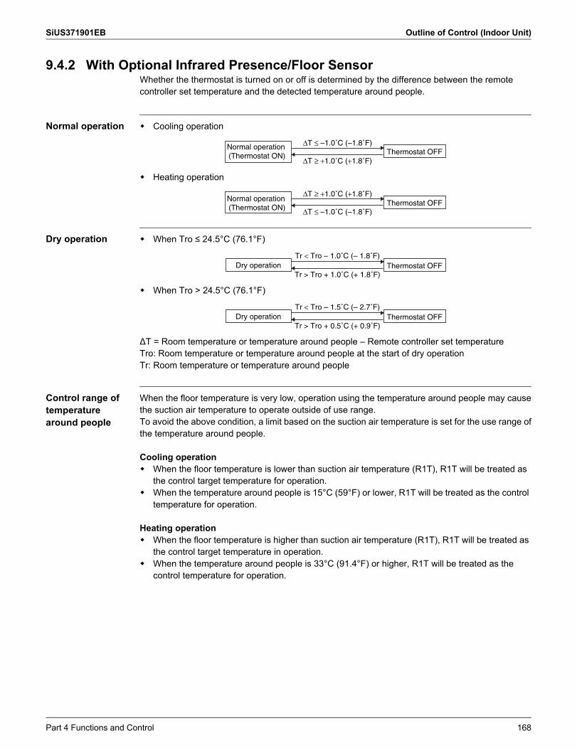
SiUS371901EB Outline of Control (Indoor Unit)
9.4.2 With Optional Infrared Presence/Floor SensorWhether the thermostat is turned on or off is determined by the difference between the remotecontroller set temperature and the detected temperature around people.
Normal operation Cooling operation
Heating operation
Dry operation When Tro ≤ 24.5°C (76.1°F)
When Tro > 24.5°C (76.1°F)
ΔT = Room temperature or temperature around people – Remote controller set temperatureTro: Room temperature or temperature around people at the start of dry operationTr: Room temperature or temperature around people
Control range of temperature around people
When the floor temperature is very low, operation using the temperature around people may causethe suction air temperature to operate outside of use range.To avoid the above condition, a limit based on the suction air temperature is set for the use range ofthe temperature around people.
Cooling operation When the floor temperature is lower than suction air temperature (R1T), R1T will be treated as
the control target temperature for operation. When the temperature around people is 15°C (59°F) or lower, R1T will be treated as the control
temperature for operation.
Heating operation When the floor temperature is higher than suction air temperature (R1T), R1T will be treated as
the control target temperature in operation. When the temperature around people is 33°C (91.4°F) or higher, R1T will be treated as the
control temperature for operation.
Thermostat OFFNormal operation (Thermostat ON)
ΔT ≤ –1.0˚C (–1.8˚F)
ΔT ≥ +1.0˚C (+1.8˚F)
Thermostat OFFNormal operation (Thermostat ON)
ΔT ≥ +1.0˚C (+1.8˚F)
ΔT ≤ –1.0˚C (–1.8˚F)
Thermostat OFFDry operationTr < Tro – 1.0˚C (– 1.8˚F)
Tr > Tro + 1.0˚C (+ 1.8˚F)
Thermostat OFFDry operationTr < Tro – 1.5˚C (– 2.7˚F)
Tr > Tro + 0.5˚C (+ 0.9˚F)
Part 4 Functions and Control 168
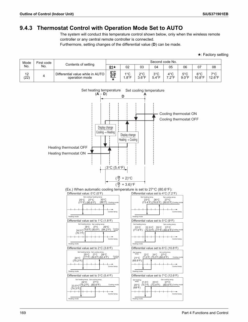
Outline of Control (Indoor Unit) SiUS371901EB
9.4.3 Thermostat Control with Operation Mode Set to AUTOThe system will conduct this temperature control shown below, only when the wireless remote controller or any central remote controller is connected.Furthermore, setting changes of the differential value (D) can be made.
: Factory setting
ModeNo.
First codeNo. Contents of setting
Second code No.01 02 03 04 05 06 07 08
12(22) 4 Differential value while in AUTO
operation mode0°C0°F
1°C1.8°F
2°C3.6°F
3°C5.4°F
4°C7.2°F
5°C9.0°F
6°C10.8°F
7°C12.6°F
Cooling thermostat ONCooling thermostat OFF
Heating thermostat ONHeating thermostat OFF
(Ex.) When automatic cooling temperature is set to 27�C (80.6�F):
D
3�C (5.4�F)
2D( + 3.6)�F2D( + 2)�C
Set cooling temperature A
Set heating temperature (A – D)
Display change Cooling � Heating
Display change Heating � Cooling
Differential value: 0�C (0�F)
30�C(86�F)
Heating mode
Cooling mode
Control temp.
Differential value set to 1�C (1.8�F)Set heating temp. Set cooling temp.
Heating mode
Control temp.
Differential value set to 2�C (3.6�F)
Heating mode
Control temp.
Differential value set to 3�C (5.4�F)
Heating mode
Cooling mode
Control temp.
Set heating temp. Set cooling temp.
Set heating temp. Set cooling temp.
Differential value set to 4�C (7.2�F)
Heating mode
Cooling mode
Control temp.
Differential value set to 5�C (9�F)Set heating temp. Set cooling temp.
Heating mode
Cooling mode
Control temp.
Differential value set to 6�C (10.8�F)
Heating mode
Cooling mode
Control temp.
Differential value set to 7�C (12.6�F)
Heating mode
Cooling mode
Control temp.
Set cooling temp.
Set cooling temp.
Set heating temp. Set cooling temp.Set cooling/ heating temp.
25�C (77�F)
27�C (80.6�F)
26�C (78.8�F)24.5�C
(76.1�F)
27�C (80.6�F)
29�C (84.2�F)
24�C (75.2�F)
25�C (77�F)
27�C (80.6�F)
28�C (82.4�F)
23.5�C (74.3�F)
24�C (75.2�F)
27�C (80.6�F) 20�C
(68�F)
21.5�C (70.7�F)
23�C (73.4�F)
27�C (80.6�F)
21�C (69.8�F)
22�C (71.6�F)
24�C (75.2�F)
27�C (80.6�F)
22�C (71.6�F)
22.5�C (72.5�F)
25�C (77�F)
27�C (80.6�F)
23�C (73.4�F)
26�C (78.8�F)
27�C (80.6�F)
Cooling mode
Cooling mode
Set heating temp.
Set heating temp.
169 Part 4 Functions and Control
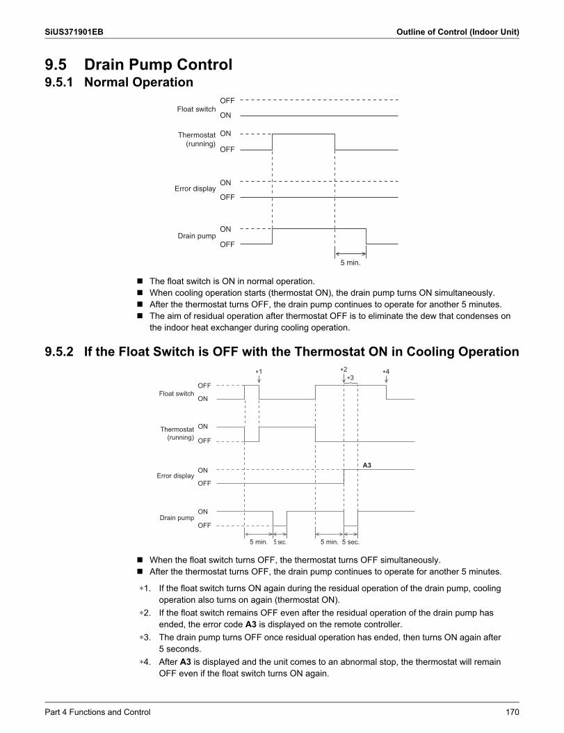
SiUS371901EB Outline of Control (Indoor Unit)
9.5 Drain Pump Control9.5.1 Normal Operation
The float switch is ON in normal operation. When cooling operation starts (thermostat ON), the drain pump turns ON simultaneously. After the thermostat turns OFF, the drain pump continues to operate for another 5 minutes. The aim of residual operation after thermostat OFF is to eliminate the dew that condenses on
the indoor heat exchanger during cooling operation.
9.5.2 If the Float Switch is OFF with the Thermostat ON in Cooling Operation
When the float switch turns OFF, the thermostat turns OFF simultaneously. After the thermostat turns OFF, the drain pump continues to operate for another 5 minutes.
Float switch
Error display
Thermostat (running)
OFF
OFF
ON
ON
ON
OFF
Drain pumpON
OFF
5 min.
OFF
OFF
ON
ON
ON
OFF
ON
OFF
5 min.5 min. 5 sec. 5 sec.
Float switch
Error display
Thermostat (running)
Drain pump
A3
�1 �2 �4�3
∗1. If the float switch turns ON again during the residual operation of the drain pump, cooling operation also turns on again (thermostat ON).
∗2. If the float switch remains OFF even after the residual operation of the drain pump has ended, the error code A3 is displayed on the remote controller.
∗3. The drain pump turns OFF once residual operation has ended, then turns ON again after 5 seconds.
∗4. After A3 is displayed and the unit comes to an abnormal stop, the thermostat will remain OFF even if the float switch turns ON again.
Part 4 Functions and Control 170
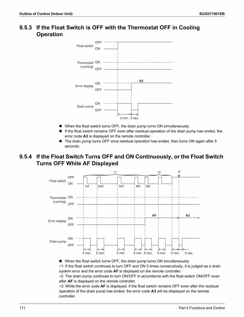
Outline of Control (Indoor Unit) SiUS371901EB
9.5.3 If the Float Switch is OFF with the Thermostat OFF in Cooling Operation
When the float switch turns OFF, the drain pump turns ON simultaneously. If the float switch remains OFF even after residual operation of the drain pump has ended, the
error code A3 is displayed on the remote controller. The drain pump turns OFF once residual operation has ended, then turns ON again after 5
seconds.
9.5.4 If the Float Switch Turns OFF and ON Continuously, or the Float Switch Turns OFF While AF Displayed
When the float switch turns OFF, the drain pump turns ON simultaneously.∗1: If the float switch continues to turn OFF and ON 5 times consecutively, it is judged as a drain system error and the error code AF is displayed on the remote controller.∗2: The drain pump continues to turn ON/OFF in accordance with the float switch ON/OFF even after AF is displayed on the remote controller.∗3: While the error code AF is displayed, if the float switch remains OFF even after the residual operation of the drain pump has ended, the error code A3 will be displayed on the remote controller.
ON
OFF
ON
ON
OFF
ON
OFF
5 min. 5 sec.
Float switch
Error display
Thermostat (running)
Drain pump
OFF
A3
OFF
OFF
ON
ON
ON
OFF
ON
OFF
5 min. 5 min. 5 min. 5 min. 5 min. 5 min. 5 sec.5 min.
1st 2nd 3rd 4th 5th
AF A3
Float switch
Error display
Thermostat (running)
Drain pump
}∗1 ∗3}∗2
171 Part 4 Functions and Control
SiUS371901EB Outline of Control (Indoor Unit)
9.6 Control of Electronic Expansion ValveElectronic expansion valves in indoor units have the functions of conducting superheating degree control in cooling operation and subcooling degree control in heating operation. However, if the indoor units receive any control command such as a protection control command or a special control command from the outdoor unit, the units will give a priority to the control command.
Superheating degree control in cooling operation
This function is used to adjust the opening of the electronic expansion valve so that superheating degree (SH), which is calculated from the detection temperature (Tg) of the gas pipe thermistor (R3T) and the detection temperature (Tl) of the liquid temperature thermistor (R2T) of the indoor unit, will come close to a target superheating degree (SHS).At that time, correction to the superheating degree is made according to the differences (ΔT) between set temperature and suction air temperature.
Normally 5°C (9°F). As ΔT (Remote controller set temp. – Suction air temp.) becomes larger, SHS becomes lower. As ΔT (Remote controller set temp. – Suction air temp.) becomes smaller, SHS becomes
higher.
Subcooling degree control in heating operation
This function is used to adjust the opening of the electronic expansion valve so that the high pressure equivalent saturated temperature (Tc), which is converted from the detected pressure of the high pressure sensor in the outdoor unit, and the subcooling degree (SC), which is calculated from the detected temperature (Tl) of the liquid temperature thermistor (R2T) in the indoor unit, will come close to the target subcooling degree (SCS).At that time, corrections to the subcooling degree are made according to differences (ΔT) between set temperature and suction air temperatures.
Normally 5°C (9°F). As ΔT (Remote controller set temp. – Suction air temp.) becomes larger, SCS becomes lower. As ΔT (Remote controller set temp. – Suction air temp.) becomes smaller, SCS becomes
higher.
SH = Tg – Tl
Where,SH: Evaporator outlet superheating degreeTg: Indoor unit gas pipe temperature (R3T)Tl: Indoor unit liquid pipe temperature (R2T)SHS: Target superheating degree
SHS (Target SH value)
SC = Tc – Tl
Where,SC: Condenser outlet subcooling degreeTc: High pressure equivalent saturated temperature detected by the high pressure sensorTl: Indoor unit liquid pipe temperature (R2T)SCS: Target subcooling degree
SCS (Target SC value)
Part 4 Functions and Control 172
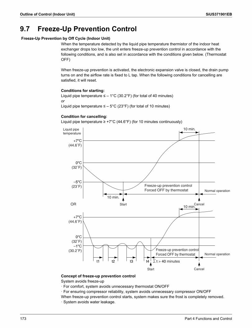
Outline of Control (Indoor Unit) SiUS371901EB
9.7 Freeze-Up Prevention Control
When the temperature detected by the liquid pipe temperature thermistor of the indoor heat exchanger drops too low, the unit enters freeze-up prevention control in accordance with the following conditions, and is also set in accordance with the conditions given below. (Thermostat OFF)
When freeze-up prevention is activated, the electronic expansion valve is closed, the drain pump turns on and the airflow rate is fixed to L tap. When the following conditions for cancelling are satisfied, it will reset.
Conditions for starting:Liquid pipe temperature ≤ – 1°C (30.2°F) (for total of 40 minutes)orLiquid pipe temperature ≤ – 5°C (23°F) (for total of 10 minutes)
Condition for cancelling:Liquid pipe temperature ≥ +7°C (44.6°F) (for 10 minutes continuously)
Concept of freeze-up prevention controlSystem avoids freeze-up· For comfort, system avoids unnecessary thermostat ON/OFF· For ensuring compressor reliability, system avoids unnecessary compressor ON/OFFWhen freeze-up prevention control starts, system makes sure the frost is completely removed.· System avoids water leakage.
Freeze-Up Prevention by Off Cycle (Indoor Unit)
Normal operation
Start Cancel
Liquid pipe temperature
Start Cancel
Normal operation
–5ºC(23˚F)
0ºC(32˚F)
+7ºC(44.6˚F)
–1ºC(30.2˚F)
t1 t2 t3 t4
0ºC(32˚F)
+7ºC(44.6˚F)
10 min.
OR10 min.
10 min.
t > 40 minutes
Freeze-up prevention control Forced OFF by thermostat
Freeze-up prevention control Forced OFF by thermostat
173 Part 4 Functions and Control
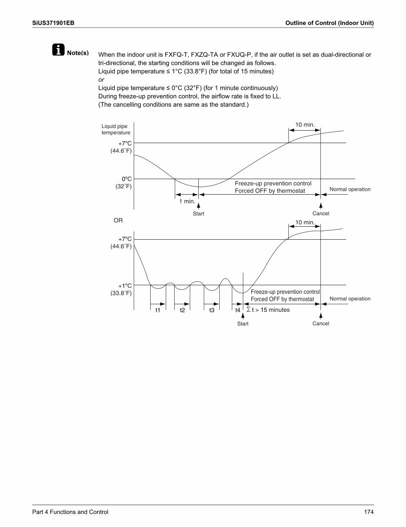
SiUS371901EB Outline of Control (Indoor Unit)
Note(s) When the indoor unit is FXFQ-T, FXZQ-TA or FXUQ-P, if the air outlet is set as dual-directional or tri-directional, the starting conditions will be changed as follows.Liquid pipe temperature ≤ 1°C (33.8°F) (for total of 15 minutes)orLiquid pipe temperature ≤ 0°C (32°F) (for 1 minute continuously)During freeze-up prevention control, the airflow rate is fixed to LL.(The cancelling conditions are same as the standard.)
0ºC(32˚F)
+7ºC(44.6˚F)
10 min.
1 min.
+1ºC(33.8˚F)
t1 t2 t3 t4
+7ºC(44.6˚F)
10 min.OR
t > 15 minutes
Freeze-up prevention control Forced OFF by thermostat
Freeze-up prevention control Forced OFF by thermostat
Liquid pipe temperature
Start Cancel
Start Cancel
Normal operation
Normal operation
Part 4 Functions and Control 174
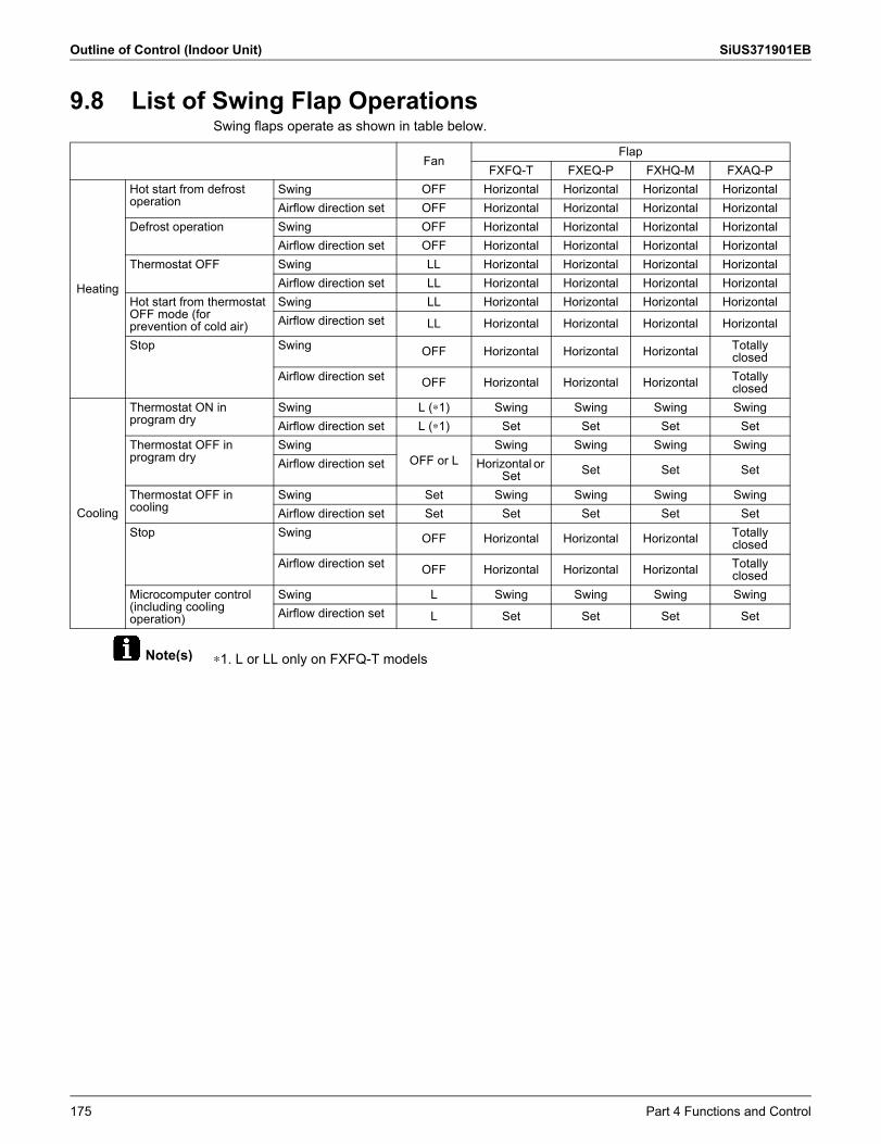
Outline of Control (Indoor Unit) SiUS371901EB
Note(s)
9.8 List of Swing Flap OperationsSwing flaps operate as shown in table below.
∗1. L or LL only on FXFQ-T models
FanFlap
FXFQ-T FXEQ-P FXHQ-M FXAQ-P
Heating
Hot start from defrost operation
Swing OFF Horizontal Horizontal Horizontal HorizontalAirflow direction set OFF Horizontal Horizontal Horizontal Horizontal
Defrost operation Swing OFF Horizontal Horizontal Horizontal HorizontalAirflow direction set OFF Horizontal Horizontal Horizontal Horizontal
Thermostat OFF Swing LL Horizontal Horizontal Horizontal HorizontalAirflow direction set LL Horizontal Horizontal Horizontal Horizontal
Hot start from thermostat OFF mode (for prevention of cold air)
Swing LL Horizontal Horizontal Horizontal HorizontalAirflow direction set LL Horizontal Horizontal Horizontal Horizontal
Stop Swing OFF Horizontal Horizontal Horizontal Totally closed
Airflow direction set OFF Horizontal Horizontal Horizontal Totally closed
Cooling
Thermostat ON in program dry
Swing L (∗1) Swing Swing Swing SwingAirflow direction set L (∗1) Set Set Set Set
Thermostat OFF in program dry
SwingOFF or L
Swing Swing Swing SwingAirflow direction set Horizontal or
Set Set Set Set
Thermostat OFF in cooling
Swing Set Swing Swing Swing SwingAirflow direction set Set Set Set Set Set
Stop Swing OFF Horizontal Horizontal Horizontal Totally closed
Airflow direction set OFF Horizontal Horizontal Horizontal Totally closed
Microcomputer control (including cooling operation)
Swing L Swing Swing Swing SwingAirflow direction set L Set Set Set Set
175 Part 4 Functions and Control
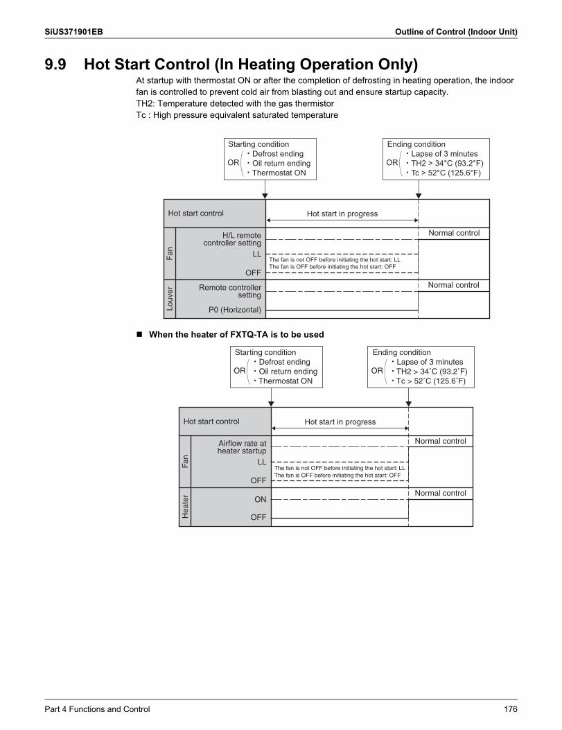
SiUS371901EB Outline of Control (Indoor Unit)
9.9 Hot Start Control (In Heating Operation Only)At startup with thermostat ON or after the completion of defrosting in heating operation, the indoor fan is controlled to prevent cold air from blasting out and ensure startup capacity.TH2: Temperature detected with the gas thermistorTc : High pressure equivalent saturated temperature
When the heater of FXTQ-TA is to be used
The fan is not OFF before initiating the hot start: LL The fan is OFF before initiating the hot start: OFF
Hot start control Hot start in progress
Normal control
Normal control
H/L remote controller setting
LL
OFF
Remote controller setting
P0 (Horizontal)
Fan
Louv
er
Ending condition· Lapse of 3 minutes· TH2 > 34°C (93.2°F)· Tc > 52°C (125.6°F)
OR
Starting condition· Defrost ending· Oil return ending· Thermostat ON
OR
The fan is not OFF before initiating the hot start: LL The fan is OFF before initiating the hot start: OFF
Hot start control Hot start in progress
Normal control
Normal control
Airflow rate at heater startup
LL
OFF
ON
OFF
Fan
Hea
ter
Ending condition· Lapse of 3 minutes· TH2 > 34˚C (93.2˚F)· Tc > 52˚C (125.6˚F)
OR
Starting condition· Defrost ending· Oil return ending· Thermostat ON
OR
Part 4 Functions and Control 176
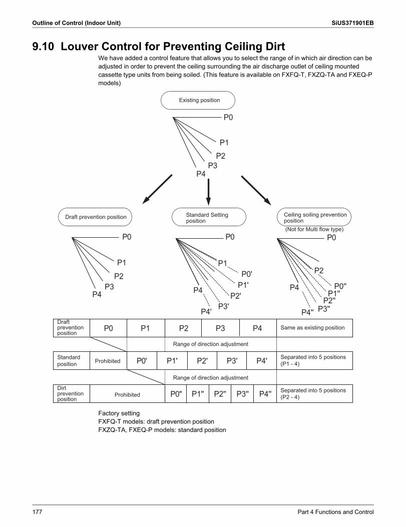
Outline of Control (Indoor Unit) SiUS371901EB
9.10 Louver Control for Preventing Ceiling DirtWe have added a control feature that allows you to select the range of in which air direction can be adjusted in order to prevent the ceiling surrounding the air discharge outlet of ceiling mounted cassette type units from being soiled. (This feature is available on FXFQ-T, FXZQ-TA and FXEQ-P models)
Factory settingFXFQ-T models: draft prevention positionFXZQ-TA, FXEQ-P models: standard position
P0
P1P2
P4P3
P0
P1
P2
P4P3
P0 P0
P1P2
P4 P4P2'
P1'P0'
P4' P4''P3'
P2''P1''
P0''
P3''
Existing position
Draft prevention position
(Not for Multi flow type)
Draft prevention position
Standard position Prohibited
ProhibitedDirt prevention position
P0
P0'
P0''
P1' P2'
P2''P1''
P3'
P3'' P4''
P4'
P1 P2 P3 P4 Same as existing position
Separated into 5 positions (P1 - 4)
Separated into 5 positions (P2 - 4)
Range of direction adjustment
Range of direction adjustment
Standard Setting position
Ceiling soiling prevention position
177 Part 4 Functions and Control
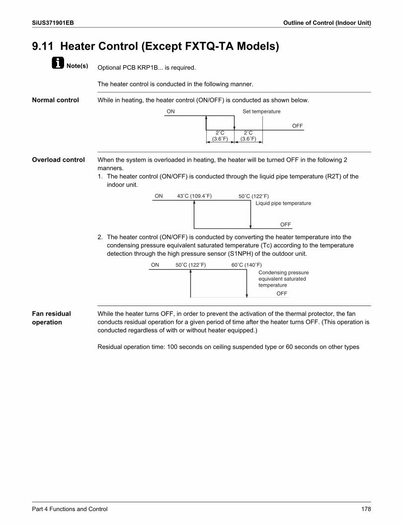
SiUS371901EB Outline of Control (Indoor Unit)
Note(s)
9.11 Heater Control (Except FXTQ-TA Models)Optional PCB KRP1B... is required.
The heater control is conducted in the following manner.
Normal control While in heating, the heater control (ON/OFF) is conducted as shown below.
Overload control When the system is overloaded in heating, the heater will be turned OFF in the following 2 manners.1. The heater control (ON/OFF) is conducted through the liquid pipe temperature (R2T) of the
indoor unit.
2. The heater control (ON/OFF) is conducted by converting the heater temperature into the condensing pressure equivalent saturated temperature (Tc) according to the temperature detection through the high pressure sensor (S1NPH) of the outdoor unit.
Fan residual operation
While the heater turns OFF, in order to prevent the activation of the thermal protector, the fan conducts residual operation for a given period of time after the heater turns OFF. (This operation is conducted regardless of with or without heater equipped.)
Residual operation time: 100 seconds on ceiling suspended type or 60 seconds on other types
ON Set temperature
OFF2˚C
(3.6˚F)2˚C
(3.6˚F)
ON 43˚C (109.4˚F)
OFF
50˚C (122˚F)Liquid pipe temperature
ON 50˚C (122˚F) 60˚C (140˚F)
OFF
Condensing pressure equivalent saturated temperature
Part 4 Functions and Control 178
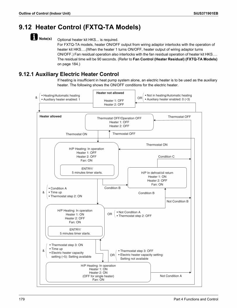
Outline of Control (Indoor Unit) SiUS371901EB
Note(s)
9.12 Heater Control (FXTQ-TA Models)Optional heater kit HKS... is required.For FXTQ-TA models, heater ON/OFF output from wiring adaptor interlocks with the operation of heater kit HKS….(When the heater 1 turns ON/OFF, heater output of wiring adaptor turns ON/OFF.) Fan residual operation also interlocks with the fan residual operation of heater kit HKS…. The residual time will be 90 seconds. (Refer to Fan Control (Heater Residual) (FXTQ-TA Models) on page 184.)
9.12.1 Auxiliary Electric Heater ControlIf heating is insufficient in heat pump system alone, an electric heater is to be used as the auxiliary heater. The following shows the ON/OFF conditions for the electric heater.
&
&
&
• Heating/Automatic heating• Auxiliary heater enabled: 1
• Not in heating/Automatic heating • Auxiliary heater enabled: 0 (∗3)
Heater not allowed
Heater allowed
Heater 1: OFFHeater 2: OFF
OR
OR
OR
Thermostat OFF/Operation OFFHeater 1: OFFHeater 2: OFF
Thermostat OFF
Thermostat ON
Thermostat ON
Condition C
Condition B
Condition B
Thermostat OFF
H/P Heating: In operationHeater 1: OFFHeater 2: OFF
Fan: ON
H/P Heating: In operationHeater 1: ONHeater 2: OFF
Fan: ON
H/P Heating: In operationHeater 1: ONHeater 2: ON
(OFF for single heater)Fan: ON
H/P In defrost/oil returnHeater 1: ONHeater 2: OFF
Fan: ON
ENTRY/5 minutes timer starts.
ENTRY/5 minutes timer starts.
• Not Condition A• Thermostat step 2: OFF
• Condition A• Time up• Thermostat step 2: ON
Not Condition A
Not Condition B
• Thermostat step 3: OFF• Electric heater capacity setting:
Setting not available
• Thermostat step 3: ON• Time up• Electric heater capacity
setting (∗5): Setting available
179 Part 4 Functions and Control
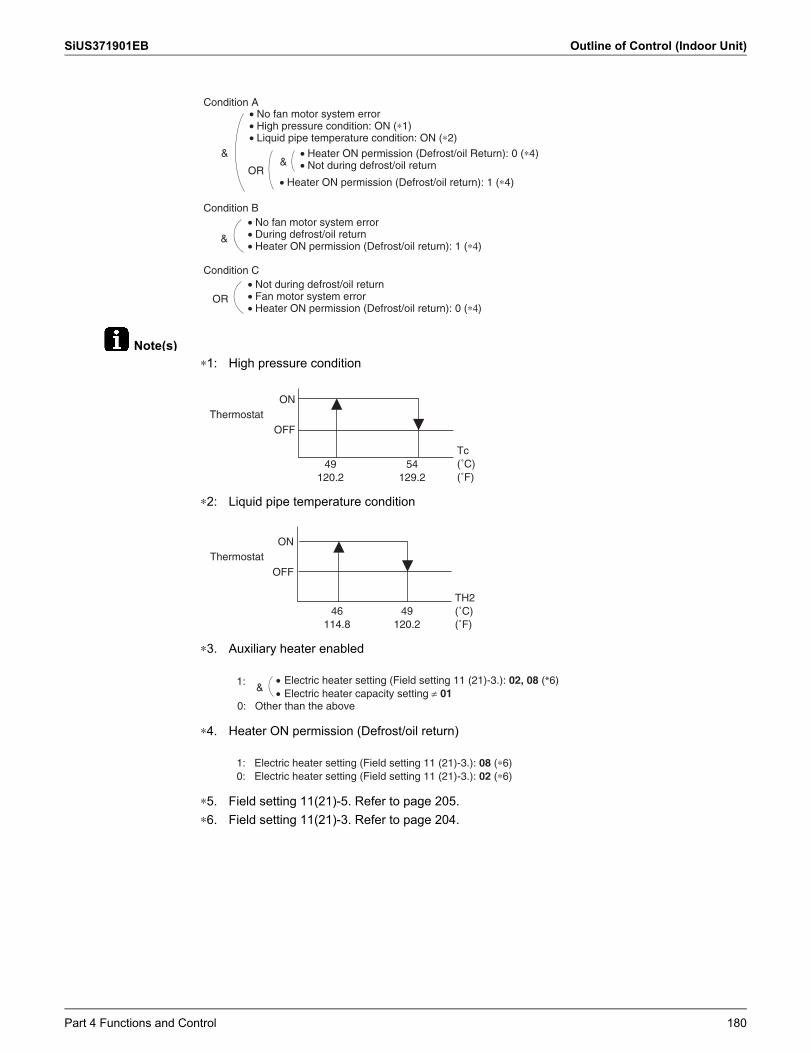
SiUS371901EB Outline of Control (Indoor Unit)
Note(s)
&&
OR
Condition A
• Heater ON permission (Defrost/oil return): 1 (∗4)
&
Condition B
Condition C
• No fan motor system error• High pressure condition: ON (∗1)• Liquid pipe temperature condition: ON (∗2)
• Heater ON permission (Defrost/oil Return): 0 (∗4)• Not during defrost/oil return
• No fan motor system error• During defrost/oil return• Heater ON permission (Defrost/oil return): 1 (∗4)
OR• Not during defrost/oil return• Fan motor system error• Heater ON permission (Defrost/oil return): 0 (∗4)
∗1: High pressure condition
∗2: Liquid pipe temperature condition
∗3. Auxiliary heater enabled
∗4. Heater ON permission (Defrost/oil return)
∗5. Field setting 11(21)-5. Refer to page 205.∗6. Field setting 11(21)-3. Refer to page 204.
ON
OFF
49120.2
54129.2
Tc(˚C)(˚F)
Thermostat
ON
OFF
46114.8
49120.2
TH2(˚C)(˚F)
Thermostat
1:&
Electric heater setting (Field setting 11 (21)-3.): 02, 08 (*6) Electric heater capacity setting 01
0: Other than the above
1: Electric heater setting (Field setting 11 (21)-3.): 08 (∗6)0: Electric heater setting (Field setting 11 (21)-3.): 02 (∗6)
Part 4 Functions and Control 180
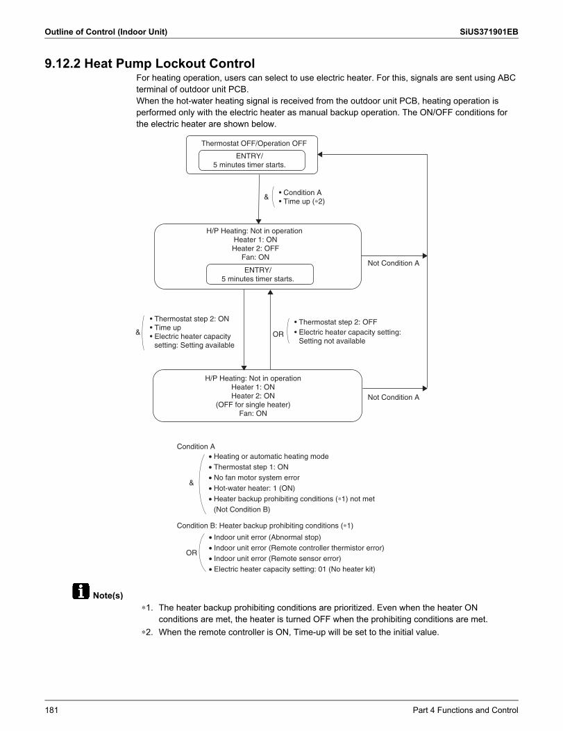
Outline of Control (Indoor Unit) SiUS371901EB
Note(s)
9.12.2 Heat Pump Lockout ControlFor heating operation, users can select to use electric heater. For this, signals are sent using ABC terminal of outdoor unit PCB.When the hot-water heating signal is received from the outdoor unit PCB, heating operation is performed only with the electric heater as manual backup operation. The ON/OFF conditions forthe electric heater are shown below.
Thermostat OFF/Operation OFF
ENTRY/5 minutes timer starts.
• Condition A• Time up (∗2)
&
H/P Heating: Not in operation Heater 1: ONHeater 2: OFF
Fan: ON
ENTRY/5 minutes timer starts.
& OR
• Thermostat step 2: OFF
H/P Heating: Not in operationHeater 1: ONHeater 2: ON
(OFF for single heater)Fan: ON
• Electric heater capacity setting: Setting not available
• Thermostat step 2: ON• Time up• Electric heater capacity
setting: Setting available
Not Condition A
Not Condition A
&
Condition A
OR
Condition B: Heater backup prohibiting conditions (∗1)
• Heating or automatic heating mode• Thermostat step 1: ON• No fan motor system error• Hot-water heater: 1 (ON)• Heater backup prohibiting conditions (∗1) not met
(Not Condition B)
• Indoor unit error (Abnormal stop)• Indoor unit error (Remote controller thermistor error)• Indoor unit error (Remote sensor error)• Electric heater capacity setting: 01 (No heater kit)
∗1. The heater backup prohibiting conditions are prioritized. Even when the heater ON conditions are met, the heater is turned OFF when the prohibiting conditions are met.
∗2. When the remote controller is ON, Time-up will be set to the initial value.
181 Part 4 Functions and Control
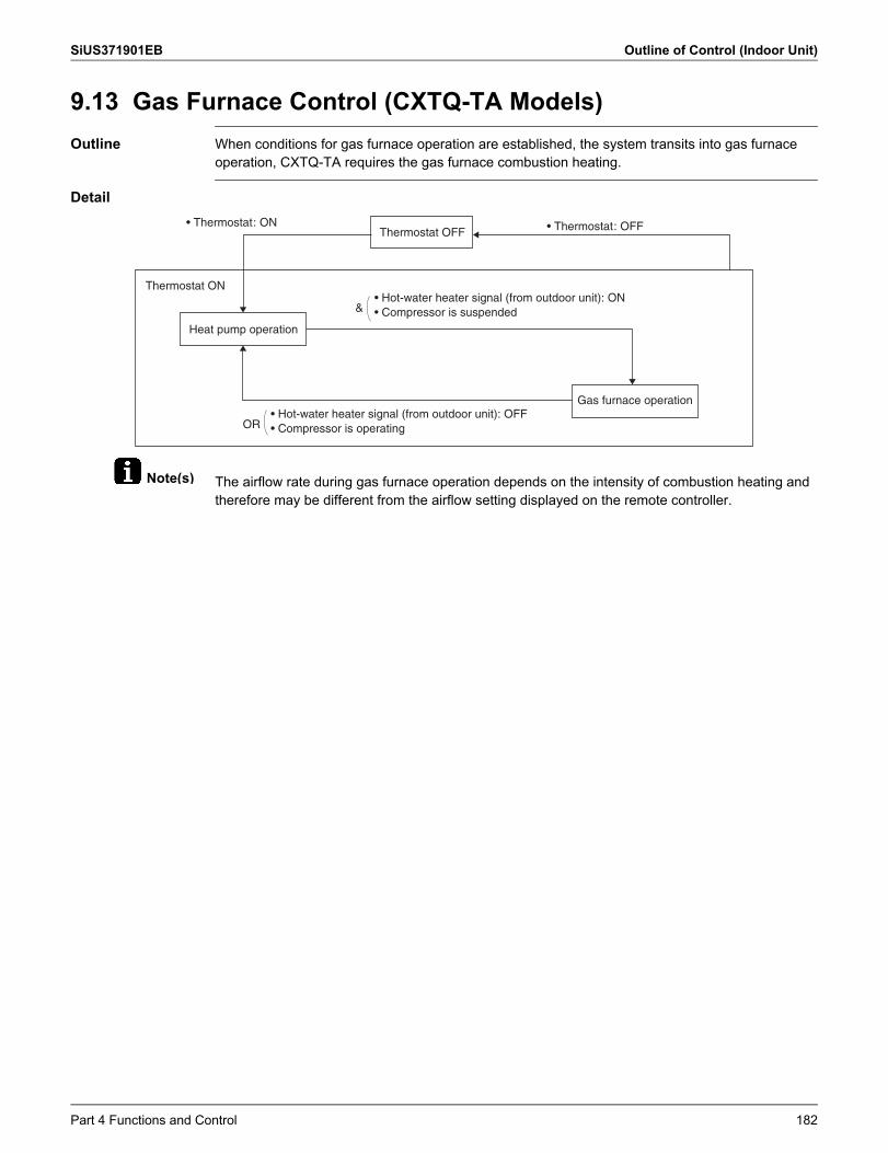
SiUS371901EB Outline of Control (Indoor Unit)
Note(s)
9.13 Gas Furnace Control (CXTQ-TA Models)Outline When conditions for gas furnace operation are established, the system transits into gas furnace
operation, CXTQ-TA requires the gas furnace combustion heating.
Detail
The airflow rate during gas furnace operation depends on the intensity of combustion heating and therefore may be different from the airflow setting displayed on the remote controller.
• Thermostat: ON • Thermostat: OFFThermostat OFF
Thermostat ON
Heat pump operation
&• Hot-water heater signal (from outdoor unit): ON• Compressor is suspended
OR• Hot-water heater signal (from outdoor unit): OFF• Compressor is operating
Gas furnace operation
Part 4 Functions and Control 182
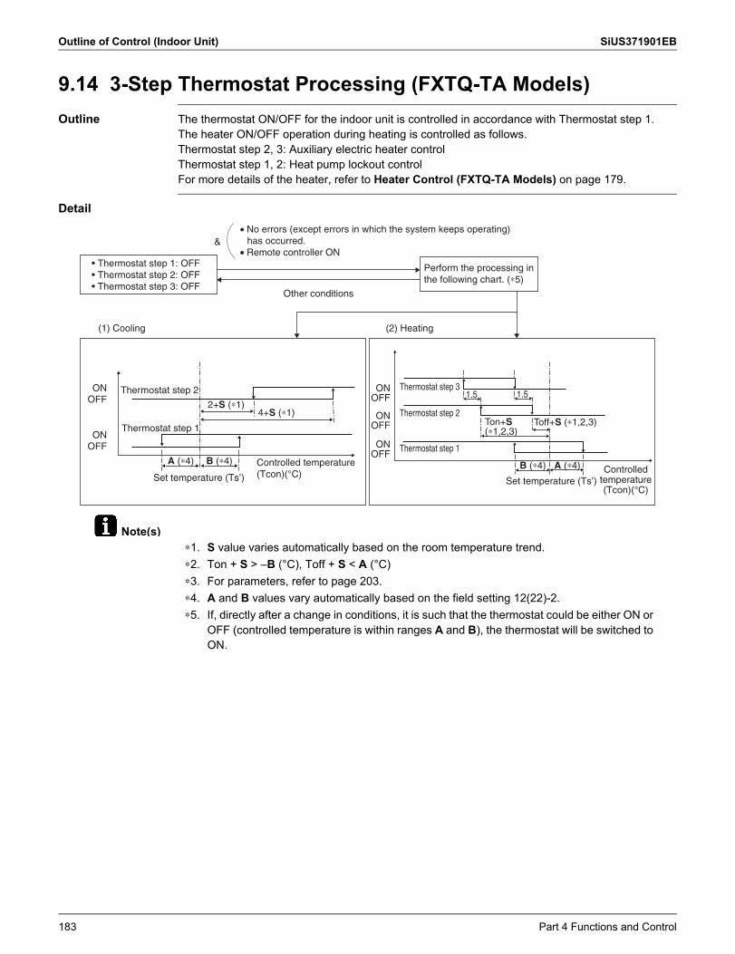
Outline of Control (Indoor Unit) SiUS371901EB
Note(s)
9.14 3-Step Thermostat Processing (FXTQ-TA Models)Outline The thermostat ON/OFF for the indoor unit is controlled in accordance with Thermostat step 1.
The heater ON/OFF operation during heating is controlled as follows.Thermostat step 2, 3: Auxiliary electric heater controlThermostat step 1, 2: Heat pump lockout controlFor more details of the heater, refer to Heater Control (FXTQ-TA Models) on page 179.
Detail
&• No errors (except errors in which the system keeps operating)
has occurred.• Remote controller ON
• Thermostat step 1: OFF• Thermostat step 2: OFF• Thermostat step 3: OFF
Other conditions
Perform the processing in the following chart. (∗5)
(1) Cooling (2) Heating
Thermostat step 2
Thermostat step 1
ONOFF
ONOFF
2+S (∗1)4+S (∗1)
A (∗4) B (∗4) Controlled temperature (Tcon)(°C)Set temperature (Ts’)
Thermostat step 3
Thermostat step 2
Thermostat step 1
ONOFF
ONOFF
ONOFF
1.5 1.5
Toff+S (∗1,2,3)Ton+S (∗1,2,3)
A (∗4)B (∗4)
Set temperature (Ts’)Controlled
temperature (Tcon)(°C)
∗1. S value varies automatically based on the room temperature trend.∗2. Ton + S > –B (°C), Toff + S < A (°C)∗3. For parameters, refer to page 203.∗4. A and B values vary automatically based on the field setting 12(22)-2.∗5. If, directly after a change in conditions, it is such that the thermostat could be either ON or
OFF (controlled temperature is within ranges A and B), the thermostat will be switched to ON.
183 Part 4 Functions and Control
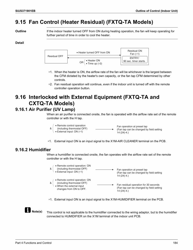
SiUS371901EB Outline of Control (Indoor Unit)
Note(s)
9.15 Fan Control (Heater Residual) (FXTQ-TA Models)Outline If the indoor heater turned OFF from ON during heating operation, the fan will keep operating for
further period of time in order to cool the heater.
Detail
9.16 Interlocked with External Equipment (FXTQ-TA and CXTQ-TA Models)
9.16.1 Air Purifier (UV Lamp)When an air purifier is connected onsite, the fan is operated with the airflow rate set of the remote controller or with the H tap.
9.16.2 HumidifierWhen a humidifier is connected onsite, the fan operates with the airflow rate set of the remotecontroller or with the H tap.
This control is not applicable to the humidifier connected to the wiring adaptor, but to the humidifier connected to HUMIDIFIER on the X1M terminal of the indoor unit PCB.
• Heater turned OFF from ON
OR• Heater ON• Time up (∗2)
Residual OFF
Residual ONFan (∗1)
ENTRY/90 sec. timer starts.
∗1. When the heater is ON, the airflow rate of the fan will be whichever is the largest between the CFM dictated by the heater's own capacity, or the fan tap CFM determined by other controls.
∗2. Fan residual operation will continue, even if the indoor unit is turned off with the remote controller operation button.
∗1. External input ON is an input signal to the X1M-AIR CLEANER terminal on the PCB.
&Fan operation at preset tap(Fan tap can be changed by field setting 14 (24)-4.)
• Remote control operation (including thermostat OFF)
• External input: ON (∗1)
∗1. External input ON is an input signal to the X1M-HUMIDIFIER terminal on the PCB.
&
&• Remote control operation: ON
(including thermostat OFF)• When the external input
changes from ON to OFF.
• Remote control operation: ON (including thermostat OFF)
• External input: ON (∗1)Fan operation at preset tap(Fan tap can be changed by field setting 14 (24)-4.)
Fan residual operation for 30 seconds(Fan tap can be changed by field setting 14 (24)-4.)
Part 4 Functions and Control 184
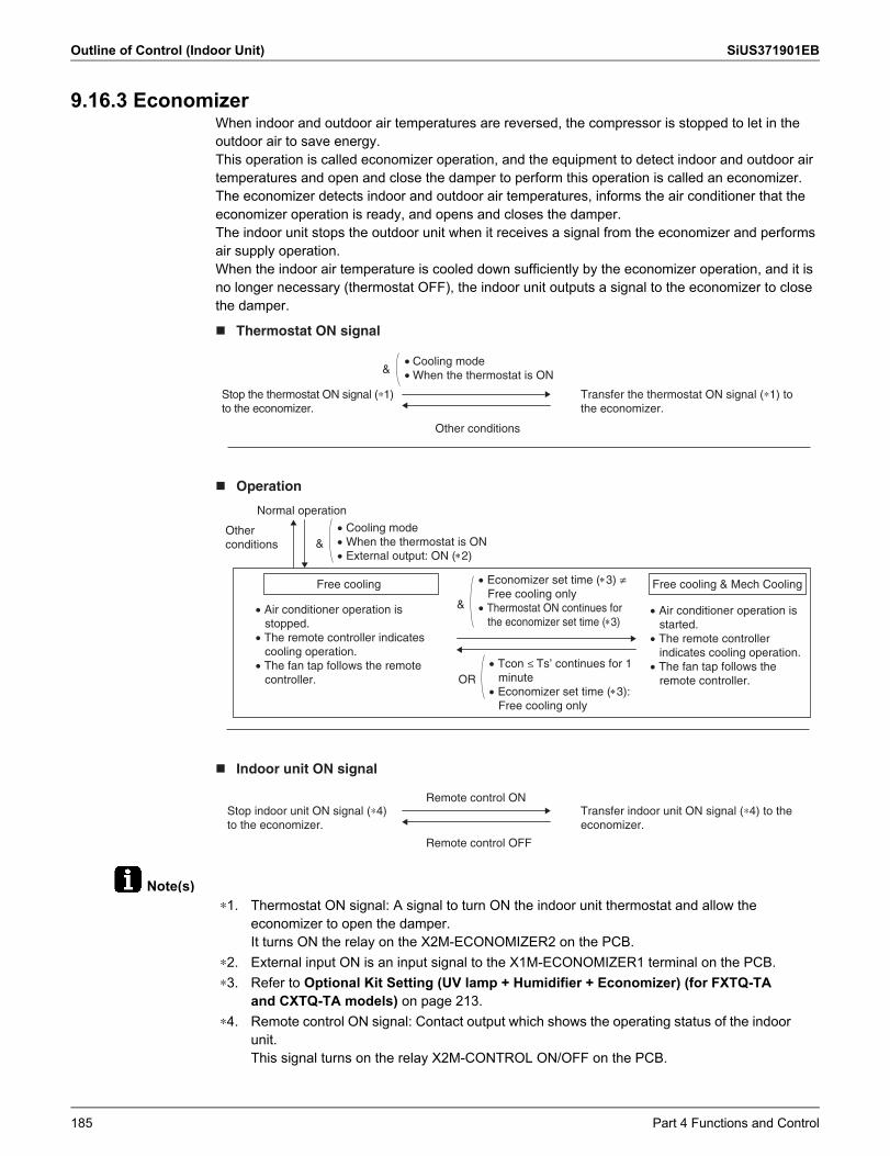
Outline of Control (Indoor Unit) SiUS371901EB
Note(s)
9.16.3 EconomizerWhen indoor and outdoor air temperatures are reversed, the compressor is stopped to let in theoutdoor air to save energy.This operation is called economizer operation, and the equipment to detect indoor and outdoor air temperatures and open and close the damper to perform this operation is called an economizer.The economizer detects indoor and outdoor air temperatures, informs the air conditioner that the economizer operation is ready, and opens and closes the damper.The indoor unit stops the outdoor unit when it receives a signal from the economizer and performs air supply operation.When the indoor air temperature is cooled down sufficiently by the economizer operation, and it is no longer necessary (thermostat OFF), the indoor unit outputs a signal to the economizer to close the damper.
&
Other conditions
Stop the thermostat ON signal (∗1) to the economizer.
Transfer the thermostat ON signal (∗1) to the economizer.
• Cooling mode• When the thermostat is ON
Thermostat ON signal
&Cooling modeWhen the thermostat is ONExternal output: ON (2)
ORTcon ≤ Ts’ continues for 1
minuteEconomizer set time (3):
Free cooling only
&
Economizer set time (3) ≠ Free cooling only
Thermostat ON continues for the economizer set time (3)
Air conditioner operation is stopped.
The remote controller indicates cooling operation.
The fan tap follows the remote controller.
Air conditioner operation is started.
The remote controller indicates cooling operation.
The fan tap follows the remote controller.
Normal operation
Other conditions
Free cooling Free cooling & Mech Cooling
Operation
Remote control ON
Remote control OFF
Stop indoor unit ON signal (∗4) to the economizer.
Transfer indoor unit ON signal (∗4) to the economizer.
Indoor unit ON signal
∗1. Thermostat ON signal: A signal to turn ON the indoor unit thermostat and allow the economizer to open the damper.It turns ON the relay on the X2M-ECONOMIZER2 on the PCB.
∗2. External input ON is an input signal to the X1M-ECONOMIZER1 terminal on the PCB.∗3. Refer to Optional Kit Setting (UV lamp + Humidifier + Economizer) (for FXTQ-TA
and CXTQ-TA models) on page 213.∗4. Remote control ON signal: Contact output which shows the operating status of the indoor
unit.This signal turns on the relay X2M-CONTROL ON/OFF on the PCB.
185 Part 4 Functions and Control
SiUS371901EB
Part 5 Field Settings and Test Operation 186
1. Field Settings for Indoor Unit...................................................................1871.1 Field Settings with Remote Controller ...................................................... 1871.2 List of Field Settings for Indoor Unit ......................................................... 1941.3 Applicable Field Settings .......................................................................... 1961.4 Details of Field Settings for Indoor Unit.................................................... 2001.5 Gas Furnace Set Up................................................................................. 2171.6 List of Field Settings for Outdoor-Air Processing Unit .............................. 2191.7 Setting of Operation Control Mode........................................................... 219
2. Field Setting from Outdoor Unit...............................................................2212.1 DIP Switch Setting when Mounting a Spare PCB .................................... 2222.2 Accessing the BS Buttons on the PCB..................................................... 2242.3 Operating the BS Buttons and DIP Switches on the PCB........................ 2252.4 Connecting the PC Configurator to the Outdoor Unit ............................... 2282.5 Monitoring Function and Field Settings .................................................... 2292.6 Cool/Heat Mode Changeover................................................................... 2522.7 Night-Time Low Noise Operation and Demand Operation....................... 253
3. Field Settings for Branch Selector Unit ...................................................2583.1 Field Settings for Single Branch Selector Unit ......................................... 2583.2 Field Settings for Multi Branch Selector Unit (Standard Series)............... 2593.3 Field Settings for Multi Branch Selector Unit (Flex Series) ...................... 2603.4 How to Check Miswiring for Multi Branch Selector Unit ........................... 262
4. Test Operation ........................................................................................2634.1 Checks before Test Operation ................................................................. 2634.2 Checkpoints.............................................................................................. 2634.3 Gas Furnace Test Operation.................................................................... 264
Part 5 Field Settings and
Test Operation
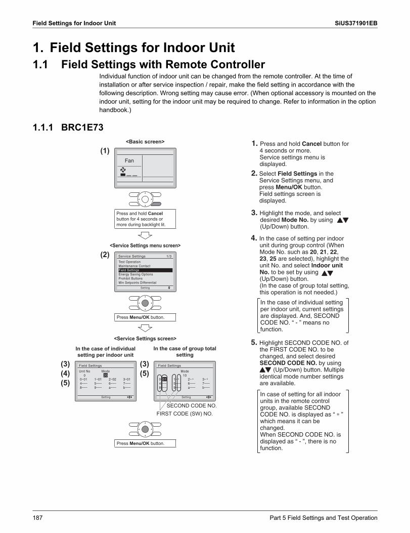
Field Settings for Indoor Unit SiUS371901EB
1. Field Settings for Indoor Unit1.1 Field Settings with Remote Controller
Individual function of indoor unit can be changed from the remote controller. At the time of installation or after service inspection / repair, make the field setting in accordance with the following description. Wrong setting may cause error. (When optional accessory is mounted on the indoor unit, setting for the indoor unit may be required to change. Refer to information in the option handbook.)
1.1.1 BRC1E73<Basic screen>
(1)
<Service Settings menu screen>
(2)
Press Menu/OK button.
<Service Settings screen>
(3)(4)(5)
(3)(5)
Press Menu/OK button.
FIRST CODE (SW) NO.SECOND CODE NO.
Press and hold Cancelbutton for 4 seconds or more during backlight lit.
In the case of individual setting per indoor unit
In the case of group total setting
1. Press and hold Cancel button for 4 seconds or more.Service settings menu is displayed.
2. Select Field Settings in the Service Settings menu, and press Menu/OK button.Field settings screen is displayed.
3. Highlight the mode, and select desired Mode No. by using (Up/Down) button.
4. In the case of setting per indoor unit during group control (When Mode No. such as 20, 21, 22, 23, 25 are selected), highlight the unit No. and select Indoor unit No. to be set by using (Up/Down) button.(In the case of group total setting, this operation is not needed.)
5. Highlight SECOND CODE NO. of the FIRST CODE NO. to be changed, and select desired SECOND CODE NO. by using (Up/Down) button. Multiple identical mode number settings are available.
In the case of individual setting per indoor unit, current settings are displayed. And, SECOND CODE NO. “ - ” means no function.
In case of setting for all indoor units in the remote control group, available SECOND CODE NO. is displayed as “ ∗ ” which means it can be changed.When SECOND CODE NO. is displayed as “ - ”, there is no function.
187 Part 5 Field Settings and Test Operation
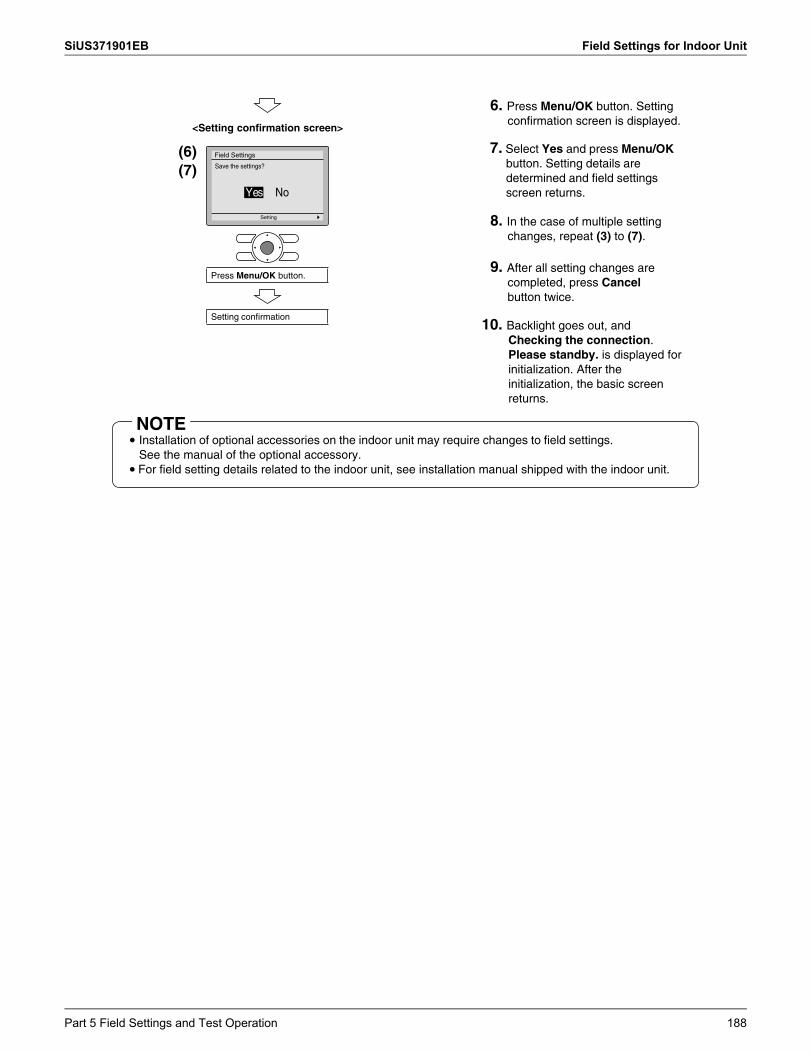
SiUS371901EB Field Settings for Indoor Unit
NOTE
<Setting confirmation screen>
(6)(7)
Press Menu/OK button.
Setting confirmation
6. Press Menu/OK button. Setting confirmation screen is displayed.
7. Select Yes and press Menu/OK button. Setting details are determined and field settings screen returns.
8. In the case of multiple setting changes, repeat (3) to (7).
9. After all setting changes are completed, press Cancel button twice.
10. Backlight goes out, and Checking the connection.Please standby. is displayed for initialization. After the initialization, the basic screen returns.
• Installation of optional accessories on the indoor unit may require changes to field settings.See the manual of the optional accessory.
• For field setting details related to the indoor unit, see installation manual shipped with the indoor unit.
Part 5 Field Settings and Test Operation 188
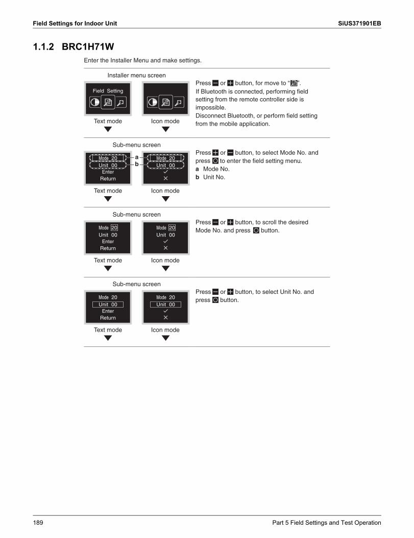
Field Settings for Indoor Unit SiUS371901EB
1.1.2 BRC1H71WEnter the Installer Menu and make settings.
Installer menu screen
Field Setting
Text mode Icon mode
Press or button, for move to “ ”.
setting from the remote controller side is impossible.
from the mobile application.
Sub-menu screen
Text mode Icon mode
Mode 20Unit 00
EnterReturn
Mode 20Unit 00
ab
Press or button, to select Mode No. and press a Mode No. b Unit No.
Sub-menu screen
Text mode Icon mode
Mode 20Unit 00
EnterReturn
Mode 20Unit 00
Press or button, to scroll the desired Mode No. and press button.
Sub-menu screen
Mode 20Unit 00
Mode 20Unit 00
EnterReturn
Text mode Icon mode
Press or button, to select Unit No. and press button.
to enter the field setting menu.
Disconnect Bluetooth, or perform field setting
If Bluetooth is connected, performing field
189 Part 5 Field Settings and Test Operation
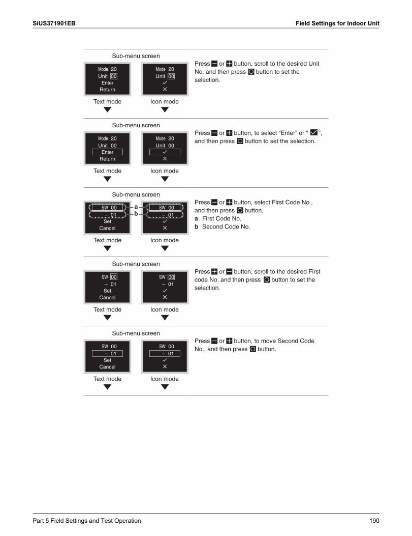
SiUS371901EB Field Settings for Indoor Unit
Sub-menu screen
Mode 20Unit 00
Mode 20Unit 00
EnterReturn
Text mode Icon mode
Press or button, scroll to the desired Unit No. and then press button to set the selection.
Sub-menu screen
Mode 20Unit 00
Mode 20Unit 00
EnterReturn
Text mode Icon mode
Press or button, to select “Enter” or “ ”, and then press button to set the selection.
Sub-menu screen
Text mode Icon mode
SW 00
SetCancel
– 01SW 00
– 01ba
Press or button, select First Code No., and then press button.a First Code No.b Second Code No.
Sub-menu screen
Text mode Icon mode
SW 00– 01
SW 00
SetCancel
– 01
Press or button, scroll to the desired First code No. and then press button to set the selection.
Sub-menu screen
SW 00– 01
SW 00– 01Set
Cancel
Text mode Icon mode
Press or button, to move Second Code No., and then press button.
Part 5 Field Settings and Test Operation 190
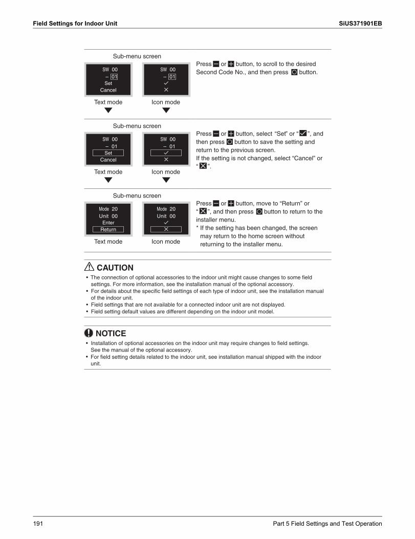
Field Settings for Indoor Unit SiUS371901EB
Sub-menu screen
SW 00– 01
SW 00– 01Set
Cancel
Text mode Icon mode
Press or button, to scroll to the desired Second Code No., and then press button.
Sub-menu screen
SW 00– 01
SW 00
SetCancel
– 01
Text mode Icon mode
Press or button, select “Set” or “ ”, and then press button to save the setting and return to the previous screen. If the setting is not changed, select “Cancel” or “ ”.
Sub-menu screen
Mode 20Unit 00
Mode 20Unit 00
EnterReturn
Text mode Icon mode
Press or button, move to “Return” or “ ”, and then press button to return to the installer menu.* If the setting has been changed, the screen
may return to the home screen without returning to the installer menu.
CAUTION•
settings. For more information, see the installation manual of the optional accessory.•
of the indoor unit.• Field settings that are not available for a connected indoor unit are not displayed.•
For details about the specific field settings of each type of indoor unit, see the installation manual
Field setting default values are different depending on the indoor unit model.
The connection of optional accessories to the indoor unit might cause changes to some field
NOTICE•
See the manual of the optional accessory.•
unit.
Installation of optional accessories on the indoor unit may require changes to field settings.
For field setting details related to the indoor unit, see installation manual shipped with the indoor
191 Part 5 Field Settings and Test Operation
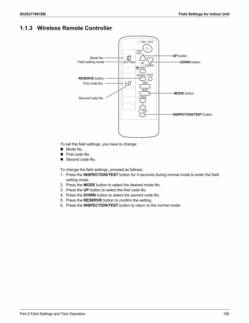
SiUS371901EB Field Settings for Indoor Unit
1.1.3 Wireless Remote Controller
To set the field settings, you have to change: Mode No. First code No. Second code No.
To change the field settings, proceed as follows:1. Press the INSPECTION/TEST button for 4 seconds during normal mode to enter the field
setting mode.2. Press the MODE button to select the desired mode No.3. Press the UP button to select the first code No.4. Press the DOWN button to select the second code No.5. Press the RESERVE button to confirm the setting.6. Press the INSPECTION/TEST button to return to the normal mode.
RESERVE button
INSPECTION/TEST button
Mode No.Field setting mode
UP button
DOWN button
First code No.
Second code No.
MODE button
Part 5 Field Settings and Test Operation 192
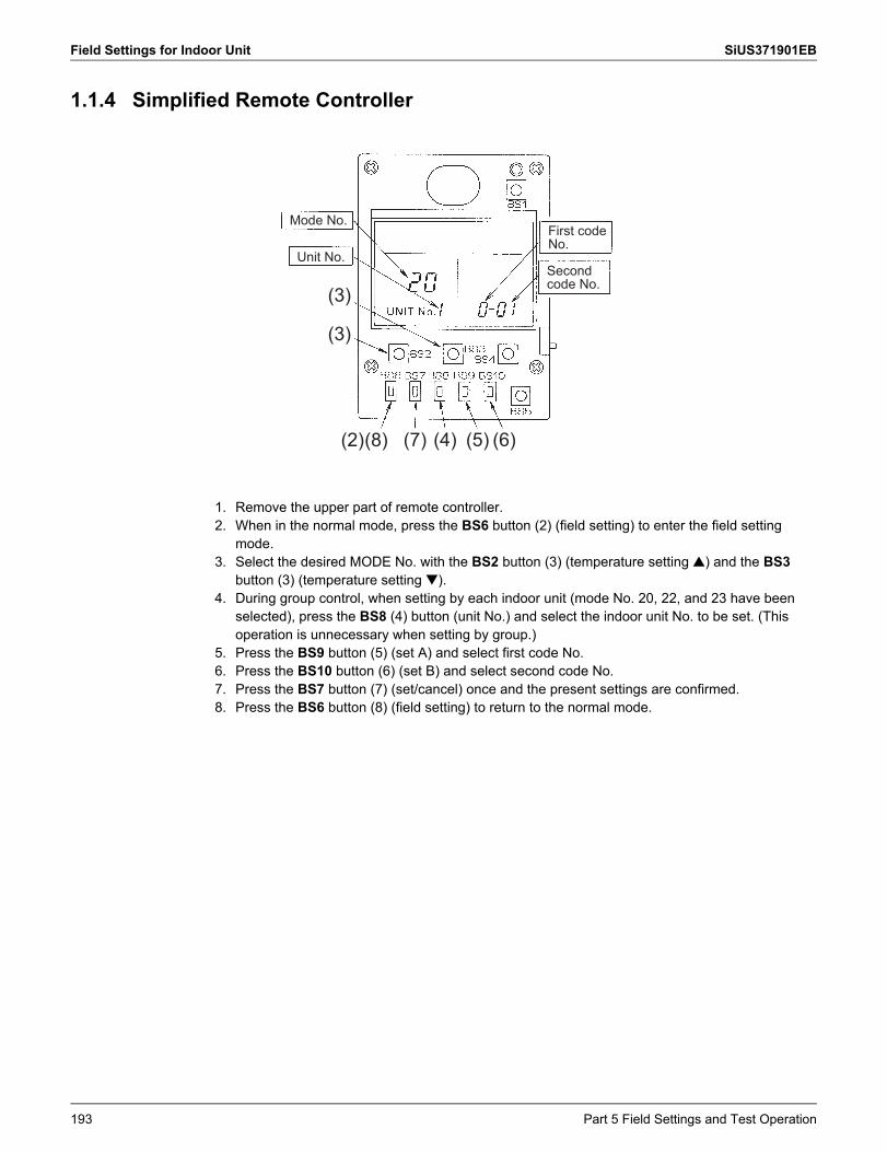
Field Settings for Indoor Unit SiUS371901EB
1.1.4 Simplified Remote Controller
1. Remove the upper part of remote controller.2. When in the normal mode, press the BS6 button (2) (field setting) to enter the field setting
mode.3. Select the desired MODE No. with the BS2 button (3) (temperature setting ) and the BS3
button (3) (temperature setting ).4. During group control, when setting by each indoor unit (mode No. 20, 22, and 23 have been
selected), press the BS8 (4) button (unit No.) and select the indoor unit No. to be set. (This operation is unnecessary when setting by group.)
5. Press the BS9 button (5) (set A) and select first code No.6. Press the BS10 button (6) (set B) and select second code No.7. Press the BS7 button (7) (set/cancel) once and the present settings are confirmed.8. Press the BS6 button (8) (field setting) to return to the normal mode.
Mode No.
Unit No.
First code No.
Second code No.
(3)
(3)
(2)(8) (7) (6)(5)(4)
193 Part 5 Field Settings and Test Operation
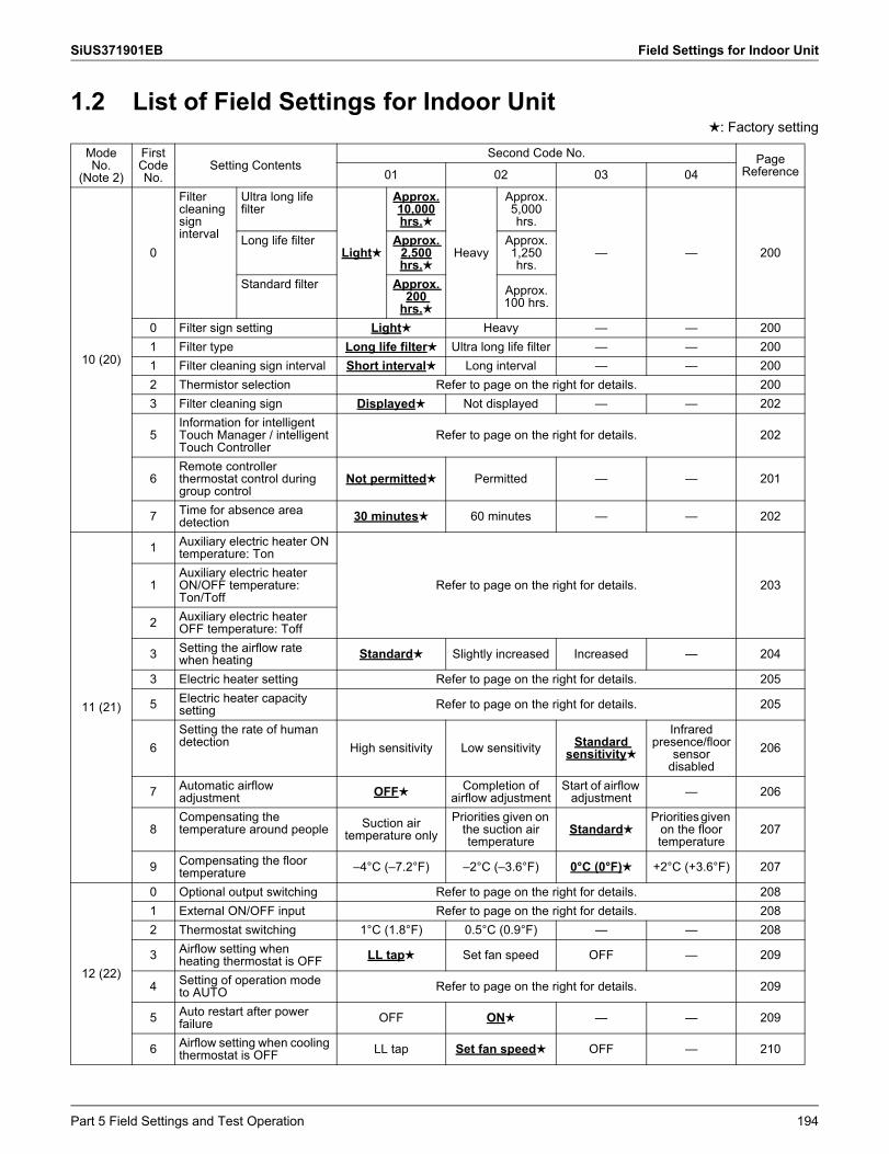
SiUS371901EB Field Settings for Indoor Unit
1.2 List of Field Settings for Indoor Unit: Factory setting
Mode No.
(Note 2)
First Code No.
Setting ContentsSecond Code No. Page
Reference01 02 03 04
10 (20)
0
Filter cleaning sign interval
Ultra long life filter
Light
Approx.10,000hrs.
Heavy
Approx.5,000 hrs.
— — 200Long life filter Approx.
2,500hrs.
Approx.1,250 hrs.
Standard filter Approx. 200
hrs.Approx.100 hrs.
0 Filter sign setting Light Heavy — — 2001 Filter type Long life filter Ultra long life filter — — 2001 Filter cleaning sign interval Short interval Long interval — — 2002 Thermistor selection Refer to page on the right for details. 2003 Filter cleaning sign Displayed Not displayed — — 202
5Information for intelligent Touch Manager / intelligent Touch Controller
Refer to page on the right for details. 202
6Remote controller thermostat control during group control
Not permitted Permitted — — 201
7 Time for absence area detection 30 minutes 60 minutes — — 202
11 (21)
1 Auxiliary electric heater ON temperature: Ton
Refer to page on the right for details. 2031Auxiliary electric heater ON/OFF temperature: Ton/Toff
2 Auxiliary electric heater OFF temperature: Toff
3 Setting the airflow rate when heating Standard Slightly increased Increased — 204
3 Electric heater setting Refer to page on the right for details. 205
5 Electric heater capacity setting Refer to page on the right for details. 205
6Setting the rate of human detection High sensitivity Low sensitivity Standard
sensitivity
Infrared presence/floor
sensor disabled
206
7 Automatic airflow adjustment OFF Completion of
airflow adjustmentStart of airflow
adjustment — 206
8Compensating the temperature around people Suction air
temperature onlyPriorities given on
the suction air temperature
StandardPriorities given
on the floor temperature
207
9 Compensating the floor temperature –4°C (–7.2°F) –2°C (–3.6°F) 0°C (0°F) +2°C (+3.6°F) 207
12 (22)
0 Optional output switching Refer to page on the right for details. 2081 External ON/OFF input Refer to page on the right for details. 2082 Thermostat switching 1°C (1.8°F) 0.5°C (0.9°F) — — 208
3 Airflow setting when heating thermostat is OFF LL tap Set fan speed OFF — 209
4 Setting of operation mode to AUTO Refer to page on the right for details. 209
5 Auto restart after power failure OFF ON — — 209
6 Airflow setting when cooling thermostat is OFF LL tap Set fan speed OFF — 210
Part 5 Field Settings and Test Operation 194
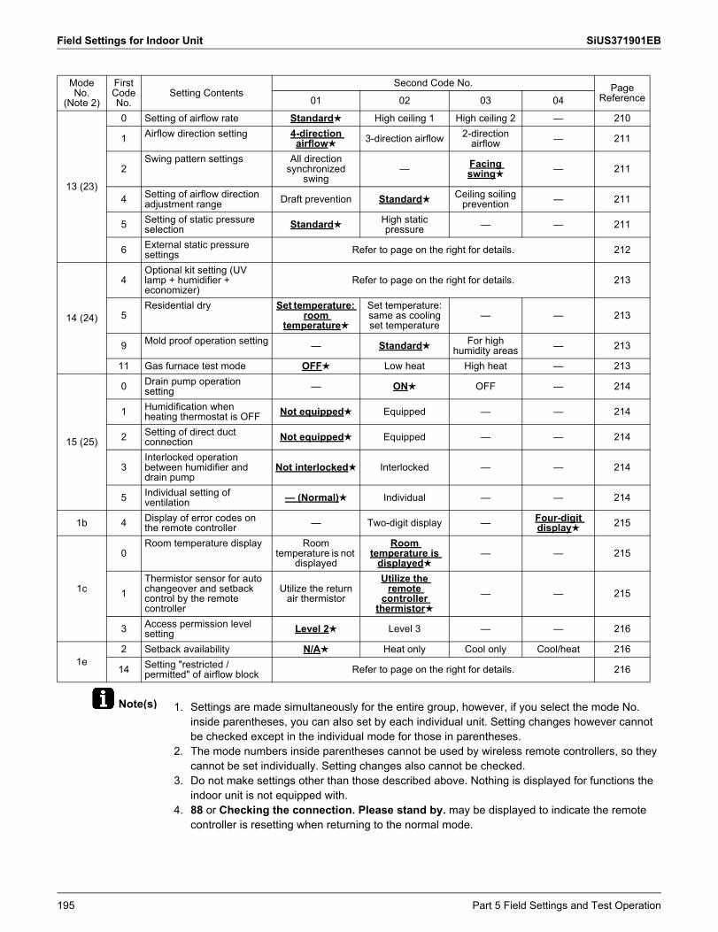
Field Settings for Indoor Unit SiUS371901EB
Note(s) 1. Settings are made simultaneously for the entire group, however, if you select the mode No. inside parentheses, you can also set by each individual unit. Setting changes however cannot be checked except in the individual mode for those in parentheses.
2. The mode numbers inside parentheses cannot be used by wireless remote controllers, so they cannot be set individually. Setting changes also cannot be checked.
3. Do not make settings other than those described above. Nothing is displayed for functions the indoor unit is not equipped with.
4. 88 or Checking the connection. Please stand by. may be displayed to indicate the remote controller is resetting when returning to the normal mode.
13 (23)
0 Setting of airflow rate Standard High ceiling 1 High ceiling 2 — 210
1 Airflow direction setting 4-direction airflow 3-direction airflow 2-direction
airflow — 211
2Swing pattern settings All direction
synchronized swing
— Facing swing — 211
4 Setting of airflow direction adjustment range Draft prevention Standard Ceiling soiling
prevention — 211
5 Setting of static pressure selection Standard High static
pressure — — 211
6 External static pressure settings Refer to page on the right for details. 212
14 (24)
4Optional kit setting (UV lamp + humidifier + economizer)
Refer to page on the right for details. 213
5Residential dry Set temperature:
room temperature
Set temperature: same as cooling set temperature
— — 213
9 Mold proof operation setting — Standard For high humidity areas — 213
11 Gas furnace test mode OFF Low heat High heat — 213
15 (25)
0 Drain pump operation setting — ON OFF — 214
1 Humidification when heating thermostat is OFF Not equipped Equipped — — 214
2 Setting of direct duct connection Not equipped Equipped — — 214
3Interlocked operation between humidifier and drain pump
Not interlocked Interlocked — — 214
5 Individual setting of ventilation — (Normal) Individual — — 214
1b 4 Display of error codes on the remote controller — Two-digit display — Four-digit
display 215
1c
0Room temperature display Room
temperature is not displayed
Room temperature is
displayed— — 215
1Thermistor sensor for auto changeover and setback control by the remote controller
Utilize the return air thermistor
Utilize the remote
controller thermistor
— — 215
3 Access permission level setting Level 2 Level 3 — — 216
1e2 Setback availability N/A Heat only Cool only Cool/heat 216
14 Setting "restricted / permitted" of airflow block Refer to page on the right for details. 216
Mode No.
(Note 2)
First Code No.
Setting ContentsSecond Code No. Page
Reference01 02 03 04
195 Part 5 Field Settings and Test Operation
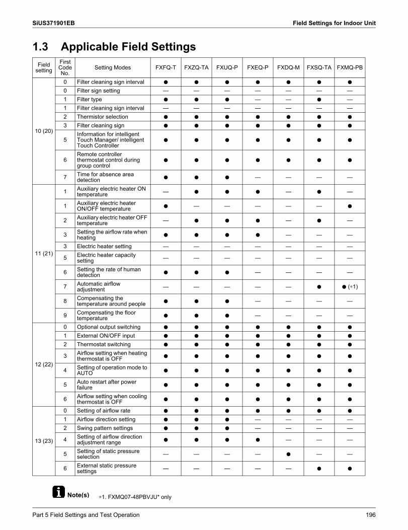
SiUS371901EB Field Settings for Indoor Unit
Note(s)
1.3 Applicable Field Settings
∗1. FXMQ07-48PBVJU* only
Field setting
FirstCodeNo.
Setting Modes FXFQ-T FXZQ-TA FXUQ-P FXEQ-P FXDQ-M FXSQ-TA FXMQ-PB
10 (20)
0 Filter cleaning sign interval h h h h h h h
0 Filter sign setting — — — — — — —1 Filter type h h h — — h —1 Filter cleaning sign interval — — — — — — —2 Thermistor selection h h h h h h h
3 Filter cleaning sign h h h h h h h
5Information for intelligent Touch Manager/ intelligent Touch Controller
h h h h h h h
6Remote controller thermostat control during group control
h h h h h h h
7 Time for absence area detection h h h — — — —
11 (21)
1 Auxiliary electric heater ON temperature — h h h — h —
1 Auxiliary electric heater ON/OFF temperature h — — — — — h
2 Auxiliary electric heater OFF temperature — h h h — h —
3 Setting the airflow rate when heating h h h h — — —
3 Electric heater setting — — — — — — —
5 Electric heater capacity setting — — — — — — —
6 Setting the rate of human detection h h h — — — —
7 Automatic airflow adjustment — — — — — h h (∗1)
8 Compensating the temperature around people h h h — — — —
9 Compensating the floor temperature h h h — — — —
12 (22)
0 Optional output switching h h h h h h h
1 External ON/OFF input h h h h h h h
2 Thermostat switching h h h h h h h
3 Airflow setting when heating thermostat is OFF h h h h h h h
4 Setting of operation mode to AUTO h h h h h h h
5 Auto restart after power failure h h h h h h h
6 Airflow setting when cooling thermostat is OFF h h h h h h h
13 (23)
0 Setting of airflow rate h h h h h h h
1 Airflow direction setting h h h — — — —2 Swing pattern settings h h h — — — —
4 Setting of airflow direction adjustment range h h h h — — —
5 Setting of static pressure selection — — — — h — —
6 External static pressure settings — — — — — h h
Part 5 Field Settings and Test Operation 196
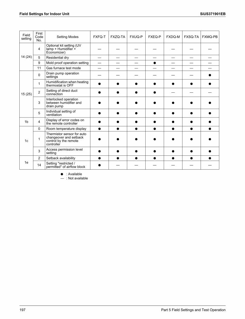
Field Settings for Indoor Unit SiUS371901EB
Field setting
FirstCodeNo.
Setting Modes FXFQ-T FXZQ-TA FXUQ-P FXEQ-P FXDQ-M FXSQ-TA FXMQ-PB
14 (24)
4Optional kit setting (UV lamp + Humidifier + Economizer)
— — — — — — —
5 Residential dry — — — — — — —9 Mold proof operation setting — — — h — — —
11 Gas furnace test mode — — — — — — —
15 (25)
0 Drain pump operation settings — — — — — — h
1 Humidification when heating thermostat is OFF h h h h h h h
2 Setting of direct duct connection h h h h — — —
3Interlocked operation between humidifier and drain pump
h h h h h h h
5 Individual setting of ventilation h h h h h h h
1b 4 Display of error codes on the remote controller h h h h h h h
1c
0 Room temperature display h h h h h h h
1Thermistor sensor for auto changeover and setback control by the remote controller
h h h h h h h
3 Access permission level setting h h h h h h h
1e2 Setback availability h h h h h h h
14 Setting "restricted / permitted" of airflow block h — — — — — —
h—
: Available: Not available
197 Part 5 Field Settings and Test Operation
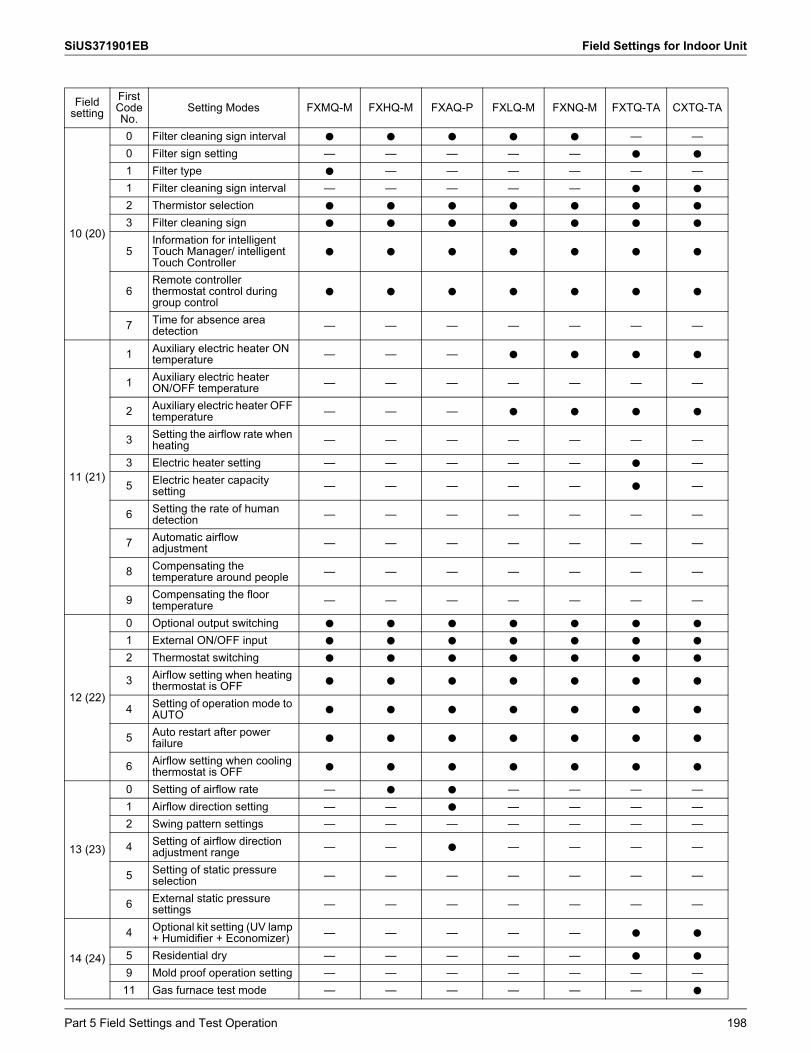
SiUS371901EB Field Settings for Indoor Unit
Field setting
FirstCodeNo.
Setting Modes FXMQ-M FXHQ-M FXAQ-P FXLQ-M FXNQ-M FXTQ-TA CXTQ-TA
10 (20)
0 Filter cleaning sign interval h h h h h — —0 Filter sign setting — — — — — h h
1 Filter type h — — — — — —1 Filter cleaning sign interval — — — — — h h
2 Thermistor selection h h h h h h h
3 Filter cleaning sign h h h h h h h
5Information for intelligent Touch Manager/ intelligent Touch Controller
h h h h h h h
6Remote controller thermostat control during group control
h h h h h h h
7 Time for absence area detection — — — — — — —
11 (21)
1 Auxiliary electric heater ON temperature — — — h h h h
1 Auxiliary electric heater ON/OFF temperature — — — — — — —
2 Auxiliary electric heater OFF temperature — — — h h h h
3 Setting the airflow rate when heating — — — — — — —
3 Electric heater setting — — — — — h —
5 Electric heater capacity setting — — — — — h —
6 Setting the rate of human detection — — — — — — —
7 Automatic airflow adjustment — — — — — — —
8 Compensating the temperature around people — — — — — — —
9 Compensating the floor temperature — — — — — — —
12 (22)
0 Optional output switching h h h h h h h
1 External ON/OFF input h h h h h h h
2 Thermostat switching h h h h h h h
3 Airflow setting when heating thermostat is OFF h h h h h h h
4 Setting of operation mode to AUTO h h h h h h h
5 Auto restart after power failure h h h h h h h
6 Airflow setting when cooling thermostat is OFF h h h h h h h
13 (23)
0 Setting of airflow rate — h h — — — —1 Airflow direction setting — — h — — — —2 Swing pattern settings — — — — — — —
4 Setting of airflow direction adjustment range — — h — — — —
5 Setting of static pressure selection — — — — — — —
6 External static pressure settings — — — — — — —
14 (24)
4 Optional kit setting (UV lamp + Humidifier + Economizer) — — — — — h h
5 Residential dry — — — — — h h
9 Mold proof operation setting — — — — — — —11 Gas furnace test mode — — — — — — h
Part 5 Field Settings and Test Operation 198
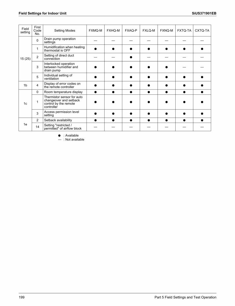
Field Settings for Indoor Unit SiUS371901EB
15 (25)
0 Drain pump operation settings — — — — — — —
1 Humidification when heating thermostat is OFF h h h h h h h
2 Setting of direct duct connection — — h — — — —
3Interlocked operation between humidifier and drain pump
h h h h h — —
5 Individual setting of ventilation h h h h h h h
1b 4 Display of error codes on the remote controller h h h h h h h
1c
0 Room temperature display h h h h h h h
1Thermistor sensor for auto changeover and setback control by the remote controller
h h h h h h h
3 Access permission level setting h h h h h h h
1e2 Setback availability h h h h h h h
14 Setting "restricted / permitted" of airflow block — — — — — — —
Field setting
FirstCodeNo.
Setting Modes FXMQ-M FXHQ-M FXAQ-P FXLQ-M FXNQ-M FXTQ-TA CXTQ-TA
h—
: Available: Not available
199 Part 5 Field Settings and Test Operation
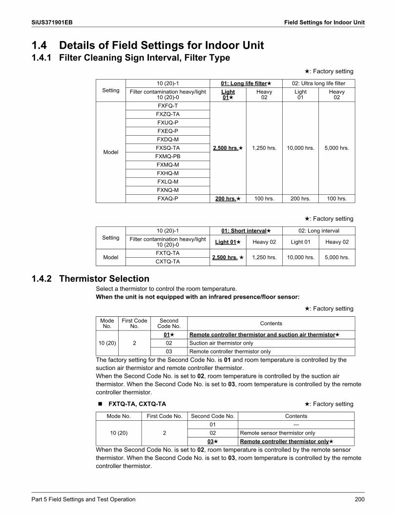
SiUS371901EB Field Settings for Indoor Unit
1.4 Details of Field Settings for Indoor Unit1.4.1 Filter Cleaning Sign Interval, Filter Type
1.4.2 Thermistor SelectionSelect a thermistor to control the room temperature.When the unit is not equipped with an infrared presence/floor sensor:
The factory setting for the Second Code No. is 01 and room temperature is controlled by the suction air thermistor and remote controller thermistor.When the Second Code No. is set to 02, room temperature is controlled by the suction air thermistor. When the Second Code No. is set to 03, room temperature is controlled by the remote controller thermistor.
When the Second Code No. is set to 02, room temperature is controlled by the remote sensor thermistor. When the Second Code No. is set to 03, room temperature is controlled by the remote controller thermistor.
: Factory setting
Setting10 (20)-1 01: Long life filter 02: Ultra long life filter
Filter contamination heavy/light10 (20)-0
Light01
Heavy02
Light01
Heavy02
Model
FXFQ-T
2,500 hrs. 1,250 hrs. 10,000 hrs. 5,000 hrs.
FXZQ-TAFXUQ-PFXEQ-PFXDQ-MFXSQ-TAFXMQ-PBFXMQ-MFXHQ-MFXLQ-MFXNQ-MFXAQ-P 200 hrs. 100 hrs. 200 hrs. 100 hrs.
: Factory setting
Setting10 (20)-1 01: Short interval 02: Long interval
Filter contamination heavy/light 10 (20)-0 Light 01 Heavy 02 Light 01 Heavy 02
ModelFXTQ-TA
2,500 hrs. 1,250 hrs. 10,000 hrs. 5,000 hrs.CXTQ-TA
: Factory setting
Mode No.
First Code No.
Second Code No. Contents
10 (20) 201 Remote controller thermistor and suction air thermistor02 Suction air thermistor only03 Remote controller thermistor only
FXTQ-TA, CXTQ-TA : Factory setting
Mode No. First Code No. Second Code No. Contents
10 (20) 201 —02 Remote sensor thermistor only
03 Remote controller thermistor only
Part 5 Field Settings and Test Operation 200
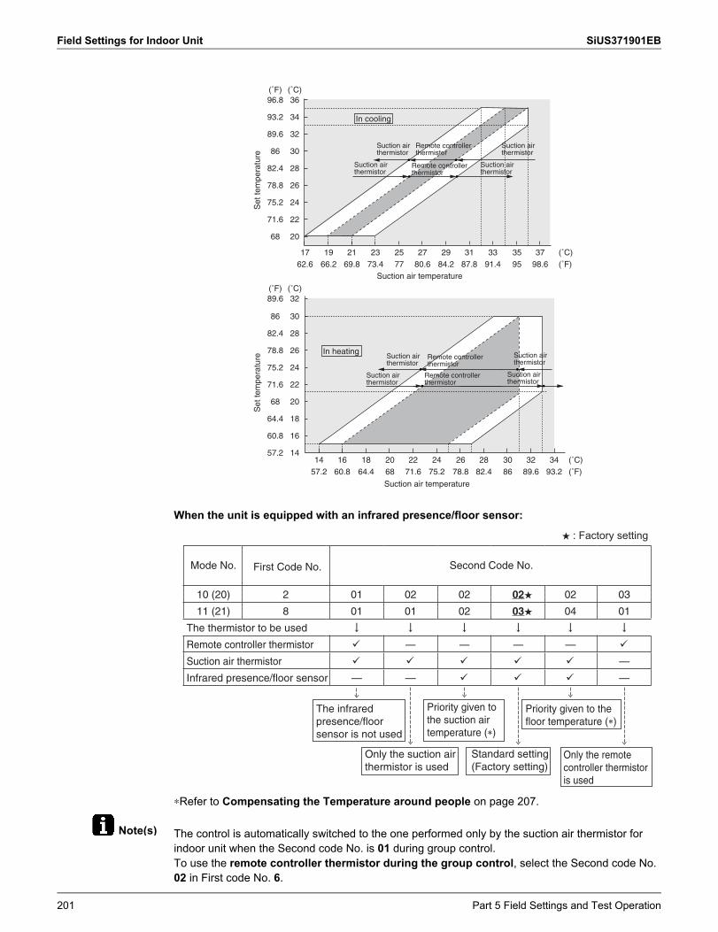
Field Settings for Indoor Unit SiUS371901EB
Note(s)
When the unit is equipped with an infrared presence/floor sensor:
∗Refer to Compensating the Temperature around people on page 207.
The control is automatically switched to the one performed only by the suction air thermistor for indoor unit when the Second code No. is 01 during group control.To use the remote controller thermistor during the group control, select the Second code No. 02 in First code No. 6.
20
22
24
26
28
30
32
34
36
211917 23 25 27 29 31 33 35 37 (˚C)
(˚C)14
16
18
20
22
24
26
28
30
32
(˚C)
(˚C)
68
71.6
75.2
78.8
82.4
86
89.6
93.2
96.8
57.2
60.8
64.4
68
71.6
75.2
78.8
82.4
86
89.6
(˚F)
(˚F)
14 16 18 20 22 24 26 28 30 32 34
66.262.6 69.8 73.4 77 80.6 84.2 87.8 91.4 95 98.6 (˚F)
(˚F)57.2 60.8 64.4 68 71.6 75.2 78.8 82.4 86 89.6 93.2
In cooling
In heating
Suction air temperature
Suction air temperature
Suction air thermistor
Suction air thermistor
Suction air thermistor
Suction air thermistor
Suction air thermistor
Suction air thermistor
Suction air thermistor
Suction air thermistor
Remote controller thermistor
Remote controller thermistor
Remote controller thermistor
Remote controller thermistor
Set
tem
pera
ture
Set
tem
pera
ture
Mode No. Second Code No.
10 (20) 2 01 02 02 02★ 02 03
11 (21) 8 01 01 02 03★ 04 01
The thermistor to be used
Remote controller thermistor � — — — — �
Suction air thermistor � � � � � —
Infrared presence/floor sensor — — � � � —
First Code No.
The infrared presence/floor sensor is not used
Priority given to the suction air temperature (�)
Priority given to the floor temperature (�)
Only the suction air thermistor is used
Standard setting (Factory setting)
Only the remote controller thermistor is used
★�: Factory setting
201 Part 5 Field Settings and Test Operation
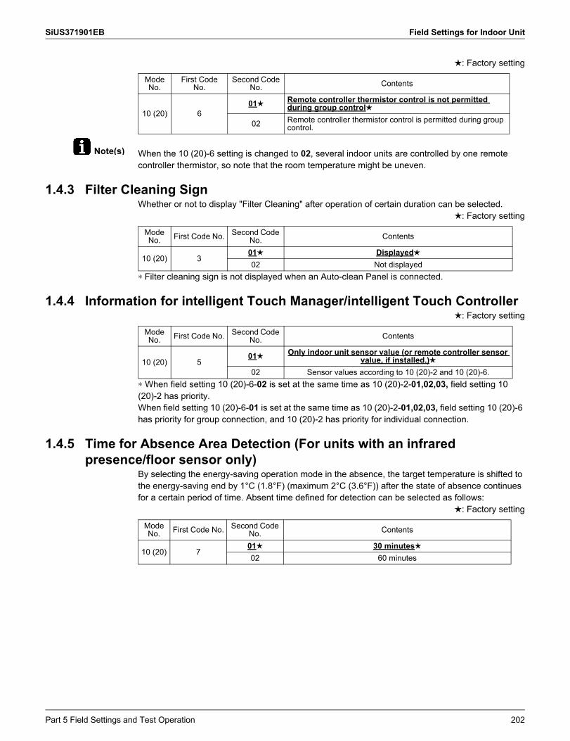
SiUS371901EB Field Settings for Indoor Unit
Note(s)
: Factory setting
When the 10 (20)-6 setting is changed to 02, several indoor units are controlled by one remote controller thermistor, so note that the room temperature might be uneven.
1.4.3 Filter Cleaning SignWhether or not to display "Filter Cleaning" after operation of certain duration can be selected.
: Factory setting
∗ Filter cleaning sign is not displayed when an Auto-clean Panel is connected.
1.4.4 Information for intelligent Touch Manager/intelligent Touch Controller: Factory setting
∗ When field setting 10 (20)-6-02 is set at the same time as 10 (20)-2-01,02,03, field setting 10 (20)-2 has priority.When field setting 10 (20)-6-01 is set at the same time as 10 (20)-2-01,02,03, field setting 10 (20)-6 has priority for group connection, and 10 (20)-2 has priority for individual connection.
1.4.5 Time for Absence Area Detection (For units with an infrared presence/floor sensor only)
By selecting the energy-saving operation mode in the absence, the target temperature is shifted to the energy-saving end by 1°C (1.8°F) (maximum 2°C (3.6°F)) after the state of absence continues for a certain period of time. Absent time defined for detection can be selected as follows:
: Factory setting
Mode No.
First Code No.
Second Code No. Contents
10 (20) 601 Remote controller thermistor control is not permitted
during group control
02 Remote controller thermistor control is permitted during group control.
Mode No. First Code No. Second Code
No. Contents
10 (20) 301 Displayed02 Not displayed
Mode No. First Code No. Second Code
No. Contents
10 (20) 501 Only indoor unit sensor value (or remote controller sensor
value, if installed.)02 Sensor values according to 10 (20)-2 and 10 (20)-6.
Mode No. First Code No. Second Code
No. Contents
10 (20) 701 30 minutes02 60 minutes
Part 5 Field Settings and Test Operation 202
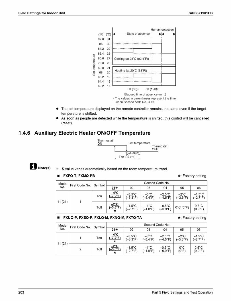
Field Settings for Indoor Unit SiUS371901EB
Note(s)
The set temperature displayed on the remote controller remains the same even if the target temperature is shifted.
As soon as people are detected while the temperature is shifted, this control will be cancelled (reset).
1.4.6 Auxiliary Electric Heater ON/OFF Temperature
∗1. S value varies automatically based on the room temperature trend.
31
(˚C)
19
28
27
26
17
21
30
29
20
18
87.8
(˚F)
66.2
82.4
80.6
78.8
62.2
69.8
86
84.2
68
64.4
Set
tem
pera
ture
Human detection
Cooling (at 28˚C (82.4˚F))
Heating (at 20˚C (68˚F))
State of absence
30 (60)∗ 60 (120)∗
Elapsed time of absence (min.)∗ The values in parentheses represent the time
when Second code No. is 02.
Set temperature
Toff + S (∗1)Ton + S (∗1)
Thermostat OFF
Thermostat ON
FXFQ-T, FXMQ-PB : Factory setting
Mode No. First Code No. Symbol
Second Code No.01 02 03 04 05 06
11 (21) 1
Ton–4°C
(–7.2°F)
–3.5°C(–6.3°F)
–3°C(–5.4°F)
–2.5°C(–4.5°F)
–2°C(–3.6°F)
–1.5°C(–2.7°F)
Toff–2°C
(–3.6°F)
–1.5°C(–2.7°F)
–1°C(–1.8°F)
–0.5°C(–0.9°F) 0°C (0°F) 0.5°C
(0.9°F)
FXUQ-P, FXEQ-P, FXLQ-M, FXNQ-M, FXTQ-TA : Factory setting
Mode No. First Code No. Symbol
Second Code No.01 02 03 04 05 06
11 (21)
1 Ton–4°C
(–7.2°F)
–3.5°C(–6.3°F)
–3°C(–5.4°F)
–2.5°C(–4.5°F)
–2°C(–3.6°F)
–1.5°C(–2.7°F)
2 Toff–2°C
(–3.6°F)
–1.5°C(–2.7°F)
–1°C(–1.8°F)
–0.5°C(–0.9°F)
0°C (0°F)
0.5°C (0.9°F)
203 Part 5 Field Settings and Test Operation
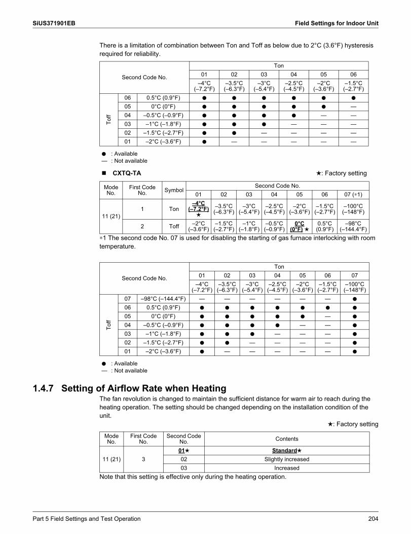
SiUS371901EB Field Settings for Indoor Unit
There is a limitation of combination between Ton and Toff as below due to 2°C (3.6°F) hysteresis required for reliability.
∗1 The second code No. 07 is used for disabling the starting of gas furnace interlocking with room temperature.
1.4.7 Setting of Airflow Rate when HeatingThe fan revolution is changed to maintain the sufficient distance for warm air to reach during the heating operation. The setting should be changed depending on the installation condition of the unit.
: Factory setting
Note that this setting is effective only during the heating operation.
Second Code No.
Ton01 02 03 04 05 06
–4°C(–7.2°F)
–3.5°C(–6.3°F)
–3°C(–5.4°F)
–2.5°C(–4.5°F)
–2°C(–3.6°F)
–1.5°C(–2.7°F)
Toff
06 0.5°C (0.9°F) h h h h h h
05 0°C (0°F) h h h h h —04 –0.5°C (–0.9°F) h h h h — —03 –1°C (–1.8°F) h h h — — —02 –1.5°C (–2.7°F) h h — — — —01 –2°C (–3.6°F) h — — — — —
h—
: Available: Not available
CXTQ-TA : Factory setting
Mode No.
First Code No. Symbol
Second Code No.01 02 03 04 05 06 07 (∗1)
11 (21)1 Ton
–4°C(–7.2°F)
–3.5°C (–6.3°F)
–3°C(–5.4°F)
–2.5°C(–4.5°F)
–2°C(–3.6°F)
–1.5°C (–2.7°F)
–100°C(–148°F)
2 Toff –2°C(–3.6°F)
–1.5°C(–2.7°F)
–1°C(–1.8°F)
–0.5°C(–0.9°F)
0°C(0°F)
0.5°C(0.9°F)
–98°C(–144.4°F)
Second Code No.
Ton01 02 03 04 05 06 07
–4°C(–7.2°F)
–3.5°C(–6.3°F)
–3°C(–5.4°F)
–2.5°C(–4.5°F)
–2°C(–3.6°F)
–1.5°C(–2.7°F)
–100°C(–148°F)
Toff
07 –98°C (–144.4°F) — — — — — — h
06 0.5°C (0.9°F) h h h h h h h
05 0°C (0°F) h h h h h — h
04 –0.5°C (–0.9°F) h h h h — — h
03 –1°C (–1.8°F) h h h — — — h
02 –1.5°C (–2.7°F) h h — — — — h
01 –2°C (–3.6°F) h — — — — — h
h—
: Available: Not available
Mode No.
First Code No.
Second Code No. Contents
11 (21) 301 Standard02 Slightly increased03 Increased
Part 5 Field Settings and Test Operation 204
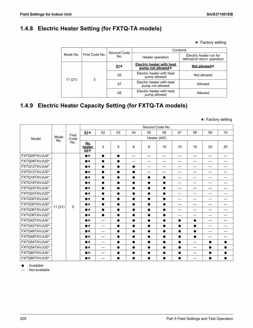
Field Settings for Indoor Unit SiUS371901EB
1.4.8 Electric Heater Setting (for FXTQ-TA models)
1.4.9 Electric Heater Capacity Setting (for FXTQ-TA models)
: Factory setting
Mode No. First Code No. Second Code No.
Contents
Heater operation Electric heater run for defrost/oil return operation
11 (21) 3
01 Electric heater with heat pump not allowed Not allowed
02 Electric heater with heat pump allowed Not allowed
07 Electric heater with heat pump not allowed Allowed
08 Electric heater with heat pump allowed Allowed
: Factory setting
Model Mode No.
First Code No.
Second Code No.01 02 03 04 05 06 07 08 09 10
Heater (kW)No
heater kit
3 5 6 8 10 15 19 20 25
FXTQ09TAVJUA*
11 (21) 5
h h h — — — — — — —FXTQ09TAVJUD* h h h — — — — — — —FXTQ12TAVJUA* h h h h — — — — — —FXTQ12TAVJUD* h h h h — — — — — —FXTQ18TAVJUA* h h h h h h — — — —FXTQ18TAVJUD* h h h h h h — — — —FXTQ24TAVJUA* h h h h h h — — — —FXTQ24TAVJUD* h h h h h h — — — —FXTQ30TAVJUA* h h h h h h — — — —FXTQ30TAVJUD* h h h h h h — — — —FXTQ36TAVJUA* h h h h h h — — — —FXTQ36TAVJUD* h h h h h h — — — —FXTQ42TAVJUA* h — h h h h h h — —FXTQ42TAVJUD* h — h h h h h h — —FXTQ48TAVJUA* h — h h h h h h — —FXTQ48TAVJUD* h — h h h h h h — —FXTQ54TAVJUA* h — h h h h h — h h
FXTQ54TAVJUD* h — h h h h h — h h
FXTQ60TAVJUA* h — h h h h h — h h
FXTQ60TAVJUD* h — h h h h h — h h
h—
: Available: Not available
205 Part 5 Field Settings and Test Operation
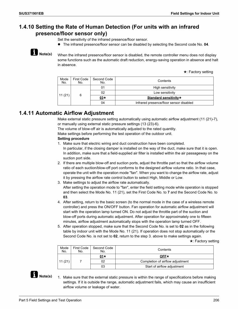
SiUS371901EB Field Settings for Indoor Unit
Note(s)
Note(s)
1.4.10 Setting the Rate of Human Detection (For units with an infrared presence/floor sensor only)
Set the sensitivity of the infrared presence/floor sensor. The infrared presence/floor sensor can be disabled by selecting the Second code No. 04.
When the infrared presence/floor sensor is disabled, the remote controller menu does not display some functions such as the automatic draft reduction, energy-saving operation in absence and halt in absence.
1.4.11 Automatic Airflow AdjustmentMake external static pressure setting automatically using automatic airflow adjustment (11 (21)-7), or manually using external static pressure settings (13 (23)-6).The volume of blow-off air is automatically adjusted to the rated quantity.Make settings before performing the test operation of the outdoor unit.Setting procedure1. Make sure that electric wiring and duct construction have been completed.
In particular, if the closing damper is installed on the way of the duct, make sure that it is open. In addition, make sure that a field-supplied air filter is installed within the air passageway on the suction port side.
2. If there are multiple blow-off and suction ports, adjust the throttle part so that the airflow volume ratio of each suction/blow-off port conforms to the designed airflow volume ratio. In that case, operate the unit with the operation mode "fan". When you want to change the airflow rate, adjust it by pressing the airflow rate control button to select High, Middle or Low.
3. Make settings to adjust the airflow rate automatically. After setting the operation mode to "fan", enter the field setting mode while operation is stopped and then select the Mode No. 11 (21), set the First Code No. to 7 and the Second Code No. to 03.
4. After setting, return to the basic screen (to the normal mode in the case of a wireless remote controller) and press the ON/OFF button. Fan operation for automatic airflow adjustment will start with the operation lamp turned ON. Do not adjust the throttle part of the suction and blow-off ports during automatic adjustment. After operation for approximately one to fifteen minutes, airflow adjustment automatically stops with the operation lamp turned OFF.
5. After operation stopped, make sure that the Second Code No. is set to 02 as in the following table by indoor unit with the Mode No. 11 (21). If operation does not stop automatically or the Second Code No. is not set to 02, return to the step 3. above to make settings again.
: Factory setting
1. Make sure that the external static pressure is within the range of specifications before making settings. If it is outside the range, automatic adjustment fails, which may cause an insufficient airflow volume or leakage of water.
: Factory setting
Mode No.
First Code No.
Second Code No. Contents
11 (21) 6
01 High sensitivity02 Low sensitivity
03 Standard sensitivity04 Infrared presence/floor sensor disabled
Mode No.
First Code No.
Second Code No. Contents
11 (21) 701 OFF02 Completion of airflow adjustment03 Start of airflow adjustment
Part 5 Field Settings and Test Operation 206
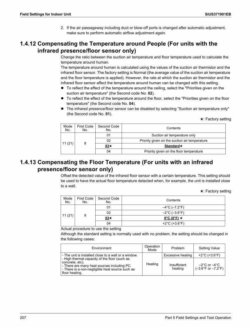
Field Settings for Indoor Unit SiUS371901EB
2. If the air passageway including duct or blow-off ports is changed after automatic adjustment, make sure to perform automatic airflow adjustment again.
1.4.12 Compensating the Temperature around People (For units with the infrared presence/floor sensor only)
Change the ratio between the suction air temperature and floor temperature used to calculate the temperature around human.The temperature around human is calculated using the values of the suction air thermistor and the infrared floor sensor. The factory setting is Normal (the average value of the suction air temperature and the floor temperature is applied). However, the rate at which the suction air thermistor and the infrared floor sensor affect the temperature around human can be changed with this setting. To reflect the effect of the temperature around the ceiling, select the "Priorities given on the
suction air temperature" (the Second code No. 02). To reflect the effect of the temperature around the floor, select the "Priorities given on the floor
temperature" (the Second code No. 04). The infrared presence/floor sensor can be disabled by selecting "Suction air temperature only"
(the Second code No. 01).: Factory setting
1.4.13 Compensating the Floor Temperature (For units with an infrared presence/floor sensor only)
Offset the detected value of the infrared floor sensor with a certain temperature. This setting should be used to have the actual floor temperature detected when, for example, the unit is installed close to a wall.
: Factory setting
Actual procedure to use the settingAlthough the standard setting is normally used with no problem, the setting should be changed in the following cases:
Mode No.
First Code No.
Second Code No. Contents
11 (21) 8
01 Suction air temperature only02 Priority given on the suction air temperature
03 Standard04 Priority given on the floor temperature
Mode No.
First Code No.
Second Code No. Contents
11 (21) 9
01 –4°C (–7.2°F)02 –2°C (–3.6°F)
03 0°C (0°F)04 +2°C (+3.6°F)
Environment Operation Mode Problem Setting Value
- The unit is installed close to a wall or a window.- High thermal capacity of the floor (such asconcrete, etc).- There are many heat sources including PC.- There is a non-negligible heat source such as floor heating.
Heating
Excessive heating +2°C (+3.6°F)
Insufficient heating
–2°C or –4°C(–3.6°F or –7.2°F)
207 Part 5 Field Settings and Test Operation
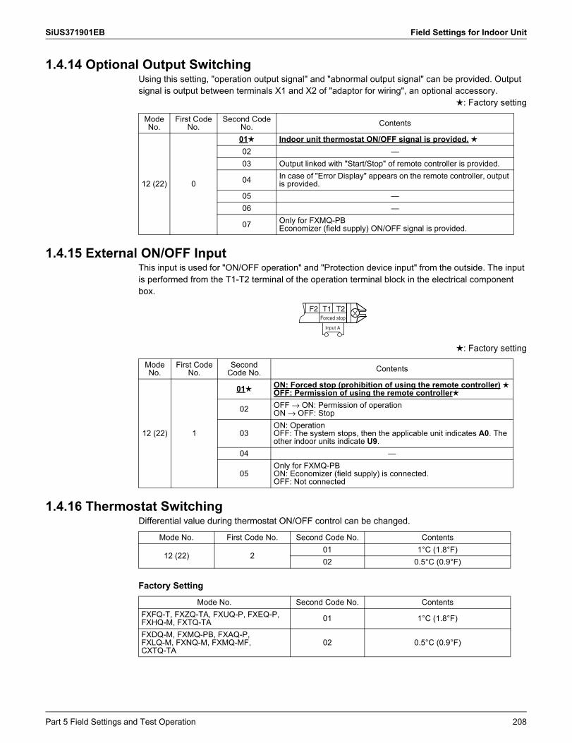
SiUS371901EB Field Settings for Indoor Unit
1.4.14 Optional Output SwitchingUsing this setting, "operation output signal" and "abnormal output signal" can be provided. Output signal is output between terminals X1 and X2 of "adaptor for wiring", an optional accessory.
: Factory setting
1.4.15 External ON/OFF InputThis input is used for "ON/OFF operation" and "Protection device input" from the outside. The input is performed from the T1-T2 terminal of the operation terminal block in the electrical component box.
: Factory setting
1.4.16 Thermostat SwitchingDifferential value during thermostat ON/OFF control can be changed.
Factory Setting
Mode No.
First Code No.
Second Code No. Contents
12 (22) 0
01 Indoor unit thermostat ON/OFF signal is provided.02 —03 Output linked with "Start/Stop" of remote controller is provided.
04 In case of "Error Display" appears on the remote controller, output is provided.
05 —06 —
07 Only for FXMQ-PBEconomizer (field supply) ON/OFF signal is provided.
Mode No.
First Code No.
Second Code No. Contents
12 (22) 1
01 ON: Forced stop (prohibition of using the remote controller)OFF: Permission of using the remote controller
02 OFF → ON: Permission of operationON → OFF: Stop
03ON: OperationOFF: The system stops, then the applicable unit indicates A0. The other indoor units indicate U9.
04 —
05Only for FXMQ-PBON: Economizer (field supply) is connected.OFF: Not connected
F2 T1 T2Forced stop
Input A
Mode No. First Code No. Second Code No. Contents
12 (22) 201 1°C (1.8°F)02 0.5°C (0.9°F)
Mode No. Second Code No. ContentsFXFQ-T, FXZQ-TA, FXUQ-P, FXEQ-P, FXHQ-M, FXTQ-TA 01 1°C (1.8°F)
FXDQ-M, FXMQ-PB, FXAQ-P,FXLQ-M, FXNQ-M, FXMQ-MF, CXTQ-TA
02 0.5°C (0.9°F)
Part 5 Field Settings and Test Operation 208
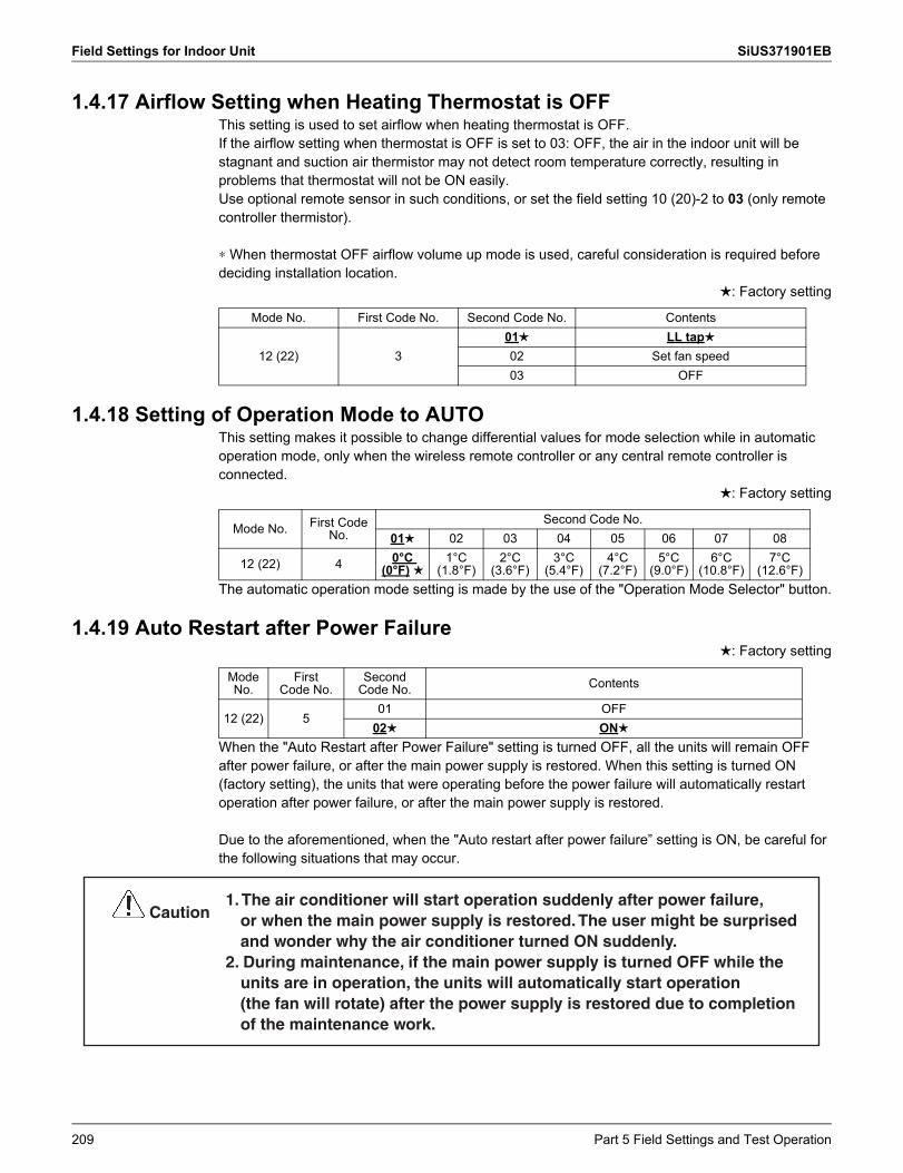
Field Settings for Indoor Unit SiUS371901EB
1.4.17 Airflow Setting when Heating Thermostat is OFFThis setting is used to set airflow when heating thermostat is OFF.If the airflow setting when thermostat is OFF is set to 03: OFF, the air in the indoor unit will be stagnant and suction air thermistor may not detect room temperature correctly, resulting in problems that thermostat will not be ON easily. Use optional remote sensor in such conditions, or set the field setting 10 (20)-2 to 03 (only remote controller thermistor).
∗ When thermostat OFF airflow volume up mode is used, careful consideration is required before deciding installation location.
: Factory setting
1.4.18 Setting of Operation Mode to AUTOThis setting makes it possible to change differential values for mode selection while in automatic operation mode, only when the wireless remote controller or any central remote controller is connected.
: Factory setting
The automatic operation mode setting is made by the use of the "Operation Mode Selector" button.
1.4.19 Auto Restart after Power Failure: Factory setting
When the "Auto Restart after Power Failure" setting is turned OFF, all the units will remain OFF after power failure, or after the main power supply is restored. When this setting is turned ON (factory setting), the units that were operating before the power failure will automatically restart operation after power failure, or after the main power supply is restored.
Due to the aforementioned, when the "Auto restart after power failure” setting is ON, be careful for the following situations that may occur.
Mode No. First Code No. Second Code No. Contents
12 (22) 301 LL tap02 Set fan speed03 OFF
Mode No. First Code No.
Second Code No.01 02 03 04 05 06 07 08
12 (22) 4 0°C (0°F)
1°C (1.8°F)
2°C (3.6°F)
3°C (5.4°F)
4°C (7.2°F)
5°C (9.0°F)
6°C (10.8°F)
7°C (12.6°F)
Mode No.
FirstCode No.
Second Code No. Contents
12 (22) 501 OFF
02 ON
1. The air conditioner will start operation suddenly after power failure, or when the main power supply is restored. The user might be surprised and wonder why the air conditioner turned ON suddenly.
2. During maintenance, if the main power supply is turned OFF while the units are in operation, the units will automatically start operation (the fan will rotate) after the power supply is restored due to completion of the maintenance work.
Caution
209 Part 5 Field Settings and Test Operation
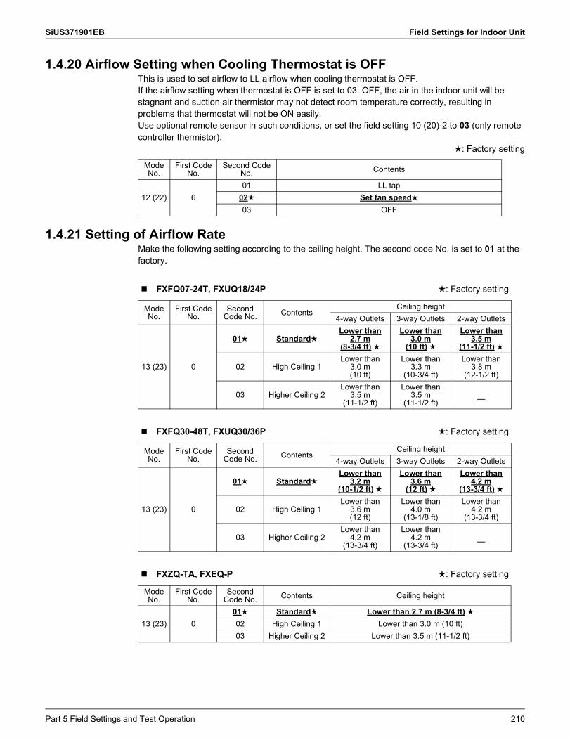
SiUS371901EB Field Settings for Indoor Unit
1.4.20 Airflow Setting when Cooling Thermostat is OFFThis is used to set airflow to LL airflow when cooling thermostat is OFF.If the airflow setting when thermostat is OFF is set to 03: OFF, the air in the indoor unit will be stagnant and suction air thermistor may not detect room temperature correctly, resulting in problems that thermostat will not be ON easily.Use optional remote sensor in such conditions, or set the field setting 10 (20)-2 to 03 (only remote controller thermistor).
: Factory setting
1.4.21 Setting of Airflow RateMake the following setting according to the ceiling height. The second code No. is set to 01 at the factory.
Mode No.
First Code No.
Second Code No. Contents
12 (22) 601 LL tap
02 Set fan speed03 OFF
FXFQ07-24T, FXUQ18/24P : Factory setting
Mode No.
First Code No.
SecondCode No. Contents
Ceiling height4-way Outlets 3-way Outlets 2-way Outlets
13 (23) 0
01 StandardLower than
2.7 m(8-3/4 ft)
Lower than3.0 m
(10 ft)
Lower than3.5 m
(11-1/2 ft)
02 High Ceiling 1Lower than
3.0 m(10 ft)
Lower than3.3 m
(10-3/4 ft)
Lower than3.8 m
(12-1/2 ft)
03 Higher Ceiling 2Lower than
3.5 m(11-1/2 ft)
Lower than3.5 m
(11-1/2 ft) —
FXFQ30-48T, FXUQ30/36P : Factory setting
Mode No.
First Code No.
SecondCode No. Contents
Ceiling height4-way Outlets 3-way Outlets 2-way Outlets
13 (23) 0
01 StandardLower than
3.2 m(10-1/2 ft)
Lower than3.6 m
(12 ft)
Lower than4.2 m
(13-3/4 ft)
02 High Ceiling 1Lower than
3.6 m(12 ft)
Lower than4.0 m
(13-1/8 ft)
Lower than4.2 m
(13-3/4 ft)
03 Higher Ceiling 2Lower than
4.2 m(13-3/4 ft)
Lower than4.2 m
(13-3/4 ft) —
FXZQ-TA, FXEQ-P : Factory setting
Mode No.
First Code No.
SecondCode No. Contents Ceiling height
13 (23) 001 Standard Lower than 2.7 m (8-3/4 ft)02 High Ceiling 1 Lower than 3.0 m (10 ft)03 Higher Ceiling 2 Lower than 3.5 m (11-1/2 ft)
Part 5 Field Settings and Test Operation 210
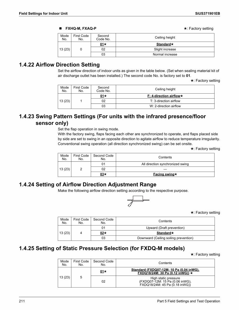
Field Settings for Indoor Unit SiUS371901EB
1.4.22 Airflow Direction SettingSet the airflow direction of indoor units as given in the table below. (Set when sealing material kit of air discharge outlet has been installed.) The second code No. is factory set to 01.
: Factory setting
1.4.23 Swing Pattern Settings (For units with the infrared presence/floor sensor only)
Set the flap operation in swing mode.With the factory swing, flaps facing each other are synchronized to operate, and flaps placed side by side are set to swing in an opposite direction to agitate airflow to reduce temperature irregularity.Conventional swing operation (all direction synchronized swing) can be set onsite.
: Factory setting
1.4.24 Setting of Airflow Direction Adjustment RangeMake the following airflow direction setting according to the respective purpose.
: Factory setting
1.4.25 Setting of Static Pressure Selection (for FXDQ-M models): Factory setting
FXHQ-M, FXAQ-P : Factory setting
Mode No.
First Code No.
SecondCode No. Ceiling height
13 (23) 001 Standard02 Slight increase03 Normal increase
Mode No.
First Code No.
SecondCode No. Ceiling height
13 (23) 101 F: 4-direction airflow
02 T: 3-direction airflow03 W: 2-direction airflow
Mode No.
First Code No.
Second Code No. Contents
13 (23) 201 All direction synchronized swing02 —
03 Facing swing
Mode No.
First Code No.
Second Code No. Contents
13 (23) 401 Upward (Draft prevention)
02 Standard03 Downward (Ceiling soiling prevention)
Mode No.
First Code No.
Second Code No. Contents
13 (23) 5
01 Standard (FXDQ07-12M: 10 Pa (0.04 inWG),FXDQ18/24M: 30 Pa (0.12 inWG))
02High static pressure
(FXDQ07-12M: 15 Pa (0.06 inWG),FXDQ18/24M: 45 Pa (0.18 inWG))
211 Part 5 Field Settings and Test Operation
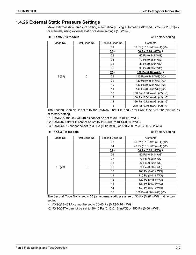
SiUS371901EB Field Settings for Indoor Unit
1.4.26 External Static Pressure SettingsMake external static pressure setting automatically using automatic airflow adjustment (11 (21)-7), or manually using external static pressure settings (13 (23)-6).
The Second Code No. is set to 02 for FXMQ07/09/12PB, and 07 for FXMQ15/18/24/30/36/48/54PB at factory setting.∗1. FXMQ15/18/24/30/36/48PB cannot be set to 30 Pa (0.12 inWG).∗2. FXMQ07/09/12PB cannot be set to 110-200 Pa (0.44-0.80 inWG).∗3. FXMQ54PB cannot be set to 30 Pa (0.12 inWG) or 150-200 Pa (0.60-0.80 inWG).
The Second Code No. is set to 05 (an external static pressure of 50 Pa (0.20 inWG)) at factory setting.∗1. FXSQ18-48TA cannot be set to 30-40 Pa (0.12-0.16 inWG).∗2. FXSQ54TA cannot be set to 30-40 Pa (0.12-0.16 inWG) or 150 Pa (0.60 inWG).
FXMQ-PB models : Factory setting
Mode No. First Code No. Second Code No. Contents
13 (23) 6
01 30 Pa (0.12 inWG) (∗1) (∗3)02 50 Pa (0.20 inWG)03 60 Pa (0.24 inWG)04 70 Pa (0.28 inWG)05 80 Pa (0.32 inWG)06 90 Pa (0.36 inWG)
07 100 Pa (0.40 inWG)08 110 Pa (0.44 inWG) (∗2)09 120 Pa (0.48 inWG) (∗2)10 130 Pa (0.52 inWG) (∗2)11 140 Pa (0.56 inWG) (∗2)12 150 Pa (0.60 inWG) (∗2) (∗3)13 160 Pa (0.64 inWG) (∗2) (∗3)14 180 Pa (0.72 inWG) (∗2) (∗3)15 200 Pa (0.80 inWG) (∗2) (∗3)
FXSQ-TA models : Factory setting
Mode No. First Code No. Second Code No. Contents
13 (23) 6
03 30 Pa (0.12 inWG) (∗1) (∗2)04 40 Pa (0.16 inWG) (∗1) (∗2)
05 50 Pa (0.20 inWG)06 60 Pa (0.24 inWG)07 70 Pa (0.28 inWG)08 80 Pa (0.32 inWG)09 90 Pa (0.36 inWG)10 100 Pa (0.40 inWG)11 110 Pa (0.44 inWG)12 120 Pa (0.48 inWG)13 130 Pa (0.52 inWG)14 140 Pa (0.56 inWG)15 150 Pa (0.60 inWG) (∗2)
Part 5 Field Settings and Test Operation 212
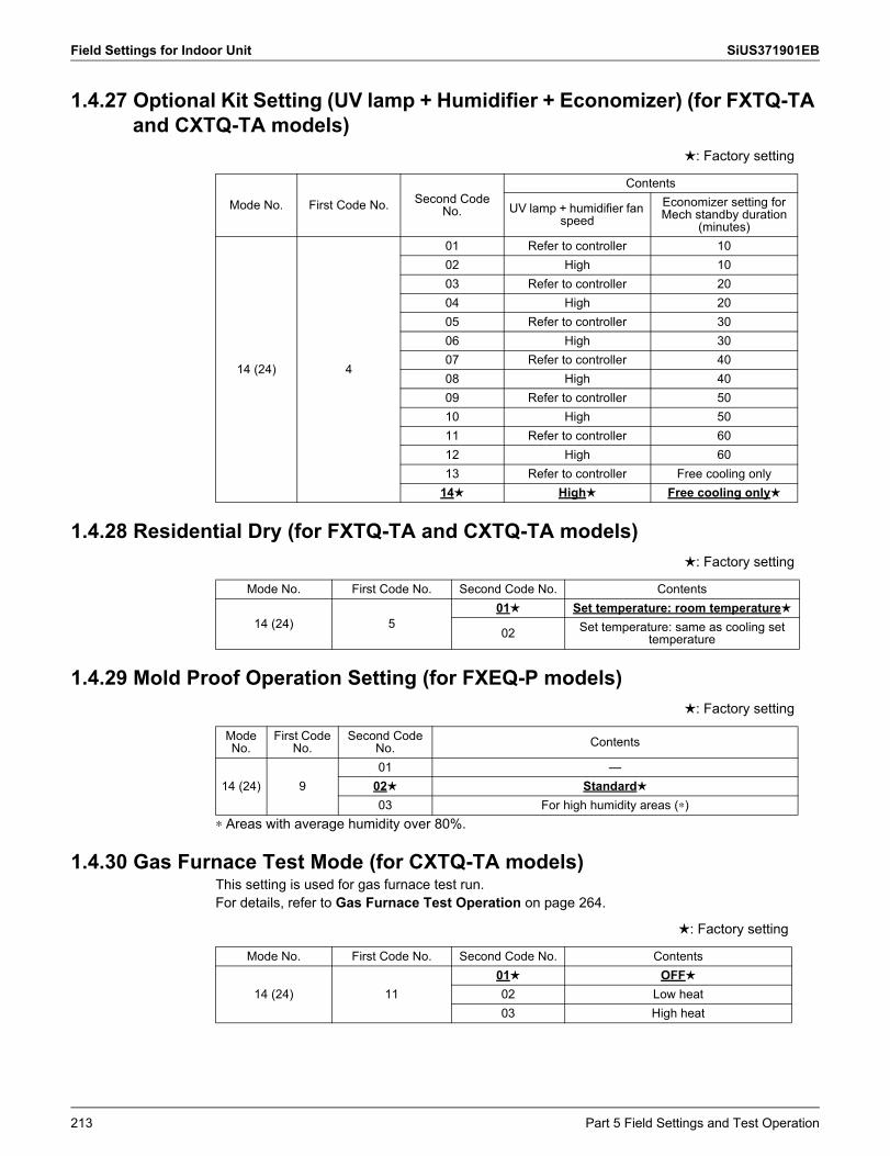
Field Settings for Indoor Unit SiUS371901EB
1.4.27 Optional Kit Setting (UV lamp + Humidifier + Economizer) (for FXTQ-TA and CXTQ-TA models)
1.4.28 Residential Dry (for FXTQ-TA and CXTQ-TA models)
1.4.29 Mold Proof Operation Setting (for FXEQ-P models)
∗ Areas with average humidity over 80%.
1.4.30 Gas Furnace Test Mode (for CXTQ-TA models)This setting is used for gas furnace test run.For details, refer to Gas Furnace Test Operation on page 264.
: Factory setting
Mode No. First Code No. Second Code No.
Contents
UV lamp + humidifier fan speed
Economizer setting for Mech standby duration
(minutes)
14 (24) 4
01 Refer to controller 1002 High 1003 Refer to controller 2004 High 2005 Refer to controller 3006 High 3007 Refer to controller 4008 High 4009 Refer to controller 5010 High 5011 Refer to controller 6012 High 6013 Refer to controller Free cooling only
14 High Free cooling only
: Factory setting
Mode No. First Code No. Second Code No. Contents
14 (24) 501 Set temperature: room temperature
02 Set temperature: same as cooling set temperature
: Factory setting
Mode No.
First Code No.
Second Code No. Contents
14 (24) 901 —
02 Standard03 For high humidity areas (∗)
: Factory setting
Mode No. First Code No. Second Code No. Contents
14 (24) 1101 OFF02 Low heat03 High heat
213 Part 5 Field Settings and Test Operation
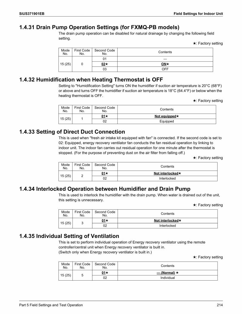
SiUS371901EB Field Settings for Indoor Unit
1.4.31 Drain Pump Operation Settings (for FXMQ-PB models)The drain pump operation can be disabled for natural drainage by changing the following field setting.
: Factory setting
1.4.32 Humidification when Heating Thermostat is OFFSetting to "Humidification Setting" turns ON the humidifier if suction air temperature is 20°C (68°F) or above and turns OFF the humidifier if suction air temperature is 18°C (64.4°F) or below when the heating thermostat is OFF.
: Factory setting
1.4.33 Setting of Direct Duct ConnectionThis is used when "fresh air intake kit equipped with fan" is connected. If the second code is set to 02: Equipped, energy recovery ventilator fan conducts the fan residual operation by linking to indoor unit. The indoor fan carries out residual operation for one minute after the thermostat is stopped. (For the purpose of preventing dust on the air filter from falling off.)
: Factory setting
1.4.34 Interlocked Operation between Humidifier and Drain PumpThis is used to interlock the humidifier with the drain pump. When water is drained out of the unit, this setting is unnecessary.
: Factory setting
1.4.35 Individual Setting of VentilationThis is set to perform individual operation of Energy recovery ventilator using the remote controller/central unit when Energy recovery ventilator is built in.(Switch only when Energy recovery ventilator is built in.)
: Factory setting
Mode No.
First Code No.
Second Code No. Contents
15 (25) 001 —
02 ON
03 OFF
Mode No.
First Code No.
Second Code No. Contents
15 (25) 101 Not equipped02 Equipped
Mode No.
First Code No.
Second Code No. Contents
15 (25) 201 Not interlocked02 Interlocked
Mode No.
First Code No.
Second Code No. Contents
15 (25) 301 Not interlocked02 Interlocked
Mode No.
First Code No.
Second Code No. Contents
15 (25) 501 — (Normal)02 Individual
Part 5 Field Settings and Test Operation 214
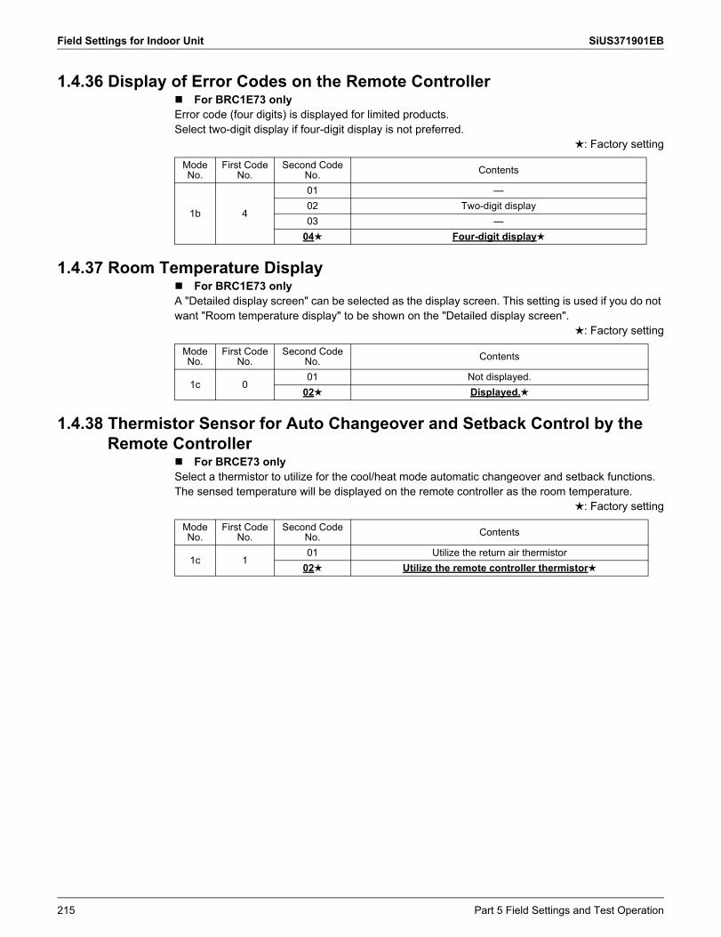
Field Settings for Indoor Unit SiUS371901EB
1.4.36 Display of Error Codes on the Remote ControllerFor BRC1E73 onlyError code (four digits) is displayed for limited products.Select two-digit display if four-digit display is not preferred.
: Factory setting
1.4.37 Room Temperature DisplayFor BRC1E73 onlyA "Detailed display screen" can be selected as the display screen. This setting is used if you do not want "Room temperature display" to be shown on the "Detailed display screen".
: Factory setting
1.4.38 Thermistor Sensor for Auto Changeover and Setback Control by the Remote Controller
For BRCE73 onlySelect a thermistor to utilize for the cool/heat mode automatic changeover and setback functions. The sensed temperature will be displayed on the remote controller as the room temperature.
: Factory setting
Mode No.
First Code No.
Second Code No. Contents
1b 4
01 —02 Two-digit display03 —
04 Four-digit display
Mode No.
First Code No.
Second Code No. Contents
1c 001 Not displayed.
02 Displayed.
Mode No.
First Code No.
Second Code No. Contents
1c 101 Utilize the return air thermistor
02 Utilize the remote controller thermistor
215 Part 5 Field Settings and Test Operation
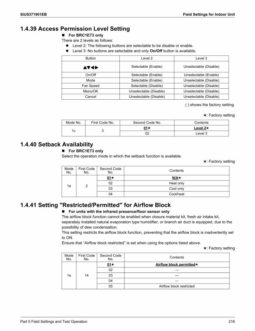
SiUS371901EB Field Settings for Indoor Unit
1.4.39 Access Permission Level Setting For BRC1E73 onlyThere are 2 levels as follows: Level 2: The following buttons are selectable to be disable or enable. Level 3: No buttons are selectable and only On/Off button is available.
( ) shows the factory setting.
: Factory setting
1.4.40 Setback AvailabilityFor BRC1E73 onlySelect the operation mode in which the setback function is available.
: Factory setting
1.4.41 Setting "Restricted/Permitted" for Airflow BlockFor units with the infrared presence/floor sensor onlyThe airflow block function cannot be enabled when closure material kit, fresh air intake kit, separately installed natural evaporation type humidifier, or branch air duct is equipped, due to the possibility of dew condensation.This setting restricts the airflow block function, preventing that the airflow block is inadvertently set to ON.Ensure that “Airflow block restricted” is set when using the options listed above.
: Factory setting
Button Level 2 Level 3
Selectable (Enable) Unselectable (Disable)
On/Off Selectable (Enable) Unselectable (Enable)Mode Selectable (Enable) Unselectable (Disable)
Fan Speed Selectable (Disable) Unselectable (Disable)Menu/OK Unselectable (Disable) Unselectable (Disable)
Cancel Unselectable (Disable) Unselectable (Disable)
Mode No. First Code No. Second Code No. Contents
1c 301 Level 202 Level 3
Mode No.
First Code No.
Second Code No. Contents
1e 2
01 N/A
02 Heat only03 Cool only04 Cool/heat
Mode No.
First Code No.
Second Code No. Contents
1e 14
01 Airflow block permitted02 —03 —04 —05 Airflow block restricted
Part 5 Field Settings and Test Operation 216
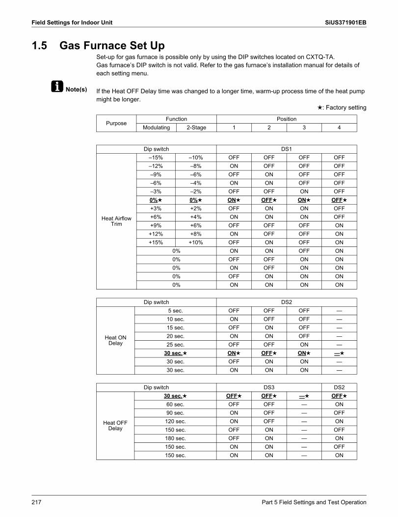
Field Settings for Indoor Unit SiUS371901EB
Note(s)
1.5 Gas Furnace Set UpSet-up for gas furnace is possible only by using the DIP switches located on CXTQ-TA.Gas furnace’s DIP switch is not valid. Refer to the gas furnace’s installation manual for details of each setting menu.
If the Heat OFF Delay time was changed to a longer time, warm-up process time of the heat pump might be longer.
: Factory setting
PurposeFunction Position
Modulating 2-Stage 1 2 3 4
Dip switch DS1
Heat Airflow Trim
–15% –10% OFF OFF OFF OFF–12% –8% ON OFF OFF OFF–9% –6% OFF ON OFF OFF–6% –4% ON ON OFF OFF–3% –2% OFF OFF ON OFF0% 0% ON OFF ON OFF+3% +2% OFF ON ON OFF+6% +4% ON ON ON OFF+9% +6% OFF OFF OFF ON
+12% +8% ON OFF OFF ON+15% +10% OFF ON OFF ON
0% ON ON OFF ON0% OFF OFF ON ON0% ON OFF ON ON0% OFF ON ON ON0% ON ON ON ON
Dip switch DS2
Heat ON Delay
5 sec. OFF OFF OFF —10 sec. ON OFF OFF —15 sec. OFF ON OFF —20 sec. ON ON OFF —25 sec. OFF OFF ON —
30 sec. ON OFF ON —
30 sec. OFF ON ON —30 sec. ON ON ON —
Dip switch DS3 DS2
Heat OFF Delay
30 sec. OFF OFF — OFF60 sec. OFF OFF — ON90 sec. ON OFF — OFF120 sec. ON OFF — ON150 sec. OFF ON — OFF180 sec. OFF ON — ON150 sec. ON ON — OFF150 sec. ON ON — ON
217 Part 5 Field Settings and Test Operation
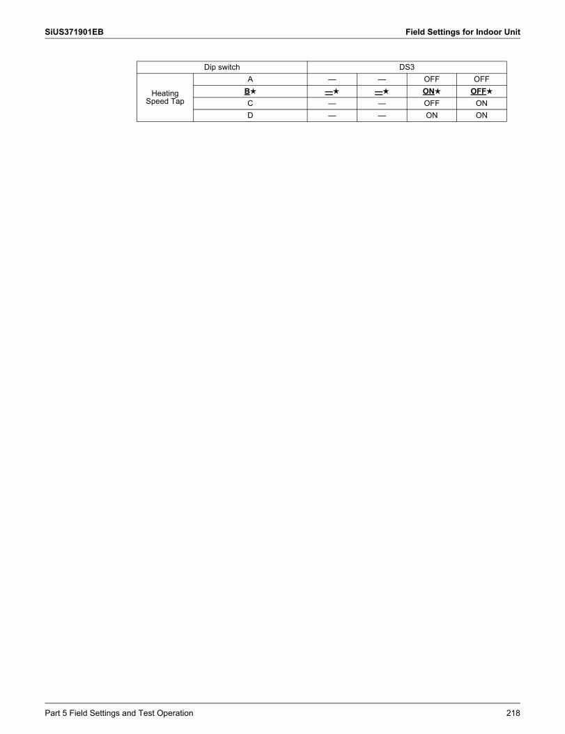
SiUS371901EB Field Settings for Indoor Unit
Dip switch DS3
Heating Speed Tap
A — — OFF OFFB — — ON OFFC — — OFF OND — — ON ON
Part 5 Field Settings and Test Operation 218
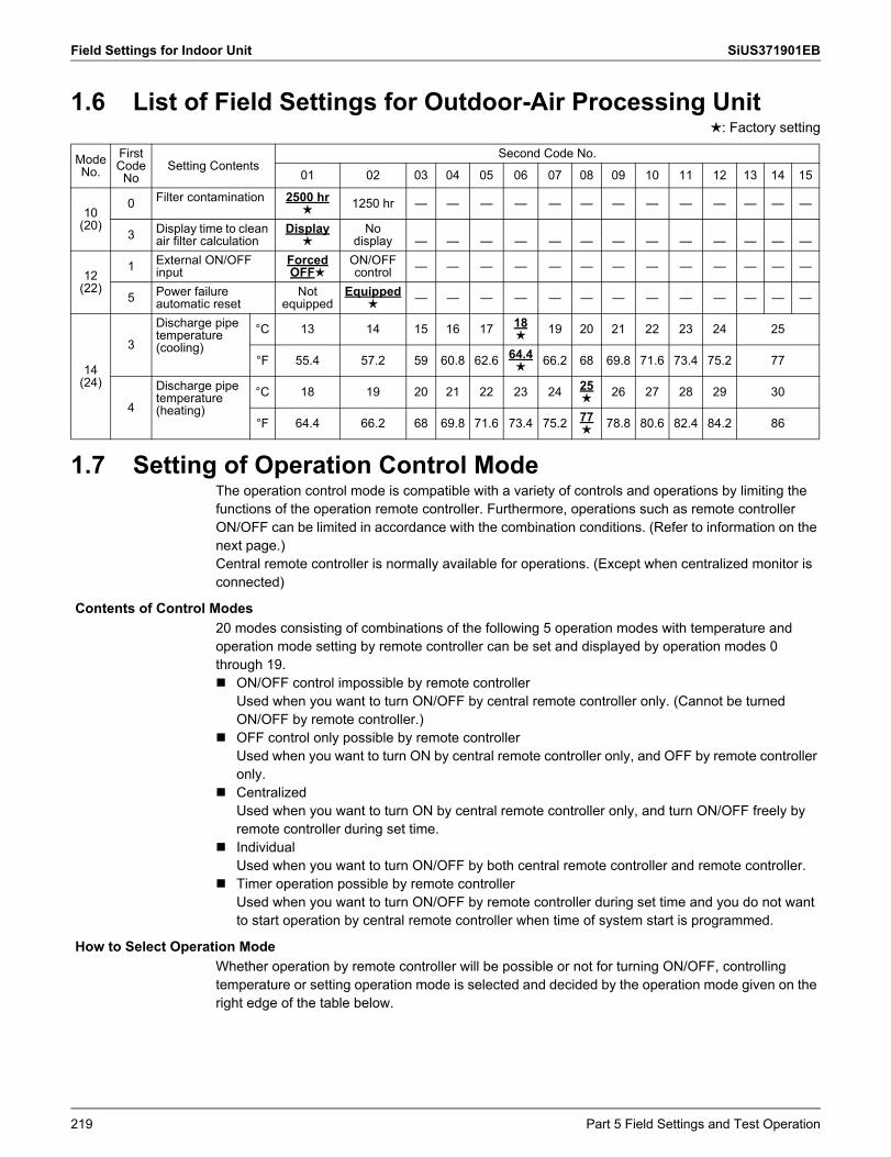
Field Settings for Indoor Unit SiUS371901EB
1.6 List of Field Settings for Outdoor-Air Processing Unit: Factory setting
1.7 Setting of Operation Control ModeThe operation control mode is compatible with a variety of controls and operations by limiting the functions of the operation remote controller. Furthermore, operations such as remote controller ON/OFF can be limited in accordance with the combination conditions. (Refer to information on the next page.)Central remote controller is normally available for operations. (Except when centralized monitor is connected)
20 modes consisting of combinations of the following 5 operation modes with temperature and operation mode setting by remote controller can be set and displayed by operation modes 0 through 19. ON/OFF control impossible by remote controller
Used when you want to turn ON/OFF by central remote controller only. (Cannot be turned ON/OFF by remote controller.)
OFF control only possible by remote controllerUsed when you want to turn ON by central remote controller only, and OFF by remote controller only.
CentralizedUsed when you want to turn ON by central remote controller only, and turn ON/OFF freely by remote controller during set time.
IndividualUsed when you want to turn ON/OFF by both central remote controller and remote controller.
Timer operation possible by remote controllerUsed when you want to turn ON/OFF by remote controller during set time and you do not want to start operation by central remote controller when time of system start is programmed.
Whether operation by remote controller will be possible or not for turning ON/OFF, controlling temperature or setting operation mode is selected and decided by the operation mode given on the right edge of the table below.
ModeNo.
FirstCode
NoSetting Contents
Second Code No.
01 02 03 04 05 06 07 08 09 10 11 12 13 14 15
10(20)
0 Filter contamination 2500 hr
1250 hr — — — — — — — — — — — — —
3 Display time to clean air filter calculation
Display
Nodisplay — — — — — — — — — — — — —
12(22)
1 External ON/OFF input
ForcedOFF
ON/OFFcontrol — — — — — — — — — — — — —
5 Power failure automatic reset
Notequipped
Equipped
— — — — — — — — — — — — —
14(24)
3
Discharge pipe temperature(cooling)
°C 13 14 15 16 17 18
19 20 21 22 23 24 25
°F 55.4 57.2 59 60.8 62.6 64.4 66.2 68 69.8 71.6 73.4 75.2 77
4
Discharge pipe temperature(heating)
°C 18 19 20 21 22 23 24 25
26 27 28 29 30
°F 64.4 66.2 68 69.8 71.6 73.4 75.2 77
78.8 80.6 82.4 84.2 86
Contents of Control Modes
How to Select Operation Mode
219 Part 5 Field Settings and Test Operation
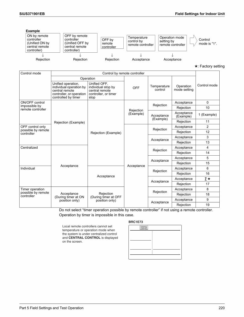
SiUS371901EB Field Settings for Indoor Unit
: Factory setting
Do not select “timer operation possible by remote controller” if not using a remote controller. Operation by timer is impossible in this case.
ON by remote controller (Unified ON by central remote controller)
OFF by remote controller (Unified OFF by central remote controller)
Temperature control by remote controller
Operation mode setting by remote controller
OFF by remote controller
Example
↓Rejection
↓Rejection
↓Rejection
↓Acceptance
↓Acceptance
Control mode is "1".
Control mode Control by remote controller
Control mode
Operation
OFF Temperature control
Operation mode setting
Unified operation, individual operation by central remote controller, or operation controlled by timer
Unified OFF, individual stop by central remote controller, or timer stop
ON/OFF control impossible by remote controller
Rejection (Example)
Rejection (Example)
Rejection (Example)
RejectionAcceptance 0Rejection 10
Acceptance (Example)
Acceptance (Example) 1 (Example)
Rejection 11OFF control only possible by remote controller
Acceptance
RejectionAcceptance 2Rejection 12
AcceptanceAcceptance 3Rejection 13
Centralized
Acceptance
RejectionAcceptance 4Rejection 14
AcceptanceAcceptance 5Rejection 15
Individual
AcceptanceRejection
Acceptance 6Rejection 16
AcceptanceAcceptance 7Rejection 17
Timer operation possible by remote controller
Acceptance(During timer at ON
position only)
Rejection(During timer at OFF
position only)
RejectionAcceptance 8Rejection 18
AcceptanceAcceptance 9Rejection 19
Local remote controllers cannot set temperature or operation mode when the system is under centralized control and CENTRAL CONTROL is displayed on the screen.
BRC1E73
Part 5 Field Settings and Test Operation 220
Field Setting from Outdoor Unit SiUS371901EB
2. Field Setting from Outdoor UnitTo continue the configuration of the VRV heat recovery system, it is required to give some input to the PCB of the unit. This chapter will describe how manual input is possible by operating the BS buttons/DIP switches on the PCB and reading the feedback from the 7 segment displays.For VRV heat recovery system it is alternatively possible to make several commissioning field setting through a personal computer interface (for this, option EKPCCAB1 is required). The installer can prepare the configuration (off-site) on PC and afterwards upload the configuration to the system.
221 Part 5 Field Settings and Test Operation
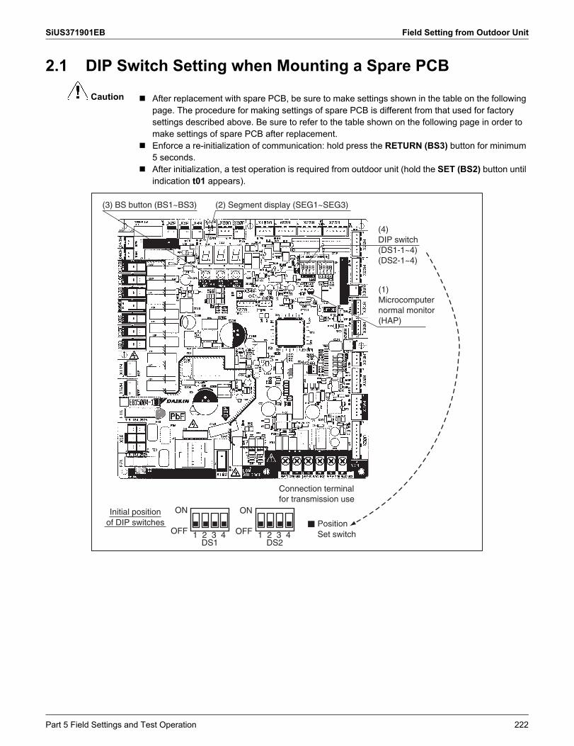
SiUS371901EB Field Setting from Outdoor Unit
Caution
2.1 DIP Switch Setting when Mounting a Spare PCB
After replacement with spare PCB, be sure to make settings shown in the table on the following page. The procedure for making settings of spare PCB is different from that used for factory settings described above. Be sure to refer to the table shown on the following page in order to make settings of spare PCB after replacement.
Enforce a re-initialization of communication: hold press the RETURN (BS3) button for minimum 5 seconds.
After initialization, a test operation is required from outdoor unit (hold the SET (BS2) button until indication t01 appears).
(3) BS button (BS1~BS3) (2) Segment display (SEG1~SEG3)
(4)DIP switch(DS1-1~4)(DS2-1~4)
(1)Microcomputer normal monitor (HAP)
Connection terminal for transmission use
ON
OFF 1 2 3 4DS1
ON
OFF 1 2 3 4DS2
Initial position of DIP switches Position
Set switch
Part 5 Field Settings and Test Operation 222
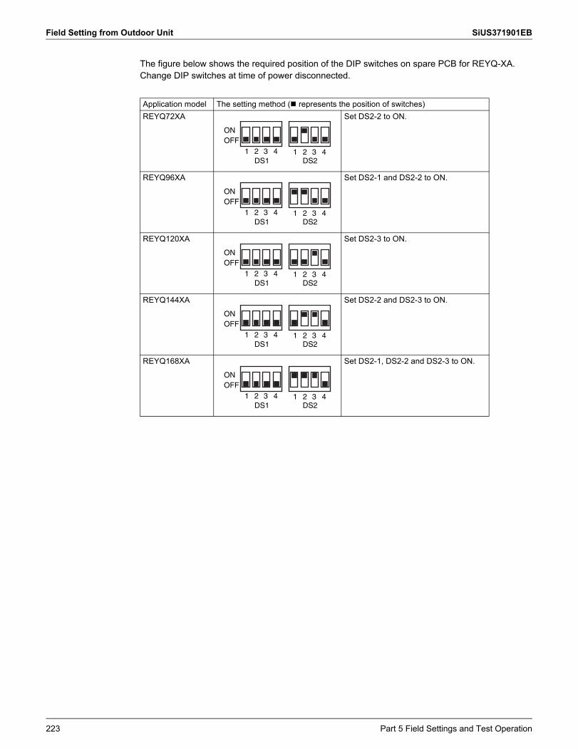
Field Setting from Outdoor Unit SiUS371901EB
The figure below shows the required position of the DIP switches on spare PCB for REYQ-XA. Change DIP switches at time of power disconnected.
Application model The setting method ( represents the position of switches)REYQ72XA Set DS2-2 to ON.
REYQ96XA Set DS2-1 and DS2-2 to ON.
REYQ120XA Set DS2-3 to ON.
REYQ144XA Set DS2-2 and DS2-3 to ON.
REYQ168XA Set DS2-1, DS2-2 and DS2-3 to ON.
1 2 3 4 1 2 3 4
ONOFF
DS1 DS2
1 2 3 4 1 2 3 4
ONOFF
DS1 DS2
1 2 3 4 1 2 3 4
ONOFF
DS1 DS2
1 2 3 4 1 2 3 4
ONOFF
DS1 DS2
1 2 3 4 1 2 3 4
ONOFF
DS1 DS2
223 Part 5 Field Settings and Test Operation
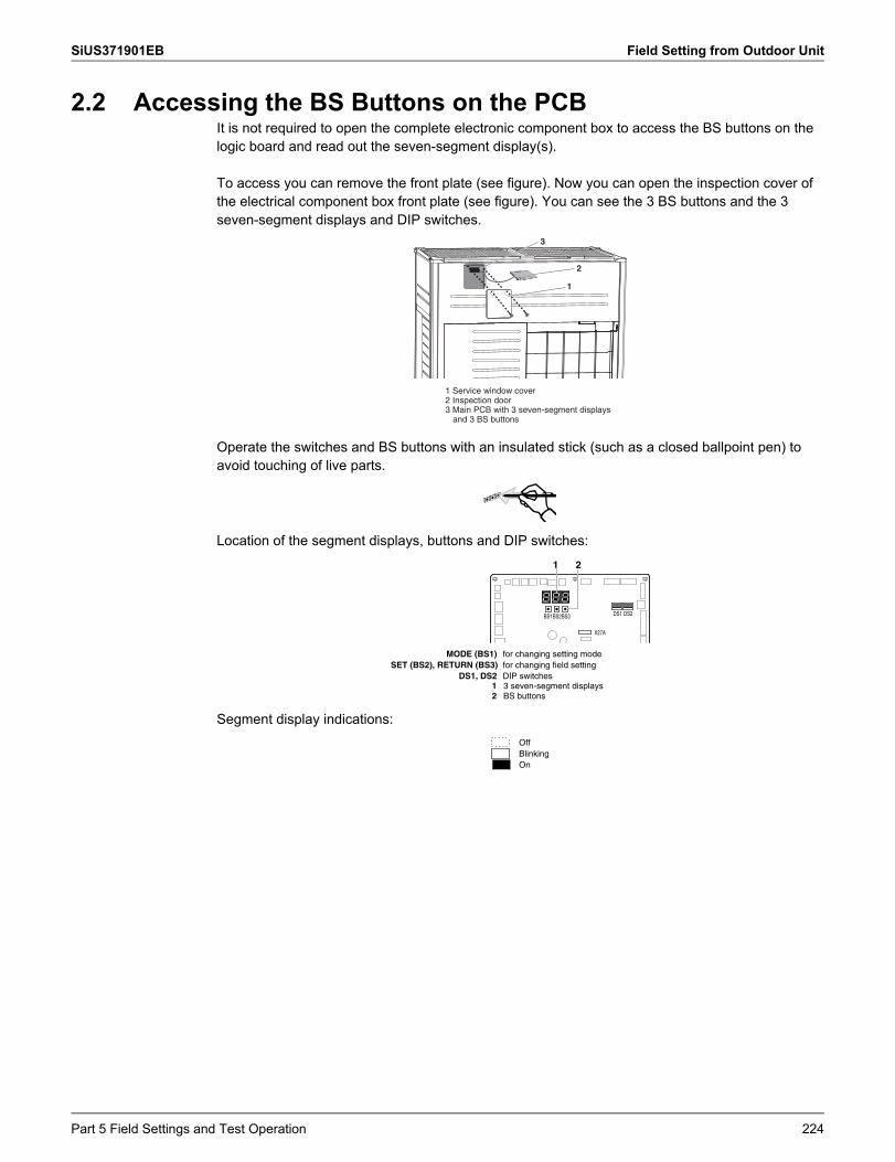
SiUS371901EB Field Setting from Outdoor Unit
2.2 Accessing the BS Buttons on the PCBIt is not required to open the complete electronic component box to access the BS buttons on the logic board and read out the seven-segment display(s).
To access you can remove the front plate (see figure). Now you can open the inspection cover of the electrical component box front plate (see figure). You can see the 3 BS buttons and the 3 seven-segment displays and DIP switches.
Operate the switches and BS buttons with an insulated stick (such as a closed ballpoint pen) to avoid touching of live parts.
Location of the segment displays, buttons and DIP switches:
Segment display indications:
1 Service window cover2 Inspection door3 Main PCB with 3 seven-segment displays
and 3 BS buttons
1
2
3
1 2
BS1BS2 DS1 DS2BS3
X27A
1 3 seven-segment displays2 BS buttons
MODE (BS1) for changing setting modeSET (BS2), RETURN (BS3) for changing field setting
DS1, DS2 DIP switches
OffBlinkingOn
Part 5 Field Settings and Test Operation 224
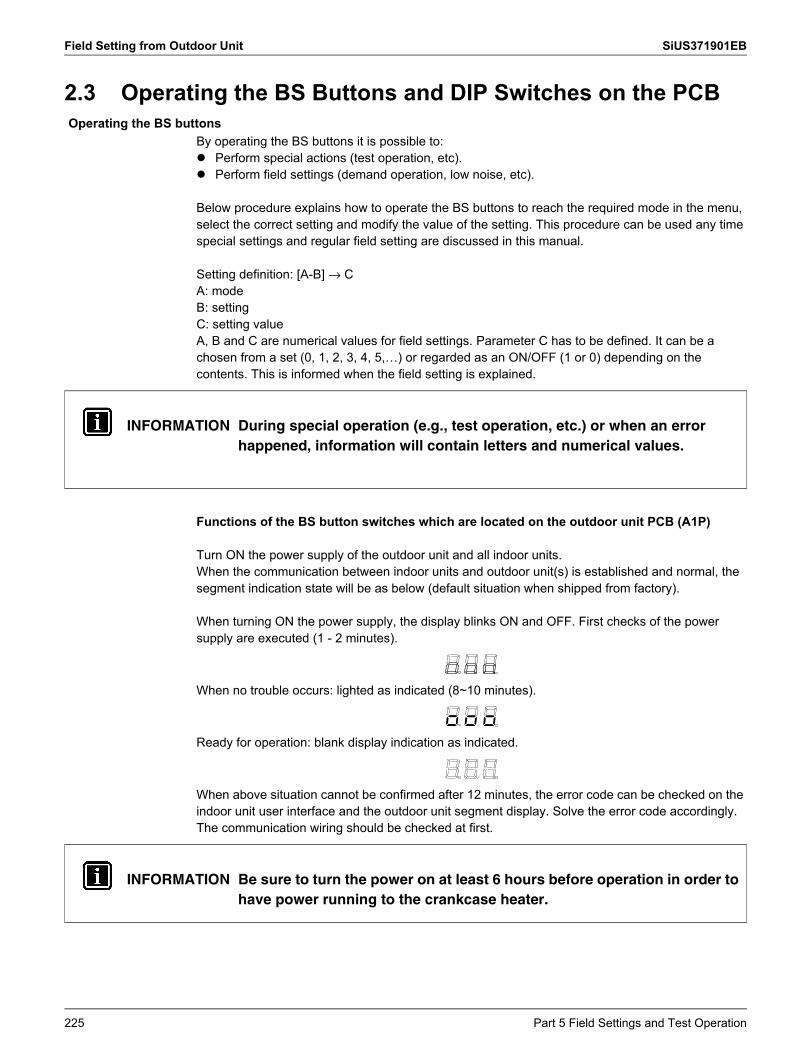
Field Setting from Outdoor Unit SiUS371901EB
2.3 Operating the BS Buttons and DIP Switches on the PCB
By operating the BS buttons it is possible to: Perform special actions (test operation, etc). Perform field settings (demand operation, low noise, etc).
Below procedure explains how to operate the BS buttons to reach the required mode in the menu, select the correct setting and modify the value of the setting. This procedure can be used any time special settings and regular field setting are discussed in this manual.
Setting definition: [A-B] → CA: modeB: settingC: setting valueA, B and C are numerical values for field settings. Parameter C has to be defined. It can be a chosen from a set (0, 1, 2, 3, 4, 5,…) or regarded as an ON/OFF (1 or 0) depending on the contents. This is informed when the field setting is explained.
Functions of the BS button switches which are located on the outdoor unit PCB (A1P)
Turn ON the power supply of the outdoor unit and all indoor units.When the communication between indoor units and outdoor unit(s) is established and normal, the segment indication state will be as below (default situation when shipped from factory).
When turning ON the power supply, the display blinks ON and OFF. First checks of the power supply are executed (1 - 2 minutes).
When no trouble occurs: lighted as indicated (8~10 minutes).
Ready for operation: blank display indication as indicated.
When above situation cannot be confirmed after 12 minutes, the error code can be checked on the indoor unit user interface and the outdoor unit segment display. Solve the error code accordingly. The communication wiring should be checked at first.
Operating the BS buttons
INFORMATION During special operation (e.g., test operation, etc.) or when an error happened, information will contain letters and numerical values.
INFORMATION Be sure to turn the power on at least 6 hours before operation in order to have power running to the crankcase heater.
225 Part 5 Field Settings and Test Operation
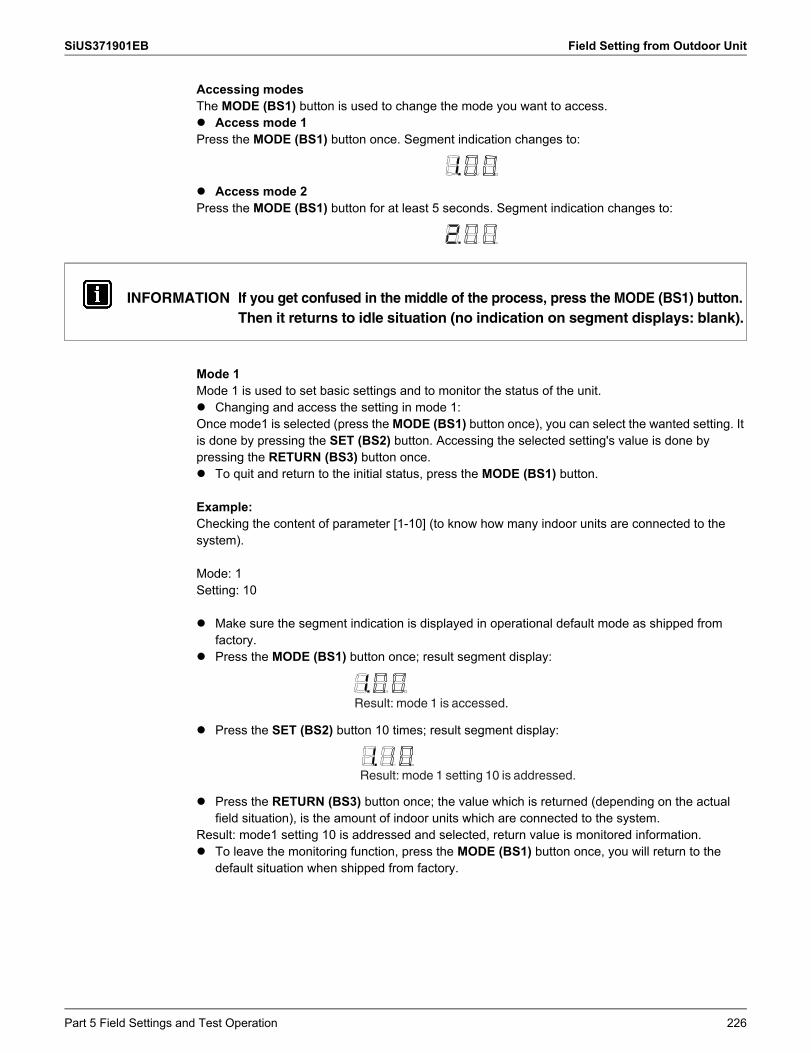
SiUS371901EB Field Setting from Outdoor Unit
Accessing modesThe MODE (BS1) button is used to change the mode you want to access. Access mode 1Press the MODE (BS1) button once. Segment indication changes to:
Access mode 2Press the MODE (BS1) button for at least 5 seconds. Segment indication changes to:
Mode 1Mode 1 is used to set basic settings and to monitor the status of the unit. Changing and access the setting in mode 1:Once mode1 is selected (press the MODE (BS1) button once), you can select the wanted setting. It is done by pressing the SET (BS2) button. Accessing the selected setting's value is done by pressing the RETURN (BS3) button once. To quit and return to the initial status, press the MODE (BS1) button.
Example:Checking the content of parameter [1-10] (to know how many indoor units are connected to the system).
Mode: 1Setting: 10
Make sure the segment indication is displayed in operational default mode as shipped from factory.
Press the MODE (BS1) button once; result segment display:
Press the SET (BS2) button 10 times; result segment display:
Press the RETURN (BS3) button once; the value which is returned (depending on the actual field situation), is the amount of indoor units which are connected to the system.
Result: mode1 setting 10 is addressed and selected, return value is monitored information. To leave the monitoring function, press the MODE (BS1) button once, you will return to the
default situation when shipped from factory.
INFORMATION If you get confused in the middle of the process, press the MODE (BS1) button.Then it returns to idle situation (no indication on segment displays: blank).
Result: mode 1 is accessed.
Result: mode 1 setting 10 is addressed.
Part 5 Field Settings and Test Operation 226
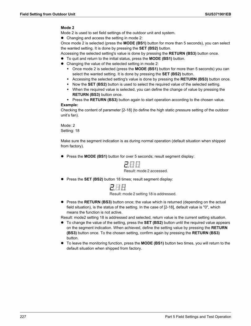
Field Setting from Outdoor Unit SiUS371901EB
Mode 2Mode 2 is used to set field settings of the outdoor unit and system. Changing and access the setting in mode 2:Once mode 2 is selected (press the MODE (BS1) button for more than 5 seconds), you can select the wanted setting. It is done by pressing the SET (BS2) button.Accessing the selected setting's value is done by pressing the RETURN (BS3) button once. To quit and return to the initial status, press the MODE (BS1) button. Changing the value of the selected setting in mode 2: Once mode 2 is selected (press the MODE (BS1) button for more than 5 seconds) you can
select the wanted setting. It is done by pressing the SET (BS2) button. Accessing the selected setting's value is done by pressing the RETURN (BS3) button once. Now the SET (BS2) button is used to select the required value of the selected setting. When the required value is selected, you can define the change of value by pressing the
RETURN (BS3) button once. Press the RETURN (BS3) button again to start operation according to the chosen value.
Example:Checking the content of parameter [2-18] (to define the high static pressure setting of the outdoor unit’s fan).
Mode: 2Setting: 18
Make sure the segment indication is as during normal operation (default situation when shipped from factory).
Press the MODE (BS1) button for over 5 seconds; result segment display:
Press the SET (BS2) button 18 times; result segment display:
Press the RETURN (BS3) button once; the value which is returned (depending on the actual field situation), is the status of the setting. In the case of [2-18], default value is "0", which means the function is not active.
Result: mode2 setting 18 is addressed and selected, return value is the current setting situation. To change the value of the setting, press the SET (BS2) button until the required value appears
on the segment indication. When achieved, define the setting value by pressing the RETURN (BS3) button once. To the chosen setting, confirm again by pressing the RETURN (BS3) button.
To leave the monitoring function, press the MODE (BS1) button two times, you will return to the default situation when shipped from factory.
Result: mode 2 accessed.
Result: mode 2 setting 18 is addressed.
227 Part 5 Field Settings and Test Operation
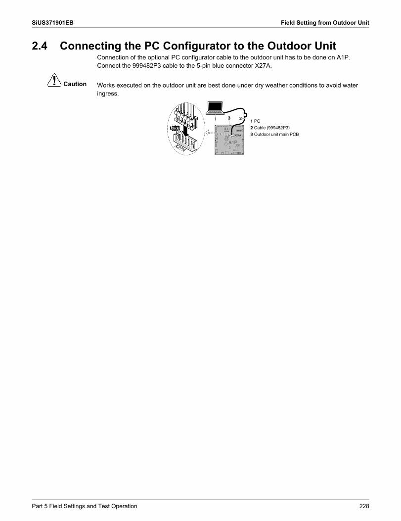
SiUS371901EB Field Setting from Outdoor Unit
Caution
2.4 Connecting the PC Configurator to the Outdoor UnitConnection of the optional PC configurator cable to the outdoor unit has to be done on A1P. Connect the 999482P3 cable to the 5-pin blue connector X27A.
Works executed on the outdoor unit are best done under dry weather conditions to avoid water ingress.
X27A
1 232
34
5
H J
ST
X27A
A1P
1 PC
2 Cable (999482P3)
3 Outdoor unit main PCB
Part 5 Field Settings and Test Operation 228
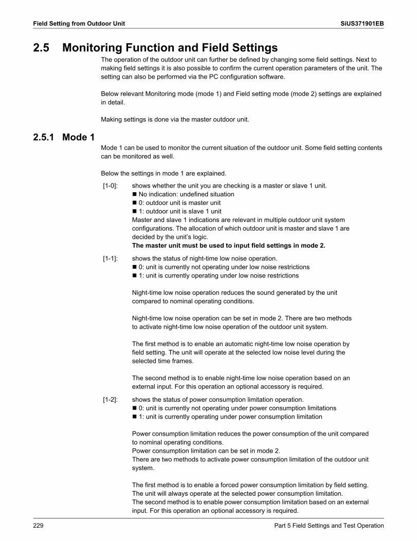
Field Setting from Outdoor Unit SiUS371901EB
2.5 Monitoring Function and Field SettingsThe operation of the outdoor unit can further be defined by changing some field settings. Next to making field settings it is also possible to confirm the current operation parameters of the unit. The setting can also be performed via the PC configuration software.
Below relevant Monitoring mode (mode 1) and Field setting mode (mode 2) settings are explained in detail.
Making settings is done via the master outdoor unit.
2.5.1 Mode 1Mode 1 can be used to monitor the current situation of the outdoor unit. Some field setting contents can be monitored as well.
Below the settings in mode 1 are explained.
[1-0]: shows whether the unit you are checking is a master or slave 1 unit. No indication: undefined situation 0: outdoor unit is master unit 1: outdoor unit is slave 1 unitMaster and slave 1 indications are relevant in multiple outdoor unit system configurations. The allocation of which outdoor unit is master and slave 1 are decided by the unit’s logic.The master unit must be used to input field settings in mode 2.
[1-1]: shows the status of night-time low noise operation. 0: unit is currently not operating under low noise restrictions 1: unit is currently operating under low noise restrictions
Night-time low noise operation reduces the sound generated by the unit compared to nominal operating conditions.
Night-time low noise operation can be set in mode 2. There are two methods to activate night-time low noise operation of the outdoor unit system.
The first method is to enable an automatic night-time low noise operation by field setting. The unit will operate at the selected low noise level during the selected time frames.
The second method is to enable night-time low noise operation based on an external input. For this operation an optional accessory is required.
[1-2]: shows the status of power consumption limitation operation. 0: unit is currently not operating under power consumption limitations 1: unit is currently operating under power consumption limitation
Power consumption limitation reduces the power consumption of the unit compared to nominal operating conditions.Power consumption limitation can be set in mode 2.There are two methods to activate power consumption limitation of the outdoor unit system.
The first method is to enable a forced power consumption limitation by field setting. The unit will always operate at the selected power consumption limitation.The second method is to enable power consumption limitation based on an external input. For this operation an optional accessory is required.
229 Part 5 Field Settings and Test Operation
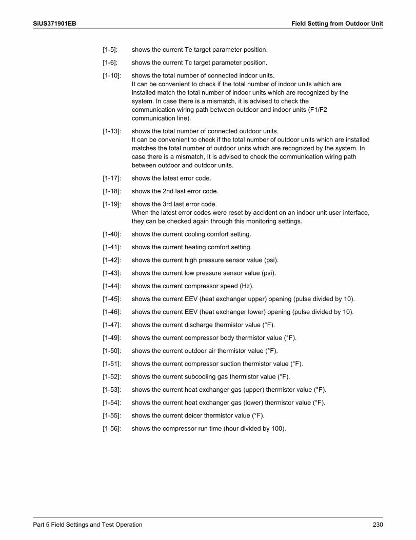
SiUS371901EB Field Setting from Outdoor Unit
[1-5]: shows the current Te target parameter position.
[1-6]: shows the current Tc target parameter position.
[1-10]: shows the total number of connected indoor units.It can be convenient to check if the total number of indoor units which are installed match the total number of indoor units which are recognized by the system. In case there is a mismatch, it is advised to check the communication wiring path between outdoor and indoor units (F1/F2 communication line).
[1-13]: shows the total number of connected outdoor units.It can be convenient to check if the total number of outdoor units which are installed matches the total number of outdoor units which are recognized by the system. In case there is a mismatch, It is advised to check the communication wiring path between outdoor and outdoor units.
[1-17]: shows the latest error code.
[1-18]: shows the 2nd last error code.
[1-19]: shows the 3rd last error code.When the latest error codes were reset by accident on an indoor unit user interface, they can be checked again through this monitoring settings.
[1-40]: shows the current cooling comfort setting.
[1-41]: shows the current heating comfort setting.
[1-42]: shows the current high pressure sensor value (psi).
[1-43]: shows the current low pressure sensor value (psi).
[1-44]: shows the current compressor speed (Hz).
[1-45]: shows the current EEV (heat exchanger upper) opening (pulse divided by 10).
[1-46]: shows the current EEV (heat exchanger lower) opening (pulse divided by 10).
[1-47]: shows the current discharge thermistor value (°F).
[1-49]: shows the current compressor body thermistor value (°F).
[1-50]: shows the current outdoor air thermistor value (°F).
[1-51]: shows the current compressor suction thermistor value (°F).
[1-52]: shows the current subcooling gas thermistor value (°F).
[1-53]: shows the current heat exchanger gas (upper) thermistor value (°F).
[1-54]: shows the current heat exchanger gas (lower) thermistor value (°F).
[1-55]: shows the current deicer thermistor value (°F).
[1-56]: shows the compressor run time (hour divided by 100).
Part 5 Field Settings and Test Operation 230
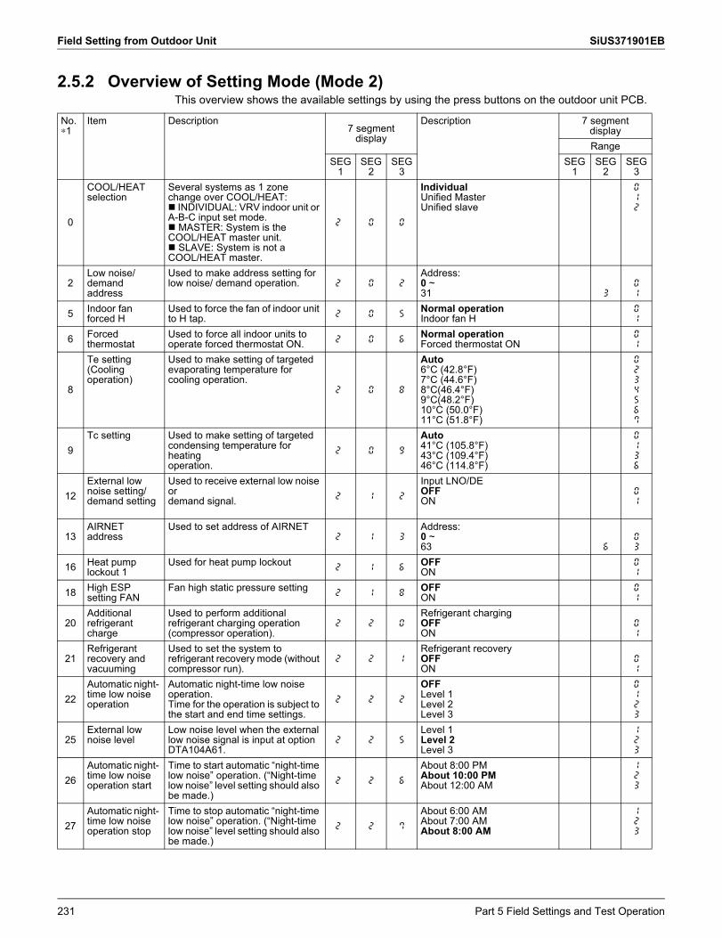
Field Setting from Outdoor Unit SiUS371901EB
2.5.2 Overview of Setting Mode (Mode 2)This overview shows the available settings by using the press buttons on the outdoor unit PCB.
No.∗1
Item Description7 segment
display
Description 7 segmentdisplayRange
SEG1
SEG2
SEG3
SEG1
SEG2
SEG3
0
COOL/HEAT selection
Several systems as 1 zone change over COOL/HEAT: INDIVIDUAL: VRV indoor unit or A-B-C input set mode. MASTER: System is the COOL/HEAT master unit. SLAVE: System is not a COOL/HEAT master.
2. 0 0
IndividualUnified MasterUnified slave
012
2Low noise/ demand address
Used to make address setting for low noise/ demand operation. 2. 0 2
Address:0 ~31 3
01
5 Indoor fan forced H
Used to force the fan of indoor unit to H tap. 2. 0 5
Normal operationIndoor fan H
01
6 Forced thermostat
Used to force all indoor units to operate forced thermostat ON. 2. 0 6
Normal operationForced thermostat ON
01
8
Te setting (Cooling operation)
Used to make setting of targeted evaporating temperature for cooling operation.
2. 0 8
Auto6°C (42.8°F)7°C (44.6°F)8°C(46.4°F)9°C(48.2°F)10°C (50.0°F)11°C (51.8°F)
0234567
9Tc setting Used to make setting of targeted
condensing temperature for heatingoperation.
2. 0 9
Auto41°C (105.8°F)43°C (109.4°F)46°C (114.8°F)
0136
12External low noise setting/ demand setting
Used to receive external low noise ordemand signal. 2. 1 2
Input LNO/DEOFFON
01
13AIRNET address
Used to set address of AIRNET2. 1 3
Address:0 ~63 6
03
16 Heat pumplockout 1
Used for heat pump lockout2. 1 6
OFFON
01
18 High ESP setting FAN
Fan high static pressure setting2. 1 8
OFFON
01
20Additionalrefrigerant charge
Used to perform additional refrigerant charging operation (compressor operation).
2. 2 0Refrigerant chargingOFFON
01
21Refrigerantrecovery and vacuuming
Used to set the system to refrigerant recovery mode (without compressor run).
2. 2 1Refrigerant recoveryOFFON
01
22Automatic night- time low noise operation
Automatic night-time low noise operation.Time for the operation is subject to the start and end time settings.
2. 2 2
OFFLevel 1Level 2Level 3
0123
25External low noise level
Low noise level when the external low noise signal is input at option DTA104A61.
2. 2 5Level 1Level 2Level 3
123
26Automatic night- time low noise operation start
Time to start automatic “night-time low noise” operation. (“Night-time low noise” level setting should also be made.)
2. 2 6
About 8:00 PMAbout 10:00 PMAbout 12:00 AM
123
27Automatic night- time low noise operation stop
Time to stop automatic “night-time low noise” operation. (“Night-time low noise” level setting should also be made.)
2. 2 7
About 6:00 AMAbout 7:00 AMAbout 8:00 AM
123
231 Part 5 Field Settings and Test Operation
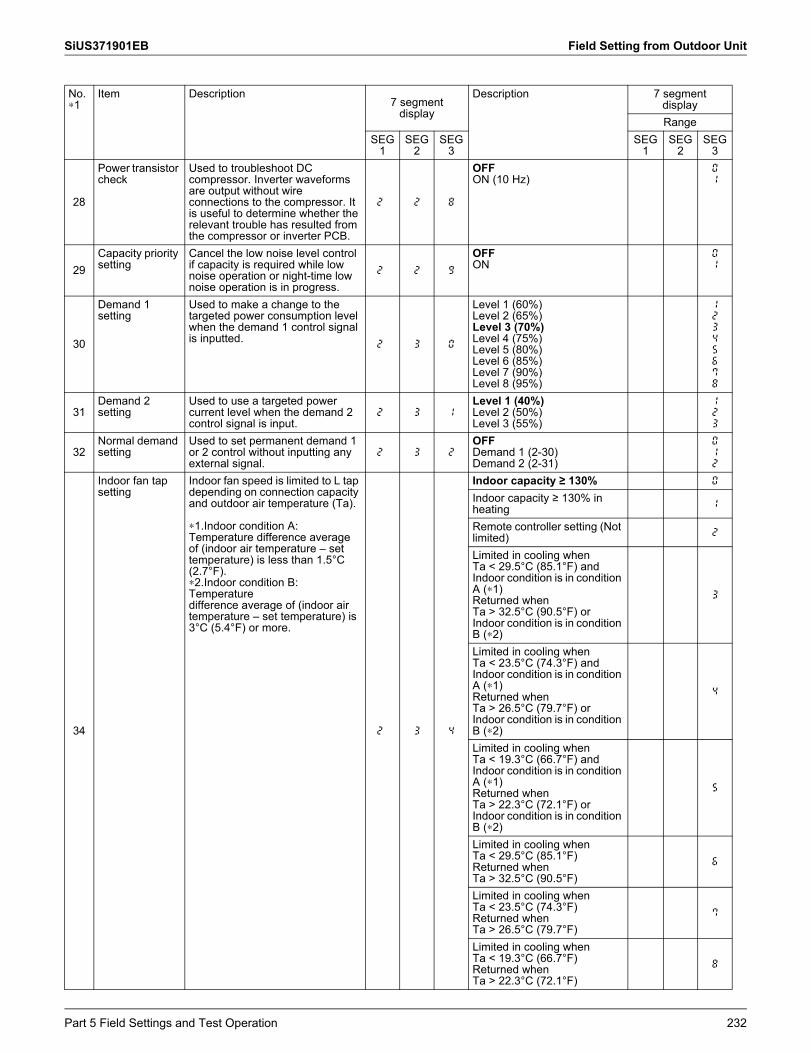
SiUS371901EB Field Setting from Outdoor Unit
28
Power transistor check
Used to troubleshoot DC compressor. Inverter waveforms are output without wire connections to the compressor. It is useful to determine whether the relevant trouble has resulted from the compressor or inverter PCB.
2. 2 8
OFFON (10 Hz)
01
29Capacity priority setting
Cancel the low noise level control if capacity is required while low noise operation or night-time low noise operation is in progress.
2. 2 9
OFFON
01
30
Demand 1 setting
Used to make a change to the targeted power consumption level when the demand 1 control signal is inputted.
2. 3 0
Level 1 (60%)Level 2 (65%)Level 3 (70%)Level 4 (75%)Level 5 (80%)Level 6 (85%)Level 7 (90%)Level 8 (95%)
12345678
31Demand 2 setting
Used to use a targeted power current level when the demand 2 control signal is input.
2. 3 1Level 1 (40%)Level 2 (50%)Level 3 (55%)
123
32Normal demand setting
Used to set permanent demand 1 or 2 control without inputting any external signal.
2. 3 2OFFDemand 1 (2-30)Demand 2 (2-31)
012
34
Indoor fan tap setting
Indoor fan speed is limited to L tap depending on connection capacity and outdoor air temperature (Ta).
∗1.Indoor condition A: Temperature difference average of (indoor air temperature – set temperature) is less than 1.5°C (2.7°F).∗2.Indoor condition B: Temperaturedifference average of (indoor air temperature – set temperature) is 3°C (5.4°F) or more.
2. 3 4
Indoor capacity ≥ 130% 0
Indoor capacity ≥ 130% in heating 1
Remote controller setting (Not limited) 2
Limited in cooling whenTa < 29.5°C (85.1°F) and Indoor condition is in condition A (∗1)Returned whenTa > 32.5°C (90.5°F) or Indoor condition is in condition B (∗2)
3
Limited in cooling whenTa < 23.5°C (74.3°F) and Indoor condition is in condition A (∗1)Returned whenTa > 26.5°C (79.7°F) or Indoor condition is in condition B (∗2)
4
Limited in cooling whenTa < 19.3°C (66.7°F) and Indoor condition is in condition A (∗1)Returned whenTa > 22.3°C (72.1°F) or Indoor condition is in condition B (∗2)
5
Limited in cooling whenTa < 29.5°C (85.1°F)Returned whenTa > 32.5°C (90.5°F)
6
Limited in cooling whenTa < 23.5°C (74.3°F)Returned whenTa > 26.5°C (79.7°F)
7
Limited in cooling whenTa < 19.3°C (66.7°F)Returned whenTa > 22.3°C (72.1°F)
8
No.∗1
Item Description7 segment
display
Description 7 segmentdisplayRange
SEG1
SEG2
SEG3
SEG1
SEG2
SEG3
Part 5 Field Settings and Test Operation 232
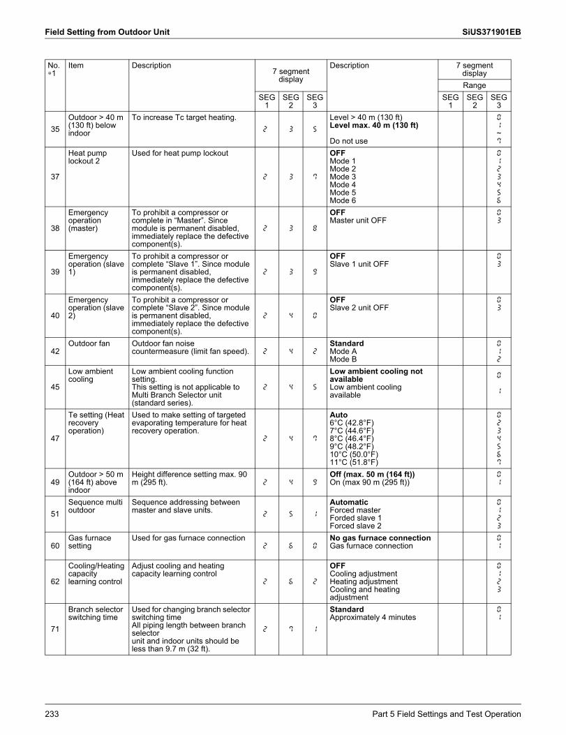
Field Setting from Outdoor Unit SiUS371901EB
35Outdoor > 40 m (130 ft) below indoor
To increase Tc target heating.2. 3 5
Level > 40 m (130 ft)Level max. 40 m (130 ft)
Do not use
01~7
37
Heat pump lockout 2
Used for heat pump lockout
2. 3 7
OFFMode 1Mode 2Mode 3Mode 4Mode 5Mode 6
0123456
38
Emergency operation (master)
To prohibit a compressor or complete in “Master”. Since module is permanent disabled, immediately replace the defective component(s).
2. 3 8
OFFMaster unit OFF
03
39
Emergency operation (slave 1)
To prohibit a compressor or complete “Slave 1”. Since module is permanent disabled, immediately replace the defective component(s).
2. 3 9
OFFSlave 1 unit OFF
03
40
Emergency operation (slave 2)
To prohibit a compressor or complete “Slave 2”. Since module is permanent disabled, immediately replace the defective component(s).
2. 4 0
OFFSlave 2 unit OFF
03
42Outdoor fan Outdoor fan noise
countermeasure (limit fan speed). 2. 4 2StandardMode AMode B
012
45
Low ambient cooling
Low ambient cooling function setting.This setting is not applicable to Multi Branch Selector unit (standard series).
2. 4 5
Low ambient cooling not availableLow ambient coolingavailable
0
1
47
Te setting (Heat recovery operation)
Used to make setting of targeted evaporating temperature for heat recovery operation.
2. 4 7
Auto6°C (42.8°F)7°C (44.6°F)8°C (46.4°F)9°C (48.2°F)10°C (50.0°F)11°C (51.8°F)
0234567
49Outdoor > 50 m (164 ft) above indoor
Height difference setting max. 90 m (295 ft). 2. 4 9
Off (max. 50 m (164 ft))On (max 90 m (295 ft))
01
51Sequence multi outdoor
Sequence addressing between master and slave units.
2. 5 1
AutomaticForced master Forded slave 1Forced slave 2
0123
60Gas furnace setting
Used for gas furnace connection2. 6 0
No gas furnace connectionGas furnace connection
01
62
Cooling/Heating capacity learning control
Adjust cooling and heating capacity learning control
2. 6 2
OFFCooling adjustmentHeating adjustmentCooling and heating adjustment
0123
71
Branch selector switching time
Used for changing branch selector switching timeAll piping length between branch selectorunit and indoor units should be less than 9.7 m (32 ft).
2. 7 1
StandardApproximately 4 minutes
01
No.∗1
Item Description7 segment
display
Description 7 segmentdisplayRange
SEG1
SEG2
SEG3
SEG1
SEG2
SEG3
233 Part 5 Field Settings and Test Operation
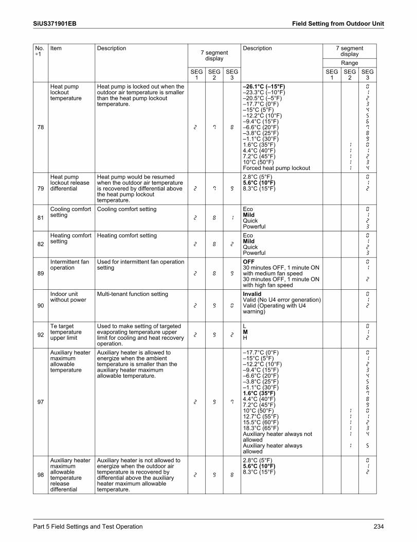
SiUS371901EB Field Setting from Outdoor Unit
78
Heat pump lockout temperature
Heat pump is locked out when the outdoor air temperature is smaller than the heat pump lockout temperature.
2. 7 8
–26.1°C (–15°F)–23.3°C (–10°F)–20.5°C (–5°F)–17.7°C (0°F)–15°C (5°F)–12.2°C (10°F)–9.4°C (15°F)–6.6°C (20°F)–3.8°C (25°F)–1.1°C (30°F)1.6°C (35°F)4.4°C (40°F)7.2°C (45°F)10°C (50°F)Forced heat pump lockout
11111
012345678901234
79
Heat pump lockout release differential
Heat pump would be resumed when the outdoor air temperature is recovered by differential above the heat pump lockout temperature.
2. 7 9
2.8°C (5°F)5.6°C (10°F)8.3°C (15°F)
012
81Cooling comfort setting
Cooling comfort setting2. 8 1
EcoMildQuickPowerful
0123
82Heating comfort setting
Heating comfort setting2. 8 2
EcoMildQuickPowerful
0123
89
Intermittent fan operation
Used for intermittent fan operation setting
2. 8 9
OFF30 minutes OFF, 1 minute ON with medium fan speed30 minutes OFF, 1 minute ON with high fan speed
01
2
90
Indoor unit without power
Multi-tenant function setting
2. 9 0
InvalidValid (No U4 error generation)Valid (Operating with U4 warning)
012
92Te target temperature upper limit
Used to make setting of targeted evaporating temperature upper limit for cooling and heat recovery operation.
2. 9 2
LMH
012
97
Auxiliary heater maximum allowable temperature
Auxiliary heater is allowed to energize when the ambient temperature is smaller than the auxiliary heater maximum allowable temperature.
2. 9 7
–17.7°C (0°F)–15°C (5°F)–12.2°C (10°F)–9.4°C (15°F)–6.6°C (20°F)–3.8°C (25°F)–1.1°C (30°F)1.6°C (35°F)4.4°C (40°F)7.2°C (45°F)10°C (50°F) 12.7°C (55°F)15.5°C (60°F)18.3°C (65°F)Auxiliary heater always not allowedAuxiliary heater always allowed
11111
1
012345678901234
5
98
Auxiliary heater maximum allowable temperature release differential
Auxiliary heater is not allowed to energize when the outdoor air temperature is recovered by differential above the auxiliary heater maximum allowable temperature.
2. 9 8
2.8°C (5°F)5.6°C (10°F)8.3°C (15°F)
012
No.∗1
Item Description7 segment
display
Description 7 segmentdisplayRange
SEG1
SEG2
SEG3
SEG1
SEG2
SEG3
Part 5 Field Settings and Test Operation 234
Field Setting from Outdoor Unit SiUS371901EB
∗1: Numbers in the "No." column represent the number of times to press the BS button.
∗ : Setting does not return to factory setting when exit mode 2. To cancel the function, change setting manually to factory setting.
∗ : Once function is activated t01 appears. To stop current function, press once the RETURN (BS3) button. For detailed description about each setting, refer to Details of Setting Mode 2 (m2) on page 236.Indication bold means factory setting.
235 Part 5 Field Settings and Test Operation
SiUS371901EB Field Setting from Outdoor Unit
2.5.3 Details of Setting Mode 2 (m2)Mode 2 is used to change the field settings of the system. Consulting the current field setting value and changing the current field setting value is possible.
In general, normal operation can be resumed without special intervention after changing field settings.
Some field settings are used for special operation (e.g. 1 time operation, recovery/vacuuming setting, adding refrigerant setting, etc.). In such a case, it is required to abort the special operation before normal operation can restart. It will be displayed in below explanations.
[2-0]: Cool/Heat selection settingCool/Heat selection setting is used in case the optional Cool/Heat selector (KRC19-26A) is used. Depending on the outdoor unit setup (single outdoor unit setup or multi outdoor unit setup), the correct setting should be chosen. More details on how to use the Cool/Heat selector option can be found in the manual of the Cool/Heat selector.Default value: 0. 0: Each individual outdoor unit can select Cool/Heat operation (by Cool/Heat selector if installed). 1: Master unit decides Cool/Heat operation when outdoor units are connected in multiple system combination 2: Slave unit for Cool/Heat operation when outdoor units are connected in multiple system combinationChange [2-0] to 0, 1 or 2 in function of required functionality.
[2-2]: Low noise/demand addressAddress for low noise/demand operation.1 or more systems (maximum 10 systems wired by “F1F2 OUT/D”) can operate use the LNO (Low Noise Operation) or/and the DE (Demand Operation) by instruction of field supplied input to optional PCB DTA104A61/62.To link the system to the corresponding DTA104A61/62, set the address same as the DIP switches position on the related optional PCB DTA104A61/62.Ensure that also field setting 2-12-1 is set to enable input from optional PCB DTA104A61/62.
[2-5]: Cross wiring checkDefault value: 0. Not active.Set 1: force all connected indoor units to operate the indoor fan on high speed. This setting can be made to check which units are missing in the communication if the number of indoor units do not correspond to the system lay out. Ensure that after cross wiring check was confirmed, to return setting to default 2-5-0. Once setting 2-5-1 is active, it is not automatically returning to default when exit mode 2.
[2-6]: Forced thermostat ON command all connected indoor unitsDefault value: 0. Not active.Set 1: force all connected indoor units to operate under “Test” (forced thermostat ON command to outdoor). Ensure that when the forced thermostat ON needs to be ended, to return setting to default 2-6-0. Once setting 2-6-1 is active, it is not automatically returning to default when exit mode 2.
Part 5 Field Settings and Test Operation 236
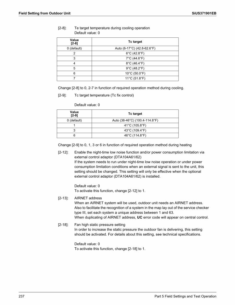
Field Setting from Outdoor Unit SiUS371901EB
[2-8]: Te target temperature during cooling operation Default value: 0
Value[2-8] Tc target
0 (default) Auto (6-17°C) (42.8-62.6°F)2 6°C (42.8°F)3 7°C (44.6°F)4 8°C (46.4°F)5 9°C (48.2°F)6 10°C (50.0°F)7 11°C (51.8°F)
Change [2-8] to 0, 2-7 in function of required operation method during cooling.
[2-9]: Tc target temperature (Tc fix control)
Default value: 0
Value[2-9] Tc target
0 (default) Auto (38-46°C) (100.4-114.8°F)1 41°C (105.8°F)3 43°C (109.4°F)6 46°C (114.8°F)
Change [2-9] to 0, 1, 3 or 6 in function of required operation method during heating
[2-12]: Enable the night-time low noise function and/or power consumption limitation via external control adaptor (DTA104A61/62)If the system needs to run under night-time low noise operation or under power consumption limitation conditions when an external signal is sent to the unit, this setting should be changed. This setting will only be effective when the optional external control adaptor (DTA104A61/62) is installed.
Default value: 0To activate this function, change [2-12] to 1.
[2-13]: AIRNET addressWhen an AIRNET system will be used, outdoor unit needs an AIRNET address.Also to facilitate the recognition of a system in the map lay out of the service checker type III, set each system a unique address between 1 and 63.When duplicating of AIRNET address, UC error code will appear on central control.
[2-18]: Fan high static pressure settingIn order to increase the static pressure the outdoor fan is delivering, this setting should be activated. For details about this setting, see technical specifications.
Default value: 0To activate this function, change [2-18] to 1.
237 Part 5 Field Settings and Test Operation
SiUS371901EB Field Setting from Outdoor Unit
[2-20]: Additional refrigerant chargeIn order to add the additional refrigerant charge amount following setting should be applied.
Default value: 0To activate this function, change [2-20] to 1.
To stop the additional refrigerant charge operation (when the required additional refrigerant amount is charged), press the RETURN (BS3) button. If this function was not aborted by pressing the RETURN (BS3) button, the unit will stop its operation after 30 minutes.If 30 minutes was not sufficient to add the needed refrigerant amount, the function can be reactivated by changing the field setting again.
[2-21]: Refrigerant recovery/vacuuming modeIn order to achieve a free pathway to recovering refrigerant out of the system or to remove residual substances or to vacuum the system it is necessary to apply a setting which will open required valves in the refrigerant circuit so the recovering of refrigerant or vacuuming process can be done properly.
Default value: 0To activate this function, change [2-21] to 1.
To stop the refrigerant recovery/vacuuming mode, press the RETURN (BS3) button. If the RETURN (BS3) button is not pressed, the system will remain in refrigerant recovery/vacuuming mode.
[2-22]: Automatic night-time low noise setting and level during night-timeBy changing this setting, you can activate the automatic night-time low noise operation function of the unit and define the level of operation. Depending on the chosen level, the noise level will be lowered (3: Level 3 < 2: Level 2 < 1: Level 1).The start and stop moments for this function are defined under setting [2-26] and [2-27].
Default value: 0Change [2-22] to 1, 2 or 3 in function of required level.
[2-25]: Night-time low noise operation level via the external control adaptorIf the system needs to run under night-time low noise operation conditions when an external signal is sent to the unit, this setting defines the level of night-time low noise that will be applied(3: Level 3 < 2: Level 2 < 1: Level 1).This setting will only be effective when the optional external control adaptor (DTA104A61/62) is installed and the setting [2-12] was activated.
Default value: 2Change [2-25] to 1, 2 or 3 in function of required level.
Part 5 Field Settings and Test Operation 238
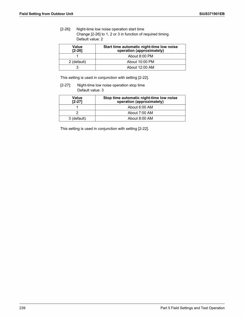
Field Setting from Outdoor Unit SiUS371901EB
[2-26]: Night-time low noise operation start timeChange [2-26] to 1, 2 or 3 in function of required timing.Default value: 2
Value[2-26]
Start time automatic night-time low noise operation (approximately)
1 About 8:00 PM2 (default) About 10:00 PM
3 About 12:00 AM
This setting is used in conjunction with setting [2-22].
[2-27]: Night-time low noise operation stop timeDefault value: 3
Value[2-27]
Stop time automatic night-time low noise operation (approximately)
1 About 6:00 AM2 About 7:00 AM
3 (default) About 8:00 AM
This setting is used in conjunction with setting [2-22].
239 Part 5 Field Settings and Test Operation
SiUS371901EB Field Setting from Outdoor Unit
[2-28]: Power transistor check modeTo evaluate the output of the power transistors. Use this function in case error code is displayed related to defective inverter PCB or compressor is locked.Default value: 0. Power transistor check mode is not active.Field setting 1: Power transistor check mode is active.Function: Inverter PCB gives output of 10 Hz in sequence by all 6 transistors. Remove the U/V/W terminals of the compressor, and connect to the inverter checker module. If all 6 LEDs blink, the transistors switch correctly. When the power transistor check mode is interrupted, after internal power circuit is disconnected on the inverter PCB, 2 LEDs will light up to indicate discharge of the DC voltage. Wait till the LEDs are OFF before returning fasten terminals back to the compressor terminals.Minimum requirements to refer to the result on the inverter checker module: All 3 phases and neutral are available, and Inverter PCB control is active. Check if the green LED “HAP” on the inverter PCBs are blinking normal (approx. 1/ second). If LEDs are OFF, need to exit the “standby mode” of the inverter: Disconnect and reconnect power supply control PCB, or Forced thermostat ON condition, or Make shortly set 2-6-1 (forced thermostat ON indoor), or 2-20-1 (manual refrigerant charge). Once the LED is blinking on the inverter PCB, change related setting immediately back to set 0 to deactivate related function. Diode module generates the required 260 VDC at REYQ-XATJU(A), 600 VDC at REYQ-XAYDU(A) or 750 VDC at REYQ-XAYCU(A).Cautions: In case there is more than 1 compressor in a system (outdoor is multi outdoor configuration) all compressor inverter PCBs will perform the power transistor check. In such case, disconnect U/V/W fasten terminals on all compressors. Avoid accidental touch of fasten terminals to short circuit or ground leak to casing. To stop the power transistor check mode, change setting to default 2-28-0. Output to U/V/W will also stop when outdoor unit main PCB decides standby mode of inverter circuit.
Part 5 Field Settings and Test Operation 240
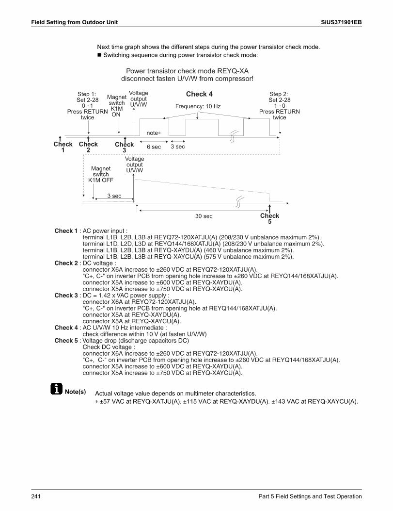
Field Setting from Outdoor Unit SiUS371901EB
Note(s) Actual voltage value depends on multimeter characteristics.∗ ±57 VAC at REYQ-XATJU(A). ±115 VAC at REYQ-XAYDU(A). ±143 VAC at REYQ-XAYCU(A).
Next time graph shows the different steps during the power transistor check mode. Switching sequence during power transistor check mode:
Power transistor check mode REYQ-XA disconnect fasten U/V/W from compressor!
Step 1:Set 2-28
0 1Press RETURN
twice
Step 2:Set 2-28
1 0Press RETURN
twice
Check1
Check2
Check3
MagnetswitchK1MON
Magnetswitch
K1M OFF
VoltageoutputU/V/W
VoltageoutputU/V/W
Frequency: 10 Hz
note∗
6 sec 3 sec
3 sec
30 sec
Check 4
Check5
Check 1 : AC power input : terminal L1B, L2B, L3B at REYQ72-120XATJU(A) (208/230 V unbalance maximum 2%).terminal L1D, L2D, L3D at REYQ144/168XATJU(A) (208/230 V unbalance maximum 2%).terminal L1B, L2B, L3B at REYQ-XAYDU(A) (460 V unbalance maximum 2%).terminal L1B, L2B, L3B at REYQ-XAYCU(A) (575 V unbalance maximum 2%).
Check 2 : DC voltage : connector X6A increase to ±260 VDC at REYQ72-120XATJU(A)."C+, C-" on inverter PCB from opening hole increase to ±260 VDC at REYQ144/168XATJU(A).connector X5A increase to ±600 VDC at REYQ-XAYDU(A). connector X5A increase to ±750 VDC at REYQ-XAYCU(A).
Check 3 : DC = 1.42 x VAC power supply : connector X6A at REYQ72-120XATJU(A)."C+, C-" on inverter PCB from opening hole at REYQ144/168XATJU(A).connector X5A at REYQ-XAYDU(A). connector X5A at REYQ-XAYCU(A).
Check 4 : AC U/V/W 10 Hz intermediate : check difference within 10 V (at fasten U/V/W)
Check 5 : Voltage drop (discharge capacitors DC)Check DC voltage : connector X6A increase to ±260 VDC at REYQ72-120XATJU(A)."C+, C-" on inverter PCB from opening hole increase to ±260 VDC at REYQ144/168XATJU(A).connector X5A increase to ±600 VDC at REYQ-XAYDU(A). connector X5A increase to ±750 VDC at REYQ-XAYCU(A).
241 Part 5 Field Settings and Test Operation
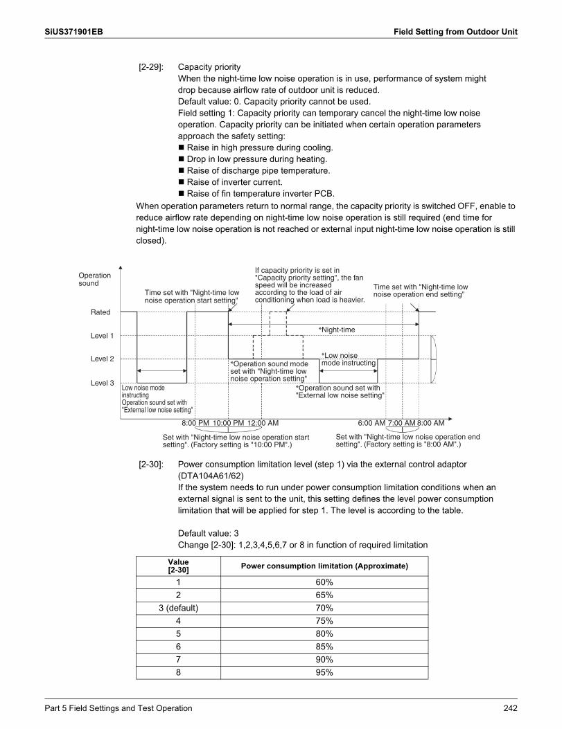
SiUS371901EB Field Setting from Outdoor Unit
When operation parameters return to normal range, the capacity priority is switched OFF, enable to reduce airflow rate depending on night-time low noise operation is still required (end time for night-time low noise operation is not reached or external input night-time low noise operation is still closed).
[2-29]: Capacity priorityWhen the night-time low noise operation is in use, performance of system might drop because airflow rate of outdoor unit is reduced.Default value: 0. Capacity priority cannot be used.Field setting 1: Capacity priority can temporary cancel the night-time low noise operation. Capacity priority can be initiated when certain operation parameters approach the safety setting: Raise in high pressure during cooling. Drop in low pressure during heating. Raise of discharge pipe temperature. Raise of inverter current. Raise of fin temperature inverter PCB.
Operation sound
Rated
Level 1
Level 2
Level 3
Time set with "Night-time low noise operation start setting"
Low noise mode instructing Operation sound set with "External low noise setting"
10:00 PM8:00 PM 12:00 AM 6:00 AM 7:00 AM 8:00 AM
Set with "Night-time low noise operation start setting". (Factory setting is "10:00 PM".)
Set with "Night-time low noise operation end setting". (Factory setting is "8:00 AM".)
*Low noise mode instructing
*Operation sound set with "External low noise setting"
*Night-time
If capacity priority is set in "Capacity priority setting", the fan speed will be increased according to the load of air conditioning when load is heavier.
Time set with "Night-time low noise operation end setting"
*Operation sound mode set with "Night-time low noise operation setting"
[2-30]: Power consumption limitation level (step 1) via the external control adaptor (DTA104A61/62)If the system needs to run under power consumption limitation conditions when an external signal is sent to the unit, this setting defines the level power consumption limitation that will be applied for step 1. The level is according to the table.
Default value: 3Change [2-30]: 1,2,3,4,5,6,7 or 8 in function of required limitation
Value[2-30] Power consumption limitation (Approximate)
1 60%2 65%
3 (default) 70%4 75%5 80%6 85%7 90%8 95%
Part 5 Field Settings and Test Operation 242
Field Setting from Outdoor Unit SiUS371901EB
[2-31]: Power consumption limitation level (step 2) via the external control adaptor (DTA104A61/62)If the system needs to run under power consumption limitation conditions when an external signal is sent to the unit, this setting defines the level power consumption limitation that will be applied for step 2. The level is according to the table.
Default value: 1Change [2-31] to 1, 2 or 3 in function of required limitation.
Value[2-31] Power consumption limitation (approximately)
1 (default) 40%2 50%3 55%
[2-32]: Forced, all time, power consumption limitation operation (no external control adaptor is required to perform power consumption limitation)If the system always needs to run under power consumption limitation conditions, this setting activates and defines the level power consumption limitation that will be applied continuously. The level is according to the table.
Default value: 0 (OFF).
Value[2-32] Restriction reference
0 (default) Function not active1 Follows [2-30] setting2 Follows [2-31] setting
Change [2-32]: 0,1 or 2 in function of required limitation.
[2-34]: Indoor fan tap settingIndoor units fan speed limitation related to connection capacity and outdoor air temperature for energy saving
Value[2-34] Indoor fan tap setting
0 (default) Fan speed is limited to L tap when indoor units capacity ≥ 130%.
1 In heating mode, fan speed is limited to L tap when indoor units capacity ≥ 130%.
2 Fan speed follows the setting of remote controllers (not limited by indoor units connection capacity).
3Limited in cooling when Ta < 29.5°C (85.1°F) and Indoor condition is in condition A (∗1) Returned when Ta > 32.5°C (90.5°F)or Indoor condition is in condition B (∗2)
4Limited in cooling when Ta < 23.5°C (74.3°F) and Indoor condition is in condition A (∗1) Returned when Ta > 26.5°C (79.7°F)or Indoor condition is in condition B (∗2)
5Limited in cooling when Ta < 19.3°C (66.7°F) and Indoor condition is in condition A (∗1) Returned when Ta > 22.3°C (72.1°F)or Indoor condition is in condition B (∗2)
6 Limited in cooling when Ta < 29.5°C (85.1°F) Returned when Ta > 32.5°C (90.5°F)
7 Limited in cooling when Ta < 23.5°C (74.3°F) Returned when Ta > 26.5°C (79.7°F)
8 Limited in cooling when Ta < 19.3°C (66.7°F) Returned when Ta > 22.3°C (72.1°F)
243 Part 5 Field Settings and Test Operation
SiUS371901EB Field Setting from Outdoor Unit
Note(s) ∗1. Indoor condition A: Temperature difference Average of (indoor air temperature – set temperature) is less than 1.5°C (2.7°F).∗2. Indoor condition B: Temperature difference Average of (indoor air temperature – set temperature) is 3°C (5.4°F) or more.
[2-35]: Height difference setting
Default value: 1
In case the outdoor unit is installed in the lowest position (indoor units are installed on a higher position than outdoor units) and the height difference between the highest indoor unit and the outdoor unit exceeds 40 m (130 ft), the setting [2-35] should be changed to 0.
[2-38]: Emergency operation “Master”To disable permanent compressor operation: in case of single module or “Master” unit of a multi outdoor system, this setting allows:Default value: 0. Compressor operation enabled.Field setting: Set 3: master module is disabled permanently.
[2-39]: Emergency operation “Slave 1”To disable permanent compressor operation of “Slave 1” unit of a multi outdoor system: Default value: 0. Compressor operation enabled.Field setting: Set 3: Slave 1 module is disabled permanently.
[2-40]: Emergency operation “Slave 2”To disable permanent compressor operation of “Slave 2” unit of a multi outdoor system: Default value: 0. Compressor operation enabled.Field setting: Set 3: Slave 2 module is disabled permanently.
Combination table setting 2-38, 2-39 and 2-40:
Disable Master/individual Slave 1 Slave 2
Module 2-38-3 2-39-3 2-40-3
[2-42]: Outdoor fan noise countermeasureChange fans rotational speed and reduce noise by the interference of air blow noise between outdoor units.Default value: 0Field setting: Mode A: 1 Mode B: 2
[2-45]: Low ambient cooling
Default value: 0.
[2-45] Description0 (default) No low ambient cooling available.
1 Low ambient cooling available.
This setting is not applicable to Multi Branch Selector unit (standard series).
Part 5 Field Settings and Test Operation 244
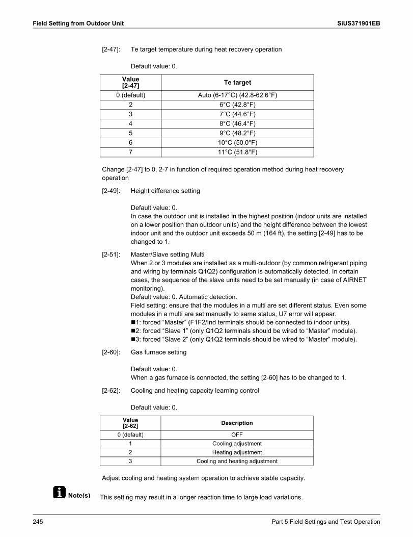
Field Setting from Outdoor Unit SiUS371901EB
Note(s) This setting may result in a longer reaction time to large load variations.
[2-47]: Te target temperature during heat recovery operation
Default value: 0.
Value[2-47] Te target
0 (default) Auto (6-17°C) (42.8-62.6°F)2 6°C (42.8°F)3 7°C (44.6°F)4 8°C (46.4°F)5 9°C (48.2°F)6 10°C (50.0°F)7 11°C (51.8°F)
Change [2-47] to 0, 2-7 in function of required operation method during heat recovery operation
[2-49]: Height difference setting
Default value: 0.In case the outdoor unit is installed in the highest position (indoor units are installed on a lower position than outdoor units) and the height difference between the lowest indoor unit and the outdoor unit exceeds 50 m (164 ft), the setting [2-49] has to be changed to 1.
[2-51]: Master/Slave setting MultiWhen 2 or 3 modules are installed as a multi-outdoor (by common refrigerant piping and wiring by terminals Q1Q2) configuration is automatically detected. In certain cases, the sequence of the slave units need to be set manually (in case of AIRNET monitoring).Default value: 0. Automatic detection.Field setting: ensure that the modules in a multi are set different status. Even some modules in a multi are set manually to same status, U7 error will appear.1: forced “Master” (F1F2/Ind terminals should be connected to indoor units).2: forced “Slave 1” (only Q1Q2 terminals should be wired to “Master” module).3: forced “Slave 2” (only Q1Q2 terminals should be wired to “Master” module).
[2-60]: Gas furnace setting
Default value: 0.When a gas furnace is connected, the setting [2-60] has to be changed to 1.
[2-62]: Cooling and heating capacity learning control
Default value: 0.
Value[2-62] Description
0 (default) OFF1 Cooling adjustment2 Heating adjustment3 Cooling and heating adjustment
Adjust cooling and heating system operation to achieve stable capacity.
245 Part 5 Field Settings and Test Operation
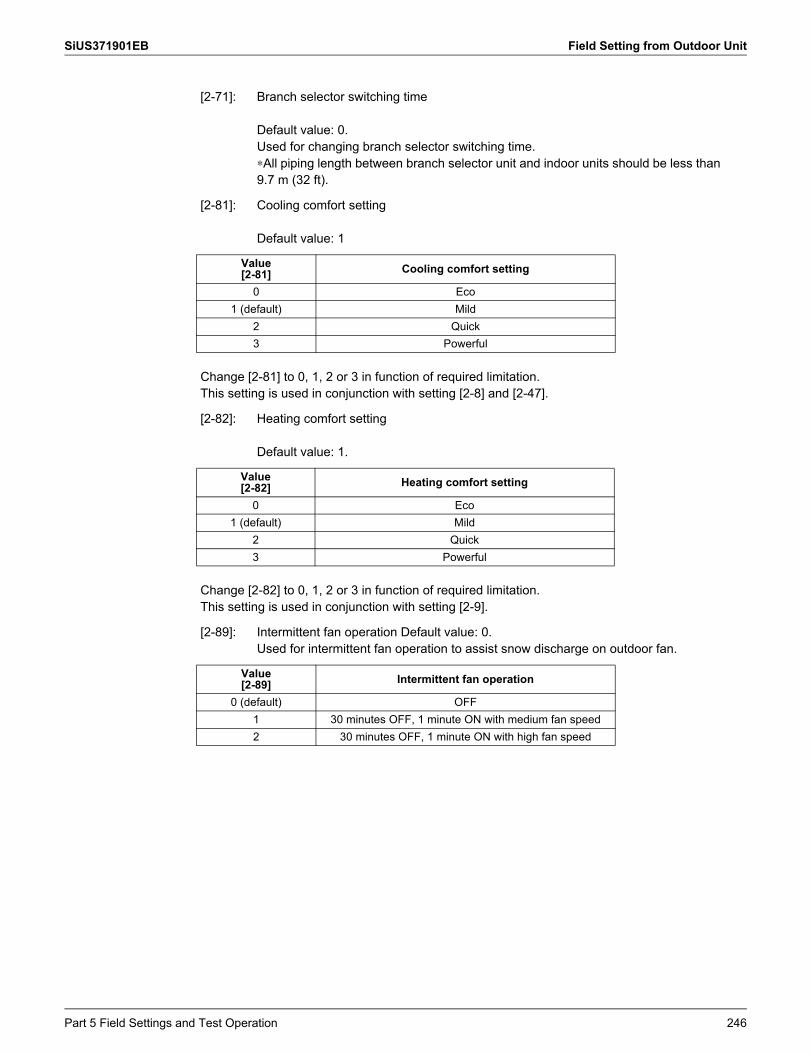
SiUS371901EB Field Setting from Outdoor Unit
[2-71]: Branch selector switching time
Default value: 0.Used for changing branch selector switching time.∗All piping length between branch selector unit and indoor units should be less than 9.7 m (32 ft).
[2-81]: Cooling comfort setting
Default value: 1
Value[2-81] Cooling comfort setting
0 Eco1 (default) Mild
2 Quick3 Powerful
Change [2-81] to 0, 1, 2 or 3 in function of required limitation.This setting is used in conjunction with setting [2-8] and [2-47].
[2-82]: Heating comfort setting
Default value: 1.
Value[2-82] Heating comfort setting
0 Eco1 (default) Mild
2 Quick3 Powerful
Change [2-82] to 0, 1, 2 or 3 in function of required limitation.This setting is used in conjunction with setting [2-9].
[2-89]: Intermittent fan operation Default value: 0.Used for intermittent fan operation to assist snow discharge on outdoor fan.
Value[2-89] Intermittent fan operation
0 (default) OFF1 30 minutes OFF, 1 minute ON with medium fan speed2 30 minutes OFF, 1 minute ON with high fan speed
Part 5 Field Settings and Test Operation 246
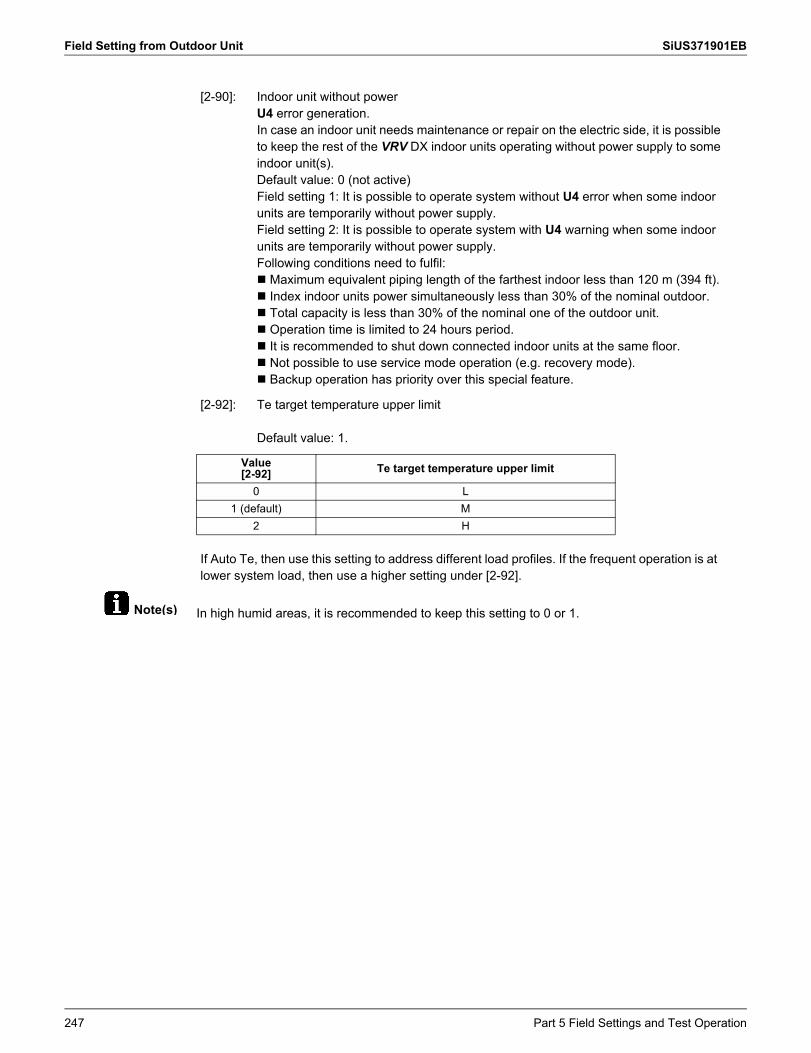
Field Setting from Outdoor Unit SiUS371901EB
Note(s) In high humid areas, it is recommended to keep this setting to 0 or 1.
[2-90]: Indoor unit without powerU4 error generation.In case an indoor unit needs maintenance or repair on the electric side, it is possible to keep the rest of the VRV DX indoor units operating without power supply to some indoor unit(s).Default value: 0 (not active)Field setting 1: It is possible to operate system without U4 error when some indoor units are temporarily without power supply.Field setting 2: It is possible to operate system with U4 warning when some indoor units are temporarily without power supply.Following conditions need to fulfil: Maximum equivalent piping length of the farthest indoor less than 120 m (394 ft). Index indoor units power simultaneously less than 30% of the nominal outdoor. Total capacity is less than 30% of the nominal one of the outdoor unit. Operation time is limited to 24 hours period. It is recommended to shut down connected indoor units at the same floor. Not possible to use service mode operation (e.g. recovery mode). Backup operation has priority over this special feature.
[2-92]: Te target temperature upper limit
Default value: 1.
Value[2-92] Te target temperature upper limit
0 L1 (default) M
2 H
If Auto Te, then use this setting to address different load profiles. If the frequent operation is at lower system load, then use a higher setting under [2-92].
247 Part 5 Field Settings and Test Operation
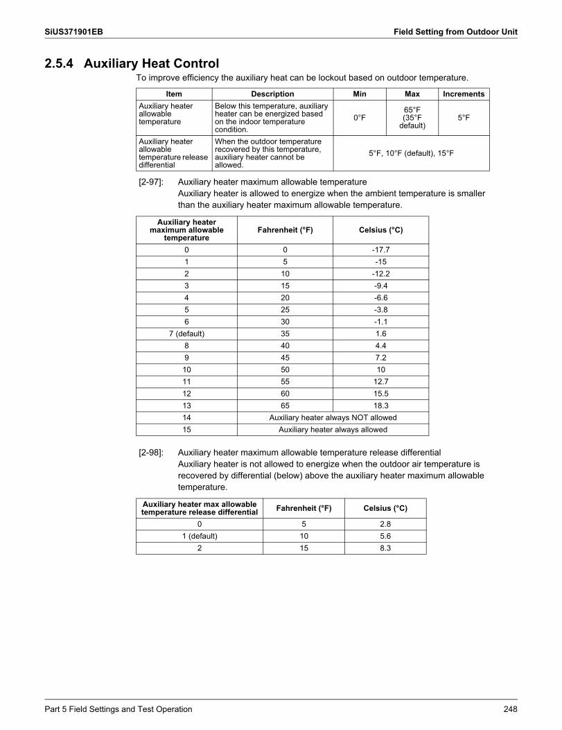
SiUS371901EB Field Setting from Outdoor Unit
2.5.4 Auxiliary Heat ControlTo improve efficiency the auxiliary heat can be lockout based on outdoor temperature.
Item Description Min Max IncrementsAuxiliary heater allowable temperature
Below this temperature, auxiliary heater can be energized based on the indoor temperature condition.
0°F65°F(35°F
default)5°F
Auxiliary heater allowable temperature release differential
When the outdoor temperature recovered by this temperature, auxiliary heater cannot be allowed.
5°F, 10°F (default), 15°F
[2-97]: Auxiliary heater maximum allowable temperatureAuxiliary heater is allowed to energize when the ambient temperature is smaller than the auxiliary heater maximum allowable temperature.
Auxiliary heater maximum allowable
temperatureFahrenheit (°F) Celsius (°C)
0 0 -17.71 5 -152 10 -12.23 15 -9.44 20 -6.65 25 -3.86 30 -1.1
7 (default) 35 1.68 40 4.49 45 7.210 50 1011 55 12.712 60 15.513 65 18.314 Auxiliary heater always NOT allowed15 Auxiliary heater always allowed
[2-98]: Auxiliary heater maximum allowable temperature release differentialAuxiliary heater is not allowed to energize when the outdoor air temperature is recovered by differential (below) above the auxiliary heater maximum allowable temperature.
Auxiliary heater max allowable temperature release differential Fahrenheit (°F) Celsius (°C)
0 5 2.81 (default) 10 5.6
2 15 8.3
Part 5 Field Settings and Test Operation 248
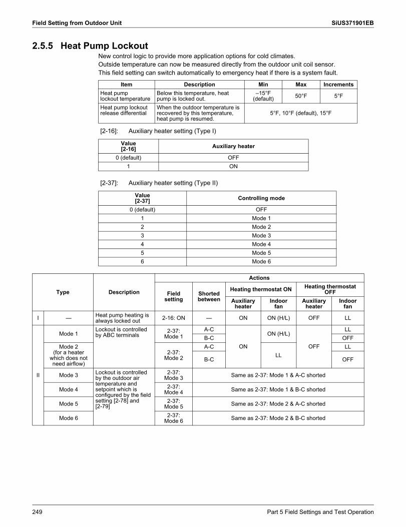
Field Setting from Outdoor Unit SiUS371901EB
2.5.5 Heat Pump LockoutNew control logic to provide more application options for cold climates.Outside temperature can now be measured directly from the outdoor unit coil sensor.This field setting can switch automatically to emergency heat if there is a system fault.
Item Description Min Max IncrementsHeat pumplockout temperature
Below this temperature, heat pump is locked out.
–15°F(default) 50°F 5°F
Heat pump lockout release differential
When the outdoor temperature is recovered by this temperature, heat pump is resumed.
5°F, 10°F (default), 15°F
[2-16]: Auxiliary heater setting (Type I)
Value[2-16] Auxiliary heater
0 (default) OFF1 ON
[2-37]: Auxiliary heater setting (Type II)
Value[2-37] Controlling mode
0 (default) OFF1 Mode 12 Mode 23 Mode 34 Mode 45 Mode 56 Mode 6
Type Description
Actions
Fieldsetting
Shorted between
Heating thermostat ON Heating thermostat OFF
Auxiliaryheater
Indoorfan
Auxiliaryheater
Indoorfan
I — Heat pump heating is always locked out 2-16: ON — ON ON (H/L) OFF LL
II
Mode 1Lockout is controlled by ABC terminals
2-37:Mode 1
A-C
ON
ON (H/L)
OFF
LLB-C OFF
Mode 2(for a heater
which does not need airflow)
2-37:Mode 2
A-CLL
LL
B-C OFF
Mode 3 Lockout is controlled by the outdoor air temperature and setpoint which is configured by the field setting [2-78] and[2-79]
2-37:Mode 3 Same as 2-37: Mode 1 & A-C shorted
Mode 4 2-37:Mode 4 Same as 2-37: Mode 1 & B-C shorted
Mode 5 2-37:Mode 5 Same as 2-37: Mode 2 & A-C shorted
Mode 6 2-37:Mode 6 Same as 2-37: Mode 2 & B-C shorted
249 Part 5 Field Settings and Test Operation
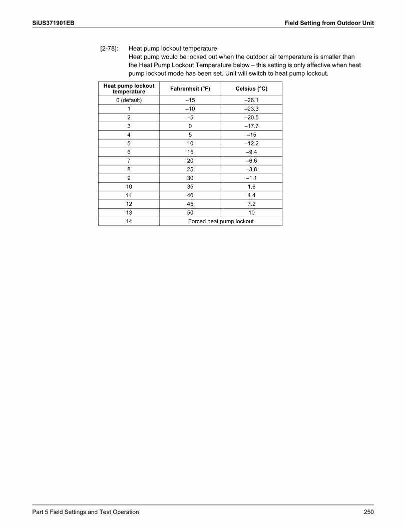
SiUS371901EB Field Setting from Outdoor Unit
[2-78]: Heat pump lockout temperatureHeat pump would be locked out when the outdoor air temperature is smaller than the Heat Pump Lockout Temperature below – this setting is only affective when heat pump lockout mode has been set. Unit will switch to heat pump lockout.
Heat pump lockouttemperature Fahrenheit (°F) Celsius (°C)
0 (default) –15 –26.11 –10 –23.32 –5 –20.53 0 –17.74 5 –155 10 –12.26 15 –9.47 20 –6.68 25 –3.89 30 –1.110 35 1.611 40 4.412 45 7.213 50 1014 Forced heat pump lockout
Part 5 Field Settings and Test Operation 250
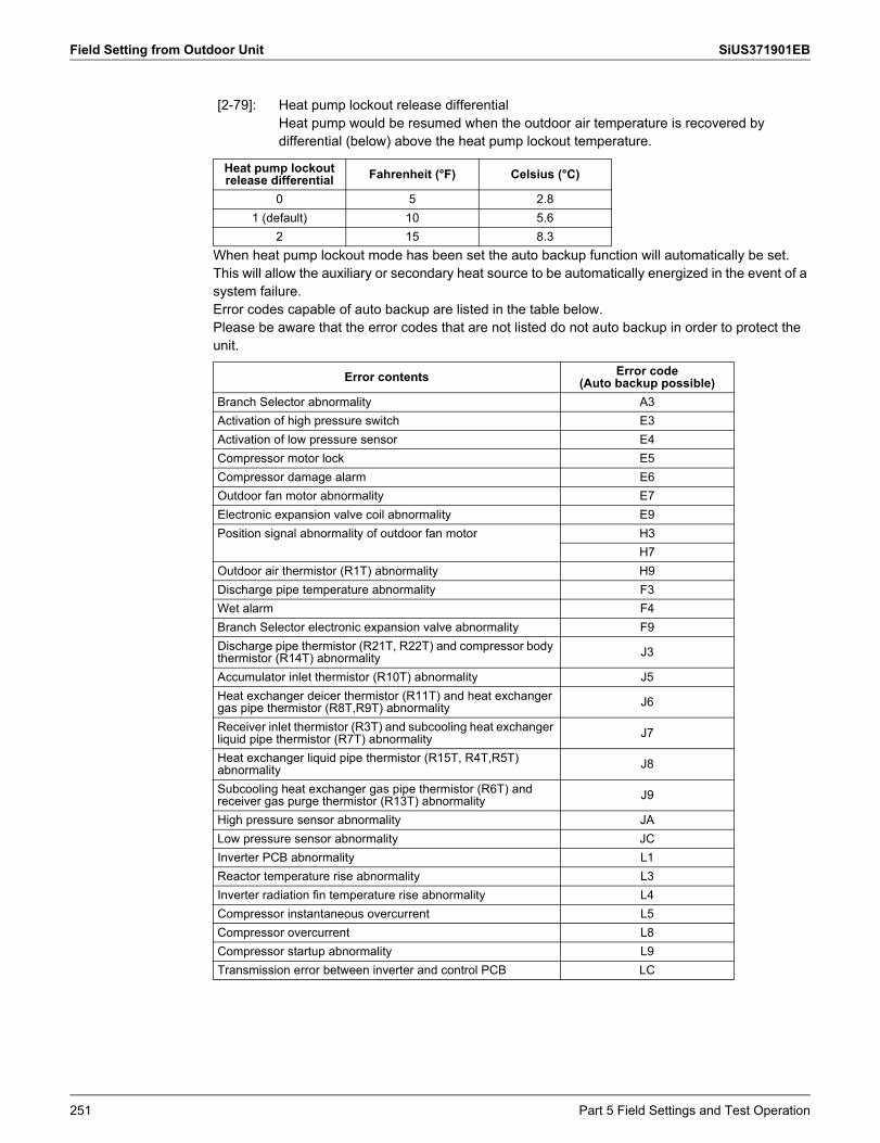
Field Setting from Outdoor Unit SiUS371901EB
When heat pump lockout mode has been set the auto backup function will automatically be set. This will allow the auxiliary or secondary heat source to be automatically energized in the event of a system failure.Error codes capable of auto backup are listed in the table below.Please be aware that the error codes that are not listed do not auto backup in order to protect the unit.
[2-79]: Heat pump lockout release differentialHeat pump would be resumed when the outdoor air temperature is recovered by differential (below) above the heat pump lockout temperature.
Heat pump lockout release differential Fahrenheit (°F) Celsius (°C)
0 5 2.81 (default) 10 5.6
2 15 8.3
Error contents Error code(Auto backup possible)
Branch Selector abnormality A3Activation of high pressure switch E3Activation of low pressure sensor E4Compressor motor lock E5Compressor damage alarm E6Outdoor fan motor abnormality E7Electronic expansion valve coil abnormality E9Position signal abnormality of outdoor fan motor H3
H7Outdoor air thermistor (R1T) abnormality H9Discharge pipe temperature abnormality F3Wet alarm F4Branch Selector electronic expansion valve abnormality F9Discharge pipe thermistor (R21T, R22T) and compressor body thermistor (R14T) abnormality J3
Accumulator inlet thermistor (R10T) abnormality J5Heat exchanger deicer thermistor (R11T) and heat exchanger gas pipe thermistor (R8T,R9T) abnormality J6
Receiver inlet thermistor (R3T) and subcooling heat exchanger liquid pipe thermistor (R7T) abnormality J7
Heat exchanger liquid pipe thermistor (R15T, R4T,R5T) abnormality J8
Subcooling heat exchanger gas pipe thermistor (R6T) and receiver gas purge thermistor (R13T) abnormality J9
High pressure sensor abnormality JALow pressure sensor abnormality JCInverter PCB abnormality L1Reactor temperature rise abnormality L3Inverter radiation fin temperature rise abnormality L4Compressor instantaneous overcurrent L5Compressor overcurrent L8Compressor startup abnormality L9Transmission error between inverter and control PCB LC
251 Part 5 Field Settings and Test Operation
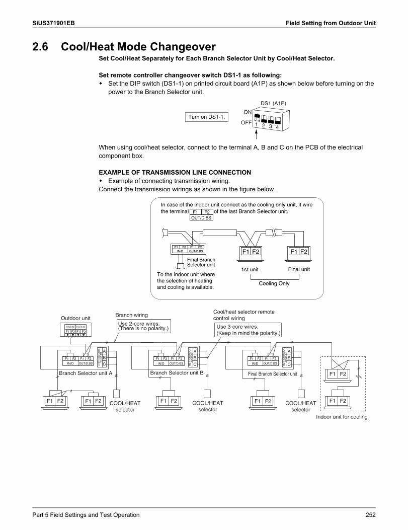
SiUS371901EB Field Setting from Outdoor Unit
2.6 Cool/Heat Mode ChangeoverSet Cool/Heat Separately for Each Branch Selector Unit by Cool/Heat Selector.
Set remote controller changeover switch DS1-1 as following: Set the DIP switch (DS1-1) on printed circuit board (A1P) as shown below before turning on the
power to the Branch Selector unit.
When using cool/heat selector, connect to the terminal A, B and C on the PCB of the electrical component box.
EXAMPLE OF TRANSMISSION LINE CONNECTION Example of connecting transmission wiring.Connect the transmission wirings as shown in the figure below.
Turn on DS1-1.
DS1 (A1P)
ON
OFF 1 2 3 4
F1 F2F1 F2 F1 F2
IN/D OUT/D.BS F1 F2
F1 F2OUT/D.BS
Cooling Only
1st unit Final unit
Final Branch Selector unit
In case of the indoor unit connect as the cooling only unit, it wire the terminal of the last Branch Selector unit.
To the indoor unit where the selection of heating and cooling is available.
F2
B
C
A
F2 F1F1 F2F1
Outdoor unit
TO IN/D UNIT TO OUT/D UNITF1 F2
F1 F2 F1 F2
F1 F2
IN/D OUT/D.BS
RE
MO
TE
CO
NT
RO
LLER
Branch Selector unit A
F1 F2 F1 F2
IN/D OUT/D.BS
Branch Selector unit B
COOL/HEATselector
Branch wiring
Use 2-core wires.(There is no polarity.)
B
C
ARE
MO
TE
CO
NT
RO
LLER
COOL/HEATselector
Cool/heat selector remote control wiring
Use 3-core wires.(Keep in mind the polarity.)
F1 F2 F1 F2
IN/D OUT/D.BS
B
C
ARE
MO
TE
CO
NT
RO
LLER
Final Branch Selector unit
Indoor unit for cooling
F2F1 COOL/HEATselector
F2F1
F2F1
Part 5 Field Settings and Test Operation 252
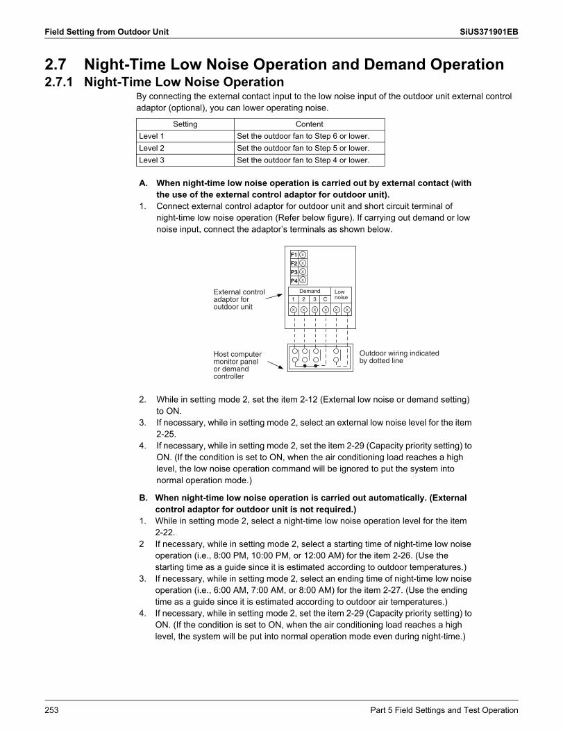
Field Setting from Outdoor Unit SiUS371901EB
2.7 Night-Time Low Noise Operation and Demand Operation2.7.1 Night-Time Low Noise Operation
By connecting the external contact input to the low noise input of the outdoor unit external control adaptor (optional), you can lower operating noise.
Setting ContentLevel 1 Set the outdoor fan to Step 6 or lower.Level 2 Set the outdoor fan to Step 5 or lower.Level 3 Set the outdoor fan to Step 4 or lower.
A.
1.
When night-time low noise operation is carried out by external contact (with the use of the external control adaptor for outdoor unit).Connect external control adaptor for outdoor unit and short circuit terminal of night-time low noise operation (Refer below figure). If carrying out demand or low noise input, connect the adaptor’s terminals as shown below.
2.
3.
4.
While in setting mode 2, set the item 2-12 (External low noise or demand setting) to ON.If necessary, while in setting mode 2, select an external low noise level for the item 2-25.If necessary, while in setting mode 2, set the item 2-29 (Capacity priority setting) to ON. (If the condition is set to ON, when the air conditioning load reaches a high level, the low noise operation command will be ignored to put the system into normal operation mode.)
B.
1.
2
3.
4.
When night-time low noise operation is carried out automatically. (External control adaptor for outdoor unit is not required.)While in setting mode 2, select a night-time low noise operation level for the item 2-22.If necessary, while in setting mode 2, select a starting time of night-time low noise operation (i.e., 8:00 PM, 10:00 PM, or 12:00 AM) for the item 2-26. (Use the starting time as a guide since it is estimated according to outdoor temperatures.)If necessary, while in setting mode 2, select an ending time of night-time low noise operation (i.e., 6:00 AM, 7:00 AM, or 8:00 AM) for the item 2-27. (Use the ending time as a guide since it is estimated according to outdoor air temperatures.)If necessary, while in setting mode 2, set the item 2-29 (Capacity priority setting) to ON. (If the condition is set to ON, when the air conditioning load reaches a high level, the system will be put into normal operation mode even during night-time.)
Outdoor wiring indicated by dotted line
External control adaptor for outdoor unit
Host computer monitor panel or demand controller
X
X
X
X
F1
F2
P3
P4
F1
F2
P3
P4
X X X X X X
1 2 3 C
Demand Low noise
253 Part 5 Field Settings and Test Operation
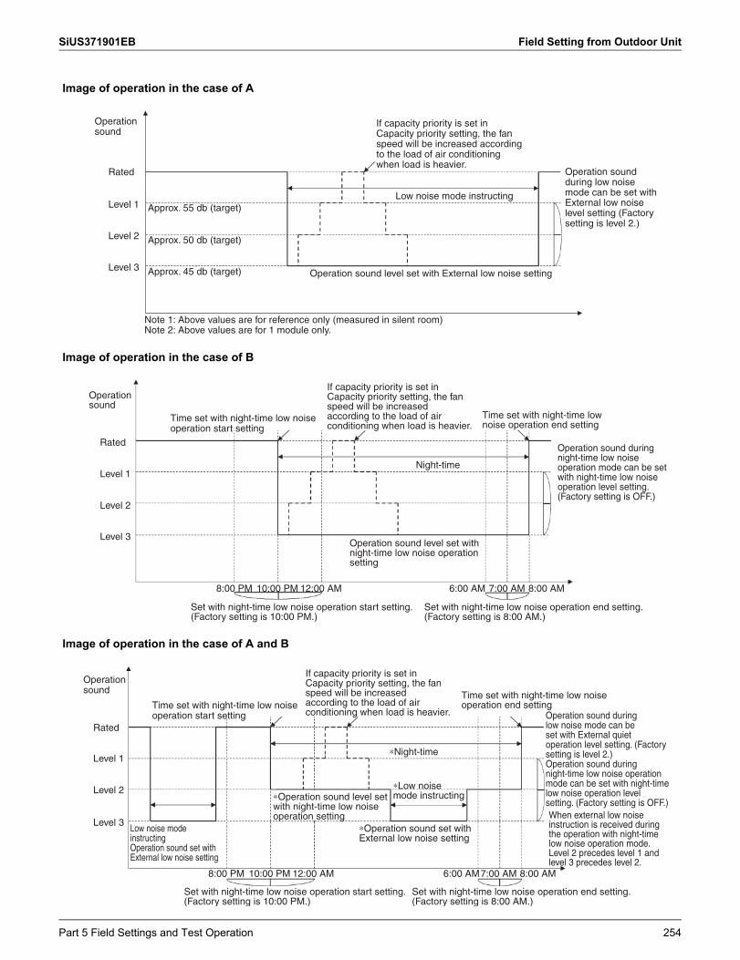
SiUS371901EB Field Setting from Outdoor Unit
Image of operation in the case of A
Image of operation in the case of B
Image of operation in the case of A and B
Operation sound
Rated
Level 1
Level 2
Level 3
Approx. 55 db (target)
Approx. 50 db (target)
Approx. 45 db (target)
Note 1: Above values are for reference only (measured in silent room)Note 2: Above values are for 1 module only.
Operation sound level set with External low noise setting
If capacity priority is set in Capacity priority setting, the fan speed will be increased according to the load of air conditioning when load is heavier.
Operation sound during low noise mode can be set with External low noise level setting (Factory setting is level 2.)
Low noise mode instructing
Operation sound
Rated
Level 1
Level 2
Level 3
Time set with night-time low noise operation start setting
If capacity priority is set in Capacity priority setting, the fan speed will be increased according to the load of air conditioning when load is heavier.
Time set with night-time low noise operation end setting
Operation sound during night-time low noise operation mode can be set with night-time low noise operation level setting. (Factory setting is OFF.)
Night-time
Operation sound level set with night-time low noise operation setting
6:00 AM8:00 PM 10:00 PM 12:00 AM 7:00 AM 8:00 AM
Set with night-time low noise operation end setting. (Factory setting is 8:00 AM.)
Set with night-time low noise operation start setting. (Factory setting is 10:00 PM.)
Operation sound
Rated
Level 1
Level 2
Level 3
Time set with night-time low noise operation start setting
Low noise mode instructing Operation sound set with External low noise setting
10:00 PM8:00 PM 12:00 AM 6:00 AM7:00 AM 8:00 AM
Set with night-time low noise operation start setting. (Factory setting is 10:00 PM.)
Set with night-time low noise operation end setting. (Factory setting is 8:00 AM.)
∗Low noise mode instructing
∗Operation sound set with External low noise setting
∗Night-time
If capacity priority is set in Capacity priority setting, the fan speed will be increased according to the load of air conditioning when load is heavier.
Time set with night-time low noise operation end setting
Operation sound during low noise mode can be set with External quiet operation level setting. (Factory setting is level 2.)Operation sound during night-time low noise operation mode can be set with night-time low noise operation level setting. (Factory setting is OFF.)When external low noise instruction is received during the operation with night-time low noise operation mode.Level 2 precedes level 1 and level 3 precedes level 2.
∗Operation sound level set with night-time low noise operation setting
Part 5 Field Settings and Test Operation 254
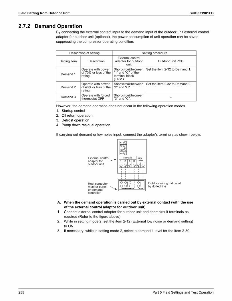
Field Setting from Outdoor Unit SiUS371901EB
2.7.2 Demand OperationBy connecting the external contact input to the demand input of the outdoor unit external control adaptor for outdoor unit (optional), the power consumption of unit operation can be saved suppressing the compressor operating condition.
However, the demand operation does not occur in the following operation modes.1. Startup control2. Oil return operation3. Defrost operation4. Pump down residual operation
If carrying out demand or low noise input, connect the adaptor’s terminals as shown below.
Description of setting Setting procedure
Setting item DescriptionExternal control
adaptor for outdoor unit
Outdoor unit PCB
Demand 1Operate with power of 70% or less of the rating.
Short circuit between "1" and "C" of the terminal block (TeS1).
Set the item 2-32 to Demand 1.
Demand 2Operate with power of 40% or less of the rating.
Short circuit between "2" and "C".
Set the item 2-32 to Demand 2.
Demand 3 Operate with forced thermostat OFF
Short circuit between "3" and "C". –
A.
1.
2.
3.
When the demand operation is carried out by external contact (with the use of the external control adaptor for outdoor unit).Connect external control adaptor for outdoor unit and short circuit terminals as required (Refer to the figure above).While in setting mode 2, set the item 2-12 (External low noise or demand setting) to ON.If necessary, while in setting mode 2, select a demand 1 level for the item 2-30.
Outdoor wiring indicated by dotted line
External control adaptor for outdoor unit
Host computer monitor panel or demand controller
X
X
X
X
F1
F2
P3
P4
F1
F2
P3
P4
X X X X X X
1 2 3 C
Demand Low noise
255 Part 5 Field Settings and Test Operation
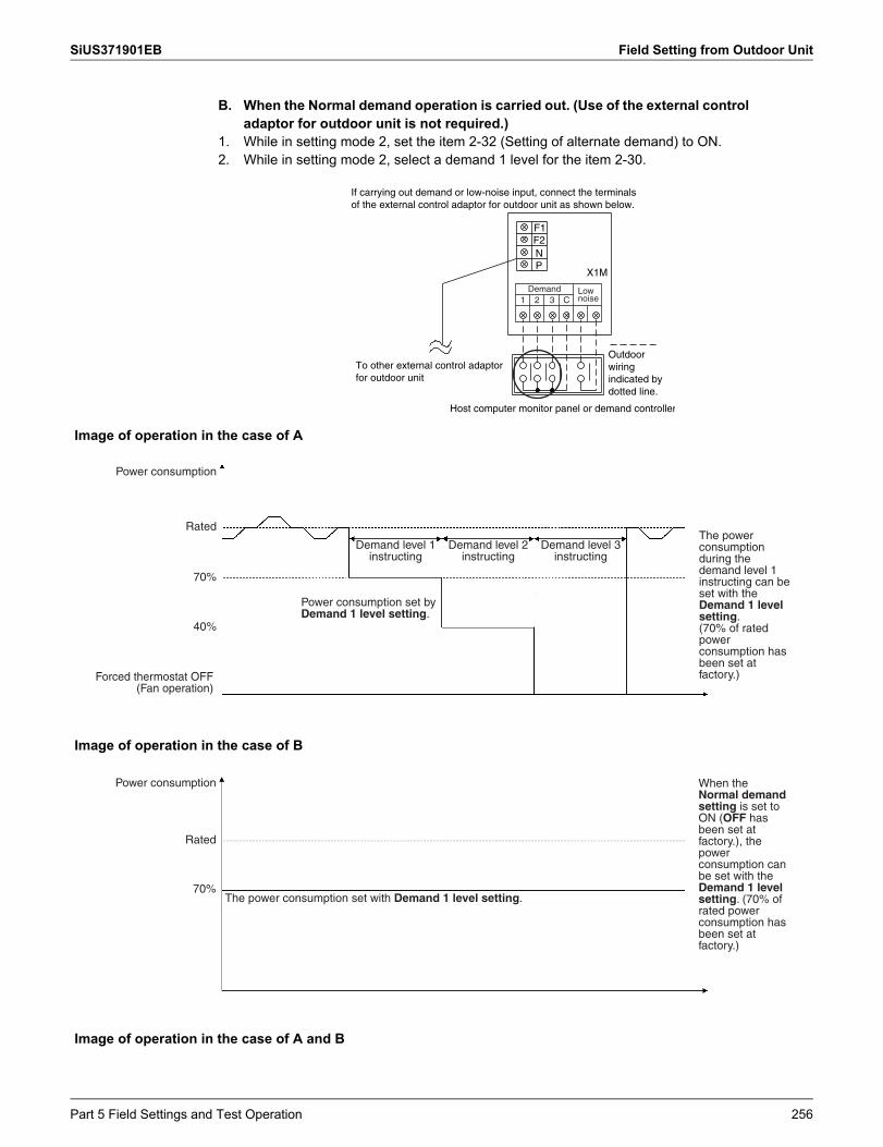
SiUS371901EB Field Setting from Outdoor Unit
B.
1.2.
When the Normal demand operation is carried out. (Use of the external control adaptor for outdoor unit is not required.)While in setting mode 2, set the item 2-32 (Setting of alternate demand) to ON.While in setting mode 2, select a demand 1 level for the item 2-30.
P
F1F2N
X1M
Host computer monitor panel or demand controller
If carrying out demand or low-noise input, connect the terminals of the external control adaptor for outdoor unit as shown below.
To other external control adaptor for outdoor unit
Outdoor wiring indicated by dotted line.
1 2 3 CDemand Low
noise
Image of operation in the case of A
Power consumption
Rated
40%
Forced thermostat OFF(Fan operation)
70%
Demand level 1 instructing
Power consumption set by Demand 1 level setting.
Demand level 2 instructing
Demand level 3 instructing
The power consumption during the demand level 1 instructing can be set with the Demand 1 level setting.(70% of rated power consumption has been set at factory.)
Image of operation in the case of B
The power consumption set with Demand 1 level setting.
When the Normal demand setting is set to ON (OFF has been set at factory.), the power consumption can be set with the Demand 1 level setting. (70% of rated power consumption has been set at factory.)
Power consumption
Rated
70%
Image of operation in the case of A and B
Part 5 Field Settings and Test Operation 256
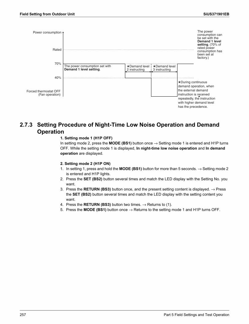
Field Setting from Outdoor Unit SiUS371901EB
2.7.3 Setting Procedure of Night-Time Low Noise Operation and Demand Operation
1. Setting mode 1 (H1P OFF)In setting mode 2, press the MODE (BS1) button once → Setting mode 1 is entered and H1P turns OFF. While the setting mode 1 is displayed, In night-time low noise operation and In demand operation are displayed.
2. Setting mode 2 (H1P ON)1. In setting 1, press and hold the MODE (BS1) button for more than 5 seconds. → Setting mode 2
is entered and H1P lights.2. Press the SET (BS2) button several times and match the LED display with the Setting No. you
want.3. Press the RETURN (BS3) button once, and the present setting content is displayed. → Press
the SET (BS2) button several times and match the LED display with the setting content you want.
4. Press the RETURN (BS3) button two times. → Returns to (1).5. Press the MODE (BS1) button once → Returns to the setting mode 1 and H1P turns OFF.
The power consumption set with Demand 1 level setting.
Demand level 2 instructing
Demand level 3 instructing
The power consumption can be set with the Demand 1 level setting. (70% of rated power consumption has been set at factory.)
During continuous demand operation, when the external demand instruction is received repeatedly, the instruction with higher demand level has the precedence.
Power consumption
Rated
Forced thermostat OFF(Fan operation)
40%
70%
257 Part 5 Field Settings and Test Operation
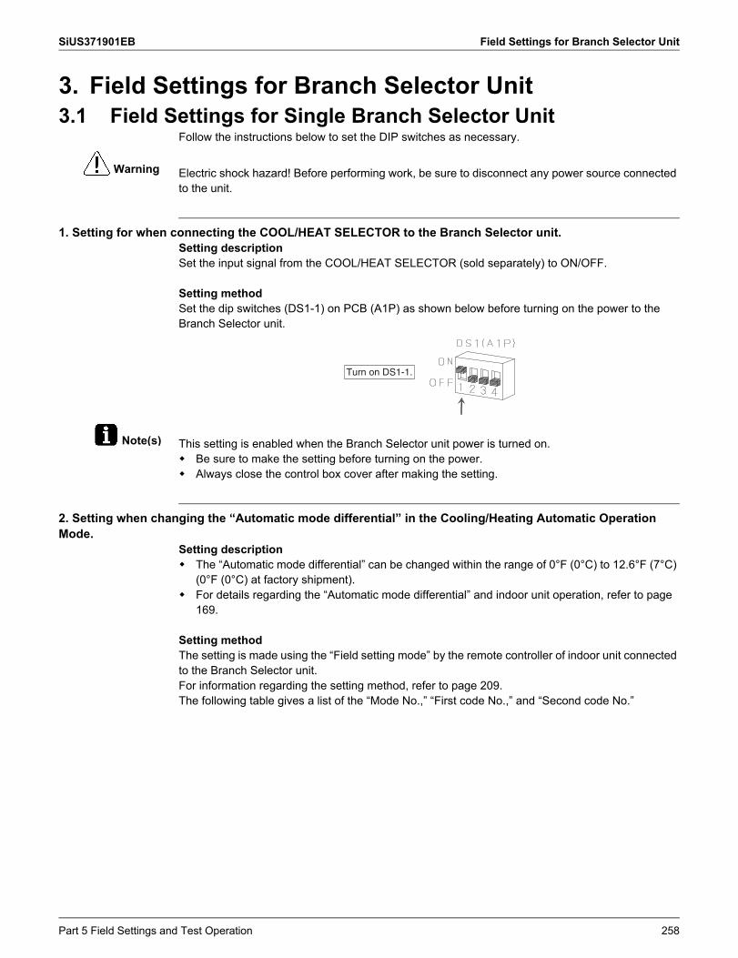
SiUS371901EB Field Settings for Branch Selector Unit
Warning
Note(s)
3. Field Settings for Branch Selector Unit3.1 Field Settings for Single Branch Selector Unit
Follow the instructions below to set the DIP switches as necessary.
Electric shock hazard! Before performing work, be sure to disconnect any power source connected to the unit.
1. Setting for when connecting the COOL/HEAT SELECTOR to the Branch Selector unit.Setting descriptionSet the input signal from the COOL/HEAT SELECTOR (sold separately) to ON/OFF.
Setting methodSet the dip switches (DS1-1) on PCB (A1P) as shown below before turning on the power to the Branch Selector unit.
This setting is enabled when the Branch Selector unit power is turned on. Be sure to make the setting before turning on the power. Always close the control box cover after making the setting.
2. Setting when changing the “Automatic mode differential” in the Cooling/Heating Automatic Operation Mode.
Setting description The “Automatic mode differential” can be changed within the range of 0°F (0°C) to 12.6°F (7°C)
(0°F (0°C) at factory shipment). For details regarding the “Automatic mode differential” and indoor unit operation, refer to page
169.
Setting methodThe setting is made using the “Field setting mode” by the remote controller of indoor unit connected to the Branch Selector unit.For information regarding the setting method, refer to page 209.The following table gives a list of the “Mode No.,” “First code No.,” and “Second code No.”
Turn on DS1-1.
Part 5 Field Settings and Test Operation 258
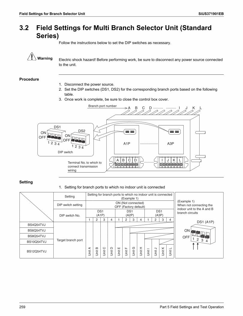
Field Settings for Branch Selector Unit SiUS371901EB
Warning
3.2 Field Settings for Multi Branch Selector Unit (Standard Series)
Follow the instructions below to set the DIP switches as necessary.
Electric shock hazard! Before performing work, be sure to disconnect any power source connected to the unit.
Procedure1. Disconnect the power source.2. Set the DIP switches (DS1, DS2) for the corresponding branch ports based on the following
table.3. Once work is complete, be sure to close the control box cover.
Setting1. Setting for branch ports to which no indoor unit is connected
ONOFF
ONOFF
1A1P A3P
2 3 41 2
DS1DS2
3 4
A B C D I J K L
..................
..........
.......... ..........A B C D I J K LBranch port number
Terminal No. to which to connect transmission wiring
DIP switch
SettingSetting for branch ports to which no indoor unit is connected
(Example 1)(Example 1)When not connecting the indoor unit to the A and B branch circuits
ON
OFF 1 2
DS1 (A1P)
3 4
DIP switch settingON (Not connected)
OFF (Factory default)
DIP switch No.DS1
(A1P)DS1
(A2P)DS1
(A3P)1 2 3 4 1 2 3 4 1 2 3 4
BS4Q54TVJ
Target branch port
Uni
t A
Uni
t B
Uni
t C
Uni
t D
BS6Q54TVJ
Uni
t E
Uni
t F
BS8Q54TVJ
Uni
t G
Uni
t H
BS10Q54TVJ
Uni
t I
Uni
t JBS12Q54TVJ
Uni
t K
Uni
t L
259 Part 5 Field Settings and Test Operation
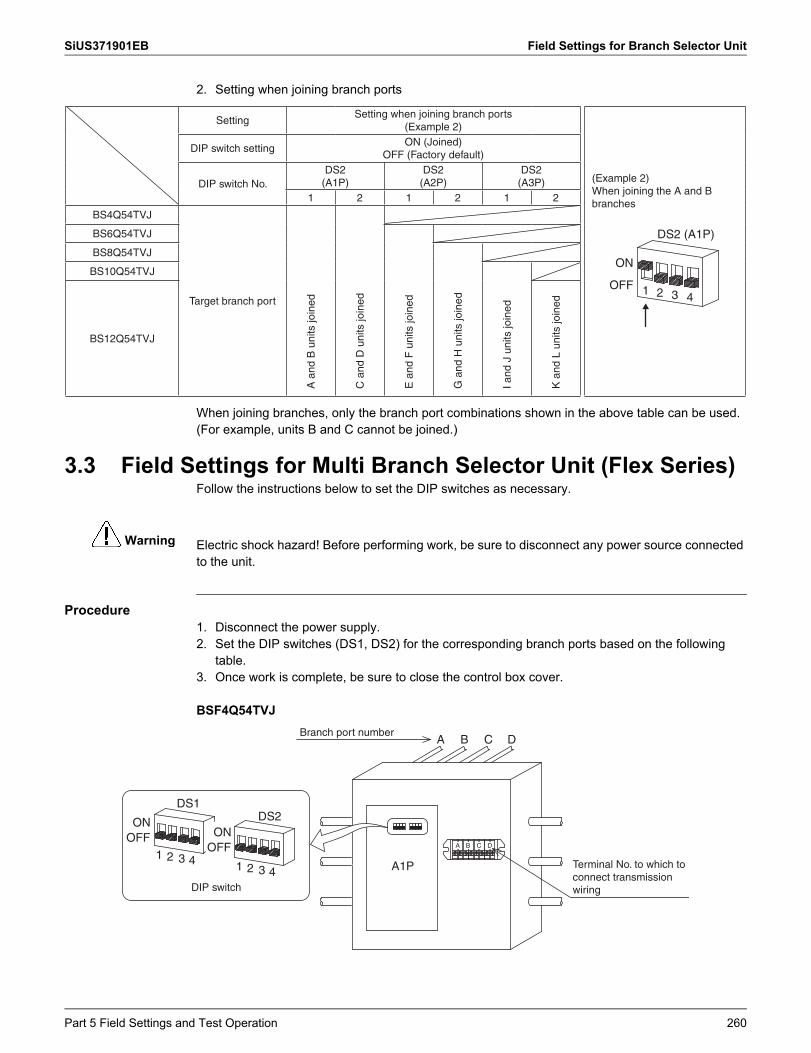
SiUS371901EB Field Settings for Branch Selector Unit
Warning
2. Setting when joining branch ports
When joining branches, only the branch port combinations shown in the above table can be used.(For example, units B and C cannot be joined.)
3.3 Field Settings for Multi Branch Selector Unit (Flex Series)Follow the instructions below to set the DIP switches as necessary.
Electric shock hazard! Before performing work, be sure to disconnect any power source connected to the unit.
Procedure1. Disconnect the power supply.2. Set the DIP switches (DS1, DS2) for the corresponding branch ports based on the following
table.3. Once work is complete, be sure to close the control box cover.
BSF4Q54TVJ
SettingSetting when joining branch ports
(Example 2)
(Example 2)When joining the A and B branches
ON
OFF 1 2
DS2 (A1P)
3 4
DIP switch settingON (Joined)
OFF (Factory default)
DIP switch No.DS2
(A1P)DS2
(A2P)DS2
(A3P)1 2 1 2 1 2
BS4Q54TVJ
Target branch portA
and
B u
nits
join
ed
C a
nd D
uni
ts jo
ined
BS6Q54TVJ
E a
nd F
uni
ts jo
ined
BS8Q54TVJ
G a
nd H
uni
ts jo
ined
BS10Q54TVJ
I and
J u
nits
join
ed
BS12Q54TVJ
K a
nd L
uni
ts jo
ined
A B C D
A1P
ONOFF
ONOFF
1 2 3 41 2
DS1DS2
3 4A B C D
Branch port number
Terminal No. to which to connect transmission wiringDIP switch
Part 5 Field Settings and Test Operation 260
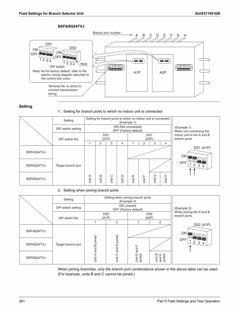
Field Settings for Branch Selector Unit SiUS371901EB
BSF6/8Q54TVJ
Setting1. Setting for branch ports to which no indoor unit is connected
2. Setting when joining branch ports
When joining branches, only the branch port combinations shown in the above table can be used.(For example, units B and C cannot be joined.)
A B C D E F G H
A1P
ONOFF
ONOFF
1 2 3 41 2
DS1DS2
3 4
A B C D
A2P
E F G H
Terminal No. to which to connect transmission wiring
DIP switch
Branch port number
Note) As for factory default, refer to the electric wiring diagram attached to the control box cover.
Note
SettingSetting for branch ports to which no indoor unit is connected
(Example 1)
(Example 1)When not connecting the indoor unit to the A and B branch ports
ON
OFF 1 2
DS1 (A1P)
3 4
DIP switch settingON (Not connected)
OFF (Factory default)
DIP switch No.DS1
(A1P)DS1
(A2P)1 2 3 4 1 2 3 4
BSF4Q54TVJ
Target branch port
Uni
t A
Uni
t B
Uni
t C
Uni
t D
BSF6Q54TVJ
Uni
t E
Uni
t FBSF8Q54TVJ
Uni
t G
Uni
t H
SettingSetting when joining branch ports
(Example 2)
(Example 2)When joining the A and B branch ports
ON
OFF 1 2
DS2 (A1P)
3 4
DIP switch settingON (Joined)
OFF (Factory default)
DIP switch No.DS2
(A1P)DS2
(A2P)1 2 1 2
BSF4Q54TVJ
Target branch port
Uni
t A a
nd B
join
ed
Uni
t C a
nd D
join
ed
BSF6Q54TVJ
Uni
t E a
nd F
jo
inedBSF8Q54TVJ
Uni
t G
and
H
join
ed
261 Part 5 Field Settings and Test Operation
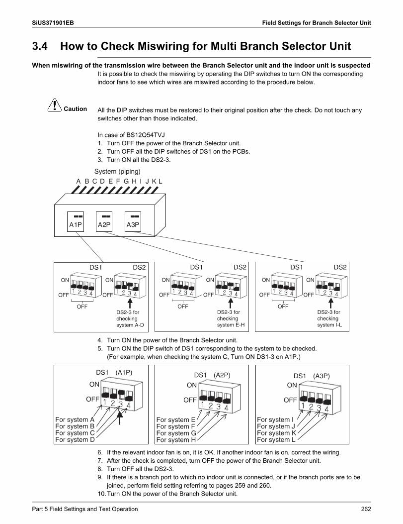
SiUS371901EB Field Settings for Branch Selector Unit
Caution
3.4 How to Check Miswiring for Multi Branch Selector UnitWhen miswiring of the transmission wire between the Branch Selector unit and the indoor unit is suspected
It is possible to check the miswiring by operating the DIP switches to turn ON the corresponding indoor fans to see which wires are miswired according to the procedure below.
All the DIP switches must be restored to their original position after the check. Do not touch any switches other than those indicated.
In case of BS12Q54TVJ1. Turn OFF the power of the Branch Selector unit.2. Turn OFF all the DIP switches of DS1 on the PCBs.3. Turn ON all the DS2-3.
4. Turn ON the power of the Branch Selector unit.5. Turn ON the DIP switch of DS1 corresponding to the system to be checked.
(For example, when checking the system C, Turn ON DS1-3 on A1P.)
6. If the relevant indoor fan is on, it is OK. If another indoor fan is on, correct the wiring.7. After the check is completed, turn OFF the power of the Branch Selector unit.8. Turn OFF all the DS2-3.9. If there is a branch port to which no indoor unit is connected, or if the branch ports are to be
joined, perform field setting referring to pages 259 and 260.10.Turn ON the power of the Branch Selector unit.
DS2DS1
A B C D E F G H I J K L
System (piping)
A1P A2P A3P
ON
OFF
ON
OFF
DS2-3 for checking system A-D
OFF
DS2DS1
ON
OFF
ON
OFF
DS2-3 for checking system E-H
OFF
DS2DS1
ON
OFF
ON
OFF
DS2-3 for checking system I-L
OFF
DS1 (A1P) DS1 (A2P) DS1 (A3P)
For system A
ON
OFF
ON
OFF
ON
OFF
For system DFor system CFor system B
For system E
For system HFor system GFor system F
For system I
For system LFor system KFor system J
Part 5 Field Settings and Test Operation 262
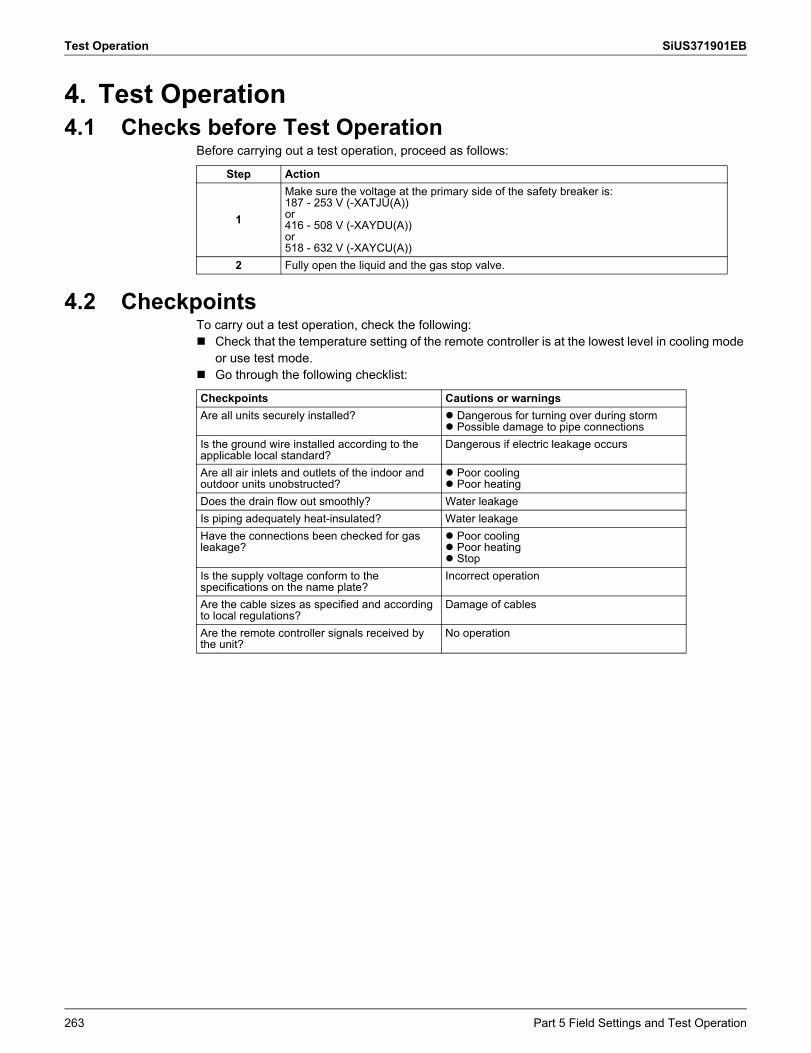
Test Operation SiUS371901EB
4. Test Operation4.1 Checks before Test Operation
Before carrying out a test operation, proceed as follows:
4.2 CheckpointsTo carry out a test operation, check the following: Check that the temperature setting of the remote controller is at the lowest level in cooling mode
or use test mode. Go through the following checklist:
Step Action
1
Make sure the voltage at the primary side of the safety breaker is:187 - 253 V (-XATJU(A))or416 - 508 V (-XAYDU(A))or518 - 632 V (-XAYCU(A))
2 Fully open the liquid and the gas stop valve.
Checkpoints Cautions or warningsAre all units securely installed? Dangerous for turning over during storm
Possible damage to pipe connectionsIs the ground wire installed according to the applicable local standard?
Dangerous if electric leakage occurs
Are all air inlets and outlets of the indoor and outdoor units unobstructed?
Poor cooling Poor heating
Does the drain flow out smoothly? Water leakageIs piping adequately heat-insulated? Water leakageHave the connections been checked for gas leakage?
Poor cooling Poor heating Stop
Is the supply voltage conform to the specifications on the name plate?
Incorrect operation
Are the cable sizes as specified and according to local regulations?
Damage of cables
Are the remote controller signals received by the unit?
No operation
263 Part 5 Field Settings and Test Operation
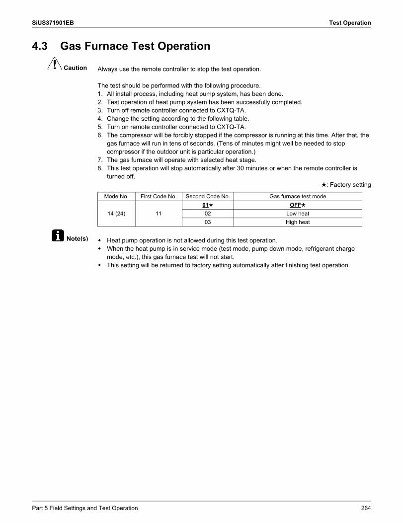
SiUS371901EB Test Operation
Caution
Note(s)
4.3 Gas Furnace Test Operation
Always use the remote controller to stop the test operation.
The test should be performed with the following procedure.1. All install process, including heat pump system, has been done.2. Test operation of heat pump system has been successfully completed.3. Turn off remote controller connected to CXTQ-TA.4. Change the setting according to the following table.5. Turn on remote controller connected to CXTQ-TA.6. The compressor will be forcibly stopped if the compressor is running at this time. After that, the
gas furnace will run in tens of seconds. (Tens of minutes might well be needed to stop compressor if the outdoor unit is particular operation.)
7. The gas furnace will operate with selected heat stage.8. This test operation will stop automatically after 30 minutes or when the remote controller is
turned off.: Factory setting
Heat pump operation is not allowed during this test operation. When the heat pump is in service mode (test mode, pump down mode, refrigerant charge
mode, etc.), this gas furnace test will not start. This setting will be returned to factory setting automatically after finishing test operation.
Mode No. First Code No. Second Code No. Gas furnace test mode
14 (24) 1101 OFF02 Low heat03 High heat
Part 5 Field Settings and Test Operation 264
SiUS371901EB
Part 6 Service Diagnosis
1. Symptom-based Troubleshooting ...........................................................2681.1 Indoor Unit Overall ................................................................................... 2681.2 With Gas Furnace .................................................................................... 2711.3 Gas Furnace Lockout Reset..................................................................... 2711.4 With Optional Infrared Presence/Floor Sensor......................................... 272
2. Troubleshooting with Remote Controller.................................................2732.1 BRC1E73 ................................................................................................. 2732.2 BRC1H71W.............................................................................................. 2742.3 Wireless Remote Controller ..................................................................... 274
3. Troubleshooting by Error Code ...............................................................2773.1 Error Codes and Descriptions .................................................................. 2773.2 Error Codes (Sub Codes)......................................................................... 2803.3 External Protection Device Abnormality ................................................... 2903.4 Indoor Unit Control PCB Abnormality....................................................... 2923.5 Drain Level Control System Abnormality.................................................. 2933.6 Indoor Fan Motor Lock, Overload............................................................. 2953.7 Indoor Fan Motor Abnormality.................................................................. 2973.8 Overload/Overcurrent/Lock of Indoor Fan Motor...................................... 3013.9 Blower Motor Not Running ....................................................................... 3023.10 Indoor Fan Motor Status Abnormality....................................................... 3033.11 Low Indoor Airflow.................................................................................... 3043.12 Swing Flap Motor Abnormality ................................................................. 3053.13 Power Supply Voltage Abnormality .......................................................... 3073.14 Blower Motor Stops for Over/Under Voltage ............................................ 3083.15 Electronic Expansion Valve Coil Abnormality, Dust Clogging .................. 3093.16 Gas Furnace Abnormality......................................................................... 3103.17 Drain Level above Limit............................................................................ 3113.18 Capacity Determination Device Abnormality ............................................ 3123.19 Transmission Abnormality between Indoor Unit Control PCB and Fan
PCB.......................................................................................................... 3133.20 Blower Motor Communication Error ......................................................... 3153.21 Climate Talk Communication Error .......................................................... 3163.22 Thermistor Abnormality ............................................................................ 3173.23 Combination Error between Indoor Unit Control PCB and Fan PCB ....... 3183.24 Blower Motor HP Mismatch...................................................................... 3193.25 Indoor Blower Does Not Have Required Parameters to Function............ 3203.26 Remote Sensor Abnormality .................................................................... 3213.27 Humidity Sensor System Abnormality ...................................................... 3223.28 Infrared Presence/Floor Sensor Error ...................................................... 323
265 Part 6 Service Diagnosis
SiUS371901EB
3.29 Remote Controller Thermistor Abnormality .............................................. 3283.30 Outdoor Unit Main PCB Abnormality........................................................ 3293.31 Detection of Ground Leakage by Leak Detection Circuit ......................... 3303.32 Missing of Ground Leakage Detection Core ............................................ 3313.33 Activation of High Pressure Switch .......................................................... 3323.34 Activation of Low Pressure Sensor .......................................................... 3343.35 Compressor Motor Lock ........................................................................... 3363.36 Compressor Damage Alarm..................................................................... 3383.37 Outdoor Fan Motor Abnormality ............................................................... 3403.38 Electronic Expansion Valve Coil Abnormality........................................... 3443.39 Discharge Pipe Temperature Abnormality ............................................... 3453.40 Wet Alarm................................................................................................. 3473.41 Refrigerant Overcharged.......................................................................... 3493.42 Branch Selector Unit Electronic Expansion Valve Abnormality................ 3503.43 Harness Abnormality (between Outdoor Unit Main PCB and Inverter
PCB)......................................................................................................... 3523.44 Outdoor Fan Motor Signal Abnormality .................................................... 3533.45 Outdoor Fan PCB Abnormality................................................................. 3543.46 Thermistor Abnormality ............................................................................ 3553.47 High Pressure Sensor Abnormality .......................................................... 3573.48 Low Pressure Sensor Abnormality ........................................................... 3583.49 Inverter PCB Abnormality......................................................................... 3593.50 Momentary Power Failure during Test Operation .................................... 3613.51 Reactor Temperature Rise Abnormality ................................................... 3623.52 Inverter Radiation Fin Temperature Rise Abnormality ............................. 3633.53 Compressor Instantaneous Overcurrent .................................................. 3663.54 Compressor Overcurrent.......................................................................... 3683.55 Compressor Startup Abnormality ............................................................. 3703.56 Transmission Error between Inverter PCB and Outdoor Unit Main PCB . 3723.57 Power Supply Voltage Imbalance ............................................................ 3743.58 Reactor Surface Thermistor Abnormality ................................................. 3763.59 Inverter Radiation Fin Temperature Abnormality ..................................... 3773.60 Field Setting after Replacing Outdoor Unit Main PCB Abnormality or
Combination of PCB Abnormality............................................................. 3793.61 Refrigerant Shortage ................................................................................ 3803.62 Reverse Phase, Open Phase................................................................... 3813.63 Power Supply Insufficient or Instantaneous Abnormality ......................... 3833.64 Check Operation Not Executed................................................................ 3853.65 Transmission Error between Indoor Units and Outdoor Units, Open
Phase in Power Supply Wiring ................................................................. 3863.66 Transmission Error between Remote Controller and Indoor Unit............. 3893.67 Transmission Error between Outdoor Units ............................................. 3903.68 Transmission Error between Main and Sub Remote Controllers ............. 3963.69 Transmission Error between Indoor Units and Outdoor Units in the
Same System........................................................................................... 3973.70 Improper Combination of Indoor, Branch Selector and Outdoor Units..... 3983.71 Incorrect Gas Furnace Connecting Number............................................. 4053.72 Incorrect Electric Heater Capacity Setting................................................ 4063.73 Address Duplication of Centralized Controller.......................................... 407
Part 6 Service Diagnosis 266
SiUS371901EB
3.74 Transmission Error between Centralized Controller and Indoor Unit ....... 4083.75 System Not Set Yet .................................................................................. 4113.76 System Abnormality, Refrigerant System Address Undefined ................. 4123.77 Climate Talk Communication System Combination Error (Before Initial
Setting for Communication Completes).................................................... 4143.78 Climate Talk Communication System Combination Error (After Initial
Setting for Communication Completes).................................................... 4154. Check ......................................................................................................416
4.1 High Pressure Check ............................................................................... 4164.2 Low Pressure Check ................................................................................ 4174.3 Superheat Operation Check..................................................................... 4194.4 Power Transistor Check ........................................................................... 4214.5 Refrigerant Overcharge Check................................................................. 4264.6 Refrigerant Shortage Check..................................................................... 4274.7 Vacuuming and Dehydration Procedure .................................................. 4284.8 Thermistor Check ..................................................................................... 4294.9 Pressure Sensor Check ........................................................................... 4324.10 Broken Wire Check of the Relay Wires .................................................... 4334.11 Fan Motor Connector Check (Power Supply Cable) ................................ 4354.12 Fan Motor Connector Check (Signal Cable) ............................................ 4374.13 Electronic Expansion Valve Coil Check ................................................... 4394.14 Fan Motor Connector Check for FXTQ-TA............................................... 442
267 Part 6 Service Diagnosis
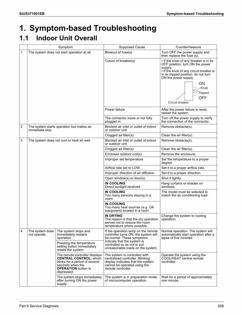
SiUS371901EB Symptom-based Troubleshooting
1. Symptom-based Troubleshooting1.1 Indoor Unit Overall
Symptom Supposed Cause Countermeasure1 The system does not start operation at all. Blowout of fuse(s) Turn OFF the power supply and
then replace the fuse (s).Cutout of breaker(s) • If the knob of any breaker is in its
OFF position, turn ON the power supply.• If the knob of any circuit breaker is in its tripped position, do not turn ON the power supply.
Power failure After the power failure is reset, restart the system.
The connector loose or not fully plugged in
Turn off the power supply to verify the connection of the connector.
2 The system starts operation but makes an immediate stop.
Blocked air inlet or outlet of indoor or outdoor unit
Remove obstacle(s).
Clogged air filter(s) Clean the air filter(s).3 The system does not cool or heat air well. Blocked air inlet or outlet of indoor
or outdoor unitRemove obstacle(s).
Clogged air filter(s) Clean the air filter(s).Enclosed outdoor unit(s) Remove the enclosure.Improper set temperature Set the temperature to a proper
degree.Airflow rate set to LOW Set it to a proper airflow rate.Improper direction of air diffusion Set it to a proper direction.Open window(s) or door(s) Shut it tightly.IN COOLINGDirect sunlight received
Hang curtains or shades on windows.
IN COOLINGToo many persons staying in a room
The model must be selected to match the air conditioning load.
IN COOLINGToo many heat sources (e.g. OA equipment) located in a roomIN DRYINGThe reason is that the dry operation serves not to reduce the room temperature where possible.
Change the system to cooling operation.
4 The system does not operate.
The system stops and immediately restarts operation.
If the operation lamp on the remote controller turns ON, the system will be normal. These symptoms indicate that the system is controlled so as not to put unreasonable loads on the system.
Normal operation. The system will automatically start operation after a lapse of five minutes.
Pressing the temperature setting button immediately resets the system.The remote controller displays CENTRAL CONTROL, which blinks for a period of several seconds when the OPERATION button is depressed.
The system is controlled with centralized controller. Blinking display indicates that the system cannot be operated using the remote controller.
Operate the system using the COOL/HEAT central remote controller.
The system stops immediately after turning ON the power supply.
The system is in preparation mode of microcomputer operation.
Wait for a period of approximately one minute.
ONKnob
Tripped
OFFCircuit breaker
Part 6 Service Diagnosis 268
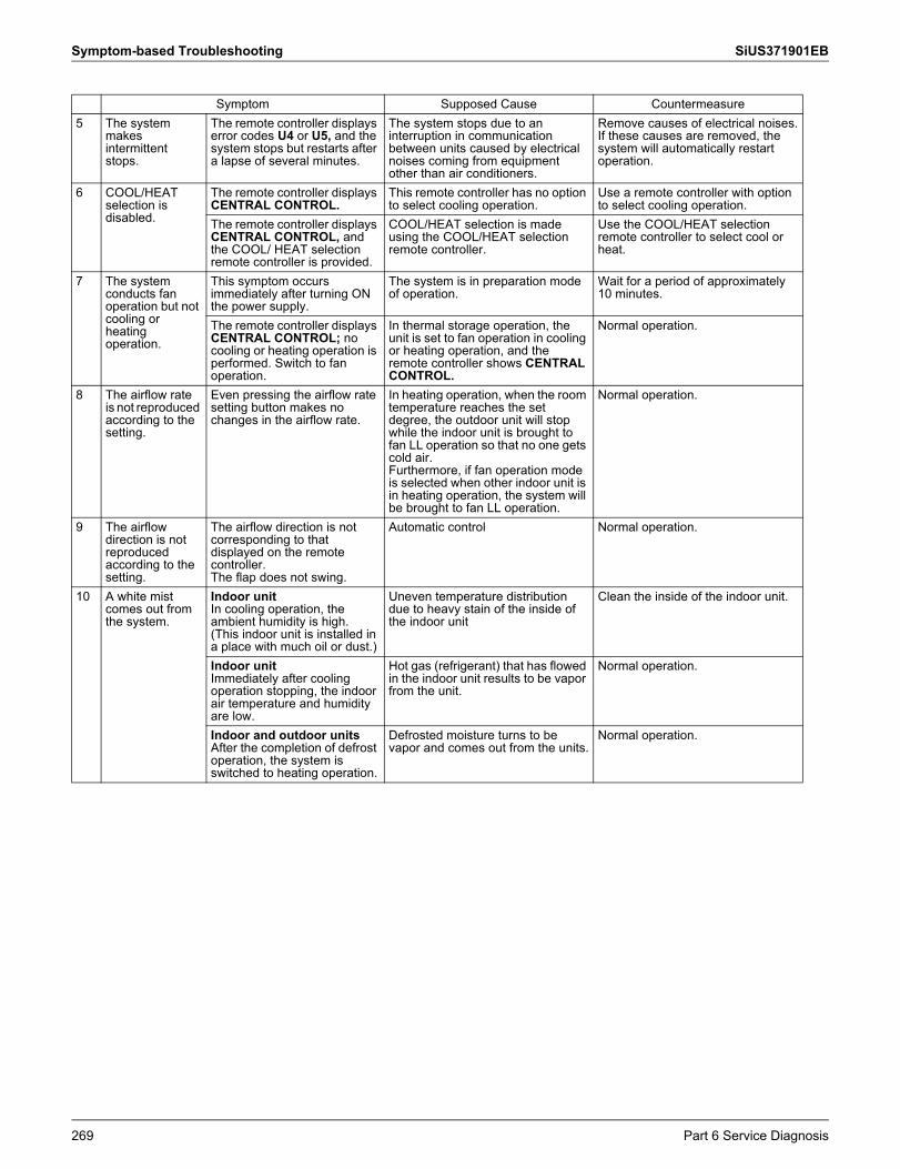
Symptom-based Troubleshooting SiUS371901EB
5 The system makes intermittent stops.
The remote controller displays error codes U4 or U5, and the system stops but restarts after a lapse of several minutes.
The system stops due to an interruption in communication between units caused by electrical noises coming from equipment other than air conditioners.
Remove causes of electrical noises.If these causes are removed, the system will automatically restart operation.
6 COOL/HEAT selection is disabled.
The remote controller displays CENTRAL CONTROL.
This remote controller has no option to select cooling operation.
Use a remote controller with option to select cooling operation.
The remote controller displays CENTRAL CONTROL, and the COOL/ HEAT selection remote controller is provided.
COOL/HEAT selection is made using the COOL/HEAT selection remote controller.
Use the COOL/HEAT selection remote controller to select cool or heat.
7 The system conducts fan operation but not cooling or heating operation.
This symptom occurs immediately after turning ON the power supply.
The system is in preparation mode of operation.
Wait for a period of approximately 10 minutes.
The remote controller displays CENTRAL CONTROL; no cooling or heating operation is performed. Switch to fan operation.
In thermal storage operation, the unit is set to fan operation in cooling or heating operation, and the remote controller shows CENTRAL CONTROL.
Normal operation.
8 The airflow rate is not reproduced according to the setting.
Even pressing the airflow rate setting button makes no changes in the airflow rate.
In heating operation, when the room temperature reaches the set degree, the outdoor unit will stop while the indoor unit is brought to fan LL operation so that no one gets cold air.Furthermore, if fan operation mode is selected when other indoor unit is in heating operation, the system will be brought to fan LL operation.
Normal operation.
9 The airflow direction is not reproduced according to the setting.
The airflow direction is not corresponding to that displayed on the remote controller.The flap does not swing.
Automatic control Normal operation.
10 A white mist comes out from the system.
Indoor unitIn cooling operation, the ambient humidity is high.(This indoor unit is installed in a place with much oil or dust.)
Uneven temperature distribution due to heavy stain of the inside of the indoor unit
Clean the inside of the indoor unit.
Indoor unitImmediately after cooling operation stopping, the indoor air temperature and humidity are low.
Hot gas (refrigerant) that has flowed in the indoor unit results to be vapor from the unit.
Normal operation.
Indoor and outdoor units After the completion of defrost operation, the system is switched to heating operation.
Defrosted moisture turns to be vapor and comes out from the units.
Normal operation.
Symptom Supposed Cause Countermeasure
269 Part 6 Service Diagnosis
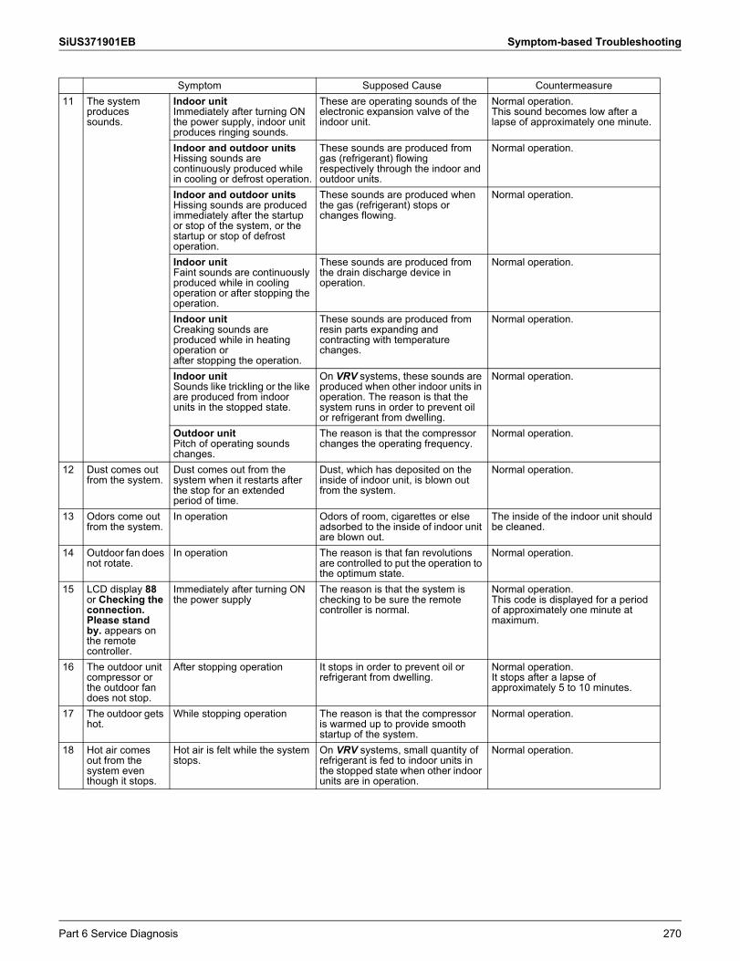
SiUS371901EB Symptom-based Troubleshooting
11 The system produces sounds.
Indoor unitImmediately after turning ON the power supply, indoor unit produces ringing sounds.
These are operating sounds of the electronic expansion valve of the indoor unit.
Normal operation.This sound becomes low after a lapse of approximately one minute.
Indoor and outdoor units Hissing sounds are continuously produced while in cooling or defrost operation.
These sounds are produced from gas (refrigerant) flowing respectively through the indoor and outdoor units.
Normal operation.
Indoor and outdoor units Hissing sounds are produced immediately after the startup or stop of the system, or the startup or stop of defrost operation.
These sounds are produced when the gas (refrigerant) stops or changes flowing.
Normal operation.
Indoor unitFaint sounds are continuously produced while in cooling operation or after stopping the operation.
These sounds are produced from the drain discharge device in operation.
Normal operation.
Indoor unitCreaking sounds are produced while in heating operation orafter stopping the operation.
These sounds are produced from resin parts expanding and contracting with temperature changes.
Normal operation.
Indoor unitSounds like trickling or the like are produced from indoor units in the stopped state.
On VRV systems, these sounds are produced when other indoor units in operation. The reason is that the system runs in order to prevent oil or refrigerant from dwelling.
Normal operation.
Outdoor unitPitch of operating sounds changes.
The reason is that the compressor changes the operating frequency.
Normal operation.
12 Dust comes out from the system.
Dust comes out from the system when it restarts after the stop for an extended period of time.
Dust, which has deposited on the inside of indoor unit, is blown out from the system.
Normal operation.
13 Odors come out from the system.
In operation Odors of room, cigarettes or else adsorbed to the inside of indoor unit are blown out.
The inside of the indoor unit should be cleaned.
14 Outdoor fan does not rotate.
In operation The reason is that fan revolutions are controlled to put the operation to the optimum state.
Normal operation.
15 LCD display 88 or Checking the connection. Please stand by. appears on the remote controller.
Immediately after turning ONthe power supply
The reason is that the system is checking to be sure the remote controller is normal.
Normal operation.This code is displayed for a period of approximately one minute at maximum.
16 The outdoor unit compressor or the outdoor fan does not stop.
After stopping operation It stops in order to prevent oil or refrigerant from dwelling.
Normal operation.It stops after a lapse of approximately 5 to 10 minutes.
17 The outdoor gets hot.
While stopping operation The reason is that the compressor is warmed up to provide smooth startup of the system.
Normal operation.
18 Hot air comes out from the system even though it stops.
Hot air is felt while the system stops.
On VRV systems, small quantity of refrigerant is fed to indoor units in the stopped state when other indoor units are in operation.
Normal operation.
Symptom Supposed Cause Countermeasure
Part 6 Service Diagnosis 270
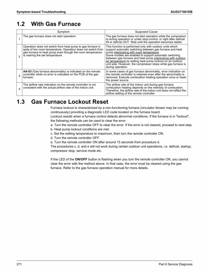
Symptom-based Troubleshooting SiUS371901EB
1.2 With Gas Furnace
1.3 Gas Furnace Lockout ResetFurnace lockout is characterized by a non-functioning furnace (circulator blower may be running continuously) providing a diagnostic LED code located on the furnace board.Lockout results when a furnace control detects abnormal conditions. If the furnace is in "lockout", the following methods can be used to clear the error.a. Turn the remote controller OFF to clear the error. If the error is not cleared, proceed to next step.b. Heat pump lockout conditions are met.c. Set the setting temperature to maximum, then turn the remote controller ON.d. Turn the remote controller OFF.e. Turn the remote controller ON after around 15 seconds from procedure d.The procedures c, d, and e will not work during certain outdoor unit operations, i.e. defrost, startup, compressor stop, service mode etc.
If the LED of the ON/OFF button is flashing when you turn the remote controller ON, you cannot clear the error with the method above. In that case, the error must be cleared using the gas furnace. Refer to the gas furnace operation manual for more details.
Symptom Supposed Cause
1The gas furnace does not start operation. The gas furnace does not start operation while the compressor
is during operation or under stop-control, or right after defrost IN or defrost OUT. Wait until the operation becomes stable.
2
Operation does not switch from heat pump to gas furnace in spite of low room temperature. Operation does not switch from gas furnace to heat pump even though the room temperature is nearing the set temperature.
This function is performed only with outdoor units which support automatic switching between gas furnace and heat pump interlocking with room temperature.Some models are enabled to support automatic switching between gas furnace and heat pump interlocking with outdoor air temperature by setting heat pump lockout on an outdoor unit side. However, the compressor stops while gas furnace is during operation.
3AA-03 (Gas furnace abnormality) is indicated on the remote controller while no error is indicated on the PCB of the gas furnace.
In some cases of gas furnace abnormality, error indication on the remote controller is retained even after the abnormality is removed. Execute combustion heating operation once or reset the power source.
4The airflow rate indication on the remote controller is not consistent with the actual airflow rate of the indoor unit.
The airflow rate of the indoor unit during gas furnace combustion heating depends on the intensity of combustion.Therefore, the airflow rate of the indoor unit does not reflect the airflow setting of the remote controller.
271 Part 6 Service Diagnosis
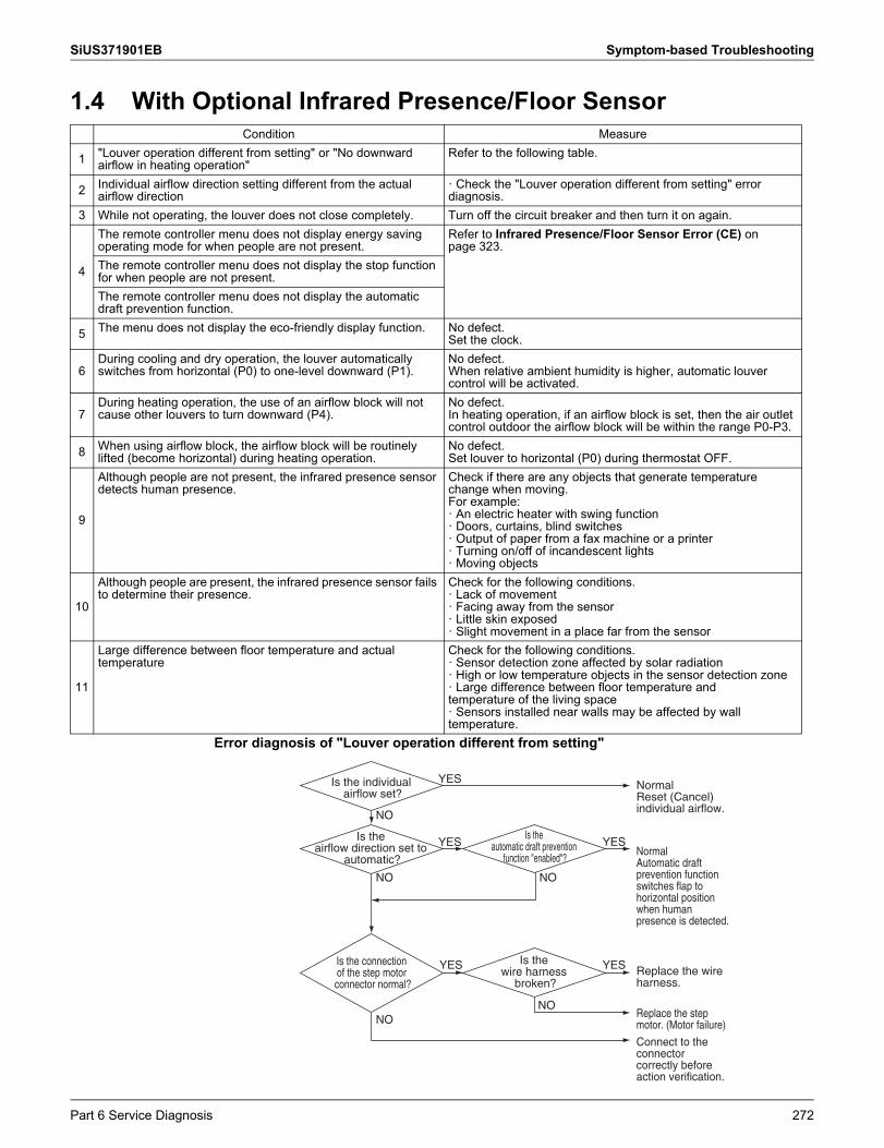
SiUS371901EB Symptom-based Troubleshooting
1.4 With Optional Infrared Presence/Floor Sensor
Error diagnosis of "Louver operation different from setting"
Condition Measure
1 "Louver operation different from setting" or "No downward airflow in heating operation"
Refer to the following table.
2 Individual airflow direction setting different from the actual airflow direction
· Check the "Louver operation different from setting" error diagnosis.
3 While not operating, the louver does not close completely. Turn off the circuit breaker and then turn it on again.
4
The remote controller menu does not display energy saving operating mode for when people are not present.
Refer to Infrared Presence/Floor Sensor Error (CE) onpage 323.
The remote controller menu does not display the stop function for when people are not present.The remote controller menu does not display the automatic draft prevention function.
5 The menu does not display the eco-friendly display function. No defect.Set the clock.
6During cooling and dry operation, the louver automaticallyswitches from horizontal (P0) to one-level downward (P1).
No defect.When relative ambient humidity is higher, automatic louver control will be activated.
7During heating operation, the use of an airflow block will not cause other louvers to turn downward (P4).
No defect.In heating operation, if an airflow block is set, then the air outlet control outdoor the airflow block will be within the range P0-P3.
8 When using airflow block, the airflow block will be routinely lifted (become horizontal) during heating operation.
No defect.Set louver to horizontal (P0) during thermostat OFF.
9
Although people are not present, the infrared presence sensor detects human presence.
Check if there are any objects that generate temperature change when moving.For example:· An electric heater with swing function· Doors, curtains, blind switches· Output of paper from a fax machine or a printer· Turning on/off of incandescent lights· Moving objects
10
Although people are present, the infrared presence sensor fails to determine their presence.
Check for the following conditions.· Lack of movement· Facing away from the sensor· Little skin exposed· Slight movement in a place far from the sensor
11
Large difference between floor temperature and actual temperature
Check for the following conditions.· Sensor detection zone affected by solar radiation· High or low temperature objects in the sensor detection zone· Large difference between floor temperature andtemperature of the living space· Sensors installed near walls may be affected by walltemperature.
NormalReset (Cancel) individual airflow.
Is the individual airflow set?
Is the airflow direction set to
automatic?
Is the wire harness
broken?
YES
YES
NO
NO
NONO
NO
Replace the step motor. (Motor failure)
YES Replace the wire harness.
YESIs the connection of the step motor connector normal?
Is the automatic draft prevention
function "enabled"?YES
NormalAutomatic draft prevention function switches flap to horizontal position when human presence is detected.
Connect to the connector correctly before action verification.
Part 6 Service Diagnosis 272
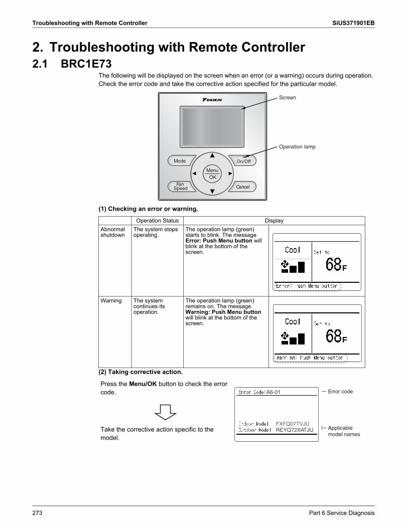
Troubleshooting with Remote Controller SiUS371901EB
2. Troubleshooting with Remote Controller2.1 BRC1E73
The following will be displayed on the screen when an error (or a warning) occurs during operation. Check the error code and take the corrective action specified for the particular model.
(1) Checking an error or warning.
(2) Taking corrective action.
Operation Status DisplayAbnormal shutdown
The system stops operating.
The operation lamp (green) starts to blink. The message Error: Push Menu button will blink at the bottom of the screen.
Warning The system continues its operation.
The operation lamp (green) remains on. The message Warning: Push Menu button will blink at the bottom of the screen.
Press the Menu/OK button to check the error code.
Take the corrective action specific to the model.
Screen
Operation lamp
Error code
Applicable model names
FXFQ07TVJUFXFQ07TVJUREYQ72XATJU
A6-01
273 Part 6 Service Diagnosis
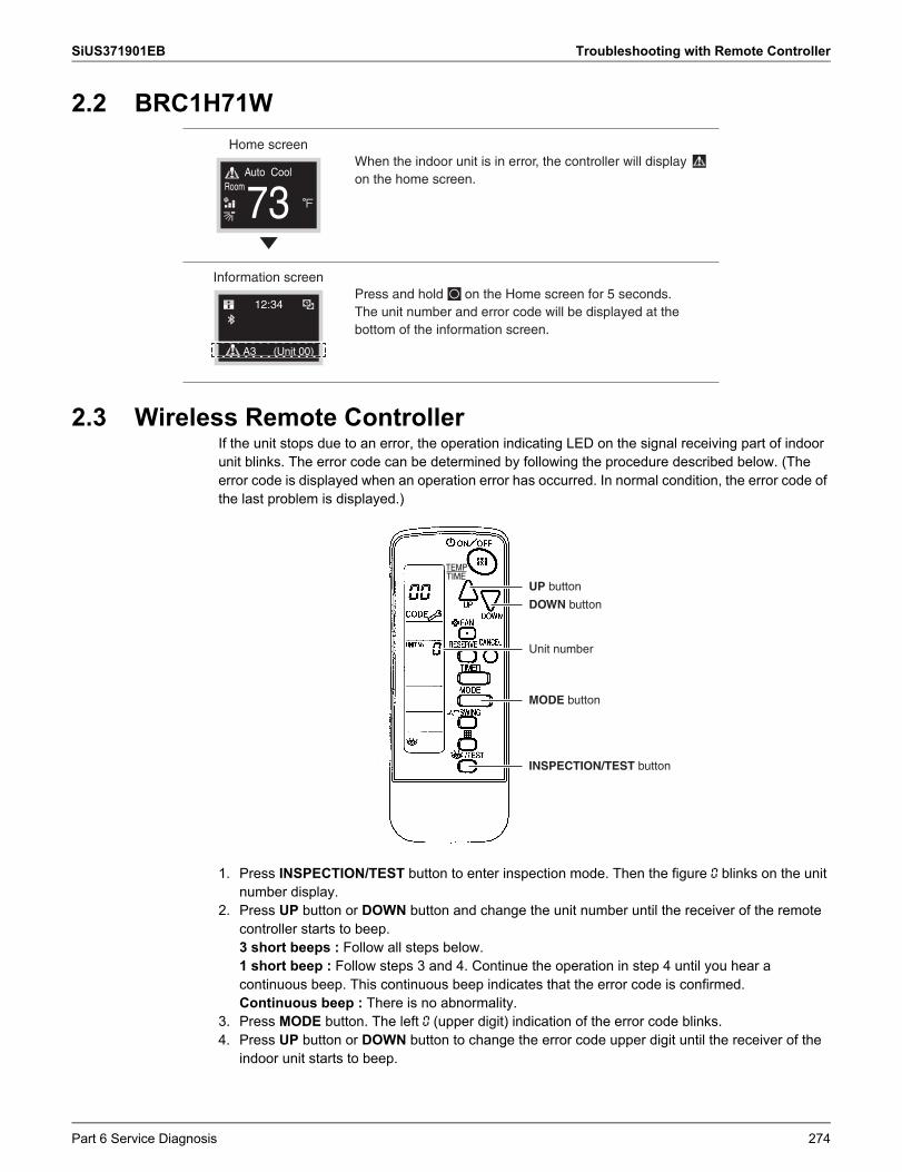
SiUS371901EB Troubleshooting with Remote Controller
2.2 BRC1H71W
2.3 Wireless Remote ControllerIf the unit stops due to an error, the operation indicating LED on the signal receiving part of indoor unit blinks. The error code can be determined by following the procedure described below. (The error code is displayed when an operation error has occurred. In normal condition, the error code of the last problem is displayed.)
1. Press INSPECTION/TEST button to enter inspection mode. Then the figure 0 blinks on the unit number display.
2. Press UP button or DOWN button and change the unit number until the receiver of the remote controller starts to beep.3 short beeps : Follow all steps below.1 short beep : Follow steps 3 and 4. Continue the operation in step 4 until you hear a continuous beep. This continuous beep indicates that the error code is confirmed.Continuous beep : There is no abnormality.
3. Press MODE button. The left 0 (upper digit) indication of the error code blinks.4. Press UP button or DOWN button to change the error code upper digit until the receiver of the
indoor unit starts to beep.
Home screen
Auto Cool
73Room
When the indoor unit is in error, the controller will display on the home screen.
Information screen
12:34
A3 (Unit 00)
Press and hold on the Home screen for 5 seconds.The unit number and error code will be displayed at the bottom of the information screen.
UP button
DOWN button
MODE button
INSPECTION/TEST button
Unit number
Part 6 Service Diagnosis 274
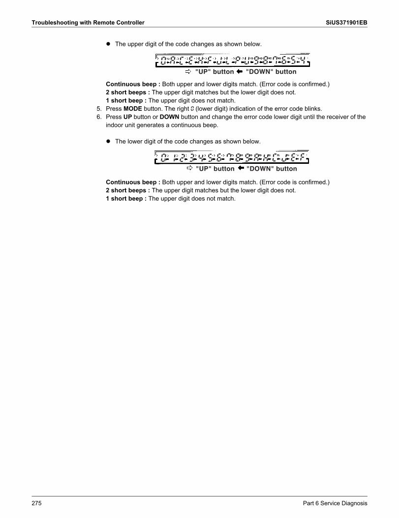
Troubleshooting with Remote Controller SiUS371901EB
The upper digit of the code changes as shown below.
Continuous beep : Both upper and lower digits match. (Error code is confirmed.)2 short beeps : The upper digit matches but the lower digit does not.1 short beep : The upper digit does not match.
5. Press MODE button. The right 0 (lower digit) indication of the error code blinks.6. Press UP button or DOWN button and change the error code lower digit until the receiver of the
indoor unit generates a continuous beep.
The lower digit of the code changes as shown below.
Continuous beep : Both upper and lower digits match. (Error code is confirmed.)2 short beeps : The upper digit matches but the lower digit does not.1 short beep : The upper digit does not match.
O0 A C E H F J L P U 9 8 7 6 5 4"UP" button "DOWN" button
0 1 2 3 4 5 6 7 8 9 A H C J E F"UP" button "DOWN" button
275 Part 6 Service Diagnosis
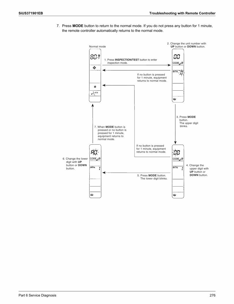
SiUS371901EB Troubleshooting with Remote Controller
7. Press MODE button to return to the normal mode. If you do not press any button for 1 minute, the remote controller automatically returns to the normal mode.
If no button is pressed for 1 minute, equipment returns to normal mode.
3. Press MODE button.The upper digit blinks.
Normal mode
1. Press INSPECTION/TEST button to enter inspection mode.
7. When MODE button is pressed or no button is pressed for 1 minute, equipment returns to normal mode.
6. Change the lower digit with UP button or DOWN button.
If no button is pressed for 1 minute, equipment returns to normal mode.
5. Press MODE button. The lower digit blinks.
4. Change the upper digit with UP button or DOWN button.
2. Change the unit number with UP button or DOWN button.
Part 6 Service Diagnosis 276
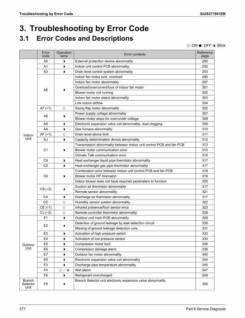
Troubleshooting by Error Code SiUS371901EB
3. Troubleshooting by Error Code3.1 Error Codes and Descriptions
k: ON h: OFF l: Blink
Error code
Operation lamp Error contents Reference
page
Indoor Unit
A0 l External protection device abnormality 290A1 l Indoor unit control PCB abnormality 292A3 l Drain level control system abnormality 293
A6 l
Indoor fan motor lock, overload 295Indoor fan motor abnormality 297Overload/overcurrent/lock of indoor fan motor 301Blower motor not running 302Indoor fan motor status abnormality 303Low indoor airflow 304
A7 (∗1) k Swing flap motor abnormality 305
A8 lPower supply voltage abnormality 307Blower motor stops for over/under voltage 308
A9 l Electronic expansion valve coil abnormality, dust clogging 309AA l Gas furnace abnormality 310
AF (∗1) k Drain level above limit 311AJ l Capacity determination device abnormality 312
C1 l
Transmission abnormality between indoor unit control PCB and fan PCB 313Blower motor communication error 315Climate Talk communication error 316
C4 l Heat exchanger liquid pipe thermistor abnormality 317C5 l Heat exchanger gas pipe thermistor abnormality 317
C6 l
Combination error between indoor unit control PCB and fan PCB 318Blower motor HP mismatch 319Indoor blower does not have required parameters to function 320
C9 (∗2) lSuction air thermistor abnormality 317Remote sensor abnormality 321
CA l Discharge air thermistor abnormality 317CC k Humidity sensor system abnormality 322
CE (∗1) k Infrared presence/floor sensor error 323CJ (∗2) k Remote controller thermistor abnormality 328
Outdoor Unit
E1 l Outdoor unit main PCB abnormality 329
E2 lDetection of ground leakage by leak detection circuit 330Missing of ground leakage detection core 331
E3 l Activation of high pressure switch 332E4 l Activation of low pressure sensor 334E5 l Compressor motor lock 336E6 l Compressor damage alarm 338E7 l Outdoor fan motor abnormality 340E9 l Electronic expansion valve coil abnormality 344F3 l Discharge pipe temperature abnormality 345F4 Kk / l Wet alarm 347F6 l Refrigerant overcharged 349
Branch Selector
UnitF9 l
Branch Selector unit electronic expansion valve abnormality350
277 Part 6 Service Diagnosis
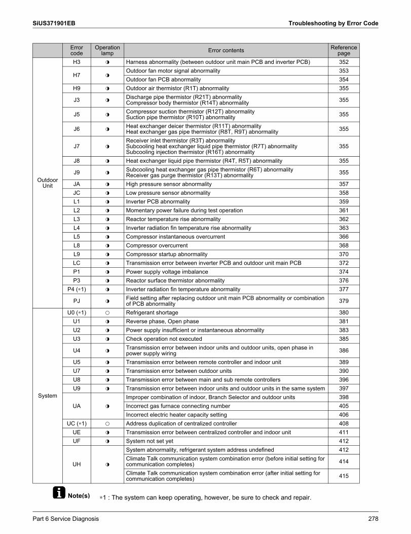
SiUS371901EB Troubleshooting by Error Code
Note(s) ∗1: The system can keep operating, however, be sure to check and repair.
Outdoor Unit
H3 l Harness abnormality (between outdoor unit main PCB and inverter PCB) 352
H7 lOutdoor fan motor signal abnormality 353Outdoor fan PCB abnormality 354
H9 l Outdoor air thermistor (R1T) abnormality 355
J3 l Discharge pipe thermistor (R21T) abnormalityCompressor body thermistor (R14T) abnormality 355
J5 l Compressor suction thermistor (R12T) abnormalitySuction pipe thermistor (R10T) abnormality 355
J6 l Heat exchanger deicer thermistor (R11T) abnormality Heat exchanger gas pipe thermistor (R8T, R9T) abnormality 355
J7 lReceiver inlet thermistor (R3T) abnormalitySubcooling heat exchanger liquid pipe thermistor (R7T) abnormalitySubcooling injection thermistor (R16T) abnormality
355
J8 l Heat exchanger liquid pipe thermistor (R4T, R5T) abnormality 355
J9 l Subcooling heat exchanger gas pipe thermistor (R6T) abnormality Receiver gas purge thermistor (R13T) abnormality 355
JA l High pressure sensor abnormality 357JC l Low pressure sensor abnormality 358L1 l Inverter PCB abnormality 359L2 l Momentary power failure during test operation 361L3 l Reactor temperature rise abnormality 362L4 l Inverter radiation fin temperature rise abnormality 363L5 l Compressor instantaneous overcurrent 366L8 l Compressor overcurrent 368L9 l Compressor startup abnormality 370LC l Transmission error between inverter PCB and outdoor unit main PCB 372P1 l Power supply voltage imbalance 374P3 l Reactor surface thermistor abnormality 376
P4 (∗1) l Inverter radiation fin temperature abnormality 377
PJ l Field setting after replacing outdoor unit main PCB abnormality or combination of PCB abnormality 379
System
U0 (∗1) k Refrigerant shortage 380U1 l Reverse phase, Open phase 381U2 l Power supply insufficient or instantaneous abnormality 383U3 l Check operation not executed 385
U4 l Transmission error between indoor units and outdoor units, open phase in power supply wiring 386
U5 l Transmission error between remote controller and indoor unit 389U7 l Transmission error between outdoor units 390U8 l Transmission error between main and sub remote controllers 396U9 l Transmission error between indoor units and outdoor units in the same system 397
UA l
Improper combination of indoor, Branch Selector and outdoor units 398Incorrect gas furnace connecting number 405Incorrect electric heater capacity setting 406
UC (∗1) k Address duplication of centralized controller 408UE l Transmission error between centralized controller and indoor unit 411UF l System not set yet 412
UH l
System abnormality, refrigerant system address undefined 412Climate Talk communication system combination error (before initial setting for communication completes) 414
Climate Talk communication system combination error (after initial setting for communication completes) 415
Error code
Operation lamp Error contents Reference
page
Part 6 Service Diagnosis 278
Troubleshooting by Error Code SiUS371901EB
∗2: The system may or may not continue operation depending on the conditions.
279 Part 6 Service Diagnosis
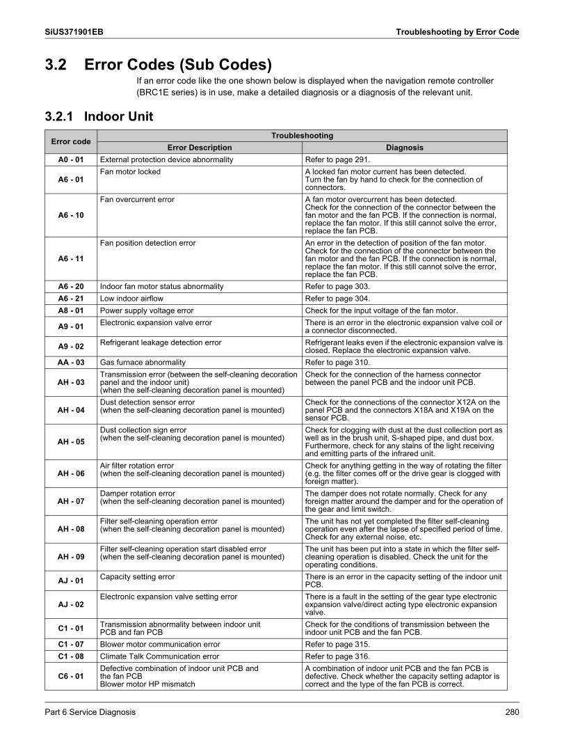
SiUS371901EB Troubleshooting by Error Code
3.2 Error Codes (Sub Codes)If an error code like the one shown below is displayed when the navigation remote controller (BRC1E series) is in use, make a detailed diagnosis or a diagnosis of the relevant unit.
3.2.1 Indoor Unit
Error codeTroubleshooting
Error Description DiagnosisA0 - 01 External protection device abnormality Refer to page 291.
A6 - 01Fan motor locked A locked fan motor current has been detected.
Turn the fan by hand to check for the connection of connectors.
A6 - 10
Fan overcurrent error A fan motor overcurrent has been detected.Check for the connection of the connector between the fan motor and the fan PCB. If the connection is normal, replace the fan motor. If this still cannot solve the error, replace the fan PCB.
A6 - 11
Fan position detection error An error in the detection of position of the fan motor. Check for the connection of the connector between the fan motor and the fan PCB. If the connection is normal, replace the fan motor. If this still cannot solve the error, replace the fan PCB.
A6 - 20 Indoor fan motor status abnormality Refer to page 303.A6 - 21 Low indoor airflow Refer to page 304.A8 - 01 Power supply voltage error Check for the input voltage of the fan motor.
A9 - 01 Electronic expansion valve error There is an error in the electronic expansion valve coil or a connector disconnected.
A9 - 02 Refrigerant leakage detection error Refrigerant leaks even if the electronic expansion valve is closed. Replace the electronic expansion valve.
AA - 03 Gas furnace abnormality Refer to page 310.
AH - 03Transmission error (between the self-cleaning decoration panel and the indoor unit)(when the self-cleaning decoration panel is mounted)
Check for the connection of the harness connector between the panel PCB and the indoor unit PCB.
AH - 04Dust detection sensor error(when the self-cleaning decoration panel is mounted)
Check for the connections of the connector X12A on the panel PCB and the connectors X18A and X19A on the sensor PCB.
AH - 05Dust collection sign error(when the self-cleaning decoration panel is mounted)
Check for clogging with dust at the dust collection port as well as in the brush unit, S-shaped pipe, and dust box. Furthermore, check for any stains of the light receiving and emitting parts of the infrared unit.
AH - 06Air filter rotation error(when the self-cleaning decoration panel is mounted)
Check for anything getting in the way of rotating the filter (e.g. the filter comes off or the drive gear is clogged with foreign matter).
AH - 07Damper rotation error(when the self-cleaning decoration panel is mounted)
The damper does not rotate normally. Check for any foreign matter around the damper and for the operation of the gear and limit switch.
AH - 08Filter self-cleaning operation error(when the self-cleaning decoration panel is mounted)
The unit has not yet completed the filter self-cleaning operation even after the lapse of specified period of time. Check for any external noise, etc.
AH - 09Filter self-cleaning operation start disabled error (when the self-cleaning decoration panel is mounted)
The unit has been put into a state in which the filter self- cleaning operation is disabled. Check the unit for the operating conditions.
AJ - 01 Capacity setting error There is an error in the capacity setting of the indoor unit PCB.
AJ - 02Electronic expansion valve setting error There is a fault in the setting of the gear type electronic
expansion valve/direct acting type electronic expansion valve.
C1 - 01 Transmission abnormality between indoor unitPCB and fan PCB
Check for the conditions of transmission between the indoor unit PCB and the fan PCB.
C1 - 07 Blower motor communication error Refer to page 315.C1 - 08 Climate Talk Communication error Refer to page 316.
C6 - 01Defective combination of indoor unit PCB andthe fan PCBBlower motor HP mismatch
A combination of indoor unit PCB and the fan PCB is defective. Check whether the capacity setting adaptor is correct and the type of the fan PCB is correct.
Part 6 Service Diagnosis 280
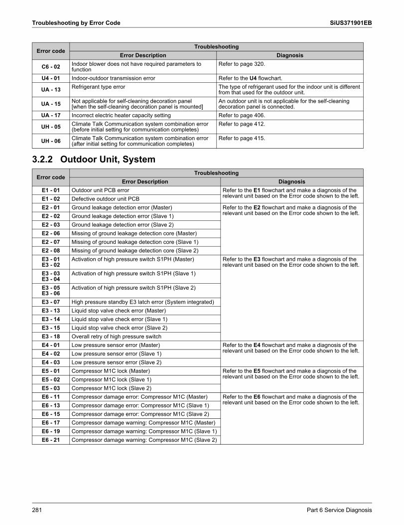
Troubleshooting by Error Code SiUS371901EB
3.2.2 Outdoor Unit, System
C6 - 02 Indoor blower does not have required parameters to function
Refer to page 320.
U4 - 01 Indoor-outdoor transmission error Refer to the U4 flowchart.
UA - 13 Refrigerant type error The type of refrigerant used for the indoor unit is different from that used for the outdoor unit.
UA - 15 Not applicable for self-cleaning decoration panel [when the self-cleaning decoration panel is mounted]
An outdoor unit is not applicable for the self-cleaning decoration panel is connected.
UA - 17 Incorrect electric heater capacity setting Refer to page 406.
UH - 05 Climate Talk Communication system combination error (before initial setting for communication completes)
Refer to page 412.
UH - 06 Climate Talk Communication system combination error (after initial setting for communication completes)
Refer to page 415.
Error codeTroubleshooting
Error Description DiagnosisE1 - 01 Outdoor unit PCB error Refer to the E1 flowchart and make a diagnosis of the
relevant unit based on the Error code shown to the left.E1 - 02 Defective outdoor unit PCBE2 - 01 Ground leakage detection error (Master) Refer to the E2 flowchart and make a diagnosis of the
relevant unit based on the Error code shown to the left.E2 - 02 Ground leakage detection error (Slave 1)E2 - 03 Ground leakage detection error (Slave 2)E2 - 06 Missing of ground leakage detection core (Master)E2 - 07 Missing of ground leakage detection core (Slave 1)E2 - 08 Missing of ground leakage detection core (Slave 2)E3 - 01E3 - 02
Activation of high pressure switch S1PH (Master) Refer to the E3 flowchart and make a diagnosis of the relevant unit based on the Error code shown to the left.
E3 - 03E3 - 04
Activation of high pressure switch S1PH (Slave 1)
E3 - 05E3 - 06
Activation of high pressure switch S1PH (Slave 2)
E3 - 07 High pressure standby E3 latch error (System integrated)E3 - 13 Liquid stop valve check error (Master)E3 - 14 Liquid stop valve check error (Slave 1)E3 - 15 Liquid stop valve check error (Slave 2)E3 - 18 Overall retry of high pressure switchE4 - 01 Low pressure sensor error (Master) Refer to the E4 flowchart and make a diagnosis of the
relevant unit based on the Error code shown to the left.E4 - 02 Low pressure sensor error (Slave 1)E4 - 03 Low pressure sensor error (Slave 2)E5 - 01 Compressor M1C lock (Master) Refer to the E5 flowchart and make a diagnosis of the
relevant unit based on the Error code shown to the left.E5 - 02 Compressor M1C lock (Slave 1)E5 - 03 Compressor M1C lock (Slave 2)E6 - 11 Compressor damage error: Compressor M1C (Master) Refer to the E6 flowchart and make a diagnosis of the
relevant unit based on the Error code shown to the left.E6 - 13 Compressor damage error: Compressor M1C (Slave 1)E6 - 15 Compressor damage error: Compressor M1C (Slave 2)E6 - 17 Compressor damage warning: Compressor M1C (Master)E6 - 19 Compressor damage warning: Compressor M1C (Slave 1)E6 - 21 Compressor damage warning: Compressor M1C (Slave 2)
Error codeTroubleshooting
Error Description Diagnosis
281 Part 6 Service Diagnosis
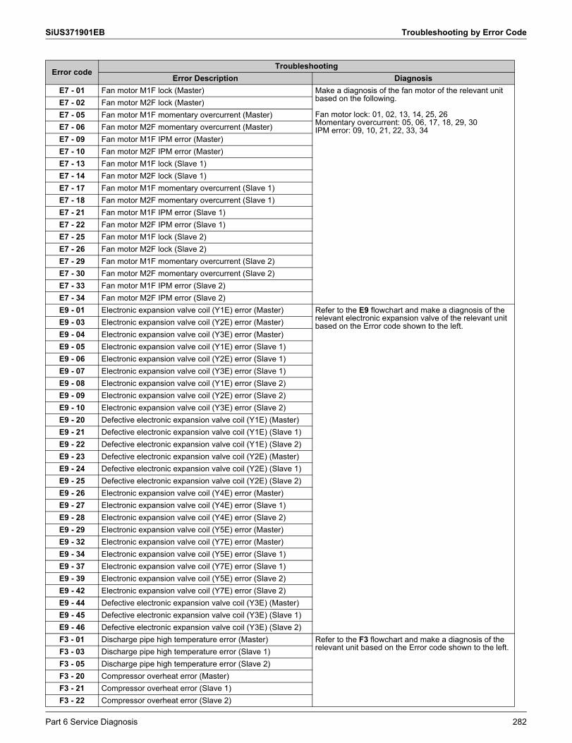
SiUS371901EB Troubleshooting by Error Code
E7 - 01 Fan motor M1F lock (Master) Make a diagnosis of the fan motor of the relevant unit based on the following.
Fan motor lock: 01, 02, 13, 14, 25, 26Momentary overcurrent: 05, 06, 17, 18, 29, 30IPM error: 09, 10, 21, 22, 33, 34
E7 - 02 Fan motor M2F lock (Master)E7 - 05 Fan motor M1F momentary overcurrent (Master)E7 - 06 Fan motor M2F momentary overcurrent (Master)E7 - 09 Fan motor M1F IPM error (Master)E7 - 10 Fan motor M2F IPM error (Master)E7 - 13 Fan motor M1F lock (Slave 1)E7 - 14 Fan motor M2F lock (Slave 1)E7 - 17 Fan motor M1F momentary overcurrent (Slave 1)E7 - 18 Fan motor M2F momentary overcurrent (Slave 1)E7 - 21 Fan motor M1F IPM error (Slave 1)E7 - 22 Fan motor M2F IPM error (Slave 1)E7 - 25 Fan motor M1F lock (Slave 2)E7 - 26 Fan motor M2F lock (Slave 2)E7 - 29 Fan motor M1F momentary overcurrent (Slave 2)E7 - 30 Fan motor M2F momentary overcurrent (Slave 2)E7 - 33 Fan motor M1F IPM error (Slave 2)E7 - 34 Fan motor M2F IPM error (Slave 2)E9 - 01 Electronic expansion valve coil (Y1E) error (Master) Refer to the E9 flowchart and make a diagnosis of the
relevant electronic expansion valve of the relevant unit based on the Error code shown to the left.E9 - 03 Electronic expansion valve coil (Y2E) error (Master)
E9 - 04 Electronic expansion valve coil (Y3E) error (Master)E9 - 05 Electronic expansion valve coil (Y1E) error (Slave 1)E9 - 06 Electronic expansion valve coil (Y2E) error (Slave 1)E9 - 07 Electronic expansion valve coil (Y3E) error (Slave 1)E9 - 08 Electronic expansion valve coil (Y1E) error (Slave 2)E9 - 09 Electronic expansion valve coil (Y2E) error (Slave 2)E9 - 10 Electronic expansion valve coil (Y3E) error (Slave 2)E9 - 20 Defective electronic expansion valve coil (Y1E) (Master)E9 - 21 Defective electronic expansion valve coil (Y1E) (Slave 1)E9 - 22 Defective electronic expansion valve coil (Y1E) (Slave 2)E9 - 23 Defective electronic expansion valve coil (Y2E) (Master)E9 - 24 Defective electronic expansion valve coil (Y2E) (Slave 1)E9 - 25 Defective electronic expansion valve coil (Y2E) (Slave 2)E9 - 26 Electronic expansion valve coil (Y4E) error (Master)E9 - 27 Electronic expansion valve coil (Y4E) error (Slave 1)E9 - 28 Electronic expansion valve coil (Y4E) error (Slave 2)E9 - 29 Electronic expansion valve coil (Y5E) error (Master)E9 - 32 Electronic expansion valve coil (Y7E) error (Master)E9 - 34 Electronic expansion valve coil (Y5E) error (Slave 1)E9 - 37 Electronic expansion valve coil (Y7E) error (Slave 1)E9 - 39 Electronic expansion valve coil (Y5E) error (Slave 2)E9 - 42 Electronic expansion valve coil (Y7E) error (Slave 2)E9 - 44 Defective electronic expansion valve coil (Y3E) (Master)E9 - 45 Defective electronic expansion valve coil (Y3E) (Slave 1)E9 - 46 Defective electronic expansion valve coil (Y3E) (Slave 2)F3 - 01 Discharge pipe high temperature error (Master) Refer to the F3 flowchart and make a diagnosis of the
relevant unit based on the Error code shown to the left.F3 - 03 Discharge pipe high temperature error (Slave 1)F3 - 05 Discharge pipe high temperature error (Slave 2)F3 - 20 Compressor overheat error (Master)F3 - 21 Compressor overheat error (Slave 1)F3 - 22 Compressor overheat error (Slave 2)
Error codeTroubleshooting
Error Description Diagnosis
Part 6 Service Diagnosis 282
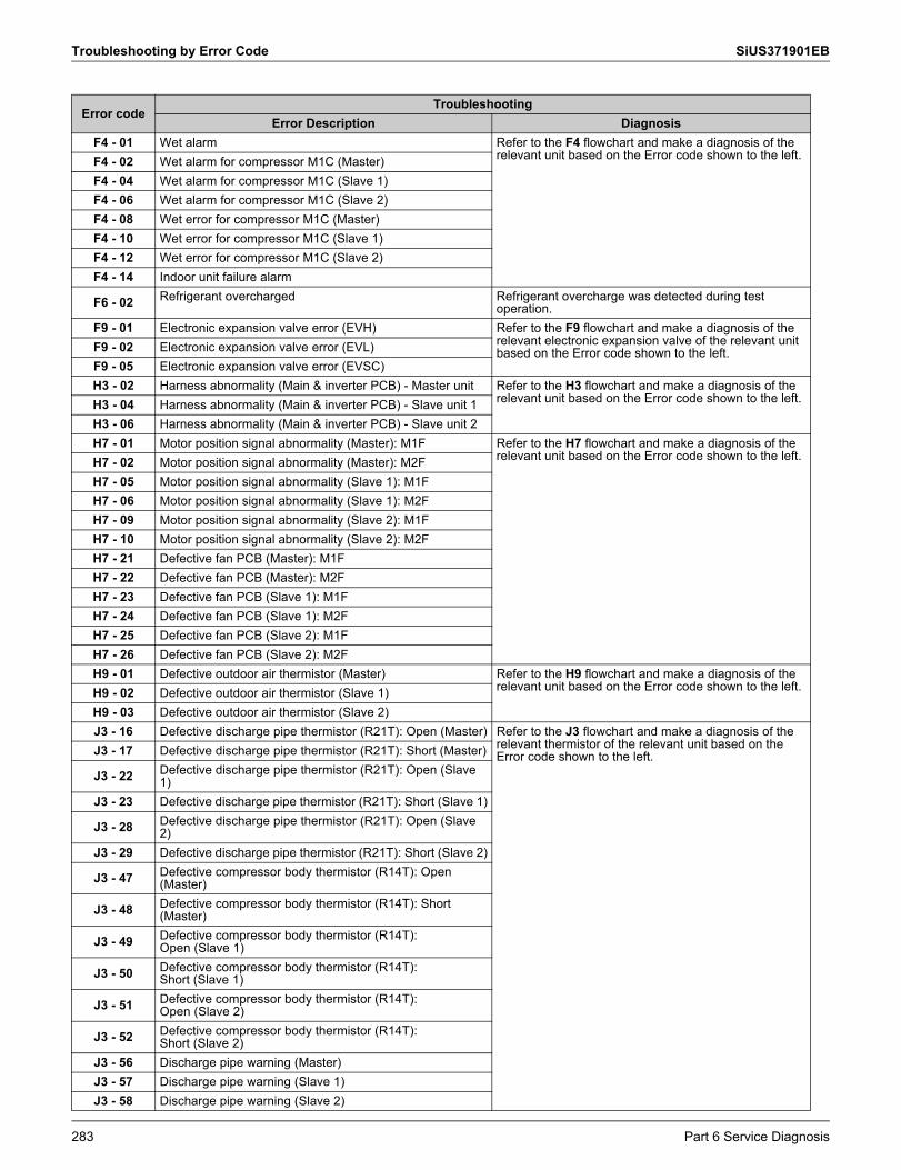
Troubleshooting by Error Code SiUS371901EB
F4 - 01 Wet alarm Refer to the F4 flowchart and make a diagnosis of the relevant unit based on the Error code shown to the left.F4 - 02 Wet alarm for compressor M1C (Master)
F4 - 04 Wet alarm for compressor M1C (Slave 1)F4 - 06 Wet alarm for compressor M1C (Slave 2)F4 - 08 Wet error for compressor M1C (Master)F4 - 10 Wet error for compressor M1C (Slave 1)F4 - 12 Wet error for compressor M1C (Slave 2)F4 - 14 Indoor unit failure alarm
F6 - 02 Refrigerant overcharged Refrigerant overcharge was detected during test operation.
F9 - 01 Electronic expansion valve error (EVH) Refer to the F9 flowchart and make a diagnosis of the relevant electronic expansion valve of the relevant unit based on the Error code shown to the left.F9 - 02 Electronic expansion valve error (EVL)
F9 - 05 Electronic expansion valve error (EVSC)H3 - 02 Harness abnormality (Main & inverter PCB) - Master unit Refer to the H3 flowchart and make a diagnosis of the
relevant unit based on the Error code shown to the left.H3 - 04 Harness abnormality (Main & inverter PCB) - Slave unit 1H3 - 06 Harness abnormality (Main & inverter PCB) - Slave unit 2H7 - 01 Motor position signal abnormality (Master): M1F Refer to the H7 flowchart and make a diagnosis of the
relevant unit based on the Error code shown to the left.H7 - 02 Motor position signal abnormality (Master): M2FH7 - 05 Motor position signal abnormality (Slave 1): M1FH7 - 06 Motor position signal abnormality (Slave 1): M2FH7 - 09 Motor position signal abnormality (Slave 2): M1FH7 - 10 Motor position signal abnormality (Slave 2): M2FH7 - 21 Defective fan PCB (Master): M1FH7 - 22 Defective fan PCB (Master): M2FH7 - 23 Defective fan PCB (Slave 1): M1FH7 - 24 Defective fan PCB (Slave 1): M2FH7 - 25 Defective fan PCB (Slave 2): M1FH7 - 26 Defective fan PCB (Slave 2): M2FH9 - 01 Defective outdoor air thermistor (Master) Refer to the H9 flowchart and make a diagnosis of the
relevant unit based on the Error code shown to the left.H9 - 02 Defective outdoor air thermistor (Slave 1)H9 - 03 Defective outdoor air thermistor (Slave 2)J3 - 16 Defective discharge pipe thermistor (R21T): Open (Master) Refer to the J3 flowchart and make a diagnosis of the
relevant thermistor of the relevant unit based on the Error code shown to the left.J3 - 17 Defective discharge pipe thermistor (R21T): Short (Master)
J3 - 22 Defective discharge pipe thermistor (R21T): Open (Slave 1)
J3 - 23 Defective discharge pipe thermistor (R21T): Short (Slave 1)
J3 - 28 Defective discharge pipe thermistor (R21T): Open (Slave 2)
J3 - 29 Defective discharge pipe thermistor (R21T): Short (Slave 2)
J3 - 47 Defective compressor body thermistor (R14T): Open (Master)
J3 - 48 Defective compressor body thermistor (R14T): Short (Master)
J3 - 49 Defective compressor body thermistor (R14T): Open (Slave 1)
J3 - 50 Defective compressor body thermistor (R14T): Short (Slave 1)
J3 - 51 Defective compressor body thermistor (R14T): Open (Slave 2)
J3 - 52 Defective compressor body thermistor (R14T): Short (Slave 2)
J3 - 56 Discharge pipe warning (Master)J3 - 57 Discharge pipe warning (Slave 1)J3 - 58 Discharge pipe warning (Slave 2)
Error codeTroubleshooting
Error Description Diagnosis
283 Part 6 Service Diagnosis
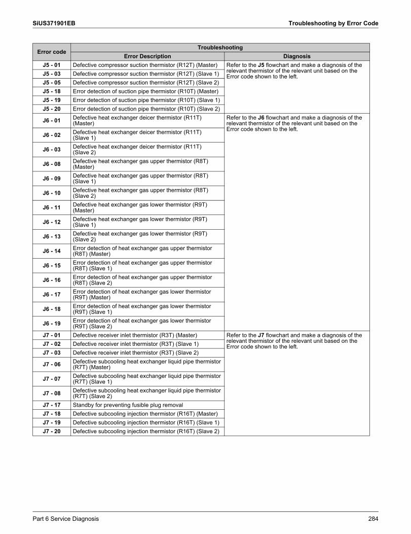
SiUS371901EB Troubleshooting by Error Code
J5 - 01 Defective compressor suction thermistor (R12T) (Master) Refer to the J5 flowchart and make a diagnosis of the relevant thermistor of the relevant unit based on the Error code shown to the left.J5 - 03 Defective compressor suction thermistor (R12T) (Slave 1)
J5 - 05 Defective compressor suction thermistor (R12T) (Slave 2)J5 - 18 Error detection of suction pipe thermistor (R10T) (Master)J5 - 19 Error detection of suction pipe thermistor (R10T) (Slave 1)J5 - 20 Error detection of suction pipe thermistor (R10T) (Slave 2)
J6 - 01 Defective heat exchanger deicer thermistor (R11T) (Master)
Refer to the J6 flowchart and make a diagnosis of the relevant thermistor of the relevant unit based on the Error code shown to the left.
J6 - 02 Defective heat exchanger deicer thermistor (R11T) (Slave 1)
J6 - 03 Defective heat exchanger deicer thermistor (R11T) (Slave 2)
J6 - 08 Defective heat exchanger gas upper thermistor (R8T) (Master)
J6 - 09 Defective heat exchanger gas upper thermistor (R8T) (Slave 1)
J6 - 10 Defective heat exchanger gas upper thermistor (R8T) (Slave 2)
J6 - 11 Defective heat exchanger gas lower thermistor (R9T) (Master)
J6 - 12 Defective heat exchanger gas lower thermistor (R9T) (Slave 1)
J6 - 13 Defective heat exchanger gas lower thermistor (R9T) (Slave 2)
J6 - 14 Error detection of heat exchanger gas upper thermistor (R8T) (Master)
J6 - 15 Error detection of heat exchanger gas upper thermistor (R8T) (Slave 1)
J6 - 16 Error detection of heat exchanger gas upper thermistor (R8T) (Slave 2)
J6 - 17 Error detection of heat exchanger gas lower thermistor (R9T) (Master)
J6 - 18 Error detection of heat exchanger gas lower thermistor (R9T) (Slave 1)
J6 - 19 Error detection of heat exchanger gas lower thermistor (R9T) (Slave 2)
J7 - 01 Defective receiver inlet thermistor (R3T) (Master) Refer to the J7 flowchart and make a diagnosis of the relevant thermistor of the relevant unit based on the Error code shown to the left.J7 - 02 Defective receiver inlet thermistor (R3T) (Slave 1)
J7 - 03 Defective receiver inlet thermistor (R3T) (Slave 2)
J7 - 06 Defective subcooling heat exchanger liquid pipe thermistor (R7T) (Master)
J7 - 07 Defective subcooling heat exchanger liquid pipe thermistor (R7T) (Slave 1)
J7 - 08 Defective subcooling heat exchanger liquid pipe thermistor (R7T) (Slave 2)
J7 - 17 Standby for preventing fusible plug removalJ7 - 18 Defective subcooling injection thermistor (R16T) (Master)J7 - 19 Defective subcooling injection thermistor (R16T) (Slave 1)J7 - 20 Defective subcooling injection thermistor (R16T) (Slave 2)
Error codeTroubleshooting
Error Description Diagnosis
Part 6 Service Diagnosis 284
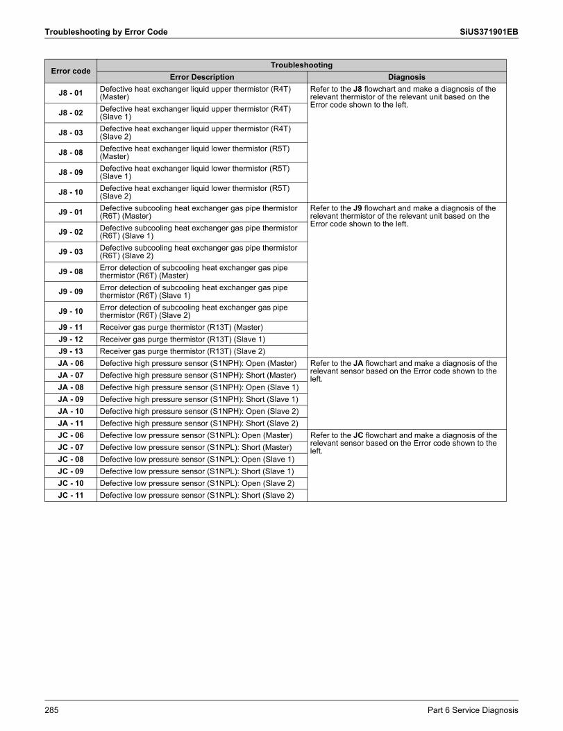
Troubleshooting by Error Code SiUS371901EB
J8 - 01 Defective heat exchanger liquid upper thermistor (R4T) (Master)
Refer to the J8 flowchart and make a diagnosis of the relevant thermistor of the relevant unit based on the Error code shown to the left.
J8 - 02 Defective heat exchanger liquid upper thermistor (R4T) (Slave 1)
J8 - 03 Defective heat exchanger liquid upper thermistor (R4T) (Slave 2)
J8 - 08 Defective heat exchanger liquid lower thermistor (R5T) (Master)
J8 - 09 Defective heat exchanger liquid lower thermistor (R5T) (Slave 1)
J8 - 10 Defective heat exchanger liquid lower thermistor (R5T) (Slave 2)
J9 - 01 Defective subcooling heat exchanger gas pipe thermistor (R6T) (Master)
Refer to the J9 flowchart and make a diagnosis of the relevant thermistor of the relevant unit based on the Error code shown to the left.
J9 - 02 Defective subcooling heat exchanger gas pipe thermistor (R6T) (Slave 1)
J9 - 03 Defective subcooling heat exchanger gas pipe thermistor (R6T) (Slave 2)
J9 - 08 Error detection of subcooling heat exchanger gas pipe thermistor (R6T) (Master)
J9 - 09 Error detection of subcooling heat exchanger gas pipe thermistor (R6T) (Slave 1)
J9 - 10 Error detection of subcooling heat exchanger gas pipe thermistor (R6T) (Slave 2)
J9 - 11 Receiver gas purge thermistor (R13T) (Master)J9 - 12 Receiver gas purge thermistor (R13T) (Slave 1)J9 - 13 Receiver gas purge thermistor (R13T) (Slave 2)JA - 06 Defective high pressure sensor (S1NPH): Open (Master) Refer to the JA flowchart and make a diagnosis of the
relevant sensor based on the Error code shown to the left.JA - 07 Defective high pressure sensor (S1NPH): Short (Master)
JA - 08 Defective high pressure sensor (S1NPH): Open (Slave 1)JA - 09 Defective high pressure sensor (S1NPH): Short (Slave 1)JA - 10 Defective high pressure sensor (S1NPH): Open (Slave 2)JA - 11 Defective high pressure sensor (S1NPH): Short (Slave 2)JC - 06 Defective low pressure sensor (S1NPL): Open (Master) Refer to the JC flowchart and make a diagnosis of the
relevant sensor based on the Error code shown to the left.JC - 07 Defective low pressure sensor (S1NPL): Short (Master)
JC - 08 Defective low pressure sensor (S1NPL): Open (Slave 1)JC - 09 Defective low pressure sensor (S1NPL): Short (Slave 1)JC - 10 Defective low pressure sensor (S1NPL): Open (Slave 2)JC - 11 Defective low pressure sensor (S1NPL): Short (Slave 2)
Error codeTroubleshooting
Error Description Diagnosis
285 Part 6 Service Diagnosis
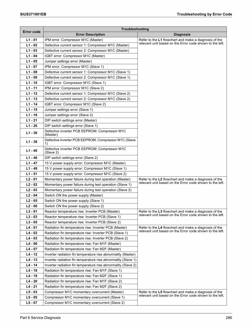
SiUS371901EB Troubleshooting by Error Code
L1 - 01 IPM error: Compressor M1C (Master) Refer to the L1 flowchart and make a diagnosis of the relevant unit based on the Error code shown to the left.L1 - 02 Defective current sensor 1: Compressor M1C (Master)
L1 - 03 Defective current sensor 2: Compressor M1C (Master)L1 - 04 IGBT error: Compressor M1C (Master)L1 - 05 Jumper settings error (Master)L1 - 07 IPM error: Compressor M1C (Slave 1)L1 - 08 Defective current sensor 1: Compressor M1C (Slave 1)L1 - 09 Defective current sensor 2: Compressor M1C (Slave 1)L1 - 10 IGBT error: Compressor M1C (Slave 1)L1 - 11 IPM error: Compressor M1C (Slave 2)L1 - 12 Defective current sensor 1: Compressor M1C (Slave 2)L1 - 13 Defective current sensor 2: Compressor M1C (Slave 2)L1 - 14 IGBT error: Compressor M1C (Slave 2)L1 - 15 Jumper settings error (Slave 1)L1 - 16 Jumper settings error (Slave 2)L1 - 21 DIP switch settings error (Master)L1 - 26 DIP switch settings error (Slave 1)
L1 - 36 Defective inverter PCB EEPROM: Compressor M1C (Master)
L1 - 38 Defective inverter PCB EEPROM: Compressor M1C (Slave 1)
L1 - 40 Defective inverter PCB EEPROM: Compressor M1C (Slave 2)
L1 - 46 DIP switch settings error (Slave 2)L1 - 47 15 V power supply error: Compressor M1C (Master)L1 - 49 15 V power supply error: Compressor M1C (Slave 1)L1 - 51 15 V power supply error: Compressor M1C (Slave 2)L2 - 01 Momentary power failure during test operation (Master) Refer to the L2 flowchart and make a diagnosis of the
relevant unit based on the Error code shown to the left.L2 - 02 Momentary power failure during test operation (Slave 1)L2 - 03 Momentary power failure during test operation (Slave 2)L2 - 04 Switch ON the power supply (Master)L2 - 05 Switch ON the power supply (Slave 1)L2 - 06 Switch ON the power supply (Slave 2)L3 - 01 Reactor temperature rise: Inverter PCB (Master) Refer to the L3 flowchart and make a diagnosis of the
relevant unit based on the Error code shown to the left.L3 - 03 Reactor temperature rise: Inverter PCB (Slave 1)L3 - 05 Reactor temperature rise: Inverter PCB (Slave 2)L4 - 01 Radiation fin temperature rise: Inverter PCB (Master) Refer to the L4 flowchart and make a diagnosis of the
relevant unit based on the Error code shown to the left.L4 - 02 Radiation fin temperature rise: Inverter PCB (Slave 1)L4 - 03 Radiation fin temperature rise: Inverter PCB (Slave 2)L4 - 06 Radiation fin temperature rise: Fan M1F (Master)L4 - 07 Radiation fin temperature rise: Fan M2F (Master)L4 - 12 Inverter radiation fin temperature rise abnormality (Master)L4 - 13 Inverter radiation fin temperature rise abnormality (Slave 1)L4 - 14 Inverter radiation fin temperature rise abnormality (Slave 2)L4 - 18 Radiation fin temperature rise: Fan M1F (Slave 1)L4 - 19 Radiation fin temperature rise: Fan M2F (Slave 1)L4 - 20 Radiation fin temperature rise: Fan M1F (Slave 2)L4 - 21 Radiation fin temperature rise: Fan M2F (Slave 2)L5 - 03 Compressor M1C momentary overcurrent (Master) Refer to the L5 flowchart and make a diagnosis of the
relevant unit based on the Error code shown to the left.L5 - 05 Compressor M1C momentary overcurrent (Slave 1)L5 - 07 Compressor M1C momentary overcurrent (Slave 2)
Error codeTroubleshooting
Error Description Diagnosis
Part 6 Service Diagnosis 286
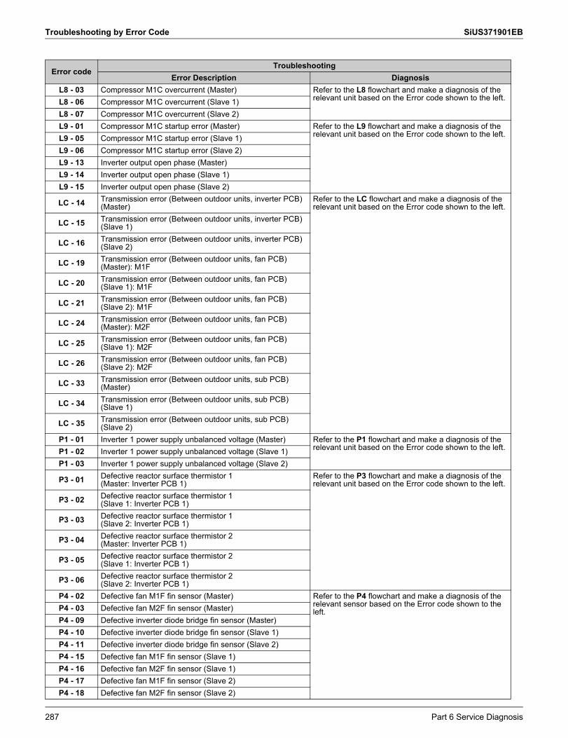
Troubleshooting by Error Code SiUS371901EB
L8 - 03 Compressor M1C overcurrent (Master) Refer to the L8 flowchart and make a diagnosis of the relevant unit based on the Error code shown to the left.L8 - 06 Compressor M1C overcurrent (Slave 1)
L8 - 07 Compressor M1C overcurrent (Slave 2)L9 - 01 Compressor M1C startup error (Master) Refer to the L9 flowchart and make a diagnosis of the
relevant unit based on the Error code shown to the left.L9 - 05 Compressor M1C startup error (Slave 1)L9 - 06 Compressor M1C startup error (Slave 2)L9 - 13 Inverter output open phase (Master)L9 - 14 Inverter output open phase (Slave 1)L9 - 15 Inverter output open phase (Slave 2)
LC - 14 Transmission error (Between outdoor units, inverter PCB) (Master)
Refer to the LC flowchart and make a diagnosis of the relevant unit based on the Error code shown to the left.
LC - 15 Transmission error (Between outdoor units, inverter PCB) (Slave 1)
LC - 16 Transmission error (Between outdoor units, inverter PCB) (Slave 2)
LC - 19 Transmission error (Between outdoor units, fan PCB) (Master): M1F
LC - 20 Transmission error (Between outdoor units, fan PCB) (Slave 1): M1F
LC - 21 Transmission error (Between outdoor units, fan PCB) (Slave 2): M1F
LC - 24 Transmission error (Between outdoor units, fan PCB) (Master): M2F
LC - 25 Transmission error (Between outdoor units, fan PCB) (Slave 1): M2F
LC - 26 Transmission error (Between outdoor units, fan PCB) (Slave 2): M2F
LC - 33 Transmission error (Between outdoor units, sub PCB) (Master)
LC - 34 Transmission error (Between outdoor units, sub PCB) (Slave 1)
LC - 35 Transmission error (Between outdoor units, sub PCB) (Slave 2)
P1 - 01 Inverter 1 power supply unbalanced voltage (Master) Refer to the P1 flowchart and make a diagnosis of the relevant unit based on the Error code shown to the left.P1 - 02 Inverter 1 power supply unbalanced voltage (Slave 1)
P1 - 03 Inverter 1 power supply unbalanced voltage (Slave 2)
P3 - 01 Defective reactor surface thermistor 1 (Master: Inverter PCB 1)
Refer to the P3 flowchart and make a diagnosis of the relevant unit based on the Error code shown to the left.
P3 - 02 Defective reactor surface thermistor 1 (Slave 1: Inverter PCB 1)
P3 - 03 Defective reactor surface thermistor 1 (Slave 2: Inverter PCB 1)
P3 - 04 Defective reactor surface thermistor 2 (Master: Inverter PCB 1)
P3 - 05 Defective reactor surface thermistor 2 (Slave 1: Inverter PCB 1)
P3 - 06 Defective reactor surface thermistor 2 (Slave 2: Inverter PCB 1)
P4 - 02 Defective fan M1F fin sensor (Master) Refer to the P4 flowchart and make a diagnosis of the relevant sensor based on the Error code shown to the left.P4 - 03 Defective fan M2F fin sensor (Master)
P4 - 09 Defective inverter diode bridge fin sensor (Master)P4 - 10 Defective inverter diode bridge fin sensor (Slave 1)P4 - 11 Defective inverter diode bridge fin sensor (Slave 2)P4 - 15 Defective fan M1F fin sensor (Slave 1)P4 - 16 Defective fan M2F fin sensor (Slave 1)P4 - 17 Defective fan M1F fin sensor (Slave 2)P4 - 18 Defective fan M2F fin sensor (Slave 2)
Error codeTroubleshooting
Error Description Diagnosis
287 Part 6 Service Diagnosis
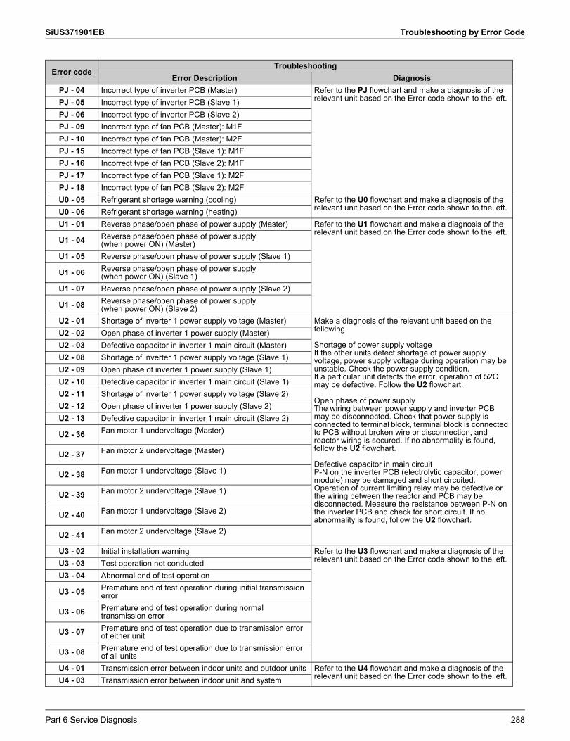
SiUS371901EB Troubleshooting by Error Code
PJ - 04 Incorrect type of inverter PCB (Master) Refer to the PJ flowchart and make a diagnosis of the relevant unit based on the Error code shown to the left.PJ - 05 Incorrect type of inverter PCB (Slave 1)
PJ - 06 Incorrect type of inverter PCB (Slave 2)PJ - 09 Incorrect type of fan PCB (Master): M1FPJ - 10 Incorrect type of fan PCB (Master): M2FPJ - 15 Incorrect type of fan PCB (Slave 1): M1FPJ - 16 Incorrect type of fan PCB (Slave 2): M1FPJ - 17 Incorrect type of fan PCB (Slave 1): M2FPJ - 18 Incorrect type of fan PCB (Slave 2): M2FU0 - 05 Refrigerant shortage warning (cooling) Refer to the U0 flowchart and make a diagnosis of the
relevant unit based on the Error code shown to the left.U0 - 06 Refrigerant shortage warning (heating)U1 - 01 Reverse phase/open phase of power supply (Master) Refer to the U1 flowchart and make a diagnosis of the
relevant unit based on the Error code shown to the left.U1 - 04 Reverse phase/open phase of power supply
(when power ON) (Master)U1 - 05 Reverse phase/open phase of power supply (Slave 1)
U1 - 06 Reverse phase/open phase of power supply (when power ON) (Slave 1)
U1 - 07 Reverse phase/open phase of power supply (Slave 2)
U1 - 08 Reverse phase/open phase of power supply (when power ON) (Slave 2)
U2 - 01 Shortage of inverter 1 power supply voltage (Master) Make a diagnosis of the relevant unit based on the following.
Shortage of power supply voltageIf the other units detect shortage of power supply voltage, power supply voltage during operation may be unstable. Check the power supply condition.If a particular unit detects the error, operation of 52C may be defective. Follow the U2 flowchart.
Open phase of power supplyThe wiring between power supply and inverter PCB may be disconnected. Check that power supply is connected to terminal block, terminal block is connected to PCB without broken wire or disconnection, and reactor wiring is secured. If no abnormality is found, follow the U2 flowchart.
Defective capacitor in main circuitP-N on the inverter PCB (electrolytic capacitor, power module) may be damaged and short circuited. Operation of current limiting relay may be defective or the wiring between the reactor and PCB may be disconnected. Measure the resistance between P-N on the inverter PCB and check for short circuit. If no abnormality is found, follow the U2 flowchart.
U2 - 02 Open phase of inverter 1 power supply (Master)U2 - 03 Defective capacitor in inverter 1 main circuit (Master)U2 - 08 Shortage of inverter 1 power supply voltage (Slave 1)U2 - 09 Open phase of inverter 1 power supply (Slave 1)U2 - 10 Defective capacitor in inverter 1 main circuit (Slave 1)U2 - 11 Shortage of inverter 1 power supply voltage (Slave 2)U2 - 12 Open phase of inverter 1 power supply (Slave 2)U2 - 13 Defective capacitor in inverter 1 main circuit (Slave 2)
U2 - 36 Fan motor 1 undervoltage (Master)
U2 - 37 Fan motor 2 undervoltage (Master)
U2 - 38 Fan motor 1 undervoltage (Slave 1)
U2 - 39 Fan motor 2 undervoltage (Slave 1)
U2 - 40 Fan motor 1 undervoltage (Slave 2)
U2 - 41 Fan motor 2 undervoltage (Slave 2)
U3 - 02 Initial installation warning Refer to the U3 flowchart and make a diagnosis of the relevant unit based on the Error code shown to the left.U3 - 03 Test operation not conducted
U3 - 04 Abnormal end of test operation
U3 - 05 Premature end of test operation during initial transmission error
U3 - 06 Premature end of test operation during normal transmission error
U3 - 07 Premature end of test operation due to transmission error of either unit
U3 - 08 Premature end of test operation due to transmission error of all units
U4 - 01 Transmission error between indoor units and outdoor units Refer to the U4 flowchart and make a diagnosis of the relevant unit based on the Error code shown to the left.U4 - 03 Transmission error between indoor unit and system
Error codeTroubleshooting
Error Description Diagnosis
Part 6 Service Diagnosis 288
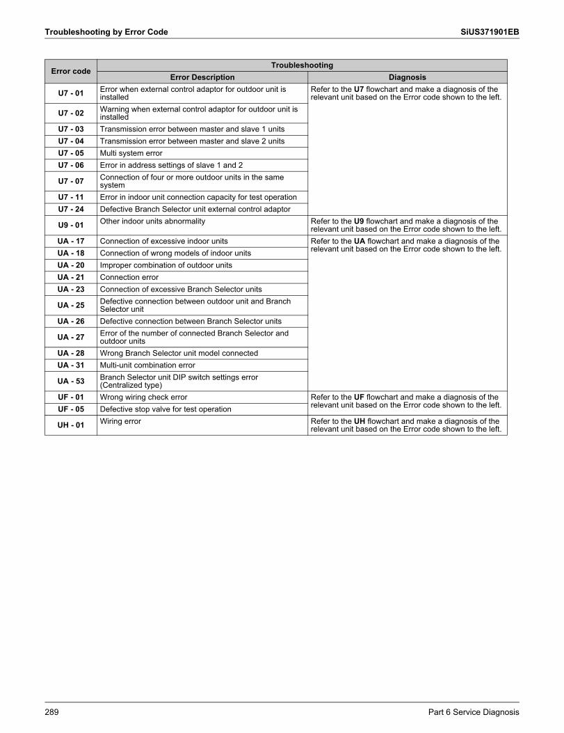
Troubleshooting by Error Code SiUS371901EB
U7 - 01 Error when external control adaptor for outdoor unit is installed
Refer to the U7 flowchart and make a diagnosis of the relevant unit based on the Error code shown to the left.
U7 - 02 Warning when external control adaptor for outdoor unit is installed
U7 - 03 Transmission error between master and slave 1 unitsU7 - 04 Transmission error between master and slave 2 unitsU7 - 05 Multi system errorU7 - 06 Error in address settings of slave 1 and 2
U7 - 07 Connection of four or more outdoor units in the same system
U7 - 11 Error in indoor unit connection capacity for test operationU7 - 24 Defective Branch Selector unit external control adaptor
U9 - 01 Other indoor units abnormality Refer to the U9 flowchart and make a diagnosis of the relevant unit based on the Error code shown to the left.
UA - 17 Connection of excessive indoor units Refer to the UA flowchart and make a diagnosis of the relevant unit based on the Error code shown to the left.UA - 18 Connection of wrong models of indoor units
UA - 20 Improper combination of outdoor unitsUA - 21 Connection errorUA - 23 Connection of excessive Branch Selector units
UA - 25 Defective connection between outdoor unit and Branch Selector unit
UA - 26 Defective connection between Branch Selector units
UA - 27 Error of the number of connected Branch Selector and outdoor units
UA - 28 Wrong Branch Selector unit model connectedUA - 31 Multi-unit combination error
UA - 53 Branch Selector unit DIP switch settings error (Centralized type)
UF - 01 Wrong wiring check error Refer to the UF flowchart and make a diagnosis of the relevant unit based on the Error code shown to the left.UF - 05 Defective stop valve for test operation
UH - 01 Wiring error Refer to the UH flowchart and make a diagnosis of the relevant unit based on the Error code shown to the left.
Error codeTroubleshooting
Error Description Diagnosis
289 Part 6 Service Diagnosis
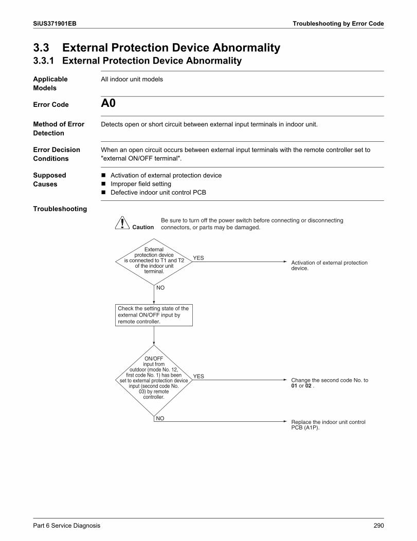
SiUS371901EB Troubleshooting by Error Code
3.3 External Protection Device Abnormality3.3.1 External Protection Device Abnormality
Applicable Models
All indoor unit models
Error Code A0Method of Error Detection
Detects open or short circuit between external input terminals in indoor unit.
Error Decision Conditions
When an open circuit occurs between external input terminals with the remote controller set to"external ON/OFF terminal".
Supposed Causes
Activation of external protection device Improper field setting Defective indoor unit control PCB
Troubleshooting
ON/OFF input from
outdoor (mode No. 12, first code No. 1) has been
set to external protection device input (second code No.
03) by remote controller.
Check the setting state of the external ON/OFF input by remote controller.
External protection device
is connected to T1 and T2 of the indoor unit
terminal.
Replace the indoor unit control PCB (A1P).
Activation of external protection device.
Change the second code No. to 01 or 02 .
YES
NO
NO
YES
CautionBe sure to turn off the power switch before connecting or disconnecting connectors, or parts may be damaged.
Part 6 Service Diagnosis 290
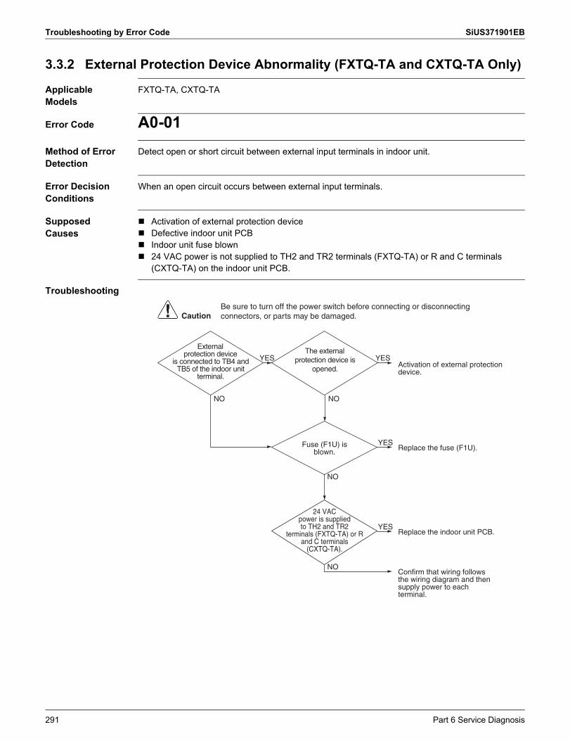
Troubleshooting by Error Code SiUS371901EB
3.3.2 External Protection Device Abnormality (FXTQ-TA and CXTQ-TA Only)
Applicable Models
FXTQ-TA, CXTQ-TA
Error Code A0-01Method of Error Detection
Detect open or short circuit between external input terminals in indoor unit.
Error Decision Conditions
When an open circuit occurs between external input terminals.
Supposed Causes
Activation of external protection device Defective indoor unit PCB Indoor unit fuse blown 24 VAC power is not supplied to TH2 and TR2 terminals (FXTQ-TA) or R and C terminals
(CXTQ-TA) on the indoor unit PCB.
Troubleshooting
Fuse (F1U) is blown.
24 VAC power is supplied to TH2 and TR2
terminals (FXTQ-TA) or R and C terminals
(CXTQ-TA).
External protection device
is connected to TB4 and TB5 of the indoor unit
terminal.
The external protection device is
opened.
Replace the indoor unit PCB.
Confirm that wiring follows the wiring diagram and then supply power to each terminal.
Activation of external protection device.
Replace the fuse (F1U).
YES YES
NO NO
NO
NO
YES
YES
CautionBe sure to turn off the power switch before connecting or disconnecting connectors, or parts may be damaged.
291 Part 6 Service Diagnosis
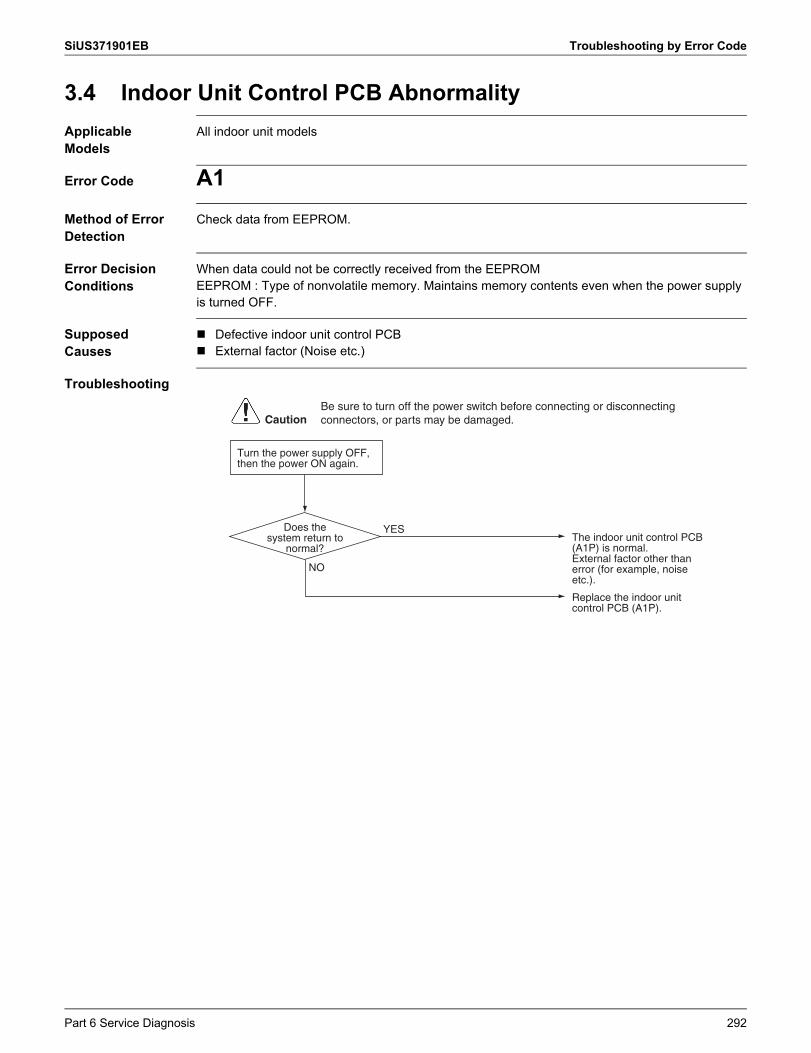
SiUS371901EB Troubleshooting by Error Code
3.4 Indoor Unit Control PCB AbnormalityApplicable Models
All indoor unit models
Error Code A1Method of Error Detection
Check data from EEPROM.
Error Decision Conditions
When data could not be correctly received from the EEPROMEEPROM : Type of nonvolatile memory. Maintains memory contents even when the power supply is turned OFF.
Supposed Causes
Defective indoor unit control PCB External factor (Noise etc.)
Troubleshooting
Turn the power supply OFF, then the power ON again.
Does the system return to
normal?
YES
CautionBe sure to turn off the power switch before connecting or disconnecting connectors, or parts may be damaged.
Replace the indoor unit control PCB (A1P).
The indoor unit control PCB (A1P) is normal.External factor other than error (for example, noise etc.).
NO
Part 6 Service Diagnosis 292
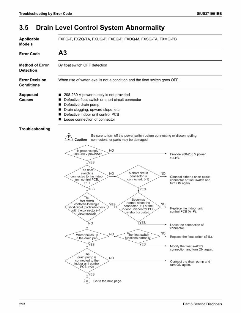
Troubleshooting by Error Code SiUS371901EB
3.5 Drain Level Control System AbnormalityApplicable Models
FXFQ-T, FXZQ-TA, FXUQ-P, FXEQ-P, FXDQ-M, FXSQ-TA, FXMQ-PB
Error Code A3Method of Error Detection
By float switch OFF detection
Error Decision Conditions
When rise of water level is not a condition and the float switch goes OFF.
Supposed Causes
208-230 V power supply is not provided Defective float switch or short circuit connector Defective drain pump Drain clogging, upward slope, etc. Defective indoor unit control PCB Loose connection of connector
Troubleshooting
CautionBe sure to turn off the power switch before connecting or disconnecting connectors, or parts may be damaged.
Replace the float switch (S1L).
Modify the float switch's connection and turn ON again.
Connect the drain pump and turn ON again.
Connect either a short circuit connector or float switch and turn ON again.
YES
YESYES
YES
YES
Replace the indoor unit control PCB (A1P).
Loose the connection of connector.
NO NO
NO
YES
NO
NO
YES
NO
NO
Provide 208-230 V power supply.
YES
NOIs power supply 208-230 V provided?
Water builds up in the drain pan.
A short circuit connector is
connected. (∗1)
The float switch functions normally.
The float switch is
connected to the indoor unit control PCB.
(∗1)
The drain pump is
connected to the indoor unit control
PCB. (∗2)
The float switch
contact is forming a short circuit (continuity check
with the connector (∗1) disconnected)
Becomes normal when the
connector (∗1) of the indoor unit control PCB
is short circuited.
A Go to the next page.
293 Part 6 Service Diagnosis
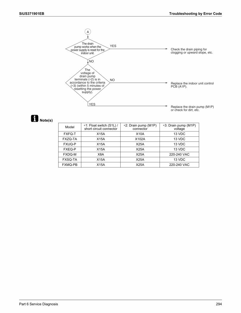
SiUS371901EB Troubleshooting by Error Code
Note(s)
Check the drain piping for clogging or upward slope, etc.
Replace the indoor unit control PCB (A1P).
Replace the drain pump (M1P) or check for dirt, etc.
YES
YES
NO
NO
The drain pump works when the
power supply is reset for the indoor unit.
The voltage of
drain pump terminals (∗2) is in
accordance to the criteria (∗3) (within 5 minutes of
resetting the power supply).
A
Model ∗1: Float switch (S1L) / short circuit connector
∗2: Drain pump (M1P) connector
∗3: Drain pump (M1P) voltage
FXFQ-T X15A X10A 13 VDCFXZQ-TA X15A X102A 13 VDCFXUQ-P X15A X25A 13 VDCFXEQ-P X15A X25A 13 VDCFXDQ-M X8A X25A 220-240 VACFXSQ-TA X15A X25A 13 VDCFXMQ-PB X15A X25A 220-240 VAC
Part 6 Service Diagnosis 294
Troubleshooting by Error Code SiUS371901EB
3.6 Indoor Fan Motor Lock, OverloadApplicable Models
FXFQ-T, FXZQ-TA, FXUQ-P, FXEQ-P, FXSQ05-48TA, FXMQ07-12PB, FXAQ-P
Error Code A6Method of Error Detection
Abnormal fan revolutions are detected by a signal output from the fan motor.
Error Decision Conditions
When the fan revolutions do not increase
Supposed Causes
Broken wires in, short circuit of, or disconnection of connectors from the fan motor harness Defective fan motor
(Broken wires or defective insulation) Abnormal signal output from the fan motor (defective circuit) Defective indoor unit control PCB Instantaneous disturbance in the power supply voltage Fan motor lock
(Due to motor or external causes) The fan does not rotate due to foreign matter blocking the fan. Disconnection of the connector between the high-power PCB (A1P) and the low-power PCB
(A2P) (FXSQ05-48TA, FXMQ07-12PB only)
295 Part 6 Service Diagnosis
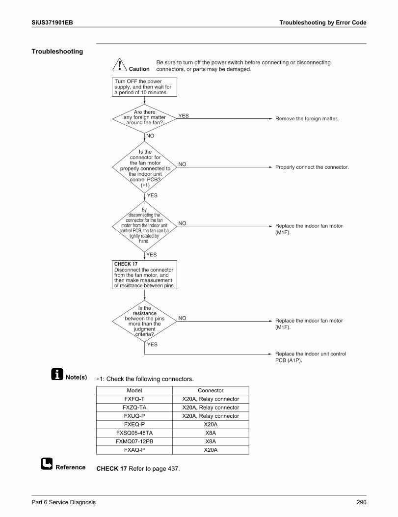
SiUS371901EB Troubleshooting by Error Code
Note(s)
Reference
Troubleshooting
∗1: Check the following connectors.
CHECK 17 Refer to page 437.
YES
Is the connector for the fan motor
properly connected to the indoor unit control PCB?
(∗1)
Remove the foreign matter.YES
Properly connect the connector.NO
NO
YES
By disconnecting the
connector for the fan motor from the indoor unit
control PCB, the fan can be lightly rotated by
hand.
NO
NO
YES
Are there any foreign matter around the fan?
YES
Is the resistance
between the pins more than the
judgment criteria?
Disconnect the connector from the fan motor, and then make measurement of resistance between pins.
Turn OFF the power supply, and then wait for a period of 10 minutes.
Replace the indoor unit control PCB (A1P).
Replace the indoor fan motor (M1F).
Replace the indoor fan motor (M1F).
CautionBe sure to turn off the power switch before connecting or disconnecting connectors, or parts may be damaged.
CHECK 17
Model ConnectorFXFQ-T X20A, Relay connector
FXZQ-TA X20A, Relay connectorFXUQ-P X20A, Relay connectorFXEQ-P X20A
FXSQ05-48TA X8AFXMQ07-12PB X8A
FXAQ-P X20A
Part 6 Service Diagnosis 296
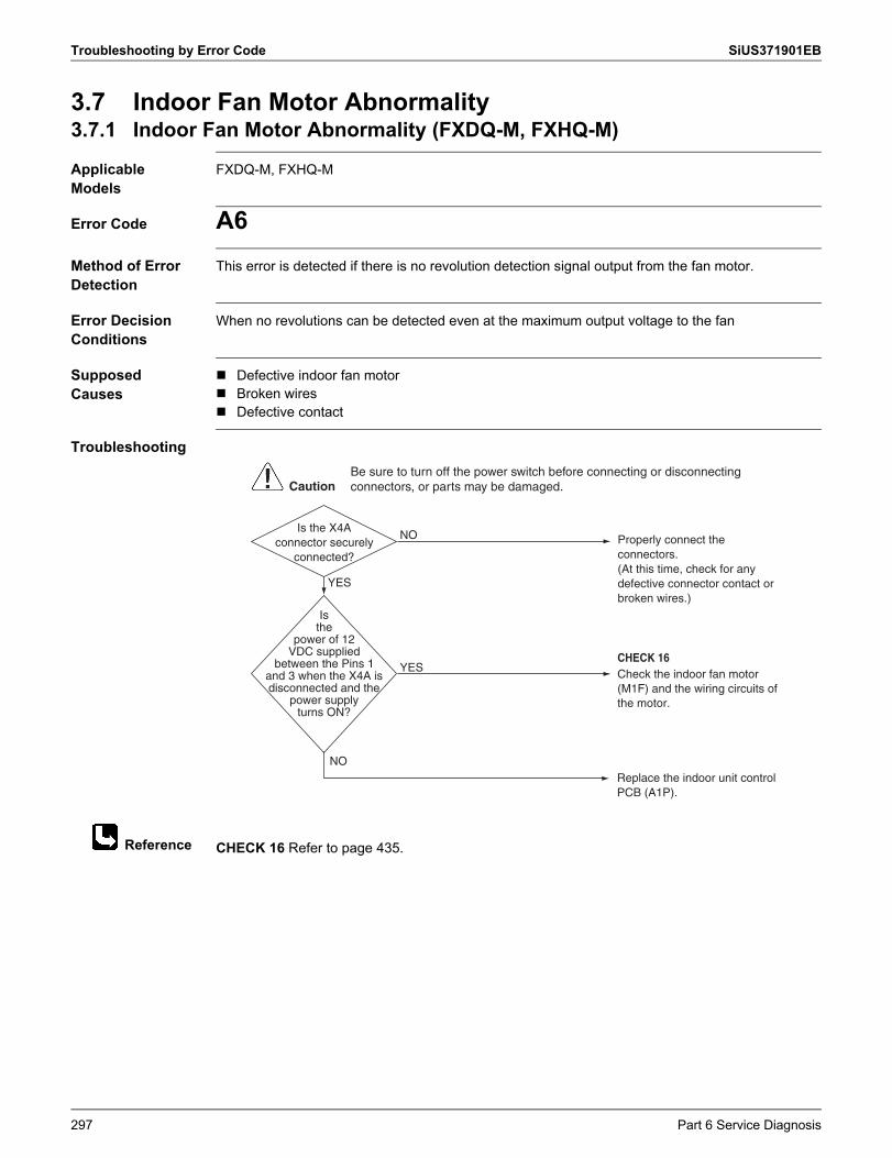
Troubleshooting by Error Code SiUS371901EB
Reference
3.7 Indoor Fan Motor Abnormality3.7.1 Indoor Fan Motor Abnormality (FXDQ-M, FXHQ-M)
Applicable Models
FXDQ-M, FXHQ-M
Error Code A6Method of Error Detection
This error is detected if there is no revolution detection signal output from the fan motor.
Error Decision Conditions
When no revolutions can be detected even at the maximum output voltage to the fan
Supposed Causes
Defective indoor fan motor Broken wires Defective contact
Troubleshooting
CHECK 16 Refer to page 435.
NO
YES
YES
Is the X4A connector securely
connected?
NO
Is the
power of 12 VDC supplied
between the Pins 1 and 3 when the X4A is disconnected and the
power supply turns ON?
Replace the indoor unit control PCB (A1P).
Properly connect the connectors.(At this time, check for any defective connector contact or broken wires.)
Check the indoor fan motor (M1F) and the wiring circuits of the motor.
CHECK 16
CautionBe sure to turn off the power switch before connecting or disconnecting connectors, or parts may be damaged.
297 Part 6 Service Diagnosis
SiUS371901EB Troubleshooting by Error Code
3.7.2 Indoor Fan Motor Abnormality (FXSQ54TA, FXMQ15-54PB)
Applicable Models
FXSQ54TA, FXMQ15-54PB
Error Code A6Method of Error Detection
Error from the current flow on the fan PCB Error from the rotation speed of the fan motor in operation Error from the position signal of the fan motor Error from the current flow on the fan PCB when the fan motor starting operation
Error Decision Conditions
An overcurrent flows. The rotation speed is less than a certain level for 6 seconds. A position error in the fan rotor continues for 5 seconds or more.
Supposed Causes
Clogging of a foreign matter Disconnection of the fan motor connectors (X1A and X2A) Disconnection of the connectors between the indoor unit control PCB (A1P) and fan PCB (A2P) Defective fan PCB (A2P) Defective fan motor
Part 6 Service Diagnosis 298
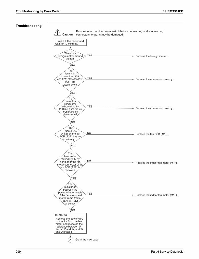
Troubleshooting by Error Code SiUS371901EB
Troubleshooting
The fan motor
connectors (X1A and X2A) of the fan PCB
(A2P) are disconnected.
Remove the foreign matter.YES
Connect the connector correctly.YES
NO
The connectors between the
indoor unit control PCB (A1P) and the fan
PCB (A2P) are disconnected.
Connect the connector correctly.YES
NO
The fuse (F3U,
white) on the fan PCB (A2P) has no
continuity.
Replace the fan PCB (A2P).NO
Replace the indoor fan motor (M1F).YES
NO
YES
The fan can be
moved lightly by hand after the fan
motor connector of the fan PCB (A2P) is
removed.
Replace the indoor fan motor (M1F).NO
YES
NO
YES
There is a foreign matter around
the fan.
The resistance
between the power wire terminals of the fan motor and motor frame (metal
part) is 1 MΩ or below.
Turn OFF the power and wait for 10 minutes.
A
Remove the power wire connector from the fan motor and measure the resistance between U and V, V and W, and W and U phases.
CHECK 16
CautionBe sure to turn off the power switch before connecting or disconnecting connectors, or parts may be damaged.
Go to the next page.
299 Part 6 Service Diagnosis
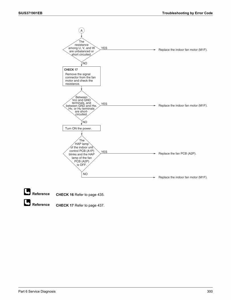
SiUS371901EB Troubleshooting by Error Code
Reference
Reference
CHECK 16 Refer to page 435.
CHECK 17 Refer to page 437.
Replace the indoor fan motor (M1F).YES
NO
Between Vcc and GND terminals, and
between GND and Hw, Hv, or Hu terminals
are short-circuited.
Replace the indoor fan motor (M1F).YES
Replace the fan PCB (A2P).YES
NO
The resistance
among U, V, and W are unbalanced or
short circuited.
NO
The HAP lamp
of the indoor unit control PCB (A1P) blinks and the HAP
lamp of the fan PCB (A2P)
is OFF.
Turn ON the power.
Replace the indoor fan motor (M1F).
A
Remove the signal connector from the fan motor and check the resistance.
CHECK 17
Part 6 Service Diagnosis 300
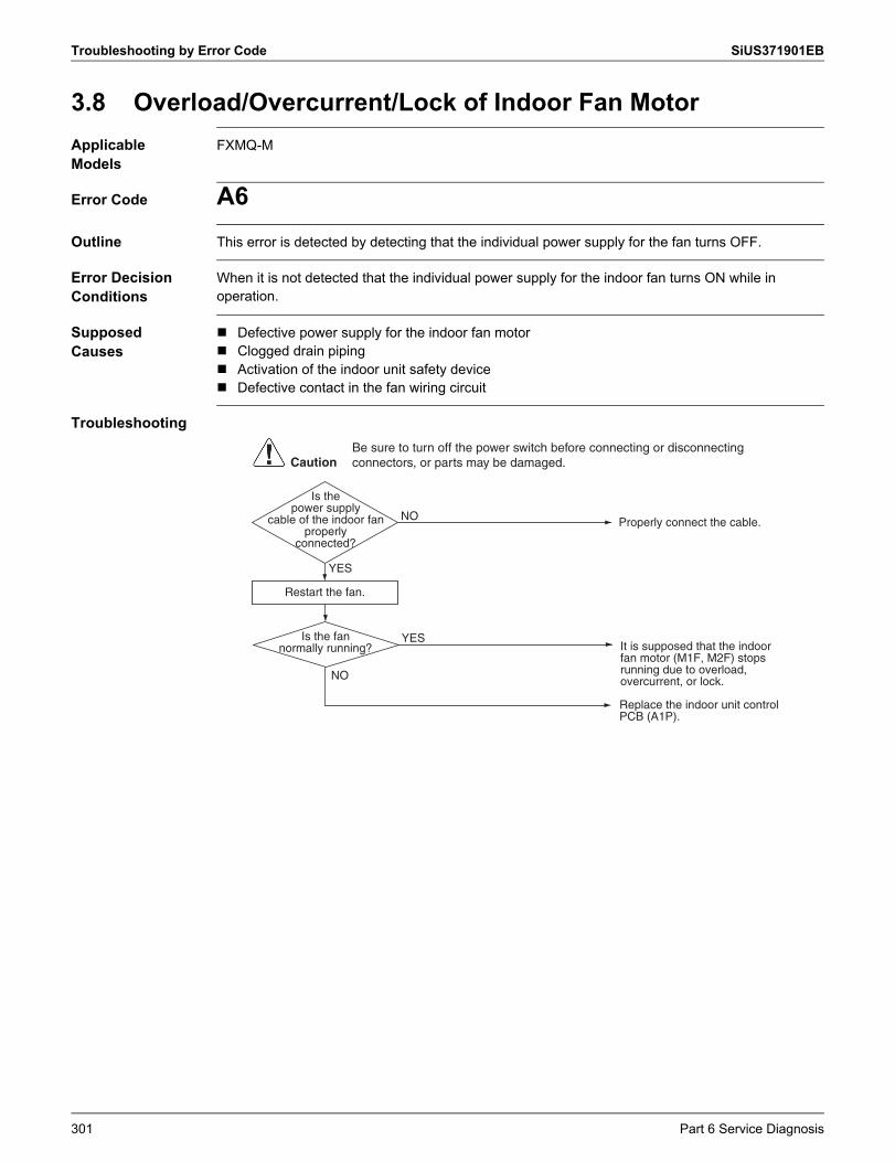
Troubleshooting by Error Code SiUS371901EB
3.8 Overload/Overcurrent/Lock of Indoor Fan MotorApplicable Models
FXMQ-M
Error Code A6Outline This error is detected by detecting that the individual power supply for the fan turns OFF.
Error Decision Conditions
When it is not detected that the individual power supply for the indoor fan turns ON while in operation.
Supposed Causes
Defective power supply for the indoor fan motor Clogged drain piping Activation of the indoor unit safety device Defective contact in the fan wiring circuit
Troubleshooting
Properly connect the cable.NO
YES
YES
Is the power supply
cable of the indoor fan properly
connected?
NO
Is the fan normally running?
Restart the fan.
Replace the indoor unit control PCB (A1P).
It is supposed that the indoor fan motor (M1F, M2F) stops running due to overload, overcurrent, or lock.
CautionBe sure to turn off the power switch before connecting or disconnecting connectors, or parts may be damaged.
301 Part 6 Service Diagnosis
SiUS371901EB Troubleshooting by Error Code
Reference
3.9 Blower Motor Not RunningApplicable Models
FXTQ-TA
Error Code A6Outline Error is issued if the indoor unit determines that the indoor fan motor cannot rotate.
Error Decision Conditions
Determining successive abnormalitiesChecks the rotation speed at 5-second intervals using the feedback of the fan motor.If that figure falls below 50 rpm 5 times successively, it is deemed abnormal operation.If, during operation, the rotation command is stopped, the 5-second interval check is halted and the counted number will be cleared.
Determining long-term abnormalitiesChecks the rotation speed at 5-second intervals using the feedback of the fan motor.Performs rotation sampling 720 times (takes approximately one hour), and if the rotation speed falls below 50 rpm over 100 times, it is deemed abnormal operation.When the sampling reaches 720 times, the counted number will be cleared and the 720 times sampling restarts.If, during this, the rotation command is stopped, the 5-second interval check is halted, but the counted number will be kept.When the rotation command is restarted, the checks will resume.
Error Reset Conditions
Reset by remote controller
Supposed Causes
Fan or motor obstruction Power interruption (low voltage) Incorrect or loose wiring
Corrective Actions
Check for obstruction on the fan or motor. Verify the input voltage at the motor. Check wiring or tighten wiring connections if needed. Replace the indoor unit control PCB or motor.
CHECK 19 Refer to page 442.
Part 6 Service Diagnosis 302
Troubleshooting by Error Code SiUS371901EB
Reference
3.10 Indoor Fan Motor Status AbnormalityApplicable Models
FXTQ-TA
Error Code A6-20Outline The indoor unit periodically receives control status information from the fan motor.
Error is issued when the information shows abnormality.
Error Decision Conditions
If the information shows Power Limit or Temp Limit status, it will be deemed a MOTOR LIMIT abnormal operation. (The system can keep operating.)If the information shows Motor Lost Control or Current Trip status, it will be deemed a MOTOR TRIP abnormal operation. (The system stops operating.)
Error Reset Conditions
If the indoor unit stops receiving abnormal information, the error will be cleared.
Supposed Causes
Fan or motor obstruction Blocked filters Power interruption (low voltage) Incorrect wiring Blockage in the airflow (ductwork) or ductwork undersized High loading conditions
Corrective Actions
Check for obstruction on the fan, motor, or ductwork. Clean filters. Check filters, grille, duct system, heat exchanger air inlet/outlet for blockages. Verify the input voltage at the motor. Check wiring. Replace motor.
CHECK 19 Refer to page 442.
303 Part 6 Service Diagnosis
SiUS371901EB Troubleshooting by Error Code
Reference
3.11 Low Indoor AirflowApplicable Models
FXTQ-TA
Error Code A6-21Outline Error is issued if the indoor unit determines that the indoor fan motor rotation is insufficient,
regardless of the rotation command from indoor unit.
Error Decision Conditions
Determining successive abnormalitiesChecks the rotation speed at 5-second intervals using the feedback of the fan motor.If that figure exceeds 50 rpm and falls below 150 rpm 10 times successively, it is deemed abnormal operation.If, during operation, the rotation command is stopped, the 5-second interval check is halted and the counted number will be cleared.
Determining long-term abnormalitiesChecks the rotation speed at 5-second intervals using the feedback of the fan motor.Performs rotation sampling 720 times (takes approximately one hour), and if the rotation speed exceeds 50 rpm and falls below 150 rpm over 360 times, it is deemed abnormal operation.When the counter reaches 720 times, the counted number will be cleared and the 720 times sampling restarts.If, during this, the rotation command is stopped, the 5-second interval check is halted, but the counted number will be kept.When the rotation command is restarted, the checks will resume.
Error Reset Conditions
Determining successive abnormalitiesChecks the rotation speed at 5-second intervals using the feedback of the fan motor. If that figure exceeds 150 rpm even once, the error will be cleared.
Determining long-term abnormalitiesChecks the rotation speed at 5-second intervals using the feedback of the fan motor.If that figure exceeds 150 rpm 36 times successively, the error will be cleared.At that point, the counted number and sampling number will be cleared, and the 720 times sampling starts again from the beginning.
Supposed Causes
Fan or motor obstruction Blocked filters Restrictive ductwork or ductwork undersized Wiring disconnected Wrong outdoor and indoor combination Indoor fan motor failure
Corrective Actions
Check for obstruction on the fan or motor. Check ductwork and filter for blockage. Clean filters. Remove obstruction. Verify all registers are fully open. Check the connections and the rotation of the motor. Verify the input voltage at the motor. Verify ductwork is appropriately sized for system. Resize or replace ductwork if needed. Replace motor.
CHECK 19 Refer to page 442.
Part 6 Service Diagnosis 304
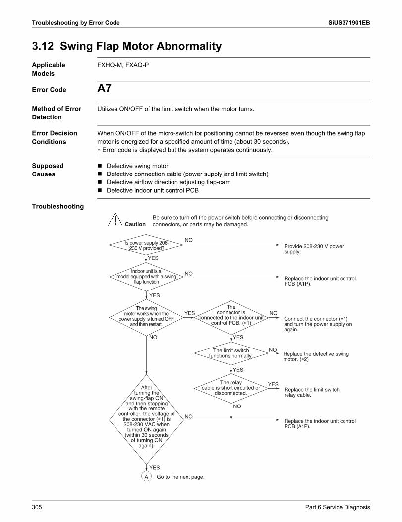
Troubleshooting by Error Code SiUS371901EB
3.12 Swing Flap Motor AbnormalityApplicable Models
FXHQ-M, FXAQ-P
Error Code A7Method of Error Detection
Utilizes ON/OFF of the limit switch when the motor turns.
Error Decision Conditions
When ON/OFF of the micro-switch for positioning cannot be reversed even though the swing flap motor is energized for a specified amount of time (about 30 seconds).∗ Error code is displayed but the system operates continuously.
Supposed Causes
Defective swing motor Defective connection cable (power supply and limit switch) Defective airflow direction adjusting flap-cam Defective indoor unit control PCB
Troubleshooting
Indoor unit is a model equipped with a swing
flap function
The swing motor works when the
power supply is turned OFF and then restart.
The relay cable is short circuited or
disconnected.
CautionBe sure to turn off the power switch before connecting or disconnecting connectors, or parts may be damaged.
Provide 208-230 V power supply.
YES
NO
The connector is
connected to the indoor unit control PCB. (�1)
Go to the next page.
Replace the limit switch relay cable.
Replace the indoor unit control PCB (A1P).
NO
YES
YES
NO
YES
Connect the connector (�1) and turn the power supply on again.
Replace the indoor unit control PCB (A1P).
NO
NO
YES NO
YES
YES
NOReplace the defective swing motor. (�2)
Is power supply 208- 230 V provided?
The limit switch functions normally.
After turning the
swing-flap ON and then stopping
with the remote controller, the voltage of
the connector (�1) is 208-230 VAC when
turned ON again (within 30 seconds
of turning ON again).
A
305 Part 6 Service Diagnosis
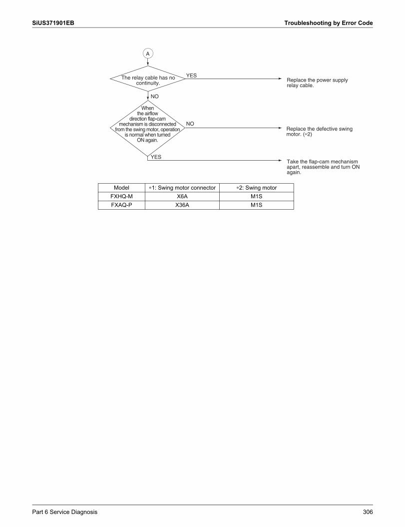
SiUS371901EB Troubleshooting by Error Code
Model ∗1: Swing motor connector ∗2: Swing motorFXHQ-M X6A M1SFXAQ-P X36A M1S
Replace the power supply relay cable.
Replace the defective swing motor. (∗2)
Take the flap-cam mechanism apart, reassemble and turn ON again.
YES
NO
YES
NO
The relay cable has no continuity.
When the airflow
direction flap-cam mechanism is disconnected
from the swing motor, operation is normal when turned
ON again.
A
Part 6 Service Diagnosis 306
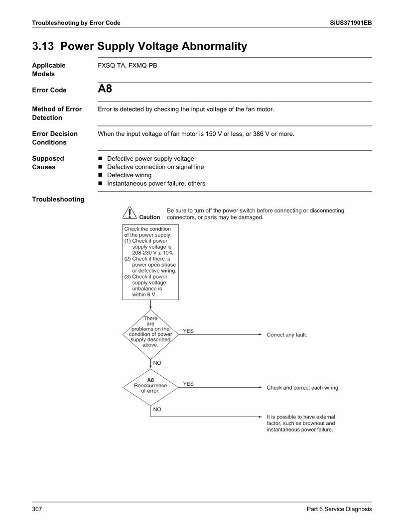
Troubleshooting by Error Code SiUS371901EB
3.13 Power Supply Voltage AbnormalityApplicable Models
FXSQ-TA, FXMQ-PB
Error Code A8Method of Error Detection
Error is detected by checking the input voltage of the fan motor.
Error Decision Conditions
When the input voltage of fan motor is 150 V or less, or 386 V or more.
Supposed Causes
Defective power supply voltage Defective connection on signal line Defective wiring Instantaneous power failure, others
Troubleshooting
Check the condition of the power supply.(1) Check if power
supply voltage is 208-230 V ± 10%.
(2) Check if there is power open phase or defective wiring.
(3) Check if power supply voltage unbalance is within 6 V.
YES
There are
problems on the condition of power supply described
above.
CautionBe sure to turn off the power switch before connecting or disconnecting connectors, or parts may be damaged.
Correct any fault.
NO
NO
YESA8
Reoccurrence of error. Check and correct each wiring.
It is possible to have external factor, such as brownout and instantaneous power failure.
307 Part 6 Service Diagnosis
SiUS371901EB Troubleshooting by Error Code
3.14 Blower Motor Stops for Over/Under VoltageApplicable Models
FXTQ-TA
Error Code A8Outline The indoor unit periodically receives control status information from the fan motor.
Error is issued when the information shows abnormality.
Error Decision Conditions
If the information shows Over/Under Voltage status, it will be deemed a MOTOR VOLTS abnormal operation.
Error Reset Conditions
If the information is normal, the error will be cleared.
Supposed Causes
High AC line voltage to indoor blower motor Low AC line voltage to indoor blower motor Incorrect wiring
Corrective Actions
Verify line voltage to indoor blower motor is within the range specified on the ID blower rating plate.
Check power to indoor blower motor. Check wiring. Replace motor.
Part 6 Service Diagnosis 308
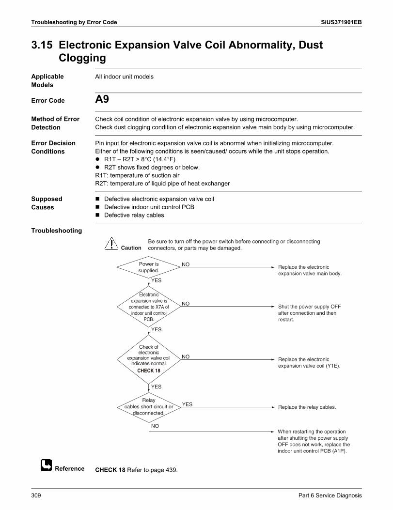
Troubleshooting by Error Code SiUS371901EB
Reference
3.15 Electronic Expansion Valve Coil Abnormality, Dust Clogging
Applicable Models
All indoor unit models
Error Code A9Method of Error Detection
Check coil condition of electronic expansion valve by using microcomputer.Check dust clogging condition of electronic expansion valve main body by using microcomputer.
Error Decision Conditions
Pin input for electronic expansion valve coil is abnormal when initializing microcomputer.Either of the following conditions is seen/caused/ occurs while the unit stops operation. R1T – R2T > 8°C (14.4°F) R2T shows fixed degrees or below.R1T: temperature of suction airR2T: temperature of liquid pipe of heat exchanger
Supposed Causes
Defective electronic expansion valve coil Defective indoor unit control PCB Defective relay cables
Troubleshooting
CHECK 18 Refer to page 439.
NO
YES
Power is supplied.
NO
Electronic expansion valve is
connected to X7A of indoor unit control
PCB.
NO
Check of electronic
expansion valve coil indicates normal.
NO
YES
YES
YES
Relay cables short circuit or
disconnected.
When restarting the operation after shutting the power supply OFF does not work, replace the indoor unit control PCB (A1P).
Replace the relay cables.
Replace the electronic expansion valve coil (Y1E).
Shut the power supply OFF after connection and then restart.
Replace the electronic expansion valve main body.
CHECK 18
CautionBe sure to turn off the power switch before connecting or disconnecting connectors, or parts may be damaged.
309 Part 6 Service Diagnosis
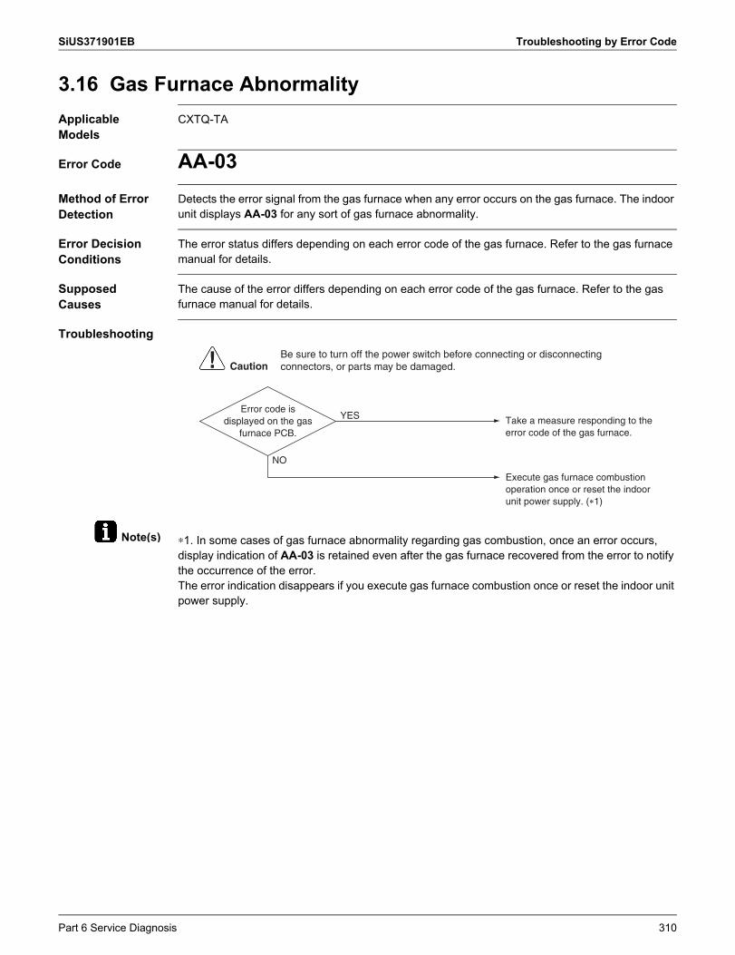
SiUS371901EB Troubleshooting by Error Code
Note(s)
3.16 Gas Furnace AbnormalityApplicable Models
CXTQ-TA
Error Code AA-03Method of Error Detection
Detects the error signal from the gas furnace when any error occurs on the gas furnace. The indoor unit displays AA-03 for any sort of gas furnace abnormality.
Error Decision Conditions
The error status differs depending on each error code of the gas furnace. Refer to the gas furnace manual for details.
Supposed Causes
The cause of the error differs depending on each error code of the gas furnace. Refer to the gas furnace manual for details.
Troubleshooting
∗1. In some cases of gas furnace abnormality regarding gas combustion, once an error occurs, display indication of AA-03 is retained even after the gas furnace recovered from the error to notify the occurrence of the error.The error indication disappears if you execute gas furnace combustion once or reset the indoor unit power supply.
NO
YES Take a measure responding to the error code of the gas furnace.
Execute gas furnace combustion operation once or reset the indoor unit power supply. (∗1)
Error code is displayed on the gas
furnace PCB.
CautionBe sure to turn off the power switch before connecting or disconnecting connectors, or parts may be damaged.
Part 6 Service Diagnosis 310
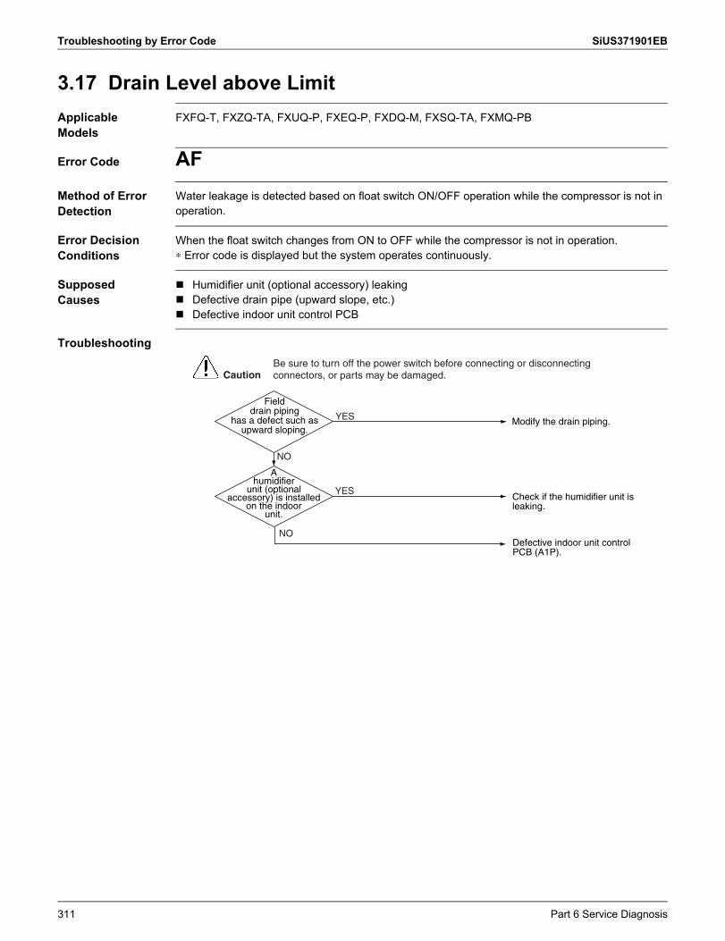
Troubleshooting by Error Code SiUS371901EB
3.17 Drain Level above LimitApplicable Models
FXFQ-T, FXZQ-TA, FXUQ-P, FXEQ-P, FXDQ-M, FXSQ-TA, FXMQ-PB
Error Code AFMethod of Error Detection
Water leakage is detected based on float switch ON/OFF operation while the compressor is not in operation.
Error Decision Conditions
When the float switch changes from ON to OFF while the compressor is not in operation.∗ Error code is displayed but the system operates continuously.
Supposed Causes
Humidifier unit (optional accessory) leaking Defective drain pipe (upward slope, etc.) Defective indoor unit control PCB
Troubleshooting
Modify the drain piping.YES
YES
NO
Field drain piping
has a defect such as upward sloping.
NO
A humidifier
unit (optional accessory) is installed
on the indoor unit.
Defective indoor unit control PCB (A1P).
Check if the humidifier unit is leaking.
CautionBe sure to turn off the power switch before connecting or disconnecting connectors, or parts may be damaged.
311 Part 6 Service Diagnosis
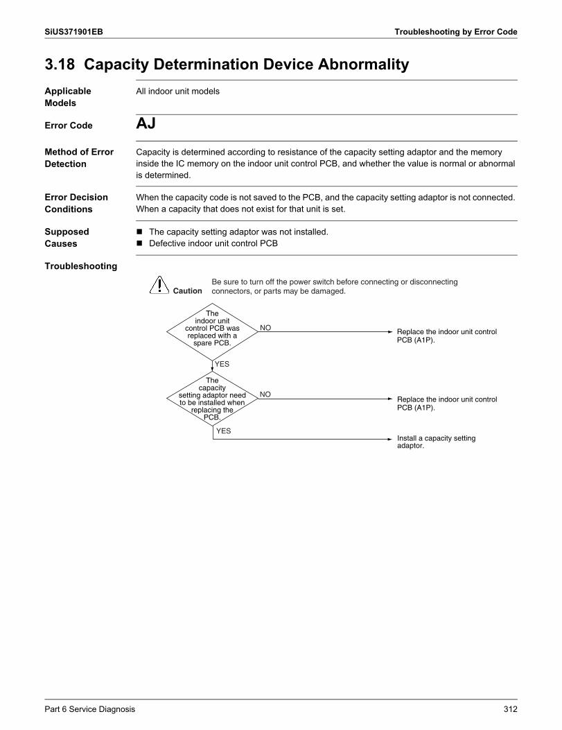
SiUS371901EB Troubleshooting by Error Code
3.18 Capacity Determination Device AbnormalityApplicable Models
All indoor unit models
Error Code AJMethod of Error Detection
Capacity is determined according to resistance of the capacity setting adaptor and the memory inside the IC memory on the indoor unit control PCB, and whether the value is normal or abnormal is determined.
Error Decision Conditions
When the capacity code is not saved to the PCB, and the capacity setting adaptor is not connected. When a capacity that does not exist for that unit is set.
Supposed Causes
The capacity setting adaptor was not installed. Defective indoor unit control PCB
Troubleshooting
NO
NO
YES
The indoor unit
control PCB was replaced with a
spare PCB.
YES
The capacity
setting adaptor need to be installed when
replacing the PCB.
Install a capacity setting adaptor.
Replace the indoor unit control PCB (A1P).
Replace the indoor unit control PCB (A1P).
CautionBe sure to turn off the power switch before connecting or disconnecting connectors, or parts may be damaged.
Part 6 Service Diagnosis 312
Troubleshooting by Error Code SiUS371901EB
3.19 Transmission Abnormality between Indoor Unit Control PCB and Fan PCB
Applicable Models
FXSQ-TA, FXMQ-PB
Error Code C1Method of Error Detection
Transmission conditions between the indoor unit control PCB (A1P) and fan PCB (A2P) are checked via microcomputer.
Error Decision Conditions
When normal transmission is not carried out for a certain duration.
Supposed Causes
Connection defective the connector between indoor unit control PCB (A1P) and fan PCB (A2P) Defective indoor unit control PCB (A1P) Defective fan PCB (A2P) External factor, such as instantaneous power failure
313 Part 6 Service Diagnosis
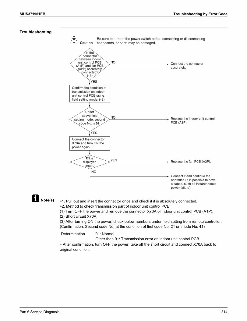
SiUS371901EB Troubleshooting by Error Code
Note(s)
Troubleshooting
∗1. Pull out and insert the connector once and check if it is absolutely connected.∗2. Method to check transmission part of indoor unit control PCB.(1) Turn OFF the power and remove the connector X70A of indoor unit control PCB (A1P).(2) Short circuit X70A.(3) After turning ON the power, check below numbers under field setting from remote controller. (Confirmation: Second code No. at the condition of first code No. 21 on mode No. 41)
∗ After confirmation, turn OFF the power, take off the short circuit and connect X70A back to original condition.
Under above field
setting mode, second code No. is 01.
NO
NO
YES
Replace the fan PCB (A2P).YES
YES
Is the connector
between indoor unit control PCB
(A1P) and fan PCB (A2P) accurately
connected? (∗1)
NO
C1 is displayed
again.
Confirm the condition of transmission on indoor unit control PCB using field setting mode. (∗2)
Connect the connector X70A and turn ON the power again.
Connect it and continue the operation (It is possible to have a cause, such as instantaneous power failure).
Connect the connector accurately.
Replace the indoor unit control PCB (A1P).
CautionBe sure to turn off the power switch before connecting or disconnecting connectors, or parts may be damaged.
Determination 01: NormalOther than 01: Transmission error on indoor unit control PCB
Part 6 Service Diagnosis 314
Troubleshooting by Error Code SiUS371901EB
3.20 Blower Motor Communication ErrorApplicable Models
FXTQ-TA
Error Code C1-07Outline Error is issued if transmission abnormalities occur between indoor unit and fan motor.
Error Decision Conditions
If the response message from the fan motor is an abnormal message, and determined as such by the indoor unit, the indoor unit will execute a retry.If everything fails for 5 seconds, it is deemed to be a transmission abnormality.
Error Reset Conditions
If the indoor unit receives even a single normal response message from the fan motor, the error will be cleared.
Supposed Causes
Incorrect or loose wiring Power interruption (low voltage)
Corrective Actions
Check wiring or tighten wiring connections if needed. Verify the input voltage at the motor. Replace the indoor unit PCB or motor.
315 Part 6 Service Diagnosis
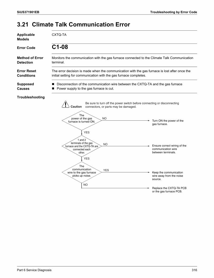
SiUS371901EB Troubleshooting by Error Code
3.21 Climate Talk Communication ErrorApplicable Models
CXTQ-TA
Error Code C1-08Method of Error Detection
Monitors the communication with the gas furnace connected to the Climate Talk Communication terminal.
Error Reset Conditions
The error decision is made when the communication with the gas furnace is lost after once the initial setting for communication with the gas furnace completes.
Supposed Causes
Disconnection of the communication wire between the CXTQ-TA and the gas furnace Power supply to the gas furnace is cut.
Troubleshooting
NO
CautionBe sure to turn off the power switch before connecting or disconnecting connectors, or parts may be damaged.
1 and 2 terminals of the gas
furnace and the CXTQ-TA are connected each
other.
NO
YES
YES
YES
NO
The communication
wire to the gas furnace picks up noise.
Replace the CXTQ-TA PCB or the gas furnace PCB.
Ensure correct wiring of the communication wire between terminals.
Turn ON the power of the gas furnace.
Keep the communication wire away from the noise source.
The power of the gas
furnace is turned ON.
Part 6 Service Diagnosis 316
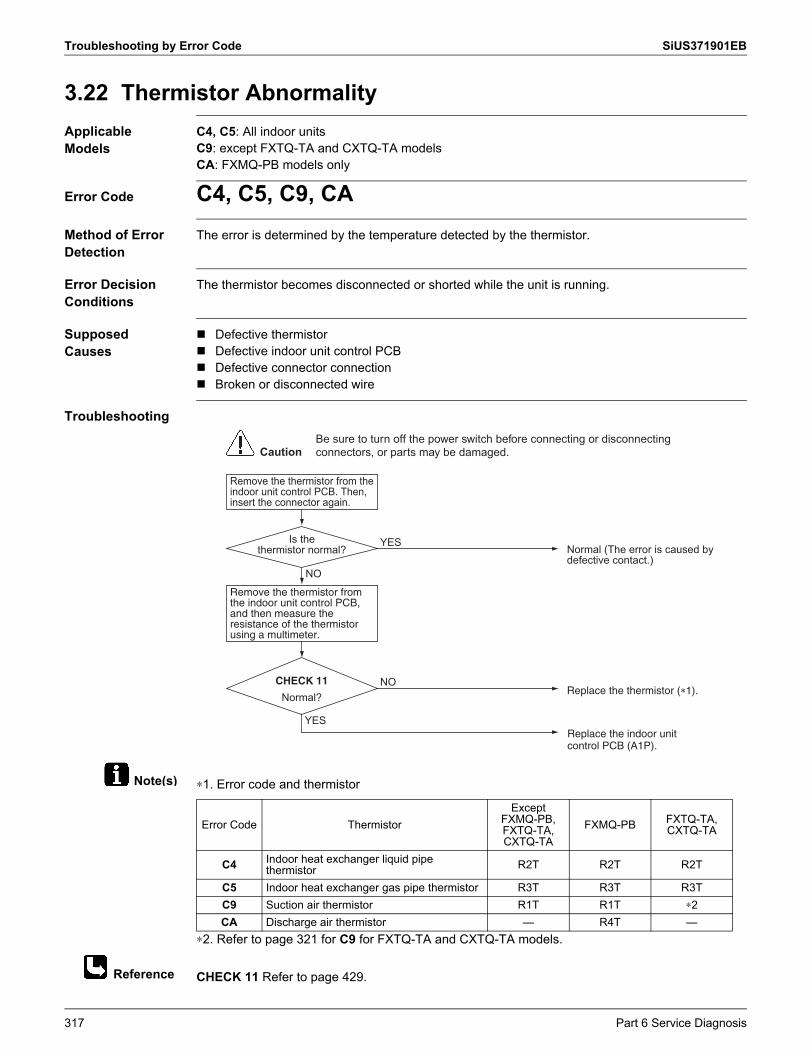
Troubleshooting by Error Code SiUS371901EB
Note(s)
Reference
3.22 Thermistor AbnormalityApplicable Models
C4, C5: All indoor unitsC9: except FXTQ-TA and CXTQ-TA modelsCA: FXMQ-PB models only
Error Code C4, C5, C9, CAMethod of Error Detection
The error is determined by the temperature detected by the thermistor.
Error Decision Conditions
The thermistor becomes disconnected or shorted while the unit is running.
Supposed Causes
Defective thermistor Defective indoor unit control PCB Defective connector connection Broken or disconnected wire
Troubleshooting
∗1. Error code and thermistor
∗2. Refer to page 321 for C9 for FXTQ-TA and CXTQ-TA models.
CHECK 11 Refer to page 429.
Is thethermistor normal?
CautionBe sure to turn off the power switch before connecting or disconnecting connectors, or parts may be damaged.
Remove the thermistor from the indoor unit control PCB. Then, insert the connector again.
Remove the thermistor from the indoor unit control PCB, and then measure the resistance of the thermistor using a multimeter.
Normal?
Normal (The error is caused by defective contact.)
YES
NO
Replace the indoor unit control PCB (A1P).
YES
Replace the thermistor (�1).NOCHECK 11
Error Code ThermistorExcept
FXMQ-PB,FXTQ-TA,CXTQ-TA
FXMQ-PB FXTQ-TA, CXTQ-TA
C4 Indoor heat exchanger liquid pipe thermistor R2T R2T R2T
C5 Indoor heat exchanger gas pipe thermistor R3T R3T R3TC9 Suction air thermistor R1T R1T ∗2CA Discharge air thermistor — R4T —
317 Part 6 Service Diagnosis
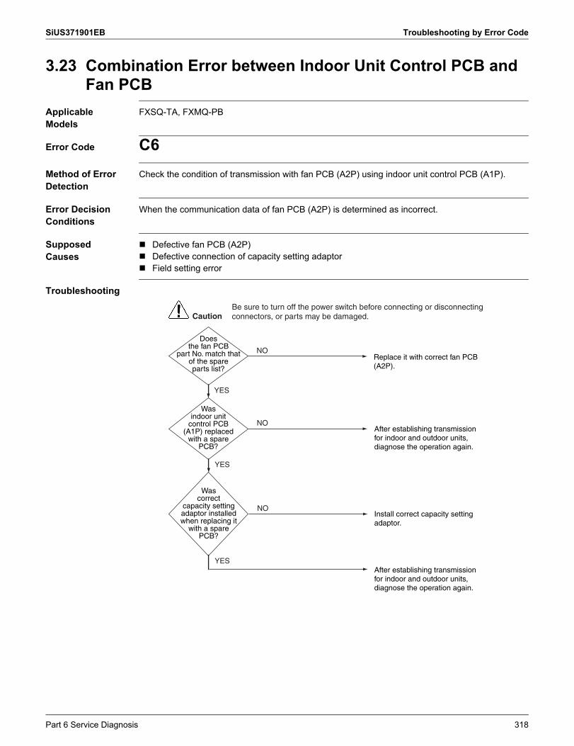
SiUS371901EB Troubleshooting by Error Code
3.23 Combination Error between Indoor Unit Control PCB and Fan PCB
Applicable Models
FXSQ-TA, FXMQ-PB
Error Code C6Method of Error Detection
Check the condition of transmission with fan PCB (A2P) using indoor unit control PCB (A1P).
Error Decision Conditions
When the communication data of fan PCB (A2P) is determined as incorrect.
Supposed Causes
Defective fan PCB (A2P) Defective connection of capacity setting adaptor Field setting error
Troubleshooting
NO
CautionBe sure to turn off the power switch before connecting or disconnecting connectors, or parts may be damaged.
Was indoor unit
control PCB (A1P) replaced
with a spare PCB?
YES
YES
YES
NO
NO
Was correct
capacity setting adaptor installed when replacing it
with a spare PCB?
After establishing transmission for indoor and outdoor units, diagnose the operation again.
After establishing transmission for indoor and outdoor units, diagnose the operation again.
Replace it with correct fan PCB (A2P).
Install correct capacity setting adaptor.
Does the fan PCB
part No. match that of the spare parts list?
Part 6 Service Diagnosis 318
Troubleshooting by Error Code SiUS371901EB
3.24 Blower Motor HP MismatchApplicable Models
FXTQ-TA
Error Code C6-01Outline Error is issued if the manufacturer ID and output of the connected fan motor do not match those
recognized by the indoor unit.
Error Decision Conditions
Gathers information on the manufacturer ID and output of the fan motor when initializing the fan motor.If those figures are not the values recognized by the indoor unit, it will be deemed abnormal operation.If deemed abnormal operation, it will keep retrying until the figures match.
Error Reset Conditions
If the manufacturer ID and output match, the error will be cleared.
Supposed Causes
Incorrect size motor Indoor unit capacity setting error
Corrective Actions
Correct motor installation. Correct the indoor unit capacity setting.
319 Part 6 Service Diagnosis
SiUS371901EB Troubleshooting by Error Code
3.25 Indoor Blower Does Not Have Required Parameters to Function
Applicable Models
FXTQ-TA
Error Code C6-02Outline Indoor units perform required settings for control on the fan motor, but if the minimum required
settings are not made then information indicating as such will be included among the periodic control status information.Error is issued when the information shows abnormality.
Error Decision Conditions
If the parameter information shows abnormality, it will be deemed abnormal operation.At that point, parameter settings when initializing the fan motor will be implemented from the beginning.
Error Reset Conditions
If the parameter information is normal, the error will be cleared.
Supposed Causes
Locked motor rotor condition
Corrective Actions
Check for locked rotor condition. Replace the indoor unit PCB or motor.
Part 6 Service Diagnosis 320
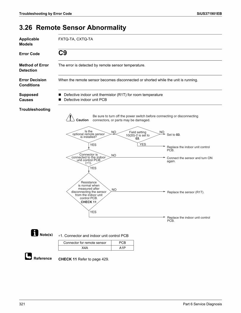
Troubleshooting by Error Code SiUS371901EB
Note(s)
Reference
3.26 Remote Sensor AbnormalityApplicable Models
FXTQ-TA, CXTQ-TA
Error Code C9Method of Error Detection
The error is detected by remote sensor temperature.
Error Decision Conditions
When the remote sensor becomes disconnected or shorted while the unit is running.
Supposed Causes
Defective indoor unit thermistor (R1T) for room temperature Defective indoor unit PCB
Troubleshooting
∗1. Connector and indoor unit control PCB
CHECK 11 Refer to page 429.
Is the optional remote sensor
is installed?
Field setting 10(20)-2 is set to
03.
Connector is connected to the indoor
unit control PCB(�1).
Resistance is normal when measured after
disconnecting the sensor from the indoor unit
control PCB.
CautionBe sure to turn off the power switch before connecting or disconnecting connectors, or parts may be damaged.
Set to 03.
Replace the indoor unit control PCB.
NO NO
YES YES
Replace the indoor unit control PCB.
Connect the sensor and turn ON again.
NO
NO
Replace the sensor (R1T).
YES
YES
CHECK 11
Connector for remote sensor PCBX4A A1P
321 Part 6 Service Diagnosis
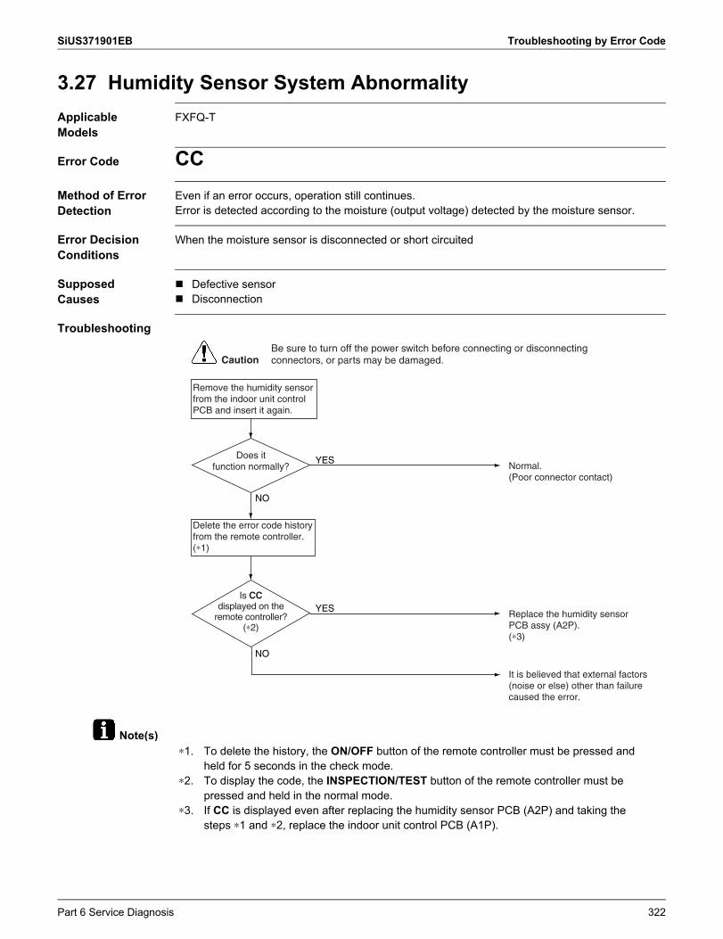
SiUS371901EB Troubleshooting by Error Code
Note(s)
3.27 Humidity Sensor System AbnormalityApplicable Models
FXFQ-T
Error Code CCMethod of Error Detection
Even if an error occurs, operation still continues.Error is detected according to the moisture (output voltage) detected by the moisture sensor.
Error Decision Conditions
When the moisture sensor is disconnected or short circuited
Supposed Causes
Defective sensor Disconnection
Troubleshooting
CautionBe sure to turn off the power switch before connecting or disconnecting connectors, or parts may be damaged.
YES
NO
Is CC displayed on the
remote controller? (∗2)
YES
NO
Does it function normally?
Remove the humidity sensor from the indoor unit control PCB and insert it again.
Normal.(Poor connector contact)
Replace the humidity sensor PCB assy (A2P).(∗3)
It is believed that external factors (noise or else) other than failure caused the error.
Delete the error code history from the remote controller. (∗1)
∗1.
∗2.
∗3.
To delete the history, the ON/OFF button of the remote controller must be pressed and held for 5 seconds in the check mode.To display the code, the INSPECTION/TEST button of the remote controller must be pressed and held in the normal mode.If CC is displayed even after replacing the humidity sensor PCB (A2P) and taking the steps ∗1 and ∗2, replace the indoor unit control PCB (A1P).
Part 6 Service Diagnosis 322

Troubleshooting by Error Code SiUS371901EB
3.28 Infrared Presence/Floor Sensor ErrorApplicable Models
FXFQ-T, FXUQ-P
Error Code CEMethod of Error Detection
The contents of a failure vary with the detailed error code. Check the code and proceed with the flowchart.
Error Decision Conditions
Error is detected based on sensor output signals
Supposed Causes
Defective or disconnected infrared presence sensor connector: CE-01 Defective infrared floor sensor (Temperature compensation circuit disconnection): CE-02 Defective infrared floor sensor (Temperature compensation short circuit): CE-03 Defective infrared floor sensor element: CE-04
Troubleshooting
See diagnosis procedure 1.
CautionBe sure to turn off the power switch before connecting or disconnecting connectors, or parts may be damaged.
Error code
CE-01
See diagnosis procedure 2.Error code
CE-02
See diagnosis procedure 3.Error code
CE-03
See diagnosis procedure 4.Error code
CE-04
Error type varies according to error code. Check the error code and take the following steps.
323 Part 6 Service Diagnosis
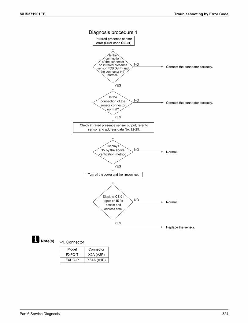
SiUS371901EB Troubleshooting by Error Code
Note(s) ∗1. Connector
Diagnosis procedure 1Infrared presence sensor error (Error code CE-01)
Turn off the power and then reconnect.
Check infrared presence sensor output; refer to sensor and address data No. 22-25.
Connect the connector correctly.
Connect the connector correctly.
NO
YES
YES
Is the connection
of the connector on infrared presence
sensor PCB (A4P) and the connector (∗1)
normal?
NO
YES
YES
Is the connection of the sensor connector
normal?
Normal.NO
Displays 15 by the above
verification method.
Normal.NO
Displays CE-01 again or 15 for
sensor and address data.
Replace the sensor.
Model ConnectorFXFQ-T X2A (A2P)FXUQ-P X81A (A1P)
Part 6 Service Diagnosis 324
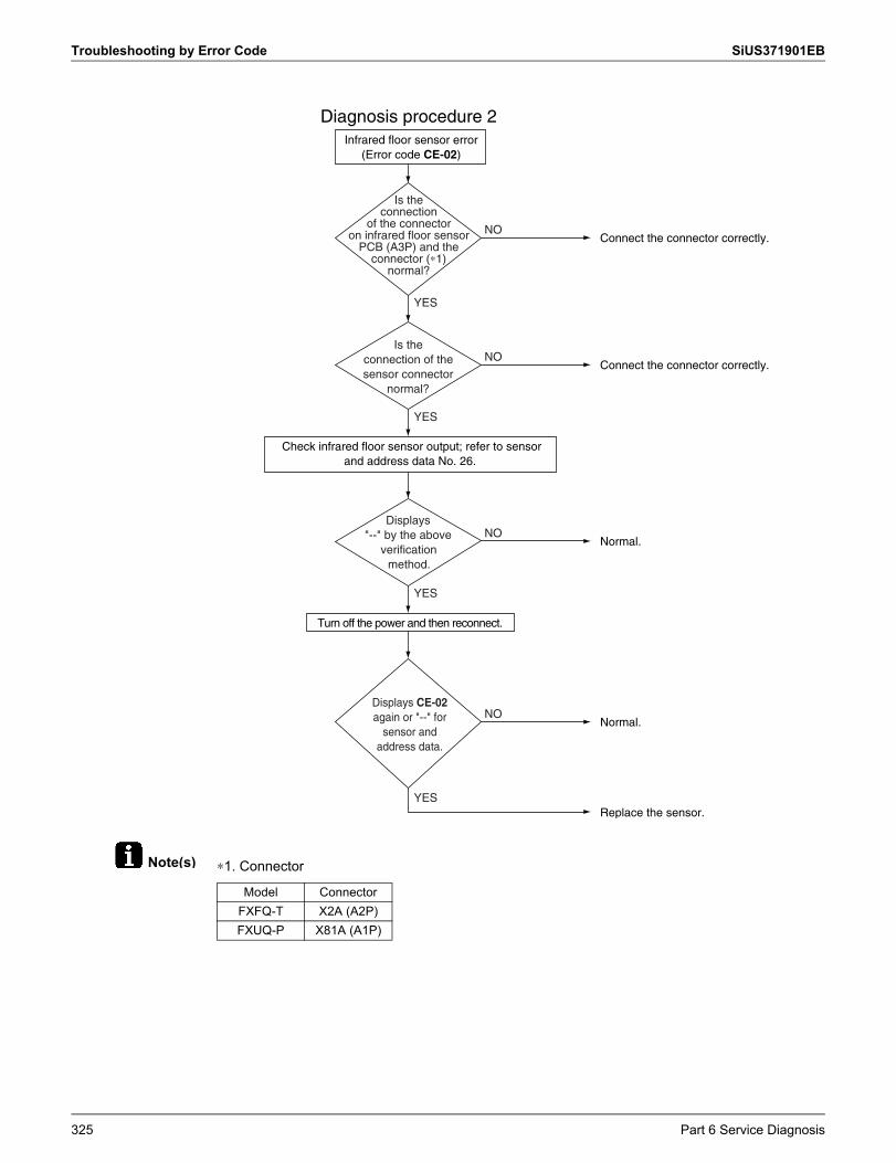
Troubleshooting by Error Code SiUS371901EB
Note(s) ∗1. Connector
Diagnosis procedure 2Infrared floor sensor error
(Error code CE-02)
Turn off the power and then reconnect.
Check infrared floor sensor output; refer to sensor and address data No. 26.
Connect the connector correctly.
Connect the connector correctly.
NO
YES
YES
Is the connection
of the connector on infrared floor sensor
PCB (A3P) and the connector (∗1)
normal?
NO
YES
YES
Is the connection of the sensor connector
normal?
Normal.NO
Displays "--" by the above
verification method.
Normal.NO
Displays CE-02 again or "--" for
sensor and address data.
Replace the sensor.
Model ConnectorFXFQ-T X2A (A2P)FXUQ-P X81A (A1P)
325 Part 6 Service Diagnosis

SiUS371901EB Troubleshooting by Error Code
Note(s) ∗1. Connector
Diagnosis procedure 3Infrared floor sensor error
(Error code CE-03)
NO
YES
YES
NO
YES
YES
NO
NO
Turn off the power and then reconnect.
Check infrared floor sensor output; refer to sensor and address data No. 26.
Is the connection of the sensor connector
normal?
Displays "--" by the above
verification method.
Displays CE-03 again or "--"
for sensor and address data.
Replace the sensor.
Connect the connector correctly.
Connect the connector correctly.
Normal.
Normal.
Is the connection
of the connector on infrared floor sensor
PCB (A3P) and the connector (∗1)
normal?
Model ConnectorFXFQ-T X2A (A2P)FXUQ-P X81A (A1P)
Part 6 Service Diagnosis 326
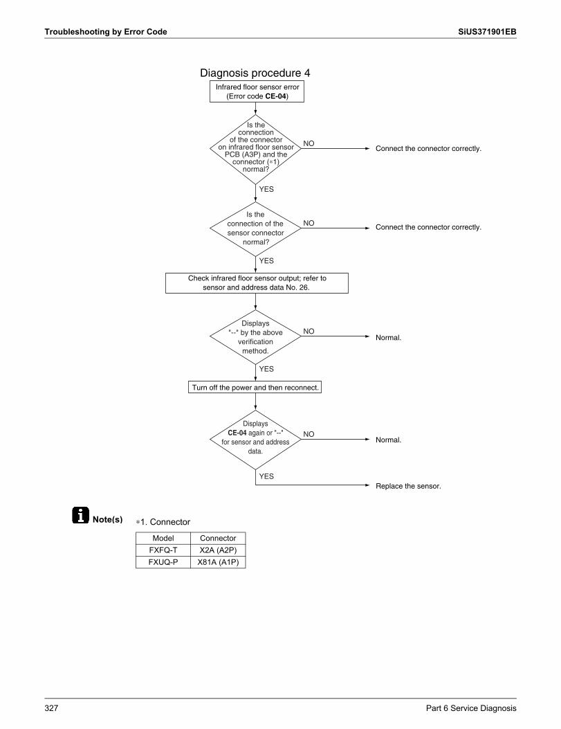
Troubleshooting by Error Code SiUS371901EB
Note(s) ∗1. Connector
NO
YES
YES
NO
YES
YES
NO
NO
Diagnosis procedure 4Infrared floor sensor error
(Error code CE-04)
Turn off the power and then reconnect.
Check infrared floor sensor output; refer to sensor and address data No. 26.
Is the connection of the sensor connector
normal?
Displays "--" by the above
verification method.
Displays CE-04 again or "--"
for sensor and address data.
Replace the sensor.
Connect the connector correctly.
Connect the connector correctly.
Normal.
Normal.
Is the connection
of the connector on infrared floor sensor
PCB (A3P) and the connector (∗1)
normal?
Model ConnectorFXFQ-T X2A (A2P)FXUQ-P X81A (A1P)
327 Part 6 Service Diagnosis
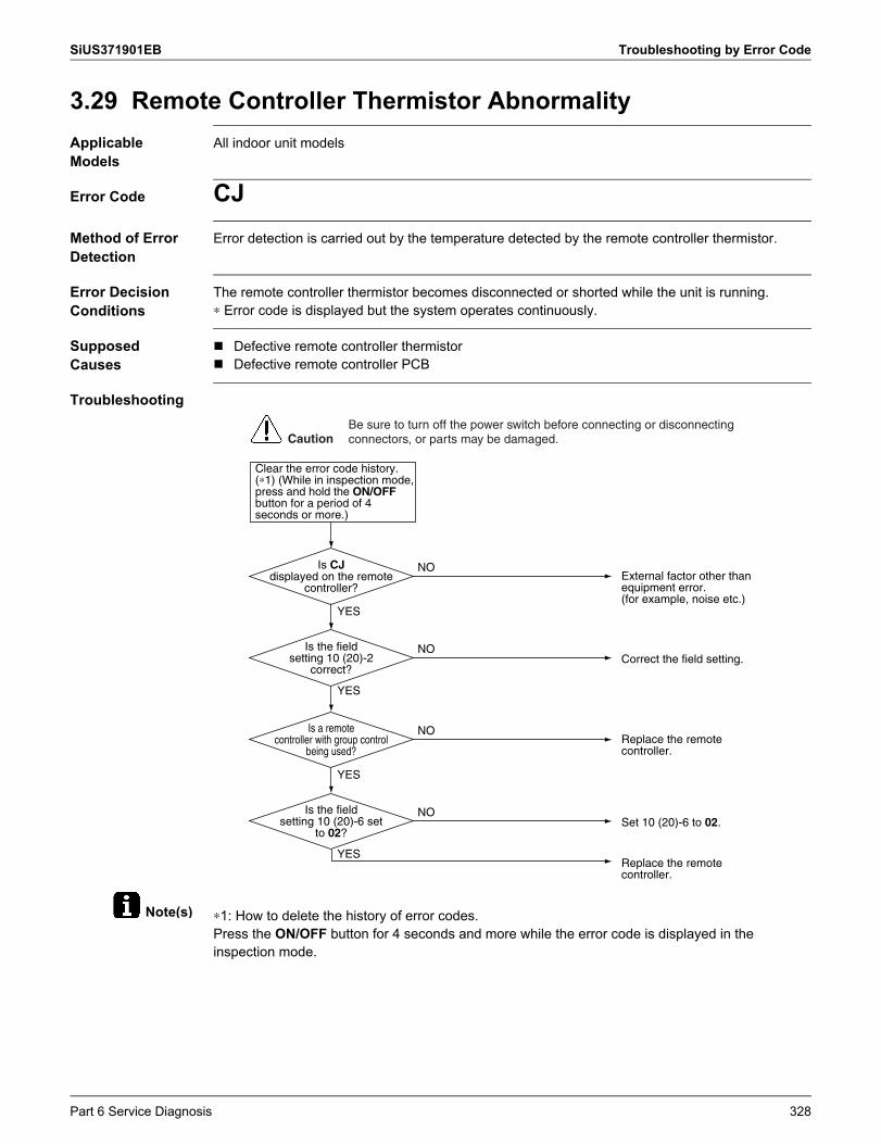
SiUS371901EB Troubleshooting by Error Code
Note(s)
3.29 Remote Controller Thermistor AbnormalityApplicable Models
All indoor unit models
Error Code CJMethod of Error Detection
Error detection is carried out by the temperature detected by the remote controller thermistor.
Error Decision Conditions
The remote controller thermistor becomes disconnected or shorted while the unit is running.∗ Error code is displayed but the system operates continuously.
Supposed Causes
Defective remote controller thermistor Defective remote controller PCB
Troubleshooting
∗1: How to delete the history of error codes.Press the ON/OFF button for 4 seconds and more while the error code is displayed in the inspection mode.
Clear the error code history. (∗1) (While in inspection mode, press and hold the ON/OFF button for a period of 4 seconds or more.)
YES
YES
Is CJ displayed on the remote
controller?
Is the field setting 10 (20)-2
correct?
YES
YES
Is a remote controller with group control
being used?
Is the field setting 10 (20)-6 set
to 02?
CautionBe sure to turn off the power switch before connecting or disconnecting connectors, or parts may be damaged.
Correct the field setting.
External factor other than equipment error.(for example, noise etc.)
NO
NO
Replace the remote controller.
Set 10 (20)-6 to 02.
Replace the remote controller.
NO
NO
Part 6 Service Diagnosis 328
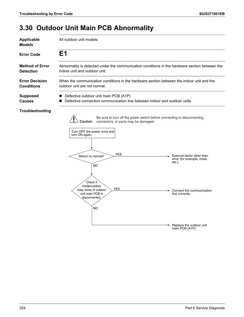
Troubleshooting by Error Code SiUS371901EB
3.30 Outdoor Unit Main PCB AbnormalityApplicable Models
All outdoor unit models
Error Code E1Method of Error Detection
Abnormality is detected under the communication conditions in the hardware section between the indoor unit and outdoor unit.
Error Decision Conditions
When the communication conditions in the hardware section between the indoor unit and the outdoor unit are not normal.
Supposed Causes
Defective outdoor unit main PCB (A1P) Defective connection communication line between indoor and outdoor units
Troubleshooting
Return to normal?YES External factor other than
error (for example, noise etc.).
Connect the communication line correctly.
Replace the outdoor unit main PCB (A1P).
NO
NO
Check if inside/outdoor
relay wires of outdoor unit main PCB is
disconnected.
YES
Turn OFF the power once and turn ON again.
CautionBe sure to turn off the power switch before connecting or disconnecting connectors, or parts may be damaged.
329 Part 6 Service Diagnosis
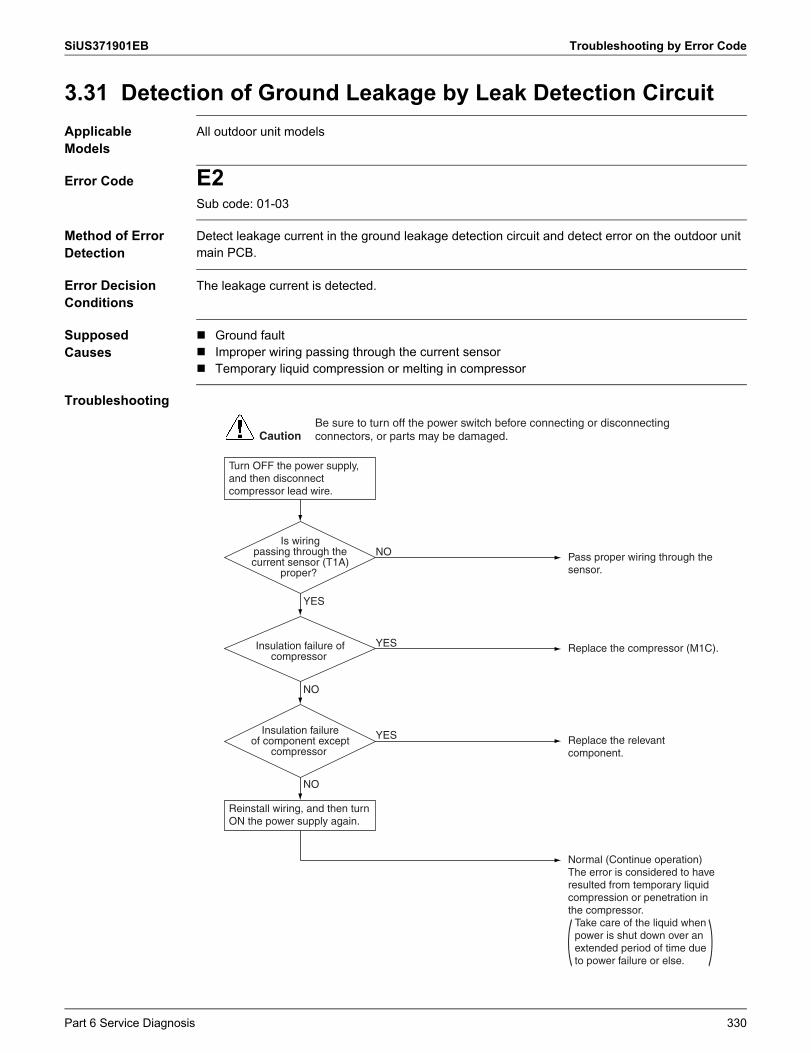
SiUS371901EB Troubleshooting by Error Code
3.31 Detection of Ground Leakage by Leak Detection CircuitApplicable Models
All outdoor unit models
Error Code E2Sub code: 01-03
Method of Error Detection
Detect leakage current in the ground leakage detection circuit and detect error on the outdoor unit main PCB.
Error Decision Conditions
The leakage current is detected.
Supposed Causes
Ground fault Improper wiring passing through the current sensor Temporary liquid compression or melting in compressor
Troubleshooting
YES
NO
NO
Is wiring passing through the current sensor (T1A)
proper?
Insulation failure of compressor
Insulation failure of component except
compressor
Pass proper wiring through the sensor.
Turn OFF the power supply, and then disconnect compressor lead wire.
Reinstall wiring, and then turn ON the power supply again.
NO
Replace the compressor (M1C).YES
Replace the relevant component.
YES
Normal (Continue operation) The error is considered to have resulted from temporary liquid compression or penetration in the compressor.
Take care of the liquid when power is shut down over an extended period of time due to power failure or else.
CautionBe sure to turn off the power switch before connecting or disconnecting connectors, or parts may be damaged.
Part 6 Service Diagnosis 330
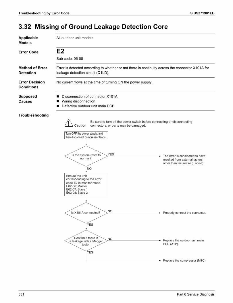
Troubleshooting by Error Code SiUS371901EB
3.32 Missing of Ground Leakage Detection CoreApplicable Models
All outdoor unit models
Error Code E2Sub code: 06-08
Method of Error Detection
Error is detected according to whether or not there is continuity across the connector X101A for leakage detection circuit (Q1LD).
Error Decision Conditions
No current flows at the time of turning ON the power supply.
Supposed Causes
Disconnection of connector X101A Wiring disconnection Defective outdoor unit main PCB
Troubleshooting
NO
YES
YES
Is the system reset to normal?
Is X101A connected?
The error is considered to have resulted from external factors other than failures (e.g. noise).
Turn OFF the power supply, and then disconnect compressor leads.
YES
Properly connect the connector. NO
Confirm if there is a leakage with a Megger
tester.Replace the outdoor unit main PCB (A1P).
NO
Replace the compressor (M1C).
CautionBe sure to turn off the power switch before connecting or disconnecting connectors, or parts may be damaged.
Ensure the unit corresponding to the error code E2 in monitor mode. E02-06: Master E02-07: Slave 1 E02-08: Slave 2
331 Part 6 Service Diagnosis
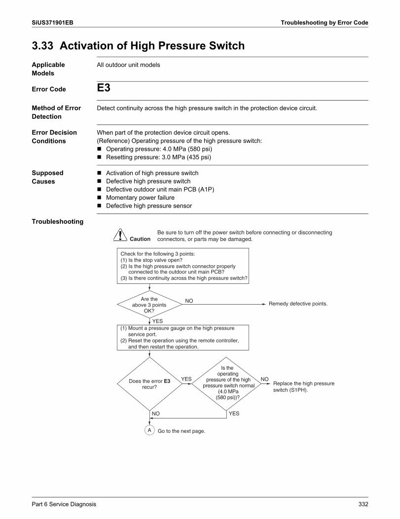
SiUS371901EB Troubleshooting by Error Code
3.33 Activation of High Pressure SwitchApplicable Models
All outdoor unit models
Error Code E3Method of Error Detection
Detect continuity across the high pressure switch in the protection device circuit.
Error Decision Conditions
When part of the protection device circuit opens.(Reference) Operating pressure of the high pressure switch: Operating pressure: 4.0 MPa (580 psi) Resetting pressure: 3.0 MPa (435 psi)
Supposed Causes
Activation of high pressure switch Defective high pressure switch Defective outdoor unit main PCB (A1P) Momentary power failure Defective high pressure sensor
Troubleshooting
NO
YES
YES
Replace the high pressure switch (S1PH).
Remedy defective points.
YES
Are the above 3 points
OK?
Does the error E3 recur?
NO
Is the operating
pressure of the high pressure switch normal
(4.0 MPa (580 psi))?
NO
(1) Mount a pressure gauge on the high pressure service port.
(2) Reset the operation using the remote controller, and then restart the operation.
A
Check for the following 3 points:(1) Is the stop valve open?(2) Is the high pressure switch connector properly
connected to the outdoor unit main PCB?(3) Is there continuity across the high pressure switch?
CautionBe sure to turn off the power switch before connecting or disconnecting connectors, or parts may be damaged.
Go to the next page.
Part 6 Service Diagnosis 332
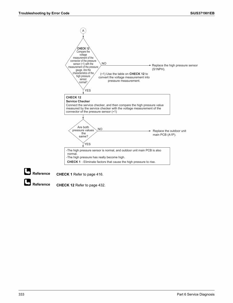
Troubleshooting by Error Code SiUS371901EB
Reference
Reference
CHECK 1 Refer to page 416.
CHECK 12 Refer to page 432.
Replace the outdoor unit main PCB (A1P).
NO
YES
Are bothpressure values
thesame?
-The high pressure sensor is normal, and outdoor unit main PCB is also normal.
-The high pressure has really become high. CHECK 1 : Eliminate factors that cause the high pressure to rise.
Connect the service checker, and then compare the high pressure valuemeasured by the service checker with the voltage measurement of theconnector of the pressure sensor (�1)
Service CheckerCHECK 12
A
Replace the high pressure sensor (S1NPH).
NO
Compare the voltage
measurement of the connector of the pressure
sensor (�1) with the measurement of the pressure
gauge. Are the characteristics of the
high pressure sensor
normal?
CHECK 12
YES
(�1) Use the table on CHECK 12 toconvert the voltage measurement into
pressure measurement.
333 Part 6 Service Diagnosis
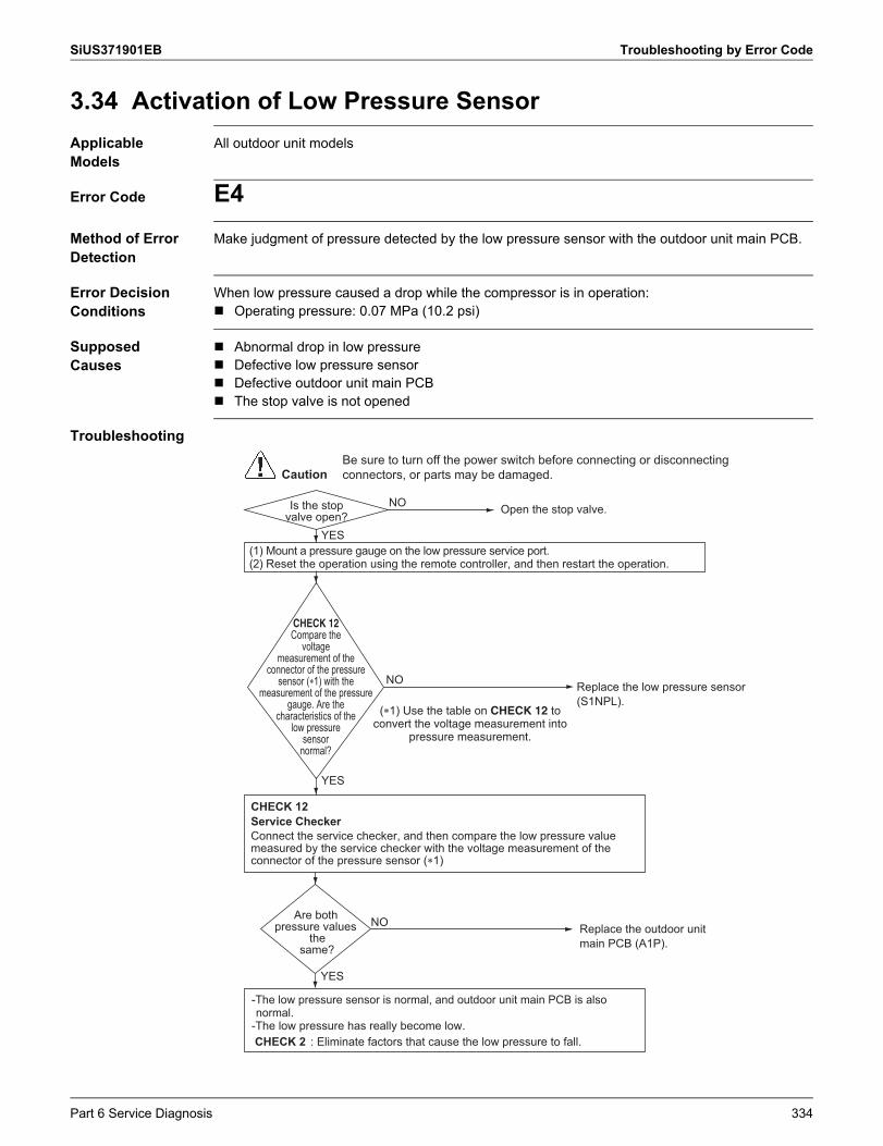
SiUS371901EB Troubleshooting by Error Code
3.34 Activation of Low Pressure SensorApplicable Models
All outdoor unit models
Error Code E4Method of Error Detection
Make judgment of pressure detected by the low pressure sensor with the outdoor unit main PCB.
Error Decision Conditions
When low pressure caused a drop while the compressor is in operation: Operating pressure: 0.07 MPa (10.2 psi)
Supposed Causes
Abnormal drop in low pressure Defective low pressure sensor Defective outdoor unit main PCB The stop valve is not opened
Troubleshooting
YES
NO
(1) Mount a pressure gauge on the low pressure service port.(2) Reset the operation using the remote controller, and then restart the operation.
Is the stop valve open? Open the stop valve.
CautionBe sure to turn off the power switch before connecting or disconnecting connectors, or parts may be damaged.
Replace the outdoor unit main PCB (A1P).
NO
YES
Are bothpressure values
thesame?
-The low pressure sensor is normal, and outdoor unit main PCB is also normal.
-The low pressure has really become low. CHECK 2 : Eliminate factors that cause the low pressure to fall.
Connect the service checker, and then compare the low pressure valuemeasured by the service checker with the voltage measurement of theconnector of the pressure sensor (�1)
Service CheckerCHECK 12
Replace the low pressure sensor (S1NPL).
NO
Compare the voltage
measurement of the connector of the pressure
sensor (�1) with the measurement of the pressure
gauge. Are the characteristics of the
low pressure sensor
normal?
CHECK 12
YES
(�1) Use the table on CHECK 12 toconvert the voltage measurement into
pressure measurement.
Part 6 Service Diagnosis 334
Troubleshooting by Error Code SiUS371901EB
Reference
Reference
CHECK 2 Refer to page 417.
CHECK 12 Refer to page 432.
335 Part 6 Service Diagnosis
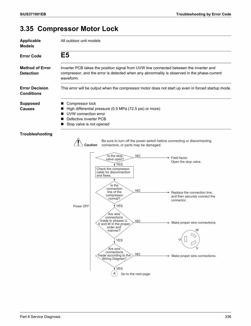
SiUS371901EB Troubleshooting by Error Code
3.35 Compressor Motor LockApplicable Models
All outdoor unit models
Error Code E5Method of Error Detection
Inverter PCB takes the position signal from UVW line connected between the inverter and compressor, and the error is detected when any abnormality is observed in the phase-current waveform.
Error Decision Conditions
This error will be output when the compressor motor does not start up even in forced startup mode.
Supposed Causes
Compressor lock High differential pressure (0.5 MPa (72.5 psi) or more) UVW connection error Defective inverter PCB Stop valve is not opened
Troubleshooting
Make proper wire connections.
Make proper wire connections.
NO
NO
NO
NO
YES
YES
YES
YES
Power OFF
Is the connectionline of the
compressor normal?
Are wire connections
made to phases U,V and W in the proper
order and manner?
Are wire connections
made according to the Wiring Diagram?
U
V
W
Is the stop valve open?
Replace the connection line, and then securely connect the connector.
Field factor Open the stop valve.
CautionBe sure to turn off the power switch before connecting or disconnecting connectors, or parts may be damaged.
A
Check the compressor cable for disconnection and flaws.
Go to the next page.
Part 6 Service Diagnosis 336
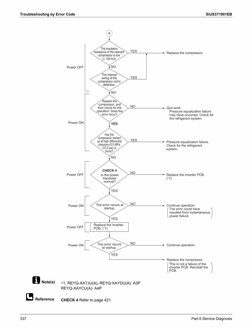
Troubleshooting by Error Code SiUS371901EB
Note(s)
Reference
∗1. REYQ-XATJU(A), REYQ-XAYDU(A): A3PREYQ-XAYCU(A): A4P
CHECK 4 Refer to page 421.
NO
YES
NO
YES
NO
Power ON
Restart the compressor, and then check for the
operation. Does the error recur?
Has the compressor started
up at high differential pressure (0.5 MPa
(72.5 psi) or more)?
The error recurs at startup.
YESYES
Power OFF
Power OFF
Power ON
Power ON
Power OFF
Pressure equalization failure.Check for the refrigerant system.
Quit work.Pressure equalization failure may have occurred. Check for the refrigerant system.
YES
YES
NOReplace the inverter PCB.(*1)
NOThe error recurs at startup.
Continue operation.The error could have resulted from instantaneous power failure.
A
Continue operation.
Replace the compressor.
CHECK 4Is the power
transistornormal?
This is not a failure of the inverter PCB. Reinstall the PCB.
Replace the compressor.YES
NO
NO
The internal wiring of the
compressor coil is defective.
The insulation resistance of the relevant
compressor is low(< 100 k�)
YES
Replace the inverterPCB. (*1)
337 Part 6 Service Diagnosis
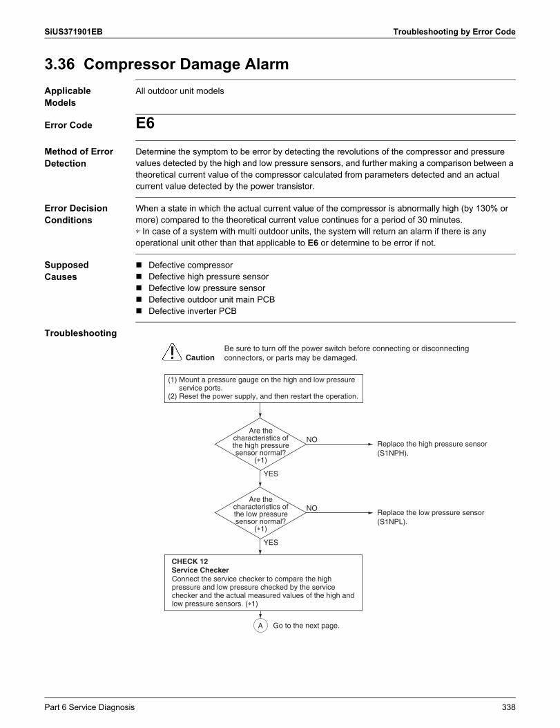
SiUS371901EB Troubleshooting by Error Code
3.36 Compressor Damage AlarmApplicable Models
All outdoor unit models
Error Code E6Method of Error Detection
Determine the symptom to be error by detecting the revolutions of the compressor and pressure values detected by the high and low pressure sensors, and further making a comparison between a theoretical current value of the compressor calculated from parameters detected and an actual current value detected by the power transistor.
Error Decision Conditions
When a state in which the actual current value of the compressor is abnormally high (by 130% or more) compared to the theoretical current value continues for a period of 30 minutes.∗ In case of a system with multi outdoor units, the system will return an alarm if there is any operational unit other than that applicable to E6 or determine to be error if not.
Supposed Causes
Defective compressor Defective high pressure sensor Defective low pressure sensor Defective outdoor unit main PCB Defective inverter PCB
Troubleshooting
NO
YES
Are the characteristics of the high pressure sensor normal?
(�1)
(1) Mount a pressure gauge on the high and low pressure service ports.
(2) Reset the power supply, and then restart the operation.
Replace the high pressure sensor (S1NPH).
CautionBe sure to turn off the power switch before connecting or disconnecting connectors, or parts may be damaged.
NO
YES
Are the characteristics of the low pressure sensor normal?
(�1)
Replace the low pressure sensor (S1NPL).
Connect the service checker to compare the high pressure and low pressure checked by the service checker and the actual measured values of the high and low pressure sensors. (�1)
Service Checker
A
CHECK 12
Go to the next page.
Part 6 Service Diagnosis 338
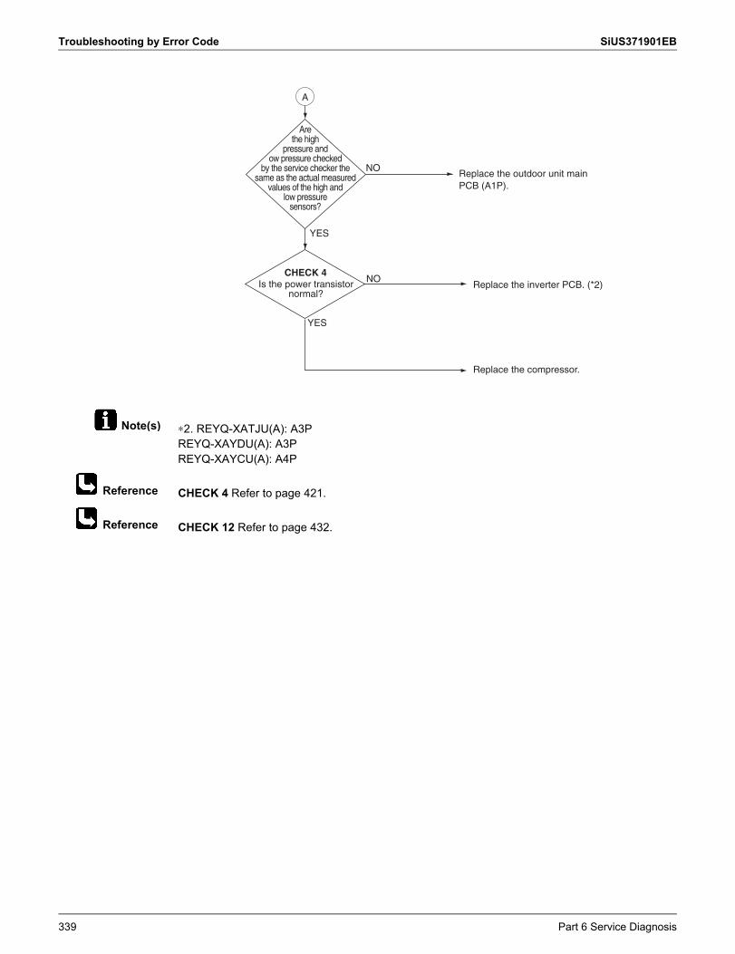
Troubleshooting by Error Code SiUS371901EB
Note(s)
Reference
Reference
∗2. REYQ-XATJU(A): A3PREYQ-XAYDU(A): A3PREYQ-XAYCU(A): A4P
CHECK 4 Refer to page 421.
CHECK 12 Refer to page 432.
NO
YES
Are the high
pressure and ow pressure checked
by the service checker the same as the actual measured
values of the high and low pressure
sensors?
Replace the outdoor unit main PCB (A1P).
NOReplace the inverter PCB. (*2)
CHECK 4Is the power transistor
normal?
YES
Replace the compressor.
A
339 Part 6 Service Diagnosis
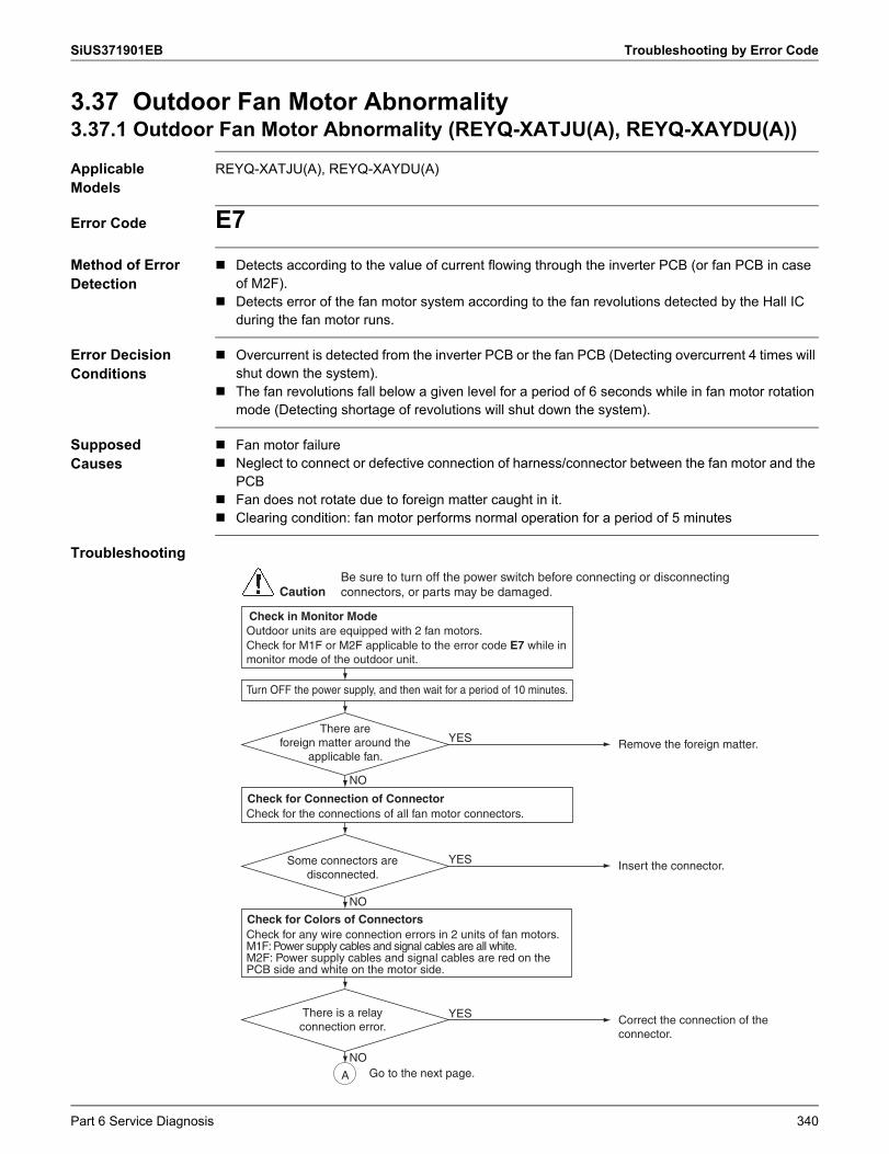
SiUS371901EB Troubleshooting by Error Code
3.37 Outdoor Fan Motor Abnormality3.37.1 Outdoor Fan Motor Abnormality (REYQ-XATJU(A), REYQ-XAYDU(A))
Applicable Models
REYQ-XATJU(A), REYQ-XAYDU(A)
Error Code E7Method of Error Detection
Detects according to the value of current flowing through the inverter PCB (or fan PCB in case of M2F).
Detects error of the fan motor system according to the fan revolutions detected by the Hall IC during the fan motor runs.
Error Decision Conditions
Overcurrent is detected from the inverter PCB or the fan PCB (Detecting overcurrent 4 times will shut down the system).
The fan revolutions fall below a given level for a period of 6 seconds while in fan motor rotation mode (Detecting shortage of revolutions will shut down the system).
Supposed Causes
Fan motor failure Neglect to connect or defective connection of harness/connector between the fan motor and the
PCB Fan does not rotate due to foreign matter caught in it. Clearing condition: fan motor performs normal operation for a period of 5 minutes
Troubleshooting
There areforeign matter around the
applicable fan. Remove the foreign matter. YES
Check for the connections of all fan motor connectors.
NO
Turn OFF the power supply, and then wait for a period of 10 minutes.
Some connectors are disconnected.
Insert the connector. YES
NO
NO
There is a relay connection error. Correct the connection of the
connector.
YES
CautionBe sure to turn off the power switch before connecting or disconnecting connectors, or parts may be damaged.
A
Check for any wire connection errors in 2 units of fan motors.M1F: Power supply cables and signal cables are all white.M2F: Power supply cables and signal cables are red on the PCB side and white on the motor side.
Check for Connection of Connector
Check for Colors of Connectors
Outdoor units are equipped with 2 fan motors.Check for M1F or M2F applicable to the error code E7 while in monitor mode of the outdoor unit.
Check in Monitor Mode
Go to the next page.
Part 6 Service Diagnosis 340
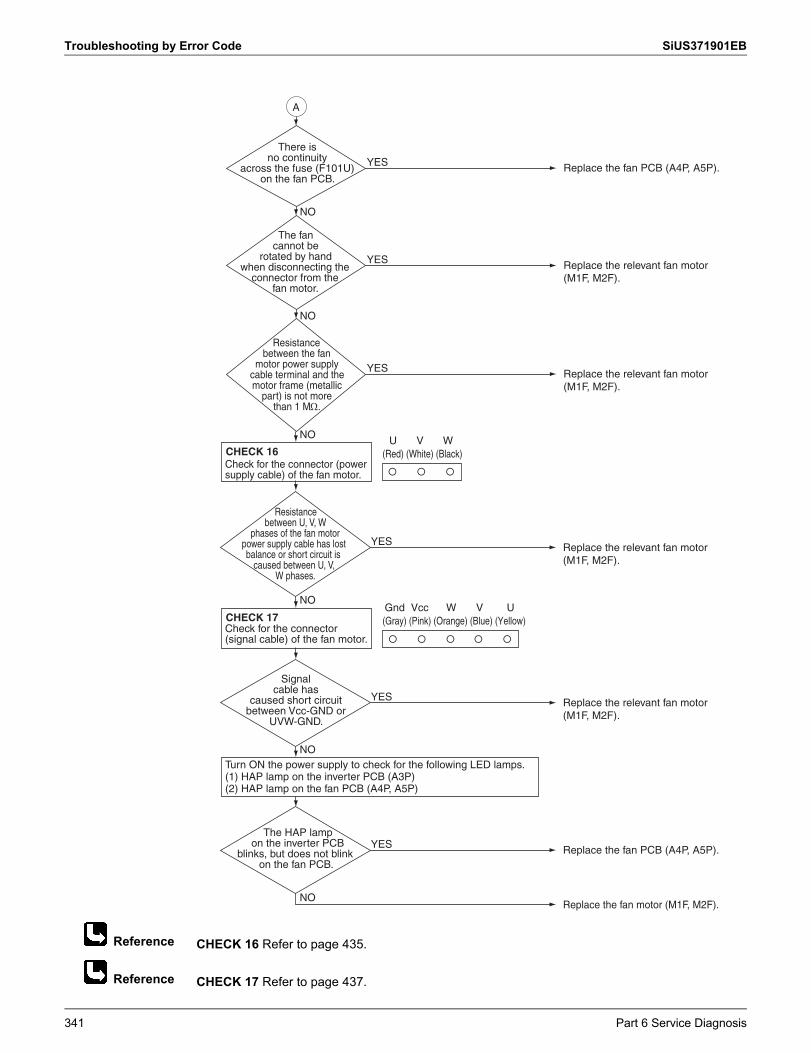
Troubleshooting by Error Code SiUS371901EB
Reference
Reference
CHECK 16 Refer to page 435.
CHECK 17 Refer to page 437.
There is no continuity
across the fuse (F101U) on the fan PCB.
Replace the fan PCB (A4P, A5P).YES
The fan cannot be
rotated by hand when disconnecting the
connector from the fan motor.
Replace the relevant fan motor (M1F, M2F).
YES
NO
Resistance between the fan
motor power supply cable terminal and the motor frame (metallic
part) is not more than 1 M.
Replace the relevant fan motor (M1F, M2F).
YES
NO
Replace the relevant fan motor (M1F, M2F).
YES
Resistance between U, V, W
phases of the fan motor power supply cable has lost balance or short circuit is
caused between U, V, W phases.
Check for the connector (power supply cable) of the fan motor.
NO
CHECK 16
Replace the fan PCB (A4P, A5P).YESThe HAP lamp
on the inverter PCB blinks, but does not blink
on the fan PCB.
Replace the relevant fan motor (M1F, M2F).
YES
Signal cable has
caused short circuit between Vcc-GND or
UVW-GND.
Turn ON the power supply to check for the following LED lamps.(1) HAP lamp on the inverter PCB (A3P)(2) HAP lamp on the fan PCB (A4P, A5P)
NO
Replace the fan motor (M1F, M2F).NO
A
U V W(Red) (White) (Black)
Check for the connector (signal cable) of the fan motor.
NO
CHECK 17Gnd Vcc W V U(Gray) (Pink) (Orange) (Blue) (Yellow)
341 Part 6 Service Diagnosis
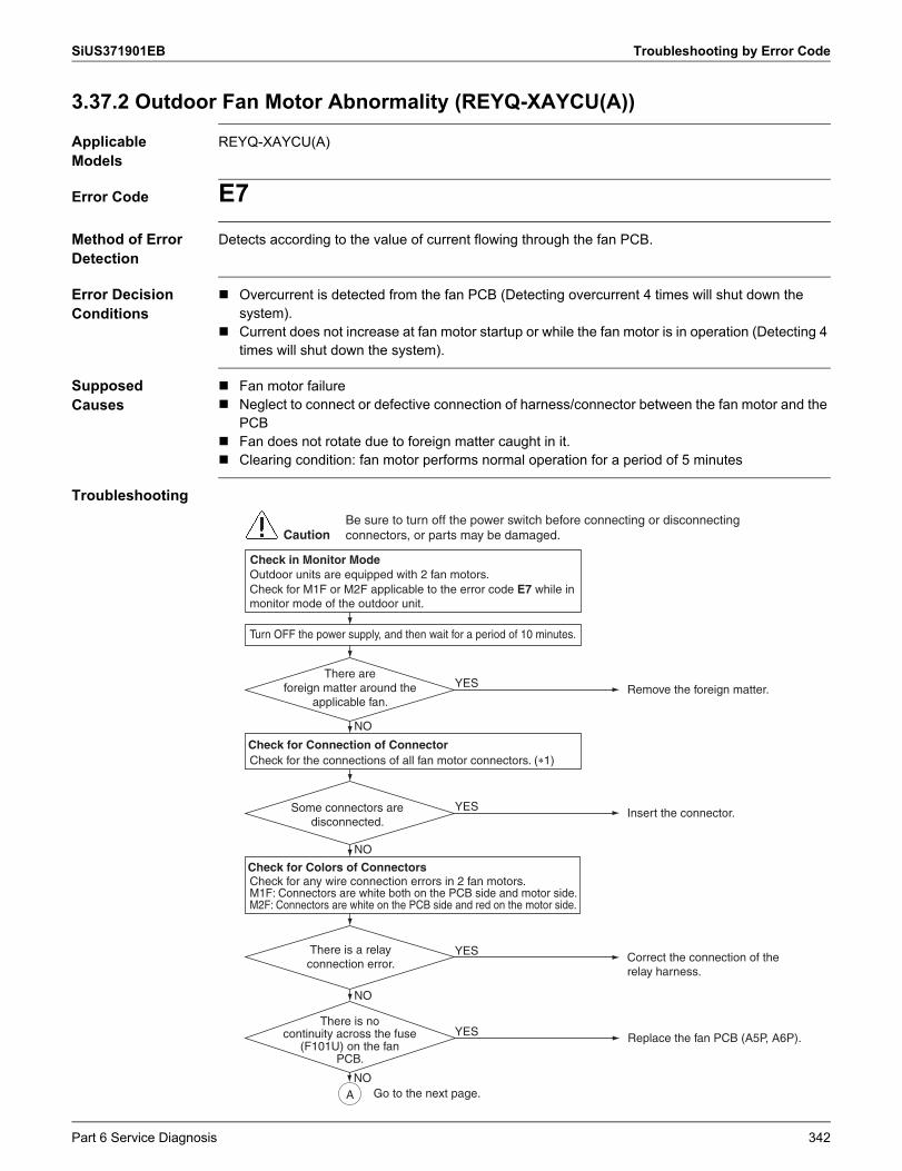
SiUS371901EB Troubleshooting by Error Code
3.37.2 Outdoor Fan Motor Abnormality (REYQ-XAYCU(A))
Applicable Models
REYQ-XAYCU(A)
Error Code E7Method of Error Detection
Detects according to the value of current flowing through the fan PCB.
Error Decision Conditions
Overcurrent is detected from the fan PCB (Detecting overcurrent 4 times will shut down the system).
Current does not increase at fan motor startup or while the fan motor is in operation (Detecting 4 times will shut down the system).
Supposed Causes
Fan motor failure Neglect to connect or defective connection of harness/connector between the fan motor and the
PCB Fan does not rotate due to foreign matter caught in it. Clearing condition: fan motor performs normal operation for a period of 5 minutes
Troubleshooting
There are oreign matter around the
applicable fan. Remove the foreign matter. YES
Check for the connections of all fan motor connectors. (�1)
NO
Turn OFF the power supply, and then wait for a period of 10 minutes.
Some connectors are disconnected.
Insert the connector. YES
NO
NO
There is a relay connection error. Correct the connection of the
relay harness.
YES
CautionBe sure to turn off the power switch before connecting or disconnecting connectors, or parts may be damaged.
A
Check for any wire connection errors in 2 fan motors.M1F: Connectors are white both on the PCB side and motor side.M2F: Connectors are white on the PCB side and red on the motor side.
Check for Connection of Connector
Check for Colors of Connectors
There is no continuity across the fuse
(F101U) on the fanPCB.
Replace the fan PCB (A5P, A6P).YES
NO
Outdoor units are equipped with 2 fan motors.Check for M1F or M2F applicable to the error code E7 while in monitor mode of the outdoor unit.
Check in Monitor Mode
Go to the next page.
Part 6 Service Diagnosis 342
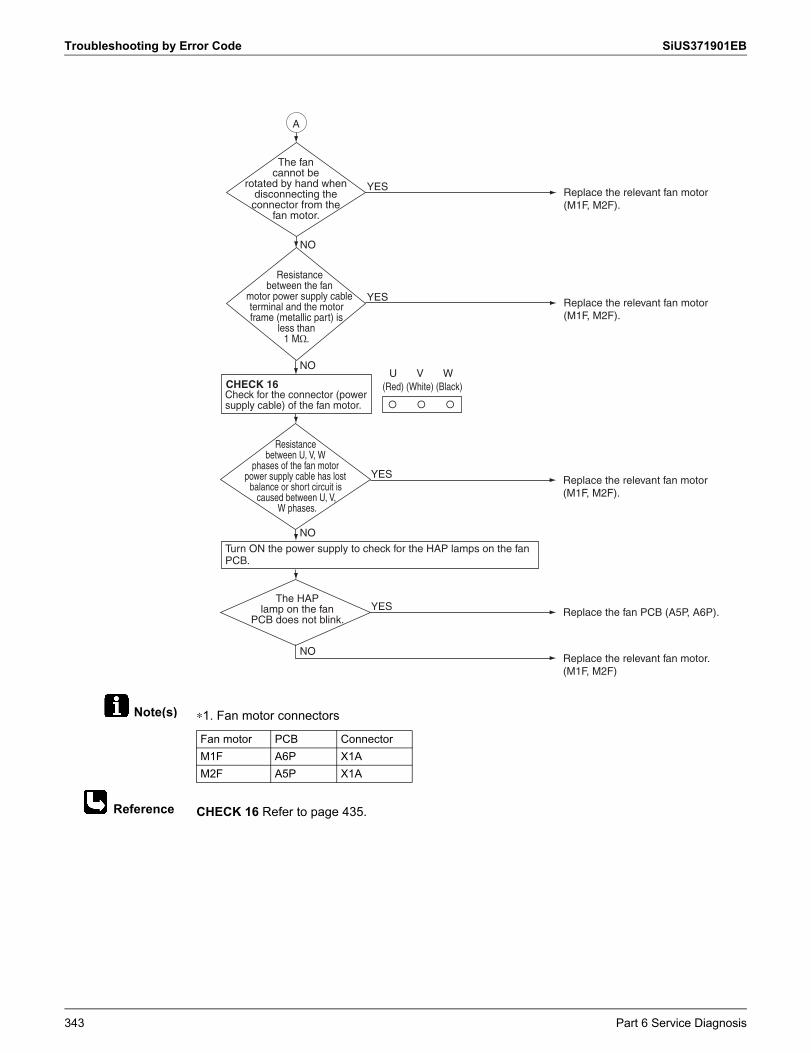
Troubleshooting by Error Code SiUS371901EB
Note(s)
Reference
∗1. Fan motor connectors
CHECK 16 Refer to page 435.
The fan cannot be
rotated by hand when disconnecting the connector from the
fan motor.
Replace the relevant fan motor (M1F, M2F).
YES
Resistance between the fan
motor power supply cable terminal and the motor frame (metallic part) is
less than1 M�.
Replace the relevant fan motor (M1F, M2F).
YES
NO
YES
Resistance between U, V, W
phases of the fan motor power supply cable has lost
balance or short circuit is caused between U, V,
W phases.
Check for the connector (power supply cable) of the fan motor.
NO
CHECK 16
Replace the fan PCB (A5P, A6P). YESThe HAP
lamp on the fan PCB does not blink.
Turn ON the power supply to check for the HAP lamps on the fan PCB.
Replace the relevant fan motor. (M1F, M2F)
Replace the relevant fan motor (M1F, M2F).
NO
A
U V W(Red) (White) (Black)
� � �
NO
Fan motor PCB ConnectorM1F A6P X1AM2F A5P X1A
343 Part 6 Service Diagnosis
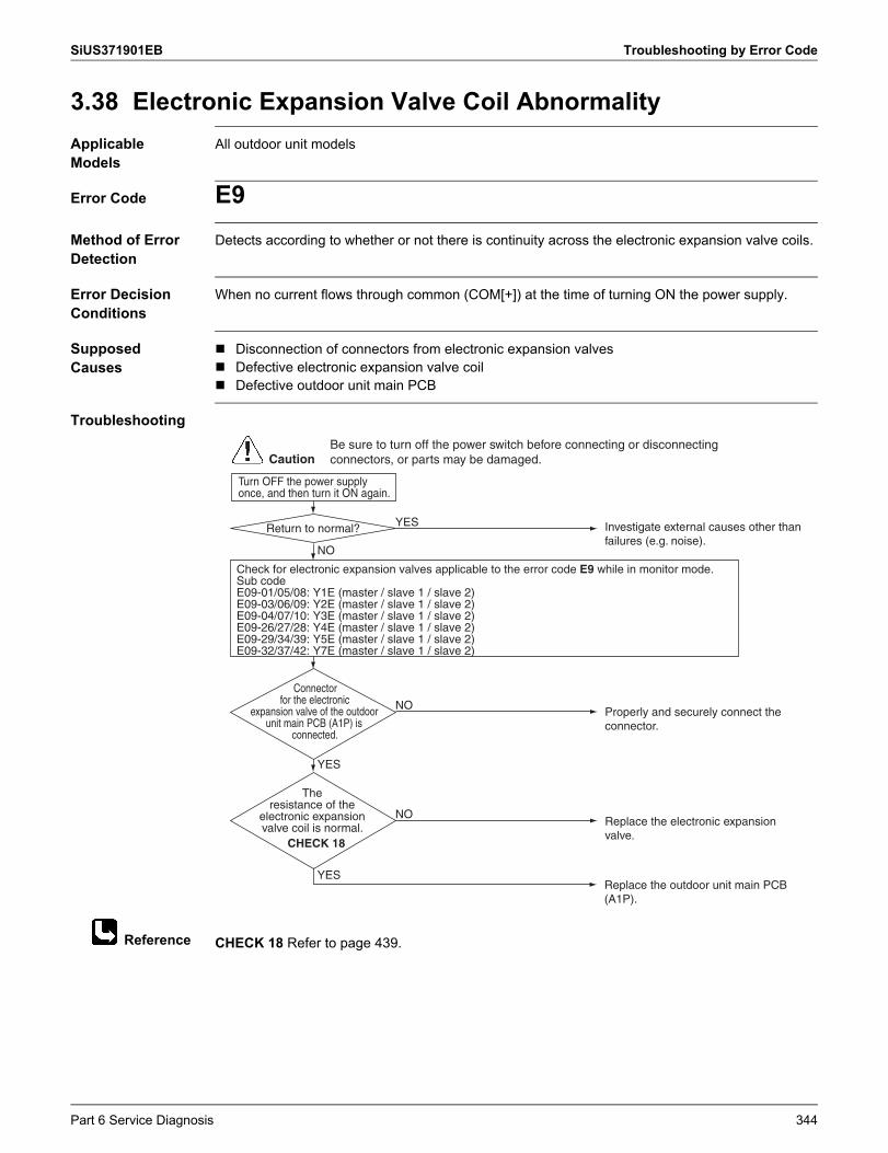
SiUS371901EB Troubleshooting by Error Code
Reference
3.38 Electronic Expansion Valve Coil AbnormalityApplicable Models
All outdoor unit models
Error Code E9Method of Error Detection
Detects according to whether or not there is continuity across the electronic expansion valve coils.
Error Decision Conditions
When no current flows through common (COM[+]) at the time of turning ON the power supply.
Supposed Causes
Disconnection of connectors from electronic expansion valves Defective electronic expansion valve coil Defective outdoor unit main PCB
Troubleshooting
CHECK 18 Refer to page 439.
Turn OFF the power supply once, and then turn it ON again.
Return to normal? Investigate external causes other than failures (e.g. noise).
YES
NO
Connector for the electronic
expansion valve of the outdoor unit main PCB (A1P) is
connected.
Properly and securely connect the connector.
NO
YES
Replace the electronic expansion valve.
NO
Replace the outdoor unit main PCB (A1P).
YES
CautionBe sure to turn off the power switch before connecting or disconnecting connectors, or parts may be damaged.
Check for electronic expansion valves applicable to the error code E9 while in monitor mode.Sub codeE09-01/05/08: Y1E (master / slave 1 / slave 2)E09-03/06/09: Y2E (master / slave 1 / slave 2)E09-04/07/10: Y3E (master / slave 1 / slave 2)E09-26/27/28: Y4E (master / slave 1 / slave 2)E09-29/34/39: Y5E (master / slave 1 / slave 2)E09-32/37/42: Y7E (master / slave 1 / slave 2)
The resistance of the
electronic expansion valve coil is normal.
CHECK 18
Part 6 Service Diagnosis 344
Troubleshooting by Error Code SiUS371901EB
3.39 Discharge Pipe Temperature AbnormalityApplicable Models
All outdoor unit models
Error Code F3Method of Error Detection
Detect according to temperature detected with the discharge pipe or compressor body thermistor.
Error Decision Conditions
When discharge pipe temperature becomes abnormally high (i.e., 135°C (275°F) or more) When discharge pipe temperature sharply rises (remains at 120°C (248°F) or more for a period
of consecutive 10 minutes) When compressor surface temperature becomes abnormally high (i.e., 120°C (248°F) or more) When compressor surface temperature sharply rises (remains at 115°C (239°F) or more for a
period of consecutive 10 minutes)
Supposed Causes
Abnormal discharge pipe temperature Defective discharge pipe thermistor Abnormal compressor surface temperature Defective compressor body thermistor Defective outdoor unit main PCB
345 Part 6 Service Diagnosis
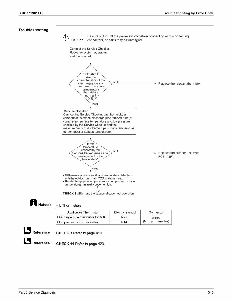
SiUS371901EB Troubleshooting by Error Code
Note(s)
Reference
Reference
Troubleshooting
∗1. Thermistors
CHECK 3 Refer to page 419.
CHECK 11 Refer to page 429.
NO
Is the temperature
checked by the Service Checker same as the
measurement of the temperature?
NO
Replace the relevant thermistor.
Replace the outdoor unit main PCB (A1P).
YES
YES
Connect the Service Checker.Reset the system operation, and then restart it.
CHECK 11Are the
characteristics of the discharge pipe and compressor surface
temperature thermistors
normal?(�1)
• All thermistors are normal, and temperature detection with the outdoor unit main PCB is also normal.
• The discharge pipe temperature (or compressor surface temperature) has really become high.
CHECK 3 : Eliminate the causes of superheat operation.
Service CheckerConnect the Service Checker, and then make a comparison between discharge pipe temperature (or compressor surface temperature and low pressure checked by the Service Checker and the measurements of discharge pipe surface temperature (or compressor surface temperature.)
CautionBe sure to turn off the power switch before connecting or disconnecting connectors, or parts may be damaged.
Applicable Thermistor Electric symbol ConnectorDischarge pipe thermistor for M1C R21T X19A
(Group connector)Compressor body thermistor R14T
Part 6 Service Diagnosis 346
Troubleshooting by Error Code SiUS371901EB
3.40 Wet AlarmApplicable Models
All outdoor unit models
Error Code F4Method of Error Detection
In cooling operation, detect the condition under which liquid refrigerant returns to the compressor, according to the temperature and pressure of each part.
Error Decision Conditions
When the following wet state continues for a period of 90 minutes, an alert is issued.An error is defined for 120 minutes. Wet state in outdoor units
When the following wet state continues for a period of 45 minutes, an alert is issued. Wet state in some of indoor units
Supposed Causes
Defective suction pipe thermistor Defective compressor suction thermistor Defective discharge pipe thermistor Defective high pressure sensor Defective indoor unit electronic expansion valve Dirty air filter
347 Part 6 Service Diagnosis
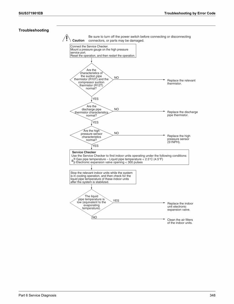
SiUS371901EB Troubleshooting by Error Code
Troubleshooting
Connect the Service Checker.Mount a pressure gauge on the high pressure service port.Reset the operation, and then restart the operation.
Stop the relevant indoor units while the system is in cooling operation, and then check for the liquid pipe temperature of these indoor units after the system is stabilized.
The liquid pipe temperature is
low (equivalent to the evaporating
temperature).
Clean the air filters of the indoor units.
NO
YES
NO
Replace the indoor unit electronic expansion valve.
Replace the relevant thermistor.
YES
YES
CautionBe sure to turn off the power switch before connecting or disconnecting connectors, or parts may be damaged.
Are the characteristics of the suction pipe
thermistor (R10T) and the compressor suction thermistor (R12T)
normal?
NOReplace the discharge pipe thermistor.
YES
NOReplace the high pressure sensor (S1NPH).
Are the high pressure sensor characteristics
normal?
Are the discharge pipe
thermistor characteristics normal?
Service CheckerUse the Service Checker to find indoor units operating under the following conditions:
& • Gas pipe temperature – Liquid pipe temperature < 2.5°C (4.5°F)• Electronic expansion valve opening < 300 pulses
Part 6 Service Diagnosis 348
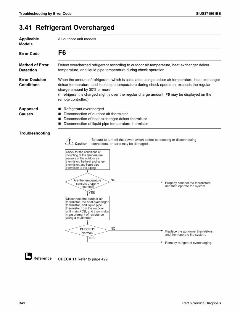
Troubleshooting by Error Code SiUS371901EB
Reference
3.41 Refrigerant OverchargedApplicable Models
All outdoor unit models
Error Code F6Method of Error Detection
Detect overcharged refrigerant according to outdoor air temperature, heat exchanger deicer temperature, and liquid pipe temperature during check operation.
Error Decision Conditions
When the amount of refrigerant, which is calculated using outdoor air temperature, heat exchanger deicer temperature, and liquid pipe temperature during check operation, exceeds the regular charge amount by 30% or more(If refrigerant is charged slightly over the regular charge amount, F6 may be displayed on the remote controller.)
Supposed Causes
Refrigerant overcharged Disconnection of outdoor air thermistor Disconnection of heat exchanger deicer thermistor Disconnection of liquid pipe temperature thermistor
Troubleshooting
CHECK 11 Refer to page 429.
Check for the conditions of mounting of the temperature sensors of the outdoor air thermistor, the heat exchanger thermistor, and liquid pipe thermistor to the piping.
Disconnect the outdoor air thermistor, the heat exchanger thermistor, and liquid pipe thermistor from the outdoor unit main PCB, and then make measurement of resistance using a multimeter.
Normal?
Remedy refrigerant overcharging.
YES
NO
NO
Replace the abnormal thermistors, and then operate the system.
Properly connect the thermistors, and then operate the system.
YES
CautionBe sure to turn off the power switch before connecting or disconnecting connectors, or parts may be damaged.
CHECK 11
Are the temperature sensors properly
mounted?
349 Part 6 Service Diagnosis
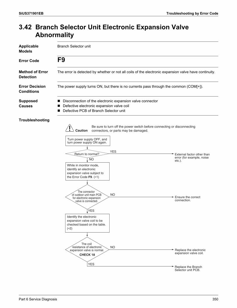
SiUS371901EB Troubleshooting by Error Code
3.42 Branch Selector Unit Electronic Expansion Valve Abnormality
Applicable Models
Branch Selector unit
Error Code F9Method of Error Detection
The error is detected by whether or not all coils of the electronic expansion valve have continuity.
Error Decision Conditions
The power supply turns ON, but there is no currents pass through the common (COM[+]).
Supposed Causes
Disconnection of the electronic expansion valve connector Defective electronic expansion valve coil Defective PCB of Branch Selector unit
Troubleshooting
While in monitor mode, identify an electronic expansion valve subject to the Error Code F9. (�1)
Identify the electronic expansion valve coil to be checked based on the table. (�2)
CautionBe sure to turn off the power switch before connecting or disconnecting connectors, or parts may be damaged.
YESReturn to normal?
Turn power supply OFF, and turn power supply ON again.
Replace the electronic expansion valve coil.
Replace the Branch Selector unit PCB.
YES
YES
NO
Ensure the correct connection.
External factor other than error (for example, noise etc.).
NO
NO
The connector of outdoor unit main PCB for electronic expansion
valve is connected.
The coil resistance of electronic
expansion valve is normal.
CHECK 18
Part 6 Service Diagnosis 350
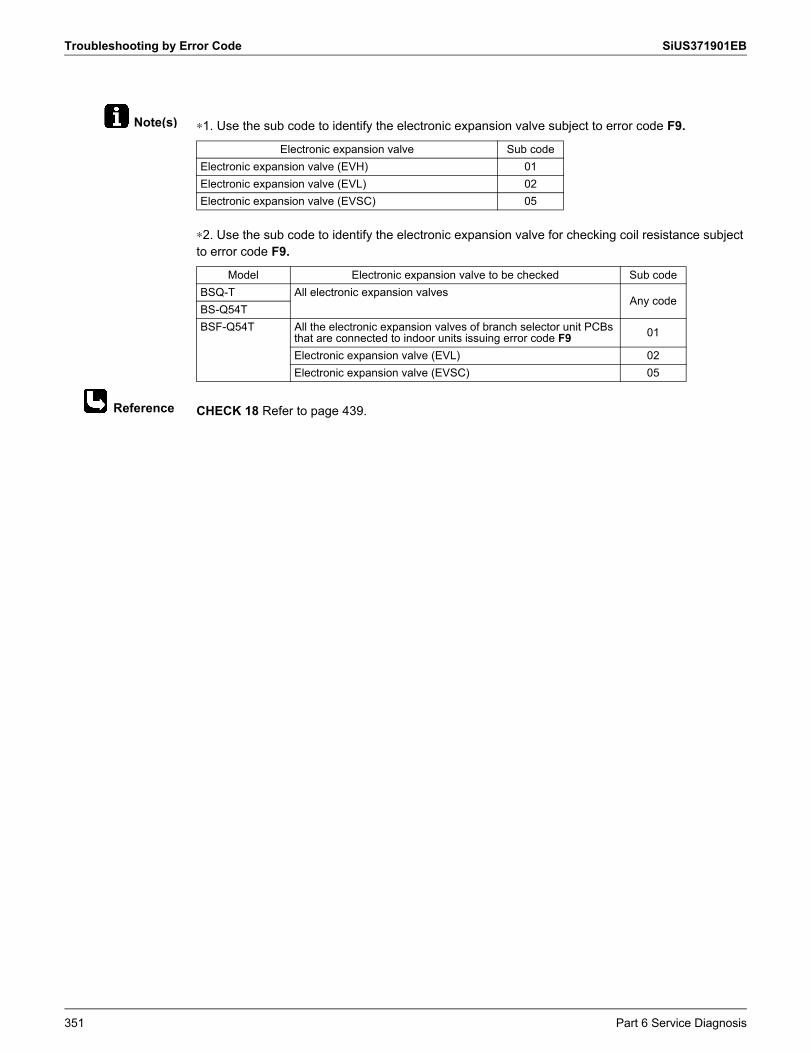
Troubleshooting by Error Code SiUS371901EB
Note(s)
Reference
∗1. Use the sub code to identify the electronic expansion valve subject to error code F9.
∗2. Use the sub code to identify the electronic expansion valve for checking coil resistance subject to error code F9.
CHECK 18 Refer to page 439.
Electronic expansion valve Sub codeElectronic expansion valve (EVH) 01Electronic expansion valve (EVL) 02Electronic expansion valve (EVSC) 05
Model Electronic expansion valve to be checked Sub codeBSQ-T All electronic expansion valves
Any codeBS-Q54TBSF-Q54T All the electronic expansion valves of branch selector unit PCBs
that are connected to indoor units issuing error code F9 01
Electronic expansion valve (EVL) 02Electronic expansion valve (EVSC) 05
351 Part 6 Service Diagnosis
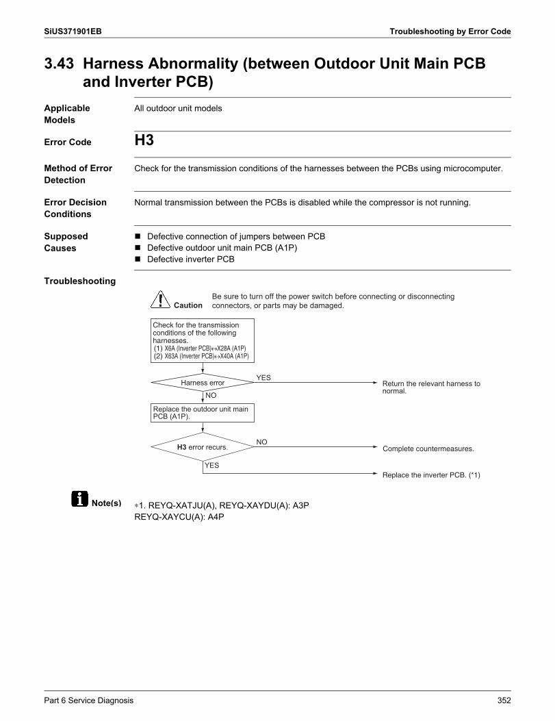
SiUS371901EB Troubleshooting by Error Code
Note(s)
3.43 Harness Abnormality (between Outdoor Unit Main PCB and Inverter PCB)
Applicable Models
All outdoor unit models
Error Code H3Method of Error Detection
Check for the transmission conditions of the harnesses between the PCBs using microcomputer.
Error Decision Conditions
Normal transmission between the PCBs is disabled while the compressor is not running.
Supposed Causes
Defective connection of jumpers between PCB Defective outdoor unit main PCB (A1P) Defective inverter PCB
Troubleshooting
∗1. REYQ-XATJU(A), REYQ-XAYDU(A): A3PREYQ-XAYCU(A): A4P
Check for the transmission conditions of the following harnesses.(1) X6A (Inverter PCB)�X28A (A1P)(2) X63A (Inverter PCB)�X40A (A1P)
Replace the outdoor unit main PCB (A1P).
Replace the inverter PCB. (*1)YES
NO
YES
Complete countermeasures.
Return the relevant harness to normal.NO
CautionBe sure to turn off the power switch before connecting or disconnecting connectors, or parts may be damaged.
Harness error
H3 error recurs.
Part 6 Service Diagnosis 352
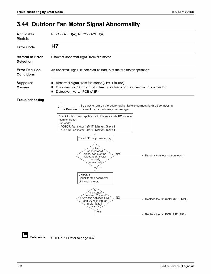
Troubleshooting by Error Code SiUS371901EB
Reference
3.44 Outdoor Fan Motor Signal AbnormalityApplicable Models
REYQ-XATJU(A), REYQ-XAYDU(A)
Error Code H7Method of Error Detection
Detect of abnormal signal from fan motor.
Error Decision Conditions
An abnormal signal is detected at startup of the fan motor operation.
Supposed Causes
Abnormal signal from fan motor (Circuit failure) Disconnection/Short circuit in fan motor leads or disconnection of connector Defective inverter PCB (A3P)
Troubleshooting
CHECK 17 Refer to page 437.
Properly connect the connector.NO
YES
Replace the fan motor (M1F, M2F).NO
YES
Turn OFF the power supply.
Check for fan motor applicable to the error code H7 while in monitor mode.Sub codeH7-01/05: Fan motor 1 (M1F) Master / Slave 1H7-02/06: Fan motor 2 (M2F) Master / Slave 1
Check for the connector of the fan motor.
Replace the fan PCB (A4P, A5P).
CautionBe sure to turn off the power switch before connecting or disconnecting connectors, or parts may be damaged.
Is the connector of
signal cable of the relevant fan motor
normally connected?
Is resistance
between Vcc and UVW and between GND
and UVW of the fan motor lead in
balance?
CHECK 17
353 Part 6 Service Diagnosis
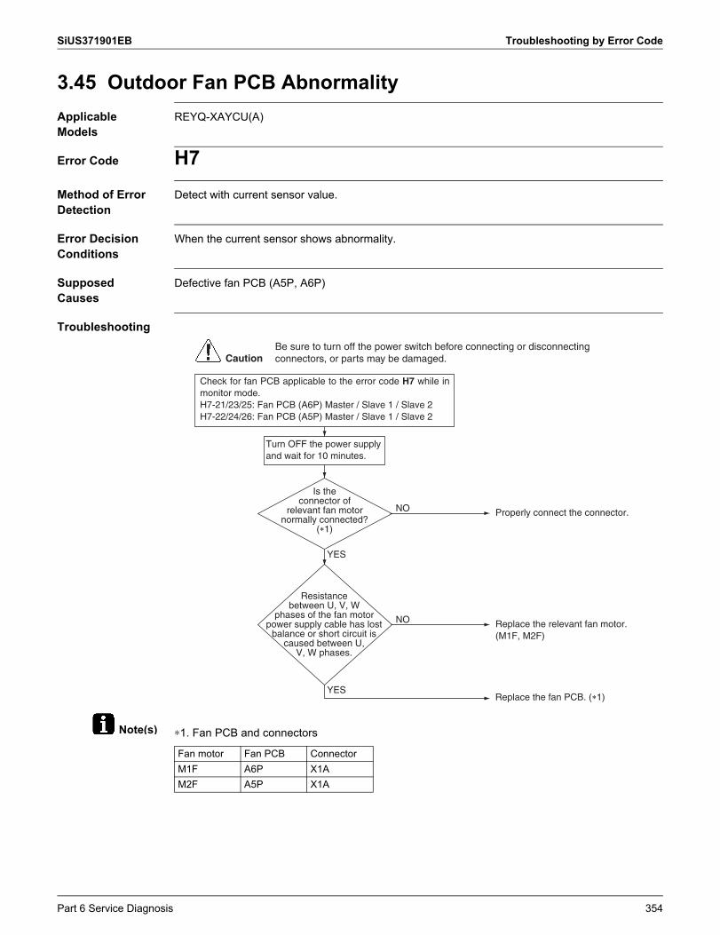
SiUS371901EB Troubleshooting by Error Code
Note(s)
3.45 Outdoor Fan PCB AbnormalityApplicable Models
REYQ-XAYCU(A)
Error Code H7Method of Error Detection
Detect with current sensor value.
Error Decision Conditions
When the current sensor shows abnormality.
Supposed Causes
Defective fan PCB (A5P, A6P)
Troubleshooting
∗1. Fan PCB and connectors
Properly connect the connector.NO
YES
Replace the relevant fan motor. (M1F, M2F)
NO
YES
Check for fan PCB applicable to the error code H7 while in monitor mode.H7-21/23/25: Fan PCB (A6P) Master / Slave 1 / Slave 2H7-22/24/26: Fan PCB (A5P) Master / Slave 1 / Slave 2
Replace the fan PCB. (�1)
CautionBe sure to turn off the power switch before connecting or disconnecting connectors, or parts may be damaged.
Is the connector of
relevant fan motor normally connected?
(�1)
Resistance between U, V, W
phases of the fan motor power supply cable has lost
balance or short circuit is caused between U,
V, W phases.
Turn OFF the power supply and wait for 10 minutes.
Fan motor Fan PCB ConnectorM1F A6P X1AM2F A5P X1A
Part 6 Service Diagnosis 354
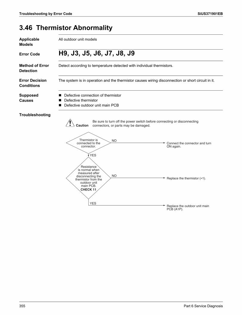
Troubleshooting by Error Code SiUS371901EB
3.46 Thermistor AbnormalityApplicable Models
All outdoor unit models
Error Code H9, J3, J5, J6, J7, J8, J9Method of Error Detection
Detect according to temperature detected with individual thermistors.
Error Decision Conditions
The system is in operation and the thermistor causes wiring disconnection or short circuit in it.
Supposed Causes
Defective connection of thermistor Defective thermistor Defective outdoor unit main PCB
Troubleshooting
Thermistor is connected to the
connector.
Replace the outdoor unit main PCB (A1P).
Connect the connector and turn ON again.
NO
NO
Replace the thermistor (�1).
YES
YES
CautionBe sure to turn off the power switch before connecting or disconnecting connectors, or parts may be damaged.
Resistance is normal when measured after
disconnecting the thermistor from the
outdoor unitmain PCB.CHECK 11
355 Part 6 Service Diagnosis
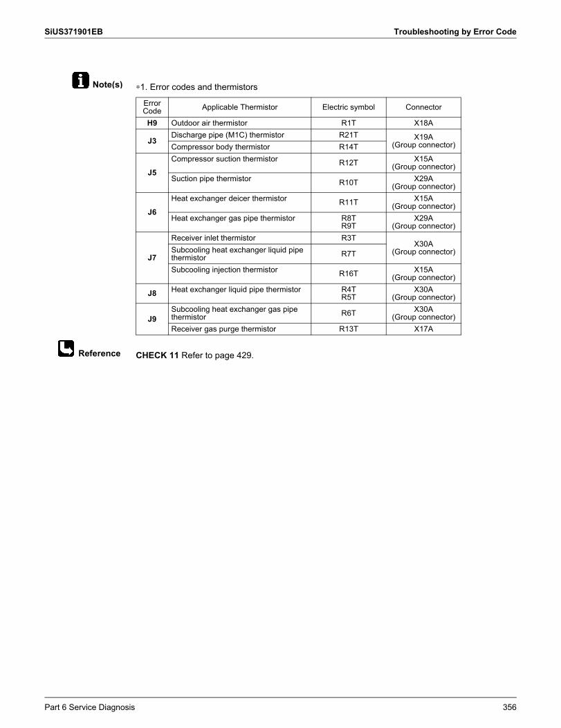
SiUS371901EB Troubleshooting by Error Code
Note(s)
Reference
∗1. Error codes and thermistors
CHECK 11 Refer to page 429.
Error Code Applicable Thermistor Electric symbol Connector
H9 Outdoor air thermistor R1T X18A
J3Discharge pipe (M1C) thermistor R21T X19A
(Group connector)Compressor body thermistor R14T
J5Compressor suction thermistor R12T X15A
(Group connector)Suction pipe thermistor R10T X29A
(Group connector)
J6Heat exchanger deicer thermistor R11T X15A
(Group connector)Heat exchanger gas pipe thermistor R8T
R9TX29A
(Group connector)
J7
Receiver inlet thermistor R3TX30A
(Group connector)Subcooling heat exchanger liquid pipe thermistor R7T
Subcooling injection thermistor R16T X15A(Group connector)
J8 Heat exchanger liquid pipe thermistor R4TR5T
X30A(Group connector)
J9Subcooling heat exchanger gas pipe thermistor R6T X30A
(Group connector)Receiver gas purge thermistor R13T X17A
Part 6 Service Diagnosis 356
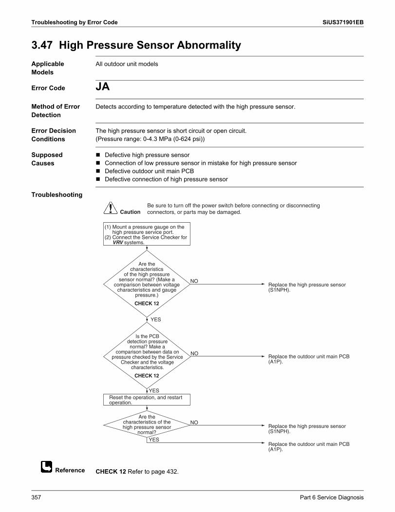
Troubleshooting by Error Code SiUS371901EB
Reference
3.47 High Pressure Sensor AbnormalityApplicable Models
All outdoor unit models
Error Code JAMethod of Error Detection
Detects according to temperature detected with the high pressure sensor.
Error Decision Conditions
The high pressure sensor is short circuit or open circuit.(Pressure range: 0-4.3 MPa (0-624 psi))
Supposed Causes
Defective high pressure sensor Connection of low pressure sensor in mistake for high pressure sensor Defective outdoor unit main PCB Defective connection of high pressure sensor
Troubleshooting
CHECK 12 Refer to page 432.
Are the characteristics
of the high pressure sensor normal? (Make a
comparison between voltage characteristics and gauge
pressure.)
Replace the high pressure sensor (S1NPH).
Replace the outdoor unit main PCB (A1P).
NO
Is the PCB detection pressure normal? Make a
comparison between data on pressure checked by the Service
Checker and the voltage characteristics.
Replace the outdoor unit main PCB (A1P).
NO
Are the characteristics of thehigh pressure sensor
normal?Replace the high pressure sensor (S1NPH).
NO
YES
YES
YES
Reset the operation, and restart operation.
(1) Mount a pressure gauge on the high pressure service port.
(2) Connect the Service Checker for VRV systems.
CautionBe sure to turn off the power switch before connecting or disconnecting connectors, or parts may be damaged.
CHECK 12
CHECK 12
357 Part 6 Service Diagnosis
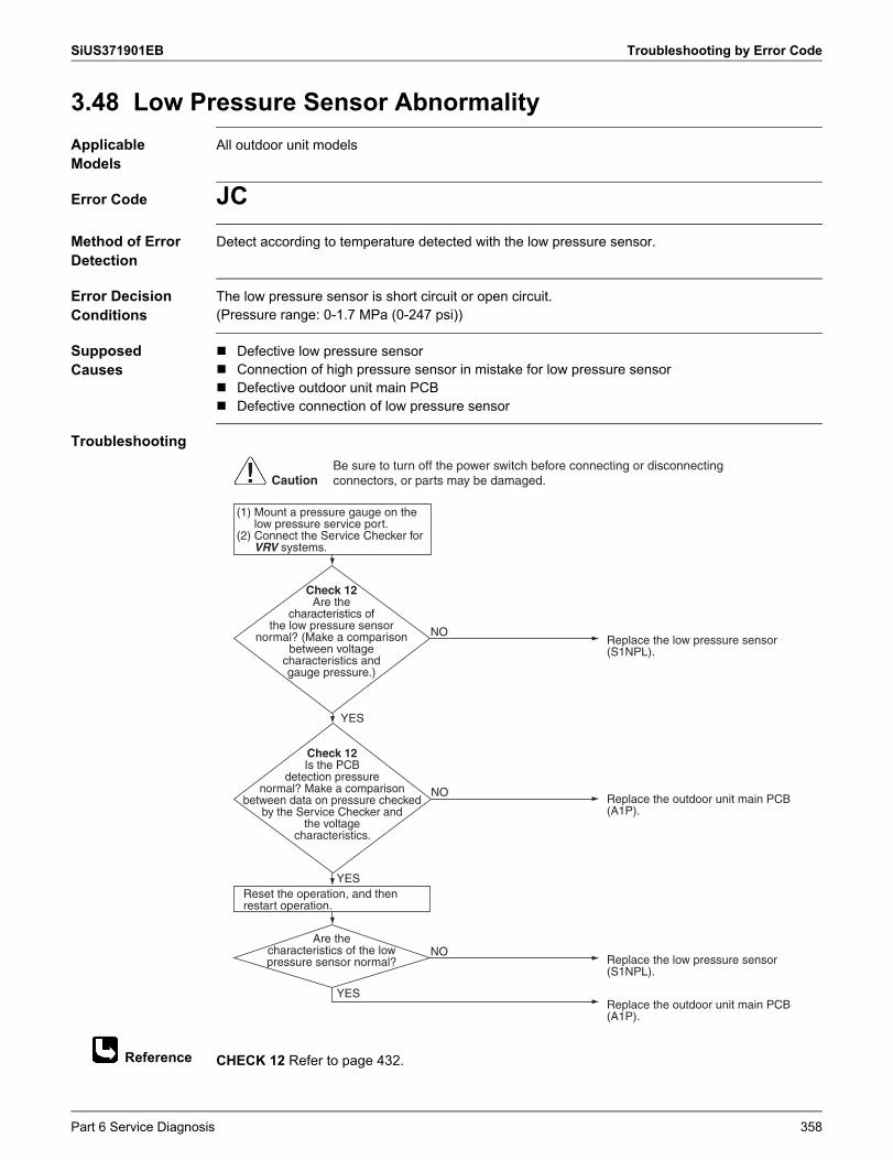
SiUS371901EB Troubleshooting by Error Code
Reference
3.48 Low Pressure Sensor AbnormalityApplicable Models
All outdoor unit models
Error Code JCMethod of Error Detection
Detect according to temperature detected with the low pressure sensor.
Error Decision Conditions
The low pressure sensor is short circuit or open circuit.(Pressure range: 0-1.7 MPa (0-247 psi))
Supposed Causes
Defective low pressure sensor Connection of high pressure sensor in mistake for low pressure sensor Defective outdoor unit main PCB Defective connection of low pressure sensor
Troubleshooting
CHECK 12 Refer to page 432.
Check 12Are the
characteristics of the low pressure sensor
normal? (Make a comparison between voltage
characteristics and gauge pressure.)
Replace the low pressure sensor (S1NPL).
Replace the outdoor unit main PCB (A1P).
NO
Check 12Is the PCB
detection pressure normal? Make a comparison
between data on pressure checked by the Service Checker and
the voltage characteristics.
Replace the outdoor unit main PCB (A1P).
NO
Are the characteristics of the low pressure sensor normal? Replace the low pressure sensor
(S1NPL).
NO
YES
YES
YES
Reset the operation, and then restart operation.
(1) Mount a pressure gauge on the low pressure service port.
(2) Connect the Service Checker for VRV systems.
CautionBe sure to turn off the power switch before connecting or disconnecting connectors, or parts may be damaged.
Part 6 Service Diagnosis 358
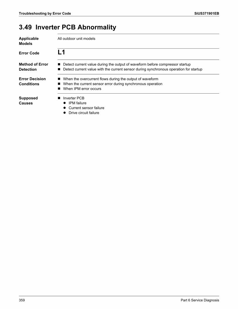
Troubleshooting by Error Code SiUS371901EB
3.49 Inverter PCB AbnormalityApplicable Models
All outdoor unit models
Error Code L1Method of Error Detection
Detect current value during the output of waveform before compressor startup Detect current value with the current sensor during synchronous operation for startup
Error Decision Conditions
When the overcurrent flows during the output of waveform When the current sensor error during synchronous operation When IPM error occurs
Supposed Causes
Inverter PCB IPM failure Current sensor failure Drive circuit failure
359 Part 6 Service Diagnosis
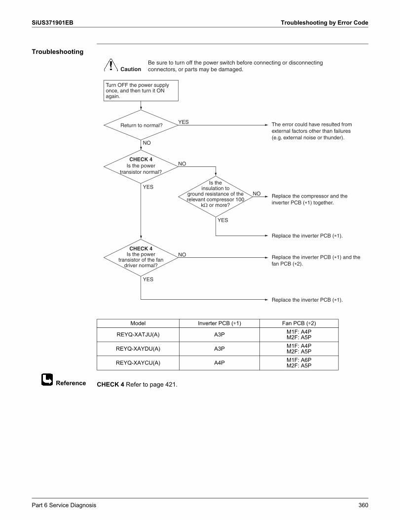
SiUS371901EB Troubleshooting by Error Code
Reference
Troubleshooting
CHECK 4 Refer to page 421.
Model Inverter PCB (∗1) Fan PCB (∗2)
REYQ-XATJU(A) A3P M1F: A4PM2F: A5P
REYQ-XAYDU(A) A3P M1F: A4PM2F: A5P
REYQ-XAYCU(A) A4P M1F: A6PM2F: A5P
CHECK 4Is the power
transistor of the fan driver normal?
CHECK 4Is the power
transistor normal?
Is the insulation to
ground resistance of the relevant compressor 100
k� or more?
The error could have resulted from external factors other than failures (e.g. external noise or thunder).
YES
Replace the compressor and the inverter PCB (�1) together.
Replace the inverter PCB (�1).
NO
NO
YES
Replace the inverter PCB (�1) and the fan PCB (�2).
Replace the inverter PCB (�1).
NO
YES
Turn OFF the power supply once, and then turn it ON again.
NO
YES
CautionBe sure to turn off the power switch before connecting or disconnecting connectors, or parts may be damaged.
Return to normal?
Part 6 Service Diagnosis 360
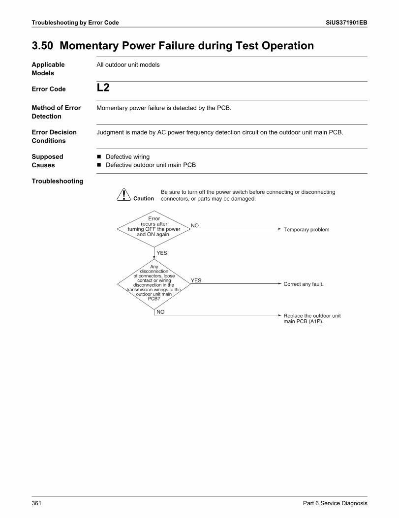
Troubleshooting by Error Code SiUS371901EB
3.50 Momentary Power Failure during Test OperationApplicable Models
All outdoor unit models
Error Code L2Method of Error Detection
Momentary power failure is detected by the PCB.
Error Decision Conditions
Judgment is made by AC power frequency detection circuit on the outdoor unit main PCB.
Supposed Causes
Defective wiring Defective outdoor unit main PCB
Troubleshooting
Error recurs after
turning OFF the power and ON again.
Any disconnection
of connectors, loose contact or wiring
disconnection in the transmission wirings to the
outdoor unit main PCB?
NO
YES
YES
NOTemporary problem
Correct any fault.
Replace the outdoor unit main PCB (A1P).
CautionBe sure to turn off the power switch before connecting or disconnecting connectors, or parts may be damaged.
361 Part 6 Service Diagnosis
SiUS371901EB Troubleshooting by Error Code
3.51 Reactor Temperature Rise AbnormalityApplicable Models
REYQ72-120XATJU(A)
Error Code L3Method of Error Detection
Detect according to the value detected with the reactor surface thermistor.
Error Decision Conditions
When the temperature detected with the reactor surface thermistor is more than the specified temperature.
Supposed Causes
Defective connection of harness Defective reactor surface thermistor Defective inverter PCB
Troubleshooting
Is reactor harness
connected to the terminal strip correctly?
Is there wiring disconnection in the
reactor surface thermistor?
NO
YES
YES
NOConnect the harness correctly.
Replace the thermistor.
Replace the inverter PCB (A3P).
CautionBe sure to turn off the power switch before connecting or disconnecting connectors, or parts may be damaged.
Part 6 Service Diagnosis 362
Troubleshooting by Error Code SiUS371901EB
3.52 Inverter Radiation Fin Temperature Rise Abnormality3.52.1 Inverter Radiation Fin Temperature Rise Abnormality (Inverter PCB)
Applicable Models
All outdoor unit models
Error Code L4Sub code: 01-03
Method of Error Detection
Detect temperature of power module of the inverter PCB.
Error Decision Conditions
Thermistor located inside the power module of the inverter PCB for compressor and fan motor. Cooling tube plate poor heat-exchange.
Supposed Causes
Cooling tube plate not fixed with screws U0 error Defective inverter PCB High outdoor air temperature Incorrect power supply voltage Defective connection of connectors
363 Part 6 Service Diagnosis
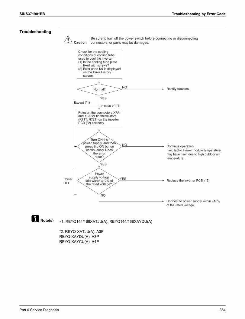
SiUS371901EB Troubleshooting by Error Code
Note(s)
Troubleshooting
∗1. REYQ144/168XATJU(A), REYQ144/168XAYDU(A)
*2. REYQ-XATJU(A): A3PREYQ-XAYDU(A): A3PREYQ-XAYCU(A): A4P
Continue operation.Field factor. Power module temperature may have risen due to high outdoor air temperature.
Turn ON the power supply, and then
press the ON button continuously. Does
the error recur?
Power supply voltage
falls within ±10% of the rated voltage?
Replace the inverter PCB. (*2)
Connect to power supply within ±10% of the rated voltage.
NO
YES
Rectify troubles.Normal?
Power OFF
NO
NO
Check for the cooling conditions of cooling tube used to cool the inverter.(1) Is the cooling tube plate
fixed with screws?(2) Error code U0 is displayed
on the Error History screen.
Reinsert the connectors X7A and X8A for fin thermistors (R71T, R72T) on the inverter PCB (*2) correctly.
YES
YES
CautionBe sure to turn off the power switch before connecting or disconnecting connectors, or parts may be damaged.
In case of (*1)Except (*1)
Part 6 Service Diagnosis 364
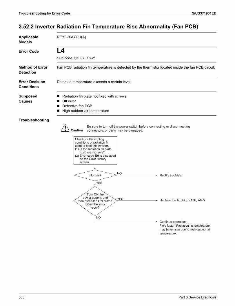
Troubleshooting by Error Code SiUS371901EB
3.52.2 Inverter Radiation Fin Temperature Rise Abnormality (Fan PCB)
Applicable Models
REYQ-XAYCU(A)
Error Code L4Sub code: 06, 07, 18-21
Method of Error Detection
Fan PCB radiation fin temperature is detected by the thermistor located inside the fan PCB circuit.
Error Decision Conditions
Detected temperature exceeds a certain level.
Supposed Causes
Radiation fin plate not fixed with screws U0 error Defective fan PCB High outdoor air temperature
Troubleshooting
Continue operation.Field factor. Radiation fin temperature may have risen due to high outdoor air temperature.
Turn ON the power supply, and
then press the ON button. Does the error
recur?
Replace the fan PCB (A5P, A6P).YES
Rectify troubles.Normal?NO
Check for the cooling conditions of radiation fin used to cool the inverter.(1) Is the radiation fin plate
fixed with screws?(2) Error code U0 is displayed
on the Error History screen.
YES
NO
CautionBe sure to turn off the power switch before connecting or disconnecting connectors, or parts may be damaged.
365 Part 6 Service Diagnosis
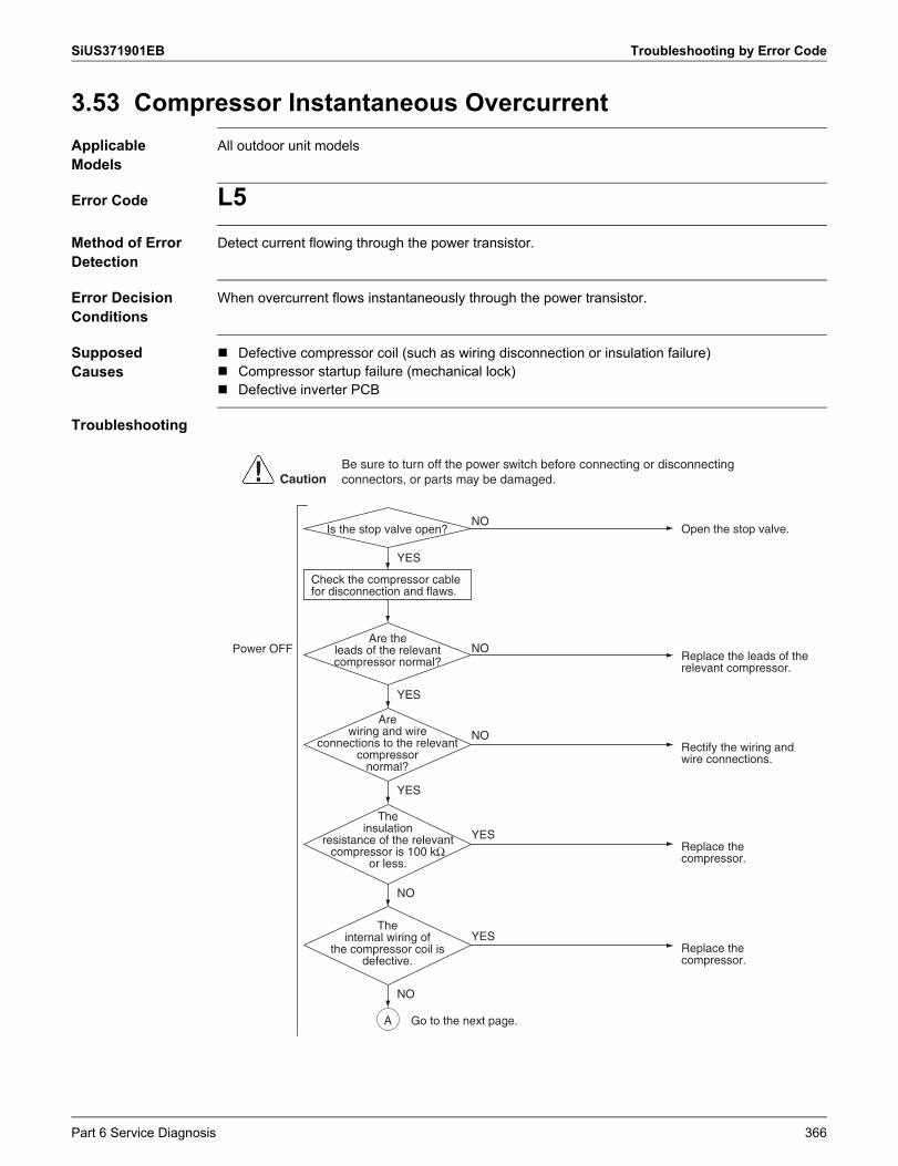
SiUS371901EB Troubleshooting by Error Code
3.53 Compressor Instantaneous OvercurrentApplicable Models
All outdoor unit models
Error Code L5Method of Error Detection
Detect current flowing through the power transistor.
Error Decision Conditions
When overcurrent flows instantaneously through the power transistor.
Supposed Causes
Defective compressor coil (such as wiring disconnection or insulation failure) Compressor startup failure (mechanical lock) Defective inverter PCB
Troubleshooting
Power OFF
Open the stop valve.
YES
NOIs the stop valve open?
YES
YES
Are wiring and wire
connections to the relevant compressor
normal?
Rectify the wiring and wire connections.
NO
CautionBe sure to turn off the power switch before connecting or disconnecting connectors, or parts may be damaged.
Are the leads of the relevant compressor normal? Replace the leads of the
relevant compressor.
NO
A
Check the compressor cable for disconnection and flaws.
NO
The insulation
resistance of the relevant compressor is 100 kΩ
or less.Replace the compressor.
YES
The internal wiring of
the compressor coil is defective.
Replace the compressor.
YES
NO
Go to the next page.
Part 6 Service Diagnosis 366
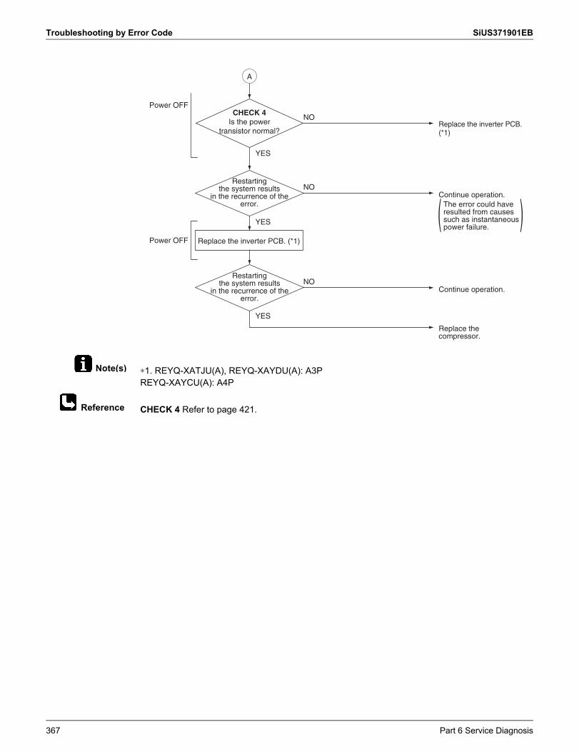
Troubleshooting by Error Code SiUS371901EB
Note(s)
Reference
∗1. REYQ-XATJU(A), REYQ-XAYDU(A): A3PREYQ-XAYCU(A): A4P
CHECK 4 Refer to page 421.
CHECK 4Is the power
transistor normal?
Power OFF
YES
Restarting the system results
in the recurrence of the error.
Continue operation.
Replace the compressor.
NO
YES
Replace the inverter PCB. (*1)
YES
Restarting the system results
in the recurrence of the error.
Continue operation.The error could have resulted from causes such as instantaneous power failure.
NO
Replace the inverter PCB. (*1)
NO
( )
Power OFF
A
367 Part 6 Service Diagnosis
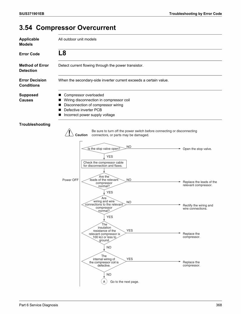
SiUS371901EB Troubleshooting by Error Code
3.54 Compressor OvercurrentApplicable Models
All outdoor unit models
Error Code L8Method of Error Detection
Detect current flowing through the power transistor.
Error Decision Conditions
When the secondary-side inverter current exceeds a certain value.
Supposed Causes
Compressor overloaded Wiring disconnection in compressor coil Disconnection of compressor wiring Defective inverter PCB Incorrect power supply voltage
Troubleshooting
Power OFF
Open the stop valve.
YES
NOIs the stop valve open?
YES
YES
Are wiring and wire
connections to the relevant compressor
normal?
Rectify the wiring and wire connections.
NO
CautionBe sure to turn off the power switch before connecting or disconnecting connectors, or parts may be damaged.
Are the leads of the relevant
compressor normal?
Replace the leads of the relevant compressor.
NO
A
Check the compressor cable for disconnection and flaws.
NO
The insulation
resistance of the relevant compressor is
100 kΩ or less to ground.
Replace the compressor.
YES
The internal wiring of
the compressor coil is defective.
Replace the compressor.
YES
NO
Go to the next page.
Part 6 Service Diagnosis 368
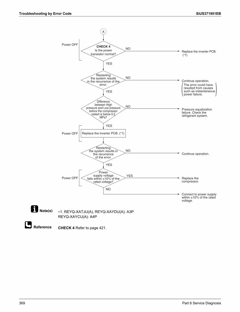
Troubleshooting by Error Code SiUS371901EB
Note(s)
Reference
∗1. REYQ-XATJU(A), REYQ-XAYDU(A): A3PREYQ-XAYCU(A): A4P
CHECK 4 Refer to page 421.
CHECK 4Is the power
transistor normal?
Power OFF
Power OFF
YES
YES
Restarting the system results in
the recurrence of the error.
Difference between High
pressure and Low pressure before the compressor
restart is below 0.2 MPa?
Continue operation.
Replace the compressor.
Connect to power supply within ±10% of the rated voltage.
NO
NO
Pressure equalization failure. Check the refrigerant system.
Power supply voltage
falls within ±10% of the rated voltage?
YES
YES
Replace the inverter PCB. (*1)
Restarting the system results
in the recurrence of the error.
Continue operation.The error could have resulted from causes such as instantaneous power failure.
NO
NO
( )
A
YES
Replace the inverter PCB. (*1)
NOPower OFF
369 Part 6 Service Diagnosis
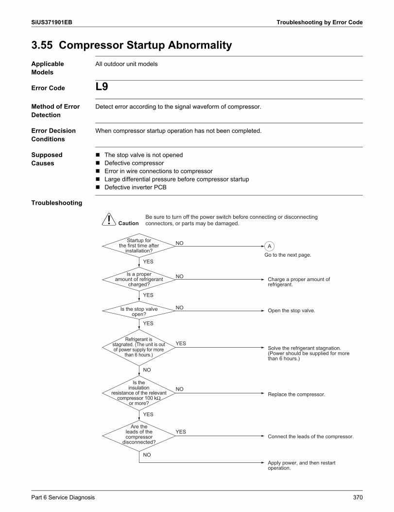
SiUS371901EB Troubleshooting by Error Code
3.55 Compressor Startup AbnormalityApplicable Models
All outdoor unit models
Error Code L9Method of Error Detection
Detect error according to the signal waveform of compressor.
Error Decision Conditions
When compressor startup operation has not been completed.
Supposed Causes
The stop valve is not opened Defective compressor Error in wire connections to compressor Large differential pressure before compressor startup Defective inverter PCB
Troubleshooting
YES
NO
NOApply power, and then restart operation.
NO
Are the leads of the compressor
disconnected?Connect the leads of the compressor.
YES
Is the insulation
resistance of the relevant compressor 100 kΩ
or more?
Replace the compressor.NO
YES
YES
YES
Refrigerant is stagnated. (The unit is out of power supply for more
than 6 hours.)Solve the refrigerant stagnation.(Power should be supplied for more than 6 hours.)
YES
CautionBe sure to turn off the power switch before connecting or disconnecting connectors, or parts may be damaged.
Is the stop valve open?
Startup for the first time after
installation?
Is a proper amount of refrigerant
charged?
Open the stop valve.NO
Charge a proper amount of refrigerant.
NO
AGo to the next page.
Part 6 Service Diagnosis 370
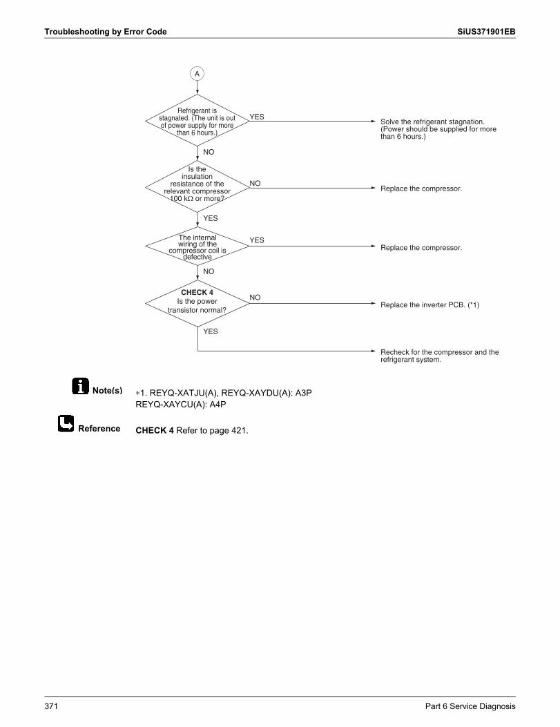
Troubleshooting by Error Code SiUS371901EB
Note(s)
Reference
∗1. REYQ-XATJU(A), REYQ-XAYDU(A): A3PREYQ-XAYCU(A): A4P
CHECK 4 Refer to page 421.
CHECK 4Is the power
transistor normal?
YES
Recheck for the compressor and the refrigerant system.
NO
Replace the inverter PCB. (*1)NO
YES
NO
The internal wiring of the
compressor coil is defective
Replace the compressor.YES
Is the insulation
resistance of the relevant compressor
100 k� or more?
Refrigerant is stagnated. (The unit is out of power supply for more
than 6 hours.)
Replace the compressor.NO
Solve the refrigerant stagnation.(Power should be supplied for more than 6 hours.)
YES
A
371 Part 6 Service Diagnosis
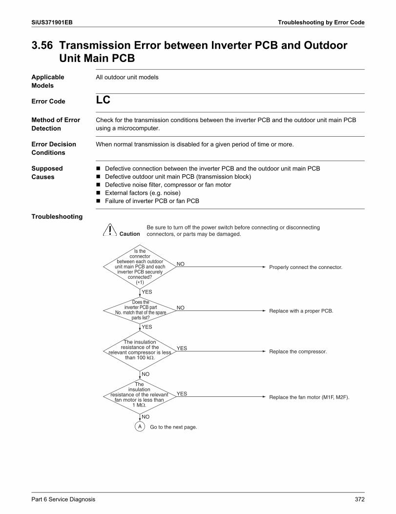
SiUS371901EB Troubleshooting by Error Code
3.56 Transmission Error between Inverter PCB and Outdoor Unit Main PCB
Applicable Models
All outdoor unit models
Error Code LCMethod of Error Detection
Check for the transmission conditions between the inverter PCB and the outdoor unit main PCB using a microcomputer.
Error Decision Conditions
When normal transmission is disabled for a given period of time or more.
Supposed Causes
Defective connection between the inverter PCB and the outdoor unit main PCB Defective outdoor unit main PCB (transmission block) Defective noise filter, compressor or fan motor External factors (e.g. noise) Failure of inverter PCB or fan PCB
Troubleshooting
Does the inverter PCB part
No. match that of the spare parts list?
Replace with a proper PCB.NO
Properly connect the connector.NO
YES
Replace the fan motor (M1F, M2F).YES
NO
The insulation resistance of the
relevant compressor is less than 100 k�.
The insulation
resistance of the relevant fan motor is less than
1 M�
Replace the compressor.YES
NO
YES
CautionBe sure to turn off the power switch before connecting or disconnecting connectors, or parts may be damaged.
Is the connector
between each outdoor unit main PCB and each inverter PCB securely
connected?(�1)
A Go to the next page.
Part 6 Service Diagnosis 372
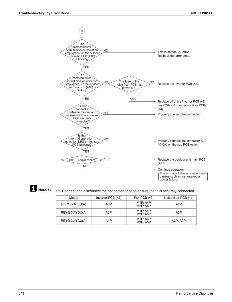
Troubleshooting by Error Code SiUS371901EB
Note(s) ∗1. Connect and disconnect the connector once to ensure that it is securely connected.
Replace all of the inverter PCB (�2), fan PCBs (�3), and noise filter PCBs (�4).
YES
This is not the LC error.Recheck the error code.
NO
YES
The microcomputer
normal monitor indication lamp (green) on the outdoor
unit main PCB (A1P) is blinking.
Replace the inverter PCB (�2).NO NO
YES
The microcomputer
normal monitor indication lamp (green) on the outdoor
unit main PCB (A1P) is blinking.
Properly connect the connector.NO
YES
Is the connector
between the outdoor unit main PCB and the sub
PCB securely connected?
Properly connect the connector X9A (X10A) on the sub PCB option.
NOIs the
normal operation indication LED on the sub
PCB blinking?
YES
NO
Replace the outdoor unit main PCB (A1P).
YES
The fuse of the noise filter PCB has
blown out.
Continue operation.The error could have resulted from causes such as instantaneous power failure.
The LC error recurs.
A
Model Inverter PCB (∗2) Fan PCB (∗3) Noise filter PCB (∗4)
REYQ-XATJU(A) A3P M1F: A4PM2F: A5P A2P
REYQ-XAYDU(A) A3P M1F: A4PM2F: A5P A2P
REYQ-XAYCU(A) A4P M1F: A6PM2F: A5P A2P, A3P
373 Part 6 Service Diagnosis
SiUS371901EB Troubleshooting by Error Code
3.57 Power Supply Voltage ImbalanceApplicable Models
All outdoor unit models
Error Code P1Method of Error Detection
Detect voltage imbalance through inverter PCB.
Error Decision Conditions
When power supply voltage imbalance exceeds approximately 12 V.
Error is not decided while the unit operation is continued.P1 will be displayed by pressing the inspection button.
Supposed Causes
Open phase Interphase voltage imbalance Defective capacitor in the main circuit Defective inverter PCB Defective magnetic relay Defective wiring in the main circuit
Part 6 Service Diagnosis 374
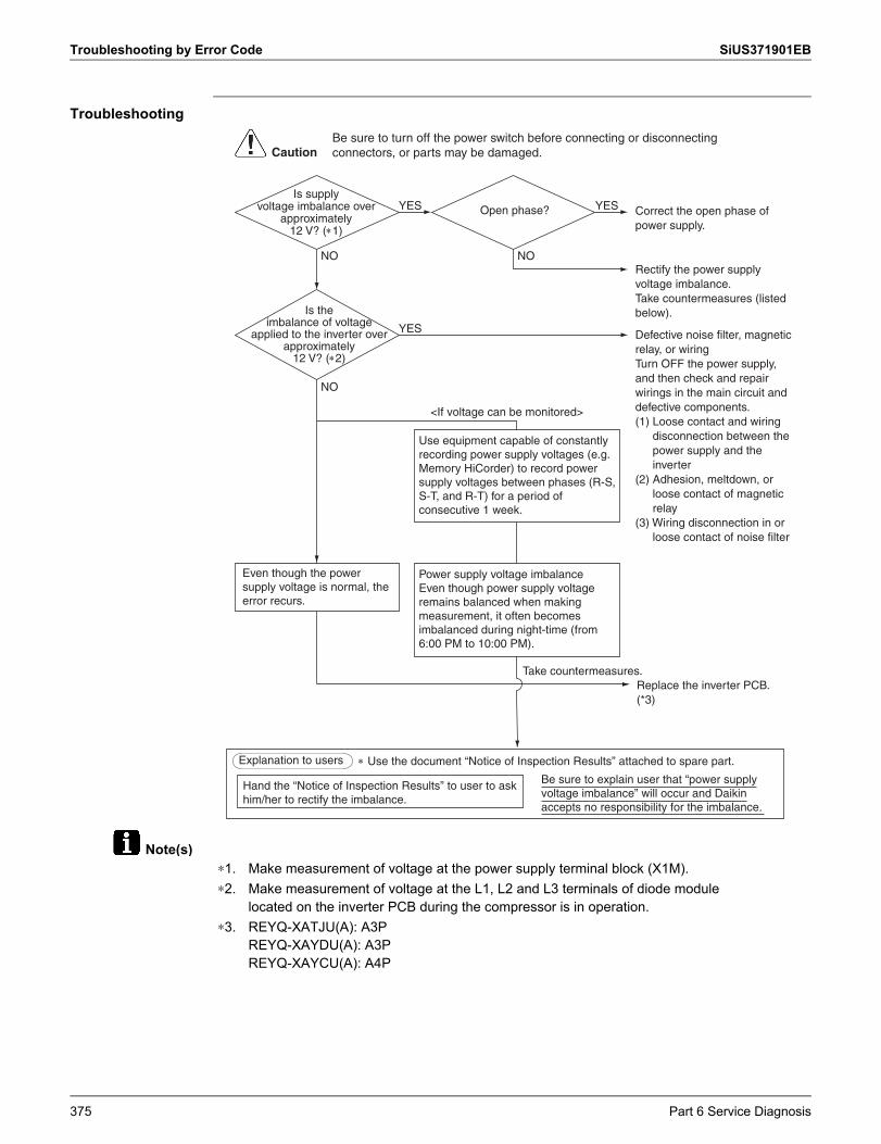
Troubleshooting by Error Code SiUS371901EB
Note(s)
Troubleshooting
Is supply voltage imbalance over
approximately 12 V? (1)
Correct the open phase of power supply.
Open phase?
Is the imbalance of voltage
applied to the inverter over approximately
12 V? (2)
Rectify the power supply voltage imbalance.Take countermeasures (listed below).
YES YES
NONO
NO
Take countermeasures.
Defective noise filter, magnetic relay, or wiringTurn OFF the power supply, and then check and repair wirings in the main circuit and defective components.(1) Loose contact and wiring
disconnection between the power supply and the inverter
(2) Adhesion, meltdown, or loose contact of magnetic relay
(3) Wiring disconnection in or loose contact of noise filter
Replace the inverter PCB. (*3)
YES
Explanation to users Use the document “Notice of Inspection Results” attached to spare part.
Hand the “Notice of Inspection Results” to user to ask him/her to rectify the imbalance.
Be sure to explain user that “power supply voltage imbalance” will occur and Daikin accepts no responsibility for the imbalance.
Use equipment capable of constantly recording power supply voltages (e.g. Memory HiCorder) to record power supply voltages between phases (R-S, S-T, and R-T) for a period of consecutive 1 week.
Power supply voltage imbalanceEven though power supply voltage remains balanced when making measurement, it often becomes imbalanced during night-time (from 6:00 PM to 10:00 PM).
Even though the power supply voltage is normal, the error recurs.
<If voltage can be monitored>
CautionBe sure to turn off the power switch before connecting or disconnecting connectors, or parts may be damaged.
∗1. Make measurement of voltage at the power supply terminal block (X1M).∗2. Make measurement of voltage at the L1, L2 and L3 terminals of diode module
located on the inverter PCB during the compressor is in operation.∗3. REYQ-XATJU(A): A3P
REYQ-XAYDU(A): A3PREYQ-XAYCU(A): A4P
375 Part 6 Service Diagnosis
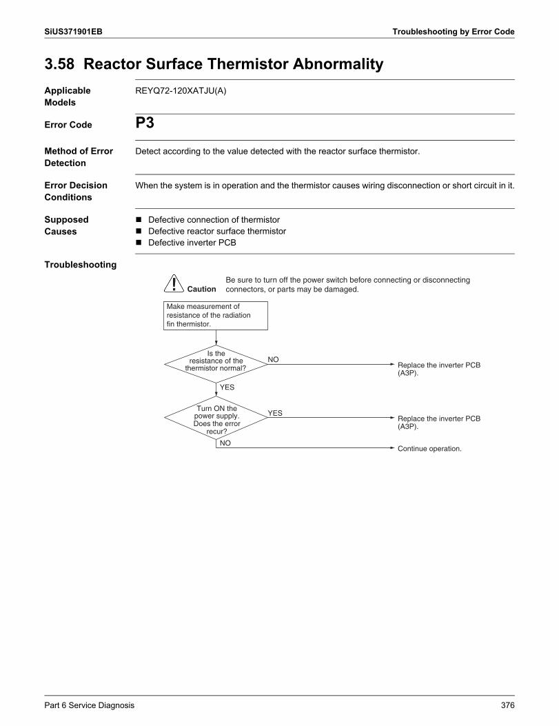
SiUS371901EB Troubleshooting by Error Code
3.58 Reactor Surface Thermistor AbnormalityApplicable Models
REYQ72-120XATJU(A)
Error Code P3Method of Error Detection
Detect according to the value detected with the reactor surface thermistor.
Error Decision Conditions
When the system is in operation and the thermistor causes wiring disconnection or short circuit in it.
Supposed Causes
Defective connection of thermistor Defective reactor surface thermistor Defective inverter PCB
Troubleshooting
Make measurement of resistance of the radiation fin thermistor.
Is the resistance of the
thermistor normal?
Turn ON the power supply.Does the error
recur?
NO
YES
YES
NOReplace the inverter PCB (A3P).
Replace the inverter PCB (A3P).
Continue operation.
CautionBe sure to turn off the power switch before connecting or disconnecting connectors, or parts may be damaged.
Part 6 Service Diagnosis 376
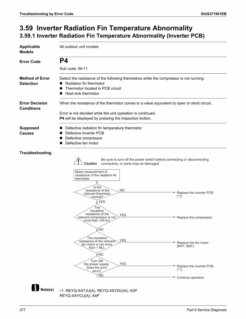
Troubleshooting by Error Code SiUS371901EB
Note(s)
3.59 Inverter Radiation Fin Temperature Abnormality3.59.1 Inverter Radiation Fin Temperature Abnormality (Inverter PCB)
Applicable Models
All outdoor unit models
Error Code P4Sub code: 09-11
Method of Error Detection
Detect the resistance of the following thermistors while the compressor is not running: Radiation fin thermistor Thermistor located in PCB circuit Heat sink thermistor
Error Decision Conditions
When the resistance of the thermistor comes to a value equivalent to open or short circuit.
Error is not decided while the unit operation is continued.P4 will be displayed by pressing the inspection button.
Supposed Causes
Defective radiation fin temperature thermistor Defective inverter PCB Defective compressor Defective fan motor
Troubleshooting
∗1. REYQ-XATJU(A), REYQ-XAYDU(A): A3PREYQ-XAYCU(A): A4P
Make measurement of resistance of the radiation fin thermistor.
Is the resistance of the
relevant thermistor normal?
The insulation
resistance of the relevant compressor is not
more than 100 k�.
The insulation resistance of the relevant
fan motor is not more than 1 M�.
Turn ONthe power supply.
Does the error recur?
NO
YES
NO
YES
NO
YES
YES
NOReplace the inverter PCB. (*1)
Replace the compressor.
Replace the fan motor (M1F, M2F).
Replace the inverter PCB. (*1)
Continue operation.
CautionBe sure to turn off the power switch before connecting or disconnecting connectors, or parts may be damaged.
377 Part 6 Service Diagnosis
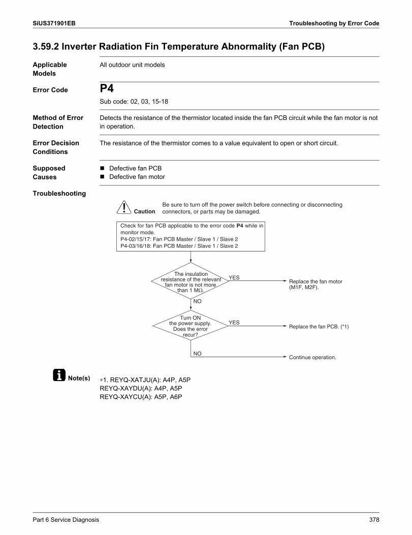
SiUS371901EB Troubleshooting by Error Code
Note(s)
3.59.2 Inverter Radiation Fin Temperature Abnormality (Fan PCB)
Applicable Models
All outdoor unit models
Error Code P4Sub code: 02, 03, 15-18
Method of Error Detection
Detects the resistance of the thermistor located inside the fan PCB circuit while the fan motor is not in operation.
Error Decision Conditions
The resistance of the thermistor comes to a value equivalent to open or short circuit.
Supposed Causes
Defective fan PCB Defective fan motor
Troubleshooting
∗1. REYQ-XATJU(A): A4P, A5PREYQ-XAYDU(A): A4P, A5PREYQ-XAYCU(A): A5P, A6P
The insulation resistance of the relevant
fan motor is not more than 1 M�.
Turn ONthe power supply.
Does the error recur?
NO
YES
NO
YESReplace the fan motor (M1F, M2F).
Replace the fan PCB. (*1)
Continue operation.
CautionBe sure to turn off the power switch before connecting or disconnecting connectors, or parts may be damaged.
Check for fan PCB applicable to the error code P4 while in monitor mode.P4-02/15/17: Fan PCB Master / Slave 1 / Slave 2P4-03/16/18: Fan PCB Master / Slave 1 / Slave 2
Part 6 Service Diagnosis 378
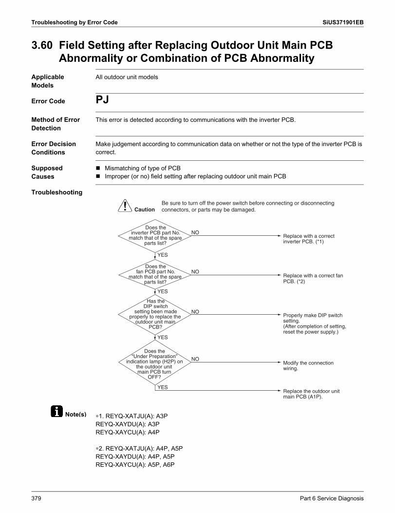
Troubleshooting by Error Code SiUS371901EB
Note(s)
3.60 Field Setting after Replacing Outdoor Unit Main PCB Abnormality or Combination of PCB Abnormality
Applicable Models
All outdoor unit models
Error Code PJMethod of Error Detection
This error is detected according to communications with the inverter PCB.
Error Decision Conditions
Make judgement according to communication data on whether or not the type of the inverter PCB is correct.
Supposed Causes
Mismatching of type of PCB Improper (or no) field setting after replacing outdoor unit main PCB
Troubleshooting
∗1. REYQ-XATJU(A): A3PREYQ-XAYDU(A): A3PREYQ-XAYCU(A): A4P
∗2. REYQ-XATJU(A): A4P, A5PREYQ-XAYDU(A): A4P, A5PREYQ-XAYCU(A): A5P, A6P
Does the inverter PCB part No.
match that of the spare parts list?
Does the fan PCB part No.
match that of the spare parts list?
Has the DIP switch
setting been made properly to replace the
outdoor unit main PCB?
Does the “Under Preparation”
indication lamp (H2P) on the outdoor unit main PCB turn
OFF?
YES
YES
NO
NO
YES
YES
NO
NO
Replace with a correct inverter PCB. (*1)
Replace with a correct fan PCB. (*2)
Properly make DIP switch setting.(After completion of setting, reset the power supply.)
Modify the connection wiring.
Replace the outdoor unit main PCB (A1P).
CautionBe sure to turn off the power switch before connecting or disconnecting connectors, or parts may be damaged.
379 Part 6 Service Diagnosis
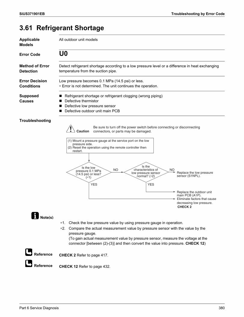
SiUS371901EB Troubleshooting by Error Code
Note(s)
Reference
Reference
3.61 Refrigerant ShortageApplicable Models
All outdoor unit models
Error Code U0Method of Error Detection
Detect refrigerant shortage according to a low pressure level or a difference in heat exchanging temperature from the suction pipe.
Error Decision Conditions
Low pressure becomes 0.1 MPa (14.5 psi) or less.∗ Error is not determined. The unit continues the operation.
Supposed Causes
Refrigerant shortage or refrigerant clogging (wrong piping) Defective thermistor Defective low pressure sensor Defective outdoor unit main PCB
Troubleshooting
CHECK 2 Refer to page 417.
CHECK 12 Refer to page 432.
Is the low pressure 0.1 MPa (14.5 psi) or less?
(∗1)
Is the characteristics of
low pressure sensor normal? (∗2)
Replace the low pressure sensor (S1NPL).
Replace the outdoor unit main PCB (A1P).
NONO
YES YES
Eliminate factors that cause decreasing low pressure.CHECK 2
CautionBe sure to turn off the power switch before connecting or disconnecting connectors, or parts may be damaged.
(1) Mount a pressure gauge at the service port on the low pressure side.
(2) Reset the operation using the remote controller then restart.
∗1. Check the low pressure value by using pressure gauge in operation.∗2. Compare the actual measurement value by pressure sensor with the value by the
pressure gauge. (To gain actual measurement value by pressure sensor, measure the voltage at the connector [between (2)-(3)] and then convert the value into pressure. CHECK 12)
Part 6 Service Diagnosis 380
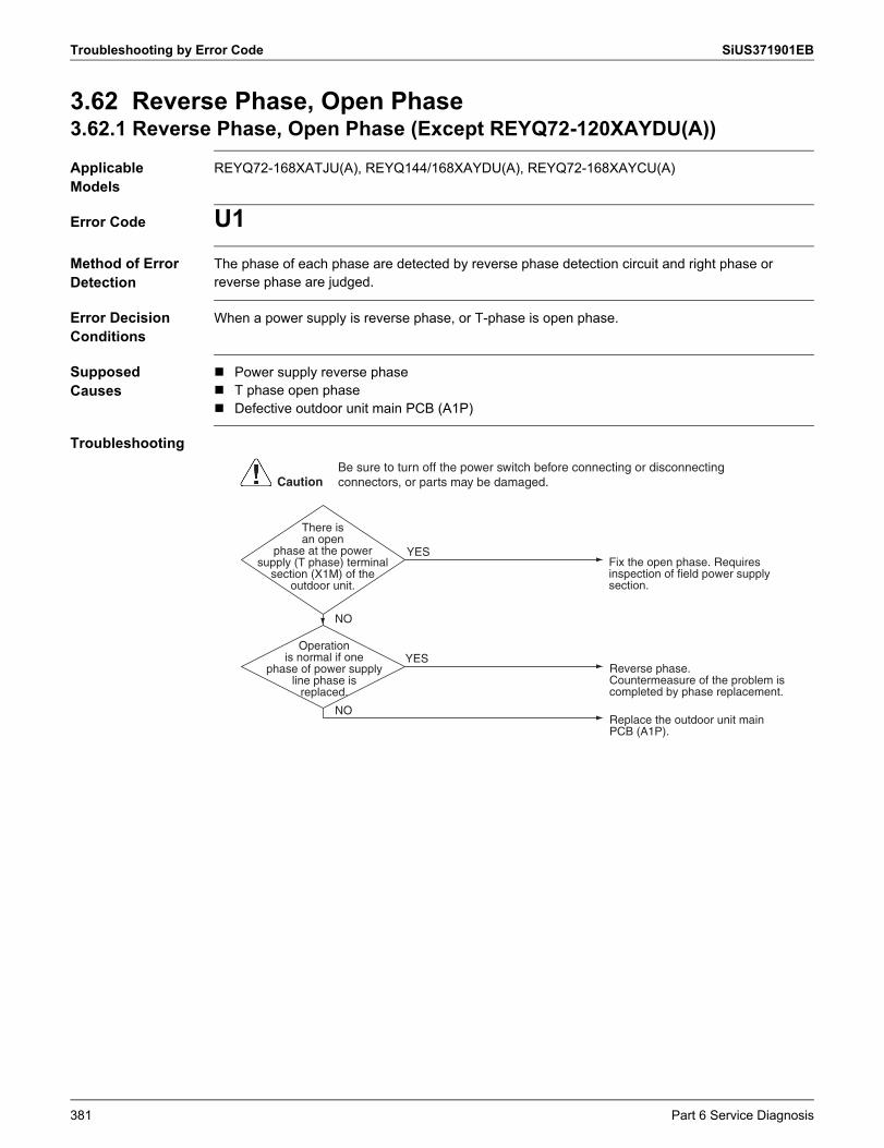
Troubleshooting by Error Code SiUS371901EB
3.62 Reverse Phase, Open Phase3.62.1 Reverse Phase, Open Phase (Except REYQ72-120XAYDU(A))
Applicable Models
REYQ72-168XATJU(A), REYQ144/168XAYDU(A), REYQ72-168XAYCU(A)
Error Code U1Method of Error Detection
The phase of each phase are detected by reverse phase detection circuit and right phase or reverse phase are judged.
Error Decision Conditions
When a power supply is reverse phase, or T-phase is open phase.
Supposed Causes
Power supply reverse phase T phase open phase Defective outdoor unit main PCB (A1P)
Troubleshooting
There is an open
phase at the power supply (T phase) terminal
section (X1M) of the outdoor unit.
Operation is normal if one
phase of power supply line phase is
replaced.
Fix the open phase. Requires inspection of field power supply section.
Reverse phase.Countermeasure of the problem is completed by phase replacement.
Replace the outdoor unit main PCB (A1P).
YES
YES
NO
NO
CautionBe sure to turn off the power switch before connecting or disconnecting connectors, or parts may be damaged.
381 Part 6 Service Diagnosis
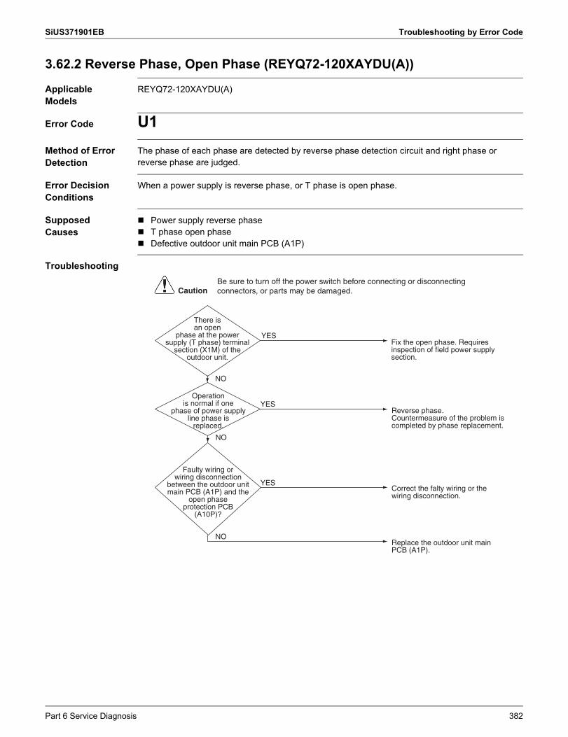
SiUS371901EB Troubleshooting by Error Code
3.62.2 Reverse Phase, Open Phase (REYQ72-120XAYDU(A))
Applicable Models
REYQ72-120XAYDU(A)
Error Code U1Method of Error Detection
The phase of each phase are detected by reverse phase detection circuit and right phase or reverse phase are judged.
Error Decision Conditions
When a power supply is reverse phase, or T phase is open phase.
Supposed Causes
Power supply reverse phase T phase open phase Defective outdoor unit main PCB (A1P)
Troubleshooting
There is an open
phase at the power supply (T phase) terminal
section (X1M) of the outdoor unit.
Operation is normal if one
phase of power supply line phase is
replaced.
Faulty wiring or wiring disconnection
between the outdoor unit main PCB (A1P) and the
open phase protection PCB
(A10P)?
Fix the open phase. Requires inspection of field power supply section.
Reverse phase.Countermeasure of the problem is completed by phase replacement.
Correct the falty wiring or the wiring disconnection.
YES
YES
YES
NO
NO
Replace the outdoor unit main PCB (A1P).
NO
CautionBe sure to turn off the power switch before connecting or disconnecting connectors, or parts may be damaged.
Part 6 Service Diagnosis 382
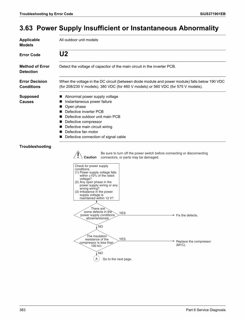
Troubleshooting by Error Code SiUS371901EB
3.63 Power Supply Insufficient or Instantaneous AbnormalityApplicable Models
All outdoor unit models
Error Code U2Method of Error Detection
Detect the voltage of capacitor of the main circuit in the inverter PCB.
Error Decision Conditions
When the voltage in the DC circuit (between diode module and power module) falls below 190 VDC (for 208/230 V models), 380 VDC (for 460 V models) or 560 VDC (for 575 V models).
Supposed Causes
Abnormal power supply voltage Instantaneous power failure Open phase Defective inverter PCB Defective outdoor unit main PCB Defective compressor Defective main circuit wiring Defective fan motor Defective connection of signal cable
Troubleshooting
There aresome defects in the
power supply conditions aforementioned.
The insulation resistance of the
compressor is less than 100 k�.
NO
YES
YES
Fix the defects.
Replace the compressor (M1C).
Check for power supply conditions.(1) Power supply voltage falls
within ±10% of the rated voltage?
(2) Any open phase in the power supply wiring or any wrong wiring?
(3) Imbalance in the power supply voltage is maintained within 12 V?
A
NO
CautionBe sure to turn off the power switch before connecting or disconnecting connectors, or parts may be damaged.
Go to the next page.
383 Part 6 Service Diagnosis
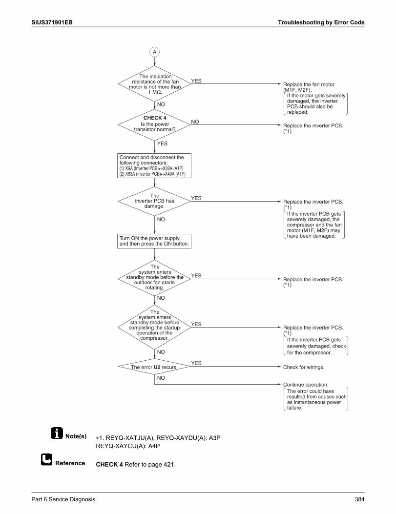
SiUS371901EB Troubleshooting by Error Code
Note(s)
Reference
∗1. REYQ-XATJU(A), REYQ-XAYDU(A): A3PREYQ-XAYCU(A): A4P
CHECK 4 Refer to page 421.
The inverter PCB has
damage.
The system enters
standby mode before the outdoor fan starts
rotating.
The system enters
standby mode before completing the startup
operation of the compressor.
The error U2 recurs.
NO
NO
YES
YES
NO
YES
NO
YES
Replace the inverter PCB. (*1)
Check for wirings.
Turn ON the power supply, and then press the ON button.
Replace the inverter PCB. (*1)
If the inverter PCB gets severely damaged, the compressor and the fan motor (M1F, M2F) may have been damaged.
Replace the inverter PCB. (*1)
If the inverter PCB gets severely damaged, check for the compressor.
Continue operation.The error could have resulted from causes such as instantaneous power failure.
A
Is the power transistor normal?
YES
NOReplace the inverter PCB. (*1)
Connect and disconnect the following connectors:(1) X6A (Inverter PCB)�X28A (A1P)(2) X63A (Inverter PCB)�X40A (A1P)
CHECK 4
The insulation resistance of the fan
motor is not more than 1 M�.
NO
YESReplace the fan motor (M1F, M2F).
If the motor gets severely damaged, the inverter PCB should also be replaced.
Part 6 Service Diagnosis 384
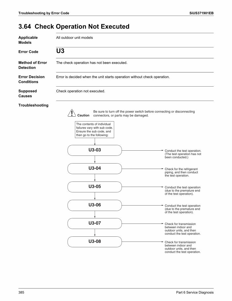
Troubleshooting by Error Code SiUS371901EB
3.64 Check Operation Not ExecutedApplicable Models
All outdoor unit models
Error Code U3Method of Error Detection
The check operation has not been executed.
Error Decision Conditions
Error is decided when the unit starts operation without check operation.
Supposed Causes
Check operation not executed.
Troubleshooting
The contents of individual failures vary with sub code. Ensure the sub code, and then go to the following:
Conduct the test operation. (The test operation has not been conducted.)
U3-03
Check for the refrigerant piping, and then conduct the test operation.
U3-04
Conduct the test operation (due to the premature end of the test operation).
U3-05
Conduct the test operation (due to the premature end of the test operation).
U3-06
Check for transmission between indoor and outdoor units, and then conduct the test operation.
U3-07
Check for transmission between indoor and outdoor units, and then conduct the test operation.
U3-08
CautionBe sure to turn off the power switch before connecting or disconnecting connectors, or parts may be damaged.
385 Part 6 Service Diagnosis
SiUS371901EB Troubleshooting by Error Code
3.65 Transmission Error between Indoor Units and Outdoor Units, Open Phase in Power Supply Wiring
Applicable Models
All indoor unit modelsAll outdoor unit models
Error Code U4Method of Error Detection
Microcomputer checks if transmission between indoor and outdoor units is normal.
Error Decision Conditions
Transmission is not carried out normally for a certain amount of time.
Supposed Causes
Open phase in power supply wiring Short circuit in indoor-outdoor or outdoor-outdoor transmission wiring (F1/F2), or wrong wiring Outdoor unit power supply is OFF System address does not match Defective indoor unit control PCB Defective outdoor unit main PCB Multi-tenant function is ON.
Part 6 Service Diagnosis 386
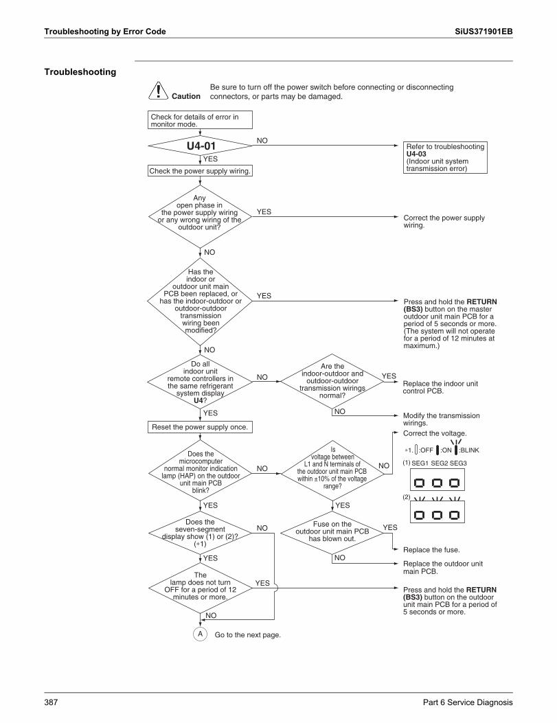
Troubleshooting by Error Code SiUS371901EB
Troubleshooting
Do all indoor unit
remote controllers in the same refrigerant
system display U4?
Are the indoor-outdoor and
outdoor-outdoor transmission wirings
normal?
Fuse on the outdoor unit main PCB
has blown out.
Does the seven-segment
display show (1) or (2)?(∗1)
The lamp does not turn
OFF for a period of 12 minutes or more.
Is voltage between
L1 and N terminals of the outdoor unit main PCB within ±10% of the voltage
range?
Does the microcomputer
normal monitor indication lamp (HAP) on the outdoor
unit main PCB blink?
Has the indoor or
outdoor unit main PCB been replaced, or
has the indoor-outdoor or outdoor-outdoor
transmission wiring been modified?
U4-01
∗1. :OFF :ON :BLINK
SEG1 SEG2 SEG3 (1)
(2)
Correct the voltage.
Replace the fuse.
Press and hold the RETURN (BS3) button on the outdoor unit main PCB for a period of 5 seconds or more.
YES
NO
YES
YES
Replace the indoor unit control PCB.
Press and hold the RETURN (BS3) button on the master outdoor unit main PCB for a period of 5 seconds or more. (The system will not operate for a period of 12 minutes at maximum.)
Modify the transmission wirings.
YES
Refer to troubleshooting U4-03(Indoor unit system transmission error)
NO
NO
NO
Replace the outdoor unit main PCB.
NO
YES
NO
NO
NO
YES
NO
Reset the power supply once.
YES
Check for details of error in monitor mode.
YES
YES
CautionBe sure to turn off the power switch before connecting or disconnecting connectors, or parts may be damaged.
Any open phase in
the power supply wiring or any wrong wiring of the
outdoor unit?
NO
Correct the power supply wiring.
YES
Check the power supply wiring.
A Go to the next page.
387 Part 6 Service Diagnosis
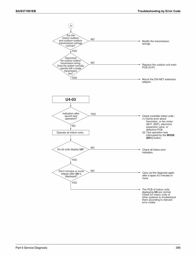
SiUS371901EB Troubleshooting by Error Code
Indication after launch test operation?
U4-03
The PCB of indoor units displaying U9 are normal.Check for indoor units of other systems to troubleshoot them according to relevant error codes.
NO
YES
Check controller indoor units : (1) Some error about
thermistor, or fan motor (M1F, M2F), electronic expansion valve, or defective PCB.
(2) Test operation was interrupted by the MODE (BS1) button.
YES
Check all indoor error indication.
NO
Operate all indoor units.
YES
Do all units display U9?
Carry out the diagnosis again after a lapse of 2 minutes or more.
NODid 2 minutes or more elapse after U9 is
displayed?
Are the indoor-outdoor
and outdoor-outdoor transmission wirings
normal?
Disconnect the outdoor-outdoor transmission wiring.
Does the system normally operate with a single
transmission line?
Modify the transmission wirings.
Replace the outdoor unit main PCB (A1P).
Mount the DIII-NET extension adaptor.
NO
NO
YES
YES
A
Part 6 Service Diagnosis 388
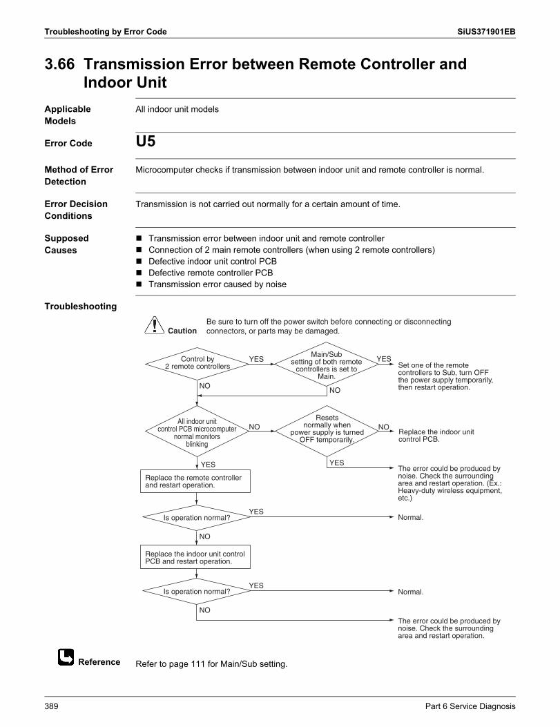
Troubleshooting by Error Code SiUS371901EB
Reference
3.66 Transmission Error between Remote Controller and Indoor Unit
Applicable Models
All indoor unit models
Error Code U5Method of Error Detection
Microcomputer checks if transmission between indoor unit and remote controller is normal.
Error Decision Conditions
Transmission is not carried out normally for a certain amount of time.
Supposed Causes
Transmission error between indoor unit and remote controller Connection of 2 main remote controllers (when using 2 remote controllers) Defective indoor unit control PCB Defective remote controller PCB Transmission error caused by noise
Troubleshooting
Refer to page 111 for Main/Sub setting.
Control by 2 remote controllers
Main/Sub setting of both remote
controllers is set to Main.
All indoor unit control PCB microcomputer
normal monitors blinking
Resets normally when
power supply is turned OFF temporarily.
NO
NO
NO
YES
NO
Replace the indoor unit control PCB.
Set one of the remote controllers to Sub, turn OFF the power supply temporarily, then restart operation.
The error could be produced by noise. Check the surrounding area and restart operation.
The error could be produced by noise. Check the surroundingarea and restart operation. (Ex.: Heavy-duty wireless equipment, etc.)
Normal.
Normal.
NO NO
YES YES
YES
Replace the remote controller and restart operation.
YES
Replace the indoor unit control PCB and restart operation.
Is operation normal?
Is operation normal?
YES
CautionBe sure to turn off the power switch before connecting or disconnecting connectors, or parts may be damaged.
389 Part 6 Service Diagnosis
SiUS371901EB Troubleshooting by Error Code
3.67 Transmission Error between Outdoor UnitsApplicable Models
All outdoor unit models
Error Code U7Method of Error Detection
Microcomputer checks if transmission between outdoor units is normal.
Error Decision Conditions
When transmission is not carried out normally for a certain amount of time
Supposed Causes
Connection error of transmission wirings between outdoor unit and external control adaptor for outdoor unit
Connection error of transmission wirings between outdoor units Cool/Heat selection setting error Cool/Heat unified address setting error (functional unit, external control adaptor for outdoor unit) Defective outdoor unit main PCB Defective external control adaptor for outdoor unit
Part 6 Service Diagnosis 390
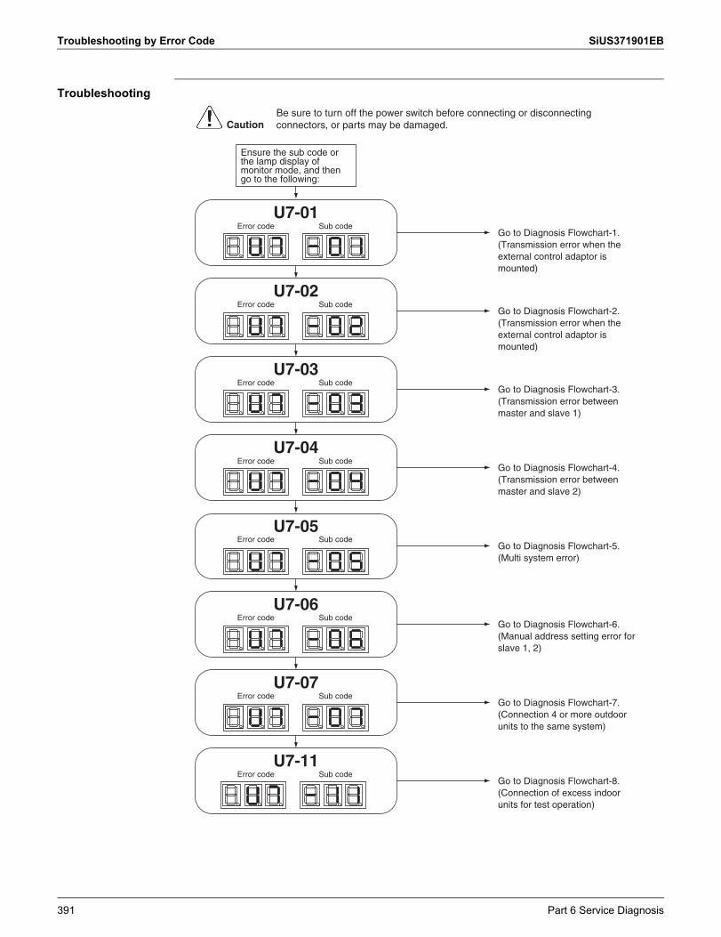
Troubleshooting by Error Code SiUS371901EB
Troubleshooting
Go to Diagnosis Flowchart-1. (Transmission error when the external control adaptor is mounted)
Ensure the sub code or the lamp display of monitor mode, and then go to the following:
CautionBe sure to turn off the power switch before connecting or disconnecting connectors, or parts may be damaged.
Go to Diagnosis Flowchart-2. (Transmission error when the external control adaptor is mounted)
Error code Sub code
Error code Sub code
Error code Sub code
Error code Sub code
Error code Sub code
Error code Sub code
Error code Sub code
Error code Sub code
Go to Diagnosis Flowchart-3. (Transmission error between master and slave 1)
Go to Diagnosis Flowchart-4. (Transmission error between master and slave 2)
Go to Diagnosis Flowchart-5. (Multi system error)
Go to Diagnosis Flowchart-6. (Manual address setting error for slave 1, 2)
Go to Diagnosis Flowchart-7. (Connection 4 or more outdoor units to the same system)
Go to Diagnosis Flowchart-8. (Connection of excess indoor units for test operation)
U7-01
U7-02
U7-03
U7-04
U7-05
U7-06
U7-07
U7-11
391 Part 6 Service Diagnosis
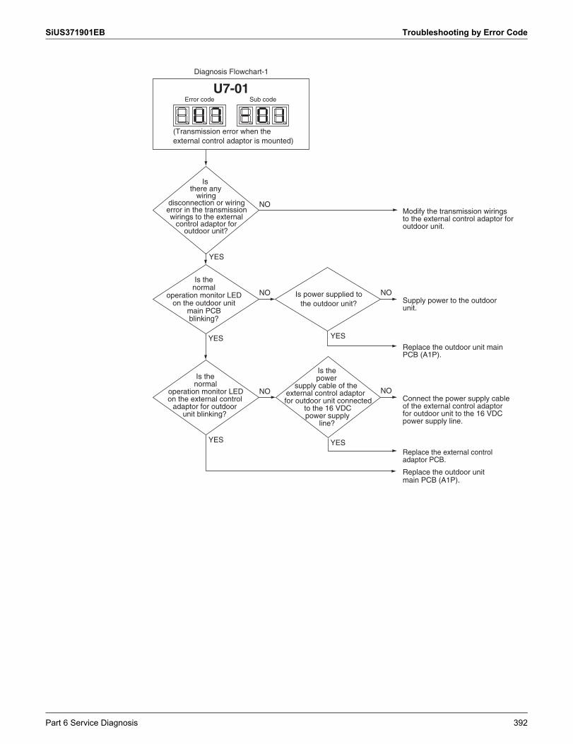
SiUS371901EB Troubleshooting by Error Code
NO
NO
YES
YES
NO
YES
YES
Connect the power supply cable of the external control adaptor for outdoor unit to the 16 VDC power supply line.
Replace the outdoor unit main PCB (A1P).
Replace the external control adaptor PCB.
Replace the outdoor unit main PCB (A1P).
NO
NO
YES
Modify the transmission wirings to the external control adaptor for outdoor unit.
Diagnosis Flowchart-1
Supply power to the outdoor unit.
Is power supplied to the outdoor unit?
Is the normal
operation monitor LED on the outdoor unit
main PCB blinking?
Is the normal
operation monitor LED on the external control
adaptor for outdoor unit blinking?
(Transmission error when the external control adaptor is mounted)
Is the power
supply cable of the external control adaptor for outdoor unit connected
to the 16 VDC power supply
line?
Is there any
wiring disconnection or wiring error in the transmission wirings to the external
control adaptor for outdoor unit?
Error code Sub codeU7-01
Part 6 Service Diagnosis 392
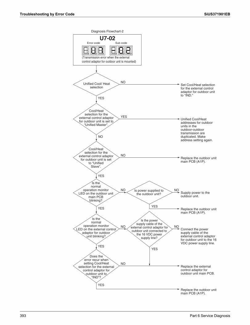
Troubleshooting by Error Code SiUS371901EB
Unified Cool/ Heat selection
Cool/Heat selection for the
external control adaptor for outdoor unit is set to
“Unified Master”.
Cool/Heat selection for the
external control adaptor for outdoor unit is set
to “Unified Slave”.
Is the normal
operation monitor LED on the outdoor unit
main PCB blinking?
Is power supplied to the outdoor unit?
Is the power supply cable of the
external control adaptor for outdoor unit connected to
the 16 VDC power supply line?
Is the normal
operation monitor LED on the external control
adaptor for outdoor unit blinking?
Does the error recur when setting Cool/Heat
selection for the external control adaptor for
outdoor unit to “IND”?
NO
NO
NO NO
NONO
NO
NO
YES
YES
YES
YES
YESYES
YES
YES
Replace the outdoor unit main PCB (A1P).
Replace the external control adaptor for outdoor unit main PCB.
Connect the power supply cable of the external control adaptor for outdoor unit to the 16 VDC power supply line.
Replace the outdoor unit main PCB (A1P).
Supply power to the outdoor unit.
Replace the outdoor unit main PCB (A1P).
Unified Cool/Heat addresses for outdoor units in the outdoor-outdoor transmission are duplicated. Make address setting again.
Set Cool/Heat selection for the external control adaptor for outdoor unit to “IND.”
Diagnosis Flowchart-2
(Transmission error when the external control adaptor for outdoor unit is mounted)
Error code Sub codeU7-02
393 Part 6 Service Diagnosis
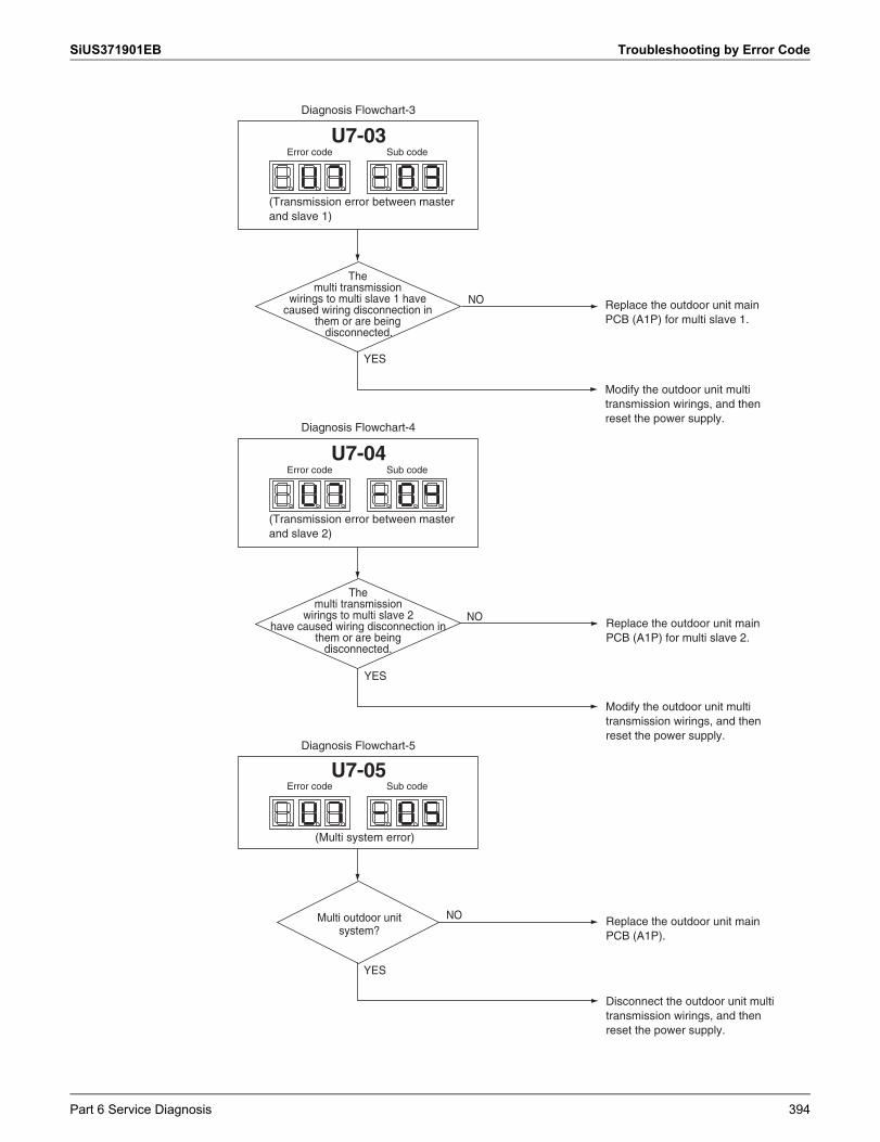
SiUS371901EB Troubleshooting by Error Code
YES
NO
YES
NO
The multi transmission
wirings to multi slave 2 have caused wiring disconnection in
them or are being disconnected.
Replace the outdoor unit main PCB (A1P) for multi slave 2.
Disconnect the outdoor unit multi transmission wirings, and then reset the power supply.
Replace the outdoor unit main PCB (A1P).
YES
NO
The multi transmission
wirings to multi slave 1 have caused wiring disconnection in
them or are being disconnected.
Modify the outdoor unit multi transmission wirings, and then reset the power supply.
Replace the outdoor unit main PCB (A1P) for multi slave 1.
Modify the outdoor unit multi transmission wirings, and then reset the power supply.
Diagnosis Flowchart-3
(Transmission error between master and slave 1)
Error code Sub codeU7-03
Diagnosis Flowchart-4
(Transmission error between master and slave 2)
Error code Sub codeU7-04
Diagnosis Flowchart-5
(Multi system error)
Error code Sub codeU7-05
Multi outdoor unit system?
Part 6 Service Diagnosis 394
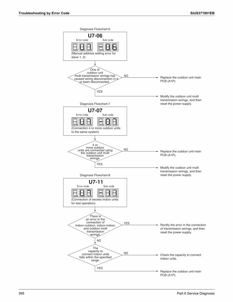
Troubleshooting by Error Code SiUS371901EB
YES
NO
YES
NO
4 or more outdoor
units are connected using the outdoor unit multi
transmission wirings.
YES
YES
There is an error in the connection of
indoor-outdoor, indoor-indoor, and outdoor multi
transmission wirings.
Modify the outdoor unit multi transmission wirings, and then reset the power supply.
Replace the outdoor unit main PCB (A1P).
Modify the outdoor unit multi transmission wirings, and then reset the power supply.
Replace the outdoor unit main PCB (A1P).
Replace the outdoor unit main PCB (A1P).
Rectify the error in the connection of transmission wirings, and then reset the power supply.
One of outdoor unit
multi transmission wirings has caused wiring disconnection in it
or been disconnected.
NO
The capacity to
connect indoor units falls within the specified
range.
Check the capacity to connect indoor units.
Diagnosis Flowchart-6
(Manual address setting error for slave 1, 2)
Error code Sub codeU7-06
Diagnosis Flowchart-7
(Connection 4 or more outdoor units to the same system)
Error code Sub codeU7-07
Diagnosis Flowchart-8
(Connection of excess indoor units for test operation)
Error code Sub codeU7-11
NO
395 Part 6 Service Diagnosis
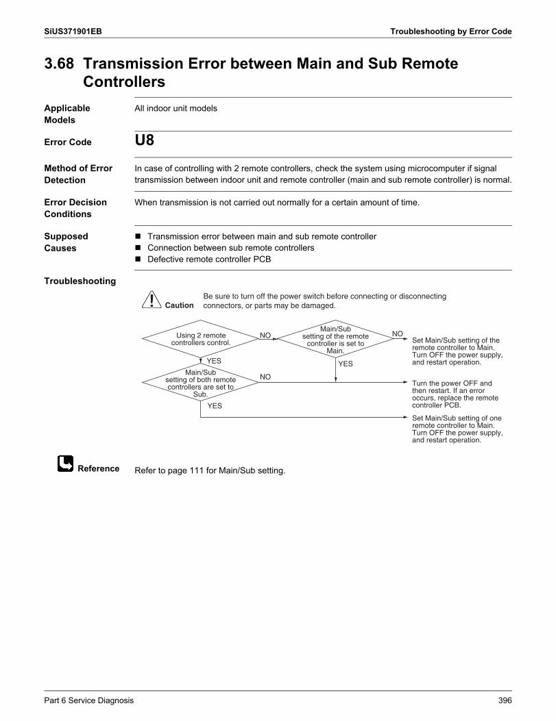
SiUS371901EB Troubleshooting by Error Code
Reference
3.68 Transmission Error between Main and Sub Remote Controllers
Applicable Models
All indoor unit models
Error Code U8Method of Error Detection
In case of controlling with 2 remote controllers, check the system using microcomputer if signal transmission between indoor unit and remote controller (main and sub remote controller) is normal.
Error Decision Conditions
When transmission is not carried out normally for a certain amount of time.
Supposed Causes
Transmission error between main and sub remote controller Connection between sub remote controllers Defective remote controller PCB
Troubleshooting
Refer to page 111 for Main/Sub setting.
Main/Sub setting of both remote controllers are set to
Sub.
Main/Sub setting of the remote
controller is set to Main.
Set Main/Sub setting of the remote controller to Main.Turn OFF the power supply, and restart operation.
Set Main/Sub setting of one remote controller to Main.Turn OFF the power supply, and restart operation.
Turn the power OFF and then restart. If an error occurs, replace the remote controller PCB.YES
YESYES
NO
NO
NOUsing 2 remote controllers control.
CautionBe sure to turn off the power switch before connecting or disconnecting connectors, or parts may be damaged.
Part 6 Service Diagnosis 396
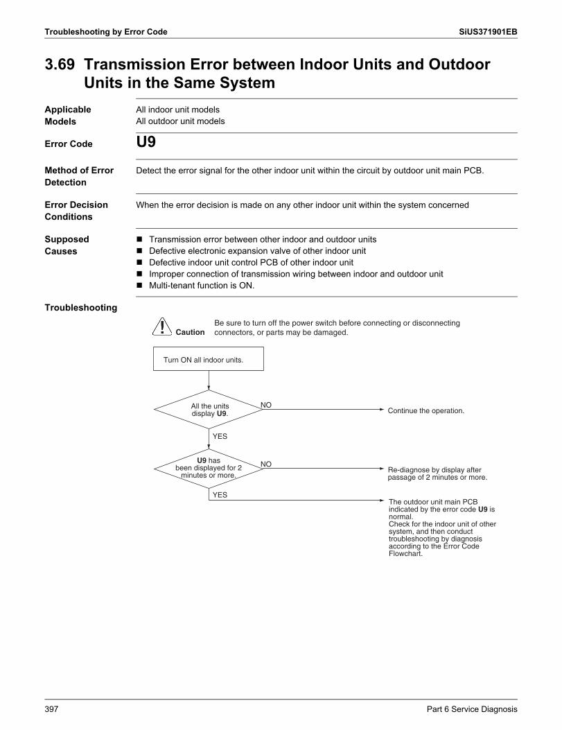
Troubleshooting by Error Code SiUS371901EB
3.69 Transmission Error between Indoor Units and Outdoor Units in the Same System
Applicable Models
All indoor unit modelsAll outdoor unit models
Error Code U9Method of Error Detection
Detect the error signal for the other indoor unit within the circuit by outdoor unit main PCB.
Error Decision Conditions
When the error decision is made on any other indoor unit within the system concerned
Supposed Causes
Transmission error between other indoor and outdoor units Defective electronic expansion valve of other indoor unit Defective indoor unit control PCB of other indoor unit Improper connection of transmission wiring between indoor and outdoor unit Multi-tenant function is ON.
Troubleshooting
U9 has been displayed for 2
minutes or more.
The outdoor unit main PCB indicated by the error code U9 is normal.Check for the indoor unit of other system, and then conduct troubleshooting by diagnosis according to the Error Code Flowchart.
Re-diagnose by display after passage of 2 minutes or more.
NO
Turn ON all indoor units.
YES
YES
Continue the operation.NOAll the units
display U9.
CautionBe sure to turn off the power switch before connecting or disconnecting connectors, or parts may be damaged.
397 Part 6 Service Diagnosis
SiUS371901EB Troubleshooting by Error Code
3.70 Improper Combination of Indoor, Branch Selector and Outdoor Units
Applicable Models
All indoor unit modelsBranch Selector unitAll outdoor unit models
Error Code UAMethod of Error Detection
A difference occurs in data by the type of refrigerant between indoor, Branch Selector and outdoor units.
The number of indoor units is out of the allowable range. Signal transmission between indoor, Branch Selector and outdoor units is abnormal.
Error Decision Conditions
The error decision is made as soon as either of the abnormalities aforementioned is detected.
Supposed Causes
Excess of connected indoor units Defective outdoor unit main PCB Mismatch of the refrigerant type of indoor and outdoor unit. Setting of outdoor unit main PCB was not carried out after replacing to spare PCB.
Part 6 Service Diagnosis 398
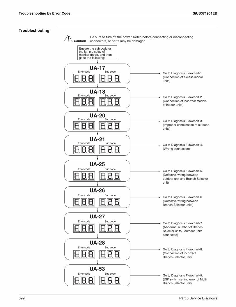
Troubleshooting by Error Code SiUS371901EB
Troubleshooting
Go to Diagnosis Flowchart-5. (Defective wiring between outdoor unit and Branch Selector unit)
Error code Sub code
UA-25
Go to Diagnosis Flowchart-6. (Defective wiring between Branch Selector units)
Error code Sub code
UA-26
Go to Diagnosis Flowchart-7. (Abnormal number of Branch Selector units - outdoor units connected)
Error code Sub code
UA-27
Go to Diagnosis Flowchart-8. (Connection of incorrect Branch Selector unit)
Error code Sub code
UA-28
Go to Diagnosis Flowchart-9. (DIP switch setting error of Multi Branch Selector unit)
Error code Sub code
UA-53
Ensure the sub code or the lamp display of monitor mode, and then go to the following:
CautionBe sure to turn off the power switch before connecting or disconnecting connectors, or parts may be damaged.
Go to Diagnosis Flowchart-1. (Connection of excess indoor units)
Go to Diagnosis Flowchart-2. (Connection of incorrect models of indoor units)
Go to Diagnosis Flowchart-3. (Improper combination of outdoor units)
Go to Diagnosis Flowchart-4. (Wrong connection)
UA-17Error code Sub code
Error code Sub code
Error code Sub code
Error code Sub code
UA-18
UA-20
UA-21
399 Part 6 Service Diagnosis
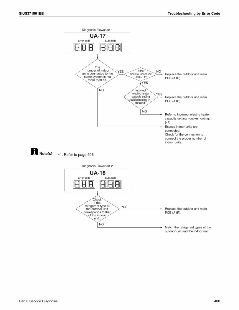
SiUS371901EB Troubleshooting by Error Code
Note(s) ∗1. Refer to page 406.
NO
YES
YES
The number of indoor
units connected to the same system is not
more than 64.
Incorrect electric heater
capacity setting troubleshooting (∗1)
checked?
Replace the outdoor unit main PCB (A1P).
Replace the outdoor unit main PCB (A1P).
Refer to Incorrect electric heater capacity setting troubleshooting. (∗1)Excess indoor units are connected.Check for the connection to connect the proper number of indoor units.
NO
Diagnosis Flowchart-1
UA-17Error code Sub code
NOIs the model of indoor unit
FXTQ-TA?
YES
NO
YES
Check if the
refrigerant type of the outdoor unit
corresponds to that of the indoor
unit.
Replace the outdoor unit main PCB (A1P).
Match the refrigerant types of the outdoor unit and the indoor unit.
Diagnosis Flowchart-2
Error code Sub code
UA-18
Part 6 Service Diagnosis 400
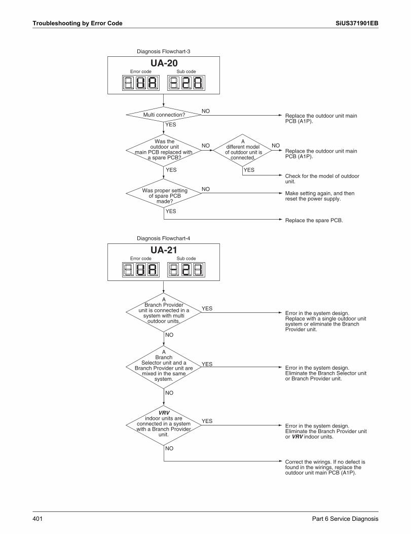
Troubleshooting by Error Code SiUS371901EB
NO
YES
YES
YES
NO
NO
Replace the outdoor unit main PCB (A1P).
Check for the model of outdoor unit.
Make setting again, and then reset the power supply.
Replace the spare PCB.
NO
YES
Replace the outdoor unit main PCB (A1P).
Was the outdoor unit
main PCB replaced with a spare PCB?
A different model of outdoor unit is
connected.
Diagnosis Flowchart-3
Error code Sub code
UA-20
Multi connection?
Was proper setting of spare PCB
made?
Diagnosis Flowchart-4
NO
Correct the wirings. If no defect is found in the wirings, replace the outdoor unit main PCB (A1P).
YES
NO
YES
NO
YES
Error in the system design. Replace with a single outdoor unit system or eliminate the Branch Provider unit.
A Branch
Selector unit and a Branch Provider unit are
mixed in the same system.
A Branch Provider
unit is connected in a system with multi
outdoor units.
Error in the system design. Eliminate the Branch Selector unit or Branch Provider unit.
VRV indoor units are
connected in a system with a Branch Provider
unit.
Error in the system design. Eliminate the Branch Provider unit or VRV indoor units.
Error code Sub code
UA-21
401 Part 6 Service Diagnosis
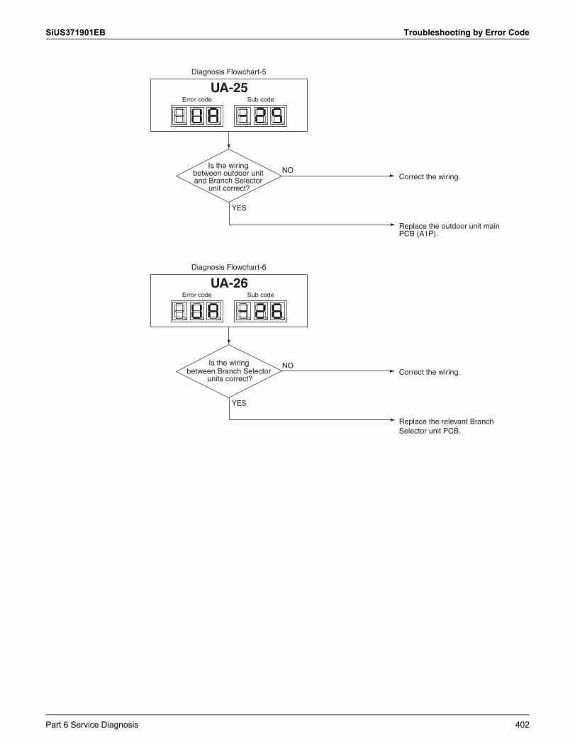
SiUS371901EB Troubleshooting by Error Code
YES
Replace the outdoor unit main PCB (A1P).
NOCorrect the wiring.
Diagnosis Flowchart-5
Is the wiring between outdoor unit and Branch Selector
unit correct?
Error code Sub code
UA-25
YES
Replace the relevant Branch Selector unit PCB.
NOCorrect the wiring.
Diagnosis Flowchart-6
Is the wiring between Branch Selector
units correct?
Error code Sub code
UA-26
Part 6 Service Diagnosis 402
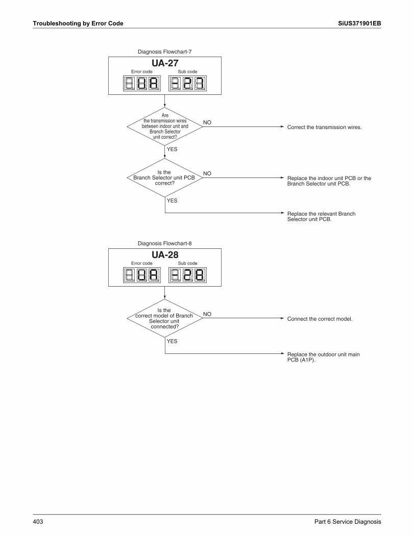
Troubleshooting by Error Code SiUS371901EB
YES
YES
Replace the relevant Branch Selector unit PCB.
NOCorrect the transmission wires.
Diagnosis Flowchart-7
NOReplace the indoor unit PCB or the Branch Selector unit PCB.
Is the Branch Selector unit PCB
correct?
Error code Sub code
UA-27
YES
Replace the outdoor unit main PCB (A1P).
NOConnect the correct model.
Diagnosis Flowchart-8
Is the correct model of Branch
Selector unit connected?
Error code Sub code
UA-28
Are the transmission wires
between indoor unit and Branch Selector
unit correct?
403 Part 6 Service Diagnosis
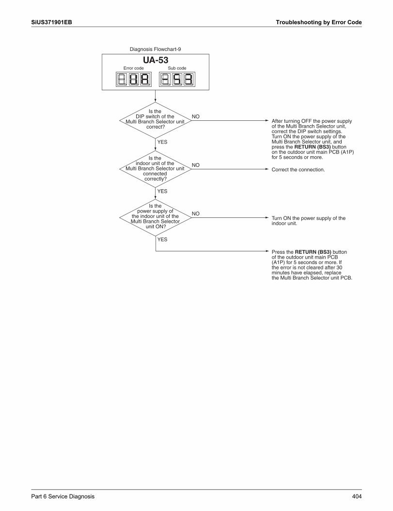
SiUS371901EB Troubleshooting by Error Code
YES
YES
YES
Press the RETURN (BS3) button of the outdoor unit main PCB (A1P) for 5 seconds or more. If the error is not cleared after 30 minutes have elapsed, replace the Multi Branch Selector unit PCB.
NOAfter turning OFF the power supply of the Multi Branch Selector unit, correct the DIP switch settings.Turn ON the power supply of the Multi Branch Selector unit, and press the RETURN (BS3) button on the outdoor unit main PCB (A1P) for 5 seconds or more.
Diagnosis Flowchart-9
Is the DIP switch of the
Multi Branch Selector unit correct?
NOCorrect the connection.
Is the indoor unit of the
Multi Branch Selector unit connected correctly?
NOTurn ON the power supply of the indoor unit.
Is the power supply of
the indoor unit of the Multi Branch Selector
unit ON?
Error code Sub code
UA-53
Part 6 Service Diagnosis 404
Troubleshooting by Error Code SiUS371901EB
3.71 Incorrect Gas Furnace Connecting NumberApplicable Models
CXTQ-TA
Error Code UAOutline Two or more "CXTQ-TA + gas furnace" and other indoor units other than CXTQ-TA are connected.
Error Decision Conditions
Check that two or more "CXTQ-TA + gas furnace" and other indoor units other than CXTQ-TA are not connected.
Operation After Error Codes Decided
The error code UA is displayed on the remote controller. Change to be the system that one "CXTQ-TA + gas furnace" and other indoor units other than
CXTQ-TA are connected.
405 Part 6 Service Diagnosis
SiUS371901EB Troubleshooting by Error Code
3.72 Incorrect Electric Heater Capacity SettingApplicable Models
FXTQ-TA
Error Code UA-17Outline After attaching optional electric heater, if the electric heater capacity setting (11 (21)-5) is made
mistakenly for heaters not featured in the lineup, heating via unintended levels of airflow will be prevented.However, the electric heater will be operable for convenience.
Error Decision Conditions
Checks when the capacity setting (11 (21)-5) of the electric heater has been set to a non-applicable value.
Operation After Error Codes Decided
The error code UA-17 is displayed on the remote controller. Indoor units can operate continuously. Incorrect setting is kept. Even if the ON condition for electric heater 2 is established, only electric heater 1 will be set to
ON.(Electric heater 1 set to ON, electric heater 2 set to OFF)(In order to deliver in terms of user-friendliness and safety, the electric heater can operate at the lowest possible power levels.)
The airflow of the fan during operation of the electric heater will be set to the largest value within the CFM dictated by the capacity of each of the electric heaters (electric heater 1, electric heater 2 both set to ON).
All other operations are the same as during normal operation.
Part 6 Service Diagnosis 406
Troubleshooting by Error Code SiUS371901EB
3.73 Address Duplication of Centralized ControllerApplicable Models
All indoor unit modelsCentralized controller
Error Code UCMethod of Error Detection
The principal indoor unit detects the same address as that of its own on any other indoor unit.
Error Decision Conditions
The error decision is made as soon as the abnormality aforementioned is detected.
Supposed Causes
Address duplication of centralized controller Defective indoor unit PCB
Troubleshooting
Make setting change so that the centralized address will not be duplicated.
The centralized address is duplicated.
CautionBe sure to turn off the power switch before connecting or disconnecting connectors, or parts may be damaged.
407 Part 6 Service Diagnosis
SiUS371901EB Troubleshooting by Error Code
3.74 Transmission Error between Centralized Controller and Indoor Unit
Applicable Models
All indoor unit modelsCentral remote controllerSchedule timerintelligent Touch Controller
Error Code UEMethod of Error Detection
Microcomputer checks if transmission between indoor unit and centralized controller is normal.
Error Decision Conditions
When transmission is not carried out normally for a certain amount of time
Supposed Causes
Transmission error between optional controllers for centralized controller and indoor unit Connector for setting main controller is disconnected.
(or disconnection of connector for independent / combined use changeover switch.) Defective PCB for centralized controller Defective indoor unit PCB
Part 6 Service Diagnosis 408
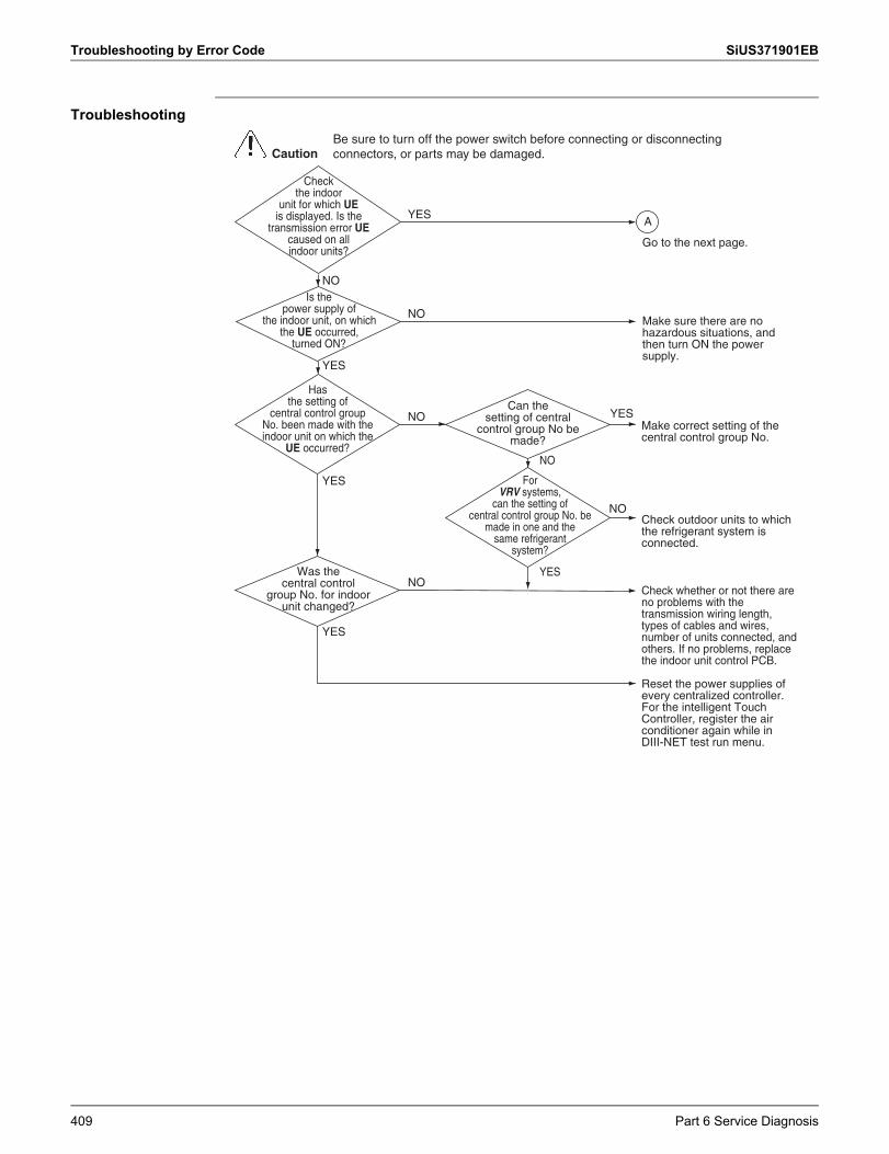
Troubleshooting by Error Code SiUS371901EB
Troubleshooting
Is the power supply of
the indoor unit, on whichthe UE occurred,
turned ON?
ForVRV systems,
can the setting ofcentral control group No. be
made in one and the same refrigerant
system?
Hasthe setting of
central control group No. been made with the indoor unit on which the
UE occurred?
Can the setting of central
control group No be made?
Checkthe indoor
unit for which UEis displayed. Is the
transmission error UE caused on allindoor units?
Was the central control
group No. for indoorunit changed?
Make correct setting of the central control group No.
Check outdoor units to which the refrigerant system is connected.
Check whether or not there are no problems with the transmission wiring length, types of cables and wires, number of units connected, and others. If no problems, replace the indoor unit control PCB.
NO
YES
YES
NO
NO
YES
Make sure there are no hazardous situations, and then turn ON the power supply.
NO
NO
YES
YES
NO
YES
Reset the power supplies of every centralized controller.For the intelligent Touch Controller, register the air conditioner again while in DIII-NET test run menu.
CautionBe sure to turn off the power switch before connecting or disconnecting connectors, or parts may be damaged.
A
Go to the next page.
409 Part 6 Service Diagnosis
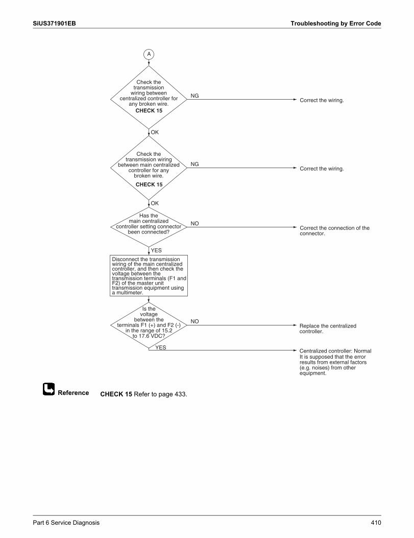
SiUS371901EB Troubleshooting by Error Code
Reference CHECK 15 Refer to page 433.
Check the transmission
wiring between centralized controller for
any broken wire.
Is the voltage
between theterminals F1 (+) and F2 (-)
in the range of 15.2 to 17.6 VDC?
Check the transmission wiring
between main centralized controller for any
broken wire.
Replace the centralized controller.
Centralized controller: Normal
OK
Correct the wiring.NG
A
NO
Correct the wiring.NG
YES
YES
Disconnect the transmission wiring of the main centralized controller, and then check the voltage between the transmission terminals (F1 and F2) of the master unit transmission equipment using a multimeter.
It is supposed that the error results from external factors (e.g. noises) from other equipment.
CHECK 15
CHECK 15
Has the main centralized
controller setting connector been connected?
OK
Correct the connection of the connector.
NO
Part 6 Service Diagnosis 410
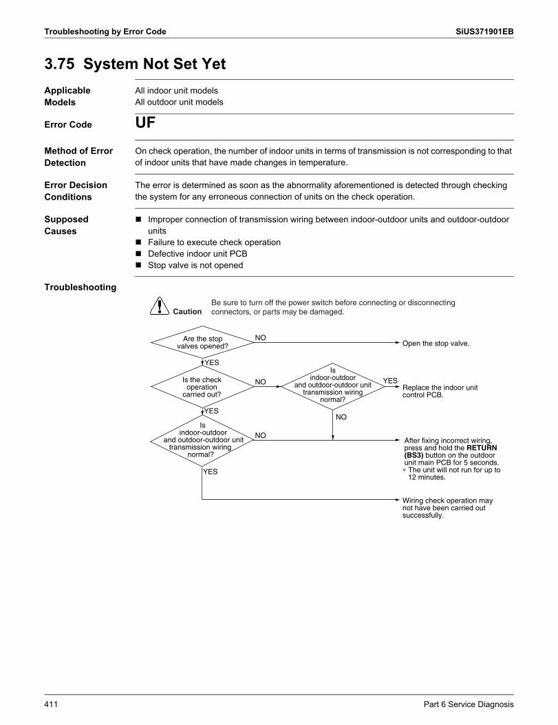
Troubleshooting by Error Code SiUS371901EB
3.75 System Not Set YetApplicable Models
All indoor unit modelsAll outdoor unit models
Error Code UFMethod of Error Detection
On check operation, the number of indoor units in terms of transmission is not corresponding to that of indoor units that have made changes in temperature.
Error Decision Conditions
The error is determined as soon as the abnormality aforementioned is detected through checking the system for any erroneous connection of units on the check operation.
Supposed Causes
Improper connection of transmission wiring between indoor-outdoor units and outdoor-outdoor units
Failure to execute check operation Defective indoor unit PCB Stop valve is not opened
Troubleshooting
Is indoor-outdoor
and outdoor-outdoor unit transmission wiring
normal?
Is indoor-outdoor
and outdoor-outdoor unit transmission wiring
normal?
Replace the indoor unit control PCB.
Wiring check operation may not have been carried out successfully.
After fixing incorrect wiring, press and hold the RETURN (BS3) button on the outdoor unit main PCB for 5 seconds.∗ The unit will not run for up to
12 minutes.YES
NOYES
NO
NO
YESIs the check operation
carried out?
Open the stop valve.
YES
NOAre the stop valves opened?
CautionBe sure to turn off the power switch before connecting or disconnecting connectors, or parts may be damaged.
411 Part 6 Service Diagnosis
SiUS371901EB Troubleshooting by Error Code
3.76 System Abnormality, Refrigerant System Address Undefined
Applicable Models
All indoor unit modelsAll outdoor unit models
Error Code UHMethod of Error Detection
System detects an indoor unit whose address is not defined by automatic address function.*Automatic address refers to the automatic designated address of indoor unit and outdoor unit when connected to the power after installation or wiring replacement (with the RETURN (BS3) button pressed for more than 5 seconds).
Error Decision Conditions
The error decision is made as soon as the abnormality aforementioned is detected.
Supposed Causes
Improper connection of transmission wiring between indoor-outdoor units and outdoor-outdoor units
Defective indoor unit PCB Defective outdoor unit main PCB (A1P)
Part 6 Service Diagnosis 412
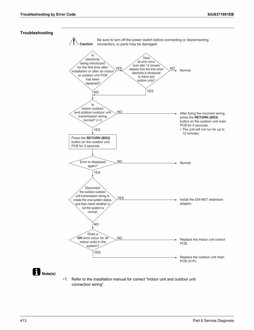
Troubleshooting by Error Code SiUS371901EB
Note(s)
Troubleshooting
Is indoor-outdoor
and outdoor-outdoor unit transmission wiring
normal? (1)
Error is displayed again?
Is electricity
being introduced for the first time after
installation or after an indoor or outdoor unit PCB
has been replaced?
Does an error occur
even after 12 minutes elapses from the time when
electricity is introduced to indoor and outdoor units?
NO
Replace the indoor unit control PCB.
Does a UH error occur for all
indoor units in the system?
NO
After fixing the incorrect wiring, press the RETURN (BS3) button on the outdoor unit main PCB for 5 seconds. The unit will not run for up to
12 minutes.
NO
NO
Install the DIII-NET extension adaptor.
YES
YES
NO
NormalNO
Press the RETURN (BS3) button on the outdoor unit PCB for 5 seconds.
YES
YES
NormalYES
Replace the outdoor unit main PCB (A1P).
YES
Disconnect the outdoor-outdoor
unit transmission wiring to create the one-system status,
and then check whether or not the system is
normal.
CautionBe sure to turn off the power switch before connecting or disconnecting connectors, or parts may be damaged.
∗1. Refer to the installation manual for correct "indoor unit and outdoor unit connection wiring”.
413 Part 6 Service Diagnosis
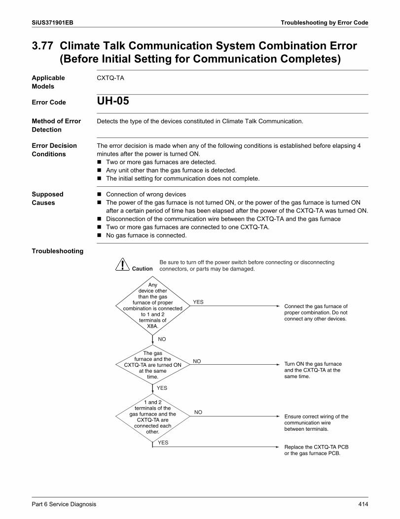
SiUS371901EB Troubleshooting by Error Code
3.77 Climate Talk Communication System Combination Error (Before Initial Setting for Communication Completes)
Applicable Models
CXTQ-TA
Error Code UH-05Method of Error Detection
Detects the type of the devices constituted in Climate Talk Communication.
Error Decision Conditions
The error decision is made when any of the following conditions is established before elapsing 4 minutes after the power is turned ON. Two or more gas furnaces are detected. Any unit other than the gas furnace is detected. The initial setting for communication does not complete.
Supposed Causes
Connection of wrong devices The power of the gas furnace is not turned ON, or the power of the gas furnace is turned ON
after a certain period of time has been elapsed after the power of the CXTQ-TA was turned ON. Disconnection of the communication wire between the CXTQ-TA and the gas furnace Two or more gas furnaces are connected to one CXTQ-TA. No gas furnace is connected.
Troubleshooting
YES
CautionBe sure to turn off the power switch before connecting or disconnecting connectors, or parts may be damaged.
The gas furnace and the
CXTQ-TA are turned ON at the same
time.
YES
YES
NO
NO
NO
1 and 2 terminals of the
gas furnace and the CXTQ-TA are
connected each other.
Replace the CXTQ-TA PCB or the gas furnace PCB.
Turn ON the gas furnace and the CXTQ-TA at the same time.
Connect the gas furnace of proper combination. Do not connect any other devices.
Ensure correct wiring of the communication wire between terminals.
Any device other than the gas
furnace of proper combination is connected
to 1 and 2 terminals of
X8A.
Part 6 Service Diagnosis 414
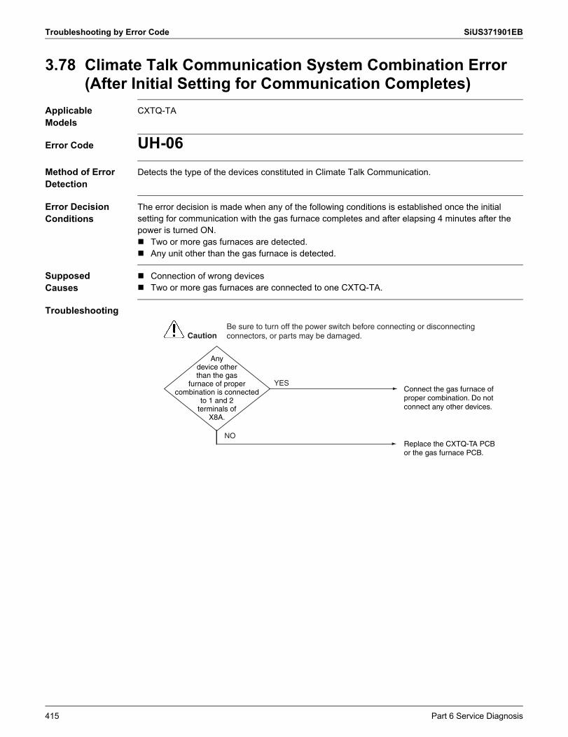
Troubleshooting by Error Code SiUS371901EB
3.78 Climate Talk Communication System Combination Error (After Initial Setting for Communication Completes)
Applicable Models
CXTQ-TA
Error Code UH-06Method of Error Detection
Detects the type of the devices constituted in Climate Talk Communication.
Error Decision Conditions
The error decision is made when any of the following conditions is established once the initial setting for communication with the gas furnace completes and after elapsing 4 minutes after the power is turned ON. Two or more gas furnaces are detected. Any unit other than the gas furnace is detected.
Supposed Causes
Connection of wrong devices Two or more gas furnaces are connected to one CXTQ-TA.
Troubleshooting
YES
CautionBe sure to turn off the power switch before connecting or disconnecting connectors, or parts may be damaged.
NOReplace the CXTQ-TA PCB or the gas furnace PCB.
Connect the gas furnace of proper combination. Do not connect any other devices.
Any device other than the gas
furnace of proper combination is connected
to 1 and 2 terminals of
X8A.
415 Part 6 Service Diagnosis
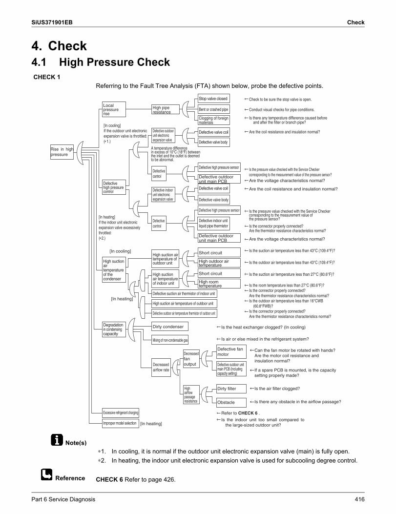
SiUS371901EB Check
Note(s)
Reference
4. Check4.1 High Pressure Check
Referring to the Fault Tree Analysis (FTA) shown below, probe the defective points.
CHECK 6 Refer to page 426.
CHECK 1
Short circuit
Rise in high pressure
Local pressure rise
High pipe resistance
Stop valve closed
Bent or crashed pipe
Clogging of foreign materials
[In cooling] If the outdoor unit electronic expansion valve is throttled: (1.)
Defective outdoor unit electronic expansion valve
Defective indoor unit electronic expansion valve
Defective valve coil
Defective valve bodyA temperature difference in excess of 10°C (18°F) between the inlet and the outlet is deemed to be abnormal.
Defective control
Defective high pressure sensor
Defective outdoor unit main PCB Defective
high pressure control
Defective valve coil
Defective valve body
[In heating] If the indoor unit electronic expansion valve excessively throttled: (2.)
Defective control
Defective high pressure sensor
Defective indoor unit liquid pipe thermistor
[In cooling]
High suction air temperature of the condenser
[In heating]
High suction air temperature of outdoor unit
Short circuit
High outdoor air temperature
High suction air temperature of indoor unit High room
temperature
Defective suction air thermistor of indoor unit
High suction air temperature of outdoor unit
Defective outdoor air temperature thermistor of outdoor unit
Degradation in condensing capacity
Dirty condenser
Mixing of non-condensable gas
Decreased airflow rate
Decreased fan output
Defective fan motor
Defective outdoor unit main PCB (Including capacity setting)
High airflow passage resistance
Dirty filter
Obstacle
Excessive refrigerant charging
Improper model selection [In heating]
Check to be sure the stop valve is open.
Conduct visual checks for pipe conditions.
Is there any temperature difference caused before and after the filter or branch pipe?
Are the coil resistance and insulation normal?
Is the pressure value checked with the Service Checkercorresponding to the measurement value of the pressure sensor?Are the voltage characteristics normal?
Are the coil resistance and insulation normal?
Is the connector properly connected?Are the thermistor resistance characteristics normal?
Is the suction air temperature less than 43°C (109.4°F)?
Is the outdoor air temperature less than 43°C (109.4°F)?
Is the suction air temperature less than 27°C (80.6°F)?
Is the room temperature less than 27°C (80.6°F)?Is the connector properly connected?Are the thermistor resistance characteristics normal?Is the outdoor air temperature less than 16°CWB
(60.8°FWB)?Is the connector properly connected?Are the thermistor resistance characteristics normal?
Is the heat exchanger clogged? (In cooling)
Is air or else mixed in the refrigerant system?
Can the fan motor be rotated with hands?Are the motor coil resistance and insulation normal?
If a spare PCB is mounted, is the capacitysetting properly made?
Is the air filter clogged?
Is there any obstacle in the airflow passage?
Refer to CHECK 6 .
Is the indoor unit too small compared to the large-sized outdoor unit?
Defective outdoor unit main PCB
Is the pressure value checked with the Service Checkercorresponding to the measurement value ofthe pressure sensor?
Are the voltage characteristics normal?
∗1. In cooling, it is normal if the outdoor unit electronic expansion valve (main) is fully open.∗2. In heating, the indoor unit electronic expansion valve is used for subcooling degree control.
Part 6 Service Diagnosis 416
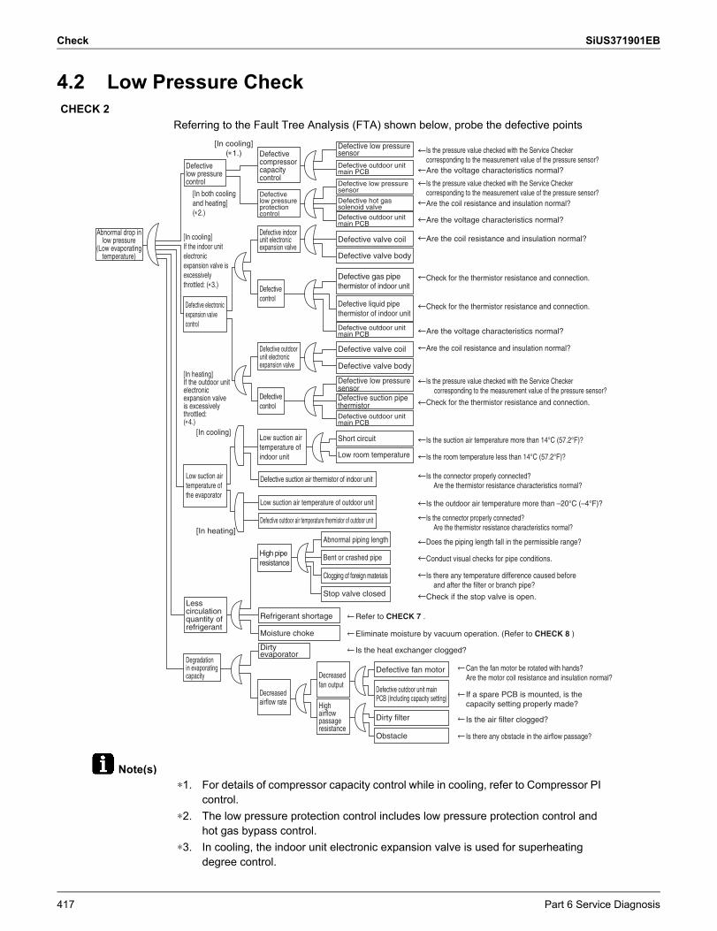
Check SiUS371901EB
Note(s)
4.2 Low Pressure Check
Referring to the Fault Tree Analysis (FTA) shown below, probe the defective pointsCHECK 2
Abnormal drop in low pressure
(Low evaporating temperature)
[In cooling] (1.)
Defective low pressure control
Defective compressor capacity control
Defective low pressure sensor
Defective outdoor unit main PCB
Defective outdoor unit main PCB
Defective outdoor unit main PCB
Defective outdoor unit main PCB
Defective low pressure protection control
Defective low pressure sensor
Defective hot gas solenoid valve
[In both cooling and heating] (2.)
[In cooling] If the indoor unit electronic expansion valve is excessively throttled: (3.)
Defective indoor unit electronic expansion valve
Defective valve coil
Defective valve body
Defective control
Defective gas pipe thermistor of indoor unit
Defective liquid pipe thermistor of indoor unit
Defective outdoor unit electronic expansion valve
Defective valve coil
Defective valve body[In heating] If the outdoor unit electronic expansion valve is excessively throttled:(4.)
Defective control
Defective low pressure sensorDefective suction pipe thermistor
[In cooling]
Low suction air temperature of the evaporator
[In heating]
Low suction air temperature of indoor unit
Short circuit
Low room temperature
Defective suction air thermistor of indoor unit
Low suction air temperature of outdoor unit
Defective outdoor air temperature thermistor of outdoor unit
High pipe resistance
Abnormal piping length
Bent or crashed pipe
Clogging of foreign materials
Stop valve closedLess circulation quantity of refrigerant
Degradation in evaporating capacity
Refrigerant shortage
Moisture choke
Dirty evaporator
Decreased airflow rate
Decreased fan output
Defective fan motor Can the fan motor be rotated with hands?Are the motor coil resistance and insulation normal?
If a spare PCB is mounted, is the capacity setting properly made?
Is the air filter clogged?
Is there any obstacle in the airflow passage?
Defective outdoor unit main PCB (Including capacity setting)
High airflow passage resistance
Dirty filter
Obstacle
Defective electronic expansion valve control
Is the pressure value checked with the Service Checkercorresponding to the measurement value of the pressure sensor?Are the voltage characteristics normal?
Is the pressure value checked with the Service Checkercorresponding to the measurement value of the pressure sensor?Are the coil resistance and insulation normal?
Are the voltage characteristics normal?
Are the coil resistance and insulation normal?
Check for the thermistor resistance and connection.
Check for the thermistor resistance and connection.
Are the voltage characteristics normal?
Are the coil resistance and insulation normal?
Is the pressure value checked with the Service Checker corresponding to the measurement value of the pressure sensor?
Check for the thermistor resistance and connection.
Is the suction air temperature more than 14°C (57.2°F)?
Is the room temperature less than 14°C (57.2°F)?
Is the connector properly connected?Are the thermistor resistance characteristics normal?
Is the outdoor air temperature more than –20°C (–4°F)?
Is the connector properly connected?Are the thermistor resistance characteristics normal?
Does the piping length fall in the permissible range?
Conduct visual checks for pipe conditions.
Is there any temperature difference caused before and after the filter or branch pipe?
Check if the stop valve is open.
Refer to CHECK 7 .
Eliminate moisture by vacuum operation. (Refer to CHECK 8 )
Is the heat exchanger clogged?
∗1. For details of compressor capacity control while in cooling, refer to Compressor PI control.
∗2. The low pressure protection control includes low pressure protection control and hot gas bypass control.
∗3. In cooling, the indoor unit electronic expansion valve is used for superheating degree control.
417 Part 6 Service Diagnosis
SiUS371901EB Check
Reference
Reference
CHECK 7 Refer to page 427.
CHECK 8 Refer to page 428.
∗4. In heating, the outdoor unit electronic expansion valve (main) is used for superheating degree control of outdoor heat exchanger.
Part 6 Service Diagnosis 418
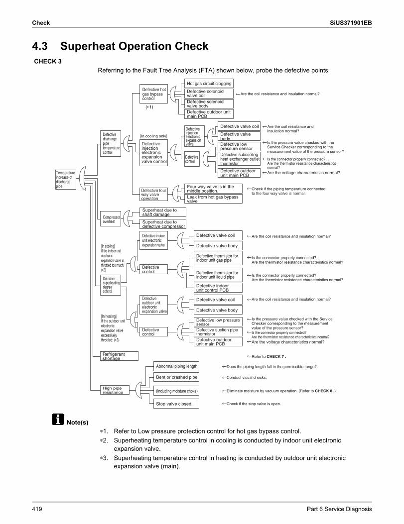
Check SiUS371901EB
Note(s)
4.3 Superheat Operation Check
Referring to the Fault Tree Analysis (FTA) shown below, probe the defective pointsCHECK 3
Abnormal piping length
Bent or crashed pipe
(Including moisture choke)
Stop valve closed.
Defective valve coil
Defective valve body
Defective valve coil
Defective valve body
Are the coil resistance and insulation normal?
Refer to CHECK 7 .
Does the piping length fall in the permissible range?
Conduct visual checks.
Eliminate moisture by vacuum operation. (Refer to CHECK 8 .)
Check if the stop valve is open.
Defective discharge pipe temperature control
Defective hot gas bypass control
Hot gas circuit clogging
Defective solenoid valve coilDefective solenoid valve bodyDefective outdoor unit main PCB
Defective outdoor unit main PCB
Defective valve coil
Defective low pressure sensorDefective subcooling heat exchanger outlet thermistor
Defective valve body
Defective injection electronic expansion valve control
Superheat due to shaft damage
Superheat due to defective compressor
Defective indoor unit electronic expansion valve
Defective control
Defective control
Defective outdoor unit electronic expansion valve
Defective four way valve operation
[In cooling only]
(1)
Compressor overheat
Refrigerant shortage
High pipe resistance
Defective superheating degree control.
[In cooling] If the indoor unit electronic expansion valve is throttled too much: (2)
[In heating] If the outdoor unit electronic expansion valve excessively throttled: (3)
Temperature increase of discharge pipe
Defective injection electronic expansion valve
Are the coil resistance andinsulation normal?
Is the connector properly connected?Are the thermistor resistance characteristics normal?Are the voltage characteristics normal?
Is the pressure value checked with theService Checker corresponding to themeasurement value of the pressure sensor?
Check if the piping temperature connected to the four way valve is normal.
Four way valve is in the middle position.Leak from hot gas bypass valve
Defective control
Defective thermistor for indoor unit gas pipe
Defective thermistor for indoor unit liquid pipe
Defective indoor unit control PCB
Defective low pressure sensorDefective suction pipe thermistorDefective outdoor unit main PCB Are the voltage characteristics normal?
Is the pressure value checked with the ServiceChecker corresponding to the measurementvalue of the pressure sensor?Is the connector properly connected? Are the thermistor resistance characteristics normal?
Is the connector properly connected?Are the thermistor resistance characteristics normal?
Are the coil resistance and insulation normal?
Are the coil resistance and insulation normal?
Is the connector properly connected?Are the thermistor resistance characteristics normal?
∗1. Refer to Low pressure protection control for hot gas bypass control.∗2. Superheating temperature control in cooling is conducted by indoor unit electronic
expansion valve.∗3. Superheating temperature control in heating is conducted by outdoor unit electronic
expansion valve (main).
419 Part 6 Service Diagnosis
SiUS371901EB Check
Reference
Reference
CHECK 7 Refer to page 427.
CHECK 8 Refer to page 428.
∗4. Judgment criteria of superheat operation: (1) Suction gas superheating degree: 10°C (18°F) and over. (2) Discharge gas superheating degree: 45°C (81°F) and over, except immediately after compressor starts up or is running under dropping control. (Use the above values as a guide. Depending on the other conditions, the unit may be normal despite the values within the above range.)
Part 6 Service Diagnosis 420
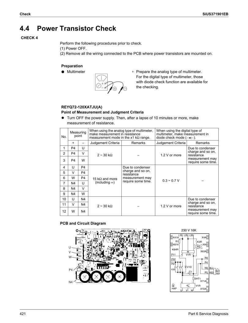
Check SiUS371901EB
4.4 Power Transistor Check
Perform the following procedures prior to check.(1) Power OFF.(2) Remove all the wiring connected to the PCB where power transistors are mounted on.
PCB and Circuit Diagram
CHECK 4
Preparationh Multimeter ∗ Prepare the analog type of multimeter.
For the digital type of multimeter, those with diode check function are available for the checking.
REYQ72-120XATJU(A) Point of Measurement and Judgment Criteria Turn OFF the power supply. Then, after a lapse of 10 minutes or more, make
measurement of resistance.
No.Measuring
pointWhen using the analog type of multimeter, make measurement in resistance measurement mode in the x1 kΩ range.
When using the digital type of multimeter, make measurement in diode check mode ( ).
+ – Judgement Criteria Remarks Judgement Criteria Remarks1 P4 U
2 ~ 30 kΩ – 1.2 V or more
Due to condenser charge and so on, resistance measurement mayrequire some time.
2 P4 V
3 P4 W
4 U P4
15 kΩ and more (including ∞)
Due to condenser charge and so on, resistance measurement may require some time. 0.3 ~ 0.7 V –
5 V P46 W P47 N4 U8 N4 V9 N4 W10 U N4
2 ~ 30 kΩ – 1.2 V or more
Due to condenser charge and so on, resistance measurement mayrequire some time.
11 V N4
12 W N4
V1R
L3B
P22
PS
X41A
V1R
N5V1D
SHT1
L2B
K1M
R1
V
+
X72A
WHT
X63A
L1B
-
X6AC1
P21
W
BLU
X4A
HAP
X601A
U
K3R
+
K84R
X71A
P11 –
P4
+
X6A
N4
P5 RED
230 V 16K
N4
U
V
W
P4
421 Part 6 Service Diagnosis
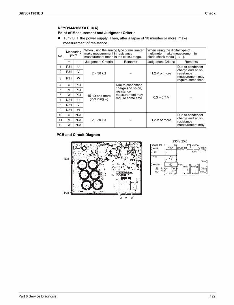
SiUS371901EB Check
PCB and Circuit Diagram
REYQ144/168XATJU(A)Point of Measurement and Judgment Criteria Turn OFF the power supply. Then, after a lapse of 10 minutes or more, make
measurement of resistance.
No.Measuring
pointWhen using the analog type of multimeter, make measurement in resistance measurement mode in the x1 kΩ range.
When using the digital type of multimeter, make measurement in diode check mode ( ).
+ – Judgement Criteria Remarks Judgement Criteria Remarks1 P31 U
2 ~ 30 kΩ – 1.2 V or more
Due to condenser charge and so on, resistance measurement may require some time.
2 P31 V
3 P31 W
4 U P31
15 kΩ and more (including ∞)
Due to condenser charge and so on, resistance measurement may require some time. 0.3 ~ 0.7 V –
5 V P316 W P317 N31 U8 N31 V9 N31 W10 U N31
2 ~ 30 kΩ – 1.2 V or moreDue to condenser charge and so on, resistance measurement may
11 V N3112 W N31
X8A
X900A
X4A
K5R
V2R
K84RN
T3AN=1
WV
R72TX6A
+-
R71T
X903A
T2AN=1
PS
X7A
R1
X63A
X601A
C1
+
U
P31
V1D
HAP
N31
X41A
t˚ t˚
P
230 V 25K
U V W
N31
P31
Part 6 Service Diagnosis 422
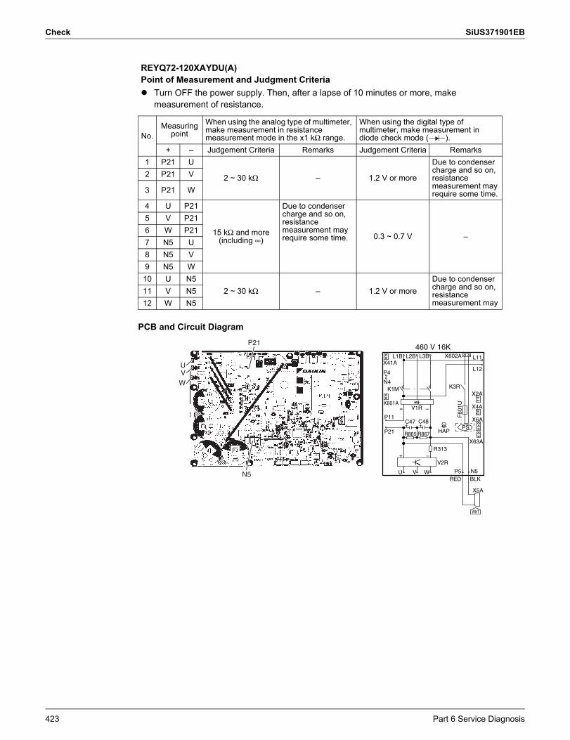
Check SiUS371901EB
PCB and Circuit Diagram
REYQ72-120XAYDU(A)Point of Measurement and Judgment Criteria Turn OFF the power supply. Then, after a lapse of 10 minutes or more, make
measurement of resistance.
No.Measuring
pointWhen using the analog type of multimeter, make measurement in resistance measurement mode in the x1 kΩ range.
When using the digital type of multimeter, make measurement in diode check mode ( ).
+ – Judgement Criteria Remarks Judgement Criteria Remarks1 P21 U
2 ~ 30 kΩ – 1.2 V or more
Due to condenser charge and so on, resistance measurement may require some time.
2 P21 V
3 P21 W
4 U P21
15 kΩ and more (including ∞)
Due to condenser charge and so on, resistance measurement may require some time. 0.3 ~ 0.7 V –
5 V P216 W P217 N5 U8 N5 V9 N5 W10 U N5
2 ~ 30 kΩ – 1.2 V or moreDue to condenser charge and so on, resistance measurement may
11 V N512 W N5
R867
V2R
C47
X41A
C48
HAP+
P11
X601A
BLK
X2A
N5
X5A
X4A
–F
601U
+
RED
+
L11
WHT
L12
+ PS
K3R
L3BL2B
V
R865
P4
X602A
N4
X63A
K1M
–
P5U
V1R
L1B
R313
P21
W
X6A
460 V 16K
UVW
N5
P21
423 Part 6 Service Diagnosis
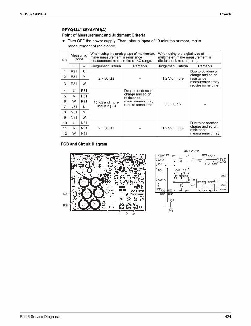
SiUS371901EB Check
PCB and Circuit Diagram
REYQ144/168XAYDU(A)Point of Measurement and Judgment Criteria Turn OFF the power supply. Then, after a lapse of 10 minutes or more, make
measurement of resistance.
No.Measuring
pointWhen using the analog type of multimeter, make measurement in resistance measurement mode in the x1 kΩ range.
When using the digital type of multimeter, make measurement in diode check mode ( ).
+ – Judgement Criteria Remarks Judgement Criteria Remarks1 P31 U
2 ~ 30 kΩ – 1.2 V or more
Due to condenser charge and so on, resistance measurement may require some time.
2 P31 V
3 P31 W
4 U P31
15 kΩ and more (including ∞)
Due to condenser charge and so on, resistance measurement may require some time. 0.3 ~ 0.7 V –
5 V P316 W P317 N31 U8 N31 V9 N31 W10 U N31
2 ~ 30 kΩ – 1.2 V or moreDue to condenser charge and so on, resistance measurement may
11 V N3112 W N31
X6A
N
+
UX63A
R72T
R1
R401
C51
W
PS
X900A
+
t˚
C48
RED
P31
V2R
N32 V
P
P32
K3RF1U
X904A
HAP
X41A
t˚
X4A
WHT
X7A
X601A
R133
+
–
V1D
R71T
R131
K84R
X8A
BLK
X5A
N31
460 V 25K
U V W
N31
P31
Part 6 Service Diagnosis 424
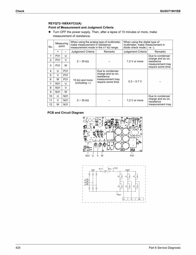
Check SiUS371901EB
PCB and Circuit Diagram
REYQ72-168XAYCU(A)Point of Measurement and Judgment Criteria Turn OFF the power supply. Then, after a lapse of 10 minutes or more, make
measurement of resistance.
No.Measuring
pointWhen using the analog type of multimeter, make measurement in resistance measurement mode in the x1 kΩ range.
When using the digital type of multimeter, make measurement in diode check mode ( ).
+ – Judgement Criteria Remarks Judgement Criteria Remarks1 P31 U
2 ~ 30 kΩ – 1.2 V or more
Due to condenser charge and so on, resistance measurement may require some time.
2 P31 V
3 P31 W
4 U P31
15 kΩ and more (including ∞)
Due to condenser charge and so on, resistance measurement may require some time. 0.3 ~ 0.7 V –
5 V P316 W P317 N31 U8 N31 V9 N31 W10 U N31
2 ~ 30 kΩ – 1.2 V or moreDue to condenser charge and so on, resistance measurement may
11 V N3112 W N31
P11 P21 IGBT
U V W
L1BL2BL3B
DMP31
N31
P31U V WN31
425 Part 6 Service Diagnosis
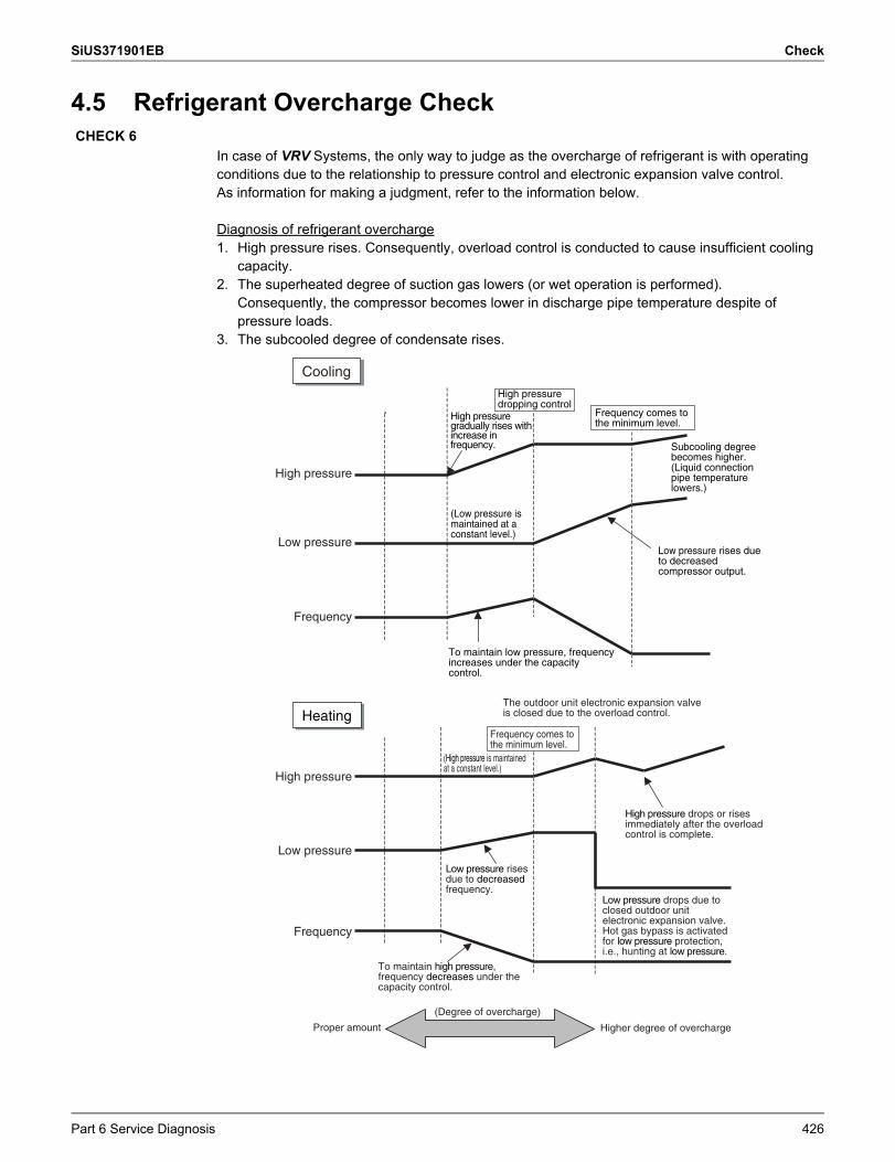
SiUS371901EB Check
4.5 Refrigerant Overcharge Check
In case of VRV Systems, the only way to judge as the overcharge of refrigerant is with operating conditions due to the relationship to pressure control and electronic expansion valve control.As information for making a judgment, refer to the information below.
Diagnosis of refrigerant overcharge1. High pressure rises. Consequently, overload control is conducted to cause insufficient cooling
capacity.2. The superheated degree of suction gas lowers (or wet operation is performed).
Consequently, the compressor becomes lower in discharge pipe temperature despite of pressure loads.
3. The subcooled degree of condensate rises.
CHECK 6
Cooling
High pressure
Low pressure
Frequency
High pressure gradually rises with increase in frequency. Subcooling degree
becomes higher. (Liquid connection pipe temperature lowers.)
Low pressure rises due to decreased compressor output.
High pressure
Low pressure
Frequency
HeatingThe outdoor unit electronic expansion valve is closed due to the overload control.
Frequency comes to the minimum level.
(High pressure is maintained at a constant level.)
Low pressure rises due to decreased frequency.
To maintain high pressure, frequency decreases under the capacity control.
High pressure drops or rises immediately after the overload control is complete.
Low pressure drops due to closed outdoor unit electronic expansion valve. Hot gas bypass is activated for low pressure protection, i.e., hunting at low pressure.
Higher degree of overcharge
(Degree of overcharge)
Proper amount
To maintain low pressure, frequency increases under the capacity control.
Frequency comes to the minimum level.
High pressure dropping control
(Low pressure is maintained at a constant level.)
Part 6 Service Diagnosis 426
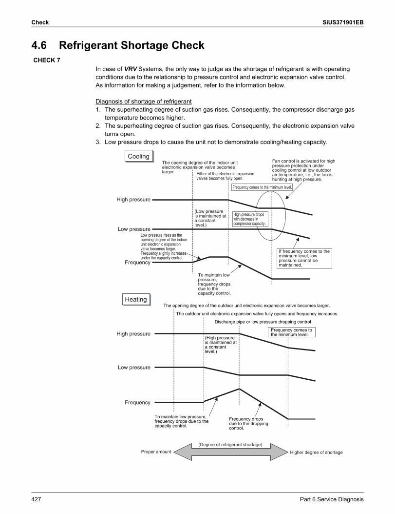
Check SiUS371901EB
4.6 Refrigerant Shortage Check
In case of VRV Systems, the only way to judge as the shortage of refrigerant is with operating conditions due to the relationship to pressure control and electronic expansion valve control.As information for making a judgement, refer to the information below.
Diagnosis of shortage of refrigerant1. The superheating degree of suction gas rises. Consequently, the compressor discharge gas
temperature becomes higher.2. The superheating degree of suction gas rises. Consequently, the electronic expansion valve
turns open.3. Low pressure drops to cause the unit not to demonstrate cooling/heating capacity.
CHECK 7
Cooling
High pressure
Low pressure
Frequency
The opening degree of the indoor unit electronic expansion valve becomes larger. Either of the electronic expansion
valves becomes fully open.
Frequency comes to the minimum level.
Fan control is activated for high pressure protection under cooling control at low outdoor air temperature, i.e., the fan is hunting at high pressure.
High pressure drops with decrease in compressor capacity.
If frequency comes to the minimum level, low pressure cannot be maintained.
Low pressure rises as the opening degree of the indoor unit electronic expansion valve becomes larger. Frequency slightly increases under the capacity control.
To maintain low pressure, frequency drops due to the capacity control.
Heating
High pressure
Low pressure
Frequency
The opening degree of the outdoor unit electronic expansion valve becomes larger.
The outdoor unit electronic expansion valve fully opens and frequency increases.
Discharge pipe or low pressure dropping control
(High pressure is maintained at a constant level.)
To maintain low pressure, frequency drops due to the capacity control.
Frequency drops due to the dropping control.
(Degree of refrigerant shortage)
Higher degree of shortageProper amount
(Low pressure is maintained at a constant level.)
Frequency comes to the minimum level.
427 Part 6 Service Diagnosis
SiUS371901EB Check
4.7 Vacuuming and Dehydration Procedure
Conduct vacuuming and dehydration in the piping system following the procedure for Normal vacuuming and dehydration described below.Furthermore, if moisture may get mixed in the piping system, follow the procedure for Special vacuuming and dehydration described below.
Normal vacuuming and dehydration1. Vacuuming and dehydration Use a vacuum pump that enables vacuuming up to –100.7 kPaG (–14.6 psiG, 5 Torr, –755
mmHgG). Connect manifold gauges to the service ports of liquid pipe and gas pipe and run the
vacuum pump for a period of 2 or more hours to conduct evacuation to –100.7 kPaG (–14.6 psiG) or less.
If the degree of vacuum does not reach –100.7 kPaG (–14.6 psiG) or less even though evacuation is conducted for a period of 2 hours, moisture will have entered the system or refrigerant leakage will have been caused. In this case, conduct evacuation for a period of another 1 hour.
If the degree of vacuum does not reach –100.7 kPaG (–14.6 psiG) or less even though evacuation is conducted for a period of 3 hours, conduct the leak tests.
2. Leaving in vacuum state Leave the compressor at the degree of vacuum of –100.7 kPaG (–14.6 psiG) or less for a
period of 1 hour or more, and then check to be sure that the vacuum gauge reading does not rise. (If the reading rises, moisture may have remained in the system or refrigerant leakage may have been caused.)
3. Additional refrigerant charge Purge air from the manifold gauge connection hoses, and then charge a necessary amount
of refrigerant.
Special vacuuming and dehydrationUse this procedure if moisture may get into the piping, such as construction during the rainy season (dew condensation may occur, or rainwater may enter the piping during construction work).1. Vacuuming and dehydration Follow the same procedure as that for normal vacuuming and dehydration described above.
2. Vacuum break Pressurize with nitrogen gas up to 0.05 MPaG (7.3 psiG).
3. Vacuuming and dehydration Conduct vacuuming and dehydration for a period of 1 hour or more. If the degree of vacuum
does not reach –100.7 kPaG (–14.6 psiG) or less even though evacuation is conducted for a period of 2 hours or more, repeat vacuum break - vacuuming and dehydration.
4. Leaving in vacuum state Leave the compressor at the degree of vacuum of –100.7 kPaG (–14.6 psiG) or less for a
period of 1 hour or more, and then check to be sure that the vacuum gauge reading does not rise.
5. Additional refrigerant charge Purge air from the manifold gauge connection hoses, and then charge a necessary amount
of refrigerant.
CHECK 8
Part 6 Service Diagnosis 428
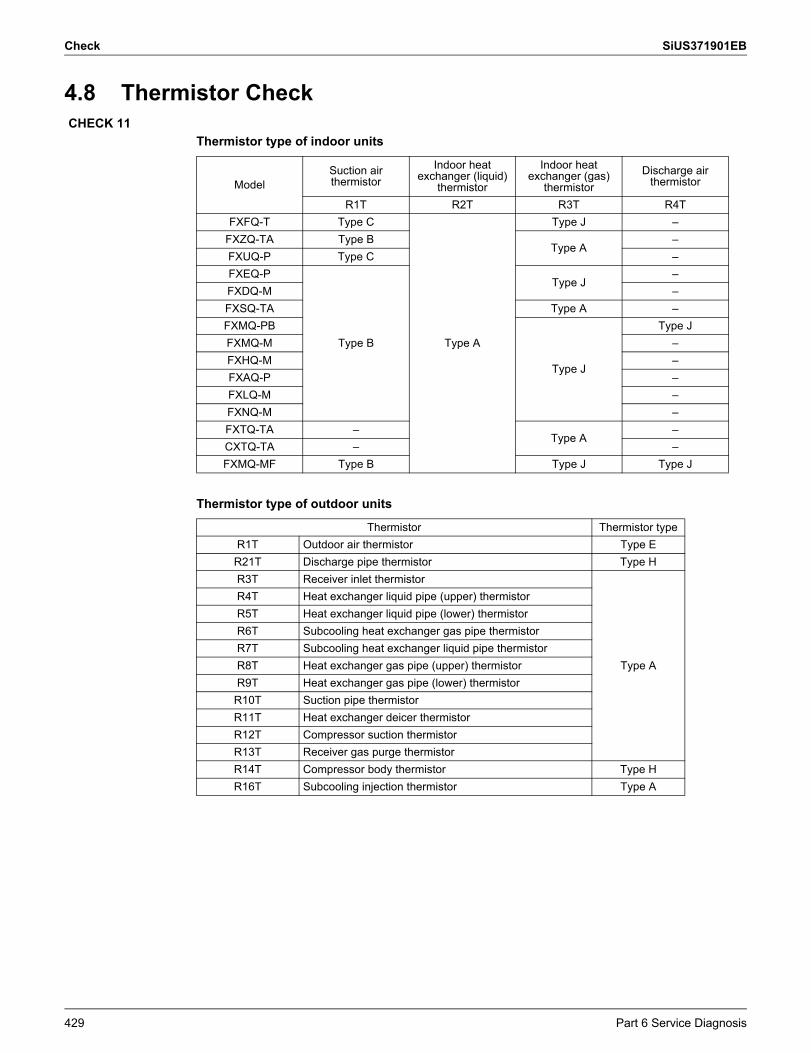
Check SiUS371901EB
4.8 Thermistor Check
Thermistor type of indoor units
Thermistor type of outdoor units
CHECK 11
ModelSuction air thermistor
Indoor heat exchanger (liquid)
thermistor
Indoor heat exchanger (gas)
thermistorDischarge air
thermistor
R1T R2T R3T R4TFXFQ-T Type C
Type A
Type J –FXZQ-TA Type B
Type A–
FXUQ-P Type C –FXEQ-P
Type B
Type J–
FXDQ-M –FXSQ-TA Type A –FXMQ-PB
Type J
Type JFXMQ-M –FXHQ-M –FXAQ-P –FXLQ-M –FXNQ-M –FXTQ-TA –
Type A–
CXTQ-TA – –FXMQ-MF Type B Type J Type J
Thermistor Thermistor typeR1T Outdoor air thermistor Type ER21T Discharge pipe thermistor Type HR3T Receiver inlet thermistor
Type A
R4T Heat exchanger liquid pipe (upper) thermistorR5T Heat exchanger liquid pipe (lower) thermistorR6T Subcooling heat exchanger gas pipe thermistorR7T Subcooling heat exchanger liquid pipe thermistorR8T Heat exchanger gas pipe (upper) thermistorR9T Heat exchanger gas pipe (lower) thermistorR10T Suction pipe thermistorR11T Heat exchanger deicer thermistorR12T Compressor suction thermistorR13T Receiver gas purge thermistorR14T Compressor body thermistor Type HR16T Subcooling injection thermistor Type A
429 Part 6 Service Diagnosis
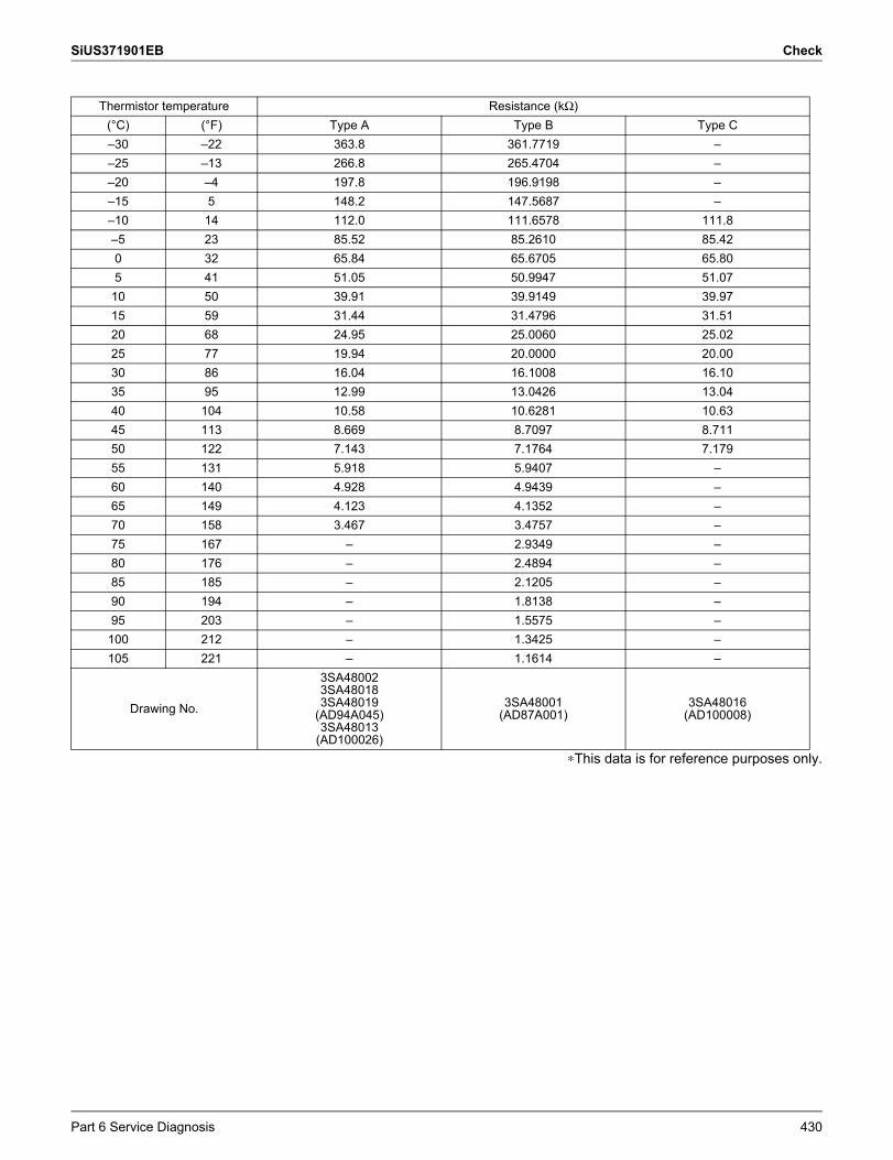
SiUS371901EB Check
∗This data is for reference purposes only.
Thermistor temperature Resistance (kΩ)(°C) (°F) Type A Type B Type C–30 –22 363.8 361.7719 ––25 –13 266.8 265.4704 ––20 –4 197.8 196.9198 ––15 5 148.2 147.5687 ––10 14 112.0 111.6578 111.8–5 23 85.52 85.2610 85.420 32 65.84 65.6705 65.805 41 51.05 50.9947 51.07
10 50 39.91 39.9149 39.9715 59 31.44 31.4796 31.5120 68 24.95 25.0060 25.0225 77 19.94 20.0000 20.0030 86 16.04 16.1008 16.1035 95 12.99 13.0426 13.0440 104 10.58 10.6281 10.6345 113 8.669 8.7097 8.71150 122 7.143 7.1764 7.17955 131 5.918 5.9407 –60 140 4.928 4.9439 –65 149 4.123 4.1352 –70 158 3.467 3.4757 –75 167 – 2.9349 –80 176 – 2.4894 –85 185 – 2.1205 –90 194 – 1.8138 –95 203 – 1.5575 –100 212 – 1.3425 –105 221 – 1.1614 –
Drawing No.
3SA480023SA480183SA48019
(AD94A045)3SA48013
(AD100026)
3SA48001(AD87A001)
3SA48016(AD100008)
Part 6 Service Diagnosis 430
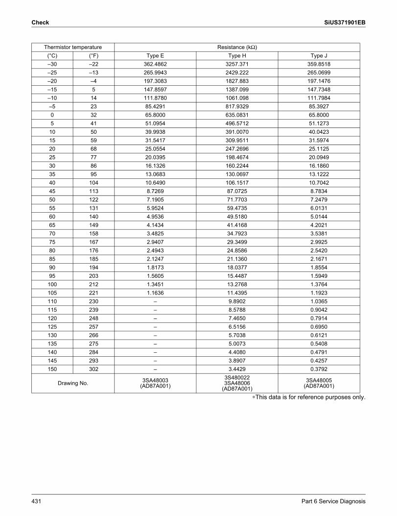
Check SiUS371901EB
∗This data is for reference purposes only.
Thermistor temperature Resistance (kΩ)(°C) (°F) Type E Type H Type J–30 –22 362.4862 3257.371 359.8518–25 –13 265.9943 2429.222 265.0699–20 –4 197.3083 1827.883 197.1476–15 5 147.8597 1387.099 147.7348–10 14 111.8780 1061.098 111.7984–5 23 85.4291 817.9329 85.39270 32 65.8000 635.0831 65.80005 41 51.0954 496.5712 51.127310 50 39.9938 391.0070 40.042315 59 31.5417 309.9511 31.597420 68 25.0554 247.2696 25.112525 77 20.0395 198.4674 20.094930 86 16.1326 160.2244 16.186035 95 13.0683 130.0697 13.122240 104 10.6490 106.1517 10.704245 113 8.7269 87.0725 8.783450 122 7.1905 71.7703 7.247955 131 5.9524 59.4735 6.013160 140 4.9536 49.5180 5.014465 149 4.1434 41.4168 4.202170 158 3.4825 34.7923 3.538175 167 2.9407 29.3499 2.992580 176 2.4943 24.8586 2.542085 185 2.1247 21.1360 2.167190 194 1.8173 18.0377 1.855495 203 1.5605 15.4487 1.5949
100 212 1.3451 13.2768 1.3764105 221 1.1636 11.4395 1.1923110 230 – 9.8902 1.0365115 239 – 8.5788 0.9042120 248 – 7.4650 0.7914125 257 – 6.5156 0.6950130 266 – 5.7038 0.6121135 275 – 5.0073 0.5408140 284 – 4.4080 0.4791145 293 – 3.8907 0.4257150 302 – 3.4429 0.3792
Drawing No. 3SA48003(AD87A001)
3S4800223SA48006
(AD87A001)3SA48005
(AD87A001)
431 Part 6 Service Diagnosis
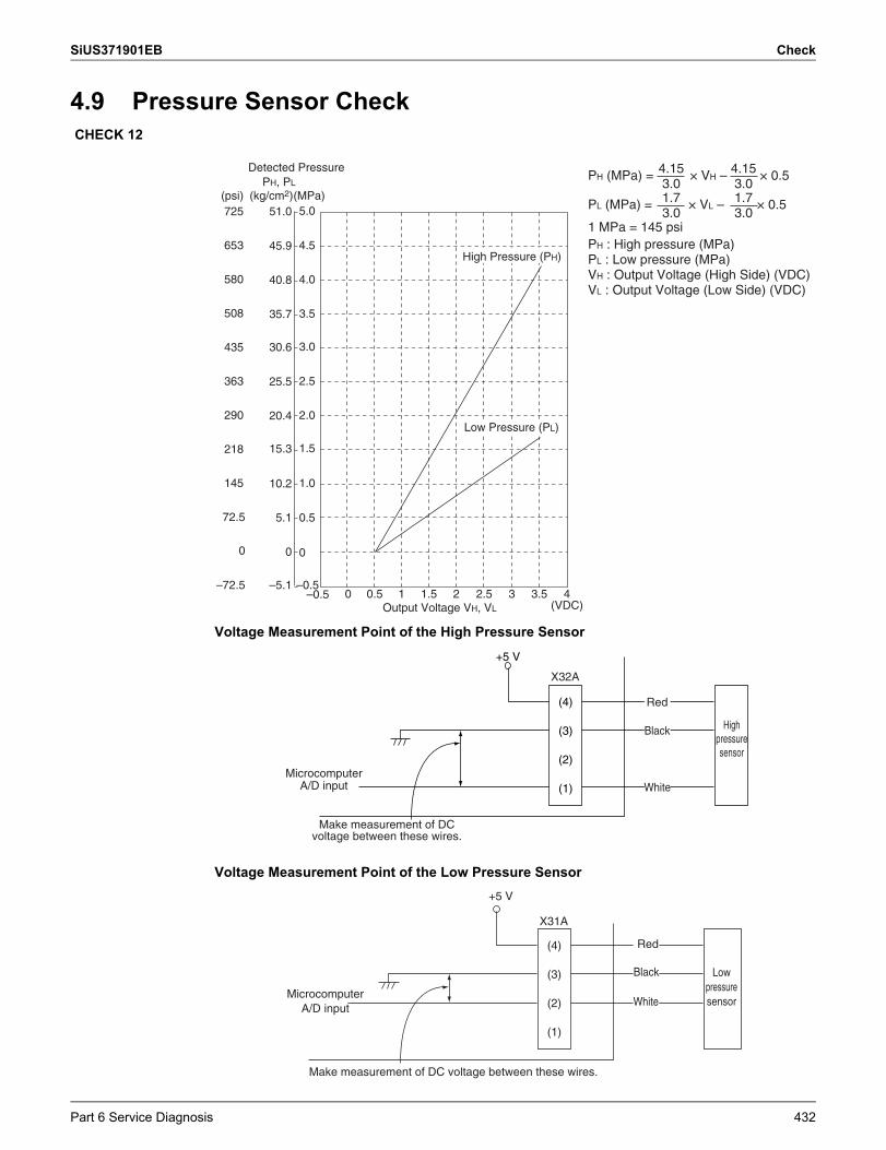
SiUS371901EB Check
4.9 Pressure Sensor Check
Voltage Measurement Point of the High Pressure Sensor
Voltage Measurement Point of the Low Pressure Sensor
CHECK 12
High Pressure (PH)
Low Pressure (PL)
Output Voltage VH, VL
Detected Pressure
5.1
–5.1
0
5.0
4.5
4.0
3.5
3.0
2.5
2.0
1.5
1.0
0.5
0
–0.5–0.5 0 0.5 1 1.5 2 2.5 3 3.5 4
(VDC)
(kg/cm2)(psi) (MPa)PH, PL
PH (MPa) = × VH – × 0.5
PL (MPa) = × VL – × 0.5
PH : High pressure (MPa)PL : Low pressure (MPa)VH : Output Voltage (High Side) (VDC)VL : Output Voltage (Low Side) (VDC)
4.153.0
4.153.0
1.73.0
1.73.0
1 MPa = 145 psi
40.8
35.7
30.6
25.5
20.4
15.3
10.2
45.9
51.0
–72.5
725
653
580
508
435
363
290
218
145
72.5
0
+5 V
(4)
(3)
(2)
(1)
Red
Black
White
X32A
High pressure sensor
Microcomputer A/D input
Make measurement of DC voltage between these wires.
+5 V
(4)
(3)
(2)
(1)
Microcomputer A/D input
Make measurement of DC voltage between these wires.
X31A
Red
Black
White
Low pressure sensor
Part 6 Service Diagnosis 432
Check SiUS371901EB
4.10 Broken Wire Check of the Relay WiresCHECK 15
1. Procedure for checking outdoor-outdoor unit transmission wiring for broken wires On the system shown below, turn OFF the power supply to all equipment, short circuit between the outdoor-outdoor unit terminal F1 and F2 in the "Outdoor Unit A" that is farthest from the central remote controller, and then conduct continuity checks between the transmission wiring terminal blocks F1 and F2 of the central remote controller using a multimeter. If there is continuity between the said terminal blocks, the outdoor-outdoor unit transmission wiring has no broken wires in it.If there is no continuity, the transmission wiring may have broken wires. With the outdoor-outdoor unit terminal of the "Outdoor Unit A" short circuited, conduct continuity checks between the transmission wiring terminal blocks F1 and F2 of the unified ON/OFF controller. If there is no continuity as well, conduct continuity checks between the outdoor-outdoor unit terminal of the "Outdoor Unit E", between the outdoor-outdoor unit terminal of the "Outdoor Unit D", between the outdoor-outdoor unit terminal of the "Outdoor Unit C", … in the order described, thus identifying the place with continuity.If the place with continuity can be identified, there may be broken wires in places before the said place with continuity.
2. Procedure for checking indoor-outdoor unit transmission wiring for broken wires (for checking the indoor-outdoor unit transmission wiring of the "Outdoor Unit C" for broken wires)Turn OFF the power supply to all equipment, short circuit between the indoor-outdoor unit terminal F1 and F2 in the "Outdoor Unit C, and then conduct continuity checks between the transmission wirings F1 and F2 of the "Indoor Unit a" that is farthest from the "Outdoor Unit C" using a multimeter. If there is continuity between the said transmission wirings, the indoor-outdoor unit transmission wiring has no broken wires in it.If there is no continuity, the transmission wiring may have broken wires. With the indoor-outdoor unit terminal of the "Outdoor Unit C" short circuited, identify the place with continuity in the transmission wiring of the "Indoor Unit b", transmission wiring of the "Indoor Unit c", and transmission wiring of the "Indoor Unit d" in the order described.If the place with continuity can be identified, there may be broken wires in places before the said place with continuity.
433 Part 6 Service Diagnosis
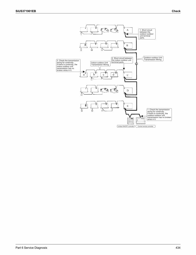
SiUS371901EB Check
1. Short circuit between the outdoor-outdoor unit terminal parts.
Outdoor-outdoor Unit Transmission Wiring2. Check the transmission
wiring for continuity.If there is continuity, the indoor-outdoor unit transmission has no broken wires in it.
Indoor-outdoor Unit Transmission Wiring
2. Short circuit between the indoor-outdoor unit terminal parts.
1. Check the transmission wiring for continuity.If there is continuity, the outdoor-outdoor unit transmission has no broken wires in it.
Unified ON/OFF controller Central remote controller
Part 6 Service Diagnosis 434
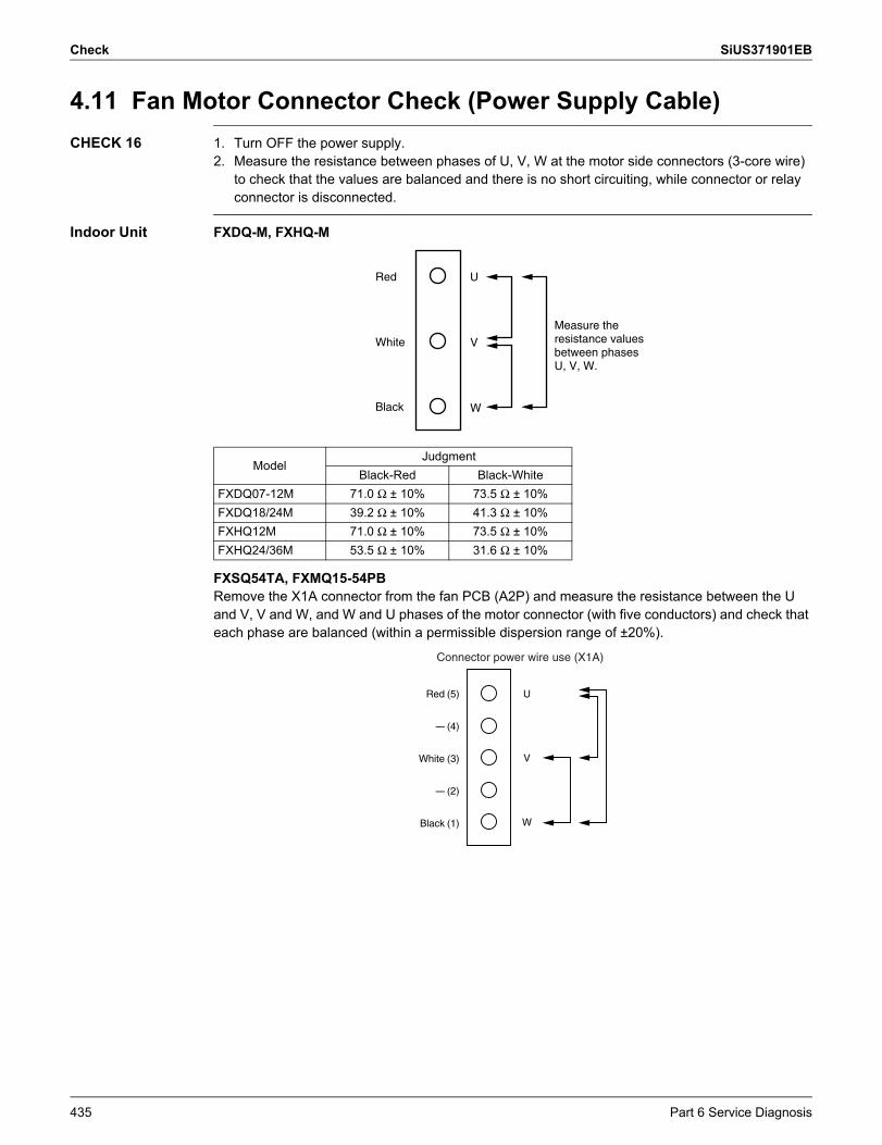
Check SiUS371901EB
4.11 Fan Motor Connector Check (Power Supply Cable)CHECK 16 1. Turn OFF the power supply.
2. Measure the resistance between phases of U, V, W at the motor side connectors (3-core wire) to check that the values are balanced and there is no short circuiting, while connector or relay connector is disconnected.
Indoor Unit FXDQ-M, FXHQ-M
FXSQ54TA, FXMQ15-54PBRemove the X1A connector from the fan PCB (A2P) and measure the resistance between the U and V, V and W, and W and U phases of the motor connector (with five conductors) and check that each phase are balanced (within a permissible dispersion range of ±20%).
ModelJudgment
Black-Red Black-WhiteFXDQ07-12M 71.0 Ω ± 10% 73.5 Ω ± 10%FXDQ18/24M 39.2 Ω ± 10% 41.3 Ω ± 10%FXHQ12M 71.0 Ω ± 10% 73.5 Ω ± 10%FXHQ24/36M 53.5 Ω ± 10% 31.6 Ω ± 10%
Measure the resistance values between phases U, V, W.
Red
White
Black W
V
U
Red
—
White
—
Black
(5)
(4)
(3)
(2)
(1)
U
V
W
Connector power wire use (X1A)
435 Part 6 Service Diagnosis
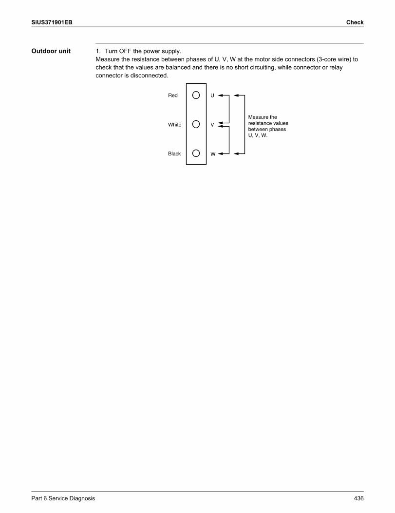
SiUS371901EB Check
Outdoor unit 1. Turn OFF the power supply.Measure the resistance between phases of U, V, W at the motor side connectors (3-core wire) to check that the values are balanced and there is no short circuiting, while connector or relay connector is disconnected.
Measure the resistance values between phases U, V, W.
Red
White
Black W
V
U
Part 6 Service Diagnosis 436
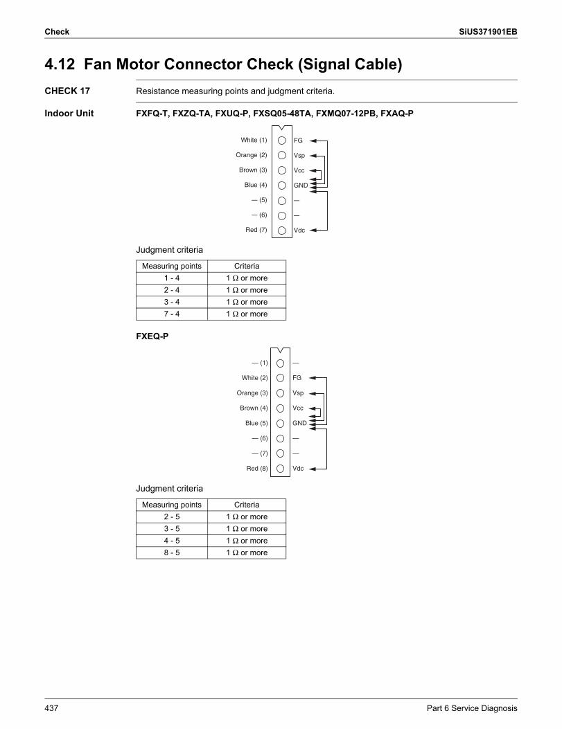
Check SiUS371901EB
4.12 Fan Motor Connector Check (Signal Cable)CHECK 17 Resistance measuring points and judgment criteria.
Indoor Unit FXFQ-T, FXZQ-TA, FXUQ-P, FXSQ05-48TA, FXMQ07-12PB, FXAQ-P
Judgment criteria
FXEQ-P
Judgment criteria
White
Orange
Brown
Blue
—
—
Red
(1)
(2)
(3)
(4)
(5)
(6)
(7)
FG
Vsp
Vcc
GND
—
—
Vdc
Measuring points Criteria1 - 4 1 Ω or more2 - 4 1 Ω or more3 - 4 1 Ω or more7 - 4 1 Ω or more
— (1)
White (2)
Orange (3)
Brown (4)
Blue (5)
— (6)
— (7)
Red (8)
—
FG
Vsp
Vcc
GND
—
—
Vdc
Measuring points Criteria2 - 5 1 Ω or more3 - 5 1 Ω or more4 - 5 1 Ω or more8 - 5 1 Ω or more
437 Part 6 Service Diagnosis
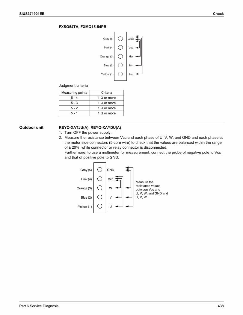
SiUS371901EB Check
FXSQ54TA, FXMQ15-54PB
Judgment criteria
Outdoor unit REYQ-XATJU(A), REYQ-XAYDU(A)1. Turn OFF the power supply.2. Measure the resistance between Vcc and each phase of U, V, W, and GND and each phase at
the motor side connectors (5-core wire) to check that the values are balanced within the range of ± 20%, while connector or relay connector is disconnected.Furthermore, to use a multimeter for measurement, connect the probe of negative pole to Vcc and that of positive pole to GND.
Gray (5)
Pink (4)
Orange (3)
Blue (2)
Yellow (1)
GND
Vcc
Hw
HV
HU
Measuring points Criteria5 - 4 1 Ω or more5 - 3 1 Ω or more5 - 2 1 Ω or more5 - 1 1 Ω or more
Measure the resistance values between Vcc and U, V, W, and GND and U, V, W.
GND
Vcc
W
V
U
Gray
Pink
Orange
Blue
Yellow
(5)
(4)
(3)
(2)
(1)
Part 6 Service Diagnosis 438
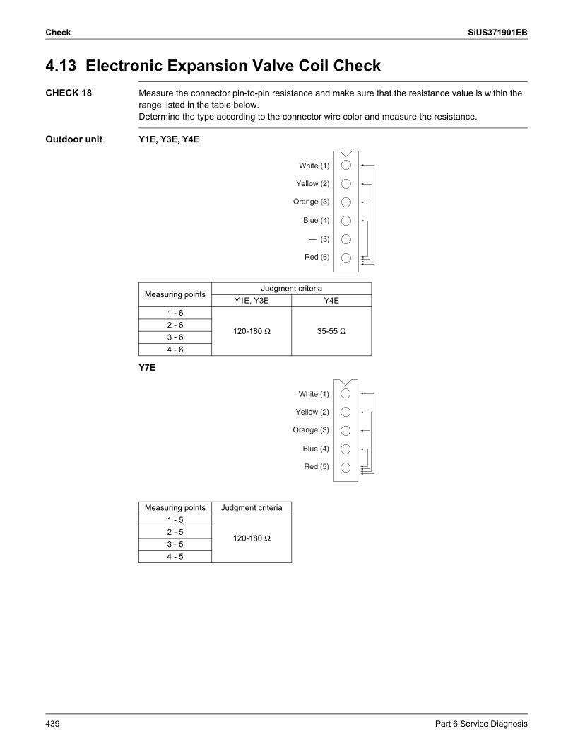
Check SiUS371901EB
4.13 Electronic Expansion Valve Coil CheckCHECK 18 Measure the connector pin-to-pin resistance and make sure that the resistance value is within the
range listed in the table below.Determine the type according to the connector wire color and measure the resistance.
Outdoor unit Y1E, Y3E, Y4E
Y7E
Measuring pointsJudgment criteria
Y1E, Y3E Y4E1 - 6
120-180 Ω 35-55 Ω2 - 63 - 64 - 6
Measuring points Judgment criteria1 - 5
120-180 Ω2 - 53 - 54 - 5
White (1)
Yellow (2)
Orange (3)
Blue (4)
— (5)
Red (6)
White (1)
Yellow (2)
Orange (3)
Blue (4)
Red (5)
439 Part 6 Service Diagnosis
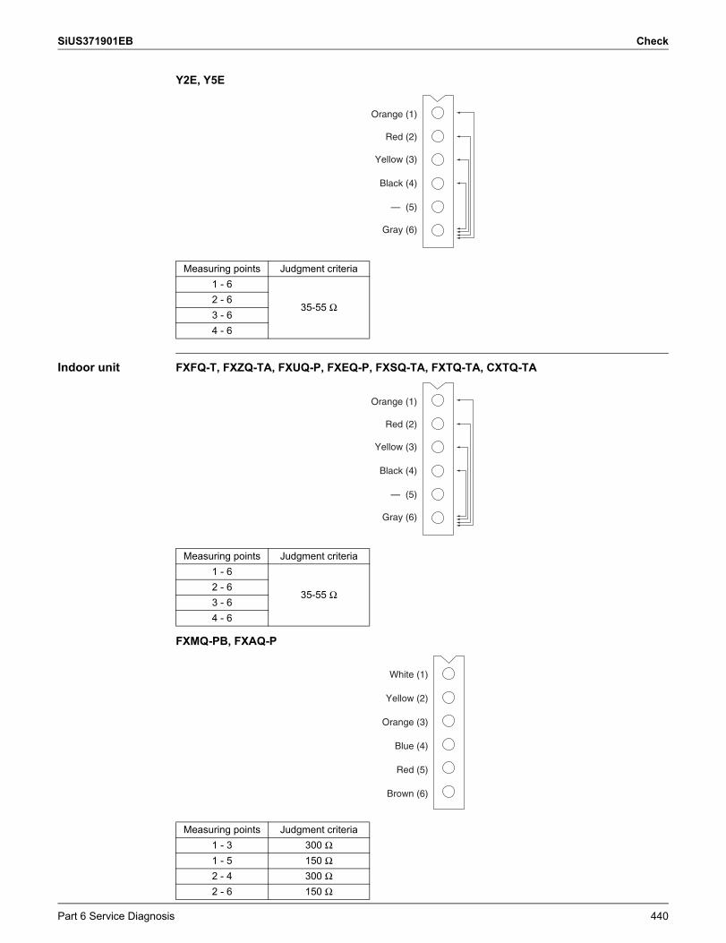
SiUS371901EB Check
Y2E, Y5E
Indoor unit FXFQ-T, FXZQ-TA, FXUQ-P, FXEQ-P, FXSQ-TA, FXTQ-TA, CXTQ-TA
FXMQ-PB, FXAQ-P
Measuring points Judgment criteria1 - 6
35-55 Ω2 - 63 - 64 - 6
Orange (1)
Red (2)
Yellow (3)
Black (4)
— (5)
Gray (6)
Measuring points Judgment criteria1 - 6
35-55 Ω2 - 63 - 64 - 6
Measuring points Judgment criteria1 - 3 300 Ω1 - 5 150 Ω2 - 4 300 Ω2 - 6 150 Ω
Orange (1)
Red (2)
Yellow (3)
Black (4)
— (5)
Gray (6)
White (1)
Yellow (2)
Orange (3)
Blue (4)
Red (5)
Brown (6)
Part 6 Service Diagnosis 440
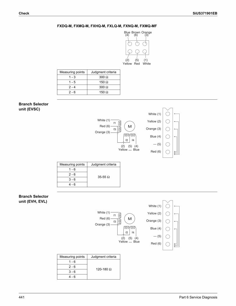
Check SiUS371901EB
FXDQ-M, FXMQ-M, FXHQ-M, FXLQ-M, FXNQ-M, FXMQ-MF
Branch Selector unit (EVSC)
Branch Selector unit (EVH, EVL)
Measuring points Judgment criteria1 - 3 300 Ω1 - 5 150 Ω2 - 4 300 Ω2 - 6 150 Ω
Orange
WhiteYellow Red(1)(2) (5)
BrownBlue(3)(6)(4)
Measuring points Judgment criteria1 - 6
35-55 Ω2 - 63 - 64 - 6
(2)Yellow
(4)Blue
f2 f4
White (1)
Red (6)
(5)—
Orange (3)
f1
f3M
White (1)
Yellow (2)
Orange (3)
Blue (4)
— (5)
Red (6)
Measuring points Judgment criteria1 - 6
120-180 Ω2 - 63 - 64 - 6
f2 f4
White (1)
(2)Yellow
(4)Blue
(5)—
White (1)
Yellow (2)
Orange (3)
Blue (4)
— (5)
Red (6)
Red (6)
Orange (3)
f1
f3M
441 Part 6 Service Diagnosis
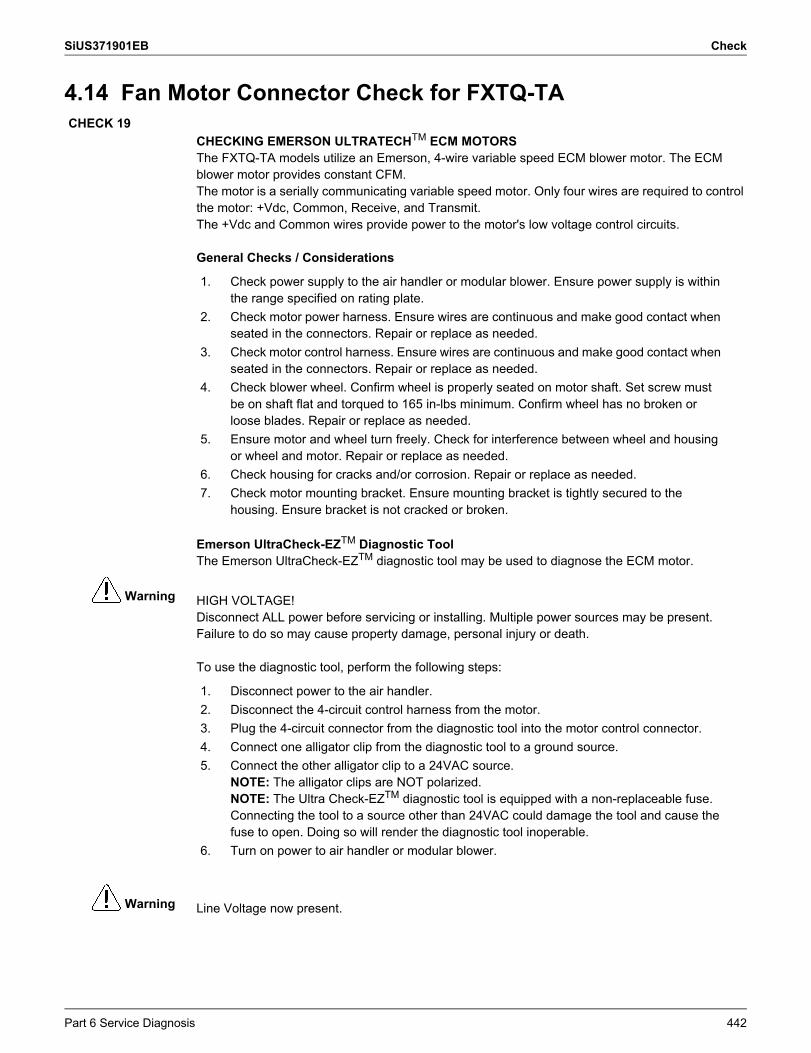
SiUS371901EB Check
Warning
Warning
4.14 Fan Motor Connector Check for FXTQ-TA
CHECKING EMERSON ULTRATECHTM ECM MOTORSThe FXTQ-TA models utilize an Emerson, 4-wire variable speed ECM blower motor. The ECM blower motor provides constant CFM.The motor is a serially communicating variable speed motor. Only four wires are required to control the motor: +Vdc, Common, Receive, and Transmit.The +Vdc and Common wires provide power to the motor's low voltage control circuits.
General Checks / Considerations
Emerson UltraCheck-EZTM Diagnostic ToolThe Emerson UltraCheck-EZTM diagnostic tool may be used to diagnose the ECM motor.
HIGH VOLTAGE!Disconnect ALL power before servicing or installing. Multiple power sources may be present. Failure to do so may cause property damage, personal injury or death.
To use the diagnostic tool, perform the following steps:
Line Voltage now present.
CHECK 19
1. Check power supply to the air handler or modular blower. Ensure power supply is within the range specified on rating plate.
2. Check motor power harness. Ensure wires are continuous and make good contact when seated in the connectors. Repair or replace as needed.
3. Check motor control harness. Ensure wires are continuous and make good contact when seated in the connectors. Repair or replace as needed.
4. Check blower wheel. Confirm wheel is properly seated on motor shaft. Set screw must be on shaft flat and torqued to 165 in-lbs minimum. Confirm wheel has no broken or loose blades. Repair or replace as needed.
5. Ensure motor and wheel turn freely. Check for interference between wheel and housing or wheel and motor. Repair or replace as needed.
6. Check housing for cracks and/or corrosion. Repair or replace as needed.7. Check motor mounting bracket. Ensure mounting bracket is tightly secured to the
housing. Ensure bracket is not cracked or broken.
1. Disconnect power to the air handler.2. Disconnect the 4-circuit control harness from the motor.3. Plug the 4-circuit connector from the diagnostic tool into the motor control connector.4. Connect one alligator clip from the diagnostic tool to a ground source.5. Connect the other alligator clip to a 24VAC source.
NOTE: The alligator clips are NOT polarized.NOTE: The Ultra Check-EZTM diagnostic tool is equipped with a non-replaceable fuse. Connecting the tool to a source other than 24VAC could damage the tool and cause the fuse to open. Doing so will render the diagnostic tool inoperable.
6. Turn on power to air handler or modular blower.
Part 6 Service Diagnosis 442
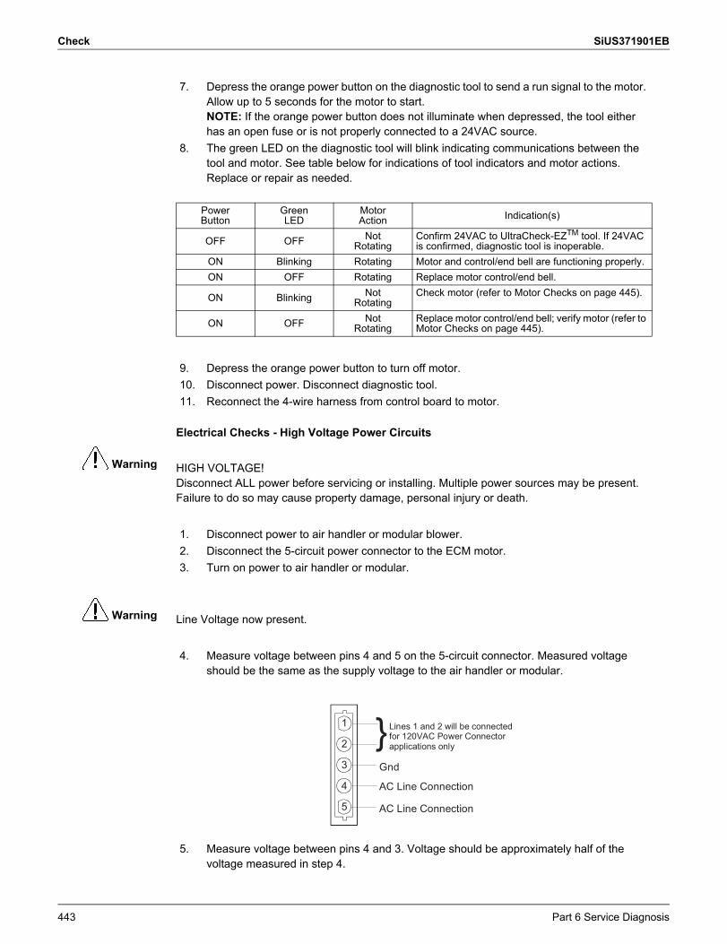
Check SiUS371901EB
Warning
Warning
Electrical Checks - High Voltage Power Circuits
HIGH VOLTAGE!Disconnect ALL power before servicing or installing. Multiple power sources may be present. Failure to do so may cause property damage, personal injury or death.
Line Voltage now present.
7. Depress the orange power button on the diagnostic tool to send a run signal to the motor. Allow up to 5 seconds for the motor to start.NOTE: If the orange power button does not illuminate when depressed, the tool either has an open fuse or is not properly connected to a 24VAC source.
8. The green LED on the diagnostic tool will blink indicating communications between the tool and motor. See table below for indications of tool indicators and motor actions. Replace or repair as needed.
PowerButton
GreenLED
MotorAction Indication(s)
OFF OFF NotRotating
Confirm 24VAC to UltraCheck-EZTM tool. If 24VAC is confirmed, diagnostic tool is inoperable.
ON Blinking Rotating Motor and control/end bell are functioning properly.ON OFF Rotating Replace motor control/end bell.
ON Blinking NotRotating
Check motor (refer to Motor Checks on page 445).
ON OFF NotRotating
Replace motor control/end bell; verify motor (refer to Motor Checks on page 445).
9. Depress the orange power button to turn off motor.10. Disconnect power. Disconnect diagnostic tool.11. Reconnect the 4-wire harness from control board to motor.
1. Disconnect power to air handler or modular blower.2. Disconnect the 5-circuit power connector to the ECM motor.3. Turn on power to air handler or modular.
4. Measure voltage between pins 4 and 5 on the 5-circuit connector. Measured voltage should be the same as the supply voltage to the air handler or modular.
5. Measure voltage between pins 4 and 3. Voltage should be approximately half of the voltage measured in step 4.
1
2
3
4
5
Lines 1 and 2 will be connected for 120VAC Power Connector applications only
Gnd
AC Line Connection
AC Line Connection
}
443 Part 6 Service Diagnosis
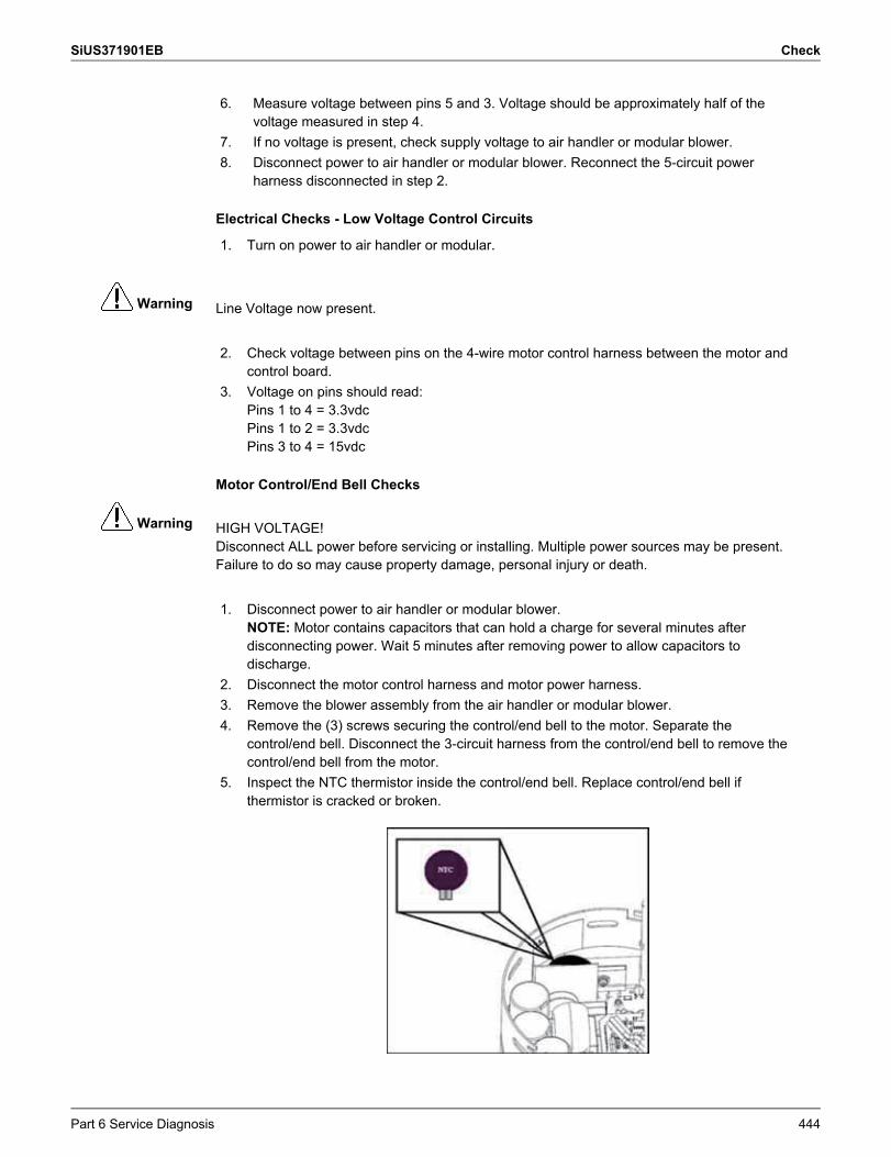
SiUS371901EB Check
Warning
Warning
Electrical Checks - Low Voltage Control Circuits
Line Voltage now present.
Motor Control/End Bell Checks
HIGH VOLTAGE!Disconnect ALL power before servicing or installing. Multiple power sources may be present. Failure to do so may cause property damage, personal injury or death.
6. Measure voltage between pins 5 and 3. Voltage should be approximately half of the voltage measured in step 4.
7. If no voltage is present, check supply voltage to air handler or modular blower.8. Disconnect power to air handler or modular blower. Reconnect the 5-circuit power
harness disconnected in step 2.
1. Turn on power to air handler or modular.
2. Check voltage between pins on the 4-wire motor control harness between the motor and control board.
3. Voltage on pins should read:Pins 1 to 4 = 3.3vdcPins 1 to 2 = 3.3vdcPins 3 to 4 = 15vdc
1. Disconnect power to air handler or modular blower.NOTE: Motor contains capacitors that can hold a charge for several minutes after disconnecting power. Wait 5 minutes after removing power to allow capacitors to discharge.
2. Disconnect the motor control harness and motor power harness.3. Remove the blower assembly from the air handler or modular blower.4. Remove the (3) screws securing the control/end bell to the motor. Separate the
control/end bell. Disconnect the 3-circuit harness from the control/end bell to remove the control/end bell from the motor.
5. Inspect the NTC thermistor inside the control/end bell. Replace control/end bell if thermistor is cracked or broken.
Part 6 Service Diagnosis 444
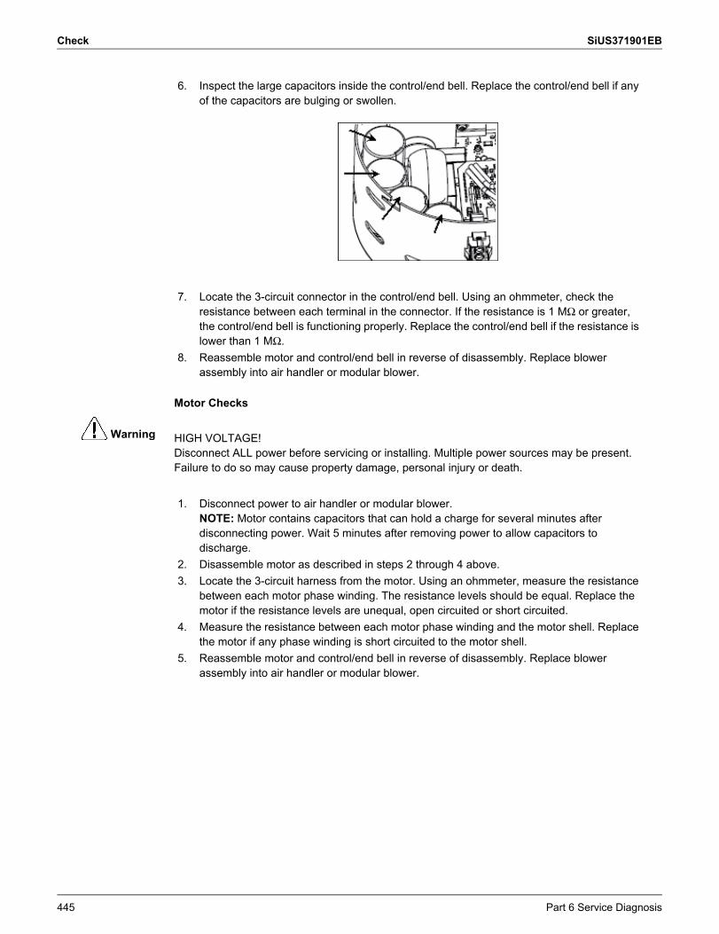
Check SiUS371901EB
Warning
Motor Checks
HIGH VOLTAGE!Disconnect ALL power before servicing or installing. Multiple power sources may be present. Failure to do so may cause property damage, personal injury or death.
6. Inspect the large capacitors inside the control/end bell. Replace the control/end bell if any of the capacitors are bulging or swollen.
7. Locate the 3-circuit connector in the control/end bell. Using an ohmmeter, check the resistance between each terminal in the connector. If the resistance is 1 MΩ or greater, the control/end bell is functioning properly. Replace the control/end bell if the resistance is lower than 1 MΩ.
8. Reassemble motor and control/end bell in reverse of disassembly. Replace blower assembly into air handler or modular blower.
1. Disconnect power to air handler or modular blower.NOTE: Motor contains capacitors that can hold a charge for several minutes after disconnecting power. Wait 5 minutes after removing power to allow capacitors to discharge.
2. Disassemble motor as described in steps 2 through 4 above.3. Locate the 3-circuit harness from the motor. Using an ohmmeter, measure the resistance
between each motor phase winding. The resistance levels should be equal. Replace the motor if the resistance levels are unequal, open circuited or short circuited.
4. Measure the resistance between each motor phase winding and the motor shell. Replace the motor if any phase winding is short circuited to the motor shell.
5. Reassemble motor and control/end bell in reverse of disassembly. Replace blower assembly into air handler or modular blower.
445 Part 6 Service Diagnosis
SiUS371901EB
Part 7 Appendix 446
1. Wiring Diagrams......................................................................................4471.1 Outdoor Unit ............................................................................................. 4471.2 Indoor Unit................................................................................................ 4521.3 Air Treatment Equipment ......................................................................... 4661.4 Branch Selector Unit ................................................................................ 469
Part 7 Appendix
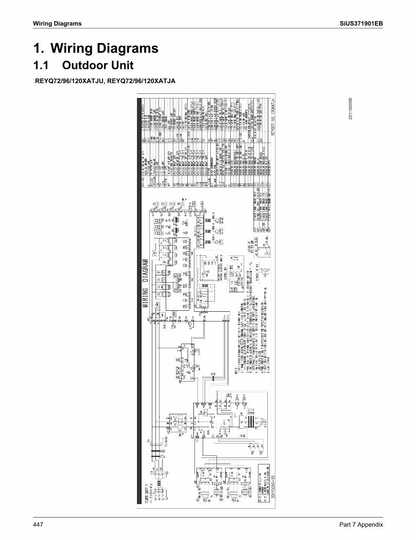
Wiring Diagrams SiUS371901EB
1. Wiring Diagrams1.1 Outdoor UnitREYQ72/96/120XATJU, REYQ72/96/120XATJA
2D11
9205
B
447 Part 7 Appendix
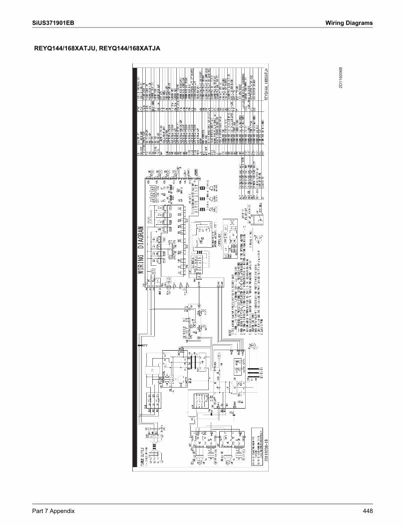
SiUS371901EB Wiring Diagrams
REYQ144/168XATJU, REYQ144/168XATJA
2D11
9206
B
Part 7 Appendix 448
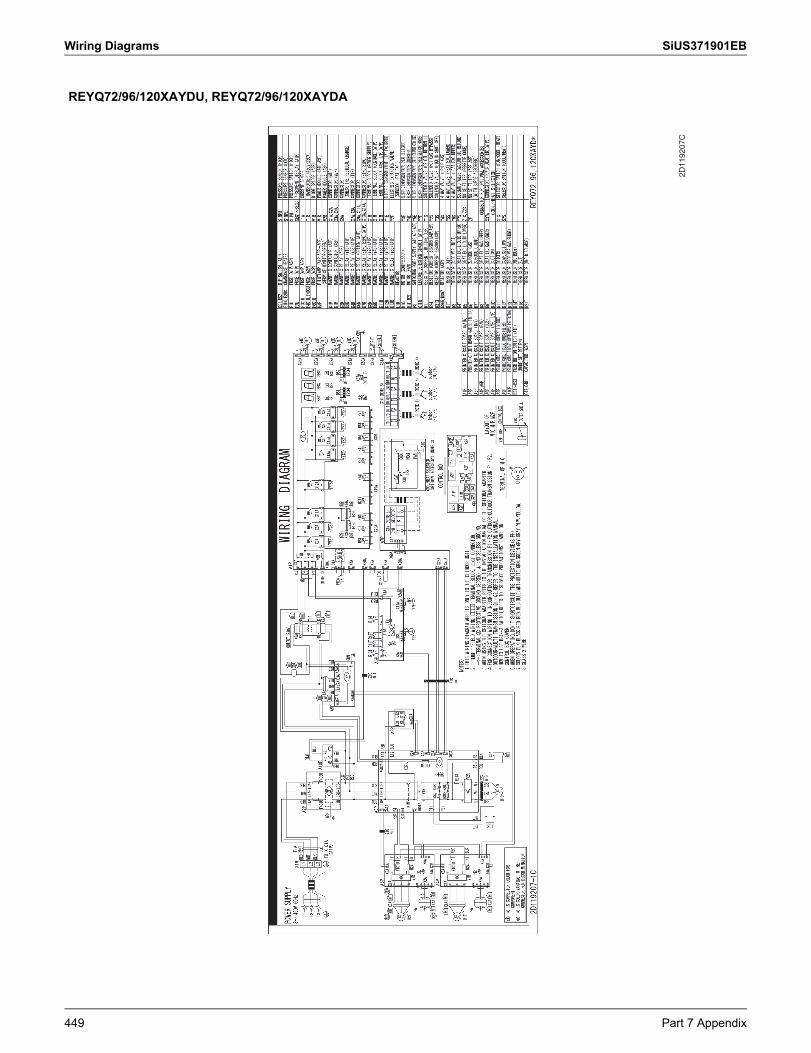
Wiring Diagrams SiUS371901EB
REYQ72/96/120XAYDU, REYQ72/96/120XAYDA
2D11
9207
C
449 Part 7 Appendix
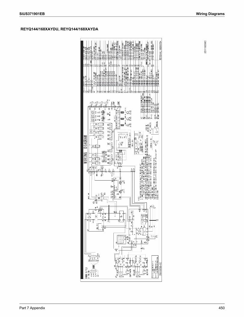
SiUS371901EB Wiring Diagrams
REYQ144/168XAYDU, REYQ144/168XAYDA
2D11
9208
C
Part 7 Appendix 450
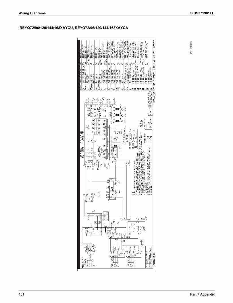
Wiring Diagrams SiUS371901EB
REYQ72/96/120/144/168XAYCU, REYQ72/96/120/144/168XAYCA
2D11
9209
B
451 Part 7 Appendix
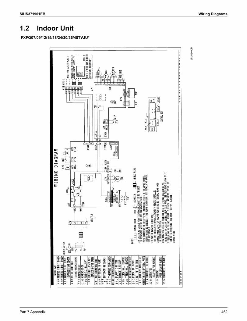
SiUS371901EB Wiring Diagrams
1.2 Indoor UnitFXFQ07/09/12/15/18/24/30/36/48TVJU*
3D08
6460
B
Part 7 Appendix 452
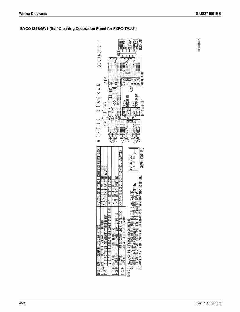
Wiring Diagrams SiUS371901EB
BYCQ125BGW1 (Self-Cleaning Decoration Panel for FXFQ-TVJU*)
3D07
6375
A
453 Part 7 Appendix
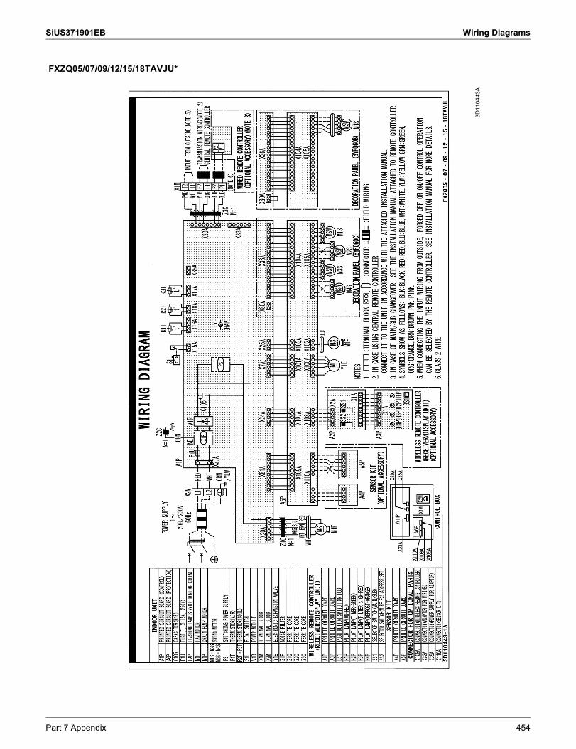
SiUS371901EB Wiring Diagrams
FXZQ05/07/09/12/15/18TAVJU*
3D11
0443
A
Part 7 Appendix 454
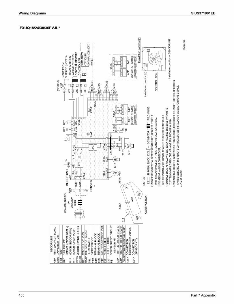
Wiring Diagrams SiUS371901EB
FXUQ18/24/30/36PVJU*
IND
OO
R U
NIT
R2T
R3T
T2PN
KS
1LP
OW
ER
SU
PP
LYIN
DO
OR
UN
ITW
HTT1
GR
Nt˚
t˚X
2MA
1PYL
WF2
V1R
NE
F1U
C10
5+
L1R
ED
X15A
X18A
X17A
F1OR
G+
Z1F
X30
AL2
WH
T-
BLU
P2
P2
X27
ABL
KP
1P
1
GR
N/Y
LWH
AP
MSW
X35
AM
4SP
SX
36A
MSW
M3S
X7A
X20
AX
25A
MSW
M2S
N=1
Z1C
X81
AM
SWX
16A
M1S
X81
AOR
GBL
UM
SM
M1P
BRN
X81
AX
35A
RE
DW
HTY
1Et˚
R1T
WH
TR
1TM
SA
3PA
4PM
1FA
3PA
4PA
1P
X2M
X1M
Inst
alla
tion
posi
tion
2
NO
TE
SC
ON
TR
OL
BO
XIn
stal
latio
n po
sitio
n 1
CO
NT
RO
L B
OX
Inst
alla
tion
posi
tion
of S
EN
SO
R K
IT
1 ~
208/
230V
60
Hz
SENS
OR
KIT
(Opt
ion)
In
stal
latio
n po
sitio
n 1
SE
NS
OR
KIT
(Opt
ion)
In
stal
latio
n po
sitio
n 2
(NO
TE
6)
X1M
INP
UT
FR
OM
O
UT
SID
E (
NO
TE
5)
TR
AN
SM
ISS
ION
W
IRIN
G (
NO
TE
2)
CE
NT
RA
L R
EM
OT
E
CO
NT
RO
LLE
RW
IRED
REM
OTE
CONT
ROLL
ER
(OPT
IONA
L AC
CESS
ORY)
(N
OTE
3)
1.
: TE
RMIN
AL B
LOCK
,
:
CONN
ECTO
R
: FI
ELD
WIR
ING
2. IN
CAS
E US
ING
CEN
TRAL
REM
OTE
CO
NTRO
LLER
, CO
NNEC
T IT
TO
THE
UNIT
IN A
CCO
RDAN
CE W
ITH
THE
ATTA
CHED
INST
ALLA
TIO
N M
ANUA
L.
3. IN
CAS
E O
F M
AIN/
SUB
CHAN
GEO
VER,
SEE
THE
INST
ALLA
TIO
N M
ANUA
L AT
TACH
ED T
O R
EMO
TE C
ONT
ROLL
ER.
4. S
YMBO
LS S
HOW
AS
FOLL
OW
S: B
LK: B
LACK
RED
: RED
BLU
: BLU
E W
HT: W
HITE
YLW
: YEL
LOW
GRN
: GRE
EN O
RG: O
RANG
E BR
N: B
ROW
N PN
K: P
INK.
5. W
HEN
CONN
ECTI
NG T
HE IN
PUT
WIR
ING
FRO
M O
UTSI
DE, F
ORC
ED O
FF O
R O
N/O
FF C
ONT
ROL
OPE
RATI
ON
CAN
BE S
ELEC
TED
BY T
HE R
EMO
TE C
ONT
ROLL
ER. S
EE IN
STAL
LATI
ON
MAN
UAL
FOR
MO
RE D
ETAI
LS.
6. C
LASS
2 W
IRE
A1P
C10
5F
1UH
AP
M1F
M1P
M1S•
M2S
M3S•
M4S
R1T
R2T•
R3T
S1L
V1R
X1M
X2M
Y1E
Z1F
Z1C
PS
A3P
A4P
X35
A
X81
A
PR
INTE
D C
IRC
UIT
BO
AR
DC
APA
CIT
OR
(M
1F)
FU
SE
FLAS
HIN
G L
AMP
(SER
VIC
E M
ON
ITO
R G
RE
EN
)M
OTO
R (
IND
OO
R F
AN
)M
OTO
R (
DR
AIN
PU
MP
)
MO
TOR
(S
WIN
G B
LAD
E)
TH
ER
MIS
TOR
(A
IR)
TH
ER
MIS
TOR
(C
OIL
)F
LOAT
SW
ITC
HD
IOD
E B
RID
GE
TE
RM
INA
L B
LOC
KT
ER
MIN
AL
BLO
CK
ELEC
TRO
NIC
EXPA
NSIO
N VA
LVE
NO
ISE
FIL
TE
RF
ER
RIT
E C
OR
EP
OW
ER
SU
PP
LY C
IRC
UIT
SE
NS
OR
KIT
PR
INTE
D C
IRC
UIT
BO
AR
DP
RIN
TED
CIR
CU
IT B
OA
RD
CONN
ECTO
R FO
R O
PTIO
NAL
PART
SC
ON
NE
CTO
R
(POW
ER S
UPPL
Y FO
R AD
APTO
R)C
ON
NE
CTO
R
(SE
NS
OR
KIT
)
3D09
0218
455 Part 7 Appendix
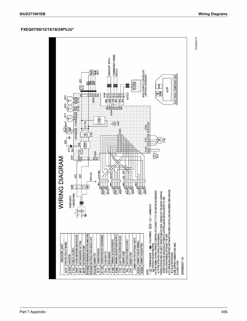
SiUS371901EB Wiring Diagrams
FXEQ07/09/12/15/18/24PVJU*
3D09
8557
A
Part 7 Appendix 456
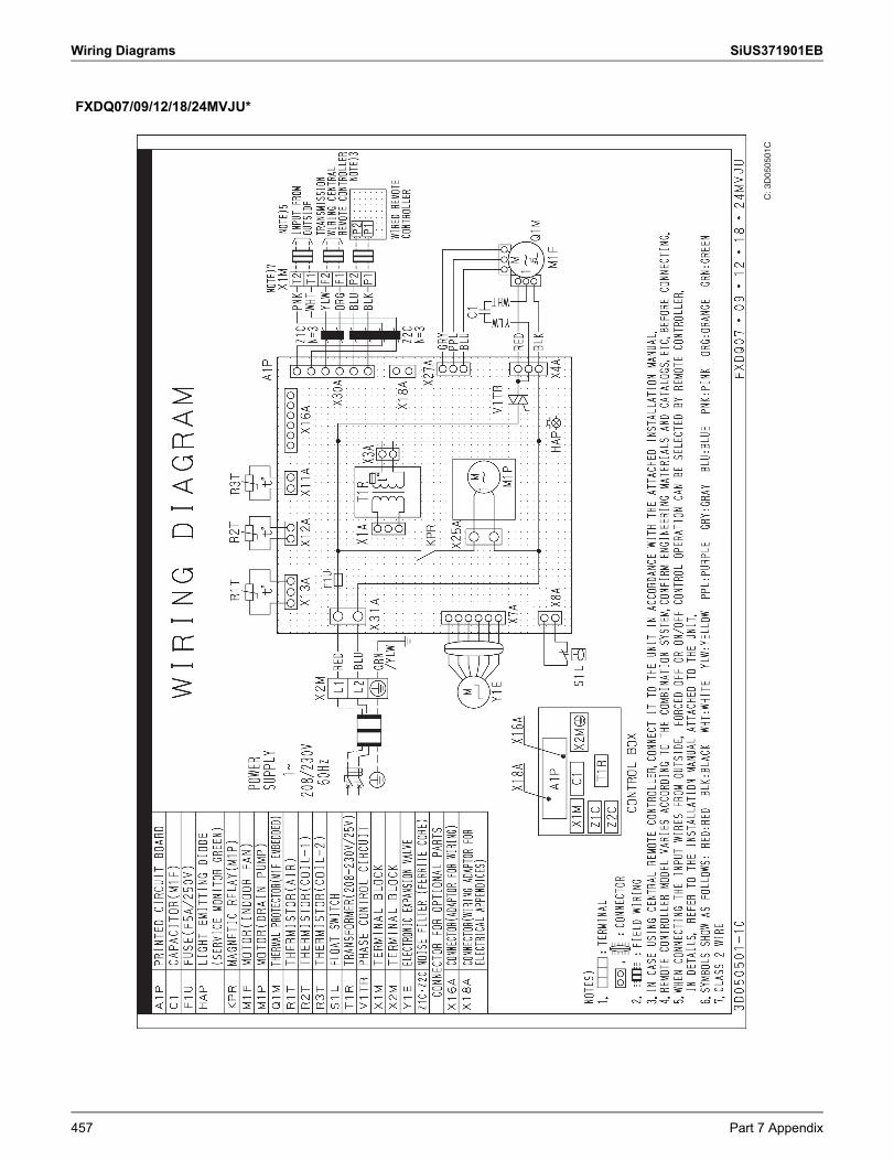
Wiring Diagrams SiUS371901EB
FXDQ07/09/12/18/24MVJU*
C: 3
D05
0501
C
457 Part 7 Appendix
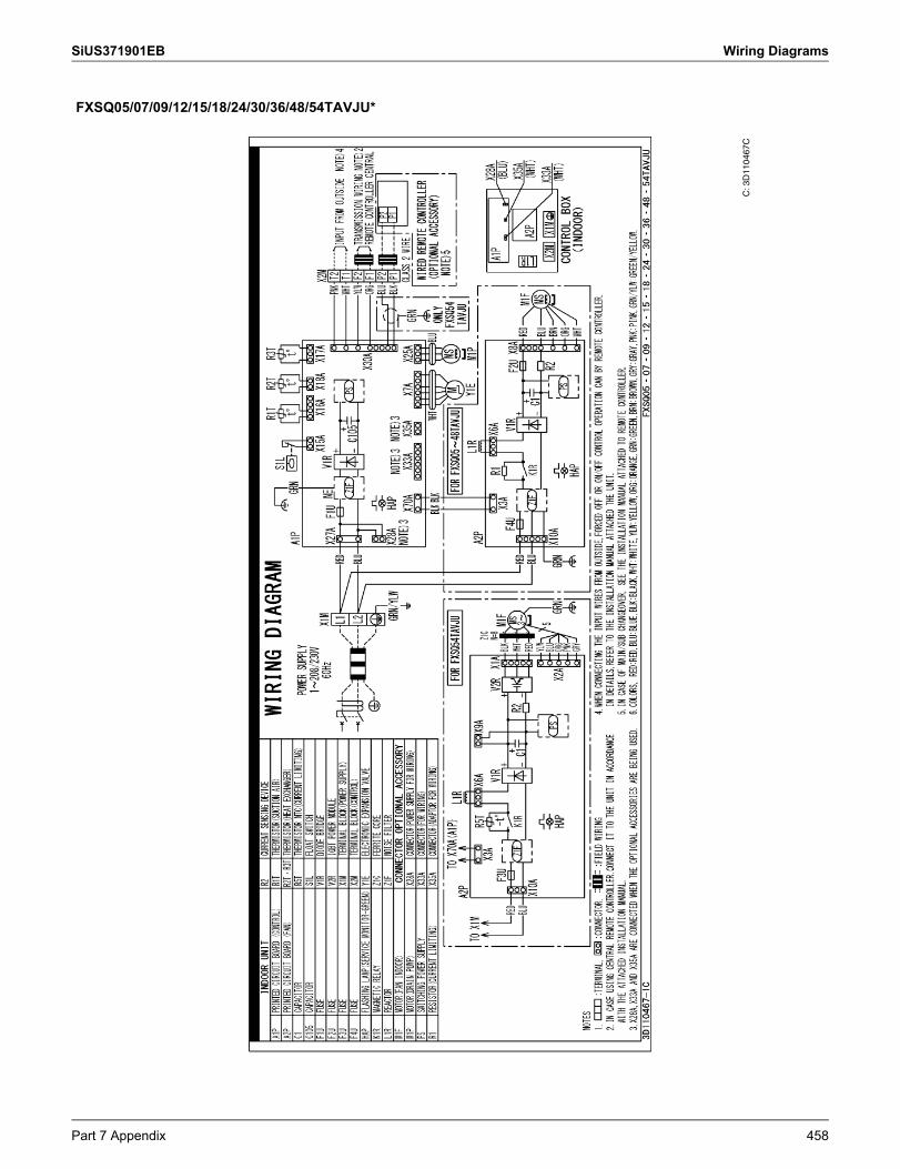
SiUS371901EB Wiring Diagrams
FXSQ05/07/09/12/15/18/24/30/36/48/54TAVJU*
C: 3
D11
0467
C
Part 7 Appendix 458
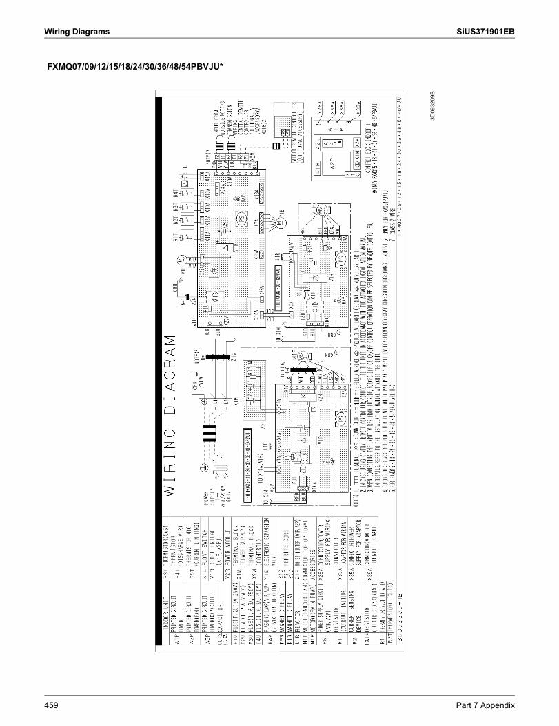
Wiring Diagrams SiUS371901EB
FXMQ07/09/12/15/18/24/30/36/48/54PBVJU*
3D09
3209
B
459 Part 7 Appendix
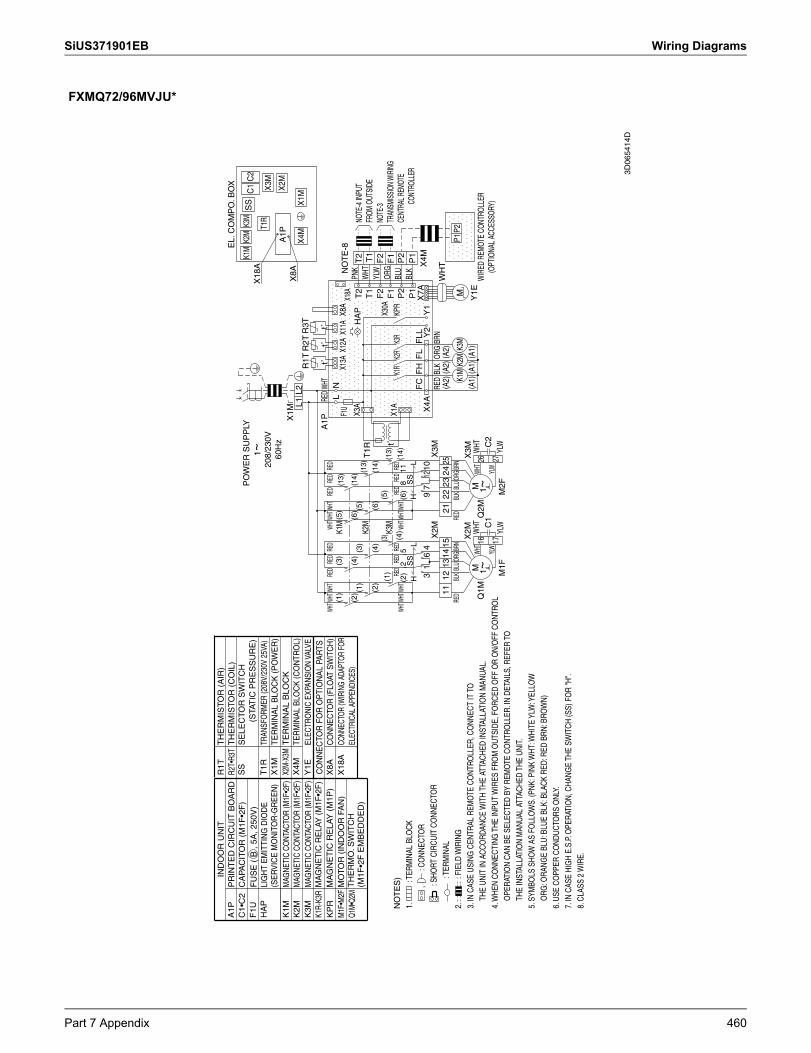
SiUS371901EB Wiring Diagrams
FXMQ72/96MVJU*
IND
OO
R U
NIT
EL.
CO
MP
O. B
OX
PO
WE
R S
UP
PLY
K3M
K2M
K1M
SS
C1
C2
X18
AT1
RX
3M
X2M
A1P
X1M
X8A
L2L1
X1M
X4M
R3T
R1T
R2T
t˚t˚
t˚RE
DWH
TA
1PRE
DRE
DRE
DWH
TWHT
WHT
RED
RED
RED
WHTW
HTWH
TL
NK1
MX1
3AX1
2AX1
1AX8
AF1
UN
OT
E-8
X18A
PNK
X3A
HA
PT
2T
2W
HTK2
MT
1RT
1T
1YL
W
NO
TE
S)
F2
F2
X30A
ORG
K3M
t˚F
1F
1X1
ABL
URE
DRE
DRE
DKP
RK2
RK1
RK3
RWH
T WHT
WHT
RED
RED
RED
WHT W
HTWH
TP
2(2
)
(2)
(2)
(1)
(1)
(1)
(3)
(3)
(3)
(4)
(4)
(5)
(5)
(5) (6
)
(6)
(13)
(14)
(13)
(14)
(13)
(14)
(4)
(6)
P2
82
511
BLK
SS
SS
P1
LH
LH
P1
FC
FL
FH
FLL
X7A
X4M
41
106
79
312
X4A
Y1
Y2
X2M
X3M
RED
ORG
BLK
BRN
WH
T11
1421
1213
1525
2322
24(A
2)(A
2)(A
2)P1
P2OR
GBRN
BLK
BLU
RED
ORG
BRN
BLK
BLU
RED
MK3
MK2
MK1
MX
3MX
2M(A
1)(A
1)(A
1)Y
1EW
HTW
HTWH
T 1626
Q1M
Q2M
C2
C1
YLW
WHT
YLW
1727
YLW
YLW
M1F
M2F
1~
208/
230V
60
Hz
WIR
ED R
EMOT
E CO
NTRO
LLER
(O
PTIO
NAL
ACCE
SSOR
Y)
NOTE
-4 IN
PUT
FROM
OUT
SIDE
NOTE
-3 TR
ANSM
ISSI
ON W
IRIN
G CE
NTRA
L REM
OTE
CONT
ROLL
ER
M
1~M
1~
1.
: T
ERM
INAL
BLO
CK
,
: C
ONN
ECTO
R
: SHO
RT C
IRCU
IT C
ONN
ECTO
R
:
TERM
INAL
2.
:
FIEL
D W
IRIN
G
3. IN
CAS
E US
ING
CEN
TRAL
REM
OTE
CO
NTRO
LLER
, CO
NNEC
T IT
TO
THE
UNIT
IN A
CCO
RDAN
CE W
ITH
THE
ATTA
CHED
INST
ALLA
TIO
N M
ANUA
L.
4. W
HEN
CONN
ECTI
NG T
HE IN
PUT
WIR
ES F
ROM
OUT
SIDE
, FO
RCED
OFF
OR
ON/
OFF
CO
NTRO
L
OPE
RATI
ON
CAN
BE S
ELEC
TED
BY R
EMO
TE C
ONT
ROLL
ER. I
N DE
TAIL
S, R
EFER
TO
THE
INST
ALLA
TIO
N M
ANUA
L AT
TACH
ED T
HE U
NIT.
5. S
YMBO
LS S
HOW
AS
FOLL
OW
S. (P
NK: P
INK
WHT
: WHI
TE Y
LW: Y
ELLO
W
ORG
: ORA
NGE
BLU:
BLU
E BL
K: B
LACK
RED
: RED
BRN
: BRO
WN)
6. U
SE C
OPP
ER C
OND
UCTO
RS O
NLY.
7. IN
CAS
E HI
GH
E.S.
P. O
PERA
TIO
N, C
HANG
E TH
E SW
ITCH
(SS)
FO
R "H
".
8. C
LASS
2 W
IRE.
A1P
C1•
C2
F1U
HA
P
K1M
K2M
K3M
K1R-
K3R
KP
RM
1F•M
2FQ1
M•Q
2M
PR
INT
ED
CIR
CU
IT B
OA
RD
CA
PAC
ITO
R (
M1F
•2F
)F
US
E (
B, 5
A, 2
50V
)LI
GH
T E
MIT
TIN
G D
IOD
E
(SE
RV
ICE
MO
NIT
OR
-GR
EE
N)
MAG
NETI
C CO
NTAC
TOR
(M1F
•2F)
MAG
NETI
C CO
NTAC
TOR
(M1F
•2F)
MAG
NETI
C CO
NTAC
TOR
(M1F
•2F)
MA
GN
ET
IC R
ELA
Y (
M1F
•2F
)M
AG
NE
TIC
RE
LAY
(M
1P)
MO
TOR
(IN
DO
OR
FA
N)
TH
ER
MO
. SW
ITC
H
(M1F
•2F
EM
BE
DD
ED
)
R1T
R2T•
R3T
SS
T1R
X1M
X2M
-X3M
X4M
Y1E
X8A
X18
A
TH
ER
MIS
TOR
(A
IR)
TH
ER
MIS
TOR
(C
OIL
)S
ELE
CTO
R S
WIT
CH
(S
TAT
IC P
RE
SS
UR
E)
TRAN
SFO
RMER
(208
V/23
0V 2
5VA)
TER
MIN
AL
BLO
CK
(PO
WE
R)
TE
RM
INA
L B
LOC
KTE
RM
INA
L B
LOC
K (C
ON
TRO
L)EL
ECTR
ONI
C EX
PANS
ION
VALV
EC
ON
NE
CTO
R F
OR
OP
TIO
NA
L PA
RTS
CO
NN
ECTO
R (F
LOAT
SW
ITC
H)
CONN
ECTO
R (W
IRIN
G AD
APTO
R FO
R EL
ECTR
ICAL
APP
ENDI
CES)
3D06
5414
D
Part 7 Appendix 460
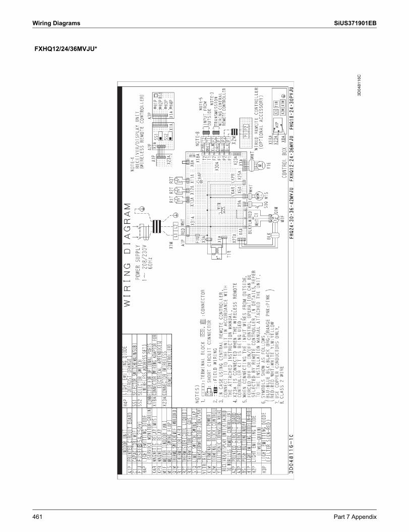
Wiring Diagrams SiUS371901EB
FXHQ12/24/36MVJU*
3D04
8116
C
461 Part 7 Appendix
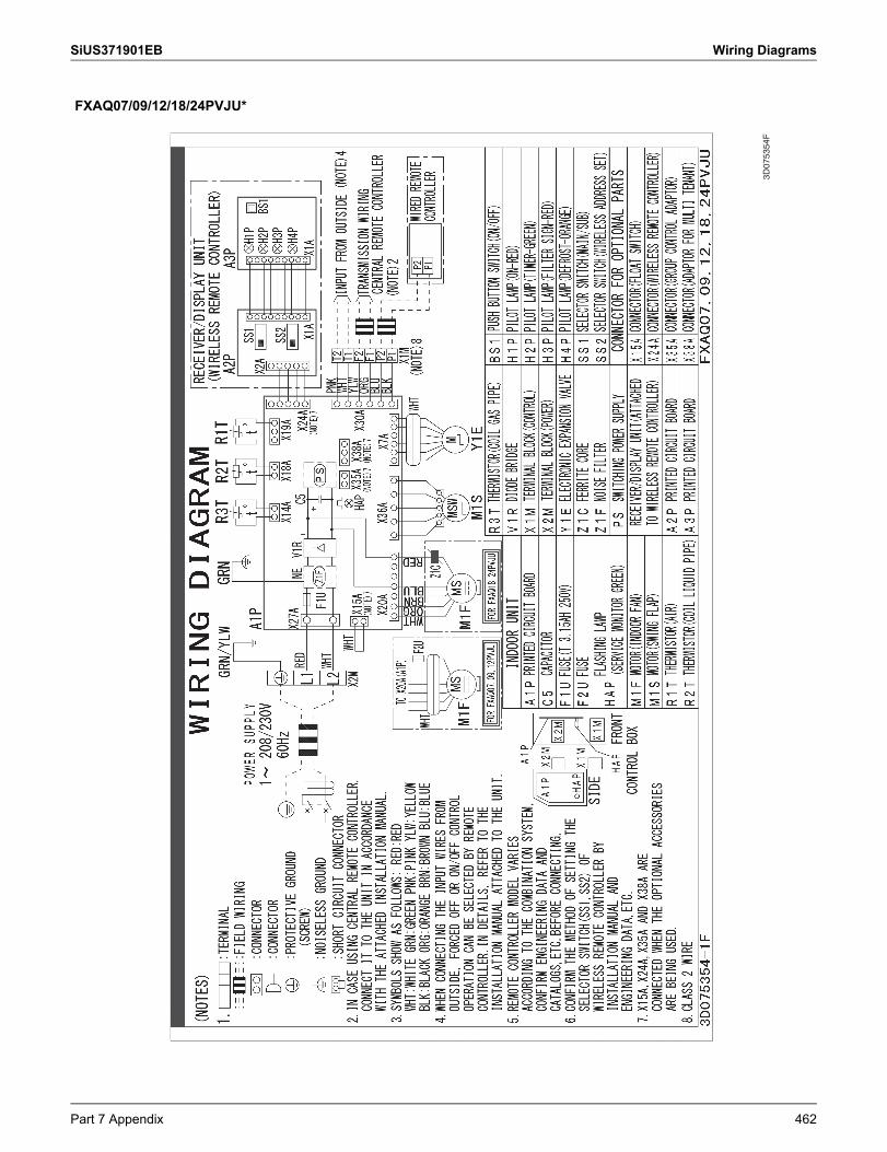
SiUS371901EB Wiring Diagrams
FXAQ07/09/12/18/24PVJU*
3D07
5354
F
Part 7 Appendix 462
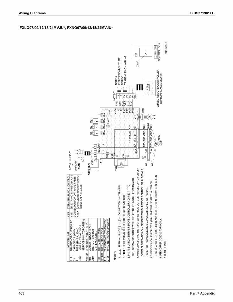
Wiring Diagrams SiUS371901EB
FXLQ07/09/12/18/24MVJU*, FXNQ07/09/12/18/24MVJU*
PO
WE
R S
UP
PLY
GR
N/Y
LWR
3TR
2TR
1TX
1ML1
L2t˚
t˚t˚
RE
DW
HT
A1P
L2L1
X8A
X11A
X13A
X12A
F1U
HA
PX
18A
X3A
NO
TE
-7X
30A
NO
TE
S)
T1R
PN
KT
2T
2W
HT
T1
T1
t˚Y
LWX
1AF
2F
2O
RG
F1
F1
BLU
K3R
K1R
K2R
P2
P2
BLK
P1
P1
FLL
FL
FH
X7A
FC
T1R
X4A
X2M
X18
A
C1
WH
TO
RG
BLK
RE
DB
RN
A1P
YLW
WH
TP
2P
1W
HT
MW
HT
RE
DY
LWB
RN
BLK
OR
GY
1EX2
MX1
M1
Q1M
CO
NT
RO
L B
OX
M1F
1 ~
208/
230V
60
Hz
NO
TE
-4IN
PU
T F
RO
M O
UT
SID
EN
OT
E-3
TR
AN
SM
ISS
ION
WIR
ING
WIR
ED
RE
MO
TE
CO
NT
RO
LLE
R
(OP
TIO
NA
L A
CC
ES
SO
RY
)
M
~
1.
:
TER
MIN
AL
BLO
CK
,
,
: C
ON
NE
CTO
R,
TER
MIN
AL
2.
:
FIE
LD W
IRIN
G,
SH
OR
T C
IRC
UIT
CO
NN
EC
TOR
3. IN
CA
SE
US
ING
CE
NTR
AL
RE
MO
TE C
ON
TRO
LLE
R, C
ON
NE
CT
IT T
O
THE
UN
IT IN
AC
CO
RD
AN
CE
WIT
H T
HE
ATT
AC
HE
D IN
STA
LLA
TIO
N M
AN
UA
L.
4. W
HE
N C
ON
NE
CTI
NG
TH
E IN
PU
T W
IRE
S F
RO
M O
UTS
IDE
, FO
RC
ED
OFF
OR
ON
/OFF
CO
NTR
OL
OP
ER
ATI
ON
CA
N B
E S
ELE
CTE
D B
Y R
EM
OTE
CO
NTR
OLL
ER
. IN
DE
TAIL
S,
RE
FER
TO
TH
E IN
STA
LLA
TIO
N M
AN
UA
L A
TTA
CH
ED
TO
TH
E U
NIT
.
5. S
YM
BO
LS S
HO
W A
S F
OLL
OW
S. (
PN
K: P
INK
WH
T: W
HIT
E Y
LW: Y
ELL
OW
OR
G: O
RA
NG
E B
LU: B
LUE
BLK
: BLA
CK
RE
D: R
ED
BR
N: B
RO
WN
GR
N: G
RE
EN
)
6. U
SE
CO
PP
ER
CO
ND
UC
TOR
S O
NLY
.
7. C
LAS
S 2
WIR
E.
IND
OO
R U
NIT
A1P
C1
F1U
HA
P
K1R
-K3R
M1F
Q1M
R1T
R2T
·R3T
T1R
X1M
PR
INT
ED
CIR
CU
IT B
OA
RD
CA
PA
CIT
OR
(M
1F)
FU
SE
(B
, 5A
, 250
V)
LIG
HT
EM
ITTI
NG
DIO
DE
(S
ER
VIC
E M
ON
ITO
R-G
RE
EN
)M
AG
NE
TIC
RE
LAY
(M
1F)
MO
TO
R (
IND
OO
R F
AN
)T
HE
RM
O. S
WIT
CH
(M
1F E
MB
ED
DE
D)
TH
ER
MIS
TO
R (
AIR
)T
HE
RM
IST
OR
(C
OIL
)TR
ANSF
OR
MER
(208
-230
V/25
V)T
ER
MIN
AL
BLO
CK
(P
OW
ER
)
X2M
Y1E
X18
A
TER
MIN
AL
BLO
CK
(CO
NTR
OL)
ELEC
TRO
NIC
EXP
ANSI
ON
VAL
VEC
ON
NE
CTO
R F
OR
OP
TIO
NA
L P
AR
TSCO
NNEC
TOR
(WIR
ING
ADAP
TOR
FOR
ELEC
TRIC
AL A
PPEN
DICE
S)
3D04
5644
C
463 Part 7 Appendix
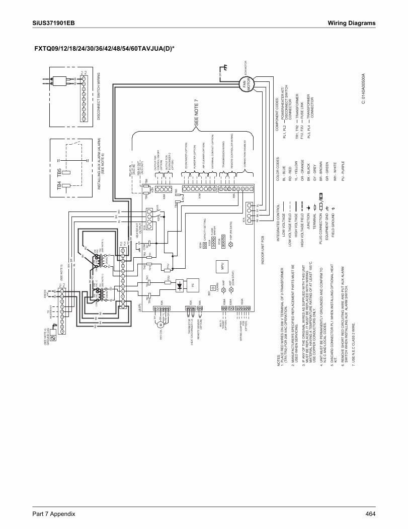
SiUS371901EB Wiring Diagrams
FXTQ09/12/18/24/30/36/42/48/54/60TAVJUA(D)*
C: 0
140A
0050
0A
NO
TE
S:
1. P
LAC
E R
ED
WIR
ES
ON
208
V T
ER
MIN
AL
OF
2-T
RA
NS
FO
RM
ER
(
TR
1/T
R2)
FO
R 2
08 V
AC
OP
ER
AT
ION
.
2. M
AN
UF
AC
TU
RE
R'S
SP
EC
IFIE
D R
EP
LAC
EM
EN
T P
AR
TS
MU
ST
BE
U
SE
D W
HE
N S
ER
VIC
ING
.
3. IF
AN
Y O
F T
HE
OR
IGIN
AL
WIR
ES
AS
SU
PP
LIE
D W
ITH
TH
IS U
NIT
M
US
T B
E R
EP
LAC
ED
, IT
MU
ST
BE
RE
PLA
CE
D W
ITH
WIR
ING
M
AT
ER
IAL
HA
VIN
G A
TE
MP
ER
AT
UR
E R
AT
ING
OF
AT
LE
AS
T 1
05°C
.
US
E C
OP
PE
R C
ON
DU
CT
OR
S O
NLY
.
4. U
NIT
MU
ST
BE
PE
RM
AN
EN
TLY
GR
OU
ND
ED
AN
D C
ON
FIR
M T
O
N.E
.C A
ND
LO
CA
L C
OD
ES
.
5. D
ISC
AR
D C
ON
NE
CT
OR
PL1
WH
EN
IN
ST
ALL
ING
OP
TIO
NA
L H
EA
T
KIT
.
6. R
EM
OV
E S
HO
RT
RE
D C
IRC
UIT
ING
WIR
E A
ND
PU
T A
UX
ALA
RM
S
WIT
CH
WH
EN
INS
TA
LLIN
G A
UX
ALA
RM
SW
ITC
H.
7. U
SE
N.E
.C C
LAS
S 2
WIR
E.
INT
EG
RA
TE
D C
ON
TR
OL:
PO
WE
R/H
EA
TE
R K
IT/
DIS
CO
NN
EC
T S
WIT
CH
CO
NN
EC
TO
R
PL1
, PL2
CO
MP
ON
EN
T C
OD
ES
:
F1U
, F2U
TR
1, T
R2
TR
AN
SF
OR
ME
R
FU
SE
LIN
K
CO
LOR
CO
DE
S:
BL
- B
LUE
RD
- R
ED
YL
- Y
ELL
OW
OR
- O
RA
NG
E
BK
- B
LAC
K
GY
- G
RE
Y
BR
- B
RO
WN
GR
- G
RE
EN
WH
- W
HIT
E
PU
- P
UR
PLE
LOW
VO
LTA
GE
LOW
VO
LTA
GE
FIE
LD
HIG
H V
OLT
AG
E
HIG
H V
OLT
AG
E F
IELD
JUN
CT
ION
TE
RM
INA
L
PLU
G C
ON
NE
CTI
ON
EQ
UIP
ME
NT
GN
D
FIE
LD G
RO
UN
D
X1A
X3A X38
A
BS
1X
12A
X13
A
HA
P
X8A
IND
OO
R U
NIT
PC
B
TH
ER
MIS
TO
R(H
EA
T E
XC
HA
NG
ER
1,2
)
MP
UM
ULT
IT
EN
AN
T(O
PT
ION
)
EE
V C
OIL
MK
1R
K3R
TB
6T
B8
K2R
HE
AT
ER
KIT
OU
TP
UT
LEA
RN
PS
TB
5T
B4
(AC
C-O
UT
)
RE
LAY
OU
T
43
65
98
710
1112
RD
BK
RD
BK
WH
BR
BL
BL
RD
FLA
SH
WR
ITE
R
OR
GY
RD
YL
BK
PU
YL
(SE
E N
OT
E 5
)
TO
HE
AT
ER
KIT
BK
GR
GR
OU
ND
LU
G
CO
NN
EC
TIO
N D
ISA
BLE
D
(SE
E N
OT
E 4
)
24V
AC
INS
TA
LLIN
G A
UX
ALA
RM
(A
LAR
M)
(SE
E N
OT
E 6
)
RD
24V
AC
CO
MC
OM
208
VA
C23
0V
AC
208
VA
C23
0V
AC
TR
1(S
EE
NO
TE
1)
TR
2(S
EE
NO
TE
1)
H2P
(CO
M S
TA
T)
H3P
(R
X D
AT
A)
X33
AW
IRIN
G A
DA
PT
ER
PC
B(O
PT
ION
)
RE
MO
TE
SE
NS
OR
(OP
TIO
N)
X4A
X35
A
X23
A
CA
PA
CIT
Y S
ET
TIN
G
X1M
X2M
F1
T1
P2
P1
T2
F2 12RC
EC
ON
OM
IZE
R (
OP
TIO
N)
HU
MID
IFIE
R (
OP
TIO
N)
AIR
CLE
AN
ER
(O
PT
ION
)
EX
TE
RN
AL
CO
NT
AC
T (
OP
TIO
N)
OU
TP
UT
FO
RC
ON
TR
OL
ON
/OF
F(O
PT
ION
)
OU
TP
UT
FO
RE
CO
NO
MIZ
ER
2(O
PT
ION
)
X7A
FA
NM
OT
OR
21
EC
M M
OT
OR
BK
RD
PL1
PL2
93
26
54
78
1BK
RD
DIS
CO
NN
EC
T S
WIT
CH
WIR
ING
PL1
PL2
97
84
56
32
1
PL3
PL4
TR
AN
SF
OR
ME
R C
ON
NE
CT
OR
PL3
, PL4
RE
LAY
IN
(AC
C-I
N)
BK
RD
GY
BL
X5A
TB
1T
H1
TB
2T
R1
TB
10T
B3
TH
2T
R2
TB
7C
OM
F1U
F2U
SE
E N
OT
E 7
TB
5T
B4
~ ~
WH
BR
BL
GR
RD
BK
BK
RD
RD
208/
230
VA
C
~ ~
TR
AN
SM
ISS
ION
WIR
ING
RE
MO
TE
CO
NT
RO
LLE
R W
IRIN
G
(A1P
)
Part 7 Appendix 464
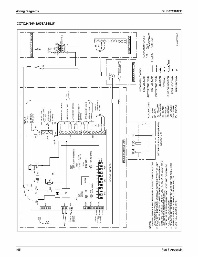
Wiring Diagrams SiUS371901EB
CXTQ24/36/48/60TASBLU*
NO
TE
S:
1. M
AN
UF
AC
TU
RE
R'S
SP
EC
IFIE
D R
EP
LAC
EM
EN
T P
AR
TS
MU
ST
BE
U
SE
D W
HE
N S
ER
VIC
ING
.2.
IF A
NY
OF
TH
E O
RIG
INA
L W
IRE
S A
S S
UP
PLI
ED
WIT
H T
HIS
UN
IT
MU
ST
BE
RE
PLA
CE
D, I
T M
US
T B
E R
EP
LAC
ED
WIT
H W
IRIN
G
MA
TE
RIA
L H
AV
ING
A T
EM
PE
RA
TU
RE
RA
TIN
G O
F A
T L
EA
ST
105
C̊.
U
SE
CO
PP
ER
CO
ND
UC
TO
RS
ON
LY.
3. U
NIT
MU
ST
BE
PE
RM
AN
EN
TLY
GR
OU
ND
ED
AN
D C
ON
FIR
M T
O
N.E
.C A
ND
LO
CA
L C
OD
ES
.4.
RE
MO
VE
SH
OR
T R
ED
CIR
CU
ITIN
G W
IRE
AN
D P
UT
AU
X A
LAR
M
SW
ITC
H W
HE
N IN
ST
ALL
ING
AU
X A
LAR
M S
WIT
CH
.5.
US
E N
.E.C
CLA
SS
2 W
IRE
.
INT
EG
RA
TE
D C
ON
TR
OL:
CO
MP
ON
EN
T C
OD
ES
:
F1U
, F2U
TR
1C
OIL
TR
AN
SF
OR
ME
RF
US
E L
INK
CO
LOR
CO
DE
S:
BL
- B
LUE
RD
- R
ED
YL
- Y
ELL
OW
OR
- O
RA
NG
EB
K -
BLA
CK
GY
- G
RE
YB
R -
BR
OW
NG
R -
GR
EE
NW
H -
WH
ITE
PU
- P
UR
PLE
LOW
VO
LTA
GE
LOW
VO
LTA
GE
FIE
LD
HIG
H V
OLT
AG
E
HIG
H V
OLT
AG
E F
IELD
JUN
CT
ION
TE
RM
INA
L
PLU
G C
ON
NE
CT
ION
EQ
UIP
ME
NT
GN
D
FIE
LD G
RO
UN
D
X3A X38
A
BS
1X
12A
X13
A
HA
P
X8A
IND
OO
R U
NIT
PC
B
TH
ER
MIS
TO
R (
HE
AT
EX
CH
AN
GE
R 1
,2)
MP
U
EE
V C
OIL
M
K3R
TB
6T
B8
LEA
RN
PS
TB
5T
B4
(AC
C-O
UT
)
RE
LAY
OU
T
FLA
SH
WR
ITE
R
GR
RD
H2P
(CO
M S
TA
T)
H3P
(R
X D
AT
A)
DS
1
WIR
ING
AD
AP
TE
RP
CB
(OP
TIO
N)
RE
MO
TE
SE
NS
OR
(OP
TIO
N)
X4A
X35
A
X23
A
CA
PAC
ITY
SE
TT
ING
X1M
X2M
F1T1
P2
P1
T2
F2 12RC
EC
ON
OM
IZE
R (
OP
TIO
N)
HU
MID
IFIE
R (
OP
TIO
N)
AIR
CLE
AN
ER
(O
PT
ION
)
EX
TE
RN
AL
CO
NTA
CT
(OP
TIO
N)
OU
TP
UT
FO
RC
ON
TR
OL
ON
/OF
F(O
PT
ION
)
OU
TP
UT
FO
RE
CO
NO
MIZ
ER
2(O
PT
ION
)
RE
LAY
IN
(AC
C-I
N)
BK
RD
GY
X5A
TB
1T
H1
TB
2T
R1
TB
10T
B3
TH
2T
R2
TB
7C
OM
F1U
F2U
SE
EN
OT
E 5
TB
5T
B4
~ ~ ~ ~
TR
AN
SM
ISS
ION
WIR
ING
RE
MO
TE
CO
NT
RO
LL
ER
WIR
ING
DS
2D
S3
ON
OF
F
2 R C1
INS
TA
LLIN
G A
UX
ALA
RM
(A
LAR
M)
(SE
E N
OT
E 4
)
GR
OU
ND
TO
FU
RN
AC
E
INS
IDE
CO
NT
RO
L B
OX
INS
IDE
FU
RN
AC
E
YL
PU
PU
RD
BK
PU
YL
24V
AC
CO
M20
8V
AC
240
VA
C TR
1(S
EE
NO
TE
1)
120
VACG
R
BL
GR
BK RD
GY
BL
YL
FU
RN
AC
ET
RA
NS
MIS
SIO
N W
IRIN
G
EE
VW
IRIN
G
12
34
12
34
12
34
12
34
INS
IDE
CX
TQ
CO
IL
X33
A
115
VA
C60
Hz
0140
D00
002-
B
465 Part 7 Appendix
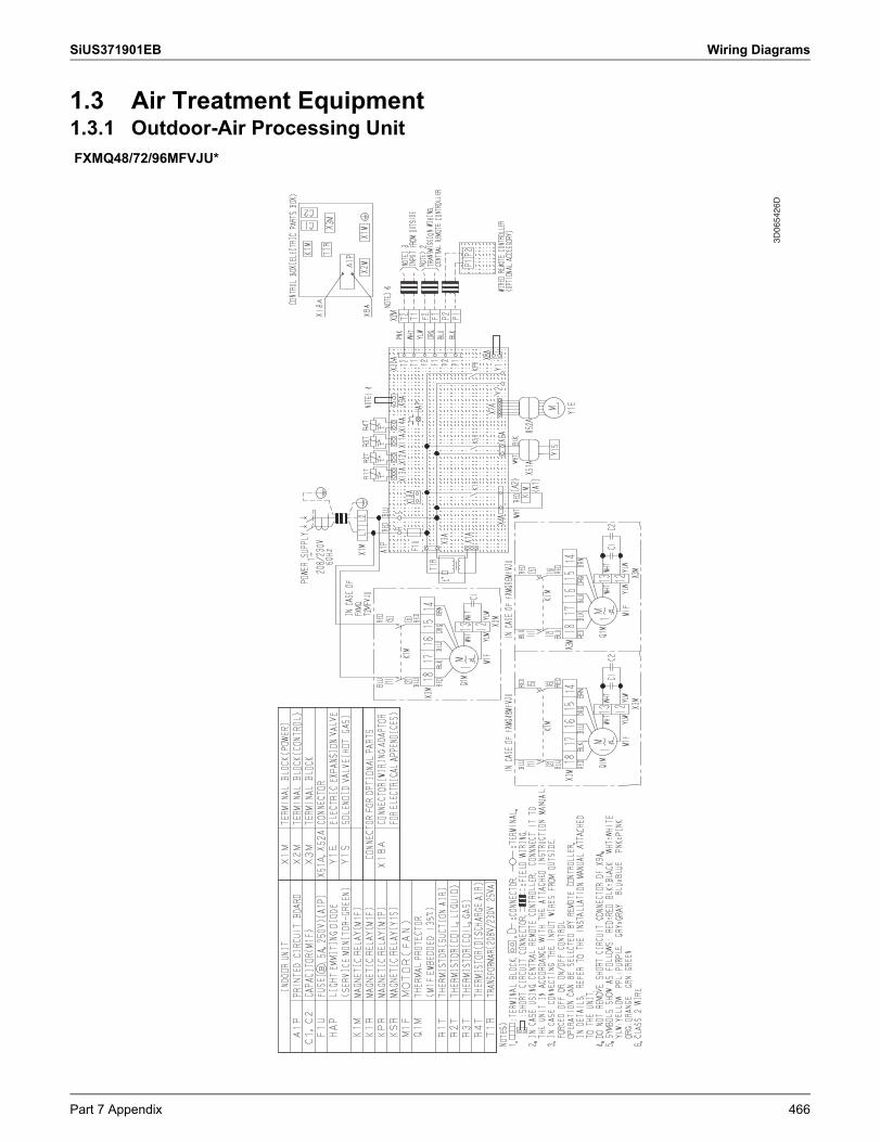
SiUS371901EB Wiring Diagrams
1.3 Air Treatment Equipment1.3.1 Outdoor-Air Processing UnitFXMQ48/72/96MFVJU*
3D06
5426
D
Part 7 Appendix 466
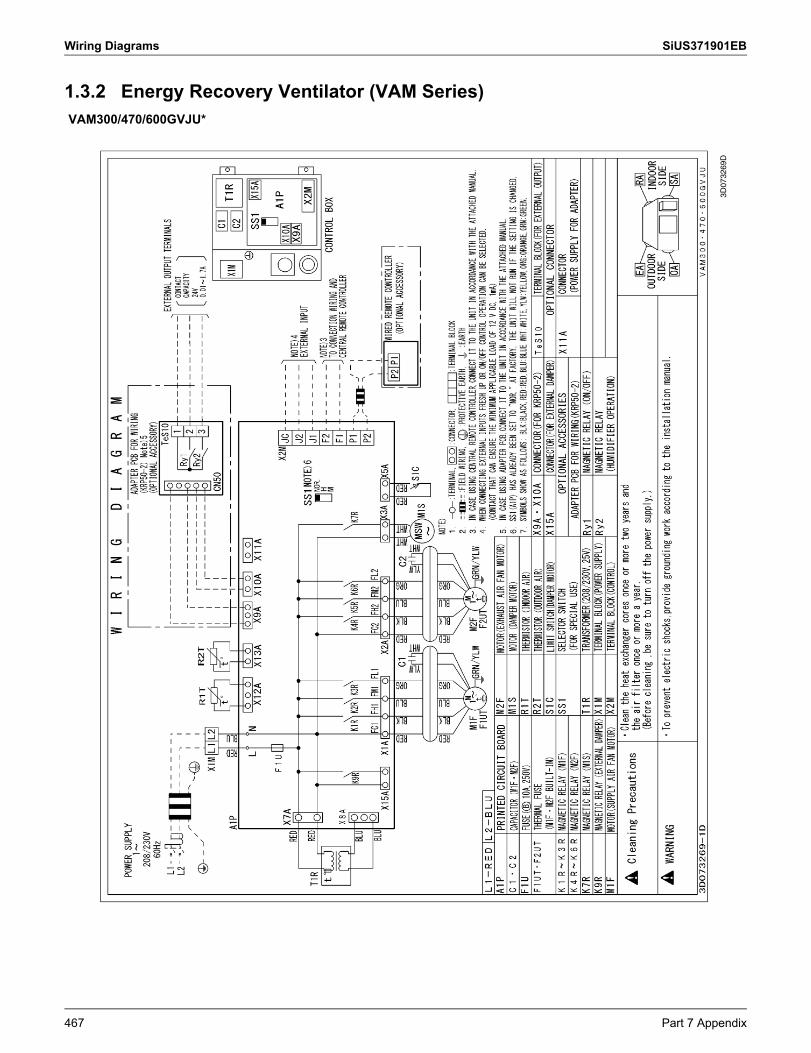
Wiring Diagrams SiUS371901EB
1.3.2 Energy Recovery Ventilator (VAM Series)VAM300/470/600GVJU*
3D07
3269
D
467 Part 7 Appendix
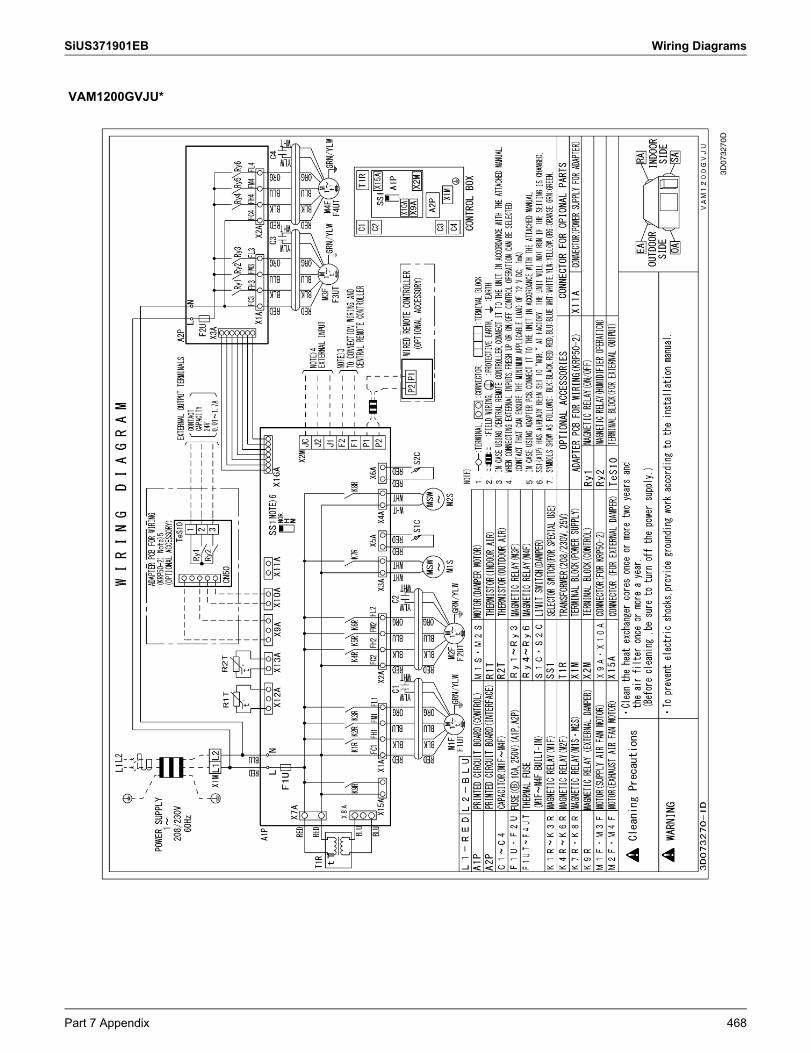
SiUS371901EB Wiring Diagrams
VAM1200GVJU*
3D07
3270
D
Part 7 Appendix 468
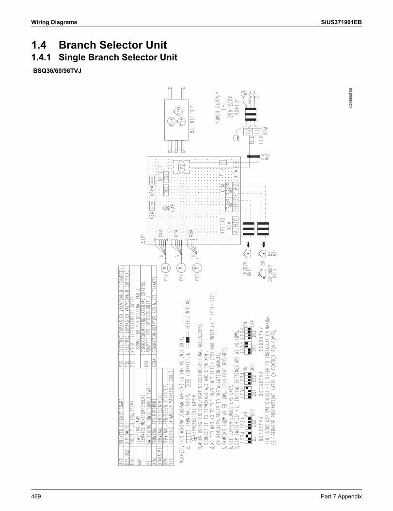
Wiring Diagrams SiUS371901EB
1.4 Branch Selector Unit1.4.1 Single Branch Selector UnitBSQ36/60/96TVJ
3D08
9521
B
469 Part 7 Appendix
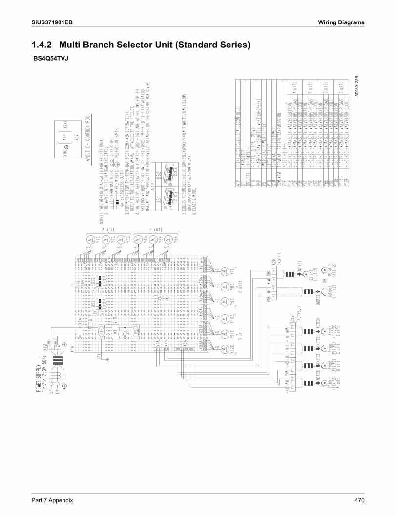
SiUS371901EB Wiring Diagrams
1.4.2 Multi Branch Selector Unit (Standard Series)BS4Q54TVJ
3D08
9123
B
Part 7 Appendix 470
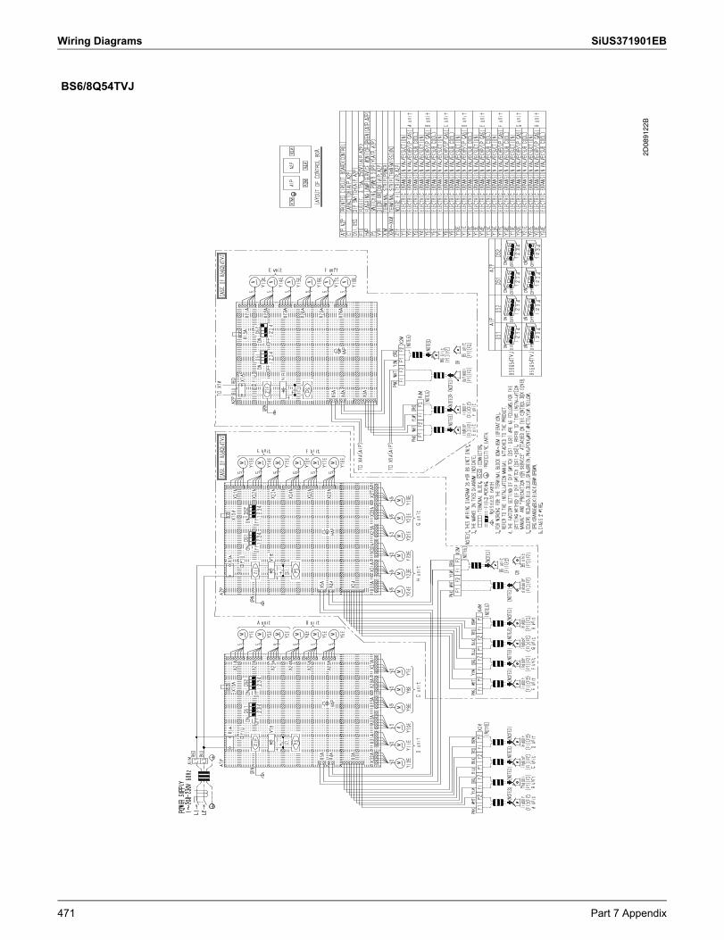
Wiring Diagrams SiUS371901EB
BS6/8Q54TVJ
2D08
9122
B
471 Part 7 Appendix
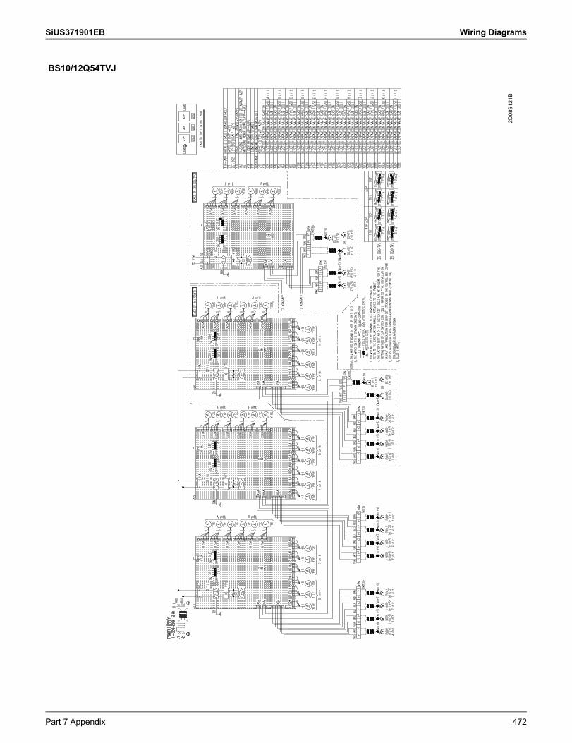
SiUS371901EB Wiring Diagrams
BS10/12Q54TVJ
2D08
9121
B
Part 7 Appendix 472
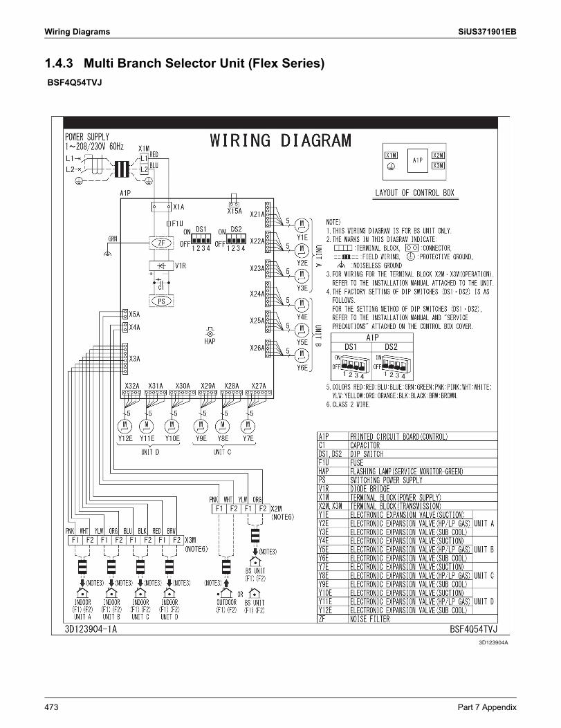
Wiring Diagrams SiUS371901EB
1.4.3 Multi Branch Selector Unit (Flex Series)BSF4Q54TVJ
3D123904A
473 Part 7 Appendix
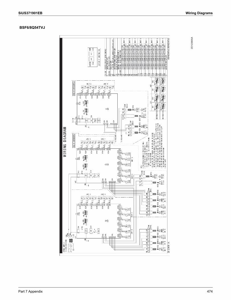
SiUS371901EB Wiring Diagrams
BSF6/8Q54TVJ
2D12
3905
A
Part 7 Appendix 474
Cautions on product corrosion1. Air conditioners should not be installed in areas where corrosive gases, such as acid gas or alkaline gas, are produced.2. If the outdoor unit is to be installed close to the sea shore, direct exposure to the sea breeze should be avoided. If you need to install
the outdoor unit close to the sea shore, contact your local distributor.
© All rights reserved
z Daikin products are manufactured for export to numerous countries throughout the world. Prior to purchase, please confirm with your local authorized importer, distributor and/or retailer whether this product conforms to the applicable standards, and is suitable for use, in the region where the product will be used. This statement does not purport to exclude, restrict or modify the application of any local legislation.
z Ask a qualified installer or contractor to install this product. Do not try to install the product yourself. Improper installation can result in water or refrigerant leakage, electrical shock, fire or explosion.
z Use only those parts and accessories supplied or specified by Daikin. Ask a qualified installer or contractor to install those parts and accessories. Use of unauthorized parts and accessories or improper installation of parts and accessories can result in water or refrigerant leakage, electrical shock, fire or explosion.
z Read the user's manual carefully before using this product. The user's manual provides important safety instructions and warnings. Be sure to follow these instructions and warnings.
If you have any inquiries, please contact your local importer, distributor and/or retailer.
zSpecifications, designs and other content appearing in this brochure are current as of February 2021 but subject to change without notice.SiUS371901EB
02/2021 AK.K
Related Documents