Service Manual SiUS341504E REYQ72-456TTJU REYQ72-456TYDN R-410A Heat Recovery 60 Hz

Welcome message from author
This document is posted to help you gain knowledge. Please leave a comment to let me know what you think about it! Share it to your friends and learn new things together.
Transcript

Service Manual
SiUS341504E
REYQ72-456TTJUREYQ72-456TYDN
R-410A Heat Recovery 60 Hz

SiUS341504E
R-410AHeat Recovery 60 Hz
ED ReferenceFor items below, please refer to Engineering Data.
1. Safety Cautions.......................................................................................... vi1.1 Warnings and Cautions Regarding Safety of Workers.................................vi1.2 Warnings and Cautions Regarding Safety of Users................................... viii
2. Used Icons ................................................................................................. xi
Part 1 General Information ..............................................................11. Model Names of Indoor/Outdoor Units........................................................2
1.1 Indoor Units .................................................................................................. 21.2 Outdoor Units ............................................................................................... 21.3 Air Treatment Equipment ............................................................................. 41.4 Branch Selector Unit .................................................................................... 4
2. External Appearance...................................................................................52.1 Indoor Units .................................................................................................. 52.2 Outdoor Units ............................................................................................... 62.3 Air Treatment Equipment ............................................................................. 72.4 Branch Selector Unit .................................................................................... 7
3. Combination of Outdoor Units.....................................................................83.1 REYQ-TYDN, REYQ-TTJU .......................................................................... 8
4. Interchangeability ........................................................................................95. Capacity Range.........................................................................................10
5.1 Combination Ratio...................................................................................... 105.2 Outdoor Unit Combinations ........................................................................ 105.3 Limitation of Capacity Index for Heat Recovery ......................................... 11
Part 2 Refrigerant Circuit .............................................................. 121. Refrigerant Circuit .....................................................................................13
1.1 REYQ72TYDN / REYQ72TTJU ................................................................. 131.2 REYQ96-168TYDN / REYQ96-168TTJU ................................................... 15
No. Item ED No. Page Remarks
1 Specifications EDUS331435-R1EDUS331435-R2
P.2-7P.2-7
2 Piping Diagrams ED331435-R1EDUS331435-R2
P.14-15P.14-15
3 Option List EDUS331435-R1EDUS331435-R2
P.116P.116
i Table of Contents

SiUS341504E
1.3 Branch Selector Unit Functional Parts ....................................................... 17
2. Functional Parts Layout ............................................................................232.1 REYQ72TYDN ........................................................................................... 232.2 REYQ96 / 120TYDN .................................................................................. 242.3 REYQ144 / 168TYDN ................................................................................ 252.4 REYQ72TTJU ............................................................................................ 262.5 REYQ96 / 120TTJU ................................................................................... 272.6 REYQ144 / 168TTJU ................................................................................. 28
3. Refrigerant Flow for Each Operation Mode...............................................293.1 REYQ72TYDN / REYQ72TTJU ................................................................. 293.2 REYQ96-168TYDN / REYQ96-168TTJU ................................................... 35
Part 3 Remote Controller ............................................................... 411. Wired Remote Controller...........................................................................42
1.1 Applicable Models ...................................................................................... 421.2 Names and Functions ................................................................................ 421.3 MAIN/SUB Setting when Using 2 Remote Controllers ............................... 441.4 Centralized Control Group No. Setting....................................................... 45
2. Wireless Remote Controller ......................................................................472.1 Applicable Models ...................................................................................... 472.2 Names and Functions ................................................................................ 472.3 Address and MAIN/SUB Setting................................................................. 49
3. Service Mode ............................................................................................503.1 BRC1E73 ................................................................................................... 50
Part 4 Function and Control........................................................... 521. Function General.......................................................................................53
1.1 Operation Mode.......................................................................................... 531.2 Stop Control ............................................................................................... 541.3 Standby Control.......................................................................................... 541.4 Startup Control ........................................................................................... 55
2. Basic Control.............................................................................................572.1 List of Functions in Normal Operation ........................................................ 572.2 Compressor PI Control............................................................................... 582.3 Operating Priority and Rotation of Compressors........................................ 582.4 Compressor Step Control........................................................................... 602.5 Electronic Expansion Valve PI Control....................................................... 632.6 Step Control of Outdoor Unit Fans ............................................................. 642.7 Heat Exchanger Control ............................................................................. 66
3. Protection Control .....................................................................................673.1 High Pressure Protection Control............................................................... 673.2 Low Pressure Protection Control................................................................ 693.3 Discharge Pipe Protection Control ............................................................. 703.4 Inverter Protection Control ......................................................................... 71
4. Special Control..........................................................................................724.1 Pump down Residual Operation................................................................. 72
Table of Contents ii

SiUS341504E
4.2 Oil Return Operation .................................................................................. 734.3 Defrost Operation ....................................................................................... 754.4 Cooling / Heating Mode Switching ............................................................. 76
5. Other Control.............................................................................................805.1 Backup Operation....................................................................................... 805.2 Demand Operation ..................................................................................... 805.3 Heating Operation Prohibition .................................................................... 80
6. Outline of Control (Indoor Unit) .................................................................816.1 Operation Flow Chart ................................................................................. 816.2 Thermostat Control..................................................................................... 836.3 Drain Pump Control.................................................................................... 856.4 Control of Electronic Expansion Valve ....................................................... 876.5 Freeze-up Prevention................................................................................. 886.6 Heater Control (Optional PCB KRP1B ... is required.) ............................... 896.7 List of Swing Flap Operations .................................................................... 906.8 Hot Start Control (In Heating Only) ............................................................ 916.9 Louver Control for Preventing Ceiling Dirt.................................................. 926.10 Heater Control (FXTQ) ............................................................................... 936.11 4 Step Thermostat Processing (FXTQ) ...................................................... 956.12 Interlocked with External Equipment (FXTQ) ............................................. 96
Part 5 Field Settings ...................................................................... 981. Test Operation ..........................................................................................99
1.1 Checks before Test Operation ................................................................... 991.2 Test Operation Checks............................................................................... 99
2. Field Setting from Remote Controller......................................................1002.1 Wired Remote Controller.......................................................................... 1002.2 Wireless Remote Controller ..................................................................... 1012.3 Simplified Remote Controller.................................................................... 1022.4 Setting Contents and Code No. for Indoor Units ...................................... 103
3. Field Setting from Outdoor Unit...............................................................1203.1 Accessing the BS Buttons on the Logic Board......................................... 1203.2 Operating the BS Buttons and DIP Switches on the Logic Board ............ 121
3.4 Monitoring Function and Field Settings .................................................... 1243.5 Cool / Heat Mode Changeover................................................................. 1303.6 Setting of Low Night Noise Operation and Demand Operation................ 131
4. Charging Refrigerant...............................................................................1364.1 Precautions .............................................................................................. 1364.2 Calculating the Additional Refrigerant Charge ......................................... 1364.3 Method for Adding Refrigerant ................................................................. 138
Part 6 Service Diagnosis..............................................................1431. Symptom-based Troubleshooting ...........................................................1452. Troubleshooting by Remote Controller ...................................................148
iii Table of Contents

SiUS341504E
2.1 Mode Access Operation ........................................................................... 1482.2 Procedure of Self-diagnosis by Remote Controller .................................. 1492.3 Error Code and Description...................................................................... 1522.4 Error Codes - Sub Codes ......................................................................... 154
3. Troubleshooting by Indication on the Remote Controller ........................1553.1 External Protection Device Abnormality ................................................... 1553.2 PCB Abnormality ...................................................................................... 1563.3 Drain Level Control System (S1L) Abnormality........................................ 1573.4 Fan Motor (M1F) Lock, Overload ............................................................. 1593.5 Indoor Unit Fan Motor Abnormality .......................................................... 1623.6 Indoor Unit Fan Motor Abnormality .......................................................... 1633.7 Overload / Overcurrent / Lock of Indoor Unit Fan Motor .......................... 1663.8 Swing Flap Motor (M1S) Abnormality....................................................... 1673.9 Power Supply Voltage Abnormality .......................................................... 1693.10 Electronic Expansion Valve Coil Abnormality / Dust Clogging ................. 1703.11 Electronic Expansion Valve Coil Abnormality........................................... 1713.12 Drain Level above Limit............................................................................ 1723.13 Capacity Determination Device Abnormality ............................................ 1733.14 Transmission Abnormality between Indoor Unit PCB and Fan PCB........ 1743.15 Thermistor Abnormality ............................................................................ 1763.16 Combination Error between Indoor Unit PCB and Fan PCB .................... 1773.17 Remote Sensor Abnormality .................................................................... 1783.18 Thermistor Abnormality ............................................................................ 1793.19 Humidity Sensor System Abnormality ...................................................... 1803.20 Room Temperature Thermistor in Remote Controller Abnormality .......... 1813.21 PCB Abnormality ...................................................................................... 1823.22 Actuation of High Pressure Switch ........................................................... 1833.23 Actuation of Low Pressure Sensor ........................................................... 1853.24 INV Compressor Motor Lock .................................................................... 1863.25 Compressor Damage Alarm..................................................................... 1883.26 Outdoor Unit Fan Motor Abnormality........................................................ 1903.27 Electronic Expansion Valve Coil Abnormality........................................... 1923.28 Discharge Pipe Temperature Abnormality ............................................... 1933.29 Wet Alarm................................................................................................. 1953.30 Refrigerant Overcharged.......................................................................... 1963.31 Harness Abnormality (between Control PCB and Inverter PCB) ............. 1973.32 Outdoor Unit Fan Motor Signal Abnormality............................................. 1983.33 Thermistor Abnormality ............................................................................ 2003.34 High Pressure Sensor Abnormality .......................................................... 2023.35 Low Pressure Sensor Abnormality ........................................................... 2033.36 Inverter PCB Abnormality......................................................................... 2043.37 Reactor Temperature Rise Abnormality ................................................... 2063.38 Inverter Radiation Fin Temperature Rise Abnormality ............................. 2073.39 INV Compressor Instantaneous Overcurrent ........................................... 2083.40 INV Compressor Overcurrent................................................................... 2103.41 INV Compressor Startup Abnormality ...................................................... 2123.42 Transmission Error between Inverter and Control PCB ........................... 2153.43 Power Supply Voltage Imbalance ............................................................ 217
Table of Contents iv

SiUS341504E
3.44 Reactor Temperature Abnormality ........................................................... 2193.45 Inverter Radiation Fin Temperature Abnormality ..................................... 2203.46 Field Setting after Replacing Outdoor Unit Main PCB Abnormality or
Combination of PCB Abnormality............................................................. 2213.47 Refrigerant Shortage ................................................................................ 2223.48 Reverse Phase, Open Phase................................................................... 2233.49 Power Supply Insufficient or Instantaneous Abnormality ......................... 2243.50 Check Operation is not Executed............................................................. 2263.51 Transmission Error between Indoor Units and Outdoor Units.................. 2273.52 Transmission Error between Remote Controller and Indoor Unit............. 2303.53 Transmission Error between Outdoor Units ............................................. 2313.54 Transmission Error between Main and Sub Remote Controllers ............. 2373.55 Transmission Error between Indoor and Outdoor Units in the
Same System........................................................................................... 2383.56 Improper Combination of Indoor and Outdoor Units,
Indoor Units and Remote Controller......................................................... 2393.57 Address Duplication of Centralized Control Equipment ........................... 2423.58 Transmission Error between Centralized Control Equipment and
Indoor Unit ................................................................................................ 2433.59 System is not Set yet................................................................................ 2453.60 System Abnormality, Refrigerant System Address Undefined ................. 2463.61 Check ....................................................................................................... 248
Part 7 Appendix............................................................................2601. Wiring Diagrams......................................................................................261
1.1 Outdoor Units ........................................................................................... 2611.2 Indoor Units .............................................................................................. 267
v Table of Contents

SiUS341504E Safety Cautions
1. Safety CautionsBe sure to read the following safety cautions before conducting repair work.After the repair work is complete, be sure to conduct a test operation to ensure that the equipment operates normally, and explain the cautions for operating the product to the customer.
Caution Items The caution items are classified into Warning and Caution. The Warning items are especially important since they can lead to death or serious injury if they are not followed closely. The Caution items can also lead to serious accidents under some conditions if they are not followed. Therefore, be sure to observe all the safety caution items described below.
Pictograms This symbol indicates the item for which caution must be exercised. The pictogram shows the item to which attention must be paid.
This symbol indicates the prohibited action. The prohibited item or action is shown in the illustration or near the symbol.
This symbol indicates the action that must be taken, or the instruction. The instruction is shown in the illustration or near the symbol.
1.1 Warnings and Cautions Regarding Safety of WorkersWarning
Do not store the equipment in a room with successive fire sources (e.g., naked flame, gas appliance, electric heater).
Be sure to disconnect the power cable plug from the plug socket before disassembling the equipment for repair.Working on the equipment that is connected to the power supply may cause an electrical shock.If it is necessary to supply power to the equipment to conduct the repair or inspecting the circuits, do not touch any electrically charged sections of the equipment.
If the refrigerant gas is discharged during the repair work, do not touch the discharged refrigerant gas.The refrigerant gas may cause frostbite.
When disconnecting the suction or discharge pipe of the compressor at the welded section, evacuate the refrigerant gas completely at a well-ventilated place first.If there is gas remaining inside the compressor, the refrigerant gas or refrigerating machine oil discharges when the pipe is disconnected, and it may cause injury.
If the refrigerant gas leaks during the repair work, ventilate the area. The refrigerant gas may generate toxic gases when it contacts flames.
Be sure to discharge the capacitor completely before conducting repair work.The step-up capacitor supplies high-voltage electricity to the electrical components of the outdoor unit.A charged capacitor may cause an electrical shock.
vi

Safety Cautions SiUS341504E
Do not start or stop the air conditioner operation by plugging or unplugging the power cable plug.Plugging or unplugging the power cable plug to operate the equipment may cause an electrical shock or fire.
Be sure to wear a safety helmet, gloves, and a safety belt when working at a high place (more than 2 m (6.5 ft)).Insufficient safety measures may cause a fall accident.
In case of R-32 / R-410A refrigerant models, be sure to use pipes, flare nuts and tools for the exclusive use of the R-32 / R-410A refrigerant.The use of materials for R-22 refrigerant models may cause a serious accident such as a damage of refrigerant cycle as well as an equipment failure.
Do not mix air or gas other than the specified refrigerant (R-32 / R-410A / R-22) in the refrigerant system.If air enters the refrigerating system, an excessively high pressure results, causing equipment damage and injury.
Warning
Caution
Do not repair the electrical components with wet hands.Working on the equipment with wet hands may cause an electrical shock.
Do not clean the air conditioner by splashing water.Washing the unit with water may cause an electrical shock.
Be sure to provide the earth / grounding when repairing the equipment in a humid or wet place, to avoid electrical shocks.
Be sure to turn off the power switch and unplug the power cable when cleaning the equipment.The internal fan rotates at a high speed, and may cause injury.
Be sure to conduct repair work with appropriate tools.The use of inappropriate tools may cause injury.
vii

SiUS341504E Safety Cautions
1.2 Warnings and Cautions Regarding Safety of Users
Be sure to check that the refrigerating cycle section has cooled down enough before conducting repair work.Working on the unit when the refrigerating cycle section is hot may cause burns.
Use the welder in a well-ventilated place.Using the welder in an enclosed room may cause oxygen deficiency.
Caution
Warning
Do not store the equipment in a room with successive fire sources (e.g., naked flame, gas appliance, electric heater).
Be sure to use parts listed in the service parts list of the applicable model and appropriate tools to conduct repair work. Never attempt to modify the equipment.The use of inappropriate parts or tools may cause an electrical shock, excessive heat generation or fire.
If the power cable and lead wires have scratches or deteriorated, be sure to replace them.Damaged cable and wires may cause an electrical shock, excessive heat generation or fire.
Do not use a joined power cable or extension cable, or share the same power outlet with other electrical appliances, since it may cause an electrical shock, excessive heat generation or fire.
Be sure to use an exclusive power circuit for the equipment, and follow the local technical standards related to the electrical equipment, the internal wiring regulations, and the instruction manual for installation when conducting electrical work.Insufficient power circuit capacity and improper electrical work may cause an electrical shock or fire.
Be sure to use the specified cable for wiring between the indoor and outdoor units.Make the connections securely and route the cable properly so that there is no force pulling the cable at the connection terminals.Improper connections may cause excessive heat generation or fire.
viii

Safety Cautions SiUS341504E
When wiring between the indoor and outdoor units, make sure that the terminal cover does not lift off or dismount because of the cable.If the cover is not mounted properly, the terminal connection section may cause an electrical shock, excessive heat generation or fire.
Do not damage or modify the power cable.Damaged or modified power cable may cause an electrical shock or fire.Placing heavy items on the power cable, and heating or pulling the power cable may damage the cable.
Do not mix air or gas other than the specified refrigerant (R-32 / R-410A / R-22) in the refrigerant system.If air enters the refrigerating system, an excessively high pressure results, causing equipment damage and injury.
If the refrigerant gas leaks, be sure to locate the leaking point and repair it before charging the refrigerant. After charging refrigerant, make sure that there is no refrigerant leak.If the leaking point cannot be located and the repair work must be stopped, be sure to perform pump-down and close the service valve, to prevent the refrigerant gas from leaking into the room. The refrigerant gas itself is harmless, but it may generate toxic gases when it contacts flames, such as fan and other heaters, stoves and ranges.
When relocating the equipment, make sure that the new installation site has sufficient strength to withstand the weight of the equipment.If the installation site does not have sufficient strength and if the installation work is not conducted securely, the equipment may fall and cause injury.
Check to make sure that the power cable plug is not dirty or loose, then insert the plug into a power outlet securely.If the plug has dust or loose connection, it may cause an electrical shock or fire.
Be sure to install the product correctly by using the provided standard installation frame.Incorrect use of the installation frame and improper installation may cause the equipment to fall, resulting in injury.
For unitary type only
Be sure to install the product securely in the installation frame mounted on the window frame.If the unit is not securely mounted, it may fall and cause injury.
For unitary type only
When replacing the coin battery in the remote controller, be sure to dispose of the old battery to prevent children from swallowing it.If a child swallows the coin battery, see a doctor immediately.
Warning
ix

SiUS341504E Safety Cautions
Caution
Installation of a leakage breaker is necessary in some cases depending on the conditions of the installation site, to prevent electrical shocks.
Do not install the equipment in a place where there is a possibility of combustible gas leaks.If the combustible gas leaks and remains around the unit, it may cause a fire.
Check to see if the parts and wires are mounted and connected properly, and if the connections at the soldered or crimped terminals are secure.Improper installation and connections may cause excessive heat generation, fire or an electrical shock.
If the installation platform or frame has corroded, replace it.Corroded installation platform or frame may cause the unit to fall, resulting in injury.
Check the earth / grounding, and repair it if the equipment is not properly earthed / grounded.Improper earth / grounding may cause an electrical shock.
Be sure to measure the insulation resistance after the repair, and make sure that the resistance is 1 MΩ or higher.Faulty insulation may cause an electrical shock.
Be sure to check the drainage of the indoor unit after the repair.Faulty drainage may cause the water to enter the room and wet the furniture and floor.
Do not tilt the unit when removing it.The water inside the unit may spill and wet the furniture and floor.
Be sure to install the packing and seal on the installation frame properly.If the packing and seal are not installed properly, water may enter the room and wet the furniture and floor.
For unitary type only
x

Used Icons SiUS341504E
2. Used IconsThe following icons are used to attract the attention of the reader to specific information.
Icon Type of Information
Description
Warning
Warning A Warning is used when there is danger of personal injury.
Caution
Caution A Caution is used when there is danger that the reader, through incorrect manipulation, may damage equipment, lose data, get an unexpected result or has to restart (part of) a procedure.
Note:
Note A Note provides information that is not indispensable, but may nevertheless be valuable to the reader, such as tips and tricks.
Reference A Reference guides the reader to other places in this binder or in this manual, where he/she will find additional information on a specific topic.
xi

SiUS341504E
General Information 1
Part 1General Information
1. Model Names of Indoor/Outdoor Units........................................................21.1 Indoor Units .................................................................................................. 21.2 Outdoor Units ............................................................................................... 21.3 Air Treatment Equipment ............................................................................. 41.4 Branch Selector Unit .................................................................................... 4
2. External Appearance...................................................................................52.1 Indoor Units .................................................................................................. 52.2 Outdoor Units ............................................................................................... 62.3 Air Treatment Equipment ............................................................................. 72.4 Branch Selector Unit .................................................................................... 7
3. Combination of Outdoor Units.....................................................................83.1 REYQ-TYDN, REYQ-TTJU .......................................................................... 8
4. Interchangeability ........................................................................................95. Capacity Range.........................................................................................10
5.1 Combination Ratio...................................................................................... 105.2 Outdoor Unit Combinations ........................................................................ 105.3 Limitation of Capacity Index for Heat Recovery ......................................... 11

Model Names of Indoor/Outdoor Units SiUS341504E
1. Model Names of Indoor/Outdoor Units1.1 Indoor Units
VJ : 1 phase, 208/230 V, 60 HzU(VJU) : Standard Symbol
1.2 Outdoor UnitsREYQ-TYDN, REYQ-TTJU
YD(N) : 3 phase, 460 V, 60 HzTJ : 3 phase, 208/230 V, 60 HzU(TJU) : Standard Symbol
Capacity Range 0.6 ton 0.8 ton 1 ton 1.25 ton 1.5 ton 2 ton 2.5 ton 3 ton 3.5 ton 4 ton 4.5 ton 6 ton 8 ton Power Supply, StandardCapacity Index 7.5 9.5 12 15 18 24 30 36 42 48 54 72 96
Ceiling Mounted Cassette (Round Flow with Sensing) Type
FXFQ 07T 09T 12T 15T 18T 24T 30T 36T — 48T — — —VJU
Ceiling Mounted Cassette (Round Flow) Type FXFQ — 09P 12P — 18P 24P 30P 36P — 48P — — —
4 Way Ceiling Mounted Cassette (2'×2') Type FXZQ 07M 09M 12M 15M 18M — — — — — — — — VJU9
Slim Ceiling Mounted Duct Type FXDQ 07M 09M 12M — 18M 24M — — — — — — —
VJU
Ceiling Mounted Duct Type (Middle and High Static Pressure) FXMQ 07PB 09PB 12PB 15PB 18PB 24PB 30PB 36PB — 48PB 54PB — —
Ceiling Mounted Duct Type FXMQ — — — — — — — — — — — 72M 96M
Ceiling Suspended Type FXHQ — — 12M — — 24M — 36M — — — — —Wall Mounted Type FXAQ 07P 09P 12P — 18P 24P — — — — — — —
4-Way Blow Ceiling-Suspended Type FXUQ — — — — 18P 24P 30P 36P — — — — —
Floor Standing Type FXLQ 07M 09M 12M — 18M 24M — — — — — — —Concealed Floor Standing Type FXNQ 07M 09M 12M — 18M 24M — — — — — — —
Vertical Air Handling Unit FXTQ — — 12PA — 18PA 24PA 30PA 36PA 42PA 48PA 54PA — —
Capacity Range 6 ton 8 ton 10 ton 12 ton 14 ton 16 ton 18 ton 20 ton 22 ton Power Supply, StandardCapacity Index 72 96 120 144 168 192 216 240 264
Heat Recovery460 V REYQ- 72T 96T 120T 144T 168T 192T 216T 240T 264T YDN
208/230 V REYQ- 72T 96T 120T 144T 168T 192T 216T 240T 264T TJU
Capacity Range 24 ton 26 ton 28 ton 30 ton 32 ton 34 ton 36 ton 38 ton Power Supply, StandardCapacity Index 288 312 336 360 384 408 432 456
Heat Recovery460 V REYQ- 288T 312T 336T 360T 384T 408T 432T 456T YDN208/230 V REYQ- 288T 312T 336T 360T 384T 408T 432T 456T TJU
2 General Information

SiUS341504E Model Names of Indoor/Outdoor Units
1.2.1 Combination of Outdoor Units (Heat Recovery 460 V)REYQ-TYDN
1.2.2 Combination of Outdoor Units (Heat Recovery 208/230 V)REYQ-TTJU
Model name REYQ72TYDN REYQ96TYDN REYQ120TYDN REYQ144TYDN REYQ168TYDNOutdoor unit 1 REYQ72TYDN REYQ96TYDN REYQ120TYDN REYQ144TYDN REYQ168TYDN
Model name REYQ192TYDN REYQ216TYDN REYQ240TYDN REYQ264TYDN REYQ288TYDNOutdoor unit 1 REYQ72TYDN REYQ96TYDN REYQ96TYDN REYQ120TYDN REYQ144TYDNOutdoor unit 2 REYQ120TYDN REYQ120TYDN REYQ144TYDN REYQ144TYDN REYQ144TYDN
Model name REYQ312TYDN REYQ336TYDN REYQ360TYDN REYQ384TYDN REYQ408TYDNOutdoor unit 1 REYQ144TYDN REYQ168TYDN REYQ120TYDN REYQ96TYDN REYQ96TYDNOutdoor unit 2 REYQ168TYDN REYQ168TYDN REYQ120TYDN REYQ120TYDN REYQ144TYDNOutdoor unit 3 — — REYQ120TYDN REYQ168TYDN REYQ168TYDN
Model name REYQ432TYDN REYQ456TYDNOutdoor unit 1 REYQ144TYDN REYQ144TYDNOutdoor unit 2 REYQ144TYDN REYQ144TYDNOutdoor unit 3 REYQ144TYDN REYQ168TYDN
Model name REYQ72TTJU REYQ96TTJU REYQ120TTJU REYQ144TTJU REYQ168TTJUOutdoor unit 1 REYQ72TTJU REYQ96TTJU REYQ120TTJU REYQ144TTJU REYQ168TTJU
Model name REYQ192TTJU REYQ216TTJU REYQ240TTJU REYQ264TTJU REYQ288TTJUOutdoor unit 1 REYQ72TTJU REYQ96TTJU REYQ96TTJU REYQ120TTJU REYQ144TTJUOutdoor unit 2 REYQ120TTJU REYQ120TTJU REYQ144TTJU REYQ144TTJU REYQ144TTJU
Model name REYQ312TTJU REYQ336TTJU REYQ360TTJU REYQ384TTJU REYQ408TTJUOutdoor unit 1 REYQ144TTJU REYQ168TTJU REYQ120TTJU REYQ96TTJU REYQ96TTJUOutdoor unit 2 REYQ168TTJU REYQ168TTJU REYQ120TTJU REYQ120TTJU REYQ144TTJUOutdoor unit 3 — — REYQ120TTJU REYQ168TTJU REYQ168TTJU
Model name REYQ432TTJU REYQ456TTJUOutdoor unit 1 REYQ144TTJU REYQ144TTJUOutdoor unit 2 REYQ144TTJU REYQ144TTJUOutdoor unit 3 REYQ144TTJU REYQ168TTJU
General Information 3

Model Names of Indoor/Outdoor Units SiUS341504E
1.3 Air Treatment EquipmentOutdoor Air Processing Unit
Energy Recovery Ventilator (VAM series)
VJ : 1 phase, 208/230 V, 60 HzU(VJU) : Standard Symbol
1.4 Branch Selector UnitSingle Branch Selector Unit for Heat Recovery
Note: No interchangeability with BSVQ36/60/96PVJU.VJ: 1 phase, 208/230 V, 60 Hz
Multi Branch Selector Unit for Heat Recovery
Note: No interchangeability with BSV4/6Q36PVJU.VJ: 1 phase, 208/230 V, 60 Hz
Series Model Name Power Supply, Standard
FXMQ 48MF 72MF 96MF VJU
Series Model Name Power Supply, Standard
VAM 300G 470G 600G 1200G VJU
Series Model Name Power Supply, Standard
Heat Recovery BSQ 36T 60T 96T VJ
Series Model Name Power Supply, Standard
Heat Recovery BS 4Q54T 6Q54T 8Q54T 10Q54T 12Q54T VJ
4 General Information

SiUS341504E External Appearance
2. External Appearance2.1 Indoor UnitsCeiling mounted cassette (Round flow with sensing) type
FXFQ-T
Shown with BYCQ125B-W1
Ceiling suspended type
FXHQ-M
Ceiling mounted cassette (Round flow) type
FXFQ-P
Shown with BYCP125K-W1
Wall mounted type
FXAQ-P
4 way ceiling mounted cassette (2’×2’) type
FXZQ-M
Shown with BYFQ60B8W1U
4-way blow ceiling-suspended type
FXUQ-P
Slim ceiling mounted duct type
FXDQ-M
Floor standing type
FXLQ-M
Ceiling mounted duct type (Middle and high static pressure)
FXMQ-PB
Concealed floor standing type
FXNQ-M
Ceiling mounted duct type
FXMQ-M
Vertical air handling unit
FXTQ-PA
General Information 5

External Appearance SiUS341504E
2.2 Outdoor Units2.2.1 REYQ-TYDN, REYQ-TTJUSingle Outdoor Units
Double Outdoor Units
Triple Outdoor Units
REYQ96 / 120 / 144 / 168TYDNREYQ96 / 120 / 144 / 168TTJU
REYQ72TYDNREYQ72TTJU
REYQ192TYDNREYQ192TTJU
REYQ216 / 240 / 264 / 288 / 312 / 336TYDNREYQ216 / 240 / 264 / 288 / 312 / 336TTJU
REYQ360 / 384 / 408 / 432 / 456TYDNREYQ360 / 384 / 408 / 432 / 456TTJU
6 General Information

SiUS341504E External Appearance
2.3 Air Treatment Equipment
2.4 Branch Selector Unit
Outdoor air processing unit
FXMQ-MF
Energy recovery ventilator (VAM series)
VAM-G
Single branch selector unit
BSQ-T
Multi branch selector unit
BS-Q54TVJ
General Information 7

Combination of Outdoor Units SiUS341504E
3. Combination of Outdoor Units3.1 REYQ-TYDN, REYQ-TTJU
Note: 1 For multiple connection, the outdoor unit multi connection piping kit (separately sold) is required.
System capacity Number of units
Module Outdoor Unit Multi Connection Piping Kit 1Ton HP kW 72 96 120 144 168
6 7.5 21.1 1
—
8 10 28.1 1
10 12.5 35.2 1
12 15 42.2 1
14 17.5 49.2 1
16 20 56.3 2
BHFP26P100U
18 22.5 63.3 2
20 25 70.3 2
22 27.5 77.4 2
24 30 84.4 2
26 32.5 91.4 2
28 35 98.5 2
30 37.5 105.5 3
BHFP26P151U
32 40 112.5 3
34 42.5 119.6 3
36 45 126.6 3
38 47.5 133.6 3
8 General Information

SiUS341504E Interchangeability
4. InterchangeabilityBranch Selector unit New Branch Selector unit (Reference)
Current Branch Selector unit
Single Branch Selector unit
Multi Branch Selector unit
Single Branch Selector unit
Multi Branch Selector unit
Outdoor unit
BSQ36TVJBSQ60TVJBSQ96TVJ
BS4Q54TVJBS6Q54TVJBS8Q54TVJBS10Q54TVJBS12Q54TVJ
BSVQ36PVJUBSVQ60PVJUBSVQ96PVJU
BSV4Q36PVJUBSV6Q36PVJU
Heat Recovery REYQ-TREYQ-TYDN Connectable Connectable Not connectable Not connectable
REYQ-TTJU Connectable Connectable Not connectable Not connectable
General Information 9

Capacity Range SiUS341504E
5. Capacity Range5.1 Combination Ratio
Notes: ∗1. If the operational capacity of indoor units is more than 130%, low airflow operation is enforced in all the indoor units. Refer to P.128 for detail.
∗2. When outdoor-air processing units (FXMQ-MF) and standard indoor units are connected, the total connection capacity of the outdoor-air processing units (FXMQ-MF) must not exceed 30% of the capacity index of the outdoor units. And the connection ratio must not exceed 100%.
5.2 Outdoor Unit CombinationsREYQ-TYDN, REYQ-TTJU
Note: ∗1.Values inside brackets are based on connection of indoor units rated at maximum capacity, 200% for single outdoor units, 160% for double outdoor units, and 130% for triple outdoor units.
Combination ratio =Total capacity index of the indoor units
Capacity index of the outdoor units
TypeMin.
combination ratio
Max. combination ratio
Types of connected indoor units Type of connected air treatment equipments
When using only FXDQ, FXMQ-PB,
FXAQ
When using only FXTQ, or at least one
FXFQ07 or FXFQ09
Other indoor unit
models
FXMQ-MF
When FXMQ-MF is only connected
When FXMQ-MF and indoor units are connected
Single outdoor units
50% 200% ∗1 130%
200% ∗1
100% 100% ∗2Double outdoor units 160% ∗1
Triple outdoor units 130%
Capacity Range 6 ton 8 ton 10 ton 12 ton 14 ton 16 ton 18 ton 20 ton 22 ton
REYQ 72TYDN72TTJU
96TYDN96TTJU
120TYDN120TTJU
144TYDN144TTJU
168TYDN168TTJU
192TYDN192TTJU
216TYDN216TTJU
240TYDN240TTJU
264TYDN264TTJU
Max. Number of Connectable Indoor Units 12 16 20 25 29 33 37 41 45
Total Capacity Index of Indoor Units to be Connected ∗1
36~93(144)
48~124(192)
60~156(240)
72~187(288)
84~218(336)
96~249(307)
108~280(346)
120~312(384)
132~343(422)
Capacity Range 24 ton 26 ton 28 ton 30 ton 32 ton 34 ton 36 ton 38 ton
REYQ 288TYDN288TTJU
312TYDN312TTJU
336TYDN336TTJU
360TYDN360TTJU
384TYDN384TTJU
408TYDN408TTJU
432TYDN432TTJU
456TYDN456TTJU
Max. Number of Connectable Indoor Units 49 54 58 62 64 64 64 64
Total Capacity Index of Indoor Units to be Connected ∗1
144~374(461)
156~405(499)
168~436(538)
180~468(468)
192~499(499)
204~530(530)
216~561(561)
228~592(592)
10 General Information

SiUS341504E Capacity Range
5.3 Limitation of Capacity Index for Heat RecoverySingle Branch Selector unit
Multi Branch Selector unit
Note: ∗1.When the total capacity of indoor units to be connected downstream is larger than 54 (Max. 96), use a junction pipe kit (KHRP26A250T, optional parts) to join 2 connections downstream from the Branch Selector unit.
Model BSQ36TVJ BSQ60TVJ BSQ96TVJ
Maximum number of connectable indoor units 4 8 8
Total capacity index of connectable indoor units 36 or less More than 36 and 60 or less More than 60 and 96 or less
Model BS4Q54TVJ BS6Q54TVJ BS8Q54TVJ BS10Q54TVJ BS14Q54TVJ
Maximum number of connectable indoor units per branch 5 5 5 5 5
Number of branches 4 6 8 10 12
Maximum capacity index of connectable indoor units 144 or less 216 or less 290 or less 290 or less 290 or less
Maximum capacity index of connectable indoor units per branch (∗1) 54 or less 54 or less 54 or less 54 or less 54 or less
Suction gas pipingLiquid piping
Indoor unit(Heating)
Indoor unit(Cooling)
Indoor unit∗(Cooling only)
Heat Recovery operation!
Branch Selector unit
Branch Selector unit
Heat Recovery
Outdoor unit
High and low pressure gas piping
∗ For indoor units used for cooling only (do not connect to Branch Selector unit when using for Heat Recovery), total capacity index must be 50% or less than the capacity index of the outdoor units.
General Information 11

SiUS341504E
12 Refrigerant Circuit
Part 2Refrigerant Circuit
1. Refrigerant Circuit .....................................................................................131.1 REYQ72TYDN / REYQ72TTJU ................................................................. 131.2 REYQ96-168TYDN / REYQ96-168TTJU ................................................... 151.3 Branch Selector Unit Functional Parts ....................................................... 17
2. Functional Parts Layout ............................................................................232.1 REYQ72TYDN ........................................................................................... 232.2 REYQ96 / 120TYDN .................................................................................. 242.3 REYQ144 / 168TYDN ................................................................................ 252.4 REYQ72TTJU ............................................................................................ 262.5 REYQ96 / 120TTJU ................................................................................... 272.6 REYQ144 / 168TTJU ................................................................................. 28
3. Refrigerant Flow for Each Operation Mode...............................................293.1 REYQ72TYDN / REYQ72TTJU ................................................................. 293.2 REYQ96-168TYDN / REYQ96-168TTJU ................................................... 35

SiUS341504E Refrigerant Circuit
1. Refrigerant Circuit1.1 REYQ72TYDN / REYQ72TTJU
U
No. in refrigerant
system diagram
Electric symbol Name Major function
(1) M1C Inverter compressor (INV) Inverter compressor is operated on frequencies between 52 Hz to 210 Hz by using the inverter. Compressor operation steps: Refer to P.60~
(2) M1F Inverter fan Because the system is an air heat exchange type, the fan is operated at 9-step rotation speed by using the inverter.
(3) Y1E Electronic expansion valve (Heat exchanger upper)
While in heating, PI control is applied to keep the outlet superheated degree of air heat exchanger constant.
(4) Y2E Electronic expansion valve (Subcooling heat exchanger)
PI control is applied to keep the outlet superheated degree of subcooling heat exchanger constant.
(5) Y3E Electronic expansion valve (Heat exchanger lower)
While in heating, PI control is applied to keep the outlet superheated degree of air heat exchanger constant.
(6) Y4E Electronic expansion valve (Receiver gas purge) Used to collect the refrigerant to receiver.
(7) Y5E Electronic expansion valve (Refrigerant cooling)
Used to control the refrigerant amount to cool the diode bridge and power module of the inverter PCB.
(8) Y6E Electronic expansion valve (Leak detection) Used to detect refrigerant leakage.
(9) Y1S Solenoid valve (OS oil return) Used to return oil from the oil separator to the compressor.(10) Y3S Solenoid valve (Liquid shutoff) Used to return oil from the accumulator to the compressor.(11) Y4S Four way valve (HP/LP gas) Used to switch dual pressure gas pipe to high pressure or low pressure.
(12) Y5S Four way valve(Heat exchanger lower)
Used to switch outdoor unit heat exchanger to evaporator or condenser.(13) Y6S Four way valve
(Heat exchanger upper)(14) S1NPH High pressure sensor Used to detect the high pressure.(15) S1NPL Low pressure sensor Used to detect the low pressure.
(16) S1PH High pressure switch(For INV compressor)
This functions when pressure increases to stop operation and avoid high pressure increase in the fault operation.
(17) — Pressure regulating valve (Liquid pipe)
This is used when pressure increases, to prevent any damage on components caused by pressure increase in transport or storage.
(18) — Subcooling heat exchanger Apply subcooling to liquid refrigerant.
(19) — Capillary tube Used to return the refrigerating oil separated through the oil separator to the INV compressor.
(20) R1T Thermistor (Outdoor air) Used to detect outdoor air temperature, correct discharge pipe temperature and others.(21) R2T Thermistor (M1C discharge) Used to detect discharge pipe temperature.(22) R3T Thermistor (Receiver inlet) Used to detect liquid pipe temperature of receiver inlet.
(23) R4T Thermistor (Heat exchanger liquid upper)
This detects temperature of liquid pipe for air heat exchanger.(24) R5T Thermistor (Heat exchanger
liquid lower)(25) R6T Thermistor (Subcooling gas) Used to detect outdoor air temperature, correct discharge pipe temperature and others.(26) R7T Thermistor (Subcooling liquid) This detects temperature of liquid pipe for subcooling heat exchanger.
(27) R8T Thermistor (Heat exchanger gas upper)
This detects temperature of gas pipe for air heat exchanger.(28) R9T Thermistor (Heat exchanger
gas lower)(29) R10T Thermistor (Suction) Used to detect suction pipe temperature.
(30) R11T Thermistor (Deicer) Used to detect liquid pipe temperature of air heat exchanger. Used to make judgements on defrosting operation.
(31) R12T Thermistor (Comp. suction) Used to detect suction pipe temperature of compressor.
(32) R13T Thermistor(Receiver gas purge) Used to detect gas pipe temperature of receiver gas purge piping.
(33) R14T Thermistor (M1C body) Detects compressor surface temperature, this switch is activated at surface temperature of 120°C (248°F) or more to stop the compressor.
(34) R15T Thermistor (Leak detection) The thermistor detects refrigerant leakage.
Refrigerant Circuit 13

Refrigerant Circuit SiUS341504E
REYQ72TYDN / REYQ72TTJU
Che
ck v
alve
Che
ck v
alve
Filt
er
SV
Filt
er
Filt
er
Fan
Filt
erM
Filt
er
Filt
er
Filt
er
S1NP
H
Filt
er
S1P
HF
ilter
S1NP
L
SV
Com
pres
sor
Filt
er
Accu
mul
ator
Sto
p va
lve
( With
ser
vice
por
t φ5/
16in
. (7.
9mm
) fla
re c
onne
ctio
n)
Liqu
id
pipe
High
/low
pres
sure
gas
pi
pe
Suc
tion
gas
pipe
Che
ck v
alve
Ele
ctro
nic
expa
nsio
n va
lve
Doub
le tu
be
heat
exc
hang
er
Ele
ctro
nic
expa
nsio
n va
lve
Cap
illar
y tu
beLiq
uid
Rece
iver F
usib
le
plug
Pre
ssur
e re
gula
ting
valv
eSol
enoi
d va
lve
Chec
k va
lve
Ele
ctro
nic
expa
nsio
n va
lve
Che
ck
valv
eC
heck
va
lve
Cap
illar
y tu
be
Ele
ctro
nic
expa
nsio
n va
lve
Elec
troni
c ex
pans
ion
valve
Hea
t sin
k
Che
ck v
alve
Oil
sepa
rato
r
Cap
illar
y tu
be
Sol
enoi
d va
lve
INV
Hig
h pr
essu
re
switc
h
Hig
h pr
essu
re
sens
or
Fou
r w
ay v
alve
Four
way
val
ve
Dou
ble
tube
he
at e
xcha
nger
Four
way
val
ve
Low
pre
ssur
e se
nsor
Fus
ible
pl
ugCap
illar
y tu
beC
harg
e po
rt
Ele
ctro
nic
expa
nsio
n va
lve
Che
ck v
alve
C: 3
D09
1128
(26)
(29)
(32)
(12)
(13)
(10)
(8)
(3)
(5)
(7)
(17)
(2)
(6)
(25)
(27)
(28)
(20)
(21)
(31)
(19)
(33)
(9)
(1)
(30)
(14)
(16)
(23)
(22)
(24)
(11)
(15)
(4)
(18)
14 Refrigerant Circuit

SiUS341504E Refrigerant Circuit
1.2 REYQ96-168TYDN / REYQ96-168TTJUNo. in
refrigerant system diagram
Electric symbol Name Major function
(1) M1C Inverter compressor (INV 1) Inverter compressor is operated on frequencies between 52 Hz to 210 Hz by using the inverter. Compressor operation steps: Refer to P.60~(2) M2C Inverter compressor (INV 2)
(3) M1FInverter fan Because the system is an air heat exchange type, the fan is operated at 9-step rotation
speed by using the inverter.(4) M2F
(5) Y1E Electronic expansion valve (Heat exchanger upper)
While in heating, PI control is applied to keep the outlet superheated degree of air heat exchanger constant.
(6) Y2E Electronic expansion valve (Subcooling heat exchanger)
PI control is applied to keep the outlet superheated degree of subcooling heat exchanger constant.
(7) Y3E Electronic expansion valve (Heat exchanger lower)
While in heating, PI control is applied to keep the outlet superheated degree of air heat exchanger constant.
(8) Y4E Electronic expansion valve (Receiver gas purge) Used to collect the refrigerant to receiver.
(9) Y5E Electronic expansion valve (Refrigerant cooling)
Used to control the refrigerant amount to cool the diode bridge and power module of the inverter PCB.
(10) Y6E Electronic expansion valve (Leak detection) Used to detect refrigerant leakage.
(11) Y1S Solenoid valve(OS oil return 1) Used to return oil from the oil separator to the compressor (M1C).
(12) Y2S Solenoid valve(OS oil return 2) Used to return oil from the oil separator to the compressor (M2C).
(13) Y3S Solenoid valve (Liquid shutoff) Used to return oil from the accumulator to the compressor.(14) Y4S Four way valve (HP/LP gas) Used to switch dual pressure gas pipe to high pressure or low pressure.
(15) Y5S Four way valve(Heat exchanger lower)
Used to switch outdoor unit heat exchanger to evaporator or condenser.(16) Y6S Four way valve
(Heat exchanger upper)(17) S1NPH High pressure sensor Used to detect the high pressure.(18) S1NPL Low pressure sensor Used to detect the low pressure.
(19) S1PH High pressure switch(For INV 1 compressor) This functions when pressure increases to stop operation and avoid high pressure
increase in the fault operation.(20) S2PH High pressure switch
(For INV 2 compressor)
(21) — Pressure regulating valve (Liquid pipe)
This is used when pressure increases, to prevent any damage on components caused by pressure increase in transport or storage.
(22) — Subcooling heat exchanger Apply subcooling to liquid refrigerant.
(23) — Capillary tube Used to return the refrigerating oil separated through the oil separator to the INV 1 compressor.
(24) — Capillary tube Used to return the refrigerating oil separated through the oil separator to the INV 2 compressor.
(25) R1T Thermistor (Outdoor air) Used to detect outdoor air temperature, correct discharge pipe temperature and others.(26) R21T Thermistor (M1C discharge)
Used to detect discharge pipe temperature.(27) R22T Thermistor (M2C discharge)(28) R3T Thermistor (Receiver inlet) Used to detect liquid pipe temperature of receiver inlet.
(29) R4T Thermistor (Heat exchanger liquid upper)
This detects temperature of liquid pipe for air heat exchanger.(30) R5T Thermistor (Heat exchanger
liquid lower)
(31) R6T Thermistor (Subcooling gas)Used to detect gas pipe temperature on the evaporating side of subcooling heat exchanger. Used to exercise the constant control of superheated degree at the outlet of subcooling heat exchanger.
(32) R7T Thermistor (Subcooling liquid) This detects temperature of liquid pipe for subcooling heat exchanger.
(33) R8T Thermistor (Heat exchanger gas upper)
This detects temperature of gas pipe for air heat exchanger.(34) R9T Thermistor (Heat exchanger
gas lower)(35) R10T Thermistor (Suction) Used to detect suction pipe temperature.
(36) R11T Thermistor (Deicer) Used to detect liquid pipe temperature of air heat exchanger. Used to make judgements on defrosting operation.
(37) R12T Thermistor (Comp. suction) Used to detect suction pipe temperature of compressor.
(38) R13T Thermistor(Receiver gas purge) Used to detect gas pipe temperature of receiver gas purge piping.
(39) R14T Thermistor (M2C body) Detects compressor surface temperature, this switch is activated at surface temperature of 120°C (248°F) or more to stop the compressor. (144/168 class models only)
(40) R15T Thermistor (Leak detection) The thermistor detects refrigerant leakage.
Refrigerant Circuit 15

Refrigerant Circuit SiUS341504E
REYQ96-168TYDN / REYQ96-168TTJU
Four
way
val
ve
Che
ck v
alve
Filt
erC
heck
val
ve
SV
Filt
er
Rece
iver
Filt
er
Fan
Fan
Filt
erM
MF
ilter
Filt
er
Filt
er
S1NP
HF
ilter
Filt
er
S2P
HS
1PH
Filt
erF
ilter
S1NP
L
SV
Com
pres
sor
Filt
er
Accu
mul
ator
Sto
p va
lve
( With
ser
vice
por
t φ5/
16in
. (7.
9mm
) fla
re c
onne
ctio
n)
Liqu
id
pipe
Che
ck v
alve
Chec
k va
lve
Ele
ctro
nic
expa
nsio
n va
lve
Ele
ctro
nic
expa
nsio
n va
lve
Ele
ctro
nic
expa
nsio
n va
lve
Doub
le tu
be
heat
exc
hang
er
Che
ck v
alve
Sol
enoi
d va
lve
Cap
illar
y tu
be
Fus
ible
pl
ug
Pre
ssur
e re
gula
ting
valv
e
Che
ck
valv
eC
heck
va
lve
Cap
illar
y tu
be
Ele
ctro
nic
expa
nsio
n va
lve
Elec
troni
c ex
pans
ion
valve
Ele
ctro
nic
expa
nsio
n va
lve
Hea
t sin
k
Fou
r w
ay v
alve
Four
way
val
ve
Dou
ble
tube
he
at e
xcha
nger
Four
way
val
ve
Low
s pr
essu
re
sens
or
High
/low
pres
sure
gas
pi
pe
Suc
tion
gas
pipe
Fus
ible
pl
ugCap
illar
y tu
be
Cha
rge
port
INV
2
Hig
h pr
essu
re
switc
hHig
h pr
essu
re
sens
or
Che
ck
valv
e
Oil
Sep
arat
orHi
gh p
ress
ure
switc
h
Com
pres
sor
INV
1
Cap
illar
y tu
be
Sol
enoi
d va
lve
Che
ck
valv
e
Oil
Sep
arat
or
Cap
illar
y tu
be
Sol
enoi
d va
lve SV
C: 3
D09
1127
(32)
(35)
(38)
(15)
(16)
(13)
(8)
(5) (7
)
(9)
(21)
(4)
(3)
(8)
(31)
(33)
(28)
(34)
(25)
(19)
(27)
(2)
(12)
(37)
(39)
(26)
(1)
(11)
(23)
(24)(36)
(17)
(20)
(29)
(30)
(14)
(18)
(6)
(22)
16 Refrigerant Circuit

SiUS341504E Refrigerant Circuit
1.3 Branch Selector Unit Functional PartsSingle Branch Selector UnitBSQ36-96TVJ
Note: Factory setting of all EV opening: 60 pulse
No. Name Electric symbol Function
1 Electronic expansion valve (EVH) Y2E Opens while in heating operation or all indoor units are in cooling.(Max : 760 pulse)
2 Electronic expansion valve (EVL) Y3E Opens while in cooling. (Max : 760 pulse)
3 Electronic expansion valve (EVSC) Y1EIn simultaneous cooling and heating operation, it is used to subcooling liquid refrigerants when an indoor unit downstream of this Branch Selector unit is in heating. (Max : 480 pulse)
Filter
Filter Filter
Filter
Liquid pipe connection port
Gas pipe connection port
Double pipe heat exchanger
Electronic Expansion Valve
(EVSC)
HP/LP gas pipe connection port
Suction gas pipe connection port
Electronic Expansion Valve
(EVH)
Electronic Expansion Valve
(EVL)
Liquid pipe connection port
(3)
(1)
(2)
4D085545A
Refrigerant Circuit 17

Refrigerant Circuit SiUS341504E
Multi Branch Selector UnitBS4Q54TVJ
Filter
Filter
Filter
Filter
Filter
Filter
Filter
Filter
Filter
Filter
D unit
B unit
C unit
A unit
Liquid pipe connection port
Suction gas pipe
connection port
HP
/LP gas pipe
connection port
Double pipe heat exchanger
Double pipe heat exchanger
Double pipe heat exchanger
Double pipe heat exchanger
Electronic Expansion Valve
(Subcooling)
Electronic Expansion Valve
(Subcooling)
Electronic Expansion Valve
(Subcooling)
Electronic Expansion Valve
(Subcooling)
Electronic Expansion Valve (HP/LP gas)
Electronic Expansion Valve (Suction)
Electronic Expansion Valve (HP/LP gas)
Electronic Expansion Valve (Suction)
Electronic Expansion Valve (HP/LP gas)
Electronic Expansion Valve (Suction)
Electronic Expansion Valve (HP/LP gas)
Electronic Expansion Valve (Suction)
Gas pipe connection port
Liquid pipe connection port
Gas pipe connection port
Liquid pipe connection port
Gas pipe connection port
Liquid pipe connection port
Gas pipe connection port
Liquid pipe connection port
3D086032A
(1)
(2)
(1)
(1)
(1)
(2)
(2)
(2)
(3)
(3)
(3)
(3)
18 Refrigerant Circuit

SiUS341504E Refrigerant Circuit
BS6Q54TVJ
Filter
Filter
Filter
Filter
Filter
Filter
Filter
Filter
Electronic Expansion Valve (Suction)
Electronic Expansion Valve (Suction)
Electronic Expansion Valve (Suction)
Electronic Expansion Valve (Suction)
Electronic Expansion Valve (Suction)
Electronic Expansion Valve (Suction)
Electronic Expansion Valve (HP/LP gas)
Electronic Expansion Valve (HP/LP gas)
Electronic Expansion Valve (HP/LP gas)
Electronic Expansion Valve (HP/LP gas)
Electronic Expansion Valve (HP/LP gas)
Electronic Expansion Valve (HP/LP gas)
Filter
Filter
Filter
Filter
Filter
Filter
B unit
A unit
C unit
D unit
E unit
F unit
Liquid pipe connection port
Suction gas pipe
connection port
HP
/LP gas pipe
connection port
Gas pipe connection port
Liquid pipe connection port
Gas pipe connection port
Liquid pipe connection port
Gas pipe connection port
Liquid pipe connection port
Gas pipe connection port
Liquid pipe connection port
Gas pipe connection port
Liquid pipe connection port
Gas pipe connection port
Liquid pipe connection port
Double pipe heat exchanger
Electronic Expansion Valve
(Subcooling)
Double pipe heat exchanger
Electronic Expansion Valve
(Subcooling)
Double pipe heat exchanger
Electronic Expansion Valve
(Subcooling)
Double pipe heat exchanger
Electronic Expansion Valve
(Subcooling)
Double pipe heat exchanger
Electronic Expansion Valve
(Subcooling)
Double pipe heat exchanger
Electronic Expansion Valve
(Subcooling)
(1)
(1)
(1)
(1)
(1)
(1)
(2) (3)
(3)
(3)
(3)
(3)
(3)
(2)
(2)
(2)
(2)
(2)
3D086033A
Refrigerant Circuit 19

Refrigerant Circuit SiUS341504E
BS8Q54TVJ
Filter
Filter
Filter
Filter
Filter
Filter
Filter
Filter
Filter
FilterElectronic Expansion Valve (HP/LP gas)
Electronic Expansion Valve (Suction)
Electronic Expansion Valve (HP/LP gas)
Electronic Expansion Valve (Suction)
Electronic Expansion Valve (HP/LP gas)
Electronic Expansion Valve (Suction)
Electronic Expansion Valve (HP/LP gas)
Electronic Expansion Valve (Suction)
Electronic Expansion Valve (HP/LP gas)
Electronic Expansion Valve (Suction)
Electronic Expansion Valve (HP/LP gas)
Electronic Expansion Valve (Suction)
Electronic Expansion Valve (HP/LP gas)
Electronic Expansion Valve (Suction)
Electronic Expansion Valve (HP/LP gas)
Electronic Expansion Valve (Suction)
Filter
Filter
Filter
Filter
Filter
Filter
Filter
Filter
D unit
F unit
H unit
A unit
G unit
E unit
C unit
B unit
Gas pipe connection portLiquid pipe connection port
Gas pipe connection portLiquid pipe connection port
Gas pipe connection portLiquid pipe connection port
Gas pipe connection portLiquid pipe connection port
Gas pipe connection portLiquid pipe connection port
Gas pipe connection portLiquid pipe connection port
Gas pipe connection portLiquid pipe connection port
Gas pipe connection portLiquid pipe connection port
Suction gas pipe
connection port
Liquid pipe connection port
HP
/LP gas pipe
connection port
Double pipe heat exchanger
Electronic Expansion Valve
(Subcooling)
Double pipe heat exchanger
Electronic Expansion Valve
(Subcooling)
Double pipe heat exchanger
Electronic Expansion Valve
(Subcooling)
Double pipe heat exchanger
Electronic Expansion Valve
(Subcooling)
Double pipe heat exchanger
Electronic Expansion Valve
(Subcooling)
Double pipe heat exchanger
Electronic Expansion Valve
(Subcooling)
Double pipe heat exchanger
Electronic Expansion Valve
(Subcooling)
Double pipe heat exchanger
Electronic Expansion Valve
(Subcooling)
(1)
(2)
(1)
(2)
(1)
(2)
(1)
(2)
(1)
(2)
(1)
(2)
(1)
(2)
(1)
(2) (3)
(3)
(3)
(3)
(3)
(3)
(3)
(3)
3D086034A
20 Refrigerant Circuit

SiUS341504E Refrigerant Circuit
BS10Q54TVJ
Filter
Filter
Filter
Filter
Filter
Filter
Filter
Filter
Filter
Filter
Filter
Filter
Filter
Filter
Filter
Filter
Filter
Filter
Filter
Filter
Filter
Filter
F unit
B unit
G unit
J unitI unit
D unit
H unit
E unit
C unit
A unit
Liquid pipe connection port
Suction gas pipe
connection port
HP
/LP gas pipe
connection port
Gas pipe connection port
Liquid pipe connection port
Gas pipe connection port
Liquid pipe connection port
Gas pipe connection port
Liquid pipe connection port
Gas pipe connection port
Liquid pipe connection port
Gas pipe connection port
Liquid pipe connection port
Gas pipe connection port
Liquid pipe connection port
Gas pipe connection port
Liquid pipe connection port
Gas pipe connection port
Liquid pipe connection port
Gas pipe connection port
Liquid pipe connection port
Gas pipe connection port
Liquid pipe connection port
Electronic Expansion Valve (HP/LP gas)
Electronic Expansion Valve (Suction)
Electronic Expansion Valve (HP/LP gas)
Electronic Expansion Valve (Suction)
Electronic Expansion Valve (HP/LP gas)
Electronic Expansion Valve (Suction)
Electronic Expansion Valve (HP/LP gas)
Electronic Expansion Valve (Suction)
Electronic Expansion Valve (HP/LP gas)
Electronic Expansion Valve (Suction)
Electronic Expansion Valve (HP/LP gas)
Electronic Expansion Valve (Suction)
Electronic Expansion Valve (HP/LP gas)
Electronic Expansion Valve (Suction)
Electronic Expansion Valve (HP/LP gas)
Electronic Expansion Valve (Suction)
Electronic Expansion Valve (HP/LP gas)
Electronic Expansion Valve (Suction)
Electronic Expansion Valve (HP/LP gas)
Electronic Expansion Valve (Suction)
Double pipe heat exchanger
Electronic Expansion Valve
(Subcooling)
Double pipe heat exchanger
Electronic Expansion Valve
(Subcooling)
Double pipe heat exchanger
Electronic Expansion Valve
(Subcooling)
Double pipe heat exchanger
Electronic Expansion Valve
(Subcooling)
Double pipe heat exchanger
Electronic Expansion Valve
(Subcooling)
Double pipe heat exchanger
Electronic Expansion Valve
(Subcooling)
Double pipe heat exchanger
Electronic Expansion Valve
(Subcooling)
Double pipe heat exchanger
Electronic Expansion Valve
(Subcooling)
Double pipe heat exchanger
Electronic Expansion Valve
(Subcooling)
Double pipe heat exchanger
Electronic Expansion Valve
(Subcooling)
3D086035A
(1)
(2)
(1)
(2)
(1)
(2)
(1)
(2)
(1)
(2)
(1)
(2)
(1)
(2)
(1)
(2)
(1)
(2)
(1)
(2) (3)
(3)
(3)
(3)
(3)
(3)
(3)
(3)
(3)
(3)
Refrigerant Circuit 21

Refrigerant Circuit SiUS341504E
BS12Q54TVJ
Filter
Filter
Filter
Filter
Filter
Filter
Filter
Filter
Filter
Filter
Filter
Filter
Filter
Filter
Filter
Filter
Filter
Filter
Filter
Filter
Filter
Filter
Filter
Filter
Filter
FilterJ unitE
unitG
unitD
unitL unit
C unit
A unit
F unit
I unitH
unitB
unitK
unit
Electronic Expansion Valve (HP/LP gas)
Electronic Expansion Valve (Suction)
Electronic Expansion Valve (HP/LP gas)
Electronic Expansion Valve (Suction)
Electronic Expansion Valve (HP/LP gas)
Electronic Expansion Valve (Suction)
Electronic Expansion Valve (HP/LP gas)
Electronic Expansion Valve (Suction)
Electronic Expansion Valve (HP/LP gas)
Electronic Expansion Valve (Suction)
Electronic Expansion Valve (HP/LP gas)
Electronic Expansion Valve (Suction)
Electronic Expansion Valve (HP/LP gas)
Electronic Expansion Valve (Suction)
Electronic Expansion Valve (HP/LP gas)
Electronic Expansion Valve (Suction)
Electronic Expansion Valve (HP/LP gas)
Electronic Expansion Valve (Suction)
Electronic Expansion Valve (HP/LP gas)
Electronic Expansion Valve (Suction)
Electronic Expansion Valve (HP/LP gas)
Electronic Expansion Valve (Suction)
Electronic Expansion Valve (HP/LP gas)
Electronic Expansion Valve (Suction)
Gas pipe connection portLiquid pipe connection port
Gas pipe connection portLiquid pipe connection port
Gas pipe connection portLiquid pipe connection port
Gas pipe connection portLiquid pipe connection port
Gas pipe connection portLiquid pipe connection port
Gas pipe connection portLiquid pipe connection port
Gas pipe connection portLiquid pipe connection port
Gas pipe connection portLiquid pipe connection port
Gas pipe connection portLiquid pipe connection port
Gas pipe connection portLiquid pipe connection port
Gas pipe connection portLiquid pipe connection port
Gas pipe connection portLiquid pipe connection port
Suction gas pipe
connection port
Liquid pipe connection port
HP
/LP gas pipe
connection port
Double pipe heat exchanger
Electronic Expansion Valve
(Subcooling)
Double pipe heat exchanger
Electronic Expansion Valve
(Subcooling)
Double pipe heat exchanger
Electronic Expansion Valve
(Subcooling)
Double pipe heat exchanger
Electronic Expansion Valve
(Subcooling)
Double pipe heat exchanger
Electronic Expansion Valve
(Subcooling)
Double pipe heat exchanger
Electronic Expansion Valve
(Subcooling)
Double pipe heat exchanger
Electronic Expansion Valve
(Subcooling)
Double pipe heat exchanger
Electronic Expansion Valve
(Subcooling)
Double pipe heat exchanger
Electronic Expansion Valve
(Subcooling)
Double pipe heat exchanger
Electronic Expansion Valve
(Subcooling)
Double pipe heat exchanger
Electronic Expansion Valve
(Subcooling)
Double pipe heat exchanger
Electronic Expansion Valve
(Subcooling)
3D086036A
(1)
(2)
(1)
(2)
(1)
(2)
(1)
(2)
(1)
(2)
(1)
(2)
(1)
(2)
(1)
(2)
(1)
(2)
(1)
(2)
(1)
(2)
(1)
(2) (3)
(3)
(3)
(3)
(3)
(3)
(3)
(3)
(3)
(3)
(3)
(3)
22 Refrigerant Circuit
SiUS341504E Functional Parts Layout
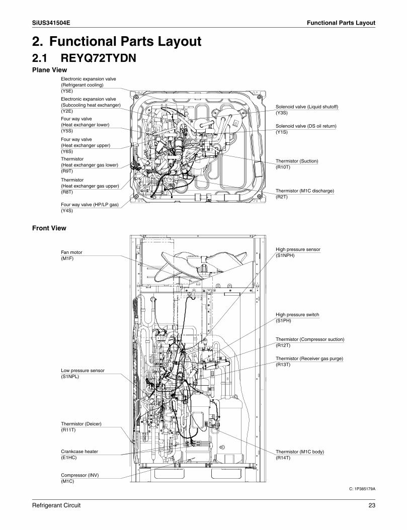
2. Functional Parts Layout2.1 REYQ72TYDNPlane View
Front View
C: 1P385179A
Electronic expansion valve (Refrigerant cooling)(Y5E)
Electronic expansion valve (Subcooling heat exchanger)(Y2E)
Four way valve (Heat exchanger lower)(Y5S)
Four way valve (Heat exchanger upper)(Y6S)
Thermistor (Heat exchanger gas lower)(R9T)
Thermistor (Heat exchanger gas upper)(R8T)
Four way valve (HP/LP gas)(Y4S)
Thermistor (M1C discharge)(R2T)
Thermistor (Suction)(R10T)
Solenoid valve (DS oil return)(Y1S)
Solenoid valve (Liquid shutoff)(Y3S)
Fan motor(M1F)
Low pressure sensor (S1NPL)
Thermistor (Deicer) (R11T)
Crankcase heater (E1HC)
Compressor (INV) (M1C)
Thermistor (M1C body) (R14T)
Thermistor (Receiver gas purge) (R13T)
Thermistor (Compressor suction) (R12T)
High pressure switch (S1PH)
High pressure sensor (S1NPH)
Refrigerant Circuit 23

Functional Parts Layout SiUS341504E
2.2 REYQ96 / 120TYDNPlane View
Front View
C: 1P385180B
Electronic expansion valve (Subcooling heat exchanger)(Y2E)
Four way valve (Heat exchanger upper)(Y6S)
Four way valve (Heat exchanger lower)(Y5S)
Thermistor (Heat exchanger gas upper)(R8T)
Thermistor (Suction)(R10T)
Thermistor (M2C discharge)(R22T)
Thermistor (M1C discharge)(R21T)
High pressure sensor(S1NPH)
Solenoid valve (DS oil return 1)(Y1S)
Solenoid valve (DS oil return 2)(Y2S)
Solenoid valve (Liquid shutoff)(Y3S)
Electronic expansion valve (Refrigerant cooling)(Y5E)
Thermistor (Outdoor air)(R1T)
Fan motor(M2F)
Four way valve (HP/LP gas)(Y4S)
Low pressure sensor(S1NPL)
Electronic expansion valve (Heat exchanger upper)(Y1E)
Electronic expansion valve (Heat exchanger lower)(Y3E)
Thermistor (Deicer)(R11T)
Crankcase heater(E2HC)
Compressor (INV 2)(M2C)
Fan motor(M1F)
Thermistor (Heat exchanger gas lower)(R9T)
High pressure switch(S2PH)
High pressure switch(S1PH)
Thermistor (Compressor suction)(R12T)
Thermistor (Receiver gas purge)(R13T)
Crankcase heater(E1HC)
Compressor (INV 1)(M1C)
24 Refrigerant Circuit

SiUS341504E Functional Parts Layout
2.3 REYQ144 / 168TYDNPlane View
Front View
C: 1P385181C
Electronic expansion valve (Subcooling heat exchanger)(Y2E)Four way valve (Heat exchanger upper)(Y6S)
Four way valve (Heat exchanger lower)(Y5S)
Thermistor (Heat exchanger gas upper)(R8T)
Thermistor (Suction)(R10T)
Thermistor (M2C discharge)(R22T)
Thermistor (M1C discharge)(R21T)
High pressure sensor (S1NPH)
Solenoid valve (DS oil return 1) (Y1S)
Solenoid valve (DS oil return 2) (Y2S)
Solenoid valve (Liquid shutoff) (Y3S)
Electronic expansion valve (Refrigerant cooling)(Y5E)
Fan motor (M2F)
Four way valve (HP/LP gas) (Y4S)
Low pressure sensor (S1NPL)
Thermistor (Deicer) (R11T)
Thermistor (M2C body) (R14T)Crankcase heater (E2HC)Compressor (INV 2) (M2C)
Compressor (INV 1) (M1C)
Crankcase heater (E1HC)
Thermistor (Receiver gas purge) (R13T)
High pressure switch (S2PH)
Thermistor (Compressor suction) (R12T)
High pressure switch (S1PH)
Thermistor (Heat exchanger gas lower) (R9T)
Fan motor (M1F)
Thermistor (Outdoor air) (R1T)
Electronic expansion valve (Heat exchanger upper) (Y1E)
Electronic expansion valve (Heat exchanger lower) (Y3E)
Refrigerant Circuit 25

Functional Parts Layout SiUS341504E
2.4 REYQ72TTJUPlane View
Front View
C: 1P383624C
Electronic expansion valve (Refrigerant cooling)(Y5E)
Solenoid valve (Liquid shutoff)(Y3S)
Solenoid valve (DS oil return)(Y1S)
Thermistor (Suction)(R10T)
Thermistor (M1C discharge)(R2T)
Electronic expansion valve (Subcooling heat exchanger)(Y2E)
Four way valve (Heat exchanger lower)(Y5S)
Four way valve (Heat exchanger upper)(Y6S)
Thermistor (Heat exchanger gas lower)(R9T)
Thermistor (Heat exchanger gas upper)(R8T)
Four way valve (HP/LP gas)(Y4S)
High pressure sensor (S1NPH)
High pressure switch(S1PH)
Thermistor (Compressor suction)(R12T)
Thermistor (Receiver gas purge)(R13T)
Thermistor (M1C body)(R14T)
Compressor (INV)(M1C)
Fan motor (M1F)
Low pressure sensor (S1NPL)
Thermistor (Deicer) (R11T)
Crankcase heater (E1HC)
26 Refrigerant Circuit

SiUS341504E Functional Parts Layout
2.5 REYQ96 / 120TTJUPlane View
Front View
C: 1P383625D
Solenoid valve (Liquid shutoff)(Y3S)
Solenoid valve (DS oil return 2)(Y2S)
Solenoid valve (DS oil return 1)(Y1S)
High pressure sensor (S1NPH)
Thermistor (M1C discharge)(R21T)
Electronic expansion valve (Refrigerant cooling)(Y5E)
Electronic expansion valve (Subcooling heat exchanger)(Y2E)
Four way valve (Heat exchanger lower)(Y5S)
Four way valve (Heat exchanger upper)(Y6S)
Thermistor (Heat exchanger gas upper)(R8T)
Thermistor (Suction)(R10T)
Thermistor (M2C discharge)(R22T)
Thermistor (Outdoor air)(R1T)
Fan motor (M2F)
Four way valve (HP/LP gas)(Y4S)
Low pressure sensor (S1NPL)
Electronic expansion valve (Heat exchanger upper)(Y1E)
Electronic expansion valve (Heat exchanger lower)(Y3E)
Thermistor (Deicer)(R11T)
Crankcase heater(E2HC)
Compressor (INV 2)(M2C)
Compressor (INV 1)(M1C)
Crankcase heater(E1HC)
Thermistor (Receiver gas purge)(R13T)
Thermistor (Compressor suction)(R12T)
High pressure switch(S1PH)
High pressure switch(S2PH)
Thermistor (Heat exchanger gas lower)(R9T)
Fan motor (M1F)
Refrigerant Circuit 27

Functional Parts Layout SiUS341504E
2.6 REYQ144 / 168TTJUPlane View
Front View
C: 1P383626D
Electronic expansion valve (Refrigerant cooling)(Y5E)
Electronic expansion valve (Subcooling heat exchanger)(Y2E)
Four way valve (Heat exchanger upper)(Y6S)
Four way valve (Heat exchanger lower)(Y5S)
Thermistor (Heat exchanger gas upper)(R8T)
Thermistor (Suction)(R10T)
Thermistor (M2C discharge)(R22T)
Thermistor (M1C discharge)(R21T)
High pressure sensor (S1NPH)
Solenoid valve (DS oil return 1) (Y1S)
Solenoid valve (DS oil return 2) (Y2S)
Solenoid valve (Liquid shutoff) (Y3S)
Fan motor (M2F)
Four way valve (HP/LP gas) (Y4S)
Low pressure sensor (S1NPL)
Thermistor (Deicer)(R11T)
Crankcase heater (E2HC)
Thermistor (M2C body) (R14T)
Compressor (INV 2)(M2C)
Electronic expansion valve (Heat exchanger upper) (Y1E)
Electronic expansion valve (Heat exchanger lower)(Y3E)
Fan motor (M1F)
Thermistor (Heat exchanger gas lower)(R9T)
High pressure switch(S1PH)
High pressure switch(S2PH)
Thermistor (Compressor suction)(R12T)
Thermistor (Receiver gas purge)(R13T)
Crankcase heater(E1HC)
Compressor (INV 1)(M1C)
28 Refrigerant Circuit

SiUS341504E Refrigerant Flow for Each Operation Mode
3. Refrigerant Flow for Each Operation Mode3.1 REYQ72TYDN / REYQ72TTJU3.1.1 Cooling Operation
High temperature, high pressure gas
High temperature, high pressure liquid
Low temperature, low pressure gas
Low temperature, low pressure liquid
Filt
er
Filt
erF
ilter
Filt
er
Dou
ble
pipe
he
at
exch
ange
rE
lect
roni
c E
xpan
sion
Val
ve
(EV
SC
)
Ele
ctro
nic
Exp
ansi
on V
alve
(E
VH
)
Ele
ctro
nic
Exp
ansi
on V
alve
(E
VL)
"OF
F"
Fan
"O
FF
"
Coo
ling
Uni
t
Dou
ble
pipe
he
at
exch
ange
rE
lect
roni
c E
xpan
sion
Val
ve
(EV
SC
)
Ele
ctro
nic
Exp
ansi
on V
alve
(E
VH
)
Ele
ctro
nic
Exp
ansi
on V
alve
(E
VL)
Filt
er
Filt
erF
ilter
Filt
er
The
rmos
tat "
OF
F"
Coo
ling
Uni
t
"ON
"
Fan
"O
N"
Dou
ble
pipe
he
at
exch
ange
rE
lect
roni
c E
xpan
sion
Val
ve
(EV
SC
)
Ele
ctro
nic
Exp
ansi
on V
alve
(E
VH
)
Ele
ctro
nic
Exp
ansi
on V
alve
(E
VL)
Filt
er
Filt
erF
ilter
Filt
er
Indo
or U
nit
The
rmos
tat "
ON
"
Coo
ling
Uni
t
"ON
"
Fan
"O
N"
Indo
or u
nit
Ope
ratio
n
Check valveCheck valve
Filter
SV
Filter
Filter
FanFilter M Filter
Filter
Filter
S1NPH
Filter
S1PHFilter
S1NPL
SV
CompressorFilter
Accumulator
Stop valve (With service port φ5/16in. (7.9mm) flare connection)
Liquid pipe
Dual pressure gas pipe
Suction gas pipe
Check valve
Electronic expansion
valve
Double tube heat exchanger
Electronic expansion valve
Capillary tube Liquid
Receiver
Fusible plug
Pressure regulating
valve
Solenoid valve
Check valve
Electronic expansion
valve
Check valve
Check valve
Capillary tube
Electronic expansion
valve
Electronic expansion valve
Heat sink
Check valve
Oil separator
Capillary tube
Solenoid valve
INV
High pressure switch
High pressure sensor
Four way valve
Four way valve
Double tube heat exchanger
Four way valve
Low pressure sensor
Fusible plug
Capillary tube
Charge port
Electronic expansion
valve
Check valve
Refrigerant Circuit 29

Refrigerant Flow for Each Operation Mode SiUS341504E
3.1.2 Heating OperationHigh temperature, high pressure gas
High temperature, high pressure liquid
Low temperature, low pressure gas
Low temperature, low pressure liquid
Filt
er
Filt
erF
ilter
Filt
er
Dou
ble
pipe
he
at
exch
ange
rE
lect
roni
c E
xpan
sion
Val
ve
(EV
SC
)
Ele
ctro
nic
Exp
ansi
on V
alve
(E
VH
)
Ele
ctro
nic
Exp
ansi
on V
alve
(E
VL)
Dou
ble
pipe
he
at
exch
ange
rE
lect
roni
c E
xpan
sion
Val
ve
(EV
SC
)
Ele
ctro
nic
Exp
ansi
on V
alve
(E
VH
)
Ele
ctro
nic
Exp
ansi
on V
alve
(E
VL)
Dou
ble
pipe
he
at
exch
ange
rE
lect
roni
c E
xpan
sion
Val
ve
(EV
SC
)
Ele
ctro
nic
Exp
ansi
on V
alve
(E
VH
)
Ele
ctro
nic
Exp
ansi
on V
alve
(E
VL)
Filt
er
Filt
erF
ilter
Filt
er
Filt
er
Filt
erF
ilter
Filt
er
Indo
or U
nit
The
rmos
tat "
OF
F"
"OF
F"
Fan
"O
FF
"
Hea
ting
Uni
t
Hea
ting
Uni
t
"ON
"19
2 pu
lse
192
puls
e
Fan
"LL
"
The
rmos
tat "
ON
"
Hea
ting
Uni
t
"ON
"
Fan
"O
N"
Indo
or u
nit
Ope
ratio
n
Check valveCheck valve
Filter
SV
Filter
Filter
FanFilter M Filter
Filter
Filter
S1NPH
Filter
S1PHFilter
S1NPL
SV
CompressorFilter
Accumulator
Stop valve (With service port φ5/16in. (7.9mm) flare connection)
Liquid pipe
Dual pressure gas pipe
Suction gas pipe
Check valve
Electronic expansion
valve
Double tube heat exchanger
Electronic expansion valve
Capillary tube Liquid
Receiver
Fusible plug
Pressure regulating
valve
Solenoid valve
Check valve
Electronic expansion
valve
Check valve
Check valve
Capillary tube
Electronic expansion
valve
Electronic expansion valve
Heat sink
Check valve
Oil separator
Capillary tube
Solenoid valve
INV
High pressure switch
High pressure sensor
Four way valve
Four way valve
Double tube heat exchanger
Four way valve
Low pressure sensor
Fusible plug
Capillary tube
Charge port
Electronic expansion
valve
Check valve
30 Refrigerant Circuit

SiUS341504E Refrigerant Flow for Each Operation Mode
3.1.3 Simultaneous Cooling / Heating OperationHigh temperature, high pressure gas
High temperature, high pressure liquid
Low temperature, low pressure gas
Low temperature, low pressure liquid
Filt
er
Filt
erF
ilter
Filt
er
Dou
ble
pipe
he
at
exch
ange
rE
lect
roni
c E
xpan
sion
Val
ve
(EV
SC
)
Ele
ctro
nic
Exp
ansi
on V
alve
(E
VH
)
Ele
ctro
nic
Exp
ansi
on V
alve
(E
VL)
Dou
ble
pipe
he
at
exch
ange
rE
lect
roni
c E
xpan
sion
Val
ve
(EV
SC
)
Ele
ctro
nic
Exp
ansi
on V
alve
(E
VH
)
Ele
ctro
nic
Exp
ansi
on V
alve
(E
VL)
Dou
ble
pipe
he
at
exch
ange
rE
lect
roni
c E
xpan
sion
Val
ve
(EV
SC
)
Ele
ctro
nic
Exp
ansi
on V
alve
(E
VH
)
Ele
ctro
nic
Exp
ansi
on V
alve
(E
VL)
Filt
er
Filt
erF
ilter
Filt
er
Filt
er
Filt
erF
ilter
Filt
er
Indo
or U
nit
The
rmos
tat "
ON
"
"ON
"19
2 pu
lse
Fan
"LL
"
The
rmos
tat
"OF
F"
Hea
ting
Uni
t
Hea
ting
Uni
t
"ON
"
Fan
"O
N"
The
rmos
tat "
ON
"
Coo
ling
Uni
t
"ON
"
Fan
"O
N"
Indo
or u
nit
Ope
ratio
n
Check valveCheck valve
Filter
SV
Filter
Filter
FanFilter M Filter
Filter
Filter
S1NPH
Filter
S1PHFilter
S1NPL
SV
CompressorFilter
Accumulator
Stop valve (With service port φ5/16in. (7.9mm) flare connection)
Liquid pipe
Dual pressure gas pipe
Suction gas pipe
Check valve
Electronic expansion
valve
Double tube heat exchanger
Electronic expansion valve
Capillary tube Liquid
Receiver
Fusible plug
Pressure regulating
valve
Solenoid valve
Check valve
Electronic expansion
valve
Check valve
Check valve
Capillary tube
Electronic expansion
valve
Electronic expansion valve
Heat sink
Check valve
Oil separator
Capillary tube
Solenoid valve
INV
High pressure switch
High pressure sensor
Four way valve
Four way valve
Double tube heat exchanger
Four way valve
Low pressure sensor
Fusible plug
Capillary tube
Charge port
Electronic expansion
valve
Check valve
Refrigerant Circuit 31

Refrigerant Flow for Each Operation Mode SiUS341504E
3.1.4 Cooling Oil Return OperationHigh temperature, high pressure gas
High temperature, high pressure liquid
Low temperature, low pressure gas
Low temperature, low pressure liquid
Check valveCheck valve
Filter
SV
Filter
Filter
FanFilter M Filter
Filter
Filter
S1NPH
Filter
S1PHFilter
S1NPL
SV
CompressorFilter
Accumulator
Stop valve (With service port φ5/16in. (7.9mm) flare connection)
Liquid pipe
Dual pressure gas pipe
Suction gas pipe
Check valve
Electronic expansion
valve
Double tube heat exchanger
Electronic expansion valve
Capillary tube Liquid
Receiver
Fusible plug
Pressure regulating
valve
Solenoid valve
Check valve
Electronic expansion
valve
Check valve
Check valve
Capillary tube
Electronic expansion
valve
Electronic expansion valve
Heat sink
Check valve
Oil separator
Capillary tube
Solenoid valve
INV
High pressure switch
High pressure sensor
Four way valve
Four way valve
Double tube heat exchanger
Four way valve
Low pressure sensor
Fusible plug
Capillary tube
Charge port
Electronic expansion
valve
Check valve
Filt
er
Filt
erF
ilter
Filt
er
Dou
ble
pipe
he
at
exch
ange
rE
lect
roni
c E
xpan
sion
Val
ve
(EV
SC
)
Ele
ctro
nic
Exp
ansi
on V
alve
(E
VH
)
Ele
ctro
nic
Exp
ansi
on V
alve
(E
VL)
Dou
ble
pipe
he
at
exch
ange
rE
lect
roni
c E
xpan
sion
Val
ve
(EV
SC
)
Ele
ctro
nic
Exp
ansi
on V
alve
(E
VH
)
Ele
ctro
nic
Exp
ansi
on V
alve
(E
VL)
Dou
ble
pipe
he
at
exch
ange
rE
lect
roni
c E
xpan
sion
Val
ve
(EV
SC
)
Ele
ctro
nic
Exp
ansi
on V
alve
(E
VH
)
Ele
ctro
nic
Exp
ansi
on V
alve
(E
VL)
Filt
er
Filt
erF
ilter
Filt
er
Filt
er
Filt
erF
ilter
Filt
er
Indo
or U
nit
The
rmos
tat "
OF
F"
"OF
F"
192
puls
e
Fan
"O
FF
"
Coo
ling
Uni
t
Coo
ling
Uni
t
"ON
"
Fan
"O
N"
The
rmos
tat "
ON
"
Coo
ling
Uni
t
"ON
"
Fan
"O
N"
Indo
or u
nit
Ope
ratio
n
32 Refrigerant Circuit

SiUS341504E Refrigerant Flow for Each Operation Mode
3.1.5 Defrost Heating Oil Return OperationHigh temperature, high pressure gas
High temperature, high pressure liquid
Low temperature, low pressure gas
Low temperature, low pressure liquid
Filt
er
Filt
erF
ilter
Filt
er
Dou
ble
pipe
he
at
exch
ange
rE
lect
roni
c E
xpan
sion
Val
ve
(EV
SC
)
Ele
ctro
nic
Exp
ansi
on V
alve
(E
VH
)
Ele
ctro
nic
Exp
ansi
on V
alve
(E
VL)
Dou
ble
pipe
he
at
exch
ange
rE
lect
roni
c E
xpan
sion
Val
ve
(EV
SC
)
Ele
ctro
nic
Exp
ansi
on V
alve
(E
VH
)
Ele
ctro
nic
Exp
ansi
on V
alve
(E
VL)
Dou
ble
pipe
he
at
exch
ange
rE
lect
roni
c E
xpan
sion
Val
ve
(EV
SC
)
Ele
ctro
nic
Exp
ansi
on V
alve
(E
VH
)
Ele
ctro
nic
Exp
ansi
on V
alve
(E
VL)
Filt
er
Filt
erF
ilter
Filt
er
Filt
er
Filt
erF
ilter
Filt
er
Indo
or U
nit
Indo
or U
nit
Indo
or U
nit
The
rmos
tat "
OF
F"
"OF
F"
Fan
"O
FF
"
Hea
ting
Uni
t
Hea
ting
Uni
t
"ON
"
224
puls
e
Fan
"LL
"
The
rmos
tat "
ON
"
Hea
ting
Uni
t
"ON
"
Fan
"O
N"
Indo
or u
nit
Ope
ratio
n
Check valveCheck valve
Filter
SV
Filter
Filter
FanFilter M Filter
Filter
Filter
S1NPH
Filter
S1PHFilter
S1NPL
SV
CompressorFilter
Accumulator
Stop valve (With service port φ5/16in. (7.9mm) flare connection)
Liquid pipe
Dual pressure gas pipe
Suction gas pipe
Check valve
Electronic expansion
valve
Double tube heat exchanger
Electronic expansion valve
Capillary tube Liquid
Receiver
Fusible plug
Pressure regulating
valve
Solenoid valve
Check valve
Electronic expansion
valve
Check valve
Check valve
Capillary tube
Electronic expansion
valve
Electronic expansion valve
Heat sink
Check valve
Oil separator
Capillary tube
Solenoid valve
INV
High pressure switch
High pressure sensor
Four way valve
Four way valve
Double tube heat exchanger
Four way valve
Low pressure sensor
Fusible plug
Capillary tube
Charge port
Electronic expansion
valve
Check valve
Refrigerant Circuit 33

Refrigerant Flow for Each Operation Mode SiUS341504E
3.1.6 Oil Return Operation at Simultaneous Cooling / Heating OperationHigh temperature, high pressure gas
High temperature, high pressure liquid
Low temperature, low pressure gas
Low temperature, low pressure liquid
Filt
er
Filt
erF
ilter
Filt
er
Dou
ble
pipe
he
at
exch
ange
rE
lect
roni
c E
xpan
sion
Val
ve
(EV
SC
)
Ele
ctro
nic
Exp
ansi
on V
alve
(E
VH
)
Ele
ctro
nic
Exp
ansi
on V
alve
(E
VL)
Dou
ble
pipe
he
at
exch
ange
rE
lect
roni
c E
xpan
sion
Val
ve
(EV
SC
)
Ele
ctro
nic
Exp
ansi
on V
alve
(E
VH
)
Ele
ctro
nic
Exp
ansi
on V
alve
(E
VL)
Dou
ble
pipe
he
at
exch
ange
rE
lect
roni
c E
xpan
sion
Val
ve
(EV
SC
)
Ele
ctro
nic
Exp
ansi
on V
alve
(E
VH
)
Ele
ctro
nic
Exp
ansi
on V
alve
(E
VL)
Filt
er
Filt
erF
ilter
Filt
er
Filt
er
Filt
erF
ilter
Filt
er
Indo
or U
nit
The
rmos
tat "
ON
"
"ON
"22
4 pu
lse
Fan
"O
N"
Hea
ting
Uni
t
Hea
ting
Uni
t
"ON
"
Fan
"O
N"
The
rmos
tat "
ON
"
Coo
ling
Uni
t
"ON
"
Fan
"O
N"
Indo
or u
nit
Ope
ratio
n
Check valveCheck valve
Filter
SV
Filter
Filter
FanFilter M Filter
Filter
Filter
S1NPH
Filter
S1PHFilter
S1NPL
SV
CompressorFilter
Accumulator
Stop valve (With service port φ5/16in. (7.9mm) flare connection)
Liquid pipe
Dual pressure gas pipe
Suction gas pipe
Check valve
Electronic expansion
valve
Double tube heat exchanger
Electronic expansion valve
Capillary tube Liquid
Receiver
Fusible plug
Pressure regulating
valve
Solenoid valve
Check valve
Electronic expansion
valve
Check valve
Check valve
Capillary tube
Electronic expansion
valve
Electronic expansion valve
Heat sink
Check valve
Oil separator
Capillary tube
Solenoid valve
INV
High pressure switch
High pressure sensor
Four way valve
Four way valve
Double tube heat exchanger
Four way valve
Low pressure sensor
Fusible plug
Capillary tube
Charge port
Electronic expansion
valve
Check valve
34 Refrigerant Circuit

SiUS341504E Refrigerant Flow for Each Operation Mode
3.2 REYQ96-168TYDN / REYQ96-168TTJU3.2.1 Cooling Operation
High temperature, high pressure gas
High temperature, high pressure liquid
Low temperature, low pressure gas
Low temperature, low pressure liquid
Four way valve
Check valve
FilterCheck valve
SV
Filter
ReceiverFilter
Fan FanFilter MM Filter
Filter
Filter
S1NPH FilterFilter
S2PH S1PHFilterFilter
S1NPL
SV
CompressorFilter
Accumulator
Stop valve (With service port φ5/16in. (7.9mm) flare connection)
Liquid pipe
Check valve
Check valve
Electronic expansion
valve Electronic expansion
valve
Electronic expansion valve
Double tube heat exchanger
Check valve
Solenoid valve
Capillary tube
Fusible plug
Pressure regulating
valve
Check valve
Check valve
Capillary tube
Electronic expansion
valve
Electronic expansion valve
Electronic expansion valve
Heat sink
Four way valve
Double tube heat exchanger
Four way valve
Low pressure sensor
Dual pressure gas pipe
Suction gas pipe
Fusible plug
Capillary tube
Charge port
INV 2
High pressure switch
High pressure sensor
Check valve
Oil Separator High pressure switch
CompressorINV 1
Capillary tube
Solenoid valve
Check valve
Oil Separator
Capillary tube
Solenoid valve
SV
Filt
er
Filt
erF
ilter
Filt
er
Dou
ble
pipe
he
at
exch
ange
rE
lect
roni
c E
xpan
sion
Val
ve
(EV
SC
)
Ele
ctro
nic
Exp
ansi
on V
alve
(E
VH
)
Ele
ctro
nic
Exp
ansi
on V
alve
(E
VL)
Dou
ble
pipe
he
at
exch
ange
rE
lect
roni
c E
xpan
sion
Val
ve
(EV
SC
)
Ele
ctro
nic
Exp
ansi
on V
alve
(E
VH
)
Ele
ctro
nic
Exp
ansi
on V
alve
(E
VL)
Dou
ble
pipe
he
at
exch
ange
rE
lect
roni
c E
xpan
sion
Val
ve
(EV
SC
)
Ele
ctro
nic
Exp
ansi
on V
alve
(E
VH
)
Ele
ctro
nic
Exp
ansi
on V
alve
(E
VL)
Filt
er
Filt
erF
ilter
Filt
er
Filt
er
Filt
erF
ilter
Filt
er
Indo
or U
nit
The
rmos
tat "
OF
F"
"OF
F"
Fan
"O
FF
"
Coo
ling
Uni
t
Coo
ling
Uni
t
"ON
"
Fan
"O
N"
The
rmos
tat "
ON
"
Coo
ling
Uni
t
"ON
"
Fan
"O
N"
Indo
or u
nit
Ope
ratio
n
Refrigerant Circuit 35

Refrigerant Flow for Each Operation Mode SiUS341504E
3.2.2 Heating OperationHigh temperature, high pressure gas
High temperature, high pressure liquid
Low temperature, low pressure gas
Low temperature, low pressure liquid
Four way valve
Check valve
FilterCheck valve
SV
Filter
ReceiverFilter
Fan FanFilter MM Filter
Filter
Filter
S1NPH FilterFilter
S2PH S1PHFilterFilter
S1NPL
SV
CompressorFilter
Accumulator
Stop valve (With service port φ5/16in. (7.9mm) flare connection)
Liquid pipe
Check valve
Check valve
Electronic expansion
valve Electronic expansion
valve
Electronic expansion valve
Double tube heat exchanger
Check valve
Solenoid valve
Capillary tube
Fusible plug
Pressure regulating
valve
Check valve
Check valve
Capillary tube
Electronic expansion
valve
Electronic expansion valve
Electronic expansion valve
Heat sink
Four way valve
Double tube heat exchanger
Four way valve
Low pressure sensor
Dual pressure gas pipe
Suction gas pipe
Fusible plug
Capillary tube
Charge port
INV 2
High pressure switch
High pressure sensor
Check valve
Oil Separator High pressure switch
CompressorINV 1
Capillary tube
Solenoid valve
Check valve
Oil Separator
Capillary tube
Solenoid valve
SV
Filt
er
Filt
erF
ilter
Filt
er
Dou
ble
pipe
he
at
exch
ange
rE
lect
roni
c E
xpan
sion
Val
ve
(EV
SC
)
Ele
ctro
nic
Exp
ansi
on V
alve
(E
VH
)
Ele
ctro
nic
Exp
ansi
on V
alve
(E
VL)
Dou
ble
pipe
he
at
exch
ange
rE
lect
roni
c E
xpan
sion
Val
ve
(EV
SC
)
Ele
ctro
nic
Exp
ansi
on V
alve
(E
VH
)
Ele
ctro
nic
Exp
ansi
on V
alve
(E
VL)
Dou
ble
pipe
he
at
exch
ange
rE
lect
roni
c E
xpan
sion
Val
ve
(EV
SC
)
Ele
ctro
nic
Exp
ansi
on V
alve
(E
VH
)
Ele
ctro
nic
Exp
ansi
on V
alve
(E
VL)
Filt
er
Filt
erF
ilter
Filt
er
Filt
er
Filt
erF
ilter
Filt
er
Indo
or U
nit
The
rmos
tat "
OF
F"
"OF
F"
Fan
"O
FF
"
Hea
ting
Uni
t
Hea
ting
Uni
t
"ON
"19
2 pu
lse
192
puls
e
Fan
"LL
"
The
rmos
tat "
ON
"
Hea
ting
Uni
t
"ON
"
Fan
"O
N"
Indo
or u
nit
Ope
ratio
n
36 Refrigerant Circuit

SiUS341504E Refrigerant Flow for Each Operation Mode
3.2.3 Simultaneous Cooling / Heating OperationHigh temperature, high pressure gas
High temperature, high pressure liquid
Low temperature, low pressure gas
Low temperature, low pressure liquid
Four way valve
Check valve
FilterCheck valve
SV
Filter
ReceiverFilter
Fan FanFilter MM Filter
Filter
Filter
S1NPH FilterFilter
S2PH S1PHFilterFilter
S1NPL
SV
CompressorFilter
Accumulator
Stop valve (With service port φ5/16in. (7.9mm) flare connection)
Liquid pipe
Check valve
Check valve
Electronic expansion
valve Electronic expansion
valve
Electronic expansion valve
Double tube heat exchanger
Check valve
Solenoid valve
Capillary tube
Fusible plug
Pressure regulating
valve
Check valve
Check valve
Capillary tube
Electronic expansion
valve
Electronic expansion valve
Electronic expansion valve
Heat sink
Four way valve
Double tube heat exchanger
Four way valve
Low pressure sensor
Dual pressure gas pipe
Suction gas pipe
Fusible plug
Capillary tube
Charge port
INV 2
High pressure switch
High pressure sensor
Check valve
Oil Separator High pressure switch
CompressorINV 1
Capillary tube
Solenoid valve
Check valve
Oil Separator
Capillary tube
Solenoid valve
SV
Filt
er
Filt
erF
ilter
Filt
er
Dou
ble
pipe
he
at
exch
ange
rE
lect
roni
c E
xpan
sion
Val
ve
(EV
SC
)
Ele
ctro
nic
Exp
ansi
on V
alve
(E
VH
)
Ele
ctro
nic
Exp
ansi
on V
alve
(E
VL)
Dou
ble
pipe
he
at
exch
ange
rE
lect
roni
c E
xpan
sion
Val
ve
(EV
SC
)
Ele
ctro
nic
Exp
ansi
on V
alve
(E
VH
)
Ele
ctro
nic
Exp
ansi
on V
alve
(E
VL)
Dou
ble
pipe
he
at
exch
ange
rE
lect
roni
c E
xpan
sion
Val
ve
(EV
SC
)
Ele
ctro
nic
Exp
ansi
on V
alve
(E
VH
)
Ele
ctro
nic
Exp
ansi
on V
alve
(E
VL)
Filt
er
Filt
erF
ilter
Filt
er
Filt
er
Filt
erF
ilter
Filt
er
Indo
or U
nit
The
rmos
tat "
ON
"
"ON
"19
2 pu
lse
Fan
"LL
"
The
rmos
tat
"OF
F"
Hea
ting
Uni
t
Hea
ting
Uni
t
"ON
"
Fan
"O
N"
The
rmos
tat "
ON
"
Coo
ling
Uni
t
"ON
"
Fan
"O
N"
Indo
or u
nit
Ope
ratio
n
Refrigerant Circuit 37

Refrigerant Flow for Each Operation Mode SiUS341504E
3.2.4 Cooling Oil Return OperationHigh temperature, high pressure gas
High temperature, high pressure liquid
Low temperature, low pressure gas
Low temperature, low pressure liquid
Four way valve
Check valve
FilterCheck valve
SV
Filter
ReceiverFilter
Fan FanFilter MM Filter
Filter
Filter
S1NPH FilterFilter
S2PH S1PHFilterFilter
S1NPL
SV
CompressorFilter
Accumulator
Stop valve (With service port φ5/16in. (7.9mm) flare connection)
Liquid pipe
Check valve
Check valve
Electronic expansion
valve Electronic expansion
valve
Electronic expansion valve
Double tube heat exchanger
Check valve
Solenoid valve
Capillary tube
Fusible plug
Pressure regulating
valve
Check valve
Check valve
Capillary tube
Electronic expansion
valve
Electronic expansion valve
Electronic expansion valve
Heat sink
Four way valve
Double tube heat exchanger
Four way valve
Low pressure sensor
Dual pressure gas pipe
Suction gas pipe
Fusible plug
Capillary tube
Charge port
INV 2
High pressure switch
High pressure sensor
Check valve
Oil Separator High pressure switch
CompressorINV 1
Capillary tube
Solenoid valve
Check valve
Oil Separator
Capillary tube
Solenoid valve
SV
Filt
er
Filt
erF
ilter
Filt
er
Dou
ble
pipe
he
at
exch
ange
rE
lect
roni
c E
xpan
sion
Val
ve
(EV
SC
)
Ele
ctro
nic
Exp
ansi
on V
alve
(E
VH
)
Ele
ctro
nic
Exp
ansi
on V
alve
(E
VL)
Dou
ble
pipe
he
at
exch
ange
rE
lect
roni
c E
xpan
sion
Val
ve
(EV
SC
)
Ele
ctro
nic
Exp
ansi
on V
alve
(E
VH
)
Ele
ctro
nic
Exp
ansi
on V
alve
(E
VL)
Dou
ble
pipe
he
at
exch
ange
rE
lect
roni
c E
xpan
sion
Val
ve
(EV
SC
)
Ele
ctro
nic
Exp
ansi
on V
alve
(E
VH
)
Ele
ctro
nic
Exp
ansi
on V
alve
(E
VL)
Filt
er
Filt
erF
ilter
Filt
er
Filt
er
Filt
erF
ilter
Filt
er
Indo
or U
nit
The
rmos
tat "
OF
F"
"OF
F"
192
puls
e
Fan
"O
FF
"
Coo
ling
Uni
t
Coo
ling
Uni
t
"ON
"
Fan
"O
N"
The
rmos
tat "
ON
"
Coo
ling
Uni
t
"ON
"
Fan
"O
N"
Indo
or u
nit
Ope
ratio
n
38 Refrigerant Circuit
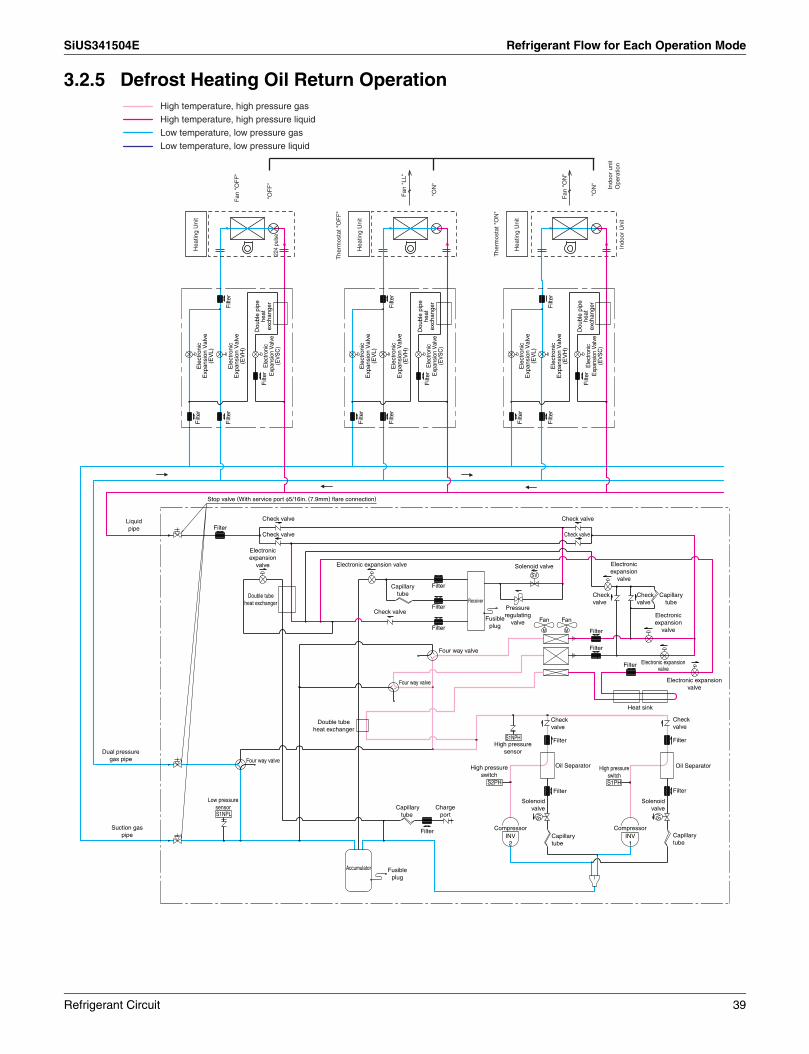
SiUS341504E Refrigerant Flow for Each Operation Mode
3.2.5 Defrost Heating Oil Return OperationHigh temperature, high pressure gas
High temperature, high pressure liquid
Low temperature, low pressure gas
Low temperature, low pressure liquid
Four way valve
Check valve
FilterCheck valve
SV
Filter
ReceiverFilter
Fan FanFilter MM Filter
Filter
Filter
S1NPH FilterFilter
S2PH S1PHFilterFilter
S1NPL
SV
CompressorFilter
Accumulator
Stop valve (With service port φ5/16in. (7.9mm) flare connection)
Liquid pipe
Check valve
Check valve
Electronic expansion
valve Electronic expansion
valve
Electronic expansion valve
Double tube heat exchanger
Check valve
Solenoid valve
Capillary tube
Fusible plug
Pressure regulating
valve
Check valve
Check valve
Capillary tube
Electronic expansion
valve
Electronic expansion valve
Electronic expansion valve
Heat sink
Four way valve
Double tube heat exchanger
Four way valve
Low pressure sensor
Dual pressure gas pipe
Suction gas pipe
Fusible plug
Capillary tube
Charge port
INV 2
High pressure switch
High pressure sensor
Check valve
Oil Separator High pressure switch
CompressorINV 1
Capillary tube
Solenoid valve
Check valve
Oil Separator
Capillary tube
Solenoid valve
SV
Filt
er
Filt
erF
ilter
Filt
er
Dou
ble
pipe
he
at
exch
ange
rE
lect
roni
c E
xpan
sion
Val
ve
(EV
SC
)
Ele
ctro
nic
Exp
ansi
on V
alve
(E
VH
)
Ele
ctro
nic
Exp
ansi
on V
alve
(E
VL)
Dou
ble
pipe
he
at
exch
ange
rE
lect
roni
c E
xpan
sion
Val
ve
(EV
SC
)
Ele
ctro
nic
Exp
ansi
on V
alve
(E
VH
)
Ele
ctro
nic
Exp
ansi
on V
alve
(E
VL)
Dou
ble
pipe
he
at
exch
ange
rE
lect
roni
c E
xpan
sion
Val
ve
(EV
SC
)
Ele
ctro
nic
Exp
ansi
on V
alve
(E
VH
)
Ele
ctro
nic
Exp
ansi
on V
alve
(E
VL)
Filt
er
Filt
erF
ilter
Filt
er
Filt
er
Filt
erF
ilter
Filt
er
Indo
or U
nit
The
rmos
tat "
OF
F"
"OF
F"
Fan
"O
FF
"
Hea
ting
Uni
t
Hea
ting
Uni
t
"ON
"
224
puls
e
Fan
"LL
"
The
rmos
tat "
ON
"
Hea
ting
Uni
t
"ON
"
Fan
"O
N"
Indo
or u
nit
Ope
ratio
n
Refrigerant Circuit 39

Refrigerant Flow for Each Operation Mode SiUS341504E
3.2.6 Oil Return Operation at Simultaneous Cooling / Heating OperationHigh temperature, high pressure gas
High temperature, high pressure liquid
Low temperature, low pressure gas
Low temperature, low pressure liquid
Four way valve
Check valve
FilterCheck valve
SV
Filter
ReceiverFilter
Fan FanFilter MM Filter
Filter
Filter
S1NPH FilterFilter
S2PH S1PHFilterFilter
S1NPL
SV
CompressorFilter
Accumulator
Stop valve (With service port φ5/16in. (7.9mm) flare connection)
Liquid pipe
Check valve
Check valve
Electronic expansion
valve Electronic expansion
valve
Electronic expansion valve
Double tube heat exchanger
Check valve
Solenoid valve
Capillary tube
Fusible plug
Pressure regulating
valve
Check valve
Check valve
Capillary tube
Electronic expansion
valve
Electronic expansion valve
Electronic expansion valve
Heat sink
Four way valve
Double tube heat exchanger
Four way valve
Low pressure sensor
Dual pressure gas pipe
Suction gas pipe
Fusible plug
Capillary tube
Charge port
INV 2
High pressure switch
High pressure sensor
Check valve
Oil Separator High pressure switch
CompressorINV 1
Capillary tube
Solenoid valve
Check valve
Oil Separator
Capillary tube
Solenoid valve
SV
Filt
er
Filt
erF
ilter
Filt
er
Dou
ble
pipe
he
at
exch
ange
rE
lect
roni
c E
xpan
sion
Val
ve
(EV
SC
)
Ele
ctro
nic
Exp
ansi
on V
alve
(E
VH
)
Ele
ctro
nic
Exp
ansi
on V
alve
(E
VL)
Dou
ble
pipe
he
at
exch
ange
rE
lect
roni
c E
xpan
sion
Val
ve
(EV
SC
)
Ele
ctro
nic
Exp
ansi
on V
alve
(E
VH
)
Ele
ctro
nic
Exp
ansi
on V
alve
(E
VL)
Dou
ble
pipe
he
at
exch
ange
rE
lect
roni
c E
xpan
sion
Val
ve
(EV
SC
)
Ele
ctro
nic
Exp
ansi
on V
alve
(E
VH
)
Ele
ctro
nic
Exp
ansi
on V
alve
(E
VL)
Filt
er
Filt
erF
ilter
Filt
er
Filt
er
Filt
erF
ilter
Filt
er
Indo
or U
nit
The
rmos
tat "
ON
"
"ON
"22
4 pu
lse
Fan
"O
N"
Hea
ting
Uni
t
Hea
ting
Uni
t
"ON
"
Fan
"O
N"
The
rmos
tat "
ON
"
Coo
ling
Uni
t
"ON
"
Fan
"O
N"
Indo
or u
nit
Ope
ratio
n
40 Refrigerant Circuit

SiUS341504E
Remote Controller 41
Part 3Remote Controller
1. Wired Remote Controller...........................................................................421.1 Applicable Models ...................................................................................... 421.2 Names and Functions ................................................................................ 421.3 MAIN/SUB Setting when Using 2 Remote Controllers ............................... 441.4 Centralized Control Group No. Setting....................................................... 45
2. Wireless Remote Controller ......................................................................472.1 Applicable Models ...................................................................................... 472.2 Names and Functions ................................................................................ 472.3 Address and MAIN/SUB Setting................................................................. 49
3. Service Mode ............................................................................................503.1 BRC1E73 ................................................................................................... 50
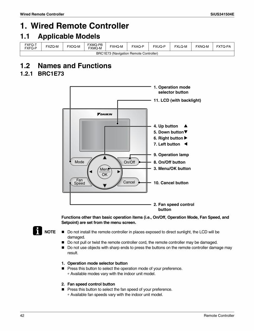
Wired Remote Controller SiUS341504E
1. Wired Remote Controller1.1 Applicable Models
1.2 Names and Functions1.2.1 BRC1E73
Functions other than basic operation items (i.e., On/Off, Operation Mode, Fan Speed, and Setpoint) are set from the menu screen.
NOTE Do not install the remote controller in places exposed to direct sunlight, the LCD will be damaged.Do not pull or twist the remote controller cord, the remote controller may be damaged.Do not use objects with sharp ends to press the buttons on the remote controller damage may result.
1. Operation mode selector buttonPress this button to select the operation mode of your preference.∗ Available modes vary with the indoor unit model.
2. Fan speed control buttonPress this button to select the fan speed of your preference. ∗ Available fan speeds vary with the indoor unit model.
FXFQ-TFXFQ-P FXZQ-M FXDQ-M FXMQ-PB
FXMQ-M FXHQ-M FXAQ-P FXUQ-P FXLQ-M FXNQ-M FXTQ-PA
BRC1E73 (Navigation Remote Controller)
3. Menu/OK button
8. On/Off button
10. Cancel button
9. Operation lamp
11. LCD (with backlight)
4. Up button5. Down button6. Right button7. Left button
1. Operation mode selector button
2. Fan speed control button
42 Remote Controller

SiUS341504E Wired Remote Controller
3. Menu/OK buttonUsed to enter the main menu.Used to enter the selected item.
4. Up button Used to raise the setpoint. The item above the current selection will be highlighted.(The highlighted items will be scrolled continuously when the button is continuously pressed.)Used to change the selected item.
5. Down button Used to lower the setpoint.The item below the current selection will be highlighted.(The highlighted items will be scrolled continuously when the button is continuously pressed.)Used to change the selected item.
6. Right button Used to highlight the next items on the right-hand side.Each screen is scrolled in the right-hand direction.
7. Left button Used to highlight the next items on the left-hand side.Each screen is scrolled in the left-hand direction.
8. On/Off button Press this button and system will start.Press this button again to stop the system.
9. Operation lampThis lamp illuminates solid green during normal operation.This lamp blinks if an error occurs.
10.Cancel button Used to return to the previous screen.
11.LCD (with backlight)The backlight will be illuminated for approximately 30 seconds by pressing any button.If two remote controllers are used to control a single indoor unit, only the controller accessed first will have backlight functionality.
Remote Controller 43
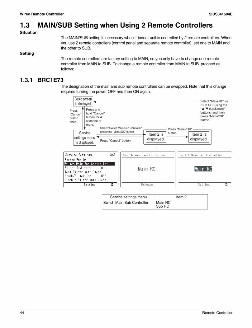
Wired Remote Controller SiUS341504E
1.3 MAIN/SUB Setting when Using 2 Remote ControllersSituation
The MAIN/SUB setting is necessary when 1 indoor unit is controlled by 2 remote controllers. When you use 2 remote controllers (control panel and separate remote controller), set one to MAIN and the other to SUB.
SettingThe remote controllers are factory setting to MAIN, so you only have to change one remote controller from MAIN to SUB. To change a remote controller from MAIN to SUB, proceed as follows:
1.3.1 BRC1E73The designation of the main and sub remote controllers can be swapped. Note that this change requires turning the power OFF and then ON again.
Service settings menu Item 2
Switch Main Sub Controller Main RCSub RC
Select "Switch Main Sub Controller" and press "Menu/OK" button.Service
settings menu is displayed.
Item 2 is displayed.
Basic screen is displayed.
Press and hold "Cancel" button for 4 seconds or more.
Press "Cancel" button once.
Press "Cancel" button.
Item 2 is displayed.
Press "Menu/OK" button.
Select "Main RC" or "Sub RC" using the
" / (Up/Down)" buttons, and then press "Menu/OK" button.
44 Remote Controller

SiUS341504E Wired Remote Controller
1.4 Centralized Control Group No. Setting1.4.1 BRC1E73
In order to conduct the centralized remote control using the central remote controller and the unified ON/OFF controller, Group No. settings should be made by group using the operating remote controller.Make Group No. settings for centralized remote control using the operating remote controller.
<When initializing Group Address>
Select "Group Address" and then press "Menu/OK" button.
Press "Cancel" button once.
Select "Group Address (Unit)" and then press "Menu/OK" button.
Press "Cancel" button once.
Service settings menu is displayed.
Item 2 is displayed.
Item 2 is displayed.
Item 2 is displayed.
Basic screen is displayed.
Press and hold "Cancel" button for 4 seconds or more.
Press "Cancel" button once.
Select the desired Group Address using the " / (Up/Down)" buttons, and then press "Menu/OK" button.
Item 2 is displayed.
Select the desired Unit No. using the " / (Up/Down)" buttons, and then select Group Address using the " " buttons.
Press "Menu/OK" button.
0 1-00
Service settings menu Item 2 DescriptionThis menu is used to make group address setting for centralized control.It is also used to make group address setting by indoor unit.
Group Address Group Address (Group)
Group Address (Unit)
Remote Controller 45

Wired Remote Controller SiUS341504E
Note: For setting group No. of Energy recovery ventilator and wiring adaptor for other air conditioners, etc., refer to the instruction manual attached.
NOTICEEnter the group No. and installation place of the indoor unit into the attached installation table. Be sure to keep the installation table with the operation manual for maintenance.
<Group Address (Group)>
Select "Group Address" and then press "Menu/OK" button.
Select "Group Address (Group)" and then press "Menu/OK" button.
Press "Cancel" button once.
Select the desired Group Address using the " / (Up/Down)" buttons, and then press "Menu/OK" button.
Service settings menu is displayed.
Item 2 is displayed.
Item 2 is displayed.
Item 2 is displayed.
Basic screen is displayed.
Press and hold "Cancel" button for 4 seconds or more.
Press "Cancel" button once.
Press "Cancel" button once.
Press "Menu/OK" button.
46 Remote Controller

SiUS341504E Wireless Remote Controller
2. Wireless Remote Controller2.1 Applicable Models
2.2 Names and Functions
3P107422-11J
FXFQ-TFXFQ-P FXZQ-M FXDQ-M FXMQ-PB
FXMQ-M FXHQ-M FXAQ-P FXUQ-P FXLQ-M FXNQ-M FXTQ-PA
BRC7C812 — BRC4C82 BRC7E83 BRC7E818 —
1-1
1-28
10
13
11
12
15
14
16
17
9
1
3
4
6
2
5
7
Remote Controller 47

Wireless Remote Controller SiUS341504E
C: 3P107422-11J
1
2
3
4
5
6
7
8
9
10
11
12
13
14
15
16
17
18
19
20
21
22
23
DISPLAY “ ” (SIGNAL TRANSMISSION)
This lights up when a signal is being transmitted.
This display shows the current OPERATION MODE. For cooling only type, “ ” (Auto) and “ ” (Heating) are not installed.
DISPLAY “ ” (SET TEMPERATURE)
This display shows the set temperature.
DISPLAY “ ” (PROGRAMMED TIME)
This display shows PROGRAMMED TIME of the system start or stop.
DISPLAY “ ” (AIRFLOW FLAP)
DISPLAY “ ” “ ” (FAN SPEED)
The display shows the set fan speed.
DISPLAY “ TEST ” (INSPECTION/ TEST OPERATION)When the INSPECTION/TEST OPERATION BUTTON is pressed, the display shows the system mode is in.
ON/OFF BUTTON
Press the button and the system will start. Press the button again and the system will stop.
FAN SPEED CONTROL BUTTON
Press this button to select the fan speed, HIGH or LOW, of your choice.
TEMPERATURE SETTING BUTTONUse this button for SETTING TEMPERATURE (Operates with the front cover of the remote controller closed.)
PROGRAMMING TIMER BUTTONUse this button for programming “START and/or STOP” time. (Operates with the front cover of the remote controller opened.)
TIMER MODE START/STOP BUTTONTIMER RESERVE/CANCEL BUTTON
AIRFLOW DIRECTION ADJUST BUTTON
OPERATION MODE SELECTOR BUTTON
Press this button to select OPERATION MODE.
FILTER SIGN RESET BUTTON
Refer to the section of MAINTENANCE in the operation manual attached to the indoor unit.
INSPECTION/TEST OPERATION BUTTON
This button is used only by qualified service persons for maintenance purposes.
EMERGENCY OPERATION SWITCH
This switch is readily used if the remote controller does not work.
RECEIVERThis receives the signals from the remote controller.
OPERATING INDICATOR LAMP (Red)This lamp stays lit while the air conditioner runs. It blinks when the unit is in trouble.
TIMER INDICATOR LAMP (Green)This lamp stays lit while the timer is set.
AIR FILTER CLEANING TIME INDICATOR LAMP (Red)
Lights up when it is time to clean the air filter.
DEFROST LAMP (Orange)
Lights up when the defrosting operation has started. (For cooling only type this lamp does not turn ON.)
NOTES• For the sake of explanation, all indications are
shown on the display in Figure 1 contrary to actual running situations.
• Fig. 1-2 shows the remote controller with the front cover opened.
• If the air filter cleaning time indicator lamp lights up, clean the air filter as explained in the operation manual provided with the indoor unit.After cleaning and reinstalling the air filter, press the filter sign reset button on the remote controller. The air filter cleaning time indicator lamp on the receiver will go out.
• The Defrost Lamp will blink when the power is turned ON. This is not an error.
DISPLAY “ ” “ ” “ ” “ ”
“ ” (OPERATION MODE)
48 Remote Controller

SiUS341504E Wireless Remote Controller
2.3 Address and MAIN/SUB SettingIntroduction
To set the wireless remote controller, you have to set the address for:The receiver of the wireless remote controllerThe wireless remote controller.
Setting the Address for the ReceiverThe address for the receiver of the wireless remote controller is factory setting to 1. To change this setting, proceed as follows:Set the wireless address switch (SS2) on the PCB according to the table below.
When using both a wired and a wireless remote controller for 1 indoor unit, the wired controller should be set to MAIN. Therefore, set the MAIN/SUB switch (SS1) of the receiver to SUB.
Setting the Address for the Wireless Remote ControllerThe address for the wireless remote controller is factory setting to 1. To change this setting, proceed as follows:
1. Hold down the “ ” button and the
“ ” button for at least 4 seconds to get
the Field setting mode.(Indicated in the display area in the figure at right.)
2. Press the “ ” button and select a multiple
setting (A/b). Each time the button is pressed the
display switches between “A” and “b”.
3. Press the “ ” button or “ ” button to set the address.
Address can be set from 1 to 6, but set it to 1 ~ 3 and to same address as the receiver. (The receiver does not work with address 4 ~ 6.)
4. Press the “ ” button to enter the setting.
5. Hold down the “ ” button for at least 1
second to quit the Field setting mode and return to
the normal display.
Unit No. No. 1 No. 2 No. 3
Wireless address switch (SS2)
MAIN/SUB MAIN SUB
MAIN/SUB switch (SS1)
1 2 3
1 2 3
1 2 3
S
M
S
M
Mode 3
2
4
1
Address
5
Multiple setting1 2 3 4 5 6
Remote Controller 49

Service Mode SiUS341504E
3. Service Mode3.1 BRC1E73
Operating the remote controller allows service data to be acquired and various services to be set.
Maintenance Menu Item 2 Remarks2.1 Model Name 1.Unit No. Select the Unit No. you want to check.
2. Indoor unit3.Outdoor unit
2.2 Operation Hours 1.Unit No. Select the Unit No. you want to check.2. Indoor unit operating
timeAll of these are displayed in hours.
3. Indoor fan operation4. Indoor unit energized
time5.Outdoor unit operating
time6.Outdoor unit fan 1
operation7.Outdoor unit fan 2
operation8.Outdoor comp. 1
operation9.Outdoor comp. 2
operation2.3 Indoor Unit Status 1.Unit No. Select the Unit No. you want to check.
2.FAN Fan tap3.FLAP Swing, fixed4.Speed Fan speed (rpm)5.EV Degree that electronic expansion valve is open (pulse)6.MP Drain pump ON/OFF7.EH Electric heater ON/OFF8.Hu Humidifier ON/OFF9.TBF Anti-freezing control ON/OFF
Service settings menu is displayed.
Basic screen is displayed.
Press and hold "Cancel" button for 4 seconds or more.
Press "Cancel" button.
Press and hold "Cancel" button for 4 seconds or more.
Press "Cancel" button once.
Select the desired item from the Maintenance menu, and then press "Menu/OK" button.Maintenance
menu is displayed.
Item 2 is displayed.
Press "Cancel" button.
Select the desired Unit No. using the " / (Up/Down)" buttons. The corresponding data will be displayed.
50 Remote Controller

SiUS341504E Service Mode
2.3 Indoor Unit Status 10.FLOAT11.T1/T212.Unit No. Select the Unit No. you want to check.
SkyAir VRV13.Th1 Suction air thermistor Suction air thermistor14.Th2 Heat exchanger
thermistorHeat exchanger liquid
pipe thermistor15.Th3 — Heat exchanger gas
pipe thermistor16.Th4 Discharge air thermistor Discharge air thermistor17.Th5 — —18.Th6 — —
2.4 Outdoor Unit Status 1.Unit No. Select the Unit No. you want to check.2.FAN step Fan tap3.COMP Compressor power supply frequency (Hz)4.EV1 Degree that electronic expansion valve is open
(pulse)5.SV1 Solenoid valve ON/OFF
SkyAir VRV6.Th1 Outdoor air thermistor —7.Th2 Heat exchanger
thermistor—
8.Th3 Discharge pipe thermistor
—
9.Th4 Heat exchanger deicer thermistor
—
10.Th5 Heat exchanger gas pipe thermistor
—
11.Th6 Liquid pipe thermistor —2.5 Forced Defrost
(SkyAir only)1.Forced defrost ON Enables the forced defrost operation.2.Forced defrost OFF Disables the forced defrost operation.
2.6 Error Display 1.Display Error ON Displays the error on the screen.2.Display Error OFF Displays neither errors nor warnings.3.Display Warning ON Displays a warning on the screen if an error
occurs.4.Display Warning OFF No warning is displayed.
2.7 Swap Unit No. 1.Current Unit No. A unit No. can be transferred to another.2.Transfer Unit No.
2.8 Addressed Sensor Value
Unit No.: 0 - 15 Select the Unit No. you want to check. Code
00:01:02:03:04:05:06:07:08:09:
Remote controller thermistor (°F)Suction air thermistor (°F)Heat exchanger liquid pipe thermistor (°F)Heat exchanger gas pipe thermistor (°F)Indoor unit address No.Outdoor unit address No.Branch selector unit address No.Zone control address No.Cooling/Heating batch address No.Demand/low-noise address No.
Data The corresponding data will be displayed, based on the Unit No. and Code selected.
Maintenance Menu Item 2 Remarks
Remote Controller 51

SiUS341504E
52 Function and Control
Part 4Function and Control
1. Function General.......................................................................................531.1 Operation Mode.......................................................................................... 531.2 Stop Control ............................................................................................... 541.3 Standby Control.......................................................................................... 541.4 Startup Control ........................................................................................... 55
2. Basic Control.............................................................................................572.1 List of Functions in Normal Operation ........................................................ 572.2 Compressor PI Control............................................................................... 582.3 Operating Priority and Rotation of Compressors........................................ 582.4 Compressor Step Control........................................................................... 602.5 Electronic Expansion Valve PI Control....................................................... 632.6 Step Control of Outdoor Unit Fans ............................................................. 642.7 Heat Exchanger Control ............................................................................. 66
3. Protection Control .....................................................................................673.1 High Pressure Protection Control............................................................... 673.2 Low Pressure Protection Control................................................................ 693.3 Discharge Pipe Protection Control ............................................................. 703.4 Inverter Protection Control ......................................................................... 71
4. Special Control..........................................................................................724.1 Pump down Residual Operation................................................................. 724.2 Oil Return Operation .................................................................................. 734.3 Defrost Operation ....................................................................................... 754.4 Cooling / Heating Mode Switching ............................................................. 76
5. Other Control.............................................................................................805.1 Backup Operation....................................................................................... 805.2 Demand Operation ..................................................................................... 805.3 Heating Operation Prohibition .................................................................... 80
6. Outline of Control (Indoor Unit) .................................................................816.1 Operation Flow Chart ................................................................................. 816.2 Thermostat Control..................................................................................... 836.3 Drain Pump Control.................................................................................... 856.4 Control of Electronic Expansion Valve ....................................................... 876.5 Freeze-up Prevention................................................................................. 886.6 Heater Control (Optional PCB KRP1B ... is required.) ............................... 896.7 List of Swing Flap Operations .................................................................... 906.8 Hot Start Control (In Heating Only) ............................................................ 916.9 Louver Control for Preventing Ceiling Dirt.................................................. 926.10 Heater Control (FXTQ) ............................................................................... 936.11 4 Step Thermostat Processing (FXTQ) ...................................................... 956.12 Interlocked with External Equipment (FXTQ) ............................................. 96

SiUS341504E Function General
1. Function General1.1 Operation ModeOperation flow chart
For detailed description of each function in the flow below, refer to the details on related function on the following pages.
Note: 1. In the event indoor unit stops or the thermostat turns OFF while in oil return operation or defrosting operation, pump down residual operation is performed on completion of the oil return operation or defrosting operation.
2. Not performed during cooling mode.
1.1 Stop control(1) Stop due to error(2) When system is in stop mode(3) Slave unit stops during master unit operation
1.2 Standby control(1) Restart standby(2) Crankcase heater control
1.3 Startup control(include pressure equalization before startup)(1) Startup control in cooling(2) Startup control in heating
1.4 Basic control(1) List of Functions in Normal Operation(2) Compressor PI control(3) Operation priority and rotation of
compressors(4) Compressor step control(5) Electronic expansion valve PI control(6) Step control of outdoor unit fans(7) Heat exchanger control
1.5 Protection control(1) High pressure protection control(2) Low pressure protection control(3) Discharge pipe protection control(4) Compressor body protection control(5) Inverter protection control
Thermo. ON
Thermo. ON
End of startupcontrol A
bnor
mal
ity
The
rmo.
OF
F
Conditions met for oil return
1.6 Special control
(1) Pump down residual operation (note 2)
(2) Outdoor unit rotation
Thermo. OFF
(3) Oil return operation (note 1)
Conditions met for defrosting(4) Defrost operation (note1)
Function and Control 53

Function General SiUS341504E
1.2 Stop Control1.2.1 Stop due to Error
In order to protect compressors, if any of the abnormal state occurs, the system will make "stop with thermostat OFF" and the error will be determined according to the number of retry times.(Refer to "Error code and Description" (P.152~) of the troubleshooting for the items to determine the error.)
1.2.2 When System is in Stop ModeThe four way valves both for heat exchanger switch and piping switch retain the condition before they were stopped.
1.2.3 Slave Unit Stops during Master Unit OperationWhen slave unit is stopped (because of low demand), conditions for this unit are set same as above “1.2.2. When System is in Stop Mode” till this unit is required to operate (increase of load).
1.3 Standby Control1.3.1 Restart Standby
Used to forcedly stop the compressor for a period of 5 minutes, in order to prevent the frequent ON/OFF of the compressor and equalize the pressure within the refrigerant system.In addition, the outdoor unit fan carry out the residual operation for a while to suppress the acceleration of the pressure equalizing and melting of the refrigerant to the evaporator.
1.3.2 Crankcase Heater ControlIn order to prevent the refrigerant from melting in the compressor oil in the stopped mode, this mode is used to control the crankcase heater.
Crankcase heaterOFF
Crankcase heaterON
Discharge pipetemperature < 70˚C (158˚F)
Discharge pipetemperature > 75˚C (167˚F)
54 Function and Control

SiUS341504E Function General
1.4 Startup ControlThis control is used to equalize the pressure in the front and back of the compressor prior to the startup of the compressor, thus reducing startup loads. Furthermore, the inverter is turned ON to charge the capacitor.To avoid stresses to the compressor due to oil return or else after the startup, the following control is made and the position of the four way valve is also determined. Start both the master and the slave units simultaneously to position the four way valve.
1.4.1 Startup Control in Cooling
0 Hz
0 Hz
0 pulse
3,000 pulse (fully open)
Step4
Pc – Pe > 0.78 MPa (261 ftH2O)Pc – Pe > 0.39 MPa (130 ftH2O)164 Hz or more
OR &
Ta < 20˚C: OFF(68˚F)
Ta ≥ 20˚C: Step4(68˚F)
Frequency step up 5 sec. interval
+1step/15 sec. (Pc > 2.16 MPa (723 ftH2O))–1step/15 sec. (Pc < 1.77 MPa (592 ftH2O))
INV compressor 1 (M1C)
INV compressor 2 (M2C)
Electronic expansion valve (main)(Y1E)
Inverter fanM1F: REYQ72TM1F + M2F: REYQ96-168T
∗ only REYQ96-168T
Pc – Pe > 0.17 MPa (57 ftH2O)
A
BC
D
EREYQ96-168T
52 Hz74 Hz90 Hz
120 Hz164 Hz
REYQ72T60 Hz75 Hz90 Hz
120 Hz180 Hz
ABCDE
Function and Control 55

Function General SiUS341504E
1.4.2 Startup Control in Heating
REYQ72T60 Hz75 Hz90 Hz
120 Hz180 Hz
0 Hz
0 Hz
+12 Hz/20 sec.
+12 Hz/20 sec.
A
B
C
DE
A
0 pulse
Step4
Step8
OR &
T(Ta–Te)control
A
INV compressor 1 (M1C)
INV compressor 2 (M2C)
Electronic expansion valve (main)(Y1E)
Inverter fanM1F: REYQ72TM1F + M2F: REYQ96-168T
∗ only REYQ96-168T
Frequency step up 5 sec. interval
Initial opening
REYQ96-168T52 Hz74 Hz90 Hz
120 Hz164 Hz
ABCDE
Pc – Pe > 0.78 MPa (261 ftH2O)Pc – Pe > 0.39 MPa (130 ftH2O)164 Hz or more
Pc – Pe > 0.17 MPa (57 ftH2O)
56 Function and Control

SiUS341504E Basic Control
2. Basic Control2.1 List of Functions in Normal Operation
Part Name
Electric Symbol Function of Functional Part
REYQ72T REYQ96-168T Normal Cooling Normal Heating
Normal Simultaneous
Cooling / Heating
Inverter compressor M1C M1C, M2C
PI control, High pressure protection, Low pressure protection, Td protection, Inverter protection,
PI control, High pressure protection, Low pressure protection, Td protection, Inverter protection,
PI control, High pressure protection, Low pressure protection, Td protection, Inverter protection,
Inverter fan M1F M1F, M2F Cooling fan control
Outdoor unit heat exchanger: Condenser /Cooling fan control Outdoor unit heat exchanger: Evaporator / Fan step 7 or 8
Outdoor unit heat exchanger: Condenser /Cooling fan control Outdoor unit heat exchanger: Evaporator / Fan step 7 or 8
Electronic expansion valve (Heat exchanger upper) Y1E Y1E Subcooled degree
control
Superheated degree control (Subcooled degree control in low load)
Subcooled degree control (when HE is evaporator)Superheated degree control (when HE is condensor)
Electronic expansion valve (Heat exchanger lower) Y3E Y3E
Subcooled degree control (0 pulse in low load)
Superheated degree control (0 pulse in low load)
Electronic expansion valve (Subcooling heat exchanger)
Y2E Y2ESuperheated degree control (discharge pipe protection)
Superheated degree control (discharge pipe protection)
Superheated degree control (discharge pipe protection)
Electronic expansion valve (Receiver gas purge) Y4E Y4E 0 pulse Gas purge control Gas purge control
Electronic expansion valve (Inverter cooling) Y5E Y5E Cooling refrigerant
controlCooling refrigerant control
Cooling refrigerant control
Solenoid valve (Oil separator oil return) Y1S Y1S, Y2S ON ON ON
Solenoid valve (Liquid pipe) Y3S Y3S ON ON ONFour way valve (HP/LP gas pipe) Y4S Y4S ON OFF OFF
Four way valve (Heat exchanger lower) Y5S Y5S OFF (ON in low load) ON OFF (in cooling)
OFF (In heating)Four way valve (Heat exchanger upper) Y6S Y6S OFF ON (OFF in low load) OFF (in cooling)
OFF (In heating)
Branch selector unit actuatorNormal cooling Normal Simultaneous Cooling /
Heating Normal heating
Cooling Cooling Heating Heating
Electronic expansion valve
(EVSC)Y1E
Thermo. ON 0 pulse 0 pulse Subcooled degree control 0 pulse
Stopping 0 pulse 0 pulse 0 pulse 0 pulse
Thermo. OFF 0 pulse 0 pulse 0 pulse 0 pulse
Electronic expansion valve
(EVH)Y2E
Thermo. ON 6,000 pulse 0 pulse 6,000 pulse 6,000 pulseStopping 6,000 pulse 0 pulse 6,000 pulse 6,000 pulse
Thermo. OFF 6,000 pulse 0 pulse 6,000 pulse 6,000 pulse
Electronic expansion valve
(EVL)Y3E
Thermo. ON 6,000 pulse 6,000 pulse 0 pulse 0 pulseStopping 6,000 pulse 6,000 pulse 0 pulse 0 pulse
Thermo. OFF 6,000 pulse 6,000 pulse 0 pulse 0 pulse
Function and Control 57

Basic Control SiUS341504E
2.2 Compressor PI ControlCarries out the compressor capacity PI control to maintain Te at constant during cooling operation and Tc at constant during heating operation to ensure stable unit performance.On multi-outdoor-unit systems, this control is made according to values of the first-priority unit, which is detected with the pressure sensor.
[Cooling operation]
[Heating operation]
2.3 Operating Priority and Rotation of Compressors Each compressor operates in the following order of priority.In the case of multi-outdoor-unit system, each compressor operates in any of Pattern 1 through Pattern 3 according to the rotation of outdoor units.
INV: Inverter compressorINV 1: Inverter compressor 1INV 2: Inverter compressor 2
[Single Outdoor Unit]
Controls compressor capacity to adjust Te to achieve target value (TeS).
Te: Low pressure equivalent saturation temperature TeS: Target temperature of Te
(Varies depending on Te setting, operating frequency, etc.)Te set value (Make this setting while in Setting
mode 2.)
Te setting
L M (Normal)(factory setting)
H
3°C(37.4°F)
6°C(42.8°F)
7°C(44.6°F)
8°C(46.4°F)
9°C(48.2°F)
10°C(50°F)
11°C(51.8°F)
Controls compressor capacity to adjust Tc to achieve target value (TcS).
Tc: High pressure equivalent saturation temperatureTcS: Target temperature of Tc
(Varies depending on Tc setting, operating frequency, etc.)Te set value (Make this setting while in Setting
mode 2.)
Tc setting
L M (Normal) :factory setting
H
43°C(109.4°F)
46°C(114.8°F)
48°C(118.4°F)
Pattern 1 Pattern 2 Pattern 3
Standard type: REYQ72T
INV
No. 1
INV1 INV2
No. 1 No. 2
Standard type: REYQ96-168T
58 Function and Control

SiUS341504E Basic Control
[2 Outdoor Units]
[3 Outdoor Units]
Note: 1. In the case of combination of 3 outdoor units, the above diagram shows master unit, slave unit 1, and slave unit 2 from left to right.
2. Compressors may operate in any pattern other than those mentioned above according to the operating status.
No. 1 No. 2 No. 4No. 2 No. 1 No. 3
No. 3No. 4
INV1 INV2 INV1 INV2INV INV1 INV2
No. 1 No. 2 No. 3No. 2 No. 1 No. 3
Standard type: REYQ192T Standard type: REYQ216-336T
No. 1 No. 4No. 3 No. 6No. 2 No. 5
INV1 INV2INV1 INV2 INV1 INV2
No. 3 No. 6No. 2 No. 5No. 1 No. 4
No. 2 No. 5No. 1 No. 4No. 3 No. 6
Standard type: REYQ360-456T
Function and Control 59
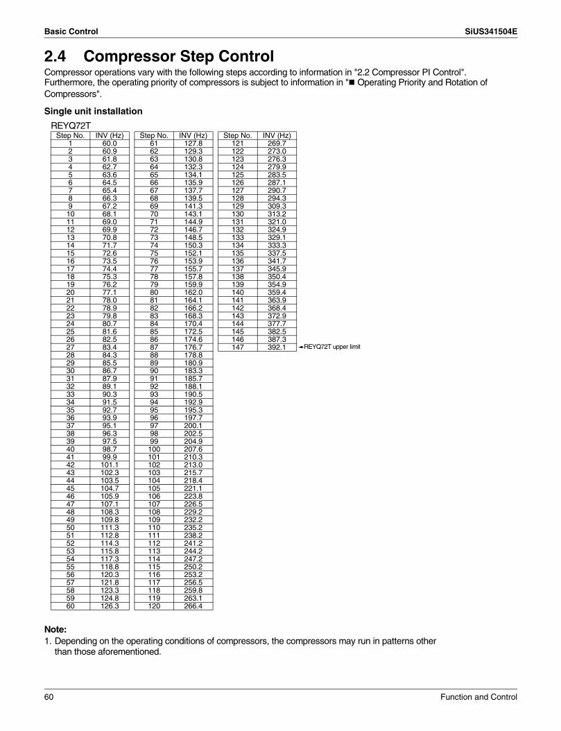
Basic Control SiUS341504E
2.4 Compressor Step ControlCompressor operations vary with the following steps according to information in "2.2 Compressor PI Control".Furthermore, the operating priority of compressors is subject to information in " Operating Priority and Rotation of Compressors".
Single unit installation
Note:1. Depending on the operating conditions of compressors, the compressors may run in patterns other
than those aforementioned.
REYQ72TStep No. INV (Hz) Step No. INV (Hz) Step No. INV (Hz)
1 60.0 61 127.8 121 269.72 60.9 62 129.3 122 273.03 61.8 63 130.8 123 276.34 62.7 64 132.3 124 279.95 63.6 65 134.1 125 283.56 64.5 66 135.9 126 287.17 65.4 67 137.7 127 290.78 66.3 68 139.5 128 294.39 67.2 69 141.3 129 309.310 68.1 70 143.1 130 313.211 69.0 71 144.9 131 321.012 69.9 72 146.7 132 324.913 70.8 73 148.5 133 329.114 71.7 74 150.3 134 333.315 72.6 75 152.1 135 337.516 73.5 76 153.9 136 341.717 74.4 77 155.7 137 345.918 75.3 78 157.8 138 350.419 76.2 79 159.9 139 354.920 77.1 80 162.0 140 359.421 78.0 81 164.1 141 363.922 78.9 82 166.2 142 368.423 79.8 83 168.3 143 372.924 80.7 84 170.4 144 377.725 81.6 85 172.5 145 382.526 82.5 86 174.6 146 387.327 83.4 87 176.7 147 392.128 84.3 88 178.829 85.5 89 180.930 86.7 90 183.331 87.9 91 185.732 89.1 92 188.133 90.3 93 190.534 91.5 94 192.935 92.7 95 195.336 93.9 96 197.737 95.1 97 200.138 96.3 98 202.539 97.5 99 204.940 98.7 100 207.641 99.9 101 210.342 101.1 102 213.043 102.3 103 215.744 103.5 104 218.445 104.7 105 221.146 105.9 106 223.847 107.1 107 226.548 108.3 108 229.249 109.8 109 232.250 111.3 110 235.251 112.8 111 238.252 114.3 112 241.253 115.8 113 244.254 117.3 114 247.255 118.8 115 250.256 120.3 116 253.257 121.8 117 256.558 123.3 118 259.859 124.8 119 263.160 126.3 120 266.4
REYQ72T upper limit
60 Function and Control

SiUS341504E Basic Control
Note:1. Depending on the operating conditions of compressors, the compressors may run in patterns other than those
aforementioned.
REYQ96/120TStep No.
Step up (Hz) Step down (Hz) Step No.
Step up (Hz) Step down (Hz) Step No.
Step up (Hz) Step down (Hz)INV1 INV2 INV1 INV2 INV1 INV2 INV1 INV2 INV1 INV2 INV1 INV2
1 52.0 0.0 52.0 0.0 64 120.8 0.0 56.4 64.4 127 154.4 164.4 154.4 164.42 52.8 0.0 52.8 0.0 65 122.4 0.0 56.6 66.0 128 156.6 166.6 156.6 166.63 53.4 0.0 53.4 0.0 66 124.0 0.0 57.0 67.0 129 158.8 168.8 158.8 168.84 54.2 0.0 54.2 0.0 67 125.8 0.0 58.0 68.0 130 161.2 171.2 161.2 171.25 54.8 0.0 54.8 0.0 68 127.4 0.0 58.8 68.8 131 163.4 173.4 163.4 173.46 55.6 0.0 55.6 0.0 69 129.2 0.0 59.6 69.6 132 165.8 175.8 165.8 175.87 56.4 0.0 56.4 0.0 70 130.8 0.0 60.4 70.4 133 168.2 178.2 168.2 178.28 57.2 0.0 57.2 0.0 71 61.4 71.4 61.4 71.4 134 170.6 180.6 170.6 180.69 57.8 0.0 57.8 0.0 72 65.0 75.0 65.0 75.0 135 173.2 183.2 173.2 183.210 58.6 0.0 58.6 0.0 73 66.0 76.0 66.0 76.0 136 175.6 185.6 175.6 185.611 59.4 0.0 59.4 0.0 74 67.0 77.0 67.0 77.0 137 180.6 190.6 180.6 190.612 60.2 0.0 60.2 0.0 75 67.8 77.8 67.8 77.8 138 183.2 193.2 183.2 193.213 61.0 0.0 61.0 0.0 76 68.8 78.8 68.8 78.8 139 192.0 202.0 192.0 202.014 61.8 0.0 61.8 0.0 77 69.8 79.8 69.8 79.8 140 195.4 205.4 195.4 205.415 62.8 0.0 62.8 0.0 78 70.8 80.8 70.8 80.8 141 199.0 209.0 199.0 209.016 63.6 0.0 63.6 0.0 79 71.8 81.8 71.8 81.8 142 201.6 213.6 201.6 213.617 64.4 0.0 64.4 0.0 80 73.0 83.0 73.0 83.0 143 205.4 217.4 205.4 217.418 65.2 0.0 65.2 0.0 81 74.0 84.0 74.0 84.0 144 207.2 223.2 207.2 223.219 66.2 0.0 66.2 0.0 82 75.0 85.0 75.0 85.0 145 211.0 227.0 211.0 227.020 67.0 0.0 67.0 0.0 83 76.2 86.2 76.2 86.2 146 215.0 231.0 215.0 231.021 68.0 0.0 68.0 0.0 84 77.2 87.2 77.2 87.2 147 218.8 234.8 218.8 234.822 68.8 0.0 68.8 0.0 85 78.4 88.4 78.4 88.4 148 223.0 239.0 223.0 239.023 69.8 0.0 69.8 0.0 86 79.4 89.4 79.4 89.4 149 227.0 243.0 227.0 243.024 70.8 0.0 70.8 0.0 87 80.6 90.6 80.6 90.6 150 229.2 249.2 229.2 249.225 71.6 0.0 71.6 0.0 88 81.8 91.8 81.8 91.8 151 233.6 253.6 233.6 253.626 72.6 0.0 72.6 0.0 89 82.8 92.8 82.8 92.8 152 237.8 257.8 237.8 257.827 73.6 0.0 73.6 0.0 90 84.0 94.0 84.0 94.0 153 242.2 262.2 242.2 262.228 74.6 0.0 74.6 0.0 91 85.2 95.2 85.2 95.2 154 246.8 266.8 246.8 266.829 75.6 0.0 75.6 0.0 92 86.4 96.4 86.4 96.4 155 251.4 271.4 251.4 271.430 76.6 0.0 76.6 0.0 93 87.8 97.8 87.8 97.8 156 256.0 276.0 256.0 276.031 77.6 0.0 77.6 0.0 94 90.2 100.2 90.2 100.232 78.8 0.0 78.8 0.0 95 91.6 101.6 91.6 101.633 79.8 0.0 79.8 0.0 96 92.8 102.8 92.8 102.834 80.8 0.0 80.8 0.0 97 94.2 104.2 94.2 104.235 82.0 0.0 82.0 0.0 98 95.4 105.4 95.4 105.436 83.0 0.0 83.0 0.0 99 96.8 106.8 96.8 106.837 84.2 0.0 84.2 0.0 100 98.2 108.2 98.2 108.238 85.4 0.0 85.4 0.0 101 99.6 109.6 99.6 109.639 86.4 0.0 86.4 0.0 102 101.0 111.0 101.0 111.040 87.6 0.0 87.6 0.0 103 102.6 112.6 102.6 112.641 88.8 0.0 88.8 0.0 104 104.0 114.0 104.0 114.042 90.0 0.0 90.0 0.0 105 105.4 115.4 105.4 115.443 91.2 0.0 91.2 0.0 106 106.8 116.8 106.8 116.844 92.4 0.0 92.4 0.0 107 108.4 118.4 108.4 118.445 93.6 0.0 93.6 0.0 108 109.8 119.8 109.8 119.846 95.0 0.0 95.0 0.0 109 111.4 121.4 111.4 121.447 96.2 0.0 96.2 0.0 110 113.0 123.0 113.0 123.048 97.6 0.0 97.6 0.0 111 114.6 124.6 114.6 124.649 98.8 0.0 98.8 0.0 112 116.2 126.2 116.2 126.250 100.2 0.0 100.2 0.0 113 118.0 128.0 118.0 128.051 101.6 0.0 101.6 0.0 114 119.6 129.6 119.6 129.652 103.0 0.0 52.0 52.0 115 121.2 131.2 121.2 131.253 104.2 0.0 52.0 53.0 116 122.8 132.8 122.8 132.854 105.6 0.0 52.0 54.0 117 130.0 140.0 130.0 140.055 107.0 0.0 52.6 54.6 118 131.8 141.8 131.8 141.856 108.6 0.0 52.8 56.0 119 133.8 143.8 133.8 143.857 110.0 0.0 53.0 57.0 120 139.6 149.6 139.6 149.658 111.4 0.0 53.8 57.8 121 141.6 151.6 141.6 151.659 113.0 0.0 54.0 59.4 122 143.6 153.6 143.6 153.660 114.6 0.0 54.4 60.4 123 145.8 155.8 145.8 155.861 116.0 0.0 55.0 61.0 124 147.8 157.8 147.8 157.862 117.6 0.0 55.2 62.6 125 150.0 160.0 150.0 160.063 119.2 0.0 55.6 63.6 126 152.2 162.2 152.2 162.2
REYQ96T upper limit
REYQ120T upper limit
Function and Control 61

Basic Control SiUS341504E
Note:1. Depending on the operating conditions of compressors, the compressors may run in patterns other than those
aforementioned.
REYQ144TStep No.
Step up (Hz) Step down (Hz) Step No.
Step up (Hz) Step down (Hz) Step No.
Step up (Hz) Step down (Hz)INV1 INV2 INV1 INV2 INV1 INV2 INV1 INV2 INV1 INV2 INV1 INV2
1 52.0 0.0 52.0 0.0 61 116.0 0.0 54.2 61.8 121 132.8 140.7 132.8 140.72 52.8 0.0 52.8 0.0 62 117.6 0.0 55.0 62.7 122 140.4 148.8 140.4 148.83 53.4 0.0 53.4 0.0 63 119.2 0.0 55.8 63.3 123 142.4 150.6 142.4 150.64 54.2 0.0 54.2 0.0 64 120.8 0.0 56.6 64.2 124 144.4 152.7 144.4 152.75 54.8 0.0 54.8 0.0 65 122.4 0.0 57.4 65.1 125 146.4 154.8 146.4 154.86 55.6 0.0 55.6 0.0 66 124.0 0.0 58.2 65.7 126 148.6 156.9 148.6 156.97 56.4 0.0 56.4 0.0 67 125.8 0.0 59.0 66.9 127 150.6 159.3 150.6 159.38 57.2 0.0 57.2 0.0 68 127.4 0.0 59.8 67.5 128 152.8 161.4 152.8 161.49 57.8 0.0 57.8 0.0 69 129.2 0.0 60.6 68.4 129 155.0 163.8 155.0 163.810 58.6 0.0 58.6 0.0 70 130.8 0.0 61.6 69.3 130 157.2 166.2 157.2 166.211 59.4 0.0 59.4 0.0 71 132.6 0.0 62.4 70.2 131 159.4 168.3 159.4 168.312 60.2 0.0 60.2 0.0 72 140.0 0.0 66.0 74.1 132 161.6 170.7 161.6 170.713 61.0 0.0 61.0 0.0 73 141.8 0.0 66.8 75.0 133 163.8 172.8 163.8 172.814 61.8 0.0 61.8 0.0 74 143.8 0.0 67.8 75.9 134 166.2 175.5 166.2 175.515 62.8 0.0 62.8 0.0 75 68.8 76.8 68.8 76.8 135 168.6 177.9 168.6 177.916 63.6 0.0 63.6 0.0 76 69.8 77.7 69.8 77.7 136 170.8 180.3 170.8 180.317 64.4 0.0 64.4 0.0 77 70.8 78.9 70.8 78.9 137 173.2 183.0 173.2 183.018 65.2 0.0 65.2 0.0 78 71.8 79.8 71.8 79.8 138 175.8 185.4 175.8 185.419 66.2 0.0 66.2 0.0 79 72.8 80.7 72.8 80.7 139 178.2 188.1 178.2 188.120 67.0 0.0 67.0 0.0 80 73.8 81.9 73.8 81.9 140 180.8 190.5 180.8 190.521 68.0 0.0 68.0 0.0 81 74.8 83.1 74.8 83.1 141 183.2 193.2 183.2 193.222 68.8 0.0 68.8 0.0 82 75.8 84.0 75.8 84.0 142 185.8 195.9 185.8 195.923 69.8 0.0 69.8 0.0 83 77.0 85.2 77.0 85.2 143 191.2 202.8 191.2 202.824 70.8 0.0 70.8 0.0 84 78.0 86.4 78.0 86.4 144 193.8 207.3 193.8 207.325 71.6 0.0 71.6 0.0 85 79.2 87.6 79.2 87.6 145 196.6 211.5 196.6 211.526 72.6 0.0 72.6 0.0 86 80.2 88.5 80.2 88.5 146 199.4 216.0 199.4 216.027 73.6 0.0 73.6 0.0 87 81.4 89.7 81.4 89.7 147 202.2 220.8 202.2 220.828 74.6 0.0 74.6 0.0 88 82.6 90.9 82.6 90.9 148 205.0 225.3 205.0 225.329 75.6 0.0 75.6 0.0 89 83.6 91.8 83.6 91.8 149 207.8 230.1 207.8 230.130 76.6 0.0 76.6 0.0 90 84.8 93.0 84.8 93.0 150 210.8 234.9 210.8 234.931 77.6 0.0 77.6 0.0 91 86.0 94.2 86.0 94.2 151 213.8 240.0 213.8 240.032 78.8 0.0 78.8 0.0 92 87.2 95.4 87.2 95.4 152 216.8 245.1 216.8 245.133 79.8 0.0 79.8 0.0 93 88.6 96.9 88.6 96.9 153 219.8 250.2 219.8 250.234 80.8 0.0 80.8 0.0 94 91.0 99.3 91.0 99.3 154 223.0 255.6 223.0 255.635 82.0 0.0 82.0 0.0 95 92.4 100.8 92.4 100.8 155 226.0 261.0 226.0 261.036 83.0 0.0 83.0 0.0 96 93.6 102.0 93.6 102.0 156 229.2 266.4 229.2 266.437 84.2 0.0 84.2 0.0 97 95.0 103.2 95.0 103.2 157 232.4 272.1 232.4 272.138 85.4 0.0 85.4 0.0 98 96.2 104.4 96.2 104.4 158 235.8 277.8 235.8 277.839 86.4 0.0 86.4 0.0 99 97.6 105.9 97.6 105.9 159 239.0 283.5 239.0 283.540 87.6 0.0 87.6 0.0 100 99.0 107.1 99.0 107.1 160 242.4 289.5 242.4 289.541 88.8 0.0 88.8 0.0 101 100.4 108.6 100.4 108.6 161 245.8 292.8 245.8 292.842 90.0 0.0 90.0 0.0 102 101.8 110.1 101.8 110.1 162 249.4 296.4 249.4 296.443 91.2 0.0 91.2 0.0 103 103.2 111.9 103.2 111.9 163 252.8 299.7 252.8 299.744 92.4 0.0 92.4 0.0 104 104.6 113.1 104.6 113.1 164 256.4 303.0 256.4 303.045 93.6 0.0 93.6 0.0 105 106.2 114.3 106.2 114.3 165 260.0 306.6 260.0 306.646 95.0 0.0 95.0 0.0 106 107.6 115.8 107.6 115.8 166 263.8 310.2 263.8 310.247 96.2 0.0 96.2 0.0 107 109.2 117.3 109.2 117.3 167 267.4 313.8 267.4 313.848 97.6 0.0 97.6 0.0 108 110.8 118.8 110.8 118.8 168 275.0 321.0 275.0 321.049 98.8 0.0 98.8 0.0 109 112.2 120.3 112.2 120.3 169 275.0 328.8 275.0 328.850 100.2 0.0 100.2 0.0 110 113.8 121.8 113.8 121.8 170 275.0 352.5 275.0 352.551 101.6 0.0 101.6 0.0 111 115.4 123.6 115.4 123.652 103.0 0.0 103.0 0.0 112 117.2 125.4 117.2 125.453 104.2 0.0 104.2 0.0 113 118.8 127.2 118.8 127.254 105.6 0.0 105.6 0.0 114 120.4 128.7 120.4 128.755 107.0 0.0 107.0 0.0 115 122.2 130.2 122.2 130.256 108.6 0.0 108.6 0.0 116 123.8 131.7 123.8 131.757 110.0 0.0 110.0 0.0 117 125.6 133.5 125.6 133.558 111.4 0.0 52.0 60.0 118 127.4 135.0 127.4 135.059 113.0 0.0 52.8 60.3 119 129.2 136.8 129.2 136.860 114.6 0.0 53.4 61.2 120 131.0 138.9 131.0 138.9
REYQ144T upper limit
62 Function and Control

SiUS341504E Basic Control
2.5 Electronic Expansion Valve PI ControlMain electronic expansion valve EVM control
When the outdoor unit heat exchanging is performed via the evaporator (20SA is set to ON), this function is used to exert PI control on the electronic expansion valve (Y1E or Y3E) so that the evaporator outlet superheated degree (SH) will become constant.
Subcooling electronic expansion valve EVT controlIn order to make the maximum use of the subcooling heat exchanger, this function is used to exert PI control on the electronic expansion valve (Y2E, Y5E or Y3E) so that the evaporator-side gas pipe superheated degree (SH) will become constant.
Refrigerant charge electronic expansion valve EVJ controlWhile in automatic refrigerant charge mode, this function is used to exert PI control on the opening degree of the electronic expansion valve (Y2E or Y4E) in response to outdoor temperature and close the valve after the completion of refrigerant charge.For normal operation, fully open this electronic expansion valve.
SH = Tg – Te SH: Evaporator outlet superheated degreeTg: Suction pipe temperature detected by the
heat exchanger gas pipe thermistor R2TTe: Low pressure equivalent saturated
temperature
SH = Tsh – Te SH: Evaporator outlet superheated degree Tsh: Suction pipe temperature detected by
the subcooling heat exchanger outlet thermistor R5T
Te: Low pressure equivalent saturated temperature
Function and Control 63

Basic Control SiUS341504E
2.6 Step Control of Outdoor Unit FansUsed to control the revolutions of outdoor unit fans in the steps listed in table below, according to condition changes.
∗1. Step 2/X∗2. Step X
REYQ72T
Step No.Standard (default)
Cooling Heating·Simultaneous
0 0 01 281 2812 291 2913 301 3014 312 3125 323 3236 334 3347 346 3468 358 3589 368 368
10 401 40111 415 41512 429 42913 444 44414 459 459
15(∗1) 475 47516 491 49117 508 50818 526 52619 544 54420 563 56321 583 58322 603 60323 624 62424 646 64625 669 66926 693 69327 717 71728 743 74329 760 760
30(∗2) 801 80131 845 84532 890 89033 920 920
REYQ96T
Step No.
Standard (default)
Cooling Heating·Simultaneous
FAN1 FAN2 FAN1 FAN20 0 0 0 01 281 0 281 02 290 0 290 03 299 0 299 04 308 0 308 05 348 0 348 06 356 0 356 07 365 0 365 08 375 0 375 09 384 0 384 010 395 0 395 011 405 0 405 012 416 0 416 013 427 0 427 014 438 0 438 015 450 0 450 016 461 0 461 017 474 0 474 018 487 0 487 019 500 0 500 020 513 0 513 021 527 0 527 022 541 0 541 023 556 0 556 024 309 339 309 33925 332 362 332 36226 348 378 348 378
27(∗1) 359 389 359 38928 374 404 374 40429 389 419 389 41930 405 435 405 43531 422 452 422 45232 440 470 440 47033 458 488 458 48834 477 507 477 50735 497 527 497 52736 518 548 518 54837 540 570 540 57038 562 592 562 59239 586 616 586 61640 610 640 610 64041 636 666 636 66642 663 693 663 69343 690 720 690 72044 719 749 719 74945 749 779 749 77946 781 811 781 81147 814 844 814 84448 848 878 848 87849 883 913 883 91350 951 921 951 92151 963 933 963 93352 1055 975 1055 975
53 (∗2) 1097 1017 1097 1017
64 Function and Control

SiUS341504E Basic Control
∗1. Step 2/X∗2. Step X
REYQ120T
Step No.
Standard (default)
Cooling Heating·Simultaneous
FAN1 FAN2 FAN1 FAN20 0 0 0 01 281 0 281 02 291 0 291 03 304 0 304 04 348 0 348 05 360 0 360 06 372 0 372 07 384 0 384 08 396 0 396 09 409 0 409 0
10 423 0 423 011 437 0 437 012 452 0 452 013 467 0 467 014 482 0 482 015 499 0 499 016 516 0 516 017 533 0 533 018 551 0 551 019 570 0 570 020 589 0 589 021 339 369 339 36922 354 384 354 38423 369 399 369 39924 384 414 384 41425 401 431 401 431
26(∗1) 418 448 418 44827 435 465 435 46528 454 484 454 48429 473 503 473 50330 493 523 493 52331 514 544 514 54432 536 566 536 56633 559 589 559 58934 582 612 582 61235 607 637 607 63736 633 663 633 66337 660 690 660 69038 688 718 688 71839 717 747 717 74740 748 778 748 77841 780 810 780 81042 813 843 813 84343 848 878 848 87844 884 914 884 91445 922 952 922 95246 961 991 961 99147 962 1072 962 107248 1005 1115 1005 111549 1050 1160 1050 116050 1096 1206 1096 120651 1135 1265 1110
52(∗2) 1340 1160 1335 1155
REYQ144T
Step No.
Standard (default)
Cooling Heating·Simultaneous
FAN1 FAN2 FAN1 FAN20 0 0 0 01 281 0 281 02 290 0 290 03 303 0 303 04 310 0 310 05 329 0 329 06 348 0 348 07 357 0 357 08 371 0 371 09 386 0 386 010 402 0 402 011 419 0 419 012 436 0 436 013 453 0 453 014 472 0 472 015 491 0 491 016 511 0 511 017 532 0 532 018 554 0 554 019 576 0 576 020 285 315 285 31521 303 333 303 33322 310 345 310 34523 329 359 329 35924 332 362 332 362
25(∗1) 345 375 345 37526 358 388 358 38827 372 402 372 40228 386 416 386 41629 401 431 401 43130 417 447 417 44731 434 464 434 46432 451 481 451 48133 470 500 470 50034 489 519 489 51935 509 539 509 53936 531 561 531 56137 553 583 553 58338 577 607 577 60739 601 631 601 63140 627 657 627 65741 655 685 655 68542 683 713 683 71343 713 743 713 74344 745 775 745 77545 778 808 778 80846 813 843 813 84347 849 879 849 87948 888 918 888 91849 928 958 928 95850 930 1040 930 1040
51(∗2) 1021 1131 1021 113152 1262 1132 1262 113253 1350 1170 1300 1120
Function and Control 65

Basic Control SiUS341504E
2.7 Heat Exchanger ControlWhile in heating or cool/heat simultaneous operation, ensure target condensing and evaporating temperature by changing over the air heat exchange of outdoor unit to the evaporator or the condenser in response to loads.
[Single system]
[Multi outdoor unit system]
Outdoor unit
Lower side
Condenser
Upper side
Condenser
Outdoor unit
Lower side
Evaporator
Upper side
Condenser
Outdoor unit
Lower side
Evaporator
Upper side
Evaporator
Outdoor unit
Lower side
—
Upper side
Condenser
CL decreaseHL increase
CL decreaseHL increase
CL increaseHL decrease
CL decreaseHL increase
CL increaseHL decrease
CL increaseHL increase
1 3
1 3
1 3
1 3
12
2
2
2
2 3
1 2 3
1 2 3
1 2 3
Lower side Upper side
Outdoor unit
Lower side Upper side Lower side Upper sideCondenser CondenserCondenser Condenser — Condenser
Lower side Upper side
Outdoor unit
Lower side Upper side Lower side Upper side— CondenserCondenser Condenser — Condenser
Lower side Upper side
Outdoor unit
Lower side Upper side Lower side Upper side— Condenser— Condenser — Condenser
Lower side Upper side
Outdoor unit
Lower side Upper side Lower side Upper side— Condenser— Condenser — —
CL decreaseHL increase
CL increaseHL decrease
Lower side Upper side
Outdoor unit
Lower side Upper side Lower side Upper side— —Evaporator Condenser — —
Lower side Upper side
Outdoor unit
Lower side Upper side Lower side Upper side— —Evaporator Evaporator — —
CL decreaseHL increase
CL increaseHL decrease
CL decreaseHL increase
CL increaseHL decrease
Lower side Upper side
Outdoor unit
Lower side Upper side Lower side Upper sideEvaporator EvaporatorEvaporator Evaporator — —
Lower side Upper side
Outdoor unit
Lower side Upper side Lower side Upper sideEvaporator EvaporatorEvaporator Evaporator Evaporator Evaporator
CL decreaseHL increase
CL increaseHL decrease
CL decreaseHL increase
CL increaseHL decrease
<Symbol meanings>CL: Cooling LoadHL: Heating Load
CL decreaseHL increase
CL increaseHL decrease
CL decreaseHL increase
CL increaseHL decrease
66 Function and Control

SiUS341504E Protection Control
3. Protection Control3.1 High Pressure Protection Control
This high pressure protection control is used to prevent the activation of protection devices due to abnormal increase of high pressure and to protect compressors against the transient increase of high pressure.
[In cooling]
Normal Operation
21-step down 9-step up
9-step down 3-step up
2-step down
1-step up2-step down
After 10 seconds After 15 seconds
After 15 secondsAfter 10 seconds
Pc > 3.57 MPa(1194 ftH2O)
Pc > 3.70 MPa(1238 ftH2O)
Pc < 3.14 MPa(1050 ftH2O)
Pc < 3.45 MPa(1154 ftH2O)
Pc > 3.67 MPa(1228 ftH2O)
Pc > 3.62 MPa(1211 ftH2O)Pc > 3.57 MPa
(1194 ftH2O)
Compressor step: 1
After 15 seconds
Pc < 3.33 MPa (1114 ftH2O)
After 10 seconds
Upper limit compressor step = max (Max. Step)
Pc > 3.72 MPa(1245 ftH2O)
Pc: High pressure sensor detection value for each outdoor unit
Current step
maintained
Abnormal stop (E3 is displayed)
High pressure standby (2 times within 30 minutes)
After 10 seconds
High pressure switch (4.0 MPa (1338 ftH2O)) is activated
Function and Control 67

Protection Control SiUS341504E
[In heating]
Pc < 3.17 MPa (1061 ftH2O)Pc < 3.17 MPa
(1061 ftH2O)
Pc > 3.31 MPa(1107 ftH2O)
Pc > 3.39 MPa(1134 ftH2O)
Pc < 3.22 MPa(1077 ftH2O)
Pc > 3.72 MPa (1245 ftH2O)
Normal Operation
System 9-step down/10 seconds
All units Compressor step: 1
System 3-step up/15 seconds
High pressure standby (2 times within 30 minutes)
Pc: High pressure sensor detection value for master unit
Abnormal stop (E3 is displayed)
Pc > 3.31 MPa(1107 ftH2O)
High pressure switch (4.0 MPa (1338 ftH2O)) is activated
68 Function and Control

SiUS341504E Protection Control
3.2 Low Pressure Protection ControlThis low pressure protection control is used to protect compressors against the transient decrease of low pressure.
[In cooling]
[In heating]
Normal Operation
All compressors step.: 1
Pe < 0.15 MPa(50.2 ftH2O)
Pe < 0.25 MPa(83.6 ftH2O)
Pe > 0.39 MPa(130.5 ftH2O)
Pe < 0.07 MPa (23.4 ftH2O)
Pe: Low pressure sensor detection value for master unit
Master unit: Compressor step: 1 Slave unit: All stop
Abnormal stop (E4 is displayed)
Low pressure standby (3 times within 60 minutes)
Low pressure standby (4 times within 60 minutes)
Normal Operation
9-step down 9-step up
3-step up21-step down
After 10 seconds After 15 seconds
After 15 secondsAfter 10 seconds
Pe < 0.17 MPa(56.9 ftH2O)
Pe < 0.13 MPa(43.5 ftH2O)
Pe > 0.27 MPa(90.3 ftH2O)
Pe > 0.20 MPa(66.9 ftH2O)
Pe < 0.17 MPa(56.9 ftH2O)
Pe < 0.14 MPa(46.8 ftH2O)
Compressor step: 1
After 10 seconds
Upper limit compressor step = max (Max. Step)
Pe < 0.07 MPa(23.4 ftH2O)
Pe: Low pressure sensor detection value for each outdoor unit
Current step maintained
Abnormal stop (E4 is displayed)
Low pressure standby (3 times within 60 minutes)
Low pressure standby (4 times within 60 minutes)
Function and Control 69
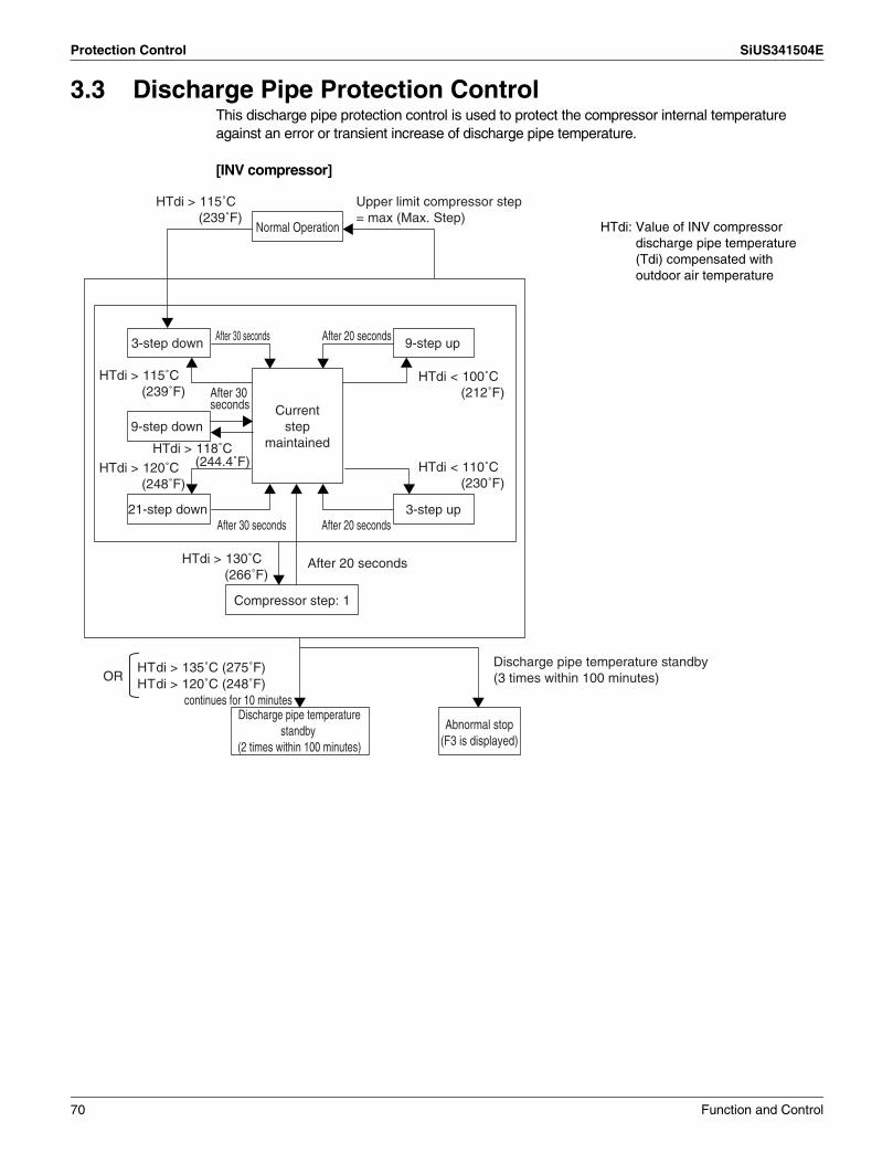
Protection Control SiUS341504E
3.3 Discharge Pipe Protection ControlThis discharge pipe protection control is used to protect the compressor internal temperature against an error or transient increase of discharge pipe temperature.
[INV compressor]
Normal Operation
3-step down 9-step up
9-step down
3-step up21-step down
After 30 seconds After 20 seconds
After 20 secondsAfter 30 seconds
HTdi > 115˚C(239˚F)
HTdi > 130˚C(266˚F)
HTdi < 100˚C(212˚F)
HTdi < 110˚C(230˚F)
HTdi > 115˚C(239˚F)
HTdi > 118˚C(244.4˚F)HTdi > 120˚C
(248˚F)
Compressor step: 1
After 20 seconds
HTdi > 135˚C (275˚F)HTdi > 120˚C (248˚F)
continues for 10 minutes
OR
HTdi: Value of INV compressor discharge pipe temperature (Tdi) compensated with outdoor air temperature
Upper limit compressor step = max (Max. Step)
Current step
maintained
Discharge pipe temperature standby (3 times within 100 minutes)
Abnormal stop(F3 is displayed)
Discharge pipe temperature standby
(2 times within 100 minutes)
After 30 seconds
70 Function and Control

SiUS341504E Protection Control
3.4 Inverter Protection ControlInverter current protection control and radiation fin temperature control are performed to prevent tripping due to an error, or transient inverter overcurrent, and fin temperature increase.In the case of multi-outdoor-unit system, each INV compressor performs these controls in the following sequence.[Inverter overcurrent protection control]Perform the following control of integrated as well as multi units for each INV compressor.
[Radiation fin temperature control]Perform the following control of integrated as well as multi units for each INV compressor.
Normal operation
Inverter current standby
Reduce compressor capacity
A B
When occurring 3 times within 60 minutes, the error code “L8” is output.
C
ModelREYQ72T REYQ96-144T REYQ168T
M1C M1C M2C M1C M2C
A > 18.5 A > 14.7 A > 14.7 A > 14.7 A > 22.0 A
B < 18.5 A < 14.7 A < 14.7 A < 14.7 A < 22.0 A
C > 22.5 A > 16.1 A > 16.1 A > 16.1 A > 22.5 A
Normal operation
Fin temperature standby
Reduce compressor capacity
When occurring 4 times within 60 minutes, the error code “L4” is output.
A B
C
ModelREYQ72T REYQ96-144T REYQ168T
M1C M1C M2C M1C M2C
A > 96 °C (204.8°F) > 99 °C (210.2°F) > 99 °C (210.2°F) > 99 °C (210.2°F) > 80 °C (176°F)
B < 93 °C (199.4°F) < 96 °C (204.8°F) < 96 °C (204.8°F) < 96 °C (204.8°F) < 77 °C (170.6°F)
C > 100 °C (212°F) > 105 °C (221°F) > 105 °C (221°F) > 105 °C (221°F) > 84 °C (183.2°F)
Function and Control 71

Special Control SiUS341504E
4. Special Control4.1 Pump down Residual OperationIf the liquid refrigerant stays in the evaporator at the startup of a compressor, this liquid refrigerant enters the compressor, thus resulting in diluted oil in the compressor and then degraded lubrication performance.Consequently, in order to recover the refrigerant in the evaporator while the compressor stops, the pump down residual operation is conducted.
∗REYQ72T
Part NameElectric Symbol Function of Functional Part
REYQ72T REYQ96-168T Normal Cooling Normal HeatingInverter compressor 1 M1C M1C 124 Hz/120 Hz∗ 124 Hz/120 Hz∗Inverter compressor 2 — M2C 0 Hz 0 Hz
Inverter fan M1F M1F, M2F For heat exchanger mode For heat exchanger modeElectronic expansion valve (Heat exchanger upper) Y1E Y1E
Same as normal operation Same as normal operationElectronic expansion valve (Heat exchanger lower) Y3E Y3E
Electronic expansion valve (Subcooling heat exchanger) Y2E Y2E 0 pulse 0 pulse
Electronic expansion valve (Receiver gas purge) Y4E Y4E Open slightly Open slightly
Electronic expansion valve (Inverter cooling) Y5E Y5E Same as normal operation Same as normal operation
Solenoid valve (Oil separator oil return) Y1S Y1S, Y2S ON ON
Solenoid valve (Liquid pipe) Y3S Y3S ON ONFour way valve (HP/LP gas pipe) Y4S Y4S Hold Hold
Four way valve (Heat exchanger lower) Y5S Y5S Hold Hold
Four way valve (Heat exchanger upper) Y6S Y6S Hold Hold
Ending condition
A lapse of 30 secondsPe_min < 0.49 Mpa (163.9 ftH2O)Master unit DSH > 35°C (95°F)Pc_max > 2.94 MPa (984 ftH2O)
A lapse of 30 secondsPe_min < 0.25 Mpa (83.6 ftH2O)Master unit DSH > 35°C (95°F)Pc_max > 3.14 MPa (1050 ftH2O)Master unit Ta–Te > 5°C (9°F)
OR OR
72 Function and Control

SiUS341504E Special Control
4.2 Oil Return OperationIn order to prevent the compressor from running out of oil, the oil return operation is conducted to recover oil flown out from the compressor to the system side.
4.2.1 Oil Return Operation in Cooling Operation[Starting conditions]Referring to the set conditions for the following items, start the oil return operation in cooling• Cumulative oil feed rate• Timer setting (Make this setting so as to start the oil return operation when the initial cumulative operating time reaches 2
hours after power supply is turned ON and then every 8 hours.)Furthermore, the cumulative oil feed rate is computed from Tc, Te, and compressor loads.
Part NameElectric Symbol
Oil return operationREYQ72T REYQ96-168T
Inverter compressor 1 M1C M1CConstant low pressure control
Inverter compressor 2 — M2CInverter fan M1F M1F, M2F For heat exchanger modeElectronic expansion valve (Heat exchanger upper) Y1E Y1E
Same as normal operation
Same as normal operationElectronic expansion valve (Heat
exchanger lower) Y3E Y3E
Electronic expansion valve (Subcooling heat exchanger) Y2E Y2E 0 pulse
Electronic expansion valve (Receiver gas purge) Y4E Y4E 0 pulse
Electronic expansion valve (Inverter cooling) Y5E Y5E Same as normal operationSolenoid valve (Oil separator oil return) Y1S Y1S, Y2S ONSolenoid valve (Liquid pipe) Y3S Y3S ONFour way valve (HP/LP gas pipe) Y4S Y4S HoldFour way valve (Heat exchanger lower) Y5S Y5S HoldFour way valve (Heat exchanger upper) Y6S Y6S Hold
Ending condition
• A lapse of 3 minutes• TsA – Te < 3°C (5.4°F)• A lapse of 6 minutes while the
frequency is more than that of oil return operation.
&OR
Indoor unit actuator Oil return operation
FanThermostat ON unit Remote controller setting
Stopping unit OFFThermostat OFF unit Remote controller setting
Electronic expansion valveThermostat ON unit Normal control
Stopping unit 224 pulseThermostat OFF unit Forced thermo. OFF (PI control)
Branch selector unit actuatorNormal cooling Normal Simultaneous Cooling / Heating Normal heating
Cooling Cooling Heating Heating
Electronic expansion valve (EVSC)
Y1EThermo. ON 0 pulse 0 pulse Subcooled degree control 0 pulse
Stopping 0 pulse 0 pulse 0 pulse 0 pulseThermo. OFF 0 pulse 0 pulse 0 pulse 0 pulse
Electronic expansion valve (EVH)
Y2EThermo. ON 6,000 pulse 0 pulse 6,000 pulse 6,000 pulse
Stopping 6,000 pulse 0 pulse 6,000 pulse 6,000 pulseThermo. OFF 6,000 pulse 0 pulse 6,000 pulse 6,000 pulse
Electronic expansion valve (EVL)
Y3EThermo. ON 6,000 pulse 6,000 pulse 0 pulse 0 pulse
Stopping 6,000 pulse 6,000 pulse 0 pulse 0 pulseThermo. OFF 6,000 pulse 6,000 pulse 0 pulse 0 pulse
Function and Control 73

Special Control SiUS341504E
4.2.2 Oil Return Operation in Heating Operation[Starting conditions]
Part NameElectric Symbol
Oil return operationREYQ72T REYQ96-168T
Inverter compressor 1 M1C M1C +1 to +6 steps from frequency to frequency when oil return is IN at a constant levelInverter compressor 2 — M2C
Inverter fan M1F M1F, M2F Same as normal operation
Electronic expansion valve (Heat exchanger upper) Y1E Y1E
Same as normal operationElectronic expansion valve (Heat exchanger lower) Y3E Y3E
Electronic expansion valve (Subcooling heat exchanger) Y2E Y2E Same as normal operation
Electronic expansion valve (Receiver gas purge) Y4E Y4E 0 pulse
Electronic expansion valve (Inverter cooling) Y5E Y5E Same as normal operation
Solenoid valve (Oil separator oil return) Y1S Y1S, Y2S ON
Solenoid valve (Liquid pipe) Y3S Y3S ONFour way valve (HP/LP gas pipe) Y4S Y4S HoldFour way valve (Heat exchanger lower) Y5S Y5S Hold
Four way valve (Heat exchanger upper) Y6S Y6S Hold
Ending condition A lapse of 8 minutes while the frequency is more than that of oil return operation.
Indoor unit actuator Cooling Heating
FanThermostat ON unit Remote controller setting Remote controller setting
Stopping unit OFF OFF
Thermostat OFF unit Remote controller setting Remote controller setting
Electronic expansion valveThermostat ON unit Normal control Normal control
Stopping unit 224 pulse 224 pulse
Thermostat OFF unit Forced thermo. OFF 224 pulse
Branch selector unit actuatorNormal cooling Normal Simultaneous Cooling / Heating Normal heating
Cooling Cooling Heating Heating
Electronic expansion valve (EVSC)
Y1EThermo. ON 0 pulse 0 pulse Subcooled degree
control 0 pulse
Stopping 0 pulse 0 pulse 0 pulse 0 pulseThermo. OFF 0 pulse 0 pulse 0 pulse 0 pulse
Electronic expansion valve (EVH)
Y2EThermo. ON 6,000 pulse 0 pulse 6,000 pulse 6,000 pulse
Stopping 6,000 pulse 0 pulse 6,000 pulse 6,000 pulseThermo. OFF 6,000 pulse 0 pulse 6,000 pulse 6,000 pulse
Electronic expansion valve (EVL)
Y3EThermo. ON 6,000 pulse 6,000 pulse 0 pulse 0 pulse
Stopping 6,000 pulse 6,000 pulse 0 pulse 0 pulseThermo. OFF 6,000 pulse 6,000 pulse 0 pulse 0 pulse
74 Function and Control

SiUS341504E Special Control
4.3 Defrost OperationTo defrost the outdoor unit heat exchanger while in Evaporator, the defrost operation is conducted to recover the heating capacity.
Part NameElectric Symbol
Defrost operationREYQ72T REYQ96-168T
Inverter compressor 1 M1C M1CREYQ72: HzREYQ96/120: HzREYQ144/168: Hz
Inverter compressor 2 — M2C With high pressureOFF ←→Step 2/X ←→ Step XInverter fan M1F M1F, M2F
Electronic expansion valve (Heat exchanger upper) Y1E Y1E
100%Electronic expansion valve (Heat exchanger lower) Y3E Y3E
Electronic expansion valve (Subcooling heat exchanger) Y2E Y2E 0 pulse
Electronic expansion valve (Receiver gas purge) Y4E Y4E 0 pulse
Electronic expansion valve (Inverter cooling) Y5E Y5E Same as normal operation
Solenoid valve (Oil separator oil return) Y1S Y1S, Y2S ON
Solenoid valve (Liquid pipe) Y3S Y3S ONFour way valve (HP/LP gas pipe) Y4S Y4S Hold
Four way valve (Heat exchanger lower) Y5S Y5S Hold
Four way valve (Heat exchanger upper) Y6S Y6S Hold
Ending condition • A lapse of 15 minutes• Tb>11°C (51.8°F) continues for 30 seconds or moreOR
Indoor unit actuator Defrost operation
Fan
Thermostat ON unit OFF
Stopping unit OFFThermostat OFF unit OFF
Electronic expansion valve
Thermostat ON unit Defrost EV opening degree
Stopping unit Defrost EV opening degreeThermostat OFF unit Defrost EV opening degree
Branch selector unit actuatorNormal cooling Normal Simultaneous Cooling / Heating Normal heating
Cooling Cooling Heating Heating
Electronic expansion valve (EVSC)
Y1EThermo. ON 0 pulse 0 pulse Subcooled degree
control 0 pulse
Stopping 0 pulse 0 pulse 0 pulse 0 pulse
Thermo. OFF 0 pulse 0 pulse 0 pulse 0 pulse
Electronic expansion valve (EVH)
Y2EThermo. ON 6,000 pulse 0 pulse 6,000 pulse 6,000 pulse
Stopping 6,000 pulse 0 pulse 6,000 pulse 6,000 pulse
Thermo. OFF 6,000 pulse 0 pulse 6,000 pulse 6,000 pulse
Electronic expansion valve (EVL)
Y3EThermo. ON 6,000 pulse 6,000 pulse 0 pulse 0 pulse
Stopping 6,000 pulse 6,000 pulse 0 pulse 0 pulse
Thermo. OFF 6,000 pulse 6,000 pulse 0 pulse 0 pulse
Function and Control 75
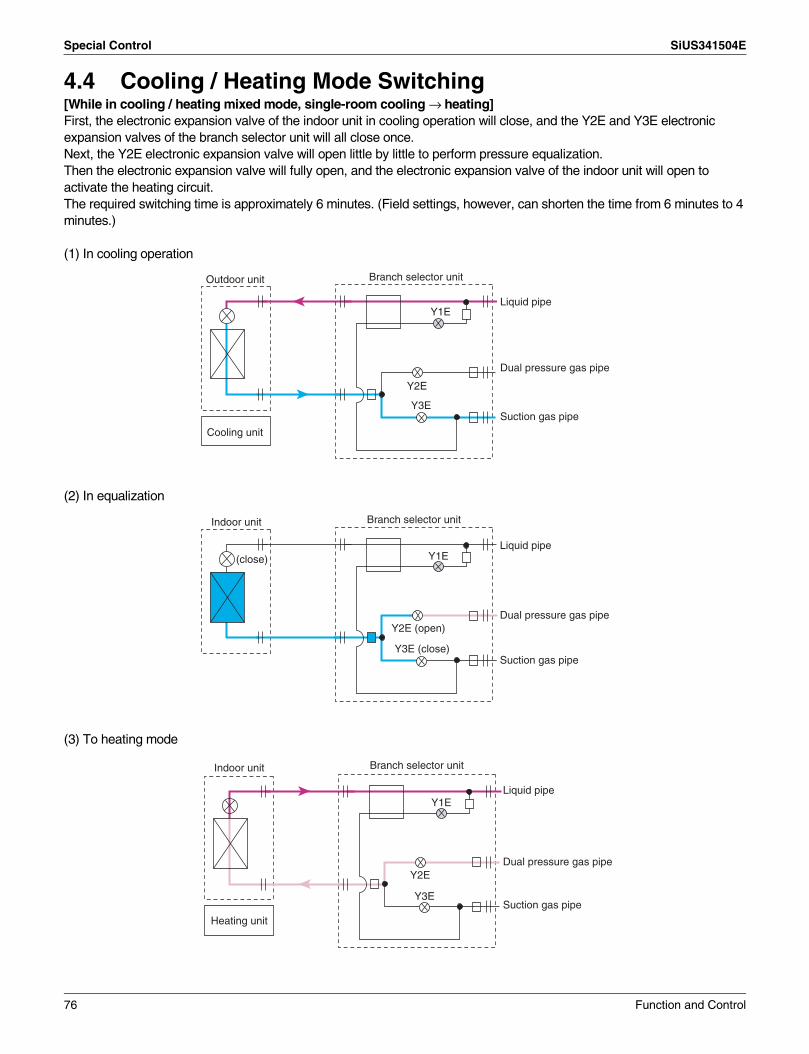
Special Control SiUS341504E
4.4 Cooling / Heating Mode Switching[While in cooling / heating mixed mode, single-room cooling → heating]First, the electronic expansion valve of the indoor unit in cooling operation will close, and the Y2E and Y3E electronic expansion valves of the branch selector unit will all close once.Next, the Y2E electronic expansion valve will open little by little to perform pressure equalization.Then the electronic expansion valve will fully open, and the electronic expansion valve of the indoor unit will open to activate the heating circuit.The required switching time is approximately 6 minutes. (Field settings, however, can shorten the time from 6 minutes to 4 minutes.)
(1) In cooling operation
(2) In equalization
(3) To heating mode
Y2E
Y3E
Y1ELiquid pipe
Dual pressure gas pipe
Suction gas pipe
Branch selector unitOutdoor unit
Cooling unit
Y2E (open)
Y3E (close)
Y1E
Branch selector unitIndoor unit
(close)Liquid pipe
Suction gas pipe
Dual pressure gas pipe
Y2E
Y3E
Y1E
Heating unit
Branch selector unitIndoor unit
Dual pressure gas pipe
Suction gas pipe
Liquid pipe
76 Function and Control

SiUS341504E Special Control
[While in cooling/heating mixed mode, single-room heating → cooling]First, the electronic expansion valve of the indoor unit in heating operation will close, and the Y2E and Y3E electronic expansion valves of the branch selector unit will all close once.Next, the Y3E electronic expansion valve will open little by little to perform pressure equalization.Then the electronic expansion valve will fully open, and the electronic expansion valve of the indoor unit will open to activate the heating circuit.The required switching time is approximately 6 minutes. (Field settings, however, can shorten the time from 6 minutes to 4 minutes.)
(1) In heating
(2) In equalization
(3) To cooling
Y2E
Y3E
Y1E
Heating unit
Branch selector unitIndoor unit
Dual pressure gas pipe
Liquid pipe
Suction gas pipe
Y2E (open)
Y3E (close)
Y1E
In equalization
(close)
Branch selector unitIndoor unit
Liquid pipe
Dual pressure gas pipe
Suction gas pipe
Y2E
Y3E
Y1E
Branch selector unitIndoor unit
Cooling unit
Liquid pipe
Dual pressure gas pipe
Suction gas pipe
Function and Control 77

Special Control SiUS341504E
[While in all-room cooling operation → All-room cooling/heating simultaneous operation]
(1) All the indoor units in cooling operation· Using the dual pressure gas pipe as a suction
gas pipe.
(2) Pump-down residual operation
(3) Pre-startup control· Switching between the electronic expansion
valves of branch selector unit.· Required switching time: 30 seconds (switching
control time)(While switching: The compressor stops operating.)
(4) Startup control· Switching the dual pressure gas pipe from low
pressure to high pressure.
(5) Into heating operation or cooling and heating simultaneous operation
Each indoor unit· In warm air supply operation under cool air
prevention control (for 3 to 5 minutes).
Suction gas pipe
Dual pressure gas pipe
Cooling Cooling Cooling Cooling Cooling
Suction gas pipe
Dual pressure gas pipe
Heating Heating Heating Heating
Heating
Liquid pipe
Liquid pipe
Suction gas pipe
Dual pressure gas pipe
Liquid pipe
78 Function and Control

SiUS341504E Special Control
[While in all-room heating operation or cooling/heating simultaneous operation → All-room cooling]
(1) In heating operation or cooling and heating simultaneous operation
· Using the dual pressure gas pipe as a suction gas pipe.
(2) Pump-down residual operation
(3) Pre-startup control· Switching between the electronic expansion
valves of branch selector unit.· Required switching time: 2 to 4 minutes
(switching control time)(While switching: The compressor stops operating.)
(4) Startup control· Switching the dual pressure gas pipe from low
pressure to high pressure.
(5) Into all-unit cooling operation· In cool air supply operation
Suction gas pipe
Dual pressure gas pipe
Heating Heating Heating Heating Heating
Suction gas pipe
Dual pressure gas pipe
Vent Vent VentVentVent
Cooling Cooling CoolingCooling
Suction gas pipe
Dual pressure gas pipe
Cooling
Liquid pipe
Liquid pipe
Liquid pipe
Function and Control 79

Other Control SiUS341504E
5. Other Control5.1 Backup Operation
If any of the compressors goes wrong, disable the relevant compressor or the relevant outdoor unit from operating, and then conduct emergency operation only with operational compressors or outdoor units."Emergency operation with remote controller reset" and "Emergency operation with outdoor unit PCB setting" are available
(1) Emergency operation with remote controller reset[Operating method]
Reset the remote controller. (Press the button for 4 seconds or more.)[Details of operation]
Disable the defective outdoor unit from operating, and then only operate other outdoor units.(On the system with 1 outdoor unit, this emergency operation is not available.)
(2) Emergency operation with outdoor unit PCB setting[Setting method]
Make setting of the compressor, "the operation of which is to be disabled", in field setting mode (setting mode 2).
[Details of operation]Disable the compressor with "operation disable setting" made from operating and only operate other compressors.(On the system with 1 compressor, REYQ72T, this emergency operation is not available.)
5.2 Demand OperationIn order to save the power consumption, the capacity of outdoor unit is saved with control forcibly by using “Demand 1 Setting” or “Demand 2 Setting”.To operate the unit with this mode, additional setting of “Continuous Demand Setting” or external input by external control adaptor for outdoor unit is required.
5.3 Heating Operation Prohibition
Heating operation is prohibited when the outdoor air temperature is above 24°C (75.2°F).
Operating methodApplicable model
(1) Emergency operation with remote controller reset
(Auto backup operation)
(2) Emergency operation with outdoor unit PCB setting
(Manual backup operation)
REYQ96-168T – Backup operation by the compressor
REYQ192-456T Backup operation by the outdoor unit
Backup operation by the outdoor unit
ON/OFF
Setting item Condition Content
Demand 1 Level 1 The compressor operates at the power of 60% or less of the rating.
Level 2 The compressor operates at the power of 70% or less of the rating.
Level 3 The compressor operates at the power of 80% or less of the rating.
Demand 2 The compressor operates at the power of 40% or less of the rating.
Demand 3 Forced thermostat OFF
80 Function and Control

SiUS341504E Outline of Control (Indoor Unit)
6. Outline of Control (Indoor Unit)6.1 Operation Flow Chart
Is test run in progress?
Is freeze-up prevention operation in
progress?
Is Restart prevention
operation in progress?(5 min.)
Dew prevention condition?
Is the safety device
activated?
Start
Heating Operation Fan OperationCooling Operation
Cooling Operation
Detect louver lock
( )Run or Stop?
RUN indicating lamp: OFF
RUN indicating lamp: BlinkError code: Displayed
RUN indicating lamp: OFFError mode display: Reset
Thermostat status
Swing flap
Swing flap Set wind direction
Program dry display: Reset
Program dry operation
A
A
A
Stop
Run
Yes
Yes
Yes
Yes
Yes
Yes
No
No
No
No
ON
OFF
No
No
No
∗1
Fan
Temp. control
Heating
Cooling
∗2 Fan : Stop
Louver : Stop
∗3
∗6
∗5
∗4
(Option)
(Option)
(Option)
(Option)
(Option)
(Option)
OFF
ON
MF
MF
: OFFMP
Drain pump kit
MP
Drain pump kit
MP
Drain pump kit
:ONMP
Drain pump kit
: ONMP
: Closed20E
Electronic expansion valve
: Capacity control20E
Electronic expansion valve
: Closed20E
MA
: OFF52H
: OFF52H
Humidifier : OFFMu
Humidifier : OFFMu
20E
OFF
ON
a b
Set temperature
The previous settings of airflow rate, wind direction, and temperature are displayed.
Is the RUN indicating lamp
blinking?
Press the RESET RUN/STOP push button.
Electronic expansion valve
Thermostat-ON-operation signal to outdoor unit: Output
Thermostat-ON-operation signal to outdoor unit: Output
∗1. If any error occurs, the relevant error code will be displayed according to the error code display of the remote controller.
∗2. When the aux. electric heater turns ON, the fan will stop after it conducts residual operation for 1 min.∗3. When the drain pump kit turns ON, the drain pump kit will stop after it conducts residual operation for a
period of 5 min.∗4. If the evaporator inlet temperature is kept at not more than –5°C (23˚F) for a period of cumulative 10
min. or not more than –1°C (30.2˚F) for a cumulative period of 40 min., freeze-up prevention operation will be conducted. If the evaporator inlet temperature is kept at not less than 7°C (44.6˚F) for a consecutive period of 10 min., the freeze-up prevention operation will be reset.
∗5. Thermostat status
∗6. The FXFQ series have the drain pump as standard equipment.
RUN indicating lamp: ON
Airflow rate display: Displayed
Wind direction display: Displayed
Temp. setting display: Displayed
Turn ON power supply
Initialize electronic expansion valve
LED in remote controller turns ON
Cyclic operation with RUN/STOP push button
Fan or Temp. control?
Cooling or Heating?
Drain pump kit
Aux. electric heater
Aux. electric heater
Dew prevention position Cassette type: P1Ceiling suspended type: P0
Program dry ON/OFF
Fan:Operating with set airflow rate
: OFF after 5-min. residual operation
: OFF after 5-min. residual operation
Suction air temperaturea = b = 1˚C (1.8˚F)(a = b = 0.5˚C (0.9˚F) is only available for the FXFQ and FXHQ series.)
Function and Control 81

Outline of Control (Indoor Unit) SiUS341504E
Is outlet air
temperature drop protection in progress?
Is test run in progress?
Restart prevention operating
in progress?(4 min.)
Is hot starting in progress?
Is defrost operation in
progress?
Program dry operation Heating Operation
Fan Operation
Thermostat status
A
A
A
OFF
Yes
ON
No
Suction air temperature
∗7
∗8
∗9
∗10
∗11
Thermostat status
No
No
∗14
∗15
(Option)
(Option) (Option) (Option) (Option)
(Option)
: OFFMP
: OFF52H
Humidifier : OFFMu
: OFF52H
Humidifier : ON
: OFF
Humidifier : OFF
: ON
Humidifier : ONMu
52H
Mu
: OFF52H
Humidifier : OFFMu
52H
Mu
(option)
: OFFMP
Fan :Operating in L mode
MF
Fan : Operatingin L mode after it stops for 6 min.
MF
20E :
Drain pump kit
20E :
MP
Swing flap
Swing flap Set wind direction
Fan MF:Operating with set airflow rate
20E :
Yes
Yes
No
No
No
∗12
∗13
∗12
Yes
Yes
Yes
Swing flap?
Swing flap Set wind direction
Fan :Operating with set airflow rate
MF
20E :20E : 20E :
Fan :LL operation
MF Fan :Operating in L mode
MF Fan :Stop
MF
ba
–2˚C (28.4˚F)–4˚C (24.8˚F)Suction air temp.
Set temp.
b
a
(3)
(2)
(1)
(3)
(2)
(1)
Closed
DEFROST/HOT STARTindicating lamp: OFF
Closed
DEFROST/HOT START indicating lamp: ON
∗9. Fan operationBy setting the remote controller to Fan, the fan will operate with thermostat OFF in set temperature control operation mode.
∗10. Set wind directionAccording to wind direction instruction from the remote controller, the wind direction is set to 100% horizontal while in heating operation.
∗11. FanAccording to fan speed instruction from the remote controller, the fan is put into operation in LL mode while in heating operation.
∗12. Wind directionWhen the heating thermostat turns OFF, the wind direction will be set to 100% horizontal.
∗13. Hot startIf the condenser inlet temperature exceeds 34°C (93.2˚F) at the time of starting operation or after the completion of defrost operation, or until 3 minutes pass or Tc is above 52°C (125.6˚F), hot starting will be conducted.
∗14. Thermostat status
∗15. Outlet air temperature drop protectionWhen the set temperature is below 24°C (75.2˚F) or the electronic expansion valve opening is small, the protection will be activated.
Program dry display
Electronic expansion valve Superheated degree control
Electronic expansion valve Closed
Drain pump kit
Electronic expansion valve Capacity control
Electronic expansion valve Open
Electronic expansion valve
Electronic expansion valve
Drain pump kit
: OFF after 5-min. residual operation
∗7. Program dry displayNo set temperature and airflow rate of the remote controller are displayed.
∗8. Thermostat statusSet temperature when operating the program dry mechanism.
Aux. electric heater
Aux. electric heater
Aux. electric heater
Aux. electric heater
Aux. electric heater
82 Function and Control

SiUS341504E Outline of Control (Indoor Unit)
6.2 Thermostat Control6.2.1 Thermostat Control While in Normal Operation
VRV multi systems are set at factory to thermostat control mode using the remote controller. While in normal thermostat differential control mode (i.e., factory setting mode), the thermostat turns OFF when the system reaches a temperature of –1°C ( –1.8°F) from the set temperature while in cooling operation or of +1°C (+1.8°F) from that while in heating operation.
While in a single remote controller group control, the suction air thermistor in the indoor unit is only used from this control.Furthermore, while in heating operation, ceiling mounted cassette type indoor units conduct the thermostat control by a value compensated by –2°C (–3.6°F) for the value detected with the suction air thermistor in the indoor unit. (Through field settings, the thermostat differential setting can be changed from 1°C (1.8°F) to 0.5°C (0.9°F). For details on the changing procedure, refer to information on page onward.)
6.2.2 Thermostat Control in Dry OperationWhile in dry operation, the thermostat control is conducted according to a suction air temperature at the time of starting the dry operation.
Assuming that the suction air temperature at the time of starting the dry operation is Tro and the suction air temperature in operation is Tr,
Furthermore, while in dry operation mode, fans operate at L flow rate, stops for a period of 6 minutes while the thermostat is OFF, and then return to operation at L flow rate. (This control is used to prevent a rise in indoor humidity while in thermostat OFF mode.)
Cooling operation:
Heating operation:
Normal operation Thermostat OFF
Normal operation Thermostat OFF
Tr: Temperature detected with the suction air thermistor (R1T)
Tr < Set temperature –1˚C(–1.8˚F)
Tr > Set temperature +1˚C(+1.8˚F)
when Tro ≤ 24.5˚C:(76.1˚F)
when Tro > 24.5˚C:(76.1˚F)
In dry operation
In dry operation
Thermostat OFF
Thermostat OFF
Tro: Suction air temperature at the time of starting the dry operation
Tr: Temperature detected with the suction air thermistor (R1T)
Tr < Tro –1˚C(–1.8˚F)
Tr < Tro –1.5˚C(–2.7˚F)
Function and Control 83

Outline of Control (Indoor Unit) SiUS341504E
6.2.3 Thermostat Control with Operation Mode Set to "AUTO"When the operation mode is set to "AUTO" on the remote controller, the system will conduct the temperature control shown below.Furthermore, setting changes of the differential value (D) can be made according to information in the "Field Setting from Remote Controller (P.100 and later)" section.
: Factory setting
Mode No.
First code No. Contents of setting
Second code No.
01 02 03 04 05 06 07 08
12 4 Differential value while in "AUTO" operation mode
0°C0°F
1°C1.8°F
2°C3.6°F
3°C5.4°F
4°C7.2°F
5°C9.0°F
6°C10.8°F
7°C12.6°F
Cooling thermostat ON
Cooling thermostat OFF
Heating thermostat ON
Heating thermostat OFF
(Ex.) When automatic cooling temperature is set to 27°C (80.6°F):
D
3°C (5.4°F)
2D( + 3.6)°F2D( + 2)°C
Set cooling temperature A
Set heating temperature (A – D)
Display change Cooling → Heating
Display change Heating → Cooling
Differential value: 0°C (0°F)
30°C(86°F)
Heating mode
Cooling mode
Control temp.
Differential value set to 1°C (1.8°F)Set heating temp. Set cooling temp.
Heating mode
Control temp.
Differential value set to 2°C (3.6°F)
Heating mode
Control temp.
Differential value set to 3°C (5.4°F)
Heating mode
Cooling mode
Control temp.
Set heating temp. Set cooling temp.
Set heating temp. Set cooling temp.
Differential value set to 4°C (7.2°F)
Heating mode
Cooling mode
Control temp.
Differential value set to 5°C (9°F)Set heating temp. Set cooling temp.
Heating mode
Cooling mode
Control temp.
Differential value set to 6°C (10.8°F)
Heating mode
Cooling mode
Control temp.
Differential value set to 7°C (12.6°F)
Heating mode
Cooling mode
Control temp.
Set cooling temp.
Set cooling temp.
Set heating temp. Set cooling temp.Set cooling/ heating temp.
25°C (77°F)
27°C (80.6°F)
26°C (78.8°F)24.5°C
(76.1°F)
27°C (80.6°F)
29°C (84.2°F)
24°C (75.2°F)
25°C (77°F)
27°C (80.6°F)
28°C (82.4°F)
23.5°C (74.3°F)
24°C (75.2°F)
27°C (80.6°F) 20°C
(68°F)
21.5°C (70.7°F)
23°C (73.4°F)
27°C (80.6°F)
21°C (69.8°F)
22°C (71.6°F)
24°C (75.2°F)
27°C (80.6°F)
22°C (71.6°F)
22.5°C (72.5°F)
25°C (77°F)
27°C (80.6°F)
23°C (73.4°F)
26°C (78.8°F)
27°C (80.6°F)
Cooling mode
Cooling mode
Set heating temp.
Set heating temp.
84 Function and Control

SiUS341504E Outline of Control (Indoor Unit)
6.3 Drain Pump Control6.3.1 Normal Operation
• The float switch is OFF in normal operation.• When cooling operation starts (thermostat ON), the drain pump turns ON simultaneously.• After the thermostat turns OFF, the drain pump continues to operate for another 5 minutes.• The aim of residual operation after thermostat OFF is to eliminate the dew that condenses on
the indoor heat exchanger during cooling operation.
6.3.2 If the Float Switch is ON with the Thermostat ON in Cooling Operation
• When the float switch turns ON, the thermostat turns OFF simultaneously.• After the thermostat turns OFF, the drain pump continues to operate for another 5 minutes.∗1. If the float switch turns OFF again during the residual operation of the drain pump, cooling
operation also turns on again (thermostat ON).∗2. If the float switch remains ON even after the residual operation of the drain pump has ended,
the error code A3 is displayed on the remote controller.∗3. The drain pump turns OFF once residual operation has ended, then turns ON again after 5
seconds.∗4. After A3 is displayed and the unit comes to an abnormal stop, the thermostat will remain OFF
even if the float switch turns OFF again.
Float switch
Error display
Thermostat (running)
ON
OFF
OFF
ON
ON
OFF
Drain pumpON
OFF
5 min.
ON
OFF
OFF
ON
ON
OFF
ON
OFF
5 min.5 min. 5 sec. 5 sec.
Float switch
Error display
Thermostat (running)
Drain pump
A3
∗1 ∗2 ∗4
∗3
Function and Control 85

Outline of Control (Indoor Unit) SiUS341504E
6.3.3 If the Float Switch is ON with the Thermostat OFF in Cooling Operation
• When the float switch turns ON, the drain pump turns ON simultaneously.• If the float switch remains ON even after the residual operation of the drain pump has ended,
the error code A3 is displayed on the remote controller.• The drain pump turns OFF once residual operation has ended, then turns ON again after 5
seconds.
6.3.4 If the Float Switch Turns ON and OFF Continuously, or the Float Switch Turns ON While AF Displayed
• When the float switch turns ON, the drain pump turns ON simultaneously.∗1: If the float switch continues to turn ON and OFF 5 times consecutively, it is judged as a drain
system error and the error code AF is displayed on the remote controller.∗2: The drain pump continues to turn ON/OFF in accordance with the float switch ON/OFF even
after AF is displayed on the remote controller.∗3: While the error code AF is displayed, if the float switch remains ON even after the residual
operation of the drain pump has ended, the error code A3 will be displayed on the remote controller.
ON
OFF
OFF
ON
ON
OFF
ON
OFF
5 min. 5 sec.
Float switch
Error display
Thermostat (running)
Drain pump
A3
ON
OFF
OFF
ON
ON
OFF
ON
OFF
5 min. 5 min. 5 min. 5 min. 5 min. 5 min. 5 sec.5 min.
1st 2nd 3rd 4th 5th
AF A3
Float switch
Error display
Thermostat (running)
Drain pump
∗1 ∗3∗2
86 Function and Control

SiUS341504E Outline of Control (Indoor Unit)
6.4 Control of Electronic Expansion ValveElectronic expansion valves in indoor units have the functions of conducting superheated degree control in cooling operation and subcooling degree control in heating operation. However, if the indoor units receive any control command such as a protection control command or a special control command from the outdoor unit, the units will give a priority to the control command.
• Superheated degree control in cooling operation
This function is used to adjust the opening of the electronic expansion valve so that superheated degree (SH), which is calculated from the detection temperature (Tg) of the gas pipe thermistor (R3T) and the detection temperature (Tl) of the liquid temperature thermistor (R2T) of the indoor unit, will come close to a target superheated degree (SHS).At that time, correction to the superheated degree is made according to the differences (∆T) between set temperature and suction air temperature.
• Normally 5°C (9°F)• As ∆T (Remote controller set temp. – Suction air temp.) becomes larger, SHS becomes
lower.• As ∆T (Remote controller set temp. – Suction air temp.) becomes smaller, SHS becomes
higher.
• Subcooling degree control in heating operation
This function is used to adjust the opening of the electronic expansion valve so that the high pressure equivalent saturated temperature (Tc), which is converted from the detected pressure of the high pressure sensor in the outdoor unit, and the subcooling degree (SC), which is calculated from the detected temperature (Tl) of the liquid temperature thermistor (R2T) in the indoor unit, will come close to the target subcooling degree (SCS).At that time, corrections to the subcooling degree are made according to differences (∆T) between set temperature and suction air temperatures.
• Normally 5°C (9°F)• As ∆T (Remote controller set temp. – Suction air temp.) becomes larger, SCS becomes
lower.• As ∆T (Remote controller set temp. – Suction air temp.) becomes smaller, SCS becomes
higher.
SH = Tg – Tl SH: Evaporator outlet superheated degreeTg: Indoor unit gas pipe temperature (R3T)Tl: Indoor unit liquid pipe temperature (R2T)
SHS (Target SH value) SHS: Target superheated degree
SC = Tc – Tl SC: Condenser outlet subcooling degreeTc: High pressure equivalent saturated temperature
detected by the high pressure sensor (S1NPH)Tl: Indoor unit liquid pipe temperature (R2T)
SCS (Target SC value) SCS: Target subcooling degree
Function and Control 87

Outline of Control (Indoor Unit) SiUS341504E
6.5 Freeze-up PreventionFreeze-up Prevention by Off Cycle (Indoor Unit)
When the temperature detected by liquid pipe thermistor (R2T) of the indoor unit heat exchanger drops too low, the unit enters freeze-up prevention operation in accordance with the following conditions, and is also set in accordance with the conditions given below.When freeze-up prevention is activated, the electronic expansion valve is closed, the drain pump turns ON and the fan tap is fixed to L airflow. When the following conditions for stopping are satisfied, it returns.
• Conditions for starting freeze-up preventionTemperature is –1°C (30.2°F) or less for total of 40 minutes, or temperature is –5°C (23°F) or less for total of 10 minutes.Conditions for stopping freeze-up prevention: Temperature is 7°C (44.6°F) or more for 10 minutes continuously.
• Conditions for starting when airflow direction is two-way or three-wayTemperature is 1°C (33.8°F) or less for a total of 15 minutes or 0°C (32°F) or less for 1 minute continuously.
–5˚C(23˚F)
0˚C(32˚F)
7˚C(44.6˚F)
–1˚C(30.2˚F)
t1 t2 t3 t4
0˚C(32˚F)
7˚C(44.6˚F)
10 minutes
OR
10 minutes
10 minutes t > 40 minutes
Freeze-up prevention operationForced OFF by thermostat
Freeze-up prevention operationForced OFF by thermostat
0˚C(32˚F)
7˚C(44.6˚F)
10 minutes
1 minute
1˚C(33.8˚F)
t1 t2 t3 t4
7˚C(44.6˚F)
10 minutes
OR
t > 15 minutes
Freeze-up prevention operationForced OFF by thermostat Freeze-up prevention operation
Forced OFF by thermostat
88 Function and Control

SiUS341504E Outline of Control (Indoor Unit)
6.6 Heater Control (Optional PCB KRP1B ... is required.)The heater control is conducted in the following manner.[Normal control]While in heating, the heater control (ON/OFF) is conducted as shown on the right.
[Overload control]When the system is overloaded in heating, the heater will be turned OFF in the following 2 manners.(1) The heater control (ON/OFF) is
conducted through the liquid pipe temperature (R2T) of the indoor unit.
(2) The heater control (ON/OFF) is conducted by converting the heater temperature into the condensing pressure equivalent saturated temperature (Tc) according to the temperature detection through the high pressure sensor (S1NPH) of the outdoor unit.
[Fan residual operation]While the heater turns OFF, in order to prevent the activation of the thermal protector, the fan conducts residual operation for a given period of time after the heater turns OFF. (This operation is conducted regardless of with or without heater equipped.)
Residual operation time = 100 seconds on ceiling suspended type or 60 seconds on other types
ON Set temperature
OFF2˚C
(3.6˚F)2˚C
(3.6˚F)
ON 43˚C (109.4˚F)
OFF
50˚C (122˚F)Liquid pipe temperature
ON 50˚C (122˚F) 60˚C (140˚F)
OFF
Condensing pressure equivalent saturated temperature
Function and Control 89

Outline of Control (Indoor Unit) SiUS341504E
6.7 List of Swing Flap OperationsSwing flaps operate as shown in table below.
Note: ∗1. L or LL only on FXFQ models
FanFlap
FXFQ FXHQ FXAQ
Heating
Hot start from defrosting operation
Swing OFF Horizontal Horizontal Horizontal
Airflow direction set OFF Horizontal Horizontal Horizontal
Defrosting operationSwing OFF Horizontal Horizontal Horizontal
Airflow direction set OFF Horizontal Horizontal Horizontal
Thermostat OFFSwing LL Horizontal Horizontal Horizontal
Airflow direction set LL Horizontal Horizontal Horizontal
Hot start from thermostat OFF mode (for prevention of cold air)
Swing LL Horizontal Horizontal Horizontal
Airflow direction set LL Horizontal Horizontal Horizontal
StopSwing OFF Horizontal Horizontal Totally closed
Airflow direction set OFF Horizontal Horizontal Totally closed
Cooling
Thermostat ON in program dry
Swing L (∗1) Swing Swing Swing
Airflow direction set L (∗1) Set Set Set
Thermostat OFF in program dry
SwingOFF or L
Swing Swing Swing
Airflow direction set Horizontal or Set Set Set
Thermostat OFF in cooling
Swing Set Swing Swing Swing
Airflow direction set Set Set Set Set
StopSwing OFF Horizontal Horizontal Totally closed
Airflow direction set OFF Horizontal Horizontal Totally closed
Micro-computer control (including cooling operation)
Swing L Swing Swing Swing
Airflow direction set L Set Set Set
90 Function and Control

SiUS341504E Outline of Control (Indoor Unit)
6.8 Hot Start Control (In Heating Only)At startup with thermostat ON or after the completion of defrosting in heating operation, the indoor unit fan is controlled to prevent cold air from blasting out and ensure startup capacity.[Detail of operation]When either the starting condition 1 or the starting condition 2 is established, the operations shown below will be conducted.
FXTQAt startup with thermostat ON or after the completion of defrosting in heating operation, the indoor unit fan is controlled to prevent cold air from blasting out and ensure startup capacity.[Detail of operation]When either the starting condition 1 or the starting condition 2 is established, the operations shown below will be conducted.
TH2: Temperature detected with the gas thermistor
TC : High pressure equivalent saturated temperature
Defrost ending or oil return ending or Thermostat ON
The fan is not OFF before initiating the hot start: LL The fan is OFF before initiating the hot start: OFF
Hot start control Hot start in progress
Normal control
Normal control
H/L remote controller setting
LL
OFF
Remote controller setting
Po (Horizontal)
Fan
Louv
er
Hot start ending conditions· lapse of 3 minutes· TH2 > 34˚C (93.2˚F)· Tc > 52˚C (125.6˚F)
OR
The fan is not OFF before initiating the hot start: LL The fan is OFF before initiating the hot start: OFF
The fan is ON: ONThe fan is OFF: OFF
Hot start control Hot start in progress
Normal control
Normal control
Normal control
H/L remote controller setting
LL
OFF
OFF
ON
OFF
ON
Fan
Hea
ter
Hum
idifi
er
30 sec.
Hot start delay
Hot start ending conditions• lapse of 3 minutes• TH2 > 34˚C (93.2˚F)• Tc > 52˚C (125.6˚F)
OROR
Hot start start conditions· Starting condition 1: Defrost ending or
oil return ending· Starting condition 2: Thermostat ON
Function and Control 91

Outline of Control (Indoor Unit) SiUS341504E
6.9 Louver Control for Preventing Ceiling DirtWe have added a control feature that allows you to select the range of in which air direction can be adjusted in order to prevent the ceiling surrounding the air discharge outlet of ceiling mounted cassette type units from being soiled. (This feature is available on round flow, 4 way ceiling mounted cassette (2'×2') types.)
Note: The factory setting position of FXFQ model only (round flow) is draft prevention position.
P0
P1
P2
P4P3
P0
P1
P2
P4P3
P0 P0
P1P2
P4 P4P2'
P1'P0'
P4' P4''P3'
P2''P1''
P0''
P3''
Existing position
Draft prevention position
Draft prevention position
Standard position
Prohibited
ProhibitedDirt prevention position
P0
P0'
P0''
P1' P2'
P2''P1''
P3'
P3'' P4''
P4'
P1 P2 P3 P4 Same as existing position
Separated into 5 positions (P1 - 4)
Separated into 5 positions (P2 - 4)
Range of direction adjustment
Range of direction adjustment
The factory setting position is standard position.
Standard Setting position
Ceiling soiling prevention position
92 Function and Control

SiUS341504E Outline of Control (Indoor Unit)
6.10 Heater Control (FXTQ)6.10.1 Auxiliary Heater Control
If heating is insufficient in heat pump system alone, an electrical heater is to be used as the auxiliary heater. The following shows the ON/OFF conditions for the electric heater.
Note: ∗1. Fixing of the fan H tap.∗2. The heater backup prohibiting conditions are prioritized. Even when the heater ON conditions
are met, the heater is turned OFF when the prohibiting conditions are met.
Thermostat OFF/Stop operation
Thermostat step 1Heat Pump: Fan normal operation
Continues for 5 minutes
Continues for 5 minutes
Continues for 5 minutes
Timer clear
Timer clear
Timer clear
Fan H tap120 seconds (∗2)
Fan H tap120 seconds (∗2)
Thermostat OFF
Condition A
Electrical heater step setting 01
Thermostat step 3 = "ON"
Thermostat step 4 = "ON"
Elimination of Condition A
Elimination of Condition A
Elimination of Condition A
Thermostat step 3 = "OFF"
Thermostat step 4 = "OFF"
Heater 1 ONHeater 2 ONFan H tap (∗1)
Heater 1 ONHeater 2 OFFFan H tap (∗1)
• Thermostat OFF• Stop operation
Heater 1 ONHeater 2 ONFan H tap (∗1)
Function and Control 93

Outline of Control (Indoor Unit) SiUS341504E
6.10.2 Heat Pump Lockout ModeDuring heating operation, users can select an electrical heater for heating. For this, signals are sent using ABC terminal of outdoor unit PCB.When the hot-water heating signal is received from the outdoor unit PCB, heating operation is performed only with the heater as manual backup operation. The ON/OFF conditions for this electrical heater are shown below.
Thermostat OFF/Stop operation
Thermostat step 1 H/PFan: Normal operation
Timer count: 5 minutes
Timer count: 5 minutes
Timer count: 5 minutes
Timer clear
Timer clear
Timer clear
Fan H tap120 seconds (∗3)
Fan H tap120 seconds (∗3)
Thermostat ON
Condition A
Electrical heater step setting 01
Thermostat step 2 = "ON"
Thermostat step 3 = "ON"
Condition B
Condition B
Condition B
Thermostat step 2 = "OFF"
Thermostat step 3 = "OFF"
• Thermostat OFF• Stop operation
Heater 1 ONHeater 2 OFFFan H tap (∗1)
Heater 1 ONHeater 2 ONFan H tap (∗1)
Heater 1 ONHeater 2 ONFan H tap (∗1)
94 Function and Control

SiUS341504E Outline of Control (Indoor Unit)
Note: ∗1. Fixing of the fan H tap.∗2. The heater backup prohibiting conditions are prioritized. Even when the heater ON conditions
are met, the heater is turned OFF when the prohibiting conditions are met.∗3. The operation must continue for a certain period of time after the heater turns OFF.4. The thermostat steps for this control comply with the “6.11 4 Step Thermostat Processing
(FXTQ)”.
6.11 4 Step Thermostat Processing (FXTQ)[Outline]The thermostat ON/OFF for the indoor unit is controlled in accordance with [Thermostat Step 1].The heater ON/OFF operation during heating is controlled in accordance with [Thermostat Step 2, 3, or 4] or [Thermostat Step 1, 2, or 3].For more details of the heater, see “9.10 Heater Control (FXTQ)”.[Detail]
Note: ∗1. This value varies according to the field setting
&
&OR
Condition A
• Hot-water heater = "1" (ON)
OR
Condition B
Heater backup prohibiting
conditions (∗2)
• Heating mode
• Thermostat step 1 = "ON"
• Not during fan residual operation
• [Electrical heater setting] = "01"
• [Electrical heater setting] = "03"
• Elimination of Condition A
• Indoor unit error [Stop due to error]
• Indoor unit error [Abnormal stop]
• Indoor unit error [Remote control thermistor error]
• Indoor unit error [Suction air thermistor error]
• During defrosting or oil return operation
&
OR
• Drain pump abnormal output = OFF• Thermostat OFF error has not occurred.• Forced thermostat OFF = "0" (OFF) • Normal operation = ON
• Remote control operation mode = "Heating"• Not during anti-freeze operation
• [Thermostat step 1] = "OFF"• [Thermostat step 2] = "OFF"• [Thermostat step 3] = "OFF"• [Thermostat step 4] = "OFF" Elimination conditions of the above
Perform the processing in the following chart.
(1) Cooling (2) Heating
1°C (∗1)(1.8°F)
1°C (∗1)(1.8°F)
Set temperature
Controlled temperature
[Thermostat step 1]ON
OFF
4˚C (7.2˚F)2˚C (3.6˚F)
[Thermostat step 2]ON
OFF
Set temperature
[Thermostat step 1]ON
OFF
[Thermostat step 4]
1°C (∗1)(1.8°F)
1°C (∗1)(1.8°F)
<Ttson><Ttsoff>
[Thermostat step 2]ON
OFF
[Thermostat step 3]
1.5˚C (2.7˚F)1.5˚C (2.7˚F)
1.5˚C (2.7˚F)1.5˚C (2.7˚F)
ONOFF
ONOFF
Controlled temperature
Function and Control 95

Outline of Control (Indoor Unit) SiUS341504E
6.12 Interlocked with External Equipment (FXTQ)6.12.1 Humidifier
When a humidifier is connected onsite, the fan operates with the airflow rate set of the remote controller or with the H tap.
Note: 1.This control is different from connection of humidifier and it is used for humidifiers locally connected in North America.
2.External input ON is an input signal to the “X12A” terminal on the PCB (A3P).∗3. Refer to “2.4 Setting Contents and Code No. for Indoor Units” (P.103)
: Factory setting
&
&• Remote control operation = ON
(including thermostat OFF)• When the external input
changes from ON to OFF.
• Remote control operation = ON (including thermostat OFF)
• External input = ONFan X (∗3) tap operation (Same operation as with the airflow rate selected with the remote controller)
Fan residual operation for Y (∗3) seconds (The fan airflow rate is set with the X (∗3) tap.)
Mode No.
First Code No. Description of Setting
Second Code No.
01 02 03 04
14(24)
4 Setting of humidifier / air purifier fan tapRemote
controller setting
H tap — —
5 Humidifier residual operation time 30 seconds 60 seconds 120 seconds —
96 Function and Control

SiUS341504E Outline of Control (Indoor Unit)
6.12.2 EconomizerWhen indoor and outdoor air temperatures are reversed, the compressor is stopped to let in the outdoor air to save energy.This operation is called economizer operation, and the equipment to detect indoor and outdoor air temperatures and open and close the damper to perform this operation is called an economizer.The economizer detects indoor and outdoor air temperatures, informs the air conditioner that the economizer operation is ready, and opens and closes the damper.The indoor unit stops the outdoor unit when it receives a signal from the economizer and performs air supply operation.When the indoor air temperature is cooled down sufficiently by the economizer operation, and it is no longer necessary (thermostat OFF), the indoor unit outputs a signal to the economizer to close the damper.
Note: ∗1. Thermostat ON signal: A signal to turn ON the indoor unit thermostat and allow the economizer to open the damper.It turns ON the relay on the “X8A side of X23A” on the PCB (A3P).
∗2. External input ON is an input signal to the “X11A” terminal on the PCB (A3P).∗3. To stop the compressor while the economizer is in operation to save energy.∗4. Remote control ON signal: Contact output which shows the operating status of the indoor unit.
This signal turns on the relay “on the opposite side of X8A of X23A” on the PCB (A3P).
6.12.3 Air Purifier (UV lamp)When an air purifier is connected onsite, the fan is operated with the airflow rate set of the remote controller or with the H tap.
Note: ∗1. External input ON is an input signal to the “X25A” terminal on the PCB (A3P).
&
Elimination of others
Remote control ON
Remote control OFF
&
Elimination of others
Normal operation
Stop Thermostat ON signal (∗1) to the economizer.
Stop indoor unit ON signal (∗4) to the economizer.
Transfer indoor unit ON signal (∗4) to the economizer.
Transfer Thermostat ON signal (∗1) to the economizer.
• Transfer the thermostat OFF state to the outdoor unit. (∗3)
• EV = 0 pulse• The remote controller indicates cooling
operation.• The fan tap follows the remote
controller.
• Cooling mode• When the thermostat is ON
• Cooling mode• When the thermostat is ON• External input = ON (∗2)
&Fan x tap operation (Same operation as with the airflow rate selected with the remote controller)
• Remote control operation (including thermostat OFF)
• External input = ON (∗1)
Function and Control 97

SiUS341504E
98 Field Settings
Part 5Field Settings
1. Test Operation ..........................................................................................991.1 Checks before Test Operation ................................................................... 991.2 Test Operation Checks............................................................................... 99
2. Field Setting from Remote Controller......................................................1002.1 Wired Remote Controller.......................................................................... 1002.2 Wireless Remote Controller ..................................................................... 1012.3 Simplified Remote Controller.................................................................... 1022.4 Setting Contents and Code No. for Indoor Units ...................................... 103
3. Field Setting from Outdoor Unit...............................................................1203.1 Accessing the BS Buttons on the Logic Board......................................... 1203.2 Operating the BS Buttons and DIP Switches on the Logic Board ............ 1213.3 Connecting of the Optional PC Configurator Cable to the
Outdoor Unit ............................................................................................. 1233.4 Monitoring Function and Field Settings .................................................... 1243.5 Cool / Heat Mode Changeover................................................................. 1303.6 Setting of Low Night Noise Operation and Demand Operation................ 131
4. Charging Refrigerant...............................................................................1364.1 Precautions .............................................................................................. 1364.2 Calculating the Additional Refrigerant Charge ......................................... 1364.3 Method for Adding Refrigerant ................................................................. 138

SiUS341504E Test Operation
1. Test Operation1.1 Checks before Test Operation
Before carrying out a test operation, proceed as follows:
1.2 Test Operation ChecksTo carry out a test operation, check the following:
Check that the temperature setting of the remote controller is at the lowest level in cooling mode or use test mode.Go through the following checklist:
Step Action1 Make sure the voltage at the primary side of the safety breaker is:
(230V or 460V) ± 10% for 3-phase units2 Fully open the liquid and the gas stop valve.
Checkpoints Cautions or warningsAre all units securely installed? Dangerous for turning over during storm
Possible damage to pipe connectionsIs the earth wire installed according to the applicable local standard?
Dangerous if electric leakage occurs
Are all air inlets and outlets of the indoor and outdoor units unobstructed?
Poor coolingPoor heating
Does the drain flow out smoothly? Water leakageIs piping adequately heat-insulated? Water leakageHave the connections been checked for gas leakage? Poor cooling
Poor heatingStop
Is the supply voltage conform to the specifications on the name plate?
Incorrect operation
Are the cable sizes as specified and according to local regulations?
Damage of cables
Are the remote controller signals received by the unit? No operation
Field Settings 99

Field Setting from Remote Controller SiUS341504E
2. Field Setting from Remote ControllerIndividual function of indoor unit can be changed from the remote controller. At the time of installation or after service inspection / repair, make the field setting in accordance with the following description.Wrong setting may cause error.(When optional accessory is mounted on the indoor unit, setting for the indoor unit may be required to change. Refer to information in the option handbook.)
2.1 Wired Remote Controller2.1.1 BRC1E73
, ,
<Basic screen>
(1)
<Service Settings menu screen>
(2)
Press Menu/OK button.
<Service Settings screen>
(3)(4)(5)
(3)(5)
Press Menu/OK button.
FIRST CODE (SW) NO.
SECOND CODE NO.
Press and hold Cancel button for 4 seconds or more during backlight lit.
In the case of individual setting per indoor unit
In the case of group total setting
1. Press and hold Cancel button for 4 seconds or more.Service settings menu is displayed.
2. Select Field Settings in the Service Settings menu, and press Menu/OK button.Field settings screen is displayed.
3. Highlight the mode, and select desired “Mode No.” by using (Up/Down) button.
4. In the case of setting per indoor unit during group control (When Mode No. such as 20 , 21 , 22 , 23 , 25 are selected), highlight the unit No. and select “Indoor unit No.” to be set by using (Up/Down) button.(In the case of group total setting, this operation is not needed.)
In the case of individual setting per indoor unit, current settings are displayed. And, SECOND CODE NO. “ - ” means no function.
5. Highlight SECOND CODE NO. of the FIRST CODE NO. to be changed, and select desired “SECOND CODE NO.” by using (Up/Down) button. Multiple identical mode number settings are available.
In case of setting for all indoor units in the remote control group, available SECOND CODE NO. is displayed as “ ∗ ” which means it can be changed.When SECOND CODE NO. is displayed as “ - ”, there is no function.
100 Field Settings

SiUS341504E Field Setting from Remote Controller
2.2 Wireless Remote Controller
1. When in the normal mode, press the “ ” button for 4 seconds or more, and operation then enters the “field setting mode.”
2. Select the desired “mode No.” with the “ ” button.3. Pressing the “ ” button, select the first code No.4. Pressing the “ ” button, select the second code No.5. Press the timer “ ” button and check the settings.6. Press the “ ” button to return to the normal mode.
(Example)When setting the filter sign time to “Contamination Heavy” in all group unit setting, set the Mode No. to “10”, First code No. to “0” and second code No. to “02”.
NOTE
<Setting confirmation screen>
(6)(7)
Press Menu/OK button.
Setting confirmation
6. Press Menu/OK button. Setting confirmation screen is displayed.
7. Select Yes and press Menu/OK button. Setting details are determined and field settings screen returns.
8. In the case of multiple setting
changes, repeat “(3)” to “(7)”.
9. After all setting changes are completed, press Cancel button twice.
10. Backlight goes out, and “Checking the connection.Please standby.” is displayed for initialization. After the initialization, the basic screen returns.
• Installation of optional accessories on the indoor unit may require changes to field settings.See the manual of the optional accessory.
• For field setting details related to the indoor unit, see installation manual shipped with the indoor unit.
MODE NO.
FIELD SETTING MODE
34
5
2
1, 6
SECOND CODE NO.
FIRST CODE NO.
Field Settings 101

Field Setting from Remote Controller SiUS341504E
2.3 Simplified Remote Controller
1. Remove the upper part of remote controller.2. When in the normal mode, press the [BS6] BUTTON () (field setting), and the FIELD SETTING MODE is
entered.3. Select the desired MODE No. with the [BS2] BUTTON () (temperature setting ) and the [BS3] BUTTON
() (temperature setting ).4. During group control, when setting by each indoor unit (mode No. 20, 22, and 23 have been selected), press
the [BS8] () BUTTON (unit No.) and select the INDOOR UNIT NO. to be set. (This operation is unnecessary when setting by group.)
5. Press the [BS9] BUTTON () (set A) and select FIRST CODE NO.6. Press the [BS10] BUTTON () (set B) and select SECOND CODE NO.7. Press the [BS7] BUTTON () (set/cancel) once and the present settings are SET.8. Press the [BS6] BUTTON () (field setting) to return to the NORMAL MODE.9. (Example) If during group setting and the time to clean air filter is set to FILTER CONTAMINATION - HEAVY,
SET MODE NO. to “10”, FIRST CODE NO. to “0”, and SECOND CODE NO. to “02”.
MODE NO.
UNIT NO.
FIRST CODE NO.
SECOND CODE NO.
3
3
8 2 7 4 5 6
102 Field Settings

SiUS341504E Field Setting from Remote Controller
2.4 Setting Contents and Code No. for Indoor Units : Factory setting
Mode No. (∗2)
First Code No.
Setting ContentsSecond Code No.
01 02 03 04
10(20)
0
Filter Sign Setting(Setting for display time to clean air filter)(Sets display time to clean air filter to half when there is heavy filter contamination.)
Ultra long life filter
Light
Approx. 10,000
hrs.
Heavy
Approx. 5,000 hrs.
— —Long life filterApprox. 2,500 hrs.
Approx. 1,250 hrs.
Standardfilter
Approx. 200 hrs.
Approx. 100 hrs.
0 (∗6) Filter Sign Setting Light Heavy — —1 Ultra Long Life Filter Sign Setting Long life filter Ultra long life filter — —
1 (∗6) Filter cleaning sign time (Light/Heavy) 2,500/1,250 10,000/5,000 — —
2 Selection of ThermistorRemote controller +
Suction air thermistor
Only suction air thermistor
Only remote controller thermistor
—
2 (∗6) Remote sensor and remote controller thermistor Both Only remote sensor thermistor
Only remote controller thermistor
—
3 "Filter Cleaning" Displayed or Not Displayed Display No display — —
6 Remote controller thermostat control during the group control
Remote controller thermostat control
is not permitted
Remote controller thermostat control
is permitted— —
7 Auxiliary electric heater ON/OFF temperature Refer to P.108 for detail.
11(21)
1 Auxiliary electric heater ON temperature: Ttson (∗8)
Refer to P.108 for detail.2 Auxiliary electric heater OFF temperature: Ttsoff
(∗8)3 Setting the airflow rate when heating Standard Slightly increased Increased —
6 Setting the rate of human detection High sensitivity Low sensitivity Standard sensitivity
Infrared presence sensor
disabled
7 Airflow adjustment OFF Completion of airflow adjustment
Start of airflow adjustment —
8 Compensating the temperature around human Suction air temperature only
Priorities given on the suction air temperature
StandardPriorities given
on the floor temperature
9 Compensating the floor temperature –4°C (–7.2°F) –2°C (–3.6°F) 0°C (0°F) +2°C (+3.6°F)
12(22)
0 Optional Output Switching(field selection of output for adaptor for wiring) Refer to P.110 for detail.
1External ON/OFF Input(Set when ON/OFF is to be controlled from outside.)
Refer to P.110 for detail.
2 Thermostat Switching(Set when remote sensor is to be used.) 1°C (1.8°F) 0.5°C (0.9°F) (∗7) — —
3 Airflow Setting when Heating Thermostat is OFF LL Set fan speed — —
4Setting of Operation Mode to "AUTO"(automatic temperature differential setting for VRV system Heat Recovery series cool/heat)
Refer to P.111 for detail.
5 Auto Restart after Power Failure Reset Not equipped Equipped — —6 Airflow when Cooling Thermostat is OFF LL Set fan speed — —
13(23)
0 Setting of Normal Airflow N H S —
1 Airflow Direction Setting(Set when a blocking pad kit has been installed.) F (4 directions) T (3 directions) W
(2 directions) —
2 Swing pattern settings(In case of an infrared floor sensor is installed)
All direction synchronized swing — Facing swing —
3 Operation of downward flow flap: Yes/No Equipped Not equipped — —
4 Setting of Airflow Direction Adjustment Range Draft prevention Standard Ceiling Soiling prevention —
5 Setting of the Static Pressure Selection Standard High static pressure — —6 External Static Pressure Settings Refer to P.113 for detail.
14(24)
4 (∗6) Setting of Humidifier / Air Purifier Fan Tap Remote controller setting H tap — —
5 (∗6) Residual Operation Time 30 seconds 60 seconds 120 seconds —
Field Settings 103

Field Setting from Remote Controller SiUS341504E
Note : 1. Settings are made simultaneously for the entire group, however, if you select the mode No. inside
parentheses, you can also set by each individual unit. Setting changes however cannot be checked except in the individual mode for those in parentheses.
∗2. The mode numbers inside parentheses cannot be used by wireless remote controllers, so they cannot be set individually. Setting changes also cannot be checked.
3. Do not make settings other than those described above. Nothing is displayed for functions the indoor unit is not equipped with.
4. “88” or “Checking the connection. Please stand by.” may be displayed to indicate the remote controller is resetting when returning to the normal mode.
∗5. If the setting mode to “Equipped”, energy recovery ventilator fan conducts the fan residual operation by linking to indoor unit.
∗6. Only for FXTQ∗7. For FXTQ: Factory setting is “02”.∗8.
Mode No. (∗2)
First Code No.
Setting ContentsSecond Code No.
01 02 03 04
15(25)
1 Humidification when Heating Thermostat is OFF Not equipped Equipped — —
2
Setting of Direct Duct Connection(when the indoor unit and energy recovery ventilator unit are connected by duct directly.) (∗5)
Not equipped Equipped — —
3 Interlocked Operation between Humidifier and Drain Pump Not equipped Equipped — —
5 Individual Setting of Ventilation Not equipped Equipped — —1b (2b) 3 Display of Contact Center Displayed Not displayed — —
4 Display of error codes on the remote controller — Two-digit display — Four-digit display
12 Key-lock pattern settings No operation allowed (Cancel
procedure is displayed.)
No operation allowed (Cancel procedure is not
displayed.)
No menu operation is
allowed (Cancel
procedure is displayed.)
No menu operation is allowed any
time.
14 Setting "restricted / permitted" of airflow block Refer to P.115 for detail.
1c (2c) 0 Room temperature display Room temperature is not displayed
Room temperature is displayed — —
Set temperature
<Ttsoff><Ttson>
Thermostat OFF
Thermostat ON
104 Field Settings

SiUS341504E Field Setting from Remote Controller
2.4.1 Applicable Range of Field setting
∗1. Static pressure selection
Setting Modes
Ceiling mounted cassette type
Slim ceiling mounted duct type
Ceiling mounted duct type
Ceiling suspended type
Wall mounted type
Floor standing type
Concealed floor standing type
Air handling unit
4-way blow ceiling suspended cassette typeRound flow 4 way flow
FXFQ FXZQ FXDQ FXMQ FXHQ FXAQ FXLQ FXNQ FXTQ FXUQ
Filter sign √ √ √ √ √ √ √ √ √ √
Ultra long life filter sign √ √ — — — — — — √ —
Remote controller √ √ √ √ √ √ √ √ √ √
Set fan speed when thermostat OFF √ √ √ √ √ √ √ √ √ √
Airflow adjustment ceiling height √ — — — √ — — — — √
Airflow direction √ √ — — — — — — — √
Airflow direction adjustment (Down flow operation)
— — — — — — — — — —
Airflow direction adjustment range √ √ — — — — — — — —
Field setting fan speed selection √ — √∗1 √∗1 — — — — — —
Auxiliary electric heater ON/OFF temperature
√(FXFQ-T only) — — √ — — √ √ √ √
Field Settings 105

Field Setting from Remote Controller SiUS341504E
2.4.2 Detailed Explanation of Setting ModesFilter Sign Setting
If switching the filter sign ON time, set as given in the table below.
FXTQ
Ultra Long Life Filter Sign SettingWhen a Ultra long life filter is installed, the filter sign timer setting must be changed.
FXTQ
Selection of ThermistorSelect a thermistor to control room temperature.
When the unit is not equipped with an infrared floor sensor:
The factory setting for the Second Code No. is "01" and room temperature is controlled by the suction air thermistor and room temperature thermistor in remote controller.When the Second Code No. is set to "02", room temperature is controlled by the suction air thermistor.When the Second Code No. is set to "03", room temperature is controlled by the room temperature thermistor in remote controller.
Mode No. First Code No.
Second Code No.
Standard Filter
Long Life Filter
Ultra Long Life Filter Setting
10 (20) 001 200 hrs. 2,500 hrs. 10,000 hrs. Contamination Light
02 100 hrs. 1,250 hrs. 5,000 hrs. Contamination Heavy
Mode No. First Code No. Second Code No. Setting
10 (20) 001 Light
02 Heavy
Mode No. First Code No. Second Code No. Setting
10 (20) 101 Long Life Filter
02 Ultra Long Life Filter
Mode No. First Code No. Second Code No. Display time (Light/Heavy)
10 (20) 101 2,500/1,250
02 10,000/5,000
Mode No. First Code No. Second Code No. Thermistor that controls room temperature
10 (20) 2
01 Room temperature thermistor in remote controller and suction air thermistor for indoor unit
02 Suction air thermistor for indoor unit
03 Room temperature thermistor in remote controller
106 Field Settings

SiUS341504E Field Setting from Remote Controller
When the unit is equipped with an infrared floor sensor:
∗ Refer to "Compensating the temperature around human."Note that the control is automatically switched to the one performed only by the suction air thermistor for indoor unit when the Second code No. is "01" during the group control.To use the remote controller thermistor during the group control, select the Second code No. "02" in First code No. "6."
Mode No. First Code No. Second Code No. Note
10 (20) 601 The remote controller thermostat control is not permitted during the group control
02 The remote controller thermostat control is permitted during the group control
20
22
24
26
28
30
32
34
36
211917 23 25 27 29 31 33 35 37 (˚C)
(˚C)14
16
18
20
22
24
26
28
30
32
(˚C)
(˚C)
68
71.6
75.2
78.8
82.4
86
89.6
93.2
96.8
57.2
60.8
64.4
68
71.6
75.2
78.8
82.4
86
89.6
(˚F)
(˚F)
14 16 18 20 22 24 26 28 30 32 34
66.262.6 69.8 73.4 77 80.6 84.2 87.8 91.4 95 98.6 (˚F)
(˚F)57.2 60.8 64.4 68 71.6 75.2 78.8 82.4 86 89.6 93.2
In cooling
In heating
Suction air temperature
Suction air temperature
Suction air thermistor
Suction air thermistor
Suction air thermistor
Suction air thermistor
Suction air thermistor
Suction air thermistor
Suction air thermistor
Suction air thermistor
Remote controller thermistor
Remote controller thermistor
Remote controller thermistor
Remote controller thermistor
Set
tem
pera
ture
Set
tem
pera
ture
Mode No. Second Code No.
10 (20) 2 01 02 02 02 02 03
11 (21) 8 01 01 02 03 04 01
The thermistor to be used
Remote controller thermistor — — — —
Suction air thermistor —
Infrared floor sensor — — —
First Code No.
The infrared floor sensor is not used
Priorities given on the suction air temperature (∗)
Only the remote controller thermistor is used
Priorities given on the floor temperature (∗)
Only the suction air thermistor is used Standard setting
(Factory setting)
Field Settings 107

Field Setting from Remote Controller SiUS341504E
"Filter Cleaning" Displayed or Not Displayed Whether or not to display "Filter Cleaning" after operation of certain duration can be selected.
∗ "Filter Cleaning" is not displayed when an Auto-clean Panel is connected.
Auxiliary Electric Heater ON/OFF Temperature Setting
FXTQ, FXMQ-PB
There is a limitation of combination between Ttson and Ttsoff as below due to 2°C (3.6°F) hysteresis required for reliability. The combinations shown with N/A cannot be selected.
Mode No. First Code No. Second Code No. "Filter Cleaning" display
10 (20) 301 Display
02 No display
Mode No. First Code No. Symbol
Second Code No.
01 02 03 04 05 06
11 (21)1 <Ttson> –4°C
(–7.2°F)–3.5°C
(–6.3°F)–3°C
(–5.4°F)–2.5°C
(–4.5°F)–2°C
(–3.6°F)–1.5°C
(–2.7°F)
2 <Ttsoff> –2°C(–3.6°F)
–1.5°C(–2.7°F)
–1°C(–1.8°F)
–0.5°C(–0.9°F)
0°C(0°F)
0.5°C(0.9°F)
Set temperature
<Ttsoff><Ttson>
Thermostat OFF
Thermostat ON
Mode No. First Code No. Symbol
Second Code No.
01 02 03 04 05 06
10 (20) 7<Ttson> –4°C
(–7.2°F)–3.5°C
(–6.3°F)–3°C
(–5.4°F)–2.5°C
(–4.5°F)–2°C
(–3.6°F)–1.5°C
(–2.7°F)
<Ttsoff> –2°C(–3.6°F)
–1.5°C(–2.7°F)
–1°C(–1.8°F)
–0.5°C(–0.9°F)
0°C(0°F)
0.5°C(0.9°F)
Second Code No.
<Ttson>
01 02 03 04 05 06
–4°C(–7.2°F)
–3.5°C(–6.3°F)
–3°C(–5.4°F)
–2.5°C(–4.5°F)
–2°C(–3.6°F)
–1.5°C(–2.7°F)
<Tts
off>
06 0.5°C (0.9°F) √ √ √ √ √ √
05 0°C (0°F) √ √ √ √ √ N/A
04 –0.5°C (–0.9°F) √ √ √ √ N/A N/A
03 –1°C (–1.8°F) √ √ √ N/A N/A N/A
02 –1.5°C (–2.7°F) √ √ N/A N/A N/A N/A
01 –2°C (–3.6°F) √ N/A N/A N/A N/A N/A
108 Field Settings

SiUS341504E Field Setting from Remote Controller
Setting the Airflow Rate when HeatingThe fan revolution is changed to maintain the sufficient distance for warm air to reach during the heating operation. The setting should be changed depending on the installation condition of the unit.
Note that this setting is effective only during the heating operation.
Setting the Rate of Human Detection(For units with the infrared presence sensor only)
Set the sensitivity of the infrared presence sensor.• The infrared presence sensor can be disabled by selecting the Second code No. "04."
(Note) When the infrared presence sensor is disabled, the remote controller menu does not display some functions such as the automatic draft reduction, energy-saving operation in absence and halt in absence.
Airflow Adjustment (AUTO)External Static Pressure SettingsMake settings in either method (a) or method (b) as explained below.(a) Use the airflow auto adjustment function to make settings.
Airflow auto adjustment: The volume of discharge air is automatically adjusted to the rated quantity.(b) Select External Static Pressure with Remote Controller Check that 01 (OFF) is set for the “SECOND CODE No.”
in “MODE No. 21” for airflow adjustment on an indoor unit basis in Table 4. The “SECOND CODE No.” is set to 01 (OFF) at factory setting. Change the “SECOND CODE No.” as shown in table according to the external static pressure of the duct to be connected.
Compensating the Temperature around Human(When the unit is equipped with an infrared floor sensor)
Change the ratio between the suction air temperature and floor temperature used to calculate the temperature around human.The temperature around human is calculated using the values of the suction air thermistor and the infrared floor sensor. The factory setting is "Normal" (the average value of the suction air temperature and the floor temperature is applied). However, the rate at which the suction air thermistor and the infrared floor sensor affect the temperature around human can be changed with this setting.• To reflect the effect of the temperature around the ceiling, select the "Priorities given on the suction air
temperature" (the Second code No. "02").• To reflect the effect of the temperature around the floor, select the "Priorities given on the floor temperature"
(the Second code No. "04").• The infrared floor sensor can be disabled by selecting "Suction air temperature only" (the Second code No.
"01").
Mode No. First Code No.Second Code No.
01 02 0311 (21) 3 Standard Slightly increased Increased
Mode No. First Code No. Second Code No. Contents
11(21) 6
01 High sensitivity02 Low sensitivity03 Standard sensitivity04 Infrared presence sensor disabled
Mode No. First Code No. Second Code No. Airflow Adjustment
11 (21) 701 OFF02 Completion of airflow adjustment03 Start of airflow adjustment
Mode No. First Code No. Second Code No. Contents
11 (21) 8
01 Suction air temperature only02 Priorities given on the suction air temperature03 Standard04 Priorities given on the floor temperature
Field Settings 109

Field Setting from Remote Controller SiUS341504E
Compensating the Floor Temperature(When the unit is equipped with an infrared floor sensor)
Offset the detected value of the infrared floor sensor with a certain temperature. This setting should be used to have the actual floor temperature detected when, for example, the unit is installed close to a wall.
[Actual procedure to use the setting]Although the standard setting is normally used with no problem, the setting should be changed in the following cases:
Optional Output SwitchingUsing this setting, "operation output signal" and "abnormal output signal" can be provided. Output signal is output between terminals X1 and X2 of "adaptor for wiring", an optional accessory.
External ON/OFF InputThis input is used for "ON/OFF operation" and "Protection device input" from the outside. The input is performed from the T1-T2 terminal of the operation terminal block in the electrical component box.
Mode No. First Code No. Second Code No. Contents
11 (21) 9
01 –4°C (–7.2°F)02 –2°C (–3.6°F)03 0°C (0°F)04 +2°C (+3.6°F)
Environment Operation Mode Problem Setting Value· The unit is installed close to a wall or a window.· High thermal capacity of the floor whose material is
concrete, etc.· There are many heat sources like a PC.· There is a non-negligible heat source such as floor
heating.
Heating
Heated too much +2°C (+3.6°F)
Heated little –2°C to –4°C(–3.6°F to –7.2°F)
Mode No. First Code No. Second Code No. Remarks
12 (22) 0
01 Indoor unit thermostat ON/OFF signal is provided.02 —
03 Output linked with "Start/Stop" of remote controller is provided.
04 In case of "Error Display" appears on the remote controller, output is provided.
05 —06 —
07 Only for FXMQ-PBEconomizer (field supply) ON/OFF signal is provided.
Mode No. First Code No. Second Code No. Operation by input of the signal A
12 (22) 1
01ON: Forced stop (prohibition of using the remote
controller)OFF: Permission of using the remote controller
02 OFF → ON: Permission of operationON → OFF: Stop
03
ON: OperationOFF: The system stops, then the applicable unit
indicates "A0". The other indoor units indicate "U9".
04 —
05Only for FXMQ-PBON: Economizer (field supply) is connected.OFF: Not connected
F2 T1 T2Forced stop
Input A
110 Field Settings

SiUS341504E Field Setting from Remote Controller
Thermostat SwitchingDifferential value during thermostat ON/OFF control can be changed.
Airflow Setting when Heating Thermostat is OFFThis setting is used to set airflow when heating thermostat is OFF.∗ When thermostat OFF airflow volume up mode is used, careful consideration is required before deciding
installation location.
Setting of Operation Mode to "AUTO"This setting makes it possible to change differential values for mode selection while in automatic operation mode.
The automatic operation mode setting is made by the use of the "Operation Mode Selector" button.
Auto Restart after Power Failure Reset
For the air conditioners with no setting for the function, the units will be left in the stop condition when the power supply is reset automatically after power failure reset or the main power supply is turned ON again after once turned OFF. However, for the air conditioners with the setting (same as factory setting), the units may start automatically after power failure reset or the main power supply turned ON again (return to the same operation condition as that of before power failure).
For the above reasons, when the unit is set enabling to utilize “Auto restart function after power failure reset”, utmost care should be paid for the occurrence of the following situation.
Airflow when Cooling Thermostat is OFFThis is used to set airflow to "LL airflow" when cooling thermostat is OFF.
Mode No. First Code No. Second Code No. Differential value
12(22) 201 1°C (1.8°F)
02 0.5°C (0.9°F)
Mode No. First Code No. Second Code No. Setting
12 (22) 301 LL airflow
02 Preset airflow
Mode No. First Code No.Second Code No.
01 02 03 04 05 06 07 08
12 (22) 4 0°C (0°F)
1°C (1.8°F)
2°C (3.6°F)
3°C (5.4°F)
4°C (7.2°F)
5°C (9.0°F)
6°C (10.8°F)
7°C (12.6°F)
Mode No. First Code No. Second Code No. Setting
12 (22) 501 Not equipped
02 Equipped
Caution 1. The air conditioner starts operation suddenly after power failure reset or the main power supply turned ON again. Consequently, the user might be surprised (with question for the reason why).
2. In the service work, for example, turning OFF the main power switch during the unit is in operation, and turning ON the switch again after the work is completed start the unit operation (the fan rotates).
Mode No. First Code No. Second Code No. Setting
12 (22) 601 LL airflow
02 Preset airflow
Field Settings 111

Field Setting from Remote Controller SiUS341504E
Setting of Normal AirflowMake the following setting according to the ceiling height. The second code No. is set to “01” at the factory.
In the Case of FXHQ, FXAQ
In the Case of FXFQ12~30
In the Case of FXFQ36
Airflow Direction SettingSet the airflow direction of indoor units as given in the table below. (Set when sealing material kit of air discharge outlet has been installed.) The second code No. is factory set to “01”.
Swing Pattern Settings(In case of a infrared floor sensor is installed)
Set the flap operation in swing mode.With the factory swing, flaps facing each other are synchronized to operate, and flaps placed side by side are set to swing in an opposite direction to agitate airflow to reduce temperature irregularity.Conventional swing operation (all direction synchronized swing) can be set onsite.
Mode No. First Code No. Second Code No. Setting
13 (23) 0
01 Standard (N)
02 Slight increase (H)
03 Normal increase (S)
Mode No. First Code No.
Second Code No. Setting
Ceiling height
4-way Outlets 3-way Outlets 2-way Outlets
13 (23) 0
01 Standard (N)Lower than
2.7 m(8-29/32 ft)
Lower than3.0 m
(9-29/32 ft)
Lower than3.5 m
(11-1/2 ft)
02 High Ceiling (H)Lower than
3.0 m(9-29/32 ft)
Lower than3.3 m
(10-27/32 ft)
Lower than3.8 m
(12-15/32 ft)
03 Higher Ceiling (S)Lower than
3.5 m(11-1/2 ft)
Lower than3.5 m
(11-1/2 ft)—
Mode No. First Code No.
Second Code No. Setting
Ceiling height
4-way Outlets 3-way Outlets 2-way Outlets
13 (23) 0
01 Standard (N)Lower than
3.2 m(10-1/2 ft)
Lower than3.6 m
(11-12/18 ft)
Lower than4.2 m
(13-25/32 ft)
02 High Ceiling (H)Lower than
3.6 m(11-12/18 ft)
Lower than4.0 m
(13-1/8 ft)
Lower than4.2 m
(13-25/32 ft)
03 Higher Ceiling (S)Lower than
4.2 m(13-25/32 ft)
Lower than4.2 m
(13-25/32 ft)—
Mode No. First Code No. Second Code No. Setting
13 (23) 1
01 F: 4-direction airflow
02 T: 3-direction airflow
03 W: 2-direction airflow
Mode No. First Code No. Second Code No. Contents
13 (23) 2
01 All direction synchronized swing
02 —
03 Facing swing
112 Field Settings

SiUS341504E Field Setting from Remote Controller
Setting of Airflow Direction Adjustment RangeMake the following airflow direction setting according to the respective purpose.
∗Some indoor unit models are not equipped with draft prevention (upward) function.
Setting of the Static Pressure Selection (for FXDQ model)
External Static Pressure Settings (for FXMQ model)
The “Second Code No.” is set to 07 (an external static pressure of 100 Pa (0.40 inH2O)) at factory setting.∗1. FXMQ15 · 18 · 24 · 30 · 36 · 48PB cannot be set to 30 Pa (0.12 inH2O).∗2. FXMQ07 · 09 · 12PB cannot be set to 110 ~ 200 Pa (0.44 ~ 0.80 inH2O).∗3. FXMQ54PB cannot be set to 30 Pa (0.12 inH2O) or 150 ~ 200 Pa (0.60 ~ 0.80 inH2O).
Setting of Humidifier / Air Purifier Fan Tap (for FXTQ model)
Residual Operation Time (for FXTQ model)
Mode No. First Code No. Second Code No. Setting
13 (23) 4
01 Upward (Draft prevention)
02 Standard
03 Downward (Ceiling soiling prevention)
Model No. First Code No. Second Code No. External static pressure
13 (23) 5
01 Standard (FXDQ07-12: 10 Pa (0.04 inH2O), FXDQ18·24: 30 Pa (0.12 inH2O))
02High static pressure
(FXDQ07-12: 15 Pa (0.06 inH2O),FXDQ18·24: 45 Pa (0.18 inH2O))
Mode No. First Code No. Second Code No. External Static Pressure
13 (23) 6
01 30 Pa (0.12 inH2O) (∗1) (∗3)
02 50 Pa (0.20 inH2O)
03 60 Pa (0.24 inH2O)
04 70 Pa (0.28 inH2O)
05 80 Pa (0.32 inH2O)
06 90 Pa (0.36 inH2O)
07 100 Pa (0.40 inH2O)
08 110 Pa (0.44 inH2O) (∗2)
09 120 Pa (0.48 inH2O) (∗2)
10 130 Pa (0.52 inH2O) (∗2)
11 140 Pa (0.56 inH2O) (∗2)
12 150 Pa (0.60 inH2O) (∗2) (∗3)
13 160 Pa (0.64 inH2O) (∗2) (∗3)
14 180 Pa (0.72 inH2O) (∗2) (∗3)
15 200 Pa (0.80 inH2O) (∗2) (∗3)
Mode No. First Code No. Second Code No. Setting
14 (24) 401 Remote controller setting
02 H tap
Mode No. First Code No. Second Code No. Setting
14 (24) 501 30 seconds02 60 seconds03 120 seconds
Field Settings 113

Field Setting from Remote Controller SiUS341504E
Humidification when Heating Thermostat is OFFSetting to "Humidification Setting" turns ON the humidifier if suction air temperature is 20°C (68°F) or above and turns OFF the humidifier if suction air temperature is 18°C (64.4°F) or below when the heating thermostat is OFF.
Setting of Direct Duct ConnectionThis is used when "fresh air intake kit equipped with fan" is connected. The indoor fan carries out residual operation for one minute after the thermostat is stopped. (For the purpose of preventing dust on the air filter from falling off.)
Interlocked Operation between Humidifier and Drain PumpThis is used to interlock the humidifier with the drain pump. When water is drained out of the unit, this setting is unnecessary.
Individual Setting of VentilationThis is set to perform individual operation of Energy recovery ventilator using the remote controller/central unit when Energy recovery ventilator is built in.(Switch only when Energy recovery ventilator is built in.)
Display of Contact Center (For BRC1E73 only)You can turn OFF the display of "DAIKIN Contact Center" as "Contact for Service Display."
Display of Error Codes on the Remote Controller (For BRC1E73 only)Error code (four digits) is displayed for limited products.Select two-digit display if four-digit display is not preferred.
Mode No. First Code No. Second Code No. Setting
15 (25) 101 Not equipped
02 Setting of humidifier
Mode No. First Code No. Second Code No. Contents
15 (25) 201 Without direct duct connection
02 With direct duct connection equipped with fan
Mode No. First Code No. Second Code No. Contents
15 (25) 301 Individual operation of humidifier
02 Interlocked operation between humidifier and drain pump
Mode No. First Code No. Second Code No. Contents
15 (25) 501 Not equipped
02 Individual operation of ventilation
Mode No. First Code No. Second Code No. Contents
1b (2b) 301 Displayed
02 Not displayed
Mode No. First Code No. Second Code No. Contents
1b (2b) 402 Two-digit display
04 Four-digit display
114 Field Settings

SiUS341504E Field Setting from Remote Controller
Key-lock Pattern Settings (For BRC1E73 only)Setting of key-lock pattern for the remote controller
∗ When the Second code No. is set to "04," no menu operation is allowed without key-lock by pressing and holding the menu button. Set the Second code No. to other than "4" to cancel it.
Setting "Restricted / Permitted" of Airflow Block (For Sensing flow type only)Due to possibility of dew condensation, the airflow block function cannot be enabled when closure material kit, fresh air intake kit, natural / separately installed evaporation humidifier, or branch air duct.This setting will prevent the airflow bock is advertently set to ON.Ensure that this setting is "Disable airflow block" when using together with options listed above.
Room Temperature Display (For BRC1E73 only)A "Detailed display screen" can be selected as the display screen. This setting is used if you do not want to display "Room temperature display" on the "Detailed display screen."
Mode No. First Code No. Second Code No. Contents
1b (2b) 12
01 No operation allowed (Cancel procedure is displayed.)
02 No operation allowed (Cancel procedure is not displayed.)
03 No menu operation is allowed.
04 No menu operation is allowed any time.
Mode No. First Code No. Second Code No. Contents
1b (2b) 14
01 Airflow block permitted
02 —
03 —
04 —
05 Airflow block restricted
Mode No. First Code No. Second Code No. Contents
1c (2c) 001 Room temperature is not displayed.
02 Room temperature is displayed.
Field Settings 115

Field Setting from Remote Controller SiUS341504E
2.4.3 Centralized Control Group No. SettingBRC1E Type
In order to conduct the centralized remote control using the central remote controller and the unified ON/OFF controller, Group No. settings should be made by group using the operating remote controller.Make Group No. settings for centralized remote control using the operating remote controller.
Note:For wireless remote controller, see the following.For setting group No. of Energy recovery ventilator and wiring adaptor for other air conditioners, etc., refer to the installation manual attached.
NOTICEEnter the group No. and installation place of the indoor unit into the attached installation table. Be sure to keep the installation table with the operation manual for maintenance.
(1) <Basic screen>
1. Press and hold Cancel button for 4 seconds or more.Service Settings menu in displayed.
(2) <Service Settings menu screen>
2. Select , and press Menu/OK button.
Group Address screen is displayed.
(3) <Group Address>
3. Select Group Address (Group), and press Menu/OK button.Group Address (Group) screen is displayed.
(3) <Group Address (Group)>
4. Select the group No. by using (Up/Down) button.Press Menu/OK button.
Group Address
116 Field Settings

SiUS341504E Field Setting from Remote Controller
BRC7C Type / BRC7E Type / BRC4C TypeGroup No. setting by wireless remote controller for centralized control
1. When in the normal mode, press “ ” button for 4 seconds or more, and operation then enters the “field setting mode.”
2. Set mode No. “00” with “ ” button. 3. Set the group No. for each group with “ ” “ ” button (advance/backward).
4. Enter the selected group numbers by pressing “ ” button. 5. Press “ ” button and return to the normal mode.
Group No. Setting Example
CautionWhen turning the power supply ON, the unit may often not accept any operation while “88” is displaying after all indications were displayed once for about 1 minute on the liquid crystal display. This is not an operative fault.
MODE No.
FIELD SETTING MODE3
4
GROUP No.
2
1, 5
Central Remote Controller
F1 F2
F1 F2 F1 F2F1 F2
P1 P2
RC
RC
RC RC RC
F1 F2 P1 P2 F1 F2 P1 P2 F1 F2 P1 P2
F1 F2 P1 P2 F1 F2 P1 P2 F1 F2 P1 P2 F1 F2 P1 P2
No Remote Controller1-03
1-001-01
Main Sub1-02
1-04
Indoor/Outdoor Outdoor/Outdoor
F1 F2 F1 F2
Indoor/Outdoor Outdoor/Outdoor
Group Control by Remote Controller (Automatic unit address)
Field Settings 117

Field Setting from Remote Controller SiUS341504E
2.4.4 Outdoor-Air Processing Unit - Field Setting (Remote Controller): Factory setting
2.4.5 Setting of Operation Control Mode from Remote Controller (Field Setting)The operation control mode is compatible with a variety of controls and operations by limiting the functions of the operation remote controller. Furthermore, operations such as remote controller ON/OFF can be limited in accordance with the combination conditions. (Refer to information in the next page.)Central remote controller is normally available for operations. (Except when centralized monitor is connected)
2.4.6 Contents of Control Modes20 modes consisting of combinations of the following 5 operation modes with temperature and operation mode setting by remote controller can be set and displayed by operation modes 0 through 19.
ON/OFF control impossible by remote controllerUsed when you want to turn ON/OFF by central remote controller only.(Cannot be turned ON/OFF by remote controller.)OFF control only possible by remote controllerUsed when you want to turn ON by central remote controller only, and OFF by remote controller only.CentralizedUsed when you want to turn ON by central remote controller only, and turn ON/OFF freely by remote controller during set time.IndividualUsed when you want to turn ON/OFF by both central remote controller and remote controller.Timer operation possible by remote controllerUsed when you want to turn ON/OFF by remote controller during set time and you do not want to start operation by central remote controller when time of system start is programmed.
Mode No.
First Code No.
Setting ContentsSecond Code No.
01 02 03 04 05 06 07 08 09 10 11 12 13 14 15
10 (20)
0 Filter contamination 2500 hr 1250 hr — — — — — — — — — — — — —
3Display time to clean air filter calculation
Display No display — — — — — — — — — — — — —
12 (22)
1 External ON/OFF input
Forced OFF
ON/OFF control — — — — — — — — — — — — —
5 Power failure automatic reset
Not equipped Equipped — — — — — — — — — — — — —
14 (24) 3
Discharge pipe temperature (cooling)
°C 13 14 15 16 17 18 19 20 21 22 23 24 25 25 25
°F 55.4 57.2 59 60.8 62.6 64.4 66.2 68 69.8 71.6 73.4 75.2 77 77 77
118 Field Settings

SiUS341504E Field Setting from Remote Controller
How to Select Operation ModeWhether operation by remote controller will be possible or not for turning ON/OFF, controlling temperature or setting operation mode is selected and decided by the operation mode given on the right edge of the table below.
: Factory setting
Do not select “timer operation possible by remote controller” if not using a remote controller. Operation by timer is impossible in this case.
ON by remote controller (Unified ON by central remote controller)
OFF by remote controller (Unified OFF by central remote controller)
Temperature control by remote controller
Operation mode setting by remote controller
OFF by remote controller
Example
↓Rejection
↓Rejection
↓Rejection
↓Acceptance
↓Acceptance
Control mode is "1".
Control mode
Control by remote controller
Control mode
Operation
OFF Temperature control
Operation mode setting
Unified operation, individual operation by central remote controller, or operation controlled by timer
Unified OFF, individual stop by central remote controller, or timer stop
ON/OFF control impossible by remote controller
Rejection (Example)
Rejection (Example)
Rejection (Example)
RejectionAcceptance 0
Rejection 10
Acceptance (Example)
Acceptance (Example) 1 (Example)
Rejection 11
OFF control only possible by remote controller
Acceptance
RejectionAcceptance 2
Rejection 12
AcceptanceAcceptance 3
Rejection 13
Centralized
Acceptance
RejectionAcceptance 4
Rejection 14
AcceptanceAcceptance 5
Rejection 15
Individual Acceptance
RejectionAcceptance 6
Rejection 16
AcceptanceAcceptance 7
Rejection 17
Timer operation possible by remote controller
Acceptance(During timer at ON position only)
Rejection(During timer at OFF position only)
RejectionAcceptance 8
Rejection 18
AcceptanceAcceptance 9
Rejection 19
Local remote controllers cannot set temperature or operation mode when the system is under centralized control and "CENTRAL CONTROL" is displayed on the screen.
Field Settings 119

Field Setting from Outdoor Unit SiUS341504E
3. Field Setting from Outdoor UnitTo continue the configuration of the VRV IV heat recovery system, it is required to give some input to the logic board of the unit. This chapter will describe how manual input is possible by operating the BS buttons/DIP switches on the logic board and reading the feedback from the 7 segment displays.For VRV IV heat recovery system it is alternatively possible to make several commissioning field setting through a personal computer interface (for this, option EKPCCAB1 is required). The installer can prepare the configuration (off-site) on PC and afterwards upload the configuration to the system.
3.1 Accessing the BS Buttons on the Logic BoardIt is not required to open the complete electronic component box to access the BS buttons on the logic board and read out the 7 segment display(s).To access you can remove the front plate (see figure). Now you can open the inspection cover of the electrical component box front plate (see figure). You can see the three BS buttons and the three 7 segment displays and DIP switches.
Operate the switches and BS buttons with an insulated stick (such as a closed ball-point pen) to avoid touching of live parts.
Location of the segment displays, buttons and DIP switches:
1
32
1 Front plate2 Inspection cover3 Main PCB with 3sevensegmentdisplay and 3 BS
buttons
1 2
BS1BS2 DS1 DS2BS3
X27A
1 7segment displays (3x)2 BS buttons
BS1 MODE for changing the set mode BS2 SET for field settingBS3 RETURN for field setting DS1, DS2 DIP switches
120 Field Settings

SiUS341504E Field Setting from Outdoor Unit
3.2 Operating the BS Buttons and DIP Switches on the Logic Board
Operating the BS buttonsBy operating the BS buttons it is possible to:• Perform special actions (testrun, etc).• Perform field settings (demand operation, low noise, etc).
Below procedure explains how to operate the BS buttons to reach the required mode in the menu, select the correct setting and modify the value of the setting. This procedure can be used any time special settings and regular field setting are discussed in this manual.
Setting definition: [A-B] = C; A = mode; B = setting; C = setting value. A, B and C are numerical values for field settings. Parameter C has to be defined. It can be a chosen from a set (0, 1, 2, 3, 4, 5, …) or regarded as an ON/OFF (1 or 0) depending on the contents. This is informed when the field setting is explained.
Functions of the BS button switches which are located on the outdoor unit PCB (A1P)Turn ON the power supply of the outdoor unit and all indoor units.When the communication between indoor units and outdoor unit(s) is established and normal, the segment indication state will be as below (default situation when shipped from factory).
When turning ON the power supply: flashing as indicated. First checks on power supply are executed (1 ~ 2 minutes).
When no trouble occurs: lighted as indicated (8 ~ 10 minutes).
Ready for operation: blank display indication as indicated.
Segment display indications:
When above situation cannot be confirmed after 12 minutes, the error code can be checked on the indoor unit user interface and the outdoor unit segment display. Solve the error code accordingly. The communication wiring should be checked at first.
INFORMATION During special operation (e.g., test run, etc.) or when an error happened, information will contain letters and numerical values.
OffBlinkingOn
INFORMATION During special operation (e.g., test run, etc.) or when an error happened, information will contain letters and numerical values.
Field Settings 121

Field Setting from Outdoor Unit SiUS341504E
Accessing modesBS1 is used to change the mode you want to access.• Access mode 1Press BS1 once. Segment indication changes to:
• Access mode 2Press BS1 for at least 5 seconds. Segment indication changes to:
Mode 1Mode 1 is used to set basic settings and to monitor the status of the unit.• Changing and access the setting in mode 1:
Once mode1 is selected (press BS1 once), you can select the wanted setting. It is done by pushing BS2. Accessing the selected setting's value is done by pressing BS3 once.
• To quit and return to the initial status, press BS1.Example:Checking the content of parameter [1-10] (to know how many indoor units are connected to the system).[A-B] = C in this case defined as: A = 1; B = 10; C = the value we want to know/monitor:• Make sure the segment indication is as during normal operation (default situation when shipped from factory).• Press BS1 once; result segment display:
• Press BS2 10 times; result segment display:
• Press BS3 1 time; the value which is returned (depending on the actual field situation), is the amount of indoor units which are connected to the system.Result: mode1 setting 10 is addressed and selected, return value is monitored information
• To leave the monitoring function, press BS1 once, you will return to the default situation when shipped from factory.
Mode 2Mode 2 is used to set field settings of the outdoor unit and system.• Changing and access the setting in mode 2:
Once mode 2 is selected (press BS1 for more than 5 seconds), you can select the wanted setting. It is done by pressing BS2.Accessing the selected setting's value is done by pressing BS3 once.
• To quit and return to the initial status, press BS1.• Changing the value of the selected setting in mode 2:
- Once mode 2 is selected (press BS1 for more than 5 seconds) you can select the wanted setting. It is done by pressing BS2.
- Accessing the selected setting's value is done by pressing BS3 once.- Now BS2 is used to select the required value of the selected setting.- When the required value is selected, you can define the change of value by pressing BS3 once.- Press BS3 again to start operation according to the chosen value.
INFORMATION If you get confused in the middle of the process, press BS1.Then it returns to idle situation (no indication on segment displays: blank)
Result: mode 1 is accessed.
Result: mode 1 setting 10 is addressed.
122 Field Settings

SiUS341504E Field Setting from Outdoor Unit
Example:Checking the content of parameter [2-18] (to define the high static pressure setting of the outdoor unit's fan).[A-B] = C in this case defined as: A = 2; B = 18; C = the value we want to know/change• Make sure the segment indication is as during normal operation (default situation when shipped from factory).• Press BS1 for over 5 seconds; result segment display:
• Press BS2 18 times; result segment display:
• Press BS3 once; the value which is returned (depending on the actual field situation), is the status of thesetting. In the case of [2-18], default value is "0", which means the function is not active.Result: mode2 setting 18 is addressed and selected, return value is the current setting situation.
• To change the value of the setting, press BS2 till the required value appears on the segment indication. Whenachieved, define the setting value by pressing BS3 once. To start operation according to the chosen setting,confirm again by pressing BS3.
• To leave the monitoring function, press BS1 2 times, you will return to the default situation when shipped fromfactory.
Operating the DIP switchesBy operating the DIP switches it is possible to:
Result: mode 2 is accessed.
Result: mode 2 setting 18 is addressed.
What to do with DIP switch DS1
2-4 NOT USEDDO NOT CHANGE THE FACTORY SETTING
What to do with DIP switch DS2
1-4 NOT USEDDO NOT CHANGE THE FACTORY SETTING
Field Settings 123

Field Setting from Outdoor Unit SiUS341504E
3.4 Monitoring Function and Field SettingsThe operation of the outdoor unit can further be defined by changing some field settings. Next to making field settings it is also possible to confirm the current operation parameters of the unit. The setting can also be performed via the PC configuration software.Below relevant Monitoring mode (mode 1) and Field setting mode (mode 2) settings are explained in detail.
Making settings is done via the master outdoor unit.
3.4.1 Mode 1Mode 1 can be used to monitor the current situation of the outdoor unit. Some field setting contents can be monitored as well.
Below the settings in mode 1 are explained.
[1-0] = shows whether the unit you check is a master, slave 1 or slave 2 unit• No indication = undefined situation• 0 = outdoor unit is master unit• 1 = outdoor unit is slave 1 unit• 2 = outdoor unit is slave 2 unitMaster, slave 1 and slave 2 indications are relevant in multiple outdoor unit system configurations. The allocation of which outdoor unit is master, slave 1 or slave 2 are decided by the unit’s logic.The master unit should be used to input field settings in mode 2.
[1-1] = shows the status of low night noise operation• 1 = unit is currently operating under low noise restrictions• 0 = unit is currently not operating under low noise restrictions
Low night noise operation reduces the sound generated by the unit compared to nominal operating conditions.
Low night noise operation can be set in mode 2. There are two methods to activate low night noise operation of the outdoor unit system.
The first method is to enable an automatic low night noise operation during night time by field setting.The unit will operate at the selected low noise level during the selected time frames.
The second method is to enable low night noise operation based on an external input. For this operation an optional accessory is required.
[1-2] = shows the status of power consumption limitation operation• 1 = unit is currently operating under power consumption limitation• 0 = unit is currently not operating under power consumption limitations
Power consumption limitation reduces the power consumption of the unit compared to nominal operating conditions.Power consumption limitation can be set in mode 2.There are two methods to activate power consumption limitation of the outdoor unit system.
The first method is to enable a forced power consumption limitation by field setting. The unit will always operate at the selected power consumption limitation.The second method is to enable power consumption limitation based on an external input. For this operation an optional accessory is required.
124 Field Settings

SiUS341504E Field Setting from Outdoor Unit
[1-5] = shows the current T target parameter position.[1-6] = shows the current T target parameter position
[1-10] =shows the total number of connected indoor unitsIt can be convenient to check if the total number of indoor units which are installed match the total number of indoor units which are recognized by the system. In case there is a mismatch, It is advised to check the communication wiring path between outdoor and indoor units (F1/F2 communication line).
[1-13] =shows the total number of connected outdoor units (in case of multiple outdoor system).It can be convenient to check if the total number of outdoor units which are installed matches the total number of outdoor units which are recognized by the system. In case there is a mismatch, It is advised to check the communication wiring path between outdoor and outdoor units (Q1/Q2 communication line).
[1-17] =shows the latest error code.
[1-18] =shows the error code which occurred 1 time before current error code.
[1-19] = shows the error code which occurred 2 time before current error code.
When the latest error codes were reset by accident on an indoor unit user interface, they can be checked again through this monitoring settings. Detailed information about error codes can be consulted in the service manual of this unit.
[1-40] =shows the current cooling comfort setting.
[1-41] =shows the current heating comfort setting.
3.4.2 Mode 2Mode 2 is used to change the field settings of the system. Consulting the current field setting value and changing the current field setting value is possible.In general, normal operation can be resumed without special intervention after changing field settings.Some field settings are used for special operation (e.g., 1 time operation, recovery/vacuuming setting, manual adding refrigerant setting, etc.). In such a case, it is required to abort the special operation before normal operation can restart. It will be indicated in below explanations.
[2-8]: Te target temperature during cooling operation
[2-9]: Tc target temperature during heating operation
Value[2-8] Te target
0 (default) Auto
2 6°C (42.8°F)
3 7°C (44.6°F)
4 8°C (46.4°F)
5 9°C (48.2°F)
6 10°C (50°F)
7 11°C (51.8°F)
Value[2-9] Tc target
0 (default) Auto
1 41°C (105.8°F)
3 43°C (109.4°F)
6 46°C (114.8°F)
Field Settings 125

Field Setting from Outdoor Unit SiUS341504E
[2-12]: Enable the low night noise function and/or power consumption limitation via external control adaptor (DTA104A61/62)If the system needs to be running under low night noise operation or under power consumption limitation conditions when an external signal is sent to the unit, this setting should be changed. This setting will only be effective when the optional external control adaptor (DTA104A61/62) is installed.
Default value: 0To activate this function: 1
[2-18]: Fan high static pressure setting In order to increase the static pressure the outdoor unit fan is delivering, this setting should be activated. For details about this setting, see technical specifications.
Default value: 0To activate this function: 1
[2-20]: Manual additional refrigerant charge In order to add the additional refrigerant charge amount in a manual way (without automatic refrigerant charging functionality), following setting should be applied.Refer to Method for Adding Refrigerant on P.138 for further instructions regarding the different ways to charge additional refrigerant.
Default value: 0To activate this function: 1
To stop the manual additional refrigerant charge operation (when the required additional refrigerant amount is charged), press BS3. If this function was not aborted by pressing BS3, the unit will stop its operation after 30 minutes.If 30 minutes was not sufficient to add the needed refrigerant amount, the function can be reactivated by changing the field setting again.
[2-21]: Refrigerant recovery/vacuuming mode In order to achieve a free pathway to reclaim refrigerant out of the system or to remove residual substances or to vacuum the system it is necessary to apply a setting which will open required valves in the refrigerant circuit so the reclaim of refrigerant or vacuuming process can be done properly.
Default value: 0To activate this function: 1
To stop the refrigerant recovery/vacuuming mode, press BS3. If BS3 is not pressed, the system will remain in refrigerant recovery/vacuuming mode.
[2-22]: Automatic low night noise setting and level during night time By changing this setting, you activate the automatic low night noise operation function of the unit and define the level of operation. Depending on the chosen level, the noise level will be lowered (3: Level 3 < 2: Level 2 < 1: Level 1).The start and stop moments for this function are defined under setting [2-26] and [2-27].
Default value: 0To activate this function: 1, 2, or 3
126 Field Settings

SiUS341504E Field Setting from Outdoor Unit
[2-25]: Low night noise operation level via the external control adaptor If the system needs to be running under low night noise operation conditions when an external signal is sent to the unit, this setting defines the level of low night noise that will be applied (3: Level 3 < 2: Level 2 < 1: Level 1).This setting will only be effective when the optional external control adaptor (DTA104A61/62) is installed and the setting [2-12] was activated.
Default value: 2To activate this function: 1, 2, or 3
[2-26]: Low night noise operation start time
This setting is used in conjunction with setting [2-22].
[2-27]: Low night noise operation stop time
This setting is used in conjunction with setting [2-22].
[2-30]: Power consumption limitation level (step 1) via the external control adaptor (DTA104A61/62)If the system needs to be running under power consumption limitation conditions when an external signal is sent to the unit, this setting defines the level power consumption limitation that will be applied for step 1. The level is according to the table.
[2-31]: Power consumption limitation level (step 2) via the external control adaptor (DTA104A61/62)If the system needs to be running under power consumption limitation conditions when an external signal is sent to the unit, this setting defines the level power consumption limitation that will be applied for step 2. The level is according to the table.
Value[2-26]
Start time automatic low night noise operation (approximately)
1 20:00
2 (default) 22:00
3 24:00
Value[2-27]
Start time automatic low night noise operation (approximately)
1 6:00
2 7:00
3 (default) 8:00
Value[2-30]
Power consumption limitation (approximately)
1 60%
2 65%
3 (default) 70%
4 75%
5 80%
6 85%
7 90%
8 95%
Value[2-31]
Power consumption limitation (approximately)
1 (default) 40%
2 50%
3 55%
Field Settings 127

Field Setting from Outdoor Unit SiUS341504E
[2-32]: Forced, all time, power consumption limitation operation (no external control adaptor is required to perform power consumption limitation)If the system always needs to be running under power consumption limitation conditions, this setting activates and defines the level power consumption limitation that will be applied continuously. The level is according to the table.
[2-34]: Indoor unit fan tap settingIndoor units fan speed limitation related to connection capacity and outdoor air temperature for energy saving.
∗ Indoor condition A: 1.7°C (–3°F) < Indoor air temperature – set temperature < 3°C (5.4°F)∗ Indoor condition B: 1.7°C (–3°F) ≥ Indoor air temperature – set temperature, or ≥ 3°C (5.4°F)
Value[2-32] Restriction reference
0 (default) Function not active
1 Follows [2-30] setting
2 Follows [2-31] setting
Value[2-34] Indoor unit fan tap setting
0 (default) Fan speed is limited to L tap when indoor units capacity ≥ 130%.
1 In heating mode, fan speed is limited to L tap when indoor units capacity ≥ 130%.
2Fan speed follows a setting of the remote controller (not limited by indoor units connection capacity).
3
Fan speed is limited to L tap when outdoor air temperature goes down to below 29.5°C (85.1°F) and indoor condition A (∗). It returns to remote controller setting when outdoor air temperature goes up to over 32.5°C (90.5 °F) or indoor condition B (∗).
4
Fan speed is limited to L tap when outdoor air temperature goes down to below 23.5°C (74.3°F) and indoor condition A (∗). It returns to remote controller setting when outdoor air temperature goes up to over 26.5°C (79.7°F) or indoor condition B (∗).
5
Fan speed is limited to L tap when outdoor air temperature goes down to below 19.3°C (66.7°F) and indoor condition A (∗). It returns to remote controller setting when outdoor air temperature goes up to over 22.3°C (72.1°F) or indoor condition B (∗).
6
Fan speed is limited to L tap when outdoor air temperature goes down to below 29.5°C (85.1°F). It returns to remote controller setting when outdoor air temperature goes up to over 32.5°C (90.5°F).
7
Fan speed is limited to L tap when outdoor air temperature goes down to below 23.5°C (74.3°F). It returns to remote controller setting when outdoor air temperature goes up to over 26.5°C (79.7°F).
8
Fan speed is limited to L tap when outdoor air temperature goes down to below 19.3°C (66.7°F). It returns to remote controller setting when outdoor air temperature goes up to over 22.3°C (72.1°F).
128 Field Settings

SiUS341504E Field Setting from Outdoor Unit
[2-35]: Height difference settingDefault value: 1In case the outdoor unit is installed in the lowest position (indoor units are installed on a higher position than outdoor units) and the height difference between the highest indoor unit and the outdoor unit exceeds 40 m (131 ft), the setting [2-35] should be changed to 0.
[2-45]: Technical cooling
[2-47]: Te target temperature during heat recovery operation
[2-49]: Max. level difference settingIn case the outdoor location is higher than indoor, extension is possible up till 90 m (295 ft), Refer to [2-49] for dedicated setting.
[2-81]: Cooling comfort setting
This setting is used in conjunction with setting [2-8].
[2-82]: Heating comfort setting
This setting is used in conjunction with setting [2-9].
[2-45] Description
0 (default) No technical cooling available
1 Technical cooling available
Value[2-47] Te target
0 (default) Auto
2 6°C (42.8°F)
3 7°C (44.6°F)
4 8°C (46.4°F)
5 9°C (48.2°F)
6 10°C (50°F)
7 11°C (51.8°F)
Value[2-49] Max. level difference setting
0 (default) OFF
1 ON
Value[2-81] Cooling comfort setting
0 Eco
1 (default) Mild
2 Quick
3 Powerful
Value[2-82] Heating comfort setting
0 Eco
1 (default) Mild
2 Quick
3 Powerful
Field Settings 129

Field Setting from Outdoor Unit SiUS341504E
3.5 Cool / Heat Mode ChangeoverSet Cool/Heat Separately for Each Branch Selector Unit by Cool/Heat Selector.
Set remote controller changeover switch (SS1, SS2) as following:• When using COOL/HEAT selector, turn this switch to the BS side.
When using cool/heat selector, connect to the terminal A, B and C on the EC of the electrical component box.
EXAMPLE OF TRANSMISSION LINE CONNECTION• Example of connecting transmission wiring.
Connect the transmission wirings as shown in the figure below.
SS2SS1
This setting must be completed before turning power supply ON.
NOTE: 1
2
1
2
F2
B
C
A
F2 F1F1 F2F1
Outdoor unit
TO IN/D UNIT TO OUT/D UNITF1 F2
F1 F2 F1 F2
F1 F2
IN/D OUT/D.BS
RE
MO
TE
CO
NT
RO
LLER
Branch Selector unit A
F1 F2 F1 F2
IN/D OUT/D.BS
Branch Selector unit B
COOL/HEATselector
Branch wiring
Use 2-core wires.(There is no polarity.)
B
C
ARE
MO
TE
CO
NT
RO
LLER
COOL/HEATselector
Cool/heat selector remote control wiring
Use 3-core wires.(Keep in mind the polarity.)
F1 F2 F1 F2
IN/D OUT/D.BS
B
C
ARE
MO
TE
CO
NT
RO
LLER
Final Branch Selector unit
Indoor unit for cooling
F2F1 COOL/HEATselector
F2F1
F2F1
F1 F2F1 F2 F1 F2
IN/D OUT/D.BS F1 F2
F1 F2OUT/D.BS
To the indoor unit where the selection of heating and cooling is available.
In case of the indoor unit connect as the cooling only unit, it wire the terminal of the last Branch Selector unit.
Cooling Only
1st unit Final unit
Final Branch Selector unit
130 Field Settings

SiUS341504E Field Setting from Outdoor Unit
3.6 Setting of Low Night Noise Operation and Demand Operation
Setting of Low Night Noise OperationBy connecting the external contact input to the low noise input of the outdoor unit external control adaptor (optional), you can lower operating noise.
A. When the low night noise operation is carried out by external contact (with the use of the external control adaptor for outdoor unit)
1. Connect external control adaptor for outdoor unit and short circuit terminal of low night noise operation. If carrying out demand or low noise input, connect the adaptor’s terminals as shown below.
2. While in "Setting mode 2", set the setting condition for set item No. 12 (Setting of external low noise/demand operation) to "YES".
3. If necessary, while in "Setting mode 2", select the setting condition (i.e., "Level 1", "Level 2", or "Level 3") for set item No. 25 (Setting of external low noise level).
4. If necessary, while in "Setting mode 2", set the setting condition for the set item No. 29 (Setting of capacity priority) to "ON".(If the condition is set to "ON", when the air conditioning load reaches a high level, the low night noise operation command will be ignored to put the system into normal operation mode.)
B. When the low night noise operation is carried out automatically at night (The external control adaptor for outdoor unit is not required)
1. While in "Setting mode 2", select the setting condition (i.e., "Level 1", "Level 2", or "Level 3") for set item No. 22 (Setting of low night noise operation level).
2. If necessary, while in "Setting mode 2", select the setting condition (i.e., "20:00", "22:00", or "24:00") for set item No. 26 (Setting of start time of low night noise operation).(Use the start time as a guide since it is estimated according to outdoor temperatures.)
3. If necessary, while in "Setting mode 2", select the setting condition (i.e., "06:00", "07:00", or "08:00") for set item No. 27 (Setting of end time of low night noise operation).(Use the end time as a guide since it is estimated according to outdoor temperatures.)
4. If necessary, while in "Setting mode 2", set the setting condition for set item No. 29 (Setting of capacity priority) to "ON".(If the condition is set to "ON", when the air conditioning load reaches a high level, the system will be put into normal operation mode even during night-time.)
Setting Content
Level 1 Set the outdoor unit fan to Step 6 or lower.
Level 2 Set the outdoor unit fan to Step 5 or lower.
Level 3 Set the outdoor unit fan to Step 4 or lower.
X
X
X
X
X X X X X X
1 2 3 CDemand
Low noise
Outside wiring indicated by dotted line
External control adaptor for outdoor unit
Host computer monitor panel or demand controller
F1
F2
P3
P4
F1
F2
P3
P4
Field Settings 131

Field Setting from Outdoor Unit SiUS341504E
Image of operation in the case of A
Image of operation in the case of B
Image of operation in the case of A and B
Operation sound
Rated operationsoundOperation sound ofmode 1Operation sound ofmode 2Operation sound ofmode 3
Approx. 55 db (target)(The power consumption may be increased by about 10%)Approx. 50 db (target)(The power consumption may be increased by about 20%)
Approx. 45 db (target)(The power consumption may be increased by about 30%)
If capacity priority is set in "Capacity priority setting", the fan speed will be increased according to the load of air conditioning when load is heavier.
Low noise mode instructing
Operation sound level set with "External low noise operation setting"
Operation sound during low noise mode is instructed can be set with "External low noise level setting"(Factory setting is "Mode 2".)
Note 1: Above values are reference only (measured in silent room)Note 2: Above values are for 1 module only.
Operation sound
Rated operationsoundOperation sound of mode 1Operation sound of mode 2Operation sound of mode 3
If capacity priority is set in "Capacity priority setting", the fan speed will be increased according to the load of air conditioning when load is heavier.
Operation sound level set with "Low night noise operation setting"
Operation sound during low night noise mode is instructed can be set with "Low night noise level setting".(Factory setting is "OFF".)
Time set with "Low night noise operationend setting"
Night-time
PM 8:00 PM 10:00 PM 0:00 AM 6:00 AM 7:00AM 8:00
Set with "Low night noise operation start setting".(Factory setting is "PM 10:00".)
Set with "Low night noise operation end setting".(Factory setting is "AM 8:00".)
Time set with "Low night noise operation start setting"
Operation sound
Rated operationsoundOperation sound of mode 1Operation sound of mode 2Operation sound of mode 3
If capacity priority is set in "Capacity priority setting", the fan speed will be increased according to the load of air conditioning when load is heavier.
Time set with "Low night noiseoperation end setting" Operation sound during low noise
mode is instructed can be set with "External low noise level setting".(Factory setting is "Mode 2".)Operation sound during low night noise mode is instructed can be set with "Low night noise level setting".(Factory setting is "OFF".)
When external low noise instruction is received during the operation with low night noise mode, Mode 2 precedes Mode 1 and Mode 3 precedes Mode 2.
∗ Night-time
∗ Low noise mode instructing∗ Operation sound
level set with "Low night noise operation setting"
∗ Operation sound set with "External low noise operation setting"
PM 8:00 PM 10:00 PM 0:00 AM 6:00 AM 7:00AM 8:00
Set with "Low night noise operation start setting".(Factory setting is "PM 10:00".)
Set with "Low night noise operation end setting".(Factory setting is "AM 8:00".)
Low noise mode instructing Operation sound set with "External low noise operation setting"
Time set with "Low night noise operation start setting"
132 Field Settings

SiUS341504E Field Setting from Outdoor Unit
Setting of Demand OperationBy connecting the external contact input to the demand input of the outdoor unit external control adaptor for outdoor unit (optional), the power consumption of unit operation can be saved suppressing the compressor operating condition.
∗: However the demand operation does not occur in the following operation modes.
If carrying out demand or low noise input, connect the adaptor’s terminals as shown below.
A. When the demand operation is carried out by external contact (with the use of the external control adaptor for outdoor unit).
1. Connect external control adaptor for outdoor unit and short circuit terminals as required (Refer above figure).2. While in "Setting mode 2", set the setting condition for set item No. 12 (Setting of external low noise/demand
operation) to "YES".3. If necessary, while in "Setting mode 2", select the set item No. 30 (Setting of Demand 1 level) and then set
the setting condition to targeted mode.
Description of setting Setting procedure
Settingitem Condition Description
External control adaptor for outdoor
unitOutdoor unit PCB
Demand 1
Level 1Operate with power of approx. 60% or less of the rating.
Short circuit between "1" and "C" of the terminal block (TeS1).
Set the setting item No. 32 to "Demand 1" and the setting item No. 30 to "Level 1".
Level 2Operate with power of approx. 70% or less of the rating.
Set the setting item No. 32 to "Demand 1" and the setting item No. 30 to "Level 2".
Level 3Operate with power of approx. 80% or less of the rating.
Set the setting item No. 32 to "Demand 1" and the setting item No. 30 to "Level 3".
Demand 2 –Operate with power of approx. 40% or less of the rating.
Short circuit between "2" and "C". Set the setting item No. 32 to "Demand 2".
Demand 3 – Operate with forced thermostat OFF
Short circuit between "3" and "C" –
(1) Startup control (2) Oil return operation(3) Defrosting operation (4) Pump down residual operation
X
X
X
X
X X X X X X
1 2 3 CDemand
Low noise
Outside wiring indicated by dotted line
External control adaptor for outdoor unit
Host computer monitor panel or demand controller
F1
F2
P3
P4
F1
F2
P3
P4
Field Settings 133

Field Setting from Outdoor Unit SiUS341504E
B. When the Normal demand operation is carried out. (Use of the external control adaptor for outdoor unit is not required.)
1. While in "Setting mode 2", make setting of the set item No. 32 (Setting of alternate demand) to "ON".2. While in "Setting mode 2", select the set item No. 30 (Setting of Demand 1 level) and then set the setting
condition to targeted mode.
Image of operation in the case of A
Image of operation in the case of B
To other external control adaptorfor outdoor unit
Demand2
P
Outsidewiringindicated bydotted line.
3
If carrying out demand or low-noise input, connect the terminalsof the external control adaptor for outdoor unit as shown below.
F1F2N
1 C Lownoise
X1M
Host computer monitor panel or demand controller
Power consumption
Rated power consumption
80 % of rated power consumption70 % of rated power consumption60 % of rated power consumption
40 % of rated power consumption
Forced thermostat OFF(Fan operation)
Demand level 1 instructing
Power consumption set by "Demand 1 level setting".
Demand level 2 instructing Demand level 3 instructing
The power consumption during the demand level 1 instructing can be set with the "Demand 1 level setting".("70 % of rated power consumption" has been set at factory.)
The power consumption set with "Demand 1 level setting".
When the "Normal demand setting" is set to ON ("OFF" has been set at factory.) , the power consumption can be set with the "Demand 1 level setting". ("70 % of rated power consumption" has been set at factory.)
Power consumption
Rated power consumption
80 % of rated power consumption70 % of rated power consumption60 % of rated power consumption
134 Field Settings

SiUS341504E Field Setting from Outdoor Unit
Image of operation in the case of A and B
Detailed Setting Procedure of Low Night Noise Operation and Demand Control1. Setting mode 1 (H1P OFF)
In setting mode 2, press the BS1 (MODE button) once → Setting mode 1 is entered and H1P turns OFF.During the setting mode 1 is displayed, “In low night noise operation” and “In demand control” are displayed.
2. Setting mode 2 (H1P ON)(1) In setting 1, press and hold the BS1 (MODE button) for more than 5 seconds. → Setting mode 2 is entered
and H1P lights.(2) Press the BS2 (SET button) several times and match the LED display with the Setting No. you want.(3) Press the BS3 (RETURN button) once, and the present setting content is displayed.
→ Press the BS2 (SET button) several times and match the LED display with the setting content you want.(4) Press the BS3 (RETURN button) two times. → Returns to (1).(5) Press the BS1 (MODE button) once → Returns to the setting mode 1 and H1P turns OFF.
The power consumption set with "Demand 1 level setting".Demand level 2 instructing Demand level 3 instructing
The power consumption can be set with the "Demand 1 level setting". ("70 % of rated power consumption" has been set at factory.)
During continuous demand operation, when the external demand instruction is received repeatedly, the instruction with higher demand level has the precedence.
Power consumption
Rated power consumption
80 % of rated power consumption70 % of rated power consumption60 % of rated power consumption
40 % of rated power consumption
Forced thermostat OFF(Fan operation)
Field Settings 135

Charging Refrigerant SiUS341504E
4. Charging Refrigerant4.1 Precautions
• To avoid compressor breakdown. Do not charge the refrigerant more than the specified amount.• This outdoor unit is factory charged with refrigerant and depending on pipe sizes and pipe lengths some
systems require additional charging of refrigerant.• In case re-charge is required, refer to the nameplate of the unit. It states the type of refrigerant and
necessary amount.
4.2 Calculating the Additional Refrigerant ChargeHow to calculate the additional refrigerant to be chargedAdditional refrigerant to be charged = R (lbs.). R should be rounded off in units of 0.1 lbs.
R = [(X1 × φ7/8) × 0.249 + (X2 × φ3/4) × 0.175 + (X3 × φ5/8) × 0.121 + (X4 × φ1/2) × 0.081 + (X5 × φ3/8) × 0.040 + (X6 × φ1/4) × 0.015] × 1.04 + [A] + [B] + [C]
X1...6 = Total length (ft. (m)) of liquid piping size at φa
∗ In units of 0.1 kg, additional refrigerant to be charged = R (kg).R = [(X1 × φ22.2) × 0.37 + (X2 × φ19.1) × 0.26 + (X3 × φ15.9) × 0.18 + (X4 × φ12.7) × 0.12 + (X5 × φ9.5) × 0.059 + (X6 × φ6.4) × 0.022] × 1.04 + [A] + [B] + [C]
NOTE • Refrigerant cannot be charged until field wiring has been completed.• Refrigerant may only be charged after performing the leak test and the vacuum
drying.• When charging a system, care shall be taken that its maximum permissible
charge is never exceeded, in view of the danger of liquid hammer.• Charging with an unsuitable substance may cause explosions and accidents,
so always ensure that the appropriate refrigerant R-410A is charged.• Refrigerant containers shall be opened slowly.• Always use protective gloves and protect your eyes when charging refrigerant.• When the refrigerant system is to be opened, refrigerant must be treated
according to the applicable legislation.
DANGER: Electrical shock
Parameter [A]Refrigerant amount for Branch Selector units
Branch Selector unit model Refrigerant amount
BS4Q54T 0.7 lbs./unit (0.3 kg/unit)
BS6Q54T 0.9 lbs./unit (0.4 kg/unit)
BS8Q54T 1.1 lbs./unit (0.5 kg/unit)
BS10Q54T 1.5 lbs./unit (0.7 kg/unit)
BS12Q54T 1.8 lbs./unit (0.8 kg/unit)
BSQ36T 0.1 lbs./unit (0.05 kg/unit)
BSQ60T 0.2 lbs./unit (0.1 kg/unit)
BSQ96T 0.4 lbs./unit (0.2 kg/unit)
136 Field Settings

SiUS341504E Charging Refrigerant
INFORMATION • Piping length is considered the distance from the outdoor unit to the farthest indoor unit.
• When using more than one multi branch selector unit, add the sum of the individual BS unit charge factors.
• In case of a multi-outdoor-unit system, add the sum of the individual outdoor unit charge factors.
Parameter [B]Refrigerant amount for outdoor units
Outdoor unit capacity type Refrigerant amount
REYQ72T 0.0 lbs./unit (0.0 kg/unit)
REYQ96T 3.1 lbs./unit (1.4 kg/unit)
REYQ120T 3.3 lbs./unit (1.5 kg/unit)
REYQ144T 10.6 lbs./unit (4.8 kg/unit)
REYQ168T 10.8 lbs./unit (4.9 kg/unit)
Parameter [C]Refrigerant amount by field piping length
and indoor units capacity
Field piping length
Total indoor unit capacity connection
ratio
Refrigerant amount Total outdoor unit capacity type
REYQ72-144T REYQ168-288T REYQ312-456T
< 295.3 ft. (90 m)≤ 85% 0.0
> 85% The smaller of [D] or 5.51 lbs. (2.5 kg)
The smaller of [D] or 6.61 lbs. (3.0 kg)
The smaller of [D] or 7.50 lbs. (3.4 kg)
≥ 295.3 ft. (90 m)≤ 85% 0.0
> 85% 2.20 lbs. (1.0 kg)
Field Settings 137

Charging Refrigerant SiUS341504E
4.3 Method for Adding Refrigerant4.3.1 Flow Chart
For more information, see “Charging Method” on P.140.
Be sure to charge the specified amount of refrigerant in liquid state.Since this refrigerant is a mixed refrigerant, adding it in gas form may cause the refrigerant composition to change, preventing normal operation.• Before charging, check whether the refrigerant cylinder is equipped with a siphon tube or not.
• Be sure to use tools exclusively for R-410A to ensure required pressure resistance and to prevent foreign materials from mixing into the system.
Pre-charging refrigerant
Step 2+3
Step 4a Step 4b
R=Q
R>Q
R>QR<Q
p< p>
R-410AN2
C D
A B
Charging refrigerant
Step 6
Step 5 (Refer as left figure)
• Connect valve A to the suction gas stop • valve service port.• Open all outdoor unit stop valves
Manual charge
p< p>
R-410A
A
Step 5 ~ End
• Close valves C, D and A
• Open valve B to the liquid line
• Execute pre-charging amount: Q (kg)
• Disconnect the manifold from the suction gas line and the high
pressure/low pressure gas line
• Close valve B• Charging is finished• Fill in the amount on the additional
refrigerant charge label• Go to test run
• Close valve B• Disconnect the manifold from
the liquid line
• Close valve A• Press BS3 to stop manual charging• Charging is finished• Fill in the amount on the additional
refrigerant charge label• Go to test run
Refrigerant overcharge happened, recover refrigerant to reach R=Q
Step 1Calculate additional refrigerant charge amount: R (kg)
• Open valve A• Charge remaining amount of refrigerant P (kg)
R = Q + P
Activate field setting [2-20] = 1Unit will start manual refrigerant charging operation.
See figure “Location of valves” on P.140 for more information refer to the text in this chapter.
Charge the liquid refrigerant with the cylinder in upside-down position.
Charge the liquid refrigerant with the cylinder in upright position.
138 Field Settings

SiUS341504E Charging Refrigerant
NOTE Charging with an unsuitable substance may cause explosions and accidents, so always make sure that the appropriate refrigerant (R-410A) in charged. Refrigerant containers must be opened slowly.
CAUTION • When charging a system, charging over the permissible quantity can cause liquid hammer.
• Always use protective gloves and protect your eyes when charging refrigerant.
• When the refrigerant charging procedure is done or when pausing, close the valve of the refrigerant tank immediately. If the tank is left with the valve open, the amount of refrigerant which is properly charged may get off point. More refrigerant may be charged by any remaining pressure after the unit has stopped.
NOTE • If the power of some units is turned OFF, the charging procedure cannot be finished properly.
• In case of a multiple outdoor system, turn on the power of all outdoor units.• Make sure to turn ON the power 6 hours before starting the operation. This is necessary to warm the crankcase by the electric heater.
• If operation is performed within 12 minutes after the indoor and outdoor units are turned on, the compressor will not operate before the communication is established in a correct way between outdoor unit(s) and indoor units.
• Before starting charging procedures, check if the segment display indication of the outdoor unit A1P PCB is as normal (see "Functions of the BS button which are located on the outdoor unit PCB (A1P)".
• Make sure all connected indoor units are recognised• Close the front panel before any refrigerant charge operation is executed. Without the front panel attached the unit cannot judge correctly whether it is operating properly or not.
NOTE In case of maintenance and the system (outdoor unit+field piping+indoor units) does not contain any refrigerant any more (e.g., after refrigerant reclaim operation), the unit has to be charged with its original amount of refrigerant (refer to the nameplate on the unit) by pre-charging before the automatic charging function can be started.
Field Settings 139

Charging Refrigerant SiUS341504E
4.3.2 Charging MethodAs explained during vacuum drying method, once vacuum drying is finished, additional refrigerant charging can start.
Adding refrigerant by using the manual refrigerant charging function. See "Adding refrigerant by using the manual charging function". This method uses a manual method for charging refrigerant.
A flow chart is available which gives an overview of the possibilities and actions to be taken (see "Flow Chart" on P.138).
To speed up the process of pre-charging refrigerant for large systems, it is recommended to first charge a portion of the refrigerant before performing charging. This step is included in below procedure. This step can be skipped, charging will take longer in such a case.
Follow the steps as described below and take into account whether you want to use the automatic charge function or not.1 Calculate the additional amount of refrigerant to be added using the formula mentioned in "Calculating the
Additional Refrigerant Charge" on P.136.2 The first 10 kg (22 lbs) of additional refrigerant can be charged without outdoor unit operation.
If the additional refrigerant amount is smaller than 10 kg (22 lbs), perform the pre-charging procedure as explained in step 3 and 4a below.If the additional refrigerant charge is larger than 10 kg (22 lbs), perform step 3 till the end of the procedure.
3 Pre-charging can be done without compressor running by connecting the refrigerant bottle to the liquid stop valve service port (open valve B). Make sure that all outdoor unit stop valve , as well as valve A,C,D are closed
4 Do one of the following:
If Then
4a The calculated additional refrigerant amount is reached by above pre-charging procedure
Close valve B and disconnect the manifold from the liquid line.
4b The total amount of refrigerant could not be charged by pre-charging
Close valve B, disconnect the manifold from the liquid line, and perform steps 5~6.
p< p>
R-410AN2
C
b e
agh
fd
A
Pressure reducing valveNitrogenWeighing scalesRefrigerant R-410A tank (siphon system)Vacuum pumpLiquid line stop valveGas line stop valveHigh pressure/low pressure gas line stop valveValve AValve BValve CValve D
abcdef
ghABCD
c
B
D
140 Field Settings

SiUS341504E Charging Refrigerant
5 After pre-charging, perform the refrigerant charge operation as shown below and connect valve A to the gas line stop valve service port and charge the remaining additional refrigerant through this port open all outdoor unit stop valves. At this point, valve A must remain closed.
Adding refrigerant by using the manual charging function6 The remaining additional refrigerant charge can be charged by operating the outdoor unit by means of the
manual refrigerant charge operation mode:• Turn on the power of the indoor units and outdoor unit.• Take all the precautions mentioned in "start-up and configuration" into account.• Activate outdoor unit setting [2-20] = 1 to start manual refrigerant charge mode.Result: The unit will start operation. Valve A can be opened.Charging of remaining additional refrigerant can be done.When the remaining calculated additional refrigerant amount is added, close valve A and press BS3 to stop the manual refrigerant charging procedure.
INFORMATION If the total additional refrigerant amount was reached in step 4 (by pre-charging only), record the amount of refrigerant that was added on the additional refrigerant charge label provided with the unit and attach it on the back side of the front panel.
Perform the test procedure as described in "Test Operation" on P.99.
p< p>
R-410A
A
INFORMATION For a multi outdoor unit system, it is not required to connect all charge ports to a refrigerant tank.
The refrigerant will be charged with ± 22 kg (48.5 lbs) in 1 hour time at an outdoor temperature of 30°C DB (86°FDB) or with ± 6 kg (13.2 lbs) at an outdoor temperature of 0°C DB (32°FDB).
If you need to speed up in case of a multiple outdoor system, connect the refrigerant tanks to each outdoor unit.
NOTE • The unit's internal piping is already factory charged with refrigerant, so be careful when connecting the charge hose.
• After adding the refrigerant, do not forget to close the lid of the refrigerant charging port. The tightening torque for the lid is 11.5 ~ 13.9 N·m (8.5 ~ 10.3 ft·lbf).
• In order to ensure uniform refrigerant distribution, it may take the compressor ±10 minutes to start up after the unit has started operation. This is not an error.
Field Settings 141

Charging Refrigerant SiUS341504E
4.3.3 Checks after Adding Refrigerant• Are the stop valves for liquid and gas open?• Is the amount of refrigerant, that has been added, recorded on the refrigerant charge label?
INFORMATION • The manual refrigerant charge operation will automatically stop within 30 minutes. If charging is not completed after 30 minutes, perform the additional refrigerant charging operation again.
• When an error is detected during the procedure (e.g., in case of closed stop valve), an error code will be displayed. In that case, refer to "Error code list" on P.152 and solve the error accordingly. Resetting the error can be done by pushing BS3. The procedure can be restarted from 6B).
• Aborting the manual refrigerant charge is possible by pressing BS3. The unit will stop and return to idle condition.
NOTE Make sure to open all stop valves after (pre-) charging the refrigerant.Operating with the stop valves closed will damage the compressor.
142 Field Settings

SiUS341504E
Part 6Service Diagnosis
1. Symptom-based Troubleshooting ...........................................................1452. Troubleshooting by Remote Controller ...................................................148
2.1 Mode Access Operation ........................................................................... 1482.2 Procedure of Self-diagnosis by Remote Controller .................................. 1492.3 Error Code and Description...................................................................... 1522.4 Error Codes - Sub Codes ......................................................................... 154
3. Troubleshooting by Indication on the Remote Controller ........................1553.1 External Protection Device Abnormality ................................................... 1553.2 PCB Abnormality ...................................................................................... 1563.3 Drain Level Control System (S1L) Abnormality........................................ 1573.4 Fan Motor (M1F) Lock, Overload ............................................................. 1593.5 Indoor Unit Fan Motor Abnormality .......................................................... 1623.6 Indoor Unit Fan Motor Abnormality .......................................................... 1633.7 Overload / Overcurrent / Lock of Indoor Unit Fan Motor .......................... 1663.8 Swing Flap Motor (M1S) Abnormality....................................................... 1673.9 Power Supply Voltage Abnormality .......................................................... 1693.10 Electronic Expansion Valve Coil Abnormality / Dust Clogging ................. 1703.11 Electronic Expansion Valve Coil Abnormality........................................... 1713.12 Drain Level above Limit............................................................................ 1723.13 Capacity Determination Device Abnormality ............................................ 1733.14 Transmission Abnormality between Indoor Unit PCB and Fan PCB........ 1743.15 Thermistor Abnormality ............................................................................ 1763.16 Combination Error between Indoor Unit PCB and Fan PCB .................... 1773.17 Remote Sensor Abnormality .................................................................... 1783.18 Thermistor Abnormality ............................................................................ 1793.19 Humidity Sensor System Abnormality ...................................................... 1803.20 Room Temperature Thermistor in Remote Controller Abnormality .......... 1813.21 PCB Abnormality ...................................................................................... 1823.22 Actuation of High Pressure Switch ........................................................... 1833.23 Actuation of Low Pressure Sensor ........................................................... 1853.24 INV Compressor Motor Lock .................................................................... 1863.25 Compressor Damage Alarm..................................................................... 1883.26 Outdoor Unit Fan Motor Abnormality........................................................ 1903.27 Electronic Expansion Valve Coil Abnormality........................................... 1923.28 Discharge Pipe Temperature Abnormality ............................................... 1933.29 Wet Alarm................................................................................................. 1953.30 Refrigerant Overcharged.......................................................................... 1963.31 Harness Abnormality (between Control PCB and Inverter PCB) ............. 1973.32 Outdoor Unit Fan Motor Signal Abnormality............................................. 1983.33 Thermistor Abnormality ............................................................................ 2003.34 High Pressure Sensor Abnormality .......................................................... 202
Service Diagnosis 143

SiUS341504E
3.35 Low Pressure Sensor Abnormality ........................................................... 2033.36 Inverter PCB Abnormality......................................................................... 2043.37 Reactor Temperature Rise Abnormality ................................................... 2063.38 Inverter Radiation Fin Temperature Rise Abnormality ............................. 2073.39 INV Compressor Instantaneous Overcurrent ........................................... 2083.40 INV Compressor Overcurrent................................................................... 2103.41 INV Compressor Startup Abnormality ...................................................... 2123.42 Transmission Error between Inverter and Control PCB ........................... 2153.43 Power Supply Voltage Imbalance ............................................................ 2173.44 Reactor Temperature Abnormality ........................................................... 2193.45 Inverter Radiation Fin Temperature Abnormality ..................................... 2203.46 Field Setting after Replacing Outdoor Unit Main PCB Abnormality or
Combination of PCB Abnormality............................................................. 2213.47 Refrigerant Shortage ................................................................................ 2223.48 Reverse Phase, Open Phase................................................................... 2233.49 Power Supply Insufficient or Instantaneous Abnormality ......................... 2243.50 Check Operation is not Executed............................................................. 2263.51 Transmission Error between Indoor Units and Outdoor Units.................. 2273.52 Transmission Error between Remote Controller and Indoor Unit............. 2303.53 Transmission Error between Outdoor Units ............................................. 2313.54 Transmission Error between Main and Sub Remote Controllers ............. 2373.55 Transmission Error between Indoor and Outdoor Units in the
Same System........................................................................................... 2383.56 Improper Combination of Indoor and Outdoor Units,
Indoor Units and Remote Controller......................................................... 2393.57 Address Duplication of Centralized Control Equipment ........................... 2423.58 Transmission Error between Centralized Control Equipment and
Indoor Unit ................................................................................................ 2433.59 System is not Set yet................................................................................ 2453.60 System Abnormality, Refrigerant System Address Undefined ................. 2463.61 Check ....................................................................................................... 248
144 Service Diagnosis

SiUS341504E Symptom-based Troubleshooting
1. Symptom-based TroubleshootingNo. Symptom Supposed Cause Countermeasure
1 The system does not start operation at all. Blowout of fuse(s) Turn OFF the power supply and then replace the fuse(s).
Cutout of breaker(s) • If the knob of any breaker is in its OFF position, turn ON the power supply.
• If the knob of any circuit breaker is in its tripped position, do not turn ON the power supply.
Power failure After the power failure is reset, restart the system.
2 The system starts operation but makes an immediate stop.
Blocked air inlet or outlet of indoor or outdoor unit
Remove obstacle(s).
Clogged air filter(s) Clean the air filter(s).
3 The system does not cool or heat air well. Blocked air inlet or outlet of indoor or outdoor unit
Remove obstacle(s).
Clogged air filter(s) Clean the air filter(s).
Enclosed outdoor unit(s) Remove the enclosure.
Improper set temperature Set the temperature to a proper degree.
Airflow rate set to "LOW" Set it to a proper airflow rate.
Improper direction of air diffusion Set it to a proper direction.
Open window(s) or door(s) Shut it tightly.
[In cooling] Direct sunlight received Hang curtains or shades on windows.
[In cooling] Too many persons staying in a room
The model must be selected to match the air conditioning load.
[In cooling] Too many heat sources (e.g. OA equipment) located in a room
4 The system does not operate.
The system stops and immediately restarts operation.
If the OPERATION lamp on the remote controller turns ON, the system will be normal. These symptoms indicate that the system is controlled so as not to put unreasonable loads on the system.
Normal operation. The system will automatically start operation after a lapse of 5 minutes.Pressing the TEMP ADJUST
button immediately resets the system.
The remote controller displays "UNDER CENTRALIZED CONTROL", which blinks for a period of several seconds when the OPERATION button is depressed.
The system is controlled with centralized control equipment. Blinking display indicates that the system cannot be operated using the remote controller.
Operate the system using the COOL/HEAT central remote controller.
The system stops immediately after turning ON the power supply.
The system is in preparation mode of micro-computer operation.
Wait for a period of approximately 1 minute.
5 The system makes intermittent stops.
The remote controller displays error codes "U4" and "U5", and the system stops but restarts after a lapse of several minutes.
The system stops due to an interruption in communication between units caused by electrical noises coming from equipment other than air conditioners.
Remove causes of electrical noises.If these causes are removed, the system will automatically restart operation.
6 COOL-HEAT selection is disabled.
The remote controller displays "UNDER CENTRALIZED CONTROL".
This remote controller has no option to select cooling operation.
Use a remote controller with option to select cooling operation.
The remote controller displays "UNDER CENTRALIZED CONTROL", and the COOL-HEAT selection remote controller is provided.
COOL-HEAT selection is made using the COOL-HEAT selection remote controller.
Use the COOL-HEAT selection remote controller to select cool or heat.
ON
OFF
Knob
Tripped
Circuit breaker
Service Diagnosis 145

Symptom-based Troubleshooting SiUS341504E
7 The system conducts fan operation but not cooling operation or heating operation.
This symptom occurs immediately after turning ON the power supply.
The system is in preparation mode of operation.
Wait for a period of approximately 10 minutes.
8 The airflow rate is not reproduced according to the setting.
Even pressing the AIRFLOW RATE SET button makes no changes in the airflow rate.
In heating operation, when the room temperature reaches the set degree, the outdoor unit will stop while the indoor unit is brought to fan LL operation so that no one gets cold air.Furthermore, if fan operation mode is selected when other indoor unit is in heating operation, the system will be brought to fan LL operation.(The fan LL operation is also enabled while in oil return mode in cooling operation.)
Normal operation.
9 The airflow direction is not reproduced according to the setting.
The airflow direction is not corresponding to that displayed on the remote controller.The flap does not swing.
Automatic control Normal operation.
10 A white mist comes out from the system.
<Indoor unit>In cooling, the ambient humidity is high.(This indoor unit is installed in a place with much oil or dust.)
Uneven temperature distribution due to heavy stain of the inside of the indoor unit.
Clean the inside of the indoor unit.
<Indoor unit>Immediately after cooling operation stopping, the outdoor air temperature and ambient humidity are low.
Hot gas (refrigerant) flown in the indoor unit results to be vapor from the unit.
Normal operation.
<Indoor and outdoor units>After the completion of defrosting operation, the system is switched to heating operation.
Defrosted moisture turns to be vapor and comes out from the units.
Normal operation.
No. Symptom Supposed Cause Countermeasure
146 Service Diagnosis

SiUS341504E Symptom-based Troubleshooting
11 The system produces sounds.
<Indoor unit>Immediately after turning ON the power supply, indoor unit produces "ringing" sounds.
These are operating sounds of the electronic expansion valve of the indoor unit.
Normal operation.This sound becomes low after a lapse of approximately 1 minute.
<Indoor and outdoor units>"Hissing" sounds are continuously produced while in cooling or defrosting operation.
These sounds are produced from gas (refrigerant) flowing respectively through the indoor and outdoor units.
Normal operation.
<Indoor and outdoor units>"Hissing" sounds are produced immediately after the startup or stop of the system, or the startup or stop of defrosting operation.
These sounds are produced when the gas (refrigerant) stops or changes flowing.
Normal operation.
<Indoor unit>Faint sounds are continuously produced while in cooling operation or after stopping the operation.
These sounds are produced from the drain discharge device in operation.
Normal operation.
<Indoor unit>"Creaking" sounds are produced while in heating operation or after stopping the operation.
These sounds are produced from resin parts expanding and contracting with temperature changes.
Normal operation.
<Indoor unit>Sounds like "trickling" or the like are produced from indoor units in the stopped state.
On VRV systems, these sounds are produced when other indoor units in operation. The reason is that the system runs in order to prevent oil or refrigerant from dwelling.
Normal operation.
<Outdoor unit>Pitch of operating sounds changes.
The reason is that the compressor changes the operating frequency.
Normal operation.
12 Dust comes out from the system.
Dust comes out from the system when it restarts after the stop for an extended period of time.
Dust, which has deposited on the inside of indoor unit, is blown out from the system.
Normal operation.
13 Odors come out from the system.
In operation Odors of room, cigarettes or else adsorbed to the inside of indoor unit are blown out.
The inside of the indoor unit should be cleaned.
14 Outdoor unit fan does not rotate.
In operation The reason is that fan revolutions are controlled to put the operation to the optimum state.
Normal operation.
15 LCD display "88" appears on the remote controller.
Immediately after turning ON the power supply
The reason is that the system is checking to be sure the remote controller is normal.
Normal operation.This code is displayed for a period of approximately 1 minute at maximum.
16 The outdoor unit compressor or the outdoor unit fan does not stop.
After stopping operation It stops in order to prevent oil or refrigerant from dwelling.
Normal operation.It stops after a lapse of approximately 5 to 10 minutes.
17 The outdoor gets hot.
While stopping operation The reason is that the compressor is warmed up to provide smooth startup of the system.
Normal operation.
18 Hot air comes out from the system even though it stops.
Hot air is felt while the system stops.
On VRV systems, small quantity of refrigerant is fed to indoor units in the stopped state when other indoor units are in operation.
Normal operation.
19 The system does not cool air well.
The system is in dry operation. The reason is that the dry operation serves not to reduce the room temperature where possible.
Change the system to cooling operation.
No. Symptom Supposed Cause Countermeasure
Service Diagnosis 147

Troubleshooting by Remote Controller SiUS341504E
2. Troubleshooting by Remote Controller2.1 Mode Access Operation2.1.1 BRC1E73
Basic screen
Main Menu screen
Service Settings screen Maintenance Menu screen
Setting
Main Menu
Airflow DirectionIndividual Airflow DirectionVentilationScheduleOff TimerCelsius / Fahrenheit
1/3 <Main Menu>• Airflow Direction• Individual Airflow Direction• Ventilation• Schedule• Off Timer• Celsius / Fahrenheit• Filter Auto Clean• Maintenance Information• Configuration• Current Settings• Clock & Calendar• Daylight Saving Time• LanguagePress "Cancel"
button once.Press "Menu/OK" button once.
<Basic Screen>• Operation mode changeover• Fan speed control• Menu display• Confirmation of each setting• On• Off• Cancel• Operation lamp
Press "Cancel" button for 4 seconds or more.
Press "Cancel" button once.
Press "Cancel" button for 4 seconds or more.
Press "Cancel" button once.
<Maintenance Menu>• Model Name• Operation Hours• Indoor Unit Status• Outdoor Unit Status• Forced Defrost• Error Display• Swap Unit No.• Addressed Sensor Value
<Service Settings>• Test Operation• Maintenance Contact• Field Settings• Energy Saving Options• Prohibit Function• Min Setpoints Differential• Group Address• Indoor unit AirNet Address• Outdoor unit AirNet Address• Error History• Indoor Unit Status• Outdoor Unit Status• Forced Fan ON• Switch Main Sub Controller• Filter Indicator• Test Filter Auto Clean• Brush / Filter Ind.• Disable Filter Auto Clean
148 Service Diagnosis

SiUS341504E Troubleshooting by Remote Controller
2.2 Procedure of Self-diagnosis by Remote Controller 2.2.1 Wired Remote Controller — BRC1E73
The following will be displayed on the screen when an error (or a warning) occurs during operation.Check the error code and take the corrective action specified for the particular model.
(1) Checking an error or warning
(2) Taking corrective action
Screen
Operation lamp
Operation Status Display
Abnormal shutdown
The system stops operating.
The operation lamp (green) starts to blink. The message "Error: Push Menu button" will appear and blink at the bottom of the screen.
Warning The system continues its operation.
The operation lamp (green) remains on. The message "Warning: Push Menu button" will appear and blink at the bottom of the screen.
· Press the Menu/OK button to check the error code.
· Take the corrective action specific to the model.
Error code
Applicable model names
FXFQ07TVJUREYQ72TTJU
Service Diagnosis 149

Troubleshooting by Remote Controller SiUS341504E
2.2.2 Wireless Remote ControllerIf unit stops due to an error, the operation indicating LED on the signal receiving part of indoor unit blinks.The error code can be determined by following the procedure described below. (The error code is displayed when an operation error has occurred. In normal condition, the error code of the last problem is displayed.)
1 Press the INSPECTION/TEST button to select “inspection”. The equipment enters the inspection mode. The “Unit” indication is displayed and the Unit No. display shows blinking “0” indication.
2 Set the Unit No.Press the UP or DOWN button and change the Unit No. display until the buzzer (∗1) is generated from the indoor unit.∗1. Number of beeps
3 short beeps: Conduct all of the following operations.1 short beep: Conduct steps 3 and 4.
Continue the operation in step 4 until a buzzer remains ON. The continuous buzzer indicates that the error code is confirmed.
Continuous beep: No abnormality.
3 Press the MODE selector button.The left “0” (upper digit) indication of the error code blinks.
4 Error code upper digit diagnosisPress the UP or DOWN button and change the error code upper digit until the error code matching buzzer (∗2) is generated.
The upper digit of the code changes as shown below when the UP and DOWN buttons are pressed.
∗2. Number of beepsContinuous beep: Both upper and lower digits matched. (Error code confirmed)2 short beeps: Upper digit matched.1 short beep: Lower digit matched.
5 Press the MODE selector button.The right “0” (lower digit) indication of the error code blinks.
6 Error code lower digit diagnosisPress the UP or DOWN button and change the error code lower digit until the continuous error code matching buzzer (∗2) is generated.
The lower digit of the code changes as shown below when the UP and DOWN buttons are pressed.
0 A C E H F J L P U 9 8 7 6 5 4"UP" button "DOWN" button
0 1 2 3 4 5 6 7 8 9 A H C J E F"UP" button "DOWN" button
150 Service Diagnosis

SiUS341504E Troubleshooting by Remote Controller
Normal statusEnters inspection mode from normal status when the INSPECTION/TEST button is pressed.
1 Press INSPECTION/TEST button.
If no button is pressed for 1 minute, equipment returns to normal status.
If no button is pressed for 1 minute, equipment returns to normal status.
When MODE selector button is pressed or no button is pressed for 1 minute, equipment returns to normal status.
3Press MODE selector button.
5 Press MODE selector button.
F
Service Diagnosis 151
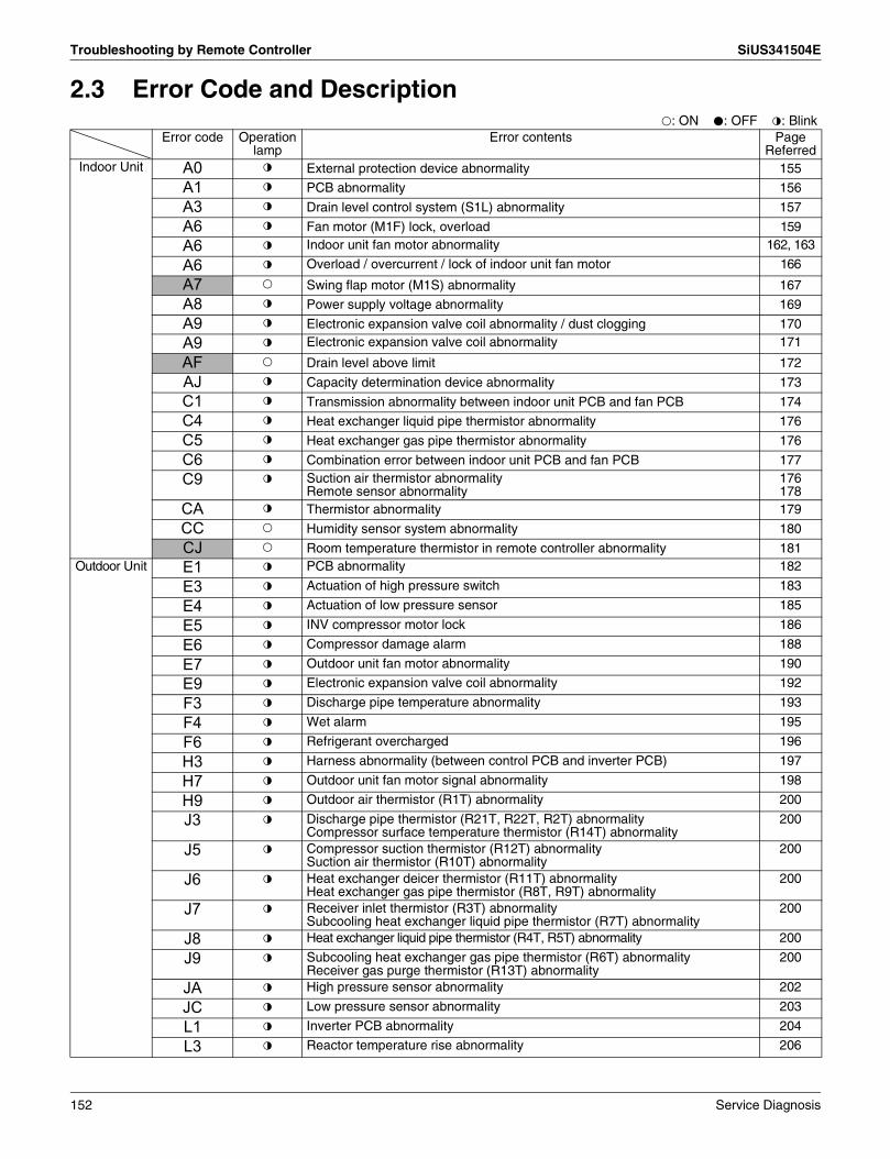
Troubleshooting by Remote Controller SiUS341504E
2.3 Error Code and Descriptionk: ON h: OFF l: Blink
Error code Operation lamp
Error contents Page Referred
Indoor Unit A0 l External protection device abnormality 155
A1 l PCB abnormality 156
A3 l Drain level control system (S1L) abnormality 157
A6 l Fan motor (M1F) lock, overload 159
A6 l Indoor unit fan motor abnormality 162, 163
A6 l Overload / overcurrent / lock of indoor unit fan motor 166
A7 k Swing flap motor (M1S) abnormality 167
A8 l Power supply voltage abnormality 169
A9 l Electronic expansion valve coil abnormality / dust clogging 170
A9 l Electronic expansion valve coil abnormality 171
AF k Drain level above limit 172
AJ l Capacity determination device abnormality 173
C1 l Transmission abnormality between indoor unit PCB and fan PCB 174
C4 l Heat exchanger liquid pipe thermistor abnormality 176
C5 l Heat exchanger gas pipe thermistor abnormality 176
C6 l Combination error between indoor unit PCB and fan PCB 177
C9 l Suction air thermistor abnormalityRemote sensor abnormality
176178
CA l Thermistor abnormality 179
CC k Humidity sensor system abnormality 180
CJ k Room temperature thermistor in remote controller abnormality 181Outdoor Unit E1 l PCB abnormality 182
E3 l Actuation of high pressure switch 183
E4 l Actuation of low pressure sensor 185
E5 l INV compressor motor lock 186
E6 l Compressor damage alarm 188
E7 l Outdoor unit fan motor abnormality 190
E9 l Electronic expansion valve coil abnormality 192
F3 l Discharge pipe temperature abnormality 193
F4 l Wet alarm 195
F6 l Refrigerant overcharged 196
H3 l Harness abnormality (between control PCB and inverter PCB) 197
H7 l Outdoor unit fan motor signal abnormality 198
H9 l Outdoor air thermistor (R1T) abnormality 200
J3 l Discharge pipe thermistor (R21T, R22T, R2T) abnormalityCompressor surface temperature thermistor (R14T) abnormality
200
J5 l Compressor suction thermistor (R12T) abnormalitySuction air thermistor (R10T) abnormality
200
J6 l Heat exchanger deicer thermistor (R11T) abnormalityHeat exchanger gas pipe thermistor (R8T, R9T) abnormality
200
J7 l Receiver inlet thermistor (R3T) abnormalitySubcooling heat exchanger liquid pipe thermistor (R7T) abnormality
200
J8 l Heat exchanger liquid pipe thermistor (R4T, R5T) abnormality 200
J9 l Subcooling heat exchanger gas pipe thermistor (R6T) abnormalityReceiver gas purge thermistor (R13T) abnormality
200
JA l High pressure sensor abnormality 202
JC l Low pressure sensor abnormality 203
L1 l Inverter PCB abnormality 204
L3 l Reactor temperature rise abnormality 206
152 Service Diagnosis

SiUS341504E Troubleshooting by Remote Controller
Outdoor Unit L4 l Inverter radiation fin temperature rise abnormality 207
L5 l INV compressor instantaneous overcurrent 208
L8 l INV compressor overcurrent 210
L9 l INV compressor startup abnormality 212
LC l Transmission error between inverter and control PCB 215
P1 l Power supply voltage imbalance 217
P3 l Reactor Temperature Abnormality 219
P4 l Inverter radiation fin temperature abnormality 220
PJ l Field setting after replacing outdoor unit main PCB abnormality or combination of PCB abnormality
221
System U0 k Refrigerant shortage 222
U1 l Reverse phase, open phase 223
U2 l Power supply insufficient or instantaneous abnormality 224
U3 l Check operation is not executed 226
U4 l Transmission error between indoor units and outdoor units 227
U5 l Transmission error between remote controller and indoor unit 230
U7 l Transmission error between outdoor units 231
U8 l Transmission error between main and sub remote controllers 237
U9 l Transmission error between indoor and outdoor units in the same system 238
UA l Improper combination of indoor and outdoor units, indoor units and remote controller
239
UC k Address duplication of centralized control equipment 242
UE l Transmission error between centralized control equipment and indoor unit 243
UF l System is not set yet 245
UH l System abnormality, refrigerant system address undefined 246
k: ON h: OFF l: BlinkError code Operation
lamp Error contents Page
Referred
The system operates for error codes indicated in black squares, however, be sure to check and repair.
Service Diagnosis 153

Troubleshooting by Remote Controller SiUS341504E
2.4 Error Codes - Sub CodesIf an error code like the one shown below is displayed when the navigation remote controller (BRC1E series) is in use, make a detailed diagnosis or a diagnosis of the relevant unit referring to the attached list of detailed error codes.
2.4.1 Indoor Unit
2.4.2 Outdoor UnitRefer to P.152.
Error codeTroubleshooting
Description of error Description of diagnosisA6 - 01 Fan motor locked A locked fan motor current has been detected.
Turn the fan by hand to check for the connection of connectors.A6 - 10 Fan overcurrent error A fan motor overcurrent has been detected.
Check for the connection of the connector between the fan motor and the PCB for the fan. If the connection is normal, replace the fan motor. If this still cannot solve the error, replace the PCB for the fan.
A6 - 11 Fan position detection error An error in the detection of position of the fan motor. Check for the connection of the connector between the fan motor and the PCB for the fan. If the connection is normal, replace the fan motor. If this still cannot solve the error, replace the PCB for the fan.
A8 - 01 Power supply voltage error Check for the input voltage of the fan motor.A9 - 01 Electronic expansion valve error There is an error in the electronic expansion valve coil or a
connector disconnected.A9 - 02 Refrigerant leakage detection error Refrigerant leaks even if the electronic expansion valve is closed.
Replace the electronic expansion valve.AH - 03 Transmission error (between the self-cleaning
decoration panel and the indoor unit) [when the self-cleaning decoration panel is mounted]
Check for the connection of the harness connector between the panel PCB and the indoor unit PCB.
AH - 04 Dust detection sensor error [when the self-cleaning decoration panel is mounted]
Check for the connections of the connector X12A on the panel PCB and the connectors X18A and X19A on the dust sensor PCBs.
AH - 05 Dust collection sign error [when the self-cleaning decoration panel is mounted]
Check for clogging with dust at the dust collection port as well as in the brush unit, S-shaped pipe, and dust box. Furthermore, check for any stains of the light receiving and emitting parts of the infrared unit.
AH - 06 Air filter rotation error[when the self-cleaning decoration panel is mounted]
Check for anything getting in the way of rotating the filter (e.g. the filter comes off or the drive gear is clogged with foreign matters).
AH - 07 Damper rotation error[when the self-cleaning decoration panel is mounted]
The damper does not rotate normally. Check for any foreign matters around the damper and for the operation of the gear and limit switch.
AH - 08 Filter self-cleaning operation error[when the self-cleaning decoration panel is mounted]
The unit has not yet completed the filter self-cleaning operation even after the lapse of specified period of time. Check for any external noise, etc.
AH - 09 Filter self-cleaning operation start disabled error [when the self-cleaning decoration panel is mounted]
The unit has been put into a state in which the filter self-cleaning operation is disabled. Check the unit for the operating conditions.
AJ - 01 Capacity setting error There is an error in the capacity setting of the indoor unit PCB.AJ - 02 Electronic expansion valve setting error There is a fault in the setting of the gear type electronic expansion
valve/direct acting type electronic expansion valve.C1 - 01 Transmission error (between indoor unit PCB
and the PCB for the fan)Check for the conditions of transmission between the indoor unit PCB and the PCB for the fan.
C6 - 01 Defective combination of indoor unit PCB and the PCB for the fan
A combination of indoor unit PCB and the PCB for the fan is defective. Check whether the capacity setting adaptor is correct and the type of the PCB for the fan is correct.
U4 - 01 Indoor-Outdoor transmission error Refer to the “U4” flow chart.UA - 13 Refrigerant type error The type of refrigerant used for the indoor unit is different from
that used for the outdoor unit.UA - 15 Not applicable for self-cleaning decoration
panel [when the self-cleaning decoration panel is mounted]
An outdoor unit is not applicable for the self-cleaning decoration panel is connected.
154 Service Diagnosis

SiUS341504E Troubleshooting by Indication on the Remote Controller
3. Troubleshooting by Indication on the Remote Controller
3.1 External Protection Device Abnormality
Error Code A0Applicable Models
All indoor models
Method of Error Detection
Detect open or short circuit between external input terminals in indoor unit.
Error Decision Conditions
When an open circuit occurs between external input terminals with the remote controller set to "external ON/OFF terminal".
Supposed Causes
Actuation of external protection deviceImproper field settingDefective of indoor unit PCB
Troubleshooting
ON/OFF input from
outside (mode No. 12, first code No. 1) has
been set to external protection device input (second
code No. 03) by remote
controller.
Check the setting state of the external ON/OFF input by remote controller.
External protection device
is connected to terminals T1 and T2 of the indoor
unit terminal block.
Replace the indoor unit PCB.
Actuation of external protection device.
Change the second code No. to "01" or "02" .
YES
NO
NO
YES
CautionBe sure to turn off the power switch before connecting or disconnecting connectors, or parts may be damaged.
Service Diagnosis 155

Troubleshooting by Indication on the Remote Controller SiUS341504E
3.2 PCB Abnormality
Error Code A1Applicable Models
All indoor models
Method of Error Detection
Check data from E²PROM.
Error Decision Conditions
When data could not be correctly received from the E²PROME²PROM : Type of nonvolatile memory. Maintains memory contents even when the power supply
is turned OFF.
Supposed Causes
Defective of indoor unit PCBExternal factor (Noise etc.)
Troubleshooting
Turn the power supply OFF, then the power ON again.
Does the system return to
normal?
YES
CautionBe sure to turn off the power switch before connecting or disconnecting connectors, or parts may be damaged.
Replace the indoor unit PCB.
The indoor unit PCB is normal.External factor other than error (for example, noise etc.).
NO
156 Service Diagnosis

SiUS341504E Troubleshooting by Indication on the Remote Controller
3.3 Drain Level Control System (S1L) Abnormality
Error Code A3Applicable Models
FXFQ, FXZQ, FXDQ, FXMQ-PB, FXMQ-M (Option), FXHQ (Option), FXAQ (Option)
Method of Error Detection
By float switch OFF detection
Error Decision Conditions
When rise of water level is not a condition and the float switch goes OFF.
Supposed Causes
208~230V power supply is not providedDefective float switch or short circuit connectorDefective drain pumpDrain clogging, upward slope, etc. Defective indoor unit PCBLoose connection of connector
Service Diagnosis 157
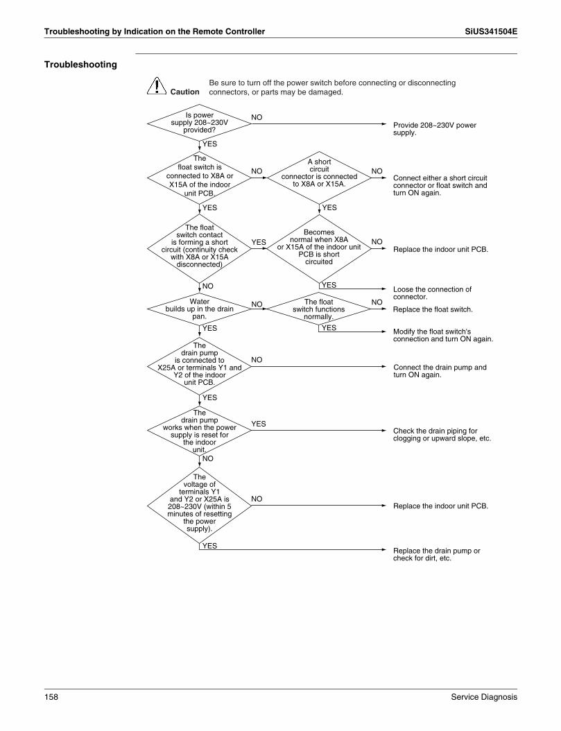
Troubleshooting by Indication on the Remote Controller SiUS341504E
Troubleshooting
The float switch is
connected to X8A or X15A of the indoor
unit PCB.
A short circuit
connector is connected to X8A or X15A.
The drain pump
works when the power supply is reset for
the indoor unit.
The drain pump
is connected to X25A or terminals Y1 and
Y2 of the indoor unit PCB.
The voltage of
terminals Y1 and Y2 or X25A is 208~230V (within 5 minutes of resetting
the power supply).
Water builds up in the drain
pan.
The float switch functions
normally.
The float switch contact
is forming a short circuit (continuity check
with X8A or X15A disconnected)
Becomes normal when X8A
or X15A of the indoor unit PCB is short
circuited
Is power supply 208~230V
provided?
CautionBe sure to turn off the power switch before connecting or disconnecting connectors, or parts may be damaged.
Replace the float switch.
Modify the float switch's connection and turn ON again.
Connect the drain pump and turn ON again.
Check the drain piping for clogging or upward slope, etc.
Replace the indoor unit PCB.
Replace the drain pump or check for dirt, etc.
Connect either a short circuit connector or float switch and turn ON again.
YES
YES
NO
YES
YES
YES
Replace the indoor unit PCB.
Loose the connection of connector.
NO NO
NO
YES
YES
NO
NO
YES
NO
YES
NO
NO
Provide 208~230V power supply.
YES
NO
158 Service Diagnosis

SiUS341504E Troubleshooting by Indication on the Remote Controller
3.4 Fan Motor (M1F) Lock, Overload
Error Code A6Applicable Models
FXFQ, FXHQ, FXAQ
Method of Error Detection
Abnormal fan revolutions are detected by a signal output from the fan motor.
Error Decision Conditions
When the fan revolutions do not increase
Supposed Causes
Broken wires in, short circuit of, or disconnection of connectors from the fan motor harnessDefective fan motor(Broken wires or defective insulation)Abnormal signal output from the fan motor (defective circuit)Defective PCBInstantaneous disturbance in the power supply voltageFan motor lock(Due to motor or external causes)The fan does not rotate due to foreign matters blocking the fan.Disconnection of the connector between the high-power PCB (A1P) and the low-power PCB (A2P)
Service Diagnosis 159

Troubleshooting by Indication on the Remote Controller SiUS341504E
Troubleshooting
YES
Is the connector
(X4A or X20A) for the fan motor
properly connected to the indoor unit
PCB? (∗1)
Remove the foreign matters.YES
Properly connect the connector.NO
NO
YES
By disconnecting the connector
(X4A or X20A) for the fan motor from the indoor
unit PCB, the fan can be lightly rotated
by hand.
Replace the fan motor.NO
Replace the fan motor.NO
YES
Are there any
foreign matters around the fan?
YES
Is the resistance
between the pins more than the
judgement criteria?
Disconnect the connector from the fan motor, and then make measurement of resistance between pins. (∗2)
Turn OFF the power supply, and then wait for a period of 10 minutes.
Replace the indoor unit PCB.
CautionBe sure to turn off the power switch before connecting or disconnecting connectors, or parts may be damaged.
160 Service Diagnosis

SiUS341504E Troubleshooting by Indication on the Remote Controller
Note: ∗1. If any junction connector is provided between the connector (X20A) on the indoor unit PCB and the fan motor, also check whether or not the junction connector is properly connected.
∗2. Check on connector of fan motor (Power supply cable)Turn OFF the power supply.Measure the resistance between phases of U, V, W at the motor side connectors (3-core wire) to check that the values are balanced and there is no short circuiting, while connector or relay connector is disconnected.
∗3. Check on connector of fan motor is not available for below models.FXFQ09~48PVJU, FXAQ07~24PVJU
Measuring Points
Black-Red
Black-White
Judgement
53.5Ω ±10%
31.6Ω ±10%
<FXHQ24·36MVJU>White
Black
RedMeasuring Points
Black-Red
Black-White
Judgement
71.0Ω ±10%
73.5Ω ±10%
<FXHQ12MVJU>
Service Diagnosis 161

Troubleshooting by Indication on the Remote Controller SiUS341504E
3.5 Indoor Unit Fan Motor Abnormality
Error Code A6Applicable Models
FXDQ
Method of Error Detection
This error is detected if there is no revolutions detection signal output from the fan motor.
Error Decision Conditions
When no revolutions can be detected even at the maximum output voltage to the fan
Supposed Causes
Defective indoor fan motorBroken wiresDefective contact
Troubleshooting
NO
YES
YES
Is the X4A
connector securely connected?
NO
Is the
power of approx. 12VDC
supplied between the Pins1 and 3 when
the X4A is disconnected and
the power supply turns
ON?
Replace the indoor unit PCB.
Properly connect the connectors.(At this time, check for any defective connector contact or broken wires.)
Check the indoor unit fan motor and the wiring circuits of the motor.
CautionBe sure to turn off the power switch before connecting or disconnecting connectors, or parts may be damaged.
162 Service Diagnosis

SiUS341504E Troubleshooting by Indication on the Remote Controller
3.6 Indoor Unit Fan Motor Abnormality
Error Code A6Applicable Models
FXMQ-PB
Method of Error Detection
Error from the current flow on the fan PCBError from the RPM of the fan motor in operationError from the position signal of the fan motorError from the current flow on the fan PCB when the fan motor starting operation
Error Decision Conditions
An overcurrent flows.The RPM is less than a certain level for 6 seconds.A position error in the fan rotor continues for 5 seconds or more.
Supposed Causes
The clogging of a foreign matterThe disconnection of the fan motor connectors (X1A and X2A)The disconnection of the connectors between the indoor unit PCB (A1P) and fan PCB (A2P)Defective fan PCB (A2P)Defective fan motor
Service Diagnosis 163

Troubleshooting by Indication on the Remote Controller SiUS341504E
Troubleshooting
The fan motor
connectors (X1A and X2A) of the fan
PCB (A2P) are disconnected.
Remove the foreign matter.YES
Connect correctly.YES
NO
The connectors between the
indoor unit PCB (A1P) and the fan PCB (A2P)
are disconnected.
Connect correctly.YES
NO
The fuse (F3U,
white) on the fan PCB (A2P) has no
continuity.
Replace the fan PCB (A2P).NO
Replace the fan motor.YES
NO
YES
The fan can
be moved lightly by hand after
the fan motor connector of the fan PCB
(A2P) is removed.
Replace the fan motor.NO
YES
NO
YES
There is a foreign matter around
the fan.
The resistance
between the power wire terminals of the fan motor and motor frame (meal
part) is 1 MΩ or below.
Remove the power wire connector from the fan motor and measure the resistance between U and V, V and W, and W and U phases (∗1).
Turn OFF the power and wait for 10 minutes.
A
CautionBe sure to turn off the power switch before connecting or disconnecting connectors, or parts may be damaged.
164 Service Diagnosis

SiUS341504E Troubleshooting by Indication on the Remote Controller
Note: ∗1. Check on connector of fan motor (Power supply cable)Turn OFF the power supply.Measure the resistance between phases of U, V, W at the motor side connectors (3-core wire) to check that the values are balanced and there is no short circuiting, while connector or relay connector is disconnected.
∗2. Measurement of signal wire connector.Remove the X2A connector and measure the resistance between GND and VCC, HW, HV, or HU terminals of the motor connector (with 5 conductors).
Replace the fan motor.YES
NO
Between Vcc and GND terminals, and
between GND and Hw, Hv, or Hu terminals
are short-circuited.
Replace the fan motor.YES
Replace the fan PCB (A2P).YES
NO
The resistance
among U, V, and W are unbalanced or
short circuited.
NO
The HAP lamp
of the indoor unit PCB (A1P) blinks and the HAP lamp of the
fan PCB (A2P) is OFF.
Turn ON the power.
Remove the signal connector from the fan motor and check the resistance (∗2).
Replace the fan motor.
A
White
Black
Red
Measuring Points
Black-Red
Black-White
Judgement
3.5Ω ±10%
3.5Ω ±10%
Connector signal wire use (X2A)
5 Gray
4 Pink
3 Orange
2 Blue
1 Yellow
GND
Vcc
HW
HV
HU
Service Diagnosis 165

Troubleshooting by Indication on the Remote Controller SiUS341504E
3.7 Overload / Overcurrent / Lock of Indoor Unit Fan Motor
Error Code A6Applicable Models
FXMQ-M
Method of Error Detection
This error is detected by detecting that the individual power supply for the fan turns OFF.
Error Decision Conditions
When it is not detected that the individual power supply for the indoor unit fan turns ON while in operation.
Supposed Causes
Defective power supply for the indoor unit fan motorClogged drain pipingActuation of the indoor unit safety deviceDefective contact in the fan wiring circuit
Troubleshooting
Properly connect the cable.NO
YES
YES
Is the power supply
cable of the indoor unit fan properly
connected?
NO
Is the fan normally running?
Restart the fan.
Replace the indoor unit PCB.
It is supposed that the indoor unit fan motor stops running due to overload, overcurrent, or lock.
CautionBe sure to turn off the power switch before connecting or disconnecting connectors, or parts may be damaged.
166 Service Diagnosis

SiUS341504E Troubleshooting by Indication on the Remote Controller
3.8 Swing Flap Motor (M1S) Abnormality
Error Code A7Applicable Models
FXHQ
Method of Error Detection
Utilizes ON/OFF of the limit switch when the motor turns.
Error Decision Conditions
When ON/OFF of the micro-switch for positioning cannot be reversed even though the swing flap motor is energized for a specified amount of time (about 30 seconds).∗ Error code is displayed but the system operates continuously.
Supposed Causes
Defective swing motorDefective connection cable (power supply and limit switch)Defective airflow direction adjusting flap-camDefective indoor unit PCB
Service Diagnosis 167

Troubleshooting by Indication on the Remote Controller SiUS341504E
Troubleshooting
Indoor unit is a model
equipped with a swing flap function
The swing motor
works when the power supply is turned OFF
and then restart.
The connector is
connected to X9A of the indoor unit
PCB.
The limit switch functions
normally.
The relay cable is short circuited
or disconnected.
The relay cable has no continuity.
CautionBe sure to turn off the power switch before connecting or disconnecting connectors, or parts may be damaged.
Is power supply 208~230V provided? Provide 208~230V power
supply.
YES
NO
Replace the limit switch relay cable.
Replace the indoor unit PCB.
Replace the power supply relay cable.
Replace the swing motor.
Take the flap-cam mechanism apart, reassemble and turn ON again.
YES
NO
YES
YES
NO
YES
NO
Connect the connector to X9A and turn ON again.
Replace the indoor unit PCB.NO
NO
YES NO
YES
NO
YES
YES
NOReplace the swing motor.
After turning the
swing-flap ON and then stopping
with the remote controller, the voltage of
X6A of the indoor unit PCB is 208~230V when turned
ON again (within 30 seconds of turning ON
again).
When the airflow direction
flap-cam mechanism is disconnected from the swing motor, operation
is normal when turned ON
again.
168 Service Diagnosis

SiUS341504E Troubleshooting by Indication on the Remote Controller
3.9 Power Supply Voltage Abnormality
Error Code A8Applicable Models
FXMQ-PB
Method of Error Detection
Detect error checking the input voltage of fan motor.
Error Decision Conditions
When the input voltage of fan motor is 150V or less, or 386V or more.
Supposed Causes
Defective power supply voltageDefective connection on signal lineDefective wiringInstantaneous blackout, others
Troubleshooting
Check the condition of the power supply.(1) Check if power
supply voltage is 208~230V ± 10%.
(2) Check if there is power open phase or defective wiring.
(3) Check if power supply voltage unbalance is within 6V.
YES
There are problems on
the condition of power supply
described above.
CautionBe sure to turn off the power switch before connecting or disconnecting connectors, or parts may be damaged.
Correct any fault.
NO
NO
YES"A8" Reoccurrence of
error.Check and correct each wiring.
It is possible to have external factor, such as brownout and instantaneous blackout.
Service Diagnosis 169

Troubleshooting by Indication on the Remote Controller SiUS341504E
3.10 Electronic Expansion Valve Coil Abnormality / Dust Clogging
Error Code A9Applicable Models
FXFQ
Method of Error Detection
Check coil condition of electronic expansion valve by using micro-computer.Check dust clogging condition of electronic expansion valve main body by using micro-computer.
Error Decision Conditions
Pin input for electronic expansion valve coil is abnormal when initializing micro-computer.Either of the following conditions is seen/caused/ occurs while the unit stops operation.
R1T – R2T > 8°C (46.4°F)R2T shows fixed degrees or below.R1T: temperature of suction airR2T: temperature of liquid pipe of heat exchanger
Supposed Causes
Defective of electronic expansion valve coilDefective PCB indoor unitDefective relay cables
Troubleshooting
Refer to P.254.
NO
YES
When power is supplied.
NO
Electronic expansion valve is
connected to X7A of indoor unit
PCB.
NO
Coil check of
electronic expansion valve drive indicates
normal.
NO
YES
YES
YES
Relay cables short circuit or disconnected.
When restarting the operation after shutting the power supply OFF does not work, replace the indoor unit PCB.
Replace the relay cables.
Replace the electronic expansion valve coil.
Shut the power supply OFF after connection and then restart.
Replace the electronic expansion valve main body.
CHECK 9
CautionBe sure to turn off the power switch before connecting or disconnecting connectors, or parts may be damaged.
CHECK 9
170 Service Diagnosis

SiUS341504E Troubleshooting by Indication on the Remote Controller
3.11 Electronic Expansion Valve Coil Abnormality
Error Code A9Applicable Models
Indoor units except FXFQ models
Method of Error Detection
Check coil condition of electronic expansion valve by using micro-computer.
Error Decision Conditions
Pin input for electronic expansion valve coil is abnormal when initializing micro-computer.
Supposed Causes
Defective of electronic expansion valve coilDefective PCB indoor unitDefective relay cables
Troubleshooting
Refer to P.254.
NO
YES
YES
Electronic expansion valve is
connected to X7A of indoor unit
PCB.
NO
YES
Coil check of
electronic expansion valve drive indicates
normal.
NO
Relay cables short
circuit or disconnected.
When restarting the operation after shutting the power supply OFF does not work, replace the indoor unit PCB.
Replace the relay cables.
Shut the power supply OFF after connection and then restart.
Replace the electronic expansion valve coil.
CautionBe sure to turn off the power switch before connecting or disconnecting connectors, or parts may be damaged.
CHECK 9
CHECK 9
Service Diagnosis 171

Troubleshooting by Indication on the Remote Controller SiUS341504E
3.12 Drain Level above Limit
Error Code AFApplicable Models
FXFQ, FXZQ, FXDQ, FXMQ
Method of Error Detection
Water leakage is detected based on float switch ON/OFF operation while the compressor is in non-operation.
Error Decision Conditions
When the float switch changes from ON to OFF while the compressor is in non-operation.∗ Error code is displayed but the system operates continuously.
Supposed Causes
Humidifier unit (optional accessory) leakingDefective drain pipe (upward slope, etc.)Defective indoor unit PCB
Troubleshooting
Modify the drain piping.YES
YES
NO
Field drain piping
has a defect such as upward sloping.
NO
A humidifier
unit (optional accessory) is installed
on the indoor unit.
Defective indoor unit PCB.
Check if the humidifier unit is leaking.
CautionBe sure to turn off the power switch before connecting or disconnecting connectors, or parts may be damaged.
172 Service Diagnosis

SiUS341504E Troubleshooting by Indication on the Remote Controller
3.13 Capacity Determination Device Abnormality
Error Code AJApplicable Models
All indoor models
Method of Error Detection
Capacity is determined according to resistance of the capacity setting adaptor and the memory inside the IC memory on the indoor unit PCB, and whether the value is normal or abnormal is determined.
Error Decision Conditions
When the capacity code is not saved to the PCB, and the capacity setting adaptor is not connected.When a capacity that does not exist for that unit is set.
Supposed Causes
The capacity setting adaptor was not installed.Defective indoor unit PCB
Troubleshooting
Replace the indoor unit PCB.NO
NO
YES
The indoor unit PCB
was replaced with a spare PCB.
YES
The capacity
setting adaptor need to be installed when
replacing the PCB.
Install a capacity setting adaptor.
Replace the indoor unit PCB.
CautionBe sure to turn off the power switch before connecting or disconnecting connectors, or parts may be damaged.
Service Diagnosis 173

Troubleshooting by Indication on the Remote Controller SiUS341504E
3.14 Transmission Abnormality between Indoor Unit PCB and Fan PCB
Error Code C1Applicable Models
FXMQ-PB
Method of Error Detection
Check the condition of transmission between indoor unit PCB (A1P) and fan PCB (A2P) using computer.
Error Decision Conditions
When normal transmission is not conducted for certain duration.
Supposed Causes
Connection defective the connecter between indoor unit PCB (A1P) and fan PCB (A2P)Defective indoor unit PCB (A1P)Defective fan PCB (A2P)External factor, such as instantaneous blackout
Troubleshooting
Under above field
setting mode, second code No. is
"01".
NO
NO
YES
Replace the fan PCB (A2P).YES
YES
Is the connector
between indoor unit PCB (A1P) and
fan PCB (A2P) accurately
connected? (∗1)
NO
"C1" is displayed
again.
Confirm the condition of transmission on indoor unit PCB using field setting mode. (∗2)
Connect the connecter X70A and turn ON the power again.
Connect it and continue the operation (It is possible to have a cause, such as instantaneous blackout).
Connect the connector accurately.
Replace the indoor unit PCB (A1P).
CautionBe sure to turn off the power switch before connecting or disconnecting connectors, or parts may be damaged.
174 Service Diagnosis

SiUS341504E Troubleshooting by Indication on the Remote Controller
Note: ∗1. Pull out and insert the connecter once and check it is absolutely connected.∗2. Method to check transmission part of indoor unit PCB.
(1) Turn OFF the power and remove the connecter X70A of indoor unit PCB (A1P).(2) Short circuit X70A.(3) After turning ON the power, check below numbers under field setting from remote controller.
(Confirmation: Second code No. at the condition of first code No. 21 on mode No. 41)↓
∗ After confirmation, turn OFF the power, take off the short circuit and connect X70A back to original condition.
Determination 01: NormalOther than 01: Transmission error on indoor unit PCB
Service Diagnosis 175

Troubleshooting by Indication on the Remote Controller SiUS341504E
3.15 Thermistor Abnormality
Error Code C4, C5, C9Applicable Models
All indoor models
Method of Error Detection
The error is detected by temperature detected by thermistor.
Error Decision Conditions
When the thermistor becomes disconnected or shorted while the unit is running.
Supposed Causes
Defective thermistorDefective indoor unit PCBDefective connector connectionBroken or disconnected wire
Troubleshooting
Note: ∗1. Error code and thermistor
Refer to P.255.
Is the thermistor normal?
CautionBe sure to turn off the power switch before connecting or disconnecting connectors, or parts may be damaged.
5 kΩ to 90 kΩ
Remove the thermistor from the indoor unit PCB, and then insert it again.
Remove the thermistor from the indoor unit PCB, and then make resistance measurement of the thermistor using a multiple meter.
Normal (The error is caused by defective contact.)
YES
NO
Replace the indoor unit PCB.
YES
Replace the thermistor (∗1).NO
CHECK 11
Error Code Thermistor Except FXTQ FXTQ
C4 Heat exchanger liquid pipe thermistor R2T R1T
C5 Heat exchanger gas pipe thermistor R3T R2T
C9 Suction air thermistor R1T —
CHECK 11
176 Service Diagnosis

SiUS341504E Troubleshooting by Indication on the Remote Controller
3.16 Combination Error between Indoor Unit PCB and Fan PCB
Error Code C6Applicable Models
FXMQ-PB
Method of Error Detection
Check the condition of transmission with fan PCB (A2P) using indoor unit PCB (A1P).
Error Decision Conditions
When the communication data of fan PCB (A2P) is determined as incorrect.
Supposed Causes
Defective fan PCB (A2P)Defective connection of capacity setting adaptorField setting error
Troubleshooting
NOIs the
type of fan PCB (A2P)
correct?
CautionBe sure to turn off the power switch before connecting or disconnecting connectors, or parts may be damaged.
Was indoor unit PCB (A1P)
replaced with a spare PCB?
YES
YES
YES
NO
NO
Was correct
capacity setting adaptor installed when replacing it
with a spare PCB?
After establishing transmission for indoor and outdoor units, diagnose the operation again.
After establishing transmission for indoor and outdoor units, diagnose the operation again.
Replace it with correct fan PCB (A2P).
Install correct capacity setting adaptor.
Service Diagnosis 177

Troubleshooting by Indication on the Remote Controller SiUS341504E
3.17 Remote Sensor Abnormality
Error Code C9Applicable Models
FXTQ
Method of Error Detection
The error is detected out by temperature detected by remote sensor.
Error Decision Conditions
When the remote sensor becomes disconnected or shorted while the unit is running.
Supposed Causes
Defective indoor unit thermistor (R1T) for air inletDefective indoor unit PCB
Troubleshooting
Refer to P.255.
Is the optional remote
sensor is installed?
Field setting 10(20)-2 is set at
C3.
Connector is connected to X16A of
the indoor unit PCB.
Resistance is normal when measured after
disconnecting the sensor from the indoor unit
PCB.
CautionBe sure to turn off the power switch before connecting or disconnecting connectors, or parts may be damaged.
Set at 03.
Replace the indoor unit PCB.
NO NO
YES YES
Replace the indoor unit PCB.
Connect the sensor and turn ON again.
NO
NO
Replace the sensor (R1T).
YES
YES
CHECK 11
CHECK 11
178 Service Diagnosis

SiUS341504E Troubleshooting by Indication on the Remote Controller
3.18 Thermistor Abnormality
Error Code CAApplicable Models
FXMQ-PB
Method of Error Detection
The error is detected by temperature detected by thermistor.
Error Decision Conditions
When the thermistor becomes disconnected or shorted while the unit is running.
Supposed Causes
Defective connector connectionDefective thermistorDefective indoor unit PCB
Troubleshooting
Note: ∗1. Error code and thermistor
Refer to P.255.
Is the thermistor normal?
CautionBe sure to turn off the power switch before connecting or disconnecting connectors, or parts may be damaged.
5 kΩ to 90 kΩ
Remove the thermistor from the indoor unit PCB, and then insert it again.
Remove the thermistor from the indoor unit PCB, and then make resistance measurement of the thermistor using a multiple meter.
Normal (The error is caused by defective contact.)
YES
NO
Replace the indoor unit PCB.YES
Replace the thermistor (∗1).NOCHECK 11
Error code Thermistor Electric symbol
CA Discharge air thermistor R4T
CHECK 11
Service Diagnosis 179

Troubleshooting by Indication on the Remote Controller SiUS341504E
3.19 Humidity Sensor System Abnormality
Error Code CCApplicable Models
FXFQ
Method of Error Detection
Even if an error occurs, operation still continues.Error is detected according to the moisture (output voltage) detected by the moisture sensor.
Error Decision Conditions
When the moisture sensor is disconnected or short circuited
Supposed Causes
Defective sensorDisconnection
Troubleshooting
Note: ∗1. To delete the history, the ON/OFF button of the remote controller must be pressed and held for 5 seconds in the check mode.
∗2. To display the code, the INSPECTION/TEST Operation button of the remote controller must be pressed and held in the normal mode.
∗3. If "CC" is displayed even after replacing the humidity sensor PCB assy (A2P) and taking the steps ∗1 and 2, replace the indoor unit PCB assy (A1P).
CautionBe sure to turn off the power switch before connecting or disconnecting connectors, or parts may be damaged.
YES
NO
Is "CC" displayed on the
remote controller? (∗2)
YES
NO
Does it function normally?
Remove the humidity sensor from the indoor unit PCB and insert it again.
It is normal.(Poor connector contact)
Replace the humidity sensor PCB assy (A2P).(∗3)
It is believed that external factors (noise or else) other than failure caused the error.
Delete the error code history from the remote controller. (∗1)
180 Service Diagnosis

SiUS341504E Troubleshooting by Indication on the Remote Controller
3.20 Room Temperature Thermistor in Remote Controller Abnormality
Error Code CJApplicable Models
All indoor models
Method of Error Detection
Error detection is carried out by temperature detected by room temperature thermistor in remote controller.
Error Decision Conditions
When the room temperature thermistor in remote controller becomes disconnected or shorted while the unit is running.
Supposed Causes
Defective room temperature thermistor in remote controllerDefective remote controller PCB
Troubleshooting
Note: ∗1. How to delete “the history of error codes”.Press the “ON/ OFF” button for 4 seconds and more while the error code is displayed in the inspection mode.
Clear the error code history. (∗1) (While in inspection mode, press and hold the “ON/OFF” button for a period of 4 seconds or more.)
YESIs "CJ" displayed on the remote
controller?
CautionBe sure to turn off the power switch before connecting or disconnecting connectors, or parts may be damaged.
Replace the remote controller.
External factor other than equipment error.(for example, noise etc.)
NO
Service Diagnosis 181

Troubleshooting by Indication on the Remote Controller SiUS341504E
3.21 PCB Abnormality
Error Code E1Applicable Models
REYQ-T
Method of Error Detection
Abnormality is detected under the communication conditions in the hardware section between the indoor unit and outdoor unit.
Error Decision Conditions
When the communication conditions in the hardware section between the indoor unit and the outdoor unit are not normal
Supposed Causes
Defective outdoor unit PCB (A1P)Defective connection communication line between indoor and outdoor units
Troubleshooting
Return to normal?YES External factor other than
error (for example, noise etc.).
Connect the communication line correctly.
Replace the outdoor unit PCB (A1P).
NO
NO
Check if inside /
outside relay wires of outdoor unit PCB is
disconnected.
YES
Turn OFF the power once and turn ON again.
CautionBe sure to turn off the power switch before connecting or disconnecting connectors, or parts may be damaged.
182 Service Diagnosis
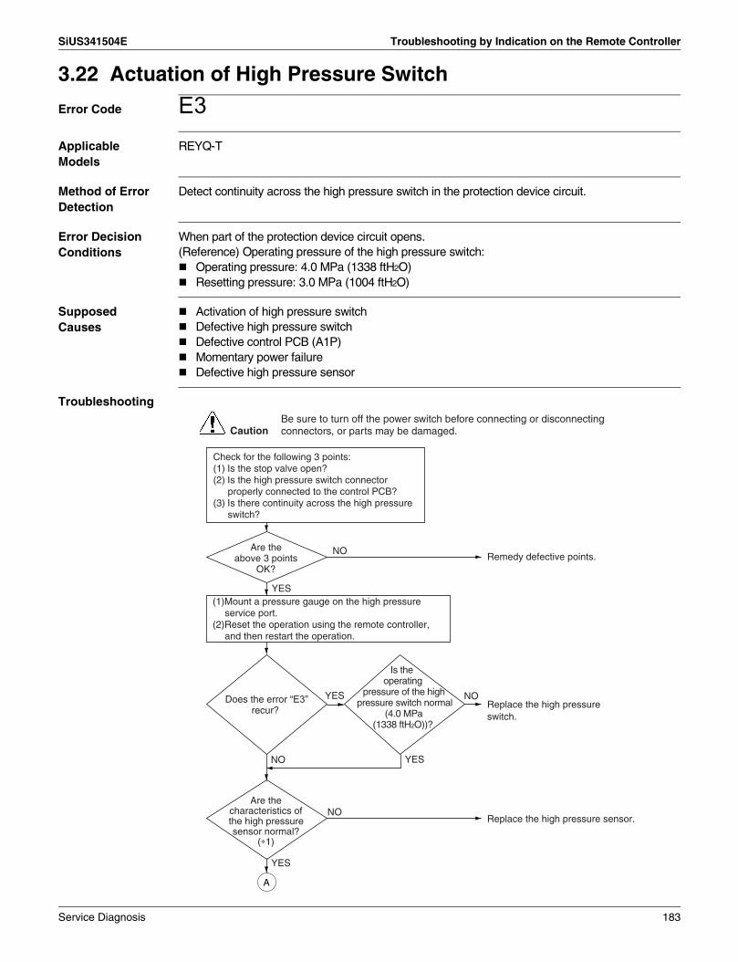
SiUS341504E Troubleshooting by Indication on the Remote Controller
3.22 Actuation of High Pressure Switch
Error Code E3Applicable Models
REYQ-T
Method of Error Detection
Detect continuity across the high pressure switch in the protection device circuit.
Error Decision Conditions
When part of the protection device circuit opens.(Reference) Operating pressure of the high pressure switch:
Operating pressure: 4.0 MPa (1338 ftH2O)Resetting pressure: 3.0 MPa (1004 ftH2O)
Supposed Causes
Activation of high pressure switchDefective high pressure switchDefective control PCB (A1P)Momentary power failureDefective high pressure sensor
Troubleshooting
NO
YES
YES
Replace the high pressure switch.
Remedy defective points.
Replace the high pressure sensor.
YES
Are the above 3 points
OK?
Does the error “E3” recur?
NO
Is the operating
pressure of the high pressure switch normal
(4.0 MPa (1338 ftH2O))?
NO
YES
Are the characteristics of the high pressure sensor normal?
(∗1)
NO
(1)Mount a pressure gauge on the high pressure service port.
(2)Reset the operation using the remote controller, and then restart the operation.
A
Check for the following 3 points:(1) Is the stop valve open?(2) Is the high pressure switch connector
properly connected to the control PCB?(3) Is there continuity across the high pressure
switch?
CautionBe sure to turn off the power switch before connecting or disconnecting connectors, or parts may be damaged.
Service Diagnosis 183

Troubleshooting by Indication on the Remote Controller SiUS341504E
Note: ∗1. Make a comparison between voltage measured by the pressure sensor and that read by the pressure gauge. (The pressure sensor makes measurement of voltage at its connector block to convert it to pressure. )
Refer to P.248.
Refer to P.256.
Refer to P.257.
Replace the control PCB (A1P).
NO
YES
Is the “high pressure”
checked by the Service Checker same as
the measurement of the high pressure
gauge?
-The high pressure sensor is normal, and pressure detection with the control PCB is also normal.
-The high pressure has really become high.
CHECK 1 : Eliminate factors that cause the high pressure to rise.
Connect the Service Checker, and then make a comparison between “high pressure” checked by the Service Checker and the measurement of the high pressure sensor (∗1)
Service Checker CHECK 13
A
CHECK 12
CHECK 1
CHECK 12
CHECK 13
184 Service Diagnosis

SiUS341504E Troubleshooting by Indication on the Remote Controller
3.23 Actuation of Low Pressure Sensor
Error Code E4Applicable Models
REYQ-T
Method of Error Detection
Make judgement of pressure detected by the low pressure sensor with the control PCB.
Error Decision Conditions
When low pressure caused a drop while the compressor is in operation:Operating pressure: 0.07 MPa (23.4 ftH2O)
Supposed Causes
Abnormally drop in low pressureDefective low pressure sensorDefective outdoor unit PCBThe stop valve is not opened
Troubleshooting
Note: ∗1. Make a comparison between voltage measured by the pressure sensor and that read by the pressure gauge.(The pressure sensor makes measurement of voltage at its connector block to convert it to pressure. )
Refer to P.249.
Refer to P.256.
Refer to P.257.
YES
NO
NO
YES
Are the characteristics
of the low pressure sensor normal?
(∗1)
NO
YES
(1) Mount a pressure gauge on the low pressure service port.(2) Reset the operation using the remote controller, and then restart the operation.
Is the stop valve open?
- The low pressure sensor is normal, and pressure detection with the control PCB is also normal.- The low pressure has really become low.
Replace the control PCB (A1P).
Replace the low pressure sensor.
Open the stop valve.
CHECK 2
CHECK 14
Is the “low pressure” checked
by the Service Checker same as the
measurement of the low pressure
gauge?
CautionBe sure to turn off the power switch before connecting or disconnecting connectors, or parts may be damaged.
: Eliminate factors that cause the low pressure to decrease.
Connect the Service Checker, and then make a comparison between “low pressure” checked by the Service Checker and the measurement of the low pressure sensor. (∗1)
Service Checker
CHECK 12
CHECK 2
CHECK 12
CHECK 14
Service Diagnosis 185
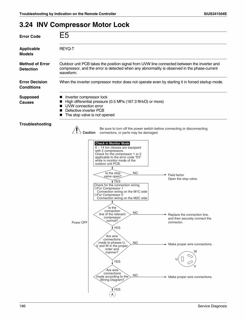
Troubleshooting by Indication on the Remote Controller SiUS341504E
3.24 INV Compressor Motor Lock
Error Code E5Applicable Models
REYQ-T
Method of Error Detection
Outdoor unit PCB takes the position signal from UVW line connected between the inverter and compressor, and the error is detected when any abnormality is observed in the phase-current waveform.
Error Decision Conditions
When the inverter compressor motor does not operate even by starting it in forced startup mode.
Supposed Causes
Inverter compressor lockHigh differential pressure (0.5 MPa (167.3 ftH2O) or more)UVW connection errorDefective inverter PCBThe stop valve is not opened
Troubleshooting
Make proper wire connections.
Make proper wire connections.
NO
NO
NO
NO
YES
YES
YES
YES
Power OFF
Is the connection
line of the relevant compressor
normal?
Are wire connections
made to phases U, V and W in the proper
order and manner?
Are wire connections
made according to the Wiring Diagram?
U
V
W
Is the stop valve open?
8 ~ 14 ton classes are equipped with 2 compressors.Check for the compressor 1 or 2 applicable to the error code “E5” while in monitor mode of the outdoor unit PCB.
Replace the connection line, and then securely connect the connector.
Field factor Open the stop valve.
CautionBe sure to turn off the power switch before connecting or disconnecting connectors, or parts may be damaged.
A
Check for the connection wiring.For Compressor 1Connection wiring on the M1C sideFor Compressor 2Connection wiring on the M2C side
Check in Monitor Mode
186 Service Diagnosis

SiUS341504E Troubleshooting by Indication on the Remote Controller
Refer to P.251.
NO
YES
NO
YES
NO
Power ON
Restart the compressor, and then check for the
operation. Does the error recur?
Has the compressor started
up at high differential pressure (0.5 MPa
(167.3 ftH2O) or more)?
The error recurs at startup.
YESYES
Power OFF
Power OFF
Power ON
Power ON
Power OFF
Pressure equalization failure.Check for the refrigerant system.
Quit work.Pressure equalization failure may have occurred. Check for the refrigerant system.
YES
YES
NO Replace the inverter PCB.
NOThe error recurs at startup.
Continue operation.The error could have resulted from instantaneous power failure.
A
Continue operation.
Replace the inverter compressor.
CHECK 4Is the power
transistor normal?
Replace the inverter PCB.
This is not a failure of the inverter PCB. Reinstall the PCB.
Replace the compressor.YES
NO
NO
The relevant compressor has a
wiring disconnection in it.
The insulation resistance of the relevant
compressor is low (< 100kΩ)
YES
CHECK 4
Service Diagnosis 187

Troubleshooting by Indication on the Remote Controller SiUS341504E
3.25 Compressor Damage Alarm
Error Code E6Applicable Models
REYQ-T
Method of Error Detection
Determine the symptom to be error by detecting the revolutions of the compressor and pressure values detected by the high and low pressure sensors, and further making a comparison between a theoretical current value of the compressor calculated from parameters detected and an actual current value detected by the power transistor.
Error Decision Conditions
When a state in which the actual current value of the compressor is abnormally high (by 130% or more) compared to the theoretical current value continues for a period of 30 minutes.∗ In case of a system with multi outdoor units, the system will return an alarm if there is any
operational unit other than that applicable to "E6" or determine to be error if not.
Supposed Causes
Defective compressorDefective high pressure sensorDefective low pressure sensorDefective control PCBDefective inverter PCB
Troubleshooting
NO
YES
Are the characteristics
of the high pressure sensor normal?
(∗1)
(1) Mount a pressure gauge on the high and low pressure service ports.
(2) Reset the power supply, and then restart the operation.
Replace the high pressure sensor.
CautionBe sure to turn off the power switch before connecting or disconnecting connectors, or parts may be damaged.
NO
YES
Are the characteristics
of the low pressure sensor normal?
(∗1)
Replace the low pressure sensor.
Connect the Service Checker, and then make a comparison between “high pressure” and “low pressure” checked by the Service Checker and the measurements of the high and low pressure gauge. (∗1)
Service Checker
A
CHECK 13 CHECK 14
188 Service Diagnosis

SiUS341504E Troubleshooting by Indication on the Remote Controller
Note: ∗1. Make a comparison between voltage measured by the pressure sensor and that read by the pressure gauge.(The pressure sensor makes measurement of voltage at its connector block to convert it to pressure. )
Refer to P.251.
Refer to P.256.
Refer to P.257.
Refer to P.257.
NO
YES
Are the “high
pressure” and “low pressure” checked by the
Service Checker same as the measurements of the high
and low pressure sensors?
Replace the control PCB (A1P).
NO Replace the inverter PCB.CHECK 4
Is the power transistor normal?
YES
Replace the inverter compressor.
A
CHECK 12
CHECK 4
CHECK 12
CHECK 13
CHECK 14
Service Diagnosis 189

Troubleshooting by Indication on the Remote Controller SiUS341504E
3.26 Outdoor Unit Fan Motor Abnormality
Error Code E7Applicable Models
REYQ-T
Method of Error Detection
Detect according to the value of current flowing through the inverter PCB (or fan inverter PCB in case of Fan Motor 2).Detect error of the fan motor system according to the fan revolutions detected by the hall IC during the fan motor runs.
Error Decision Conditions
When overcurrent is detected from the inverter PCB or the fan inverter PCB (Detecting overcurrent 4 times will shut down the system).When the fan revolutions fall below a given level for a period of 6 seconds while in fan motor rotation mode (Detecting shortage of revolutions will shut down the system).
Supposed Causes
Fan motor failureNeglect to connect or defective connection of harness/connector between the fan motor and the PCBFan does not rotate due to foreign matters caught in it.Clearing condition: fan motor performs normal operation for a period of 5 minutes
Troubleshooting
8 ~ 14 ton classes are equipped with 2 compressors.Check for the compressor 1 or 2 applicable to the error code “E7” while in monitor mode of the outdoor unit PCB.
Check in Monitor Mode
There are foreign matters around the
applicable fan. Remove the foreign matters. YES
Check for the connections of all fan motor connectors.
NO
Turn OFF the power supply, and then wait for a period of 10 minutes.
Some connectors are disconnected.
Insert the connector. YES
NO
NO
There is a junction relay connection error.
Correct the connection of the junction connector.
YES
CautionBe sure to turn off the power switch before connecting or disconnecting connectors, or parts may be damaged.
A
Check for any wire connection errors in 2 units of fan motors. Fan motor 1: Power supply cables and signal cables are all white. Fan motor 2: Power supply cables and signal cables are red on the PCB side and white on the motor side.
Check for Connection of Connector
Check for Colors of Junction Connectors
190 Service Diagnosis

SiUS341504E Troubleshooting by Indication on the Remote Controller
Refer to P.259.
Refer to P.259.
There is no continuity across the fuse
(F101U) on the fan inverter PCB.
Replace the fan inverter PCB.YES
The fan cannot be
rotated by hand when disconnecting the
connector from the fan motor.
Replace the relevant fan motor.YES
NO
Resistance between the fan
motor power supply cable terminal and the motor frame (metallic part)
is not more than 1MΩ.
Replace the relevant fan motor. YES
NO
Replace the relevant fan motor. YES
Resistance between U, V, W
phases of the fan motor power supply cable has lost
balance or short circuit is caused between U,
V, W phases.
Check for the connector (power supply cable) of the fan motor.
NO
CHECK 16
Replace the fan inverter PCB. YES
The HAP lamp on the inverter
PCB blinks, but does not blink on the fan inverter PCB.
Replace the relevant fan motor. YES
Signal cable has
caused short circuit between Vcc and Gnd,
and between UVW and Gnd.
Turn ON the power supply to check for the following LED lamps.(1) HAP lamp on the compressor inverter PCB (2) HAP lamp on the fan inverter PCB
NO
Replace the fan motor.NO
A
U V W(Red) (White) (Black)
Check for the connector (signal cable) of the fan motor.
NO
CHECK 17Gnd Vcc W V U(Gray) (Pink) (Orange) (Blue) (Yellow)
CHECK 16
CHECK 17
Service Diagnosis 191

Troubleshooting by Indication on the Remote Controller SiUS341504E
3.27 Electronic Expansion Valve Coil Abnormality
Error Code E9Applicable Models
REYQ-T
Method of Error Detection
Detect according to whether or not there is continuity across the electronic expansion valve coils (REYQ-T: Y1E~Y5E).
Error Decision Conditions
When no current flows through common (COM[+]) at the time of turning ON the power supply.
Supposed Causes
Disconnection of connectors from electronic expansion valves (REYQ-T: Y1E~Y5E)Defective electronic expansion valve coilDefective outdoor unit control PCB
Troubleshooting
Note: ∗1. Make measurement of resistance between individual pins to ensure that it falls within the range of 40 to 50Ω.
Turn OFF the power supply once, and then turn it ON again.
Return to normal? Investigate external causes other than failures (e.g. noise).
YES
NO
Connector for the electronic
expansion valve of the outdoor unit PCB (A1P)
is connected.
Properly and securely connect the connector.
NO
YES
The resistance of the electronic
expansion valve coil is normal. (∗1)
Replace the electronic expansion valve.
NO
Replace the outdoor unit control PCB (A1P).
YES
CautionBe sure to turn off the power switch before connecting or disconnecting connectors, or parts may be damaged.
Check for electronic expansion valves applicable to the error code "E9" while in monitor mode.Sub code
E09-01/05/08: Y1EE09-03/06/09: Y2EE09-04/07/10: Y3EE09-26/27/28: Y4EE09-29/34/39: Y5E
1
2
3
4
56
1 – 62 – 63 – 64 – 6
40 ~ 50Ω
(White)
(Yellow)
(Orange)
(Blue)
(Red)
Measurement Point
Acceptance Criteria
REYQ-T
192 Service Diagnosis

SiUS341504E Troubleshooting by Indication on the Remote Controller
3.28 Discharge Pipe Temperature Abnormality
Error Code F3Applicable Models
REYQ-T
Method of Error Detection
Detect according to temperature detected with the discharge pipe or compressor surface temperature thermistor.
Error Decision Conditions
When discharge pipe temperature becomes abnormally high (i.e., 135°C (275°F) or more)When discharge pipe temperature sharply rises (remains at 120°C (248°F) or more for a period of consecutive 10 minutes)When compressor surface temperature becomes abnormally high (i.e., 120°C (248°F) or more)When compressor surface temperature sharply rises (remains at 110°C (230°F) or more for a period of consecutive 10 minutes)
Supposed Causes
Abnormal discharge pipe temperatureDefective discharge pipe thermistorAbnormal compressor surface temperatureDefective compressor surface temperature thermistorDefective outdoor unit control PCB
Service Diagnosis 193

Troubleshooting by Indication on the Remote Controller SiUS341504E
Troubleshooting
Note: ∗1. Error code and thermistor
Refer to P.250.
Refer to P.255.
NO
Is the “temperature”
checked by the Service Checker same as the measurement of the
temperature?
NO
Replace the relevant thermistor.
Replace the control PCB (A1P).
YES
YES
Service CheckerConnect the Service Checker, and then make a comparison between “discharge pipe temperature” (or “compressor surface temperature” and “low pressure” checked by the Service Checker and the measurements of discharge pipe surface temperature (or “compressor surface temperature.”) CHECK 11
Connect the Service Checker.Reset the system operation, and then restart it.
Are the characteristics
of the discharge pipe and compressor surface temperature thermistors
normal? (∗1)
• All thermistors are normal, and temperature detection with the control PCB is also normal.
• The discharge pipe temperature (or compressor surface temperature) has really become high.
CHECK 3 : Eliminate the causes of superheat operation.
CautionBe sure to turn off the power switch before connecting or disconnecting connectors, or parts may be damaged.
Error Code
Applicable Thermistor
REYQ72TYDNREYQ72TTJU
REYQ96-120TYDNREYQ96-120TTJU
REYQ144-168TYDNREYQ144-168TTJU
Electric symbol Connector Electric
symbol Connector Electric symbol Connector
J3
Discharge pipe (M1C) thermistor
R2TX19A
(Group connector)
R21TX19A
(Group connector)
R21T
X19A(Group
connector)
Discharge pipe (M2C) thermistor
— — R22T R22T
Compressor surface temperature thermistor
R14TX19A
(Group connector)
— — R14T
CHECK 3
CHECK 11
194 Service Diagnosis

SiUS341504E Troubleshooting by Indication on the Remote Controller
3.29 Wet Alarm
Error Code F4Applicable Models
REYQ-T
Method of Error Detection
In cooling operation, detect the condition under which liquid refrigerant returns to the compressor, according to the temperature and pressure of each part.
Error Decision Conditions
When the following wet state continues for a period of 90 minutes, an alert is issued. An error is defined for 120 minutes.
Wet state in outdoor units
When the following wet state continues for a period of 45 minutes, an alert is issued.Wet state in some of indoor units
Supposed Causes
Defective suction pipe thermistorDefective discharge pipe thermistorDefective high pressure sensorDefective indoor unit electronic expansion valveDirty air filter
Troubleshooting
Connect the Service Checker.Mount a pressure gauge on the high pressure service port.Reset the operation, and then restart the operation.
Stop the relevant indoor units while the system is in cooling operation, and then check for the liquid pipe temperature of these indoor units after the system is stabilized.
The liquid pipe temperature is low
(equivalent to the evaporating temperature).
Clean the air filters of the indoor units.
NO
YES
NO
Replace the indoor unit electronic expansion valve.
Replace the relevant thermistor.
YES
YES
CautionBe sure to turn off the power switch before connecting or disconnecting connectors, or parts may be damaged.
Are the characteristics of the
accumulator inlet thermistor and the suction pipe thermistor
normal?
NOReplace the discharge pipe thermistor.
Are the discharge pipe
thermistor characteristics normal?
YES
NOReplace the high pressure sensor.
Are the high pressure sensor
characteristics normal?
Service CheckerUse the Service Checker to find indoor units operating under the following conditions:
& • Gas pipe temperature – Liquid pipe temperature < 2.5˚C (4.5˚F)• Electronic expansion valve opening < 300 pulses
Service Diagnosis 195

Troubleshooting by Indication on the Remote Controller SiUS341504E
3.30 Refrigerant Overcharged
Error Code F6Applicable Models
REYQ-T
Method of Error Detection
Detect overcharged refrigerant according to outdoor air temperature, heat exchanging deicer temperature, and liquid pipe temperature during check operation.
Error Decision Conditions
When the amount of refrigerant, which is calculated using outdoor air temperature, heat exchanging deicer temperature, and liquid pipe temperature during check operation, exceeds the regular charge amount by 30% or more(If refrigerant is charged slightly over the regular charge amount, "F6" may be displayed on the remote controller.)
Supposed Causes
Refrigerant overchargedDisconnection of outdoor air thermistorDisconnection of heat exchanging deicer thermistorDisconnection of liquid pipe temperature thermistor
Troubleshooting
Refer to P.255.
Check for the conditions of mounting of the temperature sensors of the outdoor air thermistor, the heat exchanger thermistor, and liquid pipe thermistor to the piping.
Disconnect the outdoor air thermistor, the heat exchanger thermistor, and liquid pipe thermistor from the outdoor unit PCB, and then make measurement of resistance using a multiple meter.
Normal?
Remedy refrigerant overcharging.YES
NO
NO
Replace the abnormal thermistors, and then operate the system.
Properly connect the thermistors, and then operate the system.
YES
CautionBe sure to turn off the power switch before connecting or disconnecting connectors, or parts may be damaged.
CHECK 11
Are the temperature sensors properly
mounted?
CHECK 11
196 Service Diagnosis

SiUS341504E Troubleshooting by Indication on the Remote Controller
3.31 Harness Abnormality (between Control PCB and Inverter PCB)
Error Code H3Applicable Models
REYQ-T
Method of Error Detection
Check for the transmission conditions of the following jumpers between the PCB using micro-computer:Between X28A (Control PCB) and X6A (Inverter PCB)∗1
Error Decision Conditions
When normal transmission between PCB is disabled during the compressor stops running.
Supposed Causes
Defective connection of jumpers between PCBDefective control PCB (A1P)Defective inverter PCB
Troubleshooting
Note: ∗1. Control PCB and Inverter PCB
Check for the transmission conditions of the following jumpers between the PCB:Between X28A (Control PCB) and X6A (Inverter PCB)∗1
Replace the control PCB (A1P).
Replace the inverter PCB.YES
NO
YES
Complete countermeasures.
Return the relevant harness to normal.
NO
CautionBe sure to turn off the power switch before connecting or disconnecting connectors, or parts may be damaged.
Harness error
“H3” error recurs.
PCB REYQ72TYDNREYQ72TTJU
REYQ96-168TYDNREYQ96-168TTJU
Control PCB A1P A1P
Inverter PCB A3P A3PA6P
Service Diagnosis 197

Troubleshooting by Indication on the Remote Controller SiUS341504E
3.32 Outdoor Unit Fan Motor Signal Abnormality
Error Code H7Applicable Models
REYQ-T
Method of Error Detection
Detect of abnormal signal from fan motor.
Error Decision Conditions
When an abnormal signal is detected at startup of the fan motor operation.
Supposed Causes
Abnormal signal from fan motor (Circuit failure)Disconnection/Short circuit in fan motor leads or disconnection of connectorDefective inverter PCB (A3P, A6P)
Troubleshooting
Properly connect the connector.NO
YES
Replace the fan motor.NO
YES
Turn OFF the power supply.
Check for fan motor applicable to the error code “H7” while in monitor mode.
Sub codeH7-01/05/09: Fan motor 1 (M1F) Master / Slave 1 / Slave 2H7-02/06/10: Fan motor 2 (M2F) Master / Slave 1 / Slave 2
Check for the connector of the fan motor. (∗1)
Replace the inverter PCB. • For Fan motor 1, replace the
inverter PCB A4P. • For Fan motor 2, replace the fan
inverter PCB A7P.
CautionBe sure to turn off the power switch before connecting or disconnecting connectors, or parts may be damaged.
Is the connector of
signal cable of the relevant fan motor
normally connected?
Is resistance
between Vcc and UVW and between GND
and UVW of the fan motor lead in
balance?
198 Service Diagnosis

SiUS341504E Troubleshooting by Indication on the Remote Controller
Note: ∗1. Procedure for checking for the connector of the fan motor.(1) Turn OFF the power supply. (2) Disconnect the connector (X2A or X502A) from the PCB, and then make measurement of
the following resistance. Acceptance criteria: Resistance between phases falls within the range of ±20%.
GND
Vcc
W
V
U
5 Gray
4 Pink
3 Orange
2 Blue
1 Yellow
Connector for signal cable (X2A or X502A)
Make measurement of resistance between Vcc and UVW and between GND and UVW.
Service Diagnosis 199

Troubleshooting by Indication on the Remote Controller SiUS341504E
3.33 Thermistor Abnormality
Error Code H9, J3, J5, J6, J7, J8, J9Applicable Models
REYQ-T
Method of Error Detection
Detect according to temperature detected with individual thermistors.
Error Decision Conditions
When the system is in operation and the thermistor causes wiring disconnection or short circuit in it.
Supposed Causes
Defective connection of thermistorDefective thermistorDefective outdoor unit PCB
Troubleshooting
Thermistor is connected to the
connector.
Replace the outdoor unit PCB.
Connect the connector and turn ON again.
NO
NO
Replace the thermistor (∗1).
YES
YES
CautionBe sure to turn off the power switch before connecting or disconnecting connectors, or parts may be damaged.
Resistance is normal when measured after
disconnecting the thermistor from the outdoor unit PCB.
CHECK 11(1.8 kΩ to 800 kΩ)
200 Service Diagnosis

SiUS341504E Troubleshooting by Indication on the Remote Controller
Note: ∗1. Error codes and thermistors
Refer to P.255.
Error Code
Applicable Thermistor
REYQ72TYDNREYQ72TTJU
REYQ96-120TYDNREYQ96-120TTJU
REYQ144-168TYDNREYQ144-168TTJU
Electric symbol Connector Electric
symbol Connector Electric symbol Connector
H9 Outdoor air R1T X18A R1T X18A R1T X18A
J3
Discharge pipe (M1C) thermistor
R2TX19A
(Group connector)
R21TX19A
(Group connector)
R21T
X19A(Group
connector)
Discharge pipe (M2C) thermistor
— — R22T R22T
Compressor surface temperature thermistor
R14TX19A
(Group connector)
— — R14T
J5
Comp. Suction R12T
X15A(Group
connector)R12T
X15A(Group
connector)R12T
X15A(Group
connector)
Suction air R10TX29A
(Group connector)
R10TX29A
(Group connector)
R10TX29A
(Group connector)
J6
H.E, deicer R11TX15A
(Group connector)
R11TX15A
(Group connector)
R11TX15A
(Group connector)
H.E. gas R8TR9T
X29A(Group
connector)
R8TR9T
X29A(Group
connector)
R8TR9T
X29A(Group
connector)
J7Receiver inlet R3T X30A
(Group connector)
R3T X30A(Group
connector)
R3T X30A(Group
connector)Subcooling H.E. liquid R7T R7T R7T
J8 H.E. liquid R4TR5T
X30A(Group
connector)
R4TR5T
X30A(Group
connector)
R4TR5T
X30A(Group
connector)
J9
Subcooling H.E. gas R6T
X30A(Group
connector)R6T
X30A(Group
connector)R6T
X30A(Group
connector)
Receiver gas purge R13T X17A R13T X17A R13T X17A
CHECK 11
Service Diagnosis 201

Troubleshooting by Indication on the Remote Controller SiUS341504E
3.34 High Pressure Sensor Abnormality
Error Code JAApplicable Models
REYQ-T
Method of Error Detection
Detect according to temperature detected with the high pressure sensor.
Error Decision Conditions
When the high pressure sensor causes wiring disconnection or open circuit (at pressure of not less than 4.22 MPa (1412 ftH2O) or not more than 0.01 MPa (3.3 ftH2O)).
Supposed Causes
Defective high pressure sensorConnection of low pressure sensor in mistake for high pressure sensorDefective outdoor unit PCBDefective connection of high pressure sensor
Troubleshooting
Refer to P.256.
Refer to P.257.
Are the characteristics of
the high pressure sensor normal? (Make a comparison
between voltage characteristics (∗) and gauge pressure.)
Replace the high pressure sensor.
Replace the control PCB.
NO
Is the PCB detection pressure normal? Make a
comparison between data on pressure checked by the Service Checker
and the voltage characteristics. Replace the control PCB.NO
Are the characteristics of the high pressure sensor
normal?Replace the high pressure sensor.
NO
YES
YES
YES
Reset the operation, and then restart it.
(1) Mount a pressure gauge on the high pressure service port.
(2) Connect the Service Checker for VRV systems.
CautionBe sure to turn off the power switch before connecting or disconnecting connectors, or parts may be damaged.
CHECK 12
CHECK 13
CHECK 12
CHECK 13
CHECK 12
CHECK 13
202 Service Diagnosis

SiUS341504E Troubleshooting by Indication on the Remote Controller
3.35 Low Pressure Sensor Abnormality
Error Code JCApplicable Models
REYQ-T
Method of Error Detection
Detect according to temperature detected with the low pressure sensor.
Error Decision Conditions
When the low pressure sensor causes wiring disconnection or open circuit (at pressure of not less than 1.77 MPa (592 ftH2O) or not more than –0.01 MPa (–3.3 ftH2O)).
Supposed Causes
Defective low pressure sensorConnection of high pressure sensor in mistake for low pressure sensorDefective outdoor unit PCBDefective connection of low pressure sensor
Troubleshooting
Refer to P.256.
Refer to P.257.
Are thecharacteristics of
the low pressure sensor normal? (Make a comparison
between voltage characteristics and gauge pressure.)
Replace the low pressure sensor.
Replace the control PCB.
NO
Is the PCB detection pressure
normal? Make a comparison between data on pressure checked
by the Service Checker and the voltage characteristics.
Replace the control PCB.NO
Are the characteristics of the low pressure sensor
normal?Replace the low pressure sensor.
NO
YES
YES
YES
Reset the operation, and then restart it.
(1) Mount a pressure gauge on the low pressure service port.
(2) Connect the Service Checker for VRV systems.
CautionBe sure to turn off the power switch before connecting or disconnecting connectors, or parts may be damaged.
CHECK 12
CHECK 14
CHECK 12
CHECK 14
CHECK 12
CHECK 14
Service Diagnosis 203

Troubleshooting by Indication on the Remote Controller SiUS341504E
3.36 Inverter PCB Abnormality
Error Code L1Applicable Models
REYQ-T
Method of Error Detection
Detect according to current value detected during the output of waveform before compressor startupDetect according to current value detected with the current sensor during sync operation for startup
Error Decision Conditions
When overcurrent (OCP) flows during the output of waveformWhen the current sensor error during sync operationWhen IPM error occurs
Supposed Causes
Inverter PCBIPM failureCurrent sensor failureDrive circuit failure
204 Service Diagnosis

SiUS341504E Troubleshooting by Indication on the Remote Controller
Troubleshooting
Refer to P.251.
Is the insulation to
ground resistance of the relevant compressor
100kΩ or more?
The error could have resulted from external factors other than failures (e.g. external noise or thunder).
YES
Replace the compressor and the compressor inverter PCB together.
Replace the inverter PCB.
NO
NO
YES
Replace the compressor inverter PCB and the fan inverter PCB (A4P).
Replace the inverter PCB.
NO
YES
Turn OFF the power supply once, and then turn it ON again.
All classes (except REYQ72T) are equipped with 2 compressors.Check for the compressor 1 or 2 applicable to the error code “L1” while in monitor mode of the outdoor unit PCB.
NO
YES
CautionBe sure to turn off the power switch before connecting or disconnecting connectors, or parts may be damaged.
Return to normal?
CHECK 4Is the power
transistor normal?
Check in Monitor Mode
CHECK 4Is the power
transistor of the fan driver normal?
CHECK 4
Service Diagnosis 205

Troubleshooting by Indication on the Remote Controller SiUS341504E
3.37 Reactor Temperature Rise Abnormality
Error Code L3Applicable Models
REYQ-T
Method of Error Detection
Detect according to the value detected with the reactor surface thermistor.
Error Decision Conditions
When the temperature detected with the reactor surface thermistor is more than the specified temperature.
Supposed Causes
Defective connection of harnessDefective reactor surface thermistorDefective inverter PCB
Troubleshooting
Is reactor
harness connected to the terminal strip
correctly?
Is the wiring
disconnection in the reactor thermistor?
NO
YES
YES
NOConnect the harness correctly.
Replace the thermistor.
Replace the inverter PCB.
CautionBe sure to turn off the power switch before connecting or disconnecting connectors, or parts may be damaged.
206 Service Diagnosis

SiUS341504E Troubleshooting by Indication on the Remote Controller
3.38 Inverter Radiation Fin Temperature Rise Abnormality
Error Code L4Applicable Models
REYQ-T
Method of Error Detection
Detect temperature of power module of the compressor inverter PCB.
Error Decision Conditions
Thermistor located inside the power module of the inverter PCB for compressor and fan motor.Cooling tube plate poor heat-exchange.
Supposed Causes
Cooling tube plate not fixed with screws“U0” errorDefective inverter PCBHigh outdoor air temperature
Troubleshooting
Continue operation. Field factor. Power module temperature may have risen due to high outdoor air temperature.
Turn ON the power supply, and
then press the ON button continuously. Does
the error recur?
Replace the inverter PCB.YES
Rectify troubles.Normal?NO
NO
Check for the cooling conditions of cooling tube used to cool the inverter.(1) Is the cooling tube plate
fixed with screws?(2) Error code “U0” is
displayed on the Error History screen.
YES
CautionBe sure to turn off the power switch before connecting or disconnecting connectors, or parts may be damaged.
All classes (except REYQ72T) are equipped with 2 compressors.Check for the compressor 1 or 2 applicable to the error code “L4” while in monitor mode of the outdoor unit PCB.
Check in Monitor Mode
Service Diagnosis 207

Troubleshooting by Indication on the Remote Controller SiUS341504E
3.39 INV Compressor Instantaneous Overcurrent
Error Code L5Applicable Models
REYQ-T
Method of Error Detection
Detect current flowing through the power transistor.
Error Decision Conditions
When instantaneously overcurrent flows through the power transistor.
Supposed Causes
Defective compressor coil (such as wiring disconnection or insulation failure)Compressor startup failure (mechanical lock)Defective inverter PCB
TroubleshootingCompressor inspection
Power OFF
Open the stop valve.
YES
NOIs the stop valve open?
YES
YES
Are wiring and wire
connections to the relevant compressor
normal?
Rectify the wiring and wire connections.
NO
CautionBe sure to turn off the power switch before connecting or disconnecting connectors, or parts may be damaged.
All classes (except REYQ72T) are equipped with 2 compressors.Check for the compressor 1 or 2 applicable to the error code “L5” while in monitor mode of the outdoor unit PCB.
Check in Monitor Mode
Check for the leads of the compressor.
For Compressor 1Leads on the M1C side
For Compressor 2Leads on the M2C side
Are the leads of the relevant
compressor normal?
Replace the leads of the relevant compressor.
NO
A
208 Service Diagnosis

SiUS341504E Troubleshooting by Indication on the Remote Controller
Refer to P.251.
Power OFF
YES
NO
Restarting the system results in the
recurrence of the error.
Continue operation.
Replace the inverter compressor.
NO
YES
Replace the inverter PCB
YES
Restarting the system results in the
recurrence of the error.
Continue operation.The error could have resulted from causes such as instantaneous power failure.
NO
The insulation
resistance of the relevant compressor is 100kΩ
or less.
Replace the inverter compressor.
YES
The coil of the relevant
compressor has caused wiring disconnection
in it.
Replace the inverter compressor.
YES
NO
Replace the inverter PCB.
NOCHECK 4Is the power
transistor normal?
( )
Power OFF
A
CHECK 4
Service Diagnosis 209

Troubleshooting by Indication on the Remote Controller SiUS341504E
3.40 INV Compressor Overcurrent
Error Code L8Applicable Models
REYQ-T
Method of Error Detection
Detect current flowing through the power transistor.
Error Decision Conditions
When the secondary-side inverter current exceeds.
Supposed Causes
Compressor overloadedWiring disconnection in compressor coilDisconnection of compressor wiringDefective inverter PCB
Troubleshooting
Power OFF
Open the stop valve.
YES
NOIs the stop valve open?
YES
YES
Are wiring and wire
connections to the relevant compressor
normal?
Rectify the wiring and wire connections.
NO
CautionBe sure to turn off the power switch before connecting or disconnecting connectors, or parts may be damaged.
All classes (except REYQ72T) are equipped with 2 compressors.Check for the compressor 1 or 2 applicable to the error code “L8” while in monitor mode of the outdoor unit PCB.
Check in Monitor Mode
Check for the leads of the compressor.
For Compressor 1Leads on the M1C side
For Compressor 2Leads on the M2C side
Are the leads of the relevant
compressor normal?
Replace the leads of the relevant compressor.
NO
A
210 Service Diagnosis

SiUS341504E Troubleshooting by Indication on the Remote Controller
Refer to P.251.
Power OFF
YES
Restarting the system results in the
recurrence of the error.
Continue operation.
Replace the inverter compressor.
NO
YES
Replace the inverter PCB
Restarting the system results in the
recurrence of the error.
Continue operation.The error could have resulted from causes such as instantaneous power failure.
NO
( )
A
NO
YES
The insulation
resistance of the relevant compressor is
1MΩ or less to ground.
Replace the inverter compressor.
YES
The coil of the relevant
compressor has caused wiring disconnection
in it.
Replace the inverter compressor.
YES
NO
Replace the inverter PCB.
NOCHECK 4Is the power
transistor normal?
Power OFF
CHECK 4
Service Diagnosis 211

Troubleshooting by Indication on the Remote Controller SiUS341504E
3.41 INV Compressor Startup Abnormality
Error Code L9Applicable Models
REYQ-T
Method of Error Detection
Detect error according to the signal waveform of compressor.
Error Decision Conditions
When compressor startup operation has not been completed.
Supposed Causes
The stop valve is not openedDefective compressorError in wire connections to compressorLarge differential pressure before compressor startupDefective inverter PCB
212 Service Diagnosis

SiUS341504E Troubleshooting by Indication on the Remote Controller
Troubleshooting
YES
NO
NO
Apply power, and then restart operation.
NO
Are the leads of the compressor
disconnected?Connect the leads of the compressor.
YES
Is the insulation
resistance of the relevant compressor 100kΩ
or more?
Eliminate the melting state of refrigerant.
NO
YES
YES
YES
Refrigerant is melting (No power
applied for a period of 6 hours or more)
Eliminate the melting state of refrigerant.
YES
CautionBe sure to turn off the power switch before connecting or disconnecting connectors, or parts may be damaged.
All classes (except REYQ72T) are equipped with 2 compressors.Check for the compressor 1 or 2 applicable to the error code “L9” while in monitor mode of the outdoor unit PCB.
Check in Monitor Mode
Is the stop valve open?
Startup for the first time after
installation?
Is a proper amount of refrigerant
charged?
Open the stop valve.NO
Charge a proper amount of refrigerant.
NO
Go to the next page. (Startup failure in aging operation)
Service Diagnosis 213

Troubleshooting by Indication on the Remote Controller SiUS341504E
Refer to P.251.
YES
Recheck for the compressor and the refrigerant system.
NO
Replace the compressor inverter PCB.NO
YES
NO
There is wiring disconnection in
the compressor.Replace the inverter compressor.
YES
Is the insulation
resistance of the relevant compressor
100kΩ or more?
Refrigerant is melting (No power
applied for a period of 6 hours or more)
Replace the inverter compressor.NO
Eliminate the melting state of refrigerant.
YES
From the previous page (Startup failure in aging operation)
CHECK 4Is the power
transistor normal?
CHECK 4
214 Service Diagnosis

SiUS341504E Troubleshooting by Indication on the Remote Controller
3.42 Transmission Error between Inverter and Control PCB
Error Code LCApplicable Models
REYQ-T
Method of Error Detection
Check for the transmission conditions between the inverter PCB and the control PCB using a micro-computer.
Error Decision Conditions
When normal transmission is disabled for a given period of time or more.
Supposed Causes
Defective connection between the inverter PCB and the control PCBDefective control PCB (transmission block)Defective noise filterExternal factors (e.g. noise)Defective inverter compressorDefective fan motor
Troubleshooting
Is the type of the
relevant inverter PCB 1 correct?
Replace with a proper PCB.NO
Properly Connect the connectorNO
YES
Replace the fan motor.YES
NO
The insulation
resistance of the relevant inverter compressor is
not more than 100kΩ.
The insulation resistance of the
relevant fan motor is not more than
1MΩ.
Replace the inverter compressor.YES
NO
YES
CautionBe sure to turn off the power switch before connecting or disconnecting connectors, or parts may be damaged.
Is the connector
between each control PCB and each inverter PCB securely
connected? (∗1)
All classes (except REYQ72T) are equipped with 2 compressors.Check for the compressor 1 or 2 applicable to the error code “LC” while in monitor mode of the outdoor unit PCB.
Check in Monitor Mode
A
Service Diagnosis 215

Troubleshooting by Indication on the Remote Controller SiUS341504E
Note: ∗1. Connect and disconnect the connector once to ensure that it is securely connected.
Replace all of the INV, FAN, and NF boards.
YES
This is not the LC error.Recheck the error code.
NO
YES
The micro-computer normal
monitor indication lamp (green) on the control
PCB (A1P) is blinking.
Replace the inverter PCB.NO NO
YES
The micro-computer normal
monitor indication lamp (green) on the control
PCB (A1P) is blinking.
Properly connect the connector.NO
YES
Is the connector
between the control PCB and the sub PCB
securely connected?
Properly connect the connector X9A (X10A) on the sub PCB option.
NOIs the
normal operation indication LED on the sub
PCB blinking?
YES
NO
Replace the control PCB (A1P).YES
The fuse of the NF board has
blown out.
Continue operation.The error could have resulted from causes such as instantaneous power failure.
The LC error recurs.
A
216 Service Diagnosis

SiUS341504E Troubleshooting by Indication on the Remote Controller
3.43 Power Supply Voltage Imbalance
Error Code P1Applicable Models
REYQ-T
Method of Error Detection
Detect voltage imbalance through PCB.
Error Decision Conditions
When power supply voltage imbalance exceeds approximately 12 V.
Error is not decided while the unit operation is continued.“P1” will be displayed by pressing the inspection button.
Supposed Causes
Open phaseInterphase voltage imbalanceDefective capacitor in the main circuitDefective inverter PCBDefective magnetic relayDefective wiring in the main circuit
Service Diagnosis 217

Troubleshooting by Indication on the Remote Controller SiUS341504E
Troubleshooting
Note: ∗1. Make measurement of voltage at the power supply terminal block (X1M).∗2. Make measurement of voltage at the L1, L2 and L3 terminals of diode module located on the
inverter PCB during the compressor is in operation.
Is supply voltage imbalance over approximately
12 V?
Correct the open phase of power supply.
Open phase?
Is the imbalance of voltage
applied to the inverter over approximately
12 V? (∗2)
Rectify the power supply voltage imbalance.Take countermeasures (listed below).
YES YES
NONO
NO
Take countermeasures.
Defective noise filter, magnetic relay, or wiringTurn OFF the power supply, and then check and repair wirings in the main circuit and defective components.(1) Loose contact and wiring
disconnection between the power supply and the inverter
(2) Adhesion, meltdown, or loose contact of magnetic relay
(3) Wiring disconnection in or loose contact of noise filter
Replace the inverter PCB.
YES
Explanation to users ∗ Use the document “Notice of Inspection Results” attached to spare part.
Hand the “Notice of Inspection Results” to user to ask him/her to rectify the imbalance.
Be sure to explain user that “power supply voltage imbalance” will occur and Daikin accepts no responsibility for the imbalance.
Use equipment capable of constantly recording power supply voltages (e.g. Memory Hicoder) to record power supply voltages between phases (R-S, S-T, and R-T) for a period of consecutive 1 week.
Power supply voltage imbalance Even though power supply voltage remains balanced when making measurement, it often becomes imbalanced during night-time (from 18:00 to 22:00).
Even though the power supply voltage is normal, the error recurs.
<If voltage can be monitored>
CautionBe sure to turn off the power switch before connecting or disconnecting connectors, or parts may be damaged.
Check in Monitor Mode8 ~ 14 ton classes are equipped with 2 compressors.Check for the compressor 1 or 2 applicable to the error code “P1” while in monitor mode of the outdoor unit PCB.
218 Service Diagnosis
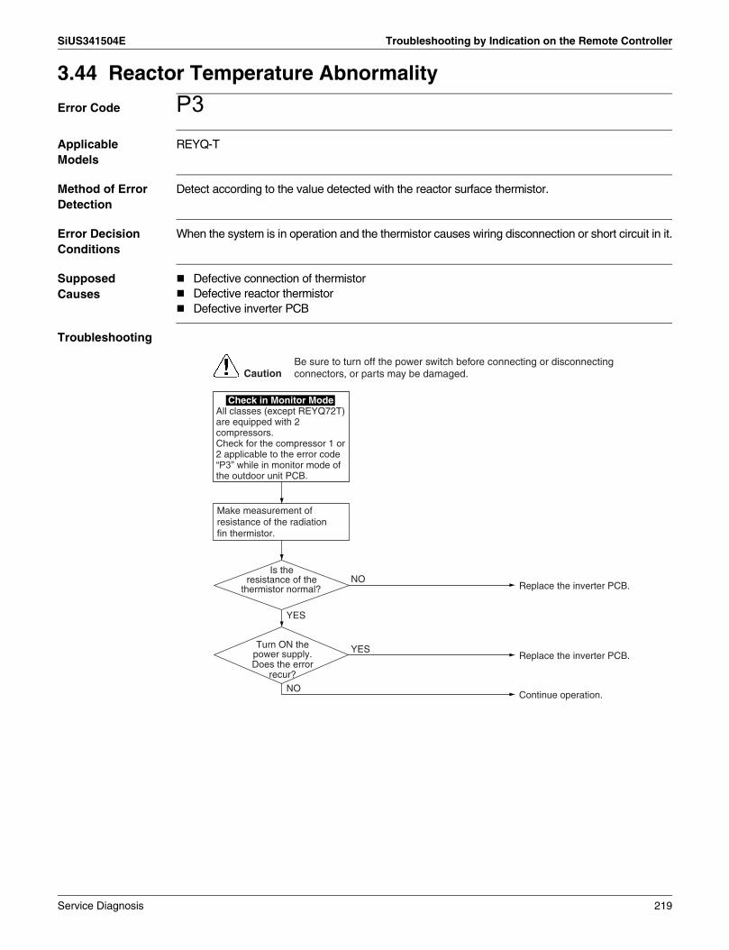
SiUS341504E Troubleshooting by Indication on the Remote Controller
3.44 Reactor Temperature Abnormality
Error Code P3Applicable Models
REYQ-T
Method of Error Detection
Detect according to the value detected with the reactor surface thermistor.
Error Decision Conditions
When the system is in operation and the thermistor causes wiring disconnection or short circuit in it.
Supposed Causes
Defective connection of thermistorDefective reactor thermistorDefective inverter PCB
Troubleshooting
Check in Monitor ModeAll classes (except REYQ72T) are equipped with 2 compressors.Check for the compressor 1 or 2 applicable to the error code “P3” while in monitor mode of the outdoor unit PCB.
Make measurement of resistance of the radiation fin thermistor.
Is the resistance of the
thermistor normal?
Turn ON the power supply.Does the error
recur?NO
YES
YES
NOReplace the inverter PCB.
Replace the inverter PCB.
Continue operation.
CautionBe sure to turn off the power switch before connecting or disconnecting connectors, or parts may be damaged.
Service Diagnosis 219

Troubleshooting by Indication on the Remote Controller SiUS341504E
3.45 Inverter Radiation Fin Temperature Abnormality
Error Code P4Applicable Models
REYQ-T
Method of Error Detection
Detect the resistance of the following thermistors during the compressor stops running:Radiation fin thermistor.Thermistor located in PCB circuit.Heat sink thermistor.
Error Decision Conditions
When the resistance of the thermistor comes to a value equivalent to open or short circuit.
Error is not decided while the unit operation is continued."P4" will be displayed by pressing the inspection button.
Supposed Causes
Defective radiation fin temperature thermistorDefective inverter PCBDefective INV compressorDefective fan motor
Troubleshooting
Check in Monitor ModeAll classes (except REYQ72T) are equipped with 2 compressors.Check for the compressor 1 or 2 applicable to the error code “P4” while in monitor mode of the outdoor unit PCB.
Make measurement of resistance of the radiation fin thermistor.
Is the resistance of the
relevant thermistor normal?
The insulation
resistance of the relevant inverter compressor
is not more than 100kΩ.
The insulation resistance of the relevant
fan motor is not more than 1MΩ.
Turn ONthe power supply.
Does the error recur?
NO
YES
NO
YES
NO
YES
YES
NOReplace the inverter PCB.
Replace the inverter compressor.
Replace the fan motor.
Replace the inverter PCB.
Continue operation.
CautionBe sure to turn off the power switch before connecting or disconnecting connectors, or parts may be damaged.
220 Service Diagnosis

SiUS341504E Troubleshooting by Indication on the Remote Controller
3.46 Field Setting after Replacing Outdoor Unit Main PCB Abnormality or Combination of PCB Abnormality
Error Code PJApplicable Models
REYQ-T
Method of Error Detection
This error is detected according to communications with the inverter PCB.
Error Decision Conditions
Make judgement according to communication data on whether or not the type of the inverter PCB is correct.
Supposed Causes
Mismatching of type of PCBImproper (or no) field setting after replacing outdoor unit main PCB
Troubleshooting
Check in Monitor ModeAll classes (except REYQ72T) are equipped with 2 compressors.Check for the compressor 1 or 2 applicable to the error code “PJ” while in monitor mode of the outdoor unit PCB.
Is the type of the
compressor inverter PCB correct?
Is the type of the fan inverter PCB
correct?
Has the DIP switch
setting been made properly to replace the
control PCB?
Does the “Under Preparation”
indication lamp (H2P) on the control PCB
turn OFF?
YES
YES
NO
NO
YES
YES
NO
NO
Replace with a correct compressor inverter PCB.
Replace with a correct fan inverter PCB.
Properly make DIP switch setting.(After completion of setting, reset the power supply.)
Modify the connection wiring.
Replace the outdoor unit control PCB.
CautionBe sure to turn off the power switch before connecting or disconnecting connectors, or parts may be damaged.
Service Diagnosis 221

Troubleshooting by Indication on the Remote Controller SiUS341504E
3.47 Refrigerant Shortage
Error Code U0Applicable Models
REYQ-T
Method of Error Detection
Detect refrigerant shortage according to a low pressure level or a difference in heat exchanging temperature from the suction pipe.
Error Decision Conditions
Low pressure becomes 0.1 MPa (33.5 ftH2O) or less.∗ Error is not determined. The unit continues the operation.
Supposed Causes
Refrigerant shortage and refrigerant clogging (wrong piping)Defective thermistorDefective low pressure sensorDefective outdoor unit main PCB
Troubleshooting
Note: ∗1. Check the low pressure value by using pressure gauge in operation. ∗2. Compare the actual measurement value by pressure sensor with the value by the pressure
gauge.(To gain actual measurement value by pressure sensor, measure the voltage at the connector [between (2)-(3)] and then convert the value into pressure. )
Refer to P.249.
Refer to P.256.
Is the low pressure 0.1 MPa
(33.5 ftH2O) or less? (∗1)
Is the characteristics of
low pressure sensor normal? (∗2)
Replace the low pressure sensor.
Replace the outdoor unit main PCB (A1P).
NONO
YES YES
Remove the factor of decreasing low pressure.CHECK 2
CautionBe sure to turn off the power switch before connecting or disconnecting connectors, or parts may be damaged.
(1) Mount a pressure gauge at the service port on the low pressure side.
(2) Reset the operation using the remote controller then
CHECK 12
CHECK 2
CHECK 12
222 Service Diagnosis

SiUS341504E Troubleshooting by Indication on the Remote Controller
3.48 Reverse Phase, Open Phase
Error Code U1Applicable Models
REYQ-T
Method of Error Detection
The phase of each phase are detected by reverse phase detection circuit and right phase or reverse phase are judged.
Error Decision Conditions
When a power supply is reverse phase, or T phase is open phase.
Supposed Causes
Power supply reverse phaseT phase open phaseDefective outdoor unit PCB (A1P)
Troubleshooting
There is an open
phase at the power supply (T phase) terminal
section (X1M) of the outdoor unit.
Operation is normal if one
phase of power supply line phase is
replaced.
Fix the open phase. Requires inspection of field power supply section.
Reverse phase.Countermeasure of the problem is completed by phase replacement.
Replace the outdoor unit PCB (A1P).
YES
YES
NO
NO
CautionBe sure to turn off the power switch before connecting or disconnecting connectors, or parts may be damaged.
Service Diagnosis 223

Troubleshooting by Indication on the Remote Controller SiUS341504E
3.49 Power Supply Insufficient or Instantaneous Abnormality
Error Code U2Applicable Models
REYQ-T
Method of Error Detection
Detect the voltage of capacitor of the main circuit in the inverter PCB.
Error Decision Conditions
When the voltage in the DC circuit (between diode module and power module) falls below 380VDC.
Supposed Causes
Abnormal power supply voltageInstantaneous power failureOpen phaseDefective inverter PCBDefective control PCBDefective compressorDefective main circuit wiringDefective fan motorDefective connection of signal cable
Troubleshooting
Check in Monitor ModeAll classes (except REYQ72T) are equipped with 2 compressors.Check for the compressor 1 or 2 applicable to the error code “U2” while in monitor mode of the outdoor unit PCB.
There aresome defects in the
power supply conditions aforementioned.
The insulation resistance of the
compressor is not more than 100kΩ.
NO
YES
YES
Remedy the defects.
Replace the compressor.
Check for power supply conditions.(1) Power supply voltage falls
within the range of 380 to 415V?
(2) Any open phase in the power supply wiring or any wrong wiring?
(3) Imbalance in the power supply voltage is maintained within 12V?
A
NO
CautionBe sure to turn off the power switch before connecting or disconnecting connectors, or parts may be damaged.
224 Service Diagnosis

SiUS341504E Troubleshooting by Indication on the Remote Controller
Refer to P.251.
The inverter PCB
(A3P, A6P) has damage.
The system enters
standby mode before the outdoor unit fan starts
rotating.
The system enters
standby mode before completing the startup
operation of the compressor.
The error “U2” recurs.
NO
NO
YES
YES
NO
YES
NO
YES
Replace the inverter PCB.
Check for wirings.
Turn ON the power supply, and then press the ON button.
Replace the inverter PCB.If the inverter PCB gets severely damaged, the compressor and the fan motor may have been damaged.
Replace the inverter PCB.If the inverter PCB gets severely damaged, check for the compressor.
Continue operation.The error could have resulted from causes such as instantaneous power failure.
A
Is the power transistor normal?
YES
NOReplace the inverter PCB.
Connect and disconnect the following connectors:(1) X4A (Inverter PCB)↔X20A
(Control PCB)(2) X6A (Inverter PCB)↔X28A
(Control PCB)
CHECK 4
The insulation resistance of the fan
motor is not more than 1MΩ.
NO
YESReplace the fan motor.
If the motor gets severely damaged, the inverter PCB (A3P, A6P) should also be replaced.
CHECK 4
Service Diagnosis 225

Troubleshooting by Indication on the Remote Controller SiUS341504E
3.50 Check Operation is not Executed
Error Code U3Applicable Models
REYQ-T
Method of Error Detection
Check operation is executed or not executed
Error Decision Conditions
Error is decided when the unit starts operation without check operation.
Supposed Causes
Check operation is not executed.
Troubleshooting
The contents of individual failures vary with sub code. Ensure the sub code, and then go to the following:
Conduct the test operation. (The test operation has not been conducted.)
U3-03
Check for the refrigerant piping, and then conduct the test operation.
U3-04
Conduct the test operation (due to the premature end of the test operation).
U3-05
Conduct the test operation (due to the premature end of the test operation).
U3-06
Check for transmission between indoor and outdoor units, and then conduct the test operation.
U3-07
Check for transmission between indoor and outdoor units, and then conduct the test operation.
U3-08
CautionBe sure to turn off the power switch before connecting or disconnecting connectors, or parts may be damaged.
226 Service Diagnosis

SiUS341504E Troubleshooting by Indication on the Remote Controller
3.51 Transmission Error between Indoor Units and Outdoor Units
Error Code U4Applicable Models
All indoor modelsREYQ-T
Method of Error Detection
Micro-computer checks if transmission between indoor and outdoor units is normal.
Error Decision Conditions
When transmission is not carried out normally for a certain amount of time
Supposed Causes
Short circuit in indoor-outdoor or outdoor-outdoor transmission wiring (F1 / F2), or wrong wiringOutdoor unit power supply is OFFSystem address does not matchDefective indoor unit PCBDefective outdoor unit PCB
Service Diagnosis 227

Troubleshooting by Indication on the Remote Controller SiUS341504E
Troubleshooting
Do all indoor unit
remote controllers in the same refrigerant
system display “U4”?
Are the indoor-outdoor and
outdoor-outdoor transmission wirings
normal?
Fuse on the outdoor unit PCB
has blown out.
Does the seven-segment
display show (1) or (2)? (∗1)
The lamp does not turn
OFF for a period of 12 minutes or more.
Are the indoor-outdoor
and outdoor-outdoor transmission wirings
normal?
Is voltage between L1 and N
terminals of the outdoor unit PCB 380 to 415 V?
Does the micro-computer normal monitor
indication lamp (HAP) on the outdoor
unit PCB
Has the indoor or
outdoor unit PCB been replaced, or has the indoor-outdoor or
outdoor-outdoor transmission wiring been modified?
Disconnect the outdoor-outdoor transmission wiring.
Does the system normally operate with a single
transmission line?
U4-01
∗1. :OFF :ON :BLINK
SEG1 SEG2 SEG3 (1)
(2)
Correct the voltage (230 V).
Replace the fuse.
Modify the transmission wirings.
Press and hold BS3 on the outdoor unit control PCB for a period of 5 seconds or more.
Replace the outdoor unit control PCB.
Mount the DIII-NET extension adaptor.
YES
NO
YES
YES
Replace the indoor unit PCB.
Press and hold BS3 on the master outdoor unit control PCB for a period of 5 seconds or more. (The system will not operate for a period of 12 minutes at maximum.)
Modify the transmission wirings.
YES
Go to the next page.U4-03(Indoor unit system transmission error)
NO
NO
NO
Replace the outdoor unit PCB.
NO
YES
NO
NO
NO
NO
NO
YES
NO
Reset the power supply once.
YES
YES
YES
Check for details of error in monitor mode.
YES
YES
CautionBe sure to turn off the power switch before connecting or disconnecting connectors, or parts may be damaged.
228 Service Diagnosis

SiUS341504E Troubleshooting by Indication on the Remote Controller
Indication after launch test operation?
U4-03
The PCB of indoor units displaying “U9” are normal.Check for indoor units of other systems to troubleshoot them according to relevant error codes.
NO
YES
Check controller indoor units : (1) Some error about
thermistor, or fan motor, electronic expansion valve, or defective board.
(2) Test operation was interrupted by button BS1 "Mode".
YES
Check all indoor error indication.
NO
Operate all indoor units.
YES
Do all units display “U9”?
Carry out the diagnosis again after a lapse of 2 minutes or more.
NODid 2 minutes or more elapse after “U9” is
displayed?
Service Diagnosis 229

Troubleshooting by Indication on the Remote Controller SiUS341504E
3.52 Transmission Error between Remote Controller and Indoor Unit
Error Code U5Applicable Models
All indoor models
Method of Error Detection
Micro-computer checks if transmission between indoor unit and remote controller is normal.
Error Decision Conditions
When transmission is not carried out normally for a certain amount of time
Supposed Causes
Transmission error between indoor unit and remote controllerConnection of 2 main remote controllers (when using 2 remote controllers)Defective indoor unit PCBDefective remote controller PCBTransmission error caused by noise
Troubleshooting
Using 2 remote controllers
control.
SS1 of both remote controllers is set
to "MAIN".
All indoor unit PCB micro-computer
monitors blink.
Operation returns to normal when the power is turned OFF
momentarily.
NO
NO
NO
YES
NO
Replace the indoor unit PCB.
Set 1 remote controller to "SUB"; turn the power supply OFF once and then restart.
There is possibility of error caused by noise. Check the surrounding area and turn ON again.
There is possibility of error caused by noise. Check the surrounding area and turn ON again.
Normal
Normal
NO NO
YES YES
YES
Replace the remote controller.
Normal
YES
Replace the indoor unit PCB.
Normal
YES
CautionBe sure to turn off the power switch before connecting or disconnecting connectors, or parts may be damaged.
230 Service Diagnosis

SiUS341504E Troubleshooting by Indication on the Remote Controller
3.53 Transmission Error between Outdoor Units
Error Code U7Applicable Models
REYQ-T
Method of Error Detection
Micro-computer checks if transmission between outdoor units is normal.
Error Decision Conditions
When transmission is not carried out normally for a certain amount of time
Supposed Causes
Connection error of transmission wirings between outdoor unit and external control adaptor for outdoor unitConnection error of transmission wirings between outdoor unitsCool/Heat selection setting errorCool/Heat unified address setting error (functional unit, external control adaptor for outdoor unit)Defective outdoor unit PCBDefective external control adaptor for outdoor unit
Service Diagnosis 231

Troubleshooting by Indication on the Remote Controller SiUS341504E
Troubleshooting
Go to Diagnosis Flowchart-1. (Transmission error when the external control adaptor is mounted)
Ensure the sub code or the lamp display of monitor mode, and then go to the following:
CautionBe sure to turn off the power switch before connecting or disconnecting connectors, or parts may be damaged.
Go to Diagnosis Flowchart-2. (Transmission error when the external control adaptor is mounted)
Error code Sub code
Error code Sub code
Error code Sub code
Error code Sub code
Error code Sub code
Error code Sub code
Error code Sub code
Error code Sub code
Go to Diagnosis Flowchart-3. (Transmission error between master and slave 1)
Go to Diagnosis Flowchart-4. (Transmission error between master and slave 2)
Go to Diagnosis Flowchart-5. (Multi system error)
Go to Diagnosis Flowchart-6. (Manual address setting error for slave 1, 2)
Go to Diagnosis Flowchart-7. (Connection 4 or more outdoor units to the same system)
Go to Diagnosis Flowchart-8. (Connection of excess indoor units for test operation)
U7-01
U7-02
U7-03
U7-04
U7-05
U7-06
U7-07
U7-11
232 Service Diagnosis

SiUS341504E Troubleshooting by Indication on the Remote Controller
NO
NO
YES
YES
NO
YES
YES
Connect the power supply cable of the external control adaptor for outdoor unit to the 16 VDC power supply line.
Replace the outdoor unit control PCB.
Replace the external control adaptor PCB.
Replace the outdoor unit control PCB.
NO
NO
YES
Modify the transmission wirings to the external control adaptor for outdoor unit.
Diagnosis Flowchart-1
Supply power to the outdoor unit.
Is power supplied to the outdoor unit?
Is the normal
operation monitor LED on the outdoor unit
control PCB blinking?
Is the normal
operation monitor LED on the external control
adaptor for outdoor unit blinking?
(Transmission error when the external control adaptor is mounted)
Is the power
supply cable of the external control adaptor for outdoor unit connected
to the 16 VDC power supply
line?
Is there any
wiring disconnection or wiring error in the transmission wirings to the external
control adaptor for outdoor unit?
Error code Sub codeU7-01
Service Diagnosis 233

Troubleshooting by Indication on the Remote Controller SiUS341504E
Unified Cool/ Heat selection
Cool/Heat selection for the
external control adaptor for outdoor unit is set to
“Unified Master”.
Cool/Heat selection for the
external control adaptor for outdoor unit is set
to “Unified Slave”.
Is the normal
operation monitor LED on the outdoor unit
control PCB blinking?
Is power supplied to the outdoor unit?
Is the power supply cable of the
external control adaptor for outdoor unit connected to
the 16 VDC power supply line?
Is the normal
operation monitor LED on the external control
adaptor for outdoor unit blinking?
Does the error recur when setting Cool/Heat
selection for the external control adaptor for
outdoor unit to “IND”?
NO
NO
NO NO
NONO
NO
NO
YES
YES
YES
YES
YESYES
YES
YESReplace the outdoor unit control PCB.
Replace the external control adaptor for outdoor unit PCB.
Connect the power supply cable of the external control adaptor for outdoor unit to the 16 VDC power supply line.
Replace the outdoor unit control PCB.
Supply power to the outdoor unit.
Replace the outdoor unit control PCB.
Unified Cool/Heat addresses for outdoor units in the outdoor-outdoor transmission are duplicated. Make address setting again.
Set Cool/Heat selection for the external control adaptor for outdoor unit to “IND.”
Diagnosis Flowchart-2
(Transmission error when the external control adaptor for outdoor unit is mounted)
Error code Sub codeU7-02
234 Service Diagnosis

SiUS341504E Troubleshooting by Indication on the Remote Controller
YES
NO
YES
NO
The multi transmission
wirings to multi slave 2 have caused wiring disconnection in
them or are being disconnected.
Replace the outdoor unit control PCB for multi slave 2.
Disconnect the outdoor unit multi transmission wirings, and then reset the power supply.
Replace the outdoor unit control PCB.
YES
NO
The multi transmission
wirings to multi slave 1 have caused wiring disconnection in
them or are being disconnected.
Modify the outdoor unit multi transmission wirings, and then reset the power supply.
Replace the outdoor unit control PCB for multi slave 1.
Modify the outdoor unit multi transmission wirings, and then reset the power supply.
Diagnosis Flowchart-3
(Transmission error between master and slave 1)
Error code Sub codeU7-03
Diagnosis Flowchart-4
(Transmission error between master and slave 2)
Error code Sub codeU7-04
Diagnosis Flowchart-5
(Multi system error)
Error code Sub codeU7-05
Is the model of outdoor unit REYQ-T?
Service Diagnosis 235

Troubleshooting by Indication on the Remote Controller SiUS341504E
YES
NO
YES
NO
4 or more outdoor
units are connected using the outdoor unit multi
transmission wirings.
YES
YES
There is an error in
the connection of indoor-outdoor, indoor-indoor,
and outdoor multi transmission
wirings.
Modify the outdoor unit multi transmission wirings, and then reset the power supply.
Replace the outdoor unit control PCB.
Modify the outdoor unit multi transmission wirings, and then reset the power supply.
Replace the outdoor unit control PCB.
Replace the outdoor unit PCB (A1P).
Rectify the error in the connection of transmission wirings, and then reset the power supply.
One of outdoor unit
multi transmission wirings has caused wiring disconnection in it
or been disconnected.
NO
The capacity to
connect indoor units falls within the specified
range.
Check the capacity to connect indoor units.
Diagnosis Flowchart-6
(Manual address setting error for slave 1, 2)
Error code Sub codeU7-06
Diagnosis Flowchart-7
(Connection 4 or more outdoor units to the same system)
Error code Sub codeU7-07
Diagnosis Flowchart-8
(Connection of excess indoor units for test operation)
Error code Sub codeU7-11
NO
236 Service Diagnosis

SiUS341504E Troubleshooting by Indication on the Remote Controller
3.54 Transmission Error between Main and Sub Remote Controllers
Error Code U8Applicable Models
All indoor models
Method of Error Detection
In case of controlling with 2 remote controller, check the system using micro-computer if signal transmission between indoor unit and remote controller (main and sub remote controller) is normal.
Error Decision Conditions
When transmission is not carried out normally for a certain amount of time.
Supposed Causes
Transmission error between main and sub remote controllerConnection between sub remote controllersDefective remote controller PCB
Troubleshooting
SS1 of both remote controllers is set to
"SUB".
SS1 of remote controller PCB is
set to "MAIN".Set SS1 to "MAIN"; the power supply OFF once and then restart.
Set 1 remote controller to "MAIN"; the power supply OFF once and then restart.
Turn the power OFF and then restart. If an error occurs, replace the remote controller PCB.YES
YESYES
NO
NO
NOUsing 2 remote controllers control.
CautionBe sure to turn off the power switch before connecting or disconnecting connectors, or parts may be damaged.
Service Diagnosis 237

Troubleshooting by Indication on the Remote Controller SiUS341504E
3.55 Transmission Error between Indoor and Outdoor Units in the Same System
Error Code U9Applicable Models
All indoor modelsREYQ-T
Method of Error Detection
Detect the error signal for the other indoor unit within the circuit by outdoor unit PCB.
Error Decision Conditions
When the error decision is made on any other indoor unit within the system concerned
Supposed Causes
Transmission error between other indoor and outdoor unitsDefective electronic expansion valve of other indoor unitDefective indoor unit PCB of other indoor unitImproper connection of transmission wiring between indoor and outdoor unit
Troubleshooting
"U9" has been displayed for 2
minutes or more.
The outdoor unit PCB indicated by the error code “U9” is normal.Check for the indoor unit of other system, and then conduct troubleshooting by diagnosis according to the Error Code Flowchart.
Re-diagnose by display after passage of 2 minutes or more.
NO
Turn ON all indoor units.
YES
YES
Continue the operation.NOAll the units are
display "U9".
CautionBe sure to turn off the power switch before connecting or disconnecting connectors, or parts may be damaged.
238 Service Diagnosis

SiUS341504E Troubleshooting by Indication on the Remote Controller
3.56 Improper Combination of Indoor and Outdoor Units, Indoor Units and Remote Controller
Error Code UAApplicable Models
All indoor modelsREYQ-T
Method of Error Detection
A difference occurs in data by the type of refrigerant between indoor and outdoor units.The number of indoor units connected is out of the allowable range.
Error Decision Conditions
The error decision is made as soon as either of the abnormalities aforementioned is detected.
Supposed Causes
Excess of connected indoor unitsDefective outdoor unit PCBMismatch of the refrigerant type of indoor and outdoor unit.Setting of outdoor unit PCB was not carried out after replacing to spare PCB.
Troubleshooting
Ensure the sub code or the lamp display of monitor mode, and then go to the following:
CautionBe sure to turn off the power switch before connecting or disconnecting connectors, or parts may be damaged.
Go to Diagnosis Flowchart-1. (Connection of excess indoor units)
Go to Diagnosis Flowchart-2. (Connection of incorrect models of indoor units)
Go to Diagnosis Flowchart-3. (Improper combination of outdoor units)
Go to Diagnosis Flowchart-4. (Wrong connection)
Go to Diagnosis Flowchart-5. (Multi system combination error)
UA-17Error code Sub code
Error code Sub code
Error code Sub code
Error code Sub code
Error code Sub code
UA-18
UA-20
UA-21
UA-31
Service Diagnosis 239

Troubleshooting by Indication on the Remote Controller SiUS341504E
NO
YES
The number of indoor
units connected to the same system is not
more than 64.
Replace the outdoor unit control PCB.
NO
YES
Check if the refrigerant type of the outdoor unit
corresponds to that of the indoor
unit.
Excess indoor units are connected.Check for the connection to connect the proper number of indoor units.
Replace the outdoor unit PCB (A1P).
Match the refrigerant types of the outdoor unit and the indoor unit.
Diagnosis Flowchart-1
UA-17Error code Sub code
Diagnosis Flowchart-2
Error code Sub code
UA-18
NO
YES
YES
YES
NO
NO
Replace the outdoor unit control PCB.
Check for the model of outdoor unit.
Make setting again, and then reset the power supply.
Replace the spare PCB.
NO
YES
Replace the outdoor unit control PCB.
Was the outdoor unit PCB
replaced with a spare PCB?
A different model of outdoor unit is
connected.
Diagnosis Flowchart-3
Error code Sub code
UA-20
Multi connection?
Was proper setting of spare PCB made?
240 Service Diagnosis

SiUS341504E Troubleshooting by Indication on the Remote Controller
YES
YES
NOMake setting again, and then reset the power supply.
Replace the outdoor unit PCB (A1P).
NOCorrect the multi combination of outdoor units.
Replace the outdoor unit PCB (A1P).
Diagnosis Flowchart-5
Diagnosis Flowchart-4
Is the multi combination of outdoor units
proper?
NOWas the
outdoor unit PCB replaced with a spare
PCB?Replace the outdoor unit PCB (A1P).
YESYES
YESYES
NOIs the
procurement of the spare PCB proper?
Procure a proper spare PCB.
Is the setting of the spare PCB proper?
Error code Sub code
UA-21
Error code Sub code
UA-31
Service Diagnosis 241

Troubleshooting by Indication on the Remote Controller SiUS341504E
3.57 Address Duplication of Centralized Control Equipment
Error Code UCApplicable Models
All indoor modelsCentralized control equipment
Method of Error Detection
The principal indoor unit detects the same address as that of its own on any other indoor unit.
Error Decision Conditions
The error decision is made as soon as the abnormality aforementioned is detected.
Supposed Causes
Address duplication of centralized control equipmentDefective indoor unit PCB
Troubleshooting
Make setting change so that the centralized address will not be duplicated.
The centralized address is duplicated.
CautionBe sure to turn off the power switch before connecting or disconnecting connectors, or parts may be damaged.
242 Service Diagnosis

SiUS341504E Troubleshooting by Indication on the Remote Controller
3.58 Transmission Error between Centralized Control Equipment and Indoor Unit
Error Code UE Applicable Models
All indoor models Schedule timerCentral remote controller
Method of Error Detection
Micro-computer checks if transmission between indoor unit and centralized control equipment is normal.
Error Decision Conditions
When transmission is not carried out normally for a certain amount of time
Supposed Causes
Transmission error between optional controllers for centralized control equipment and indoor unitConnector for setting main controller is disconnected.(or disconnection of connector for independent / combined use changeover switch.)Defective PCB for central remote controllerDefective indoor unit PCB
Troubleshooting
Is the power supply of
the indoor unit, on which the “UE” occurred,
turned ON?
For VRV systems,
can the setting of central control group No. be
made in one and the same refrigerant
system?
Has the setting of
central control group No. been made with the indoor unit on which the
“UE” occurred?
Can the setting of central
control group No be made?
Check the indoor
unit for which “UE” is displayed. Is the
transmission error “UE” caused on all indoor units?
Was the central control
group No. for indoor unit changed?
Make correct setting of the central control group No.
Check outdoor units to which the refrigerant system is connected.
Check whether or not there are no problems with the transmission wiring length, types of cables and wires, number of units connected, and others. If no problems, replace the indoor unit PCB.
NO
YES
Continued to A (on the following page)
YES
NO
NO
YES
Make sure there are no hazardous situations, and then turn ON the power supply.
NO
NO
YES
YES
NO
YES
Reset the power supplies of every centralized control equipment.For the intelligent Touch controller, register the air conditioner again while in DIII-NET test run menu.
CautionBe sure to turn off the power switch before connecting or disconnecting connectors, or parts may be damaged.
Service Diagnosis 243

Troubleshooting by Indication on the Remote Controller SiUS341504E
Refer to P.258.
Check the
transmission wiring between main centralized control
equipment for any broken wire. For details, refer to
information in the “Procedure for
checking broken wires”
section.
Check the transmission wiring between centralized
control equipment for any broken wire. For details, refer to information in
the “Procedure for checking broken wires” section.
Is the voltage
between the terminals F1 (+) and F2 (-)
in the range of 15.2 to 17.6 VDC?
Replace the centralized control equipment.
Centralized control equipment: Normal
Normal
Correct the wiring.Abnormal
A
NO
Correct the wiring.Abnormal
YES
YESDisconnect the transmission wiring of the main centralized control equipment, and then check the voltage between the transmission terminals (F1 and F2) of the master unit transmission equipment using a multiple meter.
It is supposed that the error results from external factors (e.g. noises) from other equipment.
CHECK 15
Has the main
centralized control equipment setting connector
been connected?
Normal
Correct the connection of the connector.
NO
CHECK 15
244 Service Diagnosis

SiUS341504E Troubleshooting by Indication on the Remote Controller
3.59 System is not Set yet
Error Code UFApplicable Models
All indoor modelsREYQ-T
Method of Error Detection
On check operation, the number of indoor units in terms of transmission is not corresponding to that of indoor units that have made changes in temperature.
Error Decision Conditions
The error is determined as soon as the abnormality aforementioned is detected through checking the system for any erroneous connection of units on the check operation.
Supposed Causes
Improper connection of transmission wiring between indoor-outdoor units and outdoor-outdoor unitsFailure to execute check operationDefective indoor unit PCBStop valve is not opened
Troubleshooting
Is indoor-outdoor
and outdoor-outdoor unit transmission wiring
normal?
Is indoor - outdoor
and outdoor - outdoor unit transmission wiring
normal?
Replace the indoor unit PCB.
Wiring check operation may not have been carried out successfully.
After fixing incorrect wiring, press and hold the RESET button on the outdoor unit main PCB for 5 seconds.∗ The unit will not run for up to
12 minutes.YES
NOYES
NO
NO
YESIs the check operation
carried out?
Open the stop valve.
YES
NOAre the stop valves opened?
CautionBe sure to turn off the power switch before connecting or disconnecting connectors, or parts may be damaged.
Service Diagnosis 245

Troubleshooting by Indication on the Remote Controller SiUS341504E
3.60 System Abnormality, Refrigerant System Address Undefined
Error Code UHApplicable Models
All indoor modelsREYQ-T
Method of Error Detection
Detect an indoor unit with no auto address setting.
Error Decision Conditions
The error decision is made as soon as the abnormality aforementioned is detected.
Supposed Causes
Improper connection of transmission wiring between indoor-outdoor units and outdoor-outdoor unitsDefective indoor unit PCBDefective outdoor unit PCB (A1P)
246 Service Diagnosis
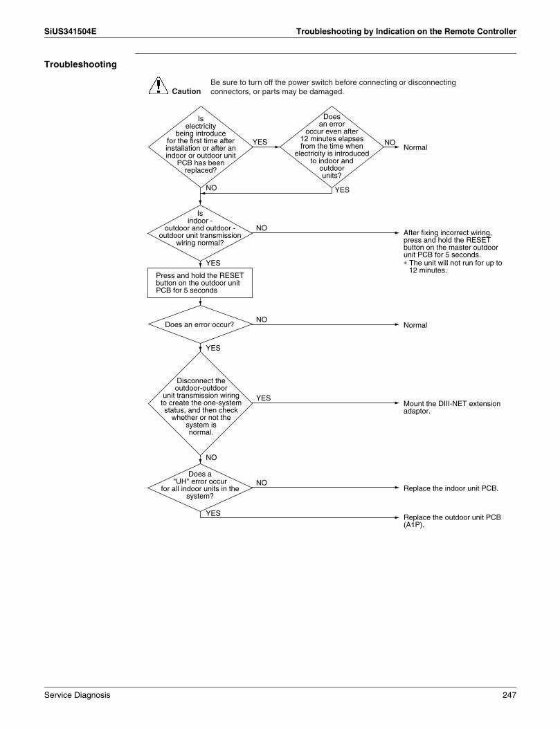
SiUS341504E Troubleshooting by Indication on the Remote Controller
Troubleshooting
Is electricity
being introduce for the first time after installation or after an indoor or outdoor unit
PCB has been replaced?
Does an error
occur even after 12 minutes elapses from the time when
electricity is introduced to indoor and
outdoor units?
Is indoor -
outdoor and outdoor - outdoor unit transmission
wiring normal?
Does a "UH" error occur
for all indoor units in the system?
Disconnect the outdoor-outdoor
unit transmission wiring to create the one-system status, and then check
whether or not the system is normal.
NO
YES
YES
After fixing incorrect wiring, press and hold the RESET button on the master outdoor unit PCB for 5 seconds.
Normal
NO
YES
NO
NormalNO
Does an error occur?
Mount the DIII-NET extension adaptor.
YES
NO
YES NO
YES
Replace the indoor unit PCB.
Replace the outdoor unit PCB (A1P).
Press and hold the RESET button on the outdoor unit PCB for 5 seconds
∗ The unit will not run for up to 12 minutes.
CautionBe sure to turn off the power switch before connecting or disconnecting connectors, or parts may be damaged.
Service Diagnosis 247

Troubleshooting by Indication on the Remote Controller SiUS341504E
3.61 Check
Check for Causes of Rise in High PressureReferring to the Fault Tree Analysis (FTA) shown below, probe the defective points.
Note: ∗1. In cooling, it is normal if the outdoor unit electronic expansion valve (main) is fully open.∗2. In heating, the indoor unit electronic expansion valve is used for “subcooled degree control”.
CHECK 1
Short circuit
Rise in high pressure
Local pressure rise
High pipe resistance
Stop valve closed
Bent or crashed pipe
Clogging of foreign materials
[In cooling] If the outdoor unit electronic expansion valve is throttled: (∗1)
Defective outdoor unit electronic expansion valve
Defective indoor unit electronic expansion valve
Defective valve coil
Defective valve body
Defective control
Defective high pressure sensor
Defective service monitor PCBDefective
high pressure control
Defective valve coil
Defective valve body
[In heating] If the indoor unit electronic expansion valve excessively throttled: (∗2)
Defective control
Defective high pressure sensor
Defective indoor unit liquid pipe thermistor
Defective service monitor PCB
[In cooling]
High suction air temperature of the condenser
[In heating]
High suction air temperature of outdoor unit
Short circuit
High outdoor air temperature
High suction air temperature of indoor unit High room
temperature
Defective suction air thermistor of indoor unit
High suction air temperature of outdoor unit
Defective outdoor air thermistor of outdoor unit
Degradation in condensing capacity
Dirty condenser
Mixing of non-condensable gas
Decreased airflow rate
Decreased fan output
Defective fan motor
Defective service monitor PCB (Including capacity setting)
High airflow passage resistance
Dirty filter
Obstacle
Excessive refrigerant charging
Improper model selection [In heating]
←Check to be sure the stop valve is open.
←Conduct visual checks for pipe conditions.
←Is there any temperature difference caused before and after the filter or branch pipe.
←Are the coil resistance and insulation normal?
←Are the electrical characteristics normal?
←Is the pressure value checked with the Service Checker corresponding to the measurement value of the pressure sensor?
←Are the coil resistance and insulation normal?
←Are the electrical characteristics normal?
←In the connector properly connected?Are the thermistor resistance characteristics normal?
←Is the pressure value checked with the Service Checker corresponding to the measurement value of the pressure sensor?
←Is the suction air temperature less than 43°C (109.4°F)?
←Is the outdoor air temperature less than 43°C (109.4°F)?
←Is the suction air temperature less than 27°C (80.6°F)?
←Is the room temperature less than 27°C (80.6°F)?
←Is the connector properly connected?Are the thermistor resistance characteristics normal?
←Is the outdoor air temperature less than 16°CWB (60.8°FWB)?
←Is the connector properly connected?Are the thermistor resistance characteristics normal?
←Is the heat exchanger clogged? (In cooling)
←Is air or else mixed in the refrigerant system?
←Can the fan motor be rotated with hands?Are the motor coil resistance and insulation normal?
←If a spare PCB is mounted, is the capacity setting properly made?
←Is the air filter clogged?
←Is there any obstacle in the airflow passage?
←Refer to the error code "F6".
←Is the indoor unit too small compared to the large-sized outdoor unit?
A temperature difference in excess of 10°C (18°F) between the inlet and the outlet is deemed to be abnormal.
248 Service Diagnosis

SiUS341504E Troubleshooting by Indication on the Remote Controller
Check for Causes of Dropping Low PressureReferring to the Fault Tree Analysis (FTA) shown below, probe the defective points.
Note: ∗1. For details of compressor capacity control while in cooling.∗2. The “low pressure protection control” includes low pressure protection control and hot gas
bypass control.∗3. In cooling, the indoor unit electronic expansion valve is used for “superheated degree control”.
CHECK 2
Abnormally drooping low pressure
(Low evaporating temperature)
[In cooling] (∗1)
Defective low pressure control
Defective compressor capacity control
Defective low pressure sensor
Defective service monitor PCB
Defective low pressure protection control
Defective low pressure sensor
Defective hot gas solenoid valveDefective service monitor PCB
[In both cooling and heating] (∗2)[In cooling] If the indoor unit electronic expansion valve is throttled too much: (∗3)
Defective indoor unit electronic expansion valve
Defective valve coil
Defective valve body
Defective control
Defective gas pipe thermistor of indoor unit
Defective liquid pipe thermistor of indoor unit
Defective service monitor PCB
[In cooling]
Low suction air temperature of the evaporator
Low suction air temperature of indoor unit
Short circuit
Low room temperature
Defective suction air thermistor of indoor unit
High pipe resistance
Abnormal piping length
Bent or crashed pipe
Clogging of foreign materials
Stop valve closedLess circulation quantity of refrigerant
Degradation in condensing capacity
Inadequate refrigerant quantity
Moisture choke
Dirty evaporator
Decreased airflow rate
Decreased fan output
Defective fan motor ←Can the fan motor be rotated with hands?Are the motor coil resistance and insulation normal?
←If a spare PCB is mounted, is the capacity setting properly made?
←Is the air filter clogged?
←Is there any obstacle in the airflow passage?
Defective service monitor PCB (Including capacity setting)
High airflow passage resistance
Dirty filter
Obstacle
Defective electronic expansion valve control
←Are the electrical characteristics normal?
←Is the pressure value checked with the Service Checker corresponding to the measurement value of the pressure sensor?
←Are the electrical characteristics normal?
←Are the coil resistance and insulation normal?
←Is the pressure value checked with the Service Checker corresponding to the measurement value of the pressure sensor?
←Are the coil resistance and insulation normal?
←Check for the thermistor resistance and connection.
←Check for the thermistor resistance and connection.
←Is the pressure value checked with the Service Checker corresponding to the measurement value of the pressure sensor?
←Is the suction air temperature more than 14˚C (57.2˚F)?
←Is the room temperature less than 14˚C (57.2˚F)?
←Is the connector properly connected?Are the thermistor resistance characteristics normal?
←Does the piping length fall in the permissible range?
←Conduct visual checks for pipe conditions.
←Is there any temperature difference caused before and after the filter or branch pipe?
←Refer to the error code "U1".
←Eliminate moisture by vacuum operation.
←Is the heat exchanger clogged?
Service Diagnosis 249

Troubleshooting by Indication on the Remote Controller SiUS341504E
Check the Factors of Overheat Operation (∗4)Identify the defective points referring to the failure factor analysis (FTA) as follows.
Note: ∗1. Refer to “Low pressure protection control” for hot gas bypass control.∗2. Refer to “Subcooling electronic expansion valve control”. ∗3. “Superheating temperature control” in cooling is conducted by indoor unit electronic expansion valve.∗4. Superheating temperature control in heating is conducted by outdoor unit electronic expansion
valve (main). ∗5. Judgement criteria of superheat operation:
(1) Suction gas superheated degree: 10°C (18°F) and over. (2) Discharge gas superheated degree: 45°C (81°F) and over, except immediately after compressor starts up or is running under drooping control.(Use the above values as a guide. Depending on the other conditions, the unit may be normal despite the values within the above range.)
CHECK 3
Abnormal piping length
Bent or crashed pipe
(Including moisture choke)
Stop valve closed.
Defective valve coil
Defective valve body
Defective valve coil
Defective valve body
←Are the coil resistance and insulation normal?
←Are the electric characteristics normal?
←Are the coil resistance and insulation normal?
←Is the connector properly connected?Are the thermistor resistance characteristics normal?
←Is the connector properly connected?Are the thermistor resistance characteristics normal?
←Are the coil resistance and insulation normal?
←Are the electric characteristics normal?
←Refer to CHECK 7
←Does the piping length fall in the permissible range?
←Conduct visual checks.
←Eliminate moisture by vacuum operation. (Refer to CHECK 8 )
←Check if the stop valve is open.
Defective discharge pipe temperature control
Defective hot gas bypass control
Hot gas circuit clogging
Defective solenoid valve coilDefective solenoid valve bodyDefective service monitor PCB
Defective service monitor PCB
Defective valve coil
Defective low pressure sensorDefective subcooling heat exchanger outlet thermistor
Defective valve body
Defective subcooling electronic expansion valve control
Superheat due to shaft damage
Superheat due to defective compressor
Defective indoor unit electronic expansion valve
Defective control
Defective control
Defective outdoor unit electronic expansion valve
Defective four way valve operation
[In cooling only]
(∗1)
(∗2)
Compressor overheat
Refrigerant shortage
High pipe resistance
Defective superheated degree control.
[In cooling]If the indoor unit electronic expansion valve is throttled too much: (∗3)
[In heading]If the outdoor unit electronic expansion valve excessively throttled: (∗4)
Temperature increase of discharge pipe
Defective subcooling electronic expansion valve
←Are the coil resistance and insulation normal?
←Is the connector properly connected?Are the thermistor resistance characteristics normal?
←Is the pressure value checked with the Service Checker corresponding to the measurement value of the pressure sensor?
←Check if the piping temperature connected to the four way valve is normal.
Four way valve is in the middle position.Leak from hot gas bypass valve
Defective control
Defective gas pipe thermistor of indoor unit
Defective thermistor for indoor unit liquid pipe
Defective service monitor PCB
Defective low pressure sensorDefective suction pipe thermistorDefective service monitor PCB ←Is the pressure value checked with the Service
Checker corresponding to the measurement value of the pressure sensor?
←Is the connector properly connected? Are the thermistor resistance characteristics normal?
250 Service Diagnosis
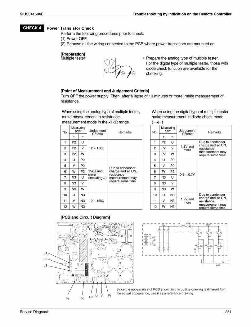
SiUS341504E Troubleshooting by Indication on the Remote Controller
Power Transistor CheckPerform the following procedures prior to check.(1) Power OFF.(2) Remove all the wiring connected to the PCB where power transistors are mounted on.
[Preparation]
[Point of Measurement and Judgement Criteria]Turn OFF the power supply. Then, after a lapse of 10 minutes or more, make measurement of resistance.
[PCB and Circuit Diagram]
CHECK 4
Multiple tester ∗ Prepare the analog type of multiple tester.For the digital type of multiple tester, those with diode check function are available for the checking.
When using the analog type of multiple tester, make measurement in resistance measurement mode in the x1kΩ range.
When using the digital type of multiple tester, make measurement in diode check mode ( )
No.Measuring
point Judgement Criteria Remarks No.
Measuring point Judgement
Criteria Remarks+ – + –
1 P2 U
2 ~ 15kΩ
1 P2 U1.2V and
more
Due to condenser charge and so ON, resistance measurement may require some time.
2 P2 V 2 P2 V
3 P2 W 3 P2 W
4 U P2
15kΩ and more (including )
Due to condenser charge and so ON, resistance measurement may require some time.
4 U P2
0.3 ~ 0.7V
5 V P2 5 V P2
6 W P2 6 W P2
7 N3 U 7 N3 U
8 N3 V 8 N3 V
9 N3 W 9 N3 W
10 U N3
2 ~ 15kΩ
10 U N31.2V and
more
Due to condenser charge and so ON, resistance measurement may require some time.
11 V N3 11 V N3
12 W N3 12 W N3
P3U V WN3
J1
J2
J3
P1
P1 P2IGBT
X11A
U V W
L1
L2
L3
X10A
DM
K2
P3
N3
J1
J2
J3
Since the appearance of PCB shown in this outline drawing is different from the actual appearance, use it as a reference drawing.
Service Diagnosis 251

Troubleshooting by Indication on the Remote Controller SiUS341504E
Check for Shortage of Refrigerant.In case of VRV Systems, the only way to judge as the shortage of refrigerant is with operating conditions due to the relationship to pressure control and electronic expansion valve control.As information for making a judgement, refer to the information below.
Diagnosis of shortage of refrigerant1. The superheated degree of suction gas rises. Consequently, the compressor discharge gas
temperature becomes higher.2. The superheated degree of suction gas rises. Consequently, the electronic expansion valve
turns open.3. Low pressure drops to cause the unit not to demonstrate cooling capacity (heating capacity).
CHECK 7
Cooling
High pressure
Low pressure
Frequency
The opening degree of the indoor unit electronic expansion valve becomes larger. Either of the electronic expansion
valves becomes fully open.
Frequency comes to the minimum level.
Fan control is activated for high pressure protection under cooling control at low outdoor air temperature, i.e., the fan is hunting at high pressure.
High pressure drops with decrease in compressor capacity.
If frequency comes to the minimum level, low pressure cannot be maintained.
Low pressure rises as the opening degree of the indoor unit electronic expansion valve becomes larger. Frequency slightly increases under the capacity control.
To maintain low pressure, frequency drops due to the capacity control.
Heating
High pressure
Low pressure
Frequency
The opening degree of the outdoor unit electronic expansion valve becomes larger.
The outdoor unit electronic expansion valve fully opens and frequency increases.
Discharge pipe or low pressure drooping control
(High pressure is maintained at a constant level.)
To maintain low pressure, frequency drops due to the capacity control.
Frequency drops due to the drooping control.
(Degree of refrigerant shortage)
Higher degree of shortageProper amount
(Low pressure is maintained at a constant level.)
Frequency comes to the minimum level.
252 Service Diagnosis

SiUS341504E Troubleshooting by Indication on the Remote Controller
Vacuuming and Dehydration ProcedureConduct vacuuming and dehydration in the piping system following the procedure for <Normal vacuuming and dehydration> described below.Furthermore, if moisture may get mixed in the piping system, follow the procedure for <Special vacuuming and dehydration> described below.
<Normal vacuuming and dehydration>(1) Vacuuming and dehydration
• Use a vacuum pump that enables vacuuming down to –100.7 kPa (–404.3 inH2O).• Connect manifold gauges to the service ports of liquid pipe and gas pipe and run the vacuum
pump for a period of 2 or more hours to conduct evacuation to –100.7 kPa (–404.3 inH2O) or less.
• If the degree of vacuum does not reach –100.7 kPa (–404.3 inH2O) or less even though evacuation is conducted for a period of 2 hours, moisture will have entered the system or refrigerant leakage will have been caused. In this case, conduct evacuation for a period of another 1 hour.
• If the degree of vacuum does not reach –100.7 kPa (–404.3 inH2O) or less even though evacuation is conducted for a period of 3 hours, conduct the leak tests.
(2) Leaving in vacuum state• Leave the compressor at the degree of vacuum of –100.7 kPa (–404.3 inH2O) or less for a
period of 1 hour or more, and then check to be sure that the vacuum gauge reading does not rise. (If the reading rises, moisture may have remained in the system or refrigerant leakage may have been caused.)
(3) Additional refrigerant charge• Purge air from the manifold gauge connection hoses, and then charge a necessary amount of
refrigerant.<Special vacuuming and dehydration> - In case of moisture may get mixed in the piping∗(1) Vacuuming and dehydration
• Follow the same procedure as that for 1) Normal vacuuming and dehydration described above.
(2) Vacuum break• Pressurize with nitrogen gas up to 0.05 MPa (200.7 inH2O).
(3) Vacuuming and dehydration• Conduct vacuuming and dehydration for a period of 1 hour or more. If the degree of vacuum
does not reach –100.7 kPa (–404.3 inH2O) or less even though evacuation is conducted for a period of 2 hours or more, repeat vacuum break - vacuuming and dehydration.
(4) Leaving in vacuum state• Leave the compressor at the degree of vacuum of –100.7 kPa (–404.3 inH2O) or less for a
period of 1 hour or more, and then check to be sure that the vacuum gauge reading does not rise.
(5) Additional refrigerant charge• Purge air from the manifold gauge connection hoses, and then charge a necessary amount of
refrigerant.
∗ In case of construction during rainy reason, if dew condensation occurs in the piping due to extended construction period, or rainwater or else may enter the piping during construction work:
CHECK 8
Service Diagnosis 253

Troubleshooting by Indication on the Remote Controller SiUS341504E
How to Check the Electronic Expansion Valve CoilRemove the connector for electronic expansion valve (X7A) from PCB. Measure the resistance value between pins and check the continuity to judge the condition.
The normal products will show the following conditions:1 No continuity between (1) and (2)2 Resistance value between (1) and (3) is approx. 300 Ω3 Resistance value between (1) and (5) is approx. 150 Ω4 Resistance value between (2) and (4) is approx. 300 Ω5 Resistance value between (2) and (6) is approx. 150 Ω
CHECK 9
1) White
2) Yellow
3) Orange
4) Blue
6) Brown
5) Red
White (1)
Red (5)
Orange (3)
φ1
φ3
φ2 φ4
M
Yellow(2)
Brown(6)
Blue(4)
254 Service Diagnosis

SiUS341504E Troubleshooting by Indication on the Remote Controller
Thermistor Resistance / Temperature Characteristics
T°C T°F kΩ T°C T°F kΩ T°C T°F kΩ–30 –22 354.1 –30 –22 361.7719 –30 –22 3257.371–25 –13 259.7 –25 –13 265.4704 –25 –13 2429.222–20 –4 192.6 –20 –4 196.9198 –20 –4 1827.883–15 5 144.2 –15 5 147.5687 –15 5 1387.099–10 14 109.1 –10 14 111.6578 –10 14 1061.098–5 23 83.25 –5 23 85.2610 –5 23 817.93290 32 64.10 0 32 65.6705 0 32 635.08315 41 49.70 5 41 50.9947 5 41 496.5712
10 50 38.85 10 50 39.9149 10 50 391.007015 59 30.61 15 59 31.4796 15 59 309.951120 68 24.29 20 68 25.0060 20 68 247.269625 77 19.41 25 77 20.0000 25 77 198.467430 86 15.61 30 86 16.1008 30 86 160.224435 95 12.64 35 95 13.0426 35 95 130.069740 104 10.30 40 104 10.6281 40 104 106.151745 113 8.439 45 113 8.7097 45 113 87.072550 122 6.954 50 122 7.1764 50 122 71.770355 131 5.761 55 131 5.9407 55 131 59.473560 140 4.797 60 140 4.9439 60 140 49.518065 149 4.014 65 149 4.1352 65 149 41.416870 158 3.375 70 158 3.4757 70 158 34.792375 167 2.851 75 167 2.9349 75 167 29.349980 176 2.418 80 176 2.4894 80 176 24.858685 185 2.060 85 185 2.1205 85 185 21.136090 194 1.762 90 194 1.8138 90 194 18.037795 203 1.513 95 203 1.5575 95 203 15.4487
100 212 1.304 100 212 1.3425 100 212 13.2768105 221 1.128 105 221 1.1614 105 221 11.4395110 230 0.9790 3SA48001 (AD87A001J) 110 230 9.8902115 239 0.8527 115 239 8.5788120 248 0.7450 120 248 7.4650125 257 0.6530 125 257 6.5156130 266 0.5741 130 266 5.7038
3PA61998L (AD92A057) 135 275 5.0073140 284 4.4080145 293 3.8907150 302 3.4429
3SA48006 (AD87A001J)
CHECK 11
Outdoor unitRefer to the table A below.
Outdoor unitFor discharge pipe R2T
R21TR22TR31TR32T
Table A
Thermistor REYQ72TYDNREYQ72TTJU
REYQ96-120TYDNREYQ96-120TTJU
REYQ144-168TYDNREYQ144-168TTJU
Outdoor air R1T R1T R1TCompressor surface temperature thermistor R14T — R14T
Comp. Suction R12T R12T R12TSuction air R10T R10T R10TH.E, deicer R11T R11T R11T
H.E. gas R8TR9T
R8TR9T
R8TR9T
Receiver inlet R3T R3T R3TSubcooling H.E. liquid R7T R7T R7T
H.E. liquid R4TR5T
R4TR5T
R4TR5T
Subcooling H.E. gas R6T R6T R6TReceiver gas purge R13T R13T R13T
Service Diagnosis 255

Troubleshooting by Indication on the Remote Controller SiUS341504E
Pressure SensorCHECK 12
High Pressure (PH)
0
0 0.5 1 1.5 2 2.5 3 3.5 4
(VDC)
–5.1 –0.5–0.5
PH, PL
MPa51.0
45.9
40.8
35.7
30.6
25.5
20.4
15.3
10.2
5.1
5.0
4.5
4.0
3.5
3.0
2.5
2.0
1.5
1.0
0.5
0
(kgf/cm2)
–167
1673
1505
1338
1171
1004
836
669
502
335
167
0
(ftH2O)
PH (MPa) = × VH – × 0.5
PL (MPa) = × VL – × 0.5
1 MPa = 334.6 ftH2O
PH : High pressurePL : Low pressureVH : Output Voltage (High Side) (VDC)VL : Output Voltage (Low Side) (VDC)
Low Pressure (PL)
4.153.0
4.153.0
1.73.0
1.73.0
Output Voltage (VH, VL)
Detected Pressure
256 Service Diagnosis

SiUS341504E Troubleshooting by Indication on the Remote Controller
Make Measurement of Voltage of the High Pressure Sensor
Make Measurement of Voltage of the Low Pressure Sensor
CHECK 13
+5 V
(4)
(3)
(2)
(1)
Red
Black
White
Connector for high pressure sensor (Red)
High pressure sensor
Micro-computer A/D input
Make measurement of DC voltage between these wires.
CHECK 14
+5 V
(4)
(3)
(2)
(1)
Connector for low pressure sensor
Micro-computer A/D input
Make measurement of DC voltage between these wires.
(Blue)
Red
Black
White
Low pressure sensor
Service Diagnosis 257

Troubleshooting by Indication on the Remote Controller SiUS341504E
Broken Wire Check of the Relay Wires1. Procedure for checking outdoor-outdoor unit transmission wiring for broken wires
On the system shown below, turn OFF the power supply to all equipment, short circuit between the outdoor-outdoor unit terminal F1 and F2 in the "Outdoor Unit A" that is farthest from the central remote controller, and then conduct continuity checks between the transmission wiring terminal blocks F1 and F2 of the central remote controller using a multiple meter. If there is continuity between the said terminal blocks, the outdoor-outdoor unit transmission wiring has no broken wires in it.If there is no continuity, the transmission wiring may have broken wires. With the outdoor-outdoor unit terminal of the "Outdoor Unit A" short circuited, conduct continuity checks between the transmission wiring terminal blocks F1 and F2 of the unified ON/OFF controller. If there is no continuity as well, conduct continuity checks between the outdoor-outdoor unit terminal of the "Outdoor Unit E", between the outdoor-outdoor unit terminal of the "Outdoor Unit D", between the outdoor-outdoor unit terminal of the "Outdoor Unit C", … in the order described, thus identifying the place with continuity.If the place with continuity can be identified, there may be broken wires in places before the said place with continuity.
2. Procedure for checking indoor-outdoor unit transmission wiring for broken wires (for checking the indoor-outdoor unit transmission wiring of the "Outdoor Unit C" for broken wires)Turn OFF the power supply to all equipment, short circuit between the indoor-outdoor unit terminal F1 and F2 in the "Outdoor Unit C, and then conduct continuity checks between the transmission wirings F1 and F2 of the "Indoor Unit a" that is farthest from the "Outdoor Unit C" using a multiple meter. If there is continuity between the said transmission wirings, the indoor-outdoor unit transmission wiring has no broken wires in it.If there is no continuity, the transmission wiring may have broken wires. With the indoor-outdoor unit terminal of the "Outdoor Unit C" short circuited, identify the place with continuity in the transmission wiring of the "Indoor Unit b", transmission wiring of the "Indoor Unit c", and transmission wiring of the "Indoor Unit d" in the order described.If the place with continuity can be identified, there may be broken wires in places before the said place with continuity.
CHECK 15
Short circuit between the outdoor-outdoor unit terminal parts.
Outdoor-outdoor Unit Transmission Wiring
Check the transmission wiring for continuity.If there is continuity, the indoor-outdoor unit transmission has no broken wires in it.
Indoor-outdoor Unit Transmission Wiring
Short circuit between the indoor-outdoor unit terminal parts.
Check the transmission wiring for continuity.If there is continuity, the outdoor-outdoor unit transmission has no broken wires in it.
Unified ON/OFF controller Central remote controller
258 Service Diagnosis

SiUS341504E Troubleshooting by Indication on the Remote Controller
Check on Connector of Fan Motor (Power Supply Cable)(1) Turn OFF the power supply.
Measure the resistance between phases of U, V, W at the motor side connectors (3-core wire) to check that the values are balanced and there is no short circuiting, while connector or relay connector is disconnected.
(1) Turn OFF the power supply.(2) Measure the resistance between Vcc and each phase of U, V, W, and GND and each phase at
the motor side connectors (5-core wire) to check that the values are balanced within the range of ± 20 %, while connector or relay connector is disconnected.Furthermore, to use a multiple meter for measurement, connect the probe of negative pole to Vcc and that of positive pole to GND.
CHECK 16
Measure the resistance values between phases U, V, W.
Red
White
Black W
V
U
CHECK 17
Measure the resistance values between Vcc and U, V, W, and GND and U, V, W.
GND
Vcc
W
V
U
5 Gray
4 Pink
3 Orange
2 Blue
1 Yellow
Service Diagnosis 259

SiUS341504E
260 Appendix
Part 7Appendix
1. Wiring Diagrams......................................................................................2611.1 Outdoor Units ........................................................................................... 2611.2 Indoor Units .............................................................................................. 267

SiUS341504E Wiring Diagrams
1. Wiring Diagrams1.1 Outdoor UnitsREYQ72TYDN
ONOFF
ONOFF
R1T
M
M
Y2E
Y1E
S1NPL
S1NPH
5
5
t˚
5
M
t˚
Y3E
Q2
R7T
X31A
X18A
X21A
X22A
X32A
PS
X23A
Q1
OUTDOOR
t˚
5
R6T
M
K13R
4
Y4E
BS3
3
SEG3
Y6S
F2
X17A
DS2
2
X37A
X25A
t˚
1
R5T
X30A
K12R
F1
OUTDOOR
BS2
SEG2
Y5S
X16A
t˚
4
R4T
3
DS1
2
F2
HAP
1
K11R
BS1
SEG1
t˚
Y3S
R3T
X15A
INDOOR
F1
t˚
K9R
R14T
Y4S
X13A
S1S
X19A
GRY
GRYX14A
C
t˚
R2T
B
X1A
E1HC
K7R
t˚
S2S
A
R10T
X11A
C/H SELECTOR
X66A
HEAT
COOL
t˚
GRY
GRYX13A
X1M
A9P
R9T
X29A
K3R
F1U
Y1S
F2U
X7A
t˚
Q1LD
K6R
R8T
X2A
X3A
X42A
X4A
X28A
X36A
L1R
A3P
L2R
X1A
X101A
A1P
X10A
X20A
A2P
A4P
A10PX10A
P>
BLURED
RED
S1PH
T1RA11P
BLU
X1A
X9AA12P
A9PX3A
RE
DX2A
CONTROL BOX
CONTROL BOX (2)
A1P
5
A8P
T1R
M
X1M
X8A
X7A
YLW
F1U
T2
RED
BLK
BLK
3
X10A
Y6E
t˚R15T
S
WHT
RED
BLK
PS
X1AX2A
5
2
M
R
t˚RE
D
Z5C N=2
R12T
X8A
WHT
X2AWHT
Y5E
X15A
X5A
X4A
t˚
A12P
BLU
BLU
X9A
5
R11T
HAP
RE
D
X2A
t˚
5
R13T
X3A
X17A
X2A
V1R
N1
R24
BLK
A8P
Z2F
L3AW
HT
X10A
L2A
M1F
F101U
P1
RED
L1A
+
BLU
X11A
X1A
X1A
X1A
X3A
WHT
WHT
WHT
WHT
WHT
WHT
WHT
WHT
WHT
WHT
WHT
X3A
A4P
X3A
RE
D
X1A
R1
:
L32
K1R
BLU
REDBLK
A11P
L31
RE
D
P5N5P4N4
BLU
W
V
X4A
X2A
A10P
X6A
X601A
X602A
X63A
RE
DF6
01U
PS
BLU
K3R
L12
U
RE
D
X41A
L11
V2R
BLK
RED
WHT
R313
X1M
BLK
BLK
-
-
-
L1
L3
L2
W
W
L3B
L3A
L3B
C48
R854
+
F403U
WH
TW
HT
V
V
Z1F
V1R
L2B
L2A
L2B
C47
U
R851
+
RE
D+
+R
ED
M1C
OUTER SHELL
U
M1C
L1B
L1A
L1B
WH
T
K1M
CONTROL BOX (2)
F401U
CONTROL BOX
P11
P21
L2R
A2P
A3P
GRN
WH
T
M1F
L1R
LAYOUT OF M1C, M1F
WH
T3~ 460V 60Hz
L1
L3
L2
POWER SUPPLY
T1A N=1
TO X101A (A1P)
(Q1) (Q2)(F1) (F2)
(NOTE 4) (NOTE 4) (NOTE 4)
(F1) (F2)
(REAR SIDE)(FRONT SIDE)
(NOTE 3)
(NOTE 3)
E
Z1C N=1
OUTPUT 230V
FROM T1A
Z2C N=1Z3C N=1
Z4C N=2
MS 3~
MS 3~
TERMINAL OF M1C
IS CONNECTOR COLOR FOR COMPONENT.
HEAT
COOL
FAN
·
COOL/HEAT SELECTOR (OPTIONAL ACCESSORY) (NOTE 3)
X1M (NOTE 8)TO IN/D UNIT TO OUT/D UNIT TO MULTI UNIT
(NOTE 8)
Z6C N=2
A1PA2PA3PA4PA8PA9PA10PA11PA12PBS1~BS3
C47, C48DS1, DS2E1HCF1U, F2UF1UF101UF401U, F403UF601UHAP
K1MK1RK3RK3RK6RK7RK9RK11RK12RK13R
L1R, L2RM1CM1FPSQ1LDR1R24R313R851, 854R1TR2TR3TR4TR5TR6TR7TR8TR9TR10TR11TR12TR13TR14TR15TS1NPHS1NPLS1PHSEG1~SEG3T1AT1RV1R
V1RV2RX1A, X2AX3AX7A~X11AX13A, X14AX1MX1MX1MY1EY2EY3EY4EY5EY6EY1SY3SY4SY5SY6SZ1C~Z6CZ1FZ2F
X10AX37A
S1SS2S
POWER MODULE (A4P)POWER MODULE (A3P)CONNECTOR (M1F)CONNECTOR (CHECK THE RESIDUAL CHARGE)CONNECTOR (CONTROL BOX (2))CONNECTOR (E1HC)TERMINAL STRIP (POWER SUPPLY)TERMINAL STRIP (CONTROL) (A1P)TERMINAL STRIP (ABC I/P) (A9P)ELECTRONIC EXPANSION VALVE (HEAT EXC. UPPER)ELECTRONIC EXPANSION VALVE (SUBCOOLING HEAT EXC.)ELECTRONIC EXPANSION VALVE (HEAT EXC. LOWER)ELECTRONIC EXPANSION VALVE (RECEIVER GAS PURGE)ELECTRONIC EXPANSION VALVE (REFRIGERANT COOLING)ELECTRONIC EXPANSION VALVE (LEAK DETECTION)SOLENOID VALVE (OS OIL RETURN)SOLENOID VALVE (LIQUID SHUTOFF)FOUR WAY VALVE (HP/LP GAS)FOUR WAY VALVE (HEAT EXC. LOWER)FOUR WAY VALVE (HEAT EXC. UPPER)NOISE FILTER (FERRITE CORE)NOISE FILTER (A2P) (WITH SURGE ABSORBER)NOISE FILTER (A11P)
CONNECTOR FOR OPTIONAL ACCESSORIESCONNECTOR (DRAIN PAN HEATER) (A1P)CONNECTOR (POWER ADAPTOR) (A1P)
COOL/HEAT SELECTORSELECTOR SWITCH (FAN/COOL·HEAT)SELECTOR SWITCH (COOL/HEAT)
REACTORMOTOR (COMPRESSOR)MOTOR (FAN)SWITCHING POWER SUPPLY (A1P, A3P, A8P)LEAKAGE DETECTION CIRCUIT (A1P)RESISTOR (CURRENT LIMITING) (A10P)RESISTOR (CURRENT SENSOR) (A4P)RESISTOR (CURRENT SENSOR) (A3P)RESISTOR (A3P)THERMISTOR (AIR)THERMISTOR (M1C DISCHARGE)THERMISTOR (RECEIVER INLET)THERMISTOR (HEAT EXC. LIQUID UPPER)THERMISTOR (HEAT EXC. LIQUID LOWER)THERMISTOR (SUBCOOLING GAS)THERMISTOR (SUBCOOLING LIQUID)THERMISTOR (HEAT EXC. GAS UPPER)THERMISTOR (HEAT EXC. GAS LOWER)THERMISTOR (SUCTION)THERMISTOR (DEICER)THERMISTOR (COMP. SUCTION)THERMISTOR (RECEIVER GAS PURGE)THERMISTOR (M1C BODY)THERMISTOR (LEAK DETECTION)PRESSURE SENSOR (HIGH)PRESSURE SENSOR (LOW)PRESSURE SWITCH (HIGH)7-SEGMENT DISPLAY (A1P)CURRENT SENSORTRANSFORMER (460V/230V)POWER MODULE (A3P)
PRINTED CIRCUIT BOARD (MAIN)PRINTED CIRCUIT BOARD (NOISE FILTER)PRINTED CIRCUIT BOARD (INV.)PRINTED CIRCUIT BOARD (FAN)PRINTED CIRCUIT BOARD (SUB)PRINTED CIRCUIT BOARD (ABC I/P)PRINTED CIRCUIT BOARD (CURRENT LIMITING)PRINTED CIRCUIT BOARD (NOISE FILTER)PRINTED CIRCUIT BOARD (OPEN PHASE PROTECTION)BS BUTTON (A1P) (MODE, SET, RETURN)CAPACITOR (A3P)DIP SWITCH (A1P)CRANKCASE HEATERFUSE (A1P)FUSE (A8P)FUSE (A4P)FUSE (A2P)FUSE (A3P)PILOT LAMP (A1P, A8P) (SERVICE MONITOR-GREEN)MAGNETIC CONTACTOR (M1C) (A3P)MAGNETIC RELAY (A10P)MAGNETIC RELAY (A3P)MAGNETIC RELAY (Y1S) (A1P)MAGNETIC RELAY (OPTION) (A1P)MAGNETIC RELAY (E1HC) (A1P)MAGNETIC RELAY (Y4S) (A1P)MAGNETIC RELAY (Y3S) (A1P)MAGNETIC RELAY (Y5S) (A1P)MAGNETIC MAGNETIC (Y6S) (A1P)
1. THIS WIRING DIAGRAM APPLIES ONLY TO THE OUTDOOR UNIT.2. : FIELD WIRING, : TERMINAL BLOCK, : CONNECTOR,
: TERMINAL, : PROTECTIVE EARTH (SCREW), : NOISELESS EARTH.3. WHEN USING THE OPTIONAL ADAPTOR, REFER TO THE INSTALLATION
MANUAL OF THE OPTIONAL ADAPTOR.4. FOR CONNECTION WIRING TO INDOOR-OUTDOOR TRANSMISSION F1·F2,
OUTDOOR-OUTDOOR TRANSMISSION F1·F2, OUTDOOR-MULTI TRANSMISSION Q1·Q2, REFER TO THE INSTALLATION MANUAL.
5. HOW TO USE BS1~3 SWITCH, REFER TO "SERVICE PRECAUTION" LABEL ON CONTROL BOX COVER.
6. WHEN OPERATING, DO NOT SHORT-CIRCUIT THE PROTECTION DEVICE (S1PH).7. COLORS BLK: BLACK; RED: RED; BLU: BLUE; WHT: WHITE; GRN: GREEN; GRY: GRAY; YLW: YELLOW8. CLASS 2 WIRE
NOTES)
C: 3D089800D
Appendix 261

Wiring Diagrams SiUS341504E
REYQ96 / 120TYDN
1. TH
IS W
IRIN
G DI
AGRA
M A
PPLI
ES O
NLY
TO T
HE O
UTDO
OR U
NIT.
2.: F
IELD
WIR
ING,
: TE
RMIN
AL B
LOCK
,
: CON
NECT
OR,
:TER
MIN
AL,
: PRO
TECT
IVE
EART
H (S
CREW
),
: N
OISE
LESS
EAR
TH.
3. W
HEN
USIN
G TH
E OP
TION
AL A
DAPT
OR, R
EFER
TO T
HE IN
STAL
LATI
ON M
ANUA
L
OF T
HE O
PTIO
NAL
ADAP
TOR.
4. FO
R CO
NNEC
TION
WIR
ING
TO IN
DOOR
-OUT
DOOR
TRA
NSM
ISSI
ON F
1•F2
,
OUTD
OOR-
OUTD
OOR
TRAN
SMIS
SION
F1•
F2, O
UTDO
OR-M
ULTI
TRAN
SMIS
SION
Q1•
Q2, R
EFER
TO T
HE IN
STAL
LATI
ON M
ANUA
L.
5. HO
W TO
USE
BS1
~3 S
WIT
CH, R
EFER
TO "S
ERVI
CE P
RECA
UTIO
N" L
ABEL
ON
CONT
ROL
BOX
COVE
R.
6. W
HEN
OPER
ATIN
G, D
O NO
T SH
ORT-C
IRCU
IT T
HE P
ROTE
CTIO
N DE
VICE
(S1P
H, S
2PH)
.
7. CO
LORS
BLK
: BLA
CK; R
ED: R
ED; B
LU: B
LUE;
WHT
: WHI
TE; G
RN: G
REEN
; GRY
: GRA
Y; Y
LW: Y
ELLO
W.
8. CL
ASS
2 WIR
E
WHT
WHT
A1P
X7A
X8A
X1A
RED
X1M
WHT
F1U
WHT
X25A
RED
Y4E
BLU
PS
L1L1
5 5 5 5
M M M M
WHT
RED
F2U
T1R
L2L2
K7R
K4R
K3R
K8R
BLKBLK
RED
RED
RED
BLK
WHT
RED
BLK
WHT
BLK
K6R
X10A
A2P
A5P
X23A
Y3E
L3L3
SEG2
SEG3
SEG1
X11A
X8A
X7A
X12A
(NO
TE
3)
L2A
L1A
L3A
L2A
L1A
L3A
L2B
L1B
L3B
L2B
L1B
L3B
X10
1A
K11R
K9R
K13R
K12R
F401
UF4
03UF4
01U
F403U
BS3
BS1
BS2
Y2S
Y1S
X22A
Q1L
DY2
EX1
7AX1
5AX1
3AX1
6AGR
NGR
NE
ED
S1
DS
2Z1
FZ1
FGR
YYLW
YLWGR
YR1
3TR1
5TR1
1TR1
2TX
4AX1
4AX1
5AX1
6AX1
3A12
3412
34Y1
EP> P>
BLURED
t˚t˚
t˚t˚
t˚t˚
t˚t˚
t˚t˚
t˚t˚
t˚t˚
t˚
X21A
A8P
Y6S
Y3S
Y4S
Y5S
S2P
HE
2HC
YLWGR
YYLW
GRY
E1H
CX1
AX
3AX
37A
R9T
R10T
R8T
R6T
R5T
R3T
R4T
R7T
R22T
R21T
X15
AX
17A
X18A
R1T
S1P
HF1
UH
AP
(NOT
E 3)
X2A
PS
S1NP
LH
AP
X31A
X29
AX
30A
X19
AX
8AX
10A
X3A
X1M
(N
OT
E 8
)X2
0AX
2A
BLK
RED
BLK
REDWHT
WHT
A6P
A3P
X32A
A9P
S1NP
HA
7PX
63A
X1M
(N
OT
E 8
)5
5F
1Q
2Q
1F
2F
2F
1L2
BL1
BL3
BL2
BL1
BL3
BX3
ARE
DRE
DX1
AF6
01U
F601
UM
M+
K3R
K3R
C/H
SELE
CTOR
X1A
WHT
WHT
X3A
P11
HE
ATY6
EY
5EX6
1AX6
6AX6
AA
X41A
P1
F101
UX4
1AK
84R
K84
RCO
OL
X62A
-X1
2AS
2SZ8
C N=
9N
11K2
MK2
MX4
AK1
MK1
MM
2F(N
OTE
4)(N
OTE
4)(N
OTE
4)X2
8AN
1R2
4V1
RX5
A5
R1
R1
X41A
X40A
S1S
++
++
5-
-V1
RV1
RX2
AX5
AP
1P
1P
SP
S X4A
(NO
TE
3)
X4A
RED
X4A
C66
C32
RED
WHT
C32
C66
X6A
++
A4P
P2
NOTE
S)
P2
X63
AX3
AR1
2R1
2R1
1R1
1
+
X1A
CONT
ROL
BOX
(2)
WHT
WHT X
1AC
ON
TR
OL
BO
XW
RED
P11
F101
UR
77R
77
-
T1R
X6A
X5A
UA1
PA8
P+
+-
-A5
PA2
PM
1FX7
AB
LKN1
1V
R24
V1R
V1R
V1R
L2R
5X1
MA9
PX8
AP
3N3
P3
N3W
A3P
VA6
PU
WV
U5
L1R
X3A
X1A
X2A
RED
BLK
RED
BLK
X5A
X4A
X2A
X5A
BLK
RED
WHT
BLK
RED
WHT
X4A
M2F
M1F
CONT
ROL
BOX
X2A
WHT
WHT
WHT
WHT
WHT
WHT
VWH
TX
6AW
UV
WU
CONT
ROL
BOX
(2)
M2C
L2R
L1R
M1C
M1C
M2C
WHT
OUT
ER S
HELL
A8P
A9P
BS1~
BS3
C32
, C66
DS1
, DS2
E1HC
, E2H
CF
1UF
2UF
101U
F401
U, F4
03U
F60
1UH
AP
K1M
, K2M
K3R
K3R
K4R
K6R
K7R
K8R
K9R
K11
RK
12R
K13
RK
84R
L1R
, L2R
M1C
, M2C
M1F
, M2F
PS
Q1L
DR
1R
11, R
12R
24R
77R
1TR
21T
R22
TR
3TR
4TR
5TR
6TR
7TR
8TR
9T
PRIN
TED
CIR
CU
IT B
OAR
D (S
UB)
PRIN
TED
CIRC
UIT
BOAR
D (A
BC I/
P)B
S B
UT
TON
(A
1P)
(MO
DE
, SE
T, R
ET
UR
N)
CA
PAC
ITO
R (
A3P
, A6P
)D
IP S
WIT
CH
(A
1P)
CR
AN
KC
AS
E H
EAT
ER
FU
SE
(A
1P, A
8P)
FU
SE
(A
1P)
FU
SE
(A
4P, A
7P)
FU
SE
(A
2P, A
5P)
FU
SE
(A
3P, A
6P)
PIL
OT
LA
MP
(A
1P, A
8P)
(SE
RV
ICE
MO
NIT
OR
-GR
EE
N)
MAG
NETI
C CO
NTAC
TOR
(A3P
, A6P
)M
AG
NE
TIC
RE
LAY
(A
3P, A
6P)
MA
GN
ETI
C R
ELA
Y (Y
1S) (
A1P
)M
AG
NE
TIC
RE
LAY
(Y2S
) (A
1P)
MAG
NET
IC R
ELAY
(OPT
ION
) (A1
P)M
AGN
ETI
C R
ELA
Y (E
1HC
) (A
1P)
MAG
NE
TIC
RE
LAY
(E2H
C) (
A1P
)M
AG
NE
TIC
RE
LAY
(Y4S
) (A
1P)
MA
GN
ETI
C R
ELA
Y (Y
3S) (
A1P
)M
AG
NE
TIC
RE
LAY
(Y5S
) (A
1P)
MA
GN
ETI
C R
ELA
Y (Y
6S) (
A1P
)M
AG
NE
TIC
RE
LAY
(A3P
) (A
6P)
RE
AC
TOR
MO
TOR
(C
OM
PR
ES
SO
R)
MO
TOR
(FA
N)
SWITC
HING
POW
ER S
UPPL
Y (A
1P, A
3P, A
6P, A
8P)
LEAK
AGE
DETE
CTIO
N CI
RCUI
T (A
1P)
RESI
STOR
(CUR
RENT
LIMI
TING
) (A3
P, A6
P)R
ES
ISTO
R (
A3P
, A6P
)RE
SIST
OR (C
URRE
NT S
ENSO
R) (A
4P, A
7P)
RESI
STOR
(CUR
RENT
SEN
SOR)
(A3P
, A6P
)T
HE
RM
ISTO
R (
AIR
)TH
ERM
ISTO
R (M
1C D
ISC
HAR
GE)
THER
MIS
TOR
(M2C
DIS
CH
ARG
E)TH
ERM
ISTO
R (R
ECEI
VER
INLE
T)TH
ERMI
STOR
(HEA
T EX
C. LI
QUID
UPP
ER)
THER
MIST
OR (H
EAT
EXC.
LIQU
ID LO
WER
)TH
ERM
ISTO
R (S
UBCO
OLI
NG G
AS)
THER
MIS
TOR
(SUB
COO
LING
LIQ
UID)
THER
MIS
TOR
(HEA
T EX
C. G
AS U
PPER
)TH
ERM
ISTO
R (H
EAT
EXC.
GAS
LOW
ER)
R10
TR
11T
R12
TR
13T
R15
TS
1NP
HS
1NP
LS1
PH, S
2PH
SEG1
~SEG
3T
1AT
1RV
1RV
1RX1
A~X4
AX5
A, X
6A
X7A,
X8A
X12
AX1
3A~X
16A
X1M
X1M
X1M
Y1E
Y2E
Y3E
Y4E
Y5E
Y6E
Y1S
Y2S
Y3S
Y4S
Y5S
Y6S
Z1C~
Z8C
Z1F
X10
AX
37A
S1S
S2S
TH
ER
MIS
TOR
(S
UC
TIO
N)
TH
ER
MIS
TOR
(D
EIC
ER
)TH
ER
MIS
TOR
(CO
MP
SU
CTI
ON
)TH
ERM
ISTO
R (R
ECEI
VER
GAS
PURG
E)TH
ERM
ISTO
R (L
EAK
DET
ECTI
ON
)P
RE
SS
UR
E S
EN
SO
R (
HIG
H)
PR
ES
SU
RE
SE
NS
OR
(LO
W)
PR
ES
SU
RE
SW
ITC
H (
HIG
H)
7-S
EG
ME
NT
DIS
PLA
Y (
A1P
)C
UR
RE
NT
SE
NS
OR
TR
AN
SF
OR
ME
R (
460V
/230
V)
PO
WE
R M
OD
ULE
(A
3P, A
6P)
PO
WE
R M
OD
ULE
(A
4P, A
7P)
CO
NN
EC
TOR
(M
1F, M
2F)
CO
NN
ECTO
R
(CH
ECK
THE
RES
IDUA
L C
HAR
GE)
CO
NN
EC
TOR
(T
1R)
CO
NN
EC
TOR
CO
NN
EC
TOR
(E
1HC
, E2H
C)
TERM
INAL
STR
IP (P
OW
ER S
UPPL
Y)TE
RMIN
AL S
TRIP
(CO
NTRO
L) (A
1P)
TER
MIN
AL
STR
IP (A
BC
I/P
) (A
9P)
ELEC
TRON
IC EX
PANS
ION V
ALVE
(HEA
T EXC
. UPP
ER)
ELEC
TRO
NIC
EXP
ANSI
ON
VAL
VE
(SU
BCO
OLI
NG
HEA
T EX
C.)
ELEC
TRON
IC EX
PANS
ION V
ALVE
(HEA
T EXC
. LOW
ER)
ELEC
TRON
IC EX
PANS
ION VA
LVE (
RECE
IVER G
AS PU
RGE)
ELEC
TRON
IC EX
PANS
ION VA
LVE (
REFR
IGERA
NT CO
OLING
)EL
ECTR
ONIC
EXPA
NSIO
N VAL
VE (L
EAK D
ETEC
TION)
SOLE
NOID
VAL
VE (O
S O
IL R
ETUR
N 1)
SOLE
NOID
VAL
VE (O
S O
IL R
ETUR
N 2)
SOLE
NOID
VAL
VE (L
IQUI
D SH
UTO
FF)
FOU
R W
AY V
ALV
E (H
P/L
P G
AS
)FO
UR W
AY V
ALVE
(HEA
T EX
C. L
OWER
)FO
UR W
AY V
ALVE
(HEA
T EX
C. U
PPER
)N
OIS
E F
ILTE
R (F
ER
RIT
E C
OR
E)
NO
ISE
FIL
TE
R (
A2P
, A5P
) (W
ITH
SU
RG
E A
BS
OR
BE
R)
CONN
ECTO
R FO
R O
PTIO
NAL
ACCE
SSO
RIES
CONN
ECTO
R (D
RAIN
PAN
HEAT
ER) (
A1P)
CONN
ECTO
R (P
OWER
ADA
PTOR
) (A1
P)
CO
OL/
HE
AT S
ELE
CTO
RSE
LECT
OR S
WIT
CH (F
AN/C
OOL•
HEAT
)SE
LEC
TOR
SW
ITC
H (C
OO
L/H
EAT)
PO
WE
R S
UP
PLY
3~
460
V 6
0Hz
T1A
N=1
Z7C
N
=1
Z7C
N
=1
A1P
A2P
, A5P
A3P
, A6P
A4P
, A7P
PRIN
TED
CIR
CU
IT B
OAR
D (M
AIN
)PR
INTE
D CI
RCUI
T BO
ARD
(NOI
SE F
ILTER
)P
RIN
TED
CIR
CU
IT B
OA
RD
(IN
V.)
PR
INTE
D C
IRC
UIT
BO
AR
D (F
AN
)
:
IS
CONN
ECTO
R CO
LOR
FOR
COM
PONE
NT.
:
IS M
ARKI
NG
CO
LOR
O
N C
ON
NEC
TOR
.
MS
3 ~ MS
3 ~
Z4C
N
=2
Z3C
N
=2
Z5C
N=1
Z6C
N=1
Z6C
N
=1IN
DO
OR
(F
1) (
F2)
OU
TDO
OR
(F
1) (
F2)
OU
TDO
OR
(Q
1) (
Q2)
CO
OL
• H
EAT
FA
N
CO
OL/
HEA
T SE
LEC
TOR
(O
PTIO
NAL
AC
CES
SORY
)
BC
TERM
INAL
OF
M1C
, M2C
LAY
OU
T O
F
M1C
, M2C
, M1F
, M2F
MS
3~M
S 3 ~
Z1C
N=5
Z2C
N=5
Z5C
N=1
Z6C
N=1
OUT
PUT
230V
ON
OFF
ON
O
FF
TO IN
/D U
NITT
O OUT
/D UN
ITTO
MULTI
UNIT
A7P
A4P
2D08
9801
B
262 Appendix

SiUS341504E Wiring Diagrams
REYQ144 / 168TYDN
A1P
RED
X1A
X7A
WHT
X25A
F1U
RED
RED
RED
Y4E
X9A
BLU
PS
BLK
BLK
RED
RED
L1
WHT
WHT
A2P
5L1
MW
HTWH
TL1
AL3
AL2
AL1
AL3
AL2
ARE
DF
2UT1
R
K3R
K7R
K8R
K4R
L2L2
BLK
X23A
RED
BLU
X7A
X11A
X12A
X8A
Y3E
A10P
X10A
K6R
L3
RED
BLU
L3BL
KBL
KSE
G3SE
G2SE
G1F4
03U
5F4
01U
K9R
K13R
K11R
L32
L31
K12R
MX8
AR
1K1
RG
RN
EE
X17A
X16A
X15A
X13A
Z1F
X101
AY2
SY1
SX2
2AA11
P
RED
BS3
REDBLU
BS2
BS1
BLKWHT
Y2E
FROM
X1A
5Q
1LD
X1A
X2A
RED
BLK
DS
1D
S2
WHT
ML3
AL2
AL1
AL2
BL1
BL3
BL1
BL2
BL3
BT1
AGR
YGR
YYLW
YLWA1
2PY6
SY3
SY5
SY4
SX1
5AX1
4AX
13A
X16A
ST2
X4A
R12
3412
34Y1
EX2
1AGR
YGR
YYLW
YLW5
32
E2H
CE
1HC
MS2
PHX
37A
BLU
R6T
R7T
R14T
R4T
R10T
R5T
R22T
R8T
R9T
R3T
R21T
X3A
R1T
X18A
YLW
HA
PS1
PHS1
NPL
R11T
R13T
R12T
R15T
X1M
X31A
X2A
WHT
RED
REDBLU
BLU
RED
RED
BLK
BLK
X30
AX
29A
X19
A
REDBLU
WHT
WHT
A3P
A6P
A8P
X10
AL3
BL2
BL1
BL3
BL2
BL1
BX3
2AA
9PA
7PQ
2F
2F
1F
1F
2Q
1X1
AX
15A
X17A
S1NP
HWH
TL1
2L1
1X4
1ARE
DRE
DF1
UX1
M ( N
OTE
8)
+
K3R
WHT
X1A
PSX
66A
P11
HA
PH
EAT
P1X3
AX
8AX
10A
X61A
K84R
X20A
X2A
CO
OL
-CO
OLN1
1K3
R5
5S
2SX6
AK2
MK1
MK1
MH
EAT
M2F
MM
N1X6
2AY
5EY6
EFA
N5
X36A
X5A
X41A
X4A
5
+
+
-V1
R-V1
RS1
SX4
AX4
1AX5
AX
2APS
P11
P1
X6A
X12
AWH
TC3
2C6
6C4
8C4
7+
++
+A
4PX2
8APS
P21
P2
X3A
CONT
ROL
BOX
( 2)
+
R12
R11
R851
R854
X1A
X40A
X63A
L3R
RED
A1P
P11
A8P
X6A
X5A
F101
UA1
1PR
313
R77
-
A5P
A2P
T1R
X1M
A9P
A7P
L2R
+
+
--
A3P
A6P
M1F
X3A
X1A
A4P
BLK
A12P
A10P
N11
V2R
R24
V1R
V1R
L1R
5X
9AX1
0AX2
AX4
AP3
N3P4
N4W
WV
VU
U5
X2A
RED
BLK
RED
BLK
X5A
WHT
WHTWHT
X4A
BLK
RED
WHT
X2A
BLK
RED
WHT
X6A
WHTWHT
X5A
VW
UCO
NTRO
L BO
XM
2FM
1FL3
RL2
RM
2CL1
RCO
NTRO
L BOX
( 2)
WHT
WHT
M1C
M2C O
UTER
SHE
LL
WU
V
PO
WE
R S
UP
PLY
3~
460
V 6
0Hz
X1M
T1A
N=1
TO X
101A
( A
1P)
GR
NA5P
Z7C
N
=1
F401
UF4
03U
Z1F
Z7C
N=1
WHT X
3A
MS 3~
X1A
X3A F1
01U
R24
V1R
Z4C
N=2
X4A
RED
WHT X
4A
X1A
WHT
WHT
MS 3~
Z3C
N=2
WHT
WHT
:
IS C
ONNE
CTOR
COL
OR F
OR
COM
PONE
NT.
:
IS D
ISCR
IMIN
ATIO
N CO
LOR
FOR
COM
PONE
NT L
EAD
WIR
E.
Z5C
N=1
Z6C
N=1
Z6C
N=1
X602
AX2
AX6
3A
F601U
MS 3~
Z1C
N=5
Z2C
N=5
M1C
VW
UM
S 3~
R1
F601
U
X11A
X3A
Z1F
OUT
PUT
230V
t˚t˚
t˚t˚
Z6C
N=1
Z5C
N=1
Z8C
N=9P>P>
(NO
TE
3)
t˚t˚
t˚t˚
t˚t˚
t˚t˚
t˚t˚
t˚( N
OTE
3)( N
OTE
8)TO
IN/D
UNI
TTO
OUT
/D UN
ITTO
MUL
TI UN
IT
( NOT
E 4)
( NOT
E 4)
( NOT
E 4)
COOL
/HEA
T SE
LECT
OR( O
PTIO
NAL
ACCE
SSOR
Y)( N
OT
E 3
)
•
INDO
OR
( F1)
( F2)
OUT
DOO
R ( F
1) ( F
2)O
UTDO
OR
(Q1)
(Q2)
C/H
SELE
CTO
RA
BC
CO
NT
RO
L B
OX
TERM
INAL
OF
M1,
M2C
LAYO
UT O
F M
1C, M
2C, M
1F, M
2F
A1P
A2P
, A5P
A3P
, A6P
A4P
, A7P
A8P
A9P
A10
PA
11P
A12
PB
S1~
BS
3
C32
, C66
C47
, C48
DS
1, D
S2
PRIN
TED
CIR
CU
IT B
OAR
D ( M
AIN
)PR
INTE
D CI
RCUI
T BOA
RD ( N
OISE
FILT
ER)
PRIN
TED
CIR
CU
IT B
OAR
D ( I
NV.
)PR
INTE
D C
IRC
UIT
BO
ARD
( FAN
)PR
INTE
D C
IRC
UIT
BO
ARD
( SU
B)PR
INTE
D CI
RCUI
T BO
ARD
( ABC
I/P)
ED CI
RCUIT
BOAR
D (CU
RREN
T LIM
ITING
)PR
INTE
D CI
RCUI
T BOA
RD ( N
OISE
FILT
ER)
ED CI
RCUIT
BOAR
D (OP
EN PH
ASE P
ROTE
CTION
)B
S B
UT
TON
(A
1P)
( MO
DE
, SE
T, R
ET
UR
N)
CA
PAC
ITO
R (
A3P
)C
APA
CIT
OR
(A
6P)
DIP
SW
ITC
H (
A1P
)
E1HC
, E2H
CF
1UF
2UF
101U
F401
U, F4
03U
F60
1UH
AP
K1M
, K2M
K1R
K3R
K3R
K4R
K6R
K7R
K8R
K9R
K11
RK
12R
K13
RK
84R
L1R
~L3
RM
1C, M
2CM
1F, M
2FP
SQ
1LD
R1
R11
, R12
R24
R77
R31
3R8
51, R
854
R1T
R21
TR
22T
R3T
R4T
R5T
R6T
R7T
R8T
R9T
R10
TR
11T
R12
T
t˚
CR
AN
KC
AS
E H
EAT
ER
FU
SE
(A
1P, A
8P)
FU
SE
(A
1P)
FU
SE
(A
4P, A
7P)
FU
SE
(A
2P, A
5P)
FU
SE
(A
3P, A
6P)
PIL
OT
LA
MP
(A
1P, A
8P)
( SE
RV
ICE
MO
NIT
OR
-GR
EE
N)
MAG
NETI
C CO
NTAC
TOR
( A3P
, A6P
)M
AG
NE
TIC
RE
LAY
(A
10P
)M
AG
NE
TIC
RE
LAY
( A3P
, A6P
)M
AGN
ETI
C R
ELA
Y ( Y
1S) (
A1P
)M
AGN
ETI
C R
ELA
Y ( Y
2S) (
A1P
)M
AGNE
TIC
RELA
Y ( O
PTIO
N) ( A
1P)
MAG
NET
IC R
ELAY
( E1H
C) (
A1P)
MAG
NET
IC R
ELAY
( E2H
C) (
A1P)
MAG
NE
TIC
RE
LAY
( Y4S
) (A
1P)
MAG
NE
TIC
RE
LAY
( Y3S
) (A
1P)
MAG
NE
TIC
RE
LAY
( Y5S
) (A
1P)
MAG
NE
TIC
RE
LAY
( Y6S
) (A
1P)
MA
GN
ET
IC R
ELA
Y (
A3P
)R
EA
CTO
RM
OTO
R (
CO
MP
RE
SS
OR
)M
OTO
R (
FAN
)SW
ITCHIN
G PO
WER S
UPPL
Y (A1
P, A3P,
A6P, A
8P)
LEAK
AGE
DETE
CTIO
N CI
RCUI
T ( A
1P)
RESIS
TOR
( CUR
RENT
LIMI
TING)
( A3P
, A10
P)R
ES
ISTO
R (
A3P
)RE
SIST
OR ( C
URRE
NT S
ENSO
R) ( A
4P, A
7P)
RESI
STOR
( CUR
RENT
SEN
SOR)
( A3P
)RE
SIST
OR ( C
URRE
NT L
IMIT
ING)
( A6P
)R
ES
ISTO
R (
A6P
)T
HE
RM
ISTO
R (
AIR
)TH
ERM
ISTO
R ( M
1C D
ISC
HAR
GE)
THER
MIS
TOR
( M2C
DIS
CH
ARG
E)TH
ERM
ISTO
R ( R
ECEI
VER
INLE
T)TH
ERMI
STOR
( HEA
T EXC
. LIQ
UID
UPPE
R)TH
ERMI
STOR
( HEA
T EXC
. LIQ
UID
LOW
ER)
THER
MIS
TOR
( SUB
COO
LING
GAS
)TH
ERM
ISTO
R ( S
UBCO
OLIN
G LI
QUID
)TH
ERMI
STOR
( HEA
T EXC
. GAS
UPP
ER) ( A
1P)
THER
MIST
OR ( H
EAT E
XC. G
AS LO
WER)
( A1P
)T
HE
RM
ISTO
R (
SU
CT
ION
)T
HE
RM
ISTO
R (
DE
ICE
R)
THER
MIS
TOR
( CO
MP.
SU
CTI
ON
)
R13
TR
14T
R15
TS
1NP
HS
1NP
LS1
PH, S
2PH
SEG1
~SEG
3T
1AT
1RV
1RV
1RV
2RX
1A~X
4AX
5A, X
6A
X7A~
X11A
X12
AX1
3A~X
16A
X1M
X1M
X1M
Y1E
Y2E
Y3E
Y4E
Y5E
Y6E
Y1S
Y2S
Y3S
Y4S
Y5S
Y6S
Z1C
~Z8C
Z1F
Z2F
X10
AX
37A
S1S
S2S
THER
MIST
OR ( R
ECEI
VER
GAS
PURG
E)T
HE
RM
ISTO
R (
M2C
BO
DY
)TH
ERM
ISTO
R ( L
EAK
DETE
CTIO
N)P
RE
SS
UR
E S
EN
SO
R (
HIG
H)
PR
ES
SU
RE
SE
NS
OR
(LO
W)
PR
ES
SU
RE
SW
ITC
H (
HIG
H)
7-S
EG
ME
NT
DIS
PLA
Y (
A1P
)C
UR
RE
NT
SE
NS
OR
TR
AN
SF
OR
ME
R (
460V
/230
V)
PO
WE
R M
OD
ULE
(A
3P, A
6P)
PO
WE
R M
OD
ULE
(A
4P, A
7P)
PO
WE
R M
OD
ULE
(A
6P)
CO
NN
EC
TOR
(M
1F, M
2F)
CO
NN
EC
TOR
( CHE
CK T
HE R
ESID
UAL
CHAR
GE)
CO
NN
EC
TOR
(T
1R)
CO
NN
EC
TOR
CO
NN
EC
TOR
(E
1HC
, E2H
C)
TERM
INAL
STR
IP ( P
OWER
SUP
PLY)
TERM
INAL
STR
IP ( C
ONT
ROL)
( A1P
)TE
RM
INAL
STR
IP ( A
BC I/
P) ( A
8P)
ELEC
TRON
IC EX
PANS
ION VA
LVE ( H
EAT E
XC. U
PPER
)EL
ECTR
ON
IC E
XPAN
SIO
N V
ALVE
( SU
BC
OO
LIN
G H
EAT
EX
C. )
ELEC
TRON
IC EX
PANS
ION VA
LVE ( H
EAT E
XC. LO
WER)
ELECT
RONIC
EXPAN
SION V
ALVE (
RECE
IVER G
AS PU
RGE)
ELECT
RONIC
EXPAN
SION V
ALVE ( R
EFRIGE
RANT
COOL
ING)
ELEC
TRON
IC EX
PANS
ION VA
LVE (
LEAK
DETE
CTION
)SO
LENO
ID V
ALVE
( OS
OIL
RETU
RN 1
)SO
LENO
ID V
ALVE
( OS
OIL
RETU
RN 2
)SO
LENO
ID V
ALVE
( LIQ
UID
SHUT
OFF
)FO
UR
WAY
VA
LVE
( HP
/LP
GA
S)
FOUR
WAY
VALV
E ( H
EAT
EXC.
LOW
ER)
FOUR
WAY
VAL
VE ( H
EAT
EXC.
UPP
ER)
NO
ISE
FILT
ER ( F
ERR
ITE
CO
RE)
NO
ISE
FIL
TE
R (
A2P
, A5P
) ( W
ITH
SU
RG
E A
BS
OR
BE
R)
NO
ISE
FIL
TE
R (
A11
P)
CONN
ECTO
R FO
R O
PTIO
NAL
ACCE
SSO
RIES
CONN
ECTO
R ( D
RAIN
PAN
HEAT
ER) (
A1P)
CONN
ECTO
R ( P
OWER
ADA
PTOR
) (A1
P)
CO
OL/
HE
AT S
ELE
CTO
RSE
LECT
OR S
WIT
CH ( F
AN/C
OOL •
HEA
T)SE
LECT
OR
SWIT
CH ( C
OO
L/HE
AT)
1. TH
IS W
IRIN
G DI
AGRA
M A
PPLI
ES O
NLY
TO T
HE O
UTDO
OR U
NIT.
2.
: F
IELD
WIR
ING,
: TE
RMIN
AL B
LOCK
,
: CON
NECT
OR,
:TER
MIN
AL,
: PRO
TECT
IVE
EART
H (S
CREW
),
: N
OISE
LESS
EAR
TH.
3. W
HEN
USIN
G TH
E OP
TION
AL A
DAPT
OR, R
EFER
TO T
HE IN
STAL
LATI
ON M
ANUA
L OF
THE
OPT
IONA
L AD
APTO
R.
4. FO
R CO
NNEC
TION
WIR
ING
TO IN
DOOR
-OUT
DOOR
TRA
NSM
ISSI
ON F
1•F2
, OUT
DOOR
-OUT
DOOR
TRA
NSM
ISSI
ON F
1•F2
,
OUTD
OOR-
MUL
TI T
RANS
MIS
SION
Q1•
Q2, R
EFER
TO T
HE IN
STAL
LATI
ON M
ANUA
L.
5. HO
W TO
USE
BS1
~3 S
WIT
CH, R
EFER
TO "S
ERVI
CE P
RECA
UTIO
N" L
ABEL
ON
CONT
ROL
BOX
COVE
R.
6. W
HEN
OPER
ATIN
G, D
O NO
T SH
ORT-C
IRCU
IT T
HE P
ROTE
CTIO
N DE
VICE
(S1P
H, S
2PH)
.
7. CO
LORS
BLK
: BLA
CK; R
ED: R
ED; B
LU: B
LUE;
WHT
: WHI
TE; G
RN: G
REEN
; GRY
: GRA
Y; Y
LW: Y
ELLO
W.
8. CL
ASS
2 WIR
E
NOTE
S)
ON
OFF
ON
OFF
2D08
9802
C
Appendix 263

Wiring Diagrams SiUS341504E
REYQ72TTJU
PRINTED CIRCUIT BOARD (MAIN)PRINTED CIRCUIT BOARD (NOISE FILTER)PRINTED CIRCUIT BOARD (INV.)PRINTED CIRCUIT BOARD (FAN)PRINTED CIRCUIT BOARD (SUB)PRINTED CIRCUIT BOARD (ABC I/P)BS BUTTON (A1P) (MODE, SET, RETURN)CAPACITOR (A3P)DIP SWITCH (A1P)CRANKCASE HEATERFUSE (A1P)FUSE (A8P)FUSE (A4P)FUSE (A2P)PILOT LAMP (SERVICE MONITOR-GREEN) (A1P, A8P)MAGNETIC CONTACTOR (M1C) (A3P)MAGNETIC RELAY (Y1S) (A1P)MAGNETIC RELAY (STANDBY) (A3P)MAGNETIC RELAY (OPTION) (A1P)MAGNETIC RELAY (E1HC) (A1P)MAGNETIC RELAY (Y3S) (A1P)MAGNETIC RELAY (Y2S) (A1P)MAGNETIC RELAY (Y4S) (A1P)MAGNETIC RELAY (Y5S) (A1P)MAGNETIC RELAY (CURRENT LIMITING) (A3P)REACTORMOTOR (COMPRESSOR)
M
M
Y1E
Y2E
R1T
5
5
S1NPL
S1NPH
t˚
5
M Y3E
Q2
t˚
X18A
X21A
X31A
X22A
X32A
M1C
OUTER SHELL
R7T
PS
CONTROL BOX
X23A
OUTDOOR
Q1
5
t˚
M
R6T
K13
R
M1F
Y4E
Y6S
X17A
F2
X25A
t˚
R5T
K12
R
X30A
BS3
DS2
SEG3
OUTDOOR
X37A
Y5S
X16A
F1
X1M (NOTE 8)
t˚
R4T
K11
R
BS2
F2
Y3S
SEG2
X15A
V
W
DS1
HAP
t˚
1234 1234
INDOOR
R3T
K9R
F1
ON
BS1
Y4S
TO IN/D UNIT TO OUT/D UNIT TO MULTI UNIT
X13A
SEG1
OFFON
OFF
t˚
U
R14T
X14A
GRY
GRY
X19A
E1HC
K7R
S1S
X11A
t˚
R2T
Q1RP
C
GRY
GRY
HEAT
COOL
FAN
X13A
t˚
R10T
B
X1AC/H SELECTOR
S2S
t˚
X66A
A
R9T
K3R
X29A
Y1S
X7A
HEAT
F1U
F2U
COOL
Q1LD
t˚
K6R
X1M
R8T
A9P
X20A
X101A
A1P
X10A
X1A
X2A
X3A
X4A
X28A
BLU
REDWHT
P>
X2A
WHT
WHT
WHT
S1PH
X1A
X2A
RE
D
X4A
X5A
5
X2A
X3A
N11
F1U
5
V3R
R2
N=3Z3C
N=2Z4C
-
N1
PS
t˚
M1F
R15T
P1
5
+
M
X15A
Y6E
WHT
t˚
X1AWHT
WHT
X1A
X10A
R12T
F101U
X3A
A4P
X3A
5M
BLU
BLU
RED
RED
t˚
Y5E
R11T
X8A
P3
N3
P32
N32
X5A
X6A
X4A
t˚
X41A
N=1T1A
HAP
R13T
X17A
PS
BLU
RED
WHT
A8P
BLU
BLU
V2R
A3P
L1R
Z1C N=1Z2C N=1
R112
L1
L3
L2
X1M
K2M
K5R
A2P
A4P
W
-
-
W
WH
TW
HT
L3
C1
BLU
+
M1C
V
V
RED
RED
L2
A9PX3A
WH
T
U
L3B
L3A+
+
F4U
U
L1
Z1F
CONTROL BOX
RE
DB
LK
K1M
V1R
L2B
L2A
K84R
A1P
A8P
X1M
BLK
L1B
L1A
R1
L1R
E1
F5U
P21
P1
A3P
A2P
3~ 208/230V 60HzPOWER SUPPLY
L1
L3
L2
X1A
(FRONT SIDE) (REAR SIDE)
GRN
X2A
(NOTE 4)
(Q1) (Q2)
(NOTE 4)
(F1) (F2)
(NOTE 3)
(NOTE 4)
(F1) (F2)
(NOTE 8)
(NOTE 3)
MS 3~
MS 3~
·
COOL/HEAT SELECTOR (OPTIONAL ACCESSORY) (NOTE 3)
TERMINAL OF M1C
IS CONNECTOR COLOR FOR COMPONENT.
:
LAYOUT OF M1C, M1F
A1PA2PA3PA4PA8PA9PBS1~BS3
C1DS1, DS2E1HCF1U, F2UF1UF101UF4U, F5UHAPK1M, K2MK3RK5RK6RK7RK9RK11RK12RK13RK84RL1RM1C
M1FPSQ1LDQ1RPR1R112R2R1TR2TR3TR4TR5TR6TR7TR8TR9TR10TR11TR12TR13TR14TR15TS1NPHS1NPLS1PHSEG1~SEG3T1AV1R
V2RV3RX1A, X2AX3AX13A, X14AX1MX1MX1MY1EY2EY3EY4EY5EY6EY1SY3SY4SY5SY6SZ1C~4CZ1F
X10AX37A
S1SS2S
MOTOR (FAN)SWITCHING POWER (A1P, A3P, A8P)LEAKAGE DETECTION CIRCUIT (A1P)PHASE REVERSAL DETECTION CIRCUIT (A1P)RESISTOR (CURRENT LIMITING) (A3P)RESISTOR (CURRENT SENSOR) (A3P)RESISTOR (CURRENT SENSOR) (A4P)THERMISTOR (AIR)THERMISTOR (M1C DISCHARGE)THERMISTOR (RECEIVER INLET)THERMISTOR (HEAT EXC. LIQUID UPPER)THERMISTOR (HEAT EXC. LIQUID LOWER)THERMISTOR (SUBCOOLING GAS)THERMISTOR (SUBCOOLING LIQUID)THERMISTOR (HEAT EXC. GAS UPPER)THERMISTOR (HEAT EXC. GAS LOWER)THERMISTOR (SUCTION)THERMISTOR (DEICER)THERMISTOR (COMP. SUCTION)THERMISTOR (RECEIVER GAS PURGE)THERMISTOR (M1C BODY)THERMISTOR (LEAK DETECTION)PRESSURE SENSOR (HIGH)PRESSURE SENSOR (LOW)PRESSURE SWITCH (HIGH)7-SEGMENT DISPLAY (A1P)CURRENT SENSORDIODE MODULE (A3P)
POWER MODULE (A3P)POWER MODULE (A4P)CONNECTOR (M1F)CONNECTOR (CHECK THE RESIDUAL CHARGE)CONNECTOR (E1HC)TERMINAL STRIP (POWER SUPPLY)TERMINAL STRIP (CONTROL) (A1P)TERMINAL STRIP (ABC I/P) (A9P)ELECTRONIC EXPANSION VALVE (HEAT EXC. UPPER)ELECTRONIC EXPANSION VALVE (SUBCOOLING HEAT EXC.)ELECTRONIC EXPANSION VALVE (HEAT EXC. LOWER)ELECTRONIC EXPANSION VALVE (RECEIVER GAS PURGE)ELECTRONIC EXPANSION VALVE (REFRIGERANT COOLING)ELECTRONIC EXPANSION VALVE (LEAK DETECTION)SOLENOID VALVE (OS OIL RETURN)SOLENOID VALVE (LIQUID SHUTOFF)FOUR WAY VALVE (HP/LP GAS)FOUR WAY VALVE (HEAT EXC. LOWER)FOUR WAY VALVE (HEAT EXC. UPPER)NOISE FILTER (FERRITE CORE)NOISE FILTER (WITH SURGE ABSORBER) (A2P)
CONNECTOR FOR OPTIONAL ACCESSORIESCONNECTOR (DRAIN PAN HEATER) (A1P)CONNECTOR (POWER ADAPTOR) (A1P)
COOL/HEAT SELECTORSELECTOR SWITCH (FAN/COOL·HEAT)SELECTOR SWITCH (COOL/HEAT)
1. THIS WIRING DIAGRAM APPLIES ONLY TO THE OUTDOOR UNIT.2. : FIELD WIRING, : TERMINAL BLOCK, : CONNECTOR,
: TERMINAL, : PROTECTIVE EARTH (SCREW), : NOISELESS EARTH.3. WHEN USING THE OPTIONAL ADAPTOR, REFER TO THE INSTALLATION MANUAL
OF THE OPTIONAL ADAPTOR.4. FOR CONNECTION WIRING TO INDOOR-OUTDOOR TRANSMISSION F1·F2, OUTDOOR-OUTDOOR TRANSMISSION F1·F2,
OUTDOOR-MULTI TRANSMISSION Q1·Q2, REFER TO THE INSTALLATION MANUAL.5. HOW TO USE BS1~3 SWITCH, REFER TO "SERVICE PRECAUTION" LABEL ON CONTROL BOX COVER.6. WHEN OPERATING, DO NOT SHORT-CIRCUIT THE PROTECTION DEVICE (S1PH).7. COLORS BLK: BLACK; RED: RED; BLU: BLUE; WHT: WHITE; GRN: GREEN; GRY: GRAY.8. CLASS 2 WIRE
NOTES)
3D088895C
264 Appendix

SiUS341504E Wiring Diagrams
REYQ96 / 120TTJU
55
Y3E
Y4E
MM
A1P
RED
R15T
R11T
R12T
R13T
F1U
X25
AX
23A
X1M
WHT
PS
RED
t˚t˚
t˚t˚
BL
UWH
TRE
DRE
DWH
TBL
UL1
RED
A8P
A2P
A5P
WHT
L1Y2
EQ1
RPX2
2ABL
U
K8R
K7R
5W
HTF2
UM
L2A
L3A
L1A
L2A
L3A
L1A
L2L2
X12A
X11A
X1A
X1A
X17
AX
15A
K6R
BLU
F1U
F4U
F4U
F5U
F5U
L3L3
(NOT
E 3)
K11R
K12R
K13R
SEG2
SEG1
SEG3
K9R
K4R
K3R
PS
X10
AY1
EX2
1AX1
5AX1
3AX8
AX7
AX1
7AX1
6AYLW
YLWGR
NGR
NH
AP
E1
E1
5Z1
FZ1
FX2
AX3
AM
X8A
X10
AX1
6AX1
5ABS
3BS
2BS
1Q1
LDX1
01A
YLWGR
YGR
YYLW
TO X
101A
(A1P
)L2
BL3
BL1
BL2
BL3
BL1
BE
2HC
DS1
DS2
Y6S
Y3S
Y4S
Y5S
Y2S
Y1S
X13A
X14A
55
X20A
MM
GRY
GRY
S1NP
L4
E1H
CA
7PX3
1AY
6EY
5EX3
AX
37A
R22T
R5T
R7T
R4T
R6T
R3T
R10T
R8T
R21T
R9T
X4A
S1NP
H
+
X1A
RED RE
DRE
D
RED
WHT WH
T
WHT WH
TWH
T
WHT
WHT
X3A
BLU
BLU
RED
WHT
WHT
RED
A6P
A3P
X32A
HA
Pt˚
(NOT
E 3)
t˚t˚
t˚t˚
t˚t˚
t˚t˚
t˚P1
L1L1
L2L2
L3L3
X61A
F101
US
2PH
X6A
X4A
-
X3A
X30
At˚
X29
AX
19A
R1T
X18
AR
1R
1K1
MK1
MK
2MK
2MX
1M (
NO
TE
8)
M2F
N1X4
AR
2A
9PP>P>
V3R
5S
1PH
TO IN
/D UN
ITTO
OUT/D
UNIT
TO MU
LTI UN
ITK8
4RK8
4RN1
1X1
M ( N
OTE
8)K5
RF
2F
1Q
2F
2F
1Q
1X
2AX1
A5
K5R
X41A
X41A
C/H
SELE
CTOR
V1R
V1R
HE
ATX
2AX
5AX5
A
+
+
PS
--
CB
AX
66A
COOL
P1
P1
X4A
COOL
X4A
PS
X6A
S2S
N32
WHT
BLU
HEAT
C1
C1
X28
AX
6A+
+A
4PP
21P
21FA
NP3
2RED
X3A +
X1A
X1A
S1S
WHT
N31B
LUM
2F M
1FP1
X5A
F101
UBL
UN3
2
-
CONT
ROL B
OXN3
BLU
R11
2R1
12RE
DP3
2M
1FN1
R2
M1C
V3R
P31
5
+
+
RED
--
M2C
CO
NT
RO
L B
OX
N11
V2R
V2R
5OU
TER
SHEL
LP3
RED
X2A
X6A
X5A
X5A
A1P
A8P
WW
VV
UU
A5P
A2P
X2A
X4A
L2R
X1M
A9P
A7P
WHT
BLK
RED
WHT
RED
BLK
A3P
A6P
WHT
WHT
X1A
X3A
A4P
L1R
VBL
KBL
KV
X2A
X4A
WU
WU
L2R
M2C
M1C
WL1
RU
V
PO
WE
R S
UP
PLY
3~
208
/230
V 6
0Hz
T1A
N=
1
MS
3~
MS
3 ~M
S 3~
IS CO
NNEC
TOR C
OLOR
FOR
COMP
ONEN
T.IS
DISCR
IMINA
TION C
OLOR
FO
R COM
PONE
NT LE
AD W
IRE.
: :
Z2C
N
=4
Z3C
N
=2
Z1C
N
=4 TE
RMIN
AL O
F M
1C, M
2CFROM
T1
A
COOL
/HEAT
SELE
CTOR
(OPT
IONAL
ACCE
SSOR
Y) (NO
TE 3)
(NOT
E 4)
(NOT
E 4)
(NOT
E 4)
INDOO
R (F1
) (F2)
OUTD
OOR
(F1) (F
2)OU
TDOO
R (Q1
) (Q2)
LAYO
UT
OF
M1C
, M2C
, M
1F, M
2F
123
412
3
ON
OFF
ON
OFF
NO
TE
S)
1. TH
IS W
IRIN
G DI
AGRA
M AP
PLIE
S ON
LY TO
THE
OUTD
OOR
UNIT.
2.
:
FIEL
D W
IRIN
G,
: TE
RMIN
AL B
LOCK
,
: C
ONNE
CTOR
, : T
ERMI
NAL,
: PRO
TECT
IVE EA
RTH
(SCR
EW),
:
NOISE
LESS
EART
H.3.
WHEN
USIN
G TH
E OPT
IONA
L ADA
PTOR
, REF
ER TO
THE I
NSTA
LLAT
ION
MANU
AL
OF TH
E OPT
IONA
L ADA
PTOR
.4.
FOR
CONN
ECTIO
N WIR
ING
TO IN
DOOR
-OUT
DOOR
TRAN
SMISS
ION
F1•F2
, OU
TDOO
R-OU
TDOO
R TRA
NSMI
SSIO
N F1
•F2, O
UTDO
OR-M
ULTI
TRAN
SMISS
ION
Q1•Q
2, RE
FER T
O TH
E INS
TALL
ATIO
N MA
NUAL
.5.
HOW
TO U
SE BS
1~3 S
WITC
H, R
EFER
TO "S
ERVIC
E PRE
CAUT
ION"
LABE
L ON
CONT
ROL B
OX C
OVER
.6.
WHEN
OPE
RATIN
G, D
O NO
T SHO
RT-C
IRCU
IT TH
E PRO
TECT
ION
DEVIC
E (S1
PH, S
2PH)
.7.
COLO
RS BL
K: BL
ACK;
RED:
RED;
BLU:
BLUE
; WHT
: WHI
TE; G
RN: G
REEN
; GRY
: GRA
Y; YL
W: YE
LLOW
.8.
CLAS
S 2 W
IRE
A1P
A2P
, A5P
A3P
, A6P
A4P
, A7P
PRIN
TED
CIRC
UIT
BOAR
D (M
AIN)
ED CI
RCUIT
BOAR
D (NO
ISE FI
LTER
)PR
INTE
D CI
RCUI
T BO
ARD
(INV.
)PR
INTE
D CI
RCUI
T BO
ARD
(FAN
)
A8P
A9P
BS1~
BS3
C1
DS1
, DS2
E1HC
, E2H
CF1
U, F
2UF
1UF
101U
F4U
, F5U
HA
P
K1M
K1M
, K2M
K3R
K4R
K5R
K6R
K7R,
K8R
K9R
K11
RK
12R
K13
RK
84R
L1R
, L2R
M1C
, M2C
M1F
, M2F
PS
Q1L
DQ
1RP
R1
R11
2R
113
R2
R1T
R21
TR
22T
R3T
R4T
R5T
R6T
R7T
PRIN
TED
CIRC
UIT
BOAR
D (S
UB)
PRIN
TED
CIRC
UIT
BOAR
D (A
BC I/P
)B
S B
UT
TON
(A
1P)
(MO
DE
, SE
T, R
ET
UR
N)
CA
PAC
ITO
R (
A3P
, A6P
)D
IP S
WIT
CH
(A
1P)
CR
AN
KC
AS
E H
EAT
ER
FU
SE
(A
1P)
FU
SE
(A
8P)
FU
SE
(A
4P, A
7P)
FU
SE
(A
2P, A
5P)
PIL
OT
LA
MP
(A
1P)
(SER
VIC
E M
ON
ITO
R-G
REE
N)
MAGN
ETIC
CON
TACT
OR (M
1C) (
A3P)
MAGN
ETIC
CON
TACT
OR (M
2C) (
A6P)
MAG
NETI
C RE
LAY
(Y1S
) (A1
P)M
AGNE
TIC
RELA
Y (Y
2S) (
A1P)
MAGN
ETIC
REL
AY (S
TAND
BY) (A
3P, A
6P)
MAG
NETI
C RE
LAY
(OPT
ION)
(A1P
)MA
GNET
IC R
ELAY
(E1H
C, E
2HC)
(A1P
)M
AGNE
TIC
RELA
Y (Y
4S) (
A1P)
MAG
NETI
C RE
LAY
(Y3S
) (A1
P)M
AGNE
TIC
RELA
Y (Y
5S) (
A1P)
MAG
NETI
C RE
LAY
(Y6S
) (A1
P)M
AG
NE
TIC
RE
LAY
(C
URRE
NT L
IMIT
ING
) (A3
P, 46
P)R
EA
CTO
RM
OTO
R (
CO
MP
RE
SS
OR
)M
OTO
R (
FAN
)SW
ITCHIN
G POW
ER SU
PPLY
(A1P, A
3P, A6
P, A8P
)LE
AKAG
E DE
TECT
ION
CIRC
UIT
(A1P
)PH
ASE R
EVER
SAL D
ETEC
T CIRC
UIT (A
1P)
RESIS
TOR (
CURR
ENT L
IMITI
NG) (A
3P, A
6P)
RESIS
TOR (
CURR
ENT S
ENSO
R) (A
3P, A6
P)RE
SISTO
R (C
URRE
NT SE
NSOR
) (A3P
)RE
SISTO
R (CU
RREN
T LIM
ITING
) (A4P,
A7P)
TH
ER
MIS
TOR
(A
IR)
THER
MIS
TOR
(M1C
DIS
CHAR
GE)
THER
MIS
TOR
(M2C
DIS
CHAR
GE)
THER
MIS
TOR
(REC
EIVE
R IN
LET)
THER
MIST
OR (H
EAT E
XC. L
IQUID
UPPE
R)TH
ERMI
STOR
(HEA
T EXC
. LIQ
UID LO
WER)
THER
MIS
TOR
(SUB
COOL
ING
GAS)
THER
MIST
OR (S
UBCO
OLIN
G LIQ
UID)
R8T
R9T
R10
TR
11T
R12
TR
13T
R15
TS
1NP
HS
1NP
LS1
PH, S
2PH
SEG1
~SEG
3T
1AV
1RV
2RV
3RX1
A~X4
AX5
A, X
6A
X13A
~X16
AX
1MX
1MX
1MY
1EY
2EY
3EY
4EY
5EY
6EY
1SY
2SY
3SY
4SY
5SY
6SZ1
C~Z
5CZ
1F
X10
AX
37A
S1S
S2S
THER
MIST
OR (H
EAT E
XC. G
AS U
PPER
)TH
ERMI
STOR
(HEA
T EXC
. GAS
LOWE
R)T
HE
RM
ISTO
R (
SU
CT
ION
)T
HE
RM
ISTO
R (
DE
ICE
R)
THER
MIS
TOR
(CO
MP.
SUCT
ION)
THER
MIST
OR (R
ECEIV
ER G
AS PU
RGE)
THER
MIS
TOR
(LEA
K DE
TECT
ION)
PRES
SUR
E SE
NSO
R (H
IGH
)PR
ESSU
RE
SEN
SOR
(LO
W)
PRES
SUR
E SW
ITC
H (H
IGH
)7-
SEG
MEN
T D
ISPL
AY (A
1P)
CU
RR
EN
T S
EN
SO
RD
IOD
E M
OD
ULE
(A3P
, A6P
)PO
WER
MO
DU
LE (A
3P, A
6P)
POW
ER M
OD
ULE
(A4P
, A7P
)C
ON
NE
CTO
R (
M1F
, M2F
)C
ON
NE
CTO
R
(CHE
CK TH
E RE
SIDU
AL C
HARG
E)C
ON
NE
CTO
R (E
1HC
, E2H
C)
TERM
INAL
STR
IP (P
OWER
SUP
PLY)
TERM
INAL
STR
IP (C
ONTR
OL) (
A1P)
TERM
INAL
STR
IP (A
BC I/
P) (A
9P)
ELECT
RONIC
EXPAN
SION V
ALVE (H
EAT EX
C. UPP
ER)
ELECTR
ONIC E
XPANSI
ON VA
LVE (SU
BCOOLI
NG HE
AT EXC.
)ELE
CTRO
NIC EX
PANSIO
N VALV
E (HEAT
EXC. L
OWER
)ELE
CTRON
IC EXPA
NSION
VALVE
(RECEI
VER GA
S PUR
GE)
ELECTR
ONIC E
XPANSI
ON VA
LVE (RE
FRIGE
RANT C
OOLIN
G)ELE
CTRO
NIC EX
PANSIO
N VALV
E (LEA
K DETE
CTION
)SO
LENO
ID VA
LVE
(OS
OIL R
ETUR
N 1)
SOLE
NOID
VALV
E (O
S OI
L RET
URN
2)SO
LENO
ID VA
LVE
(LIQU
ID S
HUTO
FF)
FOUR
WAY
VAL
VE (H
P/LP
GAS
)FO
UR W
AY VA
LVE
(HEA
T EXC
. LOW
ER)
FOUR
WAY
VALV
E (H
EAT E
XC. U
PPER
)NO
ISE
FILT
ER (F
ERRI
TE C
ORE
)N
OIS
E F
ILT
ER
(A
2P, A
5P)
(WIT
H S
UR
GE
AB
SO
RB
ER
)CO
NNEC
TOR
FOR
OPTI
ONAL
ACC
ESSO
RIES
CONN
ECTO
R (DR
AIN PA
N HEA
TER)
(A1P
)CO
NNEC
TOR
(POW
ER AD
APTO
R) (A
1P)
CO
OL/
HE
AT S
ELE
CTO
RSE
LECT
OR SW
ITCH
(FAN/
COOL
•HEA
T)SE
LECT
OR S
WIT
CH (C
OOL/
HEAT
)
MS
3~
2D08
8751
C
Appendix 265

Wiring Diagrams SiUS341504E
REYQ144 / 168TTJU
55
Y3E
Y4E
MM
A1P
RED
R15T
R11T
R12T
R13T
F1U
X23
AX
25A
X1M
WHT
t˚t˚
t˚t˚
PS
RED
BLU
WHT
BLU
RE
DW
HT
RED
RED
WHT
A2P
A8P
A5P
L1L1
Y2E
X22
ABL
UQ1
RP
K7R
K8R
5WH
TL1
AL2
AL3
AL3
AL2
AL1
AF2
UM
L2L2
X1A
X15
AX
17A
X11A
X12A
X1A
K6R
BLU
F1U
F4U
F4U
F5U
F5U
L3L3
K11R
K12R
K13R
SEG1
K3R
K9R
K4R
SEG2
SEG3
PS
X10
AY
1EX
21A
GRN
GR
NH
AP
E1
E1
YLWYLW
X7A
X13A
X8A
X15A
X16A
X17A
Z1F
Z1F
5X
10A
X8A
X3A
X2A
X15A
MX1
6AQ1
LDBS
1BS
2BS
3X1
01A
YLWYLW
E2H
CL1
BL2
BL3
BL1
BL3
BL2
BTO
X10
1A (A
1P)
DS
2D
S1
Y1S
Y5S
Y4S
Y2S
Y3S
Y6S
55
X20
AGR
YGR
YM
MX
14A
X13
AS1
NPL
1234
1234
Y5E
Y6E
A7P
X4A
X31A
GRY
GRY
E1H
CX3
AX
37A
R4T
R7T
R6T
R5T
R3T
R21
TR
9TR
10T
R8T
R22
TR
14T
S1NP
HBL
UBL
URE
DRE
DWH
TWH
TA
6PA
3PRE
DX1
ARE
DWH
TWH
TX3
AS2
PHX3
2AH
AP
t˚t˚
t˚t˚
t˚t˚
t˚t˚
t˚t˚
t˚L1
L1L2
L3L2
L3X
3AX6
1AX
6AP1
F101
UX
4A X5A
t˚R
1TX
18A
R1
X30
AR
1X
19A
X29
AK1
MK1
MK
2MK
2MX
1MX
4AS1
PHM
2FN1
A9P
R2
K84R
K84R
V3R
X2A
5N
11X1
MX6
AK5
RF1
Q2
Q1
F2F2
F1K5
RX4
1AX4
1AX1
AV1
RV1
R5
C/H
SELE
CTOR
X28
AX
2AHE
ATX
5AP
SP
1P
1B
AC
WHT
PS
RED
RED
WHT
X4A
X6A
X5A
WHT
COOL
N32
X4A
BLU
N32B
LUC
1C
1X
66A
S2S
P21
P21
LAYO
UT O
FA
4PP
32RE
DP3
2RE
DX3
AX1
AWH
TX
1AN3
1S1
SBL
UM
1FCO
OL/HE
AT SE
LECT
OR (O
PTIO
NAL A
CCES
SORY
)OU
TDOO
RIND
OOR
OUTD
OOR
P1CO
NTRO
L BOX
F101
UN3
BLU
R11
2R1
12N
OT
ES
)M
1FP3
1N1
R2
RED
V3R
5N
11OU
TER SH
ELLV
2RV2
RP3
RED
5X
2AW
WV
VX
5AU
UX2
AWH
TWH
TX
4AX5
AX6
ARE
DBL
URE
DBL
KWH
TWH
TA
1PA8
PBL
KBL
KWH
T WHT
A5P
A2P
VV
WW
UU
L2R
X1M
A9P
A7P
L1R
L2R
M1C
M2C
A3P
A6P
X1A
X3A
A4P
L1R
WX4
AX2
AU
V
(NO
TE 3
)
(NO
TE
8)
(NOT
E 8)
(NOTE
4)(NO
TE 4)
(NOTE
4)
(NO
TE
3)
(F1)
(F2)
(Q1)
(Q2)
(F1)
(F2)
(NO
TE 3
)
A1P
CO
NT
RO
L B
OX
M1C
M2C
M2F
COO
L·
HEAT
FAN
P> P>
FRO
M
T1A
ON
OFF
ON
OFF
M1C,
M2C
, M1
F, M2
F
TO IN
/D UN
ITTO
OUT/D
UNIT
TO MU
LTI UNI
T
T1A
N=1
Z3C
N
=2
Z2C
N
=3
Z1C
N
=4
: :
MS
3~ MS
3~
MS
3~MS
3~
IS C
ONNE
CTOR
COL
OR FO
R CO
MPON
ENT.
IS D
ISCR
IMIN
ATIO
N CO
LOR
FOR
COMP
ONEN
T LEA
D W
IRE.
1. TH
IS WI
RING
DIAG
RAM
APPL
IES O
NLY T
O TH
E OUT
DOOR
UNI
T.2.
: FIEL
D WIR
ING,
: T
ERMI
NAL B
LOCK
,
: C
ONNE
CTOR
, : T
ERMI
NAL,
:
PROT
ECTIV
E EAR
TH (S
CREW
),
: NOI
SELE
SS EA
RTH.
3. WH
EN U
SING
THE O
PTIO
NAL A
DAPT
OR, R
EFER
TO TH
E INS
TALL
ATIO
N MA
NUAL
OF
THE O
PTIO
NAL A
DAPT
OR.
4. FO
R CO
NNEC
TION W
IRIN
G TO
INDO
OR-O
UTDO
OR TR
ANSM
ISSIO
N F1
·F2,
OUTD
OOR-
OUTD
OOR T
RANS
MISS
ION
F1·F2
, OUT
DOOR
-MUL
TI TR
ANSM
ISSIO
N Q1
·Q2,
REFE
R TO
THE I
NSTA
LLAT
ION
MANU
AL.
5. HO
W TO
USE
BS1~
3 SWI
TCH,
REF
ER TO
"SER
VICE P
RECA
UTIO
N" LA
BEL O
N CO
NTRO
L BOX
COV
ER.
6. WH
EN O
PERA
TING,
DO
NOT S
HORT
-CIR
CUIT
THE P
ROTE
CTIO
N DE
VICE (
S1PH
, S2P
H).
7. CO
LORS
BLK:
BLAC
K; RE
D: RE
D; BL
U: BL
UE; W
HT: W
HITE
; GRN
: GRE
EN; G
RY: G
RAY;
YLW:
YELL
OW.
8. CL
ASS 2
WIR
E
A2P
, A5P
A3P
, A6P
A4P
, A7P
A8P
A9P
BS
1~3
C1
DS1
, DS2
E1HC
, E2H
CF1
U, F
2UF
1UF
101U
F4U
, F5U
HA
PK
1MK1
M, K
2MK
3RK
4RK
5RK
6RK
7R, K
8RK
9RK
11R
K12
RK
13R
K84
RL1
R, L
2RM
1C, M
2CM
1F, M
2FP
SQ
1LD
Q1R
PR
1R
112
R11
3R
2R
1TR
21T
R22
TR
3TR
4TR
5TR
6T
PRIN
TED
CIRC
UIT B
OARD
(NOI
SE FI
LTER
)PR
INTE
D CI
RCUI
T BO
ARD
(INV.
)PR
INTE
D CI
RCUI
T BO
ARD
(FAN
)PR
INTE
D CI
RCUI
T BO
ARD
(SUB
)PR
INTE
D CI
RCUI
T BO
ARD
(ABC
I/P)
BS
BU
TTO
N (A
1P)
(RE
TUR
N, M
OD
E, S
ET)
CA
PAC
ITO
R (
A3P
, A6P
)D
IP S
WIT
CH
(A
1P)
CR
AN
KC
AS
EF
US
E (
A1P
)F
US
E (
A8P
)F
US
E (
A4P
, A7P
)F
US
E (
A2P
, A5P
)PIL
OT LA
MP (S
ERVIC
E MON
ITOR-G
REEN
) (A1P,
A8P)
MAG
NET
IC R
ELAY
(M1C
) (A3
P)M
AGN
ETIC
REL
AY (M
2C) (
A6P)
MAG
NET
IC R
ELAY
(Y1S
) (A1
P)M
AGN
ETIC
REL
AY (Y
2S) (
A1P)
MAGN
ETIC
REL
AY (S
TAND
BY) (
A3P,
A6P)
MAG
NETI
C RE
LAY
(OPT
ION)
(A1P
)MA
GNET
IC R
ELAY
(E1H
C, E
2HC)
(A1P
)M
AGN
ETIC
REL
AY (Y
4S) (
A1P)
MAG
NET
IC R
ELAY
(Y3S
) (A1
P)M
AGN
ETIC
REL
AY (Y
5S) (
A1P)
MAG
NET
IC R
ELAY
(Y6S
) (A1
P)MA
GNET
IC RE
LAY (C
URRE
NT LIM
ITING
) (A3P,
A6P)
RE
AC
TOR
MO
TOR
(C
OM
PR
ES
SO
R)
MO
TOR
(FA
N)
SWITC
HING P
OWER
SUPP
LY (A1
P, A3P,
A6P, A
8P)
LEAK
AGE
DETE
CTIO
N CI
RCUI
T (A
1P)
PHAS
E REV
ERSA
L DET
ECT C
IRCU
IT (A
1P)
RESIS
TOR
(CUR
RENT
LIMI
TING)
(A3P
, A6P
)RE
SIST
OR (C
URRE
NT S
ENSO
R) (A
6P)
RESI
STOR
(CUR
RENT
SEN
SOR)
(A3P
)RE
SISTO
R (C
URRE
NT LI
MTIN
G) (A
4P, A
7P)
TH
ER
MIS
TOR
(A
IR)
THER
MIS
TOR
(M1C
DIS
CHAR
GE)
THER
MIS
TOR
(M2C
DIS
CHAR
GE)
THER
MIS
TOR
(REC
EIVE
R IN
LET)
THER
MIST
OR (H
EAT E
XC. L
IQUI
D UP
PER)
THER
MIST
OR (H
EAT E
XC. L
IQUI
D LO
WER)
THER
MIS
TOR
(SUB
COOL
ING
GAS)
R7T
R8T
R9T
R10
TR
11T
R12
TR
13T
R14
TR
15T
S1N
PH
S1N
PL
S1PH
, S2P
HSE
G1~S
EG3
T1A
V1R
V2R
V3R
X1A
~X4A
X5A
, X6A
X13A
~X16
AX
1MX
1MY
1EY
2EY
3EY
4EY
5EY
6EY
1SY
2SY
3SY
4SY
5SY
6SZ
1C~
3CZ
1F
X10
AX
37A
S1S
S2S
THER
MIST
OR (S
UBCO
OLIN
G LIQ
UID)
THER
MIST
OR (H
EAT E
XC. G
AS. U
PPER
)TH
ERMI
STOR
(HEA
T EXC
. GAS
. LOW
ER)
THE
RM
ISTO
R (S
UC
TIO
N)
THE
RM
ISTO
R (D
EIC
ER
)TH
ERMI
STOR
(COM
P. SU
CTIO
N)TH
ERMI
STOR
(REC
EIVER
GAS
PURG
E)TH
ERM
ISTO
R (M
2C B
ODY
)TH
ERMI
STOR
(LEA
K DE
TECT
ION)
PRES
SURE
SEN
SOR
(HIG
H)PR
ESSU
RE S
ENSO
R (L
OW
)PR
ESSU
RE S
WIT
CH (H
IGH)
7-SE
GM
ENT
DISP
LAY
(A1P
)C
UR
RE
NT
SE
NS
OR
DIO
DE M
ODU
LE (A
3P, A
6P)
POW
ER M
ODU
LE (A
3P, A
6P)
POW
ER M
ODU
LE (A
4P, A
7P)
CO
NN
EC
TOR
(M1F
, M2F
)CO
NNEC
TOR (
CHEC
K THE
RESID
UAL C
HARG
E)CO
NNEC
TOR
(E1H
C, E
2HC)
TERM
INAL
STRI
P (PO
WER
SUPP
LY)
TERM
INAL
STR
IP (C
ONTR
OL) (
A1P)
ELECTR
ONIC E
XPANSI
ON VA
LVE (HE
AT EXC
. UPPER
)ELE
CTRONI
C EXPA
NSION
VALVE
(SUBCO
OLING
HEAT EX
C.)ELE
CTRON
IC EXPA
NSION
VALVE
(HEAT
EXC. LO
WER)
ELECTR
ONIC E
XPANSI
ON VAL
VE (RE
CEIVER
GAS P
URGE)
ELECTR
ONIC E
XPANSI
ON VAL
VE (RE
FRIGER
ANT CO
OLING)
ELECTR
ONIC E
XPANSI
ON VA
LVE (LE
AK DET
ECTION
)SO
LENO
ID VA
LVE (
OS O
IL RE
TURN
1)SO
LENO
ID VA
LVE (
OS O
IL RE
TURN
2)SO
LENO
ID VA
LVE (
LIQUI
D SH
UT O
FF)
FOUR
WAY
VAL
VE (H
P/LP
GAS
)FO
UR W
AY VA
LVE (
HEAT
EXC.
LOWE
R)FO
UR W
AY VA
LVE (
HEAT
EXC.
UPPE
R)NO
ISE
FILT
ER (F
ERRI
TE C
ORE)
NO
ISE
FIL
TER
(A2P
, A5P
)(W
ITH
SURG
E AB
SORB
ER)
CONN
ECTO
R FO
R OP
TION
AL A
CCES
SORI
ESCO
NNEC
TOR (
DRAIN
PAN H
EATE
R) (A1
P)CO
NNEC
TOR (
POWE
R ADA
PTOR
) (A1P
)
CO
OL/
HE
AT S
ELE
CTO
RSE
LECT
OR SW
ITCH (
FAN/C
OOL·H
EAT)
SELE
CTOR
SW
ITCH
(COO
L/HEA
T)
PO
WE
R S
UP
PLY
3~
208
/230
V 6
0Hz
PRIN
TED
CIRC
UIT
BOAR
D (M
AIN)
TERM
INAL
OF
M1C
, M2C
2D08
9130
C
266 Appendix

SiUS341504E Wiring Diagrams
1.2 Indoor UnitsFXFQ07T / 09T / 12T / 15T / 18T / 24T / 30T / 36T / 48TVJU
FXFQ09P / 12P / 18P / 24P / 30P / 36P / 48PVJU
INDOOR UNIT
R2T R3T X1MS1LGRN T2PNK
A1PX2M T1WHTNE V1RF1U F2YLWC105
REDL1 X15AX18A X17A F1ORGZ1F BLU P2P2
WHTL2 P1 P1BLKX27A
PS X30AHAPGRN/YLW A2P
C21X1AX65ARED MSW+ M4SWHT PS
X8A X10AX70A MSWX7AX35AX20A X16AX7A M3SX9AX36AZ1C MSWN=1 MS M2SX33AORG BLU M1P HAPWHT BRN RED M
WHT MSW M1SX2AY1EMSM1F
NOTESA3P A4P
R1TX8A
X1M A2P A1P X2M
X36A X35AX33A
A1PA2PA3P
A4P
C21C105F1UHAP
M1FM1P
R1TR2T·R3TS1LV1RX1MX2MY1EZ1CZ1FPS
X8AX33A
X35A
X36A
PRINTED CIRCUIT BOARDPRINTED CIRCUIT BOARDPRINTED CIRCUIT BOARD (INFRARED FLOOR SENSOR)
PRINTED CIRCUIT BOARD (INFRARED PRESENCE SENSOR)
CAPACITORCAPACITORFUSE(T, 3.15A, 250V)FLASHING LAMP(A1P, A2P) (SERVICE MONITOR GREEN)
MOTOR(INDOOR FAN)MOTOR(DRAIN PUMP)
MOTOR(SWING BLADE)
THERMISTOR(AIR)THERMISTOR(COIL)FLOAT SWITCHDIODE BRIDGETERMINAL BLOCKTERMINAL BLOCKELECTRONIC EXPANSION VALVEFERRITE CORENOISE FILTERPOWER SUPPLY CIRCUIT(A1P, A2P)
CONNECTOR FOR OPTIONAL PARTS
CONNECTOR(SELF CLEAN PANEL)CONNECTOR (ADAPTOR FOR WIRING)
CONNECTOR (POWER SUPPLY FOR ADAPTOR)
CONNECTOR(SELF CLEAN PANEL)
~
M4S
M1S
,
CONTROL BOX
(NOTE 8)
INPUT FROM OUTSIDE(NOTE 3)TRANSMISSION WIRING(NOTE 2) CENTRAL REMOTE CONTROLLER
WIRED REMOTE CONTROLLER (OPTIONAL ACCESSORY)
t˚ R1T
t˚ t˚
POWER SUPPLY1~
208/230V 60Hz
1. : TERMINAL BLOCK : CONNECTOR : FIELD WIRING2. IN CASE USING CENTRAL REMOTE CONTROLLER, CONNECT IT TO THE UNIT
IN ACCORDANCE WITH THE ATTACHED INSTALLATION MANUAL.3. WHEN CONNECTING THE INPUT WIRING FROM OUTSIDE, FORCED OFF OR ON/OFF CONTROL
OPERATION CAN BE SELECTED BY THE REMOTE CONTROLLER. SEE INSTALLATION MANUAL FOR MORE DETAILS.
4. IN CASE OF MAIN/SUB OVER CHANGE, SEE THE INSTALLATION MANUAL ATTACHED TO REMOTE CONTROLLER.
5. CONNECT POWER SUPPLY OF ADAPTOR FOR WIRING TO TERMINAL BLOCK (X2M) OF INDOOR UNIT DIRECTORY.
6. X8A, X33A, X35A, X36A ARE CONNECTED WHEN THE OPTIONAL ACCESSORIES ARE BEING USED. IN CASE OF USING A SELF CLEAN PANEL, SEE THE WIRING DIAGRAM OF IT.
7. SYMBOLS SHOW AS FOLLOWS: RED: RED BLK: BLACK WHT: WHITE YLW: YELLOW GRN: GREEN ORG: ORANGE BRN: BROWN PNK: PINK BLU: BLUE
8. CLASS 2 WIRE 3D086460A
INDOOR UNIT
R2T R3TGRN S1L
t˚ t˚A1P
X2MX15AX18A X17AF1U V1RNE C105+RED
L1 +PSZ1F
-KPRWHTL2
X27A
NOTE)4PNK T2X30AWHTHAP T1X25A YLW NOTE)2YLW F2G
RN/Y
LW
ORGYLW F1BLUM1P P2 P2
P1BLK P1
X7A X36AX16AX20A X20A
Z1C Z1CN=1 N=1
M BR
N
RE
D
OR
G
BLU
RE
D
BLU
OR
G
WH
T
BR
N
WH
T
CN1MSWY1E
A2PMSMSt˚ M1S M1FM1F
R1T36~48-CLASS 09~30-CLASS
NOTES)A2P
X1M A1PX2M
X35A X33A
CONTROL BOX
M 1~
WIRED REMOTE CONTROLLER
INPUT FROM OUTSIDETRANSMISSION WIRING CENTRAL REMOTE CONTROLLER
NOTE)6 X1M
X35A NOTE)3
X33A NOTE)3
POWER SUPPLY1~
208/230V 60Hz
A1PA2P
C105F1U
HAP
KPRM1FM1PM1S
R1TR2TR3TS1L
V1RX1MX2M
Y1E
Z1CZ1FPS
X33A
X35A
PRINTED CIRCUIT BOARDPRINTED CIRCUIT BOARD
CAPACITORFUSE ( B , 5A, 250V)
LIGHT EMITTING DIODE (SERVICE MONITOR GREEN)
MAGNETIC RELAY (M1P)MOTOR (INDOOR FAN)MOTOR (DRAIN PUMP)MOTOR (SWING FLAP)
THERMISTOR (AIR)THERMISTOR (COIL LIQUID)THERMISTOR (COIL GAS)FLOAT SWITCH
DIODE BRIDGETERMINAL STRIPTERMINAL STRIP
ELECTRONIC EXPANSION VALVE
FERRITE CORENOISE FILTERPOWER SUPPLY CIRCUIT
CONNECTOR FOR OPTIONAL ACCESSORIESCONNECTOR (ADAPTOR FOR WIRING)
CONNECTOR (GROUP CONTROL ADAPTOR)
1. : TERMINAL, • : CONNECTOR,
: FIELD WIRING,
: PROTECTIVE GROUND (SCREW), : NOISELESS GROUND
2. IN CASE USING CENTRAL REMOTE CONTROLLER, CONNECT IT TO
THE UNIT IN ACCORDANCE WITH THE ATTACHED INSTALLATION
MANUAL.
3. X33A AND X35A ARE CONNECTED WHEN THE OPTIONAL
ACCESSORIES ARE USED.
4. WHEN CONNECTING THE INPUT WIRES FROM OUTSIDE, FORCED OFF OR
ON/OFF CONTROL OPERATION CAN BE SELECTED BY THE REMOTE
CONTROLLER. SEE INSTALLATION MANUAL FOR MORE DETAILS.
5. SYMBOLS SHOW AS FOLLOWS:
RED: RED BLK: BLACK WHT: WHITE YLW: YELLOW GRN: GREEN
ORG: ORANGE BRN: BROWN PNK: PINK GRY: GRAY BLU: BLUE
6. CLASS 2 WIRE
3D070301G
Appendix 267

Wiring Diagrams SiUS341504E
FXZQ07M / 09M / 12M / 15M / 18MVJU9
FXDQ07M / 09M / 12M / 18M / 24MVJU
R2T R3TR1T
t˚t˚ t˚A1P NOTE)6
T2PNKX13A X12A X11AX2M T1WHTF1U
F2YLWREDL1F1ORGWHTL2 T1RX1A X3A P2BLUX31AGRN/YLW t˚ P1BLK
X1MX30A P2P1C1KPR
V1TRA3P A4PA1P X4A WHT
YLW
SS1 H1P REDBS1H2P X25ASS2 Q1MBLKH3P YLW M1FX2A H4P YLWX1AX1A M1P MSW
M X28A M1SHAP
X7AY1EX8A
S1LC1
T1RX1M
X2MA1P
BS1H1P
H2P
H3P
H4P
SS1
SS2
X16A
X18A
X23A
BS BUTTON (ON/OFF)PILOT LAMP (ON-RED)PILOT LAMP (TIMER-GREEN)PILOT LAMP (FILTER SIGN-RED)PILOT LAMP (DEFROST-ORANGE)SELECTOR SWITCH (MAIN/SUB)SELECTOR SWITCH (WIRELESS ADDRESS SET)
CONNECTOR FOR OPTIONAL PARTSCONNECTOR (ADAPTOR FOR WIRING)CONNECTOR (WIRING ADAPTOR FOR ELECTRICAL APPENDICES)
CONNECTOR (WIRELESS REMOTE CONTROLLER)
PRINTED CIRCUIT BOARDCAPACITOR (M1F)FUSE ( B , 5A, 250V)PILOT LAMP (SERVICE MONITOR GREEN)MAGNETIC RELAY (M1P)FAN MOTORDRAIN PUMP MOTORSWING LOUVER MOTORTHERMAL PROTECTOR (M1F EMBEDDED)THERMISTOR (AIR)THERMISTOR (COIL-LIQUID)THERMISTOR (COIL-GAS)FLOAT SWITCHTRANSFORMER (208-230V/25V)TRIACTERMINAL BLOCKTERMINAL BLOCKELECTRONIC EXPANSION VALVE
WIRELESS REMOTE CONTROLLER (RECEIVER/DISPLAY UNIT)
PRINTED CIRCUIT BOARDPRINTED CIRCUIT BOARD
A1PC1F1UHAP
KPRM1FM1PM1SQ1MR1TR2TR3TS1LT1RV1TRX1MX2MY1E
A3PA4P
CONTROL BOX
POWER SUPPLY1~
208/230V 60Hz
RECEIVER/DISPLAY UNIT (OPTIONAL ACCESSORY)
M 1~
X23A NOTE)3
X23A NOTE)3
INPUT FROM OUTSIDE NOTE)4
TRANSMISSION WIRING CENTRAL REMOTE CONTROLLER
NOTE)2
WIRED REMOTE CONTROLLER (OPTIONAL ACCESSORY)
M 1~
X16A NOTE)3
X18A NOTE)3
NOTES)1. : TERMINAL
, : CONNECTOR
: FIELD WIRING
: PROTECTIVE GROUND (SCREW)2. IN CASE USING CENTRAL REMOTE CONTROLLER, CONNECT IT TO THE UNIT IN ACCORDANCE WITH THE ATTACHED INSTALLATION MANUAL.3. X16A, X18A AND X23A ARE CONNECTED WHEN THE OPTIONAL ACCESSORIES ARE USED.4. WHEN CONNECTING THE INPUT WIRES FROM OUTSIDE, FORCED OFF OR ON/OFF CONTROL OPERATION CAN BE SELECTED BY REMOTE CONTROLLER.
IN DETAILS, REFER TO THE INSTALLATION MANUAL ATTACHED TO THE UNIT.5. SYMBOLS SHOW AS FOLLOWS: RED: RED BLK: BLACK WHT: WHITE YLW: YELLOW PNK: PINK ORG: ORANGE GRN: GREEN BLU: BLUE6. CLASS 2 WIRE
3D080350C
R2TR1T R3T
t˚t˚ t˚ A1P
T2PNKX13A X12A X16AX11A
T1WHTX2M F2YLWF1U X30A
REDL1 F1ORG
P2BLU P2BLUL2X1A T1R P1 P1BLKX3AX31A
t˚
X18A
X27AKPR
GRYPPL
X25A BLUMC1
Y1E V1TR
WHT
YLW
M1PX7AX16AX18A RED
Q1MBLKM1FA1P X4AX8A HAP
X1M C1 S1LX2M
Z1CT1R
Z2C
POWER SUPPLY
1~ 208/230V
60Hz
GRN /YLW
CONTROL BOX
M 1~
M 1~
Z2C N=3
Z1C N=3
NOTE)7 X1M
NOTE)5 INPUT FROM OUTSIDETRANSMISSION WIRING CENTRAL REMOTE CONTROLLER
NOTE)3
WIRED REMOTE CONTROLLER
A1P
C1
F1U
HAP
KPR
M1F
M1P
Q1M
R1T
R2T
R3T
S1L
T1R
V1TR
X1M
X2M
Y1E
Z1C·Z2C
X16A
X18A
PRINTED CIRCUIT BOARD
CAPACITOR (M1F)
FUSE (F5A/250V)
LIGHT EMITTING DIODE
(SERVICE MONITOR GREEN)
MAGNETIC RELAY (M1P)
MOTOR (INDOOR FAN)
MOTOR (DRAIN PUMP)
THERMAL PROTECTOR (M1F EMBEDDED)
THERMISTOR (AIR)
THERMISTOR (COIL-1)
THERMISTOR (COIL-2)
FLOAT SWITCH
TRANSFORMER (208-230V/25V)
PHASE CONTROL CIRCUIT
TERMINAL BLOCK
TERMINAL BLOCK
ELECTRONIC EXPANSION VALVE
NOISE FILTER (FERRITE CORE)
CONNECTOR FOR OPTIONAL PARTS
CONNECTOR (ADAPTOR FOR WIRING)
CONNECTOR (WIRING ADAPTOR FOR
ELECTRICAL APPENDICES)
NOTES)
1. : TERMINAL
, : CONNECTOR
2. : FIELD WIRING3. IN CASE USING CENTRAL REMOTE CONTROLLER, CONNECT IT TO THE UNIT IN ACCORDANCE WITH THE ATTACHED INSTALLATION MANUAL.4. REMOTE CONTROLLER MODEL VARIES ACCORDING TO THE COMBINATION SYSTEM, CONFIRM ENGINEERING DATA AND CATALOGS, ETC. BEFORE CONNECTING.5. WHEN CONNECTING THE INPUT WIRES FROM OUTSIDE, FORCED OFF OR ON/OFF CONTROL OPERATION CAN BE SELECTED BY REMOTE CONTROLLER.
IN DETAILS, REFER TO THE INSTALLATION MANUAL ATTACHED TO THE UNIT.6. SYMBOLS SHOW AS FOLLOWS: RED: RED BLK: BLACK WHT: WHITE YLW: YELLOW PPL: PURPLE GRY: GRAY BLU: BLUE PNK: PINK ORG: ORANGE GRN: GREEN7. CLASS 2 WIRE
3D050501B
268 Appendix

SiUS341504E Wiring Diagrams
FXMQ07PB / 09PB / 12PB / 15PB / 18PB / 24PB / 30PB / 36PB / 48PB / 54PBVJU
FXMQ72M / 96MVJU
GRN R3T R4TR2TR1TM1PN=1 S1L
Z2C YLW
YLW
A1PNOTE)5X25AN=1 F1URED X15AX13AX17AX18AX16A NOTE)7
PNKKPRL1 Z1F T2BLU WHTX38A T1C5 YLWL2 X27A F2X30A ORGZ1C F1V1RX1MP2PS HAP P1BL
U
++ R3C2 C3 R4 X2MBLKX35AX70A X7A X33AX28AA3PL1R
BLK
BLK
A2PL1RX6A X9A MX3A Y1E P2A2PX1A N=8R5T P1BLK X6AX3AF3U M1FRED t˚ R1C1 WHT REDF4UZ1FBLU K1R RED
F2UC1RED BLU K1R M1FX10A R2 Z1F Z2CL1R X28AYLW BLU MSZ3CV2RV1R 5BLU BRNX10AG
RN
R2ORG ORGV1R A2P X35AHAP GR
N
PNK WHTX38APSPS GRY HAPX2A X8A
X2MX1M X33A
A1P
A2P
A3P
C1, C2,C3, C5F1UF2UF3UF4U
HAP
KPRK1RL1RM1FM1P
PS
R1
R2
R3, R4
R1TR2T
PRINTED CIRCUIT BOARDPRINTED CIRCUIT BOARD (FAN)PRINTED CIRCUIT BOARD (CAPACITOR)
CAPACITOR
FUSE (T, 3.15A, 250V)FUSE (T, 5A, 250V)FUSE (T, 6.3A, 250V)FUSE (T, 6.3A, 250V)FLASHING LAMP (A1P, A2P) (SERVICE MONITOR GREEN)MAGNETIC RELAYMAGNETIC RELAYREACTORMOTOR (INDOOR FAN)MOTOR (DRAIN PUMP)POWER SUPPLY CIRCUIT (A1P, A2P)RESISTOR (CURRENT LIMITING)
CURRENT SENSING DEVICERESISTOR (ELECTRIC DISCHARGE)THERMISTOR (SUCTION AIR)THERMISTOR (LIQUID)
R3T
R4T
R5T
S1LV1R
V2R
X1M
X2M
Y1E
Z1C, Z2C, Z3CZ1F
X28A
X33A
X35A
X38A
THERMISTOR (GAS)THERMISTOR (DISCHARGE AIR)THERMISTOR NTC (CURRENT LIMITING)FLOAT SWITCHDIODE BRIDGE (A1P, A2P)
POWER MODULETERMINAL BLOCK (POWER SUPPLY)TERMINAL BLOCK (CONTROL)ELECTRONIC EXPANSION VALVE
FERRITE CORE
NOISE FILTER (A1P, A2P)CONNECTOR FOR OPTIONAL ACCESSORIES
CONNECTOR (POWER SUPPLY FOR WIRING)CONNECTOR (ADAPTOR FOR WIRING)CONNECTOR (POWER SUPPLY FOR ADAPTOR)CONNECTOR (ADAPTOR FOR MULTI TENANT)
INDOOR UNIT
1. : TERMINAL, : CONNECTOR, : FIELD WIRING, : PROTECTIVE GROUND (SCREW), : NOISELESS GROUND2. IN CASE USING CENTRAL REMOTE CONTROLLER, CONNECT IT TO THE UNIT IN ACCORDANCE WITH THE ATTACHED INSTALLATION MANUAL.3. WHEN CONNECTING THE INPUT WIRES FROM OUTSIDE, FORCED OFF OR ON/OFF CONTROL OPERATION CAN BE SELECTED BY REMOTE CONTROLLER.
IN DETAILS, REFER TO THE INSTALLATION MANUAL ATTACHED THE UNIT.4. COLORS BLK: BLACK RED:RED BLU:BLUE WHT:WHITE PNK:PINK YLW:YELLOW BRN:BROWN GRY:GRAY GRN:GREEN ORG:ORANGE.5. FOR FXMQ15·18·24·30·36·48·54·PBVJU ARE N=26. ONLY FOR FXMQ54PBVJU7. CLASS 2 WIRE
NOTES)
CONTROL BOX (INDOOR)ONLY FXMQ15·18·24·30·36·48·54PBVJU
INPUT FROM OUTSIDE NOTE)3
( )
A 1 P
A 3 P
Z 1 C
t˚t˚ t˚t˚GRN/YLW
POWER SUPPLY
1~ 208/230V
60Hz
FOR FXMQ15·18·24·30·36·48·54PBVJU
TO X70A(A1P)TO X1M
NOTE) 6. FOR FXMQ07·09·12PBVJUTO X1M
MS 3~
M 1 ~
TRANSMISSION WIRING CENTRAL REMOTE CONTROLLER OPTIONAL ACCESSORY NOTE)2
WIRED REMOTE CONTROLLER (OPTIONAL ACCESSORY)
3D093209A
INDOOR UNITEL. COMPO. BOX
POWER SUPPLY K3MK2MK1M SS C1 C2X18A
T1R X3M
X2MA1PX1M X8A
L2L1 X1MX4MR3TR1T R2T
t˚t˚ t˚RED WHTA1PREDRED REDWHT WHTWHT REDRED REDWHT WHTWHT
L NK1M X13A X12A X11A X8AF1U NOTE-8X18APNKX3A HAP T2T2WHTK2M T1R T1T1YLW
NOTES)
F2 F2X30A ORGK3M t˚ F1 F1X1A BLURED REDRED KPRK2RK1R K3RWHT WHTWHTRED REDRED
WHTWHTWHT P2(2)
(2)
(2)
(1)
(1)
(1) (3)
(3)
(3)
(4)
(4)(5)
(5)
(5)
(6)
(6)
(13)
(14)(13)
(14)
(13)
(14)(4) (6) P282 5 11BLKSSSS P1LH LH P1
FC FLFH FLL X7A X4M41 106 793 12 X4A Y1Y2X2M X3M RED ORGBLK BRN
WHT11 14 2112 13 15 252322 24 (A2)(A2) (A2)P1 P2ORGBRNBLK BLURED ORG BRNBLK BLURED MK3MK2MK1M
X3MX2M (A1) (A1)(A1) Y1EWHTWHTWHT16 26Q1M Q2MC2C1YLW
WHT
YLW17 27 YLWYLWM1F M2F
1~ 208/230V
60Hz
WIRED REMOTE CONTROLLER (OPTIONAL ACCESSORY)
NOTE-4 INPUT FROM OUTSIDENOTE-3 TRANSMISSION WIRING CENTRAL REMOTE
CONTROLLER
M 1~ M
1~
1. : TERMINAL BLOCK
, : CONNECTOR
: SHORT CIRCUIT CONNECTOR
: TERMINAL
2. : FIELD WIRING
3. IN CASE USING CENTRAL REMOTE CONTROLLER, CONNECT IT TO
THE UNIT IN ACCORDANCE WITH THE ATTACHED INSTALLATION MANUAL.
4. WHEN CONNECTING THE INPUT WIRES FROM OUTSIDE, FORCED OFF OR ON/OFF CONTROL
OPERATION CAN BE SELECTED BY REMOTE CONTROLLER. IN DETAILS, REFER TO
THE INSTALLATION MANUAL ATTACHED THE UNIT.
5. SYMBOLS SHOW AS FOLLOWS. (PNK: PINK WHT: WHITE YLW: YELLOW
ORG: ORANGE BLU: BLUE BLK: BLACK RED: RED BRN: BROWN)
6. USE COPPER CONDUCTORS ONLY.
7. IN CASE HIGH E.S.P. OPERATION, CHANGE THE SWITCH (SS) FOR "H".
8. CLASS 2 WIRE.
A1PC1•C2F1UHAP
K1MK2MK3MK1R-K3RKPRM1F•M2FQ1M•Q2M
PRINTED CIRCUIT BOARDCAPACITOR (M1F•2F)FUSE ( B , 5A, 250V)LIGHT EMITTING DIODE (SERVICE MONITOR-GREEN)MAGNETIC CONTACTOR (M1F•2F)MAGNETIC CONTACTOR (M1F•2F)MAGNETIC CONTACTOR (M1F•2F)MAGNETIC RELAY (M1F•2F)MAGNETIC RELAY (M1P)MOTOR (INDOOR FAN)THERMO. SWITCH (M1F•2F EMBEDDED)
R1TR2T•R3TSS
T1RX1MX2M-X3MX4MY1E
X8AX18A
THERMISTOR (AIR)THERMISTOR (COIL)SELECTOR SWITCH
(STATIC PRESSURE)TRANSFORMER (208V/230V 25VA)TERMINAL BLOCK (POWER)TERMINAL BLOCKTERMINAL BLOCK (CONTROL)ELECTRONIC EXPANSION VALVE
CONNECTOR FOR OPTIONAL PARTSCONNECTOR (FLOAT SWITCH)CONNECTOR (WIRING ADAPTOR FOR ELECTRICAL APPENDICES)
3D065414D
Appendix 269

Wiring Diagrams SiUS341504E
FXHQ12M / 24M / 36MVJU
FXAQ07P / 09P / 12P / 18P / 24PVJU
POWER SUPPLY
A3PA2PA1P X2A H1PSS1
BS1H2PH3PSS2X23AX1M H4PX1AX1AR3TR2TR1T
L2L1t˚t˚t˚
WHTREDA1P
X13A X12A X8AX11AX31A
NOTES) NOTE-8F1U X18AHAP
PNKX3A T2T2WHT T1T1YLW F2F2
X30A ORG F1t˚ V1TR F1X1ABLU P2P2BLK P1T1R P1
KAR KPR X2MX27A X23AX9A X25AX6AX4A X7A
P1 P2BLK REDYLW WHT WHT
C1WHTM
S1Q M1S Y1EBLK X18A
)
1 C1X23AQ1M T1RA1PM1F X2M X1MX8A
CONTROL BOX
1~ 208/230V 60Hz
NOTE-4 RECEIVER/DISPLAY UNIT (WIRELESS REMOTE CONTROLLER)
NOTE-5 INPUT FROM OUTSIDE
NOTE-3 TRANSMISSION WIRING CENTRAL REMOTE CONTROLLER
WIRED REMOTE CONTROLLER (OPTIONAL ACCESSORY)
M ~
MSW 1~
1. : TERMINAL BLOCK , : CONNECTOR
: SHORT CIRCUIT CONNECTOR
2. : FIELD WIRING
3. IN CASE USING CENTRAL REMOTE CONTROLLER,
CONNECT IT TO THE UNIT IN ACCORDANCE WITH
THE ATTACHED INSTALLATION MANUAL.
4. X23A IS CONNECTED WHEN THE WIRELESS REMOTE
CONTROLLER KIT IS BEING USED.
5. WHEN CONNECTING THE INPUT WIRES FROM OUTSIDE,
FORCED OFF OR ON/OFF CONTROL OPERATION CAN BE
SELECTED BY REMOTE CONTROLLER. IN DETAILS, REFER
TO THE INSTALLATION MANUAL ATTACHED THE UNIT.
6. SYMBOLS SHOW AS FOLLOWS.
BLU: BLUE BLK: BLACK ORG: ORANGE PNK: PINK
RED: RED WHT: WHITE YLW: YELLOW
7. USE COPPER CONDUCTORS ONLY.
8. CLASS 2 WIRE
(
INDOOR UNITA1PC1F1UHAP
KARKPRM1FM1SQ1MR1TR2TR3TS1QT1RV1TRX1MX2MY1E
A2PA3PBS1H1PH2P
H3P
PRINTED CIRCUIT BOARDCAPACITOR (M1F)FUSE ( B 5A, 250V)LIGHT EMITTING DIODE
(SERVICE MONITOR-GREEN)MAGNETIC RELAY (M1S)MAGNETIC RELAYMOTOR (INDOOR FAN)MOTOR (SWING FLAP)THERMO. SWITCH (M1F EMBEDDED)THERMISTOR (AIR)THERMISTOR (COIL LIQUID)THERMISTOR (COIL GAS)LIMIT SWITCH (SWING FLAP)TRANSFORMER (208-230V/25V)TRIACTERMINAL BLOCK (POWER)TERMINAL BLOCK (CONTROL)ELECTRONIC EXPANSION VALVE
RECEIVER/DISPLAY UNIT (ATTACHED TO WIRELESS REMOTE CONTROLLER)
PRINTED CIRCUIT BOARDPRINTED CIRCUIT BOARDBS BUTTON (ON/OFF)LIGHT EMITTING DIODE (ON-RED)LIGHT EMITTING DIODE (TIMER-GREEN)LIGHT EMITTING DIODE (FILTER SIGN-RED)
H4P
SS1SS2
X18A
X23A
LIGHT EMITTING DIODE (DEFROST-ORANGE)SELECTOR SWITCH (MAIN/SUB)SELECTOR SWITCH (WIRELESS ADDRESS SET)
CONNECTOR FOR OPTIONAL PARTSCONNECTOR (WIRING ADAPTOR FOR
ELECTRICAL APPENDICES)CONNECTOR (WIRELESS
REMOTE CONTROLLER)
3D048116B
R1TR2TR3TGRN/YLW GRNA2P A3P
SS1 H1Pt˚t˚ t˚A1P X2A BS1H2P
H3PSS2X14A X18A X19AH4PX27A NE V1RRED C5+L1 X1A X1A+Z1F PSF1U
WHT - PNKL2 T2 INPUT FROM OUTSIDE (NOTE)4WHT T1WHTX2M YLW F2HAP X30AX15A ORG F1A1P BLU P2X36AX20A X7A BLK P1A1P X2M
X2MP2
OR
G
RE
D
BLU
BR
N
WH
T
P1HAPX1M
SIDE X1M MS MMSWHAP FRONT
M1S Y1EM1FCONTROL BOX
INDOOR UNIT
A1P
C5
F1U
HAP
M1F
M1S
R1T
R2T
R3T
PRINTED CIRCUIT BOARD
CAPACITOR
FUSE (T3.15AH 250V)
FLASHING LAMP
(SERVICE MONITOR GREEN)
MOTOR (INDOOR FAN)
MOTOR (SWING FLAP)
THERMISTOR (AIR)
THERMISTOR (COIL LIQUID PIPE)
THERMISTOR (COIL GAS PIPE)
V1R
X1M
X2M
Y1E
Z1F
PS
A2P
A3P
BS1
DIODE BRIDGE
TERMINAL BLOCK (CONTROL)
TERMINAL BLOCK (POWER)
ELECTRONIC EXPANSION VALVE
NOISE FILTER
SWITCHING POWER SUPPLY
RECEIVER/DISPLAY UNIT (ATTACHED
TO WIRELESS REMOTE CONTROLLER)
PRINTED CIRCUIT BOARD
PRINTED CIRCUIT BOARD
BS BUTTON (ON/OFF)
H1P
H2P
H3P
H4P
SS1
SS2
X15A
X24A
X35A
X38A
PILOT LAMP (ON-RED)
PILOT LAMP (TIMER-GREEN)
PILOT LAMP (FILTER SIGN-RED)
PILOT LAMP (DEFROST-ORANGE)
SELECTOR SWITCH (MAIN/SUB)
SELECTOR SWITCH
(WIRELESS ADDRESS SET)
CONNECTOR FOR OPTIONAL PARTS
CONNECTOR (FLOAT SWITCH)
CONNECTOR (WIRELESS REMOTE CONTROLLER)
CONNECTOR (GROUP CONTROL ADAPTOR)
CONNECTOR (ADAPTOR FOR MULTI TENANT)
POWER SUPPLY 1~ 208/230V
60Hz
X35A (NOTE)7
X38A (NOTE)7
X24A (NOTE)7
X1M (NOTE)8
TRANSMISSION WIRING CENTRAL REMOTE CONTROLLER
(NOTE)2
WIRED REMOTE CONTROLLER
RECEIVER/DISPLAY UNIT (WIRELESS REMOTE CONTROLLER)
(NOTES)
1. : TERMINAL
: FIELD WIRING
: CONNECTOR
: CONNECTOR
: PROTECTIVE GROUND (SCREW)
: NOISELESS GROUND
: SHORT CIRCUIT CONNECTOR
2. IN CASE USING CENTRAL REMOTE CONTROLLER, CONNECT IT TO THE UNIT IN ACCORDANCE WITH THE ATTACHED INSTALLATION MANUAL.
3. SYMBOLS SHOWS AS FOLLOWS: RED: RED WHT: WHITE GRN: GREEN PNK: PINK YLW: YELLOW BLK: BLACK ORG: ORANGE BRN: BROWN BLU: BLUE
4. WHEN CONNECTING THE INPUT WIRES FROM OUTSIDE, FORCED OFF OR ON/OFF CONTROL OPERATION CAN BE SELECTED BY REMOTE CONTROLLER. IN DETAILS, REFER TO THE INSTALLATION MANUAL ATTACHED TO THE UNIT.
5. REMOTE CONTROLLER MODEL VARIES ACCORDING TO THE COMBINATION SYSTEM, CONFIRM ENGINEERING DATA AND CATALOGS, ETC. BEFORE CONNECTING.
6. CONFIRM THE METHOD OF SETTING THE SELECTOR SWITCH (SS1, SS2) OF WIRELESS REMOTE CONTROLLER BY INSTALLATION MANUAL AND ENGINEERING DATA, ETC.
7. X15A, X24A, X35A AND X38A ARE CONNECTED WHEN THE OPTIONAL ACCESSORIES ARE BEING USED.
8. CLASS 2 WIRE
3D075354B
270 Appendix

SiUS341504E Wiring Diagrams
FXUQ18P / 24P / 30P / 36PVJU
FXLQ07M / 09M / 12M / 18M / 24MVJUFXNQ07M / 09M / 12M / 18M / 24MVJU
INDOOR UNIT
R2T R3T T2PNKS1LPOWER SUPPLYINDOOR UNIT
WHT T1GRN t˚ t˚X2M A1PYLW F2V1RNEF1U C105+L1 RED X15A X18A X17A F1ORG+
Z1F X30AL2 WHT - BLU P2P2X27A BLK P1P1
GRN/YLW HAP MSWX35A M4SPSX36A
MSW M3S
X7A X20AX25AMSW M2S
N=1Z1C X81AMSWX16A M1SX81AORG BLUMSM M1P
BRNX81AX35A REDWHTY1E t˚
R1T WHTR1T
MS A3P A4PM1F A3P A4PA1P
X2MX1M Installation position 2
NOTESCONTROL BOX Installation position 1
CONTROL BOX
Installation position of SENSOR KIT
1~ 208/230V
60Hz
SENSOR KIT (Option) Installation position 1
SENSOR KIT (Option) Installation position 2
(NOTE 6) X1M
INPUT FROM OUTSIDE (NOTE 5)
TRANSMISSION WIRING (NOTE 2) CENTRAL REMOTE CONTROLLER
WIRED REMOTE CONTROLLER (OPTIONAL ACCESSORY) (NOTE 3)
1. : TERMINAL BLOCK , : CONNECTOR : FIELD WIRING
2. IN CASE USING CENTRAL REMOTE CONTROLLER, CONNECT IT TO THE
UNIT IN ACCORDANCE WITH THE ATTACHED INSTALLATION MANUAL.
3. IN CASE OF MAIN/SUB CHANGEOVER,
SEE THE INSTALLATION MANUAL ATTACHED TO REMOTE CONTROLLER.
4. SYMBOLS SHOW AS FOLLOWS: BLK: BLACK RED: RED BLU: BLUE WHT: WHITE
YLW: YELLOW GRN: GREEN ORG: ORANGE BRN: BROWN PNK: PINK.
5. WHEN CONNECTING THE INPUT WIRING FROM OUTSIDE, FORCED OFF OR ON/OFF CONTROL OPERATION
CAN BE SELECTED BY THE REMOTE CONTROLLER. SEE INSTALLATION MANUAL FOR MORE DETAILS.
6. CLASS 2 WIRE
A1PC105F1UHAP
M1FM1PM1S•M2SM3S•M4SR1TR2T•R3TS1LV1RX1MX2MY1EZ1FZ1CPS
A3PA4P
X35A
X81A
PRINTED CIRCUIT BOARDCAPACITOR (M1F)FUSEFLASHING LAMP (SERVICE MONITOR GREEN)MOTOR (INDOOR FAN)MOTOR (DRAIN PUMP)
MOTOR (SWING BLADE)
THERMISTOR (AIR)THERMISTOR (COIL)FLOAT SWITCHDIODE BRIDGETERMINAL BLOCKTERMINAL BLOCKELECTRONIC EXPANSION VALVENOISE FILTERFERRITE COREPOWER SUPPLY CIRCUIT
SENSOR KITPRINTED CIRCUIT BOARDPRINTED CIRCUIT BOARD
CONNECTOR FOR OPTIONAL PARTSCONNECTOR (POWER SUPPLY FOR ADAPTOR)CONNECTOR (SENSOR KIT)
3D090218
POWER SUPPLY
GRN/YLWR3TR2TR1T
X1ML1 L2
t˚t˚t˚RED WHT
A1PL2L1 X8AX11AX13A X12A
F1U HAPX18A
X3ANOTE-7X30ANOTES) T1R PNK T2T2
WHT T1T1t˚ YLWX1A F2 F2ORG F1F1BLUK3RK1R K2R P2P2BLK P1P1
FLLFLFH X7AFC T1RX4A X2MX18A
C1 WHTORGBLKRED BRN A1PYLWWHT
P2P1WHT MWHT REDYLW BRNBLK ORG
Y1E X2MX1M1Q1M CONTROL BOX
M1F
1~ 208/230V
60Hz
NOTE-4INPUT FROM OUTSIDENOTE-3TRANSMISSION WIRING CENTRAL REMOTE CONTROLLER
WIRED REMOTE CONTROLLER (OPTIONAL ACCESSORY)
M ~
1. : TERMINAL BLOCK, , : CONNECTOR, TERMINAL
2. : FIELD WIRING, SHORT CIRCUIT CONNECTOR
3. IN CASE USING CENTRAL REMOTE CONTROLLER, CONNECT IT TO
THE UNIT IN ACCORDANCE WITH THE ATTACHED INSTALLATION MANUAL.
4. WHEN CONNECTING THE INPUT WIRES FROM OUTSIDE, FORCED OFF OR ON/OFF
CONTROL OPERATION CAN BE SELECTED BY REMOTE CONTROLLER. IN DETAILS,
REFER TO THE INSTALLATION MANUAL ATTACHED TO THE UNIT.
5. SYMBOLS SHOW AS FOLLOWS. (PNK: PINK WHT: WHITE YLW: YELLOW
ORG: ORANGE BLU: BLUE BLK: BLACK RED: RED BRN: BROWN GRN: GREEN)
6. USE COPPER CONDUCTORS ONLY.
7. CLASS 2 WIRE.
INDOOR UNITA1PC1F1UHAP
K1R-K3RM1FQ1M
R1TR2T·R3TT1RX1M
PRINTED CIRCUIT BOARDCAPACITOR (M1F)FUSE ( B , 5A, 250V)LIGHT EMITTING DIODE (SERVICE MONITOR-GREEN)MAGNETIC RELAY (M1F)MOTOR (INDOOR FAN)THERMO. SWITCH (M1F EMBEDDED)THERMISTOR (AIR)THERMISTOR (COIL)TRANSFORMER (208-230V/25V)TERMINAL BLOCK (POWER)
X2MY1E
X18A
TERMINAL BLOCK (CONTROL)ELECTRONIC EXPANSION VALVE
CONNECTOR FOR OPTIONAL PARTSCONNECTOR (WIRING ADAPTOR FOR ELECTRICAL APPENDICES)
3D045644C
Appendix 271

Wiring Diagrams SiUS341504E
FXTQ12PA / 18PA / 24PA / 30PA / 36PA / 42PA / 48PA / 54PAVJU
3D065036G
272 Appendix

Revision History
Month / Year Version Revised contents
06 / 2015 SiUS341504E First edition

Daikin products are manufactured for export to numerous countries throughout the world. Prior to purchase, please confirm with your local authorized importer, distributor and/or retailer whether this product conforms to the applicable standards, and is suitable for use, in the region where the product will be used. This statement does not purport to exclude, restrict or modify the application of any local legislation.
Ask a qualified installer or contractor to install this product. Do not try to install the product yourself. Improper installation can result in water or refrigerant leakage, electrical shock, fire or explosion.
Use only those parts and accessories supplied or specified by Daikin. Ask a qualified installer or contractor to install those parts and accessories. Use of unauthorized parts and accessories or improper installation of parts and accessories can result in water or refrigerant leakage, electrical shock, fire or explosion.
Read the user's manual carefully before using this product. The user's manual provides important safety instructions and warnings. Be sure to follow these instructions and warnings.
If you have any inquiries, please contact your local importer, distributor and/or retailer.
Cautions on product corrosion1. Air conditioners should not be installed in areas where corrosive gases, such as acid gas or alkaline gas, are produced.2. If the outdoor unit is to be installed close to the sea shore, direct exposure to the sea breeze should be avoided. If you need to install
the outdoor unit close to the sea shore, contact your local distributor.
Dealer
Specifications, designs and other content appearing in this brochure are current as of June 2015 but subject to change without notice.
SiUS341504E06/2015 K AK
All rights reservedc
Related Documents