COLOR TV SERVICE MANUAL CAUTION BEFORE SERVICING THE CHASSIS, READ THE SAFETY PRECAUTIONS IN THIS MANUAL. CHASSIS : CW81A MODEL : RT-21FU1RLD-T3/Z3 MODEL : 21FU1RLD-T3/Z3 North/ Latin America http://aic.lgservice.com Europe/Africa http://eic.lgservice.com Asia/Oceania http://biz.lgservice.com Feb., 2009 Printed in China P/NO : MFL42451216 Internal Use Only

Welcome message from author
This document is posted to help you gain knowledge. Please leave a comment to let me know what you think about it! Share it to your friends and learn new things together.
Transcript

COLOR TVSERVICE MANUAL
CAUTIONBEFORE SERVICING THE CHASSIS,READ THE SAFETY PRECAUTIONS IN THIS MANUAL.
CHASSIS : CW81A
MODEL : RT-21FU1RLD-T3/Z3MODEL : 21FU1RLD-T3/Z3
North/ Latin America http://aic.lgservice.comEurope/Africa http://eic.lgservice.comAsia/Oceania http://biz.lgservice.com
Feb., 2009Printed in ChinaP/NO : MFL42451216
Internal Use Only

- 2 -
CONTENTS
CONTENTS ............................................................................................... 2
SAFETY PRECAUTIONS...........................................................................3
SPECIFICATIONS ......................................................................................4
ADJUSTMENT ...........................................................................................6
TROUBLE SHOOTING ............................................................................14
BLOCK DIAGRAM...................................................................................18
PRINTED CIRCUIT BOARD ....................................................................19
EXPLODED VIEW....................................................................................21
Copyright©2009 LG Electronics.Inc. All right reserved.Only for training and service purposes.
LGE Internal Use Only

- 3 -
SAFETY PRECAUTIONS
Many electrical and mechanical parts in this chassis have special safety-related characteristics. These parts are identified by in theSchematic Diagram and Replacement Parts List. It is essential that these special safety parts should be replaced with the same components as recommended in this manual to preventX-RADIATION, Shock, Fire, or other Hazards. Do not modify the original design without permission of manufacturer.
General Guidance
An isolation Transformer should always be used during theservicing of a receiver whose chassis is not isolated from the ACpower line. Use a transformer of adequate power rating as thisprotects the technician from accidents resulting in personal injuryfrom electrical shocks.
It will also protect the receiver and it's components from beingdamaged by accidental shorts of the circuitry that may beinadvertently introduced during the service operation.
If any fuse (or Fusible Resistor) in this TV receiver is blown,replace it with the specified.
When replacing a high wattage resistor (Oxide Metal Film Resistor,over 1W), keep the resistor 10mm away from PCB.
Keep wires away from high voltage or high temperature parts.
Due to high vacuum and large surface area of picture tube,extreme care should be used in handling the Picture Tube . Donot lift the Picture tube by it's Neck.
X-RAY Radiation
Warning:
To determine the presence of high voltage, use an accurate highimpedance HV meter.
Adjust brightness, color, contrast controls to minimum. Measure the high voltage. The meter reading should indicate 23.5 ± 1.5KV: 14-19 inch, 26 ± 1.5KV: 19-21 inch,29.0 ± 1.5KV: 25-29 inch, 30.0 ± 1.5KV: 32 inchIf the meter indication is out of tolerance, immediate service andcorrection is required to prevent the possibility of prematurecomponent failure.
Before returning the receiver to the customer,
always perform an AC leakage current check on the exposedmetallic parts of the cabinet, such as antennas, terminals, etc., tobe sure the set is safe to operate without damage of electricalshock.
Leakage Current Cold Check(Antenna Cold Check)With the instrument AC plug removed from AC source, connect anelectrical jumper across the two AC plug prongs. Place the ACswitch in the on position, connect one lead of ohm-meter to the ACplug prongs tied together and touch other ohm-meter lead in turn toeach exposed metallic parts such as antenna terminals, phonejacks, etc. If the exposed metallic part has a return path to the chassis, themeasured resistance should be between 1MΩ and 5.2MΩ. When the exposed metal has no return path to the chassis thereading must be infinite.An other abnormality exists that must be corrected before thereceiver is returned to the customer.
Leakage Current Hot Check (See below Figure) Plug the AC cord directly into the AC outlet.Do not use a line Isolation Transformer during this check. Connect 1.5K/10watt resistor in parallel with a 0.15uF capacitorbetween a known good earth ground (Water Pipe, Conduit, etc.)and the exposed metallic parts.Measure the AC voltage across the resistor using AC voltmeterwith 1000 ohms/volt or more sensitivity.Reverse plug the AC cord into the AC outlet and repeat AC voltagemeasurements for each exposed metallic part. Any voltagemeasured must not exceed 0.75 volt RMS which is corresponds to0.5mA.In case any measurement is out of the limits specified, there ispossibility of shock hazard and the set must be checked andrepaired before it is returned to the customer.
Leakage Current Hot Check circuit
The source of X-RAY RADIATION in this TV receiver is the HighVoltage Section and the Picture Tube.For continued X-RAY RADIATION protection, the replacementtube must be the same type tube as specif ied in theReplacement Parts List.
1.5 Kohm/10W
To Instrument’sexposed METALLIC PARTS
Good Earth Groundsuch as WATER PIPE,CONDUIT etc.
AC Volt-meter
IMPORTANT SAFETY NOTICE
0.15uF
Copyright©2009 LG Electronics.Inc. All right reserved.Only for training and service purposes.
LGE Internal Use Only

ScopeThis specification is applied to all the television related to CW -81A Chassis.
Requirement for TestEach part is tested as below without special appointment.
1) Temperature : 25 ± 5°C (77 ± 9°F), CST : 40 ± 52) Relative Humidity : 65 ± 10%3) Power Voltage : Standard input Voltage AC220V ~ 50/60Hz.
* Standard Voltage of each products is marked by models.4) Specification and performance of each parts are followed
each drawing and specif ication by part number inaccordance with BOM.
5) The receiver must be operated for about 20 minutes prior tothe adjustment.
Test Method1) Performance : LGE TV test method followed.2) Demanded other specification
- 4 -
General specification
SPECIFICATIONSNote : Specification and others are subject to change without notice for improvement.
Item
Receiving System
Available Channel
Input Voltage
Market
Screen Size
Aspect Ratio
Display Method
Tuning System
Operating Environment
Storage Environment
Specification
PAL BG, DK, I / NTSC M (AV 3.58/ 4.43)
PAL BG, DK, I / NTSC M (AV 3.58/ 4.43)
SECAM DK
PAL NM / NTSC M (AV 3.58)
PAL BG, DK, I / NTSC M (AV 3.58/ 4.43)
SECAM BG, DK, L
VHF : E2 ~ E12
UHF : E21 ~ E69
CATV : S1 ~ S20
HYPER : S21 ~ S41
AC220V ~ 50/60Hz
AC100 ~ 240V, 50/60Hz
Korea, Latin America, China, Indonesia,
Philipines, Taiwan, Thai, Vietnam, Asia,
Africa
14 ~ 21 inch (FLAT / Conventional)
21'' Superslim/Ultraslim
4 : 3
CRT
FVS
1) Temp : 0 ~ 40 deg
2) Humidity : ~ 85 %
1) Temp : -20 ~ 60 deg
2) Humidity : ~ 90 %
Remark
China/ Indonesia/ Thai/ Vietnam
CIS
L America/ Philippines/ Taiwan
Asia/Middle East/ Africa
PAL Model
East Asia
Others
PAL Model
No.
1
2
3
4
5
6
7
8
9
10
Copyright©2009 LG Electronics.Inc. All right reserved.Only for training and service purposes.
LGE Internal Use Only
Model
T3/Z3 Model
Market
PAL Model
Remark
Safety: CB Spec. (EN60065)
EMC: CE Spec (EN55020,
EN55013)
Appliance
- 5 -
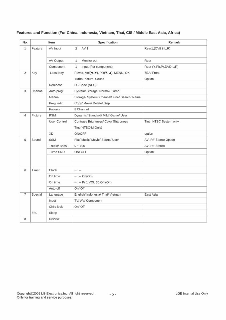
Features and Function (For China. Indonesia, Vietnam, Thai, CIS / Middle East Asia, Africa)
Copyright©2009 LG Electronics.Inc. All right reserved.Only for training and service purposes.
LGE Internal Use Only
Item
Feature AV Input
AV Output
Component
Key Local Key
Remocon
Channel Auto prog.
Manual
Prog. edit
Favorite
Picture PSM
User Control
XD
Sound SSM
Treble/ Bass
Turbo SND
Timer Clock
Off time
On time
Auto off
Special Language
Input
Child lock
Etc. Sleep
Review
Specification
2 AV 1
1 Monitor out
1 Input (For component)
Power, Vol(F, G), PR(E, D), MENU, OK
Turbo-Picture, Sound
LG Code (NEC)
System/ Storage/ Normal/ Turbo
Storage/ System/ Channel/ Fine/ Search/ Name
Copy/ Move/ Delete/ Skip
8 Channel
Dynamic/ Standard/ Mild/ Game/ User
Contrast/ Brightness/ Color Sharpness
Tint (NTSC-M Only)
ON/OFF
Flat/ Music/ Movie/ Sports/ User
0 ~ 100
ON/ OFF
-- : --
-- : -- Off(On)
-- : -- Pr 1 VOL 30 Off (On)
On/ Off
English/ Indonesia/ Thai/ Vietnam
TV/ AV/ Component
On/ Off
Remark
Rear1,(CVBS,L,R)
Rear
Rear (Y,Pb,Pr,DVD-L/R)
7EA/ Front
Option
Tint: NTSC System only
option
AV, RF Stereo Option
AV, RF Stereo
Option
East Asia
No.
1
2
3
4
5
6
7
8
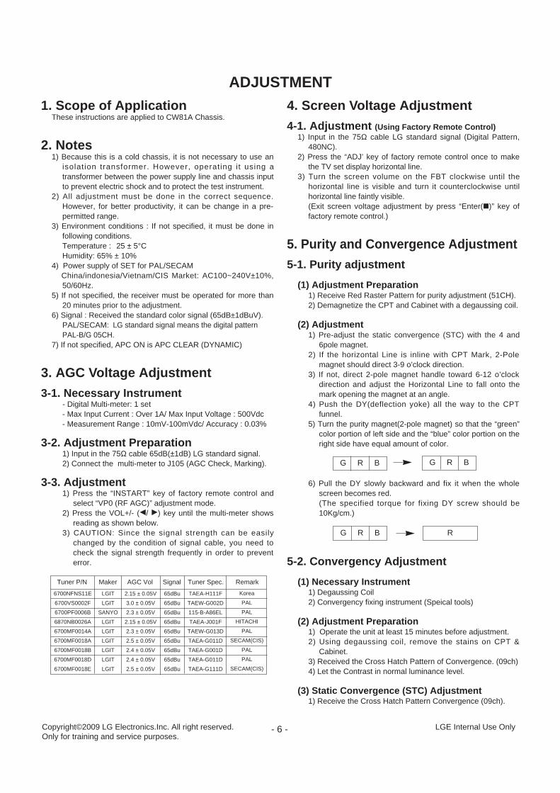
1. Scope of ApplicationThese instructions are applied to CW81A Chassis.
2. Notes1) Because this is a cold chassis, it is not necessary to use an
isolation transformer. However, operating it using atransformer between the power supply line and chassis inputto prevent electric shock and to protect the test instrument.
2) All adjustment must be done in the correct sequence.However, for better productivity, it can be change in a pre-permitted range.
3) Environment conditions : If not specified, it must be done infollowing conditions.Temperature : 25 ± 5°CHumidity: 65% ± 10%
4) Power supply of SET for PAL/SECAM China/indonesia/Vietnam/CIS Market: AC100~240V±10%,50/60Hz.
5) If not specified, the receiver must be operated for more than20 minutes prior to the adjustment.
6) Signal : Received the standard color signal (65dB±1dBuV).PAL/SECAM: LG standard signal means the digital patternPAL-B/G 05CH.
7) If not specified, APC ON is APC CLEAR (DYNAMIC)
3. AGC Voltage Adjustment
3-1. Necessary Instrument- Digital Multi-meter: 1 set- Max Input Current : Over 1A/ Max Input Voltage : 500Vdc- Measurement Range : 10mV-100mVdc/ Accuracy : 0.03%
3-2. Adjustment Preparation1) Input in the 75Ω cable 65dB(±1dB) LG standard signal.2) Connect the multi-meter to J105 (AGC Check, Marking).
3-3. Adjustment1) Press the “INSTART” key of factory remote control and
select “VP0 (RF AGC)” adjustment mode.2) Press the VOL+/- (F/ G) key until the multi-meter shows
reading as shown below.3) CAUTION: Since the signal strength can be easily
changed by the condition of signal cable, you need tocheck the signal strength frequently in order to preventerror.
4. Screen Voltage Adjustment
4-1. Adjustment (Using Factory Remote Control)1) Input in the 75Ω cable LG standard signal (Digital Pattern,
480NC).2) Press the “ADJ’ key of factory remote control once to make
the TV set display horizontal line.3) Turn the screen volume on the FBT clockwise until the
horizontal line is visible and turn it counterclockwise untilhorizontal line faintly visible.(Exit screen voltage adjustment by press “Enter(A)” key offactory remote control.)
5. Purity and Convergence Adjustment
5-1. Purity adjustment
(1) Adjustment Preparation1) Receive Red Raster Pattern for purity adjustment (51CH).2) Demagnetize the CPT and Cabinet with a degaussing coil.
(2) Adjustment1) Pre-adjust the static convergence (STC) with the 4 and
6pole magnet.2) If the horizontal Line is inline with CPT Mark, 2-Pole
magnet should direct 3-9 o’clock direction.3) If not, direct 2-pole magnet handle toward 6-12 o’clock
direction and adjust the Horizontal Line to fall onto themark opening the magnet at an angle.
4) Push the DY(deflection yoke) all the way to the CPTfunnel.
5) Turn the purity magnet(2-pole magnet) so that the “green”color portion of left side and the “blue” color portion on theright side have equal amount of color.
6) Pull the DY slowly backward and fix it when the wholescreen becomes red.(The specified torque for fixing DY screw should be10Kg/cm.)
5-2. Convergency Adjustment
(1) Necessary Instrument1) Degaussing Coil2) Convergency fixing instrument (Speical tools)
(2) Adjustment Preparation1) Operate the unit at least 15 minutes before adjustment.2) Using degaussing coil, remove the stains on CPT &
Cabinet.3) Received the Cross Hatch Pattern of Convergence. (09ch)4) Let the Contrast in normal luminance level.
(3) Static Convergence (STC) Adjustment1) Receive the Cross Hatch Pattern Convergence (09ch).
G R B
- 6 -
ADJUSTMENT
G R B
RG R B
Copyright©2009 LG Electronics.Inc. All right reserved.Only for training and service purposes.
LGE Internal Use Only
6700NFNS11E
6700VS0002F
6700PF0006B
6870NB0026A
6700MF0014A
6700MF0018A
6700MF0018B
6700MF0018D
6700MF0018E
LGIT
LGIT
SANYO
LGIT
LGIT
LGIT
LGIT
LGIT
LGIT
2.15 ± 0.05V
3.0 ± 0.05V
2.3 ± 0.05V
2.15 ± 0.05V
2.3 ± 0.05V
2.5 ± 0.05V
2.4 ± 0.05V
2.4 ± 0.05V
2.5 ± 0.05V
65dBu
65dBu
65dBu
65dBu
65dBu
65dBu
65dBu
65dBu
65dBu
TAEA-H111F
TAEW-G002D
115-B-A86EL
TAEA-J001F
TAEW-G013D
TAEA-G011D
TAEA-G001D
TAEA-G011D
TAEA-G111D
Korea
PAL
PAL
HITACHI
PAL
SECAM(CIS)
PAL
PAL
SECAM(CIS)
Tuner P/N Maker AGC Vol Signal Tuner Spec. Remark

- 7 -
2) Before adjusting Static Convergence (STC), adjust thefocus first seeing to it that the WHITE color picture qualityis sharp enough.
3) Converge the RED vertical and BLUE vertical line in unity(same line) by changing the angle between the 2 tabs of4-pole magnet.
4) Converge the RED horizontal and BLUE horizontal line inunity(same line) by turning the 2 tabs of the 4-polemagnet. At this time, do not change the angle betweenthe 2 tabs.
5) Converge the R, G, B vertical line in unity (same line) bychanging the angle between the 2 tabs of the 6-polemagnet.
6) Converge the R, G, B horizontal line in unity(same line) byturning the 2 tabs of the 6-pole magnet. At this time, donot change the angle between the 2 tabs.
(4) Dynamic Convergence (DYC) Adjustment1) Y-axis Adjustment:
Adjust convergence of Y-axis (vertical) by moving thedeflection yoke (DY) left and right.
2) X-axis Adjustment:Adjust convergence of X-axis (horizontal) by moving thedeflection yoke (DY) up and down.
6. White Balance Adjustment
6-1. Necessary Instrument1) Automatic White Balance Meter (Low/High light Pattern
generator)2) CRTColor Analyzer, CA -100: 1 set3) Factory Remote Control
6-2. Adjustment PreparationPrior to this adjustment, the Screen Voltage adjustment should be finished.
6-3. Automatic adjustment1) Adjust using Auto White Balance Meter.2) Enter CPU OFF Mode by pressing “IN-START” & “MUTE”
key of factor remote control in turn before adjustment.Exit CPU OFF mode by press the “MUTE” key of factoryremote control after adjustment finished.
* In case there is excess RED color at screen voltageadjustment, adjust it using “volume - (F) key of factory remotecontrol until the RED color disappear.
6-4. Manual adjustment1) Adjust using white Balance meter and factory remote
control.2) Enter white balance adjustment mode by pressing
“INSTART” key of factory remote control.3) Use the CHD, CHE Key to choose adjustment item.4) Use the VOLF, VOLG Key to change item data.5) Adjustment Procedure
a. Make the picture luminance 45Ft-L by changing the“CONTRAST” and “BRIGHTNESS”.
b. Adjust X data of High light with R-DRIVE and Y data ofhigh light with B-DRIVE to have the color temperatureas shown below.
c. Make the picture luminance 4.5Ft-L by changing the“CONTRAST” and “BRIGHTNESS”.
d. Adjust X data of low light with R-BIAS and Y data of low
light with B-BIAS to have the color temperature asshown below.
e. Repeat steps a~d until both low and high light have thesame readings as shown below.
7. Focus V oltage AdjustmentThis adjustment must be done after operating the TV setreceiver sufficiently.
7-1. Adjustment PreparationReceive the LG standard pattern (PAL: Digital pattern, 480NC,13CH) and set the picture condition on “APC ON” (CLEAR) mode.
7-2. AdjustmentTurn the focus volume on the FBT upper direction to havethe best focus vertical line (Fig. 1(a)) and horizontal line (Fig.1(b)) as shown below.
8. SUB-BRIGHTNESS Adjustment
8-1.Sub brightness adjustment is unnecessary(Don't adjust).
8-2. Sub-Tint adjustmentThis adjustment has to be done only if the picture has bad tintotherwise, it can be omitted if the picture has good tint.
1) Receive LG standard pattern signal (SMPTE, 2CH)2) Set the picture condition on “APC ON” (CLEAR) mode.3) Press the “ADJ” key of the factory remote control three
times to enter to “SUB-TINT” adjustment mode.4) Change the Sub-Tint data by pressing the VOLF, VOLG
key until the upper and lower CYAN color becomes samecolor.
9. Deflection setting data adjustmentThese adjustment will be done by automatic adjustmentEquipment.For manual adjustment, it is also possible by the followingprocedure.
9-1. Adjustment Preparation1) Deflection setting data adjustment can be done only with
remote control.2) Press “IN-START” key on factory remote control continuously
to enter to Deflection Adjustment mode.3) Press the CHD, E key to select adjustment item.
Market Color Temperature X-AXIS Y-AXIS
ALL 13,000 268±5 273±5
(a)
(b)
<Fig. 1>
Copyright©2009 LG Electronics.Inc. All right reserved.Only for training and service purposes.
LGE Internal Use Only

- 8 -
4) Press the VOLF, G key to change the data.
9-2. Adjustment1) Horizontal Position Adjustment
Select SVC02(H-POS) and adjust so that the left and rightvertical line are symmetrical as possible.
2) Vertical Position AdjustmentSelect SVC02(V-POS) and adjust so that the horizontalcenter line coincide with geometric horizontal center of theCPT.
3) Vertical Size AdjustmentSelect SVC02(VA) and adjust so that the middle circle of theDigital Pattern(480NC, 13CH) coincide with the effectivescreen of CPT.
9-3. Adjustment (21'' Superslim, Ultra S/S Model)
1) Vertical Position AdjustmentSelect SVC02(V-POS) and adjust so that the horizontalcenter line coincide with geometric horizontal center of theCPT.
2) Vertical linearity AdjustmentSelect SVC02(V-LIN) and adjust so that the size of the uppercircle is alike with the one of the lower circle at LG standardpattern (PAL: EU05CH, NTSC: 13CH)
3) Vertical Size AdjustmentSelect SVC02(VA) and adjust so that the middle circle of theDigital Pattern(PAL B/G 5CH) has 6~7mm gaps from theeffective screen of CPT
4) Horizontal Position AdjustmentSelect SVC02(H-POS) and adjust so that the left and right vertival line are symmetrical as possible.
5) Horizontal Size AdjustmentSelect SVC02(EW WIDTH) and adjust so that the outer line ofthe left and right and the remotest grid will correspond to theeffective boundary surface. (The remotest grid PAL: within0~25%; NTSC: within 2.5~3.0 column)
6) Parabora AdjustmentSelect SVC02(EW PARAB) and adjust so that the vertical lineof the remotest grid at the left or right side of the screen willbe parallel to the vertical line of the center of screen. (or theremotest grid of CPT)
7) Trapezoidal AdjustmentSelect SVC02(EW TRAPE) and adjust so that the width ofthe upper part of screen is alike with the one of the lower partof the screen.
8) EW UPCOR / LOCOR AdjustmentSelect SVC02(EW C UPCOR, EW LOCOR) and adjust sothat the vertical line in the four corners become straight line.
9) BOW AdjustmentSelect SVC02(HP BOW) and adjust so that the vertical line inthe four corners become straight line.
10. IIC BUS SUB Adjustment DataTable
11. Auto Adjustment PreparationSetting T able
Speed1SLave ADD
VIDEO ICBA
EEPROMA0
Delay5
EEPROM
Sub Add8D 8A 8F 8C
SpeedPlus
Step/Data3 3 3 3
Sub Add
Start Bit
Stop Bit
Masking
Direction
VCDTV PC
R DRIVE
D
6
0
0
1
R BIAS
A
7
0
0
1
B DRIVE
F
6
0
0
1
B BIAS
C
7
0
0
1
B AMP B CUT G AMP G CUT
Copyright©2009 LG Electronics.Inc. All right reserved.Only for training and service purposes.
LGE Internal Use Only
OSDSUB-BRIGHTNESS
SUB-TINT
Range0 ~ 100
-20 (R) ~ +20 (G)
PAL40R5
Secam40R5
PAL40R5
NTSC40R1
- 9 -
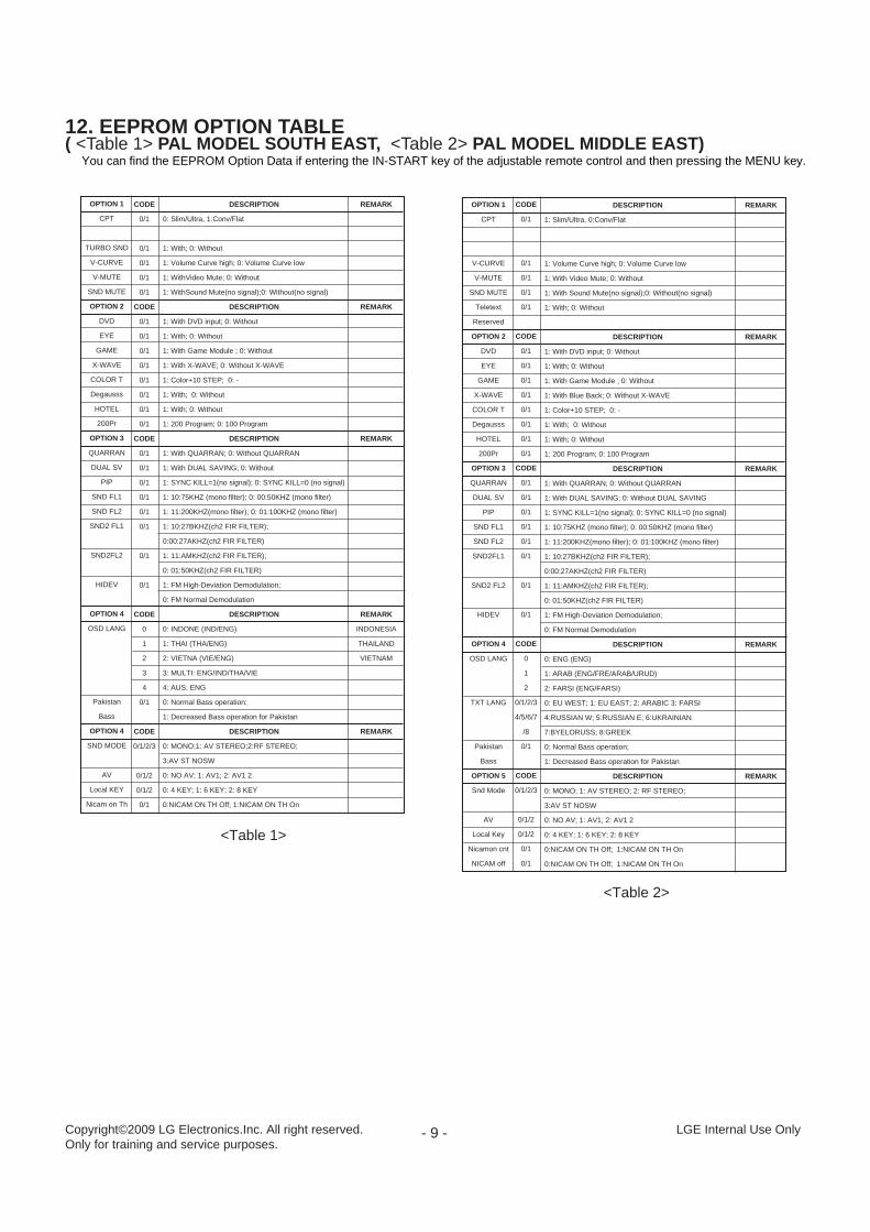
12. EEPROM OPTION TABLE( <Table 1> PAL MODEL SOUTH EAST, <Table 2> PAL MODEL MIDDLE EAST)
You can find the EEPROM Option Data if entering the IN-START key of the adjustable remote control and then pressing the MENU key.
Copyright©2009 LG Electronics.Inc. All right reserved.Only for training and service purposes.
LGE Internal Use Only
OPTION 1
CPT
TURBO SND
V-CURVE
V-MUTE
SND MUTE
OPTION 2
DVD
EYE
GAME
X-WAVE
COLOR T
Degausss
HOTEL
200Pr
OPTION 3
QUARRAN
DUAL SV
PIP
SND FL1
SND FL2
SND2 FL1
SND2FL2
HIDEV
OPTION 4
OSD LANG
Pakistan
Bass
OPTION 4
SND MODE
AV
Local KEY
Nicam on Th
REMARK
REMARK
REMARK
REMARK
INDONESIA
THAILAND
VIETNAM
REMARK
CODE
0/1
0/1
0/1
0/1
0/1
CODE
0/1
0/1
0/1
0/1
0/1
0/1
0/1
0/1
CODE
0/1
0/1
0/1
0/1
0/1
0/1
0/1
0/1
CODE
0
1
2
3
4
0/1
CODE
0/1/2/3
0/1/2
0/1/2
0/1
DESCRIPTION
0: Slim/Ultra, 1:Conv/Flat
1: With; 0: Without
1: Volume Curve high; 0: Volume Curve low
1: WithVideo Mute; 0: Without
1: WithSound Mute(no signal);0: Without(no signal)
DESCRIPTION
1: With DVD input; 0: Without
1: With; 0: Without
1: With Game Module ; 0: Without
1: With X-WAVE; 0: Without X-WAVE
1: Color+10 STEP; 0: -
1: With; 0: Without
1: With; 0: Without
1: 200 Program; 0: 100 Program
DESCRIPTION
1: With QUARRAN; 0: Without QUARRAN
1: With DUAL SAVING; 0: Without
1: SYNC KILL=1(no signal); 0: SYNC KILL=0 (no signal)
1: 10:75KHZ (mono filter); 0: 00:50KHZ (mono filter)
1: 11:200KHZ(mono filter); 0: 01:100KHZ (mono filter)
1: 10:27BKHZ(ch2 FIR FILTER);
0:00:27AKHZ(ch2 FIR FILTER)
1: 11:AMKHZ(ch2 FIR FILTER);
0: 01:50KHZ(ch2 FIR FILTER)
1: FM High-Deviation Demodulation;
0: FM Normal Demodulation
DESCRIPTION
0: INDONE (IND/ENG)
1: THAI (THA/ENG)
2: VIETNA (VIE/ENG)
3: MULTI: ENG/IND/THA/VIE
4: AUS: ENG
0: Normal Bass operation;
1: Decreased Bass operation for Pakistan
DESCRIPTION
0: MONO;1: AV STEREO;2:RF STEREO;
3:AV ST NOSW
0: NO AV; 1: AV1; 2: AV1 2
0: 4 KEY; 1: 6 KEY; 2: 8 KEY
0:NICAM ON TH Off; 1:NICAM ON TH On
OPTION 1
CPT
V-CURVE
V-MUTE
SND MUTE
Teletext
Reserved
OPTION 2
DVD
EYE
GAME
X-WAVE
COLOR T
Degausss
HOTEL
200Pr
OPTION 3
QUARRAN
DUAL SV
PIP
SND FL1
SND FL2
SND2FL1
SND2 FL2
HIDEV
OPTION 4
OSD LANG
TXT LANG
Pakistan
Bass
OPTION 5
Snd Mode
AV
Local Key
Nicamon cnt
NICAM off
REMARK
REMARK
REMARK
REMARK
REMARK
CODE
0/1
0/1
0/1
0/1
0/1
CODE
0/1
0/1
0/1
0/1
0/1
0/1
0/1
0/1
CODE
0/1
0/1
0/1
0/1
0/1
0/1
0/1
0/1
CODE
0
1
2
0/1/2/3
4/5/6/7
/8
0/1
CODE
0/1/2/3
0/1/2
0/1/2
0/1
0/1
DESCRIPTION
1: Slim/Ultra, 0:Conv/Flat
1: Volume Curve high; 0: Volume Curve low
1: With Video Mute; 0: Without
1: With Sound Mute(no signal);0: Without(no signal)
1: With; 0: Without
DESCRIPTION
1: With DVD input; 0: Without
1: With; 0: Without
1: With Game Module ; 0: Without
1: With Blue Back; 0: Without X-WAVE
1: Color+10 STEP; 0: -
1: With; 0: Without
1: With; 0: Without
1: 200 Program; 0: 100 Program
DESCRIPTION
1: With QUARRAN; 0: Without QUARRAN
1: With DUAL SAVING; 0: Without DUAL SAVING
1: SYNC KILL=1(no signal); 0: SYNC KILL=0 (no signal)
1: 10:75KHZ (mono filter); 0: 00:50KHZ (mono filter)
1: 11:200KHZ(mono filter); 0: 01:100KHZ (mono filter)
1: 10:27BKHZ(ch2 FIR FILTER);
0:00:27AKHZ(ch2 FIR FILTER)
1: 11:AMKHZ(ch2 FIR FILTER);
0: 01:50KHZ(ch2 FIR FILTER)
1: FM High-Deviation Demodulation;
0: FM Normal Demodulation
DESCRIPTION
0: ENG (ENG)
1: ARAB (ENG/FRE/ARAB/URUD)
2: FARSI (ENG/FARSI)
0: EU WEST; 1: EU EAST; 2: ARABIC 3: FARSI
4:RUSSIAN W; 5:RUSSIAN E; 6:UKRAINIAN
7:BYELORUSS; 8:GREEK
0: Normal Bass operation;
1: Decreased Bass operation for Pakistan
DESCRIPTION
0: MONO; 1: AV STEREO; 2: RF STEREO;
3:AV ST NOSW
0: NO AV; 1: AV1; 2: AV1 2
0: 4 KEY; 1: 6 KEY; 2: 8 KEY
0:NICAM ON TH Off; 1:NICAM ON TH On
0:NICAM ON TH Off; 1:NICAM ON TH On
<Table 1>
<Table 2>

- 10 -Copyright©2009 LG Electronics.Inc. All right reserved.Only for training and service purposes.
LGE Internal Use Only
SVC
SVC 01
SVC 02
RegisterRF AGCR BIASG BIAS
B BIASR DRIVEG DRIVEB DRIVEY-DELAY
OSD CONT.OSD POS.
V POS
V LIN
VA
H POS
EW WIDTH
EW PARAB
EW TRAPE
EW UPCOR
EW COR
Range0 ~ 630 ~ 2550 ~ 255
0 ~ 2550 ~ 1270 ~ 1270 ~ 1270 ~ 150 ~ 70 ~ 600 ~ 15
0 ~ 31
0 ~ 127
0 ~ 31
0 ~ 127
0 ~ 127
0 ~ 127
0 ~ 31
0:normal mode1:corner pin gain up mode
Initial(PAL)389090
127
909085907542677
9
191820
19
375412
22
161814
16
6595
2717
1615
1416
0
Initial(SECAM)389090
127
9090859075408
1817
1718
37
20
65
24
14
14
0
RemarkNecessaryNecessary
Others CPTIRICO CPT
UnnecessaryNecessaryNecessary
UnnecessaryNecessary
UnnecessaryUnnecessaryUnnecessaryUltra 2 LG CPTUltra HF CPTFLAT HF CPTFLAT IRICO CPTFLAT LG CPTNecessary
Ultra 2 LG CPTUltra HF CPTFLAT HF CPTFLAT IRICO CPTFLAT LG CPTUnnecessaryUltra 2 LG CPTUltra HF CPTFLAT HF CPTFLAT IRICO CPTFLAT LG CPTNecessary
Ultra 2 LG CPTUltra HF CPTFLAT HF CPTFLAT IRICO CPTFLAT LG CPTNecessary
Ultra 2 LG CPTUltra HF CPTFLAT HF CPTFLAT IRICO CPTFLAT LG CPTNecessary
Ultra 2 LG CPTUltra HF CPTFLAT HF CPTFLAT IRICO CPTFLAT LG CPTNecessary
Ultra 2 LG CPTUltra HF CPTFLAT HF CPTFLAT IRICO CPTFLAT LG CPTNecessary
Ultra 2 LG CPTUltra HF CPTFLAT HF CPTFLAT IRICO CPTFLAT LG CPTNecessary
Unnecessary
<TABLE 3 >

SVC
SVC 02
SVC 03
SVC 04
RegisterHP BOW
HP ANGLEHS COMP
V SCV COMP
HS COMPV DC
VBLK SWH BLK LH BLK REW Cor
DEEM TCFM GAINA2 SW
SIF SYSCH CONVFM MUTEVOL FIL
VOLUME LAUDIO SW
SURR CNTMONO
VOLUME RTONE ATTT BOOST C
TREBLEPSEUDO STBBOOST CBASS GAS TRAP
S TRAP SWF DDS
DELAY TY FILTERC FILTER
Y APF
COR GAIN
P SHOOTO SHOOTWPL OPE
GAMMA ST
DC RESTBS START
BS GAINC TRAPC BPF
GAMMA GAGRAY MDE
YCMIXTXT CC
VIN/XRGB
Range0 ~ 31
0 ~ 310 ~ 70 ~ 70 ~ 70 ~ 70 ~ 630~30 ~ 70 ~70: Normal mode; 1: Corner pin gain up mode0: 50us ; 1: 75us0: 500mVrms@± 50KHz. deviation (for PAL)0: Normal mode; 1: 5.74MHz mode need to set SIF system=10: 4.5MHz; 1: 5.5MHz; 2: 6.0MHz; 3: 6.5MHz0: Normal BPF mode; 1: CH converter measure mode at India0: Enable FM output; 1: Disable FM output0: Filter OFF; 1: TV operating mode0 ~ 127MONO Mode: 0 (0: Stereo EXT; 1: Stereo INT)MONO Mode: 1 (0: MONO CH1; 1: MONO CH2; 0: MONO CH3; 1: MONO CH4)0: Surround OFF; 1: MODE-A (-3dB); 2: MODE-B (0dB); 3:MODE-C(+3dB)0: STEREO input mode; 1: MODE input mode0 ~ 1270: 0dB; 1: -6dB0: Cut; 1: Boost0 ~ 630: Pseudo Stereo OFF; 1: Pseudo Stereo ON0: Cut; 1: Boost0 ~ 630 (min) ~ 7 (max)0: Sound trap OFF mode (need external trap); 1: Normal mode (sound trap ON)0: Normal mode (NTSC: work; PAL/SECAM: stop); 1: Forced DDS mode (always work)Delay Test0: 3.58MHz Trap; 1: 4.43MHz Trap; 2: Wide mode; 3: 4.286MHz Trap0: 3.58MHz peaking; 1: 3.58MHz symmetrical; 2: 4.43MHz peaking; 3: 4.43MHz symmetrical0: Chroma trap ON (composite video mode)1: Chroma trap OFF (YCbCr mode and YC mode)0: Coring OFF; 1: Coring Gain 1(minimum); 2: Coring Gain 2(middle); 3: Coring Gain 3(maximum)0 (narrow) ~ 3 (wide)0 (narrow) ~ 3 (wide)0: WPL OFF; 1: High operating point; 2:Middle operating point; 3: Low operating point0: Low operating point; 1: Middle operating point;2: High operating point; 3: Defect0: 100%; 1: 107%; 2: 113%; 3: 129%0: Black Stretch ON (Starting Point=401RE);1: Black Stretch ON (Starting Point=501RE)2: Black Stretch ON (Starting Point=601RE)3: Black Stretch OFF0 (min) ~ 2 (max)0 (min) ~ 7 (max)0 (min) ~ 3 (max)0 (min) ~ 3 (max)0: White (70%); 1: Gray (15%)0: YC_C; 1: 2.2V_DC0: Output without LPF; 1: Output by LPF
0: FBP/EXT RGB IN; 1: YC-C/DVD-Y/CR-IN/CB-IN
Initial(PAL)18
1671877
24(55)0(1)
2200001001180
001800230120710
110
0
2
000
3
03
321000
W/O TXT:0W/ TXT:1
1
Initial(SECAM)18
1671877
24(55)0(1)
2200001001380
003800230120710
110
0
2
000
3
03
321000
W/O TXT:0W/ TXT:1
1
RemarkNecessary
Ultra HF CPTNecessary
UnnecessaryUnnecessaryUnnecessaryUnnecessaryUnnecessaryUnnecessaryUnnecessaryUnnecessaryUnnecessaryUnnecessaryUnnecessaryUnnecessaryUnnecessaryUnnecessaryUnnecessaryUnnecessaryUnnecessaryUnnecessary
UnnecessaryUnnecessaryUnnecessaryUnnecessaryUnnecessaryUnnecessaryUnnecessaryUnnecessaryUnnecessaryUnnecessaryUnnecessaryUnnecessary
UnnecessaryUnnecessaryUnnecessary
Unnecessary
Unnecessary
UnnecessaryUnnecessaryUnnecessary
Unnecessary
UnnecessaryUnnecessary
UnnecessaryUnnecessaryUnnecessaryUnnecessaryUnnecessaryUnnecessaryUnnecessary
Unnecessary
- 11 -
<TABLE 3 >
Copyright©2009 LG Electronics.Inc. All right reserved.Only for training and service purposes.
LGE Internal Use Only

- 12 -
SVC
SVC 05
SVC 06
SVC 07
RegisterT DISABLE
H FREQAFC G
A MUTEV MUTE
SYN KILLV KILLVSEP
V RES THLVDET
V SYNCD MODEFBPBLKAFC NSTAFC2SW
CROSS BWBLK DEF.SUB BIASV TRANSDIG OSD
RGB CONTRGB TEMPACL DEF.ACL SW
ABL DEF.MID STPABL TH
VXO ADJCrCb INC EXT
C BYPASSC KI ONC KI OFFC KI OPEGRN ADJTINT THID KILL
CVCO ADJVCO CNTRFSC/STOP
C SYS
RY BY GARY BY ANR-Y LEVELB-Y LEVEL
GY AMPHTNo CIrVXO Free
VXO StbyIF AGC
SVO SWVIF SYSV LEVELOM TYPEOM SW
OM LEVELVCO FREQAMONI SW
AFT SENS
VCO ADJ
Range0: Test mode; 1: TV operating normally0 ~ 630: Automatic mode; 1: Enforce high gain mode0: Audio Mute OFF; 1: Audio Mute ON0: Video Mute OFF; 1: Video Mute ON0 ~ 10: TV operating mode; 1: Defeat the vetical output0: Normal mode; 1: Sensitivity up mode0: Normal mode; 1: Sensitivity up mode0: If H-Lock is not defect, stop vertical sync detection1: V sync system always working
0 ~ 70 ~ 10: Normal mode; 1: Enforce low gain mode (non-standard)0: About 4us ~ 8us; 1: about 8us ~ 12us0: TV operating mode; 1: Black pattern; 2: White pattern; 3: Crosshatch pattern0: Blanking ON (normal mode); 1: Blanking OFF0 ~ 1270: Random transmission; 1: Transmission between vertical retrace period0: Analogue OSD mode; 1: Digital OSD mode0 ~ 150: -1VBE; 1: Flat0: ACL Defect OFF; 1: ACL Defect ON0: High sentivity; 1: Low sentivity0: ABL Defect OFF; 1: ABL Defect ON0: Enable limit operating; 1: Disable limit operating0 ~ 7
0: Video; 1: CbCr0: Internal composite video signal; 1: From pin 2 input0: Bypass OFF; 1: Bypass ON (used in Y/C mode)0: Automatic mode (TV in operation); 1: Enforce killer ON when color control is min0: TV in operation; 1: Test mode, killer circuit is not in operation0 ~ 7 (-30dB ~ -40dB)0 ~ 7 (Auto green off ~ level high)0: Normal mode; 1: Tint control set center value (cann't control tint)0: Easy to become NTSC; 1: Easy to become PAL0 ~ 7 0: Normal mode; 1: VCO free run mode0: FSC OUT; 1: EHT0: PAL/NTSC/4.43 NTSC (AUTO); 1: PAL-M/PAL-N/NTSC(AUTO)2: PAL; 3: PAL-M; 4: PAL-N; 5: NTSC; 6: 4.43NTSC; 7: Not available0 ~ 150 ~ 150 ~ 310 ~ 310 ~ 150: Color ON; 1: Color OFF0: Normal mode;1: VXO free run mode0: Normal mode;1: VXO Standby mode0: Normal mode; 1: Minimize the gain of VIF amplifier0: Internal Video out mode; 1: Selected External video output mode0: 38.0 MHz; 1: 38.9MHz; 2: 39.5MHz; 3: 45.75MHz0 ~ 70: APC Voltage sample holde circuit type; 1: APC detector stop type0: Normal mode; 1: Over modulation measure circuit ON0 ~ 150 ~ 2550: Normal mode (de-empasis FM detector); 1: SAO mode at external audio input mode0: ±200KHz (4.5-0.5v change); 1: ±150KHz (4.5-0.5v change)2: ±100KHz (4.5-0.5v change); 3:±50KHz (4.5-0.5v change)
Initial(PAL)17001000001
00100003510800
?????????????
?O@?he??@@@@?he?
@?he?@?he?@?he?@?he?@?he?@?he?@?he?@?he?@?he?@?he?@?he?@?he?
?@@@@@@@h??????
013
?????????????
?@@@@@@?g??@@@@@@?g?J(M?he?7Yhf?@@6Xhe?@@@)X?h??I'@)Xh?V4@1h??@h??@h??@h?J5h?
?W.Yh??'6KO.Y?h??V4@0Yhe?
?????
00000
?????????????
W&h??W&@h?W&@@h?7Y@@h?
?J5?@@h?W.Y?@@h?
?O.Ye@@h?@@Y?e@@h?@@@@@@@@@@g?@@@@@@@@@@g?
@@h?@@h?@@h?@@h?@@h?
?????
0074210
8101612100000014008
1000
0
15
Initial(SECAM)17001000001
00100003510800
?????????????
?O@?he??@@@@?he?
@?he?@?he?@?he?@?he?@?he?@?he?@?he?@?he?@?he?@?he?@?he?@?he?
?@@@@@@@h??????
013
?????????????
?@@@@@@?g??@@@@@@?g?J(M?he?7Yhf?@@6Xhe?@@@)X?h??I'@)Xh?V4@1h??@h??@h??@h?J5h?
?W.Yh??'6KO.Y?h??V4@0Yhe?
?????
00000
?????????????
W&h??W&@h?W&@@h?7Y@@h?
?J5?@@h?W.Y?@@h?
?O.Ye@@h?@@Y?e@@h?@@@@@@@@@@g?@@@@@@@@@@g?
@@h?@@h?@@h?@@h?@@h?
?????
0074210
8101612100000014008
1000
0
15
RemarkUnnecessaryUnnecessaryUnnecessaryUnnecessaryUnnecessaryUnnecessaryUnnecessaryUnnecessaryUnnecessaryUnnecessary
UnnecessaryUnnecessaryUnnecessaryUnnecessaryUnnecessaryUnnecessaryUnnecessaryUnnecessaryUnnecessaryUnnecessaryUnnecessaryUnnecessaryUnnecessaryUnnecessaryUnnecessaryUnnecessaryUnnecessaryUnnecessaryUnnecessaryUnnecessaryUnnecessaryUnnecessaryUnnecessaryUnnecessaryUnnecessaryUnnecessaryUnnecessaryUnnecessaryUnnecessaryUnnecessaryUnnecessary
UnnecessaryUnnecessaryUnnecessaryUnnecessaryUnnecessaryUnnecessaryUnnecessaryUnnecessaryUnnecessaryUnnecessaryUnnecessaryUnnecessaryUnnecessaryUnnecessaryUnnecessaryUnnecessaryUnnecessary
Unnecessary
Unnecessary
Copyright©2009 LG Electronics.Inc. All right reserved.Only for training and service purposes.
LGE Internal Use Only
- 13 -
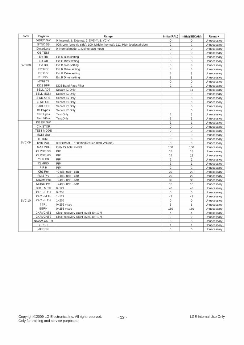
SVC
SVC 08
SVC 09
SVC 10
RegisterVIDEO SWSYNC SSDinterLaceOE TEST
Ext RBExt GBExt BBExt RDrExt GDrExt BDr
MONI C2DDS BPFBELL ADJ
BELL MONIS KIL OPES KIL ONS KIL OFFBellBypasText HposText VPosDE EM SWCIK STOP
TEST MODEMONI cbcrIF TEST
DVD VOLMAX VOLCLPDEL50CLPDEL60
CLPLENCLMPID
PIP HCh1 PreFM 2 Pre
NICAM PreMONO PreCH1 - M THCH1 - L THCH2 - M THCH2 - L TH
BERLBERH
CKRVCNT1CKRVCNT2
NICAM ON THBERSELAGCEN
Range0: Internal; 1: External; 2: DVD-Y; 3: YC-Y000: Low (sync tip side); 100: Middle (normal); 111: High (pedestal side) 0: Normal mode; 1: Deinterlace mode
Ext R Bias settingExt G Bias settingExt B Bias settingExt R Drive settingExt G Drive settingExt B Drive setting
DDS Band Pass FilterSecam IC OnlySecam IC OnlySecam IC OnlySecam IC OnlySecam IC OnlySecam IC OnlyText OnlyText Only
0:NORMAL ~ 100:Min(Reduce DVD Volume)Only for hotel modelPIPPIPPIPPIPPIP+24dB~0dB~-6dB+24dB~0dB~-6dB+24dB~0dB~-6dB+24dB~0dB~-6dB0~1270~2551~1271~2550~255 msec0~255 msecClock recovery count level1 (0~127)Clock recovery count level2 (0~127)
Initial(PAL)020088888802
33100000
1001818212
29293010480
4705
16042510
Initial(SECAM)020088888802110000033100000
1001818212292930104804705
16042510
RemarkUnnecessaryUnnecessaryUnnecessaryUnnecessaryUnnecessaryUnnecessaryUnnecessaryUnnecessaryUnnecessaryUnnecessaryUnnecessaryUnnecessaryUnnecessaryUnnecessaryUnnecessaryUnnecessaryUnnecessaryUnnecessaryUnnecessaryUnnecessaryUnnecessaryUnnecessaryUnnecessaryUnnecessaryUnnecessaryUnnecessaryUnnecessaryUnnecessaryUnnecessaryUnnecessaryUnnecessaryUnnecessaryUnnecessaryUnnecessaryUnnecessaryUnnecessaryUnnecessaryUnnecessaryUnnecessaryUnnecessaryUnnecessaryUnnecessaryUnnecessaryUnnecessaryUnnecessaryUnnecessaryUnnecessary
Copyright©2009 LG Electronics.Inc. All right reserved.Only for training and service purposes.
LGE Internal Use Only
- 14 -
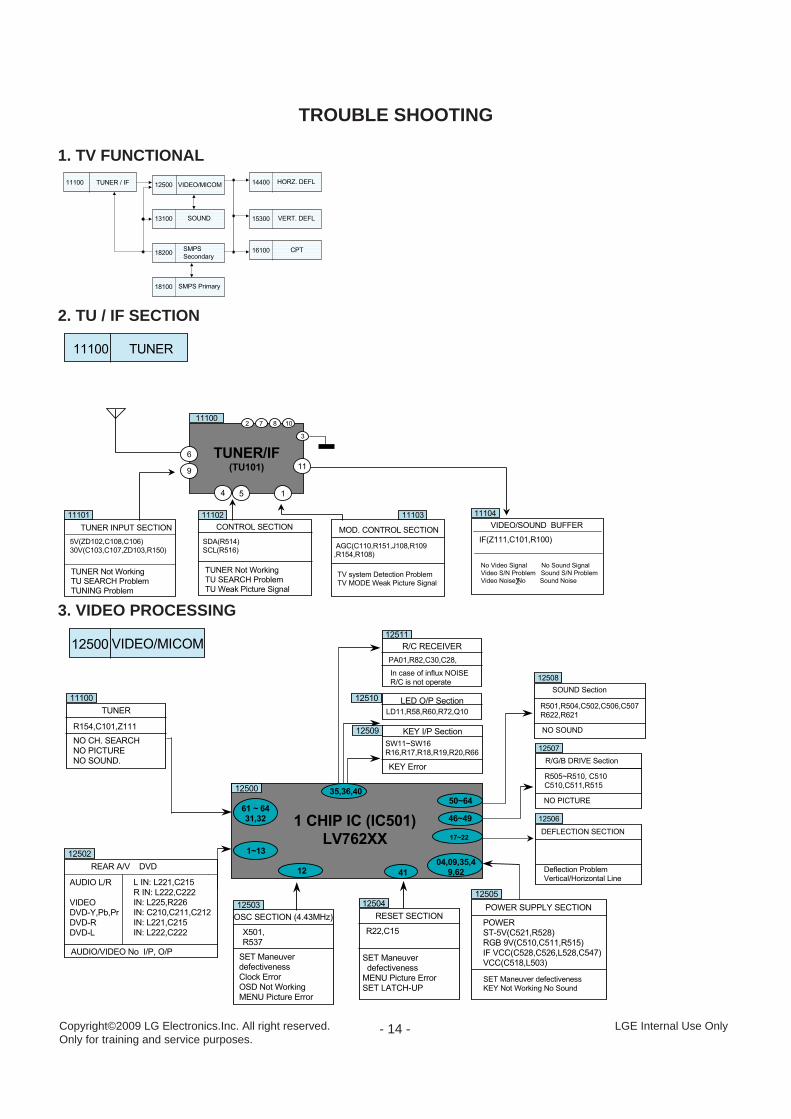
VIDEO/MICOM12500TUNER / IF11100 HORZ. DEFL14400
SOUND13100 VERT. DEFL15300
SMPS
Secondary18200
SMPS Primary18100
CPT16100
11100 TUNER
TUNER INPUT SECTION
5V(ZD102,C108,C106)
30V(C103,C107,ZD103,R150)
TUNER Not Working
TU SEARCH Problem
TUNING Problem
CONTROL SECTION
SDA(R514)
SCL(R516)
TUNER Not Working
TU SEARCH Problem
TU Weak Picture Signal
MOD. CONTROL SECTION
AGC(C110,R151,J108,R109
,R154,R108)
TV system Detection Problem
TV MODE Weak Picture Signal
VIDEO/SOUND BUFFER
IF(Z111,C101,R100)
No Video Signal No Sound Signal
Video S/N Problem Sound S/N Problem
Video Noise·No Sound Noise
11101 11102 11103 11104
TUNER/IF(TU101)
6
11100
9
4 5 1
11
8
3
2 7 10
R404,R512,R532,C512,C513
C515,C516,C517,C523,C544
R501,R504,C502,C506,C507
R622,R621
SET Maneuver defectiveness
KEY Not Working No Sound
R22,C15
RESET SECTION
SET Maneuver
defectiveness
MENU Picture Error
SET LATCH-UP
POWER
ST-5V(C521,R528)
RGB 9V(C510,C511,R515)
IF VCC(C528,C526,L528,C547)
VCC(C518,L503)
POWER SUPPLY SECTION
1 CHIP IC (IC501)
LV762XX
61 ~ 64
31,32
1~13
12 41
17~22
12500 VIDEO/MICOM
46~49
TUNER
NO CH. SEARCH
NO PICTURE
NO SOUND.
X501,
R537
OSC SECTION (4.43MHz)
SET Maneuver
defectiveness
Clock Error
OSD Not Working
MENU Picture Error
L IN: L221,C215
R IN: L222,C222
IN: L225,R226
IN: C210,C211,C212
IN: L221,C215
IN: L222,C222
REAR A/V DVD
AUDIO/VIDEO No I/P, O/P
04,09,35,4
9,62
50~6435,36,40
11100
12500
12502
12503 1250412505
12510
12509
PA01,R82,C30,C28,
R/C RECEIVER
In case of influx NOISE
R/C is not operate
LD11,R58,R60,R72,Q10
LED O/P Section
SW11~SW16
R16,R17,R18,R19,R20,R66
KEY I/P Section
KEY Error
12511
R/G/B DRIVE Section
R505~R510, C510
C510,C511,R515
DEFLECTION SECTION
Deflection Problem
Vertical/Horizontal Line
NO PICTURE
SOUND Section
NO SOUND
12506
12507
12508
AUDIO L/R
VIDEO
DVD-Y,Pb,Pr
DVD-R
DVD-L
R154,C101,Z111
1. TV FUNCTIONAL
2. TU / IF SECTION
3. VIDEO PROCESSING
TROUBLE SHOOTING
Copyright©2009 LG Electronics.Inc. All right reserved.Only for training and service purposes.
LGE Internal Use Only

- 15 -
AC INPUT
P801A/B,SW801
FUSE & VARISTOR
NO POWER
FUSE OPEN
FILTER SECTION
T802(150-F06T)
RELAY(DEGAUSS)
RL801,Q845,D847
NO MICOM CONTROL
NO DEGAUSS
PURITY PROBLEM
BRIDGE RECTIFIER
DB801(TS4B05G)
NO POWER
FUSE OPEN
NO RECTIFIER
DC O/P
T803
NO POWER
NO STR VCCSUPPLY SO
NO POWER
FUSE OPEN & STR
DAMAGED DUE TO CHANGE
IN PRIMARY INDUCTANCE
OF SMPS
IC801(STR-W6754)
SECONDARY LOAD REGULATION POOR
OVER VOLTAGE PROT. NOT OPR.
NO POWER / INTERMITANT NO POWER
SWITCHING NOISE
START RESISTOR
R804,R805
STR SWITCH ON PROB.
NO POWER
STR VCC POWER SECTION
D815,R804,R805,R810,R839
STR NO OPR./NO POWER
EXCESSIVE I/P VOLTAGE CAUSES
NO POWER/ NO OSCILLATIONS
STR FEED BACK SECTION
D845,R810,C840
STR NO OPR./NO POWER
INTERMITENT NO POWER
SECONDARY O/P VOLTAGE POOR
INTERMITANT ST-BY MODE
LOAD REG. FB SECTION
IC802,Q840,R808,R853,C852
SMPS SEC LOAD REG POOR
INTERMITANT NO POWER
18101
1810218103
18104
18105
18106
1810818110
18111
18200
18205
NO POWER
POWER RADIATION
SAFETY PROBLEM
TO
DEGAUSS
COIL
VD801(TVR621D)
F801(T4AL250V)
4. SMPS PRIMARY SECTION
5. SMPS SECONDARY SECTIONSTR-
W6554
C831
(220u/160V)
R107
(RS 12K/2W)
SMPS
Trans
(S-Vcc)17V
20V-(10W)
LA42101 (#7,Vcc)
T/X Pre-Amp
110V
D824
(SFAF504G)
C831
(330u/25V)
11V
D813
(RU3AMV)
C826
(1000u/16V)
R873
(47/0.5W)
D-Coil Relay
MAIN IC (#24, Vcc)
EEPROM (#8, Vcc)
IC804
LV76213(#9, Vcc)
D826
(RU3AMV)
LV76213(#20, Vcc)
LV76213(#49,Vcc)
FBT B+
R833
(RS 0.47/2W)
L802
(82uH)
FR403
(RF 1.2/2W)Tuner 30V
KIA78R09API
112.17V / 395mA 110.1V 110.07V 109.63V / 380mA
29.97V / 10mA
3.3V / 10mA
5.0V / 13mA
8.0V / 15mA
14V / 25mA
KIA78L05BP
IC803R620
(RS 5.6/2W) 5.0V / 231mA
LV76213(#62,#4 Vcc)
LA72730 (#8 Vcc)
(st-by 5V)
(105V~120V)
(28V~32V)
NT: 398mA
PAL:503mA
KIA7805API
LA72702N (#19 Vcc)
TUNER(Vcc)
R529
(RS 68)
R513
(RS 300)
R520
(RS 620)
5.0V / 14mA
5.0V / 40mA
5V /75mA.
NT: 360mA
PAL:465mA
LC75024E (3.3V Vcc)
85mA
LA42102 (#7,Vcc) IC 601 (SOUND-amp) 5W+5 W ST
LA42102N (#7,Vcc) IC 601 (SOUND-amp) 10W+10W ST
IC 601 (SOUND-amp) 5W MONO
17V
ST_BY 1W
Option D806
(TVR06J)
C838
(2200u/25V)
IC806
KIA78R05API
IC04
LA42102 (#5,St-by)
IC 751 (S/W IC )
IC 661 (RF STEREO NT)
IC 501 (Main IC)
IC 601 (SOUND-amp)
LC75024E (1.5V Vcc)
IC 807 (NICAM)
IC 501 (Main IC 3.3V Vcc)
IC 501 (Main IC Hor Vcc)
IC 501 (Main IC RGB Vcc)
180V
D505
(RGP10J))
C540
(4.7u/250V)
CPT Board
26V
D301
(RGP15J))
C309
(470u/35V)
LA78040N
(#2,Vcc)
184.47V / 18mA
28.2V / 320mA
FBT
Trans
FM TX, Game, USB OPT
60mA
5V
145mA.
3.3V Reg.
1.5V Reg.
ST-5V
ST-5V
5V_1
R132
(RS 68)
3.3V
1.8V
9V
9V
9V
9V
Copyright©2009 LG Electronics.Inc. All right reserved.Only for training and service purposes.
LGE Internal Use Only

- 16 -
VERTICAL IC(IC301)LA78141
V-IN VCC GNDV-
OUT
PUMP
-UPV
E
R
T
D
Y
VERTICAL I/P
VCT VERTICAL O/P
RETRACE KINE
VERT SIZE PROBLEM
VERT IC O/P CAN DECIDE
GAIN
VCC SECTION (24V)
FBT SEC O/P VCC
FULL RASTER
VERT. PROTECTION ENABLE
CAUSES NO POWER
PUMP UP VCC
C307,D302
RETRACE LINE
POWER OFF
VERTICAL O/P DAMPING
& FILTER
R310,R315,C314,C305,C310
VERTICAL FOLDING
VERTICAL ROLLING NOISE
(HORZ LINE MOVING UP/DOWN)
VETICAL REFERECE SECTION
C313,C322
VERT SIZE PROBLEM
VERT LINEARITY PROBLEM
POWER OFF(PROTECTION ENABLED)
OUTPUT STAGE VCC SECTION
C307
VCT VERT. PROTECTION
ENABLE
POWER OFF
15300
15301
15303
15305
15304
15306
15308
FR301,D301,C303,C309,C306
O/STAGE V-REF
R305,R309,R311,C322
6. VERTICAL SECTION
H
O
R
Z
D
Y
FBTT402
HORZ DRIVE SECTION
R403,R401,
Q401,T403,C404
H-OUT
47V VCC
DEFLECTI0N PROB
POWER OFF
HORZ O/P SECTION
Q402,C414
HORZ. DEF
COMPENSATION SECTION
HEATER
VOLTAGE
.FR401
X-RAY WORKING
SAFETY PROB
ROLLING PICT
180V VOLTAGE
FR501,D505,C540
HORZ LINE
NO RETRACE
MAIN VCC(110V)
DEFLECTION PROB
POWER OFF
STRANGE NOISE
COLLECTOR
C412 ,L401,L402,
INEARITY ADJ NOT WORK
HORZ SIZE PROBLEM
STRANGE NOISE
ANODE
FOCUS
SCREEN
14401 14402 14404
14410
26V VOL
FR301,D301
7. HORIZONTAL SECTION
Copyright©2009 LG Electronics.Inc. All right reserved.Only for training and service purposes.
LGE Internal Use Only

8. SOUND PROCESSING SECTION
TUNER LA42102L(10W*2))NICAM IC
(LC75024E)
ANT.
Sound Amp.
Speaker
TUNER : RF signal is feed to TUNER through Antenna. IF output from Tuner is then given to 1 CHIP IC.
1 CHIP IC : 1 CHIP IC processes the input IF. Demodulates Picture and sound information and gives analog R G B
output for Display and SPKL/R as audio output, this sound output is further Amplified and feed to speakers.
Sound Amp : Sound amps(LA42102L) is and Audio Amplifier it amplifies the output sound signal from
Surround ic(LC75024E) and feeds to speaker which generates Sound.
11100 1250013602
13603
1 CHIP IC
(LV762XX)
11500
- 17 -
CPT CIRCUIT VCC / GND
Heater Voltage
e-GUN Deade-GUN LIFEDECREASE
FR932
17006
16100CPT DRIVE
SECTION
11500VIDEO PROCESSING
SECTION
CPT / e-GUN
ONE SIGNAL R/G/B)MISSINGNO PICTURE, CPTDead
16004
DISCHARGE
PROTECTION CIRCUIT
ONE SIGNAL (R/G/B)MISSING
16101
R,G,B Signal-IN
L902, L903, L904
16005
Spot Killer CIRCUIT
SPOT & TRAY
C901, R902, D903
16002
Vcc 180V1 5 GND
R
G
B
L902
L903
L904
R915C907
R905
C904 R922
C902
R921
R906
R916
Q901
Q902
9VR908
L901180V
>
>
>
D902
9. CPT DRIVE SECTION
The CPT-BOARD assembly is composed of discrete type RGB
Amplifier.
Amp- Gain is defined by Resistance of R917, R912,R923.
High Frequency compensation is made by inductance of L901,
capacitance of C907,C904 and C902.
DC level of emitter of Q901,Q902 and Q903 is defined by R908.
CPT Board Circuit 1170016100
R G B AMP CIRCUIT16101
R
G
B
L902
L903
L904
R915C907
R905
C904 R922
C902
R921
R906
R916
Q901
Q902
9VR908
L901
R917 R912 R923
Q903
180V
D902
Copyright©2009 LG Electronics.Inc. All right reserved.Only for training and service purposes.
LGE Internal Use Only
- 18 -
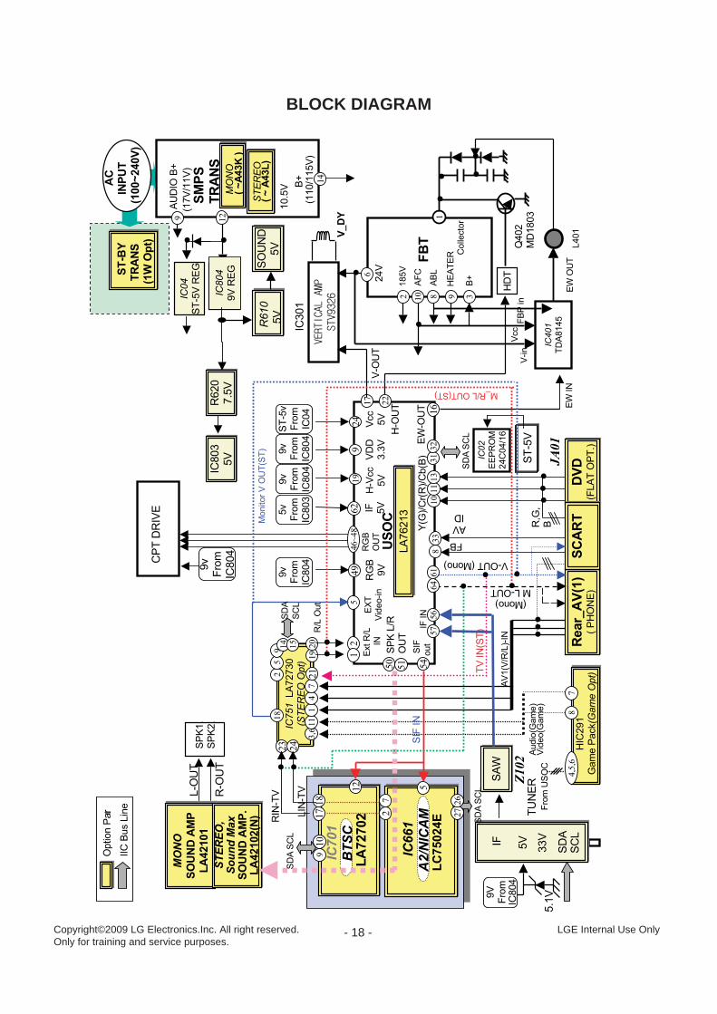
BLOCK DIAGRAM
LA76213
LA76213
DVD
(FLATOPT.)
DVD
(FLATOPT.)
CPTDRIVE
FBT
185V
AFC
ABL
HEATER
B+
HDT
Collector
AV1(V/R/L)-IN
USOC
AUDIO
B+
B+
(110/115V)
(17V/11V)
SMPS
TRANS
SCL
SDA
EXT
Video-in
RGB
OUT
TUNER
V_DY
Rear_AV(1)
(PHONE)
Rear_AV(1)
(PHONE)
IC02
EEPROM
24C04/16
V-OUT
H-OUT
SPK1.
10.5V
Y(G)/Cr(R)/Cb(B)
SDA
SCL
LC75024E
A2/NICAM
MONO
SOUNDAMP
LA42101
MONO
SOUNDAMP
LA42101
AC
INPUT
(100~240V)
STEREO,
SoundMax
SOUNDAMP.
LA42102(N)
STEREO,
SoundMax
SOUNDAMP.
LA42102(N)
R610
5V
OptionPart
IICBusLine
(Mono)
ML-OUT
31
22
17
546~48
STEREO
(~A43L)
MONO
(~A43K)
129
398102
6
24V
1
ST-BY
TRANS
(1W
Opt)
57
56
64
9V
From
IC804
IC804
9VREG
IC04
ST-5VREG
9v
From
IC804
IC661
5V
5.1V
IC751LA72730
(STEREOOpt)
IC751LA72730
(STEREOOpt)
JA01
HIC291
GamePack(GameOpt)
HIC291
GamePack(GameOpt)
4,5,6
87
FromUSOC
Video(Game)
Audio(Game)
54
SIF
out
IF
3,6
11
14
7
25
9
LA72702
BTSC
IC701
LIN-TV
RIN-TV
211920
R/LOut
L-OUT
R-OUT
SAW
SAW
5
910
IFIN
Z102
101113
14
15
12
SIF
IN
32
61
V-OUT(Mono)
18
1718
27
50
ExtR/L
IN
49
RGB
9V
SCL
SDA
2726
33V
ST-5V
9v
From
IC804
9v
From
IC804
ST-5v
From
IC04
19
924
H-Vcc
5V
VDD
3.3V
Vcc
5V
9v
From
IC804
14
SOUND
5V
SOUND
5V
R620
7.5V
R620
7.5V
IC803
5V
IC803
5V
Q402
MD1803
IC401
TDA8145
IC301
V-in
FBPin
EW
OUT
L401
Vcc
16
EW-OUT EW
IN
5v
From
IC803
62 IF 5V
SDA
SCL
23
24
SCL
SDA
51
SPKL/R
OUT
SCART
SCART
R,G,
B
833
FB
AV
ID
21 TVIN(ST)
M_R/LOUT(ST)
MonitorVOUT(ST)
SPK2.
Copyright©2009 LG Electronics.Inc. All right reserved.Only for training and service purposes.
LGE Internal Use Only

- 19 -
PRINTED CIRCUIT BOARDMAIN
Copyright©2009 LG Electronics.Inc. All right reserved.Only for training and service purposes.
LGE Internal Use Only

CONTROL
PIP (option)
LED+PRE AMP
- 20 -Copyright©2009 LG Electronics.Inc. All right reserved.Only for training and service purposes.
LGE Internal Use Only

- 21 -
EXPLODED VIEW
Copyright©2009 LG Electronics.Inc. All right reserved.Only for training and service purposes.
LGE Internal Use Only
400
112
170 150
520
174
104
504
120
300
590
530
310
331
330 320
943
913
105
591
570(option)
Many electrical and mechanical parts in this chassis have special safety-related characteristics.Theseparts are identified by in the Schematic Diagram and EXPLODED VIEW.It is essential that these special safety parts should be replaced with the same components asrecommended in this manual to prevent X-RADIATION,Shock, Fire, or other Hazards.Do not modify the original design without permission of manufacturer.
IMPORTANT SAFETY NOTICE
P/NO.:3854VA0196E (08.05.21)

SVC. SHEET : 3854VA0196E-S
Related Documents