can u THE FEA TURE OF PRODUC T Air Conditioner Mode Mode can help you sleep quickly and soundly and wake up refreshed. Silence Mod o y , " e d o M e c n e l i S " e h t e s u u o y n e h W experience extremely quiet operation of your air conditioner. ASV12(09)PSBAN* AQV12PSBANXAX COLD ONLY Basic Model AQV12PWAN AQV12PWAX Model Code HEAT PUMP Basic Model Model Code ASV12(09)PSBAX* AQV12PSBANXAX AQV12PSBAXXAX ASV12PSBANXAP ASV12PSBAXXAP ASV09PSBANXAP ASV09PSBAXXAP ASV12PSBANXAX ASV12PSBAXXAX ASV09PSBANXAX ASV09PSBAXXAX AQV12PSBAXXAX ASV12PSBANXAZ ASV12PSBAXXAZ ASV09PSBAXXAZ ASV09PSBANXAZ ASV12(09)PSBAN* ASV12(09)PSBAX* ASV12PSBANXLA ASV12PSBAXXLA ASV09PSBANXLA ASV09PSBAXXLA

Welcome message from author
This document is posted to help you gain knowledge. Please leave a comment to let me know what you think about it! Share it to your friends and learn new things together.
Transcript
canu
THE FEA TURE OF PRODUC T
Air Conditioner
ModeMode can help you sleep quickly and
soundly and wake up refreshed.
Silence Modoy,"edoMecneliS"ehtesuuoynehW
experience extremely quiet operation of yourair conditioner.
ASV12(09)PSBAN*AQV12PSBANXAX
COLD ONLY
Basic Model AQV12PWAN AQV12PWAX
Model Code
HEAT PUMP
Basic Model
Model Code
ASV12(09)PSBAX*
AQV12PSBANXAX
AQV12PSBAXXAX
ASV12PSBANXAP ASV12PSBAXXAP
ASV09PSBANXAP ASV09PSBAXXAP
ASV12PSBANXAX ASV12PSBAXXAX
ASV09PSBANXAX ASV09PSBAXXAX
AQV12PSBAXXAX
ASV12PSBANXAZ ASV12PSBAXXAZ
ASV09PSBAXXAZASV09PSBANXAZ
ASV12(09)PSBAN*
ASV12(09)PSBAX*
ASV12PSBANXLA ASV12PSBAXXLA
ASV09PSBANXLA ASV09PSBAXXLA
Operating Instructions and Installation
Samsung Electronics 1
Contents
11. Precautions ........................................................................................................................................ 1-1
1-1 Installing the air conditioner .......................................................................................................... 1-1
1-2 Power supply and circuit breaker .................................................................................................. 1-1
1-3 During operation .............................................................................................................................. 1-1
1-4 Disposing of the unit ....................................................................................................................... 1-2
1-5 Others ................................................................................................................................................. 1-2
12. Product Specifications ............................................................................................................... 2-1
2-1 The Feature of Product .................................................................................................................... 2-1
2-2 Product Specifications ..................................................................................................................... 2-2
2-3 The Comparative Specifications of Product ................................................................................ 2-3
2-4 Accessory and Option Specifications ........................................................................................... 2-4
13. Alignment and Adjustments ................................................................................................. 3-1
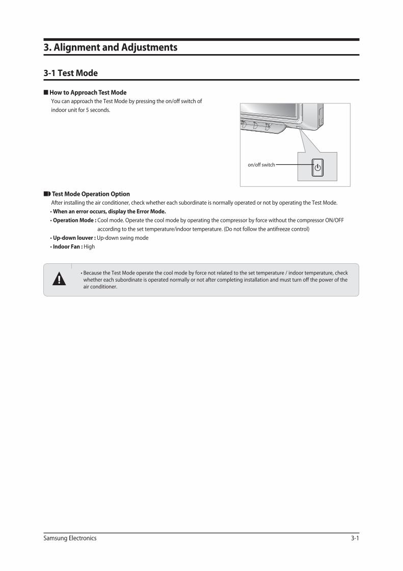
3-1 Test Mode ........................................................................................................................................... 3-1
3-2 Display Error and Check Method ................................................................................................... 3-2
3-3 Setting Option Setup Method ....................................................................................................... 3-4
14. Disassembly and Reassembly .............................................................................................. 4-1
4-1 Indoor Unit ......................................................................................................................................... 4-2
4-2 Outdoor Unit .................................................................................................................................... 4-8
15. Exploded Views and Parts List ............................................................................................. 5-1
5-1 Indoor Unit ......................................................................................................................................... 5-1
5-2 Outdoor Unit ..................................................................................................................................... 5-3
5-3 Ass’y Control In ................................................................................................................................. 5-5
5-4 Ass’y Control Out .............................................................................................................................. 5-7
16. Electrical Parts List ....................................................................................................................... 6-1
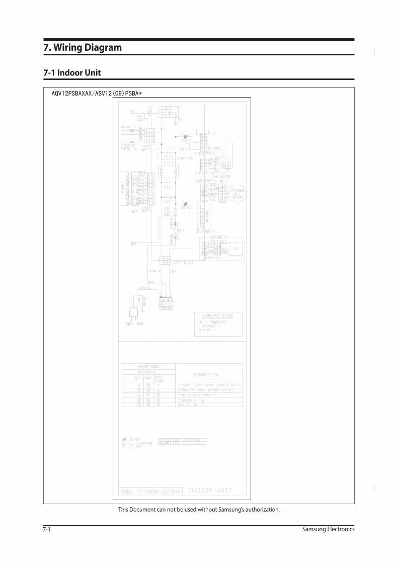
17. Wiring Diagram .............................................................................................................................. 7-1
7-1 Indoor Unit ......................................................................................................................................... 7-1
7-2 Outdoor Unit .................................................................................................................................... 7-2
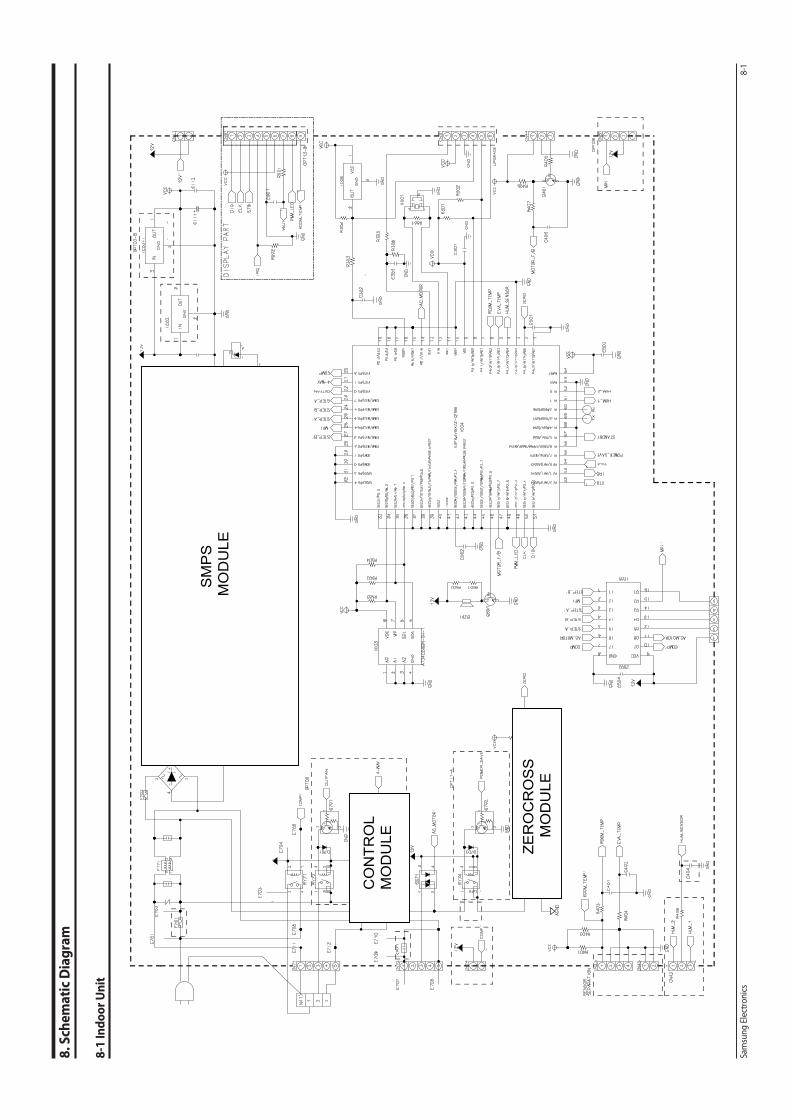
18. Schematic Diagram ..................................................................................................................... 8-1
8-1 Indoor Unit ......................................................................................................................................... 8-1
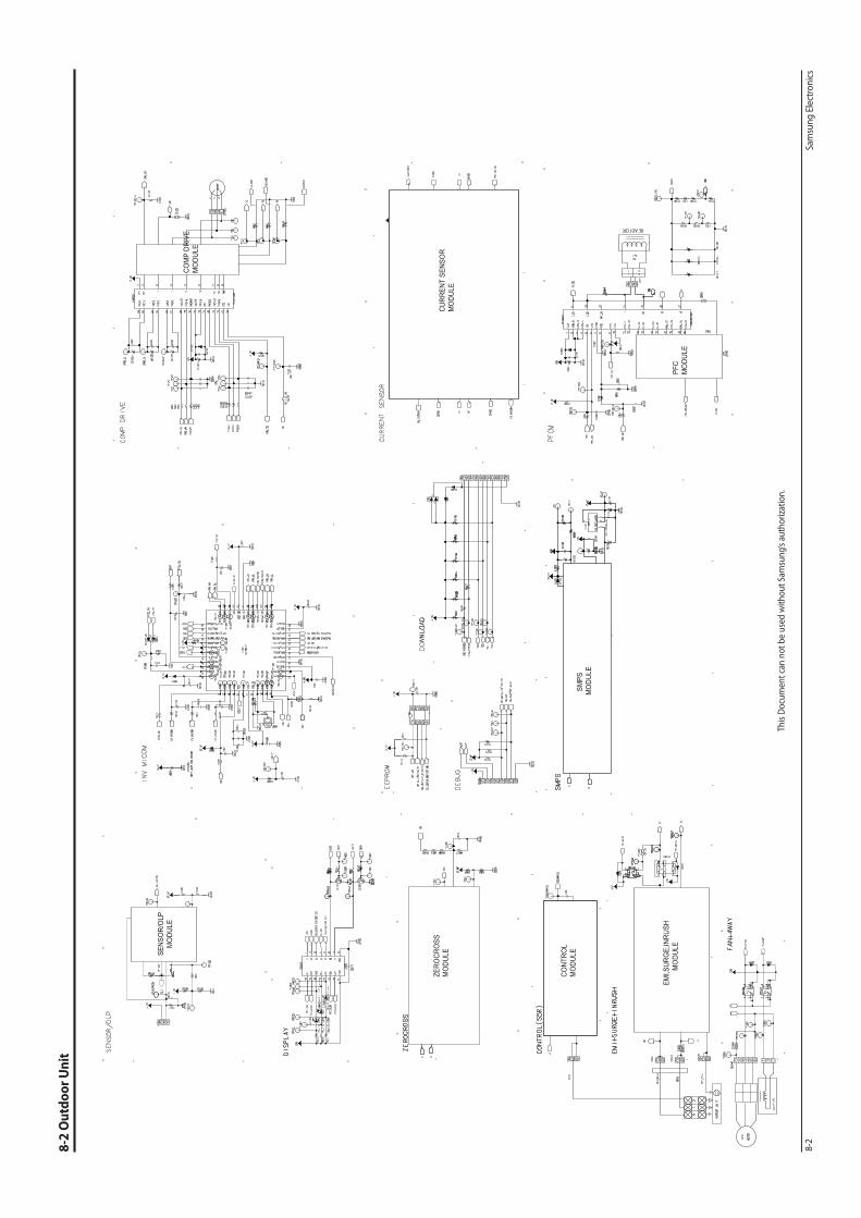
8-2 Outdoor Unit .................................................................................................................................... 8-2

Operating Instructions and Installation
2 Samsung Electronics
Contents
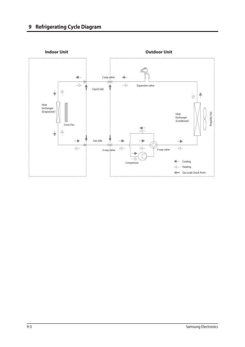
9. Re�gerating Cycle Diagram...................................................................................................................... 9-1
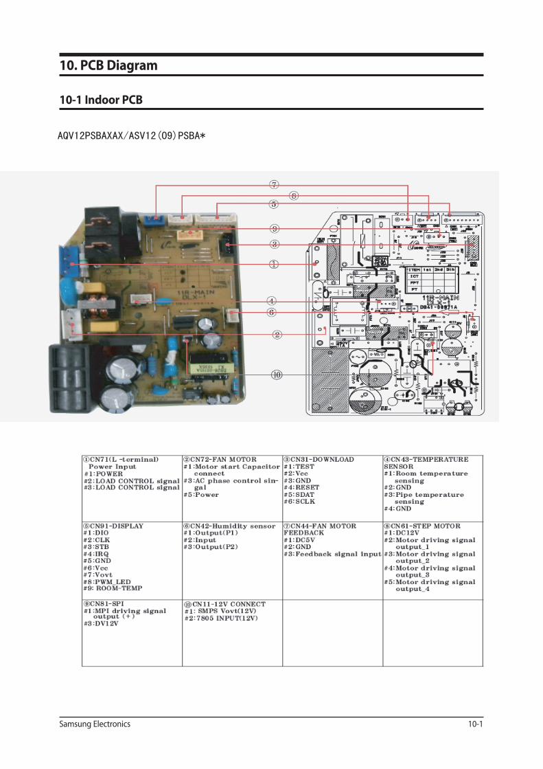
10. PCB Diagram ..................................................................................................................................... 10-110-1 Indoor PCB ....................................................................................................................................... 10-1
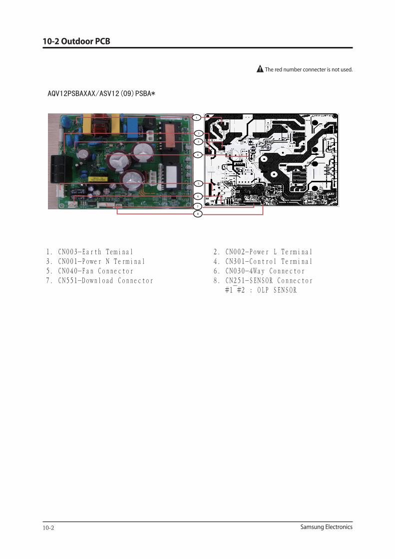
10-2 Outdoor PCB ................................................................................................................................... 10-2
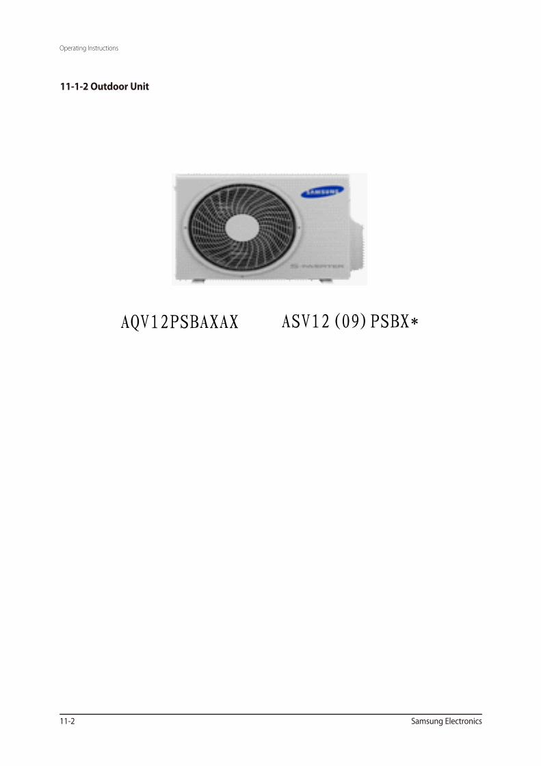
11. Operating Instructions .............................................................................................................. 11-111-1 Name of Each Part .......................................................................................................................... 11-1
11-2 Wireless Remote Control-Buttons and Display ........................................................................ 11-3 11-3 Main Function ................................................................................................................................. 11-4
12. Troubleshooting ............................................................................................................................ 12-112-1 Items to be checked rst ............................................................................................................... 12-1
12-2 Fault Diagnosis by Symptom ....................................................................................................... 12-2
12-3 PCB Inspection Method ................................................................................................................ 12-25
12-4 Main Part Inspection Method ...................................................................................................... 12-27
13. Block Diagram ................................................................................................................................. 13-113-1 Indoor Unit ...................................................................................................................................... 13-1
13-2 Outdoor Unit ................................................................................................................................... 13-3
14. Reference Sheet .............................................................................................................................. 14-114-1 Index for Model Name .................................................................................................................. 14-1
14-2 Low Refrigerant Pressure Distribution ....................................................................................... 14-2
14-3 Pressure & Capacity mark ............................................................................................................. 14-3
14-4 Q & A for Non-trouble ................................................................................................................... 14-4
14-5 Cleaning/Filter Change ................................................................................................................. 14-7
14-6 Installation ....................................................................................................................................... 14-9
14-7 Installation Diagram of Indoor Unit and Outdoor Unit .......................................................... 14-10
15.WORKING RANGE .........................................................................................................................15-115-1 Power Supply .............................................................................................................................15-115-2 Working Range ..........................................................................................................................15-1
15-2-1 MULTIZONE/MONOZONE/SUMMIT ...........................................................................15-115-2-2 BIGFLOW................................................................................................................................15-2
good' sleep Mode
good’sleep mode can help you sleep quickly and soundly and wake up refreshed.
Catechin Filter
Silver Nano Evaporator
Deodorizing Filter
them with clean,refreshing air.

2-2 Samsung Electronics
Indoor Unit Outdoor Unit Indoor Unit Outdoor Unit
kW(Low / Std / Max)
Hz(Low / Std / Max)
ℓ/h㎥/min(H/M/L)
41 53 43 53
W/W(Std)ph-V-Hz
W(Low / Std / Max)
A(Low / Std / Max)
%(Low / Std / Max)
Dimension (Net) W x H x D mm 820 x 285 x 205 720 x 548 x 265 820 x 285 x 205 720 x 548 x 265kg 8.2 26.5 8.2 27.5
LiquidGas
Dia x L(mm)
TypeRated Output
Cross Flow Fan Propeller Cross Flow Fan PropellerType
Rated Output 17W 32W 17W 32W
Heat Exchanger (Dia.,Row x Step x Length,mm)Φ7.0, 2 x 10 x L605
(Main)Φ7.0, 2 x 4 x L575
Φ7.0, 1 x 24 x L757Φ7.0, 2 x 10 x L605
(Main)Φ7.0, 2 x 4 x L575 Φ9.52, 1 x 20 x L757.6
Refrigerant Control UnitFreezer Oil Capacity ccRefrigerant to Change (R410A) gProtection Device (OLP)Cooling Test ConditionHeating Test ConditionOperation conditon range Indoor
Outdoor
Type
Drain Hose
Dia.(mm) x L(m)
TypeCompressor
Motor
Oil TypeType
BlowerMotor
Power
PowerConsumtionOperatingCurrentPowerFactor
Size
Weight (Net)
RefrigerantPipe
ASV09PSBA(N/X)*
dB
Model
Performance
Capacity
RunningFrequency
Dehumidifying
Air Volume
Noise
EnergyEfficiency
Power
18 / 46 /60 18 / 67 / 75
16 / 14 / 12
Wall-Mounted Wall-Mounted
0.75 / 2.65 / 3.20 0.75 / 3.53 / 3.80
3.40 3.21
1 - 230/- 60
20 / 16 / 13
0.4 0.8
1.7 / 4.8 / 5.6
77 / 92 / 93 76 / 94 / 95
290 / 740 / 1110 290 / 1030 / 1210
1.7 / 3.8 / 5.0
Hermetic
FREOLα68ES-T
Resin / Steel, AC
EEV
Φ 6.35 x 5Φ 9.52 x 5Φ 20 x 550
UG0A090FUBEP-SS
875W
Indoor Unit : DB20°C WB 15°C, Outdoor Unit : DB7°C WB 6°C
730 910N.A
Indoor Unit : DB27°C WB 19°C, Outdoor Unit : DB35°C WB 24°C
320
16°C ~ 32°C16°C ~ 46°C
(Sub) (Sub)
ASV12PSBA(N/X)*
2-2 Samsung Electronics
Indoor Unit Outdoor Unit
Cooling kWHeating (Low / Std / Max)Cooling HzHeating (Low / Std / Max)
ℓ/hCooling ㎥/minHeating (H/M/L)Cooling 43 53
Heating 43 53
Cooling KW/KWHeating (Std)
ph-V-HzCooling WHeating (Low / Std / Max)Cooling AHeating (Low / Std / Max)Cooling %Heating (Low / Std / Max)
Dimension (Net) W x H x D mm 820 x 285 x 205 720 x 548 x 265
kg 8.2 27.5
LiquidGas
Dia x L(mm)
TypeRated Output
Cross Flow Fan Propeller
TypeRated Output 17W 32W
Heat Exchanger (Dia.,Row x Step x Length,mm)Φ
Φ
Φ7.0, 2 x 10 x L605(Main)
Φ7.0, 2 x 4 x L575 Φ 9.52, 1 x 20 x L757.6
Refrigerant Control UnitFreezer Oil Capacity ccRefrigerant to Change (R410A) gProtection Device (OLP)Cooling Test ConditionHeating Test ConditionOperation conditon range Indoor
OutdoorIndoorOutdoor
Cooling
Heating
Type
Drain Hose
Dia.(mm) x L(m)
TypeCompressor
Motor
Oil TypeType
BlowerMotor
Power
PowerConsumtionOperatingCurrentPowerFactor
Size
Weight (Net)
RefrigerantPipe
AQV12PSBAXAX
dB
Model
Performance
Capacity
RunningFrequency
Dehumidifying
Air Volume
Noise
EnergyEfficiency
Power
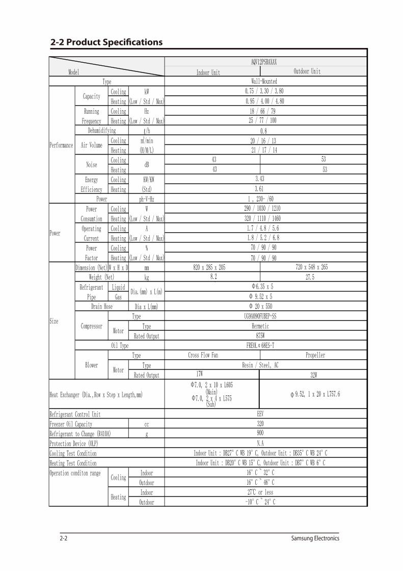
18 / 66 / 7925 / 77 / 100
Wall-Mounted0.75 / 3.30 / 3.80
0.95 / 4.00 / 4.80
3.43
3.61
1 , 230- /60
20 / 16 / 1321 / 17 / 14
0.8
1.7 / 4.8 / 5.61.8 / 5.2 / 6.870 / 90 / 90
70 / 90 / 90
290 / 1030 / 1210
320 / 1110 / 1460
-10°C ~ 24°C
Hermetic
FREOLα68ES-T
Resin / Steel, AC
EEV
Φ 6.35 x 5
Φ 9.52 x 5Φ 20 x 550
UG9A090FUBEP-SS
875W
Indoor Unit : DB20°C WB 15°C, Outdoor Unit : DB7°C WB 6°C
900
N.AIndoor Unit : DB27°C WB 19°C, Outdoor Unit : DB35°C WB 24°C
320
16°C ~ 32°C16°C ~ 46°C27℃ or less
(Sub)
AQV12PSBAXAX
2-3 The Comparative Specificati ons of Product
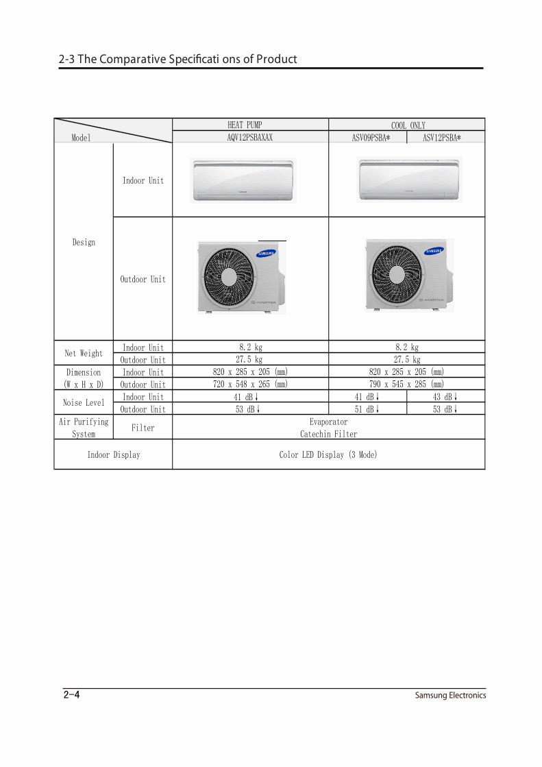
AQV12PSBAXAX ASV09PSBA* ASV12PSBA*
Indoor UnitOutdoor Unit 27.5 kg
Indoor UnitOutdoor UnitIndoor Unit 41 dB↓ 41 dB↓ 43 dB↓Outdoor Unit 53 dB↓ 51 dB↓ 53 dB↓
Air PurifyingSystem
Filter
Design
Net Weight
720 x 548 x 265 (mm)820 x 285 x 205 (mm)790 x 545 x 285 (mm)
Indoor Unit
Outdoor Unit
Color LED Display (3 Mode)
EvaporatorCatechin Filter
Model
HEAT PUMP COOL ONLY
8.2 kg 8.2 kg
Noise Level
Indoor Display
Dimension(W x H x D)
27.5 kg820 x 285 x 205 (mm)
2-4

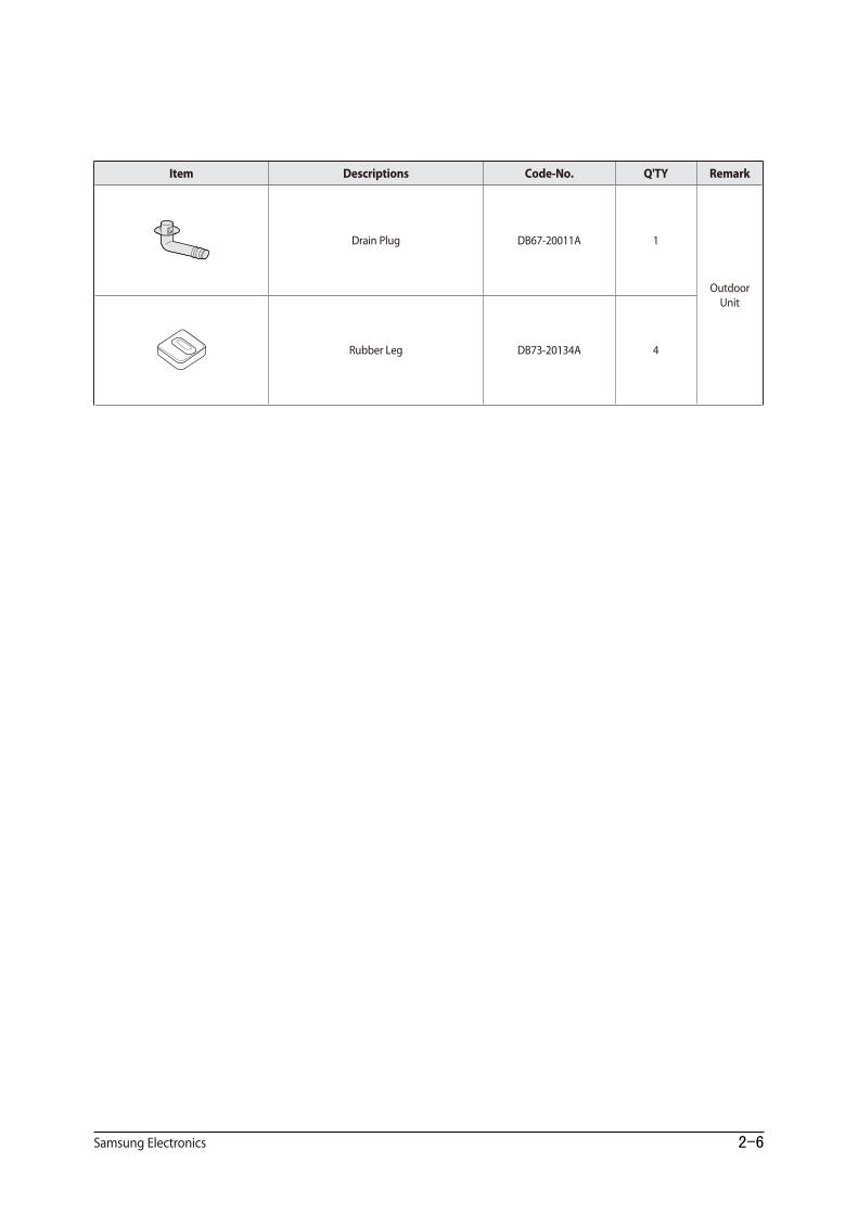
DB98-32436A
DB93-11115K
DB97-02851C
2-5
2-6
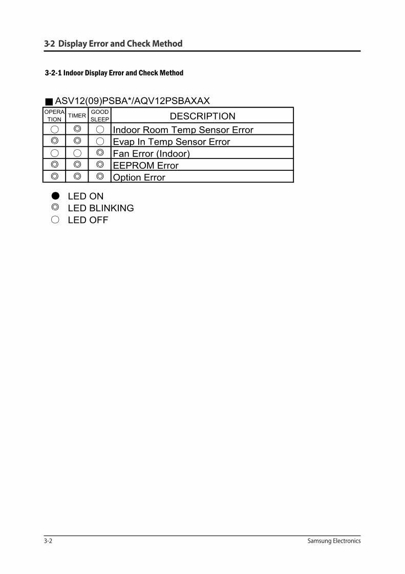
■ ASV12(09)PSBA*/AQV12PSBAXAXOPERATION
TIMER GOODSLEEP DESCRIPTION
○ ◎ ○ Indoor Room Temp Sensor Error◎ ◎ ○ Evap In Temp Sensor Error○ ○ ◎ Fan Error (Indoor)◎ ◎ ◎ EEPROM Error◎ ◎ ◎ Option Error
● LED ON◎ LED BLINKING○ LED OFF
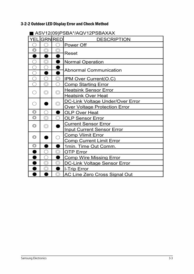
■ ASV12(09)PSBA*/AQV12PSBAXAXYEL GRN RED DESCRIPTION○ ○ ○ Power Off◎ ◎ ◎
● ● ●
○ ◎ ● Normal Operation○ ○ ●
○ ● ●
○ ○ ◎ IPM Over Current(O.C)○ ◎ ○ Comp Starting Error
Heatsink Sensor ErrorHeatsink Over HeatDC-Link Voltage Under/Over ErrorOver Voltage Protection Error
◎ ○ ● OLP Over Heat◎ ◎ ○ OLP Sensor Error
Current Sensor ErrorInput Current Sensor ErrorComp Vlimit ErrorComp Current Limit Error
◎ ● ● 1min. Time Out Comm.● ○ ◎ OTP Error● ○ ● Comp Wire Missing Error● ◎ ◎ DC-Link Voltage Sensor Error● ◎ ● I-Trip Error● ● ◎ AC Line Zero Cross Signal Out
Reset
Abnormal Communication
○ ◎ ◎
○ ● ◎
◎ ◎ ●
◎ ● ○
Samsung Electronics 4-1
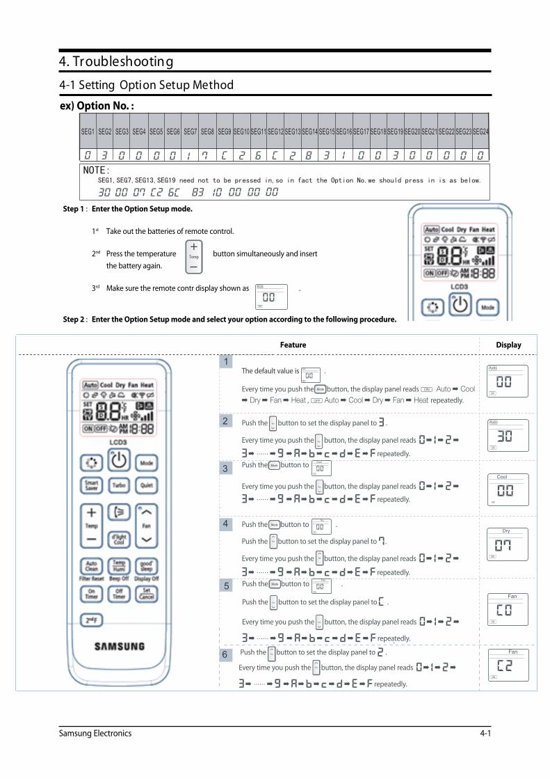
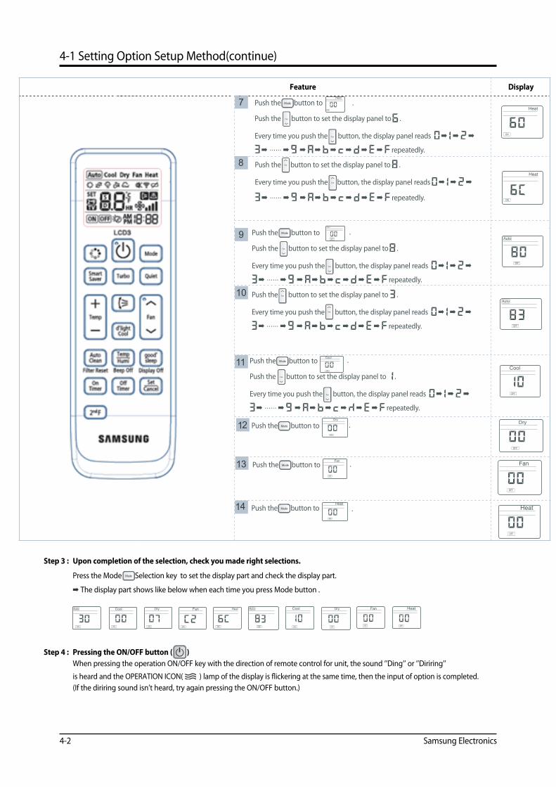
4-1 Setting Option Setup Method
4. Troubleshooting
SEG21 SEG22 SEG23 SEG24SEG16 SEG17 SEG18 SEG19 SEG20SEG11 SEG12 SEG13 SEG14 SEG15SEG6 SEG7 SEG8 SEG9 SEG10SEG1 SEG2 SEG3 SEG4 SEG5
NOTE: SEG1,SEG7,SEG13,SEG19 need not to be pressed in,so in fact the Option No.we should press in is as below.
4-2 Samsung Electronics
4-1 Setting Option Setup Method(continue)
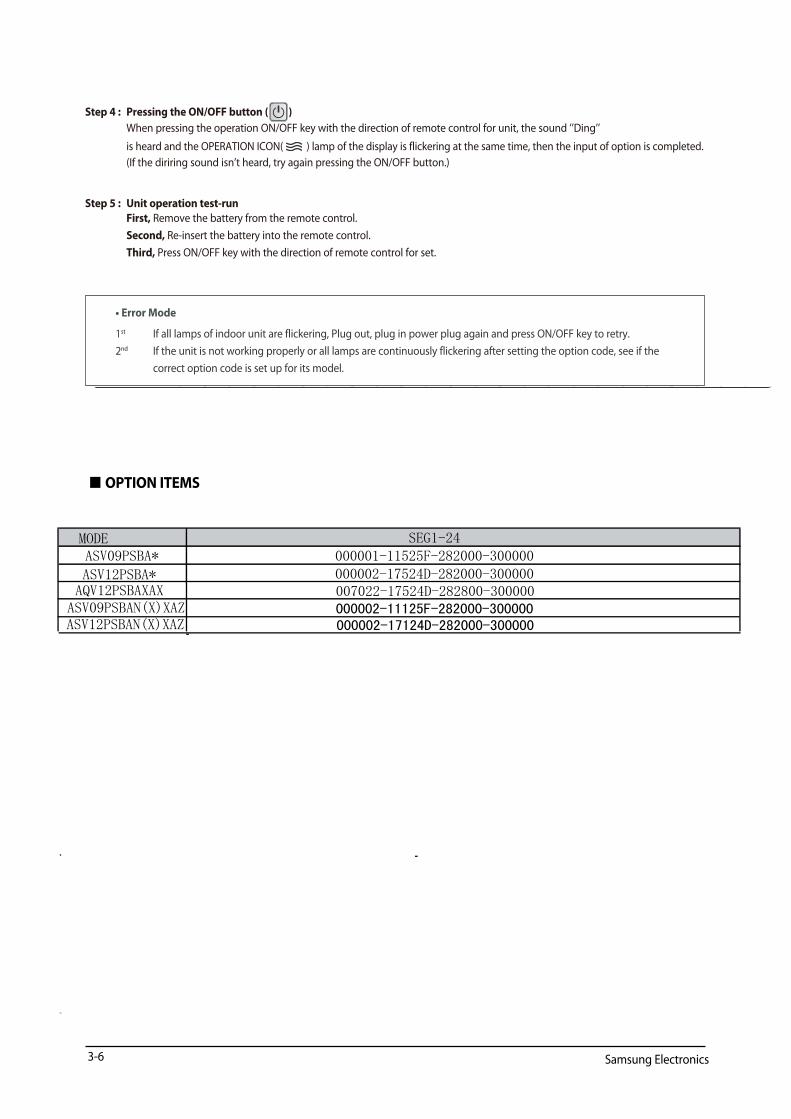
MODEASV09PSBA*
ASV12PSBA*
SEG1-24000001-11525F-282000-300000000002-17524D-282000-300000
AQV12PSBAXAX 007022-17524D-282800-300000ASV09PSBAN(X)XAZASV12PSBAN(X)XAZ
000002-11125F-282000-300000000002-17124D-282000-300000

4-2 Samsung Electronics
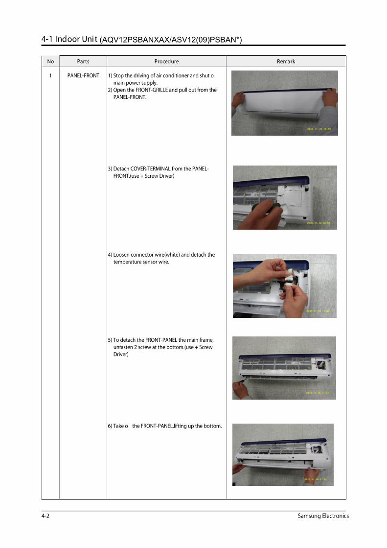
4-1 Indoor Unit
No Parts Procedure Remark
1 PANEL-FRONT 1) Stop the driving of air conditioner and shut o� main power supply.
2) Open the FRONT-GRILLE and pull out from the PANEL-FRONT.
3) Detach COVER-TERMINAL from the PANEL-FRONT.(use + Screw Driver)
4) Loosen connector wire(white) and detach the temperature sensor wire.
5) To detach the FRONT-PANEL the main frame, unfasten 2 screw at the bottom.(use + Screw Driver)
6) Take o� the FRONT-PANEL,lifting up the bottom.
(AQV12PSBANXAX/ASV12(09)PSBAN*)

Operating Instructions and Installation
Samsung Electronics 4-3
No Parts Procedure Remark
2 TRAY DRAIN 1) Loosen stepping motor wire and detach the hook of main frame.
2) To detach TRAY-DRAIN from the main frame, pull the bottom of the TRAY-DRAIN towards
you.
3 CONTROL IN 1) Unfasten the earth screw.(use + Screw Driver)
2) Detach COVER-CONTROL from the CASECONTROL.
3) Detach the temperature sensor.
4) Loosen MOTOR Wire.
5) Take o� the CASE-CONTROL from the main frame.
Operating Instructions and Installation
4-4 Samsung Electronics
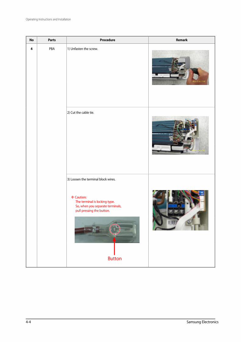
No Parts Procedure Remark
4 PBA 1) Unfasten the screw.
2) Cut the cable tie.
3) Loosen the terminal block wires.
Caution: The terminal is locking type. So, when you separate terminals, pull pressing the button.
Button
Operating Instructions and Installation
Samsung Electronics 4-5
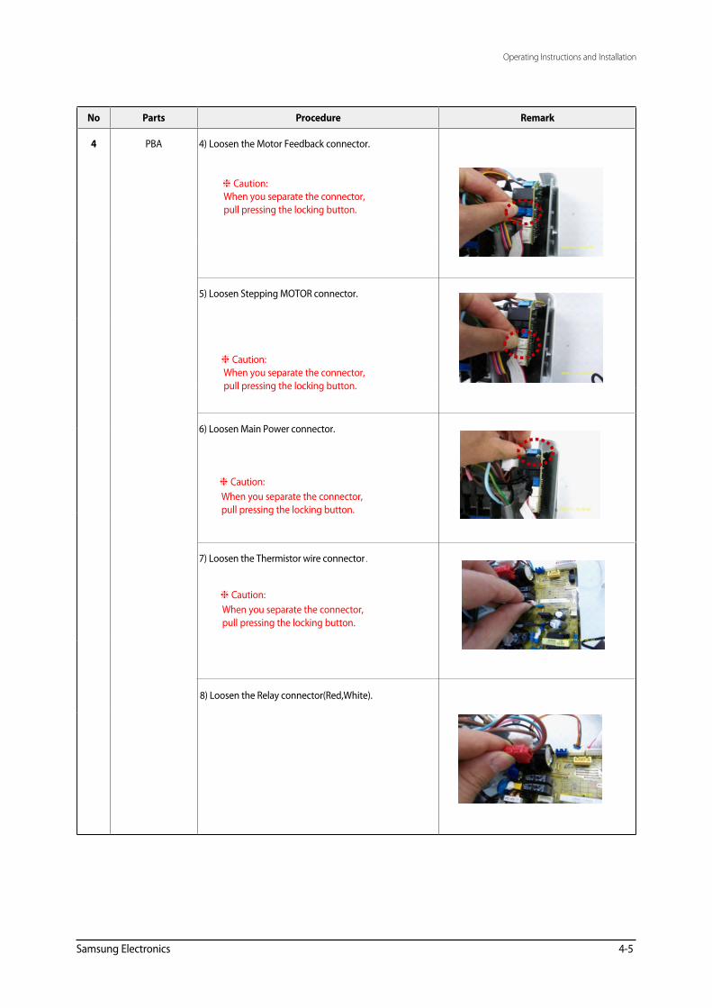
No Parts Procedure Remark
4 PBA 4) Loosen the Motor Feedback connector.
Caution: When you separate the connector, pull pressing the locking button.
5) Loosen Stepping MOTOR connector.
Caution: When you separate the connector, pull pressing the locking button.
6) Loosen Main Power connector.
Caution: When you separate the connector, pull pressing the locking button.
7) Loosen the Thermistor wire connector.
8) Loosen the Relay connector(Red,White).
Caution: When you separate the connector, pull pressing the locking button.
Operating Instructions and Installation
4-6 Samsung Electronics
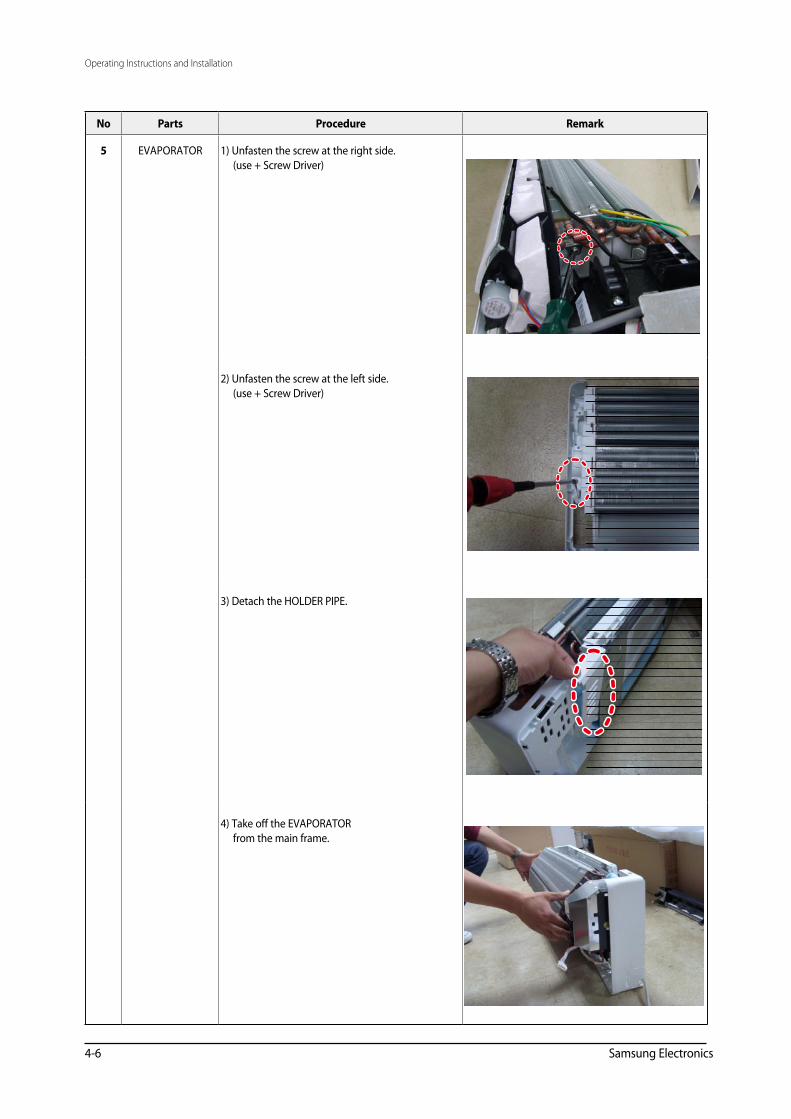
No Parts Procedure Remark
5 EVAPORATOR 1) Unfasten the screw at the right side. (use + Screw Driver)
2) Unfasten the screw at the left side. (use + Screw Driver)
3) Detach the HOLDER PIPE.
4) Take o� the EVAPORATOR from the main frame.
Operating Instructions and Installation
Samsung Electronics 4-7
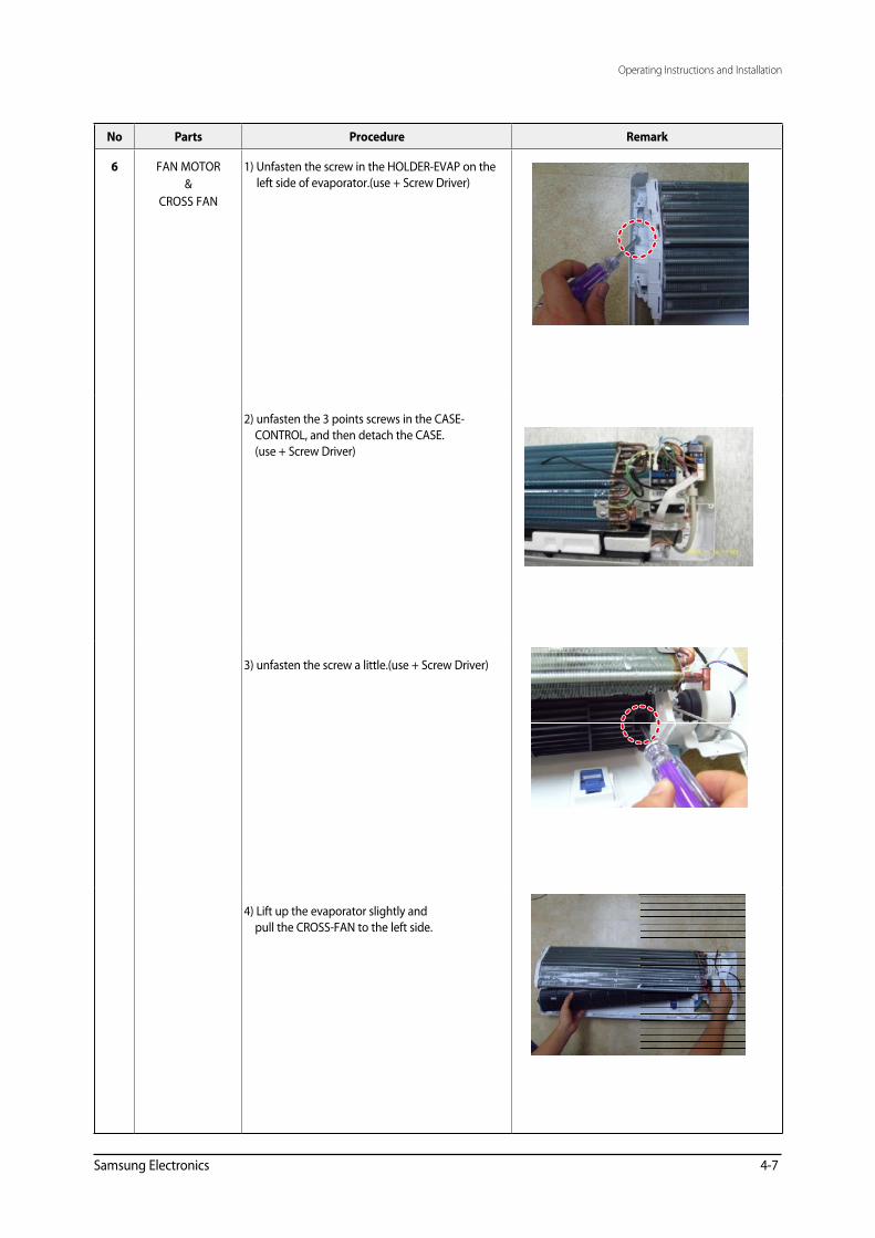
No Parts Procedure Remark
6 FAN MOTOR&
CROSS FAN
1) Unfasten the screw in the HOLDER-EVAP on the left side of evaporator.(use + Screw Driver)
2) unfasten the 3 points screws in the CASE- CONTROL, and then detach the CASE. (use + Screw Driver)
3) unfasten the screw a little.(use + Screw Driver)
4) Lift up the evaporator slightly and pull the CROSS-FAN to the left side.
4-8
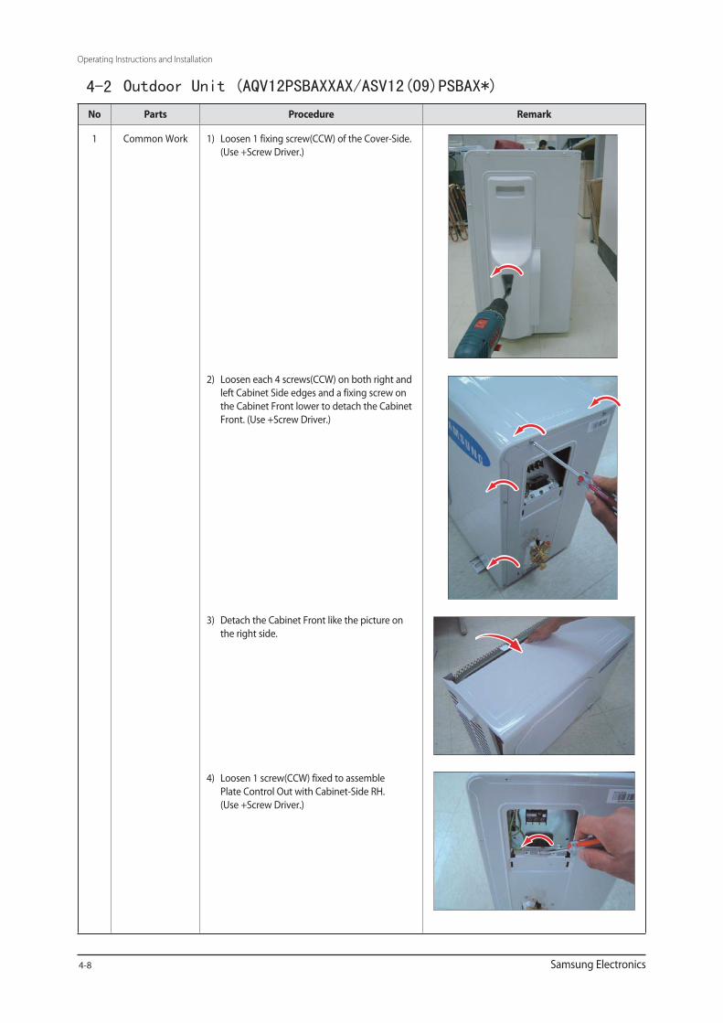
4-2 Outdoor Unit (AQV12PSBAXXAX/ASV12(09)PSBAX*)
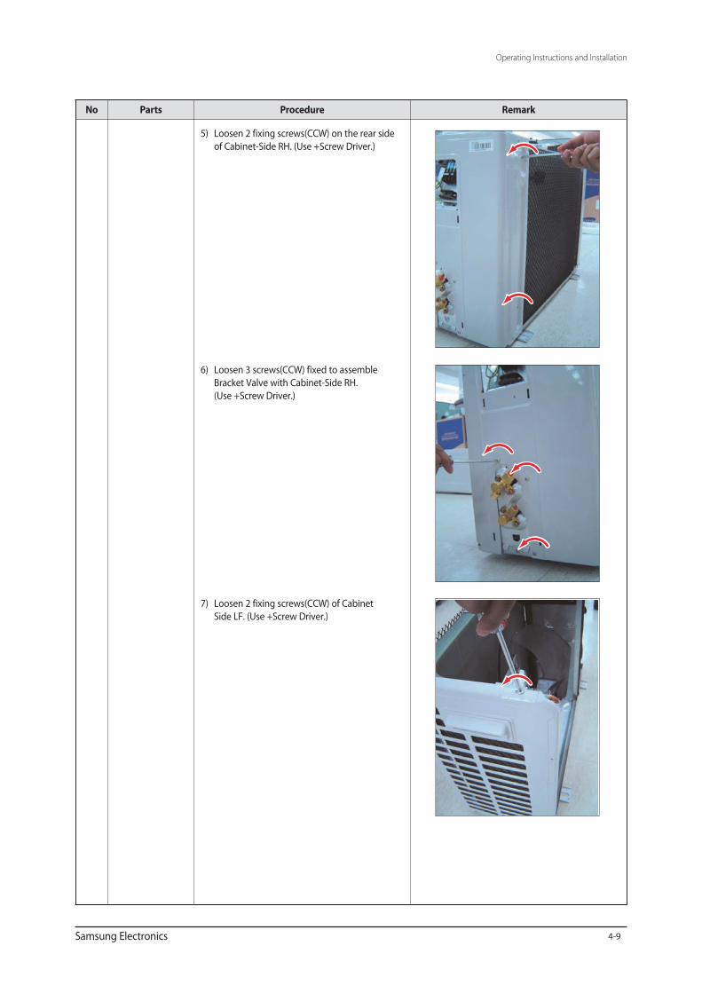
4-9

4-10
yu88.ji
图章
4-11
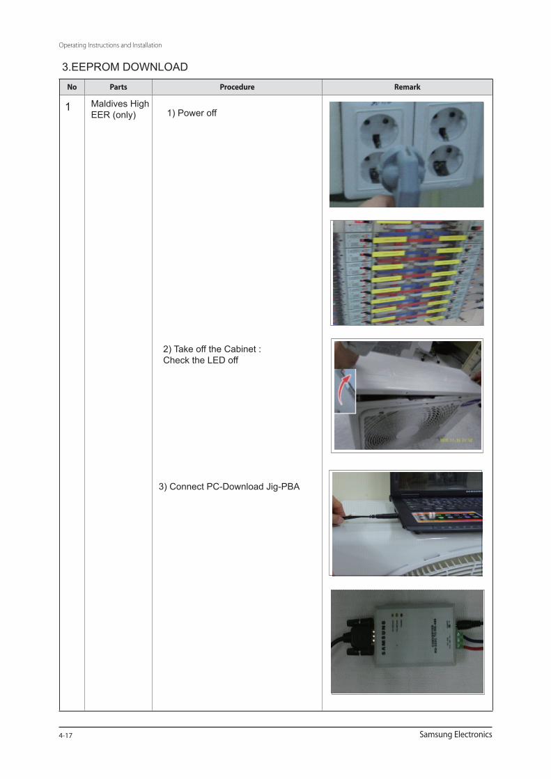
3) Connect PC-Download Jig-PBA
2) Take off the Cabinet : Check the LED off
4-17
Maldives High EER (only)
1 1) Power off
3.EEPROM DOWNLOAD
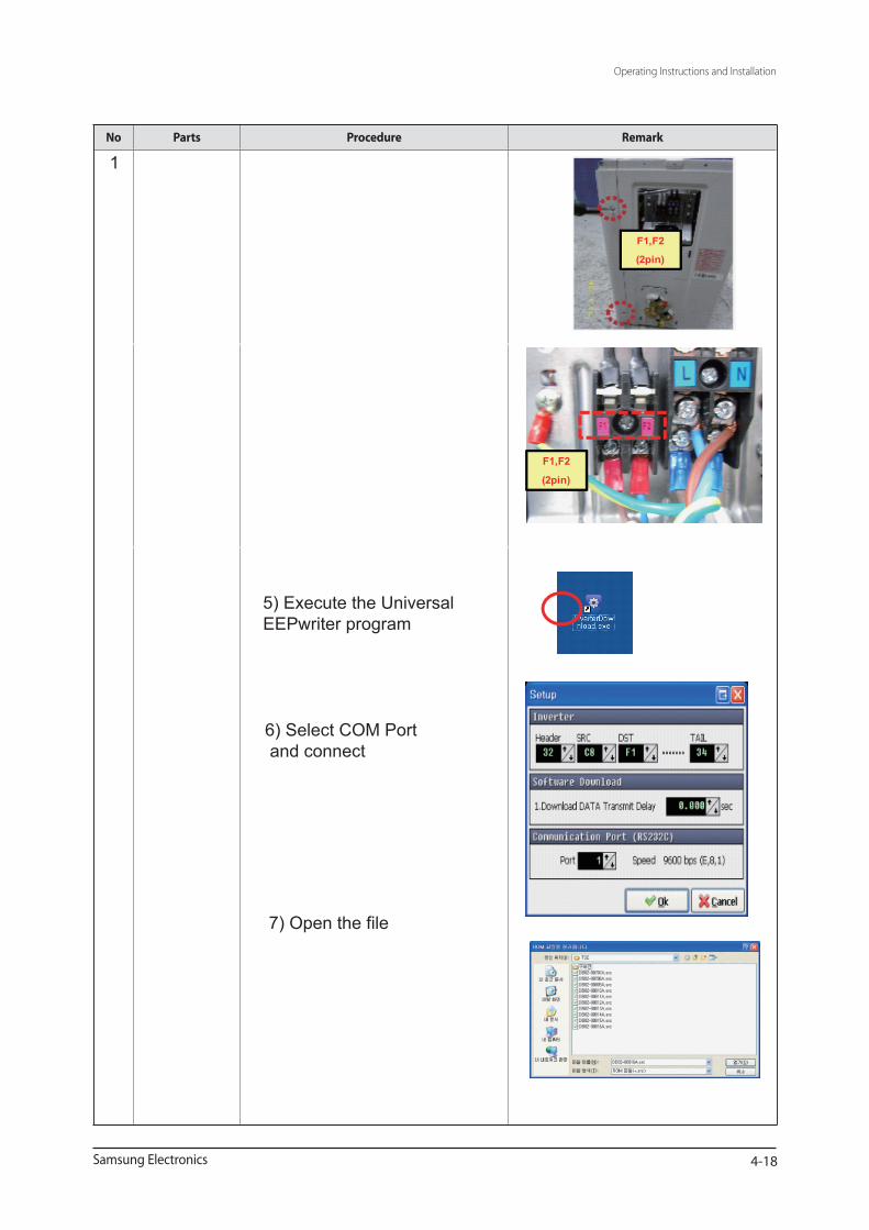
6) Select COM Port and connect
5) Execute the Universal EEPwriter program
4-18
F1,F2
(2pin)
F1,F2
(2pin)
7) Open the file
1

4-19
Download
6) CLICK
8) CLICK
7) CLICK
8) Click the Start button and reset the power
1

4-20
Maldives Normal EER (only)
1) Power off
2) Take off the Cabinet : Check the LED off
2
Download connector (10pin)
3) Connect PC-Download Jig-PBA

4-21
Download connector (10pin)
5) CLICK
7) CLICK8) CLICK
8) Start Download 7) Open the file
6) Select COM Port and connect
5) Execute the Universal EEPwriter program
3) Connect PC-Download Jig-PBA
Operating Instructions and Installation
Samsung Electronics 5-1
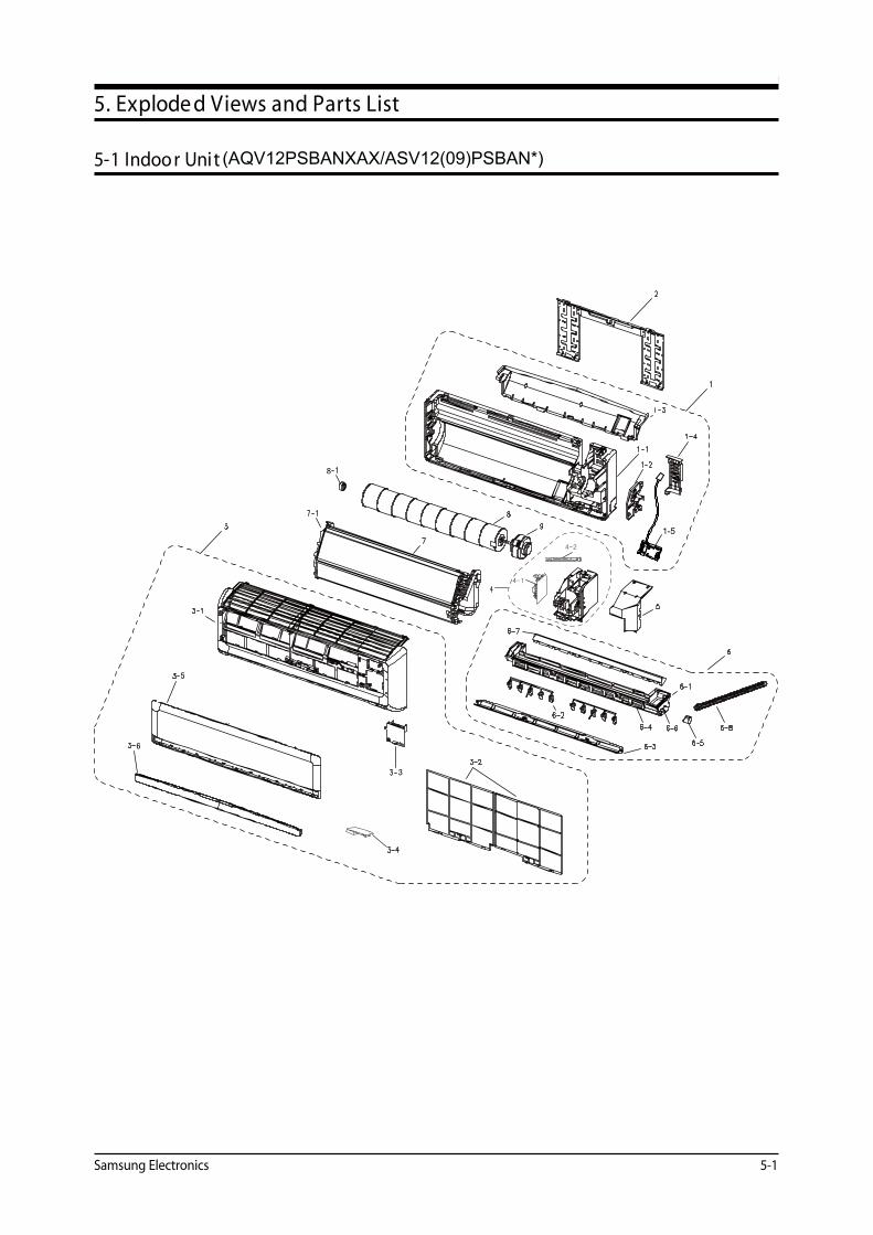
5. Explode d Views and Parts List
5-1 Indoo r Unit
8
6
5
3
(AQV12PSBANXAX/ASV12(09)PSBAN*)
1-5
5-2 Sam sung Electronics
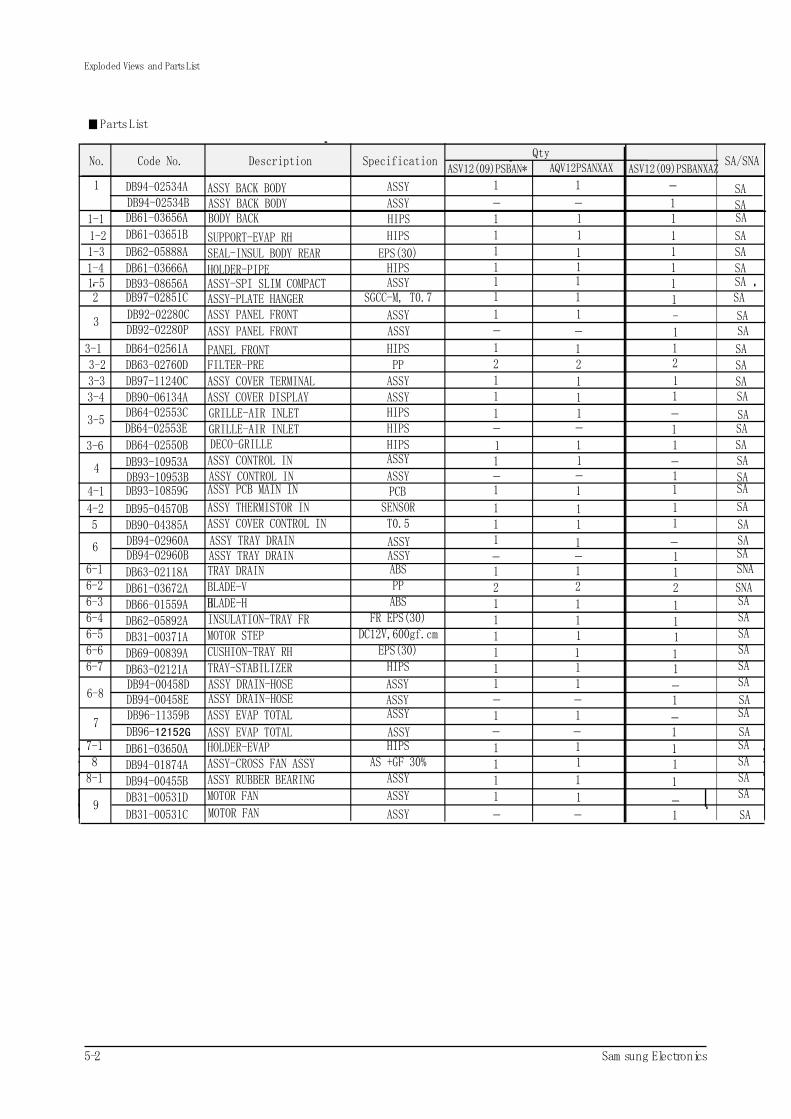
PartsList
Exploded Views and PartsList
1 DB94-02534A ASSY BACK BODY ASSY 1 SA
1-1 DB61-03656A BODY BACK HIPS 1SA
1-2 SUPPORT-EVAP RH HIPS 1 SA1-3 DB62-05888A SEAL-INSUL BODY REAR EPS(30) 1 SA1-4 DB61-03666A HOLDER-PIPE HIPS 1 SA
2 DB97-02851C ASSY-PLATE HANGER SGCC-M, T0.7 1 SA
3DB92-02280C ASSY PANEL FRONT ASSY 1
SA3-1 DB64-02561A PANEL FRONT HIPS 1
SA2
SA3-3 DB97-11240C ASSY COVER TERMINAL ASSY 1
SA
1
SA
SA
DB64-02550B 1
SA
SA/SNANo. Code No. Description SpecificationQty
ASV12(09)PSBAN* AQV12PSANXAX
4 DB93-10953A ASSY CONTROL IN ASSY 1
SNA
4-1 DB93-10859G ASSY PCB MAIN IN PCB 1
SASA
4-2 DB95-04570B ASSY THERMISTOR IN SENSOR 1
SA
5 DB90-04385A ASSY COVER CONTROL IN T0.5 1
SA
6 DB94-02960A ASSY TRAY DRAIN ASSY 1
SA
6-1 DB63-02118A TRAY DRAIN ABS 1
SA
6-2 DB61-03672A BLADE-V PP 2
SA
6-3 DB66-01559A BLADE-HH ABS 1
SA
6-4 DB62-05892A INSULATION-TRAY FR FR EPS(30) 1
SA
6-5 DB31-00371A MOTOR STEP DC12V,600gf.cm 1
SA
6-6 DB69-00839A CUSHION-TRAY RH EPS(30) 1
SA
6-7 DB63-02121A TRAY-STABILIZER HIPS 1
6-8DB94-00458D ASSY DRAIN-HOSE ASSY 1
7DB96-11359B ASSY EVAP TOTAL ASSY 1
7-1 DB61-03650A HOLDER-EVAP HIPS 18 DB94-01874A ASSY-CROSS FAN ASSY AS +GF 30% 1
8-1 DB94-00455B ASSY RUBBER BEARING ASSY 1
9DB31-00531D MOTOR FAN ASSY 1
DECO-GRILLE HIPS3-6 1
1
11
1
1
1
1
11
1
12
111
111
1
11
1
1
SA
DB61-03651B 1
SA
3-2 DB63-02760D FILTER-PRE PP
SA
2
3-5DB64-02553C GRILLE-AIR INLET HIPS 1
SA
3-4 DB90-06134A ASSY COVER DISPLAY ASSY
SA
1
SNA
1-5 DB93-08656A ASSY-SPI SLIM COMPACT ASSY 1 1 SA
1
1
1
1
ASV12(09)PSBANXAZ
SADB94-02534B ASSY BACK BODY ASSY 1
-- -
SADB92-02280P ASSY PANEL FRONT ASSY 1
1
11111
-- -
12
1
11
SA- -
-DB64-02553E GRILLE-AIR INLET HIPS
DB93-10953B ASSY CONTROL IN ASSY
1
1- --
11
1
DB94-02960B ASSY TRAY DRAIN ASSY 1- --
SA
SA
DB94-00458E ASSY DRAIN-HOSE ASSY
12
111
11
-1- -
DB96-12152G ASSY EVAP TOTAL ASSY-1- -
DB31-00531C MOTOR FAN ASSY
11
1
-1- - SA
SA
SA

3
6
12
4
28
AQV12PSBAXAX/ASV12(09)PSBA*
29
31
Samsung Electronics 5-6
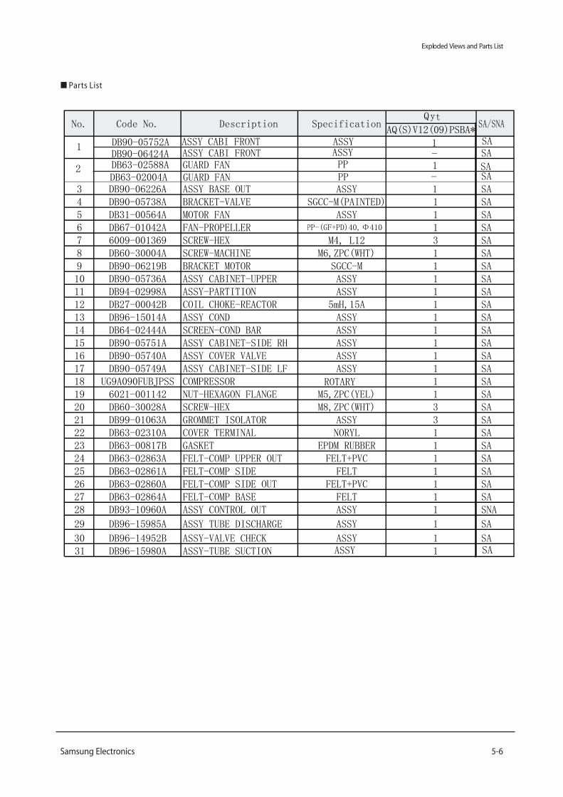
Exploded Views and Parts List
Parts List
Q ty
AQ(S)V12(09)PSBA*
1 DB90-05752A ASSY CABI FRONT ASSY 1SA
2 DB63-02588A GUARD FAN PP 1SA
3 DB90-06226A ASSY BASE OUT ASSY 1 SA4 DB90-05738A BRACKET-VALVE SGCC-M(PAINTED) 1 SA5 DB31-00564A MOTOR FAN ASSY 1 SA6 DB67-01042A FAN-PROPELLER PP-(GF+PD)40, Φ410 1 SA7 6009-001369 SCREW-HEX M4, L12 3 SA8 DB60-30004A SCREW-MACHINE M6,ZPC(WHT) 1 SA9 DB90-06219B BRACKET MOTOR SGCC-M 1 SA10 DB90-05736A ASSY CABINET-UPPER ASSY 1 SA11 DB94-02998A ASSY-PARTITION ASSY 1 SA12 DB27-00042B COIL CHOKE-REACTOR 5mH,15A 1 SA13 DB96-15014A ASSY COND ASSY 1 SA14 DB64-02444A SCREEN-COND BAR ASSY 1 SA15 DB90-05751A ASSY CABINET-SIDE RH ASSY 1 SA16 DB90-05740A ASSY COVER VALVE ASSY 1 SA17 DB90-05749A ASSY CABINET-SIDE LF ASSY 1 SA18 UG9A090FUBJPSS COMPRESSOR ROTARY 1 SA19 6021-001142 NUT-HEXAGON FLANGE M5,ZPC(YEL) 1 SA20 DB60-30028A SCREW-HEX M8,ZPC(WHT) 3 SA21 DB99-01063A GROMMET ISOLATOR ASSY 3 SA22 DB63-02310A COVER TERMINAL NORYL 1 SA23 DB63-00817B GASKET EPDM RUBBER 1 SA24 DB63-02863A FELT-COMP UPPER OUT FELT+PVC 1 SA25 DB63-02861A FELT-COMP SIDE FELT 1 SA26 DB63-02860A FELT-COMP SIDE OUT FELT+PVC 1 SA27 DB63-02864A FELT-COMP BASE FELT 1 SA28 DB93-10960A ASSY CONTROL OUT ASSY 1 SNA
29 DB96-15985A ASSY TUBE DISCHARGE ASSY 1 SA
30 DB96-14952B ASSY-VALVE CHECK ASSY 1 SA31 DB96-15980A ASSY-TUBE SUCTION 1
No. Code No. Description Specification SA/SNA
SAASSY
ASSY CABI FRONT ASSYSA
-DB90-06424A
PPSA
-DB63-02004A GUARD FAN
5-7
AQV12PSBAXAX/ASV12(09)PSBA*
APPLY MODEL
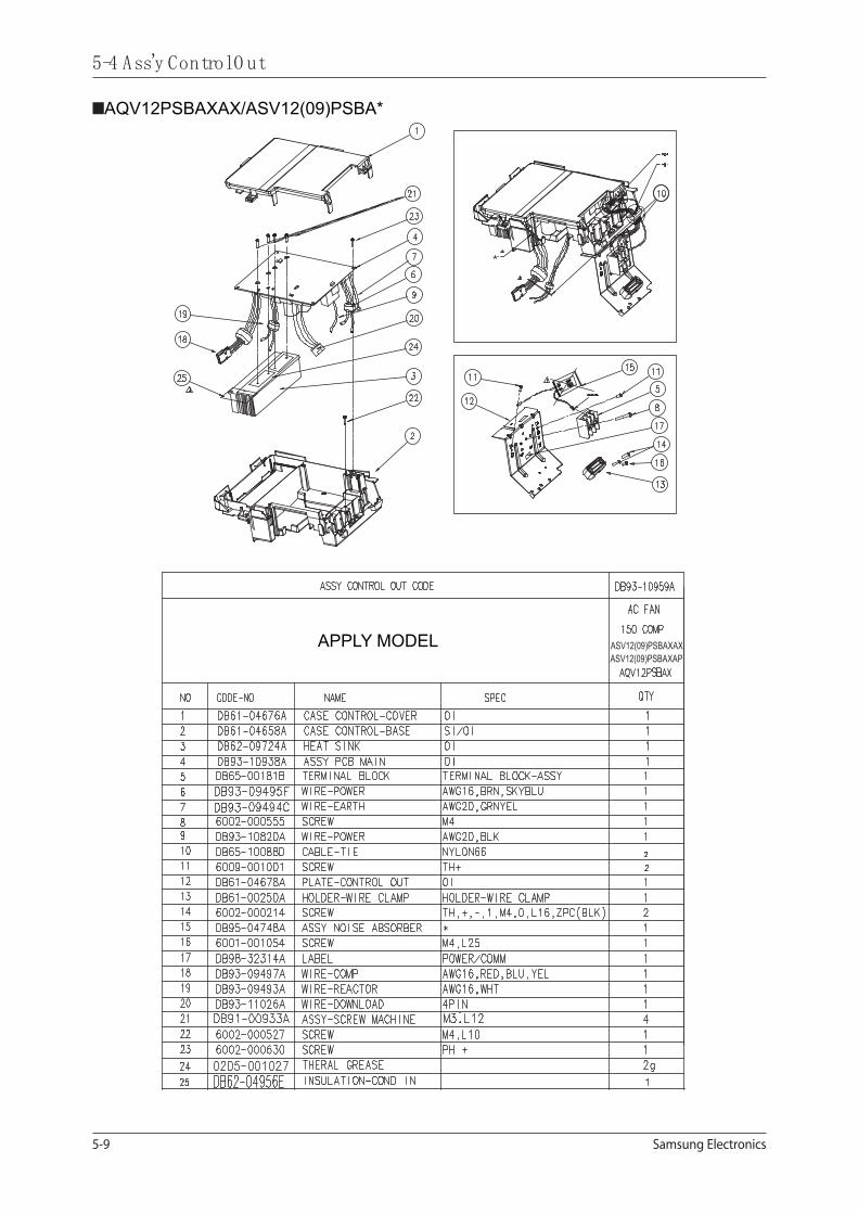
Samsung Electronics5-9
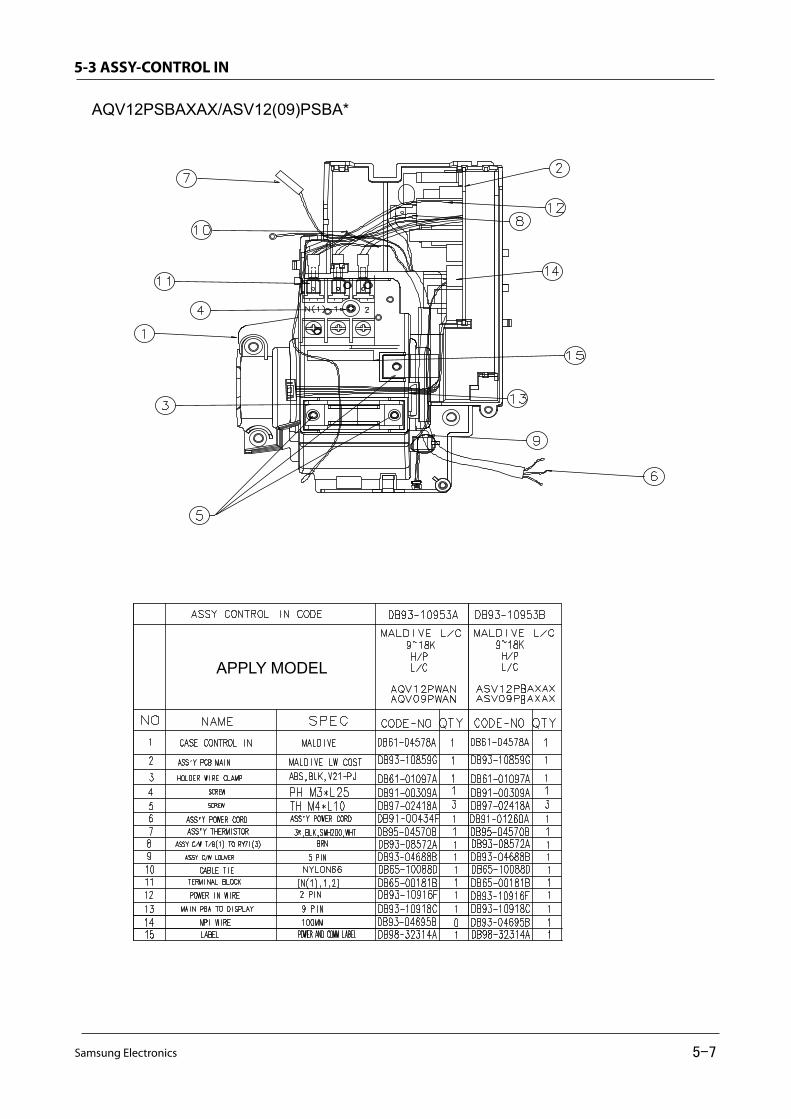
5-4 Ass'y ControlO ut
AQV12PSBAXAX/ASV12(09)PSBA*
APPLY MODEL ASV12(09)PSBAXAXASV12(09)PSBAXAP

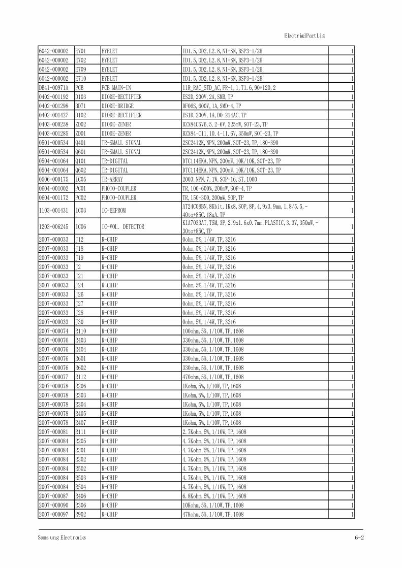
6.Elec tric al P ar ts List
INDOOR MAIN PCB( AQV12PSBAXAX/ASV12(09)PSBA*:DB93-10859G )
6-1 Samsung Electronics
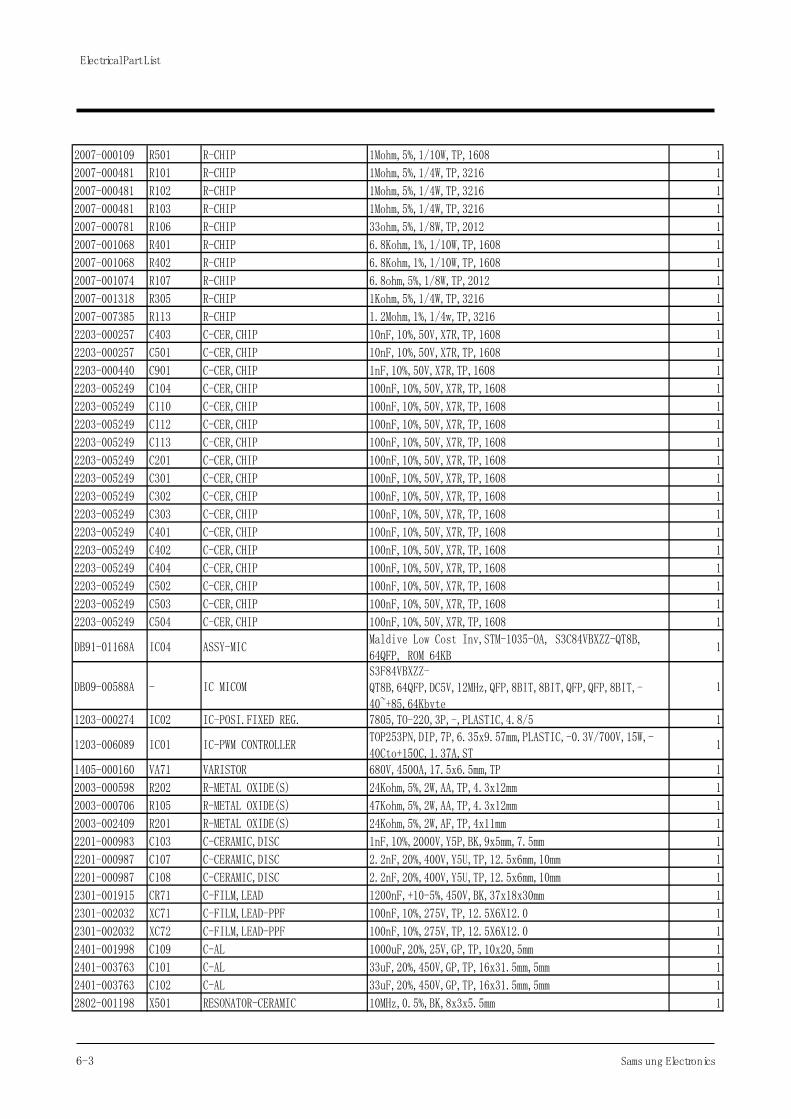
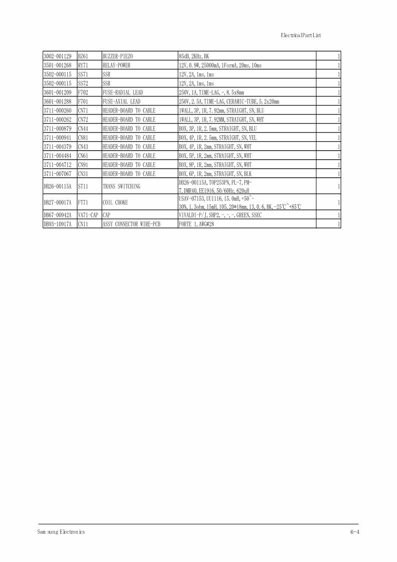
Electrical Part List
Parts Code Location Description Specification Q'TY
0402-000137 D101 DIODE-RECTIFIER 1N4007,1000V,1A,DO-41,TP 1
2001-000429 R901 R-CARBON 1Kohm,5%,1/8W,AA,TP,1.8x3.2mm 1
2002-001104 R108 R-COMPOSITION 12Mohm,5%,1/2W,AA,TP,3.4x9mm 1
2002-001104 R109 R-COMPOSITION 12Mohm,5%,1/2W,AA,TP,3.4x9mm 1
2401-000480 C106 C-AL 10uF,20%,50V,GP,TP,5x11,5 1
2401-000807 C111 C-AL 220uF,20%,16V,GP,TP,8x11.5,5 1
2401-002619 C105 C-AL 47uF,20%,25V,GP,TP,5x11,5 1
3812-001283 J10 WIRE-NO SHEATH CU FE+CU+SN,300V,52mm(TAPING),1/0.6mm 1
3812-001283 J11 WIRE-NO SHEATH CU FE+CU+SN,300V,52mm(TAPING),1/0.6mm 1
3812-001283 J13 WIRE-NO SHEATH CU FE+CU+SN,300V,52mm(TAPING),1/0.6mm 1
3812-001283 J14 WIRE-NO SHEATH CU FE+CU+SN,300V,52mm(TAPING),1/0.6mm 1
3812-001283 J15 WIRE-NO SHEATH CU FE+CU+SN,300V,52mm(TAPING),1/0.6mm 1
3812-001283 J16 WIRE-NO SHEATH CU FE+CU+SN,300V,52mm(TAPING),1/0.6mm 1
3812-001283 J17 WIRE-NO SHEATH CU FE+CU+SN,300V,52mm(TAPING),1/0.6mm 1
3812-001283 J20 WIRE-NO SHEATH CU FE+CU+SN,300V,52mm(TAPING),1/0.6mm 1
3812-001283 J22 WIRE-NO SHEATH CU FE+CU+SN,300V,52mm(TAPING),1/0.6mm 1
3812-001283 J23 WIRE-NO SHEATH CU FE+CU+SN,300V,52mm(TAPING),1/0.6mm 1
3812-001283 J25 WIRE-NO SHEATH CU FE+CU+SN,300V,52mm(TAPING),1/0.6mm 1
3812-001283 J29 WIRE-NO SHEATH CU FE+CU+SN,300V,52mm(TAPING),1/0.6mm 1
3812-001283 J3 WIRE-NO SHEATH CU FE+CU+SN,300V,52mm(TAPING),1/0.6mm 1
3812-001283 J31 WIRE-NO SHEATH CU FE+CU+SN,300V,52mm(TAPING),1/0.6mm 1
3812-001283 J32 WIRE-NO SHEATH CU FE+CU+SN,300V,52mm(TAPING),1/0.6mm 1
3812-001283 J33 WIRE-NO SHEATH CU FE+CU+SN,300V,52mm(TAPING),1/0.6mm 1
3812-001283 J34 WIRE-NO SHEATH CU FE+CU+SN,300V,52mm(TAPING),1/0.6mm 1
3812-001283 J4 WIRE-NO SHEATH CU FE+CU+SN,300V,52mm(TAPING),1/0.6mm 1
3812-001283 J5 WIRE-NO SHEATH CU FE+CU+SN,300V,52mm(TAPING),1/0.6mm 1
3812-001283 J6 WIRE-NO SHEATH CU FE+CU+SN,300V,52mm(TAPING),1/0.6mm 1
3812-001283 J7 WIRE-NO SHEATH CU FE+CU+SN,300V,52mm(TAPING),1/0.6mm 1
3812-001283 J8 WIRE-NO SHEATH CU FE+CU+SN,300V,52mm(TAPING),1/0.6mm 1
3812-001283 J9 WIRE-NO SHEATH CU FE+CU+SN,300V,52mm(TAPING),1/0.6mm 1
3812-001283 JP RY74 WIRE-NO SHEATH CU FE+CU+SN,300V,52mm(TAPING),1/0.6mm 1
3812-001283 JPNTC WIRE-NO SHEATH CU FE+CU+SN,300V,52mm(TAPING),1/0.6mm 1
6042-000001 E703 EYELET ID2.2,OD2.7,L3.1,NI+SN,BSP3-1/2H 1
6042-000001 E704 EYELET ID2.2,OD2.7,L3.1,NI+SN,BSP3-1/2H 1
6042-000001 E705 EYELET ID2.2,OD2.7,L3.1,NI+SN,BSP3-1/2H 1
6042-000001 E706 EYELET ID2.2,OD2.7,L3.1,NI+SN,BSP3-1/2H 1
6042-000001 E707 EYELET ID2.2,OD2.7,L3.1,NI+SN,BSP3-1/2H 1
6042-000001 E708 EYELET ID2.2,OD2.7,L3.1,NI+SN,BSP3-1/2H 1
6042-000001 E711 EYELET ID2.2,OD2.7,L3.1,NI+SN,BSP3-1/2H 1
6042-000001 E712 EYELET ID2.2,OD2.7,L3.1,NI+SN,BSP3-1/2H 1
6042-000002 E101 EYELET ID1.5,OD2,L2.8,NI+SN,BSP3-1/2H 1
6042-000002 E102 EYELET ID1.5,OD2,L2.8,NI+SN,BSP3-1/2H 1
6042-000002 E103 EYELET ID1.5,OD2,L2.8,NI+SN,BSP3-1/2H 1
6042-000002 E104 EYELET ID1.5,OD2,L2.8,NI+SN,BSP3-1/2H 1
6-2Sams ung Electronics
Electrical Part List
6042-000002 E701 EYELET ID1.5,OD2,L2.8,NI+SN,BSP3-1/2H 1
6042-000002 E702 EYELET ID1.5,OD2,L2.8,NI+SN,BSP3-1/2H 1
6042-000002 E709 EYELET ID1.5,OD2,L2.8,NI+SN,BSP3-1/2H 1
6042-000002 E710 EYELET ID1.5,OD2,L2.8,NI+SN,BSP3-1/2H 1
DB41-00971A PCB PCB MAIN-IN 11R_RAC_STD_AC,FR-1,1,T1.6,90*120,2 1
0402-001192 D103 DIODE-RECTIFIER ES2D,200V,2A,SMB,TP 1
0402-001298 BD71 DIODE-BRIDGE DF06S,600V,1A,SMD-4,TP 1
0402-001427 D102 DIODE-RECTIFIER ES1D,200V,1A,DO-214AC,TP 1
0403-000258 ZD02 DIODE-ZENER BZX84C5V6,5.2-6V,225mW,SOT-23,TP 1
0403-001285 ZD01 DIODE-ZENER BZX84-C11,10.4-11.6V,350mW,SOT-23,TP 1
0501-000534 Q401 TR-SMALL SIGNAL 2SC2412K,NPN,200mW,SOT-23,TP,180-390 1
0501-000534 Q601 TR-SMALL SIGNAL 2SC2412K,NPN,200mW,SOT-23,TP,180-390 1
0504-001064 Q101 TR-DIGITAL DTC114EKA,NPN,200mW,10K/10K,SOT-23,TP 1
0504-001064 Q602 TR-DIGITAL DTC114EKA,NPN,200mW,10K/10K,SOT-23,TP 1
0506-000175 IC05 TR-ARRAY 2003,NPN,7,1W,SOP-16,ST,1000 1
0604-001002 PC01 PHOTO-COUPLER TR,100-600%,200mW,SOP-4,TP 1
0604-001172 PC02 PHOTO-COUPLER TR,150-300,200mW,SOP,TP 1
1103-001431 IC03 IC-EEPROMAT24C08BN,8Kbit,1Kx8,SOP,8P,4.9x3.9mm,1.8/5.5,-40to+85C,18uA,TP
1
1203-006245 IC06 IC-VOL. DETECTORKIA7033AT,TSM,3P,2.9x1.6x0.7mm,PLASTIC,3.3V,350mW,-30to+85C,TP
1
2007-000033 J12 R-CHIP 0ohm,5%,1/4W,TP,3216 1
2007-000033 J18 R-CHIP 0ohm,5%,1/4W,TP,3216 1
2007-000033 J19 R-CHIP 0ohm,5%,1/4W,TP,3216 1
2007-000033 J2 R-CHIP 0ohm,5%,1/4W,TP,3216 1
2007-000033 J21 R-CHIP 0ohm,5%,1/4W,TP,3216 1
2007-000033 J24 R-CHIP 0ohm,5%,1/4W,TP,3216 1
2007-000033 J26 R-CHIP 0ohm,5%,1/4W,TP,3216 1
2007-000033 J27 R-CHIP 0ohm,5%,1/4W,TP,3216 1
2007-000033 J28 R-CHIP 0ohm,5%,1/4W,TP,3216 1
2007-000033 J30 R-CHIP 0ohm,5%,1/4W,TP,3216 1
2007-000074 R110 R-CHIP 100ohm,5%,1/10W,TP,1608 1
2007-000076 R403 R-CHIP 330ohm,5%,1/10W,TP,1608 1
2007-000076 R404 R-CHIP 330ohm,5%,1/10W,TP,1608 1
2007-000076 R601 R-CHIP 330ohm,5%,1/10W,TP,1608 1
2007-000076 R602 R-CHIP 330ohm,5%,1/10W,TP,1608 1
2007-000077 R112 R-CHIP 470ohm,5%,1/10W,TP,1608 1
2007-000078 R206 R-CHIP 1Kohm,5%,1/10W,TP,1608 1
2007-000078 R303 R-CHIP 1Kohm,5%,1/10W,TP,1608 1
2007-000078 R304 R-CHIP 1Kohm,5%,1/10W,TP,1608 1
2007-000078 R405 R-CHIP 1Kohm,5%,1/10W,TP,1608 1
2007-000078 R407 R-CHIP 1Kohm,5%,1/10W,TP,1608 1
2007-000081 R111 R-CHIP 2.7Kohm,5%,1/10W,TP,1608 1
2007-000084 R205 R-CHIP 4.7Kohm,5%,1/10W,TP,1608 1
2007-000084 R301 R-CHIP 4.7Kohm,5%,1/10W,TP,1608 1
2007-000084 R302 R-CHIP 4.7Kohm,5%,1/10W,TP,1608 1
2007-000084 R502 R-CHIP 4.7Kohm,5%,1/10W,TP,1608 1
2007-000084 R503 R-CHIP 4.7Kohm,5%,1/10W,TP,1608 1
2007-000084 R504 R-CHIP 4.7Kohm,5%,1/10W,TP,1608 1
2007-000087 R406 R-CHIP 6.8Kohm,5%,1/10W,TP,1608 1
2007-000090 R306 R-CHIP 10Kohm,5%,1/10W,TP,1608 1
2007-000097 R902 R-CHIP 47Kohm,5%,1/10W,TP,1608 1
6-3 Sams ung Electronics
Electrical Part List
2007-000109 R501 R-CHIP 1Mohm,5%,1/10W,TP,1608 1
2007-000481 R101 R-CHIP 1Mohm,5%,1/4W,TP,3216 1
2007-000481 R102 R-CHIP 1Mohm,5%,1/4W,TP,3216 1
2007-000481 R103 R-CHIP 1Mohm,5%,1/4W,TP,3216 1
2007-000781 R106 R-CHIP 33ohm,5%,1/8W,TP,2012 1
2007-001068 R401 R-CHIP 6.8Kohm,1%,1/10W,TP,1608 1
2007-001068 R402 R-CHIP 6.8Kohm,1%,1/10W,TP,1608 1
2007-001074 R107 R-CHIP 6.8ohm,5%,1/8W,TP,2012 1
2007-001318 R305 R-CHIP 1Kohm,5%,1/4W,TP,3216 1
2007-007385 R113 R-CHIP 1.2Mohm,1%,1/4w,TP,3216 1
2203-000257 C403 C-CER,CHIP 10nF,10%,50V,X7R,TP,1608 1
2203-000257 C501 C-CER,CHIP 10nF,10%,50V,X7R,TP,1608 1
2203-000440 C901 C-CER,CHIP 1nF,10%,50V,X7R,TP,1608 1
2203-005249 C104 C-CER,CHIP 100nF,10%,50V,X7R,TP,1608 1
2203-005249 C110 C-CER,CHIP 100nF,10%,50V,X7R,TP,1608 1
2203-005249 C112 C-CER,CHIP 100nF,10%,50V,X7R,TP,1608 1
2203-005249 C113 C-CER,CHIP 100nF,10%,50V,X7R,TP,1608 1
2203-005249 C201 C-CER,CHIP 100nF,10%,50V,X7R,TP,1608 1
2203-005249 C301 C-CER,CHIP 100nF,10%,50V,X7R,TP,1608 1
2203-005249 C302 C-CER,CHIP 100nF,10%,50V,X7R,TP,1608 1
2203-005249 C303 C-CER,CHIP 100nF,10%,50V,X7R,TP,1608 1
2203-005249 C401 C-CER,CHIP 100nF,10%,50V,X7R,TP,1608 1
2203-005249 C402 C-CER,CHIP 100nF,10%,50V,X7R,TP,1608 1
2203-005249 C404 C-CER,CHIP 100nF,10%,50V,X7R,TP,1608 1
2203-005249 C502 C-CER,CHIP 100nF,10%,50V,X7R,TP,1608 1
2203-005249 C503 C-CER,CHIP 100nF,10%,50V,X7R,TP,1608 1
2203-005249 C504 C-CER,CHIP 100nF,10%,50V,X7R,TP,1608 1
DB91-01168A IC04 ASSY-MICMaldive Low Cost Inv,STM-1035-OA, S3C84VBXZZ-QT8B,64QFP, ROM 64KB
1
DB09-00588A - IC MICOMS3F84VBXZZ-QT8B,64QFP,DC5V,12MHz,QFP,8BIT,8BIT,QFP,QFP,8BIT,-40~+85,64Kbyte
1
1203-000274 IC02 IC-POSI.FIXED REG. 7805,TO-220,3P,-,PLASTIC,4.8/5 1
1203-006089 IC01 IC-PWM CONTROLLERTOP253PN,DIP,7P,6.35x9.57mm,PLASTIC,-0.3V/700V,15W,-40Cto+150C,1.37A,ST
1
1405-000160 VA71 VARISTOR 680V,4500A,17.5x6.5mm,TP 1
2003-000598 R202 R-METAL OXIDE(S) 24Kohm,5%,2W,AA,TP,4.3x12mm 1
2003-000706 R105 R-METAL OXIDE(S) 47Kohm,5%,2W,AA,TP,4.3x12mm 1
2003-002409 R201 R-METAL OXIDE(S) 24Kohm,5%,2W,AF,TP,4x11mm 1
2201-000983 C103 C-CERAMIC,DISC 1nF,10%,2000V,Y5P,BK,9x5mm,7.5mm 1
2201-000987 C107 C-CERAMIC,DISC 2.2nF,20%,400V,Y5U,TP,12.5x6mm,10mm 1
2201-000987 C108 C-CERAMIC,DISC 2.2nF,20%,400V,Y5U,TP,12.5x6mm,10mm 1
2301-001915 CR71 C-FILM,LEAD 1200nF,+10-5%,450V,BK,37x18x30mm 1
2301-002032 XC71 C-FILM,LEAD-PPF 100nF,10%,275V,TP,12.5X6X12.0 1
2301-002032 XC72 C-FILM,LEAD-PPF 100nF,10%,275V,TP,12.5X6X12.0 1
2401-001998 C109 C-AL 1000uF,20%,25V,GP,TP,10x20,5mm 1
2401-003763 C101 C-AL 33uF,20%,450V,GP,TP,16x31.5mm,5mm 1
2401-003763 C102 C-AL 33uF,20%,450V,GP,TP,16x31.5mm,5mm 1
2802-001198 X501 RESONATOR-CERAMIC 10MHz,0.5%,BK,8x3x5.5mm 1
6-4Sam sung Electronics
Electrical Part List
3002-001129 BZ61 BUZZER-PIEZO 85dB,2KHz,BK 1
3501-001268 RY71 RELAY-POWER 12V,0.9W,25000mA,1FormA,20ms,10ms 1
3502-000115 SS71 SSR 12V,2A,1ms,1ms 1
3502-000115 SS72 SSR 12V,2A,1ms,1ms 1
3601-001209 F702 FUSE-RADIAL LEAD 250V,1A,TIME-LAG,-,8.5x8mm 1
3601-001288 F701 FUSE-AXIAL LEAD 250V,2.5A,TIME-LAG,CERAMIC-TUBE,5.2x20mm 1
3711-000260 CN71 HEADER-BOARD TO CABLE 1WALL,3P,1R,7.92mm,STRAIGHT,SN,BLU 1
3711-000262 CN72 HEADER-BOARD TO CABLE 1WALL,3P,1R,7.92MM,STRAIGHT,SN,WHT 1
3711-000879 CN44 HEADER-BOARD TO CABLE BOX,3P,1R,2.5mm,STRAIGHT,SN,BLU 1
3711-000941 CN81 HEADER-BOARD TO CABLE BOX,4P,1R,2.5mm,STRAIGHT,SN,YEL 1
3711-004379 CN43 HEADER-BOARD TO CABLE BOX,4P,1R,2mm,STRAIGHT,SN,WHT 1
3711-004484 CN61 HEADER-BOARD TO CABLE BOX,5P,1R,2mm,STRAIGHT,SN,WHT 1
3711-004712 CN91 HEADER-BOARD TO CABLE BOX,9P,1R,2mm,STRAIGHT,SN,WHT 1
3711-007067 CN31 HEADER-BOARD TO CABLE BOX,6P,1R,2mm,STRAIGHT,SN,BLK 1
DB26-00115A ST11 TRANS SWITCHINGDB26-00115A,TOP253PN,PL-7,PM-7,DMR40,EE1916,50/60Hz,620uH
1
DB27-00017A FT71 COIL CHOKEUSAV-07153,UU1116,15.0mH,+50~-30%,1.3ohm,15mH,105,20*18mm,13,0.6,BK,-25℃~+85℃
1
DB67-00942A VA71-CAP CAP VIVALDI-P/J,SHP2,-,-,-,GREEN,SSEC 1
DB93-10917A CN11 ASSY CONNECTOR WIRE-PCB FORTE 1,AWG#28 1

INDOOR SUB PCB(DB93-10861A )
11
Parts Code Location
Description Specification Q'TY
0601-003048 LED5 LED ROUND,GRN,3 PI,573mm,3.0x5.0mm 1
0601-003048 LED6 LED ROUND,GRN,3 PI,573mm,3.0x5.0mm 1
0601-003048 LED7 LED ROUND,GRN,3 PI,573mm,3.0x5.0mm 1
3404-001220 SW01 SWITCH-TACT 12V,50mA,160gf,6x6x5,SPST 1
DB41-01017A PCB PCB SUB-DISPLAY FR-1,T1.6 1
0401-001099 D01 DIODE-SWITCHING 1N4148WS,75V,150mA,SOD-323,TP 1
0504-000127 Q01 TR-DIGITAL FJV3102R,NPN,200mW,10K/10Kohm,SOT-23,TP 1
0504-000127 Q02 TR-DIGITAL FJV3102R,NPN,200mW,10K/10Kohm,SOT-23,TP 1
0504-000127 Q03 TR-DIGITAL FJV3102R,NPN,200mW,10K/10Kohm,SOT-23,TP 1
2007-000033 J1 R-CHIP 0ohm,5%,1/4W,TP,3216 1
2007-000033 J2 R-CHIP 0ohm,5%,1/4W,TP,3216 1
2007-000072 R03 R-CHIP 47ohm,5%,1/10W,TP,1608 1
2007-000084 R01 R-CHIP 4.7Kohm,5%,1/10W,TP,1608 1
2007-000090 R02 R-CHIP 10Kohm,5%,1/10W,TP,1608 1
2007-001318 R04 R-CHIP 1Kohm,5%,1/4W,TP,3216 1
2007-001318 R05 R-CHIP 1Kohm,5%,1/4W,TP,3216 1
2007-001318 R06 R-CHIP 1Kohm,5%,1/4W,TP,3216 1
2007-001318 R07 R-CHIP 1Kohm,5%,1/4W,TP,3216 1
2007-001318 R08 R-CHIP 1Kohm,5%,1/4W,TP,3216 1
2007-001318 R09 R-CHIP 1Kohm,5%,1/4W,TP,3216 1
2203-000440 C03 C-CER,CHIP 1nF,10%,50V,X7R,TP,1608 1
2203-005249 C01 C-CER,CHIP 100nF,10%,50V,X7R,TP,1608 1
2203-005249 C02 C-CER,CHIP 100nF,10%,50V,X7R,TP,1608 1
0609-001391 IC01 MODULE REMOCON 6.5mm,TRAY 1
2401-002619 C04 C-AL 47uF,20%,25V,GP,TP,5x11,5 1
3711-004742 CN01 HEADER-BOARD TO CABLE BOX,9P,1R,2mm,ANGLE,SN,NTR 1
DB93-10943B CN01-1 ASSY CONNECTOR WIRE STAR-PJT,DISPLAY TO MAIN,MILLION MODEL 1
6-10Samsung Electronics
Electrical Part List
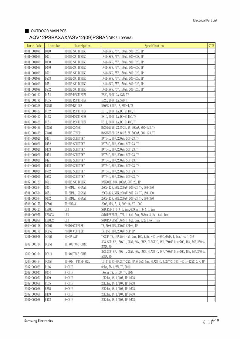
OUTDOOR MAIN PCB
AQV12PSBAXAX/ASV12(09)PSBA*(DB93-10938A)
Parts Code Location Description Specification Q'TY
0401-001099 D020 DIODE-SWITCHING 1N4148WS,75V,150mA,SOD-323,TP 1
0401-001099 D021 DIODE-SWITCHING 1N4148WS,75V,150mA,SOD-323,TP 1
0401-001099 D030 DIODE-SWITCHING 1N4148WS,75V,150mA,SOD-323,TP 1
0401-001099 D040 DIODE-SWITCHING 1N4148WS,75V,150mA,SOD-323,TP 1
0401-001099 D501 DIODE-SWITCHING 1N4148WS,75V,150mA,SOD-323,TP 1
0401-001099 D503 DIODE-SWITCHING 1N4148WS,75V,150mA,SOD-323,TP 1
0401-001099 D551 DIODE-SWITCHING 1N4148WS,75V,150mA,SOD-323,TP 1
0401-001099 D552 DIODE-SWITCHING 1N4148WS,75V,150mA,SOD-323,TP 1
0402-001192 D154 DIODE-RECTIFIER ES2D,200V,2A,SMB,TP 1
0402-001192 D155 DIODE-RECTIFIER ES2D,200V,2A,SMB,TP 1
0402-001298 BD151 DIODE-BRIDGE DF06S,600V,1A,SMD-4,TP 1
0402-001427 D152 DIODE-RECTIFIER ES1D,200V,1A,DO-214AC,TP 1
0402-001427 D153 DIODE-RECTIFIER ES1D,200V,1A,DO-214AC,TP 1
0402-001429 D151 DIODE-RECTIFIER US1J,600V,1A,DO-214AC,TP 1
0403-001499 ZD051 DIODE-ZENER MMSZ5252B,22.8/25.2V,500mW,SOD-123,TP 1
0403-001499 ZD401 DIODE-ZENER MMSZ5252B,22.8/25.2V,500mW,SOD-123,TP 1
0404-001020 D451 DIODE-SCHOTTKY BAT54C,30V,200mA,SOT-23,TP 1
0404-001020 D452 DIODE-SCHOTTKY BAT54C,30V,200mA,SOT-23,TP 1
0404-001020 D453 DIODE-SCHOTTKY BAT54C,30V,200mA,SOT-23,TP 1
0404-001020 D454 DIODE-SCHOTTKY BAT54C,30V,200mA,SOT-23,TP 1
0404-001020 D491 DIODE-SCHOTTKY BAT54C,30V,200mA,SOT-23,TP 1
0404-001020 D492 DIODE-SCHOTTKY BAT54C,30V,200mA,SOT-23,TP 1
0404-001020 D502 DIODE-SCHOTTKY BAT54C,30V,200mA,SOT-23,TP 1
0404-001020 D553 DIODE-SCHOTTKY BAT54C,30V,200mA,SOT-23,TP 1
0407-000123 D611 DIODE-SWITCHING DAN202K,80V,100mA,SOT-23,TP 1
0501-000534 Q301 TR-SMALL SIGNAL 2SC2412K,NPN,200mW,SOT-23,TP,180-390 1
0501-000534 Q651 TR-SMALL SIGNAL 2SC2412K,NPN,200mW,SOT-23,TP,180-390 1
0501-000534 Q652 TR-SMALL SIGNAL 2SC2412K,NPN,200mW,SOT-23,TP,180-390 1
0506-000175 IC801 TR-ARRAY 2003,NPN,7,1W,SOP-16,ST,1000 1
0601-002423 LED801 LED SMD,RED,1.6 X 3.2mm,639nm,1.6 X 3.2mm 1
0601-002955 LED803 LED SMD(REVERSE),YEL,1.6x1.5mm,588nm,3.2x1.6x1.1mm 1
0601-002956 LED802 LED SMD(REVERSE),GRN,1.6x1.5mm,3.2x1.6x1.1mm 1
0604-001148 IC301 PHOTO-COUPLER TR,50-600%,200mW,SMD-4,TP 1
0604-001172 IC152 PHOTO-COUPLER TR,150-300,200mW,SOP,TP 1
1201-002946 IC451 IC-OP AMP TSSOP,TR,14P,5x4.4x1.2mm,100,5.5V,-40to+85C,63dB,1,1nA,1nA,1.7mV 1
1202-000104 IC251 IC-VOLTAGE COMP.393,SOP,8P,150MIL,DUAL,36V,CMOS,PLASTIC,18V,780mW,0to+70C,18V,5mV,250nA,50NA,30
1
1202-000104 IC611 IC-VOLTAGE COMP.393,SOP,8P,150MIL,DUAL,36V,CMOS,PLASTIC,18V,780mW,0to+70C,18V,5mV,250nA,50NA,30
1
1203-005454 IC153 IC-POSI.FIXED REG. LD1117S33-HF,SOT-223,4P,6.5x3.5mm,PLASTIC,3.267/3.333,-40to+125C,0.8,TP 1
2007-000029 R166 R-CHIP 0ohm,5%,1/8W,TP,2012 1
2007-000043 R054 R-CHIP 1Kohm,1%,1/10W,TP,1608 1
2007-000052 R309 R-CHIP 10Kohm,1%,1/10W,TP,1608 1
2007-000066 R155 R-CHIP 20Kohm,1%,1/10W,TP,1608 1
2007-000066 R255 R-CHIP 20Kohm,1%,1/10W,TP,1608 1
2007-000066 R469 R-CHIP 20Kohm,1%,1/10W,TP,1608 1
2007-000066 R472 R-CHIP 20Kohm,1%,1/10W,TP,1608 1
6-11

Electrical Part List
6-13Sam sung Electronics
2007-000066 R473 R-CHIP 20Kohm,1%,1/10W,TP,1608 1
2007-000074 R053 R-CHIP 100ohm,5%,1/10W,TP,1608 1
2007-000074 R057 R-CHIP 100ohm,5%,1/10W,TP,1608 1
2007-000074 R401 R-CHIP 100ohm,5%,1/10W,TP,1608 1
2007-000074 R402 R-CHIP 100ohm,5%,1/10W,TP,1608 1
2007-000074 R403 R-CHIP 100ohm,5%,1/10W,TP,1608 1
2007-000074 R404 R-CHIP 100ohm,5%,1/10W,TP,1608 1
2007-000074 R405 R-CHIP 100ohm,5%,1/10W,TP,1608 1
2007-000074 R406 R-CHIP 100ohm,5%,1/10W,TP,1608 1
2007-000074 R507 R-CHIP 100ohm,5%,1/10W,TP,1608 1
2007-000076 R509 R-CHIP 330ohm,5%,1/10W,TP,1608 1
2007-000077 R557 R-CHIP 470ohm,5%,1/10W,TP,1608 1
2007-000077 R558 R-CHIP 470ohm,5%,1/10W,TP,1608 1
2007-000077 R661 R-CHIP 470ohm,5%,1/10W,TP,1608 1
2007-000077 R662 R-CHIP 470ohm,5%,1/10W,TP,1608 1
2007-000078 R310 R-CHIP 1Kohm,5%,1/10W,TP,1608 1
2007-000078 R311 R-CHIP 1Kohm,5%,1/10W,TP,1608 1
2007-000078 R501 R-CHIP 1Kohm,5%,1/10W,TP,1608 1
2007-000078 R510 R-CHIP 1Kohm,5%,1/10W,TP,1608 1
2007-000078 R511 R-CHIP 1Kohm,5%,1/10W,TP,1608 1
2007-000078 R512 R-CHIP 1Kohm,5%,1/10W,TP,1608 1
2007-000078 R514 R-CHIP 1Kohm,5%,1/10W,TP,1608 1
2007-000078 R517 R-CHIP 1Kohm,5%,1/10W,TP,1608 1
2007-000078 R651 R-CHIP 1Kohm,5%,1/10W,TP,1608 1
2007-000080 R256 R-CHIP 2Kohm,5%,1/10W,TP,1608 1
2007-000080 R257 R-CHIP 2Kohm,5%,1/10W,TP,1608 1
2007-000080 R409 R-CHIP 2Kohm,5%,1/10W,TP,1608 1
2007-000080 R504 R-CHIP 2Kohm,5%,1/10W,TP,1608 1
2007-000080 R621 R-CHIP 2Kohm,5%,1/10W,TP,1608 1
2007-000082 R052 R-CHIP 3.3Kohm,5%,1/10W,TP,1608 1
2007-000084 R408 R-CHIP 4.7Kohm,5%,1/10W,TP,1608 1
2007-000084 R551 R-CHIP 4.7Kohm,5%,1/10W,TP,1608 1
2007-000084 R552 R-CHIP 4.7Kohm,5%,1/10W,TP,1608 1
2007-000084 R553 R-CHIP 4.7Kohm,5%,1/10W,TP,1608 1
2007-000084 R554 R-CHIP 4.7Kohm,5%,1/10W,TP,1608 1
2007-000084 R555 R-CHIP 4.7Kohm,5%,1/10W,TP,1608 1
2007-000084 R556 R-CHIP 4.7Kohm,5%,1/10W,TP,1608 1
2007-000090 R502 R-CHIP 10Kohm,5%,1/10W,TP,1608 1
2007-000090 R515 R-CHIP 10Kohm,5%,1/10W,TP,1608 1
2007-000090 R516 R-CHIP 10Kohm,5%,1/10W,TP,1608 1
2007-000090 R559 R-CHIP 10Kohm,5%,1/10W,TP,1608 1
2007-000090 R560 R-CHIP 10Kohm,5%,1/10W,TP,1608 1
2007-000090 R561 R-CHIP 10Kohm,5%,1/10W,TP,1608 1
2007-000090 R663 R-CHIP 10Kohm,5%,1/10W,TP,1608 1
2007-000090 R664 R-CHIP 10Kohm,5%,1/10W,TP,1608 1
2007-000093 R508 R-CHIP 20Kohm,5%,1/10W,TP,1608 1
2007-000106 R506 R-CHIP 220Kohm,5%,1/10W,TP,1608 1
2007-000109 R503 R-CHIP 1Mohm,5%,1/10W,TP,1608 1
2007-000120 R313 R-CHIP 680ohm,5%,1/10W,TP,1608 1
2007-000227 R167 R-CHIP 1.2Mohm,5%,1/4W,TP,3216 1

6-12 Sams ung Electronics
Electrical Part List
2007-000238 R312 R-CHIP 1.5Kohm,1%,1/8W,TP,2012 1
2007-000238 R314 R-CHIP 1.5Kohm,1%,1/8W,TP,2012 1
2007-000263 R614 R-CHIP 1.82Kohm,1%,1/8W,TP,2012 1
2007-000263 R616 R-CHIP 1.82Kohm,1%,1/8W,TP,2012 1
2007-000468 R801 R-CHIP 1Kohm,5%,1/8W,TP,2012 1
2007-000468 R802 R-CHIP 1Kohm,5%,1/8W,TP,2012 1
2007-000468 R803 R-CHIP 1Kohm,5%,1/8W,TP,2012 1
2007-000481 R163 R-CHIP 1Mohm,5%,1/4W,TP,3216 1
2007-000481 R164 R-CHIP 1Mohm,5%,1/4W,TP,3216 1
2007-000481 R165 R-CHIP 1Mohm,5%,1/4W,TP,3216 1
2007-000614 R470 R-CHIP 24Kohm,1%,1/10W,TP,1608 1
2007-000614 R471 R-CHIP 24Kohm,1%,1/10W,TP,1608 1
2007-000614 R474 R-CHIP 24Kohm,1%,1/10W,TP,1608 1
2007-000614 R475 R-CHIP 24Kohm,1%,1/10W,TP,1608 1
2007-000614 R478 R-CHIP 24Kohm,1%,1/10W,TP,1608 1
2007-000669 R254 R-CHIP 2Kohm,1%,1/10W,TP,1608 1
2007-000669 R476 R-CHIP 2Kohm,1%,1/10W,TP,1608 1
2007-000669 R477 R-CHIP 2Kohm,1%,1/10W,TP,1608 1
2007-000683 R454 R-CHIP 3.3Kohm,1%,1/10W,TP,1608 1
2007-000683 R459 R-CHIP 3.3Kohm,1%,1/10W,TP,1608 1
2007-000683 R466 R-CHIP 3.3Kohm,1%,1/10W,TP,1608 1
2007-000708 R253 R-CHIP 3.9Kohm,1%,1/10W,TP,1608 1
2007-000869 R252 R-CHIP 4.7Kohm,1%,1/10W,TP,1608 1
2007-000924 R106 R-CHIP 470Kohm,1%,1/4W,TP,3216 1
2007-000924 R107 R-CHIP 470Kohm,1%,1/4W,TP,3216 1
2007-000924 R108 R-CHIP 470Kohm,1%,1/4W,TP,3216 1
2007-000924 R658 R-CHIP 470Kohm,1%,1/4W,TP,3216 1
2007-000924 R659 R-CHIP 470Kohm,1%,1/4W,TP,3216 1
2007-000924 R660 R-CHIP 470Kohm,1%,1/4W,TP,3216 1
2007-000929 R153 R-CHIP 470ohm,1%,1/10W,TP,1608 1
2007-000929 R154 R-CHIP 470ohm,1%,1/10W,TP,1608 1
2007-000934 R158 R-CHIP 470ohm,5%,1/4W,TP,3216 1
2007-000934 R159 R-CHIP 470ohm,5%,1/4W,TP,3216 1
2007-000939 R652 R-CHIP 47Kohm,1%,1/10W,TP,1608 1
2007-000944 R301 R-CHIP 47Kohm,5%,1/4W,TP,3216 1
2007-000944 R302 R-CHIP 47Kohm,5%,1/4W,TP,3216 1
2007-000944 R303 R-CHIP 47Kohm,5%,1/4W,TP,3216 1
2007-000944 R304 R-CHIP 47Kohm,5%,1/4W,TP,3216 1
2007-000944 R305 R-CHIP 47Kohm,5%,1/4W,TP,3216 1
2007-000944 R306 R-CHIP 47Kohm,5%,1/4W,TP,3216 1
2007-000944 R307 R-CHIP 47Kohm,5%,1/4W,TP,3216 1
2007-000944 R308 R-CHIP 47Kohm,5%,1/4W,TP,3216 1
2007-000962 R055 R-CHIP 5.1Kohm,1%,1/10W,TP,1608 1
2007-000962 R654 R-CHIP 5.1Kohm,1%,1/10W,TP,1608 1
2007-001068 R491 R-CHIP 6.8Kohm,1%,1/10W,TP,1608 1
2007-001074 R152 R-CHIP 6.8ohm,5%,1/8W,TP,2012 1
2007-001174 R104 R-CHIP 8.25Kohm,1%,1/4W,TP,3216 1
2007-001174 R657 R-CHIP 8.25Kohm,1%,1/4W,TP,3216 1
2007-001175 R056 R-CHIP 8.2Kohm,1%,1/10W,TP,1608 1
2007-001175 R410 R-CHIP 8.2Kohm,1%,1/10W,TP,1608 1
2007-001175 R655 R-CHIP 8.2Kohm,1%,1/10W,TP,1608 1
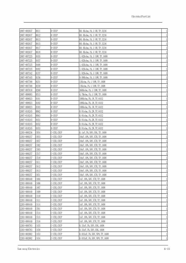
6-15Sam sung Electronics
Electrical Part List
2007-002637 R611 R-CHIP 60.4Kohm,1%,1/4W,TP,3216 1
2007-002637 R612 R-CHIP 60.4Kohm,1%,1/4W,TP,3216 1
2007-002637 R613 R-CHIP 60.4Kohm,1%,1/4W,TP,3216 1
2007-002637 R615 R-CHIP 60.4Kohm,1%,1/4W,TP,3216 1
2007-002637 R617 R-CHIP 60.4Kohm,1%,1/4W,TP,3216 1
2007-002637 R618 R-CHIP 60.4Kohm,1%,1/4W,TP,3216 1
2007-007225 R455 R-CHIP 1.62Kohm,1%,1/10W,TP,1608 1
2007-007225 R457 R-CHIP 1.62Kohm,1%,1/10W,TP,1608 1
2007-007225 R468 R-CHIP 1.62Kohm,1%,1/10W,TP,1608 1
2007-007225 R492 R-CHIP 1.62Kohm,1%,1/10W,TP,1608 1
2007-007342 R157 R-CHIP 1.82Kohm,1%,1/10W,TP,1608 1
2007-007445 R156 R-CHIP 9.09Kohm,1%,1/10W,TP,1608 1
2007-007768 R251 R-CHIP 13Kohm,1%,1/10W,TP,1608 1
2007-007768 R259 R-CHIP 13Kohm,1%,1/10W,TP,1608 1
2007-007818 R260 R-CHIP 360Kohm,1%,1/10W,TP,1608 1
2007-008003 R513 R-CHIP 4.7Mohm,1%,1/10W,TP,1608 1
2007-008023 R101 R-CHIP 100Kohm,5%,1W,TP,6432 1
2007-008023 R102 R-CHIP 100Kohm,5%,1W,TP,6432 1
2007-008023 R103 R-CHIP 100Kohm,5%,1W,TP,6432 1
2007-010245 R062 R-CHIP 0.01ohm,1%,2W,TP,6432 1
2007-010245 R063 R-CHIP 0.01ohm,1%,2W,TP,6432 1
2007-010245 R451 R-CHIP 0.01ohm,1%,2W,TP,6432 1
2007-010245 R452 R-CHIP 0.01ohm,1%,2W,TP,6432 1
2007-010245 R453 R-CHIP 0.01ohm,1%,2W,TP,6432 1
2203-000236 C054 C-CER,CHIP 0.1nF,5%,50V,C0G,TP,1608 1
2203-000257 C053 C-CER,CHIP 10nF,10%,50V,X7R,TP,1608 1
2203-000257 C057 C-CER,CHIP 10nF,10%,50V,X7R,TP,1608 1
2203-000257 C302 C-CER,CHIP 10nF,10%,50V,X7R,TP,1608 1
2203-000257 C303 C-CER,CHIP 10nF,10%,50V,X7R,TP,1608 1
2203-000257 C517 C-CER,CHIP 10nF,10%,50V,X7R,TP,1608 1
2203-000257 C518 C-CER,CHIP 10nF,10%,50V,X7R,TP,1608 1
2203-000257 C611 C-CER,CHIP 10nF,10%,50V,X7R,TP,1608 1
2203-000257 C612 C-CER,CHIP 10nF,10%,50V,X7R,TP,1608 1
2203-000257 C613 C-CER,CHIP 10nF,10%,50V,X7R,TP,1608 1
2203-000257 C651 C-CER,CHIP 10nF,10%,50V,X7R,TP,1608 1
2203-000440 C404 C-CER,CHIP 1nF,10%,50V,X7R,TP,1608 1
2203-000440 C406 C-CER,CHIP 1nF,10%,50V,X7R,TP,1608 1
2203-000440 C407 C-CER,CHIP 1nF,10%,50V,X7R,TP,1608 1
2203-000440 C409 C-CER,CHIP 1nF,10%,50V,X7R,TP,1608 1
2203-000440 C410 C-CER,CHIP 1nF,10%,50V,X7R,TP,1608 1
2203-000440 C411 C-CER,CHIP 1nF,10%,50V,X7R,TP,1608 1
2203-000440 C414 C-CER,CHIP 1nF,10%,50V,X7R,TP,1608 1
2203-000440 C501 C-CER,CHIP 1nF,10%,50V,X7R,TP,1608 1
2203-000440 C514 C-CER,CHIP 1nF,10%,50V,X7R,TP,1608 1
2203-000440 C515 C-CER,CHIP 1nF,10%,50V,X7R,TP,1608 1
2203-000440 C516 C-CER,CHIP 1nF,10%,50V,X7R,TP,1608 1
2203-000783 C455 C-CER,CHIP 0.33nF,5%,50V,C0G,1608 1
2203-000783 C458 C-CER,CHIP 0.33nF,5%,50V,C0G,1608 1
2203-002002 C453 C-CER,CHIP 0.033nF,5%,50V,NP0,TP,1608 1
2203-002002 C454 C-CER,CHIP 0.033nF,5%,50V,NP0,TP,1608 1
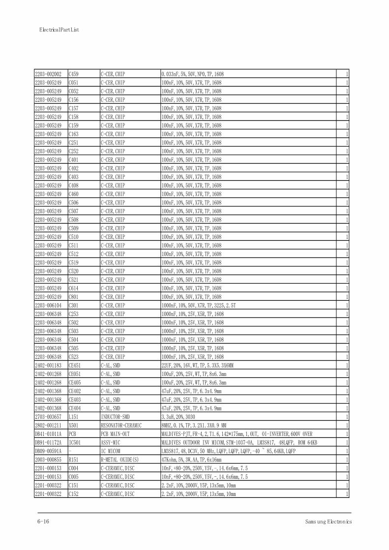
6-16 Sams ung Electronics
Electrical Part List
2203-002002 C459 C-CER,CHIP 0.033nF,5%,50V,NP0,TP,1608 1
2203-005249 C051 C-CER,CHIP 100nF,10%,50V,X7R,TP,1608 1
2203-005249 C052 C-CER,CHIP 100nF,10%,50V,X7R,TP,1608 1
2203-005249 C156 C-CER,CHIP 100nF,10%,50V,X7R,TP,1608 1
2203-005249 C157 C-CER,CHIP 100nF,10%,50V,X7R,TP,1608 1
2203-005249 C158 C-CER,CHIP 100nF,10%,50V,X7R,TP,1608 1
2203-005249 C159 C-CER,CHIP 100nF,10%,50V,X7R,TP,1608 1
2203-005249 C163 C-CER,CHIP 100nF,10%,50V,X7R,TP,1608 1
2203-005249 C251 C-CER,CHIP 100nF,10%,50V,X7R,TP,1608 1
2203-005249 C252 C-CER,CHIP 100nF,10%,50V,X7R,TP,1608 1
2203-005249 C401 C-CER,CHIP 100nF,10%,50V,X7R,TP,1608 1
2203-005249 C402 C-CER,CHIP 100nF,10%,50V,X7R,TP,1608 1
2203-005249 C403 C-CER,CHIP 100nF,10%,50V,X7R,TP,1608 1
2203-005249 C408 C-CER,CHIP 100nF,10%,50V,X7R,TP,1608 1
2203-005249 C460 C-CER,CHIP 100nF,10%,50V,X7R,TP,1608 1
2203-005249 C506 C-CER,CHIP 100nF,10%,50V,X7R,TP,1608 1
2203-005249 C507 C-CER,CHIP 100nF,10%,50V,X7R,TP,1608 1
2203-005249 C508 C-CER,CHIP 100nF,10%,50V,X7R,TP,1608 1
2203-005249 C509 C-CER,CHIP 100nF,10%,50V,X7R,TP,1608 1
2203-005249 C510 C-CER,CHIP 100nF,10%,50V,X7R,TP,1608 1
2203-005249 C511 C-CER,CHIP 100nF,10%,50V,X7R,TP,1608 1
2203-005249 C512 C-CER,CHIP 100nF,10%,50V,X7R,TP,1608 1
2203-005249 C519 C-CER,CHIP 100nF,10%,50V,X7R,TP,1608 1
2203-005249 C520 C-CER,CHIP 100nF,10%,50V,X7R,TP,1608 1
2203-005249 C521 C-CER,CHIP 100nF,10%,50V,X7R,TP,1608 1
2203-005249 C614 C-CER,CHIP 100nF,10%,50V,X7R,TP,1608 1
2203-005249 C801 C-CER,CHIP 100nF,10%,50V,X7R,TP,1608 1
2203-006104 C301 C-CER,CHIP 1000nF,10%,50V,X7R,TP,3225,2.5T 1
2203-006348 C253 C-CER,CHIP 1000nF,10%,25V,X5R,TP,1608 1
2203-006348 C502 C-CER,CHIP 1000nF,10%,25V,X5R,TP,1608 1
2203-006348 C503 C-CER,CHIP 1000nF,10%,25V,X5R,TP,1608 1
2203-006348 C504 C-CER,CHIP 1000nF,10%,25V,X5R,TP,1608 1
2203-006348 C505 C-CER,CHIP 1000nF,10%,25V,X5R,TP,1608 1
2203-006348 C523 C-CER,CHIP 1000nF,10%,25V,X5R,TP,1608 1
2402-001183 CE451 C-AL,SMD 22UF,20%,16V,WT,TP,5.3X5.3X6MM 1
2402-001268 CE051 C-AL,SMD 100uF,20%,25V,WT,TP,8x6.3mm 1
2402-001268 CE405 C-AL,SMD 100uF,20%,25V,WT,TP,8x6.3mm 1
2402-001368 CE402 C-AL,SMD 47uF,20%,25V,TP,6.3x4.9mm 1
2402-001368 CE403 C-AL,SMD 47uF,20%,25V,TP,6.3x4.9mm 1
2402-001368 CE404 C-AL,SMD 47uF,20%,25V,TP,6.3x4.9mm 1
2703-003657 L151 INDUCTOR-SMD 3.3uH,20%,3030 1
2802-001211 X501 RESONATOR-CERAMIC 8MHZ,0.1%,TP,3.2X1.3X0.9 MM 1
DB41-01011A PCB PCB MAIN-OUT MALDIVES-PJT,FR-4,2,T1.6,142*175mm,1,OUT, OI-INVERTER,600V OVER 1
DB91-01172A IC501 ASSY-MIC MALDIVES OUTDOOR INV MICOM,STM-1037-OA, LM3S817, 48LQFP, ROM 64KB 1
DB09-00591A - IC MICOM LM3S817,48,DC3V,50 MHz,LQFP,LQFP,LQFP,-40 ~ 85,64KB,LQFP 1
2003-000855 R151 R-METAL OXIDE(S) 47Kohm,5%,3W,AA,TP,6x16mm 1
2201-000153 C004 C-CERAMIC,DISC 10nF,+80-20%,250V,Y5V,-,14.6x6mm,7.5 1
2201-000153 C005 C-CERAMIC,DISC 10nF,+80-20%,250V,Y5V,-,14.6x6mm,7.5 1
2201-000322 C151 C-CERAMIC,DISC 2.2nF,10%,2000V,Y5P,13x5mm,10mm 1
2201-000322 C152 C-CERAMIC,DISC 2.2nF,10%,2000V,Y5P,13x5mm,10mm 1
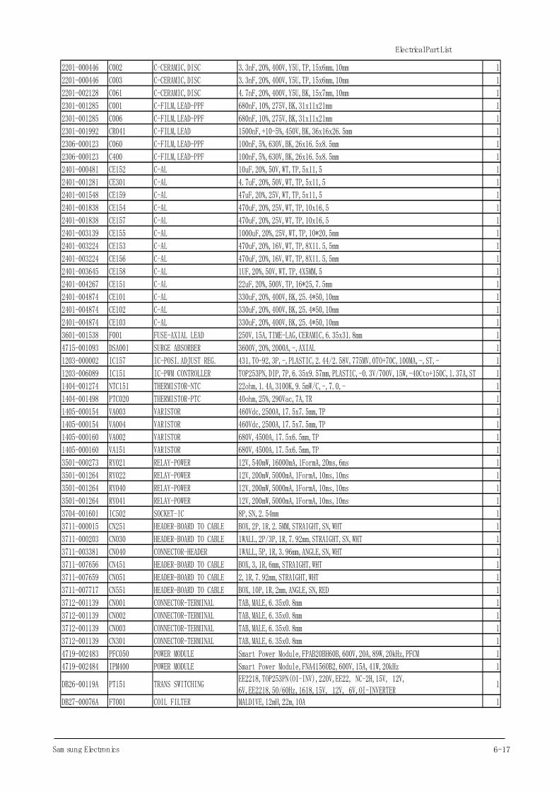
6-17Sam sung Electronics
Electrical Part List
2201-000446 C002 C-CERAMIC,DISC 3.3nF,20%,400V,Y5U,TP,15x6mm,10mm 1
2201-000446 C003 C-CERAMIC,DISC 3.3nF,20%,400V,Y5U,TP,15x6mm,10mm 1
2201-002128 C061 C-CERAMIC,DISC 4.7nF,20%,400V,Y5U,BK,15x7mm,10mm 1
2301-001285 C001 C-FILM,LEAD-PPF 680nF,10%,275V,BK,31x11x21mm 1
2301-001285 C006 C-FILM,LEAD-PPF 680nF,10%,275V,BK,31x11x21mm 1
2301-001992 CR041 C-FILM,LEAD 1500nF,+10-5%,450V,BK,36x16x26.5mm 1
2306-000123 C060 C-FILM,LEAD-PPF 100nF,5%,630V,BK,26x16.5x8.5mm 1
2306-000123 C400 C-FILM,LEAD-PPF 100nF,5%,630V,BK,26x16.5x8.5mm 1
2401-000481 CE152 C-AL 10uF,20%,50V,WT,TP,5x11,5 1
2401-001281 CE301 C-AL 4.7uF,20%,50V,WT,TP,5x11,5 1
2401-001548 CE159 C-AL 47uF,20%,25V,WT,TP,5x11,5 1
2401-001838 CE154 C-AL 470uF,20%,25V,WT,TP,10x16,5 1
2401-001838 CE157 C-AL 470uF,20%,25V,WT,TP,10x16,5 1
2401-003139 CE155 C-AL 1000uF,20%,25V,WT,TP,10*20,5mm 1
2401-003224 CE153 C-AL 470uF,20%,16V,WT,TP,8X11.5,5mm 1
2401-003224 CE156 C-AL 470uF,20%,16V,WT,TP,8X11.5,5mm 1
2401-003645 CE158 C-AL 1UF,20%,50V,WT,TP,4X5MM,5 1
2401-004267 CE151 C-AL 22uF,20%,500V,TP,16*25,7.5mm 1
2401-004874 CE101 C-AL 330uF,20%,400V,BK,25.4*50,10mm 1
2401-004874 CE102 C-AL 330uF,20%,400V,BK,25.4*50,10mm 1
2401-004874 CE103 C-AL 330uF,20%,400V,BK,25.4*50,10mm 1
3601-001538 F001 FUSE-AXIAL LEAD 250V,15A,TIME-LAG,CERAMIC,6.35x31.8mm 1
4715-001093 DSA001 SURGE ABSORBER 3600V,20%,2000A,-,AXIAL 1
1203-000002 IC157 IC-POSI.ADJUST REG. 431,TO-92,3P,-,PLASTIC,2.44/2.58V,775MV,0TO+70C,100MA,-,ST,- 1
1203-006089 IC151 IC-PWM CONTROLLER TOP253PN,DIP,7P,6.35x9.57mm,PLASTIC,-0.3V/700V,15W,-40Cto+150C,1.37A,ST 1
1404-001274 NTC151 THERMISTOR-NTC 22ohm,1.4A,3100K,9.5mW/C,-,7.0,- 1
1404-001498 PTC020 THERMISTOR-PTC 40ohm,25%,290Vac,7A,TR 1
1405-000154 VA003 VARISTOR 460Vdc,2500A,17.5x7.5mm,TP 1
1405-000154 VA004 VARISTOR 460Vdc,2500A,17.5x7.5mm,TP 1
1405-000160 VA002 VARISTOR 680V,4500A,17.5x6.5mm,TP 1
1405-000160 VA151 VARISTOR 680V,4500A,17.5x6.5mm,TP 1
3501-000273 RY021 RELAY-POWER 12V,540mW,16000mA,1FormA,20ms,6ms 1
3501-001264 RY022 RELAY-POWER 12V,200mW,5000mA,1FormA,10ms,10ms 1
3501-001264 RY040 RELAY-POWER 12V,200mW,5000mA,1FormA,10ms,10ms 1
3501-001264 RY041 RELAY-POWER 12V,200mW,5000mA,1FormA,10ms,10ms 1
3704-001601 IC502 SOCKET-IC 8P,SN,2.54mm 1
3711-000015 CN251 HEADER-BOARD TO CABLE BOX,2P,1R,2.5MM,STRAIGHT,SN,WHT 1
3711-000203 CN030 HEADER-BOARD TO CABLE 1WALL,2P/3P,1R,7.92mm,STRAIGHT,SN,WHT 1
3711-003381 CN040 CONNECTOR-HEADER 1WALL,5P,1R,3.96mm,ANGLE,SN,WHT 1
3711-007656 CN451 HEADER-BOARD TO CABLE BOX,3,1R,6mm,STRAIGHT,WHT 1
3711-007659 CN051 HEADER-BOARD TO CABLE 2,1R,7.92mm,STRAIGHT,WHT 1
3711-007717 CN551 HEADER-BOARD TO CABLE BOX,10P,1R,2mm,ANGLE,SN,RED 1
3712-001139 CN001 CONNECTOR-TERMINAL TAB,MALE,6.35x0.8mm 1
3712-001139 CN002 CONNECTOR-TERMINAL TAB,MALE,6.35x0.8mm 1
3712-001139 CN003 CONNECTOR-TERMINAL TAB,MALE,6.35x0.8mm 1
3712-001139 CN301 CONNECTOR-TERMINAL TAB,MALE,6.35x0.8mm 1
4719-002483 PFC050 POWER MODULE Smart Power Module,FPAB20BH60B,600V,20A,89W,20kHz,PFCM 1
4719-002484 IPM400 POWER MODULE Smart Power Module,FNA41560B2,600V,15A,41W,20kHz 1
DB26-00119A PT151 TRANS SWITCHINGEE2218,TOP253PN(OI-INV),220V,EE22, NC-2H,15V, 12V,6V,EE2218,50/60Hz,1618,15V, 12V, 6V,OI-INVERTER
1
DB27-00076A FT001 COIL FILTER MALDIVE,12mH,22m,10A 1
18
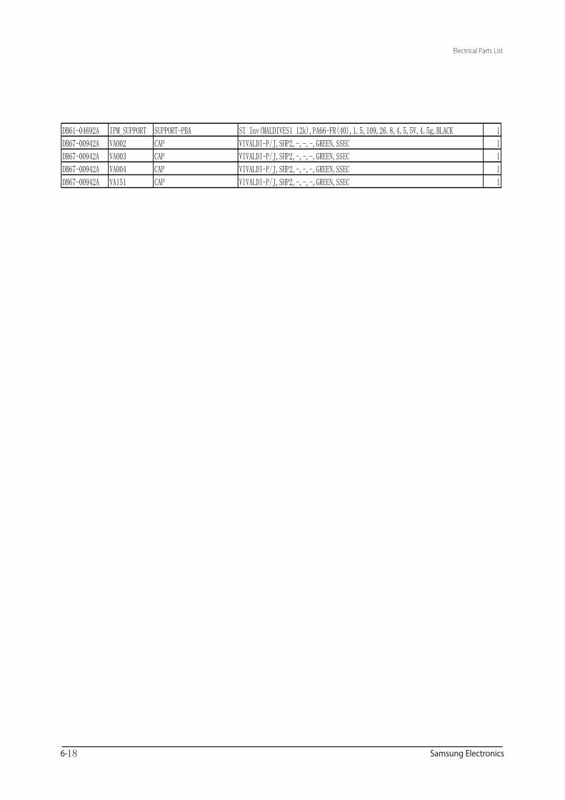
DB61-04692A IPM_SUPPORT SUPPORT-PBA SI Inv(MALDIVES1 12k),PA66-FR(40),1.5,109,26.8,4.5,5V,4.5g,BLACK 1
DB67-00942A VA002 CAP VIVALDI-P/J,SHP2,-,-,-,GREEN,SSEC 1
DB67-00942A VA003 CAP VIVALDI-P/J,SHP2,-,-,-,GREEN,SSEC 1
DB67-00942A VA004 CAP VIVALDI-P/J,SHP2,-,-,-,GREEN,SSEC 1
DB67-00942A VA151 CAP VIVALDI-P/J,SHP2,-,-,-,GREEN,SSEC 1
AQV12PSBAXAX/ASV12(09)PSBA*

AQV12PSBAXAX/ASV12(09)PSBA*
CO
NTR
OL
MO
DU
LE
SM
PS
M
OD
ULE
ZER
OC
RO
SS
M
OD
ULE
SENS
OR/
OLP
M
ODU
LE
EMI,S
URG
E,IN
RUSH
MO
DULE
SM
PSM
ODU
LE
COM
P DR
IVE
MO
DULE
CONT
ROL
MO
DULE
ZERO
CRO
SSM
ODU
LECU
RREN
T SE
NSO
RM
ODU
LE
PFC
MO
DULE
AQV12PSBAXAX/ASV12(09)PSBA*
10-2
1
2
4
5
6
8
3
7
AQV12PSBAXAX/ASV12(09)PSBA*

Main parts
Display
indicator
Timer/Auto clean indicator
Operation indicator
Power button
Remote controller receiver
(up and down)
Blade pin lever
Air intake
Room temperature sensor
ASV12(09)PSBX*AQV12PSBAXAX
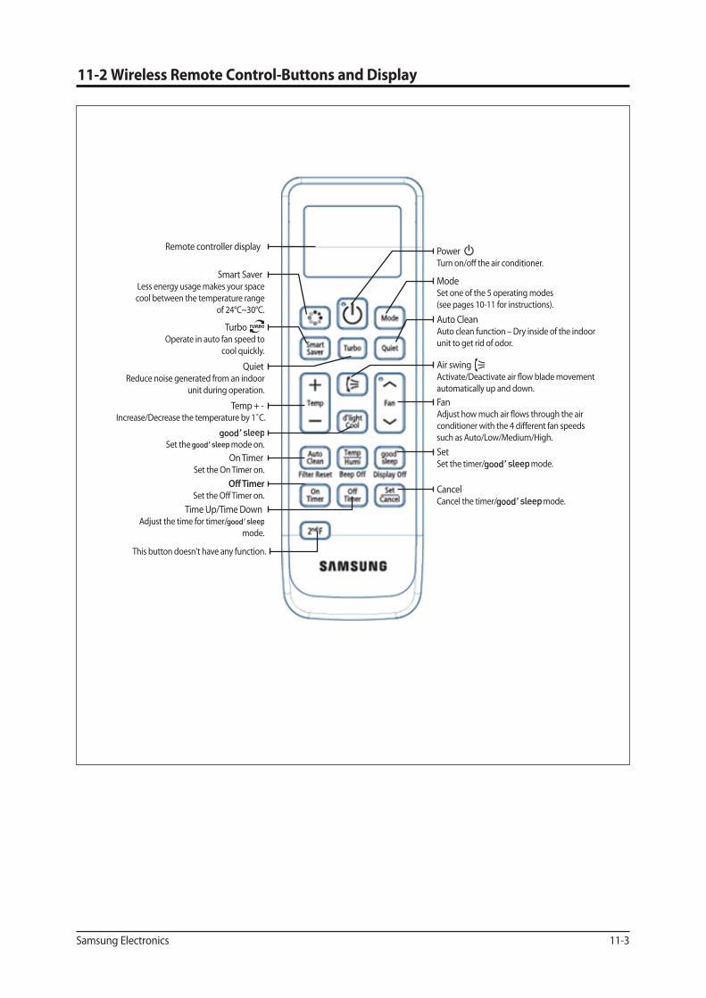
Remote controller display
Turbo Operate in auto fan speed to
cool quickly.
Time Up/Time DownAdjust the time for timer/
mode.
Fan � �
such as Auto/Low/Medium/High.
SetSet the timer/ mode.
CancelCancel the timer/ mode.
Air swing
automatically up and down.
ModeSet one of the 5 operating modes (see pages 10-11 for instructions).
Auto CleanAuto clean function – Dry inside of the indoor unit to get rid of odor.
Power
Temp + - Increase/Decrease the temperature by 1˚C.
On TimerSet the On Timer on.
QuietReduce noise generated from an indoor
unit during operation.
Set the mode on.
Smart SaverLess energy usage makes your space cool between the temperature range
of 24°C~30°C.
This button doesn't have any function.
Samsung Electronics 12-2
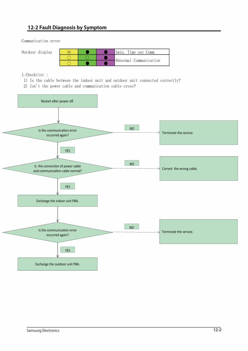
Communication error
Outdoor display ⊙ ● ● 1min. Time out Comm.○ ○ ●○ ● ●
1.Checklist : 1) Is the cable between the indoor unit and outdoor unit connected correctly? 2) Isn't the power cable and communication cable cross?
2. Troubleshooting procedure
Abnormal Communication
Is the communication error occurred again?
Restart after power off.
Terminate the service.NO
Is the connection of power cable and communication cable normal? Correct the wrong cable.
NO
YES
Exchange the indoor unit PBA.
Is the communication error occurred again?
Terminate the service.NO
YES
Exchange the outdoor unit PBA.
YES

12-3
Indoor temperature sensor error
Indoor display ○ ⊙ ○Indoor room temp sensorerror
1.Checklist : 1) Is the indoor units temperature sensor connected correctly? 2) Is the sensor placed correctly?
3) Does the both terminal of sensor satisfy the resistance value in accordance with temperature?
2. Troubleshooting procedure
Is the sensor resistance value #1-#210kohm±3% at the room
temperatureof 25℃
Detach the assembled sensor from the PBA sensor connector and measure the sensor resistance with
ohmmeter(tester)
Sensor Replace Sensor resistance value : 20℃ - 12.09kohm
30℃ - 8.31kohm 35℃ - 6.94kohm40℃ - 5.83kohm
Below 0.5V or Over 4.5V?
Connect the sensor to PBA connector (4piin)supply power and measure the voltage of #1-#2 in
the connector
Exchange the indoor PBA
NO
YES
NO
YES
Micom error or connector check
Exchange the indoor PBA
YES

12-4
Indoor Eva-in temperature sensor error
Indoor display ⊙ ⊙ ○Indoor Eva-in temp sensorerror
1.Checklist : 1) Is the indoor units temperature sensor connected correctly? 2) Is the sensor placed correctly?
3) Does the both terminal of sensor satisfy the resistance value in accordance with temperature?
2. Troubleshooting procedure
Is the sensor resistance value #3-#410kohm±3% at the room
temperatureof 25℃
Detach the assembled sensor from the PBA sensor connector and measure the sensor resistance with
ohmmeter(tester)
Sensor Replace Sensor resistance value : 20℃ - 12.09kohm
30℃ - 8.31kohm 35℃ - 6.94kohm40℃ - 5.83kohm
Below 0.5V or Over 4.5V?
Connect the sensor to PBA connector (4piin)supply power and measure the voltage of #3-#4 in
the connector
Exchange the indoor PBA
NO
YES
NO
YES
Micom error or connector check
Exchange the indoor PBA
YES

12-5
When the Up/Down louver motor does not operate (Initial Diagnosis) (Not displayed)
1.Checklist : 1) Is the input power voltage normal? 2) Is the Up/Down louver motor properly connected with the connector? (CN61)
2. Troubleshooting procedure
Is the lamp blinking?
Unplug the power cord and plug it after 30seconds later.
Check the as in the procedure.No power.
NO
Is the connected louver wire? Connect the wire PBA to louver motorNO
YES
Is the voltage changeable at the pin#2~#5 of CN61(louver
connector)?Exchange the PBA
NO
YES
Up/Down louver motor is faulty.
YES
Does operation start when swing button of the remote control unit
pushed?Normal
YES
NO

12-6
When the remote control is not receiving
1.Checklist : 1) Check if the connector was normally assembled. 2) Check the battery in remote control 3) All the lights out and check again : Change electronic typed to a fluorescent light 4) Put the set in operation and check the voltage of display PBA 5) Replace the display PBA
12-7
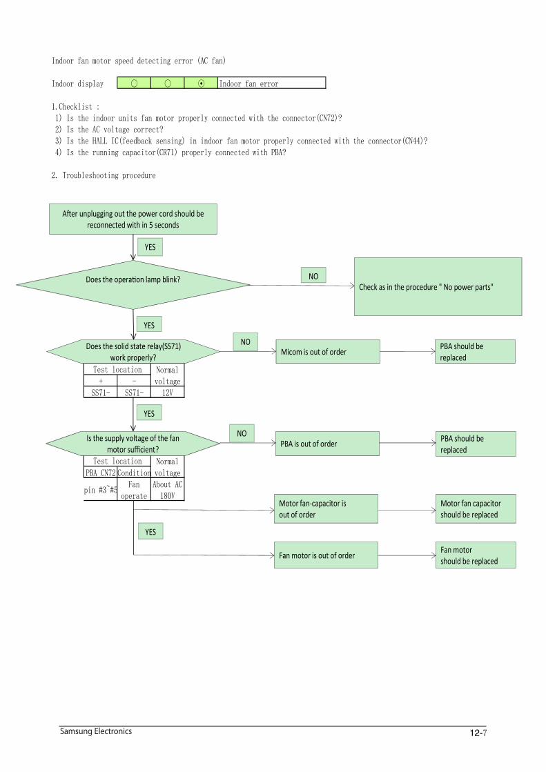
Indoor fan motor speed detecting error (AC fan)
Indoor display ○ ○ ⊙ Indoor fan error
1.Checklist : 1) Is the indoor units fan motor properly connected with the connector(CN72)? 2) Is the AC voltage correct? 3) Is the HALL IC(feedback sensing) in indoor fan motor properly connected with the connector(CN44)? 4) Is the running capacitor(CR71) properly connected with PBA?
2. Troubleshooting procedure
+ -SS71- SS71- 12V
PBA CN72 Condition
pin #3~#5Fan
operateAbout AC180V
Test location Normalvoltage
Test location Normalvoltage
After unplugging out the power cord should be reconnected with in 5 seconds
YES
Does the solid state relay(SS71) work properly?
Does the operation lamp blink?Check as in the procedure " No power parts"
NO
YES
YES
Micom is out of orderNO PBA should be
replaced
Is the supply voltage of the fan motor sufficient?
PBA is out of order PBA should be replaced
YES
Motor fan-capacitor isout of order
Motor fan capacitor should be replaced
Fan motor is out of orderFan motorshould be replaced
NO
12-8
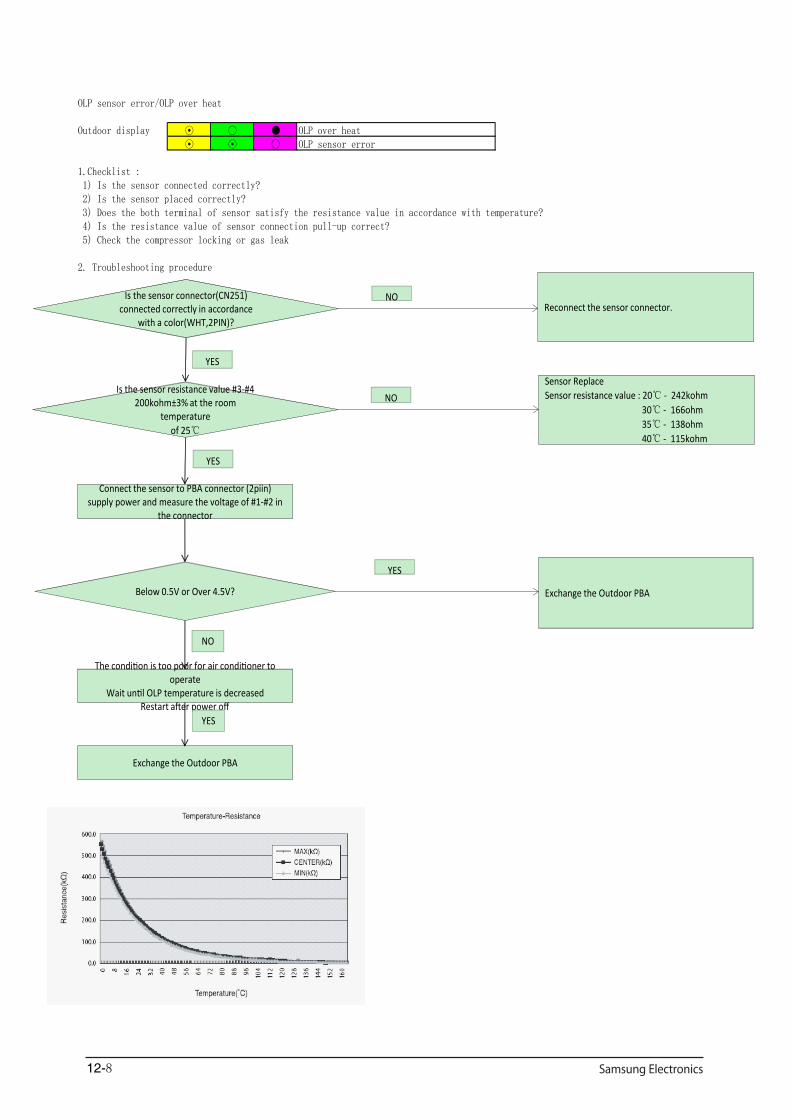
OLP sensor error/OLP over heat
Outdoor display ⊙ ○ ● OLP over heat⊙ ⊙ ○ OLP sensor error
1.Checklist : 1) Is the sensor connected correctly? 2) Is the sensor placed correctly?
3) Does the both terminal of sensor satisfy the resistance value in accordance with temperature? 4) Is the resistance value of sensor connection pull-up correct? 5) Check the compressor locking or gas leak
2. Troubleshooting procedure
Is the sensor resistance value #3-#4 200kohm±3% at the room
temperatureof 25℃
Sensor Replace Sensor resistance value : 20℃ - 242kohm
30℃ - 166ohm 35℃ - 138ohm40℃ - 115kohm
NO
YES
YES
YES
Is the sensor connector(CN251) connected correctly in accordance
with a color(WHT,2PIN)?Reconnect the sensor connector.
NO
Below 0.5V or Over 4.5V?
Connect the sensor to PBA connector (2piin)supply power and measure the voltage of #1-#2 in
the connector
Exchange the Outdoor PBA
NO
The condition is too poor for air conditioner to operate
Wait until OLP temperature is decreasedRestart after power off
Exchange the Outdoor PBA
YES

12-9
Compressor starting error
Outdoor display ○ ⊙ ○ Comp starting error
1.Checklist : 1) Is the connection of cable for the compressor? 2) Is the compressor wire is connected clockwise? U(RED)-V(BLU)-W(YEL) 3) Is the interphase resistance of compressor normal?2. Troubleshooting procedure
Is the restart error occurred again? Terminate the service
NO
YES
Is the connection of compressor wire is normal?
YES
Is the compressor body and interphase resistance insulated?
NO
Exchange the Outdoor PBA
Connect the comp wire normally
YES
NO
Exchange the compressor
Is the restart error occurred again? Terminate the service
NO
YES
Restart after power off.
Download the EEPROM data
12-10
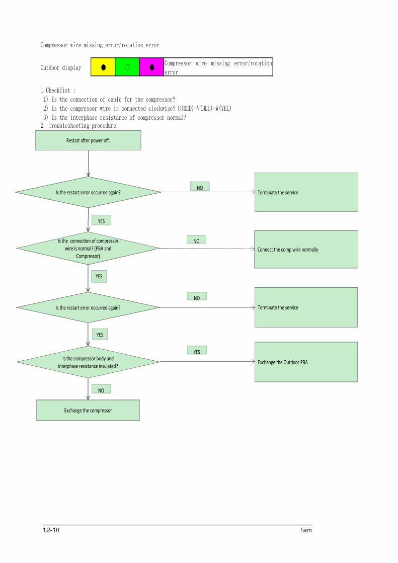
Compressor wire missing error/rotation error
Outdoor display ● ○ ●Compressor wire missing error/rotationerror
1.Checklist : 1) Is the connection of cable for the compressor? 2) Is the compressor wire is connected clockwise? U(RED)-V(BLU)-W(YEL) 3) Is the interphase resistance of compressor normal?2. Troubleshooting procedure
Is the restart error occurred again? Terminate the service
NO
YES
Is the connection of compressor wire is normal? (PBA and
Compressor)
YES
Is the compressor body and interphase resistance insulated?
NO
Exchange the Outdoor PBA
Connect the comp wire normally
YES
NO
Exchange the compressor
Is the restart error occurred again? Terminate the service
NO
YES
Restart after power off.
12-11
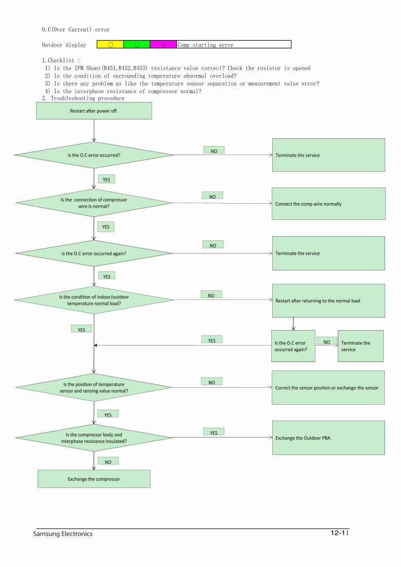
O.C(Over Current) error
Outdoor display ○ ○ ⊙ Comp starting error
1.Checklist : 1) Is the IPM Shunt(R451,R452,R453) resistance value correct? Check the resistor is opened 2) Is the condition of surrounding temperature abnormal overload? 3) Is there any problem as like the temperature sensor separation or measurement value error? 4) Is the interphase resistance of compressor normal?2. Troubleshooting procedure
Is the O.C error occurred? Terminate the service
NO
YES
Is the connection of compressor wire is normal?
YES
Is the compressor body and interphase resistance insulated?
NO
Exchange the Outdoor PBA
Connect the comp wire normally
YES
NO
Exchange the compressor
Is the O.C error occurred again? Terminate the serviceNO
YES
Restart after power off.
Is the condition of indoor/outdoor temperature normal load? Restart after returning to the normal load
YES
NO
Is the O.C error occurred again?
Terminate the service
YES
NO
Is the position of temperature sensor and sensing value normal?
Correct the sensor position or exchange the sensor
YES
NO
12-12
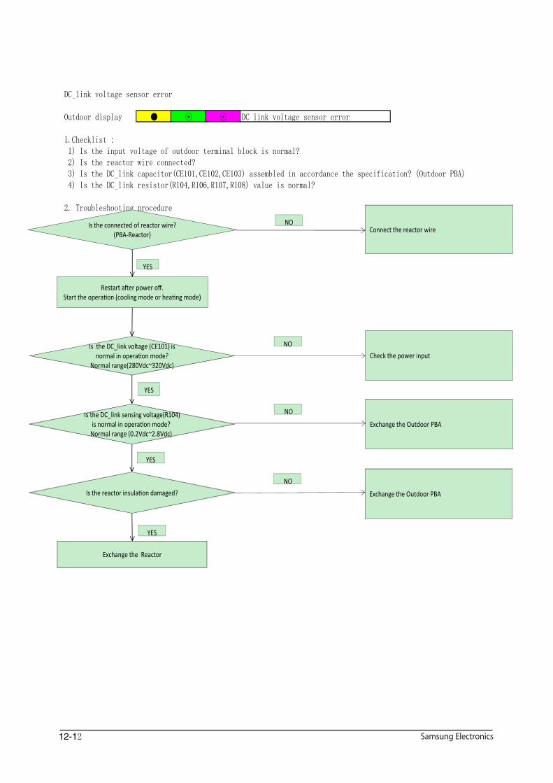
DC_link voltage sensor error
Outdoor display ● ⊙ ⊙ DC_link voltage sensor error
1.Checklist : 1) Is the input voltage of outdoor terminal block is normal? 2) Is the reactor wire connected? 3) Is the DC_link capacitor(CE101,CE102,CE103) assembled in accordance the specification? (Outdoor PBA) 4) Is the DC_link resistor(R104,R106,R107,R108) value is normal?
2. Troubleshooting procedure
Is the connected of reactor wire?(PBA-Reactor)
Is the DC_link sensing voltage(R104) is normal in operation mode?
Normal range (0.2Vdc~2.8Vdc)
YES
Exchange the Outdoor PBA
NO
Is the DC_link voltage (CE101) is normal in operation mode?
Normal range(280Vdc~320Vdc)Check the power input
NO
YES
YES
Connect the reactor wireNO
Restart after power off.Start the operation (cooling mode or heating mode)
Exchange the Reactor
Is the reactor insulation damaged?
YES
Exchange the Outdoor PBA
NO
12-13
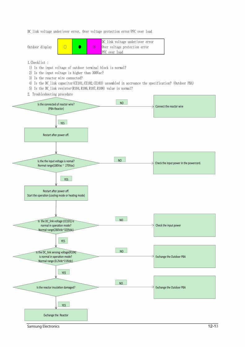
DC_link voltage under/over error, Over voltage protection error/PFC over load
Outdoor display ○ ● ⊙DC_link voltage under/over errorOver voltage protection errorPFC over load
1.Checklist : 1) Is the input voltage of outdoor terminal block is normal? 2) Is the input voltage is higher than 300Vac? 3) Is the reactor wire connected? 4) Is the DC_link capacitor(CE101,CE102,CE103) assembled in accroance the specification? (Outdoor PBA) 5) Is the DC_link resistor(R104,R106,R107,R108) value is normal?
2. Troubleshooting procedure
Is the connected of reactor wire?(PBA-Reactor)
Is the DC_link sensing voltage(R104) is normal in operation mode?
Normal range (0.2Vdc~2.8Vdc)
YES
Exchange the Outdoor PBA
NO
Is the DC_link voltage (CE101) is normal in operation mode?
Normal range(280Vdc~320Vdc)Check the input power
NO
YES
YES
Connect the reactor wireNO
Restart after power off.
Is the the input voltage is nomal?Normal range(180Vac ~ 270Vac)
Restart after power off.Start the operation (cooling mode or heating mode)
Check the input power in the powercord.NO
YES
Exchange the Reactor
Is the reactor insulation damaged?NO
Exchange the Outdoor PBA
YES
12-14
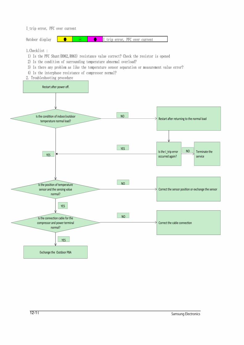
I_trip error, PFC over current
Outdoor display ● ⊙ ● I_trip error, PFC over current
1.Checklist : 1) Is the PFC Shunt(R062,R063) resistance value correct? Check the resistor is opened 2) Is the condition of surrounding temperature abnormal overload? 3) Is there any problem as like the temperature sensor separation or measurement value error? 4) Is the interphase resistance of compressor normal?2. Troubleshooting procedure
Is the condition of indoor/outdoor temperature normal load?
Restart after returning to the normal load
YES
YES
Is the connection cable for the compressor and power terminal
normal?
YES
Correct the cable connection
Is the I_trip error occurred again?
NO
NO
Exchange the Outdoor PBA
Is the position of temperature sensor and the sensing value
normal?Correct the sensor position or exchange the sensor
NO
YES
Restart after power off.
Terminate the service
NO
12-15
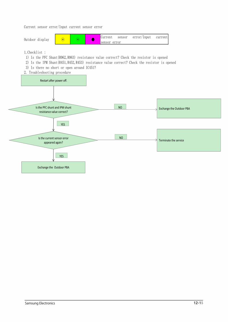
Current sensor error/Input current sensor error
Outdoor display ⊙ ⊙ ●Current sensor error/Input currentsensor error
1.Checklist : 1) Is the PFC Shunt(R062,R063) resistance value correct? Check the resistor is opened 2) Is the IPM Shunt(R451,R452,R453) resistance value correct? Check the resistor is opened 3) Is there no short or open around IC451?2. Troubleshooting procedure
Is the PFC shunt and IPM shunt resistance value correct?
Exchange the Outdoor PBA
Is the current sensor error appeared again?
YES
Terminate the serviceNO
NO
Exchange the Outdoor PBA
Restart after power off.
YES
12-16
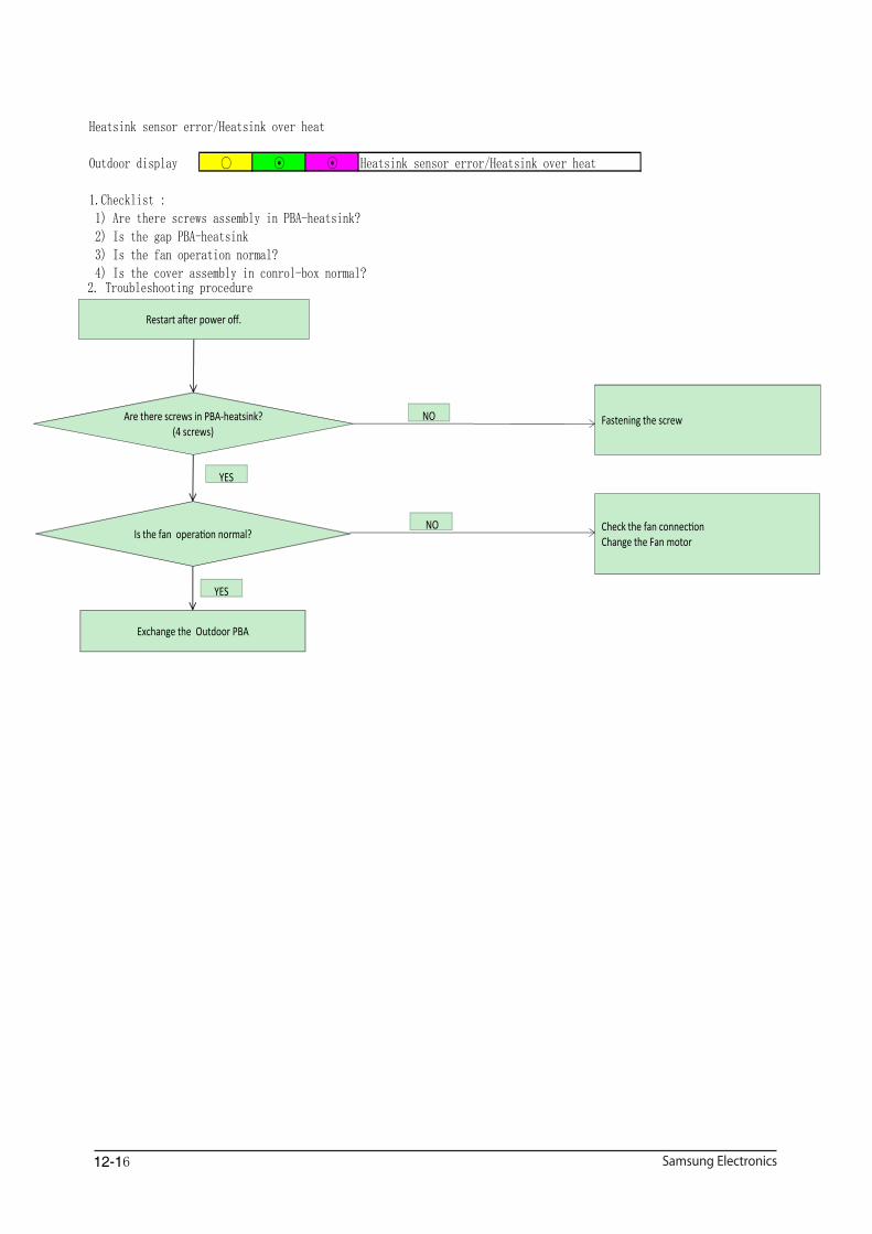
Heatsink sensor error/Heatsink over heat
Outdoor display ○ ⊙ ⊙ Heatsink sensor error/Heatsink over heat
1.Checklist : 1) Are there screws assembly in PBA-heatsink? 2) Is the gap PBA-heatsink 3) Is the fan operation normal? 4) Is the cover assembly in conrol-box normal?2. Troubleshooting procedure
Are there screws in PBA-heatsink? (4 screws)
Fastening the screw
Is the fan operation normal?
YES
Check the fan connectionChange the Fan motor
NO
NO
Exchange the Outdoor PBA
Restart after power off.
YES
12-17
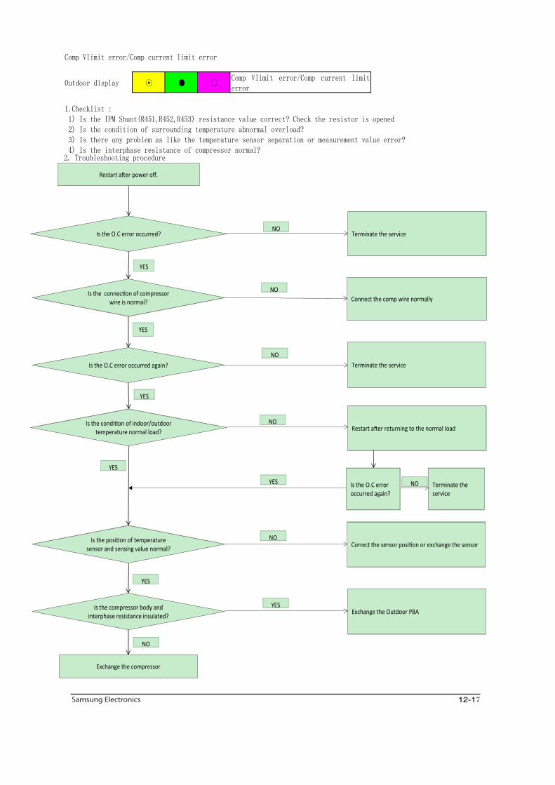
Comp Vlimit error/Comp current limit error
Outdoor display ⊙ ● ○Comp Vlimit error/Comp current limiterror
1.Checklist : 1) Is the IPM Shunt(R451,R452,R453) resistance value correct? Check the resistor is opened 2) Is the condition of surrounding temperature abnormal overload? 3) Is there any problem as like the temperature sensor separation or measurement value error? 4) Is the interphase resistance of compressor normal?2. Troubleshooting procedure
Is the O.C error occurred? Terminate the service
NO
YES
Is the connection of compressor wire is normal?
YES
Is the compressor body and interphase resistance insulated?
NO
Exchange the Outdoor PBA
Connect the comp wire normally
YES
NO
Exchange the compressor
Is the O.C error occurred again? Terminate the serviceNO
YES
Restart after power off.
Is the condition of indoor/outdoor temperature normal load? Restart after returning to the normal load
YES
NO
Is the O.C error occurred again?
Terminate the service
YES
NO
Is the position of temperature sensor and sensing value normal? Correct the sensor position or exchange the sensor
YES
NO
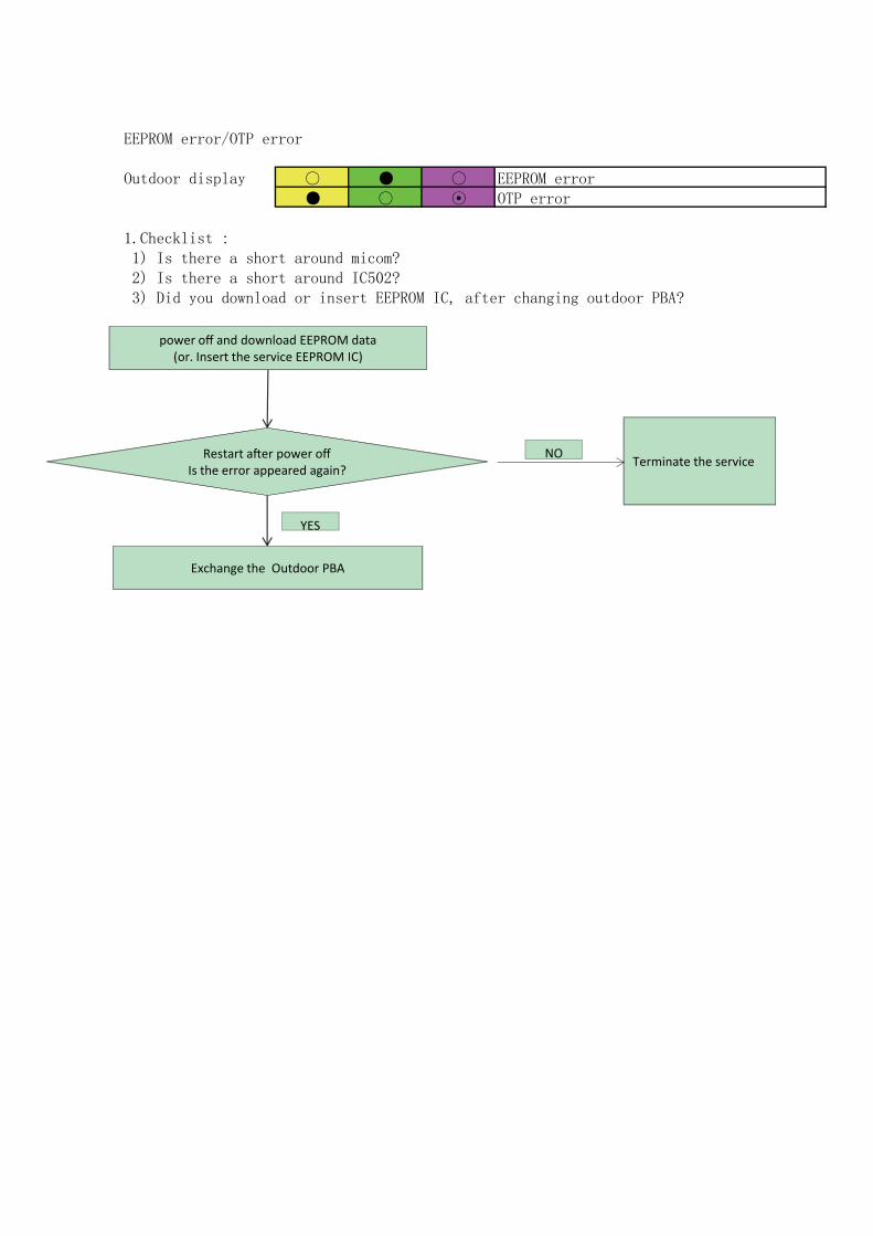
EEPROM error/OTP error
Outdoor display ○ ● ○ EEPROM error● ○ ⊙ OTP error
1.Checklist : 1) Is there a short around micom? 2) Is there a short around IC502? 3) Did you download or insert EEPROM IC, after changing outdoor PBA?
2. Troubleshooting procedure
Restart after power off Is the error appeared again?
YES
Terminate the serviceNO
Exchange the Outdoor PBA
power off and download EEPROM data(or. Insert the service EEPROM IC)

12-19
AC zero cross signal error
Outdoor display ● ● ⊙ AC zero cross signal error
1.Checklist : 1) Check the power condition at customer's house (Is there any power noise?) 2) Have been there power failure?
2. Troubleshooting procedure
Is the AC line zero cross signal error appeared again?
YES
Terminate the serviceNO
Exchange the Outdoor PBA
Restart after power off

12-20
No power indoor (Initial Diagnosis) (Not displayed)
1.Checklist : 1) Is input power normal? 2) Is AC power linked correctly? 3) Is input voltage of DC_link capacitor normal? 4) Is the voltage of DC regulator normal?
2. Troubleshooting procedure
Is the power cord connected normal?
Power cord : L-RY71:#4pinPower cord:N-T/B:N(1)-
PBA:CN71#5
YES
Reconnect the power cord correctly.NO
YES
Press the power button on the display board
The remote control signal receiver on the display PBA is wrongCheck the display board
NO
YES
Is the DC_link voltage normal?102(+)-C101(-) :270Vdc~320Vdc
Exchange the PBANO
Is the SMPS is normal?IC102 : 12Vdc-GND-5Vdc
Exchange the PBA
YES
NO
YES
Exchange the PBA
Check the fuse open or not? (F701,F702) Exchange the PBA
NO
Is the power normal?
Restart after power off.
Check the power source.
Unplug the power cord

12-22
No power outdoor (Initial Diagnosis) (Not displayed)
1.Checklist : 1) Is input power normal? 2) Is AC power linked correctly? 3) Is the cable connected correctly between indoor and outdoor unit? 4) Is there AC power in indoor terminal block? 5) Is the cable connected correctly between Terminal block and PBA? 6) Is input voltage of SMPS DC_link capacitor normal? 7) Is the voltage of SMPS normal?2. Troubleshooting procedure
Is the power cord connected normal?Is the cable connected correctly
between indoor and outdoor unit?Is the wiring correctly from outdoor
terminal block to PBA
YES
Reconnect the power cord correctly.NO
YES
Is the voltage of outdoor unit terminal block correctly? N(1)-1 :
230Vac
Check the cable connection from indoor unit to outdoor unitThe remote control signal receiver on the display PBA is wrong . Check the display board
NO
YES
Is the SMPS DC _link voltage normal?
CE151 :270Vdc~320VdcExchange the outdoor PBA
NO
Is the SMPS is normal?Check the voltage.
CE153:3.3Vdc, CE155:12Vdc, CE157:15Vdc
Exchange the outdoor PBA
YES
NO
YES
Exchange the outdoor PBA
Check the fuse open or not (F001) Exchange the outdoor PBA
NO
Is the voltage of indoor unit terminal block correctly? N(1)-1 :
230Vac
Restart after power off.Set the operation
Check the wiring from indoor terminal block to indoor PBAExchange the indoor PBA
Unplug the power cord
NO
Is the input voltage of outdoor PBA correctly? CN001-CN002:
230Vac
Check the wiring from outdoor terminal block to outdoor PBA
NO
12-23
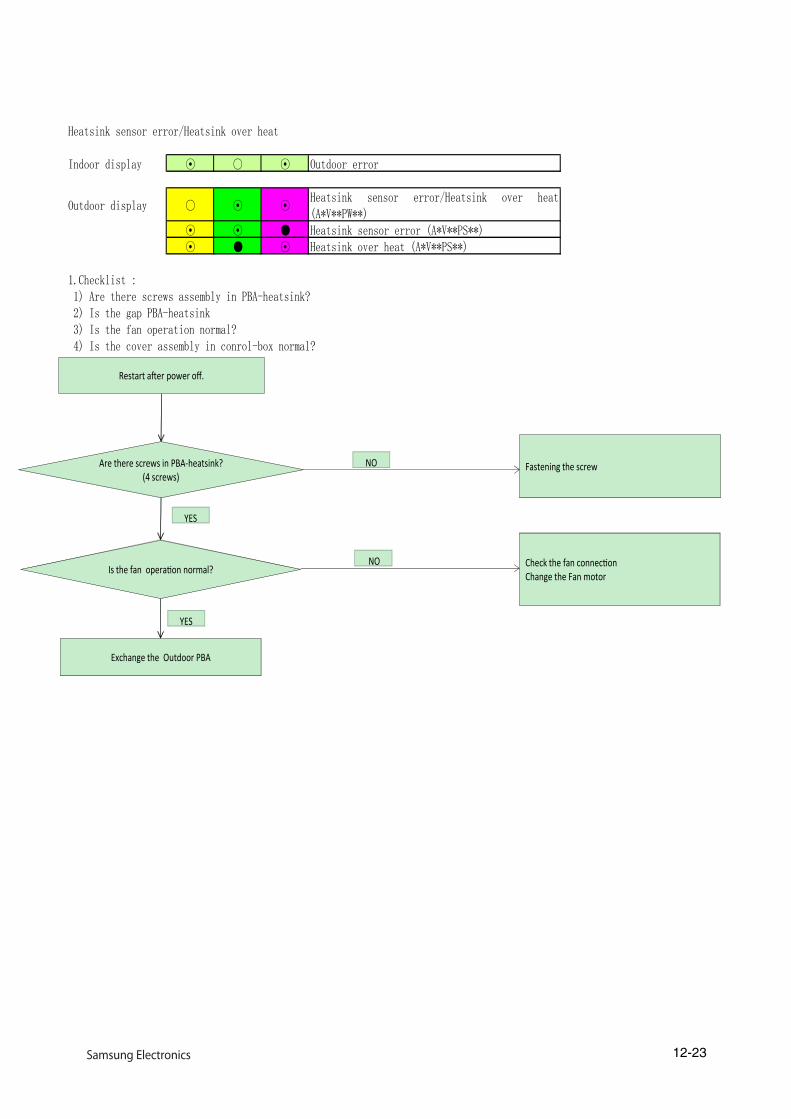
Heatsink sensor error/Heatsink over heat
Indoor display ⊙ ○ ⊙ Outdoor error
Outdoor display ○ ⊙ ⊙Heatsink sensor error/Heatsink over heat(A*V**PW**)
⊙ ⊙ ● Heatsink sensor error (A*V**PS**)⊙ ● ⊙ Heatsink over heat (A*V**PS**)
1.Checklist : 1) Are there screws assembly in PBA-heatsink? 2) Is the gap PBA-heatsink 3) Is the fan operation normal? 4) Is the cover assembly in conrol-box normal?
2. Troubleshooting procedure
Are there screws in PBA-heatsink? (4 screws)
Fastening the screw
Is the fan operation normal?
YES
Check the fan connectionChange the Fan motor
NO
NO
Exchange the Outdoor PBA
Restart after power off.
YES
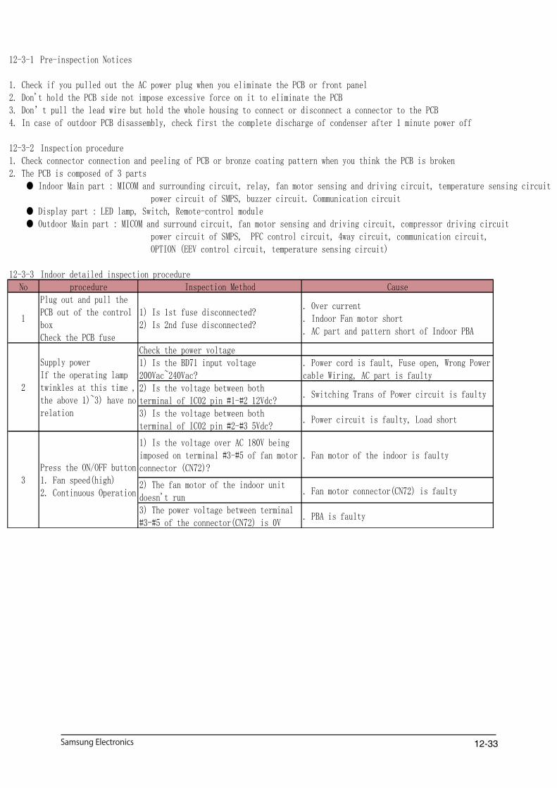
12-33
12-3-1 Pre-inspection Notices
1. Check if you pulled out the AC power plug when you eliminate the PCB or front panel2. Don't hold the PCB side not impose excessive force on it to eliminate the PCB3. Don’t pull the lead wire but hold the whole housing to connect or disconnect a connector to the PCB4. In case of outdoor PCB disassembly, check first the complete discharge of condenser after 1 minute power off
12-3-2 Inspection procedure1. Check connector connection and peeling of PCB or bronze coating pattern when you think the PCB is broken2. The PCB is composed of 3 parts ● Indoor Main part : MICOM and surrounding circuit, relay, fan motor sensing and driving circuit, temperature sensing circuit power circuit of SMPS, buzzer circuit. Communication circuit ● Display part : LED lamp, Switch, Remote-control module ● Outdoor Main part : MICOM and surround circuit, fan motor sensing and driving circuit, compressor driving circuit power circuit of SMPS, PFC control circuit, 4way circuit, communication circuit, OPTION (EEV control circuit, temperature sensing circuit)
12-3-3 Indoor detailed inspection procedureNo procedure Inspection Method Cause
1
Plug out and pull thePCB out of the controlboxCheck the PCB fuse
1) Is 1st fuse disconnected?2) Is 2nd fuse disconnected?
. Over current
. Indoor Fan motor short
. AC part and pattern short of Indoor PBA
Check the power voltage1) Is the BD71 input voltage200Vac~240Vac?
. Power cord is fault, Fuse open, Wrong Powercable Wiring, AC part is faulty
2) Is the voltage between bothterminal of IC02 pin #1-#2 12Vdc?
. Switching Trans of Power circuit is faulty
3) Is the voltage between bothterminal of IC02 pin #2-#3 5Vdc?
. Power circuit is faulty, Load short
1) Is the voltage over AC 180V beingimposed on terminal #3-#5 of fan motorconnector (CN72)?
. Fan motor of the indoor is faulty
2) The fan motor of the indoor unitdoesn't run
. Fan motor connector(CN72) is faulty
3) The power voltage between terminal#3-#5 of the connector(CN72) is 0V
. PBA is faulty
Supply powerIf the operating lamptwinkles at this time ,the above 1)~3) have norelation
2
3Press the ON/OFF button1. Fan speed(high)2. Continuous Operation

12-33
12-3-4 Outdoor detailed inspection procedure No procedure Inspection Method Cause
1
Plug out and pull the PCB out ofthe control boxCheck the PCB fuse(Wait 3 minutes after power off)
1) Is 1st fuse disconnected?2) Is indoor PBA faulty?
. Over current
. AC part and pattern short of IndoorPBA. AC part and pattern short of OutdoorPBA
2 Check the Wiring
1) Is the Compressor wire connectedclockwise?2) Is the Reactor wire connectednormal?3) Is the Fan wire connected normal?4) Is the 4way wire connected normal?5) Is the sensor wire connected
. Wrong assembly
. Installation(service) condition is bad
Check the power voltage
1) Is the voltage between Terminalblock N(1)-1 200Vac~240Vac?
. Power cord is faulty, Indoor PBAfault, Wrong Power cable Wiring
2) Is the PFC050(#26-#27) inputvoltage 200Vac~240Vac?
. L,N,E wire wrong wiring (TerminalBlock-PBA). Fuse open. PTC020 open. RY021, RY022 is faulty. Outdoor Micom(IC151) error
3) Is the CE151 voltage 280Vdc~320dc?. Power circuit is faulty. Load short
3) Is the CE101 voltage 280Vdc~320dc?. PFC050 is faulty. Reactor wire is wrong connection
4) Is the voltage CE157 voltage 15Vdc?. Switching Trans of Power circuit isfaulty. Load short
5) Is the voltage CE155 voltage 12Vdc?. Switching Trans of Power circuit isfaulty. Load short
6) Is the voltage CE153 voltage3.3Vdc?
. Switching Trans of Power circuit isfaulty. Load short
4 Check the LED lamp display
1) Normal : RED on, GRN blink, YEL off2) Abnormal - All off : check no power - abnormal display : check errormode
. L,N,C wire wrong wiring
. Outdoor PBA is faulty
Supply power and operate the set(Use Remote-control, button inindoor set)
3
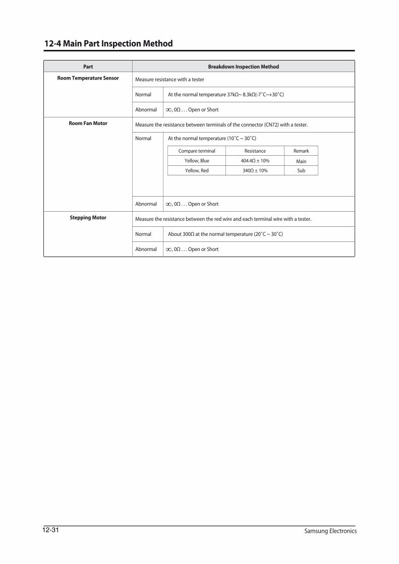
����� ���
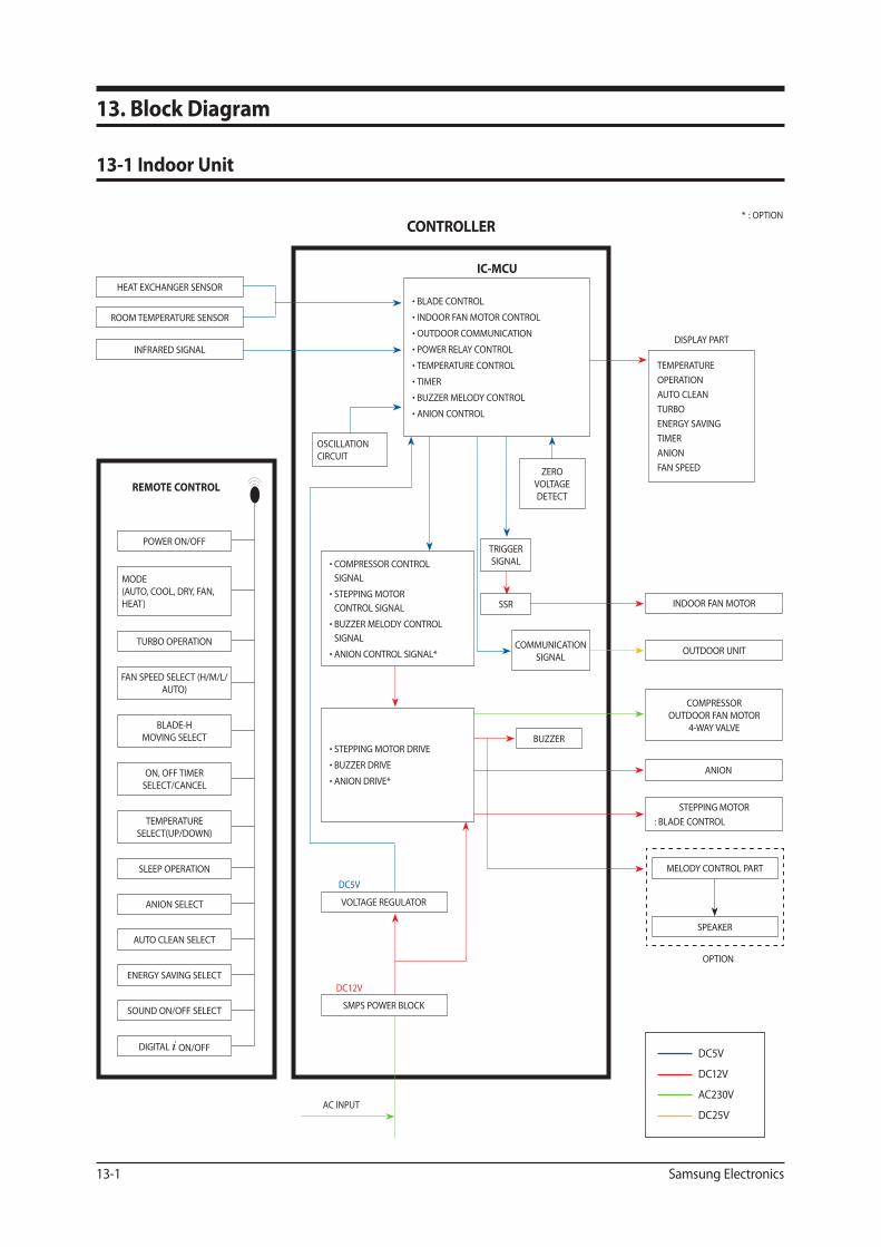
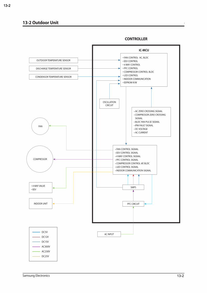
13-213-2
13-2
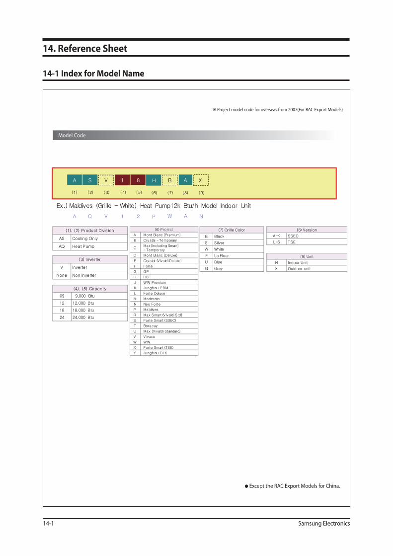
(1), (2) Product Division
AS Cooling Only
AQ Heat Pump
(8) Version
A-K SSEC
L-S TSE
(4), (5) Capacity
09 9,000 Btu
12 12,000 Btu
18 18,000 Btu
24 24,000 Btu
AH81SA B XV
(9)(1) (2) (3) (4) (5) (6) (7) (8)
(3) Inverter
V Inverter
None Non Inverter
(7) Grille Color
B Black
S Silver
W White
F La Fleur
U Blue
G Grey
(6) Project
A Mont Blanc (Premium)
B Crystal -Temporary
CMax(including Smart) - Temporary
D Mont Blanc (Deluxe)
E Crystal (V ivaldi Deluxe)
F Forte
G GP
H HB
J WW Premium
K Jungfrau-PRM
L Forte Deluxe
M Moderato
N Neo Forte
P Maldives
R Max Smart (V ivaldi Std)
S Forte Smart (SSEC)
T Boracay
U Max (V ivaldi Standard)
V V ivace
W WW
X Forte Smart (TSE)
Y Jungfrau-DLX
NP21QA WV A
(9) Unit
N Indoor Unit
X Outdoor unit
Ex.) Maldives (Grille – White) Heat Pump12k Btu/h Model Indoor Unit

Samsung Electronics
14-2 Low Refrigerant Pressure Distribution
14-2
Note : Please measure the refrigerant pressure after the air conditioner operates on testing cooling mode during more than
10 minutes.
Indoor Temp. Variation : 20°C ~ 32°C
Outdoor Temp. Variation : -5°C ~ 45°C
Outdoor Temperature[ ]
Low Refrigeran t Pressur e Distributio n
* *
*
* *
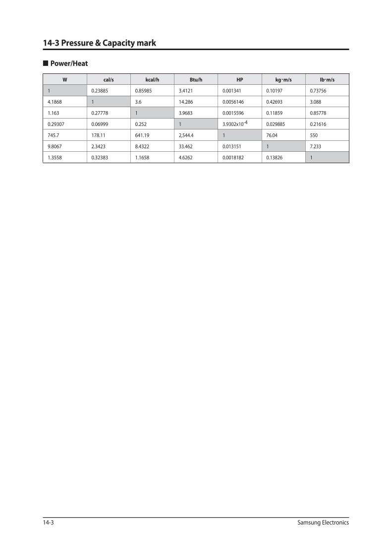
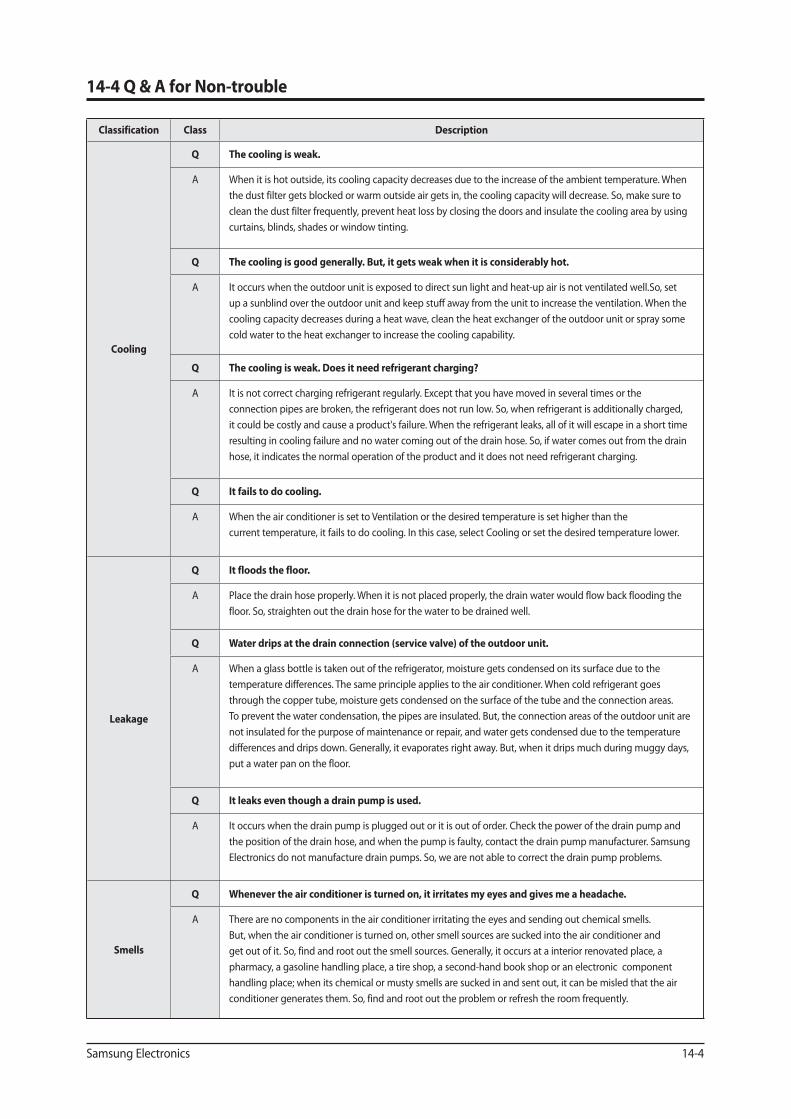
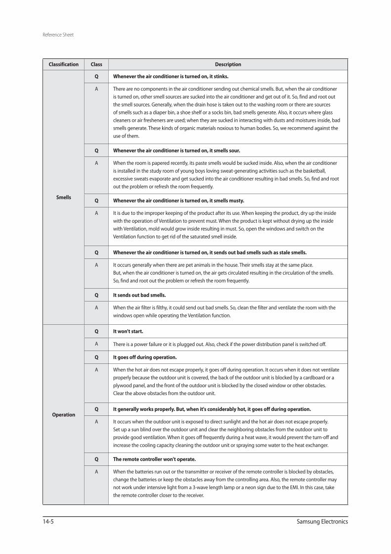
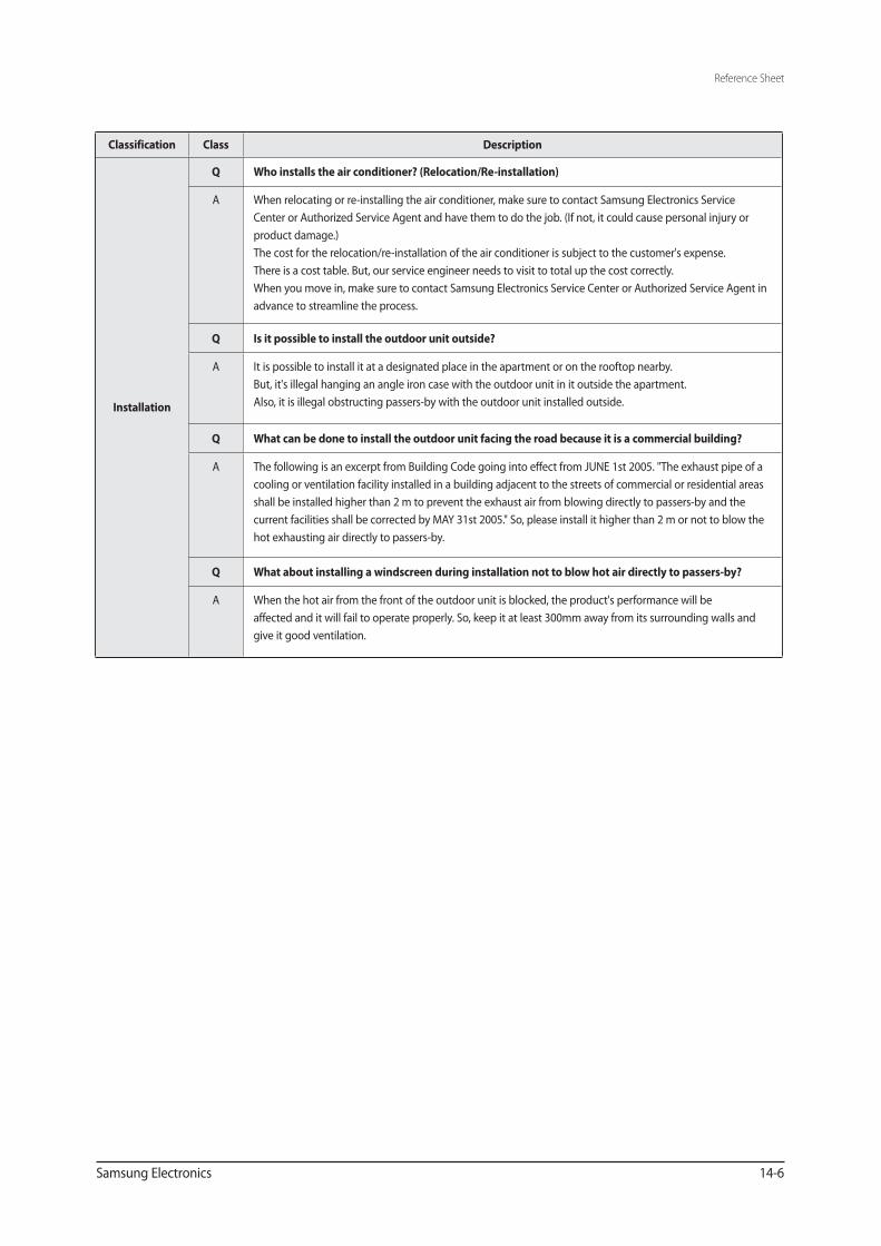
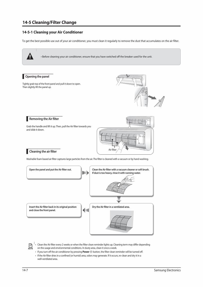
Opening the panel
Tightly grab top of the front panel and pull it down to open. Then slightly lift the panel up.
and slide it down.
Open the panel and put the Air �lter out.
Insert the Air �lter back in its original position and close the front panel.
Dry the Air �lter in a ventilated area.
Clean the Air �lter with a vacuum cleaner or soft brush. If dust is too heavy, rinse it with running water.
on the usage and environmental conditions. In dusty area, clean it once a week.Power
well-ventilated area.

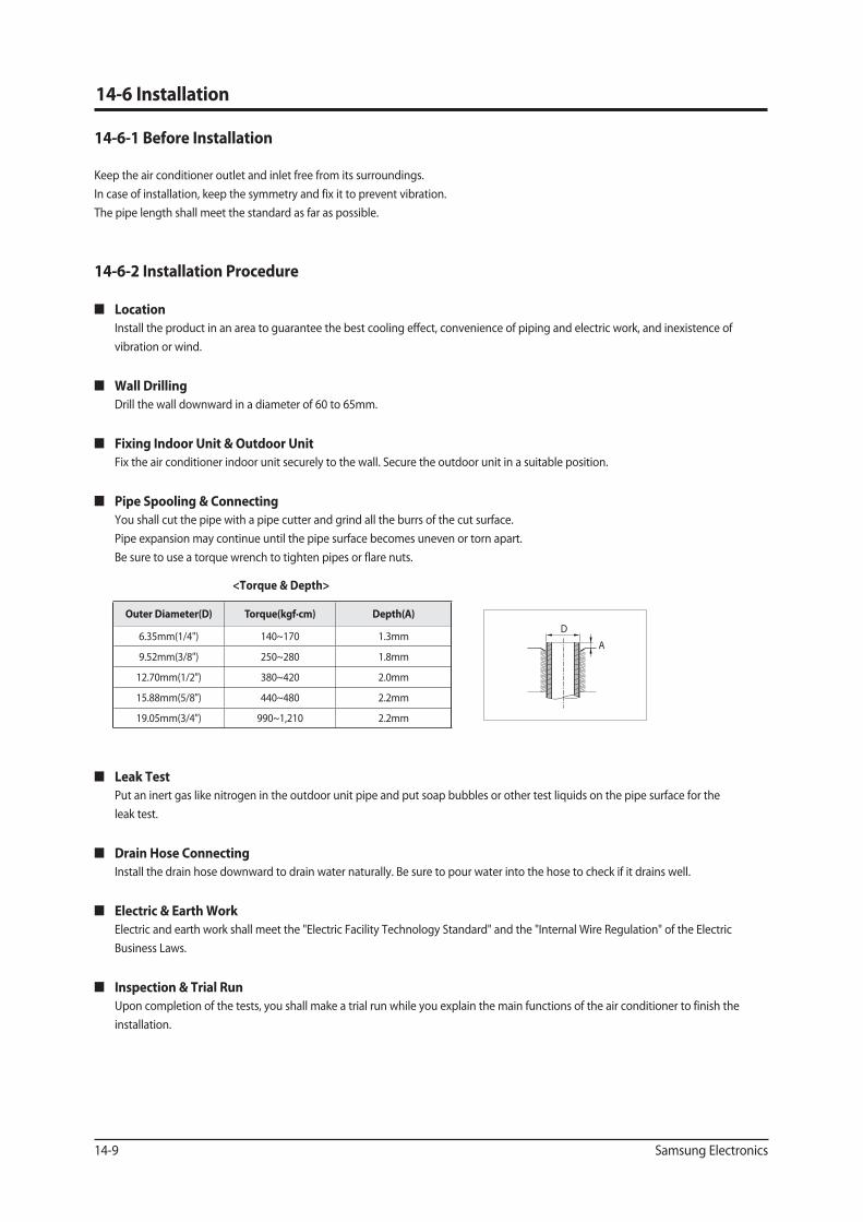
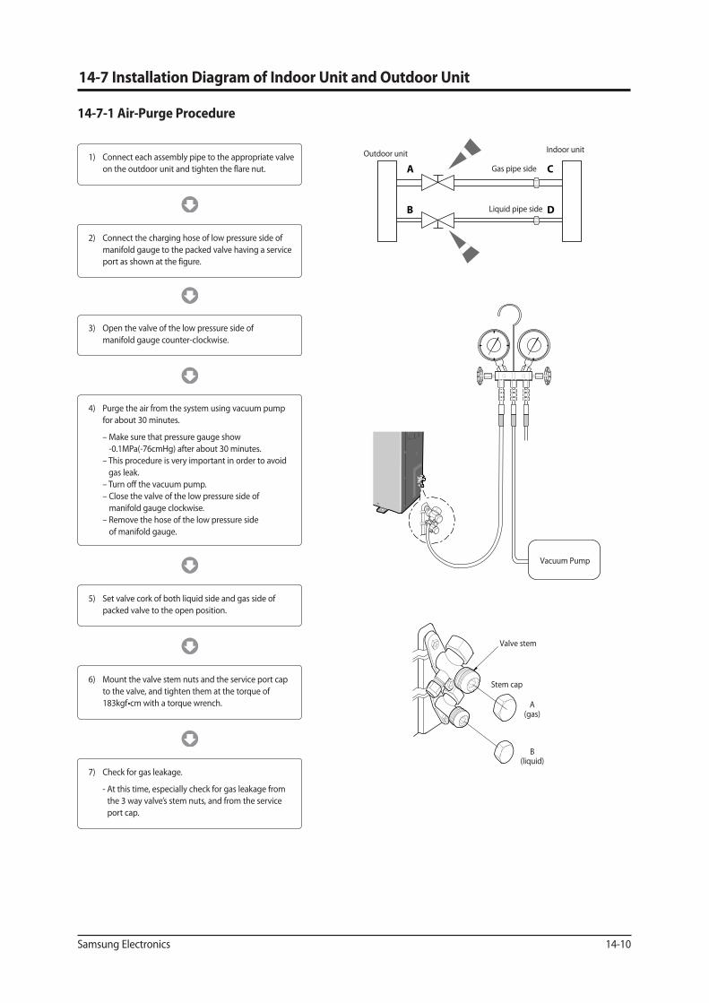

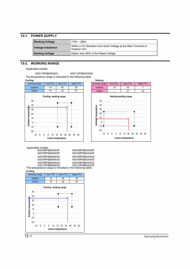
15-1. POWER SUPPLY
Working Voltage 176V ~ 264V
Voltage Imbalance Within a 3% Deviation from Each Voltage at the Main Terminal ofOutdoor Unit
Starting Voltage Higher than 80% of the Rated Voltage
15-2. WORKING RANGEApplicable models:
AQV12PSBANXAX AQV12PSBAXXAX
gnitaeHgnilooCworking range min (oC) max (oC) rated (oC) working range min (oC) max (oC) rated (oC)
outdoor -10 46 35 outdoor -10 24 7indoor 16 32 27 indoor __ 27 20
Cooling working range
-20
-10
0
10
20
30
40
50
-10 -5 0 5 10 15 20 25 30 35 40Indoor temperature
Ambi
ent t
empe
ratu
re
Heating working range
-20
-100
10
20
3040
50
-10 -5 0 5 10 15 20 25 30 35 40
Indoor temperature
Ambi
entt
empe
ratu
r e
Applicable models:
gnilooC
working range min (oC) max (oC) rated (oC)
outdoor 16 46 35indoor 16 32 27
Cooling working range
-20
-10
0
10
20
30
40
50
-10 -5 0 5 10 15 20 25 30 35 40Indoor temperature
Ambi
ent t
empe
ratu
re
ASV09PSBANXAP ASV09PSBAXXAP ASV09PSBANXAP ASV09PSBAXXAP ASV09PSBANXAX ASV09PSBAXXAX ASV09PSBANXAX ASV09PSBAXXAX ASV09PSBANXAZ ASV09PSBAXXAZ ASV12PSBANXAZ ASV12PSBAXXAZ
Related Documents


![I tÆW u Yto xla ^ ] DvYM te W Dì ú Yn DÌYW m la l] NtP (A ...](https://static.cupdf.com/doc/110x72/61d391e153bdb149ee2e2f85/i-tw-u-yto-xla-dvym-te-w-d-yn-dyw-m-la-l-ntp-a-.jpg)


