SERVICE MANUAL DATA COMPACT DISC STEREO SYSTEM BASIC TAPE MECHANISM : 6ZM-1 AR3N1M BASIC CD MECHANISM : AZG-1 YZD3RDM XH-A1060 LH S/M Code No. 09-00A-421-4S1 SUPPLEMENT • This Service Manual contains information about the difference between XH-A1060(LH) and XH-A1000(LH). If requiring other information, see Service Manual of XH-A1000(LH,U), (S/M Code No. 09-002-421-4R1). • If requiring information about the CD mechanism, see Service Manual of AZG-1(S/M Code No. 09-001-335-3N8). XH–A1060 RC–AAS01 SYSTEM CD CASSEIVER SPEAKERS REMOTE CONTROLLER CX–A1060 SX–WA1000 SX–CR1800

Welcome message from author
This document is posted to help you gain knowledge. Please leave a comment to let me know what you think about it! Share it to your friends and learn new things together.
Transcript

SERVICE MANUAL
DATA
COMPACT DISC STEREO SYSTEMBASIC TAPE MECHANISM : 6ZM-1 AR3N1MBASIC CD MECHANISM : AZG-1 YZD3RDM
XH-A1060 LH
S/M Code No. 09-00A-421-4S1 SUPPL
EMENT
• This Service Manual contains information about the difference between XH-A1060(LH) and XH-A1000(LH). If requiring other information, see Service Manual of XH-A1000(LH,U), (S/M Code No. 09-002-421-4R1).
• If requiring information about the CD mechanism, see Service Manual of AZG-1(S/M Code No. 09-001-335-3N8).
XH–A1060 RC–AAS01
SYSTEM CDCASSEIVER
SPEAKERS REMOTE CONTROLLER
CX–A1060 SX–WA1000SX–CR1800

– 2 –
SPECIFICATIONS
Main unit CX-A1060<FM Tuner section>Tuning range 87.5 MHz to 108 MHzUsable sensitivity (IHF) 13.2 dBfAntenna terminal 75 ohms (unbalanced)
<AM Tuner section>Tuning range 530 kHz to 1710 kHz (10 kHz step)
531 kHz to 1602 kHz (9 kHz step)Usable sensitivity 350 µV/mAntenna Loop antenna
<Amplifier section>Mid-high frequency amplifier
Power output FrontRated: 80 W + 80 W(8 ohms, T.H.D. 1 %, 1 kHz)Reference: 100 W + 100 W(8 ohms, T.H.D. 10 %, 1 kHz)Rear (Surround)Rated: 80 W + 80 W (8 ohms,T.H.D. 1 %, 1 kHz)Reference: 100 W + 100 W(8 ohms, T.H.D. 10 %, 1 kHz)CenterRated: 80 W (8 ohms, T.H.D. 1 %,1 kHz)Reference: 100 W (8 ohms,T.H.D. 10 %, 1 kHz)
Total harmonic distortion 0.15 % (40 W, 1 kHz, 8 ohms,DIN AUDIO/Front)
Low frequency + Sub woofer amplifierPower output Rated: 200 W + 200 W (6 ohms,
T.H.D. 1 %, 100 Hz)Reference: 250 W + 250 W(6 ohms, T.H.D. 10 %, 100 Hz)
Total harmonic distortion 0.15 % (100 W, 100 Hz, 6 ohms,DIN AUDIO/Front)
Inputs AUX: 310 mVPHONO: 400 mVVIDEO1, VIDEO2, VIDEO3: 310 mV5.1CH INPUT (adjustable)
FRONT: 300 mVSURROUND: 300 mVCENTER: 600 mVSUB WOOFER: 300 mV
MIC1, MIC2: 1.4 mV (20 kohms)Outputs CD DIGITAL OUT (OPTICAL)
SPEAKERS:LOW + SUB WOOFER: 6 ohmsHIGH: 8 ohmsSURROUND SPEAKERS: acceptspeakers of 8 – 16 ohmsCENTER SPEAKER: acceptsspeaker of 8 ohms or morePHONES (stereo jack): acceptsheadphones of 32 ohms or more
<Cassette deck section>Track format 4 tracks, 2 channels stereoFrequency response CrO2 tape: 50 Hz – 16000 Hz
Normal tape: 50 Hz – 15000 HzSignal-to noise ratio 60 dB (Dolby B NR ON, CrO2 tape
peak level, above 400 Hz)Recording system AC biasHeads Recording/playback head x 1,
erase head x 1
<Compact disc player section>Laser Semiconductor laser (λ =780 nm)D/A converter 1 bit dualSignal-to-noise ratio 85 dB (1 kHz, 0 dB)Harmonic distortion 0.03 % (1 kHz, 0 dB)
<General>Power requirements 120 V/220 – 230 V/240 V AC, switchable 50/60 HzPower consumption 320 WDimensions of main unit 361 x 372 x 423 mm(W x H x D)Weight of main unit 18.5 kg
Front speakers SX-WA1000Cabinet type 4 way, built-in subwooferSpeakers Subwoofer: 220 mm cone type
Woofer: 160 mm cone typeTweeter: 60 mm cone typeSuper tweeter: 20 mm ceramic type
Impedance 6 ohms / 8 ohmsOutput sound pressure level 89 dB/W/mDimensions (W x H x D) 250 x 592 x 300 mmWeight 11.7 kg
Surround speakers SX-R1800Speakers Full-range: 100 mm x 1, cone typeImpedance 8 ohmsDimensions (W x H x D) 120 x 230 x 175 mmWeight 1.9 kg
Center speaker SX-C1800Speakers Full-range: 100 mm x 2, cone typeImpedance 8 ohmsDimensions (W x H x D) 430 x 120 x 175 mmWeight 2.7 kg
• Design and specifications are subject to change without notice.
• Manufactured under license from Dolby Laboratories Licensing
Corporation.
“DOLBY”, the double-D symbol and "PRO LOGIC" are
trademarks of Dolby Laboratories Licensing Corporation.
• The word "BBE"and the "BBE symbol" are trademarks of BBE
Sound, Inc.
Under license from BBE Sound,Inc.

– 3 –
This set employs laser. Therefore, be sure to follow carefully the
instructions below when servicing.
WARNING!!WHEN SERVICING, DO NOT APPROACH THE LASEREXIT WITH THE EYE TOO CLOSELY. IN CASE IT ISNECESSARY TO CONFIRM LASER BEAM EMISSION.BE SURE TO OBSERVE FROM A DISTANCE OF MORETHAN 30cm FROM THE SURFACE OF THE OBJECTIVELENS ON THE OPTICAL PICK-UP BLOCK.
Caution: Invisible laser radiation whenopen and interlocks defeated avoidexposure to beam.Advarsel: Usynlig laserståling ved åbning,når sikkerhedsafbrydere er ude af funktion.Undgå udsættelse for stråling.
VAROITUS!Laiteen Käyttäminen muulla kuin tässä käyttöohjeessamainitulla tavalla saataa altistaa käyt-täjänturvall isuusluokan 1 ylittävälle näkymättömällelasersäteilylle.
VARNING!Om apparaten används på annat sätt än vad somspecificeras i denna bruksanvising, kan användarenutsättas för osynling laserstrålning, som överskridergränsen för laserklass 1.
PROTECTION OF EYES FROM LASER BEAM DURING SERVICING
CAUTIONUse of controls or adjustments or performance of proce-dures other than those specified herin may result inhazardous radiation exposure.
ATTENTIONL’utillisation de commandes, réglages ou procéduresautres que ceux spécifiés peut entraîner une dangereuseexposition aux radiations.
ADVARSELUsynlig laserståling ved åbning, når sikkerhedsafbrydereerude af funktion. Undgå udsættelse for stråling.
This Compact Disc player is classified as a CLASS 1LASER product.The CLASS 1 LASER PRODUCT label is located on therear exterior.
CLASS 1 LASER PRODUCTKLASSE 1 LASER PRODUKTLUOKAN 1 LASER LAITEKLASS 1 LASER APPARAT
(KSS – 213F)
Body or clothes electrostatic potential couldruin laser diode in the optical block. Be sureground body and workbench, and use carethe clothes do not touch the diode.
1) After the connection, remove soldershown in the right figure.
Precaution to replace Optical block
Solder
CD PICKUP Assy PWB

– 4 –
ELECTRICAL MAIN PARTS LIST
DESCRIPTIONREF. NO. KANRINO.
PART NO. DESCRIPTIONREF. NO. KANRINO.
PART NO.
IC
87-020-454-010 IC,DN6851 8A-MTM-602-110 C-IC,LC876580W-5N99 87-A21-419-040 IC,NJM14558MD-TE2 87-A21-629-010 IC,SPS-442-1-N 87-A20-355-010 IC,CXA1553P
87-A20-783-040 C-IC,BA7762AFS 87-A21-023-040 C-IC,BA3835F 87-A21-022-040 C-IC,BA3880FS 87-017-915-080 IC,BU4094BCF 87-A21-031-040 C-IC,BU4551BF
87-A21-202-040 C-IC,M62445AFP 87-A21-481-040 C-IC,HD74HC4051FP 87-070-127-110 IC,LC72131D 87-A20-913-010 IC,LA1837NL 87-A21-051-040 C-IC,BU9990-03FS
87-A21-097-040 C-IC,M62463AFP 87-A21-015-040 C-IC,M62491FP 87-A20-820-010 IC,BA7625 87-017-917-080 IC,BU4066BCF 87-017-726-080 IC,BU4052BCF
TRANSISTOR
89-213-702-010 TR,2SB1370E 87-A30-087-080 C-FET,2SK2158 87-A30-075-080 C-TR,2SA1235F 89-327-143-080 C-TR,2SC2714(O) 87-A30-076-080 C-TR,2SC3052F
89-333-266-080 C-TR,2SC3326B 87-A30-107-070 C-TR,CMBT5401 87-A30-106-080 C-TR,CMBT5551 87-A30-142-040 C-TR,DTA123EKA 87-026-580-080 C-TR,DTA123JK
87-A30-159-080 C-TR,KTA1298Y 87-A30-073-080 C-TR,RT1N141C 87-A30-074-080 C-TR,RT1P141C 87-A30-072-080 C-TR,RT1P144C 87-A30-105-080 C-TR,RT1P441C
87-A30-162-010 FET,2SK2937 87-A30-186-010 FET,2SK3053 89-109-521-080 TR,2SA952K 87-A30-374-010 TR,2SB1588A 87-A30-375-010 TR,2SD2439A
87-A30-190-080 TR,CC5551 87-A30-240-080 TR,CSA1585BC 87-A30-234-080 TR,CSC4115BC 87-A30-047-080 TR,CSD655E 87-026-245-080 TR,DTC114ES
87-A30-097-010 TR,FN1016 87-A30-098-010 TR,FP1016 87-026-609-080 TR,KTA1266GR 87-026-610-080 TR,KTC3198GR 87-A30-198-080 TR,KTC3199GR
DIODE
87-A40-224-010 DIODE,GBU8DL 87-A40-341-080 ZENER,MTZJ36A 87-A40-004-080 ZENER,MTZJ16A 87-A40-344-080 ZENER,MTZJ6.2C 87-017-932-080 ZENER,MTZJ6.2B
87-A40-002-080 ZENER,MTZJ5.1C 87-A40-438-080 ZENER,MTZJ4.7A 87-A40-234-080 ZENER,MTZJ5.6A 87-017-149-080 ZENER,HZS6A2L 87-A40-442-080 ZENER,MTZJ9.1A
87-A40-269-080 C-DIODE,MC2836 87-A40-270-080 C-DIODE,MC2838 87-A40-313-080 C-DIODE,MC2840
87-070-274-080 DIODE,1N4003 SEM 87-020-465-080 DIODE,1SS133 87-A40-488-080 DIODE,1SS244 87-A40-646-010 DIODE,FMB-G16L 87-A40-345-080 ZENER,MTZJ10C
87-070-136-080 ZENER,MTZJ5.1B 87-017-931-080 ZENER,MTZJ5.6B 87-A40-437-080 ZENER,MTZJ4.3B 87-A40-349-080 ZENER,MTZJ7.5C
MAIN C.B
C1 87-012-369-080 C-CAP,S 0.047-50F C2 87-012-369-080 C-CAP,S 0.047-50F C3 87-012-368-080 C-CAP,S 0.1-50 F C4 87-012-368-080 C-CAP,S 0.1-50 F C5 87-012-368-080 C-CAP,S 0.1-50 F
C6 87-012-368-080 C-CAP,S 0.1-50 F C9 87-A12-056-090 CAP,E 4700-35 C10 87-A12-056-090 CAP,E 4700-35 C21 87-010-385-080 CAP,ELECT 220-25V C22 87-010-385-080 CAP,ELECT 220-25V
C23 87-010-247-080 CAP,ELECT 100-50V C24 87-010-247-080 CAP,ELECT 100-50V C25 87-010-430-080 CAP,ELECT 100-63 C26 87-010-263-080 CAP,ELECT 100-10V C29 87-010-247-080 CAP,ELECT 100-50V
C30 87-010-235-080 CAP,E 470-16 SME C31 87-010-235-080 CAP,E 470-16 SME C61 87-010-260-080 CAP,ELECT 47-25V C62 87-010-403-080 CAP,ELECT 3.3-50V C91 87-010-401-080 CAP,ELECT 1-50V
C92 87-010-401-080 CAP,ELECT 1-50V C93 87-010-380-080 CAP,ELECT 47-16V C103 87-010-401-080 CAP,ELECT 1-50V C104 87-010-401-080 CAP,ELECT 1-50V C105 87-010-314-080 C-CAP,S 22P-50 CH
C106 87-010-314-080 C-CAP,S 22P-50 CH C112 87-010-187-080 C-CAP,S 5600P-50 KB C113 87-010-187-080 C-CAP,S 5600P-50 KB C115 87-010-196-080 C-CAP,S 0.1-25 ZF C116 87-010-196-080 C-CAP,S 0.1-25 ZF
C120 87-010-405-080 CAP,ELECT 10-50V C121 87-010-405-080 CAP,ELECT 10-50V C137 87-010-314-080 C-CAP,S 22P-50 CH C138 87-010-314-080 C-CAP,S 22P-50 CH C148 87-010-197-080 CAP,CHIP 0.01 DM
C149 87-010-197-080 CAP,CHIP 0.01 DM C150 87-010-197-080 CAP,CHIP 0.01 DM C151 87-010-401-080 CAP,ELECT 1-50V C152 87-010-401-080 CAP,ELECT 1-50V C153 87-010-405-080 CAP,ELECT 10-50V
C154 87-010-405-080 CAP,ELECT 10-50V C155 87-010-401-080 CAP,ELECT 1-50V C156 87-010-401-080 CAP,ELECT 1-50V C157 87-010-322-080 C-CAP,S 100P-50 CH C158 87-010-322-080 C-CAP,S 100P-50 CH
C159 87-010-196-080 C-CAP,S 0.1-25 ZF C160 87-010-196-080 C-CAP,S 0.1-25 ZF C161 87-010-197-080 C-CAP,S 0.01-25 KB C162 87-010-197-080 C-CAP,S 0.01-25 KB C229 87-010-993-080 C-CAP,S 0.056-25 B
C230 87-010-993-080 C-CAP,S 0.056-25 B C231 87-010-196-080 CHIP CAPACITOR,0.1-25 C232 87-010-196-080 CHIP CAPACITOR,0.1-25 C233 87-010-190-080 C-CAP,S 0.01-50 ZF C234 87-010-190-080 C-CAP,S 0.01-50 ZF
C237 87-010-322-080 C-CAP,S 100P-50 CH C238 87-010-322-080 C-CAP,S 100P-50 CH C303 87-012-157-080 C-CAP,S 330P-50 CH

– 5 –
DESCRIPTIONREF. NO. KANRINO.
PART NO. DESCRIPTIONREF. NO. KANRINO.
PART NO.
C304 87-012-157-080 C-CAP,S 330P-50 CH C307 87-010-196-080 CHIP CAPACITOR,0.1-25 C311 87-010-198-080 CAP,CHIP 0.022 C312 87-010-198-080 CAP,CHIP 0.022 C315 87-010-178-080 CHIP CAP,1000P
C316 87-010-178-080 CHIP CAP,1000P C317 87-012-142-080 CAP,S 0.33-16 C318 87-012-142-080 CAP,S 0.33-16 C319 87-012-141-080 CHIP-CAPACITOR,0.22-16F C320 87-012-141-080 CHIP-CAPACITOR,0.22-16F
C321 87-012-141-080 CHIP-CAPACITOR,0.22-16F C322 87-012-141-080 CHIP-CAPACITOR,0.22-16F C324 87-010-260-080 CAP,ELECT 47-25V C325 87-010-370-080 CAP,E 330-6.3 SME C327 87-010-404-080 CAP,ELECT 4.7-50V
C328 87-010-404-080 CAP,ELECT 4.7-50V C332 87-010-196-080 CHIP CAPACITOR,0.1-25 C335 87-010-401-080 CAP,ELECT 1-50V C336 87-010-401-080 CAP,ELECT 1-50V C337 87-010-196-080 CHIP CAPACITOR,0.1-25
C339 87-010-196-080 CHIP CAPACITOR,0.1-25 C340 87-010-196-080 CHIP CAPACITOR,0.1-25 C351 87-012-140-080 CAP,470P C352 87-012-140-080 CAP,470P C354 87-010-175-080 CAP,560P
C355 87-010-178-080 CHIP CAP,1000P C356 87-010-260-080 CAP,ELECT 47-25V C357 87-010-197-080 CAP,CHIP 0.01 DM C358 87-010-183-080 C-CAP,S 2700P-50 B C359 87-010-183-080 C-CAP,S 2700P-50 B
C360 87-010-183-080 C-CAP,S 2700P-50 B C370 87-010-196-080 CHIP CAPACITOR,0.1-25 C371 87-010-181-080 C-CAP,S 1800P-50 KB C372 87-010-181-080 C-CAP,S 1800P-50 KB C373 87-010-180-080 C-CAP,S 1500P-50 KB
C374 87-010-180-080 C-CAP,S 1500P-50 KB C375 87-010-545-080 CAP,ELECT 0.22-50V C376 87-010-545-080 CAP,ELECT 0.22-50V C378 87-010-196-080 CHIP CAPACITOR,0.1-25 C381 87-010-197-080 CAP,CHIP 0.01 DM
C382 87-010-318-080 C-CAP,S 47P-50 CH C383 87-010-197-080 CAP,CHIP 0.01 DM C384 87-010-402-080 CAP,ELECT 2.2-50V C385 87-010-184-080 CHIP CAPACITOR,3300P(K) C386 87-010-196-080 CHIP CAPACITOR,0.1-25
C388 87-012-156-080 C-CAP,S 220P-50 CH C401 87-010-196-080 CHIP CAPACITOR,0.1-25 C402 87-010-260-080 CAP,ELECT 47-25V C403 87-010-404-080 CAP,ELECT 4.7-50V C404 87-010-404-080 CAP,ELECT 4.7-50V
C405 87-010-404-080 CAP,ELECT 4.7-50V C406 87-010-404-080 CAP,ELECT 4.7-50V C407 87-010-188-080 CAP,CHIP 6800P C408 87-010-188-080 CAP,CHIP 6800P C409 87-012-140-080 CAP,470P
C410 87-012-140-080 CAP,470P C411 87-010-404-080 CAP,ELECT 4.7-50V C412 87-010-404-080 CAP,ELECT 4.7-50V C413 87-010-404-080 CAP,ELECT 4.7-50V C414 87-010-404-080 CAP,ELECT 4.7-50V
C415 87-010-197-080 CAP,CHIP 0.01 DM C416 87-010-197-080 CAP,CHIP 0.01 DM C417 87-010-195-080 C-CAP,S 0.068-25 F C418 87-010-956-080 CHIP-CAP,S 0.068-25B C419 87-010-260-080 CAP,ELECT 47-25V
C421 87-012-140-080 CAP,470P C422 87-012-140-080 CAP,470P C451 87-010-401-080 CAP,ELECT 1-50V C452 87-010-401-080 CAP,ELECT 1-50V C454 87-010-402-080 CAP,ELECT 2.2-50V
C457 87-010-196-080 CHIP CAPACITOR,0.1-25 C458 87-010-196-080 CHIP CAPACITOR,0.1-25 C461 87-010-544-080 CAP,ELECT 0.1-50V C471 87-010-402-080 CAP,ELECT 2.2-50V C481 87-010-196-080 CHIP CAPACITOR,0.1-25
C601 87-010-197-080 C-CAP,S 0.01-25 KB C602 87-010-197-080 C-CAP,S 0.01-25 KB C603 87-010-184-080 C-CAP,S 3300P-50 KB C604 87-010-184-080 C-CAP,S 3300P-50 KB C607 87-010-318-080 C-CAP,S 47P-50 CH
C608 87-010-318-080 C-CAP,S 47P-50 CH C611 87-018-134-080 CAP,TC U 0.01-16 NY C612 87-010-322-080 C-CAP,S 100P-50 CH C613 87-016-081-080 C-CAP,S 0.1-16 RK C614 87-016-081-080 C-CAP,S 0.1-16 RK
C617 87-A10-301-080 CAP,M 0.033-50 J C618 87-A10-301-080 CAP,M 0.033-50 J C619 87-010-185-080 C-CAP,S 3900P-50 B C620 87-010-185-080 C-CAP,S 3900P-50 B C621 87-010-401-080 CAP,ELECT 1-50V
C622 87-010-401-080 CAP,ELECT 1-50V C627 87-010-196-080 CHIP CAPACITOR,0.1-25 C628 87-010-322-080 C-CAP,S 100P-50 CH C629 87-010-405-080 CAP,ELECT 10-50V C630 87-010-213-080 C-CAP,S 0.015-50 B
C631 87-010-992-080 C-CAP,S 0.047-25 B C632 87-010-263-080 CAP,ELECT 100-10V C633 87-010-263-080 CAP,ELECT 100-10V C634 87-010-196-080 CHIP CAPACITOR,0.1-25 C635 87-010-196-080 CHIP CAPACITOR,0.1-25
C636 87-010-992-080 C-CAP,S 0.047-25 B C637 87-010-183-080 C-CAP,S 2700P-50 B C640 87-010-314-080 C-CAP,S 22P-50V C641 87-010-196-080 CHIP CAPACITOR,0.1-25 C642 87-010-196-080 CHIP CAPACITOR,0.1-25
C643 87-010-196-080 CHIP CAPACITOR,0.1-25 C644 87-010-196-080 CHIP CAPACITOR,0.1-25 C645 87-010-196-080 CHIP CAPACITOR,0.1-25 C646 87-010-196-080 CHIP CAPACITOR,0.1-25 C677 87-010-196-080 CHIP CAPACITOR,0.1-25
C678 87-010-196-080 CHIP CAPACITOR,0.1-25 C680 87-010-196-080 CHIP CAPACITOR,0.1-25 C681 87-010-197-080 CAP,CHIP 0.01 DM C731 87-010-498-080 CAP,ELECT 10-16V C732 87-010-196-080 CHIP CAPACITOR,0.1-25
C733 87-010-196-080 CHIP CAPACITOR,0.1-25 C734 87-012-156-080 C-CAP,S 220P-50 CH C735 87-010-178-080 CHIP CAP,1000P C736 87-010-196-080 CHIP CAPACITOR,0.1-25 C740 87-010-322-080 C-CAP,S 100P-50 CH
C741 87-010-178-080 CHIP CAP,1000P C801 87-010-176-080 C-CAP,S 680P-50 SL C802 87-010-176-080 C-CAP,S 680P-50 SL C803 87-010-958-080 CHIP-CAP,S 0.01-25BJ C804 87-010-958-080 CHIP-CAP,S 0.01-25BJ
C805 87-010-958-080 CHIP-CAP,S 0.01-25BJ C806 87-010-958-080 CHIP-CAP,S 0.01-25BJ C807 87-010-401-080 CAP,ELECT 1-50V C808 87-010-401-080 CAP,ELECT 1-50V C809 87-010-196-080 CHIP CAPACITOR,0.1-25
C810 87-010-112-080 CAP,ELECT 100-16V C811 87-010-070-080 CAP,ELECT 0.47-50V C812 87-010-070-080 CAP,ELECT 0.47-50V C813 87-010-401-080 CAP,ELECT 1-50V C814 87-010-494-080 CAP,ELECT 1-50V M 5L
C815 87-010-492-080 CAP,ELECT 0.33-50V C816 87-010-492-080 CAP,ELECT 0.33-50V C817 87-010-221-080 CAP,ELECT 470-10V C818 87-A10-891-080 CAP,E 4.7-25 SME(K) C819 87-A10-800-080 C-CAP,S 6800P-16 J B CM

– 6 –
DESCRIPTIONREF. NO. KANRINO.
PART NO. DESCRIPTIONREF. NO. KANRINO.
PART NO.
C820 87-010-374-080 CAP,ELECT 47-10V C821 87-010-196-080 CHIP CAPACITOR,0.1-25 C822 87-A10-804-080 C-CAP,S 0.1-25 J B C824 87-010-374-080 CAP,ELECT 47-10V C825 87-010-196-080 CHIP CAPACITOR,0.1-25
C829 87-010-544-080 CAP,ELECT 0.1-50V C830 87-016-492-080 C-CAP,S 0.33-16 FZ C831 87-010-971-080 C-CAP,S 4700P-50 B J C832 87-012-349-080 C-CAP,S 1000P-50 CH C833 87-A10-793-080 C-CAP,S 0.12-16 K B
C834 87-A11-182-080 C-CAP,S 0.27-16 J B C835 87-A11-182-080 C-CAP,S 0.27-16 J B C836 87-A11-183-080 C-CAP,S 0.12-16 J B C837 87-010-971-080 C-CAP,S 4700P-50 B J C838 87-012-349-080 C-CAP,S 1000P-50 CH
C839 87-010-805-080 CAP,S 1-16 C840 87-010-401-080 CAP,ELECT 1-50V C841 87-A10-799-080 C-CAP,S 5600P-16 J B CM C842 87-A10-802-080 C-CAP,S 0.047-16 J B CM C843 87-A10-229-080 C-CAP,S 0.68-10 K W5
C844 87-012-393-080 C-CAP,S 0.22-16 R K C845 87-012-393-080 C-CAP,S 0.22-16 R K C846 87-010-404-080 CAP,ELECT 4.7-50V C847 87-010-404-080 CAP,ELECT 4.7-50V C848 87-012-393-080 C-CAP,S 0.22-16 R K
C849 87-012-393-080 C-CAP,S 0.22-16 R K C850 87-016-081-080 C-CAP,S 0.1-16 RK C851 87-A10-802-080 C-CAP,S 0.047-16 J B CM C852 87-A10-802-080 C-CAP,S 0.047-16 J B CM C853 87-016-081-080 C-CAP,S 0.1-16 RK
C854 87-016-081-080 C-CAP,S 0.1-16 RK C855 87-A10-801-080 C-CAP,S 0.022-16 J B CM C856 87-A10-801-080 C-CAP,S 0.022-16 J B CM C857 87-016-081-080 C-CAP,S 0.1-16 RK C859 87-010-402-080 CAP,ELECT 2.2-50V
C861 87-010-196-080 CHIP CAPACITOR,0.1-25 C863 87-010-196-080 CHIP CAPACITOR,0.1-25 C867 87-016-492-080 C-CAP,S 0.33-16 FZ C868 87-A10-060-080 C-CAP,S 0.18-16 K B C878 87-010-404-080 CAP,ELECT 4.7-50V
C879 87-010-179-080 CAP,CHIP S B1200P C880 87-010-179-080 CAP,CHIP S B1200P C881 87-010-179-080 CAP,CHIP S B1200P C882 87-010-179-080 CAP,CHIP S B1200P C890 87-010-993-080 C-CAP,S 0.056-25 B
C891 87-010-993-080 C-CAP,S 0.056-25 B C892 87-010-993-080 C-CAP,S 0.056-25 B C893 87-010-196-080 CHIP CAPACITOR,0.1-25 C894 87-010-196-080 CHIP CAPACITOR,0.1-25 C899 87-010-196-080 CHIP CAPACITOR,0.1-25
C902 87-010-196-080 CHIP CAPACITOR,0.1-25 C931 87-016-299-080 CAP,E 10-100 SME C932 87-010-196-080 CHIP CAPACITOR,0.1-25 C933 87-016-299-080 CAP,E 10-100 SME CN1 87-A60-739-010 CONN,13P JL-BT
CN2 87-A60-739-010 CONN,13P JL-BT CN91 87-A60-619-010 CONN,2P V 2MM JMT CN92 87-A60-619-010 CONN,2P V 2MM JMT CN351 87-A60-625-010 CONN,8P V 2MM JMT CN601 87-A60-138-010 CONN,13P V FE
CN602 87-A60-131-010 CONN,6P V FE CN603 87-A60-142-010 CONN,17P V FE CN604 87-099-570-010 CONN,13P V TUC-P13P-B1 CN606 87-A60-621-010 CONN,4P V 2MM JMT CN607 87-A60-140-010 CONN,15P V FE
CN608 87-A60-621-010 CONN,4P V 2MM JMT CNA1 8A-NF8-653-010 CONN ASSY,9P TID-A(480) CNA3 8A-MTM-647-010 CONN ASSY,2P VH-SUPPLY CNA401 8A-MTM-646-010 CONN ASSY,10P LOWER-I/O CNA601 8A-MTM-650-010 CONN ASSY,4P DISP-IN
CNA802 8Z-NFU-631-010 CONN ASSY,2P V DA FFC602 88-906-701-110 FF-CABLE,6P 1.25 700MM J202 87-A60-929-010 JACK,DIA6.3 BLK ST W/S TAI J205 87-A60-751-010 JACK,PIN 2P R/W BLUE J206 87-A60-878-010 JACK,PIN 3P W/R/O HSP-243V4
J601 87-A60-926-010 JACK,PIN 4P,R/W TC58-118 J831 87-A61-069-010 JACK,PIN 6P R/W,R/W, O/B MSC L201 87-003-383-010 COIL,1UH-S L202 87-003-383-010 COIL,1UH-S L301 87-A50-049-010 COIL,TRAP 85K(COI)
L302 87-A50-049-010 COIL,TRAP 85K(COI) L351 87-007-342-010 COIL,OSC 85K BIAS R143 87-A00-441-050 RES,270-1/2W J RP R144 87-A00-441-050 RES,270-1/2W J RP R145 87-A00-441-050 RES,270-1/2W J RP
R146 87-A00-441-050 RES,270-1/2W J RP R653 87-010-805-080 C-CAP,S 1-16 ZF R654 87-010-805-080 C-CAP,S 1-16 ZF R807 87-022-214-080 C-RES,S 100K-1/10WF SFR303 87-024-355-080 SFR,33K DIA6 H
SFR304 87-024-355-080 SFR,33K DIA6 H SFR305 87-024-356-080 SFR,47K DIA6 H SFR306 87-024-356-080 SFR,47K DIA6 H SFR351 87-024-356-080 SFR,47K DIA6 H SFR352 87-024-356-080 SFR,47K DIA6 H
WH1 87-A90-510-010 HLDR,WIRE 2.5-9P
FRONT C.B
C101 87-010-263-040 CAP,E 100-10 C102 87-010-263-040 CAP,E 100-10 C103 87-010-178-080 CHIP CAP,1000P C105 87-010-316-080 C-CAP,S 33P-50 CH C106 87-010-313-080 C-CAP,S 18P-50J CH
C107 87-012-157-080 C-CAP,S 330P-50 CH C108 87-010-498-040 CAP,E 10-16 C109 87-010-805-080 C-CAP,S 1-16 ZF C112 87-016-081-080 C-CAP,S 0.1-16 RK C113 87-A10-189-040 CAP,E 220-10
C114 87-015-785-080 C-CAP,0.1-25 ZF C115 87-010-198-080 CAP,CHIP 0.022 C116 87-010-400-040 CAP,E 0.47-50 C117 87-010-498-040 CAP,E 10-16 C118 87-A10-189-040 CAP,E 220-10
C119 87-010-196-080 CHIP CAPACITOR,0.1-25 C121 87-012-368-080 C-CAP,S 0.1-50 F C122 87-010-178-080 CHIP CAP,1000P C123 87-010-196-080 CHIP CAPACITOR,0.1-25 C124 87-010-196-080 CHIP CAPACITOR,0.1-25
C125 87-010-196-080 CHIP CAPACITOR,0.1-25 C126 87-010-196-080 CHIP CAPACITOR,0.1-25 C127 87-010-196-080 CHIP CAPACITOR,0.1-25 C130 87-010-196-080 CHIP CAPACITOR,0.1-25 C202 87-010-196-080 CHIP CAPACITOR,0.1-25
C203 87-010-406-040 CAP,E 22-50 C221 87-010-421-040 CAP,E 4.7-50 5L C222 87-010-421-040 CAP,E 4.7-50 5L C223 87-A10-797-040 CAP,E 47-35 M 5L SRM C224 87-012-369-080 C-CAP,S 0.047-50F
C251 87-010-244-040 CAP,E 22-16 C252 87-012-365-080 C-CAP,S 0.027-25 KB C253 87-010-193-080 C-CAP,S 0.033-25 ZF C261 87-012-140-080 C-CAP,S 470P-50 J CH C262 87-012-140-080 C-CAP,S 470P-50 J CH
C263 87-012-140-080 C-CAP,S 470P-50 J CH C264 87-012-140-080 C-CAP,S 470P-50 J CH C265 87-012-140-080 C-CAP,S 470P-50 J CH C266 87-012-140-080 C-CAP,S 470P-50 J CH C267 87-012-140-080 C-CAP,S 470P-50 J CH

– 7 –
DESCRIPTIONREF. NO. KANRINO.
PART NO.
C268 87-012-140-080 C-CAP,S 470P-50 J CH C269 87-012-140-080 C-CAP,S 470P-50 J CH C270 87-012-140-080 C-CAP,S 470P-50 J CH C271 87-012-140-080 C-CAP,S 470P-50 J CH C272 87-012-140-080 C-CAP,S 470P-50 J CH
C273 87-012-140-080 C-CAP,S 470P-50 J CH C274 87-012-140-080 C-CAP,S 470P-50 J CH C275 87-012-140-080 C-CAP,S 470P-50 J CH C276 87-012-140-080 C-CAP,S 470P-50 J CH C281 87-016-044-040 CAP,E 100-16 GAS
C381 87-018-209-080 CAP,TC U 0.1-50 ZF C382 87-012-158-080 C-CAP,S 390P-50 CH C383 87-010-196-080 CHIP CAPACITOR,0.1-25 C384 87-010-196-080 CHIP CAPACITOR,0.1-25 C385 87-010-196-080 CHIP CAPACITOR,0.1-25
C386 87-010-196-080 CHIP CAPACITOR,0.1-25 C387 87-010-196-080 CHIP CAPACITOR,0.1-25 C651 87-010-213-080 C-CAP,S 0.015-50 B C652 87-010-183-080 C-CAP,S 2700P-50 B C701 87-010-196-080 CHIP CAPACITOR,0.1-25
C702 87-010-196-080 CHIP CAPACITOR,0.1-25 C703 87-010-071-040 CAP,E 1-50 M 5L SRE C704 87-010-071-040 CAP,E 1-50 M 5L SRE C705 87-010-498-040 CAP,E 10-16 C706 87-010-498-040 CAP,E 10-16
C721 87-010-196-080 CHIP CAPACITOR,0.1-25 C722 87-010-196-080 CHIP CAPACITOR,0.1-25 C723 87-010-071-040 CAP,E 1-50 M 5L SRE C724 87-010-071-040 CAP,E 1-50 M 5L SRE C725 87-010-498-040 CAP,E 10-16
C726 87-010-498-040 CAP,E 10-16 C727 87-010-263-040 CAP,E 100-10 C728 87-010-196-080 CHIP CAPACITOR,0.1-25 C741 87-010-196-080 CHIP CAPACITOR,0.1-25 C742 87-010-196-080 CHIP CAPACITOR,0.1-25
C743 87-010-071-040 CAP,E 1-50 M 5L SRE C744 87-010-071-040 CAP,E 1-50 M 5L SRE C745 87-010-498-040 CAP,E 10-16 C746 87-010-498-040 CAP,E 10-16 C801 87-010-170-080 C-CAP,S 220P-50 J SL
C802 87-010-176-080 C-CAP,S 680P-50 J SL C803 87-010-187-080 C-CAP,S 5600P-50 K B C804 87-010-191-080 C-CAP,S 0.015-50 Z F GRM C805 87-010-196-080 C-CAP,S 0.1-25 Z F C2012 C806 87-010-494-040 CAP,E 1-50 M 5L SRE
C807 87-010-196-080 C-CAP,S 0.1-25 Z F C2012 C809 87-012-155-080 C-CAP,S 180P-50 J CH GRM C810 87-010-555-040 CAP,E 100-10 M 5L SRE C811 87-010-552-040 CAP,E 22-16 M 5L SRE C812 87-010-498-040 CAP,E 10-16 M 5L SRE
CN101 87-A60-142-010 CONN,17P V FE CN102 87-A60-138-010 CONN,13P V FE CN201 87-A60-140-010 CONN,15P V FE CN501 87-A60-586-010 CONN,4P V FE CN502 87-A60-673-010 CONN,9P H 2MM JMT
CN901 87-099-015-010 CONN,13P V BLK 6216 CNA101 8A-MTM-636-010 CONN ASSY,4P DISP CNA502 8A-MTM-645-110 CONN ASSY,9P DECK-MECHA FFC101 88-917-331-110 FF-CABLE,17P 1.25 330MM FFC102 88-913-301-110 FF-CABLE,13P 1.25
FFC201 88-915-161-110 FF-CABLE,15P 1.25 FFC501 88-904-401-110 FF-CABLE,4P 1.25 FFC901 88-913-301-110 FF-CABLE,13P 1.25 FL201 8A-MTM-605-010 FL,BJ733GK FL202 8A-MTM-606-010 FL,BJ734GK
JW140 87-008-372-080 FLTR,EMI BL01 RN1 L101 87-A50-333-010 COIL,OSC 9.43MHZ L250 8A-MTM-607-010 COIL,OSC-FL 20KHZ L801 87-A50-093-010 COIL,CLOCK OSC 5.76MHZ L802 87-005-151-080 COIL,2.2UH M LAL03
OPERATE C.B
C181 87-012-157-080 C-CAP,S 330P-50 CH C183 87-010-197-080 CAP,CHIP 0.01 DM C184 87-010-182-080 C-CAP,S 2200P-50 B C185 87-010-197-080 CAP,CHIP 0.01 DM C186 87-010-182-080 C-CAP,S 2200P-50 B
C401 87-010-196-080 CHIP CAPACITOR,0.1-25 C402 87-010-196-080 CHIP CAPACITOR,0.1-25 C403 87-010-319-080 C-CAP,S 56P-50 CH C404 87-010-319-080 C-CAP,S 56P-50 CH C405 87-010-319-080 C-CAP,S 56P-50 CH
C406 87-010-322-080 C-CAP,S 100P-50 CH C407 87-010-322-080 C-CAP,S 100P-50 CH C408 87-010-322-080 C-CAP,S 100P-50 CH C409 87-A11-733-080 C-CAP,S 1-16 ZF C601 87-010-186-080 CAP,CHIP 4700P
C602 87-010-498-040 CAP,E 10-16 C603 87-010-320-080 CHIP CAP,68P C604 87-010-492-040 CAP,E 0.33-50 GAS C606 87-016-044-040 CAP,E 100-16 GAS C607 87-010-196-080 CHIP CAPACITOR,0.1-25
C608 87-010-178-080 CHIP CAP,1000P C609 87-010-178-080 CHIP CAP,1000P CN202 87-A60-163-010 CONN,15P H FE CN402 87-099-564-010 CONN,4P TUC-P4P-B1 CN403 87-099-564-010 CONN,4P TUC-P4P-B1
CN404 87-099-564-010 CONN,4P TUC-P4P-B1 CN405 87-099-564-010 CONN,4P TUC-P4P-B1 CNA301 88-802-021-620 CONN ASSY,2P CNA601 88-805-031-090 CONN ASSY,3P CNA602 8A-MTM-655-010 CONN ASSY,4P H DS-M1
LED293 87-A40-317-080 LED,SLR-342VCT31 RED LED401 87-A40-317-080 LED,SLR-342VCT31 RED LED402 87-A40-317-080 LED,SLR-342VCT31 RED LED403 87-A40-317-080 LED,SLR-342VCT31 RED LED404 87-A40-317-080 LED,SLR-342VCT31 RED
LED405 87-A40-317-080 LED,SLR-342VCT31 RED LED416 87-A40-496-040 LED,SLR-342PCT31 GRN LED417 87-A40-496-040 LED,SLR-342PCT31 GRN LED418 87-A40-496-040 LED,SLR-342PCT31 GRN LED419 87-A40-496-040 LED,SLR-342PCT31 GRN
LED420 87-A40-496-040 LED,SLR-342PCT31 GRN LED421 87-A40-496-040 LED,SLR-342PCT31 GRN S101 87-A91-589-010 SW,RTRY RE0121PVJOG S102 87-A91-590-010 SW,RTRY RE0121PVVOL S301 87-A90-095-080 SW,TACT EVQ11G04M
S302 87-A90-095-080 SW,TACT EVQ11G04M S303 87-A90-095-080 SW,TACT EVQ11G04M S304 87-A90-095-080 SW,TACT EVQ11G04M S305 87-A90-095-080 SW,TACT EVQ11G04M S306 87-A90-095-080 SW,TACT EVQ11G04M
S307 87-A90-095-080 SW,TACT EVQ11G04M S308 87-A90-095-080 SW,TACT EVQ11G04M S309 87-A90-095-080 SW,TACT EVQ11G04M S310 87-A90-095-080 SW,TACT EVQ11G04M S311 87-A90-095-080 SW,TACT EVQ11G04M
S312 87-A90-095-080 SW,TACT EVQ11G04M S314 87-A90-095-080 SW,TACT EVQ11G04M S321 87-A90-095-080 SW,TACT EVQ11G04M S322 87-A90-095-080 SW,TACT EVQ11G04M S323 87-A90-095-080 SW,TACT EVQ11G04M
S324 87-A90-095-080 SW,TACT EVQ11G04M S325 87-A90-095-080 SW,TACT EVQ11G04M S326 87-A90-095-080 SW,TACT EVQ11G04M S327 87-A90-095-080 SW,TACT EVQ11G04M S328 87-A90-095-080 SW,TACT EVQ11G04M
S329 87-A90-095-080 SW,TACT EVQ11G04M S330 87-A90-095-080 SW,TACT EVQ11G04M S331 87-A90-095-080 SW,TACT EVQ11G04M
DESCRIPTIONREF. NO. KANRINO.
PART NO.

– 8 –
S332 87-A90-095-080 SW,TACT EVQ11G04M S333 87-A90-095-080 SW,TACT EVQ11G04M S334 87-A90-095-080 SW,TACT EVQ11G04M S335 87-A90-095-080 SW,TACT EVQ11G04M S341 87-A90-095-080 SW,TACT EVQ11G04M
S342 87-A90-095-080 SW,TACT EVQ11G04M S343 87-A90-095-080 SW,TACT EVQ11G04M S344 87-A90-095-080 SW,TACT EVQ11G04M S345 87-A90-095-080 SW,TACT EVQ11G04M S346 87-A90-095-080 SW,TACT EVQ11G04M
S347 87-A90-095-080 SW,TACT EVQ11G04M S349 87-A90-095-080 SW,TACT EVQ11G04M S350 87-A90-095-080 SW,TACT EVQ11G04M S351 87-A90-095-080 SW,TACT EVQ11G04M S356 87-A90-095-080 SW,TACT EVQ11G04M
KEY C.B
CNA302 87-A60-619-010 CONN,2P V 2MM JMT S352 87-A90-095-080 SW,TACT EVQ11G04M S353 87-A90-095-080 SW,TACT EVQ11G04M S354 87-A90-095-080 SW,TACT EVQ11G04M S355 87-A90-095-080 SW,TACT EVQ11G04M
LOW AMP C.B
C26 87-010-197-080 CAP,CHIP 0.01 DM C27 87-012-140-080 CAP,470P C28 87-010-263-080 CAP,ELECT 100-10V C29 87-010-247-080 CAP,ELECT 100-50V C101 87-016-299-080 CAP,E 10-100 SME
C102 87-010-196-080 CHIP CAPACITOR,0.1-25 C103 87-016-299-080 CAP,E 10-100 SME C125 87-012-368-080 C-CAP,S 0.1-50 F C126 87-012-368-080 C-CAP,S 0.1-50 F C127 87-012-368-080 C-CAP,S 0.1-50 F
C128 87-012-368-080 C-CAP,S 0.1-50 F C129 87-010-191-080 C-CAP,S 0.015-50 F C130 87-010-191-080 C-CAP,S 0.015-50 F C131 87-010-196-080 CHIP CAPACITOR,0.1-25 C132 87-010-196-080 CHIP CAPACITOR,0.1-25
C134 87-012-368-080 C-CAP,S 0.1-50 ZF C199 87-018-209-080 CAP,TC U 0.1-50 ZF C203 87-010-260-080 CAP,ELECT 47-25V C204 87-010-260-080 CAP,ELECT 47-25V C207 87-010-260-080 CAP,ELECT 47-25V
C208 87-010-260-080 CAP,ELECT 47-25V C209 87-010-322-080 C-CAP,S 100P-50 CH C210 87-010-322-080 C-CAP,S 100P-50 CH C211 87-010-260-080 CAP,ELECT 47-25V C212 87-010-260-080 CAP,ELECT 47-25V
C213 87-A10-812-080 C-CAP,S 220P-200 J CH C214 87-A10-812-080 C-CAP,S 220P-200 J CH C215 87-010-322-080 C-CAP,S 100P-50 CH C216 87-010-322-080 C-CAP,S 100P-50 CH C221 87-010-197-080 CAP,CHIP 0.01 DM
C222 87-010-197-080 CAP,CHIP 0.01 DM C251 87-010-235-080 CAP,E 470-16 SME C297 87-010-186-080 C-CAP,S 4700P-50 KB C299 87-010-197-080 CAP,CHIP 0.01 DM CN102 87-099-410-010 CONN,10P V WHT EH
CNA101 8A-MTM-638-010 CONN ASSY,7P LOW SUPPLY J201 87-A61-167-010 TERMINAL,SP 4P LTS0420-1002 L101 87-003-383-010 COIL,1UH-S L102 87-003-383-010 COIL,1UH-S R227 87-A00-669-080 RES,M/F 0.22-2WJ RA
R228 87-A00-669-080 RES,M/F 0.22-2WJ RA R230 87-A00-669-080 RES,M/F 0.22-2WJ RA R239 87-A00-669-080 RES,M/F 0.22-2WJ RA R240 87-A00-669-080 RES,M/F 0.22-2WJ RA R241 87-A00-669-080 RES,M/F 0.22-2WJ RA
R253 87-A00-669-080 RES,M/F 0.22-2WJ RA R254 87-A00-669-080 RES,M/F 0.22-2WJ RA TH201 87-A91-042-080 C-THMS,100K 55001 TH202 87-A91-042-080 C-THMS,100K 55001
5CH AMP C.B
C403 87-010-405-080 CAP,ELECT 10-50V C404 87-010-405-080 CAP,ELECT 10-50V C405 87-010-186-080 CAP,CHIP 4700P C406 87-010-186-080 CAP,CHIP 4700P C407 87-010-405-080 CAP,ELECT 10-50V
C408 87-010-405-080 CAP,ELECT 10-50V C409 87-010-322-080 C-CAP,S 100P-50 CH C410 87-010-322-080 C-CAP,S 100P-50 CH C411 87-010-260-080 CAP,ELECT 47-25V C412 87-010-260-080 CAP,ELECT 47-25V
C413 87-A10-516-080 C-CAP,S 100P-200 J CH C414 87-A10-516-080 C-CAP,S 100P-200 J CH C421 87-010-182-080 C-CAP,S 2200P-50 KB C422 87-010-182-080 C-CAP,S 2200P-50 KB C423 87-012-368-080 C-CAP,S 0.1-50 ZF
C424 87-012-368-080 C-CAP,S 0.1-50 ZF C425 87-012-368-080 C-CAP,S 0.1-50 ZF C426 87-012-368-080 C-CAP,S 0.1-50 ZF C451 87-010-235-080 CAP,E 470-16 SME C497 87-010-186-080 C-CAP,S 4700P-50 KB
C499 87-010-182-080 C-CAP,S 2200P-50 KB C603 87-010-405-080 CAP,ELECT 10-50V C605 87-010-186-080 CAP,CHIP 4700P C607 87-010-405-080 CAP,ELECT 10-50V C609 87-010-322-080 C-CAP,S 100P-50 CH
C611 87-A10-516-080 C-CAP,S 100P-200 J CH C613 87-010-260-080 CAP,ELECT 47-25V C615 87-010-189-080 C-CAP,S 8200P-50 KB C621 87-010-182-080 C-CAP,S 2200P-50 KB C623 87-012-368-080 C-CAP,S 0.1-50 ZF
C625 87-012-368-080 C-CAP,S 0.1-50 ZF C703 87-010-405-080 CAP,ELECT 10-50V C704 87-010-405-080 CAP,ELECT 10-50V C705 87-010-186-080 CAP,CHIP 4700P C706 87-010-186-080 CAP,CHIP 4700P
C707 87-010-405-080 CAP,ELECT 10-50V C708 87-010-405-080 CAP,ELECT 10-50V C709 87-010-322-080 C-CAP,S 100P-50 CH C710 87-010-322-080 C-CAP,S 100P-50 CH C711 87-A10-516-080 C-CAP,S 100P-200 J CH
C712 87-A10-516-080 C-CAP,S 100P-200 J CH C713 87-010-260-080 CAP,ELECT 47-25V C714 87-010-260-080 CAP,ELECT 47-25V C715 87-010-187-080 C-CAP,S 5600P-50 KB C716 87-010-187-080 C-CAP,S 5600P-50 KB
C720 87-010-182-080 C-CAP,S 2200P-50 KB C721 87-010-182-080 C-CAP,S 2200P-50 KB C723 87-012-368-080 C-CAP,S 0.1-50 ZF C724 87-012-368-080 C-CAP,S 0.1-50 ZF C725 87-012-368-080 C-CAP,S 0.1-50 ZF
C726 87-012-368-080 C-CAP,S 0.1-50 ZF CN201 87-A60-727-010 CONN,13P JL-R CN202 87-A60-727-010 CONN,13P JL-R L601 87-003-383-010 COIL,1UH K L701 87-003-383-010 COIL,1UH K
L702 87-003-383-010 COIL,1UH K R427 87-A00-262-080 RES,M/F 0.15-2W J R428 87-A00-262-080 RES,M/F 0.15-2W J R439 87-A00-262-080 RES,M/F 0.15-2W J R440 87-A00-262-080 RES,M/F 0.15-2W J
R627 87-A00-262-080 RES,M/F 0.15-2W J R641 87-A00-262-080 RES,M/F 0.15-2W J R727 87-A00-262-080 RES,M/F 0.15-2W J
DESCRIPTIONREF. NO. KANRINO.
PART NO. DESCRIPTIONREF. NO. KANRINO.
PART NO.

– 9 –
R728 87-A00-262-080 RES,M/F 0.15-2W J R739 87-A00-262-080 RES,M/F 0.15-2W J R740 87-A00-262-080 RES,M/F 0.15-2W J TH401 87-A91-042-080 C-THMS,100K 55001 TH402 87-A91-042-080 C-THMS,100K 55001
TH601 87-A91-042-080 C-THMS,100K 55001 TH701 87-A91-042-080 C-THMS,100K 55001 TH702 87-A91-042-080 C-THMS,100K 55001
VIDEO I/O C.B
C901 87-010-406-040 CAP,ELECT 22-50 C902 87-010-406-040 CAP,ELECT 22-50 C903 87-010-406-080 CAP,ELECT 22-50 C904 87-010-406-080 CAP,ELECT 22-50 C905 87-010-406-080 CAP,ELECT 22-50
C906 87-010-260-080 CAP,ELECT 47-25V C907 87-010-196-080 CHIP CAPACITOR,0.1-25 C908 87-010-387-080 CAP,E 470-25 SME C909 87-010-371-040 CAP,ELECT 470-6.3V C910 87-010-371-080 CAP,ELECT 470-6.3V
C911 87-010-371-040 CAP,ELECT 470-6.3V C912 87-010-196-080 CHIP CAPACITOR,0.1-25 C913 87-010-196-080 CHIP CAPACITOR,0.1-25 C916 87-010-196-080 CHIP CAPACITOR,0.1-25 C917 87-010-196-080 CHIP CAPACITOR,0.1-25
C918 87-010-196-080 CHIP CAPACITOR,0.1-25 C919 87-010-318-080 C-CAP,S 47P-50 J CH C920 87-010-196-080 CHIP CAPACITOR,0.1-25 CN904 87-A60-140-010 CONN,15P V FE CN905 87-A60-595-010 CONN,17P TUC-P17P-B1
CNA901 87-A60-130-010 CONN,5P V FE FFC901 88-905-281-110 FF-CABLE,5P 1.25 280MM FFC904 88-915-751-110 FF-CABLE,15P 1.25 750MM FFC907 88-914-121-110 FF-CABLE,14P 1.25 750MM L901 87-003-152-080 COIL,100UH
VIDEO JACK C.B
C914 87-010-196-080 CHIP CAPACITOR,0.1-25 C915 87-010-196-080 CHIP CAPACITOR,0.1-25 CN906 87-A60-594-010 CONN,17P TUC-P17X-B1 J901 87-A61-236-010 JACK,PIN 3P Y/R/W J902 87-A61-236-010 JACK,PIN 3P Y/R/W
J903 87-A61-236-010 JACK,PIN 3P Y/R/W J904 87-A61-236-010 JACK,PIN 3P Y/R/W J905 87-A61-236-010 JACK,PIN 3P Y/R/W
VIDEO-3 C.B
C951 87-010-196-080 CHIP CAPACITOR,0.1-25 C952 87-010-196-080 CHIP CAPACITOR,0.1-25 C953 87-010-188-080 CAP,CHIP 6800P C954 87-010-188-080 CAP,CHIP 6800P CN901 87-A60-130-010 CONN,5P V FE
FB951 83-XM1-617-080 C-COIL,BK2125HM601 FFC655 88-905-201-110 FF-CABLE,5P 1.25 J951 87-A61-180-010 JACK,PIN 3P Y/W/R W/O SW G
CONNECT C.B
C691 87-010-196-080 CHIP CAPACITOR,0.1-25 C692 87-010-196-080 CHIP CAPACITOR,0.1-25 CN651 87-A60-131-010 CONN,6P V FE CN652 87-A60-131-010 CONN,6P V FE CN653 87-A60-138-010 CONN,13P V FE
CN654 87-A60-138-010 CONN,13P V FE CN655 87-A60-130-010 CONN,5P V FE CN656 87-A60-130-010 CONN,5P V FE FFC651 88-906-231-110 FF-CABLE,6P 1.25 230MM FFC654 88-913-221-110 FF-CABLE,13P 1.25 220MM
TUNER C.B
C701 87-010-381-080 CAP,ELECT 330-16V C702 87-010-404-080 CAP,ELECT 4.7-50V C703 87-012-286-020 CAP,U 0.01-25 C704 87-012-286-020 CAP,U 0.01-25 C705 87-A10-592-020 C-CAP,S 0.015-50 J B
C706 87-A10-592-020 C-CAP,S 0.015-50 J B C709 87-012-195-020 C-CAP,U 100P-50CH C711 87-010-260-080 CAP,ELECT 47-25V C712 87-010-831-020 C-CAP,U,0.1-16F C714 87-012-286-020 CAP,U 0.01-25
C717 87-012-286-020 CAP,U 0.01-25 C719 87-012-286-020 CAP,U 0.01-25 C720 87-012-195-020 C-CAP,U 100P-50CH C721 87-012-176-020 CAP,15P C722 87-012-176-020 CAP,15P
C723 87-012-274-020 CHIP CAP,U 1000P-50B C725 87-012-274-020 CHIP CAP,U 1000P-50B C727 87-010-196-020 CHIP CAPACITOR,0.1-25 C728 87-010-248-080 CAP,ELECT 220-10V C729 87-012-274-020 CHIP CAP,U 1000P-50B
C731 87-012-286-020 CAP,U 0.01-25 C733 87-010-987-080 C-CAP,S 1500P-50 CH C734 87-010-987-080 C-CAP,S 1500P-50 CH C735 87-010-987-080 C-CAP,S 1500P-50 CH C736 87-010-987-080 C-CAP,S 1500P-50 CH
C737 87-A10-592-020 C-CAP,S 0.015-50 J B C738 87-A10-592-020 C-CAP,S 0.015-50 J B C751 87-012-365-020 C-CAP,S 0.027-25VBK C752 87-012-365-020 C-CAP,S 0.027-25VBK C756 87-012-286-020 CAP,U 0.01-25
C757 87-012-188-020 C-CAP,U 47P-50 CH C758 87-012-167-020 C-CAP,U 5P-50 CH C763 87-010-829-020 CAP,U 0.047-16 C764 87-012-337-020 C-CAP,U 56P-50 CH C765 87-012-286-020 CAP,U 0.01-25
C768 87-012-286-020 CAP,U 0.01-25 C769 87-010-260-080 CAP,ELECT 47-25V C770 87-010-829-020 CAP,U 0.047-16 C771 87-010-383-080 CAP,ELECT 33-25V C772 87-010-829-020 CAP,U 0.047-16
C773 87-010-196-020 CHIP CAPACITOR,0.1-25 C774 87-010-263-080 CAP,ELECT 100-10V C775 87-010-404-080 CAP,ELECT 4.7-50V C776 87-012-286-020 CAP,U 0.01-25 C777 87-010-400-080 CAP,ELECT 0.47-50V
C778 87-010-401-080 CAP,ELECT 1-50V C779 87-010-401-080 CAP,ELECT 1-50V C780 87-010-196-020 CHIP CAPACITOR,0.1-25 C781 87-010-405-080 CAP,ELECT 10-50V C782 87-010-405-080 CAP,ELECT 10-50V
C783 87-012-286-020 CAP,U 0.01-25 C784 87-012-286-020 CAP,U 0.01-25 C785 87-010-401-080 CAP,ELECT 1-50V C786 87-010-401-080 CAP,ELECT 1-50V C789 87-012-275-020 C-CAP,U 1200P-50 B
C790 87-012-275-020 C-CAP,U 1200P-50 B C791 87-010-405-080 CAP,ELECT 10-50V C793 87-012-273-020 C-CAP,U 820P-50 B C794 87-010-406-080 CAP,ELECT 22-50 C795 87-010-596-020 CAP,S 0.047-16
C796 87-010-403-080 CAP,ELECT 3.3-50V C799 87-010-829-020 CAP,U 0.047-16 C812 87-012-286-020 CAP,U 0.01-25 C820 87-010-260-080 CAP,ELECT 47-25V C821 87-012-286-020 CAP,U 0.01-25
C822 87-012-286-020 CAP,U 0.01-25 C823 87-012-286-020 CAP,U 0.01-25 C828 87-010-196-020 CHIP CAPACITOR,0.1-25
DESCRIPTIONREF. NO. KANRINO.
PART NO. DESCRIPTIONREF. NO. KANRINO.
PART NO.

– 10 –
C829 87-010-196-020 CHIP CAPACITOR,0.1-25 C959 87-010-196-020 CHIP CAPACITOR,0.1-25 C960 87-010-196-020 CHIP CAPACITOR,0.1-25 C961 87-012-170-020 C-CAP,U 8P-50 D CH C963 87-010-196-020 CHIP CAPACITOR,0.1-25
CF801 87-008-261-010 FILTER,SFE10.7MA5 CF802 87-008-261-010 FILTER,SFE10.7MA5 CN701 87-A60-700-010 CONN,13P H GRY TUC-P13X-C1 FFE801 A8-8ZA-194-030 8ZA-1 FEMUNM J801 87-A60-702-010 TERMINAL,ANT 4P CJ-9036
L771 87-A50-266-010 COIL,FM DET-2N(TOK) L772 87-A91-110-010 FLTR,PCFJZH-450(TOK) L981 8Z-ZA1-667-010 COIL,AM PACK4F(TOK) X721 87-A70-061-010 VIB,XTAL 4.500MHZ CSA-309
PT C.B
C1 87-010-388-090 CAP,E 1000-25 M SME C2 87-A11-148-080 CAP,TC U 0.1-50F C3 87-A11-148-080 CAP,TC U 0.1-50F C4 87-A11-148-080 CAP,TC U 0.1-50F C5 87-A11-148-080 CAP,TC U 0.1-50F
C7 87-A10-479-080 CAP,CER 2200P-250 M E KH C8 87-A12-056-090 CAP,E 4700-35 C9 87-A12-056-090 CAP,E 4700-35 C10 87-A12-327-010 CAP,E 6800-85 C11 87-A12-327-010 CAP,E 6800-85
C12 87-A11-148-080 CAP,TC U 0.1-50F C13 87-A11-148-080 CAP,TC U 0.1-50F C14 87-A11-148-080 CAP,TC U 0.1-50F C15 87-A11-148-080 CAP,TC U 0.1-50F C16 87-A10-416-090 CAP,E 6800-80 SMG VB
C17 87-A10-416-090 CAP,E 6800-80 SMG VB C18 87-A11-148-080 CAP,TC U 0.1-50 Z F C19 87-A11-148-080 CAP,TC U 0.1-50 Z F C20 87-010-403-080 CAP,ELECT 3.3-50V C21 87-A11-148-080 CAP,TC U 0.1-50F
C22 87-A11-148-080 CAP,TC U 0.1-50F CN1 87-A61-110-010 CONN,9P V TID-A CN2 87-A60-850-010 CONN,7P V VH CN3 87-A60-645-010 CONN,3P V VH CN4 87-A60-129-010 CONN,3P V VA-B3P5VH
CN5 87-099-674-010 CONN,2P V VA CN6 87-A60-937-010 CONN,2P V VH PR1 87-026-682-080 PROTECTOR,10A 491 SERIES 60V PR2 87-026-682-080 PROTECTOR,10A 491 SERIES 60V PR3 87-026-682-080 PROTECTOR,10A 491 SERIES 60V
PR4 87-026-682-080 PROTECTOR,10A 491 SERIES 60V PR5 87-026-682-080 PROTECTOR,10A 491 SERIES 60V PR6 87-026-682-080 PROTECTOR,10A 491 SERIES 60V PR7 87-026-682-080 PROTECTOR,10A 491 SERIES 60V PR8 87-026-682-080 PROTECTOR,10A 491 SERIES 60V
PR9 87-026-682-080 PROTECTOR,10A 491 SERIES 60V PR10 87-026-682-080 PROTECTOR,10A 491 SERIES 60V PT1 8A-MHM-605-010 PT,HE PT2 8Z-NF8-663-010 PT,SUB ZNF-8(H) RY2 87-A91-339-010 RELAY,AC DC 12V G5PA-2
AC-SW C.B
CNA5 8A-MTM-639-010 CONN ASSY,2P AC-SW CNA6 8A-MTM-640-010 CONN ASSY,3P AC-SW S1 87-036-067-010 SW,SL 2-2-4 SDKGA7
MIC C.B
C605 87-010-196-080 CHIP CAPACITOR,0.1-25 CN601 87-A60-620-010 CONN,3P V 2MM JMT J601 87-099-659-010 JACK,6.3 JY-6314-01130 J602 87-099-659-010 JACK,6.3 JY-6314-01130
LED-A C.B
CN451 87-A60-688-010 CONN,4P H GRY TUC-P04X-C1 LED451 87-A40-786-080 LED,SMLS1BE16WTP4 BLU/UMB
LED-B C.B
CN452 87-A60-688-010 CONN,4P H GRY TUC-P04X-C1 LED453 87-A40-786-080 LED,SMLS1BE16WTP4 BLU/UMB
LED-C C.B
CN453 87-A60-688-010 CONN,4P H GRY TUC-P04X-C1 LED452 87-A40-786-080 LED,SMLS1BE16WTP4 BLU/UMB
LED-D C.B
CN454 87-A60-688-010 CONN,4P H GRY TUC-P04X-C1 LED454 87-A40-786-080 LED,SMLS1BE16WTP4 BLU/UMB
DECK C.B
CON1 87-009-352-010 CONN,9P H WHT PH SFR1 87-024-581-010 SFR,3.3K H KVSF637A SOL1 82-ZM3-628-010 SOL ASSY,23 SO SW2 87-A90-248-010 SW,MICRO ESE11SH2CXQ SW3 87-A90-248-010 SW,MICRO ESE11SH2CXQ
SW4 87-A90-248-010 SW,MICRO ESE11SH2CXQ SW5 87-A90-248-010 SW,MICRO ESE11SH2CXQ SW6 87-A90-248-010 SW,MICRO ESE11SH2CXQ W1 86-ZM1-602-110 RBN-CORD,4P 220MM
DECK MOTOR C.B
CON1 87-A60-318-010 CONN,4P H 6216-11 M1 87-A90-346-010 MOT,RF-500TB/2560 SW1 87-036-110-010 SW,MICRO SPPB62
HEAD C.B
CON101 86-ZM1-605-010 CONN ASSY,AR3
!
!!!
!!
!!
!
!!
!!
!
!!
!!!
DESCRIPTIONREF. NO. KANRINO.
PART NO. DESCRIPTIONREF. NO. KANRINO.
PART NO.
!

������������������ �� �� �� �� �� �� � � �� �� �� �� �� �� �� �� � � �� �� �� �� � � � � � � �
������
�
�
�
�
�
�
�
�
�
�
�
�
�
�
�
�
�
�
�
�

������
��������� ����������������������������������������������������
�������
�
��

������
��������� ����������������������������������������������

������
��������� ���������������������� ������������������ �

��� ��
��������� �������������������������������������������

WIRING – 2 (FRONT / CONNECT)32 31 30 29 28 27 26 25 24 23 22 21 20 19 18 17 16 15 14 13 12 11 10 9 8 7 6 5 4 3 2 1
– 16 –
A
B
C
D
E
F
G
H
I
J
K
L
M
N
O
P
Q
R
S
T
U

– 17 –
SCHEMATIC DIAGRAM – 5 (FRONT / CONNECT : 2 / 3 / DECK / DECK MOTOR)

WIRING – 3 (OPERATE / KEY / MIC / LED – A ~ D)32 31 30 29 28 27 26 25 24 23 22 21 20 19 18 17 16 15 14 13 12 11 10 9 8 7 6 5 4 3 2 1
– 18 –
A
B
C
D
E
F
G
H
I
J
K
L
M
N
O
P
Q
R
S
T
U

– 19 –
SCHEMATIC DIAGRAM – 6 (OPERATE / KEY / MIC / LED – A ~ D)

WIRING – 4 (LOW AMP)32 31 30 29 28 27 26 25 24 23 22 21 20 19 18 17 16 15 14 13 12 11 10 9 8 7 6 5 4 3 2 1
– 20 –
A
B
C
D
E
F
G
H
I
J
K
L
M
N
O
P
Q
R
S
T
U

– 21 –
SCHEMATIC DIAGRAM – 7 (LOW AMP)

WIRING – 5 (5CH AMP)32 31 30 29 28 27 26 25 24 23 22 21 20 19 18 17 16 15 14 13 12 11 10 9 8 7 6 5 4 3 2 1
– 22 –
A
B
C
D
E
F
G
H
I
J
K
L
M
N
O
P
Q
R
S
T
U

– 23 –
SCHEMATIC DIAGRAM – 8 (5CH AMP)

WIRING – 6 (VIDEO I/O / VIDEO JACK / VIDEO – 3)32 31 30 29 28 27 26 25 24 23 22 21 20 19 18 17 16 15 14 13 12 11 10 9 8 7 6 5 4 3 2 1
– 24 –
A
B
C
D
E
F
G
H
I
J
K
L
M
N
O
P
Q
R
S
T
U

– 25 –
SCHEMATIC DIAGRAM – 9 (VIDEO I/O / VIDEO JACK / VIDEO – 3 / CONNECT : 3 / 3)

WIRING – 7 (TUNER)15 14 13 12 11 10 9 8 7 6 5 4 3 2 1
A
B
C
D
E
F
G
H
I
J
K
L
M
N
O
P
Q
R
S
T
U
– 26 –

– 27 –
SCHEMATIC DIAGRAM – 10 (TUNER)

���������������� ��������� �� �� �� �� �� � � � � � � �
�
�
�
�
�
�
�
�
�
�
�
�
�
�
�
�
�
�
�
�
������

– 29 –
SCHEMATIC DIAGRAM – 11 (PT / AC – SW)

�������������� ����� ���������������� �� �� �� �� �� � � � � � � �
�
�
�
�
�
�
�
�
�
�
�
�
�
�
�
�
�
�
�
�
������

– 31 –
MECHANICAL EXPLODED VIEW 1 / 1
d bb
h
12
3
4
5
67
PWB
PWB
PWB
PWB
PWB PWB
PWB
PWB
PWB
PWB
8
9
53
11
12 13
13
14
15 1617
18
19
20
21
22
23
24
26
27
49
28
AZG-1 YZD3RDM
CHAS,3CD29
50
30
31
CHAS,MAIN
33
F
F
F
F
F
F
C
J
I
I
F
FF
F
F
H
G
H A
A
A
F
F
F
F
FF
F
F
F
F
F
BB
F
F
F
B
F B
F
F
F
F
AA
E
A
F
D
D
F
F
FF
F
DF
34
35
36
37
38
39
25
41
VOL,SELECTOR ASSY
40
42
4352
g
44
45
46
47
48
HT-SINK,TR
HT-SINK,MAIN
6ZM-1 AR3N1M
21
51
PLATE,SHLD DECK
a
a
c
d
g
e
f
k
j
m
l
l
i
i
m
j
k
f
e
F
F
F
F
J
32
PLATE,SHLDPT1
54
F
F
FJ
J
PWB
FL201
10
10
A
PLATE,SHLD PWB FL
c
FL202
A
K
K
45
J
J
J
F
F55
55
55
55
55
h55

– 32 –
MECHANICAL PARTS LIST 1 / 1
DESCRIPTIONREF. NO. KANRINO.
PART NO. DESCRIPTIONREF. NO. KANRINO.
PART NO.
! 1 88-NF3-090-010 RING,FOOT 2 8A-MTM-043-010 PANEL,DOLBY 3 8A-MTM-037-110 WINDOW,AMP 4 8A-MTM-038-210 PLATE,FL 5 87-B00-002-010 BADGE,AIWA 30 ABS SIL
6 8A-MTM-042-010 PANEL,WINDOW 7 8A-MTM-001-210 CABI,FR 8 8A-MTM-011-010 KEY,OPEN 9 8A-MTM-010-010 KEY,DOLBY 10 8Z-NF3-210-010 GUIDE,FL
11 8A-MTM-075-010 PANEL,FR 2(21 CCE) 12 8A-MTM-032-010 KNOB,RTRY JOG 13 8A-MTM-029-010 RING,VOL 14 8A-MTM-033-010 PLATE,FUN 15 8A-MTM-013-110 KEY,ENTER
16 8A-MTM-014-010 KEY,RHYTHM 17 8A-MTM-069-010 KEY,ASSY POWER 18 8A-MTM-027-010 KEY,SPICE 2 19 8A-MTM-055-010 REFLECTOR,AMP 20 8A-MTM-070-010 KEY,ASSY FUN
21 8A-MTM-063-010 KEY,VF(3) 22 8A-MTM-212-010 GUIDE,PLAY 23 8A-MTM-214-210 GUIDE,REFLECTOR CD 24 8A-MTM-026-010 KEY,ASSY PLAY 25 88-MA1-208-210 JOINT,CABI
26 8A-MTM-020-010 KEY,BBE 27 8A-MTM-062-010 PANEL,FR (21 LH) 28 8A-MTM-040-010 PANEL,TRAY CD 29 8A-MTM-009-110 PANEL,REAR CD 30 8A-MTM-064-010 HLDR,PIN JACK
31 8A-MTM-208-010 HLDR,CHAS A 32 8A-MTM-228-010 HLDR,DECK 2 33 8A-MTM-209-110 HLDR,CHAS B 34 8A-MTM-220-010 HLDR,PWB PT-M 35 8A-MTM-219-010 HLDR,PWB PT-S
36 86-LB7-694-010 AC CORD SET,KE2 BLK 37 88-NF9-210-010 BUSHING,CORD-E 38 87-A90-796-010 FAN,F614R-12MC-19-240MM 39 8A-MTM-052-010 HLDR,FAN 40 8A-MTM-223-010 JOINT,CABI 2
41 8A-MTM-006-010 CABI,REAR LH 42 8A-MTM-218-010 COVER, VOLTAGE 43 8A-MTM-041-010 PANEL,TRAY DECK 44 8A-MTM-204-110 HLDR,DECK 45 87-NF4-221-010 HLDR,CABLE
46 8A-MTM-207-010 HLDR,HT-SINK B 47 8A-MTM-206-110 HLDR,HT-SINK A 48 8A-MTM-005-010 CABI,STEEL 49 8A-MTM-031-010 KNOB,RTRY VOL 50 87-MA3-062-010 FOOT, H17
51 84-ZG1-245-210 CAP,OPTICAL 52 8A-MTM-205-010 HLDR,PWB MAIN 53 8A-MTM-056-010 REFLECTOR,CD 54 8A-MTM-227-010 COVER, PWB PT 55 87-064-185-010 HLDR,WIRE
A 87-078-060-010 BVIT3PB+3-10 B 87-067-822-010 BVT2+3-20 W/O SLOT C 87-078-191-010 S-SCREW,IT+4-10 D 87-NF4-224-010 S-SCREW,IT3B+3-8 CU E 81-MK1-210-010 S-SCREW,VFT2+3-16
F 87-067-703-010 TAPPING SCREW, BVT2+3-10 G 87-067-689-010 TAPPING SCREW, BVTT+3-8 H 87-591-095-410 TAPPING SCREW, QIT+3-8 (GLD) I 87-067-761-010 TAPPING SCREW, BVT2+3-10 J 87-067-688-010 BVTT+3-6
K 85-NF7-599-010 PVC W 3.2-8-0.3
COLOR NAME TABLEBasic color symbol Color Basic color symbol Color Basic color symbol Color
B Black C Cream D OrangeG Green H Gray L BlueLT Transparent Blue N Gold P PinkR Red S Silver ST Titan SilverT Brown V Violet W White
WT Transparent White Y Yellow YT Transparent YellowLM Metallic Blue LL Light Blue GT Transparent GreenLD Dark Blue DT Transparent Orange GM Metallic GreenYM Metallic Yellow DM Metallic Orange PT Transparent PinkLA Aqua Blue

– 33 –
TAPE MECHANISM EXPLODED VIEW 1 / 2 <6ZL–1 A1>
a
6ZM-4 R3
PWB
a
1
2
3
4
5
BASE,MECHA
6
7
89
10
11
12
13
B
A
C C

– 34 –
TAPE MECHANISM PARTS LIST 1 / 2 <6ZL–1 A1>
DESCRIPTIONREF. NO. KANRINO.
PART NO.
1 86-ZL1-203-010 TRAY,CAS 2 86-ZL1-204-010 LEVER,SLIDE L 3 86-ZL1-205-010 LEVER,SLIDE R 4 86-ZL1-202-010 FRAME,CAS 5 86-ZL1-209-010 LEVER,LOCK
6 86-ZL1-214-010 SPR-P,CAS 7 86-ZL1-211-010 ARM,CLAMP 8 86-ZL1-206-010 GEAR,TRAY 9 86-ZL1-213-010 SPR-E,CLAMP 10 86-ZL1-208-010 LEVER,SW
11 86-ZL1-207-010 GEAR,PULLEY 12 86-ZL1-212-010 BELT,L 13 86-ZL1-210-010 PULLEY,MOT A 83-ZG3-217-010 S-SCREW,GEAR D B 87-251-072-410 U+2.6-5
C 87-067-660-010 BVT2+3-8 W/0 SL0T BLK

– 35 –
TAPE MECHANISM EXPLODED VIEW 2 / 2 <6ZM–4 R3>
1
A
A
23
16
1514
30
1312
11 10
17
7
9
19
4
6
20
5
21
21
24
25
26
29
29
27
28
3
2PWB
HLDR WIRE 3
SHAFT,REEL
18
B
B
A
A
B
A
B
3138
39
40
32
34
33
35
43
45
41
41
37
44
50
PWB
SOL1
49
47
48
46
C
C
E
52
51
42
CUSH-G DIA3.7-9-3.2
PLATE,SHLD
SH,1.75-3.6-0.5 SLT
SH,1.63-3.2-0.5 SLT
53
36
22
8
22
8
C
C
C
D
D
G
H
F
– 36 –
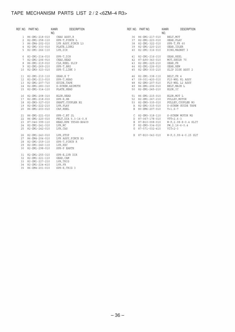
TAPE MECHANISM PARTS LIST 2 / 2 <6ZM–4 R3>
DESCRIPTIONREF. NO. KANRINO.
PART NO. DESCRIPTIONREF. NO. KANRINO.
PART NO.
1 86-ZM1-218-010 CHAS ASSY,R 2 82-ZM1-258-110 SPR-T,PINCH L 3 86-ZM4-202-010 LVR ASSY,PINCH L3 4 82-ZM1-333-010 PLATE,LINK2 5 82-ZM1-266-110 LVR,DIR
6 82-ZM1-214-010 SPR-T,DIR 7 82-ZM1-206-910 CHAS,HEAD 8 86-ZM1-219-010 CLR,REEL SLIP 9 82-ZM1-269-210 SPR-T,BRG 10 82-ZM3-323-010 SPR-T,LINK 3
11 82-ZM1-210-110 GEAR,H T 12 82-ZM1-213-010 SPR-T,HEAD 13 82-ZM1-207-710 GUIDE,TAPE 14 82-ZM1-283-310 S-SCREW,AZIMUTH 15 82-ZM1-314-110 PLATE,HEAD
16 82-ZM1-208-310 HLDR,HEAD 17 82-ZM1-218-010 SPR-E,HB 18 82-ZM3-327-010 SHAFT,COUPLER N2 19 82-ZM1-222-210 LVR,PLAY 20 86-ZM1-203-010 CAP,REEL
21 86-ZM1-221-010 SPR-C,BT 2L 22 86-ZM1-220-010 FELT,DIA 5.3-14-0.8 23 87-046-399-110 HEAD,RPH YK56R-BS409 24 82-ZM1-241-310 LVR,MC 25 82-ZM1-242-010 LVR,CAS
26 82-ZM1-243-010 LVR,STOP 27 86-ZM4-204-010 LVR ASSY,PINCH R3 28 82-ZM1-259-110 SPR-T,PINCH R 29 82-ZM1-240-110 LVR,REC 30 82-ZM1-298-010 SPR-P EARTH
31 82-ZM1-255-310 SPR-E,LVR DIR 32 82-ZM1-221-110 GEAR,CAM 33 82-ZM1-227-210 LVR,TRIG 34 82-ZM1-224-410 LVR,FR 35 86-ZM4-201-010 SPR-E,TRIG 3
36 86-ZM1-217-010 BELT,MOT 37 82-ZM1-223-010 GEAR,PLAY 38 82-ZM1-322-010 SPR-T,FR 60 39 82-ZM1-220-210 GEAR,IDLER 40 82-ZM1-316-010 RING,MAGNET 3
41 82-ZM1-216-310 GEAR,REEL 42 87-A90-343-010 MOT,SHU2R 70 43 82-ZM1-225-210 GEAR,FR 44 82-ZM1-226-010 GEAR,REW 45 82-ZM3-333-210 SLIP DISK ASSY 2
46 82-ZM1-338-110 BELT,FR 4 47 09-001-420-010 FLY-WHL RL ASSY 48 82-ZM3-207-510 FLY-WHL L2 ASSY 49 86-ZM1-206-010 BELT,MAIN L 50 82-ZM1-245-210 HLDR,IC
51 86-ZM1-215-010 HLDR,MOT L 52 82-ZM1-247-210 PULLEY,MOTOR 53 82-ZM3-335-010 PULLEY,COUPLER M3 A 82-ZM1-315-010 S-SCREW GUIDE TAPE B 80-ZM6-207-010 V+1.6-7
C 82-ZM3-318-110 S-SCREW MOTOR M2 D 87-067-178-010 VTT+2.6-3 E 87-B10-008-010 W-P,2.08-8-0.4 SLIT F 82-ZM3-334-010 PW,2.16-6-0.4 G 87-571-032-410 VIT+2-3
H 87-B10-043-010 W-P,0.99-4-0.25 SLT

– 37 –
Insert a flat-bladed screwdriver into the position indicated by thearrows and remove the panel. Remove the screws of each speakerunit and then remove the speaker units.
Type.1
Type.3
Type.2
Type.4
Fig-1 Fig-2
Fig-3
How to Attach the PANEL, FR
Attach the PANEL, FR to the PANEL, SPKR. Tap the fourcorners of the PANEL, FR with the plastic hammer to fit thePANEL, FR into the PANEL, SPKR completely.
1 2 3
Insert a flat-bladed screwdriver into the position indicated by thearrows and remove the panel. Turn the speaker unit to counter-clockwise direction while inserting a flat-bladed screwdriver intoone of the hollows around speaker unit, and then remove the speakerunit. After replacing the speaker unit, install it turning to clockwisedirection until "click" sound comes out.
Remove the grill frame and four pieces of rubber caps by pullingout with a flat-bladed screwdriver. Remove the screws from holewhere installed rubber caps. Insert a flat-bladed screwdriver intothe position indicated by the arrows and remove the panel. Re-move the screws of each speaker unit and then remove the speakerunits.
TOOLS1 Plastic head hammer2 (() flat head screwdriver3 Cut chisel
How to Remove the PANEL, FR
1. Insert the (() flat head screwdriver tip into the gapbetween the PANEL, FR and the PANEL, SPKR. Tap thehead of the (() flat head screwdriver with the plastichammer head, and create the clearance as shown in Fig-1.
2. Insert the cut chisel in the clearance, and tap the head ofthe cut chisel with plastic hammer as shown in Fig-2, toremove the PANEL, FR.
3. Place the speaker horizontally. Tap head of the cut chiselwith plastic hammer as shown in Fig-3, and remove thePANEL, FR completely.
GENERAL SPEAKER DISASSEMBLY INSTRUCTIONS (FOR REFERENCE)

– 38 –
DESCRIPTIONREF. NO. KANRINO.
PART NO.
ACCESSORIES / PACKAGE LIST
DESCRIPTIONREF. NO. KANRINO.
PART NO.
1 8A-MS1-001-010 PANEL,FR 2 8A-MS1-004-110 PANEL,TW 3 8A-MS1-005-010 PANEL,DUCT 4 8A-MS1-006-010 GRILLE,FRAME ASSY 5 8A-MS1-602-010 SPKR,W 200
6 8A-MS1-603-010 SPKR,W 160 7 8A-MS2-605-110 SPKR,TW 60 8 88-MS1-608-010 SPKR,CERAMIC 9 88-NS5-611-010 CORD,SPKR B/L 10 88-MS1-610-010 CORD,SPKR
11 8A-MS4-017-010 FOOT ASSY 12 8A-NS8-013-010 FASTENER,C 13 88-NS3-026-010 UT2 4*20 BZN
SPEAKER PARTS LIST (SX–WA1000) <YLSKM>
SPEAKER PARTS LIST (SX–CR1800) <YLSKM>
1 8Z-AS4-602-010 SPKR,100<C1800> 1 8Z-AS5-601-010 SPKR,100<R1800> 2 8A-AS4-001-010 GRILLE,FRAME ASSY<C1800> 2 8A-AS5-001-010 GRILLE,FRAME ASSY<R1800> 3 8A-AS6-614-010 CORD,SPKR B/L R<R1800>
3 8A-AS6-612-010 CORD,SPKR B/L C<C1800> 4 8A-AS6-610-010 CORD,TW 5 8A-AS6-005-010 HLDR,HANGER
1 8A-MTM-912-010 IB,LH CCE-A1060 2 87-043-115-010 ANT,FEEDER FM 3 87-006-225-010 ANT,LOOP ANT NC2 4 8A-MTM-701-010 RC UNIT,RC-AAS01
DESCRIPTIONREF. NO. KANRINO.
PART NO.
NOTE: This SX-CR1800 Speaker contains SX-C1800 (Center Speaker) and SX-R1800 (Surround Speakers)

2–11, IKENOHATA 1–CHOME, TAITO-KU, TOKYO 110, JAPAN TEL:03 (3827) 3111
Printed in Singapore9420025 0251431
Related Documents