Operating Instructions & Parts Manual SFA Companies ©2004 10939 N. Pomona Ave. Kansas City, MO 64153 816-891-6390 [email protected] Model Number HW93657 HW93667 HW93660 HW93662 Service Jacks HW93657/ HW93660 HW93667/ HW93662 Capacity 4 Ton 4 Ton Air/ Manual 10 Ton 10 Ton Air/ Manual -Before using this product, read this manual and follow all its Safety Rules and Operating Instructions Made in North America HW93657-M0

Welcome message from author
This document is posted to help you gain knowledge. Please leave a comment to let me know what you think about it! Share it to your friends and learn new things together.
Transcript

Operating Instructions & Parts Manual
SFA Companies ©200410939 N. Pomona Ave. Kansas City, MO 64153
Model NumberHW93657HW93667HW93660HW93662
Service Jacks
HW93657/ HW93660 HW93667/ HW93662
Capacity 4 Ton 4 Ton Air/ Manual10 Ton10 Ton Air/ Manual
-Before using this product, read this manual and follow all its Safety Rules and Operating Instructions
Made inNorth America
HW93657-M0
Warranty P2Save These Instructions P3Product Description P3Specifications & Safety Instructions P3Assembly P4Operation P5Maintenance P6Troubleshooting P6Replacement Parts P7
TWO YEAR LIMITED WARRANTYFor a period of two (2) years from date of purchase, SFA Companies will repair or replace, at its option, without charge, anyof its products which fails due to a defect in material or workmanship, or which fails to conform to any implied warranty notexcluded hereby.
Performance of any obligation under this warranty may be obtained by returning the warranted product, freight prepaid, toSFA Companies Warranty Service Department, 10939 N. Pomona Ave., Kansas City, MO 64153.
Except where such limitations and exclusions are specifically prohibited by applicable law.
(1) THE CONSUMER'S SOLE AND EXCLUSIVE REMEDY SHALL BE THE REPAIR OR REPLACEMENT OF DEFECTIVEPRODUCTS AS DESCRIBED ABOVE.
(2) SFA COMPANIES SHALL NOT BE LIABLE FOR ANY CONSEQUENTIAL OR INCIDENTAL DAMAGE OR LOSSWHATSOEVER.
(3) THE DURATION OF ANY AND ALL EXPRESSED AND IMPLIED WARRANTIES, INCLUDING WITHOUT LIMITATION,ANY WARRANTIES OF MERCHANTABILITY AND FITNESS FOR A PARTICULAR PURPOSE, IS LIMITED TO A PERIODOF TWO (2) YEARS FROM DATE OF PURCHASE.
Some states do not allow limitations on how long an implied warranty lasts, so the above limitation may not apply to you.Some states do not allow the exclusion or limitation of incidental or consequential damages, so the above limitation orexclusion may not apply to you. This warranty gives you specific legal rights, and you may also have other rights whichvary from state to state.
2
Table of contents
HW93657-M0
Save These InstructionsFor your safety read, understand, and follow the information provided with and on this jack. The owner and operator of thisequipment shall have an understanding of this jack and safe operating procedures before attempting to use. The owner andoperator shall be aware that use and repair of this product may require special skills and knowledge. Instructions and safetyinformation shall be conveyed in the operator's native language before use of this jack is authorized. If any doubt exists asto the safe and proper use of this jack, remove from service immediately.
Inspect before each use. Do not use if there are broken, bent, cracked, or damaged parts (including labels). Any jackthat appears damaged in any way, operates abnormally, or is missing parts, shall be removed from service immediately. Ifthe jack has been or is suspected to have been subjected to a shock load (a load dropped suddenly, unexpectedly upon it),immediately discontinue use until the jack has been checked by a Hein-Werner authorized service center. It is recom-mended that an annual inspection be done by qualified personnel. Labels and Operator's Manual are available frommanufacturer.
PRODUCT DESCRIPTIONHein-Werner Hydraulic Service Jacks are designed to lift, not sustain, rated capacity loads. They are designed to beused in conjunction with jack stands. Intended use: To lift one wheel or one axle of a vehicle for the purpose of serviceand/or repair of vehicle components. After lifting, loads must be immediately supported by appropriately rated jackstands. Check with vehicle owner's manual for proper lift points.
DO NOT USE TO DOLLY OR MOVE VEHICLE.
DO NOT USE FOR ANY PURPOSE OTHER THAN THOSE USES OUTLINED ABOVE !
3
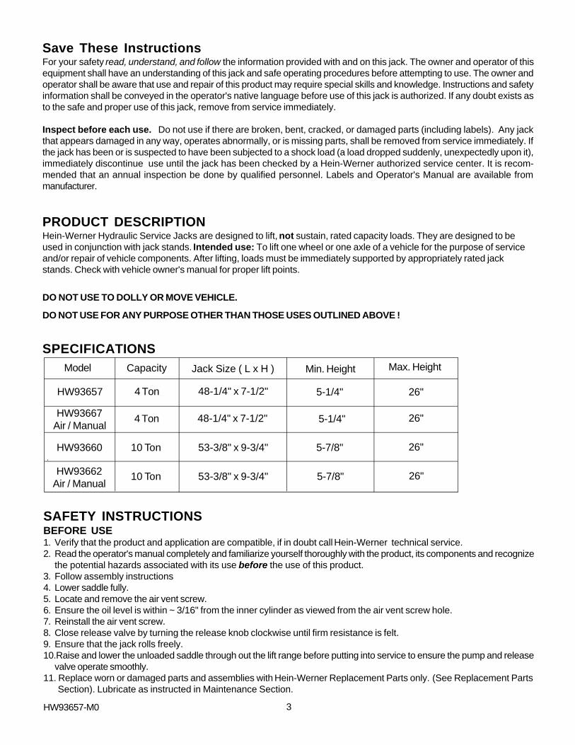
SPECIFICATIONS
SAFETY INSTRUCTIONSBEFORE USE1. Verify that the product and application are compatible, if in doubt call Hein-Werner technical service.2. Read the operator's manual completely and familiarize yourself thoroughly with the product, its components and recognize
the potential hazards associated with its use before the use of this product.3. Follow assembly instructions4. Lower saddle fully.5. Locate and remove the air vent screw.6. Ensure the oil level is within ~ 3/16" from the inner cylinder as viewed from the air vent screw hole.7. Reinstall the air vent screw.8. Close release valve by turning the release knob clockwise until firm resistance is felt.9. Ensure that the jack rolls freely.10.Raise and lower the unloaded saddle through out the lift range before putting into service to ensure the pump and release
valve operate smoothly.11. Replace worn or damaged parts and assemblies with Hein-Werner Replacement Parts only. (See Replacement Parts
Section). Lubricate as instructed in Maintenance Section.
HW93657-M0
Min. Height Max. Height
5-1/4"
Capacity
26"
Model
5-1/4"HW93657
Jack Size ( L x H )
4 Ton
4 Ton
26"
48-1/4" x 7-1/2"
HW93667Air / Manual
HW93660
HW93662Air / Manual
10 Ton
10 Ton
5-7/8"
5-7/8"
26"
26"
48-1/4" x 7-1/2"
53-3/8" x 9-3/4"
53-3/8" x 9-3/4"
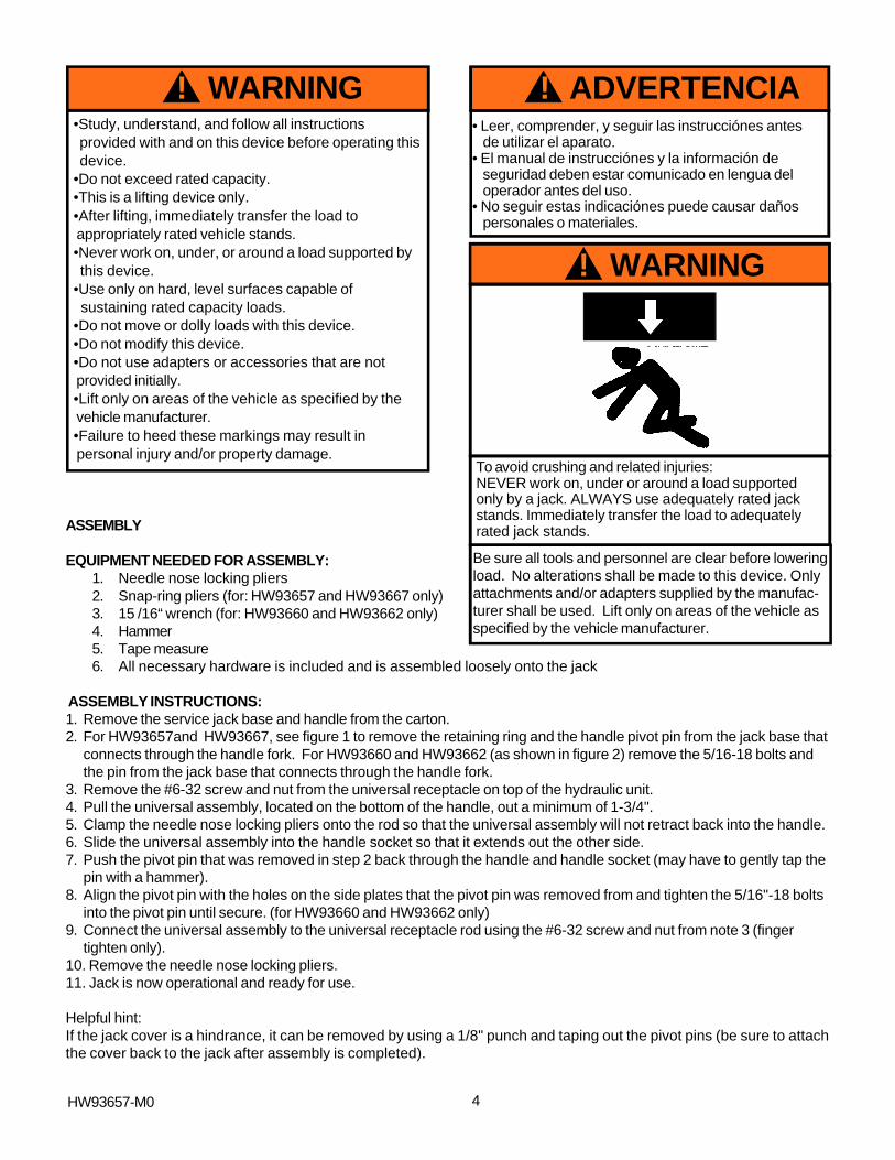
•Study, understand, and follow all instructions provided with and on this device before operating this device.•Do not exceed rated capacity.•This is a lifting device only.•After lifting, immediately transfer the load to appropriately rated vehicle stands.•Never work on, under, or around a load supported by this device.•Use only on hard, level surfaces capable of sustaining rated capacity loads.•Do not move or dolly loads with this device.•Do not modify this device.•Do not use adapters or accessories that are not provided initially.•Lift only on areas of the vehicle as specified by the vehicle manufacturer.•Failure to heed these markings may result in personal injury and/or property damage.
! WARNING
ASSEMBLY
EQUIPMENT NEEDED FOR ASSEMBLY:1. Needle nose locking pliers2. Snap-ring pliers (for: HW93657 and HW93667 only)3. 15 /16“ wrench (for: HW93660 and HW93662 only)4. Hammer5. Tape measure6. All necessary hardware is included and is assembled loosely onto the jack
ASSEMBLY INSTRUCTIONS:1. Remove the service jack base and handle from the carton.2. For HW93657and HW93667, see figure 1 to remove the retaining ring and the handle pivot pin from the jack base that
connects through the handle fork. For HW93660 and HW93662 (as shown in figure 2) remove the 5/16-18 bolts andthe pin from the jack base that connects through the handle fork.
3. Remove the #6-32 screw and nut from the universal receptacle on top of the hydraulic unit.4. Pull the universal assembly, located on the bottom of the handle, out a minimum of 1-3/4".5. Clamp the needle nose locking pliers onto the rod so that the universal assembly will not retract back into the handle.6. Slide the universal assembly into the handle socket so that it extends out the other side.7. Push the pivot pin that was removed in step 2 back through the handle and handle socket (may have to gently tap the
pin with a hammer).8. Align the pivot pin with the holes on the side plates that the pivot pin was removed from and tighten the 5/16"-18 bolts
into the pivot pin until secure. (for HW93660 and HW93662 only)9. Connect the universal assembly to the universal receptacle rod using the #6-32 screw and nut from note 3 (finger
tighten only).10. Remove the needle nose locking pliers.11. Jack is now operational and ready for use.
Helpful hint:If the jack cover is a hindrance, it can be removed by using a 1/8" punch and taping out the pivot pins (be sure to attachthe cover back to the jack after assembly is completed).
4
! WARNING
To avoid crushing and related injuries:NEVER work on, under or around a load supportedonly by a jack. ALWAYS use adequately rated jackstands. Immediately transfer the load to adequatelyrated jack stands.
Be sure all tools and personnel are clear before loweringload. No alterations shall be made to this device. Onlyattachments and/or adapters supplied by the manufac-turer shall be used. Lift only on areas of the vehicle asspecified by the vehicle manufacturer.
• Leer, comprender, y seguir las instrucciónes antesde utilizar el aparato.
• El manual de instrucciónes y la información deseguridad deben estar comunicado en lengua deloperador antes del uso.
• No seguir estas indicaciónes puede causar dañospersonales o materiales.
! ADVERTENCIA
HW93657-M0
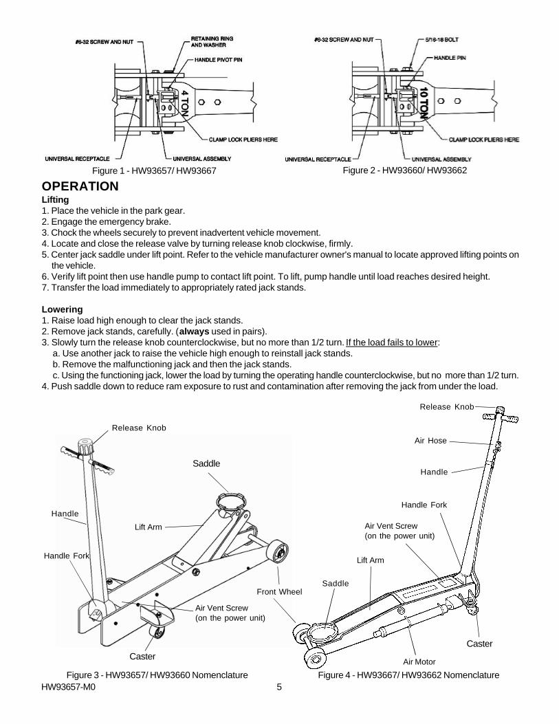
OPERATIONLifting1. Place the vehicle in the park gear.2. Engage the emergency brake.3. Chock the wheels securely to prevent inadvertent vehicle movement.4. Locate and close the release valve by turning release knob clockwise, firmly.5. Center jack saddle under lift point. Refer to the vehicle manufacturer owner's manual to locate approved lifting points on
the vehicle.6. Verify lift point then use handle pump to contact lift point. To lift, pump handle until load reaches desired height.7. Transfer the load immediately to appropriately rated jack stands.
Lowering1. Raise load high enough to clear the jack stands.2. Remove jack stands, carefully. (always used in pairs).3. Slowly turn the release knob counterclockwise, but no more than 1/2 turn. If the load fails to lower:
a. Use another jack to raise the vehicle high enough to reinstall jack stands.b. Remove the malfunctioning jack and then the jack stands.c. Using the functioning jack, lower the load by turning the operating handle counterclockwise, but no more than 1/2 turn.
4. Push saddle down to reduce ram exposure to rust and contamination after removing the jack from under the load.
5Figure 3 - HW93657/ HW93660 Nomenclature Figure 4 - HW93667/ HW93662 Nomenclature
Lift Arm
Figure 1 - HW93657/ HW93667 Figure 2 - HW93660/ HW93662
Air Hose
Saddle
Handle
Lift Arm
Handle Fork
Caster
Front Wheel
Release Knob
Saddle
Handle
Release Knob
Caster
Air Motor
Air Vent Screw(on the power unit)
Air Vent Screw(on the power unit)
Handle Fork
Lift Arm
HW93657-M0

TROUBLESHOOTING
6
MAINTENANCEImportant: Use only a good grade hydraulic jack oil. Avoid mixing different types of fluid and Never use brake fluid, turbineoil, transmission fluid, motor oil or glycerin. Improper fluid can cause failure of the jack and the potential for sudden andimmediate loss of load. We recommend Hein-Werner hydraulic jack oil HW 93291.
Adding oil1. Lower saddle fully.2. Set jack in its upright, level position.3. Locate and remove air vent screw.4. Fill with oil until ~3/16" above the inner cylinder as seen from the air vent screw hole.5. Reinstall the air vent screw.
Changing oilFor best performance and longest life, replace the complete hydraulic fluid at least once a year.1. Lower saddle fully.2. Remove the air vent screw.3. Lay the jack on its side and drain the fluid into a suitable container.
Note: Dispose of hydraulic fluid in accordance with local regulations.
4. Fill with oil until ~3/16" above the inner cylinder as seen from the air vent screw hole.5. Reinstall the air vent screw.
LubricationA periodic coating of light lubricating oil to pivot points, axles and hinges will help to prevent rust and assurethat wheels, castors and pump assemblies move freely.
CleaningPeriodically check the pump piston and ram for signs of rust or corrosion. Clean as needed and wipe with an oily cloth.
Note: Never use sandpaper or abrasive material on these surfaces!
StorageLower the saddle to its lowest position when not in use.
• Contact Hein-Werner Technical Service
Possible Causes Corrective Action
Jack will not lift load
Jack bleeds off after lift
Will not lift to full extension
• Release knob not tightly closed• Overload condition
• Fluid level low
• Hydraulic unit malfunction
• Ensure release knob tightly closed• Remedy overload condition
• Ensure proper fluid level
Jack will not lower after unloading• Reservoir overfilled• Linkages binding• Fluid level low
• Drain fluid to proper level• Clean and lubricate moving parts• Ensure proper fluid level
Symptom
HW93657-M0

REPLACEMENT PARTSNot all components of the jack are replacement items, but are illustrated as a convenient reference of location andposition in the assembly sequence. When ordering parts, give model number, part number and description on page 7-17Call or write for current pricing: Phone:(816)891-6390 or contact Hein-Werner Customer Support,[email protected] or 10939 N. Pomona Ave. Kansas City, MO 64153
Model HW93657 Replacement Parts
7
Figure 5 - Parts Illustration for Model HW93657
HW93657-M0
8
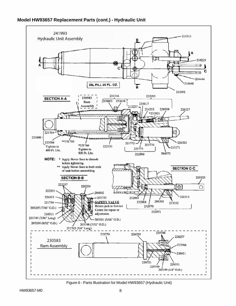
Figure 6 - Parts Illustration for Model HW93657 (Hydraulic Unit)
HW93657-M0
Model HW93657 Replacement Parts (cont.) - Hydraulic Unit
9
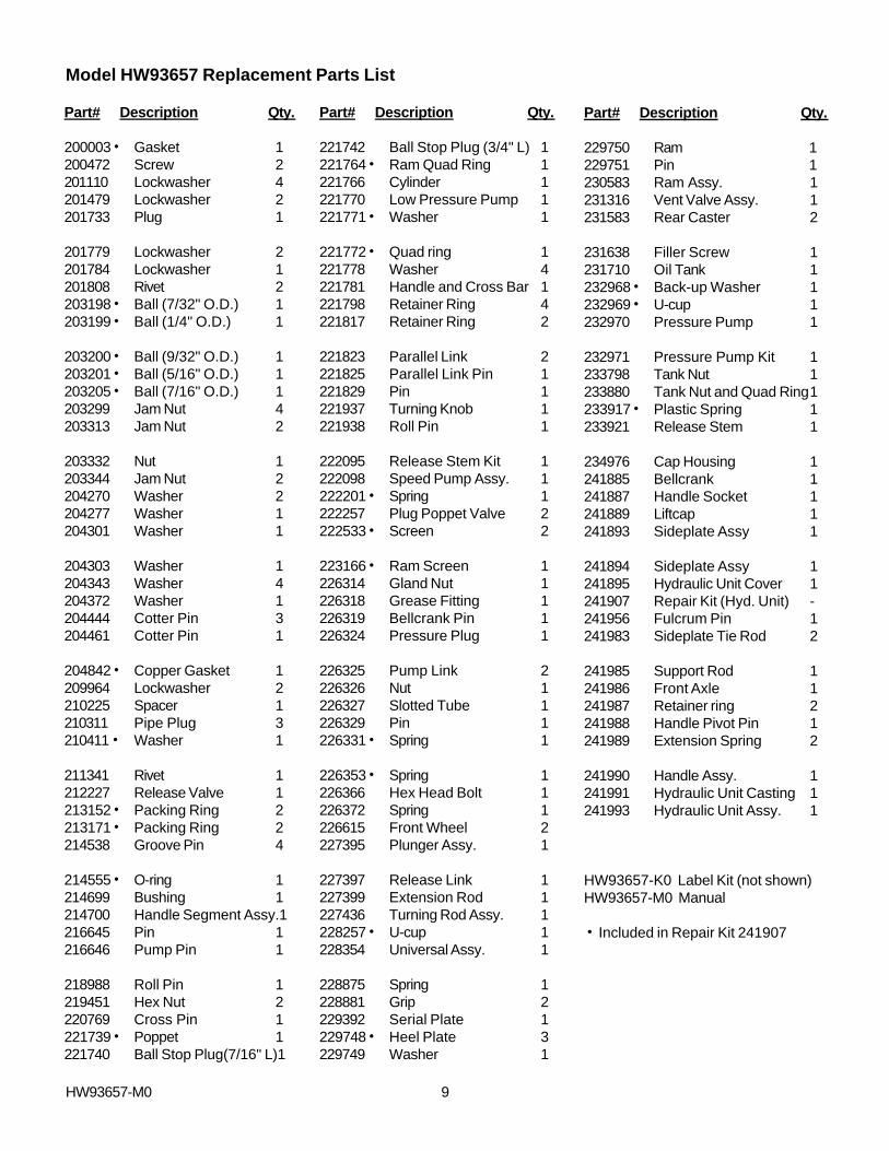
Model HW93657 Replacement Parts List
Part# Description Qty.
200003h Gasket 1200472 Screw 2201110 Lockwasher 4201479 Lockwasher 2201733 Plug 1
201779 Lockwasher 2201784 Lockwasher 1201808 Rivet 2203198h Ball (7/32" O.D.) 1203199h Ball (1/4" O.D.) 1
203200h Ball (9/32" O.D.) 1203201h Ball (5/16" O.D.) 1203205h Ball (7/16" O.D.) 1203299 Jam Nut 4203313 Jam Nut 2
203332 Nut 1203344 Jam Nut 2204270 Washer 2204277 Washer 1204301 Washer 1
204303 Washer 1204343 Washer 4204372 Washer 1204444 Cotter Pin 3204461 Cotter Pin 1
204842h Copper Gasket 1209964 Lockwasher 2210225 Spacer 1210311 Pipe Plug 3210411h Washer 1
211341 Rivet 1212227 Release Valve 1213152h Packing Ring 2213171h Packing Ring 2214538 Groove Pin 4
214555h O-ring 1214699 Bushing 1214700 Handle Segment Assy.1216645 Pin 1216646 Pump Pin 1
218988 Roll Pin 1219451 Hex Nut 2220769 Cross Pin 1221739h Poppet 1221740 Ball Stop Plug(7/16" L)1
Part# Description Qty.
221742 Ball Stop Plug (3/4" L) 1221764h Ram Quad Ring 1221766 Cylinder 1221770 Low Pressure Pump 1221771h Washer 1
221772h Quad ring 1221778 Washer 4221781 Handle and Cross Bar 1221798 Retainer Ring 4221817 Retainer Ring 2
221823 Parallel Link 2221825 Parallel Link Pin 1221829 Pin 1221937 Turning Knob 1221938 Roll Pin 1
222095 Release Stem Kit 1222098 Speed Pump Assy. 1222201h Spring 1222257 Plug Poppet Valve 2222533h Screen 2
223166h Ram Screen 1226314 Gland Nut 1226318 Grease Fitting 1226319 Bellcrank Pin 1226324 Pressure Plug 1
226325 Pump Link 2226326 Nut 1226327 Slotted Tube 1226329 Pin 1226331h Spring 1
226353h Spring 1226366 Hex Head Bolt 1226372 Spring 1226615 Front Wheel 2227395 Plunger Assy. 1
227397 Release Link 1227399 Extension Rod 1227436 Turning Rod Assy. 1228257h U-cup 1228354 Universal Assy. 1
228875 Spring 1228881 Grip 2229392 Serial Plate 1229748h Heel Plate 3229749 Washer 1
Part# Description Qty.
229750 Ram 1229751 Pin 1230583 Ram Assy. 1231316 Vent Valve Assy. 1231583 Rear Caster 2
231638 Filler Screw 1231710 Oil Tank 1232968h Back-up Washer 1232969h U-cup 1232970 Pressure Pump 1
232971 Pressure Pump Kit 1233798 Tank Nut 1233880 Tank Nut and Quad Ring1233917h Plastic Spring 1233921 Release Stem 1
234976 Cap Housing 1241885 Bellcrank 1241887 Handle Socket 1241889 Liftcap 1241893 Sideplate Assy 1
241894 Sideplate Assy 1241895 Hydraulic Unit Cover 1241907 Repair Kit (Hyd. Unit) -241956 Fulcrum Pin 1241983 Sideplate Tie Rod 2
241985 Support Rod 1241986 Front Axle 1241987 Retainer ring 2241988 Handle Pivot Pin 1241989 Extension Spring 2
241990 Handle Assy. 1241991 Hydraulic Unit Casting 1241993 Hydraulic Unit Assy. 1
HW93657-K0 Label Kit (not shown)HW93657-M0 Manual
h Included in Repair Kit 241907
HW93657-M0
10
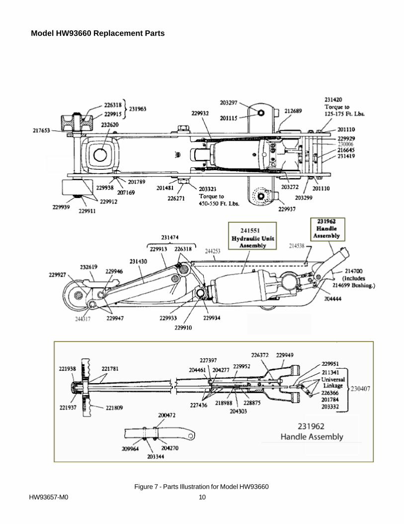
Model HW93660 Replacement Parts
Figure 7 - Parts Illustration for Model HW93660
HW93657-M0
11
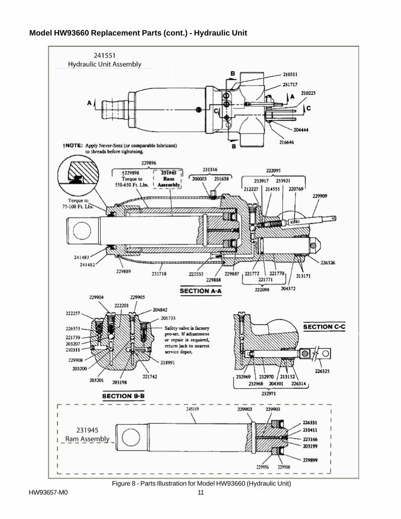
Model HW93660 Replacement Parts (cont.) - Hydraulic Unit
Figure 8 - Parts Illustration for Model HW93660 (Hydraulic Unit)HW93657-M0
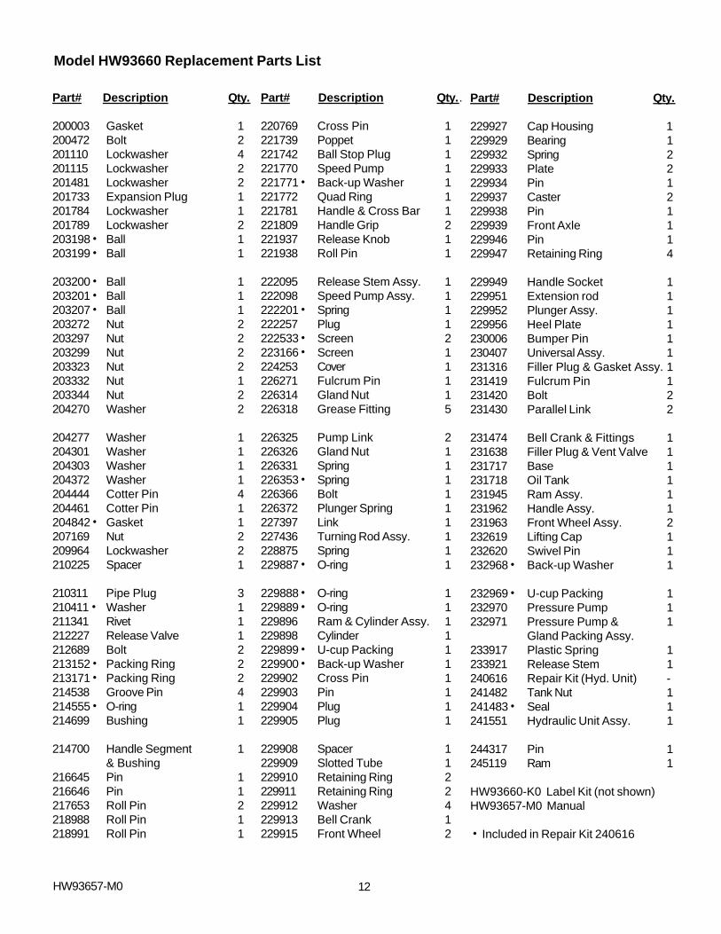
Model HW93660 Replacement Parts List
Part# Description Qty.
200003 Gasket 1200472 Bolt 2201110 Lockwasher 4201115 Lockwasher 2201481 Lockwasher 2201733 Expansion Plug 1201784 Lockwasher 1201789 Lockwasher 2203198h Ball 1203199h Ball 1
203200h Ball 1203201h Ball 1203207h Ball 1203272 Nut 2203297 Nut 2203299 Nut 2203323 Nut 2203332 Nut 1203344 Nut 2204270 Washer 2
204277 Washer 1204301 Washer 1204303 Washer 1204372 Washer 1204444 Cotter Pin 4204461 Cotter Pin 1204842h Gasket 1207169 Nut 2209964 Lockwasher 2210225 Spacer 1
210311 Pipe Plug 3210411h Washer 1211341 Rivet 1212227 Release Valve 1212689 Bolt 2213152h Packing Ring 2213171h Packing Ring 2214538 Groove Pin 4214555h O-ring 1214699 Bushing 1
214700 Handle Segment 1& Bushing
216645 Pin 1216646 Pin 1217653 Roll Pin 2218988 Roll Pin 1218991 Roll Pin 1
Part# Description Qty..
220769 Cross Pin 1221739 Poppet 1221742 Ball Stop Plug 1221770 Speed Pump 1221771h Back-up Washer 1221772 Quad Ring 1221781 Handle & Cross Bar 1221809 Handle Grip 2221937 Release Knob 1221938 Roll Pin 1
222095 Release Stem Assy. 1222098 Speed Pump Assy. 1222201h Spring 1222257 Plug 1222533h Screen 2223166h Screen 1224253 Cover 1226271 Fulcrum Pin 1226314 Gland Nut 1226318 Grease Fitting 5
226325 Pump Link 2226326 Gland Nut 1226331 Spring 1226353h Spring 1226366 Bolt 1226372 Plunger Spring 1227397 Link 1227436 Turning Rod Assy. 1228875 Spring 1229887h O-ring 1
229888h O-ring 1229889h O-ring 1229896 Ram & Cylinder Assy. 1229898 Cylinder 1229899h U-cup Packing 1229900h Back-up Washer 1229902 Cross Pin 1229903 Pin 1229904 Plug 1229905 Plug 1
229908 Spacer 1229909 Slotted Tube 1229910 Retaining Ring 2229911 Retaining Ring 2229912 Washer 4229913 Bell Crank 1229915 Front Wheel 2
Part# Description Qty.
229927 Cap Housing 1229929 Bearing 1229932 Spring 2229933 Plate 2229934 Pin 1229937 Caster 2229938 Pin 1229939 Front Axle 1229946 Pin 1229947 Retaining Ring 4
229949 Handle Socket 1229951 Extension rod 1229952 Plunger Assy. 1229956 Heel Plate 1230006 Bumper Pin 1230407 Universal Assy. 1231316 Filler Plug & Gasket Assy. 1231419 Fulcrum Pin 1231420 Bolt 2231430 Parallel Link 2
231474 Bell Crank & Fittings 1231638 Filler Plug & Vent Valve 1231717 Base 1231718 Oil Tank 1231945 Ram Assy. 1231962 Handle Assy. 1231963 Front Wheel Assy. 2232619 Lifting Cap 1232620 Swivel Pin 1232968h Back-up Washer 1
232969h U-cup Packing 1232970 Pressure Pump 1232971 Pressure Pump & 1
Gland Packing Assy.233917 Plastic Spring 1233921 Release Stem 1240616 Repair Kit (Hyd. Unit) -241482 Tank Nut 1241483h Seal 1241551 Hydraulic Unit Assy. 1
244317 Pin 1245119 Ram 1
HW93660-K0 Label Kit (not shown)HW93657-M0 Manual
h Included in Repair Kit 240616
HW93657-M0 12
HW93657-M0
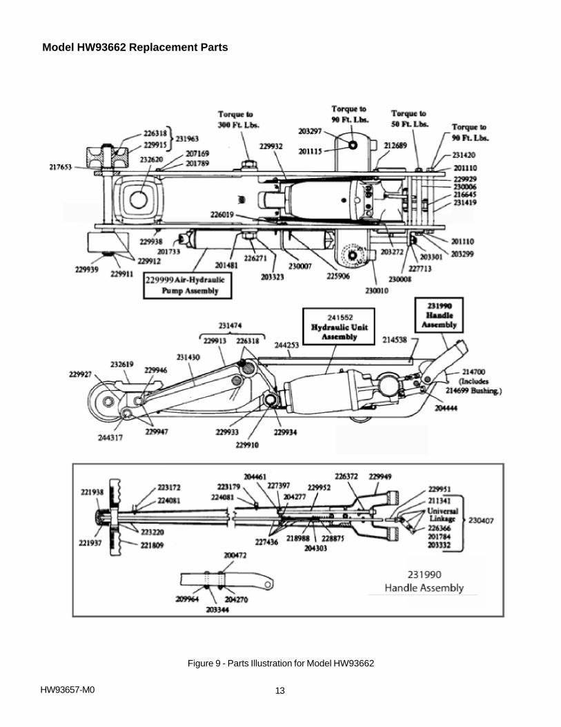
Model HW93662 Replacement Parts
13
Figure 9 - Parts Illustration for Model HW93662
14HW93657-M0
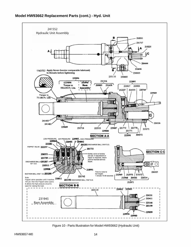
Model HW93662 Replacement Parts (cont.) - Hyd. Unit
Figure 10 - Parts Illustration for Model HW93662 (Hydraulic Unit)

15HW93657-M0
Model HW93662 Replacement Parts (cont.) - Air Hyd. Pump
Figure 11 - Parts Illustration for Model HW93662 (Air Hyd. Pump)
200003 Gasket 1200472 Bolt 2201110 Lockwasher 4201115 Lockwasher 2201481 Lockwasher 2
201733 Expansion Plug 1201784 Lockwasher 1201789 Lockwasher 2203198h Ball (7/32" O.D.) 1203199h Ball (1/4" O.D.) 1
203200h Ball (9/32" O.D.) 1203201h Ball (5/16" O.D.) 1203202 Ball (11/32" O.D.) 1203207h Ball 1203272 Nut 2
203297 Nut 2203299 Nut 2203301 Jam Nut 1203323 Nut 2203332 Nut 1
203344 Nut 2204270 Washer 2204277 Washer 1204301 Washer 1204303 Washer 1
204372 Washer 1204444 Cotter Pin 4204461 Cotter Pin 1204842h Gasket 1207169 Nut 2
209964 Lockwasher 2210225 Spacer 1210311 Pipe Plug 3210411h Washer 1211341 Rivet 1
212227 Release Valve 1212689 Bolt 2213152h Packing Ring 2213171h Packing Ring 2214538 Groove Pin 4
Model HW93662 Replacement Parts List
...Continue on next page (page 16)
Part# Description Qty
214555h O-ring 1214699 Bushing 1214700 Handle Segment & 1
Bushing216645 Pin 1
216646 Pin 1217653 Roll Pin 2218988 Roll Pin 1218991 Roll Pin 1219861 O-ring 1
220769 Coss Pin 1221013# U-cup Packing 1221739 Poppet 1221742 Ball Stop Plug 1221770 Speed Pump 1
221771h Back-up Washer 1221772 Quad Ring 1221809 Handle Grip 2221820 Retaining Ring 2221937 Release Knob 1
Part# Description Qty Part# Description Qty
16HW93657-M0
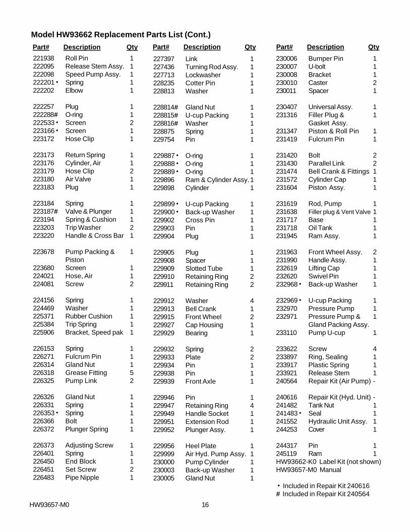
Model HW93662 Replacement Parts List (Cont.)
221938 Roll Pin 1222095 Release Stem Assy. 1222098 Speed Pump Assy. 1222201h Spring 1222202 Elbow 1
222257 Plug 1222288# O-ring 1222533h Screen 2223166h Screen 1223172 Hose Clip 1
223173 Return Spring 1223176 Cylinder, Air 1223179 Hose Clip 2223180 Air Valve 1223183 Plug 1
223184 Spring 1223187# Valve & Plunger 1223194 Spring & Cushion 1223203 Trip Washer 2223220 Handle & Cross Bar 1
223678 Pump Packing & 1Piston
223680 Screen 1224021 Hose, Air 1224081 Screw 2
224156 Spring 1224469 Washer 1225371 Rubber Cushion 1225384 Trip Spring 1225906 Bracket, Speed pak 1
226153 Spring 1226271 Fulcrum Pin 1226314 Gland Nut 1226318 Grease Fitting 5226325 Pump Link 2
226326 Gland Nut 1226331 Spring 1226353h Spring 1226366 Bolt 1226372 Plunger Spring 1
226373 Adjusting Screw 1226401 Spring 1226450 End Block 1226451 Set Screw 2226483 Pipe Nipple 1
227397 Link 1227436 Turning Rod Assy. 1227713 Lockwasher 1228235 Cotter Pin 1228813 Washer 1
228814# Gland Nut 1228815# U-cup Packing 1228816# Washer 1228875 Spring 1229754 Pin 1
229887h O-ring 1229888h O-ring 1229889h O-ring 1229896 Ram & Cylinder Assy.1229898 Cylinder 1
229899h U-cup Packing 1229900h Back-up Washer 1229902 Cross Pin 1229903 Pin 1229904 Plug 1
229905 Plug 1229908 Spacer 1229909 Slotted Tube 1229910 Retaining Ring 2229911 Retaining Ring 2
229912 Washer 4229913 Bell Crank 1229915 Front Wheel 2229927 Cap Housing 1229929 Bearing 1
229932 Spring 2229933 Plate 2229934 Pin 1229938 Pin 1229939 Front Axle 1
229946 Pin 1229947 Retaining Ring 4229949 Handle Socket 1229951 Extension Rod 1229952 Plunger Assy. 1
229956 Heel Plate 1229999 Air Hyd. Pump Assy. 1230000 Pump Cylinder 1230003 Back-up Washer 1230005 Gland Nut 1
230006 Bumper Pin 1230007 U-bolt 1230008 Bracket 1230010 Caster 2230011 Spacer 1
230407 Universal Assy. 1231316 Filler Plug & 1
Gasket Assy.231347 Piston & Roll Pin 1231419 Fulcrum Pin 1
231420 Bolt 2231430 Parallel Link 2231474 Bell Crank & Fittings 1231572 Cylinder Cap 1231604 Piston Assy. 1
231619 Rod, Pump 1231638 Filler plug & Vent Valve 1231717 Base 1231718 Oil Tank 1231945 Ram Assy. 1
231963 Front Wheel Assy. 2231990 Handle Assy. 1232619 Lifting Cap 1232620 Swivel Pin 1232968h Back-up Washer 1
232969h U-cup Packing 1232970 Pressure Pump 1232971 Pressure Pump & 1
Gland Packing Assy.233110 Pump U-cup 1
233622 Screw 4233897 Ring, Sealing 1233917 Plastic Spring 1233921 Release Stem 1240564 Repair Kit (Air Pump) -
240616 Repair Kit (Hyd. Unit) -241482 Tank Nut 1241483h Seal 1241552 Hydraulic Unit Assy. 1244253 Cover 1
244317 Pin 1245119 Ram 1HW93662-K0 Label Kit (not shown)HW93657-M0 Manual
h Included in Repair Kit 240616# Included in Repair Kit 240564
Part# Description Qty Part# Description Qty Part# Description Qty

17HW93657-M0
Model HW93667 Replacement Part
Figure 12 - Parts Illustration for Model HW93667
18HW93657-M0
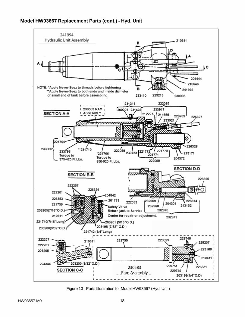
Model HW93667 Replacement Parts (cont.) - Hyd. Unit
Figure 13 - Parts Illustration for Model HW93667 (Hyd. Unit)
19
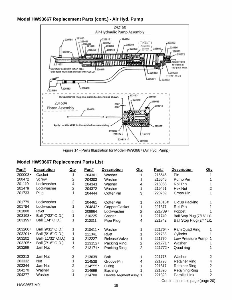
Model HW93667 Replacement Parts (cont.) - Air Hyd. Pump
Figure 14 - Parts Illustration for Model HW93667 (Air Hyd. Pump)
HW93657-M0
Model HW93667 Replacement Parts List
Part# Description Qty Part# Description Qty Part# Description Qty200003h Gasket 1200472 Screw 2201110 Lockwasher 4201479 Lockwasher 2201733 Plug 1
201779 Lockwasher 2201784 Lockwasher 1201808 Rivet 2203198h Ball (7/32" O.D.) 1203199h Ball (1/4" O.D.) 1
203200h Ball (9/32" O.D.) 1203201h Ball (5/16" O.D.) 1203202 Ball (11/32" O.D.) 1203205h Ball (7/16" O.D.) 1203299 Jam Nut 4
203313 Jam Nut 2203332 Nut 1203344 Jam Nut 2204270 Washer 2204277 Washer 1
204301 Washer 1204303 Washer 1204343 Washer 4204372 Washer 1204444 Cotter Pin 3
204461 Cotter Pin 1204842h Copper Gasket 1209964 Lockwasher 2210225 Spacer 1210311 Pipe Plug 4
210411h Washer 1211341 Rivet 1212227 Release Valve 1213152h Packing Ring 2213171h Packing Ring 2
213639 Bolt 1214538 Groove Pin 4214555h O-ring 1214699 Bushing 1214700 Handle segment Assy. 1
216645 Pin 1216646 Pump Pin 1218988 Roll Pin 1219451 Hex Nut 2220769 Cross Pin 1
221013# U-cup Packing 1221377 Roll Pin 1221739h Poppet 1221740 Ball Stop Plug (7/16" L)1221742 Ball Stop Plug (3/4" L)1
221764h Ram Quad Ring 1221766 Cylinder 1221770 Low Pressure Pump 1221771h Washer 1221772h Quad ring 1
221778 Washer 2221798 Retainer Ring 4221817 Retainer Ring 2221820 Retaining Ring 1221823 Parallel Link 2
...Continue on next page (page 20)
20HW93657-M0
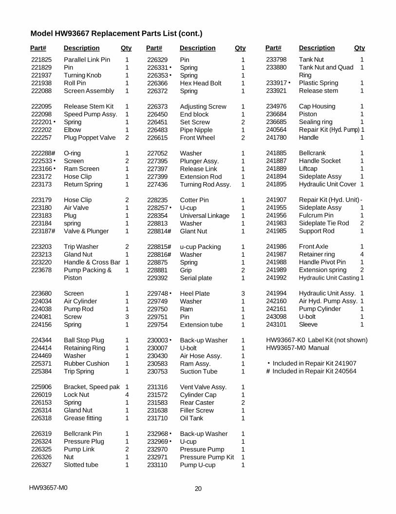
Model HW93667 Replacement Parts List (cont.)
Part# Description Qty Part# Description Qty Part# Description Qty
221825 Parallel Link Pin 1221829 Pin 1221937 Turning Knob 1221938 Roll Pin 1222088 Screen Assembly 1
222095 Release Stem Kit 1222098 Speed Pump Assy. 1222201h Spring 1222202 Elbow 1222257 Plug Poppet Valve 2
222288# O-ring 1222533h Screen 2223166h Ram Screen 1223172 Hose Clip 1223173 Return Spring 1
223179 Hose Clip 2223180 Air Valve 1223183 Plug 1223184 spring 1223187# Valve & Plunger 1
223203 Trip Washer 2223213 Gland Nut 1223220 Handle & Cross Bar 1223678 Pump Packing & 1
Piston
223680 Screen 1224034 Air Cylinder 1224038 Pump Rod 1224081 Screw 3224156 Spring 1
224344 Ball Stop Plug 1224414 Retaining Ring 1224469 Washer 1225371 Rubber Cushion 1225384 Trip Spring 1
225906 Bracket, Speed pak 1226019 Lock Nut 4226153 Spring 1226314 Gland Nut 1226318 Grease fitting 1
226319 Bellcrank Pin 1226324 Pressure Plug 1226325 Pump Link 2226326 Nut 1226327 Slotted tube 1
226329 Pin 1226331h Spring 1226353h Spring 1226366 Hex Head Bolt 1226372 Spring 1
226373 Adjusting Screw 1226450 End block 1226451 Set Screw 2226483 Pipe Nipple 1226615 Front Wheel 2
227052 Washer 1227395 Plunger Assy. 1227397 Release Link 1227399 Extension Rod 1227436 Turning Rod Assy. 1
228235 Cotter Pin 1228257h U-cup 1228354 Universal Linkage 1228813 Washer 1228814# Glant Nut 1
228815# u-cup Packing 1228816# Washer 1228875 Spring 1228881 Grip 2229392 Serial plate 1
229748h Heel Plate 3229749 Washer 1229750 Ram 1229751 Pin 1229754 Extension tube 1
230003h Back-up Washer 1230007 U-bolt 1230430 Air Hose Assy. 1230583 Ram Assy. 1230753 Suction Tube 1
231316 Vent Valve Assy. 1231572 Cylinder Cap 1231583 Rear Caster 2231638 Filler Screw 1231710 Oil Tank 1
232968h Back-up Washer 1232969h U-cup 1232970 Pressure Pump 1232971 Pressure Pump Kit 1233110 Pump U-cup 1
233798 Tank Nut 1233880 Tank Nut and Quad 1
Ring233917h Plastic Spring 1233921 Release stem 1
234976 Cap Housing 1236684 Piston 1236685 Sealing ring 1240564 Repair Kit (Hyd. Pump) 1241780 Handle 1
241885 Bellcrank 1241887 Handle Socket 1241889 Liftcap 1241894 Sideplate Assy 1241895 Hydraulic Unit Cover 1
241907 Repair Kit (Hyd. Unit) -241955 Sideplate Assy 1241956 Fulcrum Pin 1241983 Sideplate Tie Rod 2241985 Support Rod 1
241986 Front Axle 1241987 Retainer ring 4241988 Handle Pivot Pin 1241989 Extension spring 2241992 Hydraulic Unit Casting 1
241994 Hydraulic Unit Assy. 1242160 Air Hyd. Pump Assy. 1242161 Pump Cylinder 1243098 U-bolt 1243101 Sleeve 1
HW93667-K0 Label Kit (not shown)HW93657-M0 Manual
h Included in Repair Kit 241907# Included in Repair Kit 240564
Related Documents