Citation SERVICE BULLETIN SB700-29-01 REVISION TRANSMITTAL This sheet transmits Revision 1 to SB700-29-01, which: A. Added "Refer to the attached Flight Crew Operations Summary" in the Flight Crew Operations section. B. Added Flight Crew Operation Summary. NOTE: This revision replaces the original issue of SB700-29-01 in its entirety. REVISION COMPLIANCE NO EFFECT. Airplanes previously modified by this service bulletin are not affected by this revision. LOG OF REVISIONS Original Issue August 3, 2020 Revision 1 August 5, 2020 Original Issue - August 3, 2020 SB700-29-01 Revision 1 - August 5, 2020 Page 1 of 1 Textron Aviation Customer Service, P.O. Box 7706, Wichita, KS 67277, U.S.A. 1-316-517-5800 COPYRIGHT © 2020

Welcome message from author
This document is posted to help you gain knowledge. Please leave a comment to let me know what you think about it! Share it to your friends and learn new things together.
Transcript
Citation SERVICE BULLETINSB700-29-01
REVISION TRANSMITTAL
This sheet transmits Revision 1 to SB700-29-01, which:A. Added "Refer to the attached Flight Crew Operations Summary" in the Flight Crew Operations section.
B. Added Flight Crew Operation Summary.
NOTE: This revision replaces the original issue of SB700-29-01 in its entirety.
REVISION COMPLIANCENO EFFECT. Airplanes previously modified by this service bulletin are not affected by this revision.
LOG OF REVISIONS
Original Issue August 3, 2020Revision 1 August 5, 2020
Original Issue - August 3, 2020 SB700-29-01Revision 1 - August 5, 2020 Page 1 of 1
Textron Aviation Customer Service, P.O. Box 7706, Wichita, KS 67277, U.S.A. 1-316-517-5800
COPYRIGHT © 2020

Citation SERVICE BULLETINSB700-29-01
TITLEHYDRAULIC POWER - POWER TRANSFER AND CONVERSION UNIT (PTCU) INSTALLATION
EFFECTIVITYMODEL SERIAL NUMBERS
700 (Citation Longitude) -0004, -0008 thru -0016, -0018 thru -0021
The equivalent of this service document has been incorporated on production airplanes -0002, -0003,-0007, -0017 and -0022 and On.
NOTE: Textron Aviation Wichita Service Center is the only facility that can complete this servicedocument.
REASONThis service document installs a Power Transfer and Conversion Unit (PTCU) in place of the PowerTransfer Unit (PTU).
DESCRIPTIONThis service document provides parts and instructions to modify the aircraft hydraulic/electrical systemconfiguration related to the PTU and to replace the PTU with a PTCU.
NOTE: This service bulletin will require the software and configuration files as follows:• Part Number - 8204546-4 - AReS Configuration File
COMPLIANCEDISCRETIONARY. This service document can be accomplished at the discretion of the owner.
A service document published by Textron Aviation may be recorded as completed in an aircraft logonly when the following requirements are satisfied:
1) The mechanic must complete all of the instructions in the service document, including the intenttherein.
2) The mechanic must correctly use and install all applicable parts supplied with the servicedocument kit. Only with written authorization from Textron Aviation can substitute parts or rebuiltparts be used to replace new parts.
3) The mechanic or airplane owner must use the technical data in the service document only asapproved and published.
4) The mechanic or airplane owner must apply the information in the service document only toaircraft serial numbers identified in the Effectivity section of the document.
5) The mechanic or airplane owner must use maintenance practices that are identified as acceptablestandard practices in the aviation industry and governmental regulations.
No individual or corporate organization other than Textron Aviation is authorized to make or apply anychanges to a Textron Aviation-issued service document or flight manual supplement without prior writtenconsent from Textron Aviation.
Textron Aviation is not responsible for the quality of maintenance performed to comply with this document,unless the maintenance is accomplished at a Textron Aviation-owned Service Center.
Original Issue - August 3, 2020 SB700-29-01Revision 1 - August 5, 2020 Page 1 of 36
Textron Aviation Customer Service, P.O. Box 7706, Wichita, KS 67277, U.S.A. 1-316-517-5800This document contains technical data and is subject to U.S. export regulations. This information has been exported from the United States
in accordance with export administration regulations. Diversion contrary to U.S. law is prohibited. ECCN: 9E991
COPYRIGHT © 2020
SB700-29-01Page 2 Revision 1 - August 5, 2020
Citation SERVICE BULLETINSB700-29-01
APPROVAL
Textron Aviation received FAA approval for the technical data in this publication that changes the airplanetype design.
FLIGHT CREW OPERATIONS
Refer to the attached Flight Crew Operations Summary.
CONSUMABLE MATERIAL
No specialized consumable materials are required to complete this service document.
TOOLING
This specialized tooling is required to complete this service document.
NAME NUMBER MANUFACTURER USENose LandingGear Squat SwitchBreakout Box
6988012–7 Textron Aviation Parts Distribution7121 Southwest BoulevardWichita, KS 67215
To simulate nose gearposition.
Main LandingGear Squat SwitchBreakout Box
8288001–1 Textron Aviation Parts Distribution7121 Southwest BoulevardWichita, KS 67215
To simulate main gearposition.
Spoiler IsolationValve Test Box
8288012–1 Textron Aviation Parts Distribution7121 Southwest BoulevardWichita, KS 67215
To simulate thrust reverserisolation valves.
Hydraulic PressureSwitch Breakout Box
8288007–1 Textron Aviation Parts Distribution7121 Southwest BoulevardWichita, KS 67215
To simulate hydraulicpressure swtiches.
WEIGHT AND BALANCE INFORMATION
Requires aircraft reweigh to determine new weight and balance. Record new data in the Aircraft FlightManual.
REFERENCES
Cessna Model 700 Maintenance Manual
Cessna Model 700 Wiring Diagram Manual
Cessna Model 700 Electrical Wiring Interconnect System Manual
Cessna Model 700 Airplane Flight Manual, Volume 2 (700NP)
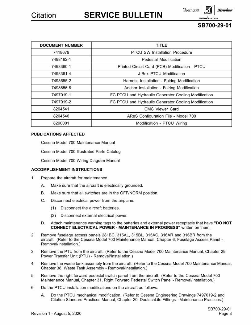
NOTE: To install the PTCU on your aircraft, you must get the engineering documents that follow. Youmust use the most recent revision and all of the applicable drawing change notices (DCN) foreach engineering document.
Citation SERVICE BULLETINSB700-29-01
DOCUMENT NUMBER TITLE7418679 PTCU SW Installation Procedure
7498162-1 Pedestal Modification
7498360-1 Printed Circuit Card (PCB) Modification - PTCU
7498361-4 J-Box PTCU Modification
7498655-2 Harness Installation - Fairing Modification
7498656-8 Anchor Installation - Fairing Modification
7497019-1 FC PTCU and Hydraulic Generator Cooling Modification
7497019-2 FC PTCU and Hydraulic Generator Cooling Modification
8204541 CMC Viewer Card
8204546 AReS Configuration File - Model 700
8290001 Modification - PTCU Wiring
PUBLICATIONS AFFECTED
Cessna Model 700 Maintenance Manual
Cessna Model 700 Illustrated Parts Catalog
Cessna Model 700 Wiring Diagram Manual
ACCOMPLISHMENT INSTRUCTIONS
1. Prepare the aircraft for maintenance.
A. Make sure that the aircraft is electrically grounded.
B. Make sure that all switches are in the OFF/NORM position.
C. Disconnect electrical power from the airplane.
(1) Disconnect the aircraft batteries.
(2) Disconnect external electrical power.
D. Attach maintenance warning tags to the batteries and external power receptacle that have "DO NOTCONNECT ELECTRICAL POWER - MAINTENANCE IN PROGRESS" written on them.
2. Remove fuselage access panels 281BC, 315AL, 315BL, 315AC, 316AR and 316BR from theaircraft. (Refer to the Cessna Model 700 Maintenance Manual, Chapter 6, Fuselage Access Panel -Removal/Installation.)
3. Remove the PTU from the aircraft. (Refer to the Cessna Model 700 Maintenance Manual, Chapter 29,Power Transfer Unit (PTU) - Removal/Installation.)
4. Remove the waste tank assembly from the aircraft. (Refer to the Cessna Model 700 Maintenance Manual,Chapter 38, Waste Tank Assembly - Removal/Installation.)
5. Remove the right forward pedestal switch panel from the aircraft. (Refer to the Cessna Model 700Maintenance Manual, Chapter 31, Right Forward Pedestal Switch Panel - Removal/Installation.)
6. Do the PTCU installation modifications on the aircraft as follows:
A. Do the PTCU mechanical modification. (Refer to Cessna Engineering Drawings 7497019-2 andCitation Standard Practices Manual, Chapter 20, DeutschLite Fittings - Maintenance Practices.)
SB700-29-01Revision 1 - August 5, 2020 Page 3
SB700-29-01Page 4 Revision 1 - August 5, 2020
Citation SERVICE BULLETINSB700-29-01
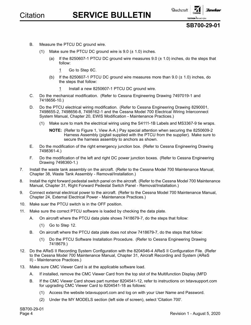
B. Measure the PTCU DC ground wire.
(1) Make sure the PTCU DC ground wire is 9.0 (± 1.0) inches.
(a) If the 8250607-1 PTCU DC ground wire measures 9.0 (± 1.0) inches, do the steps thatfollow:
1 Go to Step 6C.
(b) If the 8250607-1 PTCU DC ground wire measures more than 9.0 (± 1.0) inches, dothe steps that follow:
1 Install a new 8250607-1 PTCU DC ground wire.
C. Do the mechanical modification. (Refer to Cessna Engineering Drawing 7497019-1 and7418656-10.)
D. Do the PTCU electrical wiring modification. (Refer to Cessna Engineering Drawing 8290001,7498655-2, 7498656-8, 7498162-1 and the Cessna Model 700 Electrical Wiring InterconnectSystem Manual, Chapter 20, EWIS Modification - Maintenance Practices.)
(1) Make sure to mark the electrical wiring using the S4111-1B Labels and MS3367-9 tie wraps.
NOTE: (Refer to Figure 1, View A-A.) Pay special attention when securing the 8250609-2Harness Assembly (pigtail supplied with the PTCU from the supplier). Make sure tosecure the harness assembly to anchors as shown.
E. Do the modification of the right emergency junction box. (Refer to Cessna Engineering Drawing7498361-4.)
F. Do the modification of the left and right DC power junction boxes. (Refer to Cessna EngineeringDrawing 7498360-1.)
7. Install the waste tank assembly on the aircraft. (Refer to the Cessna Model 700 Maintenance Manual,Chapter 38, Waste Tank Assembly - Removal/Installation.)
8. Install the right forward pedestal switch panel on the aircraft. (Refer to the Cessna Model 700 MaintenanceManual, Chapter 31, Right Forward Pedestal Switch Panel - Removal/Installation.)
9. Connect external electrical power to the aircraft. (Refer to the Cessna Model 700 Maintenance Manual,Chapter 24, External Electrical Power - Maintenance Practices.)
10. Make suer the PTCU switch is in the OFF position.
11. Make sure the correct PTCU software is loaded by checking the data plate.
A. On aircraft where the PTCU data plate shows 7418679-7, do the steps that follow:
(1) Go to Step 12.
B. On aircraft where the PTCU data plate does not show 7418679-7, do the steps that follow:
(1) Do the PTCU Software Installation Procedure. (Refer to Cessna Engineering Drawing7418679.)
12. Do the AReS II Recording System Configuration with the 8204546-4 AReS II Configuration File. (Referto the Cessna Model 700 Maintenance Manual, Chapter 31, Aircraft Recording and System (AReSII) - Maintenance Practices.)
13. Make sure CMC Viewer Card is at the applicable software load.
A. If installed, remove the CMC Viewer Card from the top slot of the Multifunction Display (MFD
B. If the CMC Viewer Card shows part number 8204541-12, refer to instructions on txtavsupport.comfor upgrading CMC Viewer Card to 8204541-18 as follows:
(1) Access the website txtavsupport.com and log on with your User Name and Password.
(2) Under the MY MODELS section (left side of screen), select 'Citation 700'.
Citation SERVICE BULLETINSB700-29-01
(3) Under the MAINTENANCE INFORMATION section (Center screen), select 'MaintenanceSoftware'.
(4) Under Maintenance Software, select 'Model 700 - CMC Viewer Airplane Software'.
(5) Download the latest 8204541-18 CMC Viewer Software.
(6) Go to Step 14.
C. If the CMC Viewer Card shows 8204541-18, go to Step 14.
14. Do the CMC Viewer Card Load. (Refer to Cessna Engineering Drawing 8204541.)
15. If necessary, service the aircraft hydraulic system. (Refer to the Cessna Model 700 Maintenance Manual,Chapter 12, Hydraulic Reservoir -Servicing.)
16. Do the aircraft return to service as follows:
CAUTION: Read and fully understand all of the Hydraulic Fluid and Hydraulic System SafetyPrecautions before you do any hydraulic system maintenance. (Refer to the CessnaModel 700 Maintenance Manual, Chapter 29, Hydraulic Power - MaintenancePractices.)
A. Make sure that all hydraulic components stay idle or in the centered position to prevent flight controlsurface, landing gear, or door movement.
B. Make sure that the airplane is in an on ground, weight-on-wheels condition.
(1) Connect the landing gear simulator test boxes to the nose and the main landing gear and setthem to the ON GROUND position. (Refer to the Cessna Model 700 Maintenance Manual,Chapter 32, Landing Gear - Maintenance Practices.)
C. Connect external hydraulic power to the hydraulic reservoir servicing couplings HYDRAULICRETURN SYSTEM A, HYDRAULIC PRESSURE SYSTEM A, HYDRAULIC RETURN SYSTEM B,and HYDRAULIC PRESSURE SYSTEM B on the hydraulic service panel. (Refer to the CessnaModel 700 Maintenance Manual, Chapter 29, Hydraulic Power - Maintenance Practices.)
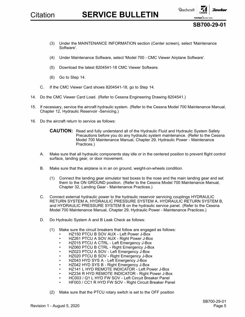
D. Do Hydraulic System A and B Leak Check as follows:
(1) Make sure the circuit breakers that follow are engaged as follows:• HZ150 PTCU B SOV AUX - Left Power J-Box• HZ261 PTCU A SOV AUX - Right Power J-Box• HZ015 PTCU A CTRL - Left Emergency J-Box• HZ060 PTCU B CTRL - Right Emergency J-Box• HZ023 PTCU A SOV - Left Emergency J-Box• HZ020 PTCU B SOV - Right Emergency J-Box• HZ043 HYD SYS A - Left Emergency J-Box• HZ042 HYD SYS B - Right Emergency J-Box• HZ141 L HYD REMOTE INDICATOR - Left Power J-Box• HZ234 R HYD REMOTE INDICATOR - Right Power J-Box• HC003 / Q1 L HYD FW SOV - Left Circuit Breaker Panel• HF003 / CC1 R HYD FW SOV - Right Circuit Breaker Panel
(2) Make sure that the PTCU rotary switch is set to the OFF position
SB700-29-01Revision 1 - August 5, 2020 Page 5
SB700-29-01Page 6 Revision 1 - August 5, 2020
Citation SERVICE BULLETINSB700-29-01
(3) Connect the spoiler isolation valve simulator to the spoiler isolation valve (VY303 SystemA) as follows:
NOTE: As an alternative to using the spoiler isolation valve simulator, you can apply a groundsignal to Pin B of the spoiler isolation valves (VY303 System A, VY309 System B) tosimulate hydraulic pressure on System A and System B hydraulic reservoirs. This isthe equivalent to setting the spoiler isolation valve simulator to the GROUND position.
NOTE: As an alternative to using the spoiler isolation valve simulator, you can apply an opensignal to Pin B of the spoiler isolation valves (VY303, System A, VY309, System B) tosimulate no or low hydraulic pressure on System A and System B hydraulic reservoirs.This is the equivalent to setting the spoiler isolation valve simulator to the AIRCRAFTposition.
(a) Disconnect the electrical connector (PY303) from the System A spoiler isolation valve(VY303).
(b) Connect the spoiler isolation valve simulator electrical connector (JY303) to the electricalconnector (PY303).
(4) Connect the spoiler isolation valve simulator to the spoiler isolation valves (VY309 SystemB) as follows:
(a) Disconnect the electrical connector (PY315) from the System B spoiler isolation valve(VY309).
(b) Connect the spoiler isolation valve simulator electrical connector (JY315) to the electricalconnector (PY315).
(5) Set the switch on the isolation valve simulator to the GROUND position.
(6) Make sure that the System A hydraulic reservoir volume stays between 300.0 and 600.0cubic inches.
NOTE: At least two people will be needed to complete this procedure. One person to monitorthe System A hydraulic reservoir volume and open the return valve as necessary andone person to do the rest of the procedure. The reservoir will increase quickly.
(a) When the System A hydraulic reservoir volume increases to more than 600.0 cubicinches, close the System A return valve.
(b) When the System A hydraulic reservoir volume decreases to 300.0 cubic inches, closeSystem A return valve.
(7) Close the System A and System B hydraulic reservoir return valves on the external hydraulicpower unit.
(8) Slowly increase System A and B pressure with the external hydraulic power unit to 500 psi.
(a) Make sure System A and B hydraulic systems lines and fittings do no show signs of leaks.
1 On aircraft where hydraulic lines and fittings show signs of leaks, do the stepsthat follow:
a Tighten and re-torque lines. (Refer to the Citation Standard Practices Manual,Chapter 20, Torque Data - Maintenance Practices.)
b Go to Step 16.D.(9).
2 On aircraft where hydraulic lines and fittings do not show signs of leaks, do thesteps that follow:
a Go to Step 16.D.(9).
Citation SERVICE BULLETINSB700-29-01
(9) Slowly increase the pressure with the external hydraulic power unit to 1,000 psi. (Refer tothe Cessna Model 700 Maintenance Manual, Chapter 29, Hydraulic Power - MaintenancePractices.)
(a) Make sure System A and B hydraulic systems lines and fittings do no show signs of leaks.
1 On aircraft where hydraulic lines and fittings show signs of leaks, do the stepsthat follow:
a Tighten and torque lines. (Refer to the Citation Standard Practices Manual,Chapter 20, Torque Data - Maintenance Practices.)
b Go to Step 16.D.(10).
2 On aircraft where hydraulic lines and fittings do not show signs of leaks, do thesteps that follow:
a Go to Step 16.D.(10).
(10) Slowly increase the pressure with the external hydraulic power unit to 1,500 psi. (Refer tothe Cessna Model 700 Maintenance Manual, Chapter 29, Hydraulic Power - MaintenancePractices.)
(a) Make sure System A and B hydraulic systems lines and fittings do no show signs of leaks.
1 On aircraft where hydraulic lines and fittings show signs of leaks, do the stepsthat follow:
a Tighten and torque lines. (Refer to the Citation Standard Practices Manual,Chapter 20, Torque Data - Maintenance Practices.)
b Go to Step 16.D.(11).
2 On aircraft where hydraulic lines and fittings do not show signs of leaks, do thesteps that follow:
a Go to Step 16.D.(11).
(11) Slowly increase the pressure with the external hydraulic power unit to 2,000 psi. (Refer tothe Cessna Model 700 Maintenance Manual, Chapter 29, Hydraulic Power - MaintenancePractices.)
(a) Make sure System A and B hydraulic systems lines and fittings do no show signs of leaks.
1 On aircraft where hydraulic lines and fittings show signs of leaks, do the stepsthat follow:
a Tighten and torque lines. (Refer to the Citation Standard Practices Manual,Chapter 20, Torque Data - Maintenance Practices.)
b Go to Step 16.D.(12).
2 On aircraft where hydraulic lines and fittings do not show signs of leaks, do thesteps that follow:
a Go to Step 16.D.(12).
SB700-29-01Revision 1 - August 5, 2020 Page 7
SB700-29-01Page 8 Revision 1 - August 5, 2020
Citation SERVICE BULLETINSB700-29-01
(12) Slowly increase the pressure with the external hydraulic power unit to 2,500 psi. (Refer tothe Cessna Model 700 Maintenance Manual, Chapter 29, Hydraulic Power - MaintenancePractices.)
(a) Make sure System A and B hydraulic systems lines and fittings do no show signs of leaks.
1 On aircraft where hydraulic lines and fittings show signs of leaks, do the stepsthat follow:
a Tighten and torque lines. (Refer to the Citation Standard Practices Manual,Chapter 20, Torque Data - Maintenance Practices.)
b Go to Step 16.D.(13).
2 On aircraft where hydraulic lines and fittings do not show signs of leaks, do thesteps that follow:
a Go to Step 16.D.(13).
(13) Slowly increase the pressure with the external hydraulic power unit to 3,000 psi for 10.0minutes.
(a) Make sure System A and B hydraulic systems lines and fittings do no show signs of leaks.
1 On aircraft where hydraulic lines and fittings show signs of leaks, do the stepsthat follow:
a Tighten and torque lines. (Refer to the Citation Standard Practices Manual,Chapter 20, Torque Data - Maintenance Practices.)
b Go to Step 16.D.(14).
2 On aircraft where hydraulic lines and fittings do not show signs of leaks, do thesteps that follow:
a Go to Step 16.D.(14).
(14) Bleed the System A and B hydraulic system as follows:
(a) Put a metal container below the hydraulic reservoir overboard drain to catch hydraulicfluid.
(b) Slowly decrease the hydraulic pressure to 500.0 psi.
(c) Pull the hydraulic reservoir relief cable (RES A BLEED CABLE) on the hydraulic servicepanel fully out.
1 Make sure that hydraulic fluid drains out of the reservoir drain tube.
(d) Push the hydraulic reservoir relief cable (RES A BLEED CABLE) on the hydraulic servicepanel fully in.
1 Make sure that hydraulic fluid stops from the reservoir drain tube.
2 Make sure that the manual bleed valve lever on the System A hydraulic reservoir isseated against the stop in the closed position.
(e) Pull the hydraulic reservoir relief cable (RES B BLEED CABLE) on the hydraulic servicepanel fully out.
1 Make sure that hydraulic fluid drains out of the reservoir drain tube.
(f) Push the hydraulic reservoir relief cable (RES B BLEED CABLE) on the hydraulic servicepanel fully in.
1 Make sure that hydraulic fluid stops from the reservoir drain tube.
2 Make sure that the manual bleed valve lever on the System B hydraulic reservoir isseated against the stop in the closed position.
Citation SERVICE BULLETINSB700-29-01
(15) Decrease the hydraulic pressure to 0.0 psi and stop the external hydraulic power unit.
(16) Disconnect the spoiler isolation valve simulator from the spoiler isolation valve (VY303 SystemA) as follows:
(a) Disconnect the electrical connector (JY303) from electrical connector (PY303).
(b) Connect electrical connector (PY303) to the spoiler isolation valve (VY303 System A).
(17) Disconnect the spoiler isolation valve simulator from the spoiler isolation valve (VY309 SystemB) as follows:
(a) Disconnect the spoiler isolation valve simulator electrical connector (JY315) fromelectrical connector (PY315).
(b) Connect the electrical connector (PY315) to the spoiler isolation valve (VY309 System B).
E. Do System A PTCU Prime and Bleeding as follows:
(1) Remove fuselage access panels 316AR and 316BR to get access to the hydraulic system filtermanifolds (UY012 System A, UY014 System B). (Refer to the Cessna Model 700 MaintenanceManual, Chapter 6, Fuselage Access Panel - Removal/Installation.)
(2) Open the left nose access door to get access the nosewheel steering accumulator bleedswitch. (Refer to the Cessna Model 700 Maintenance Manual, Chapter 6, Dimensions andAreas - Description and Operation.)
(3) Make sure that the HYDRAULICS PUMP A and the HYDRAULICS PUMP B switches areset to the NORM position.
(4) Close the System A return valve and the System B pressure and return valves and increasethe pressure with the external hydraulic power unit to 3,000 psi and 6.0 gallons-per-minute.
(5) Service the System A hydraulic reservoir to 350.0 cubic inches as shown on the hydraulicreservoir volume indicator. (Refer to the Cessna Model 700 Maintenance Manual, Chapter 12,Hydraulic Reservoir - Servicing.)
(6) Decrease the hydraulic pressure to 0.0 psi and stop the external hydraulic power unit.
(7) Push the hydraulic spoiler manifold vent switches LH INBD SPOILER BLEED (SYSTEM A),LH/RH MIDBD SPOILER BLEED (SYSTEM B), RH INBD SPOILER BLEED (SYSTEM A),and LH/RH OUTBD SPOILER BLEED (SYSTEM A) on the hydraulic service panel to releasethe hydraulic accumulator pressure.
(8) Disengage the circuit breakers as follows:• HZ023 PTCU A SOV - Left Emergency Power J-box• HZ020 PTCU B SOV - Right Emergency Power J-box• HZ261 PTCU A SOV AUX - Right Power J-box• HZ150 PTCU B SOV AUX - Left Power J-box
(9) Close the System A pressure and return valves and open the System B pressure and returnvalves and increase the flow with the external hydraulic power unit to 5.0 gallons-per-minute.
(10) Push and hold the LH INBD SPOILER BLEED (SYSTEM A), RH INBD SPOILER BLEED(SYSTEM A), and LH/RH OUTBD SPOILER BLEED (SYSTEM A) hydraulic spoiler manifoldvent switches on the hydraulic service panel to release the hydraulic pressure.
NOTE: You must continue to hold the LH INBD SPOILER BLEED (SYSTEM A), RH INBDSPOILER BLEED (SYSTEM A), and LH/RH OUTBD SPOILER BLEED (SYSTEM A)hydraulic spoiler manifold vent switches during the remaining procedure.
SB700-29-01Revision 1 - August 5, 2020 Page 9
SB700-29-01Page 10 Revision 1 - August 5, 2020
Citation SERVICE BULLETINSB700-29-01
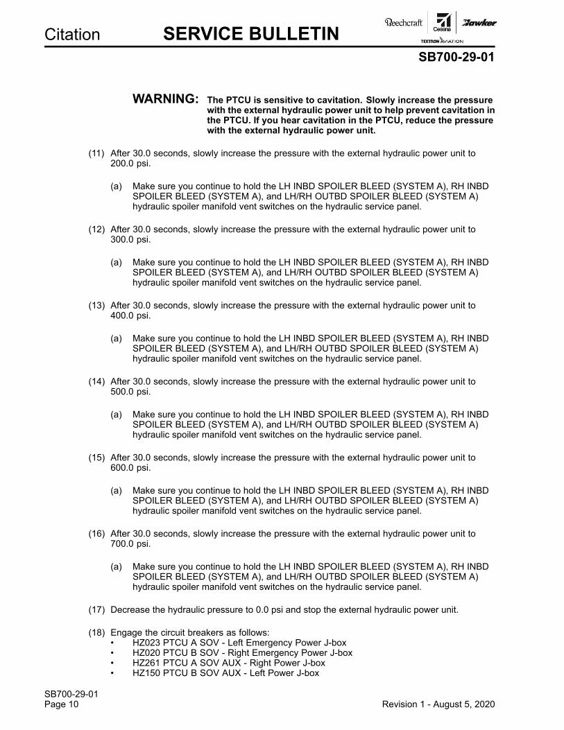
WARNING: The PTCU is sensitive to cavitation. Slowly increase the pressurewith the external hydraulic power unit to help prevent cavitation inthe PTCU. If you hear cavitation in the PTCU, reduce the pressurewith the external hydraulic power unit.
(11) After 30.0 seconds, slowly increase the pressure with the external hydraulic power unit to200.0 psi.
(a) Make sure you continue to hold the LH INBD SPOILER BLEED (SYSTEM A), RH INBDSPOILER BLEED (SYSTEM A), and LH/RH OUTBD SPOILER BLEED (SYSTEM A)hydraulic spoiler manifold vent switches on the hydraulic service panel.
(12) After 30.0 seconds, slowly increase the pressure with the external hydraulic power unit to300.0 psi.
(a) Make sure you continue to hold the LH INBD SPOILER BLEED (SYSTEM A), RH INBDSPOILER BLEED (SYSTEM A), and LH/RH OUTBD SPOILER BLEED (SYSTEM A)hydraulic spoiler manifold vent switches on the hydraulic service panel.
(13) After 30.0 seconds, slowly increase the pressure with the external hydraulic power unit to400.0 psi.
(a) Make sure you continue to hold the LH INBD SPOILER BLEED (SYSTEM A), RH INBDSPOILER BLEED (SYSTEM A), and LH/RH OUTBD SPOILER BLEED (SYSTEM A)hydraulic spoiler manifold vent switches on the hydraulic service panel.
(14) After 30.0 seconds, slowly increase the pressure with the external hydraulic power unit to500.0 psi.
(a) Make sure you continue to hold the LH INBD SPOILER BLEED (SYSTEM A), RH INBDSPOILER BLEED (SYSTEM A), and LH/RH OUTBD SPOILER BLEED (SYSTEM A)hydraulic spoiler manifold vent switches on the hydraulic service panel.
(15) After 30.0 seconds, slowly increase the pressure with the external hydraulic power unit to600.0 psi.
(a) Make sure you continue to hold the LH INBD SPOILER BLEED (SYSTEM A), RH INBDSPOILER BLEED (SYSTEM A), and LH/RH OUTBD SPOILER BLEED (SYSTEM A)hydraulic spoiler manifold vent switches on the hydraulic service panel.
(16) After 30.0 seconds, slowly increase the pressure with the external hydraulic power unit to700.0 psi.
(a) Make sure you continue to hold the LH INBD SPOILER BLEED (SYSTEM A), RH INBDSPOILER BLEED (SYSTEM A), and LH/RH OUTBD SPOILER BLEED (SYSTEM A)hydraulic spoiler manifold vent switches on the hydraulic service panel.
(17) Decrease the hydraulic pressure to 0.0 psi and stop the external hydraulic power unit.
(18) Engage the circuit breakers as follows:• HZ023 PTCU A SOV - Left Emergency Power J-box• HZ020 PTCU B SOV - Right Emergency Power J-box• HZ261 PTCU A SOV AUX - Right Power J-box• HZ150 PTCU B SOV AUX - Left Power J-box
Citation SERVICE BULLETINSB700-29-01
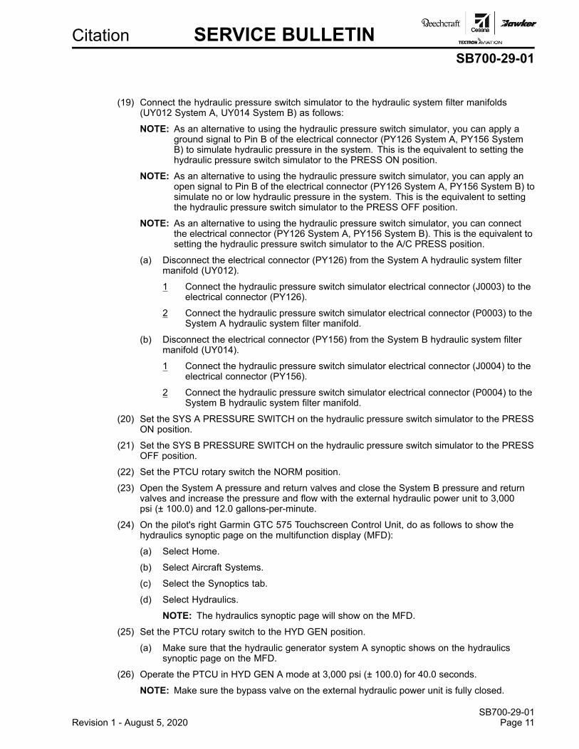
(19) Connect the hydraulic pressure switch simulator to the hydraulic system filter manifolds(UY012 System A, UY014 System B) as follows:
NOTE: As an alternative to using the hydraulic pressure switch simulator, you can apply aground signal to Pin B of the electrical connector (PY126 System A, PY156 SystemB) to simulate hydraulic pressure in the system. This is the equivalent to setting thehydraulic pressure switch simulator to the PRESS ON position.
NOTE: As an alternative to using the hydraulic pressure switch simulator, you can apply anopen signal to Pin B of the electrical connector (PY126 System A, PY156 System B) tosimulate no or low hydraulic pressure in the system. This is the equivalent to settingthe hydraulic pressure switch simulator to the PRESS OFF position.
NOTE: As an alternative to using the hydraulic pressure switch simulator, you can connectthe electrical connector (PY126 System A, PY156 System B). This is the equivalent tosetting the hydraulic pressure switch simulator to the A/C PRESS position.
(a) Disconnect the electrical connector (PY126) from the System A hydraulic system filtermanifold (UY012).
1 Connect the hydraulic pressure switch simulator electrical connector (J0003) to theelectrical connector (PY126).
2 Connect the hydraulic pressure switch simulator electrical connector (P0003) to theSystem A hydraulic system filter manifold.
(b) Disconnect the electrical connector (PY156) from the System B hydraulic system filtermanifold (UY014).
1 Connect the hydraulic pressure switch simulator electrical connector (J0004) to theelectrical connector (PY156).
2 Connect the hydraulic pressure switch simulator electrical connector (P0004) to theSystem B hydraulic system filter manifold.
(20) Set the SYS A PRESSURE SWITCH on the hydraulic pressure switch simulator to the PRESSON position.
(21) Set the SYS B PRESSURE SWITCH on the hydraulic pressure switch simulator to the PRESSOFF position.
(22) Set the PTCU rotary switch the NORM position.
(23) Open the System A pressure and return valves and close the System B pressure and returnvalves and increase the pressure and flow with the external hydraulic power unit to 3,000psi (± 100.0) and 12.0 gallons-per-minute.
(24) On the pilot's right Garmin GTC 575 Touchscreen Control Unit, do as follows to show thehydraulics synoptic page on the multifunction display (MFD):
(a) Select Home.
(b) Select Aircraft Systems.
(c) Select the Synoptics tab.
(d) Select Hydraulics.
NOTE: The hydraulics synoptic page will show on the MFD.
(25) Set the PTCU rotary switch to the HYD GEN position.
(a) Make sure that the hydraulic generator system A synoptic shows on the hydraulicssynoptic page on the MFD.
(26) Operate the PTCU in HYD GEN A mode at 3,000 psi (± 100.0) for 40.0 seconds.
NOTE: Make sure the bypass valve on the external hydraulic power unit is fully closed.
SB700-29-01Revision 1 - August 5, 2020 Page 11
SB700-29-01Page 12 Revision 1 - August 5, 2020
Citation SERVICE BULLETINSB700-29-01
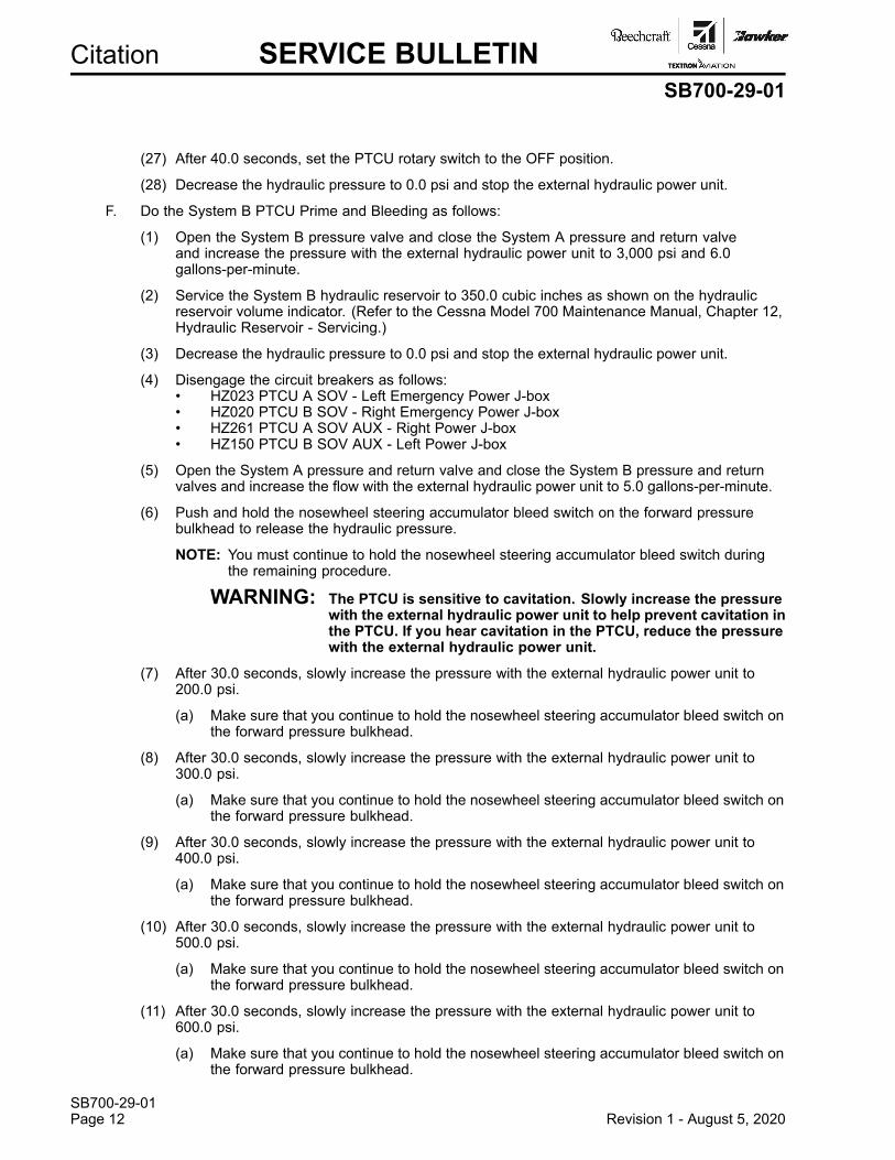
(27) After 40.0 seconds, set the PTCU rotary switch to the OFF position.
(28) Decrease the hydraulic pressure to 0.0 psi and stop the external hydraulic power unit.
F. Do the System B PTCU Prime and Bleeding as follows:
(1) Open the System B pressure valve and close the System A pressure and return valveand increase the pressure with the external hydraulic power unit to 3,000 psi and 6.0gallons-per-minute.
(2) Service the System B hydraulic reservoir to 350.0 cubic inches as shown on the hydraulicreservoir volume indicator. (Refer to the Cessna Model 700 Maintenance Manual, Chapter 12,Hydraulic Reservoir - Servicing.)
(3) Decrease the hydraulic pressure to 0.0 psi and stop the external hydraulic power unit.
(4) Disengage the circuit breakers as follows:• HZ023 PTCU A SOV - Left Emergency Power J-box• HZ020 PTCU B SOV - Right Emergency Power J-box• HZ261 PTCU A SOV AUX - Right Power J-box• HZ150 PTCU B SOV AUX - Left Power J-box
(5) Open the System A pressure and return valve and close the System B pressure and returnvalves and increase the flow with the external hydraulic power unit to 5.0 gallons-per-minute.
(6) Push and hold the nosewheel steering accumulator bleed switch on the forward pressurebulkhead to release the hydraulic pressure.
NOTE: You must continue to hold the nosewheel steering accumulator bleed switch duringthe remaining procedure.
WARNING: The PTCU is sensitive to cavitation. Slowly increase the pressurewith the external hydraulic power unit to help prevent cavitation inthe PTCU. If you hear cavitation in the PTCU, reduce the pressurewith the external hydraulic power unit.
(7) After 30.0 seconds, slowly increase the pressure with the external hydraulic power unit to200.0 psi.
(a) Make sure that you continue to hold the nosewheel steering accumulator bleed switch onthe forward pressure bulkhead.
(8) After 30.0 seconds, slowly increase the pressure with the external hydraulic power unit to300.0 psi.
(a) Make sure that you continue to hold the nosewheel steering accumulator bleed switch onthe forward pressure bulkhead.
(9) After 30.0 seconds, slowly increase the pressure with the external hydraulic power unit to400.0 psi.
(a) Make sure that you continue to hold the nosewheel steering accumulator bleed switch onthe forward pressure bulkhead.
(10) After 30.0 seconds, slowly increase the pressure with the external hydraulic power unit to500.0 psi.
(a) Make sure that you continue to hold the nosewheel steering accumulator bleed switch onthe forward pressure bulkhead.
(11) After 30.0 seconds, slowly increase the pressure with the external hydraulic power unit to600.0 psi.
(a) Make sure that you continue to hold the nosewheel steering accumulator bleed switch onthe forward pressure bulkhead.
Citation SERVICE BULLETINSB700-29-01
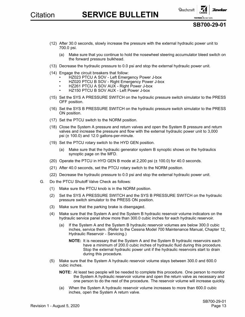
(12) After 30.0 seconds, slowly increase the pressure with the external hydraulic power unit to700.0 psi.
(a) Make sure that you continue to hold the nosewheel steering accumulator bleed switch onthe forward pressure bulkhead.
(13) Decrease the hydraulic pressure to 0.0 psi and stop the external hydraulic power unit.
(14) Engage the circuit breakers that follow:• HZ023 PTCU A SOV - Left Emergency Power J-box• HZ020 PTCU B SOV - Right Emergency Power J-box• HZ261 PTCU A SOV AUX - Right Power J-box• HZ150 PTCU B SOV AUX - Left Power J-box
(15) Set the SYS A PRESSURE SWITCH on the hydraulic pressure switch simulator to the PRESSOFF position.
(16) Set the SYS B PRESSURE SWITCH on the hydraulic pressure switch simulator to the PRESSON position.
(17) Set the PTCU switch to the NORM position.
(18) Close the System A pressure and return valves and open the System B pressure and returnvalves and increase the pressure and flow with the external hydraulic power unit to 3,000psi (± 100.0) and 12.0 gallons-per-minute.
(19) Set the PTCU rotary switch to the HYD GEN position.
(a) Make sure that the hydraulic generator system B synoptic shows on the hydraulicssynoptic page on the MFD.
(20) Operate the PTCU in HYD GEN B mode at 2,200 psi (± 100.0) for 40.0 seconds.
(21) After 40.0 seconds, set the PTCU rotary switch to the NORM position.
(22) Decrease the hydraulic pressure to 0.0 psi and stop the external hydraulic power unit.
G. Do the PTCU Shutoff Valve Check as follows:
(1) Make sure the PTCU knob is in the NORM position.
(2) Set the SYS A PRESSURE SWITCH and the SYS B PRESSURE SWITCH on the hydraulicpressure switch simulator to the PRESS ON position.
(3) Make sure that the parking brake is disengaged.
(4) Make sure that the System A and the System B hydraulic reservoir volume indicators on thehydraulic service panel show more than 300.0 cubic inches for each hydraulic reservoir.
(a) If the System A and the System B hydraulic reservoir volumes are below 300.0 cubicinches, service them. (Refer to the Cessna Model 700 Maintenance Manual, Chapter 12,Hydraulic Reservoir - Servicing.)
NOTE: It is necessary that the System A and the System B hydraulic reservoirs eachhave a minimum of 200.0 cubic inches of hydraulic fluid during this procedure.Stop the external hydraulic power unit if the hydraulic reservoirs start to drainduring this procedure.
(5) Make sure that the System A hydraulic reservoir volume stays between 300.0 and 600.0cubic inches.
NOTE: At least two people will be needed to complete this procedure. One person to monitorthe System A hydraulic reservoir volume and open the return valve as necessary andone person to do the rest of the procedure. The reservoir volume will increase quickly.
(a) When the System A hydraulic reservoir volume increases to more than 600.0 cubicinches, open the System A return valve.
SB700-29-01Revision 1 - August 5, 2020 Page 13
SB700-29-01Page 14 Revision 1 - August 5, 2020
Citation SERVICE BULLETINSB700-29-01
(b) When the System A hydraulic reservoir volume decreases to 300.0 cubic inches, closethe System A return valve.
(6) Close the System A and the System B return valves on the external hydraulic power unit.
(7) Set the external hydraulic power unit to 3,000 psi (±100.0).
(8) Set the SYS B PRESSURE SWITCH on the hydraulic pressure switch simulator to the PRESSOFF position.
(9) Close the System B pressure valve on the external hydraulic power unit.
(a) Make sure that the PTCU cogs.
(b) Make sure that the System A hydraulic pressure shown on the hydraulics synoptic pageon the MFD stays at approximately 3,000 psi and the System B hydraulic pressure shownon the hydraulic synoptic page stays between 2,200 and 3,200 psi.
(10) Open the System B pressure valve on the external hydraulic power unit.
(a) Make sure that the PTCU stops cogging.
(11) Set the SYS A PRESSURE SWITCH and the SYS B PRESSURE SWITCH on the hydraulicpressure switch simulator to the PRESS ON position.
(12) Make sure that the System A and System B hydraulic reservoir volumes are more than300.0 cubic inches.
(a) If necessary, service the applicable hydraulic reservoir. (Refer to the Cessna Model 700Maintenance Manual, Chapter 12, Hydraulic Reservoir Servicing.)
(13) Put the PTCU knob in the OFF position.
(14) Make sure that the external hydraulic power unit is set to 3,000 psi (± 100.0), with the SystemA and the System B return valves closed.
(15) Set the SYS B PRESSURE SWITCH on the hydraulic pressure switch simulator to the PRESSOFF position.
(16) Close the System B pressure valve on the external hydraulic power unit.
(a) Make sure that the PTCU does not cog.
(b) Make sure that the System A hydraulic pressure shown on the hydraulic synoptic pagestays at approximately 3,000 psi (±100.0) and the System B hydraulic pressure shown onthe hydraulic synoptic page decreases to 0.0 psi (±100.0).
(17) Decrease the hydraulic pressure to 0.0 psi.
H. Do the PTCU FAIL Message Check as follows:
(1) Make sure that the PTCU rotary switch is set to the NORM position.
NOTE: If the PTCU rotary switch was set to the OFF position at initial power-up, the PTCUwill initiate a self-test once it is set to the NORM position. The PTCU FAIL crewalerting system (CAS) message will show during the test and then will go off afterapproximately 20.0 seconds.
(2) Make sure that the amber PTCU FAIL CAS message does not show.
(3) Disengage the HZ060 PTCU B CTRL circuit breaker on the right emergency J-Box.
(a) Make sure that the amber PTCU FAIL CAS message comes on.
(4) Engage the HZ060 PTCU B CTRL circuit breaker on the right emergency J-Box.
(a) After approximately 20.0 seconds, make sure that the PTCU FAIL CAS message goes off.
(5) On the Hydraulic Panel, make sure the rudder standby switch is in the OFF position.
Citation SERVICE BULLETINSB700-29-01
(6) Set the switches the landing gear simulator test boxes for the nose and the main landinggear to the ON GROUND position.
(7) Set the PTCU rotary switch to the OFF position.
(8) Disengage the circuit breakers that follow:• HC008 Fuel Boost Pump - Right Circuit Breaker Panel• HC009 Fuel Boost Pump - Left Circuit Breaker Panel
(9) Push and release the right engine RUN/STOP button to RUN.
(a) Make sure the PTCU NOT NORM (amber) CAS message shows.
(10) Push and release the right engine RUN/STOP button to STOP.
(a) Make sure the PTCU NOT NORM (amber) CAS message does not show.
(11) Push and Release the left engine RUN/STOP button to RUN.
(a) Make sure the PTCU NOT NORM (amber) CAS message shows.
(12) Push and release the left engine RUN/STOP button.
(a) Make sure the PTCU NOT NORM (amber) CAS message does not show.
I. Do the PTCU Lock Check as follows:
(1) Make sure that the PTCU rotary switch is set to the NORM position.
(2) Make sure the parking brake is disengaged.
(3) If not already done, set the landing gear simulator test boxes to the nose and the main landinggear and set them to the ON GROUND position.
(4) Disconnect electrical power from the aircraft.
(5) Disconnect the electrical connectors (PY059, PY060, and PY061) from the PTCU.
(6) Connect a jumper between pin J and pin U on the electrical connector (PY059).
(7) Remove the HYD CONTROL PCB (NZ215) from the right DC power junction box PCBenclosure. (Refer to the Cessna Model 700 Maintenance Manual, Chapter 24, DC PowerJunction Box Printed Circuit Board (PCB) - Removal/Installation.)
(a) Install the HYD CONTROL PCB (NZ215) in a PCB extender card.
(b) Connect the PCB extender card to the electrical connector (JZ215) in the right DC powerjunction box PCB enclosure.
(8) Apply electrical power to the aircraft.
(9) Make sure that the HYDRAULICS PUMP A and the HYDRAULICS PUMP B switches areset to the NORM position.
(10) Make sure that the System A and the System B hydraulic reservoir volume indicators on thehydraulic service panel show more than 300.0 cubic inches for each hydraulic reservoir.
(a) If the System A and the System B hydraulic reservoir volumes are below 300.0 cubicinches, service them. (Refer to the Cessna Model 700 Maintenance Manual, Chapter 12,Hydraulic Reservoir - Servicing.)
NOTE: It is necessary that the System A and the System B hydraulic reservoirs eachhave a minimum of 200.0 cubic inches of hydraulic fluid during this procedure.Stop the external hydraulic power unit if the hydraulic reservoirs start to drainduring this procedure.
SB700-29-01Revision 1 - August 5, 2020 Page 15
SB700-29-01Page 16 Revision 1 - August 5, 2020
Citation SERVICE BULLETINSB700-29-01
(11) Make sure that the System A and System B hydraulic reservoir volumes stay between 300.0and 500.0 cubic inches each.
NOTE: At least two people will be needed to complete this procedure. One person to monitorthe hydraulic reservoir volumes and open the return valves as necessary and oneperson to do the rest of the procedure.
(a) When the System A or System B hydraulic reservoir volumes increase to more than500.0 cubic inches, open the return valve for that system.
(b) When the System A or System B hydraulic reservoir volumes decrease to 300.0 cubicinches, close the return valve for that system.
(12) Set the SYS A PRESSURE SWITCH and the SYS B PRESSURE SWITCH on the hydraulicpressure switch simulator to the PRESS ON position.
(13) Open the System A and the System B pressure valves on the external hydraulic power unit.
(14) Close the System A and the System B return valves on the external hydraulic power unit.
(15) Set the external hydraulic power unit to 3000 psi (±100.0).
(16) Make sure that 'PTU Mode' is set to active on the on the RH Hydraulic Control PCB pagein AReS.
(17) Using a digital multimeter to do the checks that follow:
(a) Make sure that there is 28.5 VDC (± 1.0) at the positive electrical terminal of the PTCU(UY009).
(b) Make sure that there is 28.5 VDC (± 1.0) at pin A of the electrical connector (PY060).
(c) Make sure that there is 28.5 VDC (± 1.0) at pin A of the electrical connector (PY061).
(d) Make sure that there is 0.0 VDC (± 1.0) at pin Y of the electrical connector (PY059).
(18) Connect a jumper between pin 24 and GND (pin 1 or pin 30) on the HYD CONTROL PCB(NZ215) in the PCB extender card.
(19) Using a digital multimeter, do the checks that follow:
(a) Make sure that there is 0.0 VDC (±1.0) at the positive electrical terminal of the PTCU(UY009).
(b) Make sure that there is 28.5 VDC (±1.0) at pin Y of the electrical connector (PY059).
(20) Remove the jumper between pin 24 and GND (pin 1 or pin 30) on the HYD CONTROL PCB(NZ215) in the PCB extender card.
(21) Using a digital multimeter, do the checks that follow:
(a) Make sure that there is 28.5 VDC (±1.0) at the positive electrical terminal of the PTCU(UY009).
(b) Make sure that there is ground at pin H of the electrical connector (PY059).
NOTE: The ground resistance may exceed 300k Ohms.
(22) Set the nose and main landing gear simulator test boxes to the IN AIR position.
(23) Using a digital multimeter, make sure that there is an open at pin H of the electrical connector(PY059).
(24) Make sure that 'PTU Mode' is set to active on the on the RH Hydraulic Control PCB pagein AReS.
Citation SERVICE BULLETINSB700-29-01
(25) Using a digital multimeter, do the checks that follow:
(a) Make sure that there is 0.0 VDC (±1.0) at the positive electrical terminal of the PTCU(UY009).
(b) Make sure that there is 0.0 VDC (±1.0) at pin A of the electrical connector (PY060).
(c) Make sure that there is 0.0 VDC (±1.0) at pin A of the electrical connector (PY061).
(26) Set the nose and main landing gear simulator test boxes to the ON GROUND position.
(27) After 20.0 seconds, +1 or -1 second, use a digital multimeter to do the checks that follow:
(a) Make sure that there is 28.5 VDC (±1.0) at the positive electrical terminal of the PTCU(UY009).
(b) Make sure that there is 28.5 VDC (±1.0) at pin A of the electrical connector (PY060).
(c) Make sure that there is 28.5 VDC (±1.0) at pin A of the electrical connector (PY061).
(28) Make sure that 'PTU Mode' is set to active on the on the RH Hydraulic Control PCB pagein AReS.
(29) Decrease the hydraulic pressure and stop the external hydraulic power unit.
(30) Push the LH INBD SPOILER BLEED (SYSTEM A), RH INBD SPOILER BLEED (SYSTEMA), LH/RH MIDBD SPOILER BLEED (SYSTEM B), and LH/RH OUTBD SPOILER BLEED(SYSTEM A) hydraulic spoiler manifold vent switches on the hydraulic service panel to releasethe hydraulic pressure.
(31) Disconnect external electrical power from the aircraft.
(32) Disconnect the PCB extender card from the electrical connector (JZ215) in the right DC powerjunction box PCB enclosure.
(a) Remove the HYD CONTROL PCB (NZ215) from the PCB extender card.
(b) Install the HYD CONTROL PCB (NZ215) in the right DC power junction box PCBenclosure.
(33) Remove the jumper between pin J and pin U on the electrical connector (PY059).
(34) Connect the electrical connectors (PY059, PY060, and PY061) to the PTCU.
(35) Make sure that the PTCU rotary switch is set to the NORM position.
(36) Make sure that the parking brake is disengaged.
(37) Connect external electrical power to the aircraft.
(38) Make sure that the HYDRAULICS PUMP A and the HYDRAULICS PUMP B switches areset to the NORM position.
(39) Make sure that the System A and the System B hydraulic reservoir volume indicators on thehydraulic service panel show more than 300.0 cubic inches for each hydraulic reservoir.
(a) If the System A and the System B hydraulic reservoir volumes are below 300.0 cubicinches, service them. (Refer to the Cessna Maintenance Manual, Chapter 12, HydraulicReservoir - Servicing.)
NOTE: It is necessary that the System A and the System B hydraulic reservoirs eachhave a minimum of 200.0 cubic inches of hydraulic fluid during this procedure.Stop the external hydraulic power unit if the hydraulic reservoirs start to drainduring this procedure.
(40) Make sure that the SYS A PRESSURE SWITCH and the SYS B PRESSURE SWITCH on thehydraulic pressure switch simulator are set to the PRESS ON position.
(41) Open the System A and the System B pressure valves on the external hydraulic power unit.
SB700-29-01Revision 1 - August 5, 2020 Page 17
SB700-29-01Page 18 Revision 1 - August 5, 2020
Citation SERVICE BULLETINSB700-29-01
(42) Close the System A and the System B return valves on the external hydraulic power unit.
(43) Set the external hydraulic power unit to 3,000 psi (±100.0).
(44) If not already done, on the pilot's right Garmin GTC 575 Touchscreen Control Unit, do asfollows to show the hydraulics synoptic page on the multifunction display (MFD):
(a) Select Home.
(b) Select Aircraft Systems.
(c) Select the Synoptics tab.
(d) Select Hydraulics.
NOTE: The hydraulics synoptic page will show on the MFD.
(45) Close the System B pressure valve on the external hydraulic power unit.
(a) Make sure that the PTCU cogs.
(b) Make sure the MFD stays at approximately 3,000 psi and the System B hydraulicpressure shown on the hydraulic synoptic page stays between 1,800 and 3,200 psi.
(46) Open the System B pressure valve on the external hydraulic power unit.
(a) Make sure that the PTCU stops cogging.
(47) Set the PTCU rotary switch to the OFF position.
(48) Close the System B pressure valve on the external hydraulic power unit.
(a) Make sure that the PTCU does not cog.
(b) Make sure that the System A hydraulic pressure shown on the hydraulic synoptic pagestays at approximately 3,000 psi (±100.0) and the System B hydraulic pressure shown onthe hydraulic synoptic page decreases to 0.0 psi (±100.0).
(49) Open the System B pressure valve on the external hydraulic power unit.
(50) Decrease the hydraulic pressure and stop the external hydraulic power unit.
(51) Push the LH INBD SPOILER BLEED (SYSTEM A), RH INBD SPOILER BLEED (SYSTEMA), LH/RH MIDBD SPOILER BLEED (SYSTEM B), and LH/RH OUTBD SPOILER BLEED(SYSTEM A) hydraulic spoiler manifold vent switches on the hydraulic service panel to releasethe hydraulic pressure.
J. Do the System A PTCU Auxiliary Mode Operational Check as follows:
(1) Make sure that the System A and the System B hydraulic reservoirs have been servicedto between 300.0 and 400.0 cubic inches.
NOTE: It is necessary that the System A and the System B hydraulic reservoirs each havea minimum of 200.0 cubic inches of hydraulic fluid during this procedure. Stopthe external hydraulic power unit if the hydraulic reservoirs start to drain during thisprocedure.
(2) Disconnect the external hydraulic power unit from the aircraft.
(3) Set the PTCU rotary switch to the AUX A position.
(a) Make sure that the System A pressure reaches and stays at 2,800 psi (±100.0).
(b) Make sure that the HYD AUX PUMP ON A Crew Alerting System (CAS) messagecomes on.
(c) Make sure that the hydraulic auxiliary pump System A synoptic shows on the hydraulicssynoptic page on the MFD.
Citation SERVICE BULLETINSB700-29-01
(d) Make sure that the System A spoiler and brake accumulators are fully charged on thehydraulics synoptic page on the MFD.
(4) Make sure that the SYS A PRESSURE SWITCH and the SYS B PRESSURE SWITCH on thehydraulic pressure switch simulator are set to the PRESS OFF position.
(5) Use the rudder pedals to move the rudder fully left and then fully right.
(a) Make sure that the rudder moves correctly.
(6) Set the PTCU rotary switch to the NORM position.
(a) Make sure that the AUX A mode stops operating without any unusual noise.
(7) Set the PTCU rotary switch to the OFF position.
K. Do the System B PTCU Auxiliary Mode Operational Check as follows:
(1) Make sure the System A and the System B pressure and return valves are closed on theexternal hydraulic power unit.
CAUTION: The PTCU is susceptible to overheating with two to three minutes ofcontinuous operation. Do the procedure below in 60.0 seconds or less toreduce the chances of overheating. Read through the procedure beforeyou start it.
(2) Set the PTCU rotary switch to the AUX B position.
(a) Make sure that the System B pressure reaches and stays at 2,800 psi (±100.0).
(b) Make sure that the HYD AUX PUMP ON B CAS message comes on.
(c) Make sure that the hydraulic auxiliary pump System B synoptic shows on the hydraulicssynoptic page on the MFD.
(d) Make sure that the System B spoiler and brake accumulators are fully charged on thehydraulics synoptic page on the MFD.
(3) Make sure that the SYS A PRESSURE SWITCH and the SYS B PRESSURE SWITCH on thehydraulic pressure switch simulator are set to the PRESS OFF position.
(4) Use the rudder pedals to move the rudder fully left and then fully right.
(a) Make sure that the rudder moves correctly.
(5) Set the PTCU rotary switch to the NORM position.
(a) Make sure that the AUX B mode stops operating without any unusual noise.
(6) Bleed the parking brake accumulators. (Refer to the Cessna Model 700 Maintenance Manual,Chapter 12, Hydraulic Accumulator - Servicing, Parking Brake Accumulator Servicing.)
(7) Engage the parking brake.
(a) Make sure that AUX B operates and pressurizes the system to 2,800 psi (±100.0) andthen that the auxiliary pump stops operating.
(b) Make sure that AUX A operates and pressurizes the system to 2,800 psi (±100.0) andthen that the auxiliary pump stops operating.
(8) Disengage the parking brake.
(9) Set the PTCU rotary switch to the OFF position.
L. PTCU Operational/Load Check as follows:
(1) Make sure the parking brake is disengaged.
SB700-29-01Revision 1 - August 5, 2020 Page 19
SB700-29-01Page 20 Revision 1 - August 5, 2020
Citation SERVICE BULLETINSB700-29-01
(2) Disconnect the landing gear simulator test boxes from the nose and the main landinggear. (Refer to the Cessna Model 700 Maintenance Manual, Chapter 32, Landing Gear- Maintenance Practices.)
(3) Put the aircraft on jacks. (Refer to the Cessna Model 700 Maintenance Manual, Chapter 7,Lifting - Maintenance Practices.)
(4) Make sure that the PTCU rotary switch is in the NORM position.
(5) Set the SYS A PRESSURE SWITCH and the SYS B PRESSURE SWITCH on the hydraulicpressure switch simulator to the PRESS ON position.
(6) Make sure that the HYDRAULICS PUMP A and the HYDRAULICS PUMP B switches areset to the NORM position.
(7) Make sure that the landing gear control handle is set to the GEAR DOWN position.
(8) Make sure that the landing gear is in the down-and-locked position.
(9) Make sure that the landing gear is operational and that there are no obstructions when thelanding gear is cycled.
(10) Make sure that the System A and the System B hydraulic reservoir volume indicators on thehydraulic service panel show more than 300.0 cubic inches for each hydraulic reservoir.
(a) If the System A and the System B hydraulic reservoir volumes are below 300.0 cubicinches, service as necessary. (Refer to the Cessna Model 700 Maintenance Manual,Chapter 12, Hydraulic Reservoir - Servicing.)
NOTE: It is necessary that the System A and the System B hydraulic reservoirs eachhave a minimum of 200.0 cubic inches of hydraulic fluid during this procedure.Stop the external hydraulic power unit if the hydraulic reservoirs start to drainduring this procedure.
NOTE: Due to the stroke of the main landing gear actuators, the System B hydraulic reservoirwill fluctuate, but the total system volume will stay constant as long as the System Breturn valve stays closed.
(11) Make sure that the System A hydraulic reservoir volume stays between 300.0 and 600.0cubic inches.
NOTE: At least two people will be needed to complete this procedure. One person to monitorthe System A hydraulic reservoir volume and open the return valve as necessary andone person to do the rest of the procedure. The reservoir volume will increase quickly.
(a) When the System A hydraulic reservoir volume increases to more than 600.0 cubicinches, open the System A return valve.
(b) When the System A hydraulic reservoir volume decreases to 300.0 cubic inches, closethe System A return valve.
(12) Set the SYS B PRESSURE SWITCH on the hydraulic pressure switch simulator to the PRESSOFF position.
(13) Connect external hydraulic power to the hydraulic reservoir servicing couplings HYDRAULICRETURN SYSTEM A, HYDRAULIC PRESSURE SYSTEM A, HYDRAULIC RETURNSYSTEM B, and HYDRAULIC PRESSURE SYSTEM B on the hydraulic service panel. (Referto the Cessna Model 700 Maintenance Manual, Chapter 29, Hydraulic Power - MaintenancePractices.)
(a) Open the System A and the System B pressure valves on the external hydraulic powerunit.
(b) Close the System A and the System B return valves on the external hydraulic power unit.
(c) Set the external hydraulic power unit to 3,000 psi (±100.0).
Citation SERVICE BULLETINSB700-29-01
(14) Close the System B pressure valve on the external hydraulic power unit.
(a) Make sure that the PTCU cogs.
(b) Make sure that the System A hydraulic pressure shown on the hydraulics synoptic pagestays at approximately 3,000 psi.
(c) Make sure System B hydraulic pressure shown on the hydraulic synoptic page staysbetween 2,200 and 3,200 psi.
(d) Make sure that the System A hydraulic reservoir volume stays between 200.0 and 600.0cubic inches.
(15) Retract and extend the landing gear through five cycles as follows:
(a) Using the landing gear control handle to retract the landing gear.
1 Make sure that the landing gear fully retracts within 16.0 seconds.
(b) Using the landing gear control handle to extend the landing gear.
1 Make sure that the landing gear fully extends.
(c) Make sure that the System B hydraulic reservoir volume is between 200.0 and 600.0cubic inches.
1 If the System B hydraulic reservoir volume is above 600.0 cubic inches, drain theSystem B hydraulic reservoir to 400.0 (±25.0).
(d) Do Steps 17.L(15)(a) thru (c) four more times.
(16) Decrease the hydraulic pressure to 0.0 psi and stop the external hydraulic power unit.
(17) Lower the airplane and remove the jacks. (Refer to the Cessna Model 700 MaintenanceManual, Chapter 7, Lifting - Maintenance Practices.)
(18) Push the LH INBD SPOILER BLEED (SYSTEM A), RH INBD SPOILER BLEED (SYSTEMA), LH/RH MIDBD SPOILER BLEED (SYSTEM B), and LH/RH OUTBD SPOILER BLEED(SYSTEM A) hydraulic spoiler manifold vent switches on the hydraulic service panel to releasethe hydraulic pressure.
M. Do the PTCU HYD GEN Mode Operational Check as follows:
(1) Make sure the PTCU rotary switch is the NORM position.
(2) Set the SYS A PRESSURE SWITCH and the SYS B PRESSURE SWITCH on the hydraulicpressure switch simulator to the PRESS ON position.
(3) Make sure that the left and the right batteries are connected.
(4) Make sure that the HYDRAULICS PUMP A and the HYDRAULICS PUMP B switches areset to the NORM position.
(5) Set the L BATT and the R BATT switch to the ON position.
(a) If not fully charged, let the left and the right batteries fully charge.
(6) Set the L MAIN and the R MAIN switch to the OFF position.
(7) After the left and the right batteries are fully charged, disconnect the external electrical powerfrom the aircraft.
(8) On the pilot's right Garmin GTC 575 Touchscreen Control Unit, do as follows:
(a) Select Home.
(b) Select Aircraft Systems.
(c) Select the Synoptics tab.
SB700-29-01Revision 1 - August 5, 2020 Page 21
SB700-29-01Page 22 Revision 1 - August 5, 2020
Citation SERVICE BULLETINSB700-29-01
(d) Select Electrical.
NOTE: The electrical synoptic page will show on the MFD.
(9) On the copilot's left GTC, do as follows:
(a) Select Home.
(b) Select Aircraft Systems.
(c) Select the Synoptics tab.
(d) Select Hydraulics.
NOTE: The hydraulics synoptic page will show on the copilot's display pane on the rightside of the MFD. The electrical synoptic page will still show on the pilot's displaypane in the center of the MFD.
(10) Open the System A pressure and return valves and the System B pressure and return valveson the external hydraulic power unit.
(11) Set the external hydraulic power unit to 3,000 psi (±100.0) and 12.0 or more gallons-per-minute.
(12) On the electrical synoptic page, make sure that the HYD GEN bubble is white and that novolts or amps are shown.
(13) Set the PTCU rotary switch to the HYD GEN position.
(a) Make sure that the HYD GEN ON (white) crew alerting system (CAS) message comes on.
(b) On the hydraulics synoptic page, make sure that either of the two hydraulic generatorsynoptic show.
(c) On the electrical synoptic page, make sure that the HYD GEN bubble is green, and thevoltage is between 25.0 and 29.0 volts, and the amperage is above 55.0%.
(14) Set the SYS A PRESSURE SWITCH on the hydraulic pressure switch simulator to the PRESSOFF position.
(a) On the hydraulics synoptic page, make sure that the hydraulic System B operates thegenerator.
(b) On the electrical synoptic page, make sure that the HYD GEN voltage is between 25.0and 29.0 volts and the amperage is above 5.0%.
(15) Set the SYS A PRESSURE SWITCH on the hydraulic pressure switch simulator to the PRESSON position.
(a) On the hydraulics synoptic page, make sure that the hydraulic System B still operatesthe generator.
(b) On the electrical synoptic page, make sure there is no change.
(16) Set the SYS B PRESSURE SWITCH on the hydraulic pressure switch simulator to the PRESSOFF position.
(a) On the hydraulics synoptic page, make sure that the hydraulic System A operates thegenerator.
(b) On the electrical synoptic page, make sure that the HYD GEN voltage is between 25.0and 29.0 volts and the amperage is above 5.0%.
(17) Set the PTCU rotary switch to the NORM position.
(18) Decrease the hydraulic pressure to 0.0 psi and stop the external hydraulic power unit.
(19) Push and release the L BATT switch to the OFF position.
Citation SERVICE BULLETINSB700-29-01
(20) Connect external electrical power to the aircraft. (Refer to Cessna Model 700 MaintenanceManual, Chapter 24, External Electrical Power - Maintenance Practices.)
(21) Push and release the L BATT switch to the ON position.
(22) In the baggage compartment, look inside the PTCU ventilation valve inlet.
(a) Make sure that the valve is closed.
(23) Set the SYS A PRESSURE SWITCH and the SYS B PRESSURE SWITCH on the hydraulicpressure switch simulator to the PRESS ON position.
(24) Open the System A pressure and return valves and the System B pressure and return valves.
(25) Set the external hydraulic power unit to 3,000 psi (±100.0).
(26) Set the PTCU rotary switch to the HYD GEN position.
(a) Look inside the PTCU ventilation valve inlet.
(b) Make sure that the valve fully opens in 45.0 seconds or less.
(27) Set the PTCU rotary switch to the NORM position.
(a) Look inside the PTCU ventilation valve inlet.
(b) Make sure that the valve fully closes in five minutes or less.
(28) Decrease the hydraulic pressure and disconnect the external hydraulic power unit from theaircraft. (Refer to Cessna Model 700 Maintenance Manual, Chapter 29, Hydraulic Power- Maintenance Practices.)
(29) Push the LH INBD SPOILER BLEED (SYSTEM A), RH INBD SPOILER BLEED (SYSTEMA), LH/RH MIDBD SPOILER BLEED (SYSTEM B), and LH/RH OUTBD SPOILER BLEED(SYSTEM A) hydraulic spoiler manifold vent switches on the hydraulic service panel to releasethe hydraulic pressure.
(30) Disconnect the hydraulic pressure switch simulator to the hydraulic system filter manifolds(UY012 System A, UY014 System B) as follows:
(a) Disconnect the hydraulic pressure switch simulator electrical connector (J0003) fromelectrical connector (PY126).
(b) Disconnect the hydraulic pressure switch simulator electrical connector (P0003) from theSystem A hydraulic system filter manifold.
(c) Connect electrical connector (PY126) to the System A hydraulic system filter manifold(UY012).
(d) Disconnect the hydraulic pressure switch simulator electrical connector (J0004) fromelectrical connector (PY156).
(e) Disconnect the hydraulic pressure switch simulator electrical connector (P0004) fromSystem B hydraulic system filter manifold.
(f) Connect electrical connector (PY156) to System B hydraulic system filter manifold(UY014).
N. Do the HYD CONTROL (NZ115 Left, NZ215 Right) PCB Check. (Refer to Cessna Model700 Maintenance Manual, Chapter 24, DC Power Junction Box Printed Circuit Board (PCB) -Adjustment/Test.)
NOTE: Do not do the Power Transfer Unit (PTU) Shutoff Valve Operational Check, Power TransferUnit (PTU) Operation Check or the Engine Driven Hydraulic Pump Operational Checkreference in this maintenance manual section.
O. Do the Hydraulic system A and B Engine Run Operational Test as follows:
(1) Make sure the circuit breaker that follow are engaged.
SB700-29-01Revision 1 - August 5, 2020 Page 23
SB700-29-01Page 24 Revision 1 - August 5, 2020
Citation SERVICE BULLETINSB700-29-01
• Thrust Reversers• HZ147 Left Thrust Reverser Weight On Wheel - Left J-Box• HZ158 Left Thrust Reverser Wheel Speed - Left J-Box• HZ246 Right Thrust Reverser Weight On Wheel - Right J-Box• HZ258 Right Thrust Reverser Wheel Speed - Right J-Box
• Firewall Shut Off Valves• HC003 / Q1 Left Hydraulic Forward Shutoff Valve - Left Circuit Breaker Panel• HF003 / CC1 Right Hydraulic Forward Shutoff Valve - Right Circuit Breaker Panel
• Brake System• HZ163 Inboard Brakes - Left J-Box• HZ047 Outboard Brakes - Left Emergency J-Box• HZ263 Outboard Brakes - Right J-Box• HZ054 Inboard Brakes - Right Emergency J-Box
• Landing Gear• HC037 / S3 Landing Gear Control 1 - Left Circuit Breaker Panel• HF037 / AA3 Landing Gear Control 2 - Right Circuit Breaker Panel
• Nose Wheel Steering• HZ063 Standby Nose Wheel Steering - Left Emergency J-Box• HF029 / LL2 Nose Wheel Steering - Right Circuit Breaker Panel
• Rudder• HZ011 Smart Electronic Control Unit A - Left Emergency J-Box• HC034/C2 Left Pedal Position Sensor - Left Circuit Breaker Panel• HZ207 Smart Electronic Contorl Unit B - Right Emergency J-Box• HF033/PP2 Right Pedal Position Sensor - Right Circuit Breaker Panel
• Rudder Standby• HC024 / N2 Rudder Standby - Left Circuit Breaker Panel
• PTCU• HZ150 Power Transfer and Conversion Control Unit B Shutoff Valve Auxiliary -
Left J-Box• HZ015 Power Transfer and Conversion Control Unit A Control - Left Emergency
J-Box• HZ023 Power Transfer and Conversion Control Unit A Shutoff Valve - Left
Emergency J-Box• HZ261 Power Transfer and Conversion Control Unit A Shutoff Valve Auxiliary
- Right J-Box• HZ060 Power Transfer and Conversion Control Unit B Control - Right Emergency
J-Box• HZ020 Power Transfer and Conversion Control Unit A Shutoff Valve - Right
Emergency J-Box• Hydraulic System A & B
• HZ043 Hydraulic System A - Left Emergency J-Box• HZ042 Hydraulic System B - Right Emergency J-Box
• Spoilers• HZ044 Spoiler Accumulator - Right Emergency J-Box• HC040 / P3 Primary Ground Spoiler - Left Circuit Breaker Panel• HF040 / DD3 Secondary Ground Spoiler - Right Circuit Breaker Panel• HF025 / GG2 Spoiler Control - Right Circuit Breaker Panel• HF025 / HH2 Spoiler Monitor - Right Circuit Breaker Panel
• System A and B Reservoirs• HZ141 Left Hydraulic Remote Indicator - Left J-Box• HZ234 Right Hydraulic Remote Indicator - Right J-Box
• Starting• HC020 / R2 Left Start - Left Circuit Breaker Panel• HF020 / BB2 Right Start - Right Circuit Breaker Panel
(2) Connect the landing gear simulator test boxes from the nose and the main landing gear.(Refer to Cessna Model 700 Maintenance Manual, Chapter 32, Landing Gear - MaintenancePractices.)
Citation SERVICE BULLETINSB700-29-01
(3) Set the landing gear simulator test boxes from the nose and the main landing gear to the ONGROUND position.
(4) Make sure that the System A and the System B hydraulic reservoir volume indicators on thehydraulic service panel show more than 300.0 cubic inches for each hydraulic reservoir.
(a) If necessary, service the System A and the System B hydraulic reservoir.(Refer to CessnaModel 700 Maintenance Manual, Chapter 12, Hydraulic Reservoir - Servicing.)
(b) If necessary, service the rudder standby pump. (Refer to Cessna Model 700 MaintenanceManual, Chapter 12, Rudder Standby Pump - Servicing.)
(5) If not already done, push the LH INBD SPOILER BLEED (SYSTEM A), RH INBD SPOILERBLEED (SYSTEM A), LH/RH MIDBD SPOILER BLEED (SYSTEM B), and LH/RH OUTBDSPOILER BLEED (SYSTEM A) hydraulic spoiler manifold vent switches on the hydraulicservice panel to release the hydraulic pressure.
(6) Set the PTCU rotary switch to the NORM position.
(7) Engage the parking break handle.
(a) Make sure System B AUX pump comes on.
(b) Make sure the System B park brake accumulator increases to 2,800 (±100.0) psi.
(c) Once System B brake accumulator reaches 2,800 (±100.0), make sure System A AUXpump comes on
(d) Make sure the System A park brake accumulator increases to 2,800 (±100.0) psi.
(8) Start the left and right engine. (Refer to 700 Longitude FAA Approve Airplane Flight ManualVolume 2 (700NP)
(a) Make sure hydraulic System A and B hydraulic pressure increases to 3,000 (±100.0) psion the hydraulic synoptic page.
(b) Make sure that the System A and the System B engine-driven pump pressure linesare green on the hydraulic synoptic page.
(9) Set the RUDDER STANDBY switch/light to the OFF position.
(10) Set the PTCU rotary switch to the OFF position.
(11) Apply brake pressure (toe brakes).
(12) Disengage the parking brake.
(13) Set the HYDRAULICS PUMP A switch to the MIN position.
(a) Make sure System A pressure decreases to 1,500 (±500.0) psi on the hydraulic synopticpage.
(b) Make sure the HYD PRESS LOW A CAS message shows.
NOTE: The HYD PRESS LOW A CAS (amber) message is inhibited when the parkingbrake is set on the ground. It will be necessary to disengage the parking brakeand use the brake pedals to make sure that the HYD PRESS LOW A (amber)CAS message comes on.
(14) Set the HYDRAULICS PUMP A switch to the NORM position.
(a) Make sure System A pressure increases to 3,000 (±100.0) psi on the hydraulic synopticpage.
(b) Make sure the HYD PRESS LOW A CAS message doe not show.
SB700-29-01Revision 1 - August 5, 2020 Page 25
SB700-29-01Page 26 Revision 1 - August 5, 2020
Citation SERVICE BULLETINSB700-29-01
(15) Set the HYDRAULICS PUMP B switch to the MIN position.
(a) Make sure System B pressure decreases to 1,500 (±500.0) psi on the hydraulic synopticpage.
(b) Make sure the HYD PRESS LOW B CAS message shows.
NOTE: The HYD PRESS LOW A (amber) CAS message is inhibited when the parkingbrake is set on the ground. It will be necessary to disengage the parking brakeand use the brake pedals to make sure that the HYD PRESS LOW A (amber)CAS message comes on.
(16) Set the HYDRAULICS PUMP B switch to the NORM position.
(a) Make sure System B pressure increases to 3,000 (±100.0) psi on the hydraulic synopticpage.
(b) Make sure the HYD PRESS LOW B CAS message does not show.
(17) If necessary, service the rudder standby pump. (Refer to Cessna Model 700 MaintenanceManual, Chapter 12, Rudder Standby Pump - Servicinġ.)
(18) Engage the parking brake.
NOTE: The PTU standby mode will not let the PTCU cog if there is a pressure imbalance.This mode is waiting for the correct conditions to get into PTU mode.
NOTE: The PTU mode will let the PTCU cog if there is a pressure imbalance.
(19) Make sure the PTU object on the hydraulic synoptic shows white pumps with no dash linebetween.
(20) Make sure that the System A and the System B hydraulic pressures shown on the hydraulicsynoptic are 3,000 psi (±100.0).
(21) Set the PTCU rotary switch to the NORM position.
(a) Make sure that the PTU object on the hydraulic synoptic shows white pumps with nodash line between.
(22) Disengage the circuit breakers that follow:• HZ011 Smart Electronic Control Unit A (SECU A) - Left Emergency J-Box
(23) Make sure that the rudder shows on Control B on the flight controls synoptic page.
(24) Disengage the parking brake and apply the brakes with the rudder pedals (toe brakes).
NOTE: The PTCU will be inhibited from getting into the PTU mode if the parking brake isengaged while you move the PTCU rotary switch from the OFF to the NORM position.It will be necessary to disengage the parking brake to let the PTCU get into PTU mode.Once in the PTU mode, engaging the parking brake will not move the system out of thePTU mode and into the PTU standby mode.
(25) Make sure the PTU object on the hydraulic synoptic page shows green pumps with a greendashed line between.
(26) Set the HYDRAULICS PUMP B switch to the MIN position.
(a) Make sure the System B hydraulic pressure shown on the hydraulic synoptic decreasesto 1,800 to 3,250 psi.
(b) Make sure System A hydraulic pressure stays at 3,000 (±100.0) psi.
(27) Apply full pressure to the brakes.
(a) Make sure the left and the right inboard brakes on the flight controls synoptic page shows3,000 (±100.0) psi.
Citation SERVICE BULLETINSB700-29-01
(b) Make sure the left and the right outboard brakes on the flight controls synoptic pageshows 1,800 to 3,250 psi.
(28) Using the rudder pedals, move the rudder fully left and then fully right.
(a) Make sure that the rudder moves correctly.
(29) Cycle the roll spoilers to the left and then to the right.
(a) Make sure that the four roll spoiler panels move correctly.
(30) Extend and then retract the speed brakes.
(a) Make sure that the speed brake panels extend and retract correctly.
(31) Set the HYDRAULICS PUMP B switch to the NORM position.
(a) Make sure that the System B hydraulic pressure shown on the hydraulic synoptic pageincreases to 3,000 (±100.0) psi.
(32) Engage the parking brake.
(33) Engage the circuit breakers that follow:• HZ011 SECU A - Left Emergency J-Box
(34) Disengage the circuit breakers that follow:• HZ207 SECU B- Right J-Box
(35) Make sure that the rudder shows on Control A on the flight controls synoptic page.
(36) Disengage the parking brake and apply the brakes with the rudder pedals (toe brakes).
NOTE: The PTCU will be inhibited from getting into the PTU mode if the parking brake isengaged while you move the PTCU rotary switch from the OFF to the NORM position.It will be necessary to disengage the parking brake to let the PTCU get into PTU mode.Once in the PTU mode, engaging the parking brake will not move the system out of thePTU mode and into the PTU standby mode.
(37) Set the HYDRAULICS PUMP A switch to the MIN position.
(a) Make sure that the System A hydraulic pressure shown on the hydraulic synoptic pagedecreases to 1,400 to 2,900 psi.
(b) Make sure System B hydraulic pressure stays at 3,000 (±100.0) psi.
(38) Apply full pressure to the brakes.
(a) Make sure that the left and the right inboard brakes on the flight controls synoptic pageshows 1,400 to 2,900 psi.
(b) Make sure that the left and the right outboard brakes on the flight controls synoptic pageshows 3,000 (±100.0) psi.
(39) Using the rudder pedals, move the rudder fully left and then fully right.
(a) Make sure that the rudder moves correctly.
(40) Cycle the roll spoilers to the left and then to the right.
(a) Make sure that the four roll spoiler panels move correctly.
(41) Extend and then retract the speed brakes.
(a) Make sure that the speed brake panels move correctly.
(42) Set the HYDRAULICS PUMP A switch to the NORM position.
(a) Make sure that the System A hydraulic pressure shown on the hydraulic synoptic pageincreases to 3,000 (±100.0) psi.
SB700-29-01Revision 1 - August 5, 2020 Page 27
SB700-29-01Page 28 Revision 1 - August 5, 2020
Citation SERVICE BULLETINSB700-29-01
(43) Engage the circuit breakers that follow:• HZ207 SECU B- Right J-Box
(44) Engage the parking brake.
(45) Make sure that the System A and the System B hydraulic pressures shown on the hydraulicsynoptic page are 3,000 (±100.0) psi.
(46) Set the PTCU rotary switch to the OFF position.
(a) Make sure that the parking brake is engaged.
NOTE: The steps that follow will put the airplane in the air mode and will disable thebrake pedal input. Only parking/emergency brake will be available for braking.
(47) Set the landing gear simulator test boxes to the IN AIR position.
NOTE: The RUDDER REV A-B CAS message may show when switching to “IN AIR” mode.
(48) Set the RUDDER STANDBY switch to the NORM position.
(49) Disengage the circuit breakers that follows:
(a) HZ207 SECU B- Right J-Box
(50) Make sure that the rudder shows on Control A on the flight controls synoptic page.
(51) Set the HYDRAULICS PUMP B switch to the MIN position.
(a) Make sure that the System B hydraulic pressure shown on the hydraulic synoptic pagedecreases to 1,500 (±500.0) psi.
(b) Make sure that the rudder standby system does not operate.
(c) Make sure that the RUDDER STANDBY object on the hydraulic synoptic page showswhite.
(d) Make sure that the rudder shows on Control A on the flight controls synoptic page.
(52) Using the rudder pedals, move the rudder fully left and then fully right.
(a) Make sure that the rudder moves correctly.
(53) Set the HYDRAULICS PUMP A switch to the MIN position.
(a) Make sure that the System A hydraulic pressure shown on the hydraulic synoptic pagedecreases to 1,500 (±500.0) psi.
(b) Make sure that the rudder standby system operates.
(c) Make sure that the RUDDER STANDBY object on the hydraulic synoptic shows green.
(d) Make sure that the rudder shows on Control A on the flight controls synoptic page.
(54) Using the rudder pedals, move the rudder fully left and then fully right.
(a) Make sure that the rudder moves correctly.
(55) Set the HYDRAULICS PUMP A and the HYDRAULICS PUMP B switches to the NORMposition.
(a) Make sure that the System A and the System B hydraulic pressure shown on thehydraulic synoptic page increases to 3,000 (±100.0) psi.
(b) Make sure that the rudder standby system stops.
(c) Make sure that the RUDDER STANDBY object on the hydraulic synoptic page showswhite.
Citation SERVICE BULLETINSB700-29-01
(56) Using the rudder pedals, move the rudder fully left and then fully right.
(a) Make sure that the rudder moves correctly.
(57) Engage the circuit breakers that follow:• HZ207 SECU B- Right J-Box
(58) Set the HYDRAULICS PUMP A switch to the MIN position.
(a) Make sure that the System A hydraulic pressure shown on the hydraulic synoptic pagestarts to decrease.
(b) Make sure that the rudder standby system operates.
(c) Make sure that the RUDDER STANDBY object on the hydraulic synoptic page showsgreen.
(d) Make sure that the rudder shows on Control B on the flight controls synoptic page.
(59) Using the rudder pedals, move the rudder fully left and then fully right.
(a) Make sure that the rudder moves correctly.
(60) Set the HYDRAULICS PUMP B switch to the MIN position.
(a) Make sure that the System B hydraulic pressure shown on the hydraulic synoptic starts todecrease.
(b) Make sure that the rudder changes from Control B to Control A on the flight controlssynoptic page.
(61) Using the rudder pedals to move the rudder fully left and then fully right.
(a) Make sure that the rudder moves correctly.
(62) Set the HYDRAULICS PUMP A and the HYDRAULICS PUMP B switches to the NORMposition.
(a) Make sure that the System A and the System B hydraulic pressure shown on thehydraulic synoptic page increases to 3,000 (±100.0) psi.
(b) Make sure that the rudder standby system stops.
(c) Make sure that the RUDDER STANDBY object on the hydraulic synoptic page showswhite.
(63) Using the rudder pedals to move the rudder fully left and then fully right.
(a) Make sure that the rudder moves correctly.
(64) Set the PTCU rotary switch to the NORM position.
(65) Set the landing gear simulator test boxes to the ON GROUND position.
(66) Stop the left and right engines (Refer to Model 700 Approved Flight Manual, Volume 2(700NP).)
17. Disconnect the landing gear simulator test boxes from the nose and the main landing gear. (Refer toCessna Model 700 Maintenance Manual, Chapter 32, Landing Gear - Maintenance Practices.)
18. Install fuselage access panels 281BC, 315AL, 315BL, 315AC, 316AR and 316BR on the aircraft. (Referto Cessna Model 700 Maintenance Manual, Chapter 6, Fuselage Access Panel - Removal/Installation.)
19. Remove the maintenance warning tags and connect the airplane batteries.
20. Update the 700 Longitude FAA Approved Airplane Flight Manual Volumes 1, 2 and 3.
A. Make sure the 700 Longitude FAA Approved Flight Manuals Volumes 1(700FM), 2 (700NP) and3 (700EAP) are Revision 1 or later.
SB700-29-01Revision 1 - August 5, 2020 Page 29
SB700-29-01Page 30 Revision 1 - August 5, 2020
Citation SERVICE BULLETINSB700-29-01
21. Make an entry in the airplane logbook that states compliance and method of compliance with this servicedocument.
NOTE: Textron Aviation recommends that compliance with all service documents is reported to amaintenance tracking system provider.• Complete a record of compliance. (Maintenance Transaction Report, Log Book Entry, or
other record of compliance.)• Put a copy of the completed record of compliance in the airplane logbook.• Send a copy of the completed record of compliance to the maintenance tracking system
provider used.
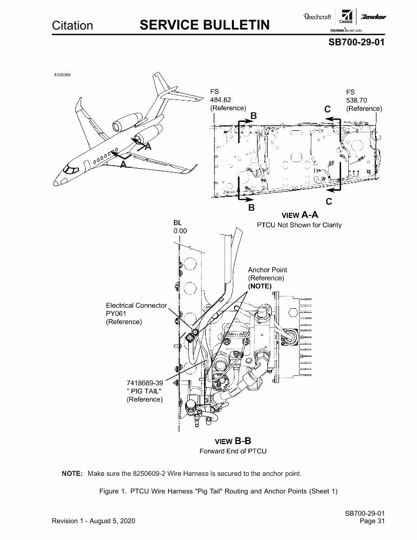
Citation SERVICE BULLETINSB700-29-01
Figure 1. PTCU Wire Harness "Pig Tail" Routing and Anchor Points (Sheet 1)
SB700-29-01Revision 1 - August 5, 2020 Page 31
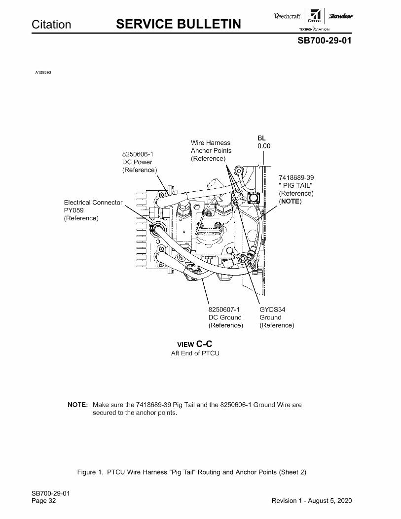
SB700-29-01Page 32 Revision 1 - August 5, 2020
Citation SERVICE BULLETINSB700-29-01
Figure 1. PTCU Wire Harness "Pig Tail" Routing and Anchor Points (Sheet 2)
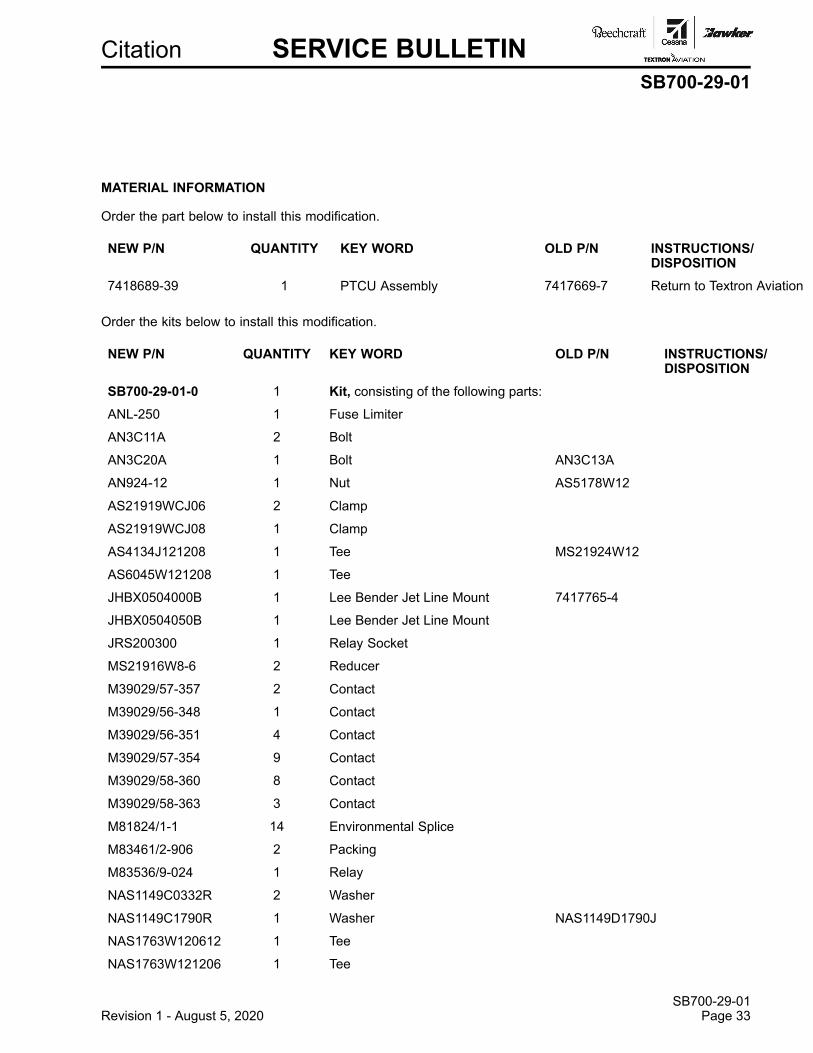
Citation SERVICE BULLETINSB700-29-01
MATERIAL INFORMATION
Order the part below to install this modification.
NEW P/N QUANTITY KEY WORD OLD P/N INSTRUCTIONS/DISPOSITION
7418689-39 1 PTCU Assembly 7417669-7 Return to Textron Aviation
Order the kits below to install this modification.
NEW P/N QUANTITY KEY WORD OLD P/N INSTRUCTIONS/DISPOSITION
SB700-29-01-0 1 Kit, consisting of the following parts:ANL-250 1 Fuse Limiter
AN3C11A 2 Bolt
AN3C20A 1 Bolt AN3C13A
AN924-12 1 Nut AS5178W12
AS21919WCJ06 2 Clamp
AS21919WCJ08 1 Clamp
AS4134J121208 1 Tee MS21924W12
AS6045W121208 1 Tee
JHBX0504000B 1 Lee Bender Jet Line Mount 7417765-4
JHBX0504050B 1 Lee Bender Jet Line Mount
JRS200300 1 Relay Socket
MS21916W8-6 2 Reducer
M39029/57-357 2 Contact
M39029/56-348 1 Contact
M39029/56-351 4 Contact
M39029/57-354 9 Contact
M39029/58-360 8 Contact
M39029/58-363 3 Contact
M81824/1-1 14 Environmental Splice
M83461/2-906 2 Packing
M83536/9-024 1 Relay
NAS1149C0332R 2 Washer
NAS1149C1790R 1 Washer NAS1149D1790J
NAS1763W120612 1 Tee
NAS1763W121206 1 Tee
SB700-29-01Revision 1 - August 5, 2020 Page 33
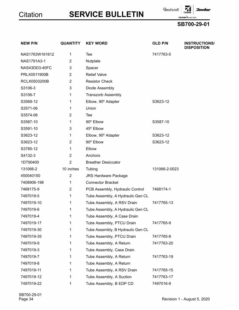
SB700-29-01Page 34 Revision 1 - August 5, 2020
Citation SERVICE BULLETINSB700-29-01
NEW P/N QUANTITY KEY WORD OLD P/N INSTRUCTIONS/DISPOSITION
NAS1763W161612 1 Tee 7417763-5
NAS1791A3-1 2 Nutplate
NAS43DD3-40FC 3 Spacer
PRLX0511900B 2 Relief Valve
RCLX0503200B 2 Resistor Check
S3106-3 3 Diode Assembly
S3106-7 1 Transzorb Assembly
S3569-12 1 Elbow, 90º Adapter S3623-12
S3571-06 1 Union
S3574-06 2 Tee
S3587-10 1 90º Elbow S3587-10
S3591-10 3 45º Elbow
S3623-12 1 Elbow, 90º Adapter S3623-12
S3623-12 2 90º Elbow S3623-12
S3785-12 1 Elbow
S4132-3 2 Anchors
1DT90400 2 Breather Desiccator
131066-2 10 inches Tubing 131066-2-0023
450040150 2 JRS Hardware Package
7408906-198 1 Connector Bracket
7468175-9 2 PCB Assembly, Hydraulic Control 7468174-1
7497019-5 1 Tube Assembly, A Hydraulic Gen CL
7497019-10 1 Tube Assembly, A RSV Drain 7417765-13
7497019-6 1 Tube Assembly, A Hydraulic Gen CL
7497019-4 1 Tube Assembly, A Case Drain
7497019-17 1 Tube Assembly, PTCU Drain 7417765-9
7497019-30 1 Tube Assembly, B Hydraulic Gen CL
7497019-35 1 Tube Assembly, PTCU Drain 7417765-8
7497019-9 1 Tube Assembly, A Return 7417763-20
7497019-3 1 Tube Assembly, Case Drain
7497019-7 1 Tube Assembly, A Return 7417763-19
7497019-8 1 Tube Assembly, A Return
7497019-11 1 Tube Assembly, A RSV Drain 7417765-15
7497019-12 1 Tube Assembly, A Suction 7417763-17
7497019-22 1 Tube Assembly, B EDP CD 7497016-9
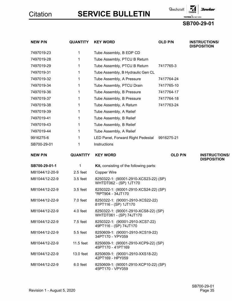
Citation SERVICE BULLETINSB700-29-01
NEW P/N QUANTITY KEY WORD OLD P/N INSTRUCTIONS/DISPOSITION
7497019-23 1 Tube Assembly, B EDP CD
7497019-28 1 Tube Assembly, PTCU B Return
7497019-29 1 Tube Assembly, PTCU B Return 7417765-3
7497019-31 1 Tube Assembly, B Hydraulic Gen CL
7497019-32 1 Tube Assembly, A Pressure 7417764-24
7497019-34 1 Tube Assembly, PTCU Drain 7417765-10
7497019-36 1 Tube Assembly, B Pressure 7417764-17
7497019-37 1 Tube Assembly, B Pressure 7417764-18
7497019-38 1 Tube Assembly, A Return 7417763-24
7497019-39 1 Tube Assembly, A Relief
7497019-41 1 Tube Assembly, B Relief
7497019-43 1 Tube Assembly, B Relief
7497019-44 1 Tube Assembly, A Relief
9916275-6 1 LED Panel, Forward Right Pedestal 9916275-21
SB700-29-01 1 Instructions
NEW P/N QUANTITY KEY WORD OLD P/N INSTRUCTIONS/DISPOSITION
SB700-29-01-1 1 Kit, consisting of the following parts:M81044/12-20-9 2.5 feet Copper Wire
M81044/12-22-9 3.5 feet 8250322-1: (90001-2910-XCS23-22) (SP)WHTDT062 - (SP) 1JT170
M81044/12-22-9 3.5 feet 8250322-1: (90001-2910-XCS24-22) (SP)*RPT904 - 34JT170
M81044/12-22-9 7.0 feet 8250322-1: (90001-2910-XCS22-22)81PT116 - (SP) 1JT170
M81044/12-22-9 4.0 feet 8250322-1: (90001-2910-XCS8-22) (SP)WHTDT061 - (SP) 74JT170
M81044/12-22-9 7.5 feet 8250322-1: (90001-2910-XCS7-22)49PT116 - (SP) 74JT170
M81044/12-22-9 5.5 feet 8250609-1: (90001-2910-XCS19-22)34PT170 - YPY059
M81044/12-22-9 11.5 feet 8250609-1: (90001-2910-XCP9-22) (SP)45PT170 - 41PT169
M81044/12-22-9 13.0 feet 8250609-1: (90001-2910-XXS18-22)42PT169 - HPY059
M81044/12-22-9 6.0 feet 8250609-1: (90001-2910-XCP10-22) (SP)45PT170 - VPY059
SB700-29-01Revision 1 - August 5, 2020 Page 35
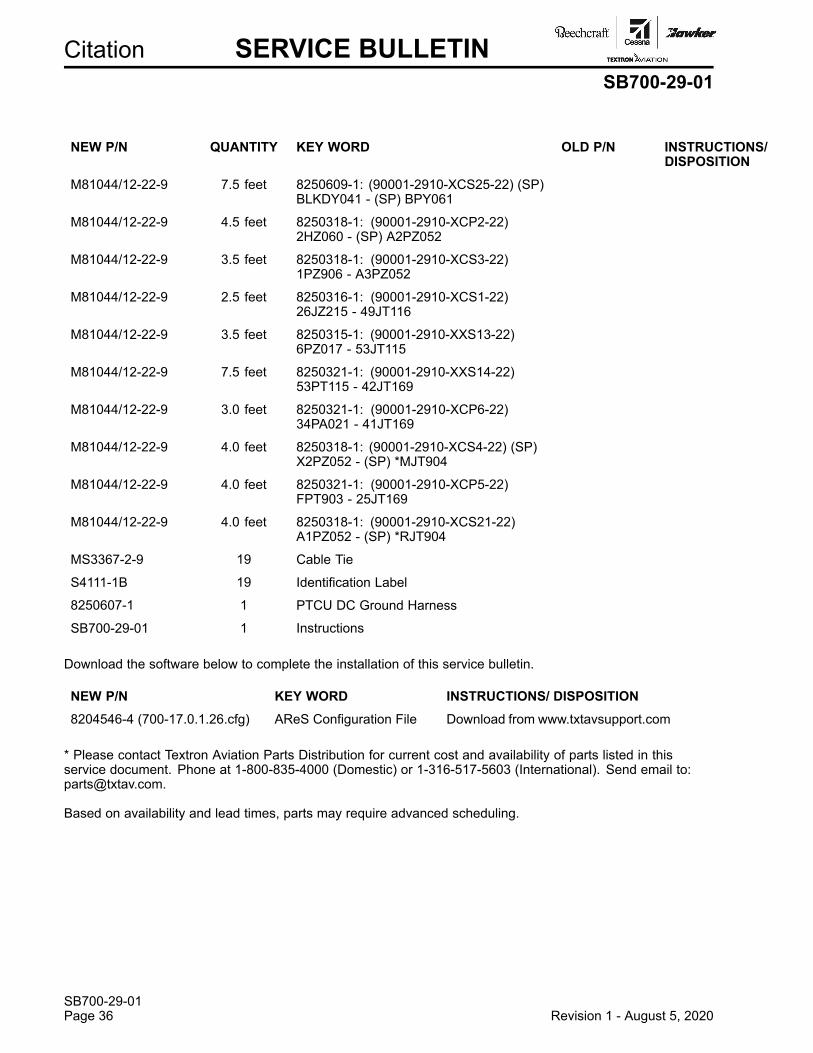
SB700-29-01Page 36 Revision 1 - August 5, 2020
Citation SERVICE BULLETINSB700-29-01
NEW P/N QUANTITY KEY WORD OLD P/N INSTRUCTIONS/DISPOSITION
M81044/12-22-9 7.5 feet 8250609-1: (90001-2910-XCS25-22) (SP)BLKDY041 - (SP) BPY061
M81044/12-22-9 4.5 feet 8250318-1: (90001-2910-XCP2-22)2HZ060 - (SP) A2PZ052
M81044/12-22-9 3.5 feet 8250318-1: (90001-2910-XCS3-22)1PZ906 - A3PZ052
M81044/12-22-9 2.5 feet 8250316-1: (90001-2910-XCS1-22)26JZ215 - 49JT116
M81044/12-22-9 3.5 feet 8250315-1: (90001-2910-XXS13-22)6PZ017 - 53JT115
M81044/12-22-9 7.5 feet 8250321-1: (90001-2910-XXS14-22)53PT115 - 42JT169
M81044/12-22-9 3.0 feet 8250321-1: (90001-2910-XCP6-22)34PA021 - 41JT169
M81044/12-22-9 4.0 feet 8250318-1: (90001-2910-XCS4-22) (SP)X2PZ052 - (SP) *MJT904
M81044/12-22-9 4.0 feet 8250321-1: (90001-2910-XCP5-22)FPT903 - 25JT169
M81044/12-22-9 4.0 feet 8250318-1: (90001-2910-XCS21-22)A1PZ052 - (SP) *RJT904
MS3367-2-9 19 Cable Tie
S4111-1B 19 Identification Label
8250607-1 1 PTCU DC Ground Harness
SB700-29-01 1 Instructions
Download the software below to complete the installation of this service bulletin.
NEW P/N KEY WORD INSTRUCTIONS/ DISPOSITION8204546-4 (700-17.0.1.26.cfg) AReS Configuration File Download from www.txtavsupport.com
* Please contact Textron Aviation Parts Distribution for current cost and availability of parts listed in thisservice document. Phone at 1-800-835-4000 (Domestic) or 1-316-517-5603 (International). Send email to:[email protected].
Based on availability and lead times, parts may require advanced scheduling.
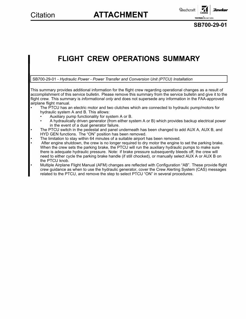
Citation ATTACHMENTSB700-29-01
FLIGHT CREW OPERATIONS SUMMARY
SB700-29-01 - Hydraulic Power - Power Transfer and Conversion Unit (PTCU) Installation
This summary provides additional information for the flight crew regarding operational changes as a result ofaccomplishment of this service bulletin. Please remove this summary from the service bulletin and give it to theflight crew. This summary is informational only and does not supersede any information in the FAA-approvedairplane flight manual.• The PTCU has an electric motor and two clutches which are connected to hydraulic pump/motors for
hydraulic system A and B. This allows:• Auxiliary pump functionality for system A or B.• A hydraulically driven generator (from either system A or B) which provides backup electrical power
in the event of a dual generator failure.• The PTCU switch in the pedestal and panel underneath has been changed to add AUX A, AUX B, and
HYD GEN functions. The “ON” position has been removed.• The limitation to stay within 64 minutes of a suitable airport has been removed.• After engine shutdown, the crew is no longer required to dry motor the engine to set the parking brake.
When the crew sets the parking brake, the PTCU will run the auxiliary hydraulic pumps to make surethere is adequate hydraulic pressure. Note: if brake pressure subsequently bleeds off, the crew willneed to either cycle the parking brake handle (if still chocked), or manually select AUX A or AUX B onthe PTCU knob.
• Multiple Airplane Flight Manual (AFM) changes are reflected with Configuration “AB”. These provide flightcrew guidance as when to use the hydraulic generator, cover the Crew Alerting System (CAS) messagesrelated to the PTCU, and remove the step to select PTCU “ON” in several procedures.

Citation OWNER ADVISORYSB700-29-01
TITLEELECTRICAL PANELS - POWER TRANSFER CONVERSION UNIT (PTCU) INSTALLATION
TO:Cessna Model 700 (Citation Longitude) Aircraft Owner
REASONThis service document installs a Power Transfer Conversion Unit (PTCU) in place of the Power TransferUnit (PTU).
COMPLIANCEDISCRETIONARY. This service document can be accomplished at the discretion of the owner.
LABOR HOURS
WORK PHASE LABOR-HOURSModification 200.0
Test 100.0
MATERIAL AVAILABILITYOrder the kits below to complete this service document.
PART NUMBER AVAILABILITY COST
SB700-29-01-0 * *
SB700-29-01-1 * *
7418689-39 * *
The existing 7417669-7 PTCU may be returned to Textron Aviation Parts Distribution, WarrantyAdministration, 285 South Greenwich Road, Bldg B89, Docks 1-4, Wichita, KS 67206, USA, andexchanged for an upgraded unit. Due to limited availability, advance scheduling is required, pleaseexpedite the return of the removed part.
* Please contact Textron Aviation Parts Distribution for current cost and availability of parts listed in thisservice document. Phone at 1-800-835-4000 (Domestic) or 1-316-517-5603 (International). Send emailto: [email protected].
Based on availability and lead times, parts may require advanced scheduling.
WARRANTYEligible airplanes exhibiting conditions described in this service document may demonstrate improvedoperation by incorporation of the work described herein. This service document is to be accomplished atthe discretion of the owner. Eligible airplanes may qualify for parts and labor coverage to the extent notedin the Labor Hours and Material Availability sections of this document.
SB700-29-01August 3, 2020 Page 1 of 2
Textron Aviation Customer Service, P.O. Box 7706, Wichita, KS 67277, U.S.A. 1-316-517-5800This document contains technical data and is subject to U.S. export regulations. This information has been exported from the United States
in accordance with export administration regulations. Diversion contrary to U.S. law is prohibited. ECCN: 9E991
COPYRIGHT © 2020
SB700-29-01Page 2 August 3, 2020
Citation OWNER ADVISORYSB700-29-01
Eligibility: Airplanes identified within the serial number effectivity of this service document must haveactive Airframe warranty coverage on the original issue date of this document and thecoverage must be active on the day the work is accomplished.
Parts Coverage: Textron Aviation-owned and Textron Aviation-authorized Service Facilities, operators, orother maintenance facilities may submit a claim for the parts required to accomplish thisservice document as defined in the Material Availability section of this document.
Labor Coverage: Textron Aviation-owned and Textron Aviation-authorized Service Facilities rated to performmaintenance on the specific model of Cessna Aircraft may submit a claim for the labornecessary to accomplish this service document as defined in the Labor Hours section ofthis document.
CreditApplication:
After this service document has been accomplished, a claim must be submitted to TextronAviation within 30 days of the service document completion. Claims for compliance of thisservice document are to be filed as a W4 type claim.
Please submit your claim form online at ww2.txtav.com/Parts or email the completedTextron Aviation Claim Form to [email protected]. If submitted on-line a ReturnAuthorization will be provided. If a paper claim is submitted your claim will be entered intothe system and a Return Authorization will be sent to you.
The Return Authorization must accompany any required return parts (see MaterialAvailability), to the point of purchase.
Parts to be returned to Textron Aviation Parts Distribution should be forwarded to:
Textron Aviation Parts DistributionWarranty Administration285 South Greenwich RoadBldg B89, Docks 1-4Wichita, KS 67206USA
Expiration: August 31, 2022 (after this date the owner/operator assumes the responsibility forcompliance costs)
Textron Aviation reserves the right to void continued airplane warranty coverage for the parts affected bythis service document until the service document is accomplished.
NOTE: As a convenience, service documents are now available online to all our customers through asimple, free-of-charge registration process. If you would like to sign up, please visit the CustomerAccess link at www.txtavsupport.com to register.
Related Documents