Issued: February, 2000 SB 57-3329 1 of 63 SERVICE BULLETIN MANDATORY Exported under the authority of license exception: TSU. "These commodities, technology or software were exported from the United States in accordance with Export Administration Regulations. Diversion contrary to U.S. law prohibited." Raytheon Aircraft Company (RAC) issues Service Information for the benefit of owners and fixed base operators in the form of two classes of Service Bulletins. The first class, Mandatory Service Bulletins (red border) includes changes, inspections and modifications that could affect safety or crashworthiness. RAC also issues Service Bulletins with no red border which are designated as either recommended or optional in the compliance section within the bulletin. In the case of recommended Service Bulletins, RAC feels the changes, modifications, improvements or inspections will benefit the owner/operator and although highly recommended, Recommended Service Bulletins are not considered mandatory at the time of issuance. In the case of Optional Service Bulletins, compliance with the changes, modifications, improvements or inspections is at the owner/operator’s discretion. Both classes are mailed to: (a) RAC Authorized Service Centers. (b) Owners of record on the FAA Aircraft Registration Branch List and the RAC International Owner Notification/Registration Service List. (c) Those having a publications subscription. Information on Owner Notification Service or subscription can be obtained through any RAC Authorized Service Center. As Mandatory Service Bulletins and Service Bulletins are issued, temporary notification in the Service Bulletin Master Index should be made until the index is revised. Warranty will be allowed only when specifically defined in the Service Bulletin and in accordance with the RAC Warranty Policy. Unless otherwise designated, RAC Mandatory Service Bulletins, Service Bulletins and RAC Kits are approved for installation on RAC airplanes in original or RAC modified configurations only. RAC Mandatory Service Bulletins, Service Bulletins and Kits may not be compatible with airplanes modified by STC installations or modifications other than RAC approved kits. Recurring Inspection Beech 1. Planning Information A. Effectivity (1) Airplanes conforming to Type Certificate No. 5A3. Beech Mentor 45 (Military YT-34), Serials G-3 through G-6; A45 (Military T-34A), Serials G-7 and After; B45, Serials CG-1 and After; D45 (Military T-34B), Serials BG-1 and After; B45 (T-34 Manufactured by Canadian Car and Foundry), Serials 34-1 through 34-125. Beech Bonanza Model 35 through Model G35, all serials which have installed T-34 wings per STC or field approval. If the airplane has been modified by any Supplemental Type Certificate (STC), the airplane owner will have to contact the owner of the STC to determine whether this Service Bulletin applies. If you are no longer in possession of the airplane, please forward this information to the present owner. (2) Spares All spare forward (main) spar assemblies and spare aft (rear) spar assemblies which conform to Type Certificate No. 5A3 for the airplanes listed in step (1) above. B. Reason This Service Bulletin is being issued because fatigue cracks have been found at specific locations in the wing spars of an airplane involved in a fatal accident where the wing separated from the aircraft. Fatigue cracks have also been found at specific locations in the wing spars of other in-service airplanes. The YT-34, T-34A, and T-34B airplanes were designed as military trainers. Less than 1400 were built between 1953 and 1958. At that time, there was no requirement for the establishment of a fatigue life for these three TITLE: WINGS - INSPECTION OF WING SPAR STRUCTURE

Welcome message from author
This document is posted to help you gain knowledge. Please leave a comment to let me know what you think about it! Share it to your friends and learn new things together.
Transcript

Issued: February, 2000 SB 57-33291 of 63
SERVICE BULLETIN
MANDATORY
Exported under the authority of license exception: TSU. "These commodities, technology orsoftware were exported from the United States in accordance with Export AdministrationRegulations. Diversion contrary to U.S. law prohibited."
Raytheon Aircraft Company (RAC) issues Service Information for the benefit of owners andfixed base operators in the form of two classes of Service Bulletins. The first class, Mandatory Service Bulletins (red border) includes changes, inspections and modifications that could affect safety or crashworthiness. RAC also issues Service Bulletins with no red border which are designated as either recommended or optional in the compliance sectionwithin the bulletin. In the case of recommended Service Bulletins, RAC feels the changes, modifications, improvements or inspections will benefit the owner/operator and although highly recommended, Recommended Service Bulletins are not considered mandatory at the time of issuance. In the case of Optional Service Bulletins, compliance with the changes, modifications, improvements or inspections is at the owner/operator’s discretion. Both classes are mailed to:
(a) RAC Authorized Service Centers.
(b) Owners of record on the FAA Aircraft Registration Branch List and the RAC International Owner Notification/Registration Service List.
(c) Those having a publications subscription.Information on Owner Notification Service or subscription can be obtained through any RAC Authorized Service Center. As Mandatory Service Bulletins and Service Bulletins are issued, temporary notification in the Service Bulletin Master Index should be made until the index is revised. Warranty will be allowed only when specifically defined in the Service Bulletin and in accordance with the RAC Warranty Policy.Unless otherwise designated, RAC Mandatory Service Bulletins, Service Bulletins and RAC Kits are approved for installation on RAC airplanes in original or RAC modified configurations only. RAC Mandatory Service Bulletins, Service Bulletins and Kits may not be compatible with airplanes modified by STC installations or modifications other than RAC approved kits.
Recurring Inspection
Beech
1. Planning Information
A. Effectivity
(1) Airplanes conforming to Type Certificate No. 5A3.
Beech Mentor 45 (Military YT-34), Serials G-3 through G-6;
A45 (Military T-34A), Serials G-7 and After;
B45, Serials CG-1 and After;
D45 (Military T-34B), Serials BG-1 and After;
B45 (T-34 Manufactured by Canadian Car and Foundry), Serials 34-1 through 34-125.
Beech Bonanza Model 35 through Model G35, all serials which have installed T-34 wings per STC orfield approval.
If the airplane has been modified by any Supplemental Type Certificate (STC), the airplane ownerwill have to contact the owner of the STC to determine whether this Service Bulletin applies.
If you are no longer in possession of the airplane, please forward this information to the presentowner.
(2) Spares
All spare forward (main) spar assemblies and spare aft (rear) spar assemblies which conform to TypeCertificate No. 5A3 for the airplanes listed in step (1) above.
B. Reason
This Service Bulletin is being issued because fatigue cracks have been found at specific locations in thewing spars of an airplane involved in a fatal accident where the wing separated from the aircraft. Fatiguecracks have also been found at specific locations in the wing spars of other in-service airplanes. TheYT-34, T-34A, and T-34B airplanes were designed as military trainers. Less than 1400 were built between1953 and 1958. At that time, there was no requirement for the establishment of a fatigue life for these three
TITLE: WINGS - INSPECTION OF WING SPAR STRUCTURE
SB 57-33292 of 63
SERVICE BULLETIN
MANDATORY
Issued: February, 2000
(3) models of military trainer. More important, the accumulated operational service history - the magnitudeand number of g-loads - of an individual airplane is unknown. Given the intermingling of spare andsalvaged parts installed on airplanes in military service, it is usually impossible to determine accurately theoverall history of the airplane. Fatigue cracks at any location in the forward or aft spar will reduce the wing’sability to carry limit load and may result in an in-flight separation of a wing.
This Service Bulletin provides inspection procedures for the forward (main) and aft (rear) wing spars of theairplanes listed in EFFECTIVITY conforming with Type Certificate No. 5A3 to detect fatigue cracks inspecified areas only. The specified areas are those where fatigue cracks have been found duringinvestigation of the aforementioned accident and during preparation of this Service Bulletin. Whileinspecting individual airplanes, inspectors must carefully examine other accessible areas and structure.During preparation of this Service Bulletin, corrosion was found on one wing that was severe enough thatthe operator elected to replace the wing.
This Service Bulletin does not provide relief from the requirements of Airworthiness Directive 62-24-01(inspection of both horizontal stabilizer front and rear spars), which remains in effect. The inspection andrecurring inspection schedule mandated by this Service Bulletin are to be accomplished in addition to anyother inspections and inspection schedules.
Reference Airworthiness Directive 99-12-02 and Safety Communique 162 Rev. 2 (or subsequent revision)for additional information.
C. Description
Part I of this Service Bulletin provides instructions for the modification and inspection of the forward wingspar structure and aft wing spar structure for fatigue cracks and corrosion at suspected locations.
Part II of this Service Bulletin provides a recurring inspection interval at 80 hour intervals. AnAccomplishment Instructions Index and Index of Illustrations is located on pages 61 through 63.
D. Compliance
Raytheon Aircraft Company considers this to be a mandatory inspection. Part I must be accomplishedbefore further flight.
Part II is a recurring mandatory inspection and must be accomplished every 80 flight hours thereafter.
An inspector must be certified in the Eddy Current Method of inspection to a Level II or Level III inaccordance with AIA Specification NAS-410 (MIL-STD-410) for the initial and recurring NDI inspections inthis Service Bulletin.
An amendment to AD 99-12-02 has been requested.
E. Approval
The engineering data contained in this Service Bulletin is FAA approved.
F. Manpower
The following information is for planning purposes only:

SB 57-33293 of 63
SERVICE BULLETIN
MANDATORY
Issued: February, 2000
Part I - Initial Inspection
Estimated man-hours for preparation and reassembly: 235 hours.
Suggested number of men for preparation: 2 men.
Estimated man-hours for NDI inspection: 6 hours.
Suggested number of men for NDI inspection: 1 man.
Part II - Recurring Inspection
Estimated man-hours for preparation and reassembly: 25 hours.
Suggested number of men for preparation and reassembly: 1 man.
Estimated man-hours for NDI inspection: 6 hours.
Suggested number of men for NDI inspection: 1 man.
The above is an estimate based on experienced, properly equipped personnel complying with this ServiceBulletin. Occasionally, after work has started, conditions may be found which could result in additionalman-hours.
G. Weight and Balance
Negligible.
H. Electrical Load Data
Not changed.
I. Software Accomplishment Summary
Not applicable.
J. References
Airworthiness Directive No. 99-12-02;
Safety Communique No. 162, Rev. 2 or subsequent revision;
Mandatory Service Bulletin 2538, Rev. I or subsequent revision.
K. Publications Affected
It is recommended that a note "See Service Bulletin No. 57-3329" be made in the following:
The appropriate chapter of the applicable parts catalog.
L. Interchangeability of Parts
Not applicable.
M. Warranty Credit
None.

SB 57-33294 of 63
SERVICE BULLETIN
MANDATORY
Issued: February, 2000
2. Material Information
A. Materials - Price and Availability
Obtain locally.
B. Industry Support
Not applicable.
C. Airplanes
The following parts required for this modification may be ordered from RAPID or obtained locally:
Part Number DescriptionQuantity Per
Airplane
MS21069L3 orMS21075L3
Nutplate 8
MS21071L3 Nutplate 10
MS20426AD3 Rivet (to fill in aft spar capstrip, see Figure 26) 6
MS20470AD4 Rivet (to install doubler plate) 40
MS20426AD6 Rivet ("AD 6" in aft spar capstrip) 12
MS20470AD3 Rivet 12
MS21042L06 Nut (box section hinge angle and trunnion fastener)
10
NAS1097AD3 Rivet (to install nutplates to mounting plates) 36
NAS 1121-X * Screw (aft MLG trunnion fastener) 4
NAS1151-XP * Screw (forward MLG trunnion fastener)* 2
NAS1121-X * Screw (box section hinge angle fasteners) 4
NAS1703-X * Bolt (forward spar lower hinge extrusion - spar cap)
8
NAS1603-X * Bolt (alternative oversize to NAS1703-X) As Required
NAS2903-X * Bolt (forward spar lower structure) 10
NAS3003-X * Bolt (alternative oversize to NAS2903-X) As Required
AN960-6 Washer (trunnion and box section hinge angle fasteners)
10
NAS9310M-4 orNAS1738B-4
Blind Fastener Where Specified, As Required
* Grip length of Screws and Bolts to be determined upon installation. X = Grip Length, P= Cad Plate

SB 57-33295 of 63
SERVICE BULLETIN
MANDATORY
Issued: February, 2000
The following materials may be obtained locally:
Raytheon Aircraft Company expressly reserves the right to supersede, cancel and/or declare obsolete,without prior notice, any parts or publications that may be referenced in this Service Bulletin.
Part Number DescriptionQuantity Per
Airplane
35-921502 Gasket, Wing Fuel Cell Filler Neck 2
35-921503 Gasket, Fuel Quantity Transmitter 2
45-921523 Gasket, Wing Fuel Cell Outlet 2
35-921502 Gasket, Submerged Fuel Boost Pump 2
Part NumberDescription
Quantity Per Airplane
8544 (33396) Tape, Fuel Resistant, Black (Minnesota Mining & Manufacturing Co.)
As Required
2024-T3 ALCLAD .020 Plate .020 inch thick (for mounting nutplates) 2 - approx. 3" x 6"
2024-T3 ALCLAD .040 Plate .040 inch thick (doubler plate for lower skin)
2 - approx. 5" x 5"
2024-T3 ALCLAD .125 Strip .125 inch thick (radius block - trunnion) As Required 1"x1"
EA9309NA Structural Adhesive As Required
6061-T4 bare .032 Fuel bladder protecting angle - fabricate locally, smooth corners and edges
2 - size as required
MIL-C-5541, CLASS 1A Alodine 1200, 1200S or 1201 (chemical film treatment)
As Required
G322L Silicone Grease (General Electric) As Required
MIL-C-16173, Grade 2 Corrosion Preventive Compound As Required
MIL-P-23377 Epoxy Polyamide Primer As Required
MIL-L-6082A Light Engine Oil As Required

SB 57-33296 of 63
SERVICE BULLETIN
MANDATORY
Issued: February, 2000
D. Spares
Any forward (main) spar assemblies or aft (rear) spar assemblies which areto be installed as replacement parts must be Eddy Current Inspected inaccordance with the instructions in Part I of this Service Bulletin, prior toinstallation.
Any replacement leading edge or box section hinge angle assemblies whichare to be installed as replacement parts must be Eddy Current Inspected inaccordance with the instructions in Part I of this Service Bulletin, prior toinstallation.
E. Reidentified Parts
None.
F. Tooling - Price and Availability
• Hand Reamers, tapered tip with spiral flute and straight shank, LH spiral/RH cut, such as Lavallee & Ide No. 503 Series Spiral Flute hand reamers in sizes (9/64, 13/64 and 7/32) which yield hole dimensions specified in this Service Bulletin. (Lavallee & Ide, 110 West Canal St./P.O. BOX 0068, Winooski, Vermont 05404, tele. 802-655-1870, FAX 802-655-3881) or (Claude Mann & Associates 1720 E. Morris, Suite 113, Wichita, KS 62211, tele. 316-267-2272, FAX 316-267-8124) or (The Wiedemann Company, 705 Bowser St., Suite #101, Richardson, TX 75081, tele. 800-392-5123)
• Nortec Staveley 19e Impedance plane Eddy Current instrument or equivalent with a frequency range of 500 Hz to 3 Mhz minimum. The instrument must be capable of connecting to the rotating probe listed below. (Staveley Instruments, Kennewick, WA. tele. 509-735-7550)
• Nortec (Staveley Inst.) RA-19 Rotating Eddy Current probe or equivalent with a rotational speed of not less than 200 rpm., and reflection differential coil bolt hole probes to fit, 300 kHz minimum. (Staveley Instruments, Kennewick, WA. tele. 509-735-7550)
• Shielded Eddy Current bolt hole probes, sizes to fit, 300 kHz minimum, absolute or differential coil.
• Shielded Eddy Current pencil probe, minimum 100 kHz, absolute coil.
• Eddy Current 90° pencil probe, maximum 1/2" drop, minimum 100 kHz, absolute coil.
• Aluminum Electron Discharge Machining (EDM) notch standard as shown in Figure 8.
• Hi-Torque drivers (MS33750) for removal/installation of NAS1703 bolts, available from tool supply companies such as Brown Aviation Tool Supply Co. 700 N. Rockwell, Bldg. Two, Suite E, Bethany, OK 73008, tele. 800-587-3883.
• Torq-Set drivers (MS33781) for removal/installation of NAS1121 and NAS1151 screws, available from tool supply companies such as Brown Aviation Tool Supply Co. 700 N. Rockwell, Bldg. Two, Suite E, Bethany, OK 73008, tele. 800-587-3883.

SB 57-33297 of 63
SERVICE BULLETIN
MANDATORY
Issued: February, 2000
3. Accomplishment Instructions
This Service Bulletin shall be accomplished as follows:
NOTE
Should any difficulty be encountered in accomplishing this Service Bulletin,contact Raytheon Aircraft Company at 1-800-429-5372 or 316-676-3140.Reference the Accomplishment Instructions Index located on pages 61 and 62 forindexes to the Accomplishment Instructions in Part I and Part II.
A. Airplane
Observe all Warnings and Cautions contained in the aircraft manualsreferred to in this Service Bulletin.
Whenever any part of this system is dismantled, adjusted, repaired orrenewed, detailed investigation must be made on completion to make surethat distortion, tools, rags or any other loose articles or foreign matter thatcould impede the free movement and safe operation of the system are notpresent, and that the systems and installations in the work area are clean.
NOTE
Accomplish all maintenance in accordance with the appropriate manual and bestshop practices.
NOTE
Maintenance procedures are the same for both left and right sides. Only themaintenance procedures for the left side are described. Reference theAccomplishment Instructions Index located on page 61 for an index of theAccomplishment Instructions in Part I.
Part I
(1) To determine whether this Service Bulletin applies, inspect the airplane to ensure it conforms to theType Certificate as follows:
(a) Review all logbooks and FAA forms 337 and inspect the airplane to ensure it conforms to TypeCertificate No. 5A3 by confirming it is in original condition. If the airplane has been modified,altered or repaired, received parts produced by an owner/operator or been modified bySupplemental Type Certificate(s) (STC)(s), contact a FAA Designated EngineeringRepresentative (DER) and the owner(s) of the STC(s) to determine whether those are allcompatible with each other and the original condition/Type Certificate.
(b) Based on the findings from step (a), remove/replace all parts that are not compatible with theoriginal condition (Type Certificate) and with all other changes since original manufacture.
SB 57-33298 of 63
SERVICE BULLETIN
MANDATORY
Issued: February, 2000
Do not defuel near an open flame or within 100 feet of any energizedelectrical equipment capable of producing sparks.
(2) Defuel and drain all fuel into a suitable container.
(3) Place the airplane on jacks and raise until the wheels are clear.
(4) Remove the flaps as follows:
(a) Lower the flaps and pull out the flap circuit breaker.
If power is left on when the left flap is disconnected from the actuator, the actuatorswitch tab will release the limit switch, closing the circuit. The flap motor will start,pushing the flap actuator through the flap.
(b) Remove all electrical power from the airplane and disconnect the battery. Display warningnotices prohibiting reconnection of airplane electrical power.
(c) Disconnect the flap actuator from the flap.
(d) Remove the inboard and outboard upper flap bolts.
(e) Pull flap down from top flap track and remove the lower inboard and lower outboard flap bolts.
(f) Remove the flap bonding cable.
(g) Remove the flap.
(5) Manually raise the landing gear using the hand crank until the inboard landing gear doors are fullyopen.
(6) Disconnect the inboard MLG door actuating rod at the bracket on the inboard door.
(7) Gain access to the forward side of the forward spar (main spar) as follows:
(a) Remove the fuel cell access panel from the inboard side of the leading edge (lower surface).
Lubricate the fuel cell with light engine oil MIL-L-6082A. The fuel cell should notbe moved until 24 hours after the oil has been applied. The lighter viscosities of oilare preferable because they leave a thinner film on the walls of the cells. Do Notpermit excessive amounts of oil to remain in the cells in pools or puddles.
A thin coating of light engine oil should be applied to the inside of all serviceablefuel cells, which have contained gasoline, if the cells are to remain unfilled for 10days or more. When working inside cell, do not allow hot light bulbs to contact thecell.

SB 57-33299 of 63
SERVICE BULLETIN
MANDATORY
Issued: February, 2000
(b) Remove the small panel from the upper surface of the leading edge which is located on the fueltank filler opening.
(c) Remove the fuel cell (fuel bladder) from the leading edge of the wing.
Do not damage the structure beneath the fuel cell liner.
(d) Trim the aft edge of the fuel cell (fuel bladder) metal liner adjacent to the forward spar assembly,and remove material from inside the leading edge fuel cavity to gain access to the lower forwardspar area as follows:
NOTE
An additional vertical stiffener and a vertical row of rivets is installed on T-34Bwing spars (not installed on T-34A spars). This stiffener is located on the forwardspar web approximately 4 inches inboard of the vertical stiffener located at WingStation (WS) 33.0. On T-34B airplanes it will be necessary to locate the thirdvertical row of rivets (as opposed to the second row on T-34A’s) in step (7) (d) (i).
(i) Look through the fuel filler opening at the forward spar (inside the leading edge fuel cellcavity) and locate the first vertical row of rivets in the forward spar web located closest tothe fuselage. Reference Figure 1. Moving outboard along the spar web, find the next(second) vertical row of rivets in the spar web. The second vertical row of rivets is locatednear WS 33.0 (reference the 3rd vertical row of rivets on T-34Bs).
(ii) Mark an area approximately 2" by 7" on the liner as shown in Figure 1 [VIEW OFFORWARD SPAR INSIDE LEADING EDGE FUEL CAVITY THROUGH FUEL FILLER].Start the mark at the inboard side of the second vertical row of rivets in the spar web (nearWS 33.0 identified in step (7) (d) (i)). Extend the line 2" forward from the spar, 7" outboardalong the spar and 2" aft to the spar. Reference Figure 1.
(iii) Remove the fastener heads (located inside the marked area) from the liner. These two (2)fasteners attach the liner to an "L" shaped bracket mounted to the aft inside structure ofthe leading edge. The "L" shaped bracket will not be visible until the liner is cut away.
Maintain a 1/4" to 1/2" radius on all cutting operations in this Service Bulletin.
(iv) Cut away the fuel cell liner along the marked line with compact sheet metal snips. Removethe cut away section of liner from the leading edge fuel cell cavity.
(v) Remove the five (5) rivets (not shown) which attach the small "L" shaped bracket to theleading edge hinge angle, located under the liner area removed in step (iii). Remove thebracket from the leading edge structure.

SB 57-332910 of 63
SERVICE BULLETIN
MANDATORY
Issued: February, 2000
Fuel Cell Liner ModificationFigure 1
Close-up View of Cutaway in Liner
SECOND ROW OF RIVETS *
LINER
WEB
VIEW
TRIM MARK
FUEL FILLER OPENING
LH LEADING EDGE
AREA TO CUT
FASTENER HEADS (IN LINER - REMOVE)
(forward side)
LH FWD SPAR
AWAY
SECOND ROWOF RIVETS *(THIRD
FIRST VERTICAL ROW OF RIVETS
LINER
CUT AWAYIN LINER
WEB(forward side)
FWD
OUTBOARD
FWD
OUTBOARD
FUEL FILLER OPENING
(WS 33.0)
NUTPLATE MOUNTING PLATE LOCATIONRef (15) (a)
VIEW THROUGH
LH FWD SPAR
FORWARDREINFORCEMENT
View of Forward Spar and Leading Edge Fuel Cavity through Fuel Filler
FORWARD REINFORCEMENT
FUEL CELL ACCESS PANEL (REMOVED)
"L" BRACKET FASTENER HOLES
*Note:
T-34A ShownT-34B is similar except an additionalrow of rivets is installed between the "first vertical row" and the "second vertical row" of rivets
ROW ON T-34B’S)
WING STATION 33.38
FWD
SB 57-332911 of 63
SERVICE BULLETIN
MANDATORY
Issued: February, 2000
The lower inboard section of the forward (main) spar is constructed of several layers of sheet metaland metal extrusions which are formed, fitted and attached to the lower wing fitting. As viewed fromthe inboard side looking outboard, the cross section of the lower forward spar is shaped similar to anupside down "T" (reference Figure 2) with multiple layers reinforcing the upside-down "T".
• The spar web is oriented vertically and attaches the upper spar structure (not shown) to thelower spar hinge extrusion (spar cap).
• The aft reinforcement is attached to the aft side of the spar web.
• A tapered spacer is attached to the forward side of the spar web.
• The aft "J" channel is attached to the forward side of the tapered shim. The aft "J" channelextends below the lower edge of the web and curves aft below the tapered shim, spar weband aft reinforcement. The aft "J" channel curves up on the aft side of the aft reinforcement.
• The forward "J" channel is attached to the forward side of the aft "J" channel. The forward "J"channel curves down and forward, and the curves back up past the forward side of theforward reinforcement.The forward reinforcement is attached to the forward side of theforward "J" channel.
• The forward reinforcement is attached to the forward side of the forward "J" channel.
• A filler strip is attached to the lower side of both "J" channels.
• The lower spar hinge extrusion (spar cap) is attached to the lower side of the filler strip.
(8) Inspect the inboard section of forward spar as follows:
(a) Locate the inboard forward (main) spar inspection area near W.S. 34.0 as shown in Figures 3, 45 and 6. This area consists of nine (9) fasteners in the lower forward spar.
Five (5) of the nine (9) fasteners are installed through the lower area (edge) of the spar web(reference Figure 4), from the forward side to the aft side (the rivet shanks are orientedhorizontally, longitudinally with respect to the airplane axis). These fasteners are located inreinforcements on the spar web in the forward (main) spar structure near the outboard end of thelower forward wing fitting.
• Of the five (5) fasteners, the inboard fastener (reference the inboard fastener position in Figure 4) is installed in the vertical stiffener, aft reinforcement, spar web (both forward and aft elements), vertical spline of the lower forward wing fitting, forward "J" channel and forward reinforcement. Reference Detail A in Figure 2.
• The other fasteners in the group of five (5) are installed in the aft reinforcement, spar web, tapered spacer, aft "J" channel, forward "J" channel and forward reinforcement. Reference Figure 4 and Detail B in Figure 2.
The other four (4) fasteners within the group of nine (9) fasteners (reference Figures 5 and 6) areinstalled through the lower forward spar hinge extrusion (spar cap), filler strip, tang on theoutboard end of the wing fitting and horizontal flange of their respective forward "J" channel oraft "J" channel near W.S. 34.0. The fastener shanks are oriented vertically (2 are located on theforward side of the spar web, the other 2 are aft of the spar web) and are installed at theoutboard end of the lower forward wing fitting. Reference Detail B in Figure 2.

SB 57-332912 of 63
SERVICE BULLETIN
MANDATORY
Issued: February, 2000
Typical Spar Cross SectionFigure 2
B332902.AI
B A
DETAIL A
DETAIL B
CROSS SECTION VIEW OF LH LOWER SPAR STRUCTURE LOOKING INBOARD (AT THE INBOARD FASTENER POSITION)
CROSS SECTION VIEW OF LH LOWER SPAR STRUCTURE LOOKING INBOARD ON THE OUTBOARD SIDE OF THE INBOARD FASTENER POSITION
WEB (.040" on T-34A) (.051" on T-34B)
WEB OUTBOARD (.040" on T-34A) (.051" on T-34B)
WEB INBOARD (.071" THICK)
AFT "J" CHANNEL (.080" THICK)
AFT "J" CHANNEL (.080" THICK)
LOCK BOLT
FORWARD "J" CHANNEL (.080" THICK)
FORWARD "J" CHANNEL (.080" THICK)
AFT REINFORCEMENT (.071" THICK)
AFT REINFORCEMENT (.071" THICK)
TAPERED SPACER (.071" THICK AT STIFFENER-TAPERS OUTBOARD)
TANG (ON LOWER WING FITTING) (VARIABLE THICKNESS)
LOWER WING FITTING (VARIABLE THICKNESS)
LOWER HINGE EXTRUSION (SPAR CAP) (.076" THICK)
LOWER HINGE EXTRUSION (SPAR CAP) (.076" THICK)
FILLER STRIP (.125" THICK)
FILLER STRIP (.125" THICK)
FORWARD REINFORCEMENT (.071" THICK)
FORWARD REINFORCEMENT (.071" THICK)
FLANGE OF VERTICAL STIFFENER
VERTICAL STIFFENER (.051" on T-34A) (.064" on T-34B)
UP
FWD
UP
UP
FWD
VIEW OF AFT SIDE OF FORWARD SPAR LOOKING FORWARD T-34A SHOWN T-34B SIMILAR
FORWARD SPAR
INBOARD CORNER OF FORWARD SPAR
INBOARD FASTENER POSITION
INBOARD

SB 57-332913 of 63
SERVICE BULLETIN
MANDATORY
Issued: February, 2000
Be very careful when removing fasteners. Ensure the heads of the fasteners aredrilled off and the fastener shanks are pushed out with a punch with samediameter as the fastener shank. Do not attempt to drill out the shanks. Drill therivet head only, do not drill the shank. If the fasteners are not removed correctlyand the fastener hole wall is damaged, the Eddy Current Inspection may produceinconsistent results.
(b) Remove the nine (9) fasteners described in step (a).
(i) Access five (5) of the fasteners from the Main Landing Gear (MLG) wheel well area on theaft side of the forward (main) spar. These fasteners are installed through the verticalmembers of the lower spar structure. When looking forward at the spar structure frominside the MLG wheel well compartment, these fasteners can be viewed by locating thevertical stiffener on the aft spar web which is closest to the forward inboard corner of theMLG wheel well. Reference Figure 4. These fasteners include the fastener in the verticalstiffener plus the four fasteners located immediately outboard of the vertical stiffener.Note that T-34B airplanes had an additional vertical stiffener (not shown in Figure 4)installed between the inboard corner of the wheel well and the vertical stiffener shown inFigure 4. On T-34B airplanes the fastener is located in the second vertical stiffener fromthe inboard corner of the wheel well.
Also note that the fastener (in the group of five (5)) located closest to the inboard corner isinstalled in a vertical stiffener on the aft reinforcement. This inboard fastener (installedthrough the vertical stiffener - see Figure 4) is a lock bolt and is slightly larger than theother fasteners, constructed of a harder material. It will be necessary to carefully cut thealuminum collar from the lock bolt (on the wheel well side) and drive the shank forward. Itmay also be necessary to cut the shank of the lock bolt into two pieces (cut it on theforward side of the spar with a cut off tool) to provide clearance as it is removed from theforward side of the forward spar.
Drill out the heads and push out the shanks of the four (4) fasteners (of the group of 5) thatremain.
(ii) Access the other four (4) fasteners from below the wing surface. Locate the forward (main)lower spar hinge extrusion (spar cap) on the lower side of the wing. The lower spar hingeextrusion has a series of fastener rows with 2 fasteners installed in each row. The four (4)fasteners to be removed are located in the lower spar hinge extrusion and are in the 11thand 12th fastener rows in the hinge extrusion as counted from the inboard edge of thelower spar hinge extrusion (reference Figure 5 and Figure 6). The fastener shanks areoriented vertically and are installed immediately aft of a drain hole in the lower side of theleading edge. These fasteners are installed through the lower spar hinge extrusion (sparcap), filler strip, lower forward wing fitting tang and respective forward or aft "J" channel.Remove the fastener heads and push the shanks up through the lower spar structure.

SB 57-332914 of 63
SERVICE BULLETIN
MANDATORY
Issued: February, 2000
Inspection Locations (LH Wing Shown)
Figure 3
B332903.AI
FORWARD
INBOARD
LEADING EDGE
FUEL CELL ACCESS PANEL
INSPECT FORWARD TRUNNION FASTENER LOCATION (FIGURE 13)
AFT TRUNNION FITTING
WHEEL WELL OPENING
AFT (REAR) SPAR REF
WING STATION
34.0
WING STATION
63.0
INSPECT STEP IN TANG OF AFT WING FITTING (FIGURES 25 & 26)
WHEEL WELL OPENING
AFT SPAR "BATHTUB" FITTING
FORWARD SPAR "BATHTUB" FITTING
VIEW LOOKING UP FROM BELOW AT LH LOWER WING SURFACE
LANDING GEAR REMOVED FOR CLARITY
FORWARD SPAR HINGE EXTRUSION
WING ROOT REF
DRAIN HOLE
DRAIN HOLE
INSPECT FIVE (5) FASTENER LOCATIONS IN AFT REINFORCEMENT (SEE FIGURE 4) INSPECT FOUR (4)
FASTENER LOCATIONS IN HINGE EXTRUSION (SEE FIGURE 5)
INSPECT LEADING EDGE HINGE ANGLE LOWER SURFACE
INSPECT LEADING EDGE HINGE ANGLE LOWER SURFACE (FIGURE 13)
LEADING EDGE HINGE ANGLE INSPECT 2 FASTENER LOCATIONS (FIGURES 13, 17 & 18)
BOX SECTION HINGE ANGLE INSPECT 2 FASTENER LOCATIONS (FIGURE 13)
INSPECT 2 AFT TRUNNION FASTENER LOCATIONS (FIGURES 14 & 15)
ALL OF THE ABOVE INSPECTIONS REQUIRE EDDY CURRENT PROCEDURES

SB 57-332915 of 63
SERVICE BULLETIN
MANDATORY
Issued: February, 2000
Inboard Forward Spar Inspection (Aft Side)Figure 4
Inboard Forward Spar Inspection (Lower Side)Figure 5
WEB
AFTREINFORCEMENT
VERTICALSTIFFENER
FORWARDINBOARDCORNER OF
REMOVE FASTENERS AND INSPECT AT THE 5 LOCATIONS
OUTBOARDWHEEL WELL
AFTREINFORCEMENT
UP
INBOARDFASTENERPOSITION
LOWER WINGFITTING
INBOARD
VIEW SECTION OF THEFORWARD SPAR
LOOKINGFORWARD AT THEAFT SIDE OF THEFORWARD SPARFROM INSIDE THEWHEEL WELL
HINGE EXTRUSION (SPAR CAP)
OF INBOARD
T-34A SHOWN, T-34B HAS ANADDITIONAL VERTICAL STIFFINER INSTALLED
SPAR CAP
INBOARD
WHEEL WELL OPENING
REMOVE FASTENERS AND INSPECT AT THE 4 LOCATIONS
FORWARD
VIEW LOOKING UP AND AFT AT THE LH FORWARD LOWER SPAR CAP
UP
OUTBOARD
AFTSPAR WEBREF. LINE
WING FITTING
ACCESSPANEL
FORWARD LOWER
DRAIN HOLE
LANDING GEAR DOOR
OPENING
FUEL CELL
WS34.0

SB 57-332916 of 63
SERVICE BULLETIN
MANDATORY
Issued: February, 2000
Inboard Forward Spar Close-UpFigure 6
Use a hand reamer (reference Figure 7) for all reaming operations in this ServiceBulletin. Hand reamers are made with both straight and helical flutes. Use a handreamer with helical flutes. Helical flutes usually produce less binding andchattering. Hand reamers are tapered slightly on the end, as opposed tomachine reamers which have the same diameter throughout the length of theflutes. The taper end on a hand reamer facilitates proper alignment and starting ofthe reamer in the hole.
Do not over-insert the hand reamer into any of the fastener holes. Conductthe reaming operation with two men to ensure the reamer does not contactcomponents on the opposite side of the fastener hole. Protect these areas withbrass or stainless steel shim stock sheet (.010 or .005 inch thick) before reaming.When reaming from below lower surface of the wing do not allow the hand reamerto nick metal on the forward reinforcement or aft reinforcement. When reamingfrom inside the wheel well do not allow the hand reamer to nick metal on theforward "J" channel or the aft flange on the leading edge. Place the brass orstainless steel shim stock sheet against these surfaces before reaming.
B332906.AICLOSE-UP VIEW OF THE LOWER FORWARD LH SPAR HINGE EXTRUSION LOOKING UP FROM BELOW
INBOARD
FORWARD
SPAR WEB REF LINE
INBOARD EDGE OF LOWER FORWARD LH SPAR HINGE EXTRUSION (SPAR CAP)
FASTENER POSITION ROWS (AS COUNTED FROM THE INBOARD EDGE)
11th AND 12th FASTENER POSITION ROWS
WHEEL WELL OPENING
WING STATION 33.381
LANDING GEAR DOOR SILL
REMOVE FASTENERS AND INSPECT AT THE 4 LOCATIONS AS SHOWN, REAM TO .2026/.2036" WITH A HAND REAMER.
1 2 3 4 5 6 7 8 9 10 11 12 13

SB 57-332917 of 63
SERVICE BULLETIN
MANDATORY
Issued: February, 2000
Hand ReamerFigure 7
(c) Using a hand reamer, enlarge the nine (9) fastener holes which were exposed in step (8) (b) asfollows:
NOTE
It is very desirable to ream a smooth hole (which can be Eddy Current inspected)at the first oversize of .2026/.2036 inch diameter as opposed to re-reaming to thenext oversize of .2183/.2193 inch diameter.
(i) Ream the group of 5 fastener holes in the aft reinforcement (reference Figure 4) removed
in step (8) (b) (i), to the first oversize of .2026/.2036 inch diameter for NAS2903 bolts. Start
at the aft reinforcement and ream through the spar structure detailed in step (8) (a). If
larger fasteners are required, use a second standard oversize of .2183/.2193 inch
diameter for NAS3003 bolts.
Do not allow the hand reamer to nick metal on the forward reinforcement or aftreinforcement on the forward spar (see Figure 2). Protect the spar structure byplacing brass or stainless steel shim stock sheet (.005 or .010 inch thick) againstthe forward reinforcement and aft reinforcement before reaming the four (4)fastener holes in the forward spar lower hinge extrusion (spar cap).
Straight Shaft
Tapered Tip (Tapered on the tip only)
Helical (Spiral)
Handle
Chuck
SB 57-332918 of 63
SERVICE BULLETIN
MANDATORY
Issued: February, 2000
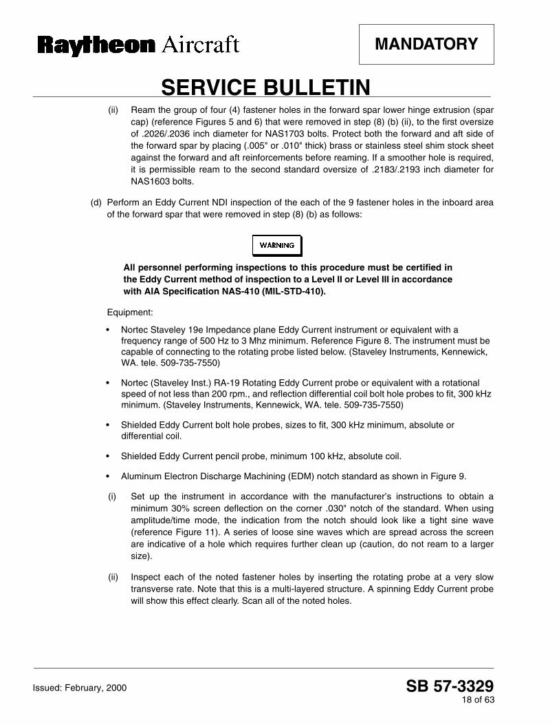
(ii) Ream the group of four (4) fastener holes in the forward spar lower hinge extrusion (sparcap) (reference Figures 5 and 6) that were removed in step (8) (b) (ii), to the first oversizeof .2026/.2036 inch diameter for NAS1703 bolts. Protect both the forward and aft side ofthe forward spar by placing (.005" or .010" thick) brass or stainless steel shim stock sheetagainst the forward and aft reinforcements before reaming. If a smoother hole is required,it is permissible ream to the second standard oversize of .2183/.2193 inch diameter forNAS1603 bolts.
(d) Perform an Eddy Current NDI inspection of the each of the 9 fastener holes in the inboard areaof the forward spar that were removed in step (8) (b) as follows:
All personnel performing inspections to this procedure must be certified inthe Eddy Current method of inspection to a Level II or Level III in accordancewith AIA Specification NAS-410 (MIL-STD-410).
Equipment:
• Nortec Staveley 19e Impedance plane Eddy Current instrument or equivalent with a frequency range of 500 Hz to 3 Mhz minimum. Reference Figure 8. The instrument must be capable of connecting to the rotating probe listed below. (Staveley Instruments, Kennewick, WA. tele. 509-735-7550)
• Nortec (Staveley Inst.) RA-19 Rotating Eddy Current probe or equivalent with a rotational speed of not less than 200 rpm., and reflection differential coil bolt hole probes to fit, 300 kHz minimum. (Staveley Instruments, Kennewick, WA. tele. 509-735-7550)
• Shielded Eddy Current bolt hole probes, sizes to fit, 300 kHz minimum, absolute or differential coil.
• Shielded Eddy Current pencil probe, minimum 100 kHz, absolute coil.
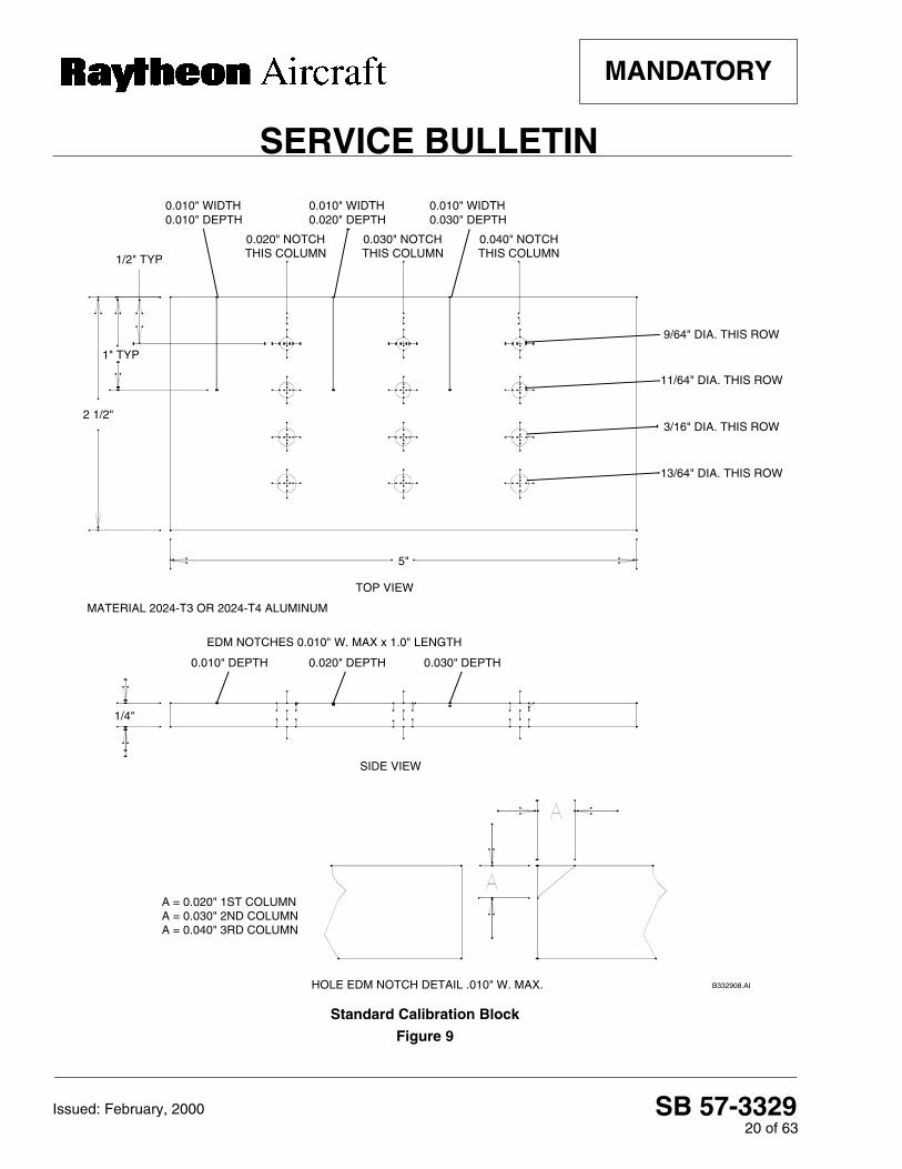
• Aluminum Electron Discharge Machining (EDM) notch standard as shown in Figure 9.
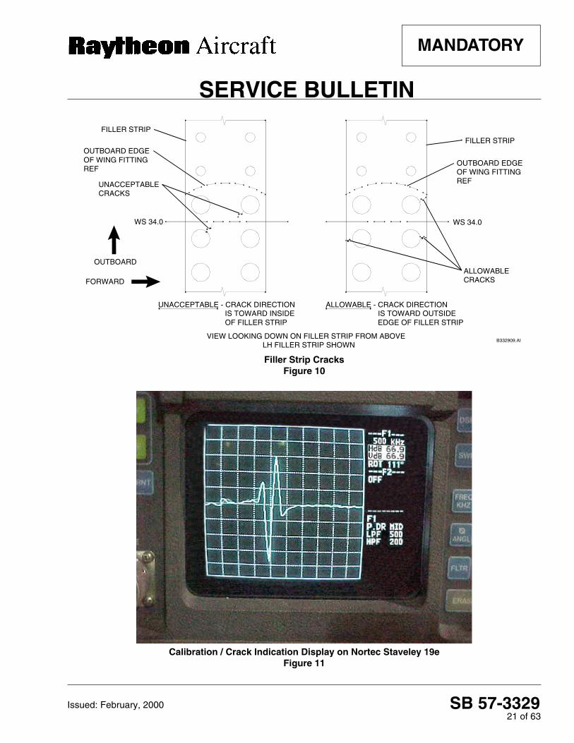
(i) Set up the instrument in accordance with the manufacturer’s instructions to obtain aminimum 30% screen deflection on the corner .030" notch of the standard. When usingamplitude/time mode, the indication from the notch should look like a tight sine wave(reference Figure 11). A series of loose sine waves which are spread across the screenare indicative of a hole which requires further clean up (caution, do not ream to a largersize).
(ii) Inspect each of the noted fastener holes by inserting the rotating probe at a very slowtransverse rate. Note that this is a multi-layered structure. A spinning Eddy Current probewill show this effect clearly. Scan all of the noted holes.

SB 57-332919 of 63
SERVICE BULLETIN
MANDATORY
Issued: February, 2000
Impedance Plane Eddy Current Instrument - Nortec Staveley 19eFigure 8
(iii) A means of clearly determining the depth of the probe coil is essential, in that theacceptance criteria varies at the second layer in some locations.
(iv) If an indication appears, note the location and verify with a manual probe set with a depthstop to the noted location. Note the direction of the crack indication and the part the crackindication was discovered in.
A crack indication in the filler strip may be allowed, but only if the directionof the crack indication is toward the outside edge of the filler strip. If thedirection of the crack indication is toward the inside of the filler strip, thespar assembly must be replaced. Reference Figure 10.
SB 57-332920 of 63
SERVICE BULLETIN
MANDATORY
Issued: February, 2000
Standard Calibration Block
Figure 9
B332908.AI
1/2" TYP
1" TYP
2 1/2"
5"
1/4"
0.020" NOTCH THIS COLUMN
0.030" NOTCH THIS COLUMN
0.040" NOTCH THIS COLUMN
TOP VIEW
9/64" DIA. THIS ROW
11/64" DIA. THIS ROW
3/16" DIA. THIS ROW
13/64" DIA. THIS ROW
SIDE VIEW
MATERIAL 2024-T3 OR 2024-T4 ALUMINUM
EDM NOTCHES 0.010" W. MAX x 1.0" LENGTH
0.010" DEPTH 0.020" DEPTH 0.030" DEPTH
HOLE EDM NOTCH DETAIL .010" W. MAX.
A = 0.020" 1ST COLUMN A = 0.030" 2ND COLUMN A = 0.040" 3RD COLUMN
0.010" WIDTH 0.010" DEPTH
0.010" WIDTH 0.030" DEPTH
0.010" WIDTH 0.020" DEPTH
SB 57-332921 of 63
SERVICE BULLETIN
MANDATORY
Issued: February, 2000
Filler Strip CracksFigure 10
Calibration / Crack Indication Display on Nortec Staveley 19eFigure 11
B332909.AI
OUTBOARD
FORWARD
FILLER STRIP
FILLER STRIPOUTBOARD EDGE OF WING FITTING REF
OUTBOARD EDGE OF WING FITTING REF
WS 34.0 WS 34.0
UNACCEPTABLE CRACKS
UNACCEPTABLE - CRACK DIRECTION IS TOWARD INSIDE OF FILLER STRIP
ALLOWABLE - CRACK DIRECTION IS TOWARD OUTSIDE EDGE OF FILLER STRIP
ALLOWABLE CRACKS
VIEW LOOKING DOWN ON FILLER STRIP FROM ABOVELH FILLER STRIP SHOWN

SB 57-332922 of 63
SERVICE BULLETIN
MANDATORY
Issued: February, 2000
All personnel performing inspections to this procedure must be certified inthe Eddy Current method of inspection to a Level II or Level III in accordancewith AIA Specification NAS-410 (MIL-STD-410).
(e) Eddy Current inspect the lower surface of the forward (main) spar hinge extrusion for the lengthof the spar. Reference Figure 3, Figure 6, Figure 12, Figure 14, and Figure 17 as follows:
Equipment:
• Instrument: Same as used to inspect the inboard area of the forward wing spar in step (8) (d).
• Shielded Eddy Current pencil probe, minimum 100 kHz, absolute coil.
• Aluminum Electron Discharge Machining (EDM) notch standard as shown in Figure 9.
(i) Adjust the instrument using the .030" EDM notch on the flat of the standard. Obtain a
minimum 50% screen deflection.
(ii) On the lower surface of the forward spar from the attach fitting outboard to the end of the
exposed spar (wingtip), scan the exposed surface of the forward and aft edges of the hinge
extrusion adjacent to the hinge attach point with the pencil probe as shown in Figure 12.
Eddy Current Inspection of Forward Spar (Lower Surface)Figure 12
B332911.AI
BOX SECTION LOWER SKIN
LEADING EDGE LOWER SKIN
LEADING EDGE HINGE ANGLE
HINGE EXTRUSION (SPAR CAP)AFT HINGE PIN
FORWARD HINGE PIN
PENCIL PROBE INSPECTION LOCATION AND ORIENTATION
PENCIL PROBE INSPECTION LOCATION AND ORIENTATION
VIEW LOOKING DOWN LENGTH OF LOWER SPAR
FILLER STRIP
FORWARD
UP

SB 57-332923 of 63
SERVICE BULLETIN
MANDATORY
Issued: February, 2000
Do Not use a metal ruler or metallic guide, as the metal will affect the coil inthe Eddy Current probe. Ensure that the spar hinge extrusion is scanned,not the lower skin which overlaps the hinge extrusion.
(iii) A one scan pass on the forward side of the spar lower hinge extrusion adjacent to the
forward lower leading edge skin is required, and one scan pass on the aft edge of the spar
lower hinge extrusion adjacent to the box section lower wing skin as shown in Figure 12 is
required. Use a plastic ruler or other nonmetallic guide to assist in the scan.
(iv) Ensure the scan is continued from the lower wing attach fitting to the end of the exposed
spar (wingtip) along the forward and aft surface of the spar hinge extrusion as shown in
Figure 12.
Any forward (main) spar assemblies or aft (rear) spar assemblies which areto be installed as replacement parts must be Eddy Current Inspected andinspected for corrosion in accordance with the instructions in Part I of thisService Bulletin, prior to installation.
(f) If a crack is found during the Eddy Current Inspection of the forward spar as outlined in step (d)and step (e), the entire forward (main) spar assembly must be replaced BEFORE FURTHERFLIGHT.
(9) Inspect three (3) MLG trunnion fitting fastener locations as follows:
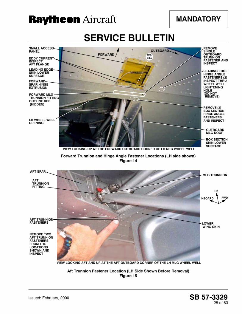
(a) Locate the MLG trunnion fittings in the wheel well area, reference Figures 3, 13, 14 and 15. Theforward trunnion fitting is attached to the aft side of the forward (main) spar and the aft trunnionfitting is attached to the forward side of the aft (rear) spar near W.S. 63.0.
Identify the single (1) outboard fastener located in the lower flange of the forward MLG trunnionfitting. The forward trunnion fastener is installed in the forward spar hinge extrusion, aft "J"channel horizontal flange ("J" angle on the forward spar) and lower flange of the forward MLGtrunnion fitting. This fastener is located in the fastener position closest to the outboard end of thelower flange on the forward MLG trunnion fitting. Reference Figure 14.
Identify the two (2) outboard fasteners in the lower flange of the aft MLG trunnion fitting. The twoaft trunnion fasteners are installed in the aft spar lower element (capstrip), forward "L" anglehorizontal flange ("L" angle of the aft spar) and lower flange of the MLG trunnion fitting. Thesetwo (2) fasteners are located in the fastener positions which are closest to the outboard end ofthe lower flange on the aft MLG trunnion fitting. Reference Figure 15 and Figure 16.

SB 57-332924 of 63
SERVICE BULLETIN
MANDATORY
Issued: February, 2000
(b) Remove the three (3) fasteners identified in step (9) (a). Drill the head of each trunnion fastenerfrom the underside of the wing and push out the shanks.
(c) Ream the three (3) fastener holes which were exposed in step (9) (b) to .1400/.1410 inchdiameter with a hand reamer. Clean the enlarged holes with Naphtha.
(d) Eddy Current Inspect the trunnion fitting fastener hole in the forward (main) spar lower hingeextrusion (spar cap) and aft "J" channel ("J" angle). Eddy Current Inspect the trunnion fittingfastener holes in the aft (rear) spar capstrip and "L" angle on the forward side of the aft spar.Conduct the Eddy Current Inspections in accordance with step (8) (d).
Any forward (main) spar assemblies or aft (rear) spar assemblies which areto be installed as replacement parts must be Eddy Current Inspected andinspected for corrosion in accordance with the instructions in Part I of thisService Bulletin, prior to installation.
(e) If a crack is found during the Eddy Current Inspection as outlined in step (9) (d), the entirecorresponding forward (main) spar assembly or aft (rear) spar assembly must be replacedBEFORE FURTHER FLIGHT.
Aft MLG Trunnion Location (LH Side Shown)Figure 13
AFTMLG TRUNNION
LOWER WINGSKIN
MLG STRUT
VIEW LOOKING AFT INTO MLG WHEEL WELL
LH SIDE SHOWN
FORWARDSIDE OF AFTSPAR
OUTBOARDMLG DOOR
FITTING
VIEW LOOKING AFT AT THE AFT SPAR
UP OUTBOARD
SB 57-332925 of 63
SERVICE BULLETIN
MANDATORY
Issued: February, 2000
Forward Trunnion and Hinge Angle Fastener Locations (LH side shown)Figure 14
Aft Trunnion Fastener Location (LH Side Shown Before Removal)Figure 15
SMALL ACCESS PANEL
EDDY CURRENT
FORWARD SPAR HINGE
OUTBOARD MLG DOOR
OUTBOARD TRUNNIONFASTENER ANDINSPECT
VIEW LOOKING UP AT THE FORWARD OUTBOARD CORNER OF LH MLG WHEEL WELL
LH WHEEL WELL OPENING
BOX SECTION
SURFACE
TRUNNION FITTING OUTLINE REF.
REMOVE (2)
HINGE ANGLE
AND INSPECTFASTENERS
BOX SECTION
LEADING EDGEHINGE ANGLE FASTENERS (2)INSPECT THRU WHEEL WELL LIGHTENING HOLE
SKIN LOWER
LEADING EDGE SKIN LOWER SURFACE
(HIDDEN)
EXTRUSION
FORWARDOUTBOARD
INSPECTAFT FLANGE
REMOVE
WS 63.0
(DO NOT REMOVE)FORWARD MLG
SINGLE
AFT TRUNNION FITTING
FASTENERS
REMOVE TWO AFT TRUNNION FASTENERS FROM THE LOCATIONS
MLG TRUNNION
FWD
UP
AFT SPAR
LOWER WING SKIN
VIEW LOOKING AFT AND UP AT THE AFT OUTBOARD CORNER OF THE LH MLG WHEEL WELL
AFT TRUNNION
INBOARD
SHOWN AND INSPECT

SB 57-332926 of 63
SERVICE BULLETIN
MANDATORY
Issued: February, 2000
Aft Trunnion Fastener Location (LH Side Shown During Removal)Figure 16
Leading Edge Hinge Angle and Fuel Cell Access PanelFigure 17
OUTBOARDMLG DOOR
AFT TRUNNIONFASTENER/HOLE
OUTBOARD
FORWARD
INBOARD
AFT
WHEEL WELLOPENING
AFT SPAR CENTER LINE
VIEW LOOKING UP AT THE AFT OUTBOARD CORNER OF THE WHEEL WELL FROM BELOW
INSPECT THESE TWO LOCATIONS(OUTBOARD FASTENER SHOWN REMOVED)
OUTBOARD
FORWARD
WHEEL WELL OPENING
ACCESS PANELOPENING
LH LEADING
EDDY CURRENT INSPECT
LEADING EDGE HINGE ANGLE
FUSELAGE
INBOARD
AFT FLANGE SURFACE
EDGE
FUEL CELL
MLG DOOR
VIEW LOOKING UP AND AFT AT THE LOWER SURFACE OF THE LH WING
EDDY CURRENTINSPECTLOWER HINGEEXTRUSION SURFACE

SB 57-332927 of 63
SERVICE BULLETIN
MANDATORY
Issued: February, 2000
(10) Inspect the leading edge lower hinge angle and the box section lower forward hinge angle as follows:
(a) Locate two (2) fasteners in the box section lower forward hinge angle.
The fasteners are installed in the box section lower forward hinge angle. They are locatedadjacent to the forward outboard corner of the MLG wheel well opening. They are the first andsecond fasteners as counted from the corner, immediately outboard of the corner on the aft sideof the lower forward spar hinge extrusion (spar cap). Reference Figure 14.
(b) Remove the two (2) fasteners identified in step (10) (a). The fastener shanks are orientedvertically and attach the wing skin to the box section hinge angle. Drill the heads and push outthe shanks.
(c) Using a hand reamer, enlarge the fastener holes identified in (10) (a) and (10) (b) as follows:
(i) Ream the two (2) box section hinge angle fastener holes (reference Figure 14) with a hand
reamer to .1400/.1410 inch diameter.
(ii) Clean the enlarged holes with Naphtha.
(d) Perform an Eddy Current NDI inspection of the fastener holes reamed in step (10) (c).
(i) Conduct the Eddy Current Inspections in accordance with the instructions in step (8) (d).
(ii) Scan the holes and note any crack indications. Verify all indications with a standard bolt
hole probe set to the precise depth of the hinge angle.
(e) Perform an Eddy Current NDI inspection of a section of the leading edge lower hinge angle (onthe outboard side of the small access panel). Locate the two (2) leading edge hinge anglefasteners which attach the leading edge lower hinge angle to the skin on the leading edge.These fasteners are located on the outboard side of the small access panel which is used toservice the MLG trunnion. The two (2) fasteners can be accessed through a wheel welllightening hole. Reference Figure 14.
These two (2) fasteners will not be removed. The upper surface of the area adjacent to thefasteners will be inspected from inside the leading edge. Eddy Current Inspect the leading edgelower hinge angle near upper side of the two (2) fasteners as follows:
All personnel performing inspections to this procedure must be certified inthe Eddy Current method of inspection to a Level II or Level III in accordancewith AIA Specification NAS-410 (MIL-STD-410).

SB 57-332928 of 63
SERVICE BULLETIN
MANDATORY
Issued: February, 2000
Equipment:
• Instrument: Same as used in the inboard forward wing spar and trunnion fitting inspections.
• Eddy Current pencil probe, straight or 90°, maximum 1/2" drop (on 90° only), minimum 100 kHz, absolute coil.
• Aluminum Electron Discharge Machining (EDM) notch standard as shown in Figure 9.
(i) Gain access to the two (2) fasteners through the lower forward lightening hole in theoutboard rib of the MLG wheel well compartment. Remove the six (6) screws that retainthe oval access panel to the outboard side of the wheel well and remove the oval accesspanel to expose the upper and lower lightening holes. Reference Figure 18 and reachforward until the aft side of the fuel cell cavity is felt. Find the flange that is attached to theaft side of the fuel cell cavity. Feel below the flange to locate the two (2) fasteners directlybelow the flange at the bottom of the opening.
(ii) Locate the leading edge lower hinge angle which is immediately aft of the two (2)fasteners. Reference the cut away T-34 spar and leading edge structure shown inFigure 18 and Figure 19.
NOTE
The following Figures 18 through 26 show sections of the right hand wing (asopposed to all other figures which show the left hand wing). All other figures in thisService Bulletin depict the left hand wing.
Cutaway View of Lower Forward Spar and Leading Edge Structure (RH Wing Shown)Figure 18
UPPER LIGHTENING HOLE
OUTBOARD RIB (OUTBOARD SIDE SHOWN)
LOWER LIGHTENING HOLE
LEADING EDGE SECTION (LOWER SKIN)View Looking Inboard
WING BOX SECTION (REF)
90° PENCIL PROBE
BOX SECTION
FORWARD SPAR
INNER RADIUS OF LEADING EDGE
COIL ON PENCIL PROBE
UP
FORWARD
INBOARD
FUEL CELL CAVITY
TWO (2) FASTENERS
HINGE ANGLE
LEADING EDGE HINGE ANGLE
FLANGE
HINGE ANGLE

SB 57-332929 of 63
SERVICE BULLETIN
MANDATORY
Issued: February, 2000
Scanning the Leading Edge Lower Hinge Angle (RH Wing Shown)
Figure 19
(iii) Adjust the instrument using the 0.030" EDM notch on the flat of the standard. Obtain a
minimum 50% screen deflection.
(iv) Scan the inside radius of the leading edge hinge angle with the pencil probe. Reach in the
lightening hole with the pencil probe and turn the probe back towards the inboard side.
Place the coil of the probe on the inner radius of the hinge angle (on the forward side of the
hinge angle, reference step (ii) and Figure 19) and scan the hinge angle. Scan along the
hinge angle starting 1/2" inboard from the inboard side of the inboard fastener continuing
to 1/2" outboard from the outboard side of the outboard fastener.
(v) Note any crack indications.
(f) Perform an Eddy Current NDI inspection of two (2) of the leading edge hinge angle surfaces.The first area to be scanned is located on the leading edge lower hinge angle adjacent to thesmall square access panel opening (fuel vent access door/trunnion access door) near the MLGtrunnion, reference the aft flange in Figure 14. The second area to be scanned is adjacent to theaft side of the fuel cell access panel opening (reference aft flange surface in Figure 17).
FORWARD
LOWER LIGHTENING HOLE
TWO (2) FASTENERS
LEADING EDGE SECTION(LOWER SKIN)
COIL ON PENCIL PROBE
View Looking Inboard
FLANGE
AFT SIDE OFFUEL CELL CAVITY
90° PENCIL PROBE
INNER RADIUS OF LEADING EDGE
BOX SECTION HINGE ANGLE
FORWARD "J" CHANNEL FORWARD SPAR
AFT "J" CHANNEL FORWARD SPAR
LEADING EDGEBOX SECTION
OUTBOARD RIB (OUTBOARD SIDE SHOWN)
UP
HINGE ANGLE

SB 57-332930 of 63
SERVICE BULLETIN
MANDATORY
Issued: February, 2000
All personnel performing inspections to this procedure must be certified inthe Eddy Current method of inspection to a Level II or Level III in accordancewith AIA Specification NAS-410 (MIL-STD-410).
(i) Remove the small access panel (square) shown in Figure 14. The small access panel is
located 38" to 42" outboard of lower wing fitting, adjacent to the forward spar hinge
extrusion (spar cap).
(ii) Use the same instrument and equipment as used in the inboard forward wing spar and
trunnion fitting inspections. Adjust the instrument using the 0.030" EDM notch on the flat of
the standard. Obtain a minimum 50% screen deflection.
(iii) Using a straight or 90° pencil probe, scan the entire length of the exposed face of the
leading edge lower hinge angle along the aft side of the small access panel opening. The
small access panel is located 38" to 42" outboard of the lower wing fitting, adjacent to the
forward spar hinge extrusion (spar cap). Reference Figure 14.
(iv) Using a straight or 90° pencil probe, scan the entire length of the exposed face of the hinge
angle along the aft side of the fuel cell access panel opening. The fuel cell access panel is
located 17" to 25" outboard of the lower wing fitting, adjacent to the lower hinge extrusion
on the forward spar (spar cap). Reference Figure 17.
(v) Visually inspect the lower wing skin adjacent to the area Eddy Current Inspected in step
(10) (f) (iv). Look closely at the area next to the fuel cell access panel aft flange surface for
cracks or distortions in the paint. Reference Figure 17. If distortions are found, remove the
paint for a closer inspection. Visually check for cracks in the lower wing skin and leading
edge lower hinge angle.
Any replacement leading edge or box section hinge angle assemblies whichare to be installed as replacement parts must be Eddy Current Inspectedand inspected for corrosion in accordance with the instructions in Part I ofthis Service Bulletin, prior to installation.
SB 57-332931 of 63
SERVICE BULLETIN
MANDATORY
Issued: February, 2000
(g) If a crack is found during the Eddy Current Inspection in any of the fastener holes inspected ineither step (10) (d), the hinge radius inspected in step (10) (e) or the lower skin and hinge anglesurface inspections in step (10) (f) the corresponding hinge angle assembly(ies) must bereplaced BEFORE FURTHER FLIGHT.
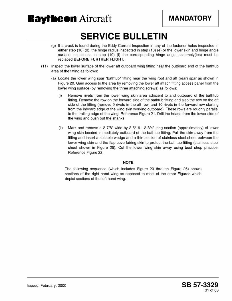
(11) Inspect the lower surface of the lower aft outboard wing fitting near the outboard end of the bathtubarea of the fitting as follows:
(a) Locate the lower wing spar "bathtub" fitting near the wing root and aft (rear) spar as shown inFigure 20. Gain access to the area by removing the lower aft attach fitting access panel from thelower wing surface (by removing the three attaching screws) as follows:
(i) Remove rivets from the lower wing skin area adjacent to and outboard of the bathtubfitting. Remove the row on the forward side of the bathtub fitting and also the row on the aftside of the fitting (remove 9 rivets in the aft row, and 10 rivets in the forward row startingfrom the inboard edge of the wing skin working outboard). These rows are roughly parallelto the trailing edge of the wing. Reference Figure 21. Drill the heads from the lower side ofthe wing and push out the shanks.
(ii) Mark and remove a 2 7/8" wide by 2 5/16 - 2 3/4" long section (approximately) of lowerwing skin located immediately outboard of the bathtub fitting. Pull the skin away from thefitting and insert a suitable wedge and a thin section of stainless steel sheet between thelower wing skin and the flap cove fairing skin to protect the bathtub fitting (stainless steelsheet shown in Figure 25). Cut the lower wing skin away using best shop practice.Reference Figure 22.
NOTE
The following sequence (which includes Figure 20 through Figure 26) showssections of the right hand wing as opposed to most of the other Figures whichdepict sections of the left hand wing.

SB 57-332932 of 63
SERVICE BULLETIN
MANDATORY
Issued: February, 2000
Lower Aft "Bathtub" Wing FittingFigure 20
Lower Wing Skin Fastener RemovalFigure 21
WING SKINSURFACE
LOWER AFT "BATHTUB" FITTING
INSPECTION AREA IS ABOVE THE SKIN IN
THE SKIN IN THIS AREA WILL BE REMOVED
FORWARD
AFT
INBOARD
OUTBOARD
THIS AREA
INBOARD EDGE
TRAILING EDGE REF.
NOTE: WING SHOWN REMOVED
(LOWER WING SKIN) FORWARD ROW OF RIVETS
AFT ROW OF RIVETS
VIEW OF THE LOWER SURFACE OF THE RH WING LOOKING UP FROM BELOW
FORWARD
AFT
INBOARD
OUTBOARD
VIEW OF THE LOWER SURFACE OF THE RH WING LOOKING UP FROM BELOW
FORWARD
INBOARD
AFT
OUTBOARD
AFT ROW OF RIVETS REMOVE 9 RIVETS STEP (11) (a) (i)
INBOARD EDGE
LOWER AFT
TRAILING EDGE REF.
NOTE: WING SHOWN REMOVED
WING SKIN SURFACE (LOWER WING SKIN)
FORWARD ROW OF
"BATHTUB" FITTING
STEP (11) (a) (i) REMOVE 10 RIVETSRIVETS

SB 57-332933 of 63
SERVICE BULLETIN
MANDATORY
Issued: February, 2000
(iii) Mark and remove a rectangular section of flap cove fairing skin. The section of flap covefairing skin is located next to the outboard side of the bathtub fitting as shown in Figure 23.Note that part of the section of flap cove fairing skin to be removed is not visible because itis installed between the lower wing skin and the lower spar structure.
• Mark the area to be removed, reference the dashed white cut-out marks shown in Figure 23. Three sides will be marked; the aft side, the outboard side and a short section of the inboard side. Note that the removal area extends forward to the forward edge of the flap cove fairing skin.
• Before cutting, pull the flap cove fairing skin away from the spar structure and place a protective stainless steel sheet between the flap cove fairing skin and the aft spar structure lower element (capstrip) (stainless steel sheet not shown in Figure 23).
• Pull the lower wing skin away from flap cove fairing skin and cut the flap cove skin using best shop practice.
• Cut the aft side of the of the flap cove fairing skin along the dashed white cut-out line shown in Figure 23.
• Cut the short section of the flap cove fairing skin on the inboard side along the dashed white cut-out line shown in Figure 23.
• Cut the outboard side along the dashed white line shown in Figure 23. It may be necessary to cut the forward portion of the outboard side from an opening in the wheel well.
• Remove the rectangular section of flap cove fairing skin. The removed section should measure approximately 2 1/4" wide by 3 1/4" long. The aft spar structure will be exposed after the flap cove skin section is removed (reference Figure 24).
(iv) Mark and remove a 1/8" section from the inboard end of the aft spar structure lowerelement (capstrip). The aft spar structure lower element (capstrip) is installed in a "notch"or "step" in the bathtub fitting. Remove six (6) AD6 fasteners from the inboard side of theaft spar structure lower element (capstrip) which retain the aft spar structure lower element(capstrip) to the bathtub fitting. Drill the heads from lower side of the wing and carefullypush out the shanks. Pull the aft spar lower element (capstrip) away from the fitting andreposition the wedge and protective stainless steel sheet between the aft spar lowerelement (capstrip) and the fitting. Remove 1/8" (.125 inch) of material from the inboardedge of the lower aft spar lower element (capstrip) per best shop practice. ReferenceFigure 25 and Figure 26. Radius the inboard edge of the spar structure lower element(capstrip) as shown in Figure 27 so the Eddy Current pencil probe can be held at 45° tothe fitting. Remove the stainless steel sheet and wedge.

SB 57-332934 of 63
SERVICE BULLETIN
MANDATORY
Issued: February, 2000
Lower Wing Skin Marking and RemovalFigure 22
Flap Cove Skin Marking and Removal
Figure 23
AFT NOTE: WING SHOWN REMOVED
VIEW OF THE LOWER SURFACE OF THE RH WING LOOKING UP FROM BELOW
FORWARD
INBOARD
OUTBOARD
FLAP COVE FAIRING SKIN
CUT OUT MARK
WING SKIN SURFACE (LOWER WING SKIN)
CUT OUT MARK
MAINTAIN 1/4" TO 1/2" RADIUS ON ALL CORNERS
CUT OUT MARKS
THE CUT OUT AREA IS BEHINDTHE LOWER WING SKIN IN THISAREA.
WEDGE
FLAP COVE FAIRING SKIN
WING SKINSURFACE(LOWER WING SKIN)
VIEW OF THE LOWER SURFACE OF THE RH WING LOOKING UP FROM BELOW
FLAP COVE FAIRING SKIN
WING SKINSURFACE(LOWER WING SKIN)
AFT
OUTBOARD INBOARD
NOTE: WING SHOWN REMOVED
FORWARD EDGE OF FLAP COVEFARING SKIN
(CUT FLAP COVEFAIRING SKIN ATWHITE LINES)
CUT OUT AREA
INBOARD EDGE OFFLAP COVE FAIRINGSKIN (HIDDEN)
EXISTING
(HIDDEN BY LOWER
CUT *
CUT *
CUT *
WING SKIN)
AFT EDGE OF LOWER WING SKIN
Outboard Side
Aft Side Inboard Side (short section)
**
* CUT FLAP COVE FAIRING SKIN ONLY
** ACCESS THIS SECTION OF THE CUTTHROUGH THE WHEEL WELL
FLAP COVE FAIRING SKIN AFT
OUTBOARD INBOARD
FORWARD
CUT *
CUT *
CUT *
Outboard Side
Aft Side Inboard
* CUT FLAP COVE FAIRING SKIN ONLY
THROUGH THE WHEEL WELL
(USE TO INSERTSTAINLESS STEELSHEET)
MAINTAIN 1/4" TO1/2" RADIUS ON ALL CORNERS

SB 57-332935 of 63
SERVICE BULLETIN
MANDATORY
Issued: February, 2000
Flap Cove Skin Shown RemovedFigure 24
Aft Spar Structure Lower Element (Capstrip) ModificationFigure 25

SB 57-332936 of 63
SERVICE BULLETIN
MANDATORY
Issued: February, 2000
(b) Conduct an Eddy Current Inspection of the lower surface of the bathtub fitting. Locate and gainaccess to the area by removing the wing lower aft attach fitting access cover from the lower wingsurface (by removing the three attaching screws) located near the wing root and aft (rear) spar.The inspection area is along the visible outboard edge of the fitting (clean the fitting withNaphtha before inspecting). Conduct the inspection as shown in Figure 26 and Figure 27 asfollows:
All personnel performing inspections to this procedure must be certified inthe Eddy Current method of inspection to a Level II or Level III in accordancewith AIA Specification NAS-410 (MIL-STD-410).
Equipment:
• Instrument: Same as used in the inboard forward wing spar and trunnion fitting inspections.
• Shielded Eddy Current pencil probe, minimum 100 kHz, absolute coil.
• Eddy Current 90° pencil probe, maximum 1/2" drop, minimum 100 kHz, absolute coil.
• Aluminum Electron Discharge Machining (EDM) notch standard as shown in Figure 9.
(i) Adjust the instrument using the .030 EDM notch by moving the probe from the solid area
onto the notched area from the end (i.e. parallel to the notch). This will simulate the signal
expected for a crack in the fitting. The signal will not give a distinctive bump on the screen,
rather it should move from one area to another and stay there while the probe is moved
along the top of the notch.
(ii) Adjust for a minimum 50% screen deflection. This scanning motion is necessary due to theconfiguration of the part.
(iii) The scan will be parallel to the expected crack direction, so care should be taken whileperforming the inspection. Scan along the entire length of the step in the fitting.
(iv) Scan the fitting along the edge of the depression. Scan several times with the probe atapproximately 45° from the surface of the fitting. Reference Figure 27.
Any forward (main) spar assemblies or aft (rear) spar assemblies which areto be installed as replacement parts must be Eddy Current Inspected andinspected for corrosion in accordance with the instructions in Part I of thisService Bulletin, prior to installation.
(c) If crack is found during the Eddy Current Inspection of the lower surface of the bathtub fittingnear the outboard edge as outlined in step (b), the entire aft (rear) spar assembly must bereplaced BEFORE FURTHER FLIGHT.

SB 57-332937 of 63
SERVICE BULLETIN
MANDATORY
Issued: February, 2000
Aft Spar Structure Lower Element (Capstrip) - After Modification
Figure 26
SB 57-332938 of 63
SERVICE BULLETIN
MANDATORY
Issued: February, 2000
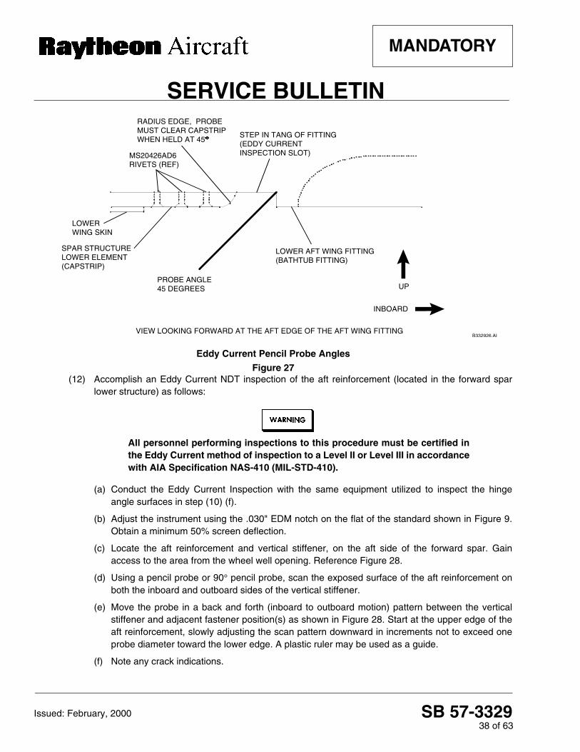
Eddy Current Pencil Probe Angles
Figure 27(12) Accomplish an Eddy Current NDT inspection of the aft reinforcement (located in the forward spar
lower structure) as follows:
All personnel performing inspections to this procedure must be certified inthe Eddy Current method of inspection to a Level II or Level III in accordancewith AIA Specification NAS-410 (MIL-STD-410).
(a) Conduct the Eddy Current Inspection with the same equipment utilized to inspect the hingeangle surfaces in step (10) (f).
(b) Adjust the instrument using the .030" EDM notch on the flat of the standard shown in Figure 9.Obtain a minimum 50% screen deflection.
(c) Locate the aft reinforcement and vertical stiffener, on the aft side of the forward spar. Gainaccess to the area from the wheel well opening. Reference Figure 28.
(d) Using a pencil probe or 90° pencil probe, scan the exposed surface of the aft reinforcement onboth the inboard and outboard sides of the vertical stiffener.
(e) Move the probe in a back and forth (inboard to outboard motion) pattern between the verticalstiffener and adjacent fastener position(s) as shown in Figure 28. Start at the upper edge of theaft reinforcement, slowly adjusting the scan pattern downward in increments not to exceed oneprobe diameter toward the lower edge. A plastic ruler may be used as a guide.
(f) Note any crack indications.
B332926.AI
LOWER AFT WING FITTING (BATHTUB FITTING)
STEP IN TANG OF FITTING (EDDY CURRENT INSPECTION SLOT)
LOWER WING SKIN
PROBE ANGLE 45 DEGREES
SPAR STRUCTURE LOWER ELEMENT (CAPSTRIP)
MS20426AD6 RIVETS (REF)
INBOARD
UP
VIEW LOOKING FORWARD AT THE AFT EDGE OF THE AFT WING FITTING
RADIUS EDGE, PROBE MUST CLEAR CAPSTRIP WHEN HELD AT 45
SB 57-332939 of 63
SERVICE BULLETIN
MANDATORY
Issued: February, 2000
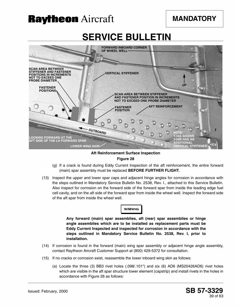
Aft Reinforcement Surface Inspection
Figure 28
(g) If a crack is found during Eddy Current Inspection of the aft reinforcement, the entire forward(main) spar assembly must be replaced BEFORE FURTHER FLIGHT.
(13) Inspect the upper and lower spar caps and adjacent hinge angles for corrosion in accordance withthe steps outlined in Mandatory Service Bulletin No. 2538, Rev. I., attached to this Service Bulletin.Also inspect for corrosion on the forward side of the forward spar from inside the leading edge fuelcell cavity, and on the aft side of the forward spar from inside the wheel well. Inspect the forward sideof the aft spar from inside the wheel well.
Any forward (main) spar assemblies, aft (rear) spar assemblies or hingeangle assemblies which are to be installed as replacement parts must beEddy Current Inspected and inspected for corrosion in accordance with thesteps outlined in Mandatory Service Bulletin No. 2538, Rev. I, prior toinstallation.
(14) If corrosion is found in the forward (main) wing spar assembly or adjacent hinge angle assembly,contact Raytheon Aircraft Customer Support at (800) 429-5372 for consultation.
(15) If no cracks or corrosion exist, reassemble the lower inboard wing skin as follows:
(a) Locate the three (3) BB3 rivet holes (.098/.101") and six (6) AD6 (MS20426AD6) rivet holeswhich are visible in the aft spar structure lower element (capstrip) and install rivets in the holes inaccordance with Figure 26 as follows:
VERTICAL STIFFENER
SCAN AREA BETWEEN STIFFENER AND FASTENER POSITION IN INCREMENTS
SCAN AREA BETWEEN
AFT REINFORCEMENT
FASTENER
FASTENER
FORWARD INBOARD CORNER OF WHEEL WELL
LOOKING FORWARD AT THE AFT SIDE OF THE LH FORWARD SPAR
LOWER WING SKIN
POSITIONS
POSITION
STIFFENER AND FASTENER
OUTBOARD
UP
NOT TO EXCEED ONE PROBE DIAMETER
T-34A SHOWNT-34B HAS AN ADDITIONAL VERTICAL STIFFENER
NOTE:
PROBE DIAMETER
POSITIONS IN INCREMENTS NOT TO EXCEED ONE
SB 57-332940 of 63
SERVICE BULLETIN
MANDATORY
Issued: February, 2000
(i) Countersink the three (3) BB3 rivet holes (.098/.101") located near the aft end of the aftspar structure lower element (capstrip).
Clean any bare aluminum surfaces with Naphtha and coat with Alodine 1200,1200S or 1201 (MIL-C-5541, CLASS 1A). Allow the coating to dwell forapproximately five minutes. After the time has elapsed, wash the coated areaswith water and blow dry (do not wipe). Paint the coated areas with epoxypolyamide primer and allow sufficient time for drying. Apply finish paint to matchthe airplane paint scheme, as desired.
(ii) Install an MS20426AD3 rivet in each of the three (3) rivet holes. Refer to Figure 26.
(iii) Install an MS20426AD6 rivet in each of the six (6) rivet holes to replace those removed instep (11) (a) (iv). Refer to Figure 26.
(b) Fabricate a doubler plate from .040 inch thick alclad 2024-T3 aluminum sheet as follows. Referto Figure 26:
NOTE
Ensure the template follows the contour of the dotted line at the inboard end of thespar structure lower element (capstrip) as shown in Figure 26. The contour of thedoubler in this area will permit access to the wing bolt and the Eddy CurrentInspection area.
(i) Construct a paper template to match the doubler template outline shown in Figure 26.
(ii) Cut out the doubler plate using the paper template as an outline.
NOTE
The doubler will cover the six (6) MS20426AD6 rivets and three (3) MS20426AD3rivets which attach the lower element to the wing fitting.
Do not drill any holes through the spar structure.
(iii) Using best shop practice (use a holefinder or comparable method) mark and drill the
doubler plate to match the location of all corresponding fasteners which were removed in
step (11) (a), with the exception of the three BB3 rivet locations and six (6) MS20426AD6
rivet locations referenced in step (15) (a). Maintain a minimum .25 inch edge distance
around all fastener holes. Reference Figure 26.

SB 57-332941 of 63
SERVICE BULLETIN
MANDATORY
Issued: February, 2000
(iv) Mark and drill the aft side of doubler plate and flap cove fairing skin for MS20470AD4rivets at the five (5) new locations shown in Figure 26. Maintain a .25 inch edge distanceand .75 - 1.00 pitch on the new MS20470AD4 rivet locations.
(c) Deburr all holes and smooth all edges on the doubler plate. Finish all bare surfaces inaccordance with the CAUTION which precedes step (15) (a) (ii).
(d) Install the doubler plate on the lower wing skin and flap cove fairing skin. Install the same sizerivets as removed. Install Cherry Lock or Monel Cherry Max fasteners wet with primer only ifconventional rivets can not be installed.
(16) Fabricate nutplate mounting plates for the forward (main) spar as follows:
(a) Fabricate an aluminum nutplate mounting plate for the forward side of the forward reinforcementon the front spar (main spar) from .020 inch thick ALCLAD 2024-T3 aluminum sheet inaccordance with Figure 29 as follows:
(i) Cut out a mounting plate with the approximate shape and dimensions shown in Figure 29.It may be necessary to cut reliefs in the lower side of the mounting plate to allow clearancefor the NAS2903 bolts which will be installed in step (17) (f). It may also be necessary tocut reliefs in the inboard side of the mounting plate to provide clearance for existingfasteners. Ensure that an edge distance of .30 inch is maintained for the NAS2903 boltholes and an edge distance of .15 inch is maintained for the NAS1097AD3 rivet holes.
(ii) Place the mounting plate on the forward side of the forward reinforcement on the front sparat the location where 5 fasteners were removed in step (8) (b) (i). Ensure the mountingplate fits flush against the forward reinforcement on the spar. Reference Figure 30.
(iii) Center the mounting plate over the 5 fastener holes and mark the fastener hole locationson the mounting plate.
Nutplate Mounting Plate Fabrication (forward reinforcement)Figure 29
B332928.AI
PICK UP HOLE LOCATION FROM SPAR ASSEMBLY DRILL .2026/.2036" DIA.* HOLE IN PLATE MS21069L3 OR MS21075L3 NUTPLATE 2 PLACES NAS1097AD3 RIVET 4 PLACES
PICK UP HOLE LOCATION FROM SPAR ASSEMBLY DRILL .2026/.2036" DIA.* HOLE IN PLATE MS21071L3 NUTPLATE 3 PLACES NAS1097AD3 RIVET 6 PLACES
MS21069L3 OR MS21075L3 NUTPLATE
1.96"
1.38"
.40"
2.93"
LH MOUNTING PLATE SHOWN RH OPPOSITE
PLATE M/F .020" 2024-T3 ALCLAD
CUT RELIEFS IN PLATE TO ACCOMMODATE NAS1703 BOLTS
NOTE: 1. * IF LARGER FASTENERS ARE REQUIRED, USE THE SECOND STANDARD OVERSIZE OF .2183/.2193" FOR NAS3003 BOLTS 2. CUT RELIEFS AS SHOWN 3. MAINTAIN EDGE DISTANCE OF .30" FOR BOLT HOLES 4. MAINTAIN EDGE DISTANCE OF .15" FOR RIVET HOLES 5. SMOOTH ALL EDGES AND DEBURR ALL HOLES

SB 57-332942 of 63
SERVICE BULLETIN
MANDATORY
Issued: February, 2000
Nutplate Mounting Plate LocationFigure 30
Move mounting plate away from the spar. Do not drill the spar. Do not use theholes in the spar as a drill guide.
(iv) Move the mounting plate away from the spar. Drill .2026/.2036 inch diameter holes in themounting plate at the fastener positions marked in step (16) (a) (iii). If larger fasteners arerequired, use the second standard oversize of .2183/.2193 inch for NAS3003 bolts.
(v) Prepare the surfaces of the nutplate mounting plate by coating them with alodine andepoxy polyamide primer in accordance with the CAUTION which precedes step (15) (a)(ii). Apply the alodine and epoxy polyamide primer (before installing the nutplates) afterdrilling and countersinking the holes used to install the NAS1097AD3 rivets in steps (16)(a) (vi), (vii) and (viii).
(vi) Install MS21071L3 nutplates on the mounting plate to match the 2 upper holes in themounting plate as shown in Figure 29. Countersink the rivet holes in the mounting plate onthe side opposite the nutplates. Secure the nutplates with NAS1097AD3 rivets, install theflush head of the rivets on the side opposite the nutplates.
(vii) Install a MS21071L3 nutplate on the mounting plate to match the middle hole in the lowerrow of holes as shown in Figure 29. Countersink the rivet holes in the mounting plate onthe side opposite the nutplates. Secure the nutplates with NAS1097AD3 rivets, install theflush head of the rivets on the side opposite the nutplates.
B332929.AI
INCREASE EXISTING HOLE SIZE IN SPAR ASSEMBLY TO .2026/.2036" DIA.* 5 PLACES NAS2903-X BOLT 5 PLACES X = GRIP TO BE DETERMINED AT INSTALLATION
VIEW LOOKING AFT AT LH FORWARD SPAR
BJ 5
OUTBD
UP
.40"WING
STATION 33.381 REF
FORWARD REINFORCEMENT (ON FORWARD SIDE OF FRONT SPAR)
RIVET
NOTE: * IF LARGER FASTENERS ARE REQUIRED, USE THE SECOND STANDARD OVERSIZE OF .2183/.2193" FOR NAS3003 BOLTS.

SB 57-332943 of 63
SERVICE BULLETIN
MANDATORY
Issued: February, 2000
(viii) Install MS 21069L3 or MS21075L3 nutplates in the mounting plate to match the 2
remaining lower holes in the mounting plate as shown in Figure 29. Countersink the rivet
holes in the mounting plate on the side opposite the nutplates. Secure the nutplates with
NAS1097AD3 rivets, install the flush head of the rivets on the side opposite the nutplates.
(b) Fabricate two aluminum nutplate mounting plates for the 4 fasteners removed from the forward(main) spar lower hinge extrusion (spar cap) identified in step (8) (b) (ii) in accordance withFigure 31 as follows:
(i) Cut out two rectangular sections (mounting plates) of .020 inch thick ALCLAD 2024-T3aluminum sheet that measure approximately .32 inch x 1.64 inch.
NOTE
One of the mounting plates will be installed on the upper surface of the horizontalflange of the forward "J" channel, on the forward side of the forward spar web. Theother mounting plate will be installed on the upper surface of the horizontal flangeof the aft "J" channel, on the aft side of the spar web.
(ii) Place one of the mounting plates on the horizontal flange of the forward "J" channel at the
location that 2 of the 4 fasteners were removed from the forward flange in step (8) (b) (ii).
These two fastener holes are located on the forward side of the forward (main spar web).
Center the plate on the two fastener holes and mark the two fastener hole locations on the
plate. Drill two .2026/.2036 inch diameter holes in the plate. If larger fasteners are
required, use the second standard oversize of .2183/.2193 inch.
Nutplate Mounting Plates (Install in Forward Spar Lower Structure on "J" Channel Flanges)
Figure 31
B332930.AI
ENLARGE EXISTING HOLE IN SPAR HINGE EXTRUSION (CAP) TO .2026/.2036" DIA. * NAS1703-X BOLT 4 PLACES X = GRIP TO BE DETERMINED AT INSTALLATION
.32".16"
.40"
1.64"
PICK UP EXISTING HOLE LOCATION IN SPAR HINGE EXTRUSION (CAP) DRILL .2026/.2036" DIA. * HOLE IN PLATE MS21069L3 NUTPLATE OR MS21075L3 NAS1097AD3 RIVET 2 PLACES
PICK UP EXISTING HOLE LOCATION IN SPAR HINGE EXTRUSION (CAP) DRILL .2026/.2036" DIA. * HOLE IN PLATE MS21071L3 NUTPLATE NAS1097AD3 RIVET 2 PLACES
PLATE 2 PLACES M/F .020" 2024-T3 ALCLAD
NOTES: 1. * IF LARGER FASTENERS ARE REQUIRED, USE THE SECOND STANDARD OVERSIZE OF .2183/.2193" FOR NAS1603-X BOLTS 2. SMOOTH ALL EDGES AND DEBURR ALL HOLES

SB 57-332944 of 63
SERVICE BULLETIN
MANDATORY
Issued: February, 2000
(iii) Place the second mounting plate on the horizontal flange of the aft "J" channel (wheel well
side) at the location from which 2 of the 4 fasteners (the 2 on the aft side of the spar web)
were removed in step (8) (b) (ii). These two fastener holes are located on the aft side of the
forward (main) spar web. Center the plate on the two aft fastener holes and mark the two
fastener hole locations on the plate. Drill two .2026/.2036 inch diameter holes in the plate.
If larger fasteners are required, use the second standard oversize of .2183/.2193 inch.
(iv) Smooth all edges and deburr all holes on the nutplate mounting plates. Prepare the
surfaces of each nutplate mounting plate by coating them with alodine and epoxy
polyamide primer in accordance with the CAUTION which precedes step (15) (a) (ii).
(v) Install a P/N MS21069L3 nutplate and a P/N MS21071L3 nutplate on each of the
mounting plates as shown in Figure 31. Align the holes in the nutplate with the .2026/.2036
inch or .2183/.2193 inch (if the second oversize is used) diameter holes in the mounting
plate. Secure the nutplates with NAS1097AD3 rivets.
To prevent moisture from entering the fastener holes and causing corrosion,lubricate each bolt or screw and fill each fastener hole with G322L silicone greaseor Mil-C-16173 Grade 2 corrosion preventive compound before installing each boltor screw.
(17) Install the nutplates and removable fasteners as follows:
(a) Position the mounting plate (fabricated in step (16) (a)) against the forward reinforcement on theforward side of the forward spar. Ensure the five (5) holes in the nutplate mounting plate arealigned with the five (5) fastener holes in the spar. Reference Figure 1 and Figure 30.
(b) Install a P/N NAS2903 bolt in the forward (main) spar web inboard fastener hole. If a largerfastener is required, install a P/N NAS3003 bolt. Determine grip length of the bolt uponinstallation. Tighten the bolt to 15 - 21 inch-pounds.
(c) Install four (4) P/N NAS2903 bolts in the remaining fastener holes in the forward spar web. Iflarger fasteners are required, install P/N NAS3003 bolts. Determine grip length of the bolts uponinstallation. Tighten the bolts to 15 - 21 inch-pounds.
(d) Position the nutplate mounting plate (fabricated in step (16) (b) (ii)) against the horizontal flangeon the forward "J" channel (on the forward side of the forward spar web). Access the "J" channelfrom the leading edge. Ensure the two (2) holes in the nutplate mounting plate are aligned withthe two (2) fastener holes in the horizontal flange on the forward "J" channel. ReferenceFigure 2.
(e) Position the nutplate mounting plate (fabricated in step (16) (b) (iii)) against the horizontal flangeon the aft "J" channel (on the aft side of the forward spar). Access the aft "J" channel from thewheel well. Ensure the two (2) holes in the nutplate mounting plate are aligned with the two (2)fastener holes in the horizontal flange on the aft "J" channel. Reference Figure 2.

SB 57-332945 of 63
SERVICE BULLETIN
MANDATORY
Issued: February, 2000
(f) Install a P/N NAS1703 bolt in each of the four (4) fastener hole locations in the forward sparlower hinge extrusion (spar cap). If larger fasteners are required, install P/N NAS1603 bolts.Reference Figure 5 and Figure 6. Determine the grip length of the bolts upon installation andtighten the bolts to 15 - 21 inch-pounds.
(g) Install a P/N NAS1121 screw in each of the two fastener holes common to the aft trunnion fittingand aft (rear) spar lower forward angle and capstrip as follows:
(i) Install the two (2) screws from below the lower surface of the wing (outside in). ReferenceFigure 15 and Figure 16. Determine the grip length of the screws upon installation.
(ii) Secure each of the two (2) screws with a P/N AN960-6 washer and a P/N MS21042L06nut. Install the washers and nuts on the upper side of the trunnion fitting. Tighten the nutsto 8 - 12 inch-pounds.
(iii) Inspect the P/N AN960-6 washer and a P/N MS21042L06 nut to ensure they seat properlyon the aft trunnion flange and do not ride in the radius of the aft trunnion flange. If thewasher and nut do not seat properly it will be necessary to install a radius block asdescribed in step (17) (h) (ii).
(h) Install a P/N NAS1151-XP screw (X = grip, P = cad plate) in the fastener hole common to theforward trunnion fitting and forward (main) spar lower hinge extrusion (spar cap) referenceFigure 14 and Figure 32 as follows:
(i) Install a P/N NAS1151-XP screw, P/N AN960-6 washer and P/N MS21042L06 nut in the
forward trunnion fastener hole (outside in) as installed in step (17) (g) (i) and (17) (g) (ii).
This will allow the nut and washer to be installed on the upper side of the trunnion fitting.
Inspect the nut and washer for clearance in the radius of the trunnion fitting. It is
permissible to trim the washer even with the perimeter of the nut as required to prevent it
from riding in the radius of the trunnion. Ensure the nut and washer seat properly on the
trunnion flange and do not ride in the radius on the trunnion flange. If the nut and washer
seat properly on the trunnion flange proceed to step (17) (h) (iii).
(ii) If clearance at the radius in forward trunnion flange is not sufficient to allow the P/N
MS21042L06 nut and P/N AN960-6 washer to seat properly, fabricate a one (1) inch long
radius block from .125 inch thick 2024-T3 ALCLAD (.125 inch thick 6061-T6 or 7075
aluminum may also be used). Shape the forward edge radius and width as required to nest
the radius block in the radius on the upper surface of the horizontal flange of the forward
trunnion fitting. Reference Figure 32. The nut should seat flat. Bond the radius block in
place with Hysol EA9309NA structural adhesive. Clean the trunnion flange and radius
block before bonding in accordance with the manufacturer’s directions.

SB 57-332946 of 63
SERVICE BULLETIN
MANDATORY
Issued: February, 2000
Forward MLG Trunnion and Radius Block
Figure 32
(iii) Secure the P/N NAS1151-XP screw with the P/N AN960-6 washer and a P/N MS21042L06 nut. Install the screw from the lower surface of the hinge extrusion (spar cap). Reference Figure 32 and tighten to 8 - 12 inch-pounds.
(i) Install a P/N NAS 1121 screw in each of the two (2) fastener holes in the box section hinge anglewhich were reamed in step (10) (c) (ii). Insert each screw from the lower surface of the wing andsecure with a P/N AN960-6 washer and a P/N MS21042L06 nut. Reference Figure 14 andtighten the nut to 8 -12 inch-pounds.
(18) Smooth and prepare the fuel cell liner area which was trimmed in step (7) (d) as follows:
(a) Sand the modified edges on the fuel cell liner (modified in step (7) (d)) smooth with 240 gritsandpaper.
(b) Coat all unfinished surfaces in the fuel cell/forward spar area by coating them with alodine andepoxy polyamide primer in accordance with the CAUTION which precedes step (15) (a) (ii).
(c) Tape all modified edges of the fuel cell liner with P/N 8544 black fuel resistant tape.
(d) Form a fuel bladder protective angle from 6061-T4 .032 inch thick aluminum sheet. Cut the sheetand bend to a size (approximately 8" to 9") which will cover the nutplate mounting plate whichwas installed against the spar in steps (16) (a) through (16) (c). The protective angle shouldoverlap the cut away section of the fuel cell liner by approximately 1" on each side. Smooth alledges and coat the protective angle with alodine and epoxy polyamide primer in accordancewith the CAUTION which precedes step (15) (a) (ii). Tape the angle in position in front of thenutplate mounting plates with P/N 8544 black fuel resistant tape. Reference Figure 1.
B332932.AI
FORWARD TRUNNION FITTING
NUT P/N MS21042L06
WASHER P/N AN960-6
RADIUS BLOCK (FABRICATE)
TRUNNION FLANGE
SCREW P/N NAS1151-XP
LOWER SPAR HINGE EXTRUSION
RADIUS OF TRUNNION FLANGE
FWD "J" CHANNEL ("J" ANGLE)
AFT "J" CHANNEL ("J" ANGLE)
VIEW LOOKING INBOARD AT THE LH FORWARD SPAR
BOND RADIUS BLOCK IN PLACE WITH EA9309NA STRUCTURAL ADHESIVE

SB 57-332947 of 63
SERVICE BULLETIN
MANDATORY
Issued: February, 2000
Care should be taken to avoid damage to the fuel cells. The fuel cell cavitiesMUST be clean of any debris before installing the fuel cell.
If the fuel cell is not thoroughly clean, it should be cleaned with a lint-free clothmoistened in water, alcohol or kerosene. No other solvent should be used to cleanthe fuel cell. Inspect the fuel cell for leaks.
(19) Install the fuel cell (lubricate with light engine oil MIL-L-6082A before installation), fuel filler and fuelfiller panel which were removed in steps (7) (b) and (7) (c).
(a) Install the fuel boost pump.
(b) Ensure the fuel level transmitter and transmitter wiring are reconnected properly.
(c) Ensure new gaskets are installed on the fuel filler neck, boost pump, fuel level transmitter andfuel cell outlet.
(20) Install the fuel cell access panel and the small square access panel located on the lower surface ofthe leading edge.
(21) Install the oval access panel at the outboard side of the wheel well and secure with the six (6)screws.
(22) Install the wing lower aft attach fitting access cover on the lower wing surface (removed in step(11)(a)) and secure with the three (3) screws.
(23) Repeat steps (7) through (22) for the opposite wing.
(24) Connect the MLG doors.
(25) Lower the landing gear.
(26) Install the flaps as follows:
(a) Place the flap in position for installation.
(b) Install the flap bonding cable.
(c) Push the flap up into the top flap track and install the lower inboard and lower outboard flap bolts.
(d) Install the inboard and outboard upper flap bolts.
(e) Connect the flap to the flap actuator.
Ensure the flaps are connected before reconnecting electrical power. If power isleft on when the left flap is disconnected from the actuator, the actuator switch tabwill release the limit switch, closing the circuit. The flap motor will start, pushingthe flap actuator through the flap.
(f) Reconnect the airplane battery, remove warning notices and restore electrical power.

SB 57-332948 of 63
SERVICE BULLETIN
MANDATORY
Issued: February, 2000
(g) Engage the flap circuit breaker and raise the flaps.
(27) Remove the airplane from the jacks.
(28) Ensure all work areas are clean and clear of tools and miscellaneous items of equipment.
After defueling or fuel cell replacement, operate the engine on each fueltank with the airplane on the ground to ensure that all air has been purgedfrom the fuel cells and the fuel lines to the engine upon refueling.
(29) Fuel the airplane and prepare the airplane for service. Ensure the fuel level indicators and fuel boostpumps are operating properly.
(30) Accomplish a flight test before returning the airplane to service.
(31) Return airplane to service.
Part II - Wing Spar Structure Recurring Inspection - accomplish at every 80 hour interval.
NOTE
Reference the Accomplishment Instructions Index located on page 62 for an indexof the Accomplishment Instructions in Part II.
(1) Place the airplane on jacks and raise until the wheels are clear.
(2) Raise the landing gear until the inboard landing gear doors are fully open.
(3) Remove all power from the airplane and disconnect the battery. Display warning notices prohibitingreconnection of airplane electrical power.
NOTE
All step number references listed in Part II pertain to the steps in Part II. All figure references pertain to the figures shown in Part I of this Service Bulletin.
When removing the bolts in steps (4), (5), (10) and (11) always leave at least one(1) of the bolts in each mounting plate attached to the spar while inspecting thefastener holes. This will keep the mounting plates in alignment with the openfastener holes. After Eddy Current Inspecting the open fastener holes, firstreinstall the bolts and then remove the remaining bolts to Eddy Current Inspectthe remaining fastener holes.
(4) Remove two (2) of the P/N NAS1703 bolts from the forward lower hinge extrusion (spar cap) on thelower inboard surface of the wing. These two (2) bolts are located closer to the wing root than theother two (2) P/N NAS1703 bolts. Reference Figure 5 and Figure 6.
(5) Remove three (3) of P/N NAS2903 bolts from the aft reinforcement, located in the lower row offasteners in the aft reinforcement as shown in Figure 4. Access the bolts from wheel well opening onthe aft side of the forward spar. Do not remove the two (2) P/N NAS2903 bolts located in the upperrow at this time.
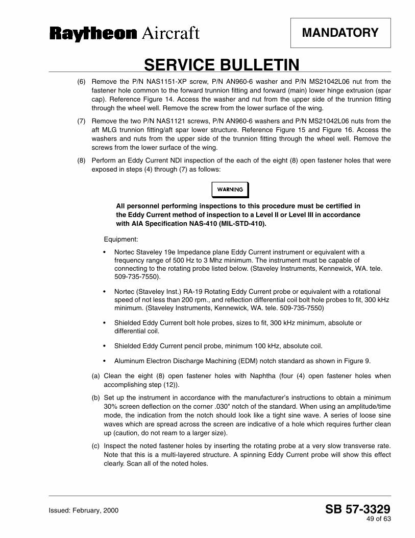
SB 57-332949 of 63
SERVICE BULLETIN
MANDATORY
Issued: February, 2000
(6) Remove the P/N NAS1151-XP screw, P/N AN960-6 washer and P/N MS21042L06 nut from thefastener hole common to the forward trunnion fitting and forward (main) lower hinge extrusion (sparcap). Reference Figure 14. Access the washer and nut from the upper side of the trunnion fittingthrough the wheel well. Remove the screw from the lower surface of the wing.
(7) Remove the two P/N NAS1121 screws, P/N AN960-6 washers and P/N MS21042L06 nuts from theaft MLG trunnion fitting/aft spar lower structure. Reference Figure 15 and Figure 16. Access thewashers and nuts from the upper side of the trunnion fitting through the wheel well. Remove thescrews from the lower surface of the wing.
(8) Perform an Eddy Current NDI inspection of the each of the eight (8) open fastener holes that wereexposed in steps (4) through (7) as follows:
All personnel performing inspections to this procedure must be certified inthe Eddy Current method of inspection to a Level II or Level III in accordancewith AIA Specification NAS-410 (MIL-STD-410).
Equipment:
• Nortec Staveley 19e Impedance plane Eddy Current instrument or equivalent with a frequency range of 500 Hz to 3 Mhz minimum. The instrument must be capable of connecting to the rotating probe listed below. (Staveley Instruments, Kennewick, WA. tele. 509-735-7550).
• Nortec (Staveley Inst.) RA-19 Rotating Eddy Current probe or equivalent with a rotational speed of not less than 200 rpm., and reflection differential coil bolt hole probes to fit, 300 kHz minimum. (Staveley Instruments, Kennewick, WA. tele. 509-735-7550)
• Shielded Eddy Current bolt hole probes, sizes to fit, 300 kHz minimum, absolute or differential coil.
• Shielded Eddy Current pencil probe, minimum 100 kHz, absolute coil.
• Aluminum Electron Discharge Machining (EDM) notch standard as shown in Figure 9.
(a) Clean the eight (8) open fastener holes with Naphtha (four (4) open fastener holes whenaccomplishing step (12)).
(b) Set up the instrument in accordance with the manufacturer’s instructions to obtain a minimum30% screen deflection on the corner .030" notch of the standard. When using an amplitude/timemode, the indication from the notch should look like a tight sine wave. A series of loose sinewaves which are spread across the screen are indicative of a hole which requires further cleanup (caution, do not ream to a larger size).
(c) Inspect the noted fastener holes by inserting the rotating probe at a very slow transverse rate.Note that this is a multi-layered structure. A spinning Eddy Current probe will show this effectclearly. Scan all of the noted holes.

SB 57-332950 of 63
SERVICE BULLETIN
MANDATORY
Issued: February, 2000
(d) A means of clearly determining the depth of the probe coil is essential, in that the acceptancecriteria varies at the second layer in some locations.
(e) If an indication appears, note the location and verify with a manual probe set with a depth stop tothe noted location. Note the direction of the crack indication and the part the crack indication wasdiscovered in.
A crack indication in the filler strip may be allowed, but only if the directionof the crack indication is toward the outside edge of the filler strip. If thedirection of the crack indication is toward the inside of the filler strip, thespar assembly must be replaced. Reference Figure 10.
To prevent moisture from entering the fastener holes and causing corrosion,lubricate each bolt or screw and fill each fastener hole with G322L silicone greaseor MIL-C-16173 Grade 2 corrosion preventive compound before installing eachbolt or screw.
(9) Install the fasteners (screws, bolts and attaching hardware) which were removed in steps (4) through(7) as follows:
(a) Install the two (2) P/N NAS1703 bolts in the forward lower hinge extrusion (spar cap) which wereremoved in step (4). Reference Figure 5 and tighten the bolts to 15 - 21 inch-pounds.
(b) Install the three (3) P/N NAS2903 bolts in aft reinforcement which were removed in step (5).Reference Figure 4 and tighten the bolts to 15 - 21 inch-pounds.
(c) Install a P/N NAS1151-XP screw in the fastener hole common to the forward trunnion fitting andforward (main) spar hinge extrusion (spar cap) (removed in step (6)). Reference Figure 14 andsecure the screw with a new P/N AN960-6 washer and a new P/N MS21042L06 nut. Tighten thenut to 8 - 12 inch-pounds.
(d) Install two P/N MS1121 screws in the aft spar lower structure/aft MLG trunnion fitting (the screwswere removed in step (7)). Insert the screws from the lower side of the wing. Secure the screwswith P/N AN960-6 washers and P/N MS21042L06 nuts on the upper side of the aft MLGtrunnion. Tighten the nuts to 8 - 12 inch-pounds. Reference Figure 15 and Figure 16.
(10) Remove the two (2) P/N NAS2903 bolts from the forward (main) spar aft reinforcement. These boltsare installed in the upper row of fasteners in the aft reinforcement. Access the bolts from the wheelwell area on the aft side of the forward spar. Reference Figure 4.
(11) Remove two (2) P/N NAS1703 bolts from the forward lower spar hinge extrusion (spar cap) on thelower inboard surface of the wing. These two (2) bolts are located closer to the wing tip than theother two (2) P/N NAS1703 bolts (in the hinge extrusion). Reference Figure 5 and Figure 6.
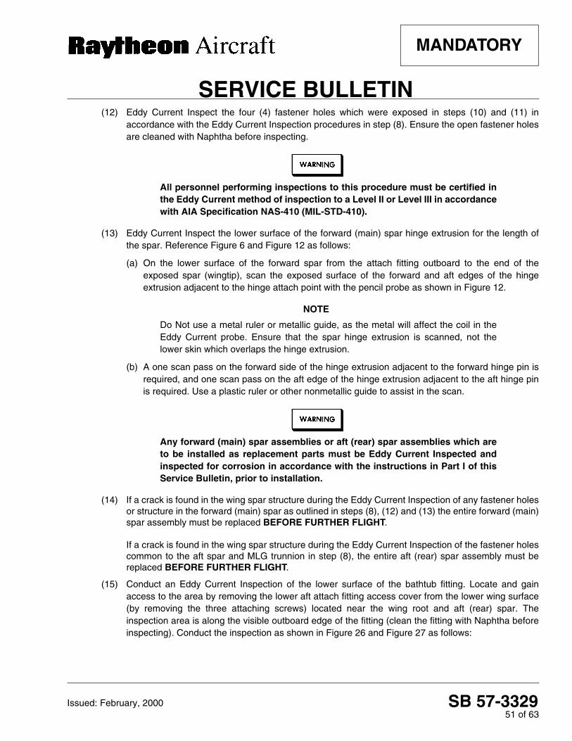
SB 57-332951 of 63
SERVICE BULLETIN
MANDATORY
Issued: February, 2000
(12) Eddy Current Inspect the four (4) fastener holes which were exposed in steps (10) and (11) inaccordance with the Eddy Current Inspection procedures in step (8). Ensure the open fastener holesare cleaned with Naphtha before inspecting.
All personnel performing inspections to this procedure must be certified inthe Eddy Current method of inspection to a Level II or Level III in accordancewith AIA Specification NAS-410 (MIL-STD-410).
(13) Eddy Current Inspect the lower surface of the forward (main) spar hinge extrusion for the length ofthe spar. Reference Figure 6 and Figure 12 as follows:
(a) On the lower surface of the forward spar from the attach fitting outboard to the end of theexposed spar (wingtip), scan the exposed surface of the forward and aft edges of the hingeextrusion adjacent to the hinge attach point with the pencil probe as shown in Figure 12.
NOTE
Do Not use a metal ruler or metallic guide, as the metal will affect the coil in theEddy Current probe. Ensure that the spar hinge extrusion is scanned, not thelower skin which overlaps the hinge extrusion.
(b) A one scan pass on the forward side of the hinge extrusion adjacent to the forward hinge pin isrequired, and one scan pass on the aft edge of the hinge extrusion adjacent to the aft hinge pinis required. Use a plastic ruler or other nonmetallic guide to assist in the scan.
Any forward (main) spar assemblies or aft (rear) spar assemblies which areto be installed as replacement parts must be Eddy Current Inspected andinspected for corrosion in accordance with the instructions in Part I of thisService Bulletin, prior to installation.
(14) If a crack is found in the wing spar structure during the Eddy Current Inspection of any fastener holesor structure in the forward (main) spar as outlined in steps (8), (12) and (13) the entire forward (main)spar assembly must be replaced BEFORE FURTHER FLIGHT.
If a crack is found in the wing spar structure during the Eddy Current Inspection of the fastener holescommon to the aft spar and MLG trunnion in step (8), the entire aft (rear) spar assembly must bereplaced BEFORE FURTHER FLIGHT.
(15) Conduct an Eddy Current Inspection of the lower surface of the bathtub fitting. Locate and gainaccess to the area by removing the lower aft attach fitting access cover from the lower wing surface(by removing the three attaching screws) located near the wing root and aft (rear) spar. Theinspection area is along the visible outboard edge of the fitting (clean the fitting with Naphtha beforeinspecting). Conduct the inspection as shown in Figure 26 and Figure 27 as follows:

SB 57-332952 of 63
SERVICE BULLETIN
MANDATORY
Issued: February, 2000
All personnel performing inspections to this procedure must be certified inthe Eddy Current method of inspection to a Level II or Level III in accordancewith AIA Specification NAS-410 (MIL-STD-410).
Equipment:
• Instrument: Same as used in the inboard forward wing spar and trunnion fitting inspections instep (8).
• Shielded Eddy Current pencil probe, minimum 100 kHz, absolute coil.
• Eddy Current 90° pencil probe, maximum 1/2" drop, minimum 100 kHz, absolute coil.
• Aluminum Electron Discharge Machining (EDM) notch standard as shown in Figure 9.
(a) Adjust the instrument using the .030 EDM notch by moving the probe from the solid area ontothe notched area from the end (i.e. parallel to the notch). This will simulate the signal expectedfor a crack in the fitting. The signal will not give a distinctive bump on the screen, rather it shouldmove from one area to another and stay there while the probe is moved along the top of thenotch.
(b) Adjust for a minimum 50% screen deflection. This scanning motion is necessary due to theconfiguration of the part.
(c) The scan will be parallel to the expected crack direction, so care should be taken whileperforming the inspection. Scan along the entire length of the step in the fitting.
(d) Scan the fitting along the edge of the depression. Scan several times with the probe atapproximately 45° from the surface of the fitting. Reference Figure 27.
Any forward (main) spar assemblies or aft (rear) spar assemblies which areto be installed as replacement parts must be Eddy Current Inspected andinspected for corrosion in accordance with the instructions in Part I of thisService Bulletin, prior to installation.
(e) If crack is found during the Eddy Current Inspection of the lower surface of the bathtub fittingnear the outboard edge as outlined in steps (15) (a) through (15) (e), the entire aft (rear) sparassembly must be replaced BEFORE FURTHER FLIGHT.
(16) Remove the fuel cell access panel and the small square access panel located on the lower surfaceof the leading edge.
(17) Remove the two (2) P/N NAS1121 screws, P/N AN960-6 washers and P/N MS21042L06 nuts fromthe box section hinge angle. These screws are located immediately outboard of the forward outboardcorner of the MLG wheel well opening. Reference Figure 14.

SB 57-332953 of 63
SERVICE BULLETIN
MANDATORY
Issued: February, 2000
(18) Perform an Eddy Current NDI inspection of the two (2) box section hinge angle fastener holesexposed in step (17) as follows:
(a) Conduct the Eddy Current Inspections in accordance with the instructions in step (8). Ensure theopen fastener holes are cleaned with Naphtha before inspecting.
(b) Scan the holes and note any crack indications. Verify all indications with a standard bolt holeprobe set to the precise depth of the box section hinge angle.
(19) Perform an Eddy Current NDI inspection of a section of the leading edge lower hinge angle. Locatethe two (2) fasteners which attach the leading edge lower hinge angle to the skin on the leadingedge. These fasteners are located on the outboard side of the small access panel which is used toservice the MLG trunnion. Reference Figure 14.
These two (2) fasteners will not be removed. The upper surface of the area adjacent to thefasteners will be inspected from inside the leading edge. Eddy Current Inspect the leading edgelower hinge angle near upper side of the two (2) fasteners as follows:
All personnel performing inspections to this procedure must be certified inthe Eddy Current method of inspection to a Level II or Level III in accordancewith AIA Specification NAS-410 (MIL-STD-410).
Equipment:
• Instrument: Same as used in the inboard forward wing spar and trunnion fitting inspections.
• Eddy Current straight or 90° pencil probe, maximum 1/2" drop (90° only), minimum 100 kHz, absolute coil.
• Aluminum Electron Discharge Machining (EDM) notch standard as shown in Figure 9.
(a) Gain access to the two (2) fasteners through the lower forward lightening hole in the outboard ribof the MLG wheel well compartment. Remove the six (6) screws that retain the oval accesspanel to the outboard side of the wheel well and remove the oval access panel to expose theupper and lower lightening holes. Reference Figure 18 and reach forward until the aft side of thefuel cell cavity is felt. Find the flange that is attached to the aft side of the fuel cell cavity. Feelbelow the flange to locate the two (2) fasteners directly below the flange at the bottom of theopening.
(b) Locate the leading edge lower hinge angle which is immediately aft of the two (2) fasteners.Reference the cut away T-34 spar and leading edge structure shown in Figure 18 and Figure 19.
(c) Adjust the instrument using the 0.030" EDM notch on the flat of the standard. Obtain a minimum50% screen deflection.

SB 57-332954 of 63
SERVICE BULLETIN
MANDATORY
Issued: February, 2000
(d) Scan the inside radius of the leading edge hinge angle with the pencil probe. Reach in thelightening hole with the pencil probe and turn the probe back towards the inboard side. Place thecoil of the probe on the inner radius of the hinge angle (on the forward side of the hinge angle,reference step (ii) and Figure 19) and scan the hinge angle. Scan along the hinge angle starting1/2" inboard from the inboard side of the inboard fastener continuing to 1/2" outboard from theoutboard side of the outboard fastener.
(e) Note any crack indications.
(20) Perform an Eddy Current NDI inspection of the leading edge hinge angle surfaces. The areas to bescanned are on the leading edge lower hinge angle located adjacent to the fuel cell access paneland adjacent to the small square access panel (fuel vent access door) near the MLG trunnion.Reference Figure 14 and Figure 17.
All personnel performing inspections to this procedure must be certified inthe Eddy Current method of inspection to a Level II or Level III in accordancewith AIA Specification NAS-410 (MIL-STD-410).
(a) Remove the small access panel (square) shown in Figure 14. The small access panel is located38" to 42" outboard of lower wing fitting, adjacent to the forward spar hinge extrusion (cap).
(b) Use the same instrument and equipment as used in the inboard forward wing spar and trunnionfitting inspections. Adjust the instrument using the 0.030" EDM notch on the flat of the standard.Obtain a minimum 50% screen deflection.
(c) Using a straight or 90° pencil probe, scan the entire length of the exposed face of the leadingedge lower hinge angle along the aft side of the small access panel opening. The small accesspanel is located 38" to 42" outboard of the lower wing fitting, adjacent to the forward spar hingeextrusion (spar cap). Reference Figure 14.
(d) Using a straight or 90° pencil probe, scan the entire length of the exposed face of the hingeangle along the aft side of the fuel cell access panel opening. The fuel cell access panel islocated 17" to 25" outboard of the lower wing fitting, adjacent to the lower hinge extrusion on theforward spar (spar cap). Reference Figure 17.
(e) Visually inspect the lower wing skin adjacent to the area Eddy Current Inspected in step (20) (d).Look closely at the area next to the fuel cell access panel aft flange surface for cracks ordistortions in the paint. Reference Figure 17. If distortions are found, remove the paint for acloser inspection. Check for cracks in the lower wing skin and leading edge lower hinge angle.
(21) Accomplish an Eddy Current NDT inspection of the aft reinforcement (located in the forward sparlower structure - reference Figure 28) as follows:
All personnel performing inspections to this procedure must be certified inthe Eddy Current method of inspection to a Level II or Level III in accordancewith AIA Specification NAS-410 (MIL-STD-410).

SB 57-332955 of 63
SERVICE BULLETIN
MANDATORY
Issued: February, 2000
(a) Conduct the Eddy Current Inspection with the same equipment utilized to inspect the hingeangle surfaces in step (20).
(b) Adjust the instrument using the .030" EDM notch on the flat of the standard shown in Figure 9.Obtain a minimum 50% screen deflection.
(c) Locate the aft reinforcement and vertical stiffener, on the aft side of the forward spar. Gainaccess to the area from the wheel well opening. Reference Figure 28.
(d) Using a pencil probe or 90° pencil probe, scan the exposed surface of the aft reinforcement onboth the inboard and outboard sides of the vertical stiffener.
(e) Move the probe in a back and forth (inboard to outboard motion) pattern between the verticalstiffener and adjacent fastener position(s) as shown in Figure 28. Start at the upper edge of theaft reinforcement, slowly adjusting the scan pattern downward in increments not to exceed oneprobe diameter toward the lower edge. A plastic ruler may be used as a guide.
(f) Note any crack indications.
(g) If a crack is found during Eddy Current Inspection of the aft reinforcement, the entire forward(main) spar assembly must be replaced BEFORE FURTHER FLIGHT.
Any replacement leading edge or box section hinge angle assemblies whichare to be installed as replacement parts must be Eddy Current Inspectedand inspected for corrosion in accordance with the instructions in Part I ofthis Service Bulletin, prior to installation.
(22) If a crack is found during the Eddy Current Inspection in any of the fastener holes or surfacesinspected in step (18), step (19), step (20) or step (21) the corresponding hinge angle assembly(ies)must be replaced BEFORE FURTHER FLIGHT.
Any forward (main) spar assemblies, aft (rear) spar assemblies or hingeangle assemblies which are to be installed as replacement parts must beEddy Current Inspected and inspected for corrosion in accordance with thesteps outlined in Mandatory Service Bulletin No. 2538, Rev. I., prior toinstallation.
(23) If no cracks are found, continue with step (24).
To prevent moisture from entering the fastener holes and causing corrosion,lubricate each bolt or screw and fill each fastener hole with G322L silicone greaseor MIL-C-16173 Grade 2 corrosion preventive compound before installing eachbolt or screw.

SB 57-332956 of 63
SERVICE BULLETIN
MANDATORY
Issued: February, 2000
(24) Install the fasteners (screws, bolts and attaching hardware) which were removed in steps (10)through (17) as follows:
(a) Install the two (2) P/N NAS2903 bolts (removed in step (10)) in the forward (main) spar aftreinforcement. These fasteners are installed in the upper row of fasteners in the forwardreinforcement. Insert the bolts from the wheel well area on the aft side of the forward spar andtighten to 15 - 21 inch-pounds. Reference Figure 4.
(b) Install two (2) P/N NAS1703 bolts (removed in step (11)) in the forward lower spar hingeextrusion (spar cap) on the lower inboard surface of the wing. These two (2) bolts are locatedcloser to the wing tip than the other two (2) P/N NAS1703 bolts (reference step (4)). Insert thebolts from below the wing surface and tighten to 15 - 21 inch-pounds. Reference Figure 5 andFigure 6.
(c) Install two (2) P/N NAS1121 screws (removed in step (17)) in the box section hinge anglefastener holes. Insert the screws from the lower surface of the wing and secure with a P/NAN960-6 washers and P/N MS21042L06 nuts. These screws are located immediately outboardof the forward outboard corner of the MLG wheel well opening. Reference Figure 14 and tightenthe nuts to 8 - 12 inch-pounds.
(25) Install the fuel cell access panel and the small square access panel located on the lower surface ofthe leading edge.
(26) Install the oval access panel at the outboard side of the wheel well and secure with the six (6)screws.
(27) Install the wing lower aft attach fitting access cover on the lower wing surface (located near the wingroot and aft (rear) spar) and secure with the three (3) screws which were removed in step (15).
(28) Reconnect the battery and restore electrical power. Remove warning notices prohibitingreconnection of airplane electrical power.
(29) Lower the landing gear.
(30) Remove the airplane from the jacks.
(31) Ensure all work areas are clean and clear of tools and miscellaneous items of equipment.
(32) Accomplish a flight test before returning the airplane to service
(33) Return airplane to service.

SB 57-332957 of 63
SERVICE BULLETIN
MANDATORY
Issued: February, 2000
B. Spares
Any forward (main) spar assemblies or aft (rear) spar assemblies which areto be installed as replacement parts must be Eddy Current Inspected andinspected for corrosion in accordance with the instructions in Part I of thisService Bulletin, prior to installation.
Any replacement leading edge or box section hinge angle assemblies whichare to be installed as replacement parts must be Eddy Current Inspectedand inspected for corrosion in accordance with the instructions in Part I ofthis Service Bulletin, prior to installation.
C. Record of Compliance
Upon completion of Part I of this Service Bulletin, make an appropriate maintenance record entry. Maketwo copies of the Inspection Survey Chart which is printed on the following three (3) pages. Fill the surveycharts out for both the R and L wings and return them to Raytheon Aircraft Company, Dept. 52, 9709 E.Central, PO Box 85, Wichita Ks. 67201-8500 or FAX them to (316) 676-8027.
Make an appropriate maintenance record entry and fill out and return the Inspection Surveys each timePart II of this Service Bulletin is accomplished.
D. Survey
It is very important these survey charts are filled out and returned. Currently, the only method of extendingthe 80 hour inspection interval is by increasing the amount of data we have on T-34 wing structures in thefield. A larger sample size may enable us to increase the time interval between inspections. Please copythese charts, fill in the information and return them to RAC at the address or FAX listed above.
If any parts are replaced as result of this Service Bulletin contact RAC Customer Support at (800)429-5372 or (316) 676-3140 to arrange delivery of the parts to RAC.

SB 57-332958 of 63
SERVICE BULLETIN
MANDATORY
Issued: February, 2000
INS
PE
CT
ION
SU
RV
EY
CH
AR
T -
Air
plan
e S
/N _
____
____
___
L W
ing
___
R W
ing
___
Tota
l Air
plan
e F
light
Hou
rs _
____
__(S
HE
ET
1 o
f 3)
Air
plan
e H
ome
Add
ress
___
____
____
____
____
____
____
____
__ C
onta
ct N
ame/
Tele
.___
____
____
____
____
____
____
__
Rep
ort i
n th
e ch
art b
elow
any
cra
ck in
dica
tions
that
wer
e fo
und
duri
ng th
is in
spec
tion,
and
the
leng
th a
nd d
irect
ion
of th
e cr
acks
. M
ake
a co
py o
f the
app
licab
le fi
gure
and
ske
tch
an o
utlin
e of
eac
h cr
ack
if po
ssib
le.
FAS
TE
NE
R
LO
CA
TIO
NS
PAR
T I
step
(#)
p
age
#
PAR
T II
step
(#)
p
age
#
LA
YE
R O
F S
TR
UC
TU
RE
5 IN
FW
D S
PAR
AF
TR
EIN
FO
RC
EM
EN
TS
EE
FIG
UR
E 4
, PG
. 15
FO
RW
AR
D
RE
INF
OR
CE
ME
NT
FW
D J
CH
AN
NE
LW
ING
F
ITT
ING
A
FT
"J"
C
HA
NN
EL
TAP
ER
ED
S
PAC
ER
WE
Bin
bd /
outb
d
AF
T R
EIN
FO
RC
EM
EN
T(A
ND
VE
RT
ICA
L S
TIF
FE
NE
R IN
BD
. ON
LY)
Inbo
ard
Fast
ener
(at v
ertic
al s
tiffe
ner)
step
(8)
pa
ge 1
1st
ep (
5)
page
48
Upp
er In
boar
d fa
sten
erst
ep (
8)
page
11
step
(10
) pa
ge 5
0
Low
er In
boar
d fa
sten
erst
ep (
8)
page
11
step
(5)
pa
ge 4
8
Upp
er O
utbo
ard
fast
ener
step
(8)
pa
ge 1
1st
ep (
10)
page
50
Low
er O
utbo
ard
fast
ener
step
(8)
pa
ge 1
1st
ep (
5)
page
48
4 IN
FW
D S
PAR
CA
PS
EE
FIG
UR
E 5
, PG
. 15
SPA
R C
AP
FIL
LER
ST
RIP
WIN
G
FIT
TIN
G
"J"
CH
AN
NE
L
Inbo
ard,
Fw
dst
ep (
8)
page
11
step
(4)
pa
ge 4
8
Inbo
ard,
Aft
step
(8)
pa
ge 1
1st
ep (
4)
page
48
Out
boar
d, F
wd
step
(8)
pa
ge 1
1st
ep (
11)
page
50
Out
boar
d, A
ftst
ep (
8)
page
11
step
(11
) pa
ge 5
0
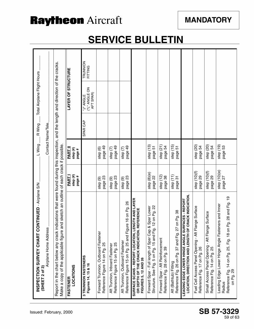
SB 57-332959 of 63
SERVICE BULLETIN
MANDATORY
Issued: February, 2000
INS
PE
CT
ION
SU
RV
EY
CH
AR
T C
ON
TIN
UE
D -
Air
plan
e S
/N _
____
____
___
L W
ing
___
R W
ing
___
Tota
l Air
plan
e F
light
Hou
rs _
____
__(S
HE
ET
2 o
f 3) A
irpl
ane
Hom
e A
ddre
ss _
____
____
____
____
____
____
____
____
_ C
onta
ct N
ame/
Tele
.___
____
____
____
____
____
____
____
___
Rep
ort i
n th
e ch
art b
elow
any
cra
ck in
dica
tions
that
wer
e fo
und
durin
g th
is in
spec
tion,
and
the
leng
th a
nd d
irect
ion
of th
e cr
acks
. M
ake
a co
py o
f the
app
licab
le fi
gure
and
ske
tch
an o
utlin
e of
eac
h cr
ack
if po
ssib
le.
FAS
TE
NE
R
LO
CA
TIO
NS
PAR
T I
step
(#)
p
age
#
PAR
T II
step
(#)
p
age
#
LA
YE
R O
F S
TR
UC
TU
RE
3 T
RU
NN
ION
FA
ST
EN
ER
S
Fig
ure
s 14
, 15
& 1
6S
PAR
CA
P"J
" A
NG
LE("
L" A
NG
LE O
N
AF
T S
PAR
)
TR
UN
NIO
N
FIT
TIN
G
For
war
d Tr
unni
on, O
utbo
ard
Fast
ener
R
efer
ence
Fig
ure
14 o
n P
g. 2
5st
ep (
9)
page
23
step
(6)
pa
ge 4
9
Aft
Trun
nion
, Inb
oard
Fas
tene
r R
efer
ence
Fig
ure
15 o
n P
g. 2
5st
ep (
9)
page
23
step
(7)
pa
ge 4
9
Aft
Trun
nion
, Out
boar
d Fa
sten
er
Ref
eren
ce F
igur
e 15
on
Pg.
25
and
Fig
ure
16 o
n P
g. 2
6st
ep (
9)
page
23
step
(7)
pa
ge 4
9
SU
RFA
CE
SC
AN
S -
RE
PO
RT
LO
CA
TIO
N, L
EN
GT
H A
ND
LA
YE
R
OR
DE
PT
H O
F T
HE
CR
AC
K IN
DIC
AT
ION
. RE
FE
RE
NC
E
FIG
UR
ES
5, 1
2 A
ND
26
For
war
d S
par
- F
ull l
engt
h of
Spa
r C
ap &
Spa
r Lo
wer
S
truc
ture
. See
Fig
. 5 o
n P
g. 1
5 an
d F
ig. 1
2 on
Pg.
22
step
(8)
(e)
page
22
step
(13
)pa
ge 5
1
For
war
d S
par
- A
ft R
einf
orce
men
t R
efer
ence
Fig
. 28
on P
g. 3
9st
ep (
12)
page
38
step
(21
) pa
ge 5
4
Aft
(Bat
htub
) F
ittin
g R
efer
ence
Fig
. 26
on P
g. 3
7 an
d F
ig. 2
7 on
Pg.
38
step
(11
) pa
ge 3
1st
ep (
15)
page
51
LE
AD
ING
ED
GE
LO
WE
R H
ING
E A
NG
LE
SU
RFA
CE
S -
RE
PO
RT
L
OC
AT
ION
, DIR
EC
TIO
N A
ND
LE
NG
TH
OF
CR
AC
K IN
DIC
AT
ION
.
Fue
l Cel
l Acc
ess
Pan
el O
peni
ng -
Aft
Fla
nge
Sur
face
R
efer
ence
Fig
. 17
on P
g. 2
6st
ep (
10)(
f)pa
ge 2
9st
ep (
20)
page
54
Sm
all A
cces
s P
anel
Ope
ning
- A
ft F
lang
e S
urfa
ce
Ref
eren
ce F
ig. 1
4 on
Pg.
25
step
(10
)(f)
pa
ge 2
9st
ep (
20)
page
54
Lead
ing
Edg
e Lo
wer
Hin
ge A
ngle
Fas
tene
rs a
nd In
ner
Rad
ius
Ref
eren
ce F
ig. 1
4 on
Pg.
25,
Fig
. 18
on P
g. 2
8 an
d F
ig. 1
9 on
Pg.
29
step
(10
)(e)
pa
ge 2
7st
ep (
19)
page
53

SB 57-332960 of 63
SERVICE BULLETIN
MANDATORY
Issued: February, 2000
INS
PE
CT
ION
SU
RV
EY
CH
AR
T C
ON
TIN
UE
D -
Air
plan
e S
/N _
____
____
___
L W
ing
___
R W
ing
___
Tota
l Air
plan
e F
light
Hou
rs _
____
__(S
HE
ET
3 o
f 3) A
irpl
ane
Hom
e A
ddre
ss _
____
____
____
____
____
____
____
____
Con
tact
Nam
e/Te
le._
____
____
____
____
____
____
____
____
__
Rep
ort i
n th
e ch
art b
elow
any
cra
ck in
dica
tions
that
wer
e fo
und
durin
g th
is in
spec
tion,
and
the
leng
th a
nd d
irect
ion
of th
e cr
acks
. M
ake
a co
py o
f the
app
licab
le fi
gure
and
ske
tch
an o
utlin
e of
eac
h cr
ack
if po
ssib
le.
FAS
TE
NE
R
LO
CA
TIO
NS
PA
RT
Ist
ep (
#)
pag
e #
PAR
T II
step
(#)
p
age
#
LA
YE
R O
F S
TR
UC
TU
RE
BO
X S
EC
TIO
N L
OW
ER
HIN
GE
AN
GL
E F
AS
TE
NE
R H
OL
ES
-
RE
PO
RT
LO
CA
TIO
N D
IRE
CT
ION
AN
D L
EN
GT
H O
F C
RA
CK
IN
DIC
AT
ION
.
Box
Sec
tion
Hin
ge A
ngle
- In
boar
d Fa
sten
er H
ole
Ref
eren
ce F
ig. 1
4 on
Pg.
25
step
(10
)(a)
pa
ge 2
7st
ep (
18)
page
53
Box
Sec
tion
Hin
ge A
ngle
- O
utbo
ard
Fast
ener
Hol
e R
efer
ence
Fig
. 14
on P
g. 2
5st
ep (
10)(
a)
page
27
step
(18
) pa
ge 5
3
CO
RR
OS
ION
INS
PE
CT
ION
- R
EP
OR
T T
YP
E, L
OC
AT
ION
AN
D
SIZ
E O
F A
RE
A (
RE
QU
IRE
D O
N IN
ITIA
L IN
SP
EC
TIO
N O
NLY
, N
OT
RE
QU
IRE
D F
OR
PA
RT
II R
EC
UR
RIN
G IN
SP
EC
TIO
NS
).
AF
TE
R IN
ITIA
L IN
SP
EC
TIO
N, R
ES
UM
E A
NN
UA
L IN
SP
EC
TIO
NS
IN
AC
CO
RD
AN
CE
WIT
H M
AN
DA
TOR
Y S
B 2
538
RE
VIS
ION
I O
R
SU
BS
EQ
UE
NT
RE
VIS
ION
.
Upp
er S
par
Cap
and
Adj
acen
t Upp
er H
inge
Ang
les
Ref
eren
ce S
B 2
538
Rev
. I o
r su
bseq
uent
st
ep (
13)
page
39
does
not
appl
y
Low
er S
par
Cap
- a
nd A
djac
ent L
ower
Hin
ge A
ngle
s R
efer
ence
SB
253
8 R
ev. I
or
subs
eque
nt
step
(13
) pa
ge 3
9do
es n
otap
ply
For
war
d S
par
- F
orw
ard
Sid
e (v
isib
le in
side
fuel
cel
l cav
ity)
Ref
eren
ce F
ig. 1
on
Pg.
10
step
(13
) pa
ge 3
9do
es n
otap
ply
For
war
d S
par
- A
ft S
ide
(vis
ible
from
insi
de w
heel
wel
l) R
efer
ence
Fig
. 4 o
n P
g. 1
5st
ep (
13)
page
39
does
not
appl
y
For
war
d S
ide
of A
ft S
par
(vis
ible
from
insi
de w
heel
wel
l) R
efer
ence
Fig
. 13
on P
g. 2
4st
ep (
13)
page
39
does
not
appl
y

SB 57-332961 of 63
SERVICE BULLETIN
MANDATORY
Issued: February, 2000
ACCOMPLISHMENT INSTRUCTIONS INDEX
Part I - Initial InspectionStep or Reference PageParts Chart............................................................................................................................................ 4 Materials Chart ................................................................................................................................... 5Tools and Availability ......................................................................................................................... 61. Ensure Airplane Conforms to Type Certificate ............................................................................. 72. Defuel .............................................................................................................................................. 83. Place the airplane on jacks ............................................................................................................. 84. Remove the flaps and disconnect the battery.................................................................................. 85. Manually raise the landing gear ..................................................................................................... 86. Disconnect the inboard MLG door actuating rod .......................................................................... 87. Gain access to the forward side of the forward spar (remove fuel cell, trim liner) ........................ 88. Eddy Current Inspect the inboard section of forward spar (remove fasteners, ream) .................. 119. Eddy Current Inspect three (3) MLG trunnion fitting fasteners locations .................................... 2310. Inspect leading edge lower hinge angle and box section lower forward hinge angle ................. 2711. Eddy Current Inspect the lower aft outboard wing fitting near the bathtub area ........................ 3112. Eddy Current Inspect the aft reinforcement ................................................................................ 3813. Inspect the upper and lower spar caps and adjacent hinge angles for corrosion ........................ 3914. If corrosion is found contact Raytheon Aircraft Customer Support ........................................... 3915. If no cracks or corrosion exist, reassemble the lower inboard wing skin ................................... 3916. Fabricate nutplate mounting plates for the forward (main) spar ................................................. 4117. Install the nutplates and removable fasteners ............................................................................. 4418. Smooth and prepare the fuel cell liner ........................................................................................ 4619. Install the fuel cell, fuel filler and fuel filler panel ..................................................................... 4720. Install the fuel cell access panel and the small square access panel ............................................ 4721. Install the oval access panel at outboard side of wheel well ....................................................... 4722. Install the wing lower aft attach fitting access cover on the lower wing surface ....................... 4723. Repeat steps (7) through (22) for opposite wing ........................................................................ 4724. Connect the MLG doors ............................................................................................................. 4725. Lower the landing gear ............................................................................................................... 4726. Install the flaps ............................................................................................................................ 4727. Remove the airplane from the jacks ........................................................................................... 4828. Ensure all work areas are clean and clear of equipment ............................................................. 4829. Fuel the airplane and check the fuel system ............................................................................... 4830. Accomplish a flight test before returning the airplane to service ............................................... 4831. Return airplane to service ........................................................................................................... 48Inspection Survey Chart (fill out and return to Raytheon Aircraft) .................................................. 58

SB 57-332962 of 63
SERVICE BULLETIN
MANDATORY
Issued: February, 2000
ACCOMPLISHMENT INSTRUCTIONS INDEX
Part II - Recurring InspectionsStep or Reference PageParts Chart ............................................................................................................................................... 4Materials Chart ....................................................................................................................................... 5Tools and Availability ............................................................................................................................ 61. Place the airplane on jacks ................................................................................................................ 482. Raise the landing gear until the inboard landing gear doors are fully open ..................................... 483. Remove all power from the airplane and disconnect the battery....................................................... 484. Remove two (2) NAS1703 bolts (closest to wing root) from the spar cap ....................................... 485. Remove three (3) NAS2903 bolts from the lower row in the aft reinforcement .............................. 486. Remove the NAS1151-XP screw, washer and nut from the forward MLG trunnion fitting ............ 497. Remove the two NAS1121 screws, washers and nuts from the aft MLG trunnion fitting ............... 498. Eddy Current Inspect the nine (9) open fastener holes exposed in steps (4) through (7) ................. 499. Install the fasteners removed in steps (4) through (7) ....................................................................... 5010. Remove the two (2) upper NAS2903 bolts from aft reinforcement/forward (main) spar .............. 5011. Remove the two (2) NAS1703 bolts (closest to wingtip) from lower spar cap .............................. 5012. Eddy Current Inspect the four (4) fastener holes exposed in steps (10) and (11) ........................... 5113. Eddy Current Inspect the lower surface of the forward spar hinge extrusion (full length) ............ 5114. If crack is found, replace cracked wing spar structure before flight ............................................... 5115. Eddy Current Inspect the lower surface of the lower aft bathtub area. ........................................... 5116. Remove the fuel cell access panel and the small square access panel ............................................ 5217. Remove the two (2) NAS1121 screws, washers and nuts from the box section hinge angle ......... 5218. Eddy Current Inspect the two (2) box section hinge angle fastener holes exposed in step (17) .... 5319. Eddy Current Inspect the leading edge lower hinge angle through the wheel well panel .............. 5320. Eddy Current Inspect the leading edge hinge angle surfaces ......................................................... 5421. Eddy Current Inspect the aft reinforcement .................................................................................... 5422. If a crack is found, replace corresponding hinge angle assembly(ies) before flight ....................... 5523. If no cracks are found, continue with step (24) .............................................................................. 5524. Install the fasteners removed in steps (10) through (17) ................................................................. 5625. Install the fuel cell access panel and the small square access panel ............................................... 5626. Install the oval access panel at the outboard side of the wheel well ............................................... 5627. Install the wing lower aft attach fitting access cover on the lower wing surface ........................... 5628. Reconnect the battery and restore electrical power ........................................................................ 5629. Lower the landing gear ................................................................................................................... 5630. Remove the airplane from the jacks ................................................................................................ 5631. Ensure all work areas are clean and clear of tools and equipment ................................................. 5632. Accomplish a flight test before returning the airplane to service ................................................... 5633. Return airplane to service ............................................................................................................... 56Inspection Survey Chart (fill out and return to Raytheon Aircraft) .......................................................58

SB 57-332963 of 63
SERVICE BULLETIN
MANDATORY
Issued: February, 2000
LIST OF ILLUSTRATIONS INDEXFigure and Title Page
Figure 1 - Fuel Cell Liner Modification ............................................................................................... 10
Figure 2 - Typical Spar Cross Section .................................................................................................. 12
Figure 3 - Inspection Locations (LH Wing Shown) ............................................................................. 14
Figure 4 - Inboard Forward Spar Inspection (Aft Side) ........................................................................ 15
Figure 5 - Inboard Forward Spar Inspection (Lower Side) ................................................................... 15
Figure 6 - Inboard Forward Spar Close-Up .......................................................................................... 16
Figure 7 - Hand Reamer ........................................................................................................................ 17
Figure 8 - Impedance Plane Eddy Current Instrument - Nortec Staveley 19e ...................................... 19
Figure 9 - Standard Calibration Block .................................................................................................. 20
Figure 10 - Filler Strip Cracks .............................................................................................................. 21
Figure 11 - Calibration / Crack Indication Display on Nortec Staveley 19e ........................................ 21
Figure 12 - Eddy Current Inspection of Forward Spar (Lower Surface) .............................................. 22
Figure 13 - Aft MLG Trunnion Location (LH Side Shown) ................................................................ 24
Figure 14 - Forward Trunnion and Hinge Angle Fastener Locations (LH side shown) ....................... 25
Figure 15 - Aft Trunnion Fastener Location (LH Side Shown Before Removal) ................................ 25
Figure 16 - Aft Trunnion Fastener Location (LH Side Shown During Removal) ................................ 26
Figure 17 - Leading Edge Hinge Angle and Fuel Cell Access Panel ................................................... 26
Figure 18 - Cutaway View of Lower Forward Spar and Leading Edge Structure (RH Shown) .......... 28
Figure 19 - Scanning the Leading Edge Lower Hinge Angle (RH Wing Shown) ............................... 29
Figure 20 - Lower Aft "Bathtub" Wing Fitting .................................................................................... 32
Figure 21 - Lower Wing Skin Fastener Removal ................................................................................. 32
Figure 22 - Lower Wing Skin Marking and Removal .......................................................................... 34
Figure 23 - Flap Cove Skin Marking and Removal .............................................................................. 34
Figure 24 - Flap Cove Skin Shown Removed ...................................................................................... 35
Figure 25 - Aft Spar Structure Lower Element (Capstrip) Modification .............................................. 35
Figure 26 - Aft Spar Structure Lower Element (Capstrip) ................................................................... 37
Figure 27 - Eddy Current Pencil Probe Angles .................................................................................... 38
Figure 28 - Aft Reinforcement Surface Inspection ............................................................................... 39
Figure 29 - Nutplate Mounting Plate Fabrication (forward reinforcement) ......................................... 41
Figure 30 - Nutplate Mounting Plate Location ..................................................................................... 42
Figure 31 - Nutplate Mounting Plates (Install in Forward Spar Lower Structure) ................................ 43
Figure 32 - Forward MLG Trunnion and Radius Block ....................................................................... 46
Related Documents