HELICAL HYDRAULIC ROTARY ACTUATORS T20 SERIES Service and Repair Manual

Welcome message from author
This document is posted to help you gain knowledge. Please leave a comment to let me know what you think about it! Share it to your friends and learn new things together.
Transcript
HELIC
AL H
YD
RA
ULIC
RO
TAR
Y A
CTU
ATO
RS
T20 SERIESService andRepair Manual
2
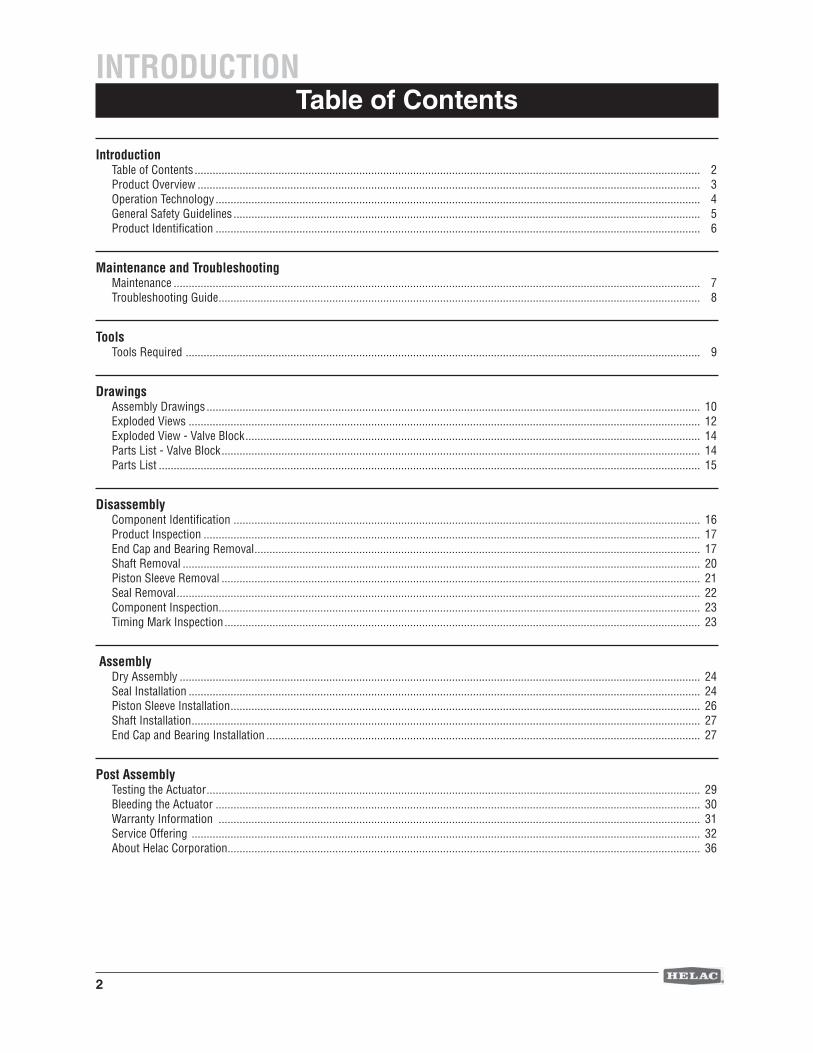
Table of Contents
IntroductionTable of Contents ......................................................................................................................................................................... 2Product Overview ........................................................................................................................................................................ 3Operation Technology .................................................................................................................................................................. 4General Safety Guidelines ............................................................................................................................................................ 5Product Identifi cation .................................................................................................................................................................. 6
Maintenance and TroubleshootingMaintenance ................................................................................................................................................................................ 7Troubleshooting Guide ................................................................................................................................................................. 8
ToolsTools Required ............................................................................................................................................................................ 9
DrawingsAssembly Drawings ..................................................................................................................................................................... 10Exploded Views ........................................................................................................................................................................... 12Exploded View - Valve Block ........................................................................................................................................................ 14Parts List - Valve Block ................................................................................................................................................................ 14Parts List ..................................................................................................................................................................................... 15
Disassembly Component Identifi cation ............................................................................................................................................................ 16Product Inspection ...................................................................................................................................................................... 17End Cap and Bearing Removal ..................................................................................................................................................... 17Shaft Removal ............................................................................................................................................................................. 20Piston Sleeve Removal ................................................................................................................................................................ 21Seal Removal ............................................................................................................................................................................... 22Component Inspection ................................................................................................................................................................. 23Timing Mark Inspection ............................................................................................................................................................... 23
AssemblyDry Assembly .............................................................................................................................................................................. 24Seal Installation ........................................................................................................................................................................... 24Piston Sleeve Installation ............................................................................................................................................................. 26Shaft Installation .......................................................................................................................................................................... 27End Cap and Bearing Installation ................................................................................................................................................. 27
Post AssemblyTesting the Actuator ..................................................................................................................................................................... 29Bleeding the Actuator .................................................................................................................................................................. 30Warranty Information ................................................................................................................................................................. 31Service Offering .......................................................................................................................................................................... 32About Helac Corporation .............................................................................................................................................................. 36
INTRODUCTION
3
Product Overview
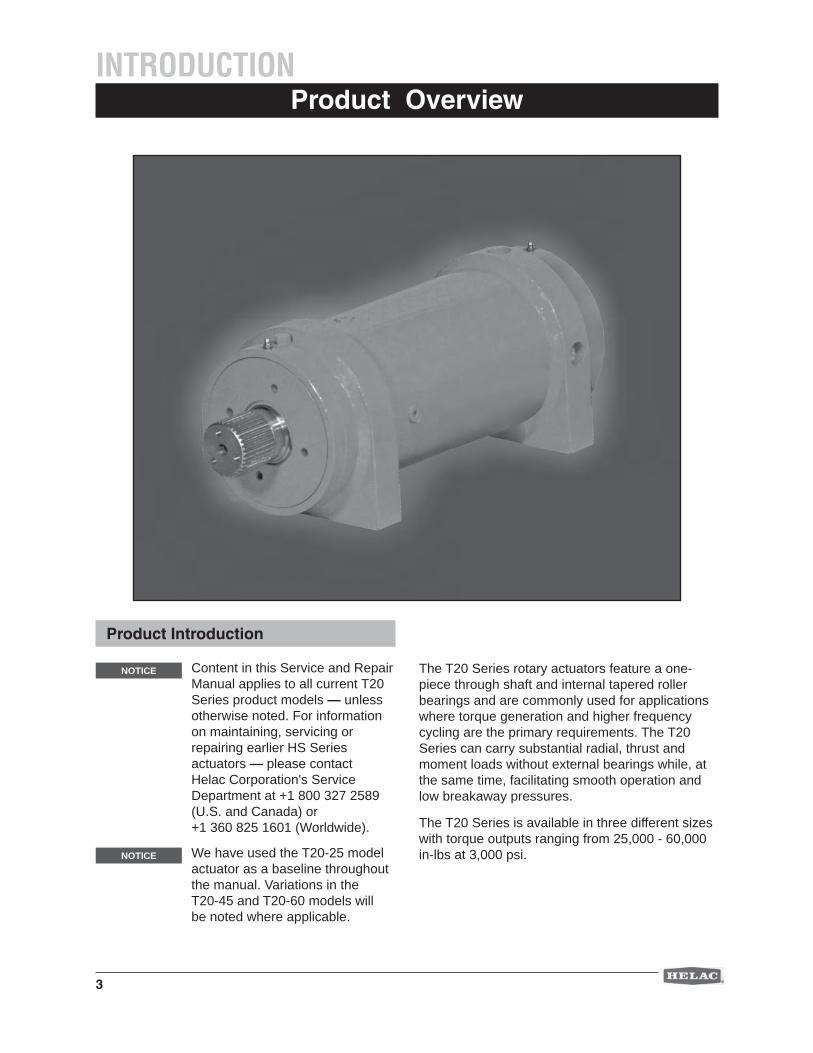
Content in this Service and Repair Manual applies to all current T20 Series product models — unless otherwise noted. For information on maintaining, servicing or repairing earlier HS Series actuators — please contact Helac Corporation's Service Department at +1 800 327 2589 (U.S. and Canada) or +1 360 825 1601 (Worldwide).
The T20 Series rotary actuators feature a one-piece through shaft and internal tapered roller bearings and are commonly used for applications where torque generation and higher frequency cycling are the primary requirements. The T20 Series can carry substantial radial, thrust and moment loads without external bearings while, at the same time, facilitating smooth operation and low breakaway pressures.
The T20 Series is available in three different sizes with torque outputs ranging from 25,000 - 60,000 in-lbs at 3,000 psi.
INTRODUCTION
Product Introduction
NOTICE
We have used the T20-25 model actuator as a baseline throughout the manual. Variations in the T20-45 and T20-60 models will be noted where applicable.
NOTICE
4
Operation TechnologyINTRODUCTION
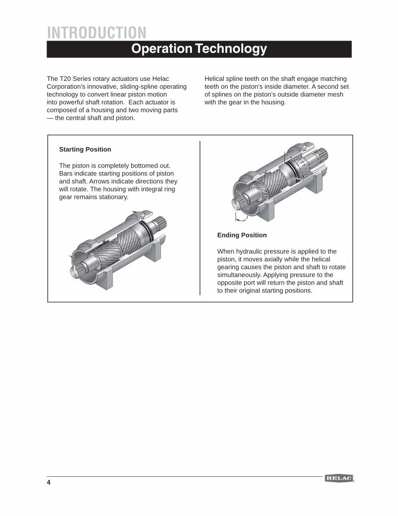
The T20 Series rotary actuators use Helac Corporation’s innovative, sliding-spline operating technology to convert linear piston motion into powerful shaft rotation. Each actuator is composed of a housing and two moving parts — the central shaft and piston.
Helical spline teeth on the shaft engage matching teeth on the piston’s inside diameter. A second set of splines on the piston’s outside diameter mesh with the gear in the housing.
Starting Position
The piston is completely bottomed out. Bars indicate starting positions of piston and shaft. Arrows indicate directions they will rotate. The housing with integral ring gear remains stationary.
Ending Position
When hydraulic pressure is applied to the piston, it moves axially while the helical gearing causes the piston and shaft to rotate simultaneously. Applying pressure to the opposite port will return the piston and shaft to their original starting positions.
5
General Safety Guidelines
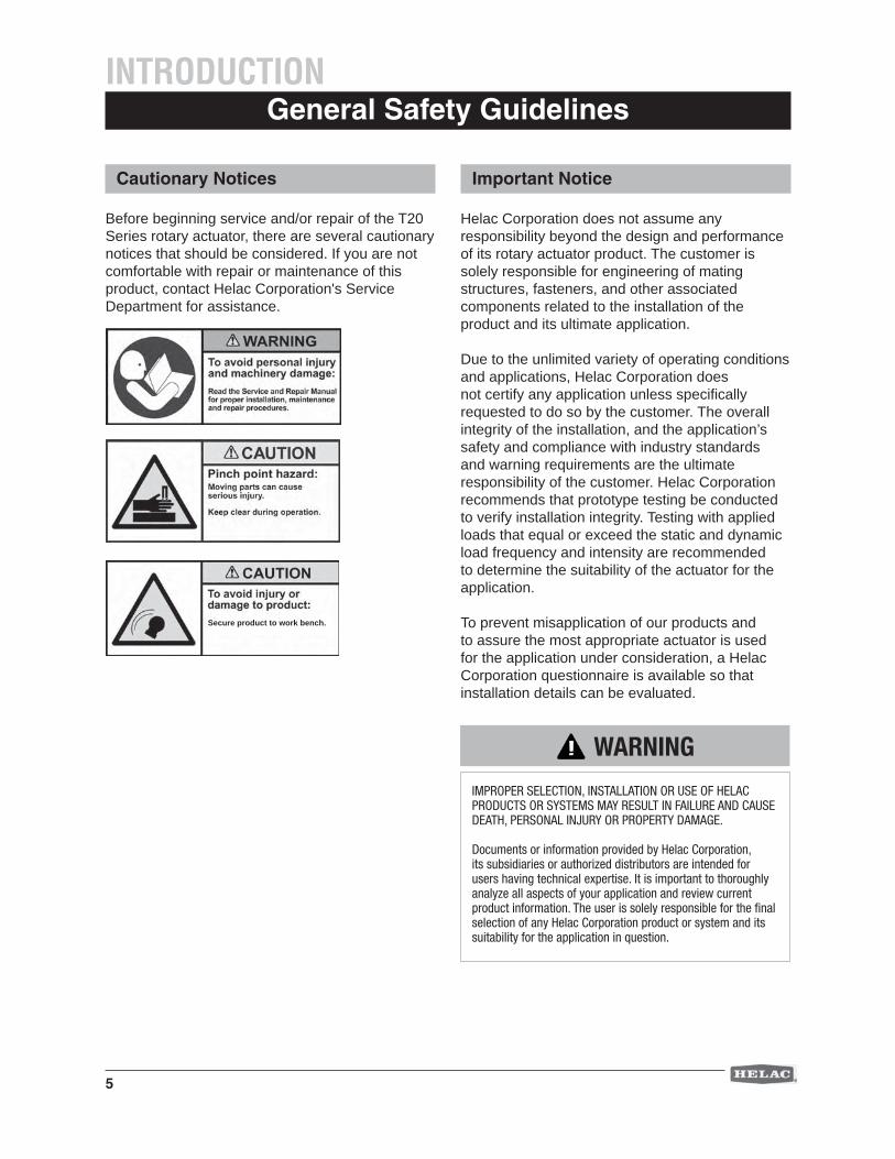
Before beginning service and/or repair of the T20 Series rotary actuator, there are several cautionary notices that should be considered. If you are not comfortable with repair or maintenance of this product, contact Helac Corporation's Service Department for assistance.
INTRODUCTION
Cautionary Notices
Secure product to work bench.
Helac Corporation does not assume any responsibility beyond the design and performance of its rotary actuator product. The customer is solely responsible for engineering of mating structures, fasteners, and other associated components related to the installation of the product and its ultimate application.
Due to the unlimited variety of operating conditions and applications, Helac Corporation does not certify any application unless specifi cally requested to do so by the customer. The overall integrity of the installation, and the application’s safety and compliance with industry standards and warning requirements are the ultimate responsibility of the customer. Helac Corporation recommends that prototype testing be conducted to verify installation integrity. Testing with applied loads that equal or exceed the static and dynamic load frequency and intensity are recommended to determine the suitability of the actuator for the application.
To prevent misapplication of our products and to assure the most appropriate actuator is used for the application under consideration, a Helac Corporation questionnaire is available so that installation details can be evaluated.
Important Notice
WARNING
IMPROPER SELECTION, INSTALLATION OR USE OF HELAC PRODUCTS OR SYSTEMS MAY RESULT IN FAILURE AND CAUSE DEATH, PERSONAL INJURY OR PROPERTY DAMAGE.
Documents or information provided by Helac Corporation, its subsidiaries or authorized distributors are intended for users having technical expertise. It is important to thoroughly analyze all aspects of your application and review current product information. The user is solely responsible for the fi nal selection of any Helac Corporation product or system and its suitability for the application in question.
6
INTRODUCTION
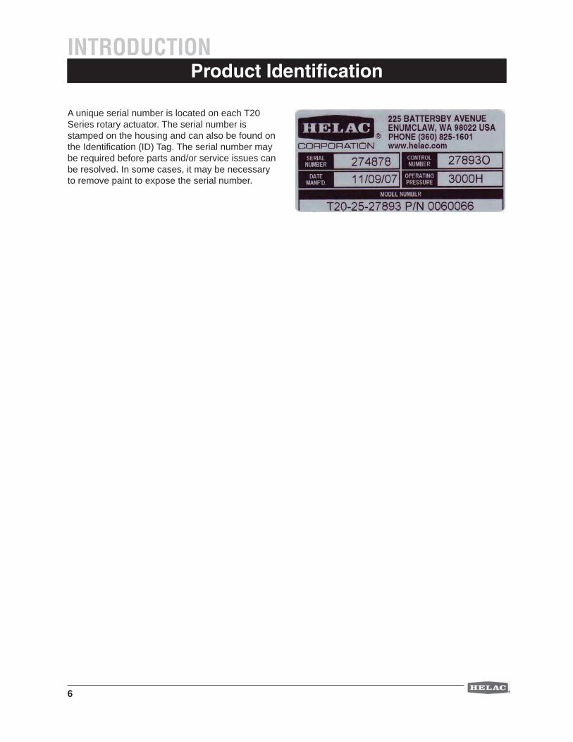
A unique serial number is located on each T20 Series rotary actuator. The serial number is stamped on the housing and can also be found on the Identifi cation (ID) Tag. The serial number may be required before parts and/or service issues can be resolved. In some cases, it may be necessary to remove paint to expose the serial number.
Product Identifi cation
7
MaintenanceMAINTENANCE AND TROUBLESHOOTING
Daily
1. Apply a clean lithium or compatible grease to the grease fi ttings daily when operating the actuator in severe conditions such as abrasive dust or prolonged submersion in water. Apply grease until grease fl ows from the grease reliefs or shaft exclusion seal.
2. Make sure the grease reliefs are functioning properly. Open or replace non-functioning grease reliefs immediately.
NOTICE Never replace the grease relief valves with grease fi ttings or plugs.
Do not operate the actuator if the grease reliefs are not functioning.
Helac Corporation uses a lithium-based grease in assembly. A high quality grease compatible with lithium grease may be used.
Weekly
1. Apply a clean lithium or compatible grease to the grease fi ttings weekly when operating the actuator in non-severe environments and conditions. Apply grease until grease fl ows from the grease reliefs.
2. Make sure the grease reliefs are functioning properly. Open or replace non-functioning grease reliefs immediately.
NOTICE
NOTICE
The T20-25 and T20-45 are greased through the grease zerks on the spline adapters.
The T20-60 is greased through the grease zerks on the housing and grease relief fi ttings on the end cap.
NOTICE
8
Troubleshooting GuideMAINTENANCE AND TROUBLESHOOTING
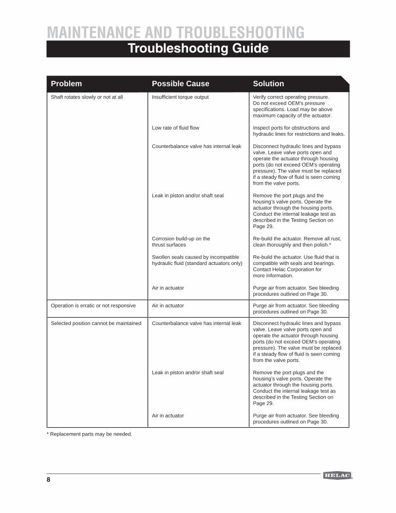
* Replacement parts may be needed.
Problem Possible Cause SolutionShaft rotates slowly or not at all Insuffi cient torque output
Low rate of fl uid fl ow
Counterbalance valve has internal leak
Leak in piston and/or shaft seal
Corrosion build-up on the thrust surfaces
Swollen seals caused by incompatible hydraulic fl uid (standard actuators only)
Air in actuator
Verify correct operating pressure. Do not exceed OEM’s pressure specifi cations. Load may be above maximum capacity of the actuator.
Inspect ports for obstructions and hydraulic lines for restrictions and leaks.
Disconnect hydraulic lines and bypass valve. Leave valve ports open and operate the actuator through housing ports (do not exceed OEM’s operating pressure). The valve must be replaced if a steady fl ow of fl uid is seen coming from the valve ports.
Remove the port plugs and the housing’s valve ports. Operate the actuator through the housing ports. Conduct the internal leakage test as described in the Testing Section on Page 29.
Re-build the actuator. Remove all rust, clean thoroughly and then polish.*
Re-build the actuator. Use fl uid that is compatible with seals and bearings. Contact Helac Corporation for more information.
Purge air from actuator. See bleeding procedures outlined on Page 30.
Operation is erratic or not responsive Air in actuator Purge air from actuator. See bleeding procedures outlined on Page 30.
Selected position cannot be maintained Counterbalance valve has internal leak
Leak in piston and/or shaft seal
Air in actuator
Disconnect hydraulic lines and bypass valve. Leave valve ports open and operate the actuator through housing ports (do not exceed OEM’s operating pressure). The valve must be replaced if a steady fl ow of fl uid is seen coming from the valve ports.
Remove the port plugs and the housing’s valve ports. Operate the actuator through the housing ports. Conduct the internal leakage test as described in the Testing Section on Page 29.
Purge air from actuator. See bleeding procedures outlined on Page 30.
9
Tools Required
1.
2.
3.
4.
5.
6.7.
8.
12.
10.
9.
11.
TOOLS
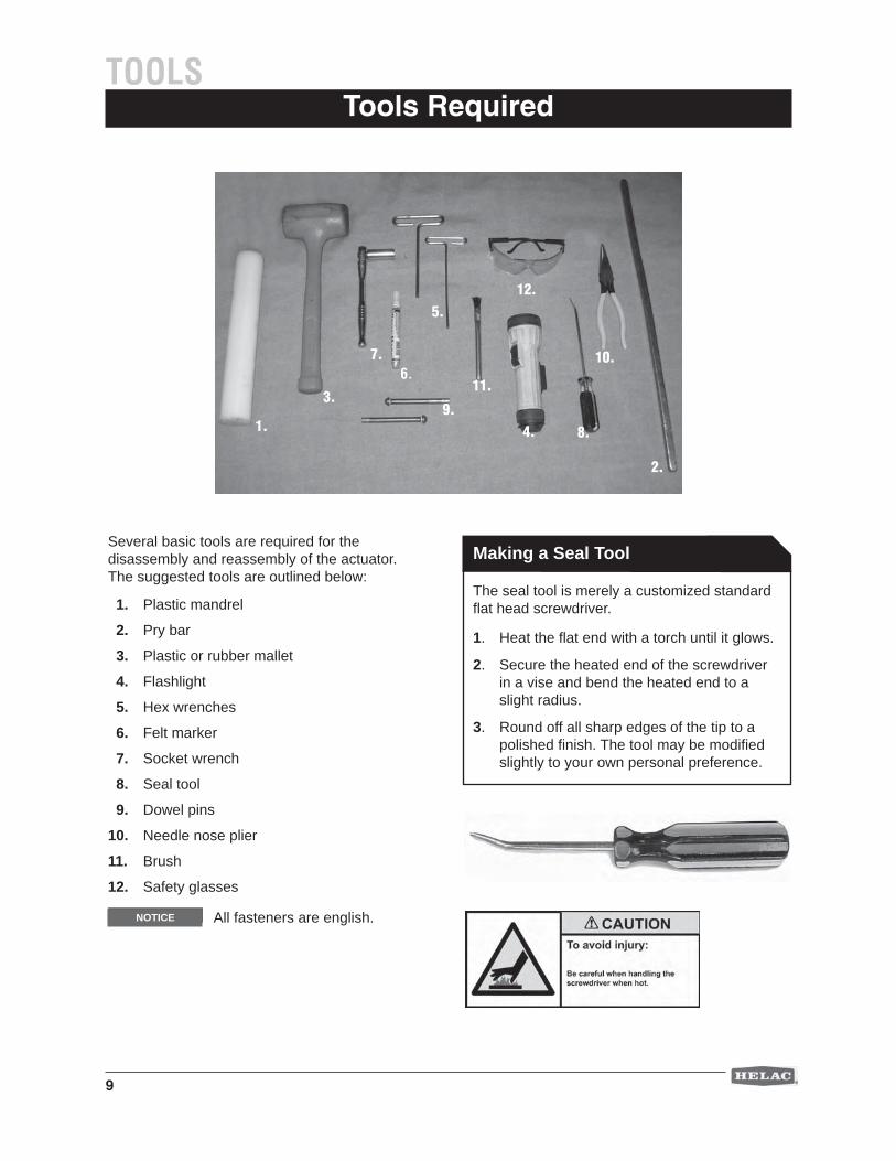
Several basic tools are required for the disassembly and reassembly of the actuator. The suggested tools are outlined below:
1. Plastic mandrel
2. Pry bar
3. Plastic or rubber mallet
4. Flashlight
5. Hex wrenches
6. Felt marker
7. Socket wrench
8. Seal tool
9. Dowel pins
10. Needle nose plier
11. Brush
12. Safety glasses
NOTICE All fasteners are english.
Making a Seal Tool
The seal tool is merely a customized standard fl at head screwdriver.
1. Heat the fl at end with a torch until it glows.
2. Secure the heated end of the screwdriver in a vise and bend the heated end to a slight radius.
3. Round off all sharp edges of the tip to a polished fi nish. The tool may be modifi ed slightly to your own personal preference.
10
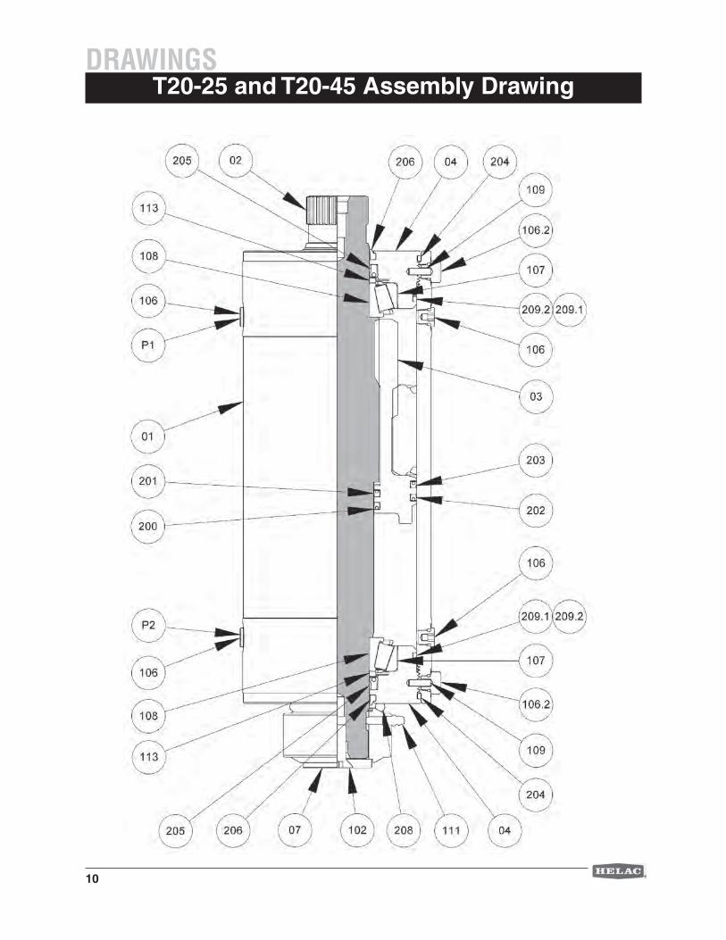
T20-25 and T20-45 Assembly DrawingDRAWINGS
11
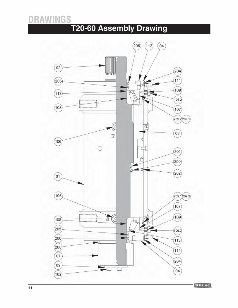
T20-60 Assembly DrawingDRAWINGS
12
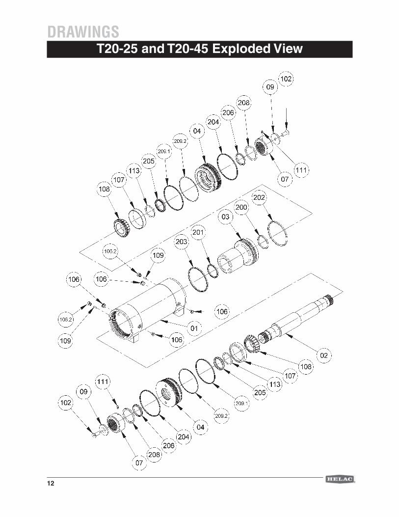
T20-25 and T20-45 Exploded ViewDRAWINGS
13
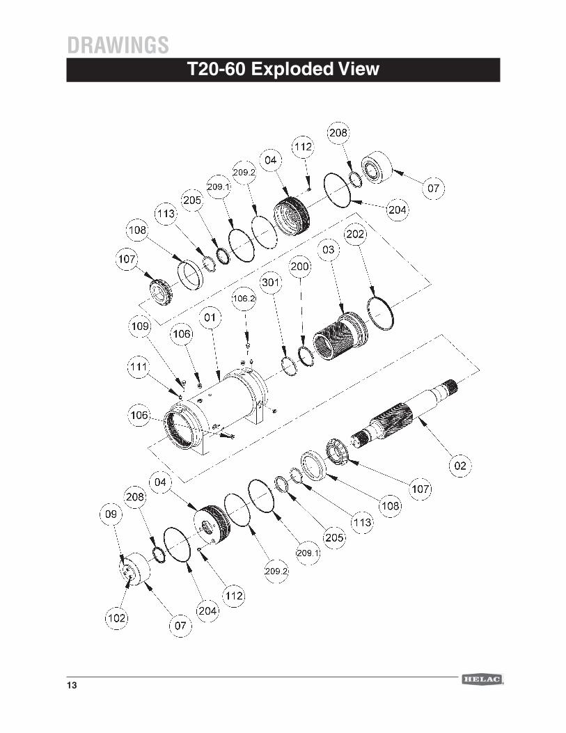
T20-60 Exploded ViewDRAWINGS
14
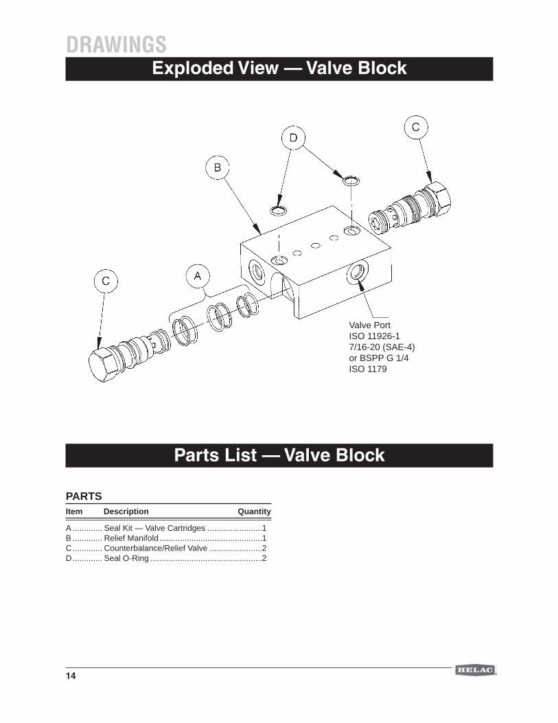
Exploded View — Valve Block
PARTSItem Description Quantity
A ............. Seal Kit — Valve Cartridges ........................1B ............. Relief Manifold .............................................1C ............. Counterbalance/Relief Valve .......................2D ............. Seal O-Ring .................................................2
Parts List — Valve Block
DRAWINGS
Valve Port ISO 11926-17/16-20 (SAE-4) or BSPP G 1/4 ISO 1179
15
PARTSItem Description Quantity
01 ........... Housing ......................................................102 ........... Shaft ...........................................................103 ........... Piston Sleeve .............................................104 ........... End Cap .....................................................207............ T20-60 Adapter ...........................................209............ T20-60 Spacer ............................................2
HARDWAREItem Description Quantity
102 ......... Screw .........................................................2 106 ......... Plug Fitting (SAE-4 or SAE-6) ....................4106.2 ...... SAE-4 Plug Fitting ......................................2107 ......... Cup Bearing ...............................................2108 ......... Cone Bearing .............................................2109 ......... Dowel Pin ...................................................2111 ......... Grease Fitting .............................................2112 .......... T20-60 Grease Relief Valve ........................2113 ......... Spacer ........................................................2
SEALSItem Description Quantity
200 ......... Cup Seal — Piston Sleeve .........................1201 ......... Cup Seal — Piston Sleeve .........................1202 ......... Cup Seal — Piston Sleeve .........................1203 ......... Cup Seal — Piston Sleeve .........................1204 ......... O-Ring Seal — End Cap ............................2205 ......... Cup Seal — Shaft ......................................2206 ......... Wiper Seal — End Cap ..............................2204 ......... O-Ring Seal — End Cap ............................2 208 ......... O-Ring Seal — Spline Adapter ..................2 209.1 ...... O-Ring Seal — End Cap ............................2209.2 ...... B/U Ring Seal — End Cap .........................2301.......... T20-60 Dura Comp Bearings* ....................1
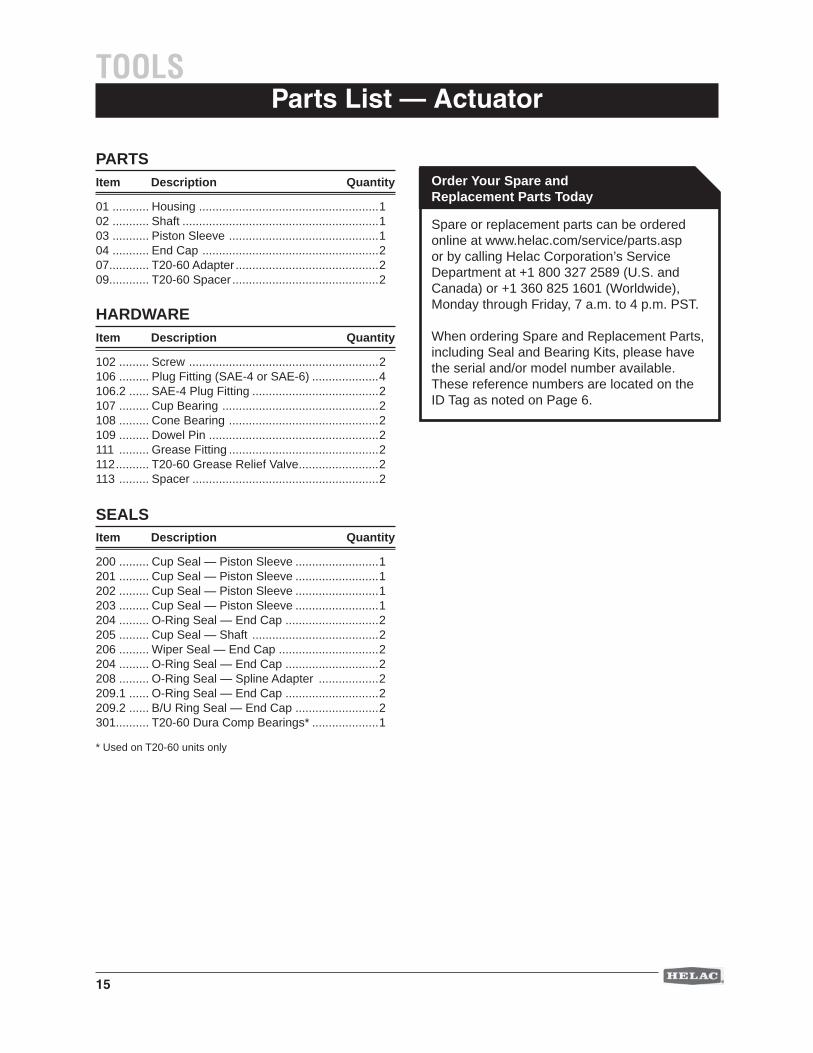
Parts List — ActuatorTOOLS
Spare or replacement parts can be ordered online at www.helac.com/service/parts.asp or by calling Helac Corporation’s Service Department at +1 800 327 2589 (U.S. and Canada) or +1 360 825 1601 (Worldwide), Monday through Friday, 7 a.m. to 4 p.m. PST.
When ordering Spare and Replacement Parts, including Seal and Bearing Kits, please have the serial and/or model number available. These reference numbers are located on the ID Tag as noted on Page 6.
Order Your Spare and Replacement Parts Today
* Used on T20-60 units only
16
DISASSEMBLYComponent Identifi cation
4.
2.
1.
5.
3.
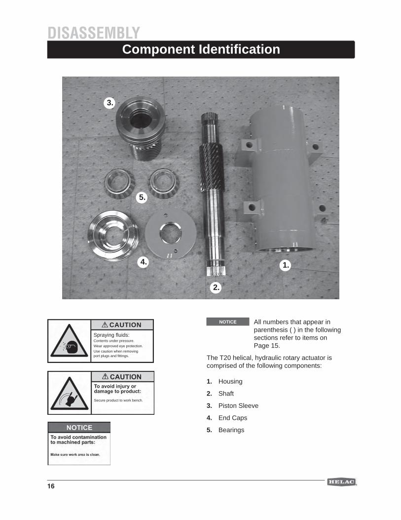
NOTICE All numbers that appear in parenthesis ( ) in the following sections refer to items on Page 15.
The T20 helical, hydraulic rotary actuator is comprised of the following components:
1. Housing
2. Shaft
3. Piston Sleeve
4. End Caps
5. Bearings
Secure product to work bench.
Spraying fl uids:Contents under pressure. Wear approved eye protection.Use caution when removing port plugs and fi ttings.
CAUTION
17
End Cap and Bearing Removal
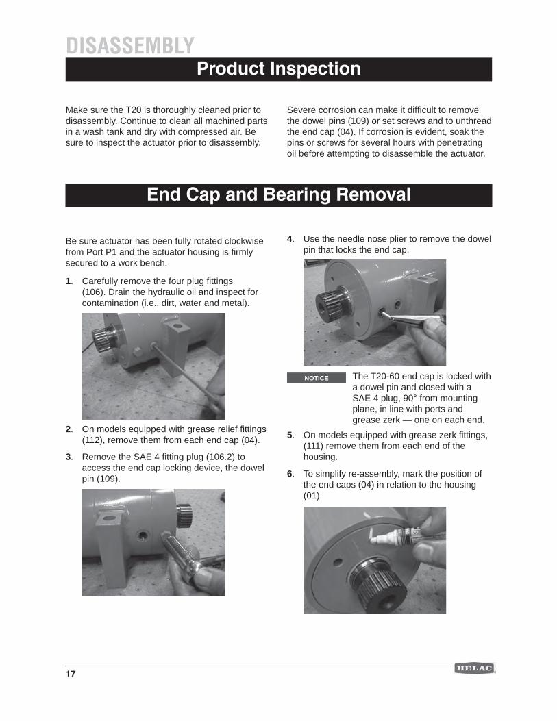
Be sure actuator has been fully rotated clockwise from Port P1 and the actuator housing is fi rmly secured to a work bench.
1. Carefully remove the four plug fi ttings (106). Drain the hydraulic oil and inspect for contamination (i.e., dirt, water and metal).
2. On models equipped with grease relief fi ttings (112), remove them from each end cap (04).
3. Remove the SAE 4 fi tting plug (106.2) to access the end cap locking device, the dowel pin (109).
DISASSEMBLY
4. Use the needle nose plier to remove the dowel pin that locks the end cap.
5. On models equipped with grease zerk fi ttings, (111) remove them from each end of the housing.
6. To simplify re-assembly, mark the position of the end caps (04) in relation to the housing (01).
Product Inspection
Make sure the T20 is thoroughly cleaned prior to disassembly. Continue to clean all machined parts in a wash tank and dry with compressed air. Be sure to inspect the actuator prior to disassembly.
Severe corrosion can make it diffi cult to remove the dowel pins (109) or set screws and to unthread the end cap (04). If corrosion is evident, soak the pins or screws for several hours with penetrating oil before attempting to disassemble the actuator.
The T20-60 end cap is locked with a dowel pin and closed with aSAE 4 plug, 90° from mounting plane, in line with ports and grease zerk — one on each end.
NOTICE
18
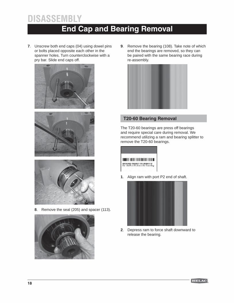
7. Unscrew both end caps (04) using dowel pins or bolts placed opposite each other in the spanner holes. Turn counterclockwise with a pry bar. Slide end caps off.
8. Remove the seal (205) and spacer (113).
End Cap and Bearing Removal
9. Remove the bearing (108). Take note of which end the bearings are removed, so they can be paired with the same bearing race during re-assembly.
DISASSEMBLY
T20-60 Bearing Removal
The T20-60 bearings are press off bearings and require special care during removal. We recommend utilizing a ram and bearing splitter to remove the T20-60 bearings.
1. Align ram with port P2 end of shaft.
2. Depress ram to force shaft downward to release the bearing.
19
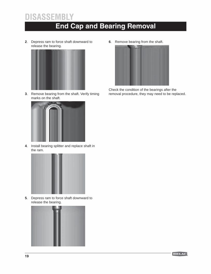
2. Depress ram to force shaft downward to release the bearing.
3. Remove bearing from the shaft. Verify timing marks on the shaft.
4. Install bearing splitter and replace shaft in the ram.
5. Depress ram to force shaft downward to release the bearing.
End Cap and Bearing Removal DISASSEMBLY
6. Remove bearing from the shaft.
Check the condition of the bearings after the removal procedure, they may need to be replaced.
20
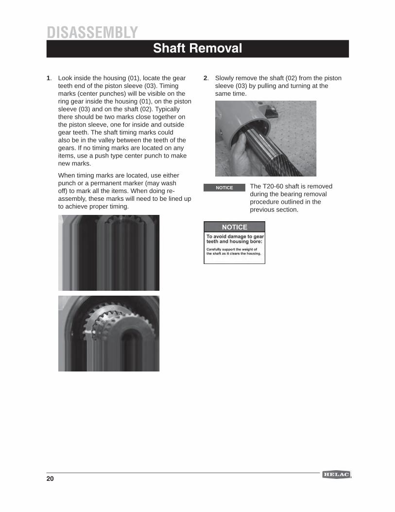
2. Slowly remove the shaft (02) from the piston sleeve (03) by pulling and turning at the same time.
1. Look inside the housing (01), locate the gear teeth end of the piston sleeve (03). Timing marks (center punches) will be visible on the ring gear inside the housing (01), on the piston sleeve (03) and on the shaft (02). Typically there should be two marks close together on the piston sleeve, one for inside and outside gear teeth. The shaft timing marks could also be in the valley between the teeth of the gears. If no timing marks are located on any items, use a push type center punch to make new marks.
When timing marks are located, use either punch or a permanent marker (may wash off) to mark all the items. When doing re-assembly, these marks will need to be lined up to achieve proper timing.
Shaft Removal DISASSEMBLY
The T20-60 shaft is removed during the bearing removal procedure outlined in the previous section.
NOTICE
21
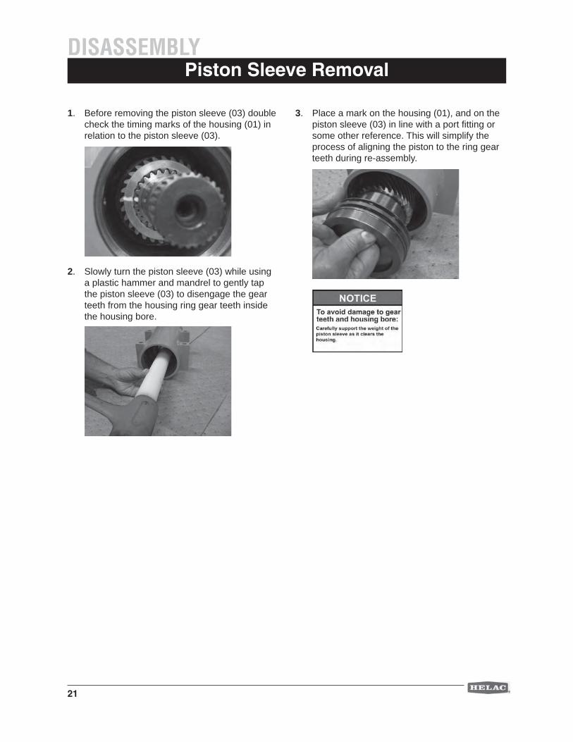
1. Before removing the piston sleeve (03) double check the timing marks of the housing (01) in relation to the piston sleeve (03).
2. Slowly turn the piston sleeve (03) while using a plastic hammer and mandrel to gently tap the piston sleeve (03) to disengage the gear teeth from the housing ring gear teeth inside the housing bore.
Piston Sleeve Removal DISASSEMBLY
3. Place a mark on the housing (01), and on the piston sleeve (03) in line with a port fi tting or some other reference. This will simplify the process of aligning the piston to the ring gear teeth during re-assembly.
22
Seal Removal
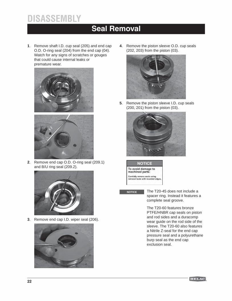
1. Remove shaft I.D. cup seal (205) and end cap O.D. O-ring seal (204) from the end cap (04). Watch for any signs of scratches or gouges that could cause internal leaks or premature wear.
2. Remove end cap O.D. O-ring seal (209.1) and B/U ring seal (209.2).
3. Remove end cap I.D. wiper seal (206).
4. Remove the piston sleeve O.D. cup seals (202, 203) from the piston (03).
5. Remove the piston sleeve I.D. cup seals (200, 201) from the piston (03).
DISASSEMBLY
The T20-45 does not include a spacer ring. Instead it features a complete seal groove.
The T20-60 features bronze PTFE/HNBR cap seals on piston and rod sides and a duracomp wear guide on the rod side of the sleeve. The T20-60 also features a Nitrile Z-seal for the end cap pressure seal and a polyurethane burp seal as the end cap exclusion seal.
NOTICE
23
DISASSEMBLYComponent Inspection
1. Prior to inspection, clean all parts in a wash tank and dry with compressed air.
2. Housing
Inspect the cylinder bore for wear and scratches. Local polishing can repair minor scratches and damage. Inspect all bearing and seal surfaces for signs of wear or damage. Check the condition of the gear teeth for any signs of extreme wear or chipping. Inspect the exterior of the housing for signs of damage or cracking.
3. Shaft
Check the shaft surface for scratches from the piston seal or other damages. Small or minor scratches can be carefully polished. Examine the condition of the gear teeth.
4. End Caps
Inspect the threads for galling or cross threading. Make sure that the end cap spins freely in the threads of the housing. Evaluate the surface fi nish of the seal grooves.
5. Piston Sleeve
Inspect the condition of the gear teeth. Evaluate the surface fi nish of the seal grooves.
6. Bearings
Check bearings for cracks, damage and signs of wear. Bearings showing wear or damage should be replaced.
7. Seals
Helac recommends replacement of all seals.
Timing Mark Inspection
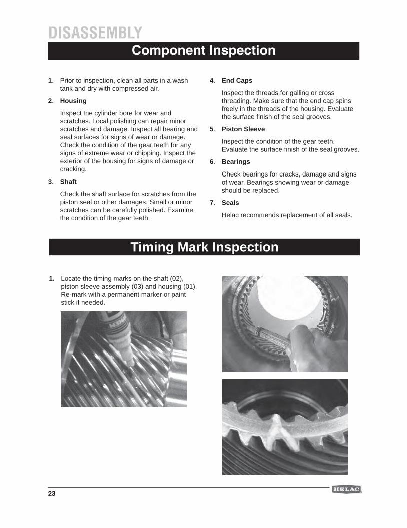
1. Locate the timing marks on the shaft (02), piston sleeve assembly (03) and housing (01). Re-mark with a permanent marker or paint stick if needed.
24
Dry AssemblyASSEMBLY
This will provide a better idea of how to properly align the gear teeth. A "dry" assembly is typically done without seals, yet requires bearing installation.
Seal Installation
Assembly procedures require the housing to be fi rmly secured to the work bench.
Thoroughly clean all components and lubricate all seals, bearings and contact surfaces with hydraulic oil prior to fi nal installation.
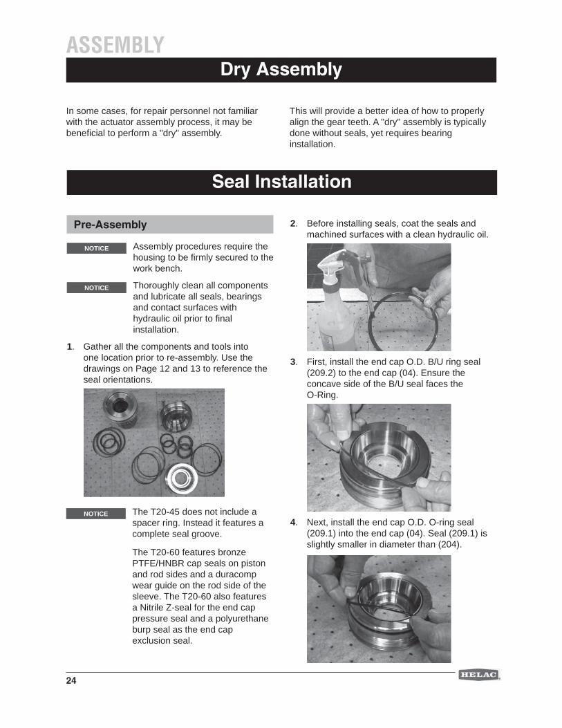
1. Gather all the components and tools into one location prior to re-assembly. Use the drawings on Page 12 and 13 to reference the seal orientations.
2. Before installing seals, coat the seals and machined surfaces with a clean hydraulic oil.
3. First, install the end cap O.D. B/U ring seal (209.2) to the end cap (04). Ensure the concave side of the B/U seal faces the O-Ring.
4. Next, install the end cap O.D. O-ring seal (209.1) into the end cap (04). Seal (209.1) is slightly smaller in diameter than (204).
Pre-Assembly
NOTICE
NOTICE
In some cases, for repair personnel not familiar with the actuator assembly process, it may be benefi cial to perform a "dry" assembly.
The T20-45 does not include a spacer ring. Instead it features a complete seal groove.
The T20-60 features bronze PTFE/HNBR cap seals on piston and rod sides and a duracomp wear guide on the rod side of the sleeve. The T20-60 also features a Nitrile Z-seal for the end cap pressure seal and a polyurethane burp seal as the end cap exclusion seal.
NOTICE
25
Seal InstallationASSEMBLY
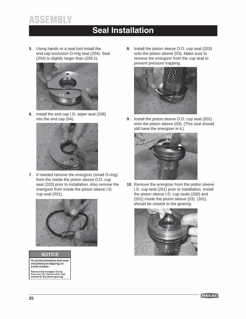
5. Using hands or a seal tool install the end cap exclusion O-ring seal (204). Seal (204) is slightly larger than (209.1).
6. Install the end cap I.D. wiper seal (206) into the end cap (04).
7. If needed remove the energizer (small O-ring) from the inside the piston sleeve O.D. cup seal (203) prior to installation. Also remove the energizer from inside the piston sleeve I.D. cup seal (201).
8. Install the piston sleeve O.D. cup seal (203) onto the piston sleeve (03). Make sure to remove the energizer from the cup seal to prevent pressure trapping.
9. Install the piston sleeve O.D. cup seal (202) onto the piston sleeve (03). (This seal should still have the energizer in it.)
10. Remove the energizer from the piston sleeve I.D. cup seal (201) prior to installation. Install the piston sleeve I.D. cup seals (200) and (201) inside the piston sleeve (03). (201) should be closest to the gearing.
26
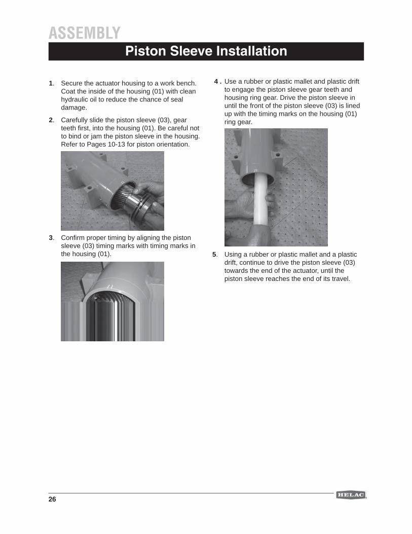
Piston Sleeve Installation
1. Secure the actuator housing to a work bench. Coat the inside of the housing (01) with clean hydraulic oil to reduce the chance of seal damage.
2. Carefully slide the piston sleeve (03), gear teeth fi rst, into the housing (01). Be careful not to bind or jam the piston sleeve in the housing. Refer to Pages 10-13 for piston orientation.
3. Confi rm proper timing by aligning the piston sleeve (03) timing marks with timing marks in the housing (01).
4 . Use a rubber or plastic mallet and plastic drift to engage the piston sleeve gear teeth and housing ring gear. Drive the piston sleeve in until the front of the piston sleeve (03) is lined up with the timing marks on the housing (01) ring gear.
5. Using a rubber or plastic mallet and a plastic drift, continue to drive the piston sleeve (03) towards the end of the actuator, until the piston sleeve reaches the end of its travel.
ASSEMBLY
27
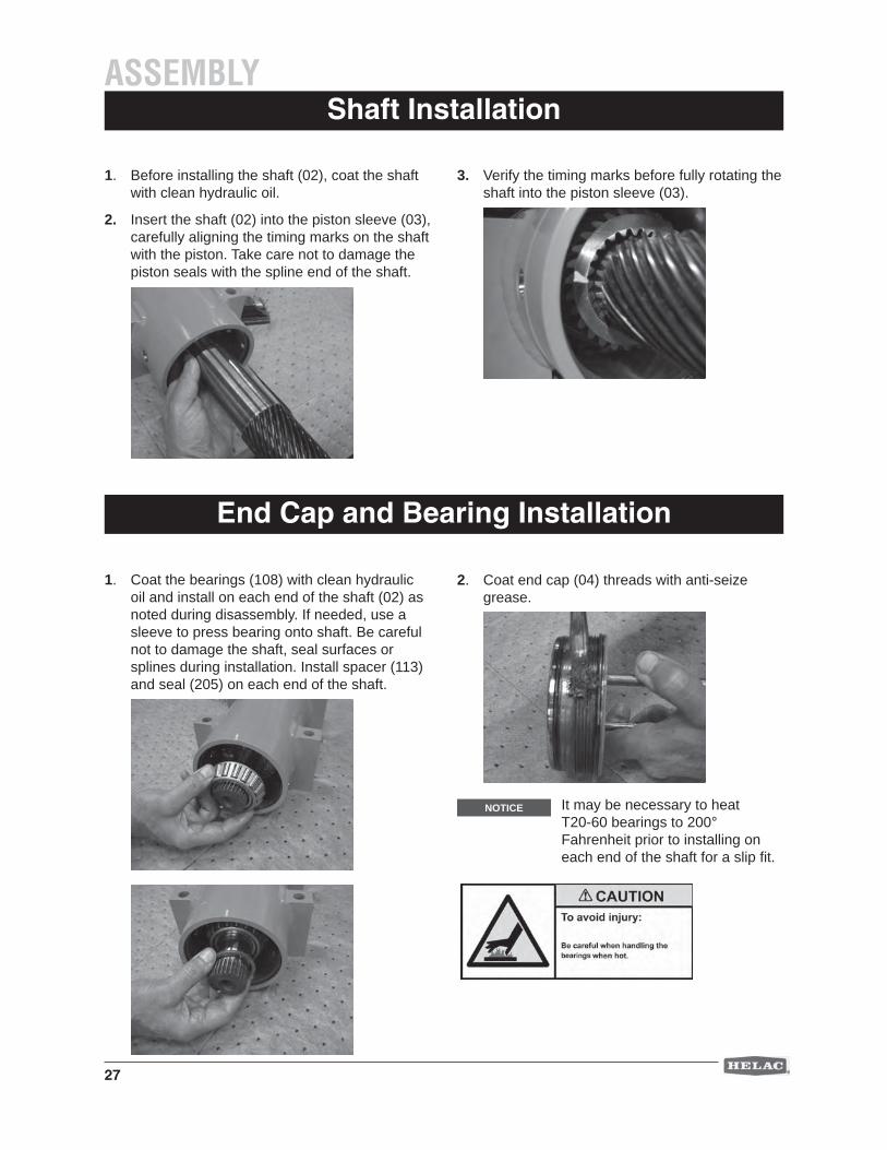
Shaft Installation
1. Before installing the shaft (02), coat the shaft with clean hydraulic oil.
2. Insert the shaft (02) into the piston sleeve (03), carefully aligning the timing marks on the shaft with the piston. Take care not to damage the piston seals with the spline end of the shaft.
3. Verify the timing marks before fully rotating the shaft into the piston sleeve (03).
ASSEMBLY
End Cap and Bearing Installation
1. Coat the bearings (108) with clean hydraulic oil and install on each end of the shaft (02) as noted during disassembly. If needed, use a sleeve to press bearing onto shaft. Be careful not to damage the shaft, seal surfaces or splines during installation. Install spacer (113) and seal (205) on each end of the shaft.
2. Coat end cap (04) threads with anti-seize grease.
It may be necessary to heat T20-60 bearings to 200° Fahrenheit prior to installing on each end of the shaft for a slip fi t.
NOTICE

28
End Cap and Bearing Installation
3. Install end caps (04) one at a time. The fi rst end cap installed must line up with the marks on the housing and dowel pin (109). Next install the second end cap (04) and torque to 200 ft. lbs. Loosen and re-torque end cap to 200 ft. lbs. If the locking pin (109) does not line up within one diameter of the hole, the holes must be re-drilled. If within one diameter, loosen end cap or tighten to align the holes. Both end caps should be very close to fl ush with the end of the housing.
4. For re-drilling actuators with dowel pins (109), use a drill bushing to create a 0.188” diameter hole. Drilled depth should match the dowel pin hole on the opposite end. Do not drill deeper.
5. On models equipped with set screws (105), install them using Loctite 242. Firmly torque, and then back off one-quarter turn. On models equipped with the dowel pin (109) and port plugs (106.2) install them into the housing (01).
6. On models equipped with grease zerks and reliefs, install them on the housing (01). Install grease relief valves on both end caps (04).
7. Shaft seals must then be fi lled with lubricating grease. The grease provides lubrication, prevents water condensation and minimizes water ingress, which can corrode internal surfaces. In order to maximize grease distribution, the actuator should be connected to the hydraulic system of the equipment or a test bench and cycled slowly as grease is applied. Apply grease slowly as the actuator is rotating until grease fl ows from the relief valve. Cycle the actuator and apply grease again.
ASSEMBLY
29
Testing the ActuatorPOST ASSEMBLY
Attach the actuator to either a hydraulic test bench or portable pump for greasing and testing. Make sure the actuator is secured to prevent movement. If not in place, install the grease fi ttings and grease reliefs.
1. After the actuator is assembled but before it is put back into service, the shaft seals must be packed with clean lithium or compatible grease.
2. Locate the grease fi ttings or ports on the actuator and using a grease gun, pack the seals with grease until it exhausts from the grease reliefs.
3. Cycle the actuator slowly and re-grease as necessary. During testing, it is recommended that the actuator be cycled 20 to 30 times to remove air, check for leaks and the proper degrees of rotation.
Secure product to work bench.
Spraying fl uids:Contents under pressure. Wear approved eye protection.Use caution when removing port plugs and fi ttings.
CAUTION
Testing and Greasing
Testing for Internal Leakage
1. Connect a 350 bar test gauge into the hydraulic line to Port P1. Pressurize Port P1 until the shaft reaches the end of rotation.
NOTICE If the shaft is not completely bottomed out, hydraulic fl uid will exhaust from Port P2 at a high velocity.
2. Remove and cap the hydraulic line to Port P2. Pressurize Port P1 to 175 bar. Check for leakage at Port P2 and from around the main shaft and end cap seals. Leaks indicate improperly installed parts.
3. Reconnect the hydraulic line to Port P2 and pressurize P2 as in Step 1 above.
4. Check for leaks at Port P1 and around the main shaft and end cap seals as in Step 2 above.
The T20-25 and T20-45 are greased through the grease zerks on the spline adapters.
The T20-60 is greased through the grease zerks on the housing and grease relief fi ttings on the end cap.
NOTICE
30
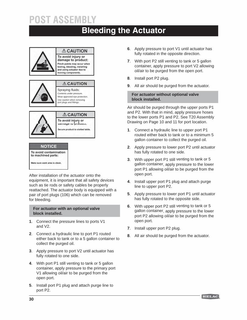
Bleeding the ActuatorPOST ASSEMBLY
After installation of the actuator onto the equipment, it is important that all safety devices such as tie rods or safety cables be properly reattached. The actuator body is equipped with a pair of port plugs (106) which can be removed for bleeding.
For actuator with an optional valve block installed.
1. Connect the pressure lines to ports V1 and V2.
2. Connect a hydraulic line to port P1 routed either back to tank or to a 5 gallon container to collect the purged oil.
3. Apply pressure to port V2 until actuator has fully rotated to one side.
4. With port P1 still venting to tank or 5 gallon container, apply pressure to the primary port V1 allowing oil/air to be purged from the open port.
5. Install port P1 plug and attach purge line to port P2.
6. Apply pressure to port V1 until actuator has fully rotated in the opposite direction.
7. With port P2 still venting to tank or 5 gallon container, apply pressure to port V2 allowing oil/air to be purged from the open port.
8. Install port P2 plug.
9. All air should be purged from the actuator.
For actuator without optional valve block installed.
Air should be purged through the upper ports P1 and P2. With that in mind, apply pressure hoses to the lower ports P1 and P2. See T20 Assembly Drawing on Page 10 and 11 for port location.
1. Connect a hydraulic line to upper port P1 routed either back to tank or to a minimum 5 gallon container to collect the purged oil.
2. Apply pressure to lower port P2 until actuator has fully rotated to one side.
3. With upper port P1 still venting to tank or 5 gallon container, apply pressure to the lower port P1 allowing oil/air to be purged from the open port.
4. Install upper port P1 plug and attach purge line to upper port P2.
5. Apply pressure to lower port P1 until actuator has fully rotated to the opposite side.
6. With upper port P2 still venting to tank or 5 gallon container, apply pressure to the lower port P2 allowing oil/air to be purged from the open port.
7. Install upper port P2 plug.
8. All air should be purged from the actuator.
Spraying fl uids:Contents under pressure. Wear approved eye protection.Use caution when removing port plugs and fi ttings.
CAUTION
31
Standard Warranty Information
Helac Corporation warrants its manufactured products to be free from defective material and factory workmanship. Helac Corporation shall replace or repair such products, which under normal use and service disclose such defects, and return the repaired or replacement products to the purchaser prepaid. Claims under this warranty will be satisfi ed only by repair or replacement of the unit or any defective part thereof. No cash payment or credit will be made for defective materials, workmanship, labor or incidental charges. Products under warranty shall be returned to Helac Corporation’s manufacturing facility at 225 Battersby Avenue, Enumclaw, Washington 98022 USA, transportation prepaid by the purchaser, for inspection by Helac Corporation, whose opinion as to defects shall be conclusive.
The warranty period shall be 12 months from the date of shipment from Helac Corporation’s manufacturing facility for Helac Corporation approved applications. This warranty shall be voided as to any products which have been repaired, worked upon, or altered by persons not authorized by Helac Corporation, or which have been subject to misuse, negligence, accident, or overload. In no event shall Helac Corporation be liable for any incidental or consequential damages.
Helac Corporation reserves the right to make changes in the design or construction of any of its products at any time without incurring any obligations to make changes or alterations to products previously sold.
This warranty is in lieu of all other and/or prior warranties, expressed or implied, and no other company or person is authorized to represent or assume for Helac Corporation any liability in connection with the sale of Helac Corporation products other than set forth herein.
Warranty Information
Return and Debit Policy for Actuators
Unless agreed to in advance, all actuators will be shipped to Helac Corporation, freight prepaid within seven days after receipt of return authorization. Prior to any returns, a Return Material Authorization (RMA) form is to be requested from an authorized Helac Corporation representative. Upon receipt of the RMA form, the customer is to provide when applicable, the part number, serial number, failure date, description of problem and the customer claim or reference number. All shipments to Helac Corporation are to include the completed RMA form.
Upon receipt of the actuator(s) at the Helac Corporation facilities, an inspection will be performed and an authorized representative will provide a written quote. This quote will list the fi ndings of the inspection and will state whether or not the warranty claim has been accepted. Actuators returned for credit may be subject to the Helac Corporation re-stocking fee.
If Helac Corporation does not receive a response to their quote within 30 calendar days, the actuator will be either scrapped or returned and an invoice for the debit amount, including the freight charges, will be sent to the claim originator.
Return and Debit Policy for Service Parts
Return of service parts, normally stocked by Helac Corporation, must be authorized in advance. This will include seal and bearing kits as well as any and all fabricated parts. Return of any special order parts will be authorized on a case-by-case basis. All returns are to be shipped to Helac Corporation freight prepaid within seven days after receipt of return authorization. Helac Corporation has a minimum re-stocking fee of 20 percent.
Prior to any returns, Return Material Authorization (RMA) form is to be requested from an authorized Helac Corporation representative. Upon receipt of the RMA form, the customer is to provide part number, receipt date, description of problem and the customer claim number. All shipments to Helac Corporation are to include the completed RMA form.
POST ASSEMBLY
32
Service OfferingPOST ASSEMBLY
Helac Corporation’s Service Department can effectively tackle your service and repair needs and provide responsive customer support. Our 30 years of extensive rotary actuator expertise coupled with an in-depth understanding of our customers’ expectations, enables us to quickly and effi ciently service your needs with the following three offerings:
Our service representatives have been trained to answer the majority of your technical questions during the initial call. If your question can’t be answered immediately, our representative will return your call quickly.
Call our Technical Support Department at +1 800 327 2589 (U.S. and Canada) or +1 360 825 1601 (Worldwide) from 7 a.m. to 4 p.m. PST on weekdays (excluding holidays), or e-mail us at [email protected].
Repair Service Our fully equipped repair department ensures factory specifi cations and customer expectations are met quickly and effi ciently.
Call or e-mail our Repair Department at +1 800 327 2589 (U.S. and Canada),+1 360 825 1601 (Worldwide) or [email protected].
Our parts service team offers same day or 24 hour turnaround, depending on when the call is received, on all common items.
When ordering Spare and Replacement Parts, including Seal and Bearing Kits, please have the serial and model number available.
Spare parts can be ordered online at www.helac.com/service/parts.asp, or by calling or e-mailing our Parts Department at +1 800 327 2589 (U.S. and Canada), +1 360 825 1601 (Worldwide) or [email protected]
Parts Service
Technical Support

33
Notes

34
Notes

35
Notes

36
HELAC CORPORATION225 BATTERSBY AVENUE • ENUMCLAW, WA 98022 USAPHONE 360.825.1601 • FAX 360.825.1603 • www.helac.com
®
Rev
12-
2007
About Helac Corporation
As a leader in the fl uid power industry for over 30 years, Helac Corporation manufactures a comprehensive line of hydraulic rotary actuators and construction equipment attachments. Helac rotary actuators are best known for their tremendous torque output, compact dimensions, exceptional load bearing capability and rugged,
reliable performance. Helac PowerTilt and PowerGrip, two specialty products, increase the utilization of backhoes and excavators. Over 1,000 worldwide customers in diverse markets depend on Helac's product lines to provide product quality, reliability, ease of use and durability.
Related Documents


