Published Manual Number/ECN: MAP30FXXBE/2006153A • Publishing System: TPAS • Access date: 4/11/2006 • Document ECN's: Latest Available Service— 30022Fxx Washer-Extractors PELLERIN MILNOR CORPORATION POST OFFICE BOX 400, KENNER, LOUISIANA 70063-0400, U.S.A.

Welcome message from author
This document is posted to help you gain knowledge. Please leave a comment to let me know what you think about it! Share it to your friends and learn new things together.
Transcript

Published Manual Number/ECN: MAP30FXXBE/2006153A• Publishing System: TPAS• Access date: 4/11/2006• Document ECN's: Latest Available
Service—
30022FxxWasher-Extractors
PELLERIN MILNOR CORPORATION POST OFFICE BOX 400, KENNER, LOUISIANA 70063-0400, U.S.A.

Please ReadAbout the Manual Identifying Information on the CoverThe front cover displays pertinent identifying information for this manual. Most important, arethe published manual number (part number) /ECN (date code). Generally, when a replacementmanual is furnished, it will have the same published manual number, but the latest available ECN.This provides the user with the latest information applicable to his machine. Similarly alldocuments comprising the manual will be the latest available as of the date the manual wasprinted, even though older ECN dates for those documents may be listed in the table ofcontents.
When communicating with the Milnor factory regarding this manual, please also provide theother identifying information shown on the cover, including the publishing system, access date,and whether the document ECN’s are the latest available or exact.
References to Yellow Troubleshooting PagesThis manual may contain references to “yellow pages.” Although the pages containingtroubleshooting procedures are no longer printed on yellow paper, troubleshooting instructions, ifany, will be contained in the easily located “Troubleshooting” chapter or section. See the table ofcontents.
Trademarks of Pellerin Milnor CorporationThe following, some of which may be used in this manual, are trademarks of Pellerin MilnorCorporation:
Ampsaver® Dye-Extractor® Gear Guardian® Milnet® Staph-Guard®
Autolint® Dyextractor® Hands-Off® Milnor® System 4®
Auto-Purge® E-P Express® Hydro-Cushion® Miltrac System 7®
Autovac E-P OneTouch® Mildata® Miltron Totaltrol®
CBW® E-P Plus®
Comments and SuggestionsHelp us to improve this manual by sending your comments to:
Pellerin Milnor CorporationAttn: Technical PublicationsP. O. Box 400Kenner, LA 70063-0400
Fax: (504) 469-1849
Table of Contentsfor MAP30FXXBE/2006153A30022Fxx Washer-Extractors
Page Description Document/ECN
1 About This Manual MHP30FXXAE/9541AV
3 Warranty BMP720097/92732A
5 How to Order Parts BMP720097R/72332A
6 Safety—Suspended, Open Pocket, Non-tilting Washer-Extractors BIUUUS27/20051111
12 About the Forces Transmitted by Milnor Washer-Extractors BIWUUI02/20001108
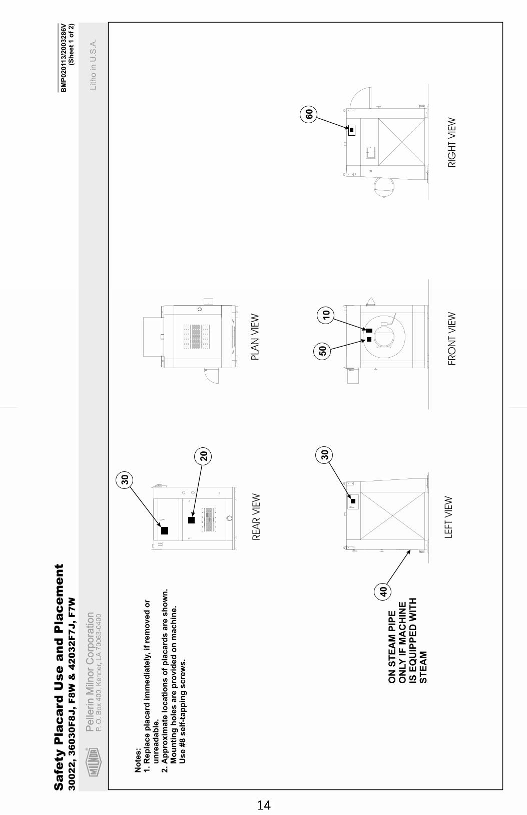
14 Safety Placard Use and Placement 3022,3630F8J,F8W & 4232F7J,F7W BMP020113/2003286V
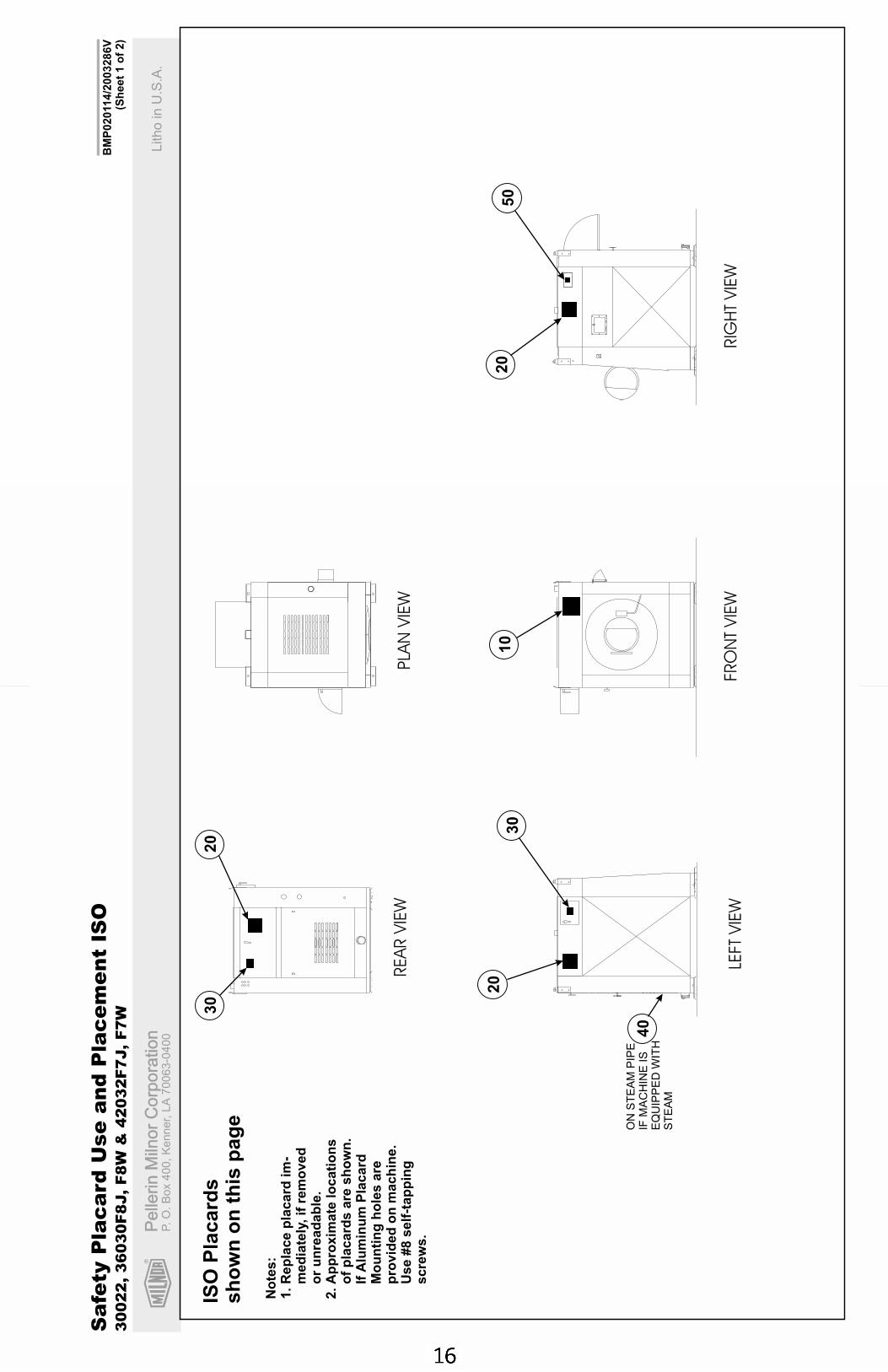
16 Safety Placard Use and Placement ISO 3022,3630F8J,F8W & 4232F7J,F7W BMP020114/2003286V
18 Glossary of Tag Illustrations - F-Style, Q-Style, 36" & 42" V-Style and X-Style Washer-Extractors MSIUUQTGAE/2003045V
23 Avoiding Damage from Allied Remote Chemical Delivery Systems BIWUUI03/20030306
29 Section 1: Service and Maintenance30 Preventive Maintenance BIIFUM01/20030311
36 Replacing 30Fxx Main Bearings MSSM0261BE/9933AV
41 Fastener Torque Requirements MSSM0101CE/9906AV
61 Section 2: Covers, Safety and Shipping Brackets62 Installation Guards & Covers - 30022F8J, F8P, F8W BMP940036/94177V
63 Shipping Bracket Installation BMP010031/2002076V
65 Section 3: Frame and Housing Assemblies66 House and Shell Vent Installation - 30022F8J, F8P, F8W BMP940043/94201V
69 Section 4: Suspension70 Marshmallow Spring Suspension BMP010029/2002076V
72 Shock Absorber Installation BMP010030/2002076V
74 Excursion Switch BMP940035/2002076V
75 Section 5: Drive Assemblies76 Drive Chart 3022F8J, F8W, J8P BMP050026/2005135V
77 Installation Drive Base Assembly - 30022F8J, F8P, F8W BMP940034/94177V
79 Main Bearing Installation - 3022F8J, F8P, F8W BMP940032/98053V
81 Main Bearing BMP980022/2003066V
83 Cylinder Installation - 30022F8J, F8P, F8W BMP940033/94162V
85 Section 6: Shell and Door Assemblies86 Installation Shellfront - 30022F8J, F8P, F8W BMP940046/94223V
88 Door Assembly BMP920009/2001036V
90 Interlock Assembly BMP750046/2001036V
93 Section 7: Water and Steam Piping and Assemblies
Table of Contents, cont.Page Description Document/ECN
94 Water Inlet Assembly BMP010032/2002076V
96 Hays Electric Inlet Valves BMP700710/96081V
98 Pressure Regulators BMP900031/96081V
100 Installation Drain Assembly - 30022F8J/F8P/F8W BMP940055/94212V
102 3" Electric Drain Valve BMP920017/2002044V
105 Section 8: Chemical Supply Devices106 Soap Chute BMP010023/2004333V
108 Peristaltic Soapchute BMP940050/2002076V
110 Five Compartment Dry Supply Assembly and Installation - 30022F8J/F8P/F8W BMP940053/94202V
112 Assembly 6 Valve Soap Manifold - 30022F8J, F8P, F8W BMP940052/94202V

MHP30FXXAE/9541AV (1 of 1)
ABOUT THIS MANUAL
Scope —This instruction manual is intended to provide preventive maintenance procedures, service proce-dures and mechanical parts identification for all Milnor® 30022Fxx suspended washer-extractors. Measurementsare in common US and metric units unless otherwise noted. Always use new fasteners when replacing or repair-ing parts. See the safety manual for safety instructions before installing, servicing, or operating this machine. Seethe installation guide for facility requirements, installation instructions, and assembly instructions. See the op-erator guide for operator instructions. See the reference manual for programming, operating, and trouble shootinginstructions. See the schematic manual for electrical parts identification and electrical trouble shooting.
Trademarks of Pellerin Milnor Corporation —The following, some of which may be used in thispublication, are trademarks of Pellerin Milnor Corporation:
Ampsaver®
Autolint®
Auto-Purge®
Autovac
CBW®
Dye-Extractor®
Dyextractor®
E-P Plus®
Gear Guardian®
Hands-Off®
Hydro-Cushion®
Mildata®
Milnet®
Milnor®
MiltracMiltron
Staph-Guard®
System 4®
System 7®
Totaltrol®
Manual Number/Date Code (When To Discard or Save) —The manual number/date code islocated on the inside front cover, upper right corner just above the manual name. Whenever the manual is re-printed with new information, part of this number changes. If the date code after the “/” changes, the newversion applies to all machines covered by the old version, but is improved— thus the old version can bediscarded. If the manual number before the “/” changes, the new manual covers only new machines. Ex-ample: Discard MATMODELAE/8739CV when MATMODELAE/8739DV is received (minor improvements).Also, discard MATMODELAE/8739DV when MATMODELAE/8746AV is received (major improvements).But keep MATMODELAE/8746FV when MATMODELBE/8815AV is received, since the new manual nolonger applies to machines originally shipped with the old manual.
Documents and Change Bars —The individual documents comprising this manual use the same revi-sion criteria as the manual. Text documents also display change bars. Example: When sectionMSOP0599AE/9135BV becomes MSOP0599AE/9135CV, change bars with the letter “C” appear next to allchanges for this revision. For a major rewrite (e.g., MSOP0599AE/9226AV), all change bars are deleted.
For Assistance —Please call:
Pellerin Milnor CorporationAttn: Service DepartmentP. O. Box 400Kenner, LA 70063-0400
Phone: (504) 467-9591Fax: (504) 467-9777

3(//(5,1�0,/125�&25325$7,21
/,0,7('�67$1'$5'�:$55$17<
We warrant to the original purchaser that MILNOR machines including electronichardware/software (hereafter referred to as “equipment”), will be free from defects in materialand workmanship for a period of one year from the date of shipment from our factory with nooperating hour limitation. This warranty is contingent upon the equipment being installed,operated and serviced as specified in the operating manual supplied with the equipment, andoperated under normal conditions by competent operators.
Providing we receive written notification of a warranted defect within 30 days of its discovery,we will – at our option – repair or replace the defective part or parts, FOB our factory. Weretain the right to require inspection of the parts claimed defective in our factory prior torepairing or replacing same. We will not be responsible, or in any way liable, for unauthorizedrepairs or service to our equipment, and this warranty shall be void if the equipment is repairedor altered in any way without MILNOR’s written consent.
Parts which require routine replacement due to normal wear – such as gaskets, contact points,brake and clutch linings and similar parts – are not covered by this warranty, nor are partsdamaged by exposure to weather or to chemicals.
We reserve the right to make changes in the design and/or construction of our equipment(including purchased components) without obligation to change any equipment previouslysupplied.
ANY SALE OR FURNISHING OF ANY EQUIPMENT BY MILNOR IS MADE ONLY UPONTHE EXPRESS UNDERSTANDING THAT MILNOR MAKES NO EXPRESSED OR IMPLIEDWARRANTIES OF MERCHANTABILITY OR FITNESS FOR ANY PARTICULAR USE ORPURPOSE. MILNOR WILL NOT BE RESPONSIBLE FOR ANY COSTS OR DAMAGESACTUALLY INCURRED OR REQUIRED AS A RESULT OF: THE FAILURE OF ANY OTHERPERSON OR ENTITY TO PERFORM ITS RESPONSIBILITIES, FIRE OR OTHER HAZARD,ACCIDENT, IMPROPER STORAGE, MISUSE, NEGLECT, POWER OR ENVIRONMENTALCONTROL MALFUNCTIONS, DAMAGE FROM LIQUIDS, OR ANY OTHER CAUSE BEYONDTHE NORMAL RANGE OF USE. REGARDLESS OF HOW CAUSED, IN NO EVENT SHALLMILNOR BE LIABLE FOR SPECIAL, INDIRECT, PUNITIVE, LIQUIDATED, ORCONSEQUENTIAL COSTS OR DAMAGES, OR ANY COSTS OR DAMAGES WHATSOEVERWHICH EXCEED THE PRICE PAID TO MILNOR FOR THE EQUIPMENT IT SELLS ORFURNISHES.
WE NEITHER ASSUME, NOR AUTHORIZE ANY EMPLOYEE OR OTHER PERSON TOASSUME FOR US, ANY OTHER RESPONSIBILITY AND/OR LIABILITY IN CONNECTIONWITH THE SALE OR FURNISHING OF OUR EQUIPMENT TO ANY BUYER.
BMP72009792732A


How to order repair parts
Repair parts may be ordered either from the authorized dealer who sold you thismachine, or directly from the MILNOR factory. In most cases, your dealer willhave these parts in stock.
When ordering parts, please be sure to give us the following information:
1. Model and serial number of the machine for which the parts are required
2. Part number
3. Name of the part
4. Quantity needed
5. Method of shipment desired
6. In correspondence regarding motors or electrical controls, please include allnameplate data, including wiring diagram number and the make ormanufacturer of the motor or controls.
All parts will be shipped C.O.D. transportation charges collect only.
Please read this manual
It is strongly recommended that you read the installation and operating manualbefore attempting to install or operate your machine. We suggest that this manualbe kept in your business office so that it will not become lost.
PELLERIN MILNOR CORPORATION3�2��%2;������.(11(5��/$���������������8�6�$�
FAX: Administration 504/468-9307, Engineering 504/469-1849, Service 504/469-9777
BMP720097R72332A

PELLERIN MILNOR CORPORATION
BIUUUS27 (Published) Book specs- Dates: 20051111 / 20051111 / 20060323 Lang: ENG01 Applic: IFN HON MXU
Safety—Suspended, Open Pocket, Non-tilting Washer-Extractors
1. General Safety Requirements—Vital Information forManagement Personnel [Document BIUUUS04]Incorrect installation, neglected preventive maintenance, abuse, and/or improper repairs, orchanges to the machine can cause unsafe operation and personal injuries, such as multiplefractures, amputations, or death. The owner or his selected representative (owner/user) isresponsible for understanding and ensuring the proper operation and maintenance of the machine.The owner/user must familiarize himself with the contents of all machine instruction manuals.The owner/user should direct any questions about these instructions to a Milnor® dealer or theMilnor® Service department.
Most regulatory authorities (including OSHA in the USA and CE in Europe) hold the owner/userultimately responsible for maintaining a safe working environment. Therefore, the owner/usermust do or ensure the following:
• recognize all foreseeable safety hazards within his facility and take actions to protect hispersonnel, equipment, and facility;
• work equipment is suitable, properly adapted, can be used without risks to health or safety,and is adequately maintained;
• where specific hazards are likely to be involved, access to the equipment is restricted to thoseemployees given the task of using it;
• only specifically designated workers carry out repairs, modifications, maintenance, orservicing;
• information, instruction, and training is provided;• workers and/or their representatives are consulted.
Work equipment must comply with the requirements listed below. The owner/user must verifythat installation and maintenance of equipment is performed in such a way as to support theserequirements:
• control devices must be visible, identifiable, and marked; be located outside dangerous zones;and not give rise to a hazard due to unintentional operation;
• control systems must be safe and breakdown/damage must not result in danger;• work equipment is to be stabilized;• protection against rupture or disintegration of work equipment;• guarding, to prevent access to danger zones or to stop movements of dangerous parts before
the danger zones are reached. Guards to be robust; not give rise to any additional hazards; notbe easily removed or rendered inoperative; situated at a sufficient distance from the dangerzone; not restrict view of operating cycle; allow fitting, replacing, or maintenance byrestricting access to relevant area and without removal of guard/protection device;
• suitable lighting for working and maintenance areas;• maintenance to be possible when work equipment is shut down. If not possible, then
protection measures to be carried out outside danger zones;• work equipment must be appropriate for preventing the risk of fire or overheating; discharges
of gas, dust, liquid, vapor, other substances; explosion of the equipment or substances in it.

Safety—Suspended, Open Pocket, Non-tilting Washer-Extractors
PELLERIN MILNOR CORPORATION
1.1. Laundry Facility—Provide a supporting floor that is strong and rigid enough to support–witha reasonable safety factor and without undue or objectionable deflection–the weight of the fullyloaded machine and the forces transmitted by it during operation. Provide sufficient clearance formachine movement. Provide any safety guards, fences, restraints, devices, and verbal and/orposted restrictions necessary to prevent personnel, machines, or other moving machinery fromaccessing the machine or its path. Provide adequate ventilation to carry away heat and vapors.Ensure service connections to installed machines meet local and national safety standards,especially regarding the electrical disconnect (see the National Electric Code). Prominently postsafety information, including signs showing the source of electrical disconnect.
1.2. Personnel—Inform personnel about hazard avoidance and the importance of care andcommon sense. Provide personnel with the safety and operating instructions that apply to them.Verify that personnel use proper safety and operating procedures. Verify that personnelunderstand and abide by the warnings on the machine and precautions in the instruction manuals.
1.3. Safety Devices—Ensure that no one eliminates or disables any safety device on the machineor in the facility. Do not allow machine to be used with any missing guard, cover, panel or door.Service any failing or malfunctioning device before operating the machine.
1.4. Hazard Information—Important information on hazards is provided on the machine safetyplacards, in the Safety Guide, and throughout the other machine manuals. Placards must be keptclean so that the information is not obscured. They must be replaced immediately if lost ordamaged. The Safety Guide and other machine manuals must be available at all times tothe appropriate personnel. See the machine service manual for safety placard part numbers.Contact the Milnor Parts department for replacement placards or manuals.
1.5. Maintenance—Ensure the machine is inspected and serviced in accordance with the norms ofgood practice and with the preventive maintenance schedule. Replace belts, pulleys, brakeshoes/disks, clutch plates/tires, rollers, seals, alignment guides, etc. before they are severelyworn. Immediately investigate any evidence of impending failure and make needed repairs (e.g.,cylinder, shell, or frame cracks; drive components such as motors, gear boxes, bearings, etc.,whining, grinding, smoking, or becoming abnormally hot; bending or cracking of cylinder, shell,frame, etc.; leaking seals, hoses, valves, etc.) Do not permit service or maintenance byunqualified personnel.
2. Safety Alert Messages—Internal Electrical and MechanicalHazards [Document BIUUUS11]The following are instructions about hazards inside the machine and in electrical enclosures.
WARNING 1 : Electrocution and Electrical Burn Hazards—Contact with electric powercan kill or seriously injure you. Electric power is present inside the cabinetry unless the mainmachine power disconnect is off.• Do not unlock or open electric box doors.• Do not remove guards, covers, or panels.• Do not reach into the machine housing or frame.• Keep yourself and others off of machine.• Know the location of the main machine disconnect and use it in an emergency to remove
all electric power from the machine.

PELLERIN MILNOR CORPORATION
WARNING 2 : Entangle and Crush Hazards—Contact with moving components normallyisolated by guards, covers, and panels, can entangle and crush your limbs. These componentsmove automatically.• Do not remove guards, covers, or panels.• Do not reach into the machine housing or frame.• Keep yourself and others off of machine.• Know the location of all emergency stop switches, pull cords, and/or kick plates and use
them in an emergency to stop machine motion.
3. Safety Alert Messages—External Mechanical Hazards [DocumentBIUUUS12]The following are instructions about hazards around the front, sides, rear or top of the machine.
WARNING 3 : Crush Hazards—Suspended machines only—Spaces between the shell andhousing can close and crush or pinch your limbs. The shell moves within the housing duringoperation.• Do not reach into the machine housing or frame.• Keep yourself and others clear of movement areas and paths.
4. Safety Alert Messages—Cylinder and Processing Hazards[Document BIUUUS13]The following are instructions about hazards related to the cylinder and laundering process.
DANGER 4 : Entangle and Sever Hazards—Contact with goods being processed cancause the goods to wrap around your body or limbs and dismember you. The goods are normallyisolated by the locked cylinder door.• Do not attempt to open the door or reach into the cylinder until the cylinder is stopped.• Do not touch goods inside or hanging partially outside the turning cylinder.• Do not operate the machine with a malfunctioning door interlock.• Open pocket machines only—Do not jog the cylinder and pull the goods at the same time.• Open pocket machines only—Keep yourself and others clear of cylinder and goods during
jogging operation.• Do not operate the machine with malfunctioning two-hand manual controls.• Know the location of all emergency stop switches, pull cords, and/or kick plates and use
them in an emergency to stop machine motion.• Know the location of the main machine disconnect and use it in an emergency to remove
all electric power from the machine.
WARNING 5 : Crush Hazards—Contact with the turning cylinder can crush your limbs. Thecylinder will repel any object you try to stop it with, possibly causing the object to strike or stabyou. The turning cylinder is normally isolated by the locked cylinder door.• Do not attempt to open the door or reach into the cylinder until the cylinder is stopped.• Do not place any object in the turning cylinder.• Do not operate the machine with a malfunctioning door interlock.• Open pocket machines only—Keep yourself and others clear of cylinder and goods during
jogging operation.

Safety—Suspended, Open Pocket, Non-tilting Washer-Extractors
PELLERIN MILNOR CORPORATION
• Do not operate the machine with malfunctioning two-hand manual controls.
WARNING 6 : Confined Space Hazards—Confinement in the cylinder can kill or injureyou. Hazards include but are not limited to panic, burns, poisoning, suffocation, heat prostration,biological contamination, electrocution, and crushing.• Do not attempt unauthorized servicing, repairs, or modification.
WARNING 7 : Explosion and Fire Hazards—Flammable substances can explode or ignitein the cylinder, drain trough, or sewer. The machine is designed for washing with water, not anyother solvent. Processing can cause solvent-containing goods to give off flammable vapors.• Do not use flammable solvents in processing.• Do not process goods containing flammable substances. Consult with your local fire
department/public safety office and all insurance providers.
5. Safety Alert Messages—Unsafe Conditions [Document BIUUUS14]
5.1. Damage and Malfunction Hazards
5.1.1. Hazards Resulting from Inoperative Safety Devices
DANGER 8 : Entangle and Sever Hazards—Cylinder door interlock—Operating themachine with a malfunctioning door interlock can permit opening the door when the cylinder isturning and/or starting the cycle with the door open, exposing the turning cylinder.• Do not operate the machine with any evidence of damage or malfunction.
WARNING 9 : Multiple Hazards—Operating the machine with an inoperative safety devicecan kill or injure personnel, damage or destroy the machine, damage property, and/or void thewarranty.• Do not tamper with or disable any safety device or operate the machine with a
malfunctioning safety device. Request authorized service.
WARNING 10 : Electrocution and Electrical Burn Hazards—Electric box doors—Operating the machine with any electric box door unlocked can expose high voltage conductorsinside the box.• Do not unlock or open electric box doors.
WARNING 11 : Entangle and Crush Hazards—Guards, covers, and panels—Operatingthe machine with any guard, cover, or panel removed exposes moving components.• Do not remove guards, covers, or panels.
5.1.2. Hazards Resulting from Damaged Mechanical Devices
WARNING 12 : Multiple Hazards—Operating a damaged machine can kill or injurepersonnel, further damage or destroy the machine, damage property, and/or void the warranty.• Do not operate a damaged or malfunctioning machine. Request authorized service.
WARNING 13 : Explosion Hazards—Cylinder—A damaged cylinder can rip apart duringextraction, puncturing the shell and discharging metal fragments at high speed.• Do not operate the machine with any evidence of damage or malfunction.
PELLERIN MILNOR CORPORATION
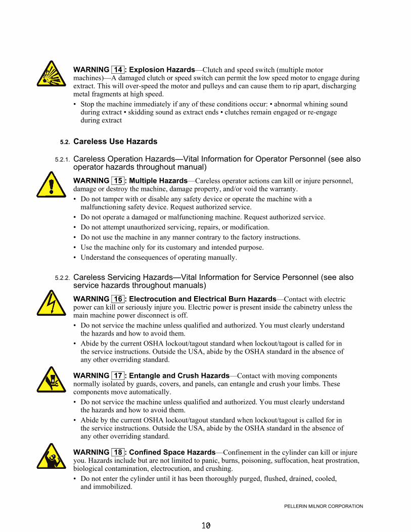
WARNING 14 : Explosion Hazards—Clutch and speed switch (multiple motormachines)—A damaged clutch or speed switch can permit the low speed motor to engage duringextract. This will over-speed the motor and pulleys and can cause them to rip apart, dischargingmetal fragments at high speed.• Stop the machine immediately if any of these conditions occur: • abnormal whining sound
during extract • skidding sound as extract ends • clutches remain engaged or re-engageduring extract
5.2. Careless Use Hazards
5.2.1. Careless Operation Hazards—Vital Information for Operator Personnel (see alsooperator hazards throughout manual)
WARNING 15 : Multiple Hazards—Careless operator actions can kill or injure personnel,damage or destroy the machine, damage property, and/or void the warranty.• Do not tamper with or disable any safety device or operate the machine with a
malfunctioning safety device. Request authorized service.• Do not operate a damaged or malfunctioning machine. Request authorized service.• Do not attempt unauthorized servicing, repairs, or modification.• Do not use the machine in any manner contrary to the factory instructions.• Use the machine only for its customary and intended purpose.• Understand the consequences of operating manually.
5.2.2. Careless Servicing Hazards—Vital Information for Service Personnel (see alsoservice hazards throughout manuals)
WARNING 16 : Electrocution and Electrical Burn Hazards—Contact with electricpower can kill or seriously injure you. Electric power is present inside the cabinetry unless themain machine power disconnect is off.• Do not service the machine unless qualified and authorized. You must clearly understand
the hazards and how to avoid them.• Abide by the current OSHA lockout/tagout standard when lockout/tagout is called for in
the service instructions. Outside the USA, abide by the OSHA standard in the absence ofany other overriding standard.
WARNING 17 : Entangle and Crush Hazards—Contact with moving componentsnormally isolated by guards, covers, and panels, can entangle and crush your limbs. Thesecomponents move automatically.• Do not service the machine unless qualified and authorized. You must clearly understand
the hazards and how to avoid them.• Abide by the current OSHA lockout/tagout standard when lockout/tagout is called for in
the service instructions. Outside the USA, abide by the OSHA standard in the absence ofany other overriding standard.
WARNING 18 : Confined Space Hazards—Confinement in the cylinder can kill or injureyou. Hazards include but are not limited to panic, burns, poisoning, suffocation, heat prostration,biological contamination, electrocution, and crushing.• Do not enter the cylinder until it has been thoroughly purged, flushed, drained, cooled,
and immobilized.

Safety—Suspended, Open Pocket, Non-tilting Washer-Extractors
PELLERIN MILNOR CORPORATION
— End of BIUUUS27 —

About the Forces Transmitted by Milnor® Washer-extractors
Document ..................... BIWUUI02Specified Date ................. 20001108As-of Date ....................... 20001108Access Date ..................... 20001108
About the Forces Transmitted by Milnor®
Washer-extractorsApplicability...........................WUU
During washing and extracting, all washer-extractors transmit both static and dynamic(cyclic) forces to the floor, foundation, or any other supporting structure. During washing, theimpact of the goods as they drop imparts forces which are quite difficult to quantify. Size for size,both rigid and flexibly-mounted machines transmit approximately the same forces duringwashing. During extracting, rigid machines transmit forces up to 30 times greater than equivalentflexibly-mounted models. The actual magnitude of these forces vary according to several factors:
• machine size,
• final extraction speed,
• amount, condition, and type of goods being processed,
• the liquor level and chemical conditions in the bath preceding extraction, and
• other miscellaneous factors.
Estimates of the maximum force normally encountered are available for each Milnor® modeland size upon request. Floor or foundation sizes shown on any Milnor® document are only foron-grade situations based only on previous experience without implying any warranty, obligation,or responsibility on our part.
1. Rigid MachinesSize for size, rigid washer-extractors naturally require a stronger, more rigid floor,
foundation, or other supporting structure than flexibly-mounted models. If the supporting soilunder the slab is itself strong and rigid enough and has not subsided to leave the floor slabsuspended without support, on grade installations can often be made directly to an existing floorslab if it has enough strength and rigidity to safely withstand our published forces withouttransmitting undue vibration. If the subsoil has subsided, or if the floor slab itself has insufficientstrength and rigidity, a deeper foundation, poured as to become monolithic with the floor slab,may be required. Support pilings may even be required if the subsoil itself is “springy” (i.e., if itsresonant frequency is near the operating speed of the machine). Above-grade installations of rigidmachines also require a sufficiently strong and rigid floor or other supporting structure asdescribed below.
2. Flexibly-mounted MachinesSize for size, flexibly-mounted machines generally do not require as strong a floor,
foundation, or other supporting structure as do rigid machines. However, a floor or othersupporting structure having sufficient strength and rigidity, as described in section 3, isnonetheless vitally important for these models as well.
3. How Strong and Rigid?Many building codes in the U.S.A. specify that laundry floors must have a minimum live
load capacity of 150 pounds per square foot (732 kilograms per square meter). However, evencompliance with this or any other standard does not necessarily guarantee sufficient rigidity. Inany event, it is the sole responsibility of the owner/user to assure that the floor and/or any othersupporting structure exceeds not only all applicable building codes, but also that the floor and/orany other supporting structure for each washer-extractor or group of washer-extractors actually
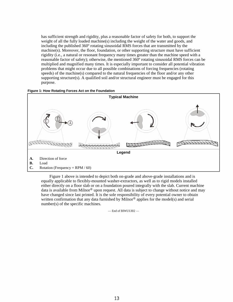
has sufficient strength and rigidity, plus a reasonable factor of safety for both, to support theweight of all the fully loaded machine(s) including the weight of the water and goods, andincluding the published 360º rotating sinusoidal RMS forces that are transmitted by themachine(s). Moreover, the floor, foundation, or other supporting structure must have sufficientrigidity (i.e., a natural or resonant frequency many times greater than the machine speed with areasonable factor of safety); otherwise, the mentioned 360º rotating sinusoidal RMS forces can bemultiplied and magnified many times. It is especially important to consider all potential vibrationproblems that might occur due to all possible combinations of forcing frequencies (rotatingspeeds) of the machine(s) compared to the natural frequencies of the floor and/or any othersupporting structure(s). A qualified soil and/or structural engineer must be engaged for thispurpose.
Figure 1: How Rotating Forces Act on the Foundation
Typical Machine
Legend
A. Direction of forceB. LoadC. Rotation (Frequency = RPM / 60)
Figure 1 above is intended to depict both on-grade and above-grade installations and isequally applicable to flexibly-mounted washer-extractors, as well as to rigid models installedeither directly on a floor slab or on a foundation poured integrally with the slab. Current machinedata is available from Milnor® upon request. All data is subject to change without notice and mayhave changed since last printed. It is the sole responsibility of every potential owner to obtainwritten confirmation that any data furnished by Milnor® applies for the model(s) and serialnumber(s) of the specific machines.
— End of BIWUUI02 —
R
Pe
llerin
Miln
or
Co
rpo
ratio
nP
elle
rin
Miln
or
Co
rpo
ratio
nP.
O.
Bo
x4
00
,K
en
ne
r,L
A7
00
63
-04
00
Litho
inU
.S.A
.
BM
P020113/2
003286V
(Sh
eet
1o
f2)
Sa
fety
Pla
ca
rdU
se
an
dP
lac
em
en
t3
00
22
,3
60
30
F8
J,
F8
W&
42
03
2F
7J,
F7
W
No
tes:
1
.A
pp
roxim
ate
locati
on
so
fp
lacard
sare
sh
ow
n.
Mo
un
tin
gh
ole
sare
pro
vid
ed
on
mach
ine.
Use
#8
self
-tap
pin
gscre
ws.
.R
ep
lace
pla
card
imm
ed
iate
ly,if
rem
oved
or
un
read
ab
le.
2
LEFT
VIE
WFRO
NT
VIE
WRIG
HT
VIE
W
REA
RVIE
WPLA
NVIE
W
30
20
40
ON
ST
EA
MP
IPE
ON
LY
IFM
AC
HIN
EIS
EQ
UIP
PE
DW
ITH
ST
EA
M
30
50
60
10
R
Pellerin Milnor CorporationPellerin Milnor CorporationP. O. Box 400, Kenner, LA 70063-0400
Litho in U.S.A.
Item Part Number Description CommentsUsed In
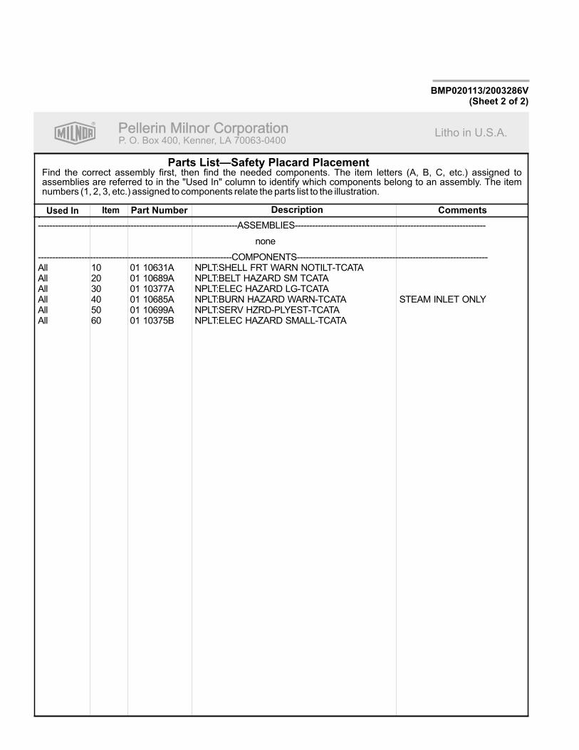
Find the correct assembly first, then find the needed components. The item letters (A, B, C, etc.) assigned toassemblies are referred to in the "Used In" column to identify which components belong to an assembly. The itemnumbers (1, 2, 3, etc.) assigned to components relate the parts list to the illustration.
Parts List—Safety Placard Placement
BMP020113/2003286V(Sheet 2 of 2)
.---------------------------------------------------------------------ASSEMBLIES------------------------------------------------------------------
none
-------------------------------------------------------------------COMPONENTS------------------------------------------------------------------All 10 01 10631A NPLT:SHELL FRT WARN NOTILT-TCATAAll 20 01 10689A NPLT:BELT HAZARD SM TCATAAll 30 01 10377A NPLT:ELEC HAZARD LG-TCATAAll 40 01 10685A NPLT:BURN HAZARD WARN-TCATA STEAM INLET ONLYAll 50 01 10699A NPLT:SERV HZRD-PLYEST-TCATAAll 60 01 10375B NPLT:ELEC HAZARD SMALL-TCATA
R
Pe
llerin
Miln
or
Co
rpo
ratio
nP
elle
rin
Miln
or
Co
rpo
ratio
nP.
O.
Bo
x4
00
,K
en
ne
r,L
A7
00
63
-04
00
Litho
inU
.S.A
.
BM
P020114/2
003286V
(Sh
eet
1o
f2)
No
tes:
1
.A
pp
roxim
ate
locati
on
so
fp
lacard
sare
sh
ow
n.
IfA
lum
inu
mP
lacard
Mo
un
tin
gh
ole
sare
pro
vid
ed
on
mach
ine.
Use
#8
self
-tap
pin
gscre
ws.
.R
ep
lace
pla
card
im-
med
iate
ly,if
rem
oved
or
un
read
ab
le.
2ISO
Pla
card
ssh
ow
no
nth
isp
ag
e
Sa
fety
Pla
ca
rdU
se
an
dP
lac
em
en
tIS
O3
00
22
,3
60
30
F8
J,
F8
W&
42
03
2F
7J,
F7
W
LEFT
VIE
WFRO
NT
VIE
WRIG
HT
VIE
W
REA
RVIE
WPLA
NVIE
W
20
30
20
40
ON
ST
EA
MP
IPE
IFM
AC
HIN
EIS
EQ
UIP
PE
DW
ITH
ST
EA
M
30
50
10
20
R
Pellerin Milnor CorporationPellerin Milnor CorporationP. O. Box 400, Kenner, LA 70063-0400
Litho in U.S.A.
Item Part Number Description CommentsUsed In
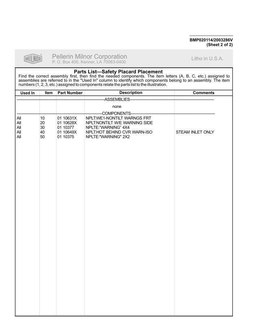
Find the correct assembly first, then find the needed components. The item letters (A, B, C, etc.) assigned toassemblies are referred to in the "Used In" column to identify which components belong to an assembly. The itemnumbers (1, 2, 3, etc.) assigned to components relate the parts list to the illustration.
Parts List—Safety Placard Placement
BMP020114/2003286V(Sheet 2 of 2)
---------------------------------------------------------------------ASSEMBLIES------------------------------------------------------------------
none
-------------------------------------------------------------------COMPONENTS------------------------------------------------------------------All 10 01 10631X NPLT:WE1-NONTILT WARNGS FRTAll 20 01 10628X NPLT:NONTILT W/E WARNING SIDEAll 30 01 10377 NPLTE:”WARNING” 4X4All 40 01 10649X NPLT:HOT BEHIND CVR WARN-ISO STEAM INLET ONLYAll 50 01 10375 NPLTE:"WARNING" 2X2
<B8DD@C604�!��"�#$E����������������� �������������������������������������������������� �������!��"���#$���%����
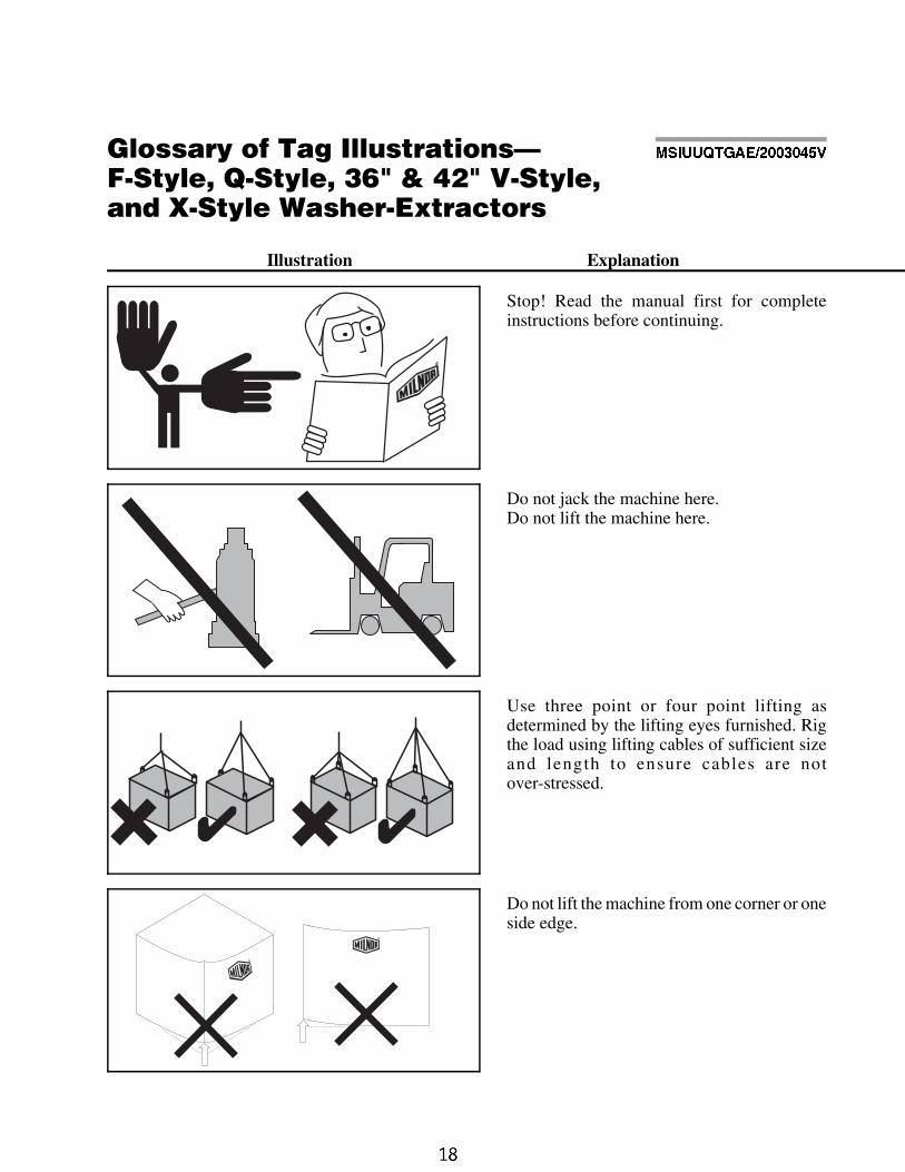
Illustration Explanation
Stop! Read the manual first for completeinstructions before continuing.
Do not jack the machine here.Do not lift the machine here.
Use three point or four point lifting asdetermined by the lifting eyes furnished. Rigthe load using lifting cables of sufficient sizeand length to ensure cables are notover-stressed.
Do not lift the machine from one corner or oneside edge.
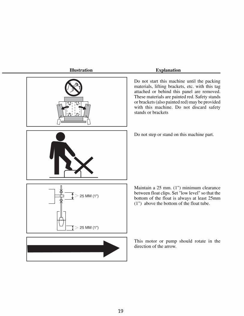
Illustration Explanation
Do not start this machine until the packingmaterials, lifting brackets, etc. with this tagattached or behind this panel are removed.These materials are painted red. Safety standsor brackets (also painted red) may be providedwith this machine. Do not discard safetystands or brackets
Do not step or stand on this machine part.
Maintain a 25 mm. (1") minimum clearancebetween float clips. Set "low level" so that thebottom of the float is always at least 25mm(1") above the bottom of the float tube.
This motor or pump should rotate in thedirection of the arrow.
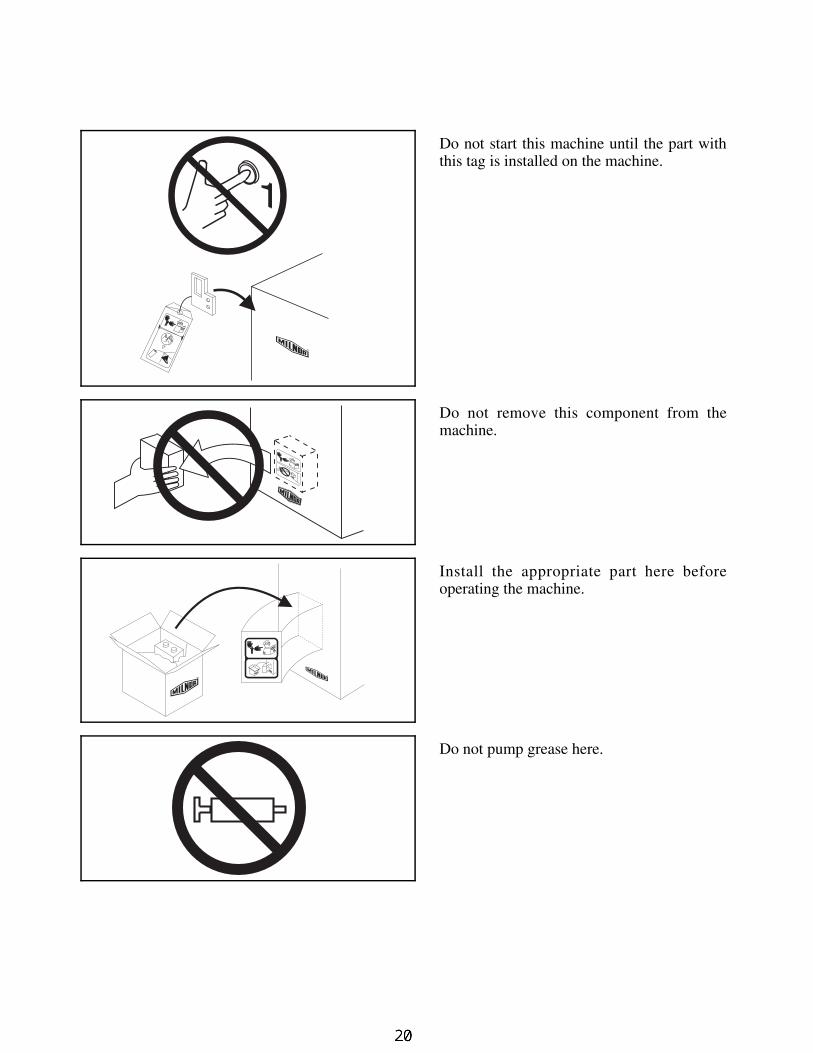
Do not start this machine until the part withthis tag is installed on the machine.
Do not remove this component from themachine.
Install the appropriate part here beforeoperating the machine.
Do not pump grease here.
7\_ccQbi _V DQW 9\\ecdbQdY_^c±6�Cdi\U� A�Cdi\U� #&� � $"� F�Cdi\U� Q^T H�Cdi\U GQcXUb�5hdbQSd_bc
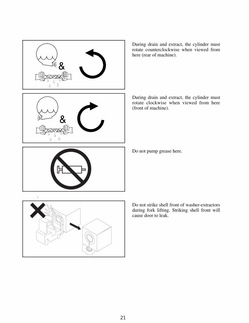
During drain and extract, the cylinder mustrotate counterclockwise when viewed fromhere (rear of machine).
During drain and extract, the cylinder mustrotate clockwise when viewed from here(front of machine).
Do not pump grease here.
.
Do not strike shell front of washer-extractorsduring fork lifting. Striking shell front willcause door to leak.
=C9EEAD715�" # $%F �" � #�
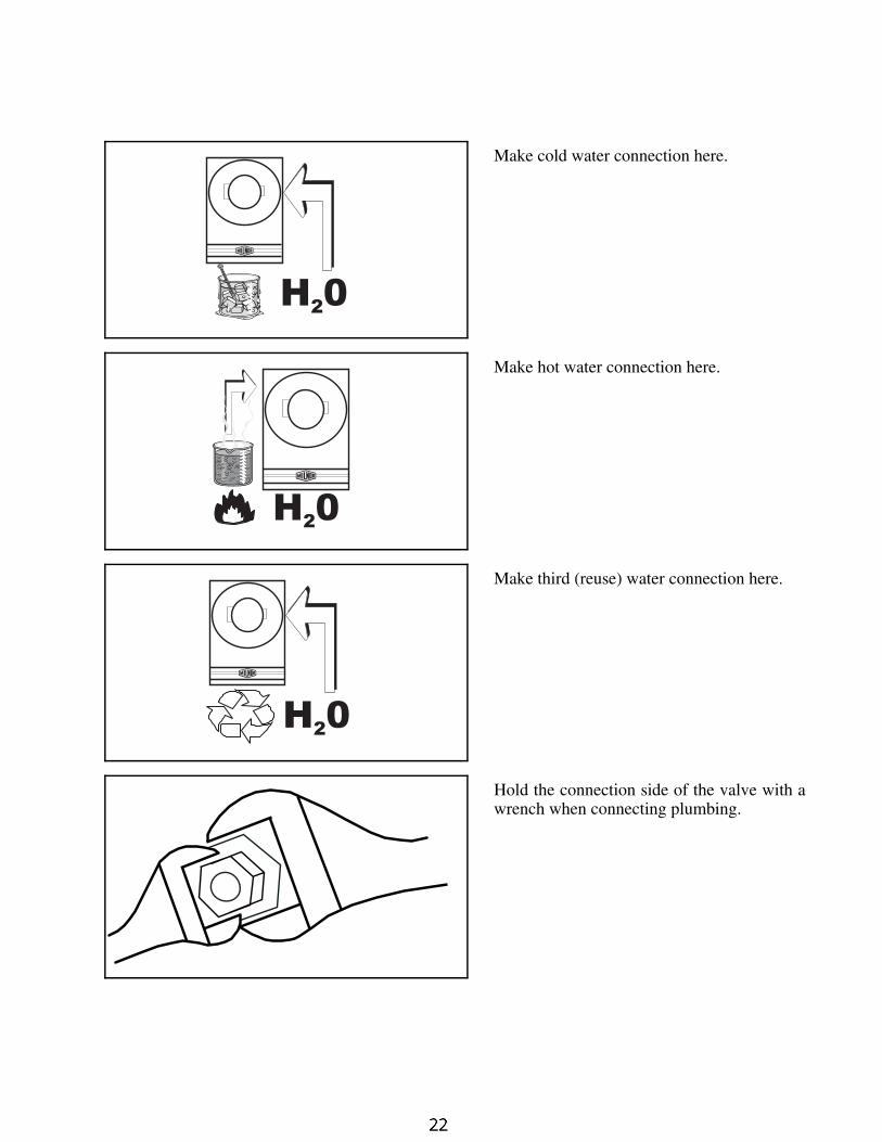
Make cold water connection here.
Make hot water connection here.
Make third (reuse) water connection here.
Hold the connection side of the valve with awrench when connecting plumbing.
H 02
H 02
H 02
7\_ccQbi _V DQW 9\\ecdbQdY_^c±6�Cdi\U� A�Cdi\U� #&� � $"� F�Cdi\U� Q^T H�Cdi\U GQcXUb�5hdbQSd_bc
PELLERIN MILNOR CORPORATION
BIWUUI03 (Published) Book specs- Dates: 20030306 / 20030306 / 20030306 Lang: ENG01 Applic: WUU
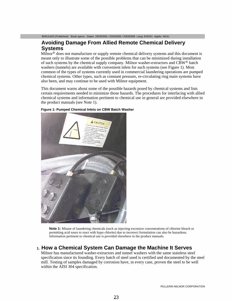
Avoiding Damage From Allied Remote Chemical DeliverySystemsMilnor® does not manufacture or supply remote chemical delivery systems and this document ismeant only to illustrate some of the possible problems that can be minimized during installationof such systems by the chemical supply company. Milnor washer-extractors and CBW® batchwashers (tunnels) are available with convenient inlets for such systems (see Figure 1). Mostcommon of the types of systems currently used in commercial laundering operations are pumpedchemical systems. Other types, such as constant pressure, re-circulating ring main systems havealso been, and may continue to be used with Milnor equipment.
This document warns about some of the possible hazards posed by chemical systems and listscertain requirements needed to minimize those hazards. The procedures for interfacing with alliedchemical systems and information pertinent to chemical use in general are provided elsewhere inthe product manuals (see Note 1).
Figure 1: Pumped Chemical Inlets on CBW Batch Washer
Note 1: Misuse of laundering chemicals (such as injecting excessive concentrations of chlorine bleach orpermitting acid sours to react with hypo chlorite) due to incorrect formulation can also be hazardous.Information pertinent to chemical use is provided elsewhere in the product manuals.
1. How a Chemical System Can Damage the Machine It ServesMilnor has manufactured washer-extractors and tunnel washers with the same stainless steelspecification since its founding. Every batch of steel used is certified and documented by the steelmill. Testing of samples damaged by corrosion have, in every case, proven the steel to be wellwithin the AISI 304 specification.
Avoiding Damage From Allied Remote Chemical Delivery Systems
PELLERIN MILNOR CORPORATION
Chemical products commonly found in the laundry industry, when used in established dosagesand proper operating parameters, under the auspices of an experienced chemical specialist, shouldproduce satisfactory results, with no consequential detrimental effects. The industry has publishedstandards in Riggs and Sherrill, “Textile Laundering Technology”. However, the stainless steelcan be damaged and even destroyed by abnormal contact with chlorine bleach, hydrofluosilicicacid and other commonly used chemicals, as will occur if chemicals are unintentionally leakedinto the machine, particularly when it is no longer in use and especially when machine surfacesare dry.
Some chemical systems have been found to permit chemicals to dribble from the supply lines, orworse, to siphon from the supply tank into the machine, during operation and long after thesystem is shut down—as after working hours and during weekends. If this occurs, deterioration(rusting) of the stainless steel and damage to any textiles therein will inevitably result. If thiscondition goes undetected, machine damage is likely to be catastrophic. No machine isimmune to such damage.
CAUTION 1 : Equipment and Textile Damage Hazards—Chemicals leaked into themachine, particularly when it is idle can destroy machine components and textiles left in themachine. Pellerin Milnor Corporation accepts absolutely no responsibility for damage to itsequipment or to textiles therein from abnormal contact with chemicals.• Ensure that the chemical system prevents unintentional release of chemicals.
• Inspect regularly for proper operation and evidence of damage.
2. Requirements for Chemical Systems Used With Milnor MachinesIt is the responsibility of the chemical system manufacturer and supplier to ensure that theirsystem is safe for personnel and equipment. Some important points are described below.
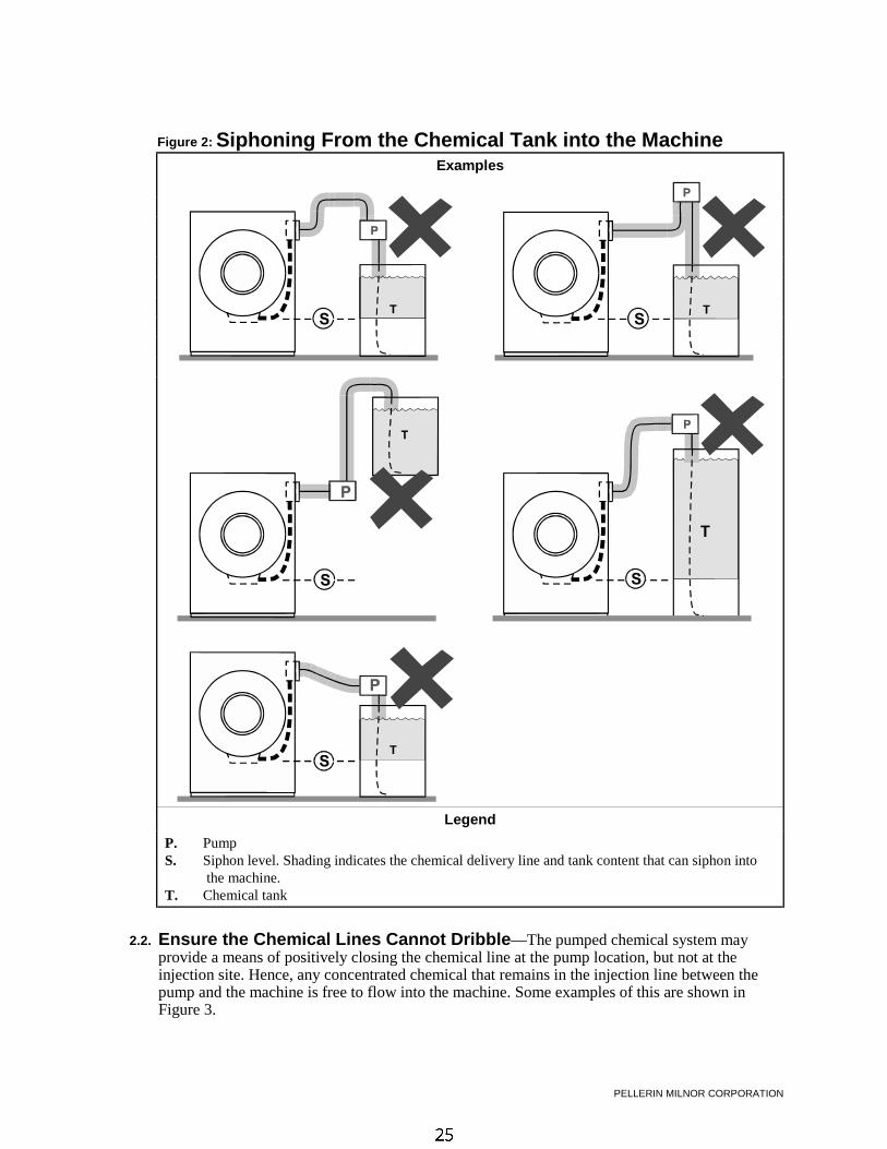
2.1. Ensure the System Cannot Siphon.—The supply system must be designed tocounteract any siphoning that could occur as a result of having a sealed supply line between thebottom of the chemical tank and the internal machine connection at the drain trough. As shown inthe Figure 2 examples, if the pump (P) and/or the valving does not provide positive closure andthere is no vacuum breaker protection, siphoning is likely to occur. In each of the Figure 2illustrations, the volume of chemical in the tank above the siphon level (S), and indicated byshading, will flow into the machine.
PELLERIN MILNOR CORPORATION
Figure 2: Siphoning From the Chemical Tank into the MachineExamples
Legend
P. PumpS. Siphon level. Shading indicates the chemical delivery line and tank content that can siphon into
the machine.T. Chemical tank
2.2. Ensure the Chemical Lines Cannot Dribble—The pumped chemical system mayprovide a means of positively closing the chemical line at the pump location, but not at theinjection site. Hence, any concentrated chemical that remains in the injection line between thepump and the machine is free to flow into the machine. Some examples of this are shown inFigure 3.
Avoiding Damage From Allied Remote Chemical Delivery Systems
PELLERIN MILNOR CORPORATION
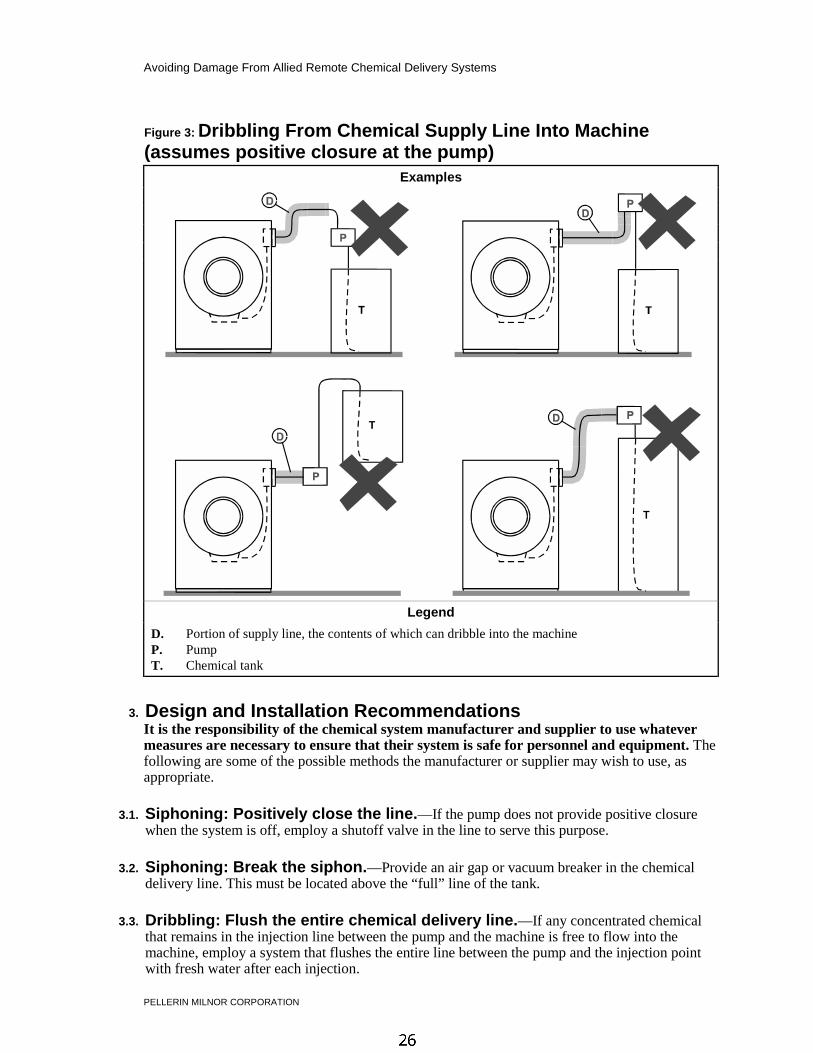
Figure 3: Dribbling From Chemical Supply Line Into Machine(assumes positive closure at the pump)
Examples
Legend
D. Portion of supply line, the contents of which can dribble into the machineP. PumpT. Chemical tank
3. Design and Installation RecommendationsIt is the responsibility of the chemical system manufacturer and supplier to use whatevermeasures are necessary to ensure that their system is safe for personnel and equipment. Thefollowing are some of the possible methods the manufacturer or supplier may wish to use, asappropriate.
3.1. Siphoning: Positively close the line.—If the pump does not provide positive closurewhen the system is off, employ a shutoff valve in the line to serve this purpose.
3.2. Siphoning: Break the siphon.—Provide an air gap or vacuum breaker in the chemicaldelivery line. This must be located above the “full” line of the tank.
3.3. Dribbling: Flush the entire chemical delivery line.—If any concentrated chemicalthat remains in the injection line between the pump and the machine is free to flow into themachine, employ a system that flushes the entire line between the pump and the injection pointwith fresh water after each injection.
PELLERIN MILNOR CORPORATION
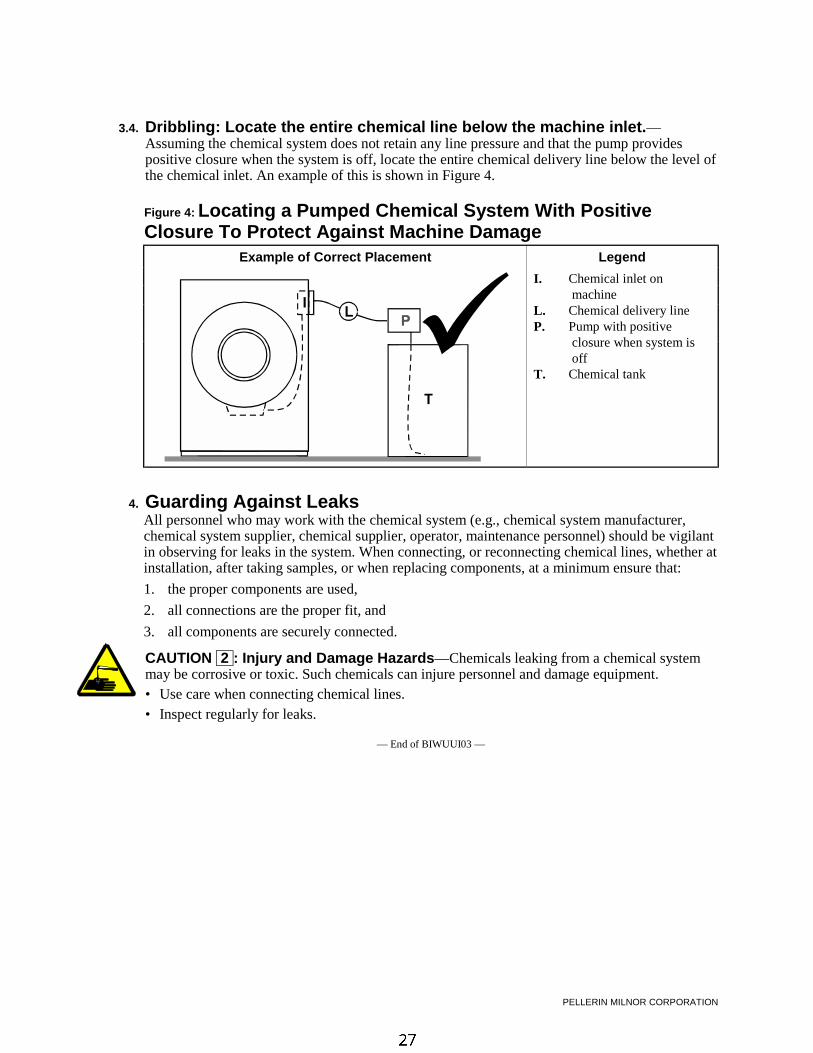
3.4. Dribbling: Locate the entire chemical line below the machine inlet.—Assuming the chemical system does not retain any line pressure and that the pump providespositive closure when the system is off, locate the entire chemical delivery line below the level ofthe chemical inlet. An example of this is shown in Figure 4.
Figure 4: Locating a Pumped Chemical System With PositiveClosure To Protect Against Machine Damage
Example of Correct Placement Legend
I. Chemical inlet onmachine
L. Chemical delivery lineP. Pump with positive
closure when system isoff
T. Chemical tank
4. Guarding Against LeaksAll personnel who may work with the chemical system (e.g., chemical system manufacturer,chemical system supplier, chemical supplier, operator, maintenance personnel) should be vigilantin observing for leaks in the system. When connecting, or reconnecting chemical lines, whether atinstallation, after taking samples, or when replacing components, at a minimum ensure that:
1. the proper components are used,
2. all connections are the proper fit, and
3. all components are securely connected.
CAUTION 2 : Injury and Damage Hazards—Chemicals leaking from a chemical systemmay be corrosive or toxic. Such chemicals can injure personnel and damage equipment.• Use care when connecting chemical lines.
• Inspect regularly for leaks.
— End of BIWUUI03 —

Section 1Service and Maintenance

@bUfU^dYfU =QY^dU^Q^SU
@5<<5B9> =9<>?B 3?B@?B1D9?>
2996E= ! �@eR\YcXUT� 2__[ c`USc� 4QdUc* " # #!! � " # #!! � " # #!! <Q^W* 5>7 ! 1``\YS* 962
������ ����� ��������As required by the warranty and to achieve optimum performance and service life from Milnorwasher-extractors, the schedules, instructions and precautions herein must be strictly followed.
F0A=8=6 ) 4]cP]V[T P]S 2adbW 7PiPaSb—Guards, covers, and panels—Operating themachine with any guard, cover, or panel removed exposes moving components.• Lock out and tag out power at the main machine disconnect before servicing, or in
accordance with factory service procedures.• Do not service machine unless qualified and authorized.
20DC8>= ! ) ?X]RW 7PiPaS—Suspended machines only—Spaces between the shell andhousing can close and crush or pinch your limbs. The shell moves within the housing duringoperation.• NEVER place fingers in gap between shell and frame.
� ���� ��� ��������� ��� J3^Rd\T]c 18DDD<� L
20DC8>= " ) <PRWX]T 3P\PVT 7PiPaS—Improper lubrication can damage machinecomponents and cause the machine to malfunction.• Do not mix petroleum and synthetic based lubricants.• Do not use an unspecified lubricant without consulting the lubricant manufacturer.• Do not apply grease with a pneumatic grease gun. Use only a hand-operated grease gun.• Do not over-lubricate.• Always clean grease fittings before adding grease. Clean off excess grease.• Ensure that lubricants do not drip onto belts, brake shoes or drums.
F0A=8=6 # ) 4]cP]V[T P]S 2adbW 7PiPaSb—Contact with moving components normallyisolated by guards, covers, and panels, can entangle and crush your limbs. These componentsmove automatically.• Lock out and tag out power at the main machine disconnect before servicing, or in
accordance with factory service procedures.• Do not service machine unless qualified and authorized.
� � ��� ���������—Pump grease slowly, taking 10-12 seconds to complete each stroke. Agrease gun can build up extremely high pressure which will force seals out of position and causethem to leak.
�!� ������������ ��—Apply the quantity of grease called for in the checklist. Over-lubricationcan be as damaging as under-lubrication. Where quantities are stated in strokes, one stroke of thegrease gun is assumed to provide .0624 fluid oz. (1.77 grams) (by volume) of grease. Therefore,one fluid ounce (28.3 grams) of grease would be provided by 16 stokes of the grease gun.Determine the flow rate of your grease gun by pumping one ounce into a calibrated container. Iffewer than 16 stokes are required, all quantities in strokes in the chart should be reducedaccordingly, and if more than 16 strokes are required, the number of strokes should be increased.Before starting lubrication, make sure your grease gun is working and that you get a full chargeof grease with every stroke.
@bUfU^dYfU =QY^dU^Q^SU
@5<<5B9> =9<>?B 3?B@?B1D9?>
�"� ���� ��������� � ��� ���—Lubricant specifications are provided in the preventivemaintenance checklist. Lubricants should be purchased locally. If a specified lubricant is notavailable locally, it is permissible to substitute a product that has been specified as equivalent bythe lubricant manufacturer. If you cannot obtain either the specified lubricant or a validequivalent locally, contact the Milnor Service Department for assistance.
!� �� ������ ������� ��������� ����� ��������1. Lock out and tag out power at the main machine disconnect.
2. Remove the rear panel.
3. Remove the drain plug on the bottom of the main bearing housing and allow the bearinghousing to drain completely. Inspect the leak-off, drained oil, and magnetic drain plug forwater and/or metal particles. Water and/or metal particles can indicate worn or damaged sealsand bearings. Reinstall the drain plug.
4. After locating the oil fill plug, refill the bearing housing following lubrication specifications.
5. Reinstall the fill plug and clean excess lubricant from the machine.
"� ����� ��������������
F0A=8=6 $ ) 4]cP]V[T P]S 2adbW 7PiPaSb—Guards, covers, and panels—Operating themachine with any guard, cover, or panel removed exposes moving components.• Power is ON and cylinder is turning during the following procedure. Permit only qualified
maintenance personnel to perform this procedure.
Grease the water seals as follows:
1. Remove side panels.
2. Restore power to machine.
3. Locate the water seal grease fitting (Figure 1).
4. Place the machine in a wash step.
5. With the cylinder turning, grease seals as called for on the “Preventive MaintenanceChecklist” and “Lubrication Precautions.”
6. Re-install side and rear panels.
@bUfU^dYfU =QY^dU^Q^SU
@5<<5B9> =9<>?B 3?B@?B1D9?>
#� ������ ����� ��������
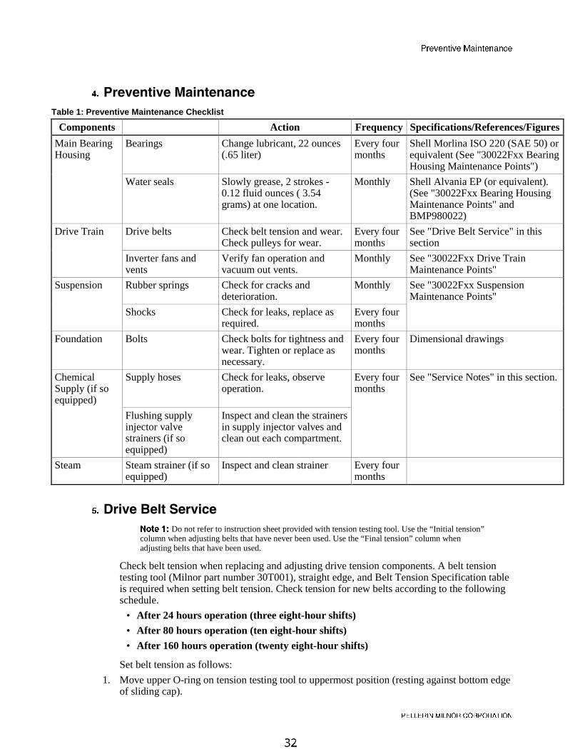
Table 1: Preventive Maintenance Checklist
Components Action Frequency Specifications/References/Figures
Main BearingHousing
Bearings Change lubricant, 22 ounces(.65 liter)
Every fourmonths
Shell Morlina ISO 220 (SAE 50) orequivalent (See "30022Fxx BearingHousing Maintenance Points")
Water seals Slowly grease, 2 strokes -0.12 fluid ounces ( 3.54grams) at one location.
Monthly Shell Alvania EP (or equivalent).(See "30022Fxx Bearing HousingMaintenance Points" andBMP980022)
Drive Train Drive belts Check belt tension and wear.Check pulleys for wear.
Every fourmonths
See "Drive Belt Service" in thissection
Inverter fans andvents
Verify fan operation andvacuum out vents.
Monthly See "30022Fxx Drive TrainMaintenance Points"
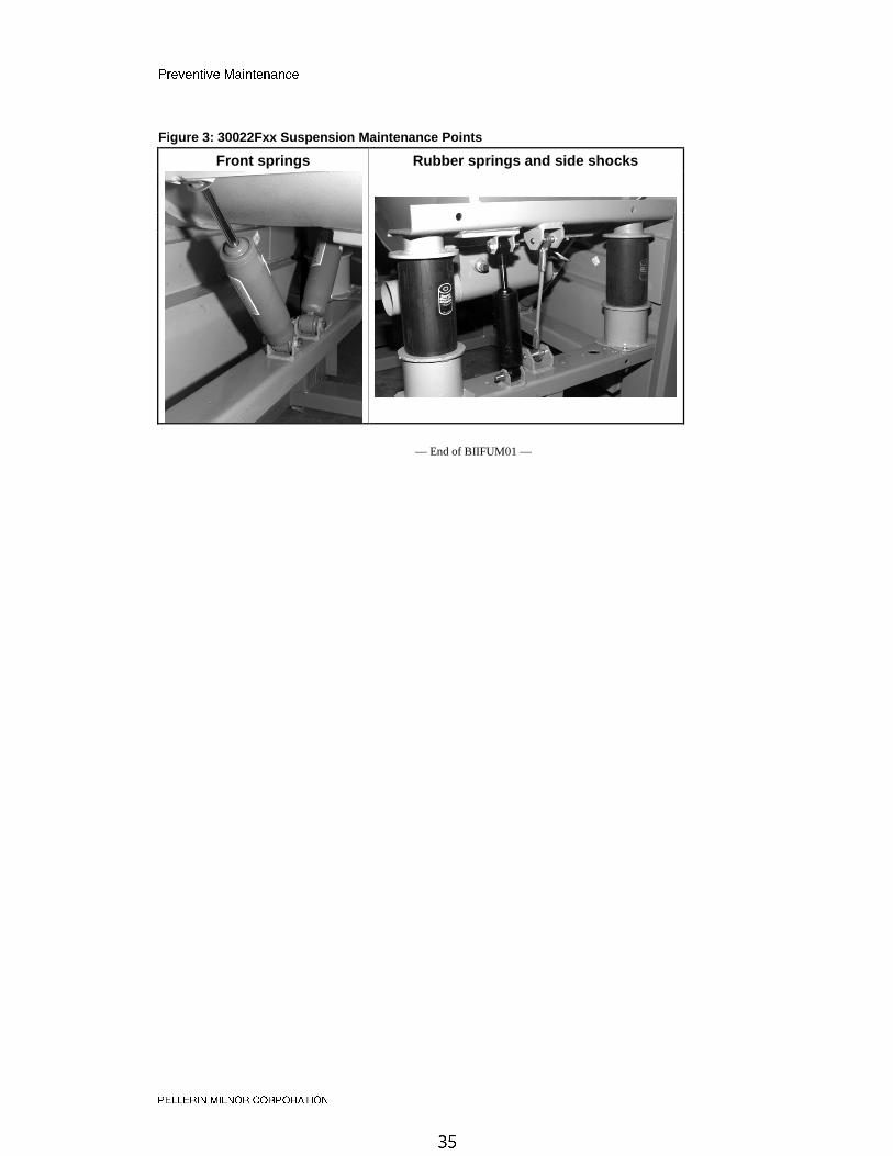
Suspension Rubber springs Check for cracks anddeterioration.
Monthly See "30022Fxx SuspensionMaintenance Points"
Shocks Check for leaks, replace asrequired.
Every fourmonths
Foundation Bolts Check bolts for tightness andwear. Tighten or replace asnecessary.
Every fourmonths
Dimensional drawings
ChemicalSupply (if soequipped)
Supply hoses Check for leaks, observeoperation.
Every fourmonths
See "Service Notes" in this section.
Flushing supplyinjector valvestrainers (if soequipped)
Inspect and clean the strainersin supply injector valves andclean out each compartment.
Steam Steam strainer (if soequipped)
Inspect and clean strainer Every fourmonths
$� �� ������������ ��
=^cT ) Do not refer to instruction sheet provided with tension testing tool. Use the “Initial tension”column when adjusting belts that have never been used. Use the “Final tension” column whenadjusting belts that have been used.
Check belt tension when replacing and adjusting drive tension components. A belt tensiontesting tool (Milnor part number 30T001), straight edge, and Belt Tension Specification tableis required when setting belt tension. Check tension for new belts according to the followingschedule.
• After 24 hours operation (three eight-hour shifts)
• After 80 hours operation (ten eight-hour shifts)
• After 160 hours operation (twenty eight-hour shifts)
Set belt tension as follows:
1. Move upper O-ring on tension testing tool to uppermost position (resting against bottom edgeof sliding cap).
@bUfU^dYfU =QY^dU^Q^SU
@5<<5B9> =9<>?B 3?B@?B1D9?>
2. Determine belt deflection for the tested belt (see “30022Fxx Bearing Housing MaintenancePoints” and Table below for the location and setting). Move lower O-ring to the correctsetting (inches or centimeters) on scale. Read the bottom edge of the O-ring.
3. Place a straight edge along the top edge (pulley to pulley) of the belt to be tested. Depress thetension testing tool by sliding the cap against the middle of the belt span until the bottomedge of the lower 0-ring aligns with the straight edge as shown in Figure 2.
4. Read the top of the upper O-ring position and determine if it is within specified range
• See specifications in the “Initial tension” column for belts that have never been used.
• See specifications in the “Final tension” column for belts that have been used.
5. If reading is below specified range, belt must be tightened. If reading is above specified rangebelt must be loosened. Adjust belt and repeat Steps 1 through 4 until tension is withinspecified range.
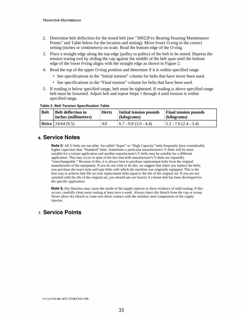
Table 2: Belt Tension Specification Table
Belt Belt deflection ininches (millimeters)
Hertz Initial tension pounds(kilograms)
Final tension pounds(kilograms)
Drive 24/64 (9.5) All 6.7 - 9.8 (3.0 - 4.4) 5.2 - 7.6 (2.4 - 3.4)
%� ���� ��������
=^cT !) All V-belts are not alike. So-called “Super” or “High Capacity” belts frequently have considerablyhigher capacities than “Standard” belts. Sometimes a particular manufacturer's V-belts will be moresuitable for a certain application and another manufacturer's V-belts may be suitable for a differentapplication. This may occur in spite of the fact that both manufacturer's V-belts are reputedly“interchangeable.” Because of this, it is always best to purchase replacement belts from the originalmanufacturer of the equipment. If you do not wish to do this, we suggest that when you replace the belts,you purchase the exact style and type belts with which the machine was originally equipped. This is thebest way to achieve belt life on your replacement belts equal to the life of the original set. If you are notsatisfied with the life of the original set, you should ask our factory if a better belt has been developed forthe specific application.
=^cT ") Dry bleaches may cause the inside of the supply injector to show evidence of mild rusting. If thisoccurs, carefully clean away rusting at least once a week. Always inject dry bleach from the cup or scoop.Never allow dry bleach to come into direct contact with the stainless steel components of the supplyinjector.
&� ���� ���� ���
@bUfU^dYfU =QY^dU^Q^SU
@5<<5B9> =9<>?B 3?B@?B1D9?>
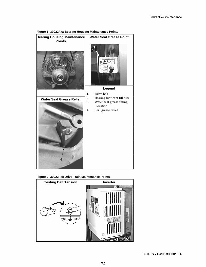
Figure 1: 30022Fxx Bearing Housing Maintenance Points
Bearing Housing MaintenancePoints
Water Seal Grease Point
�
Legend
Water Seal Grease Relief
1. Drive belt2. Bearing lubricant fill tube3. Water seal grease fitting
location4. Seal grease relief
Figure 2: 30022Fxx Drive Train Maintenance Points
Testing Belt Tension Inverter
@bUfU^dYfU =QY^dU^Q^SU
@5<<5B9> =9<>?B 3?B@?B1D9?>
Figure 3: 30022Fxx Suspension Maintenance Points
Front springs Rubber springs and side shocks
— End of BIIFUM01 —
MSSM0261BE/9933AV
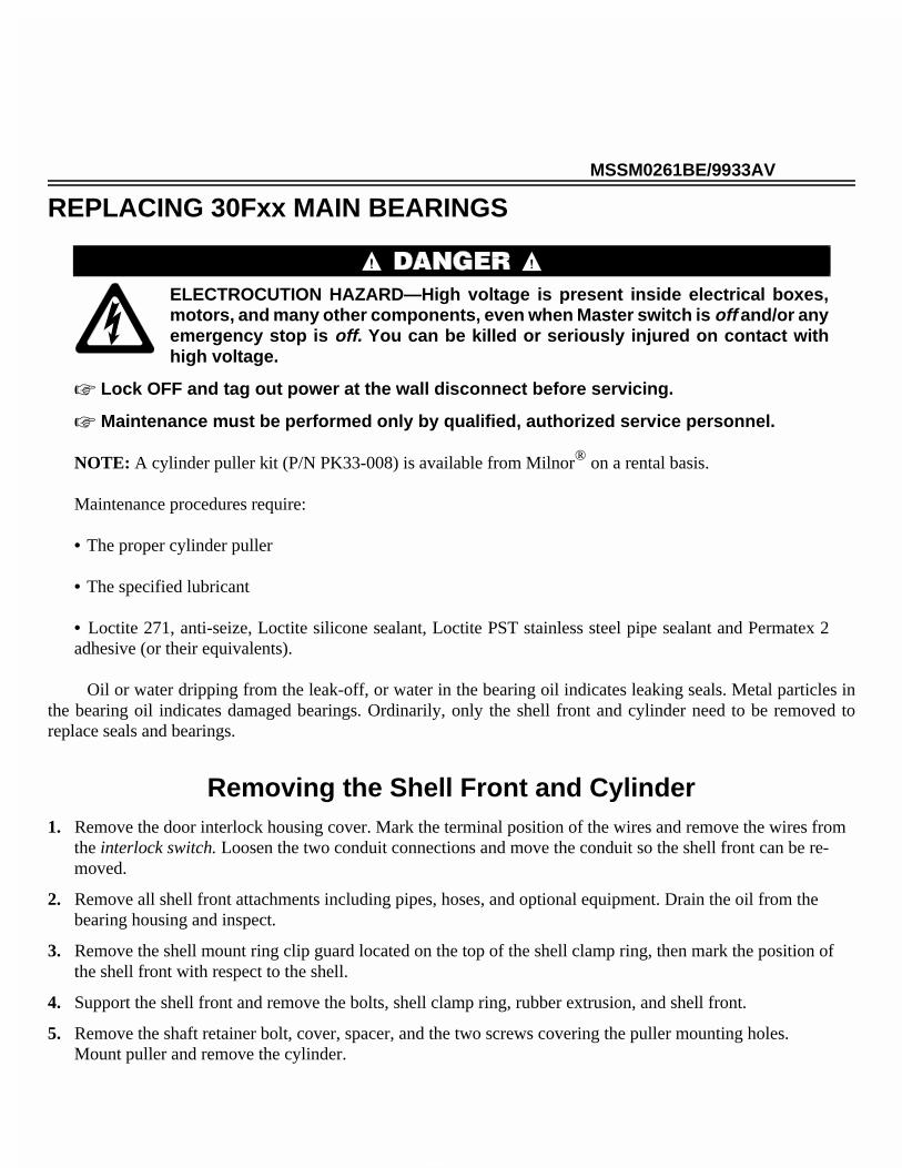
ÈREPLACING 30Fxx MAIN BEARINGS
ELECTROCUTION HAZARD—High voltage is present inside electrical boxes,motors, and many other components, even when Master switch is off and/or anyemergency stop is off. You can be killed or seriously injured on contact withhigh voltage.
☞ Lock OFF and tag out power at the wall disconnect before servicing.
☞ Maintenance must be performed only by qualified, authorized service personnel.
NOTE: A cylinder puller kit (P/N PK33-008) is available from Milnor® on a rental basis.
Maintenance procedures require:
• The proper cylinder puller
• The specified lubricant
• Loctite 271, anti-seize, Loctite silicone sealant, Loctite PST stainless steel pipe sealant and Permatex 2adhesive (or their equivalents).
Oil or water dripping from the leak-off, or water in the bearing oil indicates leaking seals. Metal particles inthe bearing oil indicates damaged bearings. Ordinarily, only the shell front and cylinder need to be removed toreplace seals and bearings.
ÊRemoving the Shell Front and Cylinder1. Remove the door interlock housing cover. Mark the terminal position of the wires and remove the wires from
the interlock switch. Loosen the two conduit connections and move the conduit so the shell front can be re-moved.
2. Remove all shell front attachments including pipes, hoses, and optional equipment. Drain the oil from thebearing housing and inspect.
3. Remove the shell mount ring clip guard located on the top of the shell clamp ring, then mark the position ofthe shell front with respect to the shell.
4. Support the shell front and remove the bolts, shell clamp ring, rubber extrusion, and shell front.
5. Remove the shaft retainer bolt, cover, spacer, and the two screws covering the puller mounting holes. Mount puller and remove the cylinder.
ÊReplacing Seals, Bearings, and Bearing Housing
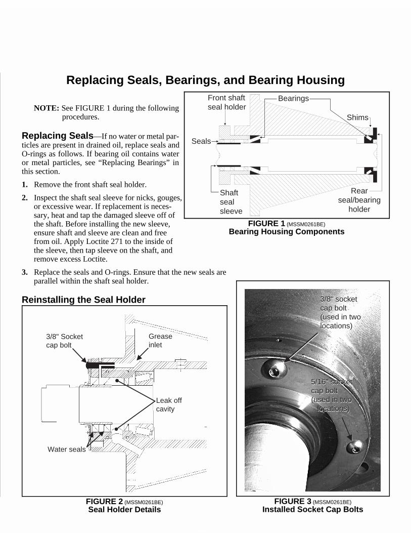
NOTE: See FIGURE 1 during the following procedures.
ËReplacing Seals —If no water or metal par-ticles are present in drained oil, replace seals andO-rings as follows. If bearing oil contains wateror metal particles, see “Replacing Bearings” inthis section.
1. Remove the front shaft seal holder.
2. Inspect the shaft seal sleeve for nicks, gouges,or excessive wear. If replacement is neces-sary, heat and tap the damaged sleeve off ofthe shaft. Before installing the new sleeve,ensure shaft and sleeve are clean and freefrom oil. Apply Loctite 271 to the inside ofthe sleeve, then tap sleeve on the shaft, andremove excess Loctite.
3. Replace the seals and O-rings. Ensure that the new seals areparallel within the shaft seal holder.
ËReinstalling the Seal Holder
Rearseal/bearing
holder
Shims
Bearings
Seals
Front shaftseal holder
Shaftsealsleeve
ÎFIGURE 1 (MSSM0261BE)
ÎBearing Housing Components
3/8" Socketcap bolt
Greaseinlet
Water seals
Leak offcavity
ÎFIGURE 2 (MSSM0261BE)
ÎSeal Holder Details
5/16" socketcap bolt(used in two
locations)
5/16" socketcap bolt(used in two
locations)
3/8" socketcap bolt(used in twolocations)
3/8" socketcap bolt(used in twolocations)
ÎFIGURE 3 (MSSM0261BE)
ÎInstalled Socket Cap Bolts
MSSM0261BE/9933AV (1 of 3)
ÈREPLACING 30Fxx MAIN BEARINGS
ELECTROCUTION HAZARD—High voltage is present inside electrical boxes,motors, and many other components, even when Master switch is off and/or anyemergency stop is off. You can be killed or seriously injured on contact withhigh voltage.
☞ Lock OFF and tag out power at the wall disconnect before servicing.
☞ Maintenance must be performed only by qualified, authorized service personnel.
NOTE: A cylinder puller kit (P/N PK33-008) is available from Milnor® on a rental basis.
Maintenance procedures require:
• The proper cylinder puller
• The specified lubricant
• Loctite 271, anti-seize, Loctite silicone sealant, Loctite PST stainless steel pipe sealant and Permatex 2adhesive (or their equivalents).
Oil or water dripping from the leak-off, or water in the bearing oil indicates leaking seals. Metal particles inthe bearing oil indicates damaged bearings. Ordinarily, only the shell front and cylinder need to be removed toreplace seals and bearings.
ÊRemoving the Shell Front and Cylinder1. Remove the door interlock housing cover. Mark the terminal position of the wires and remove the wires from
the interlock switch. Loosen the two conduit connections and move the conduit so the shell front can be re-moved.
2. Remove all shell front attachments including pipes, hoses, and optional equipment. Drain the oil from thebearing housing and inspect.
3. Remove the shell mount ring clip guard located on the top of the shell clamp ring, then mark the position ofthe shell front with respect to the shell.
4. Support the shell front and remove the bolts, shell clamp ring, rubber extrusion, and shell front.
5. Remove the shaft retainer bolt, cover, spacer, and the two screws covering the puller mounting holes. Mount puller and remove the cylinder.
ÊReplacing Seals, Bearings, and Bearing Housing
NOTE: See FIGURE 1 during the following procedures.
ËReplacing Seals —If no water or metal par-ticles are present in drained oil, replace seals andO-rings as follows. If bearing oil contains wateror metal particles, see “Replacing Bearings” inthis section.
1. Remove the front shaft seal holder.
2. Inspect the shaft seal sleeve for nicks, gouges,or excessive wear. If replacement is neces-sary, heat and tap the damaged sleeve off ofthe shaft. Before installing the new sleeve,ensure shaft and sleeve are clean and freefrom oil. Apply Loctite 271 to the inside ofthe sleeve, then tap sleeve on the shaft, andremove excess Loctite.
3. Replace the seals and O-rings. Ensure that the new seals areparallel within the shaft seal holder.
ËReinstalling the Seal Holder
Rearseal/bearing
holder
Shims
Bearings
Seals
Front shaftseal holder
Shaftsealsleeve
ÎFIGURE 1 (MSSM0261BE)
ÎBearing Housing Components
3/8" Socketcap bolt
Greaseinlet
Water seals
Leak offcavity
ÎFIGURE 2 (MSSM0261BE)
ÎSeal Holder Details
5/16" socketcap bolt(used in two
locations)
5/16" socketcap bolt(used in two
locations)
3/8" socketcap bolt(used in twolocations)
3/8" socketcap bolt(used in twolocations)
ÎFIGURE 3 (MSSM0261BE)
ÎInstalled Socket Cap Bolts
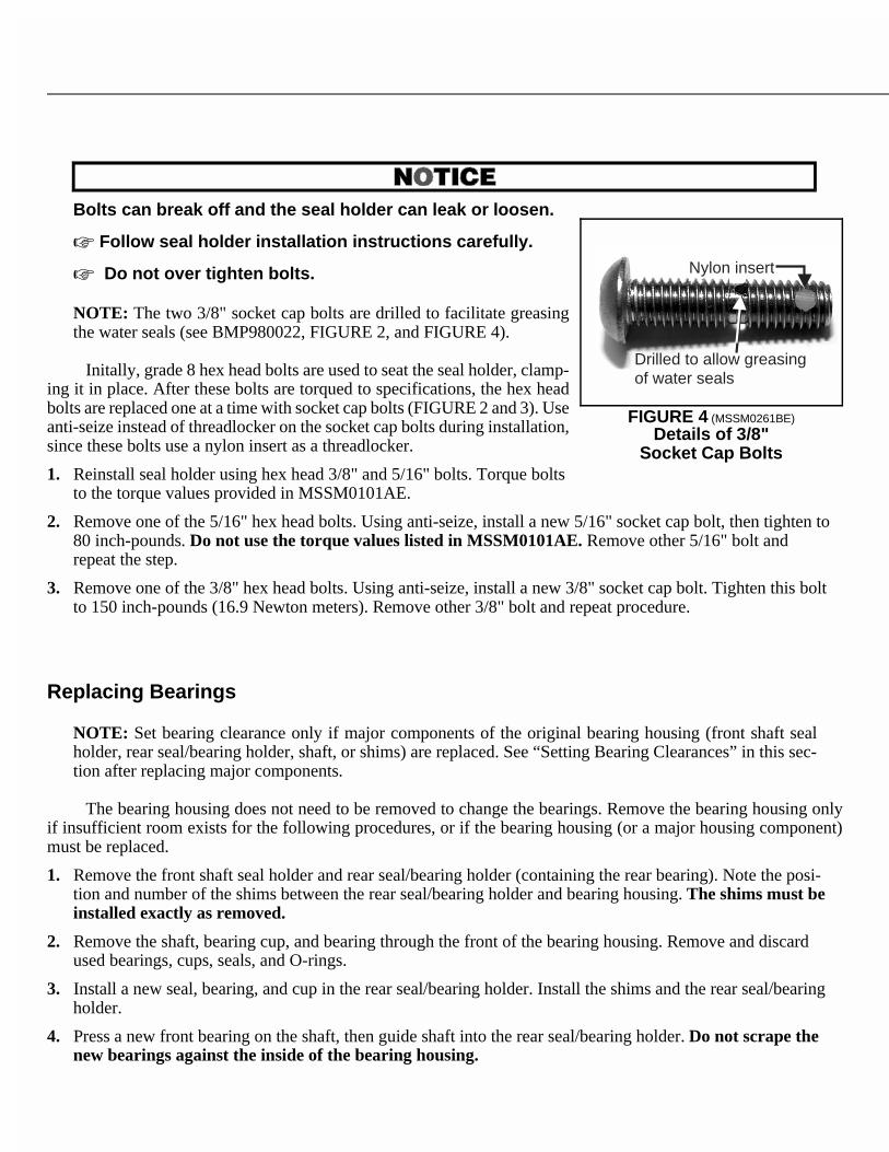
Bolts can break off and the seal holder can leak or loosen.
☞ Follow seal holder installation instructions carefully.
☞ Do not over tighten bolts.
NOTE: The two 3/8" socket cap bolts are drilled to facilitate greasingthe water seals (see BMP980022, FIGURE 2, and FIGURE 4).
Initally, grade 8 hex head bolts are used to seat the seal holder, clamp-ing it in place. After these bolts are torqued to specifications, the hex headbolts are replaced one at a time with socket cap bolts (FIGURE 2 and 3). Useanti-seize instead of threadlocker on the socket cap bolts during installation,since these bolts use a nylon insert as a threadlocker.
1. Reinstall seal holder using hex head 3/8" and 5/16" bolts. Torque boltsto the torque values provided in MSSM0101AE.
2. Remove one of the 5/16" hex head bolts. Using anti-seize, install a new 5/16" socket cap bolt, then tighten to80 inch-pounds. Do not use the torque values listed in MSSM0101AE. Remove other 5/16" bolt andrepeat the step.
3. Remove one of the 3/8" hex head bolts. Using anti-seize, install a new 3/8" socket cap bolt. Tighten this boltto 150 inch-pounds (16.9 Newton meters). Remove other 3/8" bolt and repeat procedure.
Ë
ËReplacing Bearings
NOTE: Set bearing clearance only if major components of the original bearing housing (front shaft sealholder, rear seal/bearing holder, shaft, or shims) are replaced. See “Setting Bearing Clearances” in this sec-tion after replacing major components.
The bearing housing does not need to be removed to change the bearings. Remove the bearing housing onlyif insufficient room exists for the following procedures, or if the bearing housing (or a major housing component)must be replaced.
1. Remove the front shaft seal holder and rear seal/bearing holder (containing the rear bearing). Note the posi-tion and number of the shims between the rear seal/bearing holder and bearing housing. The shims must beinstalled exactly as removed.
2. Remove the shaft, bearing cup, and bearing through the front of the bearing housing. Remove and discardused bearings, cups, seals, and O-rings.
3. Install a new seal, bearing, and cup in the rear seal/bearing holder. Install the shims and the rear seal/bearingholder.
4. Press a new front bearing on the shaft, then guide shaft into the rear seal/bearing holder. Do not scrape thenew bearings against the inside of the bearing housing.
5. Center the shaft within the housing, then gently tap in the front bearing cup. Install the front shaft seal holder.
6. The shaft should turn in the housing.
ËSetting Bearing Clearances
NOTE: This procedure is required only if a major bearing housing component is replaced. See “Replacing Bearings” in this section.
1. Set the clearance by removing all shims from the rear seal/bearing holder. Install the rear seal/bearing holder.Leave a small gap between the bearing housing and rear seal/bearing holder.
2. Insert a lead wire in the gap between flanges. Tighteneach bolt slowly while turning the shaft. Stop tighten-ing when the shaft just begins to drag or bind. Removethe rear seal/bearing holder, being careful not to markor damage the lead wire.
3. Using a micrometer, measure the thickness of the leadwire.
4. Add shims to the thickness of the lead wire to obtain a to-tal thickness of 0.004" - 0.005" (0.102 - 0.127 millime-ters). Install the rear seal/bearing holder using thisamount of shims.
5. The shaft should turn in the housing.
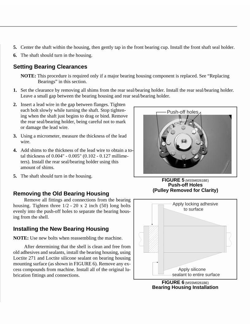
ËRemoving the Old Bearing HousingRemove all fittings and connections from the bearing
housing. Tighten three 1/2 - 20 x 2 inch (50) long boltsevenly into the push-off holes to separate the bearing hous-ing from the shell.
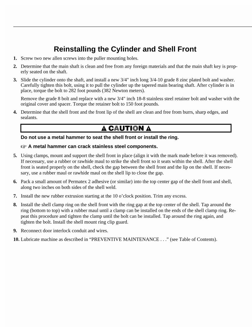
ËInstalling the New Bearing Housing
NOTE: Use new bolts when reassembling the machine.
After determining that the shell is clean and free fromold adhesives and sealants, install the bearing housing, usingLoctite 271 and Loctite silicone sealant on bearing housingmounting surface (as shown in FIGURE 6). Remove any ex-cess compounds from machine. Install all of the original lu-brication fittings and connections.
Nylon insert
Drilled to allow greasingof water seals
ÎFIGURE 4 (MSSM0261BE)
ÎDetails of 3/8"Socket Cap Bolts
Push-off holes
ÎFIGURE 5 (MSSM0261BE)
ÎPush-off Holes(Pulley Removed for Clarity)
Apply locking adhesiveto surface
Apply siliconesealant to entire surface
ÎFIGURE 6 (MSSM0261BE)
ÎBearing Housing Installation
Bolts can break off and the seal holder can leak or loosen.
☞ Follow seal holder installation instructions carefully.
☞ Do not over tighten bolts.
NOTE: The two 3/8" socket cap bolts are drilled to facilitate greasingthe water seals (see BMP980022, FIGURE 2, and FIGURE 4).
Initally, grade 8 hex head bolts are used to seat the seal holder, clamp-ing it in place. After these bolts are torqued to specifications, the hex headbolts are replaced one at a time with socket cap bolts (FIGURE 2 and 3). Useanti-seize instead of threadlocker on the socket cap bolts during installation,since these bolts use a nylon insert as a threadlocker.
1. Reinstall seal holder using hex head 3/8" and 5/16" bolts. Torque boltsto the torque values provided in MSSM0101AE.
2. Remove one of the 5/16" hex head bolts. Using anti-seize, install a new 5/16" socket cap bolt, then tighten to80 inch-pounds. Do not use the torque values listed in MSSM0101AE. Remove other 5/16" bolt andrepeat the step.
3. Remove one of the 3/8" hex head bolts. Using anti-seize, install a new 3/8" socket cap bolt. Tighten this boltto 150 inch-pounds (16.9 Newton meters). Remove other 3/8" bolt and repeat procedure.
Ë
ËReplacing Bearings
NOTE: Set bearing clearance only if major components of the original bearing housing (front shaft sealholder, rear seal/bearing holder, shaft, or shims) are replaced. See “Setting Bearing Clearances” in this sec-tion after replacing major components.
The bearing housing does not need to be removed to change the bearings. Remove the bearing housing onlyif insufficient room exists for the following procedures, or if the bearing housing (or a major housing component)must be replaced.
1. Remove the front shaft seal holder and rear seal/bearing holder (containing the rear bearing). Note the posi-tion and number of the shims between the rear seal/bearing holder and bearing housing. The shims must beinstalled exactly as removed.
2. Remove the shaft, bearing cup, and bearing through the front of the bearing housing. Remove and discardused bearings, cups, seals, and O-rings.
3. Install a new seal, bearing, and cup in the rear seal/bearing holder. Install the shims and the rear seal/bearingholder.
4. Press a new front bearing on the shaft, then guide shaft into the rear seal/bearing holder. Do not scrape thenew bearings against the inside of the bearing housing.
5. Center the shaft within the housing, then gently tap in the front bearing cup. Install the front shaft seal holder.
6. The shaft should turn in the housing.
ËSetting Bearing Clearances
NOTE: This procedure is required only if a major bearing housing component is replaced. See “Replacing Bearings” in this section.
1. Set the clearance by removing all shims from the rear seal/bearing holder. Install the rear seal/bearing holder.Leave a small gap between the bearing housing and rear seal/bearing holder.
2. Insert a lead wire in the gap between flanges. Tighteneach bolt slowly while turning the shaft. Stop tighten-ing when the shaft just begins to drag or bind. Removethe rear seal/bearing holder, being careful not to markor damage the lead wire.
3. Using a micrometer, measure the thickness of the leadwire.
4. Add shims to the thickness of the lead wire to obtain a to-tal thickness of 0.004" - 0.005" (0.102 - 0.127 millime-ters). Install the rear seal/bearing holder using thisamount of shims.
5. The shaft should turn in the housing.
ËRemoving the Old Bearing HousingRemove all fittings and connections from the bearing
housing. Tighten three 1/2 - 20 x 2 inch (50) long boltsevenly into the push-off holes to separate the bearing hous-ing from the shell.
ËInstalling the New Bearing Housing
NOTE: Use new bolts when reassembling the machine.
After determining that the shell is clean and free fromold adhesives and sealants, install the bearing housing, usingLoctite 271 and Loctite silicone sealant on bearing housingmounting surface (as shown in FIGURE 6). Remove any ex-cess compounds from machine. Install all of the original lu-brication fittings and connections.
Nylon insert
Drilled to allow greasingof water seals
ÎFIGURE 4 (MSSM0261BE)
ÎDetails of 3/8"Socket Cap Bolts
Push-off holes
ÎFIGURE 5 (MSSM0261BE)
ÎPush-off Holes(Pulley Removed for Clarity)
Apply locking adhesiveto surface
Apply siliconesealant to entire surface
ÎFIGURE 6 (MSSM0261BE)
ÎBearing Housing Installation
ÊReinstalling the Cylinder and Shell Front 1. Screw two new allen screws into the puller mounting holes.
2. Determine that the main shaft is clean and free from any foreign materials and that the main shaft key is prop-erly seated on the shaft.
3. Slide the cylinder onto the shaft, and install a new 3/4" inch long 3/4-10 grade 8 zinc plated bolt and washer.Carefully tighten this bolt, using it to pull the cylinder up the tapered main bearing shaft. After cylinder is inplace, torque the bolt to 282 foot pounds (382 Newton meters).
Remove the grade 8 bolt and replace with a new 3/4" inch 18-8 stainless steel retainer bolt and washer with theoriginal cover and spacer. Torque the retainer bolt to 150 foot pounds.
4. Determine that the shell front and the front lip of the shell are clean and free from burrs, sharp edges, andsealants.
Do not use a metal hammer to seat the shell front or install the ring.
☞ A metal hammer can crack stainless steel components.
5. Using clamps, mount and support the shell front in place (align it with the mark made before it was removed).If necessary, use a rubber or rawhide maul to strike the shell front so it seats within the shell. After the shellfront is seated properly on the shell, check the gap between the shell front and the lip on the shell. If neces-sary, use a rubber maul or rawhide maul on the shell lip to close the gap.
6. Pack a small amount of Permatex 2 adhesive (or similar) into the top center gap of the shell front and shell,along two inches on both sides of the shell weld.
7. Install the new rubber extrusion starting at the 10 o’clock position. Trim any excess.
8. Install the shell clamp ring on the shell front with the ring gap at the top center of the shell. Tap around thering (bottom to top) with a rubber maul until a clamp can be installed on the ends of the shell clamp ring. Re-peat this procedure and tighten the clamp until the bolt can be installed. Tap around the ring again, andtighten the bolt. Install the shell mount ring clip guard.
9. Reconnect door interlock conduit and wires.
10.Lubricate machine as described in “PREVENTIVE MAINTENANCE . . .” (see Table of Contents).
MSSM0101CE/9906AV (1 of 19)
ÈFASTENER TORQUE REQUIREMENTS
The specifications in this section apply to 1/4 inch and larger Unified National fine and coarse fasteners used onMilnor® machines. This information is to be used only when torque specifications are not stated in the installationor service instructions.
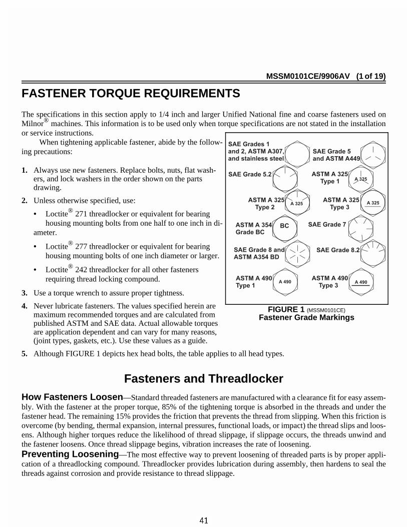
When tightening applicable fastener, abide by the follow-ing precautions:
1. Always use new fasteners. Replace bolts, nuts, flat wash-ers, and lock washers in the order shown on the partsdrawing.
2. Unless otherwise specified, use:
• Loctite® 271 threadlocker or equivalent for bearinghousing mounting bolts from one half to one inch in di-
ameter.
• Loctite® 277 threadlocker or equivalent for bearinghousing mounting bolts of one inch diameter or larger.
• Loctite® 242 threadlocker for all other fastenersrequiring thread locking compound.
3. Use a torque wrench to assure proper tightness.
4. Never lubricate fasteners. The values specified herein aremaximum recommended torques and are calculated frompublished ASTM and SAE data. Actual allowable torquesare application dependent and can vary for many reasons,(joint types, gaskets, etc.). Use these values as a guide.
5. Although FIGURE 1 depicts hex head bolts, the table applies to all head types.
ÊFasteners and ThreadlockerËHow Fasteners Loosen —Standard threaded fasteners are manufactured with a clearance fit for easy assem-bly. With the fastener at the proper torque, 85% of the tightening torque is absorbed in the threads and under thefastener head. The remaining 15% provides the friction that prevents the thread from slipping. When this friction isovercome (by bending, thermal expansion, internal pressures, functional loads, or impact) the thread slips and loos-ens. Although higher torques reduce the likelihood of thread slippage, if slippage occurs, the threads unwind andthe fastener loosens. Once thread slippage begins, vibration increases the rate of loosening.ËPreventing Loosening —The most effective way to prevent loosening of threaded parts is by proper appli-cation of a threadlocking compound. Threadlocker provides lubrication during assembly, then hardens to seal thethreads against corrosion and provide resistance to thread slippage.
ÎFIGURE 1 (MSSM0101CE)
ÎFastener Grade Markings
ÊApplying Threadlocker
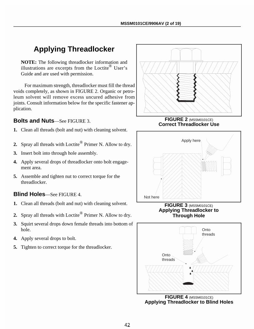
NOTE: The following threadlocker information andillustrations are excerpts from the Loctite® User’sGuide and are used with permission.
For maximum strength, threadlocker must fill the threadvoids completely, as shown in FIGURE 2. Organic or petro-leum solvent will remove excess uncured adhesive fromjoints. Consult information below for the specific fastener ap-plication.
ËBolts and Nuts —See FIGURE 3.
1. Clean all threads (bolt and nut) with cleaning solvent.
2. Spray all threads with Loctite® Primer N. Allow to dry.
3. Insert bolt into through hole assembly.
4. Apply several drops of threadlocker onto bolt engage-ment area.
5. Assemble and tighten nut to correct torque for the threadlocker.
ËBlind Holes —See FIGURE 4.
1. Clean all threads (bolt and nut) with cleaning solvent.
2. Spray all threads with Loctite® Primer N. Allow to dry.
3. Squirt several drops down female threads into bottom ofhole.
4. Apply several drops to bolt.
5. Tighten to correct torque for the threadlocker.
ÎFIGURE 2 (MSSM0101CE)
ÎCorrect Threadlocker Use
Apply here
Not here
ÎFIGURE 3 (MSSM0101CE)
ÎApplying Threadlocker toThrough Hole
Ontothreads
Ontothreads
ÎFIGURE 4 (MSSM0101CE)
ÎApplying Threadlocker to Blind Holes
MSSM0101CE/9906AV (2 of 19)
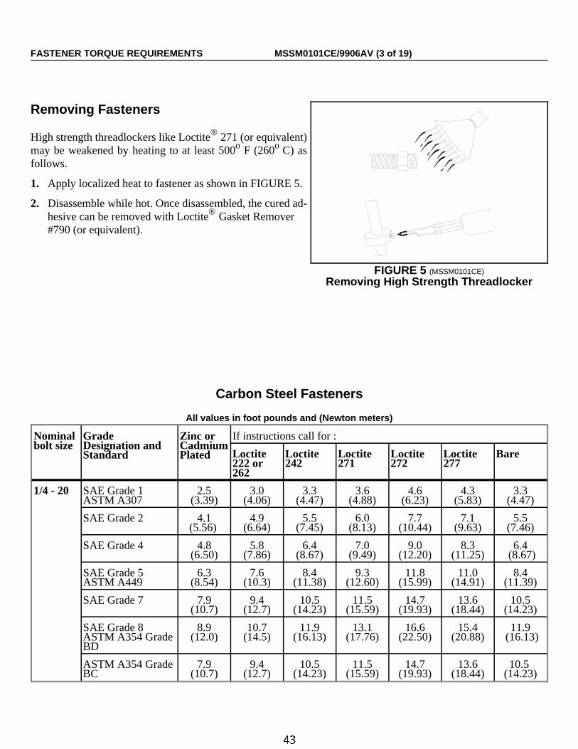
ËRemoving Fasteners
High strength threadlockers like Loctite® 271 (or equivalent)may be weakened by heating to at least 500o F (260o C) asfollows.
1. Apply localized heat to fastener as shown in FIGURE 5.
2. Disassemble while hot. Once disassembled, the cured ad-hesive can be removed with Loctite® Gasket Remover#790 (or equivalent).
ÏCarbon Steel Fasteners
ÏAll values in foot pounds and (Newton meters)
Nominalbolt size
GradeDesignation andStandard
Zinc orCadmiumPlated
If instructions call for :
Loctite222 or262
Loctite242
Loctite271
Loctite272
Loctite277
Bare
1/4 - 20 SAE Grade 1ASTM A307
2.5(3.39)
3.0(4.06)
3.3(4.47)
3.6(4.88)
4.6(6.23)
4.3(5.83)
3.3(4.47)
SAE Grade 2 4.1(5.56)
4.9(6.64)
5.5(7.45)
6.0(8.13)
7.7(10.44)
7.1(9.63)
5.5(7.46)
SAE Grade 4 4.8(6.50)
5.8(7.86)
6.4(8.67)
7.0(9.49)
9.0(12.20)
8.3(11.25)
6.4 (8.67)
SAE Grade 5ASTM A449
6.3(8.54)
7.6(10.3)
8.4(11.38)
9.3(12.60)
11.8(15.99)
11.0(14.91)
8.4(11.39)
SAE Grade 7 7.9(10.7)
9.4(12.7)
10.5(14.23)
11.5(15.59)
14.7(19.93)
13.6(18.44)
10.5(14.23)
SAE Grade 8ASTM A354 GradeBD
8.9(12.0)
10.7(14.5)
11.9(16.13)
13.1(17.76)
16.6(22.50)
15.4(20.88)
11.9 (16.13)
ASTM A354 GradeBC
7.9(10.7)
9.4(12.7)
10.5(14.23)
11.5(15.59)
14.7(19.93)
13.6(18.44)
10.5 (14.23)
ÎFIGURE 5 (MSSM0101CE)
ÎRemoving High Strength Threadlocker
FASTENER TORQUE REQUIREMENTS MSSM0101CE/9906AV (3 of 19)
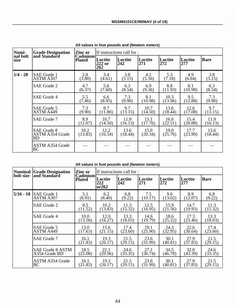
ÏAll values in foot pounds and (Newton meters)
Nomi-nal boltsize
Grade Designationand Standard
Zinc orCadmiumPlated
If instructions call for :
Loctite222 or262
Loctite242
Loctite271
Loctite272
Loctite277
Bare
1/4 - 28 SAE Grade 1ASTM A307
2.8(3.80)
3.4(4.61)
3.8(5.15)
4.1(5.56)
5.3(7.18)
4.9(6.64)
3.8(5.15)
SAE Grade 2 4.7(6.37)
5.6(7.60)
6.3(8.54)
6.9(9.36)
8.8(11.93)
8.1(10.98)
6.3(8.54)
SAE Grade 4 5.5(7.46)
6.6(8.95)
7.3(9.90)
8.1(10.98)
10.3(13.96)
9.5(12.88)
7.3(9.90)
SAE Grade 5ASTM A449
7.3(9.90)
8.7(11.80)
9.7(13.15)
10.7(14.50)
13.6(18.44)
12.6(17.08)
9.7(13.15)
SAE Grade 7 8.9(12.07)
10.7(14.50)
11.9(16.13)
13.1(17.76)
16.6(22.51)
15.4(20.88)
11.9(16.13)
SAE Grade 8ASTM A354 GradeBD
10.2(13.83)
12.2(16.54)
13.6(18.44)
15.0(20.34)
19.0(25.76)
17.7(23.99)
13.6(18.44)
ASTM A354 GradeBC
— — — — — — —
ÏAll values in foot pounds and (Newton meters)
Nominalbolt size
Grade Designationand Standard
Zinc orCadmiumPlated
If instructions call for :
Loctite222or262
Loctite242
Loctite271
Loctite272
Loctite277
Bare
5/16 - 18 SAE Grade 1ASTM A307
5.1(6.91)
6.2(8.40)
6.8(9.22)
7.5(10.17)
9.6(13.02)
8.9(12.07)
6.8(9.22)
SAE Grade 2 8.5(11.52)
10.2(13.83)
11.3(15.32)
12.5(16.95)
15.9(21.56)
14.7(19.93)
11.3(15.32)
SAE Grade 4 10.0(13.56)
12.0(16.27)
13.3(18.03)
14.6(19.79)
18.6(25.22)
17.3(23.46)
13.3(18.03)
SAE Grade 5ASTM A449
13.0(17.63)
15.6(21.15)
17.4(23.60)
19.1(25.90)
24.3(32.95)
22.6(30.64)
17.4(23.60)
SAE Grade 7 16.1(21.83)
19.3(26.17)
21.5(29.15)
23.6(31.99)
30.1(40.81)
27.9(37.83)
21.5(29.15)
SAE Grade 8 ASTMA354 Grade BD
18.5(25.08)
22.1(29.96)
24.6(33.35)
27.1(36.74)
34.5(46.78)
32.0(43.39)
24.6(33.35)
ASTM A354 GradeBC
16.1(21.83)
19.3(26.17)
21.5(29.15)
23.6(31.99)
30.1(40.81)
27.9(37.83)
21.5(29.15)
MSSM0101CE/9906AV (4 of 19)
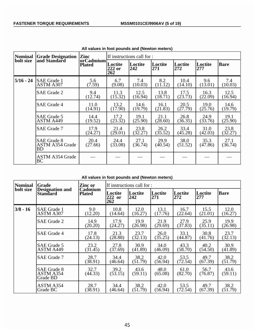
ÏAll values in foot pounds and (Newton meters)
Nominalbolt size
Grade Designationand Standard
ZincorCadmiumPlated
If instructions call for :
Loctite222 or262
Loctite242
Loctite271
Loctite272
Loctite277
Bare
5/16 - 24 SAE Grade 1ASTM A307
5.6(7.59)
6.7(9.08)
7.4(10.03)
8.2(11.12)
10.4(14.10)
9.6(13.01)
7.4(10.03)
SAE Grade 2 9.4(12.74)
11.3(15.32)
12.5(16.94)
13.8(18.71)
17.5(23.73)
16.3(22.09)
12.5(16.94)
SAE Grade 4 11.0(14.91)
13.2(17.90)
14.6(19.79)
16.1(21.83)
20.5(27.79)
19.0(25.76)
14.6(19.79)
SAE Grade 5ASTM A449
14.4(19.52)
17.2(23.32)
19.1(25.90)
21.1(28.60)
26.8(36.35)
24.9(33.76)
19.1(25.90)
SAE Grade 7 17.9(24.27)
21.4(29.01)
23.8(32.27)
26.2(35.52)
33.4(45.28)
31.0(42.03)
23.8(32.27)
SAE Grade 8ASTM A354 GradeBD
20.4(27.66)
24.4(33.08)
27.1(36.74)
29.9(40.54)
38.0(51.52)
35.3(47.86)
27.1(36.74)
ASTM A354 GradeBC
— — — — — — —
ÏAll values in foot pounds and (Newton meters)
Nominalbolt size
GradeDesignation andStandard
Zinc orCadmiumPlated
If instructions call for :
Loctite222 or262
Loctite242
Loctite271
Loctite272
Loctite277
Bare
3/8 - 16 SAE Grade 1ASTM A307
9.0(12.20)
10.8(14.64)
12.0(16.27)
13.1(17.76)
16.7(22.64)
15.5(21.01)
12.0(16.27)
SAE Grade 2 14.9(20.20)
17.9(24.27)
19.9(26.98)
21.9(29.69)
27.9(37.83)
25.9(35.11)
19.9(26.98)
SAE Grade 4 17.8(24.13)
21.3(28.88)
23.7(32.13)
26.0(35.25)
33.1(44.87)
30.8(41.76)
23.7(32.13)
SAE Grade 5ASTM A449
23.2(31.45)
27.8(37.69)
30.9(41.89)
34.0(46.09)
43.3(58.70)
40.2(54.50)
30.9(41.89)
SAE Grade 7 28.7(38.91)
34.4(46.64)
38.2(51.79)
42.0(56.94)
53.5(72.54)
49.7(67.39)
38.2(51.79)
SAE Grade 8ASTM A354Grade BD
32.7(44.33)
39.2(53.15)
43.6(59.11)
48.0(65.08)
61.0(82.70)
56.7(76.87)
43.6(59.11)
ASTM A354Grade BC
28.7(38.91)
34.4(46.64)
38.2(51.79)
42.0(56.94)
53.5(72.54)
49.7(67.39)
38.2(51.79)
FASTENER TORQUE REQUIREMENTS MSSM0101CE/9906AV (5 of 19)
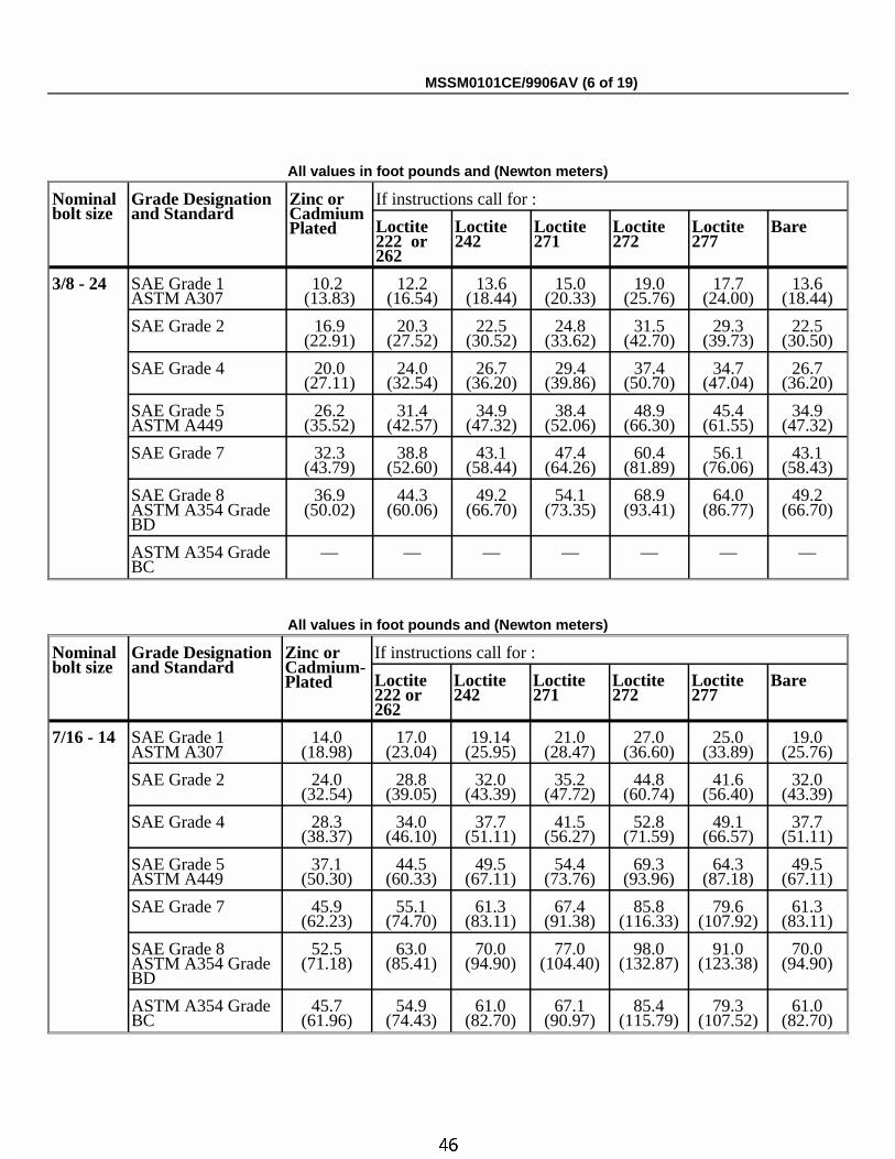
ÏAll values in foot pounds and (Newton meters)
Nominalbolt size
Grade Designationand Standard
Zinc orCadmiumPlated
If instructions call for :
Loctite222 or262
Loctite242
Loctite271
Loctite272
Loctite277
Bare
3/8 - 24 SAE Grade 1ASTM A307
10.2 (13.83)
12.2(16.54)
13.6(18.44)
15.0(20.33)
19.0(25.76)
17.7(24.00)
13.6(18.44)
SAE Grade 2 16.9(22.91)
20.3(27.52)
22.5(30.52)
24.8(33.62)
31.5(42.70)
29.3(39.73)
22.5(30.50)
SAE Grade 4 20.0(27.11)
24.0(32.54)
26.7(36.20)
29.4(39.86)
37.4(50.70)
34.7(47.04)
26.7(36.20)
SAE Grade 5ASTM A449
26.2(35.52)
31.4(42.57)
34.9(47.32)
38.4(52.06)
48.9(66.30)
45.4(61.55)
34.9(47.32)
SAE Grade 7 32.3(43.79)
38.8(52.60)
43.1(58.44)
47.4(64.26)
60.4(81.89)
56.1(76.06)
43.1(58.43)
SAE Grade 8ASTM A354 GradeBD
36.9(50.02)
44.3(60.06)
49.2(66.70)
54.1(73.35)
68.9(93.41)
64.0(86.77)
49.2(66.70)
ASTM A354 GradeBC
— — — — — — —
ÏAll values in foot pounds and (Newton meters)
Nominalbolt size
Grade Designationand Standard
Zinc orCadmium-Plated
If instructions call for :
Loctite222 or262
Loctite242
Loctite271
Loctite272
Loctite277
Bare
7/16 - 14 SAE Grade 1ASTM A307
14.0(18.98)
17.0(23.04)
19.14(25.95)
21.0(28.47)
27.0(36.60)
25.0(33.89)
19.0(25.76)
SAE Grade 2 24.0(32.54)
28.8(39.05)
32.0(43.39)
35.2(47.72)
44.8(60.74)
41.6(56.40)
32.0(43.39)
SAE Grade 4 28.3(38.37)
34.0(46.10)
37.7(51.11)
41.5(56.27)
52.8(71.59)
49.1(66.57)
37.7(51.11)
SAE Grade 5ASTM A449
37.1(50.30)
44.5(60.33)
49.5(67.11)
54.4(73.76)
69.3(93.96)
64.3(87.18)
49.5(67.11)
SAE Grade 7 45.9(62.23)
55.1(74.70)
61.3(83.11)
67.4(91.38)
85.8(116.33)
79.6(107.92)
61.3(83.11)
SAE Grade 8ASTM A354 GradeBD
52.5(71.18)
63.0(85.41)
70.0(94.90)
77.0(104.40)
98.0(132.87)
91.0(123.38)
70.0(94.90)
ASTM A354 GradeBC
45.7(61.96)
54.9(74.43)
61.0(82.70)
67.1(90.97)
85.4(115.79)
79.3(107.52)
61.0(82.70)
MSSM0101CE/9906AV (6 of 19)
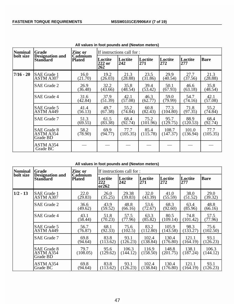
ÏAll values in foot pounds and (Newton meters)
Nominalbolt size
GradeDesignation andStandard
Zinc orCadmiumPlated
If instructions call for :
Loctite222 or262
Loctite242
Loctite271
Loctite272
Loctite277
Bare
7/16 - 20 SAE Grade 1ASTM A307
16.0(21.70)
19.2(26.03)
21.3(28.88)
23.5(31.86)
29.9(40.54)
27.7(37.56)
21.3(28.88)
SAE Grade 2 26.9(36.48)
32.2(43.66)
35.8(48.54)
39.4(53.42)
50.1(67.93)
46.6(63.18)
35.8(48.54)
SAE Grade 4 31.6(42.84)
37.9(51.39)
42.1(57.08)
46.3(62.77)
59.0(79.99)
54.7(74.16)
42.1(57.08)
SAE Grade 5ASTM A449
41.4(56.13)
49.7(67.38)
55.2(74.84)
60.8(82.43)
77.3(104.80)
71.8(97.35)
55.2(74.84)
SAE Grade 7 51.3(69.55)
61.5(83.38)
68.4(92.74)
75.2(101.96)
95.7(129.75)
88.9(120.53)
68.4(92.74)
SAE Grade 8ASTM A354Grade BD
58.2(78.90)
69.9(94.77)
77.7(105.35)
85.4(115.78)
108.7(147.37)
101.0(136.94)
77.7(105.35)
ASTM A354 Grade BC
— — — — — — —
ÏAll values in foot pounds and (Newton meters)
Nominalbolt size
GradeDesignation andStandard
Zinc orCadmiumPlated
If instructions call for :
Loctite222or262
Loctite242
Loctite271
Loctite272
Loctite277
Bare
1/2 - 13 SAE Grade 1ASTM A307
22.0(29.83)
26.0(35.25)
29.38(39.83)
32.0(43.39)
41.0(55.59)
38.0(51.52)
29.0(39.32)
SAE Grade 2 36.6(49.62)
43.9(59.52)
48.8(66.16)
53.6(72.67)
68.3(92.60)
63.4(85.96)
48.8(66.16)
SAE Grade 4 43.1(58.44)
51.8(70.23)
57.5(77.96)
63.3(85.82)
80.5(109.14)
74.8(101.42)
57.5(77.96)
SAE Grade 5ASTM A449
56.7(76.87)
68.1(92.33)
75.6(102.5)
83.2(112.80)
105.9(143.58)
98.3(133.27)
75.6(102.50)
SAE Grade 7 69.8(94.64)
83.8(113.62)
93.1(126.23)
102.4(138.84)
130.4(176.80)
121.1(164.19)
93.1(126.23)
SAE Grade 8ASTM A354Grade BD
79.7(108.05)
95.6(129.62)
106.3(144.12)
116.9(158.50)
148.8(201.75)
138.1(187.24)
106.3(144.12)
ASTM A354Grade BC
69.8(94.64)
83.8(113.62)
93.1(126.23)
102.4(138.84)
130.4(176.80)
121.1(164.19)
93.1(126.23)
FASTENER TORQUE REQUIREMENTS MSSM0101CE/9906AV (7 of 19)
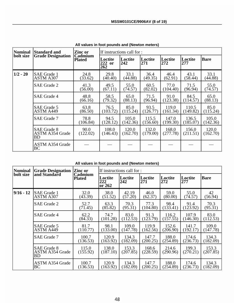
ÏAll values in foot pounds and (Newton meters)
Nominalbolt size
Standard andGrade Designation
Zinc orCadmiumPlated
If instructions call for :
Loctite222 or262
Loctite242
Loctite271
Loctite272
Loctite277
Bare
1/2 - 20 SAE Grade 1ASTM A307
24.8(33.62)
29.8(40.40)
33.1(44.88)
36.4(49.35)
46.4(62.91)
43.1(58.44)
33.1(44.88)
SAE Grade 2 41.3(56.00)
49.5(67.11)
55.0(74.57)
60.5(82.02)
77.0(104.40)
71.5(96.94)
55.0(74.57)
SAE Grade 4 48.8(66.16)
58.5(79.32)
65.0(88.13)
71.5(96.94)
91.0(123.38)
84.5(114.57)
65.0(88.13)
SAE Grade 5ASTM A449
63.8(86.50)
76.5(103.72)
85.0(115.24)
93.5(126.77)
119.0(161.34)
110.5(149.82)
85.0(115.24)
SAE Grade 7 78.8(106.84)
94.5(128.12)
105.0(142.36)
115.5(156.60)
147.0(199.30)
136.5(185.07)
105.0(142.36)
SAE Grade 8ASTM A354 GradeBD
90.0(122.02)
108.0(146.43)
120.0(162.70)
132.0(179.00)
168.0(277.78)
156.0(211.51)
120.0(162.70)
ASTM A354 GradeBC
— — — — — — —
ÏAll values in foot pounds and (Newton meters)
Nominalbolt size
Grade Designationand Standard
Zinc orCadmiumPlated
If instructions call for :
Loctite222 or 262
Loctite242
Loctite271
Loctite272
Loctite277
Bare
9/16 - 12 SAE Grade 1ASTM A307
32.0(43.39)
38.0(51.52)
42.19(57.20)
46.0(62.37)
59.0(80.00)
55.0(74.57)
42(56.94)
SAE Grade 2 52.7(71.45)
63.3(85.82)
70.3(95.31)
77.3(104.80)
98.4(133.41)
91.4(123.92)
70.3(95.31)
SAE Grade 4 62.2(84.33)
74.7(101.28)
83.0(112.53)
91.3(123.79)
116.2(157.55)
107.9(146.30)
83.0(112.53)
SAE Grade 5ASTM A449
81.7(110.77)
98.1(133.00)
109.0(147.78)
119.9(162.56)
152.6(206.90)
141.7(192.17)
109.0(147.78)
SAE Grade 7 100.7(136.53)
120.9(163.92)
134.3(182.09)
147.7(200.25)
188.0(254.89)
174.6(236.73)
134.3(182.09)
SAE Grade 8ASTM A354 GradeBD
115.0(155.92)
138.0(187.10)
153.3(207.85)
168.6(228.59)
214.6(290.96)
199.3(270.21)
153.3(207.85)
ASTM A354 GradeBC
100.7(136.53)
120.9(163.92)
134.3(182.09)
147.7(200.25)
188.0(254.89)
174.6(236.73)
134.3(182.09)
MSSM0101CE/9906AV (8 of 19)
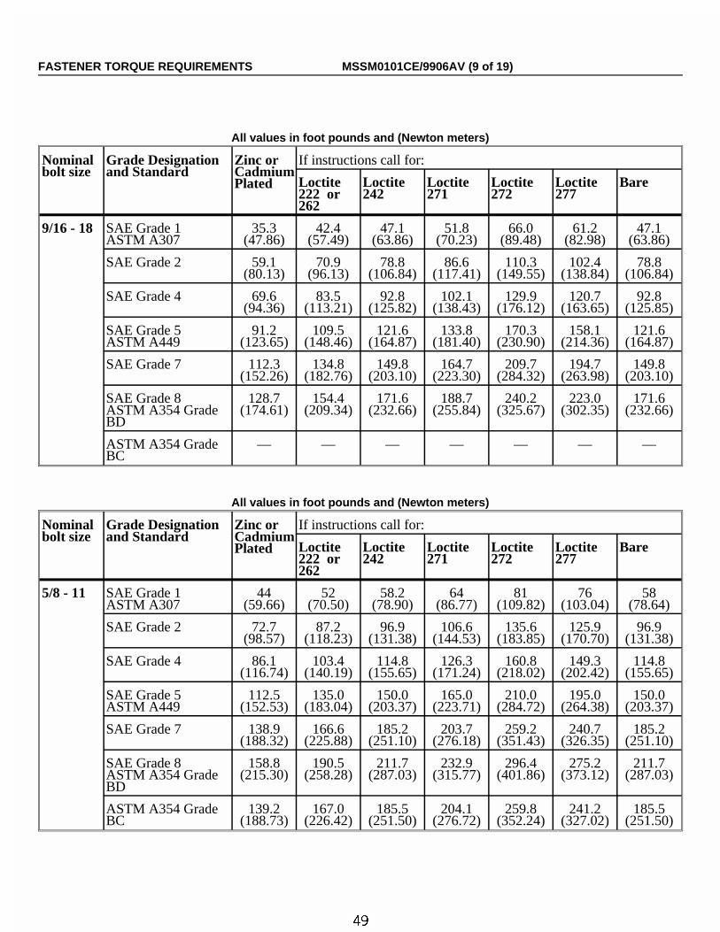
ÏAll values in foot pounds and (Newton meters)
Nominalbolt size
Grade Designationand Standard
Zinc orCadmiumPlated
If instructions call for:
Loctite222 or262
Loctite242
Loctite271
Loctite272
Loctite277
Bare
9/16 - 18 SAE Grade 1ASTM A307
35.3(47.86)
42.4(57.49)
47.1(63.86)
51.8(70.23)
66.0(89.48)
61.2(82.98)
47.1(63.86)
SAE Grade 2 59.1(80.13)
70.9(96.13)
78.8(106.84)
86.6(117.41)
110.3(149.55)
102.4(138.84)
78.8(106.84)
SAE Grade 4 69.6(94.36)
83.5(113.21)
92.8(125.82)
102.1(138.43)
129.9(176.12)
120.7(163.65)
92.8(125.85)
SAE Grade 5ASTM A449
91.2(123.65)
109.5(148.46)
121.6(164.87)
133.8(181.40)
170.3(230.90)
158.1(214.36)
121.6(164.87)
SAE Grade 7 112.3(152.26)
134.8(182.76)
149.8(203.10)
164.7(223.30)
209.7(284.32)
194.7(263.98)
149.8(203.10)
SAE Grade 8ASTM A354 GradeBD
128.7(174.61)
154.4(209.34)
171.6(232.66)
188.7(255.84)
240.2(325.67)
223.0(302.35)
171.6(232.66)
ASTM A354 GradeBC
— — — — — — —
ÏAll values in foot pounds and (Newton meters)
Nominalbolt size
Grade Designationand Standard
Zinc orCadmiumPlated
If instructions call for:
Loctite222 or262
Loctite242
Loctite271
Loctite272
Loctite277
Bare
5/8 - 11 SAE Grade 1ASTM A307
44(59.66)
52(70.50)
58.2(78.90)
64(86.77)
81(109.82)
76(103.04)
58(78.64)
SAE Grade 2 72.7(98.57)
87.2(118.23)
96.9(131.38)
106.6(144.53)
135.6(183.85)
125.9(170.70)
96.9(131.38)
SAE Grade 4 86.1(116.74)
103.4(140.19)
114.8(155.65)
126.3(171.24)
160.8(218.02)
149.3(202.42)
114.8(155.65)
SAE Grade 5ASTM A449
112.5(152.53)
135.0(183.04)
150.0(203.37)
165.0(223.71)
210.0(284.72)
195.0(264.38)
150.0(203.37)
SAE Grade 7 138.9(188.32)
166.6(225.88)
185.2(251.10)
203.7(276.18)
259.2(351.43)
240.7(326.35)
185.2(251.10)
SAE Grade 8ASTM A354 GradeBD
158.8(215.30)
190.5(258.28)
211.7(287.03)
232.9(315.77)
296.4(401.86)
275.2(373.12)
211.7(287.03)
ASTM A354 GradeBC
139.2(188.73)
167.0(226.42)
185.5(251.50)
204.1(276.72)
259.8(352.24)
241.2(327.02)
185.5(251.50)
FASTENER TORQUE REQUIREMENTS MSSM0101CE/9906AV (9 of 19)

ÏAll values in foot pounds and (Newton meters)
Nominalbolt size
Grade Designationand Standard
Zinc orCadmiumPlated
If instructions call for:
Loctite222 or262
Loctite242
Loctite271
Loctite272
Loctite277
Bare
5/8 - 18 SAE Grade 1ASTM A307
49.5(67.11)
59.4(80.54)
66.0(89.48)
72.6(98.43)
92.4(125.27)
85.8(116.33)
66.0(89.48)
SAE Grade 2 82.6(112.00)
99.1(134.36)
110.2(149.41)
121.2(164.33)
154.2(209.07)
143.2(194.15)
110.2(149.41)
SAE Grade 4 97.3(131.92)
116.7(158.22)
129.7(175.85)
142.7(193.48)
181.6(246.22)
168.6(228.59)
129.7(175.85)
SAE Grade 5ASTM A449
127.7(173.14)
153.3(207.85)
170.3(230.90)
187.3(253.95)
238.4(323.23)
221.4(300.18)
170.3(230.90)
SAE Grade 7 157.6(213.68)
189.1(256.39)
210.2(285.00)
231.2(313.47)
294.2(398.88)
273.2(370.41)
210.2(285.00)
SAE Grade 8ASTM A354 GradeBD
179.9(243.91)
215.9(292.72)
239.8(325.13)
263.8(357.66)
335.8(455.28)
311.8(422.74)
239.8(325.13)
ASTM A354 GradeBC
— — — — — — —
ÏAll values in foot pounds and (Newton meters)
Nominalbolt size
Grade Designationand Standard
Zinc orCadmiumPlated
If instructions call for:
Loctite222 or262
Loctite242
Loctite271
Loctite272
Loctite277
Bare
3/4 - 10 SAE Grade 1ASTM A307
77(104.40)
93(126.09)
103.1(139.78)
113(153.20)
144(195.24)
134(181.68)
103(139.65)
SAE Grade 2 129.4(175.44)
155.3(210.55)
172.5(233.88)
189.8(257.33)
241.5(327.43)
224.3(304.11)
172.5(233.88)
SAE Grade 4 152.6(206.90)
183.1(248.25)
203.4(275.77)
223.8(303.43)
284.8(386.14)
264.5(358.61)
203.4(275.77)
SAE Grade 5ASTM A449
199.7(270.76)
239.6(324.85)
266.3(361.05)
292.9(397.12)
372.8(505.45)
346.1(469.25)
266.3(361.05)
SAE Grade 7 246.8(334.62)
296.2(401.60)
329.1(446.20)
362.0(355.22)
460.7(624.63)
427.8(580.02)
329.1(446.20)
SAE Grade 8ASTM A354 GradeBD
282.0(382.34)
338.3(458.67)
375.9(509.65)
413.5(560.63)
526.3(713.57)
488.7(662.59)
375.9(509.65)
ASTM A354 GradeBC
246.4(334.07)
295.7(400.92)
328.6(445.53)
361.5(490.13)
460.0(623.67)
427.2(579.20)
328.6(445.53)
MSSM0101CE/9906AV (10 of 19)
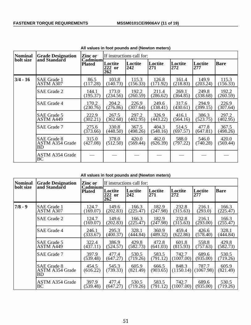
ÏAll values in foot pounds and (Newton meters)
Nominalbolt size
Grade Designationand Standard
Zinc orCadmiumPlated
If instructions call for:
Loctite222 or262
Loctite242
Loctite271
Loctite272
Loctite277
Bare
3/4 - 16 SAE Grade 1ASTM A307
86.5(117.28)
103.8(140.73)
115.3(156.33)
126.8(171.92)
161.4(218.83)
149.9(203.24)
115.3(156.33)
SAE Grade 2 144.1(195.37)
173.0(234.56)
192.2(260.59)
211.4(286.62)
269.1(364.85)
249.8(338.68)
192.2(260.59)
SAE Grade 4 170.2(230.76)
204.2(276.86)
226.9(307.64)
249.6(338.41)
317.6(430.61)
294.9(399.15)
226.9(307.64)
SAE Grade 5ASTM A449
222.9(302.21)
267.5(362.68)
297.2(402.95)
326.9(443.22)
416.1(564.16)
386.3(523.75)
297.2(402.95)
SAE Grade 7 275.6(373.66)
330.8(448.50)
367.5(498.26)
404.3(548.16)
514.5(697.57)
477.8(647.81)
367.5(498.26)
SAE Grade 8ASTM A354 GradeBD
315.0(427.08)
378.0(512.50)
420.0(569.44)
462.0(626.39)
588.0(797.22)
546.0(740.28)
420.0(569.44)
ASTM A354 GradeBC
— — — — — — —
ÏAll values in foot pounds and (Newton meters)
Nominalbolt size
Grade Designationand Standard
Zinc orCadmiumPlated
If instructions call for:
Loctite222 or262
Loctite242
Loctite271
Loctite272
Loctite277
Bare
7/8 - 9 SAE Grade 1ASTM A307
124.7(169.07)
149.6(202.83)
166.3(225.47)
182.9(247.98)
232.8(315.63)
216.1(293.0)
166.3(225.47)
SAE Grade 2 124.7(169.07)
149.6(202.83)
166.3(225.47)
182.9(247.98)
232.8(315.63)
216.1(293.00)
166.3(255.47)
SAE Grade 4 246.1(333.67)
295.3(400.37)
328.1(444.84)
360.9(489.32)
459.4(622.86)
426.6(578.40)
328.1(444.84)
SAE Grade 5ASTM A449
322.4(437.11)
386.9(524.57)
429.8(582.73)
472.8(641.03)
601.8(815.93)
558.8(757.63)
429.8(582.73)
SAE Grade 7 397.9(539.48)
477.4(647.27)
530.5(719.26)
583.5(791.12)
742.7(1007.00)
689.6(935.00)
530.5(719.26)
SAE Grade 8ASTM A354 GradeBD
454.5(616.22)
545.3(739.33)
605.9(821.49)
666.5(903.65)
848.3(1150.14)
787.7(1067.98)
605.9(821.49)
ASTM A354 GradeBC
397.9(539.48)
477.4(647.27)
530.5(719.26)
583.5(791.12)
742.7(1007.00)
689.6(935.00)
530.5(719.26)
FASTENER TORQUE REQUIREMENTS MSSM0101CE/9906AV (11 of 19)
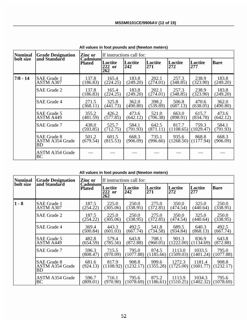
ÏAll values in foot pounds and (Newton meters)
Nominalbolt size
Grade Designationand Standard
Zinc orCadmiumPlated
If instructions call for:
Loctite222 or262
Loctite242
Loctite271
Loctite272
Loctite277
Bare
7/8 - 14 SAE Grade 1ASTM A307
137.8(186.83)
165.4(224.25)
183.8(249.20)
202.1(274.01)
257.3(348.85)
238.9(323.90)
183.8(249.20)
SAE Grade 2 137.8(186.83)
165.4(224.25)
183.8(249.20)
202.1(274.01)
257.3(348.85)
238.9(323.90)
183.8(249.20)
SAE Grade 4 271.5(368.11)
325.8(441.73)
362.0(490.80)
398.2(539.89)
506.8(687.13)
470.6(638.05)
362.0(490.80)
SAE Grade 5ASTM A449
355.2(481.59)
426.2(577.85)
473.6(642.12)
521.0(706.38)
663.0(898.91)
615.7(834.78)
473.6(642.12)
SAE Grade 7 438.0(593.85)
525.7(712.75)
584.1(791.93)
642.5(871.11)
817.7(1108.65)
759.3(1029.47)
584.1(791.93)
SAE Grade 8ASTM A354 GradeBD
501.2(679.54)
601.5(815.53)
668.3(906.09)
735.1(996.66)
935.6(1268.50)
868.8(1177.94)
668.3(906.09)
ASTM A354 GradeBC
— — — — — — —
ÏAll values in foot pounds and (Newton meters)
Nominalbolt size
Grade Designationand Standard
Zinc orCadmiumPlated
If instructions call for:
Loctite222 or262
Loctite 242
Loctite 271
Loctite 272
Loctite 277
Bare
1 - 8 SAE Grade 1ASTM A307
187.5(254.22)
225.0(305.06)
250.0(338.95)
275.0(372.85)
350.0(474.54)
325.0(440.64)
250.0(338.95)
SAE Grade 2 187.5(254.22)
225.0(305.06)
250.0(338.95)
275.0(372.85)
350.0(474.54)
325.0(440.64)
250.0(338.95)
SAE Grade 4 369.4(500.84)
443.3(601.03)
492.5(667.74)
541.8(734.58)
689.5(934.84)
640.3(868.13)
492.5(667.74)
SAE Grade 5ASTM A449
482.8(654.59)
579.4(785.56)
643.8(872.88)
708.1(960.05)
901.3(1222.00)
836.9(1134.69)
643.8(872.88)
SAE Grade 7 596.3(808.47)
715.5(970.09)
795.0(1077.88)
874.5(1185.66)
1113.0(1509.03)
1033.5(1401.24)
795.0(1077.88)
SAE Grade 8ASTM A354 GradeBD
681.6(924.13)
817.9(1108.92)
908.8(1232.17)
999.6(1355.28)
1272.3(1725.00)
1181.4(1601.77)
908.8(1232.17)
ASTM A354 GradeBC
596.7(809.01)
716.1(970.90)
795.6(1078.69)
875.2(1186.61)
1113.9(1510.25)
1034.3(1402.32)
795.6(1078.69)
MSSM0101CE/9906AV (12 of 19)
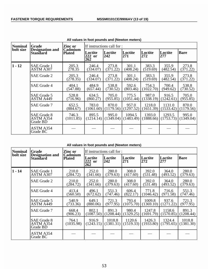
ÏAll values in foot pounds and (Newton meters)
Nominalbolt size
GradeDesignation andStandard
Zinc orCadmiumPlated
If instructions call for :
Loctite222 or262
Loctite242
Loctite271
Loctite272
Loctite277
Bare
1 - 12 SAE Grade 1ASTM A307
205.3278.35
246.4(334.07)
273.8(371.22)
301.1(408.24)
383.3(519.69)
355.9(482.54)
273.8(371.22)
SAE Grade 2 205.3(278.35)
246.4(334.07)
273.8(371.22)
301.1(408.24)
383.3(519.69)
355.9(482.54)
273.8(371.22)
SAE Grade 4 404.1(547.88)
484.9(657.44)
538.8(730.52)
592.6(803.46)
754.3(1022.70)
700.4(949.62)
538.8(730.52)
SAE Grade 5ASTM A449
528.8(716.96)
634.5(860.27)
705.0(955.85)
775.5(1051.44)
987.0(1338.19)
916.5(1242.61)
705.0(955.85)
SAE Grade 7 652.5(884.67)
783.0(1061.60)
870.0(1179.56)
957.0(1297.52)
1218.0(1651.39)
1131.0(1533.42)
870.0(1179.56)
SAE Grade 8ASTM A354Grade BD
746.3(1011.85)
895.5(1214.14)
995.0(1349.04)
1094.5(1483.49)
1393.0(1888.66)
1293.5(1753.73)
995.0(1349.04)
ASTM A354Grade BC
— — — — — — —
ÏAll values in foot pounds and (Newton meters)
Nominalbolt size
GradeDesignation andStandard
Zinc orCadmiumPlated
If instructions call for :
Loctite222 or262
Loctite242
Loctite271
Loctite272
Loctite277
Bare
1 - 14 SAE Grade 1ASTM A307
210.0(284.72)
252.0(341.66)
280.0(379.63)
308.0(417.60)
392.0(531.48)
364.0(493.52)
280.0(379.63)
SAE Grade 2 210.0(284.72)
252.0(341.66)
280.0(379.63)
308.0(417.60)
392.0(531.48)
364.0(493.52)
280.0(379.63)
SAE Grade 4 413.4(560.50)
496.1(672.62)
551.3(747.46)
606.4(822.17)
771.8(1046.42)
716.6(971.58)
551.3(747.46)
SAE Grade 5ASTM A449
540.9(733.36)
649.1(880.06)
721.3(977.95)
793.4(1075.70)
1009.8(1369.10)
937.6(1271.22)
721.3(977.95)
SAE Grade 7 668.4(906.23)
802.1(1087.50)
891.3(1208.44)
980.4(1329.25)
1247.8(1691.79)
1158.6(1570.85)
891.3(1208.44)
SAE Grade 8ASTM A354Grade BD
764.1(1035.98)
916.9(1243.15)
1018.8(1381.31)
1120.6(1519.33)
1426.3(1933.80)
1324.4(1795.65)
1018.8(1381.30)
ASTM A354Grade BC
— — — — — — —
FASTENER TORQUE REQUIREMENTS MSSM0101CE/9906AV (13 of 19)
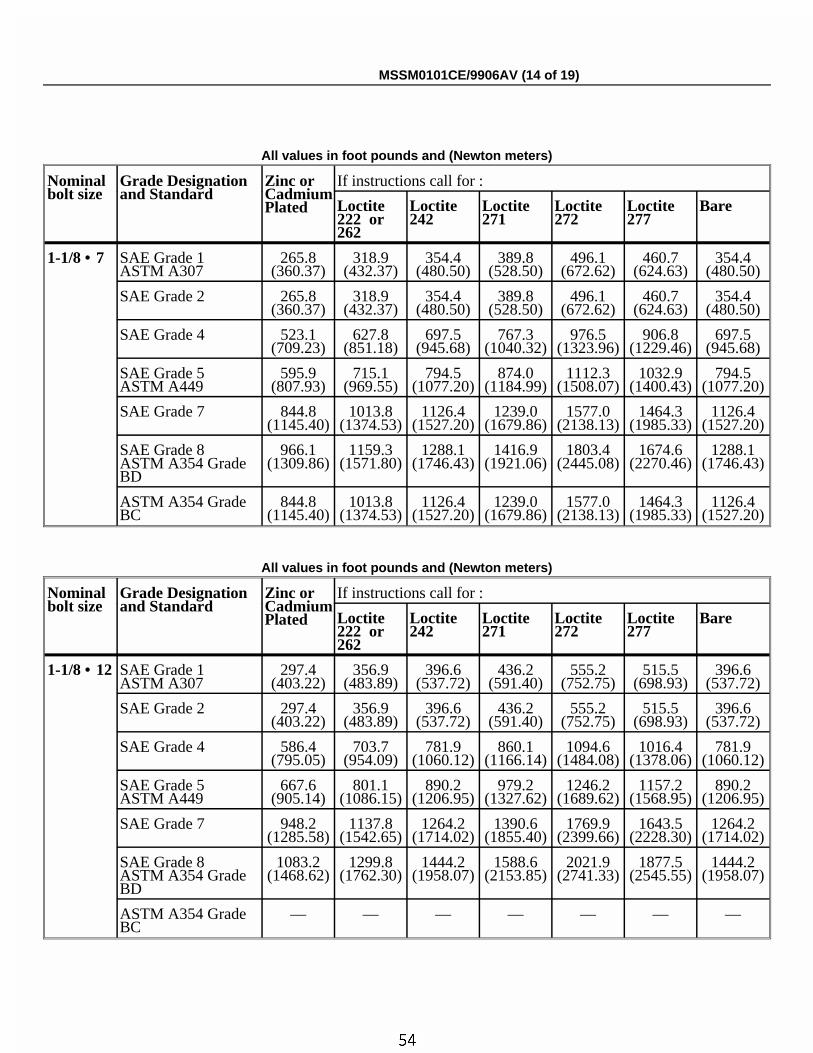
ÏAll values in foot pounds and (Newton meters)
Nominalbolt size
Grade Designationand Standard
Zinc orCadmiumPlated
If instructions call for :
Loctite222 or262
Loctite242
Loctite271
Loctite272
Loctite277
Bare
1-1/8 • 7 SAE Grade 1ASTM A307
265.8(360.37)
318.9(432.37)
354.4(480.50)
389.8(528.50)
496.1(672.62)
460.7(624.63)
354.4(480.50)
SAE Grade 2 265.8(360.37)
318.9(432.37)
354.4(480.50)
389.8(528.50)
496.1(672.62)
460.7(624.63)
354.4(480.50)
SAE Grade 4 523.1(709.23)
627.8(851.18)
697.5(945.68)
767.3(1040.32)
976.5(1323.96)
906.8(1229.46)
697.5(945.68)
SAE Grade 5ASTM A449
595.9(807.93)
715.1(969.55)
794.5(1077.20)
874.0(1184.99)
1112.3(1508.07)
1032.9(1400.43)
794.5(1077.20)
SAE Grade 7 844.8(1145.40)
1013.8(1374.53)
1126.4(1527.20)
1239.0(1679.86)
1577.0(2138.13)
1464.3(1985.33)
1126.4(1527.20)
SAE Grade 8ASTM A354 GradeBD
966.1(1309.86)
1159.3(1571.80)
1288.1(1746.43)
1416.9(1921.06)
1803.4(2445.08)
1674.6(2270.46)
1288.1(1746.43)
ASTM A354 GradeBC
844.8(1145.40)
1013.8(1374.53)
1126.4(1527.20)
1239.0(1679.86)
1577.0(2138.13)
1464.3(1985.33)
1126.4(1527.20)
ÏAll values in foot pounds and (Newton meters)
Nominalbolt size
Grade Designationand Standard
Zinc orCadmiumPlated
If instructions call for :
Loctite222 or262
Loctite242
Loctite271
Loctite272
Loctite277
Bare
1-1/8 • 12 SAE Grade 1ASTM A307
297.4(403.22)
356.9(483.89)
396.6(537.72)
436.2(591.40)
555.2(752.75)
515.5(698.93)
396.6(537.72)
SAE Grade 2 297.4(403.22)
356.9(483.89)
396.6(537.72)
436.2(591.40)
555.2(752.75)
515.5(698.93)
396.6(537.72)
SAE Grade 4 586.4(795.05)
703.7(954.09)
781.9(1060.12)
860.1(1166.14)
1094.6(1484.08)
1016.4(1378.06)
781.9(1060.12)
SAE Grade 5ASTM A449
667.6(905.14)
801.1(1086.15)
890.2(1206.95)
979.2(1327.62)
1246.2(1689.62)
1157.2(1568.95)
890.2(1206.95)
SAE Grade 7 948.2(1285.58)
1137.8(1542.65)
1264.2(1714.02)
1390.6(1855.40)
1769.9(2399.66)
1643.5(2228.30)
1264.2(1714.02)
SAE Grade 8ASTM A354 GradeBD
1083.2(1468.62)
1299.8(1762.30)
1444.2(1958.07)
1588.6(2153.85)
2021.9(2741.33)
1877.5(2545.55)
1444.2(1958.07)
ASTM A354 GradeBC
— — — — — — —
MSSM0101CE/9906AV (14 of 19)
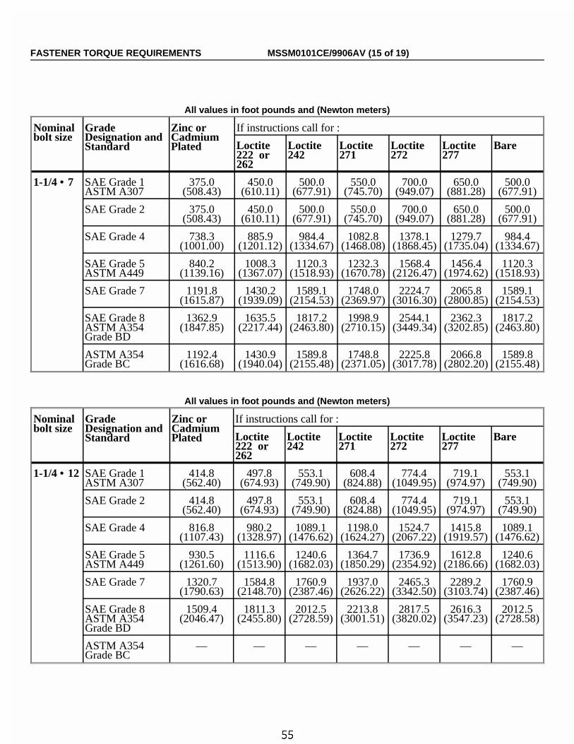
ÏAll values in foot pounds and (Newton meters)
Nominalbolt size
GradeDesignation andStandard
Zinc orCadmiumPlated
If instructions call for :
Loctite222 or262
Loctite242
Loctite271
Loctite272
Loctite277
Bare
1-1/4 • 7 SAE Grade 1ASTM A307
375.0(508.43)
450.0(610.11)
500.0(677.91)
550.0(745.70)
700.0(949.07)
650.0(881.28)
500.0(677.91)
SAE Grade 2 375.0(508.43)
450.0(610.11)
500.0(677.91)
550.0(745.70)
700.0(949.07)
650.0(881.28)
500.0(677.91)
SAE Grade 4 738.3(1001.00)
885.9(1201.12)
984.4(1334.67)
1082.8(1468.08)
1378.1(1868.45)
1279.7(1735.04)
984.4(1334.67)
SAE Grade 5ASTM A449
840.2(1139.16)
1008.3(1367.07)
1120.3(1518.93)
1232.3(1670.78)
1568.4(2126.47)
1456.4(1974.62)
1120.3(1518.93)
SAE Grade 7 1191.8(1615.87)
1430.2(1939.09)
1589.1(2154.53)
1748.0(2369.97)
2224.7(3016.30)
2065.8(2800.85)
1589.1(2154.53)
SAE Grade 8ASTM A354Grade BD
1362.9(1847.85)
1635.5(2217.44)
1817.2(2463.80)
1998.9(2710.15)
2544.1(3449.34)
2362.3(3202.85)
1817.2(2463.80)
ASTM A354Grade BC
1192.4(1616.68)
1430.9(1940.04)
1589.8(2155.48)
1748.8(2371.05)
2225.8(3017.78)
2066.8(2802.20)
1589.8(2155.48)
ÏAll values in foot pounds and (Newton meters)
Nominalbolt size
GradeDesignation andStandard
Zinc orCadmiumPlated
If instructions call for :
Loctite222 or262
Loctite242
Loctite271
Loctite272
Loctite277
Bare
1-1/4 • 12 SAE Grade 1ASTM A307
414.8(562.40)
497.8(674.93)
553.1(749.90)
608.4(824.88)
774.4(1049.95)
719.1(974.97)
553.1(749.90)
SAE Grade 2 414.8(562.40)
497.8(674.93)
553.1(749.90)
608.4(824.88)
774.4(1049.95)
719.1(974.97)
553.1(749.90)
SAE Grade 4 816.8(1107.43)
980.2(1328.97)
1089.1(1476.62)
1198.0(1624.27)
1524.7(2067.22)
1415.8(1919.57)
1089.1(1476.62)
SAE Grade 5ASTM A449
930.5(1261.60)
1116.6(1513.90)
1240.6(1682.03)
1364.7(1850.29)
1736.9(2354.92)
1612.8(2186.66)
1240.6(1682.03)
SAE Grade 7 1320.7(1790.63)
1584.8(2148.70)
1760.9(2387.46)
1937.0(2626.22)
2465.3(3342.50)
2289.2(3103.74)
1760.9(2387.46)
SAE Grade 8ASTM A354Grade BD
1509.4(2046.47)
1811.3(2455.80)
2012.5(2728.59)
2213.8(3001.51)
2817.5(3820.02)
2616.3(3547.23)
2012.5(2728.58)
ASTM A354Grade BC
— — — — — — —
FASTENER TORQUE REQUIREMENTS MSSM0101CE/9906AV (15 of 19)
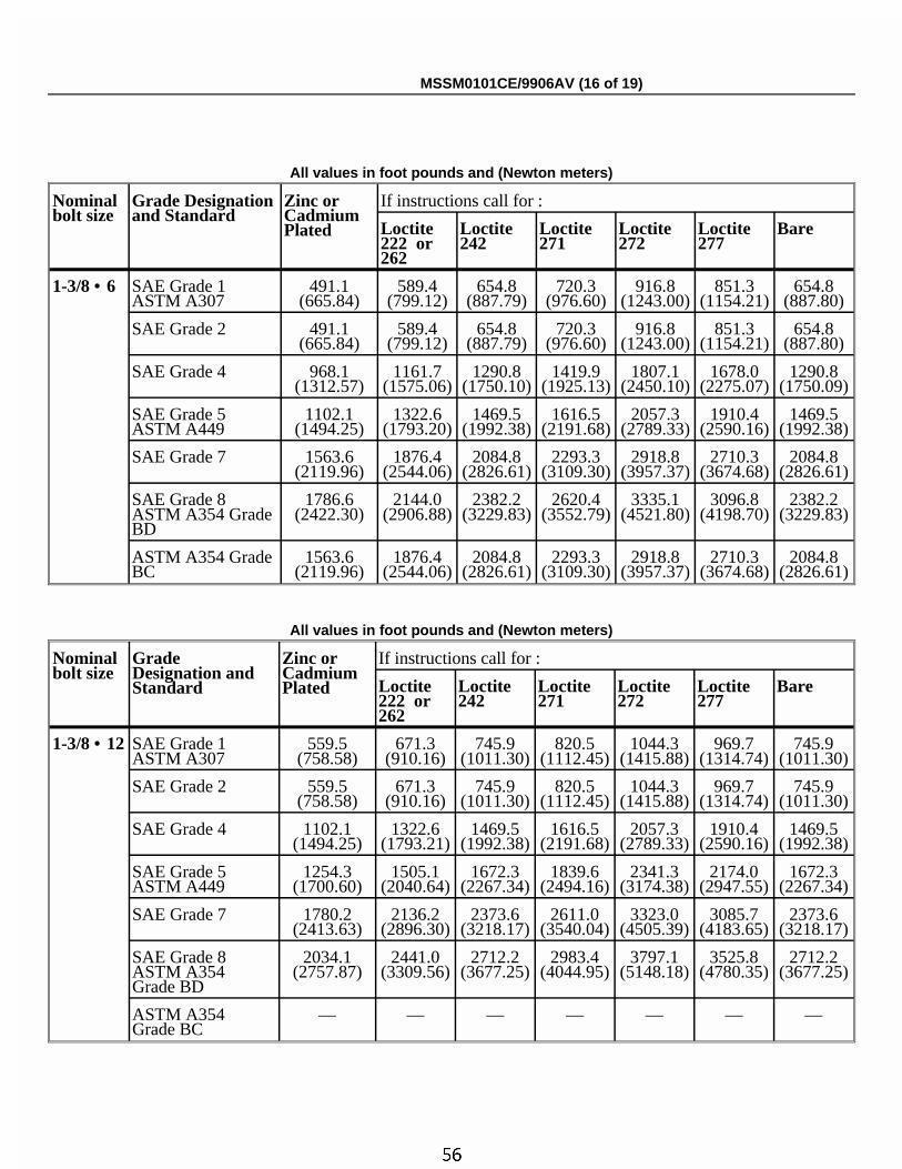
ÏAll values in foot pounds and (Newton meters)
Nominalbolt size
Grade Designationand Standard
Zinc orCadmiumPlated
If instructions call for :
Loctite222 or262
Loctite242
Loctite271
Loctite272
Loctite277
Bare
1-3/8 • 6 SAE Grade 1ASTM A307
491.1(665.84)
589.4(799.12)
654.8(887.79)
720.3(976.60)
916.8(1243.00)
851.3(1154.21)
654.8(887.80)
SAE Grade 2 491.1(665.84)
589.4(799.12)
654.8(887.79)
720.3(976.60)
916.8(1243.00)
851.3(1154.21)
654.8(887.80)
SAE Grade 4 968.1(1312.57)
1161.7(1575.06)
1290.8(1750.10)
1419.9(1925.13)
1807.1(2450.10)
1678.0(2275.07)
1290.8(1750.09)
SAE Grade 5ASTM A449
1102.1(1494.25)
1322.6(1793.20)
1469.5(1992.38)
1616.5(2191.68)
2057.3(2789.33)
1910.4(2590.16)
1469.5(1992.38)
SAE Grade 7 1563.6(2119.96)
1876.4(2544.06)
2084.8(2826.61)
2293.3(3109.30)
2918.8(3957.37)
2710.3(3674.68)
2084.8(2826.61)
SAE Grade 8ASTM A354 GradeBD
1786.6(2422.30)
2144.0(2906.88)
2382.2(3229.83)
2620.4(3552.79)
3335.1(4521.80)
3096.8(4198.70)
2382.2(3229.83)
ASTM A354 GradeBC
1563.6(2119.96)
1876.4(2544.06)
2084.8(2826.61)
2293.3(3109.30)
2918.8(3957.37)
2710.3(3674.68)
2084.8(2826.61)
ÏAll values in foot pounds and (Newton meters)
Nominalbolt size
GradeDesignation andStandard
Zinc orCadmiumPlated
If instructions call for :
Loctite222 or262
Loctite242
Loctite271
Loctite272
Loctite277
Bare
1-3/8 • 12 SAE Grade 1ASTM A307
559.5(758.58)
671.3(910.16)
745.9(1011.30)
820.5(1112.45)
1044.3(1415.88)
969.7(1314.74)
745.9(1011.30)
SAE Grade 2 559.5(758.58)
671.3(910.16)
745.9(1011.30)
820.5(1112.45)
1044.3(1415.88)
969.7(1314.74)
745.9(1011.30)
SAE Grade 4 1102.1(1494.25)
1322.6(1793.21)
1469.5(1992.38)
1616.5(2191.68)
2057.3(2789.33)
1910.4(2590.16)
1469.5(1992.38)
SAE Grade 5ASTM A449
1254.3(1700.60)
1505.1(2040.64)
1672.3(2267.34)
1839.6(2494.16)
2341.3(3174.38)
2174.0(2947.55)
1672.3(2267.34)
SAE Grade 7 1780.2(2413.63)
2136.2(2896.30)
2373.6(3218.17)
2611.0(3540.04)
3323.0(4505.39)
3085.7(4183.65)
2373.6(3218.17)
SAE Grade 8ASTM A354Grade BD
2034.1(2757.87)
2441.0(3309.56)
2712.2(3677.25)
2983.4(4044.95)
3797.1(5148.18)
3525.8(4780.35)
2712.2(3677.25)
ASTM A354Grade BC
— — — — — — —
MSSM0101CE/9906AV (16 of 19)
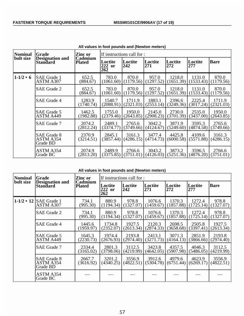
ÏAll values in foot pounds and (Newton meters)
Nominalbolt size
GradeDesignation andStandard
Zinc orCadmiumPlated
If instructions call for :
Loctite222 or262
Loctite242
Loctite271
Loctite272
Loctite277
Bare
1-1/2 • 6 SAE Grade 1ASTM A307
652.5(884.67)
783.0(1061.60)
870.0(1179.56)
957.0(1297.52)
1218.0(1651.39)
1131.0(1533.43)
870.0(1179.56)
SAE Grade 2 652.5(884.67)
783.0(1061.60)
870.0(1179.56)
957.0(1297.52)
1218.0(1651.39)
1131.0(1533.43)
870.0(1179.56)
SAE Grade 4 1283.9(1740.74)
1540.7(2088.91)
1711.9(2321.03)
1883.1(2553.14)
2396.6(3249.36)
2225.4(3017.24)
1711.9(2321.03)
SAE Grade 5ASTM A449
1462.5(1982.88)
1755.0(2379.46)
1950.0(2643.85)
2145.0(2908.23)
2730.0(3701.39)
2535.0(3437.00)
1950.0(2643.85)
SAE Grade 7 2074.2(2812.24)
2489.1(3374.77)
2765.6(3749.66)
3042.2(4124.67)
3871.9(5249.60)
3595.3(4874.58)
2765.6(3749.66)
SAE Grade 8ASTM A354Grade BD
2370.9(3214.51)
2845.1(3857.44)
3161.3(4286.15)
3477.4(4714.73)
4425.8(6000.58)
4109.6(5571.88)
3161.3(4286.15)
ASTM A354Grade BC
2074.9(2813.20)
2489.9(3375.85)
2766.6(3751.01)
3043.2(4126.03)
3873.2(5251.36)
3596.5(4876.20)
2766.6(3751.01)
ÏAll values in foot pounds and (Newton meters)
Nominalbolt size
GradeDesignation andStandard
Zinc orCadmiumPlated
If instructions call for :
Loctite222 or262
Loctite242
Loctite271
Loctite272
Loctite277
Bare
1-1/2 • 12 SAE Grade 1ASTM A307
734.1(995.30)
880.9(1194.34)
978.8(1327.07)
1076.6(1459.67)
1370.3(1857.88)
1272.4(1725.14)
978.8(1327.07)
SAE Grade 2 734.1(995.30)
880.9(1194.34)
978.8(1327.07)
1076.6(1459.67)
1370.3(1857.88)
1272.4(1725.14)
978.8(1327.07)
SAE Grade 4 1445.6(1959.97)
1734.8(2352.07)
1927.5(2613.34)
2120.3(2874.33)
2698.5(3658.68)
2505.8(3397.41)
1927.5(2613.34)
SAE Grade 5ASTM A449
1645.3(2230.73)
1974.4(2676.93)
2193.8(2974.40)
2413.1(3271.73)
3071.3(4164.13)
2851.9(3866.66)
2193.8(2974.40)
SAE Grade 7 2334.4(3165.02)
2801.3(3798.06)
3112.5(4219.99)
3423.8(4642.05)
4357.5(5907.98)
4046.3(5486.05)
3112.5(4219.99)
SAE Grade 8ASTM A354Grade BD
2667.7(3616.92)
3201.2(4340.25)
3556.9(4822.51)
3912.6(5304.78)
4979.6(6751.44)
4623.9(6269.17)
3556.9(4822.51)
ASTM A354Grade BC
— — — — — — —
FASTENER TORQUE REQUIREMENTS MSSM0101CE/9906AV (17 of 19)
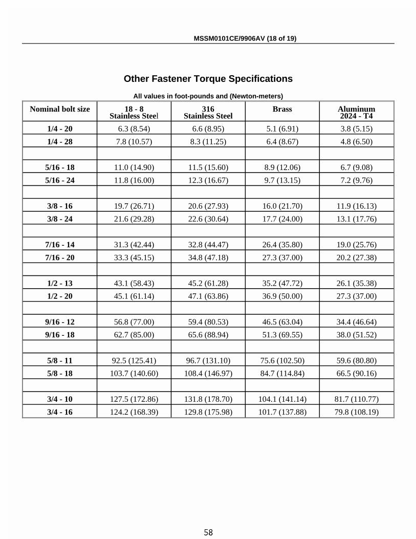
ÏOther Fastener Torque Specifications
ÏAll values in foot-pounds and (Newton-meters)
Nominal bolt size 18 - 8Stainless Steel
316Stainless Steel
Brass Aluminum2024 - T4
1/4 - 20 6.3 (8.54) 6.6 (8.95) 5.1 (6.91) 3.8 (5.15)
1/4 - 28 7.8 (10.57) 8.3 (11.25) 6.4 (8.67) 4.8 (6.50)
5/16 - 18 11.0 (14.90) 11.5 (15.60) 8.9 (12.06) 6.7 (9.08)
5/16 - 24 11.8 (16.00) 12.3 (16.67) 9.7 (13.15) 7.2 (9.76)
3/8 - 16 19.7 (26.71) 20.6 (27.93) 16.0 (21.70) 11.9 (16.13)
3/8 - 24 21.6 (29.28) 22.6 (30.64) 17.7 (24.00) 13.1 (17.76)
7/16 - 14 31.3 (42.44) 32.8 (44.47) 26.4 (35.80) 19.0 (25.76)
7/16 - 20 33.3 (45.15) 34.8 (47.18) 27.3 (37.00) 20.2 (27.38)
1/2 - 13 43.1 (58.43) 45.2 (61.28) 35.2 (47.72) 26.1 (35.38)
1/2 - 20 45.1 (61.14) 47.1 (63.86) 36.9 (50.00) 27.3 (37.00)
9/16 - 12 56.8 (77.00) 59.4 (80.53) 46.5 (63.04) 34.4 (46.64)
9/16 - 18 62.7 (85.00) 65.6 (88.94) 51.3 (69.55) 38.0 (51.52)
5/8 - 11 92.5 (125.41) 96.7 (131.10) 75.6 (102.50) 59.6 (80.80)
5/8 - 18 103.7 (140.60) 108.4 (146.97) 84.7 (114.84) 66.5 (90.16)
3/4 - 10 127.5 (172.86) 131.8 (178.70) 104.1 (141.14) 81.7 (110.77)
3/4 - 16 124.2 (168.39) 129.8 (175.98) 101.7 (137.88) 79.8 (108.19)
MSSM0101CE/9906AV (18 of 19)
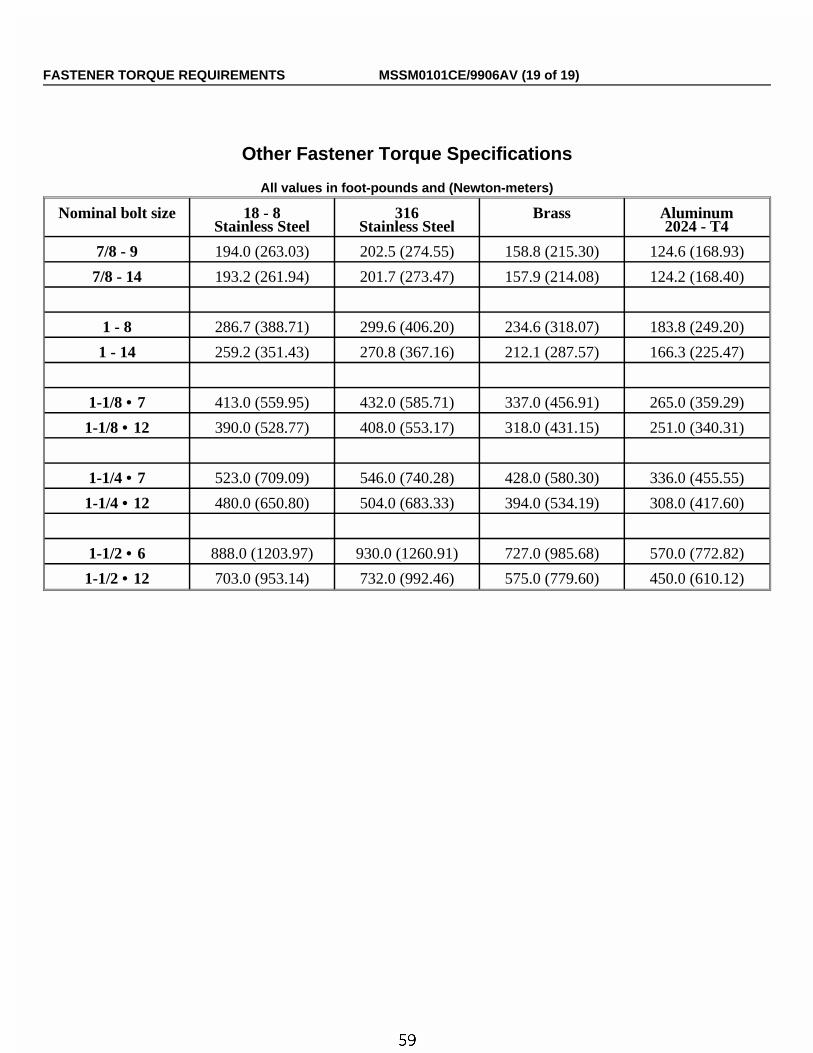
ÏOther Fastener Torque Specifications
ÏAll values in foot-pounds and (Newton-meters)
Nominal bolt size 18 - 8Stainless Steel
316Stainless Steel
Brass Aluminum2024 - T4
7/8 - 9 194.0 (263.03) 202.5 (274.55) 158.8 (215.30) 124.6 (168.93)
7/8 - 14 193.2 (261.94) 201.7 (273.47) 157.9 (214.08) 124.2 (168.40)
1 - 8 286.7 (388.71) 299.6 (406.20) 234.6 (318.07) 183.8 (249.20)
1 - 14 259.2 (351.43) 270.8 (367.16) 212.1 (287.57) 166.3 (225.47)
1-1/8 • 7 413.0 (559.95) 432.0 (585.71) 337.0 (456.91) 265.0 (359.29)
1-1/8 • 12 390.0 (528.77) 408.0 (553.17) 318.0 (431.15) 251.0 (340.31)
1-1/4 • 7 523.0 (709.09) 546.0 (740.28) 428.0 (580.30) 336.0 (455.55)
1-1/4 • 12 480.0 (650.80) 504.0 (683.33) 394.0 (534.19) 308.0 (417.60)
1-1/2 • 6 888.0 (1203.97) 930.0 (1260.91) 727.0 (985.68) 570.0 (772.82)
1-1/2 • 12 703.0 (953.14) 732.0 (992.46) 575.0 (779.60) 450.0 (610.12)
FASTENER TORQUE REQUIREMENTS MSSM0101CE/9906AV (19 of 19)

Section 2Covers, Safety and Shipping
Brackets
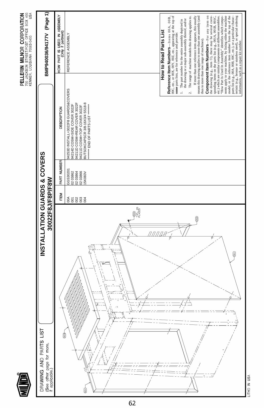
00A
GG
S30
201
9425
3D IN
ST
ALL
=30
22F
8 G
UA
RD
S&
CO
VE
RS
RE
FE
RE
NC
E A
SS
EM
BLY
001
02 0
3862
9421
4D C
OS
M=
SID
E C
OV
ER
302
2F00
202
038
6494
211D
CO
SM
=R
EA
R C
OV
ER
302
2F00
302
038
6694
211D
CO
SM
=TO
P C
OV
ER
302
2F00
415
K08
3VB
UT
SO
KC
AP
SC
R 3
/8-1
6X3/
4 S
S18
-8**
****
** E
ND
OF
PA
RT
S L
IST
***
****
*
Ho
w to
Rea
d P
arts
Lis
tR
efer
ence
Item
Nu
mb
ers—
Ite
ms
00
A,
00
B,
00C
, et
c.,
or 0
0X,
00Y
, 00
Z,
etc.
, ap
pear
ing
at t
he t
op o
fso
me
part
s lis
ts, a
re f
or r
efer
ence
and
pro
vide
:
1.T
he p
art n
umbe
r fo
r th
e en
tire
asse
mbl
y de
pict
ed in
the
draw
ing
or a
maj
or s
ub-a
ssem
bly
ther
eof,
and
/or
2.T
he r
ange
of
mac
hine
mod
els
this
dra
win
g ap
plie
s to
.
If m
ore
than
one
ref
eren
ce it
em a
ppea
rs, t
his
usua
llym
eans
this
dra
win
g ap
plie
s to
mor
e th
an o
ne a
ssem
bly
(and
thus
to m
ore
than
one
ran
ge o
f m
achi
nes)
.
Co
mp
on
ent
Item
Nu
mb
ers—
Fo
r an
y i
tem
on
the
draw
ing
(e.g
., it
em ➀
), t
here
may
be
seve
ral
corr
e-sp
ondi
ng i
tem
s on
the
par
ts l
ist
(e.g
., 00
1A,
001B
, 00
1C,
etc.
) whi
ch a
re s
imil
ar c
ompo
nent
s on
dif
fere
nt a
ssem
blie
s.“H
ow P
art I
s U
sed
In A
ssem
bly”
ide
ntif
ies
whi
ch c
ompo
-ne
nts
appl
y to
you
r m
achi
ne, b
y lis
ting
eith
er th
e m
achi
nem
odel
, or
the
ref
eren
ce i
tem
num
ber
from
the
top
of
the
part
s lis
t (e.
g., 0
0A, 0
0B, 0
0C, e
tc.)
, or
a pa
rtic
ular
cha
rac-
teri
stic
(e.
g.,
bron
ze o
r st
ainl
ess
stee
l),
or s
peci
al o
rder
ing
info
rmat
ion,
suc
h as
a r
epai
r ki
t num
ber.
BM
P94
0036
/941
77V
(Pag
e 1)
INS
TA
LL
AT
ION
GU
AR
DS
& C
OV
ER
S30
022F
8J/F
8P/F
8W
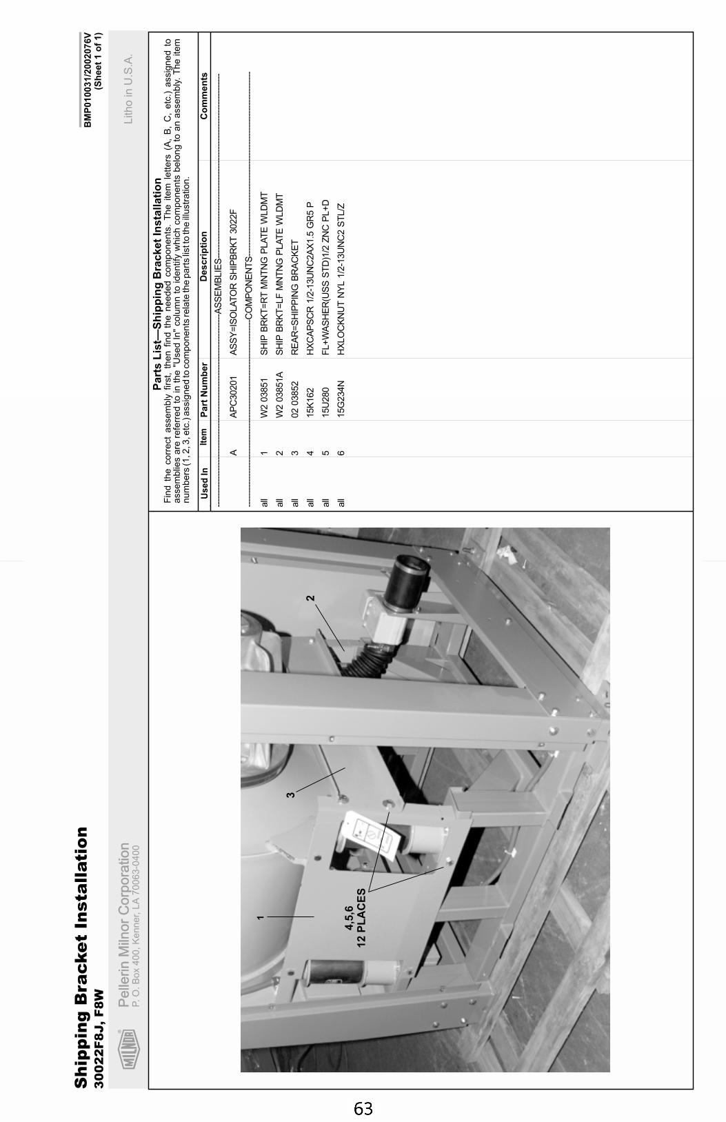
R
Pe
llerin
Miln
or
Co
rpo
ratio
nP
elle
rin
Miln
or
Co
rpo
ratio
nP.
O.
Bo
x4
00
,K
en
ne
r,L
A7
00
63
-04
00
Litho
inU
.S.A
.
Ite
mP
art
Nu
mb
er
Descri
pti
on
Co
mm
en
tsU
se
dIn
Fin
dth
ecorr
ect
assem
bly
firs
t,th
en
find
the
needed
com
ponents
.T
he
item
lett
ers
(A,
B,
C,
etc
.)assig
ned
toassem
blie
sare
refe
rred
toin
the
"Used
In"
colu
mn
toid
entify
whic
hcom
ponents
belo
ng
toan
assem
bly
.T
he
item
num
bers
(1,2
,3,e
tc.)
assig
ned
tocom
ponents
rela
teth
epart
slis
tto
the
illustr
ation.
Part
sL
ist—
Sh
ipp
ing
Bra
cket
Insta
llati
on
BM
P010031/2
002076V
(Sh
eet
1o
f1)
. ----
----
----
----
----
----
----
----
----
----
----
----
----
----
----
----
----
-AS
SE
MB
LIE
S--
----
----
----
----
----
----
----
----
----
----
----
----
----
----
----
----
AA
PC
30201
AS
SY
=IS
OLA
TO
RS
HIP
BR
KT
3022F
----
----
----
----
----
----
----
----
----
----
----
----
----
----
----
----
---C
OM
PO
NE
NT
S--
----
----
----
----
----
----
----
----
----
----
----
----
----
----
----
----
all
1W
203851
SH
IPB
RK
T=
RT
MN
TN
GP
LA
TE
WLD
MT
all
2W
203851A
SH
IPB
RK
T=
LF
MN
TN
GP
LA
TE
WLD
MT
all
302
03852
RE
AR
=S
HIP
PIN
GB
RA
CK
ET
all
415K
162
HX
CA
PS
CR
1/2
-13U
NC
2A
X1.5
GR
5P
all
515U
280
FL+
WA
SH
ER
(US
SS
TD
)1/2
ZN
CP
L+
D
all
615G
234N
HX
LO
CK
NU
TN
YL
1/2
-13U
NC
2S
TL/Z
Sh
ipp
ing
Bra
cke
tIn
sta
llati
on
30
02
2F
8J,
F8
W
2
1
3
4,5
,612
PL
AC
ES


Section 3Frame and Housing Assemblies
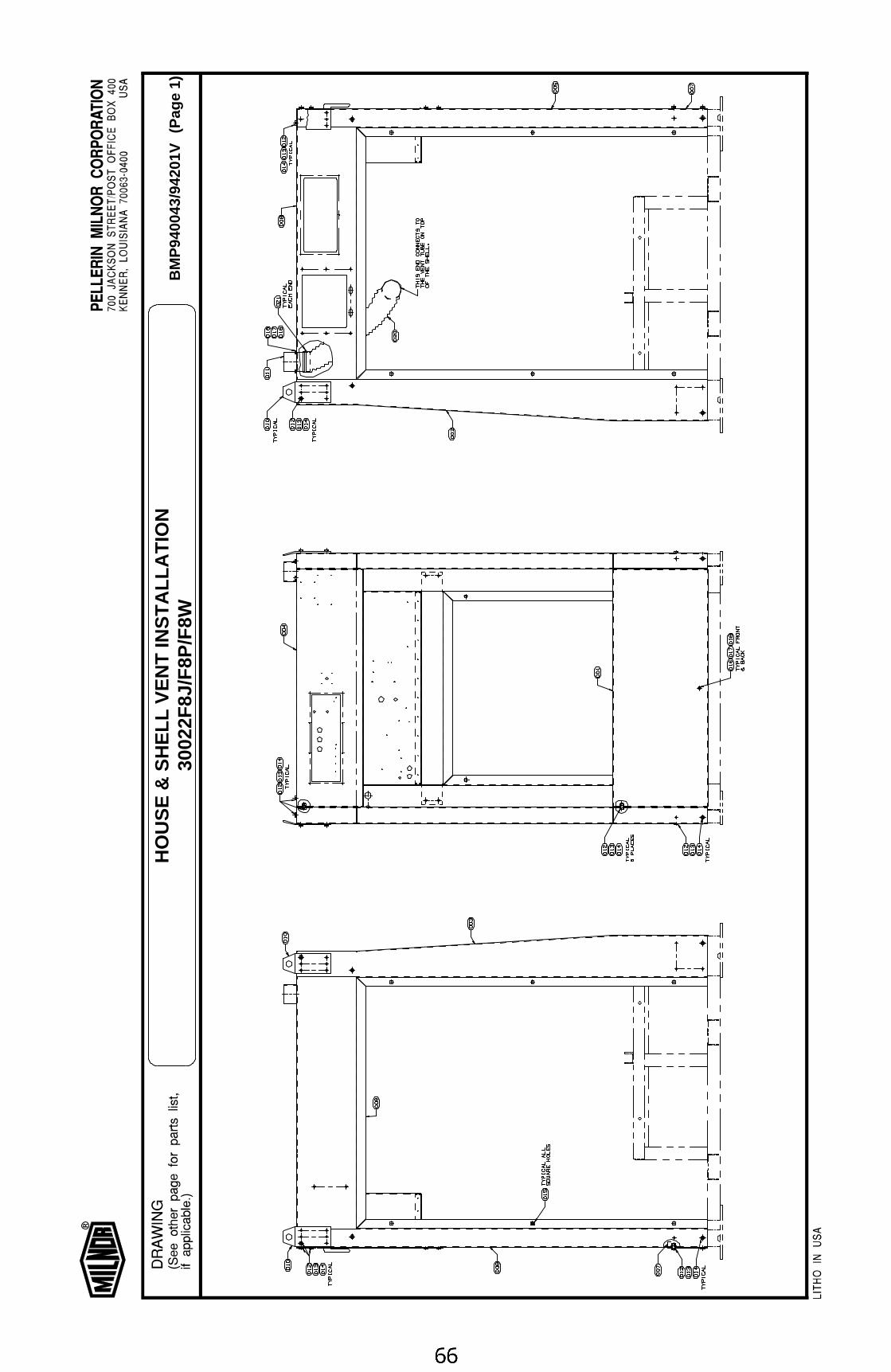
BM
P94
0043
/942
01V
(Pag
e 1)
HO
US
E &
SH
ELL
VE
NT
INS
TA
LLA
TIO
N30
022F
8J/F
8P/F
8W

00A
GH
G30
201
9420
1E IN
ST
L=30
22F
8 G
EN
HO
US
E A
SS
YR
EF
ER
EN
CE
AS
SE
MB
LY00
102
038
5093
396C
CO
SM
=LO
WE
R F
RO
NT
PA
NE
L 30
22F
002
W2
0385
394
062#
*WLM
T=
FR
NT
RT
CR
NR
PO
ST
302
2F00
3W
2 03
854
9406
2#*W
LMT
=F
RN
T L
F C
RN
R P
OS
T 3
022F
004
02 0
3855
A94
156D
CO
SM
=30
22F
UP
PE
R F
RO
NT
PA
NE
L00
502
038
5694
127D
CO
SM
=R
EA
R R
T C
RN
R P
OS
T 3
022F
006
02 0
3857
9415
3D C
OS
M=
RE
AR
LF
CR
NR
PO
ST
302
2F00
702
038
5894
153D
CO
SM
=LO
WE
R R
EA
R P
AN
EL
3022
F00
802
038
6094
127D
CO
SM
=T
OP
SID
E R
AIL
RT
302
2F00
902
038
6194
143D
CO
SM
=T
OP
SID
E R
AIL
LF
302
2F
010
02 0
3863
9315
1B H
OU
SE
=C
RN
R L
IFT
BR
KT
302
2F01
1W
2 03
846
9317
2B*W
LMT
=V
EN
T T
UB
E M
OU
NT
ING
012
15K
095
HE
XC
AP
SC
R 3
/8-1
6UN
C2A
X1"
GR
5 Z
NC
/CA
D01
315
G20
5H
XN
UT
3/8
-16U
NC
2B Z
INC
GR
201
415
U24
0F
LAT
WA
SH
ER
(US
S S
TD
) 3/
8" Z
NC
PLT
015
17N
070P
01Z
R
ET
AIN
NU
T#S
1010
0-27
016
15K
039
HX
CA
PS
CR
1/4
-20U
NC
2AX
3/4
GR
5 Z
NC
/CD
017
15G
165
HX
NU
T 1
/4-2
0UN
C2B
SA
E Z
C G
R2
018
15U
180
LOC
KW
AS
HE
R M
ED
IUM
1/4
ZIN
CP
L02
002
038
46A
9343
6B F
LEX
TU
BE
=S
PR
G M
NT
DR
N 1
8"
021
27A
082
HO
SE
CLA
MP
,2+9
/16-
3.5"
CA
DS
CR
HS
-48
****
****
EN
D O
F P
AR
TS
LIS
T *
****
***
How
to R
ead
Par
ts L
ist
Ref
eren
ce It
em N
umbe
rs—
Ite
ms
00
A,
00
B,
00C
, et
c.,
or 0
0X,
00Y
, 00
Z,
etc.
, ap
pear
ing
at t
he t
op o
fso
me p
arts
list
s, a
re fo
r re
fere
nce
and
prov
ide:
1.T
he p
art n
umbe
r fo
r th
e en
tire
asse
mbl
y de
pict
ed in
the
draw
ing
or a
maj
or s
ub-a
ssem
bly
ther
eof,
and/
or
2.T
he r
ang
e of
m
ach
ine
mo
dels
this
dra
win
g a
pp
lies
to.
If m
ore
than
one
ref
eren
ce it
em a
ppea
rs, t
his
usua
llym
eans
this
dra
win
g ap
plie
s to
mor
e th
an o
ne a
ssem
bly
(and
thus
to m
ore
than
one
ran
ge o
f mac
hine
s).
Com
pone
nt It
em N
umbe
rs—
Fo
r a
ny
ite
m o
nth
e d
raw
ing
(e
.g.,
ite
m
➀),
th
ere
ma
y b
e s
eve
ral
cor-
resp
ondi
ng it
ems
on th
e pa
rts
list (
e.g.
, 001
A, 0
01B
, 001
C,
etc.
) w
hich
are
sim
ilar
com
pone
nts
on d
iffer
ent a
ssem
blie
s.“H
ow
Pa
rt I
s U
sed
In
Ass
emb
ly”
iden
tifie
s w
hic
h c
om
-p
on
en
ts a
pp
ly t
o y
ou
r m
ac
hin
e,
by
listi
ng
eit
he
r th
em
achi
ne m
odel
, or
the
ref
eren
ce it
em n
umbe
r fr
om t
he t
opof
the
par
ts li
st (
e.g.
, 00
A,
00B
, 00
C,
etc.
), o
r a
part
icul
arch
arac
teris
tic (
e.g.
, bro
nze
or s
tain
less
ste
el),
or
spec
ial o
r-de
ring
info
rmat
ion,
suc
h as
a r
epai
r ki
t num
ber.
BM
P94
0043
/942
01V
(Pag
e 2)
HO
US
E &
SH
ELL
VE
NT
INS
TA
LLA
TIO
N30
022F
8J/F
8P/F
8W

Section 4Suspension
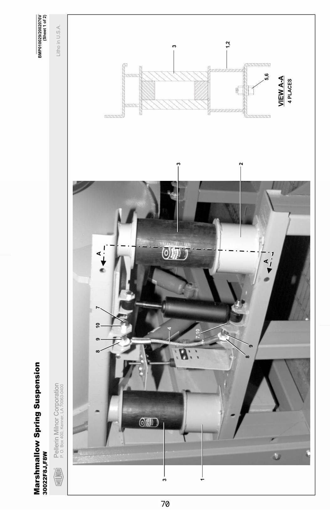
R
Pe
llerin
Miln
or
Co
rpo
ratio
nP
elle
rin
Miln
or
Co
rpo
ratio
nP.
O.
Bo
x4
00
,K
en
ne
r,L
A7
00
63
-04
00
Litho
inU
.S.A
.
BM
P010029/2
002076V
(Sh
eet
1o
f2)
Ma
rsh
ma
llow
Sp
rin
gS
usp
en
sio
n3
00
22
F8
J,F
8W
3
3 1
2
A
A
VIE
WA
-A
1,23
5,6
4
78
910
89
7,1
0
4P
LA
CE
S
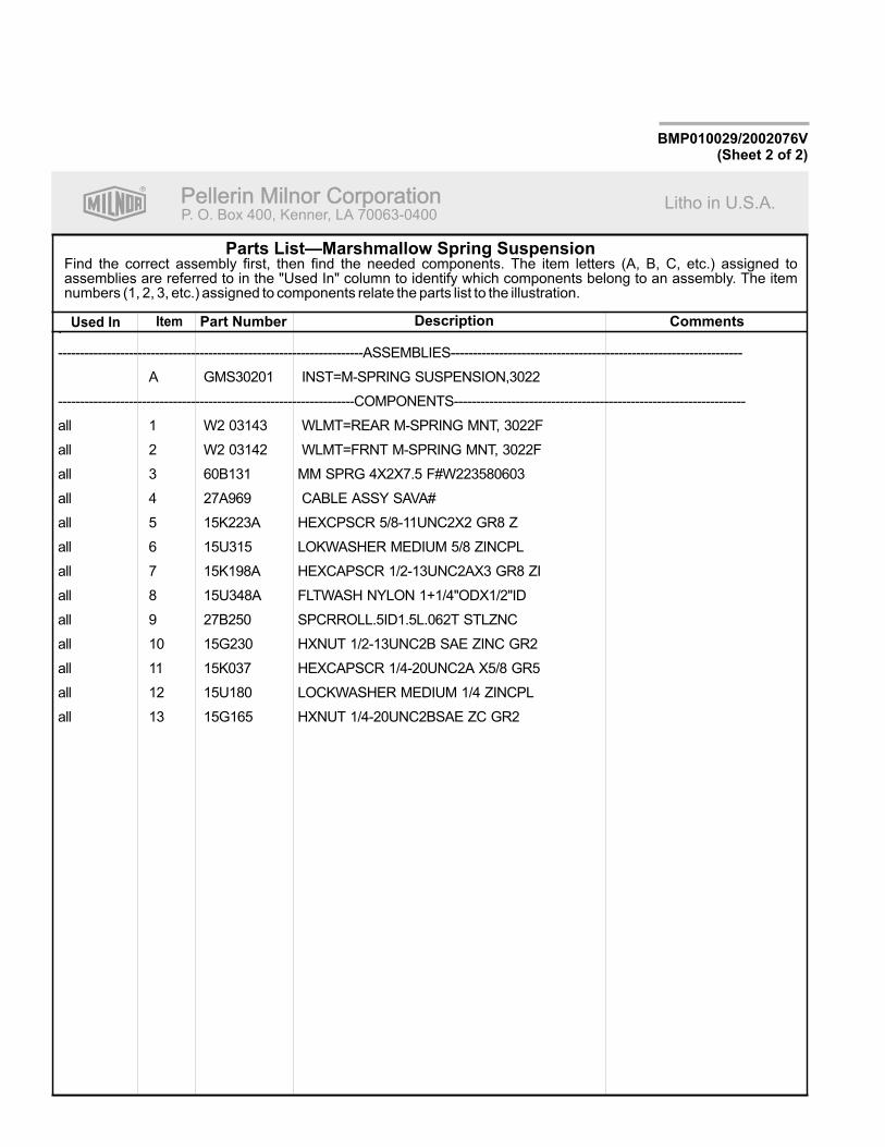
R
Pellerin Milnor CorporationPellerin Milnor CorporationP. O. Box 400, Kenner, LA 70063-0400
Litho in U.S.A.
Item Part Number Description CommentsUsed In
Find the correct assembly first, then find the needed components. The item letters (A, B, C, etc.) assigned toassemblies are referred to in the "Used In" column to identify which components belong to an assembly. The itemnumbers (1, 2, 3, etc.) assigned to components relate the parts list to the illustration.
Parts List—Marshmallow Spring Suspension
BMP010029/2002076V(Sheet 2 of 2)
.
---------------------------------------------------------------------ASSEMBLIES------------------------------------------------------------------
A GMS30201 INST=M-SPRING SUSPENSION,3022
-------------------------------------------------------------------COMPONENTS------------------------------------------------------------------
all 1 W2 03143 WLMT=REAR M-SPRING MNT, 3022F
all 2 W2 03142 WLMT=FRNT M-SPRING MNT, 3022F
all 3 60B131 MM SPRG 4X2X7.5 F#W223580603
all 4 27A969 CABLE ASSY SAVA#
all 5 15K223A HEXCPSCR 5/8-11UNC2X2 GR8 Z
all 6 15U315 LOKWASHER MEDIUM 5/8 ZINCPL
all 7 15K198A HEXCAPSCR 1/2-13UNC2AX3 GR8 ZI
all 8 15U348A FLTWASH NYLON 1+1/4"ODX1/2"ID
all 9 27B250 SPCRROLL.5ID1.5L.062T STLZNC
all 10 15G230 HXNUT 1/2-13UNC2B SAE ZINC GR2
all 11 15K037 HEXCAPSCR 1/4-20UNC2A X5/8 GR5
all 12 15U180 LOCKWASHER MEDIUM 1/4 ZINCPL
all 13 15G165 HXNUT 1/4-20UNC2BSAE ZC GR2
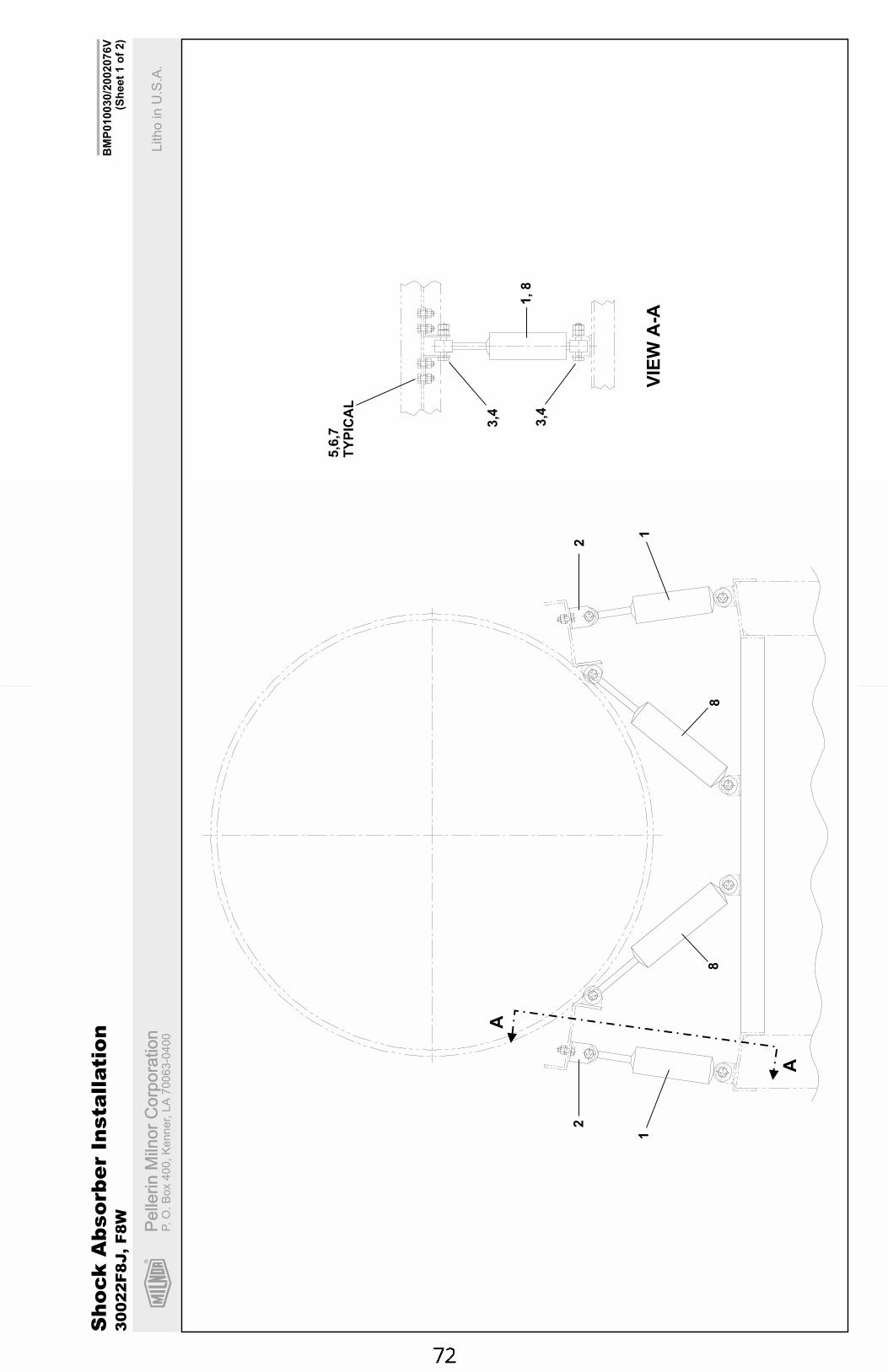
R
Pe
llerin
Miln
or
Co
rpo
ratio
nP
elle
rin
Miln
or
Co
rpo
ratio
nP.
O.
Bo
x4
00
,K
en
ne
r,L
A7
00
63
-04
00
Litho
inU
.S.A
.
BM
P010030/2
002076V
(Sh
eet
1o
f2)
Sh
ock
Ab
so
rbe
rIn
sta
llati
on
30
02
2F
8J,
F8
W
1
2
A
A
8
1
2
8
5,6
,7T
YP
ICA
L
3,4
3,4
1,8
VIE
WA
-A
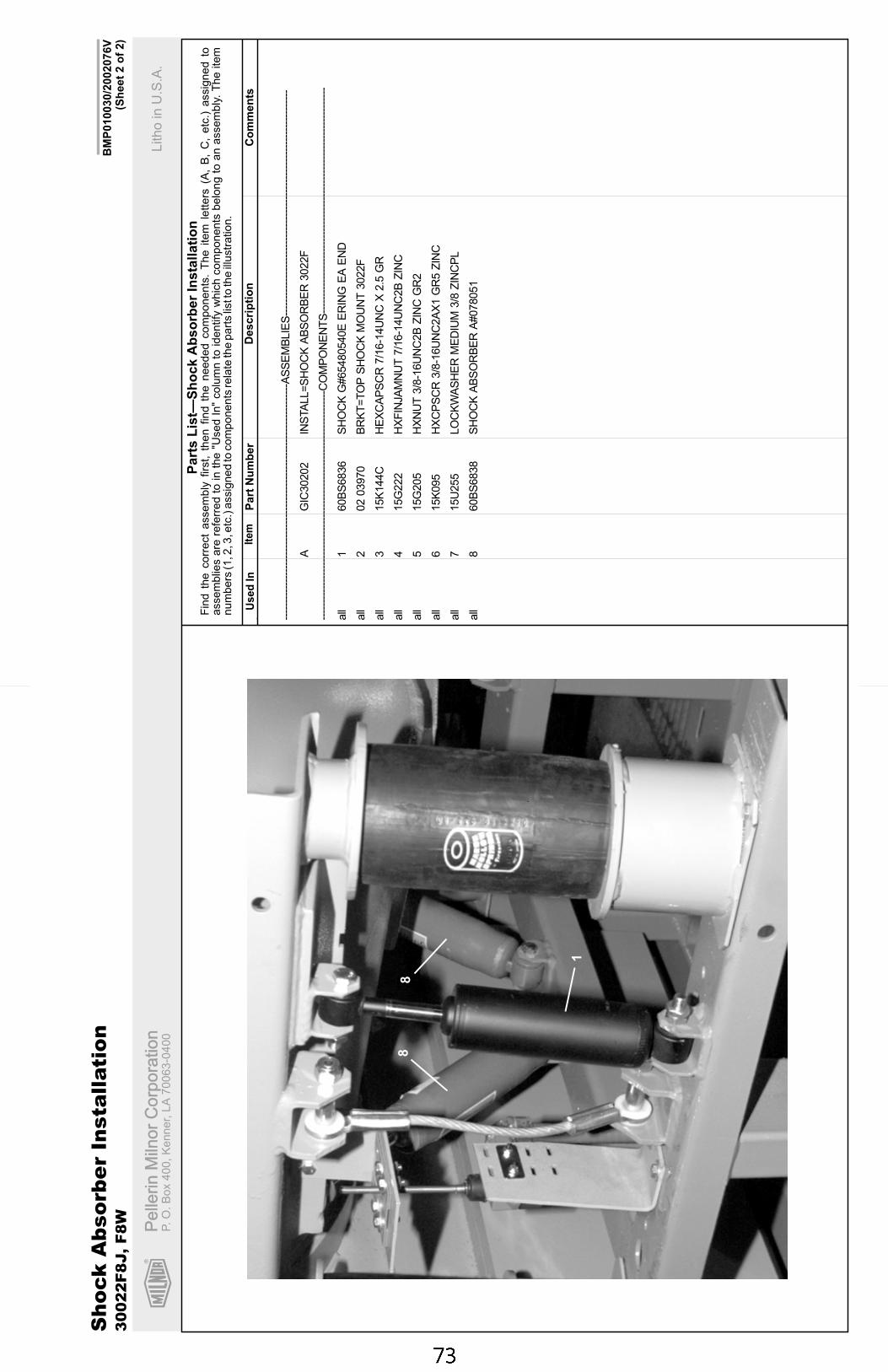
R
Pe
llerin
Miln
or
Co
rpo
ratio
nP
elle
rin
Miln
or
Co
rpo
ratio
nP.
O.
Bo
x4
00
,K
en
ne
r,L
A7
00
63
-04
00
Litho
inU
.S.A
.
Ite
mP
art
Nu
mb
er
Descri
pti
on
Co
mm
en
tsU
se
dIn
Fin
dth
ecorr
ect
assem
bly
firs
t,th
en
find
the
needed
com
ponents
.T
he
item
lett
ers
(A,
B,
C,
etc
.)assig
ned
toassem
blie
sare
refe
rred
toin
the
"Used
In"
colu
mn
toid
entify
whic
hcom
ponents
belo
ng
toan
assem
bly
.T
he
item
num
bers
(1,2
,3,e
tc.)
assig
ned
tocom
ponents
rela
teth
epart
slis
tto
the
illustr
ation.
Part
sL
ist—
Sh
ock
Ab
so
rber
Insta
llati
on
BM
P010030/2
002076V
(Sh
eet
2o
f2)
. ----
----
----
----
----
----
----
----
----
----
----
----
----
----
----
----
----
-AS
SE
MB
LIE
S--
----
----
----
----
----
----
----
----
----
----
----
----
----
----
----
----
AG
IC30202
INS
TA
LL=
SH
OC
KA
BS
OR
BE
R3022F
----
----
----
----
----
----
----
----
----
----
----
----
----
----
----
----
---C
OM
PO
NE
NT
S--
----
----
----
----
----
----
----
----
----
----
----
----
----
----
----
----
all
160B
S6836
SH
OC
KG
#65480540E
ER
ING
EA
EN
D
all
202
03970
BR
KT
=T
OP
SH
OC
KM
OU
NT
3022F
all
315K
144C
HE
XC
AP
SC
R7/1
6-1
4U
NC
X2.5
GR
all
415G
222
HX
FIN
JA
MN
UT
7/1
6-1
4U
NC
2B
ZIN
C
all
515G
205
HX
NU
T3/8
-16U
NC
2B
ZIN
CG
R2
all
615K
095
HX
CP
SC
R3/8
-16U
NC
2A
X1
GR
5Z
INC
all
715U
255
LO
CK
WA
SH
ER
ME
DIU
M3/8
ZIN
CP
L
all
860B
S6838
SH
OC
KA
BS
OR
BE
RA
#078051
Sh
ock
Ab
so
rbe
rIn
sta
llati
on
30
02
2F
8J,
F8
W
1
88
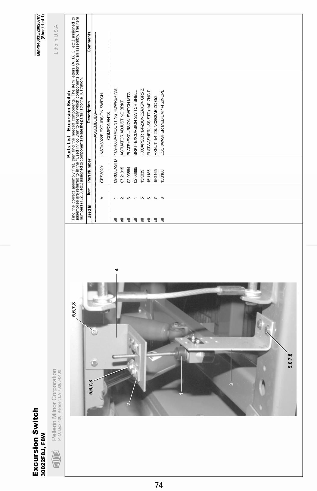
R
Pe
llerin
Miln
or
Co
rpo
ratio
nP
elle
rin
Miln
or
Co
rpo
ratio
nP.
O.
Bo
x4
00
,K
en
ne
r,L
A7
00
63
-04
00
Litho
inU
.S.A
.
Ite
mP
art
Nu
mb
er
Descri
pti
on
Co
mm
en
tsU
se
dIn
Fin
dth
ecorr
ect
assem
bly
firs
t,th
en
find
the
needed
com
ponents
.T
he
item
lett
ers
(A,
B,
C,
etc
.)assig
ned
toassem
blie
sare
refe
rred
toin
the
"Used
In"
colu
mn
toid
entify
whic
hcom
ponents
belo
ng
toan
assem
bly
.T
he
item
num
bers
(1,2
,3,e
tc.)
assig
ned
tocom
ponents
rela
teth
epart
slis
tto
the
illustr
ation.
Part
sL
ist—
Excu
rsio
nS
wit
ch
BM
P940035/2
002076V
(Sh
eet
1o
f1)
. ----
----
----
----
----
----
----
----
----
----
----
----
----
----
----
----
----
-AS
SE
MB
LIE
S--
----
----
----
----
----
----
----
----
----
----
----
----
----
----
----
----
AG
ES
30201
INS
T=
3022F
EX
CU
RS
ION
SW
ITC
H
----
----
----
----
----
----
----
----
----
----
----
----
----
----
----
----
---C
OM
PO
NE
NT
S--
----
----
----
----
----
----
----
----
----
----
----
----
----
----
----
----
all
109R
008A
ST
D*
09R
008A
+M
OU
NT
ING
HD
WR
E+
INS
T
all
207
21015
AC
TU
AT
OR
AD
JU
ST
ING
BR
KT
all
302
03884
PLA
TE
=E
XC
UR
SIO
NS
WIT
CH
MT
G
all
402
03885
BR
KT
=E
XC
UR
SIO
NS
WIT
CH
SH
ELL
all
515K
039
HX
CA
PS
CR
1/4
-20U
NC
2A
X3/4
GR
5Z
all
615U
185
FLA
TW
AS
HE
R(U
SS
ST
D)
1/4
"Z
NC
P
all
715G
165
HX
NU
T1/4
-20U
NC
2B
SA
EZ
CG
r2
all
815U
180
LO
CK
WA
SH
ER
ME
DIU
M1/4
ZIN
CP
L
Exc
ursio
nS
wit
ch
30
02
2F
8J,
F8
W
1
2
3
4
5,6
,7,8
5,6
,7,8
5,6
,7,8
Section 5Drive Assemblies
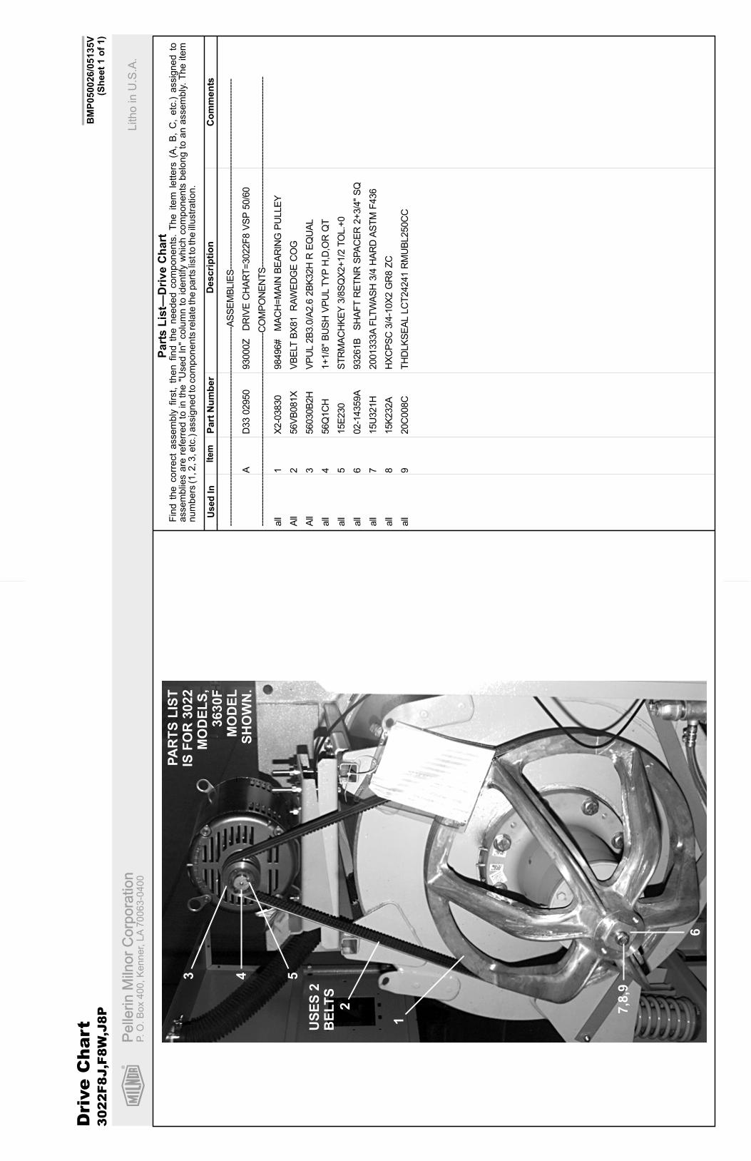
R
Pe
llerin
Miln
or
Co
rpo
ratio
nP
elle
rin
Miln
or
Co
rpo
ratio
nP.O
.B
ox
400,K
enner,
LA
70063-0
400
Litho
inU
.S.A
.
Ite
mP
art
Nu
mb
er
Descri
pti
on
Co
mm
en
tsU
se
dIn
Fin
dth
ecorr
ect
assem
bly
firs
t,th
en
find
the
needed
com
ponents
.T
he
item
letters
(A,
B,
C,
etc
.)assig
ned
toassem
blie
sare
refe
rred
toin
the
"Used
In"
colu
mn
toid
entify
whic
hcom
ponents
belo
ng
toan
assem
bly
.T
he
item
num
bers
(1,2
,3,e
tc.)
assig
ned
tocom
ponents
rela
teth
epart
slis
tto
the
illustr
ation.
Part
sL
ist—
Dri
ve
Ch
art
BM
P050026/0
5135V
(Sh
eet
1o
f1)
Dri
ve
Chart
3022F8J,F
8W
,J8P
1
2
US
ES
2B
ELT
S
3 4 5
6
7,8
,9
. ----
----
----
----
----
----
----
----
----
----
----
----
----
----
----
----
----
-AS
SE
MB
LIE
S--
----
----
----
----
----
----
----
----
----
----
----
----
----
----
----
----
AD
33
02950
93000Z
DR
IVE
CH
AR
T=
3022F
8V
SP
50/6
0
----
----
----
----
----
----
----
----
----
----
----
----
----
----
----
----
---C
OM
PO
NE
NT
S--
----
----
----
----
----
----
----
----
----
----
----
----
----
----
----
----
all
1X
2-0
3830
98496#
MA
CH
=M
AIN
BE
AR
ING
PU
LLE
Y
All
256V
B081X
VB
ELT
BX
81
RA
WE
DG
EC
OG
All
356030B
2H
VP
UL
2B
3.0
/A2.6
2B
K32H
RE
QU
AL
all
456Q
1C
H1+
1/8
"B
US
HV
PU
LT
YP
H,D
,OR
QT
all
515E
230
ST
RM
AC
HK
EY
3/8
SQ
X2+
1/2
TO
L.+
0
all
602-1
4359A
93261B
SH
AF
TR
ET
NR
SP
AC
ER
2+
3/4
"S
Q
all
715U
321H
2001333A
FLT
WA
SH
3/4
HA
RD
AS
TM
F436
all
815K
232A
HX
CP
SC
3/4
-10X
2G
R8
ZC
all
920C
008C
TH
DLK
SE
AL
LC
T24241
RM
UB
L250C
C
PA
RT
SL
IST
ISF
OR
3022
MO
DE
LS
,3630F
MO
DE
LS
HO
WN
.
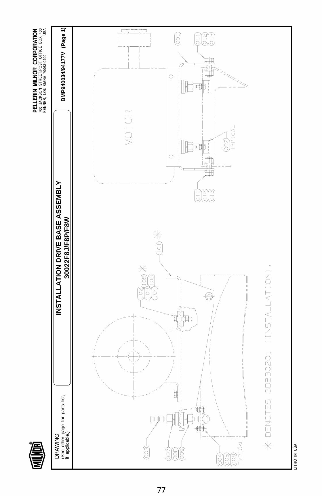
BM
P94
0034
/941
77V
(Pag
e 1)
INS
TA
LLA
TIO
N D
RIV
E B
AS
E A
SS
EM
BLY
3002
2F8J
/F8P
/F8W
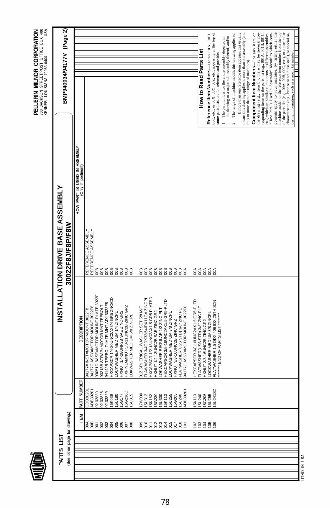
00A
GD
B30
201
9417
7# IN
ST
=M
OT
OR
MO
UN
T 3
022F
8R
EF
ER
EN
CE
AS
SE
MB
LY00
BA
DB
3020
194
177C
AS
SY
=M
OT
OR
MO
UN
T 3
022F
8R
EF
ER
EN
CE
AS
SE
MB
LY00
102
038
3993
051D
BA
SE
=M
OT
OR
MO
UN
T P
LAT
E 3
022F
00B
002
02 0
3828
9321
3B S
TR
AP
=M
OT
OR
MN
T T
EE
BO
LT00
B00
302
038
2994
142B
TE
EB
OLT
=M
TR
MN
T A
DJ
3022
F8
00B
004
15K
039
HX
CA
PS
CR
1/4
-20U
NC
2AX
3/4
GR
5 Z
NC
/CD
00B
005
15U
180
LOC
KW
AS
HE
R M
ED
IUM
1/4
ZIN
CP
L00
B00
615
G17
7H
XN
UT
1/4
-28U
NF
2B S
AE
ZIN
C G
R2
00B
007
15G
236C
HX
FIN
JAM
NU
T 5
/8-1
1UN
C2B
ZIN
C G
R2
00B
008
15U
315
LOK
WA
SH
ER
ME
DIU
M 5
/8 Z
INC
PL
00B
009
17W
030
01Z
SP
HE
RIC
AL
WA
SH
ER
SE
T 5
/8 M
/F00
B01
015
U31
2F
LAW
AS
HE
R 3
/4O
DX
33/6
4ID
X11
GA
ZIN
CP
L00
B01
115
K16
2H
XC
AP
SC
R 1
/2-1
3UN
C2A
X1.
5 G
R5
PLA
TE
D00
B01
215
G23
0H
XN
UT
1/2
-13U
NC
2B S
AE
ZIN
C G
R2
00B
013
15U
300
LOK
WA
SH
ER
RE
GU
LAR
1/2
ZIN
C P
LT00
B01
415
K11
0H
EX
CA
PS
CR
3/8
-16U
NC
2AX
1.5
GR
5-P
LTD
00B
015
15U
255
LOC
KW
AS
HE
R M
ED
IUM
3/8
ZIN
CP
L00
B01
715
G20
5H
XN
UT
3/8
-16U
NC
2B Z
INC
GR
200
B01
815
U24
0F
LAT
WA
SH
ER
(US
S S
TD
) 3/
8" Z
NC
PLT
00B
101
AD
B30
201
9417
7C A
SS
Y=
MO
TO
R M
OU
NT
302
2F8
00A
102
15K
110
HE
XC
AP
SC
R 3
/8-1
6UN
C2A
X1.
5 G
R5-
PLT
D00
A10
315
U24
0F
LAT
WA
SH
ER
(US
S S
TD
) 3/
8" Z
NC
PLT
00A
104
15G
205
HX
NU
T 3
/8-1
6UN
C2B
ZIN
C G
R2
00A
105
15U
255
LOC
KW
AS
HE
R M
ED
IUM
3/8
ZIN
CP
L00
A10
615
U24
1SZ
FLA
TW
AS
HE
R 1
.5 O
DX
.406
IDX
.25T
H S
ZN
00A
****
****
EN
D O
F P
AR
TS
LIS
T *
****
***
How
to R
ead
Par
ts L
ist
Ref
eren
ce It
em N
umbe
rs—
Ite
ms
00
A,
00
B,
00C
, et
c.,
or 0
0X,
00Y
, 00
Z,
etc.
, ap
pear
ing
at t
he t
op o
fso
me p
arts
list
s, a
re fo
r re
fere
nce
and
prov
ide:
1.T
he p
art n
umbe
r fo
r th
e en
tire
asse
mbl
y de
pict
ed in
the
draw
ing
or a
maj
or s
ub-a
ssem
bly
ther
eof,
and/
or
2.T
he r
ang
e of
m
ach
ine
mo
dels
this
dra
win
g a
pp
lies
to.
If m
ore
than
one
ref
eren
ce it
em a
ppea
rs, t
his
usua
llym
eans
this
dra
win
g ap
plie
s to
mor
e th
an o
ne a
ssem
bly
(and
thus
to m
ore
than
one
ran
ge o
f mac
hine
s).
Com
pone
nt It
em N
umbe
rs—
Fo
r a
ny
ite
m o
nth
e d
raw
ing
(e
.g.,
ite
m
➀),
th
ere
ma
y b
e s
eve
ral
cor-
resp
ondi
ng it
ems
on th
e pa
rts
list (
e.g.
, 001
A, 0
01B
, 001
C,
etc.
) w
hich
are
sim
ilar
com
pone
nts
on d
iffer
ent a
ssem
blie
s.“H
ow
Pa
rt I
s U
sed
In
Ass
emb
ly”
iden
tifie
s w
hic
h c
om
-p
on
en
ts a
pp
ly t
o y
ou
r m
ac
hin
e,
by
listi
ng
eit
he
r th
em
achi
ne m
odel
, or
the
ref
eren
ce it
em n
umbe
r fr
om t
he t
opof
the
par
ts li
st (
e.g.
, 00
A,
00B
, 00
C,
etc.
), o
r a
part
icul
arch
arac
teris
tic (
e.g.
, bro
nze
or s
tain
less
ste
el),
or
spec
ial o
r-de
ring
info
rmat
ion,
suc
h as
a r
epai
r ki
t num
ber.
BM
P94
0034
/941
77V
(Pag
e 2)
INS
TA
LLA
TIO
N D
RIV
E B
AS
E A
SS
EM
BLY
3002
2F8J
/F8P
/F8W
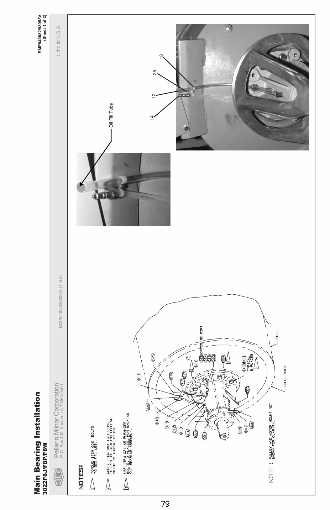
R
Pe
llerin
Miln
or
Co
rpo
ratio
nP
elle
rin
Miln
or
Co
rpo
ratio
nP.
O.
Bo
x4
00
,K
en
ne
r,L
A7
00
63
-04
00
Litho
inU
.S.A
.B
MP
94
00
32
/98
05
3V
(1o
f2
)
BM
P9
40
03
2/9
80
53
V(S
he
et
1o
f2
)
Mai
nB
eari
ngIn
stal
lati
on30
22F8
J/F8
P/F
8W
Oil
Fill
Tu
be
12
14
25
18
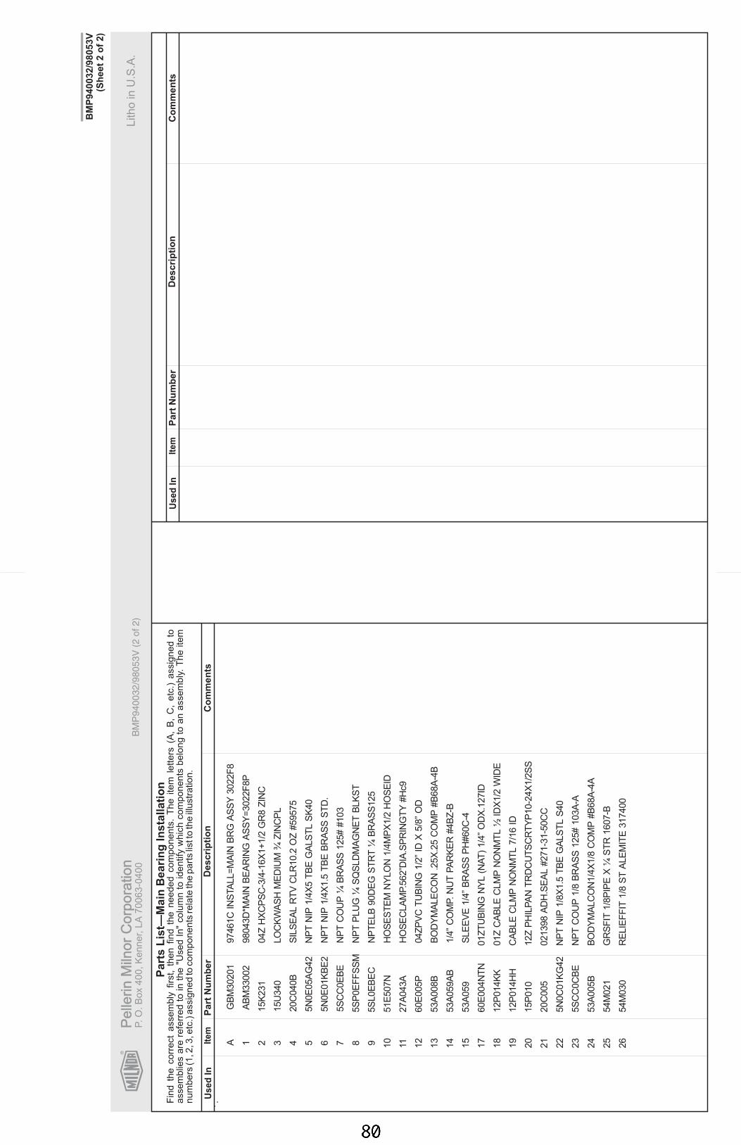
R
Pe
llerin
Miln
or
Co
rpo
ratio
nP
elle
rin
Miln
or
Co
rpo
ratio
nP.
O.
Bo
x4
00
,K
en
ne
r,L
A7
00
63
-04
00
Litho
inU
.S.A
.
Ite
mP
art
Nu
mb
er
Descri
pti
on
Co
mm
en
tsU
se
dIn
Fin
dth
ecorr
ect
assem
bly
firs
t,th
en
find
the
needed
com
ponents
.T
he
item
letters
(A,
B,
C,
etc
.)assig
ned
toa
ssem
blie
sare
refe
rred
toin
the
"Used
In"
colu
mn
toid
entify
whic
hcom
ponents
belo
ng
toan
assem
bly
.T
he
item
nu
mbers
(1,2
,3,e
tc.)
assig
ned
tocom
ponents
rela
teth
epart
slis
tto
the
illustr
ation.
Ite
mP
art
Nu
mb
er
Descri
pti
on
Co
mm
en
tsU
se
dIn
Part
sL
ist—
Main
Beari
ng
Insta
llati
on
BM
P9
40
03
2/9
80
53
V(S
he
et
2o
f2
)
.
BM
P9
40
03
2/9
80
53
V(2
of
2)
.
AG
BM
30201
97461C
INS
TA
LL=M
AIN
BR
GA
SS
Y3022F
8
1 2 3LO
CK
WA
SH
ME
DIU
M¾
ZIN
CP
L
4S
ILS
EA
LR
TV
CLR
10.2
OZ
#59575
5N
PT
NIP
1/4
X5
TB
EG
ALS
TL
SK
40
6N
PT
NIP
1/4
X1.5
TB
EB
RA
SS
ST
D.
7N
PT
CO
UP
¼B
RA
SS
125#
#103
85S
P0E
FF
SS
MN
PT
PLU
G¼
SQ
SLD
MA
GN
ET
BLK
ST
95S
L0E
BE
CN
PT
ELB
90D
EG
ST
RT
¼B
RA
SS
125
10
51E
507N
HO
SE
ST
EM
NY
LO
N1/4
MP
X1/2
HO
SE
ID
1127A
043A
HO
SE
CLA
MP.5
62”D
IA.S
PR
ING
TY
#H
c9
12
60E
005P
04Z
PV
CT
UB
ING
1/2
”ID
X5/8
”O
D
13
53A
008B
BO
DY
MA
LE
CO
N.2
5X
.25
CO
MP
#B
68A
-4B
14
53A
059A
B1/4
”C
OM
P.N
UT
PA
RK
ER
#4B
Z-B
15
53A
059
SLE
EV
E1/4
”B
RA
SS
PH
#60C
-4
17
60E
004N
TN
01Z
TU
BIN
GN
YL
(NA
T)
1/4
”O
DX
.127ID
18
12P
014K
K01Z
CA
BLE
CLM
PN
ON
MT
L½
IDX
1/2
WID
E
19
12P
014H
HC
AB
LE
CLM
PN
ON
MT
L7/1
6ID
20
15P
010
12Z
PH
ILP
AN
TR
DC
UT
SC
RT
YP
10-2
4X
1/2
SS
21
20C
005
021398
AD
H.S
EA
L#271-3
1-5
0C
C
22
5N
0C
01K
G42
NP
TN
IP1/8
X1.5
TB
EG
ALS
TL
S40
23
5S
CC
0C
BE
NP
TC
OU
P1/8
BR
AS
S125#
103A
-A
24
53A
005B
BO
DY
MA
LC
ON
1/4
X1/8
CO
MP
#B
68A
-4A
25
54M
021
GR
SF
IT1/8
PIP
EX
¼S
TR
1607-B
26
54M
030
RE
LIE
FF
IT1/8
ST
ALE
MIT
E317400
AB
M33002
98043D
*MA
INB
EA
RIN
GA
SS
Y=3022F
8P
15K
231
04Z
HX
CP
SC
-3/4
-16X
1+1/2
GR
8Z
INC
15U
340
20C
040B
5N
0E
05A
G42
5N
0E
01K
BE
2
5S
CC
0E
BE
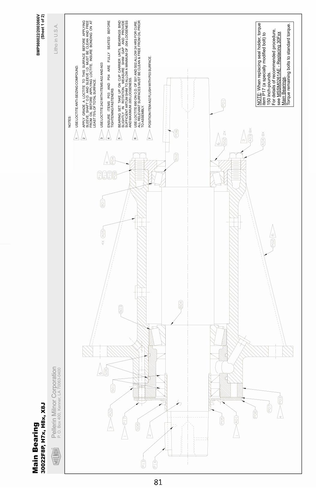
R
Pe
llerin
Miln
or
Co
rpo
ratio
nP
elle
rin
Miln
or
Co
rpo
ratio
nP.
O.
Bo
x4
00
,K
en
ne
r,L
A7
00
63
-04
00
Litho
inU
.S.A
.
BM
P980022/2
003066V
(Sh
eet
1o
f2)
Ma
inB
ea
rin
g3
00
22
F8
P,
H7
x,
H8
x,
X8
J
NO
TE M
SS
M0261A
E-
Repla
cin
g30F
xx
Main
Bearings
:W
hen
repla
cin
gsealhold
er,
torq
ue
item
P17
(aspecia
llym
odifie
dbolt)
to150
inch-p
ounds.
For
deta
ilsofre
com
mended
pro
cedure
,see
.Torq
ue
rem
ain
ing
bolts
tosta
ndard
torq
ue.
NO
TE
S:
US
ELO
CT
ITE
AN
TI-
SE
IZIN
GC
OM
PO
UN
D.
AP
PLY
GR
AD
EA
LO
CT
ITE
TO
TH
ISS
UR
FA
CE
BE
FO
RE
AP
PLY
ING
SLE
EV
E,
SH
AF
TO
.D.
AN
DS
LE
EV
EI.D
.M
US
TB
EC
LE
AN
AN
DF
RE
EF
RO
MO
ILB
EF
OR
EA
PP
LY
ING
LO
CT
ITE
.IN
SU
RE
BO
ND
ING
ON
AT
LE
AS
T75%
OF
TO
TA
LS
UR
FA
CE
.
US
ELO
CT
ITE
242
WIT
HIT
EM
SA
02
AN
DA
03
EN
SU
RE
ITE
MS
P0
3A
ND
P0
4A
RE
FU
LLY
SE
AT
ED
BE
FO
RE
TIG
HT
EN
ING
FA
ST
EN
ER
S
BE
AR
ING
SE
T:
TA
KE
UP
ON
CU
PC
AR
RIE
RU
NT
ILB
EA
RIN
GS
BIN
DS
LIG
HT
LY
INR
OTA
TIO
N,
ME
AS
UR
ES
HIM
GA
PA
ND
PR
OV
IDE
SU
FF
ICIE
NT
AR
TU
MS
HIM
TO
ALLO
WA
MIN
IMU
MO
F.0
04
LO
OS
EN
ES
SA
ND
MA
XIM
UM
.005
LO
OS
EN
ES
S.
US
ELO
CT
ITE
690
ON
O.D
.O
FS
01
AN
DS
02.A
LLO
W24
HR
SF
OR
CU
RE
.A
LL
RE
LE
VA
NT
SU
RFA
CE
SM
US
TB
EC
LE
AN
&F
RE
EF
RO
MO
ILP
RIO
RT
OA
SS
EM
BLY.
PO
SIT
ION
ITE
MA
02
FLU
SH
WIT
HP
03
SU
RFA
CE
.
1 2 3 4 5 6 7
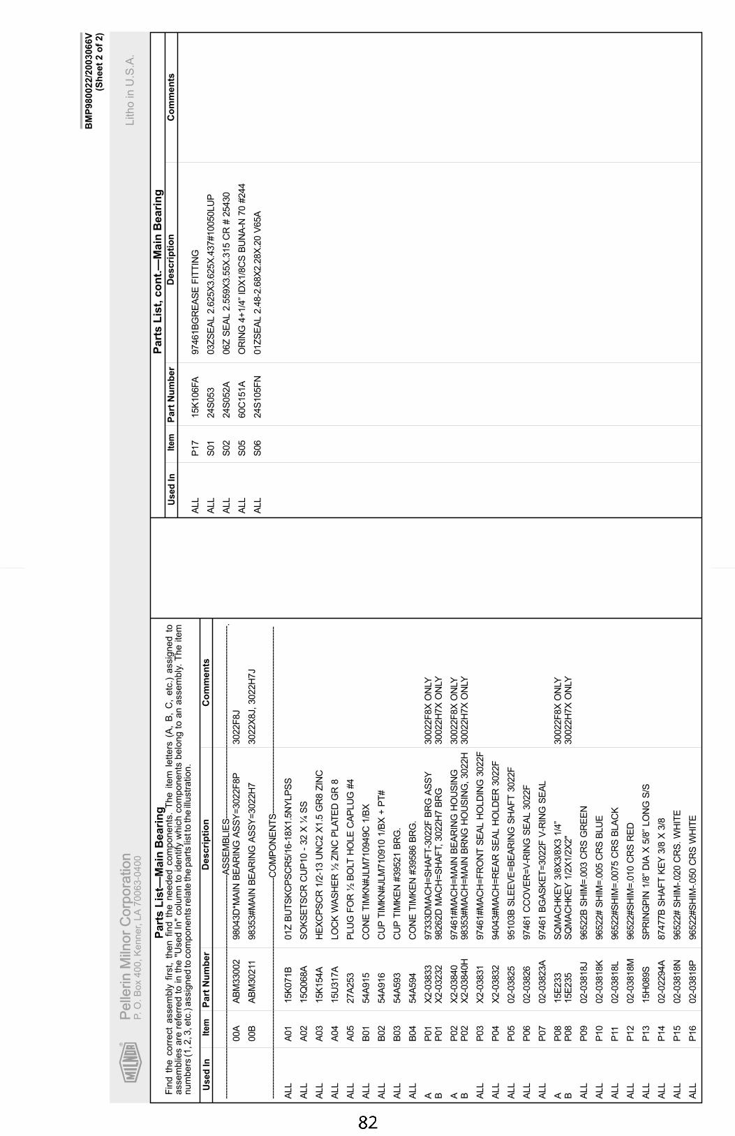
R
Pe
llerin
Miln
or
Co
rpo
ratio
nP
elle
rin
Miln
or
Co
rpo
ratio
nP.
O.
Bo
x4
00
,K
en
ne
r,L
A7
00
63
-04
00
Litho
inU
.S.A
.
Ite
mP
art
Nu
mb
er
Descri
pti
on
Co
mm
en
tsU
se
dIn
Fin
dth
ecorr
ect
assem
bly
firs
t,th
en
find
the
needed
com
ponents
.T
he
item
letters
(A,
B,
C,
etc
.)assig
ned
toassem
blie
sare
refe
rred
toin
the
"Used
In"
colu
mn
toid
entify
whic
hcom
ponents
belo
ng
toan
assem
bly
.T
he
item
num
bers
(1,2
,3,e
tc.)
assig
ned
tocom
ponents
rela
teth
epart
slis
tto
the
illustr
ation.
Ite
mP
art
Nu
mb
er
Descri
pti
on
Co
mm
en
tsU
se
dIn
Part
sL
ist,
co
nt.
—M
ain
Beari
ng
Part
sL
ist—
Main
Beari
ng
BM
P980022/2
003066V
(Sh
eet
2o
f2)
----
----
----
----
----
----
----
----
----
----
----
----
----
----
----
----
----
----
----
---A
SS
EM
BLIE
S--
----
----
----
----
----
----
----
----
----
----
----
----
----
----
----
----
--.
00A
AB
M33002
98043D
*MA
INB
EA
RIN
GA
SS
Y=
3022F
8P
3022F
8J
00B
AB
M30211
98353#M
AIN
BE
AR
ING
AS
SY
=3022H
73022X
8J,3022H
7J
----
----
----
----
----
----
----
----
----
----
----
----
----
----
----
----
----
----
----
--C
OM
PO
NE
NT
S--
----
----
----
----
----
----
----
----
----
----
----
----
----
----
----
----
ALL
A01
15K
071B
01Z
BU
TS
KC
PS
CR
5/1
6-1
8X
1.5
NY
LP
SS
ALL
A02
15Q
068A
SO
KS
ET
SC
RC
UP
10
-32
X¼
SS
ALL
A03
15K
154A
HE
XC
PS
CR
1/2
-13
UN
C2
X1.5
GR
8Z
INC
ALL
A04
15U
317A
LO
CK
WA
SH
ER
½Z
INC
PLA
TE
DG
R8
ALL
A05
27A
253
PLU
GF
OR
½B
OLT
HO
LE
CA
PLU
G#4
ALL
B01
54A
915
CO
NE
TIM
KN
#JLM
710949C
1/B
X
ALL
B02
54A
916
CU
PT
IMK
N#JLM
710910
1/B
X+
PT
#
ALL
B03
54A
593
CU
PT
IMK
EN
#39521
BR
G.
ALL
B04
54A
594
CO
NE
TIM
KE
N#39586
BR
G.
AP
01
X2-0
3833
97333D
MA
CH
=S
HA
FT
-3022F
BR
GA
SS
Y30022F
8X
ON
LYB
P01
X2-0
3232
98262D
MA
CH
=S
HA
FT,3022H
7B
RG
30022H
7X
ON
LY
AP
02
X2-0
3840
97461#M
AC
H=
MA
INB
EA
RIN
GH
OU
SIN
G30022F
8X
ON
LYB
P02
X2-0
3840H
98353#M
AC
H=
MA
INB
RN
GH
OU
SIN
G,3022H
30022H
7X
ON
LY
ALL
P03
X2-0
3831
97461#M
AC
H=
FR
ON
TS
EA
LH
OLD
ING
3022F
ALL
P04
X2-0
3832
94043#M
AC
H=
RE
AR
SE
AL
HO
LD
ER
3022F
ALL
P05
02-0
3825
95103B
SLE
EV
E=
BE
AR
ING
SH
AF
T3022F
ALL
P06
02-0
3826
97461
CC
OV
ER
=V
-RIN
GS
EA
L3022F
ALL
P07
02-0
3823A
97461
BG
AS
KE
T=
3022F
V-R
ING
SE
AL
AP
08
15E
233
SQ
MA
CH
KE
Y3/8
X3/8
X3
1/4
”30022F
8X
ON
LYB
P08
15E
235
SQ
MA
CH
KE
Y1/2
X1/2
X2"
30022H
7X
ON
LY
ALL
P09
02-0
3818J
96522B
SH
IM=
.003
CR
SG
RE
EN
ALL
P10
02-0
3818K
96522#
SH
IM=
.005
CR
SB
LU
E
ALL
P11
02-0
3818L
96522#S
HIM
=.0
075
CR
SB
LA
CK
ALL
P12
02-0
3818M
96522#S
HIM
=.0
10
CR
SR
ED
ALL
P13
15H
089S
SP
RIN
GP
IN1/8
”D
IAX
5/8
”LO
NG
S/S
ALL
P14
02-0
2294A
87477B
SH
AF
TK
EY
3/8
X3/8
ALL
P15
02-0
3818N
96522#
SH
IM-.020
CR
S.W
HIT
E
ALL
P16
02-0
3818P
96522#S
HIM
-.050
CR
SW
HIT
E
ALL
P17
15K
106FA
97461B
GR
EA
SE
FIT
TIN
G
ALL
S01
24S
053
03Z
SE
AL
2.6
25X
3.6
25X
.437#10050LU
P
ALL
S02
24S
052A
06Z
SE
AL
2.5
59X
3.5
5X
.315
CR
#25430
ALL
S05
60C
151A
OR
ING
4+
1/4
”ID
X1/8
CS
BU
NA
-N70
#244
ALL
S06
24S
105F
N01Z
SE
AL
2.4
8-2
.68X
2.2
8X
.20
V65A
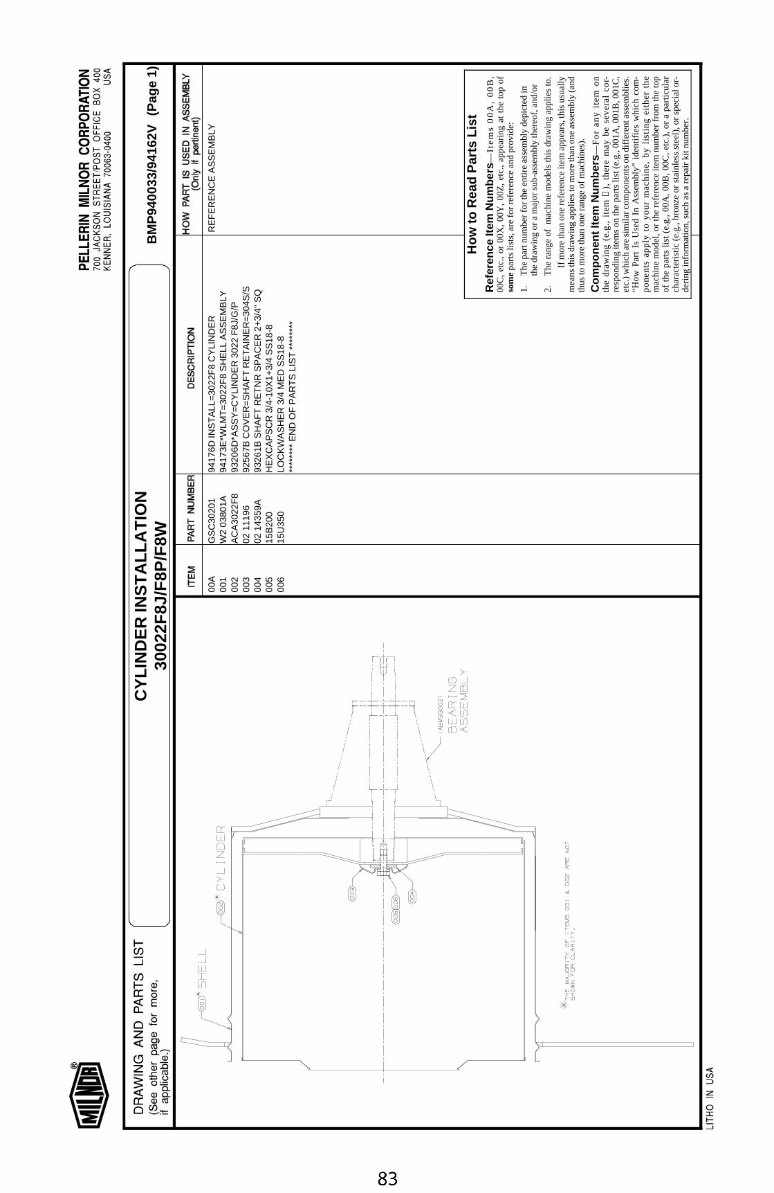
00A
GS
C30
201
9417
6D IN
ST
ALL
=30
22F
8 C
YLI
ND
ER
RE
FE
RE
NC
E A
SS
EM
BLY
001
W2
0380
1A94
173E
*WLM
T=
3022
F8
SH
ELL
AS
SE
MB
LY00
2A
CA
3022
F8
9320
6D*A
SS
Y=
CY
LIN
DE
R 3
022
F8J
/G/P
003
02 1
1196
9256
7B C
OV
ER
=S
HA
FT
RE
TA
INE
R=
304S
/S00
402
143
59A
9326
1B S
HA
FT
RE
TN
R S
PA
CE
R 2
+3/
4" S
Q00
515
B20
0H
EX
CA
PS
CR
3/4
-10X
1+3/
4 S
S18
-800
615
U35
0LO
CK
WA
SH
ER
3/4
ME
D S
S18
-8**
****
** E
ND
OF
PA
RT
S L
IST
***
****
*
How
to R
ead
Par
ts L
ist
Ref
eren
ce It
em N
umbe
rs—
Ite
ms
00
A,
00
B,
00C
, et
c.,
or 0
0X,
00Y
, 00
Z,
etc.
, ap
pear
ing
at t
he t
op o
fso
me p
arts
list
s, a
re fo
r re
fere
nce
and
prov
ide:
1.T
he p
art n
umbe
r fo
r th
e en
tire
asse
mbl
y de
pict
ed in
the
draw
ing
or a
maj
or s
ub-a
ssem
bly
ther
eof,
and/
or
2.T
he r
ang
e of
m
ach
ine
mo
dels
this
dra
win
g a
pp
lies
to.
If m
ore
than
one
ref
eren
ce it
em a
ppea
rs, t
his
usua
llym
eans
this
dra
win
g ap
plie
s to
mor
e th
an o
ne a
ssem
bly
(and
thus
to m
ore
than
one
ran
ge o
f mac
hine
s).
Com
pone
nt It
em N
umbe
rs—
Fo
r a
ny
ite
m o
nth
e d
raw
ing
(e
.g.,
ite
m
➀),
th
ere
ma
y b
e s
eve
ral
cor-
resp
ondi
ng it
ems
on th
e pa
rts
list (
e.g.
, 001
A, 0
01B
, 001
C,
etc.
) w
hich
are
sim
ilar
com
pone
nts
on d
iffer
ent a
ssem
blie
s.“H
ow
Pa
rt I
s U
sed
In
Ass
emb
ly”
iden
tifie
s w
hic
h c
om
-p
on
en
ts a
pp
ly t
o y
ou
r m
ac
hin
e,
by
listi
ng
eit
he
r th
em
achi
ne m
odel
, or
the
ref
eren
ce it
em n
umbe
r fr
om t
he t
opof
the
par
ts li
st (
e.g.
, 00
A,
00B
, 00
C,
etc.
), o
r a
part
icul
arch
arac
teris
tic (
e.g.
, bro
nze
or s
tain
less
ste
el),
or
spec
ial o
r-de
ring
info
rmat
ion,
suc
h as
a r
epai
r ki
t num
ber.
BM
P94
0033
/941
62V
(Pag
e 1)
CY
LIN
DE
R IN
ST
ALL
AT
ION
3002
2F8J
/F8P
/F8W


Section 6Shell and Door Assemblies
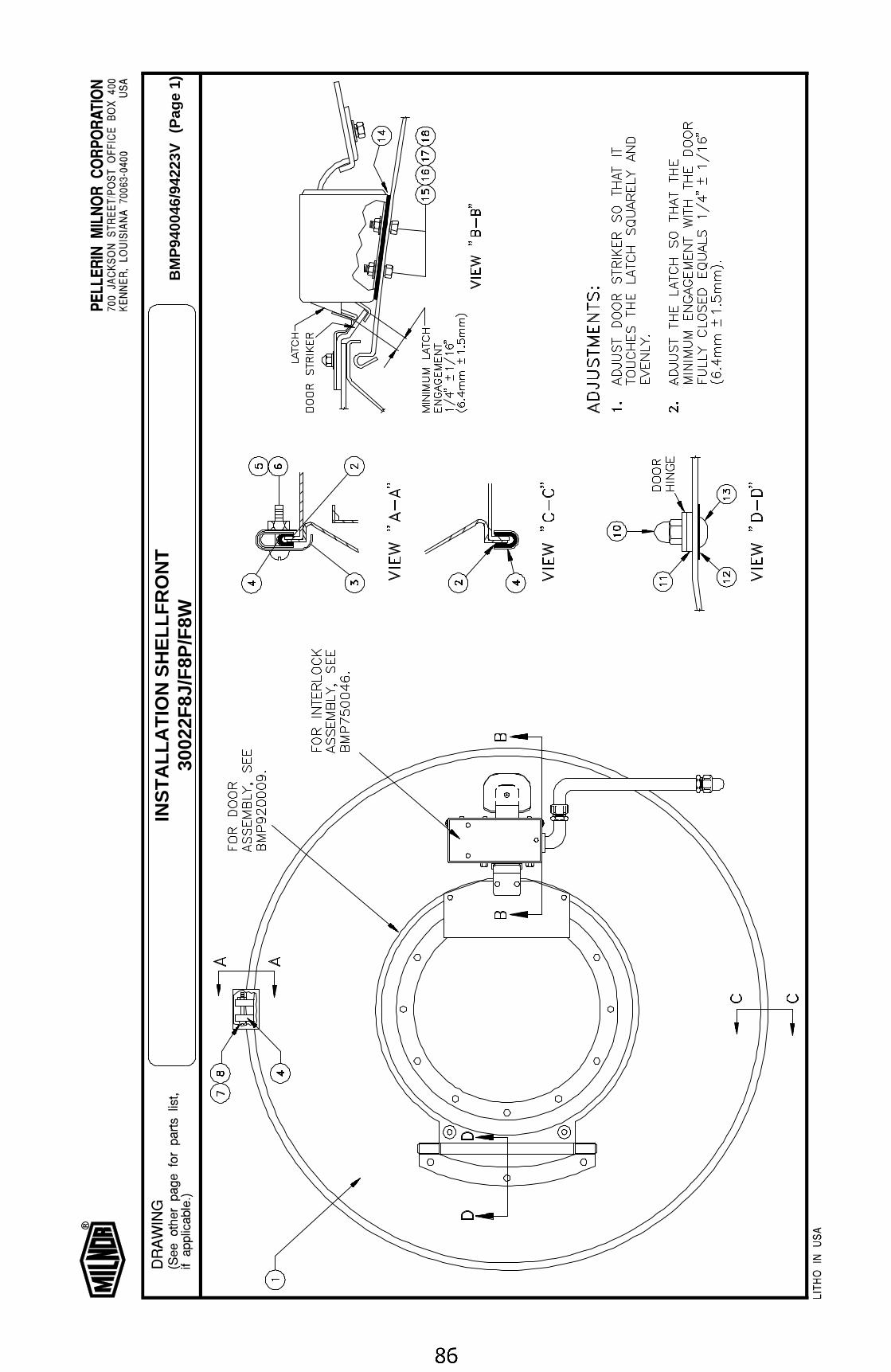
BM
P94
0046
/942
23V
(Pag
e 1)
INS
TA
LLA
TIO
N S
HE
LLF
RO
NT
3002
2F8J
/F8P
/F8W

00A
GS
F30
201
9403
7C IN
ST
ALL
=30
22F
8 S
HE
LLF
RO
NT
RE
FE
RE
NC
E A
SS
EM
BLY
001
A33
102
00D
9320
7# A
SS
Y=
SH
ELL
FR
ON
T 3
022F
800
202
020
87C
EX
TR
US
*IO
N-S
HE
LL=
30"M
AC
HIN
ES
(8.5
FT
003
02 0
2181
8533
2B G
UA
RD
=S
HE
LL M
OU
NT
RIN
G C
LIP
004
Y2
0205
970
256A
*SH
ELL
CLA
MP
RIN
G=
30"
MA
CH
INE
005
15N
146
RD
MA
CH
SC
R 1
0-24
UN
C2X
1 S
S18
-800
615
G13
0H
EX
MA
CH
SC
RN
UT
10-
24U
NC
2 S
S18
-800
715
K04
6SH
EX
CA
PS
CR
1/4
-20U
NC
2A X
2.2
5 S
S18
-800
815
G17
0H
EX
NU
T 1
/4-2
0UN
C2
SS
18-8
010
15G
200C
01Z
HX
CP
NU
T H
I 3/8
-16
BR
AS
S N
IK P
LT
011
02 0
2819
B84
383C
SP
AC
ER
HIN
GE
S/S
012
02 0
2293
9340
2A D
OO
R H
AN
DLE
NU
T G
AS
KE
T01
315
K08
485
196B
TR
US
S H
XS
OK
3/8
-16
X 2
3/32
SS
014
02 0
3669
9312
3A G
AS
KE
T=
INT
RLK
HO
US
ING
015
15N
174
HX
CA
PS
CR
1/4
-20U
NC
2X5/
8SS
18-8
016
15U
180
LOC
KW
AS
HE
R M
ED
IUM
1/4
ZIN
CP
L01
724
G02
0NR
OLL
ED
WA
SH
ER
.252
"ID
NY
LTIT
E #
25W
018
15G
168
SQ
NU
T 1
/4-2
0UN
C2
SS
18-8
****
****
EN
D O
F P
AR
TS
LIS
T *
****
***
How
to R
ead
Par
ts L
ist
Ref
eren
ce It
em N
umbe
rs—
Ite
ms
00
A,
00
B,
00C
, et
c.,
or 0
0X,
00Y
, 00
Z,
etc.
, ap
pear
ing
at t
he t
op o
fso
me p
arts
list
s, a
re fo
r re
fere
nce
and
prov
ide:
1.T
he p
art n
umbe
r fo
r th
e en
tire
asse
mbl
y de
pict
ed in
the
draw
ing
or a
maj
or s
ub-a
ssem
bly
ther
eof,
and/
or
2.T
he r
ang
e of
m
ach
ine
mo
dels
this
dra
win
g a
pp
lies
to.
If m
ore
than
one
ref
eren
ce it
em a
ppea
rs, t
his
usua
llym
eans
this
dra
win
g ap
plie
s to
mor
e th
an o
ne a
ssem
bly
(and
thus
to m
ore
than
one
ran
ge o
f mac
hine
s).
Com
pone
nt It
em N
umbe
rs—
Fo
r a
ny
ite
m o
nth
e d
raw
ing
(e
.g.,
ite
m
➀),
th
ere
ma
y b
e s
eve
ral
cor-
resp
ondi
ng it
ems
on th
e pa
rts
list (
e.g.
, 001
A, 0
01B
, 001
C,
etc.
) w
hich
are
sim
ilar
com
pone
nts
on d
iffer
ent a
ssem
blie
s.“H
ow
Pa
rt I
s U
sed
In
Ass
emb
ly”
iden
tifie
s w
hic
h c
om
-p
on
en
ts a
pp
ly t
o y
ou
r m
ac
hin
e,
by
listi
ng
eit
he
r th
em
achi
ne m
odel
, or
the
ref
eren
ce it
em n
umbe
r fr
om t
he t
opof
the
par
ts li
st (
e.g.
, 00
A,
00B
, 00
C,
etc.
), o
r a
part
icul
arch
arac
teris
tic (
e.g.
, bro
nze
or s
tain
less
ste
el),
or
spec
ial o
r-de
ring
info
rmat
ion,
suc
h as
a r
epai
r ki
t num
ber.
BM
P94
0046
/942
23V
(Pag
e 2)
INS
TA
LLA
TIO
N S
HE
LLF
RO
NT
3002
2F8J
/F8P
/F8W
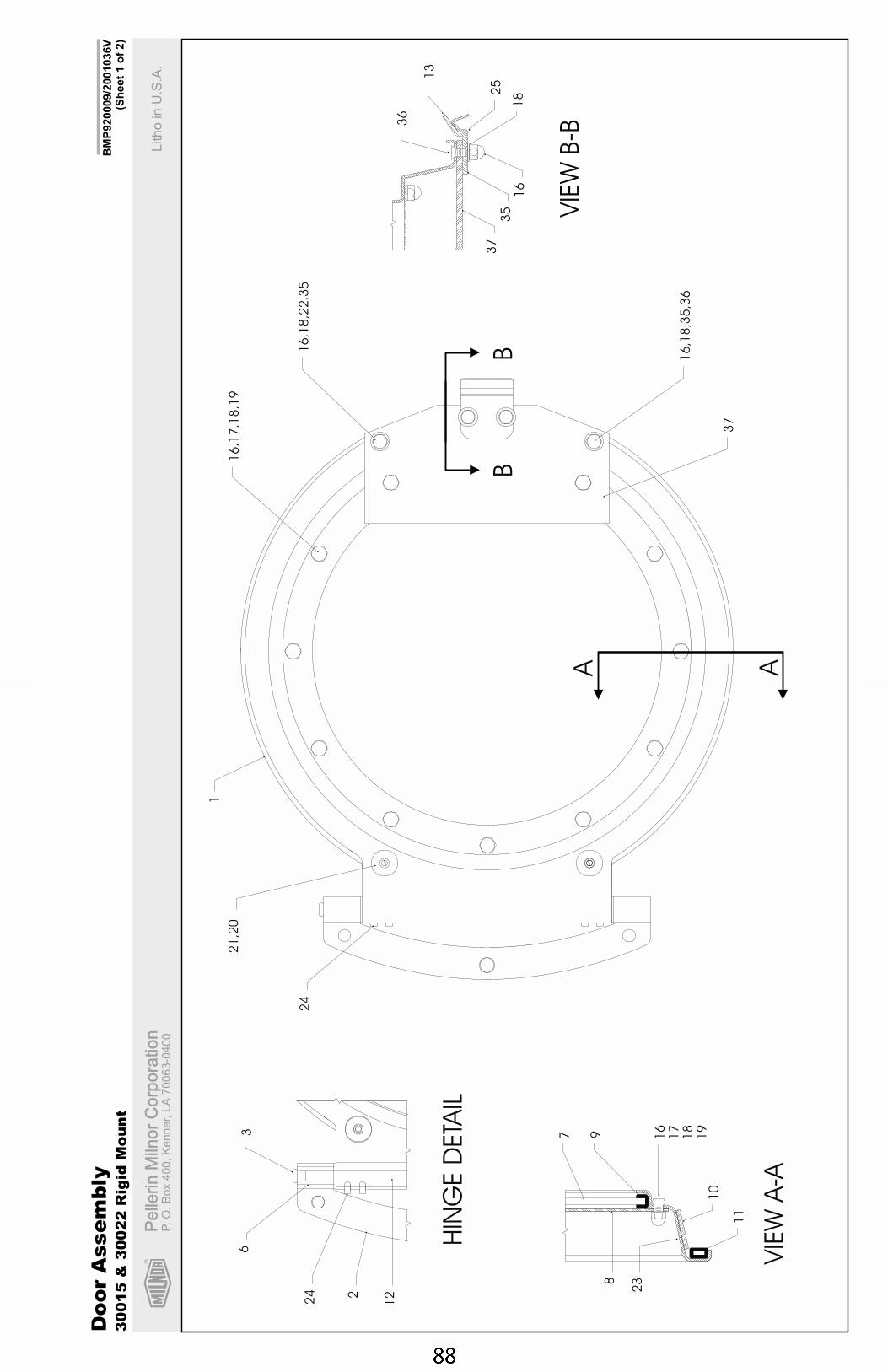
R
Pe
llerin
Miln
or
Co
rpo
ratio
nP
elle
rin
Miln
or
Co
rpo
ratio
nP.
O.
Bo
x4
00
,K
en
ne
r,L
A7
00
63
-04
00
Litho
inU
.S.A
.
BM
P920009/2
001036V
(Sh
eet
1o
f2)
Do
or
Asse
mb
ly3
00
15
&3
00
22
Rig
idM
ou
nt
VIE
WB-B
HIN
GE
DETA
IL
VIE
WA
-A
A A
36
13
25
18
37
35
16
16
,18
,22
,35
16
,17
,18
,19
16
,18
,35
,36
37
1
21
,20
24
122
24
63 9 16
17
18
19
10
11
23
7
8
BB
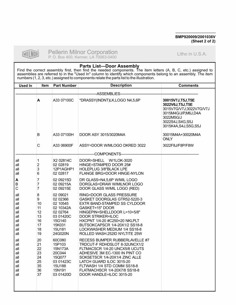
R
Pellerin Milnor CorporationPellerin Milnor CorporationP. O. Box 400, Kenner, LA 70063-0400
Litho in U.S.A.
Item Part Number Description CommentsUsed In
Find the correct assembly first, then find the needed components. The item letters (A, B, C, etc.) assigned toassemblies are referred to in the "Used In" column to identify which components belong to an assembly. The itemnumbers (1, 2, 3, etc.) assigned to components relate the parts list to the illustration.
Parts List—Door Assembly
BMP920009/2001036V(Sheet 2 of 2)
.
---------------------------------------------------------------------ASSEMBLIES------------------------------------------------------------------
A33 07100C *DRASSY(INDNT)LK,LOGO N4,5,6P
3015V7G/V7J;3022V7G/V7J3015M4G/J/P,M6J,D4A3022M5G/J3022S4J,S4G,S5J3015K4A,S4J,S5G,S5J
B A33 07100H DOOR ASY 3015/3020M4A 30015M4A+30020M4AONLY
C A33 06900F ASSY=DOOR W/MLOGO DKRED 3022 3022F8J/F8P/F8W
-------------------------------------------------------------------COMPONENTS------------------------------------------------------------------
all 1 X2 02814C DOOR=SHELL W/1LOK-3020all 2 02 02819 HINGE=STAMPED DOOR 25#all 3 12P1AGHP1 HOLEPLUG 3/8"BLACK LPEall 6 02 02817 FLANGE BRG=DOOR HINGE-NYLON
7 02 09215D DR GLASS=N4,5,6P W/MIL LOGOB 7 02 09215A DORGLAS=DRAW W/MILNOR LOGOC 7 02 09215E DOOR GLASS W/MIL LOGO (RED)
all 8 02 09021 RING=DOOR GLASS PRESSUREall 9 02 02366 GASKET DOORGLAS GTR52-5220-3all 10 02 10545 EXTR BAND-STAMPED SS CYLDOORall 11 02 10342A GASKET=15" DOORall 12 02 02764 HINGEPIN=SHELLDOOR L=10+5/8"all 13 03 01420C DOOR STRIKER=ILOCall 16 15G140 HXCPNT 1/4-20 #C250=20 NKLPLTall 17 15K031 BUTSOKCAPSCR 1/4-20X1/2 SS18-8all 18 15U181 LOCKWASHER MEDIUM 1/4 SS18-8all 19 24G020N ROLLED WASH.252ID NYLTITE 25W
all 20 60C080 RECESS BUMPER RUBBERLAVELLE #7all 21 15P103 TRDCUT-F RDHDSLOT 8-32UNCX1/2all 22 15N173A FLTMACSCR 1/4-20 UNCX5/8 UCUTSall 23 20C044 ADHESIVE 3M EC-1300 IN PINT COall 24 15Q077 SOKSETSCR 1/4-20X1/4 ZINC ALLEall 25 03 01423C LATCH GUARD ILOC 3015-20all 35 15U188 FLTWASH 1/4 STD COMM SS18-8all 36 15N191 FLATMACHSCR 1/4-20X7/8 SS18-8all 37 03 01420D DOOR HANDLE=ILOC 3015-20
A 30015V7J,T5J,T5E3022V6J,T5J,T5E
A
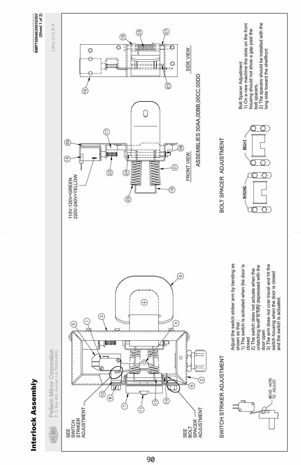
R
Pe
llerin
Miln
or
Co
rpo
ratio
nP
elle
rin
Miln
or
Co
rpo
ratio
nP.
O.
Bo
x4
00
,K
en
ne
r,L
A7
00
63
-04
00
Litho
inU
.S.A
.
BM
P750046/2
001036V
(Sh
eet
1o
f2)
Inte
rlo
ck
Asse
mb
ly
Adju
stth
esw
itch
str
iker
arm
by
bendin
gas
show
nso
that:
1)
The
sw
itch
isactivate
dw
hen
the
door
isclo
sed
2)
The
sw
itch
does
notactu
ate
when
the
unla
tchin
gle
ver
isfu
llydepre
ssed
with
the
door
open
3)
The
arm
does
notover
traveland
hit
the
sw
itch
housin
gw
hen
the
door
isclo
sed
and
the
sw
itch
isactu
ate
d.
Bolt
Spacer
Adju
stm
ent
1)
On
anew
machin
eth
eslo
tson
the
front
housin
gshould
notshow
agap
pastth
ebolt
spacers
.2)
The
spacers
should
be
insta
lled
with
the
long
sid
eto
ward
the
shellf
ront
SW
ITC
HS
TR
IKE
RA
DJU
ST
ME
NT
BO
LT
SP
AC
ER
AD
JU
ST
ME
NT
AS
SE
MB
LIE
S00A
A,0
0B
B,0
0C
C,0
0D
D
FR
ON
TV
IEW
SID
EV
IEW
SE
ES
WIT
CH
ST
RIK
ER
AD
JU
ST
ME
NT
SE
EB
OLT
SP
AC
ER
AD
JU
ST
ME
NT
110V
-120V
=G
RE
EN
220V
-240V
=Y
ELLO
W
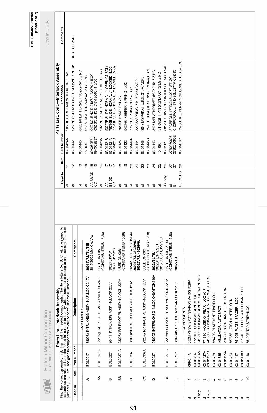
R
Pe
llerin
Miln
or
Co
rpo
ratio
nP
elle
rin
Miln
or
Co
rpo
ratio
nP.
O.
Bo
x4
00
,K
en
ne
r,L
A7
00
63
-04
00
Litho
inU
.S.A
.
Ite
mP
art
Nu
mb
er
Descri
pti
on
Co
mm
en
tsU
se
dIn
Fin
dth
ecorr
ect
assem
bly
firs
t,th
en
find
the
needed
com
ponents
.T
he
item
letters
(A,
B,
C,
etc
.)assig
ned
toassem
blie
sare
refe
rred
toin
the
"Used
In"
colu
mn
toid
entify
whic
hcom
ponents
belo
ng
toan
assem
bly
.T
he
item
num
bers
(1,2
,3,e
tc.)
assig
ned
tocom
ponents
rela
teth
epart
slis
tto
the
illustr
ation.
Ite
mP
art
Nu
mb
er
Descri
pti
on
Co
mm
en
tsU
se
dIn
Part
sL
ist,
co
nt.
—In
terl
ock
Assem
bly
Part
sL
ist—
Inte
rlo
ck
Assem
bly
BM
P750046/2
001036V
(Sh
eet
2o
f2)
. ----
----
----
----
----
----
----
----
----
----
----
----
----
----
----
----
----
-AS
SE
MB
LIE
S--
----
----
----
----
----
----
----
----
----
----
----
----
----
----
----
----
ED
L00171
88093#
INT
RLK
HS
GA
SS
Y=
N/U
NLO
CK
240V
3015/2
0/2
2M
xx,C
xx,V
xx
AA
ED
L00171A
93207@
RR
PIV
OT
PL
AS
SY
=N
/UN
LO
K240V
US
ED
ON
00A
(CO
NTA
INS
ITE
MS
15-2
8)
BE
DL00221
96411
INT
RLK
HS
GA
SS
Y=
N/L
OC
K220V
3022F
8J/P
/W3630F
8J/P
/W/S
BB
ED
L00271A
93207#*R
RP
IVO
TP
LA
SS
Y=
N/L
OC
K220V
US
ED
ON
00B
(CO
NTA
INS
ITE
MS
15-2
8)
ED
L00337
88093#*I
NT
RLK
HS
GA
SS
Y=
N/L
OC
K120V
36&
42Q
XX
,BW
P3015D
4A
CC
ED
L00337A
93207#
RR
PIV
OT
PL
AS
SY
=N
/LO
CK
120V
US
ED
ON
00C
(CO
NTA
INS
ITE
MS
15-2
8)
ED
L00371
94000Z
INT
ER
LK
HS
G=
N/L
OC
K+
SW
ITC
H240V
3022S
4J,S
4G
,S5J
3015K
4A
,S4J,S
5G
,S5J
DD
ED
L00271A
93207#*R
RP
IVO
TP
LA
SS
Y=
N/L
OC
K220V
US
ED
ON
00D
&00E
(CO
NTA
INS
ITE
MS
15-2
8)
EE
DL00271
88093#IN
TR
LK
HS
GA
SS
Y=
N/L
OC
K220V
----
----
----
----
----
----
----
----
----
----
----
----
----
----
----
----
---C
OM
PO
NE
NT
S--
----
----
----
----
----
----
----
----
----
----
----
----
----
----
----
----
all
109R
014A
05Z
MIM
I-S
WS
PD
TS
TA
KO
N#V
15G
1C
26K
all
203
01426
77201D
HO
US
ING
=F
RO
NT
=IL
OC
Donly
203
01426A
94186D
HO
US
ING
=F
RO
NT
=IL
OC
W/U
NLA
TC
all
303
01427A
77181C
HO
US
ING
=R
EA
R=
ILO
C(C
-7)
Donly
303
01427B
94186D
HO
US
ING
=R
EA
R=
ILO
CW
/UN
LA
TC
H
all
403
01429
75479C
PLA
TE
=F
NT
PIV
OT
=IL
OC
all
503
01335
INS
ULA
TO
R=
AU
TO
SP
OT
all
603
01425A
92683C
DO
OR
HA
ND
LE
EX
TE
NS
ION
all
703
01423
75736B
LA
TC
H=
INT
ER
LO
CK
all
803
01417
75100B
PLA
TE
=S
PA
CE
R=
ILO
C
all
903
01418B
75194B
KE
EP
ER
=LA
TC
HP
IN/N
OT
CH
all
10
03
01418
75100B
TA
PS
TR
IP=
ILO
C
A30015V
7J,T
5J,T
5E
C36021V
6J,36026V
5J
36026V
7J,42026V
6J
D3022V
6J,T
5J
30022T
5E
all
1103
01424A
90501B
ST
RIK
ER
=S
WIT
CH
=LO
NG
TA
B
all
12
03
01442
92697B
SO
LE
NO
IDIN
SU
LA
TIO
N=
DR
INT
RK
(NO
TS
HO
WN
)
all
13
03
01443
84251A
FLA
TH
DR
IVE
T5/3
2X
2+
5/1
6Z
INC
all
14
15H
091
01Z
ST
RG
HT
PIN
5/3
2''X
2.2
5LG
ZIN
C
AA
,BB
,DD
15
09K
062B
71
04Z
SO
LE
NO
ID240/6
0--
220/5
0=
ILO
CC
C15
09K
062B
37
03Z
SO
LE
NO
ID(C
-7)1
20/6
0--
110/5
0
all
16
03
01428A
93207C
PLA
TE
=R
EA
RP
IVO
T=
ILO
C(C
-7)
AA
17
03
01421B
93207B
SLID
E=
NO
RM
ALLY
OP
EN
(C7
SO
L)
BB
,DD
17
03
01421A
75736B
SLID
E=
NO
RM
ALLY
LO
CK
ED
=IL
OC
CC
17
03
01421D
77341B
SLID
E=
NO
RM
ALLY
LO
CK
ED
(C7-S
)
all
18
03
01425
75479B
HA
ND
LE
=IL
OC
all
19
03
01422
94256C
KE
EP
ER
=S
PR
ING
=IL
OC
all
20
03
01444A
77503B
SP
RIN
GC
UP
=IL
OC
all
21
03
01444
82293A
SP
RIN
G.5
1/1
.69/4
6+
CA
DP
L
all
22
03
01445
88481A
SP
RIN
G.2
/.625/.319+
CA
DP
L
all
23
03
01445B
75935B
TO
RQ
UE
SP
RIN
G(.53
IN-#
)CD
PL
all
24
03
01443
84251A
FLA
TH
DR
IVE
T5/3
2X
2+
5/1
6Z
INC
all
25
15H
090I
ST
RA
IGH
TP
IN5/3
2"D
IAX
1.7
5"L
GZ
INC
AA
only
26
03
S1X
188172B
SH
IM:D
OO
RIN
TLK
SO
LE
NO
IDN
4P
all
27
27B
205080Z
SP
CR
RO
LL.1
77ID
.218L.0
27T
ST
LZ
CB
27
27B
205080E
01Z
SP
CR
RO
LL.1
77ID
.25L.0
27T
KC
SZ
NC
BB
,CC
,DD
28
03
01418C
75736B
KE
EP
ER
=N
OR
MLO
CK
ED
SLID
E=
ILO
C

Section 7Water and Steam Piping
and Assemblies
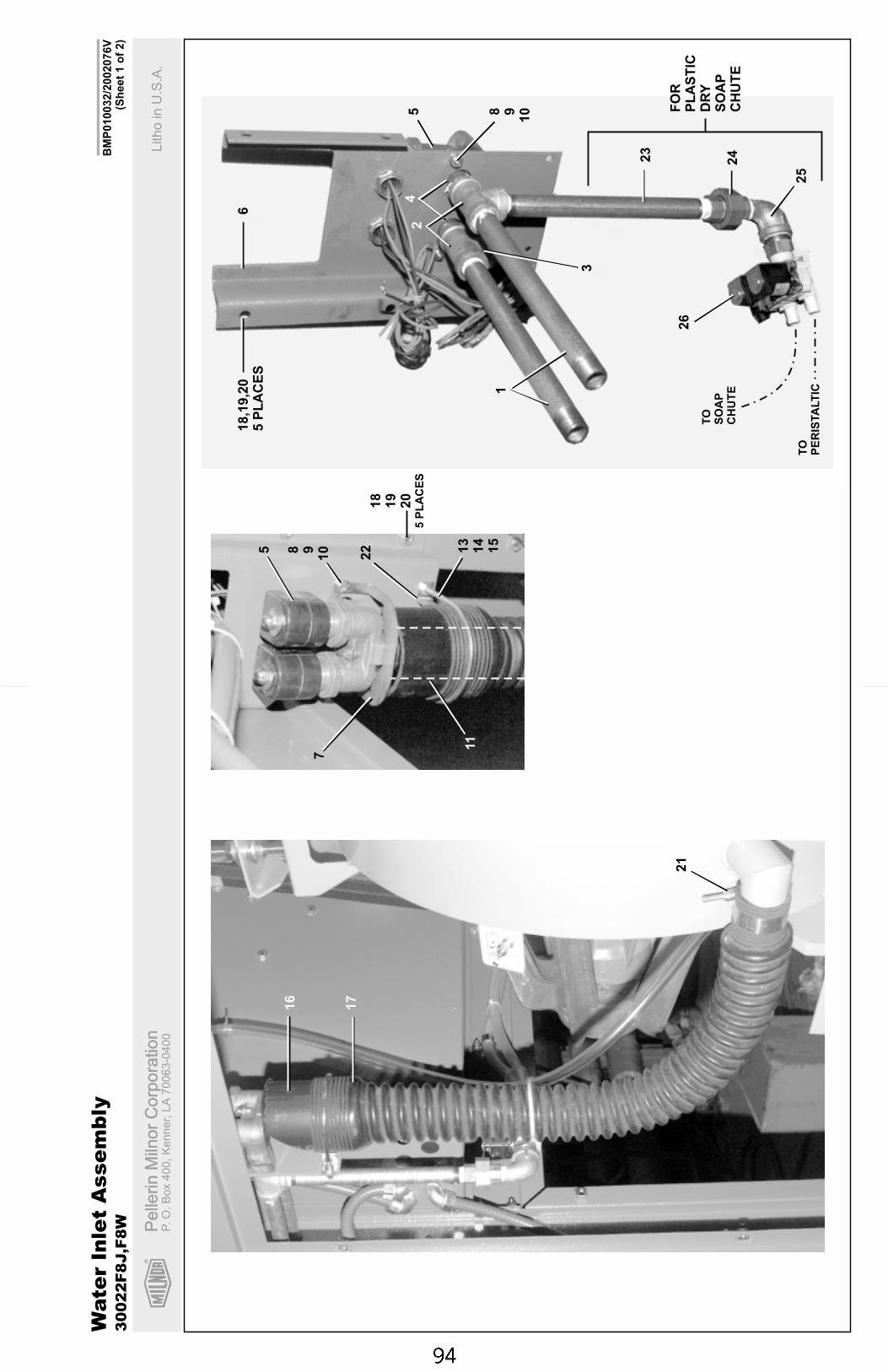
R
Pe
llerin
Miln
or
Co
rpo
ratio
nP
elle
rin
Miln
or
Co
rpo
ratio
nP.
O.
Bo
x4
00
,K
en
ne
r,L
A7
00
63
-04
00
Litho
inU
.S.A
.
BM
P010032/2
002076V
(Sh
eet
1o
f2)
Wate
rIn
let
Asse
mb
ly3
00
22
F8
J,F
8W
7
5
22 13
14
15
11
18
19
20
5P
LA
CE
S
8 910
16
17
21
18,1
9,2
05
PL
AC
ES
6
5 8 910
24
1
3
23
24
25
26
TO
SO
AP
CH
UT
E
TO
PE
RIS
TA
LT
IC
FO
RP
LA
ST
ICD
RY
SO
AP
CH
UT
E
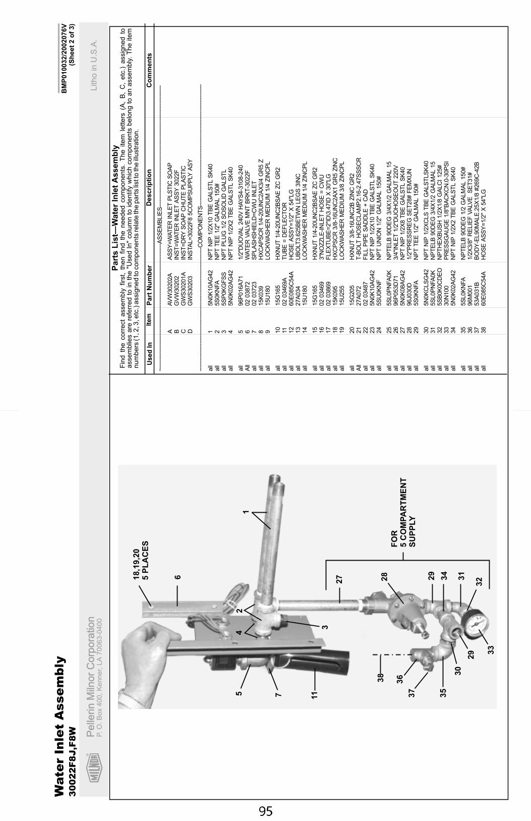
R
Pe
llerin
Miln
or
Co
rpo
ratio
nP
elle
rin
Miln
or
Co
rpo
ratio
nP.
O.
Bo
x4
00
,K
en
ne
r,L
A7
00
63
-04
00
Litho
inU
.S.A
.
Ite
mP
art
Nu
mb
er
Descri
pti
on
Co
mm
en
tsU
se
dIn
Fin
dth
ecorr
ect
assem
bly
firs
t,th
en
find
the
needed
com
ponents
.T
he
item
lett
ers
(A,
B,
C,
etc
.)assig
ned
toassem
blie
sare
refe
rred
toin
the
"Used
In"
colu
mn
toid
entify
whic
hcom
ponents
belo
ng
toan
assem
bly
.T
he
item
num
bers
(1,2
,3,e
tc.)
assig
ned
tocom
ponents
rela
teth
epart
slis
tto
the
illustr
ation.
Part
sL
ist—
Wate
rIn
let
Assem
bly
. ----
----
----
----
----
----
----
----
----
----
----
----
----
----
----
----
----
-AS
SE
MB
LIE
S--
----
----
----
----
----
----
----
----
----
----
----
----
----
----
----
----
AA
VW
30202A
AS
SY
=W
AT
ER
INLE
TP
LS
TIC
SO
AP
BG
VW
30202
INS
T=
WA
TE
RIN
LE
TA
SS
Y3022F
CG
WS
30201A
INS
T=
DR
YS
OA
PC
HU
TE
PLA
ST
ICD
GW
S30203
INS
TA
L=
3022F
85C
OM
PS
UP
PLY
AS
Y
----
----
----
----
----
----
----
----
----
----
----
----
----
----
----
----
---C
OM
PO
NE
NT
S--
----
----
----
----
----
----
----
----
----
----
----
----
----
----
----
----
all
15N
0K
10A
G42
NP
TN
IP1/2
X10
TB
EG
ALS
TL
SK
40
all
25S
0K
NFA
NP
TT
EE
1/2
"G
ALM
AL
150#
all
35S
P0K
GF
SS
NP
TP
LU
G1/2
SO
SO
LID
GA
LS
TL
all
45N
0K
02A
G42
NP
TN
IP1/2
X2
TB
EG
ALS
TL
SK
40
all
596P
016A
71
1/2
"DU
OV
AL
240V
HA
YS
4-3
108-2
40
All
602
03872
WA
TE
RV
ALV
EM
NT
BR
KT
-3022F
all
702
03723
SP
LA
SH
SH
IELD
=C
WU
INLE
Tall
815K
039
HX
CA
PS
CR
1/4
-20U
NC
2A
X3/4
GR
5Z
all
915U
180
LO
CK
WA
SH
ER
ME
DIU
M1/4
ZIN
CP
L
all
10
15G
165
HX
NU
T1/4
-20U
NC
2B
SA
EZ
CG
R2
all
1102
03469A
TU
BE
=D
EF
LE
CT
OR
all
12
60E
085C
54A
HO
SE
AS
SY
=1/2
"X
54"L
Gall
13
27A
034
UB
OLT
3.6
25B
ET
WN
LE
GS
3IN
Call
14
15U
180
LO
CK
WA
SH
ER
ME
DIU
M1/4
ZIN
CP
L
all
15
15G
165
HX
NU
T1/4
-20U
NC
2B
SA
EZ
CG
R2
all
16
02
03469
3"N
OZ
ZLE
-IN
LE
TH
OS
E=
CW
Uall
17
02
03869
FLE
XT
UB
E=
2"I
D\3
.47ID
X30"L
Gall
18
15K
095
HX
CP
SC
R3/8
-16U
NC
2A
X1
GR
5Z
INC
all
19
15U
255
LO
CK
WA
SH
ER
ME
DIU
M3/8
ZIN
CP
L
all
20
15G
205
HX
NU
T3/8
-16U
NC
2B
ZIN
CG
R2
All
21
27A
072
T-B
OLT
HO
SE
CLA
MP
2.1
6-2
.47S
SS
CR
all
22
02
03487
FIL
LP
IPE
SA
DD
LE
+C
AD
all
23
5N
0K
10A
G42
NP
TN
IP1/2
X10
TB
EG
ALS
TL
SK
40
all
24
5S
U0K
NF
NP
TU
NIO
N1/2
"G
ALM
AL
150#
all
25
5S
L0P
NFA
0K
NP
TE
LB
90D
EG
3/4
X1/2
GA
LM
AL
15
all
26
96P
053D
71
3/4
"IN
LE
T1/2
"DU
OH
OS
EO
UT
220V
all
27
5N
0K
08A
G42
NP
TN
IP1/2
X8
TB
EG
ALS
TL
SK
40
all
28
96J030D
1/2
"PR
ES
SR
EG
SE
T28#
FE
MX
UN
all
29
5S
0K
NFA
NP
TT
EE
1/2
"G
ALM
AL
150#
all
30
5N
0K
CLS
G42
NP
TN
IP1/2
XC
LS
TB
EG
ALS
TLS
K40
all
31
5S
L0P
NFA
0K
NP
TE
LB
90D
EG
3/4
X1/2
GA
LM
AL
15
all
32
5S
B0K
0C
DE
ON
PT
HE
XB
US
H1/2
X1/8
GA
LC
I125#
all
33
30N
100
PR
ES
SG
AU
GE
1/8
"BA
CK
CN
.0-3
0P
SI
all
34
5N
0K
02A
G42
NP
TN
IP1/2
X2
TB
EG
ALS
TL
SK
40
all
35
5S
L0K
NFA
NP
TE
LB
90D
EG
1/2
GA
LM
AL
150#
all
36
96M
001
1/2
X3/8
"R
ELIE
FV
ALV
ES
ET
31#
all
37
53A
031B
BO
DY
-EL90M
ALE
.25X
1/8
#269C
-42B
all
38
60E
085C
54A
HO
SE
AS
SY
=1/2
"X
54"L
G
Wate
rIn
let
Asse
mb
ly3
00
22
F8
J,F
8W
BM
P010032/2
002076V
(Sh
eet
2o
f3)
FO
R5
CO
MP
AR
TM
EN
TS
UP
PLY
18,1
9,2
05
PL
AC
ES
6
5 7 11
3
42
1
27 28 29
29
31
32
38
36
37
35
30
33
34
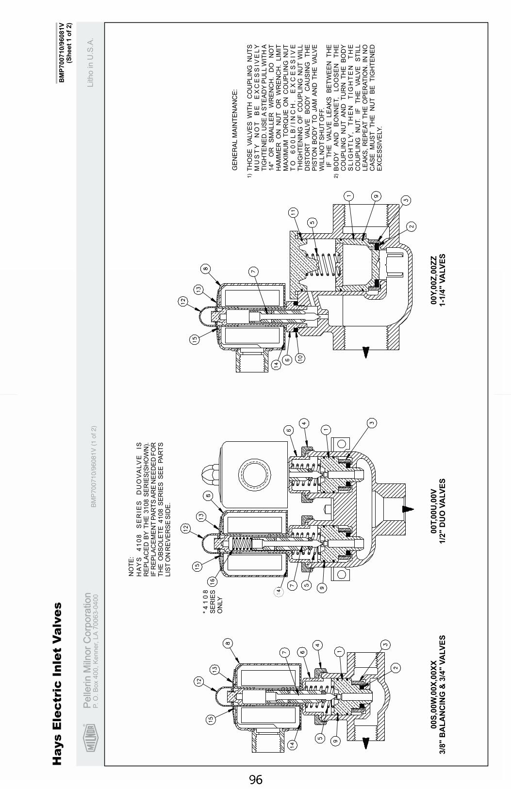
R
Pe
llerin
Miln
or
Co
rpo
ratio
nP
elle
rin
Miln
or
Co
rpo
ratio
nP.
O.
Bo
x4
00
,K
en
ne
r,L
A7
00
63
-04
00
Litho
inU
.S.A
.
BM
P700710/9
6081V
(Sh
eet
1o
f2)
Ha
ys
Ele
ctr
icIn
let
Va
lve
s
BM
P7
00
71
0/9
60
81
V(1
of2
)
TH
OS
EV
ALV
ES
WIT
HC
OU
PLIN
GN
UT
SM
US
TY
NO
TB
EE
XC
ES
SIV
EL
YT
IGH
TE
NE
D.U
SE
AS
TE
AD
YP
ULL
WIT
HA
14"
OR
SM
ALLE
RW
RE
NC
H.
DO
NO
TH
AM
ME
RO
NN
UT
OR
WR
EN
CH
.LIM
ITM
AX
IMU
MT
OR
QU
EO
NC
OU
PLIN
GN
UT
TO
60
0L
B/IN
CH
.E
XC
ES
SIV
ET
HIG
HT
EN
ING
OF
CO
UP
LIN
GN
UT
WIL
LD
IST
OR
TV
ALV
EB
OD
YC
AU
SIN
GT
HE
PIS
TO
NB
OD
YT
OJA
MA
ND
TH
EV
ALV
EW
ILL
NO
TS
HU
TO
FF.
IFT
HE
VA
LV
ELE
AK
SB
ET
WE
EN
TH
EB
OD
YA
ND
BO
NN
ET,
LO
OS
EN
TH
EC
OU
PLIN
GN
UT
AN
DT
UR
NT
HE
BO
DY
SL
IGH
TL
Y,
TH
EN
TIG
HT
EN
TH
EC
OU
PLIN
GN
UT.
IFT
HE
VA
LV
ES
TIL
LLE
AK
S,
RE
PE
AT
TH
EO
PE
RA
TIO
N.
INN
OC
AS
EM
US
TT
HE
NU
TB
ET
IGH
TE
NE
DE
XC
ES
SIV
ELY.
GE
NE
RA
LM
AIN
TE
NA
NC
E:
1)
2)
*4
10
8S
ER
IES
ON
LY
HA
YS
41
08
SE
RIE
SD
UO
VA
LV
EIS
RE
PLA
CE
DB
YT
HE
3108
SE
RIE
S(S
HO
WN
).IF
RE
PLA
CE
ME
NT
PA
RT
SA
RE
NE
ED
ED
FO
RT
HE
OB
SO
LE
TE
4108
SE
RIE
SS
EE
PA
RT
SLIS
TO
NR
EV
ER
SE
SID
E.
NO
TE
:
00S
,00W
,00X
,00X
X3/8
"B
AL
AN
CIN
G&
3/4
"V
ALV
ES
00T,0
0U
,00V
1/2
"D
UO
VA
LV
ES
00Y
,00Z
,00Z
Z1-1
/4"
VA
LV
ES
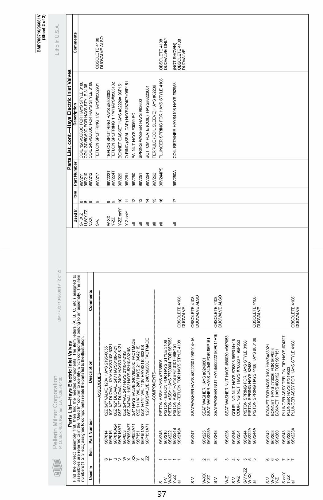
R
Pe
llerin
Miln
or
Co
rpo
ratio
nP
elle
rin
Miln
or
Co
rpo
ratio
nP.
O.
Bo
x4
00
,K
en
ne
r,L
A7
00
63
-04
00
Litho
inU
.S.A
.
Ite
mP
art
Nu
mb
er
Descri
pti
on
Co
mm
en
tsU
se
dIn
Fin
dth
ecorr
ect
assem
bly
firs
t,th
en
find
the
needed
com
ponents
.T
he
item
letters
(A,
B,
C,
etc
.)assig
ned
toassem
blie
sare
refe
rred
toin
the
"Used
In"
colu
mn
toid
entify
whic
hcom
ponents
belo
ng
toan
assem
bly
.T
he
item
num
bers
(1,2
,3,e
tc.)
assig
ned
tocom
ponents
rela
teth
epart
slis
tto
the
illustr
ation.
Ite
mP
art
Nu
mb
er
Descri
pti
on
Co
mm
en
tsU
se
dIn
Part
sL
ist,
co
nt.
—H
ays
Ele
ctr
icIn
let
Valv
es
Part
sL
ist—
Hays
Ele
ctr
icIn
let
Valv
es
BM
P700710/9
6081V
(Sh
eet
2o
f2)
. ----
----
----
----
----
----
----
----
----
----
----
----
----
----
----
----
----
-AS
SE
MB
LIE
S--
----
----
----
----
----
----
----
----
----
----
----
----
----
----
----
----
S96P
014
02Z
3/8
"V
ALV
E120V
HA
YS
2195-0
055
T96P
016
10Z
1/2
"D
UO
VA
L120V
HA
YS
3108-6
021
U96P
016A
24
08Z
1/2
"D
UO
VA
L24V
HA
YS
3108-6
421
V96P
016A
71
05Z
1/2
"D
UO
VA
L240V
HA
YS
3108-6
121
W96P
053
05Z
3/4
"VA
L24V
HA
YS
211
0-6
421IS
X96P
053A
37
06Z
3/4
"VA
L11
0V
HA
YS
#211
0-6
021IS
XX
96P
053A
71
3/4
"H
AY
SV
ALV
E240V
60/5
0C
FA
CT
MA
DE
Y96P
151
09Z
1+
1/4
"V
AL
24V
HA
YS
211
0-6
421IS
Z96P
151A
37
05Z
1+
1/4
"V
AL
110V
HA
YS
211
0-6
021IS
ZZ
96P
151A
71
1.2
5"
HA
YS
VA
LVE
240V
60/5
0C
FA
CT
MA
DE
----
----
----
----
----
----
----
----
----
----
----
----
----
----
----
----
---C
OM
PO
NE
NT
S--
----
----
----
----
----
----
----
----
----
----
----
----
----
----
----
----
S1
96V
245
PIS
TO
NA
SS
YH
AY
S#7735505
T-V
196V
216
PIS
TO
N-T
EF
LO
NF
OR
HA
YS
ST
YLE
3108
W-X
X1
96V
222
PIS
TO
NA
SS
YH
AY
S7730004
FO
R96P
053
Y-Z
Z1
96V
224B
PIS
TO
NA
SS
YH
AY
S#7643101=
96P
151
all
196V
216A
PIS
TO
N-T
EF
LO
NF
OR
HA
YS
ST
YLE
4108
OB
SO
LE
TE
4108
DU
OV
ALV
E
S-V
,2
96V
247
SE
AT
WA
SH
ER
HA
YS
#8222301
96P
014+
16
OB
SO
LE
TE
4108
DU
OV
ALV
EA
LS
O
W-X
X2
96V
225
SE
AT
WA
SH
ER
HA
YS
#8249801
Y-Z
Z2
96V
225A
SE
AT
WA
SH
ER
HA
YS
#84048
FO
R96P
151
S-V
,3
96V
248
SE
AT
WA
SH
ER
NU
TH
AY
S#82222
96P
014+
16
OB
SO
LE
TE
4108
DU
OV
ALV
EA
LS
O
W-Z
396V
226
SE
AT
WA
SH
ER
NU
TH
AY
S#86030
=96P
053
S-V
496V
246
CO
UP
LIN
GN
UT
HA
YS
#76303
96P
014+
16
W-Z
496V
254
CO
UP
LIN
GN
UT
HA
YS
#76028
=96P
053
S-V
,Y-Z
Z5
96V
244
PIS
TO
NS
PR
ING
FO
RH
AY
SS
TY
LE
3108
W-X
X5
96V
222A
PIS
TO
NS
PR
ING
HA
YS
82488
all
596V
244A
PIS
TO
NS
PR
ING
HA
YS
4108
HA
YS
#88108
OB
SO
LE
TE
4108
DU
OV
ALV
E
S-V
696V
242
BO
NN
ET
FO
RH
AY
S3108
HA
YS
#83021
W-X
X6
96V
258
BO
NN
ET
HA
YS
#73026
FO
R96P
053
Y-Z
696V
260
BO
NN
ET
HA
YS
#83192
FO
R96P
151
SonlY
796V
243
PLU
NG
ER
AS
SY
TE
FLO
NT
IPH
AY
S#74327
T-Z
Z7
96V
223
PLU
NG
ER
HA
YS
#7319503
all
796V
223A
PLU
NG
ER
AS
SY
FO
RH
AY
SS
TY
LE
4108
OB
SO
LE
TE
4108
DU
OV
ALV
E
S-T
,X,Z
896V
211
CO
IL120V
50/6
0C
FO
RH
AY
SS
TY
LE
3108
U,W
,Y,Z
Z8
96V
210
CO
IL24V
50/6
0C
FO
RH
AY
SS
TY
LE
3108
V,X
X8
96V
212
CO
IL240V
50/6
0C
FO
RH
AY
SS
TY
LE
3108
S-V
,9
96V
217
TE
FLO
NS
PLIT
RIN
G1/2
"H
AY
S#8502901
OB
SO
LE
TE
4108
DU
OV
ALV
EA
LS
O
W-X
X9
96V
222T
TE
FLO
NS
PLIT
RIN
GH
AY
S#8503002
Y-Z
Z9
96V
224T
TE
FLO
NS
PLIT
RIN
G1
1/4
"HA
YS
#8503102
Y-Z
ZonlY
10
96V
229
BO
NN
ET
GA
SK
ET
HA
YS
#82224=
96P
151
Y-Z
onlY
1196V
261
O-R
ING
(SE
AL
CA
P)
HA
YS
#87407=
96P
151
all
12
96V
250
PA
LN
UT
HA
YS
#3069-P
C
all
13
96V
251
SP
RIN
GW
AS
HE
RH
AY
S#83600
all
14
96V
264
BO
TT
OM
PLA
TE
(CO
IL)
HA
YS
#8223601
all
15
96V
262
FE
RR
ULE
(CO
ILS
LE
EV
E)
HA
YS
#82239
all
16
96V
244P
SP
LU
NG
ER
SP
RIN
GF
OR
HA
YS
ST
YLE
4108
OB
SO
LE
TE
4108
DU
OV
ALV
EO
NLY
all
17
96V
250A
CO
ILR
ETA
INE
RH
AY
S4108
HA
YS
#82958
(NO
TS
HO
WN
)O
BS
OLE
TE
4108
DU
OV
ALV
E
BM
P7
00
71
0/9
60
81
V(2
of2
)
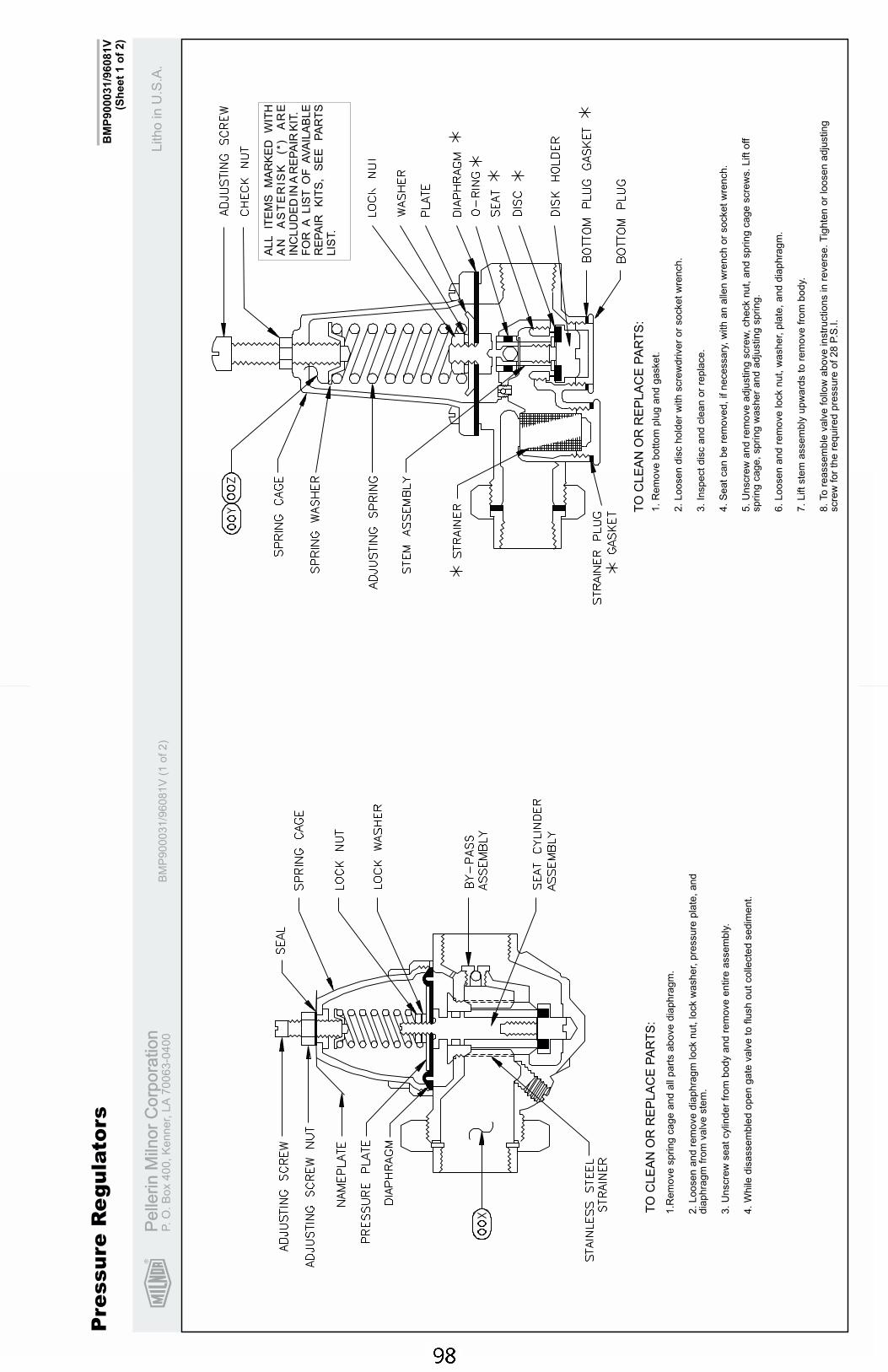
R
Pe
llerin
Miln
or
Co
rpo
ratio
nP
elle
rin
Miln
or
Co
rpo
ratio
nP.
O.
Bo
x4
00
,K
en
ne
r,L
A7
00
63
-04
00
Litho
inU
.S.A
.
BM
P900031/9
6081V
(Sh
eet
1o
f2)
Pre
ssu
reR
eg
ula
tors
BM
P900031/9
6081V
(1of2)
TO
CLE
AN
OR
RE
PLA
CE
PA
RT
S:
TO
CLE
AN
OR
RE
PLA
CE
PA
RT
S:
ALL
ITE
MS
MA
RK
ED
WIT
HA
NA
ST
ER
ISK
(*)
AR
EIN
CLU
DE
DIN
AR
EP
AIR
KIT
.F
OR
ALIS
TO
FA
VA
ILA
BLE
RE
PA
IRK
ITS
,S
EE
PA
RT
SLIS
T.
1.R
em
ove
spring
cage
and
all
part
sabove
dia
phra
gm
.
2.
Loosen
and
rem
ove
dia
phra
gm
lock
nut,
lock
washer,
pre
ssure
pla
te,
and
dia
phra
gm
from
valv
este
m.
3.
Unscre
wseat
cylin
der
from
body
and
rem
ove
entire
assem
bly
.
4.
While
dis
assem
ble
dopen
gate
valv
eto
flush
out
colle
cte
dsedim
ent.
1.
Rem
ove
bottom
plu
gand
gasket.
2.
Loosen
dis
chold
er
with
scre
wdriver
or
socket
wre
nch.
3.
Inspect
dis
cand
cle
an
or
repla
ce.
4.
Seat
can
be
rem
oved,
ifnecessary
,w
ith
an
alle
nw
rench
or
socket
wre
nch.
5.
Unscre
wand
rem
ove
adju
sting
scre
w,
check
nut,
and
spring
cage
scre
ws.
Lift
off
spring
cage,
spring
washer
and
adju
sting
spring.
6.
Loosen
and
rem
ove
lock
nut,
washer,
pla
te,
and
dia
phra
gm
.
7.
Lift
ste
massem
bly
upw
ard
sto
rem
ove
from
body.
8.
To
reassem
ble
valv
efo
llow
above
instr
uctions
inre
vers
e.
Tig
hte
nor
loosen
adju
sting
scre
wfo
rth
ere
quired
pre
ssure
of
28
P.S
.I.
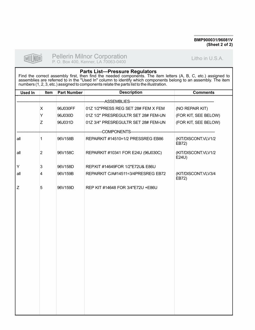
R
Pellerin Milnor CorporationPellerin Milnor CorporationP. O. Box 400, Kenner, LA 70063-0400
Litho in U.S.A.
Item Part Number Description CommentsUsed In
Find the correct assembly first, then find the needed components. The item letters (A, B, C, etc.) assigned toassemblies are referred to in the "Used In" column to identify which components belong to an assembly. The itemnumbers (1, 2, 3, etc.) assigned to components relate the parts list to the illustration.
Parts List—Pressure Regulators
BMP900031/96081V(Sheet 2 of 2)
.
---------------------------------------------------------------------ASSEMBLIES------------------------------------------------------------------
X 96J030FF 01Z 1/2"PRESS REG SET 28# FEM X FEM (NO REPAIR KIT)
Y 96J030D 01Z 1/2" PRESREGULTR SET 28# FEM-UN (FOR KIT, SEE BELOW)
Z 96J031D 01Z 3/4" PRESREGULTR SET 28# FEM-UN (FOR KIT, SEE BELOW)
-------------------------------------------------------------------COMPONENTS------------------------------------------------------------------
all 1 96V158B REPAIRKIT #14510=1/2 PRESSREG EB86 (KIT/DISCONT.VLV1/2EB72)
all 2 96V158C REPAIRKIT #10341 FOR E24U (96J030C) (KIT/DISCONT.VLV1/2E24U)
Y 3 96V158D REP.KIT #14649FOR 1/2"E72U& E86U
all 4 96V159B REPAIRKIT C/A#14511=3/4PRESREG EB72 (KIT/DISCONT.VLV3/4EB72)
Z 5 96V159D REP KIT #14648 FOR 3/4"E72U +E86U
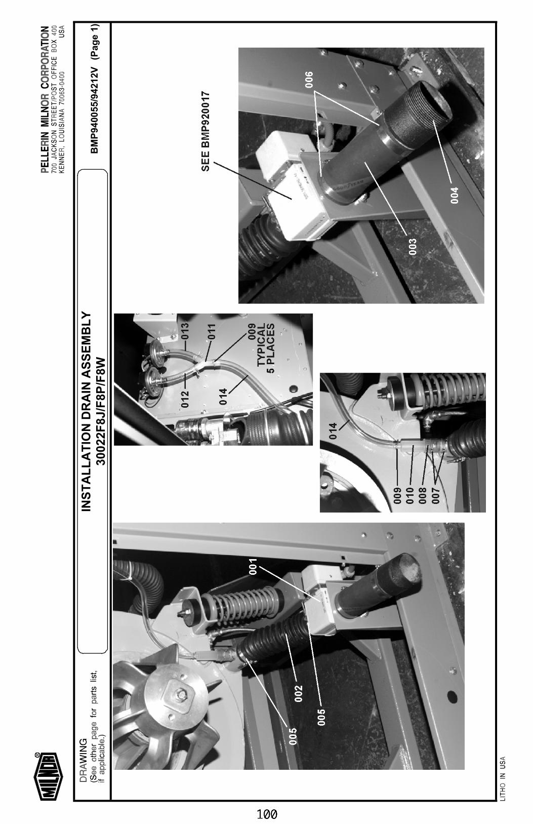
BM
P94
0055
/942
12V
(Pag
e 1)
INS
TA
LL
AT
ION
DR
AIN
AS
SE
MB
LY
3002
2F8J
/F8P
/F8W
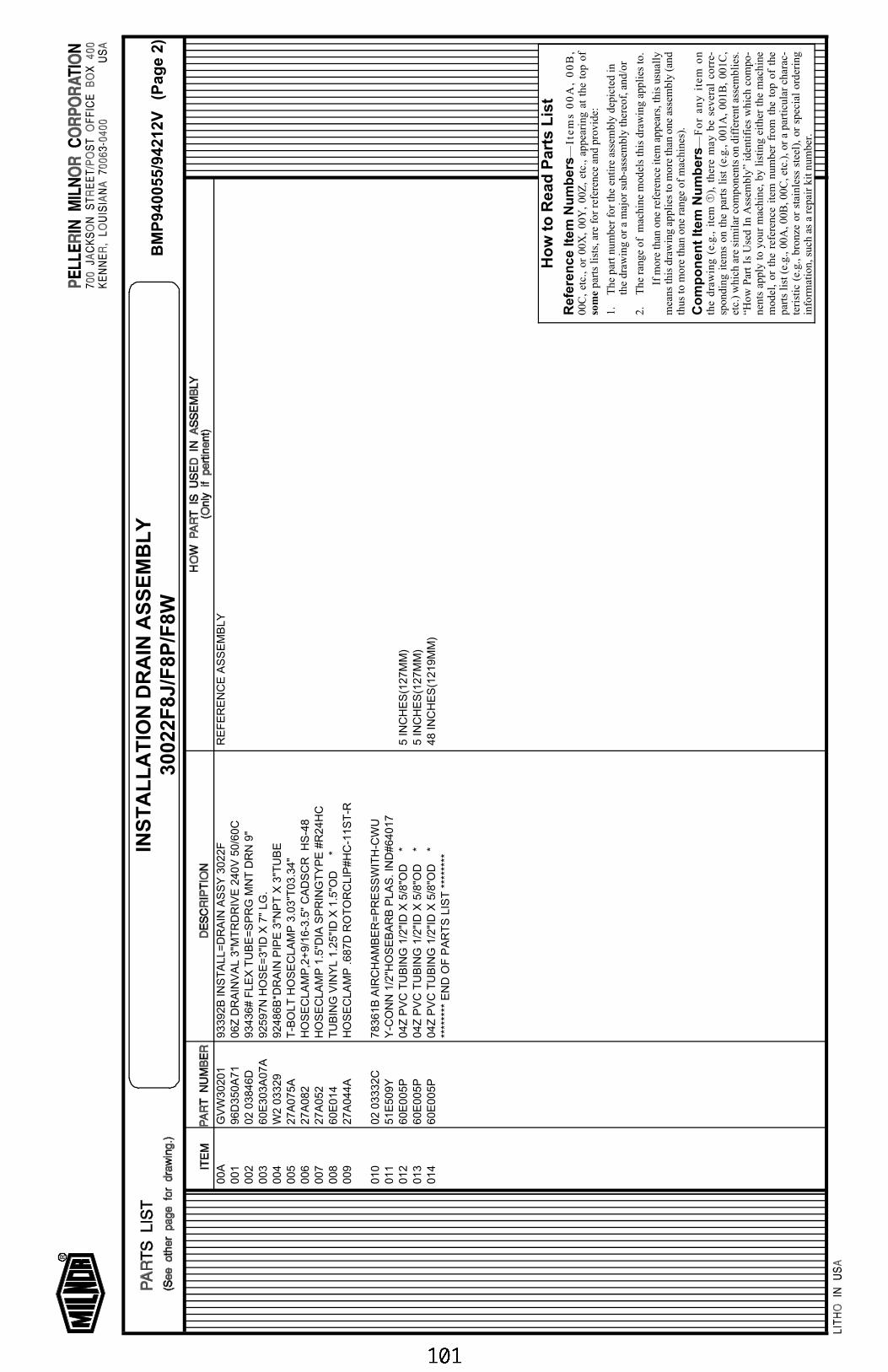
00A
GV
W30201
93392B
IN
ST
ALL=
DR
AIN
AS
SY
3022F
RE
FE
RE
NC
E A
SS
EM
BLY
001
96D
350A
71
06Z
DR
AIN
VA
L 3
"MT
RD
RIV
E 2
40V
50/6
0C
002
02 0
3846D
93436# F
LE
X T
UB
E=
SP
RG
MN
T D
RN
9"
003
60E
303A
07A
92597N
HO
SE
=3"I
D X
7"
LG
.004
W2 0
3329
92486B
*DR
AIN
PIP
E 3
"NP
T X
3"T
UB
E005
27A
075A
T-B
OLT
HO
SE
CLA
MP
3.0
3"T
03.3
4"
006
27A
082
HO
SE
CLA
MP
,2+
9/1
6-3
.5"
CA
DS
CR
H
S-4
8007
27A
052
HO
SE
CLA
MP
1.5
"DIA
SP
RIN
GT
YP
E #
R24H
C008
60E
014
TU
BIN
G V
INY
L 1
.25"I
D X
1.5
"OD
*
009
27A
044A
HO
SE
CLA
MP
.687D
RO
TO
RC
LIP
#H
C-1
1S
T-R
010
02 0
3332C
78361B
AIR
CH
AM
BE
R=
PR
ES
SW
ITH
-CW
U011
51E
509Y
Y-C
ON
N 1
/2"H
OS
EB
AR
B P
LA
S. IN
D#64017
012
60E
005P
04Z
PV
C T
UB
ING
1/2
"ID
X 5
/8"O
D *
5 IN
CH
ES
(127M
M)
013
60E
005P
04Z
PV
C T
UB
ING
1/2
"ID
X 5
/8"O
D *
5 IN
CH
ES
(127M
M)
014
60E
005P
04Z
PV
C T
UB
ING
1/2
"ID
X 5
/8"O
D *
48 IN
CH
ES
(1219M
M)
****
****
EN
D O
F P
AR
TS
LIS
T *
****
***
Ho
w t
o R
ead
Par
ts L
ist
Re
fere
nc
e It
em
Nu
mb
ers
—It
em
s 0
0A
, 0
0B
,00
C,
etc.
, or
00X
, 00
Y,
00Z
, et
c.,
appe
arin
g at
the
top
of
some
part
s li
sts,
are
for
ref
eren
ce a
nd p
rovi
de:
1.T
he p
art n
umbe
r fo
r th
e en
tire
ass
embl
y de
pict
ed in
the
draw
ing
or a
maj
or s
ub-a
ssem
bly
ther
eof,
and
/or
2.T
he r
ange
of
mac
hine
mod
els
this
dra
win
g ap
plie
s to
.
If m
ore
than
one
ref
eren
ce it
em a
ppea
rs, t
his
usua
lly
mea
ns th
is d
raw
ing
appl
ies
to m
ore
than
one
ass
embl
y (a
ndth
us to
mor
e th
an o
ne r
ange
of
mac
hine
s).
Co
mp
on
ent
Item
Nu
mb
ers —
Fo
r an
y i
tem
on
the
draw
ing
(e.g
., it
em ➀
), t
here
may
be
seve
ral
corr
e-sp
ondi
ng i
tem
s on
the
par
ts l
ist
(e.g
., 00
1A,
001B
, 00
1C,
etc.
) w
hich
are
sim
ilar
com
pone
nts
on d
iffe
rent
ass
embl
ies.
“How
Par
t Is
Use
d In
Ass
embl
y” i
dent
ifie
s w
hich
com
po-
nent
s ap
ply
to y
our
mac
hine
, by
list
ing
eith
er t
he m
achi
nem
odel
, or
the
ref
eren
ce i
tem
num
ber
from
the
top
of
the
part
s li
st (
e.g.
, 00A
, 00B
, 00C
, etc
.), o
r a
part
icul
ar c
hara
c-te
rist
ic (
e.g.
, br
onze
or
stai
nles
s st
eel)
, or
spe
cial
ord
erin
gin
form
atio
n, s
uch
as a
rep
air
kit n
umbe
r.
BM
P94
0055
/942
12V
(Pag
e 2)
INS
TA
LL
AT
ION
DR
AIN
AS
SE
MB
LY
3002
2F8J
/F8P
/F8W
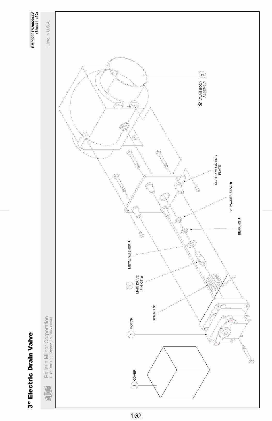
R
Pe
llerin
Miln
or
Co
rpo
ratio
nP
elle
rin
Miln
or
Co
rpo
ratio
nP.
O.
Bo
x4
00
,K
en
ne
r,L
A7
00
63
-04
00
Litho
inU
.S.A
.
BM
P920017/2
002044V
(Sh
eet
1o
f2)
3”
Ele
ctric
Dra
inV
alv
e
SP
RIN
G
MA
IND
RIV
E
PIN
KIT
ME
TA
LW
AS
HE
R
BE
AR
ING
"V"
PA
CK
ER
SE
AL
MO
TO
RM
OU
NT
ING
PLA
TE
14
3M
OT
OR
CO
VE
R
VA
LV
EB
OD
Y
AS
SE
MB
LY
2
*
*
*
**
*
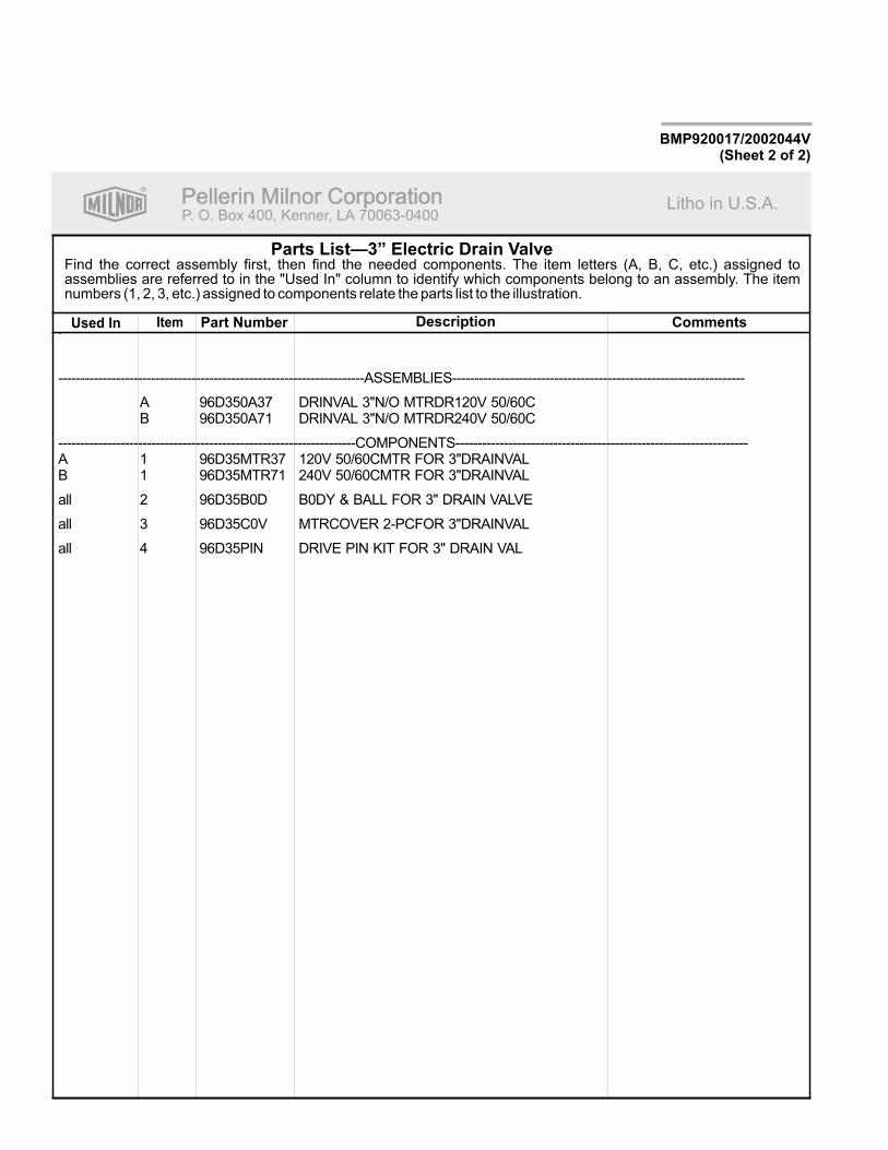
R
Pellerin Milnor CorporationPellerin Milnor CorporationP. O. Box 400, Kenner, LA 70063-0400
Litho in U.S.A.
Item Part Number Description CommentsUsed In
Find the correct assembly first, then find the needed components. The item letters (A, B, C, etc.) assigned toassemblies are referred to in the "Used In" column to identify which components belong to an assembly. The itemnumbers (1, 2, 3, etc.) assigned to components relate the parts list to the illustration.
Parts List—3” Electric Drain Valve
BMP920017/2002044V(Sheet 2 of 2)
.
---------------------------------------------------------------------ASSEMBLIES------------------------------------------------------------------
A 96D350A37 DRINVAL 3"N/O MTRDR120V 50/60CB 96D350A71 DRINVAL 3"N/O MTRDR240V 50/60C
-------------------------------------------------------------------COMPONENTS------------------------------------------------------------------A 1 96D35MTR37 120V 50/60CMTR FOR 3"DRAINVALB 1 96D35MTR71 240V 50/60CMTR FOR 3"DRAINVAL
all 2 96D35B0D B0DY & BALL FOR 3" DRAIN VALVE
all 3 96D35C0V MTRCOVER 2-PCFOR 3"DRAINVAL
all 4 96D35PIN DRIVE PIN KIT FOR 3" DRAIN VAL


Section 8Chemical Supply Devices
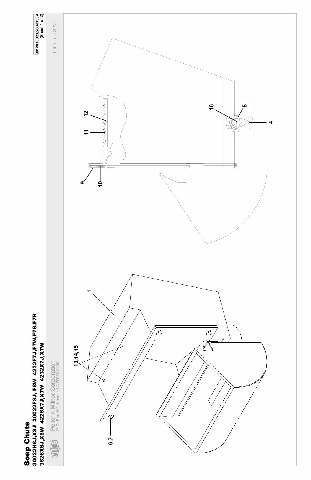
BM
P010023/2
004333V
(Sh
eet
1o
f2)
Soa
pC
hute
R
Pe
llerin
Miln
or
Co
rpo
ratio
nP
elle
rin
Miln
or
Co
rpo
ratio
nP.
O.
Bo
x4
00
,K
en
ne
r,L
A7
00
63
-04
00
Litho
inU
.S.A
.
30022H
8J,X
8J
30022F8J,F8W
4232F7J,F
7W
,F7S
,F7R
3626X
8J,X
8W
4226X
7J,X
7W
4232X
7J,X
7W
1
9
10
11
12
13,1
4,1
5
6,7
16 5
4
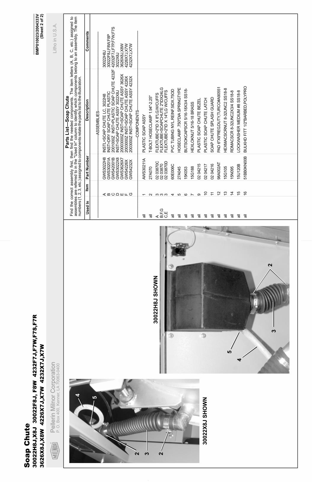
R
Pe
llerin
Miln
or
Co
rpo
ratio
nP
elle
rin
Miln
or
Co
rpo
ratio
nP.
O.
Bo
x4
00
,K
en
ne
r,L
A7
00
63
-04
00
Litho
inU
.S.A
.
BM
P010023/2
004333V
(Sh
eet
2o
f2)
Ite
mP
art
Nu
mb
er
Descri
pti
on
Co
mm
en
tsU
se
dIn
Fin
dth
ecorr
ect
assem
bly
firs
t,th
en
find
the
needed
com
ponents
.T
he
item
letters
(A,
B,
C,
etc
.)assig
ned
toassem
blie
sare
refe
rred
toin
the
"Used
In"
colu
mn
toid
entify
whic
hcom
ponents
belo
ng
toa
nassem
bly
.T
he
item
num
bers
(1,2
,3,e
tc.)
assig
ned
tocom
ponents
rela
teth
epart
slis
tto
the
illustr
ation.
Part
sL
ist—
So
ap
Ch
ute
. ----
----
----
----
----
----
----
----
----
----
----
----
----
----
----
----
----
-AS
SE
MB
LIE
S--
----
----
----
----
----
----
----
----
----
----
----
----
----
----
----
----
AG
WS
3022H
8IN
ST
L=
SO
AP
CH
UT
ELC
,3022H
830022H
8J
BG
WS
30201A
INS
T=
DR
YS
OA
PC
HU
TE
PLA
ST
IC30022F
8J,F
8W
,F8P
CG
WS
42001B
2001000Z
INS
T=
PLA
ST
ICS
OA
PC
HU
TE
4232F
42032F
7J,F
7P,F
7W
,F7S
DG
WS
3022X
8IN
ST
=S
OA
PC
HU
TE
AS
SY
3022X
8J
3022X
8J
EG
WS
3626X
720003000Z
INS
T=
SO
AP
CH
UT
EA
SS
Y3626X
3626X
8J,X
8W
FG
WS
4226X
2003000Z
INS
T=
SO
AP
CH
UT
EA
SS
Y4226X
4226X
7J,X
7W
GG
WS
4232X
2003000Z
INS
T=
SO
AP
CH
UT
EA
SS
Y4232X
4232X
7J,X
7W
----
----
----
----
----
----
----
----
----
----
----
----
----
----
----
----
---C
OM
PO
NE
NT
S--
----
----
----
----
----
----
----
----
----
----
----
----
----
----
----
----
all
1A
WS
30211
AP
LA
ST
ICS
OA
PA
SS
Y
all
227A
070
T-B
OLT
HO
SE
CLA
MP
1.9
4"-
2.2
5"
A3
02
03870C
FLE
XT
UB
E=
2"I
DX
8"L
G.W
/CU
FF
SB
,F,G
302
03870
FLE
XT
UB
E=
SO
AP
CH
UT
E2"I
DX
24LG
C,E
302
03870D
FLE
XT
UB
E=
2"I
DX
14"L
GW
/CU
FF
S
all
460E
006C
PV
CT
UB
ING
NY
L.R
EIN
F.5
IDX
.75O
D
all
527A
045
HO
SE
CLA
MP
.750"D
IAS
PR
ING
TY
PE
all
615K
053
BU
TS
OK
CA
PS
CR
5/1
6-1
8X
3/4
SS
18-
all
715G
188
HE
XLO
KN
UT
5/1
6-1
8B
RA
SS
all
902
04215
PLA
ST
ICS
OA
PC
HU
TE
BE
ZE
L
all
10
02
04217
PLA
ST
ICS
OA
PC
HU
TE
LA
TC
H
all
1102
04216
SO
AP
CH
UT
ES
PLA
SH
GU
AR
D
all
12
98A
002A
TP
AD
6"X
9"R
EG
.DU
TY,T
UR
CO
#A
90551
all
13
15G
105
HE
XM
AC
SC
RN
UT
8-3
2U
NC
2S
S18-8
all
14
15N
095
RD
MA
CS
CR
8-3
2U
NC
2X
3/4
SS
18-8
all
15
15U
120B
LO
CK
WA
SH
ER
ME
DIU
M#8
SS
18-8
all
16
51B
B0K
N00B
BU
LK
HD
FIT
T1/2
"BA
RB
ED
,PO
LYP
RO
30022H
8J
SH
OW
N
30022X
8J
SH
OW
N
32
4
5
4 5
232
Soa
pC
hute
30022H
8J,X
8J
30022F8J,F8W
4232F7J,F
7W
,F7S
,F7R
3626X
8J,X
8W
4226X
7J,X
7W
4232X
7J,X
7W
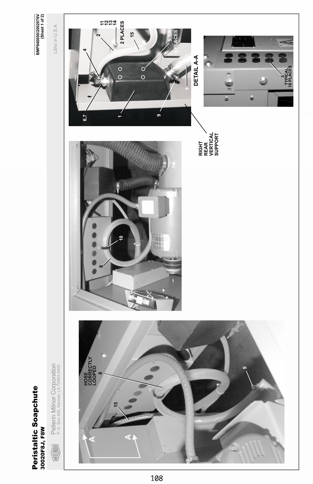
R
Pe
llerin
Miln
or
Co
rpo
ratio
nP
elle
rin
Miln
or
Co
rpo
ratio
nP.
O.
Bo
x4
00
,K
en
ne
r,L
A7
00
63
-04
00
Litho
inU
.S.A
.
BM
P940050/2
002076V
(Sh
eet
1o
f2)
Pe
rista
ltic
So
ap
ch
ute
30
02
0F
8J,
F8
W
DE
TA
ILA
-A
6,7
8
91
2
5,5
A
4
2P
LA
CE
S11
12
13
14
4P
LA
CE
S
AA
RIG
HT
RE
AR
VE
RT
ICA
LS
UP
PO
RT
8
HO
SE
CO
RR
EC
TLY
LO
OP
ED 9
3T
YP
ICA
L1
0P
LA
CE
S
10
8
15
15
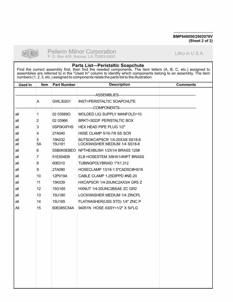
R
Pellerin Milnor CorporationPellerin Milnor CorporationP. O. Box 400, Kenner, LA 70063-0400
Litho in U.S.A.
Item Part Number Description CommentsUsed In
Find the correct assembly first, then find the needed components. The item letters (A, B, C, etc.) assigned toassemblies are referred to in the "Used In" column to identify which components belong to an assembly. The itemnumbers (1, 2, 3, etc.) assigned to components relate the parts list to the illustration.
Parts List—Peristaltic Soapchute
BMP940050/2002076V(Sheet 2 of 2)
.
---------------------------------------------------------------------ASSEMBLIES------------------------------------------------------------------
A GWL30201 INST=PERISTALTIC SOAPCHUTE
-------------------------------------------------------------------COMPONENTS------------------------------------------------------------------
all 1 02 03589O MOLDED LIQ SUPPLY MANFOLD=10
all 2 02 03966 BRKT=3022F PERISTALTIC BOX
all 3 5SP0KXFHS HEX HEAD PIPE PLUG 1/2"
all 4 27A040 H0SE CLAMP 5/16-7/8 SS SCR
all 5 15K032 BUTSOKCAPSCR 1/4-20X3/8 SS18-8all 5A 15U181 LOCKWASHER MEDIUM 1/4 SS18-8
all 6 5SB0K0EBEO NPTHEXBUSH 1/2X1/4 BRASS 125#
all 7 51E504EB ELB HOSESTEM 3/8HX1/4NPT BRASS
all 8 60E010 TUBINGPOLYBRAID 1"X1.312
all 9 27A090 HOSECLAMP 13/16-1.5"CADSC#HS16
all 10 12P019A CABLE CLAMP 1.25DIPPD #NE-20
all 11 15K039 HXCAPSCR 1/4-20UNC2AX3/4 GR5 Z
all 12 15G165 HXNUT 1/4-20UNC2BSAE ZC GR2
all 13 15U180 LOCKWASHER MEDIUM 1/4 ZINCPL
all 14 15U185 FLATWASHER(USS STD) 1/4" ZNC P
All 15 60E085C54A 94051N HOSE ASSY=1/2" X 54"LG
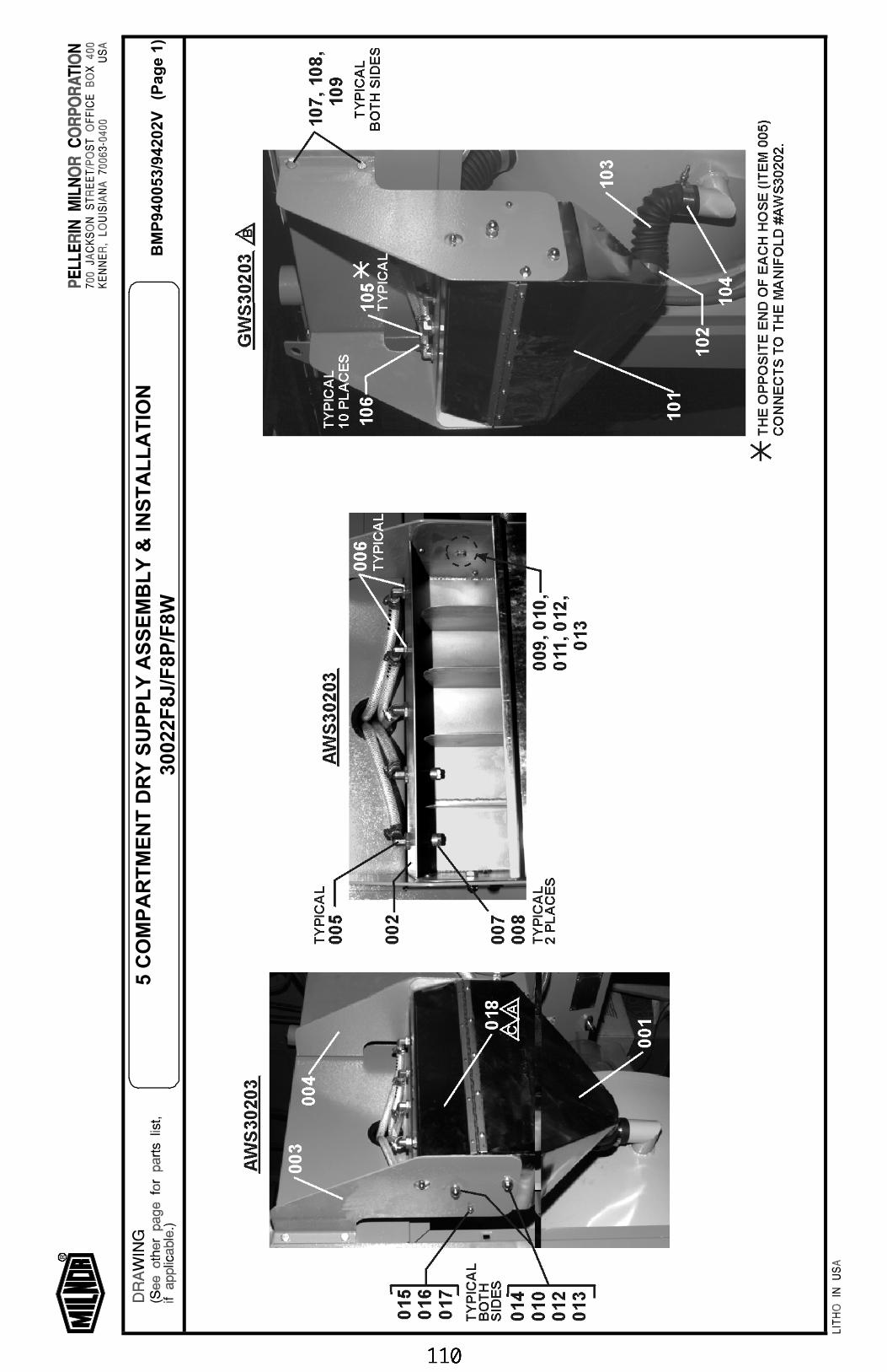
BM
P94
0053
/942
02V
(Pag
e 1)
5 C
OM
PA
RT
ME
NT
DR
Y S
UP
PL
Y A
SS
EM
BL
Y &
INS
TA
LL
AT
ION
3002
2F8J
/F8P
/F8W
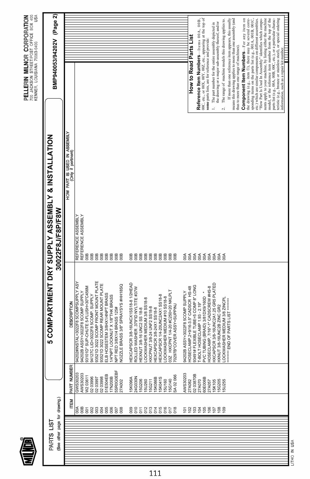
00A
GW
S30203
94202#IN
ST
AL=
3022F
8 5
CO
MP
SU
PP
LY
AS
YR
EF
ER
EN
CE
AS
SE
MB
LY
00B
AW
S30203
94202B
AS
SY
=3022F
8 5
CO
MP
SU
PP
LY
RE
FE
RE
NC
E A
SS
EM
BLY
001
W2 0
3611
93101D
* S
UP
-CH
UT
E 5
-FLU
SH
=30"C
456M
00B
002
02 0
3996
94127C
LID
=3022F
8 5
CO
MP
. S
UP
PLY
00B
003
02 0
3997
93521D
3022 5
CO
MP
FR
ON
T M
OU
NT
PLA
TE
00B
004
02 0
3998
93521D
3022 5
CO
MP
RE
AR
MO
UN
T P
LA
TE
00B
005
51E
504E
BE
LB
HO
SE
ST
EM
3/8
HX
1/4
NP
T B
RA
SS
00B
006
17N
200B
1/4
"NP
T L
OC
KN
UT
X 1
/8"T
HK
BR
AS
S00B
007
5S
R0G
0E
BF
NP
T R
ED
3/8
X1/4
BR
AS
S 1
25#
00B
008
27A
002
NO
ZZ
LE
BR
AS
S 3
/8"
SP
RA
YS
YS
#H
H18S
Q00B
009
15K
096A
HE
XC
AP
SC
R 3
/8-1
6U
NC
X1S
S18-8
1/2
HE
AD
00B
010
24G
030N
RO
LLE
D W
AS
HE
R .379"I
D N
YLT
ITE
#37W
00B
011
15G
206
HE
XN
UT
3/8
-16 U
NC
2 S
S 1
8-8
00B
012
15U
260
LO
CK
WA
SH
ER
ME
DIU
M 3
/8 S
S18-8
00B
013
15G
211
HX
CP
NU
T 3
/8-2
4 U
NF
2 S
S18-8
00B
014
15K
086B
HE
XC
AP
SC
R 3
/8-2
4X
1 S
S18-8
00B
015
15K
041S
HE
XC
AP
SC
R 1
/4-2
0U
NC
2A
X1 S
S18-8
00B
016
15U
160
LO
CK
WA
SH
ER
ME
DIU
M #
10 S
S18-8
00B
017
15G
140
03Z
H
XC
PN
T 1
/4-2
0 #
C250=
20 N
KLP
LT
00B
018
SA
02 0
66
70297B
*CO
VE
R A
SS
Y=
SU
PP
INJ
00B
101
AW
S30203
94202B
AS
SY
=3022F
8 5
CO
MP
SU
PP
LY
00A
102
27A
082
HO
SE
CLA
MP
,2+
9/1
6-3
.5"
CA
DS
CR
H
S-4
800A
103
02 0
3870B
93491# F
LE
XIB
LE
TU
BE
=5 C
OM
P 8
" LO
NG
00A
104
27A
070
T-B
OLT
HO
SE
CLA
MP
1.9
3 -
2.1
9"
00A
105
60E
006B
PV
C T
UB
ING
(B
RA
ID)
3/8
1D
X9/1
60D
*
00A
106
27A
057
HO
SE
CLA
MP
, 7/1
6"-
1"
CA
DS
CR
EW
#H
S-8
00A
107
15K
105
HX
CA
PS
CR
3/8
-16U
NC
2A
1.2
5 G
R5 P
LA
TE
D00A
108
15G
205
HX
NU
T 3
/8-1
6U
NC
2B
ZIN
C G
R2
00A
109
15U
255
LO
CK
WA
SH
ER
ME
DIU
M 3
/8 Z
INC
PL
00A
****
****
EN
D O
F P
AR
TS
LIS
T *
****
***
Ho
w t
o R
ead
Par
ts L
ist
Re
fere
nc
e It
em
Nu
mb
ers
—It
em
s 0
0A
, 0
0B
,00
C,
etc.
, or
00X
, 00
Y,
00Z
, et
c.,
appe
arin
g at
the
top
of
some
part
s li
sts,
are
for
ref
eren
ce a
nd p
rovi
de:
1.T
he p
art n
umbe
r fo
r th
e en
tire
ass
embl
y de
pict
ed in
the
draw
ing
or a
maj
or s
ub-a
ssem
bly
ther
eof,
and
/or
2.T
he r
ange
of
mac
hine
mod
els
this
dra
win
g ap
plie
s to
.
If m
ore
than
one
ref
eren
ce it
em a
ppea
rs, t
his
usua
lly
mea
ns th
is d
raw
ing
appl
ies
to m
ore
than
one
ass
embl
y (a
ndth
us to
mor
e th
an o
ne r
ange
of
mac
hine
s).
Co
mp
on
ent
Item
Nu
mb
ers —
Fo
r an
y i
tem
on
the
draw
ing
(e.g
., it
em ➀
), t
here
may
be
seve
ral
corr
e-sp
ondi
ng i
tem
s on
the
par
ts l
ist
(e.g
., 00
1A,
001B
, 00
1C,
etc.
) w
hich
are
sim
ilar
com
pone
nts
on d
iffe
rent
ass
embl
ies.
“How
Par
t Is
Use
d In
Ass
embl
y” i
dent
ifie
s w
hich
com
po-
nent
s ap
ply
to y
our
mac
hine
, by
list
ing
eith
er t
he m
achi
nem
odel
, or
the
ref
eren
ce i
tem
num
ber
from
the
top
of
the
part
s li
st (
e.g.
, 00A
, 00B
, 00C
, etc
.), o
r a
part
icul
ar c
hara
c-te
rist
ic (
e.g.
, br
onze
or
stai
nles
s st
eel)
, or
spe
cial
ord
erin
gin
form
atio
n, s
uch
as a
rep
air
kit n
umbe
r.
BM
P94
0053
/942
02V
(Pag
e 2)
5 C
OM
PA
RT
ME
NT
DR
Y S
UP
PL
Y A
SS
EM
BL
Y &
INS
TA
LL
AT
ION
3002
2F8J
/F8P
/F8W
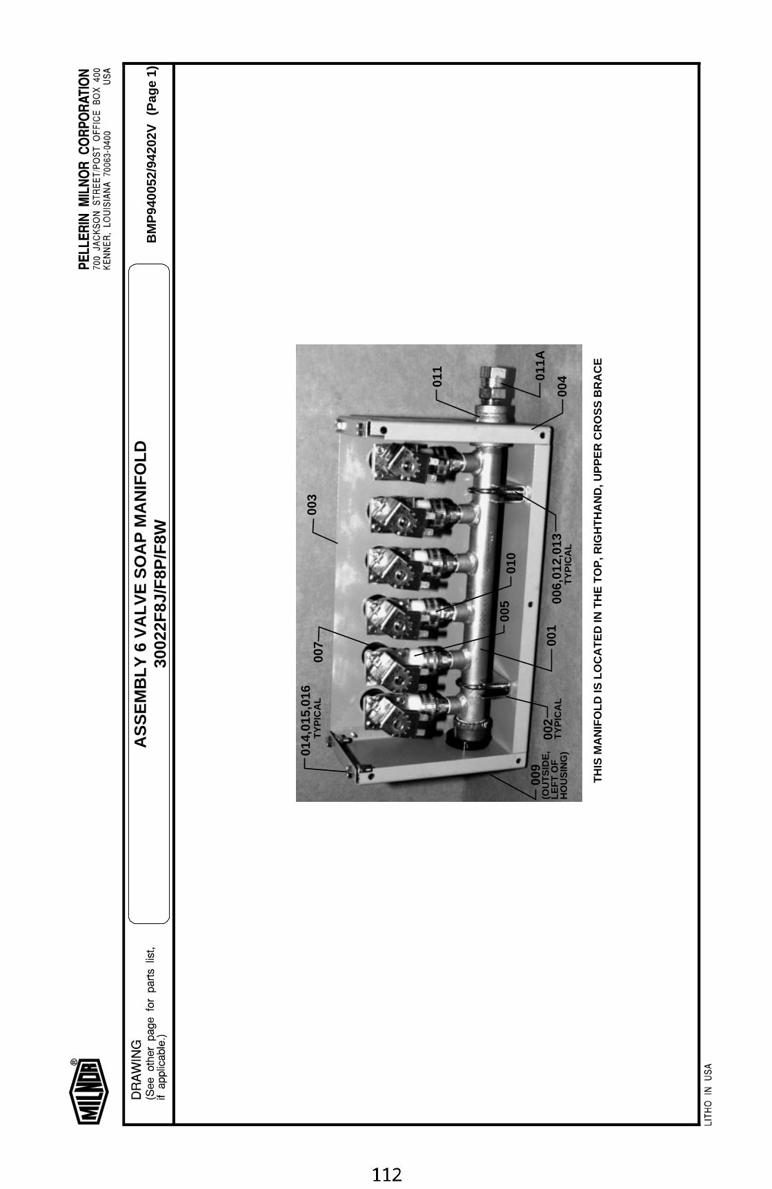
TH
IS M
AN
IFO
LD IS
LO
CA
TE
D IN
TH
E T
OP
, RIG
HT
HA
ND
, UP
PE
R C
RO
SS
BR
AC
E
014,
015,
016
TY
PIC
AL
011
001
002
TY
PIC
AL
003
004
005
007
009
010
006,
012,
013
TY
PIC
AL
(OU
TS
IDE
,LE
FT
OF
HO
US
ING
)
011A
BM
P94
0052
/942
02V
(Pag
e 1)
AS
SE
MB
LY 6
VA
LVE
SO
AP
MA
NIF
OLD
3002
2F8J
/F8P
/F8W
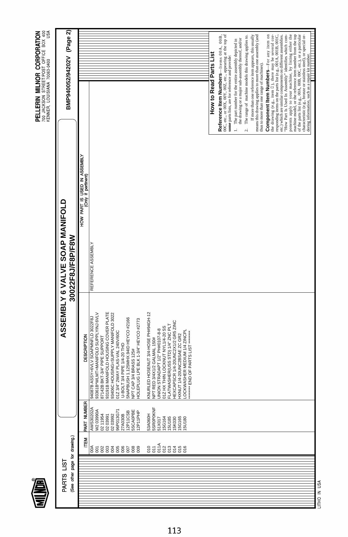
00A
AW
S30
202A
9408
7B A
SS
Y=
6VLV
SO
AP
MN
FLD
302
2F8J
RE
FE
RE
NC
E A
SS
EM
BLY
001
W2
0399
0A93
361B
*WLM
T=
MA
NIF
OLD
SU
PP
LYIN
J 6V
LV00
202
119
5487
142B
BK
T-3
/4"
PIP
E S
UP
PO
RT
003
02 0
3991
9319
1B M
AN
IFO
LD H
OU
SIN
G C
OV
ER
PLA
TE
004
02 0
3992
9340
6C H
OU
SIN
G=
SU
PP
LY M
AN
IFO
LD 3
022
005
96P
013G
7101
Z 3
/4"
2WA
Y P
LAS
-VA
L 24
0V/6
0C00
627
A03
0B U
-BO
LT 3
/4 P
IPE
1/4
-20
TH
D00
712
P11
CS
BS
NA
PB
US
H 1
.125
MH
X.9
4ID
HE
YC
O #
2166
008
5SC
A0P
BE
NP
T C
AP
3/4
BR
AS
S 1
25#
009
12P
11P
HP
HO
LEP
LUG
LP
E B
LK 1
-3/4
" H
EY
CO
#27
73
010
53A
060H
KN
UR
LED
HO
SE
NU
T 3
/4-H
OS
E P
H#9
4GH
-12
011
5SR
0P0K
NF
NP
T R
ED
3/4
X1/
2 G
ALM
AL
150#
011A
51X
017
UN
ION
ST
RA
DA
PT
1/2
" P
H#0
107-
8-8
012
15G
164
01Z
HX
TH
IN L
OC
KN
UT
NY
L1/4
-20
SS
013
15U
185
FLA
TW
AS
HE
R(U
SS
ST
D)
1/4"
ZN
C P
LT01
415
K03
0H
EX
CA
PS
CR
1/4
-20U
NC
2X1/
2 G
R5
ZIN
C01
515
G16
5H
XN
UT
1/4
-20U
NC
2BS
AE
ZC
GR
201
615
U18
0LO
CK
WA
SH
ER
ME
DIU
M 1
/4 Z
INC
PL
****
****
EN
D O
F P
AR
TS
LIS
T *
****
***
How
to R
ead
Par
ts L
ist
Ref
eren
ce It
em N
umbe
rs—
Ite
ms
00
A,
00
B,
00C
, et
c.,
or 0
0X,
00Y
, 00
Z,
etc.
, ap
pear
ing
at t
he t
op o
fso
me p
arts
list
s, a
re fo
r re
fere
nce
and
prov
ide:
1.T
he p
art n
umbe
r fo
r th
e en
tire
asse
mbl
y de
pict
ed in
the
draw
ing
or a
maj
or s
ub-a
ssem
bly
ther
eof,
and/
or
2.T
he r
ang
e of
m
ach
ine
mo
dels
this
dra
win
g a
pp
lies
to.
If m
ore
than
one
ref
eren
ce it
em a
ppea
rs, t
his
usua
llym
eans
this
dra
win
g ap
plie
s to
mor
e th
an o
ne a
ssem
bly
(and
thus
to m
ore
than
one
ran
ge o
f mac
hine
s).
Com
pone
nt It
em N
umbe
rs—
Fo
r a
ny
ite
m o
nth
e d
raw
ing
(e
.g.,
ite
m
➀),
th
ere
ma
y b
e s
eve
ral
cor-
resp
ondi
ng it
ems
on th
e pa
rts
list (
e.g.
, 001
A, 0
01B
, 001
C,
etc.
) w
hich
are
sim
ilar
com
pone
nts
on d
iffer
ent a
ssem
blie
s.“H
ow
Pa
rt I
s U
sed
In
Ass
emb
ly”
iden
tifie
s w
hic
h c
om
-p
on
en
ts a
pp
ly t
o y
ou
r m
ac
hin
e,
by
listi
ng
eit
he
r th
em
achi
ne m
odel
, or
the
ref
eren
ce it
em n
umbe
r fr
om t
he t
opof
the
par
ts li
st (
e.g.
, 00
A,
00B
, 00
C,
etc.
), o
r a
part
icul
arch
arac
teris
tic (
e.g.
, bro
nze
or s
tain
less
ste
el),
or
spec
ial o
r-de
ring
info
rmat
ion,
suc
h as
a r
epai
r ki
t num
ber.
BM
P94
0052
/942
02V
(Pag
e 2)
AS
SE
MB
LY 6
VA
LVE
SO
AP
MA
NIF
OLD
3002
2F8J
/F8P
/F8W
Related Documents