∗ The photo does not show an actual use example. DIN rail A variety of options VQ1000 (VV5Q11) VQ2000 (VV5Q21) VQ0000 (VV5Q05) Locking type (Manual) Regulator unit Elbow fitting assembly (Top entry connector) Individual EXH spacer Individual SUP spacer Port plug Dual flow fitting Locking type manual override Ejector unit Built-in silencer, direct exhaust Blanking plate assembly Elbow fitting assembly (Bottom entry connector) Innovative mounting methods The non-bias, one-clamp structure permits easy valve replacement. (Plug-in unit) Built-in One-touch fittings for easy piping. Space-saving ·········· 45% less Capacity-saving ······ 50% less Unprecedented high speed response and long service life (Metal seal, single, with indicator light/surge voltage suppressor) VQ0000 VQ1000 VQ2000 10 ms 10 ms 20 ms 200 million cycles Dispersion accuracy ±2 ms A variety of common wiring methods are standardized. kit (D-sub connector) Number of pins: 15, 25 Top entry Side entry Top entry Top entry Side entry Side entry kit (Flat ribbon cable connector) Number of pins: 10, 16, 20, 26 kit (Flat ribbon cable connector) Number of pins: 20 (PC Wiring System compliant) kit (Flat ribbon cable with terminal block) kit (Terminal box) kit (Lead wire) kit (Serial transmission unit) kit (Multi-connector kit) (VQ2000 only) Number of pins: 20 F P J G T L S M Thin compact design with large flow capacity Model Manifold pitch (mm) Flow characteristics Metal seal Rubber seal Cylinder size VQ0000 VQ1000 VQ2000 10.7 10.5 16 0.44 0.72 2.6 0.53 1.0 3.2 Up to ø40 Up to ø50 Up to ø80 C [dm 3 /(s·bar)] C [dm 3 /(s·bar)] ∗ Flow characteristics: 4/2 5/3 (A/B R1/R2) Space-saving profile All pilot valves are compactly mounted on one side. The space-saving design of mounting all fittings on one side permits mounting in three directions. Base Mounted Metal Seal/Rubber Seal Series VQ 2-4-113 VQC SQ VQ0 VQ4 VQ5 VQZ VQD

Welcome message from author
This document is posted to help you gain knowledge. Please leave a comment to let me know what you think about it! Share it to your friends and learn new things together.
Transcript
∗ The photo does not show an actual use example.
DIN rail
A variety of options
VQ1000(VV5Q11)
VQ2000(VV5Q21)
VQ0000(VV5Q05)
Locking type (Manual)
Regulator unit
Elbow fitting assembly(Top entry connector)
Individual EXH spacer
Individual SUP spacer
Port plugDual flow fitting
Locking typemanual override Ejector unitBuilt-in silencer,
direct exhaustBlankingplate assembly
Elbow fitting assembly(Bottom entry connector)
Innovativemounting methodsThe non-bias, one-clamp structurepermits easy valve replacement. (Plug-in unit)
Built-in One-touchfittings for easy piping.
Space-saving ·········· 45% less
Capacity-saving ······ 50% less
Unprecedented high speed response and long service life(Metal seal, single, with indicator light/surge voltage suppressor)
VQ0000
VQ1000
VQ2000
10 ms
10 ms
20 ms
200 million cycles
Dispersion accuracy ±2 ms
A variety of common wiring methods are standardized.
kit(D-sub connector)Number of pins: 15, 25
Top entry Side entry Top entry Top entrySide entry Side entry
kit(Flat ribbon cable connector)Number of pins: 10, 16, 20, 26
kit(Flat ribbon cable connector)Number of pins: 20(PC Wiring System compliant)
kit(Flat ribbon cable with terminal block)
kit(Terminal box)
kit(Lead wire)
kit(Serial transmission unit)
kit(Multi-connector kit)
(VQ2000 only)
Number of pins: 20
F P J
G T L S M
Thin compact designwith large flow capacity
ModelManifold
pitch(mm)
Flow characteristics
Metal seal Rubber seal Cylindersize
VQ0000
VQ1000
VQ2000
10.7
10.5
16
0.44
0.72
2.6
0.53
1.0
3.2
Up to ø40
Up to ø50
Up to ø80
C [dm3/(s·bar)] C [dm3/(s·bar)]
∗ Flow characteristics: 4/2 5/3 (A/B R1/R2)
Space-saving profileAll pilot valves are compactly mounted on one side.The space-saving design of mounting all fittings on one side permits mounting in three directions.
Base MountedMetal Seal/Rubber Seal
Series VQ
2-4-113
VQC
SQ
VQ0
VQ4
VQ5
VQZ
VQD

Bas
e M
ou
nte
d
Plu
g le
adP
lug
-in
Met
al s
eal
Sin
gle
Dou
ble
Clo
sed
cent
er
Exh
aust
cen
ter
Pre
ssur
e ce
nter
Plu
g-in
Gro
mm
et
L pl
ug c
onne
ctor
M p
lug
conn
ecto
r
Pus
h ty
pe, T
ool r
equi
red
Lock
ing
type
Lock
ing
type
(M
anua
l)
P. 2-4-128
P. 2-4-186
Sonic conductance Type of actuation Voltage Electrical entry Manual override
VQ00 0.72
1.0
2.6
3.2
0.44
0.53
0.72
1.0
0.72
0.65
2.0
2.2
0.32
0.44
0.72
0.65
Ru
bb
er s
eal
VQ101
Met
al s
eal
VQ200
Ru
bb
er s
eal
VQ201
Met
al s
eal
VQ050
Ru
bb
er s
eal
VQ051
Met
al s
eal
VQ110
Ru
bb
er s
eal
VQ111
12 V24 VDC
100 V110 VAC
200 V220 VAC
50/60Hz
50/60Hz
SeriesVQ1000
SeriesVQ2000
SeriesVQ0000
SeriesVQ1000
P. 2-4-120
P. 2-4-124
P. 2-4-182
P. 2-4-184
Valve Specifications
P. 2-4-186
P. 2-4-128
4/2 5/3(A/B R1/R2)
C [dm3/(s·bar)]
Dou
ble
Sin
gle
3 po
sitio
nC
lose
d ce
nter
(F/L
kit
only
)(F
/L k
it on
ly)
2-4-114

Plug for cylinder port
Regulator unit
Silencer for EXH port
Two stations matchingfittings for double flow rate
Elbow fitting for cylinder port
One-touch fittingInch size
DIN rail mounting style
Built-in silencer
Back pressure check valve
Name plate
Negative common specifications
Flat ribbon cable 10P 16P 20P
External pilot
D-sub connector 15P
SUP/EXH passage spacer
Individual SUP/EXH
Blanking plate
For special wiring spec.
Ejector unit mounted
Double check block
P. 2-4-215
Man
ifold
Op
tion
Op
tion
P. 2-4-177
P. 2-4-166
P. 2-4-177
P. 2-4-215
P. 2-4-210
P. 2-4-172
P. 2-4-208
Except L kitExcept L kit Except L kit
For S, G kit, please contact SMC.
Except L kit
For S kit, please contact SMC. For S kit, please contact SMC. For S, G kit, please contact SMC.
Standard
2-4-115
VQC
SQVQ
0
VQ4
VQ
5
VQZ
VQD

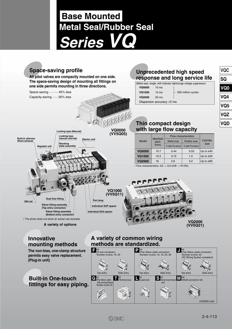
Manifold Variations
F
P. XXX
D-sub connectorConforming to MIL D-sub connector
Flat ribbon cable with power supply
terminal block
kit
Gkit
SeriesVQ1000
SeriesVQ2000
SeriesVQ0000
SeriesVQ1000
Plu
g-i
nP
lug
Lea
d
Conforming to MIL flat ribbon cable connector
Conforming to MIL flat ribbon cable connectorPC Wiring System compatible
Conforming to MIL flat ribbon cable connectorApplicable to OMRON’s serial transmission unitPC Wiring System compatible
P/J kit
P/J kit
P kit only
P kit only
Flat ribbon cable connector
(26, 20, 16, 10 pins)
Flat ribbon cableconnector (20 pins)
Pkit
Jkit
Series VQ/Base Mounted: Variations
P. 2-4-130
P. 2-4-130
P. 2-4-188
P. 2-4-188 P. 2-4-192
P. 2-4-192
P. 2-4-134 P. 2-4-142
P. 2-4-134 P. 2-4-142
2-4-116
Manifold Variations
L
L
C
C
Lead wire Direct electrical entry type
Serial transmission unit Circular connectorEnables single-wire solenoid
valve-PLC operationIP65 (Dusttight/Low jetproof type)
kit
kit
kit
kit
Terminal block box(Terminal block)
Terminal blocks are compactly arranged on one side.
Tkit
L Ckit
Skit
Mkit
Terminal block box
EnclosureIP65 compliant
Terminal block
Terminal block
EnclosureIP65 compliant W type only
EnclosureIP65 compliant
P. 2-4-146
P. 2-4-146 P. 2-4-150 P. 2-4-154
P. 2-4-196 P. 2-4-200 P. 2-4-204
P. 2-4-196 P. 2-4-200 P. 2-4-204
P. 2-4-158
P. 2-4-150 P. 2-4-154
2-4-117
VQC
SQ
VQ0
VQ4
VQ5
VQZ
VQD

2-4-118

AS3001F-06
Cylinder Speed Chart
Series
Port size: One-touch fitting for ø4
VQ0151
VQ1101
VQ2101
Average speed(mm/s)
800700600500400300200100
0
800700600500400300200100
0
800700600500400300200100
0
Bore size
Series CJ2Pressure 0.5 MPaLoad factor 50%Stroke 60 mm
Series CM2Pressure 0.5 MPaLoad factor 50%Stroke 300 mm
Series MB, CA1Pressure 0.5 MPaLoad factor 50%Stroke 500 mm
ø6 ø10 ø16 ø20 ø25 ø32 ø40 ø40 ø50 ø63 ø80 ø100
Series Conditions
VQ0151
VQ1101
VQ2101
Tube bore x LengthSpeed controllerSilencerTube bore x LengthSpeed controllerSilencerTube bore x LengthSpeed controllerSilencer
Series CJ2 Series CM2 Series MB, CA1
T0425 x 1 mAS2001F-04AN103-X233
AN103-X233
AN200-KM8
T0604 x 1 m
T0806 x 1 mAS3001F-08
Conditions
Perpendicular, upward actuationHorizontal actuation
Port size: One-touch fitting for ø6
Port size: One-touch fitting for ø8
Use as a guide for selection.Please confirm the actual conditions withSMC Sizing Program.
∗ It is when the cylinder is extending that is meter-out controlled by speed controller which is directly connected with cylinder, and its needle valve with being fully open.
∗ The average velocity of the cylinder is what the stroke is divided by the total stroke time.∗ Load factor: ((Load weight x 9.8)/Theoretical force) x 100%
2-4-119
VQC
SQ
VQ0
VQ4
VQ5
VQZ
VQD
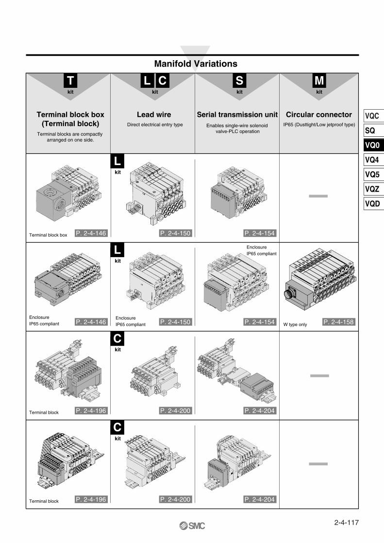
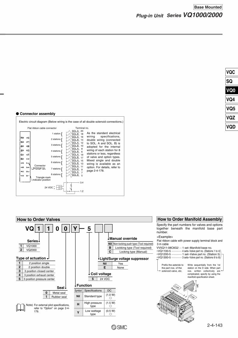
How to Order Manifold
Option
ManifoldPlug-in unit
VV5Q 1 1 08 C6
1 station
··· ···
01
1
VQ10001
Stations
OptionNone
200/220 VAC models (Applicable to F and L kits) With back pressure check valve (2)
DIN rail mounting1 set of regulator unit (3)
2 sets of regulator unit (3)
3 sets of regulator unit (3)
With vacuum ejector unit (4)
Special wiring specifications (Not double wiring) (5)
With name plateExternal pilot (6)
Built-in silencer, direct exhaust
SymbolNil2BD
G1G2G3JKNRS
With One-touch fitting for ø3.2 With One-touch fitting for ø4 With One-touch fitting for ø6
M5 thread With mixed size/with port plug (1)
W/ elbow One-touch fitting ø3.2 for top pipingW/ elbow One-touch fitting ø4 for top piping
Symbol Port size Symbol Port sizeC3C4C6M5CML3L4
L6L5B3B4B6B5LM
Cylinder port
Series
W/ elbow One-touch fitting ø6 for top pipingElbow M5 thread for top piping
W/ elbow One-touch fitting ø3.2 for bottom pipingW/ elbow One-touch fitting ø4 for bottom pipingW/ elbow One-touch fitting ø6 for bottom piping
Elbow M5 thread for bottom pipingMixed size for elbow piping
When two or more symbols are specified, indicate them alphabetically. Example) -BRSModels with a suffix “-B“ have check valves for prevention of back pressure at all manifold stations. If not all stations need this check valve, specify the stations where check valves are installed by using the manifold specification sheet.Specify the mounting position in the manifold specification sheet.Refer to page 2-4-170 for the details of ejector mounted styles. A combination of “J“ and “N“ is unavailable.Specify the wiring by means of the manifold specification sheet. (Except L kit)Indicate “R“ for the valve with external pilot.
Note 1) Specify “Mixed size/with port plug” in the manifold specification sheet.Note 2) Inch-size One-touch fittings are also available. For details, refer to page 2-4-179.Note 3) M5 fittings for M5 thread are attached without being incorporated.
U0U1U2U3
FF
S0S1S2S3
With cable (1.5 m)With cable (3 m)With cable (5 m)
2 to 24stations
Without cable
Connector entry direction
Top entry Side entry
kit(D-sub connector)
Kit Kit
F
U0U1U2U3
U0U1U2U3
S0S1S2S3
S0S1S2S3
U0U1U2U3
U0U1U2U3
P JJP
S0S1S2S3
S0S1S2S3
With cable (1.5 m)With cable (3 m)With cable (5 m)
With cable (1.5 m)With cable (3 m)With cable (5 m)
2 to 24stations
2 to 16stations
Without cable Without cable
Connector entry direction Connector entry direction
Top entry Top entrySide entry Side entry
kit(Flat ribbon cable connector)
kit(Flat ribbon cable connector (20P))
Kit KitKit Kit
P J Kit(Flat ribbon cable connector with power supply terminal block)
G
G
With cable (1.5 m)With cable (3 m)With cable (5 m)
2 to 16stations
Without cableKit
U0U1U2U3
Kit/Electrical entry/Cable length
Note 1) Besides the above, F and P kits with different number of pins are available. Refer to page 2-4-177 for details.Note 2) For details, refer to page 2-4-178.
U1F
The maximum and minimum number of stations are varied depending on kit.(Refer to the table below.)
Note 1)
Note 2)
Note 3)
Note 4)
Note 5)
Note 6)
Simple specials are available with SMC Simple Specials System. For details about applicable models, please contact SMC.
The valve is equipped with Compatible only with 24 VDC valves.
(2) (2)(2)(2)
25PNote 1) Note 1)
Note 1)26P26P
Top entry Top entry Top entry
Side entry Side entry Side entry
Order separatelySI unit made byOMRON Corp.
Series VQ1000Base Mounted
Plug-in Unit
For details about certified products conforming to international standards, visit us at www.smcworld.com.
P. 2-4-130 P. 2-4-134 P. 2-4-138 P. 2-4-142
2-4-120
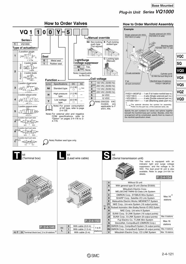
How to Order Valves How to Order Manifold Assembly
Light/Surge voltage suppressor
VQ 1 51 0 0 Y
VQ10001
Series
Metal sealRubber seal
Seal01
Specifications
Standard type
High pressuretype
Low wattagetype
Function
Manual override
Symbol
Nil
H
Y
DC AC 100 VAC (50/60 Hz)200 VAC (50/60 Hz)110 VAC (50/60 Hz)220 VAC (50/60 Hz)
24 VDC12 VDC
Coil voltage
Example
123456
YesNone
NilE
Non-lockingpush type(Tool required)
B:
C:
1 set (F kit 9 station manifold base no.)4 sets (Single solenoid part no.)4 sets (Double solenoid part no.)1 set (Blanking plate part no.)
VV5Q11-09C6FU2 ····∗VQ1100-5 ··········∗VQ1200-5 ··········∗VV1000-10A-1 ······
(1.0 W) Note)
(1.5 W)
(0.5 W)
kit(Terminal box)
Kit T O Terminal block box 2 to 24 stations (2)
T kit(Lead wire cable)
KitL
012
With cable (0.6 m)With cable (1.5 m)With cable (3 m)
1 to 8 stations
L kit(Serial transmission unit)S
Kit
S
0A
B
CDEF1GHJ1J2KQR1R2V
(2)Max.16 stations
Max.16 stations
Max. 8 stations
Max. 16 stations
Max. 8 stations
Type of actuation
1
2
3
4
5
2 position single
2 position double
2 position double
3 position closed center
3 position exhaust center
3 position pressure center
Met
alR
ubbe
r
For external pilot and negative COM specifications, refer to “Option” on pages 2-4-178 to 2-4-179.
4 position dual 3 port valve(A)
4 position dual 3 port valve(B)
4 position dual 3 port valve(C)
A
B
C
15 3
4 2
N.C N.C
15 3
4 2
N.O N.O
15 3
4 2
N.C N.O
Note) Rubber seal type only.
—
—
For power consumption of AC type, refer to page 2-4-129.
Note)
Note)
Note)
Note)
Nil: Push-locking slotted type
Locking type (Manual)
200/220 VAC models are applicable to F and L kits.
Note)
Note)
The asterisk denotes the symbol for assembly. Prefix it to the part nos. of the solenoid valve, etc.
Specify the part numbers for valves and options together beneath the manifold base part number. Besides, when the arrangement will be complicated, specify them by means of the manifold specification sheet.
Without SI unit With general type SI unit (Series EX300)
Mitsubishi Electric Corp.: MELSECNET/MINI-S3 Data Link System
OMRON Corp.: SYSBUS Wire System SHARP Corp.: Satellite I/O Link System
Matsushita Electric Works: MEWNET-F System NKE Corp.: Uni-wire System (16 output points)
Rockwell Automation: Allen Bradley Remote I/O (RIO) SystemNKE Corp.: Uni-wire H System
SUNX Corp.: S-LINK System (16 output points)SUNX Corp.: S-LINK System (8 output points)
Fuji Electric Co.: T-LINK Mini SystemDeviceNet, CompoBus/D (OMRON Corp.)
OMRON Corp.: CompoBus/S System (16 output points)OMRON Corp.: CompoBus/S System (8 output points)
Mitsubishi Electric Corp.: CC-LINK System
The valve is equipped with an indicator light and surge voltage suppressor, and the voltage is 24 VDC. The dust proof SI unit is also available. Refer to page 2-4-154 for details.
Note)
Note)
Note)
Inapplicable to the S kit.
Note)
Manifold base (9 stations)VV5Q11-09C6FU2
Cylinder portsC6: With One-touch fitting for ø6
F kit(D-sub connector)
D-sub connector
Blanking plateVQ1000-10A-1 (1 set)
Double solenoid (24 VDC)VQ1200-5 (4 sets)
Single solenoid (24 VDC)VQ1100-5 (4 sets)
D side
U side
1 2 3 ·······
··· Stations
P. 2-4-154
P. 2-4-146
P. 2-4-150
2-4-121
Series VQ1000Plug-in Unit
Base Mounted
VQC
SQ
VQ0
VQ4
VQ5
VQZ
VQD
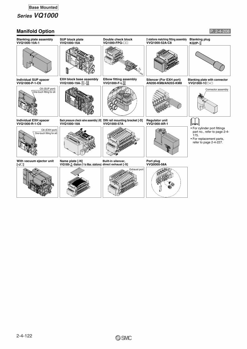
Manifold Option
VVQ1000-10A-1Blanking plate assembly
VVQ1000-16ASUP block plate
VQ1000-FPG-Double check block
VVQ1000-52A-C82 stations matching fitting assembly
KQ2P- Blanking plug
VVQ1000-P-1-C6Individual SUP spacer
VVQ1000-19A- -FPL
C3C4C6M5
C3C4C6M5
23040608
EXH block base assemblyVVQ1000-F-LElbow fitting assembly
AN200-KM8/AN203-KM8Silencer (For EXH port)
VVQ1000-1C-Blanking plate with connector
VVQ1000-R-1-C6Individual EXH spacer
VVQ1000-18ABack pressure check valve assembly [-B]
VVQ1000-57ADIN rail mounting bracket [-D]
VVQ1000-AR-1Regulator unit
[-J] With vacuum ejector unit
VVQ1000- -Station (1 to Max. stations)Name plate [-N] Built-in silencer,
direct exhaust [-S] VVQ0000-58APort plug
NNC
• For cylinder port fittings part no., refer to page 2-4-175.
• For replacement parts, refer to page 2-4-227.
ToCYL port
C6 (SUP port)One-touch fitting for ø6
Connector assembly
Exhaust port
C6 (EXH port)One-touch fitting for ø6
P. 2-4-208
2-4-122
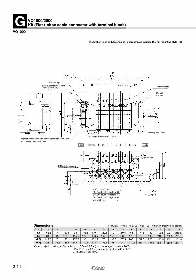
Series VQ1000Base Mounted

2-4-123

How to Order ManifoldOption
Kit type
OptionSymbolNone
Back pressure check valve (2) DIN rail mounting style
Special wiring specifications (Except double wiring) (3)
With name plateExternal pilot (4)
Built-in silencer, direct exhaust
NilBDKNRSW
ManifoldPlug-in unit
VV5Q 2 1 U1F08 C6
1 station
··· ···
01
1VQ20002
StationsSymbol Port size Symbol Port sizeC4C6C8CML4L6
L8B4B6B8LM
Cylinder port
Series
Note 1)
Note 2)
With One-touch fitting for ø4With One-touch fitting for ø6 With One-touch fitting for ø8 With mixed size/with port plug (1)
W/ elbow One-touch fitting ø8 for top pipingW/ elbow One-touch fitting ø4 for bottom pipingW/ elbow One-touch fitting ø6 for bottom pipingW/ elbow One-touch fitting ø8 for bottom piping
Mixed size for elbow piping
Note 1)
Note 2)
Note 3)
Note 4)
U0U1U2U3
FF
S0S1S2S3
With cable (1.5 m)With cable (3 m)With cable (5 m)
2 to 24
stations
Without cable
Connector entry direction
Top entry Side entry
Kit/Electrical entry/Cable length
kit(D-sub connector)
Kit Kit
F
U0U1U2U3
U0U1U2U3
S0S1S2S3
S0S1S2S3
U0U1U2U3
U0U1U2U3
P JJP
S0S1S2S3
S0S1S2S3
With cable (1.5 m)With cable (3 m)With cable (5 m)
With cable (1.5 m)With cable (3 m)With cable (5 m)
2 to24
stations
2 to16
stations
Without cable Without cable
Connector entry direction Connector entry direction
Top entry Top entrySide entry Side entry
kit(Flat ribbon cable connector)
kit(Flat ribbon cable connector (20P))
Kit KitKit Kit
P J kit(Flat ribbon cable connector with power supply terminal block)
G
G
With cable (1.5 m)With cable (3 m)With cable (5 m)
2 to 16stations
Without cableKit
U0U1U2U3
Simple specials are available with SMC Simple Specials System. For details about applicable models, Contact SMC.
Enclosure: Dust tight/splashproof type (IP65) [T, L, S and M kits only]When two or more symbols are specified, indicate them alphabetically. Example) -DNR.Models with a suffix “-B” have check valves for prevention of back pressure at all manifold stations. If not all stations need this check valve, specify the stations where check valves are installed by manifold specification sheet.Specify the wiring specifications in the manifold specification sheet. (Except L kit)Indicate “R” for the valve with external pilot.
The maximum and minimum number of stations are varied depending on kit.(Refer to the table below.)
W/ elbow One-touch fitting ø4 for top piping
W/ elbow One-touch fitting ø4 for top piping
Compatible onlywith 24 VDC valves.
Series VQ2000Base Mounted
Plug-in Unit
Specify “Mixed size/with port plug” on the manifold specification sheet.Inch-size One-touch fittings are available. For details, refer to page 2-4-179.
Side entrySide entry
Top entryTop entryTop entry
25PNote 1)
26PNote 1)
26PNote 1)
(2) (2) (2) (2)
For details about certified products conforming to international standards, visit us at www.smcworld.com.
P. 2-4-130 P. 2-4-134 P. 2-4-138 P. 2-4-142
2-4-124

How to Order Valves
Light/Surge voltage suppressor
VQ 2 51 0 0 Y
Inapplicable to the S kit.
123456
YesNone
NilE
EnclosureDust-protected
Dusttight/Low jetproof type (IP65)NilW
VV5Q21-08C8FU2 ···∗VQ2100-5 ·········∗VQ2200-5 ·········∗VVQ2000-10A-1 ··
1 set (F kit 8 station manifold base no.)3 sets (Single solenoid part no.)4 sets (Double solenoid part no.)1 set (Blanking plate part no.)
VQ20002
Series
Note)
100 VAC (50/60 Hz)200 VAC (50/60 Hz)110 VAC (50/60 Hz)220 VAC (50/60 Hz)
24 VDC12 VDC
Coil voltage
Manual overrideNil: B:
C:
How to Order Manifold Assembly
Example
Specifications
Standardtype
High pressure type
Low wattagetype
FunctionSymbol
Nil
H
Y
DC AC
(1.0 W)
(1.5 W)
(0.5 W)
SealMetal seal
Rubber seal01
Type of actuation
1
2
3
4
5
2 position double
2 position double
3 position closed center
3 position pressure center
Met
alR
ubbe
r
4 position dual 3 port valve(A)
4 position dual 3 port valve(B)
4 position dual 3 port valve(C)
A
B
C
15 3
4 2
N.C N.C
15 3
4 2
N.O N.O
15 3
4 2
N.C N.O
Note)
Note)
Note)
Rubber seal type only.
Note)Note)
Note)
Non-lockingpush type(tool required)
Push-locking slotted type
Locking type (Manual)
Note ) For sub-plate single unit type, refer to page 2-4-165.
For power consumption of AC type, refer to page 2-4-129.For external pilot and negative COM specifications, refer to “Option” on page 2-4-178 to 2-4-179.
Note)
Note)
200/220 VAC models are applicable to F and L kits.
—
—
The asterisk denotes the symbol for assembly. Prefix it to the part nos. of the solenoid valve, etc.
Specify the part numbers for valves and options together beneath the manifold base part number. Besides, when the arrangement will be complicated, specify them by means of the manifold specification sheet.
2 position single
Note)
Note)
Note)
Double solenoid (24 VDC)VQ2200-5 (4 sets)
Single solenoid (24 VDC)VQ2100-5 (3 sets)
Blanking plateVQ2000-10A-1 (1 set)
D-sub connectorAXT100-DS25-030
Cylinder portsC8: With One-touch
fitting for ø8
F kit(D-sub connector)
Manifold base (8 stations)VV5Q21-08C8FU2
1 2 3 ·······
Stations
D side
U side
3 position exhaust center
M
With cable (1.5 m)With cable (3 m)With cable (5 m)
2 to 24 stations
Without cableKit
0123
kit(Terminal box)
Kit T
Dust tight/Low jetproof type(IP65) available
Dust tight/Low jetproof type(IP65) available
OTerminalblock box
2 to 20stations (2)
T kit(Lead wire cable)
KitL
012
With cable (0.6 m)With cable (1.5 m)With cable (3 m)
1 to 8 stations
L kit(Serial transmission unit)
kit(Multi-connector)S M(4)
Note 1)Note 2)Note 3)Note 4)
Besides the above, F and P kits with different number of pins are available. Refer to page 2-4-177 for details.For details, refer to page 2-4-178.Refer to the pages on respective kits for IP65 type. (T, L and S kits)Kits with IP65 enclosure applicable to input/output are also available. Refer to page 2-4-162 for details.
The valve is equipped with an indicator light and surge voltage suppressor, and the voltage is 24 VDC. The dusttight SI unit is available. Refer to page 2-4-154 for details. Dusttight/splashproof type (IP65) is also available. (Except SE and SG.)
(2)
Dust tight/Low jetproof typeMax.16 stations(IP65) only available
Kit
S
OA
B
BB
CDEF1GHJ1J2KQR1R2V
Max.16 stations
(2)
(2)
Max.16 stations
Max.16 stations
Max. 16 stations
Max. 8 stations
Max. 8 stations
(4)
Without SI unit With general type SI unit (Series EX300)
Mitsubishi Electric Corp.: MELSECNET/MINI-S3 Data Link System
Mitsubishi Electric Corp.: MELSECNET/MINI-S3 Data Link System(2 power supply lines)
OMRON Corp.: SYSBUS Wire System SHARP Corp.: Satellite I/O Link System
Matsushita Electric Works: MEWNET-F System NKE Corp.: Uni-wire System (16 output points)Rockwell Automation: Allen Bradley Remote I/O (RIO) System
NKE Corp.: Uni-wire H System SUNX Corp.: S-LINK System (16 output points)SUNX Corp.: S-LINK System (8 output points)
Fuji Electric Co.: T-LINK Mini SystemDeviceNet, CompoBus/D (OMRON Corp.)
OMRON Corp.: CompoBus/S System (16 output points)OMRON Corp.: CompoBus/S System (8 output points)Mitsubishi Electric Corp.: CC-LINK System
P. 2-4-146P. 2-4-150
P. 2-4-154
P. 2-4-162
2-4-125
Series VQ2000Plug-in Unit
Base Mounted
VQC
SQ
VQ0
VQ4
VQ5
VQZ
VQD

2-4-126
Series VQ2000Base Mounted
Manifold Option
VVQ2000-10A-1Blanking plate assembly
VVQ2000-16ASUP block plate
VVQ2000-57ADIN rail mounting bracket [-D]
VVQ1000-58APort plug
VVQ2000-P-1-C8Individual SUP spacer
VVQ2000-19AEXH block plate Built-in silencer,
direct exhaust [-S] KQ2P- Blanking plug
VVQ2000-R-1-C8Individual EXH spacer
VVQ2000-N-Station (1 to Max. stations)Name plate [-N]
AN200-KM10Silencer (For EXH port)
VVQ2000-18ABack pressure check valve assembly [-B]
VVQ2000-F-L (C4, C6, C8)Elbow fitting assembly 2 stations matching fitting assembly
VVQ2000-52A-C10
04060810
Double check blockVQ2000-FPG-
• For cylinder port fittings part no., refer to page 2-4-175.
• For replacement parts, refer to page 2-4-227.
Exhaust port
To CYL port
C8 (EXH port)One-touch fitting for ø8
C8 (SUP port)One-touch fitting for ø8
P. 2-4-210

2-4-127
VQC
SQ
VQ0
VQ4
VQ5
VQZ
VQD
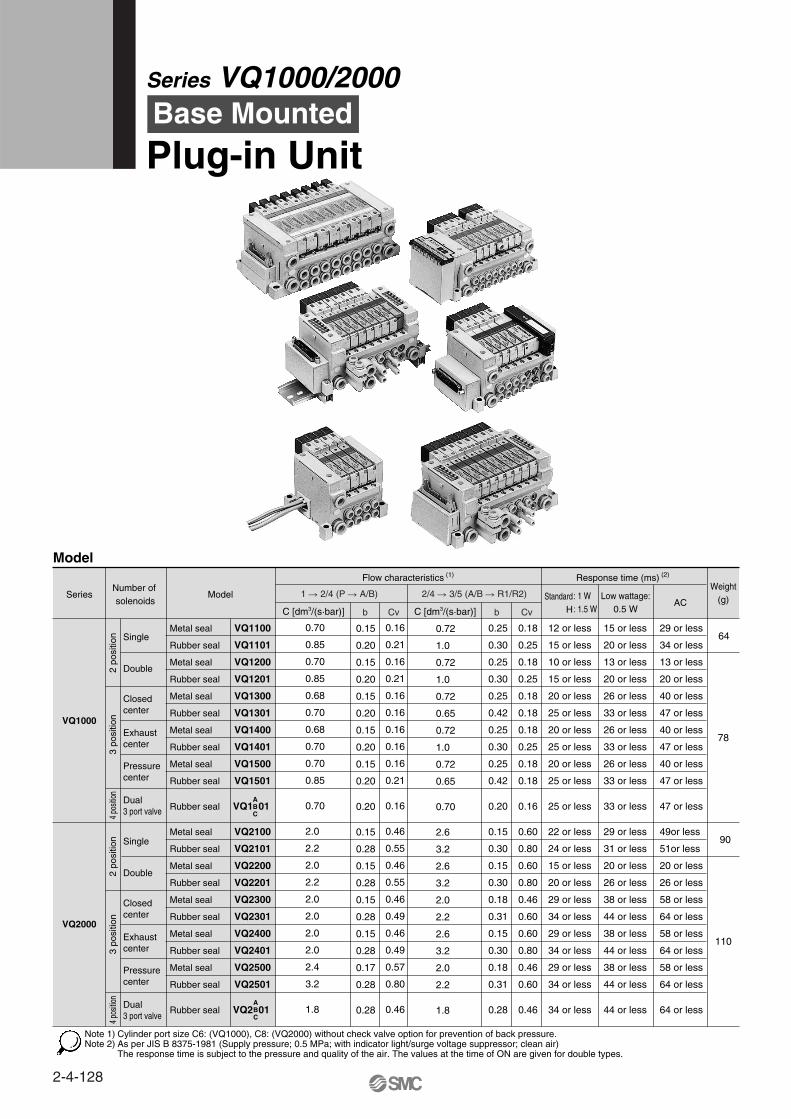
Model
Series ModelNumber of solenoids
Flow characteristics (1)
2 po
sitio
n3
posi
tion
4 po
sition
4 po
sition
3 po
sitio
n
Single
Double
Metal seal
Rubber seal
Metal seal
Rubber seal
Metal seal
Rubber seal
Metal seal
Rubber seal
Metal seal
Rubber seal
Rubber seal
Metal seal
Rubber seal
Metal seal
Rubber seal
Metal seal
Rubber seal
Metal seal
Rubber seal
Metal seal
Rubber seal
Rubber seal
Response time (ms) (2)
StandardH
: 1 W: 1.5 W
12 or less
15 or less
10 or less
15 or less
20 or less
25 or less
20 or less
25 or less
20 or less
25 or less
25 or less
22 or less
24 or less
15 or less
20 or less
29 or less
34 or less
29 or less
34 or less
29 or less
34 or less
34 or less
0.18
0.25
0.18
0.25
0.18
0.18
0.18
0.25
0.18
0.18
0.16
0.60
0.80
0.60
0.80
0.46
0.60
0.60
0.80
0.46
0.60
0.46
0.25
0.30
0.25
0.30
0.25
0.42
0.25
0.30
0.25
0.42
0.20
0.15
0.30
0.15
0.30
0.18
0.31
0.15
0.30
0.18
0.31
0.28
0.72
1.0
0.72
1.0
0.72
0.65
0.72
1.0
0.72
0.65
0.70
2.6
3.2
2.6
3.2
2.0
2.2
2.6
3.2
2.0
2.2
1.8
0.16
0.21
0.16
0.21
0.16
0.16
0.16
0.16
0.16
0.21
0.16
0.46
0.55
0.46
0.55
0.46
0.49
0.46
0.49
0.57
0.80
0.46
0.15
0.20
0.15
0.20
0.15
0.20
0.15
0.20
0.15
0.20
0.20
0.15
0.28
0.15
0.28
0.15
0.28
0.15
0.28
0.17
0.28
0.28
0.70
0.85
0.70
0.85
0.68
0.70
0.68
0.70
0.70
0.85
0.70
2.0
2.2
2.0
2.2
2.0
2.0
2.0
2.0
2.4
3.2
1.8
Low wattage:0.5 W
15 or less
20 or less
13 or less
20 or less
26 or less
33 or less
26 or less
33 or less
26 or less
33 or less
33 or less
29 or less
31 or less
20 or less
26 or less
38 or less
44 or less
38 or less
44 or less
38 or less
44 or less
44 or less
29 or less
34 or less
13 or less
20 or less
40 or less
47 or less
40 or less
47 or less
40 or less
47 or less
47 or less
49or less
51or less
20 or less
26 or less
58 or less
64 or less
58 or less
64 or less
58 or less
64 or less
64 or less
Weight(g)
64
90
VQ1100
VQ1101
VQ1200
VQ1201
VQ1300
VQ1301
VQ1400
VQ1401
VQ1500
VQ1501
VQ1 01
VQ2100
VQ2101
VQ2200
VQ2201
VQ2300
VQ2301
VQ2400
VQ2401
VQ2500
VQ2501
VQ2 01
Closed center
Exhaust center
Pressure center
Dual3 port valve
Single
Double
Closed center
Exhaust center
Pressure center
VQ1000
VQ2000
C [dm3/(s·bar)] C [dm3/(s·bar)]
1 2/4 (P A/B) 2/4 3/5 (A/B R1/R2)
b Cv b CvAC
ABC
2 po
sitio
n
Dual3 port valve
ABC
Cylinder port size C6: (VQ1000), C8: (VQ2000) without check valve option for prevention of back pressure.As per JIS B 8375-1981 (Supply pressure; 0.5 MPa; with indicator light/surge voltage suppressor; clean air)The response time is subject to the pressure and quality of the air. The values at the time of ON are given for double types.
Note 1)Note 2)
Series VQ1000/2000Base Mounted
Plug-in Unit
78
110
2-4-128

F, P kits2 to 24 stations
J, G, S kit2 to 16 stations
L kit1 to 8 stations
T kit2 to 20 stations
F, P, T kits2 to 24 stations
J, G, S kit2 to 16 stations
L kit1 to 8 stations
2 position double
3 position closed center
3 position exhaust center
3 position pressure center
Met
alR
ubbe
r
2 position double
Not required
Push type/Locking type (Tool required, Manual type) Option
150/30 m/s2
Dust-protected, Dust tight/Low jetproof type (IP65) (5)
12 , 24 VDC, 100, 110, 200, 220 VAC (50/60 Hz)
±10% of rated voltage
Class B or equivalent
1 W DC (42 mA), 1.5 W DC (63 mA) (3), 0.5 W DC (21 mA) (4)
1 W DC (83 mA), 1.5 W DC (125 mA) (3), 0.5 W DC (42 mA) (4)
Inrush 1.2 VA (12 mA), Holding 1.2 VA (12 mA)
Inrush 1.3 VA (12 mA), Holding 1.3 VA (12 mA)
Inrush 2.4 VA (12 mA), Holding 2.4 VA (12 mA)
Inrush 2.6 VA (12 mA), Holding 2.6 VA (12 mA)
Standard SpecificationsValve construction
Fluid
Maximum operating pressure
Minimum operating pressure
Ambient and fluid temperature
Lubrication
Manual override
Impact/Vibration resistance
Enclosure
Coil rated voltage
Allowable voltage fluctuation
Coil insulation type
Metal seal
Air/Inert gas
Rubber seal
Air/Inert gas
0.7 MPa (High pressure type: 0.8 MPa)
24 VDC
12 VDC
100 VAC
110 VAC
200 VAC
220 VAC
Single
Double
3 position
0.1 MPa
0.1 MPa
0.1 MPa
–10 to 50°C (1)
0.15 MPa
0.1 MPa
0.2 MPa
(2)
Power consumption(Current)
Sol
enoi
dV
alve
spe
cific
atio
ns
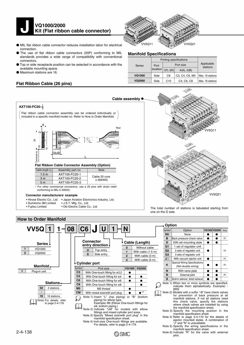
Manifold Specifications
Series Base model
VQ1000 VV5Q11-
VQ2000 VV5Q21-
Type of connection
Porting specifications
Applicable stations
Applicable solenoid valve
5 station weight
(g)Port location
Side
Port size
1(P), 3(R)
C8 (ø8)
OptionBuilt-in
silencer, direct exhaust
4(A), 2(B)
C3 (ø3.2)
C4(ø4)
C6 (ø6)
M5 (M5 thread)
628(Single)
759(Double,
3 position)
VQ100
VQ101
(2)(1)
Side
C10 (ø10)
Option Built-in
silencer,direct exhaust
C4 (ø4)
C6 (ø6)
C8 (ø8)
1051(Single)
1144(Double,
3 position)
VQ200
VQ201
Use dry air to prevent condensation when operating at low temperatures.Impact resistance ··· No malfunction occurred when it is tested with a drop tester in the axial direction
and at the right angles to the main valve and armature in both energized and de-energized states every once for each condition. (Values at the initial period)
Vibration resistance ··· No malfunction occurred in a one-sweep test between 45 and 2000 Hz. Test was performed at both energized and de-energized states in the axial direction and at the right angles to the main valve and armature. (Values at the initial period)
Value for high voltage type (1.5 W)Value for low voltage type (0.5 W)Dusttight/Low jetproof type (IP65) is available on T, L, S and M kits of VQ2000.
Note 1)Note 2)
Note 3)Note 4)Note 5)
F kit–D-sub connector
P kit–Flat ribbon cable connector
J kit–Flat ribbon cable connector (20P)
G kit–
T kit–Terminal box
L kit–Lead wire cable
S kit–Serial transmission unit
M kit–Multi-connector
F kit–D-sub connector
P kit–Flat ribbon cable connector
J kit–Flat ribbon cable connector (20P)
G kit–
T kit–Terminal box
L kit–Lead wire cable
S kit–Serial transmission unit
Flat ribbon cable connector with terminal block
Flat ribbon cable connector with terminal block
Note 1)Note 2)
Inch-size One-touch fittings are also available. For details, refer to page 2-4-179.For details, refer to page 2-4-178.
JIS Symbol2 position single
Type of connection
Type of connection
R port
R port
P port P port
A, B portA, B port
2-4-129
Series VQ1000/2000Plug-in Unit
Base Mounted
VQC
SQ
VQ0
VQ4
VQ5
VQZ
VQD

D-sub Connector (25 pins)
D-sub Connector Cable Assembly (Option)Electric Characteristics
Terminal no. Lead wire color Dot marking123456789
10111213141516171819202122232425
NoneNoneNoneNoneNoneNoneNoneWhiteBlackBlackRed Red Red BlackBlackWhiteNoneNoneBlackWhiteWhiteRed Red WhiteNone
BlackBrownRed
OrangeYellowPinkBlue
PurpleGrayWhiteWhiteYellowOrangeYellowPinkBlue
PurpleGray
OrangeRed
BrownPinkGrayBlackWhite
ItemNoteAssembly part no.
AXT100-DS25-015AXT100-DS25-030AXT100-DS25-050
1.5 m3 m5 m
Cablelength (L)
Cable 25 corex 24AWG
Conductor resistance
Ω/km, 20°CVoltage limitV, 1 min, AC
Insulation resistance
MΩkm, 20°C
Characteristics65 or less
1000
5 or more
Note) Types with 15 pin are also available. Refer to page 2-4-177 for details.
Connector manufacturers’ example• Fujitsu Limited• Japan Aviation Electronics Industry, Ltd.• J.S.T. Mfg. Co., Ltd.• Hirose Electric Co., Ltd.
How to Order Manifold
2 stations
24 stations
02
24
ManifoldPlug-in unit1
VQ1000VQ2000
12
Without cable
With cable (1.5 m)
With cable (3 m)
With cable (5 m)
0123
Top entrySide entry
US
Option
Connector entry direction
Port size
With One-touch fitting for ø3.2
With One-touch fitting for ø4
With One-touch fitting for ø6
With One-touch fitting for ø8
M5 thread
With mixed size/with port plug
VQ1000
VQ2000
SymbolC3C4C6C8M5CM
Cylinder port
Cable (Length)
Series
Stations
Cable Assembly
VV5Q 1 08 C6 U 11 NF
··· ···
Manifold Specifications
Applicable stations
Port sizePort locaition
Side
Side
Porting specifications
Max. 24 stations
Max. 24 stations
C3, C4, C6, M5
C4, C6, C8
VV5Q11 VV5Q21
C8
C10
4(A), 2(B)1(P), 3(R)
Series
VQ1000
VQ2000
Symbol
Nil
B
D
G1
G2
G3
K
N
R
S
OptionNone
With back pressure check valveDIN rail mounting style1 set of regulator unit2 sets of regulator unit3 sets of regulator unit
With vacuum ejector unitSpecial wiring specifications
(Not double wiring)With name plate
External pilotBuilt-in silencer, direct exhaust
Note
(2)
VQ1000
VQ2000
Note 1)
Note 2)
Note 3)
Note 4)
Note 5)
Note 6)
Note 1)
Note 2)
Note 3)
Note 4)
AXT100-DS25-015030050
1644
L
8
14 25
1 13
47.04
55 2-M2.6 x 0.45
Socket side
Terminal no.
ø10
Multi-core vinyl cable0.3 mm2 x 25C
J
The D-sub connector reduces installation labor for electrical connections.
Using the D-sub connector (25P), (15P as an option) conforming to MIL standard permits the use of connectors put on the market and gives a wide interchangeability.
Top or side receptacle position can be selected in accordance with the available mounting space.
Maximum stations are 24.
The D-sub connector cable assembly can be ordered individually or included in a specific manifold model no. Refer to How to Order Manifold.
∗ For other commercial connectors, use a 25 pins type with female connector conforming to MIL-C-24308.
Wire Color by Terminal No. ofD-sub Connector Cable Assembly
The min. bending radius of D-sub cable assembly is 20 mm.
Note)
When two or more symbols are specified, indicate them alphabetically. Example) -BRSModels with a suffix “-B” have check valves for prevention of back pressure at all manifold stations. If not all stations need this check valve, specify the stations where check valves are installed by using the manifold specification sheet.Specify the mounting position in the manifold specification sheet.Refer to page 2-4-170 for the details of ejector mounted styles. A combination of “J” and “N” is unavailable.Specify the wiring by using of the manifold specification sheet. Indicate “R” for the valve with external pilot.
Insert “L” (top piping) or “B” (bottom piping) for elbow type. Example) B6 (Elbow One-touch fittings for ø6, bottom piping.)Indicate “LM” for models with elbow fittings and mixed cylinder port sizes.Specify “Mixed size/with port plug” in the manifold specification sheet.Inch-size One-touch fittings are available. For details, refer to page 2-4-179.
VQ1000/2000Kit (D-sub connector)
~=
Note) For details, refer to page 2-4-178.
(3)
(3)
(4)
(5)
(6)
F
2-4-130

How to Order Valves
Metal seal
Rubber seal
01
Type of actuation2 position single
2 position double
3 position closed center
3 position exhaust center
3 position pressure center
12345
VQ1000VQ2000
12
Series
Seal
VQ 0 51 01 Y
Electrical wiring specifications
SOL.ASOL.BSOL.ASOL.BSOL.ASOL.BSOL.ASOL.BSOL.ASOL.BSOL.ASOL.BSOL.ASOL.BSOL.ASOL.BSOL.ASOL.BSOL.ASOL.BSOL.A
SOL.ASOL.B
SOL.B
COM.
1
14
2
15
3
16
4
17
5
18
6
19
7
20
8
21
9
22
10
23
11
24
12
25
13
(–)
(–)
(–)
(–)
(–)
(–)
(–)
(–)
(–)
(–)
(–)
(–)
(–)
(–)
(–)
(–)
(–)
(–)
(–)
(–)
(–)
(–)
(–)
(–)
(+)
(+)
(+)
(+)
(+)
(+)
(+)
(+)
(+)
(+)
(+)
(+)
(+)
(+)
(+)
(+)
(+)
(+)
(+)
(+)
(+)
(+)
(+)
(+)
(+)
(–)
Black
Yellow
Brown
Pink
Red
Blue
Orange
Purple
Yellow
Gray
Pink
Orange
Blue
Red
Purple
Brown
Gray
Pink
White
Gray
White
Black
Yellow
White
Orange
None
Black
None
Black
None
White
None
None
None
None
None
Black
None
White
White
White
Black
Red
Black
Red
Red
White
Red
None
Red
PolarityTerminal no. Lead wire color
015030050
Dot marking
1 station 2 stations 3 stations 4 stations 5 stations 6 stations 7 stations 8 stations 9 stations
10 stations 11 stations 12 stations
Positive commonspecifications
Negative commonspecifications
Note)
Non-locking push type (Tool required)Locking type (Tool required)
Locking type (Manual)
Manual overrideNilBC
100 VAC (50/60 Hz)200 VAC (50/60 Hz)110 VAC (50/60 Hz)220 VAC (50/60 Hz)
24 VDC12 VDC
Coil voltage123456
Light/Surge voltage suppressorYes
NoneNilE
VV5Q11-09C6FU2 ····*VQ1100-5 ·············*VQ1200-5 ·············*VQ1300-5 ·············*VVQ1000-10A-1 ······
1 set –Manifold base no.2 sets–Valve part no. (Stations 1 to 2)4 sets–Valve part no. (Stations 3 to 6)2 sets–Valve part no. (Stations 7 to 8)1 set–Blanking plate part no. (Station 9)
How to Order Manifold Assembly
<Example>D-sub connector kit with cable (3 m)
Specifications
Standardtype
Highpressure type
Low wattagetype
FunctionSymbol
Nil
H
Y
DC AC
(1.0 W)
(1.5 W)
(0.5 W)
D-sub connector assembly
AXT100-DS25- Wire color
The total number of stations is tabulated starting from station one on the D side.
Note) When using the negative common specifications, use valves for negative common. (Refer to page 2-4-178.)For details, refer to “Option” on page 2-4-178.
As the standard electrical wiring specifications, double wiring (connected to SOL. A and SOL. B) is adopted for the internal wiring of each station for 12 stations or less, regardless of valve and option types. Mixed single and double wiring is available as an option. For details, refer to page 2-4-178.
Specify the part numbers for valves and options together beneath the manifold base part number.
Prefix the asterisk to the part nos. of the solenoid valve, etc.
Write sequentially from the 1st station on the D side.When part nos. written col lect ive ly are complicated, specified by using the manifold specification sheet.
For external pilot and negative COM specifications, refer to “Option” on pages 2-4-178 to 2-4-179.
For power consumption of AC type, refer to page 2-4-129.
—
—
Note)
Note)
Connectorterminal no.
1 2 3 ·······
Stations
D side
U side
1 2 3
·······
····· S
tations
D side
U side
D-sub connector
Note) 1 2 3 ······ S
tations
D side
U side
VV5Q11
VV5Q21
2-4-131
Series VQ1000/2000Plug-in Unit
Base Mounted
VQC
SQ
VQ0
VQ4
VQ5
VQZ
VQD
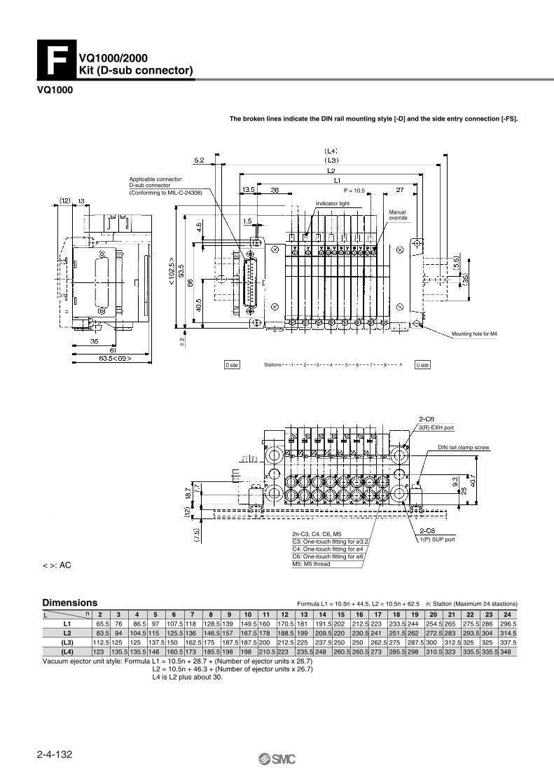
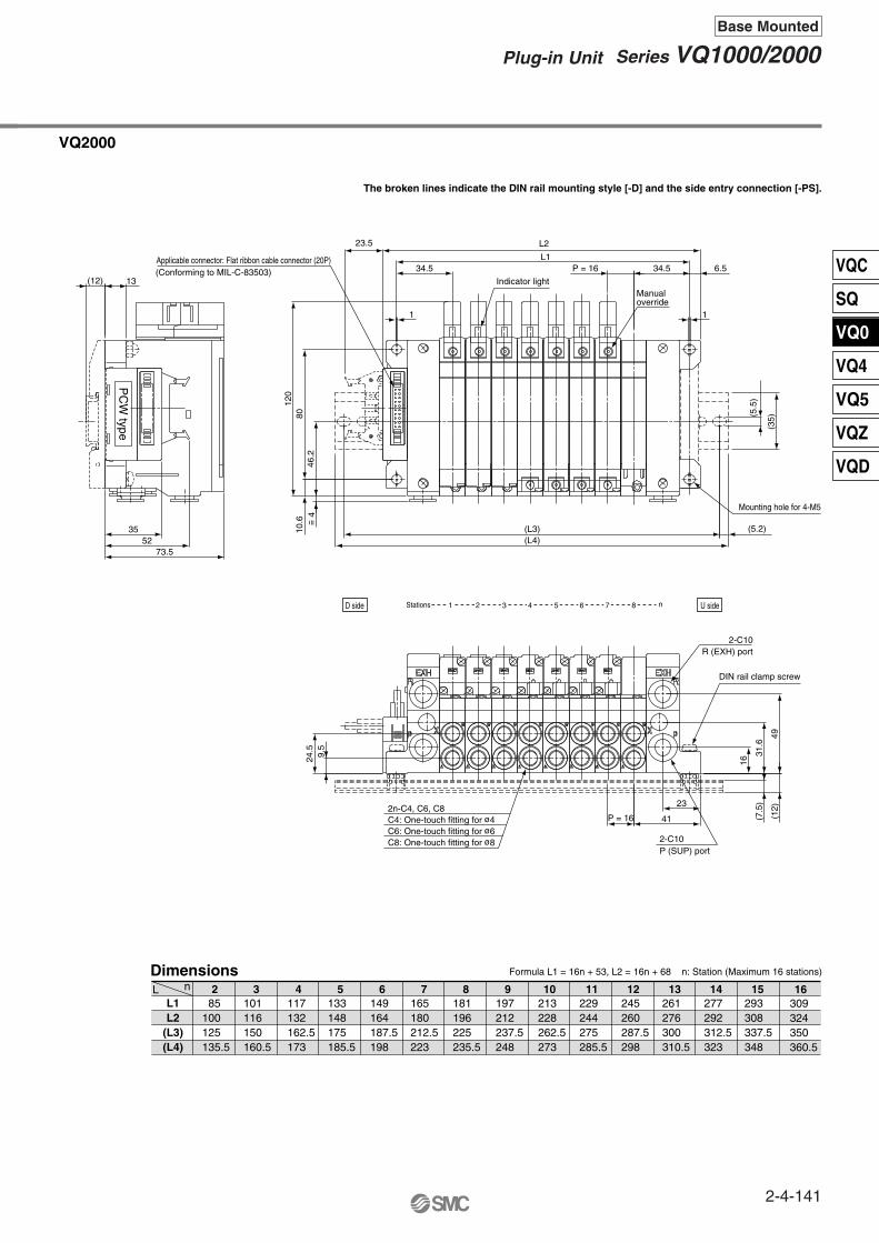
Dimensions
L1L2
(L3)(L4)
< >: AC
2 65.5 83.5112.5123
3 76 94125135.5
4 86.5104.5125135.5
5 97115137.5148
6107.5125.5150160.5
7118136162.5173
8128.5146.5175185.5
9139157187.5198
10149.5167.5187.5198
11160178200210.5
12170.5188.5212.5223
13181199225235.5
14191.5209.5237.5248
15202220250260.5
16212.5230.5250260.5
17223241262.5273
18233.5251.5275285.5
19244262287.5298
20254.5272.5300310.5
21265283312.5323
22275.5293.5325335.5
23286304325335.5
24296.5314.5337.5348
L n
Formula L1 = 10.5n + 44.5, L2 = 10.5n + 62.5 n: Station (Maximum 24 stastions)
Vacuum ejector unit style: Formula L1 = 10.5n + 28.7 + (Number of ejector units x 26.7)L2 = 10.5n + 46.3 + (Number of ejector units x 26.7)L4 is L2 plus about 30.
VQ1000
The broken lines indicate the DIN rail mounting style [-D] and the side entry connection [-FS].
VQ1000/2000Kit (D-sub connector)
Applicable connector: D-sub connector(Conforming to MIL-C-24308)
Indicator light
P = 10.5
Manualoverride
~ =2
Mounting hole for M4
3(R) EXH port
DIN rail clamp screw
F
1(P) SUP port
n21 3 4 5 6 7 8StationsD side U side
< >: AC
2n-C3, C4, C6, M5C3: One-touch fitting for ø3.2C4: One-touch fitting for ø4C6: One-touch fitting for ø6M5: M5 thread
2-4-132
Dimensions
L1L2
(L3)(L4)
2 85105137.5148
3101121150160.5
4117137162.5173
5133153187.5198
6149169200210.5
7165185212.5223
8181201225235.5
9197217250260.5
10213233262.5273
11229249275285.5
12245265300310.5
13261281312.5323
14277297325335.5
15293313337.5348
16309329350360.5
17325345375385.5
18341361387.5398
19357377400410.5
20373393412.5423
21389409437.5448
22405425450460.5
23421441462.5473
24437457487.5498
L n
Formula L1 = 16n + 53, L2 = 16n + 73 n: Station (Maximum 24 stations)
VQ2000
The broken lines indicate the DIN rail mounting style [-D] and the side entry connection [-FS].
< >: AC
Applicable connector: D-sub connector (25P)(Conforming to MIL-C-24308)
Indicator light
Manualoverride
~ =4
P = 16
Mounting hole for 4-M5
3(R) EXH port
DIN rail clamp screw
1(P) SUP port
2n-C4, C6, C8C3: One-touch fitting for ø3.2C4: One-touch fitting for ø4C6: One-touch fitting for ø6C8: One-touch fitting for ø8
n21 3 4 5 6 7 8StationsD side U side
2-4-133
Series VQ1000/2000Plug-in Unit
Base Mounted
VQC
SQ
VQ0
VQ4
VQ5
VQZ
VQD
Flat Ribbon Cable (26 pins)
AXT100-FC26- 1to3
Flat Ribbon Cable Connector Assembly (Option)NoteAssembly part no.Cable length (L)
AXT100-FC26-1AXT100-FC26-2AXT100-FC26-3
1.5 m3 m5 m
Cable 26 core x 28AWG
Connector manufacturers’ example• Hirose Electric Co., Ltd.• Sumitomo 3M Limited • Fujitsu Limited
• Japan Aviation Electronics Industry, Ltd.• J.S.T. Mfg. Co., Ltd.• Oki Electric Cable Co., Ltd.
How to Order Manifold
2 stations
24 stations
02
24
ManifoldPlug-in unit1
VQ1000VQ2000
12
Without cableWith cable (1.5 m)With cable (3 m)With cable (5 m)
0123
Top entrySide entry
US
Connector entry direction
Cable (Length)Series
Stations
Cable assembly
VV5Q 1 08 C6 U 11 NP
··· ···Manifold Specifications
Applicable stations
Port sizePort location
Side
Side
Porting specifications
Max. 24 stations
Max. 24 stations
C3, C4, C6, M5
C4, C6, C8
C8
C10
4(A), 2(B)1(P), 3(R)
Series
VQ1000
VQ2000
VV5Q11 VV5Q21
OptionSymbol Option NoteVQ1000 VQ2000
NilBD
G1G2G3J
NRS
NoneBack pressure check valve DIN rail mounting style1 set of regulator unit2 sets of regulator unit3 sets of regulator unit
With vacuum ejector unit
With name plateExternal pilot
Built-in silencer, direct exhaust
KSpecial Wiring Specifications
(Not double wiring)
(2)
(3)
(4)
(5)
(6)
VQ1000
VQ2000
SymbolC3C4C6C8M5CM
Cylinder portPort size
With One-touch fitting for ø3.2With One-touch fitting for ø4With One-touch fitting for ø6With One-touch fitting for ø8
M5 threadWith mixed size/with port plug (3)
VV5Q11
VV5Q21
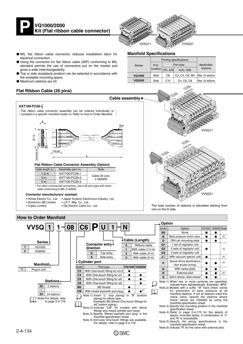
MIL flat ribbon cable connector reduces installation labor for electrical connection.
Using the connector for flat ribbon cable (26P) conforming to MIL standard permits the use of connectors put on the market and gives a wide interchangeability.
Top or side receptacle position can be selected in accordance with the available mounting space.
Maximum stations are 24.
Flat ribbon cable connector assembly can be ordered individually or included in a specific manifold model no. Refer to How to Order Manifold.
Note) For details, referto page 2-4-178.
Note 1) Insert “L” (top piping) or “B” (bottom piping) for elbow type.Example) B6 (Elbow One-touch fittings for ø6, bottom piping.)
Note 2) Indicate “LM” for models with elbow fittings and mixed cylinder port sizes.
Note 3) Specify “Mixed size/with port plug” in the manifold specification sheet.
Note 4) Inch-size One-touch fittings are available. For details, refer to page 2-4-179.
Note 1) When two or more symbols are specified, indicate them alphabetically. Example) -BRS
Note 2) Models with a suffix “-B” have check valves for prevention of back pressure at all manifold stations. If not all stations need this check valve, specify the stations where check valves are installed by using the manifold specification sheet.
Note 3) Specify the mounting position in the manifold specification sheet.
Note 4) Refer to page 2-4-170 for the details of ejector mounted styles. A combination of “J” and “N” is unavailable.
Note 5) Specify the wiring specifications in the manifold specification sheet.
Note 6) Indicate “R” for the valve with external pilot.
∗ For other commercial connectors, use a 26 pins type with strain relief conforming to MIL-C-83503.
The total number of stations is tabulated starting from one on the D side.
P VQ1000/2000Kit (Flat ribbon cable connector)
Red
Term
inal
no.
1 2 3
·······
·········
Stations
D side
U side
1 2 3 ···
···· Stations
D side
U side
2-4-134
How to Order Valves
Metal sealRubber seal
01
Type of actuation2 position single2 position double
3 position closed center3 position exhaust center3 position pressure center
12345
VQ1000VQ2000
12
Series
Seal
VQ 0 51 01 Y
Electrical wiring specifications
SOL.ASOL.BSOL.ASOL.BSOL.ASOL.BSOL.ASOL.BSOL.ASOL.BSOL.ASOL.BSOL.ASOL.BSOL.ASOL.BSOL.ASOL.BSOL.ASOL.BSOL.A
SOL.ASOL.B
SOL.B
COM.
123456789
1011121314151617181920212223242526
(–)
(–)
(–)
(–)
(–)
(–)
(–)
(–)
(–)
(–)
(–)
(–)
(–)
(–)
(–)
(–)
(–)
(–)
(–)
(–)
(–)
(–)
(–)
(–)
(+)
(+)
(+)
(+)
(+)
(+)
(+)
(+)
(+)
(+)
(+)
(+)
(+)
(+)
(+)
(+)
(+)
(+)
(+)
(+)
(+)
(+)
(+)
(+)
(+)
(+)
(–)
(–)
Terminal no. PolarityFlat ribbon cable connector
1 station 2 stations 3 stations 4 stations 5 stations 6 stations 7 stations 8 stations 9 stations
10 stations 11 stations 12 stations
Positivecommon
specifications
Electrical wiring specifications Negative Note)
commonspecifications
Non-locking push type (Tool required)Locking type (Tool required)
Locking type (Manual)
Manual overrideNilBC
100 VAC (50/60 Hz)110 VAC (50/60 Hz)
24 VDC12 VDC
Coil voltage1356
Light/Surge voltage suppressorYes
NoneNilE
COM.
1 set–Manifold base no.2 sets–Valve part no. (Stations 1 to 2)4 sets–Valve part no. (Stations 3 to 6)2 sets–Valve part no. (Stations 7 to 8)1 set–Blanking plate no. (Station 9)
How to Order Manifold Assembly
<Example>Flat ribbon cable kit with 3 m cableVV5Q11-09C6PU2 ···∗VQ1100-5 ············∗VQ1200-5 ············∗VQ1300-5 ············∗VVQ1000-10A-1 ······
Specifications
Standardtype
High pressuretype
Low wattagetype
FunctionSymbol
Nil
H
Y
DC AC
(1.0 W)
(1.5 W)
(0.5 W)
As the standard electrical wiring specifications, double wiring (connected to SOL. A and SOL. B) is adopted for the internal wiring of each station for 12 stations or less, regardless of valve and option types. Mixed single and double wiring is available as an option.For details, refer to page 2-4-178.
When using the negative common specifications, use valves for negative common. (Refer to page 2-4-178.)For details, refer to “Option” on page 2-4-178.
Note) For external pilot and negative COM specifications, refer to “Option” on pages 2-4-178 to 2-4-179.
Note)
—
—
Note) For power consumption of AC type, refer to page 2-4-129.
Specify the part numbers for valves and options together beneath the manifold base part number.
Prefix the asterisk to the part nos. of the solenoid valve, etc.
Write sequentially from the 1st station on the D side. When part nos. written collectively are complicated, specified by using the manifold specification sheet.
Note)
Connectorterminal no.
Triangle markindicator position
1 2 3 ·····
Stations
D side
U side
2-4-135
Series VQ1000/2000Plug-in Unit
Base Mounted
VQC
SQ
VQ0
VQ4
VQ5
VQZ
VQD
Dimensions
L1
L2
(L3)
(L4)
2 65.5 78.5112.5123
3 76 89125135.5
4 86.5 99.5125135.5
5 97110137.5148
6107.5120.5150160.5
7118131162.5173
8128.5141.5175185.5
9139152187.5198
10149.5162.5187.5198
11160173200210.5
12170.5183.5212.5223
13181194225235.5
14191.5204.5225235.5
15202215237.5248
16212.5225.5250260.5
17223236262.5273
18233.5246.5275285.5
19244257287.5298
20254.5267.5287.5298
21265278300310.5
22275.5288.5312.5323
23286299325335.5
24296.5309.5337.5348
L n
VQ1000
The broken lines indicate the DIN rail mounting style [-D] and the side entry connection [-PS].
Formula L1 = 10.5n + 44.5, L2 = 10.5n + 57.5 n: Station (Maximum 24 stations)
Vacuum ejector unit style: Formula L1 = 10.5n + 28.7 + (Number of ejector units x 26.7)L2 = 10.5n + 41.3 + (Number of ejector units x 26.7)L4 is L2 plus about 30.
< >: AC
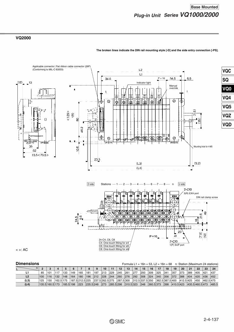
D side U sideStations ···· 1 ···· 2 ···· 3 ···· 4 ···· 5 ····6 ····7 ···· 8 ···· n
VQ1000/2000Kit (Flat ribbon cable connector)P
2n-C3, C4, C6, M5C3: One-touch fitting for ø3.2C4: One-touch fitting for ø4C6: One-touch fitting for ø6M5: M5 thread
Applicable connector: Flat ribbon cable connector (26P)(Conforming to MIL-C-83503)
Indicator lightP = 10.5
Manualoverride
Mounting hole for M4
3(R) EXH port
DIN rail clamp screw
1(P) SUP port
≅2
2-4-136
Dimensions
L1L2
(L3)(L4)
2 85100125135.5
3101116150160.5
4117132162.5173
5133148175185.5
6149164187.5198
7165180212.5223
8181196225235.5
9197212237.5248
10213228262.5273
11229244275285.5
12245260287.5298
13261276300310.5
14277292312.5323
15293308337.5348
16309324350360.5
17325340362.5373
18341356387.5398
19357372400410.5
20373388412.5423
21389404425435.5
22405420450460.5
23421436462.5473
24437452475485.5
L n
VQ2000
The broken lines indicate the DIN rail mounting style [-D] and the side entry connection [-PS].
Formula L1 = 16n + 53, L2 = 16n + 68 n: Station (Maximum 24 stations)
< >: AC
D side U sideStations ···· 1 ····· 2 ····· 3 ····· 4 ····· 5 ····· 6 ·····7 ····· 8 ····· n
2n-C4, C6, C8C4: One-touch fitting for ø4C6: One-touch fitting for ø6C8: One-touch fitting for ø8
Applicable connector: Flat ribbon cable connector (26P)(Conforming to MIL-C-83503)
Indicator light
P = 16
Manualoverride
Mounting hole for 4-M5
3(R) EXH port
DIN rail clamp screw
1(P) SUP port
2-4-137
Series VQ1000/2000Plug-in Unit
Base Mounted
VQC
SQ
VQ0
VQ4
VQ5
VQZ
VQD
Flat Ribbon Cable (26 pins)
AXT100-FC20-
Flat Ribbon Cable Connector Assembly (Option)NoteAssembly part no.Cable length (L)
AXT100-FC20-1AXT100-FC20-2AXT100-FC20-3
1.5 m3 m5 m
Cable 20 core x 28AWG
Connector manufacturers’ example• Hirose Electric Co., Ltd.• Sumitomo 3M Limited • Fujitsu Limited
• Japan Aviation Electronics Industry, Ltd.• J.S.T. Mfg. Co., Ltd.• Oki Electric Cable Co., Ltd.
How to Order Manifold
2 stations
16 stations
02
16
ManifoldPlug-in unit1
VQ1000VQ2000
12
Without cableWith cable (1.5 m)With cable (3 m)With cable (5 m)
0123
Top entrySide entry
US
Connector entry direction
Cable (Length)Series
Stations
Cable assembly
VV5Q 1 08 C6 U 11 NJ
··· ···Manifold Specifications
Applicable stations
Port sizePort location
Side
Side
Porting specifications
Max. 16 stations
Max. 16 stations
C3, C4, C6, M5
C4, C6, C8
C8
C10
4(A), 2(B)1(P), 3(R)
Series
VQ1000
VQ2000
VV5Q11 VV5Q21
OptionSymbol Option NoteVQ1000 VQ2000
NilBD
G1G2G3J
NRS
NoneBack pressure check valve DIN rail mounting style1 set of regulator unit2 sets of regulator unit3 sets of regulator unit
With vacuum ejector unit
With name plateExternal pilot
Built-in silencer, direct exhaust
KSpecial Wiring Specifications
(Not double wiring)
(2)
(3)
(4)
(5)
(6)
VQ1000
VQ2000
SymbolC3C4C6C8M5CM
Cylinder portPort size
With One-touch fitting for ø3.2With One-touch fitting for ø4With One-touch fitting for ø6With One-touch fitting for ø8
M5 threadWith mixed size/with port plug (3)
VV5Q11
VV5Q21
MIL flat ribbon cable connector reduces installation labor for electrical connection.
The use of flat ribbon cable connectors (20P) conforming to MIL standards provides a wide range of compatibility with conventional connectors.
Top or side receptacle position can be selected in accordance with the available mounting space.
Maximum stations are 16.
Flat ribbon cable connector assembly can be ordered individually or included in a specific manifold model no. Refer to How to Order Manifold.
∗ For other commercial connectors, use a 20 pins with strain relief conforming to MIL-C-83503.
The total number of stations is tabulated starting from one on the D side.
Note) For details, refer to page 2-4-178.
Note 1) Insert “L” (top piping) or “B” (bottom piping) for elbow type. Example) B6 (Elbow One-touch fittings for ø6, bottom piping.)
Note 2) Indicate “LM” for models with elbow fittings and mixed cylinder port sizes.
Note 3) Specify “Mixed size/with port plug” in the manifold specification sheet.
Note 4) Inch-size One-touch fittings are available. For details, refer to page 2-4-179.
Note 1) When two or more symbols are specified, indicate them alphabetically. Example) -BRS
Note 2) Models with a suffix “-B” have check valves for prevention of back pressure at all manifold stations. If not all stations need this check valve, specify the stations where check valves are installed by using the manifold specification sheet.
Note 3) Specify the mounting position in the manifold specification sheet.
Note 4) Refer to page 2-4-170 for the details of ejector mounted styles. A combination of “J” and “N” is unavailable.
Note 5) Specify the wiring specifications in the manifold specification sheet.
Note 6) Indicate “R” for the valve with external pilot.
VQ1000/2000Kit (Flat ribbon cable connector)J
1 2 3 ·······
Stations
D side
U side
1 2 3
·······
··········
··· Stations
D side
U side
Red
Term
inal
no.
30
20
19
1to3
2-4-138
How to Order Valves
Metal seal
Rubber seal
01
Type of actuation2 position single
2 position double
3 position closed center
3 position exhaust center
3 position pressure center
12345
VQ1000VQ2000
12
Series
Seal
VQ 11 Y 5
Electrical wiring specifications
Non-locking push type (Tool required)Locking type (Tool required)
Locking type (Manual)
Manual overrideNilBC
24 VDC
Coil voltage5
Light/Surge voltage suppressorYes
NoneNilE
1 set–Manifold base no.2 sets–Valve part no. (Stations 1 to 2)4 sets–Valve part no. (Stations 3 to 6)2 sets–Valve part no. (Stations 7 to 8)1 set–Blanking plate part no. (Station 9)
How to Order Manifold Assembly
<Example>Flat ribbon cable kit with 3 m cableVV5Q11-09C6PU2 ···∗VQ1100-5 ···········∗VQ1200-5 ···········∗VQ1300-5 ···········∗VVQ1000-10A-1 ····
Specifications
Standardtype
High pressuretype
Low wattagetype
FunctionSymbol
Nil
H
Y
DC
(1.0 W)
(1.5 W)
(0.5 W)Note) For external pilot and negative
COM specifications, refer to “Option” on pages 2-4-178 to 2-4-179.
Connector terminal no.
Flat ribbon cable connector
Triangle markindicator position
75312
468
1917151311910
1214161820
2 stations
3 stations
4 stations
1 station
5 stations
6 stations
7 stations
8 stations
Terminal no. Polarity
Positive commonspecifications
COM
SOL.ASOL.B
SOL.ASOL.B
SOL.ASOL.B
SOL.ASOL.B
COM
2018
16141210
86
1917
1513
119
75
43
21
SOL.B
SOL.B
SOL.B
SOL.B
SOL.A
SOL.A
SOL.A
SOL.A
(–)(–)
(+)(+)
(–)(–)
(+)(+)
(–)(–)
(+)(+)
(–)(–)
(+)(+)
(–)(–)
(+)(+)
(–)(–)
(+)(+)
(–)(–)
(+)(+)
(–)(–)
(+)(+)
(+)(+)
(–)(–)
Note)
Note) When using the negative common specifications, use valves for negative common. (Refer to page 2-4-178.)For details, refer to “Option” on page 2-4-178.
As the standard electrical wiring specifications, double wiring (connected to SOL. A and SOL. B) is adopted for the internal wiring of each station for 12 stations or less, regardless of valve and option types. Mixed single and double wiring is available as an option.For details, refer to page 2-4-178.
0 0Specify the part numbers for valves and options together beneath the manifold base part number.
Prefix the asterisk to the part nos. of the solenoid valve, etc.
Negative commonspecifications
When ordering, specify the part nos. in order from the 1st. station in the D side. When part nos. written collectively are complicated, specify by using the manifold specification sheet.
1 2 3 ·······
Stations
D side
U side
2-4-139
Series VQ1000/2000Plug-in Unit
Base Mounted
VQC
SQ
VQ0
VQ4
VQ5
VQZ
VQD
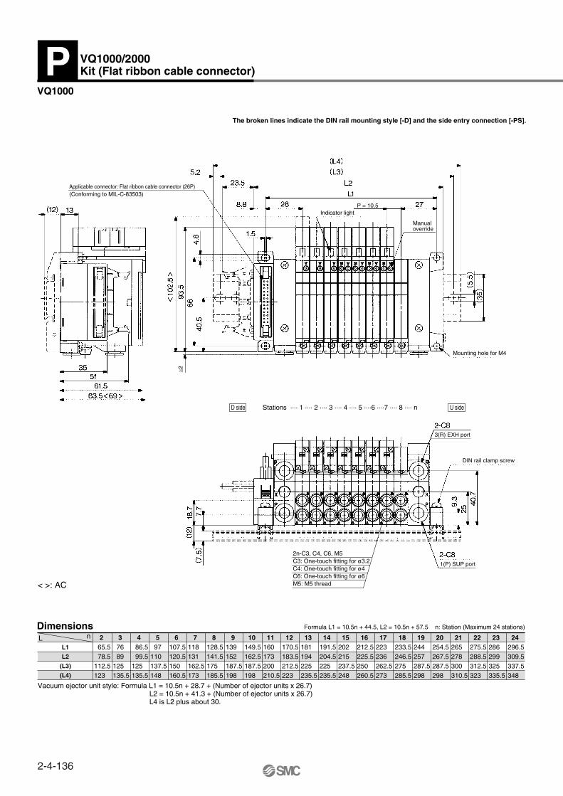
VQ1000
The broken lines indicate the DIN rail mounting style [-D] and the side entry connection [-PS].
Dimensions
L1L2
(L3)(L4)
2 3 4 5 6 7 8 9 10 11 12 13 14 15 16L nFormula L1 = 10.5n + 44.5, L2 = 10.5n + 57.5 n: Station (Maximum 16 stations)
52
(12)
35
63.5
61.5
13
(Conforming to MIL-C-83503)
Applicable connector: Flat ribbon cable connector (20P)
PC
W type
(5.5
)
(35)
40.5
23.5
5.2
(L4)
(L3)
L2
L1
27P = 10.58.8 28
1.5
293
.5
4.8
66
Manual override
Indicator light
R (EXH) port
2-C8
Mounting hole for 4-M4
40.7
25
9.3
DIN rail clamp screw
P (SUP) port2-C8
X
R
P
(12)
(7.5
)
18.7
7.7
C3: One-touch fitting for ø3.2
2n-C3, C4, C6, M5
C6: One-touch fitting for ø6
C4: One-touch fitting for ø4
M5: M5 thread
n21 3 4 5 6 7 8StationsD side U side
X
P
R
212.5225.5250260.5
202215237.5248
191.5204.5225235.5
181194225235.5
170.5183.5212.5223
160173200210.5
149.5162.5187.5198
139152187.5198
128.5141.5175185.5
118131162.5173
107.5120.5150160.5
97110137.5148
86.5 99.5125135.5
76 89125135.5
65.5 78.5112.5123
VQ1000/2000Kit (Flat ribbon cable connector)J
~ =
2-4-140
VQ2000
The broken lines indicate the DIN rail mounting style [-D] and the side entry connection [-PS].
Dimensions
L1L2
(L3)(L4)
2 3 4 5 6 7 8 9 10 11 12 13 14 15 16L nFormula L1 = 16n + 53, L2 = 16n + 68 n: Station (Maximum 16 stations)
(7.5
)
(12)
P = 16 41
23
24.5 9.5
31.6
49
16
P (SUP) port2-C10C8: One-touch fitting for ø8
DIN rail clamp screw
R (EXH) port2-C10
C6: One-touch fitting for ø6 C4: One-touch fitting for ø4 2n-C4, C6, C8
52
(12) 13
73.5
35
PC
W type
(L3)(L4)
23.5
(5.2)
L2
L16.534.5P = 1634.5
1 1
10.6
(35)(5
.5)12
080
446
.2
Indicator lightManualoverride
Mounting hole for 4-M5
(Conforming to MIL-C-83503)Applicable connector: Flat ribbon cable connector (20P)
n21 3 4 5 6 7 8StationsD side U side
309324350360.5
293308337.5348
277292312.5323
261276300310.5
245260287.5298
229244275285.5
213228262.5273
197212237.5248
181196225235.5
85100125135.5
101116150160.5
117132162.5173
133148175185.5
149164187.5198
165180212.5223
~ =
2-4-141
Series VQ1000/2000Plug-in Unit
Base Mounted
VQC
SQ
VQ0
VQ4
VQ5
VQZ
VQD

Flat Ribbon Cable (20 pins)
AXT100-FC20-1to3
NoteAssembly part no.Cable length (L)
1.5 m3 m5 m
Cable 20 core x 28AWG
Connector manufacturers’ example
How to Order Manifold
2 stations
16 stations
02
16
ManifoldPlug-in unit1
VQ1000VQ2000
12
Without cableCable length 1.5 m Cable length 3 mCable length 5 m
0123
For VQ1000For VQ2000
NilU
Connector entry direction, Top entry
Cable (Length)Series
Stations
Cable assembly
VV5Q 1 08 C61 NG
··· ···Manifold Specifications
Applicablestations
Port sizePortlicaition
Side
Side
Porting specifications
Max. 16 stations
Max. 16 stations
C3, C4, C6, M5
C4, C6, C8
C8
C10
4(A), 2(B)1(P), 3(R)
Series
VQ1000
VQ2000
VV5Q11 VV5Q21
Flat Ribbon Cable Connector Assembly (Option)
AXT100-FC20-1AXT100-FC20-2AXT100-FC20-3
Note)
OptionSymbol Option NoteVQ1000 VQ2000
NilBD
G1G2G3J
NRS
NoneBack pressure check valve DIN rail mounting style1 set of regulator unit2 sets of regulator unit3 sets of regulator unitWith vacuum ejector unit
With name plateExternal pilot
Built-in silencer, direct exhaust
KSpecial Wiring Specifications
(Not double wiring)
(2)
(3)
(4)
(5)
(6)
VQ1000
VQ2000
SymbolC3C4C6C8M5CM
Cylinder portPort size
With One-touch fitting for ø3.2With One-touch fitting for ø4With One-touch fitting for ø6With One-touch fitting for ø8
M5 threadWith mixed size/with port plug
Note 1)
Note 2)
Note 3)
Note 4)
Note 5)
Note 6)
Note 1)
Note 2)
Note 3)
Note 4)
Terminal block for power supply equipped with a 20 pins flat cable connection for rationalized connection of valves.
Solenoid valves and power supply can be connected by the same cable to a specific output unit that requires power supply from the output section to the internal circuit. (SI unit)
Maximum stations are 16.
Flat ribbon cable connector assembly can be ordered individually or included in a specific manifold model no. Refer to How to Order Manifold.
∗ For other commercial connectors, use a 20 pins with strain relief conforming to MIL-C-83503.
• Hirose Electric Co., Ltd. • Japan Aviation Electronics Industry, Ltd.• Oki Electric Cable Co. Ltd. • Sumitomo 3M Limited• J.S.T. Mfg. Co., Ltd. • Fujitsu Limited
The total number of stations is tabulated starting from station one on the D side.
When two or more symbols are specified, indicate them alphabetically. Example) -BRSModels with a suffix “-B” have check valves for prevention of back pressure at all manifold stations. If not all stations need this check valve, specify the stations where check valves are installed by using the manifold specification sheet.Specify the mounting position in the manifold specification sheet.Refer to page 2-4-170 for the details of ejector mounted styles. A combination of “J” and “N” is unavailable.Specify the wiring specifications in the manifold specification sheet.Indicate “R” for the valve with external pilot.
Insert “L” (top piping) or “B” (bottom piping) for elbow type. Example) B6 (Elbow One-touch fittings for ø6, bottom piping.)Indicate “LM” for models with elbow fittings and mixed cylinder port sizes.Specify “Mixed size/with port plug” in the manifold specification sheet.Inch-size One-touch fittings are available. For details, refer to page 2-4-179.
For details, refer to page 2-4-178.
VQ1000/2000Kit (Flat ribbon cable connector with terminal block)G
1 2 3
·······
Stations
D side
U side
Ter
min
al n
o.
Red
Power supply terminal block(Terminal screw M3)
Indicator light
SI unit made by OMRON Corp.Mountable for G71-OD16 (Order separately)
Note)
U side
D side
Stations··········· 3 2 1
2-4-142
How to Order Valves
Metal sealRubber seal
01
Type of actuation2 position single2 position double
3 position closed center3 position exhaust center3 position pressure center
12345
VQ1000VQ2000
12
Series
Seal
VQ 511 Y
Connector assembly
SOL.ASOL.BSOL.ASOL.BSOL.ASOL.BSOL.ASOL.BSOL.ASOL.BSOL.ASOL.BSOL.ASOL.BSOL.ASOL.B
201816141210861917151311975
3.4
1.2
– +
Terminal no.
Electric circuit diagram (Below wiring is the case of all double solenoid connections.)
1 station
24 VDC
2 stations 3 stations 4 stations 5 stations 6 stations 7 stations 8 stations
Non-locking push type (Tool required)Lockking type (Tool required)
Locking type (Manual)
Manual overrideNilBC
24 VDC
Coil voltage5
Light/Surge voltage suppressorYes
NoneNilE
1 set–Manifold base no.4 sets–Valve part no. (Stations 1 to 4)1 set–Valve part no. (Station 5)3 sets–Valve part no. (Stations 6 to 8)
How to Order Manifold Assembly
<Example>
VV5Q11-08C6G2 ···∗VQ1100-5 ·············∗VQ1200-5 ·············∗VQ1300-5 ·············
Specifications
Standard type
High pressuretype
Low wattagetype
FunctionSymbol
Nil
H
Y
DC
(1.0 W)
(1.5 W)
(0.5 W)
0 0
As the standard electrical wiring specifications, double wiring (connected to SOL. A and SOL. B) is adopted for the internal wiring of each station for 8 stations or less, regardless of valve and option types. Mixed single and double wiring is available as an option. For details, refer to page 2-4-178.
For external pilot specifications, refer to “Option” on page 2-4-179.
Note)
Specify the part numbers for valves and options together beneath the manifold base part number.
Flat ribbon cable with power supply terminal block and 3 m cable
Prefix the asterisk to the part nos. of the solenoid valve, etc.
Write sequentially from the 1st station on the D side. When part nos. written collectively are complicated, specify by using the manifold specification sheet.
Flat ribbon cable connector
Connectorterminal no.
Triangle markindicator position
U side
D side
Stations ········ 3 2 1
2-4-143
Series VQ1000/2000Plug-in Unit
Base Mounted
VQC
SQ
VQ0
VQ4
VQ5
VQZ
VQD
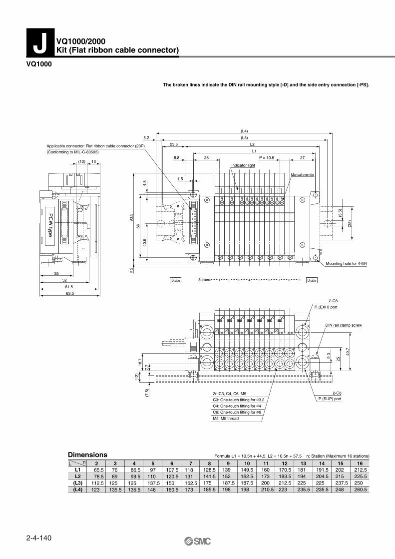
Dimensions
L1L2
(L3)(L4)
2 3 4 5 6 7 8 9 10 11 12 13 14 15 16L n
VQ1000
The broken lines and dimensions in parentheses indicate DIN rail mounting style [-D].
Formula L1 = 10.5n + 45.5, L2 = 10.5n + 63 n: Station (Maximum 16 stations)
213.5231262.5273
203220.5250260.5
192.5210237.5248
182199.5225235.5
171.5189212.5223
161178.5200210.5
150.5168187.5198
140157.5187.5198
129.5147175185.5
119136.5162.5173
108.5126150160.5
98115.5137.5148
87.5105125135.5
77 94.5125135.5
66.5 84112.5123
2n-C3, C4, C6, M5C3: One-touch fitting for ø3.2C4: One-touch fitting for ø4C6: One-touch fitting for ø6M5: M5 thread
VQ1000/2000Kit (Flat ribbon cable connector with terminal block)G
~ =
D side U sideStations ··· 1 ··· 2 ··· 3 ··· 4 ··· 5 ··· 6 ··· 7 ··· 8 ···· n
Power supply terminal block(Terminal screw M3)
Indicator light
Indicator light
Applicable connector: Flat ribbon cable connector (20P)(Conforming to MIL-C-83503)
P = 10.5
Manualoverride
Mounting hole for M4
Triangle mark indicator position
2
DIN rail clamp screw
3(R) EXH port
1(P) SUP port
Vacuum ejector unit style: Formula L1 = 10.5n + 29.7 + (Number of ejector units x 26.7)L2 = 10. 5n + 46.8 + (Number of ejector units x 26.7)L4 is L2 plus about 30.
2-4-144

Dimensions
L1L2
(L3)(L4)
2 3 4 5 6 7 8 9 10 11 12 13 14 15 16L n
VQ2000
The broken lines indicate the DIN rail mounting style [-D].
Formula L1 = 16n + 53, L2 = 16n + 87 n: Station (Maximum 16 stations)
Vacuum ejector unit style: Formula L1 = 10.5n + 29.7 + (Number of ejector units x 26.7)L2 = 10. 5n + 46.8 + (Number of ejector units x 26.7)L4 is L2 plus about 30.
309343362.5373
293327350360.5
277311337.5348
261295325335.5
245279300310.5
229263287.5298
213247275285.5
197231262.5273
181215237.5248
165199225235.5
149183212.5223
133167187.5198
117151175185.5
101135162.5173
85119150160.5
~ =
D side U sideStations ···· 1 ····· 2 ····· 3 ····· 4 ····· 5 ····· 6 ······ 7 ······ 8 ····· n
2n-C4, C6, C8C4: One-touch fitting for ø4C6: One-touch fitting for ø6C8: One-touch fitting for ø8
Power supply terminal block(Terminal screw M3) Indicator light
Indicator light
P = 16
P = 16
Mounting hole for 4-M5Applicable connector: Flat ribbon cable connector (20P)(Conforming to MIL-C-83503)
Manualoverride
Flat ribbon cable connector assembly (20P)AXT100-FC20-1: 1.5 mAXT100-FC20-2: 3 mAXT100-FC20-3: 5 m
3(R) EXH port
1(P) SUP port
DIN rail clamp screw
4
2-4-145
Series VQ1000/2000Plug-in Unit
Base Mounted
VQC
SQ
VQ0
VQ4
VQ5
VQZ
VQD

VQ1000/2000Kit (Terminal block box kit)T
1 2 3 ·······
Stations
D side
U side
Open the terminal block cover to connect the wires to the terminal block.
How to Order Manifold
ManifoldPlug-in unit1
VQ1000VQ2000
12
Series
Stations
Terminal block connection
Electrical wiring specifications: VQ1000Step 1. How to remove terminal block cover
VV5Q 1 008 C61 NT
Manifold Specifications
Applicable stationsPort sizePort location
SideSide
Porting specifications
Max. 24 stationsMax. 20 stations
C3, C4, C6, M5C4, C6, C8
C8C10
4(A), 2(B)1(P), 3(R)Series
VQ1000VQ2000
2 stations
24 stations
02
24
······
Note)
SOL.A
SOL.B
SOL.A
SOL.B
SOL.A
SOL.B
SOL.A
SOL.B
SOL.A
SOL.B
SOL.A
SOL.B
SOL.A
SOL.B
SOL.A
SOL.B
SOL.A
SOL.B
SOL.A
SOL.B
SOL.A
SOL.A
SOL.B
SOL.B
COM.
1A
1B
2A
2B
3A
3B
4A
4B
5A
5B
6A
6B
7A
7B
8A
8B
9A
9B
10A
10B
11A
11B
12A1
2B
COM
(–)
(–)
(–)
(–)
(–)
(–)
(–)
(–)
(–)
(–)
(–)
(–)
(–)
(–)
(–)
(–)
(–)
(–)
(–)
(–)
(–)
(–)
(–)
(–)
(+)
(+)
(+)
(+)
(+)
(+)
(+)
(+)
(+)
(+)
(+)
(+)
(+)
(+)
(+)
(+)
(+)
(+)
(+)
(+)
(+)
(+)
(+)
(+)
(+)
(–)
COM (+) (–)
Terminal no. Polarity
1 station 2 stations 3 stations 4 stations 5 stations 6 stations 7 stations 8 stations 9 stations
10 stations 11 stations 12 stations
Positivecommon
specifications
Negative common
specifications
Note)
Terminal blocks
2 rows
3 rows
Manifold
2 to 8 stations
9 to 12 stations
VV5Q11 VV5Q21
COM.
OptionSymbol Option NoteVQ1000 VQ2000
Nil
B
D
G1
G2
G3
J
N
R
S
W
NoneWith back pressure check valve
DIN rail mounting style1 set of regulator unit2 sets of regulator unit3 sets of regulator unit
With vacuum ejector unit
With name plateExternal pilot
Built-in silencer, direct exhaustEnclosure: Dusttight/Low jetproof type (IP65)
K Special wiring specifications(Not double wiring)
(2)
(3)
(4)
(5)
(6)
Note 1)
Note 2)
Note 3)
Note 4)
Note 5)
Note 6)
Note 1)
Note 2)
Note 3)
Note 4)
VQ1000
VQ2000
Symbol
C3C4C6C8M5CM
Cylinder portPort size
With One-touch fitting for ø3.2With One-touch fitting for ø4With One-touch fitting for ø6With One-touch fitting for ø8
M5 threadWith mixed size/with port plug (3)
IP65 compliant
VQ2000: Max. 20 stationsFor details, refer to page 2-4-178.
Insert “L” (top piping) or “B” (bottom piping) for elbow type.Example) B6 (Elbow One-touch fittings for ø6, bottom piping.)Indicate “LM” for models with elbow fittings and mixed cylinder port sizes.Specify “Mixed size/with port plug” in the manifold specification sheet.For One-touch fittings in inch size, refer to “Option” on page 2-4-179.
This kit has a small terminal box inside a junction box. The electrical entry port VQ1000: G 1/2, VQ2000: G 3/4 permits connection of conduit fittings.
Maximum stations are 24. Enclosure: Dusttight/Low jetproof type (IP65) compliant (Series
VQ2000)
Loosen the screws on the terminal block cover and open it in the direction shown by the arrow. The cover can then be removed from the terminal block.
Step 2. Wire connectionThe diagram on the left shows the terminal block wiring schematic. All stations are provided with double solenoid wiring. Insert each lead wire into the terminal opening and tighten the screw directly above.How to connect is inserting the lead wire into the terminal window, then tighten the screw on the top.
The quantity of terminal blocks used depends on the number of manifold stations:
Step 3. How to replace terminal block coverHook groove (a) on shaft (b) and close the cover. Then tighten the screws.
The total number of stations is tabulated starting from station one on the D side.
As the standard electrical wiring specifications, double wiring (connected to SOL. A and SOL. B) is adopted for the internal wiring of each station for 12 stations or less, regardless of valve and option types.Mixed single and double wiring is available as an option. For details, refer to page 2-4-178.
When using the negative common specifications, use valves for negative common.For details, refer to “Option” on page 2-4-178.
Note)
When two or more symbols are specified, indicate them alphabetically. Example) -BRSModels with a suffix “-B” have check valves for prevention of back pressure at all manifold stations. If not all stations need this check valve, specify the stations where check valves are installed by using the manifold specification sheet.Specify the mounting position in the manifold specification sheet.Refer to page 2-4-170 for the details of ejector mounted styles. A combination of “J” and “N” is unavailable.Specify the wiring specifications in the manifold specification sheet.Indicate “R” for the valve with external pilot.
For negative common specifications, refer to “Option” on page 2-4-178.
Note)
G 1/2Electrical entry
2-G 3/4Electrical entry
Cover2nd row1st row 3rd row
(a) (b)
1 2 3
·······
········
Stations
D side
U side
2-4-146

How to Order Valves
Metal sealRubber seal
01
Type of actuation2 position single2 position double
3 position closed center3 position exhaust center3 position pressure center
12345
VQ1000VQ2000
12
Series
Seal
VQ 0 51 01 Y
Special wiring specifications: VQ2000
SOL.ASOL.BSOL.ASOL.BSOL.ASOL.BSOL.ASOL.BSOL.ASOL.BSOL.ASOL.BSOL.ASOL.BSOL.ASOL.BSOL.ASOL.BSOL.ASOL.B
COM.
1A
1B
2A
2B
3A
3B
4A
4B
5A
5B
6A
6B
7A
7B
8A
8B
9A
9B
10A
10B
(–)
(–)
(–)
(–)
(–)
(–)
(–)
(–)
(–)
(–)
(–)
(–)
(–)
(–)
(–)
(–)
(–)
(–)
(–)
(–)
(+)
(+)
(+)
(+)
(+)
(+)
(+)
(+)
(+)
(+)
(+)
(+)
(+)
(+)
(+)
(+)
(+)
(+)
(+)
(+)
(+) (–)
PolarityTerminal no.
1 station 2 stations 3 stations 4 stations 5 stations 6 stations 7 stations 8 stations 9 stations
10 stations
Positivecommon
specifications
Negative common
specifications
Note)
Non-locking push type (Tool required)Locking type (Tool required)
Locking type (Manual)
Manual overrideNilBC
100 VAC (50/60 Hz)100 VAC (50/60 Hz)
24 VDC12 VDC
Coil voltage1356
Light/Surge voltage suppressorYes
NoneNilE
1 set–Manifold base no.2 sets–Valve part no. (Stations 1 to 2)4 sets–Valve part no. (Stations 3 to 6)1 set–Valve part no. (Station 7)1 set–Blanking plate part no. (Station 8)
How to Order Manifold Assembly
<Example>Terminal block box kitVV5Q11-08C6T0 ···∗VQ1100-5 ··········∗VQ1200-5 ··········∗VQ1300-5 ··········∗VVQ1000-10A-1 ···
The total number of stations is tabulated starting from station one on the D side.
Note) VQ2000 only.
SpecificationsStandard
type
High pressuretype
Low wattagetype
FunctionSymbol
Nil
H
Y
DC AC
(1.0 W)
Note)
(1.5 W)
(0.5 W)
EnclosureDust-protectedNil
VV5Q21Dust tight/Low jetproof type
Irrespective of the valves or options, the internal wiring is made double (connected to SOL.A and SOL.B) for respective stations of the manifold. Mixed single and double wiring is available as an option. For details, refer to page 2-4-178.Note) When using the negative
common specifications, use valves for negative common.For details, refer to “Option” on page 2-4-178.
Specify the part numbers for valves and options together beneath the manifold base part number.
Note) For external pilot and negative COM specifications, refer to “Option” on pages 2-4-178 to 2-4-179.
Note) For power consumption of AC type, refer to page 2-4-179.
—
—
Note)Dusttight/Low jetproof type (IP65)W
Prefix the asterisk to the part nos. of the solenoid valve, etc.
Write sequentially from the 1st station on the D side. When part nos. written collectively are complicated, specify by using the manifold specification sheet.
1 2 3
·······
Stations
D side
U side
1 2 3 ·······
Stations
D side
U side
2-G 3/4Electrical entry
2-4-147
Series VQ1000/2000Plug-in Unit
Base Mounted
VQC
SQ
VQ0
VQ4
VQ5
VQZ
VQD

Dimensions2 3 4 5 6 7 8 9 10 11 12 13 14 15 16 17 18 19 20 21 22 23 24L n
VQ1000
The broken lines and dimensions in parentheses indicate DIN rail mounting style [-D].
L1L2
(L3)(L4)
Formula L1 = 10.5n + 45.5, L2 = 10.5n + 105 n: Station (Maximum 24 stations)
< >: AC
297.5357387.5398
287346.5375385.5
276.5336362.5373
266325.5350360.5
255.5315337.5348
245304.5325335.5
234.5294325335.5
224283.5312.5323
213.5273300310.5
203262.5287.5298
192.5252275285.5
182241.5262.5273
171.5231262.5273
161220.5250260.5
150.5210237.5248
140199.5225235.5
129.5189212.5223
119178.5200210.5
108.5168187.5198
98157.5187.5198
87.5147175185.5
77136.5162.5173
66.5126150160.5
VQ1000/2000Kit (Terminal block box kit)T
D side U sideStations ······ 1 ····· 2 ····· 3 ····· 4 ····· 5 ·····6 ·····7 ····· 8 ····· n
P = 10.5 Indicator light
Manualoverride
Mounting hole for M4
Top entry portNot machined
~ =2
DIN rail clamp screw
G 1/2Electrical entry
3(R) EXH port
1(P) SUP port2n-C3, C4, C6, M5C3: One-touch fitting for ø3.2C4: One-touch fitting for ø4C6: One-touch fitting for ø6M5: M5 thread
Vacuum ejector unit style: Formula L1 = 10.5n + 29.7 + (Number of ejector units x 26.7)L2 = 10.5n + 88.8 + (Number of ejector units x 26.7)L4 is L2 plus about 30.
2-4-148

2 3 4 5 6 7 8 9 10 11 12 13 14 15 16 17 18 19 20L n
VQ2000
The broken lines and dimensions in parentheses indicate DIN rail mounting style [-D].
Dimensions
L1L2
(L3)(L4)
Formula L1 = 16n + 118.5, L2 = 16n + 131 n: Station (Maximum 10 stations)
< >: AC
n21 3 4 5 6 7 8StationsD side U side
76
13(12)
80
<13
7.5>
128
126
(L4)
(L3)
L1+ 0.5
L2 + 0.5
100.5
6.5
(L3)
(L4)
100
L1
L2
34.5P = 16
1
Indicator light Manual override
6.5
120
126<12
9>
5.2
80
46.2
10.6
4
6.5
(35)
(5.5
)
Mounting hole for 4-M5
(7.5
)
(12)
31.6
49
16
DIN rail clampscrew
R (EXH) port2-C10
46.5
24.5
9.5
Electrical entry2-G 3/4
C3: One-touch fitting for ø3.2
C8: One-touch fitting for ø8 C6: One-touch fitting for ø6 C4: One-touch fitting for ø4
2n-C3, C4, C6, C8P = 16 41
23
P (SUP) port2-C10
NO.TERMINANAL
2B2A
2
3B3A
3
4B4A
4
1B1A
1D SIDE
STA U SIDE
NO.TERMINANAL
2B2A
2
3B3A
3
4B4A
4
1B1A
1D SIDE
STA U SIDE
438.5451475485.5
422.5435462.5473
406.5419450460.5
390.5403425435.5
374.5387412.5423
358.5371400410.5
342.5355375385.5
326.5339362.5373
310.5323350360.5
294.5307337.5348
278.5291312.5323
262.5275300310.5
246.5259287.5298
230.5243262.5273
214.5227250260.5
198.5211237.5248
182.5195225235.5
166.5179200210.5
150.5163187.5198
2-4-149
Series VQ1000/2000Plug-in Unit
Base Mounted
VQC
SQ
VQ0
VQ4
VQ5
VQZ
VQD
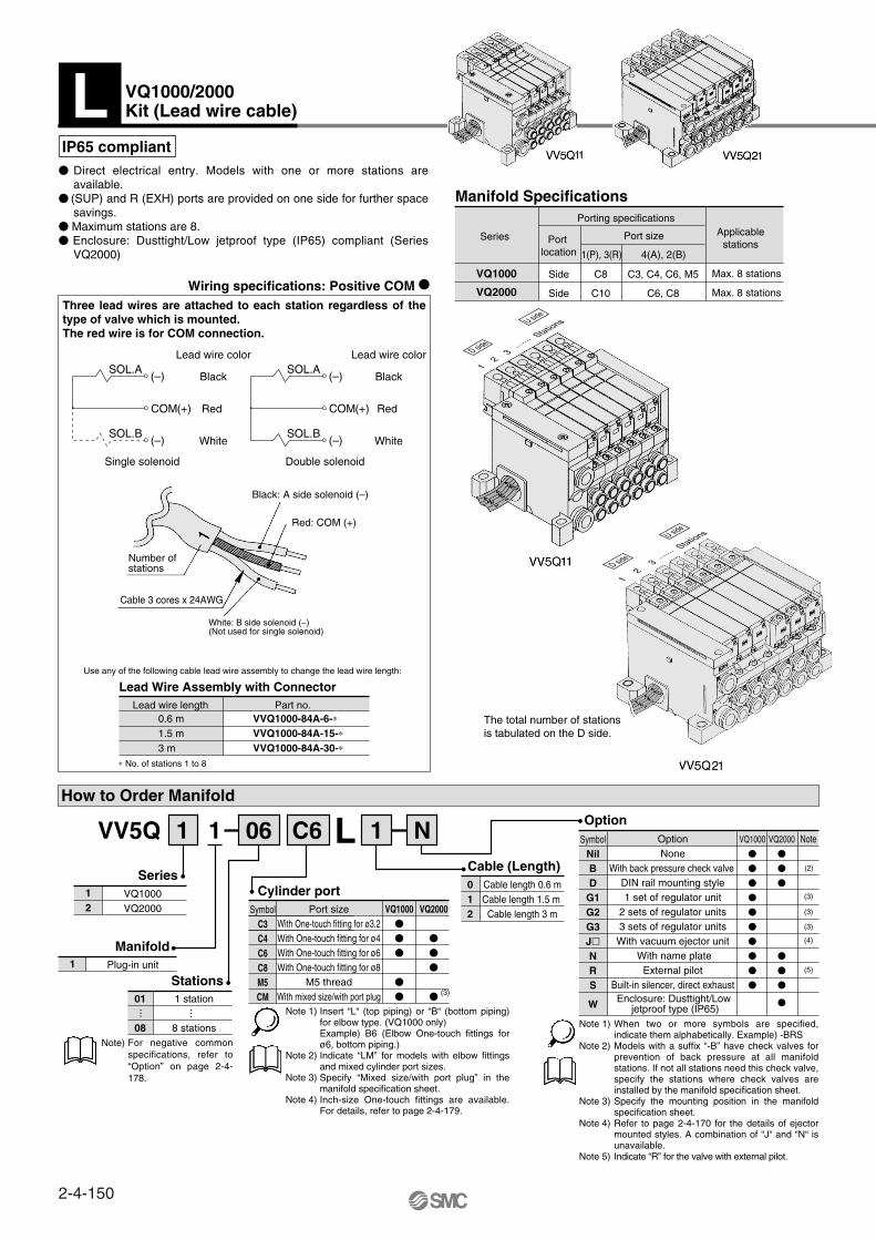
Insert “L“ (top piping) or “B“ (bottom piping) for elbow type. (VQ1000 only)Example) B6 (Elbow One-touch fittings for ø6, bottom piping.)Indicate “LM” for models with elbow fittings and mixed cylinder port sizes.Specify “Mixed size/with port plug” in the manifold specification sheet.Inch-size One-touch fittings are available. For details, refer to page 2-4-179.
Use any of the following cable lead wire assembly to change the lead wire length:
Part no.Lead wire lengthVVQ1000-84A-6-∗VVQ1000-84A-15-∗VVQ1000-84A-30-∗
0.6 m1.5 m3 m
∗ No. of stations 1 to 8
Wiring specifications: Positive COM
Manifold Specifications
Applicablestations
Port sizePort location
Side
Side
Porting specifications
Max. 8 stations
Max. 8 stations
C3, C4, C6, M5
C6, C8
C8
C10
4(A), 2(B)1(P), 3(R)
Series
VQ1000
VQ2000
Single solenoid Double solenoid
COM(+)
(–)
(–)
SOL.A
SOL.B
Black
Red
White
COM(+)
(–)
(–)
SOL.A
SOL.B
Black
Lead wire colorLead wire color
Red
White
Lead Wire Assembly with Connector
IP65 compliant
1 station
8 stations
01
08
ManifoldPlug-in unit1
VQ1000VQ2000
12
012
Option
Port sizeWith One-touch fitting for ø3.2With One-touch fitting for ø4With One-touch fitting for ø6With One-touch fitting for ø8
M5 threadWith mixed size/with port plug
VQ1000
VQ2000
SymbolC3C4C6C8M5CM
Cylinder port
Cable (Length)Series
Stations
VV5Q 1 06 C61 1 NL
······
SymbolNilBD
G1G2G3JNRS
W
OptionNone
With back pressure check valve DIN rail mounting style1 set of regulator unit
2 sets of regulator units3 sets of regulator unitsWith vacuum ejector unit
With name plateExternal pilot
Built-in silencer, direct exhaust
NoteVQ1000
VQ2000
Cable length 0.6 mCable length 1.5 m Cable length 3 m
(3)
How to Order Manifold
When two or more symbols are specified, indicate them alphabetically. Example) -BRSModels with a suffix “-B” have check valves for prevention of back pressure at all manifold stations. If not all stations need this check valve, specify the stations where check valves are installed by the manifold specification sheet. Specify the mounting position in the manifold specification sheet.Refer to page 2-4-170 for the details of ejector mounted styles. A combination of “J“ and “N“ is unavailable.Indicate “R” for the valve with external pilot.
Direct electrical entry. Models with one or more stations are available.
(SUP) and R (EXH) ports are provided on one side for further space savings.
Maximum stations are 8. Enclosure: Dusttight/Low jetproof type (IP65) compliant (Series
VQ2000)
Three lead wires are attached to each station regardless of the type of valve which is mounted.The red wire is for COM connection.
The total number of stations is tabulated on the D side.
For negative common specifications, refer to “Option” on page 2-4-178.
Note 1)
Note 2)
Note 3)
Note 4)
Note 5)
Note 1)
Note 2)
Note 3)
Note 4)
Enclosure: Dusttight/Low jetproof type (IP65)
VQ1000/2000Kit (Lead wire cable)L
1 2 3
·······
Stations
D side
U side
1 2
3 ·······
Stations
D side
U side
Black: A side solenoid (–)
Red: COM (+)
Number ofstations
Cable 3 cores x 24AWG
White: B side solenoid (–)(Not used for single solenoid)
Note)
(2)
(3)
(3)
(3)
(4)
(5)
2-4-150

How to Order Valves
Metal sealRubber seal
01
Type of actuation2 position single2 position double
3 position closed center3 position exhaust center3 position pressure center
12345
VQ1000VQ2000
12
Series
Seal
VQ 0 51 01 Y
Non-locking push type (Tool required)Locking type (Tool required)
Locking type (Manual)
Manual overrideNilBC
100 VAC (50/60 Hz)200 VAC (50/60 Hz)110 VAC (50/60 Hz)220 VAC (50/60 Hz)
24 VDC12 VDC
Coil voltage123456
Light/Surge voltage suppressorYes
NoneNilE
Lead Wire Assembly with ConnectorPart no.
0.6 m1.5 m3 m
∗ No. of stations 1 to 8
Wiring specifications: Negative COM (Option)
Lead wire lengthVVQ1000-84AN-6-∗VVQ1000-84AN-15-∗VVQ1000-84AN-30-∗
Single solenoid Double solenoid
COM(–)
(+)
(+)
SOL.A
SOL.B
Red
Black
White
COM(–)
(+)
(+)
SOL.A
SOL.B
Red
Lead wire colorLead wire color
Black
White
1 set–Manifold base no.2 sets–Valve part no. (Stations 1 to 2)2 sets–Valve part no. (Stations 3 to 4)1 set–Valve part no. (Station 5)1 set–Blanking plate part no. (Station 6)
How to Order Manifold Assembly
<Example>Lead wire kit with cable (3 m)VV5Q11-06C6L2 ····∗VQ1100-5 ··········∗VQ1200-5 ··········∗VQ1300-5 ··········∗VVQ1000-10A-1 ···
SpecificationsStandard type
High pressure typeLow wattage type
FunctionSymbol
NilHY
DC AC(1.0 W) (1.5 W) (0.5 W)
——
Note) VQ2000 only.
EnclosureDusttightNil
W
VV5Q21Dusttight/Low jetproof type
When using the negative common specifications, use valves for negative common. For negative common specifications, refer to “Option” on page 2-4-178.
For external pilot and negative COM specifications, refer to “Option” on 2-4-178 to 2-4-179.
Three lead wires are attached to each station regardless of the type of valve which is mounted.The black wire is for COM connection.
Note)
Specify the part numbers for valves and options together beneath the manifold base part number.
Note)
Note)
Note) For power consumption of AC type, refer to page 2-4-129.
Dusttight/Low jetproof type (IP65)
Note)
Prefix the asterisk to the part nos. of the solenoid valve, etc.
Write sequentially from the 1st station on the D side. When part nos. written collectively are complicated, specify by using the manifold specification sheet.
Red: A side solenoid (+)
Black: COM (–)
Number ofstations
Cable 3 cores x 24AWG
White: B side solenoid (+)(Not used for single solenoid)
1 2 3 ·······
Stations
D side
U side
2-4-151
Series VQ1000/2000Plug-in Unit
Base Mounted
VQC
SQ
VQ0
VQ4
VQ5
VQZ
VQD

1 2 3 4 5 6 7 8L n
VQ1000
The broken lines indicate DIN rail mounting style [-D].
Dimensions Formula L1 = 16n + 35, L2 = 16n + 47 n: Station (Maximum 8 stations)
L1L2
(L3)(L4)
< >: AC
112.5122150160.5
102111.5137.5148
91.5101125135.5
81 90.5112.5123
70.5 80100110.5
6069.587.598
49.55987.598
3948.57585.5
VQ0000/1000/2000Kit (Lead wire cable)L
Indicator light
Manual override
Mounting hole for M4
Number ofstations
Lead wireAWG24 x
3 cores
3(R) EXH port
1(P) SUP port
DIN rail clamp screw
2n-C3, C4, C6, M5
C3: One-touch fitting for ø3.2
C4: One-touch fitting for ø4
C6: One-touch fitting for ø6
M5: M5 thread
D side U sideStations ······ 1 ···· 2 ···· 3 ··· 4 ···· 5 ··· 6 ···· 7 ···· n
~ =2
Vacuum ejector unit style: Formula L1 = 10.5n + 28.5 + (Number of ejector units x 26.7)L2 = 10.5n + 38 + (Number of ejector units x 26.7)L4 is L2 plus about 30.
2-4-152
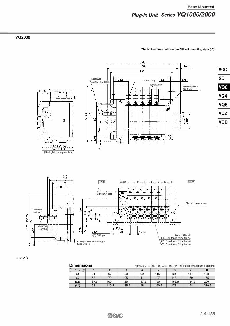
21 3 4 5 6 7 8L n
VQ2000
The broken lines indicate the DIN rail mounting style [-D].
Dimensions
L1L2
(L3)(L4)
Formula L1 = 16n + 35, L2 = 16n + 47 n: Station (Maximum 8 stations)
< >: AC
163175200210.5
147159184.5198
131143162.5173
115127150160.5
99111137.5148
83 95125135.5
67 79100110.5
516387.598
~ =
D side U sideStations ···· 1 ····· 2 ····· 3 ····· 4 ····· 5 ····· 6 ····· n
(Dusttight/Low jetproof type)
Lead wireAWG24 x 3 cores
Indicator light
Manual overrideMounting holefor 4-M5
Number of stations
Number ofstations
DIN rail clamp screw
Lead wireAWG24
Dusttight/Low jetproof typeLead wire kit
1(P) SUP port
3(R) EXH port
P = 16
4
2n-C4, C6, C8C4: One-touch fitting for ø4C6: One-touch fitting for ø6C8: One-touch fitting for ø8
2-4-153
Series VQ1000/2000Plug-in Unit
Base Mounted
VQC
SQ
VQ0
VQ4
VQ5
VQZ
VQD
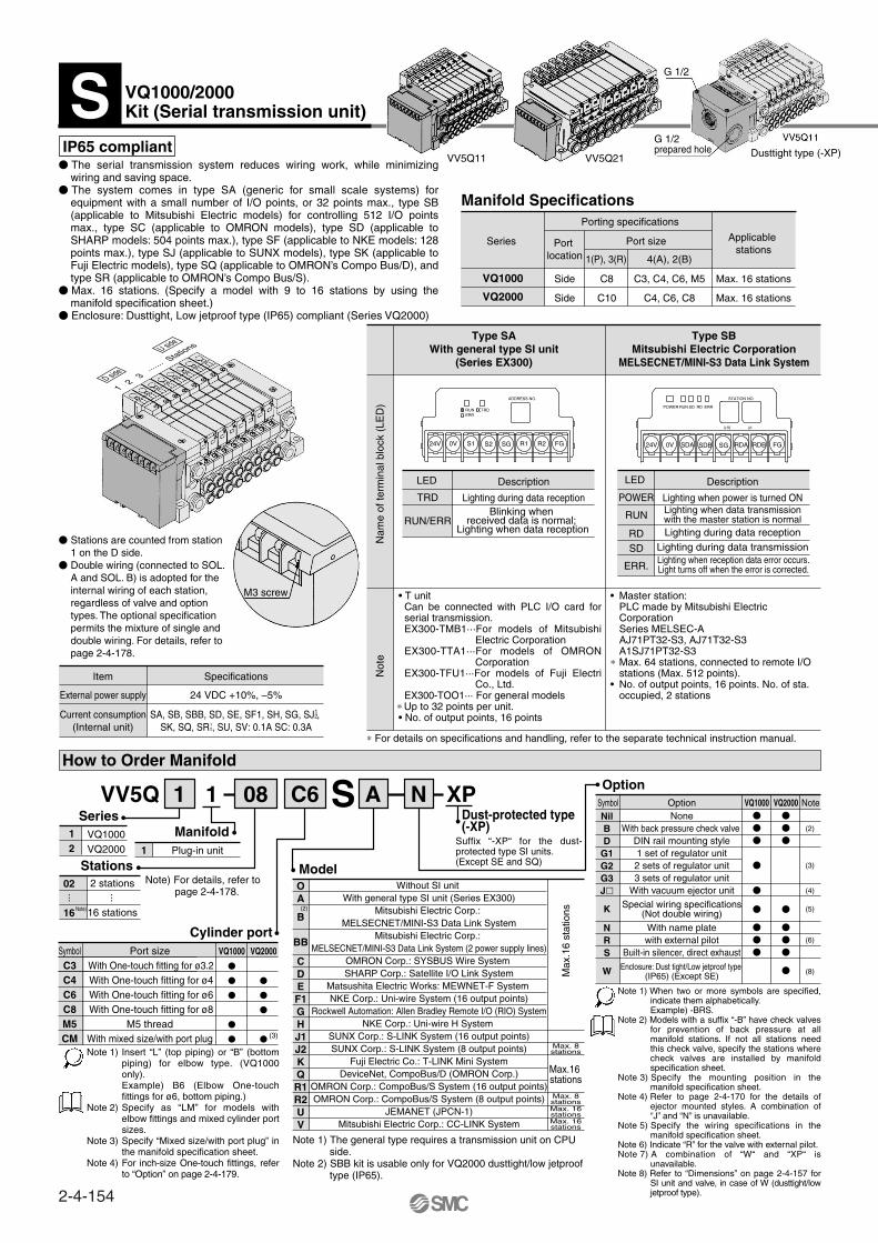
How to Order Manifold
2 stations
16 stations
02
16
ManifoldPlug-in unit1
VQ1000VQ2000
12
Option
VQ1000
VQ2000
SymbolC3C4C6C8M5CM
Cylinder port
Dust-protected type (-XP)
Model
Series
Stations
VV5Q 1 08 C61 A XPNS
··· ···
Manifold Specifications
Applicable stations
Port sizePort location
Side
Side
Porting specifications
Max. 16 stations
Max. 16 stations
C3, C4, C6, M5
C4, C6, C8
C8
C10
4(A), 2(B)1(P), 3(R)
Series
VQ1000
VQ2000
Symbol Option NoteVQ1000 VQ2000NilBD
G1G2G3J
K
NRS
W
NoneWith back pressure check valve
DIN rail mounting style1 set of regulator unit2 sets of regulator unit3 sets of regulator unit
With vacuum ejector unit
Special wiring specifications(Not double wiring)
With name platewith external pilot
Built-in silencer, direct exhaust
Enclosure: Dust tight/Low jetproof type (IP65) (Except SE)
(2)
(3)
(4)
(5)
(6)
(8)
Port size With One-touch fitting for ø3.2 With One-touch fitting for ø4 With One-touch fitting for ø6 With One-touch fitting for ø8
M5 threadWith mixed size/with port plug
VV5Q11 VV5Q21
(3)
Note 1)
Note 2)
Note 3)
Note 4)
OA
B
BB
CDEF1GHJ1J2KQR1R2UV
Without SI unit With general type SI unit (Series EX300)
Mitsubishi Electric Corp.: MELSECNET/MINI-S3 Data Link System
Mitsubishi Electric Corp.: MELSECNET/MINI-S3 Data Link System (2 power supply lines)
OMRON Corp.: SYSBUS Wire System SHARP Corp.: Satellite I/O Link System
Matsushita Electric Works: MEWNET-F System NKE Corp.: Uni-wire System (16 output points)
Rockwell Automation: Allen Bradley Remote I/O (RIO) SystemNKE Corp.: Uni-wire H System
SUNX Corp.: S-LINK System (16 output points)SUNX Corp.: S-LINK System (8 output points)
Fuji Electric Co.: T-LINK Mini SystemDeviceNet, CompoBus/D (OMRON Corp.)
OMRON Corp.: CompoBus/S System (16 output points)OMRON Corp.: CompoBus/S System (8 output points)
JEMANET (JPCN-1)Mitsubishi Electric Corp.: CC-LINK System
Max
.16
stat
ions
Max.16 stations
Type SAWith general type SI unit
(Series EX300)
Type SBMitsubishi Electric Corporation
MELSECNET/MINI-S3 Data Link System
POWER
RUN
Description
Lighting when power is turned ONTRD
RUN/ERR
Description
Lighting during data reception
∗ For details on specifications and handling, refer to the separate technical instruction manual.
Nam
e of
term
inal
blo
ck (
LED
)N
ote
SDA SDB SG RDA RDB FG24V 0V
POWER RUN SD RD ERR
STATION NO.
ù10 ù1
24V 0V S1 S2 SG R1 R2 FG
RUNERR
TRD
ADDRESS NO.
IP65 compliant
(2)
Max. 8stations
Max. 8stations
Max. 16stations
Max. 16stations
Item
External power supply
Specifications
24 VDC +10%, –5%
Current consumption(Internal unit)
SA, SB, SBB, SD, SE, SF1, SH, SG, SJ , SK, SQ, SR , SU, SV: 0.1A SC: 0.3A
The serial transmission system reduces wiring work, while minimizing wiring and saving space.
The system comes in type SA (generic for small scale systems) for equipment with a small number of I/O points, or 32 points max., type SB (applicable to Mitsubishi Electric models) for controlling 512 I/O points max., type SC (applicable to OMRON models), type SD (applicable to SHARP models: 504 points max.), type SF (applicable to NKE models: 128 points max.), type SJ (applicable to SUNX models), type SK (applicable to Fuji Electric models), type SQ (applicable to OMRON’s Compo Bus/D), and type SR (applicable to OMRON’s Compo Bus/S).
Max. 16 stations. (Specify a model with 9 to 16 stations by using the manifold specification sheet.)
Enclosure: Dusttight, Low jetproof type (IP65) compliant (Series VQ2000)
Stations are counted from station 1 on the D side.
Double wiring (connected to SOL. A and SOL. B) is adopted for the internal wiring of each station, regardless of valve and option types. The optional specification permits the mixture of single and double wiring. For details, refer to page 2-4-178.
Blinking when received data is normal;
Lighting when data reception
• T unitCan be connected with PLC I/O card for serial transmission. EX300-TMB1···For models of Mitsubishi
Electric CorporationEX300-TTA1···For models of OMRON
CorporationEX300-TFU1···For models of Fuji Electri
Co., Ltd.EX300-TOO1··· For general models
∗ Up to 32 points per unit.• No. of output points, 16 points
• Master station:PLC made by Mitsubishi Electric CorporationSeries MELSEC-AAJ71PT32-S3, AJ71T32-S3A1SJ71PT32-S3
∗ Max. 64 stations, connected to remote I/O stations (Max. 512 points).
• No. of output points, 16 points. No. of sta. occupied, 2 stations
LED LED
Lighting when data transmissionwith the master station is normalLighting during data reception
Lighting during data transmissionLighting when reception data error occurs.Light turns off when the error is corrected.
RDSD
ERR.
Note)
Note) For details, refer to page 2-4-178.
Insert “L” (top piping) or “B” (bottom piping) for elbow type. (VQ1000 only).Example) B6 (Elbow One-touch fittings for ø6, bottom piping.)Specify as “LM” for models with elbow fittings and mixed cylinder port sizes.Specify “Mixed size/with port plug” in the manifold specification sheet.For inch-size One-touch fittings, refer to “Option” on page 2-4-179.
Note 1) The general type requires a transmission unit on CPU side.
Note 2) SBB kit is usable only for VQ2000 dusttight/low jetproof type (IP65).
Note 1) When two or more symbols are specified, indicate them alphabetically.Example) -BRS.
Note 2) Models with a suffix “-B” have check valves for prevention of back pressure at all manifold stations. If not all stations need this check valve, specify the stations where check valves are installed by manifold specification sheet.
Note 3) Specify the mounting position in the manifold specification sheet.
Note 4) Refer to page 2-4-170 for the details of ejector mounted styles. A combination of “J” and “N” is unavailable.
Note 5) Specify the wiring specifications in the manifold specification sheet.
Note 6) Indicate “R” for the valve with external pilot.Note 7) A combination of “W“ and “XP“ is
unavailable.Note 8) Refer to “Dimensions” on page 2-4-157 for
SI unit and valve, in case of W (dusttight/low jetproof type).
Suffix “-XP“ for the dust-protected type SI units.(Except SE and SQ)
VQ1000/2000Kit (Serial transmission unit)S
1 2 3
·······
Stations
D side
U side
G 1/2
G 1/2prepared hole Dusttight type (-XP)
M3 screw
12
12
2-4-154
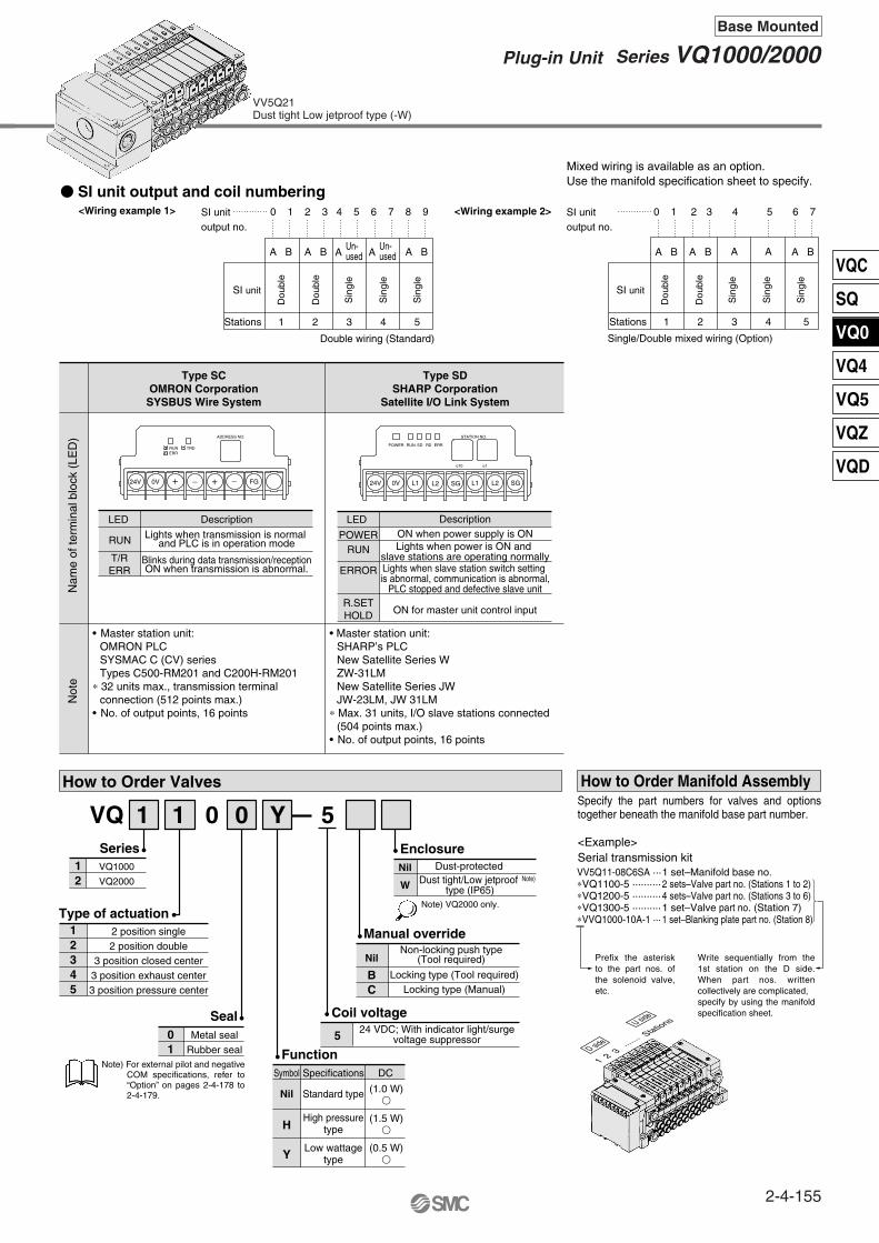
How to Order Valves
Metal sealRubber seal
01
Type of actuation12345
VQ1000
VQ2000
12
Series
Seal
VQ 0 51 01 Y
SI unit output and coil numbering<Wiring example 1>
Double wiring (Standard)
SI unitoutput no.
<Wiring example 2>
Non-locking push type(Tool required)
Manual override
Nil
BC
24 VDC; With indicator light/surgevoltage suppressor
Coil voltage
5
SI unit
Stations 1 2 3 4 5
A B A B A B A B A B A BA
Single/Double mixed wiring (Option)
SI unitoutput no.
Mixed wiring is available as an option. Use the manifold specification sheet to specify.
Stations 1 2 3 4 5
A A
2 position single2 position double
3 position closed center3 position exhaust center3 position pressure center
1 set–Manifold base no.2 sets–Valve part no. (Stations 1 to 2)4 sets–Valve part no. (Stations 3 to 6)1 set–Valve part no. (Station 7)1 set–Blanking plate part no. (Station 8)
How to Order Manifold Assembly
<Example>Serial transmission kitVV5Q11-08C6SA ···∗VQ1100-5 ··········∗VQ1200-5 ··········∗VQ1300-5 ··········∗VVQ1000-10A-1 ···
Specifications
Standard type
High pressuretype
Low wattagetype
FunctionSymbol
Nil
DC
(1.0 W)
(1.5 W)
(0.5 W)
H
Y
Type SCOMRON Corporation
SYSBUS Wire System
Type SDSHARP Corporation
Satellite I/O Link System
POWERRUN
DescriptionON when power supply is ON
RUN Lights when transmission is normal and PLC is in operation mode
Nam
e of
term
inal
blo
ck (
LED
)N
ote
T/RERR
Blinks during data transmission/receptionON when transmission is abnormal. ERROR Lights when slave station switch setting
is abnormal, communication is abnormal,PLC stopped and defective slave unit
R.SETHOLD ON for master unit control input
L1 L2 SG L1 L2 SG24V 0V
POWER RUN SD RD ERR
STATION NO.
ù10 ù1
24V 0V + – + – FG
RUNERR
TRD
ADDRESS NO.
Note) VQ2000 only.
EnclosureDust-protectedNil
W
Sin
gle
Sin
gle
Sin
gle
Dou
ble
Dou
ble
SI unit
Sin
gle
Sin
gle
Sin
gle
Dou
ble
Dou
ble
0 1 2 3 4 5 6 7 8 9 0 1 2 3 4 5 6 7
DescriptionLED LED
Lights when power is ON and slave stations are operating normally
• Master station unit:OMRON PLCSYSMAC C (CV) seriesTypes C500-RM201 and C200H-RM201
∗ 32 units max., transmission terminal connection (512 points max.)
• No. of output points, 16 points
• Master station unit:SHARP’s PLCNew Satellite Series WZW-31LM New Satellite Series JWJW-23LM, JW 31LM
∗ Max. 31 units, I/O slave stations connected (504 points max.)
• No. of output points, 16 points
Note) For external pilot and negative COM specifications, refer to “Option” on pages 2-4-178 to 2-4-179.
Note)Dust tight/Low jetproof type (IP65)
Specify the part numbers for valves and options together beneath the manifold base part number.
Prefix the asterisk to the part nos. of the solenoid valve, etc.
Write sequentially from the 1st station on the D side. When part nos. written collectively are complicated, specify by using the manifold specification sheet.
Locking type (Tool required) Locking type (Manual)
1 2 3 ·······
Stations
D side
U side
VV5Q21Dust tight Low jetproof type (-W)
Un-used A
Un-used
2-4-155
Series VQ1000/2000Plug-in Unit
Base Mounted
VQC
SQ
VQ0
VQ4
VQ5
VQZ
VQD

2 3 4 5 6 7 8 9 10 11 12 13 14 15 16L n
VQ1000
Dimensions
L1L2
(L3)(L4)
Vacuum ejector unit style: FormulaL1 = 10.5n + 28.7 + (Number of ejector units x 26.7)L2 = 10.5n + 56.3 + (Number of ejector units x 26.7)L4 is L2 plus about 30.
Manifolds with SI unit for Matsushita Electric Works’ MEWNET FP and Rockwell Automation’s model are the same with L5, L6 and L7 dimensions of dustproof SI unit.
The broken lines indicate DIN rail mounting style [-D].
Note)
212.5240.5262.5273
202230250260.5
191.5219.5250260.5
181209237.5248
170.5198.5225235.5
160188212.5223
149.5177.5200210.5
139167187.5198
128.5156.5187.5198
118146175185.5
107.5135.5162.5173
97125150160.5
86.5114.5137.5148
76104125135.5
65.5 93.5125135.5
Dust-protected type SI unit: L5 = 10.5n + 97, L6 = L3 + 25, L7 = L4 + 25Formula L1 = 10.5n + 44.5, L2 = 10.5n + 72.5 n: Station (Maximum16 stations)
2n-C3, C4, C6, M5C3: One-touch fitting for ø3.2C4: One-touch fitting for ø4C6: One-touch fitting for ø6M5: M5 thread
VQ1000/2000Kit (Serial transmission unit)S
D side U sideStations ···· 1···· 2 ··· 3 ··· 4 ··· 5 ··· 6 ··· 7 ··· 8 ···· n
~ =2
~ =2
The DWG shows a SB type(Applicable to Mitsubishi Electric models)
Dust tight SI unit
P = 10.5
Indicator lightManualoverride
Mounting hole forM4
The DWG shows the SA type(General type)
3(R) EXH port
1(P) SUP port
DIN rail clamp screw
(L4)
2-4-156

L1L2L3L4
2 3 4 5 6 7 8 9 10 11 12 13 14 15 16 85115137.5148
101131162.5173
117147175185.5
133163187.5198
149179200210.5
165195225235.5
181211237.5248
197227250260.5
213243262.5273
229259287.5298
245275300310.5
261291312.5323
277307337.5348
L n
VQ2000
Dimensions
( )( )
Dust tight/Low jetproof type (IP65) SI unit
127<
136.
5>11
3
L10 = L3 + 50L11 = L4 + 50
100L8 = 16n + 118.5L9 = 16n + 131
SERIAL U
NIT
x 1 x 10
STATION NO.
ERR.RD
SDRUN
POWER
MO
DE
LS
B(SI No. EX124-SMB1)
The broken lines indicate the DIN rail mounting style [-D].
Dust-protected type SI unit: L5 = 16 + 108, L6 = L3 + 25, L7 = L4 + 25Dusttight/Low jetproof SI unit: L8 = 16n + 118.5, L9 = 16n + 131
L10 = L3 + 50, L11 = L4 + 50Formula : L1 = 16n + 53, L2 = 16n + 83 n: Stations (Maximum 16 stations)
309339362.5373
293323350360.5
D side U sideStations ···· 1 ···· 2 ···· 3 ···· 4 ···· 5 ···· 6 ····7 ···· 8 ····· n
2n-C4, C6, C8C4: One-touch fitting for ø4C6: One-touch fitting for ø6C8: One-touch fitting for ø8
The DWG shows a SB type(Applicable to Mitsubishi Electric models)
Dusttight SI unit
(Dusttight/Low jetproof type)
Indicator lightP = 16
P = 16
Mounting hole for 4-M5
The DWG shows the SA type(General type)
Manualoverride
3(R) EXH port
1(P) SUP port
DIN rail clamp screw
~ =4
Note) Manifolds with SI unit for Matsushita Electric Works’ MEWNET FP and Rockwell Automation’s model are the same with L5, L6 and L7 dimensions of dustproof SI unit.
≅4
< >: AC
2-4-157
Series VQ1000/2000Plug-in Unit
Base Mounted
VQC
SQ
VQ0
VQ4
VQ5
VQZ
VQD

Circular Connector (26 pins)
Circular Connector Cable Assembly (Option) Electric Characteristics
Terminal no. Lead wire color Dot marking123456789
1011121314151617181920212223242526
NoneNoneNoneNoneNoneNoneNoneWhiteBlackBlackRed Red Red BlackBlackWhiteNoneNoneBlackWhiteWhiteRed Red WhiteNoneNone
BlackBrownRed
OrangeYellowPinkBlue
PurpleGrayWhiteWhiteYellowOrangeYellowPinkBlue
PurpleGray
OrangeRed
BrownPinkGrayBlackWhiteWhite
ItemNoteAssembly part no.
AXT100-MC26-015AXT100-MC26-030AXT100-MC26-050
1.5 m3 m5 m
Cablelength (L)
Cable 25 corex 24AWG
Conductor resistanceΩ/km, 20°C
Voltage limitV, 1 min, AC
Insulation resistanceMΩkm, 20°C
Characteristics65
or less
1000
5 or more
How to Order Manifold
2 stations
24 stations
02
24
ManifoldPlug-in unit1
VQ20002
Without cableWith cable (1.5 m)With cable (3 m)With cable (5 m)
0123
Option
Port sizeWith One-touch fitting for ø4With One-touch fitting for ø6With One-touch fitting for ø8
With mixed size/with port plug
SymbolC4C6C8CM
Cylinder port
Cable (Length)Series
Stations
Cable assembly
VV5Q 1 08 C6 12 NM
··· ···
Manifold Specifications
Applicablestations
Port sizePort location
Side
Porting specifications
Max. 24 stationsC4, C6, M8C10
4(A), 2(B)1(P), 3(R)
Series
VQ2000
SymbolNilBD
K
NR
OptionNone
With back pressure check valveDIN rail mounting
Special wiring specifications(Not double wiring)
With name plateExternal pilot
Note
Note 1)
Note 2)
Note 3)
Note 4)
AXT100-MC26-015030050
EnclosureIP65 (Dust tight/Low jetproof type)
VV5Q21VQ2000 only
The minimum bending radius of circular connector cable is 20 mm.
When two or more symbols are specified, indicate them alphabetically. Example) -BKRModels with a suffix “-B” have check valves for prevention of back pressure at all manifold stations. If not all stations need this check valve, specify the stations where check valves are installed by using the manifold specification sheet. Specify the wiring by using of the manifold specification sheet.Indicate “R” for the valve with external pilot.
W
0.3 mm2 x 25CMulti-core vinyl cable
L
60
Socket side
Plug terminal no.
26
2524
23
222120
19
18
1716
1514
13
12
11
10987
6
5
4
3
21
30
MIL flat cable connector reduces installation labor for electrical connection.
Manifold and connectors, both compliant with the IP65 rating (dusttight, low jetproof), provide a high degree of protection for the electrical parts.
Maximum stations are 24.
Circular Connector Cable Assembly Terminal No.Circular connector assembly included in a specific manifold model no.
specific manifold model no. Refer to How to Order Manifold.
Note)
Note) For details, refer to page 2-4-178.
Insert “L” (top piping) or “B” (bottom piping) for elbow type.Example) B6 (Elbow One-touch fittings for ø6, bottom piping.)Indicate “LM” for models with elbow fittings and mixed cylinder port sizes.Specify “Mixed size/with port plug” in the manifold specification sheet.Inch-size One-touch fittings are available. For details, refer to page 2-7-179.
Note 1)
Note 2)
Note 3)
Note 4)
VQ2000Kit (Flat ribbon cable connector)M
ø10~=
(2)
(3)
(4)
2-4-158
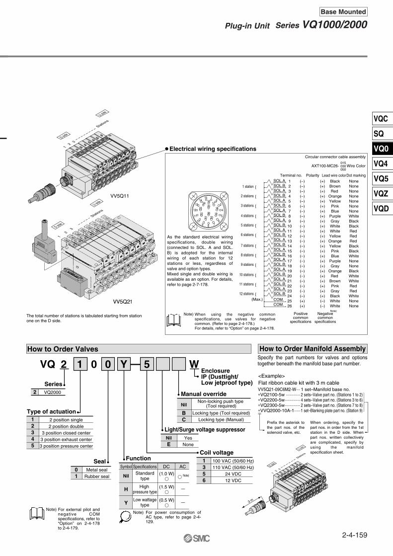
26
2524
23
2221 20
19
18
1716
1514
13
12
11
109 8 7
6
5
4
32
1
How to Order Valves
Metal sealRubber seal
01
Type of actuation2 position single2 position double
3 position closed center3 position exhaust center3 position pressure center
12345
VQ20002Series
Seal
VQ 0 51 02 Y W
SOL.ASOL.BSOL.ASOL.BSOL.ASOL.BSOL.ASOL.BSOL.ASOL.BSOL.ASOL.BSOL.ASOL.BSOL.ASOL.BSOL.ASOL.BSOL.ASOL.BSOL.A
SOL.ASOL.B
SOL.B
COM.COM.
1234567891011121314151617181920212223242526
(–)(–)(–)(–)(–)(–)(–)(–)(–)(–)(–)(–)(–)(–)(–)(–)(–)(–)(–)(–)(–)(–)(–)(–)(+)(+)
(+)(+)(+)(+)(+)(+)(+)(+)(+)(+)(+)(+)(+)(+)(+)(+)(+)(+)(+)(+)(+)(+)(+)(+)(–)(–)
BlackBrownRed
OrangeYellowPinkBlue
PurpleGrayWhiteWhiteYellowOrangeYellowPinkBlue
PurpleGray
OrangeRed
BrownPinkGrayBlackWhiteWhite
NoneNoneNoneNoneNoneNoneNoneWhiteBlackBlackRed Red Red BlackBlackWhiteNoneNoneBlackWhiteWhiteRed Red WhiteNoneNone
PolarityTerminal no. Lead wire colorDot marking
1 station
2 stations
3 stations
4 stations
5 stations
6 stations
7 stations
8 stations
9 stations
10 stations
11 stations
12 stations(Max.)
Positivecommon
specifications
Negativecommon
specifications
Note)
Manual override
Nil
BC
100 VAC (50/60 Hz)110 VAC (50/60 Hz)
24 VDC12 VDC
Coil voltage1356
Light/Surge voltage suppressorYes
NoneNilE
VV5Q21-09C6M2-W···∗VQ2100-5w ···········∗VQ2200-5w············∗VQ2300-5w············∗VVQ2000-10A-1·····
1 set–Manifold base no.2 sets–Valve part no. (Stations 1 to 2)4 sets–Valve part no. (Stations 3 to 6)2 sets–Valve part no. (Stations 7 to 8)1 set–Blanking plate part no. (Station 9)
How to Order Manifold Assembly
<Example>Flat ribbon cable kit with 3 m cable
SpecificationsStandard
type
High pressure type
Low wattagetype
FunctionSymbol
Nil
H
Y
DC AC
(1.0 W) Note)
(1.5 W)
(0.5 W)
Circular connector cable assembly
015030050
AXT100-MC26- Wire Color
EnclosureIP (Dusttight/Low jetproof type)
For external pilot and negative COM specifications, refer to “Option” on 2-4-178 to 2-4-179.
For power consumption of AC type, refer to page 2-4-129.
VV5Q11
As the standard electrical wiring specifications, double wiring (connected to SOL. A and SOL. B) is adopted for the internal wiring of each station for 12 stations or less, regardless of valve and option types. Mixed single and double wiring is available as an option. For details, refer to page 2-7-178.
When using the negative common specifications, use valves for negative common. (Refer to page 2-4-178.)For details, refer to “Option” on page 2-4-178.
Note)The total number of stations is tabulated starting from station one on the D side.
Note)
—
—
Note)
Non-locking push type (Tool required)
Specify the part numbers for valves and options together beneath the manifold base part number.
Prefix the asterisk to the part nos. of the solenoid valve, etc.
Electrical wiring specifications
Locking type (Tool required)Locking type (Manual)
When ordering, specify the part nos. in order from the 1st station in the D side. When part nos. written collectively are complicated, specify by using the manifold specification sheet.
12
3
Stations
D side
U side
12
3
Stations
D side
U side
12
3
Stations
D side
U side
3 m
2-4-159
Series VQ1000/2000Plug-in Unit
Base Mounted
VQC
SQ
VQ0
VQ4
VQ5
VQZ
VQD
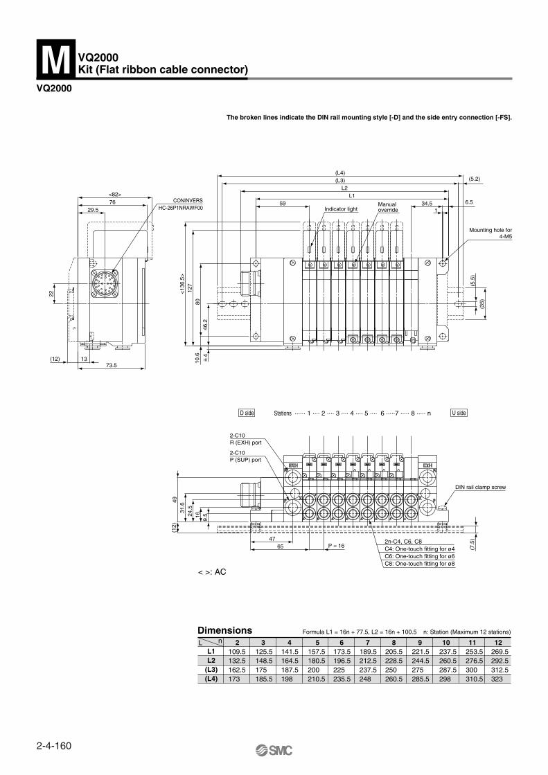
VQ2000
The broken lines indicate the DIN rail mounting style [-D] and the side entry connection [-FS].
< >: AC
Dimensions
L1L2
(L3)(L4)
2 3 4 5 6 7 8 9 10 11 12L nFormula L1 = 16n + 77.5, L2 = 16n + 100.5 n: Station (Maximum 12 stations)
<82>
29.5
22
76
(12) 1373.5
HC-26P1NRAWF00CONINVERS
<13
6.5>
(L4)(L3)
L2L1
59 34.5 6.5
127
(5.2)
1
10.6
8046
.2
(35)
(5.5
)
Indicator lightManualoverride
Mounting hole for4-M5
P (SUP) port2-C10
R (EXH) port2-C10
(7.5
)
P = 166547
(12)
4931
.6
1624.5
9.5
DIN rail clamp screw
269.5292.5312.5323
253.5276.5300310.5
237.5260.5287.5298
221.5244.5275285.5
205.5228.5250260.5
189.5212.5237.5248
173.5196.5225235.5
141.5164.5187.5198
125.5148.5175185.5
109.5132.5162.5173
157.5180.5200210.5
VQ2000Kit (Flat ribbon cable connector)M
4~ =
D side U sideStations ······ 1 ···· 2 ···· 3 ···· 4 ···· 5 ···· 6 ·····7 ····· 8 ····· n
2n-C4, C6, C8C4: One-touch fitting for ø4C6: One-touch fitting for ø6C8: One-touch fitting for ø8
2-4-160
2-4-161
VQC
SQ
VQ0
VQ4
VQ5
VQZ
VQD

Applicable network
The serial transmission system reduces wiring work, while minimizing wiring and saving space.
SI unit for DeviceNet/PROFIBUSAs a slave for DeviceNet/PROFIBUS, it is possible to control ON/OFF of a solenoid valve with the maximum of 32 points. Furthermore, by connecting a discrete input block, it is possible to input the sensor signal for 32 points at the maximum.
Input blockMeaning of an expansion block, connecting with SI unit, for sensor-inputting for auto switches, etc. Sensor-input is available up to 8 per one input block. By the NPN/PNP switch, it is able to adjust COM to sensor.
VQ2000 IP65, Applicable to Input/Output, Serial Transmission Type
VQ2000 only
How to Order Manifold
1 station
16 stations
01
16
Option
Port sizeWith One-touch fitting for ø4With One-touch fitting for ø6With One-touch fitting for ø8
With mixed size/with port plug
SymbolC4C6C8CM
Cylinder port
VQ2000Plug-in series
SI unit mountingD: D side mounting
Stations
VV5Q21 08 C6 D 1 N WQWS
··· ···
SymbolNilBD
K
NR
OptionNone
With back pressure check valveDIN rail mounting style
Special wiring specifications(Not double wiring)
With name plateExternal pilot
EnclosureIP65 (Dust tight/Low jetproof type)
When two or more symbols are specified, indicate them alphabetically.Example: -DNR
PNP(+) or SI/Input block: NoneNPN (–)
NilN
Input block COM
SI unit/Input block: NoneInput block: NoneInput block 1 pc.Input block 2 pcs.Input block 3 pcs.Input block 4 pcs.
Nil01234
Input block+COM–COM
Without SI unitDeviceNet
PROFIBUS-DP
0WQW
NWN
Model
Only +COM is available for DeviceNet. Order a mounting valve with +COM.Since PROFIBUS is –COM only, order –COM for valves to be mounted.
IP65 compliant
SI unit
Input block
If there is an input block, it comes with bracket.
DeviceNet/PROFIBUS-DP
Note)
Note)
VQ2000Kit (Serial transmission kit) for I/OS
2-4-162

VQC
SQ
VQ0
VQ4
VQ5
VQZ
VQD
2-4-163
Series VQ2000Plug-in Unit
Base Mounted
SI Unit (DeviceNet) SI Unit (PROFIBUS-DP) Input block
Indicator Unit (LED) Descriptions and Functions
Details in Connector
PWR
SI UNIT
PWR(V) MOD/NET
1
SETTINGS
4632
1
2
4
3
5
5
4
3
1
2
1
2
34
5
SW + SIGNAL–n+1
SW–SIGNAL-n
PE
Number
1
2
3
4
5
Description
SW+
N.C.
SW–
SIGNAL
PE
Function
∗ No. 2 pin of the input no. 0, 2, 4, 6 connector (connectors aligned in the right side on the input block) is connected internally with no. 4 pin (sensor input no.) of the input no. 1, 3, 5, 7 respectively. Thereby, it is possible to directly input 2 points which is bundled into 1 cable by the cluster connector, etc.
Number
1
2
3
Description
SV24V
SV0V
PE
Function
For solenoid valve +24 V
For solenoid valve 0 V
Protective ground
Number
1
2
3
4
5
Description
Drain
V+
V–
CAN_H
CAN_L
Function
Item conforming to Micro Style connector in DeviceNet specifications.
Number Description
M5V
A
B
+5V
SIELD
RTS
GND Terminal
Signal-N
Signal-P
Terminal +5 V
Shield ground
Optical fiber (Reserve)
Pin no. 3, 5, 7, 8, 10 and 11 marked with are open.
Input block SI Unit (DeviceNet) SI Unit (PROFIBUS-DP)
Input connector
Communicationconnector
Power sourceconnector
12345
12345
Connector input no.: 0, 2, 4, 6 Input no.: 1, 3, 5, 7
When an enclosure equivalent to IP65 is required, place a waterproof cover on the unused input connector. As for waterproof cover, order it separately.Example: OMRON Corp. XS2Z-12
Caution
Description
PWR(V)
PWR
MOD/NET
Function
ON when solenoid valve power supply is turned ON
ON when DeviceNet circuit power supply input is turned ON
OFF: Power supply off, off line, or when checking duplication of MAC_ID
Green blinking: Waiting for connection (On line)
Green ON: Connection established (On line)
Red blinking: Connection time out (Minor communication abnormality occurs)
Red ON: MAC_ID duplication error, or BUSOFF error (Major communication abnormality occurs)
Description Function
ON when solenoid valve power supply is turned ONOFF when the power supply voltage is less than 19 V
ON when operating (SI unit power supply is ON)
ON when self-diagnosis device detects abnormality
ON for BUS abnormality
PWR
0 to 7
Function
129
1
2
4
6
PWR(V) MOD/NETPWR
1
4632
TMTM
FB
PS
SETTINGS
ADDRESS
H
DIA BF
L
PWR(V) RUN
FB
PS
0246
1357
PWR
Communication connector (PROFIBUS-DP): Made by CONINVERS GmbH RC-2RS1N12 12 pinsCable side connector example: Made by Siemens AG 6ES5 760-2CB11
∗ Connector’s shape and pin assignment is interchangeable with ET200C made by Siemens AG.
Power source connector: Series 723 (made by Franz Binder GmbH) 5 pins (72309-0115-80-05)Cable side connector example: Franz Binder GmbH 72309-0114-70-15, etc.
Communication connector (DeviceNet): M12 5 pins (for DeviceNet compliant)Example of corresponding cable assemblies with connector: OMRON Corporation: DCA1-5CN05F1 Karl Lumberg GmbH & Co. KG: RKT5-56
Input connector: M12 5 pins (XS2F compatible made by OMRON Corp.) x 8 pcs.Cable side connector example: XS2G made by OMRON Corp.
<DeviceNet> For input block 0 V, <Profibus or Interbus> For input unit and SI unit 0 V
<DeviceNet> For input block +24 V, <Profibus or Interbus> For input unit and SI unit +24 VSW24V
SW0V
4
5
PWR
RUN
DIA
BF
DescriptionON when sensor power is turned ON
OFF when short circuit protection is working
ON when each sensor input goes ON
Function
1
2
4
6
9
12
Drain/Shield
Circuit power supply +
Circuit power supply –
Signal H
Signal L
Sensor power supply +
Open ∗
Sensor power supply –
Sensor input signal
Protective sensor ground
∗ Din type 5 pins.
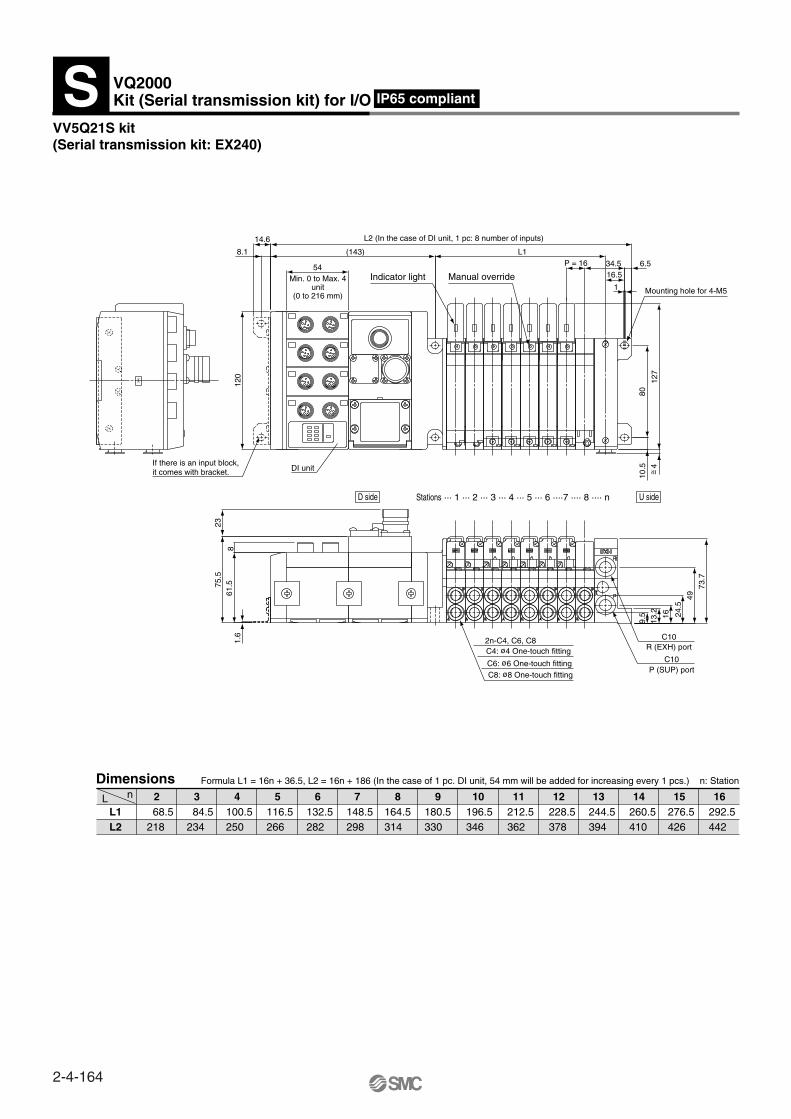
VV5Q21S kit(Serial transmission kit: EX240)
nLL1L2
2 3 4 5 6 7 8 9 10 11 12 13 14 15 16
Formula L1 = 16n + 36.5, L2 = 16n + 186 (In the case of 1 pc. DI unit, 54 mm will be added for increasing every 1 pcs.) n: StationDimensions
IP65 compliant
SM
C
14.6
8.1 (143)
120
54
L2 (In the case of DI unit, 1 pc: 8 number of inputs)
L1P = 16 34.5 6.5
16.5
1
127
8010
.5DI unit
Indicator light Manual overrideMin. 0 to Max. 4unit
(0 to 216 mm)Mounting hole for 4-M5
73.7
49
24.5
16
13.2
9.5
P (SUP) portC10
R (EXH) portC10
8
2375
.561
.51.
6
C8: ø8 One-touch fittingC6: ø6 One-touch fitting
C4: ø4 One-touch fitting2n-C4, C6, C8
If there is an input block,it comes with bracket.
292.5442
276.5426
260.5410
244.5394
228.5378
212.5362
196.5346
180.5330
164.5314
148.5298
132.5282
116.5266
100.5250
84.5234
68.5218
VQ2000Kit (Serial transmission kit) for I/OS
D side U sideStations ··· 1 ··· 2 ··· 3 ··· 4 ··· 5 ··· 6 ····7 ···· 8 ···· n
4~ =
2-4-164

VQC
SQ
VQ0
VQ4
VQ5
VQZ
VQD
Terminalblock
Conforming toIP65 in standard specifications
Easy-to-use terminal block
Valve
In the case of sub-plate alone
VQ2 1 0 0 5 W 02
VQ2000 – PW – 02
Entry is the same asstandard products.
Thread type
With and without sub-plate
EnclosureDust tight
IP65 (Dust tight/Low jetproof type)
Nil
W
Rc
NPT
NPTF
G
Nil
N
T
F
Without sub-plate
With sub-plate (Port size: 1/4)
Nil
02
Note) Valves are IP65 specifications.
Note)
Dimensions
How to Order
(43.8)10.510.5
20
130.1 (AC)
(86.3) (AC)
78.5
(A
C)
22.4
2525
53.6
70.7
15.4
5
72.6
(D
C)
121 (DC)
(77.1) (DC) 15.5
37
5
2512
39.1 43.8
2.519.514.5
45
89.4 4
(A port) (B port)
Electrical entry
G3/8
VQ21010 -
P, A, B, R1, R2 port5 1/4
2-ø4.5(Mounting hole)
Clamp screw
Manual override
Indicator light
External pilot portM5 x 0.8
+
Series VQ2000VQ2000 Only
Sub-plate Single Unit
Sub-plate
(A, B
por
t)
2-4-165
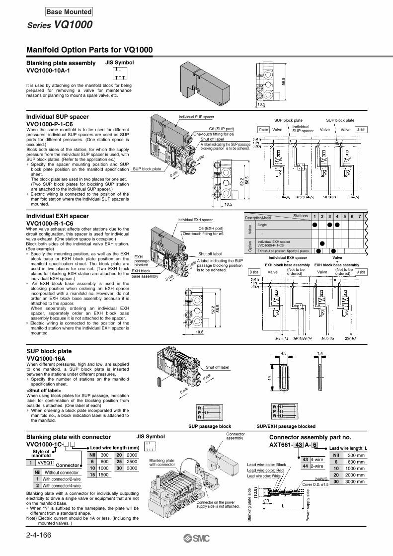
Manifold Option Parts for VQ1000
Blanking plate assemblyVVQ1000-10A-1
Individual SUP spacerVVQ1000-P-1-C6
Individual EXH spacerVVQ1000-R-1-C6
SUP block plateVVQ1000-16A
Blanking plate with connectorVVQ1000-1C-
Style of manifold
Connector
Lead wire length (mm)
1 VV5Q11
Nil Without connectorWith connector/2-wireWith connector/4-wire
12
Nil 300600
10001500
61015
200025003000
202530
Connector assembly part no.
SUP passage block SUP/EXH passage blocked
AXT661- A-Lead wire length: L
4-wire2-wire
4344
Nil 300 mm600 mm
1000 mm2000 mm3000 mm
6102030
643
Val
veO
ptio
n
Description/Model Stations 1 2 3 4 5 6 7
Single
Individual EXH spacerVVQ1000-R-1-C6
EXH shut off position: Specify 2 places.
Individual EXH spacer+
EXH block base assembly
Valve+
EXH block base assembly
It is used by attaching on the manifold block for being prepared for removing a valve for maintenance reasons or planning to mount a spare valve, etc.
When the same manifold is to be used for different pressures, individual SUP spacers are used as SUP ports for different pressures. (One station space is occupied.)Block both sides of the station, for which the supply pressure from the individual SUP spacer is used, with SUP block plates. (Refer to the application ex.)∗ Specify the spacer mounting position and SUP
block plate position on the manifold specification sheet. The block plate are used in two places for one set. (Two SUP block plates for blocking SUP station are attached to the individual SUP spacer.)
∗ Electric wiring is connected to the position of the manifold station where the individual SUP spacer is mounted.
When valve exhaust affects other stations due to the circuit configuration, this spacer is used for individual valve exhaust. (One station space is occupied.)Block both sides of the individual valve EXH station. (See example)∗ Specify the mounting position, as well as the EXH
block base or EXH block plate position on the manifold specification sheet. The block plate are used in two places for one set. (Two EXH block plates for blocking EXH station are attached to the individual EXH spacer.)
∗ An EXH block base assembly is used in the blocking position when ordering an EXH spacer incorporated with a manifold no. However, do not order an EXH block base assembly because it is attached to the spacer. When separately ordering an individual EXH spacer, separately order an EXH block base assembly because it is not attached to the spacer.
∗ Electric wiring is connected to the position of the manifold station where the individual EXH spacer is mounted.
When different pressures, high and low, are supplied to one manifold, a SUP block plate is inserted between the stations under different pressures.∗ Specify the number of stations on the manifold
specification sheet.
<Shut off label>When using block plates for SUP passage, indication label for confirmation of the blocking position from outside is attached. (One label of each)∗ When ordering a block plate incorporated with the
manifold no., a block indication label is attached to the manifold.
Blanking plate with a connector for individually outputting electricity to drive a single valve or equipment that are not on the manifold base.∗ When “N” is suffixed to the nameplate, the plate will be
different from a standard shape.Note) Electric current should be 1A or less. (Including the
mounted valves. )
JIS Symbol
JIS Symbol
Individual SUP spacer
Individual EXH spacer
C6 (SUP port)One-touch fitting for ø6
SUP block plate
SUP block plateSUP block plate
Valve Valve Valve
Shut off label
C6 (EXH port)One-touch fitting for ø6
D side
U side
D side
U side
D side
U side
Shut off label
EXH blockbase assembly
IndividualSUP spacer U side
U side
D side
Valve ValveD side(Not to beordered)
(Not to beordered)
EXHpassageblocked
···
Shut off label
Connectorassembly
Blanking platewith connector
Connector on the powersupply side is not attached.
Lead wire color: BlackLead wire color: RedLead wire color: White
Bla
nkin
g pl
ate
side
Cover O.D. ø1.524AWG
Pow
er s
uppl
y si
de
A label indicating the SUP passageblocking position is to be adhered.
A label indicating the SUP passage blocking position is to be adhered.
2-4-166
Series VQ1000Base Mounted

Manifold block assemblyElectrical entry
Blanking plug (For One-touch fittings)
KQ2P-
Name plate [-N]VVQ1000- N-Station (1 to Max. stations)
Elbow fitting assemblyVVQ1000-F-L (C3, C4, C6, M5)
Port plugVVQ0000-58A
23040608
3.2468
KQ2P-23KQ2P-04KQ2P-06KQ2P-08
16161820.5
31.5323539
3.2 6 810
A L DModelApplicable fittingssize ød
Dimensions
EXH block base assemblyVVQ1000-19A- - (C3, C4, C6, M5)
For F kit (2 to 12 stations)/Double wiringFor F kit (13 to 24 stations)/Double wiringFor F kit (2 to 24 stations)/Single wiringFor P, G, T, S kit (2 to 12 stations)/Double wiringFor P, G, T, S kit (13 to 24 stations)/Double wiringFor P, G, T, S kit (2 to 24 stations)/Single wiringL0 kitL1 kitL2 kit
∗ 1 to 8 stations
F1F2F3P1P2P3L0 ∗
L1 ∗
L2 ∗
FPL
<Blocking indication label>
Note) ( ): For VVQ1000-NC-n
EXH passage blocked SUP/EXH passage blocked
Back pressure check valve assembly [-B]VVQ1000-18A
1.
2.
NNC
The manifold block assembly is used between stations for which exhaust is desired to be divided when valve exhaust affects other stations due to the circuit configuration. The EXH passage on the D-side is blocked in the EXH block base assembly. It is also used in combination with an individual EXH spacer for individual exhaust.
∗ Specify the number of stations on the manifold specification sheet.
∗ When ordering by using the manifold specification form, specify the EXH block base assembly no. by adding suffix “∗” below the manifold no.
When blocking the EXH passage with an EXH block base assembly, indication label for confirmation of the blocking position from outside is attached. (One label for each)∗ When ordering a EXH block base incorporated with the
manifold no., a block indication label is attached to the manifold.
It prevents cylinder malfunction caused by other valve exhaust. Insert it into R (EXH) port on the manifold side of a valve which is affected. It is effective when a single action cylinder is used or an exhaust center type solenoid valve is used.Note) When a check valve for back pressure prevention is
desired, and is to be installed only in certain manifold stations, write clearly the part no. and specify the number of stations by using the manifold specification sheet.
It is a transparent resin plate for placing a label that indicates solenoid valve function, etc.Insert it into the groove on the side of the end plate and bend it as shown in the figure.∗ When the blanking plate with connector is mounted, it
automatically will be “VVQ1000-NC-n” with an option symbol [-N]
It is used for piping that extends upward or downward from the manifold.When installing it in part of the manifold stations, specify the assembly no. and the mounting position and number of stations by means of the manifold specification sheet.∗ When mounting elbow fittings assembly on the edge of
manifold station and a silencer on EXH port, select a silencer, AN203-KM8.Silencer (AN200-KB8) is interfered with fittings.
The plug is used to block the cylinder port when using a 4 port valve as a 3 port valve.
∗ When ordering a plug incorporated with a manifold, indicate “CM” for the port size in the manifold no., as well as, the mounting position and number of stations and cylinder port mounting positions, A and B, on the manifold specification sheet.
∗ Lightly screw an M3 screw in the port plug hole and pull it for removal.
∗ When ordering assemblies incorporated with a manifold, indicate “L” or “B” for the manifold port size. (When installed in all stations.)
* When ordering assemblies incorporated with a manifold, add suffix “-B” to the manifold no.
∗ When ordering assemblies incorporated with a manifold, add suffix “-N” to the manifold no.
(Precautions)The back pressure check valve assembly is assembly parts with a check valve structure. However, as slight air leakage is allowed for the back pressure, take care the exhaust air will not be throttled at the exhaust port.When a back pressure check valve is mounted, the effective area of the valve will decrease, by about 20%.
N: StandardNC: For mounting
blanking plate with connector
It is inserted into an unused cylinder port and SUP/EXH ports.Purchasing order is available in units of 10 pieces.
EXHpassage blocked
Solid forming
Black screw
Shut off label
D side
U side
EXH blockbase assembly U sideD side
2 pcs. in 1 set
P = 10.5
Stations
Hole
~ =13.
5
~ =40
Downward Upward
2-4-167
Series VQ1000Plug-in Unit
Base Mounted
VQC
SQ
VQ0
VQ4
VQ5
VQZ
VQD
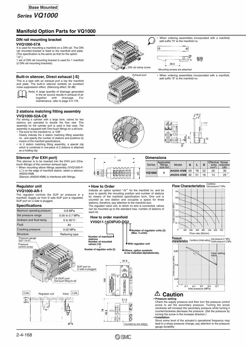
Manifold Option Parts for VQ1000
DIN rail mounting bracketVVQ1000-57A
2 stations matching fitting assemblyVVQ1000-52A-C8
Regulator unitVVQ1000-AR-1
Silencer (For EXH port)
Built-in silencer, Direct exhaust [-S]
SpecificationsMaximum operating pressure
Set pressure range
Ambient and fluid temp.
Fluid
Cracking pressure
Structure
0.8 MPa
0.05 to 0.7 MPa
5 to 50°CAir
0.02 MPa
Relieving type
• How to Order
Pressurecharacteristics
How to order manifoldVV5Q11-14C6FUO-DG2
Number of manifold stationsNumber of mountedvalves (12)
Others, option symbols: to be indicated alphabetically.
With regulator unit
Number of regulator units (2)(Max. 3 units)
VQ1000
Series Model A L D
8AN200-KM8AN203-KM8
5932
7851
2216
2014
3025 ∗
Effective area(mm2)
Noise reduction
(dB)
Applicable fittings
size ød
Dimensions
Caution
It is used for mounting a manifold on a DIN rail. The DIN rail mounted bracket is fixed to the manifold end plate. (The specification is the same as that for the option “-D”.)1 set of DIN rail mounting bracket is used for 1 manifold (2 DIN rail mounting brackets).
This is a type with an exhaust port a top the manifold end plate. The built-in silencer exhibits an excellent noise suppression effect. (Silencing effect: 30 dB)
∗ When ordering assemblies incorporated with a manifold, add suffix “D” to the manifold no.
∗ When ordering assemblies incorporated with a manifold, add suffix “S” to the manifold no.
For driving a cylinder with a large bore, valves for two stations are operated to double the flow rate. This assembly for the cylinder port is used in that case. The assembly is equipped with One-touch fittings for a ø8 bore.∗ The bore for the manifold no. is “CM”.
Clearly indicate the 2 station matching fitting assembly no., and specify the number of stations and positions by means of the manifold specifications.
∗ In 2 station matching fitting assembly, a special clip which is combined in one-piece of 2 stations is attached as a holding clip.
This silencer is to be inserted into the EXH port (One-touch fittings) of the common exhaust type∗ When mounting elbow fittings assembly (VVQ1000-F-
L) on the edge of manifold station, select a silencer, AN203-KM8.Silencer (AN200-KM8) is interfered with fittings.
The regulator controls the SUP air pressure in a manifold. Supply air from D side SUP port is regulated. SUP port on U side is plugged.
Indicate an option symbol “-G”∗ for the manifold no. and be sure to specify the mounting position and number of stations by means of the manifold specification form. One unit is counted as one station and occupies a space for three stations, therefore, pay attention to the manifold size.The regulator valve unit, to which no wire is connected, valves can be mounted up to the standard max. number of stations of each kit.
• Pressure settingCheck the supply pressure and then turn the pressure control screw to set the secondary pressure. Turning the screw clockwise will increase the secondary pressure while turning it counterclockwise decrease the pressure. (Set the pressure by turning the screw in the increase direction.)
• InstallationSince some level of the actuator’s operational frequency may lead to a sharp pressure change, pay attention to the pressure gauge durability.
Note) A large quantity of drainage generated in the air source results in exhaust of air together with drainage. For maintenance, refer to page 2-4-176.
U sideD side
DIN rail clamp screwMounting screws are attached
Exhaust port
~=~=18.3
3
~=A
Flow CharacteristicsConditions:Inlet pressure 0.7 MPa
Flow rate (Nl/min)
Inlet pressure 0.7 MPaOutlet pressure 0.2 MPaConditions (Initial setting)
Out
let p
ress
ure
(MP
a)O
utle
t pre
ssur
e (M
Pa)
Initial settingvalue
Counted as one station.
SUP port onU side is plugged
Regulator unit
Inlet pressure (MPa)
Pressure gaugeG27-10-01
Pressurecontrol screw
C8 (SUP) portOne-touch fitting for ø8
Valve
+Number of regulator units (2)
2-4-168
Series VQ1000Base Mounted

VQC
SQ
VQ0
VQ4
VQ5
VQZ
VQD
2-C3, C4, C6, M5C3: One-touch fitting for ø3.2C4: One-touch fitting for ø4C6: One-touch fitting for ø6M5: M5 thread
2n-C3, C4, C6, M5C3: One-touch fitting for ø3.2C4: One-touch fitting for ø4C6: One-touch fitting for ø6M5: M5 thread
D side U sideStations ···· 1 ··· 2 ··· 3
Double check block (Separated type): For VQ1000VQ1000-FPG-
(Check valve operation principle)
VVQ1000-FPG-02 1 set∗ VQ1000-FPG-C6M5-D 2 pcs.
Based on JIS B 8375-1981(Supply pressure: 0.5 MPa)
Dimensions
Single unit Manifold
L1L2L3
315060.5
1 2 3 4 5 6 7 8 9 10 11 124262.573
537585.5
6487.598
75100110.5
86112.5123
97125135.5
108125135.5
119137.5148
130150160.5
141162.5173
152175185.5
nL
L1L2L3
163187.5198
13 14 15 16 17 18 19 20 21 22 23 24174187.5198
185200210.5
196212.5223
207225235.5
218237.5248
229250260.5
240250260.5
251262.5273
262275285.5
273287.5298
284300310.5
nL
Dimensions Formula L1 = 11n + 20 n: Station (Maximum 24)
How to OrderDouble check block
VQ1000-FPG- FM5C4IN side port size OUT side port size
OptionNil
D
N
NoneWith bracket
DIN rail mountingstyle (For manifold)
Name plate
Note)
M5C3C4C6
M5 threadOne-touch fitting for ø3.2One-touch fitting for ø4One-touch fitting for ø6
C4C6
With One-touch fitting for ø4With One-touch fitting for ø6
Part no.VQ1000-FPG-FB
Tightening torque0.22 to 0.25 N·m
Bracket Assembly
Manifold
VVQ1000-FPG- 06Stations01
··· ···
16
1 station
16 stationsVVQ1000-FPG-06··6 types of manifold∗VQ1000-FPG-C4M5-D, 3 sets∗VQ1000-FPG-C6M5-D, 3 sets
<Example>
Double Check block
<Example>
F
Caution
SpecificationsMax. operating pressureMin. operating pressureAmbient and fluid temp.Flow characteristics: CMax. operating frequency
0.8 MPa0.15 MPa–5 to 50°C
0.60 dm3/(s·bar)180 CPM
2 position 3 positionexhaust center
It is used on the outlet side piping to keep the cylinder in the intermediate position for a long time. Combining the double check block with a built-in pilot type double check valve and a 3 position exhaust center solenoid valve will enable the cylinder to stop in the middle or maintain its position for a long time.The combination with a 2 position single/double solenoid valve will permit this block to be used for preventing the dropping at the cylinder stroke end when the SUP residual pressure is released..
Note)
When two or more symbols are specified, indicate them alphabetically. Example) -DN
• Air leakage from the pipe between the valve and cylinder or from the fittings will prevent the cylinder from stopping for a long time. Check the leakage using neutral household detergent, such as dish washing soap. Also check the cylinder’s tube gasket, piston packing and rod packing for air leakage.
• Since One-touch fittings allow slight air leakage, screw piping (with M5 thread) is recommended when stopping the cylinder in the middle for a long time.
• Combining double check block with 3 position closed center or pressure center solenoid valve will not work.• M5 fitting assembly is attached, not incorporated into the double check block. After screwing in the M5 fittings,
mount the assembly on the double check block. Tightening torque: 0.8 to 1.2 N·m• If the exhaust of the double check block is throttled too much, the cylinder may not operate properly and may
not stop intermediately. • Set the cylinder load so that the cylinder pressure will be within two times that of the supply pressure.
2-C4, C6C4: One-touch fitting for ø4C6: One-touch fitting for ø6
2n-C4, C6C4: One-touch fitting for ø4C6: One-touch fitting for ø6
Mounting holefor M3
Mounting holefor M2.5
Residual pressure releasemanual override
Residual pressure releasemanual override
DIN rail clamp screw
~ =4.
5
~ =4.
5
Dropprevention
Intermediatestops
Cylinder pressure
SUP side pressure (P1)To CYL port
2-4-169
Series VQ1000Plug-in Unit
Base Mounted
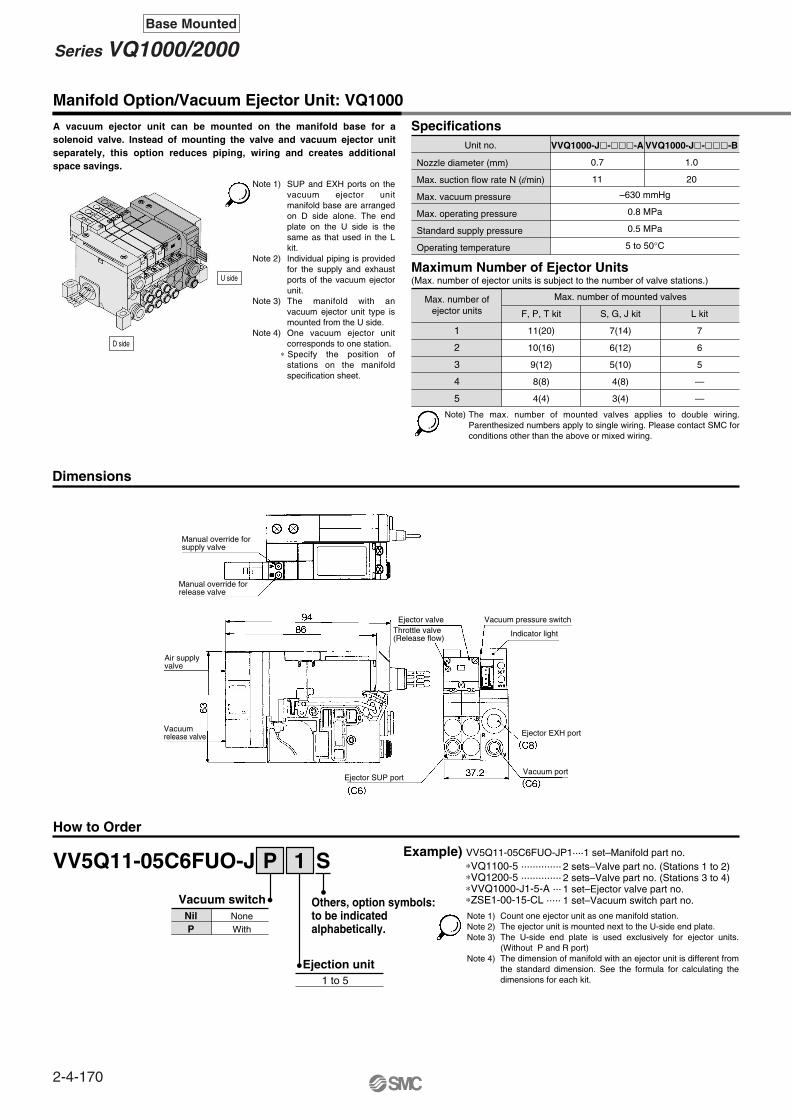
Dimensions
How to Order
VV5Q11-05C6FUO-J
Vacuum switchNilP
NoneWith
Manifold Option/Vacuum Ejector Unit: VQ1000
Specifications
Maximum Number of Ejector Units
Nozzle diameter (mm)
Max. suction flow rate N (l/min)
Max. vacuum pressure
Max. operating pressure
Standard supply pressure
Operating temperature
VVQ1000-J--A
0.7
11
VVQ1000-J--B
1.0
20
–630 mmHg
0.8 MPa
0.5 MPa
5 to 50°C
Max. number ofejector units
1
2
3
4
5
F, P, T kit
11(20)
10(16)
9(12)
8(8)
4(4)
7(14)
6(12)
5(10)
4(8)
3(4)
7
6
5
—
—
S, G, J kit
Max. number of mounted valves
L kit
Note)
1 SP
1 to 5
Ejection unit
Others, option symbols:to be indicated alphabetically.
Example) VV5Q11-05C6FUO-JP1····1 set–Manifold part no.∗VQ1100-5 ·············· ∗VQ1200-5 ·············· ∗VVQ1000-J1-5-A ···∗ZSE1-00-15-CL ·····
2 sets–Valve part no. (Stations 1 to 2)2 sets–Valve part no. (Stations 3 to 4)1 set–Ejector valve part no.1 set–Vacuum switch part no.
Note 1)Note 2)Note 3)
Note 4)
(Max. number of ejector units is subject to the number of valve stations.)
A vacuum ejector unit can be mounted on the manifold base for a solenoid valve. Instead of mounting the valve and vacuum ejector unit separately, this option reduces piping, wiring and creates additional space savings.
The max. number of mounted valves applies to double wiring. Parenthesized numbers apply to single wiring. Please contact SMC for conditions other than the above or mixed wiring.
Count one ejector unit as one manifold station.The ejector unit is mounted next to the U-side end plate.The U-side end plate is used exclusively for ejector units. (Without P and R port)The dimension of manifold with an ejector unit is different from the standard dimension. See the formula for calculating the dimensions for each kit.
U side
D side
Note 1)
Note 2)
Note 3)
Note 4)
SUP and EXH ports on the vacuum ejector unit manifold base are arranged on D side alone. The end plate on the U side is the same as that used in the L kit.Individual piping is provided for the supply and exhaust ports of the vacuum ejector unit.The manifold with an vacuum ejector unit type is mounted from the U side.One vacuum ejector unit corresponds to one station.
∗ Specify the position of stations on the manifold specification sheet.
Manual override forsupply valve
Manual override forrelease valve
Air supplyvalve
Vacuumrelease valve
Ejector valveThrottle valve(Release flow)
Ejector SUP port
Vacuum pressure switch
Indicator light
Ejector EXH port
Vacuum port
Unit no.
2-4-170
Series VQ1000/2000Base Mounted

VQC
SQ
VQ0
VQ4
VQ5
VQZ
VQD
Flow/Exhaust Characteristics of Ejector Unit
How to Order Vacuum Pressure Switches
How to Order Vacuum Ejector Valves
VVQ1000Manifold
1
1234
Plug-in unit
J 1 5 H C A
569
100 VAC (50/60 Hz)200 VAC (50/60 Hz)110 VAC (50/60 Hz)220 VAC (50/60 Hz)
24 VDC12 VDCOthers
NilBC
Non-locking push typeLocking type (Tool required)Locking type (Manual)
SymbolAB
Nozzlediameter
Vacuum release valve
Coil voltage
Specifications
Manual override
ø0.7ø1.0
With
ZSE1Switch/Voltage (Solid state: 12 to 24 VDC)
How to order connectors
141516171819
NPN/1 setting, 3 revolution adjustmentNPN/1 setting, 200° adjustment
NPN/2 setting, 3 revolution adjustmentNPN/2 setting, 200° adjustment
NPN/1 setting, 3 revolution adjustment, analogNPN/1 setting, 200° adjustment, analog
Wiring specifications
CL00 15
NilLC
CLCN
Grommet type, Lead wire length 0.6 mGrommet type, Lead wire length 3 m
Connector type, Lead wire length 0.6 mConnector type, Lead wire length 3 m
Without connector Note)
Note)
Nil3050
0.6 m3 m5 m
Lead wire length
SpecificationsStandard
typeHigh pressure
typeLow wattage
type
FunctionSymbol
Nil
H
Y
DC AC(1.0W)
(1.5 W)
(0.5W)
NegativeCOMN
For power consumption of AC type, refer to page 2-4-129.When two or more symbols are specified, indicate them alphabetically.
When ordering the switch with 5 m lead wire length, order separately the switch without connector and the connector. (Refer to below.) Besides, as for details, refer to the Vacuum Equipment catalog.
(1)
—
—
—
Note 1)Note 2)
(The flow characteristics are for the supply pressure of 0.5 MPa.)
• Without lead wire (Connector 1 pc., Socket 4 pcs.)• With lead wire
····· ZS-20-A····························································· ZS-20-5A-50
Nozzle Diameter ø0.7Exhaust Characteristics
Vac
uum
pre
ssur
e (m
mH
g)
Vacuum pressure
Vacuum pressure
Air consumption
Air consumption
Suction flow rate
Suction flow rate
Supply pressure (MPa)
Suc
tion
flow
rat
e N
(l/m
in)
Air
cons
umpt
ion
N (l/m
in)
Vac
uum
pre
ssur
e (m
mH
g)
Vac
uum
pre
ssur
e (m
mH
g)V
acuu
m p
ress
ure
(mm
Hg)
Supply pressure (MPa)
Suc
tion
flow
rat
e N
(l/m
in)
Air
cons
umpt
ion
N (l/m
in)
Flow Characteristics
Flow Characteristics
Suction flow rate N (l/min)
Suction flow rate N (l/min)
Nozzle Diameter ø1.0
2-4-171
Series VQ1000/2000Plug-in Unit
Base Mounted

Manifold Option Parts for VQ2000
Blanking plate assemblyVVQ2000-10A-1
Individual SUP spacerVVQ2000-P-1-C8
Individual EXH spacerVVQ2000-R-1-C8
SUP block plateVVQ2000-16A
EXH block plateVVQ2000-19A
<Blocking indication label>
<Blocking indication label>
It is used by attaching on the manifold block for being prepared for removing a valve for maintenance reasons or planning to mount a spare valve, etc.
When valve exhaust affects other stations due to the circuit configuration, this spacer is used for individual valve exhaust. (One station space is occupied.)Block both sides of the individual valve EXH station. (See example)∗ Specify the mounting position, as well as the EXH
block base or EXH block plate position on the manifold specification sheet. The block plates are used in two places for one set. (Two EXH block plates for blocking EXH station are attached to the individual EXH spacer.)
∗ Electric wiring is connected to the position of the manifold station where the individual EXH spacer is mounted.
When different pressures, high and low, are supplied to one manifold, a SUP block plate is inserted between the stations under different pressures.
∗ Specify the number of stations on the manifold specification sheet.
When using block plates for SUP passage, indication label for confirmation of the blocking position from outside is attached. (One label of each)
The EXH block plate is used between stations for which exhaust is desired to be divided when valve exhaust affects other stations due to the circuit configuration. It is also used in combination with an individual EXH spacer for individual exhaust.∗ Specify the number of stations on the manifold
specification sheet.
When blocking the EXH passage with an EXH block plate, an indication label for confirmation of the blocking position from outside is attached. (One label for each)
∗ When ordering a block plate incorporated with the manifold no., a block indication label is attached to the manifold.
∗ When ordering a block plate incorporated with the manifold no., a block indication label is attached to the manifold.
U sideD side
D side
U side
D side
U side
D side
U side
JIS Symbol
IndividualSUP spacer
C8 (SUP port)One-touch fitting for ø8
Shut off label
SUP block plate
SUP block plate SUP block plate
Valve
5(R)1(P)3(R2)
Valve Valve
U sideD side Valve ValveValve
IndividualSUP spacer
D side
U side
Individual EXH spacer
C8 (EXH port)One-touch fitting for ø8
Shut off labelA label indicating the EXH passageblocking position is to be adhered.
EXH block plate EXH block plate
IndividualEXH spacer
EXH blockplate
Shut off label
SUP passage blocked SUP/EXH passage blocked
SUP/EXH passage blocked
Shut off label
2 pcs. in 1 set
EXH passage blocked
A label indicating the SUP passageblocking position is to be adhered.
When the same manifold is to be used for different pressures, individual SUP spacers are used as SUP ports for different pressures. (One station space is occupied.)Block both sides of the station, for which the supply pressure from the individual SUP spacer is used, with SUP block plates. (Refer to the application ex.)∗ Specify the spacer mounting position and SUP block
plate position on the manifold specification sheet. The block plate are used in two places for one set. (Two SUP block plates for blocking SUP station are attached to the individual SUP spacer.)
∗ Electric wiring is connected to the position of the manifold station where the individual SUP spacer is mounted.
2-4-172
Series VQ2000Base Mounted
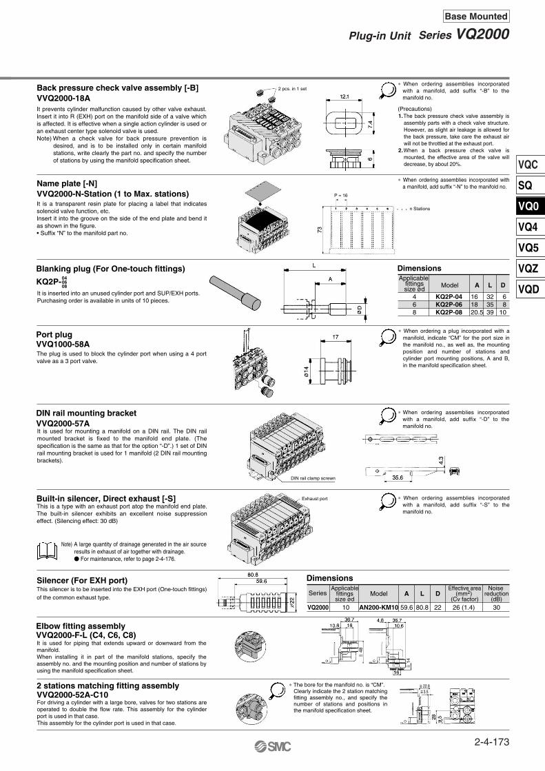
VQC
SQ
VQ0
VQ4
VQ5
VQZ
VQD
Blanking plug (For One-touch fittings)
KQ2P-
Name plate [-N]VVQ2000-N-Station (1 to Max. stations)
Elbow fitting assemblyVVQ2000-F-L (C4, C6, C8)
2 stations matching fitting assemblyVVQ2000-52A-C10
Port plugVVQ1000-58A
040608
Back pressure check valve assembly [-B]VVQ2000-18A
Silencer (For EXH port)
VQ2000
Series Model A L D
10 AN200-KM10 59.6 80.8 26 (1.4) 22 30
Effective area(mm2)
(Cv factor)
Noise reduction
(dB)
Applicablefittingssize ød
Dimensions
Built-in silencer, Direct exhaust [-S]
DIN rail mounting bracketVVQ2000-57A
468
KQ2P-04KQ2P-06KQ2P-08
161820.5
323539
68
10
A L DModelApplicable
fittingssize ød
Dimensions
It prevents cylinder malfunction caused by other valve exhaust. Insert it into R (EXH) port on the manifold side of a valve which is affected. It is effective when a single action cylinder is used or an exhaust center type solenoid valve is used.Note) When a check valve for back pressure prevention is
desired, and is to be installed only in certain manifold stations, write clearly the part no. and specify the number of stations by using the manifold specification sheet.
It is a transparent resin plate for placing a label that indicates solenoid valve function, etc.Insert it into the groove on the side of the end plate and bend it as shown in the figure.• Suffix “N” to the manifold part no.
It is inserted into an unused cylinder port and SUP/EXH ports.Purchasing order is available in units of 10 pieces.
The plug is used to block the cylinder port when using a 4 port valve as a 3 port valve.
It is used for mounting a manifold on a DIN rail. The DIN rail mounted bracket is fixed to the manifold end plate. (The specification is the same as that for the option “-D”.) 1 set of DIN rail mounting bracket is used for 1 manifold (2 DIN rail mounting brackets).
This is a type with an exhaust port atop the manifold end plate. The built-in silencer exhibits an excellent noise suppression effect. (Silencing effect: 30 dB)
This silencer is to be inserted into the EXH port (One-touch fittings) of the common exhaust type.
It is used for piping that extends upward or downward from the manifold.When installing it in part of the manifold stations, specify the assembly no. and the mounting position and number of stations by using the manifold specification sheet.
For driving a cylinder with a large bore, valves for two stations are operated to double the flow rate. This assembly for the cylinder port is used in that case.This assembly for the cylinder port is used in that case.
∗ When ordering assemblies incorporated with a manifold, add suffix “-S” to the manifold no.
∗ When ordering assemblies incorporated with a manifold, add suffix “-D” to the manifold no.
∗ When ordering a plug incorporated with a manifold, indicate “CM” for the port size in the manifold no., as well as, the mounting position and number of stations and cylinder port mounting positions, A and B, in the manifold specification sheet.
∗ When ordering assemblies incorporated with a manifold, add suffix “-N” to the manifold no.
(Precautions)1.The back pressure check valve assembly is
assembly parts with a check valve structure. However, as slight air leakage is allowed for the back pressure, take care the exhaust air will not be throttled at the exhaust port.
2.When a back pressure check valve is mounted, the effective area of the valve will decrease, by about 20%.
∗ When ordering assemblies incorporated with a manifold, add suffix “-B” to the manifold no.
Note) A large quantity of drainage generated in the air source results in exhaust of air together with drainage. For maintenance, refer to page 2-4-176.
∗ The bore for the manifold no. is “CM”.Clearly indicate the 2 station matching fitting assembly no., and specify the number of stations and positions in the manifold specification sheet.
2 pcs. in 1 set
P = 16
n Stations
DIN rail clamp screwn
Exhaust port
3.5~=~= 22.8
~ =48
~ =14
2-4-173
Series VQ2000Plug-in Unit
Base Mounted
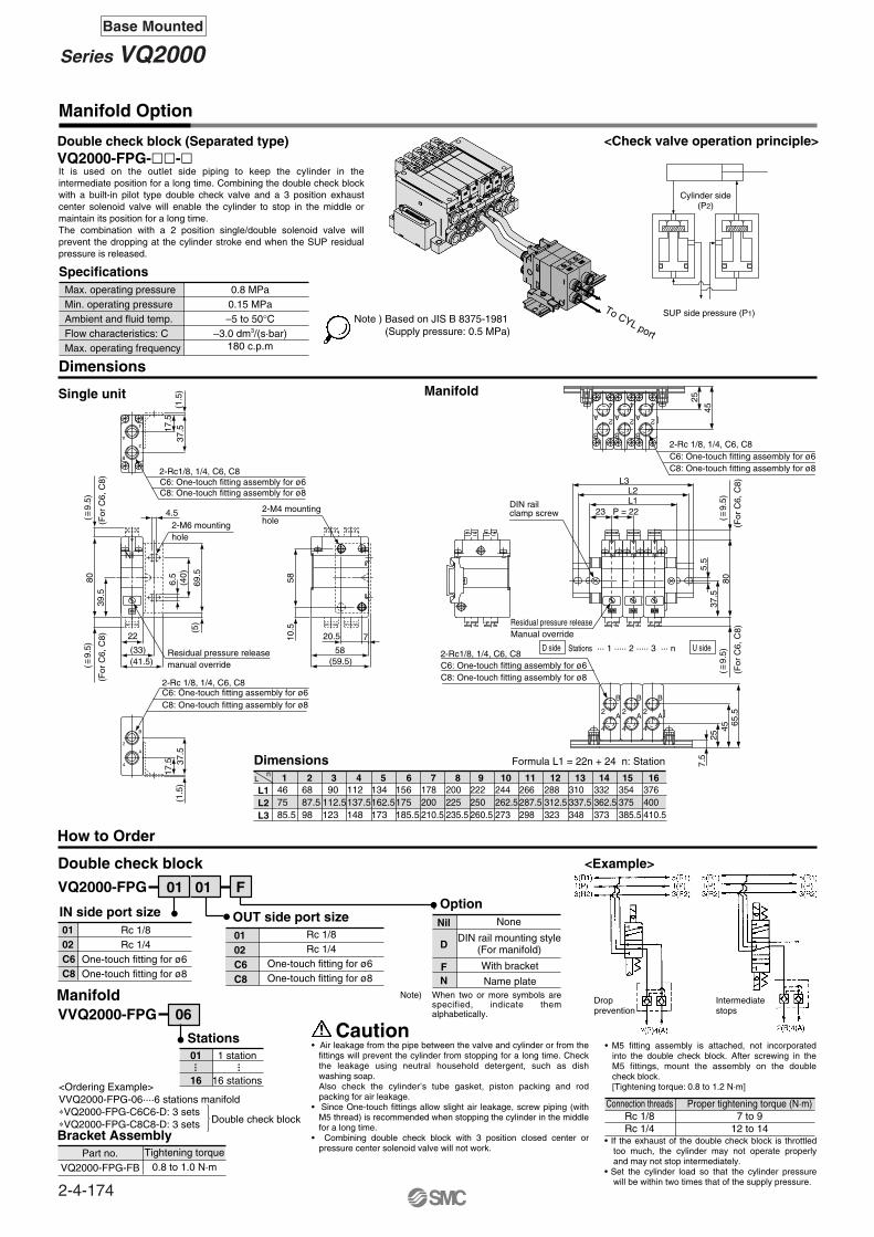
C8: One-touch fitting assembly for ø8
2-Rc1/8, 1/4, C6, C8C6: One-touch fitting assembly for ø6
Manifold Option
Double check block (Separated type)VQ2000-FPG--
Dimensions
Single unit Manifold
L1L2L3
1 2 3 4 5 6 7 8 10 11 12Ln 13 14 15 16
Dimensions Formula L1 = 22n + 24 n: Station
How to Order
Double check block
IN side port size OUT side port sizeOption
0102C6C8
One-touch fitting for ø6 One-touch fitting for ø8
0102C6C8
Nil
<Example>
Stations01
16
1 station
16 stations
··· ···
<Ordering Example>VVQ2000-FPG-06····6 stations manifold∗VQ2000-FPG-C6C6-D: 3 sets∗VQ2000-FPG-C8C8-D: 3 sets Double check block
N
To CYL port
Manifold
Cylinder side(P2)
SUP side pressure (P1)
VQ2000-FPG
9
Residual pressure releaseManual override
DIN rail clamp screw 23 P = 22
L1L2
L3
25
45
IN IN IN
257.
5
4565
.5
37.5
5.5
80
C8: One-touch fitting assembly for ø8
2-Rc 1/8, 1/4, C6, C8C6: One-touch fitting assembly for ø6
(For
C6,
C8)
(For
C6,
C8)
Rc 1/8Rc 1/4
One-touch fitting for ø6 One-touch fitting for ø8
Rc 1/8Rc 1/4
Connection threadsRc 1/8Rc 1/4
Proper tightening torque (N·m)7 to 9
12 to 14
4 4 4
2 2 2A A A
B B B
444
222AAA
BBB
D
F With bracket
DIN rail mounting style(For manifold)
Name plate
None
Caution• Air leakage from the pipe between the valve and cylinder or from the
fittings will prevent the cylinder from stopping for a long time. Check the leakage using neutral household detergent, such as dish washing soap. Also check the cylinder’s tube gasket, piston packing and rod packing for air leakage.
• Since One-touch fittings allow slight air leakage, screw piping (with M5 thread) is recommended when stopping the cylinder in the middle for a long time.
• Combining double check block with 3 position closed center or pressure center solenoid valve will not work.
• If the exhaust of the double check block is throttled too much, the cylinder may not operate properly and may not stop intermediately.
• Set the cylinder load so that the cylinder pressure will be within two times that of the supply pressure.
SpecificationsMax. operating pressureMin. operating pressureAmbient and fluid temp.Flow characteristics: CMax. operating frequency
0.8 MPa0.15 MPa–5 to 50°C
–3.0 dm3/(s·bar)180 c.p.m
Part no.VQ2000-FPG-FB
Tightening torque0.8 to 1.0 N·m
Bracket Assembly
(1.5
)37
.517.5
C8: One-touch fitting assembly for ø8C6: One-touch fitting assembly for ø62-Rc1/8, 1/4, C6, C8
2
B
A
4
4.5
(5)
69.5
(40)
6.5
(41.5)(33)
22
8039
.5(F
or C
6, C
8)(F
or C
6, C
8)
Residual pressure releasemanual override
2-M6 mounting hole
IN
20.5
(59.5)58
7
5810
.5
2-M4 mounting hole
B
2
A
4
C8: One-touch fitting assembly for ø8C6: One-touch fitting assembly for ø62-Rc 1/8, 1/4, C6, C8
(1.5
)37
.517
.5It is used on the outlet side piping to keep the cylinder in the intermediate position for a long time. Combining the double check block with a built-in pilot type double check valve and a 3 position exhaust center solenoid valve will enable the cylinder to stop in the middle or maintain its position for a long time.The combination with a 2 position single/double solenoid valve will prevent the dropping at the cylinder stroke end when the SUP residual pressure is released.
Based on JIS B 8375-1981(Supply pressure: 0.5 MPa)
376 400 410.5
354 375 385.5
332 362.5373
310 337.5348
288 312.5323
266 287.5298
244 262.5273
222 250 260.5
200 225 235.5
46 75 85.5
68 87.598
90 112.5123
112 137.5148
134 162.5173
156 175 185.5
178 200 210.5
01 01 F
When two or more symbols are specified, indicate them alphabetically.
Note )
( 9
.5)
~ =
( 9
.5)
~ =
( 9
.5)
~ =
( 9
.5)
~ =
<Check valve operation principle>
Note) Dropprevention
Intermediatestops
D side U sideStations ··· 1 ····· 2 ····· 3 ··· n
• M5 fitting assembly is attached, not incorporated into the double check block. After screwing in the M5 fittings, mount the assembly on the double check block.[Tightening torque: 0.8 to 1.2 N·m]
VVQ2000-FPG 06
2-4-174
Series VQ2000Base Mounted

VQC
SQ
VQ0
VQ4
VQ5
VQZ
VQD
Note)A side energization: A light (orange) illuminates. B side energization: B light (green) illuminates.
With wrong wiring preventing ability (stop dieode).Equipped with a surge absorption (surge absorption diode) mechanism.
DC circuit diagramSingle solenoid Double solenoid
Push type (Tool required)
Locking type (Tool required) <Option>
Locking type (Manual) <Option>
(DWG shows a VQ1000 case.)
Applicable tubing O.D.
Applicable tubing ø3.2 Applicable tubing ø4Applicable tubing ø6
Applicable tubing ø8 M5
VVQ1000-50A-C3VVQ1000-50A-C4VVQ1000-50A-C6
VVQ1000-50A-M5
VVQ1000-51A-C4VVQ1000-51A-C6VVQ1000-51A-C8
VQ1000Fitting assembly part no.
∗ Refer to “Option” on pages 2-4-172 to 2-4-173 for other types of fittings.
VQ2000
1.
2.
3.
Caution
Caution
Be sure to read before handling. For Safety Instructions and Solenoid Valve Precautions, refer to page 2-9-2.
Precautions 1
The lighting positions are concentrated on one side for both single solenoid type and double solenoid type. In the double solenoid type, A side and B side energization are indicated by two colors which match the colors of the manual overrides.
Removing1. Loosen the clamp screw until it turns freely. (The screw is captive.)2. Lift the coil side of the valve body while pressing down slightly on the
screw head and remove it from the clamp bracket B. When the screw head cannot be pressed easily, gently press the area near the manual override of the valve.
Mounting1. Press down on the clamp screw. Clamp bracket A opens. Diagonally
insert the hook on the valve end plate side into clamp B.2. Press the valve body downward. (When the screw is released, it will be
locked by clamp bracket A.)3. Tighten the clamp screw. (Proper tightening torque: VQ1000, 0.25 to
0.35 N·m; VQ2000, 0.5 to 0.7 N·m.)
CautionDust on the sealing surface of the gasket or solenoid valve can cause air leakage.
Without an electric signal for the solenoid valve the manual override is used for switching the main valve.Push type is standard. (Tool required)Option: Locking type (Tool required/Manual)
Push down on the manual override button with a small screwdriver until it stops. Release the screwdriver and the manual override will return.
Do not apply excessive torque when turning the locking type manual override. (0.1 N·m or less)
Push down on the manual override button with a small screwdriver or with your fingers until it stops. Turn clockwise by 90° to lock it. Turn it counterclockwise to release it.
Push down on the manual override button with a small screwdriver or with your fingers until it stops. Turn clockwise by 90° to lock it. Turn it counterclockwise to release it.
The cylinder port fittings are a cassette for easy replacement.The fittings are blocked by a clip inserted from the top of manifold. Remove the clip with a screwdriver to remove fittings.For replacement, insert the fitting assembly until it strikes against the inside wall and then reinsert the clip to the specified position.
Use caution that O-rings must be free from scratches and dust. Otherwise, air leakage may result.After screwing in the fittings, mount the M5 fitting assembly on the manifold base. Tightening torque: 0.8 to 1.2 N·mPurchasing order is available in units of 10 pieces.
—
—
—
Fittings assembly
Fittings assembly
Manual override: Green Indicator light
Orange
Single solenoid
Double solenoid
Indicator light
A: OrangeB: Green
Manual override:Orange
Stop diode Stop diode
Light
Light
Surge absorptiondiode
Surge absorptiondiode
Bore ø3.2Bore ø4.2
Bore ø3.2Bore ø4.2
Clamp bracket AClamp screw
Clip
Clip
Clamp bracket B
CautionLight/Surge Voltage Suppressor
CautionHow to Mount/Remove Solenoid Valve
CautionReplacement of Cylinder Port Fittings
WarningManual Override
2-4-175
Series VQ1000/2000Plug-in Unit
Base Mounted
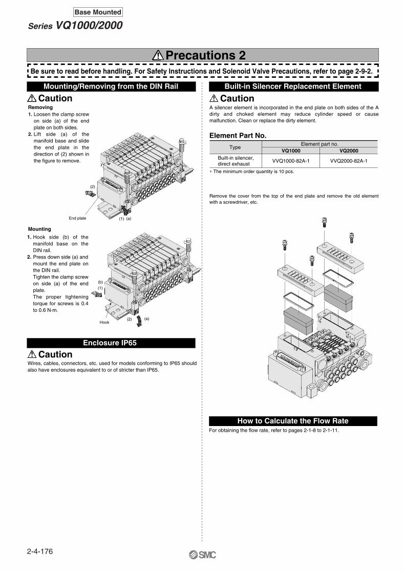
Be sure to read before handling. For Safety Instructions and Solenoid Valve Precautions, refer to page 2-9-2.
Element Part No.
Removing
Mounting
TypeElement part no.
VQ1000
VVQ1000-82A-1
VQ2000
VVQ2000-82A-1Built-in silencer, direct exhaust
∗ The minimum order quantity is 10 pcs.
1.
2.
1.
2.
For obtaining the flow rate, refer to pages 2-1-8 to 2-1-11.
Precautions 2
Loosen the clamp screw on side (a) of the end plate on both sides.Lift side (a) of the manifold base and slide the end plate in the direction of (2) shown in the figure to remove.
A silencer element is incorporated in the end plate on both sides of the A dirty and choked element may reduce cylinder speed or cause malfunction. Clean or replace the dirty element.
Remove the cover from the top of the end plate and remove the old element with a screwdriver, etc.
Hook side (b) of the manifold base on the DIN rail. Press down side (a) and mount the end plate on the DIN rail. Tighten the clamp screw on side (a) of the end plate.The proper tightening torque for screws is 0.4 to 0.6 N·m.
Wires, cables, connectors, etc. used for models conforming to IP65 should also have enclosures equivalent to or of stricter than IP65.
Hook
End plate
(2)
(2)
(1)
(1)
(a)
(a)
(b)
Mounting/Removing from the DIN Rail
CautionBuilt-in Silencer Replacement Element
Enclosure IP65
How to Calculate the Flow Rate
Caution
Caution
2-4-176
Series VQ1000/2000Base Mounted

Option
Different Number of Connector Pins
kit (D-sub connector) 15 pinsF kit (Flat ribbon cable connector)10 pins, 16 pins, 20 pinsP
How to order manifold How to order manifold
Stations
Cylinder port
06 C6 F SA NVV5Q11
Option
Kit/Electrical entry
06VV5Q11
PinsCablelength (L)
1.5 m
3 m
5 m
AXT100-FC10-1
AXT100-FC10-2
AXT100-FC10-3
17.2
AXT100-FC16-1
AXT100-FC16-2
AXT100-FC16-3
24.8
AXT100-FC20-1
AXT100-FC20-2
AXT100-FC20-3
30
10P 16P 20P
LocationPins
15P (Max. 7 stations) UA SAKit F Kit F
Top entry Side entry LocationPins
10P (Max. 4 stations)
16P (Max. 7 stations)
20P (Max. 9 stations)
Top entry Side entry
UA
UB
UC
SA
SB
SC
Kit
P
Kit
P
Flat Ribbon Cable Assembly
PinsCable length (L)
1.5 m
3 m
5 m
AXT100-DS15-1
AXT100-DS15-2
AXT100-DS15-3
15P
∗ For other commercial connectors, use a type conforming to MIL-C-24308.
D-sub Connector Cable Assembly
Wire Color Table by Terminal No.of D-sub Connector Cable Assembly
123456789
101112131415
BlackBrownRed
OrangeYellowPinkBlue
PurpleGrayWhiteWhiteYellowOrangeYellowPink
NoneNoneNoneNoneNoneNoneNoneWhiteBlackBlackRed Red Red BlackBlack
Dot markingLead wire colorTerminal no.
Stations
Cylinder port
C6 P SC N
Option
Kit/Electrical entry
Connector width (W)
∗ In the same way as the 25-pin models (standard), the terminal no. 1 is for SOL.A at the 1st station, the terminal no. 9 for SOL.B at the 1st station, and the terminal no. 8 for COM. ∗ In the same way as the 26-pin models (standard), the terminal
no. 1 is for SOL.A at the 1st station, the terminal no. 2 for SOL.B at the 1st station, and two pins from the max. terminal numbers are for COM.
F and P kits with the following number of pins are available besides the standard number (F = 25; P = 26). Select the desired number of pins and cable length from the cable assembly list.Place an order for the cable assembly separately.
How to OrderD-sub connector, 15 pinsConnector location–Side (horizontal)Without cable
How to OrderFlat ribbon cable, 20 pinsConnector location–Side (Horizontal)Without cable
∗ For other commercial connectors, use a type with strain relief conforming to MIL-C-83503.
Wiring Specifications
Wiring Specifications
Multi-core vinyl cableVVRF 0.3 mm2 x 15C
~= ø9
Plug connectorHDA-CTH(Made by Hirose Electric)
ConnectorHAD-15S(Made by Hirose Electric)
Terminal no.
Ter
min
al n
o.
Red
10P, 16P, 20P
2-4-177
Series VQ1000/2000Plug-in Unit
Base Mounted
VQC
SQ
VQ0
VQ4
VQ5
VQZ
VQD
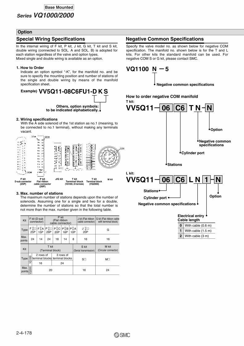
Special Wiring Specifications Negative Common Specifications
1. How to Order
2. Wiring specifications
Example) VV5Q11-08C6FU1-D K S
Others, option symbols:to be indicated alphabetically.
3. Max. number of stations
VQ1100
Negative common specifications
N 5
F kit (D-sub connector)
T kit(Terminal block)
G kit (Flat ribbon cable with terminal block)
P kit(Flat ribbon
cable connector)
S kit(Serial transmission)
Kit
Type
Max.points
Max.points
Kit
Type
F 25P
US P
26P
US J
20P
USF A
15P
US P C
20P
US P B
16P
US P A
10P
US
S
G
24 14 24 18 14 8 1616
20
M
24
2416
16
VQ20
00VQ
1000
2 rows ofterminal blocks
3 rows ofterminal blocks
How to order negative COM manifold
06VV5Q11
Stations
Cylinder port
C6 T N N
Option
T kit:
Negative commonspecifications
06VV5Q11Stations
Cylinder port
C6 L N 1 N
Option
Electrical entryCable length
L kit:
Negative common specifications
0
1
2
With cable (0.6 m)
With cable (1.5 m)
With cable (3 m)
Option
J kit (Flat ribbon cable connector)
M kit(Circular connector)
COM
26
2524
23
22
21 20
19
18
1716
1514
13
12
11
109 8 7
6
5
4
3
12
M kit
In the internal wiring of F kit, P kit, J kit, G kit, T kit and S kit, double wiring (connected to SOL. A and SOL. B) is adopted for each station regardless of the valve and option types. Mixed single and double wiring is available as an option.
Specify the valve model no. as shown below for negative COM specification. The manifold no. shown below is for the T and L kits. For other kits the standard manifold can be used. For negative COM S or G kit, please contact SMC.
Indicate an option symbol “-K”, for the manifold no. and be sure to specify the mounting position and number of stations of the single and double wiring by means of the manifold specification sheet.
With the A side solenoid of the 1st station as no.1 (meaning, to be connected to no.1 terminal), without making any terminals vacant.
The maximum number of stations depends upon the number of solenoids. Assuming one for a single and two for a double, determine the number of stations so that the total number is not more than the max. number given in the following table.
F kitD-sub connector
(25P)
P kitFlat ribbon
cable connector(26P)
J/G kit T kitTerminal block
(VQ1000, 24 termials)
T kitTerminal block
(VQ2000)
2-4-178
Series VQ1000/2000Base Mounted
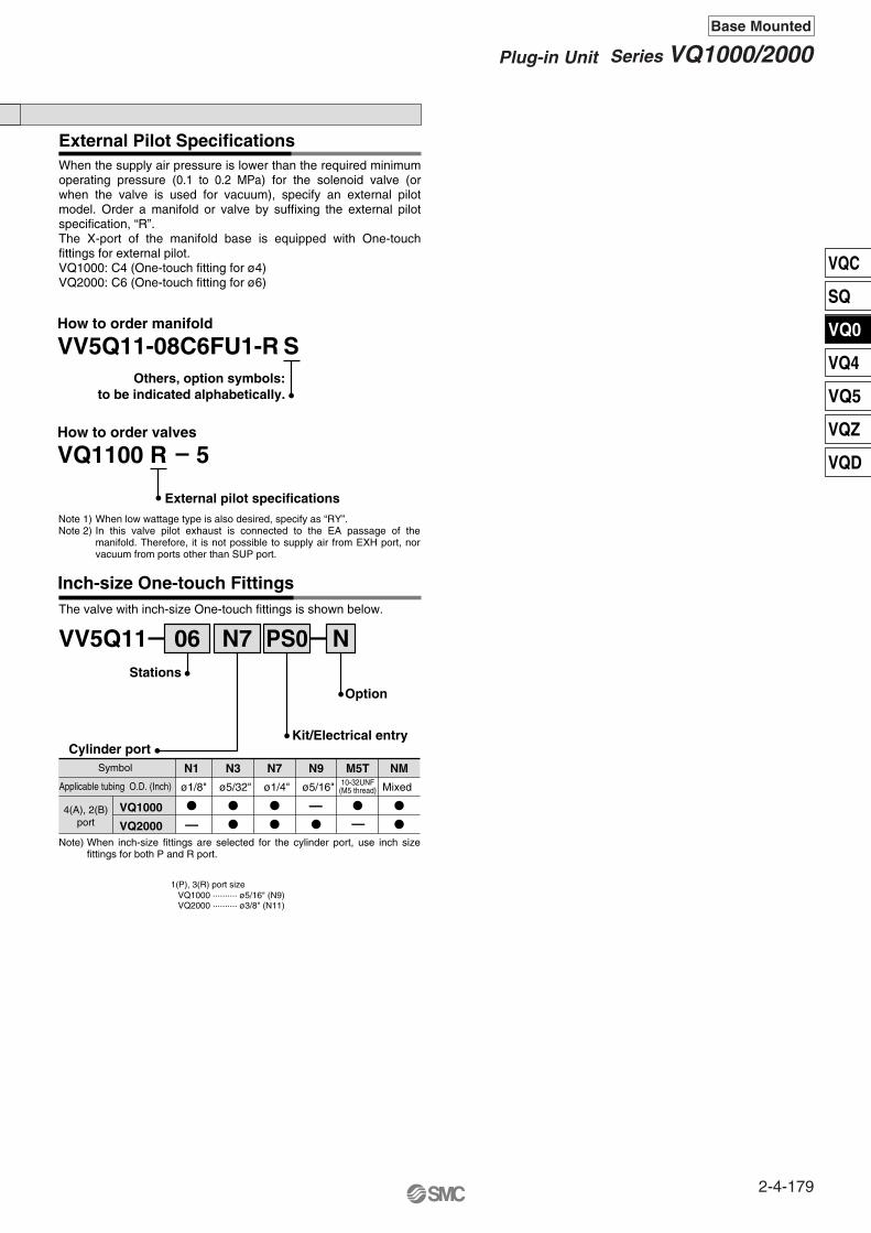
External Pilot Specifications
Inch-size One-touch Fittings
VV5Q11-08C6FU1-R SOthers, option symbols:
to be indicated alphabetically.
External pilot specifications
How to order manifold
VQ1100How to order valves
R 5
Note 1)Note 2)
VV5Q11 06 N7 PS0 N
Option
Kit/Electrical entry
Stations
Cylinder portSymbol
Applicable tubing O.D. (Inch)
VQ1000
VQ20004(A), 2(B)
port
ø1/8" ø5/32" ø1/4" ø5/16" 10-32UNF(M5 thread) Mixed
NMM5TN9N7N3N1
1(P), 3(R) port sizeVQ1000 ·········· ø5/16" (N9)VQ2000 ·········· ø3/8" (N11)
When inch-size fittings are selected for the cylinder port, use inch size fittings for both P and R port.
When the supply air pressure is lower than the required minimum operating pressure (0.1 to 0.2 MPa) for the solenoid valve (or when the valve is used for vacuum), specify an external pilot model. Order a manifold or valve by suffixing the external pilot specification, “R”. The X-port of the manifold base is equipped with One-touch fittings for external pilot.VQ1000: C4 (One-touch fitting for ø4)VQ2000: C6 (One-touch fitting for ø6)
When low wattage type is also desired, specify as “RY”.In this valve pilot exhaust is connected to the EA passage of the manifold. Therefore, it is not possible to supply air from EXH port, nor vacuum from ports other than SUP port.
The valve with inch-size One-touch fittings is shown below.
——
—Note)
2-4-179
Series VQ1000/2000Plug-in Unit
Base Mounted
VQC
SQ
VQ0
VQ4
VQ5
VQZ
VQD
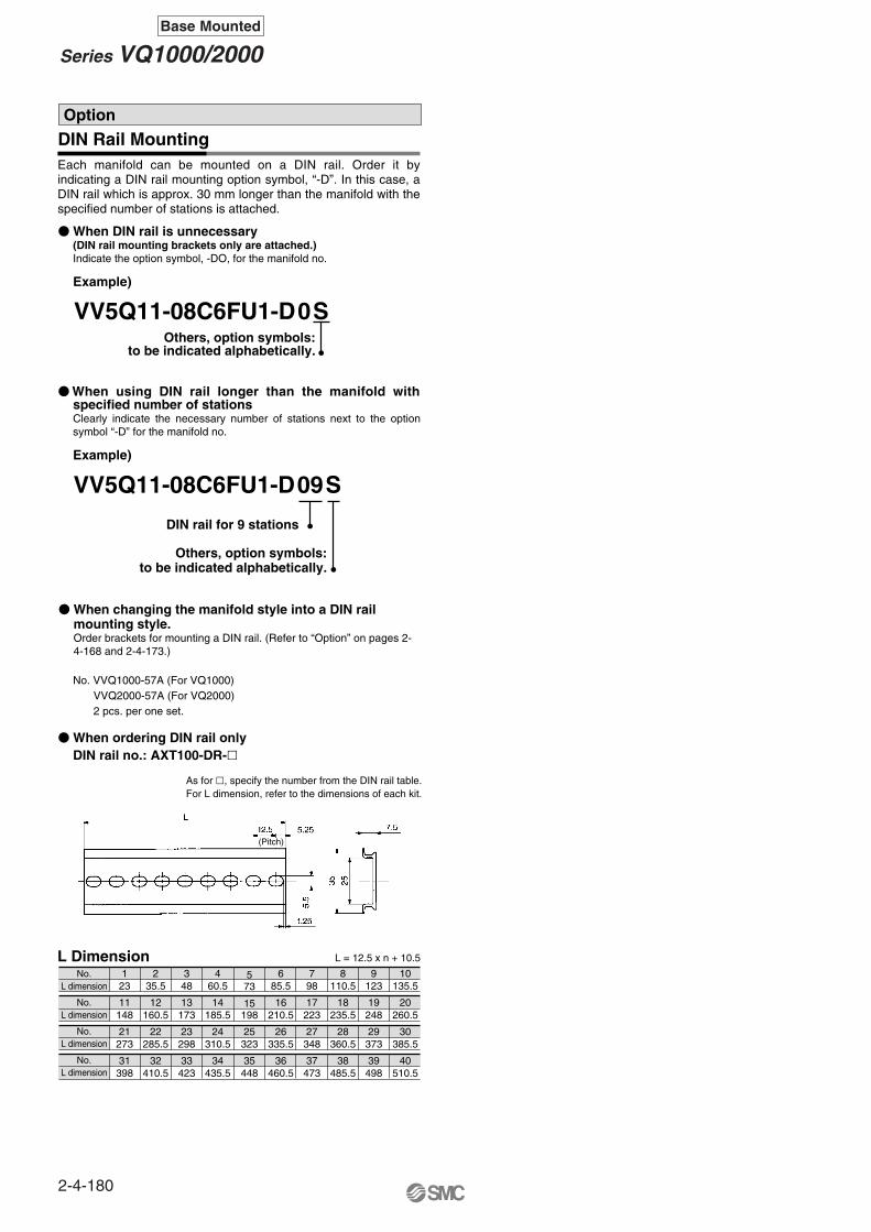
DIN Rail Mounting
Example)
VV5Q11-08C6FU1-D0SOthers, option symbols:
to be indicated alphabetically.
Example)
VV5Q11-08C6FU1-D09S
DIN rail for 9 stations
As for , specify the number from the DIN rail table.For L dimension, refer to the dimensions of each kit.
1 2 3 4 5 6 7 8 9 1023 35.5 48 60.5 73 85.5 98 110.5 123 135.5
No.L dimension
No.L dimension
No.L dimension
No.L dimension
11 12 13 14 15 16 17 18 19 20148 160.5 173 185.5 198 210.5 223 235.5 248 260.5
21 22 23 24 25 26 27 28 29 30273 285.5 298 310.5 323 335.5 348 360.5 373 385.5
31 32 33 34 35 36 37 38 39 40398 410.5 423 435.5 448 460.5 473 485.5 498 510.5
L = 12.5 x n + 10.5L Dimension
Option
Each manifold can be mounted on a DIN rail. Order it by indicating a DIN rail mounting option symbol, “-D”. In this case, a DIN rail which is approx. 30 mm longer than the manifold with the specified number of stations is attached.
When changing the manifold style into a DIN rail mounting style.Order brackets for mounting a DIN rail. (Refer to “Option” on pages 2-4-168 and 2-4-173.)
When using DIN rail longer than the manifold with specified number of stationsClearly indicate the necessary number of stations next to the option symbol “-D” for the manifold no.
When DIN rail is unnecessary(DIN rail mounting brackets only are attached.)Indicate the option symbol, -DO, for the manifold no.
Others, option symbols:to be indicated alphabetically.
No. VVQ1000-57A (For VQ1000)VVQ2000-57A (For VQ2000)2 pcs. per one set.
When ordering DIN rail onlyDIN rail no.: AXT100-DR-
(Pitch)
2-4-180
Series VQ1000/2000Base Mounted
2-4-181
VQC
SQ
VQ0
VQ4
VQ5
VQZ
VQD
Series VQ1000/2000Plug-in Unit
Base Mounted
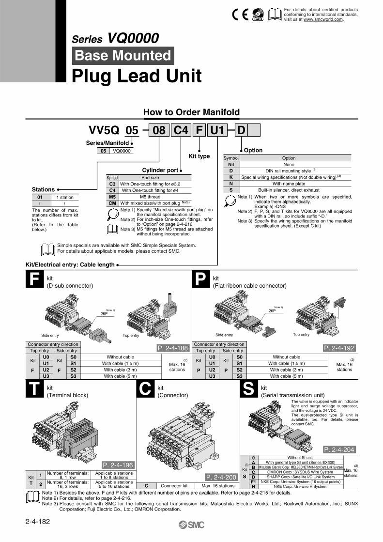
How to Order Manifold
05 08 C4 F DU1VV5Q
Stations01 1 station
··· ···
Kit/Electrical entry: Cable length
05 VQ0000
Series/Manifold
OptionNone
DIN rail mounting style Special wiring specifications (Not double wiring)
With name plateBuilt-in silencer, direct exhaust
Note 1)
Note 2)
Note 3)
DKNS
OptionKit type
(3)
SymbolNil
Port sizeWith One-touch fitting for ø3.2With One-touch fitting for ø4
M5 threadWith mixed size/with port plug
C3C4M5CM
Cylinder port
Note)
Symbol
F kit(D-sub connector) P kit
(Flat ribbon cable connector)
T kit(Terminal block) C kit
(Connector) S kit(Serial transmission unit)
Connector entry directionTop entry Side entry
Top entrySide entry Top entrySide entry
U0U1U2U3
S0S1S2S3
Without cableWith cable (1.5 m)With cable (3 m)With cable (5 m)
Max. 16stations
(2)
(3)
Connector entry directionTop entry Side entry
U0U1U2U3
S0S1S2S3
Without cableWith cable (1.5 m)With cable (3 m)With cable (5 m)
Max. 16stations
(2)
(2)
0ABCDF1H
Without SI unit With general type SI unit (Series EX300)
Mitsubishi Electric Corp.: MELSECNET/MINI-S3 Data Link SystemOMRON Corp.: SYSBUS Wire System SHARP Corp.: Satellite I/O Link System
NKE Corp.: Uni-wire System (16 output points)NKE Corp.: Uni-wire H System
Max. 16stations
C Connector kit
1
2
Applicable stations1 to 8 stations
Number of terminals:8, 1 row
Max. 16 stations
KitT
Kit Kit Kit Kit
P PFF
S
Kit
25P
The number of max. stations differs from kit to kit.(Refer to the table below.)
Specify “Mixed size/with port plug” on the manifold specification sheet.For inch-size One-touch fittings, refer to “Option” on page 2-4-216.M5 fittings for M5 thread are attached without being incorporated.
Simple specials are available with SMC Simple Specials System.For details about applicable models, please contact SMC.
When two or more symbols are specified, indicate them alphabetically.Example) -DNSF, P, S, and T kits for VQ0000 are all equipped with a DIN rail, so include suffix “-D.”Specify the wiring specifications on the manifold specification sheet. (Except C kit)
Number of terminals:16, 2 rows
Applicable stations5 to 16 stations
The valve is equipped with an indicator light and surge voltage suppressor, and the voltage is 24 VDC.The dust-protected type SI unit is available, too. For details, please contact SMC.
Note 1) Besides the above, F and P kits with different number of pins are available. Refer to page 2-4-215 for details. Note 2) For details, refer to page 2-4-216.Note 3) Please consult with SMC for the following serial transmission kits: Matsushita Electric Works, Ltd.; Rockwell Automation, Inc.; SUNX
Corporation; Fuji Electric Co., Ltd.; OMRON Corporation.
Note 1)
Note 2)
Note 3)
(2)
Note 1) 26PNote 1)
Series VQ0000Base Mounted
Plug Lead Unit
For details about certified products conforming to international standards, visit us at www.smcworld.com.
P. 2-4-188 P. 2-4-192
P. 2-4-196
P. 2-4-200
P. 2-4-204
2-4-182

VQC
SQ
VQ0
VQ4
VQ5
VQZ
VQD
Manifold Option
• For cylinder port fittings part no., refer to page 2-4-213.• For replacement parts, refer to page 2-4-231.
Individual SUP spacerVVQ0000-P-5-C4
Double check blockVQ1000-FPG-
Individual EXH spacerVVQ0000-R-5-C4
Silencer AN103-X233
Manual overrideB: Locking type
(Tool required)
How to Order Valves
5 LOVQ 1 0 Y 5
Series
1
2
3
4
Type of actuation2 position single
2 position double
2 position double
3 position closed center
3 position exhaust center
connectorWith lead wire
L: L plugC Kit only
Except AC.
G: Grommet
connectorWithout connector
MO: M plug connectorWith lead wire
M: M plug
With light/surgevoltage suppressor
With light/surgevoltage suppressor
With light/surgevoltage suppressor
With light/surgevoltage suppressor
connectorWithout connector
LO: L plug
0
Electrical entry
Note 1)
Note 2)
Coil voltage123456
100 VAC (50/60 Hz)200 VAC (50/60 Hz)110 VAC (50/60 Hz)220 VAC (50/60 Hz)
24 VDC12 VDC
Note)
Seal
Body type
Metal sealRubber seal
01
5 VQ0000
Note 1)
Note 2)
Example
∗∗∗
1 set (F kit 7 station manifold base no.)3 sets (Single solenoid part no.)2 sets (Double solenoid part no.)2 sets (3 position solenoid part no.)
VV5Q05-07C4FS2-D VQ0150-5MO VQ0250-5MO VQ0350-5MO
How to Order Valve Manifold Assembly
Blanking plugKQ2P-
Name plate [-N∗]VVQ0000-N5-Station (1 to Max. stations)
DIN rail mounting bracket [-D]VVQ0000-57A-5
Blanking plate assemblyVVQ0000-10A-5
SUP/EXH block plateVVQ0000-16A-5-
PRPR
Built-in silencer,direct exhaust [-S]
23040608
VQ00000
············
Specifications
Standard type
Highpressure type
Low wattagetype
FunctionSymbol
Nil
H
Y
DC AC
(1.0 W)
(1.5 W)
(0.5 W)
Met
alR
ubbe
r
D side
U side
32
1
Stations
3 m
Single solenoid (24 VDC)
VQ0150-5MO
Double solenoid (24 VDC)
VQ0250-5MO
Closed center (24 VDC)
VQ0350-5MO
Nil: Non-lockingpush type(Tool required)
LO or MO type valve is used for F, P, T, and S kits. The plug connector and lead wire are attached to the manifold.In cases of L and M type the connector direction is based on the pilot valve.
For negative common specifications, refer to “Option” on page 2-4-216.F, P, T and S kits requires connector assembly when increasing valve stations.Refer to “Option” on page 2-4-216 for parts nos.
—
—
Note)
For power consumption of AC type, refer to page 2-4-186.
The C kits are applicable to 200/220 VAC. Please contact SMC for other kits.
The asterisk denotes the symbol for assembly. Prefix it to the part nos. of the solenoid valve, etc.
Specify the part numbers for valves and options together beneath the manifold base part number. Besides, when the arrangement will be complicated, specify them by means of the manifold specification sheet.
Note)
SUP port blockEXHportblock
SUP/EXH port block CYLPort
Exhaust port
P. 2-4-208
2-4-183
Series VQ0000Plug-in Unit
Base Mounted
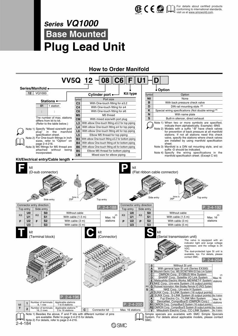
How to Order Manifold
12 08 C6 F DU1VV5Q
Stations01 1 station
··· ···
Kit/Electrical entry/Cable length
12 VQ1000
Series/Manifold
OptionNone
With back pressure check valveDIN rail mounting style
Special wiring specifications (Not double wiring)With name plate
Built-in silencer, direct exhaust
Note 1)
Note 2)
Note 3)
Note 4)
BDKNS
OptionKit type
(4)
SymbolNilPort size
With One-touch fitting for ø3.2With One-touch fitting for ø4With One-touch fitting for ø6
M5 threadWith mixed size/with port plug
With elbow One-touch fitting ø3.2 for top pipingWith elbow One-touch fitting ø4 for top pipingWith elbow One-touch fitting ø6 for top piping
Elbow M5 thread for top pipingWith elbow One-touch fitting ø3.2 for bottom pipingWith elbow One-touch fitting ø4 for bottom pipingWith elbow One-touch fitting ø6 for bottom piping
Elbow M5 thread for bottom pipingMixed size for elbow piping
C3C4C6M5CML3L4L6L5B3B4B6B5LM
Cylinder portSymbol
F kit(D-sub connector) P kit
(Flat ribbon cable connector)
T kit(Terminal block) C kit
(Connector) S kit(Serial transmission unit)
Connector entry directionTop entry Side entry
U0U1U2U3
S0S1S2S3
Without cableWith cable (1.5 m)With cable (3 m)With cable (5 m)
Connector entry directionTop entry Side entry
U0U1U2U3
S0S1S2S3
Without cableWith cable (1.5 m)With cable (3 m)With cable (5 m)
Max. 16stations
(2)Max. 16stations
(2)
(2)
Note 2)
C Connector kit
1
2 Applicable stations5 to 16 stations
Number of terminals:16, 2 rows Max. 16 stations
kitT
Kit Kit Kit Kit
P PFF
(2)
Kit
S
0ABCDEF1GHJ1J2KQR1R2V
Without SI unit With general type SI unit (Series EX300)
Mitsubishi Electric Corp.: MELSECNET/MINI-S3 Data Link SystemOMRON Corp.: SYSBUS Wire System SHARP Corp.: Satellite I/O Link System
Matsushita Electric Works: MEWNET-F SystemNKE Corp.: Uni-wire System (16 output points)Rockwell Automation: Allen Bradley Remote I/O (RIO) System
NKE Corp.: Uni-wire H System SUNX Corp.: S-LINK System (16 output points)SUNX Corp.: S-LINK System (8 output points)
Fuji Electric Co.: T-LINK Mini SystemDeviceNet, CompoBus/D (OMRON Corp.)
OMRON Corp.: CompoBus/S System (16 output points)OMRON Corp.: CompoBus/S System (8 output points)
Mitsubishi Electric Corp.: CC-LINK System
Max.16stations
Max.16stations
Max. 16 stationsMax. 8 stations
Max. 8 stations
Specify “Mixed size/with port plug” in the manifold specification sheet.For One-touch fittings in inch sizes, refer to “Option” on page 2-4-216.M5 fittings for M5 thread are attached without being incorporated.
When two or more symbols are specified, indicate them alphabetically. Example) -BNSModels with a suffix “-B” have check valves for prevention of back pressure at all manifold stations. If not all stations need this check valve, specify the stations where check valves are installed by using manifold specification sheet. Manifold is a DIN rail mounting style, and so suffix -D should be indicated.Specify the wiring specifications in the manifold specification sheet. (Except C kit)
The number of max. stations differs from kit to kit.(Refer to the table below.)
Note 1)
Note 2)
Note 3)
Number of terminals:8, 1 row
Applicable stations1 to 8 stations
Besides the above, F and P kits with different number of pins are available. Refer to page 2-4-215 for details.For details, refer to page 2-4-216.
Simple specials are available with SMC Simple Specials System. For details about applicable models, please contact SMC.
Note 1)
Note 2)
The valve is equipped with an indicator light and surge voltage suppressor, and the voltage is 24 VDC.The dust-protected type SI unit is available, too. For details, please contact SMC.
(3)
Side entry 26PNote 2)
Side entry 25PTop entry
Top entry
Series VQ1000Base Mounted
Plug Lead Unit
For details about certified products conforming to international standards, visit us at www.smcworld.com.
P. 2-4-188 P. 2-4-192
P. 2-4-196
P. 2-4-200
P. 2-4-204
2-4-184
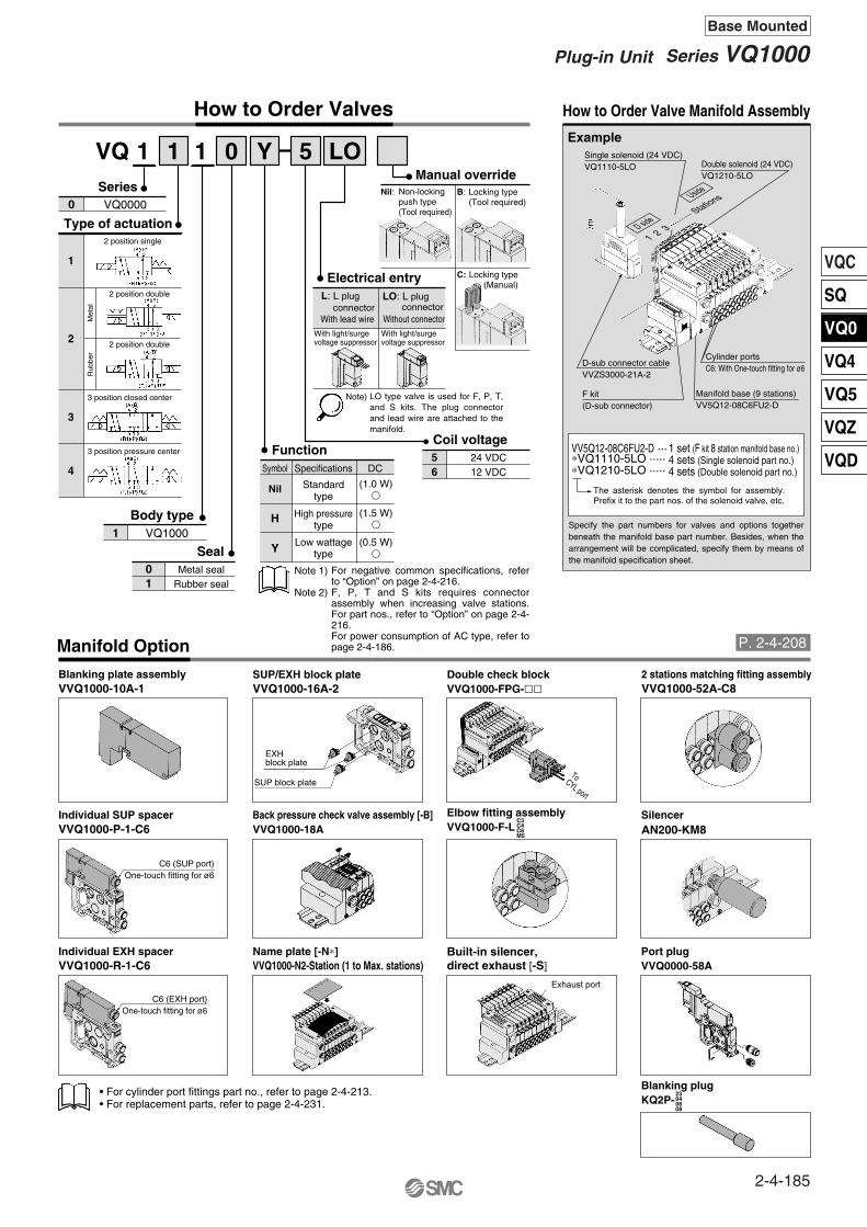
VQC
SQ
VQ0
VQ4
VQ5
VQZ
VQD
Series
1
2
3
4
Type of actuation2 position single
2 position double
3 position closed center
3 position pressure center
VQ00000
Met
alR
ubbe
r
2 position double
Manifold Option
Individual SUP spacerVVQ1000-P-1-C6
Double check block
Individual EXH spacerVVQ1000-R-1-C6 VVQ1000-N2-Station (1 to Max. stations)
SilencerAN200-KM8
VVQ1000-FPG-
Elbow fitting assemblyVVQ1000-F-L
Back pressure check valve assembly [-B]VVQ1000-18A
Manual overrideNil: B: Locking type
(Tool required)
C: Locking type(Manual)
How to Order Valves
1 LOVQ 1 0 Y 5
connectorL: L plug
With light/surgevoltage suppressor
With light/surgevoltage suppressor
connectorLO: L plug
1
Electrical entry
Note)
Coil voltage56
24 VDC12 VDC
Seal
Body type
Metal sealRubber seal
01
1 VQ1000
Note 1)
Note 2)
How to Order Valve Manifold Assembly
Blanking plugKQ2P-
23040608
Name plate [-N∗]
Blanking plate assemblyVVQ1000-10A-1
SUP/EXH block plateVVQ1000-16A-2
Built-in silencer,direct exhaust [-S]
Port plugVVQ0000-58A
C3C4C6M5
2 stations matching fitting assemblyVVQ1000-52A-C8
1 set (F kit 8 station manifold base no.)4 sets (Single solenoid part no.)4 sets (Double solenoid part no.)
VV5Q12-08C6FU2-D ···∗VQ1110-5LO ·····∗VQ1210-5LO ·····Specifications
Standardtype
High pressuretype
Low wattagetype
FunctionSymbol
Nil
H
Y
DC
(1.0 W)
(1.5 W)
(0.5 W)
Example
Non-lockingpush type(Tool required)
LO type valve is used for F, P, T, and S kits. The plug connector and lead wire are attached to the manifold.
For negative common specifications, refer to “Option” on page 2-4-216.F, P, T and S kits requires connector assembly when increasing valve stations. For part nos., refer to “Option” on page 2-4-216.For power consumption of AC type, refer to page 2-4-186.
The asterisk denotes the symbol for assembly. Prefix it to the part nos. of the solenoid valve, etc.
Specify the part numbers for valves and options together beneath the manifold base part number. Besides, when the arrangement will be complicated, specify them by means of the manifold specification sheet.
With lead wire Without connector
Single solenoid (24 VDC)VQ1110-5LO Double solenoid (24 VDC)
VQ1210-5LO
D-sub connector cableVVZS3000-21A-2
F kit(D-sub connector)
Manifold base (9 stations)VV5Q12-08C6FU2-D
C6 (SUP port)One-touch fitting for ø6
Cylinder portsC6: With One-touch fitting for ø6
D side
Uside
1 2 3 ·········
· Stations
C6 (EXH port)One-touch fitting for ø6
SUP block plate
Exhaust port
To CYL port
EXHblock plate
• For cylinder port fittings part no., refer to page 2-4-213.• For replacement parts, refer to page 2-4-231.
P. 2-4-208
2-4-185
Series VQ1000Plug-in Unit
Base Mounted
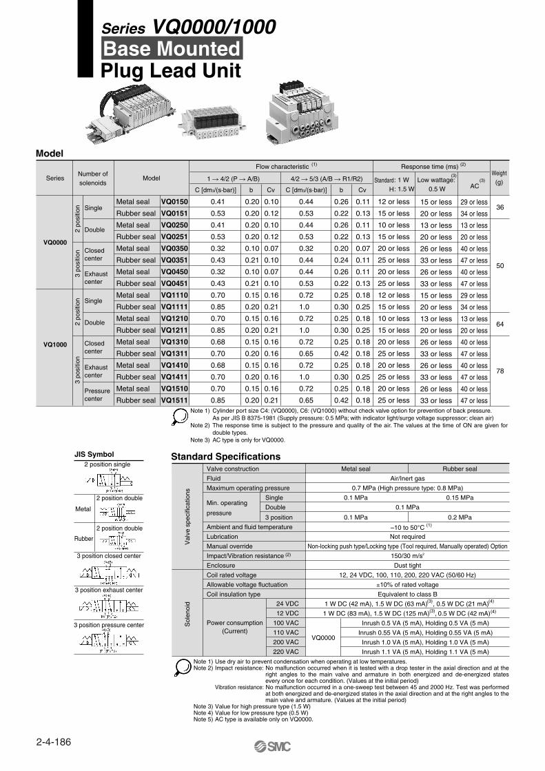
Note 1)
Note 2)
Note 3)
Standard Specifications
Ambient and fluid temperature
Coil insulation type
Allowable voltage fluctuation
Coil rated voltage
Enclosure
Impact/Vibration resistance (2)
Manual override
Lubrication
SingleMin. operating
pressure
Valve construction Metal seal
0.1 MPa
–10 to 50°C
0.7 MPa (High pressure type: 0.8 MPa)
Not required
1 W DC (83 mA), 1.5 W DC (125 mA) , 0.5 W DC (42 mA)
1 W DC (42 mA), 1.5 W DC (63 mA) , 0.5 W DC (21 mA)
Equivalent to class B
±10% of rated voltage
12, 24 VDC, 100, 110, 200, 220 VAC (50/60 Hz)
Dust tight
150/30 m/s2
Non-locking push type/Locking type (Tool required, Manually operated) Option
Rubber seal
Fluid
Maximum operating pressure
Air/Inert gas
0.15 MPa
3 position 0.1 MPa 0.2 MPa
Double 0.1 MPa
Power consumption(Current)
12 VDC
Inrush 0.5 VA (5 mA), Holding 0.5 VA (5 mA)100 VAC
Inrush 0.55 VA (5 mA), Holding 0.55 VA (5 mA)110 VAC
Inrush 1.0 VA (5 mA), Holding 1.0 VA (5 mA)200 VAC
Inrush 1.1 VA (5 mA), Holding 1.1 VA (5 mA)220 VAC
VQ0000
24 VDC
Val
ve s
peci
ficat
ions
Sol
enoi
d
(1)
(3) (4)
(4)(3)
Model
Series ModelNumber ofsolenoids
Flow characteristic (1) (2)
(3)(3)
2 po
sitio
n3
posi
tion
2 po
sitio
n3
posi
tion
Single
Double
Metal seal
Rubber seal
Metal seal
Rubber seal
Metal seal
Rubber seal
Metal seal
Rubber seal
Metal seal
Rubber seal
Metal seal
Rubber seal
Metal seal
Rubber seal
Metal seal
Rubber seal
Metal seal
Rubber seal
Response time (ms)
StandardH
: 1 W: 1.5 W
12 or less
15 or less
10 or less
15 or less
20 or less
25 or less
20 or less
25 or less
12 or less
15 or less
10 or less
15 or less
20 or less
25 or less
20 or less
25 or less
20 or less
25 or less
29 or less
34 or less
13 or less
20 or less
40 or less
47 or less
40 or less
47 or less
29 or less
34 or less
13 or less
20 or less
40 or less
47 or less
40 or less
47 or less
40 or less
47 or less
0.41
0.53
0.41
0.53
0.32
0.43
0.32
0.43
0.70
0.85
0.70
0.85
0.68
0.70
0.68
0.70
0.70
0.85
0.20
0.20
0.20
0.20
0.10
0.21
0.10
0.21
0.15
0.20
0.15
0.20
0.15
0.20
0.15
0.20
0.15
0.20
0.10
0.12
0.10
0.12
0.07
0.10
0.07
0.10
0.16
0.21
0.16
0.21
0.16
0.16
0.16
0.16
0.16
0.21
0.44
0.53
0.44
0.53
0.32
0.44
0.44
0.53
0.72
1.0
0.72
1.0
0.72
0.65
0.72
1.0
0.72
0.65
0.26
0.22
0.26
0.22
0.20
0.24
0.26
0.22
0.25
0.30
0.25
0.30
0.25
0.42
0.25
0.30
0.25
0.42
0.11
0.13
0.11
0.13
0.07
0.11
0.11
0.13
0.18
0.25
0.18
0.25
0.18
0.18
0.18
0.25
0.18
0.18
Low wattage: 0.5 W AC
15 or less
20 or less
13 or less
20 or less
26 or less
33 or less
26 or less
33 or less
15 or less
20 or less
13 or less
20 or less
26 or less
33 or less
26 or less
33 or less
26 or less
33 or less
Weight(g)
36
50
64
78
VQ0150
VQ0151
VQ0250
VQ0251
VQ0350
VQ0351
VQ0450
VQ0451
VQ1110
VQ1111
VQ1210
VQ1211
VQ1310
VQ1311
VQ1410
VQ1411
VQ1510
VQ1511
Closedcenter
Exhaust center
Single
Double
Closedcenter
Exhaust center
Pressure center
VQ0000
VQ1000
C [dm3/(s·bar)] C [dm3/(s·bar)]
1 4/2 (P A/B) 4/2 5/3 (A/B R1/R2)
b Cv b Cv
Use dry air to prevent condensation when operating at low temperatures.Impact resistance: No malfunction occurred when it is tested with a drop tester in the axial direction and at the
right angles to the main valve and armature in both energized and de-energized states every once for each condition. (Values at the initial period)
Vibration resistance: No malfunction occurred in a one-sweep test between 45 and 2000 Hz. Test was performed at both energized and de-energized states in the axial direction and at the right angles to the main valve and armature. (Values at the initial period)
Value for high pressure type (1.5 W)Value for low pressure type (0.5 W)AC type is available only on VQ0000.
2 position single
2 position double
3 position closed center
3 position exhaust center
3 position pressure center
Metal
Rubber
2 position double
JIS Symbol
Cylinder port size C4: (VQ0000), C6: (VQ1000) without check valve option for prevention of back pressure.As per JIS B 8375-1981 (Supply pressure: 0.5 MPa; with indicator light/surge voltage suppressor; clean air) The response time is subject to the pressure and quality of the air. The values at the time of ON are given for double types.AC type is only for VQ0000.
Plug Lead Unit
Series VQ0000/1000
Note 1)Note 2)
Note 3)Note 4)Note 5)
Base Mounted
2-4-186

Manifold Specifications
Series Base model Type of connection Applicablestations
Applicable solenoid
valve
Porting specifications
Port sizePortlocation 1(P), 3(R) 4(A), 2(B)
(1)
(2)5 stationweight
(g)
VQ0000
VQ1000
Side
Side
330(Single)
400(Double,
3 position)
818(Single)
885(Double,
3 position)
F kit– D-sub connector P kit–Flat ribbon cable connector T kit–Terminal block C kit–Individual connector S kit–Serial transmission
F kit–D-sub connector P kit–Flat ribbon cable connector T kit–Terminal block C kit–Individual connector S kit–Serial transmission
VV5Q05- VQ050VQ051
VQ110VQ111VV5Q12-
C3 (ø3.2)
C4 (ø4)
M5 (M5 thread)
C3 (ø3.2)
C4 (ø4)C6 (ø6)
M5 (M5 thread)
1 to 16stations
1 to 16stations
C6 (ø6)Option
Built-in silencer,direct exhaust
C8 (ø8)
Note 1) Inch-size One-touch fittings are also available. For details, refer to page 2-4-216.Note 2) For details, refer to page 2-4-216.
Option
Built-insilencer,direct exhaust
P portR port
A, B porting
Type ofconnection
Type of connection
3(R) port
1(P) port
4(A), 2(B) port
2-4-187
Series VQ0000/1000Plug Lead Unit
Base Mounted
VQC
SQ
VQ0
VQ4
VQ5
VQZ
VQD
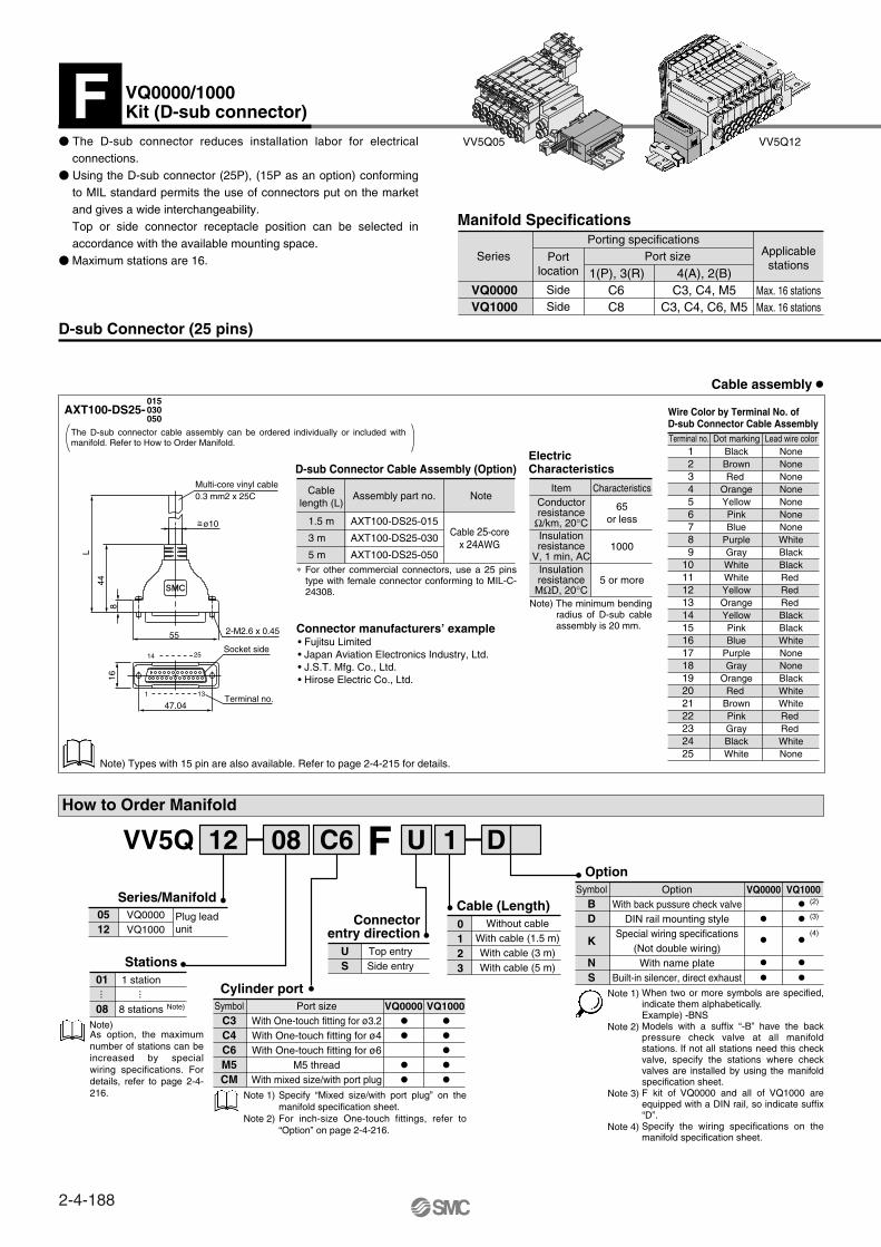
D-sub Connector (25 pins)
Wire Color by Terminal No. of D-sub Connector Cable AssemblyTerminal no. Lead wire colorDot marking
123456789
10111213141516171819202122232425
BlackBrownRed
OrangeYellowPinkBlue
PurpleGrayWhiteWhiteYellowOrangeYellowPinkBlue
PurpleGray
OrangeRed
BrownPinkGrayBlackWhite
NoneNoneNoneNoneNoneNoneNoneWhiteBlackBlackRed Red Red BlackBlackWhiteNoneNoneBlackWhiteWhiteRed Red WhiteNone
How to Order Manifold
Series
VQ0000VQ1000
Porting specifications
Portlocation
SideSide
Port size
1(P), 3(R)C6C8
4(A), 2(B)C3, C4, M5
C3, C4, C6, M5
Applicablestations
Max. 16 stationsMax. 16 stations
Manifold Specifications
VV5Q05 VV5Q12
Item CharacteristicsConductorresistance
Ω/km, 20°C65
or less
Insulationresistance
MΩD, 20°C
Insulationresistance
V, 1 min, AC1000
5 or more
ElectricCharacteristics
Cablelength (L)
Assembly part no.
1.5 m
3 m
5 m
AXT100-DS25-015
AXT100-DS25-030
AXT100-DS25-050
Note
Cable 25-corex 24AWG
D-sub Connector Cable Assembly (Option)
Connector manufacturers’ example• Fujitsu Limited• Japan Aviation Electronics Industry, Ltd.• J.S.T. Mfg. Co., Ltd.• Hirose Electric Co., Ltd.
Cable assembly
AXT100-DS25-015030050
1644
L
8
14 25
1 13
47.04
55 2-M2.6 x 0.45
Socket side
Terminal no.
Multi-core vinyl cable0.3 mm2 x 25C
The D-sub connector reduces installation labor for electrical connections.
Using the D-sub connector (25P), (15P as an option) conforming to MIL standard permits the use of connectors put on the market and gives a wide interchangeability.Top or side connector receptacle position can be selected in accordance with the available mounting space.
Maximum stations are 16.
The D-sub connector cable assembly can be ordered individually or included with manifold. Refer to How to Order Manifold.
Note) Types with 15 pin are also available. Refer to page 2-4-215 for details.
∗ For other commercial connectors, use a 25 pins type with female connector conforming to MIL-C-24308.
Note) The minimum bending radius of D-sub cable assembly is 20 mm.
D1U12 08 C6VV5Q F
0512
VQ0000VQ1000
Series/Manifold
Stations
Connectorentry direction
Cylinder port01 1 station
08 8 stations
··· ···
Cable (Length)0123
Without cableWith cable (1.5 m)With cable (3 m)With cable (5 m)
Note)
Note)
US
Top entrySide entry
OptionWith back pussure check valve
DIN rail mounting style
Option
BD
NS
Plug leadunit
K
Symbol
Special wiring specifications(Not double wiring)
With name plateBuilt-in silencer, direct exhaust
VQ0000 VQ1000
C3C4C6M5CM
Symbol VQ0000 VQ1000Port sizeWith One-touch fitting for ø3.2With One-touch fitting for ø4With One-touch fitting for ø6
M5 threadWith mixed size/with port plug
Note 1)
Note 2)
When two or more symbols are specified, indicate them alphabetically.Example) -BNSModels with a suffix “-B” have the back pressure check valve at all manifold stations. If not all stations need this check valve, specify the stations where check valves are installed by using the manifold specification sheet.F kit of VQ0000 and all of VQ1000 are equipped with a DIN rail, so indicate suffix “D”.Specify the wiring specifications on the manifold specification sheet.
Specify “Mixed size/with port plug” on the manifold specification sheet.For inch-size One-touch fittings, refer to “Option” on page 2-4-216.
As option, the maximum number of stations can be increased by special wiring specifications. For details, refer to page 2-4-216.
Note 1)
Note 2)
Note 3)
Note 4)
VQ0000/1000Kit (D-sub connector)F
ø10~=
(2)
(3)
(4)
2-4-188

Electrical wiring specifications
How to Order Valves
SOL.ASOL.BSOL.ASOL.BSOL.ASOL.BSOL.ASOL.BSOL.ASOL.BSOL.ASOL.BSOL.ASOL.BSOL.ASOL.BCOM.
1
14
2
15
3
16
4
17
5
18
6
19
7
20
8
21
13
(–)
(–)
(–)
(–)
(–)
(–)
(–)
(–)
(–)
(–)
(–)
(–)
(–)
(–)
(–)
(–)
(+)
(+)
(+)
(+)
(+)
(+)
(+)
(+)
(+)
(+)
(+)
(+)
(+)
(+)
(+)
(+)
(+)
(–)
Black
Yellow
Brown
Pink
Red
Blue
Orange
Purple
Yellow
Gray
Pink
Orange
Blue
Red
Purple
Brown
Orange
None
Black
None
Black
None
White
None
None
None
None
None
Black
None
White
White
White
Red
PolarityTerminal no. Lead wire color Dot marking
1 station 2 stations 3 stations 4 stations 5 stations 6 stations 7 stations 8 stations
Positivecommon
specifications
Negativecommon
specifications
VQ0000
VQ1000
Metal seal
Rubber seal
Plug lead unit
51
2 position single
2 position double
3 position closed center
3 position exhaust center
3 position pressure center (VQ1000 only)
12345
01
Series
01
Seal
Type of actuation
Non-locking push type (Tool required)
Locking type (Tool required)
Locking type (Manual) Note)
NilBC
Manual override
100 VAC (50/60 Hz)
110 VAC(50/60 Hz)
1
3
56
Coil voltageBody type
VQ 1 1 1 0 Y 5 LO
VQ0000
VQ1000
L plug connector without connector
M plug terminal without connector
VQ0000 VQ1000
LOMO
Electrical entry
The total number of stations is tabulatedstarting from station one on the D side.
1 set–Manifold base no.4 sets–Valve part no. (Stations 1 to 4)4 sets–Valve part no. (Stations 5 to 8)2 sets–Valve part no. (Stations 7 to 8)1 set–Blanking plate part no. (Station 9)
How to Order Manifold Assembly
<Example>D-sub connector kit with cable (3 m)VV5Q12-08C6FU2-D ···∗VQ1110-5LO ·······∗VQ1210-5LO ·······∗VQ1310-5LO ·······∗VVQ1000-10A-1····
Note) VQ1000 only.
VQ0000 VQ1000
SpecificationsStandard
type
Highpressure type
Low wattagetype
FunctionSymbol
Nil
H
Y
DC AC
(1.0 W)
(1.5 W)
(0.5 W)
015030050
D-sub connector assembly
AXT100-DS25- Wire color
VV5Q05
U side
D side
Stations
23
1
Note) When using the negative common specifications, use valves for negative common. (Refer to page 2-4-216.)
As the standard electrical wiring specifications, double wiring (connected to SOL. A and SOL. B) is adopted for the internal wiring of each station for 8 stations or less, regardless of valve and option types. Mixed single and double wiring is available as an option.For details, refer to page 2-4-216.
Specify the part numbers for valves and options together beneath the manifold base part number.
For negative common specifications, refer to “Option” on page 2-4-216.Connector assembly will be required when the F kits add a valve. For part nos., refer to “Option” on page 2-4-216.
For power consumption of AC type, refer to page 2-4-186.
Note) Plug connector and lead wire layers are attached to the manifold.
—
24 VDC
12 VDC
—
—Note)
—
—
Note 1)Note 2)
Prefix the asterisk to the part nos. of the solenoid valve, etc.
Write sequentially from the 1st station on the D side. When part nos. written collectively are complicated, specified by using the manifold specification sheet.
Note)
D side
Uside
1 2 3 ·········
·········
Stations
D side
Uside
1 2 3 ·········
·· Stations
D-sub connector
Connectorterminal no.
Note)
2-4-189
Series VQ0000/1000Plug Lead Unit
Base Mounted
VQC
SQ
VQ0
VQ4
VQ5
VQZ
VQD
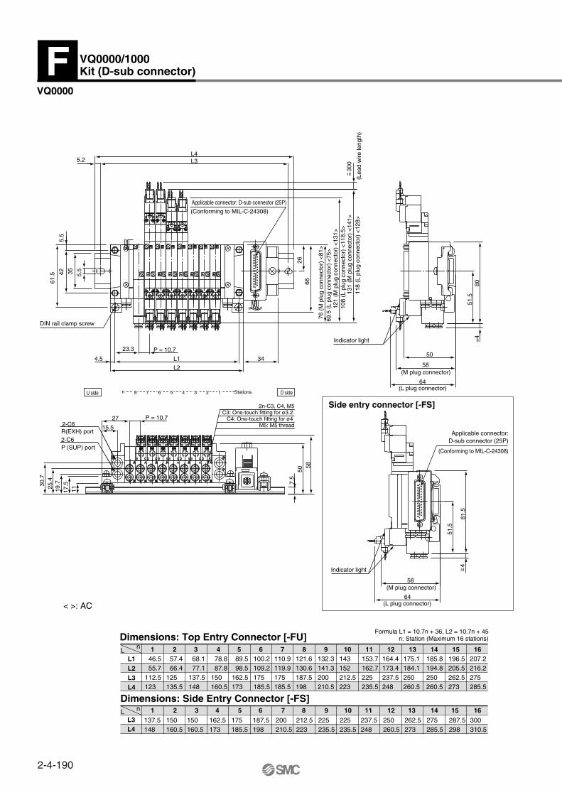
L1L2L3L4
1 2 3 4 5 6 7 8 9 12 13 14 15 1610 11
Dimensions: Top Entry Connector [-FU]
Dimensions: Side Entry Connector [-FS]L
L
1 2 3 4 5 6 7 8 9 12 13 14 15 1610 11
VQ0000
Formula L1 = 10.7n + 36, L2 = 10.7n + 45n: Station (Maximum 16 stations)
L3L4
< >: AC
Side entry connector [-FS]
58
131
(M p
lug
conn
ecto
r) <
141>
121
(M p
lug
conn
ecto
r) <
131>
76 (
M p
lug
conn
ecto
r) <
81>
64
58
80=
4
507.
5
30.7
25.4
19.7
17.5
11
51.5
5034
L3L4
P = 10.727
L1
23.3
4.5
5.5
42
5.2
L2
15.5
6626
61.5 35 5.
5
P = 10.7(L
ead
wire
leng
th)
118
(L p
lug
conn
ecto
r) <
128>
108
(L p
lug
conn
ecto
r) <
118.
5>
69.5
(L
plug
con
nect
or)
<75>
C3: One-touch fitting for ø3.2 C4: One-touch fitting for ø4
2n-C3, C4, M5
M5: M5 thread
(Conforming to MIL-C-24308)
Applicable connector: D-sub connector (25P)
DIN rail clamp screw
Indicator light
P (SUP) port2-C6R(EXH) port2-C6
(L plug connector)
(M plug connector)
64
58
81.5
51.5
(Conforming to MIL-C-24308)
Applicable connector:D-sub connector (25P)
Indicator light
(L plug connector)
(M plug connector)
n 8 7 6 5 4 3 2 Stations1U side D side
137.5148
150 160.5
150160.5
162.5173
175185.5
187.5198
200210.5
212.5223
225235.5
300310.5
287.5298
275285.5
262.5273
250260.5
237.5248
225235.5
46.5 55.7112.5123
57.4 66.4 125135.5
68.1 77.1137.5148
78.8 87.8150 160.5
89.5 98.5162.5 173
100.2109.2175185.5
110.9119.9175 185.5
121.6130.6187.5198
132.3141.3200210.5
143152212.5223
153.7162.7225235.5
164.4173.4237.5248
175.1184.1250260.5
185.8194.8 250260.5
196.5205.5262.5273
207.2216.2275285.5
VQ0000/1000Kit (D-sub connector)F
300
~ =
4~ =
n
n
2-4-190
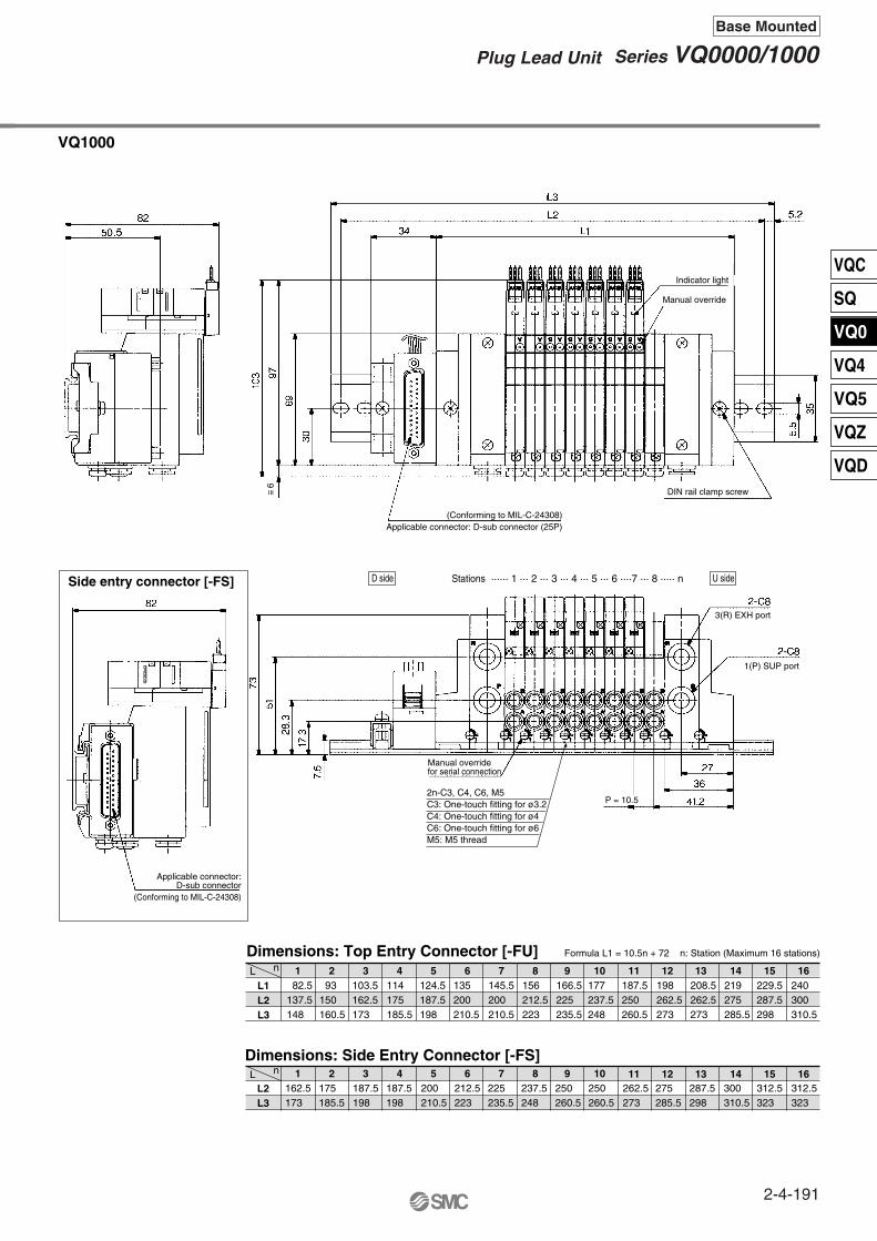
L1L2L3
Dimensions: Top Entry Connector [-FU]
L2L3
Dimensions: Side Entry Connector [-FS]L
L 82.5137.5148
93150 160.5
103.5 162.5173
114 175 185.5
124.5187.5198
135200210.5
145.5 200210.5
156 212.5223
166.5225 235.5
198262.5273
208.5262.5273
219275 285.5
229.5 287.5298
240300310.5
177237.5248
187.5250 260.5
162.5173
175 185.5
187.5198
187.5198
200210.5
212.5223
225 235.5
237.5248
250260.5
275285.5
287.5298
300310.5
312.5 323
312.5323
250260.5
262.5 273
VQ1000
Formula L1 = 10.5n + 72 n: Station (Maximum 16 stations)
Side entry connector [-FS]
1 2 3 4 5 6 7 8 9 10
1 2 3 4 5 6 7 8 9 10
11 12 13 14 15 16
11 12 13 14 15 16
(Conforming to MIL-C-24308)Applicable connector: D-sub connector (25P)
Indicator light
Manual override
DIN rail clamp screw
3(R) EXH port
1(P) SUP port
Manual overridefor serial connection
Applicable connector:D-sub connector
(Conforming to MIL-C-24308)
P = 10.52n-C3, C4, C6, M5C3: One-touch fitting for ø3.2C4: One-touch fitting for ø4C6: One-touch fitting for ø6M5: M5 thread
D side U sideStations ······ 1 ··· 2 ··· 3 ··· 4 ··· 5 ··· 6 ····7 ··· 8 ····· n
~ =6
n
n
2-4-191
Series VQ0000/1000Plug Lead Unit
Base Mounted
VQC
SQ
VQ0
VQ4
VQ5
VQZ
VQD
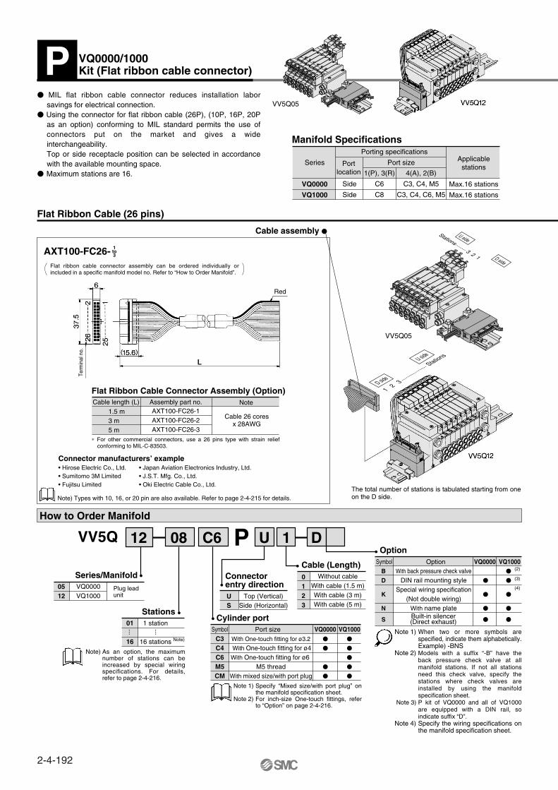
Series
VQ0000
VQ1000
Max.16 stations
Max.16 stations
Port size
Side
Side
Porting specifications
4(A), 2(B)
C3, C4, M5
C3, C4, C6, M5
1(P), 3(R)
C6
C8
Flat Ribbon Cable (26 pins)
Manifold Specifications
AXT100-FC26- 1to3
Flat Ribbon Cable Connector Assembly (Option)NoteAssembly part no.
AXT100-FC26-1AXT100-FC26-2AXT100-FC26-3
Cable length (L)1.5 m3 m5 m
Cable 26 coresx 28AWG
Note) Types with 10, 16, or 20 pin are also available. Refer to page 2-4-215 for details.
How to Order Manifold
1 station
16 stations
01
16
Plug lead unit
Port size VQ0000 VQ1000
VQ0000 VQ1000
SymbolWith One-touch fitting for ø3.2
With One-touch fitting for ø4With One-touch fitting for ø6
M5 threadWith mixed size/with port plug
C3C4C6M5CM
Top (Vertical)Side (Horizontal)
US
OptionSymbol Option
B
D
N
S
K
With back pressure check valveDIN rail mounting style
Special wiring specification(Not double wiring)
With name plate
Connectorentry direction
Cylinder port
VQ0000VQ1000
0512
Series/Manifold
Stations
Cable assembly
VV5Q 08 C612 U 1 DP
······
Without cableWith cable (1.5 m)With cable (3 m)With cable (5 m)
0123
Cable (Length)
(2)
(3)
(4)
Connector manufacturers’ example• Hirose Electric Co., Ltd.• Sumitomo 3M Limited• Fujitsu Limited
• Japan Aviation Electronics Industry, Ltd.• J.S.T. Mfg. Co., Ltd.• Oki Electric Cable Co., Ltd.
Note)
Note)
Specify “Mixed size/with port plug” on the manifold specification sheet. For inch-size One-touch fittings, refer to “Option” on page 2-4-216.
When two or more symbols are specified, indicate them alphabetically.Example) -BNSModels with a suffix “-B” have the back pressure check valve at all manifold stations. If not all stations need this check valve, specify the stations where check valves are installed by using the manifold specification sheet.P kit of VQ0000 and all of VQ1000 are equipped with a DIN rail, so indicate suffix “D”.Specify the wiring specifications on the manifold specification sheet.
MIL flat ribbon cable connector reduces installation labor savings for electrical connection.
Using the connector for flat ribbon cable (26P), (10P, 16P, 20P as an option) conforming to MIL standard permits the use of connectors put on the market and gives a wide interchangeability.Top or side receptacle position can be selected in accordance with the available mounting space.
Maximum stations are 16.
ApplicablestationsPort
location
Flat ribbon cable connector assembly can be ordered individually or included in a specific manifold model no. Refer to “How to Order Manifold”.
∗ For other commercial connectors, use a 26 pins type with strain relief conforming to MIL-C-83503.
The total number of stations is tabulated starting from one on the D side.
As an option, the maximum number of stations can be increased by special wiring specifications. For details, refer to page 2-4-216.
Built-in silencer(Direct exhaust)
Note 1)
Note 2)
Note 1)
Note 2)
Note 3)
Note 4)
VQ0000/1000Kit (Flat ribbon cable connector)P
Red
Term
inal
no.
U side
D side
Stations········ 3 2 1
U side
D side
1 2 3
·········
·········
Stations
VV5Q05
VV5Q05
2-4-192
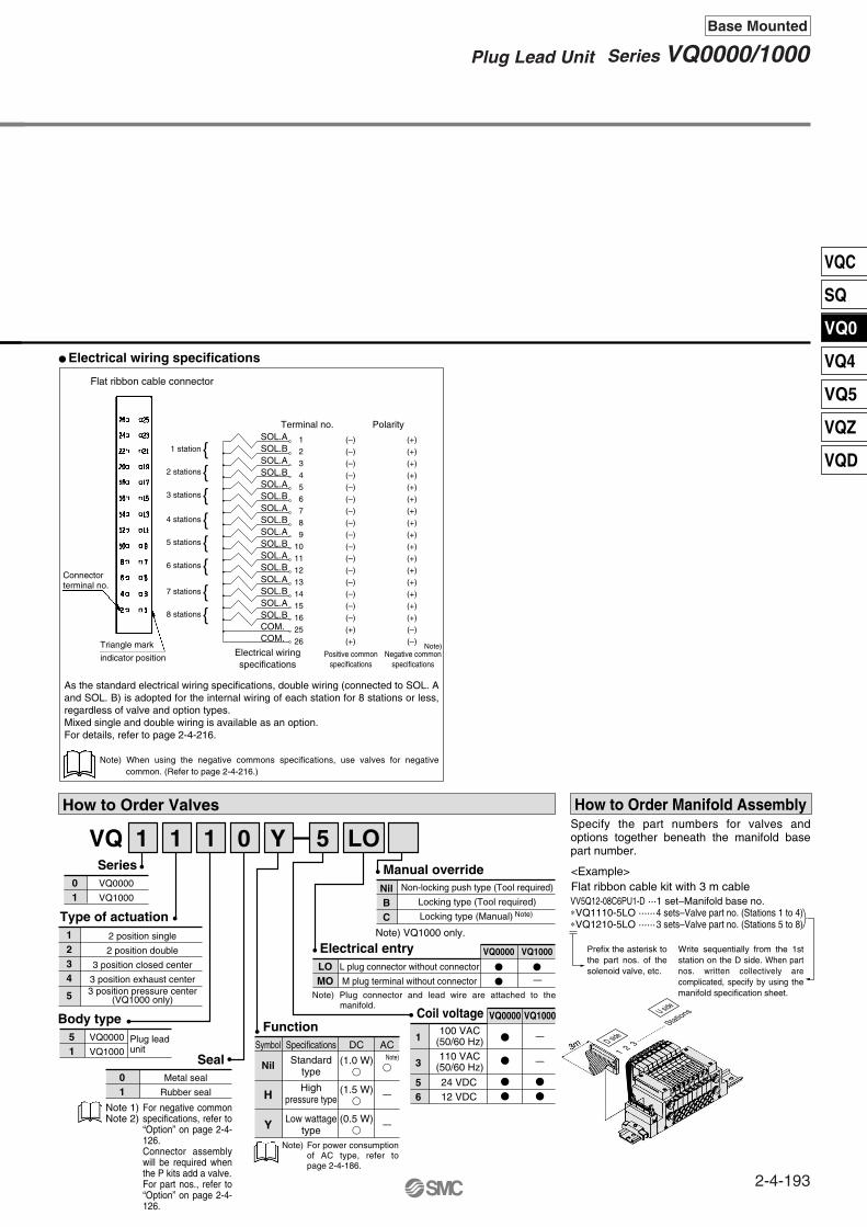
Electrical wiring specifications
How to Order Valves
SOL.ASOL.BSOL.ASOL.BSOL.ASOL.BSOL.ASOL.BSOL.ASOL.BSOL.ASOL.BSOL.ASOL.BSOL.ASOL.BCOM.COM.
VQ0000
VQ1000
Metal seal
Rubber seal
Plug leadunit
51
2 position single
2 position double
3 position closed center
3 position exhaust center
1234
5
01
Series
01
Seal
Type of actuation
Non-locking push type (Tool required)
Locking type (Tool required)
Locking type (Manual) Note)
NilBC
Manual override
Body type
1
2
3
4
5
6
7
8
9
10
11
12
13
14
15
16
25
26
(–)
(–)
(–)
(–)
(–)
(–)
(–)
(–)
(–)
(–)
(–)
(–)
(–)
(–)
(–)
(–)
(+)
(+)
(+)
(+)
(+)
(+)
(+)
(+)
(+)
(+)
(+)
(+)
(+)
(+)
(+)
(+)
(+)
(+)
(–)
(–)
Terminal no.
Electrical wiringspecifications
Polarity
1 station2 stations3 stations4 stations5 stations6 stations7 stations8 stations
Positive commonspecifications
Negative commonspecifications
VQ 1 1 1 0 Y 5 LO
VQ0000
VQ1000
Note)
L plug connector without connector
M plug terminal without connector
VQ0000 VQ1000
LOMO
Electrical entryNote) VQ1000 only.
Flat ribbon cable connector
1 set–Manifold base no.4 sets–Valve part no. (Stations 1 to 4)3 sets–Valve part no. (Stations 5 to 8)
How to Order Manifold Assembly
<Example>Flat ribbon cable kit with 3 m cableVV5Q12-08C6PU1-D ···∗VQ1110-5LO ······∗VQ1210-5LO ······
100 VAC (50/60 Hz)
110 VAC(50/60 Hz)
1
3
56
Coil voltage VQ0000 VQ1000
Specifications
Standardtype
Highpressure type
Low wattagetype
FunctionSymbol
Nil
H
Y
DC AC
(1.0 W)
(1.5 W)
(0.5 W)
As the standard electrical wiring specifications, double wiring (connected to SOL. A and SOL. B) is adopted for the internal wiring of each station for 8 stations or less, regardless of valve and option types. Mixed single and double wiring is available as an option.For details, refer to page 2-4-216.
Note) When using the negative commons specifications, use valves for negative common. (Refer to page 2-4-216.)
—
—
—
—
—
Note) Plug connector and lead wire are attached to the manifold.
24 VDC12 VDC
For negative common specifications, refer to “Option” on page 2-4-126.Connector assembly will be required when the P kits add a valve. For part nos., refer to “Option” on page 2-4-126.
Note)
For power consumption of AC type, refer to page 2-4-186.
Note)
Note 1)Note 2)
3 position pressure center(VQ1000 only)
Specify the part numbers for valves and options together beneath the manifold base part number.
Prefix the asterisk to the part nos. of the solenoid valve, etc.
Write sequentially from the 1st station on the D side. When part nos. written collectively are complicated, specify by using the manifold specification sheet.
Triangle mark
indicator position
Connectorterminal no.
U side
D side
1 2 3 ·········
······ Stations
2-4-193
Series VQ0000/1000Plug Lead Unit
Base Mounted
VQC
SQ
VQ0
VQ4
VQ5
VQZ
VQD
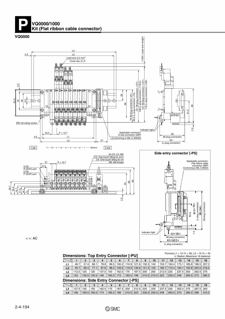
L1L2L3L4
46.7 55.7112.5123
57.4 66.4125135.5
68.1 77.1125 135.5
78.8 87.8137.5148
89.5 98.5150160.5
100.2109.2162.5173
110.9119.9175185.5
121.6130.6187.5198
132.3141.3200210.5
164.4173.4225235.5
175.1184.1237.5248
185.8 194.8250260.5
196.5205.5262.5273
207.2216.2275285.5
143152200210.5
153.7162.7212.5223
Dimensions: Top Entry Connector [-PU]
L3L4
Dimensions: Side Entry Connector [-PS]L
L
137.5148
150160.5
150160.5
162.5173
175185.5
187.5 198
200 210.5
212.5223
225 235.5
250260.5
262.5273
275 285.5
287.5298
300310.5
225235.5
237.5248
VQ0000
Formula L1 = 10.7n + 36, L2 = 10.7n + 45n: Station (Maximum 16 stations)
< >: AC
Side entry connector [-PS]
300
( L
ead
wire
leng
th)
76 (
M p
lug
conn
ecto
r) <
81>
121
(M p
lug
conn
ecto
r) <
131>
131
(M p
lug
conn
ecto
r) <
141>
64
58
27
80
L4
L3
66
26
61.5
51.5
5.5
42
4.5
L2
5.2
L1
23.3
35 5.5
P = 10.7
118
(L p
lug
conn
ecto
r) <
128>
108
(L p
lug
conn
ecto
r) <
118.
5>
69.5
(L
plug
con
nect
or)
<75
>
Cover dia. ø1.5Lead wire 0.2 mm2
(Conforming to MIL-C-83503)
Applicable connector:D-sub connector (26P)
Indicator light
(L plug connector)
(M plug connector)
58 63
50
11
25.4
16.730
.7
19.7
17.5
15.5
7.5
P = 10.727
C3: One-touch fitting for ø3.2C4: One-touch fitting for ø4
2n-C3, C4, M5
M5: M5 thread
P (SUP) port2-C6R (EXH) port2-C6
n 8 7 6 5 4 3 2 1 Stations D sideU side
1 2 3
1 2 3
4 5 6 7 8 9
4 5 6 7 8 9
10 11 12 13 14 15 16
10 11 12 13 14 15 16
VQ0000/1000Kit (Flat ribbon cable connector)P
~ =
4~ = 5~ =
DIN rail clamp screw
Applicable connector:Flat ribbon cableconnector (26P)
(Conforming to MIL-C-83503)
Indicator light
(M plug connector)
(L plug connector)
(M p
lug
conn
ecto
r)
(L p
lug
conn
ecto
r)
n
n
2-4-194
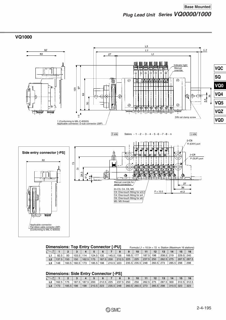
L1L2L3
Dimensions: Top Entry Connector [-PU]
L2L3
Dimensions: Side Entry Connector [-PS] L
L 82.5137.5148
93150160.5
103.5150 160.5
114162.5 173
124.5175185.5
135187.5198
145.5200210.5
156212.5223
166.5225235.5
198250 260.5
208.5262.5273
219275285.5
229.5287.5298
240287.5298
177225235.5
187.5237.5248
162.5173
175 185.5
187.5198
187.5 198
200210.5
212.5223
225235.5
237.5248
250260.5
275 285.5
287.5298
300310.5
312.5323
312.5 323
250260.5
262.5273
VQ1000
Formula L1 = 10.5n + 72 n: Station (Maximum 16 stations)
Side entry connector [-PS]
1 2 3
1 2 3
4 5 6 7 8
4 5 6 7 8
9 10 11 12 13 14 15 16
9 10 11 12 13 14 15 16
1 (Conforming to MIL-C-83503)Applicable connector: D-sub connector (26P)
Indicator lightManualoverride
DIN rail clamp screw
R (EXH) port
P (SUP) port
Manual override forserial connection
P = 10.5
Applicable connector:Flat ribbon cable connector (26P)(Conforming to MIL-C-83503)
D side U sideStations ·· 1 ···2 ··· 3 ·· 4 ·· 5 ··6 ···7 ··8 ·· n
~ =6
n
n
2n-C3, C4, C6, M5C3: One-touch fitting for ø3.2C4: One-touch fitting for ø4C6: One-touch fitting for ø6M5: M5 thread
2-4-195
Series VQ0000/1000Plug Lead Unit
Base Mounted
VQC
SQ
VQ0
VQ4
VQ5
VQZ
VQD

Series
VQ0000
VQ1000
Max.16 stations
Max.16 stations
Port size
Side
Side
Porting specifications
4(A), 2(B)
C3, C4, M5
C3, C4, C6, M5
1(P), 3(R)
C6
C6
Manifold Specifications
How to Order Manifold
1 station
16 stations Note)
01
16
Plug lead unit
VQ0000 VQ1000
OptionSymbol Option
B
D
K
N
S
With back pressure check valve
DIN rail mounting style
Special wiring specifications (Not double wiring)
With name plate
Built-in silencer, direct exhaust
Cylinder ports
VQ0000
VQ1000
0512
Manifold
1 to 4 stations
5 to 8 stations
Terminal blocks
1 row
2 rows
Series/Manifold
Stations
VV5Q 08 C612 2 DT
··· ···
8 terminals in 1 rowApplicable stations
1 to 4 stations (Double wiring),8 stations (Single wiring)
1
Number of terminals
SOL.ASOL.BSOL.ASOL.BSOL.ASOL.BSOL.ASOL.B
COM.
1
2
3
4
5
6
7
8
COM
(–)
(–)
(–)
(–)
(–)
(–)
(–)
(–)
(+)
Terminal no.
1 station 2 stations 3 stations 4 stations
SOL.ASOL.BSOL.ASOL.BSOL.ASOL.BSOL.ASOL.B
COM.
1
2
3
4
5
6
7
8
COM
(–)
(–)
(–)
(–)
(–)
(–)
(–)
(–)
(+)
5 stations6 stations7 stations8 stations
Terminal no.
Note)
Port sizeSymbol With One-touch fitting for ø3.2
With One-touch fitting for ø4
With One-touch fitting for ø6
M5 thread
With mixed size/with port plug
C3C4C6M5CM
(2)
(3)
(4)
Note 1)
Note 2)
Note 3)
Note 4)
U side
D side
Stations
3 2 1
Terminal blockconnections
Cover
It is a standard terminal block type. Two quantities of terminals can be selected in accordance with the
number of stations. (8 terminals/16 terminals) Maximum stations are 8. (16 stations as an option)
Portlocation
Applicablestations
Open the terminal block cover to connect the wires to the terminal block. (With M3 thread)
In the case of double wiring (standard spec.)T1 (Terminal block of 1 row): 1-4 stationsT2 (Terminal block of 2 rows): 5-8 stations
T1 and T2 can be optionally chosen by adopting the combinations of single and double wiring (option spec.) etc.
The quantity of terminal blocks used depends on the number of manifold stations
Double wiring (connected to SOL. A and SOL. B) is adopted for the internal wiring of each station, regardless of valve and option types. Mixed single and double wiring is available as an option. For details, refer to page 2-4-216.
Wiring other than those above is possible. For details, refer to page 2-4-216.
Note)
Refer to page 2-4-216 for details.
When two or more symbols are specified, indicate them alphabetically.Example) -BNSModels with a suffix “-B” have the back pressure check valve at all manifold stations. If not all stations need this check valve, specify the stations where check valves are installed by using the manifold specification sheet.T kit of VQ0000 and all of VQ1000 are equipped with a DIN rail, so indicate suffix “-D”.Specify the wiring specifications on the manifold specification sheet.
Specify “Mixed size/with port plug” on the manifold specification sheet.For inch-size One-touch fittings, refer to “Option” on page 2-4-216.
The number of terminal blocks can be chosen regardless of station qty. Suffix the option symbol, “K” when the wiring specifications are special.
Applicable stations5 to 8 stations (Double wiring),
16 stations (Single wiring)
Note)
Note 1)
Note 2)
Note)
VQ0000/1000Kit (Terminal block)T
Electrical wiring specifications
T1
Terminal no.
T2
U side
D side1 2 3 ····
········ S
tations
16 terminals in 2 rows2
VV5Q05
VV5Q05
2-4-196
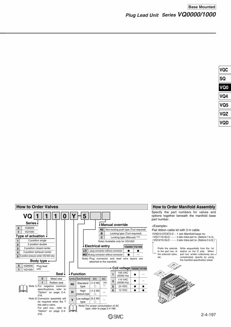
How to Order Valves
VQ0000
VQ1000
Metal seal
Rubber seal
Plug lead unit
51
2 position single
2 position double
3 position closed center
3 position exhaust center
3 position pressure center (VQ1000 only)
12345
01
Series
01
Seal
Type of actuation
Non-locking push type (Tool required)
Locking type (Tool required)
Locking type (Manual) Note)
NilBC
Manual override
Body type
VQ 1 1 1 0 Y 5
VQ0000
VQ1000
L plug connector without connector
M plug connector without connector
VQ0000 VQ1000
LOMO
Electrical entry
Note) Available only for VQ1000
1 set–Manifold base no.4 sets–Valve part no. (Stations 1 to 4)3 sets–Valve part no. (Stations 5 to 8)
How to Order Manifold Assembly
<Example>Flat ribbon cable kit with 3 m cableVV5Q12-07C6T2-D ···∗VQ1110-5LO ········∗VQ1210-5LO ········
100 VAC (50/60 Hz)
110 VAC(50/60 Hz)
24 VDC
12 VDC
1
3
56
Coil voltage VQ0000 VQ1000
Specifications
Standardtype
Highpressure type
Low wattagetype
FunctionSymbol
Nil
H
Y
DC AC
(1.0 W)
(1.5 W)
(0.5 W)
For negative common specifications, refer to “Option” on page 2-4-216.Connector assembly will be required when the T kits add a valve. For part nos., refer to “Option” on page 2-4-216.
Plug connector and lead wire layers are attached to the manifold.
—
—
—
—
—
Note)
Note)
For power consumption of AC type, refer to page 2-4-186.
Note)
Note 1)
Note 2)
Specify the part numbers for valves and options together beneath the manifold base part number.
Prefix the asterisk to the part nos. of the solenoid valve, etc.
Write sequentially from the 1st station on the D side. When part nos. written collectively are complicated, specify by using the manifold specification sheet.
U side
D side
1 2 3 ·········
··· Stations
2-4-197
Series VQ0000/1000Plug Lead Unit
Base Mounted
VQC
SQ
VQ0
VQ4
VQ5
VQZ
VQD
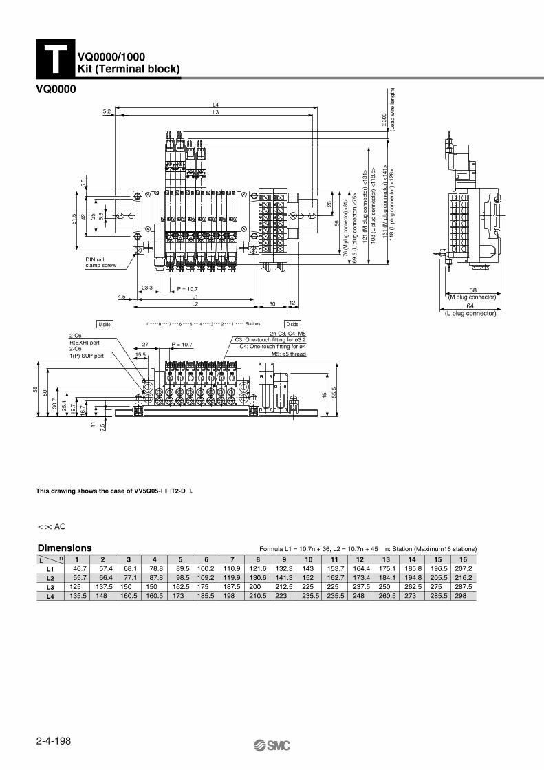
5.5
35
(Lea
d w
ire le
ngth
)
L1L2L3L4
46.7 55.7125 135.5
57.4 66.4137.5148
68.1 77.1150160.5
78.8 87.8 150160.5
89.5 98.5 162.5173
100.2109.2175185.5
110.9 119.9187.5198
121.6130.6200210.5
132.3141.3212.5223
164.4173.4237.5 248
175.1184.1250260.5
185.8194.8262.5273
196.5 205.5275285.5
207.2216.2287.5298
143152 225235.5
153.7 162.7225235.5
DimensionsL n
Formula L1 = 10.7n + 36, L2 = 10.7n + 45 n: Station (Maximum16 stations)
< >: AC
VQ0000
This drawing shows the case of VV5Q05-T2-D.
131
(M p
lug
conn
ecto
r) <
141>
121
(M p
lug
conn
ecto
r) <
131>
76 (M
plu
g co
nnec
tor)
<81>
L4L35.2
42
6626
61.5 5.5
118
(L p
lug
conn
ecto
r) <
128>
108
(L p
lug
conn
ecto
r) <
118.
5>
69.5
(L
plug
con
nect
or)
<75
>
DIN railclamp screw
1230
23.3
L14.5L2
P = 10.7
2n-C3, C4, M5
n 8 7 6 5 4 3 2 Stations1U side D side
58
50
30.7
25.4
19.7
16.7
11
7.5
1(P) SUP port2-C6R(EXH) port2-C6
P = 10.727
15.5
C3: One-touch fitting for ø3.2C4: One-touch fitting for ø4
M5: ø5 thread
55.5
45
64
58
(L plug connector)
(M plug connector)
1 2 3 4 5 6 7 8 9 10 11 12 13 14 15 16
VQ0000/1000Kit (Terminal block)T
~ =30
0
2-4-198

L1L2L3
82.5150160.5
93162.5173
103.5175185.5
114 187.5198
124.5187.5198
135200210.5
145.5212.5223
156225 235.5
166.5 237.5 248
198262.5273
208.5275285.5
219 287.5298
229.5300310.5
240312.5323
177 250260.5
187.5250260.5
DimensionsL n
VQ1000
Formula L1 = 10.5n + 72 n: Station (Maximum 16 stations)
This drawing shows the case of VV5Q12-T2-D.
1 2 3 4 5 6 7 8 9 10 11 12 13 14 15 16
2n-C3, C4, C6, M5C3: One-touch fitting for ø3.2C4: One-touch fitting for ø4C6: One-touch fitting for ø6M5: M5 thread
D side U sideStations ··1 ·· 2 ·· 3 ·· 4 ·· 5 ···6 ···7 ·· 8 ··· n
~ =6
Indicator light
Manual override
DIN rail clamp screw
3(R) EXH port
1(P) SUP port
Manual override forserial connection
P = 10.5
2-4-199
Series VQ0000/1000Plug Lead Unit
Base Mounted
VQC
SQ
VQ0
VQ4
VQ5
VQZ
VQD
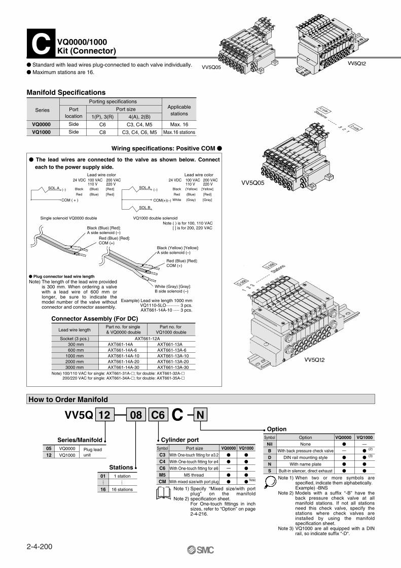
VQ0000
VQ1000
Max. 16
Max.16 stations
Port size
Side
Side
Porting specifications
4(A), 2(B)
C3, C4, M5
C3, C4, C6, M5
1(P), 3(R)
C6
C8
Wiring specifications: Positive COM
Connector Assembly (For DC)
Manifold Specifications
How to Order Manifold
1 station
16 stations
01
16
Plug lead unit With One-touch fitting for ø3.2
With One-touch fitting for ø4
With One-touch fitting for ø6
M5 thread
With mixed size/with port plug
VQ1000VQ0000
C3C4C6M5CM
Port sizeSymbol
Option
Cylinder portVQ0000
VQ1000
0512
Socket (3 pcs.)300 mm600 mm
1000 mm2000 mm3000 mm
Lead wire length
AXT661-14AAXT661-14A-6AXT661-14A-10AXT661-14A-20AXT661-14A-30
AXT661-13AAXT661-13A-6AXT661-13A-10AXT661-13A-20AXT661-13A-30
Part no. for single & VQ0000 double
Part no. for VQ1000 double
Series/Manifold
Stations
VV5Q 08 C612 NC
··· ···
Note)
SOL.A
COM ( + )
Black
Red
(Blue)
(Blue)
[Red]
[Red]
Lead wire color24 VDC 100 VAC
110 V200 VAC220 V
Black
Red
White
(Yellow)
(Blue)
(Gray)
[Yellow]
[Red]
[Gray]
Lead wire color24 VDC 100 VAC
110 V200 VAC220 V
SOL.A
SOL.B
(–)
COM(+)(–)
Single solenoid VQ0000 double VQ1000 double solenoid
Plug connector lead wire length
Example) Lead wire length 1000 mmVQ1110-5LO··········· 3 pcs. AXT661-14A-10 ····· 3 pcs.
Note) 100/110 VAC for single: AXT661-31A-; for double: AXT661-32A-200/220 VAC for single: AXT661-34A-; for double: AXT661-35A-
AXT661-12A
VQ0000 VQ1000
Symbol Option
Nil
B
D
N
S
None
With back pressure check valve
DIN rail mounting style
With name plate
Built-in silencer, direct exhaust
—
(2)
(3)
Note 1)
Note 2)
Note 3)
(–)
Standard with lead wires plug-connected to each valve individually. Maximum stations are 16.
Portlocation
Applicablestations
The lead wires are connected to the valve as shown below. Connect each to the power supply side.
U side
D side
Stations
3 2 1
U side
D side
Stations
1 2 3
The length of the lead wire provided is 300 mm. When ordering a valve with a lead wire of 600 mm or longer, be sure to indicate the model number of the valve without connector and connector assembly.
( ) is for 100, 110 VAC[ ] is for 200, 220 VAC
Note
Note)
When two or more symbols are specified, indicate them alphabetically.Example) -BNSModels with a suffix “-B” have the back pressure check valve at all manifold stations. If not all stations need this check valve, specify the stations where check valves are installed by using the manifold specification sheet.VQ1000 are all equipped with a DIN rail, so indicate suffix “-D“.
Specify “Mixed size/with port plug” on the manifold specification sheet.For One-touch fittings in inch sizes, refer to “Option” on page 2-4-216.
—
Note 1)
Note 2)
—
VQ0000/1000Kit (Connector)C
Black (Blue) [Red]: A side solenoid (–)
Red (Blue) [Red]:COM (+)
Black (Yellow) [Yellow]:A side solenoid (–)
Red (Blue) [Red]: COM (+)
White (Gray) [Gray]:B side solenoid (–)
Series
VV5Q05
2-4-200
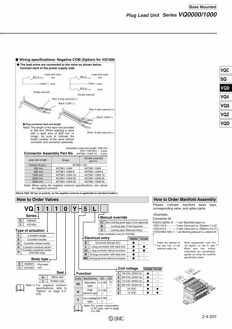
VV5Q12-08C6C-D ····∗VQ1110-5 ············∗VQ1210-5 ············∗VVQ1000-10A-1···
Wiring specifications: Negative COM (Option) for VQ1000
How to Order Valves
VQ0000
VQ1000
Metal seal
Rubber seal
Plug leadunit
51
2 position single
2 position double
3 position closed center
3 position exhaust center
1234
5
01
Series
01
Seal
Type of actuation
Non-locking push type (Tool required)
Locking type (Tool required)
Locking type (Manual) Note)
NilBC
Manual override
Body type
VQ 1 1 1 0 Y 5 L
VQ0000
VQ1000
Grommet (Except AC)
L plug connector with lead wire
L plug connector without connector
M plug connector with lead wire
M plug terminal without connector
VQ0000 VQ1000
GL
LOM
MO
Electrical entry
Note)
(Series VQ050 has no polarity, so the negative common is applicable to standard models.)
Note) Available only for VQ1000.
SOL.A (+)
COM (–)
Red
Black
Lead wire colorRed
Black
White
Lead wire colorSOL.A
SOL.B
(+)
COM (–)
(+)
Single solenoidDouble solenoid
Connector Assembly Part No.
Socket (3 pcs.)300 mm600 mm
1000 mm2000 mm3000 mm
Lead wire length
AXT661-14ANAXT661-14AN-6AXT661-14AN-10AXT661-14AN-20AXT661-14AN-30
AXT661-13ANAXT661-13AN-6AXT661-13AN-10AXT661-13AN-20AXT661-13AN-30
SingleDouble solenoid
part no.
Note) Plug connector lead wire length
Example) Lead wire length 1000 mmVQ1110N-5LO······3 pcs.
AXT661-14AN-10······3 pcs.
AXT661-12A
1 set–Manifold base no.3 sets–Valve part no. (Stations 1 to 3)4 sets–Valve part no. (Stations 4 to 7)1 set–Blanking plate part no. (stations 8)
How to Order Manifold Assembly
<Example>Connector kit
Coil voltage VQ0000 VQ1000
Specifications
Standardtype
Highpressure type
Low wattagetype
FunctionSymbol
Nil
H
Y
DC AC
(1.0 W)
(1.5 W)
(0.5 W)
100 VAC (50/60 Hz)
200 VAC (50/60 Hz)
110 VAC (50/60 Hz)
220 VAC (50/60 Hz)
24 VDC
12 VDC
123456
For power consumption of AC type, refer to page 2-4-186.
The lead wires are connected to the valve as shown below. Connect each to the power supply side.
The length of the lead wire provided is 300 mm. When ordering a valve with a lead wire of 600 mm or longer, be sure to indicate the model number of the valve without connector and connector assembly.
3 position pressure center(VQ1000 only)
For negative common specifications, refer to “Option” on page 2-4-216.
Note 1)
—
—
—
—Note)
—
—
Note)
—
—
—
Please indicate manifold base type, corresponding valve, and option parts.
Prefix the asterisk to the part nos. of the solenoid valve, etc.
Write sequentially from the 1st station on the D side. When part nos. written collectively are complicated, specify by using the manifold specification sheet.
Red: A side solenoid (+)
Black: COM (–)
Red: A side solenoid (+)
Black: COM (–)
White: B side solenoid (+)
When using the negative common specifications, use valves for negative common.
U side
D side
1 2 3 ·········
·· Stations
2-4-201
Series VQ0000/1000Plug Lead Unit
Base Mounted
VQC
SQ
VQ0
VQ4
VQ5
VQZ
VQD

(L plug connector)
VQ0000
The broken lines indicate DIN rail mounting style [-D].
< >: AC
47
300
(Le
ad w
ire)
131
(M p
lug
conn
ecto
r) <
141>
121
(M p
lug
conn
ecto
r) <
131>
76 (
M p
lug
conn
ecto
r) <
81>
53
474
123.
5
77.5
48.5
36300
3 po
sitio
n 11
5
Dou
ble
107
Sin
gle
69
19.7
8.7
23.3
P = 10.727
5.7
L1
1
4.5
1
5.5
39
(7.5
)
6.5
5.2 (L3)(L4)
L2
(11)
11
15.5
6626
P = 10.7
14.5
61.5 (3
5)
Cover O.D. ø1.4Lead wire: 0.2 mm2
L/M type plug connector
(Lead wire length)
Grommet
C3: One-touch fitting for ø3.2C4: One-touch fitting for ø4
2n-C3, C4, M5
M5: M5 thread
DIN railclamp screw
Mounting hole for 4-M4
Indicator light
118
(L p
lug
conn
ecto
r) <
128>
108
(L p
lug
conn
ecto
r) <
118.
5>
69.5
(L
plug
con
nect
or)
<75
>
P(SUP) port2-C63(R) EXH port2-C6
(M plug connector)
n 8 7 6 5 4 3 2 Stations1U side D side
4261
.5 (35)
(5.5
)
L1L2
(L3) (L4)
46.755.787.598
57.466.487.598
68.1 77.1100110.5
78.8 87.8112.5123
89.5 98.5125135.5
100.2109.2137.5148
110.9119.9150160.5
121.6130.6162.5173
132.3141.3162.5173
164.4173.4200210.5
175.1184.1212.5223
185.8194.8225235.5
196.5205.5225235.5
207.2216.2237.5248
143152175185.5
153.7162.7187.5198
DimensionsnL
Formula L1 = 10.7n + 36, L2 = 10.7n + 45 n: Station (Maximum 16 stations)
1 2 3 4 5 6 7 8 9 10 11 12 13 14 15 16
VQ0000/1000Kit (Connector)C
~=~ =
~ =
2-4-202
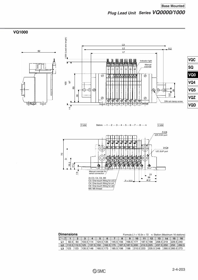
L1L2L3
82.5112.5123
93112.5123
103.5125135.5
114 137.5148
124.5150160.5
135162.5173
145.5175185.5
156187.5198
166.5187.5198
198225235.5
208.5237.5248
219250260.5
229.5250260.5
240262.5273
177200210.5
187.5212.5223
DimensionsnL
VQ1000
Formula L1 = 10.5n + 72 n: Station (Maximum 16 stations)
1 2 3 4 5 6 7 8 9 10 11 12 13 14 15 16
300
(Lea
d w
ire le
ngth
)
2n-C3, C4, C6, M5C3: One-touch fitting for ø3.2C4: One-touch fitting for ø4C6: One-touch fitting for ø6M5: M5 thread
~ =
D side U sideStations ····1 ··· 2 ···· 3 ··· 4 ··· 5 ··· 6 ····7 ···· 8 ····· n
Indicator light
Manualoverride
DIN rail clamp screw
3(R) EXH port
1(P) SUP port
Manual override forserial connection
P = 10.5
~ =6
2-4-203
Series VQ0000/1000Plug Lead Unit
Base Mounted
VQC
SQ
VQ0
VQ4
VQ5
VQZ
VQD

Series
VQ0000
VQ1000
Max.16 stations
Max.16 stations
Port size
Side
Side
Porting specifications
4(A), 2(B)
C3, C4, M5
C3, C4, C6, M5
1(P), 3(R)
C6
C8
Manifold Specifications
How to Order Manifold
1 station
16 stations Note)
01
16
Plug leadunit
Port size VQ0000 VQ1000Symbol
With One-touch fittings for ø3.2With One-touch fitting for ø4
With One-touch fitting for ø6
M5 thread
With mixed size/with port plug
C3C4C6M5CM
Model
Cylinder port
VQ0000
VQ1000
0512
Series/Manifold
Stations
VV5Q 08 C612 D XPAS
··· ···
VQ0000 VQ1000
Option
Dust-protected type (-XP) (VQ1000 only)
Symbol NoteOption
B
D
With back pressure check valve
DIN rail mounting
K
(2)
(3)
(4)
Suffix “-XP” for the dust-protected type SI unit.(Except SE and SQ.)
Note)
Note 1)
Note 2)
0A
B
CDEF1GHJ1J2KQR1R2V
Max.16stations
Max.16stations
Note 1)
Note 2)
Note 2)
Note 2)
Note 2)
Note 2)
Note 2)
Note 2)
Note 2)
Note 2)
Max. 8stations
Max. 8stationsMax. 16stations
Type SAWith general type SI unit
(Series EX300)
Type SBMitsubishi Electric Corporation
MELSECNET/MINI-S3 Data Link System
LEDPOWER
RUN
RDSD
ERR.
DescriptionLighting when power is turned ON
LEDTRD
RUN/ERR
DescriptionLighting during data reception
∗ For details on specifications and handling, refer to the separate technical instruction manual.
Nam
e of
term
inal
blo
ck (
LED
)N
ote
SDA SDB SG RDA RDB FG24V 0V
POWER RUN SD RD ERR
STATION NO.
ù10 ù1
24V 0V S1 S2 SG R1 R2 FG
RUNERR
TRD
ADDRESS NO.
Item
External power supply
Specifications
24 VDC, +10%, –5%
Currentconsumption(Internal unit)
SA, SB, SD, SE, SF, SG, SJ, SK, SQ, SR, SH, SV: 0.1ASC: 0.3A
Specify “Mixed size/with port plug” on the manifold specification sheet.For inch-size One-touch fittings, refer to “Option” on page 2-4-216.
When two or more symbols are specified, indicate them alphabetically.Example) -BNSModels with a suffix “-B” have the back pressure check valve at all manifold stations. If not all stations need this check valve, specify the stations where check valves are installed by using the manifold specification sheet. S kit of VQ0000 and all of VQ1000 are equipped with a DIN rail, so indicate suffix “-D”.Specify the wiring specifications on the manifold specification sheet.
Portlocation
Applicablestations
Stations are counted from station 1 on the D side.
Double wiring (connected to SOL. A and SOL. B) is adopted for the internal wiring of each station, regardless of valve and option types. Mixed single and double wiring is available as an option. For details, refer to page 2-4-216.
The serial transmission system reduces wiring work, while minimizing wiring and saving space.
The system comes in type SA (generic for small scale systems) for equipment with a small number of I/O points, or 32 points max., type SB (applicable to Mitsubishi Electric models) for controlling 512 I/O points max., type SC (applicable to OMRON models), type SD (applicable to SHARP models: 504 points max.), type SF (applicable to NKE models: 128 points max.), type SJ (applicable to SUNX models), type SK (applicable to Fuji Electric models), type SQ (applicable to OMRON’s Compo Bus/D), and type SR (applicable to OMRON’s Compo Bus/S).
Max. 8 stations. (Specify a option model with 9 to 16 stations by using the manifold specification sheet.)
Blinking when received data is normal;Lighting when data reception
Lighting when reception data error occursLight turns off when the error is corrected
Lighting during data receptionLighting during data transmission
Lighting when data transmissionwith the master station is normal
• T unitCan be connected with PLC I/O card for serial transmission. EX300-TMB1···· For models of Mitsubishi
Electric CorporationEX300-TTA1···· For models of OMRON
CorporationEX300-TFU1···· For models of Fuji Electric
Co., Ltd.EX300-T001··· For general models
∗ Up to 32 points per unit.• No. of output points, 16 point
• Master station:PLC made by Mitsubishi Electric CorporationSeries MELSEC-AAJ71PT32-S3, AJ71T32-S3A1SJ71PT32-S3
∗ Max. 64 stations, connected to remote I/O stations (Max. 512 points).
• No. of output points, 16 points. No. of sta. occupied, 2 stations
For details, refer to page 2-4-216.
—
The general type requires a transmission unit on CPU side.Usable only for VQ1000
Built-in silencer,direct exhaust
Special wiring specifications(Not double wiring)
With name plate
—
N
S
Without SI unit With general type SI unit (Series EX300)
Mitsubishi Electric Corp.: MELSECNET/MINI-S3 Data Link SystemOMRON Corp.: SYSBUS Wire SystemSHARP Corp.: Satellite I/O Link System
Matsushita Electric Works: MEWNET-F SystemNKE Corp.: Uni-wire System (16 output points)Rockwell Automation: Allen Bradley Remote I/O (RIO) System
NKE Corp.: Uni-wire H SystemSUNX Corp.: S-LINK System (16 output points)SUNX Corp.: S-LINK System (8 output points)
Fuji Electric Co.: T-LINK Mini SystemDeviceNet, CompoBus/D (OMRON Corp.)OMRON Corp.: CompoBus/S System (16 output points)OMRON Corp.: CompoBus/S System (8 output points)Mitsubishi Electric Corp.: CC-LINK System
Note 1)
Note 2)
Note 1)
Note 2)
Note 3)
Note 4)
VQ0000/1000Kit (Serial transmission unit)S
U side
D side
1 2 3 ·········
·········
Stations
VV5Q12Standard
G 1/2
G 1/2 prepared holeVV5Q12Dusttight (-XP)VV5Q05
M3 screw
2-4-204

SI unit output and coil numbering
How to Order Valves
<Wiring example 1> <Wiring example 2> Mixed wiring is available as an option. Use the manifold specification sheet to specify.
VQ0000
VQ1000
Metal seal
Rubber seal
Plug leadunit
51
2 position single
2 position double
3 position closed center
3 position exhaust center
1234
5
01
Series
01
Seal
Type of actuation
Non-locking push type (Tool required)
Locking type (Tool required)
Locking type (Manual) Note)
NilBC
Manual override
24 VDC; With light/surgevoltage suppressor5
Coil voltageBody type
VQ 1 1 1 0 Y 5 LO
VQ0000
VQ1000
L plug terminal without connector
M plug terminal without connector
VQ0000 VQ1000
LOMO
Electrical entryNote) Available only for VQ1000
SI unitoutput no.
0 1 2 3 4 5 6 7 8 9
A B A AB BUn-used A Un-
used A
SI U
nit
Dou
ble
Dou
ble
Sin
gle
Sin
gle
Sin
gle
Stations 1 2 3 4 5
Double wiring (Standard)
SI unitoutput no.
0 1 2 3 4 5 6 7
A B A B BA A A
SI U
nit
Dou
ble
Dou
ble
Dou
ble
Sin
gle
Sin
gle
Stations 1 2 3 4 5
Single/Double Mixed Wiring (Option)
Note)
1 set-Manifold base no.4 sets-Valve part no. (Stations 1 to 4)3 sets-Valve part no. (Stations 5 to 8)
How to Order Manifold Assembly
<Example>Serial transmission kitVV5Q12-08C6SA-D ····∗VQ1110-5LO ·····∗VQ1210-5LO ·····
Specifications
Standardtype
Highpressure type
Low wattagetype
FunctionSymbol
Nil
DC
(1.0 W)
(1.5 W)
(0.5 W)
H
Y
Type SCOMRON Corporation
SYSBUS Wire System
Type SDSHARP Corporation
Satellite I/O Link System
LEDPOWER
RUN
DescriptionON when power supply is ON
LED
RUN
Description
Nam
e of
term
inal
blo
ck (
LED
)N
ote
T/RERR
Blinks during data transmission/receptionON when transmission is abnormal
ERRORLights when slave station switch setting isabnormal, communication is abnormal,PLC stopped and defective slave unit
R.SETHOLD
ON for master unit control input
L1 L2 SG L1 L2 SG24V 0V
POWER RUN SD RD ERR
STATION NO.
ù10 ù1
24V 0V + – + – FG
RUNERR
TRD
ADDRESS NO.
Lights when power is ON andslave stations are operating normally
Lights when transmission is normal andPLC is in operation mode
• Master station unit:OMRON PLCSYSMAC C(CV) seriesTypes C500-RM201 and C200H-RM201
∗ 32 units max., transmission terminal connection(512 points max.)
• No. of output points, 16 points
• Master station unit:SHARP’s PLCNew Satellite Series WZW-31LMNew Satellite Series JWJW-23LM, JW-31LM
∗ Max. 31 units, I/O slave stations connected (504 points max.)
• No. of output points, 16 points
—
Plug connector and lead wire layers are attached to the manifold.
Note)
Connector assembly will be required when the S kits add a valve. For part nos., refer to “Option” on page 2-4-216.
3 position pressure center(VQ1000 only)
Please indicate manifold base type, corresponding valve, and option parts.
Prefix the asterisk to the part nos. of the solenoid valve, etc.
Write sequentially from the 1st station on the D side. When part nos. written collectively are complicated, specify by using the manifold specification sheet.U side
D side
1 2 3 ········
Stations
2-4-205
Series VQ0000/1000Plug Lead Unit
Base Mounted
VQC
SQ
VQ0
VQ4
VQ5
VQZ
VQD

L1L2L3L4
46.7 55.7225235.5
57.4 66.4237.5248
68.1 77.1250260.5
78.8 87.8250260.5
89.5 98.5262.5273
100.2109.2275285.5
110.9119.9287.5298
121.6130.6300310.5
132.3141.3312.5323
164.4 173.4337.5348
175.1184.1350360.5
185.8194.8362.5373
196.5 205.5375385.5
207.2216.2387.5398
143152325335.5
153.7162.7325335.5
DimensionsnL
VQ0000
Formula L1 = 10.7n + 36, L2= 10.7n + 45 n: Station (Maximum 16 stations)
5876
(M p
lug
conn
ecto
r) <8
1>
121
(M p
lug
conn
ecto
r) <
131>
131
(M p
lug
conn
ecto
r) <
141>
300
(Le
ad w
ire)
64
5850
38.5
7.5
30.7
25.4
19.7
16.7
17.5
11
15.5
51.5
14165
L4L3
L2
83.5
65
P = 10.727
L123.3
4.5
5.5
42
5.2
6626
61.5 35 5.
5
P = 10.7
8642
4632
DF
SA
MO
DE
L
AD
DR
ES
S
ER
RR
UN T
RD
FG
R2
R1
SG
S2
S1
0V24
V
69.5
(L p
lug
conn
ecto
r) <7
5>
108
(L p
lug
conn
ecto
r) <
118.
5>
118
(L p
lug
conn
ecto
r) <
128>
The DWG shows the SA type(General type)
C3: One-touch fitting for ø3.2C4: One-touch fitting for ø4
2n-C3, C4, M5
M5: M5 thread
(Conforming to MIL-C-83503)
Applicable connector: Flat ribbon cable connector (20P)
Mounting screw
Flat ribboncable unit
DIN railclamp screw
Indicator light
(P) SUP port2-C63 (R) (EXH port)2-C6
(L plug connector)
(M plug connector)
n 8 7 6 5 4 3 2 Stations1 D sideU side
16151413121110987654321
VQ0000/1000Kit (Serial transmission unit)S
~ =
~ =5
2-4-206
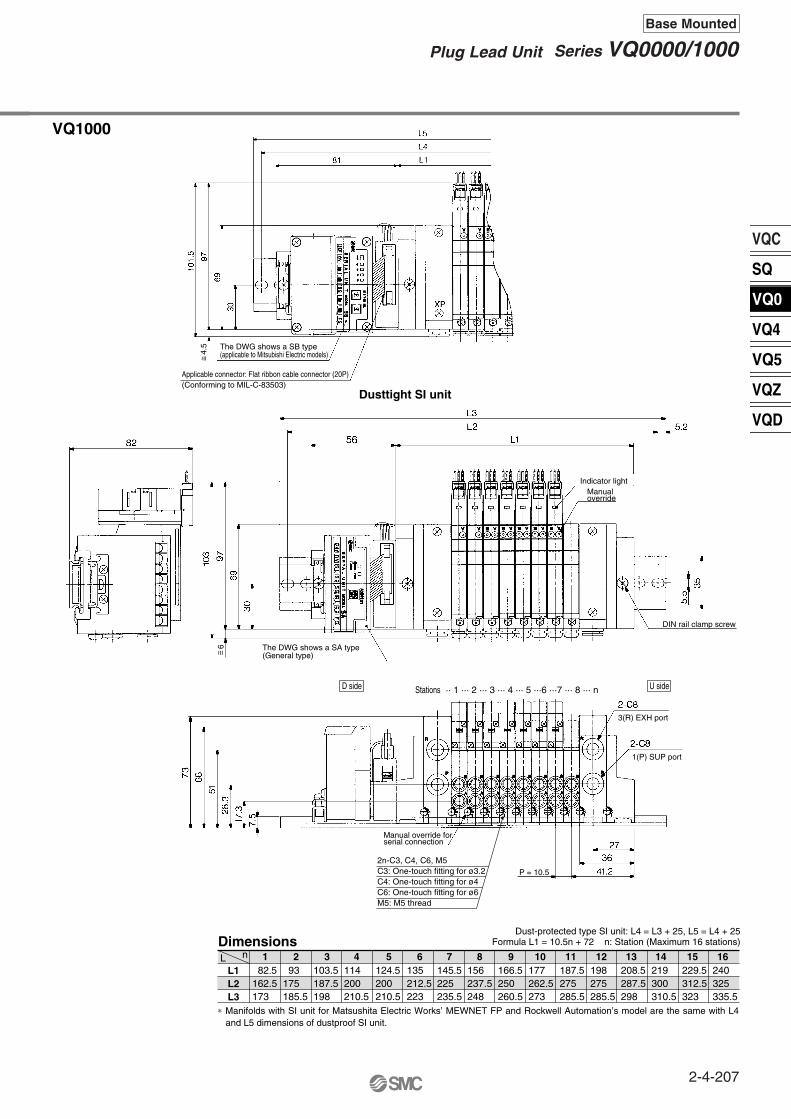
VQC
SQ
VQ0
VQ4
VQ5
VQZ
VQD
82.5162.5173
93175185.5
103.5187.5198
114 200210.5
124.5200210.5
135212.5223
145.5225235.5
156237.5248
166.5250260.5
198275285.5
208.5287.5298
219300310.5
229.5312.5323
240325335.5
177262.5273
187.5275285.5
Dimensions
VQ1000
L1L2L3
nL
Dust-protected type SI unit: L4 = L3 + 25, L5 = L4 + 25Formula L1 = 10.5n + 72 n: Station (Maximum 16 stations)
1 2 3 4 5 6 7 8 9 10 11 12 13 14 15 16
∗ Manifolds with SI unit for Matsushita Electric Works’ MEWNET FP and Rockwell Automation’s model are the same with L4 and L5 dimensions of dustproof SI unit.
2n-C3, C4, C6, M5C3: One-touch fitting for ø3.2C4: One-touch fitting for ø4C6: One-touch fitting for ø6M5: M5 thread
~ =
D side U sideStations ·· 1 ··· 2 ··· 3 ··· 4 ··· 5 ···6 ···7 ··· 8 ··· n
Applicable connector: Flat ribbon cable connector (20P)(Conforming to MIL-C-83503)
4.5 The DWG shows a SB type
(applicable to Mitsubishi Electric models)
Dusttight SI unit
Indicator lightManualoverride
DIN rail clamp screw
The DWG shows a SA type(General type)
3(R) EXH port
Manual override forserial connection
1(P) SUP port
P = 10.5
~ =6
2-4-207
Series VQ0000/1000Plug Lead Unit
Base Mounted

Manifold Option Parts for VQ0000
Blanking plate assemblyVVQ0000-10A-5
Individual SUP spacerVVQ0000-P-5-C4
JIS Symbol
Individual EXH spacerVVQ0000-R-5-C4
SUP/EXH block plateVVQ0000-16A-5-
Name plate [-N∗]VVQ0000-N5-Station (1 to Max. stations)
P (SUP)R (EXH)PR (SUP/EXH)
<Blocking indication label>
It is used by attaching on the manifold block for being prepared for removing a valve for maintenance reasons or planning to mount a spare valve, etc.
When the same manifold is to be used for different pressures, this spacer is mounted under the valve to equip each valve with an individual supply port.
When a valve exhaust affects other stations due to the circuit configuration, this spacer is mounted under the valve to equip each valve with an individual valve exhaust.
1(P) (For SUP)When different pressures, high and low, are supplied to one manifold, block a plate is inserted between the stations under different pressures.
3(R) (For EXH)
When a valve exhaust affects other stations due to the circuit configuration, this plate is used between the stations where exhaust should be separated.
1(P), 3(R) (For SUP/EXH)When blocking SUP and EXH simultaneously, SUP/EXH block plate (PR) is used.∗ Specify the number of stations on the manifold
specification sheet.
When blocking the SUP, EXH passage with a SUP, EXH block plate, indication label for confirmation of the blocking position from outside is attached. (One label for each)∗ When ordering a block plate incorporated with the
manifold no., a block indication label is attached to the manifold.
∗ When ordering assemblies incorporated with a manifold, add suffix “N” to the manifold no.
It is a transparent resin plate for placing a label that indicates solenoid valve function, etc.Insert it into the groove on the side of the end plate and bend it as shown in the figure.
C4 (SUP port)One-touch fittingfor ø4
D side U side
D side U side
Valve Valve Valve
Valve Valve Valve
Valve+
Individual SUPspacer
Valve+
Individual EXHspacer
C4 (EXH port)One-touch fittingfor ø4
SUP port block
SUP/EXH port block
EXH port block
D side
U side
SUP passage blocked(VVQ0000-16A-5-P)
EXH passage blocked(VVQ0000-16A-5-R)
SUP/EXH passage blocked(VVQ0000-16A-5-PR)
2-4-208
Series VQ0000Base Mounted
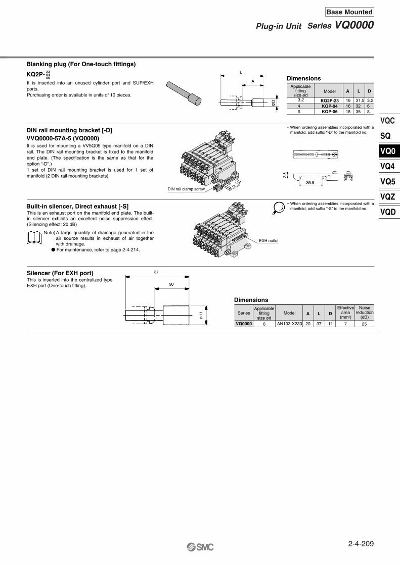
VQC
SQ
VQ0
VQ4
VQ5
VQZ
VQD
Blanking plug (For One-touch fittings)
KQ2P-
DIN rail mounting bracket [-D]VVQ0000-57A-5 (VQ0000)
Built-in silencer, Direct exhaust [-S]
Silencer (For EXH port)
230406
3.2
46
Model
KQ2P-23KQP-04KQP-06
A L D
6 25
Effectivearea
(mm2)Model
AN103-X233
Series
VQ0000
A
20
L
37
D
11
Dimensions
Dimensions
7
DIN rail clamp screw
EXH outlet
It is inserted into an unused cylinder port and SUP/EXH ports.Purchasing order is available in units of 10 pieces.
It is used for mounting a VV5Q05 type manifold on a DIN rail. The DIN rail mounting bracket is fixed to the manifold end plate. (The specification is the same as that for the option “-D”.)1 set of DIN rail mounting bracket is used for 1 set of manifold (2 DIN rail mounting brackets).
Applicablefitting
size ød3.268
31.53235
161618
∗ When ordering assemblies incorporated with a manifold, add suffix “-D” to the manifold no.
∗ When ordering assemblies incorporated with a manifold, add suffix “-S” to the manifold no.
This is an exhaust port on the manifold end plate. The built-in silencer exhibits an excellent noise suppression effect. (Silencing effect: 20 dB)
This is inserted into the centralized type EXH port (One-touch fitting).
A large quantity of drainage generated in the air source results in exhaust of air together with drainage.
For maintenance, refer to page 2-4-214.
Note)
Applicablefitting
size ød
Noisereduction
(dB)
2-4-209
Series VQ0000Plug-in Unit
Base Mounted
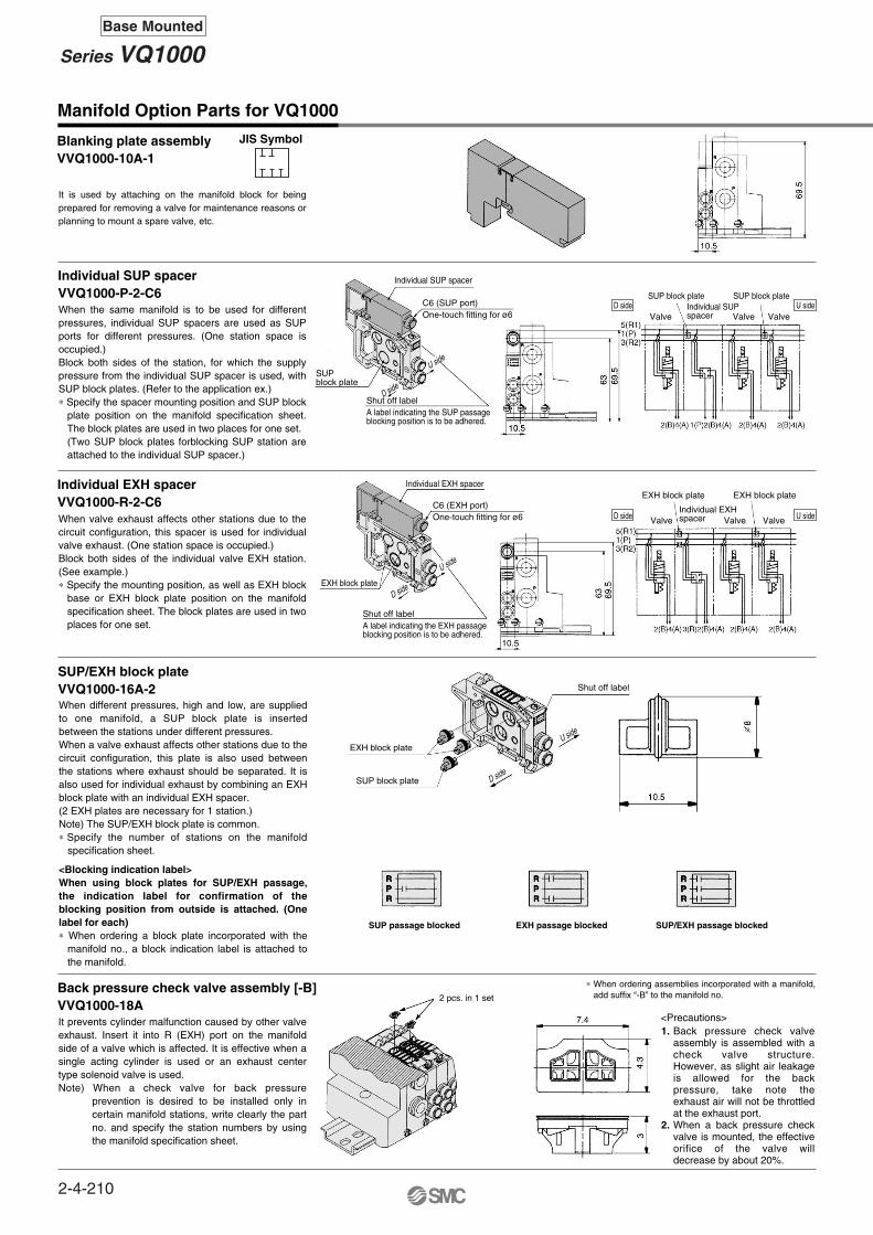
Manifold Option Parts for VQ1000
Individual EXH spacerVVQ1000-R-2-C6
Back pressure check valve assembly [-B]VVQ1000-18A
<Precautions>1.
2.
Blanking plate assemblyVVQ1000-10A-1
JIS Symbol
Individual SUP spacerVVQ1000-P-2-C6
SUP/EXH block plateVVQ1000-16A-2
It is used by attaching on the manifold block for being prepared for removing a valve for maintenance reasons or planning to mount a spare valve, etc.
When the same manifold is to be used for different pressures, individual SUP spacers are used as SUP ports for different pressures. (One station space is occupied.) Block both sides of the station, for which the supply pressure from the individual SUP spacer is used, with SUP block plates. (Refer to the application ex.)∗ Specify the spacer mounting position and SUP block
plate position on the manifold specification sheet. The block plates are used in two places for one set. (Two SUP block plates forblocking SUP station are attached to the individual SUP spacer.)
When valve exhaust affects other stations due to the circuit configuration, this spacer is used for individual valve exhaust. (One station space is occupied.) Block both sides of the individual valve EXH station. (See example.)∗ Specify the mounting position, as well as EXH block
base or EXH block plate position on the manifold specification sheet. The block plates are used in two places for one set.
When different pressures, high and low, are supplied to one manifold, a SUP block plate is inserted between the stations under different pressures.When a valve exhaust affects other stations due to the circuit configuration, this plate is also used between the stations where exhaust should be separated. It is also used for individual exhaust by combining an EXH block plate with an individual EXH spacer. (2 EXH plates are necessary for 1 station.)Note) The SUP/EXH block plate is common.∗ Specify the number of stations on the manifold
specification sheet.
<Blocking indication label>When using block plates for SUP/EXH passage, the indication label for confirmation of the blocking position from outside is attached. (One label for each)∗ When ordering a block plate incorporated with the
manifold no., a block indication label is attached to the manifold.
It prevents cylinder malfunction caused by other valve exhaust. Insert it into R (EXH) port on the manifold side of a valve which is affected. It is effective when a single acting cylinder is used or an exhaust center type solenoid valve is used.Note) When a check valve for back pressure
prevention is desired to be installed only in certain manifold stations, write clearly the part no. and specify the station numbers by using the manifold specification sheet.
Back pressure check valve assembly is assembled with a check valve structure. However, as slight air leakage is allowed for the back pressure, take note the exhaust air will not be throttled at the exhaust port.When a back pressure check valve is mounted, the effective orifice of the valve will decrease by about 20%.
∗ When ordering assemblies incorporated with a manifold, add suffix “-B” to the manifold no.
Individual SUP spacer
C6 (SUP port)One-touch fitting for ø6
SUPblock plate
Shut off labelA label indicating the SUP passageblocking position is to be adhered.
Valve
Valve Valve Valve
Valve Valve
SUP block plate
SUP block plate
SUP block plateIndividual SUPspacer
Individual EXH spacer
EXH block plate
Shut off labelA label indicating the EXH passageblocking position is to be adhered.
Individual EXHspacer
Shut off label
C6 (EXH port)One-touch fitting for ø6
SUP passage blocked EXH passage blocked SUP/EXH passage blocked
2 pcs. in 1 set
EXH block plate
EXH block plate EXH block plate
D side
U side
D side
U side
D side
U side
U sideD side
U sideD side
2-4-210
Series VQ1000Base Mounted

VQC
SQ
VQ0
VQ4
VQ5
VQZ
VQD
Name plate [-N∗]VVQ1000-N2-Station (1 to Max. stations)
Port plug VVQ0000-58A
2 stations matching fitting assemblyVVQ1000-52A-C8
Elbow fittings assemblyVVQ1000-F-L
Built-in silencer, Direct exhaust [-S]
Silencer (For EXH port)
C3C4C6M5
3.2
468
KQ2P-23KQP-04KQP-06KQP-08
16161820.5
31.5323539
3.2 6 810
8
Model
AN200-KM8
AN203-KM8
Series
VQ1000
A
59
32
L
78
51
D
22
16
30
25
20
14
Dimensions
DimensionsBlanking plug (For One-touch fittings)
KQ2P- 23040608
∗
This is inserted into the centralized type EXH port (One-touch fitting).∗ When mounting elbow fittings assembly (VVQ1000-
F-L) on the edge of manifold station, select a silencer, AN203-KM8.Silencer (AN200-KM8) is interfered with fittings.
For driving a cylinder with a large bore, valves for two stations are operated to double the flow rate. This assembly for the cylinder port is used in that case. The assembly is equipped with One-touch fittings for a ø8 bore.∗ The bore for the manifold no. is “CM”.
Clearly indicate the 2 station matching fitting assembly no., and specify the number of stations and positions on the manifold specification sheet.
This is an exhaust port on the manifold end plate.The built-in silencer exhibits an excellent noise suppression
effect. (Silencing effect: 30 dB)Note) A large quantity of drainage generated in the air source
results in exhaust of air together with drainage.
It is used for piping that extends upward or downward from the manifold.When not mounting it to all manifold stations, clearly write the elbow type fitting assembly no. and specify the station’s qty and position by manifold specifications.∗ When mounting elbow fittings assembly on the edge of
manifold station and a silencer on EXH port, select a silencer, AN203-KM8.Silencer (AN200-KM8) is interfered with fittings.
The plug is used to block the cylinder port when using a 4 port valve as a 3 port valve.
It is inserted into an unused cylinder port and SUP/EXH ports.Purchasing order is available in units of 10 pieces.
It is a transparent resin plate for placing a label that indicates solenoid valve function, etc.Insert it into the groove on the side of the end plate and bend it as shown in the figure.
∗ When ordering a plug incorporated with a manifold, indicate “CM” for the port size in the manifold no., as well as, the mounting position and number of stations andcylinder port mounting positions, A and B, by means of the manifold specification sheet.
∗ Lightly screw an M3 screw in the port plug hole and pull it for removal.
∗ When ordering assemblies incorporated with a manifold, add suffix “-N” to the manifold no.
∗ When ordering assemblies incorporated with a manifold, indicate “L” or “B” for the manifold port size.
∗ When ordering assemblies incorporated with a manifold, add suffix “-S” to the manifold no.
Applicablefitting
size ødModel A L D
• For maintenance, refer to page 2-4-214.
Applicablefitting
size ød
Effectivearea
(mm2)
Noisereduction
(dB)
Exhaust port
P = 10.5
n: Stations
Hole
~= A
~= 23
~ =49
.5
2-4-211
Series VQ1000Plug-in Unit
Base Mounted

Manifold Option Parts for VQ0000/VQ1000
Double check block (Separated type)VQ1000-FPG-
<Check valveoperation principle>
VVQ1000-FPG-02 1 set∗VQ1000-FPG-C6M5-D 2 pcs.
Dimensions
Single unit Manifold
L1L2L3
315060.5
1 2 3 4 5 6 7 8 9 10 11 124262.573
537585.5
6487.598
75100110.5
86112.5123
97125135.5
108125135.5
119137.5148
130150160.5
141162.5173
152175185.5
nL
L1L2L3
163187.5198
13 14 15 16 17 18 19 20 21 22 23 24174187.5198
185200210.5
196212.5223
207225235.5
218237.5248
229250260.5
240250260.5
251262.5273
262275285.5
273287.5298
284300310.5
nL
Dimensions Formula L1=11n+20 n: Station (Maximum 24 stations)
How to Order
Double check blockVQ1000-FPG- FM5C4
Manifold
IN side port size OUT side port sizeOptionNil
D
N
NoneWith bracket
DIN rail mountingstyle (For manifold)
Name plate
Note)
M5C3C4C6
M5 threadOne-touch fitting for ø3.2One-touch fitting for ø4One-touch fitting for ø6
C4C6
One-touch fitting for ø4One-touch fitting for ø6
VVQ1000-FPG- 06Stations01
··· ···
16
1 station
16 stations
VVQ1000-FPG-06 ··· 6 types of manifold∗VQ1000-FPG-C4M5-D, 3 sets∗VQ1000-FPG-C6M5-D, 3 sets
<Example>
Doublecheckblock
<Example>
F
Caution
SpecificationsMax. operating pressureMin. operating pressureAmbient and fluid temperatureFlow characteristics: CMax. operating frequency
0.8 MPa0.15 MPa–5 to 50°C
0.60 dm3/(s·bar)180 CPM
Part no.VQ1000-FPG-FB
Tightening torque0.22 to 0.25 N·m
Bracket Assembly
It is used on the outlet side piping to keep the cylinder in the intermediate position for a long time. Combining the double check block with a built-in pilot type double check valve and a 3 position exhaust center solenoid valve will enable the cylinder to stop in the middle or maintain its position for a long time.The combination with a 2 position single/double solenoid valve will permit this block to be used for preventing the dropping at the cylinder stroke end when the SUP residual pressure is released.
When two or more symbols are specified, indicate them alphabetically.Example) -DN
Based on JIS B 8375-1981 (Supply pressure: 0.5 MPa)
Note)
• Air leakage from the pipe between the valve and cylinder or from the fittings will prevent the cylinder from stopping for a long time. Check the leakage using neutral household detergent, such as dish washing soap.Also check the cylinder’s tube gasket, piston packing and rod packing for air leakage.
• Since One-touch fittings allow slight air leakage, screw piping (with M5 thread) is recommended when stopping the cylinder in the middle for a long time.
• Combining double check block with 3 position closed center or pressure center solenoid valve will not work.• M5 fitting assembly is attached, not incorporated into the double check block. After screwing in the M5 fittings, mount
the assembly on the double check block. Tightening torque: 0.8 to 1.2 N·m
• If the exhaust of the double check block is throttled too much, the cylinder may not operate properly and may not stop intermediately.
• Set the cylinder load so that the cylinder pressure will be within two times that of the supply pressure.
Cylinder pressure
SUP side pressure (P1)
To CYL port
2-C4, C6C4: One-touch fitting for ø4C6: One-touch fitting for ø6
2n-C4, C6C4: One-touch fitting for ø4C6: One-touch fitting for ø6
Mounting holefor M3
Mounting holefor M2.5
Residual pressure releasemanual override
Residual pressure releasemanual override
DIN rail clamp screw
Dropprevention
Stations ····1 ···2 ···3 U sideD side2n-C3, C4, C6, M5
C3: One-touch fitting for ø3.2C4: One-touch fitting for ø4C6: One-touch fitting for ø6
M5: M5 thread
2-C3, C4, C6, M5C3: One-touch fitting for ø3.2C4: One-touch fitting for ø4C6: One-touch fitting for ø6M5: M5 thread
Intermediatestops
~ =4.
5
~ =4.
5
2-4-212
Series VQ0000/1000
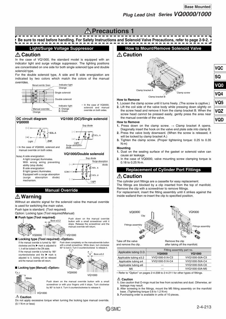
Note)
DC circuit diagramVQ0000
VQ1000 (DC)/Single solenoid
VQ1000/Double solenoid
Push type (Tool required)
Locking type (Tool required) <Option>
Locking type (Manual) <Option>
VQ0000 VQ1000
VQ1000
VQ1000
Applicable tubing O.D.
Applicable tubing ø3.2Applicable tubing ø4Applicable tubing ø6
M5
VVQ1000-51A-C3VVQ1000-51A-C4
——
VVQ1000-50A-C3VVQ1000-50A-C4VVQ1000-50A-C6VVQ1000-50A-M5
VQ0000Fitting assembly part no.
∗ Refer to “Option” on pages 2-4-208 to 2-4-211 for other types of fittings.
VQ1000
Take off the valve and remove the clip.
Remove the clip after taking off the manifold.
Precautions 1
Caution
Caution
In the case of VQ1000, the standard model is equipped with an indicator light and surge voltage suppressor. The lighting positions are concentrated on one side for both single solenoid type and double solenoid type. For the double solenoid type, A side and B side energization are indicated by two colors which match the colors of the manual overrides.
Without an electric signal for the solenoid valve the manual override is used for switching the main valve.Push type is standard. (Tool required)Option: Locking type (Tool required/Manual)
If the manual override is turned by 180° clockwise and the mark is adjusted to 1, it will be locked in the ON state. If the manual override is turned by 180° counterclockwise and the mark is adjusted to 0, locking will be released and the manual override will return.
Push down completely on the manualoverride button with a small screwdriver. While down, turn clockwise 90° to lock it. Turn it counterclockwise to release it.
Push down on the manual override button with a small screwdriver until it stops. Release the screwdriver and the manual override will return.
Push down on the manual override button with a small screwdriver or with your fingers until it stops. Turn clockwise by 90° to lock it. Turn it counterclockwise to release it.
How to Remove1. Loosen the clamp screw until it turns freely. (The screw is captive.)2. Lift the coil side of the valve body while pressing down slightly on
the screw head and remove it from the clamp bracket B. When the screw head cannot be pressed easily, gently press the area near the manual override of the valve.
How to Remove1. Press down on the clamp screw. Clamp bracket A opens.
Diagonally insert the hook on the valve end plate side into clamp B.2. Press the valve body downward. (When the screw is released, it
will be locked by clamp bracket A.)3. Tighten the clamp screw. (Proper tightening torque: 0.25 to 0.35
N·m)Mounting1. Dust on the sealing surface of the gasket or solenoid valve can
cause air leakage.2. In the case of VQ0000, valve mounting screw clamping torque is
0.18 to 0.25 N·m.
A side energization:A light (orange) illuminates.With wrong wiring preventing ability (stop diode) B side energization:B light (green) illuminates.Equipped with a surge absorption (surge absorption diode) mechanism.
∗ In the case of VQ0000, solenoid and manual override on both sides.
The cylinder port fittings are a cassette for easy replacement.The fittings are blocked by a clip inserted from the top of manifold. Remove the clip with a screwdriver to remove fittings.For replacement, insert the fitting assembly until it strikes against the inside walland then re-insert the clip to specified position.
1. Use caution that O-rings must be free from scratches and dust. Otherwise, air leakage may result.
2. After screwing in the fittings, mount the M5 fitting assembly on the manifold base. (Tightening torque 0.8 to 1.2 N·m)
3. Purchasing order is available in units of 10 pieces.
Do not apply excessive torque when turning the locking type manual override. (0.1 N·m or less)
∗ In the case of VQ0000, solenoid and manual override on both sides.
VQ0000
Caution
Be sure to read before handling. For Safety Instructions and Solenoid Valve Precautions, refer to page 2-9-2.
Caution
Caution
Light/Surge Voltage Suppressor How to Mount/Remove Solenoid Valve
Replacement of Cylinder Port Fittings
WarningManual Override
Manual override: Green Indicator lightOrange
Double solenoid
Single solenoid
Manual override:Orange
Indicator lightA: OrangeB: Green
LightLight
Light
Surge absorptiondiode
Surge absorption
diode
Sop diode
Sop diode
Clamp bracket A
Clamp bracket B
Clamp screw
Fittings assemblyFittings assembly
Bore ø3.2
Bore ø3.2
Clip
Clip
2-4-213
Series VQ0000/1000Plug Lead Unit
Base Mounted
VQC
SQ
VQ0
VQ4
VQ5
VQZ
VQD
Wires, cables, connectors, etc. used for models conforming to IP65 should also have enclosures equivalent to or of stricter than IP65.
Attaching and detaching connectors
Crimping the lead wireand socket
Attaching and detaching lead wires with socketsAttaching
Detaching
+ —
Element part no.
TypeElement part no.
VQ0000
VVQ0000-82A-1
VQ1000
VVQ1000-82A-1Built-in silencer,
direct exhaust (-S)
∗ The minimum order quantity is 10 pcs.
1.
2.
3.
Manifold Block AssemblyVQ1000
VVQ1000-1A-2-C3VVQ1000-1A-2-C4VVQ1000-1A-2-C6VVQ1000-1A-2-M5
Port sizeWith One-touch fitting for ø3.2With One-touch fitting for ø4With One-touch fitting for ø6
M5 threadFor obtaining the flow rate, refer to pages 2-1-8 to 2-1-11.
To attach a connector, hold the lever and connector unit between your fingers and insert straight onto the pins of the solenoid valve so that the lever’s pawl is pushed into the groove and locks.
To detach a connector, remove the pawl from the groove by pushing the lever downward with your thumb, and pull the connector straight out.
Peel 3.2 to 3.7 mm of the tip of lead wire, neatly into a socket and press contact it by a press tool. Be careful so that the cover of lead wire does not enter into the core press contacting part.
Insert a socket in the square hole (Indicated as , ) of connector, push in the lead wire and lock by hanging the hook of socket to the seat of connector. (Pushing-in can open the hook and lock it automatically.) Then confirm the lock by lightly pulling on the lead wire.
RemovingLoosen the clamp screw on side (a) of the end plate on both sides.Lift side (a) of the manifold base and slide the end plate in the direction of (2) shown in the figure to remove.
1.
2.
MountingHook side (b) of the manifold base on the DIN rail.Press side (a) and mount the end plate on the DIN rail.Tighten the clamp screw on side (a) of the end plate. The proper tightening torque for screws is 1.2 to 1.6 N·m.
1.
2.
3.
A silencer element is incorporated in the end plate on both sides of the manifold base. A dirty and choked element may reduce cylinder speed and cause malfunction. Clean or replace the dirty element.
Remove the cover from the top of the end plate and remove the old element with a screwdriver, etc.
Loosen the clamp screw on the top surface of the end plate on one side.Turn the manual override between the manifold blocks with a regular screwdriver, etc. in a couterclockwise direction.
Slide the manifold base to the side where the screw is loosened. Make a clearance of 15 mm or more.
5.
6.
Slide the manifold bases with a slight clearance in-between and lock them by turning the manual override between the manifold blocks clockwise.Tighten the screw on the top surface of the end plate, and the station has been added. (Proper tightening torque 1.2 to 1.6 N·m)
4. Mount the station increasing manifold block assembly and solenoid valve on the DIN rail. Install it to the DIN rail by applying the hook on the (b) side of the manifold block and pushing down the (a) side.
Caution Caution
Caution
Caution
Caution
Caution
Manifold Base Station Increasing Procedure (VQ1000)
Mounting/Removing from the DIN Rail (VQ1000)
Enclosure IP65
Cover
Cover
Concave
Concave
Pin
Pin
LeverDC indicator
SocketPart no. DXT170-71-1
Lead wire0.2 to 0.33 mm2
(Max. cover diameterø 1.7 mm)
Hook
Hook
Hook
ConnectorPart no. AXT661-12
Terminal
Core wirecrimping area Crimping area
Core wire
Lead wire
Lead wire
Cover0.2 to 0.33 mm2
Max. cover diameter:ø1.7 mm
Connector
End plate
End plate
15 mm or more
Socket
DIN rail
For pulling-out the socket from the connector, pull out the lead wire while pushing the hook of the socket with a fine point (ca.1 mm) tool. If the socket is to be re-used, spread the hook to the outside.
(1)
(2)(1)
(2)
(b)
(a)
(b)
(b)
(a)
(a)
How to Calculate the Flow Rate
Precautions 2Be sure to read before handling. For Safety Instructions and Solenoid Valve Precautions, refer to page 2-9-2.
How to Use Plug Connector Built-in Silencer Replacement
2-4-214
Series VQ0000/1000

Option
Different Number of Connector Pins
kit (D-sub connector) 15 pinsF kit (Flat ribbon cable connector)10 pins, 16 pins, 20 pinsP
How to order manifold How to order manifold
Stations
06 F SA DVV5Q12
Option
D
Option
06VV5Q12
PinsCable length (L)
1.5 m
3 m
5 m
AXT100-FC10-1
AXT100-FC10-2
AXT100-FC10-3
17.2
AXT100-FC16-1
AXT100-FC16-2
AXT100-FC16-3
24.8
AXT100-FC20-1
AXT100-FC20-2
AXT100-FC20-3
30
10P 16P 20P
LocationPins
15P (Max. 7 stations) UA SAKit F Kit F
Top entry Side entry LocationPins
10P (Max. 4 stations)
16P (Max. 7 stations)
20P (Max. 9 stations)
Top entry Side entry
UA
UB
UC
SA
SB
SC
Kit
P
Kit
P
Flat Ribbon Cable Assembly
PinsCable length (L)
1.5 m
3 m
5 m
AXT100-DS15-1
AXT100-DS15-2
AXT100-DS15-3
15P
∗ For other commercial connectors, use a type conforming to MIL-C-24308.
D-sub Connector Cable Assembly
Wire Color by TerminalNo. of D-sub ConnectorCable Assembly
123456789
101112131415
BlackBrownRed
OrangeYellowPinkBlue
PurpleGrayWhiteWhiteYellowOrangeYellowPink
NoneNoneNoneNoneNoneNoneNoneWhiteBlackBlackRed Red Red BlackBlack
Dot markingLead wire colorTerminal no.
Stations
P SC
Kit/Electrical entry Kit/Electrical entry
Connector width (W)
∗ In the same way as the 25-pin models (standard), terminal no. 1 for is SOL.A at the 1st station, terminal no. 9 for SOL.B at the 1st station, and terminal no. 8 for COM. ∗ In the same way as the 26-pin models (standard), terminal no.
1 is SOL.A at the 1st station, terminal no. 2 for SOL.B at the 1st station, and two pins from the max.
F and P kits with the following number of pins are available besides the standard number (F = 25; P = 26). Select the desired number of pins and cable length from the cable assembly list.Place an order for the cable assembly separately.
How to OrderD-sub connector, 15 pinsConnector location – Side (horizontal)Without cable
How to OrderFlat ribbon cable, 20 pinsConnector location – Side (horizontal)Without cable
∗ For other commercial connectors, use a type with strain relief conforming to MIL-C-83503.
Multi-core vinyl cableVVRF 0.3 mm2 x 15C
Plug connectorHDA-CTH(Made by Hirose Electric)
ConnectorHDA-15S(Made by Hirose Electric)
Terminal no.
Ter
min
al n
o.
10P, 16P, 20P
Red
Wiring Specifications
Wiring Specifications
ø9~=
AXT100-DS151to3
2-4-215
Series VQ0000/1000Plug Lead Unit
Base Mounted
VQC
SQ
VQ0
VQ4
VQ5
VQZ
VQD

Lead wire length: 300 mmThe part numbers above are applicable to 2 to 10 stations. 11 to 16 stations: “AXT661- A(N)-F-425”.
Special Wiring Specifications Inch-size One-touch Fittings
Negative Common Specifications [Series VQ110]
Example) VV5Q05-08C4FU1-D K S
Others, option symbols:to be indicated alphabetically.
VQ1110Negative common specifications
N 5M
F kit (D-subconnector)
T kit(Terminal
block)
P kit(Flat ribbon
cable connector)S kit (Serial transmission)Kit
Type
Max.points
F 25P
US P
26P
USF A
15P
US P C
20P
US P
16P
US B P A
10P
US S
16 14 14 8 8
F kitD-sub connector
(25 P)
P kitFlat ribbon cable connector
(26 P)
T kitTerminal block(16 terminals)
How to order negative COM valves
Option
T1 T2
Note) Due to the limitation of internal wiring.
Valve with inch-size One-touch fittings is shown below.
VV5Q12 06 N7 PSO DOption
Kit/Electrical entry
Stations
Cylinder portSymbol
VQ0000
VQ1000A, Bport
ø1/8" ø5/32" ø1/4" 10-32UNF(M5 thread) Mixed
NMM5TN7N3N1
Note)
1(P), 3(R) port sizeVQ0000VQ1000
······ø1/4"······ø5/16"
Applicable tubingO.D. (Inch)
Plug Connector Assembly Model
Connector Assembly Part No.Specifications Part no.
Single VQ0000(2-wire)
Double (latching)(3-wire)
Positive common
Negative common
Positive common
Negative common
AXT661-14A-F
AXT661-14AN-F
AXT661-13A-F
AXT661-13AN-FNote)
1314
Note)16
Note)16 16 16
Note)
In the internal wiring of F kit, P kit, T kit and S kit, double wiring (connected to SOL. A and SOL. B) is adopted for each station regardless of the valve and option types. Mixed single and double wiring is available as an option.
1. How to OrderIndicate an option symbol “-K”, for the manifold no. and be sure to specify the mounting position and number of stations of the single and double wiring by means of the manifold specification sheet.
2. Wiring specificationsWith the A side solenoid of the 1st station as no. 1 (meaning, to be connected to no. 1 terminal), without making any terminals vacant.
3. Max. number of stationsThe maximum number of stations depends upon the number of solenoids. Assuming one for a single and two for a double, determine the number of stations so that the total number is not more than the max. number given in the following table.
The following valve part numbers are for negative COM specifications. Manifold model no. is the same as the standard products.
∗ Series VQ050 has no polarity, so the negative common is applicable to standard models.
When inch size fittings are selected for a cylinder port, use inch size fittings for both P and R port, too.
—
Connector assembly will be required when the F, P, S kits add a valve. Specify the style of valve and connector assembly.
2-4-216
Series VQ0000/1000Base Mounted

VQC
SQ
VQ0
VQ4
VQ5
VQZ
VQD
DIN Rail Mounting
Example)
VV5Q05-08C4C-DOSOthers, option symbols:
to be indicated alphabetically.
When ordering DIN rail only (VQ0000 only)
Example)
VV5Q05-08C4FU1-D09S
Others, option symbols:to be indicated alphabetically.
DIN rail for 9 stations
DIN rail no.: AXT100-DR-As for , specify the number from the DIN rail table.
For L dimension, refer to the dimensions of each kit.
1 2 3 4 5 6 7 8 9 1023 35.5 48 60.5 73 85.5 98 110.5 123 135.5
No.L dimension
No.L dimension
No.L dimension
No.L dimension
11 12 13 14 15 16 17 18 19 20148 160.5 173 185.5 198 210.5 223 235.5 248 260.5
21 22 23 24 25 26 27 28 29 30273 285.5 298 310.5 323 335.5 348 360.5 373 385.5
31 32 33 34 35 36 37 38 39 40398 410.5 423 435.5 448 460.5 473 485.5 498 510.5
L = 12.5 x n + 10.5L Dimension
Each manifold can be mounted on a DIN rail. Order it by indicating a DIN rail mounting option symbol, “-D”. In this case, a DIN rail which is approx. 30 mm longer than the manifold with the specified number of stations is attached. Other than this, it is applicable for the following cases.
When using DIN rail longer than the manifold with specified number of stations (VQ0000/VQ1000)Clearly indicate the necessary number of stations next to the option symbol. “D” for the manifold no.
When DIN rail is unnecessary (C kit VQ0000 only)Indicate the option symbol, -DO, for the manifold no.
When changing the manifold style into a DIN rail mounting style (VQ0000 only)Order brackets for mounting a DIN rail. (Refer to “Option” on page 2-4-209.)No. VVQ0000-57A-5 2 pcs. per one set.
(Pitch)
2-4-217
Series VQ0000/1000Plug Lead Unit
Base Mounted
SeriesNumber ofsolenoid Model
VQ0000Pluglead
2 po
sitio
n
Bas
e m
ount
ed
3 po
sitio
n
Single
Double
Closedcenter
Exhaust center
Metal seal
Rubber seal
Metal seal
Rubber seal
Metal seal
Rubber seal
Metal seal
Rubber seal
VQ0150
VQ0151
VQ0250
VQ0251
VQ0350
VQ0351
VQ0450
VQ0451
Response time (ms)
12 or less
15 or less
10 or less
15 or less
20 or less
25 or less
20 or less
25 or less
0.41
0.53
0.41
0.53
0.32
0.43
0.32
0.43
0.20
0.20
0.20
0.20
0.10
0.21
0.10
0.21
0.10
0.12
0.10
0.12
0.07
0.10
0.07
0.10
0.44
0.53
0.44
0.53
0.32
0.44
0.44
0.53
0.26
0.22
0.26
0.22
0.20
0.24
0.26
0.22
0.11
0.13
0.11
0.13
0.07
0.11
0.11
0.13
15 or less
20 or less
13 or less
20 or less
26 or less
33 or less
26 or less
33 or less
29 or less
34 or less
13 or less
20 or less
40 or less
47 or less
40 or less
47 or less
50
65
Weight(g)
Lowwattage:
0.5 W
Standard: 1WH: 1.5W
(1) (2)
(3)
(3)
Note 1)Note 2)
Note3)
Standard Specifications
Model
Ambient and fluid temperature
Lubrication
Manual override
Impact/Vibration resistance
Enclosure
Coil rated voltage
Allowable voltage fluctuation
Coil insulation type
Single
Double
3 position
Min. operatingpressure
Valve construction
Fluid
Maximum operating pressure
Metal seal
Air/Inert gas
0.1 MPa
0.1 MPa
0.1 MPa
–10 to 50°C
0.7 MPa (High pressure type: 0.8 MPa)
Not required
Push type/Locking type (Tool required, Manual type) Option
150/30 m/s2
Dust tight
12, 24 VDC, 100, 110, 200, 220 VAC (50/60 Hz)
±10% of rated voltage
Class B or equivalent
1 W DC (42 mA), 1.5 W DC (63 mA) , 0.5 W DC (21 mA)
1 W DC (83 mA), 1.5 W DC (125 mA) , 0.5 W DC (42 mA)
Inrush 0.5 VA (5 mA), Holding 0.5 VA (5 mA)
Inrush 0.55 VA (5 mA), Holding 0.55 VA (5 mA)
Inrush 1.0 VA (5 mA), Holding 1.0 VA (5 mA)
Inrush 1.1 VA (5 mA), Holding 1.1 VA (5 mA)
Rubber seal
Air/Inert gas
0.15 MPa
0.1 MPa
0.2 MPa
Powerconsumption(Current)
24 VDC
12 VDC
100 VAC
110 VAC
200 VAC
220 VAC
Val
ve s
peci
ficat
ions
Sol
enoi
d
(1)
(3)
(3)
(4)
(4)
(2)
For individual use of a single valve.
Flow characteristic
C [dm3/(s·bar)] C [dm3/(s·bar)]
1 4/2 (P A/B) 4/2 5/3 (A/B R1/R2)
b Cv b CvAC
2 position single
2 position double
3 position closed center
3 position exhaust center
3 position pressure center
Met
alR
ubbe
r
2 position double
Series VQSingle Unit
Cylinder port size C4: (VQ0000)Based on JIS B 8375-1981 (Supply pressure: 0.5 MPa; with indicator light and surge voltage suppressor; clean air) The response time is subject to the pressure and quality of the air. The valves at the time of ON are given for double types.Weight including sub-plate.
JIS Symbol
Use dry air to prevent condensation when operating at low temperatures.Impact resistance ··· No malfunction occurred when it is tested with a drop tester in the axial
direction and at the right angles to the main valve and armature in both energized and de-energized states every once for each condition. (Values at the initial period)
Vibration resistance ··· No malfunction occurred in a one-sweep test between 45 and 2000 Hz. Test was performed at both energized and de-energized states in the axial direction and at the right angles to the main valve and armature. (Values at the initial period)
Values for high pressure type (1.5 W)Values for low wattage type (0.5 W)
Note 1)Note 2)
Note 3)Note 4)
2-4-218
····· 3 pcs.····· 3 pcs.
Wiring Specifications
Connector Assembly Part No. (For DC)
Lead wire length
AXT661-12AAXT661-14AAXT661-14A-6AXT661-14A-10AXT661-14A-20AXT661-14A-30
Part no.
Socket (3 pcs.)300 mm600 mm
1000 mm2000 mm3000 mm
Note)AXT661-31A-, for 100/110 VAC.AXT661-34A-, for 200/220 VAC.
Example) Lead wire length 1000 mmVQ0150-5LOAXT661-14A-10
Lead wire color
COM(+)
(–)SOL.A
Black
Red
(Blue)
(Blue)
[Red]
[Red]
24 VDC 200 VAC220 VAC
100 VAC110 VAC
Black (Blue) [Red]A side solenoid (–)
Red (Blue)[Red]COM(+)
How to Order Valves
0 Y51 5 L C4VQ0Series VQ0000
Type of actuation12
2 position single2 position double
3 position closed center3 position exhaust center
34
Manual overrideNil Non-locking push type (Tool required)
Locking type (Tool required)B
Sub-plateSUP, Cylinder portNilC3C4M5
Without sub-plateWith One-touch fitting for ø3.2With One-touch fitting for ø4
M5 thread
Note) EXH port: M5 thread
Electrical entryGL
LOM
MO
Grommet (Except AC)L plug connector with lead wire
L plug connector without connectorM plug connector with lead wire
M plug connector without connector
Coil rated voltage123456
100 VAC (50/60 Hz)200 VAC (50/60 Hz)110 VAC (50/60 Hz)220 VAC (50/60 Hz)
24 VDC12 VDC
Seal01
Metal sealRubber seal
∗ Option
∗
Note)
Specifications
Standard type
High pressuretype
Low wattagetype
FunctionSymbol
Nil
H
Y
DC AC(1.0 W)
(1.5 W)
(0.5 W)
—
—
Note)
For power consumption of AC type, refer to page 2-4-218.
The lead wires are connected to the valve as shown below. Connect each to the power supply side.
Note) The length of the lead wire provided is 300 mm. When ordering a valve with a lead wire of 600 mm or longer, be sure to indicate the model number of the valve without connector and connector assembly.
Plug connector lead wire length
2-4-219
Single Unit Series VQ
VQC
SQ
VQ0
VQ4
VQ5
VQZ
VQD
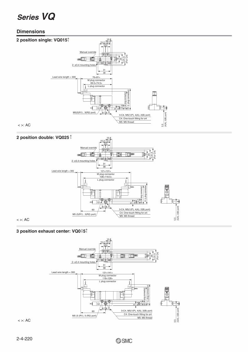
Dimensions
2 position double: VQ025 01
3 position exhaust center: VQ0 5 34
01
2 position single: VQ01501
< >: AC
< >: AC
< >: AC
SMC
SMC
SMC
31.
5
15.215.8
38
12.35 5
31
251810.5
(For
C4)
2- ø3.4 mounting holes
Manual override
Lead wire length = 300 76<81>
69.5<74.5>L plug connector
M plug connector
51 (L
plu
g co
nnec
tor)
45 (M
plu
g co
nnec
tor)
9.9
8.7 8.7
13.5
5
M5: M5 thread
C4: One-touch fitting for ø4
3-C4, M5(1(P), 4(A), 2(B) port)M5(5(R1) , 3(R2) port)
5.5
9(4
(A),
2(B
) po
rt)
31.
5
10.5
2518
15.215.812.3
5 5
(For
C4)
121<131>
108<118.5>
3831
L plug connector
M plug connector
2- ø3.4 mounting holes
Manual override51
(L p
lug
conn
ecto
r)
45 (M
plu
g co
nnec
tor)
Lead wire length = 300
60
13.5
9.9
5
8.7 8.7
M5: M5 threadC4: One-touch fitting for ø4
3-C4, M5(1(P), 4(A), 2(B) port)
M5 (5(R1) , 3(R2) port)
5.5
9(4
(A),
2(B
) po
rt)
31.
5
131<141>
118<128>
10.5
2518
3831
15.215.8
12.35 5
L plug connector
M plug connector
(For
C4)
2- ø3.4 mounting holes
Manual override
M5: M5 thread
C4: One-touch fitting for ø4
3-C4, M5(1(P), 4(A), 2(B) port)
51 (L
plu
g co
nnec
tor)
45 (M
plu
g co
nnec
tor)
13.5
9.9
5
M5 (5 (R1), 3 (R2) port)
5.5
9(4
(A),
2(B
) po
rt)
Lead wire length = 300
8.7 8.760
99
9
~ =
~ =~ =
A B
EBEBPEAEA
B
A
A B
EBPEA
B
A
B
A
A B
EBEBPEAEA
B
A
A B
EBPEA
B
A
A B
EBPEA
B
A
A B
EBPEA
Series VQ
2-4-220

2-4-221
VQC
SQ
VQ0
VQ4
VQ5
VQZ
VQD
A B
EBPEA
B
A
B
A
A B
EBPEA
B
A
A B
EBPEA
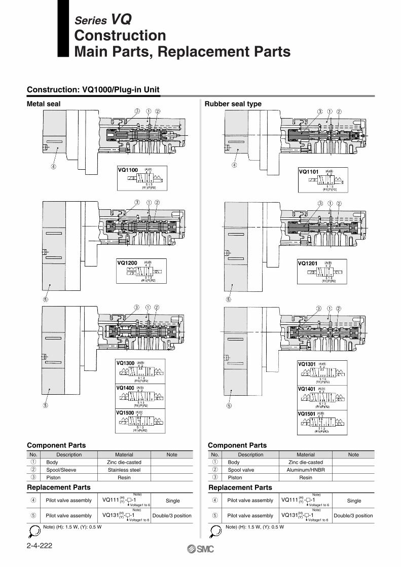
Construction: VQ1000/Plug-in Unit
Metal seal Rubber seal type
Component PartsNo. Description
Body
Spool/Sleeve
Piston
Material
Zinc die-casted
Stainless steel
Resin
Note
q
w
e
Component PartsNo. Description
Body
Spool valve
Piston
Material
Zinc die-casted
Aluminum/HNBR
Resin
Note
q
w
e
Replacement Parts
Pilot valve assembly
Pilot valve assembly Single
Double/3 position
Single
Double/3 position
r
t
VQ111 --1(H)(Y)
Voltage1 to 6
Note)
VQ131 --1(H)(Y)
Voltage1 to 6
Note)
VQ111 --1(H)(Y)
Voltage1 to 6
Note)
VQ131 --1(H)(Y)
Voltage1 to 6
Note)
Replacement Parts
Pilot valve assembly
Pilot valve assemblyr
t
Note) (H): 1.5 W, (Y): 0.5 W Note) (H): 1.5 W, (Y): 0.5 W
Series VQConstructionMain Parts, Replacement Parts
2-4-222

Construction: VQ2000/Plug-in Unit
Metal seal Rubber seal type
Component PartsNo. Description
Body
Spool/Sleeve
Piston
Material
Aluminum die-casted
Stainless steel
Resin
Note
q
w
e
Component PartsNo. Description
Body
Spool valve
Piston
Material
Aluminum die-casted
Aluminum/HNBR
Resin
Noteq
w
e
Replacement Parts
Pilot valve assembly
Pilot valve assembly Single
Double/3 position
Single
Double/3 position
r
t
VQ111 --1(H)(Y)
(H)(Y)
Voltage1 to 6
Note)
VQ131 --1Voltage1 to 6
Note)
VQ111 --1(H)(Y)
Voltage1 to 6
Note)
(H)(Y)VQ131 --1
Voltage1 to 6
Note)
Replacement Parts
Pilot valve assembly
Pilot valve assemblyr
t
Note) (H): 1.5 W, (Y): 0.5 W Note) (H): 1.5 W, (Y): 0.5 W
2-4-223
Series VQConstructionMain Parts, Replacement Parts
VQC
SQ
VQ0
VQ4
VQ5
VQZ
VQD

Construction: VQ0000/Plug Lead Unit
Metal seal Rubber seal type
Component PartsNo. Description
Body
Spool/Sleeve
Piston
Material
Aluminum die-casted
Stainless steel
Resin
Note
q
w
e
Component PartsNo. Description
Body
Spool valve
Piston
Material
Aluminum die-casted
Aluminum/HNBR
Resin
Note
q
w
e
Replacement Parts
Pilot valve assemblyr VQ110 -(H)(Y)
Voltage1 to 6
Note)
Replacement Parts
Pilot valve assemblyr
Note) (Y): 0.5 W, (H): 1.5 W, (G): DC Note) (Y): 0.5 W, (H): 1.5 W, (G): DC
LMG VQ110 -(H)
(Y)Voltage1 to 6
Note)LMG
Series VQ
2-4-224

VQC
SQ
VQ0
VQ4
VQ5
VQZ
VQD
Construction: VQ1000/Plug Lead Unit
Metal seal
Component PartsNo. Description
Body
Spool/Sleeve
Piston
Material
Zinc die-casted
Stainless steel
Resin
Note
q
w
e
Component PartsNo. Description
Body
Spool valve
Piston
Material
Zinc die-casted
Aluminum/HNBR
Resin
Note
q
w
e
Replacement Parts
Pilot valve assembly
Pilot valve assembly Single
Double/3 position
r
t
VQ111 --1(H)(Y)
Voltage1 to 6
Note)
(H)(Y)
Voltage1 to 6
Note)
VQ131 --1
Single
Double/3 position
VQ111 --1(H)(Y)
Voltage1 to 6
Note)
(H)(Y)
Voltage1 to 6
Note)
VQ131 --1
Replacement Parts
Pilot valve assembly
Pilot valve assemblyr
t
Note) (H): 1.5 W, (Y): 0.5 W
Rubber seal type
Note) (H): 1.5 W, (Y): 0.5 W
2-4-225
Series VQConstructionMain Parts, Replacement Parts

Exploded view: VQ1000/Plug-in Unit
Manifold block assemblyD side end plate assembly U side end plate assemblyHousing assembly and SI unit
(F, P, J, L, Skit)
S k
itP
/J k
itF
kit
L k
it
Exploded View of Manifold
2-4-226
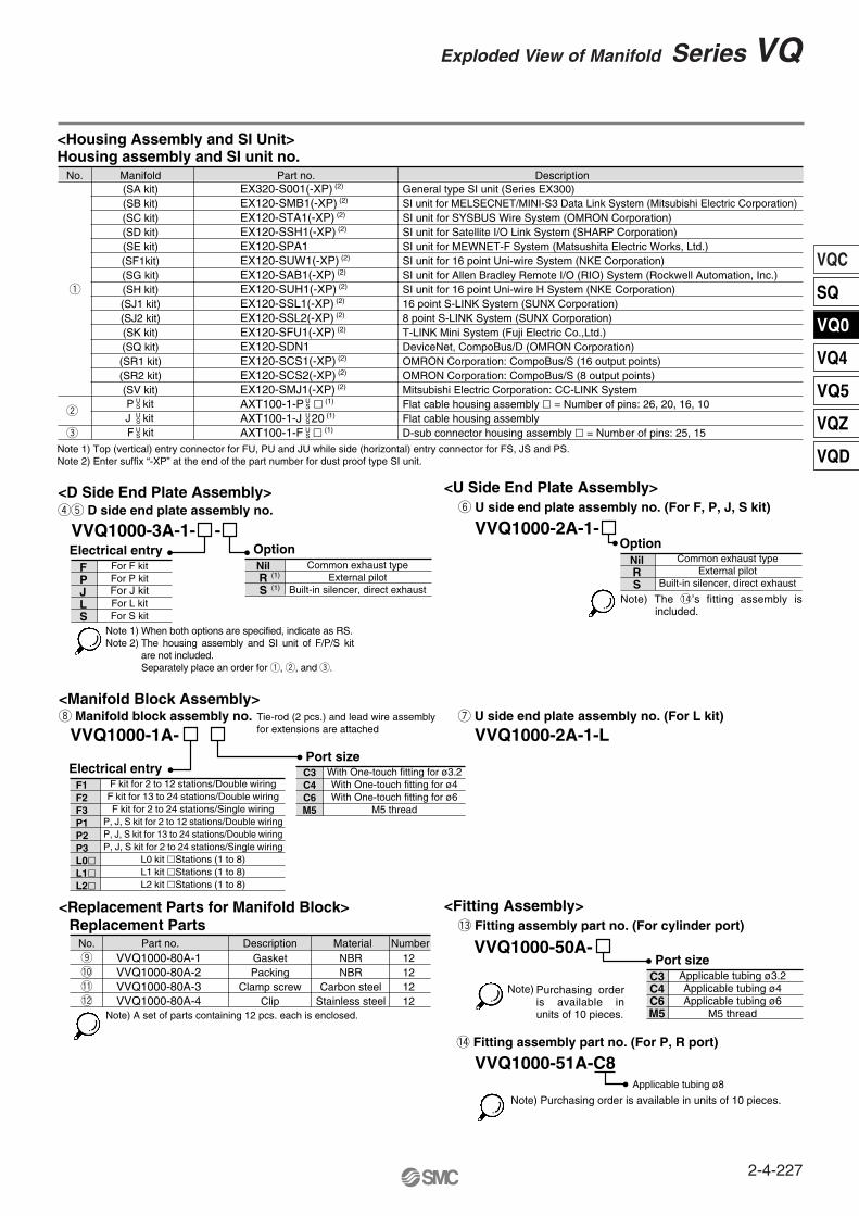
<Housing Assembly and SI Unit>Housing assembly and SI unit no.
No. Manifold Part no. Description(SA kit)(SB kit)(SC kit)(SD kit)(SE kit)(SF1kit)(SG kit)(SH kit)(SJ1 kit)(SJ2 kit)(SK kit)(SQ kit)(SR1 kit)(SR2 kit)(SV kit)
USUSUS
EX320-S001(-XP) (2)
EX120-SMB1(-XP) (2)
EX120-STA1(-XP) (2)
EX120-SSH1(-XP) (2)
EX120-SPA1EX120-SUW1(-XP) (2)
EX120-SAB1(-XP) (2)
EX120-SUH1(-XP) (2)
EX120-SSL1(-XP) (2)
EX120-SSL2(-XP) (2)
EX120-SFU1(-XP) (2)
EX120-SDN1EX120-SCS1(-XP) (2)
EX120-SCS2(-XP) (2)
EX120-SMJ1(-XP) (2)
AXT100-1-P (1)
AXT100-1-J 20 (1)
AXT100-1-F (1)
USUS
US
General type SI unit (Series EX300)SI unit for MELSECNET/MINI-S3 Data Link System (Mitsubishi Electric Corporation)SI unit for SYSBUS Wire System (OMRON Corporation)SI unit for Satellite I/O Link System (SHARP Corporation)SI unit for MEWNET-F System (Matsushita Electric Works, Ltd.)SI unit for 16 point Uni-wire System (NKE Corporation)SI unit for Allen Bradley Remote I/O (RIO) System (Rockwell Automation, Inc.)SI unit for 16 point Uni-wire H System (NKE Corporation)16 point S-LINK System (SUNX Corporation)8 point S-LINK System (SUNX Corporation)T-LINK Mini System (Fuji Electric Co.,Ltd.)DeviceNet, CompoBus/D (OMRON Corporation)OMRON Corporation: CompoBus/S (16 output points)OMRON Corporation: CompoBus/S (8 output points)Mitsubishi Electric Corporation: CC-LINK SystemFlat cable housing assembly = Number of pins: 26, 20, 16, 10Flat cable housing assemblyD-sub connector housing assembly = Number of pins: 25, 15
q
e
w
<Replacement Parts for Manifold Block>Replacement Parts
No. Part no. Description Material NumberVVQ1000-80A-1VVQ1000-80A-2VVQ1000-80A-3VVQ1000-80A-4
Note 1) Top (vertical) entry connector for FU, PU and JU while side (horizontal) entry connector for FS, JS and PS.Note 2) Enter suffix “-XP” at the end of the part number for dust proof type SI unit.
<D Side End Plate Assembly>rt D side end plate assembly no.
VVQ1000-3A-1- -OptionElectrical entry
y U side end plate assembly no. (For F, P, J, S kit)
<Manifold Block Assembly>
VVQ1000-2A-1-Option
u U side end plate assembly no. (For L kit)
VVQ1000-2A-1-L
Note) A set of parts containing 12 pcs. each is enclosed.
GasketPacking
Clamp screwClip
NBRNBR
Carbon steelStainless steel
12121212
Note)
i Manifold block assembly no.
VVQ1000-1A- -
Electrical entryPort size
!3 Fitting assembly part no. (For cylinder port)
VVQ1000-50A-o
!0
!1
!2
Port size
!4 Fitting assembly part no. (For P, R port)
VVQ1000-51A-C8Applicable tubing ø8
For F kitFor P kitFor J kitFor L kitFor S kit
FPJLS
NilRS
Common exhaust typeExternal pilot
Built-in silencer, direct exhaust
Common exhaust typeExternal pilot
Built-in silencer, direct exhaust
NilRS
F kit for 2 to 12 stations/Double wiringF kit for 13 to 24 stations/Double wiringF kit for 2 to 24 stations/Single wiring
P, J, S kit for 2 to 12 stations/Double wiringP, J, S kit for 13 to 24 stations/Double wiringP, J, S kit for 2 to 24 stations/Single wiring
L0 kit Stations (1 to 8)L1 kit Stations (1 to 8)L2 kit Stations (1 to 8)
F1F2F3P1P2P3L0L1L2
With One-touch fitting for ø3.2With One-touch fitting for ø4With One-touch fitting for ø6
M5 thread
C3C4C6M5
Applicable tubing ø3.2Applicable tubing ø4Applicable tubing ø6
M5 thread
C3C4C6M5
Note 1)Note 2)
Tie-rod (2 pcs.) and lead wire assembly for extensions are attached
P kitJ kitF kit
When both options are specified, indicate as RS.The housing assembly and SI unit of F/P/S kit are not included. Separately place an order for q, w, and e.
Purchasing order is available in units of 10 pieces.
Note) Purchasing order is available in units of 10 pieces.
(1)
(1)
<U Side End Plate Assembly>
<Fitting Assembly>
Note) The !4’s fitting assembly is included.
2-4-227
Exploded View of Manifold Series VQ
VQC
SQ
VQ0
VQ4
VQ5
VQZ
VQD
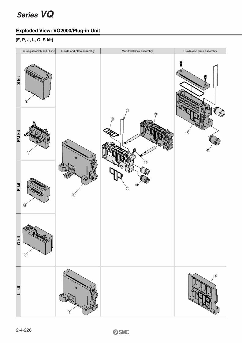
Exploded View: VQ2000/Plug-in Unit
Manifold block assemblyD side end plate assembly U side end plate assemblyHousing assembly and SI unit
(F, P, J, L, G, S kit)
S k
itP
/J k
itF
kit
L k
itG
kit
Series VQ
2-4-228
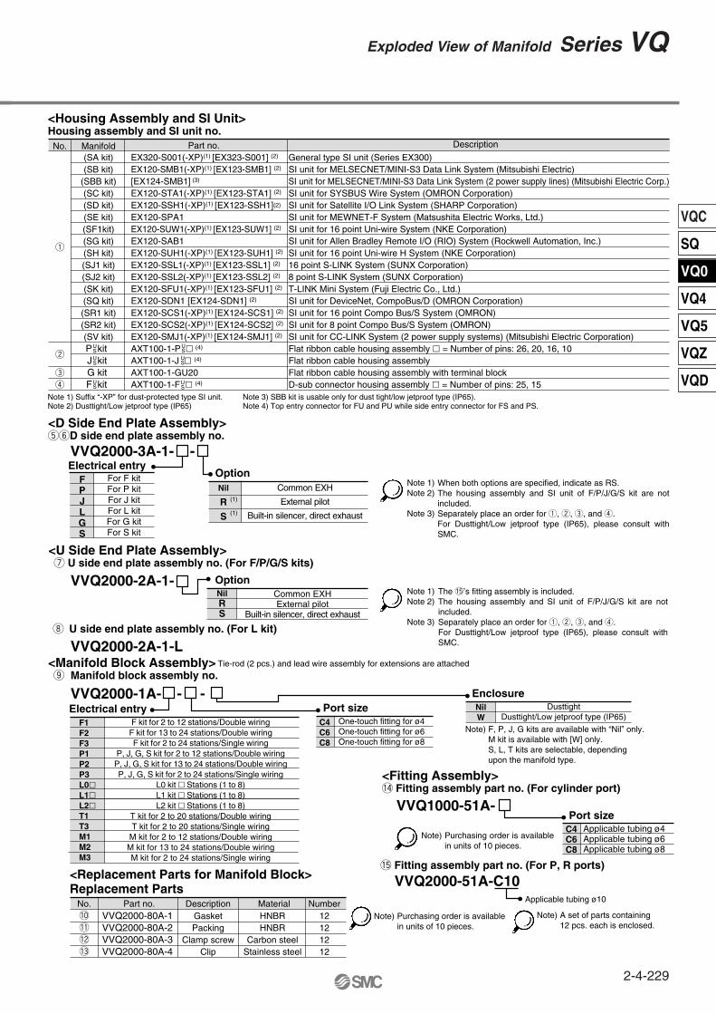
P kitJ kitG kitF kit
General type SI unit (Series EX300)SI unit for MELSECNET/MINI-S3 Data Link System (Mitsubishi Electric)SI unit for MELSECNET/MINI-S3 Data Link System (2 power supply lines) (Mitsubishi Electric Corp.)SI unit for SYSBUS Wire System (OMRON Corporation)SI unit for Satellite I/O Link System (SHARP Corporation)SI unit for MEWNET-F System (Matsushita Electric Works, Ltd.)SI unit for 16 point Uni-wire System (NKE Corporation)SI unit for Allen Bradley Remote I/O (RIO) System (Rockwell Automation, Inc.)SI unit for 16 point Uni-wire H System (NKE Corporation)16 point S-LINK System (SUNX Corporation)8 point S-LINK System (SUNX Corporation)T-LINK Mini System (Fuji Electric Co., Ltd.)SI unit for DeviceNet, CompoBus/D (OMRON Corporation)SI unit for 16 point Compo Bus/S System (OMRON)SI unit for 8 point Compo Bus/S System (OMRON)SI unit for CC-LINK System (2 power supply systems) (Mitsubishi Electric Corporation)Flat ribbon cable housing assembly = Number of pins: 26, 20, 16, 10Flat ribbon cable housing assembly Flat ribbon cable housing assembly with terminal blockD-sub connector housing assembly = Number of pins: 25, 15
<Housing Assembly and SI Unit>Housing assembly and SI unit no.
<Replacement Parts for Manifold Block>Replacement Parts
No. Part no. Description Material NumberVVQ2000-80A-1VVQ2000-80A-2VVQ2000-80A-3VVQ2000-80A-4
<D Side End Plate Assembly>tyD side end plate assembly no.
VVQ2000-3A-1- -Option
Electrical entry
Note 1)Note 2)
Note 3)
Note 1)Note 2)
Note 3)
<U Side End Plate Assembly> u U side end plate assembly no. (For F/P/G/S kits)
<Manifold Block Assembly> o Manifold block assembly no.
VVQ2000-2A-1- Option
i U side end plate assembly no. (For L kit)
VVQ2000-2A-1-L
Note)GasketPacking
Clamp screwClip
HNBRHNBR
Carbon steelStainless steel
12121212
A set of parts containing12 pcs. each is enclosed.
Note)
Note) Purchasing order is availablein units of 10 pieces.
VVQ2000-1A- - -Electrical entry Port size
<Fitting Assembly>!4 Fitting assembly part no. (For cylinder port)
VVQ1000-51A-
Tie-rod (2 pcs.) and lead wire assembly for extensions are attached
!0
!1
!2
!3
Port size
!5 Fitting assembly part no. (For P, R ports)
VVQ2000-51A-C10Applicable tubing ø10
FPJLGS
For F kitFor P kitFor J kitFor L kitFor G kitFor S kit
Nil
R
S
Common EXH
External pilot
Built-in silencer, direct exhaust
NilRS
Common EXHExternal pilot
Built-in silencer, direct exhaust
F kit for 2 to 12 stations/Double wiringF kit for 13 to 24 stations/Double wiringF kit for 2 to 24 stations/Single wiring
P, J, G, S kit for 2 to 12 stations/Double wiringP, J, G, S kit for 13 to 24 stations/Double wiringP, J, G, S kit for 2 to 24 stations/Single wiring
L0 kit Stations (1 to 8)L1 kit Stations (1 to 8)L2 kit Stations (1 to 8)
T kit for 2 to 20 stations/Double wiringT kit for 2 to 20 stations/Single wiring
M kit for 2 to 12 stations/Double wiringM kit for 13 to 24 stations/Double wiringM kit for 2 to 24 stations/Single wiring
F1F2F3P1P2P3L0L1L2T1T3M1M2M3
One-touch fitting for ø4One-touch fitting for ø6One-touch fitting for ø8
C4C6C8
Applicable tubing ø4Applicable tubing ø6Applicable tubing ø8
C4C6C8
EnclosureNilW
DusttightDusttight/Low jetproof type (IP65)
No. Manifold Part no. Description
(SA kit)(SB kit)
(SBB kit)(SC kit)(SD kit)(SE kit)(SF1kit)(SG kit)(SH kit)(SJ1 kit)(SJ2 kit)(SK kit)(SQ kit)(SR1 kit)(SR2 kit)(SV kit)
USUS
US
EX320-S001(-XP)(1) [EX323-S001] (2)
EX120-SMB1(-XP)(1) [EX123-SMB1] (2)
[EX124-SMB1] (3)
EX120-STA1(-XP)(1) [EX123-STA1] (2)
EX120-SSH1(-XP)(1) [EX123-SSH1](2)
EX120-SPA1EX120-SUW1(-XP)(1) [EX123-SUW1] (2)
EX120-SAB1EX120-SUH1(-XP)(1) [EX123-SUH1] (2)
EX120-SSL1(-XP)(1) [EX123-SSL1] (2)
EX120-SSL2(-XP)(1) [EX123-SSL2] (2)
EX120-SFU1(-XP)(1) [EX123-SFU1] (2)
EX120-SDN1 [EX124-SDN1] (2)
EX120-SCS1(-XP)(1) [EX124-SCS1] (2)
EX120-SCS2(-XP)(1) [EX124-SCS2] (2)
EX120-SMJ1(-XP)(1) [EX124-SMJ1] (2)
AXT100-1-P (4)
AXT100-1-J (4)
AXT100-1-GU20AXT100-1-F (4)
US
US
q
e
r
w
Note 1) Suffix “-XP” for dust-protected type SI unit. Note 2) Dusttight/Low jetproof type (IP65)
Note 3) SBB kit is usable only for dust tight/low jetproof type (IP65).Note 4) Top entry connector for FU and PU while side entry connector for FS and PS.
US
F, P, J, G kits are available with “Nil” only.M kit is available with [W] only.S, L, T kits are selectable, depending upon the manifold type.
Note)
Purchasing order is available in units of 10 pieces.
When both options are specified, indicate as RS.The housing assembly and SI unit of F/P/J/G/S kit are not included.Separately place an order for q, w, e, and r.For Dusttight/Low jetproof type (IP65), please consult with SMC.
The !5’s fitting assembly is included.The housing assembly and SI unit of F/P/J/G/S kit are not included.Separately place an order for q, w, e, and r.For Dusttight/Low jetproof type (IP65), please consult with SMC.
(1)
(1)
2-4-229
Exploded View of Manifold Series VQ
VQC
SQ
VQ0
VQ4
VQ5
VQZ
VQD

Exploded View: VQ0000/Plug Lead Unit
Manifold block assembly D side end block assemblyTie-rod U side end block assembly Housing assembly and SI unit
(F, P, C, S kit)
S k
itP
kit
F k
itT
kit
S k
itP
kit
F k
itT
kit
Note 3)
∗ For how to increase the stations, refer to the instruction manual.
The drawing shows FU. (Top entry connector)
Note 2)
The drawing shows PU. (Top entry connector)
S kit is composed of a flat ribbon cable housing assembly (AXT100-2-PS20) of q SI unit and w P kit (20 pins). Since no connector assembly is included, order it separately. (Refer to page 2-4-216.)A housing assembly is not used for a C kit.A DIN rail clamping bracket is attached to each.
Note 1)Note 2)Note 3)Note 4)
Connector assembly
Connector assembly
Note 2)
Note 2)
Connector assembly
Connector assemblyNote 2)
Note 1)
Note 4)
Note 4)
Series VQ
2-4-230

VVQ0000-103A-5-
<Housing Assembly and SI Unit>Housing assembly and SI unit no.
No. Manifold Part no. Description
(SA kit)
(SB kit)
(SC kit)
(SD kit)
(SF1 kit)
(SH kit)
P kit
F kit
T kit
T kit
USUS
EX330-S001
EX130-SMB1
EX130-STA1
EX130-SSH1
EX130-SUW1
EX130-SUH1
AXT100-2-P (2)
AXT100-2-F (2)
AXT100-2-TB1 (4)
AXT100-2-TB2 (4)
US
US
General type SI unit (Series EX300)
SI unit for MELSECNET/MINI-S3 Data Link System (Mitsubishi Electric Corp.)
SI unit for SYSBUS Wire System (OMRON Corporation)
SI unit for Satellite I/O Link System (SHARP Corporation)
16 point Uni-wire System (NKE Corporation)
SI unit for 16 point Uni-wire H System (NKE Corporation)
Flat ribbon cable housing assembly l = Number of pins: 26, 20, 16, 10
D-sub connector housing assembly l = Number of pins: 25, 15
Terminal block assembly (8 terminals)
Terminal block assembly (8 terminals)
q
w
e
r
t
<Replacement Parts for Manifold Block>Replaceable PartsNo. Part no. Description Material Number
VVQ0000-80A-5-2
VVQ0000-80A-5-4
<D Side End Plate Assembly>y D side end plate assembly no.
VVQ0000-3A-5-Option
Note) The !2’s fitting assembly is included.
Note) 2 bolts per one set.
<U Side End Plate Assembly>
<Manifold Block Assembly>
u U side end plate assembly no.
VVQ0000-2A-5-
Note) A set of parts containing 12 pcs. each is enclosed.Seal
Clip
HNBR
HNBR
12
12
Note) Purchasing order is available in units of 10 pieces.
i manifold block assembly no.
VVQ0000-1A-5-Port size
<Fitting Assembly>!1 Fittings assembly part no. (For cylinder port)
VVQ0000-50A-
o
!0
Port size
<Tie-rod Bolt>!3 Tie-rod bolt
Stations
!2 Fitting assembly part no. (For P, R port)
VVQ1000-50A-C6Applicable tubing ø6
Note 1)
Note 2)Note 3)Note 4)
Common exhaust typeBuilt-in silencer, direct exhaust
OptionCommon exhaust type
Built-in silencer, direct exhaust
NilS
NilS
With One-touch fitting for ø3.2With One-touch fitting for ø4
M5 thread
C3C4M5
With One-touch fitting for ø3.2With One-touch fitting for ø4
C3C4
For 1 stationFor 2 station
For 16 station
12
16
S kit is composed of a flat ribbon cable housing assembly (AXT100-2-PS20) of q SI unit and w P kit (20 pins). Place an order for AXT100-2-PS20 separately.Top/vertical entry connector for FU and PU while side (horizontal) entry connector for FS and PS.Since no connector assembly is included, order it separately. (Refer to page 2-4-216.)In the case of standard specifications and double wring, r is for 1 to t stations and t is for 5 to 8 stations.
Note)Purchasing order is available in units of 10 pieces.
······
(1)
2-4-231
Exploded View of Manifold Series VQ
VQC
SQ
VQ0
VQ4
VQ5
VQZ
VQD

Exploded View: VQ1000/Plug Lead Unit
Manifold block assemblySUP/EXH block assembly SUP/EXH block assemblyD side end block assembly U side end block assemblyHousing assembly and SI unit
(F, P, T, S kit)
S k
itP
kit
F k
itT
kIt
Note 3)
∗ For how to increase the stations, refer to the instruction manual.
The drawing shows FU.(Top entry connector)
Note 4)
Note 4)
The drawing shows PU.(Top entry connector)
S kit is composed of a flat ribbon cable housing assembly (AXT100-2-PU20) of q SI unit and w P kit (20 pins).Since no connector assembly is included, order it separately. (Refer to page 2-4-216.)A housing assembly is not used for a C kit.A DIN rail clamping bracket is attached to each.
Note 1)Note 2)Note 3)Note 4)
Connector assembly
Connector assembly
Note 2)
Connector assemblyNote 2)
Note 2)
Connector assemblyNote 2)
Note 1)
Series VQ
2-4-232
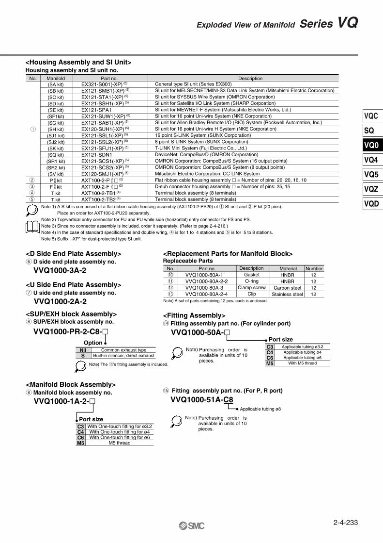
<Housing Assembly and SI Unit>Housing assembly and SI unit no.
<Replacement Parts for Manifold Block>Replaceable Parts
No. Part no. Description Material NumberVVQ1000-80A-1VVQ1000-80A-2-2VVQ1000-80A-3VVQ1000-80A-2-4
<D Side End Plate Assembly>y D side end plate assembly no.
VVQ1000-3A-2
<SUP/EXH block Assembly>
<Manifold Block Assembly>i Manifold block assembly no.
i SUP/EXH block assembly no.
VVQ1000-PR-2-C8-Option
<U Side End Plate Assembly>u U side end plate assembly no.
VVQ1000-2A-2
Note) The !5’s fitting assembly is included.
Note) A set of parts containing 12 pcs. each is enclosed.
GasketO-ring
Clamp screwClip
HNBRHNBR
Carbon steelStainless steel
12121212
Note)
VVQ1000-1A-2-
Port size
<Fitting Assembly>!4 Fitting assembly part no. (For cylinder port)
VVQ1000-50A-
!0
!1
!2
!3
Port size
!5 Fitting assembly part no. (For P, R port)
VVQ1000-51A-C8Applicable tubing ø8
Note 1)
Note 2)Note 3)Note 4)Note 5)
Common exhaust typeBuilt-in silencer, direct exhaust
NilS
With One-touch fitting for ø3.2With One-touch fitting for ø4With One-touch fitting for ø6
M5 thread
C3C4C6M5
Applicable tubing ø3.2Applicable tubing ø4Applicable tubing ø6
With M5 thread
C3C4C6M5
No. Manifold Part no. Description(SA kit)(SB kit)(SC kit)(SD kit)(SE kit)(SF1kit)(SG kit)(SH kit)(SJ1 kit)(SJ2 kit)(SK kit)(SQ kit)(SR1 kit)(SR2 kit)(SV kit)P kitF kitT kitT kit
USUS
EX321-S001(-XP) (5)
EX121-SMB1(-XP) (5)
EX121-STA1(-XP) (5)
EX121-SSH1(-XP) (5)
EX121-SPA1EX121-SUW1(-XP) (5)
EX121-SAB1(-XP) (5)
EX120-SUH1(-XP) (5)
EX121-SSL1(-XP) (5)
EX121-SSL2(-XP) (5)
EX121-SFU1(-XP) (5)
EX121-SDN1EX121-SCS1(-XP) (5)
EX121-SCS2(-XP) (5)
EX120-SMJ1(-XP) (5)
AXT100-2-P (2)
AXT100-2-F (2)
AXT100-2-TB1 (4)
AXT100-2-TB2 (4)
US
US
General type SI unit (Series EX300)SI unit for MELSECNET/MINI-S3 Data Link System (Mitsubishi Electric Corporation)SI unit for SYSBUS Wire System (OMRON Corporation)SI unit for Satellite I/O Link System (SHARP Corpoation)SI unit for MEWNET-F System (Matsushita Electric Works, Ltd.)SI unit for 16 point Uni-wire System (NKE Corporation)SI unit for Allen Bradley Remote I/O (RIO) System (Rockwell Automation, Inc.)SI unit for 16 point Uni-wire H System (NKE Corporation)16 point S-LINK System (SUNX Corporation)8 point S-LINK System (SUNX Corporation)T-LINK Mini System (Fuji Electric Co., Ltd.)DeviceNet, CompoBus/D (OMRON Corporation)OMRON Corporation: CompoBus/S System (16 output points)OMRON Corporation: CompoBus/S System (8 output points)Mitsubishi Electric Corporation: CC-LINK SystemFlat ribbon cable housing assembly = Number of pins: 26, 20, 16, 10D-sub connector housing assembly = Number of pins: 25, 15Terminal block assembly (8 terminals)Terminal block assembly (8 terminals)
q
w
e
r
t
A S kit is composed of a flat ribbon cable housing assembly (AXT100-2-PS20) of q SI unit and w P kit (20 pins).Place an order for AXT100-2-PU20 separately.Top/vertical entry connector for FU and PU while side (horizontal) entry connector for FS and PS.Since no connector assembly is included, order it separately. (Refer to page 2-4-216.)In the case of standard specifications and double wring, r is for 1 to 4 stations and t is for 5 to 8 stations.Suffix “-XP” for dust-protected type SI unit.
Purchasing order is available in units of 10 pieces.
Note) Purchasing order is available in units of 10 pieces.
2-4-233
Exploded View of Manifold Series VQ
VQC
SQ
VQ0
VQ4
VQ5
VQZ
VQD

2-4-234
Related Documents