50 50 NFPA MDX NFPA MP1 • • • • • • • • • • • • • • NFPA MX1 NFPA MX0 NFPA MX3 NFPA MX2 NFPA MF5 NFPA MF6 NFPA MF1 NFPA MF2 NFPA MS4 NFPA MS2 NFPA MS7 NFPA MS3 NFPA MT1 NFPA MP5 NFPA MT2 NFPA MT4 50 Series LH Milwaukee Cylinder Series LH Low Pressure Hydraulic Cylinders are built to perform on the toughest applications. The nominal pressure for Series LH ranges from 750 psi to 1500 psi, depending on bore size. Advanced engineering, combined with quality materials and expert workmanship, contribute to the making of a rugged, top quality low-pressure hydraulic cylinder that will provide a long, maintenance-free service life. LH10 LH11 LH12 LH13 LH21 LH22 LH31 LH32 LH41 LH42 LH43 LH51 LH62 LH71 LH72 LH73/LH74 Key Mount Double Rod End LH61

Welcome message from author
This document is posted to help you gain knowledge. Please leave a comment to let me know what you think about it! Share it to your friends and learn new things together.
Transcript
5050
NFPA MX1 NFPA MX NFPA MX3 NFPA MX2
NFPA MF5 NFPA MF6 NFPA MF1 NFPA MF2
NFPA MS4 NFPA MS2 NFPA MS7 NFPA MS3
NFPA MT2 NFPA MT2 NFPA ME5
NFPA MDX
NFPA MP1
•
• • •
• • •
• • •
• • •
•
NFPA MX1 NFPA MX0 NFPA MX3 NFPA MX2
NFPA MF5 NFPA MF6 NFPA MF1 NFPA MF2
NFPA MS4 NFPA MS2 NFPA MS7 NFPA MS3
NFPA MT1NFPA MP5 NFPA MT2 NFPA MT4
50
Series LH
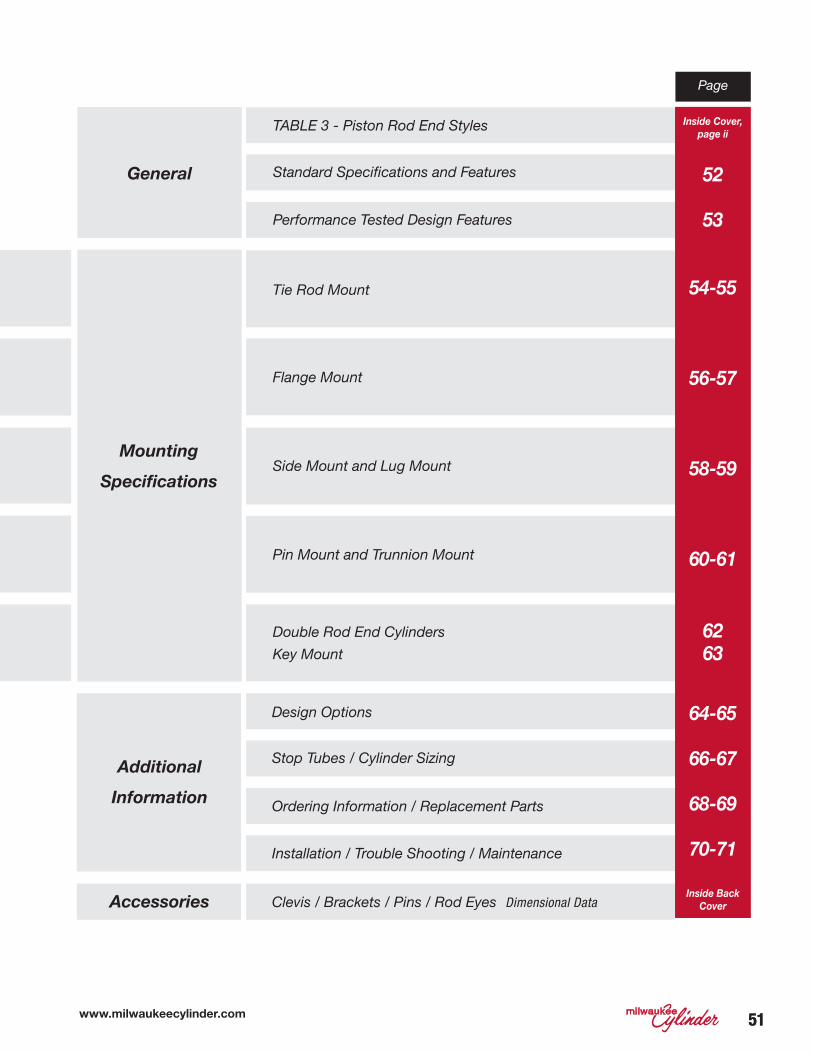
Milwaukee Cylinder Series LH Low Pressure Hydraulic
Cylinders are built to perform on the toughest applications. The nominal
pressure for Series LH ranges from 750 psi to 1500 psi, depending on
bore size. Advanced engineering, combined with quality materials and
expert workmanship, contribute to the making of a rugged, top quality
low-pressure hydraulic cylinder that will provide a long, maintenance-free
service life.
LH10 LH11 LH12 LH13
LH21 LH22 LH31 LH32
LH41 LH42 LH43 LH51
LH62 LH71 LH72 LH73/LH74
Key MountDouble Rod End
LH61
www.milwaukeecylinder.com 5151
Page
TABLE 3 - Piston Rod End Styles
Standard Specifications and Features
Performance Tested Design Features
Design Options
Installation / Trouble Shooting / Maintenance
Clevis / Brackets / Pins / Rod Eyes Dimensional Data
Stop Tubes / Cylinder Sizing
Ordering Information / Replacement Parts
Tie Rod Mount
Flange Mount
Side Mount and Lug Mount
Pin Mount and Trunnion Mount
Double Rod End Cylinders
Key Mount
General
Accessories
Additional
Information
Mounting
Specifications
Inside Cover,
page ii
52
53
54-55
56-57
58-59
60-61
6263
64-65
66-67
68-69
70-71
Inside Back
Cover

5252
1
2
3
4
7
5
6
89
10
Se
rie
s H
Se
rie
s M
HS
eri
es
LH
Standard Specifications and Features
STANDARD FEATURES
1. Removable Retainer Plate
The retainer plate and rod bushing
are externally removable without
disassembling the cylinder on most
standard models. Four capscrews
securely hold and lock the retainer
plate in place.
2. Rod Bushing and Seals
A combination of spring loaded multiple
lip vee rings with a supporting bronze
bushing is standard in Milwaukee
Cylinder Series LH Cylinders.
3. Ports
Large NPTF cylinder ports are standard
and can be located to customer
requirements. SAE ports available
upon request.
4. Piston Rod
The piston rod is of high strength steel,
hardened and plated to resist scoring
and corrosion to assure maximum
seal life.
5. Piston
The Series LH piston is precision
machined from fine grained iron alloy.
It is pilot fitted and threaded to the
piston rod.
6. Cylinder Barrel and Seals
The barrel is of chrome plated steel
tubing, honed to a fine finish to assure
superior sealing, minimum friction and
maximum seal life. It is step cut on the
I.D. of both ends for O-ring seals.
7. End Caps
End caps and mountings are of high
quality steel, precision machined for
accurate mounting.
8. Tie-Rods
The tie rods are constructed from a
high quality medium carbon steel. The
threads are accurately rolled for rigid
engagement of the nuts.
9. Cushions
Cushions are machined to close
tolerance to provide positive, smooth
deceleration at the end of stroke. On
all bore sizes we provide the longest
cushion possible, based on the rod size
and blind end caps. Longer cushions
are available; for further information,
consult factory.
10. Cushion Needle Adjustment and
Ball Check
The cushion needle adjustment valve
and cushion-check ball retainer screw
are specifically designed to provide full
cushion adjustment.
STANDARD SPECIFICATIONS
• Standard construction –
square head – tie rod design
• Nominal pressure – 750 psi to
1500 psi (range varies by bore
size)
• Standard fluid-hydraulic oil
• Standard temperature –
-20° F to +200° F
• Standard bore sizes –
1½ " to 6"
• Standard piston rod
diameters ⅝ " thru 4"
• Standard mounting styles –
17 standard styles plus custom
designs to suit your needs
• Strokes – available in any
practical stroke length
• Cushions – available at either
or both ends of stroke
• Standard 7 rod end styles, plus
specials designed to order
• Rod end style KK2 - is studded
as standard for ⅝ " and 1"
diameter rods. Studded rod
end style is available for all
rod sizes.
MilCad Cylinder
Configurator
Visit milwaukeecylinder.com
to configure and download
CAD files of your cylinders.
www.milwaukeecylinder.com 5353
Se
ries
LH
Se
ries
AS
erie
s M
NH
yd-P
neu
Devices
Cyl A
ccessoriesM
anip
ulators
Pow
er Un
its/Valves D
esign
Gu
ide
Performance Tested Design Features
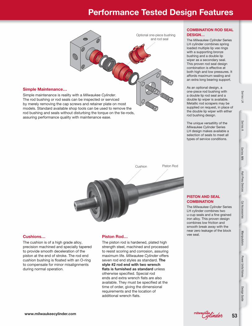
COMBINATION ROD SEAL
DESIGN…
The Milwaukee Cylinder Series
LH cylinder combines spring
loaded multiple lip vee rings
with a supporting bronze
bushing and a double lip
wiper as a secondary seal.
This proven rod seal design
combination is effective at
both high and low pressures. It
affords maximum sealing and
an extra long bearing support.
As an optional design, a
one-piece rod bushing with
a double lip rod seal and a
double lip wiper is available.
Metallic rod scrapers may be
supplied on request, in place of
the double lip wiper with either
rod bushing design.
The unique versatility of the
Milwaukee Cylinder Series
LH design makes available a
selection of seals to meet all
types of service conditions.
Simple Maintenance…
Simple maintenance is reality with a Milwaukee Cylinder.
The rod bushing or rod seals can be inspected or serviced
by merely removing the cap screws and retainer plate on most
models. Standard available shop tools can be used to remove the
rod bushing and seals without disturbing the torque on the tie-rods,
assuring performance quality with maintenance ease.
PISTON AND SEAL
COMBINATION
The Milwaukee Cylinder Series
LH cylinder combines two
u-cup seals and a fine grained
iron alloy. This proven design
combines low friction and
smooth break away with the
near zero leakage of the block
vee seal. Cushions…
The cushion is of a high grade alloy,
precision machined and specially tapered
to provide smooth deceleration of the
piston at the end of stroke. The rod end
cushion bushing is floated with an O-ring
to compensate for minor misalignments
during normal operation.
Piston Rod…
The piston rod is hardened, plated high
strength steel, machined and processed
to resist scoring and corrosion, assuring
maximum life. Milwaukee Cylinder offers
seven rod end styles as standard. The
style #2 rod end with two wrench
flats is furnished as standard unless
otherwise specified. Special rod
ends and extra wrench flats are also
available. They must be specified at the
time of order, giving the dimensional
requirements and the location of
additional wrench flats.
Cushion Piston Rod
Optional one-piece bushing
and rod seal
5454
G J
V
YW K
BBBB
MM
FDD
EELB + STROKE
P + STROKEZB + STROKE
ZT + STROKE
E
E
AA
B
1
3
4 2
Y
G J
VW
K
MM
F
EELB + STROKE
P + STROKEZB + STROKE
E
E
1
3
4 2
AA
BB
Y
G J
VW K
MM
FDD
EELB + STROKE
P + STROKEZB + STROKE
E
E
AA
B
1
3
4 2
Y
G J
VW K
BB
MM
F
AA(BoltCircle)
DD
EELB + STROKE
P + STROKEZB + STROKE
ZT + STROKE
E
E
1
3
4 2
AA
MODEL LH10
NFPA STYLE MX1
MODEL LH11
NFPA STYLE MX0
MODEL LH12
NFPA STYLE MX3
MODEL LH13
NFPA STYLE MX2
Se
rie
s H
Se
rie
s M
HS
eri
es
LH
See Table 3(Inside Cover)Rod End Style
See Table 3(Inside Cover)Rod End Style
See Table 3(Inside Cover)Rod End Style
See Table 3(Inside Cover)Rod End Style
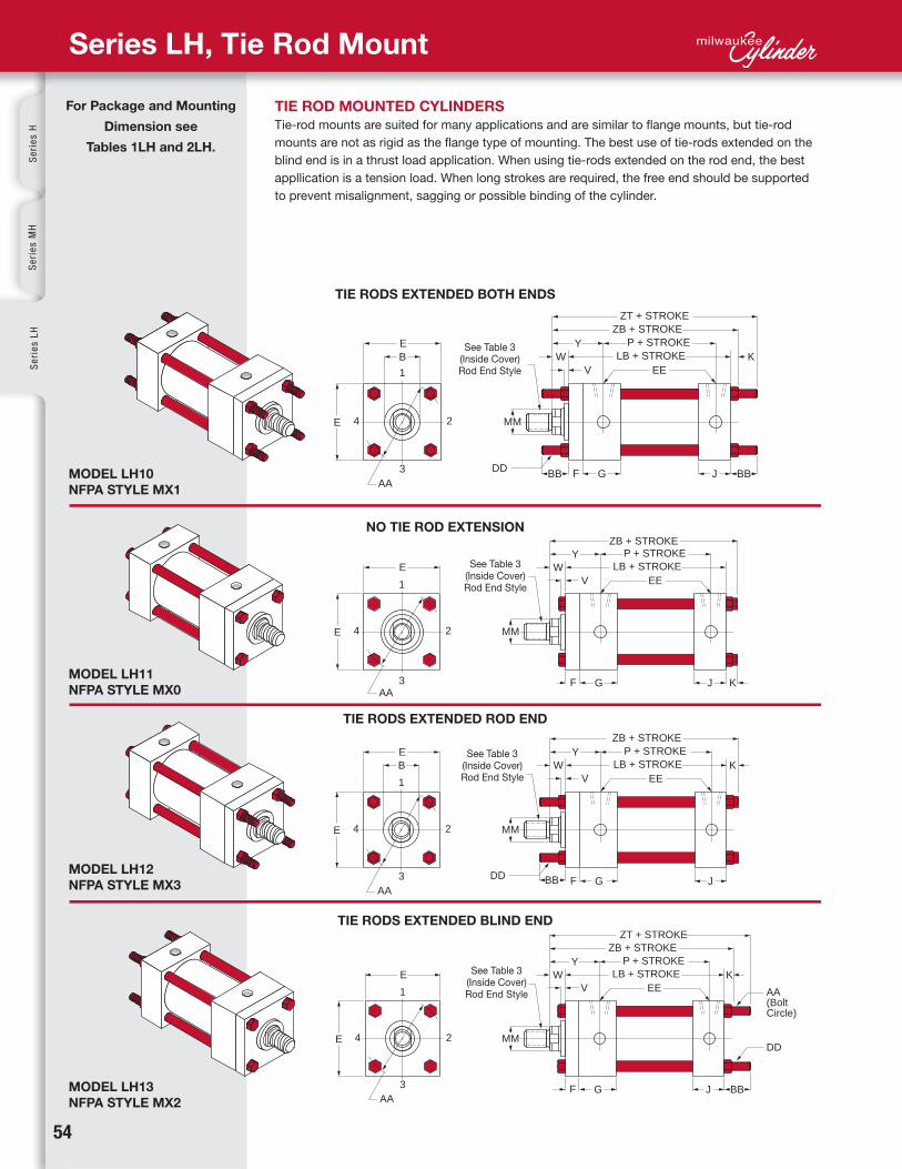
Series LH, Tie Rod Mount
TIE RODS EXTENDED BOTH ENDS
NO TIE ROD EXTENSION
TIE RODS EXTENDED ROD END
TIE RODS EXTENDED BLIND END
TIE ROD MOUNTED CYLINDERS
Tie-rod mounts are suited for many applications and are similar to flange mounts, but tie-rod
mounts are not as rigid as the flange type of mounting. The best use of tie-rods extended on the
blind end is in a thrust load application. When using tie-rods extended on the rod end, the best
appllication is a tension load. When long strokes are required, the free end should be supported
to prevent misalignment, sagging or possible binding of the cylinder.
For Package and Mounting
Dimension see
Tables 1LH and 2LH.
www.milwaukeecylinder.com 5555
Page ii
Se
ries
LH
Se
ries
AS
erie
s M
NH
yd-P
neu
Devices
Cyl A
ccessoriesM
anip
ulators
Pow
er Un
its/Valves D
esign
Gu
ide
Bore
Ø
Rod
MM
Cylinder
Code ♦B LB P V W Y ZB ZT
Bore
Ø
AA BB DD E EE
NPT
EE
SAE
F G J K
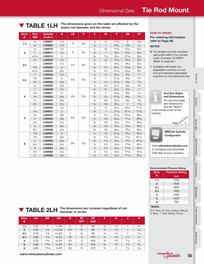
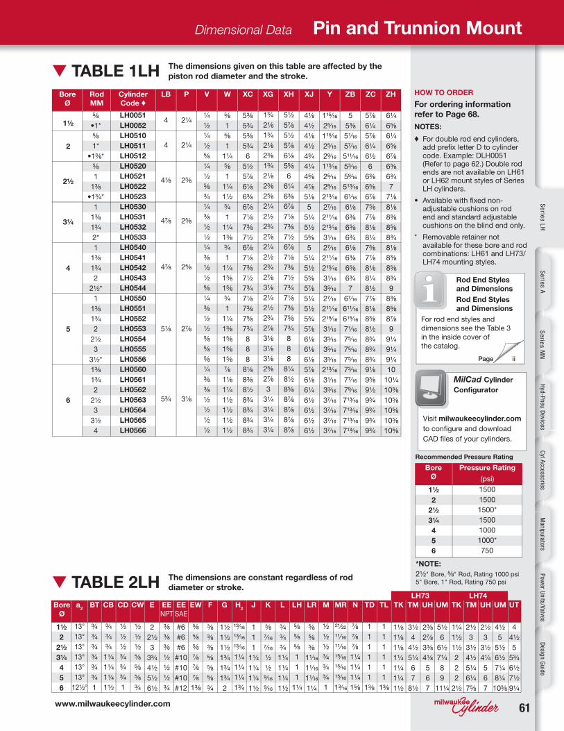
HOW TO ORDER
For ordering information
refer to Page 68.
NOTES:
♦ For double rod end cylinders,
add prefix letter D to cylinder
code. Example: DLH0051
(Refer to page 62.)
• Available with fixed-non-
adjustable cushions on rod
end and standard adjustable
cushions on the blind end only.
The dimensions given on this table are affected by the
piston rod diameter and the stroke.▼ TABLE 1LH
The dimensions are constant regardless of rod
diameter or stroke. ▼ TABLE 2LH
Dimensional Data Tie Rod Mount
Bore
Ø
Pressure Rating
(psi)
Recommended Pressure Rating
*NOTE:
2½ " Bore, ⅝ " Rod, Rating 1000 psi
5" Bore, 1" Rod, Rating 750 psi
MilCad Cylinder
Configurator
Visit milwaukeecylinder.com
to configure and download
CAD files of your cylinders.
Rod End Styles
and Dimensions
For rod end styles
and dimensions
see the Table 3
in the inside cover of the
catalog.
1½
2
2½
3¼
4
5
6
LH0051
LH0052
LH0510
LH0511
LH0512
LH0520
LH0521
LH0522
LH0523
LH0530
LH0531
LH0532
LH0533
LH0540
LH0541
LH0542
LH0543
LH0544
LH0550
LH0551
LH0552
LH0553
LH0554
LH0555
LH0556
LH0560
LH0561
LH0562
LH0563
LH0564
LH0565
LH0566
1⅛
1½
1⅛
1½
2
1⅛
1½
2
2⅜
1½
2
2⅜
2⅝
1½
2
2⅜
2⅝
3⅛
1½
2
2⅜
2⅝
3⅛
3¾
4¼
2
2⅜
2⅝
3⅛
3¾
4¼
4¾
4
4
4⅛
4⅞
4⅞
5⅛
5¾
2¼
2¼
2⅜
2⅝
2⅝
2⅞
3⅛
¼
½
¼
½
⅝
¼
½
⅝
¾
¼
⅜
½
½
¼
⅜
½
½
⅝
¼
⅜
½
½
⅝
⅝
⅝
¼
⅜
⅜
½
½
½
½
⅝
1
⅝
1
1¼
⅝
1
1¼
1½
¾
1
1¼
1⅜
¾
1
1¼
1⅜
1⅝
¾
1
1¼
1⅜
1⅝
1⅝
1⅝
⅞
1⅛
1¼
1½
1½
1½
1½
115⁄16
25⁄16
115⁄16
25⁄16
29⁄16
115⁄16
25⁄16
29⁄16
213⁄16
27⁄16
211⁄16
215⁄16
31⁄16
27⁄16
211⁄16
215⁄16
31⁄16
35⁄16
27⁄16
211⁄16
215⁄16
31⁄16
35⁄16
35⁄16
35⁄16
213⁄16
31⁄16
33⁄16
37⁄16
37⁄16
37⁄16
37⁄16
5
5⅜
51⁄16
57⁄16
511⁄16
53⁄16
59⁄16
513⁄16
61⁄16
6⅛
6⅜
6⅝
6¾
6⅛
6⅜
6⅝
6¾
7
67⁄16
611⁄16
615⁄16
71⁄16
75⁄16
75⁄16
75⁄16
73⁄16
77⁄16
79⁄16
713⁄16
713⁄16
713⁄16
713⁄16
⅝
•1
⅝
1
•1⅜
⅝
1
1⅜
•1¾
1
1⅜
1¾
2
1
1⅜
1¾
2
2½
1
1⅜
1¾
2
2½
3
3½
1⅜
1¾
2
2½
3
3½
4
1½
2
2½
3¼
4
5
6
2.02
2.60
3.10
3.90
4.70
5.80
6.90
1
1⅛
1⅛
1⅜
1⅜
113⁄16
113⁄16
¼ -28
5⁄16-24
5⁄16-24
⅜ -24
⅜ -24
½ -20
½ -20
2
2½
3
3¾
4½
5½
6½
⅜
⅜
⅜
½
½
½
¾
#6
#6
#6
#10
#10
#10
#12
⅜
⅜
⅜
⅝
⅝
⅝
¾
1½
1½
1½
1¾
1¾
1¾
2
1
1
1
1¼
1¼
1¼
1½
⅜
7⁄16
7⁄16
½
½
9⁄16
9⁄16
5⅝
6
5¾
6⅛
6⅜
5⅞
6¼
6½
6¾
7
7¼
7½
7⅝
7
7¼
7½
7⅝
7⅞
711⁄16
715⁄16
83⁄16
85⁄16
89⁄16
89⁄16
89⁄16
87⁄16
811⁄16
813⁄16
91⁄16
91⁄16
91⁄16
91⁄16
1½
2
2½
3¼
4
5
6
1500
1500
1500*
1500
1000
1000*
750
5656
G
J
V
YW
K
MM
FB8 HOLES
F
EE
LB + STROKEP + STROKE
ZB + STROKEE
RTF
UF
UF E B
1
3
4 2 R TF
FB8 HOLES
GWF J
V
YW K
MM
FF
EE
LB + STROKEP + STROKE
ZF + STROKEE
RTF
UF
UF E B
1
3
2 4 R TF
G J
V
YW K
MM
F
EELB + STROKE
P + STROKEZB + STROKE
B
FB4 HOLES
E
TFUF
E
1
3
4 2 R
WF G
J
V
YW
MM
F
EELB + STROKE
P + STROKEZF + STROKE
B
FB4 HOLES
E
TFUF
E
1
3
2 4 R
MODEL LH21
NFPA STYLE MF5
MODEL LH22*
NFPA STYLE MF6
MODEL LH31
NFPA STYLE MF1
MODEL LH32*
NFPA STYLE MF2
Se
rie
s H
Se
rie
s M
HS
eri
es
LH
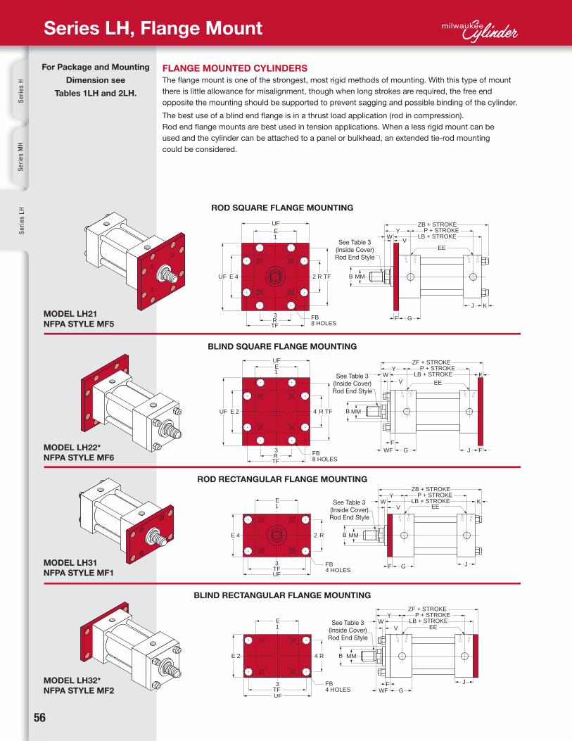
Series LH, Flange Mount
See Table 3(Inside Cover)Rod End Style
See Table 3(Inside Cover)Rod End Style
See Table 3(Inside Cover)Rod End Style
See Table 3(Inside Cover)Rod End Style
FLANGE MOUNTED CYLINDERS
The flange mount is one of the strongest, most rigid methods of mounting. With this type of mount
there is little allowance for misalignment, though when long strokes are required, the free end
opposite the mounting should be supported to prevent sagging and possible binding of the cylinder.
The best use of a blind end flange is in a thrust load application (rod in compression).
Rod end flange mounts are best used in tension applications. When a less rigid mount can be
used and the cylinder can be attached to a panel or bulkhead, an extended tie-rod mounting
could be considered.
ROD SQUARE FLANGE MOUNTING
BLIND SQUARE FLANGE MOUNTING
ROD RECTANGULAR FLANGE MOUNTING
BLIND RECTANGULAR FLANGE MOUNTING
For Package and Mounting
Dimension see
Tables 1LH and 2LH.
www.milwaukeecylinder.com 5757
Page ii
Se
ries
LH
Se
ries
AS
erie
s M
NH
yd-P
neu
Devices
Cyl A
ccessoriesM
anip
ulators
Pow
er Un
its/Valves D
esign
Gu
ide
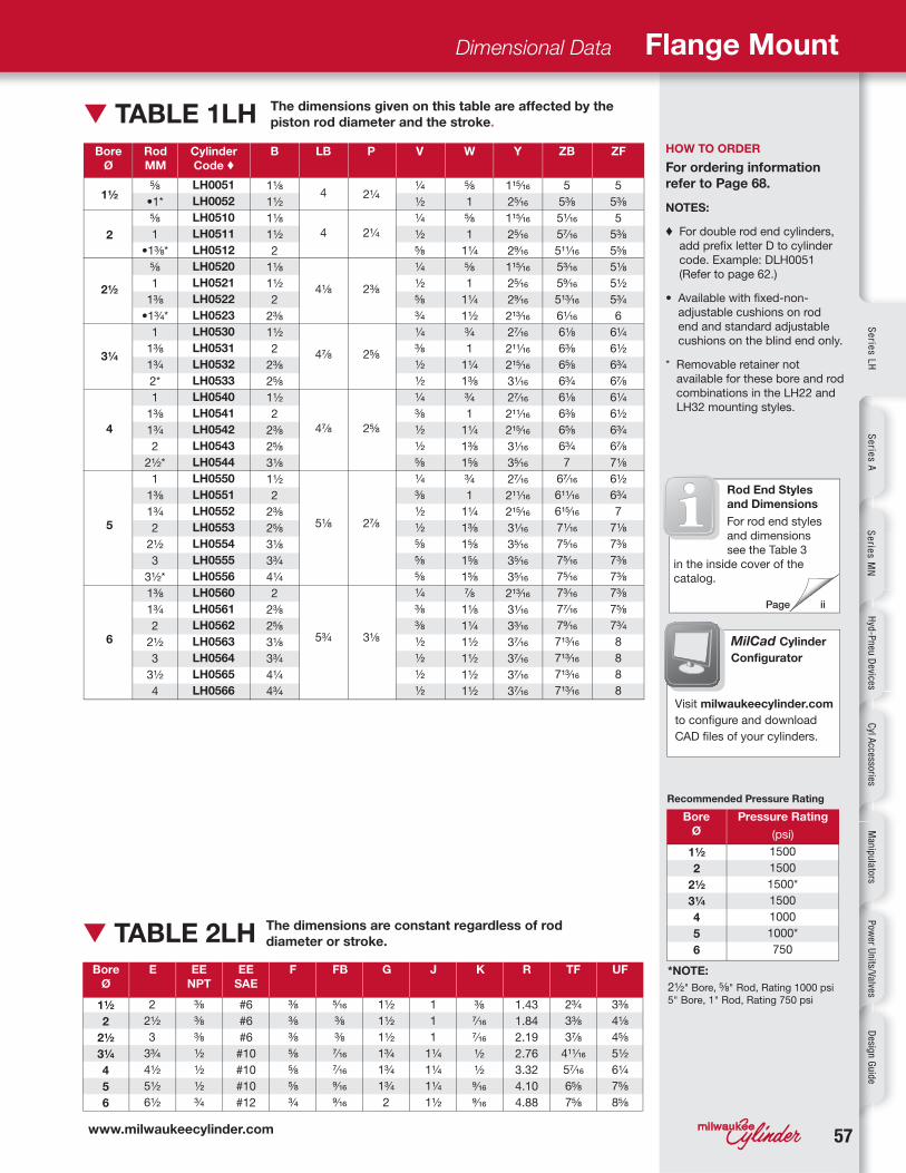
▼ TABLE 1LH HOW TO ORDER
For ordering information
refer to Page 68.
NOTES:
♦ For double rod end cylinders,
add prefix letter D to cylinder
code. Example: DLH0051
(Refer to page 62.)
• Available with fixed-non-
adjustable cushions on rod
end and standard adjustable
cushions on the blind end only.
* Removable retainer not
available for these bore and rod
combinations in the LH22 and
LH32 mounting styles.
Dimensional Data Flange Mount
The dimensions given on this table are affected by the
piston rod diameter and the stroke.
Bore
Ø
Pressure Rating
(psi)
Recommended Pressure Rating
*NOTE:
2½ " Bore, ⅝ " Rod, Rating 1000 psi
5" Bore, 1" Rod, Rating 750 psi
Bore
Ø
Rod
MM
Cylinder
Code ♦B LB P V W Y ZB ZF
Bore
Ø
E EE
NPT
EE
SAE
F FB G J K R UF
The dimensions are constant regardless of rod
diameter or stroke. ▼ TABLE 2LHTF
MilCad Cylinder
Configurator
Visit milwaukeecylinder.com
to configure and download
CAD files of your cylinders.
Rod End Styles
and Dimensions
For rod end styles
and dimensions
see the Table 3
in the inside cover of the
catalog.
1½
2
2½
3¼
4
5
6
1500
1500
1500*
1500
1000
1000*
750
1½
2
2½
3¼
4
5
6
LH0051
LH0052
LH0510
LH0511
LH0512
LH0520
LH0521
LH0522
LH0523
LH0530
LH0531
LH0532
LH0533
LH0540
LH0541
LH0542
LH0543
LH0544
LH0550
LH0551
LH0552
LH0553
LH0554
LH0555
LH0556
LH0560
LH0561
LH0562
LH0563
LH0564
LH0565
LH0566
1⅛
1½
1⅛
1½
2
1⅛
1½
2
2⅜
1½
2
2⅜
2⅝
1½
2
2⅜
2⅝
3⅛
1½
2
2⅜
2⅝
3⅛
3¾
4¼
2
2⅜
2⅝
3⅛
3¾
4¼
4¾
4
4
4⅛
4⅞
4⅞
5⅛
5¾
2¼
2¼
2⅜
2⅝
2⅝
2⅞
3⅛
¼
½
¼
½
⅝
¼
½
⅝
¾
¼
⅜
½
½
¼
⅜
½
½
⅝
¼
⅜
½
½
⅝
⅝
⅝
¼
⅜
⅜
½
½
½
½
⅝
1
⅝
1
1¼
⅝
1
1¼
1½
¾
1
1¼
1⅜
¾
1
1¼
1⅜
1⅝
¾
1
1¼
1⅜
1⅝
1⅝
1⅝
⅞
1⅛
1¼
1½
1½
1½
1½
115⁄16
25⁄16
115⁄16
25⁄16
29⁄16
115⁄16
25⁄16
29⁄16
213⁄16
27⁄16
211⁄16
215⁄16
31⁄16
27⁄16
211⁄16
215⁄16
31⁄16
35⁄16
27⁄16
211⁄16
215⁄16
31⁄16
35⁄16
35⁄16
35⁄16
213⁄16
31⁄16
33⁄16
37⁄16
37⁄16
37⁄16
37⁄16
5
5⅜
51⁄16
57⁄16
511⁄16
53⁄16
59⁄16
513⁄16
61⁄16
6⅛
6⅜
6⅝
6¾
6⅛
6⅜
6⅝
6¾
7
67⁄16
611⁄16
615⁄16
71⁄16
75⁄16
75⁄16
75⁄16
73⁄16
77⁄16
79⁄16
713⁄16
713⁄16
713⁄16
713⁄16
⅝
•1*
⅝
1
•1⅜ *
⅝
1
1⅜
•1¾ *
1
1⅜
1¾
2*
1
1⅜
1¾
2
2½ *
1
1⅜
1¾
2
2½
3
3½ *
1⅜
1¾
2
2½
3
3½
4
1½
2
2½
3¼
4
5
6
3⅜
4⅛
4⅝
5½
6¼
7⅝
8⅝
2
2½
3
3¾
4½
5½
6½
5⁄16
⅜
⅜
7⁄16
7⁄16
9⁄16
9⁄16
#6
#6
#6
#10
#10
#10
#12
⅜
⅜
⅜
⅝
⅝
⅝
¾
1½
1½
1½
1¾
1¾
1¾
2
1.43
1.84
2.19
2.76
3.32
4.10
4.88
⅜
7⁄16
7⁄16
½
½
9⁄16
9⁄16
5
5⅜
5
5⅜
5⅝
5⅛
5½
5¾
6
6¼
6½
6¾
6⅞
6¼
6½
6¾
6⅞
7⅛
6½
6¾
7
7⅛
7⅜
7⅜
7⅜
7⅜
7⅝
7¾
8
8
8
8
⅜
⅜
⅜
½
½
½
¾
2¾
3⅜
3⅞
411⁄16
57⁄16
6⅝
7⅝
1
1
1
1¼
1¼
1¼
1½
5858
G
XT SN + STROKE
J
V
YW
K
MM
F
EELB + STROKE
P + STROKEZB + STROKE
E
EE2
– .006– .008
1
3
4 2
TN
G
SU SUSW SW
XS SS + STROKE
J
V
YW
K
MM
F
EELB + STROKE
P + STROKEZB + STROKE
E SW
SWTS
ST
US
E
SB4 HOLES
E2
– .006– .008
1
3
4 2
GELEL
EO EOSE + STROKE
J
V
YW
K
MM
F
EELB + STROKE
P + STROKE
ZE + STROKEXE + STROKE
ER
ET
E
EB4 HOLES
ET
E2
– .006– .008
1
3
4 2
G
SU SUSW SW
XS SS + STROKE
J KFE SW
SWTS
ST
US
E
SB4 HOLES
E2
– .004– .000
1
3
4 2
V
YW
MM
EELB + STROKE
P + STROKEZB + STROKE
MODEL LH41
NFPA STYLE MS4
MODEL LH42
NFPA STYLE MS2
MODEL LH43
NFPA STYLE MS7
MODEL LH51
NFPA STYLE MS3
Se
rie
s H
Se
rie
s M
HS
eri
es
LH
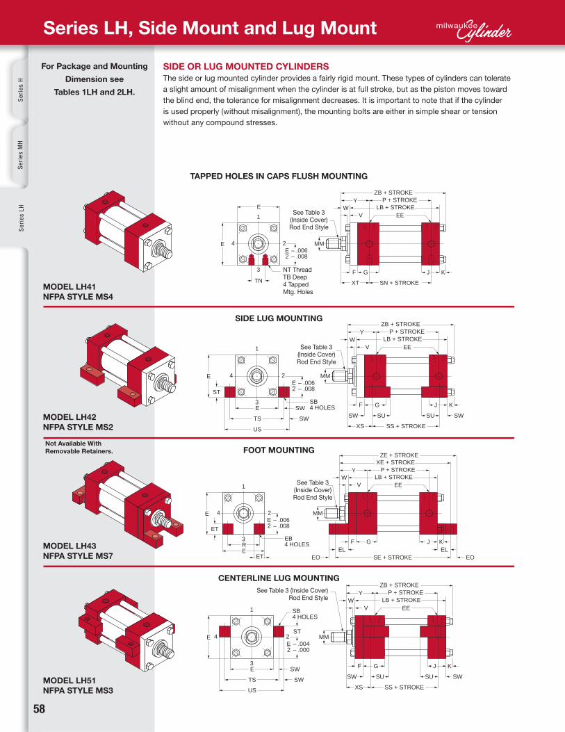
Series LH, Side Mount and Lug Mount
See Table 3(Inside Cover)Rod End Style
See Table 3(Inside Cover)Rod End Style
See Table 3(Inside Cover)Rod End Style
See Table 3 (Inside Cover) Rod End Style
NT ThreadTB Deep4 TappedMtg. Holes
SIDE OR LUG MOUNTED CYLINDERS
The side or lug mounted cylinder provides a fairly rigid mount. These types of cylinders can tolerate
a slight amount of misalignment when the cylinder is at full stroke, but as the piston moves toward
the blind end, the tolerance for misalignment decreases. It is important to note that if the cylinder
is used properly (without misalignment), the mounting bolts are either in simple shear or tension
without any compound stresses.
TAPPED HOLES IN CAPS FLUSH MOUNTING
SIDE LUG MOUNTING
FOOT MOUNTING
CENTERLINE LUG MOUNTING
Not Available With
Removable Retainers.
For Package and Mounting
Dimension see
Tables 1LH and 2LH.

www.milwaukeecylinder.com 5959
Page ii
Se
ries
LH
Se
ries
AS
erie
s M
NH
yd-P
neu
Devices
Cyl A
ccessoriesM
anip
ulators
Pow
er Un
its/Valves D
esign
Gu
ide
Bore
Ø
Rod
MM
Cylinder
Code ♦
LB
Bore
Ø
E
HOW TO ORDER
For ordering information
refer to Page 68.
NOTES:
♦ For double rod end cylinders,
add prefix letter D to cylinder
code. (Example: DLH0051
(Refer to page 62.)
* Tapped holes on LH41 rod end
cap have a shallower TB depth
in these sizes.
† The standard rod eye or rod
clevis will interfere with foot
lugs on Model LH43. When
these rod end accessories are
required, use additional rod
extension.
▲ For double rod end cylinders
from 1½" thru 6" bore,
add ½ + F to this dimension.
■ For double rod end cylinders
from 1½" thru 6" bore,
add ½ to this dimension.
• Available with fixed non-
adjustable cushions on rod
end and standard adjustable
cushions on the blind end only.
Dimensional Data Side Mount and Lug Mount
P SE
▲SN SS
■V XE XS XT Y ZEW ZB
EB EE
NPT
EE
SAE
EL EO ET F G J K NT R SB ST SU SW TB TN TS US
▼ TABLE 1LH
The dimensions are constant regardless of rod
diameter or stroke.▼ TABLE 2LH
The dimensions given on this table are affected by the
piston rod diameter and the stroke.
Bore
Ø
Pressure Rating
(psi)
Recommended Pressure Rating
*NOTE:
2½ " Bore, ⅝ " Rod, Rating 1000 psi
5" Bore, 1" Rod, Rating 750 psi
Rod End Styles
and Dimensions
For rod end styles
and dimensions
see the Table 3
in the inside cover of the
catalog.
1½
2
2½
3¼
4
5
6
1½
2
2½
3¼
4
5
6
1.43
1.84
2.19
2.76
3.32
4.10
4.88
¼ -20
5⁄16-18
⅜ -16
½ -13
½ -13
⅝ -11
¾ -10
1½
1½
1½
1¾
1¾
1¾
2
5⁄16
⅜
⅜
7⁄16
7⁄16
9⁄16
9⁄16
#6
#6
#6
#10
#10
#10
#12
⅜
7⁄16
7⁄16
½
½
9⁄16
9⁄16
1
1
1
1¼
1¼
1¼
1½
⅜
⅜
⅜
½
½
½
¾
2
2½
3
3¾
4½
5½
6½
¾
15⁄16
11⁄16
⅞
1
11⁄16
1
¼
5⁄16
5⁄16
⅜
⅜
½
½
½
19⁄32
¾
29⁄32
1⅛
11⅓ 2
19⁄16
⅜
⅜
⅜
⅝
⅝
⅝
¾
7⁄16
7⁄16
7⁄16
9⁄16
9⁄16
13⁄16
13⁄16
½
½
½
¾
¾
1
1
15⁄16
15⁄16
15⁄16
1¼
1¼
19⁄16
19⁄16
⅜
⅜
⅜
½
½
11⁄16
11⁄16
⅜
9⁄16
⅝
¾
1
1
1⅛
⅝
⅞
1¼
1½
21⁄16
211⁄16
3¼
2¾
3¼
3¾
4¾
5½
6⅞
7⅞
3½
4
4½
5¾
6½
8¼
9¼
LH0051
LH0052
LH0510
LH0511
LH0512
LH0520
LH0521
LH0522
LH0523
LH0530
LH0531
LH0532
LH0533
LH0540
LH0541
LH0542
LH0543
LH0544
LH0550
LH0551
LH0552
LH0553
LH0554
LH0555
LH0556
LH0560
LH0561
LH0562
LH0563
LH0564
LH0565
LH0566
⅝
•1*
⅝
†1*
•1⅜ *
⅝
1
†1⅜ *
•1¾ *
1
1⅜
1¾ *
2*
1
1⅜
1¾
2
2½ *
1
1⅜
1¾
2
2½
3
3½ *
1⅜
1¾
2
2½
3
3½
4*
4
4
4⅛
4⅞
4⅞
5⅛
5¾
2¼
2¼
2⅜
2⅝
2⅝
2⅞
3⅛
¼
½
¼
½
⅝
¼
½
⅝
¾
¼
⅜
½
½
¼
⅜
½
½
⅝
¼
⅜
½
½
⅝
⅝
⅝
¼
⅜
⅜
½
½
½
½
⅝
1
⅝
1
1¼
⅝
1
1¼
1½
¾
1
1¼
1⅜
¾
1
1¼
1⅜
1⅝
¾
1
1¼
1⅜
1⅝
1⅝
1⅝
⅞
1⅛
1¼
1½
1½
1½
1½
5⅜
5¾
59⁄16
515⁄16
63⁄16
513⁄16
63⁄16
67⁄16
611⁄16
6½
6¾
7
7⅛
6⅝
6⅞
7⅛
7¼
7½
615⁄16
73⁄16
77⁄16
79⁄16
713⁄16
713⁄16
713⁄16
7⅝
7⅞
8
8¼
8¼
8¼
8¼
5½
5⅞
6¼
6⅝
6⅞
7¼
7¾
2¼
2¼
2⅜
2⅝
2⅝
2⅞
3⅛
2⅞
2⅞
3
3¼
3¼
3⅛
3⅝
1⅜
1¾
1⅜
1¾
2
1⅜
1¾
2
2¼
1⅞
2⅛
2⅜
2½
1⅞
2⅛
2⅜
2½
2¾
21⁄16
25⁄16
29⁄16
211⁄16
215⁄16
215⁄16
215⁄16
25⁄16
29⁄16
211⁄16
215⁄16
215⁄16
215⁄16
215⁄16
115⁄16
25⁄16
115⁄16
25⁄16
29⁄16
115⁄16
25⁄16
29⁄16
213⁄16
27⁄16
211⁄16
215⁄16
31⁄16
27⁄16
211⁄16
215⁄16
31⁄16
35⁄16
27⁄16
211⁄16
215⁄16
31⁄16
35⁄16
35⁄16
35⁄16
213⁄16
31⁄16
33⁄16
37⁄16
37⁄16
37⁄16
37⁄16
115⁄16
25⁄16
115⁄16
25⁄16
29⁄16
115⁄16
25⁄16
29⁄16
213⁄16
27⁄16
211⁄16
215⁄16
31⁄16
27⁄16
211⁄16
215⁄16
31⁄16
35⁄16
27⁄16
211⁄16
215⁄16
31⁄16
35⁄16
35⁄16
35⁄16
213⁄16
31⁄16
33⁄16
37⁄16
37⁄16
37⁄16
37⁄16
5
5⅜
51⁄16
57⁄16
511⁄16
53⁄16
59⁄16
513⁄16
61⁄16
6⅛
6⅜
6⅝
6¾
6⅛
6⅜
6⅝
6¾
7
67⁄16
611⁄16
615⁄16
71⁄16
75⁄16
75⁄16
75⁄16
73⁄16
77⁄16
79⁄16
713⁄16
713⁄16
713⁄16
713⁄16
5⅜
6
5⅞
6¼
6½
6⅛
6½
6¾
7
6⅞
7⅛
7⅜
7½
7
7¼
7½
7⅝
7⅞
77⁄16
711⁄16
715⁄16
81⁄16
85⁄16
85⁄16
85⁄16
8⅛
8⅜
8½
8¾
8¾
8¾
8¾
1½
2
2½
3¼
4
5
6
1500
1500
1500*
1500
1000
1000*
750

6060
GXH + STROKE EW
a2
J N
V
YW K
MM
F
EE
CD
LB + STROKEP + STROKE
ZH + STROKE
E
E+ .0015– .0005
1
3
2 4
LH H2
GXG
J
V
YW
K
MM
F
EELB + STROKE
P + STROKEZB + STROKE
E
UT
E TD
+ .000– .001
1
3TL
4 2
GXJ + STROKE
J
V
YW
K
MM
F
EELB + STROKE
P + STROKEZB + STROKE
E
UT
E TD
+ .000– .001
1
3TL
4 2
G
XI*
J
V
Y
KTK
MM
F
EELB + STROKE
P + STROKEZB + STROKE
ETMUM
EUH
TD + .000– .001
1
3
TLBT
4 2
W
MODEL LH71
NFPA STYLE MT1
MODEL LH62
NFPA STYLE MP5
MODEL LH72
NFPA STYLE MT2
MODEL LH73/LH74
NFPA STYLE MT4
GXC + STROKE CW CWCBJ L M
V
YW
K
MM
F
EECD
LB + STROKEP + STROKE
ZC + STROKE
E
E
+ .000– .001
MR
LR MODEL LH61
NFPA STYLE MP1
Se
rie
s H
Se
rie
s M
HS
eri
es
LH
Series LH, Pin and Trunnion Mount
See Table 3(Inside Cover)Rod End Style
See Table 3(Inside Cover)Rod End Style
See Table 3(Inside Cover)Rod End Style
PIN AND TRUNNION MOUNTED CYLINDERS
All pin and trunnion cylinders need a provision on both ends for pivoting. These types of cylinders are
designed to carry shear loads and the trunnion and pivot pins should be carried by bearings that are
rigidly held and closely fit for the entire length of the pin.
SPHERICAL EYE MOUNT
ROD END TRUNNION MOUNT
BLIND END TRUNNION MOUNT
CENTER TRUNNION MOUNT
LH73 is an exclusive Milwaukee Cylinder design.
LH74 is the Industry “Standard” design.
Trunnion pins hard chrome plated
Trunnion pins hard chrome plated
See Table 3(Inside Cover)Rod End Style
Trunnion pins hard chrome plated
* Customer to specify XI dimension.
For Package and Mounting
Dimension see
Tables 1LH and 2LH.
See Table 3(Inside Cover)Rod End Style
Pivot pin included
CLEVIS MOUNT
www.milwaukeecylinder.com 6161
Page ii
Se
ries
LH
Se
ries
AS
erie
s M
NH
yd-P
neu
Devices
Cyl A
ccessoriesM
anip
ulators
Pow
er Un
its/Valves D
esign
Gu
ide
Dimensional Data Pin and Trunnion Mount
Bore
Ø
Rod
MM
Cylinder
Code ♦LB P V XC XH Y ZB ZHW XG HOW TO ORDER
For ordering information
refer to Page 68.
NOTES:
♦ For double rod end cylinders, add prefix letter D to cylinder code. Example: DLH0051(Refer to page 62.) Double rod ends are not available on LH61 or LH62 mount styles of Series LH cylinders.
• Available with fixed non-adjustable cushions on rod end and standard adjustable cushions on the blind end only.
* Removable retainer not available for these bore and rod combinations: LH61 and LH73/LH74 mounting styles.
Bore
Ø
a2
BT CB E EE
NPT
EE
SAE
TK TM UTUH UM TK TM UH UM
LH73 LH74
▼ TABLE 1LH
The dimensions are constant regardless of rod
diameter or stroke.▼ TABLE 2LH
The dimensions given on this table are affected by the
piston rod diameter and the stroke.
XJ ZC
CD CW EW TLTDNMRMLRLHLKJH2
GF
MilCad Cylinder
Configurator
Visit milwaukeecylinder.com
to configure and download
CAD files of your cylinders.
Bore
Ø
Pressure Rating
(psi)
Recommended Pressure Rating
*NOTE:
2½ " Bore, ⅝ " Rod, Rating 1000 psi
5" Bore, 1" Rod, Rating 750 psi
Rod End Styles
and Dimensions
Rod End Styles
and Dimensions
For rod end styles and
dimensions see the Table 3
in the inside cover of
the catalog.
1½
2
2½
3¼
4
5
6
LH0051
LH0052
LH0510
LH0511
LH0512
LH0520
LH0521
LH0522
LH0523
LH0530
LH0531
LH0532
LH0533
LH0540
LH0541
LH0542
LH0543
LH0544
LH0550
LH0551
LH0552
LH0553
LH0554
LH0555
LH0556
LH0560
LH0561
LH0562
LH0563
LH0564
LH0565
LH0566
1¾
2⅛
1¾
2⅛
2⅜
1¾
2⅛
2⅜
2⅝
2¼
2½
2¾
2⅞
2¼
2½
2¾
2⅞
3⅛
2¼
2½
2¾
2⅞
3⅛
3⅛
3⅛
2⅝
2⅞
3
3¼
3¼
3¼
3¼
4
4
4⅛
4⅞
4⅞
5⅛
5¾
¼
½
¼
½
⅝
¼
½
⅝
¾
¼
⅜
½
½
¼
⅜
½
½
⅝
¼
⅜
½
½
⅝
⅝
⅝
¼
⅜
⅜
½
½
½
½
⅝
1
⅝
1
1¼
⅝
1
1¼
1½
¾
1
1¼
1⅜
¾
1
1¼
1⅜
1⅝
¾
1
1¼
1⅜
1⅝
1⅝
1⅝
⅞
1⅛
1¼
1½
1½
1½
1½
5⅜
5¾
5⅜
5¾
6
5½
5⅞
6⅛
6⅜
6⅞
7⅛
7⅜
7½
6⅞
7⅛
7⅜
7½
7¾
7⅛
7⅜
7⅝
7¾
8
8
8
8⅛
8⅜
8½
8¾
8¾
8¾
8¾
5½
5⅞
5½
5⅞
6⅛
5⅝
6
6¼
6⅜
6⅞
7⅛
7⅜
7½
6⅞
7⅛
7⅜
7½
7¾
7⅛
7⅜
7⅝
7¾
8
8
8
8¼
8½
8⅝
8⅞
8⅞
8⅞
8⅞
1½
2
2½
3¼
4
5
6
¾
¾
¾
¾
¾
¾
1
13⁄16
13⁄16
13⁄16
1¼
1¼
1¼
1¾
¾
¾
¾
1¼
1¼
1¼
1½
13°
13°
13°
13°
13°
13°
12½ °
½
½
½
¾
¾
¾
1
½
½
½
⅝
⅝
⅝
¾
⅝
⅝
⅝
1
1
1
1¼
2¼
2¼
2⅜
2⅝
2⅝
2⅞
3⅛
⅝
•1*
⅝
1*
•1⅜ *
⅝
1
1⅜
•1¾ *
1
1⅜
1¾
2*
1
1⅜
1¾
2
2½ *
1
1⅜
1¾
2
2½
3
3½ *
1⅜
1¾
2
2½
3
3½
4
115⁄16
25⁄16
115⁄16
25⁄16
29⁄16
115⁄16
25⁄16
29⁄16
213⁄16
27⁄16
211⁄16
215⁄16
31⁄16
27⁄16
211⁄16
215⁄16
31⁄16
35⁄16
27⁄16
211⁄16
215⁄16
31⁄16
35⁄16
35⁄16
35⁄16
213⁄16
31⁄16
33⁄16
37⁄16
37⁄16
37⁄16
37⁄16
4⅛
4½
4⅛
4½
4¾
4¼
4⅝
4⅞
5⅛
5
5¼
5½
5⅝
5
5¼
5½
5⅝
5⅞
5¼
5½
5¾
5⅞
6⅛
6⅛
6⅛
5⅞
6⅛
6¼
6½
6½
6½
6½
5
5⅜
51⁄16
57⁄16
511⁄16
53⁄16
59⁄16
513⁄16
61⁄16
6⅛
6⅜
6⅝
6¾
6⅛
6⅜
6⅝
6¾
7
67⁄16
611⁄16
615⁄16
71⁄16
75⁄16
75⁄16
75⁄16
73⁄16
77⁄16
79⁄16
713⁄16
713⁄16
713⁄16
713⁄16
5⅞
6¼
5⅞
6¼
6½
6
6⅜
6⅝
6⅞
7⅝
7⅞
8⅛
8¼
7⅝
7⅞
8⅛
8¼
8½
7⅞
8⅛
8⅜
8½
8¾
8¾
8¾
9⅛
9⅜
9½
9¾
9¾
9¾
9¾
6¼
6⅝
6¼
6⅝
6⅞
6⅜
6¾
7
7⅛
8⅛
8⅜
8⅝
8¾
8⅛
8⅜
8⅝
8¾
9
8⅜
8⅝
8⅞
9
9¼
9¼
9¼
10
10¼
10⅜
10⅝
10⅝
10⅝
10⅝
#6
#6
#6
#10
#10
#10
#12
⅜
⅜
⅜
½
½
½
¾
2
2½
3
3¾
4½
5½
6½
⅝
⅝
⅝
⅞
⅞
⅞
1⅜
1½
1½
1½
1¾
1¾
1¾
2
⅜
7⁄16
7⁄16
½
½
9⁄16
9⁄16
1
1
1
1¼
1¼
1¼
1½
⅜
⅜
⅜
⅝
⅝
⅝
¾
¾
¾
¾
1¼
1¼
1¼
1½
⅝
⅝
⅝
11⁄16
11⁄16
11⁄16
1¼
⅞
⅞
⅞
1¼
1¼
1¼
1⅝
2⅓ 2
11⁄16
11⁄16
15⁄16
15⁄16
15⁄16
13⁄16
½
½
½
¾
¾
¾
1
1
1
1
1
1
1
1⅜
1
1
1
1
1
1
1⅜
1⅛
1⅛
1⅛
1¼
1¼
1¼
1½
3½
4
4½
5¼
6
7
8½
2⅜
2⅞
3⅜
4⅛
5
6
7
5½
6
6½
7¼
8
9
11¼
1¼
1½
1½
2
2
2
2½
2½
3
3½
41⁄2
5¼
6¼
7⅝
2½
3
3½
41⁄4
5
6
7
4½
5
5½
6½
7¼
8¼
10⅜
4
4½
5
5¾
6½
7½
9¼
1½
2
2½
3¼
4
5
6
1500
1500
1500*
1500
1000
1000*
750
6262
Se
rie
s H
Se
rie
s M
HS
eri
es
LH
Bore
Ø
Rod
MM
Cylinder
Code
LD* SE* SS* ZL ZM
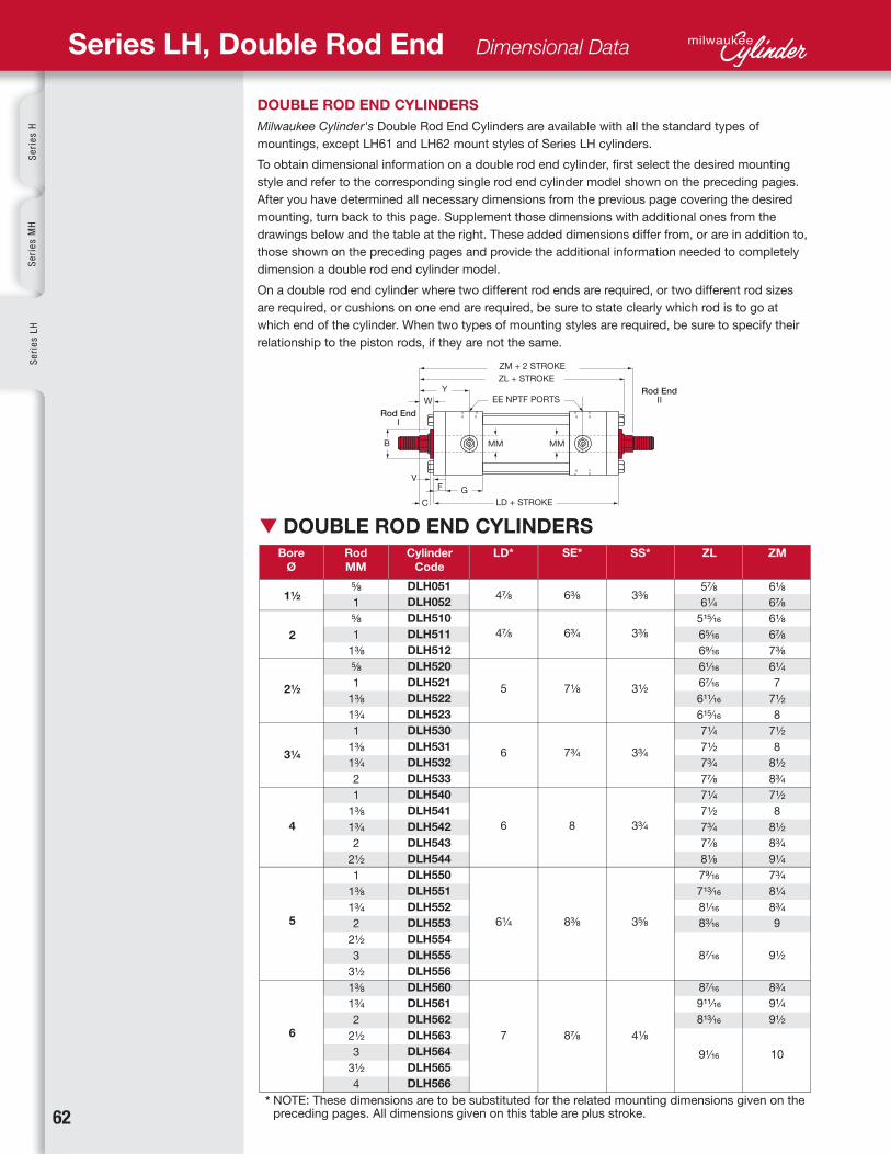
▼ DOUBLE ROD END CYLINDERS
DOUBLE ROD END CYLINDERS
Milwaukee Cylinder's Double Rod End Cylinders are available with all the standard types of
mountings, except LH61 and LH62 mount styles of Series LH cylinders.
To obtain dimensional information on a double rod end cylinder, first select the desired mounting
style and refer to the corresponding single rod end cylinder model shown on the preceding pages.
After you have determined all necessary dimensions from the previous page covering the desired
mounting, turn back to this page. Supplement those dimensions with additional ones from the
drawings below and the table at the right. These added dimensions differ from, or are in addition to,
those shown on the preceding pages and provide the additional information needed to completely
dimension a double rod end cylinder model.
On a double rod end cylinder where two different rod ends are required, or two different rod sizes
are required, or cushions on one end are required, be sure to state clearly which rod is to go at
which end of the cylinder. When two types of mounting styles are required, be sure to specify their
relationship to the piston rods, if they are not the same.
Series LH, Double Rod End Dimensional Data
* NOTE: These dimensions are to be substituted for the related mounting dimensions given on the preceding pages. All dimensions given on this table are plus stroke.
Rod End
ZM + 2 STROKE
YW
V
B
C
F G
MM MM
ZL + STROKE
EE NPTF PORTS
LD + STROKE
Rod End
1½
2
2½
3¼
4
5
6
DLH051
DLH052
DLH510
DLH511
DLH512
DLH520
DLH521
DLH522
DLH523
DLH530
DLH531
DLH532
DLH533
DLH540
DLH541
DLH542
DLH543
DLH544
DLH550
DLH551
DLH552
DLH553
DLH554
DLH555
DLH556
DLH560
DLH561
DLH562
DLH563
DLH564
DLH565
DLH566
6⅜
6¾
7⅛
7¾
8
8⅜
8⅞
3⅜
3⅜
3½
3¾
3¾
3⅝
4⅛
⅝
1
⅝
1
1⅜
⅝
1
1⅜
1¾
1
1⅜
1¾
2
1
1⅜
1¾
2
2½
1
1⅜
1¾
2
2½
3
3½
1⅜
1¾
2
2½
3
3½
4
4⅞
4⅞
5
6
6
6¼
7
5⅞
6¼
515⁄16
65⁄16
69⁄16
61⁄16
67⁄16
611⁄16
615⁄16
7¼
7½
7¾
7⅞
7¼
7½
7¾
7⅞
8⅛
79⁄16
713⁄16
81⁄16
83⁄16
87⁄16
87⁄16
911⁄16
813⁄16
91⁄16
6⅛
6⅞
6⅛
6⅞
7⅜
6¼
7
7½
8
7½
8
8½
8¾
7½
8
8½
8¾
9¼
7¾
8¼
8¾
9
9½
8¾
9¼
9½
10
www.milwaukeecylinder.com 6363
G J K
E2
FA
PA
E
E
1
3
4 2
PD (Ref.)
Se
ries
LH
Se
ries
AS
erie
s M
NH
yd-P
neu
Devices
Cyl A
ccessoriesM
anip
ulators
Pow
er Un
its/Valves D
esign
Gu
ide
Bore
Ø
E F FA G PA PD
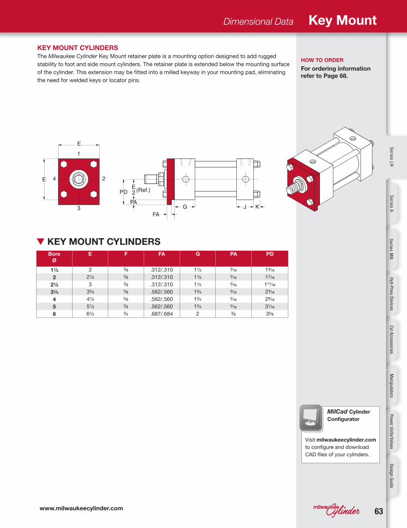
▼ KEY MOUNT CYLINDERS
Dimensional Data Key Mount
KEY MOUNT CYLINDERS
The Milwaukee Cylinder Key Mount retainer plate is a mounting option designed to add rugged
stability to foot and side mount cylinders. The retainer plate is extended below the mounting surface
of the cylinder. This extension may be fitted into a milled keyway in your mounting pad, eliminating
the need for welded keys or locator pins.
MilCad Cylinder
Configurator
Visit milwaukeecylinder.com
to configure and download
CAD files of your cylinders.
HOW TO ORDER
For ordering information
refer to Page 68.
1½
2
2½
3¼
4
5
6
13⁄16
17⁄16
111⁄16
23⁄16
29⁄16
31⁄16
3⅝
⅜
⅜
⅜
⅝
⅝
⅝
¾
3⁄16
3⁄16
3⁄16
5⁄16
5⁄16
5⁄16
⅜
1½
1½
1½
1¾
1¾
1¾
2
2
2½
3
3¾
4½
5½
6½
.312/.310
.312/.310
.312/.310
.562/.560
.562/.560
.562/.560
.687/.684
6464 www.milwaukeecylinder.com
Se
rie
s H
Se
rie
s M
HS
eri
es
LH
Series LH, Design Options
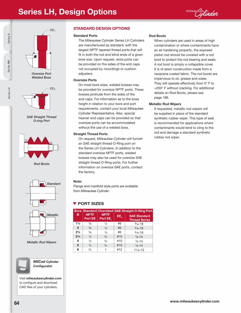
STANDARD DESIGN OPTIONS
Standard Ports
The Milwaukee Cylinder Series LH Cylinders
are manufactured as standard, with the
largest NPTF tapered thread ports that will
fit in both the rod and blind ends of a given
bore size. Upon request, extra ports can
be provided on the sides of the end caps
not occupied by mountings or cushion
adjusters.
Oversize Ports
On most bore sizes, welded bosses may
be provided for oversize NPTF ports. These
bosses protrude from the sides of the
end caps. For information as to the boss
height in relation to your bore and port
requirements, contact your local Milwaukee
Cylinder Representative. Also, special
heavier end caps can be provided so that
oversize ports can be accommodated
without the use of a welded boss.
Straight Thread Ports
On request, Milwaukee Cylinder will furnish
an SAE straight thread O-Ring port on
the Series LH Cylinders. In addition to the
standard oversize NPTF ports, welded
bosses may also be used for oversize SAE
straight thread O-Ring ports. For further
information on oversize SAE ports, contact
the factory.
Note:
Flange and manifold style ports are available
from Milwaukee Cylinder.
Rod Boots
When cylinders are used in areas of high
contamination or where contaminants have
an air hardening property, the exposed
piston rod should be covered with a rod
boot to protect the rod bearing and seals.
A rod boot is simply a collapsible cover.
It is of sewn construction made from a
neoprene coated fabric. The rod boots are
impervious to oil, grease and water.
They will operate effectively from 0° F to
+200° F without cracking. For additional
details on Rod Boots, please see
page 186.
Metallic Rod Wipers
If requested, metallic rod wipers will
be supplied in place of the standard
synthetic rubber wiper. This type of seal
is recommended for applications where
contaminants would tend to cling to the
rod and damage a standard synthetic
rubber rod wiper.
Rod Boots
SAE Straight Thread
O-ring Port
Oversize Port
Welded Boss
Metallic Rod Wipers
Bore
Ø
Standard
NPTF
Port EE
SAE Straight O-Ring Port
EE2
Oversized
NPTF
Port EE1
SAE Standard
Thread Series
Standard
Metallic
MilCad Cylinder
Configurator
Visit milwaukeecylinder.com
to configure and download
CAD files of your cylinders.
▼ PORT SIZES
1½
2
2½
3¼
4
5
6
#6
#6
#6
#10
#10
#10
#12
⅜
⅜
⅜
½
½
½
¾
½
½
½
¾
¾
¾
1
9⁄16-18
9⁄16-18
9⁄16-18
⅞ -14
⅞ -14
⅞ -14
11⁄16-12
656565
Se
ries
LH
Se
ries
AS
erie
s M
NH
yd-P
neu
Devices
Cyl A
ccessoriesM
anip
ulators
Pow
er Un
its/Valves D
esign
Gu
ide
DESIGN OPTIONS FOR SPECIAL CYLINDERS
Special Rod Ends
Modifications of standard or entirely
special rod ends are available from
Milwaukee Cylinder. When your
requirements call for a special rod end
style, your order should include a sketch
if it is to be an entirely special rod end
or note reference as to which letter
dimensions you wish to have modified
(see inside front cover).
Special Assemblies from
Standard Parts
Each style of the various standard
cylinder mountings is illustrated, using
the commonly recognized cylinder
dimensional symbols of the National
Fluid Power Association. Each side of
the end views are numbered to aid in
communication when referring to the
relationship between the ports and the
mountings. When requesting information
or placing an order that requires a
dimension other than standard, always
make reference to the given dimensional
symbol in the catalog and then give your
requirements.
Cushion Adjustment Locations
A ball check and a cushion adjustment
needle are supplied as standard in
position #2 on most models. The cushion
needle and ball check are interchangeable
as far as location and may be put in any
side not occupied by a port or mounting.
Port Locations
Ports are located in position
#1 as standard unless
otherwise specified. By
using the position numbers
given with the end views
in the dimensional data
section of this catalog, ports can be
arranged in any one of four 90° positions
in relation to the cylinder mounting.
When ports are relocated on a cushioned
cylinder, the cushion needle and ball
check are automatically relocated to
hold their relationship to the port as on
a standard cylinder, unless otherwise
specified at the time of the order.
Removable Trunnion Pins
Removable trunnion pins are available
on models LH71 and LH72. They can be
used on all bore and rod combinations,
except on the largest oversize rods
offered with each bore size on all model
LH71 cylinders.
Single-Acting Cylinders
The Milwaukee Cylinder's Series LH
cylinders are designed for either single
or double action. When used as a single
acting cylinder, hydraulic power drives
the piston in one direction, only relying
on either the load or an external force
to return the piston after the pressure is
exhausted.
Single-Acting Spring Cylinders
Single-acting spring return cylinders
normally have a spring inside of the
cylinder to return the piston to its original
position. The application load and friction
conditions must be specified when
placing an order to properly size the
spring. Also specify whether the spring
is to return or advance the piston. A
spring return cylinder is designed with a
stop tube to act as spring guide, which
prevents binding of the cylinder due to
misalignment of the spring. To accurately
determine the cylinder length and
mounting dimensions for your application,
contact your local Milwaukee Cylinder
representative or the factory.
Water Service Cylinders
Milwaukee Cylinder's Series LH
Cylinders can be used with water as
an operating fluid with some standard
modifications to the types of material
and the manufacturing processes used.
These modifications will include, at some
additional cost, bronze piston, nickel
plated end caps, a hard chrome plated
cylinder barrel and a chrome plated piston
or stainless steel piston rod at extra cost.
Due to the increased factors of corrosion,
electrolysis and mineral deposits acting
within a water fitted cylinder, Milwaukee
Cylinder cannot warrant or make any
guarantees other than a water service
cylinder will be free of defects in
workmanship or materials.
Proximity Switches
End of Stroke Limit Switches:
We provide inductive proximity switches
for end of stroke sensing. These non-
contact switches detect the
presence of the spud/cushion
bushing. See page 185 for more
information.
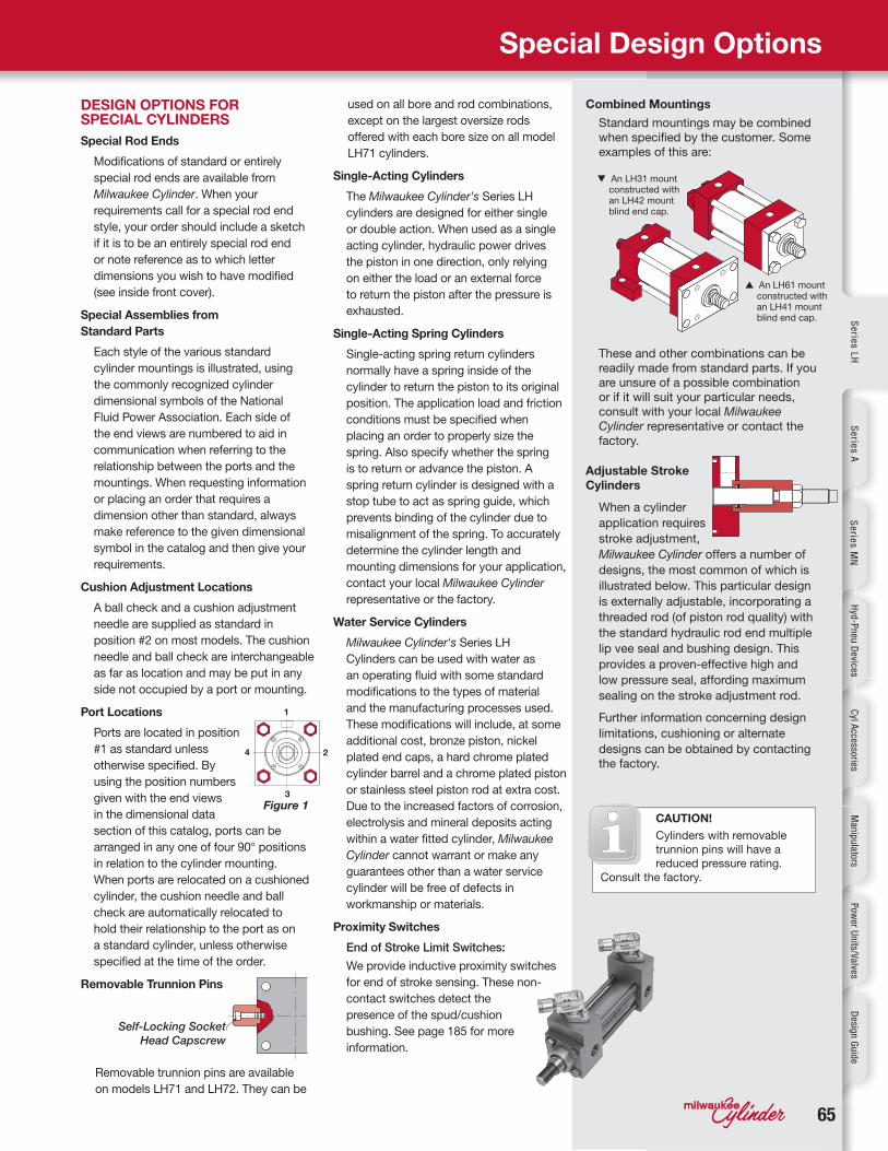
Combined Mountings
Standard mountings may be combined when specified by the customer. Some examples of this are:
These and other combinations can be readily made from standard parts. If you are unsure of a possible combination or if it will suit your particular needs, consult with your local Milwaukee Cylinder representative or contact the factory.
Adjustable Stroke
Cylinders
When a cylinder
application requires
stroke adjustment,
Milwaukee Cylinder offers a number of
designs, the most common of which is
illustrated below. This particular design
is externally adjustable, incorporating a
threaded rod (of piston rod quality) with
the standard hydraulic rod end multiple
lip vee seal and bushing design. This
provides a proven-effective high and
low pressure seal, affording maximum
sealing on the stroke adjustment rod.
Further information concerning design
limitations, cushioning or alternate
designs can be obtained by contacting the factory.
Special Design Options
Self-Locking Socket
Head Capscrew
▼ An LH31 mount constructed with an LH42 mount blind end cap.
▲ An LH61 mount constructed with an LH41 mount blind end cap.
Figure 1CAUTION!
Cylinders with removable
trunnion pins will have a
reduced pressure rating.
Consult the factory.

6666
Se
rie
s H
Se
rie
s M
HS
eri
es
LH
Series LH, Stop Tubes
To determine “K” (see to Figure 1)
*Note: W = the rod stick out
(refer to pages 54-63)
Cylinder #1, #4, #8 – see Figure 1
K = 4L= 4 (stroke + W*)
Cylinder #2 - see Figure 1
K = L = (CA or CE) + XG + Stroke
Note: CA = rod eye dimension (back inside cover) CE = rod clevis dimension (back inside cover)XG = mounting dimension page 60
Cylinder #3 – see Figure 1
K = L = W* + Stroke
Cylinder #5 – see Figure 1
K = L = (CA or CE) + XC + (2 x Stroke)
Note: CA = rod eye dimension (back inside cover)
CE = rod clevis dimension (back inside cover)
XC = mounting dimension page 60
Cylinder #6 – see Figure 1
K = L = (CA or CE) + XJ + (2 x Stroke)
Note: CA = rod eye dimension (back inside cover)
CE = rod clevis dimension (back inside cover)
XJ = mounting dimension page 60
Cylinder #7 – see Figure 1
K = L/2 =(W* + Stroke)/2
When mounting long stroke cylinders, care
should be taken to assure cylinder alignment
over the entire length of stroke. The use
of external guides or swivel bushings is
recommended to reduce side load conditions
and prolong the cylinder’s service life.
Note: Stop tube length must be added to
“K” factor before making final selection of
rod size. This is primarily true in No. 5 long
stroke applications.
Stop Tube Length
Stop Tube
The stop tube is located between the
piston and the rod end cap. It limits
the extended stroke of the cylinder,
providing additional strength for less
cost and reduced weight than the use
of an oversize rod.
▼ FIGURE 1 STOP TUBES
Stop tubes are used to maintain bearing pressure within acceptable limits and are recommended
on cylinders with long strokes or poorly guided rods.
The stop tube is a spacer between the rod end cap and the piston, which provides separation
between the piston and the rod bearing. This separation reduces the moment forces developed
between the rod bearing and piston when the rod is extended.
To determine if stop tube is necessary for your cylinder requirements, you have to solve for “K”
(refer to Figure 1). If your required cylinder has a “K” dimension in excess of 40 inches, stop tube
is required. For each 10 inch increment or fraction thereof in excess of 40 inches, one inch of
stop tube is recommended. When stop tube is required, the overall length of the cylinder will be
increased by the length of the stop tube to be used.
Stop Tubes
For more
information on
Stop Tubes, see
page 181 in the
Design Engineer's Guide.
www.milwaukeecylinder.com 6767
Se
ries
LH
Se
ries
AS
erie
s M
NH
yd-P
neu
Devices
Cyl A
ccessoriesM
anip
ulators
Pow
er Un
its/Valves D
esign
Gu
ide
Dimensional Data Cylinder Sizing
100psi
200psi
250psi
500psi
750psi
1000psi
1250psi
1500psi
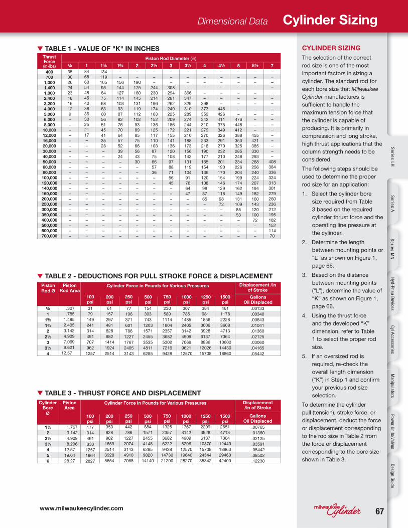
CYLINDER SIZING
The selection of the correct
rod size is one of the most
important factors in sizing a
cylinder. The standard rod for
each bore size that Milwaukee
Cylinder manufactures is
sufficient to handle the
maximum tension force that
the cylinder is capable of
producing. It is primarily in
compression and long stroke,
high thrust applications that the
column strength needs to be
considered.
The following steps should be
used to determine the proper
rod size for an application:
1. Select the cylinder bore
size required from Table
3 based on the required
cylinder thrust force and the
operating line pressure at
the cylinder.
2. Determine the length
between mounting points or
“L” as shown on Figure 1,
page 66.
3. Based on the distance
between mounting points
(“L”), determine the value of
“K” as shown on Figure 1,
page 66.
4. Using the thrust force
and the developed “K”
dimension, refer to Table
1 to select the proper rod
size.
5. If an oversized rod is
required, re-check the
overall length dimension
(“K”) in Step 1 and confirm
your previous rod size
selection.
To determine the cylinder
pull (tension), stroke force, or
displacement, deduct the force
or displacement corresponding
to the rod size in Table 2 from
the force or displacement
corresponding to the bore size
shown in Table 3.
Cylinder Bore
Ø
Piston
Rod Ø
Thrust Force (in-lbs)
Piston Area
Piston Rod Area
Cylinder Force in Pounds for Various Pressures
Cylinder Force in Pounds for Various Pressures
Piston Rod Diameter (in)
Displacement /in of Stroke
Displacement /in of Stroke
1⅝ 1⅜ 1¾ 2 2½ 3 3½ 4 4½ 5 5½ 7
Gallons Oil Displaced
Gallons Oil Displaced
▼ TABLE 3 - THRUST FORCE AND DISPLACEMENT
▼ TABLE 2 - DEDUCTIONS FOR PULL STROKE FORCE & DISPLACEMENT
▼ TABLE 1 - VALUE OF "K" IN INCHES
200psi
100psi
250psi
500psi
750psi
1000psi
1250psi
1500psi
177
314
491
830
1257
1964
2827
31
79
149
241
314
491
707
962
1257
61
157
297
481
628
982
1414
1924
2514
77
196
371
601
786
1227
1767
2405
3143
154
393
743
1203
1571
2455
3535
4811
6285
230
589
1114
1804
2357
3682
5302
7216
9428
307
785
1485
2405
3142
4909
7069
9621
12570
384
981
1856
3006
3928
6137
8836
12026
15708
461
1178
2228
3608
4713
7364
10600
14430
18860
1.767
3.142
4.909
8.296
12.57
19.64
28.27
1½
2
2½
3¼
4
5
6
⅝
1
1⅜
1¾
2
2½
3
3½
4
400
700
1,000
1,400
1,800
2,400
3,200
4,000
5,000
6,000
8,000
10,000
12,000
16,000
20,000
30,000
40,000
50,000
60,000
80,000
100,000
120,000
140,000
160,000
200,000
250,000
300,000
350,000
400,000
500,000
600,000
700,000
35
30
26
24
23
18
16
12
9
–
–
–
–
–
–
–
–
–
–
–
–
–
–
–
–
–
–
–
–
–
–
–
84
68
60
54
48
45
40
38
36
30
25
21
17
–
–
–
–
–
–
–
–
–
–
–
–
–
–
–
–
–
–
–
134
119
105
93
84
75
68
63
60
56
51
45
41
35
28
–
–
–
–
–
–
–
–
–
–
–
–
–
–
–
–
–
–
–
156
144
127
114
103
93
87
82
76
70
64
57
52
39
24
–
–
–
–
–
–
–
–
–
–
–
–
–
–
–
–
–
190
175
160
145
131
119
112
102
93
89
85
75
66
56
43
30
–
–
–
–
–
–
–
–
–
–
–
–
–
–
–
–
–
244
230
214
196
174
163
152
136
125
117
110
103
87
75
66
57
36
–
–
–
–
–
–
–
–
–
–
–
–
–
–
–
308
294
281
262
240
225
209
186
172
155
141
136
120
108
97
88
71
56
45
–
–
–
–
–
–
–
–
–
–
–
–
–
–
366
347
329
310
289
274
244
221
210
188
173
156
142
131
119
104
91
76
64
47
–
–
–
–
–
–
–
–
–
–
–
–
–
–
398
373
359
342
310
279
270
233
218
190
177
165
154
136
120
108
98
87
65
–
–
–
–
–
–
–
–
–
–
–
–
–
–
446
426
411
375
349
326
291
270
232
210
201
190
170
154
146
129
118
98
72
–
–
–
–
–
–
–
–
–
–
–
–
–
–
–
476
448
412
388
350
325
285
248
234
226
204
199
174
162
149
131
109
85
53
–
–
–
–
–
–
–
–
–
–
–
–
–
–
–
–
455
421
385
330
293
268
256
240
224
207
194
182
160
143
120
100
72
–
–
–
–
–
–
–
–
–
–
–
–
–
–
–
–
–
–
–
–
408
384
336
324
313
301
279
260
236
212
195
182
152
114
70
.307
.785
1.485
2.405
3.142
4.909
7.069
9.621
12.57
.00765
.01360
.02125
.03591
.05442
.08502
.12230
.00133
.00340
.00643
.01041
.01360
.02125
.03060
.04165
.05442
353
628
982
1659
2514
3928
5654
442
786
1227
2074
3143
4910
7068
884
1571
2455
4148
6285
9820
14140
1325
2357
3682
6222
9428
14730
21200
1767
3142
4909
8296
12570
19640
28270
2209
3928
6137
10370
15708
24544
35342
2651
4713
7364
12440
18860
29460
42400
6868
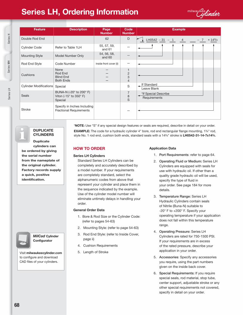
LH0542 – 31 – 1 4 – 7 × 143/4
Se
rie
s H
Se
rie
s M
HS
eri
es
LH
MilCad Cylinder
Configurator
Visit milwaukeecylinder.com
to configure and download
CAD files of your cylinders.
Series LH, Ordering Information
Feature Description Page
Number
Code
Number
Example
Refer to Table 1LH
Model Number Only
Code Number
NoneRod EndBlind EndBoth Ends
Special
BUNA-N (-20° to 200° F)
Viton (-15° to 350° F)
Special
Specify in Inches Including
Fractional Requirements
Double Rod End
Cylinder Code
Mounting Style
Rod End Style
Cushions
Cylinder Modifications
Seals
Stroke
62
55, 57, 59, and 61
54, 56, 58, and 60
inside front cover (ii)
————
If Standard
Leave Blank
* If Special Describe
Requirements
HOW TO ORDER
Series LH Cylinders
Standard Series LH Cylinders can be
completely and accurately described by
a model number. If your requirements
are completely standard, select the
alphanumeric codes from above that
represent your cylinder and place them in
the sequence indicated by the example.
Use of the cylinder model number will
eliminate untimely delays in handling your
order.
General Order Data
1. Bore & Rod Size or the Cylinder Code:
(refer to pages 54-63)
2. Mounting Style: (refer to page 54-63)
3. Rod End Style: (refer to Inside Cover,
page ii)
4. Cushion Requirements
5. Length of Stroke
Application Data
1. Port Requirements: refer to page 64.
2. Operating Fluid or Medium: Series LH
Cylinders are equipped with seals for
use with hydraulic oil. If other than a
quality grade hydraulic oil will be used,
specify the type of fluid in
your order. See page 184 for more
details.
3. Temperature Range: Series LH
Hydraulic Cylinders contain seals
of Nitrile (Buna-N) suitable to
-20° F to +200° F. Specify your
operating temperature if your application
does not fall within this temperature
range.
4. Operating Pressure: Series LH
Cylinders are rated for 750-1500 PSI.
If your requirements are in excess
of the rated pressure, describe your
application in your order.
5. Accessories: Specify any accessories
you require, using the part numbers
given on the inside back cover.
6. Special Requirements: If you require
special seals, rod material, stop tube,
center support, adjustable stroke or any
other special requirements not covered,
specify in detail on your order.
* NOTE: Use “S” if any special design features or seals are required, describe in detail on your order.
EXAMPLE: The code for a hydraulic cylinder 4" bore, rod end rectangular flange mounting, 1¾ " rod,
style No. 1 rod end, cushion both ends, standard seals with a 14¾ " stroke is LH0542-31-14-7x14¾ .
DUPLICATE
CYLINDERS
Duplicate
cylinders can
be ordered by giving
the serial number
from the nameplate of
the original cylinder.
Factory records supply
a quick, positive
identification.
D
—
—
—
1234
S
78S
—
www.milwaukeecylinder.com 6969
Se
ries
LH
Se
ries
AS
erie
s M
NH
yd-P
neu
Devices
Cyl A
ccessoriesM
anip
ulators
Pow
er Un
its/Valves D
esign
Gu
ide
Replacement Parts
Item
No.
Description
1
2
313
14
4
7 12
16
19
23
18
8
5
22
6
15
9
20
21
17
10
11
1
2
3
4
5
6
7
8
9
10
11
12
13
14
15
16
17
18
19
20
21
22
23
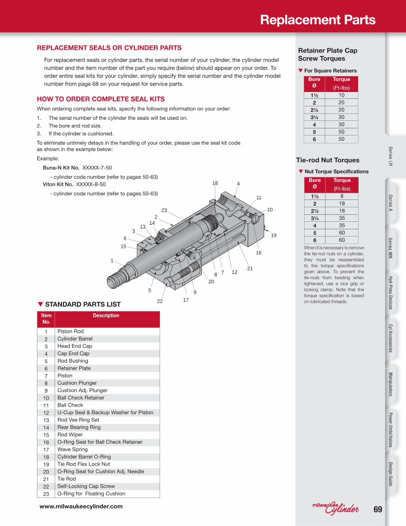
Piston Rod
Cylinder Barrel
Head End Cap
Cap End Cap
Rod Bushing
Retainer Plate
Piston
Cushion Plunger
Cushion Adj. Plunger
Ball Check Retainer
Ball Check
U-Cup Seal & Backup Washer for Piston
Rod Vee Ring Set
Rear Bearing Ring
Rod Wiper
O-Ring Seal for Ball Check Retainer
Wave Spring
Cylinder Barrel O-Ring
Tie Rod Flex Lock Nut
O-Ring Seal for Cushion Adj. Needle
Tie Rod
Self-Locking Cap Screw
O-Ring for Floating Cushion
REPLACEMENT SEALS OR CYLINDER PARTS
For replacement seals or cylinder parts, the serial number of your cylinder, the cylinder model
number and the item number of the part you require (below) should appear on your order. To
order entire seal kits for your cylinder, simply specify the serial number and the cylinder model
number from page 68 on your request for service parts.Bore
Ø
Bore
Ø
Torque
(Ft-lbs)
Torque
(Ft-lbs)
▼ For Square Retainers
Retainer Plate Cap
Screw Torques
Tie-rod Nut Torques
▼ Nut Torque Specifications
When it is necessary to remove
the tie-rod nuts on a cylinder,
they must be reassembled
to the torque specifications
given above. To prevent the
tie-rods from twisting when
tightened, use a vice grip or
locking clamp. Note that the
torque specification is based
on lubricated threads.
HOW TO ORDER COMPLETE SEAL KITS
When ordering complete seal kits, specify the following information on your order:
1. The serial number of the cylinder the seals will be used on.
2. The bore and rod size.
3. If the cylinder is cushioned.
To eliminate untimely delays in the handling of your order, please use the seal kit code
as shown in the example below:
Example:
Buna-N Kit No. XXXXX-7-50
- cylinder code number (refer to pages 50-63)
Viton Kit No. XXXXX-8-50
- cylinder code number (refer to pages 50-63)
▼ STANDARD PARTS LIST
1½
2
2½
3¼
4
5
6
1½
2
2½
3¼
4
5
6
10
20
20
30
30
50
50
8
18
18
35
35
60
60
7070
Se
rie
s H
Se
rie
s M
HS
eri
es
LH
INSTALLATION FOR SERIES LH
General Information
Cleanliness
The most important consideration when
installing the cylinder. When cylinders are
shipped from Milwaukee Cylinder, the ports
are securely plugged with plastic plugs which
should not be removed until the piping is to
be installed. All piping should be thoroughly
clean, to include the removal of all threading
and flaring burrs or chips, before making the
connection to the cylinder ports. One chip can
cause premature failure of the cylinder or other
hydraulic system components.
Alignment
Improper alignment will result in excessive
cylinder wear. Check to assure rod alignment
between the cylinder and its mating
component on your machine in both the
extended and retracted positions.
Environment
Cylinders operating in areas where there is
weld splatter, fast drying chemicals, paint,
excessive heat or other hazardous conditions,
should have covers or shields to prevent
damage to the rod and rod seals.
Bleeding
Air within the cylinder or system will cause
erratic operation of the cylinder. Our cylinders
generally do not require bleed ports if the
cylinder ports are mounted in an upright
position. Several full strokes of the cylinder
will purge air from the cylinder into the circuit
piping, where it can be bled off. Bleeder
ports are available for applications where the
cylinder is the high point of the circuit or where
the cylinder does not complete a full stroke
during its normal cycle.
Series LH, Installation
MOUNTING RECOMMENDATIONS
Foot Mounted Cylinders
The use of high strength alloy steel mounting
bolts 1/16" smaller than the hole size is
recommended. After final alignment, foot
mounted cylinders should be dowel pinned
in place.
Trunnion Mounted Cylinders
Lubricated pillow blocks designed for close
tolerance applications should be used. It
is important to rigidly mount and align the
pillow blocks so that the trunnion pins will
not be subjected to any extreme bending
moments The rod end should be pivoted
with the pivot pin in line and parallel to the
axis of the trunnion pins.
Flush Mount Cylinders
The use of high strength alloy steel mounting
bolts is recommended. Shear keys should
be used to reduce the stress on the
mounting bolts created by the normal push
and pull forces created by the cylinder cycle.
Flange Mount Cylinders
The controlled diameter rod bushing
extension can be used as a pilot to locate
the flange mount. Dowel pins should be
used after the cylinder is mounted and
aligned to prevent shifting.
Clevis Mount Cylinders
This type of cylinder must be pivoted at
both ends and the pins must be in line and
parallel to each other. After the cylinder is
mounted, the customer should check to
assure that the cylinder is free to swing
through its working arc without interference
from other machined parts.
STORAGE
Often times, cylinders are delivered before a
customer is prepared to install them and must
be stored for a period of time. When storage is
required:
1. Select an area indoors for storage, which
has dry and non-corrosive atmosphere. Take
caution to protect the cylinder from both
internal and external corrosion.
2. Cylinders to be stored should be kept in a
vertical position (piston rod up) whenever
possible.
3. Port protector plugs should be kept in the
cylinder ports until the time of installation.
www.milwaukeecylinder.com 7171
Se
ries
LH
Se
ries
AS
erie
s M
NH
yd-P
neu
Devices
Cyl A
ccessoriesM
anip
ulators
Pow
er Un
its/Valves D
esign
Gu
ide
CYLINDER TROUBLE SHOOTING
1. External leakage
If leaking occurs between the end cap and
barrel, check tie-rod torque. Do not over
torque. If the torque is correct, then replace
the barrel seal. When leakage occurs in the
rod bushing area, replace the rod seals. If
leakage continues or reoccurs in short period
of operation, check items 2 thru 5, page 69.
2. Cylinder misalignment
Side load is a common problem which occurs
when the cylinder application does not allow
the piston rod to work in line during the
extend and retract motions of the cylinder.
Evidence of this is excessive seal failure,
bushing wear or galling of the piston rod.
Often, bending of the piston rod or complete
failure (breakage) of the rod occurs.
3. Contamination on the piston rod
Dirt and other material is often picked up
when the piston rod is extended. When
the rod is retracted in an excessive dirty
application, it often carries the dirt back
into the rod seal cavity of the cylinder,
causing damage to the seals. With a slight
modification of the cylinder rod end, a
rod boot can be added to protect the rod
bushing and seals for most applications.
4. Bad mountings
Due to wear of pivot pins or mounting bolts
working loose, a cylinder may have side
load, even though the rod was in line when
the cylinder was first installed. All cylinder
mountings should be checked periodically.
5. Damaged piston rod
An extended piston rod can be damaged
by the impact of a hard object which could
burr the rod. If this occurs, the rod should
be checked immediately to prevent seal
damage.
6. Internal leakage
Inside the cylinder, leakage past the piston
seals can cause sluggish movement or
settling of the cylinder under load conditions.
This occurs due to leakage of worn piston
seals or rings.
7. Creeping cylinder
When a cylinder is stopped in midstroke
and it creeps, check for internal leakage.
Creeping can also be caused by a worn
control valve and this should be checked,
even if the cylinder is found to have internal
leakage.
8. Erratic operation
When a cylinder is erratic or sluggish
in operation, this may be caused by a
number of problems. The most common
cause of sluggish operation is air in the
system. Internal leakage could also be a
cause. If the system starts out sluggishly
and, as it warms, speeds up, the oil may
be of too high viscosity. The whole system
should be checked for worn components
if after these checks, the cylinder is still
operating in a sluggish manner.
CYLINDER MAINTENANCE
Rod Seal Replacement
When changing rod seals, extend the piston rod
3" or more if possible, being sure to support
the rod at all times. Remove the retainer plate
screws (if tie-rod nuts have to be removed,
refer to the nut torque specification on this
page when reassembling the cylinder), retainer
plate and outer bushing. Using an eye hook
or thin screwdriver, pry the vees from the end
cap cavity (if low pressure air is applied to the
rod end port, this will help to force the vees
from the cavity). The new set of vees should be
assembled into the cavity separately and lubed
with the soft vee in the center. Replace the rod
wiper in the bushing and reassemble
the cylinder.
Piston Seal Replacement
When changing piston seals, extend the piston
rod 3" or more if possible, being sure to support
the piston rod and the piston at all times.
*Remove the tie-rod nuts, blind end cap, the
barrel and then the piston seals. A light grease,
compatible with the system fluid, should be used
on the rings and block vee seals for smooth
assembly. Install the block vee piston seals,
scarf cutting on only the back-up washers.
Then install the cast iron rings with the joints
in opposite directions. To reassemble, start the
piston into the tube, compressing the cast iron
rings using twine or a ring compressor. When the
piston block vee seal is to the edge of the barrel,
use a thin rounded blade to start the lip of the
block vee, making sure the entire lip is started
before moving the piston further into the tube.
*Note: When a cylinder has been disassembled
this far, the barrel seals should at least be
inspected, if not replaced.
Barrel Seal Replacement
When replacing barrel seals, use the same
method of disassembling the cylinder as used
when replacing piston seals. The barrel seal
consists of a backup washer and O-Ring, which
is assembled on the first step of both ends of the
tube, with the backup washer going on first. The
outer diameter of the tube groove on the end
caps must be checked for nicks or burrs and
then greased. Position the end caps squarely
on the tube (check to make sure port location is
correct) and firmly force or tap the end cap over
the tube until it bottoms. Check to make sure the
O-Ring did not shear and then finish assembling
the cylinder.
Trouble Shooting / Maintenance
Bore
Ø
Torque
(Ft-lbs)
▼ Nut Torque Specifications
When it is necessary to remove
the tie-rod nuts on a cylinder,
they must be reassembled
to the torque specifications
given above. To prevent the
tie-rods from twisting when
tightened, use a vice grip or
locking clamp. Note that the
torque specification is based
on lubricated threads.
1½
2
2½
3¼
4
5
6
8
18
18
35
35
60
60
Related Documents