Clean One-touch Fittings Series KP/KPQ/KPG Series KP Series KPQ Series KPG Series KPQ/KPG for drive system air piping added to Clean One-touch fitting Series KP 15-5-5 K M H D MS T VMG Courtesy of CMA/Flodyne/Hydradyne ▪ Motion Control ▪ Hydraulic ▪ Pneumatic ▪ Electrical ▪ Mechanical ▪ (800) 426-5480 ▪ www.cmafh.com

Welcome message from author
This document is posted to help you gain knowledge. Please leave a comment to let me know what you think about it! Share it to your friends and learn new things together.
Transcript
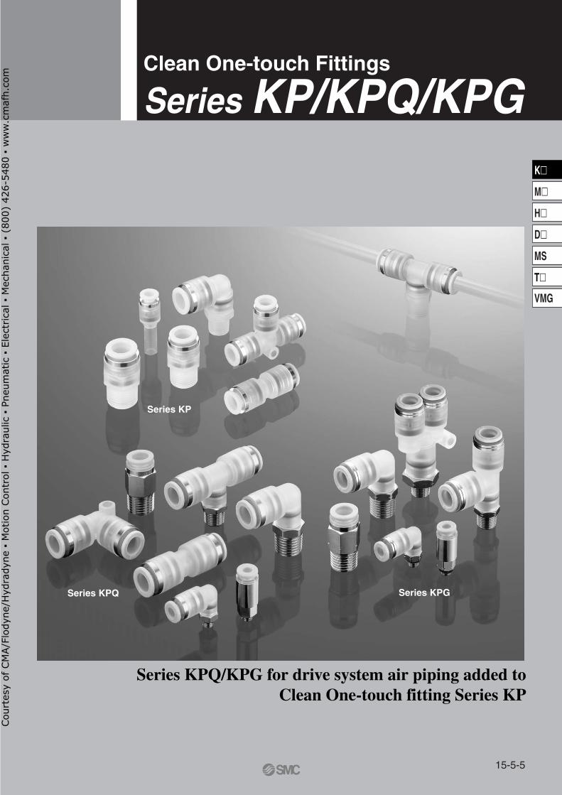
Clean One-touch Fittings
Series KP/KPQ/KPG
Series KP
Series KPQ Series KPG
Series KPQ/KPG for drive system air piping added toClean One-touch fitting Series KP
15-5-5
K�
M�
H�
D�
MS
T�
VMG
Cou
rtes
y of
CM
A/F
lody
ne/H
ydra
dyne
▪ M
otio
n Con
trol
▪ H
ydra
ulic
▪ P
neum
atic
▪ E
lect
rica
l ▪ M
echa
nica
l ▪ (
800)
426
-548
0 ▪
ww
w.c
maf
h.co
m
N2
Super mistseparator
Odorremoval
filterSR
LV
SFA
SFB
SFC
SRH
Cleanregulator
2 portair operated
valve
Cleangas filter
Cleaning liquidpressure feed
Clean blow
N2 blow
Air micro meter
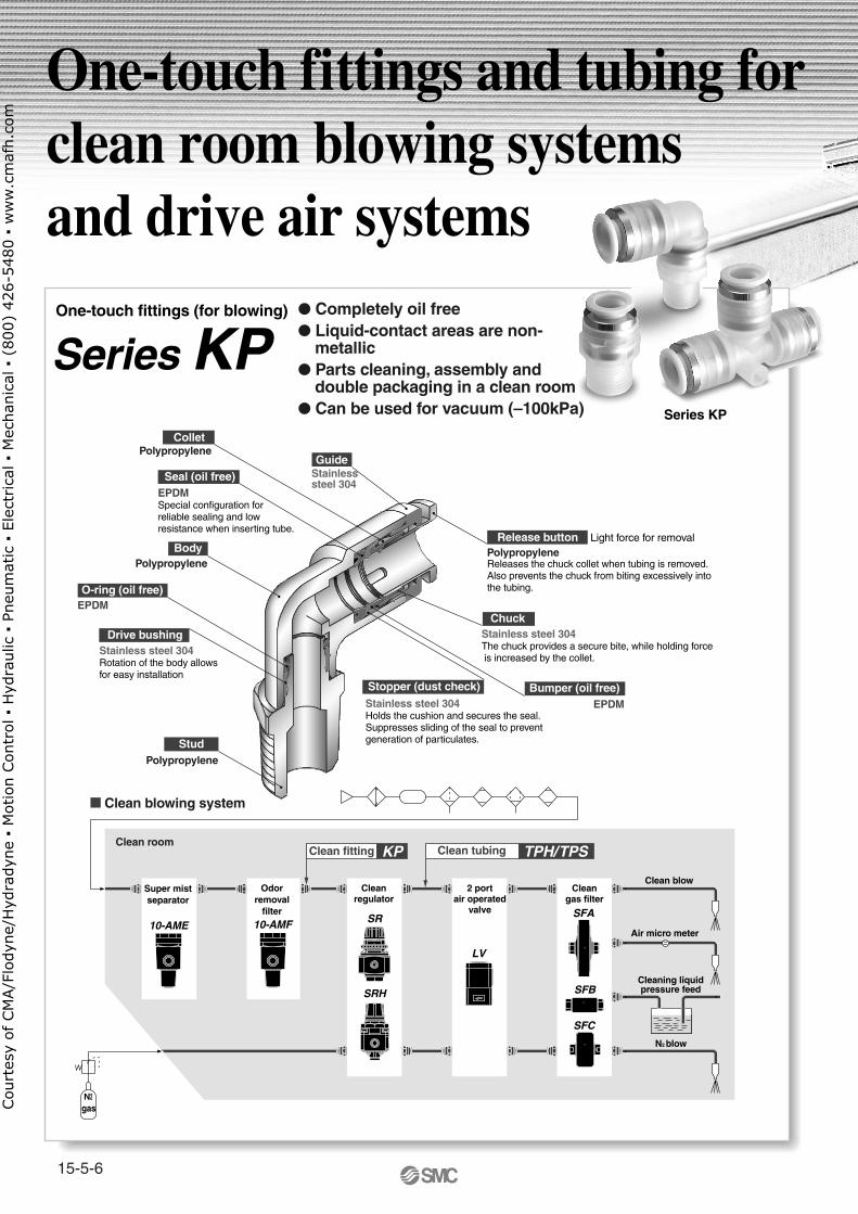
� Clean blowing system
Clean fittingClean room
10-AMF10-AME
KP Clean tubing TPH/TPS
One-touch fittings (for blowing)
Series KP
Stainless steel 304The chuck provides a secure bite, while holding force is increased by the collet.
Stainless steel 304Holds the cushion and secures the seal.Suppresses sliding of the seal to prevent generation of particulates.
Polypropylene
EPDMSpecial configuration for reliable sealing and low resistance when inserting tube.
Release button
Stopper (dust check)
Guide
Collet
PolypropyleneBody
Polypropylene
Stud
Seal (oil free)
EPDM O-ring (oil free)
EPDMBumper (oil free)
Chuck
Light force for removal
Series KP
Stainless steel 304Rotation of the body allows for easy installation
Drive bushing
Polypropylene
gas
Stainlesssteel 304
One-touch fittings and tubing for clean room blowing systemsand drive air systems
Releases the chuck collet when tubing is removed.Also prevents the chuck from biting excessively into the tubing.
� Completely oil free� Liquid-contact areas are non-
metallic� Parts cleaning, assembly and
double packaging in a clean room� Can be used for vacuum (–100kPa)
15-5-6
Cou
rtes
y of
CM
A/F
lody
ne/H
ydra
dyne
▪ M
otio
n Con
trol
▪ H
ydra
ulic
▪ P
neum
atic
▪ E
lect
rica
l ▪ M
echa
nica
l ▪ (
800)
426
-548
0 ▪
ww
w.c
maf
h.co
m
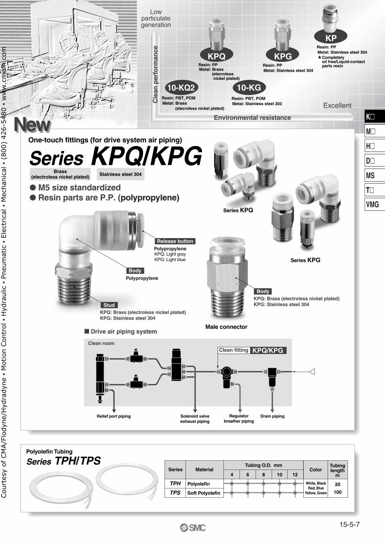
Lowparticulategeneration
Excellent
Environmental resistance
KP
KPGKPQ
10-KG10-KQ2Resin: PBT, POMMetal: Stainless steel 303
Resin: PPMetal: Stainless steel 304
Resin: PPMetal: Stainless steel 304
Completely oil free/Liquid-contactparts resin
Series Material ColorTubinglength
m
Tubing O.D. mm
TPH
TPS
Polyolefin
Soft Polyolefin
White, BlackRed, Blue
Yellow, Green
20
100
�
�
�
�
�
�
�
�
4 6 8 10
�
�
12
Polyolefin Tubing
Series TPH/TPS
� Drive air piping system
Drain pipingRegulatorbreather piping
Solenoid valveexhaust piping
Relief port piping
Clean roomClean fitting KPQ/KPG
NewNew
Series KPG
Series KPQ
� M5 size standardized� Resin parts are P.P. (polypropylene)
Stainless steel 304
Polypropylene
Body
KPQ: Brass (electroless nickel plated) KPG: Stainless steel 304
Stud
KPQ: Light grayKPG: Light blue
Release buttonPolypropylene
KPQ: Brass (electroless nickel plated) KPG: Stainless steel 304
Body
Male connector
One-touch fittings (for drive system air piping)
Series KPQ/KPG Brass
(electroless nickel plated)
Cle
an p
erfo
rman
ce
Resin: PPMetal: Brass
(elecroless nickel plated)
Resin: PBT, POMMetal: Brass
(elecroless nickel plated)
15-5-7
K�
M�
H�
D�
MS
T�
VMG
Cou
rtes
y of
CM
A/F
lody
ne/H
ydra
dyne
▪ M
otio
n Con
trol
▪ H
ydra
ulic
▪ P
neum
atic
▪ E
lect
rica
l ▪ M
echa
nica
l ▪ (
800)
426
-548
0 ▪
ww
w.c
maf
h.co
m
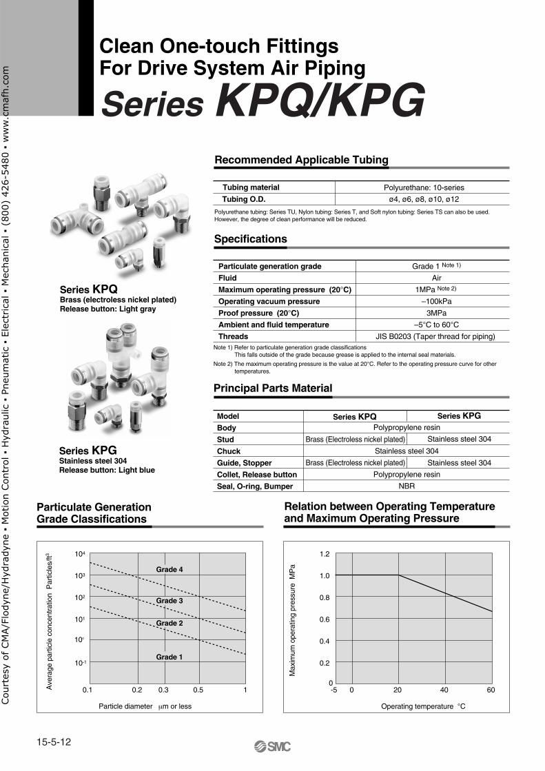
Recommended Applicable Tubing
Tubing material
Tubing O.D.
Polyolefin: Series TPHSoft polyolefin: Series TPS
ø4, ø6, ø8, ø10, ø12
Grade 1 Note 1)
Air/Nitrogen gas/Water (pure water) Note 2)
1MPa Note 3)
–100kPa
3MPa
– 20°C to 80°C
JIS B0203 (Taper thread for piping)
Polypropylene resin
Polypropylene resin
Stainless steel 304
Stainless steel 304
Polypropylene resin
EPDM
Specifications
Particulate generation grade
Fluid
Maximum operating pressure (20°C)
Operating vacuum pressure
Proof pressure (20°C)
Ambient and fluid temperature
Threads
Principal Parts Material
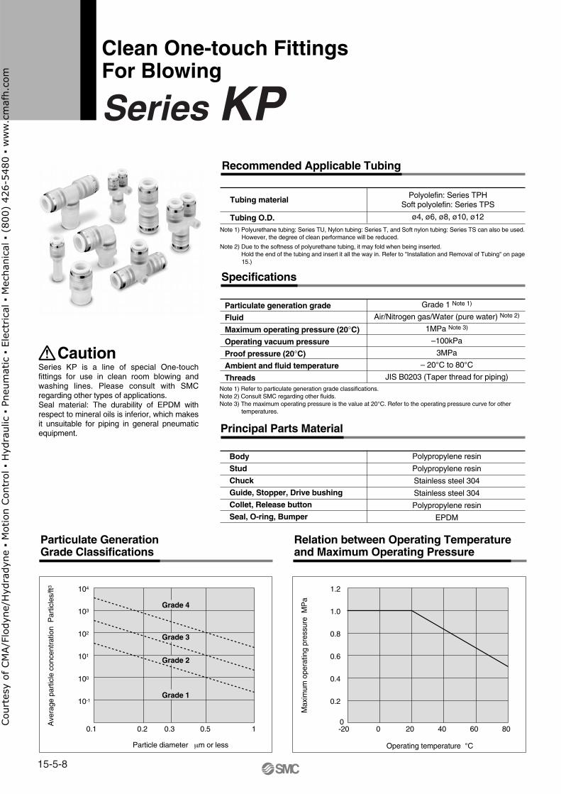
Particulate Generation Grade Classifications
Relation between Operating Temperature and Maximum Operating Pressure
Body
Stud
Chuck
Guide, Stopper, Drive bushing
Collet, Release button
Seal, O-ring, Bumper
-20 0
Operating temperature °C
Max
imum
ope
ratin
g pr
essu
re M
Pa
20 40 60 80
0.2
0.4
0.6
0.8
1.0
1.2
00.1 0.2
Particle diameter µm or less
Ave
rage
par
ticle
con
cent
ratio
n P
artic
les/
ft3
0.3 0.5 1
10-1
100
101
102
103
104
Grade 4
Grade 3
Grade 2
Grade 1
CautionSeries KP is a line of special One-touch fittings for use in clean room blowing and washing lines. Please consult with SMC regarding other types of applications.Seal material: The durability of EPDM with respect to mineral oils is inferior, which makes it unsuitable for piping in general pneumatic equipment.
Note 1) Polyurethane tubing: Series TU, Nylon tubing: Series T, and Soft nylon tubing: Series TS can also be used. However, the degree of clean performance will be reduced.
Note 2) Due to the softness of polyurethane tubing, it may fold when being inserted. Hold the end of the tubing and insert it all the way in. Refer to "Installation and Removal of Tubing" on page
15.)
Note 1) Refer to particulate generation grade classifications.Note 2) Consult SMC regarding other fluids. Note 3) The maximum operating pressure is the value at 20°C. Refer to the operating pressure curve for other
temperatures.
Clean One-touch FittingsFor Blowing
Series KP
15-5-8
Cou
rtes
y of
CM
A/F
lody
ne/H
ydra
dyne
▪ M
otio
n Con
trol
▪ H
ydra
ulic
▪ P
neum
atic
▪ E
lect
rica
l ▪ M
echa
nica
l ▪ (
800)
426
-548
0 ▪
ww
w.c
maf
h.co
m
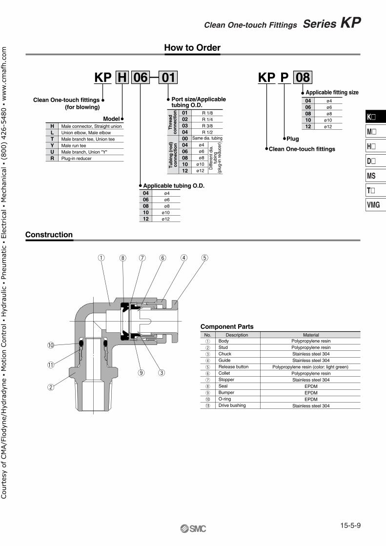
Model
KP H 06
Clean One-touch fittings (for blowing)
R 1/8R 1/4 R 3/8 R 1/2
ø4ø6ø8
ø10ø12
ø4ø6ø8
ø10ø12
Same dia. tubing
Port size/Applicabletubing O.D.
01
01020304000406081012
0406081012
Applicable tubing O.D.
Male connector, Straight unionUnion elbow, Male elbow Male branch tee, Union teeMale run teeMale branch, Union "Y"Plug-in reducer
HLTYUR
Plug
KP P 08
Clean One-touch fittings
ø4ø6ø8
ø10ø12
0406081012
Applicable fitting size
How to Order
Construction
No.q
w
e
r
t
y
u
i
o
!0
!11
Description Material
Component Parts
BodyStudChuckGuideRelease buttonColletStopperSealBumperO-ringDrive bushing
Polypropylene resinPolypropylene resinStainless steel 304Stainless steel 304
Polypropylene resin (color: light green) Polypropylene resinStainless steel 304
EPDMEPDMEPDM
Stainless steel 304
Diff
eren
t dia
.tu
bing
(plu
g-in
redu
cer)
Th
read
con
nec
tion
Tu
bin
g (r
od
)co
nn
ectio
n
15-5-9
K�
M�
H�
D�
MS
T�
VMG
Clean One-touch Fittings Series KPCou
rtes
y of
CM
A/F
lody
ne/H
ydra
dyne
▪ M
otio
n Con
trol
▪ H
ydra
ulic
▪ P
neum
atic
▪ E
lect
rica
l ▪ M
echa
nica
l ▪ (
800)
426
-548
0 ▪
ww
w.c
maf
h.co
m
Dimensions
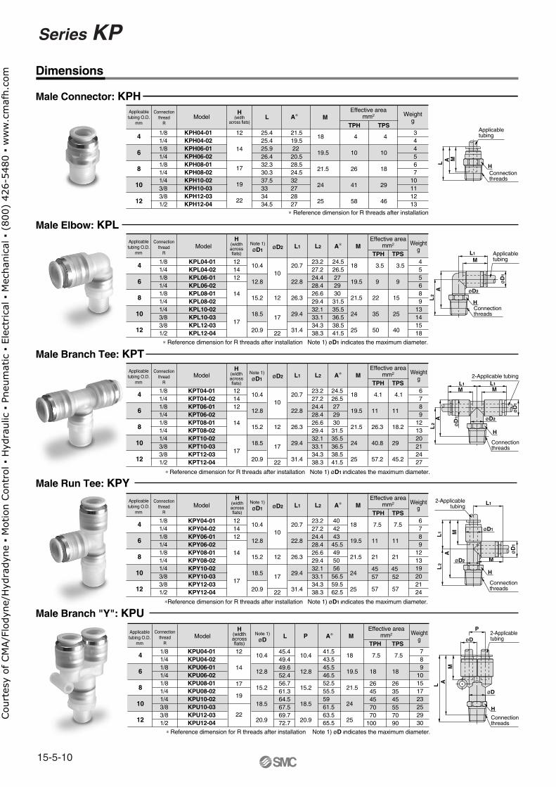
Male Connector: KPH
Male Elbow: KPL
Applicabletubing O.D.
mm
H(width
across flats)
Connectionthread
R
Weightg
Effective areamm2Model L M
TPH TPSA∗
4
6
8
10
12
18
19.5
21.5
24
25
4
10
26
41
58
4
10
18
29
46
12
14
17
19
22
1/81/41/81/41/81/41/43/83/81/2
25.425.425.926.432.330.337.533 34 34.5
21.519.522 20.528.524.532 27 28 27
344567
10111213
KPH04-01KPH04-02KPH06-01KPH06-02KPH08-01KPH08-02KPH10-02KPH10-03KPH12-03KPH12-04
Weightg
Effective areamm2Note 1)
øD1Model L1
TPH TPSA∗
4
6
8
10
12
10.4
12.8
15.2
18.5
20.9
20.7
22.8
26.3
29.4
31.4
M
18
19.5
21.5
24
25
øD2
10
12
17
22
3.5
9
22
35
50
3.5
9
15
25
40
121412
14
17
1/81/41/81/41/81/41/43/83/81/2
24.526.527 29 30 31.535.536.538.541.5
455689
13141518
L2
23.227.224.428.426.629.432.133.134.338.3
KPL04-01KPL04-02KPL06-01KPL06-02KPL08-01KPL08-02KPL10-02KPL10-03KPL12-03KPL12-04
H(widthacrossflats)
Weightg
Effective areamm2Note 1)
øD1Model L1
TPH TPSA∗
4
6
8
10
12
10.4
12.8
15.2
18.5
20.9
20.7
22.8
26.3
29.4
31.4
M
18
19.5
21.5
24
25
øD2
10
12
17
22
4.1
11
26.3
40.8
57.2
4.1
11
18.2
29
45.2
121412
14
17
1/81/41/81/41/81/41/43/83/81/2
24.526.527 29 30 31.535.536.538.541.5
6789
121320212427
L2
23.227.224.428.426.629.432.133.134.338.3
KPT04-01KPT04-02KPT06-01KPT06-02KPT08-01KPT08-02KPT10-02KPT10-03KPT12-03KPT12-04
∗ Reference dimension for R threads after installation
∗ Reference dimension for R threads after installation Note 1) øD1 indicates the maximum diameter.
Weightg
Effective areamm2Note 1)
øDModel L
TPH TPSA∗
4
6
8
10
12
10.4
12.8
15.2
18.5
20.9
10.4
12.8
15.2
18.5
20.9
45.449.449.652.456.761.364.567.569.772.7
M
18
19.5
21.5
24
25
7.5
18
2645457070
100
7.5
18
263545557090
12
14
17
19
22
1/81/41/81/41/81/41/43/83/81/2
41.543.545.546.552.555.559 61.563.565.5
789
10151723252930
P
KPU04-01KPU04-02KPU06-01KPU06-02KPU08-01KPU08-02KPU10-02KPU10-03KPU12-03KPU12-04
∗ Reference dimension for R threads after installation Note 1) øD indicates the maximum diameter.
∗ Reference dimension for R threads after installation Note 1) øD1 indicates the maximum diameter.
Weightg
Effective areamm2Note 1)
øD1Model L1
TPH TPSA∗
4
6
8
10
12
10.4
12.8
15.2
18.5
20.9
20.7
22.8
26.3
29.4
31.4
M
18
19.5
21.5
24
25
øD2
10
12
17
22
7.5
11
21
45 57
57
7.5
11
21
45 52
57
121412
14
17
1/81/41/81/41/81/41/43/83/81/2
40 42 43 45.549 50 56 56.559.562.5
6789
121319202124
L2
23.227.224.428.426.629.432.133.134.338.3
KPY04-01KPY04-02KPY06-01KPY06-02KPY08-01KPY08-02KPY10-02KPY10-03KPY12-03KPY12-04
∗Reference dimension for R threads after installation Note 1) øD1 indicates the maximum diameter.
Male Branch Tee: KPT
Male Run Tee: KPY
Male Branch "Y": KPU
Applicabletubing
HL A M
Connectionthreads
Applicabletubing
H
L2
A øD2
øD
1
L1
MA
L1
L2
AL
2
øD
1
øD2
øD
1
ML1
L1
H
L1
2-Applicable tubing
2-Applicabletubing
2-Applicabletubing
M
H
Connectionthreads
øD
1
L AM
øD1
øD
øD
P
øD2 M
Connectionthreads
H
Connectionthreads
M
Connectionthreads
Applicabletubing O.D.
mm
Connectionthread
R
H(widthacrossflats)
Applicabletubing O.D.
mm
Connectionthread
R
Applicabletubing O.D.
mm
Connectionthread
R
H(widthacrossflats)
H(widthacrossflats)
Applicabletubing O.D.
mm
Connectionthread
R
Series KP
15-5-10
Cou
rtes
y of
CM
A/F
lody
ne/H
ydra
dyne
▪ M
otio
n Con
trol
▪ H
ydra
ulic
▪ P
neum
atic
▪ E
lect
rica
l ▪ M
echa
nica
l ▪ (
800)
426
-548
0 ▪
ww
w.c
maf
h.co
m
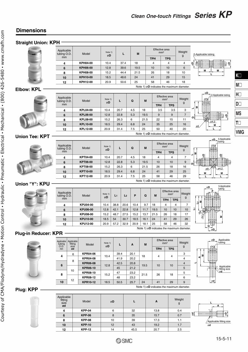
Straight Union: KPH
Elbow: KPL
Union Tee: KPT
Union "Y": KPU
Plug-in Reducer: KPR
Plug: KPP
2-Applicable tubing
2-Applicable tubing
3-Applicabletubing
3-Applicabletubing
Applicabletubing
Applicablefitting sizeød
Applicable fitting size
ød
M
M
M M
ML
L
L L
LQ
LQ
MM
M
MM
A
LL
2
L1
øD
øD
øD
øD
øD
øD
øD
ød
ød
øD
LA
ø4.
2ø8
Q
P
ø4.2ø8
ø4.2
ø8
øD
øD
øD
Applicabletubing O.D.
mm
Weightg
Effective areamm2Note 1)
øDModel L
TPH TPS
4
6
8
10
12
37.4
39.6
44.4
48.6
50.6
18
19.5
21.5
24
25
4
10
26
41
58
4
10
18
29
46
4
6
10
15
18
10.4
12.8
15.2
18.5
20.9
M
KPH04-00
KPH06-00
KPH08-00
KPH10-00
KPH12-00
Note 1) øD indicates the maximum diameter.
Weightg
Effective areamm2Note 1)
øDModel L
TPH TPS
4
6
8
10
12
20.7
22.8
26.3
29.4
31.4
4.5
5.3
6
6.8
7.5
18
19.5
21.5
24
25
3.5
9
22
35
50
3.5
9
15
25
40
3
7
11
16
20
10.4
12.8
15.2
18.5
20.9
MQ
KPL04-00
KPL06-00
KPL08-00
KPL10-00
KPL12-00
Note 1) øD indicates the maximum diameter.
Weightg
Effective areamm2Note 1)
øDModel L
TPH TPS
4
6
8
10
12
20.7
22.8
26.3
29.4
31.4
4.5
5.3
6
6.8
7.5
18
19.5
21.5
24
25
4
10
26
41
58
4
10
18
29
46
7
9
16
25
29
10.4
12.8
15.2
18.5
20.9
MQ
KPT04-00
KPT06-00
KPT08-00
KPT10-00
KPT12-00
Note 1) øD indicates the maximum diameter.
Applicablefittingsizeød
Weightg
Effective areamm2Note 1)
øDModel LTPH TPS
4
6
8
10
10.4
12.8
15.2
18.5
18
19.5
21.5
24
4
10
26
41
4
10
18
29
6
8
10
12
39.4
41.9
42.5
45
47
48
50.5
20.1
20.2
20.8
21.2
23.2
23.2
25.7
3
4
4
5
5
6
9
MA
KPR04-06
KPR04-08
KPR06-08
KPR06-10
KPR08-10
KPR08-12
KPR10-12
Note 1) øD indicates the maximum diameter.
Applicablefittingsizeød
WeightgøDModel L
4
6
8
10
12
32
35
39
43
45.5
6
8
10
12
14
13.8
15.7
17.3
19.2
20.7
0.4
0.7
1.1
1.7
2.5
A
KPP-04
KPP-06
KPP-08
KPP-10
KPP-12
Weightg
Effective areamm2Note 1)
øDModel L1
TPH TPS
4
6
8
10
12
38.8
42.1
48.7
54
57.2
L2
20.6
22.8
27.5
30.7
32.9
10.4
12.8
15.2
18.5
20.9
9.7
11.7
13.7
16.1
18.1
4
10
26
41
58
4
10
18
29
46
7
10
17
26
32
10.4
12.8
15.2
18.5
20.9
Q
18
19.5
21.5
24
25
MP
KPU04-00
KPU06-00
KPU08-00
KPU10-00
KPU12-00
Note 1) øD indicates the maximum diameter.
Applicabletubing O.D.
mm
Applicabletubing O.D.
mm
Applicabletubing O.D.
mm
ApplicabletubingO.D.mm
Dimensions
15-5-11
K�
M�
H�
D�
MS
T�
VMG
Clean One-touch Fittings Series KPCou
rtes
y of
CM
A/F
lody
ne/H
ydra
dyne
▪ M
otio
n Con
trol
▪ H
ydra
ulic
▪ P
neum
atic
▪ E
lect
rica
l ▪ M
echa
nica
l ▪ (
800)
426
-548
0 ▪
ww
w.c
maf
h.co
m
Tubing material Polyurethane: 10-series
ø4, ø6, ø8, ø10, ø12
Grade 1 Note 1)
Air
1MPa Note 2)
–100kPa
3MPa
–5°C to 60°C
JIS B0203 (Taper thread for piping)
Polypropylene resin
Stainless steel 304
Polypropylene resin
NBR
Brass (Electroless nickel plated)
Brass (Electroless nickel plated)
Stainless steel 304
Stainless steel 304
Tubing O.D.
Principal Parts Material
Particulate Generation Grade Classifications
Series KPQ Series KPG
-5 0 20 40 60
0.2
0.4
0.6
0.8
1.0
1.2
00.1 0.2
Particle diameter µm or less
0.3 0.5 1
10-1
100
101
102
103
104
Grade 4
Grade 3
Grade 2
Grade 1
Series KPGStainless steel 304Release button: Light blue
Particulate generation grade
Fluid
Maximum operating pressure (20°C)
Operating vacuum pressure
Proof pressure (20°C)
Ambient and fluid temperature
Threads
Polyurethane tubing: Series TU, Nylon tubing: Series T, and Soft nylon tubing: Series TS can also be used. However, the degree of clean performance will be reduced.
Recommended Applicable Tubing
Specifications
Model
Body
Stud
Chuck
Guide, Stopper
Collet, Release button
Seal, O-ring, Bumper
Relation between Operating Temperature and Maximum Operating Pressure
Ave
rage
par
ticle
con
cent
ratio
n P
artic
les/
ft3
Max
imum
ope
ratin
g pr
essu
re M
Pa
Operating temperature °C
Note 1) Refer to particulate generation grade classificationsThis falls outside of the grade because grease is applied to the internal seal materials.
Note 2) The maximum operating pressure is the value at 20°C. Refer to the operating pressure curve for other temperatures.
Series KPQBrass (electroless nickel plated)Release button: Light gray
Clean One-touch FittingsFor Drive System Air Piping
Series KPQ/KPG
15-5-12
Cou
rtes
y of
CM
A/F
lody
ne/H
ydra
dyne
▪ M
otio
n Con
trol
▪ H
ydra
ulic
▪ P
neum
atic
▪ E
lect
rica
l ▪ M
echa
nica
l ▪ (
800)
426
-548
0 ▪
ww
w.c
maf
h.co
m
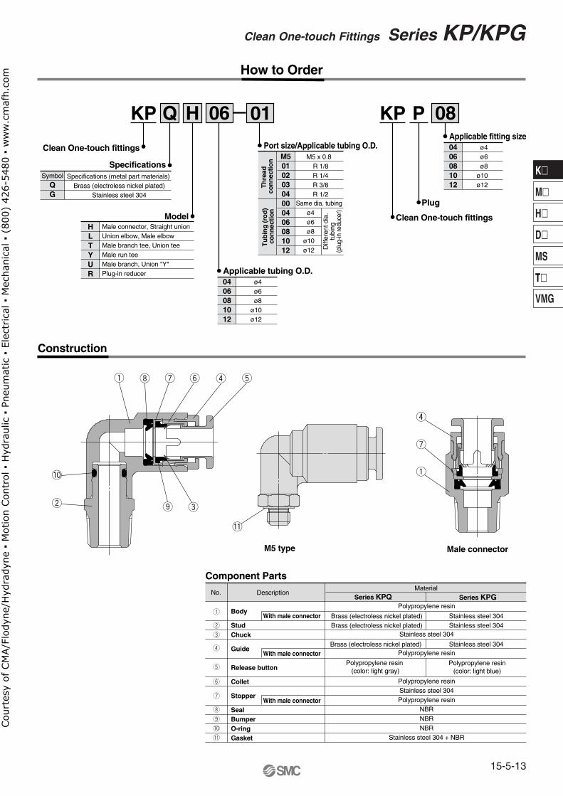
Plug
KP P 08
Clean One-touch fittings
ø4ø6ø8
ø10ø12
0406081012
Applicable fitting size
M5 x 0.8
Model
KP H 06
Clean One-touch fittings
Specifications
Q
R 1/8R 1/4R 3/8 R 1/2
ø4ø6ø8
ø10ø12
Th
read
co
nn
ectio
nT
ub
ing
(ro
d)
con
nec
tion ø4
Diff
eren
t dia
.tu
bing
(plu
g-in
redu
cer)
ø6ø8
ø10ø12
Same dia. tubing
Port size/Applicable tubing O.D.
01
01020304000406081012
0406081012
Applicable tubing O.D.
HLTYUR
Specifications (metal part materials) Brass (electroless nickel plated)
Stainless steel 304
SymbolQG
How to Order
Construction
DescriptionMaterial
Component Parts
Body
StudChuck
Guide
Release button
Collet
Stopper
SealBumperO-ringGasket
Polypropylene resin
Stainless steel 304
Polypropylene resin
Polypropylene resinStainless steel 304Polypropylene resin
NBRNBRNBR
Stainless steel 304 + NBR
Polypropylene resin (color: light gray)
Polypropylene resin (color: light blue)
With male connector
With male connector
With male connector
Brass (electroless nickel plated)Brass (electroless nickel plated)
Brass (electroless nickel plated)
Stainless steel 304Stainless steel 304
Stainless steel 304
Series KPQ Series KPG
M5 type Male connector
M5
Male connector, Straight unionUnion elbow, Male elbow Male branch tee, Union teeMale run teeMale branch, Union "Y"Plug-in reducer
q
w
e
r
t
y
u
i
o
!0
!1
No.
15-5-13
Clean One-touch Fittings Series KP/KPG
K�
M�
H�
D�
MS
T�
VMG
Cou
rtes
y of
CM
A/F
lody
ne/H
ydra
dyne
▪ M
otio
n Con
trol
▪ H
ydra
ulic
▪ P
neum
atic
▪ E
lect
rica
l ▪ M
echa
nica
l ▪ (
800)
426
-548
0 ▪
ww
w.c
maf
h.co
m
Dimensions
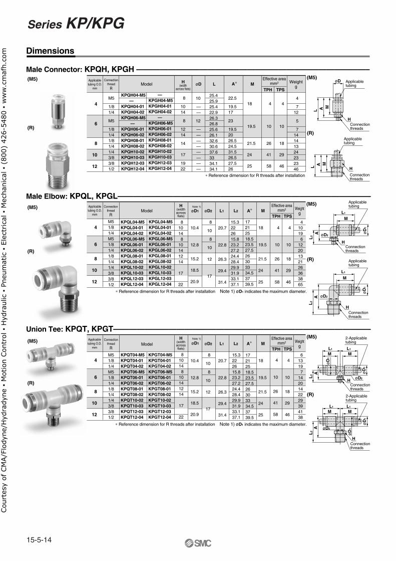
Male Connector: KPQH, KPGH ——————————————————————————————
Applicabletubing O.D.
mm
H(widthacrossflats)
Connectionthread
R
Weightg
Effective areamm2øD1Model L1
TPH TPSA∗
4
6
8
10
12
4
6
8
10
12
10.4
12.8
15.2
18.5
20.9
M
18
19.5
21.5
24
25
4
10
26
41
58
4
10
18
29
46
øD2
810148
10141214
17
22
8
10
8
10
12
17
20.7
22.8
26.3
29.4
31.4
M51/81/4M51/81/41/81/41/43/83/81/2
M5
1/81/4
M5
1/81/41/81/41/43/83/81/2
410196
1220132126363865
L2
15.3222615.823.227.224.428.429.931.933.137.1
17212518.523.527.526303334.53739.5
KPQL04-M5KPQL04-01KPQL04-02KPQL06-M5KPQL06-01KPQL06-02KPQL08-01KPQL08-02KPQL10-02KPQL10-03KPQL12-03KPQL12-04
KPGL04-M5KPGL04-01KPGL04-02KPGL06-M5KPGL06-01KPGL06-02KPGL08-01KPGL08-02KPGL10-02KPGL10-03KPGL12-03KPGL12-04
KPQH04-M5 —KPQH04-01KPQH04-02KPQH06-M5 —KPQH06-01KPQH06-02KPQH08-01KPQH08-02KPQH10-02KPQH10-03KPQH12-03KPQH12-04
—KPGH04-M5KPGH04-01KPGH04-02 —KPGH06-M5KPGH06-01KPGH06-02KPGH08-01KPGH08-02KPGH10-02KPGH10-03KPGH12-03KPGH12-04
∗ Reference dimension for R threads after installation Note 1) øD1 indicates the maximum diameter.
Applicabletubing O.D.
mm
H(width
across flats)
Connectionthread
R
Weightg
Effective areamm2Model LøD M
TPH TPSA∗
8
1014
8
1214
14
17
1922
25.425.925.422.926.326.825.626.132.630.637.63334.134.1
——
10
12
————————
4
712
5
714141324232346
22.5
19.517
23
19.52026.524.531.526.527.526
18
19.5
21.5
24
25
4
10
26
41
58
4
10
18
29
46
Union Tee: KPQT, KPGT————————————————————————————————–Applicabletubing O.D.
mm
H(widthacrossflats)
Connectionthread
R
Weightg
Effective areamm2øD1Model L1
TPH TPSA∗
4
6
8
10
12
10.4
12.8
15.2
18.5
20.9
M
18
19.5
21.5
24
25
4
10
26
41
58
4
10
18
29
46
øD2
810148
10141214
17
22
8
10
8
10
12
17
20.7
22.8
26.3
29.4
31.4
M51/81/4M51/81/41/81/41/43/83/81/2
613197
1420142229394138
L2
15.3222615.823.227.224.428.429.931.933.137.1
17212518.523.527.526303334.53739.5
KPQT04-M5KPQT04-01KPQT04-02KPQT06-M5KPQT06-01KPQT06-02KPQT08-01KPQT08-02KPQT10-02KPQT10-03KPQT12-03KPQT12-04
KPGT04-M5KPGT04-01KPGT04-02KPGT06-M5KPGT06-01KPGT06-02KPGT08-01KPGT08-02KPGT10-02KPGT10-03KPGT12-03KPGT12-04
HConnectionthreads
øD Applicabletubing
MAL
H
Applicabletubing
M
Connectionthreads
L A
L1
øD
1
øD2
L2
A
M
H
ML1
øD2
øD
1
H
AL
2
ML1
øD
1
ML1
2-Applicabletubing
øD
1
øD2HConnectionthreads
AL
2
ML1
ML1
øD
1øD2
2-Applicabletubing
øD
1
HConnectionthreads
AL
2
(M5)
(R)
(M5)
(R)
(M5)
(R)
∗ Reference dimension for R threads after installation
(M5)
(R)
(M5)
(R)
(M5)
(R)
Applicabletubing
Connectionthreads
Connectionthreads
Applicabletubing
∗ Reference dimension for R threads after installation Note 1) øD1 indicates the maximum diameter.
Note 1)
Note 1)
Male Elbow: KPQL, KPGL————————————————————————————————
Series KP/KPG
15-5-14
Cou
rtes
y of
CM
A/F
lody
ne/H
ydra
dyne
▪ M
otio
n Con
trol
▪ H
ydra
ulic
▪ P
neum
atic
▪ E
lect
rica
l ▪ M
echa
nica
l ▪ (
800)
426
-548
0 ▪
ww
w.c
maf
h.co
m
Dimensions
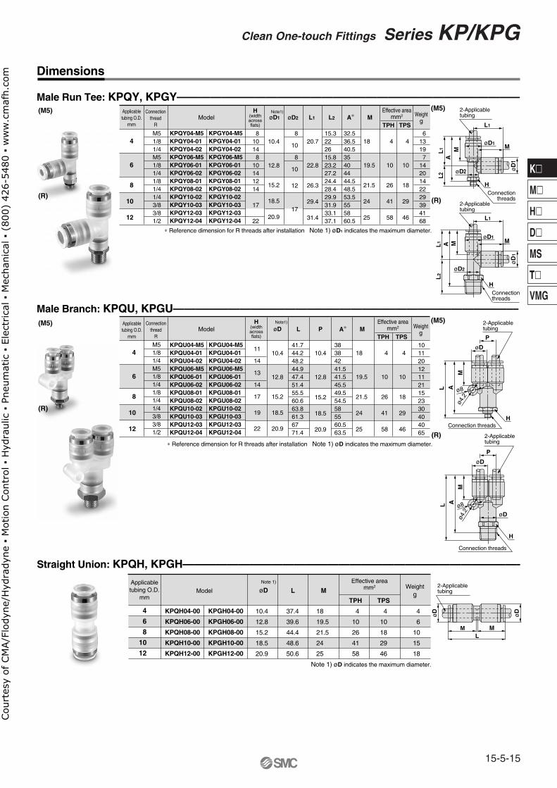
Male Run Tee: KPQY, KPGY——————————————————————————————––Applicabletubing O.D.
mm
H(widthacrossflats)
Connectionthread
R
Weightg
Effective areamm2øD1Model L1
TPH TPSA∗
4
6
8
10
12
10.4
12.8
15.2
18.5
20.9
M
18
19.5
21.5
24
25
4
10
26
41
58
4
10
18
29
46
øD2
810148
10141214
17
22
8
10
8
10
12
17
20.7
22.8
26.3
29.4
31.4
M51/81/4M51/81/41/81/41/43/83/81/2
613197
1420142229394168
L2
15.3222615.823.227.224.428.429.931.933.137.1
32.536.540.535404444.548.553.5555860.5
KPQY04-M5KPQY04-01KPQY04-02KPQY06-M5KPQY06-01KPQY06-02KPQY08-01KPQY08-02KPQY10-02KPQY10-03KPQY12-03KPQY12-04
KPGY04-M5KPGY04-01KPGY04-02KPGY06-M5KPGY06-01KPGY06-02KPGY08-01KPGY08-02KPGY10-02KPGY10-03KPGY12-03KPGY12-04
Male Branch: KPQU, KPGU——————————————————————————————–—Applicabletubing O.D.
mm
H(widthacrossflats)
Connectionthread
R
Weightg
Effective areamm2øDModel L
TPH TPSA∗
4
6
8
10
12
10.4
12.8
15.2
18.5
20.9
M
18
19.5
21.5
24
25
4
10
26
41
58
4
10
18
29
46
11
14
13
14
17
19
22
10.4
12.8
15.2
18.5
20.9
M51/81/4M51/81/41/81/41/43/83/81/2
101120121121152330404065
P
41.744.248.244.947.451.455.560.663.861.36771.4
38384241.541.545.549.554.5585560.563.5
KPQU04-M5KPQU04-01KPQU04-02KPQU06-M5KPQU06-01KPQU06-02KPQU08-01KPQU08-02KPQU10-02KPQU10-03KPQU12-03KPQU12-04
KPGU04-M5KPGU04-01KPGU04-02KPGU06-M5KPGU06-01KPGU06-02KPGU08-01KPGU08-02KPGU10-02KPGU10-03KPGU12-03KPGU12-04
HConnection
threads
ML1
øD1
øD2
2-Applicabletubing
øD
1
M
L1
L2
AMAL1
øD
1
M
øD2
Connectionthreads
H
L1
øD1
L2
M
øD
øD
P
Connection threads
H
AL ø8
ø4.2
øD
P
ø8
ø4.2
M
Connection threadsH
AL
Applicabletubing O.D.
mm
Weightg
Effective areamm2
øDModel L
TPH TPS
4
6
8
10
12
37.4
39.6
44.4
48.6
50.6
18
19.5
21.5
24
25
4
10
26
41
58
4
10
18
29
46
4
6
10
15
18
10.4
12.8
15.2
18.5
20.9
M
KPQH04-00
KPQH06-00
KPQH08-00
KPQH10-00
KPQH12-00
KPGH04-00
KPGH06-00
KPGH08-00
KPGH10-00
KPGH12-00
Straight Union: KPQH, KPGH——————————————————————————————–
M ML
øD
øD
(M5)
(R)
(M5)
(R)
(M5)
(R)
(M5)
(R)
∗ Reference dimension for R threads after installation Note 1) øD1 indicates the maximum diameter.
∗ Reference dimension for R threads after installation Note 1) øD indicates the maximum diameter.
Note 1) øD indicates the maximum diameter.
2-Applicabletubing
2-Applicabletubing
2-Applicabletubing
2-Applicabletubing
Note1)
Note1)
Note 1)
15-5-15
Clean One-touch Fittings Series KP/KPG
K�
M�
H�
D�
MS
T�
VMG
Cou
rtes
y of
CM
A/F
lody
ne/H
ydra
dyne
▪ M
otio
n Con
trol
▪ H
ydra
ulic
▪ P
neum
atic
▪ E
lect
rica
l ▪ M
echa
nica
l ▪ (
800)
426
-548
0 ▪
ww
w.c
maf
h.co
m
Applicabletubing O.D.
mm
Weightg
Effective areamm2
øDModel L
TPH TPS
4
6
8
10
12
20.7
22.8
26.3
29.4
31.4
4.5
5.3
6
6.8
7.5
18
19.5
21.5
24
25
3.5
9
22
35
50
3.5
9
15
25
40
3
7
11
16
20
10.4
12.8
15.2
18.5
20.9
MQ
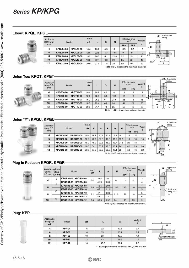
KPQL04-00
KPQL06-00
KPQL08-00
KPQL10-00
KPQL12-00
KPGL04-00
KPGL06-00
KPGL08-00
KPGL10-00
KPGL12-00
Elbow: KPQL, KPGL——————————————————————————————————–2-Applicabletubing
ML
LQ
M
øD
ø4.2
ø8
Note 1) øD indicates the maximum diameter.
Union Tee: KPQT, KPGT————————————————————————————————–
Union "Y": KPQU, KPGU—————————————————————————————————
Plug-in Reducer: KPQR, KPGR——————————————————————————————
Plug: KPP———————————————————————————————————————
Applicabletubing O.D.
mm
Weightg
Effective areamm2
øDModel L
TPH TPS
4
6
8
10
12
20.7
22.8
26.3
29.4
31.4
4.5
5.3
6
6.8
7.5
18
19.5
21.5
24
25
4
10
26
41
58
4
10
18
29
46
7
9
16
25
29
10.4
12.8
15.2
18.5
20.9
MQ
KPQT04-00
KPQT06-00
KPQT08-00
KPQT10-00
KPQT12-00
KPGT04-00
KPGT06-00
KPGT08-00
KPGT10-00
KPGT12-00
Note 1) øD indicates the maximum diameter.
ApplicabletubingO.D. mm
Applicablefitting
size ød
Weightg
Effective areamm2Note 1)
øDModel LTPH TPS
4
6
8
10
10.4
12.8
15.2
18.5
18
19.5
21.5
24
4
10
26
41
4
10
18
29
6
8
10
12
39.4
41.9
42.5
45
47
48
50.5
20.1
20.2
20.8
21.2
23.2
23.2
25.7
3
4
4
5
5
6
9
MA
KPQR04-06
KPQR04-08
KPQR06-08
KPQR06-10
KPQR08-10
KPQR08-12
KPQR10-12
KPGR04-06
KPGR04-08
KPGR06-08
KPGR06-10
KPGR08-10
KPGR08-12
KPGR10-12
Note 1) øD indicates the maximum diameter.
∗ The plug is commom for series KPQ, KPG and KP.
Applicablefitting size
ød
WeightgøDModel L
4
6
8
10
12
32
35
39
43
45.5
6
8
10
12
14
13.8
15.7
17.3
19.2
20.7
0.4
0.7
1.1
1.7
2.5
A
KPP-04
KPP-06
KPP-08
KPP-10
KPP-12
Applicabletubing O.D.
mm
Weightg
Effective areamm2
øDModel L1
TPH TPS
4
6
8
10
12
38.8
42.1
48.7
54
57.2
L2
20.6
22.8
27.5
30.7
32.9
10.4
12.8
15.2
18.5
20.9
9.7
11.7
13.7
16.1
18.1
4
10
26
41
58
4
10
18
29
46
7
10
17
26
32
10.4
12.8
15.2
18.5
20.9
Q
18
19.5
21.5
24
25
MP
KPQU04-00
KPQU06-00
KPQU08-00
KPQU10-00
KPQU12-00
KPGU04-00
KPGU06-00
KPGU08-00
KPGU10-00
KPGU12-00
Note 1) øD indicates the maximum diameter.
Applicable fitting size
ød
ød
øD
LA
3 Applicabletubing
M ML L
LQ
M
øD
ø4.2ø8
øD
øD
3-Applicabletubing
M
ML2
L1
øD
øDø
4.2ø8
Q
P
Applicabletubing
Applicablefitting size
ød
MAL
øD
ød
Note 1)
Note 1)
Note 1)
Series KP/KPG
15-5-16
Cou
rtes
y of
CM
A/F
lody
ne/H
ydra
dyne
▪ M
otio
n Con
trol
▪ H
ydra
ulic
▪ P
neum
atic
▪ E
lect
rica
l ▪ M
echa
nica
l ▪ (
800)
426
-548
0 ▪
ww
w.c
maf
h.co
m
Selection
Handling
Mounting
Installation of Threads
Series KP/KPQ/KPGSpecific Product Precautions 1Be sure to read before handling.
Caution Caution
Installation and Removal of Tubing
Caution
Caution
Caution
Installation of Threads
Caution
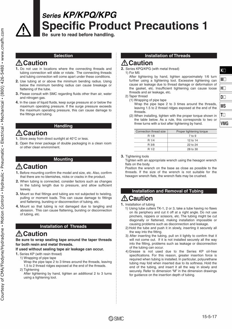
1. Do not use in locations where the connecting threads and tubing connection will slide or rotate. The connecting threads and tubing connection will come apart under these conditions.
2. Use tubing at or above the minimum bending radius. Using below the minimum bending radius can cause breakage or flattening of the tube.
3. Please consult with SMC regarding fluids other than air, water and nitrogen gas.
4. In the case of liquid fluids, keep surge pressure at or below the maximum operating pressure. If the surge pressure exceeds the maximum operating pressure, this can cause damage to the fittings and tubing.
1. Store away from direct sunlight at 40°C or less.2. Open the inner package of double packaging in a clean room
or other clean environment.
1. Before mounting confirm the model and size, etc. Also, confirm that there are no blemishes, nicks or cracks in the product.
2. When tubing is connected, consider factors such as changes in the tubing length due to pressure, and allow sufficient leeway.
3. Mount so that fittings and tubing are not subjected to twisting, pulling or moment loads. This can cause damage to fittings and flattening, bursting or disconnection of tubing, etc.
4. Mount so that tubing is not damaged due to tangling and abrasion. This can cause flattening, bursting or disconnection of tubing, etc.
Be sure to wrap sealing tape around the taper threads for both resin and metal threads.If used without sealing tape air leakage can occur.1. Series KP (with resin thread)
1) Wrapping of pipe tapeWrap the pipe tape 2 to 3 times around the threads, leaving 1.5 to 2 thread ridges exposed at the end of the threads.
2) TighteningAfter tightening by hand, tighten an additional 2 to 3 turns using a tightening tool.
2. Series KPQ/KPG (with metal thread)1) For M5
After tightening by hand, tighten approximately 1/6 turn further using a tightening tool. Excessive tightening can cause air leakage due to thread damage or deformation of the gasket, etc. Insufficient tightening can cause loose threads and air leakage, etc.
2) Taper thread(1) Wrapping of pipe tape
Wrap the pipe tape 2 to 3 times around the threads, leaving 1.5 to 2 thread ridges exposed at the end of the threads.
(2) When installing, tighten with the proper torque shown in the table below. As a rule, this corresponds to two or three turns with a tool after tightening by hand.
Connection thread size
R 1/8
R 1/4
R 3/8
R 1/2
Proper tightening torque
7 to 9
12 to 14
22 to 24
28 to 30
3. Tightening toolsTighten with an appropriate wrench using the hexagon wrench flats on the body.Position the wrench on the base as close as possible to the threads. If the size of the wrench is not suitable for the hexagon wrench flats, the wrench flats may be crushed.
1. Installation of tubing1) Using tube cutters TK-1, 2 or 3, take a tube having no flaws
on its periphery and cut it off at a right angle. Do not use pinchers, nippers or scissors, etc. The tubing might be cut diagonally or flattened, making installation impossible or causing problems such as disconnection and leakage.
2) Hold the tube and push it in slowly, inserting it securely all the way into the fitting.
3) After inserting the tubing, pull on it lightly to confirm that it will not come out. If it is not installed securely all the way into the fitting, problems such as leakage or disconnection of the tubing can occur.
4) Grease is not used due to the Series KP oil-free specifications. For this reason, greater insertion force is required when tubing is installed. In particular, polyurethane tubing may fold when inserted due to its softness. Hold the end of the tubing, and insert it all the way in slowly and securely. Refer to dimension “M” in the dimension drawings for guidance on the insertion depth of tubing.
15-5-17
K�
M�
H�
D�
MS
T�
VMG
Cou
rtes
y of
CM
A/F
lody
ne/H
ydra
dyne
▪ M
otio
n Con
trol
▪ H
ydra
ulic
▪ P
neum
atic
▪ E
lect
rica
l ▪ M
echa
nica
l ▪ (
800)
426
-548
0 ▪
ww
w.c
maf
h.co
m
Installation and Removal of Tubing
Operating Environment
Maintenance
Series KP/KPQ/KPGSpecific Product Precautions 2Be sure to read before handling.
Caution
Caution
Caution
Precaution on Use of Other Tubing Brands
Caution
Warning
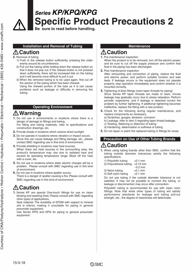
2. Removal of tubing1) Push in the release button sufficiently, pressing the collar
evenly around its circumference.2) Pull out the tubing while holding down the release button so
that it does not pop out. If the release button is not pressed down sufficiently, there will be increased bite on the tubing and it will become more difficult to pull it out.
3) When the removed tubing is to be used again, first cut off the section of the tubing which has been chewed.Using the chewed portion of the tube as it is can cause problems such as leakage or difficulty in removing the tubing.
1. Do not use in environments or locations where there is a danger of damage to fittings and tubing.For fitting and tubing materials, refer to specifications and construction drawings, etc.
2. Provide shade in locations which receive direct sunlight.3. Do not operate in locations where vibration or impact occurs.
Since this can cause leakage and fitting damage, etc., please contact SMC regarding use in this kind of environment.
4. Provide shielding in locations near heat sources.When there are heat sources in the surrounding area, the product’s temperature may rise due to radiated heat and exceed its operating temperature range. Block off the heat with a cover, etc.
5. Do not use in locations where static electric charges will be a problem. Please consult with SMC regarding use in this kind of environment.
6. Do not use in locations where spatter occurs.There is a danger of spatter causing a fire. Please consult with SMC regarding use in this kind of environment.
1. Series KP are special One-touch fittings for use on clean blowing and washing lines. Please consult with SMC regarding other types of applications.Seal material: The durability of EPDM with respect to mineral oils is inferior, making it unsuitable for piping in general pneumatic equipment.Use Series KPQ and KPG for piping to general pneumatic equipment.
1. Pre-maintenance inspectionWhen the product is to be removed, turn off the electric power, and be sure to cut off the supply pressure and confirm that fluid in the piping has been discharged.
2. Post maintenance inspectionAfter remounting and connection of piping, restore the fluid and electric power, and perform suitable function and leak tests. If leakage occurs or the equipment does not operate properly, stop operation immediately and confirm whether it is mounted correctly.
3. Tightening of blow fittings (resin taper threads for piping)Since Series KP taper threads are made of resin, minute leakage may gradually occur due to stress relaxation. Perform periodic inspections, and if leakage is detected correct the problem by further tightening. If additional tightening becomes ineffective, replace the fitting with a new product.
4. Check for the following during regular maintenance, and replace components as necessary.a) Scratches, gouges, abrasion, corrosionb) Leakage, refer to item 3 regarding taper thread leakage.c) Twisting, flattening or distortion of tubingd) Hardening, deterioration or softness of tubing
5. Do not repair or patch the replaced tubing or fittings for reuse.
1. When using tubing brands other than SMC, confirm that the tubing outside diameter tolerances satisfy the following specifications.1) Polyolefin tubing ±0.1 mm2) Polyurethane tubing +0.15 mm –0.2 mm3) Nylon tubing ±0.1 mm4) Soft nylon tubing ±0.1 mmDo not use tubing if the outside diameter tolerance is not satisfied. It may not be possible to connect the tubing, or leakage or disconnection may occur after connection.Polyolefin tubing is recommended for use with clean room fittings. Note that while other types of tubing will satisfy performance standards for leakage and tubing pull-out strength, etc., the degree of cleanliness will deteriorate.
15-5-18
Cou
rtes
y of
CM
A/F
lody
ne/H
ydra
dyne
▪ M
otio
n Con
trol
▪ H
ydra
ulic
▪ P
neum
atic
▪ E
lect
rica
l ▪ M
echa
nica
l ▪ (
800)
426
-548
0 ▪
ww
w.c
maf
h.co
m
Safety Instructions
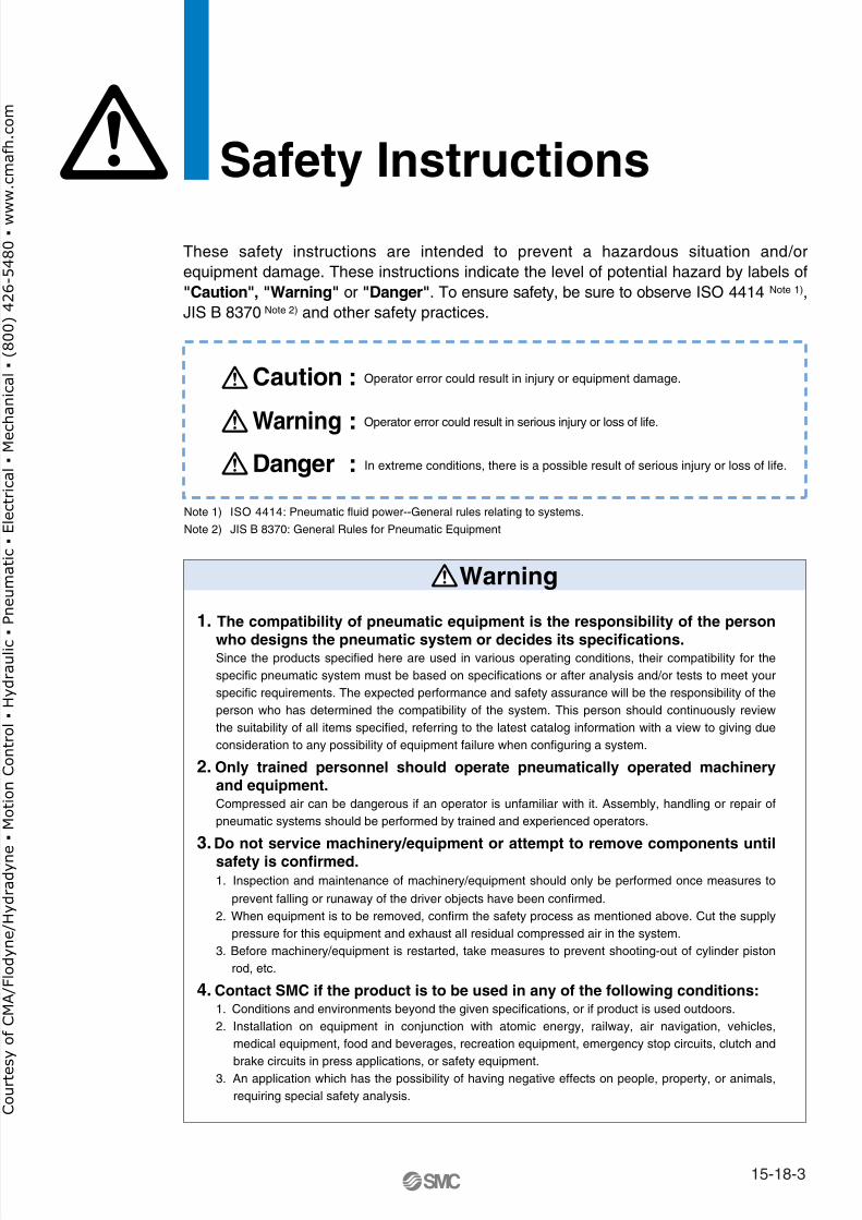
These safety instructions are intended to prevent a hazardous situation and/or equipment damage. These instructions indicate the level of potential hazard by labels of "Caution", "Warning" or "Danger". To ensure safety, be sure to observe ISO 4414 Note 1), JIS B 8370 Note 2) and other safety practices.
1. The compatibility of pneumatic equipment is the responsibility of the person who designs the pneumatic system or decides its specifications.Since the products specified here are used in various operating conditions, their compatibility for the specific pneumatic system must be based on specifications or after analysis and/or tests to meet your specific requirements. The expected performance and safety assurance will be the responsibility of the person who has determined the compatibility of the system. This person should continuously review the suitability of all items specified, referring to the latest catalog information with a view to giving due consideration to any possibility of equipment failure when configuring a system.
2. Only trained personnel should operate pneumatically operated machinery and equipment.Compressed air can be dangerous if an operator is unfamiliar with it. Assembly, handling or repair of pneumatic systems should be performed by trained and experienced operators.
3. Do not service machinery/equipment or attempt to remove components until safety is confirmed.1. Inspection and maintenance of machinery/equipment should only be performed once measures to
prevent falling or runaway of the driver objects have been confirmed. 2. When equipment is to be removed, confirm the safety process as mentioned above. Cut the supply
pressure for this equipment and exhaust all residual compressed air in the system.3. Before machinery/equipment is restarted, take measures to prevent shooting-out of cylinder piston
rod, etc.
4. Contact SMC if the product is to be used in any of the following conditions:1. Conditions and environments beyond the given specifications, or if product is used outdoors.2. Installation on equipment in conjunction with atomic energy, railway, air navigation, vehicles,
medical equipment, food and beverages, recreation equipment, emergency stop circuits, clutch and brake circuits in press applications, or safety equipment.
3. An application which has the possibility of having negative effects on people, property, or animals, requiring special safety analysis.
Note 1) ISO 4414: Pneumatic fluid power--General rules relating to systems.
Note 2) JIS B 8370: General Rules for Pneumatic Equipment
Warning
Caution : Operator error could result in injury or equipment damage.
Warning : Operator error could result in serious injury or loss of life.
Danger : In extreme conditions, there is a possible result of serious injury or loss of life.
15-18-3
Cou
rtes
y of
CM
A/F
lody
ne/H
ydra
dyne
▪ M
otio
n Con
trol
▪ H
ydra
ulic
▪ P
neum
atic
▪ E
lect
rica
l ▪ M
echa
nica
l ▪ (
800)
426
-548
0 ▪
ww
w.c
maf
h.co
m
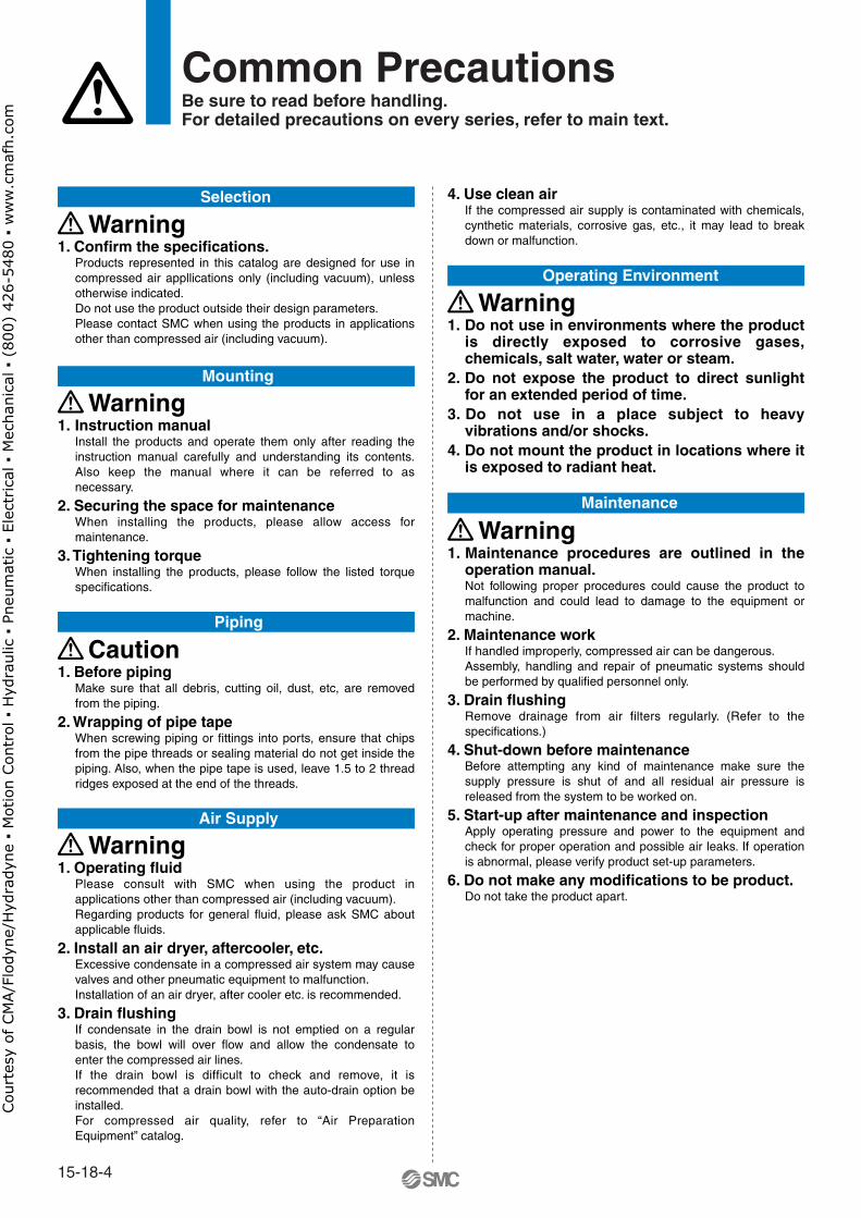
1. Confirm the specifications.Products represented in this catalog are designed for use in compressed air appllications only (including vacuum), unless otherwise indicated.Do not use the product outside their design parameters.Please contact SMC when using the products in applications other than compressed air (including vacuum).
4. Use clean airIf the compressed air supply is contaminated with chemicals, cynthetic materials, corrosive gas, etc., it may lead to break down or malfunction.
Selection
Mounting
Piping
Air Supply
Maintenance
Operating Environment
Warning
1. Instruction manualInstall the products and operate them only after reading the instruction manual carefully and understanding its contents. Also keep the manual where it can be referred to as necessary.
2. Securing the space for maintenanceWhen installing the products, please allow access for maintenance.
3. Tightening torqueWhen installing the products, please follow the listed torque specifications.
Warning
1. Do not use in environments where the product is directly exposed to corrosive gases, chemicals, salt water, water or steam.
2. Do not expose the product to direct sunlight for an extended period of time.
3. Do not use in a place subject to heavy vibrations and/or shocks.
4. Do not mount the product in locations where it is exposed to radiant heat.
Warning
1. Maintenance procedures are outlined in the operation manual.Not following proper procedures could cause the product to malfunction and could lead to damage to the equipment or machine.
2. Maintenance workIf handled improperly, compressed air can be dangerous.Assembly, handling and repair of pneumatic systems should be performed by qualified personnel only.
3. Drain flushingRemove drainage from air filters regularly. (Refer to the specifications.)
4. Shut-down before maintenanceBefore attempting any kind of maintenance make sure the supply pressure is shut of and all residual air pressure is released from the system to be worked on.
5. Start-up after maintenance and inspectionApply operating pressure and power to the equipment and check for proper operation and possible air leaks. If operation is abnormal, please verify product set-up parameters.
6. Do not make any modifications to be product.Do not take the product apart.
Warning
1. Before pipingMake sure that all debris, cutting oil, dust, etc, are removed from the piping.
2. Wrapping of pipe tapeWhen screwing piping or fittings into ports, ensure that chips from the pipe threads or sealing material do not get inside the piping. Also, when the pipe tape is used, leave 1.5 to 2 thread ridges exposed at the end of the threads.
Caution
1. Operating fluidPlease consult with SMC when using the product in applications other than compressed air (including vacuum).Regarding products for general fluid, please ask SMC about applicable fluids.
2. Install an air dryer, aftercooler, etc.Excessive condensate in a compressed air system may cause valves and other pneumatic equipment to malfunction.Installation of an air dryer, after cooler etc. is recommended.
3. Drain flushingIf condensate in the drain bowl is not emptied on a regular basis, the bowl will over flow and allow the condensate to enter the compressed air lines.If the drain bowl is difficult to check and remove, it is recommended that a drain bowl with the auto-drain option be installed.For compressed air quality, refer to “Air Preparation Equipment” catalog.
Warning
Common PrecautionsBe sure to read before handling.For detailed precautions on every series, refer to main text.
15-18-4
Cou
rtes
y of
CM
A/F
lody
ne/H
ydra
dyne
▪ M
otio
n Con
trol
▪ H
ydra
ulic
▪ P
neum
atic
▪ E
lect
rica
l ▪ M
echa
nica
l ▪ (
800)
426
-548
0 ▪
ww
w.c
maf
h.co
m
Quality Assurance Information(ISO 9001, ISO 14001)
Reliable quality of products in the global market
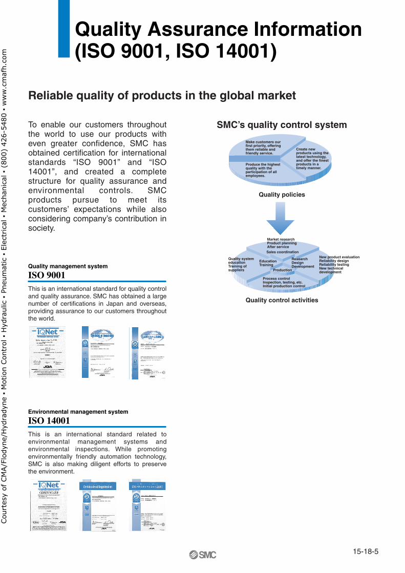
To enable our customers throughout the world to use our products with even greater confidence, SMC has obtained certification for international standards “ISO 9001” and “ISO 14001”, and created a complete structure for quality assurance and environmental controls. SMC products pursue to meet its customers’ expectations while also considering company’s contribution in society.
This is an international standard for quality control and quality assurance. SMC has obtained a large number of certifications in Japan and overseas, providing assurance to our customers throughout the world.
Quality management system
ISO 9001
This is an international standard related to environmental management systems and environmental inspections. While promoting environmentally friendly automation technology, SMC is also making diligent efforts to preserve the environment.
Environmental management system
ISO 14001
Sales coordination
Production
Make customers our first priority, offering them reliable and friendly service.
Market researchProduct planningAfter service
Process controlInspection, testing, etc.Initial production control
Quality system educationTraining of suppliers
New product evaluationReliability designReliability testingNew technical development
EducationTraining
ResearchDesignDevelopment
Produce the highest quality with the participation of all employees.
Create new products using the latest technology, and offer the finest products in a timely manner.
SMC’s quality control system
Quality policies
Quality control activities
15-18-5
Cou
rtes
y of
CM
A/F
lody
ne/H
ydra
dyne
▪ M
otio
n Con
trol
▪ H
ydra
ulic
▪ P
neum
atic
▪ E
lect
rica
l ▪ M
echa
nica
l ▪ (
800)
426
-548
0 ▪
ww
w.c
maf
h.co
m
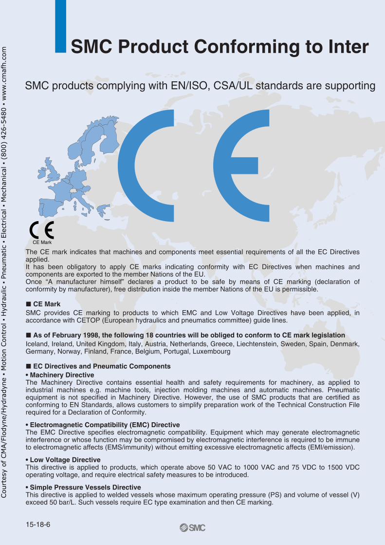
CE Mark
SMC Product Conforming to Inter
SMC products complying with EN/ISO, CSA/UL standards are supporting
The CE mark indicates that machines and components meet essential requirements of all the EC Directives applied.It has been obligatory to apply CE marks indicating conformity with EC Directives when machines and components are exported to the member Nations of the EU. Once “A manufacturer himself” declares a product to be safe by means of CE marking (declaration of conformity by manufacturer), free distribution inside the member Nations of the EU is permissible.
� CE MarkSMC provides CE marking to products to which EMC and Low Voltage Directives have been applied, in accordance with CETOP (European hydraulics and pneumatics committee) guide lines.
� As of February 1998, the following 18 countries will be obliged to conform to CE mark legislationIceland, Ireland, United Kingdom, Italy, Austria, Netherlands, Greece, Liechtenstein, Sweden, Spain, Denmark, Germany, Norway, Finland, France, Belgium, Portugal, Luxembourg
� EC Directives and Pneumatic Components• Machinery DirectiveThe Machinery Directive contains essential health and safety requirements for machinery, as applied to industrial machines e.g. machine tools, injection molding machines and automatic machines. Pneumatic equipment is not specified in Machinery Directive. However, the use of SMC products that are certified as conforming to EN Standards, allows customers to simplify preparation work of the Technical Construction File required for a Declaration of Conformity.
• Electromagnetic Compatibility (EMC) DirectiveThe EMC Directive specifies electromagnetic compatibility. Equipment which may generate electromagnetic interference or whose function may be compromised by electromagnetic interference is required to be immune to electromagnetic affects (EMS/immunity) without emitting excessive electromagnetic affects (EMI/emission).
• Low Voltage DirectiveThis directive is applied to products, which operate above 50 VAC to 1000 VAC and 75 VDC to 1500 VDC operating voltage, and require electrical safety measures to be introduced.
• Simple Pressure Vessels DirectiveThis directive is applied to welded vessels whose maximum operating pressure (PS) and volume of vessel (V) exceed 50 bar/L. Such vessels require EC type examination and then CE marking.
15-18-6
Cou
rtes
y of
CM
A/F
lody
ne/H
ydra
dyne
▪ M
otio
n Con
trol
▪ H
ydra
ulic
▪ P
neum
atic
▪ E
lect
rica
l ▪ M
echa
nica
l ▪ (
800)
426
-548
0 ▪
ww
w.c
maf
h.co
m
http://www.smcworld.com
you to comply with EC directives and CSA/UL standards.
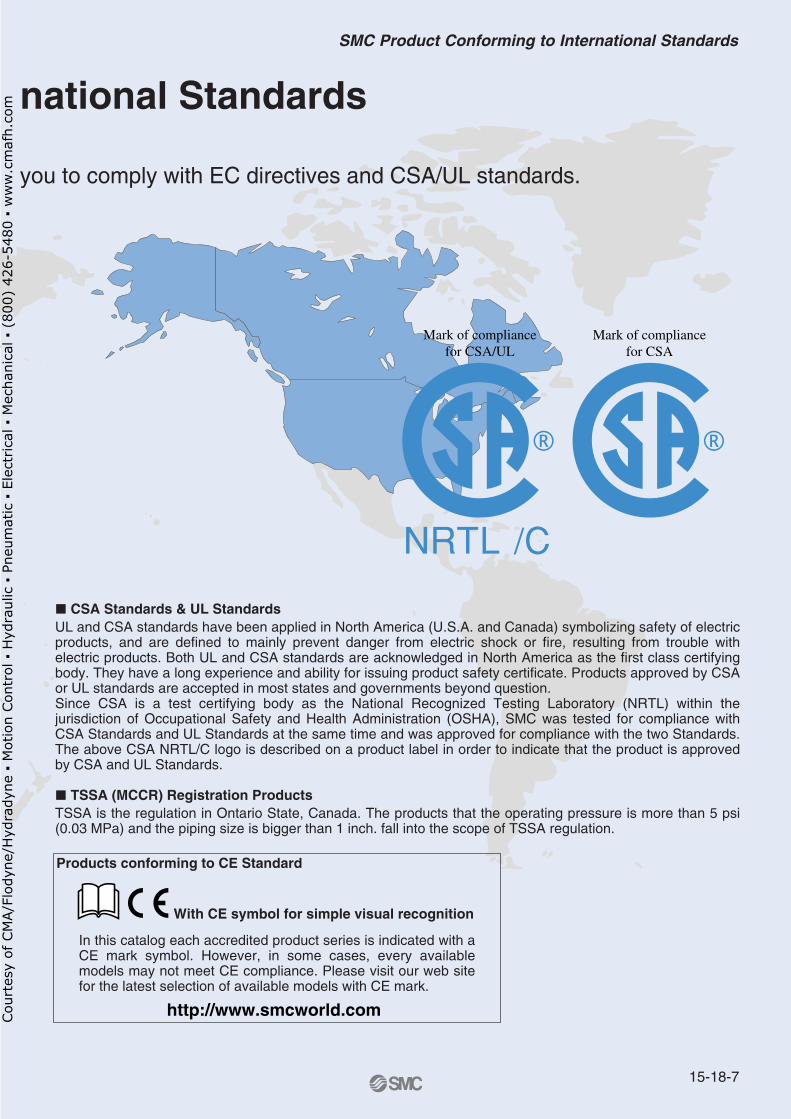
� CSA Standards & UL StandardsUL and CSA standards have been applied in North America (U.S.A. and Canada) symbolizing safety of electric products, and are defined to mainly prevent danger from electric shock or fire, resulting from trouble with electric products. Both UL and CSA standards are acknowledged in North America as the first class certifying body. They have a long experience and ability for issuing product safety certificate. Products approved by CSA or UL standards are accepted in most states and governments beyond question.Since CSA is a test certifying body as the National Recognized Testing Laboratory (NRTL) within the jurisdiction of Occupational Safety and Health Administration (OSHA), SMC was tested for compliance with CSA Standards and UL Standards at the same time and was approved for compliance with the two Standards. The above CSA NRTL/C logo is described on a product label in order to indicate that the product is approved by CSA and UL Standards.
� TSSA (MCCR) Registration Products TSSA is the regulation in Ontario State, Canada. The products that the operating pressure is more than 5 psi (0.03 MPa) and the piping size is bigger than 1 inch. fall into the scope of TSSA regulation.
Products conforming to CE Standard
With CE symbol for simple visual recognition
In this catalog each accredited product series is indicated with a CE mark symbol. However, in some cases, every available models may not meet CE compliance. Please visit our web site for the latest selection of available models with CE mark.
Mark of compliance for CSA
Mark of compliance for CSA/UL
national Standards
15-18-7
SMC Product Conforming to International Standards
Cou
rtes
y of
CM
A/F
lody
ne/H
ydra
dyne
▪ M
otio
n Con
trol
▪ H
ydra
ulic
▪ P
neum
atic
▪ E
lect
rica
l ▪ M
echa
nica
l ▪ (
800)
426
-548
0 ▪
ww
w.c
maf
h.co
m
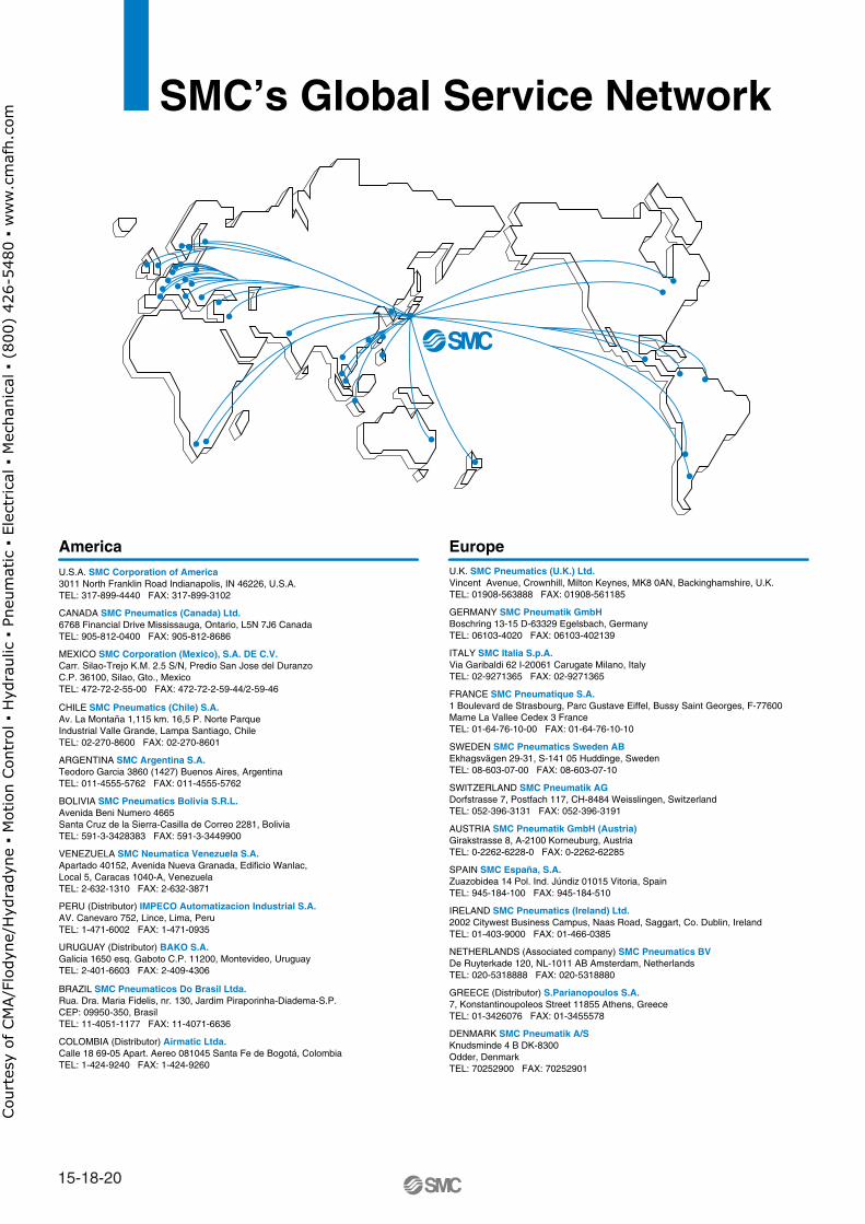
America EuropeU.S.A. SMC Corporation of America3011 North Franklin Road Indianapolis, IN 46226, U.S.A.TEL: 317-899-4440 FAX: 317-899-3102
CANADA SMC Pneumatics (Canada) Ltd.6768 Financial Drive Mississauga, Ontario, L5N 7J6 CanadaTEL: 905-812-0400 FAX: 905-812-8686
MEXICO SMC Corporation (Mexico), S.A. DE C.V.Carr. Silao-Trejo K.M. 2.5 S/N, Predio San Jose del DuranzoC.P. 36100, Silao, Gto., MexicoTEL: 472-72-2-55-00 FAX: 472-72-2-59-44/2-59-46
CHILE SMC Pneumatics (Chile) S.A.Av. La Montaña 1,115 km. 16,5 P. Norte ParqueIndustrial Valle Grande, Lampa Santiago, ChileTEL: 02-270-8600 FAX: 02-270-8601
ARGENTINA SMC Argentina S.A.Teodoro Garcia 3860 (1427) Buenos Aires, ArgentinaTEL: 011-4555-5762 FAX: 011-4555-5762
BOLIVIA SMC Pneumatics Bolivia S.R.L.Avenida Beni Numero 4665Santa Cruz de la Sierra-Casilla de Correo 2281, BoliviaTEL: 591-3-3428383 FAX: 591-3-3449900
VENEZUELA SMC Neumatica Venezuela S.A. Apartado 40152, Avenida Nueva Granada, Edificio Wanlac,Local 5, Caracas 1040-A, VenezuelaTEL: 2-632-1310 FAX: 2-632-3871
PERU (Distributor) IMPECO Automatizacion Industrial S.A. AV. Canevaro 752, Lince, Lima, PeruTEL: 1-471-6002 FAX: 1-471-0935
URUGUAY (Distributor) BAKO S.A. Galicia 1650 esq. Gaboto C.P. 11200, Montevideo, UruguayTEL: 2-401-6603 FAX: 2-409-4306
BRAZIL SMC Pneumaticos Do Brasil Ltda.Rua. Dra. Maria Fidelis, nr. 130, Jardim Piraporinha-Diadema-S.P. CEP: 09950-350, BrasilTEL: 11-4051-1177 FAX: 11-4071-6636
COLOMBIA (Distributor) Airmatic Ltda.Calle 18 69-05 Apart. Aereo 081045 Santa Fe de Bogotá, ColombiaTEL: 1-424-9240 FAX: 1-424-9260
U.K. SMC Pneumatics (U.K.) Ltd.Vincent Avenue, Crownhill, Milton Keynes, MK8 0AN, Backinghamshire, U.K.TEL: 01908-563888 FAX: 01908-561185
GERMANY SMC Pneumatik GmbHBoschring 13-15 D-63329 Egelsbach, GermanyTEL: 06103-4020 FAX: 06103-402139
ITALY SMC Italia S.p.A.Via Garibaldi 62 I-20061 Carugate Milano, ItalyTEL: 02-9271365 FAX: 02-9271365
FRANCE SMC Pneumatique S.A.1 Boulevard de Strasbourg, Parc Gustave Eiffel, Bussy Saint Georges, F-77600Marne La Vallee Cedex 3 FranceTEL: 01-64-76-10-00 FAX: 01-64-76-10-10
SWEDEN SMC Pneumatics Sweden ABEkhagsvägen 29-31, S-141 05 Huddinge, SwedenTEL: 08-603-07-00 FAX: 08-603-07-10
SWITZERLAND SMC Pneumatik AGDorfstrasse 7, Postfach 117, CH-8484 Weisslingen, SwitzerlandTEL: 052-396-3131 FAX: 052-396-3191
AUSTRIA SMC Pneumatik GmbH (Austria)Girakstrasse 8, A-2100 Korneuburg, AustriaTEL: 0-2262-6228-0 FAX: 0-2262-62285
SPAIN SMC España, S.A.Zuazobidea 14 Pol. Ind. Júndiz 01015 Vitoria, SpainTEL: 945-184-100 FAX: 945-184-510
IRELAND SMC Pneumatics (Ireland) Ltd.2002 Citywest Business Campus, Naas Road, Saggart, Co. Dublin, IrelandTEL: 01-403-9000 FAX: 01-466-0385
NETHERLANDS (Associated company) SMC Pneumatics BVDe Ruyterkade 120, NL-1011 AB Amsterdam, NetherlandsTEL: 020-5318888 FAX: 020-5318880
GREECE (Distributor) S.Parianopoulos S.A.7, Konstantinoupoleos Street 11855 Athens, GreeceTEL: 01-3426076 FAX: 01-3455578
DENMARK SMC Pneumatik A/SKnudsminde 4 B DK-8300Odder, DenmarkTEL: 70252900 FAX: 70252901
SMC’s Global Service Network
15-18-20
Cou
rtes
y of
CM
A/F
lody
ne/H
ydra
dyne
▪ M
otio
n Con
trol
▪ H
ydra
ulic
▪ P
neum
atic
▪ E
lect
rica
l ▪ M
echa
nica
l ▪ (
800)
426
-548
0 ▪
ww
w.c
maf
h.co
m
EuropeFINLAND SMC Pneumatics Finland OYPL72, Tiistinniityntie 4, SF-02231 ESP00, FinlandTEL: 09-8595-80 FAX: 09-8595-8595
NORWAY SMC Pneumatics Norway A/SVollsveien 13C, Granfoss Næringspark N-1366 LYSAKER, NorwayTEL: 67-12-90-20 FAX: 67-12-90-21
BELGIUM (Distributor) SMC Pneumatics N.V./S.A.Nijverheidsstraat 20 B-2160 Wommelgem BelguimTEL: 03-355-1464 FAX: 03-355-1466
POLAND SMC Industrial Automation Polska Sp.z.o.o.ul. Konstruktorska 11A, PL-02-673 Warszawa, PolandTEL: 022-548-5085 FAX: 022-548-5087
TURKEY (Distributor) Entek Pnömatik San.ve Tic. Ltd. StiPerpa Tic. Merkezi Kat:11 No.1625 80270 Okmeydani Istanbul, TürkiyeTEL: 0212-221-1512 FAX: 0212-221-1519
RUSSIA SMC Pneumatik LLC.36/40 Sredny prospect V.O. St. Petersburg 199004, RussiaTEL: 812-118-5445 FAX: 812-118-5449
CZECH SMC Industrial Automation CZ s.r.o.Hudcova 78a, CZ-61200 Brno, Czech RepublicTEL: 05-4121-8034 FAX: 05-4121-8034
HUNGARY SMC Hungary Ipari Automatizálási kft.Budafoki ut 107-113 1117 BudapestTEL: 01-371-1343 FAX: 01-371-1344
ROMANIA SMC Romania S.r.l.Str. Frunzei, Nr. 29, Sector 2, Bucharest, RomaniaTEL: 01-3205111 FAX: 01-3261489
SLOVAKIA SMC Priemyselná automatizáciá, s.r.oNova 3, SK-83103 BratislavaTEL: 02-4445-6725 FAX: 02-4445-6028
SLOVENIA SMC Industrijska Avtomatilca d.o.o.Grajski trg 15, SLO- 8360 Zuzemberk, SloveniaTEL: 07388-5240 FAX: 07388-5249
SOUTH AFRICA (Distributor) Hyflo Southern Africa (Pty.) Ltd.P.O.Box 240 Paardeneiland 7420 South AfricaTEL: 021-511-7021 FAX: 021-511-4456
EGYPT (Distributor) Saadani Trading & Ind. Services15 Sebaai Street, Miami 21411 Alexandria, EgyptTEL: 3-548-50-34 FAX: 3-548-50-34
Oceania/AsiaAUSTRALIA SMC Pneumatics (Australia) Pty.Ltd.14-18 Hudson Avenue Castle Hill NSW 2154, AustraliaTEL: 02-9354-8222 FAX: 02-9894-5719
NEW ZEALAND SMC Pneumatics (New Zealand) Ltd.8C Sylvia Park Road Mt.Wellington Auckland, New ZealandTEL: 09-573-7007 FAX: 09-573-7002
TAIWAN SMC Pneumatics (Taiwan) Co.,Ltd.17, Lane 205, Nansan Rd., Sec.2, Luzhu-Hsiang, Taoyuan-Hsien, TAIWANTEL: 03-322-3443 FAX: 03-322-3387
HONG KONG SMC Pneumatics (Hong Kong) Ltd. 29/F, Clifford Centre, 778-784 Cheung, Sha Wan Road, Lai Chi Kok, Kowloon,Hong KongTEL: 2744-0121 FAX: 2785-1314
SINGAPORE SMC Pneumatics (S.E.A.) Pte. Ltd.89 Tuas Avenue 1, Jurong Singapore 639520TEL: 6861-0888 FAX: 6861-1889
PHILIPPINES SHOKETSU SMC CorporationUnit 201 Common Goal Tower, Madrigal Business Park,Ayala Alabang Muntinlupa, PhilippinesTEL: 02-8090565 FAX: 02-8090586
MALAYSIA SMC Pneumatics (S.E.A.) Sdn. Bhd.Lot 36 Jalan Delima1/1, Subang Hi-Tech Industrial Park, Batu 3 40000 Shah AlamSelangor, MalaysiaTEL: 03-56350590 FAX: 03-56350602
SOUTH KOREA SMC Pneumatics Korea Co., Ltd.Woolim e-BIZ Center (Room 1008), 170-5, Guro-Dong, Guro-Gu,Seoul, 152-050, South KoreaTEL: 02-3219-0700 FAX: 02-3219-0702
CHINA SMC (China) Co., Ltd.7 Wan Yuan St. Beijing Economic & Technological Development Zone 100176, China TEL: 010-67882111 FAX: 010-67881837
THAILAND SMC Thailand Ltd.134/6 Moo 5, Tiwanon Road, Bangkadi, Amphur Muang, Patumthani 12000, ThailandTEL: 02-963-7099 FAX: 02-501-2937
INDIA SMC Pneumatics (India) Pvt. Ltd.D-107 to 112, Phase-2, Extension, Noida, Dist. Gautaim Budh Nagar,U.P. 201 305, IndiaTEL: (0120)-4568730 FAX: 0120-4568933
INDONESIA (Distributor) P.T. Riyadi Putera MakmurJalan Hayam Wuruk Komplek Glodok Jaya No. 27-28 Jakarta 11180 IndonesiaTEL: 021-625 5548 FAX: 021-625 5888
PAKISTAN (Distributor) Jubilee CorporationFirst Floor Mercantile Centre, Newton Road Near Boulton Market P.O. Box 6165 Karachi 74000 PakistanTEL: 021-243-9070/8449 FAX: 021-241-4589
ISRAEL (Distributor) Baccara Automation ControlKvutzat Geva 18915 IsraelTEL: 04-653-5960 FAX: 04-653-1445
SAUDI ARABIA (Distributor) Assaggaff Trading Est.P.O. Box 3385 Al-Amir Majed Street, Jeddah-21471, Saudi ArabiaTEL: 02-6761574 FAX: 02-6708173
15-18-21
SMC’s Global Service Network
Cou
rtes
y of
CM
A/F
lody
ne/H
ydra
dyne
▪ M
otio
n Con
trol
▪ H
ydra
ulic
▪ P
neum
atic
▪ E
lect
rica
l ▪ M
echa
nica
l ▪ (
800)
426
-548
0 ▪
ww
w.c
maf
h.co
m
Related Documents