988-00007 Gamry Instruments, Inc. © 2011 1 Series G 300 ™ and Series G 750 ™ Potentiostat/Galvanostat/ZRA Quick-Start Guide Installation Sequence is Important for Success The Gamry potentiostats are plug-and-play devices. Therefore, setup is easiest if you use the sequence below, installing the software before the hardware. Setup of the Series G Potentiostat takes about 15 minutes. 1) Install the Gamry Framework™ software on the PC. In the process, you will also install the Gamry software packages you have purchased, such as DC105 DC Corrosion Techniques and EIS300 Electrochemical Impedance Spectroscopy Software. See page 5. 2) Install the Series G 300™ or Series G 750™ Potentiostat in the PC. The operating system and Gamry software will recognize the Potentiostat automatically when you restart the PC. See page 6. 3) Complete software setup. You will be prompted through this task when you restart the PC after installing the software and hardware. See page 8. 4) Calibrate the potentiostat using the Universal Dummy Cell 4 included in your Gamry shipment. See page 9. 5) Do optional tests using the Universal Dummy Cell 4. See page 13. When the first four tasks have been completed, the Series G potentiostat is ready to use. You can run experiments and gather data with your Gamry software packages. Instructions for running experiments are on page 15. This guide also includes instructions for installing Gamry Echem Analyst. Gamry Echem Analyst makes it easy for you to view and manipulate experiment data. Table of Contents Installation Sequence is Important for Success ........... 1 Table of Contents ......................................................... 1 Cautions ....................................................................... 1 Computer Requirements .............................................. 2 Compatibility Between Software Versions and Potentiostats................................................................. 2 Authorization Codes and Serial Numbers .................... 2 Preparations ................................................................. 3 Installation of Gamry Framework, Echem Analyst and Software Packages ...................................................... 5 Installing Potentiostat and Controller Boards ............... 6 Completing Software Setup ......................................... 8 Calibration .................................................................... 9 Sources of More Information ...................................... 14 Contacting Gamry ...................................................... 14 Reference Information................................................ 15 Procedure for Experiments .................................... 15 Grounding .............................................................. 15 Gamry File Types................................................... 15 General Instructions for Connecting Leads ........... 15 Cautions To avoid damaging electronic components on the Gamry Potentiostat and controller boards, and in your PC, observe standard precautions against static damage. Ground yourself before touching the potentiostat boards or components inside your PC. Handle printed circuit boards only by their edges. (Fingerprints on the boards can be harmful.)

Welcome message from author
This document is posted to help you gain knowledge. Please leave a comment to let me know what you think about it! Share it to your friends and learn new things together.
Transcript

988-00007 Gamry Instruments, Inc. © 2011 1
Series G 300™ and Series G 750™ Potentiostat/Galvanostat/ZRA
Quick-Start Guide
Installation Sequence is Important for Success
The Gamry potentiostats are plug-and-play devices. Therefore, setup is easiest if you use the sequence below, installing the software before the hardware. Setup of the Series G Potentiostat takes about 15 minutes.
1) Install the Gamry Framework™ software on the PC. In the process, you will also install the Gamry software packages you have purchased, such as DC105 DC Corrosion Techniques and EIS300 Electrochemical Impedance Spectroscopy Software. See page 5.
2) Install the Series G 300™ or Series G 750™ Potentiostat in the PC. The operating system and Gamry software will recognize the Potentiostat automatically when you restart the PC. See page 6.
3) Complete software setup. You will be prompted through this task when you restart the PC after installing the software and hardware. See page 8.
4) Calibrate the potentiostat using the Universal Dummy Cell 4 included in your Gamry shipment. See page 9.
5) Do optional tests using the Universal Dummy
Cell 4. See page 13.
When the first four tasks have been completed, the Series G potentiostat is ready to use.
You can run experiments and gather data with your Gamry software packages. Instructions for running experiments are on page 15.
This guide also includes instructions for installing
Gamry Echem Analyst. Gamry Echem Analyst makes it easy for you to view and manipulate experiment data.
Table of Contents
Installation Sequence is Important for Success ........... 1 Table of Contents ......................................................... 1 Cautions ....................................................................... 1 Computer Requirements .............................................. 2 Compatibility Between Software Versions and Potentiostats................................................................. 2 Authorization Codes and Serial Numbers.................... 2 Preparations ................................................................. 3 Installation of Gamry Framework, Echem Analyst and Software Packages ...................................................... 5 Installing Potentiostat and Controller Boards............... 6 Completing Software Setup ......................................... 8 Calibration .................................................................... 9 Sources of More Information...................................... 14 Contacting Gamry ...................................................... 14 Reference Information................................................ 15
Procedure for Experiments .................................... 15 Grounding .............................................................. 15 Gamry File Types................................................... 15 General Instructions for Connecting Leads ........... 15
Cautions
To avoid damaging electronic components on the Gamry Potentiostat and controller boards, and in your PC, observe standard precautions against static damage.
Ground yourself before touching the potentiostat boards or components inside your PC.
Handle printed circuit boards only by their edges. (Fingerprints on the boards can be harmful.)

Series G 300™ and Series G 750™ Potentiostat/Galvanostat/ZRA Quick-Start Guide
2 Gamry Instruments, Inc. © 2011 988-00007
Installed Potentiostat with Cell Cable Attached
Computer Requirements
You must install the Gamry Potentiostat board (with controller board)
and the Gamry Framework Version 5 software in the same
computer. This PC must meet the requirements below.
Hardware
• A Windows-compatible personal computer
• Two unobstructed, full height (11 cm, 4.3 in) PCI expansion
slots for the Series G potentiostat board and controller board;
each slot must be capable of accepting a board that is 26 cm
(10 in) long
• Up to 50 watts of power supply capacity for each pair of
Series G potentiostat and controller boards (in addition to the
power normally drawn by your computer and its usual
peripherals)
• One unused disk drive power connector for each potentiostat
and controller board pair
Software
• Microsoft® Windows
® 7, Vista, or Windows
® XP SP2
• At least 512 MB of memory (1 GB recommended) and
200 MB of available hard disk space
• Web browser, such as Microsoft® Internet Explorer
Compatibility Between Software Versions and Potentiostats
Gamry Version 5 software is compatible with all Gamry Potentiostats
in the current generation.
• The Reference Family and Series G Potentiostats work with
Gamry Version 5 software only.
• The PCI4/300™ and PCI4/750™ Potentiostats, and the FAS2™
Femtostat work with either Version 5 or Version 4 of the Gamry
software.
Earlier potentiostat generations (PC4, FAS1, and PC3 Potentiostats)
are not compatible with Version 5 Gamry software.
Authorization Codes and Serial Numbers
A sticker on the software license envelope contains the ten-digit
Authorization Codes needed to install (or upgrade) the Gamry
software.
Before you can use a Gamry software package, you must enter the
Authorization Code to access the software. Authorization Codes are
tied to the five-digit serial number of the controller board associated
with a specific potentiostat. The serial number of each potentiostat
board and controller board is on a sticker on the end plate of the
board.
If you bought more than one potentiostat (to be installed in more than
one PC), each potentiostat will be packed in a separate carton with
its own controller board and software Authorization Codes. Keep the
contents of each carton together. Authorization Codes are valid only
for the potentiostat board and controller board shipped with the
codes.
Series G 300™ and Series G 750™ Potentiostat/Galvanostat/ZRA Quick-Start Guide
988-00007 Gamry Instruments, Inc. © 2011 3
Preparations
The pictures below and on the following page identify the items in a
typical shipment from Gamry.
Standard cables are pictured on page 4. If you ordered special
cables, those may also be included in the potentiostat shipment.
To prepare to install your new Potentiostat:
1) Unpack the shipment carefully.
Do not discard the software license shipped with the CD.
Authorization Codes that you will need to install the software
are on the license sheet. (See Authorization Codes and Serial
Numbers on page 2.)
The potentiostat and controller printed circuit boards are
shipped in anti-static bags. Leave the circuit boards in these
bags until you install the boards.
Save the anti-static bags. If you return the boards to Gamry,
put the boards in the bags before packing the boards for
shipment.
2) If custom scripts (or standard scripts with modifications) are
already on this PC, back up the scripts.
3) If Version 4 of Gamry Framework and associated software
packages are on the PC, you will uninstall Version 4 during the
installation process.
The contents of your “My Gamry Data” folder will not be
removed when you upgrade. The data in the folder will not be
overwritten when you install the new version of the Gamry
software. Scripts in the “Scripts” folder will be overwritten if they
have the same name as Version 5 scripts.
4) No tools are needed to install the potentiostat. However, a
Phillips screwdriver may be needed to open the computer case
and to anchor the boards in the PC.
If you need a screwdriver for these tasks, find one now.
Potentiostat Board
Control Board

Series G 300™ and Series G 750™ Potentiostat/Galvanostat/ZRA Quick-Start Guide
4 Gamry Instruments, Inc. © 2011 988-00007
Mouse Pad with Color Coding for Leads
Cell Cable (black with color-coded clips on leads), Ribbon Cable, CD, Universal Dummy Cell 4, Power Extension Cable and Power Y Cable (multi-colored wires with white connectors)
Series G 300™ and Series G 750™ Potentiostat/Galvanostat/ZRA Quick-Start Guide
988-00007 Gamry Instruments, Inc. © 2011 5
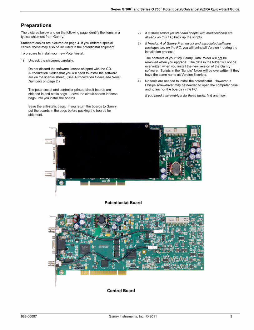
Installation of Gamry Framework and Software Packages
Purpose of Gamry Framework Software
Gamry Framework software serves as the user interface for
the Gamry software packages used to acquire experiment
data. Examples of Gamry software packages are DC105 DC
Corrosion Techniques and EIS300 Electrochemical
Impedance Spectroscopy Software.
The Framework software is also used to calibrate the
potentiostat. Therefore, install the Framework software,
even if you do not plan to use any of the Gamry software
packages. If you bought only Gamry ESA410, VFP600, or
Electrochemistry Toolkit software (which have their own
graphical user interfaces), install the Framework software for
calibration.
All the Gamry software is provided on a single CD.
Starting the Installation Process
To start the installation process:
5) Put the Gamry software CD into the drive. The Gamry
setup screen will be displayed automatically, if auto-run
is enabled.
6) If the Gamry software setup page is not displayed
automatically, select Start > Run. In the Run window,
type D:\autorun in the Open field, and then click on
OK. (Substitute the letter of your CD drive for D.)
7) Click on the Install Software button to start the
Installation Wizard. The Wizard will step you through the
installation process. Most of the steps will be familiar;
they are common to many other software installation
procedures. The next subsections provide instructions
for two Gamry-specific screens.
Selecting Software Packages to Install
When you get to the Select Features screen, check all the
software packages (applications) that you want to install.
Installation of Gamry Echem Analyst is Recommended
Use Gamry Echem Analyst software to manipulate and
interpret data gathered with experiments run with Gamry
software packages (through the Gamry Framework user
interface).
Echem Analyst can be installed on the same PC as the one
containing the potentiostat or on a different PC. You are
licensed to install Echem Analyst on multiple computers.
You can install software you have not yet purchased, as well
as the software packages you did buy. After installation, you
will be able to see the standard experiments available in all
installed applications. However, you will not be able to use
unlicensed applications. Your Gamry shipment included
Authorization Codes for the software packages you bought.
You will enter those codes later in the installation process.
The installation routine assumes that at least one Gamry
Potentiostat will be installed in this PC. Therefore, no
potentiostats are listed on the Select Features screen. If you
have ordered additional Gamry hardware that is on the list,
check the name of the hardware now.
Tip: If you like what you see and decide to buy more Gamry software packages, contact your Gamry sales representative. When you buy an additional software package you will get a new Authorization Code. If you have already installed the software package, you will be able to enter the Authorization Code without repeating the installation process. The tip on page 9 explains how to enter an additional Authorization Code.

Series G 300™ and Series G 750™ Potentiostat/Galvanostat/ZRA Quick-Start Guide
6 Gamry Instruments, Inc. © 2011 988-00007
Specifying Line Frequency
On the Additional Information screen, be sure to select the
appropriate AC line frequency for your location. In the United
States, select 60 Hertz. In Europe, select 50 Hertz.
Completing Installation
To complete software installation and get ready for hardware
installation:
1) Continue the installation process via the InstallShield
Wizard.
2) Read the Readme file at the end of the installation
process. In addition to release history information and
notes on software fixes, this file contains any late-
breaking news about the software that is not included in
the other documentation.
3) Leave the Gamry CD in the drive.
4) Shut down Microsoft Windows.
Next you will install the potentiostat in this PC.
Installing Potentiostat and Controller Boards Before opening the PC case, remove AC power by
unplugging the computer.
Preparations
To prepare to install the potentiostat board and controller
board:
1) Be sure the PC is completely powered off.
2) Unplug the PC.
3) Open the PC’s case.
4) The potentiostat board and controller board must be
installed in two adjacent PCI slots. If necessary, move
an existing board out of the way.
5) Cable connectors on the end plates of the potentiostat
and controller boards must extend through the back of
the PC case. If necessary, remove knock-out panels
behind the PCI slots.
6) Move the anchoring brackets or clips out of the way.
(Save bracket screws. You will need them to anchor the
potentiostat and controller boards.)
Install and Anchor Potentiostat and Controller Boards
Save the anti-static bags in which the boards are shipped.
If you return the boards to Gamry, put the boards in the bags
before packing the boards for shipment.
To install the potentiostat and controller boards:
1) Orient and align the controller board’s edge connectors
with a PCI slot as shown. (It does not matter whether
you install the controller board in the first or second
available slot.)
2) Gently, but firmly, press the controller board into the PCI
slot. Do not use excessive force. (If the board does not
snap into the connector easily, the board is not aligned
correctly.)
3) Anchor the board using the bracket or clip provided by
the PC manufacturer.
Repeat these steps to install the potentiostat board.
Series G 300™ and Series G 750™ Potentiostat/Galvanostat/ZRA Quick-Start Guide
988-00007 Gamry Instruments, Inc. © 2011 7
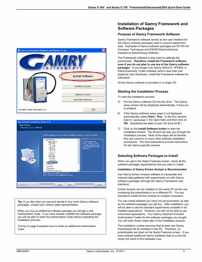
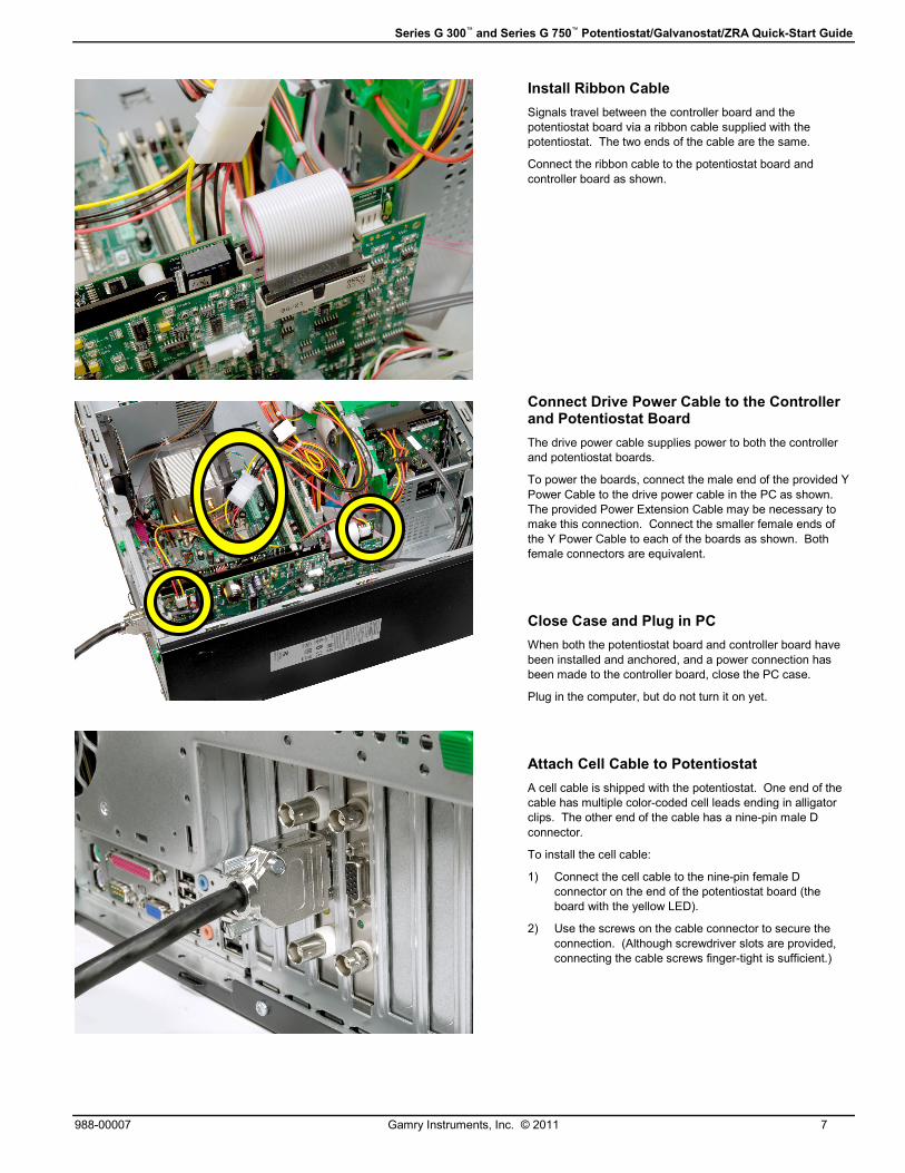
Install Ribbon Cable
Signals travel between the controller board and the
potentiostat board via a ribbon cable supplied with the
potentiostat. The two ends of the cable are the same.
Connect the ribbon cable to the potentiostat board and
controller board as shown.
Connect Drive Power Cable to the Controller and Potentiostat Board
The drive power cable supplies power to both the controller
and potentiostat boards.
To power the boards, connect the male end of the provided Y
Power Cable to the drive power cable in the PC as shown.
The provided Power Extension Cable may be necessary to
make this connection. Connect the smaller female ends of
the Y Power Cable to each of the boards as shown. Both
female connectors are equivalent.
Close Case and Plug in PC
When both the potentiostat board and controller board have
been installed and anchored, and a power connection has
been made to the controller board, close the PC case.
Plug in the computer, but do not turn it on yet.
Attach Cell Cable to Potentiostat
A cell cable is shipped with the potentiostat. One end of the
cable has multiple color-coded cell leads ending in alligator
clips. The other end of the cable has a nine-pin male D
connector.
To install the cell cable:
1) Connect the cell cable to the nine-pin female D
connector on the end of the potentiostat board (the
board with the yellow LED).
2) Use the screws on the cable connector to secure the
connection. (Although screwdriver slots are provided,
connecting the cable screws finger-tight is sufficient.)
Series G 300™ and Series G 750™ Potentiostat/Galvanostat/ZRA Quick-Start Guide
8 Gamry Instruments, Inc. © 2011 988-00007
.
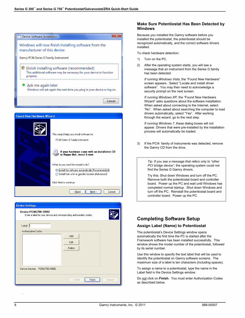
Make Sure Potentiostat Has Been Detected by Windows
Because you installed the Gamry software before you
installed the potentiostat, the potentiostat should be
recognized automatically, and the correct software drivers
installed.
To check hardware detection:
1) Turn on the PC.
2) After the operating system starts, you will see a
message that an instrument from the Series G family
has been detected.
If running Windows Vista, the “Found New Hardware”
screen appears. Select “Locate and install driver
software”. You may then need to acknowledge a
security prompt on the next screen.
If running Windows XP, the “Found New Hardware
Wizard” asks questions about the software installation.
When asked about connecting to the Internet, select
“No”. When asked about searching the computer to load
drivers automatically, select “Yes”. After working
through the wizard, go to the next step.
If running Windows 7, these dialog boxes will not
appear. Drivers that were pre-installed by the installation
process will automatically be loaded.
3) If the PCI4 family of instruments was detected, remove
the Gamry CD from the drive.
Completing Software Setup
Assign Label (Name) to Potentiostat
The potentiostat’s Device Settings window opens
automatically the first time the PC is started after the
Framework software has been installed successfully. This
window shows the model number of the potentiostat, followed
by its serial number.
Use this window to specify the text label that will be used to
identify the potentiostat on Gamry software screens. The
maximum size of a label is ten characters (including spaces).
To assign a name to a potentiostat, type the name in the
Label field in the Device Settings window.
Do not click on Finish. You must enter Authorization Codes
as described below.
Tip: If you see a message that refers only to “other
PCI bridge device”, the operating system could not
find the Series G Gamry drivers.
Try this: Shut down Windows and turn off the PC.
Remove both the potentiostat board and controller
board. Power up the PC and wait until Windows has
completed normal startup. Shut down Windows and
turn off the PC. Reinstall the potentiostat board and
controller board. Power up the PC.
Series G 300™ and Series G 750™ Potentiostat/Galvanostat/ZRA Quick-Start Guide
988-00007 Gamry Instruments, Inc. © 2011 9
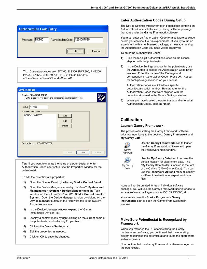
Tip: Current packages are: DC105, EIS300, PWR800, PHE200,
PV220, EN120, EFM140, CPT110, VFP600, ESA410,
eChemBasic, eChemDC, and eChemAC.
Tip: If you want to change the name of a potentiostat or enter
Authorization Codes after setup, use the Properties window for the
potentiostat.
To edit the potentiostat’s properties:
1) Open the Control Panel by selecting Start > Control Panel.
2) Open the Device Manger window by: In Vista/7, System and
Maintenance > System > Device Manager from the Task
Window on the left. In Windows XP: Start > Control Panel >
System. Open the Device Manager window by clicking on the
Device Manager button on the Hardware tab in the System
Properties window.
3) In the Device Manager window, expand the “Gamry
Instruments Devices” list.
4) Display a context menu by right-clicking on the current name of
the potentiostat and selecting Properites.
5) Click on the Device Settings tab.
6) Edit the properties as needed.
7) Click on OK to save the changes.
Enter Authorization Codes During Setup
The Device Settings window for each potentiostat contains an
Authorization Code field for every Gamry software package
that runs under the Gamry Framework software.
You must enter an Authorization Code for a software package
before you can use it to run experiments. If you try to run an
experiment with an unlicensed package, a message naming
the Authorization Code you need will be displayed.
To enter the Authorization Codes:
1) Find the ten-digit Authorization Codes on the license
shipped with the potentiostat.
2) In the Device Settings window for the potentiostat, use
the Add button to access the Authorization Code Entry
window. Enter the name of the Package and
corresponding Authorization Code. Press Ok. Repeat
for each package included on your license.
Authorization Codes are linked to a specific
potentiostat’s serial number. Be sure to enter the
Authorization Codes that were shipped with the
potentiostat named in the Device Settings window.
3) When you have labeled the potentiostat and entered all
Authorization Codes, click on Finish.
Calibration
Launch Gamry Framework
The process of installing the Gamry Framework software
adds two new icons to the desktop: Gamry Framework and
My Gamry Data.
Use the Gamry Framework icon to launch
the Gamry Framework software and open
the Framework main window.
Use the My Gamry Data icon to access the
default location for experiment data. The
“My Gamry Data” folder is located in the root
of the C drive (C:\My Gamry Data). You can
use the Framework Options menu to specify
a different destination for experiment data
files.
Icons will not be created for each individual software
package. You will use the Gamry Framework user interface to
access software packages such as DC105, EIS300, etc.
You can also use the Start > Programs > Gamry
Instruments path to open the Gamry Framework main
window.
Make Sure Potentiostat Is Recognized by Framework
When you restarted the PC after installing the Gamry
hardware and software, you confirmed that the operating
system recognized the potentiostat and found the appropriate
software drivers.
Now confirm that the Gamry Framework software recognizes
the potentiostat.

Series G 300™ and Series G 750™ Potentiostat/Galvanostat/ZRA Quick-Start Guide
10 Gamry Instruments, Inc. © 2011 988-00007
virtual LED
Tip: If the selected potentiostat has never been calibrated in this
PC, no Current Calibration Status information is displayed in the
bottom half of the Potentiostat Calibration window.
However, if the potentiostat has already been calibrated in this PC,
this window displays information about the most recent calibration.
To confirm hardware recognition:
1) Look at the top left corner of Framework screen (below
the menu bar). When the Framework window first opens
“Initializing Devices” is displayed.
2) After the potentiostat has been initialized, the “Devices
Present” line should display the name (label) assigned to
the potentiostat. A green “virtual LED” should also be
displayed to symbolize that the potentiostat is ready for
use.
When a potentiostat is in use, the virtual LED turns
yellow. The virtual LED and potentiostat label should
always be displayed.
3) If the name of the potentiostat is displayed and the
virtual LED is green, you are ready to calibrate the
potentiostat as described in the next subsection.
4) However, if a potentiostat’s name is not displayed, the
potentiostat board and controller board may not be
installed correctly. In this case, shut down the operating
system, unplug the PC, open the case, and make sure
the potentiostat and controller boards are seated
properly. Close the case, power up the PC, and launch
the Framework software again.
Calibration Preparation
Before you can use a new potentiostat, you must calibrate it
using the Universal Dummy Cell 4 shipped with the
potentiostat (or a Gamry Universal Dummy Cell 3 or 2).
Recalibrate a potentiostat every six months or after moving
the potentiostat to a different computer.
To prepare for calibration:
1) Let the PC warm up for at least 30 minutes.
2) If you are in a noisy environment, construct or buy a
Faraday Cage.
3) Make sure the cell cable supplied with the potentiostat is
firmly connected to the potentiostat to be calibrated.
Start Calibration Utility and Select the Potentiostat
If you see a green virtual LED and the name of the
potentiostat installed in the PC, you are ready to calibrate.
A Utilities submenu in the Experiment menu is always
available in Framework. The Utilities submenu always
includes the Calibrate Instrument choice.
The other submenus available from the Experiment menu
depend on the selections you made when installing the
Gamry software. An Experiment submenu is available for
every Gamry software package you installed, although you
can run experiments only for authorized software packages.
To start the calibration utility:
1) Open the Potentiostat Calibration window by selecting
Experiment > Utilities > Calibrate Instrument from the
Framework menu bar.
2) In the Potentiostat Calibration window select the option
button labeled with the name of the potentiostat to be
calibrated.
3) Select the calibration type “Both”.
4) Click on OK. The Potentiostat Calibration window
remains open. The Connection Information window will
open. It contains general instructions for using the
Universal Dummy Cell (UDC). Specific instructions for
using the Universal Dummy Cell are in this document
(see below).
Series G 300™ and Series G 750™ Potentiostat/Galvanostat/ZRA Quick-Start Guide
988-00007 Gamry Instruments, Inc. © 2011 11
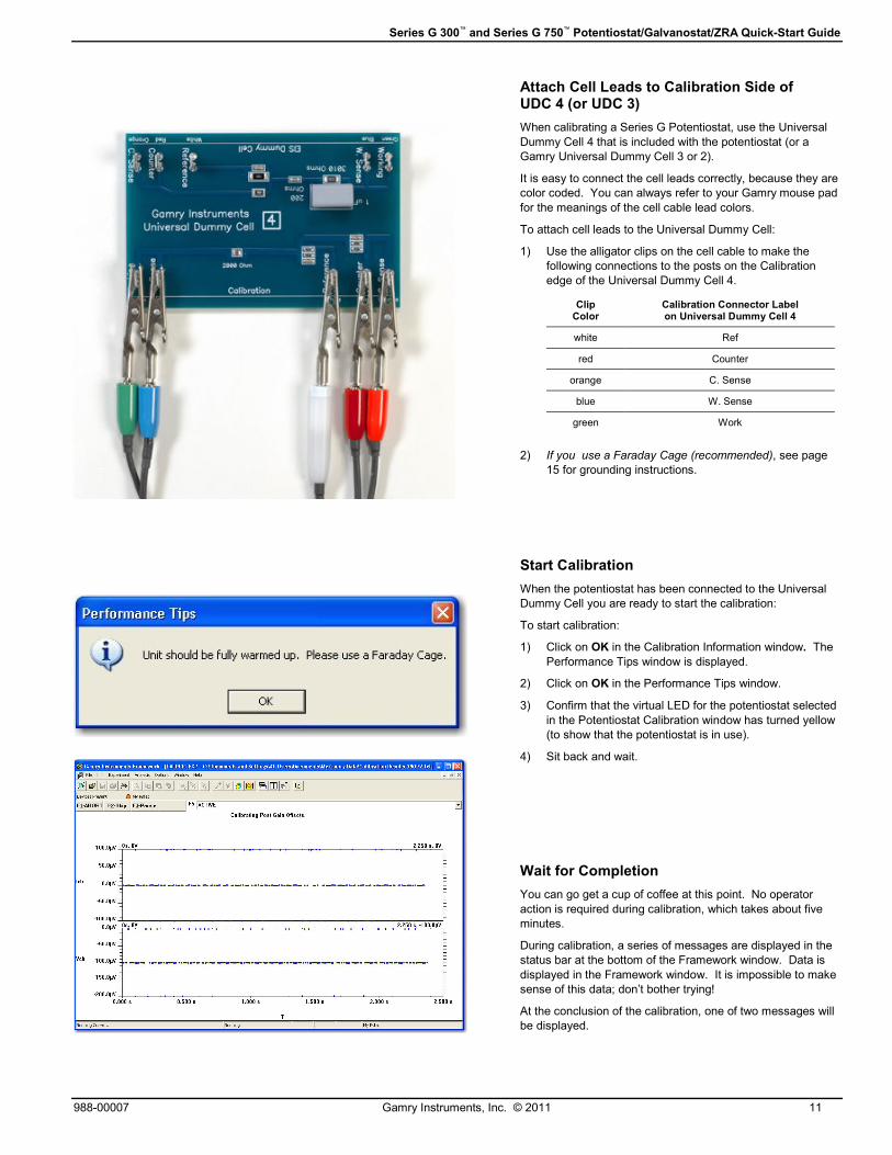
Attach Cell Leads to Calibration Side of UDC 4 (or UDC 3)
When calibrating a Series G Potentiostat, use the Universal
Dummy Cell 4 that is included with the potentiostat (or a
Gamry Universal Dummy Cell 3 or 2).
It is easy to connect the cell leads correctly, because they are
color coded. You can always refer to your Gamry mouse pad
for the meanings of the cell cable lead colors.
To attach cell leads to the Universal Dummy Cell:
1) Use the alligator clips on the cell cable to make the
following connections to the posts on the Calibration
edge of the Universal Dummy Cell 4.
Clip Color
Calibration Connector Label on Universal Dummy Cell 4
white Ref
red Counter
orange C. Sense
blue W. Sense
green Work
2) If you use a Faraday Cage (recommended), see page
15 for grounding instructions.
Start Calibration
When the potentiostat has been connected to the Universal
Dummy Cell you are ready to start the calibration:
To start calibration:
1) Click on OK in the Calibration Information window. The
Performance Tips window is displayed.
2) Click on OK in the Performance Tips window.
3) Confirm that the virtual LED for the potentiostat selected
in the Potentiostat Calibration window has turned yellow
(to show that the potentiostat is in use).
4) Sit back and wait.
Wait for Completion
You can go get a cup of coffee at this point. No operator
action is required during calibration, which takes about five
minutes.
During calibration, a series of messages are displayed in the
status bar at the bottom of the Framework window. Data is
displayed in the Framework window. It is impossible to make
sense of this data; don’t bother trying!
At the conclusion of the calibration, one of two messages will
be displayed.
Series G 300™ and Series G 750™ Potentiostat/Galvanostat/ZRA Quick-Start Guide
12 Gamry Instruments, Inc. © 2011 988-00007
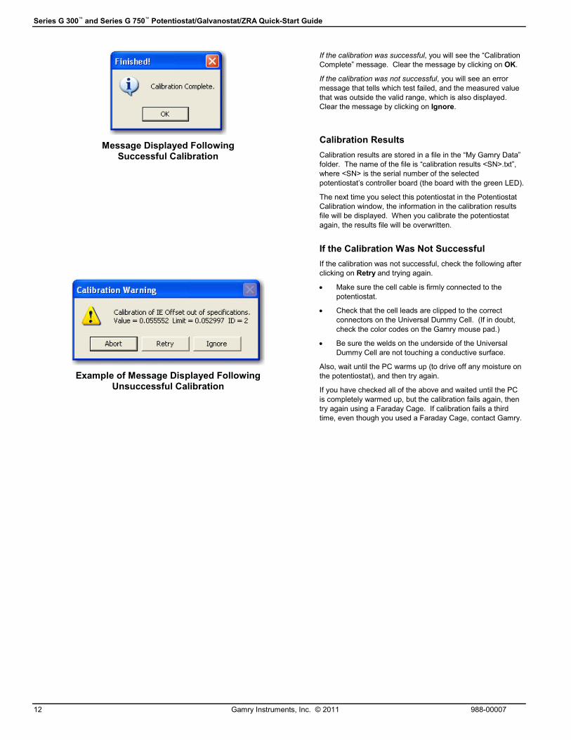
Message Displayed Following Successful Calibration
Example of Message Displayed Following Unsuccessful Calibration
If the calibration was successful, you will see the “Calibration
Complete” message. Clear the message by clicking on OK.
If the calibration was not successful, you will see an error
message that tells which test failed, and the measured value
that was outside the valid range, which is also displayed.
Clear the message by clicking on Ignore.
Calibration Results
Calibration results are stored in a file in the “My Gamry Data”
folder. The name of the file is “calibration results <SN>.txt”,
where <SN> is the serial number of the selected
potentiostat’s controller board (the board with the green LED).
The next time you select this potentiostat in the Potentiostat
Calibration window, the information in the calibration results
file will be displayed. When you calibrate the potentiostat
again, the results file will be overwritten.
If the Calibration Was Not Successful
If the calibration was not successful, check the following after
clicking on Retry and trying again.
• Make sure the cell cable is firmly connected to the
potentiostat.
• Check that the cell leads are clipped to the correct
connectors on the Universal Dummy Cell. (If in doubt,
check the color codes on the Gamry mouse pad.)
• Be sure the welds on the underside of the Universal
Dummy Cell are not touching a conductive surface.
Also, wait until the PC warms up (to drive off any moisture on
the potentiostat), and then try again.
If you have checked all of the above and waited until the PC
is completely warmed up, but the calibration fails again, then
try again using a Faraday Cage. If calibration fails a third
time, even though you used a Faraday Cage, contact Gamry.
Series G 300™ and Series G 750™ Potentiostat/Galvanostat/ZRA Quick-Start Guide
988-00007 Gamry Instruments, Inc. © 2011 13
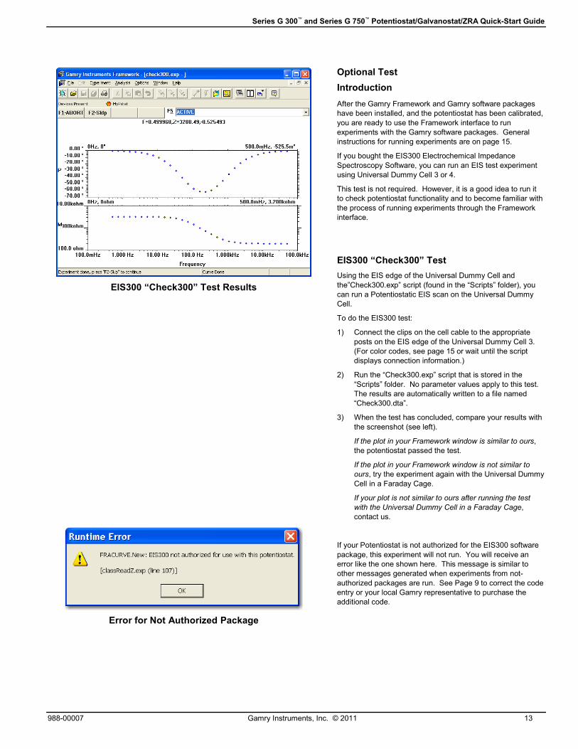
EIS300 “Check300” Test Results
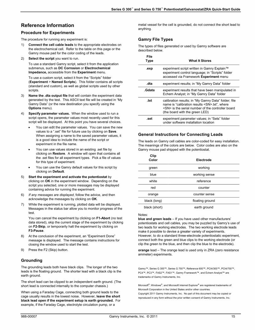
Error for Not Authorized Package
Optional Test
Introduction
After the Gamry Framework and Gamry software packages
have been installed, and the potentiostat has been calibrated,
you are ready to use the Framework interface to run
experiments with the Gamry software packages. General
instructions for running experiments are on page 15.
If you bought the EIS300 Electrochemical Impedance
Spectroscopy Software, you can run an EIS test experiment
using Universal Dummy Cell 3 or 4.
This test is not required. However, it is a good idea to run it
to check potentiostat functionality and to become familiar with
the process of running experiments through the Framework
interface.
EIS300 “Check300” Test
Using the EIS edge of the Universal Dummy Cell and
the”Check300.exp” script (found in the “Scripts” folder), you
can run a Potentiostatic EIS scan on the Universal Dummy
Cell.
To do the EIS300 test:
1) Connect the clips on the cell cable to the appropriate
posts on the EIS edge of the Universal Dummy Cell 3.
(For color codes, see page 15 or wait until the script
displays connection information.)
2) Run the “Check300.exp” script that is stored in the
“Scripts” folder. No parameter values apply to this test.
The results are automatically written to a file named
“Check300.dta”.
3) When the test has concluded, compare your results with
the screenshot (see left).
If the plot in your Framework window is similar to ours,
the potentiostat passed the test.
If the plot in your Framework window is not similar to
ours, try the experiment again with the Universal Dummy
Cell in a Faraday Cage.
If your plot is not similar to ours after running the test
with the Universal Dummy Cell in a Faraday Cage,
contact us.
If your Potentiostat is not authorized for the EIS300 software
package, this experiment will not run. You will receive an
error like the one shown here. This message is similar to
other messages generated when experiments from not-
authorized packages are run. See Page 9 to correct the code
entry or your local Gamry representative to purchase the
additional code.

Series G 300™ and Series G 750™ Potentiostat/Galvanostat/ZRA Quick-Start Guide
14 Gamry Instruments, Inc. © 2011 988-00007
(A) Sample Potentiostatic EIS data file as it opens
in the Gamry Echem Analyst.
(B) Manipulated form of the same data file — the secondary Y-axis (Phase
Angle) is reversed, data are fitted, axes are formatted, and both the Curve
Selector and Point Information Viewer are open.
Accessing Gamry Echem Analyst
Installing the Gamry Echem Analyst software
adds a new icon to the desktop: Echem
Analyst.
You can also use the Start > Programs > Gamry
Instruments path to open the Gamry Echem Analyst main
window. A shortcut to the Echem Analyst main window is also
available in Framework. Click on Analysis in the Framework
menu bar to launch the Echem Analyst software.
Manipulating Sample Data
Files containing sample data are written to the “My Gamry
Data” folder when the Gamry Framework software is installed.
You can begin to gain an appreciation for the rich set of
features available in Echem Analyst by manipulating this
sample data.
To open a data file, select File > Open from the Echem
Analyst menu bar. The sample data filenames start with
“Sample” and include the name of the type of experiment,
such as “Sample Cyclic Voltammetry.dta”. Figure A is an
example of a data file as it opens.
Some functions available in the Echem Analyst window are
applicable to many types of experiments. For example,
commands in the Tools menu are available to display point
information, change the current convention, and make other
choices that affect how data is displayed. The Common
Tools menu choices, such as Linear Fit, Add Constant E,
and Add Constant I, let you manipulate data.
Other functions, specific to the experiment type, are available
from the menu named for the type of experiment. For
example, when analyzing data gathered with Potentiostatic
EIS, the Impedance menu contains commands for functions
specific to EIS300 experiments.
Similarly, some tabs in the display, such as Experimental
Setup and Hardware Settings, are common to all types of
experiments. Other tabs, such as Bode, Nyquist, and
Randles (the selected Fit model) in Figure B, are specific to
particular types of experiments.
After you have used Echem Analyst menu functions to
manipulate the data and its presentation, you can use File >
Save As to save your changes, along with the experiment
data, as .GData files. You can open the .GData file later (by
selecting File > Open) and see the data presented exactly as
you saved it.
Sources of More Information Technical specifications for the potentiostat are in the hardware manual on the
CD shipped with the instrument.
More information about the Gamry software is available in Help, accessible from
the Framework and Echem Analyst menu bars.
Gamry manuals (as .pdf files) are on the software CD. Access the files from the
setup screen you used to install the Gamry software. You may also browse to
the locations, or use the installation notes button on setup. For example, if your
CD drive is D, the path to the setup screen is D:\autorun.
The Readme file is installed in the same folder as the Gamry software.
More information about Gamry potentiostats, software, and electrochemical
applications is available at the Gamry Web site: http://www.gamry.com
Contacting Gamry Do not hesitate to contact us if you have questions or
problems during the installation or operation of the
potentiostat.
E-mail: [email protected]
Telephone: Within the USA and Canada phone 1-877-367-
4267. From other countries phone +1-215-682-9330.
The support team is available from 8:15 AM to 6:00 PM
US Eastern Standard Time.
Fax: 215-682-9331
Mail: Gamry Instruments, Inc.
734 Louis Drive
Warminster, PA 18974
USA
Series G 300™ and Series G 750™ Potentiostat/Galvanostat/ZRA Quick-Start Guide
988-00007 Gamry Instruments, Inc. © 2011 15
Reference Information
Procedure for Experiments
The procedure for running any experiment is:
1) Connect the cell cable leads to the appropriate electrodes on
the electrochemical cell. Refer to the table on this page or the
Gamry mouse pad for the color coding of the leads.
2) Select the script you want to run.
To use a standard Gamry script, select it from the application
submenus, such as DC Corrosion or Electrochemical
Impedance, accessible from the Experiment menu.
To use a custom script, select it from the “Scripts” folder
(Experiment > Named Scripts). This folder contains all scripts
(standard and custom), as well as global scripts used by other
scripts.
3) Name the .dta output file that will contain the experiment data
generated by the test. This ASCII text file will be created in “My
Gamry Data” (or the new destination you specify using the
Options menu).
4) Specify parameter values. When the window used to run a
script opens, the parameter values most recently used for this
script will be displayed. At this point you have several choices.
• You can edit the parameter values. You can save the new
values to a “.set” file for future use by clicking on Save.
When assigning a name to the saved parameter values, it
is a good idea to include the name of the script or
experiment in the file name.
• You can use values stored in an existing .set file by
clicking on Restore. A window will open that contains all
the .set files for all experiment types. Pick a file of values
for this type of experiment.
• You can use the Gamry default values for this script by
clicking on Default.
5) Start the experiment and activate the potentiostat by
clicking on OK in the experiment window. Depending on the
script you selected, one or more messages may be displayed
containing advice for running the experiment.
6) If any messages are displayed, follow the advice, and then
acknowledge the messages by clicking on OK.
7) While the experiment is running, plotted data will be displayed.
Messages in the status bar allow you to monitor progress of the
test.
You can cancel the experiment by clicking on F1-Abort (no test
data stored), skip the current stage of the experiment by clicking
on F2-Skip, or temporarily halt the experiment by clicking on
F3-Pause.
8) At the conclusion of the experiment, an “Experiment Done”
message is displayed. The message contains instructions for
closing the window used to start the test.
9) Press the F2 (Skip) button.
Grounding
The grounding leads both have black clips. The longer of the two
leads is the floating ground. The shorter lead with a black clip is the
earth ground.
The short lead can be clipped to an independent earth ground. (The
short lead is connected internally to the computer chassis.)
When using a Faraday Cage, connecting both ground leads to the
cage usually results in the lowest noise. However, leave the short
black lead open if the experiment setup is earth grounded. For
example, if the Faraday Cage, electrolyte circulation pump, or a
metal vessel for the cell is grounded, do not connect the short lead to
anything.
Gamry File Types
The types of files generated or used by Gamry software are
described below.
File
Type
What It Stores
.exp experiment script written in Gamry Explain™
experiment control language; in “Scripts” folder
accessed via Framework Experiment menu
.dta experiment results; in “My Gamry Data” folder
.Gdata experiment results that have been manipulated in Echem Analyst; in “My Gamry Data” folder
.txt calibration results; in “My Gamry Data” folder; file name is “calibration results <SN>.txt”, where <SN> is the serial number of the controller board (the board with the green LED)
.set experiment parameter values; in “Sets” folder under software installation location
General Instructions for Connecting Leads
The leads on Gamry cell cables are color-coded for easy installation.
The meanings of the colors are below. Color codes are also on the
Gamry mouse pad shipped with the potentiostat.
Clip
Color
Electrode
green working
blue working sense
white reference
red counter
orange counter sense
black (long) floating ground
black (short) earth ground
Notes:
blue and green leads – If you have used other manufacturers’
potentiostats and cell cables, you may be puzzled by Gamry’s use of
two leads for working electrodes. The two working electrode leads
make it possible to devise a greater variety of experiments.
However, to do a standard three-electrode potentiostatic experiment,
connect both the green and blue clips to the working electrode (or
clip the green to the blue, and then clip the blue to the electrode).
orange lead – The orange lead is used only in ZRA (zero resistance
ammeter) experiments.
Gamry™, Series G 300™, Series G 750™, Reference 600™, PCI4/300™, PCI4/750™,
PC4™, PC3™, FAS2™, FAS1™, Gamry Framework™, and Echem Analyst™ are
trademarks of Gamry Instruments, Inc.
Microsoft®, Windows
®, and Microsoft Internet Explorer
® are registered trademarks of
Microsoft Corporation in the United States and/or other countries.
Copyright 2011 Gamry Instruments, Inc. No part of this document may be copied or
reproduced in any form without the prior written consent of Gamry Instruments, Inc.
Related Documents