energies Review Series Compensation of Transmission Systems: A Literature Survey Camilo Andrés Ordóñez 1,* , Antonio Gómez-Expósito 2,* and José María Maza-Ortega 1,* Citation: Ordóñez, C.A.; Gómez-Expósito, A.; Maza-Ortega, J.M. Series Compensation of Transmission Systems: A Literature Survey. Energies 2021, 14, 1717. https://doi.org/10.3390/en14061717 Academic Editor: Anna Richelli Received: 3 February 2021 Accepted: 15 March 2021 Published: 19 March 2021 Publisher’s Note: MDPI stays neutral with regard to jurisdictional claims in published maps and institutional affil- iations. Copyright: © 2021 by the authors. Licensee MDPI, Basel, Switzerland. This article is an open access article distributed under the terms and conditions of the Creative Commons Attribution (CC BY) license (https:// creativecommons.org/licenses/by/ 4.0/). 1 Department of Electrical Engineering, University of Sevilla, 41004 Sevilla, Spain 2 Laboratory of Engineering for Energy and Environmental Sustainability, University of Sevilla, 41004 Sevilla, Spain * Correspondence: [email protected] (C.A.O.); [email protected] (A.G.-E.); [email protected] (J.M.M.-O.) Abstract: This paper reviews the basics of series compensation in transmission systems through a literature survey. The benefits that this technology brings to enhance the steady state and dynamic op- eration of power systems are analyzed. The review outlines the evolution of the series compensation technologies, from mechanically operated switches to line- and self-commutated power electronic devices, covering control issues, different applications, practical realizations, and case studies. Finally, the paper closes with the major challenges that this technology will face in the near future to achieve a fully decarbonized power system. Keywords: series compensation; Flexible AC Transmission Systems (FACTS); Distributed-FACTS (D-FACTS); Fixed Series Capacitor (FSC); Thyristor-Switched Series Capacitor (TSSC); Thyristor- Controlled Series Capacitor (TCSC); Static Synchronous Series Compensator (SSSC); Distributed Static Series Compensator (DSSC) 1. Introduction FACTS is the acronym for Flexible Alternating Current Transmission System. FACTS is an evolving technology-based solution to help the utility industry and power system operators to deal with changes in the power delivery business [1]. The concept of FACTS was first introduced by Dr. N.G. Hingorani in 1988 [2]. In Reference [1], the flexibility of the system is defined as the ability to accommodate changes in the electric transmission system or operating conditions while maintaining sufficient steady state and transient margins. In this regard, FACTS technology, defined as AC transmission systems incorporating power electronic-based and other static controllers to enhance controllability and increase power transfer capability, may bring such flexibility to the power system. FACTS can be classified according to different criteria. In case of their connection to the power system, they can be grouped into series, shunt or shunt-series devices. In addition, it is possible to group them depending on the used power-electronic switch into line-commutated (e.g., thyristors) and auto-commutated (e.g., Insulated-gate bipolar transistor (IGBTs)) devices. Figure 1 presents the different FACTS with their acronyms and names, classified according with these categories. Some of the principal benefits of using a FACTS are [3]: • Power flow control. • Increase of transmission and loading capability. • Increasing the power system security through stability improvement. • Provide secure tie line connections. • Voltage control and flicker mitigation. • Reactive power compensation and reduction of reactive power flows. • Power quality improvement and power conditioning. • Provide flexibility in interconnecting new renewable and distributed generation, as well as energy storage devices. Energies 2021, 14, 1717. https://doi.org/10.3390/en14061717 https://www.mdpi.com/journal/energies

Welcome message from author
This document is posted to help you gain knowledge. Please leave a comment to let me know what you think about it! Share it to your friends and learn new things together.
Transcript

energies
Review
Series Compensation of Transmission Systems:A Literature Survey
Camilo Andrés Ordóñez 1,∗ , Antonio Gómez-Expósito 2,∗ and José María Maza-Ortega 1,∗
�����������������
Citation: Ordóñez, C.A.;
Gómez-Expósito, A.; Maza-Ortega,
J.M. Series Compensation of
Transmission Systems: A Literature
Survey. Energies 2021, 14, 1717.
https://doi.org/10.3390/en14061717
Academic Editor: Anna Richelli
Received: 3 February 2021
Accepted: 15 March 2021
Published: 19 March 2021
Publisher’s Note: MDPI stays neutral
with regard to jurisdictional claims in
published maps and institutional affil-
iations.
Copyright: © 2021 by the authors.
Licensee MDPI, Basel, Switzerland.
This article is an open access article
distributed under the terms and
conditions of the Creative Commons
Attribution (CC BY) license (https://
creativecommons.org/licenses/by/
4.0/).
1 Department of Electrical Engineering, University of Sevilla, 41004 Sevilla, Spain2 Laboratory of Engineering for Energy and Environmental Sustainability, University of Sevilla,
41004 Sevilla, Spain* Correspondence: [email protected] (C.A.O.); [email protected] (A.G.-E.); [email protected] (J.M.M.-O.)
Abstract: This paper reviews the basics of series compensation in transmission systems through aliterature survey. The benefits that this technology brings to enhance the steady state and dynamic op-eration of power systems are analyzed. The review outlines the evolution of the series compensationtechnologies, from mechanically operated switches to line- and self-commutated power electronicdevices, covering control issues, different applications, practical realizations, and case studies. Finally,the paper closes with the major challenges that this technology will face in the near future to achievea fully decarbonized power system.
Keywords: series compensation; Flexible AC Transmission Systems (FACTS); Distributed-FACTS(D-FACTS); Fixed Series Capacitor (FSC); Thyristor-Switched Series Capacitor (TSSC); Thyristor-Controlled Series Capacitor (TCSC); Static Synchronous Series Compensator (SSSC); DistributedStatic Series Compensator (DSSC)
1. Introduction
FACTS is the acronym for Flexible Alternating Current Transmission System. FACTSis an evolving technology-based solution to help the utility industry and power systemoperators to deal with changes in the power delivery business [1]. The concept of FACTSwas first introduced by Dr. N.G. Hingorani in 1988 [2]. In Reference [1], the flexibility ofthe system is defined as the ability to accommodate changes in the electric transmission system oroperating conditions while maintaining sufficient steady state and transient margins. In this regard,FACTS technology, defined as AC transmission systems incorporating power electronic-basedand other static controllers to enhance controllability and increase power transfer capability, maybring such flexibility to the power system. FACTS can be classified according to differentcriteria. In case of their connection to the power system, they can be grouped into series,shunt or shunt-series devices. In addition, it is possible to group them depending on theused power-electronic switch into line-commutated (e.g., thyristors) and auto-commutated(e.g., Insulated-gate bipolar transistor (IGBTs)) devices. Figure 1 presents the differentFACTS with their acronyms and names, classified according with these categories. Some ofthe principal benefits of using a FACTS are [3]:
• Power flow control.• Increase of transmission and loading capability.• Increasing the power system security through stability improvement.• Provide secure tie line connections.• Voltage control and flicker mitigation.• Reactive power compensation and reduction of reactive power flows.• Power quality improvement and power conditioning.• Provide flexibility in interconnecting new renewable and distributed generation, as
well as energy storage devices.
Energies 2021, 14, 1717. https://doi.org/10.3390/en14061717 https://www.mdpi.com/journal/energies
Energies 2021, 14, 1717 2 of 28
• Increase utilization of lower cost generation assets through enhancement of transmis-sion capacity.
Figure 1. Flexible AC Transmission System (FACTS) classification by topology and technology.
This survey paper focuses on series compensation, including series capacitors andseries FACTS, their technological evolution through the revision of the principal publishedliterature. The survey is motivated because series capacitors are becoming a key elementin power transmission systems around the world. This subsystem is characterized bylong high-voltage (HV) AC lines connecting major generation and demand areas in ameshed fashion, to increase as much as possible the overall system reliability. In suchHV-AC systems, the power transmission between two nodes is primarily limited by the lineseries reactance. In addition, the power flows in the meshed network fulfill the Kirchhoffequations, irrespective of physical constraints (ampacity or nodal voltage limits) whichmay lead to loop flows or network congestions [4]. The use of series capacitors may preventthese adverse situations by partly compensating the line reactance to either increase thetransmittable power or modify the power flow patterns in the meshed network.
The first transmission series capacitor was installed in 1928 by the General Electric on a33-kV line (1.2 Mvar) of the New York Power & Light system, in Ballston Spa, New York, NY,USA [5]. Some improvements were published in the next few years [6,7], all the applicationsrelying on mechanically operated switches. The advent of power electronics in the lastquarter of the 20th century has driven the change from the conventional mechanically-switched capacitors [8,9] to the brand new series compensators, under the umbrella ofFACTS. The Thyristor-Controlled Series Capacitor (TCSC), the Thyristor-Switched SeriesCapacitor (TSSC) [10], the GTO-Controlled Series Capacitor (GCSC) [10,11], the Static

Energies 2021, 14, 1717 3 of 28
Synchronous Series Compensation (SSSC) [12], and the Distributed SSSC (DSSC) [13,14]are the most prominent topologies within this FACTS category. It has been demonstratedthat variable series compensation is a cornerstone of FACTS technology [3], owing to itseffectiveness in both controlling line power flows and improving system stability. Theseries FACTS allows maximizing the utilization of transmission assets by controllingthe power flow in the lines, preventing loop flows and, with the use of fast controllers,minimizing the effect of system disturbances, thereby reducing traditional stability marginrequirements [15]. In this regard, the current power system transition towards a fullydecarbonized paradigm will definitely require the additional flexibility that series FACTSmay bring, with the support of power electronics technologies [16].
This paper presents a literature survey of the series compensation technologies de-ployed so far in transmission systems. The aim is to provide an overview of each technology,pointing out its fundamentals, applications from an operation and planning perspective,benefits, and drawbacks, supported by an extensive and exhaustive review of the state ofthe art. For this purpose, the methodology outlined in the next section, aimed at performinga taxonomic classification of published works, has been elaborated, followed by a numberof sections devoted to each relevant topology. Particularly, the analyzed arrangements havebeen grouped according to the way the series compensation is implemented (a generic“Series FACTS” category has been added, for convenience, to account for those papersin which no particular technology is discussed): first, those technologies that modify theline impedance by the insertion of series capacitors, either mechanically or through powerelectronic devices; then, those technologies based on self-commuted switches, which be-have as a voltage source. The paper closes with the main conclusions, challenges, andrecommendations to foster the deployment of this technology.
2. Taxonomic Methodology for the Literature Review
Several survey papers have been published, both in journals and conferences, aboutseries compensation in transmission systems. Most of those papers, however, are restrictedto general aspects of the series FACTS, rather than providing a systematic classification andholistic overview [17]. For this reason, it is yet difficult to answer major questions, such aswhere the research focus has been concentrated, which technologies are most promising,which problems have been addressed, and which commercial realizations are alreadyavailable in the market. The aim of this paper was to answer those questions, while, at thesame time, performing a comprehensive literature review. For this purpose, the followingset of the most recognized journals and international conferences in the field have beensystematically searched:
• IEEE Transactions on Power Systems.• IEEE Transactions on Power Electronics.• IEEE Transactions on Power Delivery.• IEEE Transactions on Industrial Electronics.• IEEE Transactions on Industry Applications.• IEEE Transactions on Power Apparatus and Systems.• IET Power Electronics.• IET Generation, Transmission & Distribution.• International Journal of Electrical Power & Energy Systems (Elsevier).• Electric Power Systems Research (Elsevier).• Journal of Modern Power and Clean Energy Systems (SGEPRI).• Energies (MDPI).• Energy Procedia (Elsevier).• CIGRE Publications (reports, papers, and technical brochures).
In order to identify the key publications, the databases related to those journalsand conference proceedings have been explored, by applying complex queries analyzingmetadata, keywords, title and abstract contents. Different concepts have been searched,and the results have been clustered into the following categories: Fixed Series Capacitor

Energies 2021, 14, 1717 4 of 28
(FSC), series FACTS, Distributed-FACTS (D-FACTS), TSSC, TCSC, GCSC, SSSC, and DSSC(all the acronyms are provided at the end of the paper). Table 1 shows the numberof publications found within each category. As expected, there is a huge amount ofpublications presented in conferences, meetings, and symposia, overall representing about80% of the total published works. The stacked bar chart in Figure 2 shows the numberof publications in each category, separating journals and conferences. In this figure, thecategory ‘Others’ refers jointly to series FACTS, GCSC, FSR, TCSR, and TSSC. It is evidentthat the largest number of published articles are related with TCSC, followed by SSSC.
Table 1. Number of publications organized by category and publisher.
Category IEEE/IET Journals Elsevier and Energies CIGRE IEEE/IET Conferences Total
FSC 68 31 14 93 206FSR/TCSR 1 0 3 2 7
TSSC 1 0 0 2 3TCSC 50 70 13 923 1056GCSC 7 2 1 15 25SSSC 25 42 2 307 376
DSSC/D-FACTS 13 1 2 56 72Series FACTS 0 5 0 37 42
Total 165 151 35 1435 1786
0 100 200 300 400 500 600 700 800 900 1000
TCSC
SSSC
FSC
Others
DSSC
133
69
113
20
16
923
307
93
56
56
Number of publications
Journals Conferences
Figure 2. Journal and conference papers published, organized by category.
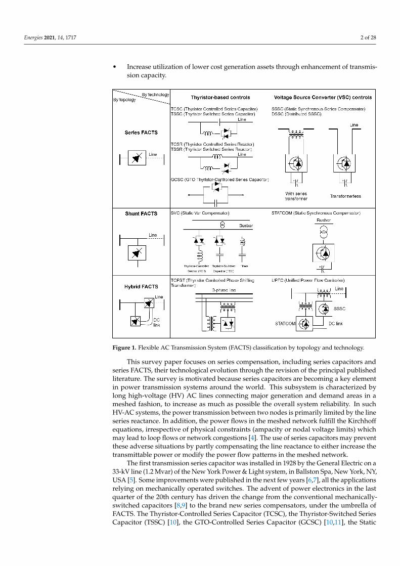
The research effort on each of the considered topologies evolves over time dependingon the technology maturity. A natural indicator for measuring this trend is the number ofpublications per year related to each category, represented in Figure 3 for the last 60 years.This figure reveals that the FSC was the principal element analyzed during more than30 years. Since the 1990s, though, the line-commutated power electronic devices, suchas the TCSC, have been the principal series FACTS in which academia and R&D effortshave been interested. Since the beginning of the 21st century, with the irruption of theself-commutated switches, an increase of publications dealing with SSSC and DSSC isapparent. In this regard, it is somewhat surprising that the publications dealing withthyristor technology keeps really high. This can be explained by the fact that the mainthyristor-based converters manufacturers worldwide have promoted the research sectorto continue producing publications related to the TCSC technology, still remaining inforce, although new technologies, such as DSSC, are increasingly entering the market.Publications accepted during 2020 has been added to those of 2019 because it has beenconsidered that probably journal databases are not fully updated in the period this researchhas been issued.
Energies 2021, 14, 1717 5 of 28
1960 1970 1980 1990 2000 2010 20190
10
20
30
40
50
60
70
80
Year
Num
ber
ofpu
blic
atio
ns
TCSCSSSCFSC
DSSCOthers
Figure 3. Time evolution of number of publications by category.
Finally, this outlook closes with a review of the research focus of the different publica-tions, grouped by the following criteria:
• Control strategies to improve the steady-state and dynamic performance of power systems.• Design and modeling issues dealing with modifications proposed to the FACTS design,
including new features or additional elements, as well as new models for new powersystems software tools.
• Operational analysis, assessing the FACTS impact on the power system, includingsteady-state simulations, real-time and wide-area control applications.
• Planning studies, dealing with location and sizing of FACTS. An important research isfocused on the placement of series controllers. That includes methodologies to achievean equivalent objective than if it were located in another points. However, it has to beconsidered that, sometimes, series FACTS may be located at non-optimal locations ifthe aim is minimizing costs because the the cost of lands and all the environmentallicenses are becoming crucial for projects development.
• Protections design and coordination issues, focusing on the interaction of seriescompensation with new protections schemes and its behavior in transient simulations.
• Stability issues dealing with dynamic assessment and new methods to enhance angu-lar, frequency, or voltage stability.
• FACTS Installations.
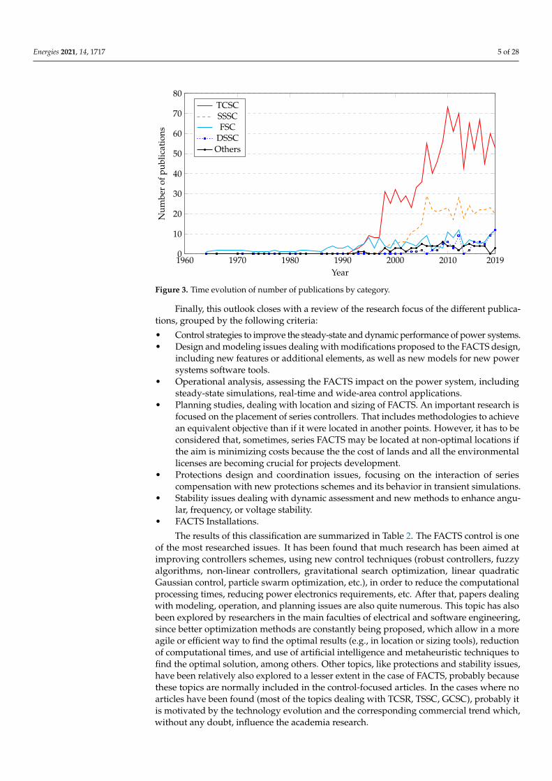
The results of this classification are summarized in Table 2. The FACTS control is oneof the most researched issues. It has been found that much research has been aimed atimproving controllers schemes, using new control techniques (robust controllers, fuzzyalgorithms, non-linear controllers, gravitational search optimization, linear quadraticGaussian control, particle swarm optimization, etc.), in order to reduce the computationalprocessing times, reducing power electronics requirements, etc. After that, papers dealingwith modeling, operation, and planning issues are also quite numerous. This topic has alsobeen explored by researchers in the main faculties of electrical and software engineering,since better optimization methods are constantly being proposed, which allow in a moreagile or efficient way to find the optimal results (e.g., in location or sizing tools), reductionof computational times, and use of artificial intelligence and metaheuristic techniques tofind the optimal solution, among others. Other topics, like protections and stability issues,have been relatively also explored to a lesser extent in the case of FACTS, probably becausethese topics are normally included in the control-focused articles. In the cases where noarticles have been found (most of the topics dealing with TCSR, TSSC, GCSC), probably itis motivated by the technology evolution and the corresponding commercial trend which,without any doubt, influence the academia research.
Energies 2021, 14, 1717 6 of 28
Finally, the publications were filtered according to their impact level, measured bythe number of citations, prioritizing the journal papers. Approximately 222 publications(180 Journals, 37 Conferences, and 5 Chapter Books) were selected and included in thefollowing review.
Table 2. Taxonomy of journals by their main topic.
Category Control Design/Model Operation Planning Protections Stability Installation Total
TCSC 55 13 24 5 10 12 1 120FSC 20 23 7 11 16 15 7 99SSSC 42 3 2 14 4 2 0 67DSSC 3 2 7 2 0 0 0 14GCSC 2 2 0 4 1 0 0 9Series
FACTS 3 0 1 0 0 1 0 5
TCSR 0 0 0 1 0 0 0 1TSSC 1 0 0 0 0 0 0 1
Total 126 43 41 37 31 30 8 316
3. Series Compensation by Inserting Capacitors
Series capacitive compensation is well known and has been widely applied in trans-mission grids. The basic principle is to reduce the inductive reactance of the electricaltransmission line by means of a series capacitor, leading to an increased power transfercapability and steady-state stability margin, owing to the higher synchronizing power [4].Figure 4 shows the one-line and phasor diagrams related to the series compensation usinga fixed capacitor. This yields an apparent reduction of the line reactance, Xe = XL − XC,and an associated increase in the transmitted power (assuming the voltage magnitudesand angles remain constant), according to the well-known expression:
Pe =VAVB
XL − XCsin δ ≈ V2
XL(1− k)sin δ, (1)
where VA and VB are the voltage magnitudes of buses A and B (VA ≈ VB ≈ V), XL is theimpedance of the transmission line, XC is the reactance of the series capacitor, k = XC/XLis the degree of compensation, and δ is the angular difference of the busbar voltages.The reactive power injected by the capacitor depends on the compensation degree [3],as follows:
Q ≈ 2V2
XL
k(1− k)2 (1− cos δ). (2)
From those expressions, the active power increases if the compensation k increases,at the cost of the large series capacitor reactive power, which sharply increases with k [3].According to the phasor diagram of Figure 4d, this reduces the voltage drop and theangular deviation between the sending and receiving line ends, providing [4]: increasedtransmission capacity [18], possibility of modifying the power flows in the meshed net-work [19], improved voltage profile of the grid [20], enhanced angular stability of the powercorridor [21,22], damping of power oscillations [23,24], and the possibility of optimizingpower transported by parallel lines [25]. In addition, it has to be considered that seriescompensation may interfere with the conventional power system operation. For this reason,researchers have also analyzed the impact of series compensation on voltage sags [26],radial distribution systems [27], Wide-Area Measurement Systems (WAMS) [28], securityanalysis with massive penetration of renewable generation [29], and even the modificationof spot prices in wholesale energy markets [30].

Energies 2021, 14, 1717 7 of 28
Figure 4. Change of line reactance caused by the insertion of a series capacitor: (a) one-line diagram,(b) phasor diagram, (c) one-line diagram with the inserted capacitor, and (d) phasor diagram. Basedon Reference [4].
The following subsections are devoted to give an overview of the mechanical- andpower electronics-based options that can be used for introducing a series capacitor in thetransmission system.
3.1. Mechanically Commutated Series Devices
The Mechanically Commutated Series Capacitors (MCSC), also called Fixed SeriesCompensation (FSC) is the most common series compensation equipment currently in-stalled in power systems [31,32]. The MCSC scheme is shown in Figure 5 [4]. The ca-pacitor banks consist of parallel and series arrays of AC capacitors, along with otherauxiliary equipment. Metal-oxide varistor (MOV) arresters and spark gaps are installedto protect the capacitors from overvoltages [33,34]. The bypass switch is used for connect-ing/disconnecting the series capacitor to/from the line, while the disconnector switchesprovide the required isolation for maintenance operations. Finally, current transformersare used for monitoring and control purposes.
Figure 5. Components of the Fixed Series Capacitor (FSC). From Reference [4], based on Reference [35].
Energies 2021, 14, 1717 8 of 28
Several studies have been published about the impact of series compensation on thepower system stability. A bang-bang control for stabilization of interconnected powersystems using a series capacitor was presented in Reference [36]. Reference [37] shows acontrol scheme using fuzzy logic to enhance the overall power system stability, while atransient stability preventive control design has been analyzed in Reference [38].
Additionally, planning studies of FSC have also been published. In Reference [39],a multistage transmission expansion planning model is proposed considering FSC allo-cation and N-1 security constraints. The problem is modeled as a mixed-integer linearprogramming (MILP) approach, and it is solved using branch-and-cut methodology toobtain the optimal solution. In Reference [40], a methodology is developed for identifyingthe critical lines and their compensation degree in terms of voltage stability using decisiontrees methodology.
It is possible to find several contributions regarding protection issues related withseries compensation. Reference [41] presents a fault current limiter (FCL) with seriescompensation based on a fast-closing switch composed of a capacitor bank and a seriesreactor. Reference [42] introduces a non-iterative fault-location algorithm for compensatedtransmission lines, while Reference [43] presents a non-unit protection scheme usingdiscrete wavelet transform and k-nearest neighbor algorithm. In Reference [44], an accuratefault-location algorithm is proposed making use of synchronized measurements from bothends of the series compensated line.
One of the main concerns related to the series compensation of transmission linesrefers to the Sub-synchronous Resonance (SSR), due to the interaction of the series capacitorand line reactance. Note that the natural frequency of a series compensated line is given by:
fseries = f
√XCXL
= f√
k, (3)
which is lower than the network frequency (k < 1); therefore, a sub-synchronous oscil-lation mode can be excited creating dangerous SSR situations. Interactions between atransmission line (compensated with a series capacitor), which oscillates at the naturalresonant frequency, and the mechanical oscillations in a generator mechanical system cancause negative damping with the consequent mutual reinforcement of the electrical andmechanical oscillations [3]. This phenomenon, identified in 1937 [45], and the possiblecontrol actions for preventing SSR in a series capacitor-compensated transmission line wereworked widely in the 1990s [46–48]. Following this research line, Reference [49] providesan overview of the impact of series compensation on SSR and the recommended studies fordifferent applications with SC. The evaluation of SSR risk, like stability and transient torqueanalysis, and some methods for mitigating SSR problems and the torsional protection andmonitoring schemes are included.
3.2. Static-Controlled Series Capacitive Compensation
The following subsections are devoted to describe the power electronics-based seriescompensation. For this purpose, a chronological order has been followed to present thedifferent technologies from the initial TSSC to the GCSC, including the TCSC, which hasconcentrated most of the research effort in this field.
3.2.1. Thyristor-Switched Series Capacitor (TSSC)
The Thyristor-Switched Series Capacitor (TSSC), in which the scheme is shown inFigure 6, consists of a set of series capacitors which are shunted by two anti-parallelthyristors (which can be modeled in series with a small reactor, if the design requires it).This thyristor couple acts as an AC static switch which can bypass the capacitor. Thecompensation degree of the transmission line is controlled in a step-wise way by increasingthe number of the inserted capacitors. A capacitor is inserted by using the thyristorvalves, by activating (or not) the gating signals. Conversely, a capacitor is bypassed by

Energies 2021, 14, 1717 9 of 28
conducting fully the thyristor valves [3]. A patent related with this technology is presentedin References [50,51].
Figure 6. Thyristor-Switched Series Capacitor (TSSC) scheme [4].
From a steady-state point of view, the TSSC is similar to the FSC with mechanicalswitches. However, the following advantages with respect to this conventional technologycan be mentioned [4]:
• The commutation with thyristors allows unlimited number of switching operations,maximizing its usability along its life cycle.
• The thyristors allow choosing the commutation instants, i.e., the point on the voltagewaveform where the transition between the conducting and non-conducting statesis produced. In this way, the switching transients are minimized, in contrast to theclassical commutation with mechanical switches, which is hardly synchronized.
• A very fast response, as typically the interval between the control command and thecapacitor operation is less than a cycle.
• It does not generate harmonics in contrast to the GCSC and TSSC technologies whichwill be reviewed later. This is because TSSC works either in full-conduction or blockingmodes, i.e., the thyristors act as a conventional but fast-acting conventional switch.
• TSSC modules can be quickly inserted or bypassed if SSR oscillations are detected.In this way, the SSR frequency can be controlled and moved away from the criticalturbine-generator resonance frequencies.
Additionally, TSSCs have been applied for damping power system oscillations [52,53],including inter-area modes, considerably improving the transient stability of the powersystem. Particularly, Reference [54] proposes an interesting application where an adaptivedamping controller estimates the parameters of a power system by using a two-areasimplified power system model. However, Direct Current (DC)-offset voltages can appearin the transmission line, resulting from the insertion of series capacitors.
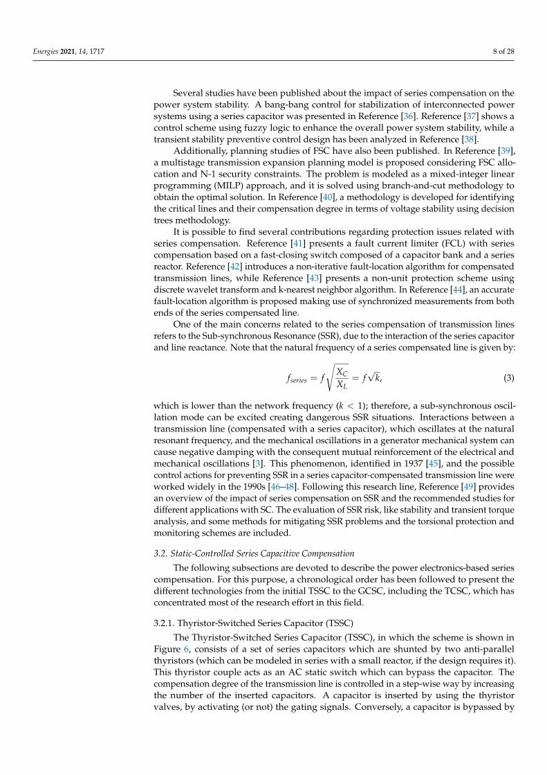
3.2.2. Thyristor-Controlled Series Capacitor (TCSC)
The TCSC, originally called and patented [55] as Rapid Adjustment of NetworkImpedance (RANI) by Vithayathil et al. in 1986 [56], is shown in Figure 7. The TCSCconsists of a series capacitor shunted by a Thyristor-Controlled Reactor (TCR). The basicobjective of the TCSC is to provide a variable-reactance capacitor by canceling (partially)the effective capacitance injected by the TCR. The equivalent impedance as a function ofthe thyristor firing angle α is presented in Reference [3] and can be expressed as:
XTCSC(α) =XC
1− XCXL
(1− 2α−sin απ )
, (4)
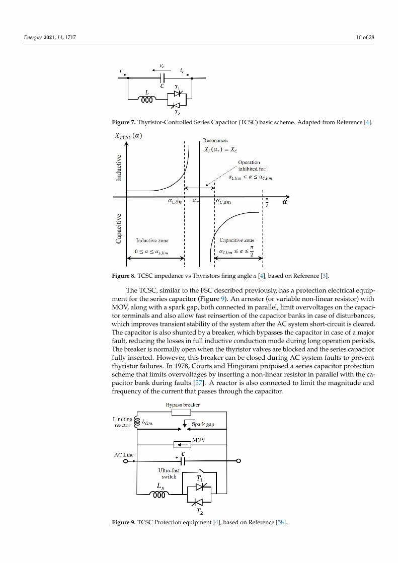
where XC is the fixed capacitor impedance, and XL is the inductance impedance. In themost common TCSC arrangement, the TCR reactance XL is smaller than the capacitor one,XC, and the TCSC has two operation ranges depending on the firing angle α: capacitive andinductive. According to Equation (4), a parallel resonance is created between the capacitorand the inductor for the firing angle αr, which clearly separates the different operationmodes. Due to the fact that the TCSC impedance sharply varies around αr, the capacitiveand inductive operating modes are practically constrained in the ranges [0, αL,lim] and[αC,lim, π/2], respectively, as shown in Figure 8.
Energies 2021, 14, 1717 10 of 28
Figure 7. Thyristor-Controlled Series Capacitor (TCSC) basic scheme. Adapted from Reference [4].
Figure 8. TCSC impedance vs Thyristors firing angle α [4], based on Reference [3].
The TCSC, similar to the FSC described previously, has a protection electrical equip-ment for the series capacitor (Figure 9). An arrester (or variable non-linear resistor) withMOV, along with a spark gap, both connected in parallel, limit overvoltages on the capaci-tor terminals and also allow fast reinsertion of the capacitor banks in case of disturbances,which improves transient stability of the system after the AC system short-circuit is cleared.The capacitor is also shunted by a breaker, which bypasses the capacitor in case of a majorfault, reducing the losses in full inductive conduction mode during long operation periods.The breaker is normally open when the thyristor valves are blocked and the series capacitorfully inserted. However, this breaker can be closed during AC system faults to preventthyristor failures. In 1978, Courts and Hingorani proposed a series capacitor protectionscheme that limits overvoltages by inserting a non-linear resistor in parallel with the ca-pacitor bank during faults [57]. A reactor is also connected to limit the magnitude andfrequency of the current that passes through the capacitor.
Figure 9. TCSC Protection equipment [4], based on Reference [58].

Energies 2021, 14, 1717 11 of 28
TCSCs introduce a number of important advantages in the application of seriescompensation compared to TSSCs [58,59]:
• Rapid and continuous control of the transmission line series-compensation level whichenables optimal power-flow conditions and prevents the power loops.
• Damping of the power swings from local and inter-area oscillations [60–64].• Prevent SSR conditions due to the inherent resistive-inductive reactance of the TCSC.
In this way, the sub-synchronous oscillations cannot be sustained and, consequently,get damped [65].
• The DC-offset voltages, invariably resulting from the insertion of series capacitors,decay very quickly (within a few cycles) due to the continuous control of the TCSCthyristors [66].
• A better protection level for series capacitors. It uses a fast bypass through a veryfast thyristor control in case of large overvoltages after a fault. To aid in systemstabilization, the series capacitors can be re-inserted rapidly after the fault clearing,thanks to the thyristor action [67].
• Voltage support. The TCSC can produce reactive power which increases with the lineloading, thus helping the voltage’s regulation and preventing voltage instability [68].
• Short-circuit current reduction. The TCSC can restrict the short-circuit current, byswitching from the controllable-capacitance to the controllable-inductance mode.
Optimal location or placement of FACTS in transmission power systems has beenwidely worked on. The objective function can be designed to improve technical require-ments or power system economics issues. In any case, the following conditions must beconsidered [69]:
1. The TCSC should be located in transmission lines that experience limiting poweroscillations.
2. The voltages swing on the TCSC sides must remain with acceptable limits; otherwise,multiple TCSC locations may be needed.
3. The TCSC control actions in one transmission path should not cause undue powerswings in any parallel paths. Otherwise, additional compensations might be necessary.
4. Considering reliability issues, it is advisable to implement a distributed control, inwhich actions are applied among some TCSCs, rather than setting up a control actionto a single, large TCSC.
For the first aim (technical requirements), the most common issue is the optimallocation for enhancement of total transfer capability [70] and congestion management forsecured optimal power flow under normal and contingencies operating condition [71]. Fordoing so, Reference [72] proposes a method to determine the suitable locations of TCSCbased on the real power flow performance index sensitivity. An optimal TCSC sizing andlocation methodology under power system normal and contingency conditions is proposedin Reference [73], without sacrificing the system security. Evolutionary programmingmethod is worked in Reference [74] to find an optimal FACTS allocation, by maximizingthe total transmission transfer capability.
For the second group, which deals with power system economics, the objective inReference [75] is to achieve the minimum overall system cost function, including theFACTS investment cost, in that case using Genetic Algorithms (GA). In Reference [76], theoverall objective of FACTS device placement can be either to minimize the total congestionrent or to maximize the social welfare. In Reference [77], the objective is to minimizethe total generation cost based on the DC load flow model with multi-objective GA. Thereduction of congestion costs by using shadow prices is analyzed in Reference [78]. Otherobjective functions, like real power or reactive power losses minimization, are consideredin References [79,80].
Regarding the methods used for solving the TCSC placing and sizing, some publica-tions present analytical techniques, such as Reference [81], where bifurcation analysis isapplied and a continuation power flow is used to evaluate the effects of these devices on

Energies 2021, 14, 1717 12 of 28
system loadability, or Reference [82], where a mathematical model for the computationof reactances is proposed for selecting the candidate lines for the installation of TCSC. InReference [83], the impacts on the locational marginal pricing and system voltages areinvestigated, based on variations in control parameters of the TCSC and a double auctionbidding model.
However, in the last few years, the application of heuristic and artificial intelligenttechniques has been explored to determine the optimal number, locations, and parametersettings of multiple TCSC to maximize system loadability with minimum installationcost or to enhance power system stability: GA [84–86], Tabu Search [87], Particle SwarmOptimization (PSO) [88–90], and Neural Networks [91]. In Reference [92], a hybrid tabusearch and simulated annealing approach is proposed to find the optimal placement ofFACTS to minimize the total generator fuel cost for all loading levels. Furthermore, inReference [93], the optimization is based on a variant of PSO specialized in multi-objectiveoptimization problem, known as non-dominated sorting PSO (NSPSO).
Regarding the research dealing with control algorithms, most of the publicationson controlled series compensation are devoted to damping power oscillations [94] orto improve transient stability [95]. For doing that, it is necessary to counteract the ac-celerating and decelerating swings of the disturbed machines, by varying the appliedcompensation. That is, when the angle δ increases (the oscillating generator accelerates),the electrical power must be incremented to compensate for the excess mechanical power.Conversely, when the angle δ decreases (the generator decelerates), the electric power mustbe decremented to balance the missing mechanical power [3]. Furthermore, N.G. Hingoraniproposed in 1981 a thyristor-controller damping scheme for series capacitors, called NGB,which has proven to provide effective SSR mitigation [96]. Subsequent research effortsfound that the NGB damping principle can be extended to the basic TCSC circuit structureto make it substantially immune to SSR. This seminal publication paved the way to manyothers dealing with this issue [97–99].
These improvements on the power system damping and stability can be achievedapplying different control techniques which are summarized below:
1. Fuzzy methods [100–106].2. Robust control (H∞) or adaptive control [107–111].3. Linear Quadratic Gaussian (LQG) technique [112,113].4. PSO [114,115].5. Pole placement, small signal stability (eigenvalue analysis) and PSS tuning [116–120].6. Bacterial Swarm Optimization (BSO) [121,122].7. Nonlinear control [123,124].8. Other control techniques: Gravitational Search Algorithm (GSA) [125], frequency
response [126], phasorial-based [127], discrete control [128], GA [129], hierarchicalcontrol [130], modified group searcher optimization (GSO) [131].
It is important to highlight that these dynamic studies require accurate TCSC modelswhich are investigated in References [132–134]. Other TCSC studies are related with faultlocation [135–139], impact of TCSC on market prices [140], and reliability [141]. Finally,there are some patents related with TCSC control [142,143].
3.2.3. GTO-Controlled Series Capacitor (GCSC)
The Gate Turn-off (GTO) Thyristor-Controlled Series Capacitor (GCSC) proposed byKarady et al. in 1992 [11] is shown in Figure 10. The basic GCSC consists of a capacitor Cand a pair of GTO switches connected in anti-parallel. It is interesting to note that the GCSCis the dual circuit of the shunt TCR. The TCR controls the current in a fixed inductor froma sinusoidal voltage source, thereby presenting a variable reactive admittance. Similarly,the GCSC controls the voltage across a fixed capacitor supplied by a sinusoidal currentsource, thereby presenting a variable reactive impedance [3]. The capacitor is removedwhen the thyristors are switched on. Conversely, the capacitor insertion is done by turningoff the thyristors. Therefore, it is mandatory to control both the turn-on and turn-off

Energies 2021, 14, 1717 13 of 28
instants, being required a GTO or any other self-commutated power electronic switch. Theswitch-off angle (insertion angle) controls the level of average compensation. As a result,the capacitor is in the circuit just a fraction of the cycle. As a matter of fact, the turn-offdelay angle control of the GCSC, just like the TCR turn-on delay angle control, generatesharmonics. In Reference [144], the operation and harmonic analysis of the GCSC wasperformed, and configurations using multi-module and multi-pulse GCSC were proposedwith the objective of reducing the voltage harmonics.
The continuous GCSC control capability allows to mitigate SSR conditions and elec-tromechanical oscillations even with a simple control [145]. Another control scheme pro-posed in Reference [146] allows the GCSC to damp both the SSR and Low Frequency PowerOscillations using a constant power control. Recently, Reference [147] presents a GCSC con-trol approach embedded in an automatic generation control (AGC) to provide an effectivefrequency control specially suited to two-area power systems. The controller outperformsother alternative techniques specially designed for improving the dynamic response.
Figure 10. GTO-Controlled Series Capacitor (GCSC) basic scheme. Based on Reference [11].
4. Static Synchronous Series Compensator (SSSC)
The SSSC or series STATCOM was proposed by Dr. Laszlo Gyugyi [12] and consistsof a voltage-sourced converter (VSC) in series with the transmission line, as illustrated inFigure 11. The SSSC provides a wider control range compared to the previous topologiesbecause it injects a series voltage rather than a series impedance. Therefore, the seriescompensation is independent of the line current [148,149].
Figure 11. Representation of the Static Synchronous Series Compensation (SSSC) based on a voltage-sourced converter (VSC). Adapted from Reference [3].
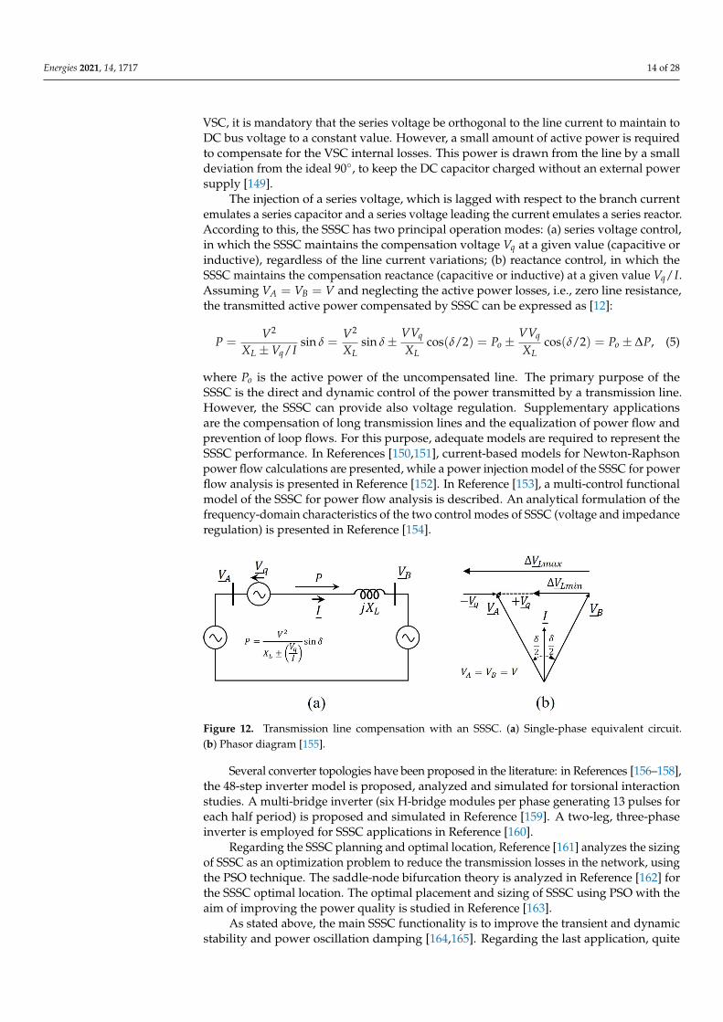
The SSSC is synchronized with the transmission line current, I, and injects a seriesvoltage Vq which is orthogonal to it, lagging or leading as shown in the single-phase circuitof the Figure 12a and the phasor diagram in Figure 12b. Note that, assuming a lossless
Energies 2021, 14, 1717 14 of 28
VSC, it is mandatory that the series voltage be orthogonal to the line current to maintain toDC bus voltage to a constant value. However, a small amount of active power is requiredto compensate for the VSC internal losses. This power is drawn from the line by a smalldeviation from the ideal 90◦, to keep the DC capacitor charged without an external powersupply [149].
The injection of a series voltage, which is lagged with respect to the branch currentemulates a series capacitor and a series voltage leading the current emulates a series reactor.According to this, the SSSC has two principal operation modes: (a) series voltage control,in which the SSSC maintains the compensation voltage Vq at a given value (capacitive orinductive), regardless of the line current variations; (b) reactance control, in which theSSSC maintains the compensation reactance (capacitive or inductive) at a given value Vq/I.Assuming VA = VB = V and neglecting the active power losses, i.e., zero line resistance,the transmitted active power compensated by SSSC can be expressed as [12]:
P =V2
XL ±Vq/Isin δ =
V2
XLsin δ±
VVq
XLcos(δ/2) = Po ±
VVq
XLcos(δ/2) = Po ± ∆P, (5)
where Po is the active power of the uncompensated line. The primary purpose of theSSSC is the direct and dynamic control of the power transmitted by a transmission line.However, the SSSC can provide also voltage regulation. Supplementary applicationsare the compensation of long transmission lines and the equalization of power flow andprevention of loop flows. For this purpose, adequate models are required to represent theSSSC performance. In References [150,151], current-based models for Newton-Raphsonpower flow calculations are presented, while a power injection model of the SSSC for powerflow analysis is presented in Reference [152]. In Reference [153], a multi-control functionalmodel of the SSSC for power flow analysis is described. An analytical formulation of thefrequency-domain characteristics of the two control modes of SSSC (voltage and impedanceregulation) is presented in Reference [154].
Figure 12. Transmission line compensation with an SSSC. (a) Single-phase equivalent circuit.(b) Phasor diagram [155].
Several converter topologies have been proposed in the literature: in References [156–158],the 48-step inverter model is proposed, analyzed and simulated for torsional interactionstudies. A multi-bridge inverter (six H-bridge modules per phase generating 13 pulses foreach half period) is proposed and simulated in Reference [159]. A two-leg, three-phaseinverter is employed for SSSC applications in Reference [160].
Regarding the SSSC planning and optimal location, Reference [161] analyzes the sizingof SSSC as an optimization problem to reduce the transmission losses in the network, usingthe PSO technique. The saddle-node bifurcation theory is analyzed in Reference [162] forthe SSSC optimal location. The optimal placement and sizing of SSSC using PSO with theaim of improving the power quality is studied in Reference [163].
As stated above, the main SSSC functionality is to improve the transient and dynamicstability and power oscillation damping [164,165]. Regarding the last application, quite

Energies 2021, 14, 1717 15 of 28
a few papers have been published demonstrating and exploring this benefit, and evencomparing the SSSC performance with other FACTS [166–168]. The SSSC can increase ordecrease the line current and the active power flow, by a quick injection of the compensat-ing series voltage when the generation plants accelerate or decelerate, respectively [149].Several control schemes designed to improve the SSSC dynamic performance and thepositive effect of damping the power system oscillations have been proposed. The controlschemes for a 24- and 48-pulse VSC are presented in References [169,170], respectively.The most relevant publications, classified depending on the applied control technique, aresummarized as follows:
1. Fuzzy methods: with real-time RTDS application [171], considering offshore windfarms [172] and an evolutionary method with GA [173].
2. PSO to improve the stability of an interconnected system with a wind farm of Double-Fed Induction Machines (DFIM) [174]. Modified group search optimization appliedto an AGC of a deregulated power system using Reference [175]. In Reference [176],a hybrid PSO and GSA is used to find the PSS and SSSC controller parameters toimprove the power system stability, and in Reference [177] the optimal design ofparameters of synchronous machines PSS, series FACTS, and Photovoltaic (PV) andwind farm controllers is formulated, and some techniques, like PSO, GSA, and GA,are employed.
3. Bacterial Swarm Optimization (BSO): In Reference [178], a hybrid BSO with PSO isproposed to search for the optimal PSS and SSSC-based controller to improve thepower system stability, i.e., to provide efficient damping to oscillations under a widerange of operating conditions and disturbances.
4. GSA [179].5. Pole placement, small-signal stability (eigenvalue analysis) [180], Power Oscillation
Damping (POD) tuning [181].6. Nonlinear Lyapunov method [182,183].7. Other control techniques: Seeker Optimization Algorithm [184], robust control with
Tabu Search Algorithm [185], predictive control [186].
In addition, SSSC has been applied for mitigating SSR conditions [187–193] and powerquality improvement [194,195]. Finally, the SSSC impact on grid protection and faultlocation has been assessed [196,197]. In Reference [198], a fault location algorithm basedon a distributed time domain model for a compensated transmission line is proposed. Inaddition, Reference [199] proposes an external fault current protection for the SSSC.
5. Distributed Static Series Compensator (DSSC) or D-FACTS
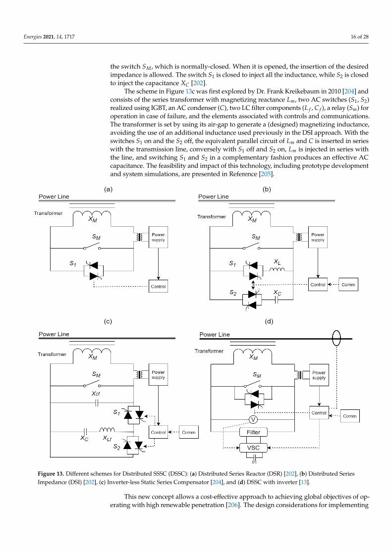
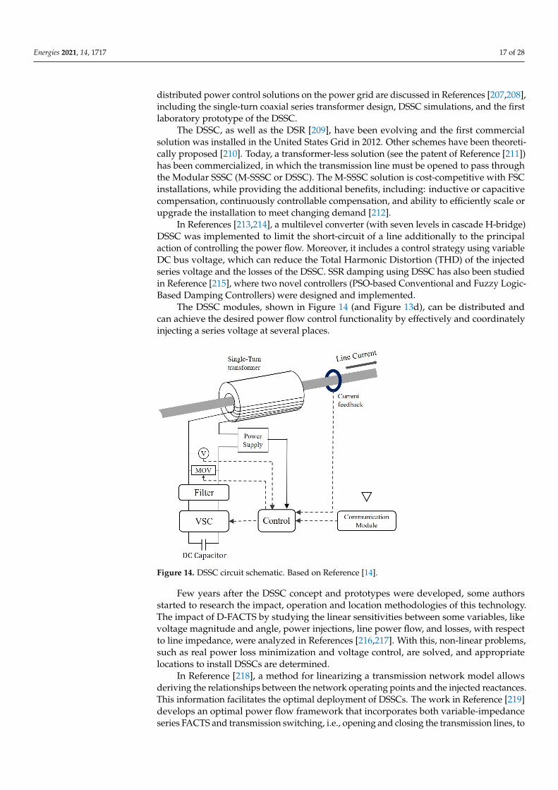
Dr. D.M. Divan proposed the DSSC concept in References [13,14,200]. The DSSC at-taches directly to the line conductor and does not require insulation, as shown in Figure 13.The normally closed switch SM maintains the unit in bypass mode (bypass on) until theinverter is activated. To control the DC voltage of the control power supply, a regulator withone switch is used; the DC supply can start the module turn-on by turning-off the switchSM. Then, the converter VSC DC bus is charged up and it starts the inverter operation. Theinverter can inject a quadrature (90 degrees) voltage into the transmission line to emulatea reactance. The DC voltage regulation is achieved using power balance through a smallin-phase voltage component.
Different topologies have been proposed in several publications, summarized inFigure 13. The Distributed Series Reactor (DSR), shown in Figure 13a, is presented inReferences [201,202]. An electromechanical switch (normally-closed) noted SM is used tobypass the DSR. With SM open, the switch S1 controls the series reactance insertion. WhenS1 is closed, the minimal series transformer leakage reactance is inserted in the line. WithS1 open, the transformer magnetizing inductance is inserted into the line. The benefit ofthis technology in reducing transmission investment is explored in Reference [203]. TheDistributed Series Impedance (DSI) shown in Figure 13b uses a capacitor, an inductor, threeswitches, and the series coupling transformer. The transformer is normally bypassed by
Energies 2021, 14, 1717 16 of 28
the switch SM, which is normally-closed. When it is opened, the insertion of the desiredimpedance is allowed. The switch S1 is closed to inject all the inductance, while S2 is closedto inject the capacitance XC [202].
The scheme in Figure 13c was first explored by Dr. Frank Kreikebaum in 2010 [204] andconsists of the series transformer with magnetizing reactance Lm, two AC switches (S1, S2)realized using IGBT, an AC condenser (C), two LC filter components (L f , C f ), a relay (Sm) foroperation in case of failure, and the elements associated with controls and communications.The transformer is set by using its air-gap to generate a (designed) magnetizing inductance,avoiding the use of an additional inductance used previously in the DSI approach. With theswitches S1 on and the S2 off, the equivalent parallel circuit of Lm and C is inserted in serieswith the transmission line, conversely with S1 off and S2 on, Lm is injected in series withthe line, and switching S1 and S2 in a complementary fashion produces an effective ACcapacitance. The feasibility and impact of this technology, including prototype developmentand system simulations, are presented in Reference [205].
Figure 13. Different schemes for Distributed SSSC (DSSC): (a) Distributed Series Reactor (DSR) [202], (b) Distributed SeriesImpedance (DSI) [202], (c) Inverter-less Static Series Compensator [204], and (d) DSSC with inverter [13].
This new concept allows a cost-effective approach to achieving global objectives of op-erating with high renewable penetration [206]. The design considerations for implementing
Energies 2021, 14, 1717 17 of 28
distributed power control solutions on the power grid are discussed in References [207,208],including the single-turn coaxial series transformer design, DSSC simulations, and the firstlaboratory prototype of the DSSC.
The DSSC, as well as the DSR [209], have been evolving and the first commercialsolution was installed in the United States Grid in 2012. Other schemes have been theoreti-cally proposed [210]. Today, a transformer-less solution (see the patent of Reference [211])has been commercialized, in which the transmission line must be opened to pass throughthe Modular SSSC (M-SSSC or DSSC). The M-SSSC solution is cost-competitive with FSCinstallations, while providing the additional benefits, including: inductive or capacitivecompensation, continuously controllable compensation, and ability to efficiently scale orupgrade the installation to meet changing demand [212].
In References [213,214], a multilevel converter (with seven levels in cascade H-bridge)DSSC was implemented to limit the short-circuit of a line additionally to the principalaction of controlling the power flow. Moreover, it includes a control strategy using variableDC bus voltage, which can reduce the Total Harmonic Distortion (THD) of the injectedseries voltage and the losses of the DSSC. SSR damping using DSSC has also been studiedin Reference [215], where two novel controllers (PSO-based Conventional and Fuzzy Logic-Based Damping Controllers) were designed and implemented.
The DSSC modules, shown in Figure 14 (and Figure 13d), can be distributed andcan achieve the desired power flow control functionality by effectively and coordinatelyinjecting a series voltage at several places.
Figure 14. DSSC circuit schematic. Based on Reference [14].
Few years after the DSSC concept and prototypes were developed, some authorsstarted to research the impact, operation and location methodologies of this technology.The impact of D-FACTS by studying the linear sensitivities between some variables, likevoltage magnitude and angle, power injections, line power flow, and losses, with respectto line impedance, were analyzed in References [216,217]. With this, non-linear problems,such as real power loss minimization and voltage control, are solved, and appropriatelocations to install DSSCs are determined.
In Reference [218], a method for linearizing a transmission network model allowsderiving the relationships between the network operating points and the injected reactances.This information facilitates the optimal deployment of DSSCs. The work in Reference [219]develops an optimal power flow framework that incorporates both variable-impedanceseries FACTS and transmission switching, i.e., opening and closing the transmission lines, to

Energies 2021, 14, 1717 18 of 28
study the link between the two power flow control technologies, finding that the operationof FACTS devices affect the location and frequency of transmission switching actions.
Determining the location and amount of distributed series compensation to be em-ployed is an important problem. For this purpose, a PSO technique for the optimal de-ployment of D-FACTS has been analyzed in Reference [220]. In Reference [221], the studyuses the DC load flow model, and the optimization problem is solved using mixed-integerlinear programming (MILP).
In recent years, Dr. Xiaohu Zhang has published relevant advances in transmissionexpansion planning considering DSSC. In Reference [222], a multi-stage transmissionexpansion planning with the DSSC considering the N-1 security constraints is formulatedas an MILP model. In Reference [223], a bi-level optimization model is proposed. Theupper level problem seeks to minimize the investment cost on series FACTS, the cost ofwind power curtailment and load shedding. The lower level problem captures the marketclearing under different operating scenarios.
In References [224,225], the original Mixed-integer non-linear programming (MINLP)model is transformed into MILP model to enable the planning model to be directly appliedto practical large-scale systems. A similar approach was presented in Reference [226], inwhich an approximation method to linearize the model in the structure of the Bendersdecomposition algorithm is proposed.
Other approaches have been published or presented in the last two years related withpower systems with wind energy integration. In Reference [227], the model minimizes thegeneration and investment costs, while guaranteeing that the robust solution is customizedto cover the wind uncertainty interval. In Reference [228], an AC power flow model isproposed and applied to a real power system problem, and the resulting MINLP is solvedusing MATLAB routines; in Reference [229], an MILP is applied initially to find the optimalnumber, locations and set points of multiple DSSCs, and then a fuzzy algorithm is used toselect the most preferred solution.
Finally, about the DSSC operation, a heuristic algorithm is developed to control a set ofD-FACTS devices connected to all transmission lines of a power system in Reference [230].The changes required in line impedances, which will be achieved by D-FACTS, are decidedby the proposed algorithm. In this regard, the patent of Reference [231] proposes a methodfor enabling intelligent control of large number of DSSC distributed over the grid.
6. Conclusions
As discussed in this paper, different technologies for series compensation have beingdeveloped over almost the last 100 years of history, some of them effectively installedin power transmission grids, and some still at the theoretical or concept stage. Afterthe proliferation of FSC in the power transmission systems, two approaches to powerelectronics-based series compensators (series FACTS) have been proposed and investigated(and successfully installed in some cases): one family, employing thyristor-switched reac-tors and thyristor-controlled condensers to realize a variable reactive impedance (includingGCSC, TSSC, and TCSC), and the other, employing a switching power converter to realizea controllable synchronous voltage source (VSC) in series with the line (SSSC and DSSCbelong to that approach).
This paper has presented a literature survey that explores and summarizes the mostrelevant publications in this field, from the FSC to the latest and most promising series com-pensation technology, namely the DSSC, including the more conventional, thyristor-basedseries FACTS. The DSSC is believed to be already cost-competitive with FSC, providing ad-ditional benefits, such as inductive or capacitive compensation, continuously controllablecompensation, and ability to efficiently scale the installation to meet changing require-ments. Furthermore, they have several advantages over TCSC, including increased controlcapabilities, minimal impact on line protection system, minimal environmental impact,higher resiliency and reliability (because a set of them can be installed at different locationsof the same transmission line or operational area), and reduced substation infrastructure
Energies 2021, 14, 1717 19 of 28
requirements (because of its footprint size). Additionally, they have a shorter installationtime than other FACTS, which can be a decisive factor in the case of power grids that needan immediate solution.
Variable series compensation is highly effective in both controlling line power flowsand improving stability. It can be applied in many applications: to achieve full utilizationof transmission assets by controlling the power flow across the lines, preventing loop flowsand reducing stability margin requirements, voltage controlling and stability enhancement.More applications and benefits of this FACTS should continue to be investigated, butmore importantly, the research and development of university and research centers willcontinue to give way to the commercial development of cost-efficient technologies for theirinstallation and proliferation in power transmission systems. From the literature reviewsynthesized in Section 2, it can be inferred that future challenges have to be oriented to findnovel applications, additional to those already known, so that different series technologiescan be increasingly considered by those in charge of planning the expansion of electricaltransmission grids and the electrical equipment development. Particularly, future researchmight be focused on new protection schemes for SSSC and DSSC considering that these newtechnologies can be massively deployed in the power system, therefore requiring a smoothintegration with legacy power system protection strategies. In addition, more controlapproaches to find additional applications for DSSC and GCSC are of utmost importancein order to widen the possible economic incomes due to the provision of new services tothe power system operator. These new control methodologies along with new planningstrategies (i.e., location and sizing of series devices) may facilitate the business plan of thesetechnologies characterized by large investment costs. In this regard, it is key to maximizetheir capabilities once installed by applying convenient wide area coordinated controltechniques aiming at optimizing their operation. In this way, power system operators willbe able to achieve the required flexibility to reduce the stress in the complex operation ofan increasingly renewable-based power system pursuing its fully decarbonization.
Author Contributions: Conceptualization, A.G.-E. and J.M.M.-O.; methodology, A.G.-E.; formalanalysis, C.A.O., A.G.-E. and J.M.M.-O.; investigation, C.A.O.; resources, C.A.O.; data curation,C.A.O.; writing—original draft preparation, C.A.O.; writing—review and editing, A.G.-E. and J.M.M.-O.; visualization, C.A.O.; supervision, A.G.-E. and J.M.M.-O. All authors have read and agreed to thepublished version of the manuscript.
Funding: This research received no external funding.
Institutional Review Board Statement: Not applicable.
Informed Consent Statement: Not applicable.
Data Availability Statement: Not applicable.
Conflicts of Interest: The authors declare no conflict of interest.
Abbreviations
The following abbreviations are used in this manuscript:CIGRE International Council on Large Electric SystemsDPFC Distributed Power Flow ControllerDSI Distributed Series ImpedanceDSSC Distributed Static Series CompensatorDSR Distributed Series ReactorFACTS Flexible AC Transmission SystemFSC Fixed Series CapacitorFSR Fixed Series ReactorGA Genetic AlgorithmGSA Gravitational Search AlgorithmGCSC GTO Thyristor-Controlled Series Capacitor

Energies 2021, 14, 1717 20 of 28
IEEE Institute of Electrical and Electronics EngineersIET Institution of Engineering and TechnologyMINLP Mixed-integer non-linear programmingMILP Mixed-integer linear programmingPSO Particle Swarm OptimizationSSR Sub-synchronous ResonanceSSSC Static Synchronous Series CompensationTCR Thyristor-Controlled ReactorTCSC Thyristor-Controlled Series CapacitorTCSR Thyristor-Controlled Series ReactorTSSC Thyristor-Switched Series CapacitorTSSR Thyristor-Switched Series Reactor
References1. Edris, A.A.; Adapa, R.; Baker, M.; Bohmann, L.; Clark, K.; Habashi, K.; Gyugyi, L.; Lemay, J.; Mehraban, A.; Myers, A.; et al.
Proposed terms and definitions for flexible AC transmission system (FACTS). IEEE Trans. Power Deliv. 1997, 12, 1848–1853.[CrossRef]
2. Hingorani, N.G. High Power Electronics and flexible AC Transmission System. IEEE Power Eng. Rev. 1988, 8, 3–4. [CrossRef]3. Hingorani, N.G.; Gyugyi, L. Static Series Compensators: GCSC, TSSC, TCSC and SSSC. In Understanding FACTS: Concepts and
Technology of Flexible AC Transmission Systems; IEEE Press: Piscataway, NJ, USA; John Wiley & Sons: Hoboken, NJ, USA, 2000;pp. 209–265. [CrossRef]
4. Eremia, M.; Liu, C.C.; Edris, A.A. Series Capacitive Compensation. In Advanced Solutions in Power Systems: HVDC, FACTS, andArtificial Intelligence; IEEE Press: Piscataway, NJ, USA; John Wiley & Sons: Hoboken, NJ, USA, 2016; pp. 339–407. [CrossRef]
5. Shelton, E.K. The series capacitor installation at ballston. Gen. Electr. Rev. 1928, 31, 432–434.6. Alimansky, M.I. Application and performance of Series Capacitors. Gen. Electr. Rev. 1930, 33, 616–625.7. Alimansky, M.I. Series Capacitor Improves. Gen. Electr. Rev. 1933, 36, 461.8. Maneatis, J.A.; Hubacher, E.J.; Rothenbuhler, W.N.; Sabath, J. 500 KV Series Capacitor Installations in California. IEEE Trans.
Power Appar. Syst. 1971, PAS-90, 1138–1149. [CrossRef]9. Jancke, G.; Fahlen, N.; Nerf, O. Series capacitors in power systems. IEEE Trans. Power Appar. Syst. 1975, 94, 915–925. [CrossRef]10. Helbing, S.G.; Karady, G.G. Investigations of an advanced form of series compensation. IEEE Trans. Power Deliv. 1994, 9, 939–947.
[CrossRef]11. Karady, G.G.; Ortmeyer, T.H.; Pilvelait, B.R.; Maratukulam, D. Continuously regulated series capacitor. IEEE Trans. Power Deliv.
1993, 8, 1348–1355. [CrossRef]12. Gyugyi, L.; Schauder, C.D.; Sen, K.K. Static synchronous series compensator: A solid-state approach to the series compensation
of transmission lines. IEEE Trans. Power Deliv. 1997, 12, 406–417. [CrossRef]13. Divan, D.M.; Brumsickle, W.E.; Schneider, R.S.; Kranz, B.; Gascoigne, R.W.; Bradshaw, D.T.; Ingram, M.R.; Grant, I.S. A
Distributed Static Series Compensator System for Realizing Active Power Flow Control on Existing Power Lines. IEEE Trans.Power Deliv. 2007, 22, 642–649. [CrossRef]
14. Divan, D.; Brumsickle, W.; Schneider, R.; Kranz, B.; Gascoigne, R.; Bradshaw, D.; Ingram, M.; Grant, I. A distributed static seriescompensator system for realizing active power flow control on existing power lines. In Proceedings of the IEEE PES PowerSystems Conference and Exposition, New York, NY, USA, 10–13 October 2004; Volume 2, pp. 654–661. [CrossRef]
15. Kimbark, E.W. Improvement of System Stability by Switched Series Capacitors. IEEE Trans. Power Appar. Syst. 1966, PAS-85,180–188. [CrossRef]
16. Maza-Ortega, J.M.; Acha, E.; Garcia, S.; Gómez-Expósito, A. Overview of power electronics technology and applications in powergeneration transmission and distribution. J. Mod. Power Syst. Clean Energy 2017, 499–514. [CrossRef]
17. Bocovich, M.; Iyer, K.; Terhaar, R.M.; Mohan, N. Overview of series connected flexible AC transmission systems (FACTS).In Proceedings of the 2013 North American Power Symposium (NAPS), Manhattan, KS, USA, 22–24 September 2013; pp. 1–6.[CrossRef]
18. Rajarman, R.; Alvarado, F.; Maniaci, A.; Camfield, R.; Jalali, S. Determination of location and amount of series compensation toincrease power transfer capability. IEEE Trans. Power Syst. 1998, 13, 294–300. [CrossRef]
19. Kazerani, Y.Y.M. Power flow control schemes for series-connected FACTS controllers. Electr. Power Syst. Res. 2006, 824–831.[CrossRef]
20. Lakkireddy, J.; Rastgoufard, R.; Leevongwat, I.; Rastgoufard, P. Steady state voltage stability enhancement using shunt andseries FACTS devices. In Proceedings of the 2015 Clemson University Power Systems Conference (PSC), Clemson, SC, USA,10–13 March 2015; pp. 1–5.
21. Kilgore, L.A.; Elliott, L.C.; Taylor, E.R. The Prediction and Control of Self-Excited Oscillations Due to Series Capacitors in PowerSystems. IEEE Trans. Power Appar. Syst. 1971, PAS-90, 1305–1311. [CrossRef]
Energies 2021, 14, 1717 21 of 28
22. Hamouda, R.M.; Iravani, M.R.; Hackam, R. Torsional oscillations of series capacitor compensated AC/DC systems. IEEE Trans.Power Syst. 1989, 4, 889–896. [CrossRef]
23. Rustebakke, H.M.; Concordia, C. Self-Excited Oscillations in a Transmission System Using Series Capacitors. IEEE Trans. PowerAppar. Syst. 1970, PAS-89, 1504–1512. [CrossRef]
24. Bowler, C.E.J.; Ewart, D.N.; Concordia, C. Self Excited Torsional Frequency Oscillations with Series Capacitors. IEEE Trans. PowerAppar. Syst. 1973, PAS-92, 1688–1695. [CrossRef]
25. Korot, D.; Marken, P.; Bock, L. The next fifty years of series capacitors—And the last eighty-six. In Proceedings of the 2014 IEEEPES T D Conference and Exposition, Chicago, IL, USA, 14–17 April 2014; pp. 1–5.
26. Faried, S.O.; Aboreshaid, S. Stochastic evaluation of voltage sags in series capacitor compensated radial distribution systems.IEEE Trans. Power Deliv. 2003, 18, 744–750. [CrossRef]
27. Ping Y.; Sekar, A. Analysis of radial distribution systems with embedded series FACTS devices using a fast line flow-basedalgorithm. IEEE Trans. Power Syst. 2005, 20, 1775–1782.
28. Nayak, P.K.; Pradhan, A.K.; Bajpai, P. Wide-Area Measurement-Based Backup Protection for Power Network with SeriesCompensation. IEEE Trans. Power Deliv. 2014, 29, 1970–1977. [CrossRef]
29. Shchetinin, D.; Hug, G. Decomposed algorithm for risk-constrained AC OPF with corrective control by series FACTS devices.Electr. Power Syst. Res. 2016, 344–353. [CrossRef]
30. Shrestha, G.B.; Feng, W. Effects of series compensation on spot price power markets. Int. J. Electr. Power Energy Syst. 2005,428–436. [CrossRef]
31. McLaren, P.G.; Kuffel, R.; Giesbrecht, J.; Keerthipala, W.; Castro, A.; Fedirchuk, D.; Innes, S.; Mustaphi, K.; Sletten, K. On siterelay transient testing for a series compensation upgrade. IEEE Trans. Power Deliv. 1994, 9, 1308–1315. [CrossRef]
32. Lee, G.E.; Goldsworthy, D.L. BPA’s Pacific AC intertie series capacitors: Experience, equipment and protection. IEEE Trans.Power Deliv. 1996, 11, 253–259. [CrossRef]
33. Coursol, M.; Nguyen, C.T.; Lord, R.; Do, X. Modeling MOV-protected series capacitors for short-circuit studies. IEEE Trans. PowerDeliv. 1993, 8, 448–453. [CrossRef]
34. Goldsworthy, D.L. A Linearized Model for Mov-Protected Series Capacitors. IEEE Trans. Power Syst. 1987, 2, 953–957. [CrossRef]35. Anderson, P.M.; Farmer, R.G. Series Compensation of Power Systems; PBLSH! Inc.: Encinitas, CA, USA, 1996.36. Kosterev, D.N.; Kolodziej, W.J. Bang-bang series capacitor transient stability control. IEEE Trans. Power Syst. 1995, 10, 915–924.
[CrossRef]37. Hiyama, T.; Mishiro, M.; Kihara, H.; Ortmeyer, T.H. Coordinated fuzzy logic control for series capacitor modules and PSS to
enhance stability of power system. IEEE Trans. Power Deliv. 1995, 10, 1098–1104. [CrossRef]38. Lin, Y.J. Prevention of transient instability employing rules based on back propagation based ANN for series compensation. Int. J.
Electr. Power Energy Syst. 2011, 1776–1783. [CrossRef]39. Rahmani, M.; Vinasco, G.; Rider, M.J.; Romero, R.; Pardalos, P.M. Multistage Transmission Expansion Planning Considering
Fixed Series Compensation Allocation. IEEE Trans. Power Syst. 2013, 28, 3795–3805. [CrossRef]40. Leonidaki, E.A.; Georgiadis, D.P.; Hatziargyriou, N.D. Decision trees for determination of optimal location and rate of series
compensation to increase power system loading margin. IEEE Trans. Power Syst. 2006, 21, 1303–1310. [CrossRef]41. Zou, J.; Chen, J.; Dong, E. Study of fast-closing switch based fault current limiter with series compensation. Int. J. Electr. Power
Energy Syst. 2002, 719–722. [CrossRef]42. Ahsaee, M.G.; Sadeh, J. A Novel Fault-Location Algorithm for Long Transmission Lines Compensated by Series FACTS Devices.
IEEE Trans. Power Deliv. 2011, 26, 2299–2308. [CrossRef]43. Swetapadma, A.; Mishra, P.; Yadav, A.; Abdelaziz, A.Y. A non-unit protection scheme for double circuit series capacitor
compensated transmission lines. Electr. Power Syst. Res. 2017, 311–325. [CrossRef]44. Bains, T.P.S.; Sidhu, T.S.; Xu, Z.; Voloh, I.; Zadeh, M.R.D. Impedance-Based Fault Location Algorithm for Ground Faults in
Series-Capacitor-Compensated Transmission Lines. IEEE Trans. Power Deliv. 2018, 33, 189–199. [CrossRef]45. Butler, J.W.; Concordia, C. Analysis of Series Capacitor Application Problems. Trans. Am. Inst. Electr. Eng. 1937, 56, 975–988.
[CrossRef]46. Edris, A. Series compensation schemes reducing the potential of subsynchronous resonance. IEEE Trans. Power Syst. 1990,
5, 219–226. [CrossRef]47. Hedin, R.A.; Weiss, S.; Torgerson, D.; Eilts, L.E. SSR characteristics of alternative types of series compensation schemes. IEEE
Trans. Power Syst. 1995, 10, 845–852. [CrossRef]48. Iravani, M.R.; Edris, A. Eigen analysis of series compensation schemes reducing the potential of subsynchronous resonance.
IEEE Trans. Power Syst. 1995, 10, 876–883. [CrossRef]49. Baker, D.H.; Boukarim, G.E.; D’Aquila, R.; Piwko, R.J. Subsynchronous resonance studies and mitigation methods for series
capacitor applications. In Proceedings of the 2005 IEEE Power Engineering Society Inaugural Conference and Exposition inAfrica, Durban, South Africa, 11–15 July 2005; pp. 386–392.
50. Nilsson, S.L. Apparatus for Controlling the Reactive Impedance of a Transmission Line. U.S. Patent US4999565, 12 March 1990.51. Hingorani, N.G. Transmission Line Power Flow Controller. U.S. Patent US5420495A, 19 April 1993.52. Angquist, L.; Lundin, B.; Samuelsson, J. Power oscillation damping using controlled reactive power compensation-a comparison
between series and shunt approaches. IEEE Trans. Power Syst. 1993, 8, 687–700. [CrossRef]

Energies 2021, 14, 1717 22 of 28
53. Jaewon, C.; Chow, J.H. Time-optimal series capacitor control for damping interarea modes in interconnected power systems.IEEE Trans. Power Syst. 1997, 12, 215–221. [CrossRef]
54. Johansson, N.; Angquist, L.; Nee, H. An Adaptive Controller for Power System Stability Improvement and Power Flow Controlby Means of a Thyristor Switched Series Capacitor (TSSC). IEEE Trans. Power Syst. 2010, 25, 381–391. [CrossRef]
55. Vithayathil, J.J. Scheme for Rapid Adjustment of Network Impedance. U.S. Patent US5032738A, 16 July 1986. Available online:https://patents.google.com/patent/US5032738A (accessed on 17 March 2021).
56. Vithayathil, J.; Taylor, C.; Klinger, M.; Mittelstadt, W. Case Studies of Conventional and Novel Methods of Reactive Power Control on anAC Transmission System; CIGRE Paper 38-02; CIGRE: Paris, France, 1986.
57. Courts, A.L.; Hingorani, N.G.; Stemler, G.E. A New Series Capacitor Protection Scheme Using Nonlinear Resistors. IEEE Trans.Power Appar. Syst. 1978, PAS-97, 1042–1052. [CrossRef]
58. Mathur, R.M.; Varma, R.K. The ThyristorControlled Series Capacitor (TCSC). In Thyristor-Based FACTS Controllers for ElectricalTransmission Systems; Wiley-IEEE Press: Piscataway, NJ, USA, 2002; pp. 277–314. [CrossRef]
59. Nilsson, S.; Aho, J.; Chandrasena, W.; Gama, C.; Shen, H.; Powers, K.; Reynolds, M.; Rudin, A.; Santo, S.; Sen, S.; et al. Reviews ofexisting thyristor control series capacitor devices—TCSC. In Performance Evaluation and Applications; Technical Brochure No. 554;CIGRE Working Group B4-49; CIGRE: Paris, France, 2013.
60. Chaudhuri, B.; Pal, B.C. Robust damping of multiple swing modes employing global stabilizing signals with a TCSC. IEEE Trans.Power Syst. 2004, 19, 499–506. [CrossRef]
61. Noroozian, M.; Angquist, L.; Ghandhari, M.; Andersson, G. Improving power system dynamics by series-connected FACTSdevices. IEEE Trans. Power Deliv. 1997, 12, 1635–1641. [CrossRef]
62. Canizares, C.A. Power flow and transient stability models of FACTS controllers for voltage and angle stability studies. In Pro-ceedings of the 2000 IEEE Power Engineering Society Winter Meeting. Conference Proceedings (Cat. No.00CH37077), Singapore,23–27 January 2000; Volume 2, pp. 1447–1454. [CrossRef]
63. Halder, A.; Pal, N.; Mondal, D. Transient Stability Analysis of a Multimachine Power System with TCSC Controller—A ZeroDynamic Design Approach. Int. J. Electr. Power Energy Syst. 2018, 51–71. [CrossRef]
64. Colvara, L.D.; Araujo, S.C.B. Festraits, E.B. Stability analysis of power system including facts (TCSC) effects by direct methodapproach. Int. J. Electr. Power Energy Syst. 2005, 264–274. [CrossRef]
65. Mattavelli, P.; Stankovic, A.M.; Verghese, G.C. SSR analysis with dynamic phasor model of thyristor-controlled series capacitor.IEEE Trans. Power Syst. 1999, 14, 200–208. [CrossRef]
66. Torgerson, D.; Allaire, J.; Chakravorty, S.; Clark, K.; Edris, A.; Gama, C.; George, T.; Kinney, S.; Othman, H.A. Thyristor ControlledSeries Capacitor—TCSC; CIGRE Working Group 14.18; CIGRE: Paris, France, 1997.
67. Li, B.H.; Wu, Q.H.; Wang, P.Y.; Zhou, X.X. Influence of the transient process of TCSC and MOV on power system stability. IEEETrans. Power Syst. 2000, 15, 798–803. [CrossRef]
68. Sode-Yome, A.; Mithulananthan, N.; Lee, K.Y. Static Voltage Stability Margin Enhancement Using STATCOM, TCSC and SSSC.In Proceedings of the 2005 IEEE/PES Transmission Distribution Conference Exposition: Asia and Pacific, Dalian, China, 18 August2005; pp. 1–6.
69. Mathur, R.M.; Varma, R.K. TTCSC Applications. In Thyristor-Based FACTS Controllers for Electrical Transmission Systems; JohnWiley & Sons: Hoboken, NJ, USA, 2002; pp. 315–358. [CrossRef]
70. Orfanogianni, T.; Bacher, R. Steady-state optimization in power systems with series FACTS devices. IEEE Trans. Power Syst. 2003,18, 19–26. [CrossRef]
71. Duong, T.; JianGang, Y.; Truong, V. A new method for secured optimal power flow under normal and network contingencies viaoptimal location of TCSC. Int. J. Electr. Power Energy Syst. 2013, 68–80. [CrossRef]
72. Verma, K.S.; Singh, S.N.; Gupta, H.O. FACTS devices location for enhancement of total transfer capability. In Proceedings of the2001 IEEE Power Engineering Society Winter Meeting. Conference Proceedings (Cat. No.01CH37194), Columbus, OH, USA,28 January–1 February 2001; Volume 2, pp. 522–527. [CrossRef]
73. Shanmukha Sundar, K.; Ravikumar, H. Selection of TCSC location for secured optimal power flow under normal and networkcontingencies. Int. J. Electr. Power Energy Syst. 2012, 29–37. [CrossRef]
74. Wartana, I.M.; Singh, J.G.; Ongsakul, W.; Agustini, N.P. Optimal Placement of a Series FACTS Controller in Java-Bali 24-busIndonesian System for Maximizing System Loadability by Evolutionary Optimization Technique. In Proceedings of the 2012Third International Conference on Intelligent Systems Modelling and Simulation, Kota Kinabalu, Malaysia, 8–10 February 2012;pp. 516–521.
75. Cai, L.J.; Erlich, I.; Stamtsis, G. Optimal choice and allocation of FACTS devices in deregulated electricity market using geneticalgorithms. In Proceedings of the IEEE PES Power Systems Conference and Exposition, New York, NY, USA, 10–13 October 2004;Volume 1, pp. 201–207. [CrossRef]
76. Mithulananthan, N.A.N. Locating series FACTS devices for congestion management in deregulated electricity markets. Electr.Power Syst. Res. 2007, 352–360. [CrossRef]
77. Ziaee, O.; Choobineh, F.F. Thyristor-controlled switch capacitor placement in large-scale power systems via mixed integer linearprogramming and Taylor series expansion. In Proceedings of the 2014 IEEE PES General Meeting|Conference Exposition,National Harbor, MD, USA, 27–31 July 2014; pp. 1–5.
Energies 2021, 14, 1717 23 of 28
78. Lee, K.H. Optimal siting of TCSC for reducing congestion cost by using shadow prices. Int. J. Electr. Power Energy Syst. 2002,647– 653. [CrossRef]
79. Kulkarni, P.P.; Ghawghawe, N.D. Optimal placement and parameter setting of TCSC in power transmission system to increasethe power transfer capability. In Proceedings of the 2015 International Conference on Energy Systems and Applications, Pune,India, 30 October–1 November 2015; pp. 735–739. [CrossRef]
80. Besharat, H.; Taher, S.A. Congestion management by determining optimal location of TCSC in deregulated power systems. Int. J.Electr. Power Energy Syst. 2008, 563–568. [CrossRef]
81. Kazemi, A.; Badrzadeh, B. Modeling and simulation of SVC and TCSC to study their limits on maximum loadability point. Int. J.Electr. Power Energy Syst. 2004, 619–626. [CrossRef]
82. Ghawghawe, N.D.; Thakre, K.L. Computation of TCSC reactance and suggesting criterion of its location for ATC improvement.Int. J. Electr. Power Energy Syst. 2009, 86–93. [CrossRef]
83. Dawn, S.; Tiwari, P.K. Improvement of economic profit by optimal allocation of TCSC & UPFC with wind power generators indouble auction competitive power market. Int. J. Electr. Power Energy Syst. 2016, 190–201. [CrossRef]
84. Rashed, G.I.; Shaheen, H.I.; Cheng, S.J. Optimal Location and Parameter Settings of Multiple TCSCs for Increasing Power SystemLoadability Based on GA and PSO Techniques. In Proceedings of the Third International Conference on Natural Computation(ICNC 2007), Haikou, China, 24–27 August 2007; Volume 4, pp. 335–344. [CrossRef]
85. Reddy, K.R.S.; Padhy, N.P.; Patel, R.N. Congestion management in deregulated power system using FACTS devices. In Proceed-ings of the 2006 IEEE Power India Conference, New Delhi, India, 10–12 April 2006; p. 8. [CrossRef]
86. Rashidinejad, M.; Farahmand, H.; Fotuhi-Firuzabad, M.; Gharaveisi, A.A. ATC enhancement using TCSC via artificial intelligenttechniques. Electr. Power Syst. Res. 2008, 11–20. [CrossRef]
87. Gerbex, S.; Cherkaoui, R.; Germond, A.J. Optimal location of FACTS devices to enhance power system security. In Proceedingsof the 2003 IEEE Bologna Power Tech Conference Proceedings, Bologna, Italy, 23–26 June 2003; Volume 3, p. 7. [CrossRef]
88. Saravanan, M.; Slochanal, S.M.R.; Venkatesh, P.; Abraham, P.S. Application of PSO technique for optimal location of FACTSdevices considering system loadability and cost of installation. In Proceedings of the 2005 International Power EngineeringConference, Singapore, 29 November–2 December 2005; Volume 2, pp. 716–721. [CrossRef]
89. Mondal, D.; Chakrabarti, A.; Sengupta, A. Optimal placement and parameter setting of SVC and TCSC using PSO to mitigatesmall signal stability problem. Int. J. Electr. Power Energy Syst. 2012, 334–340. [CrossRef]
90. Rezaee Jordehi, A.; Jasni, J.; Abd Wahab, N.; Kadir, M.; Javadi, M. Enhanced leader PSO (ELPSO): A new algorithm for allocatingdistributed TCSC’s in power systems. Int. J. Electr. Power Energy Syst. 2015, 771–784. [CrossRef]
91. Nagalakshmi, S.; Kamaraj, N. On-line evaluation of loadability limit for pool model with TCSC using back propagation neuralnetwork. Int. J. Electr. Power Energy Syst. 2013, 52–60. [CrossRef]
92. Bhasaputra, P.; Ongsakul, W. Optimal placement of multi-type FACTS devices by hybrid TS/SA approach. In Proceedings of the2003 International Symposium on Circuits and Systems, (ISCAS ’03), Bangkok, Thailand, 25–28 May 2003; Volume 3. [CrossRef]
93. Benabid, R.; Boudour, M.; Abido, M.A. Optimal location and setting of SVC and TCSC devices using non-dominated sortingparticle swarm optimization. Electr. Power Syst. Res. 2009, 1668–1677. [CrossRef]
94. Bruno, S.; De Carne, G.; La Scala, M. Transmission Grid Control Through TCSC Dynamic Series Compensation. IEEE Trans.Power Syst. 2016, 31, 3202–3211. [CrossRef]
95. Shubhanga, K.N.; Kulkarni, A.M. Application of structure preserving energy margin sensitivity to determine the effectiveness ofshunt and series FACTS devices. IEEE Trans. Power Syst. 2002, 17, 730–738. [CrossRef]
96. Hingorani, N.G. A New Scheme for Subsynchronous Resonance Damping of Torsional Oscillations and Transient Torque—Part I.IEEE Trans. Power Appar. Syst. 1981, PAS-100, 1852–1855. [CrossRef]
97. Piwko, R.J.; Wegner, C.A.; Kinney, S.J.; Eden, J.D. Subsynchronous resonance performance tests of the Slatt thyristor-controlledseries capacitor. IEEE Trans. Power Deliv. 1996, 11, 1112–1119. [CrossRef]
98. Rajaraman, R.; Dobson, I.; Lasseter, R.H.; Shern, Y. Computing the damping of subsynchronous oscillations due to a thyristorcontrolled series capacitor. IEEE Trans. Power Deliv. 1996, 11, 1120–1127. [CrossRef]
99. Mohammadpour, H.A.; Islam, M.M.; Santi, E.; Shin, Y. SSR Damping in Fixed-Speed Wind Farms Using Series FACTS Controllers.IEEE Trans. Power Deliv. 2016, 31, 76–86. [CrossRef]
100. Dash, P.K.; Mishra, S.; Panda, G. Damping multimodal power system oscillation using a hybrid fuzzy controller for seriesconnected FACTS devices. IEEE Trans. Power Syst. 2000, 15, 1360–1366. [CrossRef]
101. Hameed, S.; Das, B.; Pant, V. A self-tuning fuzzy PI controller for TCSC to improve power system stability. Electr. Power Syst. Res.2008, 1726–1735. [CrossRef]
102. Khan, L.; Lo, K.L. Hybrid micro-GA based FLCs for TCSC and UPFC in a multi-machine environment. Electr. Power Syst. Res.2006, 832–843. [CrossRef]
103. Hameed, S.; Das, B.; Pant, V. Reduced rule base self-tuning fuzzy PI controller for TCSC. Int. J. Electr. Power Energy Syst. 2010,1005–1013. [CrossRef]
104. Bakhshi, M.; Holakooie, M.H.; Rabiee, A. Fuzzy based damping controller for TCSC using local measurements to enhancetransient stability of power systems. Int. J. Electr. Power Energy Syst. 2017, 12–21. [CrossRef]
105. Tripathy, M.; Mishra, S. Interval type-2-based thyristor controlled series capacitor to improve power system stability. Iet Gener.Transm. Distrib. 2011, 5, 209–222. [CrossRef]

Energies 2021, 14, 1717 24 of 28
106. Mohamed, A.A.A.; El-Gaafary, A.A.; Mohamed, Y.S.; Hemeida, A.M. Multi-objective states of matter search algorithm forTCSC-based smart controller design. Electr. Power Syst. Res. 2016, 874–885. [CrossRef]
107. Taranto, G.N.; Chow, J.H. A robust frequency domain optimization technique for tuning series compensation damping controllers.IEEE Trans. Power Syst. 1995, 10, 1219–1225. [CrossRef]
108. Sadikovic, R.; Korba, P.; Andersson, G. Application of FACTS devices for damping of power system oscillations. In Proceedingsof the 2005 IEEE Russia Power Tech, St. Petersburg, Russia, 27–30 June 2005; pp. 1–6. [CrossRef]
109. Zhao, Q.; Jiang, J. A TCSC damping controller design using robust control theory. Int. J. Electr. Power Energy Syst. 1998, 25–33.[CrossRef]
110. Ishimaru, M.; Yokoyama, R.; Shirai, G.; Niimura, T. Robust thyristor-controlled series capacitor controller design based on linearmatrix inequality for a multi-machine power system. Int. J. Electr. Power Energy Syst. 2002, 621–629. [CrossRef]
111. Cai, Z.; Zhu, L.; Lan, Z.; Gan, D.; Ni, Y.; Shi, L.; Bi, T. A study on robust adaptive modulation controller for TCSC based on COIsignal in interconnected power systems. Electr. Power Syst. Res. 2008, 147–157. [CrossRef]
112. Son, K.M.; Park, J.K. On the robust LQG control of TCSC for damping power system oscillations. IEEE Trans. Power Syst. 2000,15, 1306–1312. [CrossRef]
113. Ferreira, A.M.; Barreiros, J.A.; Barra, W., Jr.; Brito-de-Souza, J.R. A robust adaptive LQG/LTR TCSC controller applied to damppower system oscillations. Electr. Power Syst. Res. 2007, 956–964. [CrossRef]
114. Zare, K.; Hagh, M.T.; Morsali, J. Effective oscillation damping of an interconnected multi-source power system with automaticgeneration control and TCSC. Int. J. Electr. Power Energy Syst. 2015, 220–230. [CrossRef]
115. Jamnani, J.G.; Pandya, M. Coordination of SVC and TCSC for Management of Power Flow by Particle Swarm Optimization.Energy Procedia 2019, 321–326. [CrossRef]
116. Abido, M. Pole placement technique for PSS and TCSC-based stabilizer design using simulated annealing. Int. J. Electr. PowerEnergy Syst. 2000, 543–554. [CrossRef]
117. Abdel-Magid, Y.L.; Abido, M.A. Robust coordinated design of excitation and TCSC-based stabilizers using genetic algorithms.Electr. Power Syst. Res. 2004, 129–141. [CrossRef]
118. Fan, L.; Feliachi, A.; Schoder, K. Selection and design of a TCSC control signal in damping power system inter-area oscillationsfor multiple operating conditions. Electr. Power Syst. Res. 2002, 127–137. [CrossRef]
119. Hasanvand, H.; Arvan, M.R.; Mozafari, B.; Amraee, T. Coordinated design of PSS and TCSC to mitigate interarea oscillations. Int.J. Electr. Power Energy Syst. 2016, 194–206. [CrossRef]
120. Maddela, C.O.; Subudhi, B. Robust wide-area TCSC controller for damping enhancement of inter-area oscillations in aninterconnected power system with actuator saturation. Int. J. Electr. Power Energy Syst. 2019, 478–487. [CrossRef]
121. Ali, E.S.; Abd-Elazim, S.M. Coordinated design of PSSs and TCSC via bacterial swarm optimization algorithm in a multimachinepower system. Int. J. Electr. Power Energy Syst. 2012, 84–92. [CrossRef]
122. Ali, E.S.; Abd-Elazim, S.M. TCSC damping controller design based on bacteria foraging optimization algorithm for a multimachinepower system. Int. J. Electr. Power Energy Syst. 2012, 23–30. [CrossRef]
123. Lei, X.; Li, X.; Povh, D. A nonlinear control for coordinating TCSC and generator excitation to enhance the transient stability oflong transmission systems. Electr. Power Syst. Res. 2001, 103–109. [CrossRef]
124. Tripathy, M.; Mishra, S. Coordinated tuning of PSS and TCSC to improve Hopf Bifurcation margin in multimachine powersystem by a modified Bacteria Foraging Algorithm. Int. J. Electr. Power Energy Syst. 2015, 97–109. [CrossRef]
125. Eslami, M.; Shareef, H.; Mohamed, A.; Khajehzadeh, M. PSS and TCSC Damping Controller Coordinated Design Using GSA.Energy Procedia 2012, 763–769. [CrossRef]
126. Elenius, S.; Uhlen, K.; Lakervi, E. Effects of controlled shunt and series compensation on damping in the Nordel system. IEEETrans. Power Syst. 2005, 20, 1946–1957. [CrossRef]
127. Angquist, L.; Gama, C. Damping algorithm based on phasor estimation. In Proceedings of the 2001 IEEE Power EngineeringSociety Winter Meeting. Conference Proceedings (Cat. No.01CH37194), Columbus, OH, USA, 28 January–1 February 2001;Volume 3, pp. 1160–1165. [CrossRef]
128. Padiyar, K.R.; Rao, K.U. Discrete control of series compensation for stability improvement in power systems. Int. J. Electr. PowerEnergy Syst. 1997, 311–319. [CrossRef]
129. Alam, M.S.; Shafiullah, M.; Hossain, M.I.; Hasan, M.N. Enhancement of power system damping employing TCSC with geneticalgorithm based controller design. In Proceedings of the 2015 International Conference on Electrical Engineering and InformationCommunication Technology (ICEEICT), Savar, Bangladesh, 21–23 May 2015; pp. 1–5. [CrossRef]
130. Del Rosso, A.D.; Canizares, C.A.; Dona, V.M. A study of TCSC controller design for power system stability improvement. IEEETrans. Power Syst. 2003, 18, 1487–1496. [CrossRef]
131. Li, C.; Xiao, L.; Cao, Y.; Zhu, Q.; Fang, B.; Tan, Y.; Zeng, L. Optimal allocation of multi-type FACTS devices in power systemsbased on power flow entropy. J. Mod. Power Syst. Clean Energy 2014, 173–180. [CrossRef]
132. Li, B.H.; Wu, Q.H.; Turner, D.R.; Wang, P.Y.; Zhou, X.X. Modelling of TCSC dynamics for control and analysis of power systemstability. Int. J. Electr. Power Energy Syst. 2000, 43–49. [CrossRef]
133. Ambriz-Perez, H.; Acha, E.; Fuerte-Esquivel, C.R. TCSC-firing angle model for optimal power flow solutions using Newton’smethod. Int. J. Electr. Power Energy Syst. 2006, 77–85. [CrossRef]
Energies 2021, 14, 1717 25 of 28
134. Chatterjee, D.; Ghosh, A. TCSC control design for transient stability improvement of a multi-machine power system usingtrajectory sensitivity. Electr. Power Syst. Res. 2007, 470–483. [CrossRef]
135. Dash, P.K.; Pradhan, A.K.; Panda, G.; Liew, A.C. Digital protection of power transmission lines in the presence of series connectedFACTS devices. In Proceedings of the 2000 IEEE Power Engineering Society Winter Meeting. Conference Proceedings (Cat.No.00CH37077), Singapore, 23–27 January 2000; Volume 3, pp. 1967–1972.
136. Weiguo, W.; Xianggen, Y.; Jiang, Y.; Xianzhong, D.; Deshu, C. The impact of TCSC on distance protection relay. In Proceedingsof the POWERCON ’98. 1998 International Conference on Power System Technology, Proceedings (Cat. No.98EX151), Beijing,China, 18–21 August 1998; Volume 1, pp. 382–388. [CrossRef]
137. Li, S. Power flow control effect with TCSC on operation margin of zone 3 impedance relays. Int. J. Electr. Power Energy Syst. 2010,998–1004. [CrossRef]
138. Sahoo, B.; Samantaray, S.R. An enhanced fault detection and location estimation method for TCSC compensated line connectingwind farm. Int. J. Electr. Power Energy Syst. 2018, 432–441. [CrossRef]
139. Nobakhti, S.M.; Akhbari, M. A new algorithm for fault location in series compensated transmission lines with TCSC. Int. J. Electr.Power Energy Syst. 2014, 79–89. [CrossRef]
140. Acharya, N.; Mithulananthan, N. Influence of TCSC on congestion and spot price in electricity market with bilateral contract.Electr. Power Syst. Res. 2007, 1010–1018. [CrossRef]
141. Billinton, R.; Fotuhi-Firuzabad, M.; Faried, S.O. Power system reliability enhancement using a thyristor controlled series capacitor.IEEE Trans. Power Syst. 1999, 14, 369–374. [CrossRef]
142. Benchaib, A.; Poullain, S.; Weiler, Y. Control System and a Method of Controlling a TCSC in an Electrical TransmissionNetwork, in Particular by an Approach Using Sliding Modes. U.S. Patent US20100292863A1, 24 April 2007. Available online:https://patents.google.com/patent/US20100292863A1 (accessed on 17 March 2021).
143. Larsen, E.V.; Nyati, S.; Eitzmann, M.A.; Urbanek, J.; Clark, K. Transient Damping Thyristor Controlled Series Capacitor System.U.S. Patent US5374853A, 20 December 1993. Available online: https://patents.google.com/patent/US5374853A (accessed on 17March 2021).
144. De Souza, L.F.W.; Watanabe, E.H.; Aredes, M. GTO controlled series capacitors: Multi-module and multi-pulse arrangements.IEEE Trans. Power Deliv. 2000, 15, 725–731. [CrossRef]
145. de Jesus, F.D.; Watanabe, E.H.; de Souza, L.F.W.; Alves, J.E.R. SSR and Power Oscillation Damping Using Gate-Controlled SeriesCapacitors (GCSC). IEEE Trans. Power Deliv. 2007, 22, 1806–1812. [CrossRef]
146. Alizadeh Pahlavani, M.R.; Mohammadpour, H.A. Damping of sub-synchronous resonance and low-frequency power oscillationin a series-compensated transmission line using gate-controlled series capacitor. Electr. Power Syst. Res. 2011, 308–317. [CrossRef]
147. Morsali, J.; Zare, K.; Tarafdar Hagh, M. MGSO optimised TID-based GCSC damping controller in coordination with AGC fordiverse-GENCOs multi-DISCOs power system with considering GDB and GRC non-linearity effects. IET Gener. Transm. Distrib.2017, 11, 193–208. [CrossRef]
148. Sen, K.K. SSSC-static synchronous series compensator: Theory, modeling, and application. IEEE Trans. Power Deliv. 1998,13, 241–246. [CrossRef]
149. Edris, A.A.C.; Chow, J.; Watanabe, E.; Barbosa, P.; Halvarsson, P.; Angquist, L.; Fardenesh, B.; Uzunovic, E.; Huang, A.; Tyll,H.; et al. Static synchronous series compensator (SSSC); Technical Brochure No. 371, CIGRE Working Group B4-40; CIGRE: Paris,France, 2009.
150. Vinkovic, A.; Mihalic, R. A current-based model of the static synchronous series compensator (SSSC) for Newton—Raphsonpower flow. Electr. Power Syst. Res. 2008, 1806–1813. [CrossRef]
151. Kamel, S.; Jurado, F.; Chen, Z. Power flow control for transmission networks with implicit modeling of static synchronous seriescompensator. Int. J. Electr. Power Energy Syst. 2015, 911–920. [CrossRef]
152. Zhang, Y.; Zhang, Y. A novel power injection model of embedded SSSC with multi-control modes for power flow analysisinclusive of practical constraints. Electr. Power Syst. Res. 2006, 374–381. [CrossRef]
153. Zhang, X.-P. Advanced modeling of the multicontrol functional static synchronous series compensator (SSSC) in Newton powerflow. IEEE Trans. Power Syst. 2003, 18, 1410–1416. [CrossRef]
154. Pradhan, A.C.; Lehn, P.W. Frequency-domain analysis of the static synchronous series compensator. IEEE Trans. Power Deliv.2006, 21, 440–449. [CrossRef]
155. Eremia, M.; Liu, C.C.; Edris, A.A. Static Synchronous Series Compensator (SSSC). In Advanced Solutions in Power Systems: HVDC,FACTS, and Artificial Intelligence; IEEE Press: Piscataway, NJ, USA; John Wiley & Sons: Hoboken, NJ, USA, 2016; pp. 527–557.[CrossRef]
156. Pillai, G.N.; Ghosh, A.; Joshi, A. Torsional interaction studies on a power system compensated by SSSC and fixed capacitor. IEEETrans. Power Deliv. 2003, 18, 988–993. [CrossRef]
157. Sunil Kumar, L.; Ghosh, A. Modeling and control design of a static synchronous series compensator. IEEE Trans. Power Deliv.1999, 14, 1448–1453. [CrossRef]
158. Pillai, G.N.; Ghosh, A.; Joshi, A. Torsional oscillation studies in an SSSC compensated power system. Electr. Power Syst. Res. 2000,57–64. [CrossRef]
159. Han, B.; Baek, S.; Kim, H.; Karady, G. Dynamic characteristic analysis of SSSC based on multibridge inverter. IEEE Trans. PowerDeliv. 2002, 17, 623–629. [CrossRef]

Energies 2021, 14, 1717 26 of 28
160. Griffo, A.; Lauria, D. Two-Leg Three-Phase Inverter Control for STATCOM and SSSC Applications. IEEE Trans. Power Deliv. 2008,23, 361–370. [CrossRef]
161. El-Zonkoly, A. Optimal sizing of SSSC controllers to minimize transmission loss and a novel model of SSSC to study transientresponse. Electr. Power Syst. Res. 2008, 1856–1864. [CrossRef]
162. Natesan, R.; Radman, G. Effects of STATCOM, SSSC and UPFC on voltage stability. In Proceedings of the Thirty-SixthSoutheastern Symposium on System Theory, Atlanta, GA, USA, 16 March 2004; pp. 546–550. [CrossRef]
163. Devi, S.; Geethanjali, M. Optimal location and sizing of Distribution Static Synchronous Series Compensator using ParticleSwarm Optimization. Int. J. Electr. Power Energy Syst. 2014, 646–653. [CrossRef]
164. Wang, H. Static synchronous series compensator to damp power system oscillations. Electr. Power Syst. Res. 2000, 113–119.[CrossRef]
165. Wang, H.F. Design of SSSC damping controller to improve power system oscillation stability. In Proceedings of the 1999IEEE Africon. 5th Africon Conference in Africa (Cat. No.99CH36342), Cape Town, South Africa, 28 September–1 October 1999;Volume 1, pp. 495–500.
166. Al-Jowder, F. Improvement of synchronizing power and damping power by means of SSSC and STATCOM: A comparativestudy. Electr. Power Syst. Res. 2007, 1112–1117. [CrossRef]
167. Tarafdar Hagh, M.; Sharifian, M.; Galvani, S. Impact of SSSC and STATCOM on power system predictability. Int. J. Electr. PowerEnergy Syst. 2014, 159–167. [CrossRef]
168. Haque, M. Damping improvement by FACTS devices: A comparison between STATCOM and SSSC. Electr. Power Syst. Res. 2006,865–872. [CrossRef]
169. Norouzi, A.H.; Sharaf, A.M. Two control schemes to enhance the dynamic performance of the STATCOM and SSSC. IEEE Trans.Power Deliv. 2005, 20, 435–442.
170. El-Moursi, M.S.; Sharaf, A.M. Novel controllers for the 48-pulse VSC STATCOM and SSSC for voltage regulation and reactivepower compensation. IEEE Trans. Power Syst. 2005, 20, 1985–1997. [CrossRef]
171. Chen, J.; Lie, T.T.; Vilathgamuwa, D.M. Damping of power system oscillations using SSSC in real-time implementation. Int. J.Electr. Power Energy Syst. 2004, 357–364. [CrossRef]
172. Truong, D.N.; Ngo, V.T. Designed damping controller for SSSC to improve stability of a hybrid offshore wind farms consideringtime delay. Int. J. Electr. Power Energy Syst. 2015, 425–431. [CrossRef]
173. Panda, S. Multi-objective evolutionary algorithm for SSSC-based controller design. Electr. Power Syst. Res. 2009, 937–944.[CrossRef]
174. Bhukya, J.; Mahajan, V. Optimization of damping controller for PSS and SSSC to improve stability of interconnected system withDFIG based wind farm. Int. J. Electr. Power Energy Syst. 2019, 314–335. [CrossRef]
175. Morsali, J.; Zare, K.; Hagh, M.T. A novel dynamic model and control approach for SSSC to contribute effectively in AGC of aderegulated power system. Int. J. Electr. Power Energy Syst. 2018, 239–253. [CrossRef]
176. Khadanga, R.K.; Satapathy, J.K. Time delay approach for PSS and SSSC based coordinated controller design using hybridPSO—GSA algorithm. Int. J. Electr. Power Energy Syst. 2015, 262–273. [CrossRef]
177. Movahedi, A.; Niasar, A.H.; Gharehpetian, G.B. Designing SSSC, TCSC, and STATCOM controllers using AVURPSO, GSA, andGA for transient stability improvement of a multi-machine power system with PV and wind farms. Int. J. Electr. Power EnergySyst. 2019, 455–466. [CrossRef]
178. Panda, S.; Yegireddy, N.K.; Mohapatra, S.K. Hybrid BFOA—PSO approach for coordinated design of PSS and SSSC-basedcontroller considering time delays. Int. J. Electr. Power Energy Syst. 2013, 221–233. [CrossRef]
179. Abd Elazim, S.; Ali, E. Optimal SSSC design for damping power systems oscillations via Gravitational Search Algorithm. Int. J.Electr. Power Energy Syst. 2016, 161–168. [CrossRef]
180. Jowder, F.A.L. Influence of mode of operation of the SSSC on the small disturbance and transient stability of a radial powersystem. IEEE Trans. Power Syst. 2005, 20, 935–942. [CrossRef]
181. Castro, M.S.; Ayres, H.M.; Da Costa, V.F.; Da Silva, L.C.P Impacts of the SSSC control modes on small-signal and transientstability of a power system. Electr. Power Syst. Res. 2007, 1–9. [CrossRef]
182. de Dieu Nguimfack-Ndongmo, J.; Kenné, G.; Kuate-Fochie, R.; Cheukem, A.; Fotsin, H.B.; Lamnabhi-Lagarrigue, F. A simplifiednonlinear controller for transient stability enhancement of multimachine power systems using SSSC device. Int. J. Electr. PowerEnergy Syst. 2014, 650–657. [CrossRef]
183. Mihalic, R.; Gabrijel, U. A structure-preserving energy function for a static series synchronous compensator. IEEE Trans. PowerSyst. 2004, 19, 1501–1507. [CrossRef]
184. Gholipour, E.; Nosratabadi, S.M. A new coordination strategy of SSSC and PSS controllers in power system using SOA algorithmbased on Pareto method. Int. J. Electr. Power Energy Syst. 2015, 462–471. [CrossRef]
185. Ngamroo, I.; Kongprawechnon, W. A robust controller design of SSSC for stabilization of frequency oscillations in interconnectedpower systems. Electr. Power Syst. Res. 2003, 161–176. [CrossRef]
186. Mihalic, R.; Papic, I. Static synchronous series compensator—A mean for dynamic power flow control in electric power systems.Electr. Power Syst. Res. 1998, 65–72. [CrossRef]
187. Bongiorno, M.; Angquist, L.; Svensson, J. A Novel Control Strategy for Subsynchronous Resonance Mitigation Using SSSC. IEEETrans. Power Deliv. 2008, 23, 1033–1041. [CrossRef]
Energies 2021, 14, 1717 27 of 28
188. Bongiorno, M.; Svensson, J.; Angquist, L. Single-Phase VSC Based SSSC for Subsynchronous Resonance Damping. IEEE Trans.Power Deliv. 2008, 23, 1544–1552. [CrossRef]
189. Rai, D.; Faried, S.O.; Ramakrishna, G.; Edris, A. An SSSC-Based Hybrid Series Compensation Scheme Capable of DampingSubsynchronous Resonance. IEEE Trans. Power Deliv. 2012, 27, 531–540. [CrossRef]
190. Jowder, F.A.R.A.; Ooi, B.-T. Series compensation of radial power system by a combination of SSSC and dielectric capacitors. IEEETrans. Power Deliv. 2005, 20, 458–465.
191. Farahani, M. Damping of subsynchronous oscillations in power system using static synchronous series compensator. IET Gener.Transm. Distrib. 2012, 6, 539–544. [CrossRef]
192. Rajaram, T.; Reddy, J.M.; Xu, Y. Kalman Filter Based Detection and Mitigation of Subsynchronous Resonance with SSSC. IEEETrans. Power Syst. 2017, 32, 1400–1409.
193. Widyan, M.S. Controlling chaos and bifurcations of SMIB power system experiencing SSR phenomenon using SSSC. Int. J. Electr.Power Energy Syst. 2013, 66–75. [CrossRef]
194. Awad, H.; Nelsen, H.; Blaabjerg, F.; Newman, M.J. Operation of static series compensator under distorted utility conditions.IEEE Trans. Power Syst. 2005, 20, 448–457. [CrossRef]
195. Qader, M. A novel strategic-control-based Distribution Static Synchronous Series Compensator (DSSSC) for power qualityimprovement. Int. J. Electr. Power Energy Syst. 2015, 1106–1118. [CrossRef]
196. Ghorbani, A.; Mozafari, B.; Ranjbar, A.M. Digital distance protection of transmission lines in the presence of SSSC. Int. J. Electr.Power Energy Syst. 2012, 712–719. [CrossRef]
197. Abdollahzadeh, H.; Mozafari, B.; Jazaeri, M. Realistic insights into impedance seen by distance relays of a SSSC-compensatedtransmission line incorporating shunt capacitance of line. Int. J. Electr. Power Energy Syst. 2015, 394–407. [CrossRef]
198. Sadeh, J.; Adinehzadeh, A. Accurate fault location algorithm for transmission line in the presence of series connected FACTSdevices. Int. J. Electr. Power Energy Syst. 2010, 323–328. [CrossRef]
199. Inam, H.; Das, D.; Iyer, A. Modular FACTS Devices with External Fault Current Protection. US Patent US10666038B2, 26 May2017.
200. Divan, D. Improving power line utilization and performance with D-FACTS devices. In Proceedings of the IEEE PowerEngineering Society General Meeting, San Francisco, CA, USA, 16 June 2005; Volume 3, pp. 2419–2424.
201. Divan, D.; Johal, H. Distributed FACTS—A New Concept for Realizing Grid Power Flow Control. In Proceedings of the 2005IEEE 36th Power Electronics Specialists Conference, Dresden, Germany, 16 June 2005; pp. 8–14. [CrossRef]
202. Divan, D.; Johal, H. Distributed FACTS—A New Concept for Realizing Grid Power Flow Control. IEEE Trans. Power Electron.2007, 22, 2253–2260. [CrossRef]
203. Das, D.; Kreikebaum, F.; Divan, D.; Lambert, F. Reducing transmission investment to meet Renewable Portfolio Standards UsingSmart Wires. In Proceedings of the IEEE PES T D 2010, New Orleans, LA, USA, 19–22 April 2010; pp. 1–7.
204. Kreikebaum, F.; Imayavaramban, M.; Divan, D. Active smart wires: An inverter-less static series compensator. In Proceedings ofthe 2010 IEEE Energy Conversion Congress and Exposition, Atlanta, GA, USA, 12–16 September 2010; pp. 3626–3630.
205. Kreikebaum, F.; Das, D.; Yang, Y.; Lambert, F.; Divan, D. Smart Wires—A distributed, low-cost solution for controlling powerflows and monitoring transmission lines. In Proceedings of the 2010 IEEE PES Innovative Smart Grid Technologies ConferenceEurope (ISGT Europe), Gothenburg, Sweden, 11–13 October 2010; pp. 1–8.
206. Divan, D.; Kandula, P. Distributed power electronics: An enabler for the future grid. CPSS Trans. Power Electron. Appl. 2016,1, 57–65. [CrossRef]
207. Johal, H.; Divan, D. Design considerations for series connected distributed FACTS converters. In Proceedings of the FourtiethIAS Annual Meeting. Conference Record of the 2005 Industry Applications Conference, Hong Kong, China, 2–6 October 2005;Volume 2, pp. 889–895.
208. Johal, H.; Divan, D. Design Considerations for Series-Connected Distributed FACTS Converters. IEEE Trans. Ind. Appl. 2007,43, 1609–1618. [CrossRef]
209. Perez, R.; Oliveira, G.; Pereira, M.; Falcao, D.; Kreikebaum, F.; Ramsay, S. FACTS and D-FACTS: The Operational FlexibilityDemanded by the Transmission Expansion Planning Task with Increasing RES; CIGRE Paper C1-202-2014; CIGRE: Paris, France, 2014.
210. Lopes, L.A.C.; Joos, G. Pulse width modulated capacitor for series compensation. IEEE Trans. Power Electron. 2001, 16, 167–174.[CrossRef]
211. Li, T.; Xie, H. Transformer-Less Static Synchronous Series Compensator and Method Therefor. Patent WO2017008245A9, 14 July2015. Available online: https://patents.google.com/patent/WO2017008245A9 (accessed on 17 March 2021).
212. Bojorquez, B.; Santos Lopez, E.; Longoria, M.; Babaei, S. Advantages of M-SSSC Devices over Traditional Series Compensation; CIGRESession 48 B4-PS3-FACTS; CIGRE: Paris, France, 2020.
213. Saradarzadeh, M.; Farhangi, S.; Schanen, J.L.; Jeannin, P.; Frey, D. Application of cascaded H-bridge distribution-staticsynchronous series compensator in electrical distribution system power flow control. IET Power Electron. 2012, 5, 1660–1675.[CrossRef]
214. Saradarzadeh, M.; Farhangi, S.; Schanen, J.L.; Jeannin, P.; Frey, D. Combination of power flow controller and short-circuit limiterin distribution electrical network using a cascaded H-bridge distribution-static synchronous series compensator. IET Gener.Transm. Distrib. 2012, 6, 1121–1131. [CrossRef]
Energies 2021, 14, 1717 28 of 28
215. Khazaie, J.; Mokhtari, M.; Khalilyan, M.; Nazarpour, D. Sub-Synchronous Resonance damping using Distributed Static SeriesCompensator (DSSC) enhanced with fuzzy logic controller. Int. J. Electr. Power Energy Syst. 2012, 80–89. [CrossRef]
216. Rogers, K.M.; Overbye, T.J. Power flow control with Distributed Flexible AC Transmission System (D-FACTS) devices. In Pro-ceedings of the 41st North American Power Symposium, Starkville, MS, USA, 4–6 October 2009; pp. 1–6.
217. Rogers, K.M.; Overbye, T.J. Some applications of Distributed Flexible AC Transmission System (D-FACTS) devices in powersystems. In Proceedings of the 2008 40th North American Power Symposium, Calgary, AB, Canada, 28–30 September 2008;pp. 1–8.
218. Brissette, A.; Maksimovic, D.; Levron, Y. Distributed Series Static Compensator Deployment Using a Linearized TransmissionSystem Model. IEEE Trans. Power Deliv. 2015, 30, 1269–1277. [CrossRef]
219. Sang, Y.; Sahraei-Ardakani, M. The Interdependence between Transmission Switching and Variable-Impedance Series FACTSDevices. IEEE Trans. Power Syst. 2018, 33, 2792–2803. [CrossRef]
220. Das, D.; Prasai, A.; Harley, R.G.; Divan, D. Optimal placement of Distributed Facts devices in power networks Using ParticleSwarm Optimization. In Proceedings of the 2009 IEEE Energy Conversion Congress and Exposition, San Jose, CA, USA,20–24 September 2009; pp. 527–534. [CrossRef]
221. Dorostkar-Ghamsari, M.; Fotuhi-Firuzabad, M.; Aminifar, F.; Safdarian, A.; Lehtonen, M. Optimal distributed static seriescompensator placement for enhancing power system loadability and reliability. IET Gener. Transm. Distrib. 2015, 9, 1043–1050.[CrossRef]
222. Zhang, X.; Tomsovic, K.; Dimitrovski, A. Security Constrained Multi-Stage Transmission Expansion Planning Considering aContinuously Variable Series Reactor. IEEE Trans. Power Syst. 2017, 32, 4442–4450. [CrossRef]
223. Zhang, X.; Shi, D.; Wang, Z.; Zeng, B.; Wang, X.; Tomsovic, K.; Jin, Y. Optimal Allocation of Series FACTS Devices under HighPenetration of Wind Power within a Market Environment. IEEE Trans. Power Syst. 2018, 33, 6206–6217. [CrossRef]
224. Zhang, X.; Tomsovic, K.; Dimitrovski, A. Optimal allocation of series FACTS devices in large-scale systems. IET Gener. Transm.Distrib. 2018, 12, 1889–1896. [CrossRef]
225. Zhang, X.; Xu, C.; Shi, D.; Wang, Z.; Zhang, Q.; Liu, G.; Tomsovic, K.; Dimitrovski, A. Allocation of a variable series reactorconsidering AC constraints and contingencies. CSEE J. Power Energy Syst. 2019, 5, 63–72. [CrossRef]
226. Yuan, Z.; Wang, W.; Wang, H.; Ghadimi, N. Probabilistic decomposition-based security constrained transmission expansionplanning incorporating distributed series reactor. IET Gener. Transm. Distrib. 2020, 14, 3478–3487. [CrossRef]
227. Nikoobakht, A.; Aghaei, J.; Niknam, T.; Shafie-khah, M.; Cataláo, J.P.S. Smart Wire Placement to Facilitate Large-Scale WindEnergy Integration: An Adaptive Robust Approach. IEEE Trans. Sustain. Energy 2019, 10, 1981–1992. [CrossRef]
228. Vinasco, G.E.; Ordóñez, C.A. Optimization Model for Distributed Series Compensation with AC Power Flow. In Proceedings ofthe 2019 FISE-IEEE/CIGRE Conference—Living the energy Transition (FISE/CIGRE), Medellin, Colombia, 4–6 December 2019;pp. 1–4. [CrossRef]
229. Dai, J.; Tang, Y.; Liu, Y.; Ning, J.; Wang, Q.; Zhu, N.; Zhao, J. Optimal configuration of distributed power flow controller toenhance system loadability via mixed integer linear programming. J. Mod. Power Syst. Clean Energy 2019, 7, 1484–1494. [CrossRef]
230. Kirthika, N.; Balamurugan, S. A new dynamic control strategy for power transmission congestion management using seriescompensation. Int. J. Electr. Power Energy Syst. 2016, 271–279. [CrossRef]
231. Inam, H.; Das, D.; Kreikebaum, F.; Iyer, A.; Zhao, A. System and method for distributed grid control with sub-cyclic local responsecapability. US Patent US10559975B2, 9 October 2016. Available online: https://patents.google.com/patent/US10559975B2(accessed on 17 March 2021).
Related Documents