SERIES C CRYOGENIC BALL VALVES

Welcome message from author
This document is posted to help you gain knowledge. Please leave a comment to let me know what you think about it! Share it to your friends and learn new things together.
Transcript
SERIES CCRYOGENIC BALL VALVES
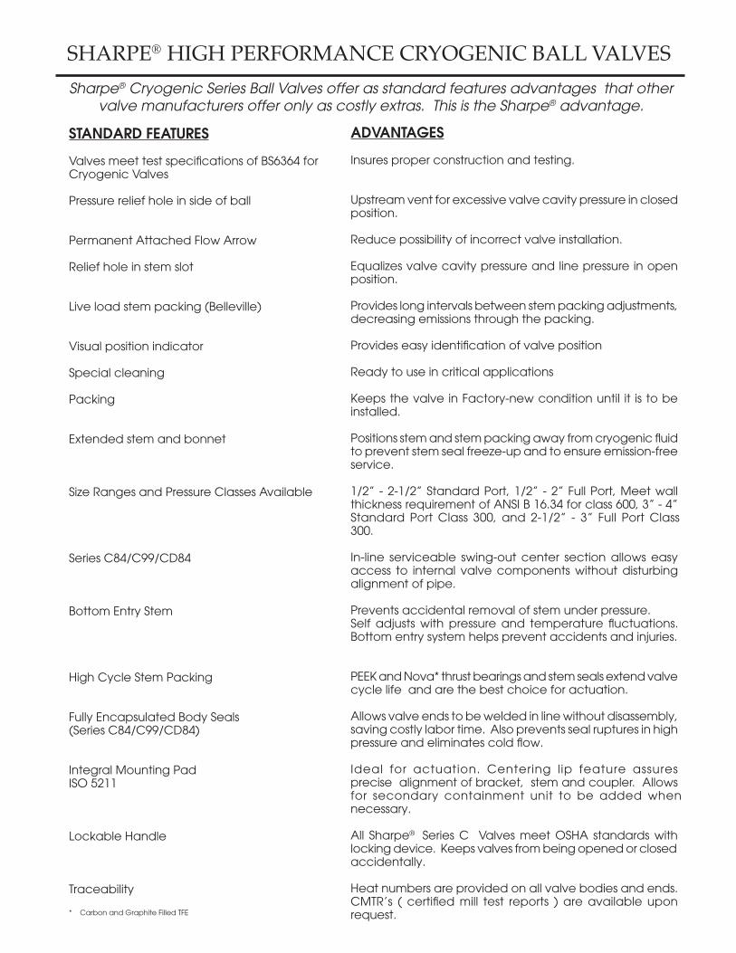
SHARPE® HIGH PERFORMANCE CRYOGENIC BALL VALVESSharpe® Cryogenic Series Ball Valves offer as standard features advantages that other
valve manufacturers offer only as costly extras. This is the Sharpe® advantage.
STANDARD FEATURES
Valves meet test specifications of BS6364 for Cryogenic Valves
Pressure relief hole in side of ball
Permanent Attached Flow Arrow
Relief hole in stem slot
Live load stem packing (Belleville)
Visual position indicator
Special cleaning
Packing
Extended stem and bonnet
Size Ranges and Pressure Classes Available
Series C84/C99/CD84
Bottom Entry Stem
High Cycle Stem Packing
Fully Encapsulated Body Seals(Series C84/C99/CD84)
Integral Mounting PadISO 5211
Lockable Handle
Traceability
* Carbon and Graphite Filled TFE
ADVANTAGES
Insures proper construction and testing.
Upstream vent for excessive valve cavity pressure in closed position.
Reduce possibility of incorrect valve installation.
Equalizes valve cavity pressure and line pressure in open position.
Provides long intervals between stem packing adjustments, decreasing emissions through the packing.
Provides easy identification of valve position
Ready to use in critical applications
Keeps the valve in Factory-new condition until it is to be installed.
Positions stem and stem packing away from cryogenic fluid to prevent stem seal freeze-up and to ensure emission-free service.
1/2” - 2-1/2” Standard Port, 1/2” - 2” Full Port, Meet wall thickness requirement of ANSI B 16.34 for class 600, 3” - 4” Standard Port Class 300, and 2-1/2” - 3” Full Port Class 300.
In-line serviceable swing-out center section allows easy access to internal valve components without disturbing alignment of pipe.
Prevents accidental removal of stem under pressure.Self adjusts with pressure and temperature fluctuations. Bottom entry system helps prevent accidents and injuries.
PEEK and Nova* thrust bearings and stem seals extend valve cycle life and are the best choice for actuation.
Allows valve ends to be welded in line without disassembly, saving costly labor time. Also prevents seal ruptures in high pressure and eliminates cold flow.
Ideal for actuation. Centering lip feature assures precise alignment of bracket, stem and coupler. Allows for secondary containment unit to be added when necessary.
All Sharpe® Series C Valves meet OSHA standards with locking device. Keeps valves from being opened or closed accidentally.
Heat numbers are provided on all valve bodies and ends. CMTR’s ( certified mill test reports ) are available upon request.

78
4
25
6
2
19A
5
22
7
21
1
56
2
19A8A
3
26
23
11
21A
9A
16A
16B16C
14
13
7A
12
12
24
PART NO. PART QTY. MATERIAL
15B Upper Lock Latch 1 Stainless Steel
15C Latch Bolt 1 Stainless Steel
16 Handle (1/4”-2”) 1 Stainless Steel
16A Wrench (3” & 4”) 1 Cad Plate Carbon Steel
16B Wrench Block 1 Stainless Steel
16C Hex Head Bolt 1 Stainless Steel
17 Lock Washer 1 Stainless Steel
18 Handle Nut (1/4”-2”) 1 Stainless Steel
19 Body Bolts 4 Stainless Steel
19A Body Connector Bolts 16 Stainless Steel
20 Nuts 4 Stainless Steel
21 Stop Pin 1 Stainless Steel (1/4”-1/2”) 2 Stainless Steel
21A Stopper 1 Stainless Steel
22 Seat Retainer 1 Stainless Steel 23 Cryo Extension 1 Stainless Steel 316 24 Cryo Extension Bolts 4 Stainless Steel 304 25 Bonnet Seal 1 TFM / TFE 26 Cryo Extension Bushing 1 TFM
PART NO. PART QTY. MATERIAL
1 Body 1 Stainless Steel 316 ASTM A351 CF8M
2 Pipe Ends 2 Stainless Steel 316L ASTM A351 CF3M Bronze ASTM B62/B584 C83600
3 Ball 1 Stainless Steel 316 4 Stem 1 Stainless Steel 316 / 17-4PH 5 Valve Seat 2 PCTFE - KEL-F®** / Reinforced TFE
6 Body Seal 2 TFM / RTFE
7 Thrust Bearing 1 Nova*
7A Stem Location 1 Stainless Steel Ring (3” & 4”) 8 Thrust Bearing 1 PEEK
8A Thrust Bearing 1 Nova*
9 Stem Packing 2 Nova*
9A Stem Packing 3 Nova* (3” & 4”)
10 Seal Protector 1 PEEK
11 Gland Packing 1 Stainless Steel
12 Belleville Washer 2 Stainless Steel
13 Packing Nut 1 Stainless Steel
14 Lock Tab 1 Stainless Steel 15 Lower Lock Latch 1 Stainless Steel
SERIES C84/C99VALVE PARTS AND IDENTIFICATION
C84 1/2” - 2-1/2” C99 1/2”- 2”
C84 3” - 4” C99 2-1/2” - 3”
* Nova: Carbon and Graphite Filled TFE** Kel-F® is registed trade mark of 3M Company.*** TFM is registered trade mark of Dyneon,LLC
78
4
2526
2324
15C
15
21
1817
16
15B
14
13
12
12
111099
5
1
3
5
6
2
19
6
2
207
8

19A
20A
7
3
8A
6
2
19A
5
22
1
56
2
19A
180º
90º
14
13
78
4
2526
23
24
11
21A
9A
16A
16B
7A
7
8A
21
16C
12
12
180º
90º
3
5
6
2
19 19A
7
8
13
12
12
111099
18
17
16
14
15B
1
6
20
20
2
6
5
78
4
26
2324
15C
15
21
25
1/2” - 2-1/2”3” - 4”
SERIES CD84VALVE PARTS AND IDENTIFICATION
PART NO. PART QTY. MATERIAL
16 Handle (1/4”-2”) 1 Stainless Steel
16A Wrench (3” & 4”) 1 Cad Plate Carbon Steel
16B Wrench Block 1 Stainless Steel
16C Hex Head Bolt 1 Stainless Steel
17 Lock Washer 1 Stainless Steel
18 Handle Nut (1/4”-2”) 1 Stainless Steel
19 Body Bolts 4 Stainless Steel
19A Body Connector Bolts 4/24 Stainless Steel
20 Nuts 8 Stainless Steel
20A Nuts 16 Stainless Steel
21 Stop Pin 1 Stainless Steel (1/4”-1/2”) 2 Stainless Steel
21A Stopper 1 Stainless Steel
22 Seat 1 Stainless Steel Retainer
23 Cryo Extension 1 Stainless Steel 316
24 Cryo Extension Bolts 4 Stainless Steel 304
25 Bonnet Seal 1 TFM / TFE
26 Cryo Extension Bushing 1 TFM
PART NO. PART QTY. MATERIAL
1 Body 1 Stainless Steel 316 ASTM A351 CF8M 2 Pipe Ends 3 Stainless Steel 316L ASTM A351 CF3M Bronze ASTM B62/B584 C83600 3 Ball 1 Stainless Steel 316
4 Stem 1 Stainless Steel 316 / 17-4PH
5 Valve Seat 2 PCTFE - KEL-F® / Reinforced TFE
6 Body Seal 3 TFM / TFE
7 Thrust Bearing 1 Nova*
7A Stem Location Ring (3” & 4”) 1 Stainless Steel 8 Thrust Bearing 1 PEEK
8A Thrust Bearing 1 Nova*
9 Stem Packing 2 Nova* 9A Stem Packing 3 Nova* (3” & 4”)
10 Seal Protector 1 PEEK
11 Gland Packing 1 Stainless Steel
12 Belleville Washer 2 Stainless Steel
13 Packing Nut 1 Stainless Steel
14 Lock Tab 1 Stainless Steel
15 Lower Lock Latch 1 Stainless Steel
15B Upper Lock Latch 1 Stainless Steel
15C Latch Bolt 1 Stainless Steel

1
16
17
4
3
4
5
7
2
11B
11C
11A
11
10
10
9
13
15
14
8
8
8
78
6
2324
2122
20
23
78
6
24
2122
13
17
7
16
1
4
3
4
5
2
11B
13A
11A11
12
10
10
9
8
8
8
8
15
20
20
PART NO. PART QTY. MATERIAL
1 Body 1 Stainless Steel 316 ASTM A351 CF8M
2 End Connector 1 Stainless Steel 316 ASTM A351 CF8M 3 Ball 1 Stainless Steel 316
4 Seat 2 PCTFE - KEL-F® / Reinforced TFE 5 Body Seal 1 TFE
6 Stem 1 Stainless Steel 316 / 17-4PH
7 Thrust Bearing 2 Reinforced TFE
8 Stem Packing 3/4 Reinforced TFE
9 Gland Packing 1 304 Stainless Steel 10 Belleville Washer 2 304 Stainless Steel
11 Packing Nut 1 304 Stainless Steel
11A Lock Tab 1 Stainless Steel
11B Handle Nut 1 304 Stainless Steel
11C Lock Washer 1 304 Stainless Steel (1/2”-2”) 12 Stopper 1 304 Stainless Steel
SERIES C50VALVE PARTS AND IDENTIFICATION
CLASS 150BLOW OUT PROOF STEMLOCKING DEVICE
APPLICABLE STANDARDS
Shell Wall Thickness ASME B 16.34
Face to Face Dimensions ASME B 16.10
Flange Dimensions ASME B 16.5
Tests ASME B 16.34 API 598
Basic Design API 608
*See Dimensions
PART NO. PART QTY. MATERIAL
13 Handle 1 304 Stainless Steel (1/2”-2”) Galvanized Steel (2-1/2”-4”)
13A Wrench Block 1 Stainless Steel
13B Hex Head Bolt 1 304 Stainless Steel
14 Locking Device 1 304 Stainless Steel (1/2”-2”)
15 Sleeve 1 Vinyl
16 Body Stud SEE* A193 B8M N
17 Nut SEE* A194 B8M N
20 Stop Pin (1/2”-2”) 1 304 Stainless Steel (2-1/2”-4”) 2 304 Stainless Steel
21 Cryo Extension 1 Stainless Steel 316
22 Cryo Extension Bolts 4 Stainless Steel
23 Bonnet Seal 1 TFM / TFE
24 Cryo Extension Bushing 1 TFM
2-1/2” - 4”
1/2 - 2”

SIZE A B C D E F G L M N Q R T V
150# 300#
1/2” 2.78 4.25 5.50 .969 1.50 6.25 1.00 2.05 6.59 3/8”-24 UNF .22 6.87 1.00 4.50 M5 .28 8 3.90 .44
3/4” 2.78 4.62 6.00 .969 1.50 6.25 1.00 2.05 6.59 3/8”-24 UNF .22 6.87 1.00 4.50 M5 .28 12 3.90 .56
1” 3.68 5.00 6.50 1.25 1.75 7.50 1.18 2.42 8.19 7/16”-20 UNF .30 8.40 1.18 5.75 M5 .30 32 6.70 .81
1-1/4” 4.22 5.50 7.00 1.63 2.00 7.65 1.18 2.70 8.38 7/16”-20 UNF .30 8.70 1.18 5.75 M5 .30 46 7.60 1.00
1-1/2” 4.55 6.50 7.50 1.91 2.25 9.70 1.38 3.16 10.88 9/16”-18 UNF .35 11.16 1.38 7.00 M6 .42 80 12.00 1.25
2” 5.00 7.00 8.50 2.22 2.62 9.90 1.38 3.56 11.06 9/16”-18 UNF .35 11.35 1.38 7.00 M6 .42 120 14.00 1.50
2-1/2” 5.86 7.50 9.50 2.86 3.35 10.90 2.75 4.57 16.56 M20 .55 17.58 1.25 10.00 M8 .55 240 41.00 2.00
SIZE A B C D E F G L M N Q R T V
150# 300#
3” 6.66 8.00 11.12 3.28 5.50 16.09 3.38 6.44 19.44 1-14 UNS .745 19.69 1.75 13.80 M10 .66 350 50.00 2.50
4” 8.40 9.00 12.00 4.28 6.97 16.65 3.38 8.12 20.00 1-14 UNS .745 20.24 1.75 22.00 M10 .66 720 71.00 3.25
SERIES C84DIMENSIONS
FLOWCOEFF.
Cv
APPROX.WEIGHT
PORTSIZE
FLOWCOEFF.
Cv
APPROX.WEIGHT
PORTSIZE
THRD.SW / BW
THRD.SW / BW
1/2” - 2” 2-1/2”
3” - 4”
A
N G D
B
R
L
A
R
B
L
N G D
SIZE A B C D E F G L M N Q R T V
150# 300#
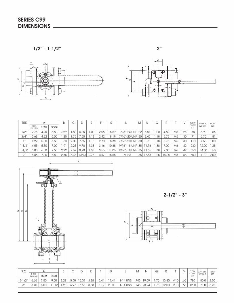
1/2” 2.78 4.25 5.50 .969 1.50 6.25 1.00 2.05 6.59 3/8”-24 UNF .22 6.87 1.00 4.50 M5 .28 38 3.90 .56
3/4” 3.68 4.62 6.00 1.25 1.75 7.50 1.18 2.42 8.19 7/16”-20 UNF .30 8.40 1.18 5.75 M5 .30 71 6.70 .81
1” 4.22 5.00 6.50 1.63 2.00 7.65 1.18 2.70 8.38 7/16”-20 UNF .30 8.70 1.18 5.75 M5 .30 110 7.60 1.00
1-1/4” 4.55 5.50 7.00 1.91 2.25 9.70 1.38 3.16 10.88 9/16”-18 UNF .35 11.16 1.38 7.00 M6 .42 230 12.00 1.25
1-1/2” 5.00 6.50 7.50 2.22 2.62 9.90 1.38 3.56 11.06 9/16”-18 UNF .35 11.35 1.38 7.00 M6 .42 350 14.00 1.50
2” 5.86 7.00 8.50 2.86 3.35 10.90 2.75 4.57 16.56 M-20 .55 17.58 1.25 10.00 M8 .55 600 41.0 2.00
SERIES C99DIMENSIONS
FLOWCOEFF.
Cv
APPROX.WEIGHT
PORTSIZE
SIZE A B C D E F G L M N Q R T V
150# 300#
2-1/2” 6.66 7.50 9.50 3.28 5.50 16.09 3.38 6.44 19.44 1-14 UNS .745 19.69 1.75 13.80 M10 .66 780 50.0 2.50
3” 8.40 8.00 11.12 4.28 6.97 16.65 3.38 8.12 20.00 1-14 UNS .745 20.24 1.75 22.00 M10 .66 1200 71.0 3.25
FLOWCOEFF.
Cv
APPROX.WEIGHT
PORTSIZE
THRD.SW / BW
THRD.SW / BW
1/2” - 1-1/2” 2”
2-1/2” - 3”
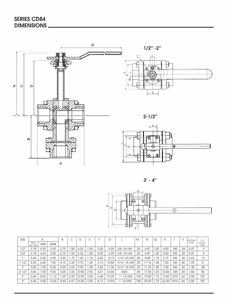
SIZE A B C D E F G L M N Q R T V
150# 300#
1/2” 2.78 4.25 5.50 2.75 1.50 6.25 1.00 2.05 6.59 3/8”-24 UNF .22 6.87 1.00 4.50 M5 .28 0.47 5
3/4” 2.78 4.62 6.00 2.75 1.50 6.25 1.00 2.05 6.59 3/8”-24 UNF .22 6.87 1.00 4.50 M5 .28 0.47 5
1” 3.68 5.00 6.50 3.45 1.75 7.50 1.18 2.42 8.19 7/16”-20 UNF .30 8.40 1.18 5.75 M5 .30 0.63 13
1-1/2” 4.55 6.50 7.50 4.15 2.25 9.70 1.38 3.16 10.88 9/16”-18 UNF .35 11.16 1.38 7.00 M6 .42 1.05 31
2” 5.00 7.00 8.50 4.50 2.62 9.90 1.38 3.56 11.06 9/16”-18 UNF .35 11.35 1.38 7.00 M6 .42 1.40 48
2-1/2” 5.86 7.50 9.50 6.00 3.35 10.90 2.92 4.57 16.56 M20 .55 17.58 1.25 10.00 M8 .55 1.84 82
3” 6.66 8.00 11.12 7.25 5.50 15.90 3.38 6.44 19.25 1”-14 UNS .745 19.50 1.75 13.80 M10 .66 2.00 120
4” 8.40 9.00 12.00 8.60 6.97 16.50 3.38 8.12 19.84 1”-14 UNS .745 20.09 1.75 22.00 M10 .66 2.50 155
SERIES CD84DIMENSIONS
BOTTOMPORT
CV*US GAL.
GPMTHRD.
SW / BW
1/2” -2”
2-1/2”
3’ - 4”

SIZE N G H I J K W
CLASS 150# 300# 150# 300# 150# 300# 150# 300# 150# 300# 150# 300# 150# 300#
1/2” 4 4 9.60 9.60 3/8-24 UNF 0.22 0.22 0.28 0.28 0.63 0.63 M5 M5
3/4” 4 4 9.75 9.75 3/8-24 UNF 0.22 0.22 0.28 0.28 0.63 0.63 M5 M5
1” 4 4 11.75 11.75 7/16-20 UNF 0.30 0.30 0.30 0.30 0.90 0.90 M6 M6
1-1/2” 4 4 12.50 12.50 9/16-18 UNF 0.35 0.35 0.42 0.42 1.18 1.18 M8 M8
2” 4 8 16.80 16.80 9/16-18 UNF 0.35 0.35 0.42 0.42 1.18 1.18 M8 M8
2-1/2” 4 8 18.45 18.45 M20 0.55 0.55 0.55 0.55 1.83 1.83 M10 M10
3” 4 8 18.75 18.75 1”-14 UNS 0.745 0.745 0.66 0.66 1.83 1.83 M10 M10
4” 8 8 19.45 19.45 1”-14 UNS 0.745 0.745 0.66 0.66 1.83 1.83 M10 M10
A
B
E F
C G
D
0.06
A
D
N
E F
C
G
B
0.06
SERIES C50DIMENSIONS
1/2” - 2” 2-1/2” - 4”
SIZE A B C D E F
CLASS 150# 300# 150# 300# 150# 300# 150# 300# 150# 300# 150# 300#
1/2” 4.25 5.50 4.75 4.75 9.70 9.70 1.80 2.64 2.38 2.62 3.50 3.75
3/4” 4.62 6.00 4.75 4.75 9.90 9.90 2.00 2.94 2.75 3.25 3.85 4.60
1” 5.00 6.50 6.22 6.22 11.90 11.90 2.12 3.19 3.13 3.50 4.25 4.90
1-1/2” 6.50 7.50 9.00 9.00 12.70 12.70 2.76 3.63 3.56 4.50 5.00 6.15
2” 7.00 8.50 9.00 9.00 17.00 17.00 3.08 4.30 4.75 5.00 6.00 6.50
2-1/2” 7.50 9.50 13.75 13.75 18.70 18.70 3.09 4.90 5.50 5.86 7.00 7.48
3” 8.00 11.12 13.75 13.75 19.00 19.00 3.74 5.40 6.00 6.62 7.48 8.26
4” 9.00 12.00 13.75 13.75 19.70 19.70 4.46 5.94 7.50 7.88 9.01 10.00
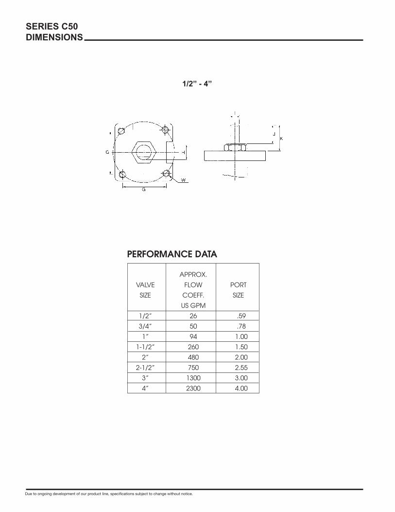
SERIES C50DIMENSIONS
APPROX.
VALVE FLOW PORT
SIZE COEFF. SIZE
US GPM
1/2” 26 .59
3/4” 50 .78
1” 94 1.00
1-1/2” 260 1.50
2” 480 2.00
2-1/2” 750 2.55
3” 1300 3.00
4” 2300 4.00
PERFORMANCE DATA
Due to ongoing development of our product line, specifications subject to change without notice.
1/2” - 4”
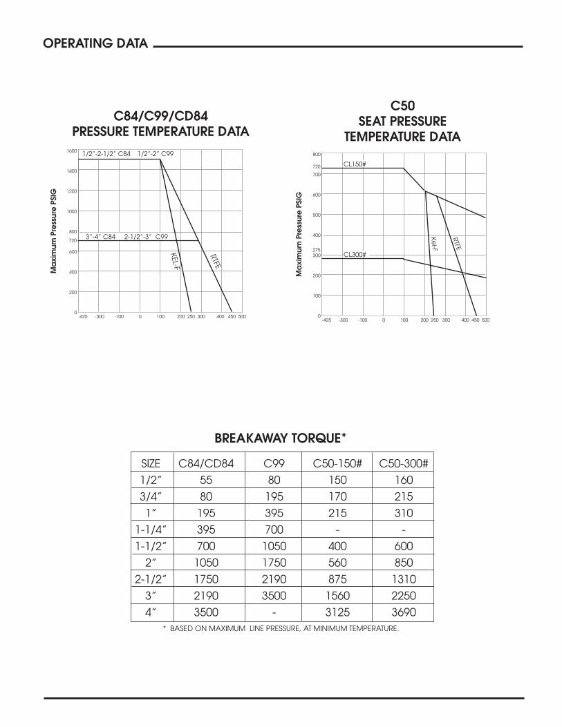
OPERATING DATA
1600
1400
1200
1000
800
600
400
200
0
C84/C99/CD84PRESSURE TEMPERATURE DATA
-425 -300 -100 0 100 200 250 300 400 450 500
Ma
xim
um P
ress
ure
PSI
G
RTFE
SIZE C84/CD84 C99 C50-150# C50-300#
1/2” 55 80 150 160
3/4” 80 195 170 215
1” 195 395 215 310
1-1/4” 395 700 - -
1-1/2” 700 1050 400 600
2” 1050 1750 560 850
2-1/2” 1750 2190 875 1310
3” 2190 3500 1560 2250
4” 3500 - 3125 3690
BREAKAWAY TORQUE*
* BASED ON MAXIMUM LINE PRESSURE, AT MINIMUM TEMPERATURE.
720
KEL-F
1/2”-2-1/2” C84 1/2”-2” C99
3”-4” C84 2-1/2”-3” C99
-425 -300 -100 0 100 200 250 300 400 450 500
C50SEAT PRESSURE
TEMPERATURE DATA800
700
600
500
400
300
200
100
0
Ma
xim
um P
ress
ure
PSI
G
275
720
RTFE
Kel-F
CL300#
CL150#

3/4” C84 6 6 K M TE FS
3/4” CD84 6 6 K M TE P1 FS
HOW TO ORDER
HOW TO ORDER
HOW TO ORDER
3/4” C50 11 6 K FS
VALVE VALVE BODY, STEM SIZE SERIES & BALL ENDS SEATS SEALS ENDS OPTIONS
1/2” C84 Standard Port 6 = 316 Stainless Steel 6 = 316L Stainless Steel K = KEL-F® M = TFM IPS GO = Gear Operator
3/4” C99 Full Port 1 = Bronze R= RTFE T = TFE TE = Threaded NB = Non Extended Bonnet**
1” TEB = Threaded BSPT SB = Special Extended Length
1-1/4” R= BW = Butt Weld SCH 5,10,40,80 OH = Oval Handle
1-1/2” SW = Socket Weld OH = Oval Handle
2” 1 = 150# Flanged
2-1/2” 3 = 300# Flanged
3” TUBE ENDS 4”* IE = Instrumentation Ends ** Valves available without
(*C84 Only) BE = Tube Buttweld Bonnet Extension, for intermittent
BTE = Tube Extended Buttweld Cryogenic service.
VALVE VALVE BODY, STEM ENDS BALL SIZE SERIES & BALL SIDE & BOTTOM SEATS SEALS ENDS CONFIGURATIONS OPTIONS
1/2” CD84 6 = 316 Stainless Steel 6 = 316L Stainless Steel K = KEL-F® M = TFM IPS P1 GO = Gear Operator
3/4” (DIVERTERS) 1 = Bronze R = RTFE T = TFE TE = Threaded P2 NB = Non Extended Bonnet**
1” R= RTFE TEB = Threaded BSPT SB = Special Extended Length
1-1/2” R= BW = Butt Weld OH = Oval Handle
2” SCH 5,10,40,80 OH = Oval Handle
2-1/2” SW = Socket Weld
3” 1 = 150# Flanged
4” 3 = 300# Flanged
TUBE ENDS IE = Instrumentation Ends
BE = Tube Buttweld ** Valves available without
BTE = Tube Extended Bonnet Extension, for intermittent
BButtweld Cryogenic service.
T
VALVE VALVE SIZE SERIES CLASS ALLOY SEATS OPTIONS
1/2” 2” C50 11 = 150# 6 = 316 Stainless Steel K = KEL-F® GO = Gear Operator
3/4” 2-1/2” 33 = 300# K R = RTFE NB = Non Extended Bonnet** 1” 3” SB = Special Extended Length 1-1/4” 4” R = OH = Oval HandleNB = 1-1/2” ** Valves available without Bonnet Extension, for
intermittent Cryogenic service.
Toll-Free 1-877-7SHARPE(877) 774-2773
Fax: (708) 562-9250E-Mail: [email protected]
www.sharpevalves.com1260 Garnet Drive
Northlake, Illinois 60164 U.S.A. A Division of Smith-Cooper International, LLC
Due to continuous development of our product range we reserve the right to change the dimensions and information contained in the leaflet as required. Rev. 1/09TFE is a registered trademark of Dyneon, LLC.
Related Documents