4GV23EN - 10/2020 1 Angle pattern globe valves Series AU, AB, AM Neles™ A series angle pattern globe valves are economical high-performance control valves designed to provide the best possible control accuracy and wide rangeability with the all inherent benefits of linear control valves. The A series valves are designed for use in modulating control, available with Unbalanced trim, Balanced cage trim and Omega™ multistage trim. They provide reliable operation and are well suited for many different kind of applications. The angle pattern valves are especially suitable for severe applications where high pressure drop and erosive fluid exist. The flow in an angle valve does not impact directly into the body as it exits the trim, instead, it passes straight down into the downstream piping, which is an advantage if the fluid is erosive and moving at high velocity. Standard valves are equipped with spring diaphragm actuators and Neles™intelligent valve controllers for precise flow control, extended operational life and performance monitoring on-line. Construction • Compact and lightweight construction • Wide variety of trims with different Cv and characteristics • Both metal and soft seat available depending from the application • Option for bellows seal for toxic or other application where no leak is allowed • Wide material selection for different applications • Many end connection styles available for different applications • Extension bonnet design for wide temperature range Wide range of applications • Suitable for gas, liquid and steam • Temperature limits -29...+425°C with standard bonnet construction. Over +425 °C and under -29 °C with extension bonnet • Tendril™ multi-hole trim for high pressure drop and cavitation applications • Micro trim for small flow and/or to get rid of the stability problems in high pressure drop application • Omega multistage trim for severe service applications Accurate control • Neles™ digital valve controller for auto-calibration and accurate control • Accurate and sensitive diaphragm and piston actuators Safety and quality • Rugged one piece body structure to minimizes the leak paths and makes the valve insensitive to pipe stress • Strictly tested to ensure specified performance with quality assurance systems in according to ISO 9001 • Certified ISO 15848 fugitive emissions • Certified CE/PED & ATEX, TSG & EAC (GOST-R) Easy maintenance • Quick change trim and top entry construction for easy in-line maintenance • Valve assembly is easy and self guiding • Flow characteristics can be easily changed with interchangable trim parts • Neles™ digital valve controller with online diagnostics enables performance follow up and predictive maintenance • Efficient asset management with any FDT frame application and excellent networking capabilities

Welcome message from author
This document is posted to help you gain knowledge. Please leave a comment to let me know what you think about it! Share it to your friends and learn new things together.
Transcript

Angle pattern globe valvesSeries AU, AB, AM
Neles™ A series angle pattern globe valves are economical high-performance control valves designed to provide the best possible control accuracy and wide rangeability with the all inherent benefits of linear control valves. The A series valves are designed for use in modulating control, available with Unbalanced trim, Balanced cage trim and Omega™ multistage trim. They provide reliable operation and are well suited for many different kind of applications.The angle pattern valves are especially suitable for severe applications where high pressure drop and erosive fluid exist. The flow in an angle valve does not impact directly into the body as it exits the trim, instead, it passes straight down into the downstream piping, which is an advantage if the fluid is erosive and moving at high velocity. Standard valves are equipped with spring diaphragm actuators and Neles™intelligent valve controllers for precise flow control, extended operational life and performance monitoring on-line.
Construction• Compact and lightweight construction• Wide variety of trims with different Cv and characteristics• Both metal and soft seat available depending from the
application• Option for bellows seal for toxic or other application where no
leak is allowed• Wide material selection for different applications• Many end connection styles available for different
applications• Extension bonnet design for wide temperature range
Wide range of applications• Suitable for gas, liquid and steam• Temperature limits -29...+425°C with standard bonnet
construction. Over +425 °C and under -29 °C with extension bonnet
• Tendril™ multi-hole trim for high pressure drop and cavitation applications
• Micro trim for small flow and/or to get rid of the stability problems in high pressure drop application
• Omega multistage trim for severe service applications
Accurate control• Neles™ digital valve controller for auto-calibration and
accurate control• Accurate and sensitive diaphragm and piston actuators
Safety and quality• Rugged one piece body structure to minimizes the leak paths
and makes the valve insensitive to pipe stress• Strictly tested to ensure specified performance with quality
assurance systems in according to ISO 9001• Certified ISO 15848 fugitive emissions• Certified CE/PED & ATEX, TSG & EAC (GOST-R)
Easy maintenance• Quick change trim and top entry construction for easy in-line
maintenance• Valve assembly is easy and self guiding• Flow characteristics can be easily changed with
interchangable trim parts• Neles™ digital valve controller with online diagnostics
enables performance follow up and predictive maintenance• Efficient asset management with any FDT frame application
and excellent networking capabilities
4GV23EN - 10/2020 1

Angle pattern globe valves Series AU, AB, AM
AU, Different trim designs
AU, Standard contoured trimAU, Quick change standard contoured plug offers a smooth flow profile.
The trim is most suited to low pressure drop application and is used in the majority of control applications.
AU, Soft seat trimAU, Soft seat option is used on applications where bubble tight shut off, seat leackage class VI is required.
AU, Tendril trimAU, Tendril trim is multi drilled hole trim.
This gives excellent resistance to noise on high pressure drop applications.
AU, Micro trimAU, Micro trim design is an ideal selection for the very low flow rates which is from rated Cv 0.003 to 0.1.
2 4GV23EN - 10/2020

Angle pattern globe valves Series AU, AB, AM
AB, Different trim designs
AB, Quick change, standard cage trimThe standard cage trim is designed with a specially represented window shape cage and balanced plug. The window shape defines the flow path and the flow characteristic of the valve (linear, equal percentage, others). The balancing holes are located in the top of the plug. This trim is suited for both high and low pressure drop application and is used in the majority of control applications.
AB, Tendril™ Multi-hole trimThe trim design presented a multi-hole trim. There are Tendril 1 or Tendril 2 designs in standard depending on pressure drop and potential for cavitation.
The pressure drop is divided by multi-hole so that the pressure progressively reduces as it passes through the trim. This gives excellent resistance to cavitation on high pressure drop applications.
AM, Different trim designs
AM, Omega™ quick change, Standard balanced trimThe Omega standard balanced trim design is based on 2 or 3 dimensional labyrinth disk stack cage and balanced plug. The opened disk stack shape defines the flow path and flow characteristics of the valve(linear, equal percentage, others) standard trim characteristic is linear.
The balancing holes are located in the top of the plug. This trim is specially suited to high pressure drop application and is used in the majority of control applications.
AM, Omega™ quick change, Pilot balanced trimPilot balanced trim construction is designed with a special pilot plug & seat built-in the main plug.
The design gives excellent seat tightness to leakage on high pressure drop and high temperature applications. The design applicable TSO (Tight Shut Off, seat leakage class V) requirement in high temperature services.
4GV23EN - 10/2020 3
Angle pattern globe valves Series AU, AB, AM
4 4GV23EN - 10/2020
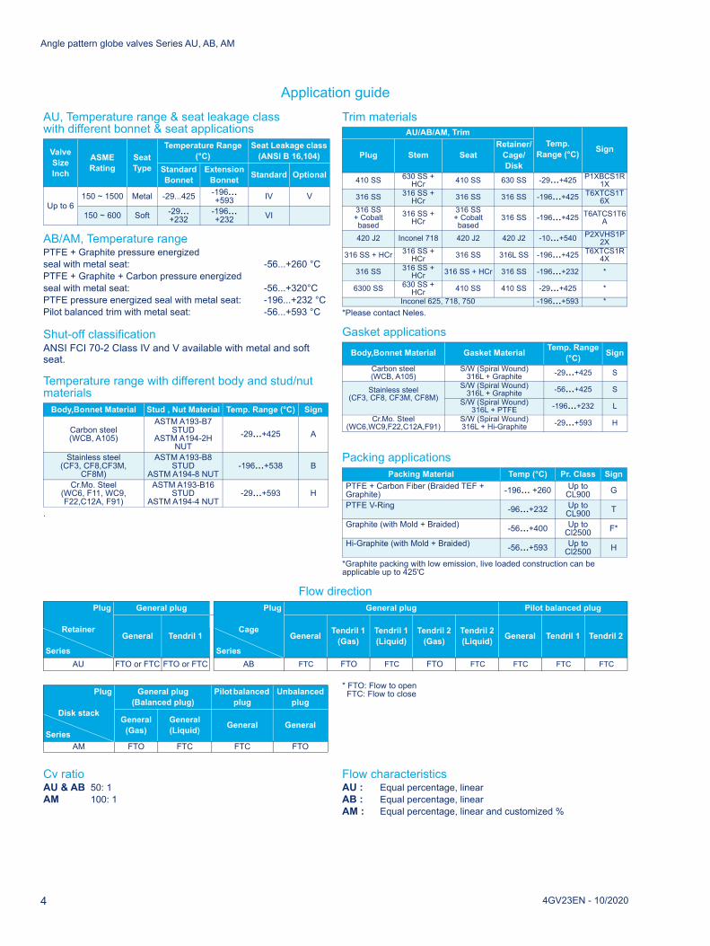
Application guideAU, Temperature range & seat leakage class with different bonnet & seat applications
AB/AM, Temperature range PTFE + Graphite pressure energized seal with metal seat: -56...+260 °C PTFE + Graphite + Carbon pressure energizedseal with metal seat: -56...+320°CPTFE pressure energized seal with metal seat: -196...+232 °C Pilot balanced trim with metal seat: -56...+593 °C
Shut-off classification ANSI FCI 70-2 Class IV and V available with metal and soft seat.
Temperature range with different body and stud/nut materials
.
Trim materials
*Please contact Neles.
Gasket applications
Packing applications
*Graphite packing with low emission, live loaded construction can be applicable up to 425'C
Flow direction
* FTO: Flow to open FTC: Flow to close
Cv ratioAU & AB 50: 1AM 100: 1
Flow characteristicsAU : Equal percentage, linearAB : Equal percentage, linearAM : Equal percentage, linear and customized %
Valve Size Inch
ASMERating
SeatType
Temperature Range (°C)
Seat Leakage class(ANSI B 16,104)
StandardBonnet
ExtensionBonnet Standard Optional
Up to 6150 ~ 1500 Metal -29...425 -196...
+593 IV V
150 ~ 600 Soft -29... +232
-196... +232 VI
Body,Bonnet Material Stud , Nut Material Temp. Range (°C) Sign
Carbon steel(WCB, A105)
ASTM A193-B7 STUD
ASTM A194-2H NUT
-29...+425 A
Stainless steel(CF3, CF8,CF3M,
CF8M)
ASTM A193-B8 STUD
ASTM A194-8 NUT-196...+538 B
Cr.Mo. Steel(WC6, F11, WC9, F22,C12A, F91)
ASTM A193-B16 STUD
ASTM A194-4 NUT-29...+593 H
AU/AB/AM, TrimTemp.
Range (°C) SignPlug Stem SeatRetainer/
Cage/Disk
410 SS 630 SS + HCr 410 SS 630 SS -29...+425 P1XBCS1R
1X316 SS 316 SS +
HCr 316 SS 316 SS -196...+425 T6XTCS1T6X
316 SS + Cobalt based
316 SS + HCr
316 SS + Cobalt based
316 SS -196...+425 T6ATCS1T6A
420 J2 Inconel 718 420 J2 420 J2 -10...+540 P2XVHS1P2X
316 SS + HCr 316 SS + HCr 316 SS 316L SS -196...+425 T6XTCS1R
4X316 SS 316 SS +
HCr 316 SS + HCr 316 SS -196...+232 *
6300 SS 630 SS + HCr 410 SS 410 SS -29...+425 *
Inconel 625, 718, 750 -196...+593 *
Body,Bonnet Material Gasket Material Temp. Range (°C) Sign
Carbon steel(WCB, A105)
S/W (Spiral Wound)316L + Graphite -29...+425 S
Stainless steel(CF3, CF8, CF3M, CF8M)
S/W (Spiral Wound)316L + Graphite -56...+425 S
S/W (Spiral Wound) 316L + PTFE -196...+232 L
Cr.Mo. Steel(WC6,WC9,F22,C12A,F91)
S/W (Spiral Wound) 316L + Hi-Graphite -29...+593 H
Packing Material Temp (°C) Pr. Class SignPTFE + Carbon Fiber (Braided TEF + Graphite) -196... +260 Up to
CL900 G
PTFE V-Ring -96...+232 Up to CL900 T
Graphite (with Mold + Braided) -56...+400 Up to Cl2500 F*
Hi-Graphite (with Mold + Braided) -56...+593 Up to Cl2500 H
Plug
Retainer
Series
General plug Plug
Cage
Series
General plug Pilot balanced plug
General Tendril 1 General Tendril 1 (Gas)
Tendril 1 (Liquid)
Tendril 2 (Gas)
Tendril 2 (Liquid) General Tendril 1 Tendril 2
AU FTO or FTC FTO or FTC AB FTC FTO FTC FTO FTC FTC FTC FTC
Plug
Disk stack
Series
General plug (Balanced plug)
Pilot balanced plug
Unbalanced plug
General (Gas)
General (Liquid) General General
AM FTO FTC FTC FTO

Angle pattern globe valves Series AU, AB, AM
Packing constructions
Seal-ring & seat solutions for AB & AM valve trims
9B
Standard construction
Packing Ring
21
Packing Spacer
9A
Lantern Ring
67
Gland
69
Gland Flange
Hexagon Nut18
12 Disk Spring Assembly
Low Emission withLive Loaded Spring
9A
9B
21
67
69
14
18
Stud1412
Soft seal(pressure energized)
Soft seal withBack-up ring(pressure energized)
Metal seatSoft seat
4GV23EN - 10/2020 5
Angle pattern globe valves Series AU, AB, AM
4GV23EN - 10/2020
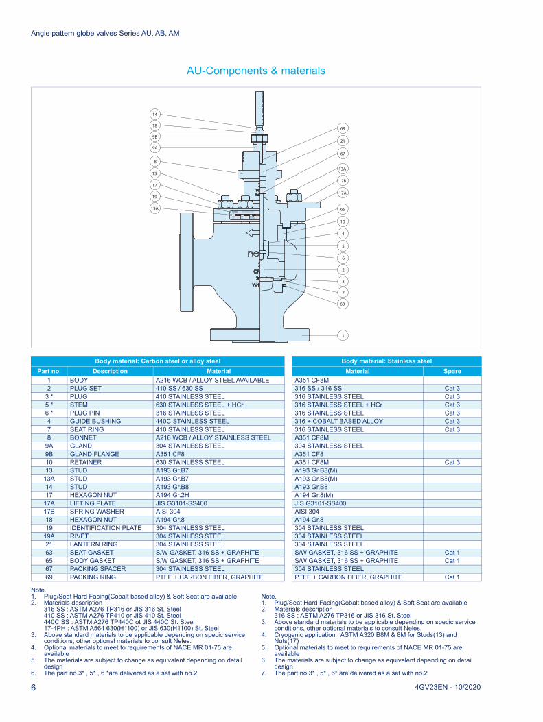
AU-Components & materials
Note.1. Plug/Seat Hard Facing(Cobalt based alloy) & Soft Seat are available2. Materials description
316 SS : ASTM A276 TP316 or JIS 316 St. Steel410 SS : ASTM A276 TP410 or JIS 410 St. Steel440C SS : ASTM A276 TP440C ot JIS 440C St. Steel17-4PH : ASTM A564 630(H1100) or JIS 630(H1100) St. Steel
3. Above standard materials to be applicable depending on specic service conditions, other optional materials to consult Neles.
4. Optional materials to meet to requirements of NACE MR 01-75 are available
5. The materials are subject to change as equivalent depending on detail design
6. The part no.3* , 5* , 6 *are delivered as a set with no.2
Note.1. Plug/Seat Hard Facing(Cobalt based alloy) & Soft Seat are available2. Materials description
316 SS : ASTM A276 TP316 or JIS 316 St. Steel3. Above standard materials to be applicable depending on specic service
conditions, other optional materials to consult Neles.4. Cryogenic application : ASTM A320 B8M & 8M for Studs(13) and
Nuts(17)5. Optional materials to meet to requirements of NACE MR 01-75 are
available6. The materials are subject to change as equivalent depending on detail
design7. The part no.3* , 5* , 6* are delivered as a set with no.2
Body material: Carbon steel or alloy steel Body material: Stainless steelPart no. Description Material Material Spare
1 BODY A216 WCB / ALLOY STEEL AVAILABLE A351 CF8M2 PLUG SET 410 SS / 630 SS 316 SS / 316 SS Cat 3
3 * PLUG 410 STAINLESS STEEL 316 STAINLESS STEEL Cat 35 * STEM 630 STAINLESS STEEL + HCr 316 STAINLESS STEEL + HCr Cat 36 * PLUG PIN 316 STAINLESS STEEL 316 STAINLESS STEEL Cat 34 GUIDE BUSHING 440C STAINLESS STEEL 316 + COBALT BASED ALLOY Cat 37 SEAT RING 410 STAINLESS STEEL 316 STAINLESS STEEL Cat 38 BONNET A216 WCB / ALLOY STAINLESS STEEL A351 CF8M
9A GLAND 304 STAINLESS STEEL 304 STAINLESS STEEL9B GLAND FLANGE A351 CF8 A351 CF810 RETAINER 630 STAINLESS STEEL A351 CF8M Cat 313 STUD A193 Gr.B7 A193 Gr.B8(M)
13A STUD A193 Gr.B7 A193 Gr.B8(M)14 STUD A193 Gr.B8 A193 Gr.B817 HEXAGON NUT A194 Gr.2H A194 Gr.8(M)
17A LIFTING PLATE JIS G3101-SS400 JIS G3101-SS40017B SPRING WASHER AISI 304 AISI 30418 HEXAGON NUT A194 Gr.8 A194 Gr.819 IDENTIFICATION PLATE 304 STAINLESS STEEL 304 STAINLESS STEEL
19A RIVET 304 STAINLESS STEEL 304 STAINLESS STEEL21 LANTERN RING 304 STAINLESS STEEL 304 STAINLESS STEEL63 SEAT GASKET S/W GASKET, 316 SS + GRAPHITE S/W GASKET, 316 SS + GRAPHITE Cat 165 BODY GASKET S/W GASKET, 316 SS + GRAPHITE S/W GASKET, 316 SS + GRAPHITE Cat 167 PACKING SPACER 304 STAINLESS STEEL 304 STAINLESS STEEL69 PACKING RING PTFE + CARBON FIBER, GRAPHITE PTFE + CARBON FIBER, GRAPHITE Cat 1
1
63
7
2
6
5
4
10
65TYPE
BODY
STEM
SEAT
PLUG
t max.
SIZE
MAX PRESSURE
TAG No.
Valve Identification Plate
t min.
RATING
19A
19
17
13
8
9A
9B
18
14
67
21
69
13A
17B
17A
3
6
Angle pattern globe valves Series AU, AB, AM
4GV23EN - 10/2020 7
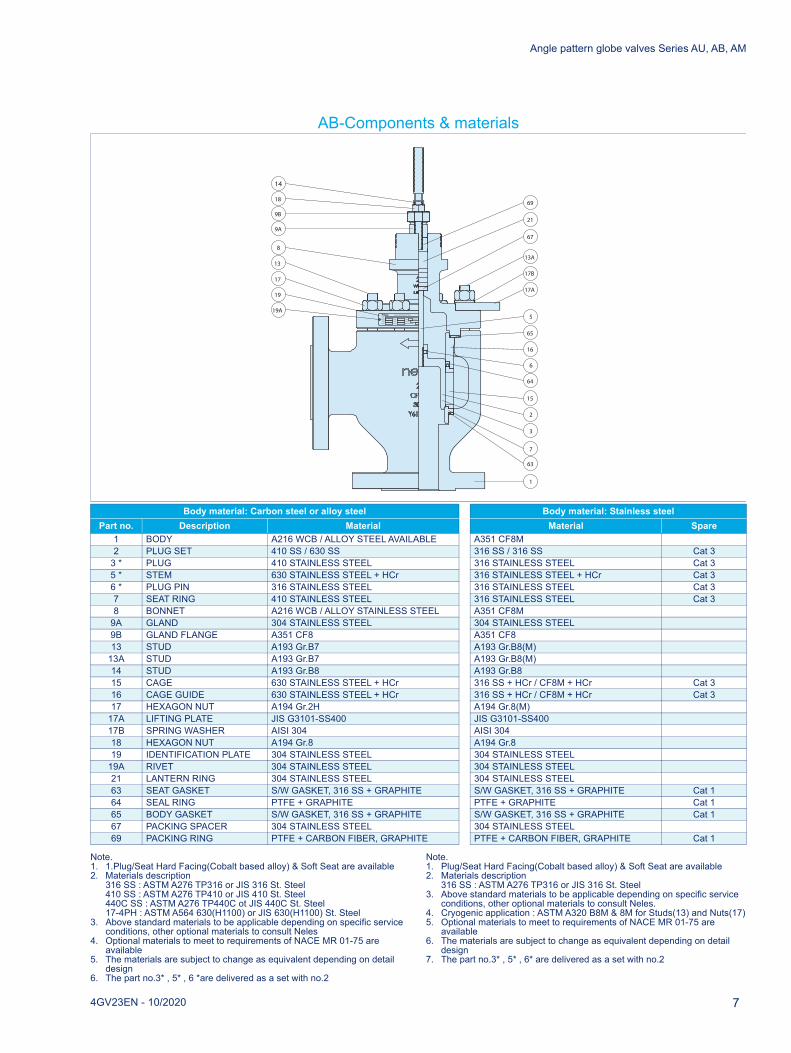
AB-Components & materials
Note.1. 1.Plug/Seat Hard Facing(Cobalt based alloy) & Soft Seat are available2. Materials description
316 SS : ASTM A276 TP316 or JIS 316 St. Steel410 SS : ASTM A276 TP410 or JIS 410 St. Steel440C SS : ASTM A276 TP440C ot JIS 440C St. Steel17-4PH : ASTM A564 630(H1100) or JIS 630(H1100) St. Steel
3. Above standard materials to be applicable depending on specific service conditions, other optional materials to consult Neles
4. Optional materials to meet to requirements of NACE MR 01-75 are available
5. The materials are subject to change as equivalent depending on detail design
6. The part no.3* , 5* , 6 *are delivered as a set with no.2
Note.1. Plug/Seat Hard Facing(Cobalt based alloy) & Soft Seat are available2. Materials description
316 SS : ASTM A276 TP316 or JIS 316 St. Steel3. Above standard materials to be applicable depending on specific service
conditions, other optional materials to consult Neles.4. Cryogenic application : ASTM A320 B8M & 8M for Studs(13) and Nuts(17)5. Optional materials to meet to requirements of NACE MR 01-75 are
available6. The materials are subject to change as equivalent depending on detail
design7. The part no.3* , 5* , 6* are delivered as a set with no.2
Body material: Carbon steel or alloy steel Body material: Stainless steelPart no. Description Material Material Spare
1 BODY A216 WCB / ALLOY STEEL AVAILABLE A351 CF8M2 PLUG SET 410 SS / 630 SS 316 SS / 316 SS Cat 3
3 * PLUG 410 STAINLESS STEEL 316 STAINLESS STEEL Cat 35 * STEM 630 STAINLESS STEEL + HCr 316 STAINLESS STEEL + HCr Cat 36 * PLUG PIN 316 STAINLESS STEEL 316 STAINLESS STEEL Cat 37 SEAT RING 410 STAINLESS STEEL 316 STAINLESS STEEL Cat 38 BONNET A216 WCB / ALLOY STAINLESS STEEL A351 CF8M
9A GLAND 304 STAINLESS STEEL 304 STAINLESS STEEL9B GLAND FLANGE A351 CF8 A351 CF813 STUD A193 Gr.B7 A193 Gr.B8(M)
13A STUD A193 Gr.B7 A193 Gr.B8(M)14 STUD A193 Gr.B8 A193 Gr.B815 CAGE 630 STAINLESS STEEL + HCr 316 SS + HCr / CF8M + HCr Cat 316 CAGE GUIDE 630 STAINLESS STEEL + HCr 316 SS + HCr / CF8M + HCr Cat 317 HEXAGON NUT A194 Gr.2H A194 Gr.8(M)
17A LIFTING PLATE JIS G3101-SS400 JIS G3101-SS40017B SPRING WASHER AISI 304 AISI 30418 HEXAGON NUT A194 Gr.8 A194 Gr.819 IDENTIFICATION PLATE 304 STAINLESS STEEL 304 STAINLESS STEEL
19A RIVET 304 STAINLESS STEEL 304 STAINLESS STEEL21 LANTERN RING 304 STAINLESS STEEL 304 STAINLESS STEEL63 SEAT GASKET S/W GASKET, 316 SS + GRAPHITE S/W GASKET, 316 SS + GRAPHITE Cat 164 SEAL RING PTFE + GRAPHITE PTFE + GRAPHITE Cat 165 BODY GASKET S/W GASKET, 316 SS + GRAPHITE S/W GASKET, 316 SS + GRAPHITE Cat 167 PACKING SPACER 304 STAINLESS STEEL 304 STAINLESS STEEL69 PACKING RING PTFE + CARBON FIBER, GRAPHITE PTFE + CARBON FIBER, GRAPHITE Cat 1
TYPE
BODY
STEM
SEAT
PLUG
t max.
SIZE
MAX PRESSURE
TAG No.
Valve Identification Plate
t min.
RATING
19A
19
17
13
8
9A
9B
18
14
67
21
69
13A
17B
17A
1
63
7
3
6
65
15
16
64
5
2
Angle pattern globe valves Series AU, AB, AM
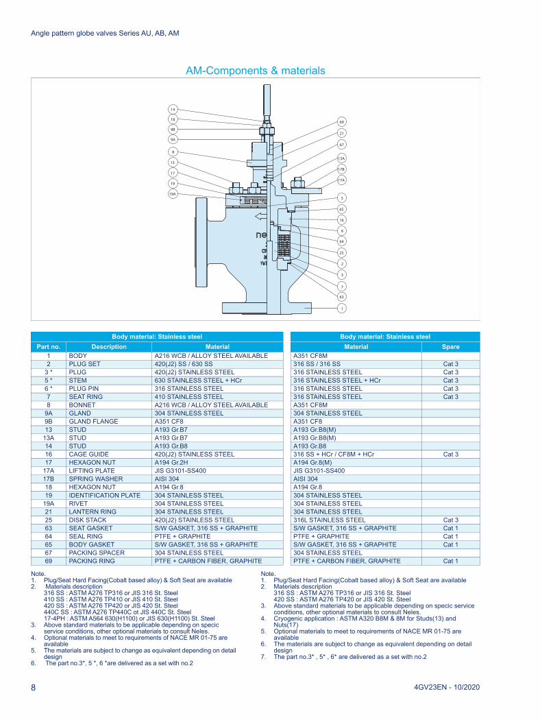
AM-Components & materials
Note.1. Plug/Seat Hard Facing(Cobalt based alloy) & Soft Seat are available2. Materials description
316 SS : ASTM A276 TP316 or JIS 316 St. Steel410 SS : ASTM A276 TP410 or JIS 410 St. Steel420 SS : ASTM A276 TP420 or JIS 420 St. Steel440C SS : ASTM A276 TP440C ot JIS 440C St. Steel17-4PH : ASTM A564 630(H1100) or JIS 630(H1100) St. Steel
3. Above standard materials to be applicable depending on specic service conditions, other optional materials to consult Neles.
4. Optional materials to meet to requirements of NACE MR 01-75 are available
5. The materials are subject to change as equivalent depending on detail design
6. The part no.3*, 5 *, 6 *are delivered as a set with no.2
Note.1. Plug/Seat Hard Facing(Cobalt based alloy) & Soft Seat are available2. Materials description
316 SS : ASTM A276 TP316 or JIS 316 St. Steel420 SS : ASTM A276 TP420 or JIS 420 St. Steel
3. Above standard materials to be applicable depending on specic service conditions, other optional materials to consult Neles.
4. Cryogenic application : ASTM A320 B8M & 8M for Studs(13) and Nuts(17)
5. Optional materials to meet to requirements of NACE MR 01-75 are available
6. The materials are subject to change as equivalent depending on detail design
7. The part no.3* , 5* , 6* are delivered as a set with no.2
Body material: Stainless steel Body material: Stainless steelPart no. Description Material Material Spare
1 BODY A216 WCB / ALLOY STEEL AVAILABLE A351 CF8M2 PLUG SET 420(J2) SS / 630 SS 316 SS / 316 SS Cat 3
3 * PLUG 420(J2) STAINLESS STEEL 316 STAINLESS STEEL Cat 35 * STEM 630 STAINLESS STEEL + HCr 316 STAINLESS STEEL + HCr Cat 36 * PLUG PIN 316 STAINLESS STEEL 316 STAINLESS STEEL Cat 37 SEAT RING 410 STAINLESS STEEL 316 STAINLESS STEEL Cat 38 BONNET A216 WCB / ALLOY STEEL AVAILABLE A351 CF8M
9A GLAND 304 STAINLESS STEEL 304 STAINLESS STEEL9B GLAND FLANGE A351 CF8 A351 CF813 STUD A193 Gr.B7 A193 Gr.B8(M)
13A STUD A193 Gr.B7 A193 Gr.B8(M)14 STUD A193 Gr.B8 A193 Gr.B816 CAGE GUIDE 420(J2) STAINLESS STEEL 316 SS + HCr / CF8M + HCr Cat 317 HEXAGON NUT A194 Gr.2H A194 Gr.8(M)
17A LIFTING PLATE JIS G3101-SS400 JIS G3101-SS40017B SPRING WASHER AISI 304 AISI 30418 HEXAGON NUT A194 Gr.8 A194 Gr.819 IDENTIFICATION PLATE 304 STAINLESS STEEL 304 STAINLESS STEEL
19A RIVET 304 STAINLESS STEEL 304 STAINLESS STEEL21 LANTERN RING 304 STAINLESS STEEL 304 STAINLESS STEEL25 DISK STACK 420(J2) STAINLESS STEEL 316L STAINLESS STEEL Cat 363 SEAT GASKET S/W GASKET, 316 SS + GRAPHITE S/W GASKET, 316 SS + GRAPHITE Cat 164 SEAL RING PTFE + GRAPHITE PTFE + GRAPHITE Cat 165 BODY GASKET S/W GASKET, 316 SS + GRAPHITE S/W GASKET, 316 SS + GRAPHITE Cat 167 PACKING SPACER 304 STAINLESS STEEL 304 STAINLESS STEEL69 PACKING RING PTFE + CARBON FIBER, GRAPHITE PTFE + CARBON FIBER, GRAPHITE Cat 1
TYPE
BODY
STEM
SEAT
PLUG
t max.
SIZE
MAX PRESSURE
TAG No.
Valve Identification Plate
t min.
RATING
19A
19
17
13
8
9A
9B
18
14
67
21
69
13A
17B
17A
1
6
65
16
64
5
25
63
7
3
2
8 4GV23EN - 10/2020

Angle pattern globe valves Series AU, AB, AM
Rated Cv and trim table (Top-guided angle valve, series AU)
- Rated Cv is different depending on trim type and characteristic.- Str. : valve stroke length(mm). It should be matched with actuator stroke length.
Sign TRIM TYPE SignTRIM
CHARACTERISTIC
SignRATED C
DescriptionBody Size and Stroke
0.5" Str. 0.75" Str. 1" Str. 1.5" Str. 2" Str. 3" Str. 4" Str. 6" Str.A General
plug E Equal % FC General / Full capacity 7 (20) 9 (20) 13.5 (20) 28 (20) 49 (20) 100 (40) 190 (40) 295 (60)
L Linear 1A General / 1-Step reduction 4 (20) 5.5 (20) 8.5 (20) 16 (20) 28 (20) 70 (40) 120 (40) 165 (60)2A General / 2-Step reduction 2.3 (20) 3 (20) 5.4 (20) 10.5 (20) 17 (20) 42 (40) 72 (40) 85 (60)3A General / 3-Step reduction 1.5 (20) 2 (20) 3.1 (20) 6 (20) 10 (20) 25 (40) 42 (40) 50 (60)4A General / 4-Step reduction 0.8 (20) 1.2 (20) 2 (20) 4 (20)5A General / 5-Step reduction 0.5 (20) 0.7 (20) 1.2 (20) 2.2 (20)6A General / 6-Step reduction 0.3 (20) 0.4 (20) 0.8 (20) 1.2 (20)FT Tendril / Full capacity 7 (20) 9 (20) 13.5 (20) 28 (20) 49 (20) 100 (40) 190 (40) IQI (60)1T Tendril / 1-Step reduction 4 (20) 5.5 (20) 8.5 (20) 16 (20) 28 (20) 70 (40) 120 (40) IQI (60)2T Tendril / 2-Step reduction 2.3 (20) 3 (20) 5.4 (20) 10.5 (20) 17 (20) 42 (40) 72 (40) IQI (60)3T Tendril / 3-Step reduction 1.5 (20) 2 (20) 3.1 (20) 6 (20) 10 (20) 25 (40) 42 (40) IQI (60)4T Tendril / 4-Step reduction 0.8 (20) 1.2 (20) 2 (20) 4 (20)5T Tendril / 5-Step reduction 0.5 (20) 0.7 (20) 1.2 (20) 2.2 (20)6T Tendril / 6-Step reduction 0.3 (20) 0.4 (20) 0.8 (20) 1.2 (20)
C Micro plug L Linear FC General / Full capacity 0.1 (20) 0.1 (20) 0.1 (20)1A General / 1-Step reduction 0.06 (20) 0.06 (20) 0.06 (20)2A General / 2-Step reduction 0.03 (20) 0.03 (20) 0.03 (20)3A General / 3-Step reduction 0.01 (20) 0.01 (20) 0.01 (20)4A General / 4-Step reduction 0.006 (20) 0.006 (20) 0.006 (20)5A General / 5-Step reduction 0.003 (20) 0.003 (20) 0.003 (20)
Y Special Y Special YY Special Contact Neles for Cv details
4GV23EN - 10/2020 9

Angle pattern globe valves Series AU, AB, AM
Rated Cv and trim table (Cage-guided angle valve, series AB)
Rated Cv and Trim Table (Omega angle valve, series AM)
- Rated Cv is different depending on trim type and characteristic.
Sign TRIM TYPE SignTRIM
CHARACTERISTIC
SignRATED Cv
DescriptionBody Size and Stroke
2" Str. 3" Str. 4" Str. 6" Str. 8" Str. 10" Str. 12" Str. 14" Str. 16" Str.
A General plug E Equal % FC General / Full capacity 82 (40) 174 (50) 280 (50) 470 (60) 810 (70) 1250 (80) 1810 (120) 2530 (140) 2960 (160)
P Pilot balanced plug 1A General / 1-Step
reduction 74 (40) 104 (50) 170 (50) 284 (60) 500 (70) 760 (80) 1100 (120) 1540 (140) 1780 (160)
2A General / 2-Step reduction 44 (40) 62 (50) 100 (50) 170 (60) 320 (70) 460 (80) 680 (120) 940 (140) 1080 (160)
3A General / 3-Step reduction 26 (40) 40 (50) 64 (50) 100 (60) 200 (70) 280 (80) 420 (120) 580 (140) 660 (160)
FT Tendril 1 / Full capacity 52 (40) 102 (50) 160 (50) 290 (60) 460 (70) 630 (80) 980 (120) 1300 (140) 1580 (160)
1T Tendril 1 / 1-Step reduction 40 (40) 75 (50) 120 (50) 220 (60) 340 (70) 460 (80) 735 (120) 985 (140) 1145 (160)
2T Tendril 1 / 2-Step reduction 27 (40) 40 (50) 70 (50) 130 (60) 195 (70) 255 (80) 405 (120) 565 (140) 670 (160)
3T Tendril 1 / 3-Step reduction 10 (40) 21 (50) 46 (50) 75 (60) 105 (70) 140 (80) 240 (120) 310 (140) 415 (160)
FM Tendril 2 / Full capacity 50 (40) 100 (50) 155 (50) 280 (60) 425 (70) 590 (80) 920 (120) 1240 (140) 1530 (160)
1M Tendril 2 / 1-Step reduction 35 (40) 74 (50) 115 (50) 215 (60) 330 (70) 450 (80) 720 (120) 970 (140) 1130 (160)
2M Tendril 2 / 2-Step reduction 23 (40) 33 (50) 65 (50) 120 (60) 190 (70) 240 (80) 380 (120) 550 (140) 640 (160)
3M Tendril 2 / 3-Step reduction 8 (40) 18 (50) 38 (50) 67 (60) 100 (70) 130 (80) 220 (120) 290 (140) 390 (160)
L Linear FC General / Full capacity 76 (40) 160 (50) 256 (50) 430 (60) 740 (70) 1140 (80) 1650 (120) 2300 (140) 2700 (160)
1A General / 1-Step reduction 46 (40) 98 (50) 156 (50) 260 (60) 450 (70) 680 (80) 1000 (120) 1400 (140) 1640 (160)
2A General / 2-Step reduction 28 (40) 60 (50) 94 (50) 156 (60) 270 (70) 410 (80) 640 (120) 840 (140) 980 (160)
3A General / 3-Step reduction 18 (40) 35 (50) 60 (50) 96 (60) 164 (70) 250 (80) 384 (120) 520 (140) 600 (160)
FT Tendril 1 / Full capacity 50 (40) 82 (50) 135 (50) 235 (60) 370 (70) 500 (80) 840 (120) 1110 (140) 1400 (160)
1T Tendril 1 / 1-Step reduction 35 (40) 58 (50) 95 (50) 170 (60) 265 (70) 370 (80) 600 (120) 785 (140) 1020 (160)
2T Tendril 1 / 2-Step reduction 20 (40) 35 (50) 58 (50) 100 (60) 170 (70) 225 (80) 355 (120) 480 (140) 600 (160)
3T Tendril 1 / 3-Step reduction 10 (40) 20 (50) 32 (50) 58 (60) 105 (70) 125 (80) 205 (120) 290 (140) 350 (160)
FM Tendril 2 / Full capacity 47 (40) 74 (50) 130 (50) 230 (60) 330 (70) 470 (80) 770 (120) 1050 (140) 1320 (160)
1M Tendril 2 / 1-Step reduction 33 (40) 56 (50) 92 (50) 165 (60) 245 (70) 330 (80) 570 (120) 720 (140) 960 (160)
2M Tendril 2 / 2-Step reduction 19 (40) 33 (50) 52 (50) 95 (60) 145 (70) 190 (80) 330 (120) 430 (140) 550 (160)
3M Tendril 2 / 3-Step reduction 8 (40) 16 (50) 25 (50) 52 (60) 80 (70) 110 (80) 190 (120) 270 (140) 295 (160)
Y Special Y Special YY Special Contact Neles for Cv details
Sign TRIM TY0PE SignTRIM
CHARACTERISTIC
SignRATED Cv
DescriptionBody size and stroke
1" Str. 1.5" Str. 2" Str. 3" Str. 4" Str. 6" Str. 8" Str. 10" Str. 12" Str. 14" Str. 16" Str.
A Balanced plug E Equal % FG Full capa. / Gas
8 (20) 18 (20) 30 (40) 62 (50) 96 (50) 168 (60) 290 (70) 440 (80) 640 (120) 880 (140) 1160 (160)
P Pilot balanced plug FL Full capa. /
LiquidU Unbalanced
plug 1G 1-Step red. / Gas
5 (20) 12 (20) 20 (40) 40 (50) 60 (50) 100 (60) 180 (70) 270 (80) 400 (120) 530 (140) 700 (160)
1L 1-Step red. / Liquid
2G 2-Step red. / Gas
3 (20) 26 (20) 40 (40) 64 (50) 110 (50) 160 (60) 240 (70) 320 (80) 420 (120) 320 (140) 420 (160)
2L 2-Step red. / Liquid
3G 3-Step red. / Gas
2 (20) 5 (20) 8 (40) 16 (50) 24 (50) 42 (60) 70 (70) 100 (80) 150 (120) 200 (140) 260 (160)
3L 3-Step red. / Liquid
L Linear FG Full capa. / Gas
5 (20) 10 (20) 18 (40) 38 (50) 60 (50) 104 (60) 176 (70) 268 (80) 390 (120) 540 (140) 710 (160)
FL Full capa. / Liquid
1G 1-Step red. / Gas
2.5 (20) 6 (20) 11 (40) 24 (50) 36 (50) 64 (60) 108 (70) 164 (80) 236 (120) 328 (140) 430 (160)
1L 1-Step red. / Liquid
2G 2-Step red. / Gas
1.2 (20) 3 (20) 5 (40) 12 (50) 18 (50) 32 (60) 54 (70) 82 (80) 118 (120) 164 (140) 214 (160)
2L 2-Step red. / Liquid
3G 3-Step red. / Gas
0.6 (20) 1.5 (20) 2 (40) 6 (50) 9 (50) 16 (60) 27 (70) 40 (80) 60 (120) 82 (140) 106 (160)
3L 3-Step red. / Liquid
Y Special Y Special YY Special Contact Neles for Cv details
10 4GV23EN - 10/2020
Angle pattern globe valves Series AU, AB, AM
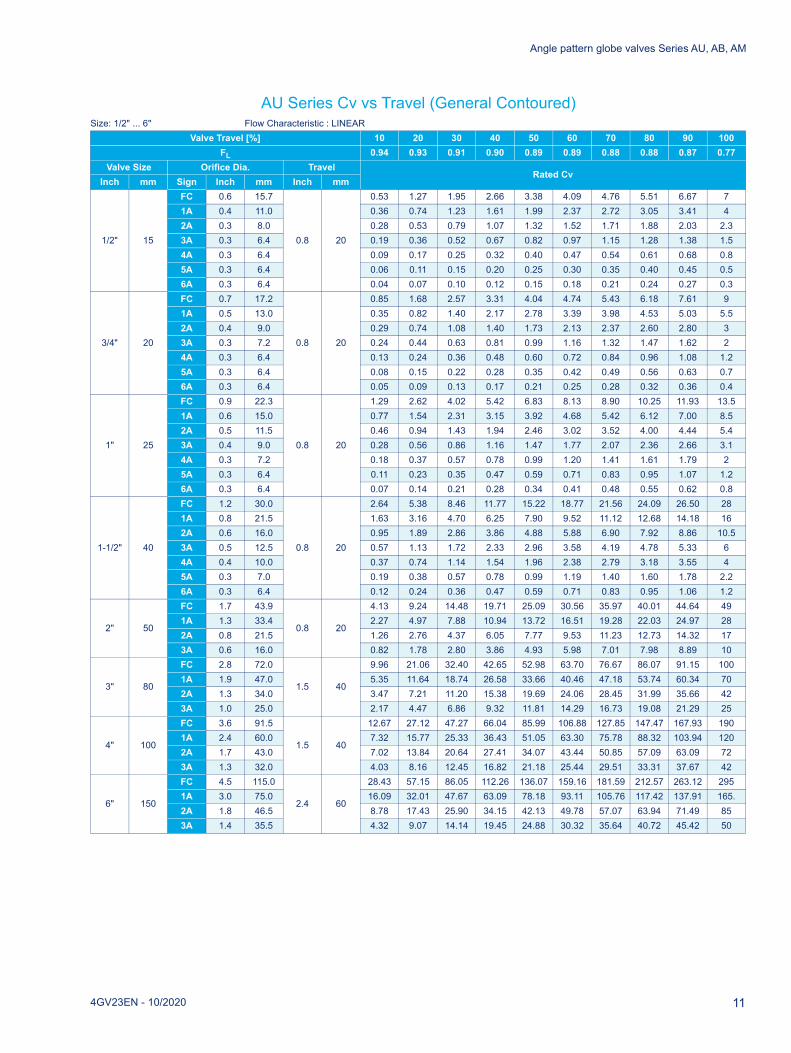
AU Series Cv vs Travel (General Contoured)Size: 1/2" ... 6" Flow Characteristic : LINEAR
Valve Travel [%] 10 20 30 40 50 60 70 80 90 100FL 0.94 0.93 0.91 0.90 0.89 0.89 0.88 0.88 0.87 0.77
Valve Size Orifice Dia. TravelRated Cv
Inch mm Sign Inch mm Inch mm
1/2" 15
FC 0.6 15.7
0.8 20
0.53 1.27 1.95 2.66 3.38 4.09 4.76 5.51 6.67 71A 0.4 11.0 0.36 0.74 1.23 1.61 1.99 2.37 2.72 3.05 3.41 42A 0.3 8.0 0.28 0.53 0.79 1.07 1.32 1.52 1.71 1.88 2.03 2.33A 0.3 6.4 0.19 0.36 0.52 0.67 0.82 0.97 1.15 1.28 1.38 1.54A 0.3 6.4 0.09 0.17 0.25 0.32 0.40 0.47 0.54 0.61 0.68 0.85A 0.3 6.4 0.06 0.11 0.15 0.20 0.25 0.30 0.35 0.40 0.45 0.56A 0.3 6.4 0.04 0.07 0.10 0.12 0.15 0.18 0.21 0.24 0.27 0.3
3/4" 20
FC 0.7 17.2
0.8 20
0.85 1.68 2.57 3.31 4.04 4.74 5.43 6.18 7.61 91A 0.5 13.0 0.35 0.82 1.40 2.17 2.78 3.39 3.98 4.53 5.03 5.52A 0.4 9.0 0.29 0.74 1.08 1.40 1.73 2.13 2.37 2.60 2.80 33A 0.3 7.2 0.24 0.44 0.63 0.81 0.99 1.16 1.32 1.47 1.62 24A 0.3 6.4 0.13 0.24 0.36 0.48 0.60 0.72 0.84 0.96 1.08 1.25A 0.3 6.4 0.08 0.15 0.22 0.28 0.35 0.42 0.49 0.56 0.63 0.76A 0.3 6.4 0.05 0.09 0.13 0.17 0.21 0.25 0.28 0.32 0.36 0.4
1" 25
FC 0.9 22.3
0.8 20
1.29 2.62 4.02 5.42 6.83 8.13 8.90 10.25 11.93 13.51A 0.6 15.0 0.77 1.54 2.31 3.15 3.92 4.68 5.42 6.12 7.00 8.52A 0.5 11.5 0.46 0.94 1.43 1.94 2.46 3.02 3.52 4.00 4.44 5.43A 0.4 9.0 0.28 0.56 0.86 1.16 1.47 1.77 2.07 2.36 2.66 3.14A 0.3 7.2 0.18 0.37 0.57 0.78 0.99 1.20 1.41 1.61 1.79 25A 0.3 6.4 0.11 0.23 0.35 0.47 0.59 0.71 0.83 0.95 1.07 1.26A 0.3 6.4 0.07 0.14 0.21 0.28 0.34 0.41 0.48 0.55 0.62 0.8
1-1/2" 40
FC 1.2 30.0
0.8 20
2.64 5.38 8.46 11.77 15.22 18.77 21.56 24.09 26.50 281A 0.8 21.5 1.63 3.16 4.70 6.25 7.90 9.52 11.12 12.68 14.18 162A 0.6 16.0 0.95 1.89 2.86 3.86 4.88 5.88 6.90 7.92 8.86 10.53A 0.5 12.5 0.57 1.13 1.72 2.33 2.96 3.58 4.19 4.78 5.33 64A 0.4 10.0 0.37 0.74 1.14 1.54 1.96 2.38 2.79 3.18 3.55 45A 0.3 7.0 0.19 0.38 0.57 0.78 0.99 1.19 1.40 1.60 1.78 2.26A 0.3 6.4 0.12 0.24 0.36 0.47 0.59 0.71 0.83 0.95 1.06 1.2
2" 50
FC 1.7 43.9
0.8 20
4.13 9.24 14.48 19.71 25.09 30.56 35.97 40.01 44.64 491A 1.3 33.4 2.27 4.97 7.88 10.94 13.72 16.51 19.28 22.03 24.97 282A 0.8 21.5 1.26 2.76 4.37 6.05 7.77 9.53 11.23 12.73 14.32 173A 0.6 16.0 0.82 1.78 2.80 3.86 4.93 5.98 7.01 7.98 8.89 10
3" 80
FC 2.8 72.0
1.5 40
9.96 21.06 32.40 42.65 52.98 63.70 76.67 86.07 91.15 1001A 1.9 47.0 5.35 11.64 18.74 26.58 33.66 40.46 47.18 53.74 60.34 702A 1.3 34.0 3.47 7.21 11.20 15.38 19.69 24.06 28.45 31.99 35.66 423A 1.0 25.0 2.17 4.47 6.86 9.32 11.81 14.29 16.73 19.08 21.29 25
4" 100
FC 3.6 91.5
1.5 40
12.67 27.12 47.27 66.04 85.99 106.88 127.85 147.47 167.93 1901A 2.4 60.0 7.32 15.77 25.33 36.43 51.05 63.30 75.78 88.32 103.94 1202A 1.7 43.0 7.02 13.84 20.64 27.41 34.07 43.44 50.85 57.09 63.09 723A 1.3 32.0 4.03 8.16 12.45 16.82 21.18 25.44 29.51 33.31 37.67 42
6" 150
FC 4.5 115.0
2.4 60
28.43 57.15 86.05 112.26 136.07 159.16 181.59 212.57 263.12 2951A 3.0 75.0 16.09 32.01 47.67 63.09 78.18 93.11 105.76 117.42 137.91 165.2A 1.8 46.5 8.78 17.43 25.90 34.15 42.13 49.78 57.07 63.94 71.49 853A 1.4 35.5 4.32 9.07 14.14 19.45 24.88 30.32 35.64 40.72 45.42 50
4GV23EN - 10/2020 11

Angle pattern globe valves Series AU, AB, AM
AU Series Cv vs Travel (General Contoured)
NOTECv : Valve flow coefficientFL: Liquid pressure recovery factorFC: Full Capacity 1A: 1-Step reduction2A: 2-Step reduction 3A: 3-Step reduction4A: 4-Step reduction 5A: 5-Step reduction
Size : 1/2" ... 6" Flow Characteristic : EQ%Valve Travel [%] 10 20 30 40 50 60 70 80 90 100
FL 0.94 0.94 0.93 0.93 0.92 0.90 0.89 0.88 0.87 0.77Valve Size Orifice Dia. Travel
Rated CvInch mm Sign Inch mm Inch mm
1/2" 15
FC 0.6 15.7
0.8 20
0.16 0.36 0.56 0.89 1.38 2.16 3.42 4.84 6.44 71A 0.4 11.0 0.06 0.16 0.31 0.49 0.78 1.46 2.17 2.88 3.53 42A 0.3 8.0 0.08 0.16 0.23 0.34 0.59 0.94 1.37 1.70 2.01 2.33A 0.3 6.4 0.05 0.09 0.14 0.20 0.35 0.56 0.82 1.11 1.33 1.54A 0.3 6.4 0.02 0.04 0.06 0.08 0.16 0.28 0.41 0.54 0.66 0.85A 0.3 6.4 0.01 0.02 0.04 0.05 0.10 0.17 0.25 0.33 0.41 0.56A 0.3 6.4 0.01 0.01 0.02 0.03 0.06 0.11 0.15 0.20 0.25 0.3
3/4" 20
FC 0.7 17.2
0.8 20
0.24 0.45 0.67 1.07 1.85 2.93 4.02 5.23 7.13 91A 0.5 13.0 0.06 0.20 0.40 0.67 1.11 1.79 2.79 3.71 4.74 5.52A 0.4 9.0 0.05 0.17 0.28 0.45 0.78 1.20 1.80 2.35 2.72 33A 0.3 7.2 0.04 0.09 0.15 0.21 0.41 0.68 1.00 1.30 1.67 24A 0.3 6.4 0.03 0.06 0.09 0.13 0.25 0.42 0.62 0.82 1.01 1.25A 0.3 6.4 0.01 0.03 0.05 0.08 0.14 0.23 0.34 0.45 0.58 0.76A 0.3 6.4 0.01 0.02 0.03 0.04 0.08 0.14 0.21 0.27 0.33 0.4
1" 25
FC 0.9 22.3
0.8 20
0.27 0.57 0.91 1.55 2.75 4.66 7.08 9.49 11.63 13.51A 0.6 15.0 0.12 0.29 0.51 0.83 1.56 2.70 4.14 5.61 7.03 8.52A 0.5 11.5 0.07 0.19 0.33 0.53 0.97 1.67 2.65 3.59 4.37 5.43A 0.4 9.0 0.03 0.09 0.19 0.32 0.58 1.00 1.52 2.05 2.54 3.14A 0.3 7.2 0.03 0.08 0.13 0.22 0.40 0.67 1.00 1.35 1.70 25A 0.3 6.4 0.03 0.05 0.08 0.13 0.25 0.43 0.64 0.85 1.06 1.26A 0.3 6.4 0.01 0.03 0.04 0.07 0.14 0.24 0.35 0.46 0.59 0.8
1-1/2" 40
FC 1.2 30.0
0.8 20
0.45 1.12 2.00 3.07 5.91 10.57 16.18 21.57 25.66 281A 0.8 21.5 0.23 0.58 1.06 1.69 3.16 5.36 7.97 10.69 13.44 162A 0.6 16.0 0.20 0.44 0.71 1.02 1.88 3.25 4.93 6.71 8.59 10.53A 0.5 12.5 0.09 0.22 0.40 0.62 1.13 2.02 3.17 4.26 5.21 64A 0.4 10.0 0.05 0.14 0.26 0.41 0.79 1.36 2.08 2.83 3.45 45A 0.3 7.0 0.03 0.08 0.13 0.21 0.39 0.69 1.07 1.43 1.74 2.26A 0.3 6.4 0.03 0.06 0.09 0.13 0.23 0.40 0.59 0.78 0.98 1.2
2" 50
FC 1.7 43.9
0.8 20
1.21 2.46 3.31 5.12 9.42 16.83 26.55 36.59 44.52 491A 1.3 33.4 0.32 0.82 1.51 2.87 5.48 9.31 13.77 18.31 23.17 282A 0.8 21.5 0.17 0.47 0.88 1.63 3.18 5.47 8.21 11.09 13.68 173A 0.6 16.0 0.15 0.37 0.66 1.02 1.89 3.29 5.01 6.71 8.41 10
3" 80
FC 2.8 72.0
1.5 40
2.01 4.47 7.37 12.28 22.52 38.62 62.02 79.57 90.09 1001A 1.9 47.0 1.00 2.51 4.50 6.96 12.95 23.65 36.15 47.82 58.70 702A 1.3 34.0 0.73 1.61 2.64 3.95 7.53 13.57 21.26 28.97 34.99 423A 1.0 25.0 0.36 0.89 1.59 2.46 4.51 8.08 12.55 16.82 20.78 25
4" 100
FC 3.6 91.5
1.5 40
2.90 6.72 11.48 17.16 29.35 56.26 86.65 120.90 153.84 1901A 2.4 60.0 1.56 3.77 6.63 10.11 18.42 32.83 55.27 77.53 98.63 1202A 1.7 43.0 1.45 3.05 4.82 8.10 14.86 24.20 35.22 49.81 61.14 723A 1.3 32.0 0.88 1.82 2.84 4.44 8.42 14.38 21.12 27.79 34.17 42
6" 150
FC 4.5 115.0
2.4 60
4.23 9.72 16.43 25.73 49.58 89.69 140.01 195.77 256.78 2951A 3.0 75.0 2.83 6.73 11.68 17.72 31.53 53.90 88.38 113.11 140.55 1652A 1.8 46.5 1.36 3.61 6.68 10.62 17.82 28.66 42.88 57.38 71.53 853A 1.4 35.5 0.91 1.90 2.95 4.26 7.77 13.68 21.42 29.72 37.96 50
12 4GV23EN - 10/2020

Angle pattern globe valves Series AU, AB, AM
AU Series Cv vs Travel (Tendril 1)
NOTECv: Valve flow coefficientFL: Liquid pressure recovery factorFT: Full Capacity 1T: 1-Step reduction2T: 2-Step reduction 3T: 3-Step reduction4T: 4-Step reduction 5T: 5-Step reduction6T: 6-Step reduction
Size : 1/2" ... 4" Flow Characteristic : LINEAR
Valve Travel [%] 10 20 30 40 50 60 70 80 90 100FL 0.95 0.95 0.95 0.94 0.94 0.94 0.93 0.93 0.91 0.91
Valve Size Orifice Dia. TravelRated Cv
Inch mm Sign Inch mm Inch mm
1/2" 15
FT 0.6 15.7
0.8 20
0.53 1.27 1.95 2.66 3.38 4.09 4.76 5.51 6.67 71T 0.4 11.0 0.36 0.74 1.23 1.61 1.99 2.37 2.72 3.05 3.41 42T 0.3 8.0 0.28 0.53 0.79 1.07 1.32 1.52 1.71 1.88 2.03 2.33T 0.3 6.4 0.19 0.36 0.52 0.67 0.82 0.97 1.15 1.28 1.38 1.54T 0.3 6.4 0.09 0.17 0.25 0.32 0.40 0.47 0.54 0.61 0.68 0.85T 0.3 6.4 0.06 0.11 0.15 0.20 0.25 0.30 0.35 0.40 0.45 0.56T 0.3 6.4 0.04 0.07 0.10 0.12 0.15 0.18 0.21 0.24 0.27 0.3
3/4" 20
FT 0.7 17.2
0.8 20
0.85 1.68 2.57 3.31 4.04 4.74 5.43 6.18 7.61 91T 0.5 13.0 0.35 0.82 1.40 2.17 2.78 3.39 3.98 4.53 5.03 5.52T 0.4 9.0 0.29 0.74 1.08 1.40 1.73 2.13 2.37 2.60 2.80 33T 0.3 7.2 0.24 0.44 0.63 0.81 0.99 1.16 1.32 1.47 1.62 24T 0.3 6.4 0.13 0.24 0.36 0.48 0.60 0.72 0.84 0.96 1.08 1.25T 0.3 6.4 0.08 0.15 0.22 0.28 0.35 0.42 0.49 0.56 0.63 0.76T 0.3 6.4 0.05 0.09 0.13 0.17 0.21 0.25 0.28 0.32 0.36 0.4
1" 25
FT 0.9 22.3
0.8 20
1.29 2.62 4.02 5.42 6.83 8.13 8.90 10.25 11.93 13.51T 0.6 15.0 0.77 1.54 2.31 3.15 3.92 4.68 5.42 6.12 7.00 8.52T 0.5 11.5 0.46 0.94 1.43 1.94 2.46 3.02 3.52 4.00 4.44 5.43T 0.4 9.0 0.28 0.56 0.86 1.16 1.47 1.77 2.07 2.36 2.66 3.14T 0.3 7.2 0.18 0.37 0.57 0.78 0.99 1.20 1.41 1.61 1.79 25T 0.3 6.4 0.11 0.23 0.35 0.47 0.59 0.71 0.83 0.95 1.07 1.26T 0.3 6.4 0.07 0.14 0.21 0.28 0.34 0.41 0.48 0.55 0.62 0.8
1-1/2" 40
FT 1.2 30.0
0.8 20
2.64 5.38 8.46 11.77 15.22 18.77 21.56 24.09 26.50 281T 0.8 21.5 1.63 3.16 4.70 6.25 7.90 9.52 11.12 12.68 14.18 162T 0.6 16.0 0.95 1.89 2.86 3.86 4.88 5.88 6.90 7.92 8.86 10.53T 0.5 12.5 0.57 1.13 1.72 2.33 2.96 3.58 4.19 4.78 5.33 64T 0.4 10.0 0.37 0.74 1.14 1.54 1.96 2.38 2.79 3.18 3.55 45T 0.3 7.0 0.19 0.38 0.57 0.78 0.99 1.19 1.40 1.60 1.78 2.26T 0.3 6.4 0.12 0.24 0.36 0.47 0.59 0.71 0.83 0.95 1.06 1.2
2" 50
FT 1.7 43.9
0.8 20
4.13 9.24 14.48 19.71 25.09 30.56 35.97 40.01 44.64 491T 1.3 33.4 2.27 4.97 7.88 10.94 13.72 16.51 19.28 22.03 24.97 282T 0.8 21.5 1.26 2.76 4.37 6.05 7.77 9.53 11.23 12.73 14.32 173T 0.6 16.0 0.82 1.78 2.80 3.86 4.93 5.98 7.01 7.98 8.89 10
3" 80
FT 2.8 72.0
1.5 40
9.96 21.06 32.40 42.65 52.98 63.70 76.67 86.07 91.15 1001T 1.9 47.0 5.35 11.64 18.74 26.58 33.66 40.46 47.18 53.74 60.34 702T 1.3 34.0 3.47 7.21 11.20 15.38 19.69 24.06 28.45 31.99 35.66 423T 1.0 25.0 2.17 4.47 6.86 9.32 11.81 14.29 16.73 19.08 21.29 25
4" 100
FT 3.6 91.5
1.5 40
12.67 27.12 47.27 66.04 85.99 106.88 127.85 147.47 167.93 1901T 2.4 60.0 7.32 15.77 25.33 36.43 51.05 63.30 75.78 88.32 103.94 1202T 1.7 43.0 7.02 13.84 20.64 27.41 34.07 43.44 50.85 57.09 63.09 723T 1.3 32.0 4.03 8.16 12.45 16.82 21.18 25.44 29.51 33.31 37.67 42
4GV23EN - 10/2020 13

Angle pattern globe valves Series AU, AB, AM
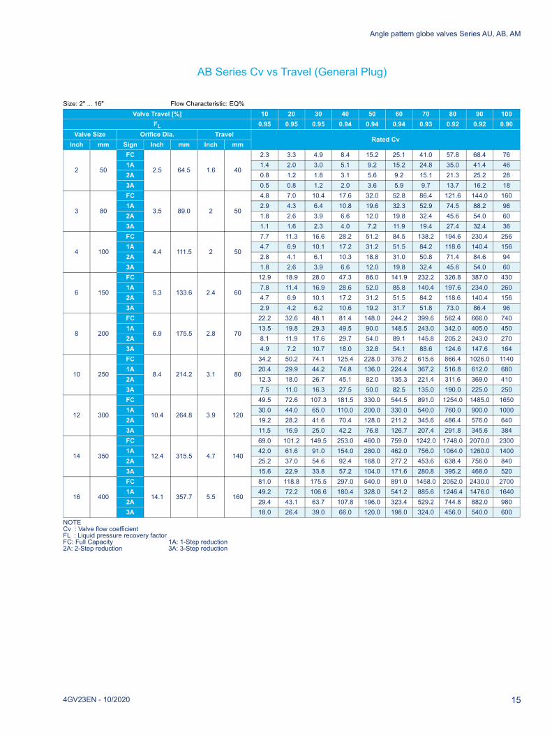
AB Series Cv vs Travel (General Plug)
NOTECv: Valve flow coefficientFL: Liquid pressure recovery factorFC: Full Capacity 1A: 1-Step reduction2A: 2-Step reduction 3A: 3-Step reduction
Size : 2" ... 16" Flow Characteristic: LINEARValve Travel [%] 10 20 30 40 50 60 70 80 90 100
FL 0.95 0.95 0.94 0.94 0.93 0.93 0.92 0.92 0.91 0.91Valve Size Orifice Dia. Travel
Rated CvInch mm Sign Inch mm Inch mm
2 50
FC
2.5 64.5 1.6 40
8.1 16.1 24.1 32.2 40.2 48.2 56.3 64.3 72.3 821A 7.3 14.5 21.8 29.0 36.3 43.5 50.8 58.0 65.3 742A 4.3 8.6 12.9 17.3 21.6 25.9 30.2 34.5 38.8 443A 2.6 5.1 7.6 10.2 12.7 15.3 17.8 20.4 22.9 26
3 80
FC
3.5 89.0 2 50
17.1 34.1 51.2 68.2 85.3 102.3 119.4 136.5 153.5 1741A 10.2 20.4 30.6 40.8 51.0 61.2 71.4 81.6 91.7 1042A 6.1 12.2 18.2 24.3 30.4 36.5 42.5 48.6 54.7 623A 3.9 7.8 11.8 15.7 19.6 23.5 27.4 31.4 35.3 40
4 100
FC
4.4 111.5 2 50
27.5 54.9 82.4 109.8 137.3 164.7 192.1 219.6 247.0 2801A 16.7 33.4 50.0 66.7 83.3 100.0 116.7 133.3 150.0 1702A 9.8 19.6 29.4 39.2 49.0 58.8 68.6 78.4 88.2 1003A 6.3 12.6 18.8 25.1 31.4 37.6 43.9 50.2 56.5 64
6 150
FC
5.3 133.6 2.4 60
46.2 92.2 138.3 184.3 230.4 276.5 322.5 368.6 414.6 4701A 27.9 55.7 83.6 111.4 139.2 167.0 194.9 222.7 250.5 2842A 16.7 33.4 50.0 66.7 83.3 100.0 116.7 133.3 150.0 1703A 9.8 19.6 29.4 39.2 49.0 58.8 68.6 78.4 88.2 100
8 200
FC
6.9 175.5 2.8 70
79.5 158.9 238.3 317.7 397.1 476.4 555.8 635.2 714.6 8101A 49.1 98.1 147.1 196.1 245.1 294.1 343.1 392.1 441.1 5002A 31.4 62.8 94.1 125.5 156.9 188.2 219.6 250.9 282.3 3203A 19.6 39.2 58.8 78.4 98.0 117.6 137.2 156.8 176.4 200
10 250
FC
8.4 214.2 3.1 80
122.8 245.3 367.8 490.3 612.8 735.3 857.8 980.3 1102.8 12501A 74.6 149.1 223.6 298.1 372.6 447.0 521.5 596.0 670.5 7602A 45.2 90.3 135.3 180.4 225.5 270.6 315.7 360.7 405.8 4603A 27.5 54.9 82.4 109.8 137.3 164.7 192.1 219.6 247.0 280
12 300
FC
10.4 264.8 3.9 120
177.7 355.1 532.5 709.9 887.3 1064.6 1242.0 1419.4 1596.8 18101A 108.0 215.8 323.6 431.4 539.2 647.0 754.8 862.6 970.4 11002A 66.8 133.4 200.1 266.7 333.3 400.0 466.6 533.3 599.9 6803A 41.2 82.4 123.6 164.7 205.9 247.0 288.2 329.4 370.5 420
14 350
FC
12.4 315.5 4.7 140
248.4 496.4 744.3 992.3 1240.2 1488.1 1736.1 1984.0 2232.0 25301A 150.9 302.1 453.1 604.0 754.9 905.8 1056.7 1207.7 1358.6 15402A 92.1 184.4 276.5 368.7 460.8 552.9 645.0 737.1 829.3 9403A 56.9 113.8 170.6 227.5 284.3 341.2 398.0 454.8 511.7 580
16 400
FC
14.1 357.7 5.5 160
290.1 580.8 870.8 1160.9 1451.0 1741.1 2031.2 2321.2 2611.3 29601A 174.5 349.2 523.7 698.1 872.6 1047.0 1221.4 1395.9 1570.3 17802A 105.9 211.9 317.7 423.6 529.4 635.3 741.1 846.9 952.8 10803A 64.7 129.5 194.2 258.9 323.5 388.2 452.9 517.6 582.3 660
14 4GV23EN - 10/2020
Angle pattern globe valves Series AU, AB, AM
AB Series Cv vs Travel (General Plug)
NOTECv : Valve flow coefficientFL : Liquid pressure recovery factorFC: Full Capacity 1A: 1-Step reduction2A: 2-Step reduction 3A: 3-Step reduction
Size: 2" ... 16" Flow Characteristic: EQ%Valve Travel [%] 10 20 30 40 50 60 70 80 90 100
FL 0.95 0.95 0.95 0.94 0.94 0.94 0.93 0.92 0.92 0.90Valve Size Orifice Dia. Travel
Rated CvInch mm Sign Inch mm Inch mm
2 50
FC
2.5 64.5 1.6 40
2.3 3.3 4.9 8.4 15.2 25.1 41.0 57.8 68.4 761A 1.4 2.0 3.0 5.1 9.2 15.2 24.8 35.0 41.4 462A 0.8 1.2 1.8 3.1 5.6 9.2 15.1 21.3 25.2 283A 0.5 0.8 1.2 2.0 3.6 5.9 9.7 13.7 16.2 18
3 80
FC
3.5 89.0 2 50
4.8 7.0 10.4 17.6 32.0 52.8 86.4 121.6 144.0 1601A 2.9 4.3 6.4 10.8 19.6 32.3 52.9 74.5 88.2 982A 1.8 2.6 3.9 6.6 12.0 19.8 32.4 45.6 54.0 603A 1.1 1.6 2.3 4.0 7.2 11.9 19.4 27.4 32.4 36
4 100
FC
4.4 111.5 2 50
7.7 11.3 16.6 28.2 51.2 84.5 138.2 194.6 230.4 2561A 4.7 6.9 10.1 17.2 31.2 51.5 84.2 118.6 140.4 1562A 2.8 4.1 6.1 10.3 18.8 31.0 50.8 71.4 84.6 943A 1.8 2.6 3.9 6.6 12.0 19.8 32.4 45.6 54.0 60
6 150
FC
5.3 133.6 2.4 60
12.9 18.9 28.0 47.3 86.0 141.9 232.2 326.8 387.0 4301A 7.8 11.4 16.9 28.6 52.0 85.8 140.4 197.6 234.0 2602A 4.7 6.9 10.1 17.2 31.2 51.5 84.2 118.6 140.4 1563A 2.9 4.2 6.2 10.6 19.2 31.7 51.8 73.0 86.4 96
8 200
FC
6.9 175.5 2.8 70
22.2 32.6 48.1 81.4 148.0 244.2 399.6 562.4 666.0 7401A 13.5 19.8 29.3 49.5 90.0 148.5 243.0 342.0 405.0 4502A 8.1 11.9 17.6 29.7 54.0 89.1 145.8 205.2 243.0 2703A 4.9 7.2 10.7 18.0 32.8 54.1 88.6 124.6 147.6 164
10 250
FC
8.4 214.2 3.1 80
34.2 50.2 74.1 125.4 228.0 376.2 615.6 866.4 1026.0 11401A 20.4 29.9 44.2 74.8 136.0 224.4 367.2 516.8 612.0 6802A 12.3 18.0 26.7 45.1 82.0 135.3 221.4 311.6 369.0 4103A 7.5 11.0 16.3 27.5 50.0 82.5 135.0 190.0 225.0 250
12 300
FC
10.4 264.8 3.9 120
49.5 72.6 107.3 181.5 330.0 544.5 891.0 1254.0 1485.0 16501A 30.0 44.0 65.0 110.0 200.0 330.0 540.0 760.0 900.0 10002A 19.2 28.2 41.6 70.4 128.0 211.2 345.6 486.4 576.0 6403A 11.5 16.9 25.0 42.2 76.8 126.7 207.4 291.8 345.6 384
14 350
FC
12.4 315.5 4.7 140
69.0 101.2 149.5 253.0 460.0 759.0 1242.0 1748.0 2070.0 23001A 42.0 61.6 91.0 154.0 280.0 462.0 756.0 1064.0 1260.0 14002A 25.2 37.0 54.6 92.4 168.0 277.2 453.6 638.4 756.0 8403A 15.6 22.9 33.8 57.2 104.0 171.6 280.8 395.2 468.0 520
16 400
FC
14.1 357.7 5.5 160
81.0 118.8 175.5 297.0 540.0 891.0 1458.0 2052.0 2430.0 27001A 49.2 72.2 106.6 180.4 328.0 541.2 885.6 1246.4 1476.0 16402A 29.4 43.1 63.7 107.8 196.0 323.4 529.2 744.8 882.0 9803A 18.0 26.4 39.0 66.0 120.0 198.0 324.0 456.0 540.0 600
4GV23EN - 10/2020 15

Angle pattern globe valves Series AU, AB, AM
AB Series Cv vs Travel (Tendril 1)
Size: 2" ... 16" Flow Characteristic: LINEARValve Travel [%] 10 20 30 40 50 60 70 80 90 100
FL 0.84 0.84 0.85 0.85 0.85 0.86 0.87 0.87 0.95 0.86Valve Size Orifice Dia. Travel
Rated CvInch mm Sign Inch mm Inch mm
2 50
FC
2.5 64.5 1.6 40
3.0 11.8 19.7 26.6 33.2 39.0 43.8 47.7 50.8 521A 1.9 7.7 13.0 17.7 22.4 26.8 31.0 34.8 38.3 402A 1.2 4.8 8.1 11.2 14.3 17.2 20.1 22.8 25.4 273A 0.4 1.7 2.9 4.0 5.2 6.3 7.4 8.5 9.6 10
3 80
FC
3.5 89.0 2 50
7.5 23.0 36.9 49.9 61.9 73.2 82.9 91.2 98.0 1021A 4.7 14.6 23.7 32.4 40.6 48.8 56.4 63.6 70.4 752A 2.4 7.6 12.4 17.1 21.7 26.2 30.5 34.8 38.9 403A 1.2 3.9 6.4 8.9 11.3 13.8 16.1 18.4 20.7 21
4 100
FC
4.4 111.5 2 50
8.5 32.6 55.1 75.9 95.6 113.8 130.5 144.6 156.2 1601A 5.3 20.4 34.8 48.3 61.5 74.1 86.7 98.5 109.6 1202A 2.9 11.3 19.5 27.3 34.9 42.4 49.9 57.1 64.2 703A 1.9 7.6 13.2 18.5 23.8 28.9 34.2 39.2 44.1 46
6 150
FC
5.3 133.6 2.4 60
13.8 54.4 95.1 134.3 170.9 204.3 234.1 259.9 281.9 2901A 9.0 35.2 61.8 88.2 114.1 139.2 163.1 185.7 206.9 2202A 4.9 18.9 33.1 47.3 61.6 75.9 90.1 104.1 117.9 1303A 2.9 10.8 18.8 26.9 35.0 43.2 51.4 59.5 67.7 75
8 200
FC
6.9 175.5 2.8 70
19.7 87.1 152.3 213.7 271.5 323.2 368.8 409.4 444.2 4601A 12.7 56.0 98.8 140.5 181.6 220.5 257.3 292.4 324.9 3402A 6.4 28.0 49.5 70.8 92.4 113.6 134.4 155.2 175.5 1953A 3.6 15.6 27.5 39.3 51.4 63.3 75.1 87.1 99.0 105
10 250
FC
8.4 214.2 3.1 80
39.7 122.6 206.9 287.7 361.2 430.8 493.5 548.0 597.7 6301A 25.7 78.3 132.7 186.4 237.5 288.4 337.1 382.2 426.0 4602A 14.2 41.5 69.9 98.4 126.0 154.4 182.4 209.4 236.8 2553A 8.4 23.2 38.6 54.1 69.1 84.6 100.2 115.3 130.8 140
12 300
FC
10.4 264.8 3.9 120
76.8 216.1 351.6 478.6 594.1 696.7 786.2 863.1 928.4 9801A 48.9 136.8 224.6 310.8 394.0 473.3 548.1 617.8 682.3 7352A 25.2 68.8 112.8 156.8 200.8 244.4 287.5 330.0 371.7 4053A 15.4 40.7 66.1 91.7 117.4 143.1 168.8 194.5 220.0 240
14 350
FC
12.4 315.5 4.7 140
89.2 275.6 460.6 634.1 789.1 929.1 1050.3 1151.4 1237.4 13001A 56.5 174.0 293.5 410.7 521.9 629.9 731.6 824.7 912.3 9852A 29.7 90.1 152.1 214.2 274.8 336.1 396.5 454.9 513.1 5653A 16.4 48.4 81.3 114.3 146.8 179.9 212.9 245.3 278.2 310
16 400
FC
14.1 357.7 5.5 160
121.6 332.6 546.9 756.9 949.0 1121.7 1274.6 1402.5 1508.5 15801A 73.6 198.0 326.6 458.4 586.9 712.2 834.3 948.3 1055.2 11452A 41.5 108.3 177.2 248.6 319.8 391.4 464.1 535.3 605.7 6703A 26.9 68.0 110.1 153.6 197.1 241.1 286.2 330.8 375.6 415
16 4GV23EN - 10/2020

Angle pattern globe valves Series AU, AB, AM
AB Series Cv vs Travel (Tendril 1)
NOTECv : Valve flow coefficientFL : Liquid pressure recovery factorFC : Full Capacity 1A : 1-Step reduction2A : 2-Step reduction 3A : 3-Step reduction
Size: 2" ... 16"" Flow Characteristic: EQ%Valve Travel [%] 10 20 30 40 50 60 70 80 90 100
FL 0.84 0.84 0.84 0.84 0.84 0.85 0.85 0.86 0.95 0.88Valve Size Orifice Dia. Travel
Rated CvInch mm Sign Inch mm Inch mm
2 50
FC
2.5 64.5 1.6 40
0.4 2.4 4.4 8.1 13.7 20.5 28.3 36.4 44.1 501A 0.4 2.4 4.2 5.9 9.5 14.6 20.4 25.7 30.7 352A 0.2 1.0 2.3 4.0 6.2 8.9 11.9 14.8 17.7 203A 0.2 1.0 2.2 3.4 4.5 5.7 6.8 7.9 9.0 10
3 80
FC
3.5 89.0 2 50
0.7 2.7 6.3 12.5 20.9 31.5 43.6 57.0 71.1 821A 0.7 2.7 4.7 8.5 14.8 23.6 33.3 42.5 51.3 582A 0.7 2.7 4.7 8.5 13.3 18.1 22.6 27.1 31.3 353A 0.3 1.4 3.1 5.5 8.0 10.5 12.9 15.3 17.6 20
4 100
FC
4.4 111.5 2 50
1.0 5.2 9.5 17.1 30.3 48.2 71.3 95.5 117.5 1351A 0.5 2.6 6.3 13.0 22.3 34.2 48.8 65.1 82.1 952A 0.5 2.6 4.8 8.7 15.6 24.6 33.8 42.5 51.1 583A 0.5 2.6 4.8 8.5 12.6 16.6 20.7 24.6 28.5 32
6 150
FC
5.3 133.6 2.4 60
1.6 7.5 16.2 33.1 58.4 91.7 131.8 172.1 208.6 2351A 1.6 7.5 13.4 22.2 39.2 64.5 92.9 120.7 147.3 1702A 0.9 3.8 6.8 11.1 19.5 32.0 48.7 67.1 85.4 1003A 0.9 3.8 6.8 11.1 18.8 26.9 35.0 43.2 51.4 58
8 200
FC
6.9 175.5 2.8 70
1.5 12.8 35.3 68.6 113.2 167.1 227.7 288.0 341.3 3701A 1.5 8.5 21.5 45.3 80.7 122.9 163.9 204.1 242.0 2652A 0.8 4.3 10.8 22.6 40.3 63.6 91.9 122.8 152.7 1703A 0.8 4.3 8.0 15.1 28.0 44.6 61.2 78.0 94.6 105
10 250
FC
8.4 214.2 3.1 80
4.2 19.1 48.4 91.6 147.0 216.6 295.8 370.8 441.5 5001A 4.2 12.2 31.1 63.9 109.2 165.6 221.2 273.6 325.3 3702A 4.2 12.2 21.5 43.8 73.9 105.0 136.0 166.0 196.5 2253A 2.9 6.8 11.5 22.6 39.3 57.3 75.4 93.0 111.1 125
12 300
FC
10.4 264.8 3.9 120
7.4 26.7 75.3 153.7 260.7 391.7 527.8 648.9 754.0 8401A 7.4 18.8 52.7 116.3 202.8 289.5 373.5 453.9 529.8 6002A 4.5 10.2 27.1 58.6 104.8 156.2 207.5 258.3 308.3 3553A 4.5 10.2 27.1 52.5 78.0 103.7 129.4 155.1 180.7 205
14 350
FC
12.4 315.5 4.7 140
6.7 30.7 93.6 195.6 332.7 504.5 687.7 849.2 992.0 11101A 6.7 21.0 67.3 152.6 264.7 378.6 489.2 593.3 693.8 7852A 4.0 11.1 34.1 76.5 137.3 207.6 277.7 345.7 414.0 4803A 4.0 11.1 34.1 70.6 107.0 144.2 181.4 217.9 255.1 290
16 400
FC
14.1 357.7 5.5 160
9.4 44.5 125.3 258.1 439.8 664.3 890.8 1090.8 1263.7 14001A 9.4 30.8 94.0 207.6 349.8 493.0 635.9 771.9 901.1 10202A 6.1 16.7 47.8 102.8 180.1 263.7 349.8 434.9 519.6 6003A 6.1 16.7 47.8 90.1 132.6 175.8 220.2 264.5 309.0 350
4GV23EN - 10/2020 17

Angle pattern globe valves Series AU, AB, AM
A series, Valve dimensions and weights
150 #/ 300 #/ 600 #D
CB
ØE
A
C
DRILLING
No of Hole. = H
Dia. Of Hole = FPitch Circle Dia. = G
EXT & CRY
Dimension(mm) A B C D E F G H Weight(kg)
(Approximate)Size
(mm)150# 300# 600# 150# 300# 600# STDEXT CRY COMMON 150# 300# 600# 150# 300# 600# 150# 300# 600# 150# 300# 600# 150# 300# 600#
25 92 99 105 92 99 105 142 250 400 110 110 125 125 15.9 19.1 19.1 79.4 88.9 88.9 4 4 4 14 15 2340 111 118 125 111 118 125 161 269 419 110 125 155 155 15.9 22.2 22.2 98.4 114.3 114.3 4 4 4 22 23 2750 127 133 143 127 133 143 178 333 458 110 150 165 165 19.1 19.1 19.1 120.7 127 127 4 8 8 25 27 3280 149 159 168 149 159 168 222 395 545 115 190 210 210 19.1 22.2 22.2 152.4 168.3 168.3 4 8 8 65 67 72100 176 184 197 176 184 197 248 402 552 140 230 255 275 19.1 22.2 25.4 190.5 200 215.9 8 8 8 100 103 112150 226 236 254 226 236 254 340 467 642 150 280 320 355 22.2 22.2 28.6 241.3 269.9 292.1 8 12 12 185 195 240200 272 284 305 272 284 305 451 557 732 150 345 380 420 22.2 25.4 31.8 298.5 330.2 349.2 8 12 12 363 385 443250 337 354 376 337 354 376 488 670 870 150 405 445 510 25.4 28.6 34.9 362 387.4 431.8 12 16 16 552 595 681300 369 388 410 369 388 410 543 716 916 150 485 520 560 25.4 31.8 34.9 431.8 450.8 489 12 16 20 905 955 1020350 445 464 486 445 464 486 616 846 1046 210 535 585 605 28.6 31.8 38.1 476.3 514.4 527 12 20 20 1170 1230 1311400 508 529 554 508 529 554 692 909 1109 220 595 650 685 28.6 34.9 41.3 539.8 571.5 603.2 16 20 20 1380 1460 1587
Dimension(inch) A B C D E F G H Weight(lbs)
(Approximate)Size
(inch) 150# 300# 600# 150# 300# 600# STD EXT CRY COMMON 150# 300# 600# 150# 300# 600# 150# 300# 600# 150# 300# 600# 150# 300# 600#
1" 3.6 3.9 4.1 3.6 3.9 4.1 5.6 9.8 15.7 4.3 4.3 4.9 4.9 0.6 0.8 0.8 3.1 3.5 3.5 4 4 4 30.9 33.1 50.71-1/2" 4.4 4.6 4.9 4.4 4.6 4.9 6.3 10.6 16.5 4.3 4.9 6.1 6.1 0.6 0.9 0.9 3.9 4.5 4.5 4 4 4 48.5 50.7 59.5
2" 5 5.2 5.6 5 5.2 5.6 7 13.1 18 4.3 5.9 6.5 6.5 0.8 0.8 0.8 4.8 5 5 4 8 8 55.1 59.5 70.53" 5.9 6.3 6.6 5.9 6.3 6.6 8.7 15.6 21.5 4.5 7.5 8.3 8.3 0.8 0.9 0.9 6 6.6 6.6 4 8 8 143.3 147.7 158.74" 6.9 7.2 7.8 6.9 7.2 7.8 9.8 15.8 21.7 5.5 9.1 10 10.8 0.8 0.9 1 7.5 7.9 8.5 8 8 8 220.5 227.1 246.96" 8.9 9.3 10 8.9 9.3 10 13.4 18.4 25.7 5.9 11 12.6 14 0.9 0.9 1.1 9.5 10.6 11.5 8 12 12 407.9 429.9 529.18" 10.7 11.2 12 10.7 11.2 12 17.8 21.9 28.8 5.9 13.6 15 16.5 0.9 1 1.3 11.8 13 13.7 8 12 12 800.3 848.8 976.610" 13.3 13.9 14.8 13.3 13.9 14.8 19.2 26.4 34.3 5.9 15.9 17.5 20.1 1 1.1 1.4 14.3 15.3 17 12 16 16 1217 1311.8 1501.312" 15 15.3 16.1 14.5 15.3 16.1 21.4 28.2 36.1 5.9 19.1 20.5 22 1 1.3 1.4 17 17.7 19.3 12 16 20 1995.2 2105.4 2248.714" 18 18.3 19.1 17.5 18.3 19.1 24.3 33.3 41.2 8.3 21.1 23 23.8 1.1 1.3 1.5 18.8 20.3 20.7 12 20 20 2579.4 2711.7 2890.316" 20 20.8 21.8 20 20.8 21.8 27.2 35.8 43.7 8.7 23.4 25.6 27 1.1 1.4 1.6 21.3 22.5 23.7 16 20 20 3042.4 3218.7 3498.7
18 4GV23EN - 10/2020

Angle pattern globe valves Series AU, AB, AM
900 #/ 1500 #
*Bigger sizes and higher ratings are available, please contact sales office for more information
Dimension(mm) A B C D E F G H Weight (kg)
(Approximate)Size
(mm) 900# 1500# 900# 1500# STD EXT COMMON 900# 1500# 900# 1500# 900# 1500# 900# 1500# 900# 1500#
25 146 146 146 146 229 330 110 150 150 25.4 25.4 101.6 101.6 4 4 44 4640 167 167 167 167 278 380 110 180 180 28.6 28.6 123.8 123.8 4 4 63 6350 188 188 188 188 300 400 110 215 215 25.4 25.4 165.1 165.1 8 8 67 6780 221 230 221 230 330 430 115 240 265 25.4 31.8 190.5 203.2 8 8 150 163
100 256 265 256 265 350 450 140 290 310 31.8 34.9 235 241.3 8 8 244 255150 357 384 357 384 393 500 150 380 395 31.8 38.1 317.5 317.5 12 12 530 540200 457 486 457 486 480 600 150 470 485 38.1 44.5 393.7 393.7 12 12 698 821250 496 534 496 534 518 650 150 545 585 38.1 50.8 469.9 482.6 16 12 955 1137300 565 610 565 610 680 800 150 610 675 38.1 54 533.4 571.5 20 16 1180 1240350 629 629 629 629 770 920 210 640 750 41.3 60.3 558.8 635 20 16 1387 1477400 711 711 711 711 850 1050 220 705 825 44.5 66.7 616 704.8 20 16 1601 1721
Dimension(inch) A B C D E F G H Weight (lbs)
(Approximate)Size
(inch) 900# 1500# 900# 1500# STD EXT COMMON 900# 1500# 900# 1500# 900# 1500# 900# 1500# 900# 1500#
1" 5.7 5.7 5.7 5.7 9 13 4.3 5.9 5.9 1 1 4 4 4 4 97 101.41-1/2" 6.6 6.6 6.6 6.6 11 15 4.3 7.1 7.1 1.1 1.1 4.9 4.9 4 4 138.9 138.9
2" 7.4 7.4 7.4 7.4 12 16 4.3 8.5 8.5 1 1 6.5 6.5 8 8 147.7 147.73" 8.7 9.1 8.7 9.1 13 17 4.5 9.4 10.4 1 1.3 7.5 8 8 8 330.7 359.44" 10.1 10.4 10.1 10.4 14 18 5.5 11.4 12.2 1.3 1.4 9.3 9.5 8 8 537.9 562.26" 14.1 15.1 14.1 15.1 15 20 5.9 15 15.6 1.3 1.5 12.5 12.5 12 12 1168.4 1190.58" 18 19.1 18 19.1 19 24 5.9 18.5 19.1 1.5 1.8 15.5 15.5 12 12 1538.8 1810
10" 20 21 19.5 21 20 26 5.9 21.5 23 1.5 2 18.5 19 16 12 2105.4 2506.712" 22.2 24 22.2 24 27 31 5.9 24 26.6 1.5 2.1 21 22.5 20 16 2601.5 2733.714" 24.8 24.8 24.8 24.8 30 36 8.3 25.2 29.5 1.6 2.4 22 25 20 16 3057.8 3256.216" 28 28 28 28 33 41 8.7 27.8 32.5 1.8 2.6 24.3 27.7 20 16 3529.6 3794.2
4GV23EN - 10/2020 19

Angle pattern globe valves Series AU, AB, AM
HOW TO ORDER
Angle Unbalanced, Top Guided Type, Series AU
VALVE CONSTRUCTIONS
- Bonnet material is equivalent to Body material.
TRIM CONSTRUCTIONS
- AISI 410 is general for carbon steel valve.- AISI 316 is general for carbon steel valve.
1. 2. 3. 4. 5. 6. 7. 8. 9. 10. 11. 12. 13. 14. 15. 16. 17. 18. 19. 20. 21. 22.AU 01 C W A J2 B P1 X BC S1 R1 X S G X S A X A E FC
1. VALVE SERIESAU Angle Unbalanced, Top guided type
2. BODY SIZE0H 0.5" / DN 15 3Q 0.75" / DN 2001 1" / DN 25 1H 1.5" / DN 4002 2" / DN 50 03 3" / DN 8004 4" / DN 100 06 6" / DN 150Y Special
3. PRESSURE RATINGC ASME class 150 D ASME class 300F ASME class 600 G ASME class 900H ASME class 1500 I ASME class 2500Y Special
4. END CONNECTIONW Flanged RF, ASME B16.5Z Ring joint flange, ASME B16.5V Socket welding, ASME B16.11Q Butt welding, ASME B16.25Y Special
5.BONNET CONSTRUCTION
Bonnet Type Actuator ConnectionA General Applicable for VD_25/29/37B General Applicable for VD_48/55C General Applicable for VC_30, VB_32E Extension Applicable for VD_25/29/37F Extension Applicable for VD_48/55G Extension Applicable for VC_30, VB_32P Cryogenic Applicable for VD_25/29/37Q Cryogenic Applicable for VD_48/55R Cryogenic Applicable for VC_30, VB_32J Bellows Seals Applicable for VD_25/29/37K Bellows Seals Applicable for VD_48/55L Bellows Seals Applicable for VC_30, VB_32
6. BODY MATERIALJ2 A216 gr. WCBS6 A351 gr. CF8MS1 A351 gr. CF3MYY Special
7. MODEL CODEB Model B
8.PLUG MATERIAL
Material DescriptionP1 410 SS General for carbon steel valveT6 316 SS General for stainless steel valveVM Alloy 6 Use for small Cv and Micro trimS1 316L SSYY Special Special materials
9. PLUG APPLICATIONX Not applicableA Cobalt based alloyY Special
10.STEM MATERIAL
Material DescriptionBC 630 SS + HCr General for carbon steel valveTC 316 SS + HCr General for stainless steel valveFC 316L SS + HCrYY Special Special materials
11. SEAT TYPES1 Single metal seatT1 Single soft seatYY Special
12.SEAT / RETAINER MATERIAL
Seat Retainer Guide BushingR1 410 SS CB7Cu-1 / 630 SS AISI 440CT6 316 SS CF8M / 316 SS AISI 316 + Alloy 6V6 Alloy 6 CF8M / 316 SS AISI 316 + Alloy 6R2 420J2 SS CB7Cu-1 / 630 SS AISI 440CR3 316L SS 316L SS AISI 316 + Alloy 6YY Special Special Special
13. SEAT APPLICATIONX Not applicableA Cobalt based alloyP Insert PTFEQ Insert PTFE + Cobalt based alloyY Special
20 4GV23EN - 10/2020

Angle pattern globe valves Series AU, AB, AM
OTHERS
* Face to face length according to ISA 75.08* The body, bonnet, trim materials are subject to change as equivalent depending on detail design.* See 'NelesGlobe Type code Instruction' for further options and explanations.
TRIM TYPE & RATED Cv
- Rated Cv is different depending on trim type and characteristic.- Str. : valve stroke length(mm). It should be matched with actuator stroke length.
14. PACKING / BELLOWS TYPES General packingE Low emission, Live loadedC Bellows Seal (316L SS, Formed)Y Special
15. PACKING MATERIALG PTFE + Carbon fiberF GraphiteT PTFE V-RingC PTFE + Carbon fiber (ATEX)H Hi-GraphiteY Special
16. SEAL RING MATERIALX Not applicable
17. GASKET MATERIALS S/W gasket type, 316L SS + GraphiteH S/W gasket type, 316L SS + Graphite for high temp.L S/W gasket type, 316L SS + Hi-GraphiteY Special
18. STUD / NUT MATERIALA A193 gr. B7 / A194 gr. 2HB A193 gr. B8 / A194 gr. 8K A320 gr. B8M cl. 2 / A194 gr. 8MH A193 gr. B16 / A194 gr. 4Y Special
19. OPTIONSX Not applicableE Anti-erosionL Lub. & Isol. valveW Water sealY Special
20.TRIM TYPE
21.TRIM
CHARACTERISTIC
22. RATED Cv
Sign Sign Sign DescriptionBody Size and Stroke
0.5" Str. 0.75" Str. 1" Str. 1.5" Str. 2" Str. 3" Str. 4" Str. 6" Str.A General plug E Equal % FC General / Full capacity 7 (20) 9 (20) 13.5 (20) 28 (20) 49 (20) 100 (40) 190 (40) 295 (60)
L Linear 1A General / 1-Step reduction 4 (20) 5.5 (20) 8.5 (20) 16 (20) 28 (20) 70 (40) 120 (40) 165 (60)2A General / 2-Step reduction 2.3 (20) 3 (20) 5.4 (20) 10.5 (20) 17 (20) 42 (40) 72 (40) 85 (60)3A General / 3-Step reduction 1.5 (20) 2 (20) 3.1 (20) 6 (20) 10 (20) 25 (40) 42 (40) 50 (60)4A General / 4-Step reduction 0.8 (20) 1.2 (20) 2 (20) 4 (20)5A General / 5-Step reduction 0.5 (20) 0.7 (20) 1.2 (20) 2.2 (20)6A General / 6-Step reduction 0.3 (20) 0.4 (20) 0.8 (20) 1.2 (20)FT Tendril / Full capacity 7 (20) 9 (20) 13.5 (20) 28 (20) 49 (20) 100 (40) 190 (40) IQI (60)1T Tendril / 1-Step reduction 4 (20) 5.5 (20) 8.5 (20) 16 (20) 28 (20) 70 (40) 120 (40) IQI (60)2T Tendril / 2-Step reduction 2.3 (20) 3 (20) 5.4 (20) 10.5 (20) 17 (20) 42 (40) 72 (40) IQI (60)3T Tendril / 3-Step reduction 1.5 (20) 2 (20) 3.1 (20) 6 (20) 10 (20) 25 (40) 42 (40) IQI (60)4T Tendril / 4-Step reduction 0.8 (20) 1.2 (20) 2 (20) 4 (20)5T Tendril / 5-Step reduction 0.5 (20) 0.7 (20) 1.2 (20) 2.2 (20)6T Tendril / 6-Step reduction 0.3 (20) 0.4 (20) 0.8 (20) 1.2 (20)
C Micro plug L Linear FC General / Full capacity 0.1 (20) 0.1 (20) 0.1 (20)1A General / 1-Step reduction 0.06 (20) 0.06 (20) 0.06 (20)2A General / 2-Step reduction 0.03 (20) 0.03 (20) 0.03 (20)3A General / 3-Step reduction 0.01 (20) 0.01 (20) 0.01 (20)4A General / 4-Step reduction 0.006 (20) 0.006 (20) 0.006 (20)5A General / 5-Step reduction 0.003 (20) 0.003 (20) 0.003 (20)
Y Special Y Special YY Special Contact Neles for Cv details
4GV23EN - 10/2020 21

Angle pattern globe valves Series AU, AB, AM
HOW TO ORDER
Angle Balanced, Cage Guided Type, Series AB
VALVE CONSTRUCTIONS
- Bonnet material is equivalent to Body material.
TRIM CONSTRUCTIONS
- CA15 / AISI 410 is general for carbon steel valve. - CF8M / AISI 316 is general for stainless steel valve.
1. 2. 3. 4. 5. 6. 7. 8. 9. 10. 11. 12. 13. 14. 15. 16. 17. 18. 19. 20. 21. 22.AB 03 C W A J2 B P1 X BC S1 R1 X S F G S A X A E FC
1. VALVE SERIESAB Angle Balanced, Cage guided type
2. BODY SIZE02 2" / DN 50 03 3" / DN 8004 4" / DN 100 06 6" / DN 15008 8" / DN 200 10 10" / DN 25012 12" / DN 300 14 14" / DN 35016 16" / DN 400 18 18" / DN 45020 20" / DN 500 24 24" / DN 600YY Special
3. PRESSURE RATINGC ASME class 150 D ASME class 300F ASME class 600 G ASME class 900H ASME class 1500 I ASME class 2500Y Special
4. END CONNECTIONW Flanged RF, ASME B16.5Z Ring joint flange, ASME B16.5V Socket welding, ASME B16.11Q Butt welding, ASME B16.25Y Special
5.BONNET CONSTRUCTION
Bonnet Type Actuator ConnectionA General Applicable for VD_25/29/37B General Applicable for VD_48/55C General Applicable for VC_30, VB_32D General Applicable for VC/VB_40/50/60/70E Extension Applicable for VD_25/29/37F Extension Applicable for VD_48/55G Extension Applicable for VC_30, VB_32H Extension Applicable for VC/VB_40/50/60/70P Cryogenic Applicable for VD_25/29/37Q Cryogenic Applicable for VD_48/55R Cryogenic Applicable for VC_30, VB_32S Cryogenic Applicable for VC/VB_40/50/60/70Y Special Special
6. BODY MATERIALJ2 A216 gr. WCBS6 A351 gr. CF8MS1 A351 gr. CF3MYY Special
7. MODEL CODEB Model B
8.PLUG MATERIAL
Material DescriptionP1 CA15 General for carbon steel valveT6 CF8M General for stainless steel valveS1 CF3MYY Special Special materials
9. PLUG APPLICATIONX Not applicableA Cobalt based alloyY Special
10.STEM MATERIAL
Material DescriptionBC 630 SS + HCr General for carbon steel valveTC 316 SS + HCr General for stainless steel valveFC 316L SS + HCrYY Special Special materials
11. SEAT TYPES1 Single metal seatT1 Single soft seatYY Special
12.SEAT / CAGE MATERIAL
Seat Cage Cage GuideR1 CA15 CB7Cu-1 / 630 SS + HCr CB7Cu-1 + HCrT6 CF8M CF8M / 316 SS + HCr CF8M + HCrR3 CF3M CF3M / 316L SS + HCr CF3M + HCrYY Special Special Special
13. SEAT APPLICATIONX Not applicableA Cobalt based alloyP Insert PTFEQ Insert PTFE + Cobalt based alloyY Special
22 4GV23EN - 10/2020

Angle pattern globe valves Series AU, AB, AM
4GV23EN - 10/2020 23
OTHERS
* Face to face length according to ISA 75.08* The body, bonnet, trim materials are subject to change as equivalent depending on detail design.* See 'NelesGlobe Type code Instruction' for further options and explanations.
TRIM TYPE & RATED Cv
- Rated Cv is different depending on trim characteristic.- Str. : valve stroke length(mm). It should be matched with actuator stroke length.
14. PACKING / BELLOWS TYPES General packingE Low emission, Live loadedC Bellows Seal (316L SS, Formed)Y Special
15. PACKING MATERIALG PTFE + Carbon fiberF GraphiteT PTFE V-RingC PTFE + Carbon fiber (ATEX)H Hi-GraphiteY Special
16. SEAL RING MATERIALG PTFE + GraphiteT PTFEH PTFE + Graphite + CarbonY Special
17. GASKET MATERIALS S/W gasket type, 316L SS + GraphiteL S/W gasket type, 316L SS + PTFEH S/W gasket type, 316L SS + Hi-GraphiteY Special
18. STUD / NUT MATERIALA A193 gr. B7 / A194 gr. 2HB A193 gr. B8 / A194 gr. 8K A320 gr. B8M cl. 2 / A194 gr. 8MH A193 gr. B16 / A194 gr. 4Y Special
19. OPTIONSX Not applicableE Anti-erosionL Lub. & Isol. valveW Water sealY Special
20.TRIM TYPE
21. TRIMCHARACTERI
STIC
22. RATED Cv
Sign Sign Sign DescriptionBody Size and Stroke
2" Str. 3" Str. 4" Str. 6" Str. 8" Str. 10" Str. 12" Str. 14" Str. 16" Str.
A General plug L Linear FC General / Full capacity 82 (40) 174 (50) 280 (50) 470 (60) 810 (70) 1250 (80) 1810 (120) 2530 (140) 2960 (160)
P Pilot balanced plug 1A General / 1-Step
reduction 74 (40) 104 (50) 170 (50) 284 (60) 500 (70) 760 (80) 1100 (120) 1540 (140) 1780 (160)
2A General / 2-Step reduction 44 (40) 62 (50) 100 (50) 170 (60) 320 (70) 460 (80) 680 (120) 940 (140) 1080 (160)
3A General / 3-Step reduction 26 (40) 40 (50) 64 (50) 100 (60) 200 (70) 280 (80) 420 (120) 580 (140) 660 (160)
FT Tendril 1 / Full capacity 52 (40) 102 (50) 160 (50) 290 (60) 460 (70) 630 (80) 980 (120) 1300 (140) 1580 (160)
1T Tendril 1 / 1-Step reduction 40 (40) 75 (50) 120 (50) 220 (60) 340 (70) 460 (80) 735 (120) 985 (140) 1145 (160)
2T Tendril 1 / 2-Step reduction 27 (40) 40 (50) 70 (50) 130 (60) 195 (70) 255 (80) 405 (120) 565 (140) 670 (160)
3T Tendril 1 / 3-Step reduction 10 (40) 21 (50) 46 (50) 75 (60) 105 (70) 140 (80) 240 (120) 310 (140) 415 (160)
FM Tendril 2 / Full capacity 50 (40) 100 (50) 155 (50) 280 (60) 425 (70) 590 (80) 920 (120) 1240 (140) 1530 (160)
1M Tendril 2 / 1-Step reduction 35 (40) 74 (50) 115 (50) 215 (60) 330 (70) 450 (80) 720 (120) 970 (140) 1130 (160)
2M Tendril 2 / 2-Step reduction 23 (40) 33 (50) 65 (50) 120 (60) 190 (70) 240 (80) 380 (120) 550 (140) 640 (160)
3M Tendril 2 / 3-Step reduction 8 (40) 18 (50) 38 (50) 67 (60) 100 (70) 130 (80) 220 (120) 290 (140) 390 (160)
E Equal % FC General / Full capacity 76 (40) 160 (50) 256 (50) 430 (60) 740 (70) 1140 (80) 1650 (120) 2300 (140) 2700 (160)
1A General / 1-Step reduction 46 (40) 98 (50) 156 (50) 260 (60) 450 (70) 680 (80) 1000 (120) 1400 (140) 1640 (160)
2A General / 2-Step reduction 28 (40) 60 (50) 94 (50) 156 (60) 270 (70) 410 (80) 640 (120) 840 (140) 980 (160)
3A General / 3-Step reduction 18 (40) 35 (50) 60 (50) 96 (60) 164 (70) 250 (80) 384 (120) 520 (140) 600 (160)
FT Tendril 1 / Full capacity 50 (40) 82 (50) 135 (50) 235 (60) 370 (70) 500 (80) 840 (120) 1110 (140) 1400 (160)
1T Tendril 1 / 1-Step reduction 35 (40) 58 (50) 95 (50) 170 (60) 265 (70) 370 (80) 600 (120) 785 (140) 1020 (160)
2T Tendril 1 / 2-Step reduction 20 (40) 35 (50) 58 (50) 100 (60) 170 (70) 225 (80) 355 (120) 480 (140) 600 (160)
3T Tendril 1 / 3-Step reduction 10 (40) 20 (50) 32 (50) 58 (60) 105 (70) 125 (80) 205 (120) 290 (140) 350 (160)
FM Tendril 2 / Full capacity 47 (40) 74 (50) 130 (50) 230 (60) 330 (70) 470 (80) 770 (120) 1050 (140) 1320 (160)
1M Tendril 2 / 1-Step reduction 33 (40) 56 (50) 92 (50) 165 (60) 245 (70) 330 (80) 570 (120) 720 (140) 960 (160)
2M Tendril 2 / 2-Step reduction 19 (40) 33 (50) 52 (50) 95 (60) 145 (70) 190 (80) 330 (120) 430 (140) 550 (160)
3M Tendril 2 / 3-Step reduction 8 (40) 16 (50) 25 (50) 52 (60) 80 (70) 110 (80) 190 (120) 270 (140) 295 (160)
Y Special Y Special YY Special Contact Neles for Cv details

Angle pattern globe valves Series AU, AB, AM
HOW TO ORDER
Angle Omega Trim, Multi-Stage Type, Series AM
VALVE CONSTRUCTIONS
- Bonnet material is equivalent to Body material.
TRIM CONSTRUCTIONS
1. 2. 3. 4. 5. 6. 7. 8. 9. 10. 11. 12. 13. 14. 15. 16. 17. 18. 19. 20. 21. 22.AM 02 C W A J2 B P2 X BC S1 P2 X S G G S A X A E FG
1. VALVE SERIESAM Angle Omega trim, Multi-stage type
2. BODY SIZE01 1" / DN 25 1H 1.5" / DN 4002 2" / DN 50 03 3" / DN 8004 4" / DN 100 06 6" / DN 15008 8" / DN 200 10 10" / DN 25012 12" / DN 300 14 14" / DN 35016 16" / DN 400 18 18" / DN 45020 20" / DN 500 24 24" / DN 600YY Special
3. PRESSURE RATINGC ASME class 150 D ASME class 300F ASME class 600 G ASME class 900H ASME class 1500 I ASME class 2500Y Special
4. END CONNECTIONW Flanged RF, ASME B16.5V Socket welding, ASME B16.11Q Butt welding, ASME B16.25Z Ring joint flange, ASME B16.5Y Special
5.BONNET CONSTRUCTION
Bonnet Type Actuator ConnectionA General Applicable for VD_25/29/37B General Applicable for VD_48/55C General Applicable for VC_30, VB_32D General Applicable for VC/VB_40/50/60/70E Extension Applicable for VD_25/29/37F Extension Applicable for VD_48/55G Extension Applicable for VC_30, VB_32H Extension Applicable for VC/VB_40/50/60/70P Cryogenic Applicable for VD_25/29/37Q Cryogenic Applicable for VD_48/55R Cryogenic Applicable for VC_30, VB_32S Cryogenic Applicable for VC/VB_40/50/60/70Y Special Special
6. BODY MATERIALJ2 A216 gr. WCBS6 A351 gr. CF8MS1 A351 gr. CF3MYY Special
7. MODEL CODEB Model B
8.PLUG MATERIAL
Material DescriptionP2 SUS 420J2 General for carbon steel valveT6 CF8M + HCr General for stainless steel valveYY Special Special materials
9. PLUG APPLICATIONX Not applicableA Cobalt based alloyY Special
10.STEM MATERIAL
Material DescriptionBC 630 SS + HCr General for carbon steel valveTC 316 SS + HCr General for stainless steel valveYY Special Special materials
11. SEAT TYPES1 Single metal seatYY Special
12.SEAT / DISK STACK MATERIAL
Seat Disk Stack Cage GuideP2 SUS 420J2 SUS 420J2 SUS 420J2R4 CF8M 316L SS CF8M + HCrYY Special Special Special
13. SEAT APPLICATIONX Not applicable
A Cobalt based alloy
Y Special
24 4GV23EN - 10/2020
Angle pattern globe valves Series AU, AB, AM
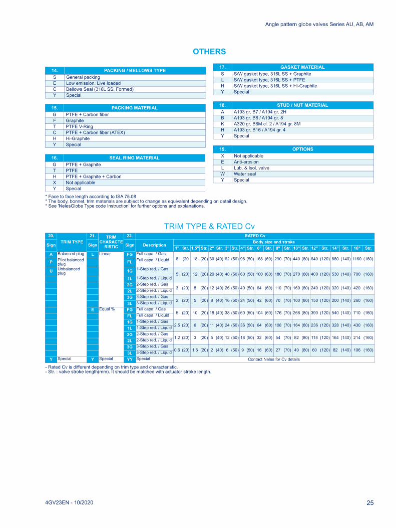
OTHERS
* Face to face length according to ISA 75.08* The body, bonnet, trim materials are subject to change as equivalent depending on detail design.* See 'NelesGlobe Type code Instruction' for further options and explanations.
TRIM TYPE & RATED Cv
- Rated Cv is different depending on trim type and characteristic.- Str. : valve stroke length(mm). It should be matched with actuator stroke length.
14. PACKING / BELLOWS TYPES General packingE Low emission, Live loadedC Bellows Seal (316L SS, Formed)Y Special
15. PACKING MATERIALG PTFE + Carbon fiberF GraphiteT PTFE V-RingC PTFE + Carbon fiber (ATEX)H Hi-GraphiteY Special
16. SEAL RING MATERIALG PTFE + GraphiteT PTFEH PTFE + Graphite + CarbonX Not applicableY Special
17. GASKET MATERIALS S/W gasket type, 316L SS + GraphiteL S/W gasket type, 316L SS + PTFEH S/W gasket type, 316L SS + Hi-Graphite Y Special
18. STUD / NUT MATERIALA A193 gr. B7 / A194 gr. 2HB A193 gr. B8 / A194 gr. 8K A320 gr. B8M cl. 2 / A194 gr. 8MH A193 gr. B16 / A194 gr. 4Y Special
19. OPTIONSX Not applicableE Anti-erosionL Lub. & Isol. valveW Water sealY Special
20.TRIM TYPE
21. TRIMCHARACTE
RISTIC
22. RATED Cv
Sign Sign Sign DescriptionBody size and stroke
1" Str. 1.5" Str. 2" Str. 3" Str. 4" Str. 6" Str. 8" Str. 10" Str. 12" Str. 14" Str. 16" Str.A Balanced plug L Linear FG Full capa. / Gas
8 (20 18 (20) 30 (40) 62 (50) 96 (50) 168 (60) 290 (70) 440 (80) 640 (120) 880 (140) 1160 (160)P Pilot balanced
plug FL Full capa. / Liquid
U Unbalanced plug 1G 1-Step red. / Gas
5 (20) 12 (20) 20 (40) 40 (50) 60 (50) 100 (60) 180 (70) 270 (80) 400 (120) 530 (140) 700 (160)1L 1-Step red. / Liquid2G 2-Step red. / Gas
3 (20) 8 (20) 12 (40) 26 (50) 40 (50) 64 (60) 110 (70) 160 (80) 240 (120) 320 (140) 420 (160)2L 2-Step red. / Liquid3G 3-Step red. / Gas
2 (20) 5 (20) 8 (40) 16 (50) 24 (50) 42 (60) 70 (70) 100 (80) 150 (120) 200 (140) 260 (160)3L 3-Step red. / Liquid
E Equal % FG Full capa. / Gas5 (20) 10 (20) 18 (40) 38 (50) 60 (50) 104 (60) 176 (70) 268 (80) 390 (120) 540 (140) 710 (160)
FL Full capa. / Liquid1G 1-Step red. / Gas
2.5 (20) 6 (20) 11 (40) 24 (50) 36 (50) 64 (60) 108 (70) 164 (80) 236 (120) 328 (140) 430 (160)1L 1-Step red. / Liquid2G 2-Step red. / Gas
1.2 (20) 3 (20) 5 (40) 12 (50) 18 (50) 32 (60) 54 (70) 82 (80) 118 (120) 164 (140) 214 (160)2L 2-Step red. / Liquid3G 3-Step red. / Gas
0.6 (20) 1.5 (20) 2 (40) 6 (50) 9 (50) 16 (60) 27 (70) 40 (80) 60 (120) 82 (140) 106 (160)3L 3-Step red. / Liquid
Y Special Y Special YY Special Contact Neles for Cv details
4GV23EN - 10/2020 25

Angle pattern globe valves Series AU, AB, AM
26 4GV23EN - 10/2020

Angle pattern globe valves Series AU, AB, AM
4GV23EN - 10/2020 27

4GV23EN
- 10/2020
NelesVanha PoTel. +358 1
neles.com
Subject to chare either reStates and/o
rvoontie 229, 01380 Vantaa, Finland.
0 417 5000.
ange without prior notice. Neles, Jamesbury and Easyflow by Negistered trademarks or trademarks of Neles Corporation or its subr in other countries. For more information www.neles.com/tradem
les, and certain other trademarks, sidiaries or affiliates in the United arks
Related Documents