Manual Switches Series 2 Pushbutton Switches and Indicators Honeywell 1 Sensing and Control 1 1-800-537-6945 USA 1F1-815-235-6847 International 1 1-800-737-3360 Canada 105 FEATURES 1 Easy-to-assemble modules provide thousands of display/control combinations 1 Up to 4 incandescent lamps 1 1, 2, 3, or 4-section display 1 Transmitted or projected color 1 Integral hold-in coil option provides remote released contacts. Pull-in coils (flange mount only) enable remote actuation 1 Switch guard accessory. CHANGE LAMPS OR FILTERS FROM PANEL FRONT Without tool. Remove display screen/ lampholder assembly from 2C200 oper- ator-indicator (or 2F200 indicator). Unit is keyed to maintain proper orientation when replacing. Use only flange base T-1 3 /4 lamps with 2C200 and 2F200 de- vices. LAMPS AND FILTERS Order lamps and filters for projected color from page 111. BARRIER MOUNT Display screen (page 115) Housing (next page) Mounting barrier (next page) Switch unit (page 114) Mounting barriers attach to either the long or short sides of the housing. They have spring clips which grip the panel. Mount- ing barriers also separate display screens to protect against inadvertent operation. Multiple units can be attached together in a strip and snapped into a panel slot; or they can be mounted individually. FLANGE MOUNT Display screen (page 115) Housing (page 113) Switch unit (page 114) Flange mount units have mounting clips ready-attached to the housing. They can be individually installed or replaced; and enable use of an overlay panel, if desired. Groupings can be separated by optional spacing barriers. MODULES ASSEMBLE EASILY All modules are ordered as separate items which snap together for easy as- sembly. Pushbuttons

Welcome message from author
This document is posted to help you gain knowledge. Please leave a comment to let me know what you think about it! Share it to your friends and learn new things together.
Transcript

Manual Switches Series 2Pushbutton Switches and Indicators
Honeywell 1 Sensing and Control 1 1-800-537-6945 USA 1 F1-815-235-6847 International 1 1-800-737-3360 Canada 105
FEATURES1 Easy-to-assemble modules provide
thousands of display/controlcombinations
1 Up to 4 incandescent lamps1 1, 2, 3, or 4-section display1 Transmitted or projected color1 Integral hold-in coil option provides
remote released contacts. Pull-in coils(flange mount only) enable remoteactuation
1 Switch guard accessory.
CHANGE LAMPS OR FILTERSFROM PANEL FRONT
Without tool. Remove display screen/lampholder assembly from 2C200 oper-ator-indicator (or 2F200 indicator). Unit iskeyed to maintain proper orientationwhen replacing. Use only flange baseT-13⁄4 lamps with 2C200 and 2F200 de-vices.
LAMPS AND FILTERSOrder lamps and filters for projected colorfrom page 111.
BARRIER MOUNT
Display screen(page 115)
Housing(next page)
Mounting barrier(next page)
Switch unit(page 114)
Mounting barriers attach to either the longor short sides of the housing. They havespring clips which grip the panel. Mount-ing barriers also separate display screens
to protect against inadvertent operation.Multiple units can be attached together ina strip and snapped into a panel slot; orthey can be mounted individually.
FLANGE MOUNT
Display screen(page 115)
Housing(page 113)
Switchunit(page 114)
Flange mount units have mounting clipsready-attached to the housing. They canbe individually installed or replaced; and
enable use of an overlay panel, if desired.Groupings can be separated by optionalspacing barriers.
MODULES ASSEMBLE EASILYAll modules are ordered as separateitems which snap together for easy as-sembly.
Push
butto
ns

Manual Switches Series 2Pushbuttons Switches and Indicators
106 Honeywell 1 Sensing and Control 1 1-800-537-6945 USA 1 F1-815-235-6847 International 1 1-800-737-3360 Canada
Barriers on long sides
Barriers on short sides
BARRIER MOUNT MODULESBarrier mount assemblies are identical inpanel appearance. Operator-indicatorhousings have spring clips for attachingswitch modules. This feature is not pro-vided with indicator housings.
Barriers are necessary for mounting.They can be specified for attachment tothe long or short side of the housing, asstated in the order guides.
BARRIER MOUNT HOUSING ORDER GUIDESee ‘‘Application Data’’ for typical bailing circuits for coil-equipped modules.
Tool Not RequiredBarriersAttach On:
No. ofLamp Sockets Operator-Indicator Indicator Only
Long Sidesof Housing
2 (A & C) 2C2074 (A-D) 2C209
Short Sidesof Housing
2 (A & C) 2C2014 (A-D) 2C203 2F203
MOUNTING BARRIER ORDER GUIDEFor strip mounting, specify one more barrier than the number of units in the group.
Catalog ListingsMounting Barrier For PanelType Thickness Gray Black
Attach toLong Sides .06-.19 in. (1,52-4,83 mm) 2B2 2B4
Attach toShort Sides .06-.19 in. (1,52-4,83 mm) 2B1 2B3
Note: Panels .19 in. (1,52 mm) thick require the .06-.19 in. (1,52-4,83 mm) type barriers.
Manual Switches Series 2Pushbutton Switches and Indicators
Honeywell 1 Sensing and Control 1 1-800-537-6945 USA 1 F1-815-235-6847 International 1 1-800-737-3360 Canada 107
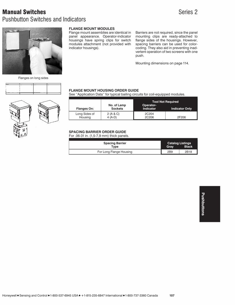
Flanges on long sides
FLANGE MOUNT MODULESFlange mount assemblies are identical inpanel appearance. Operator-indicatorhousings have spring clips for switchmodules attachment (not provided withindicator housings).
Barriers are not required, since the panelmounting clips are ready-attached toflange sides of the housings. However,spacing barriers can be used for color-coding. They also aid in preventing inad-vertent operation of two screens with onepush.
Mounting dimensions on page 114.
FLANGE MOUNT HOUSING ORDER GUIDESee ‘‘Application Data’’ for typical bailing circuits for coil-equipped modules.
Tool Not Required
Flanges On:No. of Lamp
SocketsOperator-Indicator Indicator Only
Long Sides ofHousing
2 (A & C) 2C2044 (A-D) 2C206 2F206
SPACING BARRIER ORDER GUIDEFor .06-31 in. (1,5-7,9 mm) thick panels.
Catalog ListingsSpacing BarrierType Gray Black
For Long Flange Housing 2B9 2B18
Push
butto
ns
Manual Switches Series 2Pushbutton Switches and Indicators
108 Honeywell 1 H Sensing and Control 1 1-800-537-6945 USA 1 F1-815-235-6847 International 1 1-800-737-3360 Canada
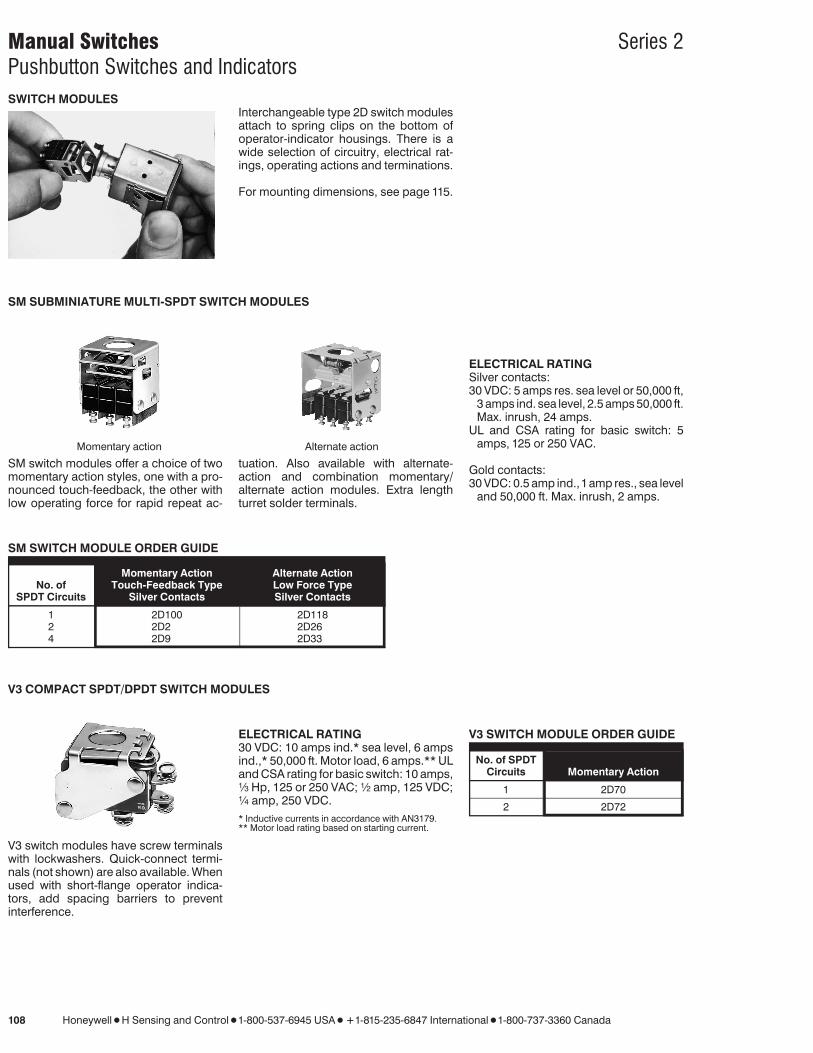
SWITCH MODULESInterchangeable type 2D switch modulesattach to spring clips on the bottom ofoperator-indicator housings. There is awide selection of circuitry, electrical rat-ings, operating actions and terminations.
For mounting dimensions, see page 115.
ELECTRICAL RATINGSilver contacts:30 VDC: 5 amps res. sea level or 50,000 ft,
3 amps ind. sea level, 2.5 amps 50,000 ft.Max. inrush, 24 amps.
UL and CSA rating for basic switch: 5amps, 125 or 250 VAC.
Gold contacts:30 VDC: 0.5 amp ind.,1amp res., sea level
and 50,000 ft. Max. inrush, 2 amps.
SM SUBMINIATURE MULTI-SPDT SWITCH MODULES
Momentary action Alternate action
SM switch modules offer a choice of twomomentary action styles, one with a pro-nounced touch-feedback, the other withlow operating force for rapid repeat ac-
tuation. Also available with alternate-action and combination momentary/alternate action modules. Extra lengthturret solder terminals.
SM SWITCH MODULE ORDER GUIDE
Momentary Action Alternate ActionTouch-Feedback Type Low Force TypeNo. of
SPDT Circuits Silver Contacts Silver Contacts
1 2D100 2D1182 2D2 2D264 2D9 2D33
V3 COMPACT SPDT/DPDT SWITCH MODULES
V3 switch modules have screw terminalswith lockwashers. Quick-connect termi-nals (not shown) are also available. Whenused with short-flange operator indica-tors, add spacing barriers to preventinterference.
ELECTRICAL RATING30 VDC: 10 amps ind.* sea level, 6 ampsind.,* 50,000 ft. Motor load, 6 amps.** ULand CSA rating for basic switch: 10 amps,1⁄3 Hp, 125 or 250 VAC; 1⁄2 amp, 125 VDC;1⁄4 amp, 250 VDC.* Inductive currents in accordance with AN3179.** Motor load rating based on starting current.
V3 SWITCH MODULE ORDER GUIDE
No. of SPDTCircuits Momentary Action
1 2D70
2 2D72
Manual Switches Series 2Pushbutton Switches and Indicators
Honeywell 1 Sensing and Control 1 1-800-537-6945 USA 1 F1-815-235-6847 International 1 1-800-737-3360 Canada 109
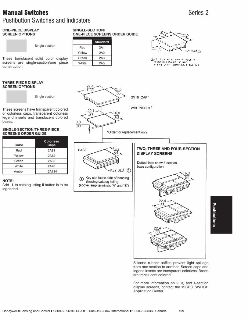
ONE-PIECE DISPLAYSCREEN OPTIONS
Single-section
These translucent solid color displayscreens are single-section/one piececonstruction
SINGLE-SECTION/ONE-PIECE SCREENS ORDER GUIDE
Colors Standard
Red 2A1
Yellow 2A2
Green 2A3
White 2A5
THREE-PIECE DISPLAYSCREEN OPTIONS
Single-section
These screens have transparent coloredor colorless caps, transparent colorlesslegend inserts and translucent coloredbases.
SINGLE-SECTION/THREE-PIECESCREENS ORDER GUIDE
ColorlessColor Caps
Red 2A81
Yellow 2A82
Green 2A85
White 2A70
Amber 2A114
NOTE:Add –L to catalog listing if button is to belegended.
Silicone rubber baffles prevent light spillagefrom one section to another. Screen caps andlegend inserts are transparent colorless. Basesare translucent colored.
For more information on 2, 3, and 4-sectiondisplay screens, contact the MICRO SWITCHApplication Center.
Push
butto
ns
Manual Switches Series 2Pushbutton Switches and Indicators
110 Honeywell 1 Sensing and Control 1 1-800-537-6945 USA 1 F1-815-235-6847 International 1 1-800-737-3360 Canada

Manual Switches Series 2Pushbutton Switches and Indicators
Honeywell 1 Sensing and Control 1 1-800-537-6945 USA 1 F1-815-235-6847 International 1 1-800-737-3360 Canada 111
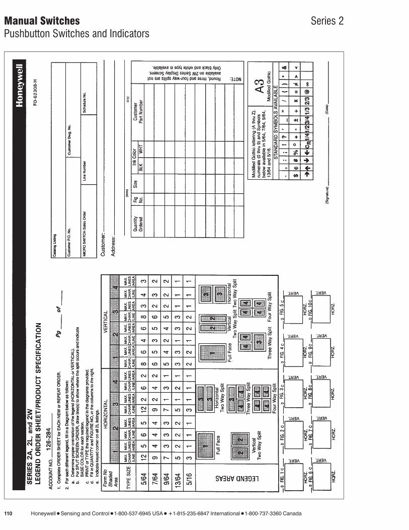
LEGEND INFORMATIONHoneywell MICRO SWITCH Division pro-vides legend service on the inserts sup-plied with three-piece screens only. Tospecify your needs, add -L to the cataloglistings (example: 2A81-L) and use Leg-end Order Sheet (Form FO-62308),shown on facing page. Reproduce it onyour office copier.
On any one insert, only one size of type isprovided in either black or white. Afterlegending, the insert is assembled to thedisplay screen. The type face used is‘‘Modified Gothic’’.
LAMPST-13⁄4 incandescent lamps are availablefrom MICRO SWITCH in 28 volt versions.
Use of neon lamps is not recommended.Light output is approximately 30% of anincandescent lamp. Also, a neon lampwill not illuminate blue or green filters ordisplay screens due to the absence ofthese colors from the neon light spec-trum.
LAMP POLICYThe 28 volt lamps are offered as a conve-nience to customers. Honeywell MICROSWITCH Division does not extend anywarranty as to such lamps, and cannotguarantee to provide lamps from specificmanufacturers. Any technical or qualityquestions regarding such lamps shouldbe directed to the lamp manufacturer.
COLOR FILTERS FOR PROJECTEDCOLORProjected color is achieved by usingwhite buttons and color filters over clearlamps. When lamps are lighted, whitebutton takes on color projected by thefilters.
Filters used with type 2C200 and 2F200housings (no-tool relamping) slip overlamp sockets in lampholder.
SCREEN/LEGEND COLORSThe chart below shows recommendeddisplay screen and legend color combi-nations for optimum legibility.
Legend Lettering
ScreenColor Black White
Red x
Green x
Yellow x
Amber x x
White x
LAMP ORDER GUIDE
Rating Life/Voltage†
Catalog Base Type Life in ExpectedListing Style No. Volts Amps Hours Volts Life (Hrs.)
2E1 Flange 327 28 .040 1000 24.0 7,50026.0 2,80030.0 400
† These are experimental continuous life test results supplied by a lamp manufacturer for reference only.Intermittent operation may reduce these figures as much as 50%. Ratings are based on median values ofcurrent and life.
Wattage should not exceed 2.4 watts (2 lamps) per switch, for continuous illumination.
FILTER ORDER GUIDE
Filter Style Red Green Amber White*
For Type 2C200 and 2G12 2G14 2G16 2G172F200 Housings
* Has blue tint to compensate for high yellow content of incandescent lamps at low voltages.
Push
butto
ns
Manual Switches Series 2Pushbutton Switches and Indicators
112 Honeywell 1 Sensing and Control 1 1-800-537-6945 USA 1 F1-815-235-6847 International 1 1-800-737-3360 Canada
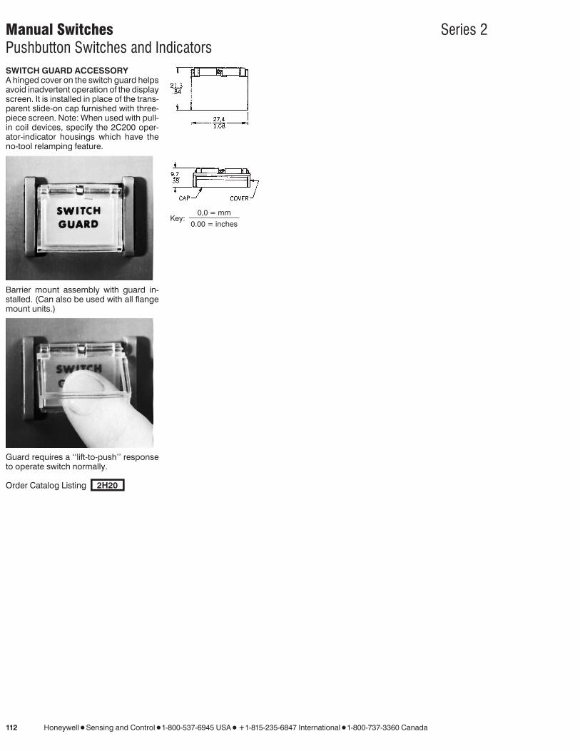
SWITCH GUARD ACCESSORYA hinged cover on the switch guard helpsavoid inadvertent operation of the displayscreen. It is installed in place of the trans-parent slide-on cap furnished with three-piece screen. Note: When used with pull-in coil devices, specify the 2C200 oper-ator-indicator housings which have theno-tool relamping feature.
Barrier mount assembly with guard in-stalled. (Can also be used with all flangemount units.)
Guard requires a ‘‘lift-to-push’’ responseto operate switch normally.
Order Catalog Listing 2H20
Key:0,0 = mm
0.00 = inches

Manual Switches Series 2Pushbutton Switches and Indicators
Honeywell 1 Sensing and Control 1 1-800-537-6945 USA 1 F1-815-235-6847 International 1 1-800-737-3360 Canada 113
MOUNTING DIMENSIONS (For reference only)
Long barrier operator-indicators Short barrier operator-indicators
Short barrier indicators Long barrier indicators Mounting barriers
Short Long
0,0 = mmKey:
0.00 = inches.
A Panel Thickness
1,5/.06 1,5-4,81/.06-.194,6/.18 4,8-7,9/.19-.31
Length Of Panel Cutout*
Number of UnitsType of Indicator orOperator-Indicator 1 2 3 4 5 6 7
Short mm 36,09 68,00 99,87 131,72 163,60 195,48 227,36
Barrier in. 1.421 2.677 3.932 5.186 6.441 7.696 8.951
Long mm 30,00 55,78 81,58 106,34 133,12 159,90 184,68
Barrier in. 1.181 2.196 3.212 4.226 5.241 6.256 7.271
*Nominal dimensions, ±0,25 mm/0.10 in. (In 5% ofthe cases, the cutout will be undersized for the build-up of assembled units and will require enlargement.
Push
butto
ns

Manual Switches Series 2Pushbutton Switches and Indicators
114 Honeywell 1 Sensing and Control 1 1-800-537-6945 USA 1 F1-815-235-6847 International 1 1-800-737-3360 Canada
MOUNTING DIMENSIONS (For reference only)
Long flangeoperator-indicators
Long flange indicators Spacing barriers
Short Long
0,0 = mmKey: 0.00 = inches.
Length Of Panel Cutout*Add 4,19 mm/.165 in. to length for each optional spacing barrier used.
Number of UnitsType of Indicator orOperator-Indicator 1 2 3 4 5 6 7
Long mm 27,94 55,75 83,57 111,36 139,17 166,98 194,77
Flange in. 1.1 2.195 3.290 4.384 5.479 6.574 7.668
*Nominal dimensions, ±0,25 mm/0.10 in. (In 5% ofthe cases, the cutout will be undersized for thebuild-up of assembled units and will requireenlargement.
Manual Switches Series 2Pushbutton Switches and Indicators
Honeywell 1 Sensing and Control 1 1-800-537-6945 USA 1 F1-815-235-6847 International 1 1-800-737-3360 Canada 115
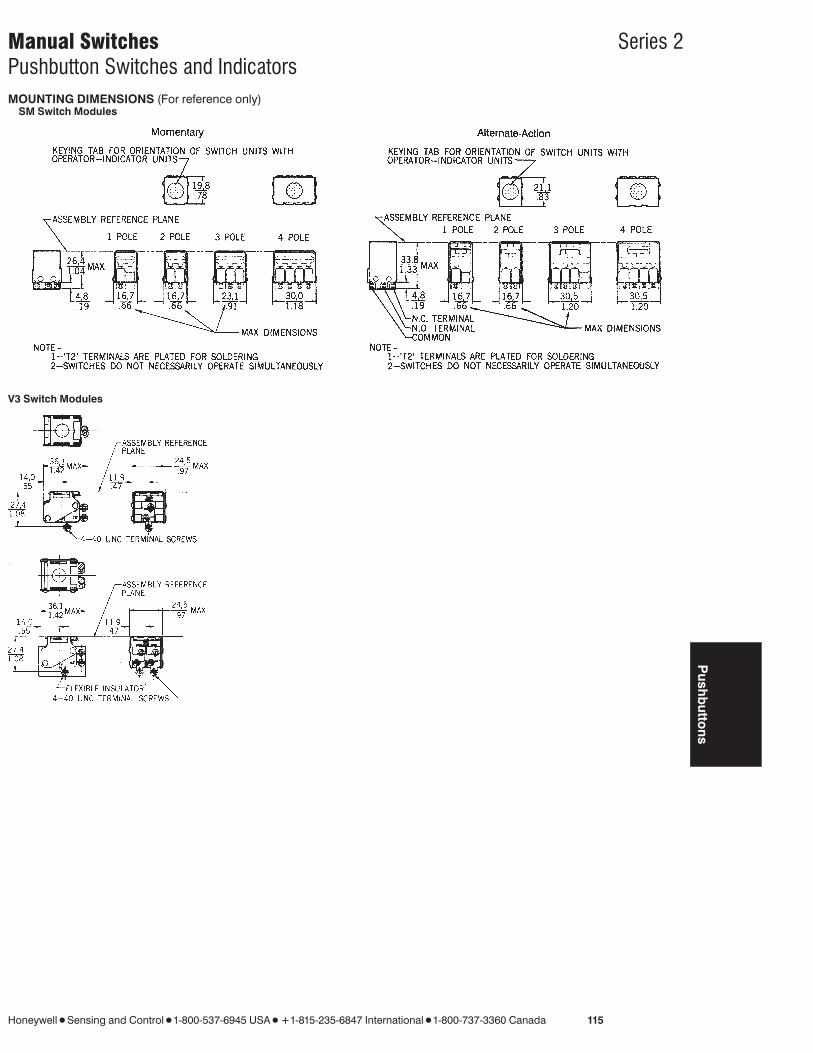
MOUNTING DIMENSIONS (For reference only)SM Switch Modules
V3 Switch Modules
Push
butto
ns
Related Documents