GE Fanuc Automation Computer Numerical Control Products Series 15i/150i-Model A Programming Manual (Macro Compiler/Macro Executor) GFZ-63323EN-2/01 November 2000

Welcome message from author
This document is posted to help you gain knowledge. Please leave a comment to let me know what you think about it! Share it to your friends and learn new things together.
Transcript
GE Fanuc Automation
Computer Numerical Control Products
Series 15i/150i-Model AProgramming Manual(Macro Compiler/Macro Executor)GFZ-63323EN-2/01 November 2000
GFL-001
Warnings, Cautions, and Notesas Used in this Publication
Warning
Warning notices are used in this publication to emphasize that hazardous voltages, currents,temperatures, or other conditions that could cause personal injury exist in this equipment ormay be associated with its use.
In situations where inattention could cause either personal injury or damage to equipment, aWarning notice is used.
Caution
Caution notices are used where equipment might be damaged if care is not taken.
NoteNotes merely call attention to information that is especially significant to understanding andoperating the equipment.
This document is based on information available at the time of its publication. While effortshave been made to be accurate, the information contained herein does not purport to cover alldetails or variations in hardware or software, nor to provide for every possible contingency inconnection with installation, operation, or maintenance. Features may be described hereinwhich are not present in all hardware and software systems. GE Fanuc Automation assumesno obligation of notice to holders of this document with respect to changes subsequently made.
GE Fanuc Automation makes no representation or warranty, expressed, implied, or statutorywith respect to, and assumes no responsibility for the accuracy, completeness, sufficiency, orusefulness of the information contained herein. No warranties of merchantability or fitness forpurpose shall apply.
©Copyright 2002 GE Fanuc Automation North America, Inc.
All Rights Reserved.
SAFETY PRECAUTIONS
This manual includes safety precautions for protecting the user and preventing damage to the
machine. Precautions are classified into Warnings and Cautions according to their bearing on safety.
Also, supplementary information is described as Notes. Read the Warnings, Cautions, and Notes
thoroughly before attempting to use the machine.
WARNINGApplied when there is a danger of the user being injured or when thereis a danger of both the user being injured and the equipment beingdamaged if the approved procedure is not observed.
CAUTIONApplied when there is a danger of the equipment being damaged, if theapproved procedure is not observed.
NOTENotes are used to indicate supplementary information other thanWarnings and Cautions.
* Read this manual carefully, and store it in a safe place.
B-63323EN-2/01 CONTENTS
c - 1
CONTENTS
1111 GENERALGENERALGENERALGENERAL .................................................................................................................................................................................................................................................................................................................................................................................................................................................................................................... 1111
2222 MACRO COMPILER ANDMACRO COMPILER ANDMACRO COMPILER ANDMACRO COMPILER AND MACRO MACRO MACRO MACRO EXECUTOREXECUTOREXECUTOREXECUTOR ................................................................................................................................................................................................................................................ 3333
2.12.12.12.1 Macro CompilerMacro CompilerMacro CompilerMacro Compiler.................................................................................................................................................................................................................................................................................................................................................................................................................................................................................................... 4444
2.1.1 P-CODE macro and P-CODE file...................................................................................... 4
2.22.22.22.2 Macro ExecutorMacro ExecutorMacro ExecutorMacro Executor .................................................................................................................................................................................................................................................................................................................................................................................................................................................................................................... 7777
2.32.32.32.3 P-CODE MacroP-CODE MacroP-CODE MacroP-CODE Macro........................................................................................................................................................................................................................................................................................................................................................................................................................................................................................................ 8888
2.3.1 Limitations on commands ................................................................................................. 8
2.3.2 Differences from the FS15-B........................................................................................... 10
3333 EEEEXECUTION MACRO FUNCTIONXECUTION MACRO FUNCTIONXECUTION MACRO FUNCTIONXECUTION MACRO FUNCTION................................................................................................................................................................................................................................................................................................................................ 11111111
3.13.13.13.1 GeneralGeneralGeneralGeneral................................................................................................................................................................................................................................................................................................................................................................................................................................................................................................................................................ 12121212
3.23.23.23.2 Calling an Execution MacroCalling an Execution MacroCalling an Execution MacroCalling an Execution Macro ............................................................................................................................................................................................................................................................................................................................................................................................................ 13131313
3.2.1 Simple call (G65).............................................................................................................. 16
3.2.2 Modal call (G66 or G66.1)................................................................................................ 17
3.2.3 Macro call using a G code................................................................................................ 17
3.2.4 Macro calls with G codes (Specification of Multiple G codes) ....................................... 18
3.2.5 Macro call using an M code ............................................................................................. 20
3.2.6 Macro call using a T code ................................................................................................ 21
3.2.7 Macro call using an axis address .................................................................................... 23
3.2.8 Subprogram call (M98) .................................................................................................... 27
3.2.9 Subprogram call using an M code................................................................................... 27
3.2.10 Subprogram call using an M code in the specified range.............................................. 28
3.2.11 Subprogram call using an S code.................................................................................... 29
3.2.12 Subprogram call using a T code...................................................................................... 30
3.2.13 Subprogram call using a second auxiliary function code .............................................. 31
3.2.14 Subprogram call using a specific code ............................................................................ 32
3.2.15 Subprogram call for a user program............................................................................... 33
3.2.16 P-CODE workpiece number search ................................................................................ 33
3.33.33.33.3 Limitations on Execution MacrosLimitations on Execution MacrosLimitations on Execution MacrosLimitations on Execution Macros............................................................................................................................................................................................................................................................................................................................................................................ 35353535
3.3.1 Commands that cannot be used in execution macros.................................................... 35
3.3.2 Functions which cannot use execution macros .............................................................. 35
3.3.3 Optional block skip .......................................................................................................... 35
CONTENTS B-63323EN-2/01
c - 2
3.43.43.43.4 Differences from the FS15-BDifferences from the FS15-BDifferences from the FS15-BDifferences from the FS15-B ........................................................................................................................................................................................................................................................................................................................................................................................................ 37373737
4444 CONVERSATIONAL MACCONVERSATIONAL MACCONVERSATIONAL MACCONVERSATIONAL MACRO (TALK MACRO) FUNCTION ANDRO (TALK MACRO) FUNCTION ANDRO (TALK MACRO) FUNCTION ANDRO (TALK MACRO) FUNCTION AND
AUXILIARY AUXILIARY AUXILIARY AUXILIARY MACRO FUNCTIONMACRO FUNCTIONMACRO FUNCTIONMACRO FUNCTION .................................................................................................................................................................................................................................................................................................................................... 39393939
4.14.14.14.1 Conversational Macro (Talk Macro) FunctionConversational Macro (Talk Macro) FunctionConversational Macro (Talk Macro) FunctionConversational Macro (Talk Macro) Function ............................................................................................................................................................................................................................................................................................ 40404040
4.1.1 Execution and termination ............................................................................................. 40
4.1.2 Commands........................................................................................................................ 43
4.24.24.24.2 Auxiliary Macro FunctionAuxiliary Macro FunctionAuxiliary Macro FunctionAuxiliary Macro Function............................................................................................................................................................................................................................................................................................................................................................................................................................ 44444444
4.2.1 Execution and termination ............................................................................................. 44
4.2.2 Commands........................................................................................................................ 45
4.2.3 Execution cycle................................................................................................................. 46
4.34.34.34.3 Execution Control CodesExecution Control CodesExecution Control CodesExecution Control Codes ................................................................................................................................................................................................................................................................................................................................................................................................................................ 48484848
4.44.44.44.4 Execution Control Variables (#8500, #8510, and #8600)Execution Control Variables (#8500, #8510, and #8600)Execution Control Variables (#8500, #8510, and #8600)Execution Control Variables (#8500, #8510, and #8600) ........................................................................................................................................................................................................................ 50505050
4.54.54.54.5 Fatal ErrorFatal ErrorFatal ErrorFatal Error ........................................................................................................................................................................................................................................................................................................................................................................................................................................................................................................................ 52525252
5555 MACRO VARIABLESMACRO VARIABLESMACRO VARIABLESMACRO VARIABLES........................................................................................................................................................................................................................................................................................................................................................................................................................ 54545454
5.15.15.15.1 Macro Variable ListMacro Variable ListMacro Variable ListMacro Variable List ................................................................................................................................................................................................................................................................................................................................................................................................................................................................ 55555555
5.25.25.25.2 Local VaLocal VaLocal VaLocal Variables (#1 to #33)/Array Variables (#1 to #99)riables (#1 to #33)/Array Variables (#1 to #99)riables (#1 to #33)/Array Variables (#1 to #99)riables (#1 to #33)/Array Variables (#1 to #99) ............................................................................................................................................................................................................................ 57575757
5.35.35.35.3 Common Variables (#100 to #199, #200 to #499, and #500 to #999)Common Variables (#100 to #199, #200 to #499, and #500 to #999)Common Variables (#100 to #199, #200 to #499, and #500 to #999)Common Variables (#100 to #199, #200 to #499, and #500 to #999).................................................................................................................................................... 58585858
5.45.45.45.4 P-CODE Variables (#30000 and Above)P-CODE Variables (#30000 and Above)P-CODE Variables (#30000 and Above)P-CODE Variables (#30000 and Above) .................................................................................................................................................................................................................................................................................................................................... 60606060
5.55.55.55.5 Extended P-CODE Variables (#40000 and Above)Extended P-CODE Variables (#40000 and Above)Extended P-CODE Variables (#40000 and Above)Extended P-CODE Variables (#40000 and Above) ................................................................................................................................................................................................................................................................ 63636363
5.65.65.65.6 Custom Macro Common Variables (#99100 to #99999)Custom Macro Common Variables (#99100 to #99999)Custom Macro Common Variables (#99100 to #99999)Custom Macro Common Variables (#99100 to #99999) .................................................................................................................................................................................................................................... 66666666
5.75.75.75.7 Custom Macro System Variables (#1000 and Above)Custom Macro System Variables (#1000 and Above)Custom Macro System Variables (#1000 and Above)Custom Macro System Variables (#1000 and Above) ................................................................................................................................................................................................................................................ 67676767
6666 MAMAMAMACRO EXECUTOR FUNCTIONSCRO EXECUTOR FUNCTIONSCRO EXECUTOR FUNCTIONSCRO EXECUTOR FUNCTIONS ............................................................................................................................................................................................................................................................................................................................ 70707070
6.16.16.16.1 Screen Display FunctionsScreen Display FunctionsScreen Display FunctionsScreen Display Functions ............................................................................................................................................................................................................................................................................................................................................................................................................................ 76767676
6.1.1 Screen coordinate system................................................................................................ 76
6.1.2 Screen display control codes ........................................................................................... 79
6.1.2.1 Screen clear (G202) .......................................................................................................81
6.1.2.2 Color specification (G240) .............................................................................................82
6.1.2.3 Drawing start point setting (G242) ..............................................................................84
6.1.2.4 Character display (G243) ..............................................................................................84
6.1.2.5 Drawing line type specification (G244) ........................................................................89
6.1.2.6 Prompt statement display (G280) ................................................................................90
6.1.2.7 Linear drawing (G301)..................................................................................................90
6.1.2.8 Circular drawing (clockwise) (G302) ............................................................................91
6.1.2.9 Circular drawing (counterclockwise) (G303)................................................................91

B-63323EN-2/01 CONTENTS
c - 3
6.1.2.10 Cursor display (G230) ...................................................................................................92
6.1.2.11 Absolute mode (G390)/incremental mode (G391) specification...................................93
6.1.2.12 Graphic coordinate system setting (G392)...................................................................93
6.1.2.13 Rapid traverse rate specification (G311)......................................................................94
6.1.2.14 Rapid traverse drawing (G300) ....................................................................................95
6.1.2.15 Closed area filling (G320) .............................................................................................96
6.1.2.16 Rectangular display (G204) ..........................................................................................97
6.1.2.17 Marking (G321) .............................................................................................................98
6.1.2.18 Shift function for graphic screen adjustment ............................................................100
6.1.2.19 Reading of the graphic state .......................................................................................100
6.1.2.20 Differences from the FS15-B.......................................................................................101
6.1.3 Character string registration program number specification (#8509) ....................... 101
6.1.4 Function screen control function (#8530)..................................................................... 101
6.26.26.26.2 Key Input and Data Input/OutputKey Input and Data Input/OutputKey Input and Data Input/OutputKey Input and Data Input/Output ............................................................................................................................................................................................................................................................................................................................................................ 103103103103
6.2.1 Command key input variable (#8501) .......................................................................... 103
6.2.2 Data input control variable (#8502).............................................................................. 105
6.2.3 Extended data input control variable #8552................................................................ 106
6.2.4 Consecutive input of cursor and page keys.................................................................. 108
6.2.5 MDI key image reading function (variables #8540 to #8549) ..................................... 108
6.36.36.36.3 Address FunctionsAddress FunctionsAddress FunctionsAddress Functions ................................................................................................................................................................................................................................................................................................................................................................................................................................................................ 112112112112
6.3.1 PMC address reference.................................................................................................. 112
6.3.2 CNC parameter reference ............................................................................................. 113
6.46.46.46.4 PMC Address Reading/Writing (G310)PMC Address Reading/Writing (G310)PMC Address Reading/Writing (G310)PMC Address Reading/Writing (G310) ................................................................................................................................................................................................................................................................................................................................ 115115115115
6.56.56.56.5 Reader/Puncher InterfaceReader/Puncher InterfaceReader/Puncher InterfaceReader/Puncher Interface ................................................................................................................................................................................................................................................................................................................................................................................................................ 118118118118
6.5.1 General ........................................................................................................................... 118
6.5.2 Functions........................................................................................................................ 119
6.5.3 Macro variable input/output functions......................................................................... 121
6.5.4 Data transmission/reception waiting cancellation ...................................................... 126
6.5.5 FANUC cassette control ................................................................................................ 127
6.5.6 Completion codes ........................................................................................................... 133
6.66.66.66.6 Referencing and Writing CNC ProgramsReferencing and Writing CNC ProgramsReferencing and Writing CNC ProgramsReferencing and Writing CNC Programs ................................................................................................................................................................................................................................................................................................................ 135135135135
6.6.1 General ........................................................................................................................... 135
6.6.2 Details of control codes and control variables.............................................................. 136
6.6.3 Limitations ..................................................................................................................... 146
6.6.4 Appendix tables ............................................................................................................. 147
6.76.76.76.7 Cutting Time and Distance Read and Preset FunctionsCutting Time and Distance Read and Preset FunctionsCutting Time and Distance Read and Preset FunctionsCutting Time and Distance Read and Preset Functions .................................................................................................................................................................................................................... 148148148148
6.86.86.86.8 Relative Coordinate Read and Preset Functions (#8996 to #8999)Relative Coordinate Read and Preset Functions (#8996 to #8999)Relative Coordinate Read and Preset Functions (#8996 to #8999)Relative Coordinate Read and Preset Functions (#8996 to #8999)........................................................................................................................................................................ 150150150150
CONTENTS B-63323EN-2/01
c - 4
6.96.96.96.9 Array-Type Processing and Referencing of P-CODE VariablesArray-Type Processing and Referencing of P-CODE VariablesArray-Type Processing and Referencing of P-CODE VariablesArray-Type Processing and Referencing of P-CODE Variables............................................................................................................................................................................................ 152152152152
6.106.106.106.10 Torque Limit Override Control (#8990 to #8993)Torque Limit Override Control (#8990 to #8993)Torque Limit Override Control (#8990 to #8993)Torque Limit Override Control (#8990 to #8993) ................................................................................................................................................................................................................................................................ 155155155155
6.116.116.116.11 Reading A/D Conversion DataReading A/D Conversion DataReading A/D Conversion DataReading A/D Conversion Data........................................................................................................................................................................................................................................................................................................................................................................................ 156156156156
6.126.126.126.12 Reading the Distance to Go (#5181 to #5200 and #100801 to 100824)Reading the Distance to Go (#5181 to #5200 and #100801 to 100824)Reading the Distance to Go (#5181 to #5200 and #100801 to 100824)Reading the Distance to Go (#5181 to #5200 and #100801 to 100824) ............................................................................................................................ 159159159159
6.136.136.136.13 PMC Axis ControlPMC Axis ControlPMC Axis ControlPMC Axis Control .................................................................................................................................................................................................................................................................................................................................................................................................................................................................... 160160160160
6.13.1 General ........................................................................................................................... 160
6.13.2 Details of control codes.................................................................................................. 161
6.13.3 Limitations ..................................................................................................................... 164
6.13.4 Cautions ......................................................................................................................... 165
6.146.146.146.14 File ControlFile ControlFile ControlFile Control ............................................................................................................................................................................................................................................................................................................................................................................................................................................................................................................ 166166166166
6.14.1 General ........................................................................................................................... 166
6.14.2 Setup procedure ............................................................................................................. 166
6.14.3 Setting ............................................................................................................................ 168
6.14.4 Error messages .............................................................................................................. 169
6.14.5 List of commands ........................................................................................................... 169
6.14.6 Cautions ......................................................................................................................... 173
6.156.156.156.15 Axis-Direction-by-Axis-Direction Interlock Function (#8605 to #8608)Axis-Direction-by-Axis-Direction Interlock Function (#8605 to #8608)Axis-Direction-by-Axis-Direction Interlock Function (#8605 to #8608)Axis-Direction-by-Axis-Direction Interlock Function (#8605 to #8608) .................................................................................................................... 175175175175
6.166.166.166.16 Window Function (#8996 to #8999)Window Function (#8996 to #8999)Window Function (#8996 to #8999)Window Function (#8996 to #8999)........................................................................................................................................................................................................................................................................................................................................................ 178178178178
6.16.1 General ........................................................................................................................... 178
6.16.2 Alarm information and external alarm information ................................................... 182
6.16.3 The number of controlled axes and the number of servo axes.................................... 204
6.16.4 Cumulative operation time and parts count ................................................................ 204
6.16.5 Diagnosis information ................................................................................................... 205
6.16.6 System, servo, and PMC series information ................................................................ 206
6.176.176.176.17 Function for Searching Data Tables for Control VariablesFunction for Searching Data Tables for Control VariablesFunction for Searching Data Tables for Control VariablesFunction for Searching Data Tables for Control Variables.................................................................................................................................................................................................... 208208208208
7777 DEBUGGING FUNCTIONDEBUGGING FUNCTIONDEBUGGING FUNCTIONDEBUGGING FUNCTION ................................................................................................................................................................................................................................................................................................................................................................................212212212212
7.17.17.17.1 GeneralGeneralGeneralGeneral........................................................................................................................................................................................................................................................................................................................................................................................................................................................................................................................................ 213213213213
7.27.27.27.2 Displaying and Setting on the Debugger ScreenDisplaying and Setting on the Debugger ScreenDisplaying and Setting on the Debugger ScreenDisplaying and Setting on the Debugger Screen.................................................................................................................................................................................................................................................................... 214214214214
7.37.37.37.3 Direct Setting by Parameter and KeyDirect Setting by Parameter and KeyDirect Setting by Parameter and KeyDirect Setting by Parameter and Key........................................................................................................................................................................................................................................................................................................................................ 219219219219
8888 OPERATIONOPERATIONOPERATIONOPERATION ........................................................................................................................................................................................................................................................................................................................................................................................................................................................................221221221221
8.18.18.18.1 Displaying and Setting Values in Macro VariablesDisplaying and Setting Values in Macro VariablesDisplaying and Setting Values in Macro VariablesDisplaying and Setting Values in Macro Variables.................................................................................................................................................................................................................................................... 222222222222
8.28.28.28.2 Displaying P-CODE Macro Program NumbersDisplaying P-CODE Macro Program NumbersDisplaying P-CODE Macro Program NumbersDisplaying P-CODE Macro Program Numbers ............................................................................................................................................................................................................................................................................ 232232232232
8.38.38.38.3 Displaying Execution Macro Call InformationDisplaying Execution Macro Call InformationDisplaying Execution Macro Call InformationDisplaying Execution Macro Call Information ................................................................................................................................................................................................................................................................................ 234234234234
9999 PARAMETERSPARAMETERSPARAMETERSPARAMETERS............................................................................................................................................................................................................................................................................................................................................................................................................................................................237237237237
B-63323EN-2/01 CONTENTS
c - 5
9.19.19.19.1 Compile ParametersCompile ParametersCompile ParametersCompile Parameters .................................................................................................................................................................................................................................................................................................................................................................................................................................................... 238238238238
9.29.29.29.2 P-CODE Macro ParametersP-CODE Macro ParametersP-CODE Macro ParametersP-CODE Macro Parameters .................................................................................................................................................................................................................................................................................................................................................................................................... 253253253253
10101010 APPENDIXAPPENDIXAPPENDIXAPPENDIX....................................................................................................................................................................................................................................................................................................................................................................................................................................................................................255255255255
10.110.110.110.1 Error No. ListError No. ListError No. ListError No. List................................................................................................................................................................................................................................................................................................................................................................................................................................................................................................ 256256256256
10.210.210.210.2 Macro Program Example (Inputting Data and Performing Circle Cutting)Macro Program Example (Inputting Data and Performing Circle Cutting)Macro Program Example (Inputting Data and Performing Circle Cutting)Macro Program Example (Inputting Data and Performing Circle Cutting) ........................................................................................ 261261261261
10.2.1 Program functions ......................................................................................................... 261
10.2.2 Meanings of macro variables ........................................................................................ 262
10.2.3 Source programs ............................................................................................................ 262
10.2.4 Flowchart ....................................................................................................................... 272
10.2.5 Program explanation ..................................................................................................... 277
10.310.310.310.3 Code TablesCode TablesCode TablesCode Tables ............................................................................................................................................................................................................................................................................................................................................................................................................................................................................................................ 280280280280

B-63323EN-2/01 1.GENERAL
- 1 -
1 GENERALSome NC programs such as programs created using custommacros need not be modified once created. Others such asmachining programs differ depending on the machiningtarget.This function can convert a custom macro program createdby the machine tool builder to an executable macro program,load the executable macro program (P-CODE macro) into F-ROM (FLASH ROM module), and execute it.The function which converts a custom macro program to anexecutable macro program is called the macro compiler.The function which reads and executes a P-CODE macro iscalled the macro executor.
Features• The execution speed is high because a custom macro
program is loaded after converted to an executable so thatthe machining time can be reduced and the machiningprecision can be improved.
• Any custom macro is not destroyed because it is loadedinto F-ROM so that reliability is improved.
• Because any program converted to an executable is notdisplayed on the program screen, the know-how themachine tool builder has can be protected.
• Because executable macro programs are loaded into F-ROM, program editing memory can efficiently be used.
• The users can call each executable macro program using asimple call procedure without considering the loadedprogram.
• A conversational macro (talk macro) function is available.This function allows the machine tool builder to createoriginal screens.
• An auxiliary macro function is available. This functioncan execute each P-CODE macro regardless of which modeor screen is selected.
• Programming errors in each P-CODE macro to beexecuted using the conversational macro (talk macro)function or auxiliary macro function can easily be detectedusing a debugging function.
1.GENERAL B-63323EN-2/01
- 2 -
Differences from the FS15-B(1) Any custom macro program cannot be converted to an
executable macro program using the CNC itself.(2) Each executable macro program can be executed only
after loaded into F-ROM.
This manual covers the following models.In this manual, the following abbreviations may be used forthe models:
Model name AbbreviationsFANUC Series 15i-MA 15i-MA Series15i
FANUC Series 150i-MA 150i-MA Series150i
Definitions of termsTerms which appear in this manual are defined as follows.
(1) P-CODE macro and P-CODE programExecutable macro program created by the machine toolbuilder that is compiled and loaded into F-ROM
(2) Execution macroMacro program for moving the machine that is a P-CODEmacro
(3) Conversational macro (talk macro)Macro program for processing screens that is a P-CODEmacro
(4) Auxiliary macroMacro program for performing auxiliary processing ofexecution macros and conversational macros (talkmacros) that is a P-CODE macro
(5) User programProgram each end user creates in program editingmemory
B-63323EN-2/01 2.MACRO COMPILER AND MACRO EXECUTOR
- 3 -
2 EXECUTORMACRO COMPILER AND MACRO
2.MACRO COMPILER AND MACRO EXECUTOR B-63323EN-2/01
- 4 -
2.1 Macro Compiler
The macro compiler converts (compiles) a custom macroprogram (P-CODE source program) to an executable macroprogram. Then, the macro compiler links the executablemacro program with compile parameters and converts it to aMEM-format file.The macro compiler loads the created MEM-format file intoF-ROM (FLASH ROM module).Note) For details such as operation procedures, refer to
"FAPT Macro Compiler for PC Programming Manual"(B-66102E).
2.1.1 P-CODE macro and P-CODE file
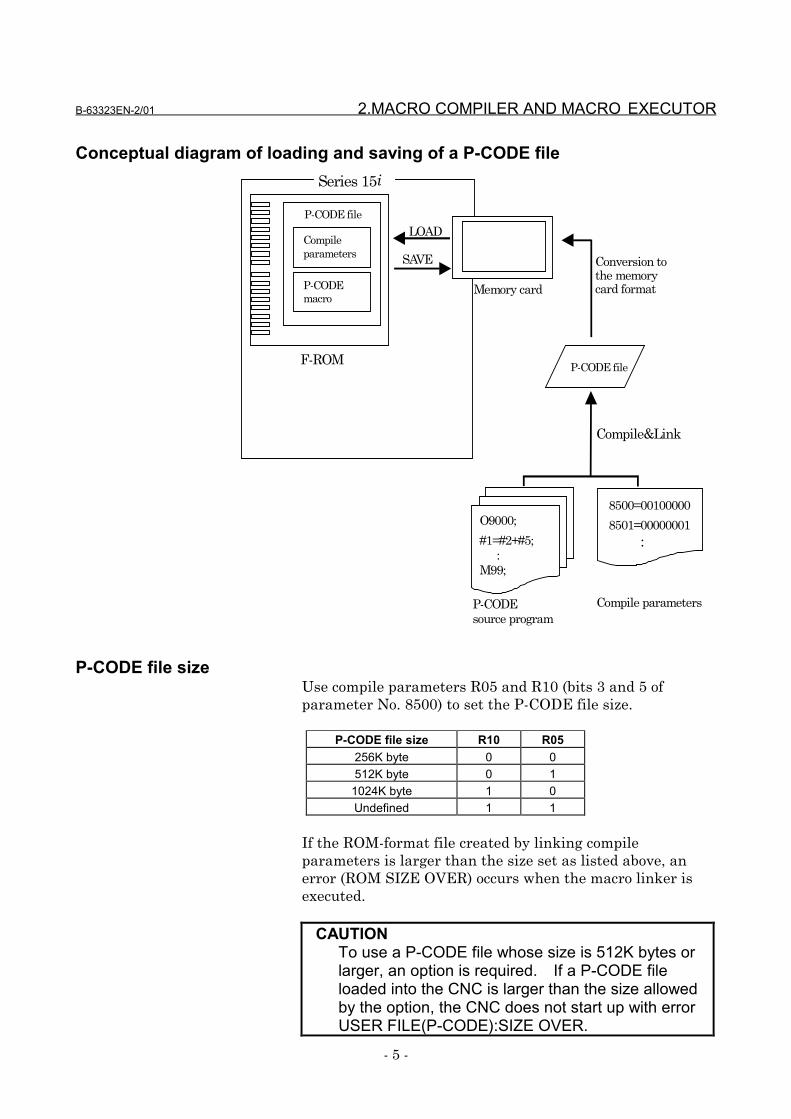
A ROM-format file created by linking an executable macroprogram compiled on a personal computer and compileparameters is called a P-CODE file. A P-CODE file isconverted to a MEM-format file and the MEM-format file isloaded from the memory card into Series 15i F-ROM. A P-CODE file loaded into F-ROM can also be saved onto amemory card.
B-63323EN-2/01 2.MACRO COMPILER AND MACRO EXECUTOR
- 5 -
Conceptual diagram of loading and saving of a P-CODE file Series 15i
P-CODE file
O9000;
#1=#2+#5; :M99;
8500=00100000
8501=00000001 :
P-CODEsource program
Compile parameters
Compile&Link
Memory card
F-ROM
LOAD
SAVE Conversion tothe memorycard format
Compileparameters
P-CODEmacro
P-CODE file
P-CODE file sizeUse compile parameters R05 and R10 (bits 3 and 5 ofparameter No. 8500) to set the P-CODE file size.
P-CODE file size R10 R05256K byte 0 0512K byte 0 1
1024K byte 1 0Undefined 1 1
If the ROM-format file created by linking compileparameters is larger than the size set as listed above, anerror (ROM SIZE OVER) occurs when the macro linker isexecuted.
CAUTIONTo use a P-CODE file whose size is 512K bytes orlarger, an option is required. If a P-CODE fileloaded into the CNC is larger than the size allowedby the option, the CNC does not start up with errorUSER FILE(P-CODE):SIZE OVER.
2.MACRO COMPILER AND MACRO EXECUTOR B-63323EN-2/01
- 6 -
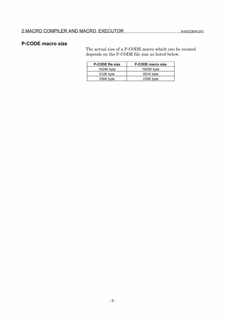
P-CODE macro sizeThe actual size of a P-CODE macro which can be createddepends on the P-CODE file size as listed below.
P-CODE file size P-CODE macro size1024K byte 1003K byte512K byte 491K byte256K byte 235K byte
B-63323EN-2/01 2.MACRO COMPILER AND MACRO EXECUTOR
- 7 -
2.2 Macro Executor
The macro executor has execution macro function,conversational macro (talk macro) function, and auxiliarymacro function.
Execution macro functionWhen the user specifies a G, M, T, or specific code specifiedby a compile parameter from a user program, the executionmacro function calls and executes the macro program formoving the machine (execution macro) that is a P-CODEmacro.The user can also execute a user program not to call anexecution macro, but to execute a custom macro program.
Conversational macro (talk macro) functionWhen function key C US TOM is pressed, the conversational
macro (talk macro) function calls and executes a macroprogram for processing screens (conversational macro [talkmacro]) that is a P-CODE macro.
Auxiliary macro functionAt power-on, the auxiliary macro function calls and executesa macro program for performing auxiliary processing(auxiliary macro) that is a P-CODE macro.

2.MACRO COMPILER AND MACRO EXECUTOR B-63323EN-2/01
- 8 -
2.3 P-CODE Macro
A P-CODE macro means an executable macro programcreated by compiling a P-CODE source program using themacro compiler and loaded it into F-ROM.
Program numberThe program number range is from 1 to 99999999.
Sequence numberThe sequence number range is from 1 to 99999999.
•••• CautionCAUTION
No sequence number must be added to any blockwith an O number.(The sequence number is invalidated if added.)
Number of digits of a valid settingThe maximum number of digits of a valid setting is 9.
Maximum number of P-CODE macrosThe maximum number of P-CODE macros is 1000.
2.3.1 Limitations on commands
NOTEFor each macro executor function, there may belimitations other than listed below. See theexplanation of each macro executor function.
Custom macroCustom macro commands can be used for P-CODE macros,but some commands cannot be used and some commands canbe used with restrictions as listed below.
15i-MA/150i-MA custom macro command P-CODE macroA constant value consisting of up to 12 digitscan be specified in <expression>.Maximum value: ±999999999999Minimum value : ±0.00000000001
A constant valueconsisting of up to ninedigits can be specified.Maximum value:
+999999999Minimum value:
+0.00000001
B-63323EN-2/01 2.MACRO COMPILER AND MACRO EXECUTOR
- 9 -
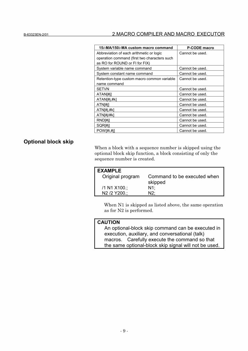
15i-MA/150i-MA custom macro command P-CODE macroAbbreviation of each arithmetic or logicoperation command (first two characters suchas RO for ROUND or FI for FIX)
Cannot be used.
System variable name command Cannot be used.System constant name command Cannot be used.Retention-type custom macro common variablename command
Cannot be used.
SETVN Cannot be used.ATAN[#j] Cannot be used.ATAN[#j,#k] Cannot be used.ATN[#j] Cannot be used.ATN[#j,#k] Cannot be used.ATN[#j/#k] Cannot be used.RND[#j] Cannot be used.SQR[#j] Cannot be used.POW[#i,#j] Cannot be used.
Optional block skipWhen a block with a sequence number is skipped using theoptional block skip function, a block consisting of only thesequence number is created.
EXAMPLEOriginal program Command to be executed when
skipped/1 N1 X100.; N1;N2 /2 Y200.; N2;
When N1 is skipped as listed above, the same operationas for N2 is performed.
CAUTIONAn optional-block skip command can be executed inexecution, auxiliary, and conversational (talk)macros. Carefully execute the command so thatthe same optional-block skip signal will not be used.
2.MACRO COMPILER AND MACRO EXECUTOR B-63323EN-2/01
- 10 -
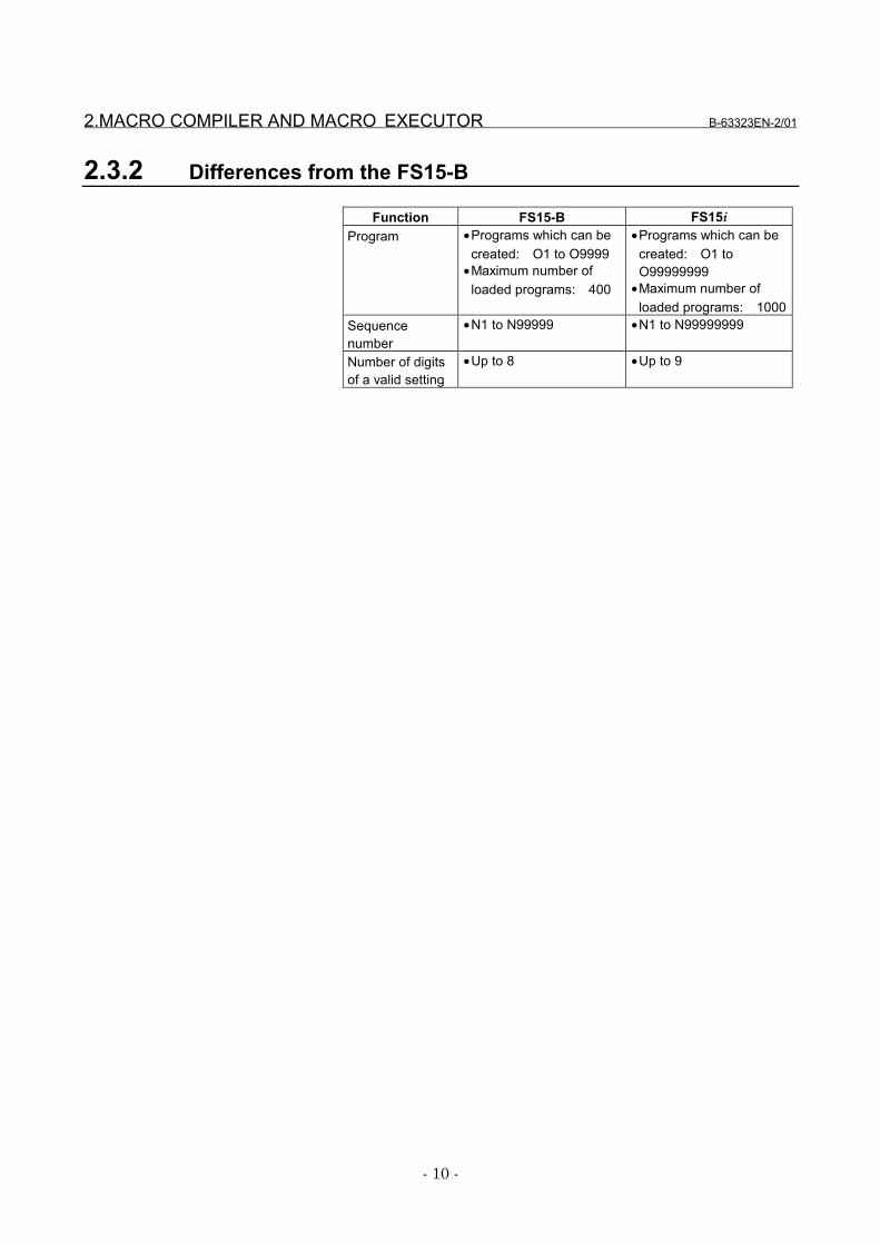
2.3.2 Differences from the FS15-B
Function FS15-B FS15iProgram •Programs which can be
created: O1 to O9999•Maximum number of
loaded programs: 400
•Programs which can becreated: O1 toO99999999
•Maximum number ofloaded programs: 1000
Sequencenumber
•N1 to N99999 •N1 to N99999999
Number of digitsof a valid setting
•Up to 8 •Up to 9
B-63323EN-2/01 3.EXECUTION MACRO FUNCTION
- 11 -
3 EXECUTION MACRO FUNCTION

3.EXECUTION MACRO FUNCTION B-63323EN-2/01
- 12 -
3.1 General
Execution macroAn execution macro is a loaded P-CODE macro which isoperated as a machining program.M, S, T, and other call codes are set for parameters inadvance. When a set code is specified, the correspondingexecution macro is called. For an execution macro, the sameitems as for a custom macro can be specified.
User program/custom macro
A user program means an NC program loaded into programmemory or an NC program to be executed as an executionmacro caller during DNC or MDI operation.
A custom macro means an NC program to be called as amacro or subprogram in a user program.
B-63323EN-2/01 3.EXECUTION MACRO FUNCTION
- 13 -
3.2 Calling an Execution Macro
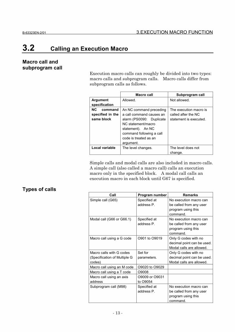
Macro call andsubprogram call
Execution macro calls can roughly be divided into two types:macro calls and subprogram calls. Macro calls differ fromsubprogram calls as follows.
Macro call Subprogram callArgumentspecification
Allowed. Not allowed.
NC commandspecified in thesame block
An NC command precedinga call command causes analarm (PS0090: DuplicateNC statement/macrostatement). An NCcommand following a callcode is treated as anargument.
The execution macro iscalled after the NCstatement is executed.
Local variable The level changes. The level does notchange.
Simple calls and modal calls are also included in macro calls.A simple call (also called a macro call) calls an executionmacro only in the specified block. A modal call calls anexecution macro in each block until G67 is specified.
Types of callsCall Program number Remarks
Simple call (G65) Specified ataddress P.
No execution macro canbe called from any userprogram using thiscommand.
Modal call (G66 or G66.1) Specified ataddress P.
No execution macro canbe called from any userprogram using thiscommand.
Macro call using a G code O901 to O9019 Only G codes with nodecimal point can be used.Modal calls are allowed.
Macro calls with G codes(Specification of Multiple Gcodes)
Set forparameters.
Only G codes with nodecimal point can be used.Modal calls are allowed.
Macro call using an M code O9020 to O9029Macro call using a T code O9008Macro call using an axisaddress
O9009 or O9031to O9054
Subprogram call (M98) Specified ataddress P.
No execution macro canbe called from any userprogram using thiscommand.
3.EXECUTION MACRO FUNCTION B-63323EN-2/01
- 14 -
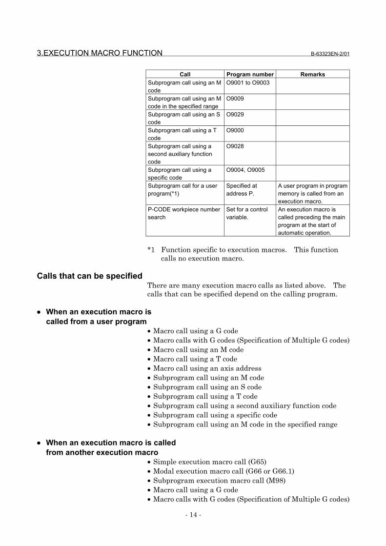
Call Program number RemarksSubprogram call using an Mcode
O9001 to O9003
Subprogram call using an Mcode in the specified range
O9009
Subprogram call using an Scode
O9029
Subprogram call using a Tcode
O9000
Subprogram call using asecond auxiliary functioncode
O9028
Subprogram call using aspecific code
O9004, O9005
Subprogram call for a userprogram(*1)
Specified ataddress P.
A user program in programmemory is called from anexecution macro.
P-CODE workpiece numbersearch
Set for a controlvariable.
An execution macro iscalled preceding the mainprogram at the start ofautomatic operation.
*1 Function specific to execution macros. This functioncalls no execution macro.
Calls that can be specifiedThere are many execution macro calls as listed above. Thecalls that can be specified depend on the calling program.
•••• When an execution macro iscalled from a user program
• Macro call using a G code• Macro calls with G codes (Specification of Multiple G codes)• Macro call using an M code• Macro call using a T code• Macro call using an axis address• Subprogram call using an M code• Subprogram call using an S code• Subprogram call using a T code• Subprogram call using a second auxiliary function code• Subprogram call using a specific code• Subprogram call using an M code in the specified range
•••• When an execution macro is calledfrom another execution macro
• Simple execution macro call (G65)• Modal execution macro call (G66 or G66.1)• Subprogram execution macro call (M98)• Macro call using a G code• Macro calls with G codes (Specification of Multiple G codes)
B-63323EN-2/01 3.EXECUTION MACRO FUNCTION
- 15 -
• Macro call using an M code• Macro call using a T code• Macro call using an axis address• Subprogram call using an M code• Subprogram call using an S code• Subprogram call using a T code• Subprogram call using a second auxiliary function code• Subprogram call using a specific code• Subprogram call using an M code in the specified range
•••• When a user program is calledfrom an execution macro
• External device subprogram call (M198)• Subprogram call for a user program
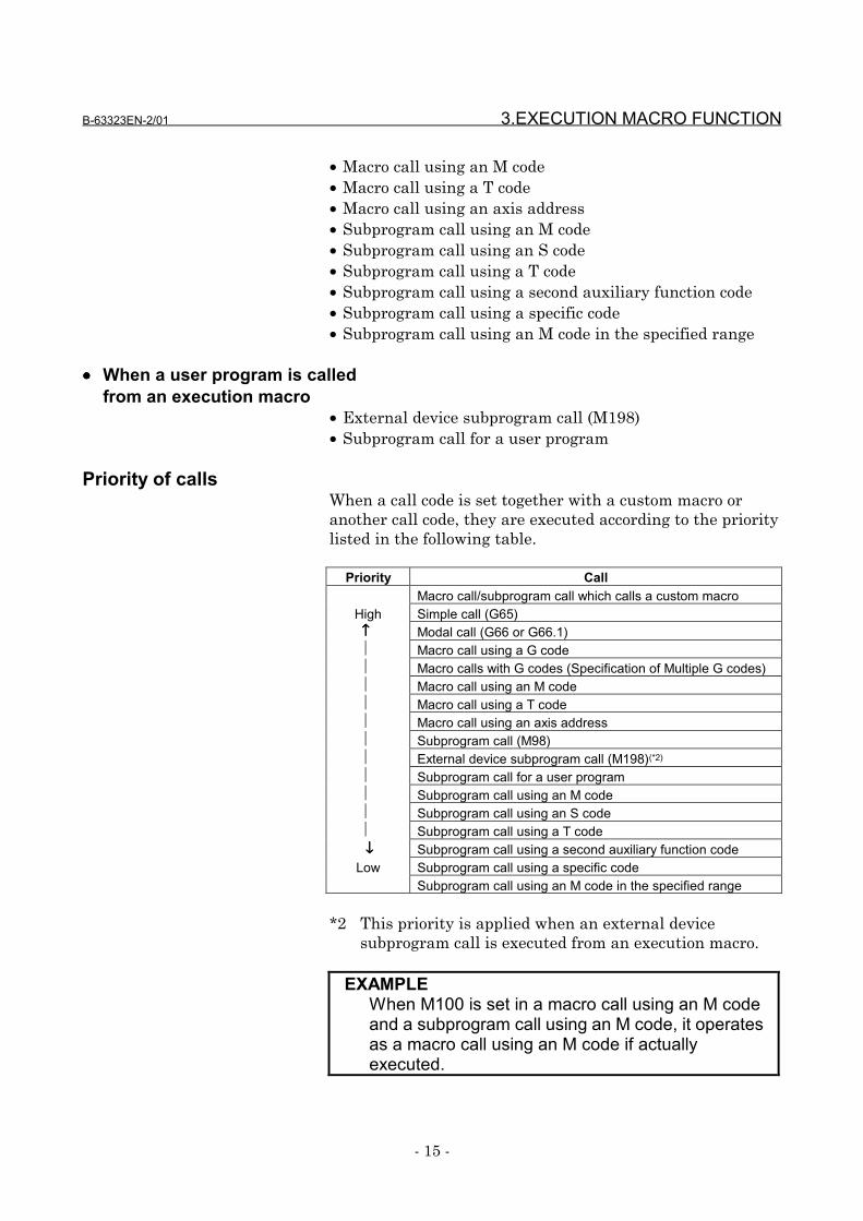
Priority of callsWhen a call code is set together with a custom macro oranother call code, they are executed according to the prioritylisted in the following table.
Priority CallMacro call/subprogram call which calls a custom macro
High Simple call (G65)↑↑↑↑ Modal call (G66 or G66.1) Macro call using a G code Macro calls with G codes (Specification of Multiple G codes) Macro call using an M code Macro call using a T code Macro call using an axis address Subprogram call (M98) External device subprogram call (M198)(*2)
Subprogram call for a user program Subprogram call using an M code Subprogram call using an S code Subprogram call using a T code↓↓↓↓ Subprogram call using a second auxiliary function code
Low Subprogram call using a specific codeSubprogram call using an M code in the specified range
*2 This priority is applied when an external devicesubprogram call is executed from an execution macro.
EXAMPLEWhen M100 is set in a macro call using an M codeand a subprogram call using an M code, it operatesas a macro call using an M code if actuallyexecuted.
3.EXECUTION MACRO FUNCTION B-63323EN-2/01
- 16 -
NestingExecution macro calls can be nested to a depth of ten levelsincluding only subprogram calls, to a depth of five levelsincluding only macro calls, or to a depth of ten levelsincluding subprogram calls and macro calls (to a depth of fivelevels for macro calls). This does not include custommacros.
Subprogram calls for user programs and external devicesubprogram calls from execution macros are included in thecustom macro nesting levels.
3.2.1 Simple call (G65)
The execution macro specified at address P is called as amacro.
FormatG65 Pp Ll <argument> ;
G65 : Call command. Must be specified before any argument.P : Program number of an execution macro to be calledL : Repetition count (1 by default)Argument : Data to be passed to the execution macro. Argument
specifications I and II are available.
LimitationNo execution macro can be called from any user programusing this command. This command can be specified onlyfor calling an execution macro from another execution macro.
B-63323EN-2/01 3.EXECUTION MACRO FUNCTION
- 17 -
3.2.2 Modal call (G66 or G66.1)
A modal call is performed for the execution macro specified ataddress P.The functions such as move command calling (G66) and per-block calling (G66.1) operation and modal call nesting areexactly the same as for custom macros.
FormatG66 Pp Ll <argument> ;
G66 : Call command. Must be specified before any argument.p : Program number of an execution macro to be calledl : Repetition count (1 by default)argument : Data to be passed to the execution macro. Argument
specifications I and II are available. Arguments only in G66blocks are passed to local variables.
G66.1 Pp Ll <argument> ;G66.1 : Call command. Must be specified before argument.p : Program number of an execution macro to be calledl : Repetition count (1 by default)Argument : Data to be passed to the execution macro. Argument
specifications I and II are available.
LimitationNo execution macro can be called from any user programusing this command. This command can be specified onlyfor calling an execution macro from another execution macro.
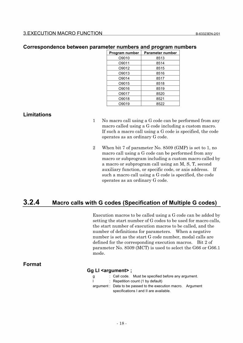
3.2.3 Macro call using a G code
Execution macro O9010 to O9019 is called using the G codespecified for parameter No. 8513 to 8522 as a macro.When a negative G code is set for a parameter, a modal call isperformed for the corresponding execution macro. Bit 2 ofparameter No. 8509 (MCT) is used to select the G66 or G66.1mode.
FormatGg Ll <argument> ;
g : Call code. Must be specified before any argument.l : Repetition count (1 by default)argument : Data to be passed to the execution macro. Argument
specifications I and II are available.
3.EXECUTION MACRO FUNCTION B-63323EN-2/01
- 18 -
Correspondence between parameter numbers and program numbersProgram number Parameter number
O9010 8513O9011 8514O9012 8515O9013 8516O9014 8517O9015 8518O9016 8519O9017 8520O9018 8521O9019 8522
Limitations1 No macro call using a G code can be performed from any
macro called using a G code including a custom macro.If such a macro call using a G code is specified, the codeoperates as an ordinary G code.
2 When bit 7 of parameter No. 8509 (GMP) is set to 1, nomacro call using a G code can be performed from anymacro or subprogram including a custom macro called bya macro or subprogram call using an M, S, T, secondauxiliary function, or specific code, or axis address. Ifsuch a macro call using a G code is specified, the codeoperates as an ordinary G code.
3.2.4 Macro calls with G codes (Specification of Multiple G codes)
Execution macros to be called using a G code can be added bysetting the start number of G codes to be used for macro calls,the start number of execution macros to be called, and thenumber of definitions for parameters. When a negativenumber is set as the start G code number, modal calls aredefined for the corresponding execution macros. Bit 2 ofparameter No. 8509 (MCT) is used to select the G66 or G66.1mode.
FormatGg Ll <argument> ;
g : Call code. Must be specified before any argument.l : Repetition count (1 by default)argument : Data to be passed to the execution macro. Argument
specifications I and II are available.
B-63323EN-2/01 3.EXECUTION MACRO FUNCTION
- 19 -
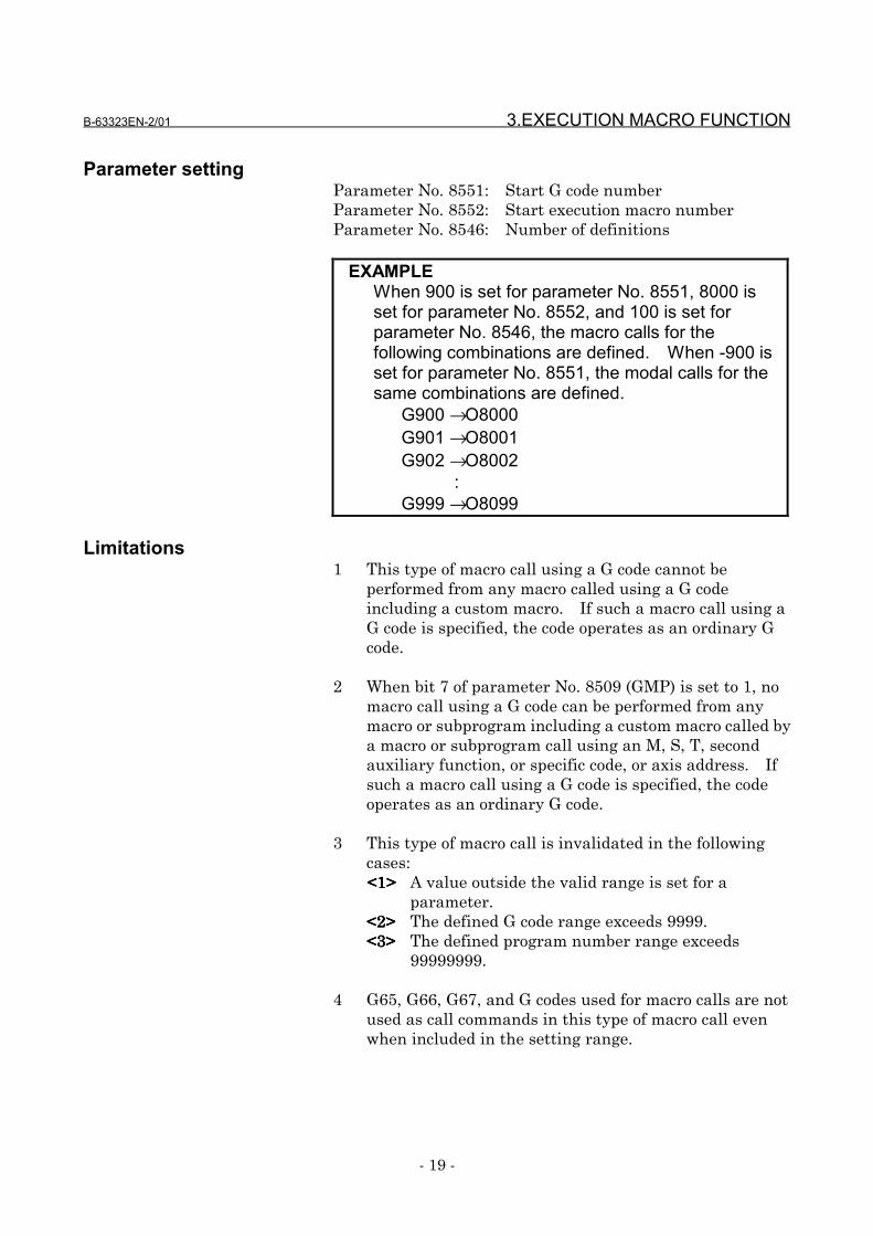
Parameter settingParameter No. 8551: Start G code numberParameter No. 8552: Start execution macro numberParameter No. 8546: Number of definitions
EXAMPLEWhen 900 is set for parameter No. 8551, 8000 isset for parameter No. 8552, and 100 is set forparameter No. 8546, the macro calls for thefollowing combinations are defined. When -900 isset for parameter No. 8551, the modal calls for thesame combinations are defined.
G900 → O8000 G901 → O8001 G902 → O8002 : G999 → O8099
Limitations1 This type of macro call using a G code cannot be
performed from any macro called using a G codeincluding a custom macro. If such a macro call using aG code is specified, the code operates as an ordinary Gcode.
2 When bit 7 of parameter No. 8509 (GMP) is set to 1, nomacro call using a G code can be performed from anymacro or subprogram including a custom macro called bya macro or subprogram call using an M, S, T, secondauxiliary function, or specific code, or axis address. Ifsuch a macro call using a G code is specified, the codeoperates as an ordinary G code.
3 This type of macro call is invalidated in the followingcases:<<<<1111>>>> A value outside the valid range is set for a
parameter.<<<<2222>>>> The defined G code range exceeds 9999.<<<<3333>>>> The defined program number range exceeds
99999999.
4 G65, G66, G67, and G codes used for macro calls are notused as call commands in this type of macro call evenwhen included in the setting range.
3.EXECUTION MACRO FUNCTION B-63323EN-2/01
- 20 -
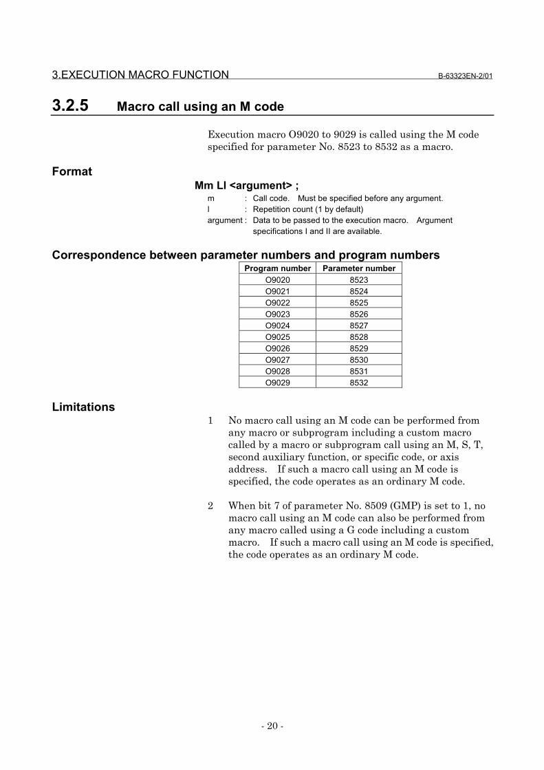
3.2.5 Macro call using an M code
Execution macro O9020 to 9029 is called using the M codespecified for parameter No. 8523 to 8532 as a macro.
FormatMm Ll <argument> ;
m : Call code. Must be specified before any argument.l : Repetition count (1 by default)argument : Data to be passed to the execution macro. Argument
specifications I and II are available.
Correspondence between parameter numbers and program numbersProgram number Parameter number
O9020 8523O9021 8524O9022 8525O9023 8526O9024 8527O9025 8528O9026 8529O9027 8530O9028 8531O9029 8532
Limitations1 No macro call using an M code can be performed from
any macro or subprogram including a custom macrocalled by a macro or subprogram call using an M, S, T,second auxiliary function, or specific code, or axisaddress. If such a macro call using an M code isspecified, the code operates as an ordinary M code.
2 When bit 7 of parameter No. 8509 (GMP) is set to 1, nomacro call using an M code can also be performed fromany macro called using a G code including a custommacro. If such a macro call using an M code is specified,the code operates as an ordinary M code.
B-63323EN-2/01 3.EXECUTION MACRO FUNCTION
- 21 -
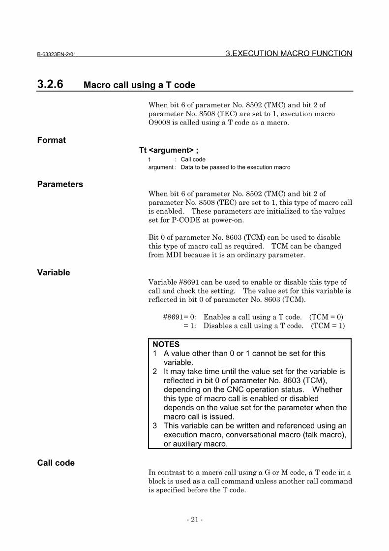
3.2.6 Macro call using a T code
When bit 6 of parameter No. 8502 (TMC) and bit 2 ofparameter No. 8508 (TEC) are set to 1, execution macroO9008 is called using a T code as a macro.
FormatTt <argument> ;
t : Call codeargument : Data to be passed to the execution macro
ParametersWhen bit 6 of parameter No. 8502 (TMC) and bit 2 ofparameter No. 8508 (TEC) are set to 1, this type of macro callis enabled. These parameters are initialized to the valuesset for P-CODE at power-on.
Bit 0 of parameter No. 8603 (TCM) can be used to disablethis type of macro call as required. TCM can be changedfrom MDI because it is an ordinary parameter.
VariableVariable #8691 can be used to enable or disable this type ofcall and check the setting. The value set for this variable isreflected in bit 0 of parameter No. 8603 (TCM).
#8691= 0: Enables a call using a T code. (TCM = 0)= 1: Disables a call using a T code. (TCM = 1)
NOTES1 A value other than 0 or 1 cannot be set for this
variable.2 It may take time until the value set for the variable is
reflected in bit 0 of parameter No. 8603 (TCM),depending on the CNC operation status. Whetherthis type of macro call is enabled or disableddepends on the value set for the parameter when themacro call is issued.
3 This variable can be written and referenced using anexecution macro, conversational macro (talk macro),or auxiliary macro.
Call codeIn contrast to a macro call using a G or M code, a T code in ablock is used as a call command unless another call commandis specified before the T code.
3.EXECUTION MACRO FUNCTION B-63323EN-2/01
- 22 -
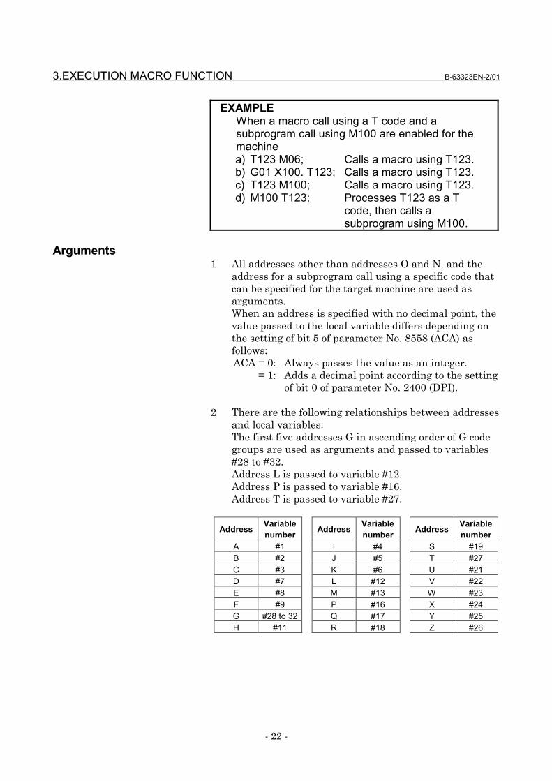
EXAMPLEWhen a macro call using a T code and asubprogram call using M100 are enabled for themachinea) T123 M06; Calls a macro using T123.b) G01 X100. T123; Calls a macro using T123.c) T123 M100; Calls a macro using T123.d) M100 T123; Processes T123 as a T
code, then calls asubprogram using M100.
Arguments1 All addresses other than addresses O and N, and the
address for a subprogram call using a specific code thatcan be specified for the target machine are used asarguments.When an address is specified with no decimal point, thevalue passed to the local variable differs depending onthe setting of bit 5 of parameter No. 8558 (ACA) asfollows:ACA = 0: Always passes the value as an integer.
= 1: Adds a decimal point according to the settingof bit 0 of parameter No. 2400 (DPI).
2 There are the following relationships between addressesand local variables:The first five addresses G in ascending order of G codegroups are used as arguments and passed to variables#28 to #32.Address L is passed to variable #12.Address P is passed to variable #16.Address T is passed to variable #27.
Address Variablenumber Address Variable
number Address Variablenumber
A #1 I #4 S #19B #2 J #5 T #27C #3 K #6 U #21D #7 L #12 V #22E #8 M #13 W #23F #9 P #16 X #24G #28 to 32 Q #17 Y #25H #11 R #18 Z #26
B-63323EN-2/01 3.EXECUTION MACRO FUNCTION
- 23 -
EXAMPLEWhen G91 G28 X123.45678 T999; is specified foran IS-B machine, values are passed as follows:#24 → 123.457#27 → 999.0#28 → 28.0#29 → 91.0
Limitations1 No macro call using a T code can be performed from any
macro or subprogram including a custom macro called bya macro or subprogram call using an M, S, T, secondauxiliary function, or specific code, or axis address. Ifsuch a macro call using a T code is specified, the codeoperates as an ordinary T code.
2 When bit 7 of parameter No. 8509 (GMP) is set to 1, nomacro call using a T code can also be performed from anymacro called using a G code including a custom macro.If such a macro call using a T code is specified, the codeoperates as an ordinary T code.
3 No repetition count can be specified because address L isalso used as an argument.
Difference from the FS15-BThe FS15-B evaluates the specified address, then calls anexecution macro. For this reason, the FS15-B changes themodal status at the specified address, then calls an executionmacro.The FS15i calls an execution macro without changing themodal status at the specified address because it does notevaluates the specified address.
3.2.7 Macro call using an axis address
When parameters Nos. 8555 to 8557 are set, an executionmacro is called using an axis address (controlled axis movecommand) as a macro.
FormatXx <argument> ;
x : Call codeargument : Data to be passed to the execution macro
3.EXECUTION MACRO FUNCTION B-63323EN-2/01
- 24 -
Selecting axesSelect the target controlled axes for a macro call using eachbit of parameters Nos. 8555 to 8557 for each axis. Theseparameters are initialized to the values set for P-CODE atpower-on.
For the target axes for a macro call, a macro call can also bedisabled using each bit of parameters Nos. 8600 to 8602 foreach axis for which the macro call is to be disabled asrequired. These parameters can be changed using MDIbecause they are ordinary parameters.
EXAMPLEWhen parameter No. 8555 is set to 00000111 for amachine having five axes, X, Y, Z, A, and C, amacro call is enabled for X, Y, and Z axes.When parameter No. 8600 is set to 00000101, amacro call is disabled for X and Z axes.
VariableVariable #8690 can be used to set and check each axis forwhich this type of macro call is disabled. The value set forthis variable is reflected in parameters Nos. 8600 to 8602.The following shows the relationships between variablesettings and parameter settings:
#8690= 1: Disables the macro call for the first axis.
(Bit 0 of parameter No. 8600 = 1)= 2: Disables the macro call for the second axis.
(Bit 1 of parameter No. 8600 = 1)= 4: Disables the macro call for the third axis.
(Bit 2 of parameter No. 8600 = 1) • •
= 8388608: Disables the macro call for the 24th axis.(Bit 7 of parameter No. 8602 = 1)
To disable the macro call for multiple axes, set the algebraicsum of the value set for each axis.
EXAMPLETo disable a call for the first and third axes, setvariable #8690 to (1 + 4) = 5.
B-63323EN-2/01 3.EXECUTION MACRO FUNCTION
- 25 -
NOTES1 It may take time until the value set for the variable is
reflected in parameters Nos. 8600 to 8602,depending on the CNC operation status. Whethera macro call is enabled or disabled depends on thevalues set for the parameters when the macro call isissued.
2 This variable can be written and referenced using anexecution macro, conversational macro (talk macro),or auxiliary macro.
Selecting an execution macroWhen multiple axes for which macro calls are enabled are set,whether to always call the same execution macro or call anexecution macro for each axis can be selected using bit 0 ofparameter No. 8558 (ACS).
ACS = 0: Always calls O9009.= 1: First axis specification → Calls O9031.
Second axis specification → Calls O9032. :nth axis specification → Calls O9030+n
Call code1 In contrast to a macro call using a G or M code, an axis
address specified as a call code in a block is used as a callcommand unless another call code is specified before theaxis address.
2 When multiple axis addresses for macro calls arespecified in the same block, the axis address whichappears first in the block is used as a call command.
EXAMPLEWhen a macro call using X and Y and asubprogram call using M100 are enabled for themachinea) X100. B10; Calls a macro using X100.b) G91 G01 X100.; Calls a macro using X100.c) Y200. X100.; Calls a macro using Y200.d) X100. M100; Calls a macro using X100.e) M100 X100.; Calls a subprogram using
M100 after the tool movesalong the X axis according toX100.
3.EXECUTION MACRO FUNCTION B-63323EN-2/01
- 26 -
Arguments1 All addresses other than addresses O and N, and the
address for a subprogram call using a specific code thatcan be specified for the target machine are used asarguments.
When an address is specified with no decimal point, thevalue passed to the local variable differs depending onthe setting of bit 5 of parameter No. 8558 (ACA) asfollows:ACA = 0: Always passes the value as an integer.
= 1: Adds a decimal point according to the settingof bit 0 of parameter No. 2400 (DPI).
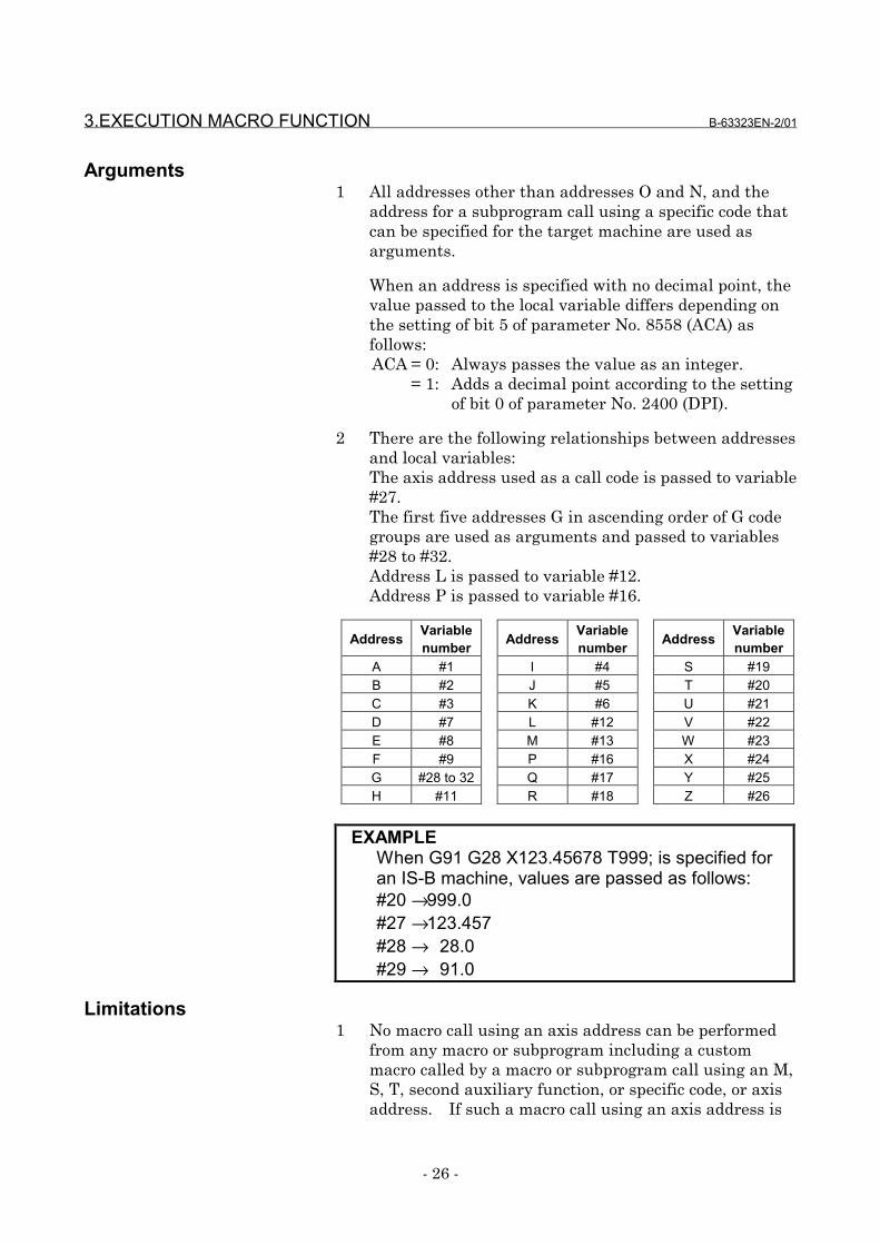
2 There are the following relationships between addressesand local variables:The axis address used as a call code is passed to variable#27.The first five addresses G in ascending order of G codegroups are used as arguments and passed to variables#28 to #32.Address L is passed to variable #12.Address P is passed to variable #16.
Address Variablenumber Address Variable
number Address Variablenumber
A #1 I #4 S #19B #2 J #5 T #20C #3 K #6 U #21D #7 L #12 V #22E #8 M #13 W #23F #9 P #16 X #24G #28 to 32 Q #17 Y #25H #11 R #18 Z #26
EXAMPLEWhen G91 G28 X123.45678 T999; is specified foran IS-B machine, values are passed as follows:#20 → 999.0#27 → 123.457#28 → 28.0#29 → 91.0
Limitations1 No macro call using an axis address can be performed
from any macro or subprogram including a custommacro called by a macro or subprogram call using an M,S, T, second auxiliary function, or specific code, or axisaddress. If such a macro call using an axis address is
B-63323EN-2/01 3.EXECUTION MACRO FUNCTION
- 27 -
specified, the address operates as an ordinary axiscommand.
2 When bit 7 of parameter No. 8509 (GMP) is set to 1, nomacro call using an axis address can also be performedfrom any macro called using a G code including a custommacro. If such a macro call using an axis address isspecified, the address operates as an ordinary axiscommand.
3 No repetition count can be specified because address L isalso used as an argument.
Difference from the FS15-BThe FS15-B evaluates the specified address, then calls anexecution macro. For this reason, the FS15-B changes themodal status at the specified address, then calls an executionmacro.The FS15i calls an execution macro without changing themodal status at the specified address because it does notevaluates the specified address.
3.2.8 Subprogram call (M98)
The execution macro specified at address P is called as asubprogram.
FormatM98 Pp Ll;
M98 : Call commandp : Program number of an execution macro to be calledL : Repetition count (1 by default)
LimitationNo execution macro can be called from any user programusing this command. This command can be specified onlyfor calling an execution macro from another execution macro.
3.2.9 Subprogram call using an M code
Execution macro O9001 to O9003 is called as a subprogramusing the M code specified for parameter No. 8510 to 8512.
FormatMm Ll;
m : Call code
3.EXECUTION MACRO FUNCTION B-63323EN-2/01
- 28 -
L : Repetition count (1 by default)
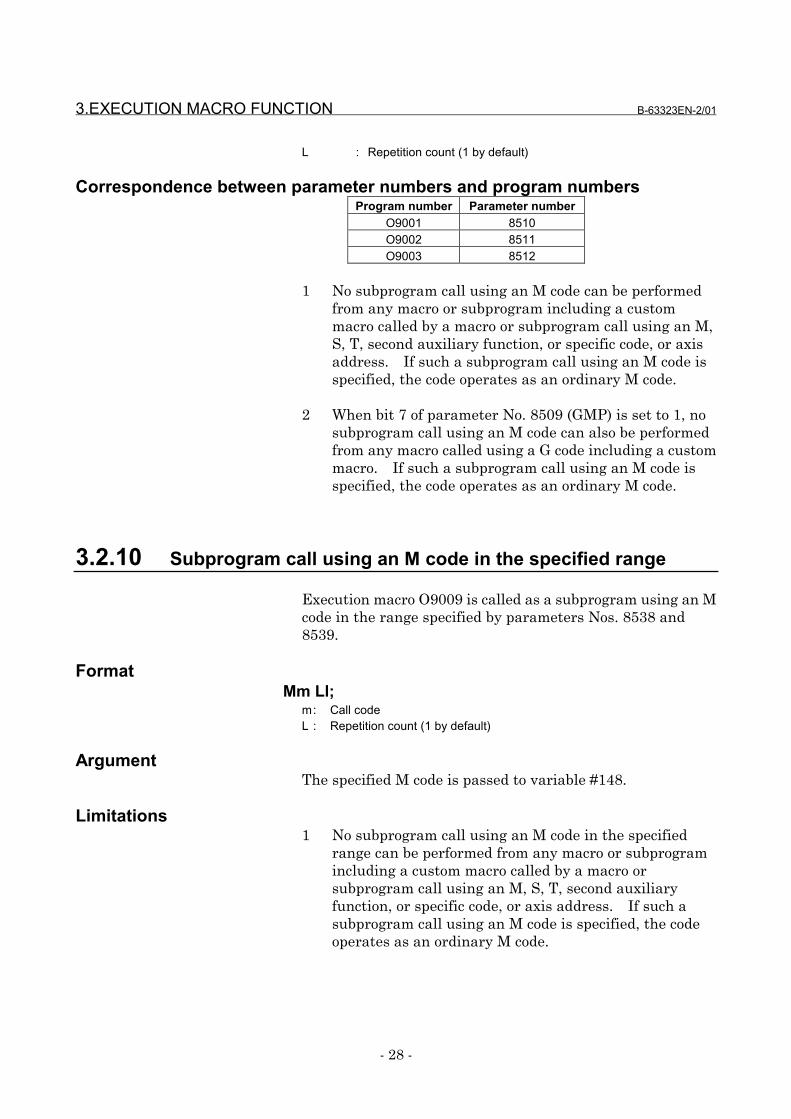
Correspondence between parameter numbers and program numbersProgram number Parameter number
O9001 8510O9002 8511O9003 8512
1 No subprogram call using an M code can be performedfrom any macro or subprogram including a custommacro called by a macro or subprogram call using an M,S, T, second auxiliary function, or specific code, or axisaddress. If such a subprogram call using an M code isspecified, the code operates as an ordinary M code.
2 When bit 7 of parameter No. 8509 (GMP) is set to 1, nosubprogram call using an M code can also be performedfrom any macro called using a G code including a custommacro. If such a subprogram call using an M code isspecified, the code operates as an ordinary M code.
3.2.10 Subprogram call using an M code in the specified range
Execution macro O9009 is called as a subprogram using an Mcode in the range specified by parameters Nos. 8538 and8539.
FormatMm Ll;
m: Call codeL : Repetition count (1 by default)
ArgumentThe specified M code is passed to variable #148.
Limitations1 No subprogram call using an M code in the specified
range can be performed from any macro or subprogramincluding a custom macro called by a macro orsubprogram call using an M, S, T, second auxiliaryfunction, or specific code, or axis address. If such asubprogram call using an M code is specified, the codeoperates as an ordinary M code.
B-63323EN-2/01 3.EXECUTION MACRO FUNCTION
- 29 -
2 When bit 7 of parameter No. 8509 (GMP) is set to 1, nosubprogram call using an M code in the specified rangecan also be performed from any macro called using a Gcode including a custom macro. If such a subprogramcall using an M code is specified, the code operates as anordinary M code.
3 This type of subprogram call is invalidated in thefollowing cases:<<<<1111>>>> A value outside the valid range is set for a
parameter.<<<<2222>>>> The value set for parameter No. 8538 is greater
than the value set for parameter No. 8539.
4 M98, M99, and M codes used for macro and subprogramcalls are not used as call codes in this type ofsubprogram call even when included in the settingrange.
3.2.11 Subprogram call using an S code
When bit 3 of parameter No. 8508 (SSC) is set to 1, executionmacro O9029 is called as a subprogram using an S code.
FormatSs Ll;
s : Call codeL : Repetition count (1 by default)
ArgumentThe specified S code is passed to variable #147.
Limitations1 No subprogram call using an S code can be performed
from any macro or subprogram including a custommacro called by a macro or subprogram call using an M,S, T, second auxiliary function, or specific code, or axisaddress. If such a subprogram call using an S code isspecified, the code operates as an ordinary S code.
2 When bit 7 of parameter No. 8509 (GMP) is set to 1, nosubprogram call using an S code can also be performedfrom any macro called using a G code including a custommacro. If such a subprogram call using an S code isspecified, the code operates as an ordinary S code.
3.EXECUTION MACRO FUNCTION B-63323EN-2/01
- 30 -
3.2.12 Subprogram call using a T code
When bit 6 of parameter No. 8502 (TMC) is set to 0 and bit 2of parameter No. 8508 (TEC) is set to 1, execution macroO9000 is called as a subprogram using a T code.
FormatTt Ll;
T : Call codeL : Repetition count (1 by default)
ParametersSetting bit 6 of parameter No. 8502 (TMC) to 0 and bit 2 ofparameter No. 8508 (TEC) to 1 enables this type ofsubprogram call. These parameters are initialized to thevalues set for P-CODE at power-on.Bit 0 of parameter No. 8603 (TCM) can be used to disablethis type of subprogram call as required. This parametercan be changed from MDI because it is an ordinaryparameter.
VariableVariable #8691 can be used to enable or disable this type ofsubprogram call and check the setting. The value set forthis variable is reflected in bit 0 of parameter No. 8603(TCM).
#8691= 0: Enables a call using a T code. (TCM = 0)= 1: Disables a call using a T code. (TCM = 1)
NOTES1 A value other than 0 or 1 cannot be set for this
variable.2 It may take time until the value set for the variable is
reflected in bit 0 of parameter No. 8603 (TCM),depending on the CNC operation status. Whetherthis type of call is enabled or disabled depends onthe value set for the parameter when the call isissued.
3 This variable can be written and referenced using anexecution macro, conversational macro (talk macro),or auxiliary macro.
ArgumentThe specified T code is passed to variable #149.
B-63323EN-2/01 3.EXECUTION MACRO FUNCTION
- 31 -
Limitations1 No subprogram call using a T code can be performed
from any macro or subprogram including a custommacro called by a macro or subprogram call using an M,S, T, second auxiliary function, or specific code, or axisaddress. If such a subprogram call using a T code isspecified, the code operates as an ordinary T code.
2 When bit 7 of parameter No. 8509 (GMP) is set to 1, nosubprogram call using a T code can also be performedfrom any macro called using a G code including a custommacro. If such a subprogram call using a T code isspecified, the code operates as an ordinary T code.
3.2.13 Subprogram call using a second auxiliary function code
When bit 5 of parameter No. 8508 (BSC) is set to 1, executionmacro O9028 is called as a subprogram using a secondauxiliary function code.
FormatBb Ll;b : Call codel : Repetition count (1 by default)
ArgumentThe specified second auxiliary function code is passed tovariable #146.
Limitations1 No subprogram call using a second auxiliary function
code can be performed from any macro or subprogramincluding a custom macro called by a macro orsubprogram call using an M, S, T, second auxiliaryfunction, or specific code, or axis address. If such asubprogram call using a second auxiliary function code isspecified, the code operates as an ordinary secondauxiliary function code.
2 When bit 7 of parameter No. 8509 (GMP) is set to 1, nosubprogram call using a second auxiliary function codecan also be performed from any macro called using a Gcode including a custom macro. If such a subprogramcall using a second auxiliary function code is specified,the code operates as an ordinary second auxiliaryfunction code.
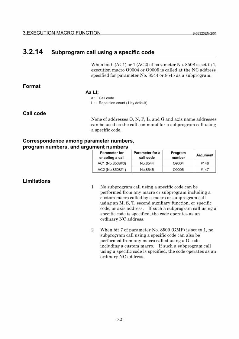
3.EXECUTION MACRO FUNCTION B-63323EN-2/01
- 32 -
3.2.14 Subprogram call using a specific code
When bit 0 (AC1) or 1 (AC2) of parameter No. 8508 is set to 1,execution macro O9004 or O9005 is called at the NC addressspecified for parameter No. 8544 or 8545 as a subprogram.
FormatAa Ll;
a : Call codel : Repetition count (1 by default)
Call codeNone of addresses O, N, P, L, and G and axis name addressescan be used as the call command for a subprogram call usinga specific code.
Correspondence among parameter numbers,program numbers, and argument numbers
Parameter forenabling a call
Parameter for acall code
Programnumber Argument
AC1 (No.8508#0) No.8544 O9004 #146
AC2 (No.8508#1) No.8545 O9005 #147
Limitations1 No subprogram call using a specific code can be
performed from any macro or subprogram including acustom macro called by a macro or subprogram callusing an M, S, T, second auxiliary function, or specificcode, or axis address. If such a subprogram call using aspecific code is specified, the code operates as anordinary NC address.
2 When bit 7 of parameter No. 8509 (GMP) is set to 1, nosubprogram call using a specific code can also beperformed from any macro called using a G codeincluding a custom macro. If such a subprogram callusing a specific code is specified, the code operates as anordinary NC address.
B-63323EN-2/01 3.EXECUTION MACRO FUNCTION
- 33 -
3.2.15 Subprogram call for a user program
A user program is called as a subprogram using the M codespecified for parameter No. 8533.
FormatMm Pp Ll;
m : Call codep : Program number of a user program to be calledl : Repetition count (1 by default)
Nesting and local variablesEach subprogram call for a user program is assumed to call acustom macro as a subprogram using M98 and is countedamong custom macro nesting levels.The local variables of the calling execution macro are passed.
3.2.16 P-CODE workpiece number search
When automatic operation is started in the memory or DNCoperation mode, the execution macro specified for variable#8610 is executed before the main program.
Call conditions and operationa) Bit 5 of parameter No. 8507 (PWS) is set to 1.b) The memory or DNC operation mode is selected.c) The program number of an execution macro is set for
variable #8610 using a conversational macro (talkmacro) or auxiliary macro before the start of automaticoperation.
When the above three conditions are satisfied, startingautomatic operation:(1) Calls the execution macro specified for variable #8610.
Use bit 4 of parameter No. 8558 (P98) to select thesimple call (G65) or subprogram call (M98) mode.
(2) Executes the main program after termination of theexecution macro.
3.EXECUTION MACRO FUNCTION B-63323EN-2/01
- 34 -
WarningWARNING
When conditions a) to c) are satisfied, this functioncalls an execution macro regardless of the userprogram to be started. For this reason, takecountermeasures such as issuing a warningmessage using an auxiliary macro or PMC andsetting interlock processing to prevent operatorerrors when using this function.
Nesting and local variablesThe execution macro is counted among execution macronesting levels. Because the execution macro is called in thesimple call (G65) or subprogram call (M98) mode, anotherexecution macro can be called from the called executionmacro using any call method.
In the simple call (G65) mode, the execution macro isexecuted using a local variable level different from the levelthe main program uses. In other words, the local variablesused by the execution macro are not passed to the mainprogram.In the subprogram call (M98) mode, the execution macro usesthe same local variable level as the main program. In otherwords, the local variables used by the execution macro arepassed to the main program.
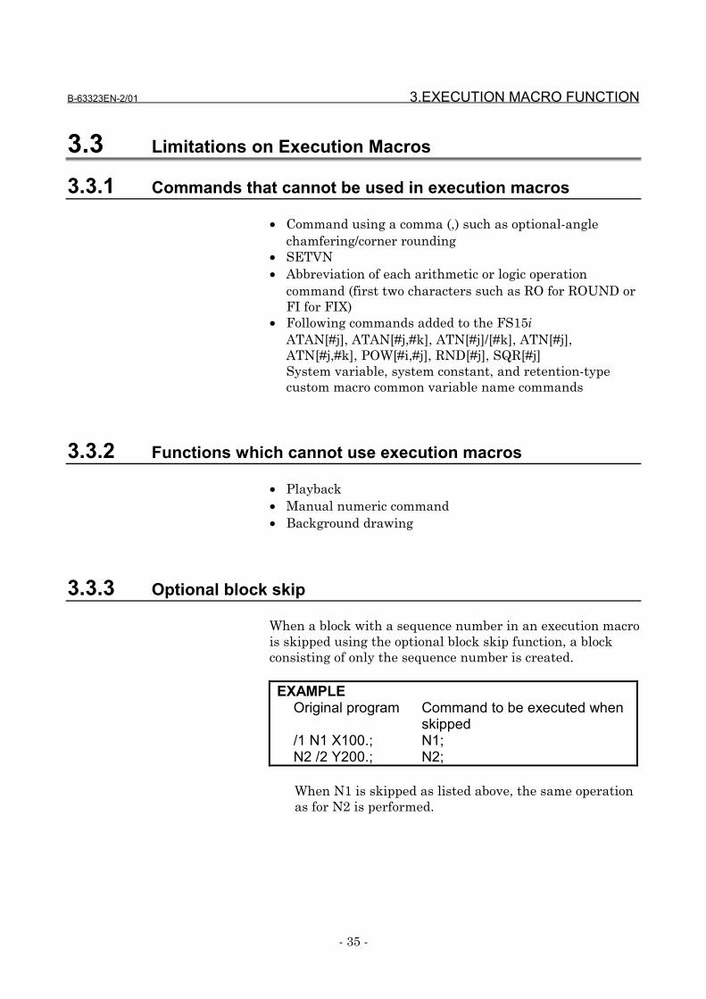
B-63323EN-2/01 3.EXECUTION MACRO FUNCTION
- 35 -
3.3 Limitations on Execution Macros
3.3.1 Commands that cannot be used in execution macros
• Command using a comma (,) such as optional-anglechamfering/corner rounding
• SETVN• Abbreviation of each arithmetic or logic operation
command (first two characters such as RO for ROUND orFI for FIX)
• Following commands added to the FS15iATAN[#j], ATAN[#j,#k], ATN[#j]/[#k], ATN[#j],ATN[#j,#k], POW[#i,#j], RND[#j], SQR[#j]System variable, system constant, and retention-typecustom macro common variable name commands
3.3.2 Functions which cannot use execution macros
• Playback• Manual numeric command• Background drawing
3.3.3 Optional block skip
When a block with a sequence number in an execution macrois skipped using the optional block skip function, a blockconsisting of only the sequence number is created.
EXAMPLEOriginal program Command to be executed when
skipped/1 N1 X100.; N1;N2 /2 Y200.; N2;
When N1 is skipped as listed above, the same operationas for N2 is performed.
3.EXECUTION MACRO FUNCTION B-63323EN-2/01
- 36 -
CAUTIONWhen such a block is skipped in an executionmacro, the block consists of only the sequencenumber with no travel distance. For this reason, ifsuch a block is skipped in the cutter or anothercompensation mode, the tool path may differ fromthat in a user program.
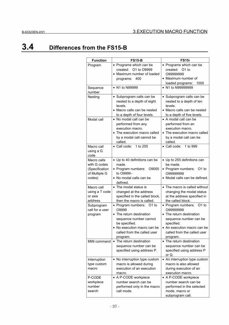
B-63323EN-2/01 3.EXECUTION MACRO FUNCTION
- 37 -
3.4 Differences from the FS15-B
Function FS15-B FS15iProgram • Programs which can be
created: O1 to O9999• Maximum number of loaded
programs: 400
• Programs which can becreated: O1 toO99999999
• Maximum number ofloaded programs: 1000
Sequencenumber
• N1 to N99999 • N1 to N99999999
Nesting • Subprogram calls can benested to a depth of eightlevels.
• Macro calls can be nestedto a depth of four levels.
• Subprogram calls can benested to a depth of tenlevels.
• Macro calls can be nestedto a depth of five levels.
Modal call • No modal call can beperformed from anyexecution macro.
• The execution macro calledby a modal call cannot becalled.
• A modal call can beperformed from anexecution macro.
• The execution macro calledby a modal call can becalled.
Macro callusing a Gcode
• Call code: 1 to 255 • Call code: 1 to 999
Macro callswith G codes(Specificationof Multiple Gcodes)
• Up to 40 definitions can bemade.
• Program numbers: O9000to O9999。
• No modal calls can bedefined.
• Up to 255 definitions canbe made.
• Program numbers: O1 toO99999999
• Modal calls can be defined.
Macro callusing a T codeor axisaddress
• The modal status ischanged at the addressspecified in the called block,then the macro is called.
• The macro is called withoutchanging the modal statusat the address specified inthe called block.
Subprogramcall for a userprogram
• Program numbers: O1 toO9999
• The return destinationsequence number cannotbe specified.
• No execution macro can becalled from the called userprogram.
• Program numbers: O1 toO99999999
• The return destinationsequence number can bespecified.
• An execution macro can becalled from the called userprogram.
M99 command • The return destinationsequence number can bespecified using address P.
• The return destinationsequence number can bespecified using address Por Q.
Interruptiontype custommacro
• No interruption type custommacro is allowed duringexecution of an executionmacro.
• An interruption type custommacro is also allowedduring execution of anexecution macro.
P-CODEworkpiecenumbersearch
• A P-CODE workpiecenumber search can beperformed only in the macrocall mode.
• A P-CODE workpiecenumber search can beperformed in the selectedmode, macro orsubprogram call.
3.EXECUTION MACRO FUNCTION B-63323EN-2/01
- 38 -
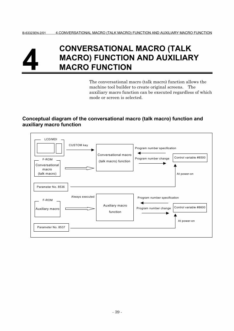
B-63323EN-2/01 4.CONVERSATIONAL MACRO (TALK MACRO) FUNCTION AND AUXILIARY MACRO FUNCTION
- 39 -
4 MACRO FUNCTIONThe conversational macro (talk macro) function allows themachine tool builder to create original screens. Theauxiliary macro function can be executed regardless of whichmode or screen is selected.
Conceptual diagram of the conversational macro (talk macro) function andauxiliary macro function
CUSTOM key
Program number change
LCD/MDI
Parameter No. 8536
Control variable #8600
Control variable #8500
At power-on
Program number specification
Program number change
Always executed
Conversationalmacro
(talk macro)
F-ROM
Parameter No. 8537
Program number specification
At power-on
Conversational macro
(talk macro) function
Auxiliary macro
function
F-ROM
Auxiliary macro
CONVERSATIONAL MACRO (TALKMACRO) FUNCTION AND AUXILIARY
4.CONVERSATIONAL MACRO (TALK MACRO) FUNCTION AND AUXILIARY MACRO FUNCTION B-63323EN-2/01
- 40 -
4.1 Conversational Macro (Talk Macro) Function
The conversational macro (talk macro) functionindependently executes a conversational macro (talk macro)loaded into F-ROM in parallel with ordinary part programoperation.This function is executed at a level lower than that ofautomatic operation processing. This function isindependent of the operation mode or automatic operationstatus.
CautionsCAUTIONS1 The conversational macro (talk macro) function is
executed at a level lower than that of CNCoperation processing. Therefore, execution of theconversational macro (talk macro) function doesnot affect the speed of CNC operation processing,but the speed at which the conversational macro(talk macro) function is executed may become lowduring CNC operation. For this reason, theconversational macro (talk macro) function is notsuitable to control the machine at a constantprocessing speed.
2 The conversational macro (talk macro) functioncannot execute any CNC part program statementfor operation.
4.1.1 Execution and termination
ExecutionExecute the conversational macro (talk macro) function usingone of the following methods:
(1) Press function key on the MDI panel.
(2) Press function selection key (soft key) "TALK MACRO".(3) Set the control variable for starting a conversational
macro (talk macro) (#8510) to 1.
CUSTOM
B-63323EN-2/01 4.CONVERSATIONAL MACRO (TALK MACRO) FUNCTION AND AUXILIARY MACRO FUNCTION
- 41 -
When the conversational macro (talk macro) function isexecuted, the conversational macro (talk macro) mainprogram with the value of the control variable for executing aconversational macro (talk macro) (#8500) as the programnumber is executed. When the power is turned on, thevalue of compile parameter No. 8536 is set for the controlvariable for executing a conversational macro (talk macro)(#8500).
NOTES1 An error may occur and execution may not be able
to be continued. Such an error includes the casewhere no P-CODE macro is found as theconversational macro (talk macro) with the value ofthe control variable for executing a conversationalmacro (talk macro) (#8500) as the programnumber. In this case, a message indicating that afatal error occurs is displayed on theconversational macro (talk macro) screen. (Fordetails, see Section 4.5, "Fatal Error.")
2 When the value of the control variable forexecuting a conversational macro (talk macro)(#8500) is 0, the conversational macro (talk macro)function is executed and only the system displaysection is displayed. The system display sectionincludes the O number, N number, and soft keyframes.
•••• Initial screen at power-onWhen bit 2 of parameter No. 8558 (PWT) is set to 1, theconversational macro (talk macro) function is executed atpower-on.
TerminationTerminate execution of the conversational macro (talkmacro) function using one of the following methods:
(1) Press a function key (such as or ) on the MDIpanel.
(2) Press the function menu key.(3) Set the control variable for starting a conversational
macro (talk macro) (#8510) to 0.(4) Set the control variable for executing a conversational
macro (talk macro) (#8500) to 0.(5) Screen switching request from the system due to an
alarm or another event
POS PROG
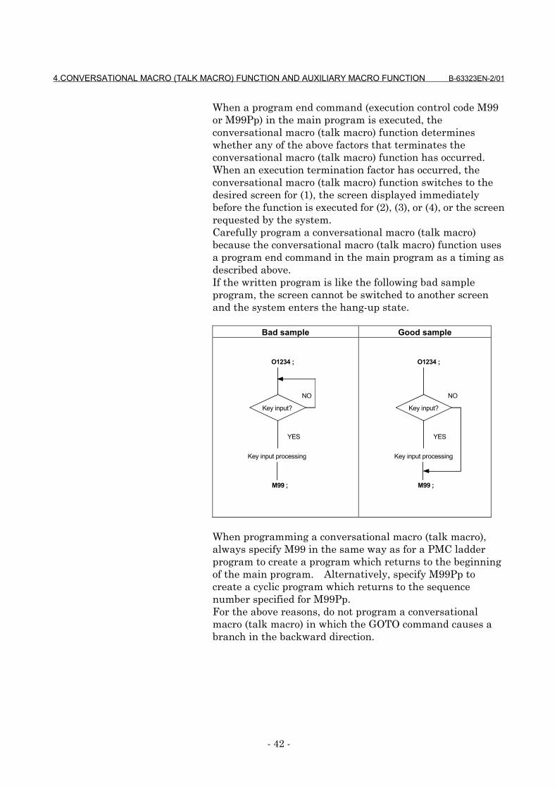
4.CONVERSATIONAL MACRO (TALK MACRO) FUNCTION AND AUXILIARY MACRO FUNCTION B-63323EN-2/01
- 42 -
When a program end command (execution control code M99or M99Pp) in the main program is executed, theconversational macro (talk macro) function determineswhether any of the above factors that terminates theconversational macro (talk macro) function has occurred.When an execution termination factor has occurred, theconversational macro (talk macro) function switches to thedesired screen for (1), the screen displayed immediatelybefore the function is executed for (2), (3), or (4), or the screenrequested by the system.Carefully program a conversational macro (talk macro)because the conversational macro (talk macro) function usesa program end command in the main program as a timing asdescribed above.If the written program is like the following bad sampleprogram, the screen cannot be switched to another screenand the system enters the hang-up state.
Bad sample Good sample
Key input?
O1234 ;
NO
YES
Key input processing
M99 ;
Key input?
O1234 ;
NO
YES
Key input processing
M99 ;
When programming a conversational macro (talk macro),always specify M99 in the same way as for a PMC ladderprogram to create a program which returns to the beginningof the main program. Alternatively, specify M99Pp tocreate a cyclic program which returns to the sequencenumber specified for M99Pp.For the above reasons, do not program a conversationalmacro (talk macro) in which the GOTO command causes abranch in the backward direction.
B-63323EN-2/01 4.CONVERSATIONAL MACRO (TALK MACRO) FUNCTION AND AUXILIARY MACRO FUNCTION
- 43 -
•••• Forced terminationNOTE
With the 15i-MA, to recover from the hang-upstate, execution of the conversational macro (talkmacro) function can forcibly be terminated.If the system enters the hang-up state,simultaneously press and . However,recovery from the hang-up state is not alwaysguaranteed. Carefully program a conversationalmacro (talk macro).
4.1.2 Commands
Commands that can be usedMacro statements and NC statements (special G codecommands) can be written in conversational macros (talkmacros) as in the case of CNC part programs.Macro statements can contain commands similar to thosewhich can be written in custom macros and macro variables.Macro variables include local variables, common variables,and P-CODE variables. In addition, the macro executorfunction is available. This function can read keys, displayscreens, and perform other processing.For details, see Chapter 5, "Macro Variables," and Chapter 6,"Macro Executor Function."
NOTECarefully use system variables #3000, #3003,#3004, and #3006 because they affect automaticoperation.
Commands that cannot be usedThe following custom macro commands are not available:(1) Modal call and macro call using a G, M, or T code or axis
address(2) Subprogram call using an M, S, or T code, M code in the
specified range, or second auxiliary function code(3) External output commands BPRNT, DPRNT, POPEN,
and PCLOS
SHIFT RESET
4.CONVERSATIONAL MACRO (TALK MACRO) FUNCTION AND AUXILIARY MACRO FUNCTION B-63323EN-2/01
- 44 -
4.2 Auxiliary Macro Function
The conversational macro (talk macro) function is executed
using function key , but the auxiliary macro function
does not need such an operation or command. After power-on, the auxiliary macro function starts execution.This function is executed at a level lower than that ofautomatic operation processing. This function isindependent of the operation mode or automatic operationstatus.
CautionsCAUTIONS1 The auxiliary macro function is executed at a level
lower than that of CNC operation processing.Therefore, execution of the auxiliary macrofunction does not affect the speed of CNCoperation processing, but the speed at which theauxiliary macro function is executed may becomelow during CNC operation. For this reason, theauxiliary macro function is not suitable to controlthe machine at a constant processing speed.
2 The auxiliary macro function cannot execute anyCNC part program statement for operation.
4.2.1 Execution and termination
ExecutionAfter power-on, the auxiliary macro function is alwaysexecuted.After the auxiliary macro function enters the constantexecution state, it executes the auxiliary macro mainprogram with the value of the control variable for executingan auxiliary macro (#8600) as the program number. Whenthe power is turned on, the value of compile parameter No.8537 is set for the control variable for executing an auxiliarymacro (#8600).
CUSTOM
B-63323EN-2/01 4.CONVERSATIONAL MACRO (TALK MACRO) FUNCTION AND AUXILIARY MACRO FUNCTION
- 45 -
NOTEAn error may occur and execution may not be ableto be continued. Such an error includes the casewhere no P-CODE macro is found as the auxiliarymacro with the value of the control variable forexecuting an auxiliary macro (#8600) as theprogram number. In this case, a messageindicating that a fatal error occurs is displayed onthe conversational macro (talk macro) screen.(For details, see Section 4.5, "Fatal Error.")
TerminationThe auxiliary macro function does not terminate because it isalways executed. Setting the control variable for executingan auxiliary macro (#8600) to 0 places the auxiliary macrofunction in the wait state when a program end command(execution control code M99 or M99Pp) in the main programis executed. The function remains in the wait state until aprogram number is set for the control variable for executingan auxiliary macro (#8600) again.Program an auxiliary macro as a cyclic program like aconversational macro (talk macro).
4.2.2 Commands
Commands that can be usedA main difference between the conversational macro (talkmacro) function and auxiliary macro function is that thecontrol codes for the macro executor function that are relatedto key reading and screen display are not available for theauxiliary macro function. For details, see Chapter 5,"Macro Variables," and Chapter 6, "Macro ExecutorFunctions."
NOTECarefully use system variables #3000, #3003,#3004, and #3006 because they affect automaticoperation.
4.CONVERSATIONAL MACRO (TALK MACRO) FUNCTION AND AUXILIARY MACRO FUNCTION B-63323EN-2/01
- 46 -
Commands that cannot be usedThe following custom macro commands are not available:(1) Modal call and macro call using a G, M, or T code or axis
address(2) Subprogram call using an M, S, or T code, M code in the
specified range, or second auxiliary function code(3) External output commands BPRNT, DPRNT, POPEN,
and PCLOS
4.2.3 Execution cycle
Whether an auxiliary macro is executed depends on whethera conversational macro (talk macro) is executed.
When a conversational macro(talk macro) is executed
Auxiliary macro and conversational macro (talk macro) aresequentially executed.
NOTEWhen an auxiliary macro is executed, aconversational macro (talk macro) is executed afterexecution of a program end command (executioncontrol code M99 or M99Pp) in the auxiliary macromain program. After a program end command(execution control code M99 or M99Pp) in theconversational macro (talk macro) main program isexecuted, execution of the auxiliary macro startsagain.
•••• FS15i original specificationSelecting the FS15i origination specification using bit 3 ofparameter No. 8558 (15I) can change the execution modefrom sequential to parallel.
NOTEThe conversational macro (talk macro) is notsynchronized with the auxiliary macro in theparallel execution mode. When the same macrovariable or macro executor function is to be used,program the conversational macro (talk macro) andauxiliary macro so that no competition will occur.
B-63323EN-2/01 4.CONVERSATIONAL MACRO (TALK MACRO) FUNCTION AND AUXILIARY MACRO FUNCTION
- 47 -
NOTEWhen the FS15i original specification is selectedusing bit 3 of parameter No. 8558 (15I), somespecifications of the macro executor functionchange. For details, see Section 9.1, "CompileParameters."
When no conversational macro(talk macro) is executed
The auxiliary macro is repeatedly executed.
NOTEWhen no conversational macro (talk macro) isexecuted, the auxiliary macro function executes theauxiliary macro at the specified intervals as manyblocks as the number specified for parameter No.7045 at a time.Execution of the auxiliary macro is affected by theCNC operation processing time because theauxiliary macro is executed at a level lower thanthat of CNC operation processing. For thisreason, the specified intervals are not guaranteed.If the number of execution blocks in the auxiliarymacro is increased and the processing timebecomes longer, the screen may be displayedslowly.
•••• FS15i original specificationNOTE
When the FS15i original specification is selectedusing bit 3 of parameter No. 8558 (15I), parameterNo. 7045 is also valid.
NOTEWhen the FS15i original specification is selectedusing bit 3 of parameter No. 8558 (15I), somespecifications of the macro executor functionchange. For details, see Section 9.1, "CompileParameters."

4.CONVERSATIONAL MACRO (TALK MACRO) FUNCTION AND AUXILIARY MACRO FUNCTION B-63323EN-2/01
- 48 -
4.3 Execution Control Codes
The following control codes are available for controllingexecution.These control codes can be specified in conversational macros(talk macros) and auxiliary macros.G65: Macro callM98: Subprogram callM99: Program end
Macro call (G65)
•••• FormatG65 Pp <Ll> <argument-specification> ;
p : Program number of a P-CODE macro to be calledl : Repetition count (1 by default)argument : Data to be passed to the P-CODE macro. (Argument
specifications I and II are available.)
Specify G65 before any argument.Macro calls can be nested to a depth of ten levels includingonly macro calls or to a depth of ten levels includingsubprogram calls and macro calls.
Subprogram call (M98)
•••• FormatM98 Pp <Ll> ;
p : Program number of a P-CODE macro to be calledl : Repetition count (1 by default)
Subprogram calls can be nested to a depth of ten levelsincluding only subprogram calls or to a depth of ten levelsincluding subprogram calls and macro calls.
Program end (M99<Pp>)
•••• FormatM99 <Pp> ;
p: Sequence number of the calling P-CODE macro(By default, control is returned to the block following the callcommand in the calling macro.)
•••• M99<Pp> command in the conversational macro (talk macro) main program
Always specify M99<Pp> at the end of the main program.M99<Pp> in the main program is a special command unlikesubprogram end.
B-63323EN-2/01 4.CONVERSATIONAL MACRO (TALK MACRO) FUNCTION AND AUXILIARY MACRO FUNCTION
- 49 -
When M99<Pp> is executed in the main program, executionof the conversational macro (talk macro) temporarilyterminates. Then, the following processing is performed:
1 Determines whether to terminate the conversationalmacro (talk macro) function.When the conversational macro (talk macro) function isexecuted again after terminated, executes theconversational macro (talk macro) specified by thecontrol variable for executing a conversational macro(talk macro) (#8500) from the beginning regardless ofthe <Pp> specification.
2 When the value of the control variable for executing aconversational macro (talk macro) (#8500) is changed,erases both character and graphic displays, thenexecutes the new conversational macro (talk macro).When the value is not changed, repeatedly executes thesame macro without erasing both character and graphicdisplays. When <Pp> is specified, starts execution fromthe block with the sequence number specified by p.
3 Initializes the local variables to <null>.
•••• M99<Pp> command in the auxiliary macro main program
Always specify M99<Pp> at the end of the main program.M99<Pp> in the main program is a special command unlikesubprogram end.When M99<Pp> is executed in the main program, executionof the auxiliary macro temporarily terminates. Then, thefollowing processing is performed:
1 Checks whether the value of the control variable forexecuting an auxiliary macro (#8600) is 0. When thevalue is 0, places the auxiliary macro function in thewait state.When the program number of an auxiliary macro is setfor the control variable for executing an auxiliary macro(#8600) again, executes the specified auxiliary macrofrom the beginning regardless of the <Pp> specification.
2 When the value of the control variable for executing anauxiliary macro (#8600) is changed, executes the newauxiliary macro. When the value is not changed,repeatedly executes the same auxiliary macro. When<Pp> is specified, starts execution from the block withthe sequence number specified by p.
3 Initializes the local variables to <null>.
4.CONVERSATIONAL MACRO (TALK MACRO) FUNCTION AND AUXILIARY MACRO FUNCTION B-63323EN-2/01
- 50 -
4.4 Execution Control Variables (#8500, #8510, and #8600)
Control variable for executing a conversational macro (talk macro) (#8500)
This control variable sets the main program number of aconversational macro (talk macro) to be executed.When the conversational macro (talk macro) function isexecuted, the conversational macro (talk macro) with thevalue of variable #8500 as the program number is executed.At power-on, the value of parameter No. 8536 is set forvariable #8500.When M99<Pp> is executed in the conversational macro (talkmacro) main program, whether the value of variable #8500 ischanged is checked. When the value is changed, bothcharacter and graphic displays are erased, then the newconversational macro (talk macro) is executed.Setting variable #8500 to 0 terminates the conversationalmacro (talk macro) function after execution of M99<Pp> inthe conversational macro (talk macro) main program, thendisplays the screen displayed immediately before executionof the conversational macro (talk macro) function.
Control variable for starting a conversational macro (talk macro) (#8510)
Setting variable #8510 to 1 executes the conversationalmacro (talk macro) function and the conversational macro(talk macro) set for the control variable for executing aconversational macro (talk macro) (#8500).Setting variable #8510 to 0 terminates the conversationalmacro (talk macro) function after execution of M99<Pp> inthe conversational macro (talk macro) main program, thendisplays the screen immediately before execution of theconversational macro (talk macro) function.
Control variable for executing an auxiliary macro (#8600)
This control variable sets the main program number of anauxiliary macro.At power-on, the value of parameter No. 8537 is set forvariable #8600.Setting variable #8600 to other than 0 executes the auxiliarymacro with the value of variable #8600 as the programnumber.When M99<Pp> is executed in the auxiliary macro mainprogram, whether the value of variable #8600 is changed ischecked. When the value is changed, the new auxiliarymacro is executed. When the value is not changed, the sameauxiliary macro is repeatedly executed.
B-63323EN-2/01 4.CONVERSATIONAL MACRO (TALK MACRO) FUNCTION AND AUXILIARY MACRO FUNCTION
- 51 -
Setting variable #8600 to 0 terminates execution of theauxiliary macro after execution of M99<Pp> in the auxiliarymacro main program.
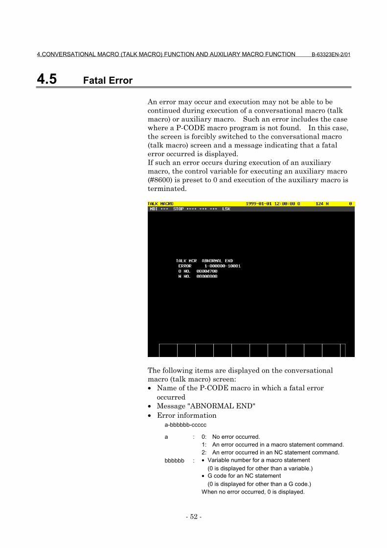
4.CONVERSATIONAL MACRO (TALK MACRO) FUNCTION AND AUXILIARY MACRO FUNCTION B-63323EN-2/01
- 52 -
4.5 Fatal Error
An error may occur and execution may not be able to becontinued during execution of a conversational macro (talkmacro) or auxiliary macro. Such an error includes the casewhere a P-CODE macro program is not found. In this case,the screen is forcibly switched to the conversational macro(talk macro) screen and a message indicating that a fatalerror occurred is displayed.If such an error occurs during execution of an auxiliarymacro, the control variable for executing an auxiliary macro(#8600) is preset to 0 and execution of the auxiliary macro isterminated.
The following items are displayed on the conversationalmacro (talk macro) screen:• Name of the P-CODE macro in which a fatal error
occurred• Message "ABNORMAL END"• Error information
a-bbbbbb-ccccc
a : 0: No error occurred.1: An error occurred in a macro statement command.2: An error occurred in an NC statement command.
bbbbbb : • Variable number for a macro statement(0 is displayed for other than a variable.)
• G code for an NC statement(0 is displayed for other than a G code.)
When no error occurred, 0 is displayed.
B-63323EN-2/01 4.CONVERSATIONAL MACRO (TALK MACRO) FUNCTION AND AUXILIARY MACRO FUNCTION
- 53 -
ccccc : Error numberWhen no error occurred, 0 is displayed.For details of the error, see Section 10.1, "Error No.List."
• Number of the program in which the error occurred• Sequence number for which the error occurred
Clearing the error information display screen
Error information display can be canceled by pressing
function key or and terminating
the conversational macro (talk macro) function.
NOTEIf an error occurs during execution of an auxiliarymacro, the control variable for executing anauxiliary macro (#8600) is preset to 0. To restartexecution of an auxiliary macro, set the programnumber for the control variable for executing anauxiliary macro (#8600).
POS PROG

5.MACRO VARIABLES B-63323EN-2/01
- 54 -
5 MACRO VARIABLES
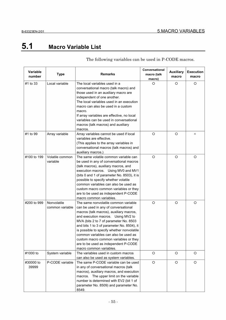
B-63323EN-2/01 5.MACRO VARIABLES
- 55 -
5.1 Macro Variable List
The following variables can be used in P-CODE macros.
Variablenumber Type Remarks
Conversationalmacro (talk
macro)
Auxiliarymacro
Executionmacro
#1 to 33 Local variable The local variables used in aconversational macro (talk macro) andthose used in an auxiliary macro areindependent of one another.The local variables used in an executionmacro can also be used in a custommacro.If array variables are effective, no localvariables can be used in conversationalmacros (talk macros) and auxiliarymacros.
� � �
#1 to 99 Array variable Array variables cannot be used if localvariables are effective.(This applies to the array variables inconversational macros (talk macros) andauxiliary macros.)
� � ×
#100 to 199 Volatile commonvariable
The same volatile common variable canbe used in any of conversational macros(talk macros), auxiliary macros, andexecution macros. Using MV0 and MV1(bits 0 and 1 of parameter No. 8503), it ispossible to specify whether volatilecommon variables can also be used ascustom macro common variables or theyare to be used as independent P-CODEmacro common variables.
� � �
#200 to 999 Nonvolatilecommon variable
The same nonvolatile common variablecan be used in any of conversationalmacros (talk macros), auxiliary macros,and execution macros. Using MV2 toMVA (bits 2 to 7 of parameter No. 8503and bits 1 to 3 of parameter No. 8504), itis possible to specify whether nonvolatilecommon variables can also be used ascustom macro common variables or theyare to be used as independent P-CODEmacro common variables.
� � �
#1000 to System variable The variables used in custom macroscan also be used as system variables.
� � �
#30000 to39999
P-CODE variable The same P-CODE variable can be usedin any of conversational macros (talkmacros), auxiliary macros, and executionmacros. The upper limit on the variablenumber is determined with EV2 (bit 1 ofparameter No. 8509) and parameter No.8549.
� � �

5.MACRO VARIABLES B-63323EN-2/01
- 56 -
#40000 to99099
Extended P-CODE variable
The same extended P-CODE variablecan be used in any of conversationalmacros (talk macros), auxiliary macros,and execution macros. The upper limiton the variable number is determinedwith EV1 (bit 0 of parameter No. 8509)and parameter No. 8550.
� � �
#99100 to99199
Volatile custommacro commonvariable
The same variable can be used in any ofconversational macros (talk macros),auxiliary macros, and execution macros.
� � �
#99200 to99999
Nonvolatilecustom macrocommon variable
The same variable can be used in any ofconversational macros (talk macros),auxiliary macros, and execution macros.
� � �
B-63323EN-2/01 5.MACRO VARIABLES
- 57 -
5.2 Local Variables (#1 to #33)/Array Variables (#1 to #99)
Local variables can be used in any of conversational macros(talk macros), auxiliary macros, and execution macros. Thelocal variables used in an execution macro, those used in aconversational macro (talk macro), and those used in anauxiliary macro are independent of one another. The localvariables used in an execution macro can also be used in acustom macro.
NOTEIf array variables are effective, local variables arenot effective in conversational macros (talkmacros) and auxiliary macros.In execution macros, local variables are effectiveregardless of whether array variables are effectiveor not.
If a P-CODE variable is to be referenced by a conversationalmacro (talk macro) or auxiliary macro as an array variable,an array variable (#1 to #99) can be used. See Section 6.9,"Array-Type Processing and Referencing of P-CODEVariables" for details.
NOTELocal variables are effective if array variables arenot effective.
5.MACRO VARIABLES B-63323EN-2/01
- 58 -
5.3 Common Variables (#100 to #199, #200 to #499, and #500to #999)
Common variables can be used in any of conversationalmacros (talk macros), auxiliary macros, and executionmacros, and the same common variable can be used in any ofthem. It is possible to specify whether to use commonvariables as custom macro common variables or use them asP-CODE macro common variables, independent of custommacro common variables. To do this, use MV0 to MVA (bits0 to 7 of parameter No. 8503 and bits 1 to 3 of parameter No.8504).
NOTEIf the parameters are set so that variables #200 to#499 are used as custom macro commonvariables, an option for additional 900 custommacro common variables is required.
By setting variable numbers for the appropriate parametersin the same way as in custom macros, multiple commonvariables (#200 to #499 and #500 to #999) can be protected.The parameters used for the protection differ depending onwhether P-CODE macro common variables are used orcustom macro common variables are used.
NOTEParameters Nos. 8574 to 8577 are for P-CODEmacro common variables.Parameters Nos. 7036 to 7039 are for custommacro common variables.
B-63323EN-2/01 5.MACRO VARIABLES
- 59 -
CautionCAUTION
The same common variable can be used in any ofconversational macros (talk macros), auxiliarymacros, and execution macros, but caution isnecessary. If the common variable used in anexecution macro and a user program is the sameas the common variable used in a conversationalmacro (talk macro) and an auxiliary macro, writingmay occur from the execution macro while writingis performed from the conversational macro (talkmacro) or auxiliary macro because executionmacros have a higher processing level thanconversational macros (talk macros) and auxiliarymacros, with the result that the values written bythe execution macro may be overwritten by theremaining processing of the conversational macro(talk macro) or auxiliary macro. For this reason,make sure that the variables used in executionmacros are different from those used inconversational macros (talk macros) and auxiliarymacros.
5.MACRO VARIABLES B-63323EN-2/01
- 60 -
5.4 P-CODE Variables (#30000 and Above)
P-CODE variables can be used in P-CODE macros.P-CODE variables start with #30000, and the number of P-CODE variables that can be used is determined using theappropriate parameter.It is possible to specify whether to use P-CODE variables asfloating-point data variables or integer data variables, usingthe appropriate parameter.
Setting1. Set the variable type for EV2 (bit 1 of parameter No.
8509).2. Set the number of variables for parameter No. 8549.
The number of variables that can be used is the value setfor this parameter times n, where n differs depending onthe variable type.
Floating-point data: 40Integer data : 100
The maximum value that can be set for this parameter is100.If this parameter is 0, no P-CODE variables can be used.
EXAMPLE[Setting example]1. If EV2 (bit 1 of parameter No. 8509) is 0 (floating-
point data):If parameter No. 8549 is set to 1: #30000 to 30039If parameter No. 8549 is set to 2: #30000 to 30079
2. If EV2 (bit 1 of parameter No. 8509) is 1 (integerdata):If parameter No. 8549 is set to 1: #30000 to 30099If parameter No. 8549 is set to 2: #30000 to 30199
CautionCAUTION
EV2 (bit 1 of parameter No. 8509) and parameterNo. 8549 cannot be set from the MDI.The compile parameters set when a P-CODE macrowas created are copied to EV2 and the parameterwhen the power is turned on.
B-63323EN-2/01 5.MACRO VARIABLES
- 61 -
•••• Caution on settingThe maximum value that can be set for parameter No. 8549is 100. The actual maximum value that can be set, however,depends on the free space of the backup memory.The free space of the backup memory can be checked on themain CPU board module screen on the system configurationscreen.
If one capacity unit of the backup memory is assumedequivalent to one page, the relationships between the valueset for parameter No. 8549 and the number of pages used areas follows:
For floating-point data : Parameter No. 8549 times1.25 pages
For integer data : Parameter No. 8549 times0.78125 pages
(In either case, the result is rounded up to an integernumber.)
CautionCAUTION
The free space of the backup memory must not beexceeded.Otherwise, "FILE ALLOCATION ERROR" isdisplayed when the power is turned on, and thesystem stops.If "FILE ALLOCATION ERROR" is displayed, useeither of the following recovery methods:<1> Register a P-CODE macro that does not cause
the free space to be exceeded.<2> Delete the P-CODE macro.
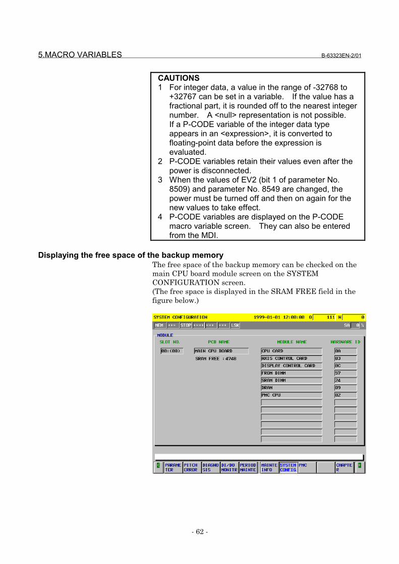
5.MACRO VARIABLES B-63323EN-2/01
- 62 -
CAUTIONS1 For integer data, a value in the range of -32768 to
+32767 can be set in a variable. If the value has afractional part, it is rounded off to the nearest integernumber. A <null> representation is not possible.If a P-CODE variable of the integer data typeappears in an <expression>, it is converted tofloating-point data before the expression isevaluated.
2 P-CODE variables retain their values even after thepower is disconnected.
3 When the values of EV2 (bit 1 of parameter No.8509) and parameter No. 8549 are changed, thepower must be turned off and then on again for thenew values to take effect.
4 P-CODE variables are displayed on the P-CODEmacro variable screen. They can also be enteredfrom the MDI.
Displaying the free space of the backup memoryThe free space of the backup memory can be checked on themain CPU board module screen on the SYSTEMCONFIGURATION screen.(The free space is displayed in the SRAM FREE field in thefigure below.)
B-63323EN-2/01 5.MACRO VARIABLES
- 63 -
5.5 Extended P-CODE Variables (#40000 and Above)
Extended P-CODE variables can be used in P-CODE macros.Extended P-CODE variables start with #40000, and thenumber of extended P-CODE variables that can be used isdetermined using the appropriate parameter.It is possible to specify whether to use extended P-CODEvariables as floating-point data variables or integer datavariables, using the appropriate parameter.
Setting1. Set the variable type for EV1 (bit 0 of parameter No.
8509).2. Set the number of variables for parameter No. 8550.
The number of variables that can be used is the value setfor this parameter times n, where n differs depending onthe variable type.
Floating-point data: 10Integer data: 30
The maximum number that can be set for thisparameter is 1970.If this parameter is 0, no extended P-CODE variablescan be used.
EXAMPLE[Setting example]1. If EV1 (bit 0 of parameter No. 8509) is 0 (floating-
point data):If parameter No. 8550 is set to 1: #40000 to
#40009If parameter No. 8550 is set to 2: #40000 to
#400192. If EV1 (bit 0 of parameter No. 8509) is 1 (integer
data):If parameter No. 8550 is set to 1: #40000 to
#40029If parameter No. 8550 is set to 2: #40000 to
#40059
CautionCAUTION
EV1 (bit 0 of parameter No. 8509) and parameterNo. 8550 cannot be set from the MDI.The compile parameters set when a P-CODE macrowas created are copied to EV1 and the parameterwhen the power is turned on.
5.MACRO VARIABLES B-63323EN-2/01
- 64 -
•••• Caution on settingThe maximum value that can be set for parameter No. 8550is 1970. The actual maximum value that can be set,however, depends on the free space of the backup memory.The free space of the backup memory can be checked on themain CPU board module screen on the system configurationscreen. See "Displaying the free space of the backupmemory" in Section 5.4, "P-CODE Variables (#30000 andAbove)."
If one capacity unit of the backup memory is assumedequivalent to one page, the relationship between the valueset for parameter No. 8550 and the number of pages used isas follows:
For floating-point data: Parameter No. 8550 times0.3125 pages
For integer data : Parameter No. 8550 times0.234375 pages
(In either case, the result is rounded up to an integernumber.)
CautionCAUTION
The free space of the backup memory must not beexceeded.Otherwise, "FILE ALLOCATION ERROR" isdisplayed when the power is turned on, and thesystem stops.If "FILE ALLOCATION ERROR" is displayed, useeither of the following recovery methods:<1> Register a P-CODE macro that does not cause
the free space to be exceeded.<2> Delete the P-CODE macro.

B-63323EN-2/01 5.MACRO VARIABLES
- 65 -
CAUTIONS1 For integer data, a value in the range of -32768 to
+32767 can be set in a variable. If the value has afractional part, it is rounded off to the nearest integernumber. A <null> representation is not possible.If an extended P-CODE variable of the integer datatype appears in an <expression>, it is converted tofloating-point data before the expression isevaluated.
2 Extended P-CODE variables retain their values evenafter the power is turned off.
3 When the values of EV1 (bit 0 of parameter No.8509) and parameter No. 8550 are changed, thepower must be turned off and on again for the newvalues to take effect.
4 Extended P-CODE variables are displayed on the P-CODE macro variable screen. They can also beentered from the MDI.
5.MACRO VARIABLES B-63323EN-2/01
- 66 -
5.6 Custom Macro Common Variables (#99100 to #99999)
Using numbers #99100 to #99999, it is possible to write andread values to and from custom macro common variables(#100 to #199, #200 to #499, and #500 to #999) fromconversational macros (talk macros), auxiliary macros, andexecution macros.The number of the variable to be read plus 99000 is thenumber to be used.
#99100 corresponds to variable #100.#99199 corresponds to variable #199.#99500 corresponds to variable #500.#99999 corresponds to variable #999.
NOTEIf the option for additional 900 custom macrocommon variables is not attached, it is possible towrite and read values from only variables #100 to#199 and #500 to #999.
B-63323EN-2/01 5.MACRO VARIABLES
- 67 -
5.7 Custom Macro System Variables (#1000 and Above)
All system variables that can be used in the Series15i andSeries150i custom macros can be used in execution macros,conversational macros (talk macros), and auxiliary macros.For details of system variables, refer to "FANUC Series15i/150i-MA Operator's Manual (Programming)" (B-63324EN).
CautionCAUTION
It is possible to specify system variables #3000,#3003, #3004, and #3006 from conversationalmacros (talk macros) and auxiliary macros. Usegreat caution when specifying the variablesbecause they affect automatic operation.
Displaying an alarm messageusing variable #3000
Specifying variable #3000 from a conversational macro (talkmacro) or auxiliary macro places the CNC in the alarm state.On the alarm message screen, the number of the specifiedmacro alarm is displayed along with the message. Placingthe CNC in the alarm state causes automatic operation tostop.Specifying the variable from an execution macro has thesame effect as specifying it from a user program.
•••• CautionCAUTION
Specifying variable #3000 from a conversationalmacro (talk macro) or auxiliary macro causesautomatic operation to stop due to an alarm.
Displaying an operator messageusing variable #3006
Specifying variable #3006 from a conversational macro (talkmacro) or auxiliary macro causes a message to be displayedon the external operator message screen and automaticoperation to stop.Specifying the variable from an execution macro has thesame effect as specifying it from a custom macro program.
•••• CautionCAUTION
Specifying variable #3006 from a conversationalmacro (talk macro) or auxiliary macro causesautomatic operation to stop.
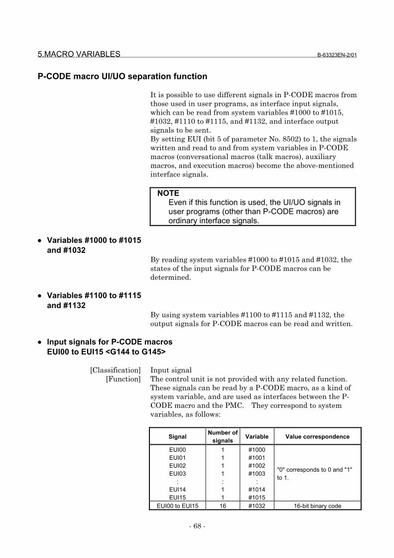
5.MACRO VARIABLES B-63323EN-2/01
- 68 -
P-CODE macro UI/UO separation function
It is possible to use different signals in P-CODE macros fromthose used in user programs, as interface input signals,which can be read from system variables #1000 to #1015,#1032, #1110 to #1115, and #1132, and interface outputsignals to be sent.By setting EUI (bit 5 of parameter No. 8502) to 1, the signalswritten and read to and from system variables in P-CODEmacros (conversational macros (talk macros), auxiliarymacros, and execution macros) become the above-mentionedinterface signals.
NOTEEven if this function is used, the UI/UO signals inuser programs (other than P-CODE macros) areordinary interface signals.
•••• Variables #1000 to #1015and #1032
By reading system variables #1000 to #1015 and #1032, thestates of the input signals for P-CODE macros can bedetermined.
•••• Variables #1100 to #1115and #1132
By using system variables #1100 to #1115 and #1132, theoutput signals for P-CODE macros can be read and written.
•••• Input signals for P-CODE macrosEUI00 to EUI15 <G144 to G145>
[Classification] Input signal[Function] The control unit is not provided with any related function.
These signals can be read by a P-CODE macro, as a kind ofsystem variable, and are used as interfaces between the P-CODE macro and the PMC. They correspond to systemvariables, as follows:
Signal Number ofsignals Variable Value correspondence
EUI00EUI01EUI02EUI03
:EUI14EUI15
1111:11
#1000#1001#1002#1003
:#1014#1015
"0" corresponds to 0 and "1"to 1.
EUI00 to EUI15 16 #1032 16-bit binary code
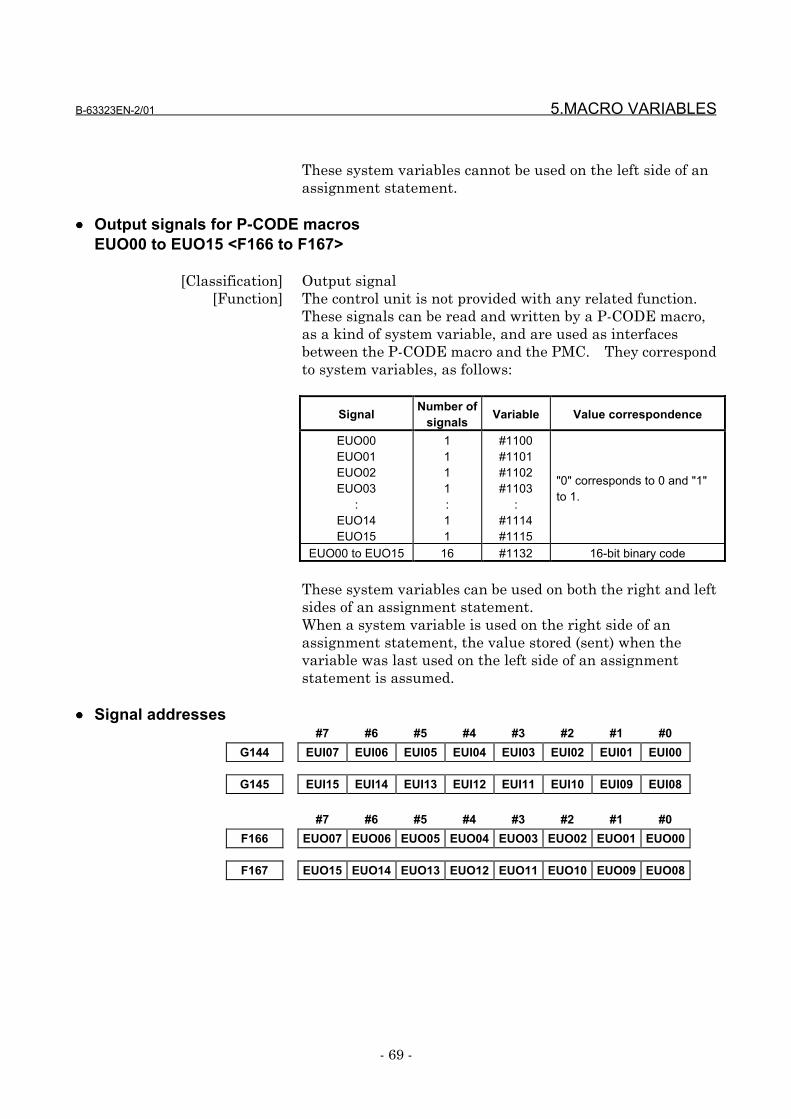
B-63323EN-2/01 5.MACRO VARIABLES
- 69 -
These system variables cannot be used on the left side of anassignment statement.
•••• Output signals for P-CODE macrosEUO00 to EUO15 <F166 to F167>
[Classification] Output signal[Function] The control unit is not provided with any related function.
These signals can be read and written by a P-CODE macro,as a kind of system variable, and are used as interfacesbetween the P-CODE macro and the PMC. They correspondto system variables, as follows:
Signal Number ofsignals Variable Value correspondence
EUO00EUO01EUO02EUO03
:EUO14EUO15
1111:11
#1100#1101#1102#1103
:#1114#1115
"0" corresponds to 0 and "1"to 1.
EUO00 to EUO15 16 #1132 16-bit binary code
These system variables can be used on both the right and leftsides of an assignment statement.When a system variable is used on the right side of anassignment statement, the value stored (sent) when thevariable was last used on the left side of an assignmentstatement is assumed.
•••• Signal addresses#7 #6 #5 #4 #3 #2 #1 #0
G144 EUI07 EUI06 EUI05 EUI04 EUI03 EUI02 EUI01 EUI00
G145 EUI15 EUI14 EUI13 EUI12 EUI11 EUI10 EUI09 EUI08
#7 #6 #5 #4 #3 #2 #1 #0F166 EUO07 EUO06 EUO05 EUO04 EUO03 EUO02 EUO01 EUO00
F167 EUO15 EUO14 EUO13 EUO12 EUO11 EUO10 EUO09 EUO08
6.MACRO EXECUTOR FUNCTIONS B-63323EN-2/01
- 70 -
6 MACRO EXECUTOR FUNCTIONS
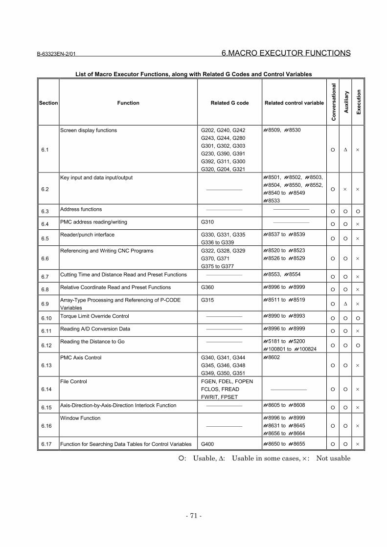
B-63323EN-2/01 6.MACRO EXECUTOR FUNCTIONS
- 71 -
List of Macro Executor Functions, along with Related G Codes and Control Variables
Section Function Related G code Related control variable
Con
vers
atio
nal
Aux
iliar
y
Exec
utio
n
6.1
Screen display functions G202, G240, G242 G243, G244, G280 G301, G302, G303 G230, G390, G391 G392, G311, G300 G320, G204, G321
#8509, #8530
� ∆ ×
6.2
Key input and data input/output
#8501, #8502, #8503,#8504, #8550, #8552,#8540 to #8549#8533
� × ×
6.3 Address functions � � �
6.4 PMC address reading/writing G310 � � ×
6.5Reader/punch interface G330, G331, G335
G336 to G339#8537 to #8539
� � ×
6.6Referencing and Writing CNC Programs G322, G328, G329
G370, G371 G375 to G377
#8520 to #8523#8526 to #8529 � � ×
6.7 Cutting Time and Distance Read and Preset Functions #8553, #8554� � ×
6.8 Relative Coordinate Read and Preset Functions G360 #8996 to #8999� � ×
6.9Array-Type Processing and Referencing of P-CODEVariables
G315 #8511 to #8519� ∆ ×
6.10 Torque Limit Override Control #8990 to #8993� � �
6.11 Reading A/D Conversion Data #8996 to #8999� � ×
6.12Reading the Distance to Go #5181 to #5200
#100801 to #100824 � � �
6.13PMC Axis Control G340, G341, G344
G345, G346, G348 G349, G350, G351
#8602� � ×
6.14File Control FGEN, FDEL, FOPEN
FCLOS, FREAD FWRIT, FPSET
� � ×
6.15 Axis-Direction-by-Axis-Direction Interlock Function #8605 to #8608� � ×
6.16Window Function
#8996 to #8999#8631 to #8645#8656 to #8664
� � ×
6.17 Function for Searching Data Tables for Control Variables G400 #8650 to #8655 � � ×
�: Usable, ∆: Usable in some cases, × : Not usable
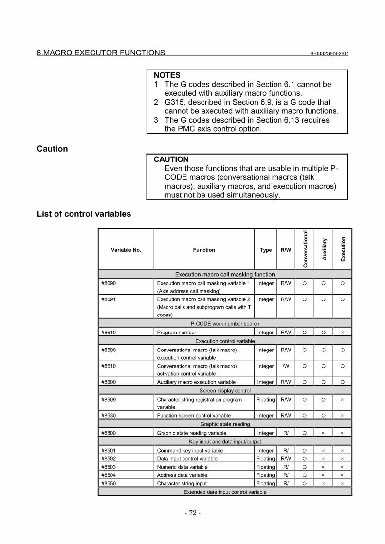
6.MACRO EXECUTOR FUNCTIONS B-63323EN-2/01
- 72 -
NOTES1 The G codes described in Section 6.1 cannot be
executed with auxiliary macro functions.2 G315, described in Section 6.9, is a G code that
cannot be executed with auxiliary macro functions.3 The G codes described in Section 6.13 requires
the PMC axis control option.
CautionCAUTION
Even those functions that are usable in multiple P-CODE macros (conversational macros (talkmacros), auxiliary macros, and execution macros)must not be used simultaneously.
List of control variables
Variable No. Function Type R/W
Con
vers
atio
nal
Aux
iliar
y
Exec
utio
n
Execution macro call masking function#8690 Execution macro call masking variable 1
(Axis address call masking)Integer R/W � � �
#8691 Execution macro call masking variable 2(Macro calls and subprogram calls with Tcodes)
Integer R/W � � �
P-CODE work number search#8610 Program number Integer R/W � � ×
Execution control variable#8500 Conversational macro (talk macro)
execution control variableInteger R/W � � �
#8510 Conversational macro (talk macro)activation control variable
Integer /W � � �
#8600 Auxiliary macro execution variable Integer R/W � � �
Screen display control#8509 Character string registration program
variableFloating R/W � � ×
#8530 Function screen control variable Integer R/W � � ×
Graphic state reading#8800 Graphic state reading variable Integer R/ � × ×
Key input and data input/output#8501 Command key input variable Integer R/ � × ×
#8502 Data input control variable Floating R/W � × ×
#8503 Numeric data variable Floating R/ � × ×
#8504 Address data variable Floating R/ � × ×
#8550 Character string input Floating R/ � × ×
Extended data input control variable
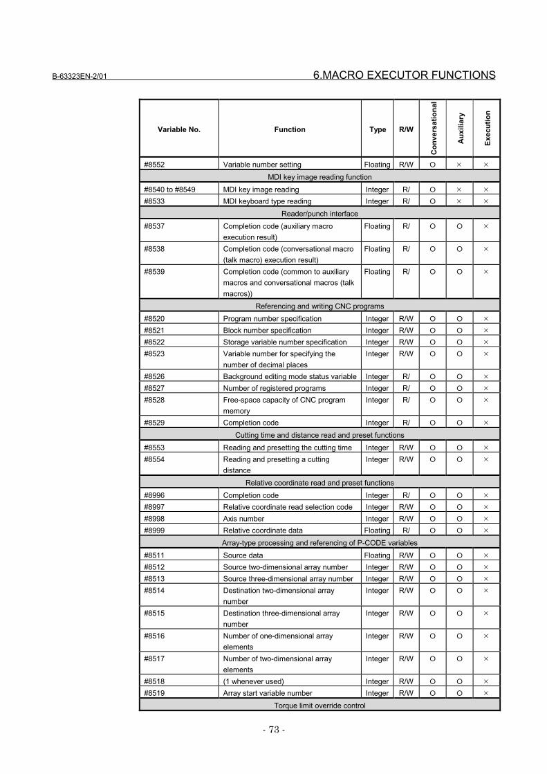
B-63323EN-2/01 6.MACRO EXECUTOR FUNCTIONS
- 73 -
Variable No. Function Type R/W
Con
vers
atio
nal
Aux
iliar
y
Exec
utio
n
#8552 Variable number setting Floating R/W � × ×
MDI key image reading function#8540 to #8549 MDI key image reading Integer R/ � × ×
#8533 MDI keyboard type reading Integer R/ � × ×
Reader/punch interface#8537 Completion code (auxiliary macro
execution result)Floating R/ � � ×
#8538 Completion code (conversational macro(talk macro) execution result)
Floating R/ � � ×
#8539 Completion code (common to auxiliarymacros and conversational macros (talkmacros))
Floating R/ � � ×
Referencing and writing CNC programs#8520 Program number specification Integer R/W � � ×
#8521 Block number specification Integer R/W � � ×
#8522 Storage variable number specification Integer R/W � � ×
#8523 Variable number for specifying thenumber of decimal places
Integer R/W � � ×
#8526 Background editing mode status variable Integer R/ � � ×
#8527 Number of registered programs Integer R/ � � ×
#8528 Free-space capacity of CNC programmemory
Integer R/ � � ×
#8529 Completion code Integer R/ � � ×
Cutting time and distance read and preset functions#8553 Reading and presetting the cutting time Integer R/W � � ×
#8554 Reading and presetting a cuttingdistance
Integer R/W � � ×
Relative coordinate read and preset functions#8996 Completion code Integer R/ � � ×
#8997 Relative coordinate read selection code Integer R/W � � ×
#8998 Axis number Integer R/W � � ×
#8999 Relative coordinate data Floating R/ � � ×
Array-type processing and referencing of P-CODE variables#8511 Source data Floating R/W � � ×
#8512 Source two-dimensional array number Integer R/W � � ×
#8513 Source three-dimensional array number Integer R/W � � ×
#8514 Destination two-dimensional arraynumber
Integer R/W � � ×
#8515 Destination three-dimensional arraynumber
Integer R/W � � ×
#8516 Number of one-dimensional arrayelements
Integer R/W � � ×
#8517 Number of two-dimensional arrayelements
Integer R/W � � ×
#8518 (1 whenever used) Integer R/W � � ×
#8519 Array start variable number Integer R/W � � ×
Torque limit override control
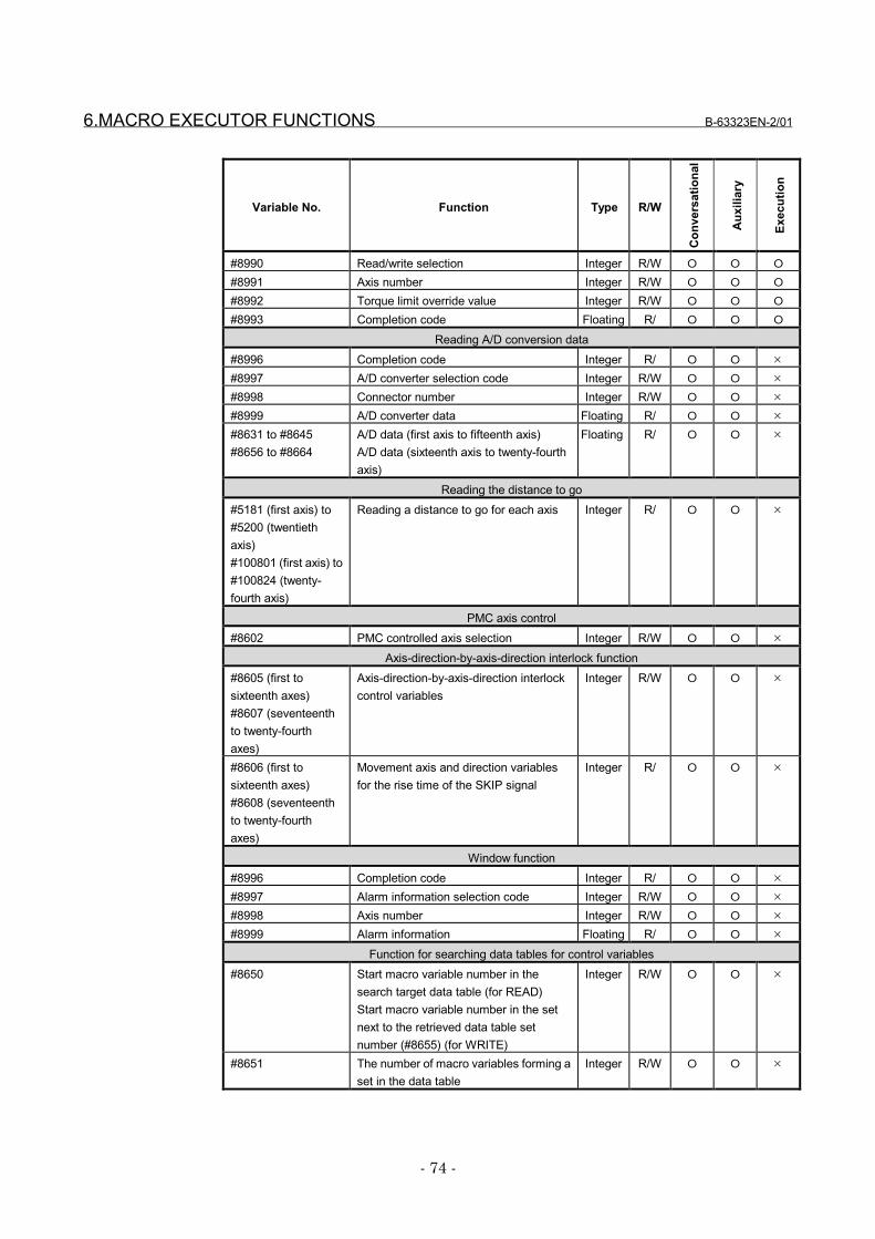
6.MACRO EXECUTOR FUNCTIONS B-63323EN-2/01
- 74 -
Variable No. Function Type R/W
Con
vers
atio
nal
Aux
iliar
y
Exec
utio
n
#8990 Read/write selection Integer R/W � � �
#8991 Axis number Integer R/W � � �
#8992 Torque limit override value Integer R/W � � �
#8993 Completion code Floating R/ � � �
Reading A/D conversion data#8996 Completion code Integer R/ � � ×
#8997 A/D converter selection code Integer R/W � � ×
#8998 Connector number Integer R/W � � ×
#8999 A/D converter data Floating R/ � � ×
#8631 to #8645#8656 to #8664
A/D data (first axis to fifteenth axis)A/D data (sixteenth axis to twenty-fourthaxis)
Floating R/ � � ×
Reading the distance to go#5181 (first axis) to#5200 (twentiethaxis)#100801 (first axis) to#100824 (twenty-fourth axis)
Reading a distance to go for each axis Integer R/ � � ×
PMC axis control#8602 PMC controlled axis selection Integer R/W � � ×
Axis-direction-by-axis-direction interlock function#8605 (first tosixteenth axes)#8607 (seventeenthto twenty-fourthaxes)
Axis-direction-by-axis-direction interlockcontrol variables
Integer R/W � � ×
#8606 (first tosixteenth axes)#8608 (seventeenthto twenty-fourthaxes)
Movement axis and direction variablesfor the rise time of the SKIP signal
Integer R/ � � ×
Window function#8996 Completion code Integer R/ � � ×
#8997 Alarm information selection code Integer R/W � � ×
#8998 Axis number Integer R/W � � ×
#8999 Alarm information Floating R/ � � ×
Function for searching data tables for control variables#8650 Start macro variable number in the
search target data table (for READ)Start macro variable number in the setnext to the retrieved data table setnumber (#8655) (for WRITE)
Integer R/W � � ×
#8651 The number of macro variables forming aset in the data table
Integer R/W � � ×
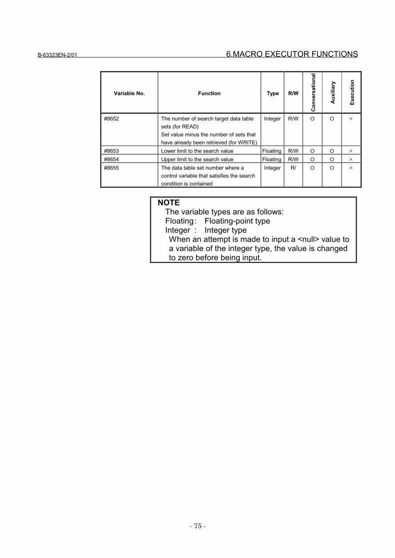
B-63323EN-2/01 6.MACRO EXECUTOR FUNCTIONS
- 75 -
Variable No. Function Type R/W
Con
vers
atio
nal
Aux
iliar
y
Exec
utio
n
#8652 The number of search target data tablesets (for READ)Set value minus the number of sets thathave already been retrieved (for WRITE)
Integer R/W � � ×
#8653 Lower limit to the search value Floating R/W � � ×
#8654 Upper limit to the search value Floating R/W � � ×
#8655 The data table set number where acontrol variable that satisfies the searchcondition is contained
Integer R/ � � ×
NOTEThe variable types are as follows:Floating: Floating-point typeInteger : Integer typeWhen an attempt is made to input a <null> value toa variable of the integer type, the value is changedto zero before being input.
6.MACRO EXECUTOR FUNCTIONS B-63323EN-2/01
- 76 -
6.1 Screen Display Functions
6.1.1 Screen coordinate system
Explanation of the systemdisplay section
The screen contains 30 lines. Of these lines, the uppermostthree lines are used by the system only. Thus, the lower 27lines can be used for replacement by conversational macros(talk macros).In the system display section, the first line displays the title,date and time, program number, and sequence number andthe second line displays the status.In the lines where replacement can be performed byconversational macros (talk macros), there is a data inputline and a soft key frame.
Character coordinate systemThe coordinate system that a conversational macro (talkmacro) function uses to display characters as well as thecursor is called the character coordinate system. In thecharacter coordinate system, the horizontal axis is assumedto be the X-axis, while the vertical axis is assumed to be theY-axis. The X coordinates are in the range of 0 to 73 fromleft to right (0 to 79 if 15I (bit 3 of parameter No. 8558) is 1),while the Y coordinates are in the range of 0 to 26 from top tobottom.Any display commands exceeding these ranges are ignored.One unit is one character.The following portions cannot be used because they are usedby the system:22nd line (data input line) (23rd line if 15I (bit 3 of parameterNo. 8558 is 1) and the soft key frame on the 24th, 25th, and26th lines.
NOTEWhen the FS15i original specifications areselected with 15I (bit 3 of parameter No. 8558), thespecifications of several macro executor functionsare changed. See Section 9.1, "CompileParameters" for details.
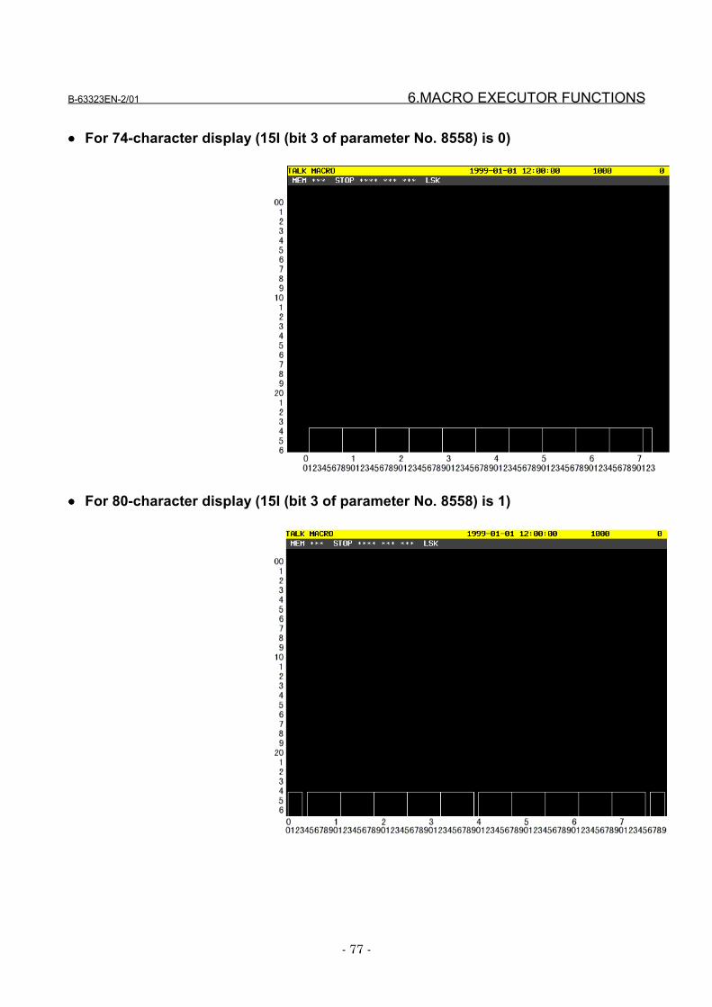
B-63323EN-2/01 6.MACRO EXECUTOR FUNCTIONS
- 77 -
•••• For 74-character display (15I (bit 3 of parameter No. 8558) is 0)
•••• For 80-character display (15I (bit 3 of parameter No. 8558) is 1)
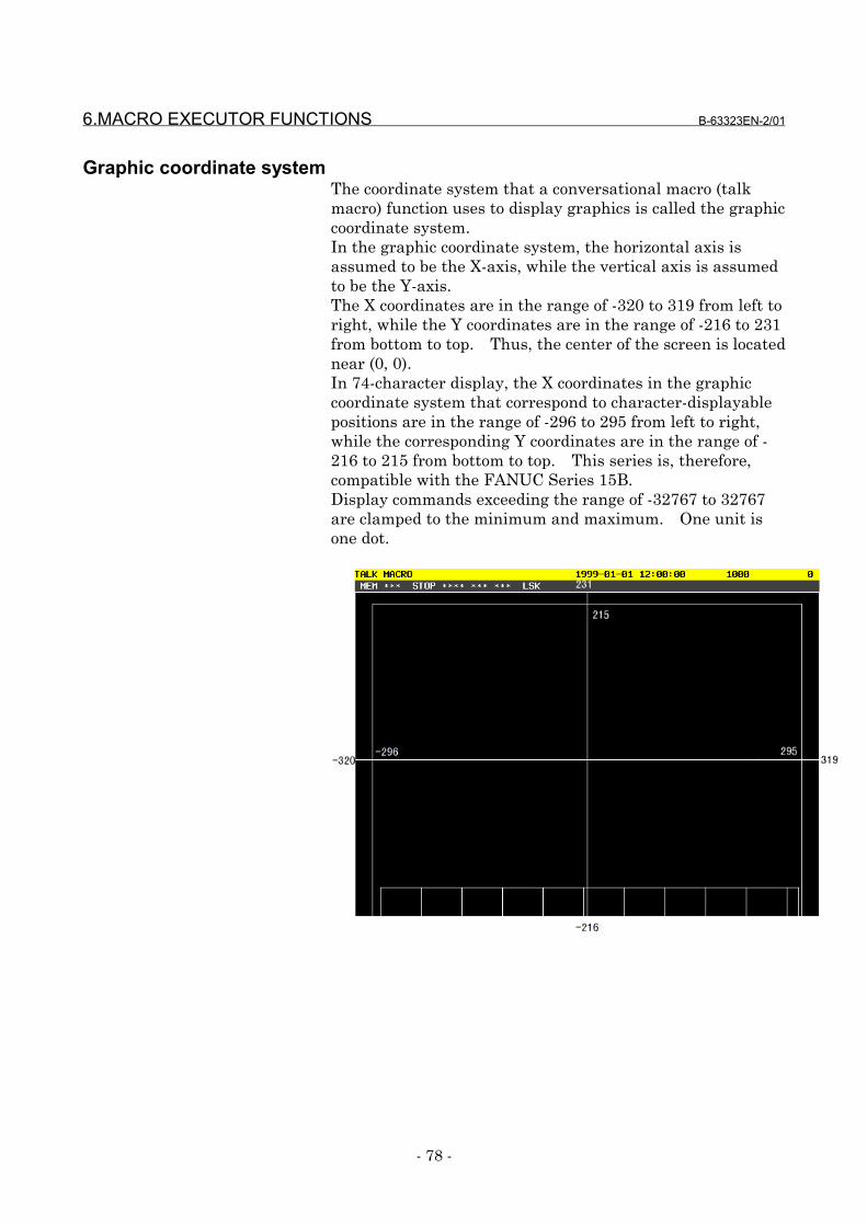
6.MACRO EXECUTOR FUNCTIONS B-63323EN-2/01
- 78 -
Graphic coordinate systemThe coordinate system that a conversational macro (talkmacro) function uses to display graphics is called the graphiccoordinate system.In the graphic coordinate system, the horizontal axis isassumed to be the X-axis, while the vertical axis is assumedto be the Y-axis.The X coordinates are in the range of -320 to 319 from left toright, while the Y coordinates are in the range of -216 to 231from bottom to top. Thus, the center of the screen is locatednear (0, 0).In 74-character display, the X coordinates in the graphiccoordinate system that correspond to character-displayablepositions are in the range of -296 to 295 from left to right,while the corresponding Y coordinates are in the range of -216 to 215 from bottom to top. This series is, therefore,compatible with the FANUC Series 15B.Display commands exceeding the range of -32767 to 32767are clamped to the minimum and maximum. One unit isone dot.
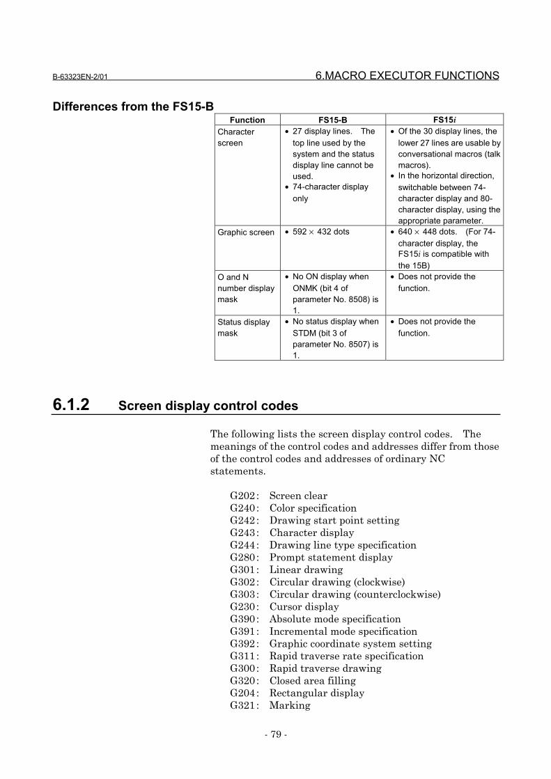
B-63323EN-2/01 6.MACRO EXECUTOR FUNCTIONS
- 79 -
Differences from the FS15-BFunction FS15-B FS15i
Characterscreen
• 27 display lines. Thetop line used by thesystem and the statusdisplay line cannot beused.
• 74-character displayonly
• Of the 30 display lines, thelower 27 lines are usable byconversational macros (talkmacros).
• In the horizontal direction,switchable between 74-character display and 80-character display, using theappropriate parameter.
Graphic screen • 592 × 432 dots • 640 × 448 dots. (For 74-character display, theFS15i is compatible withthe 15B)
O and Nnumber displaymask
• No ON display whenONMK (bit 4 ofparameter No. 8508) is1.
• Does not provide thefunction.
Status displaymask
• No status display whenSTDM (bit 3 ofparameter No. 8507) is1.
• Does not provide thefunction.
6.1.2 Screen display control codes
The following lists the screen display control codes. Themeanings of the control codes and addresses differ from thoseof the control codes and addresses of ordinary NCstatements.
G202 : Screen clearG240 : Color specificationG242 : Drawing start point settingG243 : Character displayG244 : Drawing line type specificationG280 : Prompt statement displayG301 : Linear drawingG302 : Circular drawing (clockwise)G303 : Circular drawing (counterclockwise)G230 : Cursor displayG390 : Absolute mode specificationG391 : Incremental mode specificationG392 : Graphic coordinate system settingG311 : Rapid traverse rate specificationG300 : Rapid traverse drawingG320 : Closed area fillingG204 : Rectangular displayG321 : Marking
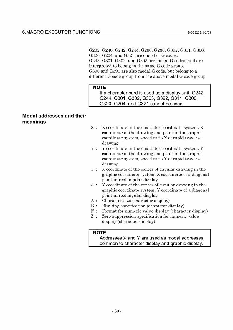
6.MACRO EXECUTOR FUNCTIONS B-63323EN-2/01
- 80 -
G202, G240, G242, G244, G280, G230, G392, G311, G300,G320, G204, and G321 are one-shot G codes.G243, G301, G302, and G303 are modal G codes, and areinterpreted to belong to the same G code group.G390 and G391 are also modal G code, but belong to adifferent G code group from the above modal G code group.
NOTEIf a character card is used as a display unit, G242,G244, G301, G302, G303, G392, G311, G300,G320, G204, and G321 cannot be used.
Modal addresses and theirmeanings
X : X coordinate in the character coordinate system, Xcoordinate of the drawing end point in the graphiccoordinate system, speed ratio X of rapid traversedrawing
Y : Y coordinate in the character coordinate system, Ycoordinate of the drawing end point in the graphiccoordinate system, speed ratio Y of rapid traversedrawing
I : X coordinate of the center of circular drawing in thegraphic coordinate system, X coordinate of a diagonalpoint in rectangular display
J : Y coordinate of the center of circular drawing in thegraphic coordinate system, Y coordinate of a diagonalpoint in rectangular display
A : Character size (character display)B : Blinking specification (character display)F : Format for numeric value display (character display)Z : Zero suppression specification for numeric value
display (character display)
NOTEAddresses X and Y are used as modal addressescommon to character display and graphic display.

B-63323EN-2/01 6.MACRO EXECUTOR FUNCTIONS
- 81 -
One-shot addresses and theirmeanings
D : Numeric value to be displayedK : Number of spaces to be displayedC : Character codeP : Sequence number, screen specification, attribute
specification, drawing line type specificationM : Mark number (marking)
L : Cursor length (cursor display), blinking specification(character display)
Q : Number of the program containing a character string(character display)
NOTEDuring a macro call, none of the addresses isprocessed; they are treated as arguments.
6.1.2.1 Screen clear (G202)
This code clears either the graphic screen or character screen(or both) according to the specification of address P.
FormatG202 Pp ;
P = 1: Clears the graphic screen.= 2: Clears the character screen.= 3: Clears both the graphic and character screens.
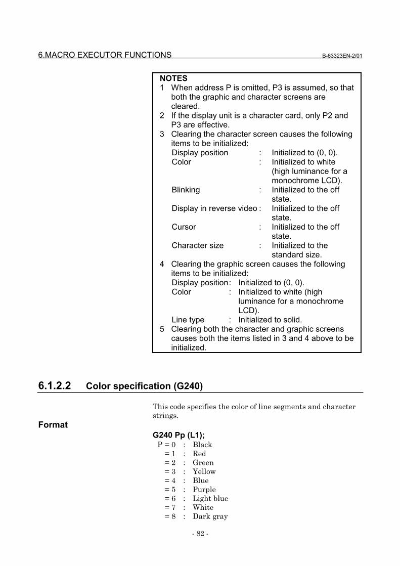
6.MACRO EXECUTOR FUNCTIONS B-63323EN-2/01
- 82 -
NOTES1 When address P is omitted, P3 is assumed, so that
both the graphic and character screens arecleared.
2 If the display unit is a character card, only P2 andP3 are effective.
3 Clearing the character screen causes the followingitems to be initialized:Display position : Initialized to (0, 0).Color : Initialized to white
(high luminance for amonochrome LCD).
Blinking : Initialized to the offstate.
Display in reverse video : Initialized to the offstate.
Cursor : Initialized to the offstate.
Character size : Initialized to thestandard size.
4 Clearing the graphic screen causes the followingitems to be initialized:Display position: Initialized to (0, 0).Color : Initialized to white (high
luminance for a monochromeLCD).
Line type : Initialized to solid.5 Clearing both the character and graphic screens
causes both the items listed in 3 and 4 above to beinitialized.
6.1.2.2 Color specification (G240)
This code specifies the color of line segments and characterstrings.
FormatG240 Pp (L1);
P = 0 : Black= 1 : Red= 2 : Green= 3 : Yellow= 4 : Blue= 5 : Purple= 6 : Light blue= 7 : White= 8 : Dark gray
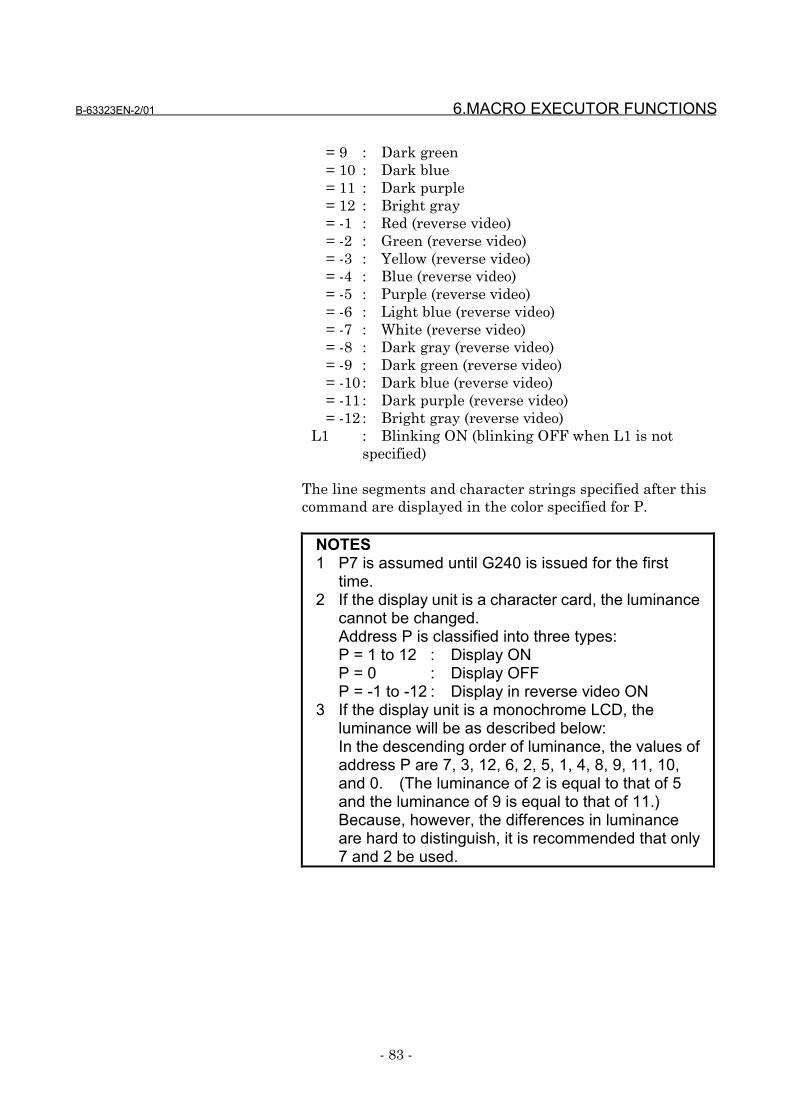
B-63323EN-2/01 6.MACRO EXECUTOR FUNCTIONS
- 83 -
= 9 : Dark green= 10 : Dark blue= 11 : Dark purple= 12 : Bright gray= -1 : Red (reverse video)= -2 : Green (reverse video)= -3 : Yellow (reverse video)= -4 : Blue (reverse video)= -5 : Purple (reverse video)= -6 : Light blue (reverse video)= -7 : White (reverse video)= -8 : Dark gray (reverse video)= -9 : Dark green (reverse video)= -10 : Dark blue (reverse video)= -11 : Dark purple (reverse video)= -12 : Bright gray (reverse video)
L1 : Blinking ON (blinking OFF when L1 is notspecified)
The line segments and character strings specified after thiscommand are displayed in the color specified for P.
NOTES1 P7 is assumed until G240 is issued for the first
time.2 If the display unit is a character card, the luminance
cannot be changed.Address P is classified into three types:P = 1 to 12 : Display ONP = 0 : Display OFFP = -1 to -12 : Display in reverse video ON
3 If the display unit is a monochrome LCD, theluminance will be as described below:In the descending order of luminance, the values ofaddress P are 7, 3, 12, 6, 2, 5, 1, 4, 8, 9, 11, 10,and 0. (The luminance of 2 is equal to that of 5and the luminance of 9 is equal to that of 11.)Because, however, the differences in luminanceare hard to distinguish, it is recommended that only7 and 2 be used.
6.MACRO EXECUTOR FUNCTIONS B-63323EN-2/01
- 84 -
6.1.2.3 Drawing start point setting (G242)
This code allows specification of the drawing start point inthe graphic coordinate system, using addresses X and Y.The next drawing starts at that point.
FormatG242 Xx Yy ;
X: X coordinate of the drawing start pointY: Y coordinate of the drawing start point
NOTEThe values specified for addresses X and Y areswitched between absolute and incremental valuesby using G390 and G391.
6.1.2.4 Character display (G243)
This code displays characters.
FormatG243 Xx Yy Aa Bb Cc Kk Ff.e Dd ZzPp Qq( __ ) ( ' __ ') (*__*) ;
•••• Addresses X and YAddresses X and Y are used to specify the display position ofthe character string in the character coordinate system.
X: X coordinate of the display position of the characterstring
Y: Y coordinate of the display position of the characterstring
NOTES1 When specifying both X and Y, specify them in
succession.2 The values specified for addresses X and Y are
switched between absolute and incremental valuesby using G390 and G391.
•••• Address AAddress A specifies the character size.
A = 1: Standard size= 2: Double size= 3: Triple size
B-63323EN-2/01 6.MACRO EXECUTOR FUNCTIONS
- 85 -
The double size is effective to alphanumeric characters only,and causes them to be displayed with the same size asChinese characters. It is not effective to the characters andsymbols given in the Chinese and hiragana code table.The triple size is three times wider and two times higherthan the standard size. The characters that can bedisplayed with the triple size are the alphabetic characters,digits, the minus sign, and the decimal point. No othercharacters can be displayed with the triple size.
•••• Address BAddress B specifies blinking control.
B = 0: Does not blink the character string.= 1: Blinks the character string.
NOTESpecifying B1 causes all the subsequent characterstrings to blink.
•••• Address KAddress K specifies the number of spaces. The specifiednumber of spaces are displayed.
K: Specification of the number of spacesWhen spaces are displayed, the affected coordinates areupdated.
•••• Address CAddress C is used to directly specify the character codes to bedisplayed. The codes that can be specified are 32 to 95 (20to 5F in hexadecimal) and 160 to 223 (A0 to DF inhexadecimal).Do not attempt to display codes other than those that can bespecified.
C: Direct specification of the character code to bedisplayed
EXAMPLEG243 C65 ;"A" is displayed.
NOTEUse ASCII codes.
6.MACRO EXECUTOR FUNCTIONS B-63323EN-2/01
- 86 -
•••• Address P•••• Address Q
Address P specifies the number of the sequence containing acharacter string.Address Q specifies the number of the program containing acharacter string.When address Q is not specified, the character string in thesingle block determined with the sequence number specifiedfor P in the program set in the character string registrationprogram control variable (#8509) is displayed.If the value of variable #8509 is 0, the character string in thesingle block determined with the sequence number specifiedin the same program is displayed.When address Q is specified, the character string in thesingle block determined with the sequence number specifiedfor P in the program set for address Q is displayed.
P: Specification of the number of the sequence containinga character string
Q: Specification of the number of the program containinga character string
EXAMPLEO9000 ; O8000 ;
#8509=8000 ; N10(IJK) ;G243(ABC)P20 ; N20(XYZ) ;
M99 ; M99 ;
O9100 ; O8100 ;
#8509=8000 ; N20 (OPQ)G243 (DEF) P30 Q8100 ; N30 (LMN) ;
M99 ; M99 ;
In the above example, when O9000 is executed, the characterstring in the single block with the sequence number 20 ofprogram No. 8000 is displayed. Thus, "ABCXYZ" isdisplayed.When O9100 is executed, the character string in the singleblock with the sequence number 30 of program No. 8100 isdisplayed. Thus, "DEFLMN" is displayed.
B-63323EN-2/01 6.MACRO EXECUTOR FUNCTIONS
- 87 -
•••• Address DAddress D specifies the numeric value to be displayed:
D: Specification of the numeric value to be displayedThe number of significant digits of the value that can bespecified directly for address D is 9.The number of display significant digits for address D is,however, 12, so that values in the range of -999999999999 to-0.000000001, 0, and 0.000000001 to 999999999999 can bedisplayed. The number of decimal places can be up to 9.
•••• Address FAddress F specifies the format in which a numeric value is tobe displayed. To the left side of the decimal point, specifythe number of digits of the numeric value to be displayed; tothe right side, specify the number of decimal places.
F: Specification of the format in which a numeric value isto be displayed
The valid range of address F is 1.0 to 40.9. The decimalplaces to be specified to the right side of the decimal pointmust be a single digit of 0 to 9. Note that the number ofdisplay digits varies with the specified value and the value ofaddress Z.
•••• Address ZAddress Z specifies whether to suppress leading zeros when anumeric value is displayed. When Z is equal to 0, the sign isnot displayed.Z = 0: Does not suppress leading zeros.
= 1: Suppresses leading zeros.
EXAMPLES1 G243 D-123.4567 F8.3 Z1;
"∆∆-123.457" is displayed. (10-character display)2 G243 D-123.4567 F8.3 Z0;
"00123.457" is display. (9-character display)3 G243 D-123.4567 F8.0 Z1;
"∆∆∆∆-123" is displayed. (9-character display)4 G243 D-123.4567 F8.0 Z0;
"00000123" is displayed. (8-character display)(∆ represents a space.)
6.MACRO EXECUTOR FUNCTIONS B-63323EN-2/01
- 88 -
NOTEThe number of digits of the integer part, which isequal to the number of display digits minus thenumber of decimal places, both specified foraddress F, must be equal to or greater than thenumber of digits of the integer part of the numericvalue specified for address D. Otherwise, thenumeric value is not displayed correctly.
•••• ( __ )( and ) are used to directly specify the character string to bedisplayed. The characters that can be enclosed in ( and ) arethe alphabetic characters (uppercase only), digits, the minussign, the decimal point, and spaces.
EXAMPLEG243(FANUC);"FANUC" is displayed.
•••• ( '__' )(' and ') are used to specify the character string (of single- anddouble-byte characters) to be displayed. The charactersthat can be enclosed in (' and ') are the characters given inthe Katakana Code Table and the Chinese and HiraganaCode Table in Section 10.3 in Chapter 10.Hiragana and Chinese characters each take a space twicewider than a single-byte character.
EXAMPLEG243('Fanuc NC 装置');;"Fanuc NC 装置" is displayed.
•••• (*__*)(* and *) are used to specify the internal codes correspondingto the character string to be displayed. The character codesmust be specified in hexadecimal.The codes must be delimited by a space. Hiragana andKanji characters each take a space twice wider than asingle-byte character.
EXAMPLEG243(*46 41 4E 55 43 20*);G243(*4E 43 4175 4356*)"Fanuc NC 装置" is displayed.
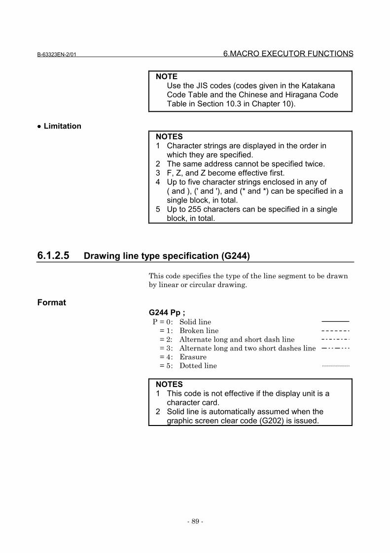
B-63323EN-2/01 6.MACRO EXECUTOR FUNCTIONS
- 89 -
NOTEUse the JIS codes (codes given in the KatakanaCode Table and the Chinese and Hiragana CodeTable in Section 10.3 in Chapter 10).
•••• LimitationNOTES1 Character strings are displayed in the order in
which they are specified.2 The same address cannot be specified twice.3 F, Z, and Z become effective first.4 Up to five character strings enclosed in any of
( and ), (' and '), and (* and *) can be specified in asingle block, in total.
5 Up to 255 characters can be specified in a singleblock, in total.
6.1.2.5 Drawing line type specification (G244)
This code specifies the type of the line segment to be drawnby linear or circular drawing.
FormatG244 Pp ;P = 0: Solid line
= 1: Broken line= 2: Alternate long and short dash line= 3: Alternate long and two short dashes line= 4: Erasure= 5: Dotted line
NOTES1 This code is not effective if the display unit is a
character card.2 Solid line is automatically assumed when the
graphic screen clear code (G202) is issued.
6.MACRO EXECUTOR FUNCTIONS B-63323EN-2/01
- 90 -
6.1.2.6 Prompt statement display (G280)
A prompt statement is a statement that prompts input. Incharacter string input mode (data input control variable#8502 is equal to 3), a prompt statement of up to 39characters can be displayed on the data input line.The character string can be specified in the same way as withG243.
FormatG280 Cc Kk Pp Qq ( __ ) ( '__' ) (*__*);
C : Character code. (See the explanation of G243.)K : Number of spaces. (See the explanation of
G243.)P : Number of the sequence containing a character
string. (See the explanation of G243.)Q : Number of the program containing a character
string. (See the explanation of G243.)( __ ) : Character string to be displayed. (See the
explanation of G243)( '__' ) : Character string to be displayed. (See the
explanation of G243)(*__*): Character string to be displayed. (See the
explanation of G243)
NOTES1 G280 is a one-shot G code, which means that the
code is effective only in the block in which it isspecified.
2 If a prompt statement is displayed with multipleaddresses, a single space is automatically insertedbetween the character string displayed with oneaddress and that displayed with another.
6.1.2.7 Linear drawing (G301)
This code draws a straight line up to the specified X and Ycoordinates, with the line type specified with G244 and thecolor specified with G240.
FormatG301 Xx Yy ;
X: X coordinate of the end point of linear drawingY: Y coordinate of the end point of linear drawing
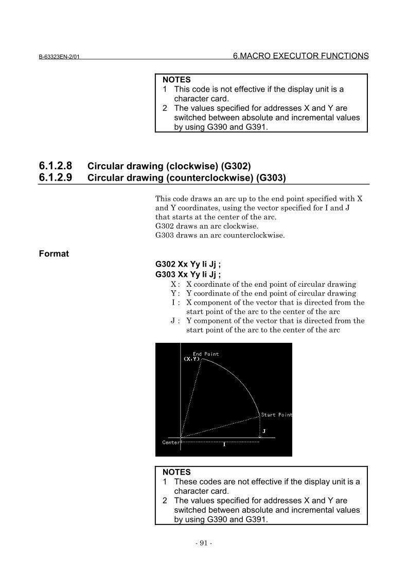
B-63323EN-2/01 6.MACRO EXECUTOR FUNCTIONS
- 91 -
NOTES1 This code is not effective if the display unit is a
character card.2 The values specified for addresses X and Y are
switched between absolute and incremental valuesby using G390 and G391.
6.1.2.8 Circular drawing (clockwise) (G302)6.1.2.9 Circular drawing (counterclockwise) (G303)
This code draws an arc up to the end point specified with Xand Y coordinates, using the vector specified for I and Jthat starts at the center of the arc.G302 draws an arc clockwise.G303 draws an arc counterclockwise.
FormatG302 Xx Yy Ii Jj ;G303 Xx Yy Ii Jj ;
X : X coordinate of the end point of circular drawingY : Y coordinate of the end point of circular drawing I : X component of the vector that is directed from the
start point of the arc to the center of the arcJ : Y component of the vector that is directed from the
start point of the arc to the center of the arc
NOTES1 These codes are not effective if the display unit is a
character card.2 The values specified for addresses X and Y are
switched between absolute and incremental valuesby using G390 and G391.
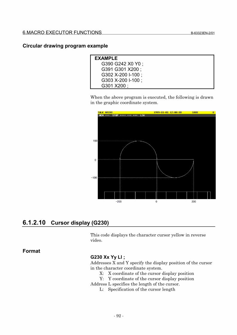
6.MACRO EXECUTOR FUNCTIONS B-63323EN-2/01
- 92 -
Circular drawing program example
EXAMPLEG390 G242 X0 Y0 ;G391 G301 X200 ;G302 X-200 I-100 ;G303 X-200 I-100 ;G301 X200 ;
When the above program is executed, the following is drawnin the graphic coordinate system.
6.1.2.10 Cursor display (G230)
This code displays the character cursor yellow in reversevideo.
FormatG230 Xx Yy Ll ;Addresses X and Y specify the display position of the cursorin the character coordinate system.
X: X coordinate of the cursor display positionY: Y coordinate of the cursor display position
Address L specifies the length of the cursor.L: Specification of the cursor length
B-63323EN-2/01 6.MACRO EXECUTOR FUNCTIONS
- 93 -
NOTES1 The cursor is erased when the cursor length is set
to 0.2 The cursor can also be erased by the character
screen clear code (G202).3 The values specified for addresses X and Y are
switched between absolute and incremental valuesby using G390 and G391.
6.1.2.11 Absolute mode (G390)/incremental mode (G391) specification
These codes respectively specify that the coordinatecommand in the character or graphic coordinate system is anabsolute mode command (G390) and incremental modecommand (G391).
NOTEThese codes are effective to G204, G230, G242,G243, G300, G301, G302, G303, G320, and G321.
6.1.2.12 Graphic coordinate system setting (G392)
This code sets the current position to a specified position inthe graphic coordinate system. The subsequent drawingcommands are executed in this coordinate system.
FormatG392 Xx Yy ;
X: X coordinateY: Y coordinate

6.MACRO EXECUTOR FUNCTIONS B-63323EN-2/01
- 94 -
EXAMPLEN01 G242 X100 Y100 ;N02 G392 X60 Y60 ;N03 G301 X100 ;
When the aboveprogram is executed,the position (100, 100)assumed in N01changes to (60, 60) inN02, and lineardrawing is performedfrom (60, 60) to (100,60) in N03.As a result, the originposition shifts by (40,40).
100 60 N01(100,100) N02(60,60) N03(100,60)
40 0 0 60
00 40 100
NOTES1 The specified X and Y coordinates are always
assumed absolute.2 This code is not effective if the display unit is a
character card.
6.1.2.13 Rapid traverse rate specification (G311)
This code specifies the X- and Y-axis speed ratios assumedduring rapid traverse drawing.
FormatG311 Xx Yy ;Specify the speed ratios assumed during rapid traversedrawing.
X: Rapid traverse drawing speed ratio in the X axisY: Rapid traverse drawing speed ratio in the Y axis
NOTES1 The rapid traverse drawing speed ratios must be
positive integer numbers in the range of 1 to32767.
2 The specified X and Y values are always assumedabsolute.
3 This code is not effective if the display unit is acharacter card.
B-63323EN-2/01 6.MACRO EXECUTOR FUNCTIONS
- 95 -
6.1.2.14 Rapid traverse drawing (G300)
This code performs drawing with rapid traverse from thecurrent position to a specified point. The path isdetermined with the rapid traverse rate specification.
FormatG300 Xx Yy ;
X: X coordinate for rapid traverse drawingY: Y coordinate for rapid traverse drawing
NOTES1 The values specified for addresses X and Y are
switched between absolute and incremental valuesby using G390 and G391.
2 Non-linear drawing is always performed regardlessof the CNC parameters.
3 This code is not effective if the display unit is acharacter card.
Rapid traverse drawing program example
EXAMPLEG311 X200 Y100 ;G242 X-150 Y-150 ;G300 X150 Y150 ;
When the above program is executed, drawing is performedin the graphic coordinate system as shown below.
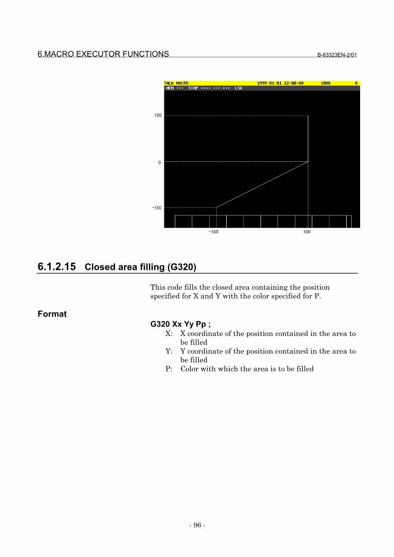
6.MACRO EXECUTOR FUNCTIONS B-63323EN-2/01
- 96 -
6.1.2.15 Closed area filling (G320)
This code fills the closed area containing the positionspecified for X and Y with the color specified for P.
FormatG320 Xx Yy Pp ;
X: X coordinate of the position contained in the area tobe filled
Y: Y coordinate of the position contained in the area tobe filled
P: Color with which the area is to be filled
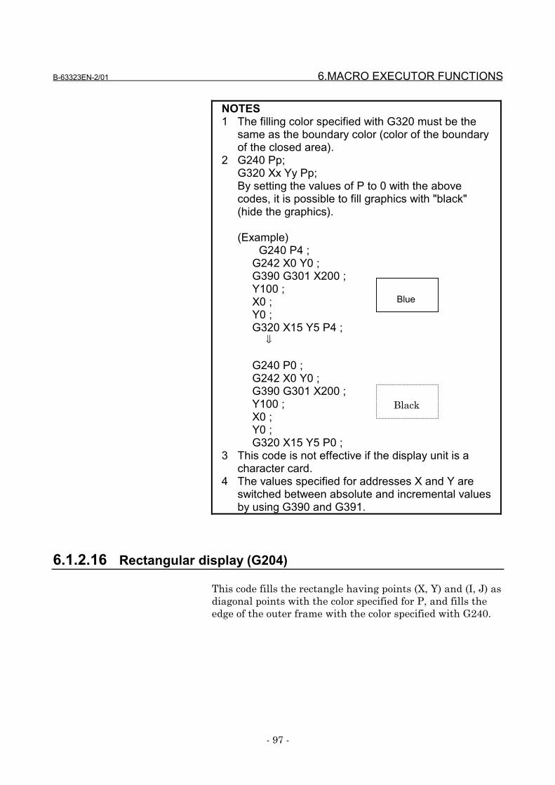
B-63323EN-2/01 6.MACRO EXECUTOR FUNCTIONS
- 97 -
NOTES1 The filling color specified with G320 must be the
same as the boundary color (color of the boundaryof the closed area).
2 G240 Pp;G320 Xx Yy Pp;By setting the values of P to 0 with the abovecodes, it is possible to fill graphics with "black"(hide the graphics).
(Example)G240 P4 ;
G242 X0 Y0 ;G390 G301 X200 ;Y100 ;X0 ;Y0 ;G320 X15 Y5 P4 ; ⇓
G240 P0 ;G242 X0 Y0 ;G390 G301 X200 ;Y100 ;X0 ;Y0 ;G320 X15 Y5 P0 ;
3 This code is not effective if the display unit is acharacter card.
4 The values specified for addresses X and Y areswitched between absolute and incremental valuesby using G390 and G391.
6.1.2.16 Rectangular display (G204)
This code fills the rectangle having points (X, Y) and (I, J) asdiagonal points with the color specified for P, and fills theedge of the outer frame with the color specified with G240.
Blue
Black
6.MACRO EXECUTOR FUNCTIONS B-63323EN-2/01
- 98 -
FormatG204 Xx Yy Ii Jj Pp ;
X: X coordinate of the rectangular display startposition
Y: Y coordinate of the rectangular display startposition
I: X coordinate of the rectangular display end positionJ: X coordinate of the rectangular display end positionP: Color with which the rectangle is to be filled
NOTES1 The values specified for addresses X, Y, I, and J
are switched between absolute and incrementalvalues by using G390 and G391.
2 When P is omitted, the rectangle is not filled, andthe edge of the outer frame is filled with the colorspecified with G240.
3 This code is not effective if the display unit is acharacter card.
6.1.2.17 Marking (G321)
This code draws the mark specified for M with the colorspecified for P at the position specified for X and Y (graphiccoordinates).
FormatG321 Xx Yy Mm Pp ;
X: X coordinate of the position at which a mark is to bedisplayed
Y: Y coordinate of the position at which a mark is to bedisplayed
M: Specification of the number of the mark to bedisplayed
P: Specification of the color of the mark to be displayed
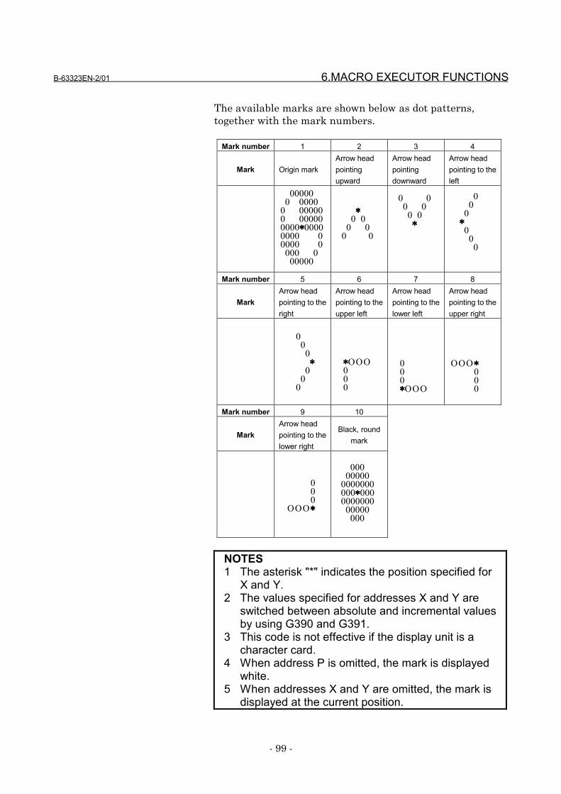
B-63323EN-2/01 6.MACRO EXECUTOR FUNCTIONS
- 99 -
The available marks are shown below as dot patterns,together with the mark numbers.
Mark number 1 2 3 4
Mark Origin markArrow headpointingupward
Arrow headpointingdownward
Arrow headpointing to theleft
Mark number 5 6 7 8
MarkArrow headpointing to theright
Arrow headpointing to theupper left
Arrow headpointing to thelower left
Arrow headpointing to theupper right
Mark number 9 10
MarkArrow headpointing to thelower right
Black, roundmark
NOTES1 The asterisk "*" indicates the position specified for
X and Y.2 The values specified for addresses X and Y are
switched between absolute and incremental valuesby using G390 and G391.
3 This code is not effective if the display unit is acharacter card.
4 When address P is omitted, the mark is displayedwhite.
5 When addresses X and Y are omitted, the mark isdisplayed at the current position.
00000 0 00000 000000 000000000****00000000 00000 0 000 0 00000
**** 0 0 0 0 0 0
0 0 0 0 0 0 ****
0 0 0 **** 0 0 0
OOO**** 0 0 0
0 0 0OOO****
000 00000 0000000 000****000 0000000 00000 000
000****OOO
****OOO000
0 0 0 **** 0 0 0
6.MACRO EXECUTOR FUNCTIONS B-63323EN-2/01
- 100 -
6.1.2.18 Shift function for graphic screen adjustment
This function allows shifting of the origin of the graphiccoordinate system on the TALK MACRO screen in units ofdots by using parameters Nos. 8570 and 8571.The X coordinate of the current origin of the graphiccoordinate system is changed to the coordinate specified forparameter No. 8570. The Y coordinate of the current originof the graphic coordinate system is changed to the coordinatespecified for parameter No. 8571.
NOTEThis function is not effective if the display unit is acharacter card.
6.1.2.19 Reading of the graphic state
By reading graphic state reading variable #8800, it can bedetermined whether the use of graphics is possible inconversational macros (talk macros).
#8800 = 0: The use of graphics is possible inconversational macros (talk macros).
#8800 = 1: The use of graphics is not possible inconversational macros (talk macros).
NOTEIf the display unit is a character card, the use ofgraphics is not possible and, therefore, graphicstate reading variable #8800 is always 1 when it isread.
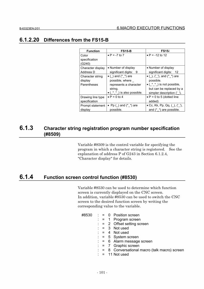
B-63323EN-2/01 6.MACRO EXECUTOR FUNCTIONS
- 101 -
6.1.2.20 Differences from the FS15-B
Function FS15-B FS15iColorspecification(G240)
• P = -7 to 7 • P = -12 to 12
Character displayAddress D
• Number of displaysignificant digits: 9
• Number of displaysignificant digits: 12
Character stringdisplayParentheses
• (_) and (*_*) arepossible, where _represents a characterstring.
• (_*_*_) is also possible.
• (_), ('_'), and (*_*) arepossible.
• (_*_*_) is not possible,but can be replaced by asimpler description ('_').
Drawing line typespecification
• P = 0 to 4 • P = 0 to 5 (dotted lineadded)
Prompt statementdisplay
• Pp (_) and (*_*) arepossible.
• Cc, Kk, Pp, Qq, (_), ('_'),and (*_*) are possible.
6.1.3 Character string registration program number specification(#8509)
Variable #8509 is the control variable for specifying theprogram in which a character string is registered. See theexplanation of address P of G243 in Section 6.1.2.4,"Character display" for details.
6.1.4 Function screen control function (#8530)
Variable #8530 can be used to determine which functionscreen is currently displayed on the CNC screen.In addition, variable #8530 can be used to switch the CNCscreen to the desired function screen by writing thecorresponding value to the variable.
#8530 : = 0 Position screen: = 1 Program screen: = 2 Offset setting screen: = 3 Not used: = 4 Not used: = 5 System screen: = 6 Alarm message screen: = 7 Graphic screen: = 8 Conversational macro (talk macro) screen: = 11 Not used
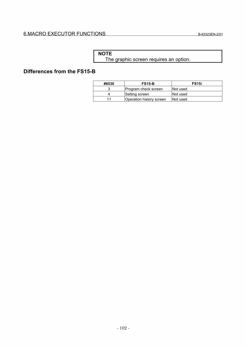
6.MACRO EXECUTOR FUNCTIONS B-63323EN-2/01
- 102 -
NOTEThe graphic screen requires an option.
Differences from the FS15-B
#8530 FS15-B FS15i3 Program check screen Not used4 Setting screen Not used
11 Operation history screen Not used
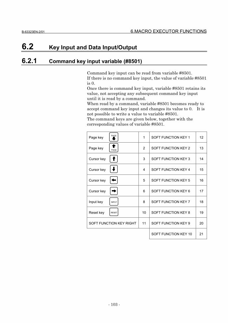
B-63323EN-2/01 6.MACRO EXECUTOR FUNCTIONS
- 103 -
6.2 Key Input and Data Input/Output
6.2.1 Command key input variable (#8501)
Command key input can be read from variable #8501.If there is no command key input, the value of variable #8501is 0.Once there is command key input, variable #8501 retains itsvalue, not accepting any subsequent command key inputuntil it is read by a command.When read by a command, variable #8501 becomes ready toaccept command key input and changes its value to 0. It isnot possible to write a value to variable #8501.The command keys are given below, together with thecorresponding values of variable #8501.
Page key 1 SOFT FUNCTION KEY 1 12
Page key 2 SOFT FUNCTION KEY 2 13
Cursor key 3 SOFT FUNCTION KEY 3 14
Cursor key 4 SOFT FUNCTION KEY 4 15
Cursor key 5 SOFT FUNCTION KEY 5 16
Cursor key 6 SOFT FUNCTION KEY 6 17
Input key 8 SOFT FUNCTION KEY 7 18
Reset key 10 SOFT FUNCTION KEY 8 19
SOFT FUNCTION KEY RIGHT 11 SOFT FUNCTION KEY 9 20
SOFT FUNCTION KEY 10 21
PAGE
PAGE
INPUT
RESET
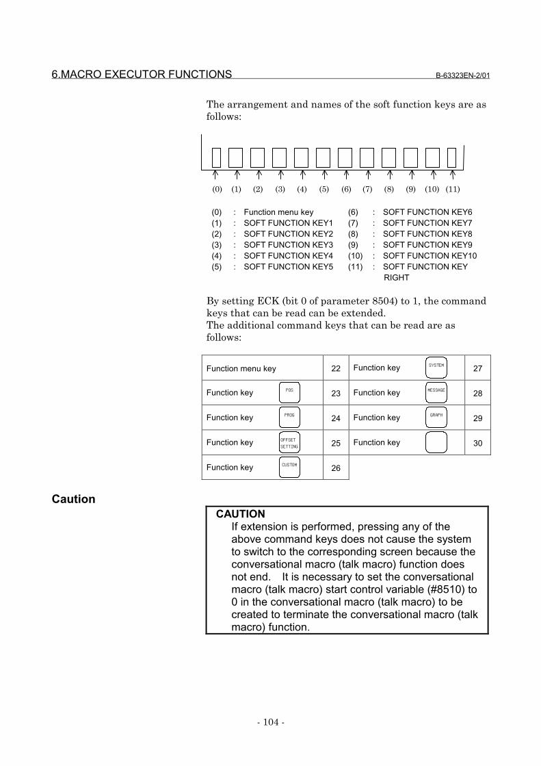
6.MACRO EXECUTOR FUNCTIONS B-63323EN-2/01
- 104 -
The arrangement and names of the soft function keys are asfollows:
(0) (1) (2) (3) (4) (5) (6) (7) (8) (9) (10) (11)
(0)(1)(2)(3)(4)(5)
: Function menu key: SOFT FUNCTION KEY1: SOFT FUNCTION KEY2: SOFT FUNCTION KEY3: SOFT FUNCTION KEY4: SOFT FUNCTION KEY5
(6)(7)(8)(9)(10)(11)
: SOFT FUNCTION KEY6: SOFT FUNCTION KEY7: SOFT FUNCTION KEY8: SOFT FUNCTION KEY9: SOFT FUNCTION KEY10: SOFT FUNCTION KEY
RIGHT
By setting ECK (bit 0 of parameter 8504) to 1, the commandkeys that can be read can be extended.The additional command keys that can be read are asfollows:
Function menu key 22 Function key SYSTEM 27
Function key POS 23 Function key MESSAGE 28
Function key PROG 24 Function key GRAPH 29
Function key OFFSETSETTING 25 Function key 30
Function key CUSTOM 26
CautionCAUTION
If extension is performed, pressing any of theabove command keys does not cause the systemto switch to the corresponding screen because theconversational macro (talk macro) function doesnot end. It is necessary to set the conversationalmacro (talk macro) start control variable (#8510) to0 in the conversational macro (talk macro) to becreated to terminate the conversational macro (talkmacro) function.
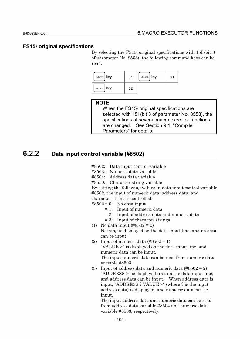
B-63323EN-2/01 6.MACRO EXECUTOR FUNCTIONS
- 105 -
FS15i original specificationsBy selecting the FS15i original specifications with 15I (bit 3of parameter No. 8558), the following command keys can beread.
INSERT key 31 DELETE key 33
ALTER key 32
NOTEWhen the FS15i original specifications areselected with 15I (bit 3 of parameter No. 8558), thespecifications of several macro executor functionsare changed. See Section 9.1, "CompileParameters" for details.
6.2.2 Data input control variable (#8502)
#8502: Data input control variable#8503: Numeric data variable#8504: Address data variable#8550: Character string variableBy setting the following values in data input control variable#8502, the input of numeric data, address data, andcharacter string is controlled.#8502 = 0: No data input
= 1: Input of numeric data= 2: Input of address data and numeric data= 3: Input of character strings
(1) No data input (#8502 = 0)Nothing is displayed on the data input line, and no datacan be input.
(2) Input of numeric data (#8502 = 1)"VALUE >" is displayed on the data input line, andnumeric data can be input.The input numeric data can be read from numeric datavariable #8503.
(3) Input of address data and numeric data (#8502 = 2)"ADDRESS >" is displayed first on the data input line,and address data can be input. When address data isinput, "ADDRESS ? VALUE >" (where ? is the inputaddress data) is displayed, and numeric data can beinput.The input address data and numeric data can be readfrom address data variable #8504 and numeric datavariable #8503, respectively.
6.MACRO EXECUTOR FUNCTIONS B-63323EN-2/01
- 106 -
The addresses that can be input and their correspondingvalues of variable #8504 are given below.A : 1 B : 2 C : 3 D : 4 E : 5 F : 6G : 7 H : 8 I : 9 J : 10 K : 11 L : 12M : 13 N : 14 O : 15 P : 16 Q : 17 R : 18S : 19 T : 20 U : 21 V : 22 W : 23 X : 24Y : 25 Z : 26
(4) Input of character strings (#8502 = 3)Nothing is displayed on the data input line, butcharacter data can be input. The input characters canbe read from character string variable #8550 in the orderin which they are input. The data that can be read isASCII codes. After the last character is read, <null> isread. The maximum allowable number of characters ina character string is 73.A prompt statement can be displayed on the data inputline, using the G280 command.
When a command key that causes command key inputvariable #8501 to be set to a non-zero value is input, the datainput line returns to its initial state. Then, the inputnumeric data, address data, and character data can be readfrom the numeric data variable, address data variable, andcharacter string variable, respectively. When neithernumeric data or address data is input, the values of variables#8503 and #8504 are <null>. The numeric data variableand the address data variable retain their values until inputis made again.
6.2.3 Extended data input control variable #8552
By setting 3 in variable #8502 and setting a variable numberin variable #8552, the system enters full key data input mode,allowing input of address data and numeric data.When a command key that causes command key inputvariable #8501 to be set to a non-zero value is input, the datainput line returns to its initial state. The input numericdata and address data can be read from 32 variables startingwith the one having the variable number set in variable#8552, as ASCII code data.If nothing has been input, 32 <null> codes are read.
B-63323EN-2/01 6.MACRO EXECUTOR FUNCTIONS
- 107 -
EXAMPLEAssume that the variables are set as follows:#8502=3;#8552=500;and that the following is input:0123456ABCDWhen the <INPUT> key is pressed,the following data is read from the variables:#500=48#501=49#502=50#503=51#504=52#505=53#506=54#507=65#508=66#509=67#510=68#511=<Null> • • •
#531=<Null>#8501=8
NOTES1 The macro variables starting with the one having
the number set in variable #8552 retain theirprevious values until the <INPUT> key is pressed.It is after the <INPUT> key is pressed that the newvalues are set in these variables.
2 The values of variables #8503 and #8504 are notguaranteed.
3 If a non-zero macro variable number is set invariable #8552, this function is executedunconditionally when the <INPUT> key is pressed.In this case, the input data cannot be read fromcharacter string variable #8550.

6.MACRO EXECUTOR FUNCTIONS B-63323EN-2/01
- 108 -
6.2.4 Consecutive input of cursor and page keys
Command key input variable #8501 allows consecutive inputof cursor and page keys.When a cursor or page key is pressed and held down, thedata for the cursor or page key is set in variable #8501 withthe following timing, and can be read consecutively. Notethat the cursor or page key is not buffered in variable 8501but that the data is read with the following timing.
6.2.5 MDI key image reading function (variables #8540 to #8549)
From control variables #8540 to #8549, the MDI key imagesshowing the current MDI key pressing states can be read.Using these variables, the states of the MDI keys currentlypressed can be monitored.
The pressing of the SHIFT key + a key can be distinguished
from the pressing of the key once. See the key code list fordetails.Each of the variables showing the MDI key images can beread in 8-bit binary format.
EXAMPLEWhen the SHIFT and H keys are pressed at thesame time on the standard MDI keyboard ("&" isinput), 32 (= 25) is set in variable #8542 and 64 (=26) is set in variable #8544.
It is assumed below that data is read from variable #8501 as soon as it isset.
Page key ON
OFF#8501 = Data
#8501 = 0
256 32 32 (MSEC)
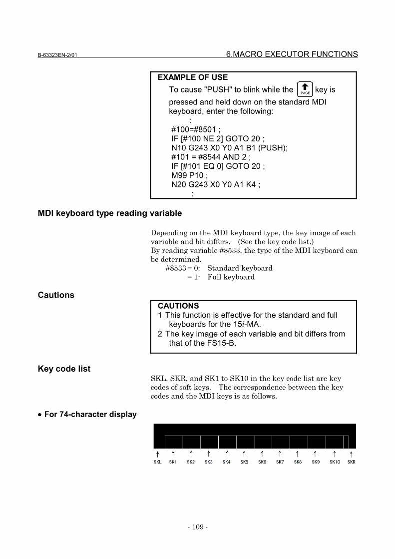
B-63323EN-2/01 6.MACRO EXECUTOR FUNCTIONS
- 109 -
EXAMPLE OF USETo cause "PUSH" to blink while the PAGE key ispressed and held down on the standard MDIkeyboard, enter the following:
:#100=#8501 ;IF [#100 NE 2] GOTO 20 ;N10 G243 X0 Y0 A1 B1 (PUSH);#101 = #8544 AND 2 ;IF [#101 EQ 0] GOTO 20 ;M99 P10 ;N20 G243 X0 Y0 A1 K4 ; :
MDI keyboard type reading variable
Depending on the MDI keyboard type, the key image of eachvariable and bit differs. (See the key code list.)By reading variable #8533, the type of the MDI keyboard canbe determined.
#8533 = 0: Standard keyboard= 1: Full keyboard
CautionsCAUTIONS1 This function is effective for the standard and full
keyboards for the 15i-MA.2 The key image of each variable and bit differs from
that of the FS15-B.
Key code listSKL, SKR, and SK1 to SK10 in the key code list are keycodes of soft keys. The correspondence between the keycodes and the MDI keys is as follows.
•••• For 74-character display
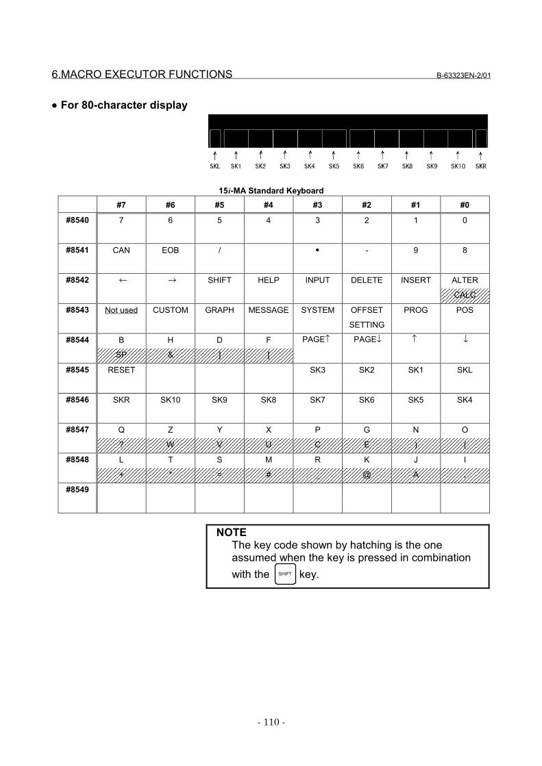
6.MACRO EXECUTOR FUNCTIONS B-63323EN-2/01
- 110 -
•••• For 80-character display
15i-MA Standard Keyboard#7 #6 #5 #4 #3 #2 #1 #0
#8540 7 6 5 4 3 2 1 0
#8541 CAN EOB / • - 9 8
#8542 ← → SHIFT HELP INPUT DELETE INSERT ALTER
CALC
#8543 Not used CUSTOM GRAPH MESSAGE SYSTEM OFFSET PROG POS
SETTING
#8544 B H D F PAGE↑ PAGE↓ ↑ ↓
SP & ] [
#8545 RESET SK3 SK2 SK1 SKL
#8546 SKR SK10 SK9 SK8 SK7 SK6 SK5 SK4
#8547 Q Z Y X P G N O
? W V U C E ) (
#8548 L T S M R K J I
+ * = # _ @ A ,
#8549
NOTEThe key code shown by hatching is the oneassumed when the key is pressed in combinationwith the SHIFT key.
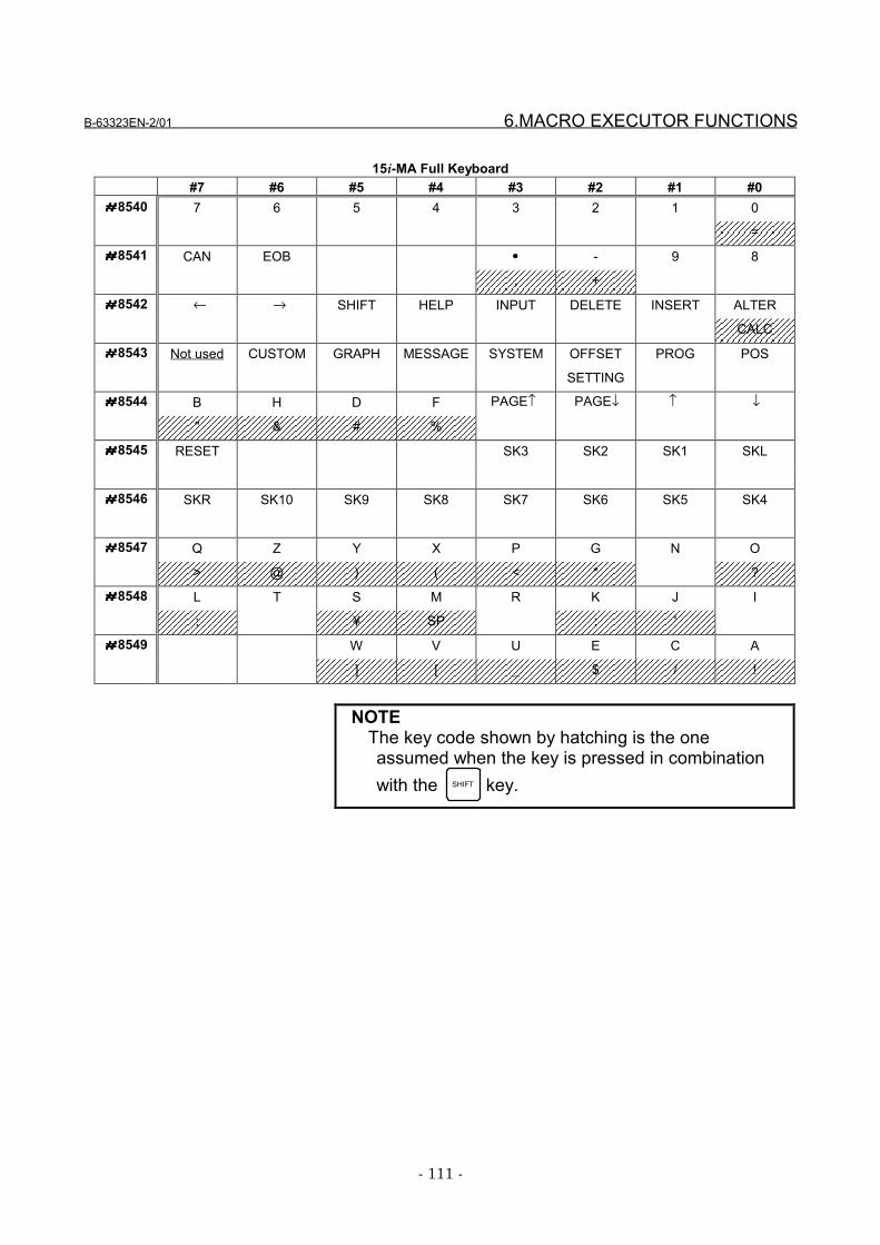
B-63323EN-2/01 6.MACRO EXECUTOR FUNCTIONS
- 111 -
15i-MA Full Keyboard#7 #6 #5 #4 #3 #2 #1 #0
####8540 7 6 5 4 3 2 1 0
=
####8541 CAN EOB • - 9 8
, +
####8542 ← → SHIFT HELP INPUT DELETE INSERT ALTER
CALC
####8543 Not used CUSTOM GRAPH MESSAGE SYSTEM OFFSET PROG POS
SETTING
####8544 B H D F PAGE↑ PAGE↓ ↑ ↓
" & # %
####8545 RESET SK3 SK2 SK1 SKL
####8546 SKR SK10 SK9 SK8 SK7 SK6 SK5 SK4
####8547 Q Z Y X P G N O
> @ ) ( < * ?
####8548 L T S M R K J I
; ¥ SP : '
####8549 W V U E C A
] [ _ $ / !
NOTEThe key code shown by hatching is the oneassumed when the key is pressed in combinationwith the SHIFT key.
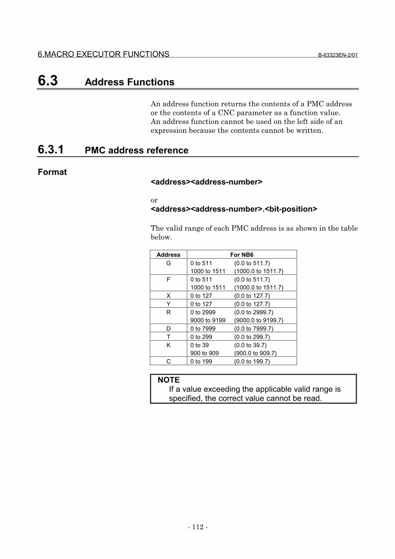
6.MACRO EXECUTOR FUNCTIONS B-63323EN-2/01
- 112 -
6.3 Address Functions
An address function returns the contents of a PMC addressor the contents of a CNC parameter as a function value.An address function cannot be used on the left side of anexpression because the contents cannot be written.
6.3.1 PMC address reference
Format<address><address-number>
or<address><address-number>.<bit-position>
The valid range of each PMC address is as shown in the tablebelow.
Address For NB6G 0 to 511
1000 to 1511(0.0 to 511.7)(1000.0 to 1511.7)
F 0 to 5111000 to 1511
(0.0 to 511.7)(1000.0 to 1511.7)
X 0 to 127 (0.0 to 127.7)Y 0 to 127 (0.0 to 127.7)R 0 to 2999
9000 to 9199(0.0 to 2999.7)(9000.0 to 9199.7)
D 0 to 7999 (0.0 to 7999.7)T 0 to 299 (0.0 to 299.7)K 0 to 39
900 to 909(0.0 to 39.7)(900.0 to 909.7)
C 0 to 199 (0.0 to 199.7)
NOTEIf a value exceeding the applicable valid range isspecified, the correct value cannot be read.
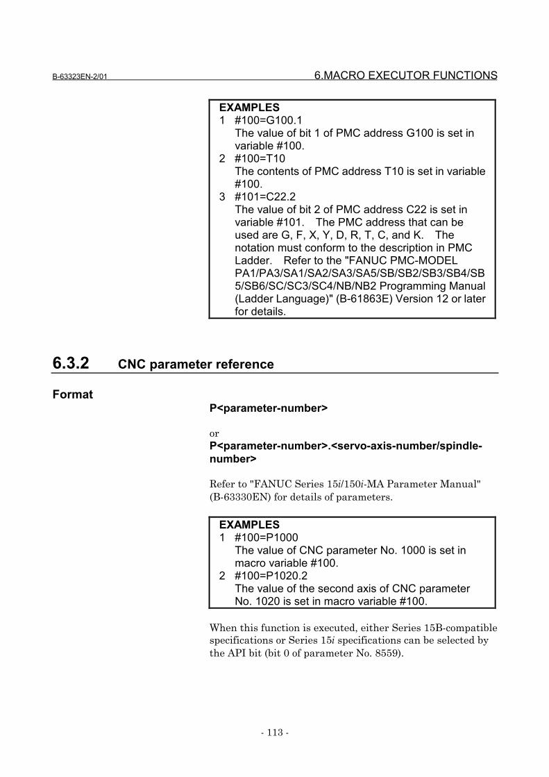
B-63323EN-2/01 6.MACRO EXECUTOR FUNCTIONS
- 113 -
EXAMPLES1 #100=G100.1
The value of bit 1 of PMC address G100 is set invariable #100.
2 #100=T10The contents of PMC address T10 is set in variable#100.
3 #101=C22.2The value of bit 2 of PMC address C22 is set invariable #101. The PMC address that can beused are G, F, X, Y, D, R, T, C, and K. Thenotation must conform to the description in PMCLadder. Refer to the "FANUC PMC-MODELPA1/PA3/SA1/SA2/SA3/SA5/SB/SB2/SB3/SB4/SB5/SB6/SC/SC3/SC4/NB/NB2 Programming Manual(Ladder Language)" (B-61863E) Version 12 or laterfor details.
6.3.2 CNC parameter reference
FormatP<parameter-number>
orP<parameter-number>.<servo-axis-number/spindle-number>
Refer to "FANUC Series 15i/150i-MA Parameter Manual"(B-63330EN) for details of parameters.
EXAMPLES1 #100=P1000
The value of CNC parameter No. 1000 is set inmacro variable #100.
2 #100=P1020.2The value of the second axis of CNC parameterNo. 1020 is set in macro variable #100.
When this function is executed, either Series 15B-compatiblespecifications or Series 15i specifications can be selected bythe API bit (bit 0 of parameter No. 8559).
6.MACRO EXECUTOR FUNCTIONS B-63323EN-2/01
- 114 -
NOTEWhen the Series 15B-compatible specifications areselected, a parameter value of the Series 15B canbe reference by entering the parameter number.Note that only parameters of which inputspecifications are completely compatible with thoseof the Series 15i can be referenced. If an attemptis made to reference another type of parameter,empty(#0) is read as the value. If an executionmacro references that type of parameter, alarmPS302 is issued.
When the Series 15i specifications are selected, allparameters can be referenced. The parameterscan be referenced in the same units as the valuesdisplayed on the parameter screen. However, ifparameters No. 2210 and No. 2211, which areused for Program Encryption, are referenced, zerois read.
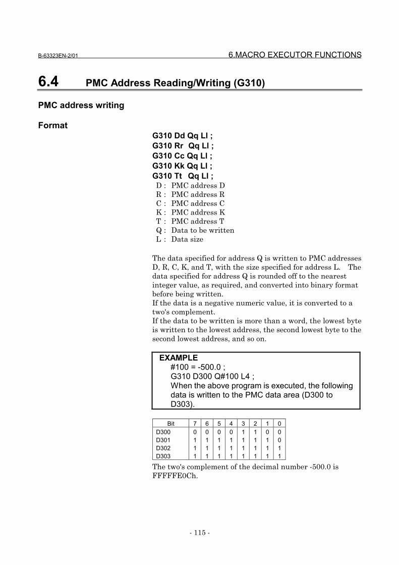
B-63323EN-2/01 6.MACRO EXECUTOR FUNCTIONS
- 115 -
6.4 PMC Address Reading/Writing (G310)
PMC address writing
FormatG310 Dd Qq Ll ;G310 Rr Qq Ll ;G310 Cc Qq Ll ;G310 Kk Qq Ll ;G310 Tt Qq Ll ;D : PMC address DR : PMC address RC : PMC address CK : PMC address KT : PMC address TQ : Data to be writtenL : Data size
The data specified for address Q is written to PMC addressesD, R, C, K, and T, with the size specified for address L. Thedata specified for address Q is rounded off to the nearestinteger value, as required, and converted into binary formatbefore being written.If the data is a negative numeric value, it is converted to atwo's complement.If the data to be written is more than a word, the lowest byteis written to the lowest address, the second lowest byte to thesecond lowest address, and so on.
EXAMPLE#100 = -500.0 ;G310 D300 Q#100 L4 ;When the above program is executed, the followingdata is written to the PMC data area (D300 toD303).
Bit 7 6 5 4 3 2 1 0D300D301D302D303
0111
0111
0111
0111
1111
1111
0111
0011
The two's complement of the decimal number -500.0 isFFFFFE0Ch.
6.MACRO EXECUTOR FUNCTIONS B-63323EN-2/01
- 116 -
NOTES1 Data cannot be specified in bit units.2 If the specified data exceeds the byte length
specified for address L, only the specified bytelength of data is written and no error handling isperformed.In the example shown on the previous page, if "L1"is specified, the lowest byte (0CH) of -500.0 iswritten in D300 only.
PMC address reading
•••• FormatG310 Dd Pp Ll ;G310 Rr Pp Ll ;G310 Cc Pp Ll ;G310 Kk Pp Ll ;G310 Tt Pp Ll ;
D : PMC address DR : PMC address RC : PMC address CK : PMC address KT : PMC address TP : Number of the variable in which data is to be setL : Data size
By specifying a variable number for address P with thecontrol code (G310) command, data can be read from PMCaddresses D, R, C, K, and T. By using address L, 2/4-bytedata can be read as a batch.The data that has been read is regarded to be binary formatdata with the specified byte length, converted, and stored inthe variable specified for address P. If the data to be read ismore than a word, the data from the lowest address iswritten to the lowest byte, the data from the second lowestaddress to the second lowest byte, and so on.
EXAMPLEAssume that the PMC data area (D400 and D401)contains the following data: D400 = 0Ch D401 = Fehand that the following is issued: G310 D400 P101 L2;then, "-500.0" is input to variable #101.
B-63323EN-2/01 6.MACRO EXECUTOR FUNCTIONS
- 117 -
Differences from the FS15-B
Function FS15-B FS15iWriting andreading data toand from thePMC
• There are PMC-NA andPMC-NB, and for data oftwo or more bytes, theorder of the highest tothe lowest byte may bechanged to the order ofthe lowest to the highestbyte.
• For data of two or morebytes, the order is alwaysfrom the lowest to thehighest byte.
NOTES1 If the byte length of the data to be read is 1 byte,
the data can also be read with the PMC addressfunction. The function, however, converts thedata into signed data (two's complementrepresentation), so that different data may bestored.
2 Whether writing or reading control is to beperformed is determined by which of addresses Qand P is specified. If both addresses Q and P arespecified, writing control is executed.
3 The addresses other than D, R, C, K, and T (suchas X, Y, G, and F) cannot be used for specification.
4 Only one of 1, 2, and 4 bytes can be specified foraddress L.When a value other than 2 and 4 is specified orwhen address L is omitted, reading/writing of 1-byte data is performed.
5 The valid range of each PMC address is as shownin the table below.If a command exceeding any of the ranges isexecuted, writing may not be performed correctly.
Address Valid PMC address rangeR 0 to 2999, 9000 to 9199D 0 to 7999K 0 to 39, 900 to 909C 0 to 199T 0 to 299

6.MACRO EXECUTOR FUNCTIONS B-63323EN-2/01
- 118 -
6.5 Reader/Puncher Interface
6.5.1 General
Using conversational macro (talk macro) functions/auxiliarymacro functions, communication lines can be controlled.Line control is performed using the following seven controlcodes.Line control functions are effective when PCR (bit 7 ofparameter No. 8508) is 1.
G330: Line openG331: Line closeG335: 1-byte receptionG336: Data transmissionG337: Macro variable inputG338: Macro variable outputG339: File information reading/file deletion
One of the following four line control methods can be selectedwhen a line is opened.
(1) Hard flow controlThe line is opened in bidirectional mode and the macroexecutor does not perform output control with controlcodes DC1 to DC4. Use this method when creating auser-unique protocol. When an overflow is detected inthe receive buffer, the remote device is requested tostop/resume transmission by turning the control signalRS on/off.
(2) Reception control (automatic control with DC1/DC3)When the line is opened, the DC1 code is automaticallysent to request the remote device to send data. Whenthe line is closed, the DC3 code is sent. When anoverflow is detected in the receive buffer, control isautomatically performed with DC1 and DC3. When theline is opened in reception control mode, G336 for datatransmission and G338 for macro variable output cannotbe executed.
(3) Transmission control (automatic control with DC2/DC4)When the line is opened, the DC2 code is automaticallysent to request the remote device to receive data. Whenthe line is closed, the DC4 code is sent. Theinterruption and resumption of transmission due to DC3and DC1 from the remote device are automaticallyperformed.When the line is opened in transmission control mode,

B-63323EN-2/01 6.MACRO EXECUTOR FUNCTIONS
- 119 -
G335 for 1-byte reception and G337 for macro variableinput cannot be executed.
(4) File controlWhen the FANUC Handy File, FANUC Floppy Cassette,FANUC FA Card, or FANUC Program File Mate is used,and the line is opened in file control mode, it is possibleto acquire file names and sizes, delete files, and changefile names.
Completion codes are available for checking whetherinput/output processing has been executed correctly. Checkthe completion code after executing a control code.All completion codes are for read only.
#8537: Completion code for the result of executing anauxiliary macro
#8538: Completion code for the result of executing aconversational macro (talk macro)
#8539: Completion code common to auxiliary macrosand conversational macros (talk macros)
See Section 6.5.6, "Completion codes" for details ofcompletion codes.
6.5.2 Functions
Line open G330•••• Format
G330 Pp Bb Ss Cc ;
P: Interface number and control method of the input/outputdevice for the foreground
P = 1: Hard flow control with RS-232-C12: Hard flow control with RS-232-C23: Hard flow control with RS-232-C3
101: Reception control with RS-232-C1102: Reception control with RS-232-C2103: Reception control with RS-232-C3110: Reception control with remote buffer113: Reception control with RS422
6.MACRO EXECUTOR FUNCTIONS B-63323EN-2/01
- 120 -
201: Transmission control with RS-232-C1202: Transmission control with RS-232-C2203: Transmission control with RS-232-C3210: Transmission control with remote buffer213: Transmission control with RS422
301: File control with RS-232-C1302: File control with RS-232-C2303: File control with RS-232-C3310: File control with remote buffer313: File control with RS422
B: Baud rate of the input/output device
b = 1: 50b/s 2: 100b/s 3: 110b/s4: 150b/s 5: 200b/s 6: 300b/s7: 600b/s 8: 1200b/s 9: 2400b/s
10: 4800b/s 11: 9600b/s 12: 19200b/s
S: Number of stop bits
s = 1: 1 stop bit, data parity not used2: 2 stop bits, data parity not used
11: 1 stop bit, data parity used12: 2 stop bits, data parity used
NOTEWhen the FANUC Handy File, FANUC FloppyCassette, FANUC FA Card, or FANUC Program FileMate is used, specify S11/S12.
C: Output code specification
c = 0: ISO code1: EIA code
•••• ExplanationThis code opens a specified line according to the controlconditions to make it usable.
Line close G331•••• Format
G331 ;
•••• ExplanationThis code closes an open line.When a line is closed, the completion code is always 0(normal termination).
B-63323EN-2/01 6.MACRO EXECUTOR FUNCTIONS
- 121 -
1-byte reception G335•••• Format
G335 Pp ;
P: Number of the macro variable in which the received datais to be stored
•••• ExplanationThis code reads one byte of received data and stores it in aspecified macro variable.
When a line is opened in transmission control mode, 1-bytereception cannot be executed. If an attempt is made toexecute it, a completion code of 20 is set.
Data transmission G336•••• Format
G336 Cc (c・・・・・・・・) (*H・・・・・・・・) Kk Ff.e Dd Pp Zz ;
•••• ExplanationThis code sends data in a specified format.The addresses to be specified are the same as those of screendisplay control G243. See Section 6.1.2.4, "Characterdisplay" for details.When a line is opened in reception control mode, datatransmission cannot be executed. If an attempt is made toexecute it, a completion code of 20 is set.
6.5.3 Macro variable input/output functions
Macro variable data input G337•••• Format
G337 Pp Qq R99 ;
P: Read variable number (effective when variable number"N" is not specified)
Q: Number of read variables (optional)R: Continuous reading specification (optional)
•••• ExplanationThis code sets the macro variable data received from a lineopened in reception control mode into the macro variablehaving a specified number.
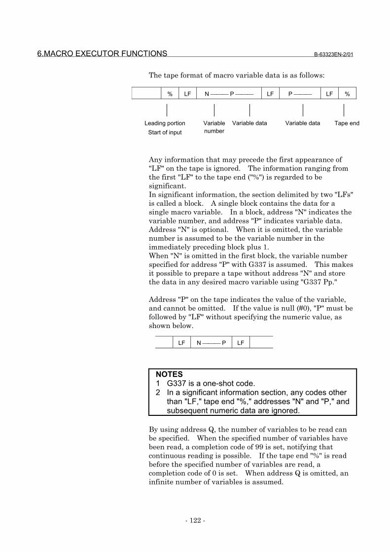
6.MACRO EXECUTOR FUNCTIONS B-63323EN-2/01
- 122 -
The tape format of macro variable data is as follows:
Any information that may precede the first appearance of"LF" on the tape is ignored. The information ranging fromthe first "LF" to the tape end ("%") is regarded to besignificant.In significant information, the section delimited by two "LFs"is called a block. A single block contains the data for asingle macro variable. In a block, address "N" indicates thevariable number, and address "P" indicates variable data.Address "N" is optional. When it is omitted, the variablenumber is assumed to be the variable number in theimmediately preceding block plus 1.When "N" is omitted in the first block, the variable numberspecified for address "P" with G337 is assumed. This makesit possible to prepare a tape without address "N" and storethe data in any desired macro variable using "G337 Pp."
Address "P" on the tape indicates the value of the variable,and cannot be omitted. If the value is null (#0), "P" must befollowed by "LF" without specifying the numeric value, asshown below.
NOTES1 G337 is a one-shot code.2 In a significant information section, any codes other
than "LF," tape end "%," addresses "N" and "P," andsubsequent numeric data are ignored.
By using address Q, the number of variables to be read canbe specified. When the specified number of variables havebeen read, a completion code of 99 is set, notifying thatcontinuous reading is possible. If the tape end "%" is readbefore the specified number of variables are read, acompletion code of 0 is set. When address Q is omitted, aninfinite number of variables is assumed.
% LF N P LF P LF %
Leading portionStart of input
Variablenumber
Variable data Variable data Tape end
LF N P LF
B-63323EN-2/01 6.MACRO EXECUTOR FUNCTIONS
- 123 -
When the number of variables to be read is specified and acompletion code of 99 is set, the subsequent macro variabledata can be read by specifying R99.When continuous reading R99 is not specified, the data forthe next variable will be lost because of the significantinformation check (discarding of the data up to the first":(LF).")
EXAMPLEInput of macro variable dataTo read the following data in which macro variablenumber address "N" is omitted, enter the following:
G330 Pp Bp ..... ;
G337 P100 Q10 ; The data for the first 10 variables isIF [#8539 NE 99] GOTO 888 ; stored in variables #100 to #109.
G337 P15000 Q20 R99 ; The data for the next 20 variables isIF [#8539 NE 0] GOTO 888 ; stored in variables #15000 to #15019.
G337 P16000 R99 ; The data for the remaining variablesIF [#8539 NE 0] GOTO 888 ; is stored in variable #16000 and
above.G331 ;
Macro variable data output G338•••• Format
G338 Pp Qq Ff.e Zz Rr;
P: Specification of the number of the first output macrovariable
Q: Specification of the number of output macro variabledata items
F: Specification of the output format of macro variable dataf: Specifies the total number of digits.e: Specifies the number of decimal places.
Z: Specification of the zero suppression of macro variabledataz = 0: Does not perform zero suppression.
1: Performs zero suppression.R: Tape format of output data
r = 0: Standard format. (The standard format is alsoassumed when R is omitted.)
1: Does not output macro variable numbers.
% LF P____ LF .... P____ LF P____ LF .... P____ LF P____ LF .... P____ LF %
Data for 10variables
Data for 20variables
Data for theremaining variables
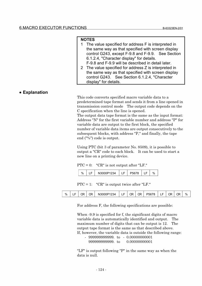
6.MACRO EXECUTOR FUNCTIONS B-63323EN-2/01
- 124 -
NOTES1 The value specified for address F is interpreted in
the same way as that specified with screen displaycontrol G243, except F-9.8 and F-9.9. See Section6.1.2.4, "Character display" for details.F-9.8 and F-9.9 will be described in detail later.
2 The value specified for address Z is interpreted inthe same way as that specified with screen displaycontrol G243. See Section 6.1.2.4, "Characterdisplay" for details.
•••• ExplanationThis code converts specified macro variable data to apredetermined tape format and sends it from a line opened intransmission control mode The output code depends on theC specification when the line is opened.The output data tape format is the same as the input format:Address "N" for the first variable number and address "P" forvariable data are output to the first block, the specifiednumber of variable data items are output consecutively to thesubsequent blocks, with address "P," and finally, the tapeend ("%") code is output.
Using PTC (bit 3 of parameter No. 8509), it is possible tooutput a "CR" code to each block. It can be used to start anew line on a printing device.
PTC = 0: "CR" is not output after "LF."
PTC = 1: "CR" is output twice after "LF."
For address F, the following specifications are possible:
When -9.9 is specified for f, the significant digits of macrovariable data is automatically identified and output. Themaximum number of digits that can be output is 12. Theoutput tape format is the same as that described above.If, however, the variable data is outside the following range:
- 999999999999. to - 0.00000000001999999999999. to 0.00000000001
"LF" is output following "P" in the same way as when thedata is null.
% LF N3000P1234 LF P5678 LF %
% LF CR CR N3000P1234 LF CR CR P5678 LF CR CR %
B-63323EN-2/01 6.MACRO EXECUTOR FUNCTIONS
- 125 -
When -9.8 is specified for f, data is output in floating-pointformat. The output tape format is the same as thatdescribed above, except that address "Q" is output instead ofaddress "P" and the variable data is fixed to 10 characters.The macro variable data that has been output in this tapeformat can be read by using G337; the data is stored in theappropriate variables in floating-point format.During output, the feed portion is not controlled. Toperform feed using a paper tape punch, etc., use datatransmission G336.
NOTES1 f is set to 9.3 when the power is turned on. When a
value is specified for address f, that value is stored.When F is omitted, the previously specified valuetakes effect.
2 z is set to 0 when the power is turned on. When avalue is specified for address Z, that value is stored.When Z is omitted, the previously specified valuetakes effect.
Using address R, it is possible to suppress the output ofmacro variable numbers.When variable numbers are not output, the output variabledata can be stored in any desired variables using address Pwith macro variable input function G337.Because "%" is output by line open G330 and line close G331,multiple variable groups can be output in a single tapeformat.
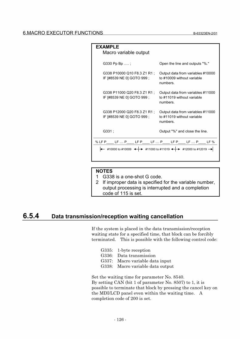
6.MACRO EXECUTOR FUNCTIONS B-63323EN-2/01
- 126 -
EXAMPLEMacro variable output
G330 Pp Bp ..... ; Open the line and outputs "%."
G338 P10000 Q10 F8.3 Z1 R1 ; Output data from variables #10000IF [#8539 NE 0] GOTO 999 ; to #10009 without variable
numbers.
G338 P11000 Q20 F8.3 Z1 R1 ; Output data from variables #11000IF [#8539 NE 0] GOTO 999 ; to #11019 without variable
numbers.
G338 P12000 Q20 F8.3 Z1 R1 ; Output data from variables #11000IF [#8539 NE 0] GOTO 999 ; to #11019 without variable
numbers.
G331 ; Output "%" and close the line.
NOTES1 G338 is a one-shot G code.2 If improper data is specified for the variable number,
output processing is interrupted and a completioncode of 115 is set.
6.5.4 Data transmission/reception waiting cancellation
If the system is placed in the data transmission/receptionwaiting state for a specified time, that block can be forciblyterminated. This is possible with the following control code:
G335: 1-byte receptionG336: Data transmissionG337: Macro variable data inputG338: Macro variable data output
Set the waiting time for parameter No. 8540.By setting CAN (bit 1 of parameter No. 8507) to 1, it ispossible to terminate that block by pressing the cancel key onthe MDI/LCD panel even within the waiting time. Acompletion code of 200 is set.
% LF P____ LF .... P____ LF P____ LF .... P____ LF P____ LF .... P____ LF %
#10000 to #10009 #11000 to #11019 #12000 to #12019

B-63323EN-2/01 6.MACRO EXECUTOR FUNCTIONS
- 127 -
EXAMPLEProgram in which cancellation is taken intoconsideration
09000;N1 G330 P101 B10 S12 C0; Line openN2 IF [#8539 NE 0] GOTO 10;N3 G335 P500; 1-byte receptionN4 IF [#8539 NE 0] GOTO 11;N5 G331; Line close
‥N11 G331;N12 G243 X0 Y1 (DATA INPUT ERROR);
‥
If, in block N3, the reception waiting state continues evenafter the time set for parameter No. 8540, block N3 isterminated and control jumps from block N4 to the errorhandling block N11. At this time, completion code variable#8539 is set to 200.By using the appropriate parameter, block N3 can beterminated by pressing the cancel key on the MDI/LCD paneleven when the reception waiting state continues in block N3.
NOTECancellation by using parameters No. 8540 andsetting CAN (bit 1 of parameter No. 8507) to 1 isalso effective to the transmission/receptioncommands executed by auxiliary macros. Iftransmission/reception is to be performed by anauxiliary macro, therefore, the possibility that thecancel key may be pressed regardless of the stateof the auxiliary macro must be taken intoconsideration during programming.
6.5.5 FANUC cassette control
Using line open G330 and file information control G339, it ispossible to read file data from FANUC Handy File, FANUCFloppy Cassette, FANUC FA Card, and FANUC PROGRAMFile Mate, create and delete files, and perform otheroperations.
Searching for the beginning of a file G330File creation G330File information reading G330/G339 P1File deletion G330/G339 P2File renaming G330/G339 P3
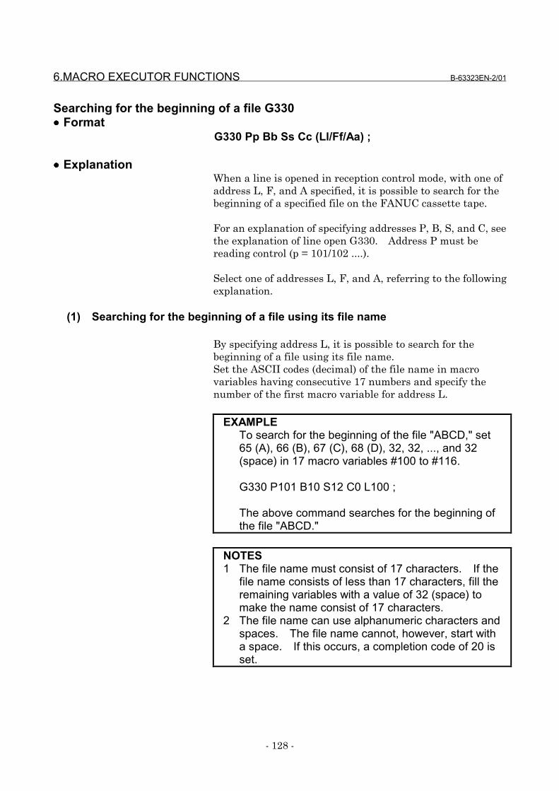
6.MACRO EXECUTOR FUNCTIONS B-63323EN-2/01
- 128 -
Searching for the beginning of a file G330•••• Format
G330 Pp Bb Ss Cc (Ll/Ff/Aa) ;
•••• ExplanationWhen a line is opened in reception control mode, with one ofaddress L, F, and A specified, it is possible to search for thebeginning of a specified file on the FANUC cassette tape.
For an explanation of specifying addresses P, B, S, and C, seethe explanation of line open G330. Address P must bereading control (p = 101/102 ....).
Select one of addresses L, F, and A, referring to the followingexplanation.
(1) Searching for the beginning of a file using its file name
By specifying address L, it is possible to search for thebeginning of a file using its file name.Set the ASCII codes (decimal) of the file name in macrovariables having consecutive 17 numbers and specify thenumber of the first macro variable for address L.
EXAMPLETo search for the beginning of the file "ABCD," set65 (A), 66 (B), 67 (C), 68 (D), 32, 32, ..., and 32(space) in 17 macro variables #100 to #116.
G330 P101 B10 S12 C0 L100 ;
The above command searches for the beginning ofthe file "ABCD."
NOTES1 The file name must consist of 17 characters. If the
file name consists of less than 17 characters, fill theremaining variables with a value of 32 (space) tomake the name consist of 17 characters.
2 The file name can use alphanumeric characters andspaces. The file name cannot, however, start witha space. If this occurs, a completion code of 20 isset.
B-63323EN-2/01 6.MACRO EXECUTOR FUNCTIONS
- 129 -
(2) Searching for the beginning of a file using its file number
By specifying address F, it is possible to search for thebeginning of a file using its file number.Specify the number of the file to search for (1 to 9999).
EXAMPLETo search for the beginning of a file with file number3, enter the following:
G330 P101 P10 S12 C0 F3 ;
(3) Searching for the beginning of the next file
By specifying address A, it is possible to search for thebeginning of the file following the one the beginning of whichhas been searched for. Use this address to read files insuccession. For address A, always specify 1 (a = 1).Otherwise, a completion code of 20 is set.
EXAMPLETo search for the beginning of the file following theone the beginning of which has been searched for,enter the following:
G330 P101 B10 S12 C0 A1 ;
File creation G330•••• Format
G330 Pp Bb Ss Cc (Ll/Ff) ;
•••• ExplanationWhen a line is opened in transmission control mode, witheither address L and F specified, it is possible to create a newfile on the FANUC cassette tape.
For an explanation of specifying addresses P, B, S, and C, seethe explanation of line open G330. Address P must bewriting control (p = 201/202 ....).
Select either address L or F, referring to the followingexplanation.
6.MACRO EXECUTOR FUNCTIONS B-63323EN-2/01
- 130 -
(1) Creating a file with a file name
By specifying address L, it is possible to create a file with afile name. Set the ASCII codes (decimal) of the file name inmacro variables having consecutive 17 numbers and specifythe number of the first macro variable for address L.
EXAMPLETo create a file "ABCD," set 65 (A), 66 (B), 67 (C),68 (D), 32, 32, ..., and 32 (space) in 17 macrovariables #100 to #116.
G330 P201 B10 S12 C0 L100 ;
The above command crates a file with the file name"ABCD."
NOTES1 The file name must consist of 17 characters. If the
file name consists of less than 17 characters, fill theremaining variables with a value of 32 (space) tomake the name consist of 17 characters.
2 The file name can use alphanumeric characters andspaces. The file name cannot, however, start witha space. If this occurs, a completion code of 20 isset.
3 The created file is added at the end of the alreadyregistered ones.
(2) Creating a file with a file number
By specifying address F, it is possible to create a new filewith a specified file number. Specify the number of the fileto be created (1 to 9999).
EXAMPLETo create a file with file number 3, enter thefollowing:
G330 P201 P10 S12 C0 F3 ;
B-63323EN-2/01 6.MACRO EXECUTOR FUNCTIONS
- 131 -
NOTES1 When a file is created with a file number, the existing
file with that file number is deleted, as well as anyfiles with the subsequent file numbers.For the FANUC Handy File in DOS format, however,the files with the file numbers subsequent to thespecified number are not deleted.
2 This method of creating a file with a file numberallows only an existing file number to be specified.To add a new file, create it with a file name.
File information control G330/G339•••• Format
G330 Pp Bb Ss ;p = 301: File control with RS-232-C1
302: File control with RS-232-C2303: File control with RS-232-C3310: File control with remote buffer313: File control with RS422
For an explanation of addresses B and S, see the explanationof line open G330. When a line is opened in file informationcontrol mode, file information reading and file deletioncannot be executed more than once while the line is open.For example, after file information is read and checked, theline must be closed before that file can be deleted.
G339 Pp (Ll Ss Ff) ;p = 1: Reads file information
2: Deletes a file3: Rename a file
Specify addresses L, S, and F as required.
•••• ExplanationG339 can be used to read file information, delete a file, andrename a file.
File information reading G339 P1File deletion G339 P2File renaming G339 P3
To enable of the use of this function, the control mode mustbe file information control mode when the line is opened(G330). To specify file information control mode, specify301/302 ... for address P when opening the line.

6.MACRO EXECUTOR FUNCTIONS B-63323EN-2/01
- 132 -
EXAMPLEOrder in which commands are issued1) Open the line in file information control mode.2) File information reading3) Line close4) Open the line in file information control mode.5) File deletion6) Line close
(1) File information reading G339 P1
G339 P1 stores file information (file name and size) inspecified macro variables.
G339 P1 Ff Ll Ss ;
F: File number specification (1 to 9999)L: Number of the first one of the consecutive 17 macro
variables used to store the 17-character file name to beread. The file name is stored as ASCII codes (decimal).
S: Number of the macro variable used to store the file sizeto be read
By reading file information by specifying a file number foraddress F and then issuing G339 P1 with a file numberomitted, the file information for the next file number can beread. If a file with the specified file number does not exist, acompletion code of 23 is set.
(2) File deletion G339 P2
G339 P2 deletes a specified file.
G339 P2 (Ll/Ff) ;
Specify the file with its file name or file number.
L: Number of the first one of the consecutive 17 macrovariables used to store the 17-character file name of thefile to be deleted. The file name must be set with ASCIIcodes (decimal).
F: File number specification (1 to 9999)
NOTEWhen a file is deleted, any subsequent files aremoved backward, with their file numbers changed.Bear this in mind when issuing a command with afile number after deleting a file.
B-63323EN-2/01 6.MACRO EXECUTOR FUNCTIONS
- 133 -
(3) File renaming
G339 P3 renames a specified file.
G339 P3 Ll Ff ;
Specify the file number of the file to be renamed and the newfile name.
F: File number specification (1 to 9999)L: Number of the first one of the consecutive 17 macro
variables containing the ASCII codes of the new 17-character file name
6.5.6 Completion codes
Completion codes are returned for G330 to G339 commands.If an error occurs, its description is set in a completion code.Check the completion code after issuing a command.There are three types of completion codes:
#8537: Completion code for the result of executing anauxiliary macro
#8538: Completion code for the result of executing aconversational macro (talk macro)
#8539: Completion code common to auxiliary commands andconversational macros (talk macros)
When the command specified in an auxiliary macro programis completed, a completion code is set in both variables #8537and #8539. If the command specified in a conversationalmacro (talk macro) program is completed, a completion codeis set in both variables #8438 and #8539.
Value Description0 Normal termination1 An illegal command was issued.3 No line function option.
10 Line error (DR signal off)11 Line error (CD signal off)12 Line error (overrun error)13 Line error (framing error)14 Line error (buffer over error)15 The line is not open.20 Invalid parameter
G336 or G338 was issued in reception control mode.G335 or G337 was issued in transmission control mode.G339 was specified in a mode other than file control mode.
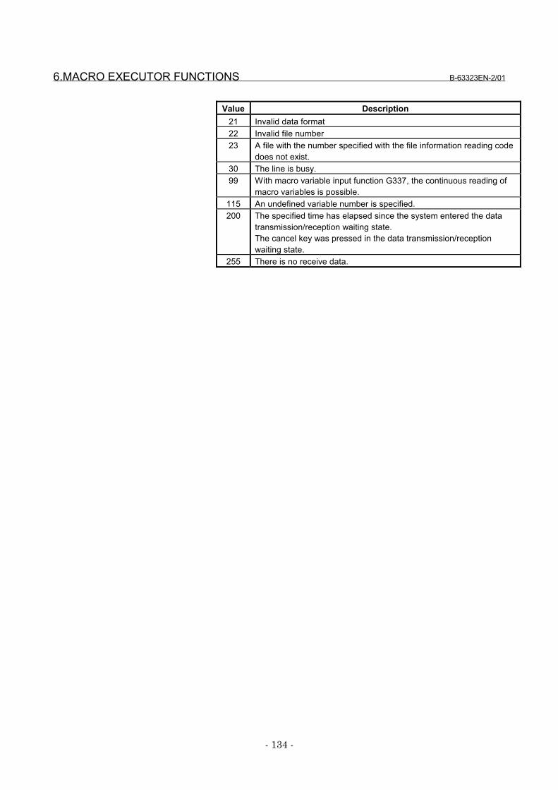
6.MACRO EXECUTOR FUNCTIONS B-63323EN-2/01
- 134 -
Value Description21 Invalid data format22 Invalid file number23 A file with the number specified with the file information reading code
does not exist.30 The line is busy.99 With macro variable input function G337, the continuous reading of
macro variables is possible.115 An undefined variable number is specified.200 The specified time has elapsed since the system entered the data
transmission/reception waiting state.The cancel key was pressed in the data transmission/receptionwaiting state.
255 There is no receive data.
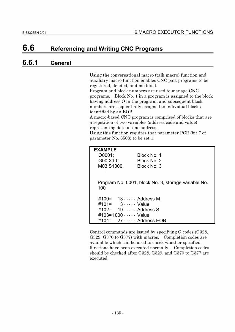
B-63323EN-2/01 6.MACRO EXECUTOR FUNCTIONS
- 135 -
6.6 Referencing and Writing CNC Programs
6.6.1 General
Using the conversational macro (talk macro) function andauxiliary macro function enables CNC part programs to beregistered, deleted, and modified.Program and block numbers are used to manage CNCprograms. Block No. 1 in a program is assigned to the blockhaving address O in the program, and subsequent blocknumbers are sequentially assigned to individual blocksidentified by an EOB.A macro-based CNC program is comprised of blocks that area repetition of two variables (address code and value)representing data at one address.Using this function requires that parameter PCR (bit 7 ofparameter No. 8508) to be set 1.
EXAMPLEO0001; Block No. 1G00 X10; Block No. 2M03 S1000; Block No. 3 :
Program No. 0001, block No. 3, storage variable No.100
#100= 13 ・・・・・ Address M#101= 3 ・・・・・ Value#102= 19 ・・・・・ Address S#103=1000 ・・・・・ Value#104= 27 ・・・・・ Address EOB
Control commands are issued by specifying G codes (G328,G329, G370 to G377) with macros. Completion codes areavailable which can be used to check whether specifiedfunctions have been executed normally. Completion codesshould be checked after G328, G329, and G370 to G377 areexecuted.
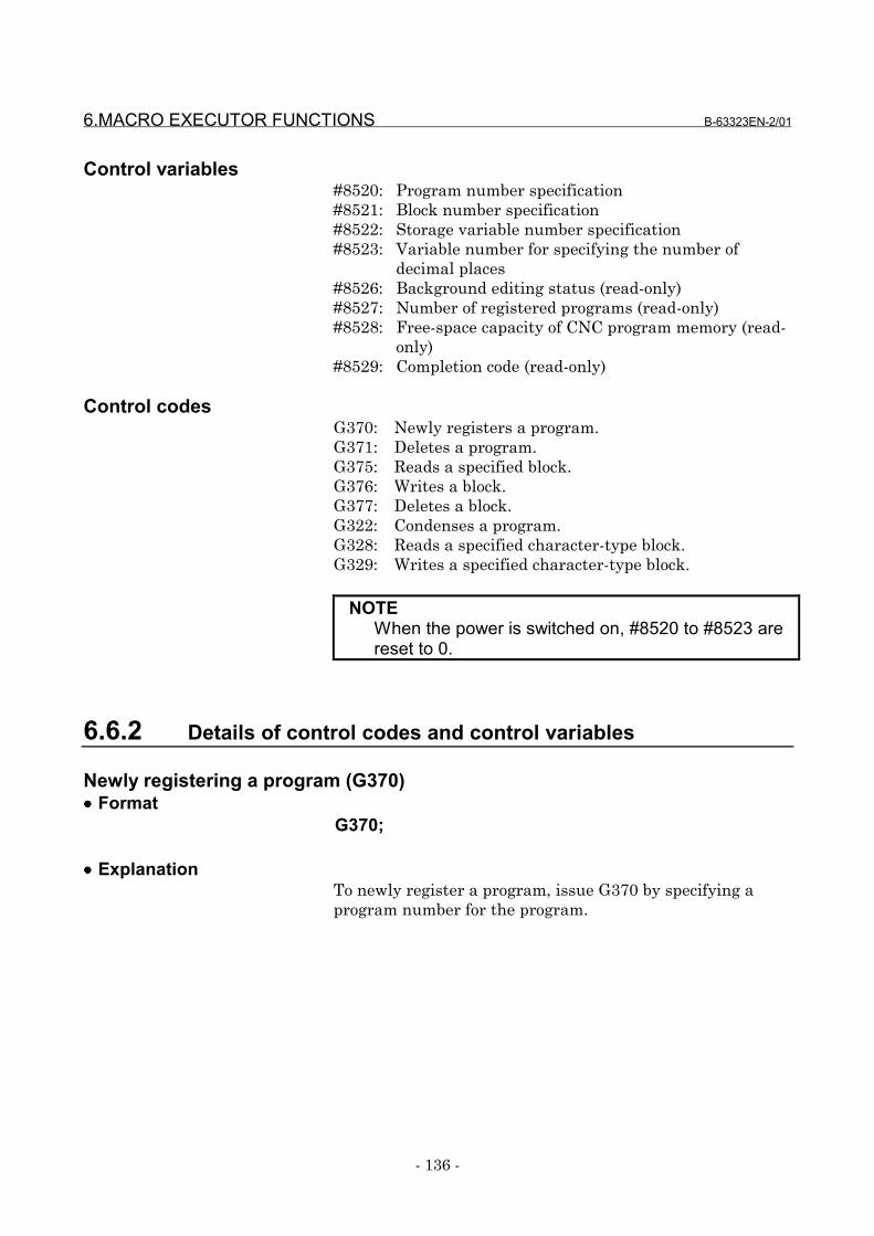
6.MACRO EXECUTOR FUNCTIONS B-63323EN-2/01
- 136 -
Control variables#8520: Program number specification#8521: Block number specification#8522: Storage variable number specification#8523: Variable number for specifying the number of
decimal places#8526: Background editing status (read-only)#8527: Number of registered programs (read-only)#8528: Free-space capacity of CNC program memory (read-
only)#8529: Completion code (read-only)
Control codesG370: Newly registers a program.G371: Deletes a program.G375: Reads a specified block.G376: Writes a block.G377: Deletes a block.G322: Condenses a program.G328: Reads a specified character-type block.G329: Writes a specified character-type block.
NOTEWhen the power is switched on, #8520 to #8523 arereset to 0.
6.6.2 Details of control codes and control variables
Newly registering a program (G370)•••• Format
G370;
•••• ExplanationTo newly register a program, issue G370 by specifying aprogram number for the program.
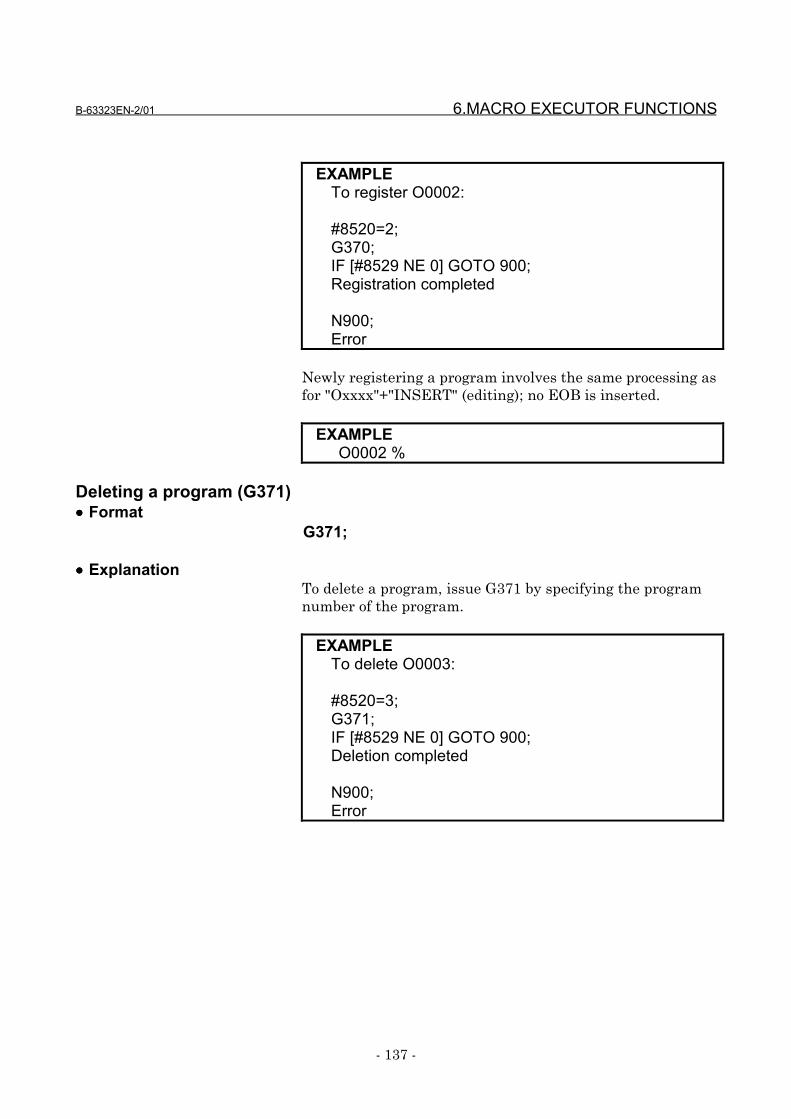
B-63323EN-2/01 6.MACRO EXECUTOR FUNCTIONS
- 137 -
EXAMPLETo register O0002:
#8520=2;G370;IF [#8529 NE 0] GOTO 900;Registration completed
N900;Error
Newly registering a program involves the same processing asfor "Oxxxx"+"INSERT" (editing); no EOB is inserted.
EXAMPLEO0002 %
Deleting a program (G371)•••• Format
G371;
•••• ExplanationTo delete a program, issue G371 by specifying the programnumber of the program.
EXAMPLETo delete O0003:
#8520=3;G371;IF [#8529 NE 0] GOTO 900;Deletion completed
N900;Error

6.MACRO EXECUTOR FUNCTIONS B-63323EN-2/01
- 138 -
Reading a specified block (G375)•••• Format
G375;
•••• ExplanationA block can be read into a specified variable area byspecifying its program number and block number. Theblock number used here is relative to the O-number block,which is counted as block No. 1. Therefore, it is differentfrom a sequence number (Nxxxx). A block number is usedalso in G376, G377, G328, and G329.
EXAMPLE 1O0004;G92 X0. M08;G90 G00 X10.5 M05;Assuming the above steps, the variable area will be:
#8520=4;#8521=3;#8522=100;G375;IF [#8529 NE 0] GOTO 900;Read completed
N900;Error
Executing the above commands causes program data to bestored in an area starting at #100 specified using storagevariable number #8522, as follows:
#100= 7 ・・・・・・ Address G#101= 90 ・・・・・・ Value#102= 7 ・・・・・・ Address G#103= 0 ・・・・・・ Value#104= 24 ・・・・・・ Address X#105=10.5 ・・・・・・ Value#106= 13 ・・・・・・ Address M#107= 5 ・・・・・・ Value#108= 27 ・・・・・・ Address EOB
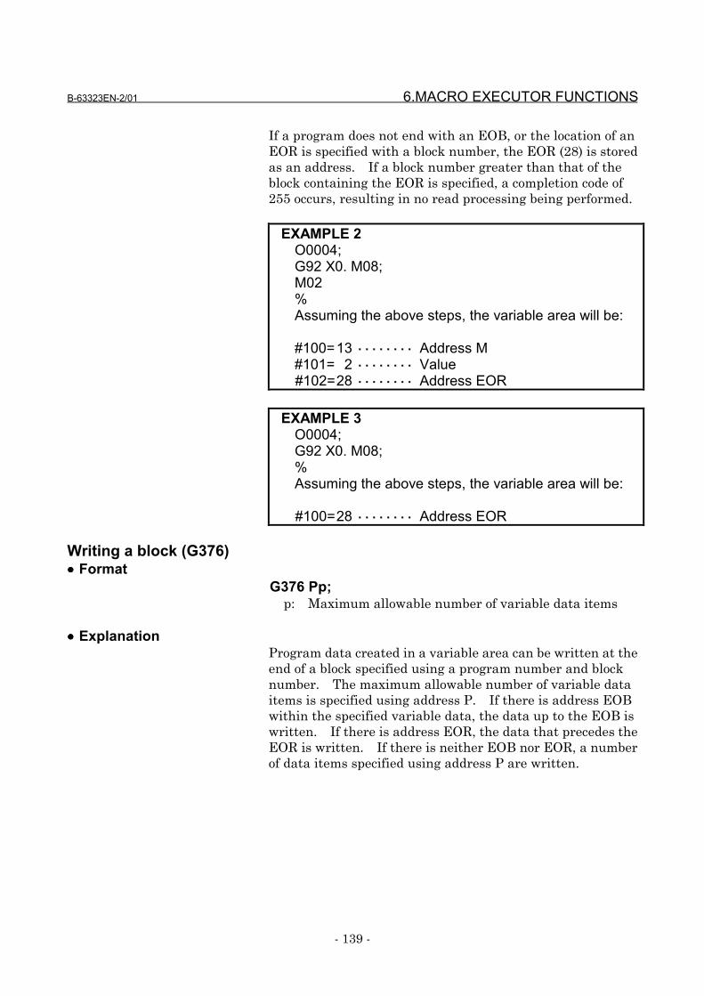
B-63323EN-2/01 6.MACRO EXECUTOR FUNCTIONS
- 139 -
If a program does not end with an EOB, or the location of anEOR is specified with a block number, the EOR (28) is storedas an address. If a block number greater than that of theblock containing the EOR is specified, a completion code of255 occurs, resulting in no read processing being performed.
EXAMPLE 2O0004;G92 X0. M08;M02%Assuming the above steps, the variable area will be:
#100=13 ・・・・・・・・ Address M#101= 2 ・・・・・・・・ Value#102=28 ・・・・・・・・ Address EOR
EXAMPLE 3O0004;G92 X0. M08;%Assuming the above steps, the variable area will be:
#100=28 ・・・・・・・・ Address EOR
Writing a block (G376)•••• Format
G376 Pp;p: Maximum allowable number of variable data items
•••• ExplanationProgram data created in a variable area can be written at theend of a block specified using a program number and blocknumber. The maximum allowable number of variable dataitems is specified using address P. If there is address EOBwithin the specified variable data, the data up to the EOB iswritten. If there is address EOR, the data that precedes theEOR is written. If there is neither EOB nor EOR, a numberof data items specified using address P are written.
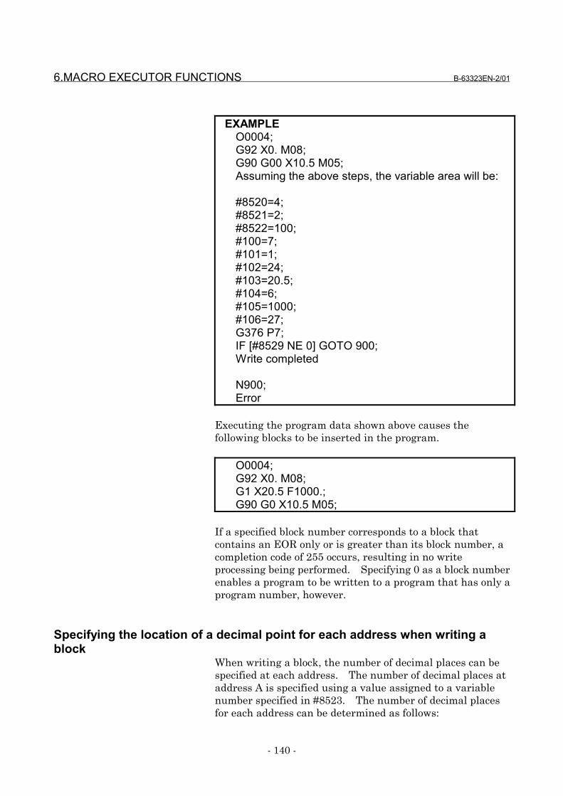
6.MACRO EXECUTOR FUNCTIONS B-63323EN-2/01
- 140 -
EXAMPLEO0004;G92 X0. M08;G90 G00 X10.5 M05;Assuming the above steps, the variable area will be:
#8520=4;#8521=2;#8522=100;#100=7;#101=1;#102=24;#103=20.5;#104=6;#105=1000;#106=27;G376 P7;IF [#8529 NE 0] GOTO 900;Write completed
N900;Error
Executing the program data shown above causes thefollowing blocks to be inserted in the program.
O0004;G92 X0. M08;G1 X20.5 F1000.;G90 G0 X10.5 M05;
If a specified block number corresponds to a block thatcontains an EOR only or is greater than its block number, acompletion code of 255 occurs, resulting in no writeprocessing being performed. Specifying 0 as a block numberenables a program to be written to a program that has only aprogram number, however.
Specifying the location of a decimal point for each address when writing ablock
When writing a block, the number of decimal places can bespecified at each address. The number of decimal places ataddress A is specified using a value assigned to a variablenumber specified in #8523. The number of decimal placesfor each address can be determined as follows:
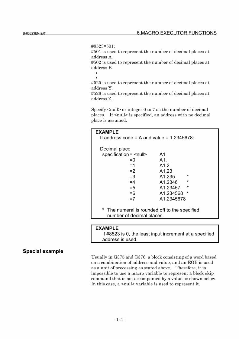
B-63323EN-2/01 6.MACRO EXECUTOR FUNCTIONS
- 141 -
#8523=501;#501 is used to represent the number of decimal places ataddress A.#502 is used to represent the number of decimal places ataddress B. • •
#525 is used to represent the number of decimal places ataddress Y.#526 is used to represent the number of decimal places ataddress Z.
Specify <null> or integer 0 to 7 as the number of decimalplaces. If <null> is specified, an address with no decimalplace is assumed.
EXAMPLEIf address code = A and value = 1.2345678:
Decimal placespecification = <null> A1
=0 A1.=1 A1.2=2 A1.23=3 A1.235 *=4 A1.2346 *=5 A1.23457 *=6 A1.234568 *=7 A1.2345678
* The numeral is rounded off to the specifiednumber of decimal places.
EXAMPLEIf #8523 is 0, the least input increment at a specifiedaddress is used.
Special exampleUsually in G375 and G376, a block consisting of a word basedon a combination of address and value, and an EOB is usedas a unit of processing as stated above. Therefore, it isimpossible to use a macro variable to represent a block skipcommand that is not accompanied by a value as shown below.In this case, a <null> variable is used to represent it.
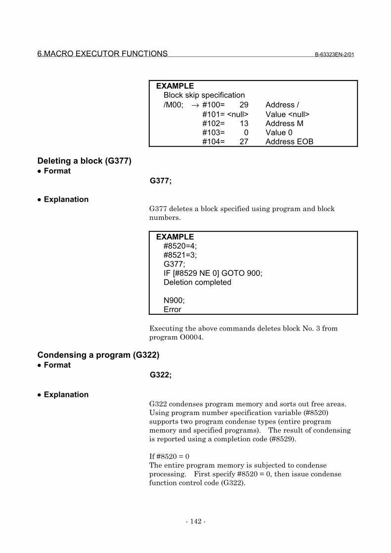
6.MACRO EXECUTOR FUNCTIONS B-63323EN-2/01
- 142 -
EXAMPLEBlock skip specification/M00; → #100= 29 Address /
#101= <null> Value <null>#102= 13 Address M#103= 0 Value 0#104= 27 Address EOB
Deleting a block (G377)•••• Format
G377;
•••• ExplanationG377 deletes a block specified using program and blocknumbers.
EXAMPLE#8520=4;#8521=3;G377;IF [#8529 NE 0] GOTO 900;Deletion completed
N900;Error
Executing the above commands deletes block No. 3 fromprogram O0004.
Condensing a program (G322)•••• Format
G322;
•••• ExplanationG322 condenses program memory and sorts out free areas.Using program number specification variable (#8520)supports two program condense types (entire programmemory and specified programs). The result of condensingis reported using a completion code (#8529).
If #8520 = 0The entire program memory is subjected to condenseprocessing. First specify #8520 = 0, then issue condensefunction control code (G322).
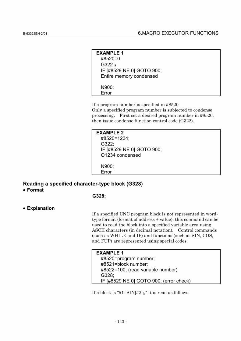
B-63323EN-2/01 6.MACRO EXECUTOR FUNCTIONS
- 143 -
EXAMPLE 1#8520=0G322;IF [#8529 NE 0] GOTO 900;Entire memory condensed
N900;Error
If a program number is specified in #8520Only a specified program number is subjected to condenseprocessing. First set a desired program number in #8520,then issue condense function control code (G322).
EXAMPLE 2#8520=1234;G322;IF [#8529 NE 0] GOTO 900;O1234 condensed
N900;Error
Reading a specified character-type block (G328)•••• Format
G328;
•••• ExplanationIf a specified CNC program block is not represented in word-type format (format of address + value), this command can beused to read the block into a specified variable area usingASCII characters (in decimal notation). Control commands(such as WHILE and IF) and functions (such as SIN, COS,and FUP) are represented using special codes.
EXAMPLE 1#8520=program number;#8521=block number;#8522=100; (read variable number)G328;IF [#8529 NE 0] GOTO 900; (error check)
If a block is "#1=SIN[#2];," it is read as follows:
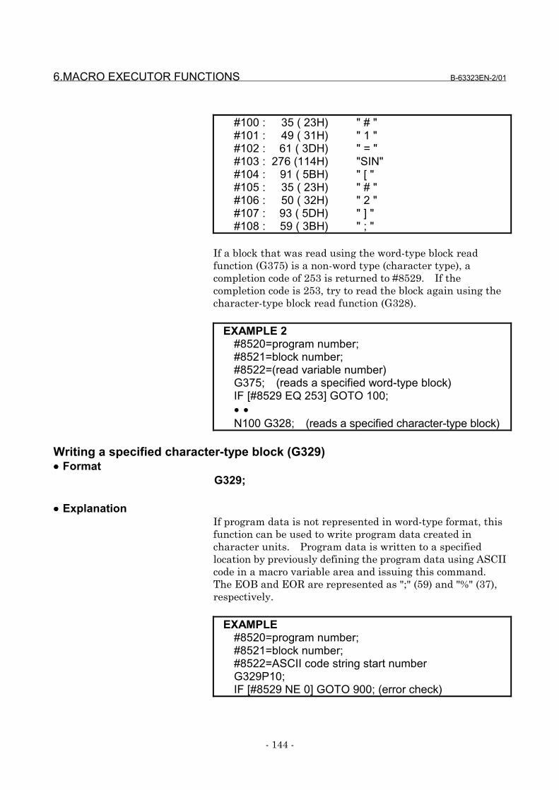
6.MACRO EXECUTOR FUNCTIONS B-63323EN-2/01
- 144 -
#100 : 35 ( 23H) " # "#101 : 49 ( 31H) " 1 "#102 : 61 ( 3DH) " = "#103 : 276 (114H) "SIN"#104 : 91 ( 5BH) " [ "#105 : 35 ( 23H) " # "#106 : 50 ( 32H) " 2 "#107 : 93 ( 5DH) " ] "#108 : 59 ( 3BH) " ; "
If a block that was read using the word-type block readfunction (G375) is a non-word type (character type), acompletion code of 253 is returned to #8529. If thecompletion code is 253, try to read the block again using thecharacter-type block read function (G328).
EXAMPLE 2#8520=program number;#8521=block number;#8522=(read variable number)G375; (reads a specified word-type block)IF [#8529 EQ 253] GOTO 100;• •N100 G328; (reads a specified character-type block)
Writing a specified character-type block (G329)•••• Format
G329;
•••• ExplanationIf program data is not represented in word-type format, thisfunction can be used to write program data created incharacter units. Program data is written to a specifiedlocation by previously defining the program data using ASCIIcode in a macro variable area and issuing this command.The EOB and EOR are represented as ";" (59) and "%" (37),respectively.
EXAMPLE#8520=program number;#8521=block number;#8522=ASCII code string start numberG329P10;IF [#8529 NE 0] GOTO 900; (error check)
B-63323EN-2/01 6.MACRO EXECUTOR FUNCTIONS
- 145 -
The command P for the maximum allowable write data itemsis the same as for writing of word-type blocks (G376).
Background editing status (#8526)
#8526: Background editing status= 0: Background editing at a stop= 1: Background editing in progress
This variable can be used to read the status of CNCbackground editing.
Number of registered programs (#8527)
#8527: Number of registered programs
This variable can be used to read the number of programsregistered in the program memory of the CNC.
Free-space capacity of CNC program memory (#8528)
#8528: Free-space capacity of CNC program memory(in units of characters)
This variable can be used to check the free-space capacity ofCNC program memory.
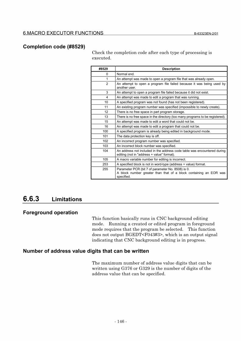
6.MACRO EXECUTOR FUNCTIONS B-63323EN-2/01
- 146 -
Completion code (#8529)Check the completion code after each type of processing isexecuted.
#8529 Description0 Normal end.1 An attempt was made to open a program file that was already open.2 An attempt to open a program file failed because it was being used by
another user.3 An attempt to open a program file failed because it did not exist.4 An attempt was made to edit a program that was running.
10 A specified program was not found (has not been registered).11 An existing program number was specified (impossible to newly create).12 There is no free space in part program storage.13 There is no free space in the directory (too many programs to be registered).15 An attempt was made to edit a word that could not be.16 An attempt was made to edit a program that could not be.
100 A specified program is already being edited in background mode.101 The data protection key is off.102 An incorrect program number was specified.103 An incorrect block number was specified.104 An address not included in the address code table was encountered during
editing (not in "address + value" format).105 A macro variable number for editing is incorrect.253 A specified block is not in word-type (address + value) format.255 Parameter PCR (bit 7 of parameter No. 8508) is 0.
A block number greater than that of a block containing an EOR wasspecified.
6.6.3 Limitations
Foreground operationThis function basically runs in CNC background editingmode. Running a created or edited program in foregroundmode requires that the program be selected. This functiondoes not output BGEDT<F043#3>, which is an output signalindicating that CNC background editing is in progress.
Number of address value digits that can be written
The maximum number of address value digits that can bewritten using G376 or G329 is the number of digits of theaddress value that can be specified.
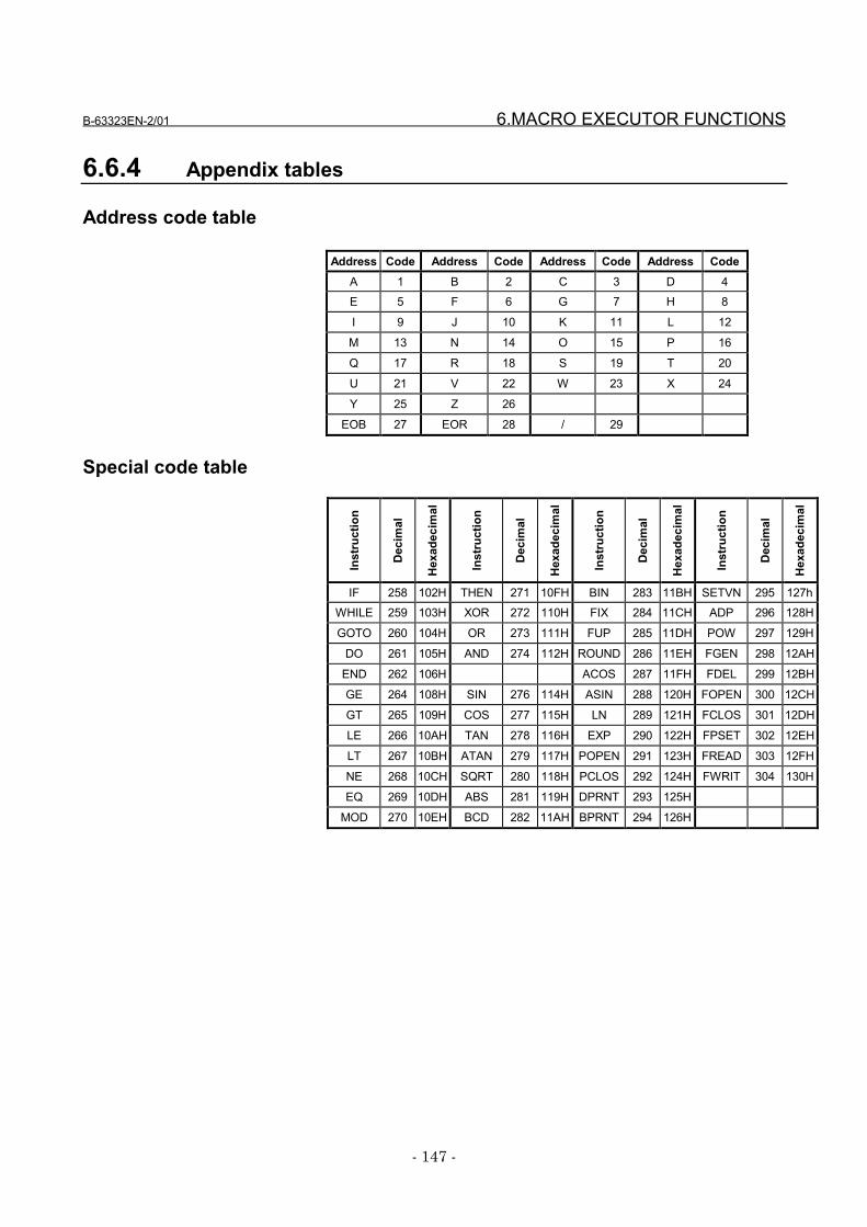
B-63323EN-2/01 6.MACRO EXECUTOR FUNCTIONS
- 147 -
6.6.4 Appendix tables
Address code table
Address Code Address Code Address Code Address CodeA 1 B 2 C 3 D 4E 5 F 6 G 7 H 8
I 9 J 10 K 11 L 12
M 13 N 14 O 15 P 16
Q 17 R 18 S 19 T 20
U 21 V 22 W 23 X 24
Y 25 Z 26
EOB 27 EOR 28 / 29
Special code table
Inst
ruct
ion
Dec
imal
Hex
adec
imal
Inst
ruct
ion
Dec
imal
Hex
adec
imal
Inst
ruct
ion
Dec
imal
Hex
adec
imal
Inst
ruct
ion
Dec
imal
Hex
adec
imal
IF 258 102H THEN 271 10FH BIN 283 11BH SETVN 295 127hWHILE 259 103H XOR 272 110H FIX 284 11CH ADP 296 128H
GOTO 260 104H OR 273 111H FUP 285 11DH POW 297 129H
DO 261 105H AND 274 112H ROUND 286 11EH FGEN 298 12AH
END 262 106H ACOS 287 11FH FDEL 299 12BH
GE 264 108H SIN 276 114H ASIN 288 120H FOPEN 300 12CH
GT 265 109H COS 277 115H LN 289 121H FCLOS 301 12DH
LE 266 10AH TAN 278 116H EXP 290 122H FPSET 302 12EH
LT 267 10BH ATAN 279 117H POPEN 291 123H FREAD 303 12FH
NE 268 10CH SQRT 280 118H PCLOS 292 124H FWRIT 304 130H
EQ 269 10DH ABS 281 119H DPRNT 293 125H
MOD 270 10EH BCD 282 11AH BPRNT 294 126H
6.MACRO EXECUTOR FUNCTIONS B-63323EN-2/01
- 148 -
6.7 Cutting Time and Distance Read and Preset Functions
Control variables can be used to read and preset the cuttingtime and cutting distance. This function can be used tomanage the service life of tools.
Reading and presetting the cutting time (#8553)
#8553 reads the cutting time specified in commands such asG01 (linear interpolation), G02, and G03 (circularinterpolation). The value that is read using #8553 is thesum of values specified in parameters (parameter Nos. 103and 104), and they are represented in hour units in the sameway as for the corresponding macro variable (#3002). It isalso possible to preset the cutting time. When it is preset,the related parameters (parameter Nos. 103 and 104) arealso preset.
EXAMPLE#100=#8553 ;#8553=0 ;
→ The cutting time is read into #100.→ The cutting time is preset to 0; the
related parameters (parameter Nos.103 and 104) are also preset to 0.
Reading and presetting a cutting distance (#8554)
#8554 adds up the cutting distance specified in commandssuch as G01 (linear interpolation), G02, and G03 (circularinterpolation). Their measurement unit is the least inputincrement for the basic axis. Writing a value to #8554enables the cutting distance to be preset.
EXAMPLE#100 = #8554 ; --- The cutting distance is read
into #100.#8554 = 0 ; --- The cutting distance is preset
to 0.
B-63323EN-2/01 6.MACRO EXECUTOR FUNCTIONS
- 149 -
CautionsCAUTIONS1 Using the functions for reading and presetting a
cutting distance requires that:Parameter PCR (bit 7 of parameter No. 8508) = 1Parameter CLG (bit 6 of parameter No. 8508) = 1
2 The tool travel distance is added up into #8554 atthe start of a cutting block. Even if a cutting blockis stopped prematurely, for example, due to areset, therefore, the travel distance specified in theblock is included in the sum.
3 Switching on the power does not reset #8553 and#8554 to 0. The user is responsible to managethese variables.
6.MACRO EXECUTOR FUNCTIONS B-63323EN-2/01
- 150 -
6.8 Relative Coordinate Read and Preset Functions (#8996 to#8999)
These functions enable reading and presetting of relativecoordinates.
Reading relative coordinates
Once a target axis number is set in #8998, #8999 can be usedto read its relative coordinate.
#8997 .... Information ID. 500: Relative coordinate isread.
#8998 .... Axis number (1 to the maximum allowablenumber of controlled axes)
#8999 .... Relative coordinate#8996 .... Completion code. 0: Normal end.
-1: Abnormal end.
EXAMPLEIf the relative coordinate of the first axis is -123.456,executing the following steps sets #500 with -123456.
#8997 = 500;#8998 = 1; (acquires the information about the
first axis)#500 = #8999;
•••• CautionsCAUTIONS1 If a value that does not fall in a range between 1
and the maximum allowable number of controlledaxes is specified in #8998, #8999 is set with <null>.
2 When the power is switched on, #8999 is reset to0.
3 The unit of a read value is the least input incrementfor a specified axis.
Presetting relative coordinates
•••• FormatG360 Aa Qq;
A: Controlled-axis number to be subjected to presetting(1 to the maximum allowable number of controlledaxes)
Q: Coordinate to be preset
B-63323EN-2/01 6.MACRO EXECUTOR FUNCTIONS
- 151 -
Address Q specifies the coordinate to be preset.Q = -999999999 to +999999999
Executing this control code presets the relative coordinate.
EXAMPLETo preset the relative coordinate of the first axis to-123.45, issue:
G360 A1 Q - 123450 ;
•••• CautionsCAUTIONS1 If address A is specified as a value that does no fall
in a range of 1 to the maximum allowable numberof controlled axes, or it is not specified, G360 isignored.
2 The unit of address Q is the least input incrementof the specified axis.
6.MACRO EXECUTOR FUNCTIONS B-63323EN-2/01
- 152 -
6.9 Array-Type Processing and Referencing of P-CODE Variables
Array-type processing of P-CODE variables
This function controls processing of array-type macrovariables or a sequence of macro variables.
1) Clearing array-type variables and a sequence ofvariables (continuous writing of specified data)
2) Transferring from array-type variables or a sequence ofvariable to a sequence of variables
Each type of processing is performed by first defining anarray, a sequence of variables, or data in each of thefollowing control variables, then issuing control code G315.
#8511: Source data#8512: Source two-dimensional array number or the
start variable number of a sequence of variables#8513: Source three-dimensional array number#8514: Destination two-dimensional array number or
the start variable number of a sequence ofvariables
#8515: Destination three-dimensional array number
•••• FormatG315 P (processing code) K (number of data items tobe processed);
P001 (P1) : Stores data from #8511 to K consecutivevariables starting at the one specified in#8514.
P002 (P2) : Transfers data from K consecutivevariables starting at the one specified in#8512 to K consecutive variables starting atthe one specified in #8514 (transfer inascending order).
P003 (P3) : Transfers data from K consecutivevariables starting at the one specified in#8512 to K consecutive variables starting atthe one specified in #8514 (transfer indescending order).
P101 : Stores data from #8511 to K consecutivearray variables starting at array variable#1 specified in #8514 and #8515.
B-63323EN-2/01 6.MACRO EXECUTOR FUNCTIONS
- 153 -
P102 : Transfers data from K consecutive arrayvariables starting at array variable #1specified in #8512 and #8513 to Kconsecutive array variables starting atarray variable #1 specified in #8514 and#8515 (ascending order).
P103 : Transfers data from K consecutive arrayvariables starting at array variable #1specified in #8512 and #8513 to Kconsecutive array variables starting atarray variable #1 specified in #8514 and#8515 (descending order).
Each process code consists of three digits and specifies thetype of processing to be performed. Leading zeros areomissible.A difference between P2 and P3 and between P102 and P103is whether a transfer progresses from a small variablenumber to a large or from a large to a small.
EXAMPLEIf #8512 = 30000 and #8514 = 30010,G315 P2 K3; is equivalent to the following steps:
#30010 = #30000#30011 = #30001#30012 = #30002, and
G315 P3 K3; is equivalent to the following steps:#30012 = #30002#30011 = #30001#30010 = #30000
Array-type referencing of P-CODE variables
P-CODE variables (#30000 and above) can be referenced astwo-dimensional or three-dimensional array-type variables.Previously assigning proper values to the following arraycontrol variables enables variable numbers #1 to #99 to beused to reference the P-CODE variables for thecorresponding array elements.
Array control variables#8512: Two-dimensional array number#8513: Three-dimensional array number#8516: Number of one-dimensional array elements#8517: Number of two-dimensional array elements#8518: 1#8519: Array start variable number
6.MACRO EXECUTOR FUNCTIONS B-63323EN-2/01
- 154 -
Variables #1 to #99 are used to reference the P-CODEvariables by previously specifying array types using arraycontrol variables #8516 to #8519, then specifying the targetarray numbers using #8512 and #8513.
The P-CODE variables are associated with the arrayelements as shown below.
P-CODE variable number= #8519 + ((#8516*#8517)*(#8513 - 1))+ (#8516*(#8512 -1)) + (specified variable number - 1)
EXAMPLEIf #8516 = 10, #8517 = 5, and #8519 = 30100,(1) #1 with #8512 = 1 and #8513 = 1 specified
corresponds to #30100.(2) #10 with #8512 = 3 and #8513 = 2 specified
corresponds to #30179.
When the power is switched on, each array control variable isset up as follows:#8512 to #8517 = 1 and #8519 = 30000So, when using P-CODE variables as two-dimensional arrays,you need not beware of #8513 and #8517.
NOTE1 When using variables #1 to #99 to reference P-
CODE variables as array-type, set #8518 = 1. If#8518 = 0, an alarm is issued, because #1 to #33are treated as local variables and #34 to #99 aretreated as unusable. When the power is switchedon, #8518 = 0.
CautionCAUTION1 No check is made on any variable and calculated
variable number for validity. Use a macroprogram to make validity checks if necessary.
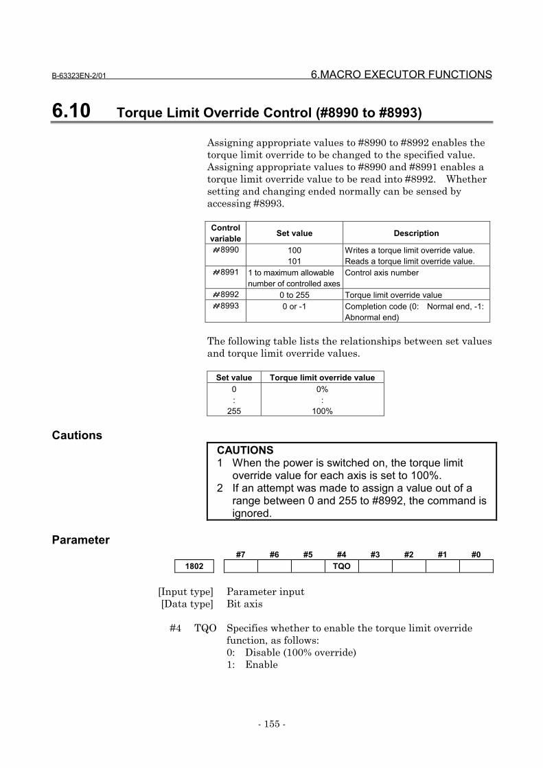
B-63323EN-2/01 6.MACRO EXECUTOR FUNCTIONS
- 155 -
6.10 Torque Limit Override Control (#8990 to #8993)
Assigning appropriate values to #8990 to #8992 enables thetorque limit override to be changed to the specified value.Assigning appropriate values to #8990 and #8991 enables atorque limit override value to be read into #8992. Whethersetting and changing ended normally can be sensed byaccessing #8993.
Controlvariable Set value Description
#8990 100101
Writes a torque limit override value.Reads a torque limit override value.
#8991 1 to maximum allowablenumber of controlled axes
Control axis number
#8992 0 to 255 Torque limit override value#8993 0 or -1 Completion code (0: Normal end, -1:
Abnormal end)
The following table lists the relationships between set valuesand torque limit override values.
Set value Torque limit override value0:
255
0%:
100%
CautionsCAUTIONS1 When the power is switched on, the torque limit
override value for each axis is set to 100%.2 If an attempt was made to assign a value out of a
range between 0 and 255 to #8992, the command isignored.
Parameter#7 #6 #5 #4 #3 #2 #1 #0
1802 TQO
[Input type] Parameter input[Data type] Bit axis
#4 TQO Specifies whether to enable the torque limit overridefunction, as follows:0: Disable (100% override)1: Enable

6.MACRO EXECUTOR FUNCTIONS B-63323EN-2/01
- 156 -
6.11 Reading A/D Conversion Data
This function reads data from an A/D converter or a valueresulting from conversion of the load current of eachcontrolled axis to voltage form.The data types that can be read are:• General-purpose analog input• Voltage value converted from spindle load current• Voltage value converted from the load current of a
controlled axis (servo motor)
The present data of each channel can be input by assigningthe necessary values listed below to control variables #8997and #8998, then by read-accessing #8999.After this, #8996 is set with information indicating whetherthe read operation ended normally (0 for normal end and -1for abnormal end).
For controlled axes, data can be input by read-accessing thefollowing control variables.
#8631: Voltage value converted from the load current ofthe first axis
#8632: Voltage value converted from the load current ofthe second axis
:#8645: Voltage value converted from the load current of
the fifteenth axis#8656: Voltage value converted from the load current of
the sixteenth axis#8657: Voltage value converted from the load current of
the seventeenth axis:
#8664: Voltage value converted from the load current ofthe twenty-fourth axis
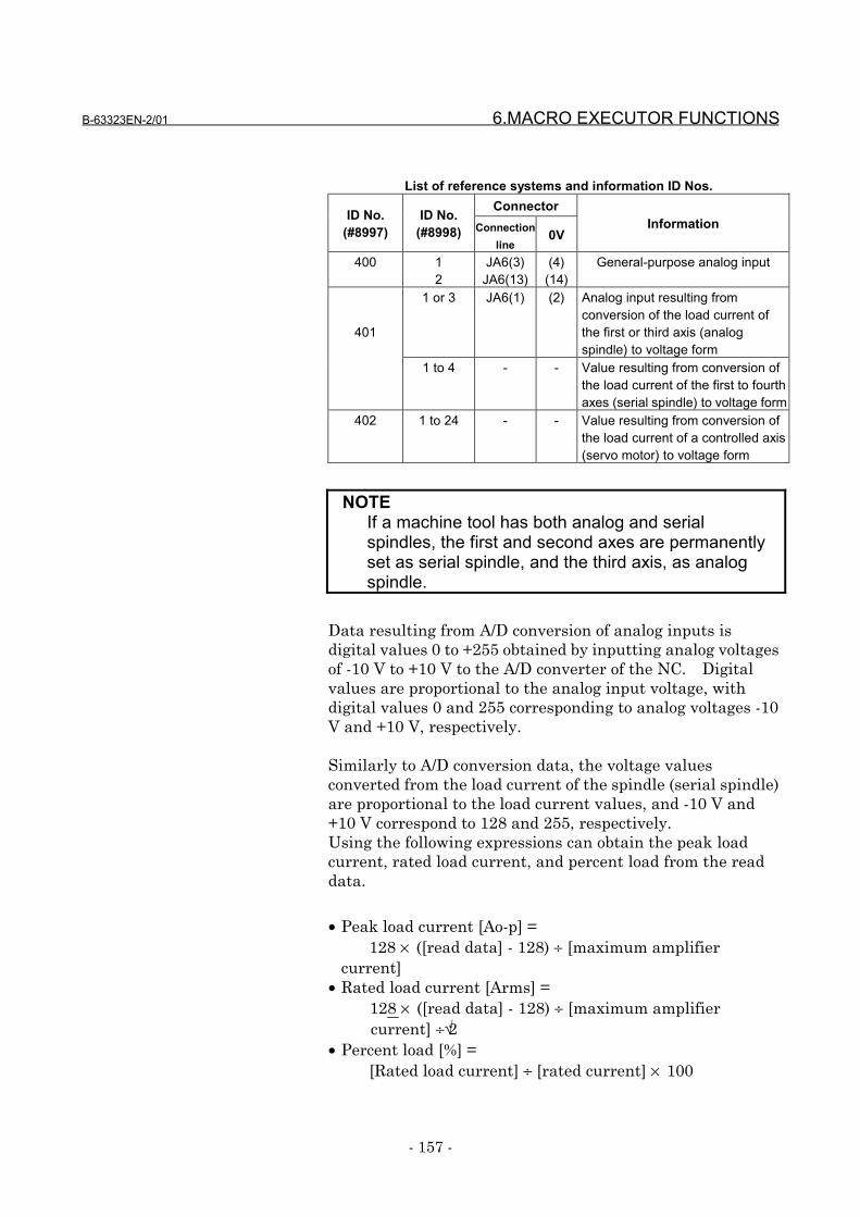
B-63323EN-2/01 6.MACRO EXECUTOR FUNCTIONS
- 157 -
List of reference systems and information ID Nos.ConnectorID No.
(#8997)ID No.
(#8998) Connectionline
0VInformation
400 12
JA6(3)JA6(13)
(4)(14)
General-purpose analog input
1 or 3 JA6(1) (2) Analog input resulting fromconversion of the load current ofthe first or third axis (analogspindle) to voltage form
401
1 to 4 - - Value resulting from conversion ofthe load current of the first to fourthaxes (serial spindle) to voltage form
402 1 to 24 - - Value resulting from conversion ofthe load current of a controlled axis(servo motor) to voltage form
NOTEIf a machine tool has both analog and serialspindles, the first and second axes are permanentlyset as serial spindle, and the third axis, as analogspindle.
Data resulting from A/D conversion of analog inputs isdigital values 0 to +255 obtained by inputting analog voltagesof -10 V to +10 V to the A/D converter of the NC. Digitalvalues are proportional to the analog input voltage, withdigital values 0 and 255 corresponding to analog voltages -10V and +10 V, respectively.
Similarly to A/D conversion data, the voltage valuesconverted from the load current of the spindle (serial spindle)are proportional to the load current values, and -10 V and+10 V correspond to 128 and 255, respectively.Using the following expressions can obtain the peak loadcurrent, rated load current, and percent load from the readdata.
• Peak load current [Ao-p] =128 × ([read data] - 128) ÷ [maximum amplifier
current]• Rated load current [Arms] =
128 × ([read data] - 128) ÷ [maximum amplifiercurrent] ÷√2
• Percent load [%] =[Rated load current] ÷ [rated current] × 100
6.MACRO EXECUTOR FUNCTIONS B-63323EN-2/01
- 158 -
For the maximum amplifier current and rated current, referto the specification manual of your motor.
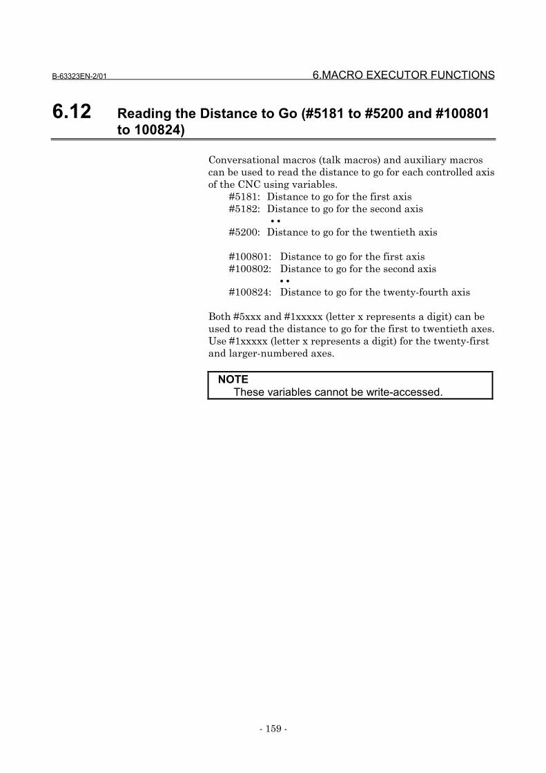
B-63323EN-2/01 6.MACRO EXECUTOR FUNCTIONS
- 159 -
6.12 Reading the Distance to Go (#5181 to #5200 and #100801to 100824)
Conversational macros (talk macros) and auxiliary macroscan be used to read the distance to go for each controlled axisof the CNC using variables.
#5181: Distance to go for the first axis#5182: Distance to go for the second axis
• •
#5200: Distance to go for the twentieth axis
#100801: Distance to go for the first axis#100802: Distance to go for the second axis
• •
#100824: Distance to go for the twenty-fourth axis
Both #5xxx and #1xxxxx (letter x represents a digit) can beused to read the distance to go for the first to twentieth axes.Use #1xxxxx (letter x represents a digit) for the twenty-firstand larger-numbered axes.
NOTEThese variables cannot be write-accessed.
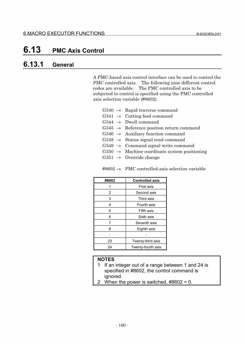
6.MACRO EXECUTOR FUNCTIONS B-63323EN-2/01
- 160 -
6.13 PMC Axis Control
6.13.1 General
A PMC-based axis control interface can be used to control thePMC controlled axis. The following nine different controlcodes are available. The PMC controlled axis to besubjected to control is specified using the PMC controlledaxis selection variable (#8602).
G340 → Rapid traverse commandG341 → Cutting feed commandG344 → Dwell commandG345 → Reference position return commandG346 → Auxiliary function commandG348 → Status signal read commandG349 → Command signal write commandG350 → Machine coordinate system positioningG351 → Override change
#8602 → PMC controlled-axis selection variable
#8602 Controlled axis1 First axis2 Second axis3 Third axis4 Fourth axis5 Fifth axis6 Sixth axis7 Seventh axis8 Eighth axis: :
23 Twenty-third axis24 Twenty-fourth axis
NOTES1 If an integer out of a range between 1 and 24 is
specified in #8602, the control command isignored.
2 When the power is switched, #8602 = 0.
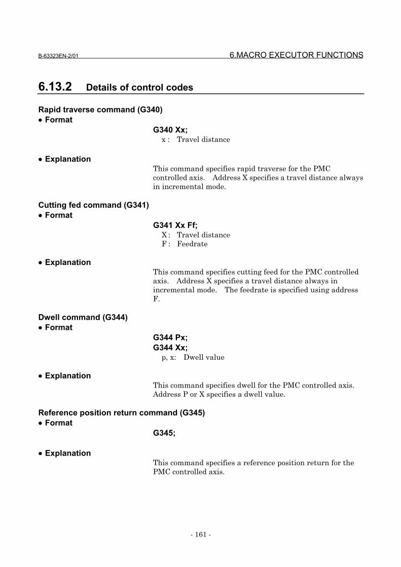
B-63323EN-2/01 6.MACRO EXECUTOR FUNCTIONS
- 161 -
6.13.2 Details of control codes
Rapid traverse command (G340)•••• Format
G340 Xx;x : Travel distance
•••• ExplanationThis command specifies rapid traverse for the PMCcontrolled axis. Address X specifies a travel distance alwaysin incremental mode.
Cutting fed command (G341)•••• Format
G341 Xx Ff;X : Travel distanceF : Feedrate
•••• ExplanationThis command specifies cutting feed for the PMC controlledaxis. Address X specifies a travel distance always inincremental mode. The feedrate is specified using addressF.
Dwell command (G344)•••• Format
G344 Px;G344 Xx;
p, x: Dwell value
•••• ExplanationThis command specifies dwell for the PMC controlled axis.Address P or X specifies a dwell value.
Reference position return command (G345)•••• Format
G345;
•••• ExplanationThis command specifies a reference position return for thePMC controlled axis.
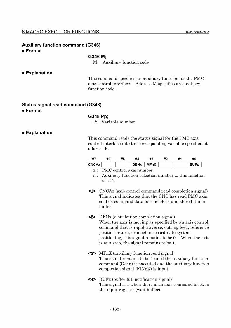
6.MACRO EXECUTOR FUNCTIONS B-63323EN-2/01
- 162 -
Auxiliary function command (G346)•••• Format
G346 M;M: Auxiliary function code
•••• ExplanationThis command specifies an auxiliary function for the PMCaxis control interface. Address M specifies an auxiliaryfunction code.
Status signal read command (G348)•••• Format
G348 Pp;P: Variable number
•••• ExplanationThis command reads the status signal for the PMC axiscontrol interface into the corresponding variable specified ataddress P.
#7 #6 #5 #4 #3 #2 #1 #0CNCAx DENx MFnX BUFx
x : PMC control axis numbern : Auxiliary function selection number ... this function
uses 1.
<1><1><1><1> CNCAx (axis control command read completion signal)This signal indicates that the CNC has read PMC axiscontrol command data for one block and stored it in abuffer.
<2><2><2><2> DENx (distribution completion signal)When the axis is moving as specified by an axis controlcommand that is rapid traverse, cutting feed, referenceposition return, or machine coordinate systempositioning, this signal remains to be 0. When the axisis at a stop, the signal remains to be 1.
<3><3><3><3> MFnX (auxiliary function read signal)This signal remains to be 1 until the auxiliary functioncommand (G346) is executed and the auxiliary functioncompletion signal (FINnX) is input.
<4><4><4><4> BUFx (buffer full notification signal)This signal is 1 when there is an axis command block inthe input register (wait buffer).
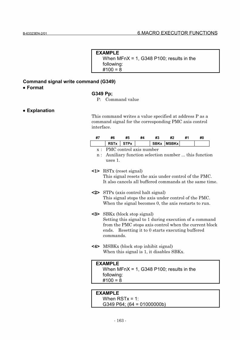
B-63323EN-2/01 6.MACRO EXECUTOR FUNCTIONS
- 163 -
EXAMPLEWhen MFnX = 1, G348 P100; results in thefollowing:#100 = 8
Command signal write command (G349)•••• Format
G349 Pp;P: Command value
•••• ExplanationThis command writes a value specified at address P as acommand signal for the corresponding PMC axis controlinterface.
#7 #6 #5 #4 #3 #2 #1 #0RSTx STPx SBKx MSBKx
x : PMC control axis numbern : Auxiliary function selection number ... this function
uses 1.
<1><1><1><1> RSTx (reset signal)This signal resets the axis under control of the PMC.It also cancels all buffered commands at the same time.
<2><2><2><2> STPx (axis control halt signal)This signal stops the axis under control of the PMC.When the signal becomes 0, the axis restarts to run.
<3><3><3><3> SBKx (block stop signal)Setting this signal to 1 during execution of a commandfrom the PMC stops axis control when the current blockends. Resetting it to 0 starts executing bufferedcommands.
<4><4><4><4> MSBKx (block stop inhibit signal)When this signal is 1, it disables SBKx.
EXAMPLEWhen MFnX = 1, G348 P100; results in thefollowing:#100 = 8
EXAMPLEWhen RSTx = 1:G349 P64; (64 = 01000000b)

6.MACRO EXECUTOR FUNCTIONS B-63323EN-2/01
- 164 -
Machine coordinate system positioning (G350)•••• Format
G350 Xx;X: Travel distance
•••• ExplanationThis command performs machine coordinate systempositioning for the PMC controlled axis. Address X specifiesa travel distance using an absolute position in the machinecoordinate system.
Override change (G351)•••• Format
G351 Pp;P: Override value
•••• ExplanationThis command specifies the override to be applied to thecutting feed for the PMC controlled axis using a value ataddress P. The override is represented in percent and canbe set to any value in a range between 0% and 255%. Thespecified override value remains valid until another overridechange command is executed. It is set to 100%, when thepower is switched on.
6.13.3 Limitations
Command bufferingPMC-based axis control is implemented by issuing more thanone commands sequentially. So, command blocks arebuffered on the CNC side. To put another way, when theCNC is executing a block, another command can be issued aslong as the CNC's buffer has room to receive it. Note,however, that if the buffer has no room to receive a newcommand, the new command is kept waiting while theprevious command is being executed, that is, until theprevious command is finished to create room in the buffer.Executing G3** causes buffering; so the PMCAx (axis controlcommand read strobe signal) is not needed.
Auxiliary function commandThe auxiliary function command can be implemented usingG346, but the auxiliary function completion signal FINnXcannot be controlled on the macro side. It should becontrolled by the PMC.
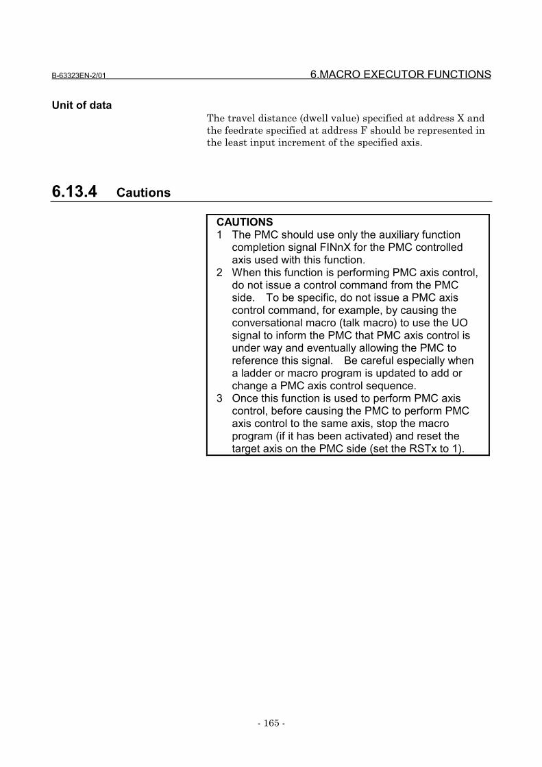
B-63323EN-2/01 6.MACRO EXECUTOR FUNCTIONS
- 165 -
Unit of dataThe travel distance (dwell value) specified at address X andthe feedrate specified at address F should be represented inthe least input increment of the specified axis.
6.13.4 Cautions
CAUTIONS1 The PMC should use only the auxiliary function
completion signal FINnX for the PMC controlledaxis used with this function.
2 When this function is performing PMC axis control,do not issue a control command from the PMCside. To be specific, do not issue a PMC axiscontrol command, for example, by causing theconversational macro (talk macro) to use the UOsignal to inform the PMC that PMC axis control isunder way and eventually allowing the PMC toreference this signal. Be careful especially whena ladder or macro program is updated to add orchange a PMC axis control sequence.
3 Once this function is used to perform PMC axiscontrol, before causing the PMC to perform PMCaxis control to the same axis, stop the macroprogram (if it has been activated) and reset thetarget axis on the PMC side (set the RSTx to 1).
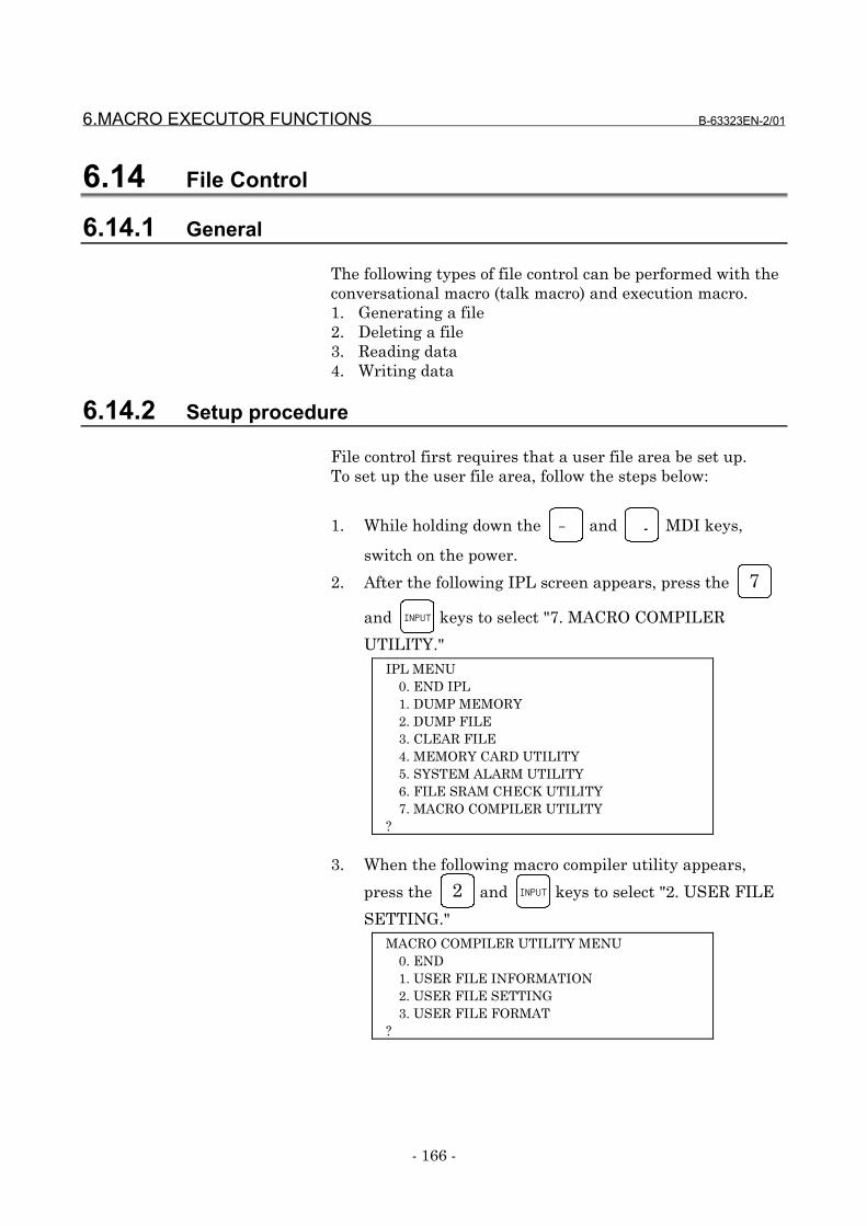
6.MACRO EXECUTOR FUNCTIONS B-63323EN-2/01
- 166 -
6.14 File Control
6.14.1 General
The following types of file control can be performed with theconversational macro (talk macro) and execution macro.1. Generating a file2. Deleting a file3. Reading data4. Writing data
6.14.2 Setup procedure
File control first requires that a user file area be set up.To set up the user file area, follow the steps below:
1. While holding down the ― and . MDI keys,
switch on the power.
2. After the following IPL screen appears, press the 7
and INPUT keys to select "7. MACRO COMPILER
UTILITY." IPL MENU 0. END IPL 1. DUMP MEMORY 2. DUMP FILE 3. CLEAR FILE 4. MEMORY CARD UTILITY 5. SYSTEM ALARM UTILITY 6. FILE SRAM CHECK UTILITY 7. MACRO COMPILER UTILITY ?
3. When the following macro compiler utility appears,
press the 2 and INPUT keys to select "2. USER FILE
SETTING." MACRO COMPILER UTILITY MENU 0. END 1. USER FILE INFORMATION 2. USER FILE SETTING 3. USER FILE FORMAT ?

B-63323EN-2/01 6.MACRO EXECUTOR FUNCTIONS
- 167 -
4. First, the currently set values are displayed as follows: CURRENT DATA : USER FILE AREA SIZE = xx NUMBER OF USER FILE = xx DATA AREA SIZE (BYTE) = xx SRAM FREE = xx
5. According to the displays, specify the size of the user filearea and the number of files that can be generated in theuser file area.
MODIFY DATA : USER FILE AREA SIZE = ? NUMBER OF USER FILE = ?
If you want to change the data, enter the desired value,
and press the INPUT key. If not, simply press the INPUT
key. If you want to cancel the setting, press the RESET
key.6. When setting ends, the following message is displayed.
• If the setting has not been changed:"DATA NOT CHANGED" is displayed.
• If setting has been completed normally:The new setting is displayed in the same manner as atstep 4, and "DATA SETTING END" is displayed.
• If an invalid value has been specified:"SETTING ERROR" is displayed and followed by adescription of the cause of the error.
7. Pressing the INPUT key displays the macro compiler
utility screen again.8. After user file area setup is completed normally, perform
formatting.
On the macro compiler utility screen, press the 3 and
INPUT keys to select "3. USER FILE FORMAT."
9. When "USER FILE FORMAT OK? [Y/N]" is displayed,
press the Y key.
10. When formatting ends normally, "USER FILEFORMAT: END" is displayed.
11. Pressing the INPUT key displays the macro compiler
utility screen again.
12. Press the 0 and INPUT keys to select "0. END."
13. When the IPL screen appears again, press the 0 and
INPUT keys to select "0. END IPL."
14. The IPL screen is exited, and a usual screen appears.
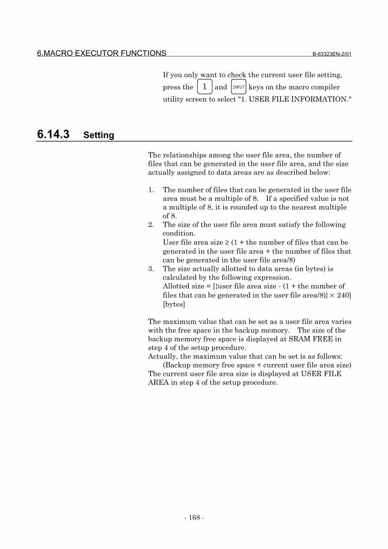
6.MACRO EXECUTOR FUNCTIONS B-63323EN-2/01
- 168 -
If you only want to check the current user file setting,
press the 1 and INPUT keys on the macro compiler
utility screen to select "1. USER FILE INFORMATION."
6.14.3 Setting
The relationships among the user file area, the number offiles that can be generated in the user file area, and the sizeactually assigned to data areas are as described below:
1. The number of files that can be generated in the user filearea must be a multiple of 8. If a specified value is nota multiple of 8, it is rounded up to the nearest multipleof 8.
2. The size of the user file area must satisfy the followingcondition.User file area size ≥ (1 + the number of files that can begenerated in the user file area + the number of files thatcan be generated in the user file area/8)
3. The size actually allotted to data areas (in bytes) iscalculated by the following expression.Allotted size = [{user file area size - (1 + the number offiles that can be generated in the user file area/8)} × 240][bytes]
The maximum value that can be set as a user file area varieswith the free space in the backup memory. The size of thebackup memory free space is displayed at SRAM FREE instep 4 of the setup procedure.Actually, the maximum value that can be set is as follows:
(Backup memory free space + current user file area size)The current user file area size is displayed at USER FILEAREA in step 4 of the setup procedure.
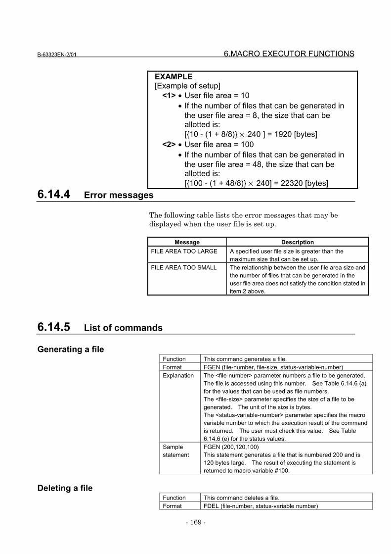
B-63323EN-2/01 6.MACRO EXECUTOR FUNCTIONS
- 169 -
EXAMPLE[Example of setup]
<1> • User file area = 10• If the number of files that can be generated in
the user file area = 8, the size that can beallotted is:[{10 - (1 + 8/8)} × 240 ] = 1920 [bytes]
<2> • User file area = 100• If the number of files that can be generated in
the user file area = 48, the size that can beallotted is:[{100 - (1 + 48/8)} × 240] = 22320 [bytes]
6.14.4 Error messages
The following table lists the error messages that may bedisplayed when the user file is set up.
Message DescriptionFILE AREA TOO LARGE A specified user file size is greater than the
maximum size that can be set up.FILE AREA TOO SMALL The relationship between the user file area size and
the number of files that can be generated in theuser file area does not satisfy the condition stated initem 2 above.
6.14.5 List of commands
Generating a fileFunction This command generates a file.Format FGEN (file-number, file-size, status-variable-number)Explanation The <file-number> parameter numbers a file to be generated.
The file is accessed using this number. See Table 6.14.6 (a)for the values that can be used as file numbers.The <file-size> parameter specifies the size of a file to begenerated. The unit of the size is bytes.The <status-variable-number> parameter specifies the macrovariable number to which the execution result of the commandis returned. The user must check this value. See Table6.14.6 (e) for the status values.
Samplestatement
FGEN (200,120,100)This statement generates a file that is numbered 200 and is120 bytes large. The result of executing the statement isreturned to macro variable #100.
Deleting a fileFunction This command deletes a file.Format FDEL (file-number, status-variable number)
6.MACRO EXECUTOR FUNCTIONS B-63323EN-2/01
- 170 -
Explanation The <file-number> parameter specifies a file to be deleted.See Table 6.14.6 (a) for the values that can be used as filenumbers.The <status-variable-number> parameter specifies the macrovariable number to which the execution result of the commandis returned. The user must check this value. See Table6.14.6 (e) for the status values.
Caution A file that is open cannot be deleted.Samplestatement
FDEL (200,100)This statement deletes file No. 200. The result of executingthe statement is returned to macro variable #100.

B-63323EN-2/01 6.MACRO EXECUTOR FUNCTIONS
- 171 -
Opening a fileFunction This command opens a file.Format FOPEN (file-number, access-mode, status-variable-number)Explanation The <file-number> parameter specifies a file to be opened. See
Table 6.14.6 (a) for the values that can be used as file numbers.The <access-mode> parameter specifies a read or write mode.See Table 6.14.6 (b) for the access mode values that can bespecified.The <status-variable-number> parameter specifies the macrovariable number to which the execution result of the command isreturned. The user must check this value. See Table 6.14.6(e) for the status values.This status variable number is valid also for FCLOS, FREAD,FWRIT, and FPSET.
Caution Up to 10 files can be open at the same time.The file open command cannot be executed for a file that isalready open.
Samplestatement
FOPEN (200,1,100)This statement opens file No. 200 in both write and read modes.The result of executing the statement is returned to macrovariable #100.
Closing a fileFunction This command closes a file.Format FCLOS (file-number)Explanation The <file-number> parameter specifies a file to be closed. See
Table 6.14.6 (a) for the values that can be used as file numbers.The result of executing this command is returned to the macrovariable number specified in FOPEN. The user must check thisvalue. See Table 6.14.6 (e) for the status values.
Samplestatement
FCLOS (200)This statement closes file No. 200. The result of executing thisstatement is returned to the status variable number specifiedwhen the file was opened.
Reading data from a fileFunction This command reads the contents of a file.Format FREAD (file-number, data-type, data-variable-number)Explanation The <file-number> parameter specifies a file to be read from.
See Table 6.14.6 (a) for the values that can be used as filenumbers.The <data-type> parameter specifies the type of the data to beread. See Table 6.14.6 (c) for the data type values.The <data-variable-number> parameter specifies the number ofthe macro variable to which the read data is to be assigned.The result of executing this command is returned to the macrovariable number specified in FOPEN. The user must check thisvalue. See Table 6.14.6 (e) for the status values.
Caution After data is read, its pointer is updated automatically.Samplestatement
FREAD (200,2,500)The data currently indicated by the pointer of file No. 200 is readin binary form 1 (word type) and assigned to macro variable#500. The result of executing this statement is returned to thestatus variable number specified when the file was opened.
6.MACRO EXECUTOR FUNCTIONS B-63323EN-2/01
- 172 -
Writing data to a fileFunction This command writes data to a file.Format FWRIT (file-number, data-type, data)Explanation The <file-number> parameter specifies a file to be written to.
See Table 6.14.6 (a) for the values that can be used as filenumbers.The <data-type> parameter specifies the type of the data to bewritten. See Table 6.14.6 (c) for the data type values.The <data> parameter specifies the data to be written.The result of executing this command is returned to the macrovariable number specified in FOPEN. The user must checkthis value. See Table 6.14.6 (e) for the status values.
Caution After data is written, its pointer is updated automatically.Samplestatement
FWRIT (200,2,123)The data 123 is written to a location currently indicated by thepointer of file No. 200 in binary form 1 (word type). The resultof executing this statement is returned to the status variablenumber specified when the file was opened.
Setting a file pointerFunction This command sets a file pointer.Format FPSET (file-number, pointer-type, pointer)Explanation The <file-number> parameter specifies the file for which a
pointer is to be set up. See Table 6.14.6 (a) for the values thatcan be used as file numbers.The <pointer-type> parameter specifies the type of the pointerto be set up. See Table 6.14.6 (d) for the type values.The <pointer> specifies a desired pointer according to thespecified type.The result of executing this command is returned to the macrovariable number specified in FOPEN. The user must checkthis value. See Table 6.14.6 (e) for the status values.
Caution If pointer type 0 is specified, the <pointer> parameter isnullified.If pointer type 2 is specified, the positive and negative values ofthe <pointer> parameter correspond to the backward andforward directions from the current pointer, respectively.
Samplestatement
FPSET (200,2,12)This statement advances the current pointer of file No. 200 by12. The result of executing this statement is returned to thestatus variable number specified when the file was opened.
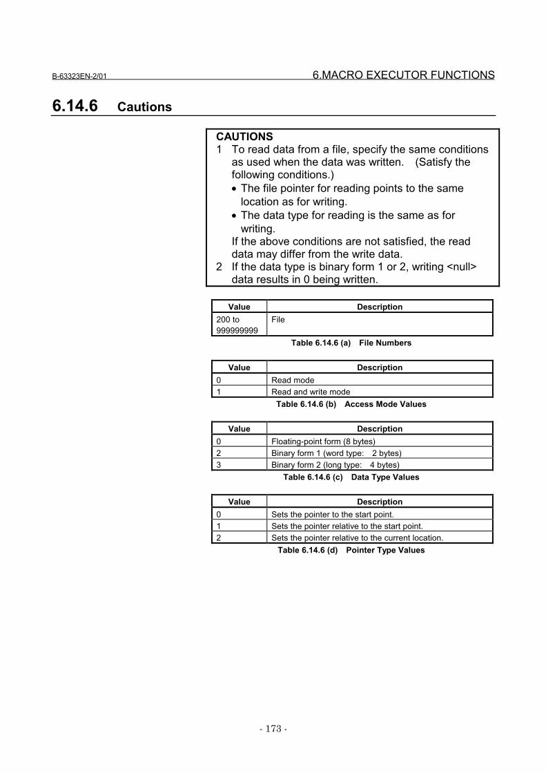
B-63323EN-2/01 6.MACRO EXECUTOR FUNCTIONS
- 173 -
6.14.6 Cautions
CAUTIONS1 To read data from a file, specify the same conditions
as used when the data was written. (Satisfy thefollowing conditions.)• The file pointer for reading points to the same
location as for writing.• The data type for reading is the same as for
writing.If the above conditions are not satisfied, the readdata may differ from the write data.
2 If the data type is binary form 1 or 2, writing <null>data results in 0 being written.
Value Description200 to999999999
File
Table 6.14.6 (a) File Numbers
Value Description0 Read mode1 Read and write mode
Table 6.14.6 (b) Access Mode Values
Value Description0 Floating-point form (8 bytes)2 Binary form 1 (word type: 2 bytes)3 Binary form 2 (long type: 4 bytes)
Table 6.14.6 (c) Data Type Values
Value Description0 Sets the pointer to the start point.1 Sets the pointer relative to the start point.2 Sets the pointer relative to the current location.
Table 6.14.6 (d) Pointer Type Values
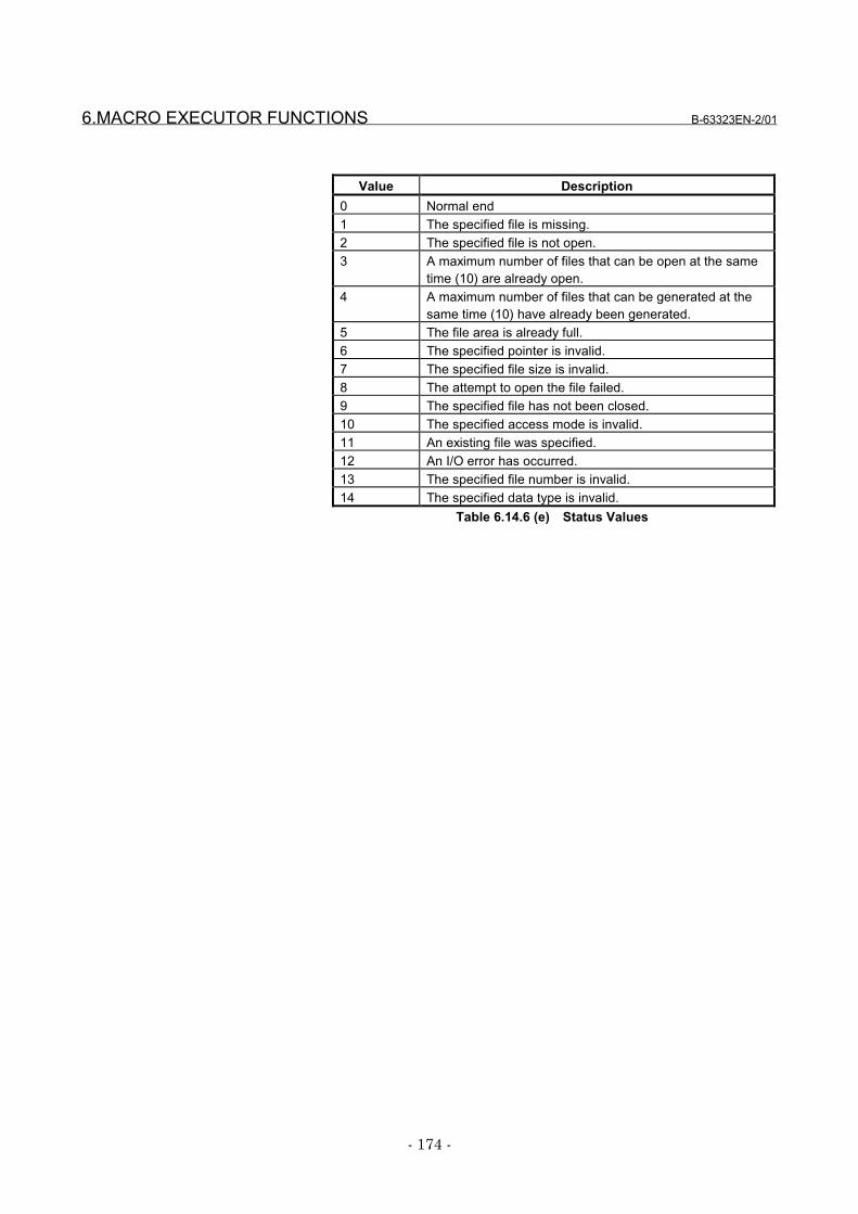
6.MACRO EXECUTOR FUNCTIONS B-63323EN-2/01
- 174 -
Value Description0 Normal end1 The specified file is missing.2 The specified file is not open.3 A maximum number of files that can be open at the same
time (10) are already open.4 A maximum number of files that can be generated at the
same time (10) have already been generated.5 The file area is already full.6 The specified pointer is invalid.7 The specified file size is invalid.8 The attempt to open the file failed.9 The specified file has not been closed.10 The specified access mode is invalid.11 An existing file was specified.12 An I/O error has occurred.13 The specified file number is invalid.14 The specified data type is invalid.
Table 6.14.6 (e) Status Values
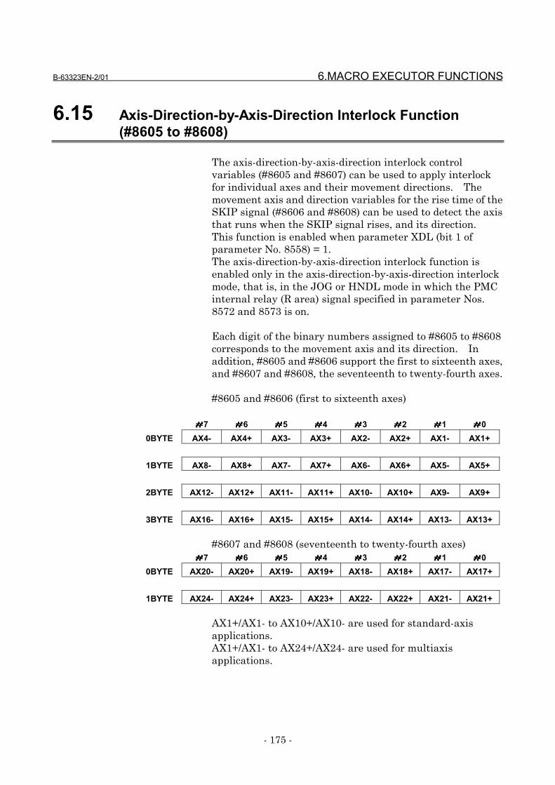
B-63323EN-2/01 6.MACRO EXECUTOR FUNCTIONS
- 175 -
6.15 Axis-Direction-by-Axis-Direction Interlock Function(#8605 to #8608)
The axis-direction-by-axis-direction interlock controlvariables (#8605 and #8607) can be used to apply interlockfor individual axes and their movement directions. Themovement axis and direction variables for the rise time of theSKIP signal (#8606 and #8608) can be used to detect the axisthat runs when the SKIP signal rises, and its direction.This function is enabled when parameter XDL (bit 1 ofparameter No. 8558) = 1.The axis-direction-by-axis-direction interlock function isenabled only in the axis-direction-by-axis-direction interlockmode, that is, in the JOG or HNDL mode in which the PMCinternal relay (R area) signal specified in parameter Nos.8572 and 8573 is on.
Each digit of the binary numbers assigned to #8605 to #8608corresponds to the movement axis and its direction. Inaddition, #8605 and #8606 support the first to sixteenth axes,and #8607 and #8608, the seventeenth to twenty-fourth axes.
#8605 and #8606 (first to sixteenth axes)
####7 ####6 ####5 ####4 ####3 ####2 ####1 ####00BYTE AX4- AX4+ AX3- AX3+ AX2- AX2+ AX1- AX1+
1BYTE AX8- AX8+ AX7- AX7+ AX6- AX6+ AX5- AX5+
2BYTE AX12- AX12+ AX11- AX11+ AX10- AX10+ AX9- AX9+
3BYTE AX16- AX16+ AX15- AX15+ AX14- AX14+ AX13- AX13+
#8607 and #8608 (seventeenth to twenty-fourth axes)####7 ####6 ####5 ####4 ####3 ####2 ####1 ####0
0BYTE AX20- AX20+ AX19- AX19+ AX18- AX18+ AX17- AX17+
1BYTE AX24- AX24+ AX23- AX23+ AX22- AX22+ AX21- AX21+
AX1+/AX1- to AX10+/AX10- are used for standard-axisapplications.AX1+/AX1- to AX24+/AX24- are used for multiaxisapplications.
6.MACRO EXECUTOR FUNCTIONS B-63323EN-2/01
- 176 -
EXAMPLES1 If #8605 and #8606 have a binary number of
1000000000000001, they indicate the positivedirection of the first axis (AX1+) and the negativedirection of the eighth axis (AX8-). This binarynumber is equivalent to 32769 in decimal.
2 If #8607 and #8608 have a binary number of1000000000000001, they indicate the positivedirection of the seventeenth axis (AX17+) and thenegative direction of the twenty-fourth axis (AX24-).This binary number is equivalent to 32769 indecimal.
Axis-direction-by-axis-direction interlock control variables (#8605 and #8607)
When both #8605 and #8607 are 0, interlock is applied to allaxes when the SKIP signal (or, at a high-speed skip, thehigh-speed skip signal) is on. Even if this function is notused for the seventeenth axis and those assigned a higheraxis number, not only #8605 but also #8607 must be 0.#8606 and #8608 reflect the axes that are caused to stopwhen the skip signal becomes on and the direction in whichthe axes were moving just before they stopped. Thesecontrol variables retain the information until the skip signalis turned off and on again. Interlock is kept applied to theaxes and directions that correspond to the values of thecontrol variables. To release interlock, turn off the PMCinternal relay (R area).If either #8605 or #8607 is not 0, interlock is applied to theaxes and directions indicated by #8605 or #8607.#8605 supports the first to sixteenth axes, and #8607, theseventieth to twenty-fourth axes.
NOTESet data in #8607 and #8605 in the statedsequence. Interlock begins when data is set in#8605.Consider the following example.#8607=32769;....(Positive direction of the
seventeenth axis, negativedirection of the twenty-fourth axis)
#8605=1;............(Positive direction of the first axis)At this point, interlock is appliedto the first, seventeenth, andtwenty-fourth axes.
B-63323EN-2/01 6.MACRO EXECUTOR FUNCTIONS
- 177 -
To release interlock, reset #8605 and #8607 to 0, or turn offthe PMC internal relay (R area) to reset these controlvariables to 0. Immediately after the power is switched on,or when the axis-direction-by-axis-direction interlockfunction is disabled (parameter XDL (bit 1 of parameter No.8558) = 0 or the PMC internal relay (R area) is off), #8605and #8607 are 0.
Movement axis and direction variables for the rise time of the SKIP signal(#8606 and #8608)
When the state of the SKIP signal (or, at a high-speed skip,the high-speed skip signal) is changed from off to on, #8606and #8608 indicate the axis that moved most recently andthe direction of its movement. #8606 supports the first tosixteenth axes, and #8608, the seventeenth to twenty-fourthaxes.#8606 and #8608 retains their values until the state of theSKIP signal changes from off to on again. When the PMCinternal relay (R area) is turned off, both #8606 and #8608are reset to 0, thereby disabling this function.
NOTEAny value can be written to neither #8606 nor#8608.
6.MACRO EXECUTOR FUNCTIONS B-63323EN-2/01
- 178 -
6.16 Window Function (#8996 to #8999)
6.16.1 General
The window function enables referencing of the followingsystem information:
1. Alarm information and external alarm information2. Number of controlled axes and number of servo axes3. Cumulative operation time and number of parts4. Diagnosis information (No. 1000 and No. 1001)5. System series information, servo series information,
and PMC series information
Window control variables#8997: System information ID#8998: Axis number#8999: System information#8996: Completion code
Method of usingSet #8997 with the ID No. of the system information to bereferenced.If the system information depends on the controlled axis orspindle, set #8998 with the number of the controlled axis orspindle.Now read-accessing #8999 enables you to view theinformation about the system.Then, #8996 indicates whether the window function wasexecuted normally (0 for normal end and -1 for abnormalend).
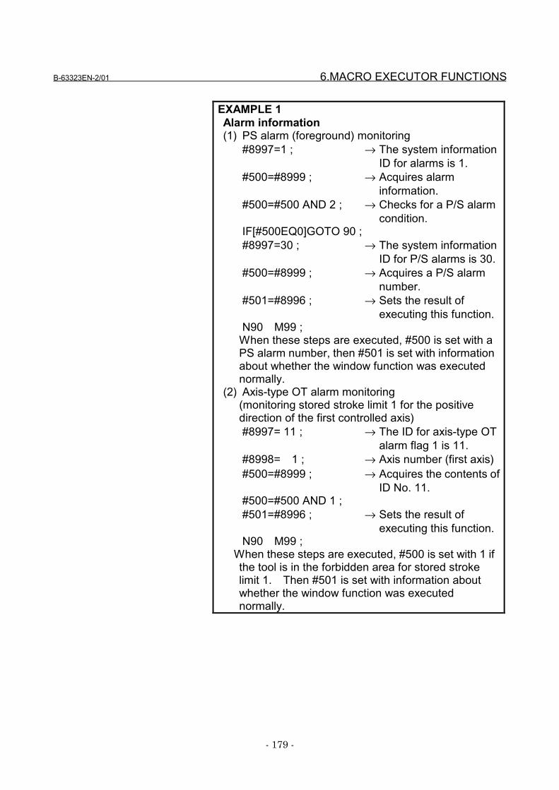
B-63323EN-2/01 6.MACRO EXECUTOR FUNCTIONS
- 179 -
EXAMPLE 1Alarm information(1) PS alarm (foreground) monitoring
#8997=1 ; → The system informationID for alarms is 1.
#500=#8999 ; → Acquires alarminformation.
#500=#500 AND 2 ; → Checks for a P/S alarmcondition.
IF[#500EQ0]GOTO 90 ;#8997=30 ; → The system information
ID for P/S alarms is 30.#500=#8999 ; → Acquires a P/S alarm
number.#501=#8996 ; → Sets the result of
executing this function.N90 M99 ;
When these steps are executed, #500 is set with aPS alarm number, then #501 is set with informationabout whether the window function was executednormally.
(2) Axis-type OT alarm monitoring(monitoring stored stroke limit 1 for the positivedirection of the first controlled axis)#8997= 11 ; → The ID for axis-type OT
alarm flag 1 is 11.#8998= 1 ; → Axis number (first axis)#500=#8999 ; → Acquires the contents of
ID No. 11.#500=#500 AND 1 ;#501=#8996 ; → Sets the result of
executing this function.N90 M99 ;
When these steps are executed, #500 is set with 1 ifthe tool is in the forbidden area for stored strokelimit 1. Then #501 is set with information aboutwhether the window function was executednormally.
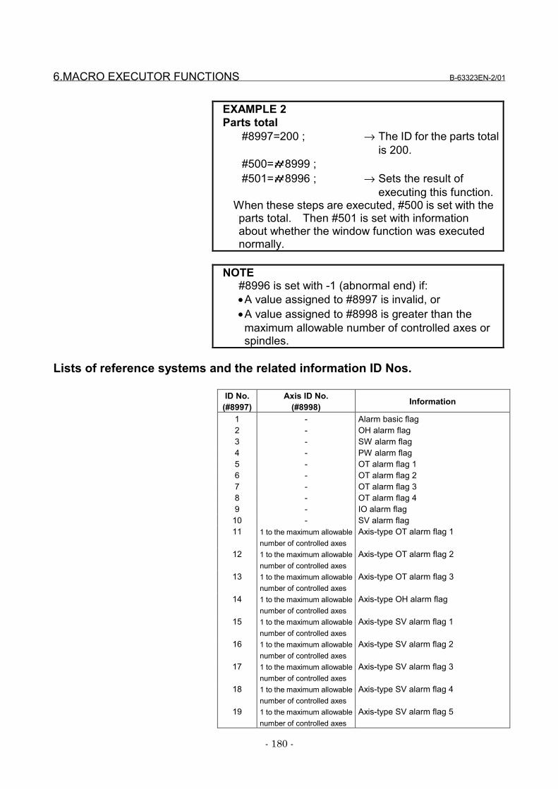
6.MACRO EXECUTOR FUNCTIONS B-63323EN-2/01
- 180 -
EXAMPLE 2Parts total
#8997=200 ; → The ID for the parts totalis 200.
#500=#8999 ;#501=#8996 ; → Sets the result of
executing this function.When these steps are executed, #500 is set with theparts total. Then #501 is set with informationabout whether the window function was executednormally.
NOTE#8996 is set with -1 (abnormal end) if:•A value assigned to #8997 is invalid, or•A value assigned to #8998 is greater than the
maximum allowable number of controlled axes orspindles.
Lists of reference systems and the related information ID Nos.
ID No.(#8997)
Axis ID No.(#8998) Information
1 - Alarm basic flag2 - OH alarm flag3 - SW alarm flag4 - PW alarm flag5 - OT alarm flag 16 - OT alarm flag 27 - OT alarm flag 38 - OT alarm flag 49 - IO alarm flag
10 - SV alarm flag11 1 to the maximum allowable
number of controlled axesAxis-type OT alarm flag 1
12 1 to the maximum allowablenumber of controlled axes
Axis-type OT alarm flag 2
13 1 to the maximum allowablenumber of controlled axes
Axis-type OT alarm flag 3
14 1 to the maximum allowablenumber of controlled axes
Axis-type OH alarm flag
15 1 to the maximum allowablenumber of controlled axes
Axis-type SV alarm flag 1
16 1 to the maximum allowablenumber of controlled axes
Axis-type SV alarm flag 2
17 1 to the maximum allowablenumber of controlled axes
Axis-type SV alarm flag 3
18 1 to the maximum allowablenumber of controlled axes
Axis-type SV alarm flag 4
19 1 to the maximum allowablenumber of controlled axes
Axis-type SV alarm flag 5
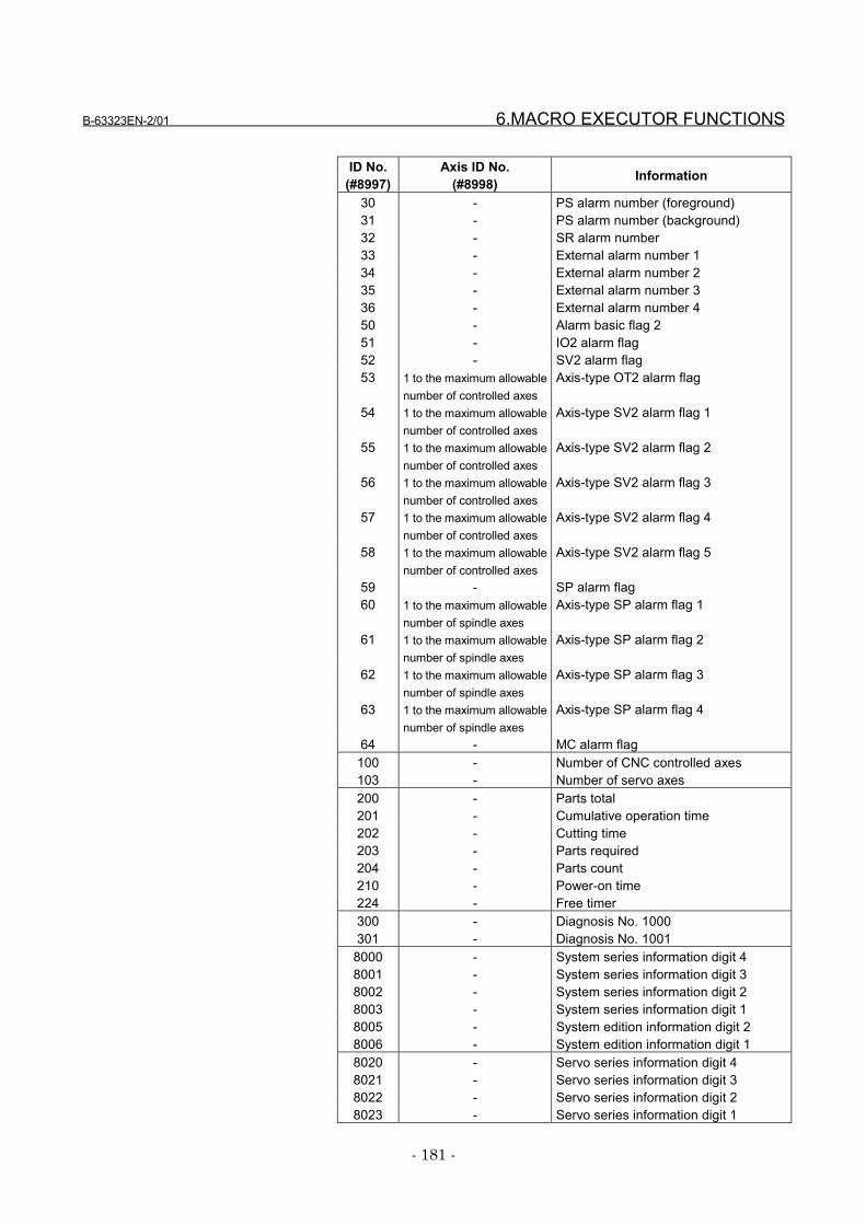
B-63323EN-2/01 6.MACRO EXECUTOR FUNCTIONS
- 181 -
ID No.(#8997)
Axis ID No.(#8998) Information
30 - PS alarm number (foreground)31 - PS alarm number (background)32 - SR alarm number33 - External alarm number 134 - External alarm number 235 - External alarm number 336 - External alarm number 450 - Alarm basic flag 251 - IO2 alarm flag52 - SV2 alarm flag53 1 to the maximum allowable
number of controlled axesAxis-type OT2 alarm flag
54 1 to the maximum allowablenumber of controlled axes
Axis-type SV2 alarm flag 1
55 1 to the maximum allowablenumber of controlled axes
Axis-type SV2 alarm flag 2
56 1 to the maximum allowablenumber of controlled axes
Axis-type SV2 alarm flag 3
57 1 to the maximum allowablenumber of controlled axes
Axis-type SV2 alarm flag 4
58 1 to the maximum allowablenumber of controlled axes
Axis-type SV2 alarm flag 5
59 - SP alarm flag60 1 to the maximum allowable
number of spindle axesAxis-type SP alarm flag 1
61 1 to the maximum allowablenumber of spindle axes
Axis-type SP alarm flag 2
62 1 to the maximum allowablenumber of spindle axes
Axis-type SP alarm flag 3
63 1 to the maximum allowablenumber of spindle axes
Axis-type SP alarm flag 4
64 - MC alarm flag100 - Number of CNC controlled axes103 - Number of servo axes200 - Parts total201 - Cumulative operation time202 - Cutting time203 - Parts required204 - Parts count210 - Power-on time224 - Free timer300 - Diagnosis No. 1000301 - Diagnosis No. 1001
8000 - System series information digit 48001 - System series information digit 38002 - System series information digit 28003 - System series information digit 18005 - System edition information digit 28006 - System edition information digit 18020 - Servo series information digit 48021 - Servo series information digit 38022 - Servo series information digit 28023 - Servo series information digit 1
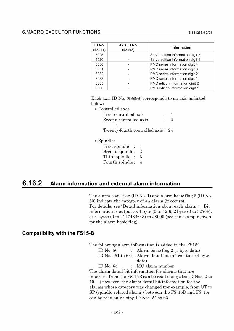
6.MACRO EXECUTOR FUNCTIONS B-63323EN-2/01
- 182 -
ID No.(#8997)
Axis ID No.(#8998) Information
8025 - Servo edition information digit 28026 - Servo edition information digit 18030 - PMC series information digit 48031 - PMC series information digit 38032 - PMC series information digit 28033 - PMC series information digit 18035 - PMC edition information digit 28036 - PMC edition information digit 1
Each axis ID No. (#8998) corresponds to an axis as listedbelow:
• Controlled axesFirst controlled axis : 1Second controlled axis : 2
:Twenty-fourth controlled axis : 24
• SpindlesFirst spindle : 1Second spindle : 2Third spindle : 3Fourth spindle : 4
6.16.2 Alarm information and external alarm information
The alarm basic flag (ID No. 1) and alarm basic flag 2 (ID No.50) indicate the category of an alarm (if occurs).For details, see "Detail information about each alarm." Bitinformation is output as 1 byte (0 to 128), 2 byte (0 to 32768),or 4 bytes (0 to 2147483648) to #8999 (see the example givenfor the alarm basic flag).
Compatibility with the FS15-B
The following alarm information is added in the FS15i.ID No. 50 : Alarm basic flag 2 (1-byte data)ID Nos. 51 to 63: Alarm detail bit information (4-byte
data)ID No. 64 : MC alarm number
The alarm detail bit information for alarms that areinherited from the FS-15B can be read using also ID Nos. 2 to19. (However, the alarm detail bit information for thealarms whose category was changed (for example, from OT toSP (spindle-related alarm)) between the FS-15B and FS-15ican be read only using ID Nos. 51 to 63.
B-63323EN-2/01 6.MACRO EXECUTOR FUNCTIONS
- 183 -
NOTES1 Information about the alarms added in the FS15i
can be read only using ID Nos. 50 to 64 (new alarminformation).
2 Some spindle-related alarms were changed in theFS15i (OT → SP). For details, see "Detailinformation about each alarm."
3 The detail bit information about an alarm that existsin both the FS15-B and FS15i and has the samecategory and number for both systems can be readusing both ID Nos. 51 to 63 (4-byte data) and IDNos. 2 to 19 (1-byte data), because thecorresponding bit in both data becomes 1. (Seethe example given in "Detail information abouteach alarm.")
FS15i original informationIf an MC alarm occurs, the information indicated by thealarm basic flag (ID No. 1) varies with the setting ofparameter 15I (bit 3 of parameter No. 8558) as follows:• If parameter 15I (bit 3 of parameter No. 8558) = 0, the
foreground PS alarm (02h) is 1.• If parameter 15I (bit 3 of parameter No. 8558) = 1, the
foreground PS alarm (02h) is 0.In either case, however, the MC alarm flag (01h) in alarmbasic flag 2 (ID No. 50) is 1.
NOTEThe specifications of some macro executorfunctions in parameter 15I (bit 3 of parameter No.8558) original to the FS15i have been changed .For details, see 9.1, "Compile Parameters."
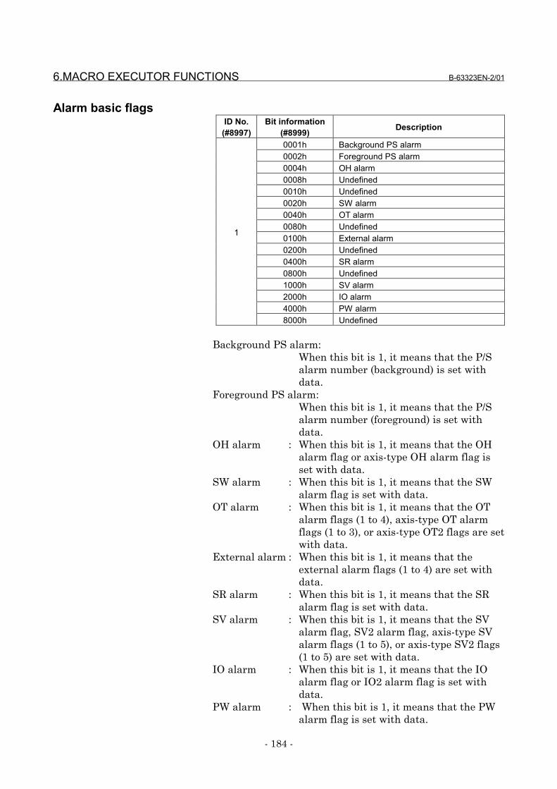
6.MACRO EXECUTOR FUNCTIONS B-63323EN-2/01
- 184 -
Alarm basic flagsID No.
(#8997)Bit information
(#8999) Description
0001h Background PS alarm0002h Foreground PS alarm0004h OH alarm0008h Undefined0010h Undefined0020h SW alarm0040h OT alarm0080h Undefined0100h External alarm0200h Undefined0400h SR alarm0800h Undefined1000h SV alarm2000h IO alarm4000h PW alarm
1
8000h Undefined
Background PS alarm:When this bit is 1, it means that the P/Salarm number (background) is set withdata.
Foreground PS alarm:When this bit is 1, it means that the P/Salarm number (foreground) is set withdata.
OH alarm : When this bit is 1, it means that the OHalarm flag or axis-type OH alarm flag isset with data.
SW alarm : When this bit is 1, it means that the SWalarm flag is set with data.
OT alarm : When this bit is 1, it means that the OTalarm flags (1 to 4), axis-type OT alarmflags (1 to 3), or axis-type OT2 flags are setwith data.
External alarm : When this bit is 1, it means that theexternal alarm flags (1 to 4) are set withdata.
SR alarm : When this bit is 1, it means that the SRalarm flag is set with data.
SV alarm : When this bit is 1, it means that the SValarm flag, SV2 alarm flag, axis-type SValarm flags (1 to 5), or axis-type SV2 flags(1 to 5) are set with data.
IO alarm : When this bit is 1, it means that the IOalarm flag or IO2 alarm flag is set withdata.
PW alarm : When this bit is 1, it means that the PWalarm flag is set with data.
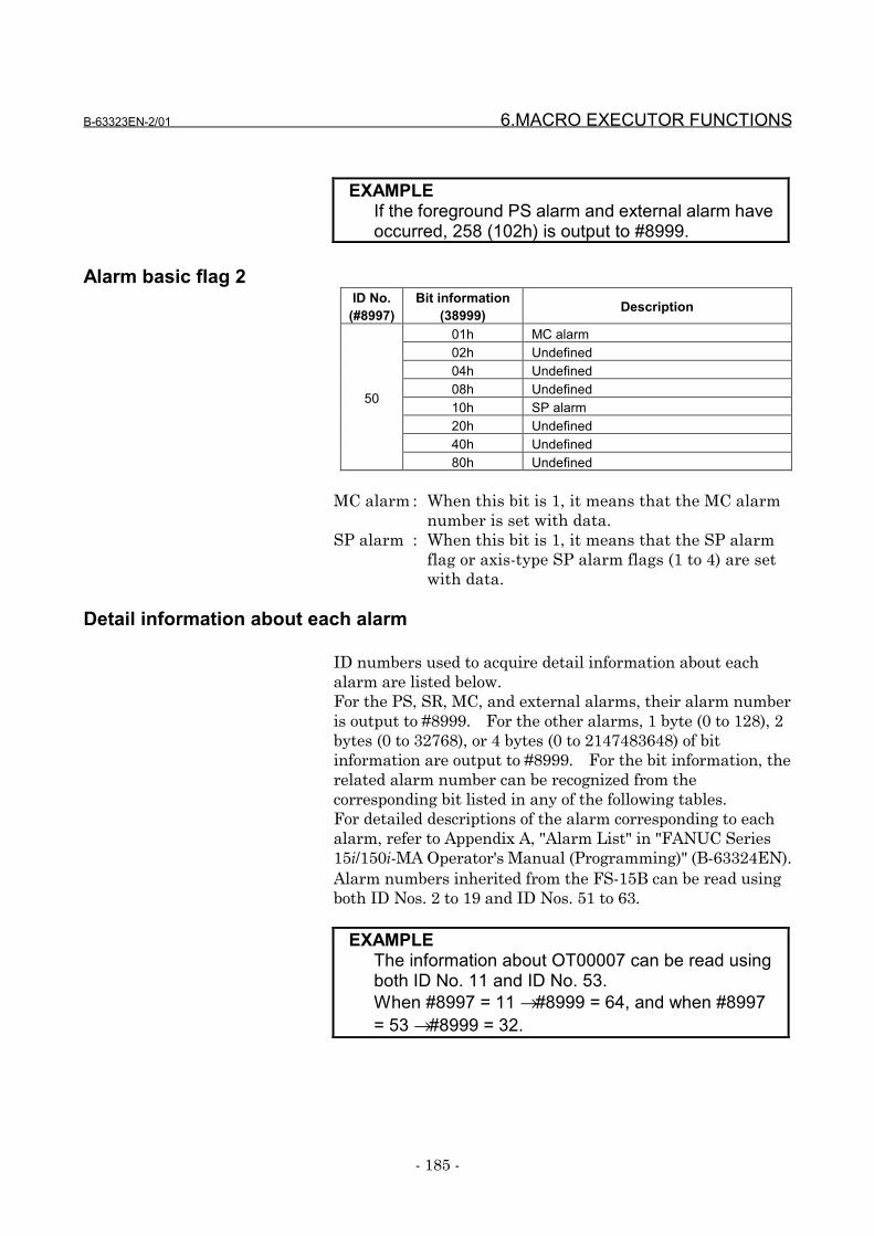
B-63323EN-2/01 6.MACRO EXECUTOR FUNCTIONS
- 185 -
EXAMPLEIf the foreground PS alarm and external alarm haveoccurred, 258 (102h) is output to #8999.
Alarm basic flag 2ID No.
(#8997)Bit information
(38999) Description
01h MC alarm02h Undefined04h Undefined08h Undefined10h SP alarm20h Undefined40h Undefined
50
80h Undefined
MC alarm : When this bit is 1, it means that the MC alarmnumber is set with data.
SP alarm : When this bit is 1, it means that the SP alarmflag or axis-type SP alarm flags (1 to 4) are setwith data.
Detail information about each alarm
ID numbers used to acquire detail information about eachalarm are listed below.For the PS, SR, MC, and external alarms, their alarm numberis output to #8999. For the other alarms, 1 byte (0 to 128), 2bytes (0 to 32768), or 4 bytes (0 to 2147483648) of bitinformation are output to #8999. For the bit information, therelated alarm number can be recognized from thecorresponding bit listed in any of the following tables.For detailed descriptions of the alarm corresponding to eachalarm, refer to Appendix A, "Alarm List" in "FANUC Series15i/150i-MA Operator's Manual (Programming)" (B-63324EN).Alarm numbers inherited from the FS-15B can be read usingboth ID Nos. 2 to 19 and ID Nos. 51 to 63.
EXAMPLEThe information about OT00007 can be read usingboth ID No. 11 and ID No. 53.When #8997 = 11 → #8999 = 64, and when #8997= 53 → #8999 = 32.
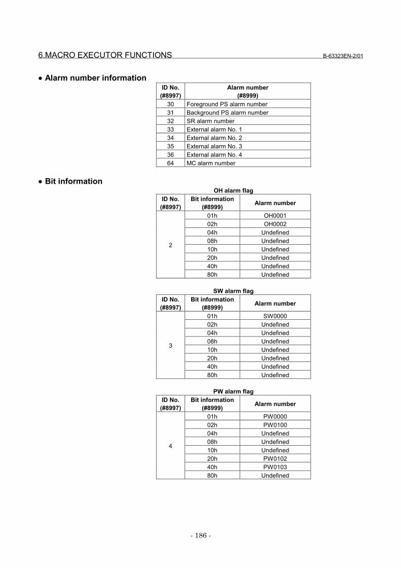
6.MACRO EXECUTOR FUNCTIONS B-63323EN-2/01
- 186 -
•••• Alarm number informationID No.
(#8997)Alarm number
(#8999)30 Foreground PS alarm number31 Background PS alarm number32 SR alarm number33 External alarm No. 134 External alarm No. 235 External alarm No. 336 External alarm No. 464 MC alarm number
•••• Bit informationOH alarm flag
ID No.(#8997)
Bit information(#8999) Alarm number
01h OH000102h OH000204h Undefined08h Undefined10h Undefined20h Undefined40h Undefined
2
80h Undefined
SW alarm flagID No.
(#8997)Bit information
(#8999) Alarm number
01h SW000002h Undefined04h Undefined08h Undefined10h Undefined20h Undefined40h Undefined
3
80h Undefined
PW alarm flagID No.
(#8997)Bit information
(#8999) Alarm number
01h PW000002h PW010004h Undefined08h Undefined10h Undefined20h PW010240h PW0103
4
80h Undefined
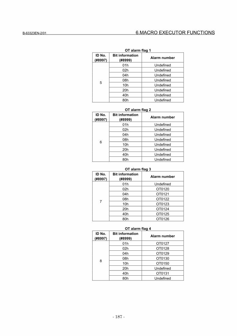
B-63323EN-2/01 6.MACRO EXECUTOR FUNCTIONS
- 187 -
OT alarm flag 1ID No.
(#8997)Bit information
(#8999) Alarm number
01h Undefined02h Undefined04h Undefined08h Undefined10h Undefined20h Undefined40h Undefined
5
80h Undefined
OT alarm flag 2ID No.
(#8997)Bit information
(#8999) Alarm number
01h Undefined02h Undefined04h Undefined08h Undefined10h Undefined20h Undefined40h Undefined
6
80h Undefined
OT alarm flag 3ID No.
(#8997)Bit information
(#8999) Alarm number
01h Undefined02h OT012004h OT012108h OT012210h OT012320h OT012440h OT0125
7
80h OT0126
OT alarm flag 4ID No.
(#8997)Bit information
(#8999) Alarm number
01h OT012702h OT012804h OT012908h OT013010h OT015020h Undefined40h OT0131
8
80h Undefined
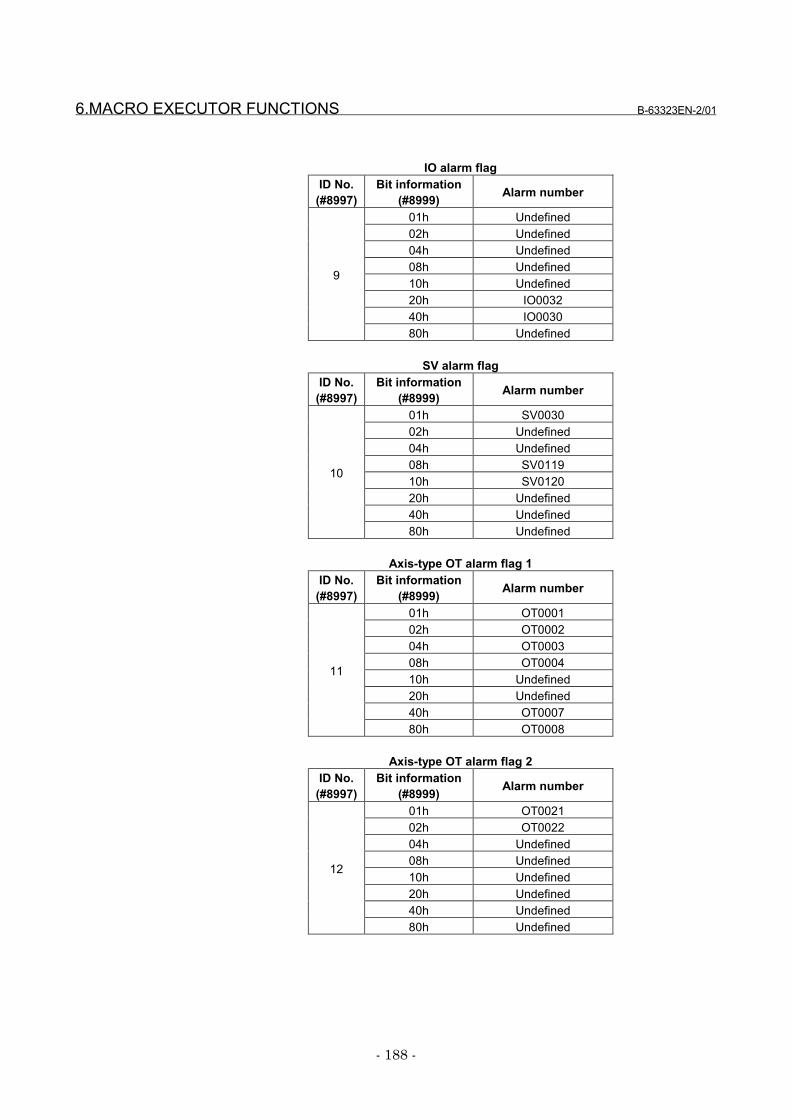
6.MACRO EXECUTOR FUNCTIONS B-63323EN-2/01
- 188 -
IO alarm flagID No.
(#8997)Bit information
(#8999) Alarm number
01h Undefined02h Undefined04h Undefined08h Undefined10h Undefined20h IO003240h IO0030
9
80h Undefined
SV alarm flagID No.
(#8997)Bit information
(#8999) Alarm number
01h SV003002h Undefined04h Undefined08h SV011910h SV012020h Undefined40h Undefined
10
80h Undefined
Axis-type OT alarm flag 1ID No.
(#8997)Bit information
(#8999) Alarm number
01h OT000102h OT000204h OT000308h OT000410h Undefined20h Undefined40h OT0007
11
80h OT0008
Axis-type OT alarm flag 2ID No.
(#8997)Bit information
(#8999) Alarm number
01h OT002102h OT002204h Undefined08h Undefined10h Undefined20h Undefined40h Undefined
12
80h Undefined
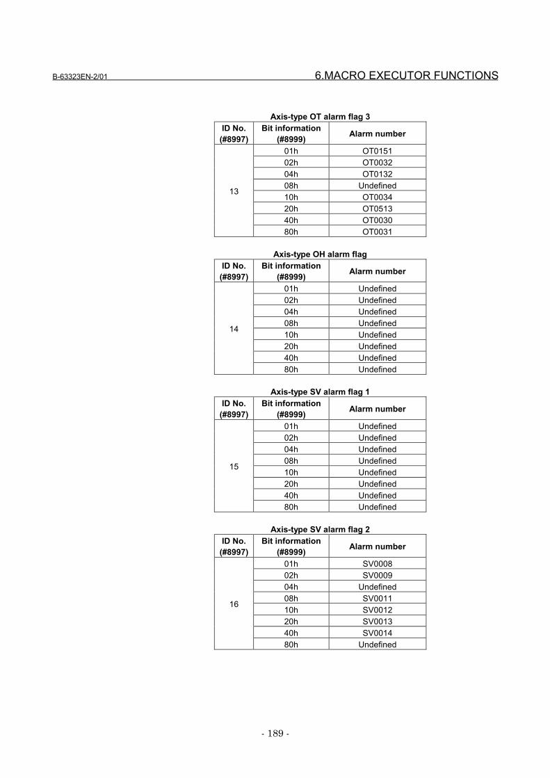
B-63323EN-2/01 6.MACRO EXECUTOR FUNCTIONS
- 189 -
Axis-type OT alarm flag 3ID No.
(#8997)Bit information
(#8999) Alarm number
01h OT015102h OT003204h OT013208h Undefined10h OT003420h OT051340h OT0030
13
80h OT0031
Axis-type OH alarm flagID No.
(#8997)Bit information
(#8999) Alarm number
01h Undefined02h Undefined04h Undefined08h Undefined10h Undefined20h Undefined40h Undefined
14
80h Undefined
Axis-type SV alarm flag 1ID No.
(#8997)Bit information
(#8999) Alarm number
01h Undefined02h Undefined04h Undefined08h Undefined10h Undefined20h Undefined40h Undefined
15
80h Undefined
Axis-type SV alarm flag 2ID No.
(#8997)Bit information
(#8999) Alarm number
01h SV000802h SV000904h Undefined08h SV001110h SV001220h SV001340h SV0014
16
80h Undefined
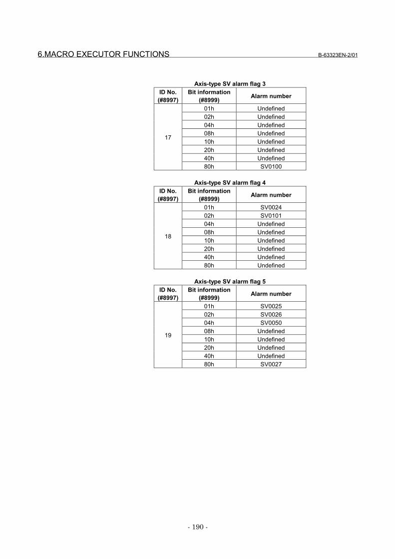
6.MACRO EXECUTOR FUNCTIONS B-63323EN-2/01
- 190 -
Axis-type SV alarm flag 3ID No.
(#8997)Bit information
(#8999) Alarm number
01h Undefined02h Undefined04h Undefined08h Undefined10h Undefined20h Undefined40h Undefined
17
80h SV0100
Axis-type SV alarm flag 4ID No.
(#8997)Bit information
(#8999) Alarm number
01h SV002402h SV010104h Undefined08h Undefined10h Undefined20h Undefined40h Undefined
18
80h Undefined
Axis-type SV alarm flag 5ID No.
(#8997)Bit information
(#8999) Alarm number
01h SV002502h SV002604h SV005008h Undefined10h Undefined20h Undefined40h Undefined
19
80h SV0027

B-63323EN-2/01 6.MACRO EXECUTOR FUNCTIONS
- 191 -
IO2 alarm flagID No.
(#8997)Bit information
(#8999) Alarm number
00000001h Undefined00000002h IO000100000004h IO000200000008h IO003000000010h IO003200000020h Undefined00000040h Undefined00000080h Undefined00000100h Undefined00000200h Undefined00000400h Undefined00000800h Undefined00001000h Undefined00002000h Undefined00004000h Undefined00008000h Undefined00010000h Undefined00020000h Undefined00040000h Undefined00080000h Undefined00100000h Undefined00200000h Undefined00400000h Undefined00800000h Undefined01000000h Undefined02000000h Undefined04000000h Undefined08000000h Undefined10000000h Undefined20000000h Undefined40000000h Undefined
51
80000000h Undefined

6.MACRO EXECUTOR FUNCTIONS B-63323EN-2/01
- 192 -
SV2 alarm flagID No.
(#8997)Bit information
(#8999) Alarm number
00000001h Undefined00000002h SV003000000004h SV006000000008h SV006100000010h SV006200000020h SV006300000040h SV006400000080h SV006500000100h SV006600000200h SV006700000400h SV011900000800h SV012000001000h SV012700002000h SV012800004000h Undefined00008000h Undefined00010000h Undefined00020000h Undefined00040000h Undefined00080000h Undefined00100000h Undefined00200000h Undefined00400000h Undefined00800000h Undefined01000000h Undefined02000000h Undefined04000000h Undefined08000000h Undefined10000000h Undefined20000000h Undefined40000000h Undefined
52
80000000h Undefined
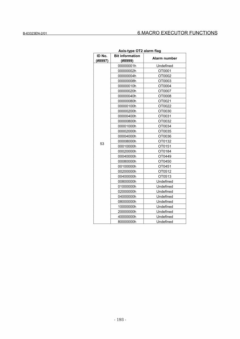
B-63323EN-2/01 6.MACRO EXECUTOR FUNCTIONS
- 193 -
Axis-type OT2 alarm flagID No.
(#8997)Bit information
(#8999) Alarm number
00000001h Undefined00000002h OT000100000004h OT000200000008h OT000300000010h OT000400000020h OT000700000040h OT000800000080h OT002100000100h OT002200000200h OT003000000400h OT003100000800h OT003200001000h OT003400002000h OT003500004000h OT003600008000h OT013200010000h OT015100020000h OT018400040000h OT044900080000h OT045000100000h OT045100200000h OT051200400000h OT051300800000h Undefined01000000h Undefined02000000h Undefined04000000h Undefined08000000h Undefined10000000h Undefined20000000h Undefined40000000h Undefined
53
80000000h Undefined
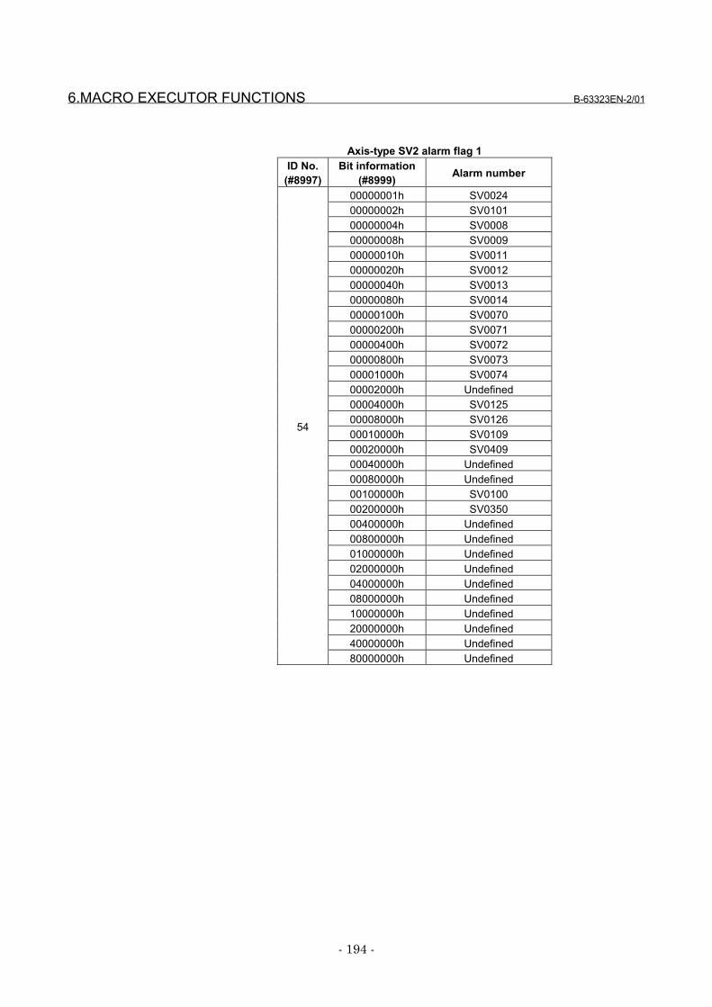
6.MACRO EXECUTOR FUNCTIONS B-63323EN-2/01
- 194 -
Axis-type SV2 alarm flag 1ID No.
(#8997)Bit information
(#8999) Alarm number
00000001h SV002400000002h SV010100000004h SV000800000008h SV000900000010h SV001100000020h SV001200000040h SV001300000080h SV001400000100h SV007000000200h SV007100000400h SV007200000800h SV007300001000h SV007400002000h Undefined00004000h SV012500008000h SV012600010000h SV010900020000h SV040900040000h Undefined00080000h Undefined00100000h SV010000200000h SV035000400000h Undefined00800000h Undefined01000000h Undefined02000000h Undefined04000000h Undefined08000000h Undefined10000000h Undefined20000000h Undefined40000000h Undefined
54
80000000h Undefined

B-63323EN-2/01 6.MACRO EXECUTOR FUNCTIONS
- 195 -
Axis-type SV2 alarm flag 2ID No.
(#8997)Bit information
(#8999) Alarm number
00000001h SV043000000002h SV043100000004h SV043200000008h SV043300000010h SV043400000020h SV043500000040h SV043600000080h SV043700000100h SV043800000200h SV043900000400h SV044000000800h SV044100001000h SV044200002000h SV044300004000h SV044400008000h SV044500010000h SV044600020000h SV044700040000h SV044800080000h SV044900100000h SV036000200000h SV036100400000h SV036300800000h SV036401000000h SV036502000000h SV036604000000h SV036708000000h SV036810000000h SV036920000000h SV038040000000h SV0381
55
80000000h SV0382
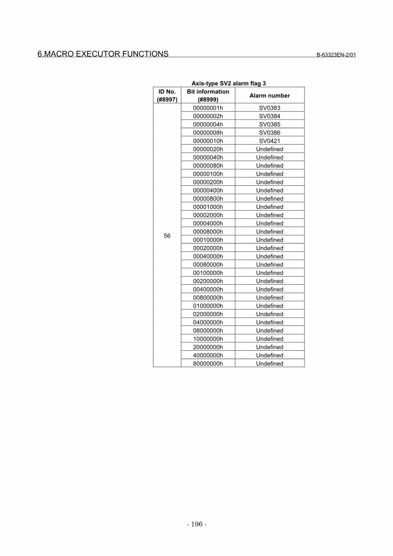
6.MACRO EXECUTOR FUNCTIONS B-63323EN-2/01
- 196 -
Axis-type SV2 alarm flag 3ID No.
(#8997)Bit information
(#8999) Alarm number
00000001h SV038300000002h SV038400000004h SV038500000008h SV038600000010h SV042100000020h Undefined00000040h Undefined00000080h Undefined00000100h Undefined00000200h Undefined00000400h Undefined00000800h Undefined00001000h Undefined00002000h Undefined00004000h Undefined00008000h Undefined00010000h Undefined00020000h Undefined00040000h Undefined00080000h Undefined00100000h Undefined00200000h Undefined00400000h Undefined00800000h Undefined01000000h Undefined02000000h Undefined04000000h Undefined08000000h Undefined10000000h Undefined20000000h Undefined40000000h Undefined
56
80000000h Undefined
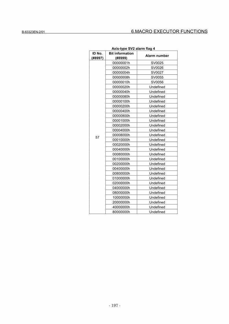
B-63323EN-2/01 6.MACRO EXECUTOR FUNCTIONS
- 197 -
Axis-type SV2 alarm flag 4ID No.
(#8997)Bit information
(#8999) Alarm number
00000001h SV002500000002h SV002600000004h SV002700000008h SV005500000010h SV005600000020h Undefined00000040h Undefined00000080h Undefined00000100h Undefined00000200h Undefined00000400h Undefined00000800h Undefined00001000h Undefined00002000h Undefined00004000h Undefined00008000h Undefined00010000h Undefined00020000h Undefined00040000h Undefined00080000h Undefined00100000h Undefined00200000h Undefined00400000h Undefined00800000h Undefined01000000h Undefined02000000h Undefined04000000h Undefined08000000h Undefined10000000h Undefined20000000h Undefined40000000h Undefined
57
80000000h Undefined

6.MACRO EXECUTOR FUNCTIONS B-63323EN-2/01
- 198 -
Axis-type SV2 alarm flag 5ID No.
(#8997)Bit information
(#8999) Alarm number
00000001h Undefined00000002h SV004000000004h SV004100000008h SV005000000010h SV007500000020h SV007600000040h Undefined00000080h Undefined00000100h Undefined00000200h Undefined00000400h Undefined00000800h Undefined00001000h Undefined00002000h Undefined00004000h Undefined00008000h Undefined00010000h Undefined00020000h Undefined00040000h Undefined00080000h Undefined00100000h Undefined00200000h Undefined00400000h Undefined00800000h Undefined01000000h Undefined02000000h Undefined04000000h Undefined08000000h Undefined10000000h Undefined20000000h Undefined40000000h Undefined
58
80000000h Undefined
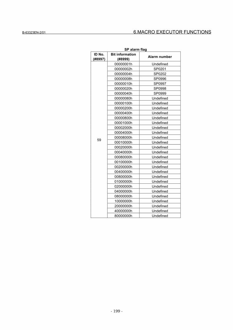
B-63323EN-2/01 6.MACRO EXECUTOR FUNCTIONS
- 199 -
SP alarm flagID No.
(#8997)Bit information
(#8999) Alarm number
00000001h Undefined00000002h SP020100000004h SP020200000008h SP099600000010h SP099700000020h SP099800000040h SP099900000080h Undefined00000100h Undefined00000200h Undefined00000400h Undefined00000800h Undefined00001000h Undefined00002000h Undefined00004000h Undefined00008000h Undefined00010000h Undefined00020000h Undefined00040000h Undefined00080000h Undefined00100000h Undefined00200000h Undefined00400000h Undefined00800000h Undefined01000000h Undefined02000000h Undefined04000000h Undefined08000000h Undefined10000000h Undefined20000000h Undefined40000000h Undefined
59
80000000h Undefined

6.MACRO EXECUTOR FUNCTIONS B-63323EN-2/01
- 200 -
Axis-type SP alarm flag 1ID No.
(#8997)Bit information
(#8999) Alarm number
00000001h Undefined00000002h SP000100000004h SP000200000008h SP000300000010h SP000400000020h SP000500000040h SP000600000080h SP000700000100h SP000800000200h SP000900000400h SP001000000800h SP001100001000h SP001200002000h SP001300004000h SP001400008000h SP001500010000h SP001600020000h SP001700040000h SP001800080000h SP001900100000h SP002000200000h SP002100400000h SP002200800000h SP002301000000h SP002402000000h SP002504000000h SP002608000000h SP002710000000h SP002820000000h SP002940000000h SP0030
60
80000000h SP0031
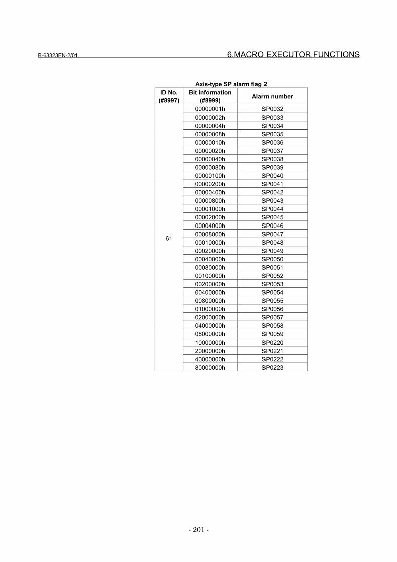
B-63323EN-2/01 6.MACRO EXECUTOR FUNCTIONS
- 201 -
Axis-type SP alarm flag 2ID No.
(#8997)Bit information
(#8999) Alarm number
00000001h SP003200000002h SP003300000004h SP003400000008h SP003500000010h SP003600000020h SP003700000040h SP003800000080h SP003900000100h SP004000000200h SP004100000400h SP004200000800h SP004300001000h SP004400002000h SP004500004000h SP004600008000h SP004700010000h SP004800020000h SP004900040000h SP005000080000h SP005100100000h SP005200200000h SP005300400000h SP005400800000h SP005501000000h SP005602000000h SP005704000000h SP005808000000h SP005910000000h SP022020000000h SP022140000000h SP0222
61
80000000h SP0223
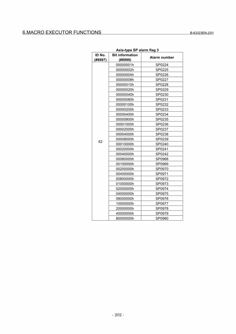
6.MACRO EXECUTOR FUNCTIONS B-63323EN-2/01
- 202 -
Axis-type SP alarm flag 3ID No.
(#8997)Bit information
(#8999) Alarm number
00000001h SP022400000002h SP022500000004h SP022600000008h SP022700000010h SP022800000020h SP022900000040h SP023000000080h SP023100000100h SP023200000200h SP023300000400h SP023400000800h SP023500001000h SP023600002000h SP023700004000h SP023800008000h SP023900010000h SP024000020000h SP024100040000h SP024200080000h SP096800100000h SP096900200000h SP097000400000h SP097100800000h SP097201000000h SP097302000000h SP097404000000h SP097508000000h SP097610000000h SP097720000000h SP097840000000h SP0979
62
80000000h SP0980
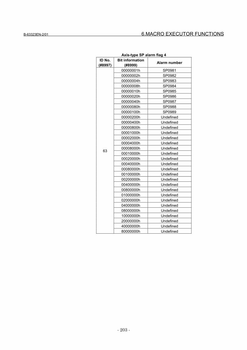
B-63323EN-2/01 6.MACRO EXECUTOR FUNCTIONS
- 203 -
Axis-type SP alarm flag 4ID No.
(#8997)Bit information
(#8999) Alarm number
00000001h SP098100000002h SP098200000004h SP098300000008h SP098400000010h SP098500000020h SP098600000040h SP098700000080h SP098800000100h SP098900000200h Undefined00000400h Undefined00000800h Undefined00001000h Undefined00002000h Undefined00004000h Undefined00008000h Undefined00010000h Undefined00020000h Undefined00040000h Undefined00080000h Undefined00100000h Undefined00200000h Undefined00400000h Undefined00800000h Undefined01000000h Undefined02000000h Undefined04000000h Undefined08000000h Undefined10000000h Undefined20000000h Undefined40000000h Undefined
63
80000000h Undefined
6.MACRO EXECUTOR FUNCTIONS B-63323EN-2/01
- 204 -
6.16.3 The number of controlled axes and the number of servo axes
The number of CNC controlled axes and the number of servoaxes are output using ID Nos. 100 and 103, respectively.
EXAMPLEIf #8997 = 100, 6 read into #8999 indicates that thenumber of CNC controlled axes is 6. In this case,parameter No. 9000 is 6.
6.16.4 Cumulative operation time and parts count
The following statuses are output.• ID No. 200: Parts total• ID No. 201: Cumulative operation time• ID No. 202: Cutting time• ID No. 203: Parts required• ID No. 204: Parts count• ID No. 210: Power-on time• ID No. 224: Free timer
Information read using ID No. 200 : Value of parameter No.0107
Information read using ID No. 201 : Sum of values ofparameter Nos. 0101and 0102 (in hours)
Information read using ID No. 202 : Sum of values ofparameter Nos. 0103and 0104 (in hours)
Information read using ID No. 203 : Value of parameter No.0109
Information read using ID No. 204 : Value of parameter No.0108
Information read using ID No. 210 : Value of parameter No.0100 (in minutes)
Information read using ID No. 224 : Sum of values ofparameter Nos. 0105and 0106 (in hours)
EXAMPLEIf #8997 = 202, 1 read into #8999 indicates acutting time of 1 hour. In this case, parameterNos. 0103 an 0104 are 0 and 60, respectively.
B-63323EN-2/01 6.MACRO EXECUTOR FUNCTIONS
- 205 -
6.16.5 Diagnosis information
The states of diagnosis Nos. 1000 and 1001 are output usingID Nos. 300 and 301, respectively.The output data is one byte of bit information, that is, aninteger ranging from 0 to 128.
The following tables list the detail bit information ofdiagnosis Nos. 1000 and 1001.
Information Read Using ID No. 300 (Diagnosis No. 1000)Bit information Description
01h An in-position check is in progress.02h The feedrate override value is 0%.03h The jog feedrate override value is 0%.04h Interlock/start lock is on.05h The speed arrival signal is being awaited to become on.06h The spindle one revolution signal is being awaited during
threading.07h The position coder is being awaited to rotate during
spindle feed per revolution.08h Feed is at a rest.
Information Read Using ID No. 301 (Diagnosis No. 1001)Bit information Description
01h Foreground data input is in progress.02h Background data input is in progress.03h Undefined04h Undefined05h Undefined06h Undefined07h Undefined08h Undefined
EXAMPLEIf #8997 = 300, 96 (60h) read into #8999 meansthat the spindle one revolution signal is beingawaited during threading and the position coder isbeing awaited to rotate during spindle feed perrevolution.
6.MACRO EXECUTOR FUNCTIONS B-63323EN-2/01
- 206 -
6.16.6 System, servo, and PMC series information
System series information, servo series information, andPMC series information are output using ID Nos. 8000 to8006, ID Nos. 8020 to 8026, and ID Nos. 8030 to 8036,respectively.Each output value is a decimal representation of ASCII code.
• ID No. 8000: System series information digit 4• ID No. 8001: System series information digit 3• ID No. 8002: System series information digit 2• ID No. 8003: System series information digit 1• ID No. 8005: System edition information digit 2• ID No. 8006: System edition information digit 1
• ID No. 8020: Servo series information digit 4• ID No. 8021: Servo series information digit 3• ID No. 8022: Servo series information digit 2• ID No. 8023: Servo series information digit 1• ID No. 8025: Servo edition information digit 2• ID No. 8026: Servo edition information digit 1
• ID No. 8030: PMC series information digit 4• ID No. 8031: PMC series information digit 3• ID No. 8032: PMC series information digit 2• ID No. 8033: PMC series information digit 1• ID No. 8035: PMC edition information digit 2• ID No. 8036: PMC edition information digit 1

B-63323EN-2/01 6.MACRO EXECUTOR FUNCTIONS
- 207 -
EXAMPLEAssume the following for a system of series NW10and edition 01:#8997=8000 ;#500=#8999 ; → Saves system series information
digit 4#8997=8001 ; #501=#8999 ; → Saves system series information
digit 3#8997=8002 ;#502=#8999 ; → Saves system series information
digit 2#8997=8003 ;#503=#8999 ; → Saves system series information
digit 1#8997=8005 ;#504=#8999 ; → Saves system edition information
digit 2#8997=8006 ;#505=#8999 ; → Saves system edition information
digit 1#500, #501, #502, and #503 are set with 78, 87,49, and 48, respectively. The hexadecimalrepresentations of these values are 4Eh, 57h, 31h,and 30h, respectively; so it turns out that digit 4 =N, digit 3 = W, digit 2 = 1, and digit 1 = 0.Similarly, #504 and #505 are set with 48 and 49,respectively. The hexadecimal representations ofthese values are 30h and 31h, respectively; so itturns out that digit 2 = 0 and digit 1 = 1.
6.MACRO EXECUTOR FUNCTIONS B-63323EN-2/01
- 208 -
6.17 Function for Searching Data Tables for Control Variables
This function searches a data table, which contains sets ofconsecutive control variables, for a control variable thatsatisfies a specified condition. If it finds the target controlvariable, it returns the data table set number where thetarget control variable is contained.The function can read the following data:
FormatInput#8530 : Start control variable number in the search target
data table (setting: 1 or greater)#8651 : The number of macro variables that forms a set in
the data table (setting: 1 or greater)#8652 : The number of search target data table sets
(setting: 1 or greater)#8653 : Lower limit to the search value (sign and decimal
point can be entered)#8654 : Upper limit to the search value (sign and decimal
point can be entered)G400 : Search execution (searches for control variable X
that satisfies: #8653 ≤ X ≤ #8654)
Output#8655 : The data table set number where a control variable
that satisfies the search condition is contained (0 orgreater), or= -1: There is no control variable that satisfies the
condition.= -2: The setting of any of #8650 to #8652 is
invalid (0 or less has been set).= -3: #8653 ≤ #8654 is not satisfied.
#8650 : Start control variable number in the set next to theretrieved data table set number (#8655)
#8652 : Set value minus the number of sets that havealready been retrieved

B-63323EN-2/01 6.MACRO EXECUTOR FUNCTIONS
- 209 -
NOTES1 If #8655 = -1:
#8650 = 1 (next control variable number in thesearch target data table)#8652 = 0
2 The set number begins with 0, but the minimumvalue of #8652 (the number of search data tablesets) is 1.
3 If more than one control variable satisfies thesearch condition, a search ends by returning thedata table set number that contains the first controlvariable to be found.
4 Only #8655 is a read-only variable.
EXAMPLEData table#40000
#40010
If X = #40011 (set 1), for example, executing G400results in:
#8655 = 1 : Set 1#8650 = 40020 : Start control variable number
in set 2#8652 = 398 : 400 - 2
Set 0
#8650=40000 ;#8651=10 ;#8652=400 ;#8653=10.5 ;#8654=11.5 ;#G400 ;
Set 1
#100=#8655 ;With the above steps, this functionsearches the data table shown at theleft, in which the first control variablebegins with #40000 and ten controlvariables form one set, for a controlvariable that satisfies the condition10.5 ≤ X ≤ 11.5. If it finds such acontrol variable, it returns the setnumber where the control variable iscontained, using #8655. If no suchcontrol variable is found, -1 isreturned.
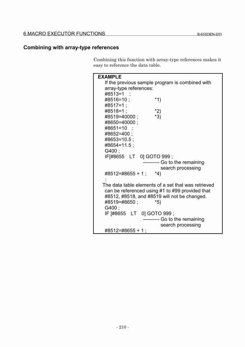
6.MACRO EXECUTOR FUNCTIONS B-63323EN-2/01
- 210 -
Combining with array-type references
Combining this function with array-type references makes iteasy to reference the data table.
EXAMPLEIf the previous sample program is combined witharray-type references:#8513=1 ;#8516=10 ; *1)#8517=1 ;#8518=1 ; *2)#8519=40000 ; *3)#8650=40000 ;#8651=10 ;#8652=400 ;#8653=10.5 ;#8654=11.5 ;G400 ;IF[#8655 LT 0] GOTO 999 ;
---------- Go to the remainingsearch processing
#8512=#8655 + 1 ; *4) :
The data table elements of a set that was retrievedcan be referenced using #1 to #99 provided that#8512, #8518, and #8519 will not be changed.#8519=#8650 ; *5)G400 ;IF [#8655 LT 0] GOTO 999 ;
---------- Go to the remainingsearch processing
#8512=#8655 + 1 ;

B-63323EN-2/01 6.MACRO EXECUTOR FUNCTIONS
- 211 -
NOTES*1) Specifies the number of elements of a data table
set (number of control variables). The array-type references that can be used are only #1 to#99; so the maximum allowable number ofelements is 99.
*2) Before starting to make array-type references, set#8518 = 1. #1 to #99 function as array-typereference variables while #8518 = 1.
*3) Sets the start macro variable number of an array.*4) Sets an array number (set number + 1) to be
used for array-type references.This associates #1 to #99 as follows:#1: = #[0 + [#8519 + [#8512 -1] * #8516]]#2: = #[1 + [#8519 + [#8512 -1] * #8516]]#3: = #[2 + [#8519 + [#8512 -1] * #8516]]As many definitions as the number of elementsset in #8516 follow.
*5) To continue the second or subsequent searches,just change the start macro variable number of thearray; array-type references can be continuedaccordingly.
CautionsCAUTIONS1 This function is valid only with the conversational
macro (talk macro) and auxiliary macro functions.2 The macro variable numbers in the search target
data table must be consecutive. Otherwise, asearch cannot be performed correctly. Inaddition, be careful not to specify a nonexistingcontrol variable number or system variable as asearch target.
3 A search target control variable can be either acustom macro variable or macro compiler-onlyvariable.
7.DEBUGGING FUNCTION B-63323EN-2/01
- 212 -
7 DEBUGGING FUNCTION
B-63323EN-2/01 7.DEBUGGING FUNCTION
- 213 -
7.1 General
The debugging function allows debugging of conversationalmacros (talk macros) and auxiliary macros. When theconversational macro (talk macro) function is executed, thedebugger starts, displaying a debugger screen on theconversational macro (talk macro) screen. The debuggerhas the following functions:
(1) Displaying the operation status(2) Displaying the program number of an executed P-CODE
macro(3) Displaying the sequence number of an executed P-CODE
macro(4) Displaying the number of blocks in an executed P-CODE
macro(5) Single-block execution(6) Break function
Break by program numberBreak by sequence numberBreak by the number of executed blocksBreak by iteration count
(7) Displaying and setting macro variables (five variables)(8) Changing targets(9) Temporarily erasing the debugger screen and re-
displaying it(10) Displaying error information regarding an executed P-
CODE macro
Single-block execution and break conditions can also be setdirectly by pressing an appropriate key instead of settingfrom the debugger screen.
NOTES1 When using the debugging function, set bit 3
(DBG) of parameter No. 8502 to 1.2 When the debugging function is used, entering
data form the keyboard displays the data in thedata input line even if the content of the data inputcontrol variable (#8502) is 0.
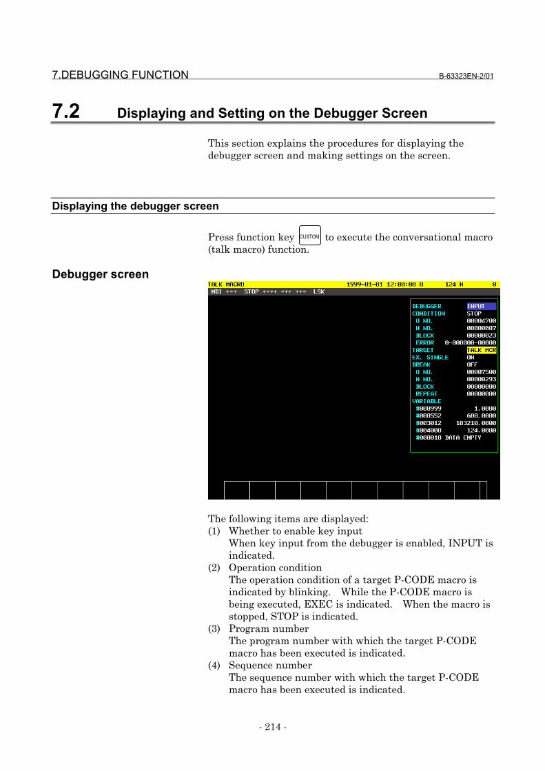
7.DEBUGGING FUNCTION B-63323EN-2/01
- 214 -
7.2 Displaying and Setting on the Debugger Screen
This section explains the procedures for displaying thedebugger screen and making settings on the screen.
Displaying the debugger screen
Press function key to execute the conversational macro(talk macro) function.
Debugger screen
The following items are displayed:(1) Whether to enable key input
When key input from the debugger is enabled, INPUT isindicated.
(2) Operation conditionThe operation condition of a target P-CODE macro isindicated by blinking. While the P-CODE macro isbeing executed, EXEC is indicated. When the macro isstopped, STOP is indicated.
(3) Program numberThe program number with which the target P-CODEmacro has been executed is indicated.
(4) Sequence numberThe sequence number with which the target P-CODEmacro has been executed is indicated.
CUSTOM
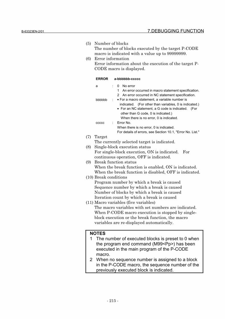
B-63323EN-2/01 7.DEBUGGING FUNCTION
- 215 -
(5) Number of blocksThe number of blocks executed by the target P-CODEmacro is indicated with a value up to 99999999.
(6) Error informationError information about the execution of the target P-CODE macro is displayed.
ERROR a-bbbbbb-ccccc
a : 0 No error1 An error occurred in macro statement specification.2 An error occurred in NC statement specification.
bbbbbb : • For a macro statement, a variable number isindicated. (For other than variables, 0 is indicated.)
• For an NC statement, a G code is indicated. (Forother than G code, 0 is indicated.)When there is no error, 0 is indicated.
ccccc : Error No.When there is no error, 0 is indicated.For details of errors, see Section 10.1, "Error No. List."
(7) TargetThe currently selected target is indicated.
(8) Single-block execution statusFor single-block execution, ON is indicated. Forcontinuous operation, OFF is indicated.
(9) Break function statusWhen the break function is enabled, ON is indicated.When the break function is disabled, OFF is indicated.
(10) Break conditionsProgram number by which a break is causedSequence number by which a break is causedNumber of blocks by which a break is causedIteration count by which a break is caused
(11) Macro variables (five variables)The macro variables with set numbers are indicated.When P-CODE macro execution is stopped by single-block execution or the break function, the macrovariables are re-displayed automatically.
NOTES1 The number of executed blocks is preset to 0 when
the program end command (M99<Pp>) has beenexecuted in the main program of the P-CODEmacro.
2 When no sequence number is assigned to a blockin the P-CODE macro, the sequence number of thepreviously executed block is indicated.
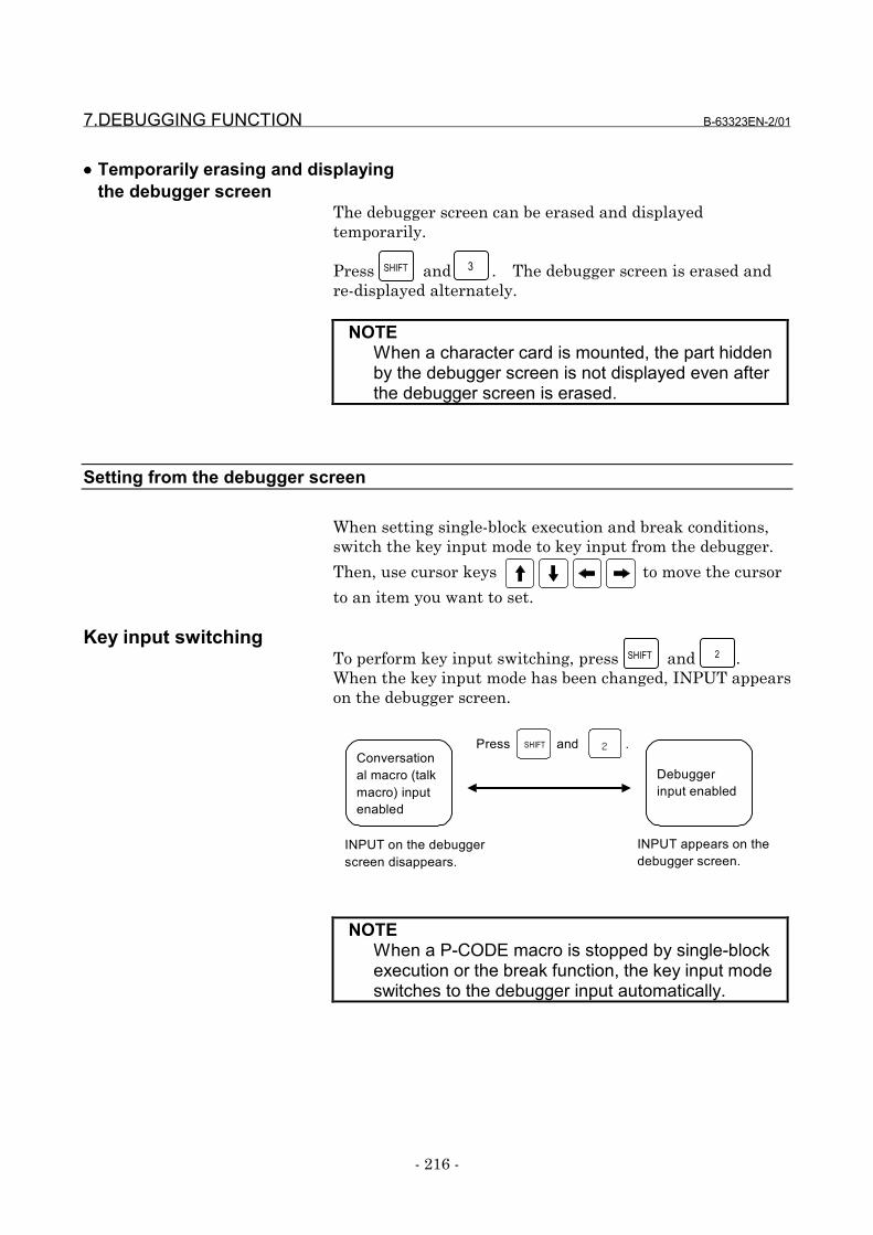
7.DEBUGGING FUNCTION B-63323EN-2/01
- 216 -
•••• Temporarily erasing and displayingthe debugger screen
The debugger screen can be erased and displayedtemporarily.
Press and . The debugger screen is erased andre-displayed alternately.
NOTEWhen a character card is mounted, the part hiddenby the debugger screen is not displayed even afterthe debugger screen is erased.
Setting from the debugger screen
When setting single-block execution and break conditions,switch the key input mode to key input from the debugger.
Then, use cursor keys to move the cursor
to an item you want to set.
Key input switchingTo perform key input switching, press and .When the key input mode has been changed, INPUT appearson the debugger screen.
NOTEWhen a P-CODE macro is stopped by single-blockexecution or the break function, the key input modeswitches to the debugger input automatically.
SHIFT 2
SHIFT 3
INPUT on the debuggerscreen disappears.
Conversational macro (talkmacro) inputenabled
Debuggerinput enabled
Press and .2SHIFT
INPUT appears on thedebugger screen.
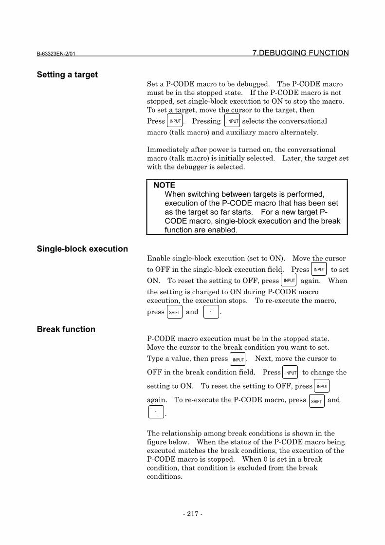
B-63323EN-2/01 7.DEBUGGING FUNCTION
- 217 -
Setting a targetSet a P-CODE macro to be debugged. The P-CODE macromust be in the stopped state. If the P-CODE macro is notstopped, set single-block execution to ON to stop the macro.To set a target, move the cursor to the target, then
Press . Pressing selects the conversational
macro (talk macro) and auxiliary macro alternately.
Immediately after power is turned on, the conversationalmacro (talk macro) is initially selected. Later, the target setwith the debugger is selected.
NOTEWhen switching between targets is performed,execution of the P-CODE macro that has been setas the target so far starts. For a new target P-CODE macro, single-block execution and the breakfunction are enabled.
Single-block executionEnable single-block execution (set to ON). Move the cursor
to OFF in the single-block execution field. Press to set
ON. To reset the setting to OFF, press again. When
the setting is changed to ON during P-CODE macroexecution, the execution stops. To re-execute the macro,
press and .
Break functionP-CODE macro execution must be in the stopped state.Move the cursor to the break condition you want to set.
Type a value, then press . Next, move the cursor to
OFF in the break condition field. Press to change the
setting to ON. To reset the setting to OFF, press
again. To re-execute the P-CODE macro, press and
.
The relationship among break conditions is shown in thefigure below. When the status of the P-CODE macro beingexecuted matches the break conditions, the execution of theP-CODE macro is stopped. When 0 is set in a breakcondition, that condition is excluded from the breakconditions.
INPUT
SHIFT 1
SHIFT
1
INPUT
INPUT
INPUT
INPUT
INPUT INPUT
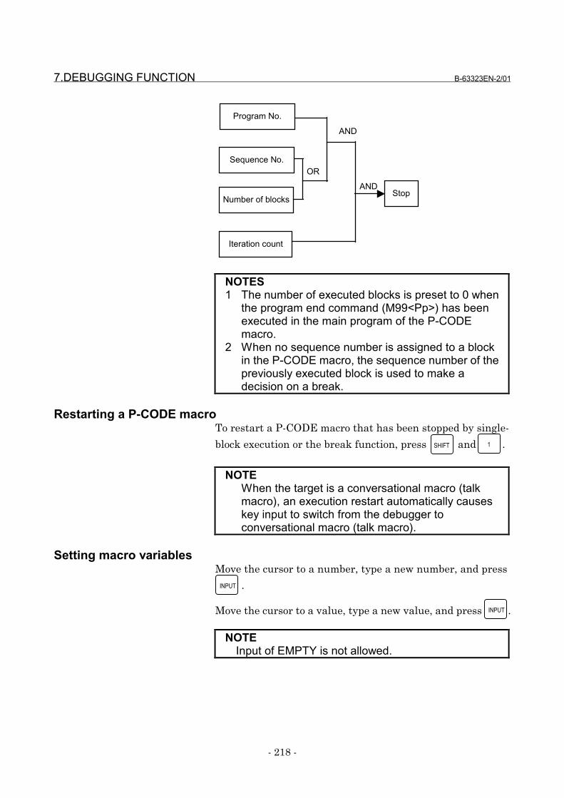
7.DEBUGGING FUNCTION B-63323EN-2/01
- 218 -
Program No.
Sequence No.
Number of blocks
OR
Iteration count
ANDStop
AND
NOTES1 The number of executed blocks is preset to 0 when
the program end command (M99<Pp>) has beenexecuted in the main program of the P-CODEmacro.
2 When no sequence number is assigned to a blockin the P-CODE macro, the sequence number of thepreviously executed block is used to make adecision on a break.
Restarting a P-CODE macroTo restart a P-CODE macro that has been stopped by single-
block execution or the break function, press and .
NOTEWhen the target is a conversational macro (talkmacro), an execution restart automatically causeskey input to switch from the debugger toconversational macro (talk macro).
Setting macro variablesMove the cursor to a number, type a new number, and press
.
Move the cursor to a value, type a new value, and press .
NOTEInput of EMPTY is not allowed.
SHIFT 1
INPUT
INPUT

B-63323EN-2/01 7.DEBUGGING FUNCTION
- 219 -
7.3 Direct Setting by Parameter and Key
Break condition settingby parameter
If a non-zero value is set in parameter No. 8547 or 8548,break conditions are set as follows according to theparameter setting and the break function is enabled (ON)when the conversational macro (talk macro) function hasbeen executed to start the debugger:
• Program number to cause a break : Parameter No. 8547• Sequence number to cause a break: Parameter No. 8548
Single-block executionby parameter
If bit 2 (SBK) of parameter No. 8502 is set to 1, single-blockexecution is enabled (ON) when the conversational macro(talk macro) function has been executed to start thedebugger.
Single-block executionby key
If the debugger has been started by executing theconversational macro (talk macro) function, single-blockexecution is enabled (ON) and disabled (OFF) alternately by
pressing and .
Break condition settingby key input
If the debugger has been started by executing theconversational macro (talk macro) function and the target P-CODE macro is in the stopped state, break conditions can beset, and the break function can be enabled (ON) by followingthe steps explained below.
(1) Type break conditions.• For a program number (Oxxxxxxxx)• For a sequence number (Nxxxxxxxx)• For the number of blocks (Bxxxxxxxx)• For an iteration count (Lxxxxxxxx)
(2) Press and .
When and are pressed without inputting any
break condition, the break function is disabled (OFF).
SHIFT 4
SHIFT 5
SHIFT 5
7.DEBUGGING FUNCTION B-63323EN-2/01
- 220 -
Debugging an auxiliarymacro
The auxiliary macro function allows an auxiliary macro to beexecuted immediately after the CNC is turned on if theprogram number of the auxiliary macro is set in the auxiliarymacro control variable (#8600). To debug an auxiliarymacro starting with the first block, follow the steps explainedbelow.(1) Set bit 4 (VAR) of parameter No. 8502 to 1 to display the
P-CODE macro variable screen.(2) On the P-CODE macro variable screen, set 0 in #8600.(3) Start the debugger, and enable single-block execution
(ON).(4) Change the target to the auxiliary macro.(5) In #8600, set the program number of the auxiliary macro
you want to execute. Then, the first block of theauxiliary macro is executed then stopped.
B-63323EN-2/01 8.OPERATION
- 221 -
8 OPERATION
8.OPERATION B-63323EN-2/01
- 222 -
8.1 Displaying and Setting Values in Macro Variables
Besides the custom macro variable screen, the P-CODEmacro variable screen is provided. On the P-CODE macrovariable screen, the values of the following variables aredisplayed and set:
VariableNo. Type Remarks
#1 to 33 Local variables for aconversational macro(talk macro)
#1 to 33 Local variables for anauxiliary macro
Local variables for the current nestare displayed. (For conversationalmacros (talk macros), the localvariables only for nest 0 aredisplayed.)Display of these variables and displayof array type variables are mutuallyexclusive.
#1 to 99 Array type variables Display of these variables and displayof local variables are mutuallyexclusive.
#100 to 199
Volatile commonvariables
Variables for the P-CODE macro orcustom macro is displayed accordingto bits 0 and 1 (MV0 and MV1) ofparameter No. 8503.
#200 to 999
Nonvolatile commonvariables
Variables for the P-CODE macro orcustom macro is displayed accordingto bits 2 to 7 of parameter No. 8503and bits 1 to 3 of parameter No. 8504(MV2 to MVA).
#8500 to 8999
Control variables
#30000 to 39999
P-CODE variables P-CODE variables as many as thenumber of variables set in bit 1 (EV2)of parameter No. 8509 and parameterNo. 8549 are displayed.
#40000 to 99099
Extended P-CODEvariables
Extended P-CODE variables as manyas the number of variables set in bit 0(EV1) of parameter No. 8509 andparameter No. 8550.
#99100 to 99199
Volatile custom macrocommon variables
Also used as custom macro commonvariables.
#99200 to 99999
Nonvolatile custom macrocommon variables
Also used as custom macro commonvariables.
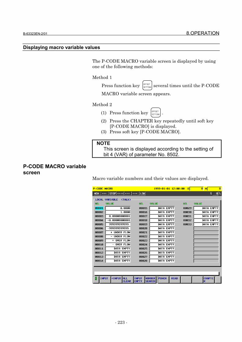
B-63323EN-2/01 8.OPERATION
- 223 -
Displaying macro variable values
The P-CODE MACRO variable screen is displayed by usingone of the following methods:
Method 1
Press function key OFFSETSETTING several times until the P-CODE
MACRO variable screen appears.
Method 2
(1) Press function key OFFSETSETTING .
(2) Press the CHAPTER key repeatedly until soft key[P-CODE MACRO] is displayed.
(3) Press soft key [P-CODE MACRO].
NOTEThis screen is displayed according to the setting ofbit 4 (VAR) of parameter No. 8502.
P-CODE MACRO variablescreen
Macro variable numbers and their values are displayed.
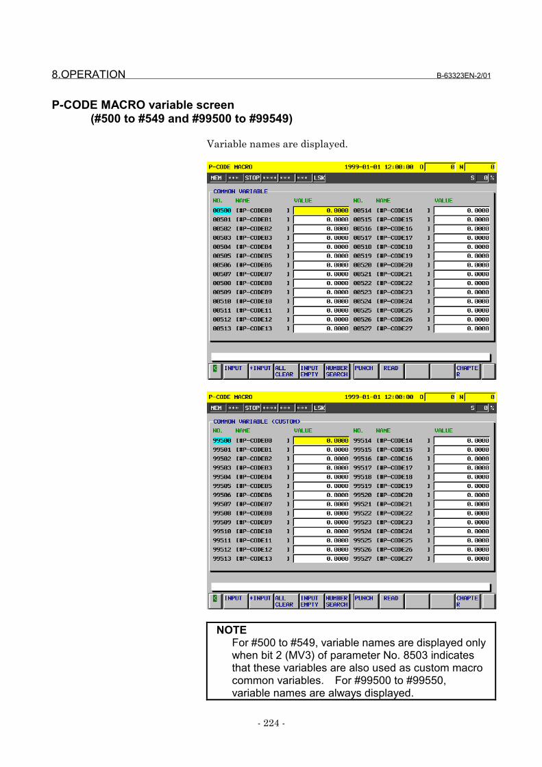
8.OPERATION B-63323EN-2/01
- 224 -
P-CODE MACRO variable screen(#500 to #549 and #99500 to #99549)
Variable names are displayed.
NOTEFor #500 to #549, variable names are displayed onlywhen bit 2 (MV3) of parameter No. 8503 indicatesthat these variables are also used as custom macrocommon variables. For #99500 to #99550,variable names are always displayed.
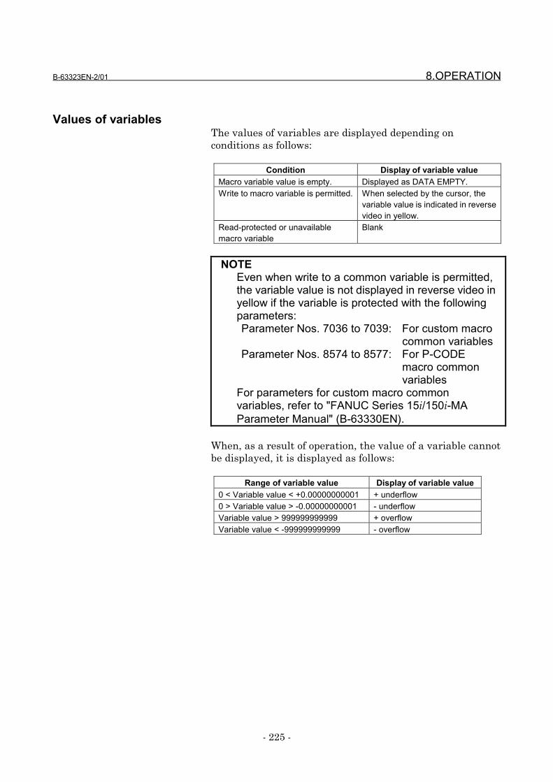
B-63323EN-2/01 8.OPERATION
- 225 -
Values of variablesThe values of variables are displayed depending onconditions as follows:
Condition Display of variable valueMacro variable value is empty. Displayed as DATA EMPTY.Write to macro variable is permitted. When selected by the cursor, the
variable value is indicated in reversevideo in yellow.
Read-protected or unavailablemacro variable
Blank
NOTEEven when write to a common variable is permitted,the variable value is not displayed in reverse video inyellow if the variable is protected with the followingparameters:Parameter Nos. 7036 to 7039: For custom macro
common variablesParameter Nos. 8574 to 8577: For P-CODE
macro commonvariables
For parameters for custom macro commonvariables, refer to "FANUC Series 15i/150i-MAParameter Manual" (B-63330EN).
When, as a result of operation, the value of a variable cannotbe displayed, it is displayed as follows:
Range of variable value Display of variable value0 < Variable value < +0.00000000001 + underflow0 > Variable value > -0.00000000001 - underflowVariable value > 999999999999 + overflowVariable value < -999999999999 - overflow
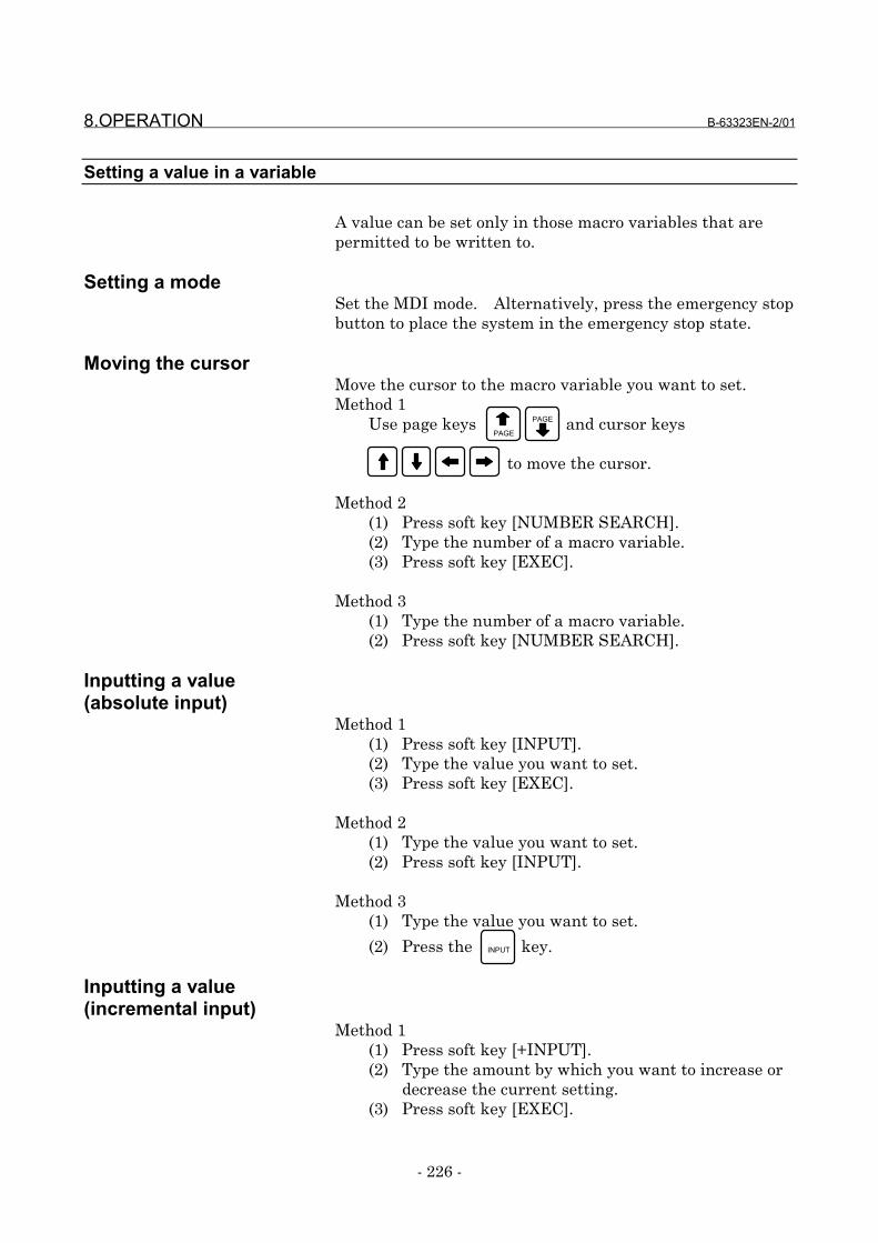
8.OPERATION B-63323EN-2/01
- 226 -
Setting a value in a variable
A value can be set only in those macro variables that arepermitted to be written to.
Setting a modeSet the MDI mode. Alternatively, press the emergency stopbutton to place the system in the emergency stop state.
Moving the cursorMove the cursor to the macro variable you want to set.Method 1
Use page keys and cursor keys
to move the cursor.
Method 2(1) Press soft key [NUMBER SEARCH].(2) Type the number of a macro variable.(3) Press soft key [EXEC].
Method 3(1) Type the number of a macro variable.(2) Press soft key [NUMBER SEARCH].
Inputting a value(absolute input)
Method 1(1) Press soft key [INPUT].(2) Type the value you want to set.(3) Press soft key [EXEC].
Method 2(1) Type the value you want to set.(2) Press soft key [INPUT].
Method 3(1) Type the value you want to set.
(2) Press the key.
Inputting a value(incremental input)
Method 1(1) Press soft key [+INPUT].(2) Type the amount by which you want to increase or
decrease the current setting.(3) Press soft key [EXEC].
INPUT
PAGE
PAGE
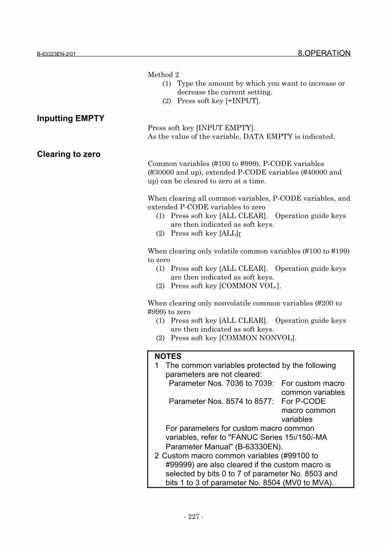
B-63323EN-2/01 8.OPERATION
- 227 -
Method 2(1) Type the amount by which you want to increase or
decrease the current setting.(2) Press soft key [+INPUT].
Inputting EMPTYPress soft key [INPUT EMPTY].As the value of the variable, DATA EMPTY is indicated.
Clearing to zeroCommon variables (#100 to #999), P-CODE variables(#30000 and up), extended P-CODE variables (#40000 andup) can be cleared to zero at a time.
When clearing all common variables, P-CODE variables, andextended P-CODE variables to zero
(1) Press soft key [ALL CLEAR]. Operation guide keysare then indicated as soft keys.
(2) Press soft key [ALL].
When clearing only volatile common variables (#100 to #199)to zero
(1) Press soft key [ALL CLEAR]. Operation guide keysare then indicated as soft keys.
(2) Press soft key [COMMON VOL.].
When clearing only nonvolatile common variables (#200 to#999) to zero
(1) Press soft key [ALL CLEAR]. Operation guide keysare then indicated as soft keys.
(2) Press soft key [COMMON NONVOL].
NOTES1 The common variables protected by the following
parameters are not cleared:Parameter Nos. 7036 to 7039: For custom macro
common variablesParameter Nos. 8574 to 8577: For P-CODE
macro commonvariables
For parameters for custom macro commonvariables, refer to "FANUC Series 15i/150i-MAParameter Manual" (B-63330EN).
2 Custom macro common variables (#99100 to#99999) are also cleared if the custom macro isselected by bits 0 to 7 of parameter No. 8503 andbits 1 to 3 of parameter No. 8504 (MV0 to MVA).
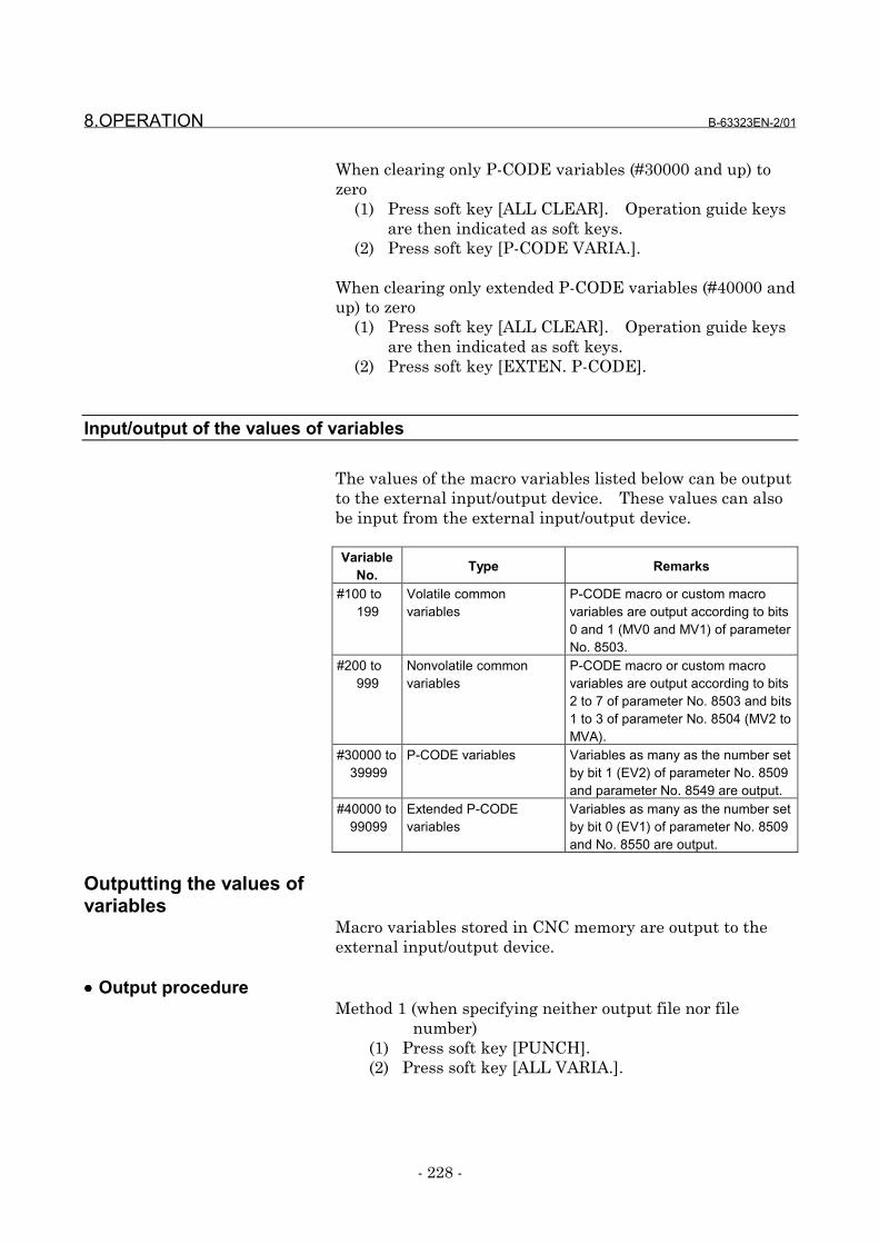
8.OPERATION B-63323EN-2/01
- 228 -
When clearing only P-CODE variables (#30000 and up) tozero
(1) Press soft key [ALL CLEAR]. Operation guide keysare then indicated as soft keys.
(2) Press soft key [P-CODE VARIA.].
When clearing only extended P-CODE variables (#40000 andup) to zero
(1) Press soft key [ALL CLEAR]. Operation guide keysare then indicated as soft keys.
(2) Press soft key [EXTEN. P-CODE].
Input/output of the values of variables
The values of the macro variables listed below can be outputto the external input/output device. These values can alsobe input from the external input/output device.
VariableNo. Type Remarks
#100 to 199
Volatile commonvariables
P-CODE macro or custom macrovariables are output according to bits0 and 1 (MV0 and MV1) of parameterNo. 8503.
#200 to 999
Nonvolatile commonvariables
P-CODE macro or custom macrovariables are output according to bits2 to 7 of parameter No. 8503 and bits1 to 3 of parameter No. 8504 (MV2 toMVA).
#30000 to 39999
P-CODE variables Variables as many as the number setby bit 1 (EV2) of parameter No. 8509and parameter No. 8549 are output.
#40000 to 99099
Extended P-CODEvariables
Variables as many as the number setby bit 0 (EV1) of parameter No. 8509and No. 8550 are output.
Outputting the values ofvariables
Macro variables stored in CNC memory are output to theexternal input/output device.
•••• Output procedureMethod 1 (when specifying neither output file nor file
number)(1) Press soft key [PUNCH].(2) Press soft key [ALL VARIA.].
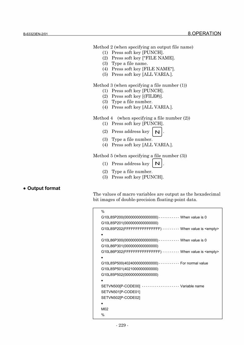
B-63323EN-2/01 8.OPERATION
- 229 -
Method 2 (when specifying an output file name)(1) Press soft key [PUNCH].(2) Press soft key ["FILE NAME].(3) Type a file name.(4) Press soft key [FILE NAME"].(5) Press soft key [ALL VARIA.].
Method 3 (when specifying a file number (1))(1) Press soft key [PUNCH].(2) Press soft key [(FILE#)].(3) Type a file number.(4) Press soft key [ALL VARIA.].
Method 4 (when specifying a file number (2))(1) Press soft key [PUNCH].
(2) Press address key .
(3) Type a file number.(4) Press soft key [ALL VARIA.].
Method 5 (when specifying a file number (3))
(1) Press address key .
(2) Type a file number.(3) Press soft key [PUNCH].
•••• Output formatThe values of macro variables are output as the hexadecimalbit images of double-precision floating-point data.
N
N
%G10L85P200(0000000000000000)・・・・・・・・・・・ When value is 0G10L85P201(0000000000000000)G10L85P202(FFFFFFFFFFFFFFFF) ・・・・・・・・・ When value is <empty>•G10L86P300(0000000000000000)・・・・・・・・・・・ When value is 0G10L86P301(0000000000000000)G10L86P302(FFFFFFFFFFFFFFFF) ・・・・・・・・・ When value is <empty>•G10L85P500(4024000000000000)・・・・・・・・・・・ For normal valueG10L85P501(4021000000000000)G10L85P502(0000000000000000)•SETVN500[P-CODE00] ・・・・・・・・・・・・・・・・・・・・ Variable nameSETVN501[P-CODE01]SETVN502[P-CODE02]•M02%
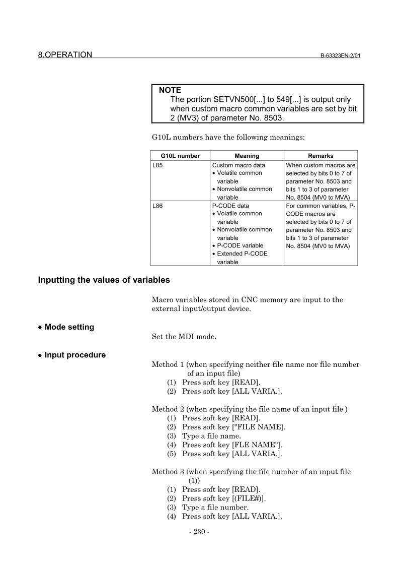
8.OPERATION B-63323EN-2/01
- 230 -
NOTEThe portion SETVN500[...] to 549[...] is output onlywhen custom macro common variables are set by bit2 (MV3) of parameter No. 8503.
G10L numbers have the following meanings:
G10L number Meaning RemarksL85 Custom macro data
• Volatile commonvariable
• Nonvolatile commonvariable
When custom macros areselected by bits 0 to 7 ofparameter No. 8503 andbits 1 to 3 of parameterNo. 8504 (MV0 to MVA)
L86 P-CODE data• Volatile common
variable• Nonvolatile common
variable• P-CODE variable• Extended P-CODE
variable
For common variables, P-CODE macros areselected by bits 0 to 7 ofparameter No. 8503 andbits 1 to 3 of parameterNo. 8504 (MV0 to MVA)
Inputting the values of variables
Macro variables stored in CNC memory are input to theexternal input/output device.
•••• Mode settingSet the MDI mode.
•••• Input procedureMethod 1 (when specifying neither file name nor file number
of an input file)(1) Press soft key [READ].(2) Press soft key [ALL VARIA.].
Method 2 (when specifying the file name of an input file )(1) Press soft key [READ].(2) Press soft key ["FILE NAME].(3) Type a file name.(4) Press soft key [FLE NAME"].(5) Press soft key [ALL VARIA.].
Method 3 (when specifying the file number of an input file(1))
(1) Press soft key [READ].(2) Press soft key [(FILE#)].(3) Type a file number.(4) Press soft key [ALL VARIA.].
B-63323EN-2/01 8.OPERATION
- 231 -
Method 4 (when specifying the file number of an input file(2))
(1) Press soft key [READ].
(2) Press address key .
(3) Type a file number.(4) Press soft key [ALL VARIA.].
Method 5 (when specifying the file number of an input file(3))
(1) Press address key .
(2) Type a file number.(3) Press soft key [READ].
The input values of macro variables are automatically storedin CNC memory.
NOTES1 When variables are output to FANUC Floppy
Cassette, FANUC FA Card, FANUC Handy File, orthe memory card by using output method 1 (whenspecifying neither output file name nor file number),file name PCODE.TXT is set.
2 When FANUC Floppy Cassette, FANUC FA Card,or FANUC Handy File is used for input/output ofvariables, an input/output file can be specified witha file name or file number.
3 When the memory card is used for input/output, aninput/output file can be specified with a file name.
Input/output with anotherscreen
Macro variable input/output operation is enabled with thefloppy list screen and memory card screen as well as the P-CODE macro variable screen.* For operation methods and other detail information, refer
to "FANUC Series 15i/150i-MA Operator's Manual(Operation)" (B-63324EN-1).
NOTEWhen display of the P-CODE macro variable screenis suppressed (bit 4 (VAR) of parameter No. 8502 is0), input/output is disabled on the floppy list screenand memory card screen.
N
N
8.OPERATION B-63323EN-2/01
- 232 -
8.2 Displaying P-CODE Macro Program Numbers
On the P-CODE macro program number list screen, theprogram numbers of P-CODE macros registered in FROMare displayed.
Displaying a list of P-CODE macro program numbers
The P-CODE macro program number list screen is displayedby following one of the methods explained below.
Method 1
(1) Press function key PROG several times until the
PROGRAM DIRECTORY screen is displayed.
(2) Use page keys PAGE
PAGE or cursor keys
to change pages until the P-CODE
macro program number list screen is displayed.
Method 2
(1) Press function key PROG .
(2) Press soft key [DIR.MEMORY].
(3) Use page keys PAGE
PAGE or cursor keys
to change pages until the P-CODE
macro program number list screen is displayed.
NOTEThis screen is displayed according to the setting ofbit 0 (DIR) of parameter No. 8502.
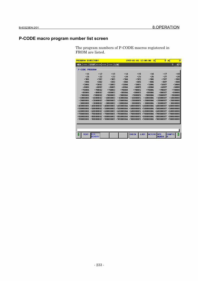
B-63323EN-2/01 8.OPERATION
- 233 -
P-CODE macro program number list screen
The program numbers of P-CODE macros registered inFROM are listed.
8.OPERATION B-63323EN-2/01
- 234 -
8.3 Displaying Execution Macro Call Information
On the last block screen and active block screen of theprogram check screen, execution macro call information isalso included in the call stack information.
Displaying the last block and active block screens
The last block or active block screen is displayed by using oneof the following methods:
Method 1
(1) Press function key PROG several times until the last
block or active block screen is displayed.
Method 2
(1) Press function key PROG .
(2) Press soft key [LAST] or [ACTIVE].
* For details, refer to "FANUC Series 15i/150i-MA Operator'sManual (Operation)" (B-63324EN-1).

B-63323EN-2/01 8.OPERATION
- 235 -
Execution macro callinformation
Execution macro call information is displayed.
When the call stack information exceeds 12 lines, pages can
be changed using page keys PAGE
PAGE or cursor keys
.
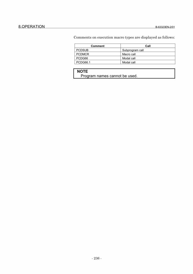
8.OPERATION B-63323EN-2/01
- 236 -
Comments on execution macro types are displayed as follows:
Comment CallPCDSUB Subprogram callPCDMCR Macro callPCDG66 Modal callPCDG66.1 Modal call
NOTEProgram names cannot be used.
B-63323EN-2/01 9.PARAMETERS
- 237 -
9 PARAMETERS
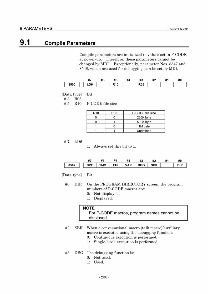
9.PARAMETERS B-63323EN-2/01
- 238 -
9.1 Compile Parameters
Compile parameters are initialized to values set in P-CODEat power-up. Therefore, these parameters cannot bechanged by MDI. Exceptionally, parameter Nos. 8547 and8548, which are used for debugging, can be set by MDI.
#7 #6 #5 #4 #3 #2 #1 #08500 LD6 R10 R05
[Data type] Bit# 3 R05# 5 R10 P-CODE file size
R10 R05 P-CODE file size0 0 256K byte0 1 512K byte1 0 1M byte1 1 Undefined
# 7 LD61: Always set this bit to 1.
#7 #6 #5 #4 #3 #2 #1 #08502 NPE TMC EUI VAR DBG SBK DIR
[Data type] Bit
#0 DIR On the PROGRAM DIRECTORY screen, the programnumbers of P-CODE macros are:0: Not displayed.1: Displayed.
NOTEFor P-CODE macros, program names cannot bedisplayed.
#2 SBK When a conversational macro (talk macro)/auxiliarymacro is executed using the debugging function:0: Continuous execution is performed.1: Single-block execution is performed.
#3 DBG The debugging function is:0: Not used.1: Used.
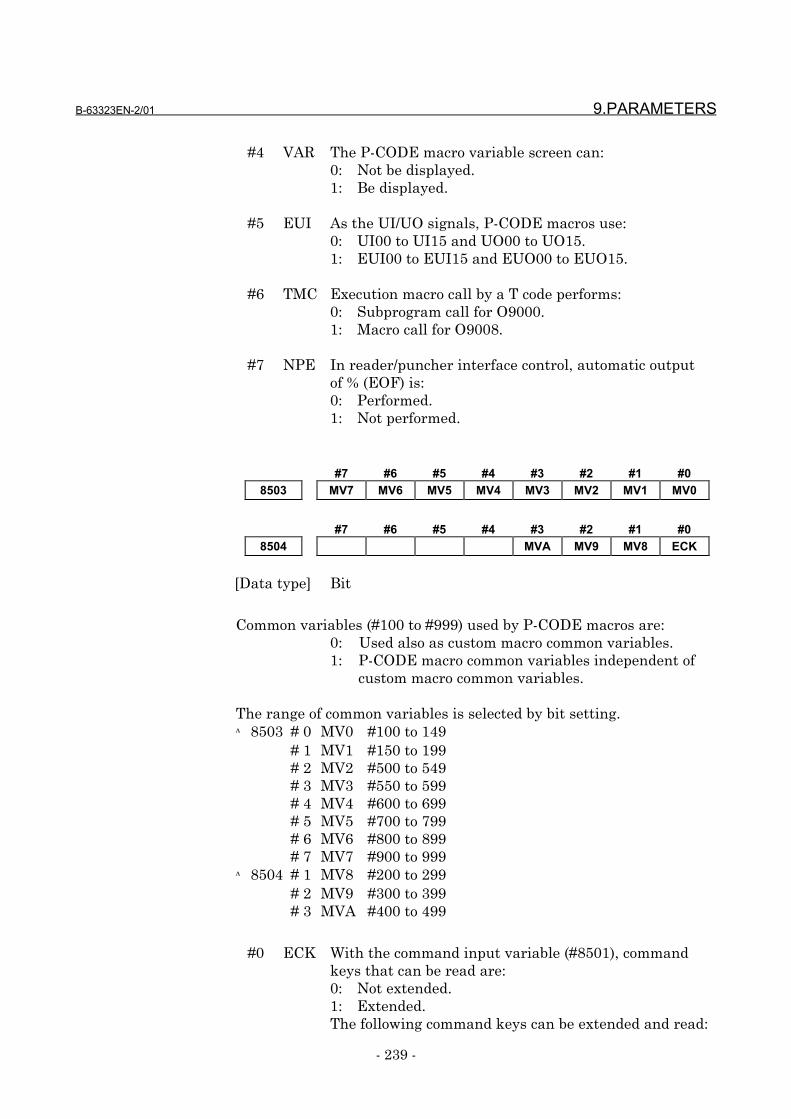
B-63323EN-2/01 9.PARAMETERS
- 239 -
#4 VAR The P-CODE macro variable screen can:0: Not be displayed.1: Be displayed.
#5 EUI As the UI/UO signals, P-CODE macros use:0: UI00 to UI15 and UO00 to UO15.1: EUI00 to EUI15 and EUO00 to EUO15.
#6 TMC Execution macro call by a T code performs:0: Subprogram call for O9000.1: Macro call for O9008.
#7 NPE In reader/puncher interface control, automatic outputof % (EOF) is:0: Performed.1: Not performed.
#7 #6 #5 #4 #3 #2 #1 #08503 MV7 MV6 MV5 MV4 MV3 MV2 MV1 MV0
#7 #6 #5 #4 #3 #2 #1 #08504 MVA MV9 MV8 ECK
[Data type] Bit
Common variables (#100 to #999) used by P-CODE macros are:0: Used also as custom macro common variables.1: P-CODE macro common variables independent of
custom macro common variables.
The range of common variables is selected by bit setting.№8503 # 0 MV0 #100 to 149
# 1 MV1 #150 to 199# 2 MV2 #500 to 549# 3 MV3 #550 to 599# 4 MV4 #600 to 699# 5 MV5 #700 to 799# 6 MV6 #800 to 899# 7 MV7 #900 to 999
№8504 # 1 MV8 #200 to 299# 2 MV9 #300 to 399# 3 MVA #400 to 499
#0 ECK With the command input variable (#8501), commandkeys that can be read are:0: Not extended.1: Extended.The following command keys can be extended and read:
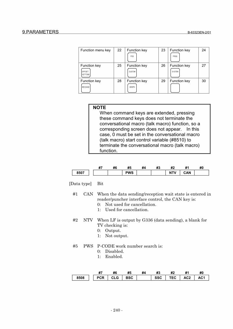
9.PARAMETERS B-63323EN-2/01
- 240 -
Function menu key 22 Function keyPOS
23 Function keyPROG
24
Function keyOFFSETSETTING
25 Function keyCUSTOM
26 Function keySYSTEM
27
Function keyMESSAGE
28 Function keyGRAPH
29 Function key 30
NOTEWhen command keys are extended, pressingthese command keys does not terminate theconversational macro (talk macro) function, so acorresponding screen does not appear. In thiscase, 0 must be set in the conversational macro(talk macro) start control variable (#8510) toterminate the conversational macro (talk macro)function.
#7 #6 #5 #4 #3 #2 #1 #08507 PWS NTV CAN
[Data type] Bit
#1 CAN When the data sending/reception wait state is entered inreader/puncher interface control, the CAN key is:0: Not used for cancellation.1: Used for cancellation.
#2 NTV When LF is output by G336 (data sending), a blank forTV checking is:0: Output.1: Not output.
#5 PWS P-CODE work number search is:0: Disabled.1: Enabled.
#7 #6 #5 #4 #3 #2 #1 #08508 PCR CLG BSC SSC TEC AC2 AC1
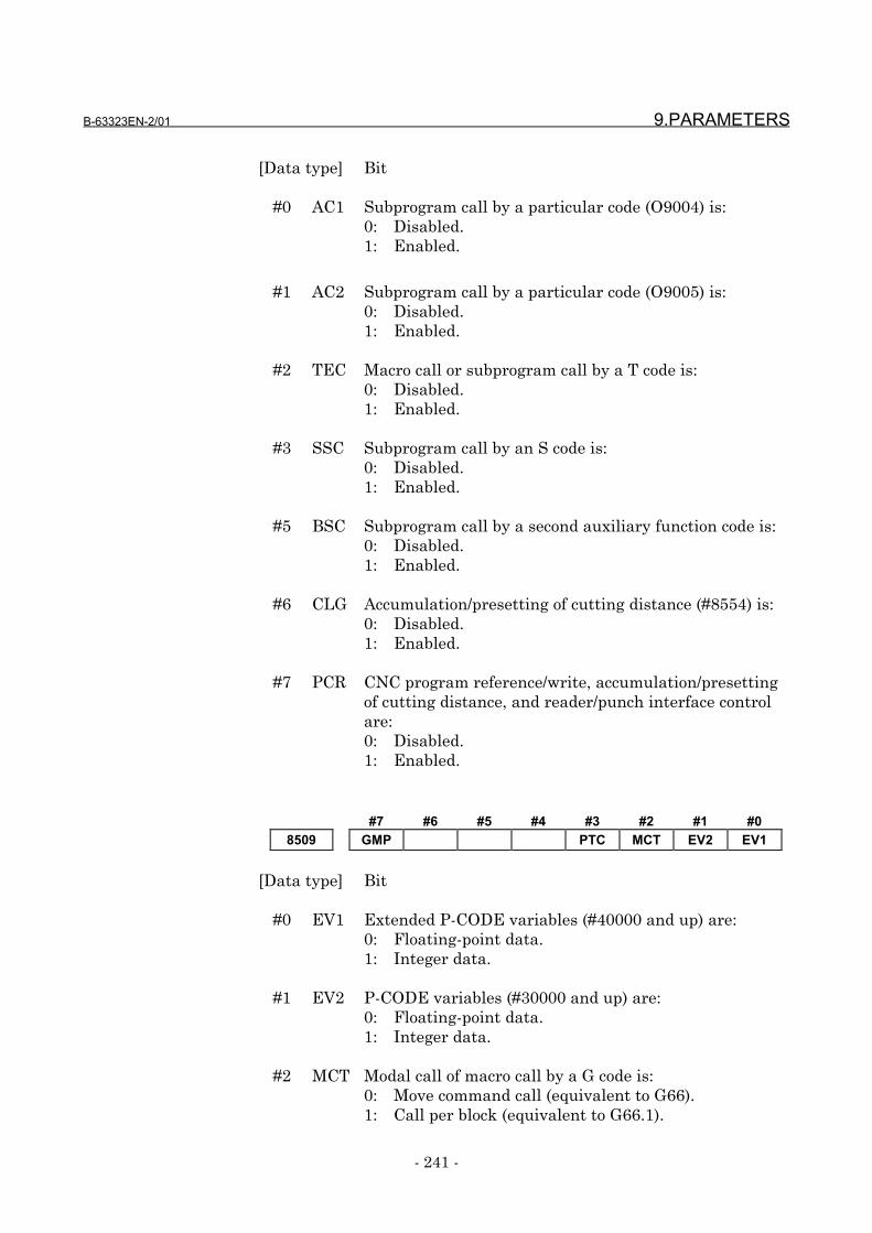
B-63323EN-2/01 9.PARAMETERS
- 241 -
[Data type] Bit
#0 AC1 Subprogram call by a particular code (O9004) is:0: Disabled.1: Enabled.
#1 AC2 Subprogram call by a particular code (O9005) is:0: Disabled.1: Enabled.
#2 TEC Macro call or subprogram call by a T code is:0: Disabled.1: Enabled.
#3 SSC Subprogram call by an S code is:0: Disabled.1: Enabled.
#5 BSC Subprogram call by a second auxiliary function code is:0: Disabled.1: Enabled.
#6 CLG Accumulation/presetting of cutting distance (#8554) is:0: Disabled.1: Enabled.
#7 PCR CNC program reference/write, accumulation/presettingof cutting distance, and reader/punch interface controlare:0: Disabled.1: Enabled.
#7 #6 #5 #4 #3 #2 #1 #08509 GMP PTC MCT EV2 EV1
[Data type] Bit
#0 EV1 Extended P-CODE variables (#40000 and up) are:0: Floating-point data.1: Integer data.
#1 EV2 P-CODE variables (#30000 and up) are:0: Floating-point data.1: Integer data.
#2 MCT Modal call of macro call by a G code is:0: Move command call (equivalent to G66).1: Call per block (equivalent to G66.1).
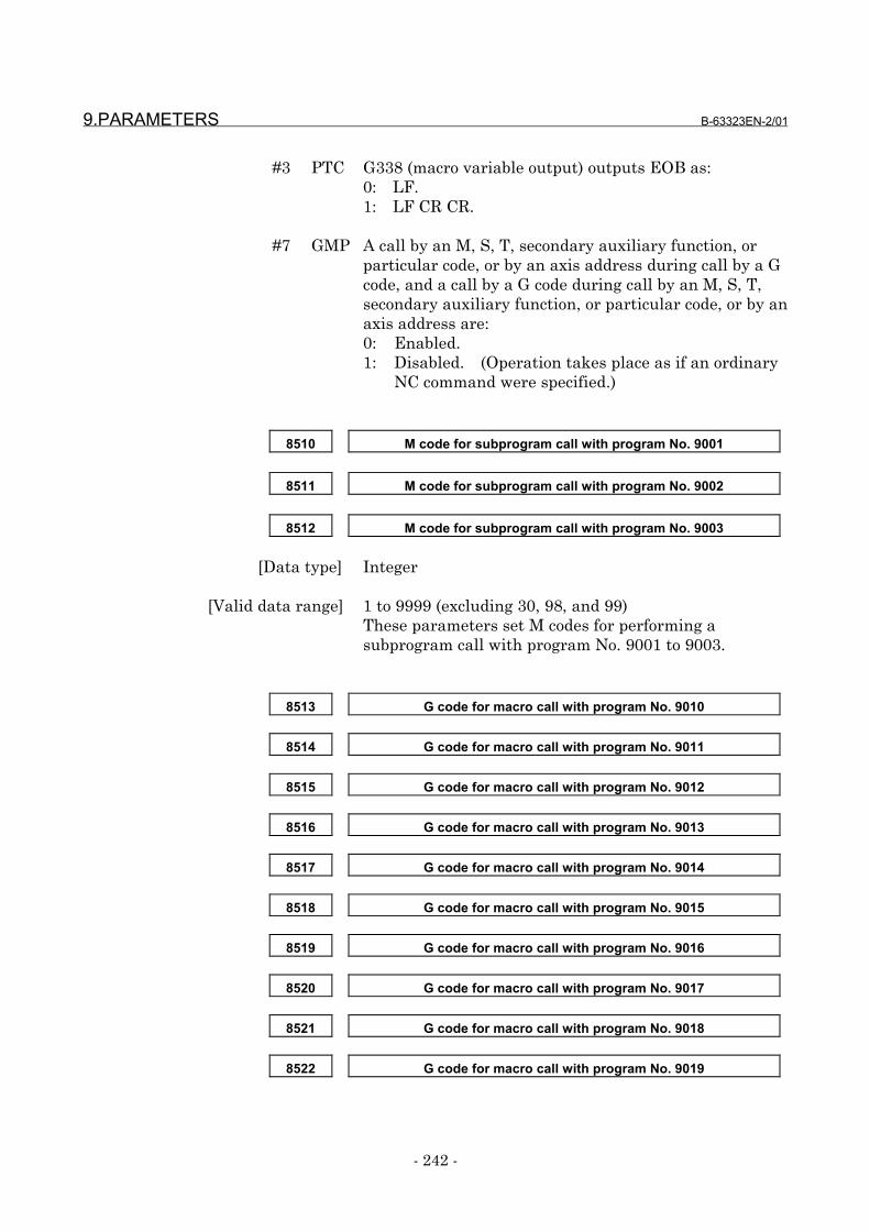
9.PARAMETERS B-63323EN-2/01
- 242 -
#3 PTC G338 (macro variable output) outputs EOB as:0: LF.1: LF CR CR.
#7 GMP A call by an M, S, T, secondary auxiliary function, orparticular code, or by an axis address during call by a Gcode, and a call by a G code during call by an M, S, T,secondary auxiliary function, or particular code, or by anaxis address are:0: Enabled.1: Disabled. (Operation takes place as if an ordinary
NC command were specified.)
8510 M code for subprogram call with program No. 9001
8511 M code for subprogram call with program No. 9002
8512 M code for subprogram call with program No. 9003
[Data type] Integer
[Valid data range] 1 to 9999 (excluding 30, 98, and 99)These parameters set M codes for performing asubprogram call with program No. 9001 to 9003.
8513 G code for macro call with program No. 9010
8514 G code for macro call with program No. 9011
8515 G code for macro call with program No. 9012
8516 G code for macro call with program No. 9013
8517 G code for macro call with program No. 9014
8518 G code for macro call with program No. 9015
8519 G code for macro call with program No. 9016
8520 G code for macro call with program No. 9017
8521 G code for macro call with program No. 9018
8522 G code for macro call with program No. 9019
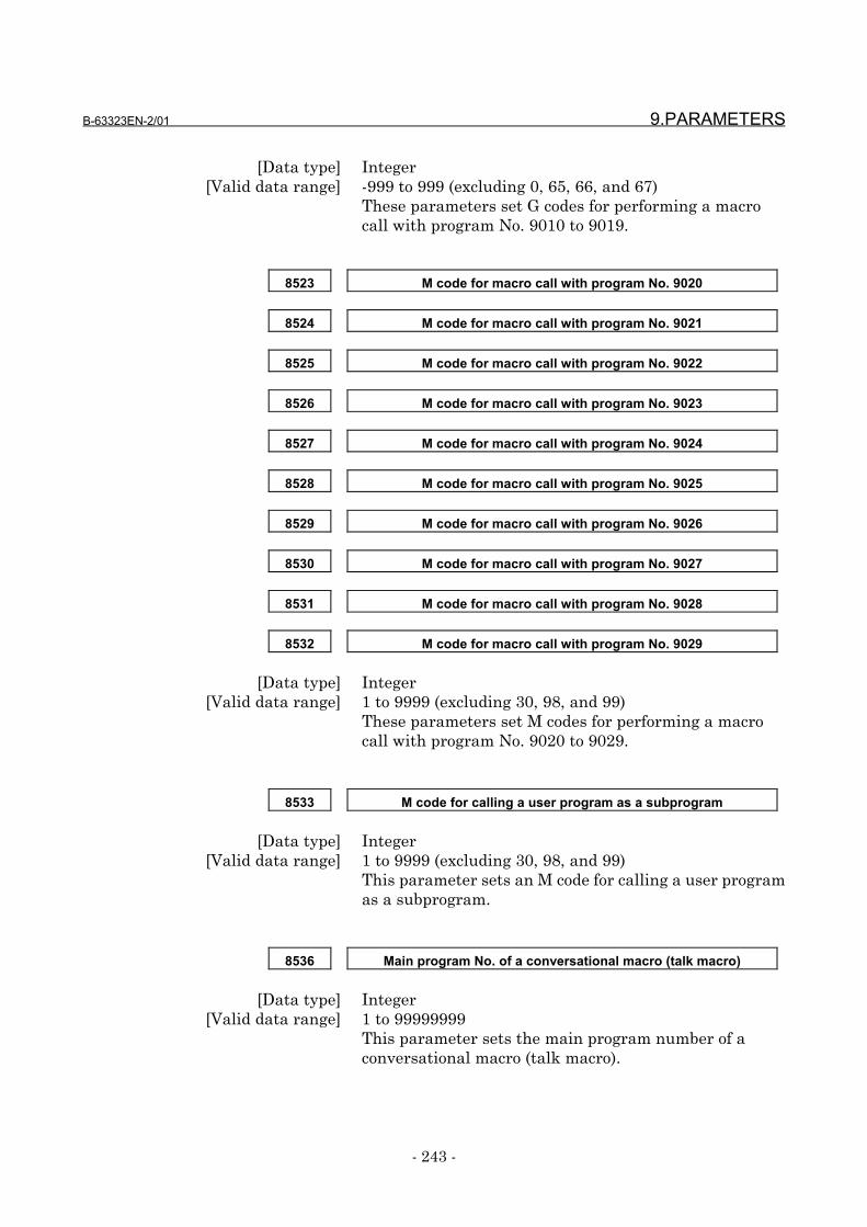
B-63323EN-2/01 9.PARAMETERS
- 243 -
[Data type] Integer[Valid data range] -999 to 999 (excluding 0, 65, 66, and 67)
These parameters set G codes for performing a macrocall with program No. 9010 to 9019.
8523 M code for macro call with program No. 9020
8524 M code for macro call with program No. 9021
8525 M code for macro call with program No. 9022
8526 M code for macro call with program No. 9023
8527 M code for macro call with program No. 9024
8528 M code for macro call with program No. 9025
8529 M code for macro call with program No. 9026
8530 M code for macro call with program No. 9027
8531 M code for macro call with program No. 9028
8532 M code for macro call with program No. 9029
[Data type] Integer[Valid data range] 1 to 9999 (excluding 30, 98, and 99)
These parameters set M codes for performing a macrocall with program No. 9020 to 9029.
8533 M code for calling a user program as a subprogram
[Data type] Integer[Valid data range] 1 to 9999 (excluding 30, 98, and 99)
This parameter sets an M code for calling a user programas a subprogram.
8536 Main program No. of a conversational macro (talk macro)
[Data type] Integer[Valid data range] 1 to 99999999
This parameter sets the main program number of aconversational macro (talk macro).

9.PARAMETERS B-63323EN-2/01
- 244 -
NOTEThe program number set in this parameter is set inthe conversational macro (talk macro) executioncontrol variable at power-up.
8537 Main program No. of an auxiliary macro
[Data type] Integer[Valid data range] 1 to 99999999
This parameter sets the main program number of anauxiliary macro.
NOTEThe program number set in this parameter is set inthe auxiliary macro execution control variable atpower-up.
8538 Call code of subprogram call by range specification M code (lower limit)
8539 Call code of subprogram call by range specification M code (upper limit)
[Data type] Integer[Valid data range] 1 to 9999
These parameters specify the range of a call code thatcan be used for performing a subprogram call by rangespecification M code.
NOTES1 If a value beyond the range is set, or if the value set
in parameter No. 8538 is greater than the value setin parameter No. 8539, a subprogram call by rangespecification M code is disabled.
2 M30, M98, M99, and the M codes used for macroand subprogram calls are not used as a call codeeven if these codes are within the set range.

B-63323EN-2/01 9.PARAMETERS
- 245 -
8540 Time until the sending/reception wait state results in time-out
[Data type] Integer[Unit of data] s
[Valid data range] 0 to 180This parameter sets the time from when thesending/reception function (G335 to G338) inreader/punch interface control enters thesending/reception wait state until a time-out occurs.When 0 is set, no time-out occurs.
8544 Call address of subprogram call by a particular code (O9004)
8545 Call address of subprogram call by a particular code (O9005)
[Data type] Integer[Valid data range] 65(A) to 90(Z) (excluding O, N, P, L, G, and axis names)
These parameters set the call address of a subprogramcall by a particular code.
8546 Number of definitions of macro calls by G codes (multiple specifications)
8551 First G code of macro calls by G codes (multiple specifications)
8552 First program No. of macro calls by G codes (multiple specifications)
[Data type] Integer[Valid data range] No. 8546: 1 to 255
No. 8551: -9999 to 9999 (excluding 0)No. 8552: 1 to 99999999
Parameter No. 8546 sets the number of programs whenmore than one macro call is specified with G codes.Parameter No. 8551 sets the first number of the callcodes. Parameter No. 8552 sets the first program No. ofexecution macros.When a negative value is set in parameter No. 8551, amodal call is performed. For specification equivalent tomove command call (G66)/call per block (G66.1), set bit 2(MCT) of parameter No. 8509.
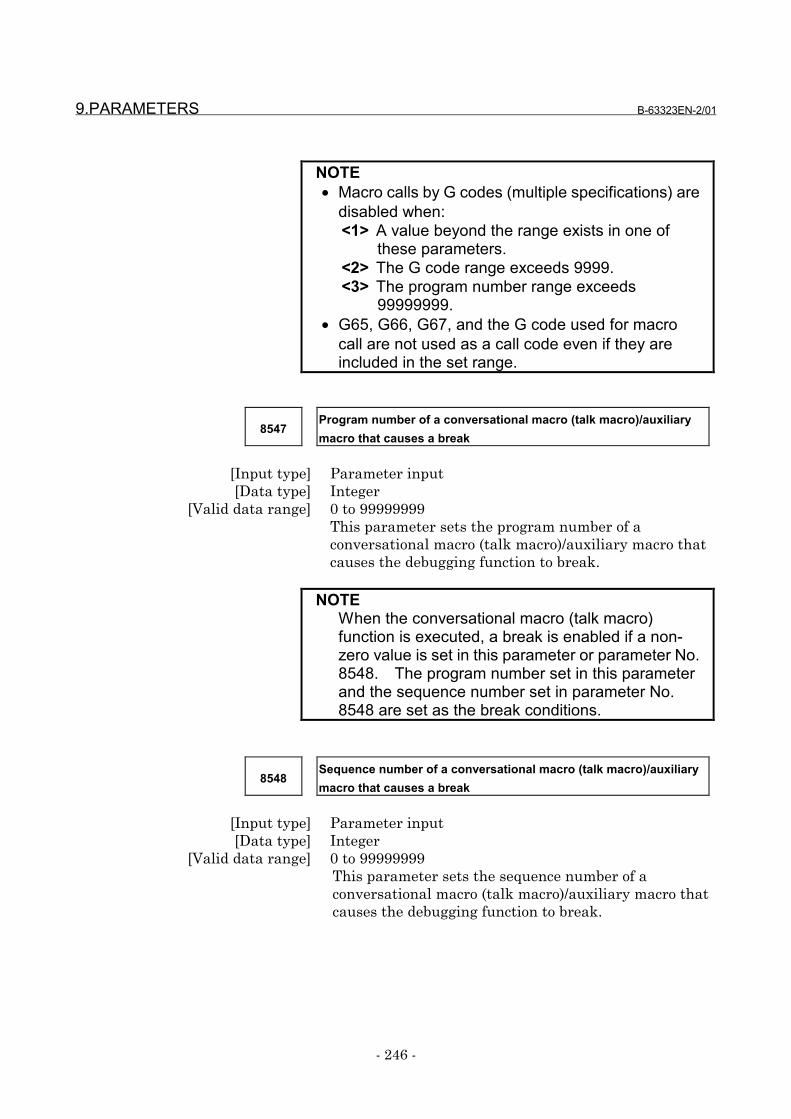
9.PARAMETERS B-63323EN-2/01
- 246 -
NOTE• Macro calls by G codes (multiple specifications) are
disabled when:<1> A value beyond the range exists in one of
these parameters.<2> The G code range exceeds 9999.<3> The program number range exceeds
99999999.• G65, G66, G67, and the G code used for macro
call are not used as a call code even if they areincluded in the set range.
8547Program number of a conversational macro (talk macro)/auxiliarymacro that causes a break
[Input type] Parameter input[Data type] Integer
[Valid data range] 0 to 99999999This parameter sets the program number of aconversational macro (talk macro)/auxiliary macro thatcauses the debugging function to break.
NOTEWhen the conversational macro (talk macro)function is executed, a break is enabled if a non-zero value is set in this parameter or parameter No.8548. The program number set in this parameterand the sequence number set in parameter No.8548 are set as the break conditions.
8548Sequence number of a conversational macro (talk macro)/auxiliarymacro that causes a break
[Input type] Parameter input[Data type] Integer
[Valid data range] 0 to 99999999This parameter sets the sequence number of aconversational macro (talk macro)/auxiliary macro thatcauses the debugging function to break.
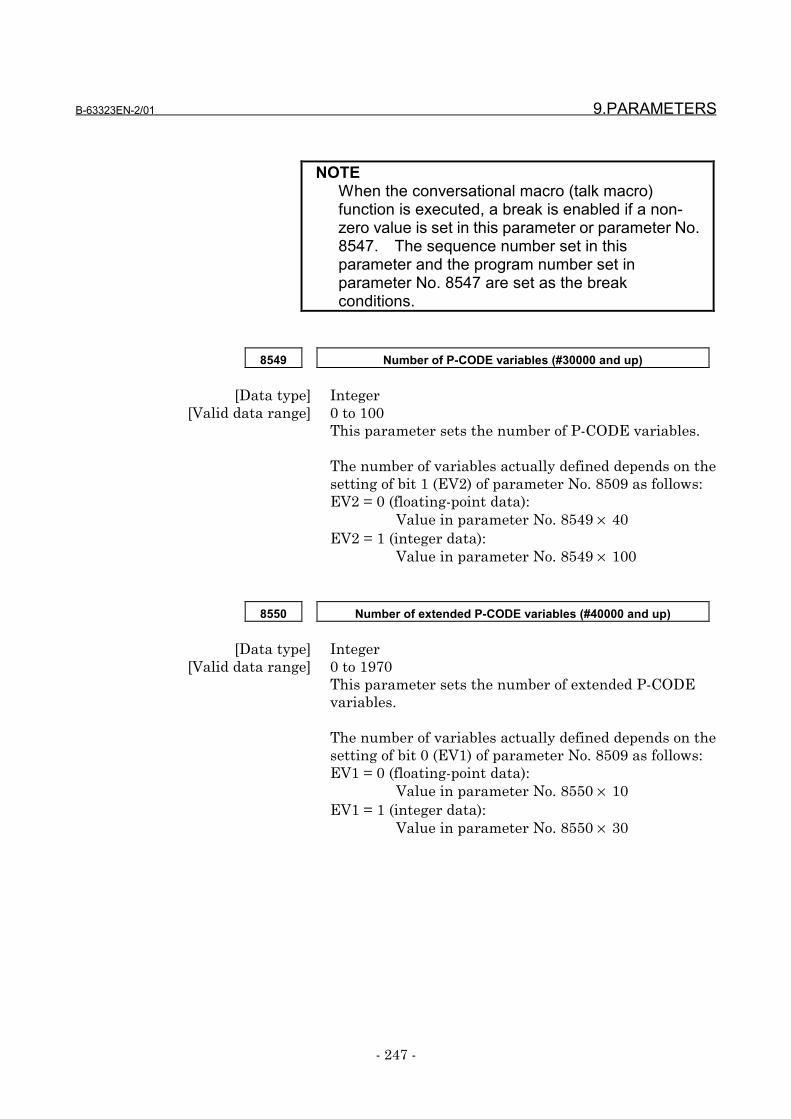
B-63323EN-2/01 9.PARAMETERS
- 247 -
NOTEWhen the conversational macro (talk macro)function is executed, a break is enabled if a non-zero value is set in this parameter or parameter No.8547. The sequence number set in thisparameter and the program number set inparameter No. 8547 are set as the breakconditions.
8549 Number of P-CODE variables (#30000 and up)
[Data type] Integer[Valid data range] 0 to 100
This parameter sets the number of P-CODE variables.
The number of variables actually defined depends on thesetting of bit 1 (EV2) of parameter No. 8509 as follows:EV2 = 0 (floating-point data):
Value in parameter No. 8549 × 40EV2 = 1 (integer data):
Value in parameter No. 8549 × 100
8550 Number of extended P-CODE variables (#40000 and up)
[Data type] Integer[Valid data range] 0 to 1970
This parameter sets the number of extended P-CODEvariables.
The number of variables actually defined depends on thesetting of bit 0 (EV1) of parameter No. 8509 as follows:EV1 = 0 (floating-point data):
Value in parameter No. 8550 × 10EV1 = 1 (integer data):
Value in parameter No. 8550 × 30
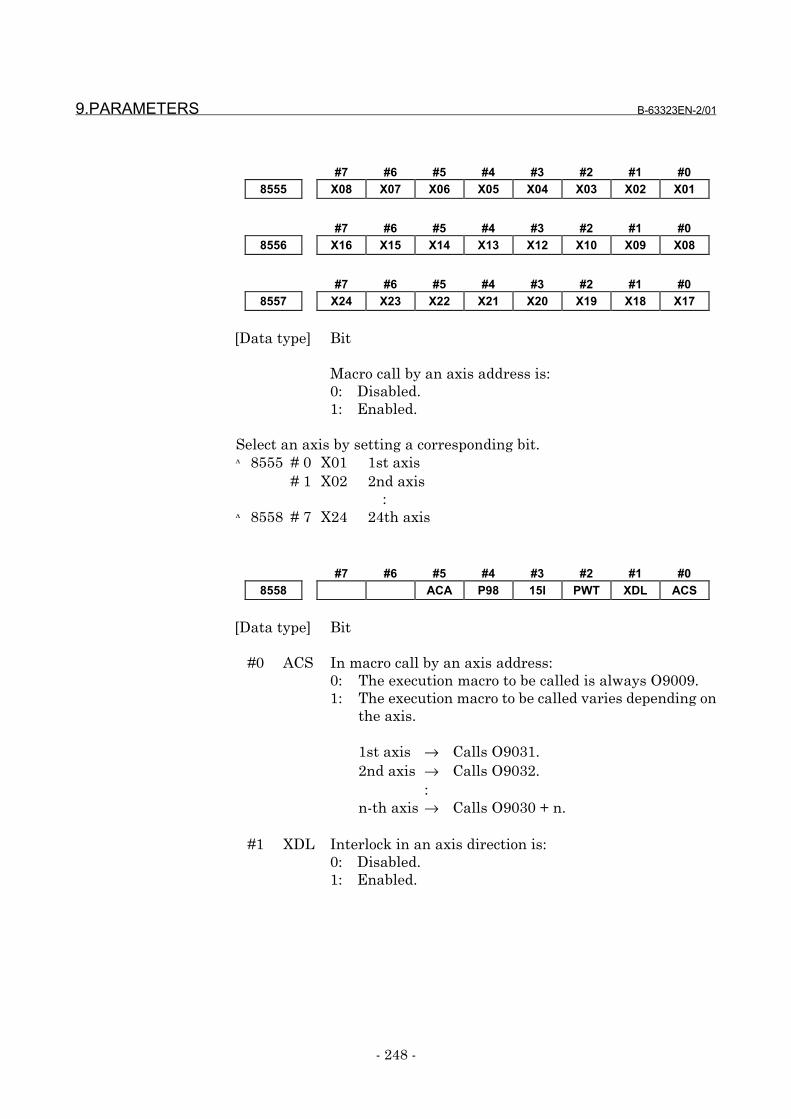
9.PARAMETERS B-63323EN-2/01
- 248 -
#7 #6 #5 #4 #3 #2 #1 #08555 X08 X07 X06 X05 X04 X03 X02 X01
#7 #6 #5 #4 #3 #2 #1 #08556 X16 X15 X14 X13 X12 X10 X09 X08
#7 #6 #5 #4 #3 #2 #1 #08557 X24 X23 X22 X21 X20 X19 X18 X17
[Data type] Bit
Macro call by an axis address is:0: Disabled.1: Enabled.
Select an axis by setting a corresponding bit.№8555 # 0 X01 1st axis
# 1 X02 2nd axis :
№8558 # 7 X24 24th axis
#7 #6 #5 #4 #3 #2 #1 #08558 ACA P98 15I PWT XDL ACS
[Data type] Bit
#0 ACS In macro call by an axis address:0: The execution macro to be called is always O9009.1: The execution macro to be called varies depending on
the axis.
1st axis → Calls O9031.2nd axis → Calls O9032.
:n-th axis → Calls O9030 + n.
#1 XDL Interlock in an axis direction is:0: Disabled.1: Enabled.
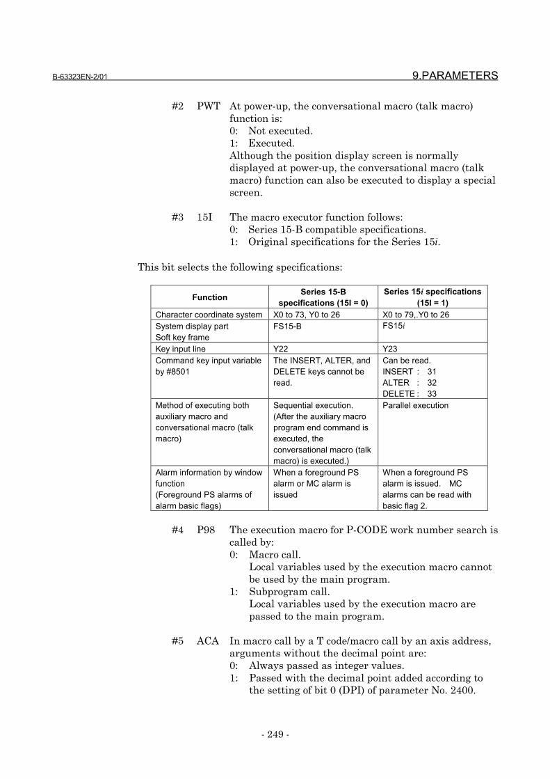
B-63323EN-2/01 9.PARAMETERS
- 249 -
#2 PWT At power-up, the conversational macro (talk macro)function is:0: Not executed.1: Executed.Although the position display screen is normallydisplayed at power-up, the conversational macro (talkmacro) function can also be executed to display a specialscreen.
#3 15I The macro executor function follows:0: Series 15-B compatible specifications.1: Original specifications for the Series 15i.
This bit selects the following specifications:
Function Series 15-Bspecifications (15I = 0)
Series 15i specifications(15I = 1)
Character coordinate system X0 to 73, Y0 to 26 X0 to 79,.Y0 to 26System display partSoft key frame
FS15-B FS15i
Key input line Y22 Y23Command key input variableby #8501
The INSERT, ALTER, andDELETE keys cannot beread.
Can be read.INSERT : 31ALTER : 32DELETE : 33
Method of executing bothauxiliary macro andconversational macro (talkmacro)
Sequential execution.(After the auxiliary macroprogram end command isexecuted, theconversational macro (talkmacro) is executed.)
Parallel execution
Alarm information by windowfunction(Foreground PS alarms ofalarm basic flags)
When a foreground PSalarm or MC alarm isissued
When a foreground PSalarm is issued. MCalarms can be read withbasic flag 2.
#4 P98 The execution macro for P-CODE work number search iscalled by:0: Macro call.
Local variables used by the execution macro cannotbe used by the main program.
1: Subprogram call.Local variables used by the execution macro arepassed to the main program.
#5 ACA In macro call by a T code/macro call by an axis address,arguments without the decimal point are:0: Always passed as integer values.1: Passed with the decimal point added according to
the setting of bit 0 (DPI) of parameter No. 2400.
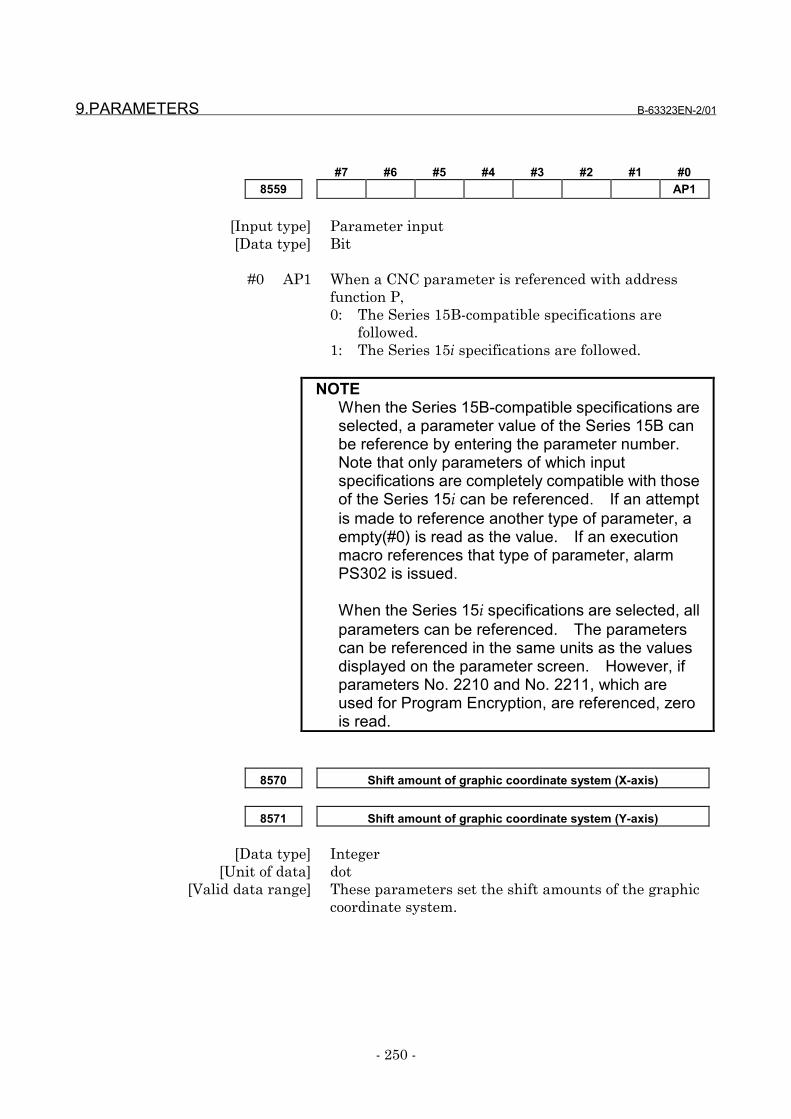
9.PARAMETERS B-63323EN-2/01
- 250 -
#7 #6 #5 #4 #3 #2 #1 #08559 AP1
[Input type] Parameter input[Data type] Bit
#0 AP1 When a CNC parameter is referenced with addressfunction P,0: The Series 15B-compatible specifications are
followed.1: The Series 15i specifications are followed.
NOTEWhen the Series 15B-compatible specifications areselected, a parameter value of the Series 15B canbe reference by entering the parameter number.Note that only parameters of which inputspecifications are completely compatible with thoseof the Series 15i can be referenced. If an attemptis made to reference another type of parameter, aempty(#0) is read as the value. If an executionmacro references that type of parameter, alarmPS302 is issued.
When the Series 15i specifications are selected, allparameters can be referenced. The parameterscan be referenced in the same units as the valuesdisplayed on the parameter screen. However, ifparameters No. 2210 and No. 2211, which areused for Program Encryption, are referenced, zerois read.
8570 Shift amount of graphic coordinate system (X-axis)
8571 Shift amount of graphic coordinate system (Y-axis)
[Data type] Integer[Unit of data] dot
[Valid data range] These parameters set the shift amounts of the graphiccoordinate system.

B-63323EN-2/01 9.PARAMETERS
- 251 -
8572 Address of axis interlock mode signal
8573 Bit position of axis interlock mode signal
[Data type] Integer[Valid data range] 0 to 7
These parameters specify the PMC internal relay (Rarea) signal that determines the control mode of the axisinterlock function.
Address : Specify an R area number.Bit position: Specify the bit position of the signal.
NOTEThe axis interlock function is disabled when:<1> The address is beyond the R area.<2> The bit position is not correct.
8574 P-CODE common variable (#500 to #999) protection range (top)
8575 P-CODE common variable (#500 to #999) protection range (end)
[Data type] Integer[Valid data range] 500 to 999
These parameters set the range of write-protectednonvolatile P-CODE common variables (#500 to #999).
NOTEIf a value beyond the range is set, or if the value setin parameter No. 8574 is greater than the value inparameter No. 8575, write protection is notprovided.
8576 P-CODE common variable (#200 to #499) protection range (top)
8577 P-CODE common variable (#200 to #499) protection range (end)
[Data type] Integer[Valid data range] 200 to 499
These parameters set the range of write-protectednonvolatile P-CODE common variables (#200 to #499).
9.PARAMETERS B-63323EN-2/01
- 252 -
NOTEIf a value beyond the range is set, or if the value setin parameter No. 8576 is greater than the value inparameter No. 8577, write protection is notprovided.
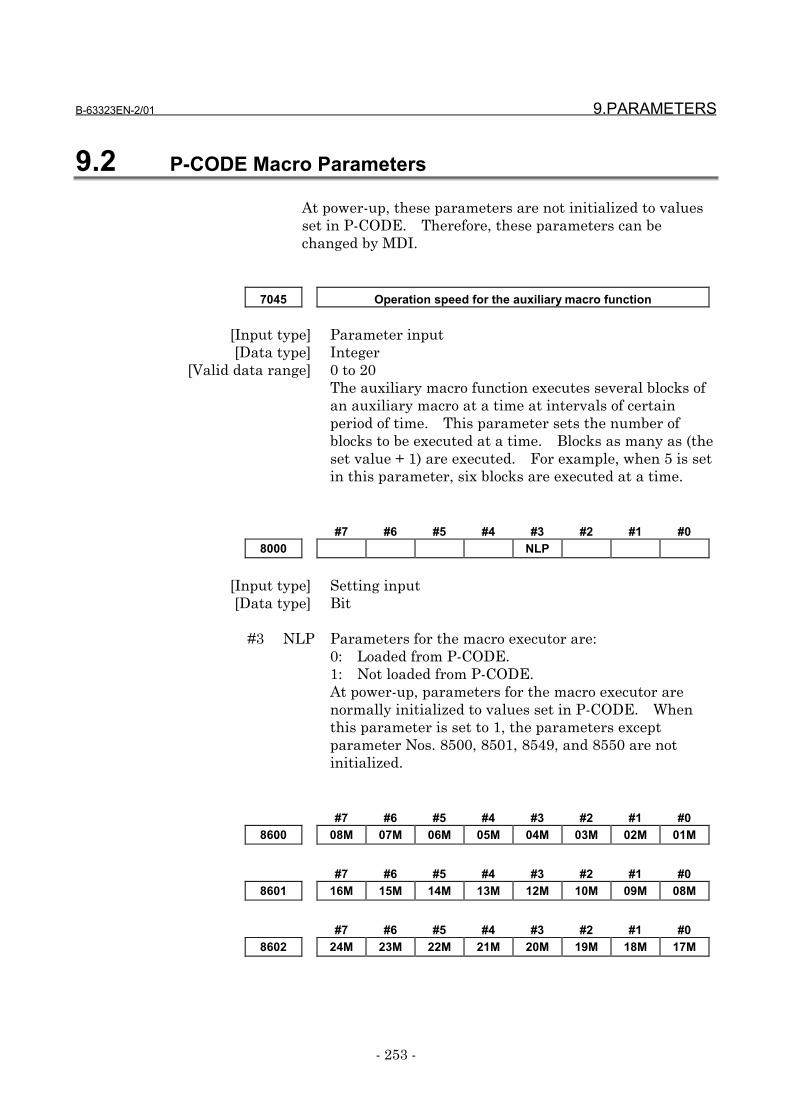
B-63323EN-2/01 9.PARAMETERS
- 253 -
9.2 P-CODE Macro Parameters
At power-up, these parameters are not initialized to valuesset in P-CODE. Therefore, these parameters can bechanged by MDI.
7045 Operation speed for the auxiliary macro function
[Input type] Parameter input[Data type] Integer
[Valid data range] 0 to 20The auxiliary macro function executes several blocks ofan auxiliary macro at a time at intervals of certainperiod of time. This parameter sets the number ofblocks to be executed at a time. Blocks as many as (theset value + 1) are executed. For example, when 5 is setin this parameter, six blocks are executed at a time.
#7 #6 #5 #4 #3 #2 #1 #08000 NLP
[Input type] Setting input[Data type] Bit
#3 NLP Parameters for the macro executor are:0: Loaded from P-CODE.1: Not loaded from P-CODE.At power-up, parameters for the macro executor arenormally initialized to values set in P-CODE. Whenthis parameter is set to 1, the parameters exceptparameter Nos. 8500, 8501, 8549, and 8550 are notinitialized.
#7 #6 #5 #4 #3 #2 #1 #08600 08M 07M 06M 05M 04M 03M 02M 01M
#7 #6 #5 #4 #3 #2 #1 #08601 16M 15M 14M 13M 12M 10M 09M 08M
#7 #6 #5 #4 #3 #2 #1 #08602 24M 23M 22M 21M 20M 19M 18M 17M

9.PARAMETERS B-63323EN-2/01
- 254 -
[Input type] Parameter input[Data type] Bit
Macro call by an axis address is:0: Enabled.1: Disabled.
Select an axis by setting a corresponding bit.№8600 # 0 01M 1st axis
# 1 02M 2nd axis :
№8602 # 7 24M 24th axis
#7 #6 #5 #4 #3 #2 #1 #08603 TCM
[Input type] Parameter input[Data type] Bit
#0 TCM Macro call/subprogram call by a T code is:0: Enabled.1: Disabled.

B-63323EN-2/01 10.APPENDIX
- 255 -
10 APPENDIX
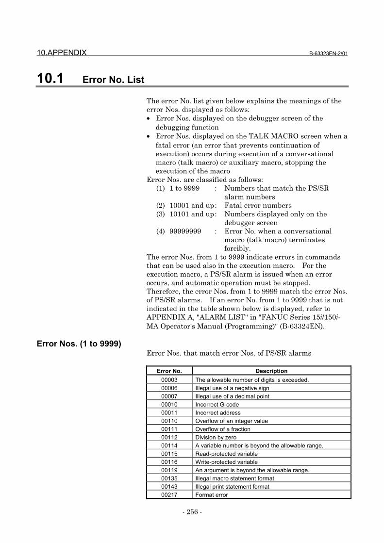
10.APPENDIX B-63323EN-2/01
- 256 -
10.1 Error No. List
The error No. list given below explains the meanings of theerror Nos. displayed as follows:• Error Nos. displayed on the debugger screen of the
debugging function• Error Nos. displayed on the TALK MACRO screen when a
fatal error (an error that prevents continuation ofexecution) occurs during execution of a conversationalmacro (talk macro) or auxiliary macro, stopping theexecution of the macro
Error Nos. are classified as follows:(1) 1 to 9999 : Numbers that match the PS/SR
alarm numbers(2) 10001 and up: Fatal error numbers(3) 10101 and up: Numbers displayed only on the
debugger screen(4) 99999999 : Error No. when a conversational
macro (talk macro) terminatesforcibly.
The error Nos. from 1 to 9999 indicate errors in commandsthat can be used also in the execution macro. For theexecution macro, a PS/SR alarm is issued when an erroroccurs, and automatic operation must be stopped.Therefore, the error Nos. from 1 to 9999 match the error Nos.of PS/SR alarms. If an error No. from 1 to 9999 that is notindicated in the table shown below is displayed, refer toAPPENDIX A, "ALARM LIST" in "FANUC Series 15i/150i-MA Operator's Manual (Programming)" (B-63324EN).
Error Nos. (1 to 9999)Error Nos. that match error Nos. of PS/SR alarms
Error No. Description00003 The allowable number of digits is exceeded.00006 Illegal use of a negative sign00007 Illegal use of a decimal point00010 Incorrect G-code00011 Incorrect address00110 Overflow of an integer value00111 Overflow of a fraction00112 Division by zero00114 A variable number is beyond the allowable range.00115 Read-protected variable00116 Write-protected variable00119 An argument is beyond the allowable range.00135 Illegal macro statement format00143 Illegal print statement format00217 Format error
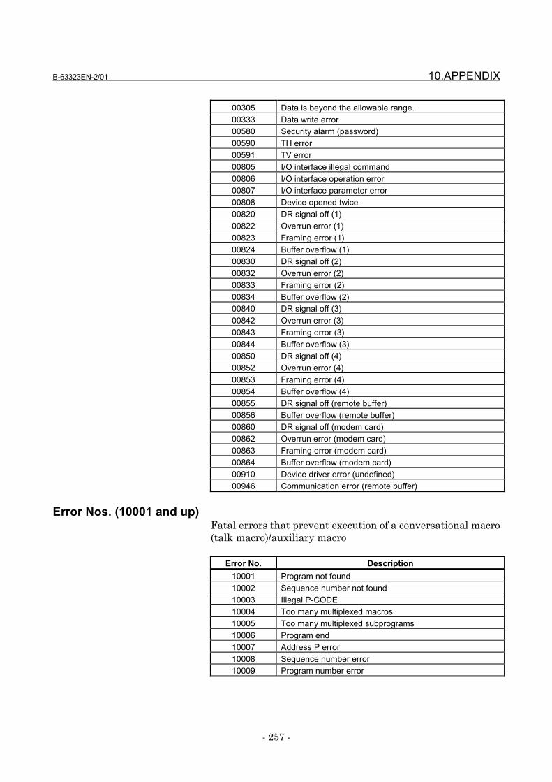
B-63323EN-2/01 10.APPENDIX
- 257 -
00305 Data is beyond the allowable range.00333 Data write error00580 Security alarm (password)00590 TH error00591 TV error00805 I/O interface illegal command00806 I/O interface operation error00807 I/O interface parameter error00808 Device opened twice00820 DR signal off (1)00822 Overrun error (1)00823 Framing error (1)00824 Buffer overflow (1)00830 DR signal off (2)00832 Overrun error (2)00833 Framing error (2)00834 Buffer overflow (2)00840 DR signal off (3)00842 Overrun error (3)00843 Framing error (3)00844 Buffer overflow (3)00850 DR signal off (4)00852 Overrun error (4)00853 Framing error (4)00854 Buffer overflow (4)00855 DR signal off (remote buffer)00856 Buffer overflow (remote buffer)00860 DR signal off (modem card)00862 Overrun error (modem card)00863 Framing error (modem card)00864 Buffer overflow (modem card)00910 Device driver error (undefined)00946 Communication error (remote buffer)
Error Nos. (10001 and up)Fatal errors that prevent execution of a conversational macro(talk macro)/auxiliary macro
Error No. Description10001 Program not found10002 Sequence number not found10003 Illegal P-CODE10004 Too many multiplexed macros10005 Too many multiplexed subprograms10006 Program end10007 Address P error10008 Sequence number error10009 Program number error
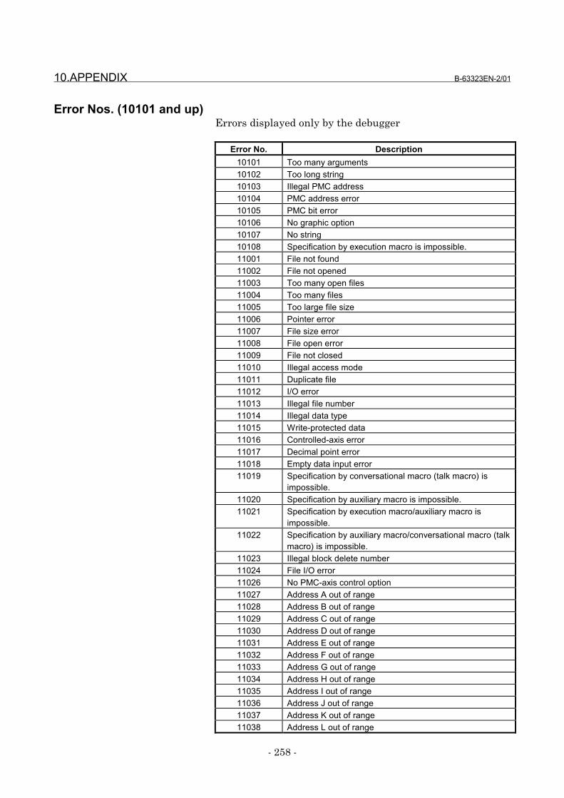
10.APPENDIX B-63323EN-2/01
- 258 -
Error Nos. (10101 and up)Errors displayed only by the debugger
Error No. Description10101 Too many arguments10102 Too long string10103 Illegal PMC address10104 PMC address error10105 PMC bit error10106 No graphic option10107 No string10108 Specification by execution macro is impossible.11001 File not found11002 File not opened11003 Too many open files11004 Too many files11005 Too large file size11006 Pointer error11007 File size error11008 File open error11009 File not closed11010 Illegal access mode11011 Duplicate file11012 I/O error11013 Illegal file number11014 Illegal data type11015 Write-protected data11016 Controlled-axis error11017 Decimal point error11018 Empty data input error11019 Specification by conversational macro (talk macro) is
impossible.11020 Specification by auxiliary macro is impossible.11021 Specification by execution macro/auxiliary macro is
impossible.11022 Specification by auxiliary macro/conversational macro (talk
macro) is impossible.11023 Illegal block delete number11024 File I/O error11026 No PMC-axis control option11027 Address A out of range11028 Address B out of range11029 Address C out of range11030 Address D out of range11031 Address E out of range11032 Address F out of range11033 Address G out of range11034 Address H out of range11035 Address I out of range11036 Address J out of range11037 Address K out of range11038 Address L out of range
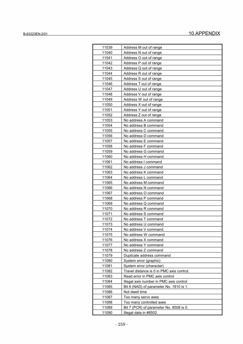
B-63323EN-2/01 10.APPENDIX
- 259 -
11039 Address M out of range11040 Address N out of range11041 Address O out of range11042 Address P out of range11043 Address Q out of range11044 Address R out of range11045 Address S out of range11046 Address T out of range11047 Address U out of range11048 Address V out of range11049 Address W out of range11050 Address X out of range11051 Address Y out of range11052 Address Z out of range11053 No address A command11054 No address B command11055 No address C command11056 No address D command11057 No address E command11058 No address F command11059 No address G command11060 No address H command11061 No address I command11062 No address J command11063 No address K command11064 No address L command11065 No address M command11066 No address N command11067 No address O command11068 No address P command11069 No address Q command11070 No address R command11071 No address S command11072 No address T command11073 No address U command11074 No address V command11075 No address W command11076 No address X command11077 No address Y command11078 No address Z command11079 Duplicate address command11080 System error (graphic)11081 System error (character)11082 Travel distance is 0 in PMC axis control.11083 Read error in PMC axis control11084 Illegal axis number in PMC axis control11085 Bit 6 (NAD) of parameter No. 1810 is 1.11086 Not dwell time11087 Too many servo axes11088 Too many controlled axes11089 Bit 7 (PCR) of parameter No. 8508 is 0.11090 Illegal data in #8502
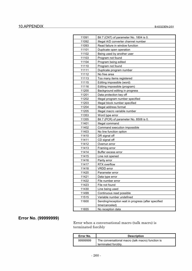
10.APPENDIX B-63323EN-2/01
- 260 -
11091 Bit 7 (CNT) of parameter No. 1804 is 0.11092 Illegal A/D converter channel number11093 Read failure in window function11101 Duplicate open operation11102 Being used by another user11103 Program not found11104 Program being edited11110 Program not found11111 Duplicate program number11112 No free area11113 Too many items registered11115 Editing impossible (word)11116 Editing impossible (program)11200 Background editing in progress11201 Data protection key off11202 Illegal program number specified11203 Illegal block number specified11204 Illegal address format11205 Illegal macro variable number11353 Word type error11355 Bit 7 (PCR) of parameter No. 8508 is 0.11401 Illegal command11402 Command execution impossible11403 No line function option11410 DR signal off11411 CD signal off11412 Overrun error11413 Framing error11414 Buffer excess error11415 Line not opened11416 Parity error11417 RTX overflow11418 VRDD error11420 Parameter error11421 Data type error11422 File number error11423 File not found11430 Line being used11499 Continuous read possible11515 Variable number undefined11600 Sending/reception wait in progress (after specified
time/canceled)11655 No reception data
Error No. (99999999)Error when a conversational macro (talk macro) isterminated forcibly
Error No. Description99999999 The conversational macro (talk macro) function is
terminated forcibly.
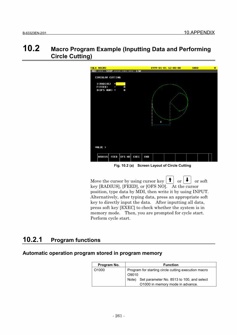
B-63323EN-2/01 10.APPENDIX
- 261 -
10.2 Macro Program Example (Inputting Data and PerformingCircle Cutting)
Fig. 10.2 (a) Screen Layout of Circle Cutting
Move the cursor by using cursor key or or softkey [RADIUS], [FEED], or [OFS NO]. At the cursorposition, type data by MDI, then write it by using INPUT.Alternatively, after typing data, press an appropriate softkey to directly input the data. After inputting all data,press soft key [EXEC] to check whether the system is inmemory mode. Then, you are prompted for cycle start.Perform cycle start.
10.2.1 Program functions
Automatic operation program stored in program memory
Program No. FunctionO1000 Program for starting circle cutting execution macro
O9010Note) Set parameter No. 8513 to 100, and select
O1000 in memory mode in advance.
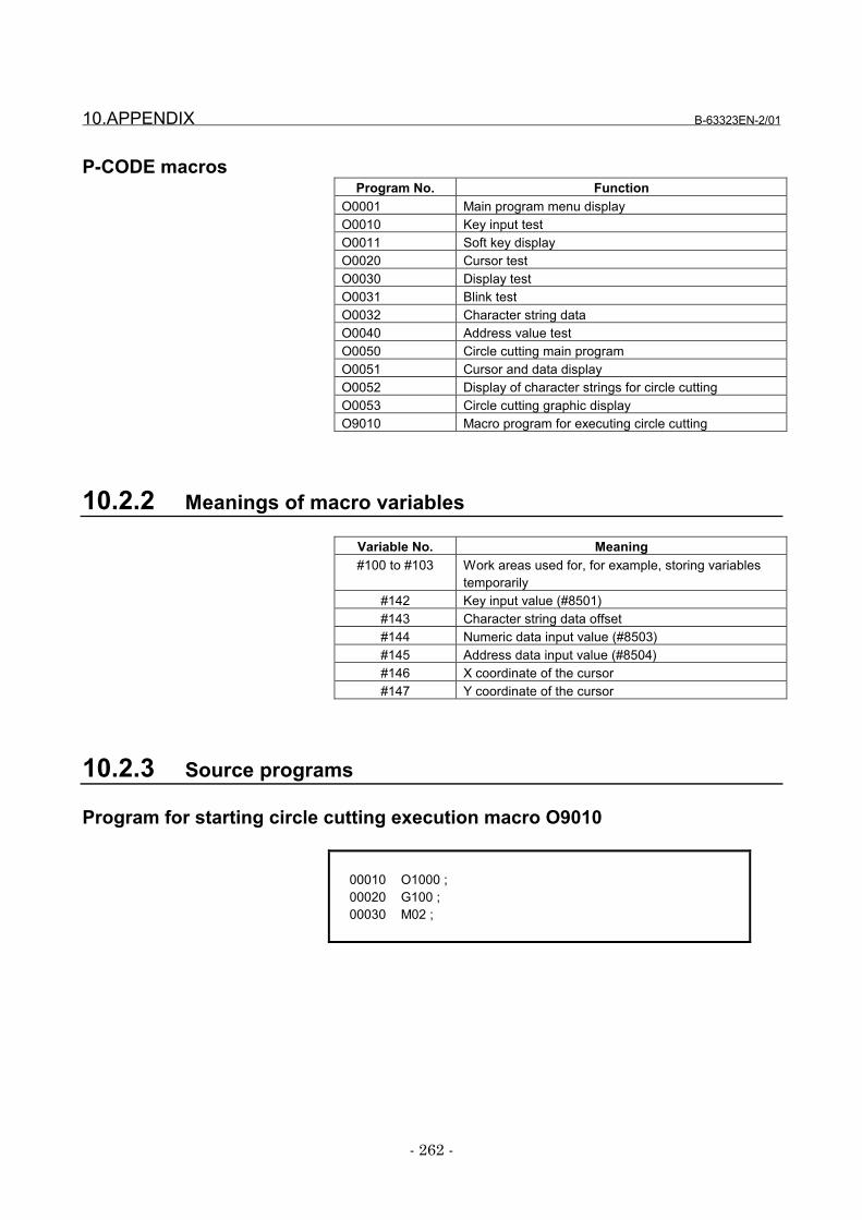
10.APPENDIX B-63323EN-2/01
- 262 -
P-CODE macrosProgram No. Function
O0001 Main program menu displayO0010 Key input testO0011 Soft key displayO0020 Cursor testO0030 Display testO0031 Blink testO0032 Character string dataO0040 Address value testO0050 Circle cutting main programO0051 Cursor and data displayO0052 Display of character strings for circle cuttingO0053 Circle cutting graphic displayO9010 Macro program for executing circle cutting
10.2.2 Meanings of macro variables
Variable No. Meaning#100 to #103 Work areas used for, for example, storing variables
temporarily#142 Key input value (#8501)#143 Character string data offset#144 Numeric data input value (#8503)#145 Address data input value (#8504)#146 X coordinate of the cursor#147 Y coordinate of the cursor
10.2.3 Source programs
Program for starting circle cutting execution macro O9010
00010 O1000 ;00020 G100 ;00030 M02 ;
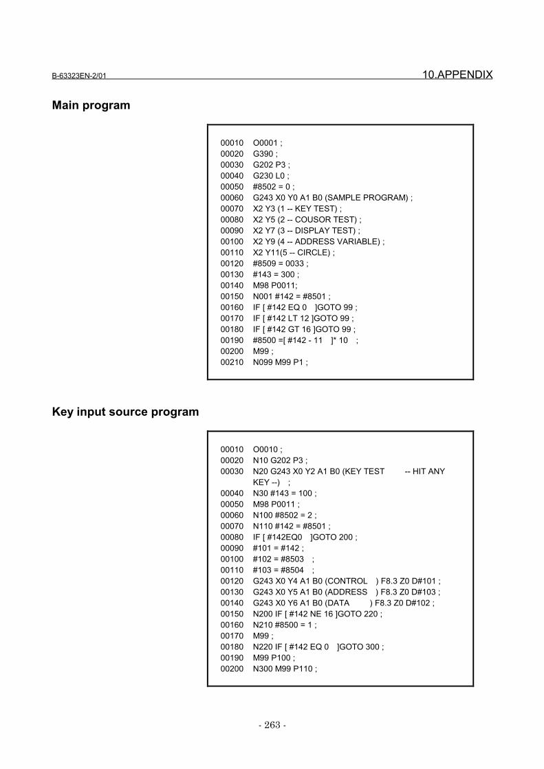
B-63323EN-2/01 10.APPENDIX
- 263 -
Main program
00010 O0001 ;00020 G390 ;00030 G202 P3 ;00040 G230 L0 ;00050 #8502 = 0 ;00060 G243 X0 Y0 A1 B0 (SAMPLE PROGRAM) ;00070 X2 Y3 (1 -- KEY TEST) ;00080 X2 Y5 (2 -- COUSOR TEST) ;00090 X2 Y7 (3 -- DISPLAY TEST) ;00100 X2 Y9 (4 -- ADDRESS VARIABLE) ;00110 X2 Y11(5 -- CIRCLE) ;00120 #8509 = 0033 ;00130 #143 = 300 ;00140 M98 P0011;00150 N001 #142 = #8501 ;00160 IF [ #142 EQ 0 ]GOTO 99 ;00170 IF [ #142 LT 12 ]GOTO 99 ;00180 IF [ #142 GT 16 ]GOTO 99 ;00190 #8500 =[ #142 - 11 ]* 10 ;00200 M99 ;00210 N099 M99 P1 ;
Key input source program
00010 O0010 ;00020 N10 G202 P3 ;00030 N20 G243 X0 Y2 A1 B0 (KEY TEST -- HIT ANY
KEY --) ;00040 N30 #143 = 100 ;00050 M98 P0011 ;00060 N100 #8502 = 2 ;00070 N110 #142 = #8501 ;00080 IF [ #142EQ0 ]GOTO 200 ;00090 #101 = #142 ;00100 #102 = #8503 ;00110 #103 = #8504 ;00120 G243 X0 Y4 A1 B0 (CONTROL ) F8.3 Z0 D#101 ;00130 G243 X0 Y5 A1 B0 (ADDRESS ) F8.3 Z0 D#103 ;00140 G243 X0 Y6 A1 B0 (DATA ) F8.3 Z0 D#102 ;00150 N200 IF [ #142 NE 16 ]GOTO 220 ;00160 N210 #8500 = 1 ;00170 M99 ;00180 N220 IF [ #142 EQ 0 ]GOTO 300 ;00190 M99 P100 ;00200 N300 M99 P110 ;
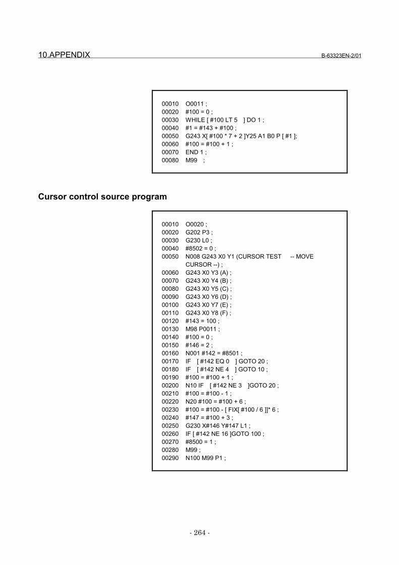
10.APPENDIX B-63323EN-2/01
- 264 -
00010 O0011 ;00020 #100 = 0 ;00030 WHILE [ #100 LT 5 ] DO 1 ;00040 #1 = #143 + #100 ;00050 G243 X[ #100 * 7 + 2 ]Y25 A1 B0 P [ #1 ];00060 #100 = #100 + 1 ;00070 END 1 ;00080 M99 ;
Cursor control source program
00010 O0020 ;00020 G202 P3 ;00030 G230 L0 ;00040 #8502 = 0 ;00050 N008 G243 X0 Y1 (CURSOR TEST -- MOVE
CURSOR --) ;00060 G243 X0 Y3 (A) ;00070 G243 X0 Y4 (B) ;00080 G243 X0 Y5 (C) ;00090 G243 X0 Y6 (D) ;00100 G243 X0 Y7 (E) ;00110 G243 X0 Y8 (F) ;00120 #143 = 100 ;00130 M98 P0011 ;00140 #100 = 0 ;00150 #146 = 2 ;00160 N001 #142 = #8501 ;00170 IF [ #142 EQ 0 ] GOTO 20 ;00180 IF [ #142 NE 4 ] GOTO 10 ;00190 #100 = #100 + 1 ;00200 N10 IF [ #142 NE 3 ]GOTO 20 ;00210 #100 = #100 - 1 ;00220 N20 #100 = #100 + 6 ;00230 #100 = #100 - [ FIX[ #100 / 6 ]]* 6 ;00240 #147 = #100 + 3 ;00250 G230 X#146 Y#147 L1 ;00260 IF [ #142 NE 16 ]GOTO 100 ;00270 #8500 = 1 ;00280 M99 ;00290 N100 M99 P1 ;
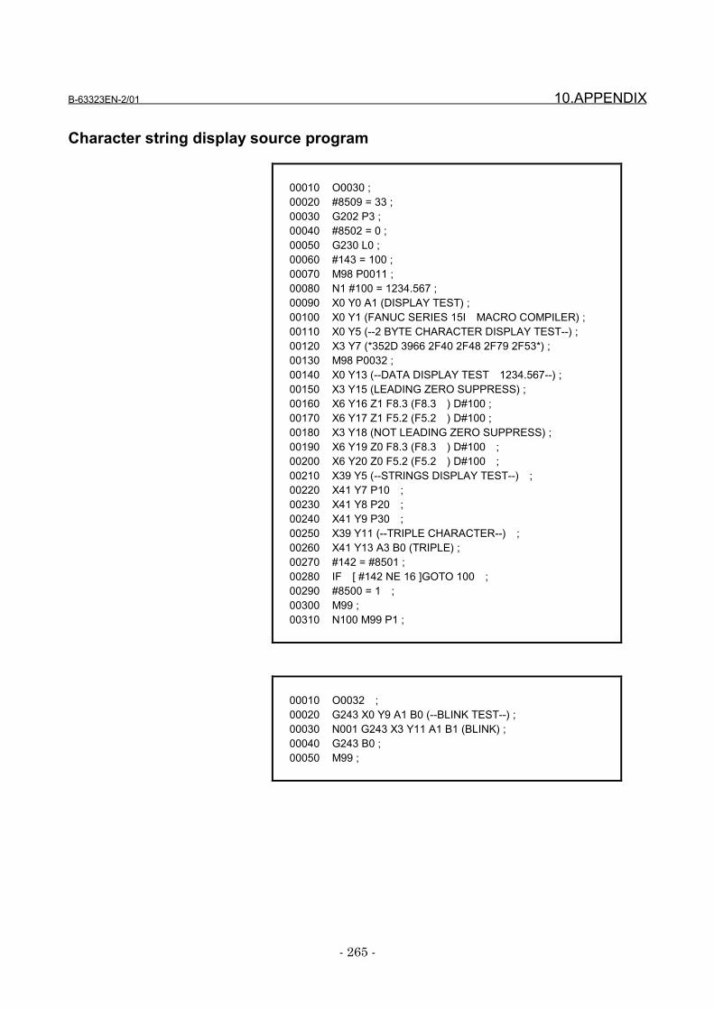
B-63323EN-2/01 10.APPENDIX
- 265 -
Character string display source program
00010 O0030 ;00020 #8509 = 33 ;00030 G202 P3 ;00040 #8502 = 0 ;00050 G230 L0 ;00060 #143 = 100 ;00070 M98 P0011 ;00080 N1 #100 = 1234.567 ;00090 X0 Y0 A1 (DISPLAY TEST) ;00100 X0 Y1 (FANUC SERIES 15I MACRO COMPILER) ;00110 X0 Y5 (--2 BYTE CHARACTER DISPLAY TEST--) ;00120 X3 Y7 (*352D 3966 2F40 2F48 2F79 2F53*) ;00130 M98 P0032 ;00140 X0 Y13 (--DATA DISPLAY TEST 1234.567--) ;00150 X3 Y15 (LEADING ZERO SUPPRESS) ;00160 X6 Y16 Z1 F8.3 (F8.3 ) D#100 ;00170 X6 Y17 Z1 F5.2 (F5.2 ) D#100 ;00180 X3 Y18 (NOT LEADING ZERO SUPPRESS) ;00190 X6 Y19 Z0 F8.3 (F8.3 ) D#100 ;00200 X6 Y20 Z0 F5.2 (F5.2 ) D#100 ;00210 X39 Y5 (--STRINGS DISPLAY TEST--) ;00220 X41 Y7 P10 ;00230 X41 Y8 P20 ;00240 X41 Y9 P30 ;00250 X39 Y11 (--TRIPLE CHARACTER--) ;00260 X41 Y13 A3 B0 (TRIPLE) ;00270 #142 = #8501 ;00280 IF [ #142 NE 16 ]GOTO 100 ;00290 #8500 = 1 ;00300 M99 ;00310 N100 M99 P1 ;
00010 O0032 ;00020 G243 X0 Y9 A1 B0 (--BLINK TEST--) ;00030 N001 G243 X3 Y11 A1 B1 (BLINK) ;00040 G243 B0 ;00050 M99 ;
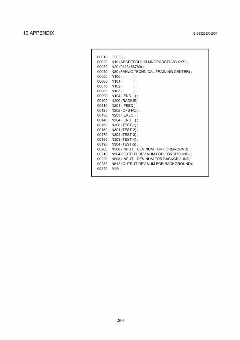
10.APPENDIX B-63323EN-2/01
- 266 -
00010 O0033 ;00020 N10 (ABCDEFGHIJKLMNOPQRSTUVWXYZ) ;00030 N20 (0123456789) ;00040 N30 (FANUC TECHNICAL TRAINING CENTER) ;00050 N100 ( ) ;00060 N101 ( ) ;00070 N102 ( ) ;00080 N103 ( ) ;00090 N104 ( END ) ;00100 N200 (RADIUS) ;00110 N201 ( FEED ) ;00120 N202 (OFS NO) ;00130 N203 ( EXEC ) ;00140 N204 ( END ) ;00150 N300 (TEST-1) ;00160 N301 (TEST-2) ;00170 N302 (TEST-3) ;00180 N303 (TEST-4) ;00190 N304 (TEST-5) ;00200 N500 (INPUT DEV NUM FOR FORGROUND) ;00210 N504 (OUTPUT DEV NUM FOR FORGROUND) ;00220 N508 (INPUT DEV NUM FOR BACKGROUND);00230 N512 (OUTPUT DEV NUM FOR BACKGROUND);00240 M99 ;
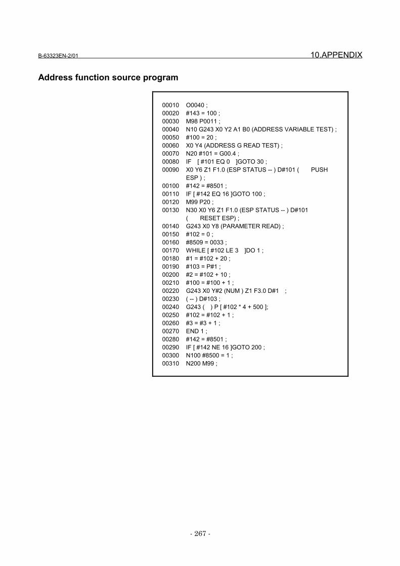
B-63323EN-2/01 10.APPENDIX
- 267 -
Address function source program
00010 O0040 ;00020 #143 = 100 ;00030 M98 P0011 ;00040 N10 G243 X0 Y2 A1 B0 (ADDRESS VARIABLE TEST) ;00050 #100 = 20 ;00060 X0 Y4 (ADDRESS G READ TEST) ;00070 N20 #101 = G00.4 ;00080 IF [ #101 EQ 0 ]GOTO 30 ;00090 X0 Y6 Z1 F1.0 (ESP STATUS -- ) D#101 ( PUSH
ESP ) ;00100 #142 = #8501 ;00110 IF [ #142 EQ 16 ]GOTO 100 ;00120 M99 P20 ;00130 N30 X0 Y6 Z1 F1.0 (ESP STATUS -- ) D#101
( RESET ESP) ;00140 G243 X0 Y8 (PARAMETER READ) ;00150 #102 = 0 ;00160 #8509 = 0033 ;00170 WHILE [ #102 LE 3 ]DO 1 ;00180 #1 = #102 + 20 ;00190 #103 = P#1 ;00200 #2 = #102 + 10 ;00210 #100 = #100 + 1 ;00220 G243 X0 Y#2 (NUM ) Z1 F3.0 D#1 ;00230 ( -- ) D#103 ;00240 G243 ( ) P [ #102 * 4 + 500 ];00250 #102 = #102 + 1 ;00260 #3 = #3 + 1 ;00270 END 1 ;00280 #142 = #8501 ;00290 IF [ #142 NE 16 ]GOTO 200 ;00300 N100 #8500 = 1 ;00310 N200 M99 ;
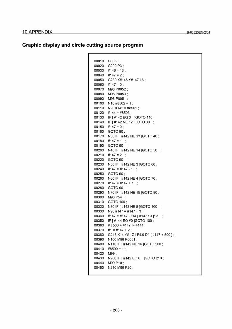
10.APPENDIX B-63323EN-2/01
- 268 -
Graphic display and circle cutting source program
00010 O0050 ;00020 G202 P3 ;00030 #146 = 13 ;00040 #147 = 2 ;00050 G230 X#146 Y#147 L6 ;00060 #147 = 0 ;00070 M98 P0052 ;00080 M98 P0053 ;00090 M98 P0051 ;00100 N10 #8502 = 1 ;00110 N20 #142 = #8501 ;00120 #144 = #8503 ;00130 IF [ #142 EQ 0 ]GOTO 110 ;00140 IF [ #142 NE 12 ]GOTO 30 ;00150 #147 = 0 ;00160 GOTO 90 ;00170 N30 IF [ #142 NE 13 ]GOTO 40 ;00180 #147 = 1 ;00190 GOTO 90 ;00200 N40 IF [ #142 NE 14 ]GOTO 50 ;00210 #147 = 2 ;00220 GOTO 90 ;00230 N50 IF [ #142 NE 3 ]GOTO 60 ;00240 #147 = #147 - 1 ;00250 GOTO 90 ;00260 N60 IF [ #142 NE 4 ]GOTO 70 ;00270 #147 = #147 + 1 ;00280 GOTO 90 ;00290 N70 IF [ #142 NE 15 ]GOTO 80 ;00300 M98 P54 ;00310 GOTO 100 ;00320 N80 IF [ #142 NE 8 ]GOTO 100 ;00330 N90 #147 = #147 + 3 ;00340 #147 = #147 - FIX [ #147 / 3 ]* 3 ;00350 IF [ #144 EQ #0 ]GOTO 100 ;00360 # [ 500 + #147 ]= #144 ;00370 #1 = #147 + 2 ;00380 G243 X14 Y#1 Z1 F4.0 D# [ #147 + 500 ] ;00390 N100 M98 P0051 ;00400 N110 IF [ #142 NE 16 ]GOTO 200 ;00410 #8500 = 1 ;00420 M99 ;00430 N200 IF [ #142 EQ 0 ]GOTO 210 ;00440 M99 P10 ;00450 N210 M99 P20 ;
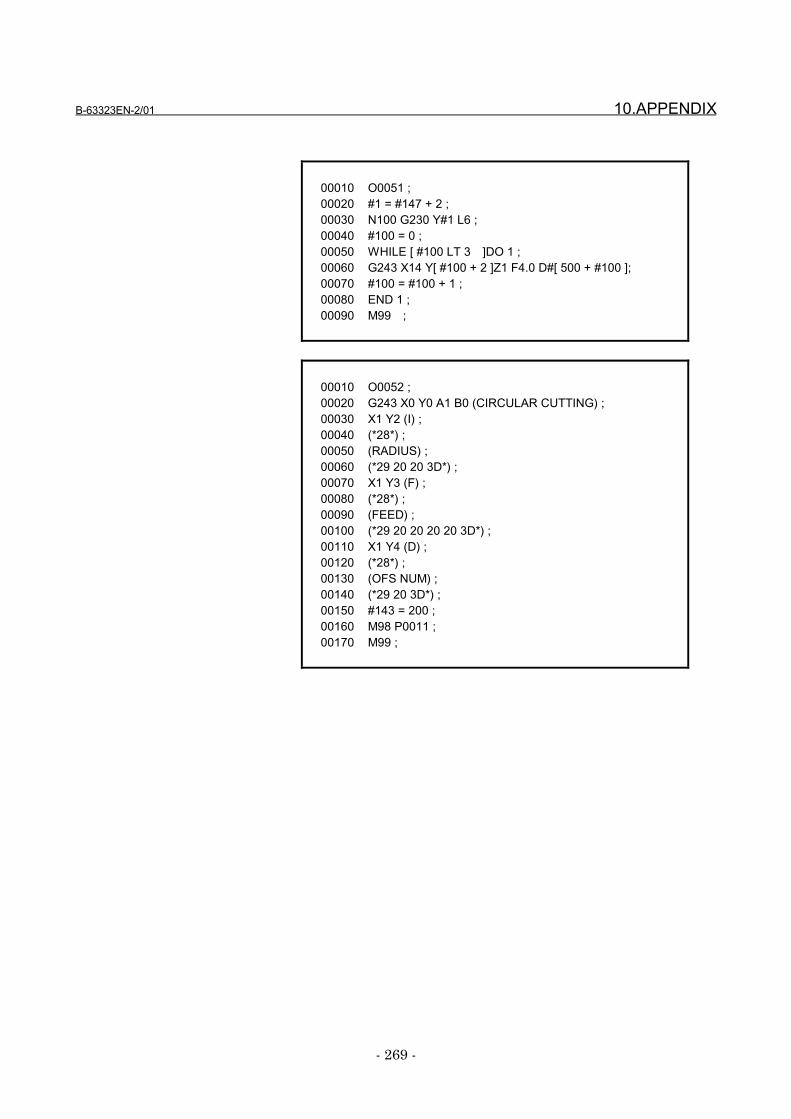
B-63323EN-2/01 10.APPENDIX
- 269 -
00010 O0051 ;00020 #1 = #147 + 2 ;00030 N100 G230 Y#1 L6 ;00040 #100 = 0 ;00050 WHILE [ #100 LT 3 ]DO 1 ;00060 G243 X14 Y[ #100 + 2 ]Z1 F4.0 D#[ 500 + #100 ];00070 #100 = #100 + 1 ;00080 END 1 ;00090 M99 ;
00010 O0052 ;00020 G243 X0 Y0 A1 B0 (CIRCULAR CUTTING) ;00030 X1 Y2 (I) ;00040 (*28*) ;00050 (RADIUS) ;00060 (*29 20 20 3D*) ;00070 X1 Y3 (F) ;00080 (*28*) ;00090 (FEED) ;00100 (*29 20 20 20 20 3D*) ;00110 X1 Y4 (D) ;00120 (*28*) ;00130 (OFS NUM) ;00140 (*29 20 3D*) ;00150 #143 = 200 ;00160 M98 P0011 ;00170 M99 ;
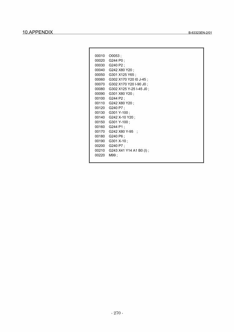
10.APPENDIX B-63323EN-2/01
- 270 -
00010 O0053 ;00020 G244 P0 ;00030 G240 P2 ;00040 G242 X80 Y20 ;00050 G301 X125 Y65 ;00060 G302 X170 Y20 I0 J-45 ;00070 G302 X170 Y20 I-90 J0 ;00080 G302 X125 Y-25 I-45 J0 ;00090 G301 X80 Y20 ;00100 G244 P2 ;00110 G242 X80 Y20 ;00120 G240 P7 ;00130 G301 Y-100 ;00140 G242 X-10 Y20 ;00150 G301 Y-100 ;00160 G244 P1 ;00170 G242 X80 Y-95 ;00180 G240 P6 ;00190 G301 X-10 ;00200 G240 P7 ;00210 G243 X41 Y14 A1 B0 (I) ;00220 M99 ;
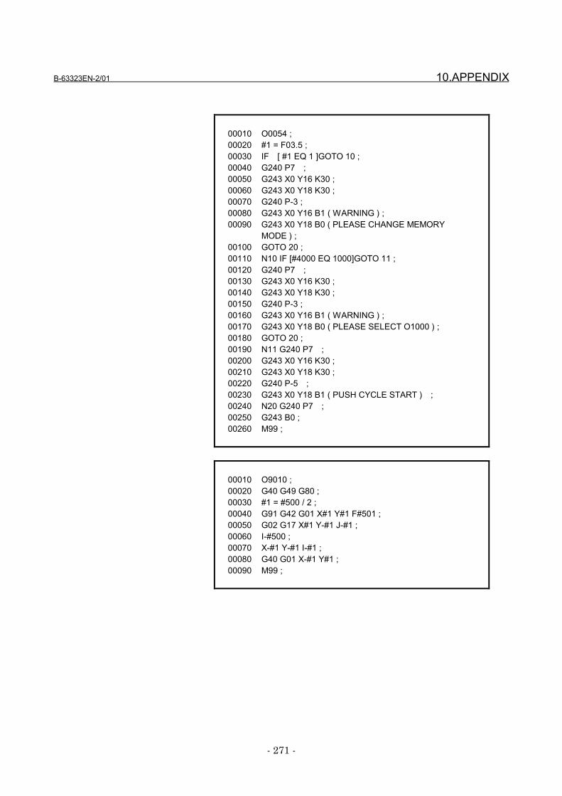
B-63323EN-2/01 10.APPENDIX
- 271 -
00010 O0054 ;00020 #1 = F03.5 ;00030 IF [ #1 EQ 1 ]GOTO 10 ;00040 G240 P7 ;00050 G243 X0 Y16 K30 ;00060 G243 X0 Y18 K30 ;00070 G240 P-3 ;00080 G243 X0 Y16 B1 ( WARNING ) ;00090 G243 X0 Y18 B0 ( PLEASE CHANGE MEMORY
MODE ) ;00100 GOTO 20 ;00110 N10 IF [#4000 EQ 1000]GOTO 11 ;00120 G240 P7 ;00130 G243 X0 Y16 K30 ;00140 G243 X0 Y18 K30 ;00150 G240 P-3 ;00160 G243 X0 Y16 B1 ( WARNING ) ;00170 G243 X0 Y18 B0 ( PLEASE SELECT O1000 ) ;00180 GOTO 20 ;00190 N11 G240 P7 ;00200 G243 X0 Y16 K30 ;00210 G243 X0 Y18 K30 ;00220 G240 P-5 ;00230 G243 X0 Y18 B1 ( PUSH CYCLE START ) ;00240 N20 G240 P7 ;00250 G243 B0 ;00260 M99 ;
00010 O9010 ;00020 G40 G49 G80 ;00030 #1 = #500 / 2 ;00040 G91 G42 G01 X#1 Y#1 F#501 ;00050 G02 G17 X#1 Y-#1 J-#1 ;00060 I-#500 ;00070 X-#1 Y-#1 I-#1 ;00080 G40 G01 X-#1 Y#1 ;00090 M99 ;
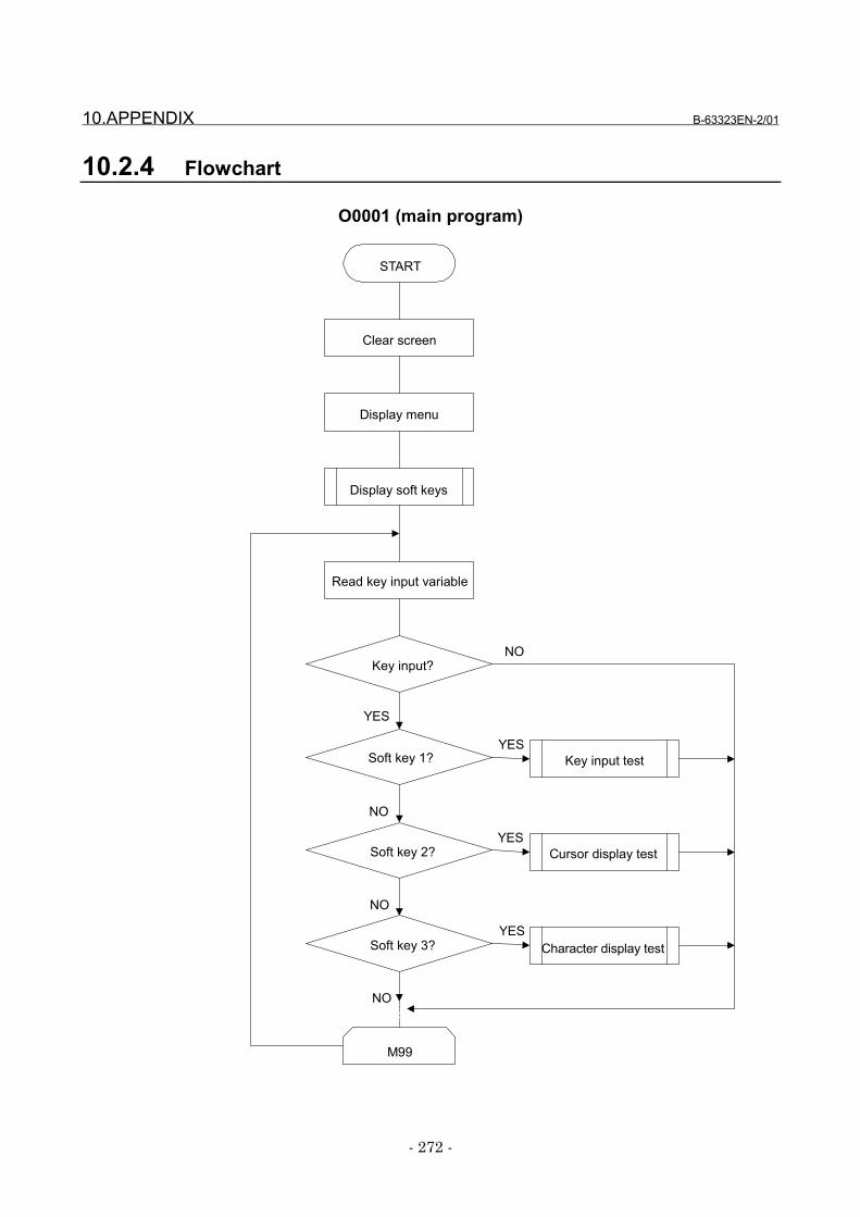
10.APPENDIX B-63323EN-2/01
- 272 -
10.2.4 Flowchart
O0001 (main program)
START
Display soft keys
Clear screen
Display menu
Read key input variable
Key input?
Soft key 3?
Soft key 2?
Soft key 1?
M99
Character display test
Cursor display test
Key input test
NO
YES
YES
YES
YES
NO
NO
NO
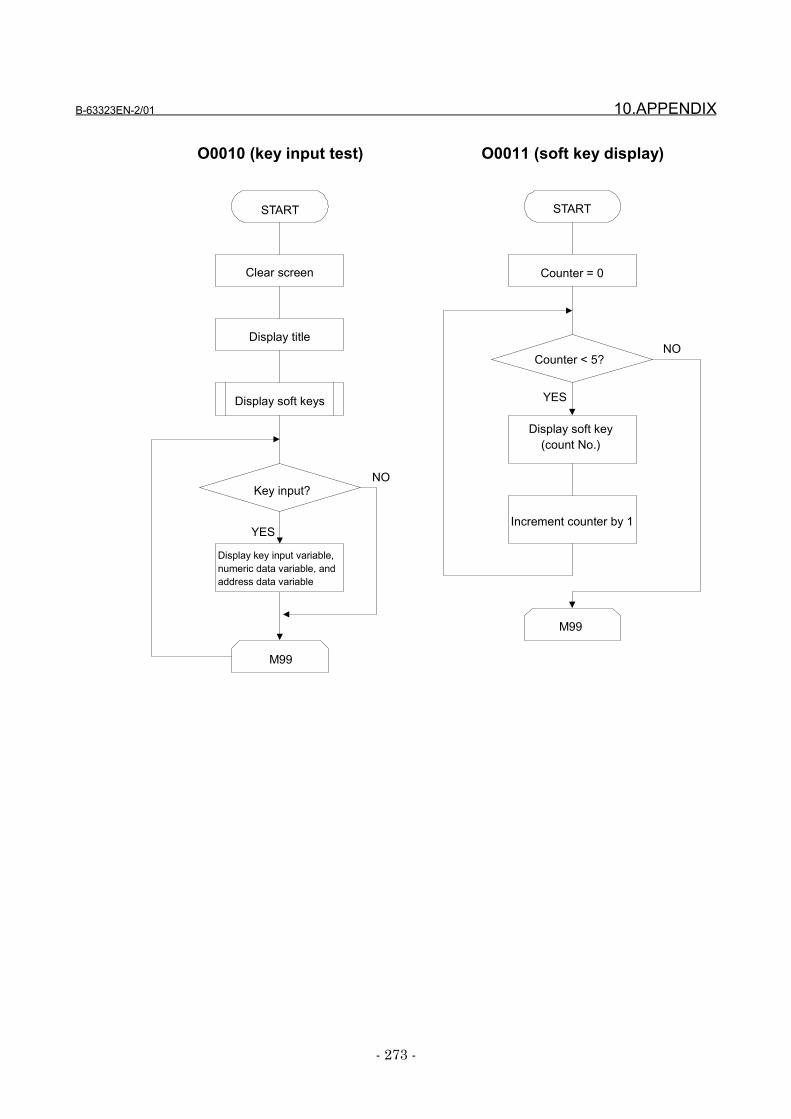
B-63323EN-2/01 10.APPENDIX
- 273 -
O0010 (key input test) O0011 (soft key display)
START
Display soft keys
Clear screen
Display title
Key input?
M99
YES
NO
Display key input variable,numeric data variable, andaddress data variable
START
Counter = 0
Counter < 5?
M99
Display soft key(count No.)
Increment counter by 1
NO
YES

10.APPENDIX B-63323EN-2/01
- 274 -
O0020 (cursor test) O0030 (display test)
START
Display soft keys
Clear screen
Cursor off
Key input?
M99
Display cursor
Display title
Counter = 0
Cursor X coordinate = 2
Is key inputbelow cursor?
Increment counter by 1
Calculate cursor position
Is key inputabove cursor?
Decrement counter by 1
NO
NO
YES
YES
NO
YES
M99
Display characters
Blink display
Is end key pressed?
Display data
Display character string
Display 3-time characters
#8500=1
YES
NO
START
Clear screen
Cursor off
Display soft keys
Display title
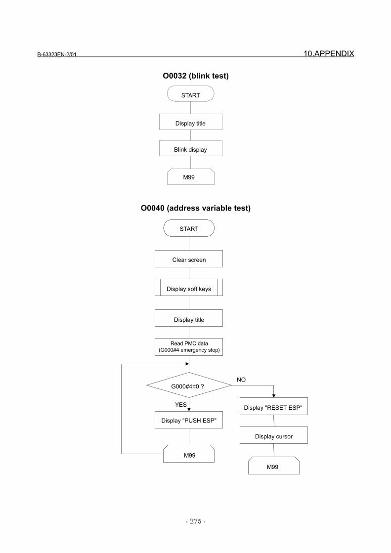
B-63323EN-2/01 10.APPENDIX
- 275 -
O0032 (blink test)
O0040 (address variable test)
START
Display title
M99
Blink display
START
Display soft keys
Clear screen
G000#4=0 ?
M99
Display "PUSH ESP"
Display title
Read PMC data(G000#4 emergency stop)
Display cursor
Display "RESET ESP"
M99
NO
YES
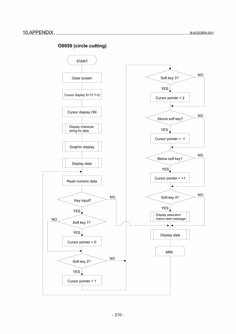
10.APPENDIX B-63323EN-2/01
- 276 -
O0050 (circle cutting)
START
Display characterstring for data
Clear screen
Cursor display X=13 Y=2
Key input?
M99
Read numeric data
Soft key 1?
Cursor display ON
Display data
Graphic display
Cursor pointer = 0
Soft key 2?
Cursor pointer = 1
Soft key 3?
Cursor pointer = 2
Above soft key?
Cursor pointer = -1
Below soft key?
Cursor pointer = +1
Soft key 4?
Display executionmacro start message
Display data
NO
YES
YES
NO
NO
YES
YES
NO
NO
YES
YES
NO
NO
YES
B-63323EN-2/01 10.APPENDIX
- 277 -
10.2.5 Program explanation
Explanation of O000100030 00030 00030 00030 G202 P3G202 P3G202 P3G202 P3Erases a screen. P1: Character screen
P2: Graphic screenP3: Character and graphic screen
00040 00040 00040 00040 G230 L0G230 L0G230 L0G230 L0Cursor control L0: Cursor OFF
L1: Cursor ON. The cursor length is 1.
00060 G243 X0 Y0 A1 B0 (SAMPLE PROGRAM)00060 G243 X0 Y0 A1 B0 (SAMPLE PROGRAM)00060 G243 X0 Y0 A1 B0 (SAMPLE PROGRAM)00060 G243 X0 Y0 A1 B0 (SAMPLE PROGRAM)00070 X2 Y3 (00070 X2 Y3 (00070 X2 Y3 (00070 X2 Y3 ( •••• •••• •••• •••• ))))Displays a character string on the screen.
G243 : Character displayX0 : X-axis display start positionY0 : Y-axis display start positionA1 : Character size (A1: 100%, A3: 300%)
( • • • • ): The character string enclosed in parenthesesis displayed on the screen.
NOTEIn NC programming, the control-in/out functionallows parentheses to be used to indicatecomments. In conversational macros (talkmacros), parentheses indicate data to bedisplayed, so comments cannot be used.
00000120012001200120 #8509 = 0033 #8509 = 0033 #8509 = 0033 #8509 = 003300130001300013000130 #143 = 300 #143 = 300 #143 = 300 #143 = 30000140001400014000140 M98 P0011 M98 P0011 M98 P0011 M98 P0011#8509 is a character string registration program controlvariable which allows use of the G243XYP sequence numberto display a character string corresponding to the sequencenumber. #8509 sets a program number including asequence number. #143 is a common variable. Here, it isused as an offset of the sequence number. O0011 displays amenu for a soft key.
00150 00150 00150 00150 N001 #142=#8501N001 #142=#8501N001 #142=#8501N001 #142=#8501#8501 is a key input variable used to accept a key such as acursor key, page key, soft key, or input key. Once thevariable is read, it is cleared to zero. So, the data in thevariable is saved in #142.
10.APPENDIX B-63323EN-2/01
- 278 -
Explanation of O001100030 00030 00030 00030 WHILE WHILE WHILE WHILE [conditional-expression][conditional-expression][conditional-expression][conditional-expression] DO1 DO1 DO1 DO1
• • • •• • • •
00070 00070 00070 00070 END1END1END1END1While the conditional expression holds, the WHILEstatement performs the processing between DO and END.If the conditional expression does not hold, the block next tothe corresponding END statement and subsequent blocks areexecuted.
00040 #1 = #143 + #10000040 #1 = #143 + #10000040 #1 = #143 + #10000040 #1 = #143 + #10000050 G243 X00050 G243 X00050 G243 X00050 G243 X [ [ [ [#100 * 7 +2#100 * 7 +2#100 * 7 +2#100 * 7 +2] ] ] ] Y25 A1 B0 PY25 A1 B0 PY25 A1 B0 PY25 A1 B0 P[[[[#1#1#1#1]]]]#1 is a local variable that contains the sum of the value ofcommon variable #143 used as an offset of the sequencenumber and the value of counter #100. #100 is used as acounter for counting from 0 to 4.Here, the start number of the character string written inO0033 is set in #143, and a loop is caused using #100 toassociate the program number with soft keys 1 to 5.
Explanation of O002000220 N20 #100 = #100 + 600220 N20 #100 = #100 + 600220 N20 #100 = #100 + 600220 N20 #100 = #100 + 600230 #100 = #100 + 00230 #100 = #100 + 00230 #100 = #100 + 00230 #100 = #100 + [[[[FIX FIX FIX FIX [[[[#100/6#100/6#100/6#100/6]]]]]]]]* 6* 6* 6* 6A calculation is performed to obtain the cursor position. Atline 220, 6 is added in advance to prevent the cursor positionfrom becoming negative. The value 6 means that there aresix positions to which the cursor moves.FIX at line 230 is a function to discard the fractionalremainder from the quotient; the remainder of the divisionby 6 is obtained.
Explanation of O003000020 #8509 = 3300020 #8509 = 3300020 #8509 = 3300020 #8509 = 33The character string registration program variable (#8509) isused to specify the program number including the sequencenumber to be specified in G243P (sequence number). Here,the character string of program number 0033 is used.
00120 X3 Y7 (*352D 3966 2F40 ......)00120 X3 Y7 (*352D 3966 2F40 ......)00120 X3 Y7 (*352D 3966 2F40 ......)00120 X3 Y7 (*352D 3966 2F40 ......)To use internal codes of characters such as kanji characterson the display screen, enclose the codes with "(*" and "*)". Akanji character occupies two horizontal character spaces.
00100100100177770 X6 Y10 X6 Y10 X6 Y10 X6 Y17777 Z1 F5.2 (F5.2) D#100 Z1 F5.2 (F5.2) D#100 Z1 F5.2 (F5.2) D#100 Z1 F5.2 (F5.2) D#100F5.2 specifies the number of numeric data digits whennumeric data is displayed. F5.2 indicates that 5-digitnumeric data including a two-digit fractional part is to bedisplayed.
B-63323EN-2/01 10.APPENDIX
- 279 -
EXAMPLEIf 1234.567 is stored in #100, "234.57" is displayed.
Explanation of O003200030 N001 G243 X3 Y11 A1 B1 (BLINK)00030 N001 G243 X3 Y11 A1 B1 (BLINK)00030 N001 G243 X3 Y11 A1 B1 (BLINK)00030 N001 G243 X3 Y11 A1 B1 (BLINK)G243 B1 sets the blink display mode. The characters to bedisplayed after this command are all displayed in the blinkdisplay mode. To cancel the blink display mode, specifyG243 B0.
Explanation of O004000070 N20 #100 = G00.400070 N20 #100 = G00.400070 N20 #100 = G00.400070 N20 #100 = G00.4 ||||The state of G00.4 (emergency stop) is read into commonvariable #100.
00180 #1 = #102 + 2000180 #1 = #102 + 2000180 #1 = #102 + 2000180 #1 = #102 + 2000190 #103 = P#100190 #103 = P#100190 #103 = P#100190 #103 = P#1The content of the parameter specified by P# is read intocommon variable #103. Here, the contents of parameterNos. 20, 21, 22, and 23 are read by changing the #102 contentfrom 0 to 3.
20 Interface number of the input device for the foreground21 Interface number of the output device for the foreground22 Interface number of the input device for the background23 Interface number of the output device for the background
Explanation of O005400020 #1 = F03.500020 #1 = F03.500020 #1 = F03.500020 #1 = F03.5The state of F03.5 (memory mode in progress) is read intolocal variable #1.
00000000000077770 G240 P-30 G240 P-30 G240 P-30 G240 P-3The color of lines and characters to be displayed is specified.In this case, the lines and characters are displayed in reversevideo in yellow.
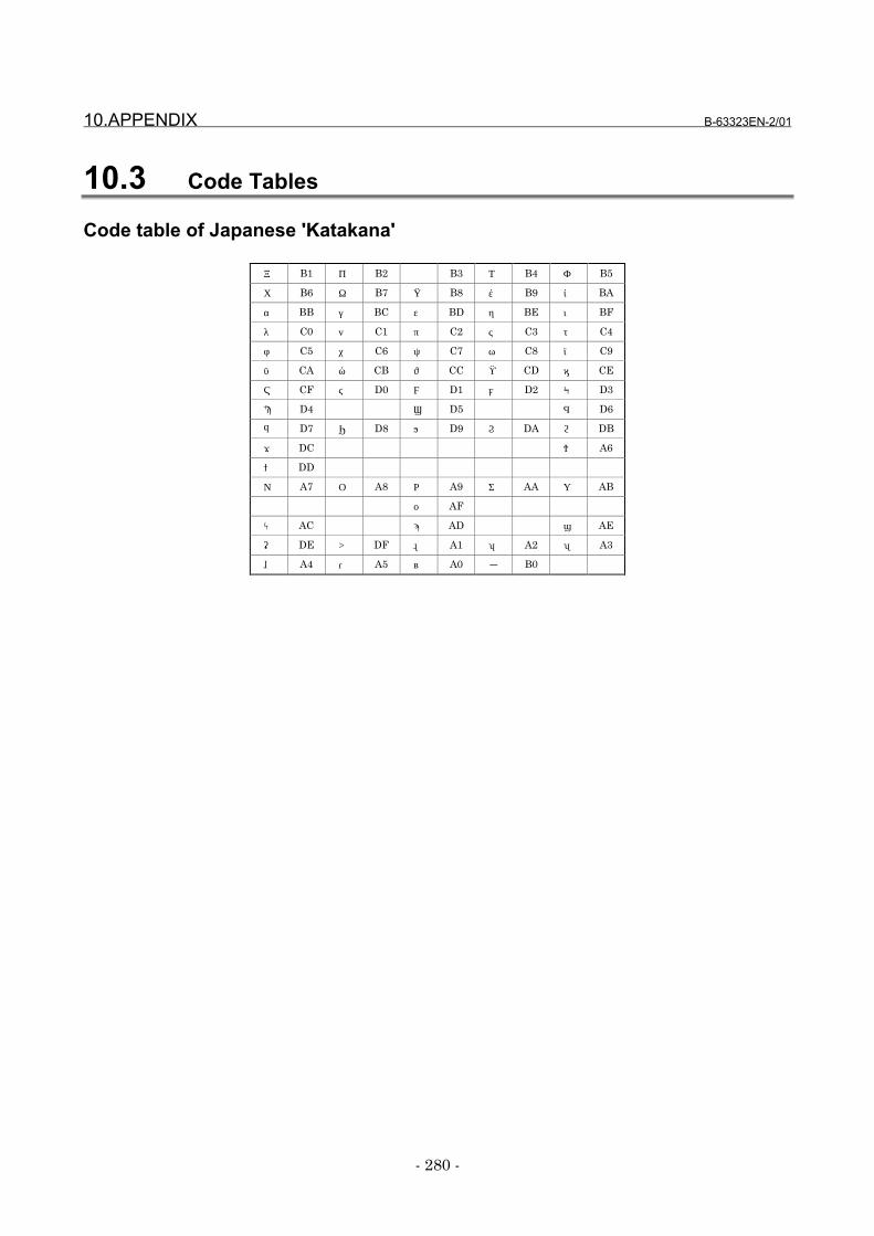
10.APPENDIX B-63323EN-2/01
- 280 -
10.3 Code Tables
Code table of Japanese 'Katakana'
ア B1 イ B2 ウ B3 エ B4 オ B5
カ B6 キ B7 ク B8 ケ B9 コ BA
サ BB シ BC ス BD セ BE ソ BF
タ C0 チ C1 ツ C2 テ C3 ト C4
ナ C5 ニ C6 ヌ C7 ネ C8 ノ C9
ハ CA ヒ CB フ CC ヘ CD ホ CE
マ CF ミ D0 ム D1 メ D2 モ D3
ヤ D4 ユ D5 ヨ D6
ラ D7 リ D8 ル D9 レ DA ロ DB
ワ DC ヲ A6
ン DD
ァ A7 ィ A8 ゥ A9 ェ AA ォ AB
ッ AF
ャ AC ュ AD ョ AE
” DE ° DF 。 A1 「 A2 」 A3
、 A4 ・ A5 ~ A0 - B0
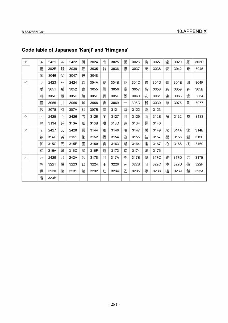
B-63323EN-2/01 10.APPENDIX
- 281 -
Code table of Japanese 'Kanji' and 'Hiragana'
ア ぁ 2421 あ 2422 阿 3024 哀 3025 愛 3026 挨 3027 逢 3029 悪 302D
握 302E 旭 3030 圧 3035 斡 3036 扱 3037 宛 3038 安 3042 暗 3045
案 3046 闇 3047 鞍 3048
イ ぃ 2423 い 2424 以 304A 伊 304B 位 304C 依 304D 偉 304E 囲 304F
委 3051 威 3052 意 3055 慰 3056 易 3057 椅 3058 為 3059 異 305B
移 305C 維 305D 緯 305E 胃 305F 萎 3060 衣 3061 違 3063 遺 3064
医 3065 井 3066 域 3068 育 3069 一 306C 稲 3030 印 3075 員 3077
因 3078 引 307A 飲 307B 院 3121 陰 3122 隠 3123
ウ ぅ 2425 う 2426 右 3126 宇 3127 羽 3129 雨 312B 渦 3132 嘘 3133
唄 3134 浦 313A 瓜 313B 噂 313D 運 313F 雲 3140
エ ぇ 2427 え 2428 営 3144 影 3146 映 3147 栄 3149 永 314A 泳 314B
洩 314C 英 3151 衛 3152 鋭 3154 液 3155 益 3157 駅 3158 越 315B
閲 315C 円 315F 園 3160 宴 3163 延 3164 援 3167 沿 3168 演 3169
炎 316A 煙 316C 縁 316F 遠 3173 鉛 3174 塩 3176
オ ぉ 2429 お 242A 汚 3178 凹 317A 央 317B 奥 317C 往 317D 応 317E
押 3221 横 3223 欧 3224 王 3226 黄 322B 岡 322C 沖 322D 億 322F
屋 3230 憶 3231 臆 3232 牡 3234 乙 3235 恩 3238 温 3239 穏 323A
音 323B
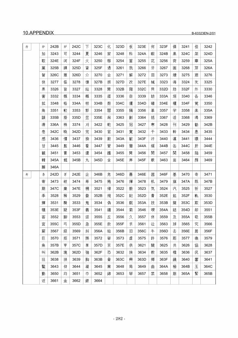
10.APPENDIX B-63323EN-2/01
- 282 -
カ か 242B が 242C 下 323C 化 323D 仮 323E 何 323F 価 3241 佳 3242
加 3243 可 3244 夏 3246 家 3248 科 324A 暇 324B 果 324C 架 324D
歌 324E 河 324F 火 3250 稼 3254 箇 3255 花 3256 荷 3259 華 325A
菓 325B 課 325D 貨 325F 過 3261 我 3266 牙 3267 画 3268 芽 326A
賀 326C 雅 326D 介 3270 会 3271 解 3272 回 3273 壊 3275 廻 3276
快 3277 怪 3278 懐 327B 拐 327D 改 327E 械 3323 海 3324 灰 3325
界 3326 皆 3327 絵 3328 開 332B 階 332C 貝 332D 劾 332F 外 3330
害 3332 慨 3334 概 3335 涯 3336 街 3339 該 333A 垣 3340 各 3346
拡 3348 格 334A 核 334B 殻 334C 獲 334D 確 334E 穫 334F 覚 3350
角 3351 較 3353 郭 3354 閣 3355 隔 3356 革 3357 学 3358 楽 335A
額 335B 掛 335D 笠 335E 潟 3363 割 3364 括 3367 活 3368 渇 3369
滑 336A 株 3374 刈 3422 乾 3425 冠 3427 寒 3428 刊 3429 勧 342B
巻 342C 喚 342D 完 3430 官 3431 寛 3432 干 3433 幹 3434 患 3435
感 3436 慣 3437 換 3439 敢 343A 歓 343F 汗 3440 漢 3441 環 3444
甘 3445 監 3446 看 3447 管 3449 簡 344A 緩 344B 缶 344C 肝 344E
観 3451 貫 3453 還 3454 鑑 3455 間 3456 閑 3457 関 3458 陥 3459
韓 345A 館 345B 丸 345D 含 345E 岸 345F 眼 3463 岩 3464 顔 3469
願 346A
キ き 242D ぎ 242E 企 346B 危 346D 喜 346E 器 346F 基 3470 奇 3471
寄 3473 岐 3474 希 3475 幾 3476 揮 3478 机 3479 旗 347A 既 347B
期 347C 棄 347E 機 3521 帰 3522 毅 3523 気 3524 汽 3525 祈 3527
季 3528 稀 3529 徽 352B 規 352C 記 352D 貴 352E 起 352F 軌 3530
輝 3531 騎 3533 鬼 3534 偽 3536 戯 353A 技 353B 擬 353C 欺 353D
犠 353E 疑 353F 義 3541 議 3544 菊 3546 喫 354A 詰 354D 却 3551
客 3552 脚 3553 逆 3555 丘 3556 久 3557 休 3559 及 355A 吸 355B
宮 355C 弓 355D 急 355E 救 355F 求 3561 泣 3563 球 3565 究 3566
窮 3567 級 3569 糾 356A 給 356B 旧 356C 牛 356D 去 356E 居 356F
巨 3570 拒 3571 拠 3572 挙 3573 虚 3575 許 3576 距 3577 漁 3579
魚 357B 亨 357C 享 357D 京 357E 供 3621 競 3625 共 3626 協 3628
叫 362B 境 362D 強 362F 恐 3632 挟 3634 教 3635 橋 3636 況 3637
狂 3638 狭 3639 胸 363B 脅 363C 興 363D 郷 363F 鏡 3640 響 3641
驚 3643 仰 3644 凝 3645 業 3648 局 3649 曲 364A 極 364B 玉 364C
勤 3650 均 3651 巾 3652 錦 3653 琴 3657 禁 3658 筋 365A 緊 365B
近 3661 金 3662 銀 3664

B-63323EN-2/01 10.APPENDIX
- 283 -
ク く 242F ぐ 2430 九 3665 句 3667 区 3668 矩 366B 苦 366C 駆 366E
具 3671 愚 3672 空 3675 偶 3676 遇 3678 隅 3679 屑 367D 屈 367E
掘 3721 靴 3724 熊 3727 繰 372B 君 372F 訓 3731 群 3732 軍 3733
郡 3734
ケ け 2431 げ 2432 係 3738 傾 3739 刑 373A 兄 373B 啓 373C 型 373F
契 3740 形 3741 径 3742 慶 3744 憩 3746 掲 3747 携 3748 敬 3749
景 374A 系 374F 経 3750 継 3751 茎 3754 計 3757 警 3759 軽 375A
芸 375D 迎 375E 劇 3760 撃 3762 激 3763 隙 3764 桁 3765 傑 3766
欠 3767 決 3768 潔 3769 穴 376A 結 376B 血 376C 月 376E 件 376F
倹 3770 健 3772 兼 3773 券 3774 剣 3775 圏 3777 堅 3778 嫌 3779
建 377A 憲 377B 懸 377C 拳 377D 検 3821 権 3822 犬 3824 献 3825
研 3826 絹 3828 県 3829 肩 382A 見 382B 謙 382C 軒 382E 鍵 3830
険 3831 験 3833 元 3835 原 3836 厳 3837 幻 3838 弦 3839 減 383A
源 383B 現 383D 言 3840 限 3842
コ こ 2433 ご 2434 個 3844 古 3845 呼 3846 固 3847 己 384A 庫 384B
弧 384C 戸 384D 故 384E 湖 3850 狐 3851 誇 3858 雇 385B 顧 385C
五 385E 互 385F 午 3861 娯 3864 後 3865 御 3866 語 386C 誤 386D
護 386E 交 3872 侯 3874 候 3875 光 3877 公 3878 功 3879 効 387A
勾 387B 厚 387C 口 387D 向 387E 喉 3922 坑 3923 好 3925 孔 3926
孝 3927 工 3929 巧 392A 幸 392C 広 392D 康 392F 弘 3930 抗 3933
拘 3934 控 3935 攻 3936 更 3939 校 393B 構 393D 江 393E 洪 393F
港 3941 溝 3942 甲 3943 硬 3945 稿 3946 紅 3948 絞 394A 綱 394B
耕 394C 考 394D 肯 394E 航 3952 荒 3953 行 3954 衡 3955 講 3956
貢 3957 購 3958 郊 3959 鉱 395B 鋼 395D 降 395F 項 3960 香 3961
高 3962 剛 3964 号 3966 合 3967 克 396E 刻 396F 告 3970 国 3971
穀 3972 酷 3973 黒 3975 腰 3978 骨 397C 込 397E 此 3A21 頃 3A22
今 3A23 困 3A24 婚 3A27 根 3A2C 混 3A2E
サ さ 2435 ざ 2436 左 3A38 差 3A39 査 3A3A 砂 3A3D 鎖 3A3F 座 3A42
挫 3A43 債 3A44 催 3A45 再 3A46 最 3A47 妻 3A4A 彩 3A4C 才 3A4D
採 3A4E 栽 3A4F 済 3A51 災 3A52 砕 3A55 祭 3A57 細 3A59 菜 3A5A
裁 3A5B 載 3A5C 際 3A5D 剤 3A5E 在 3A5F 材 3A60 罪 3A61 財 3A62
坂 3A64 阪 3A65 咲 3A69 崎 3A6A 作 3A6E 削 3A6F 咋 3A72 柵 3A74
策 3A76 索 3A77 錯 3A78 桜 3A79 冊 3A7D 刷 3A7E 察 3B21 拶 3B22
撮 3B23 擦 3B24 札 3B25 殺 3B26 雑 3B28 皿 3B2E 三 3B30 傘 3B31
参 3B32 山 3B33 撒 3B35 散 3B36 産 3B3A 算 3B3B 讃 3B3E 賛 3B3F
酸 3B40 残 3B44
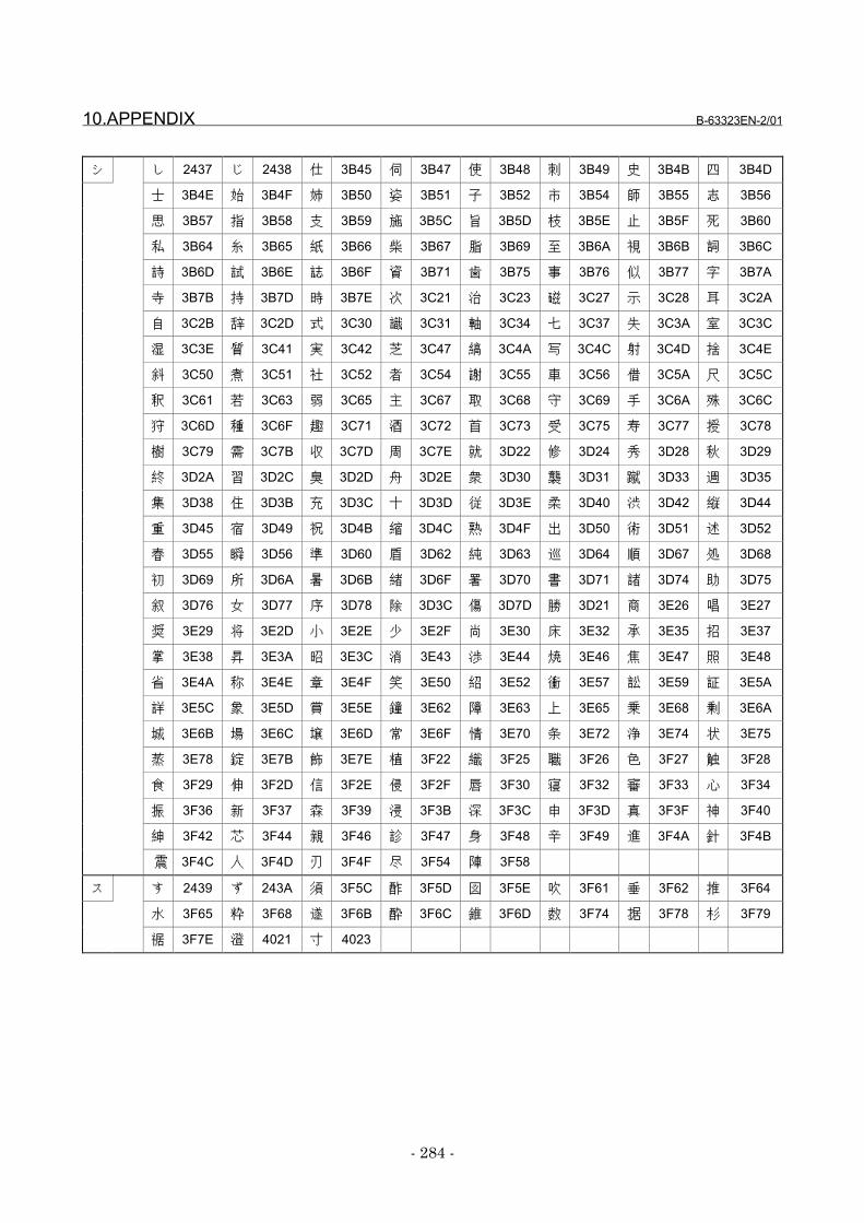
10.APPENDIX B-63323EN-2/01
- 284 -
シ し 2437 じ 2438 仕 3B45 伺 3B47 使 3B48 刺 3B49 史 3B4B 四 3B4D
士 3B4E 始 3B4F 姉 3B50 姿 3B51 子 3B52 市 3B54 師 3B55 志 3B56
思 3B57 指 3B58 支 3B59 施 3B5C 旨 3B5D 枝 3B5E 止 3B5F 死 3B60
私 3B64 糸 3B65 紙 3B66 柴 3B67 脂 3B69 至 3B6A 視 3B6B 詞 3B6C
詩 3B6D 試 3B6E 誌 3B6F 資 3B71 歯 3B75 事 3B76 似 3B77 字 3B7A
寺 3B7B 持 3B7D 時 3B7E 次 3C21 治 3C23 磁 3C27 示 3C28 耳 3C2A
自 3C2B 辞 3C2D 式 3C30 識 3C31 軸 3C34 七 3C37 失 3C3A 室 3C3C
湿 3C3E 質 3C41 実 3C42 芝 3C47 縞 3C4A 写 3C4C 射 3C4D 捨 3C4E
斜 3C50 煮 3C51 社 3C52 者 3C54 謝 3C55 車 3C56 借 3C5A 尺 3C5C
釈 3C61 若 3C63 弱 3C65 主 3C67 取 3C68 守 3C69 手 3C6A 殊 3C6C
狩 3C6D 種 3C6F 趣 3C71 酒 3C72 首 3C73 受 3C75 寿 3C77 授 3C78
樹 3C79 需 3C7B 収 3C7D 周 3C7E 就 3D22 修 3D24 秀 3D28 秋 3D29
終 3D2A 習 3D2C 臭 3D2D 舟 3D2E 衆 3D30 襲 3D31 蹴 3D33 週 3D35
集 3D38 住 3D3B 充 3D3C 十 3D3D 従 3D3E 柔 3D40 渋 3D42 縦 3D44
重 3D45 宿 3D49 祝 3D4B 縮 3D4C 熟 3D4F 出 3D50 術 3D51 述 3D52
春 3D55 瞬 3D56 準 3D60 盾 3D62 純 3D63 巡 3D64 順 3D67 処 3D68
初 3D69 所 3D6A 暑 3D6B 緒 3D6F 署 3D70 書 3D71 諸 3D74 助 3D75
叙 3D76 女 3D77 序 3D78 除 3D3C 傷 3D7D 勝 3D21 商 3E26 唱 3E27
奨 3E29 将 3E2D 小 3E2E 少 3E2F 尚 3E30 床 3E32 承 3E35 招 3E37
掌 3E38 昇 3E3A 昭 3E3C 消 3E43 渉 3E44 焼 3E46 焦 3E47 照 3E48
省 3E4A 称 3E4E 章 3E4F 笑 3E50 紹 3E52 衝 3E57 訟 3E59 証 3E5A
詳 3E5C 象 3E5D 賞 3E5E 鐘 3E62 障 3E63 上 3E65 乗 3E68 剰 3E6A
城 3E6B 場 3E6C 壌 3E6D 常 3E6F 情 3E70 条 3E72 浄 3E74 状 3E75
蒸 3E78 錠 3E7B 飾 3E7E 植 3F22 織 3F25 職 3F26 色 3F27 触 3F28
食 3F29 伸 3F2D 信 3F2E 侵 3F2F 唇 3F30 寝 3F32 審 3F33 心 3F34
振 3F36 新 3F37 森 3F39 浸 3F3B 深 3F3C 申 3F3D 真 3F3F 神 3F40
紳 3F42 芯 3F44 親 3F46 診 3F47 身 3F48 辛 3F49 進 3F4A 針 3F4B
震 3F4C 人 3F4D 刃 3F4F 尽 3F54 陣 3F58
ス す 2439 ず 243A 須 3F5C 酢 3F5D 図 3F5E 吹 3F61 垂 3F62 推 3F64
水 3F65 粋 3F68 遂 3F6B 酔 3F6C 錐 3F6D 数 3F74 据 3F78 杉 3F79
裾 3F7E 澄 4021 寸 4023
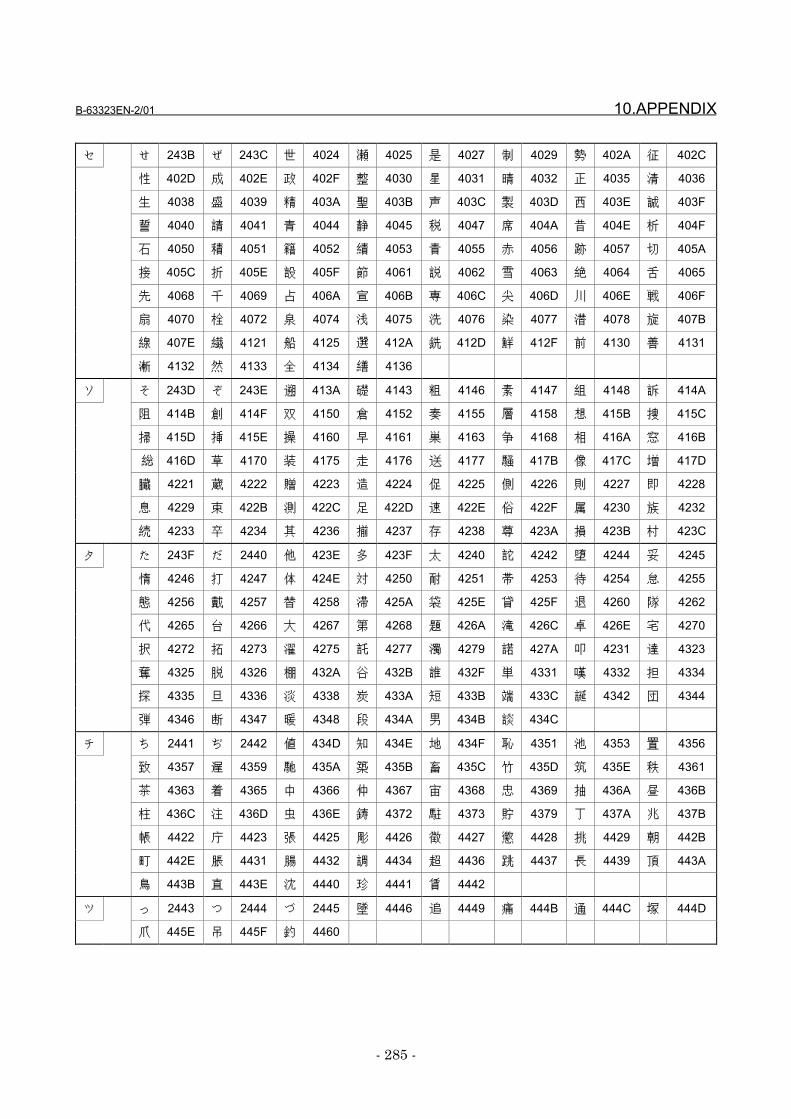
B-63323EN-2/01 10.APPENDIX
- 285 -
セ せ 243B ぜ 243C 世 4024 瀬 4025 是 4027 制 4029 勢 402A 征 402C
性 402D 成 402E 政 402F 整 4030 星 4031 晴 4032 正 4035 清 4036
生 4038 盛 4039 精 403A 聖 403B 声 403C 製 403D 西 403E 誠 403F
誓 4040 請 4041 青 4044 静 4045 税 4047 席 404A 昔 404E 析 404F
石 4050 積 4051 籍 4052 績 4053 責 4055 赤 4056 跡 4057 切 405A
接 405C 折 405E 設 405F 節 4061 説 4062 雪 4063 絶 4064 舌 4065
先 4068 千 4069 占 406A 宣 406B 専 406C 尖 406D 川 406E 戦 406F
扇 4070 栓 4072 泉 4074 浅 4075 洗 4076 染 4077 潜 4078 旋 407B
線 407E 繊 4121 船 4125 選 412A 銑 412D 鮮 412F 前 4130 善 4131
漸 4132 然 4133 全 4134 繕 4136
ソ そ 243D ぞ 243E 遡 413A 礎 4143 粗 4146 素 4147 組 4148 訴 414A
阻 414B 創 414F 双 4150 倉 4152 奏 4155 層 4158 想 415B 捜 415C
掃 415D 挿 415E 操 4160 早 4161 巣 4163 争 4168 相 416A 窓 416B
総 416D 草 4170 装 4175 走 4176 送 4177 騒 417B 像 417C 増 417D
臓 4221 蔵 4222 贈 4223 造 4224 促 4225 側 4226 則 4227 即 4228
息 4229 束 422B 測 422C 足 422D 速 422E 俗 422F 属 4230 族 4232
続 4233 卒 4234 其 4236 揃 4237 存 4238 尊 423A 損 423B 村 423C
タ た 243F だ 2440 他 423E 多 423F 太 4240 詑 4242 堕 4244 妥 4245
惰 4246 打 4247 体 424E 対 4250 耐 4251 帯 4253 待 4254 怠 4255
態 4256 戴 4257 替 4258 滞 425A 袋 425E 貸 425F 退 4260 隊 4262
代 4265 台 4266 大 4267 第 4268 題 426A 滝 426C 卓 426E 宅 4270
択 4272 拓 4273 濯 4275 託 4277 濁 4279 諾 427A 叩 4231 達 4323
奪 4325 脱 4326 棚 432A 谷 432B 誰 432F 単 4331 嘆 4332 担 4334
探 4335 旦 4336 淡 4338 炭 433A 短 433B 端 433C 誕 4342 団 4344
弾 4346 断 4347 暖 4348 段 434A 男 434B 談 434C
チ ち 2441 ぢ 2442 値 434D 知 434E 地 434F 恥 4351 池 4353 置 4356
致 4357 遅 4359 馳 435A 築 435B 畜 435C 竹 435D 筑 435E 秩 4361
茶 4363 着 4365 中 4366 仲 4367 宙 4368 忠 4369 抽 436A 昼 436B
柱 436C 注 436D 虫 436E 鋳 4372 駐 4373 貯 4379 丁 437A 兆 437B
帳 4422 庁 4423 張 4425 彫 4426 徴 4427 懲 4428 挑 4429 朝 442B
町 442E 脹 4431 腸 4432 調 4434 超 4436 跳 4437 長 4439 頂 443A
鳥 443B 直 443E 沈 4440 珍 4441 賃 4442
ツ っ 2443 つ 2444 づ 2445 墜 4446 追 4449 痛 444B 通 444C 塚 444D
爪 445E 吊 445F 釣 4460
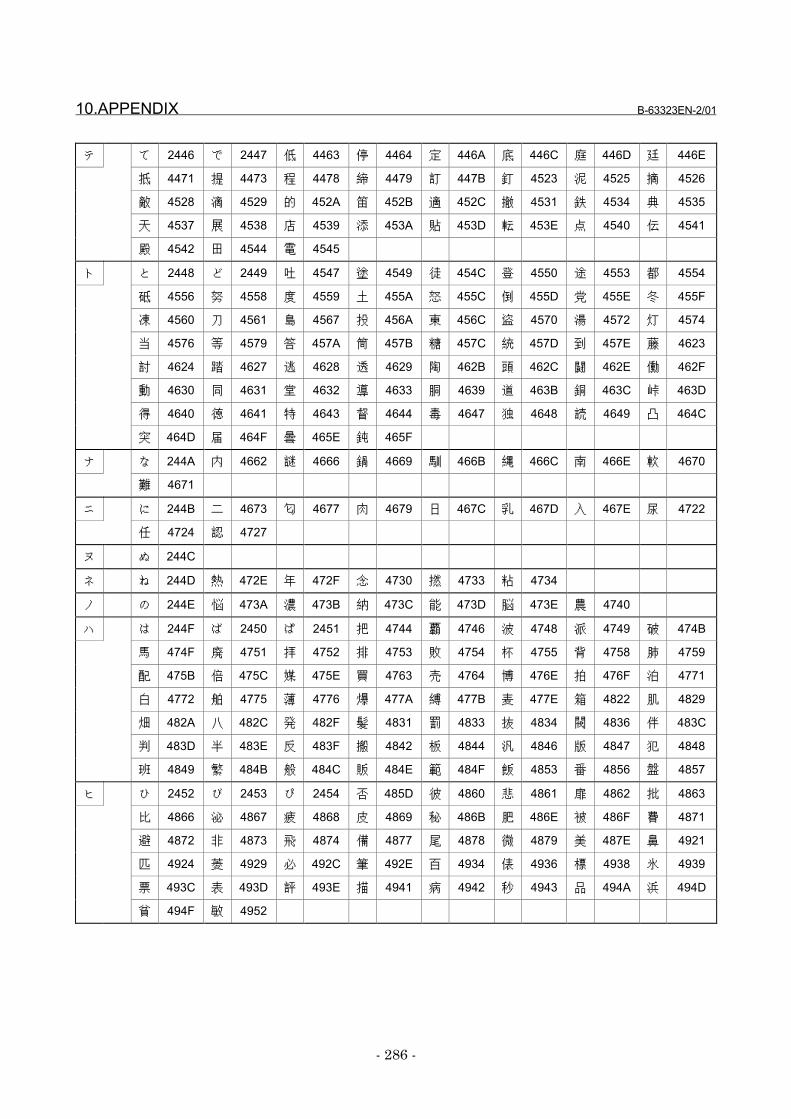
10.APPENDIX B-63323EN-2/01
- 286 -
テ て 2446 で 2447 低 4463 停 4464 定 446A 底 446C 庭 446D 廷 446E
抵 4471 提 4473 程 4478 締 4479 訂 447B 釘 4523 泥 4525 摘 4526
敵 4528 滴 4529 的 452A 笛 452B 適 452C 撤 4531 鉄 4534 典 4535
天 4537 展 4538 店 4539 添 453A 貼 453D 転 453E 点 4540 伝 4541
殿 4542 田 4544 電 4545
ト と 2448 ど 2449 吐 4547 塗 4549 徒 454C 登 4550 途 4553 都 4554
砥 4556 努 4558 度 4559 土 455A 怒 455C 倒 455D 党 455E 冬 455F
凍 4560 刀 4561 島 4567 投 456A 東 456C 盗 4570 湯 4572 灯 4574
当 4576 等 4579 答 457A 筒 457B 糖 457C 統 457D 到 457E 藤 4623
討 4624 踏 4627 逃 4628 透 4629 陶 462B 頭 462C 闘 462E 働 462F
動 4630 同 4631 堂 4632 導 4633 胴 4639 道 463B 銅 463C 峠 463D
得 4640 徳 4641 特 4643 督 4644 毒 4647 独 4648 読 4649 凸 464C
突 464D 届 464F 曇 465E 鈍 465F
ナ な 244A 内 4662 謎 4666 鍋 4669 馴 466B 縄 466C 南 466E 軟 4670
難 4671
ニ に 244B 二 4673 匂 4677 肉 4679 日 467C 乳 467D 入 467E 尿 4722
任 4724 認 4727
ヌ ぬ 244C
ネ ね 244D 熱 472E 年 472F 念 4730 撚 4733 粘 4734
ノ の 244E 悩 473A 濃 473B 納 473C 能 473D 脳 473E 農 4740
ハ は 244F ば 2450 ぱ 2451 把 4744 覇 4746 波 4748 派 4749 破 474B
馬 474F 廃 4751 拝 4752 排 4753 敗 4754 杯 4755 背 4758 肺 4759
配 475B 倍 475C 媒 475E 買 4763 売 4764 博 476E 拍 476F 泊 4771
白 4772 舶 4775 薄 4776 爆 477A 縛 477B 麦 477E 箱 4822 肌 4829
畑 482A 八 482C 発 482F 髪 4831 罰 4833 抜 4834 閥 4836 伴 483C
判 483D 半 483E 反 483F 搬 4842 板 4844 汎 4846 版 4847 犯 4848
班 4849 繁 484B 般 484C 販 484E 範 484F 飯 4853 番 4856 盤 4857
ヒ ひ 2452 び 2453 ぴ 2454 否 485D 彼 4860 悲 4861 扉 4862 批 4863
比 4866 泌 4867 疲 4868 皮 4869 秘 486B 肥 486E 被 486F 費 4871
避 4872 非 4873 飛 4874 備 4877 尾 4878 微 4879 美 487E 鼻 4921
匹 4924 菱 4929 必 492C 筆 492E 百 4934 俵 4936 標 4938 氷 4939
票 493C 表 493D 評 493E 描 4941 病 4942 秒 4943 品 494A 浜 494D
貧 494F 敏 4952
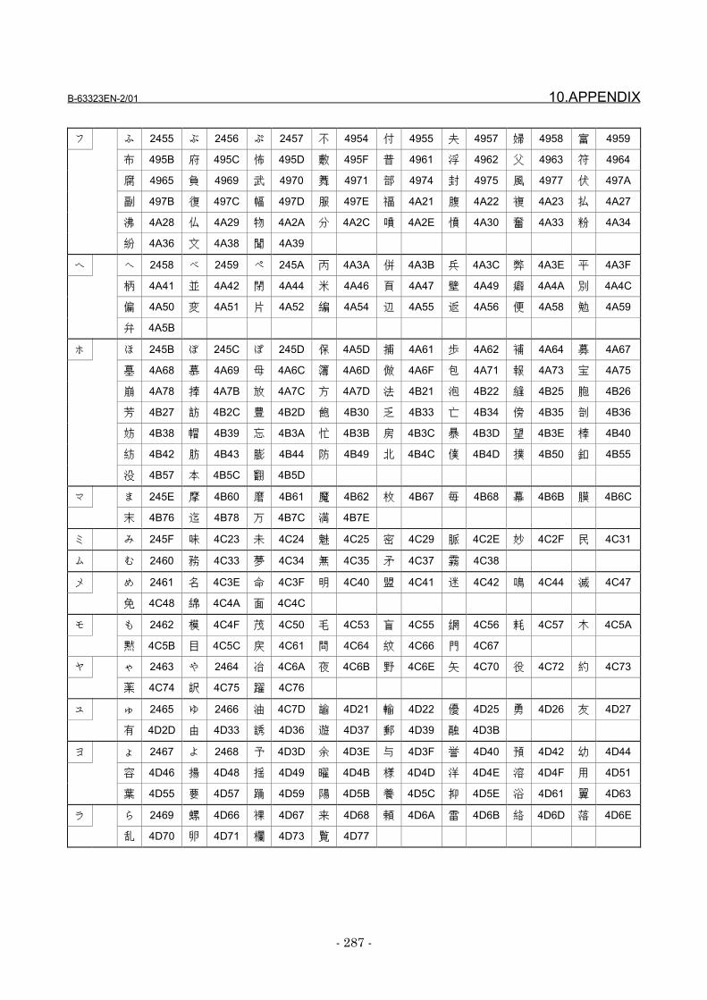
B-63323EN-2/01 10.APPENDIX
- 287 -
フ ふ 2455 ぶ 2456 ぷ 2457 不 4954 付 4955 夫 4957 婦 4958 富 4959
布 495B 府 495C 怖 495D 敷 495F 普 4961 浮 4962 父 4963 符 4964
腐 4965 負 4969 武 4970 舞 4971 部 4974 封 4975 風 4977 伏 497A
副 497B 復 497C 幅 497D 服 497E 福 4A21 腹 4A22 複 4A23 払 4A27
沸 4A28 仏 4A29 物 4A2A 分 4A2C 噴 4A2E 憤 4A30 奮 4A33 粉 4A34
紛 4A36 文 4A38 聞 4A39
ヘ へ 2458 べ 2459 ぺ 245A 丙 4A3A 併 4A3B 兵 4A3C 弊 4A3E 平 4A3F
柄 4A41 並 4A42 閉 4A44 米 4A46 頁 4A47 壁 4A49 癖 4A4A 別 4A4C
偏 4A50 変 4A51 片 4A52 編 4A54 辺 4A55 返 4A56 便 4A58 勉 4A59
弁 4A5B
ホ ほ 245B ぼ 245C ぽ 245D 保 4A5D 捕 4A61 歩 4A62 補 4A64 募 4A67
墓 4A68 慕 4A69 母 4A6C 簿 4A6D 倣 4A6F 包 4A71 報 4A73 宝 4A75
崩 4A78 捧 4A7B 放 4A7C 方 4A7D 法 4B21 泡 4B22 縫 4B25 胞 4B26
芳 4B27 訪 4B2C 豊 4B2D 飽 4B30 乏 4B33 亡 4B34 傍 4B35 剖 4B36
妨 4B38 帽 4B39 忘 4B3A 忙 4B3B 房 4B3C 暴 4B3D 望 4B3E 棒 4B40
紡 4B42 肪 4B43 膨 4B44 防 4B49 北 4B4C 僕 4B4D 撲 4B50 釦 4B55
没 4B57 本 4B5C 翻 4B5D
マ ま 245E 摩 4B60 磨 4B61 魔 4B62 枚 4B67 毎 4B68 幕 4B6B 膜 4B6C
末 4B76 迄 4B78 万 4B7C 満 4B7E
ミ み 245F 味 4C23 未 4C24 魅 4C25 密 4C29 脈 4C2E 妙 4C2F 民 4C31
ム む 2460 務 4C33 夢 4C34 無 4C35 矛 4C37 霧 4C38
メ め 2461 名 4C3E 命 4C3F 明 4C40 盟 4C41 迷 4C42 鳴 4C44 滅 4C47
免 4C48 綿 4C4A 面 4C4C
モ も 2462 模 4C4F 茂 4C50 毛 4C53 盲 4C55 網 4C56 耗 4C57 木 4C5A
黙 4C5B 目 4C5C 戻 4C61 問 4C64 紋 4C66 門 4C67
ヤ ゃ 2463 や 2464 冶 4C6A 夜 4C6B 野 4C6E 矢 4C70 役 4C72 約 4C73
薬 4C74 訳 4C75 躍 4C76
ユ ゅ 2465 ゆ 2466 油 4C7D 諭 4D21 輸 4D22 優 4D25 勇 4D26 友 4D27
有 4D2D 由 4D33 誘 4D36 遊 4D37 郵 4D39 融 4D3B
ヨ ょ 2467 よ 2468 予 4D3D 余 4D3E 与 4D3F 誉 4D40 預 4D42 幼 4D44
容 4D46 揚 4D48 揺 4D49 曜 4D4B 様 4D4D 洋 4D4E 溶 4D4F 用 4D51
葉 4D55 要 4D57 踊 4D59 陽 4D5B 養 4D5C 抑 4D5E 浴 4D61 翼 4D63
ラ ら 2469 螺 4D66 裸 4D67 来 4D68 頼 4D6A 雷 4D6B 絡 4D6D 落 4D6E
乱 4D70 卵 4D71 欄 4D73 覧 4D77

10.APPENDIX B-63323EN-2/01
- 288 -
リ り 246A 利 4D78 理 4D7D 裏 4E22 里 4E24 離 4E25 陸 4E26 律 4E27
率 4E28 立 4E29 略 4E2C 流 4E2E 留 4E31 粒 4E33 隆 4E34 慮 4E38
旅 4E39 虜 4E3A 了 4E3B 両 4E3E 寮 4E40 料 4E41 療 4E45 稜 4E47
良 4E49 量 4E4C 領 4E4E 力 4E4F 緑 4E50 林 4E53 臨 4E57 輪 4E58
隣 4E59
ル る 246B 塁 4E5D 涙 4E5E 累 4E5F 類 4E60
レ れ 246C 令 4E61 例 4E63 冷 4E64 励 4E65 礼 4E69 鈴 4E6B 隷 4E6C
霊 4E6E 暦 4E71 歴 4E72 列 4E73 劣 4E74 烈 4E75 裂 4E76 恋 4E78
練 4E7D 連 4F22
ロ ろ 246D 路 4F29 労 4F2B 浪 4F32 漏 4F33 老 4F37 郎 4F3A 六 4F3B
録 4F3F 論 4F40
ワ ゎ 246E わ 246F 和 4F42 話 4F43 歪 4F44 脇 4F46 惑 4F47 枠 4F48
詫 4F4D 湾 4F51 腕 4F53
ヲ を 2472
ン ん 2473
特殊 α 2641 β 2642 2F40 2F41 2F42 2F43 2F44 2F45
記号 2F46 2F47 2F48 2F49 2F4A 2F4B 2F4C 2F50
2F51 2F52 2F53
B-63323EN-2/01 INDEX
- 289 -
INDEXAddress FunctionsAddress FunctionsAddress FunctionsAddress Functions ................................................................................................................................112112112112
Alarm information and external alarmAlarm information and external alarmAlarm information and external alarmAlarm information and external alarm
informationinformationinformationinformation ................................................................................................................................................................182182182182
APPENDIXAPPENDIXAPPENDIXAPPENDIX ............................................................................................................................................................................255255255255
Appendix tablesAppendix tablesAppendix tablesAppendix tables ................................................................................................................................................147147147147
Array-Type Processing and Referencing ofArray-Type Processing and Referencing ofArray-Type Processing and Referencing ofArray-Type Processing and Referencing of
P-CODE VariablesP-CODE VariablesP-CODE VariablesP-CODE Variables ....................................................................................................................152152152152
Auxiliary Macro FunctionAuxiliary Macro FunctionAuxiliary Macro FunctionAuxiliary Macro Function............................................................................................44444444
Axis-Direction-by-Axis-Direction InterlockAxis-Direction-by-Axis-Direction InterlockAxis-Direction-by-Axis-Direction InterlockAxis-Direction-by-Axis-Direction Interlock
Function (#8605 to #8608)Function (#8605 to #8608)Function (#8605 to #8608)Function (#8605 to #8608) ....................................................................175175175175
Calling an Execution MacroCalling an Execution MacroCalling an Execution MacroCalling an Execution Macro ............................................................................13131313
CautionsCautionsCautionsCautions ................................................................................................................................................................ 165, 173165, 173165, 173165, 173
Character string registration programCharacter string registration programCharacter string registration programCharacter string registration program
number specification (#8509)number specification (#8509)number specification (#8509)number specification (#8509) ................................................101101101101
CNC parameter referenceCNC parameter referenceCNC parameter referenceCNC parameter reference....................................................................................113113113113
Code TablesCode TablesCode TablesCode Tables............................................................................................................................................................................280280280280
Command key input variable (#8501)Command key input variable (#8501)Command key input variable (#8501)Command key input variable (#8501) ........103103103103
CommandsCommandsCommandsCommands ................................................................................................................................................................43, 4543, 4543, 4543, 45
Commands that cannot be used inCommands that cannot be used inCommands that cannot be used inCommands that cannot be used in
execution macrosexecution macrosexecution macrosexecution macros ....................................................................................................................................35353535
Common Variables (#100 to #199, #200 toCommon Variables (#100 to #199, #200 toCommon Variables (#100 to #199, #200 toCommon Variables (#100 to #199, #200 to
#499, and #500 to #999)#499, and #500 to #999)#499, and #500 to #999)#499, and #500 to #999)............................................................................................58585858
Compile ParametersCompile ParametersCompile ParametersCompile Parameters ....................................................................................................................238238238238
Completion codesCompletion codesCompletion codesCompletion codes ........................................................................................................................................133133133133
Consecutive input of cursor and page keysConsecutive input of cursor and page keysConsecutive input of cursor and page keysConsecutive input of cursor and page keys
............................................................................................................................................................................................................................................108108108108
Conversational Macro (Talk Macro)Conversational Macro (Talk Macro)Conversational Macro (Talk Macro)Conversational Macro (Talk Macro)
FunctionFunctionFunctionFunction........................................................................................................................................................................................ 40404040
CONVERSATIONAL MACRO (TALKCONVERSATIONAL MACRO (TALKCONVERSATIONAL MACRO (TALKCONVERSATIONAL MACRO (TALK
MACRO) FUNCTION AND AUXILIARYMACRO) FUNCTION AND AUXILIARYMACRO) FUNCTION AND AUXILIARYMACRO) FUNCTION AND AUXILIARY
MACRO FUNCTIONMACRO FUNCTIONMACRO FUNCTIONMACRO FUNCTION ........................................................................................................ 39393939
Cumulative operation time and partsCumulative operation time and partsCumulative operation time and partsCumulative operation time and parts
countcountcountcount ........................................................................................................................................................................................................204204204204
Custom Macro Common Variables (#99100Custom Macro Common Variables (#99100Custom Macro Common Variables (#99100Custom Macro Common Variables (#99100
to #99999)to #99999)to #99999)to #99999) ............................................................................................................................................................................ 66666666
Custom Macro System Variables (#1000Custom Macro System Variables (#1000Custom Macro System Variables (#1000Custom Macro System Variables (#1000
and Above)and Above)and Above)and Above) ........................................................................................................................................................................ 67676767
Cutting Time and Distance Read andCutting Time and Distance Read andCutting Time and Distance Read andCutting Time and Distance Read and
Preset FunctionsPreset FunctionsPreset FunctionsPreset Functions................................................................................................................................148148148148
Data input control variable (#8502)Data input control variable (#8502)Data input control variable (#8502)Data input control variable (#8502) ....................105105105105
Data transmission/reception waitingData transmission/reception waitingData transmission/reception waitingData transmission/reception waiting
cancellationcancellationcancellationcancellation................................................................................................................................................................126126126126
DEBUGGING FUNCTIONDEBUGGING FUNCTIONDEBUGGING FUNCTIONDEBUGGING FUNCTION ............................................................................212212212212
Details of control codesDetails of control codesDetails of control codesDetails of control codes ....................................................................................................161161161161
Details of control codes and controlDetails of control codes and controlDetails of control codes and controlDetails of control codes and control
variablesvariablesvariablesvariables ................................................................................................................................................................................136136136136
Diagnosis informationDiagnosis informationDiagnosis informationDiagnosis information............................................................................................................205205205205
Differences from the FS15-BDifferences from the FS15-BDifferences from the FS15-BDifferences from the FS15-B ................................................10, 3710, 3710, 3710, 37
Direct Setting by Parameter and KeyDirect Setting by Parameter and KeyDirect Setting by Parameter and KeyDirect Setting by Parameter and Key ........219219219219
Displaying and Setting on the DebuggerDisplaying and Setting on the DebuggerDisplaying and Setting on the DebuggerDisplaying and Setting on the Debugger
ScreenScreenScreenScreen ................................................................................................................................................................................................214214214214
Displaying and Setting Values in MacroDisplaying and Setting Values in MacroDisplaying and Setting Values in MacroDisplaying and Setting Values in Macro
VariablesVariablesVariablesVariables................................................................................................................................................................................222222222222

INDEX B-63323EN-2/01
- 290 -
Displaying Execution Macro CallDisplaying Execution Macro CallDisplaying Execution Macro CallDisplaying Execution Macro Call
InformationInformationInformationInformation................................................................................................................................................................234234234234
Displaying P-CODE Macro ProgramDisplaying P-CODE Macro ProgramDisplaying P-CODE Macro ProgramDisplaying P-CODE Macro Program
NumbersNumbersNumbersNumbers ................................................................................................................................................................................232232232232
Error messagesError messagesError messagesError messages ....................................................................................................................................................169169169169
Error No. ListError No. ListError No. ListError No. List ............................................................................................................................................................256256256256
Execution and terminationExecution and terminationExecution and terminationExecution and termination ............................................................40, 4440, 4440, 4440, 44
Execution Control CodesExecution Control CodesExecution Control CodesExecution Control Codes....................................................................................................48484848
Execution Control Variables (#8500, #8510,Execution Control Variables (#8500, #8510,Execution Control Variables (#8500, #8510,Execution Control Variables (#8500, #8510,
and #8600)and #8600)and #8600)and #8600) ............................................................................................................................................................................50505050
Execution cycleExecution cycleExecution cycleExecution cycle ............................................................................................................................................................46464646
EXECUTION MACRO FUNCTIONEXECUTION MACRO FUNCTIONEXECUTION MACRO FUNCTIONEXECUTION MACRO FUNCTION ............................11111111
Extended data input control variableExtended data input control variableExtended data input control variableExtended data input control variable
#8552#8552#8552#8552 ....................................................................................................................................................................................................106106106106
Extended P-CODE Variables (#40000 andExtended P-CODE Variables (#40000 andExtended P-CODE Variables (#40000 andExtended P-CODE Variables (#40000 and
Above)Above)Above)Above) ........................................................................................................................................................................................................63636363
FANUC cassette controlFANUC cassette controlFANUC cassette controlFANUC cassette control ............................................................................................127127127127
Fatal ErrorFatal ErrorFatal ErrorFatal Error........................................................................................................................................................................................52525252
File ControlFile ControlFile ControlFile Control ............................................................................................................................................................................166166166166
FlowchartFlowchartFlowchartFlowchart ........................................................................................................................................................................................272272272272
Function for Searching Data Tables forFunction for Searching Data Tables forFunction for Searching Data Tables forFunction for Searching Data Tables for
Control VariablesControl VariablesControl VariablesControl Variables............................................................................................................................208208208208
Function screen control function (#8530)Function screen control function (#8530)Function screen control function (#8530)Function screen control function (#8530)
............................................................................................................................................................................................................................................101101101101
FunctionsFunctionsFunctionsFunctions ........................................................................................................................................................................................119119119119
Functions which cannot use executionFunctions which cannot use executionFunctions which cannot use executionFunctions which cannot use execution
macrosmacrosmacrosmacros........................................................................................................................................................................................................35353535
GeneralGeneralGeneralGeneral ................12, 118, 135, 160, 166, 178, 21312, 118, 135, 160, 166, 178, 21312, 118, 135, 160, 166, 178, 21312, 118, 135, 160, 166, 178, 213
GENERALGENERALGENERALGENERAL................................................................................................................................................................................................ 1111
Key Input and Data Input/OutputKey Input and Data Input/OutputKey Input and Data Input/OutputKey Input and Data Input/Output ............................103103103103
LimitationsLimitationsLimitationsLimitations................................................................................................................................................146, 164146, 164146, 164146, 164
Limitations on commandsLimitations on commandsLimitations on commandsLimitations on commands................................................................................................ 8888
Limitations on Execution MacrosLimitations on Execution MacrosLimitations on Execution MacrosLimitations on Execution Macros ........................................ 35353535
List of commandsList of commandsList of commandsList of commands ........................................................................................................................................169169169169
Local Variables (#1 to #33)/ArrayLocal Variables (#1 to #33)/ArrayLocal Variables (#1 to #33)/ArrayLocal Variables (#1 to #33)/Array
Variables (#1 to #99)Variables (#1 to #99)Variables (#1 to #99)Variables (#1 to #99)............................................................................................................ 57575757
Macro call using a G codeMacro call using a G codeMacro call using a G codeMacro call using a G code ........................................................................................ 17171717
Macro call using a T codeMacro call using a T codeMacro call using a T codeMacro call using a T code............................................................................................ 21212121
Macro call using an axis addressMacro call using an axis addressMacro call using an axis addressMacro call using an axis address ............................................ 23232323
Macro call using an M codeMacro call using an M codeMacro call using an M codeMacro call using an M code ............................................................................ 20202020
Macro calls with G codes (Specification ofMacro calls with G codes (Specification ofMacro calls with G codes (Specification ofMacro calls with G codes (Specification of
Multiple G codes)Multiple G codes)Multiple G codes)Multiple G codes)................................................................................................................................ 18181818
Macro CompilerMacro CompilerMacro CompilerMacro Compiler................................................................................................................................................................ 4444
MACRO COMPILER AND MACROMACRO COMPILER AND MACROMACRO COMPILER AND MACROMACRO COMPILER AND MACRO
EXECUTOREXECUTOREXECUTOREXECUTOR ........................................................................................................................................................................ 3333
Macro ExecutorMacro ExecutorMacro ExecutorMacro Executor ................................................................................................................................................................ 7777
MACRO EXECUTOR FUNCTIONSMACRO EXECUTOR FUNCTIONSMACRO EXECUTOR FUNCTIONSMACRO EXECUTOR FUNCTIONS ........................ 70707070
Macro Program Example (Inputting DataMacro Program Example (Inputting DataMacro Program Example (Inputting DataMacro Program Example (Inputting Data
and Performing Circle Cutting)and Performing Circle Cutting)and Performing Circle Cutting)and Performing Circle Cutting)....................................261261261261
Macro variable input/output functionsMacro variable input/output functionsMacro variable input/output functionsMacro variable input/output functions ....121121121121
Macro Variable ListMacro Variable ListMacro Variable ListMacro Variable List ............................................................................................................................ 55555555
MACRO VARIABLESMACRO VARIABLESMACRO VARIABLESMACRO VARIABLES ................................................................................................................ 54545454
MDI key image reading function (variablesMDI key image reading function (variablesMDI key image reading function (variablesMDI key image reading function (variables
B-63323EN-2/01 INDEX
- 291 -
#8540 to #8549)#8540 to #8549)#8540 to #8549)#8540 to #8549) ....................................................................................................................................108108108108
Meanings of macro variablesMeanings of macro variablesMeanings of macro variablesMeanings of macro variables ................................................................262262262262
Modal call (G66 or G66.1)Modal call (G66 or G66.1)Modal call (G66 or G66.1)Modal call (G66 or G66.1) ............................................................................................17171717
OPERATIONOPERATIONOPERATIONOPERATION....................................................................................................................................................................221221221221
Optional block skipOptional block skipOptional block skipOptional block skip ....................................................................................................................................35353535
PARAMETERSPARAMETERSPARAMETERSPARAMETERS ....................................................................................................................................................237237237237
P-CODE MacroP-CODE MacroP-CODE MacroP-CODE Macro ................................................................................................................................................................ 8888
P-CODE macro and P-CODE fileP-CODE macro and P-CODE fileP-CODE macro and P-CODE fileP-CODE macro and P-CODE file.................................................... 4444
P-CODE Macro ParametersP-CODE Macro ParametersP-CODE Macro ParametersP-CODE Macro Parameters........................................................................253253253253
P-CODE Variables (#30000 and Above)P-CODE Variables (#30000 and Above)P-CODE Variables (#30000 and Above)P-CODE Variables (#30000 and Above) ....60606060
P-CODE workpiece number searchP-CODE workpiece number searchP-CODE workpiece number searchP-CODE workpiece number search ................................33333333
PMC Address Reading/Writing (G310)PMC Address Reading/Writing (G310)PMC Address Reading/Writing (G310)PMC Address Reading/Writing (G310)....115115115115
PMC address referencePMC address referencePMC address referencePMC address reference ....................................................................................................112112112112
PMC Axis ControlPMC Axis ControlPMC Axis ControlPMC Axis Control ....................................................................................................................................160160160160
Program explanationProgram explanationProgram explanationProgram explanation ................................................................................................................277277277277
Program functionsProgram functionsProgram functionsProgram functions ................................................................................................................................261261261261
Reader/Puncher InterfaceReader/Puncher InterfaceReader/Puncher InterfaceReader/Puncher Interface....................................................................................118118118118
Reading A/D Conversion DataReading A/D Conversion DataReading A/D Conversion DataReading A/D Conversion Data ........................................................156156156156
Reading the Distance to Go (#5181 toReading the Distance to Go (#5181 toReading the Distance to Go (#5181 toReading the Distance to Go (#5181 to
#5200 and #100801 to 100824)#5200 and #100801 to 100824)#5200 and #100801 to 100824)#5200 and #100801 to 100824) ........................................159159159159
Referencing and Writing CNC ProgramsReferencing and Writing CNC ProgramsReferencing and Writing CNC ProgramsReferencing and Writing CNC Programs
............................................................................................................................................................................................................................................135135135135
Relative Coordinate Read and PresetRelative Coordinate Read and PresetRelative Coordinate Read and PresetRelative Coordinate Read and Preset
Functions (#8996 to #8999)Functions (#8996 to #8999)Functions (#8996 to #8999)Functions (#8996 to #8999) ............................................................150150150150
Screen coordinate systemScreen coordinate systemScreen coordinate systemScreen coordinate system ........................................................................................ 76767676
Screen display control codesScreen display control codesScreen display control codesScreen display control codes ........................................................................ 79797979
Screen Display FunctionsScreen Display FunctionsScreen Display FunctionsScreen Display Functions ........................................................................................ 76767676
SettingSettingSettingSetting............................................................................................................................................................................................................168168168168
Setup procedureSetup procedureSetup procedureSetup procedure ................................................................................................................................................166166166166
Simple call (G65)Simple call (G65)Simple call (G65)Simple call (G65)................................................................................................................................................ 16161616
Source programsSource programsSource programsSource programs ............................................................................................................................................262262262262
Subprogram call (M98)Subprogram call (M98)Subprogram call (M98)Subprogram call (M98) ........................................................................................................ 27272727
Subprogram call for a user programSubprogram call for a user programSubprogram call for a user programSubprogram call for a user program........................ 33333333
Subprogram call using a second auxiliarySubprogram call using a second auxiliarySubprogram call using a second auxiliarySubprogram call using a second auxiliary
function codefunction codefunction codefunction code............................................................................................................................................................ 31313131
Subprogram call using a specific codeSubprogram call using a specific codeSubprogram call using a specific codeSubprogram call using a specific code ............ 32323232
Subprogram call using a T codeSubprogram call using a T codeSubprogram call using a T codeSubprogram call using a T code.................................................... 30303030
Subprogram call using an M codeSubprogram call using an M codeSubprogram call using an M codeSubprogram call using an M code........................................ 27272727
Subprogram call using an M code in theSubprogram call using an M code in theSubprogram call using an M code in theSubprogram call using an M code in the
specified rangespecified rangespecified rangespecified range ................................................................................................................................................ 28282828
Subprogram call using an S codeSubprogram call using an S codeSubprogram call using an S codeSubprogram call using an S code............................................ 29292929
System, servo, and PMC seriesSystem, servo, and PMC seriesSystem, servo, and PMC seriesSystem, servo, and PMC series
informationinformationinformationinformation ................................................................................................................................................................206206206206
The number of controlled axes and theThe number of controlled axes and theThe number of controlled axes and theThe number of controlled axes and the
number of servo axesnumber of servo axesnumber of servo axesnumber of servo axes ....................................................................................................204204204204
Torque Limit Override Control (#8990 toTorque Limit Override Control (#8990 toTorque Limit Override Control (#8990 toTorque Limit Override Control (#8990 to
#8993)#8993)#8993)#8993) ................................................................................................................................................................................................155155155155
Window Function (#8996 to #8999)Window Function (#8996 to #8999)Window Function (#8996 to #8999)Window Function (#8996 to #8999) ........................178178178178
Rev
isio
n R
ecor
d
FAN
UC
Ser
ies
15i/1
50i-M
OD
EL A
Mac
ro C
ompi
ler/M
acro
Exe
cuto
r PR
OG
RAM
MIN
G M
ANU
AL (B
-633
23EN
-2)
01S
ep.,’
99
Edi
tion
Dat
eC
onte
nts
Edi
tion
Dat
eC
onte
nts
• No part of this manual may bereproduced in any form.
• All specifications and designsare subject to change withoutnotice.
Related Documents