ECE 442 Power Electronics 1

Welcome message from author
This document is posted to help you gain knowledge. Please leave a comment to let me know what you think about it! Share it to your friends and learn new things together.
Transcript
ECE 442 Power Electronics 1
ECE 442 Power Electronics 2
3
4
5
6
ECE 442 Power Electronics 7
ECE 442 Power Electronics 8
ECE 442 Power Electronics 9

ECE 442 Power Electronics 10
ECE 442 Power Electronics 11
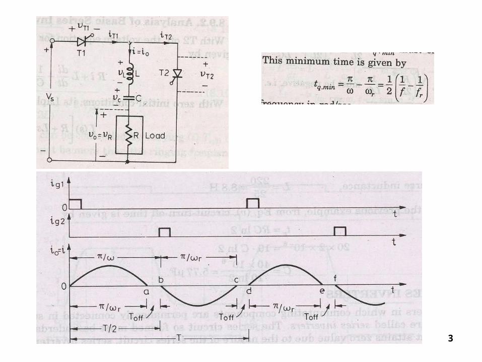
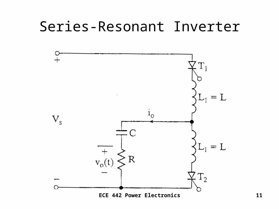
Series-Resonant Inverter
ECE 442 Power Electronics 12
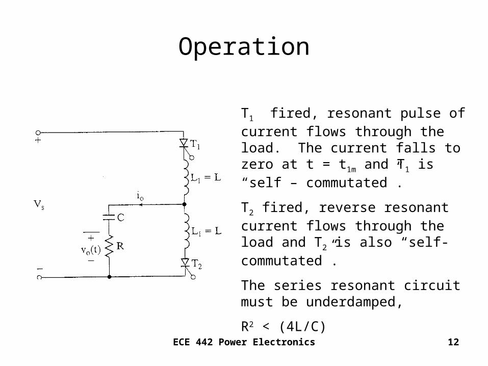
Operation
T1 fired, resonant pulse of current flows through the load. The current falls to zero at t = t1m and T1 is “self – commutated”.
T2 fired, reverse resonant current flows through the load and T2 is also “self-commutated”.
The series resonant circuit must be underdamped,
R2 < (4L/C)
ECE 442 Power Electronics 13
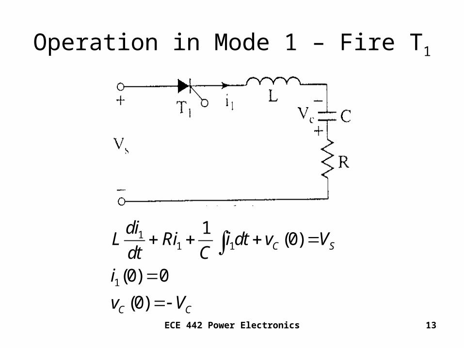
Operation in Mode 1 – Fire T1
11 1
1
1(0)
(0) 0
(0)
C S
C C
diL Ri i dt v Vdt C
i
v V

ECE 442 Power Electronics 14
21 1
12 2
2
11
0
1
( ) sin
1
4
( ) sin
2
RtL
r
r
s c
t r
ts cr
r
i t A e t
R
LC L
V VdiA
dt L
V Vi t e t
L
R
L
ECE 442 Power Electronics 15
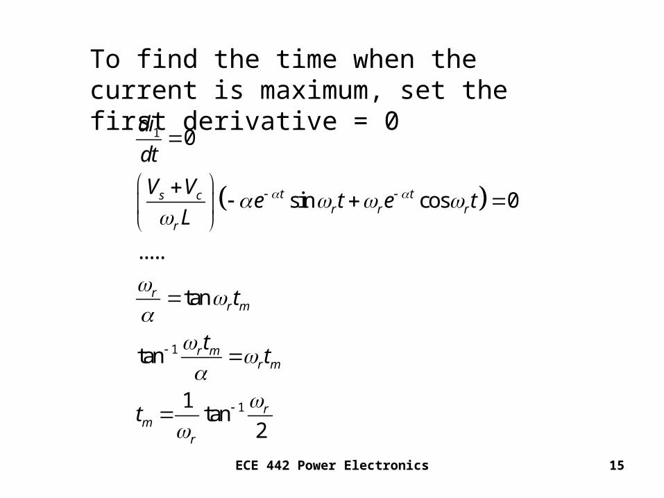
To find the time when the current is maximum, set the first derivative = 0
1
1
1
0
sin cos 0
.....
tan
tan
1tan
2
t ts cr r r
r
rr m
r mr m
rm
r
di
dt
V Ve t e t
L
t
tt
t
ECE 442 Power Electronics 16
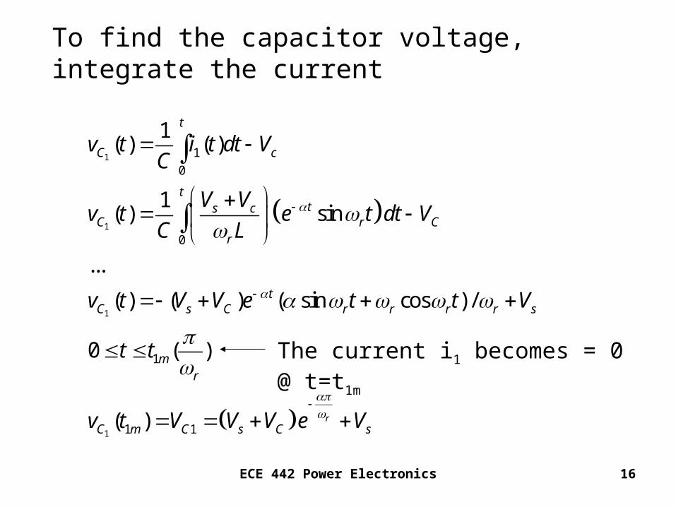
To find the capacitor voltage, integrate the current
1
1
1
1
1
0
0
1
1 1
1( ) ( )
1( ) sin
...
( ) ( ) ( sin cos ) /
0 ( )
( ) r
t
C c
tts c
C r Cr
tC s C r r r r s
mr
C m C s C s
v t i t dt VC
V Vv t e t dt V
C L
v t V V e t t V
t t
v t V V V e V
The current i1 becomes = 0 @ t=t1m

ECE 442 Power Electronics 17
ECE 442 Power Electronics 18
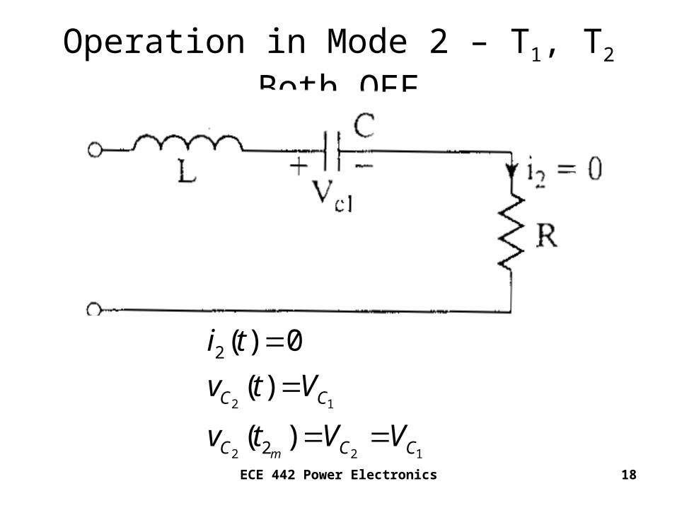
Operation in Mode 2 – T1, T2 Both OFF
2 1
2 2 1
2
2
( ) 0
( )
( )m
C C
C C C
i t
v t V
v t V V
ECE 442 Power Electronics 19
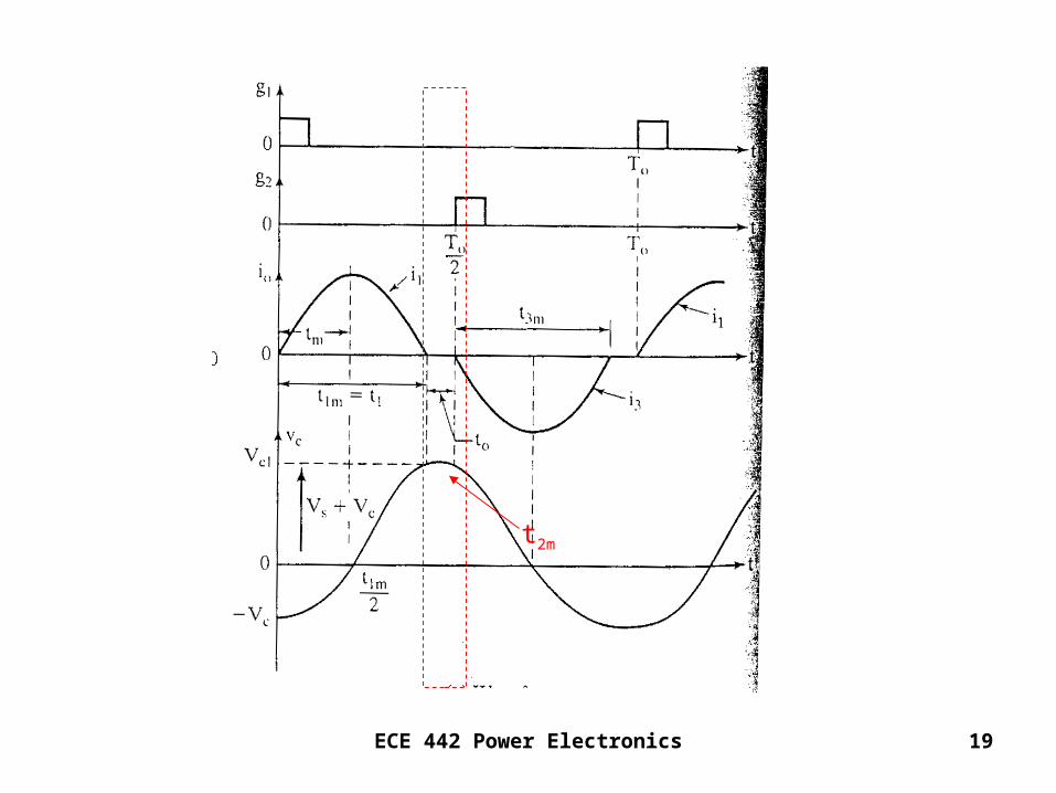
t2m
ECE 442 Power Electronics 20
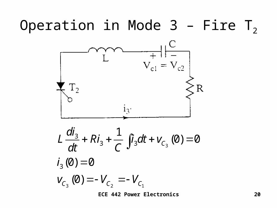
Operation in Mode 3 – Fire T2
3
3 2 1
33 3
3
1(0) 0
(0) 0
(0)
C
C C C
diL Ri i dt vdt C
i
v V V
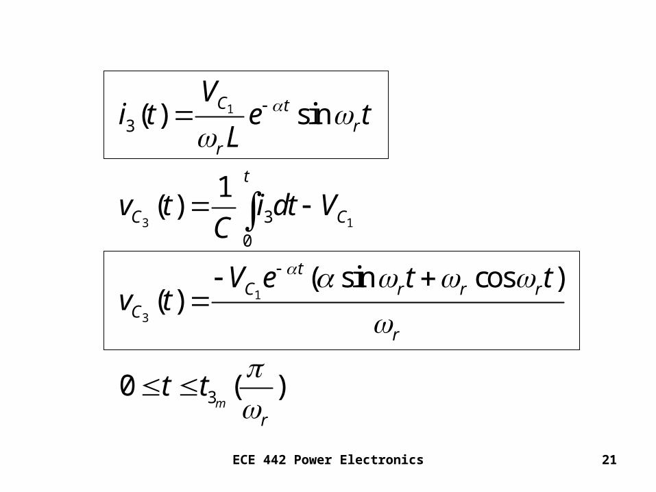
ECE 442 Power Electronics 21
1
3 1
1
3
3
3
0
3
( ) sin
1( )
( sin cos )( )
0 ( )m
C tr
r
t
C C
tC r r r
Cr
r
Vi t e t
L
v t i dt VC
V e t tv t
t t
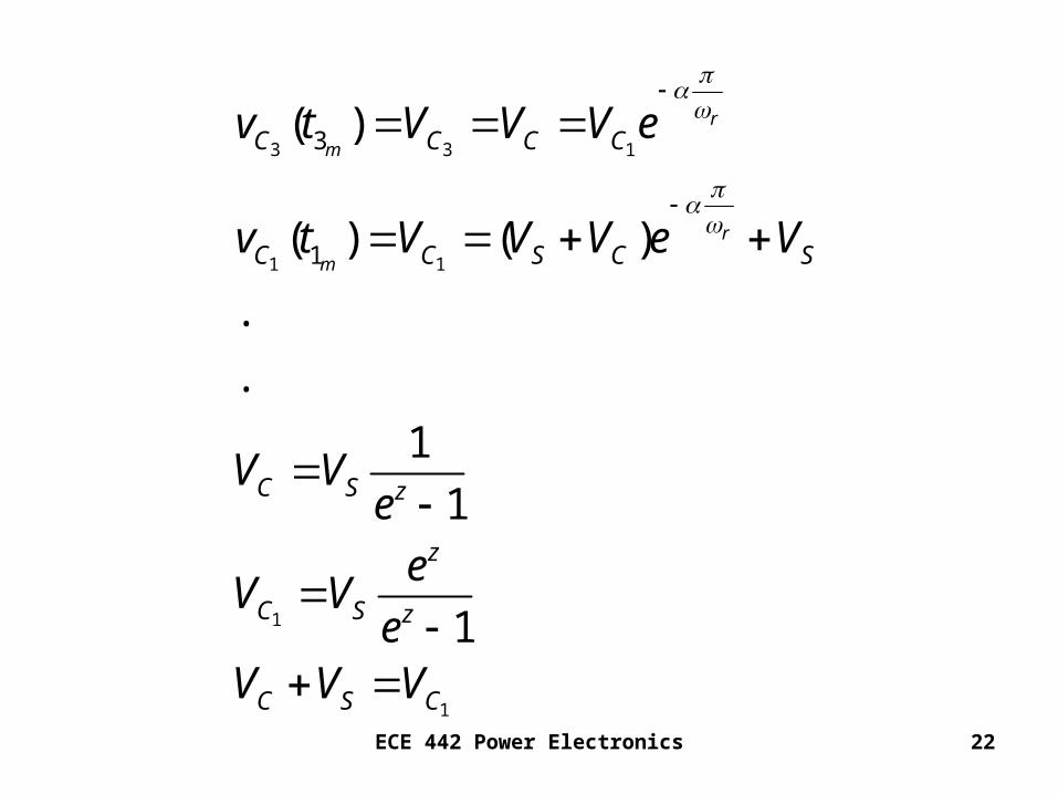
ECE 442 Power Electronics 22
3 3 1
1 1
1
1
3
1
( )
( ) ( )
.
.
1
1
1
r
m
r
m
C C C C
C C S C S
C S z
z
C S z
C S C
v t V V V e
v t V V V e V
V Ve
eV V
eV V V

ECE 442 Power Electronics 23
ECE 442 Power Electronics 24
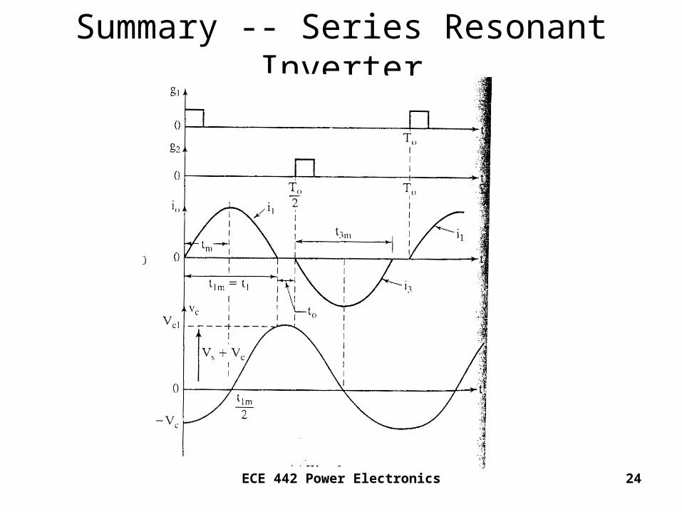
Summary -- Series Resonant Inverter
ECE 442 Power Electronics 25
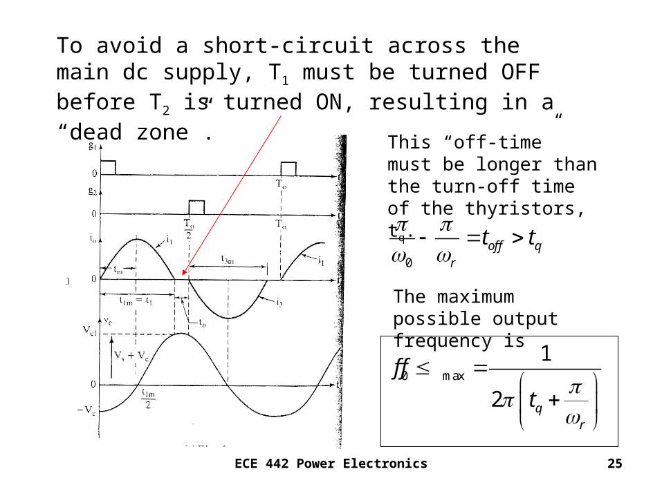
To avoid a short-circuit across the main dc supply, T1 must be turned OFF before T2 is turned ON, resulting in a “dead zone”.
This “off-time” must be longer than the turn-off time of the thyristors, tq.
0
0 max
1
2
off qr
qr
t t
f f
t
The maximum possible output frequency is
ECE 442 Power Electronics 26
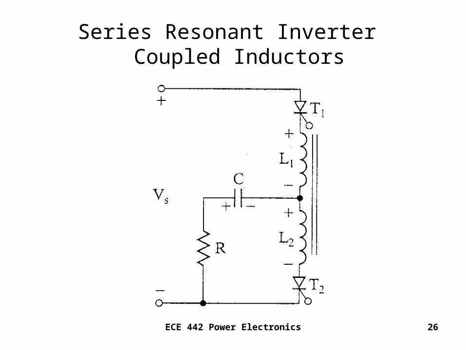
Series Resonant Inverter Coupled Inductors
ECE 442 Power Electronics 27
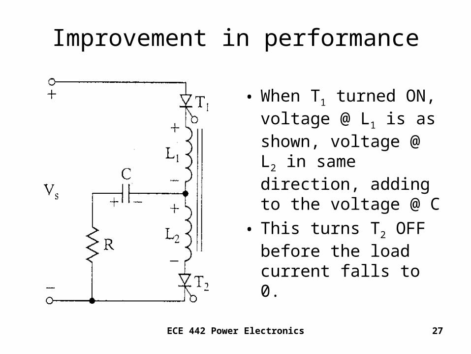
Improvement in performance
• When T1 turned ON, voltage @ L1 is as shown, voltage @ L2 in same direction, adding to the voltage @ C
• This turns T2 OFF before the load current falls to 0.
ECE 442 Power Electronics 28
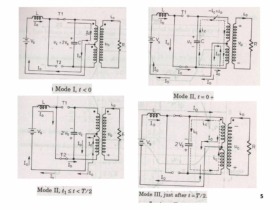
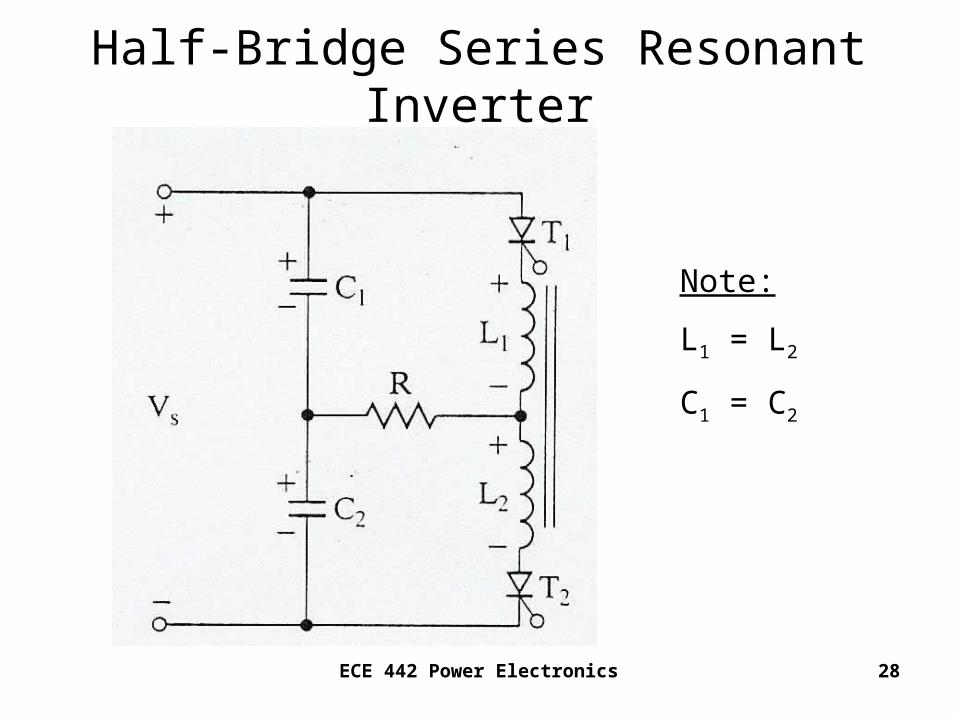
Half-Bridge Series Resonant Inverter
Note:
L1 = L2
C1 = C2
ECE 442 Power Electronics 29
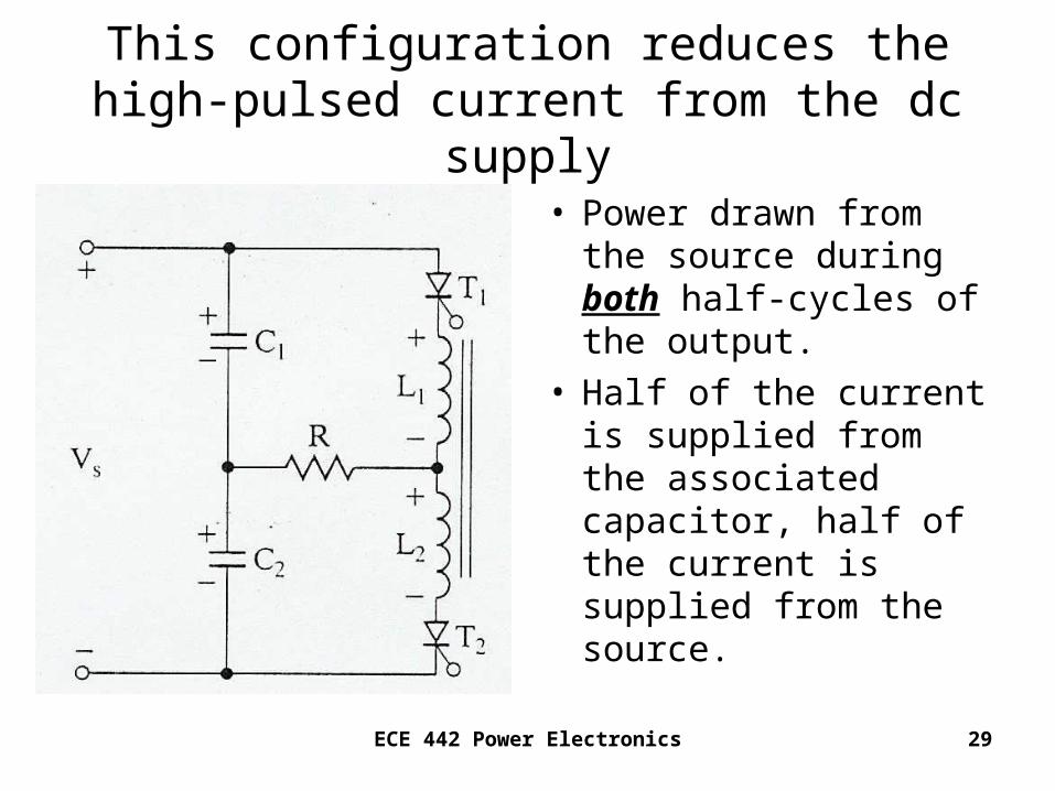
This configuration reduces the high-pulsed current from the dc supply
• Power drawn from the source during both half-cycles of the output.
• Half of the current is supplied from the associated capacitor, half of the current is supplied from the source.
ECE 442 Power Electronics 30
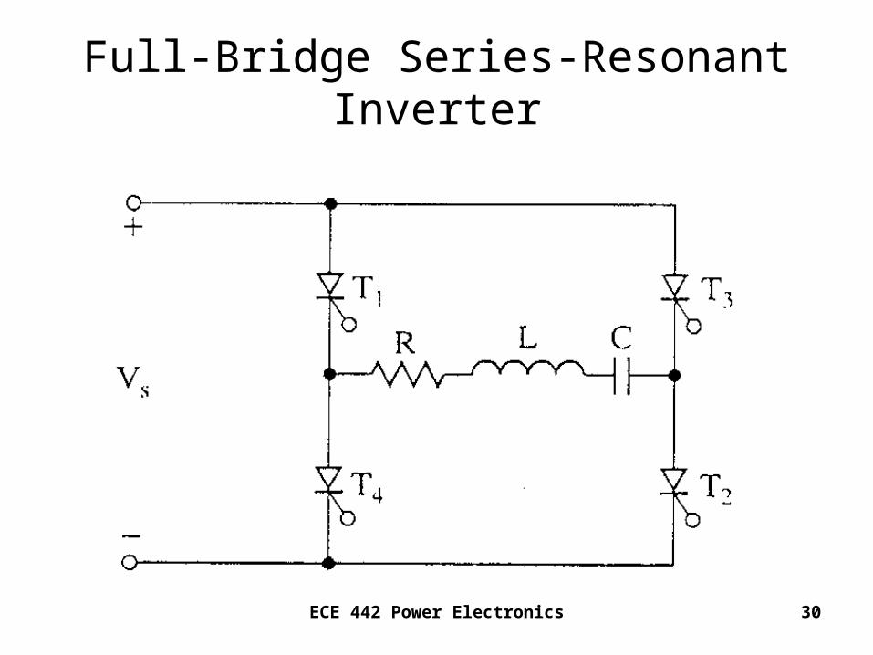
Full-Bridge Series-Resonant Inverter
ECE 442 Power Electronics 31
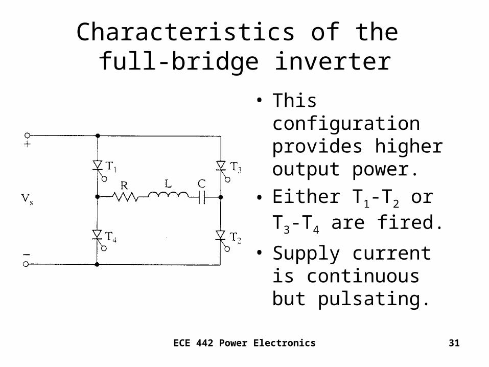
Characteristics of the full-bridge inverter
• This configuration provides higher output power.
• Either T1-T2 or T3-T4 are fired.
• Supply current is continuous but pulsating.
ECE 442 Power Electronics 32
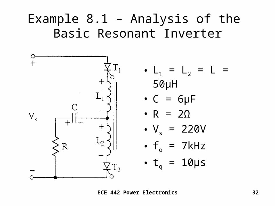
Example 8.1 – Analysis of the Basic Resonant Inverter
• L1 = L2 = L = 50μH
• C = 6μF• R = 2Ω
• Vs = 220V
• fo = 7kHz
• tq = 10μs
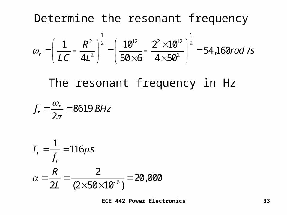
ECE 442 Power Electronics 33
1 12 12 2 122 2
2 2
6
1 10 2 1054,160 /
4 50 6 4 50
8619.82
1116
220,000
2 (2 50 10 )
r
rr
rr
Rrad s
LC L
f Hz
T sf
R
L
Determine the resonant frequency
The resonant frequency in Hz
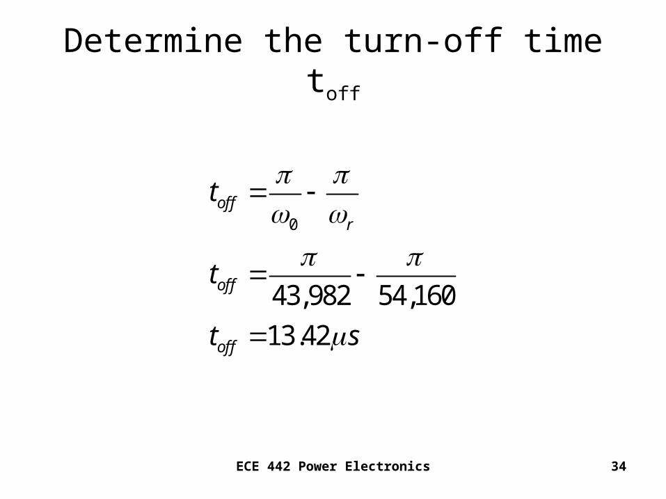
ECE 442 Power Electronics 34
Determine the turn-off time toff
0
43,982 54,160
13.42
offr
off
off
t
t
t s

ECE 442 Power Electronics 35
Determine the maximum permissible frequency
max
max6
max
1
2
1
2 10 1054,160
7352
qr
f
t
f
f Hz
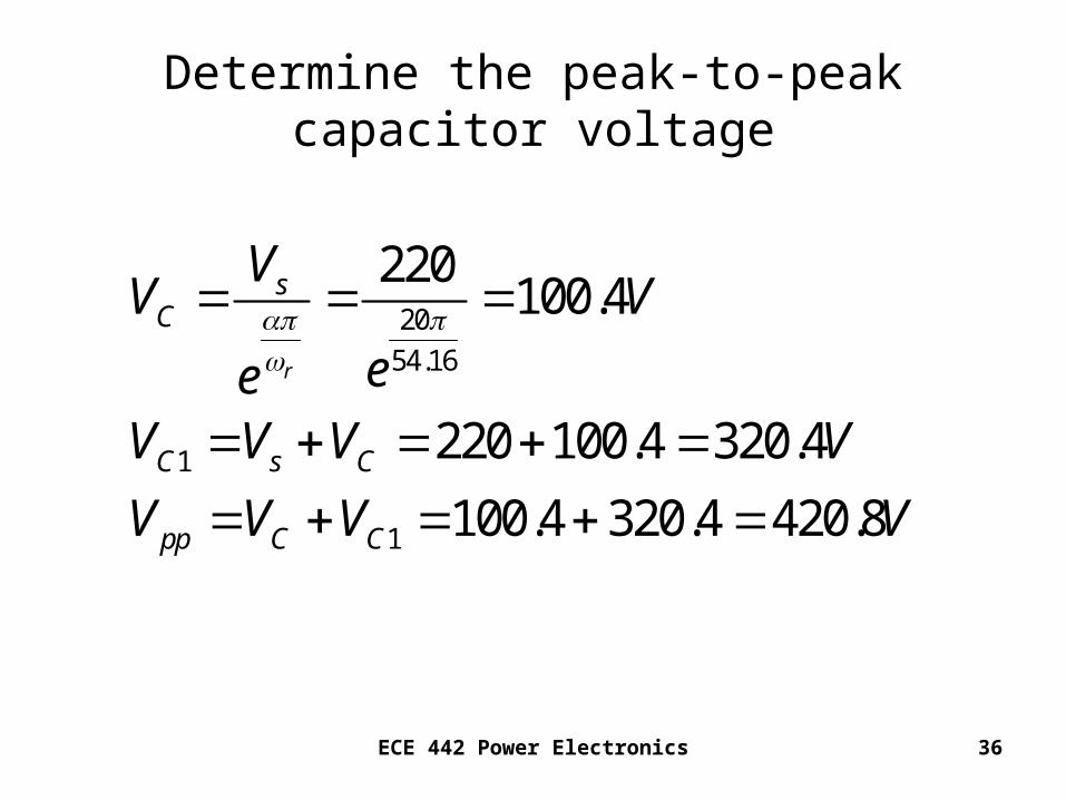
ECE 442 Power Electronics 36
Determine the peak-to-peak capacitor voltage
20
54.16
1
1
220100.4
220 100.4 320.4
100.4 320.4 420.8
r
sC
C s C
pp C C
VV V
eeV V V V
V V V V
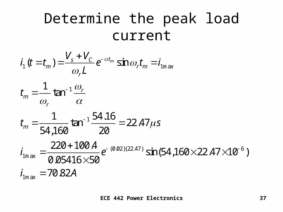
ECE 442 Power Electronics 37
Determine the peak load current
1 1max
1
1
(0.02)(22.47) 61max
1max
( ) sin
1tan
1 54.16tan 22.47
54,160 20
220 100.4sin(54,160 22.47 10 )
0.05416 5070.82
mts Cm r m
r
rm
r
m
V Vi t t e t i
L
t
t s
i e
i A
ECE 442 Power Electronics 38
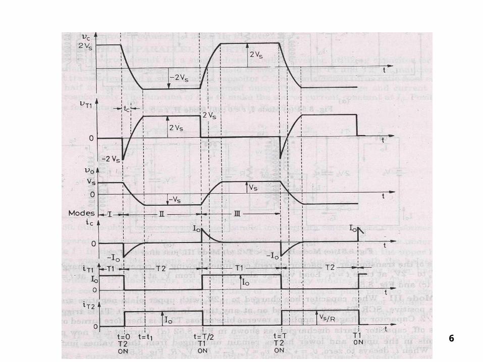
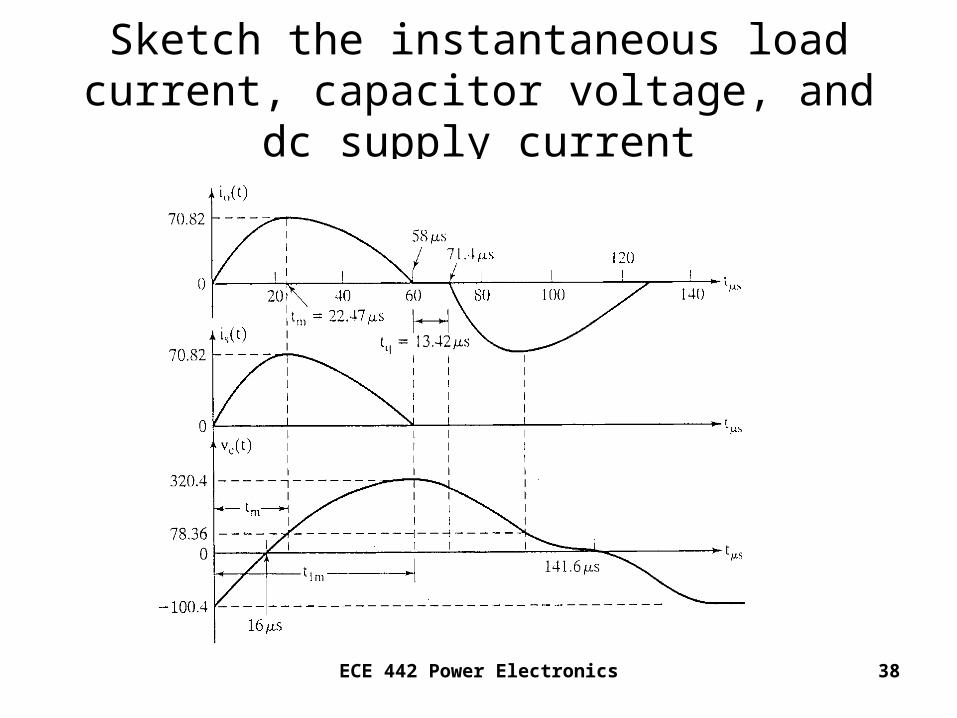
Sketch the instantaneous load current, capacitor voltage, and dc supply current
ECE 442 Power Electronics 39
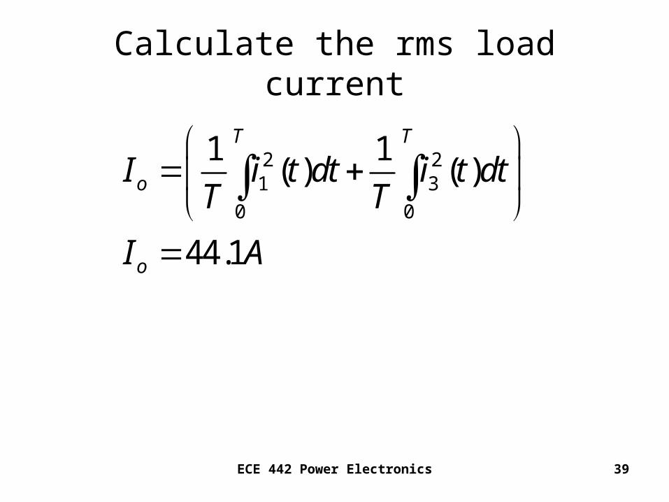
Calculate the rms load current
2 21 3
0 0
1 1( ) ( )
44.1
T T
o
o
I i t dt i t dtT T
I A

ECE 442 Power Electronics 40
2 7000
0
58 1006
t320.4exp 20000 t( ) sin 54160t( )
5416050 1006
2
d
1
2
44.091
158 22
0
2s
o o oI fi dt
Using MATHCAD,
Io = 44.1Amperes
ECE 442 Power Electronics 41
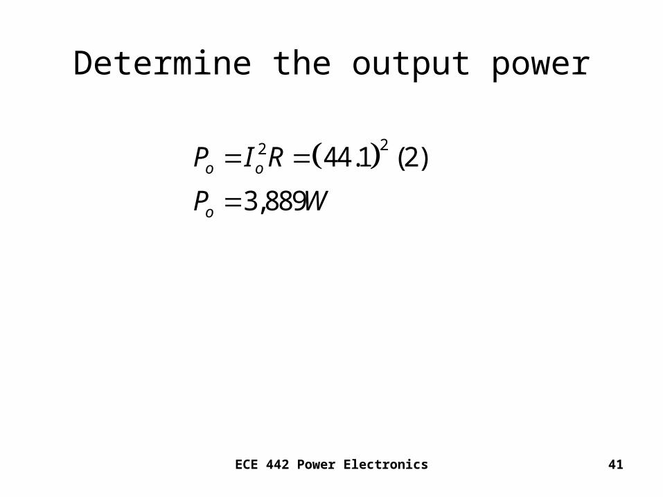
Determine the output power
22 44.1 (2)
3,889o o
o
P I R
P W
ECE 442 Power Electronics 42
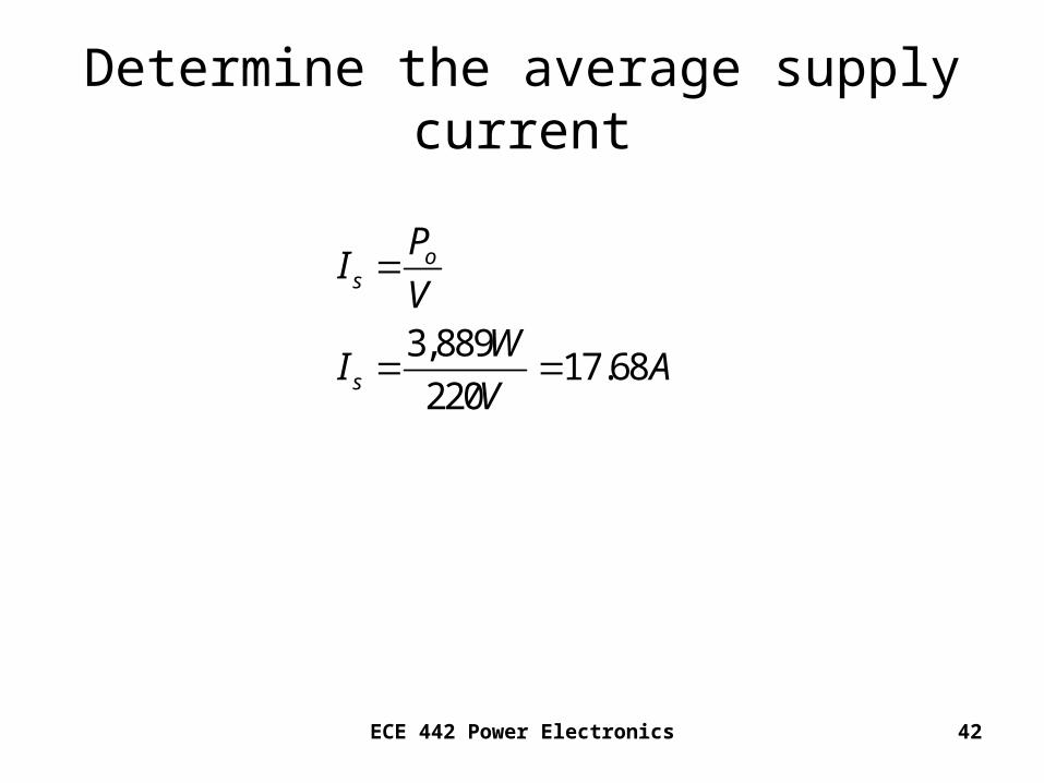
Determine the average supply current
3,88917.68
220
os
s
PI
VW
I AV
ECE 442 Power Electronics 43
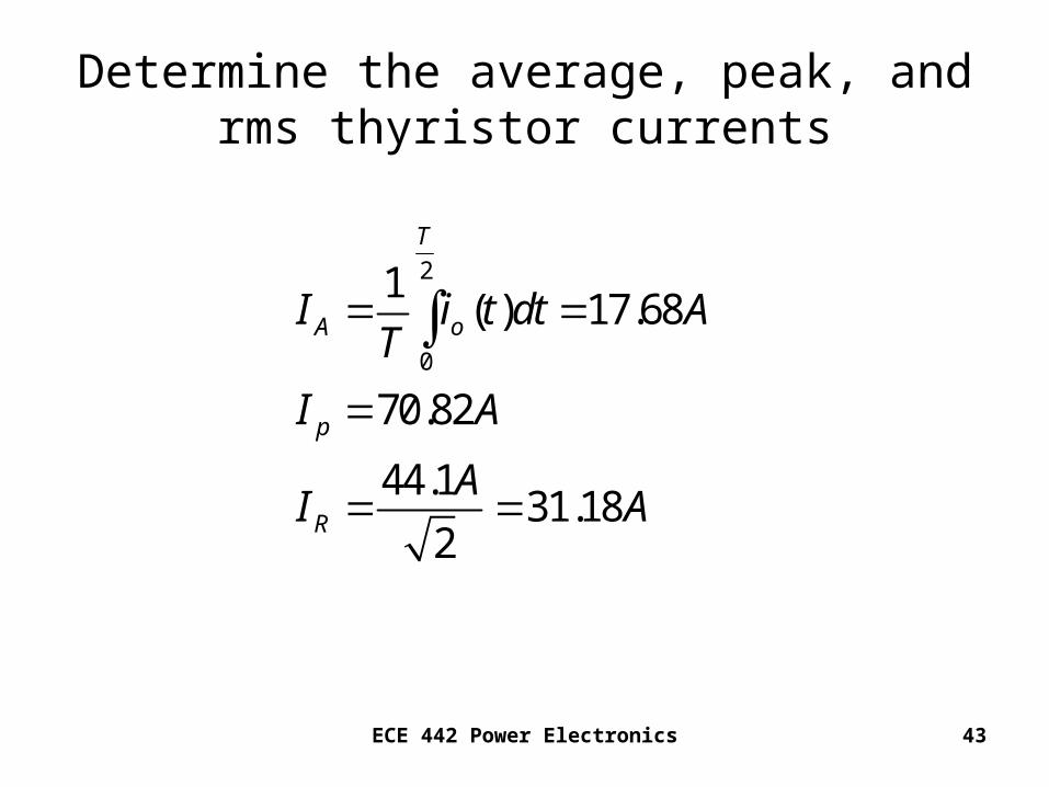
Determine the average, peak, and rms thyristor currents
2
0
1( ) 17.68
70.82
44.131.18
2
T
A o
p
R
I i t dt AT
I A
AI A
ECE 442 Power Electronics 44
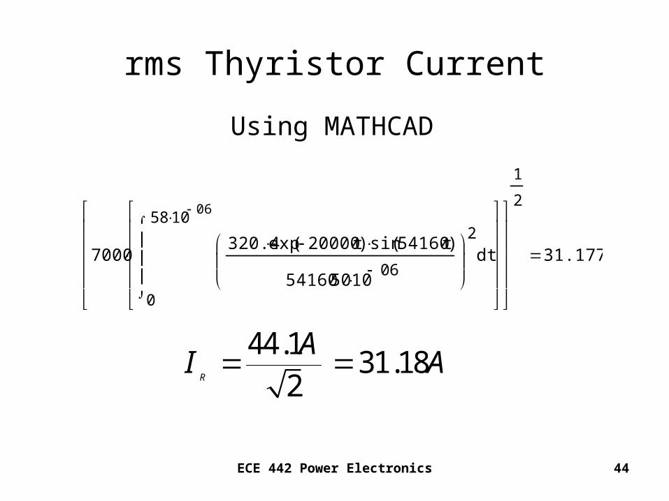
7000
0
58 1006
t320.4exp 20000 t( ) sin 54160t( )
5416050 1006
2
d
1
2
31.177
rms Thyristor Current
44.131.18
2R
AI A
Using MATHCAD