Serial Numbers: 409429 + www.discount-equipment.com Go to Discount-Equipment.com to order your parts

Welcome message from author
This document is posted to help you gain knowledge. Please leave a comment to let me know what you think about it! Share it to your friends and learn new things together.
Transcript

Serial Numbers: 409429 +www.discount-equipment.com
Go to Disc
ount-
Equipm
ent.c
om to
order
your
parts

Discount-Equipment.com is your online resource for quality parts & equipment.
Florida: 561-964-4949 Outside Florida TOLL FREE: 877-690-3101
Need parts? Click on this link: http://www.discount-equipment.com/category/5443-parts/ and choose one of the options to help get the right parts and equipment you are looking for. Please have the machine model and serial number available in order to help us get you the correct parts. If you don’t find the part on the website or on one of the online manuals, please fill out the request form and one of our experienced staff members will get back to you with a quote for the right part that your machine needs.
We sell worldwide for the brands: Genie, Terex, JLG, MultiQuip, Mikasa, Essick, Whiteman, Mayco, Toro Stone, Diamond Products, Generac Magnum, Airman, Haulotte, Barreto,
Power Blanket, Nifty Lift, Atlas Copco, Chicago Pneumatic, Allmand, Miller Curber, Skyjack, Lull, Skytrak, Tsurumi, Husquvarna Target, Stow, Wacker, Sakai, Mi-T-M, Sullair, Basic,
Dynapac, MBW, Weber, Bartell, Bennar Newman, Haulotte, Ditch Runner, Menegotti, Morrison, Contec, Buddy, Crown, Edco, Wyco, Bomag, Laymor, EZ Trench, Bil-Jax, F.S.
Curtis, Gehl Pavers, Heli, Honda, ICS/PowerGrit, IHI, Partner, Imer, Clipper, MMD, Koshin, Rice, CH&E, General Equipment ,Amida, Coleman, NAC, Gradall, Square Shooter, Kent,
Stanley, Tamco, Toku, Hatz, Kohler, Robin, Wisconsin, Northrock, Oztec, Toker TK, Rol-Air, APT, Wylie, Ingersoll Rand / Doosan, Innovatech, Con X, Ammann, Mecalac, Makinex, Smith
Surface Prep,Small Line, Wanco, Yanmar

BROCE BROOM MODEL 350
ESTIMATED DIMENSIONS
Go to Disc
ount-
Equipm
ent.c
om to
order
your
parts

TABLE OF CONTENTS Main Frame Component Parts ............................................................................................. 1-2 Instrument Panel & Components ........................................................................................ 3-4 Seat and Suspension ........................................................................................................... 5-6 Brake Control Assemblies ................................................................................................... 7-8 Hydrostatic Control Assemblies ......................................................................................... 9-10 Circle Frame and Components ........................................................................................... 11-12 Direct Drive Core Assembly ................................................................................................ 13-14 Chain Drive Core Assembly ................................................................................................ 15-16 Broom Core Wafers and Spacers ....................................................................................... 17-18 Bolster Assembly ................................................................................................................. 19-20 Front Axle Parts and Steering ............................................................................................. 21-22 Front Brake Assembly ......................................................................................................... 23-24 Rear Axle & Drive Assembly ............................................................................................... 25-26 Rear Brake Assembly ........................................................................................................... 27-28 Two Speed Gear Box ............................................................................................................ 29-30 Model 44 Industrial Axle ...................................................................................................... 31-32 Tow Bar Assembly ............................................................................................................... 33-34 Cab Assembly ....................................................................................................................... 35-36 Roll Over Protection Structure & Related Parts ................................................................ 37-38 Fuel Tank Assembly ............................................................................................................. 39-40 Decal Kit ................................................................................................................................ 42 HYDRAULIC SYSTEM DETAILS ..................................................................44-54 Hydraulic System Components – Front Section ............................................................... 45-46 Hydraulic System Components – Cab/Valve Section ....................................................... 47-48 Hydraulic System Components – Variable Speed Option ................................................ 49-50 Hydraulic System Components – Rear Section ................................................................ 51-52 Hydrostatic Drive System .................................................................................................... 53-54
Go to D
iscou
nt-Equ
ipmen
t.com
to or
der y
our p
arts

TABLE OF CONTENTS (Cont.)
HYDRAULIC SYSTEM DETAILS (Cont.) Core Rotation Valve Assembly ........................................................................................... 55-56 Joystick Valve Assembly ..................................................................................................... 57-58 Optional Down Pressure Limiter ......................................................................................... 59-60
ELECTRICAL SYSTEM & ACCESSORIES ..................................................62-76 Gauges & Senders ................................................................................................................ 63-64 Windshield Wipers & Washer .............................................................................................. 65-66 Misc. Switches, Fuses, Etc. ................................................................................................. 67-68 Lights & Horns ...................................................................................................................... 69-70 Heater/Defroster.................................................................................................................... 71-72 Air Conditioning System ...................................................................................................... 73-76
BROOM ACCESSORY SYSTEMS ...............................................................77-89 Water System Illustrations .................................................................................................. 79-80 Scraper Blade Illustrations .................................................................................................. 81-82 Scraper Blade Hydraulics .................................................................................................... 83-84 Curb Sweeper Illustrations .................................................................................................. 85-86 Curb Broom Hydraulics ....................................................................................................... 87-88
ENGINES AND RELATED PARTS ...............................................................89-121 RCT-350 EXPORT Engine .................................................................................................... 91-98 RJT-350 Tier 4 Final (US) John Deere Engine ................................................................... 98-103 RCT-350 Tier 4 Final (US) Cummins Engine ...................................................................... 104-111 KR-350 Engine ...................................................................................................................... 112-113 CR-350 ................................................................................................................................... 114-115
MAINTENANCE, SPECIFICATIONS AND SCHEMATICS ........................ 116+
Go to D
iscou
nt-Equ
ipmen
t.com
to or
der y
our p
arts

1
MAIN FRAME COMPONENT PARTS
1
4
10
16
7
6
9
12
8
14
2
11
13
5
3
2 15
17
16
18
20
Go to D
iscou
nt-Equ
ipmen
t.com
to or
der y
our p
arts

2
MAIN FRAME COMPONENT PARTS Reference Part No. Description Qty. 1. .................................. F-201-R .................. Main Frame w/ Decking .................................... 1 2 ................................... F-206-RS ................ Main Deck (Smooth) ......................................... 1 F-206-R .................. Main Deck (Diamond Tread) ............................ 1 3 ................................... F-205-R .................. Diagonal Deck (w/o Water System) ................ 1 F-205-RW ............... Diagonal Deck (w/ Water System) ................... 1 4 ................................... F-204-R .................. Front Deck (w/o Water System) ...................... 1 F-204-RW ............... Front Deck (w/ Water System) ......................... 1 5 ................................... F-209-EX ................ Deck Step (Expanded Metal) ........................... 1 F-209-R .................. Deck Step (Diamond Tread) ............................ 1 6 ................................... 850073 ................... Rear Fender, LH ................................................ 1 7 ................................... 850072 ................... Rear Fender, RH ............................................... 1 8 ................................... 852049-C ............... Fire Wall ............................................................. 1 9 ................................... See Roll Over ........ Roll Bar (2 Post) ................................................ 1 Protection 10 ................................. F-202 ...................... Frame Step ........................................................ 1 11 ................................. 203138 ................... Seat Support Base (Non-suspension) ............ 1 12 ................................. F-826 ...................... Front Fenders (pair) ......................................... 1 13 ................................. VF-208-C ................ Hood Assembly ................................................ 1 14 ................................. 203274 ................... Hood Support Linkage ..................................... 1 15 ................................. 001687 ................... Hood Support Linkage ..................................... 1 16 ................................. VF-317-B ................ Hinge, (Set of 2) ................................................ 1 17 ................................. VF-803-R ................ Hood Catch (Rubber Strap only) ..................... 2 18 ................................. VF-319-RA ............. Catch Assembly (Complete) ............................ 2 19 ................................. F-811-R .................. Rock Guard ....................................................... 1 20 ................................. 304009 ................... Rubber Hood Molding ...................................... 1 Go t
o Disc
ount-
Equipm
ent.c
om to
orde
r you
r part
s

3
INSTRUMENT PANEL AND COMPONENTS
1
4
16
7
6
9
2
5
3
2
10
12
11
13
15
16
Go to D
iscou
nt-Equ
ipmen
t.com
to or
der y
our p
arts

4
INSTRUMENT PANEL AND COMPONENTS Reference Part No. Description Qty. 1. .................................. I-217-AR ................. Dash Housing ................................................... 1 2 ................................... I-218-R ................... Dash Back Cover .............................................. 1 3 ................................... See Hydraulic ....... Power Steering Unit ......................................... 1 System – Front Section 4 ................................... SM-249-D ............... Power Steering Unit Mount ............................. 1 5 ................................... 305945 ................... Steering Column ............................................... 1 305950 .................... Tilt Steering Column (No Conversion) ........... 1 6 ................................... 205169 ................... Access Cover .................................................... 1 7 ................................... S-253-R .................. Steering Wheel/Horn Assembly ...................... 1 9 ................................... See Electrical ....... Ignition Switch .................................................. 1 Section 10 ................................. HS-230-A ............... Shifter Assembly (2 Speed) ............................. 1 HS-231-A ................ Shifter Cable (Not Shown) ............................... 1 11 ................................. See Electrical ........ Universal Accessory Switch ........................... 3 Section See Electrical ........ Lighted Rocker Switch (Not Shown) .............. 1 Section 12 ................................. See Electrical ........ Wiper Switch ..................................................... 1 Section 13 ................................. See Heater/ ............ Heater Switch (2 Speed)................................... 1 Defroster 15 ................................. N/A ......................... Horn Sender (Replace Column) ...................... 1 16 ................................. See Electrical ........ Spare Key (pair) ................................................ 1 Section
Go to D
iscou
nt-Equ
ipmen
t.com
to or
der y
our p
arts

5
SEAT AND SUSPENSION COMPONENTS
1
4
8
16
10
6
2
3
2
7
9
6
11 Go t
o Disc
ount-
Equipm
ent.c
om to
orde
r you
r part
s

6
SEAT AND SUSPENSION COMPONENTS Reference Part No. Description Qty. 1. .................................. BS-1050 ................. Seat Assembly .................................................. 1 2 ................................... BS-1051 ................. Back Rest .......................................................... 1 3 ................................... BS-1052 ................. Seat Cushion ..................................................... 1 4 ................................... BS-1053L+R .......... Arm Rest Pad .................................................... 2 6 ................................... C-211...................... Retractable Seat Belt (Shown) ........................ 1 C-211-SH ................ Retractable Seat Belt w/ Shoulder Harness (Not Shown) ........................................ 1 7 ................................... C-211-RT ............... Tether Strap Set (for use w/ Suspension Seat) .................................................................... 1 8 ................................... T-213-R .................. Throttle Cable ................................................... 1 9 ................................... 203436 ................... Hydraulic Control Cabinet ............................... 1 10 ................................. 203183 ................... Valve Box Cover ............................................... 1 11 ................................. BS-1054 ................. Suspension Assembly ..................................... 1 Not Shown .................. 203181 ................... Hydraulic Control Cover Back ........................ 1 Not Shown .................. 309456 ................... Throttle Cable (Cat Engine) ............................ 1
Go to D
iscou
nt-Equ
ipmen
t.com
to or
der y
our p
arts

7
BRAKE CONTROL ASSEMBLIES
1
4
10
16
7
6
12
8
2
5 3
2
9
11
14
13
15
16
Go to D
iscou
nt-Equ
ipmen
t.com
to or
der y
our p
arts

8
BRAKE CONTROL ASSEMBLIES Reference Part No. Description Qty. 1. .................................. B-240-B .................. Dual Master Cylinder ........................................ 1 2 ................................... BM-245-R ............... Master Cylinder Mount ..................................... 1 3 ................................... B-284...................... Rubber Boot ...................................................... 1 4 ................................... K00001 ................... Push Rod ........................................................... 1 5 ................................... B-238-R .................. Brake Pedal ....................................................... 1 6 ................................... B-241-R .................. Brake Pedal Pad ............................................... 1 7 ................................... BM-244-R ............... Pedal Mount ...................................................... 1 8 ................................... B-242-R .................. Pedal Bushing ................................................... 2 9 ................................... BLS-15 ................... Brake Light Switch ........................................... 1 10 ................................. PBS-13 ................... Parking Brake Switch ....................................... 1 11 ................................. PB-237 ................... Parking Brake Cable........................................ 2 12 ................................. PB-233-C ............... Brake Lever Assembly ..................................... 1 13 ................................. PB-229-C ............... Clevis (3/8” Fine Thread) ................................. 1 14 ................................. PB-235-C ............... Primary Parking Brake Cable .......................... 1 15 ................................. 202091 ................... Parking Brake Adjuster .................................... 1 16 ................................. 344105 ................... Tension Spring ................................................. 1 Not Shown .................. F97935 ................... Master Cylinder Repair Kit .............................. 1
Go to D
iscou
nt-Equ
ipmen
t.com
to or
der y
our p
arts

9
HYDROSTATIC CONTROL ASSEMBLIES
1
4
16
7
6
2
5
3
2
8
Go to D
iscou
nt-Equ
ipmen
t.com
to or
der y
our p
arts

10
HYDROSTATIC CONTROL ASSEMBLIES Reference Part No. Description Qty. 1. .................................. HC-226-R ............... Control Pedal Assembly .................................. 1 2 ................................... HC-229-B ............... 1/4” Clevis w/ Pin (Note: Control Cable) ........ 1 3 ................................... HC-228-B ............... Hydro-Back Boot .............................................. 1 4 ................................... HC-228-HB ............ Hydro-Back Device ........................................... 1 5 ................................... HC-228-E ............... Hydro-Back Cable ............................................. 1 6 ................................... HC-226-HA ............ Hand Control Kit (Note: Converts Foot Control to Hand Control) .................................. 1 7 ................................... HC-228-OH ............ Hand Control Cable .......................................... 1 8 ................................... 309466 ................... Heims End ......................................................... 1
Go to D
iscou
nt-Equ
ipmen
t.com
to or
der y
our p
arts

11
CIRCLE FRAME & COMPONENTS
1
16
7
6
2
5
3
2
4
10
9
8
8 11
Go to D
iscou
nt-Equ
ipmen
t.com
to or
der y
our p
arts

12
CIRCLE FRAME & COMPONENTS Reference Part No. Description Qty. 1. .................................. C-102...................... Circle Frame ...................................................... 1 1a. ................................ C-102A ................... Circle Frame w/Curb Broom Mount Bracket .. 1 2 ................................... See Hydraulic ....... Shift Cylinder .................................................... 1 Section 3 ................................... See Hydraulic ....... Lift Cylinder ....................................................... 1 Section 4 ................................... B-103...................... Circle Bearing ................................................... 9 5 ................................... D-20-R .................... Shock Absorber ................................................ 1 6 ................................... D-21-R .................... Shock Pin .......................................................... 2 7 ................................... C-109...................... Hinge Pin ........................................................... 3 8 ................................... RC-19 ..................... Cylinder Pin ....................................................... 2 9 ................................... B-105...................... Bearing Bracket Assembly (qty as required) 10 ................................. B-104...................... Bearing Bracket ................................................ 5 11 ................................. 850006 ................... Circle Cylinder Lug ........................................... 1
Go to D
iscou
nt-Equ
ipmen
t.com
to or
der y
our p
arts

DIRECT DRIVE CORE ASSEMBLY
13
1
4
7
6
5
3
2
11
10
9
8
6
10
12
13
15
14
Go to D
iscou
nt-Equ
ipmen
t.com
to or
der y
our p
arts

DIRECT DRIVE CORE ASSEMBLY
Reference Part No. Description Qty.
1 ................................... C-108-SPC ............. Core Support ..................................................... 1
2 ................................... D-12-8 .................... Core Cover ........................................................ 1
3 ................................... D-15-SPCA ............ Core w/ Flat End Caps...................................... 1 D-15-SPC ............... Core w/ Formed End Caps ............................... 1
4 ................................... D-17........................ Spindle ............................................................... 1
5 ................................... 203010 ................... End Cap ( Flat ) ................................................. 2 202144 .................... End Cap (Formed – Bell) .................................. 2
6 ................................... 202145 ................... Support Bracket ................................................ 2
7 ................................... 305943 ................... Hydraulic Motor (Core)..................................... 1
8 ................................... MR-16-SPC ............ Hydraulic Motor Mount (Core) ......................... 1
9 ................................... DD-257-R ............... Splined Hub ....................................................... 1
10 ................................. MR-16-LR .............. Lock Ring .......................................................... 2
11 ................................. D-13........................ Pillow Block Bearing ........................................ 1
12 ................................. 304129 ................... Core Rock Guard .............................................. 1
13……………… ........... 001397 ................... Double Hose Clamp .......................................... 2
14 ................................. K00041 ................... Rod Guide Cone ............................................... 1
15 ................................. 203167 ................... Core Cover End Plate Set ................................ 1
14
Go to D
iscou
nt-Equ
ipmen
t.com
to or
der y
our p
arts

15
CHAIN DRIVE CORE ASSEMBLY
1
4 16
7
6
2
5 3
2
11 10
9
8
5
6
12
4
13
15
14
13
Go to D
iscou
nt-Equ
ipmen
t.com
to or
der y
our p
arts

16
CHAIN DRIVE CORE ASSEMBLY Reference Part No. Description Qty. 1 ................................... C-108-R .................. Core Support ..................................................... 1 2 ................................... D-12-8 .................... Core Cover ........................................................ 1 3 ................................... D-15-8 .................... Core.................................................................... 1 4 ................................... D-17........................ Spindle ............................................................... 2 5 ................................... D-16........................ End Cap ............................................................. 2 6 ................................... D-11........................ Support Bracket ................................................ 2 7 ................................... MAB-16-B .............. Hydraulic Motor (Core)..................................... 1 8 ................................... MR-16-AR .............. Hydraulic Motor Mount (Core) ......................... 1 9 ................................... C-111...................... Sprocket (Drive) ................................................ 1 10 ................................. C-109-AR ............... Sprocket (Idler) ................................................. 1 11 ................................. C-110...................... Sprocket (Driven) .............................................. 1 12 ................................. D-14-R .................... Roller Chain ...................................................... 1 13 ................................. D-13........................ Pillow Block Bearing ........................................ 2 14 ................................. D-18-R .................... Chain Guard ...................................................... 1 15 ................................. 304129 ................... Core Rock Guard .............................................. 1
Go to D
iscou
nt-Equ
ipmen
t.com
to or
der y
our p
arts

17
BROOM CORE WAFER & SPACERS
1
4 16
2
5
3
2
Go to D
iscou
nt-Equ
ipmen
t.com
to or
der y
our p
arts

18
BROOM CORE WAFER & SPACERS Reference Part No. Description Qty. 1. .................................. RW-503 .................. 10” x 32” Poly Wafer ........................................ 1 2 ................................... RW-504 .................. 10” x 32” Wire Wafer ........................................ 1 3 ................................... RW-500 .................. 8’ Set, Poly Wafers w/Spacers ........................ 1 RW-502 .................. 8’ Set, ½ Poly, ½ Wire w/Spacers .................... 1 4 ................................... CS-01 ..................... Core Service Stand ........................................... 1 5 ................................... CS-02 ..................... Core Service Ring ............................................. 1 Not Shown .................. 304290 ................... Tube Brush Poly Brush.................................... 1 304289 ................... Tube Brush ½ Poly, ½ Wire Brush .................. 1 Not Shown .................. 852427 ................... Strip Brush Mandrel ......................................... 1 304298 ................... Strip Brush Poly Brush (8’ Set – 2 req’d) ....... 1
Go to D
iscou
nt-Equ
ipmen
t.com
to or
der y
our p
arts

19
BOLSTER ASSEMBLY
1
4
16
2
5
3
2
8
7
6
Go to D
iscou
nt-Equ
ipmen
t.com
to or
der y
our p
arts

20
BOLSTER ASSEMBLY Reference Part No. Description Qty. 1. .................................. 752002 ................... Bolster Assembly, Complete ........................... 1 Serial Number 402415 and Higher 2 ................................... 852001 ................... Bolster Brace .................................................... 1 3 ................................... 203002 ................... Bolster Pin ......................................................... 1 4 ................................... 852002 ................... Bolster A-Frame Assembly ............................. 1 5 ................................... 852003 ................... Bolster Support ................................................ 1 6 ................................... 309507 ................... Oil Light Bushing (1 1/4” x 1 1/2” x 1 1/2”)..... 1 7 ................................... 309505 ................... Oil Light Bushing (1 1/4” x 1 1/2” x 2”) ........... 1 8 ................................... 309506 ................... Oil Light Bushing (1 1/4” x 1 1/2” x 2 1/4”)..... 1
Go to D
iscou
nt-Equ
ipmen
t.com
to or
der y
our p
arts

21
FRONT AXLE ASSEMBLY
17
1
8 5
4
6
7a
2
9
16
15
14
13
12
10
7b
11
18
21
19
20
3
22
Go to D
iscou
nt-Equ
ipmen
t.com
to or
der y
our p
arts

22
FRONT AXLE ASSEMBLY Reference Part No. Description Qty. 1. .................................. 403090 ................... Front Axle Assembly (6 Lug x 5 1/2) ............... 1 2 ................................... 203526 ................... Steering Cylinder Assembly ............................ 1 4 ................................... 403091 ................... Knuckle w/Spindle, LH ..................................... 1 403092 Knuckle w/ Spindle, RH.................................... 1 5 ................................... BF4454................... King Pin Cap ..................................................... 2 6 ................................... 403093 ................... Tie Rod Tube ..................................................... 1 7a ................................. BF4470................... Jam Nut, RH Thread ......................................... 1 7b ................................. BF4471................... Jam Nut, LH Thread .......................................... 1 8 ................................... BF4465R ................ Tie Rod End, LH Thread ................................... 1 9 ................................... 203523 ................... Lock Nut ............................................................ 1 10 ................................. BF4465L ................ Tie Rod End, RH Thread .................................. 1 11 ................................. BF4460................... Seal .................................................................... 2 12 ................................. BF4461X ................ Inner Bearing Kit (w/Race) ............................... 2 13 ................................. 203544 ................... Hub Assembly, (6 Lug x 5 1/2) ........................ 2 14 ................................. 69957B ................... Lug Nut .............................................................. 10 15 ................................. 752547 ................... Outer Bearing Kit (w/Race) .............................. 2 16 ................................. 400195 ................... Washer ............................................................... 2 17 ................................. 203549 ................... Lock Nut ............................................................ 2
18 ................................. 203550 ................... Hub Cap ............................................................. 2 19 ................................. BF4470................... Jam Nut, RH Thread ......................................... 1 20 ................................. BF4455................... King Pin Kit ....................................................... 1 21 ................................. 203520 ................... Steering Cylinder Heims End .......................... 1 22 .… ........................... 203556…… ............ Bolt (¾-16 UNF-2A) Grade 8 (2-1/2” x ¾ )……1 Not Shown .................. 203553 ................... Steering Cylinder Seal Kit ............................... 1 Not Shown .................. 304039 ................... Wheel – 6 Lug ................................................... 1
Go to D
iscou
nt-Equ
ipmen
t.com
to or
der y
our p
arts

23
5200-6000 LB FRONT BRAKE ASSEMBLY
1
4
3
2
12
8
7
6
5
11
10
9
13
15
16
Go to D
iscou
nt-Equ
ipmen
t.com
to or
der y
our p
arts

24
5200-6000 LB FRONT BRAKE ASSEMBLY Reference Part No. Description Qty. 1 ................................... 203554 ................... Complete Caliper Assembly w/ Pads ............. 1 2. .................................. 203530 ................... Friction Pads (Organic) .................................... 1 3 ................................... 203531 ................... 1/4” – 28 Brass Bleed Screw ........................... 1 4 ................................... 203532 ................... 1/8” Brass Bleed Screw Adapter ..................... 1 5 ................................... 203533 ................... Guide Bolt Sleeve O-ring ................................. 1 6 ................................... 203534 ................... Guide Bolt Rubber Sleeve ............................... 1 7 ................................... 203535 ................... Guide Bolt Stainless Steel Sleeve .................. 1 8 ................................... 203536 ................... Guide Bolt (M11 x 1.5) w/ Thread Locker ....... 1 9 ................................... 203537 ................... 90 1/8” NPT to 3/16” F.I.F. .............................. 1 10 ................................. 203538 ................... Caliper Piston 2 1/4” Stainless Steel .............. 1 11 ................................. 203539 ................... Rubber Dust Boot ............................................. 1 12 ................................. 203540 ................... Piston Rubber Seal ........................................... 1 13 ................................. 203541 ................... 1/8” NPT Brass Plug ......................................... 1 15 ................................. 203543 ................... 12” Integral Rotor w/ Hub (5 Lug x 5 1/2) ....... 1 203544 .................... 12” Integral Rotor w/ Hub (6 Lug x 5 1/2) ....... 1 16 ................................. 203555 ................... Wheel Stud ........................................................ 5 or 6 Not Shown .................. FA-306-R ............... Brake Hose ........................................................ 2
Go to D
iscou
nt-Equ
ipmen
t.com
to or
der y
our p
arts

25
REAR AXLE & DRIVE ASSEMBLIES
1
4
3
2
12
8
7
6
5
11
10
9
13
14
15
Go to D
iscou
nt-Equ
ipmen
t.com
to or
der y
our p
arts

26
REAR AXLE & DRIVE ASSEMBLIES Reference Part No. Description Qty. 1 ................................... PB-237 ................... Parking Brake Cable......................................... 2 2 ................................... RA-293-R ............... Rear Axle Assembly Dana 44 (5 Lug) ............. 1 RA-293-RA ............. Rear Axle Assembly Dana 44 (6 Lug) ............. 1 RA-293-60 .............. XHD Rear Axle Assembly (Optional – 5 Lug) Dana Model 60 ................................................... 1 RA-293-60A ........... XHD Rear Axle Assembly (Optional – 6 Lug) Dana Model 60 ................................................... 1 3 ................................... 403083 ................... Cap U-Joint Dura-Axles ................................... 2 4 ................................... DS-299-C ............... Drive Line Assembly (Complete) .................... 1 5 ................................... DS-298-R ............... Universal Joint Assembly ................................ 2 6 ................................... TS-302-C ................ 2-Speed Gearbox .............................................. 1 TS-302-CR ............. 2-Speed Gearbox (Reconditioned) Subject to Availability ....................................... 1 7 ................................... HS-231-A ............... Shift Cable ......................................................... 1 8 ................................... 203109 ................... Hydraulic Shift Linkage.................................... 1 9 ................................... HC-229-R ............... 3/8” Clevis Assembly w/ Pin ............................ 1 10 ................................. BL-296-R ............... Brake Line Assembly ....................................... 1 11 ................................. RA-294-R ............... Breather ............................................................. 1 12 ................................. BL-297-R ............... Brake Line Assembly ....................................... 1 13 ................................. RA-295-C ............... Union Tee .......................................................... 1 14 ................................. ?????? .................. Shoulder Bolt .................................................... 3 15 ................................. 850013 ................... Shift Linkage Couple W/A ................................ 1
Go to D
iscou
nt-Equ
ipmen
t.com
to or
der y
our p
arts

27
REAR BRAKE ASSEMBLY
IN KIT 23
IN KIT 23
IN KIT 23
Go to D
iscou
nt-Equ
ipmen
t.com
to or
der y
our p
arts

28
REAR BRAKE ASSEMBLY Reference Part No. Description Qty. 1 ................................... 4402AL................... Backing Plate Assembly (Left) ........................ 1 4402AR .................. Backing Plate Assembly (Right) ..................... 1 2 ................................... 4414A ..................... Shoe Set (Set of 4) ............................................ 1 3 ................................... 4408A ..................... Anchor ............................................................... 1 4 ................................... See Ref 23 ............. Return Spring (Front) ....................................... 1 5 ................................... See Ref 23 ............. Return Spring (Rear) ........................................ 1 6 ................................... 4406L ..................... Wheel Cylinder (Left) ........................................ 1 4406R ..................... Wheel Cylinder (Right) ..................................... 1 7 ................................... 4407A ..................... Push Rod ........................................................... 2 8 ................................... 4411A ..................... Strut (Left) ......................................................... 1 4411AR .................. Strut (Right) ....................................................... 1 9 ................................... 4410 ....................... Spring ................................................................ 1 10 ................................. 4418 ....................... Guide.................................................................. 1 11 ................................. 4415 ....................... Cable .................................................................. 1 12 ................................. 4413AL................... Parking Brake Lever (Left) ............................... 1 4413AR .................. Parking Brake Lever (Right) ............................ 1 13 ................................. See Ref 23 ............. Pin, Shoe Hold Down ....................................... 2 14 ................................. See Ref 23 ............. Hold Down Spring ............................................ 2 15 ................................. See Ref 23 ............. Cup, Hold Down ................................................ 2 16 ................................. See Ref 23 ............. Spacer ................................................................ 1 17 ................................. See Ref 23 ............. Retainer ............................................................. 1 18 ................................. 4419L ..................... Adjusting Lever, (Left) ..................................... 1 4419R ..................... Adjusting Lever, (Right) ................................... 1 19 ................................. 4423L ..................... Adjusting Screw Assembly, (Left) .................. 1 4423R ..................... Adjusting Screw Assembly, (Right) ................ 1 20 ................................. See Ref 23 ............. Spring ................................................................ 1 21 ................................. 4404A ..................... Brake Drum (5 Lug) .......................................... 1 403082 .................... Brake Drum (6 Lug) .......................................... 1 22 ................................. 4427 ....................... Wheel Cylinder Repair Kit ............................... A/R 23 ................................. 4409 ....................... Kit (Contains Ref 4, 5, 13, 14, 15, 16, 17, 20) .. 1 Not Shown .................. 4400AL................... Complete Assembly, (Left) .............................. 1 Not Shown .................. 4400AR .................. Complete Assembly, (Right) ........................... 1
Go to D
iscou
nt-Equ
ipmen
t.com
to or
der y
our p
arts

29
TS-302-C TWO SPEED GEARBOX
Go to D
iscou
nt-Equ
ipmen
t.com
to or
der y
our p
arts

30
TS-302-C TWO SPEED GEARBOX
Reference Part No. Description Qty. 1 ................................... 2S-11A ................... Main Housing .................................................... 1 2 ................................... 2S-12 ...................... Housing Cover .................................................. 1 3 ................................... 2S-13 ...................... Bearing Cap ...................................................... 1 4 ................................... 2S-14 ...................... Bearing & Seal Cap .......................................... 1 5 ................................... 2S-15 ...................... Vent Plug ........................................................... 1 6 ................................... 2S-16 ...................... Bearing Assembly ............................................ 1 7 ................................... 2S-17 ...................... Pinion Gear w/ Key ........................................... 1 8 ................................... 2S-18 ...................... Input Shaft ......................................................... 1 9 ................................... 2S-19 ...................... Bearing Assembly ............................................ 3 10 ................................. 2S-20 ...................... Shift Rail ............................................................ 1 11 ................................. 2S-21 ...................... Shift Fork ........................................................... 1 12 ................................. 2S-22 ...................... Seal, Shift Rail ................................................... 2 13 ................................. 2S-23 ...................... Gear, High Range ............................................. 1 14 ................................. 2S-24 ...................... Sliding Collar .................................................... 1 15 ................................. 2S-25 ...................... Gear, Low Range .............................................. 1 16 ................................. 2S-26 ...................... Output Shaft ...................................................... 1 17 ................................. 2S-27 ...................... Seal, Output Shaft ............................................ 1 18 ................................. 2S-28 ...................... Output Flange ................................................... 1 19 ................................. 2S-29 ...................... Jam Nut ............................................................. 1 20 ................................. 2S-30 ...................... Detent Kit ........................................................... 1 Not Shown .................. 2S-31 ...................... Shim Kit ............................................................. 1
Go to D
iscou
nt-Equ
ipmen
t.com
to or
der y
our p
arts

31
Go to D
iscou
nt-Equ
ipmen
t.com
to or
der y
our p
arts

32
MODEL 44 INDUSTRIAL AXLE Reference Part No. Description Qty. 1 ................................... 459109 C94 ............ Axle Housing ..................................................... 1 2* ................................. NSS ........................ Gear & Pinion Set ............................................. 1 3* ................................. 706031X ................. Inner Pinion Bearing ........................................ 1 4* ................................. NSS ........................ Shim – Drive Pinion .......................................... 1 5* ................................. 30765 ..................... Baffle – Pinion Bearing .................................... 1 6* ................................. NSS ........................ Shim – Pinion Bearing ..................................... 1 7* ................................. 706030X ................. Outer Pinion Bearing ........................................ 1 8 ................................... 30784 ..................... Slinger................................................................ 1 9* ................................. 35723 ..................... Pinion Seal ........................................................ 1 10 ................................. 3-4-5761X .............. End Yoke Assembly ......................................... 1 11* ............................... 30186 ..................... Washer – Pinion Nut ......................................... 1 12* ............................... 30185 ..................... Pinion Nut .......................................................... 1 14 ................................. 343825 ................... Cover – Carrier .................................................. 1 15** .............................. 34685 ..................... Gasket – Carrier Cover..................................... 1 16 ................................. 36472 ..................... Plug – Cover ...................................................... 1 17 ................................. 34279 ..................... Bolt – Cover (source locally) ........................... 18 ................................. NSS ........................ Cap – Differ Bearing ......................................... 1 19 ................................. NSS ........................ Bolt – Differ Bearing Cap ................................. 4 20 ................................. 706032XA .............. Differ Bearing Kit .............................................. 1 21 ................................. NSS ........................ Shim – Differ Bearing ....................................... 1 22 ................................. 32684 ..................... Differ Case ......................................................... 1 23** .............................. 30187 ..................... Bolt – Drive Gear .............................................. 10 24** .............................. NSS ........................ Pinion – Differ ................................................... 1 25** .............................. NSS ........................ Differ – Gear ...................................................... 1 26** .............................. NSS ........................ Thrust Washer – Differ Pinion ......................... 1 27** .............................. NSS ........................ Thrust Washer – Differ Gear ............................ 1 28** .............................. NSS ........................ Differ Shaft ........................................................ 1 29** .............................. 13449 ..................... Lock – Differ Shaft ............................................ 1 30 ................................. 34616-1 .................. Bolt – Brake Mounting ..................................... 8 31 ................................. 35704 ..................... Nut – Brake Mounting ...................................... 8 32 ................................. 34419 ..................... Seal – Shaft Inboard ......................................... 2 33*** ............................. 36797 ..................... Retaining Ring – Wheel Bearing ..................... 2 34*** ............................. 565903 ................... Bearing Assembly ............................................ 2 35*** ............................. 35239 ..................... Seal – Shaft Outboard ...................................... 2 36*** ............................. 35490A ................... Retainer – Oil Seal ............................................ 2 37*** ............................. 26726A ................... Shaft – Axle Flange (5 Lug) ............................. 2 403081 .................... Shaft – Axle Flange (6 Lug) ............................. 2 38 ................................. 35491A ................... Bolt – Wheel ...................................................... 5 or 6 * Included in Kit Number 7066139X ** Included in Kit Number 706027X *** Included in Kit Number 26726A *** Included in Kit Number 403081 NSS – Not Sold Separately
Go to D
iscou
nt-Equ
ipmen
t.com
to or
der y
our p
arts

33
TOW BAR ASSEMBLIES
1
3
2
Go to D
iscou
nt-Equ
ipmen
t.com
to or
der y
our p
arts

34
TOW BAR ASSEMBLIES
Reference Part No. Description Qty. 1 ................................... 4201P ..................... Tow Bar w/ 3” Pintle ......................................... 1 4201B ..................... Tow Bar w/ 2 5/16” Receiver ............................ 1 2 ................................... K00003 ................... Hitch, Shutoff Assembly Kit (Valve, Hoses, and Fittings) .......................................... 1 3 ................................... 305025 ................... Tow Valve .......................................................... 1 Note: Tow bars come as complete kit. Kit includes Mounts, Chains, and Pin. Hitch Shutoff Assembly is separate. The Hitch Shutoff is for a safer and easier way of towing the broom. All Broce Brooms are towable as long as the Gearbox is in neutral, the Parking Brake is released, and the Shutoff Valve is engaged.
Go to D
iscou
nt-Equ
ipmen
t.com
to or
der y
our p
arts

35
CAB ASSEMBLY
9
5 4
2
1
3
8
7
6
12
11
10
13
Go to D
iscou
nt-Equ
ipmen
t.com
to or
der y
our p
arts

36
CAB ASSEMBLY Reference Part No. Description Qty. 1 ................................... P-315-B .................. Cab Assembly, Complete ................................ 1 345055 .................... Cab Keys, (Sold as a Pair) ............................... 1 2 ................................... 202116 ................... Mirror Bracket, (2 per Side) ............................. 4 3 ................................... P-353-R .................. West Coast Style Mirror (1 per Side) .............. 2 4 ................................... P-352-B .................. Strut, (1 per Side) .............................................. 2 5 ................................... 309406 ................... Ball for Strut ...................................................... 2 6 ................................... 345051 ................... Outside Door Handle (Paddle Style) ............... 2 7 ................................... P-320-B .................. Striker Assembly .............................................. 2 8 ................................... 345053 ................... Latch Assembly ................................................ 2 9 ................................... 345050 ................... Inside Door Handle (Paddle Style) .................. 2 10 ................................. 304089 ................... Door Seal, 14’ per door .................................... 1 11 ................................. P-325-R .................. Window Rubber Molding, (As Required) ........ 1 P-316-R .................. Floor Mat, 5’ x 4’ Blank..................................... 1 12 ................................. K00002 ................... Door Tether Strap, Inside (1 per Side) ............ 2 13 ................................. B239920C .............. Outside Grab Handle ........................................ 1 Not Shown .................. 345052 ................... Inside Grab Handle ........................................... 2 Not Shown .................. 344075 ................... Cab Mounting Springs ..................................... 4 Not Shown .................. AC-708-R ............... Air Cleaner Assembly ...................................... 1 Not Shown .................. AC-785-R ............... Air Cleaner Bonnet (Top Cap) ......................... 1 Not Shown .................. P10-3113 ................ Air Cleaner End Cap ......................................... 1 Not Shown .................. P00-3951 ................ Air Cleaner Clamp ............................................ 2 Not Shown .................. 110-20027 .............. Air Cleaner Flex Hose ...................................... 1 Not Shown .................. P10-2114 ................ Air Cleaner Vent ................................................ 1 Not Shown .................. AC-709-R ............... Air Cleaner Filter ............................................... 1 Note: Items 10 & 11 are sold by the foot. Floor mat is a “Cut to Fit” item.
Go to D
iscou
nt-Equ
ipmen
t.com
to or
der y
our p
arts

37
ROLL OVER PROTECTION STRUCTURE & RELATED PARTS
Go to D
iscou
nt-Equ
ipmen
t.com
to or
der y
our p
arts

38
ROLL OVER PROTECTION STRUCTURE & RELATED PARTS
Reference Part No. Description Qty. 1 ................................... P-310-R .................. Two-Post Roll Bar ............................................. 1 2 ................................... 852057 ................... Canopy .............................................................. 1 3 ................................... See Seat & ............. Seat Belt w/ Shoulder Harness (Optional) ..... 1 Suspension 4 ................................... See Seat & ............. Retractable Seat Belt (Standard) .................... 1 Suspension 5 ................................... C-211-RT ............... Tether Strap Set (For use w/ Suspension Seat) ................................................................... 1 6 ................................... P-312-R .................. Windshield Frame w/ Molding (Safety Glass Not Included. See Note) ............ 1 7 ................................... P-356-R .................. Rear View Mirror ............................................... 1 8 ................................... P-325-R .................. Offset Rubber Molding ..................................... 1 9 ................................... P-355-R .................. Rubber Trim ...................................................... 1
Note: 1. Due to the abundant availability of automotive safety glass from local vendors
and the likelihood of breakage during shipment, the windshield frame is sold w/o glass.
2. Seat belt tether straps MUST be used on suspension seats. 3. Items 8 & 9 are sold by the foot.
Go to D
iscou
nt-Equ
ipmen
t.com
to or
der y
our p
arts

39
FUEL TANK ASSEMBLY
4
3
2
5
1
6
Go to D
iscou
nt-Equ
ipmen
t.com
to or
der y
our p
arts

40
FUEL TANK ASSEMBLY Reference Part No. Description Qty. 1 ................................... 852454 ................... Fuel & Hydraulic Tank ...................................... 1 2 ................................... T-703-BA ............... Hydraulic Cap ................................................... 1 3 ................................... T-702-B .................. Fuel Cap ............................................................ 1 4 ................................... T-805-R .................. Rubber Tank Pad .............................................. 2 5 ................................... 550-5 ...................... Sight Glass ........................................................ 1 6 ................................... 344175 ................... Fuel Gauge Assembly ...................................... 1
Go to D
iscou
nt-Equ
ipmen
t.com
to or
der y
our p
arts

42
DECAL KIT
Reference Part No. Description Qty. 1. .................................. VL-833-R ................ Decal Kit w/ Stripes and Broce Logos* .......... 1
Go to D
iscou
nt-Equ
ipmen
t.com
to or
der y
our p
arts

44
4W BROOM HYDRAULIC SYSTEM DETAILS
Go to D
iscou
nt-Equ
ipmen
t.com
to or
der y
our p
arts

45
4W BROOM HYDRAULIC SYSTEM COMPONENTS
(Front Section)
1
4
7
12
6 9
5
10
26
2
27
11
13
3
14
15
See Cab-Valve Section
15
17
18
16
19
23
22
20
21
To Hydraulic Pump
To Tank
8
25
24
25a
Go to D
iscou
nt-Equ
ipmen
t.com
to or
der y
our p
arts

46
4W BROOM HYDRAULIC SYSTEM COMPONENTS
(Front Section)
Reference Part No. Description Qty. 1 ..................... 203526 .................... Steering Cylinder, 10” ................................................................... 1 2 ..................... 208 .......................... Lift Cylinder .................................................................................... 1 3 ..................... 305943 .................... Core Motor, Direct Drive ................................................................ 1 305972 .................... Seal Kit for Direct Drive Core Motor ............................................. 1 MAB-16-B ............... Core Motor, Chain Drive ................................................................ 1 SK000092 ............... Seal Kit, Chain Drive Motor ........................................................... 1 4 ..................... 305944 .................... Steering unit ................................................................................... 1 5 ..................... 305525 .................... Hydraulic Manifold ......................................................................... 1 6 ..................... HF-278-R ................ Filter Element ................................................................................. 1 HF-278-RAF25 ....... Filter Assembly .............................................................................. 1 7 ..................... 216 .......................... Shift Cylinder .................................................................................. 1 216A ....................... Shift Cylinder for Curb & Gutter Models...................................... 1 8 ..................... 305829 .................... Hydraulic Fitting, FF1852T06-06 ................................................... 1 9 ..................... N/A .......................... Hydraulic Hose Assembly, 30”-1AA6FR6 & 1AAGFRB6............ 1 10 ................... N/A .......................... Hydraulic Hose Assembly, 30”-1AA6FR6 & 1AA6FRCG............ 1 11 ................... N/A .......................... Hydraulic Hose Assembly, 35”-1AA6FRB6 & 1AA6FRA6 .......... 1 12 ................... N/A .......................... Hydraulic Hose Assembly, 76”-1AA6FR64 & 1AA6FRB6 .......... 1 13 ................... N/A .......................... Hydraulic Hose Assembly, 40”-1AA4FRB4 (2) ............................ 1 14 ................... N/A .......................... Hydraulic Hose Assembly, 32”-1AA4FRB4 & 1AA4FRC4 .......... 1 15 ................... 305818 .................... Hydraulic Fitting, FF1852T04-06 ................................................... 4 16 ................... 305871 .................... Hydraulic Fitting, FF1852T12-10 ................................................... 1 17 ................... N/A .......................... Hydraulic Hose Assembly, 94.5”-1AA12FR12 (2) ....................... 1 18 ................... N/A .......................... Hydraulic Hose Assembly, 94.5”-1AA12FR12 (2) ....................... 1 19 ................... 305841 .................... Hydraulic Fitting, Caterpillar 3E-7420 ......................................... 1 20 ................... 305827 .................... Hydraulic Fitting, FF1852T06-08 ................................................... 6 21 ................... 305824 .................... Hydraulic Fitting, FF1852T12-12 ................................................... 2 22 ................... 305837 .................... Hydraulic Fitting, FF1868T06-08 ................................................... 2 23 ................... N/A .......................... Hydraulic Fitting, FF1852T16-20 ................................................... 2 24 ................... 305198 .................... Hydraulic Fitting, 3474-20-20 ........................................................ 1 25 ................... 305177 .................... Hydraulic Fitting, 900598-12 ......................................................... 1 25a ................. 305177 .................... Hydraulic Fitting, 900598-8 ........................................................... 1 26 ................... N/A .......................... Hydraulic Hose Assembly, 56”-1AA6FRB6 (2) ............................ 1 27 ................... 305864 .................... Hydraulic Fitting, FF2068T06-06 .................................................. 2
Not Shown..... RC-19 ..................... Clevis Pin (Shift Cylinder) ............................................................. 2 Not Shown..... D-21-R .................... Shock Pin (Lift Cylinder) .............................................................. 2 Not Shown..... IC-4244 ................... Seal Kit, Replaces P/N RC-20 ....................................................... 1 Not Shown..... 203553 .................... Seal Kit – Steering Cylinder ......................................................... 1 Note: If Steering Cylinder Rod becomes damaged or broken, it is not economically feasible to replace. Therefore the entire cylinder must be replaced.
Go to D
iscou
nt-Equ
ipmen
t.com
to or
der y
our p
arts

47
4W BROOM HYDRAULIC SYSTEM COMPONENTS
(Cab-Valve Section)
35
29
41
30
28
36
42
39
38
40
45
32
37
20
20
31
34
Go to D
iscou
nt-Equ
ipmen
t.com
to or
der y
our p
arts

48
4W BROOM HYDRAULIC SYSTEM COMPONENTS
(Cab-Valve Section)
Reference Part No. Description Qty. 20 ................... 305827 .................... Hydraulic Fitting, FF1852T06-08 ................................................... 6 28 ................... 305763 .................... Core Lock Solenoid ....................................................................... 1 29 ................... See Valve ............... Control Valve .................................................................................. 1 Section 30 ................... See Valve ............... Rotation Valve ................................................................................ 1 Section 31 ................... 305818 .................... Hydraulic Fitting, FF1852T04-06 ................................................... 1
32 ................... N/A .......................... Hydraulic Hose Assembly, 8” 1AA4FR4 & 1AA4FRC4............... 1
34 ................... 305827 .................... Hydraulic Fitting, FF1852T0408S .................................................. 2
35 ................... 305827A ................. Hydraulic Fitting, FF1852T0408S with 0.05 orifice ..................... 2
36 ................... N/A .......................... Hydraulic Hose Assembly, 50”-1AA4FRB4 & 1AA4FRC4 .......... 1 37 ................... N/A .......................... Hydraulic Hose Assembly, 27”-1AA6FRB6 & 1AA6FRA6 .......... 1
38 ................... N/A .......................... Hydraulic Hose Assembly, 20”-1AA12FR12 & 1AA12FRB12 .... 1
39 ................... 305871 .................... Hydraulic Fitting, FF1852T12-10 ................................................... 1
40 ................... 305840 .................... Hydraulic Fitting, FF1852T12-08 ................................................... 1
41 ................... 305836 .................... Hydraulic Fitting, FF1868T04-06 ................................................... 1
42 ................... 305872 .................... Hydraulic Fitting, FF1868T12-10 ................................................... 1
45 ................... N/A .......................... Hydraulic Hose Assembly, 54”-1AA4FRB44 (2) .......................... 1
Go to D
iscou
nt-Equ
ipmen
t.com
to or
der y
our p
arts

49
4W BROOM HYDRAULIC SYSTEM COMPONENTS
VARIABLE SPEED OPTION (Cab-Valve Section)
35
29
31
41
30
28
36
42
39
38
45
32
37
20
40
20
34
47
48
30a
30b
30c
30d
Go to D
iscou
nt-Equ
ipmen
t.com
to or
der y
our p
arts

50
4W BROOM HYDRAULIC SYSTEM COMPONENTS
VARIABLE SPEED OPTION (Cab-Valve Section)
Reference Part No. Description Qty. 20 ...................... 305827 ....................... Hydraulic Fitting, FF1852T06-08 .............................................................. 6 28 ...................... 305763 ....................... Core Lock Solenoid .................................................................................. 1 29 ...................... See Valve .................. Control Valve ............................................................................................ 1 Section 30 ...................... 305981 ....................... Rotation Valve, Variable Speed, Complete ............................................. 1 30a .................... 355003 ....................... Rotation Valve, Variable Speed, Block Only .......................................... 1 30b .................... 305986 ....................... Rotation Valve, Variable Speed, Cartridge ............................................. 1 30c .................... 305002 ....................... Rotation Valve, Variable Speed, Cartridge ............................................. 1 30d .................... 305976 ....................... Rotation Valve, Variable Speed, Cartridge ............................................. 1 31 ...................... 305818 ....................... Hydraulic Fitting, FF1852T04-06 .............................................................. 1
32 ...................... N/A ............................. Hydraulic Hose Assembly, 8” 1AA4FR4 & 1AA4FRB4 .......................... 1
34 ...................... 305827 ....................... Hydraulic Fitting, FF1852T0408S ............................................................ 2
35 ...................... 305827A ..................... Hydraulic Fitting, FF1852T0408S with 0.05 orifice ................................. 2
36 ...................... N/A ............................. Hydraulic Hose Assembly, 50”-1AA4FRB4 & 1AA4FRB4 ..................... 1 37 ...................... N/A ............................. Hydraulic Hose Assembly, 27”-1AA6FRB6 & 1AA6FRA6 ..................... 1
38 ...................... N/A ............................. Hydraulic Hose Assembly, 28”-1AA12FRB12 (2) ................................... 1
39 ...................... 307525 ....................... Variable Speed Controller ........................................................................ 1
40 ...................... 305840 ....................... Hydraulic Fitting, FF1852T12-10 .............................................................. 3
41 ...................... 305836 ....................... Hydraulic Fitting, FF1868T04-06 .............................................................. 1
42 ...................... N/A ............................. Hydraulic Hose Assembly, 80”-1AA12FRB12 ........................................ 1
45 ...................... N/A ............................. Hydraulic Hose Assembly, 54”-1AA4FRB44 (2) ..................................... 1
46 ...................... N/A ............................. Hydraulic Hose Assembly, 36”-1AA12FRB12 ........................................ 1
47 ...................... 307450 ....................... Potentiometer ........................................................................................... 1
48 ...................... K00031 ....................... Variable Speed Kit .................................................................................... 1
Note: Item #30 Replaces Rotation Valve on standard broom and is located under cab. Hydraulic Hose Items #38, #42, and #46 replace Items #19, #38, and #72 of standard broom hydraulic illustrations shown in this section.
Go to D
iscou
nt-Equ
ipmen
t.com
to or
der y
our p
arts

51
AB
4W BROOM HYDRAULIC SYSTEM COMPONENTS
(Rear Section)
46
54
59 53
52
50
49
48
47
55
51
68
72
57
65 75
61
64
73
74
60
56
58
63
67
62
To Steering
To Rot. Valve
To Manifold
66
76
36
69
71
70
60
77
Go to D
iscou
nt-Equ
ipmen
t.com
to or
der y
our p
arts

52
4W BROOM HYDRAULIC SYSTEM COMPONENTS
(Rear Section)
Reference Part No. Description Qty. 46 ................... See Fuel Tank ........ Fuel Tank & Hydraulic Tank .......................................................... 1
Assembly 47 ................... 305767 .................... Oil Cooler, RJ & RCT ..................................................................... 1 305766 .................... Oil Cooler, CR 305768 .................... Oil Cooler, RC 48 ................... See Next ................ Hydraulic Pump .............................................................................. 1 Section 49 ................... See Next ................. Fix Motor ......................................................................................... 1 Section 50 ................... HF-278-R ................ Filter Element ................................................................................. 2 HF-278-RAF03 ....... Filter Assembly, 3 psi. ................................................................... 1 51 ................... 305680 .................... Hydraulic Fitting, 6805-20-20 ........................................................ 1 52 ................... 305843 .................... Hydraulic Fitting, FF2031T20-20 ................................................... 1 53 ................... N/A .......................... Hydraulic Hose Assembly, 24”-1GA20FRA20 (2) ....................... 1 54 ................... N/A .......................... Hydraulic Hose Assembly, 27”-1GA16FR16 ............................... 1 55 ................... 306538 .................... 1 1/4” Ball Valve ............................................................................. 1 56 ................... H-227-R .................. 1” Ball Valve ................................................................................... 2 57 ................... N/A .......................... Hydraulic Hose Assembly, 21”-1AA12FR8 & 1AA8FRB8 .......... 1 58 ................... N/A .......................... Hydraulic Hose Assembly, 16.5”-1GA16FR16 (2) ....................... 1 59 ................... 305869 .................... Hydraulic Fitting, FF1868T12-16 ................................................... 1 60 ................... 305825 .................... Hydraulic Fitting, FF1852T16-16 ................................................... 3 61 ................... N/A .......................... Hydraulic Fitting, FF2032T16-16 ................................................... 1 62 ................... 305849 .................... Hydraulic Fitting, FF1868T16-20 ................................................... 1 63 ................... 305806 .................... Hydraulic Fitting, FF2068T16-16 ................................................... 1 64 ................... N/A .......................... Hydraulic Fitting, FF1865T12-12 ................................................... 1 65 ................... N/A .......................... Hydraulic Fitting, FF1868T8-10 ..................................................... 1 66 ................... 305880 .................... Hydraulic Fitting, FF2068T16-12 .................................................. 2 67 ................... N/A .......................... Hydraulic Fitting, FF1852T20-16 ................................................... 1 68 ................... N/A .......................... Hydraulic Fitting, FF2068T06-08 ................................................... 1 69 ................... 305840 .................... Hydraulic Fitting, FF1852T12-08S ................................................ 1 70 ................... N/A .......................... Hydraulic Fitting, 2083-20-20 ........................................................ 1 71 ................... 305199 .................... Hydraulic Fitting, 6401-16-16 ........................................................ 1 72 ................... N/A .......................... Hydraulic Hose Assembly, 30.5”-1AA12FR12 & 1AA12FRB12 . 1 73 ................... N/A .......................... Hydraulic Hose Assembly, 52”-1AA12FR12 & 1AA12FRB12 .... 1 74 ................... N/A .......................... Hydraulic Hose Assembly, 70”-1AA12FR12 & 1AA12FRB12 .... 1 75 ................... N/A .......................... Hydraulic Hose Assembly, 12”-1GA16FR16 & 1GA16FRB16 .... 1 76 ................... N/A .......................... Hydraulic Hose (JD/CAT), 20”-1BA16FRA16 & 1BA16FRB16 ... 1 Hydraulic Hose (CUM.), 25”-1BA16FRA16 & 1BA16FRB16 ........ 1 77 ................... N/A .......................... Hydraulic Hose (JD/CAT), 19”-1BA16FRA16 & 1BA16FRB16 ... 1 Hydraulic Hose (CUM.), 24”-1BA16FRA16 & 1BA16FRB16 ........ 1
Go t
o Disc
ount-
Equipm
ent.c
om to
orde
r you
r part
s

53
HYDROSTATIC DRIVE SYSTEM
1
4
16
2
5
3
2
8
7
6
Go to D
iscou
nt-Equ
ipmen
t.com
to or
der y
our p
arts

54
HYDROSTATIC DRIVE SYSTEM Reference Part No. Description Qty. 1 ................................... 305997 ................... Variable Displacement Pump .......................... 1 2 ................................... 1508 ....................... O-Ring ................................................................ 1 3 ................................... 355011 ................... Hydraulic Pump ................................................ 1 355025 .................... Hydraulic Pump for Machines with Curb Brooms ..................................................... 1 4 ................................... 305975 ................... Fixed Displacement Motor ............................... 1 5 ................................... 305957 ................... Neutral Safety Switch ....................................... 1 6 ................................... 1216 ....................... Bracket .............................................................. 1 7 ................................... 1215 ....................... Lever .................................................................. 1 8 ................................... 1214 ....................... Centering Spring .............................................. 1 Not Shown .................. 0301 ....................... Front Seal (Same for Item 1 or 4) .................... 1 Not Shown .................. 4510017 ................. Seal Kit for 305997 ............................................ 1 Note: Rebuilt Components Subject to Availability.
Go to D
iscou
nt-Equ
ipmen
t.com
to or
der y
our p
arts

55
CORE ROTATION VALVE ASSEMBLY
1
3
4
2
Go to D
iscou
nt-Equ
ipmen
t.com
to or
der y
our p
arts

56
CORE ROTATION VALVE ASSEMBLY Reference Part No. Description Qty. 1. .................................. 355012 ................... Complete Valve Assembly ............................... 1 2 ................................... 355014 ................... Handle Kit .......................................................... 1 3 ................................... 355026 ................... Detent (Standard) ............................................. 1 3 ................................... 355022 ................... Detent (Forward and Reverse) ........................ 1 4 ................................... 355024 ................... Relief Cartridge ................................................. 1 Not Shown .................. 355017 ................... Seal Kit .............................................................. 1
Go to D
iscou
nt-Equ
ipmen
t.com
to or
der y
our p
arts

57
JOYSTICK VALVE ASSEMBLY
1
2
4
3
5
Go to D
iscou
nt-Equ
ipmen
t.com
to or
der y
our p
arts

58
JOYSTICK VALVE ASSEMBLY Reference Part No. Description Qty. 1. .................................. 355030 ................... Complete Valve Assembly ............................... 1 2 ................................... 355040 ................... Float Detent ....................................................... 1 3 ................................... 355036 ................... Spring Center Detent ........................................ 1 4 ................................... 355037 ................... Joystick Kit ....................................................... 1 5 ................................... 355033 ................... Joystick Handle/Lever...................................... 1 Not Shown .................. 355039 ................... Seal Kit .............................................................. 1
Go to D
iscou
nt-Equ
ipmen
t.com
to or
der y
our p
arts

59
Down Pressure Limit
Lift Cyl.
Valve set at 400 PSI
RT IN
PA
A1
2
TB
B
17
13
9
5
1
18
14
10
6
2
1915
11
7
3
20
16
12
8
4
1A
Go to D
iscou
nt-Equ
ipmen
t.com
to or
der y
our p
arts

60
OPTIONAL DOWN PRESSURE LIMIT Reference Part No. Description Qty. 1. .................................. 305771 ................... Down Pressure Limit Valve ............................. 1 1A ................................ 305772 ................... Cartridge ............................................................ 1 2 ................................... 305763 ................... Core Lock Solenoid .......................................... 1 3 ................................... 355030 ................... Control Valve .................................................... 1 4 ................................... 305525 ................... Hydraulic Manifold ........................................... 1 5 ................................... 208 ......................... Lift Cylinder ....................................................... 1 6 ................................... 305817 ................... Hydraulic Fitting, FF1852T04-04 ..................... 1 7 ................................... 305835 ................... Hydraulic Fitting, FF1868T04-04 ..................... 1 8 ................................... 305835 ................... Hydraulic Fitting, FF1868T04-04 ..................... 1 9 ................................... 305818 ................... Hydraulic Fitting, FF1852T04-06 ..................... 1 10 ................................. 305836 ................... Hydraulic Fitting, FF1868T04-06 ..................... 1 11 ................................. 305818 ................... Hydraulic Fitting, FF1852T04-06 ..................... 1 12 ................................. 305818 ................... Hydraulic Fitting, FF1852T04-06 ..................... 1 13 ................................. 305827A ................. Hydraulic Fitting, FF1852T04-08 ..................... 1 14 ................................. 305827A ................. Hydraulic Fitting, FF1852T04-08 w/orifice...... 1 15 ................................. 305869 ................... Hydraulic Fitting, FF1868T06-12 ..................... 1 16 ................................. N/A ......................... Hydraulic Hose, 42"-1AA4FRB4 & 1AA6FR4 . 1 17 ................................. N/A ......................... Hydraulic Hose, 36"-1AA4FRB4 & 1AA4FRA4 ...... 1 18 ................................. N/A ......................... Hydraulic Hose, 8"-1AA4FR4 & 1AA4FRC4 ... 1 19 ................................. N/A ......................... Hydraulic Hose, 40"-1AA4FRB4 & 1AA4FRB4 ...... 1 20 ................................. N/A ......................... Hydraulic Hose, 11"-1AA4FRB4 & 1AA4FRB4 ...... 1 Go t
o Disc
ount-
Equipm
ent.c
om to
orde
r you
r part
s

62
ELECTRICAL SYSTEM AND ACCESSORIES
Go to D
iscou
nt-Equ
ipmen
t.com
to or
der y
our p
arts

63
GAUGES AND SENDERS
1
4 10
16
7
6
12
13
8
2
5
3
2
9
11
Go to D
iscou
nt-Equ
ipmen
t.com
to or
der y
our p
arts

64
GAUGES AND SENDERS Reference Part No. Description Qty. 1. .................................. I-222-HO ................ Hour Meter ......................................................... 1 2 ................................... I-221-R ................... Oil Pressure Gauge .......................................... 1 3 ................................... I-223-R ................... Fuel Gauge ........................................................ 1 4 ................................... I-220-V.................... Voltmeter ........................................................... 1 5 ................................... I-219-R ................... Temperature Gauge (Engine) .......................... 1 6 ................................... I-222-B ................... Tachometer ....................................................... 1 307097 .................... Tachometer (RCT-350 Model Only) ................. 1 7 ................................... IS-219-R ................. Temperature Sender......................................... 1 8 ................................... IS-219-WC ............. Temperature Sender w/ Contact ..................... 1 Note: Use w/ warning or shutdown system 9 ................................... IS-221-R ................. Oil Pressure Sender ......................................... 1 10 ................................. IS-221-WC ............. Pressure Sender w/ Contact ............................ 1 Note: Use w/ warning or shutdown system 11 ................................. I-228-R ................... Hydraulic Temperature Gauge ........................ 1 Note: Mechanical 12’ Capillary 12 ................................. 344257 ................... Murphy Shutdown Unit .................................... 1 Note: Engine Safety Shutdown 13 ................................. 344175 ................... Fuel Sender ....................................................... 1 Items Not Shown........ 1-220-A .................. Ammeter ............................................................ 1 307255 .................... Buzz Light Assembly ....................................... 1 I-224-R35 ................ Fuel Sender (35 gal. Tank) ............................... 1
Go to D
iscou
nt-Equ
ipmen
t.com
to or
der y
our p
arts

WINDSHIELD WIPERS & WASHER
1
3
2
5
4
7
8
6
9
10
11
12
13
Go to D
iscou
nt-Equ
ipmen
t.com
to or
der y
our p
arts

66
WINDSHIELD WIPERS & WASHER Reference Part No. Description Qty. 1. .................................. 1-182-54MO ........... Wiper Motor ....................................................... 1 2 ................................... LE581022-1 ........... Drive Arm .......................................................... 1 3 ................................... 2-615-2218 ............. 18” Blade (Canopy Windshield) ...................... 1 2-615-2214 ............. 14” Blade (Rear) ................................................ 1
1-182-54 Wiper Kit – Canopy Windshield (Includes Motor, Blade, and Arm) ................... 1
1-182-54R ............... Rear Wiper Kit (Includes Motor, Blade, and Arm)............................................................. 1 4 ................................... 2-615-15 ................. Wiper Motor ....................................................... 1 5 ................................... BK721005 .............. Wiper Motor Mount ........................................... 1 6 ................................... 2-615-19 ................. Wiper Drive Arm (Tapered Motor Shaft) ......... 1 7 ................................... 2-615-60 ................. Wiper Shaft & Arm Assembly .......................... 1 8 ................................... 2-615-17 ................. Pantograph Adapter & Gasket ........................ 1 9 ................................... 721014 ................... Link & Bolt Kit (Includes Bolts, Washers, & Clips to Mount Motor) ................................... 1 10 ................................. 2-615-24 ................. Pantograph Drive Arm ..................................... 1 11 ................................. 2-615-2226 ............. 26” Blade ........................................................... 1 12 ................................. 2-686-67 ................. Two Speed Wiper Switch ................................. 1 13 ................................. 66-01 ...................... Washer Pump & Reservoir .............................. 1 66-01A .................... Washer Kit (Includes Tubing & Hardware for New Installation) ......................................... 1
Go to D
iscou
nt-Equ
ipmen
t.com
to or
der y
our p
arts

67
MISC. SWITCHES, FUSES, ETC.
10
1
2
4
3
8
7
6
5
9
11
12
13
14
Go to D
iscou
nt-Equ
ipmen
t.com
to or
der y
our p
arts

68
MISC. SWITCHES, FUSES, ETC. Reference Part No. Description Qty. 1. .................................. PBL-12 ................... Warning Light ................................................... 1 2 ................................... 307098 ................... Parking Brake Switch ....................................... 1 3 ................................... 46050-12 ................ Fuse Block (12 Fuse Capacity) ....................... 1 46050-10 ................ Fuse Block (10 Fuse Capacity) ....................... 1 46050-8 .................. Fuse Block (8 Fuse Capacity) ......................... 1 46050-6 .................. Fuse Block (6 Fuse Capacity) ......................... 1 4 ................................... 307902 ................... Relay – Air Conditioning Shutoff .................... 1 5 ................................... 46330 ..................... 30 Amp Breaker ................................................ 1 6 ................................... 23836 ..................... Universal Accessory Switch ........................... 1 7 ................................... WH46242 ............... 40 Amp Maxi Fuse ............................................ 1 46243 ...................... 50 Amp Maxi Fuse ............................................ 1 8 ................................... WH-767-FH ............ Maxi Fuse Holder .............................................. 1 9 ................................... X770050 ................. Air Restrictor Sender (Air Cleaner Ind.) ......... 1 10 ................................. BLS-15 ................... Stop Light Switch ............................................. 1 11 ................................. 76052 ..................... Pressure Switch (Air Conditioner Shutoff) .... 1 12 ................................. 307044 ................... Ignition Switch .................................................. 1 307045 .................... Key (pair) ........................................................... 1 13 ................................. 307071 ................... Core Lock Switch ............................................. 1 14 ................................. 307042 ................... Switch, Lighted, Rocker for Beacon ............... 1 Not Shown .................. 307235 ................... Push Button Switch for Preheat (All Same) ... 1
Go to D
iscou
nt-Equ
ipmen
t.com
to or
der y
our p
arts

69
LIGHTS – HORNS
9
11
8
5
7
4
6
3
2
1
13
12
10
14
Go to D
iscou
nt-Equ
ipmen
t.com
to or
der y
our p
arts

70
LIGHTS - HORNS Reference Part No. Description Qty. 1. .................................. 9-50004-SBA ......... Driving Light ..................................................... A/R 2 ................................... 4-75001 .................. Turn Signal ........................................................ 2 3 ................................... 6-70001 .................. Stop/Turn Signal ............................................... 2 4 ................................... 16-35800 ................ Turn Signal Switch ........................................... 1 5 ................................... 23836 ..................... Universal Accessory Switch ........................... 1 6 ................................... 550 ......................... Flasher ............................................................... 1 7 ................................... 550FH..................... Flasher Socket .................................................. 1 8 ................................... LG-100-SBA .......... Light Group Kit w/950004-SBA Driving Lights ............................................. See Note
9 ................................... 7-40004 .................. Amber Beacon .................................................. A/R 10 ................................. 3614A ..................... Amber Strobe Light .......................................... A/R 11 ................................. RH-250 ................... Reverse Alarm .................................................. 1 12 ................................. LDA-50-1R ............. Reverse Alarm Switch ...................................... 1 13 ................................. 4-302 ...................... Traffic Horn ....................................................... 1 14 ................................. 307031 ................... Flush Mount Tail/Brake Lights (Starting w/ Serial Number 90044) ................... 2
Note: Light Group Kit, Part Number LG-100-SBA, contains all signals, switches, lights, and wiring harness required for field installation.
Go to D
iscou
nt-Equ
ipmen
t.com
to or
der y
our p
arts

71
4W BROOM HEATER/DEFROSTER
1
2
7
8
5
3
4
6
9
10
11
13
14
15
16
17
12
Go to D
iscou
nt-Equ
ipmen
t.com
to or
der y
our p
arts

72
4W BROOM HEATER/DEFROSTER
Reference Part No. Description Qty. 1. .................................. 403153 ................... Case, Bottom/Side ............................................ 1 2 ................................... 403154 ................... Coil ..................................................................... 1 3 ................................... 403155 ................... Case, Top/Side .................................................. 1 4 ................................... 403156 ................... Panel, Blower .................................................... 1 5 ................................... 403157 ................... Resistor, 3 – Speed .......................................... 1 6 ................................... 403158 ................... Housing, Blower ............................................... 1 7 ................................... 403159 ................... Motor, CCW ....................................................... 1 8 ................................... 403160 ................... Wheel, Blower ................................................... 1 9 ................................... 403161 ................... Ring, Venturi ..................................................... 1 10 ................................. 403162 ................... Hose, Vent Motor Blower ................................. 1 11 ................................. 403163 ................... Plenum, Heater ................................................. 1 12 ................................. 403164 ................... Louver, 3” Round ............................................. 2 13 ................................. 403165 ................... Plenum, Defrost ................................................ 1 14 ................................. 403166 ................... Hose, Flex, Wire, Metal, 2.5” Dia. .................... 1 15 ................................. 403167 ................... Harness, Wire, Heater ...................................... 1 16 ................................. 403168 ................... Switch, Rot 4 Position ...................................... 1 17 ................................. 403169 ................... Knob, Switch, Rotary ....................................... 1 KIT ............................... K00016 ................... Heater/Defroster Kit (JD RJ-350) ..................... 1 KIT ............................... K00017 ................... Heater/Defroster Kit (Cummins RC-350) ........ 1 KIT ............................... K00018 ................... Heater/Defroster Kit (CAT CR-350) ................. 1 KIT ............................... K00019 ................... Heater/Defroster Kit (Cummins Turbo RCT-350) ................................................. 1 KIT ............................... K00020 ................... Heater/Defroster Kit (Kubota KR-350) ............ 1 Go t
o Disc
ount-
Equipm
ent.c
om to
orde
r you
r part
s
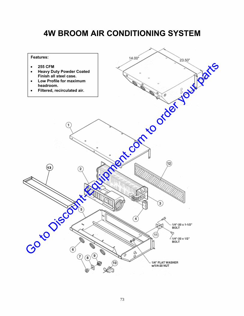
73
4W BROOM AIR CONDITIONING SYSTEM
Features: 255 CFM Heavy Duty Powder Coated
Finish all steel case. Low Profile for maximum
headroom. Filtered, recirculated air.
13
Go to D
iscou
nt-Equ
ipmen
t.com
to or
der y
our p
arts

74
4W BROOM AIR CONDITIONING SYSTEM Reference Part No. Description Qty. 1. .................................. 403184 ................... Cover, Evaporator ............................................ 1 2 ................................... 403180 ................... Blower Assembly .............................................. 1 3 ................................... 403175 ................... Coil, Evaporator ................................................ 1 4 ................................... 403174 ................... Valve, Exp., Block, R134a ................................ 1 5 ................................... 403183 ................... Housing, Evaporator ........................................ 1 6 ................................... 403164 ................... Louver, 3” Round ............................................. 3 7 ................................... 403177 ................... Knob, Fan .......................................................... 1 8 ................................... 403181 ................... Decal, Fan .......................................................... 1 9 ................................... 403173 ................... Switch, Rotary ................................................... 1 10 ................................. 403176 ................... Thermostat ........................................................ 1 11 ................................. 403187 ................... Bracket, Mounting, Exp. Valve ........................ 1 12 ................................. 403178 ................... Filter ................................................................... 1 13 ................................. 403192 ................... Drain Pan (Evaporator) .................................... 1 Not Shown .................. 403182 ................... TSTAT Knob ...................................................... 1 Not Shown .................. 403185 ................... Binary Switch .................................................... 1
Go to D
iscou
nt-Equ
ipmen
t.com
to or
der y
our p
arts

75
4W BROOM AIR CONDITIONING SYSTEM
1
6
2
3
4
5
9 8 7
Go to D
iscou
nt-Equ
ipmen
t.com
to or
der y
our p
arts

4W BROOM AIR CONDITIONING SYSTEM Reference Part No. Description Qty. 1 ................................... 509-5406 ................ Compressor (RCT-350) .................................... 1 403170 ................... Compressor (CR-350 & KR-350) ..................... 1 2 ................................... 403179 ................... Wiring Harness ................................................. 1 3 ................................... 403186 ................... Dryer Clamp ...................................................... 1 4 ................................... 403171 ................... Receiver Dryer .................................................. 1 5 ................................... 403150 ................... Condenser ......................................................... 1 6 ................................... 304027 ................... Belt, CR-350 ...................................................... 1 304014 .................... Belt, KR-350 ...................................................... 1 5254354 .................. Belt, RCT-350 .................................................... 1 7 ................................... 203341 ................... Pulley, KR-350 ................................................... 1 8 ................................... 203261 ................... Adjustment Arm, CR-350 & KR-350 ................ 1 9 ................................... 853610 ................... Compressor Mount, CR-350 ............................ 1 852808 .................... Compressor Mount, KR-350 ............................ 1
76
Go to D
iscou
nt-Equ
ipmen
t.com
to or
der y
our p
arts

78
BROOM ACCESSORIES SYSTEMS
Go to D
iscou
nt-Equ
ipmen
t.com
to or
der y
our p
arts

79
NOZZLE DETAIL
4W BROOM WATER SYSTEM
1
4
10
16
7
6
9
12
13
8 15
2
11
14
5
3
5
16
17
18
25
24
23
22
Go to D
iscou
nt-Equ
ipmen
t.com
to or
der y
our p
arts

80
4W BROOM WATER SYSTEM Reference Part No. Description Qty. 1 ................................... 201761 ................... Strap................................................................... 2 2 ................................... WS-145-D .............. Filler Cap, Plastic, 6” Dia. ................................ 1 3 ................................... WS-143-D .............. Low Profile Plastic Tank .................................. 1 4 ................................... WS-176-E ............... Tank Adapter (1 1/4” Dia.) ................................ 1
5 ................................... 345012 ................... Plastic Pipe Fitting, 90 .................................... 3 6 ................................... 306535 ................... 3/4” Ball Valve ................................................... 1 7 ................................... 306120 ................... Pipe Nipple ........................................................ 1 8 ................................... WS-148 .................. Inline Strainer, Complete ................................. 1 9 ................................... 345011 ................... Plastic Pipe Fitting, Straight ............................ 1 10 ................................. 345010 ................... Plastic Pipe Fitting, Straight ............................ 2 11 ................................. WS-146 .................. Pump .................................................................. 1 12 ................................. 850025 ................... Pump Mount ...................................................... 1 13 ................................. 345009 ................... Plastic Pipe Fitting, Straight ............................ 2 14 ................................. 306950 ................... Check Valve ...................................................... 1 15 ................................. WS-154 .................. Spray Bar Assembly......................................... 1 16 ................................. 202101 ................... Brace w/ U Bolt ................................................. 2 17 ................................. 001716 ................... Brace w/ U Bolt ................................................. 1 18 ................................. 344999 ................... Hose (sold by foot) ........................................... n/a 22 ................................. WS-155 .................. Nozzle Assembly, Complete ............................ 8 23 ................................. WS-158 .................. Nozzle Screen ................................................... 8 24 ................................. TP8002 ................... Spray Tip ........................................................... 8 25 ................................. 1458 ....................... Cap ..................................................................... 8 Go t
o Disc
ount-
Equipm
ent.c
om to
orde
r you
r part
s
81
SCRAPER BLADE ASSEMBLY
1
4
10
16
7
6
9
12
13
8
15
2
11
14
5
3
Go to D
iscou
nt-Equ
ipmen
t.com
to or
der y
our p
arts

82
SCRAPER BLADE ASSEMBLY
Reference Part No. Description Qty.
1. ..................................850022 ................... Blade WA (7 1/2” scraper) ................................ 1
2 ...................................SBA09796 .............. Cutting Edge (High Carbon Steel) ................... 1
3 ...................................850024 ................... Blade Pivot WA ................................................. 1
4 ...................................850023 ................... Blade A-Frame WA ........................................... 1
5 ...................................850026 ................... Blade Lift Arm WA ............................................ 1
6 ...................................850017 ................... Lift Frame .......................................................... 1
7 ...................................850016 ................... Frame Mount ..................................................... 1
8 ...................................201956 ................... Frame Brace ...................................................... 1
9 ...................................SBA05437 .............. Shift Cylinder .................................................... 2
10 .................................208 ......................... Lift Cylinder ....................................................... 1
11 .................................SBA09126 .............. Shoe Assembly ................................................. 2
12 .................................SBA08541 .............. Pivot Pin Set (2 Pins) ........................................ 1
13 .................................SBA08562 .............. Hinge Pin Set (2 Pins) ...................................... 1
14 .................................SBA09124 .............. Eye Bolts (for springs) ..................................... 3
15 .................................SBA07017 .............. Tip Spring .......................................................... 3
16 .................................SBA08184 .............. Cutting Edge Bolt Set ....................................... 1
17 .................................SBA02020 .............. Marker Kit (not shown) ..................................... 1
Go to D
iscou
nt-Equ
ipmen
t.com
to or
der y
our p
arts

83
LEGEND
Pressure Hoses Return HosesService Hoses
Scraper Blade Valve
Stee
ring
Cyl
.
A B
PB2
T
1
A BP
Angle Cyl.
A PALock Solenoid
Steering Unit
Blade Lift Cyl.
LPBRP T
Priority side of gear pump
Core Lift Cyl.
Core Motor
Rotation Valve
TB B
Swing Cyl.
Scraper Blade2 1 Swing Cyl.
Return Manifold
Tank
8" 4FR4-4FRB434" 4FRB4-4FRB4
50" 4FRB4-4FRB4 54" 4FRB4-4FRB4
80" 4
FRB
4-4F
RB
4
85" 4
FR4-
4FR
B4
88" 4
FR4-
4FR
C4
90" 4
FRB
4-4F
RC
427" 6FRB6-6FRA6
33" 6FRB6-6FRB6
58" 6
FRC
6-6F
R6
63" 6FR6-6FRB6
65" 6FRB6-6FRA6
76" 6FR6-6FRB6
94" 6
FRB
6-6F
RB
6
104"
6FR
B6-
6FR
A6
17" 12FR12-12FR12
95" 12FR12-12FR12
23" 16FR16-16FRA16
SCRAPER BLADE HYDRAULICS ASSEMBLY
1
4
2
5
3
6 Go t
o Disc
ount-
Equipm
ent.c
om to
orde
r you
r part
s

SCRAPER BLADE HYDRAULICS ASSEMBLY Reference Part No. Description Qty. 1. .................................. SBA05437 .............. Angle Cylinder .................................................. 2 2 ................................... 208 ......................... Lift Cylinder (208-R) ......................................... 1 3 ................................... 355035 ................... Joystick Control Valve .................................... 1 4 ................................... 305944 ................... Steering Unit ..................................................... 1 5 ................................... 305525 ................... Hydraulic Manifold ........................................... 1 6 ................................... 355031 ................... Foot Pedal Scraper Control Valve .................. 1 Not Shown .................. 852443 ................... RH Foot Control Pedal ..................................... 1 Not Shown .................. 852439 ................... LH Foot Control Pedal...................................... 1
* Note: Hydraulic Hoses and Aeroquip fittings not available through Broce Mfg. Parts Dept. – Please Source Locally
84
Go to D
iscou
nt-Equ
ipmen
t.com
to or
der y
our p
arts

85
CURB SWEEPER ASSEMBLY
(Sweeper and Components)
1 4
10
15
7
6
9
12
8
13
8
16
2
11
14
17
5
3
19
20
19
18
Go to D
iscou
nt-Equ
ipmen
t.com
to or
der y
our p
arts

86
CURB SWEEPER ASSEMBLY
(Sweeper and Components) Reference Part No. Description Qty. 1. .................................. 854005 ................... Mounting Bracket ............................................. 1 2 ................................... 854001 ................... Main Lift Arm ..................................................... 1 3 ................................... 304299 ................... Curb Brush (Wire) ............................................. 1 304296 ................... Curb Brush (Poly) ............................................. 1 4 ................................... 854004 ................... Tilt Arm .............................................................. 1 5 ................................... 854006 ................... Hub Ext. ............................................................. 1 6 ................................... 854003 ................... Motor Mount Bracket ........................................ 1 7 ................................... 204027 ................... Broom Mounting Plate ..................................... 1 8 ................................... 204017 ................... Lift and Tilt Cylinder Pin .................................. 2 9 ................................... 204019 ................... Motor Bracket Pin ............................................. 1 10 ................................. 204018 ................... Accumulator Pin ............................................... 1 11 ................................. 204016 ................... Pivot Pin ............................................................ 1 12 ................................. 204005 ................... Mounting Bracket Arm Pin .............................. 1 13 ................................. 204008 ................... Lift Cylinder Lower Pin .................................... 1 14 ................................. See Hydraulic ....... Lift Cylinder ....................................................... 1 Section 15 ................................. See Hydraulic ....... Spring Cylinder ................................................. 1 Section 16 ................................. See Hydraulic ....... Tilt Cylinder ....................................................... 1 Section 17 ................................. See Hydraulic ....... Hydraulic Motor ................................................ 1 Section 18 ................................. 400910 ................... C-Clip ................................................................. 4 19 ................................. 400911 ................... C-Clip ................................................................. 5 20 ................................. 400912 ................... C-Clip ................................................................. 2
Go to D
iscou
nt-Equ
ipmen
t.com
to or
der y
our p
arts

87
CURB BROOM HYDRAULICS ASSEMBLY
1
4
10
16
6
9
12
13
8
15
2
11
14
5
3
22
21
23
22
20
19
24
27
26
28
11
11
29
Note: Hydraulic Hoses and Aeroquip fittings not available through Broce Mfg. Parts Dept.- Source Locally Go t
o Disc
ount-
Equipm
ent.c
om to
orde
r you
r part
s

88
CURB BROOM HYDRAULICS ASSEMBLY Reference Part No. Description Qty. 1. .................................. 305916 ................... Broom Motor ..................................................... 1 2 ................................... 325037 ................... Spring Cylinder ................................................. 1 3 ................................... 305913 ................... Tilt Cylinder ...................................................... 1 4 ................................... 305914 ................... Lift Cylinder ....................................................... 1 5 ................................... 355032 ................... Control Valve .................................................... 1 6 ................................... 305917 ................... Flow Divider ...................................................... 1 8* ................................. Hydraulic Hose Assembly, 16”HL-1AA12FR12 & 1AA12FRB12 .. 1 9* ................................. Hydraulic Fitting, FF1868T12-10 ...................................................... 1 10* ............................... Hydraulic Fitting, FF1852T12-08 ...................................................... 2 11* ............................... Hydraulic Fitting, FF1852T06-08 ...................................................... 3 12* ............................... Hydraulic Hose Assembly, 52.5”HL-1AA6FR6 & 1AA6FRB6........ 1 13* ............................... Hydraulic Fitting, FF1868T06-125 .................................................... 1 14* ............................... Hydraulic Hose Assembly, 32”HL-1AA6FR6 & 1AA6FRB6........... 1 15* ............................... Hydraulic Hose Assembly, 81”HL-1AA4FRC4 & 1AA4FR4........... 1 16* ............................... Hydraulic Hose Assembly, 75.5”HL-1AAFR4 & 1AA6FRB4.......... 1 19* ............................... Hydraulic Hose Assembly, 68”HL-1AA4FR4 & 1AA4FRB4........... 1 20* ............................... Hydraulic Hose Assembly, 89”HL-1AA6FRB6 (2) .......................... 1 21* ............................... Hydraulic Hose Assembly, 91”HL-1AA6FRC6 & 1AA6FRB6 ........ 1 23* ............................... Hydraulic Fitting, FF1868T04-04 ...................................................... 4 24* ............................... Hydraulic Fitting, FF1852T04-04 ...................................................... 1 26 ................................. 305763 ................... Solenoid Valve .................................................. 1 27* ............................... Hydraulic Fitting, FF1868T04-06 ...................................................... 1 28* ............................... Hydraulic Fitting, FF185204-08 ........................................................ 5 29* ............................... Hydraulic Hose Assembly, 59”HL-1AA4FR4 & 1AA4FRB4........... 1
*Note: Hydraulic Hoses and Aeroquip fittings not available through Broce Mfg. Parts Dept.- Source Locally
Go to D
iscou
nt-Equ
ipmen
t.com
to or
der y
our p
arts

89
ENGINES AND RELATED PARTS
Go to D
iscou
nt-Equ
ipmen
t.com
to or
der y
our p
arts

RCT-350 Export
Cummins Engine
2
3 & 4
7
5 & 6
8
9
10
13 11
12
15
14
16 17 18
19
1
11.1
6.1
90
Go to D
iscou
nt-Equ
ipmen
t.com
to or
der y
our p
arts

RCT-350 Export Cummins Engine
Reference Part No. Description Qty. 1. ................................. 344054 .................... Cummins Diesel Engine .................................. 1 2 .................................. 344053 .................... Pump Drive (Complete) ................................... 1 3 .................................. 203643 .................... Right Rear Motor Mount .................................. 1 4 .................................. 203644 .................... Left Rear Motor Mount ..................................... 1 5 .................................. 203641 .................... Right Front Motor Mount ................................. 1 6 .................................. 203642 .................... Left Front Motor Mount ................................... 1 6.1 ............................... CM-714-B ............... Motor Mount Rubber Isolators ........................ 4 7 .................................. 203656 .................... Silicone Hose Air-to-Air ................................... 1 8 .................................. 203661 .................... Charge Air Tube ............................................... 1 9 .................................. 203671 .................... Support for Pressure Tube ............................. 1 10 ................................ 203657 .................... Silicone Hose w/Bend Air-to-Air ..................... 1 11 ................................ 203665 .................... Fan Guard ......................................................... 1 11.1 ............................. 304097 .................... Fan Guard Rubber Isolators ........................... 4 12 ................................ 203650 .................... Cummins Fan ................................................... 1 13 ................................ 203649 .................... Fan Spacer ........................................................ 1 14 ................................ 203653 .................... Supports for Air Duct Frame ........................... 1 15 ................................ 203651 .................... Radiator Shroud ............................................... 1 16 ................................ 203658 .................... Silicone Hose Air-to-Air ................................... 1 17 ................................ 203662 .................... Charge Air Return Tube .................................. 1 18 ................................ 203659 .................... Air-to-Air 45 degree Hose ................................ 1 19 ................................ 344405 .................... Exhaust Elbow.................................................. 1
91
Go to D
iscou
nt-Equ
ipmen
t.com
to or
der y
our p
arts

RCT-350 Export Cummins Engine
21
22
23
25
22
24
24.1
20
92
Go to D
iscou
nt-Equ
ipmen
t.com
to or
der y
our p
arts

RCT-350 Export Cummins Engine
Reference Part No. Description Qty. 20 ................................ 203646 .................... Radiator/Oil/Charge Air Cooler Assembly ..... 1 21 ................................ 203652 .................... Air Duct Frame ................................................. 1 22 ................................ 203185 .................... Left & Right Air Duct Seals ............................. 2 23 ................................ 203105 .................... Exhaust Heat Shield ........................................ 1 24 ................................ 203645 .................... Bottom Radiator Support ................................ 1 24.1 ............................. 344121 .................... Bottom Radiator Rubber Isolators ................. 2 25 ................................ 203190 .................... Upper & Lower Air Duct Seals ........................ 2
93
Go to D
iscou
nt-Equ
ipmen
t.com
to or
der y
our p
arts

RCT-350 Export Cummins Engine
26
27
28
29
30
31
32
33
34
See A/C Section
94
Go to D
iscou
nt-Equ
ipmen
t.com
to or
der y
our p
arts
McNamara
Text Box
344054

RCT-350 Export Cummins Engine Reference Part No. Description Qty. 26 ................................ 304106 .................... Rubber Elbow (3 x 2.5”)................................... 1 27 ................................ JE-758-B ................ Head Pipe Clamp .............................................. 1 28 ................................ 203663 .................... Exhaust Pipe .................................................... 1 Not Shown ................. 344040 .................... Tail Pipe ............................................................ 1 Not Shown ................. JE-705-B ................ Muffler ............................................................... 1 Not Shown ................. 852110 .................... Muffler Clamp ................................................... 2 29 ................................ 203622 .................... Elbow, Steel 3” ................................................. 1 30 ................................ 203673 .................... Air-to-Air Hose Clamps ................................... 8 31 ................................ 203660 .................... Connecting Tube .............................................. 1 32 ................................ 344407 .................... Fan Belt ............................................................. 1 33 ................................ 304070 .................... Rubber Elbow (3” x 2.5”L) .............................. 1 34 ................................ 344408 .................... Oil Filter ............................................................ 1 35 ................................ 203670 .................... Solenoid ............................................................ 1 36 ................................ 203666 .................... Air Heat Plate .................................................... 1 37 ................................ 203668 .................... Fuse ................................................................... 1 38 ................................ 203669 .................... Fuse Holder ...................................................... 1 39 ................................ 203667 .................... Air Heat Wiring Harness .................................. 1
35
36
37 & 38
39
95
Go to D
iscou
nt-Equ
ipmen
t.com
to or
der y
our p
arts

RCT-350 Export Cummins Engine
36
37 & 38
39
40
41
42
43 44
53 & 54
38.1
96
Go to D
iscou
nt-Equ
ipmen
t.com
to or
der y
our p
arts

RCT-350 Export Cummins Engine Reference Part No. Description Qty. 36 .................................... 203654 ....................... Upper Radiator Hose ............................................... 1 37 .................................... 203647 ....................... Upper Radiator Support .......................................... 1 38 .................................... 203664 ....................... Upper Radiator Support Spacer .............................. 1 38.1 ................................. 304096 ....................... Upper Radiator Rubber Isolator .............................. 1 39 .................................... 203309 ....................... Lower Radiator Hose ............................................... 1 40 .................................... 344406 ....................... Fuel Filter .................................................................. 1 41 .................................... 203648 ....................... Radiator to Engine Support..................................... 1 42 .................................... 203678 ....................... Vent Line Fitting ....................................................... 1 43 .................................... AC-763-R ................... Connecting Tube (short) ......................................... 1 44 .................................... AC-764-R ................... Strap .......................................................................... 2 45 .................................... P103113 .................... Cup ............................................................................ 1 46 .................................... P102980 .................... Air Cleaner Baffle ..................................................... 1 47 .................................... TT-771-R ................... Turbo II Precleaner ................................................... 1 48 .................................... 304059 ....................... Enginair Precleaner ................................................. 1 304063 ....................... Sy-Klone Precleaner ................................................ 1 49 .................................... DE-770-R ................... Air Cleaner (Dual Element) ...................................... 1 50 .................................... P11-9410 ................... Safety Element ......................................................... 1 51 .................................... P18-2059 ................... Service Element ....................................................... 1 52 .................................... P003951 .................... Clamp ........................................................................ 1 53 .................................... 203676 ....................... Hose Guide ............................................................... 1 54 .................................... P003951 .................... Hose Guide Spacer .................................................. 1
44
45
46
47 48
49
50
51
52
97
Go to D
iscou
nt-Equ
ipmen
t.com
to or
der y
our p
arts

RJT-350 Deere Tier 4 Final
Engine
1
3
2
4
5
7
12
9
8
10
11
13
14
14 15 16
17 & 18
6
13
98
Go to D
iscou
nt-Equ
ipmen
t.com
to or
der y
our p
arts

RJT-350 DEERE TIER 4 FINAL ENGINE Reference Part No. Description Qty. 1. ................................. 344019 .................... Engine, Complete Package ............................. 1 2 .................................. RE504836 ............... Filter, Engine Oil .............................................. 1 3 .................................. JDA05RE551507 ... Filter, Fuel Primary .......................................... 1 4 .................................. JDA05RE551508 ... Filter, Fuel Secondary ..................................... 1 5 .................................. JDA05DZ105796 .... Filter Element, Open Crankcase Ventilation . 1 6 .................................. DE-770-R ................ Air Cleaner Kit .................................................. 1 P18-2059 ................ Filter Element, Outer........................................ 1 P11-9410 ................ Filter Element, Inner ........................................ 1 TT-771-R ................ Turbo II Precleaner .......................................... 1 ESA55BRO8767 .... Extension Tube, PVC ....................................... 1 AC-760-B ................ Air Cleaner Elbow ........................................... 1 HDA55X220027 ..... Air Filter Minder ............................................... 1 7 .................................. JDA55R523153 ...... Belt, JD 96.85” x 1.097 x 8 Rib ........................ 1 8 .................................. GYA5562280 .......... Hose, Lower Radiator ...................................... 1 9 .................................. GYA5560914 .......... Hose, Upper Radiator ...................................... 1 10 ................................ JDA55RE170320 ... Relay, Starter Circuit ....................................... 1 11 ................................ HIA55II1398 ........... Mount, Fuse Block ........................................... 1 12 ................................ IIS2003 ................... Rubber, Top Radiator Flap 5”x25” ................. 1 13 ................................ IIS2002 ................... Rubber, Side Radiator Flap 5”x29.75” ........... 2 14 ................................ RSA55RS8191 ....... Radiator ............................................................ 1 FLA55S85 .............. Coolant Level Switch ....................................... 1 CAPPRE10710 ....... Radiator Cap ..................................................... 1 15 ................................ JDA55AT139776 .... Isolator, Cooling IT-4 ....................................... 2 16 ................................ HIA55II1427 ........... Cantilever Mount, Radiator ............................. 1 17 ................................ HIA55II1428 ........... Cantilever Mount, Right Front ........................ 1 18 ................................ HIA55II1429 ........... Cantilever Mount, Left Front ........................... 1 Not Shown ................. EIA559146034 ........ Wire Harness, Broce 4045TFC03 .................... 1 Not Shown ................. 976-145-P204 ......... Analog Throttle W/Jumper .............................. 1 Not Shown ................. CTA55TA0442A ..... Battery Cables, JD 36 Long, 2/0 ..................... 1
15 16
17
18
15
7 Belt Routing
99
Go to D
iscou
nt-Equ
ipmen
t.com
to or
der y
our p
arts

1
2
3
6
5
3 3
4
7
8
9 (3 pcs.)
10
11
12
13
14
100
Go to D
iscou
nt-Equ
ipmen
t.com
to or
der y
our p
arts

RJT-350 DEERE TIER 4 FINAL ENGINE
Reference Part No. Description Qty. 1. ................................. GIA553210015K42EC ... Pump Mount, #4, 10"SAE"BB"SPLINE 2 ....... 1 2 .................................. IIS5015 ................... Exhaust Pipe .................................................... 1 GTA55WS31030 .... Blanket Wrap, Exhaust Pipe (not shown) ...... 1 3 .................................. HDA55P105532 ..... 3” Rubber 90 Degree Elbow ............................ 3 4 .................................. HIA55II1425 ........... Mount, Engine Right Rear ............................... 1 5 .................................. HIA55II1426 ........... Mount, Engine Left Rear.................................. 1 6 .................................. HIA55II1431 ........... Mount, Top Radiator ........................................ 1 7 .................................. HIA55II1430 ........... Mount, Exhaust Front ...................................... 1 8 .................................. IIS5017 ................... Tail Pipe ............................................................ 1 9 .................................. IIS9044 ................... Air Cleaner Pipe Kit (3 pcs.) ............................ 1 10 ................................ JDA55AT375421 .... Isolator, Exhaust .............................................. 4 11 ................................ MWA552536215 ..... Fan, Plastic 3-Blade Suction ........................... 1 12 ................................ SRA5565500001 .... Isolator, Top Radiator ...................................... 2 13 ................................ IIS9045 ................... Bracket, Radiator Isolator & Lift ..................... 1 14 ................................ SMA552962 ............ Fan Spacer, 1 ½” .............................................. 1 15 ................................ RE566836 ............... Diesel Oxidation Catalyst (DOC) .................... 1 16 ................................ RE545865 ............... Clamp ................................................................ 2 17 ................................ RE567056 ............... Diesel Particulate Filter (includes gaskets) .. 1 18 ................................ R532139 ................. Gasket ............................................................... 2 19 ................................ RE549532 ............... Exhaust Pipe .................................................... 1
15
16
16
17
18
18
19
101
Go to D
iscou
nt-Equ
ipmen
t.com
to or
der y
our p
arts

RJT-350 DEERE TIER 4 FINAL ENGINE PV380 Display
Reference Part No. Description Qty. 1. ................................. MUA5578350774 ... PV380-R2, BROCE BROOM - JD ..................... 1
102
Go to D
iscou
nt-Equ
ipmen
t.com
to or
der y
our p
arts

RJT-350 DEERE TIER 4 FINAL ENGINE PV380 Display
103
Go to D
iscou
nt-Equ
ipmen
t.com
to or
der y
our p
arts

RCT-350 Cummins USA Tier 4 Final Engine
1
2
4
5
3
8
9
6
7
10
11
12
12
13
14
104
Go to D
iscou
nt-Equ
ipmen
t.com
to or
der y
our p
arts

RCT-350 CUMMINS USA TIER 4 FINAL ENGINE AND RELATED PARTS
Reference Part No. Description Qty. 1. ................................. 344022 .................... Engine, Complete Package ............................. 1 2 .................................. LF9230 ................... Filter, Engine Oil .............................................. 1 3 .................................. FF90567-01 ............ Filter, Fuel Primary Cartridge ......................... 1 4 .................................. FS19732 ................. Filter, Fuel Secondary ..................................... 1 5 .................................. AH55642VEJX ....... Air Cleaner, Dual Element ............................... 1 AF55020 ................. Primary Air Cleaner Filter Element ................ 1 AF55320 ................. Secondary Air Cleaner Filter Element ........... 1 135501-00825 ........ Filter Minder ..................................................... 1 6 .................................. 5H4 ......................... Hose, Reducing Hump..................................... 1 210-102 ................... Clamp, Upper .................................................... 1 210-118 .................. Clamp, Lower ................................................... 1 7 .................................. MAI675-B ............... Tube, Extension Air Intake .............................. 1 8 .................................. MCA374-A .............. Hose, Upper Radiator ...................................... 1 9 .................................. MCA375-A .............. Hose, Lower Radiator ...................................... 1 10 ................................ MFM111-A .............. Mount, Motor Left Front .................................. 1 MFM110-A .............. Mount, Motor Right Front ................................ 1 11 ................................ MRM125-A ............. Mount, Motor Left Rear.................................... 1 MRM124-A ............. Mount, Motor Right Rear ................................. 1 12 ................................ CB-1180-1 .............. Isolator, Engine Mount .................................... 4 13 ................................ MFC131-A .............. Fuel Hose, Quick-Connect .............................. 1 14 ................................ MFC131-B .............. Fuel Hose, Quick-Connect .............................. 1 Not Shown ................. MWH369-B ............. Cable, Battery Power ....................................... 1
105
Go to D
iscou
nt-Equ
ipmen
t.com
to or
der y
our p
arts

RCT-350 Cummins USA Tier 4 Final Engine
1
7
4
3
5
6
2
8
9
1
10
11 12
13
15
14
16
106
Go to D
iscou
nt-Equ
ipmen
t.com
to or
der y
our p
arts

RCT-350 Cummins USA TIER 4 Final Engine
Reference Part No. Description Qty. 1................................... 5254354 .................. Belt, Serpentine ................................................ 1 2................................... 509-5406 ................. Compressor, A/C .............................................. 1 3................................... 90HL40R25 ............ Hose, 90 Degree Reducing 4-2.5" ................... 1 210-102 ................... Clamp ................................................................ 1 4................................... MAI584-B ............... Tube, Air Intake ................................................ 4 5................................... 304110 .................... Hose, 90 Degree 2" .......................................... 1 6................................... MXS410-A .............. Downpipe, Exhaust .......................................... 1 7................................... MXS411-A .............. Tailpipe, Exhaust .............................................. 1 8................................... MAI582-A ............... Tube, Hot CAC .................................................. 1 250-73B .................. Clamp ................................................................ 1 9................................... MAI583-A ............... Tube, Cold CAC ................................................ 1 10 ................................ A048Y154 ............... DOC, Exhaust ................................................... 1 11 ................................ MXS428-A .............. DOC Mounting Bracket .................................... 1 12 ................................ MXS265-B .............. Base, CCC Mounting ........................................ 2 13 ................................ MXS258-B .............. U-Bolt................................................................. 2 14 ................................ 203485 .................... Anti-Recirculation Flap, Left/Right ................. 2 15 ............................... 203484 .................... Anti-Recirculation Flap, Lower ....................... 1 16 ................................ 203483 .................... Anti-Recirculation Flap, Upper ....................... 1
107
Go to D
iscou
nt-Equ
ipmen
t.com
to or
der y
our p
arts

108
RCT-350 Cummins USA Tier 4 Final Engine
1
2
3
4
5
6
7
8
Go to D
iscou
nt-Equ
ipmen
t.com
to or
der y
our p
arts

109
RCT-350 Cummins USA TIER 4 Final Engine
Reference Part No. Description Qty. 1................................... 01-41129 ................. Cooling Package (HOC, CAC, Rad) ................ 1 2................................... 34-41317-01 ........... Guard, Fan, Left ................................................ 1 34-41317-02 ............ Guard, Fan, Right ............................................. 1 3................................... 33-41316 ................. Shroud, Fan ...................................................... 1 4................................... 14-41318-9 ............. Reservoir, Coolant ........................................... 1 5................................... 24-41319-9 ............. Radiator, CAC, HOC ......................................... 1 6................................... 344001 .................... Fan, Engine Cooling ........................................ 1 7................................... 11-01534 ................. Cap, Radiator .................................................... 1 8................................... 1035100002-001 ..... Low Water Probe .............................................. 1
Go to D
iscou
nt-Equ
ipmen
t.com
to or
der y
our p
arts

RCT-350 Cummins USA TIER 4 Final Engine
Reference Part No. Description Qty. 1 .................................. 976-145-P204 ......... Throttle, Cummins ........................................... 1
110
Go to D
iscou
nt-Equ
ipmen
t.com
to or
der y
our p
arts

RCT-350 Cummins USA TIER 4 Final Engine
Reference Part No. Description Qty. 1 .................................. 344021 .................... Digital Display, Cummins ................................ 1
111
Go to D
iscou
nt-Equ
ipmen
t.com
to or
der y
our p
arts

KR-350 KUBOTA ENGINE AND RELATED PARTS
1
21
7
8
20
3
2
9
6
19
18
17
14
15
14
12
11
10
15
23
22
40
33
32
31
30
29
28
27a
26
25
24
39
38
37
36
35
34
47
46
45
44
43
42
41
Pictures may vary from actual model.
28a
27
48
5
44
112
Go to D
iscou
nt-Equ
ipmen
t.com
to or
der y
our p
arts

KR-350 KUBOTA ENGINE AND RELATED PARTS Reference Part No. Description Qty. 1. ..................................... 344064 ....................... Kubota Diesel Engine .............................................. 1 2 ...................................... N/A ............................. Drive Plate................................................................. 1 3 ...................................... 344052 ....................... Pump Drive, Complete ............................................. 1 5 ...................................... 203794 ....................... Oil Cooler Asm/ Radiator Asm. ............................... 1 6 ...................................... 203330 ....................... Right Front Motor Mount ......................................... 1 7 ...................................... 203331 ....................... Left Front Motor Mount ............................................ 1 8 ...................................... 203780 ....................... Right Rear Motor Mount .......................................... 1 9 ...................................... 203794 ....................... Radiator Assembly / Oil Cooler Asm. ..................... 1 10 .................................... CR-721-B ................... Lower Radiator Hose ............................................... 1 11 .................................... 304099 ....................... Upper Radiator Hose ............................................... 1 12 .................................... CALL ......................... Radiator Cap ............................................................. 1 14 .................................... 203800 ....................... Top and Bottom Seal ............................................... 2 15 .................................... 203799 ....................... Left and Right Seal ................................................... 2 17 .................................... 344040 ....................... Tail Pipe .................................................................... 1 18 .................................... 852110 ....................... Muffler Clamp ........................................................... 2 19 .................................... JE-705-B ................... Muffler ....................................................................... 1 20 .................................... 203781 ....................... Left Rear Motor Mount ............................................. 1 21 .................................... JE-758-B ................... Head Pipe Clamp ...................................................... 2 22 .................................... 852337 ....................... Exhaust Pipe ............................................................. 1 23 .................................... 19258-12230 .............. Exhaust Gasket ........................................................ 1 24 .................................... 203105 ....................... Exhaust Heat Shield ................................................. 1 25 .................................... 304106 ....................... Rubber Elbow (3” x 2.5”) ......................................... 1 26 .................................... AC-760-B ................... Rubber Elbow (3.5” x 3”) ......................................... 1 27 .................................... 304110 ....................... Rubber Elbow (1.75” x 2”) ....................................... 1 28 .................................... 202152 ....................... Connecting Tube ...................................................... 1 28a .................................. 203345 ....................... Connecting Tube ...................................................... 1 29 .................................... DE-770-R ................... Air Cleaner (Dual Element) ...................................... 1 30 .................................... P182059 .................... Service Element ....................................................... 1 31 .................................... P119410 .................... Safety Element ......................................................... 1 32 .................................... 304059 ....................... Enginair Precleaner ................................................. 1 304063 ....................... Sy-Klone Precleaner ................................................ 1 33 .................................... 203806 ....................... Fan Guard ................................................................. 1 34 .................................... P003951 .................... Clamp ........................................................................ 1 35 .................................... AC-764-R ................... Strap .......................................................................... 2 36 .................................... TT-771-R ................... Turbo II Precleaner ................................................... 1 37 .................................... P103113 .................... Cup ............................................................................ 1 38 .................................... P102980 .................... Air Cleaner Baffle ..................................................... 1 39 .................................... CM-714-B .................. Engine Isolator Kit ................................................... 4 40 .................................... 203797 ....................... Radiator Shroud ....................................................... 1 41 .................................... 203801 ....................... Upper Radiator Support........................................... 1 42 .................................... 852802 ....................... Bottom Radiator Support ........................................ 1 43 .................................... 304096 ....................... Top Radiator Isolator ............................................... 1 44 .................................... 344121 ....................... Bottom Radiator Isolator & Heat Shield Isolator ... 6 45 .................................... 203334 ....................... Radiator to Mount Support ...................................... 1 46 .................................... 203798 ....................... Air Guide Frame ....................................................... 1 47 .................................... 203804 ....................... Hose Guide ............................................................... 1 48 .................................... 001397 ....................... Hump Clamp ............................................................. 1 Not Shown ..................... 203795 ....................... Kubota Fan ............................................................... 1 Not Shown ..................... 203805 ....................... Fan Spacer ................................................................ 1 Not Shown ..................... 344550 ....................... Oil Filter..................................................................... 1 Not Shown ..................... 16631-43560 .............. Fuel Filter .................................................................. 1 Not Shown ..................... 304015 ....................... Alternator/Engine Belt ............................................. 1 Not Shown ..................... 203346 ....................... Alternator Support Bracket ..................................... 1 Not Shown ..................... 203347 ....................... Alternator Adjustment Bracket ............................... 1 Not Shown ..................... 203348 ....................... Alternator Bushing ................................................... 1
113
Go to D
iscou
nt-Equ
ipmen
t.com
to or
der y
our p
arts

CAT C4.4 ENGINE AND RELATED PARTS
10
7
1
6
4
5
3
2
9
8
16
15
14
13
12
11
22
21
20
19 18 17
30
29
28
27
36
35
34
33
32
31 37
38
25
39
26
24
23
Pictures may vary from actual model.
114
Go to D
iscou
nt-Equ
ipmen
t.com
to or
der y
our p
arts

CAT C4.4 ENGINE AND RELATED PARTS
ITEM
PART NUMBER
DESCRIPTION
QUANTITY
1 344023 CAT C4.4 Diesel Engine 1
2 852045 Oil Cooler Hose Guide Sleeve 1
3 325027 Oil Cooler - Aluminum 1
4 203600 Right Front Motor Mount 1
5 203601 Left Front Motor Mount 1
6 852042 Right Rear Motor Mount 1
7 852043 Left Rear Motor Mount 1
8 344508 Radiator Assembly 1
9 344511 Lower Radiator Hose 1
10 344510 Upper Radiator Hose 1
11 853606 Oil Cooler Mount 1
12 203480 Right Side Oil Cooler Seal 1
13 203481 Lower Seal (Rubber) 1
14 203479 Left Side Oil Cooler Seal 1
15 203482 Upper Seal (Rubber) 1
16 344040 Tail Pipe 1
17 852110 Muffler Clamp 2
18 JE-705-B Muffler 1
19 JE-758-B Head Pipe Clamp 2
20 855612 Exhaust Pipe 1
21 344031 Exhaust Gasket 1
22 203105 Exhaust Heat Shield 1
23 304106 Rubber Elbow 2
24 304119 Rubber Elbow 1
25 304195 Heater Hose 1
26 203614 Connecting Tube 1
27 DE-770-R Air Cleaner (Dual Element) 1
28 P182059 Service Element 1
29 P119410 Safety Element 1
30 PC-710-B Precleaner, 4” 1
31 PC-765-R Precleaner, Top 1
32 PC-711-R Precleaner Bowl 1
33 304095 Engine Isolator Kit 4
34 P003951 Clamp 1
35 AC-764-R Strap 2
36 TT-771-R Turbo II Precleaner 1
37 P103113 Cup 1
38 P102980 Air Cleaner Baffle 1
39 344509 Radiator Cap 1
NS 101-3770 CAT Fan 1
NS 5M8155 Fan Belt 1
NS 304196 Compressor Belt, A/C Only 1
NS 344079 Fuel Filter 1
NS 344078 Oil Filter 1
115
Go to D
iscou
nt-Equ
ipmen
t.com
to or
der y
our p
arts

PREVENTIVE MAINTENANCE BROOM SPECIFICATIONS
& SCHEMATICS
116
Go to D
iscou
nt-Equ
ipmen
t.com
to or
der y
our p
arts

Preventative Maintenance
A well maintained A/C system would save on downtime and premature component failures. Weekly inspections or every 2 days in severe environments should include:
1. Inspect compressor clutch drive belts (tightness, wear). 2. Inspect compressor-mounting brackets (bolts, alignment). 3. Inspect mounting hardware on evaporator unit and condensers. 4. Inspect air intake filter. Clean or replace filter. 5. Inspect evaporator and condenser coils. Clean using air pressure.
(DO NOT USE WATER OR PRESSURE WASHERS). 6. Inspect hose and wire harness for proper routing. Leaks and wear.
Helpful Hints
Make sure the evaporator air intake area is not obstructed (i.e. toolboxes, clothing, lunch box, etc.) Manual thermostats on our systems, when rotated clockwise to the stop position will not allow the A/C compressor clutch to cycle. The compressor will run continuously and the evaporator coil will not defrost. REMEDY: Turn the manual thermostat knob clockwise to the stop position, and then turn the thermostat knob back counter clockwise ¼ turn. Broce thanks you for purchasing our units. It is our endeavor to provide you with a quality A/C unit with trouble free service.
117
Go to D
iscou
nt-Equ
ipmen
t.com
to or
der y
our p
arts

HYDRAULIC COMPONENT SPECIFICATIONS
Propel Pump Displacement at MAX Angle: 46 cc (2.8 CU IN) Rated Speed: 4000 RPM MAX Speed: 4100 RPM MIN Speed: 500 RPM Case Pressure – Continuous: 1.7 BAR (25 PSI) Case Pressure – MAX: 5.2 BAR (75 PSI) System Pressure – Continuous: 210 BAR (3000 PSI) System Pressure – MAX: 345 BAR (5000 PSI) Inlet Vacuum – Continuous: .8 BAR Absolute (5 IN Hg) Inlet Vacuum – MAX: .7 BAR Absolute (10 IN Hg) Charge Pressure Setting: 19.5 BAR (283 PSI) System Pressure Setting: 280 BAR (4060 PSI) Approximate Flow at 2400 RPM 26 GPM
Propel Motor
Displacement: 46 cc (2.8 CU IN) Rated Speed: 3600 RPM MAX Speed: 3600 RPM Case Pressure – Continuous 1.7 BAR (25 PSI) Case Pressure – MAX: 5.2 BAR (75 PSI) System Pressure – Continuous: 210 BAR (3000 PSI) System Pressure – MAX: 345 BAR (5000 PSI)
Auxiliary Pump
Displacement: 38 cc (2.32 CU IN) MAX Speed: 2500 RPM MAX Continuous Pressure: 3000 PSI Approximate Flow at 2400 RPM Priority (Steering and Broom) 3 GPM Secondary (Broom Rotation) 18 GPM MAX Pressure Setting (Priority): 1600 PSI MAX Pressure Setting * (Secondary) 3000 PSI *Relief Valve in the Broom Rotation Valve
118
Go to D
iscou
nt-Equ
ipmen
t.com
to or
der y
our p
arts

FLUID CAPACITIES
Component Fluid Type Quantity
Hydraulic Tank DYNA-PLEX 21C CURSA HYDRAULIC OIL 27 Gal. Must meet Caterpillar spec. T02 or Allison C3
Fuel #2 DIESEL 27 Gal.
Radiator ETHYLENE GLYCOL 50/50 MIX 2.5 Gal
Engine Crankcase API Classification CE or CD 10 Qts CCMC Specification D4 or D5
Rear Axle EP-90 GEAR LUBE 2 Qts*
2-Speed G-Box EP-90 GEAR LUBE 2 Qts*
* 2 Quarts is approximate. Fill to the level of the filler plug.
119
Go to D
iscou
nt-Equ
ipmen
t.com
to or
der y
our p
arts

Broce Brooms
DYNA-PLEX 21C CURSA HYDRAULIC OIL
Dyna-Plex 21C Cursa Hydraulic Oils are high quality; extra-inhibited oils designed with hydrocrack Group II base oils, for use in multi-functional applications where long oil life is required. These oils will give you steady, reliable performance as a hydraulic medium. Dyna-Plex 21C Cursa Hydraulic Oils have been finely filtered to remove external contamination and contain special O-Ring conditioners to prolong hydraulic component life. Seal swell agents have been added to prevent leaks and Cursa’s demulsability characteristics enhance separation and removal of water. These oils will supply 5000 hours of service before extreme oxidation problems occur and also provide excellent resistance to foaming, rust and wear. ASTM TEST MULTI- PROPERTY METHOD FUNCTION Viscosity @ 40C,CST D445 46.00 Viscosity @ 100C,CST D445 9.75 Viscosity Index D2270 200 Flash Point, COC, C D92 200 Flash Point, COC, F D92 392 Pour Point, C (F) D97 -36 (-33) Color D1500 Orange Gravity, API D287 32.0 Turbine Oil Oxidation D943 5000+ Copper Strip D130 LB Rust Test D665 Pass Vane Pump, Mgs. Wt. Loss D2882 12 Usable Temperature Range, F -10-110 Maximum Hydra. Temperature, F 205 Dielectric Strength, kv 35 RBOT, Minutes D2272 950 Demulsibility D1401 40-40-0 (5) Meets or exceeds the following tests and requirements:
AFNOR E 48-603
B.F. Goodrich – 0152 Cincinnati Milacron – P-68 (light hydraulic oils), P-69, P-70 Denison – HF-0, HF-1, HF-2 DIN – 51524, Part 2 FMC – High-Performance Hydraulic Oil Ford – M-6C32 General Motors – LH-04-1, LH-06-1, LH-15-1 Jeffrey - #87 Lee Norse 100-1 Racine – Model S, variable volume vane pump U.S. Steel – 136, 127 Vickers – I-286-S, M-2950-S, 35VQ25
HO-11/4-14-00
120
Go to D
iscou
nt-Equ
ipmen
t.com
to or
der y
our p
arts

DYNA-PLEX 21C EXTENDED DRAIN ANTI-FREEZE/ENGINE COOLANT
Dyna-Plex 21C Extended Drain Anti-Freeze/Engine Coolant is a premium quality ethylene glycol based product. It is pre-diluted to a 50/50 mixture with de-ionized water to provide excellent corrosion control and a deduction of scale buildup. The corrosion inhibitor package eliminates the need for an initial charge of supplemental coolant additive (SCA). The 50/50 dilution with de-ionized water insures high water quality and eliminates the chance for error when mixing anti-freeze with water in the field. Dyna-Plex 21C Extended Drain Anti-Freeze gives the maximum protection and performance available for heavy-duty diesel applications, while eliminating potential water related problems. Advantages of this product include the highest quality inhibitor package available and its ready to use convenience. Universal recommends good maintenance practices to monitor inhibitor levels on a regular basis by utilizing coolant analysis, which is an important aspect of extending the life of this coolant/anti-freeze. This product meets or exceeds manufacturer specifications for use in both heavy-duty diesel and automotive applications.
Physical and ASTM Test Chemical Properties Test Method Specifications Specific Gravity @ 60F D-1122 1.110 – 1.145 pH 50% Dilution D-1287 10.0 – 10.4 Reserve Alkalinity D-1121 5.0 ml min. Boiling Point D-1120 320F min. Flash Point D-92 240F min. Freeze Point D-1177 -34F max. Color OEM Standard Green Foaming – Foam Volume, ml D-1881 50 max. Break Time, sec. D-1881 5 max. Composition (% by weight) Total Glycols 45.0% min. Total De-ionized Water 53.0% max. Inhibitors and Dye 2.0% min.
Dyna-Plex 21C Extended Drain Anti-Freeze/Engine Coolant meets or exceeds the following specifications:
American Society for Testing and Materials (ASTM)- D-33-6; D-4985; D-4656 General Motors – GM 1899M; GM 1825M Society for Automotive Engineers – SAE J1941, J1034 Cummins – 85T8-2; 90T8-4; Bulletin #3666132 Ford Motor Corporation – ESE M97B44A; ESE-M97B18-C Chrysler Motors - MS7170 Detroit Diesel 7SE298 John Deere H24A2; H24C2 ATA Maintenance Council – RP-329
AF-1/9-12-01
121
Go to D
iscou
nt-Equ
ipmen
t.com
to or
der y
our p
arts

150 AMP
59
3
4
6
2
1
8
8
8
7
CG 7/7/16
ELECTRICAL PANEL TIER 4F
BAT
AUX
ITEM NO. PART NUMBER DESCRIPTION QTY.
1 203150 PANEL ELECTRIC 1
2 307900 BREAKER 150 AMP 1
3 203669 FUSE HOLDER 1
4 203668 250 AMP FUSE 15 203670 SOLENOID CONTROL 16 307804 5" 4G WIRE 57 307353 4 g 1/4" Eyelet 1
8 307352 4 g 5/16" Eyelet 39 307804 4" 4G WIRE 4
UNLESS OTHERWISE SPECIFIED:
CHECKED
SIZE
APPLICATION
TITLE:
PROPRIETARY AND CONFIDENTIALINTERPRET GEOMETRICTOLERANCING PER:
Q.A.
FINISH
DWG. NO.
DATE
USED ON A
DIMENSIONS ARE IN INCHESTOLERANCES:FRACTIONALANGULAR: MACH BEND TWO PLACE DECIMAL THREE PLACE DECIMAL
NEXT ASSY
MATERIAL
NAME
REV
DO NOT SCALE DRAWING SCALE: 1:4
752407
ENG APPR.
THE INFORMATION CONTAINED IN THISDRAWING IS THE SOLE PROPERTY OF<INSERT COMPANY NAME HERE>. ANY REPRODUCTION IN PART OR AS A WHOLEWITHOUT THE WRITTEN PERMISSION OF<INSERT COMPANY NAME HERE> IS PROHIBITED.
COMMENTS:
DRAWN
MFG APPR.
SHEET 1 OF 1
BROCE MANUFACTURING1460 S 2ND AVE DODGE CITY KS, 67801
Go to D
iscou
nt-Equ
ipmen
t.com
to or
der y
our p
arts

125
Go to D
iscou
nt-Equ
ipmen
t.com
to or
der y
our p
arts

126
Go to D
iscou
nt-Equ
ipmen
t.com
to or
der y
our p
arts

127
Go to D
iscou
nt-Equ
ipmen
t.com
to or
der y
our p
arts

128
Go to D
iscou
nt-Equ
ipmen
t.com
to or
der y
our p
arts

129
Go to D
iscou
nt-Equ
ipmen
t.com
to or
der y
our p
arts

130
Go to D
iscou
nt-Equ
ipmen
t.com
to or
der y
our p
arts

131
Go to D
iscou
nt-Equ
ipmen
t.com
to or
der y
our p
arts

132
Go to D
iscou
nt-Equ
ipmen
t.com
to or
der y
our p
arts

133
Go to D
iscou
nt-Equ
ipmen
t.com
to or
der y
our p
arts

134
Go to D
iscou
nt-Equ
ipmen
t.com
to or
der y
our p
arts

135
Go to D
iscou
nt-Equ
ipmen
t.com
to or
der y
our p
arts

136
Go to D
iscou
nt-Equ
ipmen
t.com
to or
der y
our p
arts

137
Go to D
iscou
nt-Equ
ipmen
t.com
to or
der y
our p
arts

138
Go to D
iscou
nt-Equ
ipmen
t.com
to or
der y
our p
arts

139
Go to D
iscou
nt-Equ
ipmen
t.com
to or
der y
our p
arts

140
Go to D
iscou
nt-Equ
ipmen
t.com
to or
der y
our p
arts

141
Go to D
iscou
nt-Equ
ipmen
t.com
to or
der y
our p
arts

142
Go to D
iscou
nt-Equ
ipmen
t.com
to or
der y
our p
arts

143
Go to D
iscou
nt-Equ
ipmen
t.com
to or
der y
our p
arts

Go to D
iscou
nt-Equ
ipmen
t.com
to or
der y
our p
arts

145
Go to D
iscou
nt-Equ
ipmen
t.com
to or
der y
our p
arts

146
Go to D
iscou
nt-Equ
ipmen
t.com
to or
der y
our p
arts

Discount-Equipment.com is your online resource for quality parts & equipment.
Florida: 561-964-4949 Outside Florida TOLL FREE: 877-690-3101
Need parts? Click on this link: http://www.discount-equipment.com/category/5443-parts/ and choose one of the options to help get the right parts and equipment you are looking for. Please have the machine model and serial number available in order to help us get you the correct parts. If you don’t find the part on the website or on one of the online manuals, please fill out the request form and one of our experienced staff members will get back to you with a quote for the right part that your machine needs.
We sell worldwide for the brands: Genie, Terex, JLG, MultiQuip, Mikasa, Essick, Whiteman, Mayco, Toro Stone, Diamond Products, Generac Magnum, Airman, Haulotte, Barreto,
Power Blanket, Nifty Lift, Atlas Copco, Chicago Pneumatic, Allmand, Miller Curber, Skyjack, Lull, Skytrak, Tsurumi, Husquvarna Target, Stow, Wacker, Sakai, Mi-T-M, Sullair, Basic,
Dynapac, MBW, Weber, Bartell, Bennar Newman, Haulotte, Ditch Runner, Menegotti, Morrison, Contec, Buddy, Crown, Edco, Wyco, Bomag, Laymor, EZ Trench, Bil-Jax, F.S.
Curtis, Gehl Pavers, Heli, Honda, ICS/PowerGrit, IHI, Partner, Imer, Clipper, MMD, Koshin, Rice, CH&E, General Equipment ,Amida, Coleman, NAC, Gradall, Square Shooter, Kent,
Stanley, Tamco, Toku, Hatz, Kohler, Robin, Wisconsin, Northrock, Oztec, Toker TK, Rol-Air, APT, Wylie, Ingersoll Rand / Doosan, Innovatech, Con X, Ammann, Mecalac, Makinex, Smith
Surface Prep,Small Line, Wanco, Yanmar
Related Documents