RoHS Compliant Serial ATA Flash Drive SAFD 25P-M Specifications March 20 th , 2012 Version 1.6 Apacer Technology Inc. 4 th Fl., 75 Hsin Tai Wu Rd., Sec.1, Hsichih, New Taipei City, Taiwan 221 Tel: +886-2-2698-2888 Fax: +886-2-2698-2889 www.apacer.com

Welcome message from author
This document is posted to help you gain knowledge. Please leave a comment to let me know what you think about it! Share it to your friends and learn new things together.
Transcript
RoHS Compliant
Serial ATA Flash Drive SAFD 25P-M Specifications
March 20th, 2012
Version 1.6
Apacer Technology Inc. 4th Fl., 75 Hsin Tai Wu Rd., Sec.1, Hsichih, New Taipei City, Taiwan 221 Tel: +886-2-2698-2888 Fax: +886-2-2698-2889 www.apacer.com
Serial ATA Flash Drive APS25P6Bxxxx- CCMX
1 © 2012 Apacer Technology Inc. Rev. 1.6
Features:
Standard Serial ATA 2.6 – Serial ATA 2.6 – SATA II, 3.0 Gbps – ATA-compatible command set
Capacities – 16, 32, 64, 128, 256, 512 GB
Performance* – Burst read/write: 300 MB/sec – Sustained read: up to 260 MB/sec – Sustained write: up to 220 MB/sec
Intelligent endurance design – Built-in hardware ECC, enabling up to
16/24 bit correction per 1024 bytes – Static wear-leveling scheme together
with dynamical block allocation to significantly increase the lifetime of a flash device and optimize the disk performance
– Flash bad block management – S.M.A.R.T. – Power Failure Management – ATA Secure Erase – TRIM
NAND Flash Type: MLC
MTBF (hours): >1,000,000
Temperature ranges – Operation: Standard: 0°C to 70°C (32 ~ 158°F) Extended: -40 ~ +85°C (-40° ~ 185°F)** – Storage: -40°C to 100°C (-40° ~ 212°F)
Supply voltage – 5.0 V ± 5%
Power consumption (typical)* – Active mode: 872 [email protected] V – Idle mode: 203 [email protected] V
Form factor – 2.5 inch (100 x 69.9 x 9.3, unit: mm)
Connector – 7-pin SATA male connector – 15-pin SATA power connector
IOPS 4K Random (approx.) – 10,000
Shock & Vibration – Shock: 1500g (approx.) – Vibration: 15g (approx.)
Zero power data retention No battery required for data storage
RoHS compliant
*Varies from capacities. The values presented for Performances and Power Consumption are typical and may vary depending on different configurations and platforms. **Only available in 32, 64, 128, and 256GB capacities. For details, please see “Product Ordering Information”.
Serial ATA Flash Drive APS25P6Bxxxx- CCMX
2 © 2012 Apacer Technology Inc. Rev. 1.6
Table of Contents 1. Product Description................................................................................................. 3
1.1 Introduction............................................................................................................................. 3 1.2 Functional Block Diagram ...................................................................................................... 3 1.3 ATA Mode Support.................................................................................................................. 4 1.4 Capacity Specification ............................................................................................................ 4 1.5 Performance............................................................................................................................ 4 1.6 Pin Assignments..................................................................................................................... 5
2. Software Interface .................................................................................................... 7 2.1 Command Set.......................................................................................................................... 7 2.2 S.M.A.R.T. ................................................................................................................................ 9
3. Flash Management ................................................................................................. 10 3.1 Error Correction/Detection ................................................................................................... 10 3.2 Bad Block Management ........................................................................................................ 10 3.3 Wear Leveling........................................................................................................................ 10 3.4 Power Failure Management .................................................................................................. 10 3.5 ATA Secure Erase ................................................................................................................. 10 3.6 TRIM....................................................................................................................................... 11
4. Environmental Specifications ............................................................................... 12 4.1 Environments........................................................................................................................ 12 4.2 Mean Time Between Failures (MTBF)................................................................................... 12 4.3 Certification and Compliance ............................................................................................... 12
5. Electrical Characteristics ...................................................................................... 13 5.1 Operating Voltage ................................................................................................................. 13 5.2 Power Consumption ............................................................................................................. 13 5.3 Electrostatic Discharge......................................................................................................... 13 5.4 Electrical Fast Transient/Burst ............................................................................................. 14
6. Physical Characteristics........................................................................................ 15 6.1 Metal Housing ....................................................................................................................... 15
7. Product Ordering Information............................................................................... 16 7.1 Product Code Designations.................................................................................................. 16 7.2 Valid Combinations............................................................................................................... 17
Serial ATA Flash Drive APS25P6Bxxxx- CCMX
3 © 2012 Apacer Technology Inc. Rev. 1.6
1. Product Description
1.1 Introduction Apacer’s Serial ATA Flash Drive (SAFD) is a solid-state disk (SSD) drive that contains a controller, embedded firmware, and flash media along with a male connector. Using NAND flash memory devices, the SAFD drive interfaces with the host allowing data to be seamlessly transferred between the host and the flash devices.
SAFD 25P-M drive is designed with a single-chip controller, offering capacities of up to 512 gigabytes and providing full support for the SATA II high-speed interface standard. It can operate at sustained access rates higher than 100 megabytes per second, which is much faster than any other traditional SATA-based hard disk drive currently available on the market. Though built with MLC, this SSD can work in highly demanding environment as it can withstand ambient temperature from -40°C to +85°C (for certain capacities only).
In addition to buffer management through dynamical allocation, SAFD 25P-M adopts the global wear-leveling scheme to allow uniform use of all storage blocks, ensuring that the lifespan of a flash media can be significantly increased and the disk performance is optimized as well. SAFD 25P-M provides the S.M.A.R.T. feature that follows the SATA Rev. 2.6, ATA/ATAPI-7 specifications and uses the standard SMART command B0h to read data from the drive. This feature protects the user from unscheduled downtime by monitoring and storing critical drive performance.
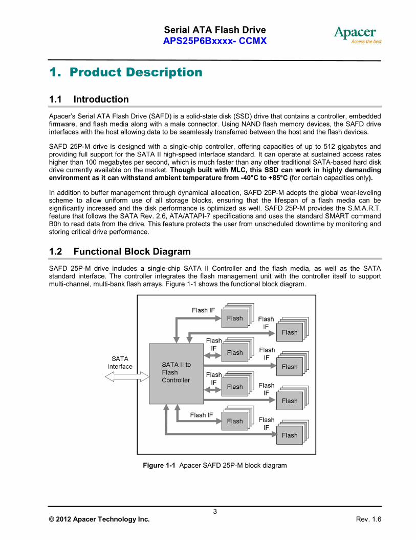
1.2 Functional Block Diagram SAFD 25P-M drive includes a single-chip SATA II Controller and the flash media, as well as the SATA standard interface. The controller integrates the flash management unit with the controller itself to support multi-channel, multi-bank flash arrays. Figure 1-1 shows the functional block diagram.
Figure 1-1 Apacer SAFD 25P-M block diagram
Serial ATA Flash Drive APS25P6Bxxxx- CCMX
4 © 2012 Apacer Technology Inc. Rev. 1.6
1.3 ATA Mode Support SAFD 25P-M provides ATA mode support as follows:
Up to PIO mode-4 Up to Multiword DMA mode-2 Up to UDMA mode-5
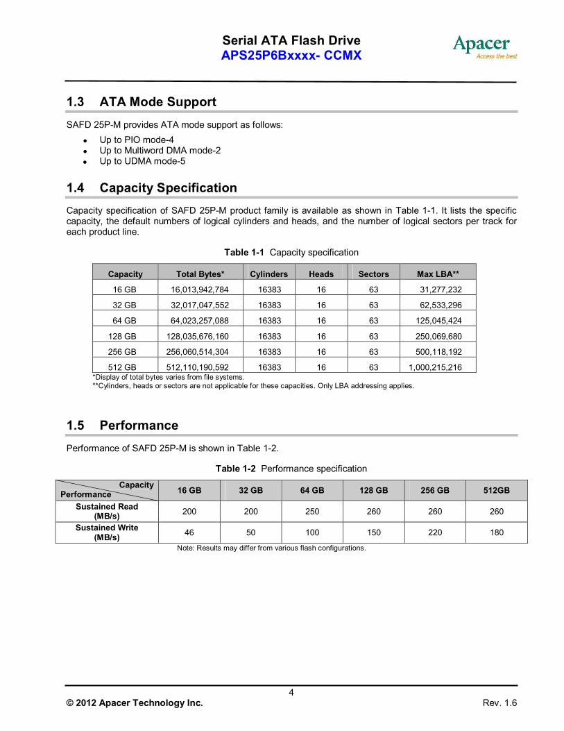
1.4 Capacity Specification Capacity specification of SAFD 25P-M product family is available as shown in Table 1-1. It lists the specific capacity, the default numbers of logical cylinders and heads, and the number of logical sectors per track for each product line.
Table 1-1 Capacity specification
Capacity Total Bytes* Cylinders Heads Sectors Max LBA**
16 GB 16,013,942,784 16383 16 63 31,277,232
32 GB 32,017,047,552 16383 16 63 62,533,296
64 GB 64,023,257,088 16383 16 63 125,045,424
128 GB 128,035,676,160 16383 16 63 250,069,680
256 GB 256,060,514,304 16383 16 63 500,118,192
512 GB 512,110,190,592 16383 16 63 1,000,215,216 *Display of total bytes varies from file systems. **Cylinders, heads or sectors are not applicable for these capacities. Only LBA addressing applies.
1.5 Performance Performance of SAFD 25P-M is shown in Table 1-2.
Table 1-2 Performance specification
Capacity Performance 16 GB 32 GB 64 GB 128 GB 256 GB 512GB
Sustained Read (MB/s) 200 200 250 260 260 260
Sustained Write (MB/s) 46 50 100 150 220 180
Note: Results may differ from various flash configurations.
Serial ATA Flash Drive APS25P6Bxxxx- CCMX
5 © 2012 Apacer Technology Inc. Rev. 1.6
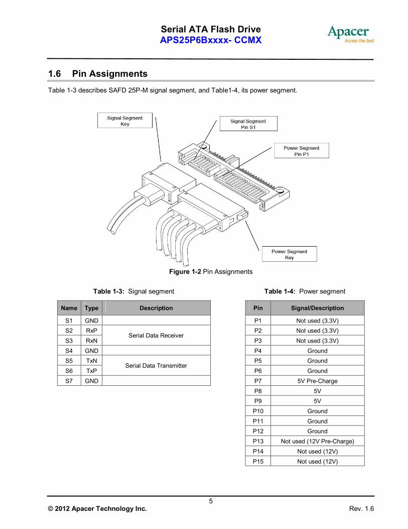
1.6 Pin Assignments Table 1-3 describes SAFD 25P-M signal segment, and Table1-4, its power segment.
Figure 1-2 Pin Assignments
Table 1-3: Signal segment Table 1-4: Power segment
Name Type Description Pin Signal/Description
S1 GND
P1 Not used (3.3V) S2 RxP
P2 Not used (3.3V)
S3 RxN Serial Data Receiver
P3 Not used (3.3V)
S4 GND
P4 Ground S5 TxN
P5 Ground
S6 TxP Serial Data Transmitter
P6 Ground
S7 GND
P7 5V Pre-Charge
P8 5V
P9 5V
P10 Ground
P11 Ground
P12 Ground
P13 Not used (12V Pre-Charge)
P14 Not used (12V)
P15 Not used (12V)

Serial ATA Flash Drive APS25P6Bxxxx- CCMX
6 © 2012 Apacer Technology Inc. Rev. 1.6
Figure 1-3 SATA Cable / Connector Connection Diagram
The connector on the left represents the Host with TX/RX differential pairs connected to a cable while the connector on the right shows the Device with TX/RX differential pairs also connected to the cable. Notice also the ground path connecting the shielding of the cable to the Cable Receptacle.
Serial ATA Flash Drive APS25P6Bxxxx- CCMX
7 © 2012 Apacer Technology Inc. Rev. 1.6
2. Software Interface
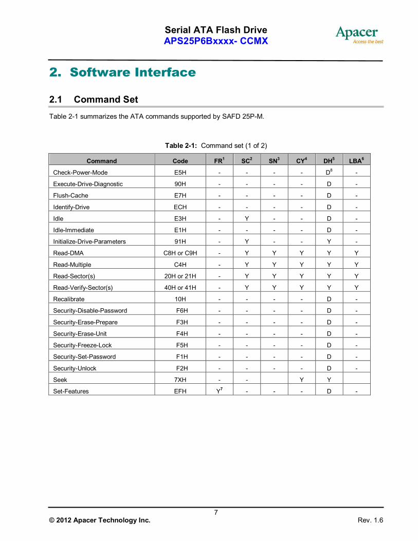
2.1 Command Set Table 2-1 summarizes the ATA commands supported by SAFD 25P-M.
Table 2-1: Command set (1 of 2)
Command Code FR1 SC2 SN3 CY4 DH5 LBA6
Check-Power-Mode E5H - - - - D8 -
Execute-Drive-Diagnostic 90H - - - - D -
Flush-Cache E7H - - - - D -
Identify-Drive ECH - - - - D -
Idle E3H - Y - - D -
Idle-Immediate E1H - - - - D -
Initialize-Drive-Parameters 91H - Y - - Y -
Read-DMA C8H or C9H - Y Y Y Y Y
Read-Multiple C4H - Y Y Y Y Y
Read-Sector(s) 20H or 21H - Y Y Y Y Y
Read-Verify-Sector(s) 40H or 41H - Y Y Y Y Y
Recalibrate 10H - - - - D -
Security-Disable-Password F6H - - - - D -
Security-Erase-Prepare F3H - - - - D -
Security-Erase-Unit F4H - - - - D -
Security-Freeze-Lock F5H - - - - D -
Security-Set-Password F1H - - - - D -
Security-Unlock F2H - - - - D -
Seek 7XH - - Y Y
Set-Features EFH Y7 - - - D -

Serial ATA Flash Drive APS25P6Bxxxx- CCMX
8 © 2012 Apacer Technology Inc. Rev. 1.6
Table 2-1: Command set (2 of 2)
Command Code FR1 SC2 SN3 CY4 DH5 LBA6
Set-Multiple-Mode C6H - Y - - D -
Sleep E6H - - - - D -
SMART B0H Y Y Y Y D
Standby E2H - - - - D -
Standby-lmmediate E0H - - - - D -
Write-DMA CAH - Y Y Y Y Y
Write-Multiple C5H - Y Y Y Y Y
Write-Sector(s) 30H - Y Y Y Y Y 1. FR - Features register 2. SC - Sector Count register 3. SN - Sector Number register 4. CY - Cylinder registers 5. DH - Drive/Head register 6. LBA - Logical Block Address mode supported (see command descriptions for use) 7. Y - The register contains a valid parameter for this command. 8. For the Drive/Head register:
Y means both the SAFD and Head parameters are used D means only the SAFD parameter is valid and not the Head parameter

Serial ATA Flash Drive APS25P6Bxxxx- CCMX
9 © 2012 Apacer Technology Inc. Rev. 1.6
2.2 S.M.A.R.T. S.M.A.R.T. is an acronym for Self-Monitoring, Analysis and Reporting Technology, an open standard allowing disk drives to automatically monitor their own health and report potential problems. It protects the user from unscheduled downtime by monitoring and storing critical drive performance and calibration parameters. Ideally, this should allow taking proactive actions to prevent impending drive failure.
Apacer SAFD 25P-M uses the standard SMART command B0h to read data from the drive for SMART feature as the SATA Rev.2.6 ATA/ATAPI-7 specifications. Based on the SFF-8035i Rev. 2.0 specifications, Apacer SMART defines vendor-specified SMART Attribute IDs (A0 ~ A5, and 0C) in SAFD 25P-M. They represent Initial bad block count, Bad block count, Spare block count, Maximum erase count, Average erase count and Power cycle. When the Apacer SMART Utility running on the host, it analyzes and reports the disk status to the host before SAFD 25P-M is in critical condition.

Serial ATA Flash Drive APS25P6Bxxxx- CCMX
10 © 2012 Apacer Technology Inc. Rev. 1.6
3. Flash Management
3.1 Error Correction/Detection SAFD 25P-M implements hardware ECC scheme based on the BCH algorithm which can detect and correct up to 16 bits or 24 bits error in 1024 bytes.
3.2 Bad Block Management Although bad blocks on the flash media are already identified by the flash manufacturer, they can also be accumulated over time during operation. SAFD 25P-M’s controller maintains a table that lists those normal blocks with disk data, the free blocks for wear leveling, and bad blocks with errors. When a normal block is detected broken, it is replaced with a free block and listed as a bad block. When a free block is detected broken, it is then removed from the free block list and marked as a bad block.
During device operation, this ensures that newly accumulated bad blocks are transparent to the host. The device will stop file write service once there are only two free blocks left such that the read function is still available for copying the files from the disk into another.
3.3 Wear Leveling The NAND flash devices are limited by a certain number of write cycles. When using a FAT-based file system, frequent FAT table updates are required. If some area on the flash wears out faster than others, it would significantly reduce the lifetime of the whole SSD, even if the erase counts of others are far from the write cycle limit. Thus, if the write cycles can be distributed evenly across the media, the lifetime of the media can be prolonged significantly. This scheme is called wear leveling.
Apacer’s wear-leveling scheme is achieved both via buffer management and global wear leveling. They both ensure that the lifetime of the flash media can be increased, and the disk access performance is optimized as well.
3.4 Power Failure Management The Low Power Detection on the controller initiates crucial data saving before the power supplied to the device is too low. This feature prevents the device from crash and ensures data integrity during an unexpected power-off.
3.5 ATA Secure Erase Accomplished by the Secure Erase (SE) command, which added to the open ANSI standards that control disk drives, “ATA Secure Erase” is built into the disk drive itself and thus far less susceptible to malicious software attacks than external software utilities. It is a positive easy-to-use data destroy command, amounting to electronic data shredding. Executing the command causes a drive to internally completely erase all possible user data. This command is carried out within disk drives, so no additional software is required. Once executed, neither data nor the erase counter on the device would be recoverable, which blurs the accuracy of device lifespan. The process to erase will not be stopped until finished while encountering power failure, and will be continued when power is back on.

Serial ATA Flash Drive APS25P6Bxxxx- CCMX
11 © 2012 Apacer Technology Inc. Rev. 1.6
3.6 TRIM Made of millions of NAND flash cells, SSD can be written into groups called pages in 4K size generally, but can only be erased in larger groups called blocks of 128 pages or 512KB. These stipulations are partially the source of many performance issues. Until an address gets used again, the SSD has to keep track of every last bit of data that’s written on it. The ATA-TRIM instruction tilts the balance in favor of the SSD. TRIM addresses a major part of the performance degradation issue over time that plagues all SSDs. A TRIM enabled drive running an OS with TRIM support will stay closer to its peak performance over time.
Serial ATA Flash Drive APS25P6Bxxxx- CCMX
12 © 2012 Apacer Technology Inc. Rev. 1.6
4. Environmental Specifications
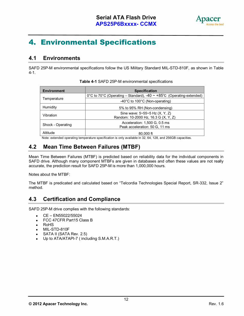
4.1 Environments SAFD 25P-M environmental specifications follow the US Military Standard MIL-STD-810F, as shown in Table 4-1.
Table 4-1 SAFD 25P-M environmental specifications
Environment Specification 0°C to 70°C (Operating – Standard), -40 ~ +85℃ (Operating-extended)
Temperature -40°C to 100°C (Non-operating)
Humidity 5% to 95% RH (Non-condensing)
Vibration Sine wave: 5~55~5 Hz (X, Y, Z) Random: 10-2000 Hz, 16.3 G (X, Y, Z)
Shock - Operating Acceleration: 1,500 G, 0.5 ms Peak acceleration: 50 G, 11 ms
Altitude 80,000 ft Note: extended operating temperature specification is only available in 32, 64, 128, and 256GB capacities.
4.2 Mean Time Between Failures (MTBF) Mean Time Between Failures (MTBF) is predicted based on reliability data for the individual components in SAFD drive. Although many component MTBFs are given in databases and often these values are not really accurate, the prediction result for SAFD 25P-M is more than 1,000,000 hours.
Notes about the MTBF:
The MTBF is predicated and calculated based on “Telcordia Technologies Special Report, SR-332, Issue 2” method.
4.3 Certification and Compliance SAFD 25P-M drive complies with the following standards:
CE – EN55022/55024 FCC 47CFR Part15 Class B RoHS MIL-STD-810F SATA II (SATA Rev. 2.5) Up to ATA/ATAPI-7 ( including S.M.A.R.T.)

Serial ATA Flash Drive APS25P6Bxxxx- CCMX
13 © 2012 Apacer Technology Inc. Rev. 1.6
5. Electrical Characteristics
5.1 Operating Voltage Table 5-1 lists the supply voltage for SAFD 25P-M.
Table 5-1 SAFD 25P-M operating voltage
Parameter Conditions
Supply voltage 5.0 V ±5% ( 4.75-5.25 V)
5.2 Power Consumption Table 5-2 lists SAFD 25P-M power consumption.
Table 5-2 SAFD 25P-M power consumption (typical)
Capacity Performance 16 GB 32 GB 64 GB 128 GB 256 GB 512 GB
Active Mode (mA) 365 472 520 612 826 872
Idle Mode (mA) 180 194 198 203 203 203
Note: power consumption may vary depending on flash configurations or platforms.
5.3 Electrostatic Discharge Table 5-3 Electrostatic discharge
Item Amount of
Discharge Voltage Required
Criteria Complied To Criteria (A,B,C)
Air Discharge 10
10
+8kV
-8kV
B
B
A
A
Contact Discharge
25
25
+4kV
-4kV
B
B
A
A
Indirect Discharge
(HCP)
25
25
+4kV
-4kV
B
B
A
A
Indirect Discharge
(VCP Front)
25
25
+4kV
-4kV
B
B
A
A
Indirect Discharge (VCP Left)
25 +4kV B A

Serial ATA Flash Drive APS25P6Bxxxx- CCMX
14 © 2012 Apacer Technology Inc. Rev. 1.6
25 -4kV B A
Indirect Discharge
(VCP Back)
25
25
+4kV
-4kV
B
B
A
A
Indirect Discharge
(VCP Right)
25
25
+4kV
-4kV
B
B
A
A
5.4 Electrical Fast Transient/Burst Table 5-4 Electrical Fast Transient/Burst
Inject Line Polarity Voltage
kV Inject Time (Second)
Inject Method
Required Criteria
Complied to Criteria
L-N-PE ± 1kV 60 Direct B A
Notes about 5.3 Electrostatic Discharge & 5.4 Electrical Fast Transient/Burst
The tests performed are from lowest level up to the highest level as required by standard, but only highest level is shown on the report. Meet criteria A: Operate as intended during and after the test Meet criteria B: Operate as intended after the test Meet criteria C: Loss/Error of function Additional Information: EUT stopped operation and could / could not be reset by operator at kV. No false alarms or other malfunctions were observed during or after the test. The Contact discharges were applied at least total 200 discharges at a minimum of four test points.

Serial ATA Flash Drive APS25P6Bxxxx- CCMX
15 © 2012 Apacer Technology Inc. Rev. 1.6
6. Physical Characteristics
6.1 Metal Housing Figure 6-1 illustrates the overall dimensions of SAFD 25P-M w/Metal Housing, as listed in Table 6-1.
Table 6-1 SAFD 25P-M w/Metal Housing dimensions
Dimension Millimeters (㎜)
Height 9.30 ± 0.20
Width 69.90 ± 0.15
Length 100.00 ± 0.15
Figure 6-1 SAFD 25P-M w/Metal Housing physical dimensions
Serial ATA Flash Drive APS25P6Bxxxx- CCMX
16 © 2012 Apacer Technology Inc. Rev. 1.6
7. Product Ordering Information
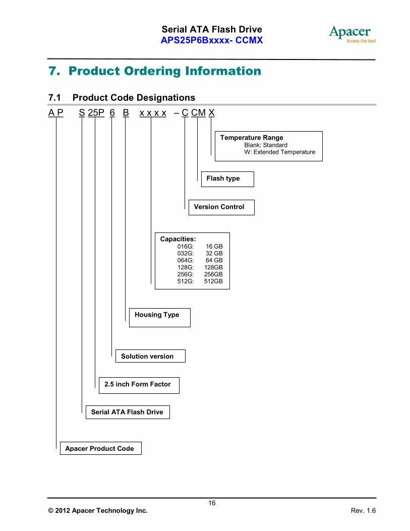
7.1 Product Code Designations A P S 25P 6 B x x x x – C CM X
Capacities: 016G: 16 GB 032G: 32 GB 064G: 64 GB 128G: 128GB 256G: 256GB 512G: 512GB
Serial ATA Flash Drive
Apacer Product Code
2.5 inch Form Factor
Solution version
Housing Type
Version Control
Flash type
Temperature Range Blank: Standard
W: Extended Temperature
Serial ATA Flash Drive APS25P6Bxxxx- CCMX
17 © 2012 Apacer Technology Inc. Rev. 1.6
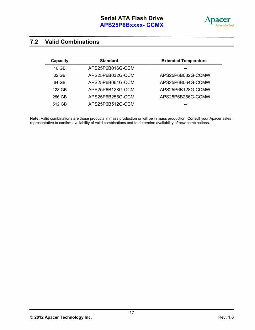
7.2 Valid Combinations
Capacity Standard Extended Temperature
16 GB APS25P6B016G-CCM -- 32 GB APS25P6B032G-CCM APS25P6B032G-CCMW 64 GB APS25P6B064G-CCM APS25P6B064G-CCMW 128 GB APS25P6B128G-CCM APS25P6B128G-CCMW 256 GB APS25P6B256G-CCM APS25P6B256G-CCMW 512 GB APS25P6B512G-CCM --
Note: Valid combinations are those products in mass production or will be in mass production. Consult your Apacer sales representative to confirm availability of valid combinations and to determine availability of new combinations.
Serial ATA Flash Drive APS25P6Bxxxx- CCMX
18 © 2012 Apacer Technology Inc. Rev. 1.6
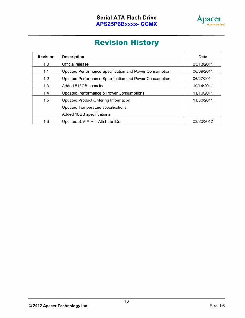
Revision History
Revision Description Date
1.0 Official release 05/13/2011
1.1 Updated Performance Specification and Power Consumption 06/09/2011
1.2 Updated Performance Specification and Power Consumption 06/27/2011
1.3 Added 512GB capacity 10/14/2011
1.4 Updated Performance & Power Consumptions 11/10/2011
1.5 Updated Product Ordering Information
Updated Temperature specifications
Added 16GB specifications
11/30/2011
1.6 Updated S.M.A.R.T Attribute IDs 03/20/2012
Serial ATA Flash Drive APS25P6Bxxxx- CCMX
19 © 2012 Apacer Technology Inc. Rev. 1.6
Global Presence
Taiwan (Headquarters)
Apacer Technology Inc. 4th Fl., 75 Hsin Tai Wu Rd., Sec.1 Hsichih, New Taipei City Taiwan 221 R.O.C. Tel: +886-2-2698-2888 Fax: +886-2-2698-2889 [email protected]
U.S.A.
Apacer Memory America, Inc. 386 Fairview Way, Suite102, Milpitas, CA 95035 Tel: 1-408-518-8699 Fax: 1-408-935-9611 [email protected]
Japan
Apacer Technology Corp. 5F, Matsura Bldg., Shiba, Minato-Ku Tokyo, 105-0014, Japan Tel: 81-3-5419-2668 Fax: 81-3-5419-0018 [email protected]
Europe
Apacer Technology B.V. Science Park Eindhoven 5051 5692 EB Son, The Netherlands Tel: 31-40-267-0000 Fax: 31-40-267-0000#6199 [email protected]
China
Apacer Electronic (Shanghai) Co., Ltd 1301, No.251,Xiaomuqiao Road, Shanghai, 200032, China Tel: 86-21-5529-0222 Fax: 86-21-5206-6939 [email protected]
India
Apacer Technologies Pvt Ltd, #1064, 1st Floor, 7th ‘A’ Main, 3rd Block Koramangala, Bangalore – 560 034 Tel: +91 80 4152 9061/62/63 Fax: +91 80 4170 0215 [email protected]
Related Documents