Sequential Circuits : Part I Read Sections 5-1, 5-2, 5-3

Sequential Circuits : Part I Read Sections 5-1, 5-2, 5-3.
Dec 15, 2015
Welcome message from author
This document is posted to help you gain knowledge. Please leave a comment to let me know what you think about it! Share it to your friends and learn new things together.
Transcript

Sequential Circuits : Part I
Read Sections 5-1, 5-2, 5-3

2
Topics
• Sequential Circuits♦ Latches♦ Flip Flops

3
Sequential Circuits
• Definition: State of system is “stored information”
• Present state and inputs, determine outputs and next state

4
Types of Sequential Circuits
• Synchronous♦ State changes are synchronized by one
or more clocks
• Asynchronous♦ Each state change occurs independently
of other changes

5
Clocking of Synchronous
• Changes of the state enabled by a clock

6
Comparison
• Synchronous♦ Easier to analyze ♦ Choose the clock so that changes are
only allowed to occur before next clock pulse
• Asynchronous♦ Potentially faster♦ Harder to analyze
• Will look mostly at synchronous

7
Basic Storage
Fig. 5-2 Logic Structures for Storing Information
____________________________________
YES.YESYESYESYESYESYESYESYESYESYESYESYES.YESYESYESYESYESYESYESYESYESYESYESYES.YESYESYESYESYESYESYESYESYESYESYESYES.YESYESYESYESYESYESYESYESYESYESYESYES.YESYESYESYESYESYESYESYESYESYESYESYES.YESYESYESYESYESYESYESYESYESYESYESYES.YESYESYESYESYESYESYESYESYESYESYESYES.YESYESYESYESYESYESYESYESYESYESYESYES.YESYESYESYESYESYESYESYESYESYESYESYES.YESYESYESYESYESYESYESYESYESYESYESYES.YESYESYESYESYESYESYESYESYESYESYES

8
Basic Storage• Apply low or high for longer
than tpd
• Feedback will hold the value of the input
Fig. 5-2 Logic Structures for Storing Information
____________________________________
YES.YESYESYESYESYESYESYESYESYESYESYESYES.YESYESYESYESYESYESYESYESYESYESYESYES.YESYESYESYESYESYESYESYESYESYESYESYES.YESYESYESYESYESYESYESYESYESYESYESYES.YESYESYESYESYESYESYESYESYESYESYESYES.YESYESYESYESYESYESYESYESYESYESYES

9
Basic Storage• Apply low or high for longer
than tpd
• Feedback will hold the value of the input
Fig. 5-2 Logic Structures for Storing Information
____________________________________
10
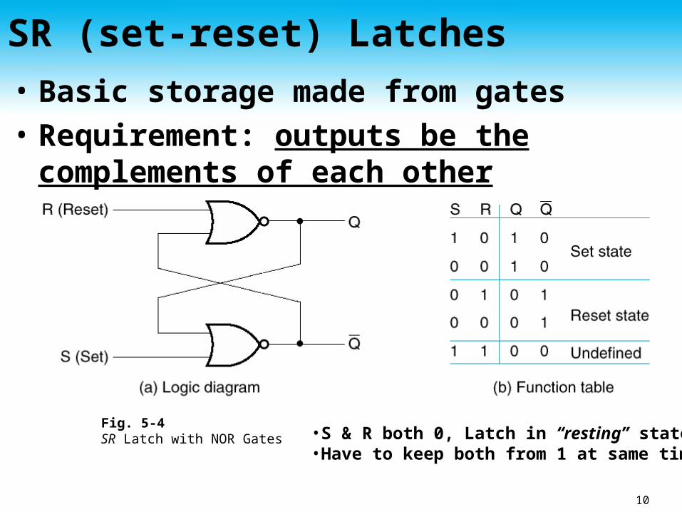
SR (set-reset) Latches• Basic storage made from gates• Requirement: outputs be the
complements of each other
•S & R both 0, Latch in “resting” state•Have to keep both from 1 at same time
Fig. 5-4SR Latch with NOR Gates

11
Simulation Of SR BehaviorWhen both S and R go to 0 after 11, Q & Q_b take on unknown values; depends on circuit delays and slight differences in the times at which S & R change values

12
LatchRS
YES. yes. YES.YES.YES.YES.YES. YES YES.
YES. yes. YES.YES.YES.YES.YES. YES YES. YES. yes. YES.YES.YES.YES.YES. YES YES.

13
LatchRS

14
Add Control Input (SR )• Input, C, controls when state can
change
S
R
Good Morning. Good Morning. Good Morning. Good Morning

15
Add Control Input (SR )• Input, C, controls when state can change
• Is there a latch with no undefined state?
S
R

16
D-type Latch
• No undefined (illegal) state

17
D-type Latch
• No undefined (illegal) state

18
Flip-Flops
• Two major types♦ Master-Slave
• Two stage• Output not changed until clock disabled (low)
♦ Edge triggered• Change happens when clock level changes

19
Master-Slave Flip-Flop
• Either master or slave is enabled, not both
Master LatchSlave Latch

20
Timing Diagram Illegal State
(b) FF in wrong state due to 1’s catching
(a) Q should be 0 since Q was 0 before the clock pulse and both S & R are 0 just before the clock goes to 0

21
Note:
• New inputs appear at latches are not sent to output until clock low
• Changes at input of FF when clock high trigger next state

22
D-Type Positive-Edge Triggered FF

23
Master-Slave:Postponed outputindicators
Edge-Triggered:Dynamicindicator
(a) Latches
S
R
SR SR
S
R
D with 0 Control
D
C
D with 1 Control
D
C
(b) Master-Slave Flip-Flops
D
C
Triggered DTriggered SR
S
R
C
D
C
Triggered DTriggered SR
S
R
C
(c) Edge-Triggered Flip-Flops
Triggered D
D
C
Triggered D
D
C
Standard Symbols for Storage Elements

24
Direct Inputs
• Set/Reset independent of clock♦ Direct set or preset♦ Direct reset or clear
• Often used for power-up reset
25
Next
• State Diagrams• Registers
Related Documents