ORIGINAL ARTICLE Sequential bone healing of immediately loaded mini-implants Glaucio Serra, a Liliane S. Morais, a Carlos Nelson Elias, b Marc A. Meyers, c Leonardo Andrade, d Carlos Muller, e and Marcelo Muller e Rio de Janeiro, Brazil, and San Diego, Calif Introduction: The relatively small size and the ability to load mini-implants without delay are important changes in the simplification of bone rigid anchorage. The purpose of this study was to analyze interfacial healing 1, 4, and 12 weeks after the placment of titanium mini-implants in New Zealand rabbits by removal torque test (RTT) and scanning electron microscopy (SEM). Methods: Eighteen animals were used in the experiment, in which 72 titanium grade 5 mini-implants 2.0 mm in diameter and 6.0 mm long, were placed. Each animal received 4 mini-implants; 2 were immediately loaded with 1 N. Results: The RTT means for the unloaded mini-implants at 1, 4, and 12 weeks were 15.2 4.2 N mm (n 5), 13.1 5.7 N mm (n 5), and 54.4 12.8 N mm (n 4), respectively. The loaded groups had means of 12.7 5.1 N mm (n 4), 11.1 5.4 N mm (n 4), and 32.9 12.8 N mm (n 5) for the same healing periods, respectively. The statistical evaluation indicated significance in the comparison between loaded and unloaded 12-week groups (P 0.05). SEM analysis in the loaded group showed the formation of less fibrous interfacial tissue after 4 weeks and more lamellar appearance after 12 weeks. Conclusions: The immediate 1-N load did not cause significant changes in the fixation of the mini-implants after 1 and 4 weeks of bone healing. Nevertheless, after 12 weeks, the loaded group had significantly lower RTT values than the unloaded group without compromising the stability of the mini-implants (P 0.05). (Am J Orthod Dentofacial Orthop 2008;134:44-52) C onventional implants have proved to be suc- cessful for orthodontic anchorage. 1-4 Neverthe- less, the substantially different needs between orthodontic and prosthetic implants resulted in the development of systems specific to orthodontic use, such as plates, 5 onplants, 6 bicortical screws, 7 and mini- implants. 8-11 Mini-implants became widely used because they have few limitations of placement sites, a simple surgical procedure, little postoperative pain, low cost, easy maintenance of oral hygiene, and easy attachment of elastics or springs. 8,10,11 The methodology for implemen- tation of mini-implants is continuously being devel- oped. The smaller implant size permits more placement sites but influences in the material of choice. 12,13 In addition, the required early load has an important influence on the characteristics of the newly formed bone. 2,14,15 Commercially pure titanium is the most used ma- terial in implantology, and, due to its particular fea- tures, excellent results were described in animal and human research. 7,16-18 However, the size reduction of titanium mini-implants could result in fracture during placement and removal. 12,19 The use of titanium alloys could overcome this disadvantage, 20-23 but osseointe- gration could be impaired. 24 Implants of 3 to 4 mm in diameter and 6 to 13 mm in length loaded just after an unloaded healing period were extensively tested and had high success rates. 4,15,25 Nev- ertheless, mini-implants have had more clinical failures than conventional implants. 13 Important changes in implant size and, consequently, in the bone contact and the force transmission could be related to these failures. Moreover, the anchorage value of implants depends on the response of supporting bone to applied loads. 26,27 Huja and Roberts 26 concluded that an elevated rate of remodeling within about 1 mm of the loaded implant surface is a long, continuous process that maintains the inert metal in compliant bone. The continuous remod- eling is a possible mechanism whereby loaded implants resist bone fatigue and maintain the integration in less a Postgraduate student, University of California at San Diego; Engineering Military Institute, Rio de Janeiro, RJ, Brazil. b Professor, Department of Mechanical Engineering and Materials Science, Military Engineering Institute, Rio de Janeiro, RJ, Brazil. c Professor, Department of Mechanical and Aerospace Engineering, University of California at San Diego. d Professor, Department of Biomineralization, University of Brazil, Rio de Janeiro, Brazil. e Reseacher, Department of Animal Experimentation, Oswaldo Cruz Institute, Rio de Janeiro, RJ, Brazil. Supported by CAPES, Ministry of Education and Culture, Brazil. Reprint requests to: Glaucio Serra, Av Nossa Senhora de Copacabana 1355, Apt 805, Copacabana, Rio de Janeiro, RJ, Brazil; e-mail, gserrag@ hotmail.com. Submitted, February 2006; revised August 2006; and accepted September 2006. 0889-5406/$34.00 Copyright © 2008 by the American Association of Orthodontists. doi:10.1016/j.ajodo.2006.09.057 44

Welcome message from author
This document is posted to help you gain knowledge. Please leave a comment to let me know what you think about it! Share it to your friends and learn new things together.
Transcript
ORIGINAL ARTICLE
Sequential bone healing of immediatelyloaded mini-implantsGlaucio Serra,a Liliane S. Morais,a Carlos Nelson Elias,b Marc A. Meyers,c Leonardo Andrade,d
Carlos Muller,e and Marcelo Mullere
Rio de Janeiro, Brazil, and San Diego, Calif
Introduction: The relatively small size and the ability to load mini-implants without delay are importantchanges in the simplification of bone rigid anchorage. The purpose of this study was to analyze interfacialhealing 1, 4, and 12 weeks after the placment of titanium mini-implants in New Zealand rabbits by removaltorque test (RTT) and scanning electron microscopy (SEM). Methods: Eighteen animals were used in theexperiment, in which 72 titanium grade 5 mini-implants 2.0 mm in diameter and 6.0 mm long, were placed.Each animal received 4 mini-implants; 2 were immediately loaded with 1 N. Results: The RTT means for theunloaded mini-implants at 1, 4, and 12 weeks were 15.2 ! 4.2 N mm (n " 5), 13.1 ! 5.7 N mm (n " 5), and54.4 ! 12.8 N mm (n " 4), respectively. The loaded groups had means of 12.7 ! 5.1 N mm (n " 4), 11.1 !5.4 N mm (n " 4), and 32.9 ! 12.8 N mm (n " 5) for the same healing periods, respectively. The statisticalevaluation indicated significance in the comparison between loaded and unloaded 12-week groups (P#0.05). SEM analysis in the loaded group showed the formation of less fibrous interfacial tissue after 4 weeksand more lamellar appearance after 12 weeks. Conclusions: The immediate 1-N load did not causesignificant changes in the fixation of the mini-implants after 1 and 4 weeks of bone healing. Nevertheless,after 12 weeks, the loaded group had significantly lower RTT values than the unloaded group withoutcompromising the stability of the mini-implants (P #0.05). (Am J Orthod Dentofacial Orthop 2008;134:44-52)
Conventional implants have proved to be suc-cessful for orthodontic anchorage.1-4 Neverthe-less, the substantially different needs between
orthodontic and prosthetic implants resulted in thedevelopment of systems specific to orthodontic use,such as plates,5 onplants,6 bicortical screws,7 and mini-implants.8-11 Mini-implants became widely used becausethey have few limitations of placement sites, a simplesurgical procedure, little postoperative pain, low cost, easymaintenance of oral hygiene, and easy attachment ofelastics or springs.8,10,11 The methodology for implemen-tation of mini-implants is continuously being devel-oped. The smaller implant size permits more placement
sites but influences in the material of choice.12,13 Inaddition, the required early load has an importantinfluence on the characteristics of the newly formedbone.2,14,15
Commercially pure titanium is the most used ma-terial in implantology, and, due to its particular fea-tures, excellent results were described in animal andhuman research.7,16-18 However, the size reduction oftitanium mini-implants could result in fracture duringplacement and removal.12,19 The use of titanium alloyscould overcome this disadvantage,20-23 but osseointe-gration could be impaired.24
Implants of 3 to 4 mm in diameter and 6 to 13 mm inlength loaded just after an unloaded healing period wereextensively tested and had high success rates.4,15,25 Nev-ertheless, mini-implants have had more clinical failuresthan conventional implants.13 Important changes inimplant size and, consequently, in the bone contact andthe force transmission could be related to these failures.Moreover, the anchorage value of implants depends onthe response of supporting bone to applied loads.26,27
Huja and Roberts26 concluded that an elevated rate ofremodeling within about 1 mm of the loaded implantsurface is a long, continuous process that maintains theinert metal in compliant bone. The continuous remod-eling is a possible mechanism whereby loaded implantsresist bone fatigue and maintain the integration in less
aPostgraduate student, University of California at San Diego; EngineeringMilitary Institute, Rio de Janeiro, RJ, Brazil.bProfessor, Department of Mechanical Engineering and Materials Science,Military Engineering Institute, Rio de Janeiro, RJ, Brazil.cProfessor, Department of Mechanical and Aerospace Engineering, Universityof California at San Diego.dProfessor, Department of Biomineralization, University of Brazil, Rio deJaneiro, Brazil.eReseacher, Department of Animal Experimentation, Oswaldo Cruz Institute,Rio de Janeiro, RJ, Brazil.Supported by CAPES, Ministry of Education and Culture, Brazil.Reprint requests to: Glaucio Serra, Av Nossa Senhora de Copacabana 1355,Apt 805, Copacabana, Rio de Janeiro, RJ, Brazil; e-mail, [email protected], February 2006; revised August 2006; and accepted September2006.0889-5406/$34.00Copyright © 2008 by the American Association of Orthodontists.doi:10.1016/j.ajodo.2006.09.057
44
mineralized bone.28 The timing of loading is not acritical point to implant failures, but micromotion is.27
We hypothesized that, after an immediate loadingprotocol, there will be less bone fixation of the mini-implant than in the unloaded protocol because of thequality of the interfacial tissue formed. The aims of thisstudy were to compare biomechanically the sequentialbone response to titanium alloy mini-implants (Ti-6Al-4V) subjected to immediate loading with the removaltorque test (RTT) and the stiffness test, and to analyzethe interfacial tissue evolution during bone healing byscanning electron microscopy (SEM).
MATERIAL AND METHODS
The protocol for this study was approved by thestanding ethics committee on animal research of Os-waldo Cruz Foundation in Brazil, and all procedureswere conducted in accordance with Canadian Councilof Animal Care guidelines.
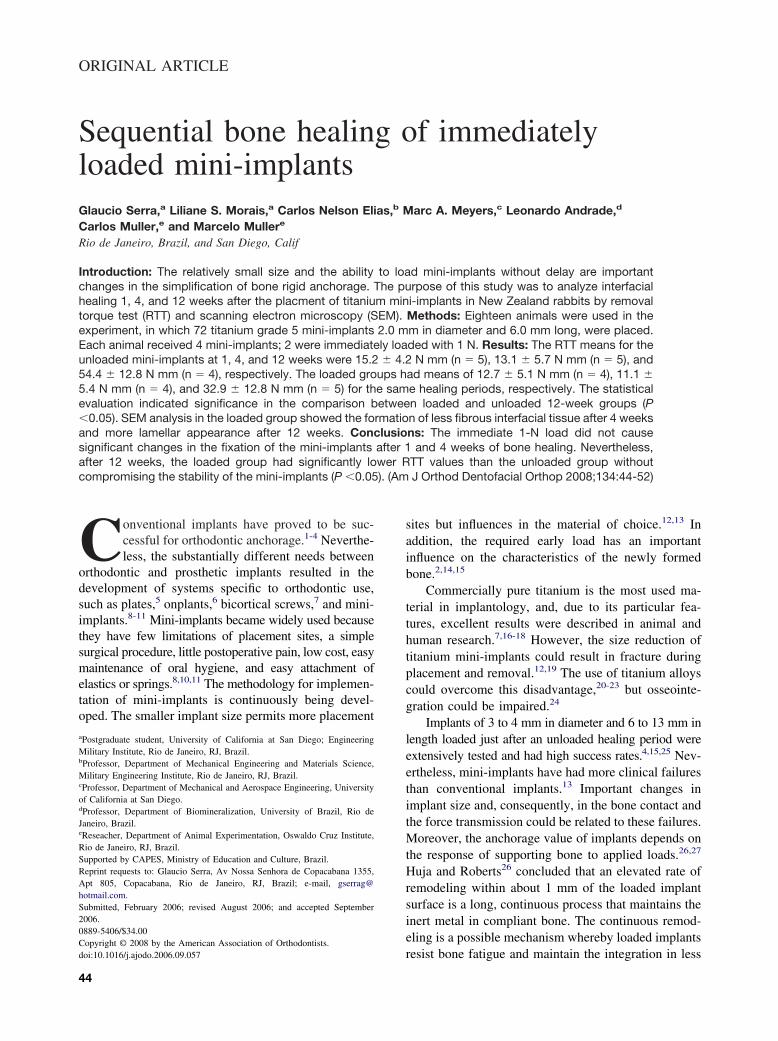
The mini-implants had a cylindrical screw design of2.0 mm in diameter and 6.0 mm in length (ConexãoSistemas e Próteses, São Paulo, Brazil). The implantmaterial was titanium-aluminum-vanadium alloy, whichhas better mechanical resistance than commercially puretitanium.20,21 The mini-implants were machined andpassivated with nitric acid (Fig 1).
Eighteen 6-month-old male New Zealand whiterabbits, weighing 3.0 to 3.5 kg, were used. The surgicalprocedure consisted of the implantation of 4 mini-implants in the left tibial metaphyses of each animal.All surgeries were performed under sterile conditions ina veterinary operating room.
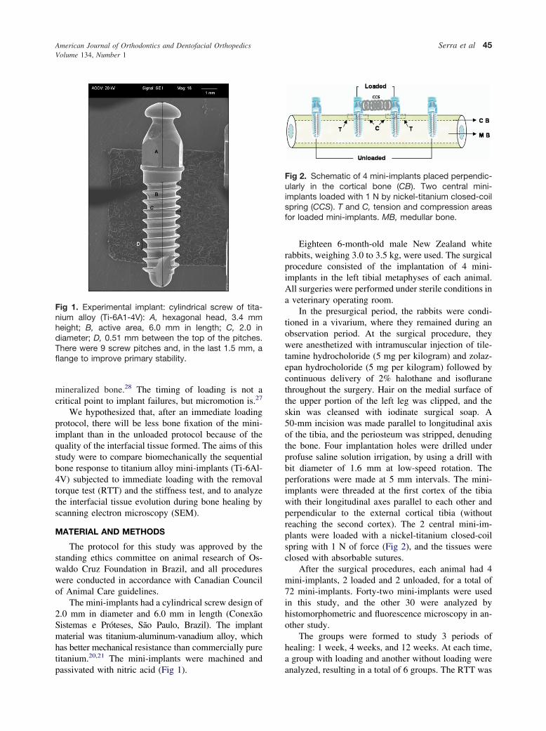
In the presurgical period, the rabbits were condi-tioned in a vivarium, where they remained during anobservation period. At the surgical procedure, theywere anesthetized with intramuscular injection of tile-tamine hydrocholoride (5 mg per kilogram) and zolaz-epan hydrocholoride (5 mg per kilogram) followed bycontinuous delivery of 2% halothane and isofluranethroughout the surgery. Hair on the medial surface ofthe upper portion of the left leg was clipped, and theskin was cleansed with iodinate surgical soap. A50-mm incision was made parallel to longitudinal axisof the tibia, and the periosteum was stripped, denudingthe bone. Four implantation holes were drilled underprofuse saline solution irrigation, by using a drill withbit diameter of 1.6 mm at low-speed rotation. Theperforations were made at 5 mm intervals. The mini-implants were threaded at the first cortex of the tibiawith their longitudinal axes parallel to each other andperpendicular to the external cortical tibia (withoutreaching the second cortex). The 2 central mini-im-plants were loaded with a nickel-titanium closed-coilspring with 1 N of force (Fig 2), and the tissues wereclosed with absorbable sutures.
After the surgical procedures, each animal had 4mini-implants, 2 loaded and 2 unloaded, for a total of72 mini-implants. Forty-two mini-implants were usedin this study, and the other 30 were analyzed byhistomorphometric and fluorescence microscopy in an-other study.
The groups were formed to study 3 periods ofhealing: 1 week, 4 weeks, and 12 weeks. At each time,a group with loading and another without loading wereanalyzed, resulting in a total of 6 groups. The RTT was
Fig 1. Experimental implant: cylindrical screw of tita-nium alloy (Ti-6A1-4V): A, hexagonal head, 3.4 mmheight; B, active area, 6.0 mm in length; C, 2.0 indiameter; D, 0.51 mm between the top of the pitches.There were 9 screw pitches and, in the last 1.5 mm, aflange to improve primary stability.
Fig 2. Schematic of 4 mini-implants placed perpendic-ularly in the cortical bone (CB). Two central mini-implants loaded with 1 N by nickel-titanium closed-coilspring (CCS). T and C, tension and compression areasfor loaded mini-implants. MB, medullar bone.
American Journal of Orthodontics and Dentofacial OrthopedicsVolume 134, Number 1
Serra et al 45
done by using 5 samples from different animals, andSEM analysis was done in 2 samples in each group.
After the healing time, the animals were killed byexsanguination. The tibiae were dissected, and blockscontaining a mini-implant and the adjacent bone weresectioned to have at least 2 mm of surrounding bone.
The blocks with the implants were kept in refriger-ated saline-solution soaked gauze until testing, and thetests were performed at room temperature. To obtainthe correct alignment between the mini-implant and the
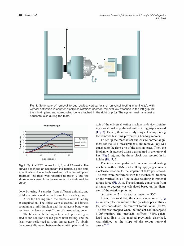
axis of the universal testing machine, a device contain-ing a rotational grip aligned with a fixing grip was used(Fig 3). Hence, there was only torque loading duringthe removal test; this prevented a bending moment.
To set up the mechanism and ensure correct align-ment for the RTT measurements, the removal key wasattached to the right grip of the torsion tester. Then, theimplant with attached tissue was secured in the removalkey (Fig 3, a), and the tissue block was secured in itsholder (Fig 3, b).
The tests were performed on a universal testingmachine with a 50-N load cell by applying counter-clockwise rotation to the implant at 0.1° per second.The tests were performed with the mechanical tractionon the vertical axis of the device resulting in removaltorque force (Fig 3, c). The arithmetic conversion fromdistance to degrees was calculated based on the diam-eter of the rotation pivot as:
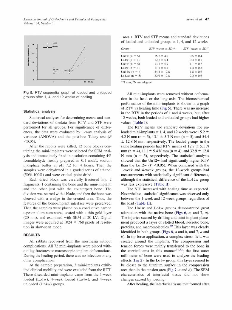
perimeter " 2 · $ · r and perimeter " 360°In each removal test, the curve was recorded (Fig
4), in which the maximum value (newtons per millime-ter) was considered the removal torque value (RTV).The test was stopped when the implant had undergonea 90° rotation. The interfacial stiffness (STF), calcu-lated according to the method previously described,was defined as the slope of the torque removalcurve.14,29
Fig 3. Schematic of removal torque device: vertical axis of universal testing machine (a), withvertical activation in counter-clockwise rotation; insertion-removal key attached in the left grip (b);the mini-implant and surrounding bone attached in the right grip (c). The system maintains just ahorizontal axis during the tests.
Fig 4. Typical RTT curves for 1, 4, and 12 weeks. Thecurves described an ascendant inclination, a peak and,a declination, due to the breakdown of the bone-implantinterface. The peak was recorded as the RTV and thestiffness was taken from the ascendant inclination of thecurve.
American Journal of Orthodontics and Dentofacial OrthopedicsJuly 2008
46 Serra et al
Statistical analysis
Statistical analyses for determining means and stan-dard deviations of thedata from RTV and STF wereperformed for all groups. For significance of differ-ences, the data were evaluated by 1-way analysis ofvariance (ANOVA) and the post-hoc Tukey test (P#0.05).
After the rabbits were killed, 12 bone blocks con-taining the mini-implants were selected for SEM anal-ysis and immediately fixed in a solution containing 4%formaldehyde freshly prepared in 0.1 mol/L sodiumphosphate buffer at pH 7.2 for 4 hours. Then thesamples were dehydrated in a graded series of ethanol(50%-100%) and were critical point dried.
Each dried block was carefully fractured into 2fragments, 1 containing the bone and the mini-implant,and the other just with the counterpart bone. Thedivision was started with a blade, and then the bone wascleaved with a wedge in the created area. Thus, thefeatures of the bone-implant interface were preserved.Then the samples were placed on a conductive carbontape on aluminum stubs, coated with a thin gold layer(20 nm), and examined with SEM at 20 kV. Digitalimages were acquired at 1024 % 768 pixels of resolu-tion in slow-scan mode.
RESULTS
All rabbits recovered from the anesthesia withoutcomplications. All 72 mini-implants were placed with-out leg fractures or macroscopic implant deformations.During the healing period, there was no infection or anyother complication.
At the sample preparation, 3 mini-implants exhib-ited clinical mobility and were excluded from the RTT.These discarded mini-implants came from the 1-weekloaded (Lo1w), 4-week loaded (Lo4w), and 4-weekunloaded (Un4w) groups.
All mini-implants were removed without deforma-tion in the head or the long axis. The biomechanicalperformance of the mini-implants is shown in a graphof RTV vs healing time (Fig 5). There was no increasein the RTV in the periods of 1 and 4 weeks, but, after12 weeks, both loaded and unloaded groups had highervalues (Table I).
The RTV means and standard deviations for un-loaded mini-implants at 1, 4, and 12 weeks were 15.2 !4.2 N mm (n " 5), 13.1 ! 5.7 N mm (n " 5), and 54.4! 12.8 N mm, respectively. The loaded groups in thesame healing periods had RTV means of 12.7 ! 5.1 Nmm (n " 4), 11.1! 5.4 N mm (n " 4), and 32.9 ! 12.8N mm (n " 5), respectively. The statistical analysisshowed that the Un12w had significantly higher RTVthan the Lo12w (P #0.05). When compared with the1-week and 4-week groups, the 12-week groups hadmeasurements with statistically significant differences,although the statistical difference of the Lo12w groupwas less expressive (Table II).
The STF increased with healing time as expected.Nevertheless, statistical significance was observed onlybetween the 1-week and 12-week groups, regardless ofthe load (Table II).
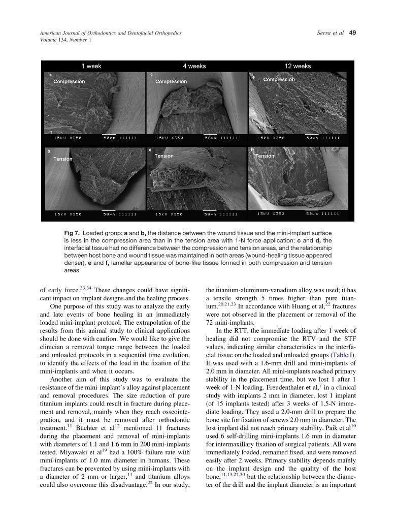
The Un1w and Lo1w groups demonstrated greatadaptation with the native bone (Figs 6, a, and 7, a).The injuries caused by drilling and mini-implant place-ment produced a layer of clotted blood, necrotic bone,proteins, and macromolecules.30 This layer was clearlyidentified in both groups (Figs 6, a and b, and 7, a andb). In tip force application, a complex stress field wascreated around the implants. The compression andtension forces were mainly transferred to the bone inthe cervical area in this manner31,32; the first outermillimeter of bone were used to analyze the loadingeffects (Fig 2). In the Lo1w group, this layer seemed tobe closer to the titanium surface in the compressionarea than in the tension area (Fig 7, a and b). The SEMcharacteristics of interfacial tissue did not showchanges caused by loading.
After healing, the interfacial tissue that formed after
Fig 5. RTV sequential graph of loaded and unloadedgroups after 1, 4, and 12 weeks of healing.
Table I. RTV and STF means and standard deviationsof loaded and unloaded groups at 1, 4, and 12 weeks
Group RTV (mean ! SD)* STF (mean ! SD)†
Un1w (n " 5) 15.2 ! 4.2 0.5 ! 0.4Lo1w (n " 4) 12.7 ! 5.1 0.3 ! 0.1Un4w (n " 5) 13.1 ! 5.7 1.1 ! 0.7Lo4w (n " 4) 11.1 ! 5.4 1.4 ! 0.3Un12w (n " 4) 54.4 ! 12.8 1.8 ! 0.6Lo12w (n " 5) 32.9 ! 12.8 2.2 ! 0.6
*N mm; †N mm/degree.
American Journal of Orthodontics and Dentofacial OrthopedicsVolume 134, Number 1
Serra et al 47
4 weeks demonstrated differences between the Un4wand Lo4w groups. The new tissue formed in the Un4wgroup had a more fibrous appearance than in the Lo4wgroup, and the Lo4w interfacial tissue had a denserappearance than did the Un4w (Figs 6, c and d, and 7,c and d). However, the compression and tension areasof the Lo4w interfacial tissue did not have a difference(Fig 7, c and d). The native bone was preserved in bothgroups after 4 weeks of healing.
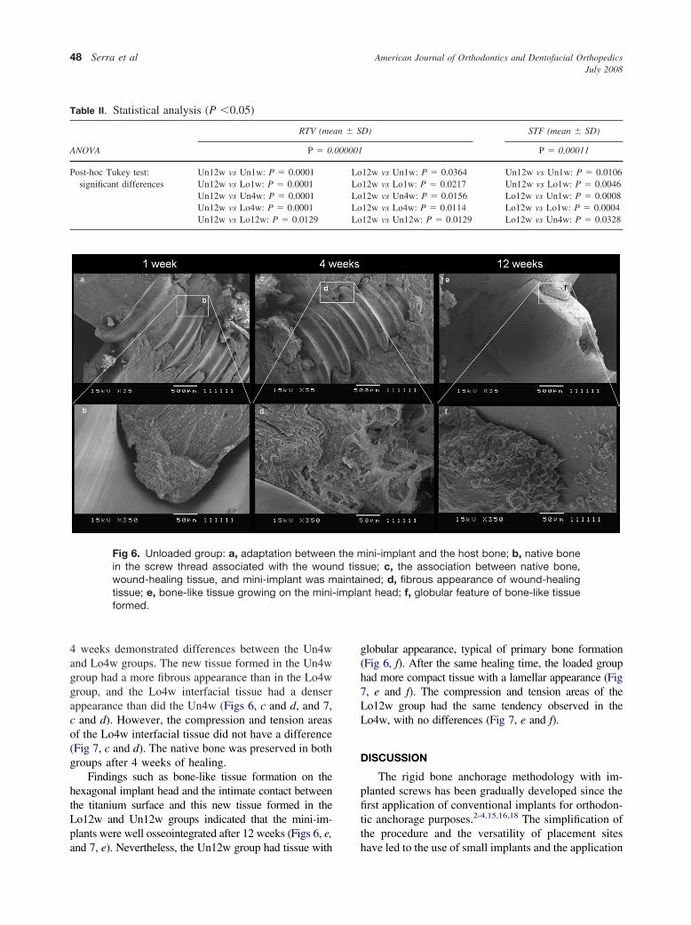
Findings such as bone-like tissue formation on thehexagonal implant head and the intimate contact betweenthe titanium surface and this new tissue formed in theLo12w and Un12w groups indicated that the mini-im-plants were well osseointegrated after 12 weeks (Figs 6, e,and 7, e). Nevertheless, the Un12w group had tissue with
globular appearance, typical of primary bone formation(Fig 6, f). After the same healing time, the loaded grouphad more compact tissue with a lamellar appearance (Fig7, e and f). The compression and tension areas of theLo12w group had the same tendency observed in theLo4w, with no differences (Fig 7, e and f).
DISCUSSION
The rigid bone anchorage methodology with im-planted screws has been gradually developed since thefirst application of conventional implants for orthodon-tic anchorage purposes.2-4,15,16,18 The simplification ofthe procedure and the versatility of placement siteshave led to the use of small implants and the application
Fig 6. Unloaded group: a, adaptation between the mini-implant and the host bone; b, native bonein the screw thread associated with the wound tissue; c, the association between native bone,wound-healing tissue, and mini-implant was maintained; d, fibrous appearance of wound-healingtissue; e, bone-like tissue growing on the mini-implant head; f, globular feature of bone-like tissueformed.
Table II. Statistical analysis (P #0.05)
ANOVA
RTV (mean ! SD) STF (mean ! SD)
P " 0.000001 P " 0.00011
Post-hoc Tukey test:significant differences
Un12w vs Un1w: P " 0.0001 Lo12w vs Un1w: P " 0.0364 Un12w vs Un1w: P " 0.0106Un12w vs Lo1w: P " 0.0001 Lo12w vs Lo1w: P " 0.0217 Un12w vs Lo1w: P " 0.0046Un12w vs Un4w: P " 0.0001 Lo12w vs Un4w: P " 0.0156 Lo12w vs Un1w: P " 0.0008Un12w vs Lo4w: P " 0.0001 Lo12w vs Lo4w: P " 0.0114 Lo12w vs Lo1w: P " 0.0004Un12w vs Lo12w: P " 0.0129 Lo12w vs Un12w: P " 0.0129 Lo12w vs Un4w: P " 0.0328
American Journal of Orthodontics and Dentofacial OrthopedicsJuly 2008
48 Serra et al
of early force.33,34 These changes could have signifi-cant impact on implant designs and the healing process.
One purpose of this study was to analyze the earlyand late events of bone healing in an immediatelyloaded mini-implant protocol. The extrapolation of theresults from this animal study to clinical applicationsshould be done with caution. We would like to give theclinician a removal torque range between the loadedand unloaded protocols in a sequential time evolution,to identify the effects of the load in the fixation of themini-implants and when it occurs.
Another aim of this study was to evaluate theresistance of the mini-implant’s alloy against placementand removal procedures. The size reduction of puretitanium implants could result in fracture during place-ment and removal, mainly when they reach osseointe-gration, and it must be removed after orthodontictreatment.11 Büchter et al12 mentioned 11 fracturesduring the placement and removal of mini-implantswith diameters of 1.1 and 1.6 mm in 200 mini-implantstested. Miyawaki et al19 had a 100% failure rate withmini-implants of 1.0 mm diameter in humans. Thesefractures can be prevented by using mini-implants witha diameter of 2 mm or larger,11 and titanium alloyscould also overcome this disadvantage.22 In our study,
the titanium-aluminum-vanadium alloy was used; it hasa tensile strength 5 times higher than pure titan-ium.20,21,23 In accordance with Huang et al,22 fractureswere not observed in the placement or removal of the72 mini-implants.
In the RTT, the immediate loading after 1 week ofhealing did not compromise the RTV and the STFvalues, indicating similar characteristics in the interfa-cial tissue on the loaded and unloaded groups (Table I).It was used with a 1.6-mm drill and mini-implants of2.0 mm in diameter. All mini-implants reached primarystability in the placement time, but we lost 1 after 1week of 1-N loading. Freudenthaler et al,7 in a clinicalstudy with implants 2 mm in diameter, lost 1 implant(of 15 implants tested) after 3 weeks of 1.5-N imme-diate loading. They used a 2.0-mm drill to prepare thebone site for fixation of screws 2.0 mm in diameter. Thelost implant did not reach primary stability. Paik et al10
used 6 self-drilling mini-implants 1.6 mm in diameterfor intermaxillary fixation of surgical patients. All wereimmediately loaded, remained fixed, and were removedeasily after 2 weeks. Primary stability depends mainlyon the implant design and the quality of the hostbone,11,13,27,30 but the relationship between the diame-ter of the drill and the implant diameter is an important
Fig 7. Loaded group: a and b, the distance between the wound tissue and the mini-implant surfaceis less in the compression area than in the tension area with 1-N force application; c and d, theinterfacial tissue had no difference between the compression and tension areas, and the relationshipbetween host bone and wound tissue was maintained in both areas (wound-healing tissue appeareddenser); e and f, lamellar appearance of bone-like tissue formed in both compression and tensionareas.
American Journal of Orthodontics and Dentofacial OrthopedicsVolume 134, Number 1
Serra et al 49
factor, especially when the placement site is in cancel-lous bone.27 This suggests that reaching primary sta-bility in the placement time is fundamental to mainte-nance of the mini-implant, but it does not guarantee itssuccess.
In the 4-week groups, the RTV indicated that thehealing tissue formed did not enhance the fixation ofthe mini-implant in the bone (Fig 3). It could becorrelated with the study of Deguchi et al35 thatdescribed the reduction of the bone-implant contact 3 to6 weeks after mini-implant placement as a normal partof healing. Büchter et al,12 in a pig study, analyzed theeffects of immediate loading of 1 to 5 N in mini-implants after 22 and 70 days. The force was applied atdistances of 1, 2, and 3 mm from the crestal bone. Theydid not find a statistical difference between the 2 timesin the group with 1-N force and 1-mm distance. In ourstudy, the force was applied approximately 1.6 mmfrom the crestal bone, and the comparison between 28and 84 days (Lo4w and Lo12w groups) resulted in asignificant difference (P " 0.01). This discrepancy canbe related to the relative bone metabolic rates of thedifferent animals in each study. The RTVs of this studywere significantly higher in the 12-week groups than inthe 1-week and 4-week groups. This confirms that, withor without load, the mini-implants reached osseointe-gration. Nevertheless, the RTVs in the Un12w werestatistically higher than in the Lo12w, suggesting thatthe newly formed tissue had different features. Theosseointegration mechanism near the loaded implantsurface has been defined as a high rate of boneremodeling.26 Hence, the total mineralization neverfinishes, resulting in an incompletely mineralized la-mellar tissue in contact with the implant surface. Thismechanism has been suggested to be important toprevent microdamage and crack accumulation at theinterfacial bone.26,27,36,37 It could explain the differencebetween the loaded and unloaded groups: less mineral-ized bone in the loaded group provided a lower RTV. Inaddition, this RTV result could be interpretated as apositive find, because mini-implants must be removedafter orthodontic treatment.
Although not statistically significant, both the un-loaded and the loaded groups after 1, 4, and 12 weekshad gradual increases in the stiffness values, suggestingthat the healing process produced denser tissue (TableII).
The SEM findings in this study suggested that thehealing mechanism matched the RTV results. There-fore, conclusions should not be made without a histo-logic basis. Bone injury during placement results indisruption of microcirculation, ischemia, and cellularnecrosis to the first millimeter of the wound area.38
These events result in a layer formed by necrotic bone,blood clots, cells, and matrix; this is the bridge betweenthe host bone and the mini-implant in the first healingtime.30 In our study, unorganized tissue was clearlyobserved between the host bone and the mini-implant.The distance between this tissue and the mini-implantsurface was decreased in the Lo1w group at thecompression area. The elastic property of the bone andthe small displacement described in implants orthodon-tically loaded could explain the reduction of the inter-facial distance observed.15,30,39,40 After healing, woundtissue degradation, angiogenesis, and cellular prolifer-ation are expected phenomena, and fibrous tissue isnormally formed before the deposition of primarybone.2,30 Accordingly, fibrous-like tissue was observedin the Un4w and Lo4w groups, although the formergroup had interfacial tissue with a more fibrous appear-ance than the latter group. The early biomechanicalstimulation could result in fast bone formation.26,36,41-44
Sarmiento et al42 provided experimental evidence byradiographic, histologic, and mechanical analysis thatearly weight bearing can accelerate the process offracture healing. Wehrbein and Diedrich15 and Ohmaeet al,10 in implant studies, observed extensive remod-eling in the bone around loaded implants when com-pared with unloaded implants. Because biomechanicalstimulation induces fast bone healing, it could besuggested that less fibrous tissue found in the Lo4wgroup indicates the acceleration of bone healing in theimmediate load protocol in this orthodontic simula-tion.26,36,41-44 After 12 weeks, the SEM images showedstrong differences between these groups, with a glob-ular appearance in the Un12w group and a lamellarappearance in the Lo12w group. Globular mineraldeposition is the primary phase of bone formation bymigratory osteogenic cells in unloaded solid surfaces.30
The high remodeling and the less mineralized boneformation around loaded implants were well de-scribed.26-28 Thus, it can be suggested that there isinitial and unorganized bone formation in the unloadedgroup and more organized but less mineralized boneformation in the loaded group. The higher RTV in theunloaded group could emphasize this suggestion.
Despite the success described by many authors,even experienced groups have had some clinical fail-ures.26 Inflammation of peri-implant tissue, diameter ofthe mini-implant, high mandibular plane angle,34 mi-cromotion,27 and primary stability2,13,26 are related toimplant failures. The load per se does not cause the lossof stability until an overload limit.3,12,27 In this study,we demonstrated that 1-N forces applied 1.6 mm fromthe crestal bone modified the interfacial tissue formedbut did not cause the failure of mini-implant integration
American Journal of Orthodontics and Dentofacial OrthopedicsJuly 2008
50 Serra et al
or supra-crestal bone loss. Roberts et al3 stated thatforces between 1 and 3 N did not affect the implant’sstability, and Büchter et al12 showed that tip forceshigher than 9 N resulted in a high risk for osseointe-gration loss. Isidor45 added that high forces tend todamage the interface integration. This overloading limitis influenced by the implant design; the first screwthreads of mini-implants with screws have stress con-centrations after a lateral or an oblique load, causingmarginal bone loss.36,39 Thus, it could be suggestedthat, with the mini-implant design we used, the force of1 N did not reach the overloading limit.
The clinical success of rigid orthodontic anchoragewith mini-implants is related to several factors.25 First,the material must be nontoxic and biocompatible.25,30
In addition, the design of the implant must provideprimary stability and support immediate load, transmit-ting the forces without overload points and damage tohost bone.12,36,39 These features depend on the relation-ship between the quality and quantity of host bone inthe placement site and the implant form. This relation-ship is fundamental to the maximum force suppor-ted.12,14,25,34 During healing, micromotion and inflamma-tion of peri-implant tissue are associated with failure andmust be avoided.27,34 The immediate loading with lowand unidirectional forces in this study resulted in lowerRTV. From an orthodontic point of view, the lowerRTV could be considered positive because of thenecessity of removal after treatment.
CONCLUSIONS
1. The mini-implants used in this study are appropri-ate as orthodontic anchorage with an immediate1-N load.
2. The absence of fractures indicated that the titanium-aluminum-vanadium alloy has adequate mechani-cal properties for this application.
3. The immediate 1-N load did not cause significantchanges in the fixation of the mini-implants after 1week and 4 weeks of bone healing. Nevertheless,after 12 weeks, the loaded group had significantlylower RTT values than the unloaded group withoutcompromising the stability of the mini-implants (P#0.05).
We thank Sara Bodde and Lars Bjursten (bioengi-neering department, University of California at SanDiego) for reading and considerably improving themanuscript, and the National Science Foundation Ce-ramics Program for travel and laboratory supplies.
REFERENCES
1. Turley PK, Kean C, Schur J, Stefanac J, Gray J, Hennes J, et al.Orthodontic force application to titanium endosseous implants.Angle Orthod 1988;58:151-62.
2. Roberts EW, Smith RK, Zilberman Y, Mozsary PG, Smith RS.Osseous adaptation to continuous loading of rigid endosseousimplants. Am J Orthod 1984;86:95-111.
3. Roberts EW, Helm RF, Marshall JK, Gongloff RK. Rigidendosseous implants for orthodontic and orthopedic anchorage.Angle Orthod 1989;59:247-56.
4. Roberts EW, Marshall KJ, Mozsary PG. Rigid endosseousimplant utilized as anchorage to protract molars and close anatrophic extraction site. Angle Orthod 1990;60:135-52.
5. Chung KR, Kim YS, Linton JL, Lee YJ. The miniplate with tubefor skeletal anchorage. J Clin Orthod 2002;36:407-12.
6. Janssens F, Swennen G, Dujardin T, Glineur R, Malevez C. Useof an onplant as orthodontic anchorage. Am J Orthod DentofacialOrthop 2002;122:566-70.
7. Freudenthaler JW, Hass R, Bantleon HP. Bicortical titaniumscrews for critical orthodontic anchorage in the mandible: apreliminary report on clinical applications. Clin Oral ImplantsRes 2001;12:358-63.
8. Kanomi R. Mini-implant for orthodontic anchorage. J ClinOrthod 1997;36:763-7.
9. Paik CH, Woo YJ, Kim J, Park JU. Use of miniscrews forintermaxillary fixation of lingual-orthodontic surgical patients.J Clin Orthod 2002;36:132-6.
10. Ohmae M, Saito S, Morohashi T, Seki K, Qu H, Kanomi R, et al.A clinical and histological evaluation of titanium mini-implantsas anchor for orthodontic intrusion in the beagle dog. Am JOrthod Dentofacial Orthop 2001;119:489-97.
11. Park YC, Lee SY, Kim DH, Jee SH. Intrusion of posterior teethusing mini-screw implants. Am J Orthod Dentofacial Orthop2003;123:690-4.
12. Büchter A, Wiechmann, Koerdt S, Wiesmann HP, Piffko J,Meyer U. Load-related implant reaction of mini-implants usedfor orthodontic anchorage. Clin Oral Implants Res 2005;16:473-9.
13. Huja SS, Litsky AS, Beck FM, Johnson KA, Larsen PE. Pull-outstrength of monocortical screws placed in maxillae and mandi-bles of dogs. Am J Orthod Dentofacial Orthop 2005;127:307-13.
14. Li D, Ferguson SJ, Beutler T, Cochran DL, Sittig C, Hirt PH, etal. Biomechanical comparison of the sandblasted and acid-etchedand machined and acid-etched titanium surface for dental im-plants. J Biomed Mater Res 2002;60:325-32.
15. Wehrbein H, Diedrich P. Endosseous titanium implants duringand after orthodontic load—an experimental study in the dog.Clin Oral Implants Res 1993;4:76-82.
16. Johansson CB, Albrektsson T. A removal torque and histomor-phometric study of commercially pure niobium and titaniumimplants in rabbit bone. Clin Oral Implants Res 1991;2:24-9.
17. Gotfredsen K, Berghlund T, Lindhe J. The anchorage of titaniumimplants with different surface characteristics: an experimentalstudy in rabbits. Clin Implant Dent Relat Res 2000;2:120-8.
18. Albrektsson T, Dahl E, Enbom L, Engevall S, Engquist B,Eriksson AR, et al. Osseointegrated oral implants. A Swedishmulticenter study of 8139 consecutively inserted Nobelpharmaimplants. J Periodontol 1988;59:287-96.
19. Miyawaki S, Koyama I, Inoue M, Mashima K, Sugahara T,Takano-Yamamoto T. Factors associated with the stability oftitanium screws placed in the posterior region for orthodonticanchorage. Am J Orthod Dentofacial Orthop 2003;124:373-8.
American Journal of Orthodontics and Dentofacial OrthopedicsVolume 134, Number 1
Serra et al 51
20. Boyer R, Welsch G, Collings EW. Materials properties hand-book: titanium alloys. Cleveland, Ohio: ASM International;1994.
21. Steiner R. Metals handbook. Vol 2. Properties and selection:nonferrous alloys and special purpose materials. 10th ed. Cleve-land, Ohio: ASM International; 1990.
22. Huang LH, Shotwell JL, Wang HL. Dental implants for orth-odontic anchorage. Am J Orthod Dentofacial Orthop 2005;127:713-22.
23. Misch CE. Contemporary implant dentistry. 2nd ed. St Louis:Mosby; 1999.
24. Saldaña L, Barranco V, Gárcia-Alonso MC, Vallés G, EscuderoML, Manuera L, et al. Concentration-dependent effects oftitanium and aluminium ions released from thermally oxidizedTi6Al4V alloy on human osteoblasts. J Biomed Mater Res A2006;77:220-9.
25. Favero L, Brollo P, Bressan E. Orthodontic anchorage withspecific fixtures: related study analysis. Am J Orthod DentofacialOrthop 2002;122:84-94.
26. Huja SS, Roberts E. Mechanism of osseointegration: character-ization of supporting bone with indentation testing and backscat-tered imaging. Semin Orthod 2004;10:162-73.
27. Szmukler-Moncler S, Salama H, Reingewirtz Y, Dubruille JH.Timing of loading and effect of micromotion on bone-implantinterface: review of experimental literature. J Biomed Mater Res1998;43:193-203.
28. Huja SS, Katona TR, Burr DB, Garetto LP, Roberts WE.Microdamage adjacent to endosseous implants. Bone 1999;25:217-22.
29. Skoglund B, Holmertz J, Aspenberg P. Systemic and local ibandr-onate enhance screw fixation. J Orthop Res 2004;22:1108-13.
30. Davis JE. Bone engineering. Toronto: Mosby; 2000.31. Vásquez M, Calao E, Becerra F, Ossa J, Enríquez C, Fresneda E.
Initial stress differences between sliding and sectional mechanicswith an endosseous implant as anchorage: a 3-dimensional finiteelement analysis. Angle Orthod 2001;71:247-56.
32. Chen F, Terada K, Hanada K, Saito I. Anchorage effects ofpalatal osseointegrated implant with different fixation: a finiteelement study. Angle Orthod 2005;75:593-601.
33. Wehrbein H, Glatzmaier J, Yildirim M. Orthodontic anchoragecapacity of short titanium screw implants in the maxilla. An
experimental study in the dog. Clin Oral Implants Res1997;8:131-41.
34. Ödman J, Lekholm U, Jemt T, Branemark PI, Thilander B.Osseointegrated titanium implants—a new approach in orth-odontic treatment. Eur J Orthod 1988;10:98-105.
35. Deguchi T, Takano-Yamamoto T, Kanomi R, Hartsfield JK,Roberts WE, Garetto LP. The use of small titanium screws fororthodontic anchorage. J Dent Res 2003;82:377-81.
36. Oyonarte R, Pilliar R, Deporter D, Woodside DG. Peri-implantbone response to orthodontic loading: part 2. Implant surfacegeometry and its effect on regional bone remodeling. Am JOrthod Dentofacial Orthop 2005;128:182-9.
37. Klokkevold PR, Johnson P, Dadgostari S, Caputo A, Davies JE,Nishimura RD. Early endosseous integration enhanced by dualacid etching of titanium: a torque removal study in the rabbit.Clin Oral Implants Res 2001;12:350-7.
38. Perren SM, Rahn BA. Biomechanism of fracture healing:histological review and mechanical aspects of internal fixa-tion. Orthop Survey 1978;33:108-43.
39. Oyonarte R, Pilliar R, Deporter D, Woodside DG. Peri-implantbone response to orthodontic loading: part 1. A histomorphomet-ric study of the effects of implant surface design. Am J OrthodDentofacial Orthop 2005;128:173-81.
40. Liou EJ, Pai BC, Lin JC. Do miniscrews remain stationary underorthodontic forces? Am J Orthod Dentofacial Orthop 2004;126:42-7.
41. Goodman S, Aspenberg P. Effects of mechanical stimulation onthe differentiation of hard tissues. Biomaterials 1993;14:563-9.
42. Sarmiento A, Schaeffer JK, Beckerman L, Latta L, Enis JE.Fracture healing in rat femora as affected by functional weight-bearing. J Bone Joint Surg 1977;59:269-75.
43. Sarmiento A. Functional bracing of tibial and femoral shaftfractures. Clin Orthop Relat Res 1972;82:2-13.
44. Rubin CT, McLeod KJ. Promotion of bony ingrowth by frequen-cy-specific, low-amplitude mechanical strain. Clin Orthop RelatRes 1994;298:165-74.
45. Isidor F. Histological evaluation of peri-implant bone at implantssubjected to occlusal overload or plaque accumulation. Clin OralImplants Res 1997;8:1-9.
American Journal of Orthodontics and Dentofacial OrthopedicsJuly 2008
52 Serra et al
Related Documents


![OPEN ACCESS Jacobs Journal of Anatomy · loaded Strategic Implants® is the key to success [17]. This is true for axial basal implants (screw types) or the older lateral basal implants,](https://static.cupdf.com/doc/110x72/5f70f46f79a9fc6c7b5c1212/open-access-jacobs-journal-of-anatomy-loaded-strategic-implants-is-the-key-to.jpg)