Separation, Purification, and Clean‐Up Developments for MIPS and SHINE Argonne National Laboratory Mo‐99 Topical Meeting Santa Fe, New Mexico December 4 – 7, 2011 *

Welcome message from author
This document is posted to help you gain knowledge. Please leave a comment to let me know what you think about it! Share it to your friends and learn new things together.
Transcript

Separation, Purification, and Clean‐Up Developments for MIPS and SHINE
Argonne National LaboratoryMo‐99 Topical MeetingSanta Fe, New Mexico
December 4 – 7, 2011
*

MIPS and SHINE
Argonne is assisting 2 potential domestic suppliers
Babcock and Wilcox Technical Services Group (BWTSG) –Medical Isotope Production System (MIPS)
Morgridge Institute for Research (MIR) – Subcritical Hybrid Intense Neutron Emitter (SHINE)
Pure titania sorbent to separate Mo‐99 from uranyl nitrate and uranyl sulfate solutions
LEU‐Modified Cintichem process is being considered for Mo purification
2
Mo‐99 Separation
S110 (pure titania sorbent) is the top candidate for Mo‐99 separation and recovery column
S110 replaces S80 which has been discontinued
S110 outperforms S80
Plant‐scale column has been designed for BWTSG
Plant‐scale column design will be available for MIR in ~ 1 week
Mo‐99 recovery continuously being optimized
Oxidizing agents have been added to water wash and strip solutions to help improve Mo‐99 recovery
3
4
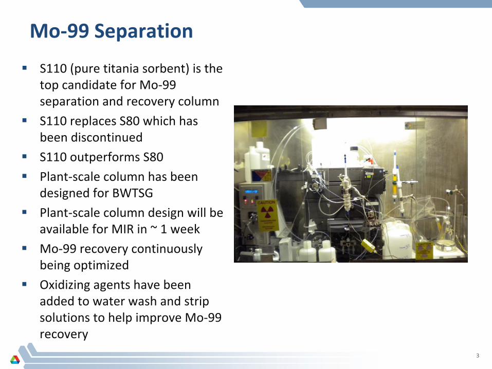
From Batch to Column…
Batch data input into VERSE (Versatile Reaction Separation) simulator
Data specific to VERSE code for column design
Langmuir‐type adsorption via batch contact experiments
Mo breakthrough column tests
Preliminary plant‐scale column design
Small‐scale column tests
Modified plant‐scale column design
4

Langmuir Data for Uranyl Sulfate
Batch data fit to Langmuir model for 150 and 90 g‐U/L uranyl sulfate solutions
Langmuir data in batch mode yields a good estimate of “a” linear parameter for Langmuir model
Data used to predict conditions for Mo breakthrough curve experiments
Mo breakthrough column tests give a good estimate of “b” non‐linear parameter for Langmuir model
5
ai
·Ci (1 +bi
·Ci
)
150 g-U/L Uranyl Sulfate 90 g-U/L Uranyl Sulfate
6
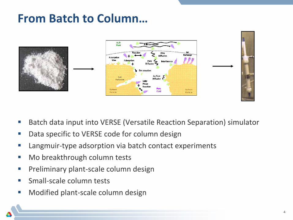
Mo Breakthrough Column Designs – 90 g‐U/L
0.045 mM Mo ‐ ~20X higher than actual Mo concentration expected
Lower Mo concentration may take 15 – 20 hours to achieve full Mo breakthrough with S110
Loading velocities range from 3 – 10 cm/min
Experiments have been completed with 0.66 cm ID x 1 cm L and 1 cm ID x I cm L S110 columns
Sorbent ID(cm)
L
(cm) CV(mL)
us
/L(min‐1)
us
(cm/min) Mo amount
*(meq/CV)∆P
(atm)Flowrate
(mL/min)To achieve a complete
breakthrough curveTime (hr) Volume*
(mL)S110 0.66 1 0.34 3 3 0.0032 0.01 1.0 > 10 > 616S110 0.66 1 0.34 4 4 0.0032 0.01 1.4 10 821S110 0.66 1 0.34 5 5 0.0032 0.01 1.7 10 1026S110 1.0 1 0.8 3 3 0.0074 0.01 2.4 > 10 > 1414S110 1.0 1 0.8 4 4 0.0074 0.01 3.1 10 1885S110 1.0 1 0.8 5 5 0.0074 0.01 3.9 10 2356S110 1.0 1.5 1.2 3 4.5 0.0111 0.01 3.5 > 10 > 2121S110 1.0 1.5 1.2 4 6.0 0.0111 0.02 4.7 10 2827S110 1.0 1.5 1.2 5 7.5 0.0111 0.02 5.9 10 3534S110 1.0 2.0 1.6 3 6 0.0148 0.02 4.7 > 10 > 2827S110 1.0 2.0 1.6 4 8 0.0148 0.03 6.3 10 3770S110 1.0 2.0 1.6 5 10 0.0148 0.04 7.9 10 4712
6

7
VERSE Mo Breakthrough Simulations ‐
90 g‐U/L
Mo breakthrough curve simulations
Loading velocities for 3, 4, and 5 cm/min with a column length of 1 cm
Breakthrough occurs earlier when loading velocity is increased
0.66 cm ID x 1 cm L S110 column
0.000
0.010
0.020
0.030
0.040
0.050
0 60 120 180 240 300 360 420 480 540 600
C (m
M)
0.000
0.010
0.020
0.030
0.040
0.050
0 60 120 180 240 300 360 420 480 540 600
C (m
M)
0.000
0.010
0.020
0.030
0.040
0.050
0 60 120 180 240 300 360 420 480 540 600
C (m
M)
Time starts from loading (min)
7

0.66 cm ID x 1 cm L Results
VERSE predicted full Mo breakthrough achieved after >616, 821, and 1026 mL are passed through column at 3, 4, and 5 cm/minS110 performs better than expected based on VERSE predictions Mo breakthrough is not achieved after 980 mL at 3 cm/min and 1330 mL at 4 cm/min are passed through the column Full Mo breakthrough achieved after 1750 mL of solution are passed through the column at 5 cm/min
8
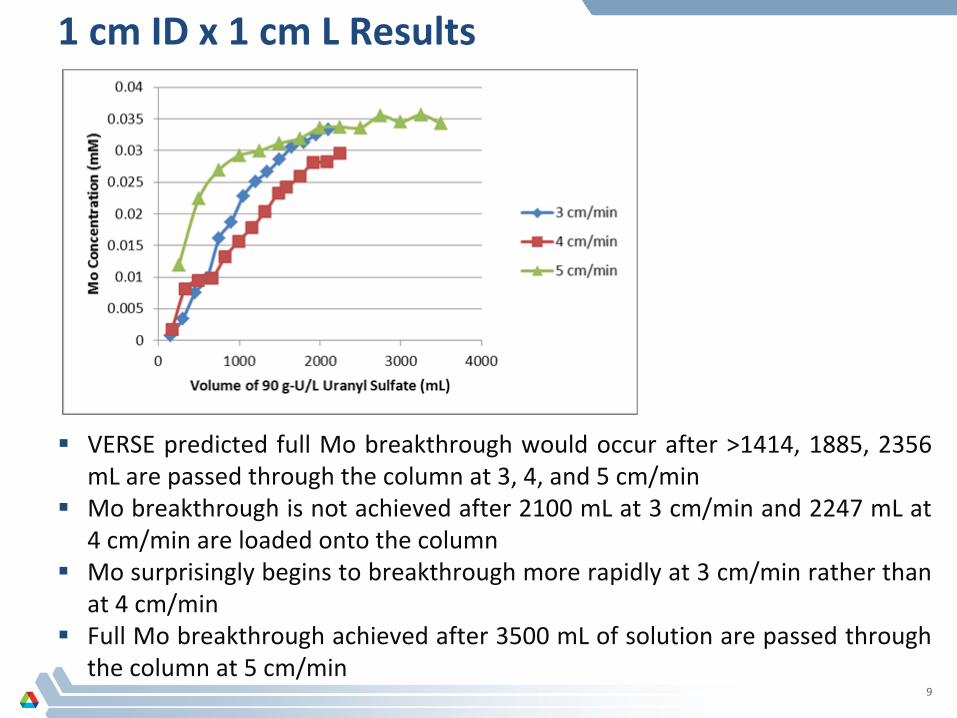
1 cm ID x 1 cm L Results
VERSE predicted full Mo breakthrough would occur after >1414, 1885, 2356 mL are passed through the column at 3, 4, and 5 cm/minMo breakthrough is not achieved after 2100 mL at 3 cm/min and 2247 mL at 4 cm/min are loaded onto the columnMo surprisingly begins to breakthrough more rapidly at 3 cm/min rather than at 4 cm/minFull Mo breakthrough achieved after 3500 mL of solution are passed through the column at 5 cm/min
9

10
Mo‐99 Separation Updates for Uranyl Nitrate
Feed solution ~150 g‐U/L uranyl nitrate, stable Mo, and Mo‐99
Column tests performed with S40 and S110 with 60 Å pores
S110 outperforms S40 which had a significant amount of Mo in effluent
Mo recoveries varied from 73 – 89%
Stripping velocity had little effect on Mo recovery
0.5 wt.% KMnO4 added to first water wash for runs on 10/06 and 10/12
Date of Run
Column Size (ID x L)
Velocity (cm/min) Sorbent %Mo in
Effluent%Mo in Washes
%Mo Recovered
Stripping Agent
09/15/11 1.5 x 3.1 9 S40 16.0 0.6 86.0 1 M NH4 OH
09/21/11 1.5 x 6.2 3 S110 1.0 0.6 88.0 1 M NH4 OH
09/23/11 1.5 x 6.3 5 S110 1.0 1.0 85.0 1 M NH4 OH
09/26/11 1.5 x 2.6 5 S40 32.0 0.3 80.0 1 M NH4 OH
09/28/11 1.5 x 6.3 10 S110 1.0 0.1 77.0 1 M NH4 OH
09/30/11 1.5 x 6.3 7.5 S110 2.0 0.1 85.0 1 M NH4 OH
10/06/11 1.5 x 6.2 7.5 S110 7.3 0.8 73.0* 1 M NH4 OH
10/12/11 1.5 x 6.2 3 S110 7.0 1.0 89.0* 1 M NH4 OH
10

11
S110 vs. S80 for Mo Breakthrough
S110 Mo Breakthrough Results S80 Mo Breakthrough Results
S80 Mo Breakthrough
-0.005
0
0.005
0.01
0.015
0.02
0.025
0.03
0.035
0 500 1000 1500 2000 2500 3000 3500
Volume of Uranyl Nitrate (mL)
Mo
Con
cent
ratio
n (m
M)
1 cm ID x 1.6 cm L column with a linear velocity of 13 cm/min5 L for S110 compared to 3 L for S80 for almost full Mo breakthrough to occurMo breakthrough occurs more rapidly with S110 compared to S80Current plant‐scale column designs for uranyl nitrate solutions using S80 should work for S110
11

Effects of Temperature
Batch studies performed as a function of temperature after 24 hours of contact Kd values ~2X higher for sulfate and 3X higher for nitrate in going from 20‐60oCSolution is not heated prior to column loading due to heat loss in the pumpTemperature of solution entering column is not 60oC but column is kept at 60oCStainless steel coils wrapped in heat tape were added before and after the columnMo adsorption is significantly affected by temperatureIf temperature is controlled better, more Mo may adsorb2 – 5% Mo typically observed in effluentVERSE column sizes are designed to be able to adsorb at least 2X more Mo than needed
Sorbent Solution
Kd
, Mo,
(mL/g)
20oC
Kd
, Mo,
(mL/g)
40oC
Kd
, Mo,
(mL/g)
60oC
S110
90 g‐U/L
uranyl
sulfate 2600 3500 6200
S110
150 g‐U/L
uranyl
nitrate 7000 12000 21000
12

Mo‐99 Separation Wrap‐Up
S110 can be used to separate Mo‐99 from LEU uranyl nitrate or uranyl sulfate solutions
Current plant‐scale column designs for BWTSG using S80 will work for S110 as well
Plant‐scale column designs are almost complete for MIR
Recovery of Mo‐99 continuously being optimized
Small‐scale column experiments will be done for MIR when plant‐scale design is complete
Mini‐MIPS/SHINE experiments will provide useful data regarding the fate of other fission products in the separation, recovery, and purification processes
13

Radiolytic Stability of Mo‐ABO Precipitate
Precipitation of Mo with alpha‐benzoin oxime is an important step in Cintichem purification processMo yields unaffected when up to 1000 Ci of Mo‐99 was processed in a single Cintichem runIf production yields are higher, primary concern isthat ABO will radiolytically breakdown and Mo yields will decreaseSeveral 6‐day kCi per batch are expected for processingVan de Graaff (VDG) accelerator was used to irradiate the Mo‐ABO precipitate at doses equivalent to ~160 kCi of Mo‐99Stability of the precipitate was examined after irradiation
14

ABO Irradiation at Van de Graaff
•
ABO precipitate•
Centrifuge, discard solution•
Irradiate (0.1 M HNO3
)•
Transfer to filter vial•
Wash with 0.1 M HNO3•
Centrifuge•
Dissolve in 0.4 M NaOH/1%H2
O2•
Centrifuge•
Dissolve in 0.2 M NaOH/1%H2
O2•
Centrifuge•
Rinse with 0.2 M NaOH•
Count filter, HNO3
, NaOH fraction
Mo carrier
and KMnO4
to
~1.4M HNO3
ABO precipitate,
centrifug., wash
0.1M HNO3
Dissolution0.4M; 0.2M
NaOH/1%H2
O2
Before irradiation
After irradiation
(24.4GRad)
15

MCNPX Simulations and Mo Recovery Results
MCNPX calculations20 minutes (Cintichem process) is eq.
~62.5 MRad/ 1 kCi of 99Mo
If modeled as a single layer ABO ~150
MRad per 1 kCi of Mo‐99(more conservative)
‐5%
15%
35%
55%
75%
95%
2.0 22.0 42.0 62.0 82.0 102.0 122.0 142.0 162.0
Mo fraction
Mo‐99, kCi
ABO irradiated no solution
NaOH
HNO3
filter
NaOH control
HNO3 control
filter control
~41kCi of Mo‐99
‐5%
15%
35%
55%
75%
95%
2.0 7.0 12.0 17.0 22.0 27.0 32.0
Mo fraction
Mo‐99, kCi
ABO irradiated with HNO3NaOH
HNO3
filter
NaOH control
HNO3 control
filter control
~10kCi of Mo‐99
~6.1GRad
~1.5GRad
16
Four Potential Clean‐Up Methods, If Required
Methods listed below assume a uranyl sulfate solution
1.
Anion Exchange of uranyl
sulfate complexes
2.
Direct Solvent‐Extraction Process for Uranyl
Sulfate
3.
Precipitation of Uranyl
Ion as Uranyl
Peroxide
4.
Conversion to nitrate media followed by UREX processing
17
Least Favorable Options for Clean‐Up
Anion exchange of uranyl sulfate complexes will not work because of the low capacity of the resins (1‐2 meq/g and ~500 kg of resin for 200 L at 150 g‐U/L )
Direct solvent‐extraction process for uranyl sulfate could work but the concentrations of trioctyl ammonium sulfate (TOA) and trioctyl phosphate (TOPO) and stripping conditions need to be determined
Precipitation of uranyl ion as uranyl peroxide is problematic because it cannot be filtered or centrifuged
The last two options could work but both would require a significant amount of R&D
18

Conversion to Nitrate Media Followed by UREX
Steps –
Addition of Ca(NO3
)2
dissolved in 1 M HNO3
to the irradiated uranyl
sulfate solution in a
stirred
vessel;
addition
rate,
stirring
speed,
and
temperature
must
be
set
to
optimize
the morphology and size of the crystals formed to allow facile filtration
–
Passing the slurry into a filtration system to collect and wash the precipitate
–
UREX processing of the filtrate
–
Precipitation of uranium as ammonium diuranate
and its filtration
–
Conversion of uranium to UO3
–
Dissolution of UO3
in sulfuric acid
–
Reconstitution to the uranyl‐sulfate/0.1 M‐sulfuric‐acid target solution
–
Potential recycle of uranium from ammonium diuranate
filtrate
–
Treatment of waste streams generated for storage and final disposal
All process steps are used commercially and well understood–
Minimum R&D is required to design processing facility
19
Concluding Remarks
S110 will be used for Mo‐99 separation and recovery columns for MIPS and SHINEColumn stripping and loading conditions will continue to be optimizedFuture irradiations will take place at Argonne using the linac(mini‐MIPS/SHINE experiments)Mo‐ABO radiolytic stability tests show that ~10 kCi Mo‐99 can be purified via the Cintichem process without losses due to ABO degradationIf solutions need to be cleaned up, conversion to nitrate followed by UREX processing is the best option
20
Acknowledgements
Work
supported
by
the
U.S.
Department
of
Energy,
National
Nuclear
Security
Administration's (NNSA's) Office of Defense Nuclear Nonproliferation, under Contract
DE‐AC02‐06CH11357.
Argonne
National
Laboratory
is
operated
for
the
U.S.
Department of Energy by UChicago
Argonne, LLC.
21
22
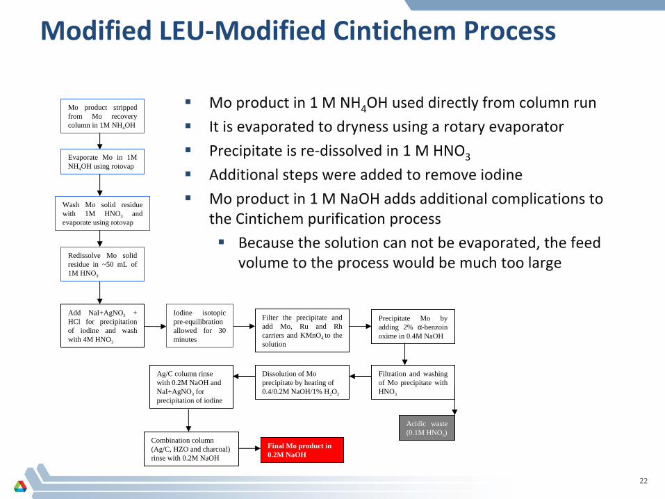
Modified LEU‐Modified Cintichem
Process
Mo product in 1 M NH4OH used directly from column run
It is evaporated to dryness using a rotary evaporator
Precipitate is re‐dissolved in 1 M HNO3
Additional steps were added to remove iodine
Mo product in 1 M NaOH adds additional complications to the Cintichem purification process
Because the solution can not be evaporated, the feed volume to the process would be much too large
Add NaI+AgNO3 + HCl for precipitation of iodine and wash with 4M HNO3
Filter the precipitate and add Mo, Ru and Rh carriers and KMnO4 to the solution
Precipitate Mo by adding 2% α-benzoin oxime in 0.4M NaOH
Acidic waste (0.1M HNO3 )
Dissolution of Mo precipitate by heating of 0.4/0.2M NaOH/1% H2 O2
Filtration and washing of Mo precipitate with HNO3
Ag/C column rinse with 0.2M NaOH and NaI+AgNO3 for precipitation of iodine
Combination column (Ag/C, HZO and charcoal) rinse with 0.2M NaOH
Final Mo product in 0.2M NaOH
Mo product stripped from Mo recovery column in 1M NH4 OH
Evaporate Mo in 1M NH4 OH using rotovap
Wash Mo solid residue with 1M HNO3 and evaporate using rotovap
Redissolve Mo solid residue in ~50 mL of 1M HNO3
Iodine isotopic pre-equilibration allowed for 30 minutes
Related Documents